
EFV 3160-92 X - Range hood GRAM - Free user manual and instructions
Find the device manual for free EFV 3160-92 X GRAM in PDF.

| Product Type | Range Hood |
| Brand | Gram |
| Model | EFV 3160-92 X |
| Width | 92 cm |
| Depth | 50 cm |
| Height (min-max) | 65-125 cm |
| Weight | 16 kg |
| Power Supply | 220-240 V ~ 50 Hz |
| Motor Power | 250 W |
| Max Extraction Rate | 720 m³/h |
| Noise Level (max) | 68 dB(A) |
| Energy Class | A+ |
| Grease Filter Type | Aluminum washable |
| Carbon Filter (optional) | Yes |
| Lighting | 2 x 1.5 W LED |
| Controls | Push buttons |
| Number of Speeds | 3 + Boost |
| Duct Diameter | 150 mm |
| Installation Type | Wall-mounted / Ducted or Recirculation |
| Remote Control | Not included |
Frequently Asked Questions - EFV 3160-92 X GRAM
User questions about EFV 3160-92 X GRAM
0 question about this device. Answer the ones you know or ask your own.
Ask a new question about this device
Download the instructions for your Range hood in PDF format for free! Find your manual EFV 3160-92 X - GRAM and take your electronic device back in hand. On this page are published all the documents necessary for the use of your device. EFV 3160-92 X by GRAM.
USER MANUAL EFV 3160-92 X GRAM
Before using the appliance, please carefully read this manual!
BETJENINGSVEJLEDNING - EMFANG
other
| Dimension | Value | | --------- | ----- | | Top Height | 164 | | Middle Height | 350 | | Bottom Height | 400 | | Total Height | 498,598 | | Inner Height | 172 | | Outer Height | 23.5 | | Inner Wall Width | 20 | | Outer Wall Width | 24 | | Total Wall Width | 211 |
natural_image
Vertical arrangement of gray rectangular blocks with no text or symbols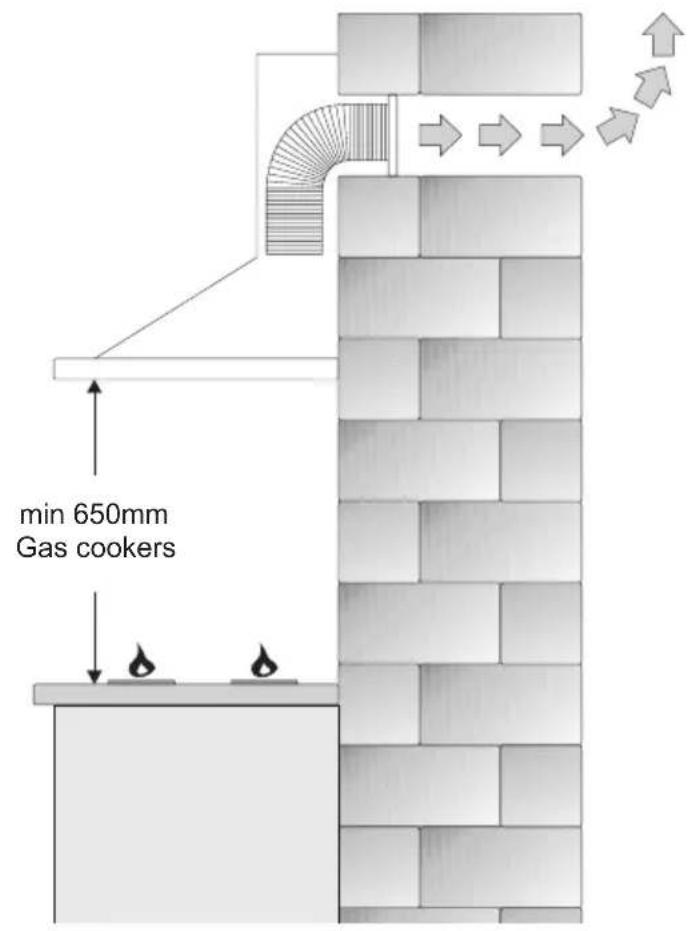
natural_image
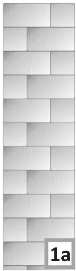
Vertical wall pattern composed of stacked rectangular blocks, no text or symbols present1a
2
natural_image
Black and white photo of a small white object near a black triangular object on a stand (no text or symbols visible)3a 3b
natural_image
Technical line drawing of a vertical structural frame with an inset detail showing internal components (no text or symbols)3c 3|d
natural_image
Technical diagram showing a mechanical component with an inset close-up of a pin inserted into a bracket (no text or symbols present)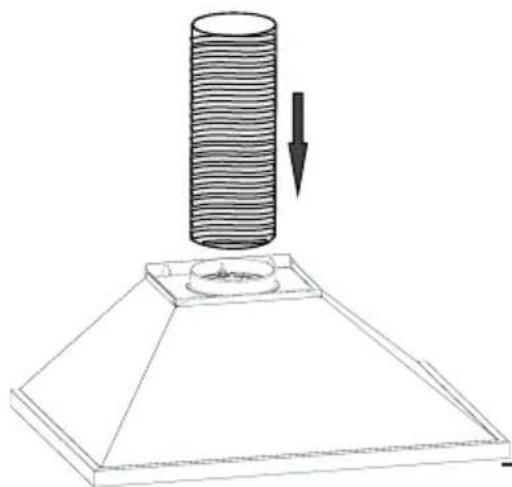
natural_image
Diagram of a cylindrical object being inserted into a base, with an arrow indicating direction (no text or symbols present)3e 3f
natural_image
Isometric diagram of a 3D geometric structure with labeled point 'a' and directional arrows, no text or symbols present.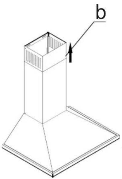
natural_image
Isometric line drawing of a chimney or chimney structure with a base platform and an arrow labeled 'b' pointing to the chimney (no text or symbols beyond label)3g 3h
natural_image
Two rectangular panels with grid patterns, one with a small cutout and the other with a handle (no text or symbols)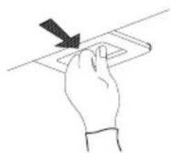
natural_image
Hand holding a rectangular object with a downward arrow, no text or symbols present4
natural_image
Line drawing of a kitchen air conditioner unit with ventilation duct and mounting base (no text or symbols)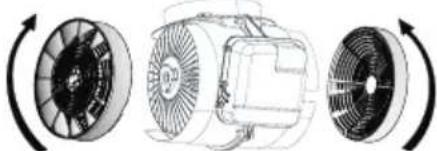
natural_image
Diagram of three types of electric motors with rotating blades, showing different fan orientations (no text or labels)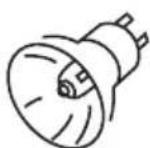
natural_image
Illustration of hands using a mechanical tool to adjust a circular component, with no visible text or symbols.6
5
THANK YOU FOR PURCHASING AN GRAM APPLIANCE
DEAR CUSTOMER!
You are now a user of a kitchen extractor hood. This hood has been designed and manufactured specially with a view to satisfying your expectations and it will certainly constitute a fitting element of a modern kitchen. The modern structural solutions and the newest technologies used in production of this hood guarantee its high effectiveness and good appearance.
Please read these instructions carefully before installing the hood. They will help you avoid mistakes during installation and operation of the hood.
We wish you a lot of satisfaction from choosing our kitchen extractor hood.
Symbols appearing in these instructions have the following meaning:

Important information concerning proper operation of the appliance and your personal safety.

Risks resulting from improper operation of the appliance. Activities that must be performed by a qualified technician.

Tips on how to use the appliance.

Information on how to protect the environment.

This indicates actions than must not be performed by the user.
TABLE OF CONTENTS
GUIDELINES CONCERNING THE SAFETY OF USE 7
| INSTALLATION | 10 | ||
| OPERATION | AND | MAINTENANCE | 11 |
| ENVIRONMENTAL | PROTECTION | 13 | |

The appliance is intended for household use only.
The manufacturer reserves the right to introduce changes which do not affect the operation of the appliance.

●The manufacturer will accept no responsibility for any damage due to installation or operation not conforming to these instructionsi
● Cooker hood is designed to remove cooking odours. Do not use cooker hood for other purposes.
- Connect the cooker hood operating in extraction mode to a suitable ventilation duct (do NOT connect the cooker to smoke or flue gas ducts, which are in use). It requires installation of the air extraction duct to the outside. The duct length (typically 120 or 150mm in diameter) should not exceed 4-5 m. The air exhaust duct is also required for telescopic and under furniture cooker hoods operating in air recirculation mode.
● Cooker hood operating in air recirculation mode requires the installation of an activated charcoal filter. In this case, installing an extractor duct is not required, however it is recommended to install an air guide vane. (chimney cooker hoods only).


●The cooker hood features independent lighting and exhaust fan that can be operated at one of several speeds.
- Depending on the type, the hood is designed to be permanently attached to a vertical wall over a gas or electric stove (chimney and universal hoods); on the ceiling over a gas or electric stove (island hoods); on the vertical built in furniture over a gas or electric stove (telescopic and built-in hoods). Before installing, make sure that the wall/ceiling structure is strong enough to suspend the hood. Some hoods are very heavy.
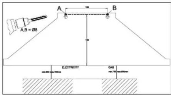
●For details of the installation distance above an electric hob please refer to product technical sheet. If the installation instructions of the gas cooker specify a greater distance, this must be taken into account (Fig. 1a).
- Do not leave an open flame under the hood. When the pots are removed from the burner, set the minimum flame. Always make sure that the flame does not ex-

tend outside the pot, because it causes unwanted loss of energy and a dangerous concentration of heat.
●Any food cooked in fat shall be constantly monitored, since overheated fat can ignite very easily.
- Pull the plug of the power cord from a wall socket before any filter cleaning or repair operation.
●The textile grease filter should be replaced, and the aluminium filter should be cleaned at least every one month in connection with the existing fire danger (saturated fat is very flammable).
- If any other non-electric devices are used in the same room as the hood (e.g. liquid fuel ovens, flow-through or volumetric water heaters), it is necessary to provide appropriate ventilation (air supply). Safe operation is possible when during simultaneous operation of the hood and combustion devices dependent on air supply the negative pressure of not more than 0.004 milibar is


maintained at the location of these devices inside the room (this point does not apply when the hood is used as an odour absorber).
●Do not lean on hood
●The hood should be frequently cleaned inside and on the outside surfaces (at least once a month). See “Cleaning section” in this manual.
- If the power wire gets broken, it should be replaced with a new one in a specialist repair shop.
- If the power wire gets broken, it should be replaced with a new one in a specialist repair shop.
●Make sure the appliance can be easily disconnected from the mains, either by pulling the plug out of the mains socket, or by switching the two-pole switch off.
●This appliance is not intended for use by persons (including children) with reduced physical, sensory or mental capabilities, or lack of experience and knowledge, unless they have been given supervision or instruction concerning use of the appliance by a person responsible for their safety.
●Children should be su-

pervised to ensure that they do not play with the appliance.
- Check if the voltage indicated on the rating plate corresponds to the local power supply parameters.
●Before installing unwind and straighten the power cord.
●Warning! The packaging materials (polyethylene bags, small pieces of foamed poly-
styrene etc.) should be kept away from children while unpacking.
NOTE: Before connecting the hood to the mains power supply always check that the power cord is properly installed and is not trapped by the appliance. It is recommended to make sure the hood operates correctly before installation.
INSTALLATION
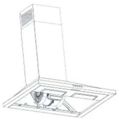
Elements
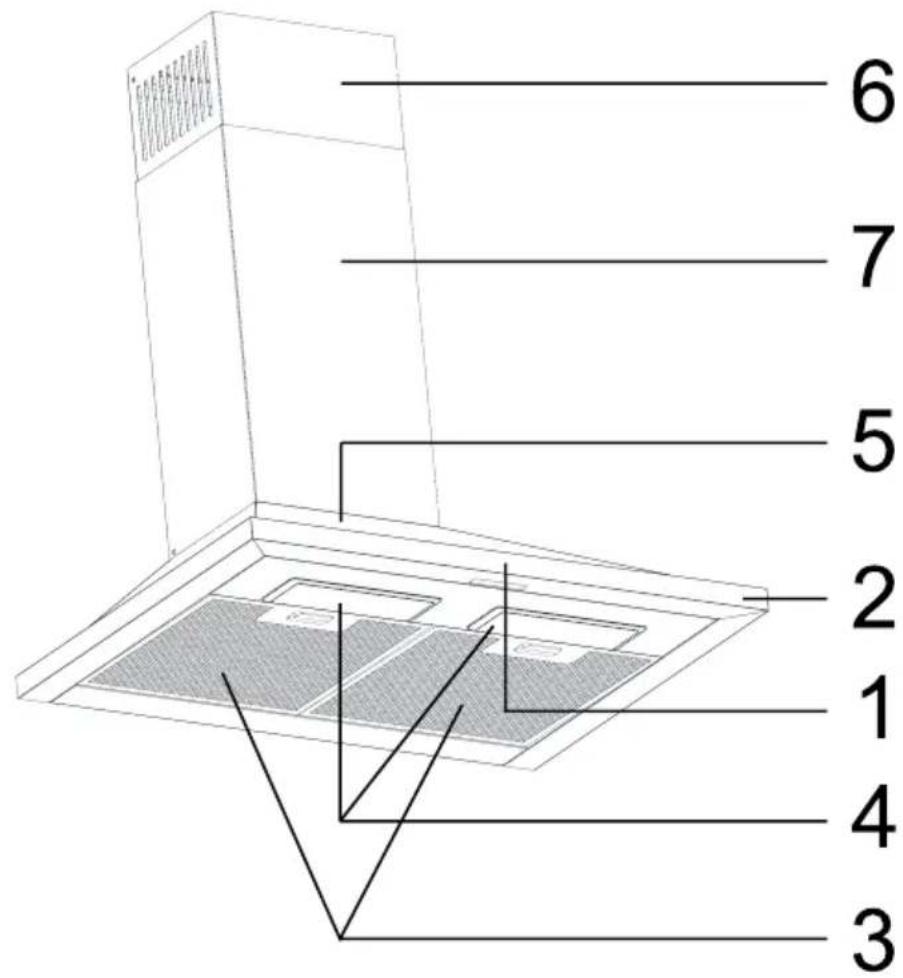
Kitchen hood consists of the following elements (Fig. 2):
- Control panel
- Front panel
- Aluminium cassette filter (dishwasher safe)
- Lighting
- Hood body
- Upper duct enclosure
- Lower duct enclosure
Installation
Step-by-step appliance installation:
Mounting template
Please refer to mounting template enclosed with the appliance (fig. 3a)
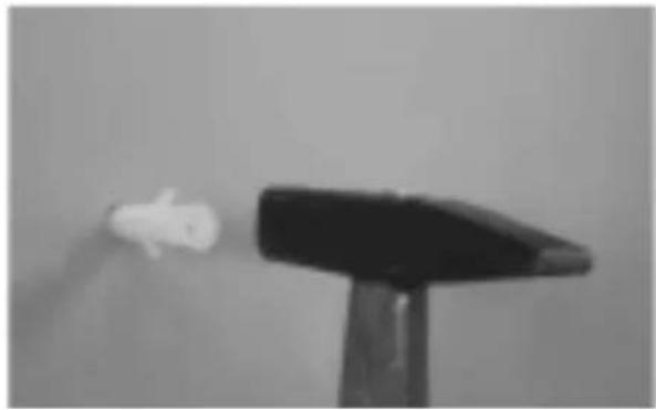
Wall plugs
Using a hammer drive the 10 mm wall plugs into the wholes (A,B) for the fixing screws. For the duct, use 2x6 mm wall plugs in the 4 mm holes (fig. 3b).
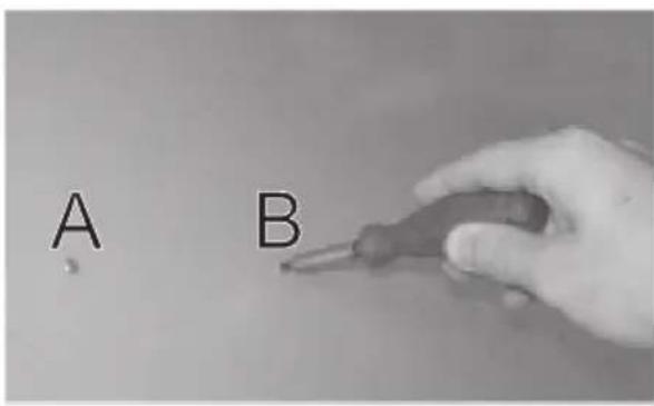
Screw the hanging screws
Screw the 5,5x45 hanging screws in the ∅8 wall plugs (A,B) that are already driven in the wall. The screws should protrude from the wall about 5 mm (fig. 3c).
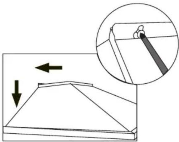
Install the hood
This model is not available with hanging plate. Hang your product on the slot on the back and then fix it with the screws (fig. 3d and 3e).
Install the aluminium duct
Connect aluminium flexible duct to outlets on the product and kitchen wall. Ensure connection will hold when the product is operated at airflow level (fig. 3f and 3i).
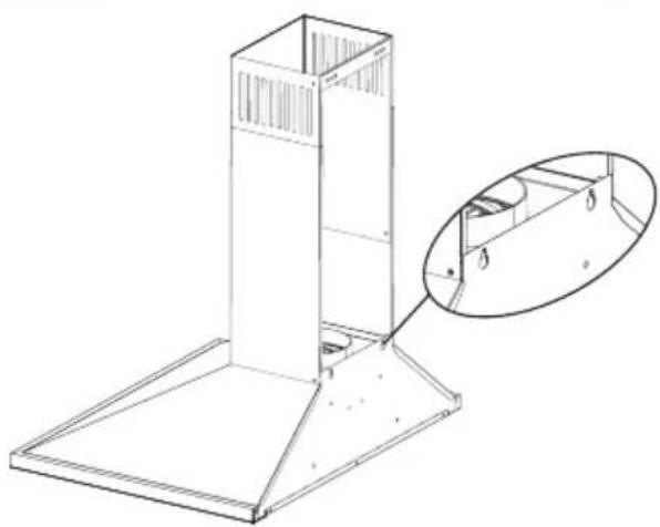
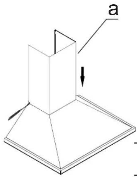
Install enclosures.
To install the enclosure use 3,9x x 9,5 flat head RYSB screws (fig. 3g and 3h).
a) Lower duct enclosure
b) Upper duct enclosure
Bending the aluminium duct reduces the air flow, so makes sure there are as few bends as possible
Setting the air extractor mode of operation of the hood
In the extractor mode air is discharged to the outside by a special conduit. In that setting any carbon filters shall be removed. The hood should be connected to the opening discharging air to the outside by means of a rigid or flexible conduit of 120 mm diameter, which should be purchased in a shop selling installation materials.
A qualified installer should be commissioned to make the connection.
Setting the odour absorber mode of operation of the hood
In this option filtered air returns to the room through openings in the front of the hood. In this setting it is necessary to install the carbon filter. It is recommended to install the air guide (availability depending on model).
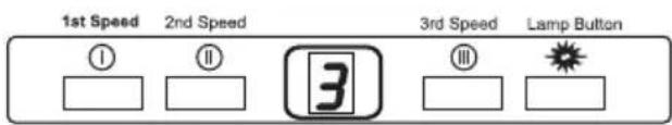
Use control panel to control your cooker hood (Fig. 4)
Speed choice
The appliance has 3 fan speeds. Depending on cooking intensity and the amount of steam, you can choose low, medium or high fan speed. Buttons on the front panel are used for turning the appliance on.
Please turn on hob and hood at the same time to provide effective circulation. Allow the appliance to run for a while after cooking is finished, so the remaining odour and steam will be absorbed.
Lighting
The product has 2 lamps and one lamp button to operate light. Press lamp button in order to turn on the light.
Regular maintenance and cleaning of the device will ensure faultless operation, and help extend the life of the unit. Attention should be paid to replacing grease and carbon filters according to instructions.
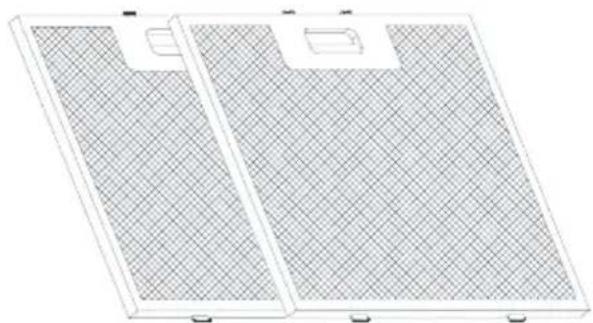
Aluminium grease filter
Cleaning
For normal hood operation, aluminium grease filter should be cleaned every month in the dishwasher or by hand using a mild detergent or liquid soap.
To replace:
Dismantling of aluminium grease filter is shown on Figure 5.
Acrylic filter is used in some models. This filter should be replaced at least once every two months or more frequently if the appliance is used intensively.
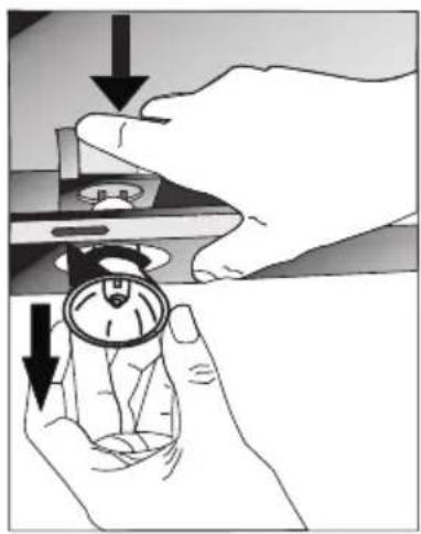
Charcoal filter (only the recirculation version)
Operation - Carbon filters can be used only when the hood is not connected to any ventilation duct. Filters with active carbon can absorb odours until they are saturated. They cannot be washed or regenerated and should be replaced at least every 2 months or more frequently in case of very intensive use.
Replace:
Dismantling of charcoal filter is shown on Figure 6.
Lighting
See Figure 7 for details how to replace lights. Use incandescent / halogen / LED modules of the same specification as those factory-installed in the appliance.
Cleaning
Normal hood cleaning:
- Do not use a soaked cloth, sponge, or water jet.
- Do not use solvents or alcohol, as they may tarnish lacquered surfaces.
- Do not use caustic substances, especially for cleaning stainless steel.
- Do not use a rough or abrasive cloth.
It is recommend to use a damp cloth and a neutral detergent.
Aluminium filters may be washed in the dishwasher. The colour of aluminium filters may change after several washings. This is normal and it is not necessary to renew the filters.

RECYCLING OF THE PACKAGING
natural_image
Simple line drawing of a recycling symbol (three chasing arrows), no text or labels present.Our packaging is made of environmentally friendly materials, which can be reused:
● The external packaging is made of cardboard/foil
● The FCKW free shape of foamed polystyrene (PS)
● Polyethylene (PE) foils and bags
ELIMINATION / DISPOSAL OF THE EU-IPMENT
If the appliance is no longer in use, cut the connecting cable off the used equipment before scrapping. We also recommend that the appliance is locked or render it useless so that the appliance presents no danger to children while being stored for disposal. This appliance is marked with a symbol of the crossed out waste container in conformance with the European Directive 2002/96/EC. Such

marking informs that the equipment may not be kept together with other waste coming from the household after the period of its use. The user is obliged to dispose of the appliance at the waste collection point authorised by the local authority. The local waste collection points, shops and communal units form an appropriate system enabling the disposal of the equipment.
Handling the used electrical and electronic equipment and any hazardous substances contained therein in a correct manner is vital to avoid damage the local natural environment. Therefore care and responsibility should always be taken in the disposal of these products
Manufacturer's Declaration
The manufacturer hereby declares that this product meets the requirements of the following European directives:
● Low Voltage Directive 2006/95/EC,
● Electromagnetic Compatibility (EMC) Directive 2004/108/EC,
● ErP Directive 2009/125/EC
and has thus been marked with the symbol and been issued with a declaration of compliance made available to market regulators.
TIL LYKKE MED DIT NYE GRAM EMFANG
natural_image
Simple line drawing of a recycling symbol (three chasing arrows), no text or labels present.natural_image
Simple line drawing of a recycling symbol (three chasing arrows), no text or labels present.INNEHÅLLSFÖRTECKNING
SÄKERHETSANVISNINGAR 31
INSTALLATION 34
ANVÄNDNING OCH SKÖTSEL 35
MILJÖSKYDD 37

natural_image
Simple line drawing of a recycling symbol (three chasing arrows), no text or labels present.BRUK OG VEDLIKEHOLD 43
MILJ∅VERN 45

natural_image
Simple line drawing of a recycling symbol (three chasing arrows), no text or labels present.- THANK YOU FOR PURCHASING AN GRAM APPLIANCE
- DEAR CUSTOMER!
- INSTALLATION
- Elements
- Setting the odour absorber mode of operation of the hood
- Use control panel to control your cooker hood (Fig. 4)
- Aluminium grease filter
- Charcoal filter (only the recirculation version)
- Lighting
- Cleaning
- RECYCLING OF THE PACKAGING
- ELIMINATION / DISPOSAL OF THE EU-IPMENT
- Manufacturer's Declaration
- TIL LYKKE MED DIT NYE GRAM EMFANG
- INNEHÅLLSFÖRTECKNING
Brand : GRAM
Model : EFV 3160-92 X
Category : Range hood