
MTH 350 - Uncategorized AEG - Free user manual and instructions
Find the device manual for free MTH 350 AEG in PDF.


| Product Type | Hydraulically controlled, open vented small instantaneous water heater with bare wire heating system |
| Intended Use | Heating domestic hot water for one hand washbasin |
| Dimensions (H x W x D) | 143 x 190 x 82 mm |
| Weight | 1.4 kg |
| Rated Voltage | 220-240 V |
| Rated Output | 3.2-3.8 kW (depending on voltage) |
| Rated Current | 14.5-15.8 A |
| Phases | 1/N/PE |
| Frequency | 50/60 Hz |
| Max Throughput | 2.3 l/min |
| Max Permissible Pressure | 0 MPa (open vented) |
| Max Inlet Temperature | 35°C |
| Heating System | Bare wire, low susceptibility to scale build-up |
| IP Rating | IP25 |
| Protection Class | I |
| Color | White |
| Installation Options | Undersink or oversink, with non-pressurised tap |
| Energy Efficiency Class | A (load profile XXS) |
| Annual Power Consumption | 478 kWh |
| Sound Power Level | 15 dB(A) |
Frequently Asked Questions - MTH 350 AEG
User questions about MTH 350 AEG
0 question about this device. Answer the ones you know or ask your own.
Ask a new question about this device
Download the instructions for your Uncategorized in PDF format for free! Find your manual MTH 350 - AEG and take your electronic device back in hand. On this page are published all the documents necessary for the use of your device. MTH 350 by AEG.
USER MANUAL MTH 350 AEG
Hydraulically controlled, open vented small instantaneous water heater with bare wire heating system
Operation and installation 24
natural_image
Technical diagram of a mechanical device with ports and arrows indicating flow or movement (no text or symbols)natural_image
Technical line drawing of a mechanical component with grid background and no visible text or symbolsnatural_image
Line drawing of a faucet and sink with pipe fittings (no text or symbols)Montage der Armatur
Schutzleiter prüfen
X Volumenstrom in l/min
Y Temperaturerhöhung in K
1 3,5 kW - 230 V
2 4,4 kW - 230 V
3 5,7 kW - 230 V
- General information ......26
1.1 Safety instructions 26
1.2 Other symbols in this documentation 26
1.3 Units of measurement....27 - Safety 27
2.1 Intended use 27
2.2 General safety instructions....27
2.3 Test symbols....28 - Appliance description....28
- Settings....29
- Cleaning, care and maintenance 29
- Troubleshooting 29
INSTALLATION
- Safety 30
7.1 General safety instructions....30
7.2 Instructions, standards and regulations....30 - Appliance description....30
8.1 Standard delivery....30
8.2 Accessories 31 - Preparations....31
-
Installation....31
10.1 Installation site 31
10.2 Installation options 32
10.3 Connecting the power supply 34 -
Commissioning....35
11.1 Initial start-up 35
11.2 Appliance handover 35
11.3 Recommissioning 35 - Shutting down....35
- Troubleshooting 35
- Maintenance....36
- Specification 37
15.1 Dimensions 37
15.2 Wiring diagram....37
15.3 Increasing the temperature....38
15.4 Application areas....38
15.5 Details on energy consumption 39
15.6 Data table....39
GUARANTEE
ENVIRONMENT AND RECYCLING
SPECIAL INFORMATION
• The appliance may be used by children aged 8 and up and persons with reduced physical, sensory or mental capabilities or a lack of experience and know-how, provided that they are supervised or they have been instructed on how to use the appliance safely and have understood the resulting risks. Children must never play with the appliance. Children must never clean the appliance or perform user maintenance unless they are supervised.
- Ensure the appliance can be separated from the power supply by an isolator that disconnects all poles with at least 3 mm contact separation.
• In the case of damage, the power cable must only be replaced by a qualified contractor authorised by the manufacturer using the original spare part.
- Secure the appliance as described in chapter "Installation / Installation".
- Observe the maximum permissible pressure (see chapter "Specification / Data table").
- Drain the appliance as described in chapter "Installation / Maintenance / Draining the appliance".
Operation - for users and contractors
OPERATION
1. General information
The chapter "Operation" is intended for appliance users and qualified contractors.
The chapter "Installation" is intended for qualified contractors.

Note
Read these instructions carefully before using the appliance and retain them for future reference.
Pass on the instructions to a new user if required.
1.1 Safety instructions
1.1.1 Structure of safety instructions

KEYWORD Type of risk
Here, possible consequences are listed that may result from failure to observe the safety instructions.
» Steps to prevent the risk are listed.
1.1.2 Symbols, type of risk
| Symbol Type of risk | |
 | Injury |
 | Electrocution |
 | Burns(burns, scalding) |
1.1.3 Keywords
| KEYWORD | Meaning |
| DANGER | Failure to observe this information will result in serious injury or death. |
| WARNING | Failure to observe this information may result in serious injury or death. |
| CAUTION | Failure to observe this information may result in non-serious or minor injury. |
1.2 Other symbols in this documentation

Note
Notes are bordered by horizontal lines above and below the text. General information is identified by the symbol shown on the left.
» Read these texts carefully.
| Symbol | |
| Material losses(appliance damage, consequential losses and environmental pollution) | |
| Appliance disposal |
» This symbol indicates that you have to do something. The action you need to take is described step by step.
1.3 Units of measurement

Note Unless specified otherwise, all dimensions are given in mm.
2. Safety
2.1 Intended use
This appliance is intended for domestic use. It can be used safely by untrained persons. The appliance can also be used in a non-domestic environment, e.g. in a small business, as long as it is used in the same way.
This appliance is designed to heat DHW. The appliance is designed for one hand washbasin.
Any other use beyond that described shall be deemed inappropriate. Observation of these instructions and of instructions for any accessories used is also part of the correct use of this appliance.
2.2 General safety instructions

DANGER Scalding
During operation, the tap can reach temperatures in excess of 50 °C.
There is a risk of scalding at outlet temperatures in excess of 43 °C.

WARNING Injury
The appliance may be used by children aged 8 and up and persons with reduced physical, sensory or mental capabilities or a lack of experience and know-how, provided that they are supervised or they have been instructed on how to use the appliance safely and have understood the resulting risks. Children must never play with the appliance. Children must never clean the appliance or perform user maintenance unless they are supervised.

DANGER Electrocution
Any damaged power cables must be replaced by a qualified electrician. This prevents potential hazards from arising.

Material losses
Protect the appliance and tap against frost.
Operation - for users and contractors

Material losses
Ensure that the non-pressurised appliance is not exposed to any pressure as this could cause irreparable damage:
» Only use the special aerator provided.
» Never use aerators or hoses with aerators.
» Never seal the tap outlets.
» Prevent scale build-up at the tap outlets (see
chapter "Cleaning, care and maintenance").
2.3 Test symbols
See type plate on the appliance.
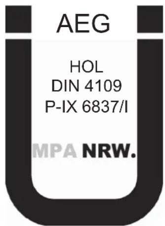
Country-specific approvals and certifications: Germany
In line with [German] State Building Regulations, a general test certificate has been issued for these appliances, as verification of their suitability regarding noise emissions.
3. Appliance description
The hydraulically controlled, non-pressurised small instantaneous water heater heats the water directly at the draw-off point. The heating system starts automatically when the tap is opened. The short pipe runs ensure that energy and water losses are minimal.
The DHW output depends on the cold water temperature, the heating output and the flow rate.
The bare wire heating system is suitable for hard and soft water areas. This heating system has a low susceptibility to scale build-up. The heating system ensures quick and efficient DHW provision at the hand washbasin.
Fitting the special aerator supplied provides an optimum water jet.
Operation - for users and contractors
4. Settings
The appliance heating system switches on automatically as soon as you open the DHW valve at the tap or activate the sensor of a sensor tap. The water is heated. The water temperature can be adjusted at the tap:
For the start volume, see chapter "Specification / Data table / On".
Increasing the temperature
» Reduce the flow rate at the tap.
Reducing the temperature
» Open the tap further or add more cold water.
Following an interruption of the water supply
See chapter "Commissioning / Recommissioning".
5. Cleaning, care and maintenance
» Never use abrasive or corrosive cleaning agents. A damp cloth is sufficient for cleaning the appliance.

Material losses
Scale build-up at the tap outlets can put the appliance under pressure and may cause irreparable damage.
» Check the taps/valves regularly. Limescale deposits at the spouts can be removed using commercially available descaling agents.
» Have the electrical safety of the appliance regularly checked by an electrician.
» Regularly descale or replace the special aerator (see chapter "Appliance description / Accessories").
6. Troubleshooting
| Problem Cause Remedy | ||
| The appliance will not start despite the DHW valve being fully open. | No power to the ap- pliance. | Check the fuses/ MCBs in your fuse box. |
| The aerator in the tap is scaled up or dirty. | Clean and/or descale the aerator or replace the special aerator. | |
| The water supply has been interrupted. | Vent the appliance and the cold water inlet line (see chapter "Settings"). | |
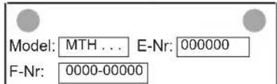
If you cannot remedy the fault, notify your qualified contractor. To facilitate and speed up your enquiry, please provide the serial number from the type plate (000000 / 0000-00000).
Only a qualified contractor should carry out installation, commissioning, maintenance and repair of the appliance.
7.1 General safety instructions
We guarantee trouble-free function and operational reliability only if original accessories and spare parts intended for the appliance are used.

Material losses
Observe the max. permissible inlet temperature. Higher temperatures may damage the appliance. You can limit the inlet temperature by means of a central thermostatic valve.

Material losses
Only operate the appliance with non-pressurised taps.
7.2 Instructions, standards and regulations

Note
Observe all applicable national and regional regulations and instructions.
The specific electrical resistance of the water must not fall below that stated on the type plate. In a linked water network, factor in the lowest electrical resistance of the water (see chapter "Specification / Data table"). Your water supply utility will advise you of the specific electrical water resistance or conductivity.
8. Appliance description
8.1 Standard delivery
The following are delivered with the appliance:
- Sieve inside the cold water inlet
- Special aerator "SR"
- Company logo for oversink installation
8.2 Accessories
Special aerator "SR"\*
SR 3: Part number 289591 for MTH 350 and MTH 440
• SR 5: Part number 270582 for MTH 570
* For use in thread M22/M24.
Non-pressurised taps
- AHo 40 MTH - non-pressurised wall mounted tap
- AHu 40 MTH - non-pressurised twin lever basin tap
• AHEu 40 MTH - non-pressurised mono lever basin tap
9. Preparations
» Flush the water line thoroughly.
Water installation
A safety valve is not required.
Taps
» Use suitable taps (see chapter "Appliance description / Accessories").

Note
Fitting the special aerator supplied provides an optimum water jet.
10. Installation
10.1 Installation site
Install the appliance in a room free from the risk of frost and near the draw-off tap.
Ensure that the lateral fixing screws for the cover are always accessible.
The appliance is suitable for undersink installation (water connections at the top) and oversink installation (water connections at the bottom).

DANGER Electrocution
Protection rating IP25 is only ensured if the appliance back panel is fitted.
» Always fit the appliance back panel.
Installation - for contractors
10.2 Installation options
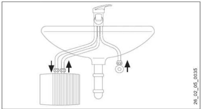
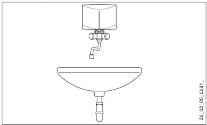
10.2.1 Undersink installation, non-pressurised, with non-pressurised tap
natural_image
Technical line drawing of a mechanical device with pipes and a cylindrical component (no text or symbols)10.2.2 Appliance installation
» Mount the appliance on the wall.

Note
The wall must have a sufficient load-bearing capacity.
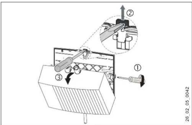
» Undo the cover fixing screws by two turns.
» Undo the snap fastener using a screwdriver.
» Remove the appliance cover with the heater towards the front.
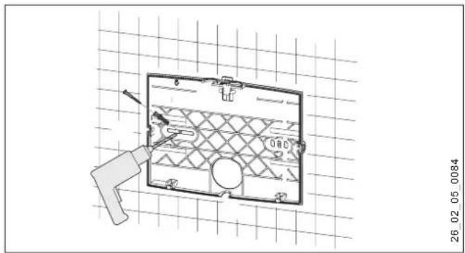
» Using pliers, break out the knock-out for the power cable in the appliance cover. Correct the contours with a file if necessary.
» Use the appliance back panel as a drilling template.
» Secure the appliance back panel to the wall with suitable rawl plugs and screws.
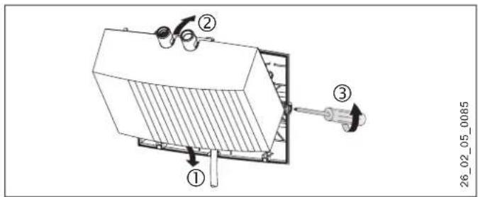
» Route the power cable through the cable entry in the back panel.
» Hook in the appliance cover with the heater at the bottom.
» Click the heater into place using the snap fastener.
» Secure the appliance cover with the cover fixing screws.
Tap installation

Material losses
When making the connections, counter the torque on the appliance using a size 14 spanner.
» Install the tap. For this, also observe the tap operating and installation instructions.
10.2.3 Oversink installation, non-pressurised, with non-pressurised tap
natural_image
Line drawing of a faucet with a container and pipe, plus a funnel (no text or symbols)Tap installation
» Install the tap. For this, also observe the tap operating and installation instructions.

Material losses
» When making the connections, counter the torque on the appliance using a size 14 spanner; see chapter "Installation alternatives / Under-sink installation".
Appliance installation
» Fit the appliance to the tap with the water connections.
10.3 Connecting the power supply

DANGER Electrocution
Carry out all electrical connection and installation work in accordance with regulations.

DANGER Electrocution
Ensure that the appliance is earthed.
Ensure the appliance can be separated from the power supply by an isolator that disconnects all poles with at least 3 mm contact separation.

DANGER Electrocution
The appliances are delivered with a power cable (MTH 350 with plug).
Connection to a permanent power supply is possible, provided the fixed cable has a cross-section that is at least equal to that of the standard power cable of the appliance. A maximum cross-section of 3 × 6 ~mm^2 may be used.
» If the appliance is installed over the sink, route the power cable behind the appliance.

Material losses
When making the connection to a standard safety socket (in the case of a power cable with plug), ensure that the socket is freely accessible after the appliance has been installed.

Material losses
Take note of the type plate. The specified voltage must match the mains voltage.
» Connect the power cable as shown in the wiring diagram (see chapter "Specification / Wiring diagram").
11. Commissioning
11.1 Initial start-up
on
26_02_05_0087
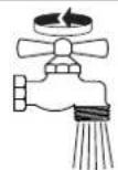
» Fill the appliance by running the tap several times until the pipework and appliance are free of air.
» Carry out a tightness check.
» Insert the power cable plug, if present, into the standard safety socket or set the fuse/MCB.
» Check the function of the appliance.
» In the case of oversink installation, affix the company logo supplied over the existing company logo.
11.2 Appliance handover
» Explain the appliance function to users and familiarise them with its operation.
» Make users aware of potential dangers, especially the risk of scalding.
» Hand over these instructions.
11.3 Recommissioning

Material losses
Following an interruption of the water supply, recommission the appliance by carrying out the following steps, in order to prevent irreparable damage to the bare wire heating system.
» Isolate the appliance from the power supply. Pull the power cable plug, if present, from the socket, or remove the fuse/reset the MCB.
» See chapter "Initial start-up".
12. Shutting down
» Isolate the appliance from the power supply by means of the fuse/MCB in your fuse box or by pulling the power cable plug from the socket.
» Drain the appliance (see chapter "Maintenance").
13. Troubleshooting
| Problem Cause Remedy | ||
| The appliance will not start despite the DHW valve being fully open. | The aerator in the tap is scaled up or dirty. | Clean and/or descale the aerator or replace the special aerator. |
| The sieve in the cold water line is blocked. | Clean the sieve after shutting off the cold water inlet line. | |
| The heater is faulty. | Check the resistance of the heating system and replace the appli-ance if required. | |
14. Maintenance

DANGER Electrocution
Before any work on the appliance, disconnect all poles from the power supply.
Draining the appliance

DANGER Scalding
Hot water may escape during the draining process.
If the appliance needs to be drained for maintenance or to protect the whole installation when there is a risk of frost, proceed as follows:
» Close the shut-off valve in the cold water inlet line.
» Open the draw-off valve.
» Undo the water connections on the appliance.
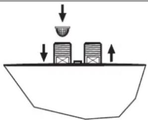
Cleaning the strainer
You can clean the fitted strainer after removing the cold water supply pipe.
natural_image
Simple line drawing of a container with two containers and a downward arrow, no text or symbols present26_02_05_0065
Checking the earth conductor
» Check the earth conductor (in Germany e.g. BGV A3) on the earth conductor contact of the power cable and on the appliance connector.
Appliance storage
» Store the dismantled appliance in a room free from the risk of frost, as water residues remaining inside the appliance can freeze and cause damage.
Replacing the power cable for the MTH 570
» If replacing the cable for the MTH 570, use a power cable with 4 mm ^2 cross-section.
15. Specification
15.1 Dimensions
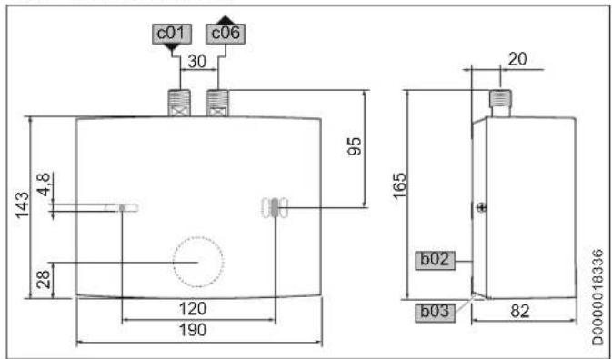
| b02 Entry electrical cables I | ||
| b03 Entry electrical cables II | ||
| c01 Cold water inlet Male thread G 3/8 A | ||
| c06 DHW outlet Male thread G 3/8 A |
15.2 Wiring diagram
15.2.1 MTH 350-570
1/N/PE \~ 220-240 V

15.3 Increasing the temperature
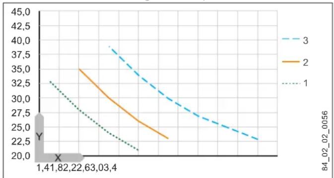
At 230 V, the following water temperature increases result:
line
| X | 1 | 2 | 3 | |---|---|---|---| | 1 | 20.0 | 25.0 | 38.0 | | 2 | 22.5 | 27.5 | 34.0 | | 3 | 25.0 | 30.0 | 30.0 | | 4 | 27.5 | 32.5 | 26.0 | | 5 | 30.0 | 35.0 | 22.0 | | 6 | 32.5 | 37.5 | 18.0 | | 7 | 35.0 | 40.0 | 14.0 | | 8 | 37.5 | 42.5 | 10.0 | | 9 | 40.0 | 45.0 | 6.0 | | 10 | 42.5 | 47.5 | 2.0 | Y-axis (labeled) ranges from 20.0 to 45.0; X-axis (labeled) ranges from -1 to +1; Legend: Line labels '1', '2', '3' represent different series; Y-axis label '84_02_02_0056' appears in the legend but lacks explicit numerical labels on the chart.X Flow rate in l/min
Y Temperature increase in K
1 3.5 kW - 230 V
2 4.4 kW - 230 V
3 5.7 kW - 230 V
| Example MTH 350 with 3.5 kW | ||
| Flow rate l/min 2.0 | ||
| Increasing the temperature K 25 | ||
| Cold water supply temperature °C 12 | ||
| Maximum possible outlet temperature °C 37 | ||

Note
An outlet temperature of 50 °C can be achieved with the lowest possible flow rate and the following cold water inlet temperatures:
15.4 Application areas
For the specific electrical resistance and specific electrical conductivity, see "Data table".
| Standard specification at 15 °C | 20 °C | 25 °C | ||||||
| Spec. resist-ance ρ ≥ | Spec. conduc-tivity σ ≤ | Spec. resist-ance ρ ≥ | Spec. conduc-tivity σ ≤ | Spec. resist-ance ρ ≥ | Spec. conduc-tivity σ ≤ | |||
| Ωcm | mS/m | μS/cm | Ωcm | mS/m | μS/cm | Ωcm | mS/m | μS/cm |
| 1100 | 91 | 909 | 970 | 103 | 1031 | 895 | 112 | 1117 |
15.5 Details on energy consumption
Product data complies with EU regulations relating to the Directive on the ecodesign of energy related products (ErP).
| MTH 350 MTH 440 MTH 570 MTH 350 UTE MTH 350 UT MTH 350 OT | |||||||
| 189554 | 189555 | 222116 | 189557 | 189631 | 189556 | ||
| Manufacturer | AEG Haustech-nik | AEG Haustech-nik | AEG Haustech-nik | AEG Haustech-nik | AEG Haustech-nik | AEG Haustech-nik | |
| Load profile | XXS | XXS | XXS | XXS | XXS | XXS | |
| Energy efficiency category | A | A | A | A | A | A | |
| Annual power consump-tion | kWh | 478 | 478 | 478 | 478 | 478 | 478 |
| Energy efficiency | % | 39 | 39 | 39 | 39 | 39 | 39 |
| Sound power level | dB(A) | 15 | 15 | 15 | 15 | 15 | 15 |
| Special information on measuring the efficiency | None | None | None | None | None | None | |
15.6 Data table
| MTH 350 | MTH 440 | MTH 570 | MTH 350 UTE | MTH 350 UT | MTH 350 OT | ||||||||||||||
| 189554 | 189555 | 222116 | 189557 | 189631 | 189556 | ||||||||||||||
| Electrical details | |||||||||||||||||||
| Rated voltage | V | 220 | 230 | 240 | 220 | 230 | 240 | 220 | 230 | 240 | 220 | 230 | 240 | 220 | 230 | 240 | 220 | 230 | 240 |
| Rated output | kW | 3,2 | 3,5 | 3,8 | 4,0 | 4,4 | 4,8 | 5,2 | 5,7 | 6,2 | 3,2 | 3,5 | 3,8 | 3,2 | 3,5 | 3,8 | 3,2 | 3,5 | 3,8 |
| Rated current | A | 14,5 | 15,2 | 15,8 | 18,2 | 19,1 | 20 | 23,6 | 24,7 | 25,8 | 14,5 | 15,2 | 15,8 | 14,5 | 15,2 | 15,8 | 14,5 | 15,2 | 15,8 |
| Fuse | A | 16 | 16 | 16 | 20 | 20 | 20 | 25 | 25 | 32 | 16 | 16 | 16 | 16 | 16 | 16 | 16 | 16 | 16 |
| Frequency | Hz | 50/60 | 50/60 | 50/60 | 50/60 | 50/60 | 50/60 | ||||||||||||
| Phases | 1/N/PE | 1/N/PE | 1/N/PE | 1/N/PE | 1/N/PE | 1/N/PE | |||||||||||||
| Max. mains impedance at 50 Hz | Ω | 0,394 | 0,377 | 0,361 | |||||||||||||||
| Specific resistance ρ 15 ≥ (at θcold ≤25 °C) | Ω cm | 1100 | 1100 | 1100 | 1100 | 1100 | 1100 | ||||||||||||
| Specific conductivity σ 15≤ (at θcold ≤25 °C) | μS/cm | 909 | 909 | 909 | 909 | 909 | 909 | ||||||||||||
Installation - for contractors
| MTH 350 MTH 440 MTH 570 MTH 350 UTE MTH 350 UT MTH 350 OT | |||||||
| Specific resistance _15 ≥ (at cold >25 °C) | cm | 1100 1100 1100 1100 1100 1100 | |||||
| Specific conductivity _15 ≤ (at cold >25 °C) | S/cm | 909 909 909 909 | |||||
| Application limits | |||||||
| Max. throughput | l/min | 2,3 | 2,7 | 3,5 | 2,3 | 2,3 | 2,3 |
| Max. permissible pressure | MPa | 0 | 0 | 0 | 0 | 0 | 0 |
| Values | |||||||
| Max. permissible inlet temperature | °C | 35 | 35 | 35 | 35 | 35 | 35 |
| ON | l/min | >1,6 | >2,0 | >2,6 | >1,6 | >1,6 | >1,6 |
| Pressure drop at flow rate | MPa | 0,05 | 0,06 | 0,08 | 0,05 | 0,05 | 0,05 |
| Flow rate for pressure drop | l/min | 1,6 | 2,0 | 2,6 | 1,6 | 1,6 | 1,6 |
| Flow rate limit at | l/min | 2,2 | 2,8 | 4,3 | 2,2 | 2,2 | 2,2 |
| DHW delivery | l/min | 2,0 | 2,5 | 3,2 | 2,0 | 2,0 | 2,0 |
| at DHW delivery | K | 25 | 25 | 25 | 25 | 25 | 25 |
| Hydraulic data | |||||||
| Rated capacity | I | 0,1 | 0,1 | 0,1 | 0,1 | 0,1 | 0,1 |
| Versions | |||||||
| Oversink installation | X | X | X | X | X | X | |
| Undersink installation | X | X | X | X | X | X | |
| Open vented type | X | X | X | X | X | X | |
| IP-Rating | IP25 | IP25 | IP25 | IP25 | IP25 | IP25 | |
| Protection class | 1 | 1 | 1 | 1 | 1 | 1 | |
| Insulation block | Plastic | Plastic | Plastic | Plastic | Plastic | Plastic | |
| Heating system heat generator | Bare wire | Bare wire | Bare wire | Bare wire | Bare wire | Bare wire | |
| Cap and back panel | Plastic | Plastic | Plastic | Plastic | Plastic | Plastic | |
| Colour | white | white | white | white | white | white | |
Guarantee - Environment and recycling
| MTH 350 MTH 440 MTH 570 MTH 350 UTE MTH 350 UT MTH 350 QT | |||||||
| Dimensions | |||||||
| Height mm 143 143 143 143 | 143 143 | ||||||
| Width | mm | 190 190 190 190 190 190 190 190 190 190 190 190 190 190 190 190 190 190 190 190 190 190 190 190 190 190 | 90 190 | ||||
| Depth | mm | 82 | 82 | 82 | 82 | 82 | 82 |
| Weights | |||||||
| Weight | kg | 1,4 | 1,4 | 1,4 | 1,4 | 1,4 | 1,4 |
Guarantee
The guarantee conditions of our German companies do not apply to appliances acquired outside of Germany. In countries where our subsidiaries sell our products a guarantee can only be issued by those subsidiaries. Such guarantee is only granted if the subsidiary has issued its own terms of guarantee. No other guarantee will be granted.
We shall not provide any guarantee for appliances acquired in countries where we have no subsidiary to sell our products. This will not affect warranties issued by any importers.
Environment and recycling
We would ask you to help protect the environment. After use, dispose of the various materials in accordance with national regulations.
Inhoud
BIJZONDERE INFO
BEDIENING
natural_image
Technical line drawing of a mechanical device with pipes and a central component (no text or symbols)natural_image
Technical line drawing of a mechanical component with grid background and measurement annotations (no readable text or symbols)natural_image
Line drawing of a faucet and funnel (no text or symbols)natural_image
Simple line drawing of a container with two buildings on a boat, no text or symbols present26_02_05_0065_
natural_image
Technical line drawing of a mechanical device with ports and arrows indicating flow or movement (no text or symbols)natural_image
Line drawing of a faucet with a container above it, showing a funnel and pipe (no text or symbols)Montáž armatury
natural_image
Simple line drawing of a container with two containers and a bowl above it, no text or symbols present.26_02_05_0065
line
| X | 1 | 2 | 3 | |---|---|---|---| | 1 | 20.0 | 25.0 | 38.0 | | 2 | 22.5 | 27.5 | 34.0 | | 3 | 25.0 | 30.0 | 30.0 | | 4 | 27.5 | 32.5 | 26.0 | | 5 | 30.0 | 35.0 | 22.0 | | 6 | 32.5 | 37.5 | 18.0 | | 7 | 35.0 | 40.0 | 14.0 | | 8 | 37.5 | 42.5 | 10.0 | | 9 | 40.0 | 45.0 | 6.0 | | 10 | 42.5 | 47.5 | 2.0 | | 11 | 45.0 | 50.0 | -2.0 | The chart displays a single data series with X-axis values ranging from approximately 1 to 141 and Y-axis values from -25 to +45. The legend indicates three distinct series labeled 1, 2, and 3. The chart lacks explicit title or axis labels but visually represents the relationship between X and Y for each series.Urzhumskaya street 4,
building 2
129343 Moscow
Tel. 0495 7753889
Fax 0495 7753887
Switzerland
STIEBEL ELTRON AG
Industrie West
Gass 8
5242 Lupfig
Tel. 056 4640-500
Fax 056 4640-501
AEG is a registered trademark used under license from AB Electrolux (publ).
Irrium und technische Änderungen vorbehallen! | Subject to errors and technical changes! | Sous réserve d'erreurs et de modifications techniques! | Onder voorbehoud van vergissingen en technische wijzigingen! | Salvo error o modificación técnica! | Rätt till misstag och tekniska ändringar förbehalls! | Excepto erro ou alteração técnica | Zastrzeżone zmiany techniczne iewentualne błędy! | Omyly a technické zmény jsou vyhrazeny! | A muszaki változtatások és tevedések jogát fenntartjuk! | Отсутствие ошибok ne гаранtryerset. Возможны технические изменения. | Chiby a technikke zmeny sú vyhradene! 1505
- Montage der Armatur
- Schutzleiter prüfen
- INSTALLATION
- GUARANTEE
- ENVIRONMENT AND RECYCLING
- SPECIAL INFORMATION
- Operation - for users and contractors
- OPERATION
- General information
- Note
- Safety instructions
- Structure of safety instructions
- KEYWORD Type of risk
- Symbols, type of risk
- Keywords
- Other symbols in this documentation
- Units of measurement
- Safety
- Intended use
- General safety instructions
- Material losses
- Test symbols
- Appliance description
- Settings
- Increasing the temperature
- Reducing the temperature
- Following an interruption of the water supply
- Cleaning, care and maintenance
- Troubleshooting
- General safety instructions
- Instructions, standards and regulations
- Appliance description
- Standard delivery
- Accessories
- Special aerator "SR"\*
- Non-pressurised taps
- Preparations
- Water installation
- Taps
- Installation
- Installation site
- DANGER Electrocution
- Installation - for contractors
- Installation options
- Undersink installation, non-pressurised, with non-pressurised tap
- Appliance installation
- Tap installation
- Oversink installation, non-pressurised, with non-pressurised tap
- Appliance installation
- Connecting the power supply
- Commissioning
- Initial start-up
- Appliance handover
- Recommissioning
- Shutting down
- Troubleshooting
- Maintenance
- Cleaning the strainer
- Checking the earth conductor
- Appliance storage
- Replacing the power cable for the MTH 570
- Specification
- Wiring diagram
- Increasing the temperature
- Application areas
- Details on energy consumption
- Data table
- Inhoud
- BIJZONDERE INFO
- BEDIENING
- Montáž armatury
- Switzerland
Brand : AEG
Model : MTH 350
Category : Uncategorized