
Reader 2.0 - Barcode Reader Code Corporation - Free user manual and instructions
Find the device manual for free Reader 2.0 Code Corporation in PDF.


| Product Type | Barcode Reader |
| Brand | Code Corporation |
| Model | Reader 2.0 (CR2) |
| Category | Portable Barcode Scanner |
| Dimensions (approx.) | 13 x 8 x 5 cm (5.1 x 3.1 x 2.0 in) |
| Weight (approx.) | 200 g (7.1 oz) with battery |
| Power Supply | 1950 mAh Lithium-Ion rechargeable battery |
| Charging Method | Via USB or powered RS-232 cable |
| Connectivity | USB, RS-232, PS/2, Bluetooth Class 1 (300 ft range) |
| Supported Symbologies | 1D: Code 39, Code 128, UPC/EAN, Interleaved 2 of 5, etc.; 2D: PDF417, Data Matrix, QR Code, Aztec, MaxiCode, etc. |
| Processor | 400 MHz |
| Imager | 1.3 megapixel CMOS sensor, dual field optical system |
| Feedback | Two LEDs (memory/connection and battery), beeper, vibration |
| Laser Class | Class 2M (targeting only, <1 mW, 650-700 nm) |
| Operating Range | Bluetooth up to 90 m (300 ft) line of sight |
| Data Storage | 1 MB non-volatile memory (batch mode) |
| Drop Specification | Withstands multiple drops to concrete |
| Warranty | 3 years limited (battery 2 years) |
| Accessories Included | USB cable, battery blank, user manual (67 pages) |
| Certifications | FCC, CE, CB, UL listed |
| Operating Conditions | Indoor use, ambient lighting |
| Maintenance | Clean window with soft moist cloth; do not open casing |
Frequently Asked Questions - Reader 2.0 Code Corporation
User questions about Reader 2.0 Code Corporation
0 question about this device. Answer the ones you know or ask your own.
Ask a new question about this device
Download the instructions for your Barcode Reader in PDF format for free! Find your manual Reader 2.0 - Code Corporation and take your electronic device back in hand. On this page are published all the documents necessary for the use of your device. Reader 2.0 by Code Corporation.
USER MANUAL Reader 2.0 Code Corporation
natural_image
Black remote control device with red LED indicators and illuminated ports (no text or symbols visible)Statement of Agency Compliance

The CR2 has been tested for compliance with FCC regulations and was found to be compliant with all applicable FCC Rules and Regulations.
IMPORTANT NOTE: To comply with FCC RF exposure compliance requirements, this device must not be co-located or operate in conjunction with any other antenna or transmitter.
CAUTION: Changes or modifications not expressly approved by the party responsible for compliance could void the user's authority to operate the equipment.

The CR2 has been tested for compliance to CE standards and guidelines and was found to conform to applicable CE standards, specifically the EMC requirements EN 55024, ESD EN 61000-4-2, Radiated RF Immunity EN 61000-4-3, ENV 50204, EFT EN 61000-4-4, Conducted RF Immunity EN 61000-4-6, EN 55022, Class B Radiated Emissions, and Class B Conducted Emissions.
The CR2 can be set to use targeting lasers. The CR2's targeting laser emits Class 2M radiation outside of the product per IEC 60825-1. Class 2M Laser/LED product. Do not stare into beam or view directly with optical instruments.
The CR2 has been tested by an independent electromagnetic compatibility laboratory in accordance with the applicable specifications and instructions.

37AW US LISTED E300884
Laser/LED Radiation
Wavelength: <1mW
Maximum Output: 650-700 nm
Laser Pulse Duration: 0.977 mSec.
LED Pulse Duration: 0.255 uSec.
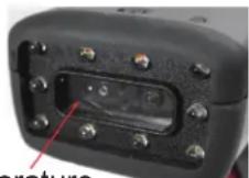
Laser aperture
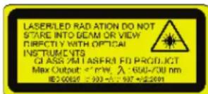
Enlarged for readability
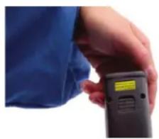
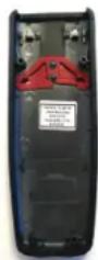
A Warning Label (see left) is located on the underside of the CR2 near the battery locking mechanism as pictured (see right).
natural_image
Close-up of a hand holding a handheld electronic device (no visible text or symbols)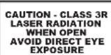
Enlarged for readability
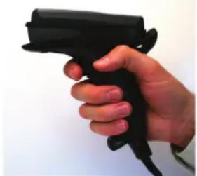
Code voids product warranty if the hard case has been opened or tampered with in any way. Opening the case may put the user at risk of laser radiation exposure (Class 3R). A second Warning Label (see left) is placed within the casing structure as pictured (see right).
Caution – Use of controls or adjustments, or performance of procedures other than those specified herein may result in hazardous radiation exposure.
In addition, a CB Test Certificate has been issued by the National Certification Board (NCB) indicating Code Reader 2.0 (CR2) meets all safety and quality standards in accordance to IEC 60950-1:2001, First Edition.
Code Reader 2.0 User Manual
Copyright © 2006 Code Corporation.
All Rights Reserved.
The software described in this manual may only be used in accordance with the terms of its license agreement.
No part of this publication may be reproduced in any form or by any means without written permission from Code Corporation. This includes electronic or mechanical means such as photocopying or recording in information storage and retrieval systems.
NO WARRANTY. This technical documentation is provided AS-IS. Further, the documentation does not represent a commitment on the part of Code Corporation. Code Corporation does not warrant that it is accurate, complete or error free. Any use of the technical documentation is at the risk of the user. Code Corporation reserves the right to make changes in specifications and other information contained in this document without prior notice, and the reader should in all cases consult Code Corporation to determine whether any such changes have been made. Code Corporation shall not be liable for technical or editorial errors or omissions contained herein; nor for incidental or consequential damages resulting from the furnishing, performance, or use of this material. Code Corporation does not assume any product liability arising out of or in connection with the application or use of any product or application described herein.
NO LICENSE. No license is granted, either by implication, estoppel, or otherwise under any intellectual property rights of Code Corporation. Any use of hardware, software and/or technology of Code Corporation is governed by its own agreement.
The following are trademarks or registered trademarks of Code Corporation:
CodeXML, Maker, QuickMaker, CodeXML Maker, CodeXML Maker Pro, CodeXML Router, CodeXML Client SDK, CodeXML Filter, HyperPage, CodeTrack, GoCard, GoWeb, ShortCode, GoCode, Code Router, QuickConnect Codes
All other product names mentioned in this manual may be trademarks of their respective companies and are hereby acknowledged.
The software and/or products of Code Corporation include inventions that are patented or that are the subject of patents pending. U.S. Patents: 6997387, 6957769, 7428981, 6619547, 6736320, 7392933, 7014113, 7240831, 7353999, 7519239, 7204417, 6942152, 7036735, 7070091, 7097099, 7621453
The Code Reader software uses the Mozilla SpiderMonkey JavaScript engine, which is distributed under the terms of the Mozilla Public License Version 1.1. Source code for this version of Spider Monkey is available at:
http://www.codecorp.com/source/spidermonkey.
The Code Reader software is based in part on the work of the Independent JPEG Group.
Code Corporation, 14940 S. Pony Express Road, Suite 500, Bluffdale, UT 84065
www.codecorp.com
Table of Contents
Chapter 1 - Getting Started .... 1
1.1 - Introduction ...... 2
1.2 - Unpacking .... 3
1.3 - Reader Battery Installation.... 4
1.4 - Attaching Handles 5
1.5 - Batch Operation 6
1.5.1 - Introduction ...... 6
1.6 - Cabled Operation 8
1.6.2 - CR2 as a USB Keyboard 9
1.6.2.1 - Additional USB Communication Settings.... 10
1.6.2.2 - Keyboard Support 10
1.6.3 - PS/2 Cable Installation Guide .... 11
1.6.4 - RS-232 (Serial) Cable Installation Guide 12
1.6.4.1 - Additional RS-232 (Serial) Communication Data Bit Settings.... 13
1.6.4.2 - Additional RS-232 (Serial) Communication Baud Rate Settings.... 13
1.6.4.3 - Additional RS-232 (Serial) Communication Parity Settings.... 13
1.6.5 - Cabled Reader - Time Out Settings 13
1.7 - Bluetooth Radio Operation.... 14
1.7.1 - Introduction ...... 14
1.7.2 - Bluetooth Radio Auto Connect 16
1.7.3 - Bluetooth Radio Auto Disconnect.... 16
1.7.4 - Bluetooth Radio Time Out Settings 17
1.7.5 - Bluetooth Radio Out of Range Notification Settings 17
1.7.6 - Auto Save Last Bluetooth Address.... 17
1.7.7 - Configuration for Belkin Bluetooth Manager Software (Version 1.4.2.10).... 18
1.7.9 - Configuration for Microsoft Bluetooth Stack Instructions 22
1.7.10 - Installing CodeXML Router Bluetooth Edition for Windows 24
1.8 - CR2 Feedback Guide.... 25
1.9 - Targeting and Reading Techniques 27
1.10 - Imager Field of View and Resolution.... 28
1.11 - Decode Zone 29
Chapter 2 - Optimization and Trigger Programming .... 30
2.1 - Introduction ...... 31
2.2 - Global Trigger Optimization Matrix.... 32
2.3 - Left Trigger Optimization Matrix 32
2.4 - Left Trigger Programming 33
2.5 - Right Trigger Optimization Matrix.... 33
2.6 - Right Trigger Programming 33
2.7 - Handle Optimization Matrix 34
2.8 - Handle Trigger Programming 34
2.9 - Continuous Trigger Optimization Matrix 35
2.10 - Continuous Scan 35
2.11 - Continuous Scan Settings 36
2.11.1 - Continuous Scan - Sleep Time Out 36
2.11.2 - Continuous Scan - Trigger Delays 36
2.11.3 - Continuous Scan - Duplicate Scan Delay 36
2.12 - Motion Detection Scan Settings 36
Chapter 3 - CR2 Programming: Symbology Settings 37
3.1 - Aztec Symbology.... 38
3.2 - Codabar Symbology.... 38
3.3 - Codablock F Symbology 38
3.4 - Code 11 Symbology 38
3.5 - Code 39 Symbology.... 39
3.6 - Code 93 Symbology.... 39
3.7 - Code 128 Symbology....40
3.8 - Composite Symbologies 40
3.9 - Data Matrix Symbology 40
3.10 - GoCode Symbology 41
3.11 - Interleaved 2 of 5 Symbology ...... 41
3.12 - Maxicode Symbology 41
3.13 - Matrix 2 of 5 Symbology....42
3.14 - Micro PDF417 Symbology 42
3.15 - MSI Plessy Symbology 42
3.16 - NEC 2 of 5 Symbology....42
3.17 - Optical Character Recognition (OCR) 42
3.18 - PDF 417 Symbology 43
3.19 - Pharmacode 43
3.20 - Postal Symbologies.... 43
3.21 - QR Code Symbology 44
3.22 - GS1 data bar ( formerly RSS) Symbology 44
3.23 - Telepen Symbology 45
3.24 - UPC/EAN/JAN 45
Chapter 4 - Reader Feedback and Special Settings 46
4.1 - Volume and Vibration Settings 47
4.2 - Code Readability Index 47
4.3 - Laser Settings 48
4.4 - Reader Power Off Settings.... 48
4.5 - Reader ID and Firmware Version 49
4.6 - Reader Settings Lock 49
4.7 - Lock-out Link Mode 50
Chapter 5 - Advanced Decode Performance .... 51
5.1 - Set Targeting Tolerances.... 52
5.2 - Windowing.... 53
5.3 - Mirror Decoding.... 54
Chapter 6 - Adding a Prefix or Suffix and Reader Text Commands .... 55
6.1 - Prefix Settings 56
6.2 - Suffix Settings 56
6.3 - Erase Prefix and Suffix Settings.... 57
6.4 - Reader Text Commands.... 57
Chapter 7 - CR2: Maintenance and Troubleshooting .... 58
7.1 - Reset Reader to Factory Defaults.... 59
7.2 - General Safety Information 59
7.3 - Warranty....60
7.4 - CR2 Accessories 61
7.5 - Frequently Asked Questions 61
7.6 - CR2 Maintenance 61
Chapter 1 - Getting Started
1.1 - Introduction
CR2 is a revolutionary bar code and 2-dimensional code reader. Developed to be the first universal reader, no other single device performs as many functions. With a cost of ownership far less than comparable systems, the CR2 incorporates a unique dual path optical system, a 1.3 million pixel CMOS sensor, and a 400 MHz processor. This
combination has created a reading system that supports:
- High density matrix codes and larger low density linear codes
• Superior working range
• High-speed omni-directional decoding - Cordless and cabled interfaces
• Unsurpassed data read rates
natural_image
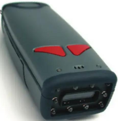
Hand holding a black handheld device against a plain background (no text or symbols visible)The CR2 sets a new benchmark for size and weight. It is smaller and lighter than comparable systems yet can withstand multiple drops to concrete. It is the only product available in batch, cabled or wireless formats; handheld, ruggedized cabled or battery handle use-case scenarios; and lanyard hook attachment or reader stand form factors. The cordless version utilizes the latest Bluetooth™ class 1 radio with a 300 foot operating range. The CR2 is rugged and lightweight and the cordless version will operate for more than a complete shift at the highest use rate. The CR2 performs more than 11,000 reads and transmits from a single battery charge. The CR2 will automatically discriminate between all major 2-D matrix and linear bar code symbologies and features a timestamp feature for logging data.
Whether you need a small, palm-held device or a traditional gun, CR2 was specifically developed so users may easily choose the device that best meets their needs. The CR2 is available in three basic configurations:
natural_image
Close-up of a black handheld electronic device with red triangular buttons and ports (no visible text or symbols)- CR2 Cabled - USB, RS-232 or PS/2 interfaces
- CR2 Batch - Store and forward device with memory and long-life battery
- CR2 Cordless - Long life battery and Bluetooth radio
1.2 - Unpacking
Remove the imager from its packing and inspect it for damage. If the scanner was damaged during shipping, please call Code at (801) 495-2200.
The standard CR2 unit is shipped with a USB cable interface. The unit also features a battery blank which must be installed when using the reader (except when attached to the H2, BH1 or BH2 handle).
Various accessories are available for the CR2.
• 4 cable options (USB 6ft., USB 12 ft., RS-232 or PS/2)
• 1950 mAH long-life Lithium-Ion battery
• Class 1 Bluetooth radio with 300 foot operating range (shorter ranges available)
- Clip-on pistol grip handle
• Ruggedized Cabled Handle
- Battery Handle (in two battery sizes)
• External single-bay and two-bay battery charger
• CodeXML Bluetooth modem
• Protective Elastomer Boot
- Protective Case Cover or Holster
• Power Supplies: US/Europe/SA/UK/Asia
- Reader Stand
• Lanyard Hook attachment option
Please keep your packing materials. The CR2 is shipped in an approved shipping container and should be used if you ever need to return your equipment for servicing.
1.3 - Reader Battery Installation
Attaching and Detaching the Lithium Ion Battery
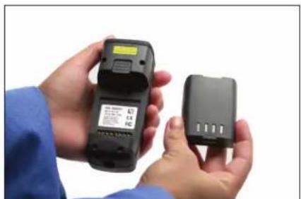
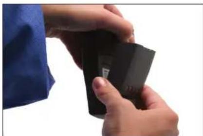
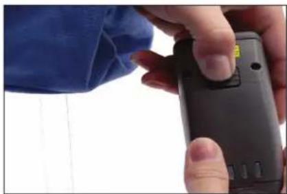
The CR2 has an option to include a 1950 mAH Lithium Ion battery. To install battery, make sure the battery is in the correct position (figure 1.1). Place the plastic tab of the battery into the reader (figure 1.2). Push the battery in and slide the locking mechanism down (figures 1.3)
Charging the Lithium Ion Battery
The battery automatically charges every time a USB or Powered RS-232 cable interface is attached to the unit and the host is powered up.
Note: The RS-232 interface power adapter must be plugged into a wall socket for the unit to charge.
If you power-up the CR2 with a completely discharged battery it will take up to 10 minutes before the unit will become operational.
natural_image
Two hands holding black electronic devices, one open and one closed, against a white background (no visible text or symbols)Figure 1.1
natural_image
Close-up of hands holding a black rectangular object with a label, against a white background (no visible text or symbols)Figure 1.2
natural_image
Close-up of hands holding a black handheld device with a small yellow tag, against a plain background (no text or symbols visible)Figure 1.3
1.4 - Attaching Handles
H1 - Handle
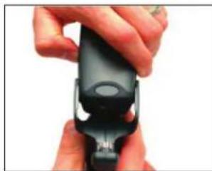
- Place the CR2 in the cradle of the handle and slide the unit back (Figure 1.4).
Be careful not to place fingerprints on the front glass when attaching handle.
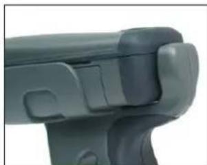
- Once the 8-pin DIN connector of the handle begins to enter the opening in the back of the unit, firmly press the unit back until the unit is flush against the handle (Figure 1.5).
natural_image
Close-up of hands holding a black mechanical device (no visible text or symbols)Figure 1.4
natural_image
Close-up of a mechanical component with no visible text or symbolsFigure 1.5
H2 - Ruggedized Cabled Handle
- Make sure the reader has no battery or battery blank installed.
- Insert the reader's 8-pin DIN connector into the flexible connector at the back of the H2 handle (Figure 1.6).
- The reader 'snaps' onto the H2 handle utilizing the battery compartment.
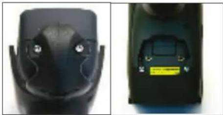
- The reader can be further secured to the handle with two threaded screws through the flexible connector and two more threaded screws on the underside of the reader and handle (Figure 1.7).
BH1 or BH2 Battery Handle
-
Make sure the reader has no battery or battery blank installed.
-
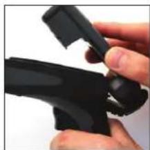
Insert the tab on the back of the BH1 or BH2 Handle into the reader's recessed slot typically utilized to secure the battery in place on the reader (Figure 1.8).
-
The reader 'snaps' to the handle utilizing the battery compartment (Figure 1.6). The reader will 'quick release' from the handle to accommodate quick and easy battery charging.
-
Optionally, the reader can be further secured to the handle with two threaded screws on the underside of the reader and handle (Figure 1.7).
natural_image
Close-up of hands holding a black handheld device (no visible text or symbols)Figure 1.6
natural_image
Close-up of a black robotic device with a small yellow warning label on its side (no visible text or symbols)Figure 1.7
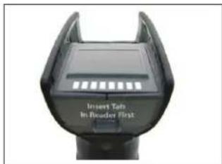
Figure 1.8
1.5 - Batch Operation
1.5.1 - Introduction
The CR2 unit features a batch mode for applications requiring a portable reader. Batch mode allows a user to store scanned data to the reader's non-volatile memory. The user may transfer the data to a host computer when needed. To utilize batch functionality you will need to purchase the 1950 mAH Lithium Ion battery from a Code representative.
The CR2 may be programmed to operate in three different batch modes:
- Send & Buffer Mode (Default) - In Send and Buffer Mode, the CR2 unit will automatically detect when the USB or RS-232 cable is detached, or the Bluetooth® radio is out of range, and will switch into batch mode and buffer the data in non-volatile memory. When the reader is reconnected to your host computer, or when the Bluetooth Radio is back in range, the reader will auto transfer the buffered data. Once transferred, the data is automatically erased from the reader's memory.
Note: Once a unit is reattached to a cable or enters within radio range, any data scanned WILL NOT be saved to the non-volatile memory. For RS-232, a power supply connection is used to detect when a reader is attached to a host computer.
- Log Only Mode - In Log Only Mode, the reader will only store data into non-volatile memory. You can only retrieve the data by scanning the Transfer All Stored Data in Memory code (see explanation next page). Once the reader's memory has been transferred to a host computer, all of the data will still reside in memory. A user must scan the Delete Scanned Data from Memory code to clear memory.
- Send & Log Mode - In Send and Log Mode the reader will save a copy in non-volatile memory as well as send the data if the reader is connected. The data can be retrieved by scanning the Transfer All Stored Data in Memory code or the Transfer Only Unsent Data in Memory code (see explanations next page). Once the reader's memory has been transferred to a host computer, all of the data will still reside in memory. A user must scan the Delete Scanned Data from Memory code to clear memory.
Note: The reader can be defined as connected if:
1) The Bluetooth radio is in range;
2) The USB cable is attached to a host and the reader is enumerated;
3) The reader is in RS-232 Cabled - No Power mode; or
4) The RS-232 cable is attached to host with power supply and the reader is in RS-232 Batch-Cable Detect (Default) mode.
The CR2's dedicated batch memory is a minimum of 1MB. To determine the number of reads that may be stored, divide the average bytes of a scan into the total minimum memory.
Feedback
After a successful decode in batch mode, the unit will beep once and the memory LED will flash either red or amber depending on memory level, and every 15 seconds the battery LED will flash green, amber or red depending on the battery level. This feedback behavior is accurate when a reader is cabled or uncabled.
Transferring and Deleting Data
There are three different codes to transfer and delete data in memory.
- Transfer All Data in Memory - This code will send all data in memory every time the code is scanned.
- Transfer Only Unsent Data in Memory - This code will send only the data in memory that hasn't already been sent when the code is scanned (ONLY works in Send & Buffer and Send & Log modes).
- Delete Scanned Data from Memory - Scanning this code will erase all data in the reader's non-volatile memory.
Auto Transfer Buffer Memory
By default, when reconnected, the CR2 will automatically transfer any data in memory once a connection to a host is established. If your application is not ready, the reader will send the data anyway and the data could be lost. If you do not wish for the reader to immediately send data upon connection, please scan the Disable Auto Transfer Buffer Memory code.
Send & Buffer Mode (Default)

M075_01
Log Only Mode
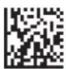
M072_01
Send & Log Mode

M076_01
Transfer Only Unsent Delete Scanned Data
Transfer All Data in Memory

M077_02
Data in Memory

M078_02
from Memory

M071_01
Enable Auto Transfer Buffer Memory (Default)

M070_01
Disable Auto Transfer
Buffer Memory

M069_01
RS-232 Considerations
In RS-233 Cabled-No Power mode, the CR2 will behave as if it is always connected even though the serial cable is disconnected or the power adapter is unplugged. Data scanned will be sent, regardless of connection status. Data scanned in Cabled-No Power mode will be lost if the CR2 is not connected to the serial cable - it will not buffer the data, unless Send & Log or Log Only mode has been enabled.
In RS-232 Batch-Cable Detect (Default) mode, the CR2 will detect if it is connected to a powered serial cable, if it is, it will then send the data. If a powered serial cable is not connected or if the power adapter is not connected to the serial cable, the CR2 will buffer the data. When the CR2 is then connected to a powered serial cable, the data will automatically upload.
RS-232 Batch-Cable Detect (Default)

M073_02
RS-232 Cabled-No Power

M074_02

M188_02
1.6 - Cabled Operation
1.6.1- Introduction
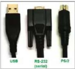
The CR2 is a Multi-Interface Unit (MIU) and is available with USB (6 ft. or 12 ft.), RS-232 (Serial) and PS/2 cables (Figure 1.9). All of the cables are connected to the CR2 with a 8-pin DIN connector.
natural_image
Three black USB connectors labeled USB, RS-232 (serial), and PS/2, shown without any text or symbols on the connectors themselves.Figure 1.9
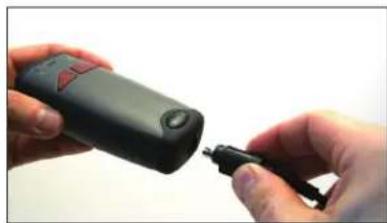
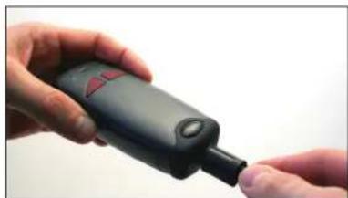
Hand Held CR2 - To install a cable directly to the CR2, correctly line up the 8-pin DIN connector into the back end of the reader. The arrows on the connector should be facing down (Figure 1.10). When the reader and the cable connector are lined up, firmly push the cable into the reader. The cable has a locking mechanism that will firmly hold the cable in place (Figure 1.11). To deattach the cable from the reader, you must pinch the plastic on the 8-pin DIN and pull back to disengage the connector.
natural_image
Close-up of hands holding a black handheld device with a small plug inserted (no visible text or symbols)Figure 1.10
natural_image
Close-up of hands holding a black handheld device with a red button, no visible text or symbolsFigure 1.11
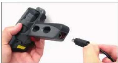
CR2 with Cabled Handle - If a handle was purchased for use with the CR2, the 8-pin DIN connector is at the bottom of the handle (Figure 1.12). Insert the 8-pin connector and firmly push the cable into the handle. The cable has a locking mechanism that will firmly hold the cable in place. If using the H2 cabled handle, for additional stability, there is an optional cable attachment clip that can secure the cable to the handle with two threaded screws (Figure 1.13).
natural_image
Close-up of hands holding a black electronic device with multiple holes and a small plug inserted (no visible text or symbols)Figure 1.12
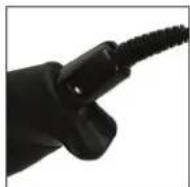
Figure 1.13
1.6.2 - CR2 as a USB Keyboard
To connect the CR2 to your host computer via USB interface:
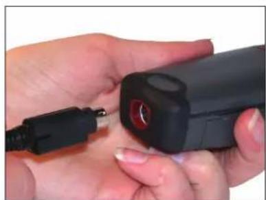
- Attach the USB cable to CR2 (Figure 1.14).
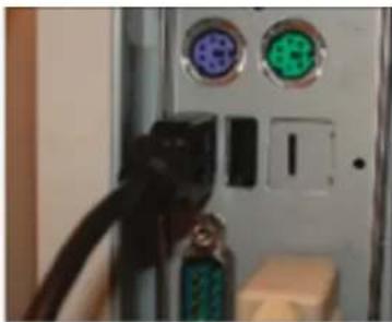
- There is no need to power off the computer (Figure 1.15) Connect the USB cable to a USB port on the computer (Figure 1.16).
- Once properly connected, the CR2 will power on and beep.
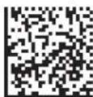
- Scan the below code (M049 03) for USB Keyboard Mode:
USB Keyboard Factory Reset Save Settings
M049 03

M188 02
- Scan the Save Settings Code (M188_02)
natural_image
Close-up of hands using a handheld electronic device to interact with a small black connector (no visible text or symbols)Figure 1.14
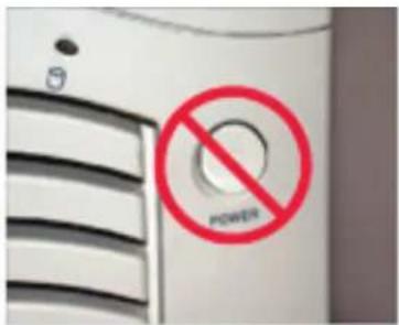
Figure 1.15
natural_image
Close-up of a computer interface panel with two connected cables and two labeled buttons (no readable text or symbols)Figure 1.16
1.6.2.1 - Additional USB Communication Settings
USB Keyboard Mode - Data is sent from the Reader and interpreted by the host just as if a USB keyboard was being used to enter data.
USB Downloader - This mode is used when downloading firmware.
USB Native Two Way Mode - This mode is utilized when there is a need for error-corrected communication between the CR2 and an application through the USB port.
USB Virtual COM 1 Way Mode - This mode allows a USB-cabled CR2 to function as a virtual COM port. To use the CR2 in this mode, download the driver at www.codecorp.com/downloads.html.
USB HID POS (Terminal ID 131) - This mode allows a USB-cabled CR2 to communicate as a USB HID POS (Terminal ID 131) device.
Scan the following codes to set the appropriate USB communication setting:
USB Keyboard
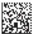
M134_02
USB Downloader
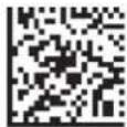
M133 01
USB Native Two Way Mode
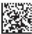
M135_04
USB Virtual COM 1 Way Mode
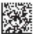
M668 01
USB HID POS (Terminal ID 131)
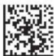
M736 01
1.6.2.2 - Keyboard Support
Scan the following codes to set appropriate keyboard mapping:
US English (Default)
No Leading 0
US English - Leading 0
US English - ctrl + char
for non-printable characters
for non-printable characters
for non-printable characters

M172 01

M602 01

M606 01
French

M603 01
German

M604 01
Japanese

M605 01
Universal Keyboard

M173 01
Alternative OS
(Windows CE/MAC/Unix/Linux)
Custom Keyboard
Enable

M171_01
Requests map to be installed
Alternative OS Disable
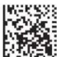
M585 02
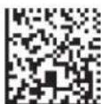
M584 02

M188 02
Save Settings
1.6.3 - PS/2 Cable Installation Guide
- Power off the computer. If you disconnect the computer's keyboard while it is powered on, your computer will lock up.
- Attach the the PS/2 cable to the CR2.
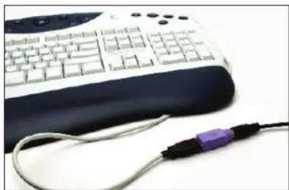
- If you have a cabled keyboard, detach the keyboard cable from the computer and connect that same connector to the female connection on the CR2 PS/2 cable (Figure 1.17).
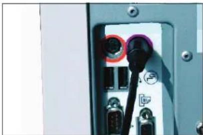
- Now connect the male CR2 PS/2 connector into the keyboard port on the computer (Figure 1.18).
- Power on the computer. The CR2 is powered by the PS/2 port and does not require a power supply.
- Once properly connected, the CR2 will power on and beep.
natural_image
Close-up of a white keyboard with black buttons and a purple USB cable, no visible text or symbols.Figure 1.17
natural_image
Close-up of a computer interface socket with black connectors and indicator lights (no readable text or symbols)Figure 1.18
PS/2 Factory Reset
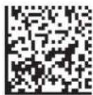
M060 03
Save Settings

M188 02
Code does not guarantee compatibility with all models of computers.
1.6.4 - RS-232 (Serial) Cable Installation Guide
- Attach the RS-232 (Serial) Cable to the CR2.
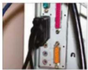
- Connect the RS-232 (Serial) cable to a serial port on the computer (Figure 1.19). There is no need to power off the computer.
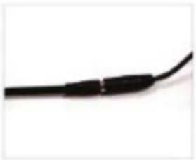
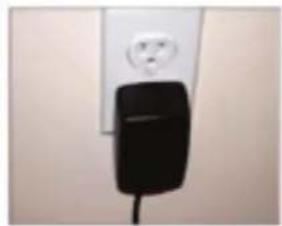
- The RS-232 (Serial) interface has an optional 5V/1.5A power supply (Figure 1.20). If you have a power supply, plug the power supply adapter into the RS-232 (Serial) cable and then plug the power adapter into a wall socket (Figure 1.21).
natural_image
Close-up of a mounted electronic device with black connectors and orange/red components (no visible text or symbols)Figure 1.19
natural_image
Close-up of a black cable with connectors, isolated on white background (no text or symbols)Figure 1.20
natural_image
Close-up of a black electrical plug attached to a wall-mounted power outlet (no text or symbols visible)Figure 1.21
- Once properly connected, the CR2 will power on and beep.
- For RS-232 (Serial) mode scan M418_02 (below). If the power supply is not connected scan M074_02 (below).
- Scan the Save Settings Code (M188_02).
RS-232 (Serial)
Factory Reset
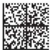
M418 02
RS-232 (Serial) Mode
No Power Supply
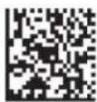
M074 02
Save Settings

M188_02
RS-232 Factory Default Settings
Mode: RS-232 One Way Mode
Baud Rate: 57600
Stop Bits: 2
Data Bits: 8
Parity: None
Warning: Code Corporation approved power adapter must be used. Reader failure due to use of incorrect power adapter will void warranties.
1.6.4.1 - Additional RS-232 (Serial) Communication Data Bit Settings
Scan the following codes to set the appropriate data bit:
7 Data Bits
8 Data Bits (Default)


1.6.4.2 - Additional RS-232 (Serial) Communication Baud Rate Settings
Scan the following codes to set the appropriate baud rate:
1200
2400
4800
9600

M092_01

M093_01

M094 01

M095_01
19200
38400
57600 (Default)
115200

M096_01

M097_01

M098_01

M099_01
1.6.4.3 - Additional RS-232 (Serial) Communication Parity Settings
Scan the following codes to set parity:
Even
Odd
None (Default)

M102 01

M104 01

M103 01
1.6.5 - Cabled Reader - Time Out Settings
Scan one of the codes below to set the amount of time a cabled CR2 will be enumerated before entering sleep mode in order to more quickly charge the battery:
Note: These settings will only work in versions 2098 and above.
Cabled Reader Time Out: 2 hours
Cabled Reader Time Out: Never (Default)

M136_01

M137_01

Save Settings
1.7 - Bluetooth Radio Operation
1.7.1 - Introduction
The CR2 features a Bluetooth® wireless radio. The radio allows for point-to-point wireless communication with other Bluetooth devices that support serial port protocol (SPP). If keyboard entry is necessary, Code XML Router will need to be installed. The following guide will give you general instructions on connecting your CR2 to a desktop or laptop computer with a Bluetooth radio.
Connecting With A QuickConnect Code
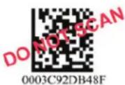
The easiest way to connect to a Bluetooth device is to visit the Code website and create a QuickConnect Code that is specific to your device (Figure 1.22). This code will link your CR2 directly to the desired Bluetooth device. To create a QuickConnect Code, you will need to know the Bluetooth address (often referred to as the BD_ADDR) of that device. You can usually find the 12-character Bluetooth address somewhere on the device near the device's serial number (see Figure 1.23).
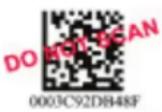
Figure 1.22
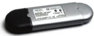
Figure 1.23
If you purchased a CodeXML Bluetooth Modem or a Belkin® Bluetooth adapter from Code or from an authorized distributor, a QuickConnect Code was included. If you bought a Bluetooth adapter separately and wish to create a QuickConnect Code, please visit Code's web site at: http://www.codecorp.com/bdaddr.php.
Important Note: You will need to locate the Communications (COM) Port assigned to the Bluetooth serial port protocol. While installing the Bluetooth Configuration Manager Software that was included with your Bluetooth adapter, make sure to note the Communications (COM) Port number the software assigned for the adapter (e.g., COM 10). This is the COM Port through which the CR2 will connect.
To connect your reader, use the following steps:
- Power on the CR2 reader by pressing one of the red buttons for one second to power on the reader.
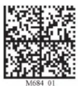
- Scan the Reset to RF Factory Defaults Code (M684_01).
- Scan the Quick Connect Code you received or created from Code's website.
- The CR2 will automatically connect to the computer. By default, the CR2 will beep once after it connects and beep four times in a row if it did not connect.
- Scan the Save Settings Code (M188_02) if you want to save the wireless connection settings to the CR2 so that the CR2 will automatically try to connect wirelessly the next time it is powered on.
Example:
Reset to RF Factory Defaults QuickConnect Save Settings


1.7 - Bluetooth Radio Operation (continued)
Radio Range and Transferring Data
The CR2 radio is a Class 1 device. If connected to another Class 1 device the reader has roughly a 100 meter (300 feet) line of sight operating range. If connecting to a Class 2 or Class 3 device, the operating range may drop to match the lower range. Once a reader is connected, a serial application must be opened (HyperTerminal) unless Code XML Router is installed.
When the CR2 detects the radio is out of range, the CR2 will store data on the reader's non-volatile memory. The reader will continue to try and send data until radio is back in range. Once the data is sent the data will be erased from the reader's memory. The reader will continue to try and connect until it has reached the programmable radio time out setting.
The CR2 Bluetooth protocol allows for two (2) forms of communication:
-
Standard Bluetooth Reliability Mode (previously One Way Mode) - Communication between the reader and host, that does not require host acknowledgement. This mode is only recommended when connecting to a device well within its specified range or if connecting to a simple device (e.g., printer). There are two settings in this mode:
-
Max Range (Default) - Greater range but data reliability is lower
- Max Reliability - Limits range but reliability is improved
RF Standard Bluetooth
Reliability Mode (Max Range)
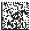
M127_01
RF Standard Bluetooth
Reliability Mode (Max Reliability)
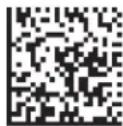
M128_01
Note: One Way Mode doesn't guarantee data integrity, and you may have data loss when operating in the fringes of radio range or in the presence of radio interference.
- Additional Bluetooth Reliability Mode (previously Two Way Mode) - This mode requires the implementation of software at the application level.* The reader receives confirmation via packet protocol verification and is 100% reliable. Data will be automatically
retransmitted if necessary.
RF Additional Bluetooth
Reliability Mode
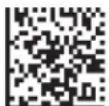
M129_02
* Note: You will need either Code XML Router Software or a Code XML Bluetooth Modem on the PC side to use the Additional Bluetooth Reliability Mode.
If you are using the CodeXML Bluetooth Modem, you must use RF Additional Bluetooth Reliability Mode.
1.7 - Bluetooth Radio Operation (continued)
Permanently Establishing a Connection
Scan the Save Settings Code at the bottom of the page to make the RF settings (including which device to connect to) permanent on the reader:
Disconnecting from the Device
You may force disconnection by reading the disconnect code below (The CR2 may not appear disconnected in the slave Bluetooth connection manager for 10 – 15 seconds after the command is issued). The CR2 will also disconnect after 90 seconds of inactivity (Note: You may change the radio sleep time out setting; however, it may reduce battery life).
Bluetooth Disconnect

Reconnecting to the Device
If the device is saved in RF mode and has a save connection (save was performed while connected) it will automatically reconnect when:
- CR2 is powered up
- CR2 wakes from sleep mode
- CR2 reads another code
1.7.2 - Bluetooth Radio Auto Connect
Auto Connect: After coming out of sleep mode or after powering up the CR2 tries to auto connect with the last Bluetooth radio with which it was connected if the steps (previous) were followed (see Section 1.7.1 - Connecting with a Quick Connect Code). You may also re-connect by scanning a QuickConnect code.
Scan the following codes to enable or disable Auto Connect feature for the Bluetooth radio:
Bluetooth Radio
Auto Connect: On (Default)
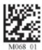
Bluetooth Radio
Auto Connect: Off
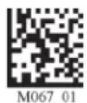
Note: Auto Connect should always be set to "On" if Auto Disconnect is set to "On". Otherwise the QuickConnect code would need to be re-scanned after every disconnect.
1.7.3 - Bluetooth Radio Auto Disconnect
Auto Disconnect: This feature is used when multiple CR2 readers are connecting to the same Bluetooth Radio. By enabling Auto Disconnect the CR2 radio disconnects after each data transmission, allowing other radios to connect.
Scan the following codes to enable or disable Auto Disconnect feature for the Bluetooth radio:
Bluetooth Radio
Auto Disconnect: On
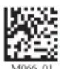
Bluetooth Radio
Auto Disconnect: Off (Default)
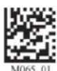

Save Settings
1.7.4 - Bluetooth Radio Time Out Settings
Scan the following codes to set the period of time before the Bluetooth Radio will go into sleep mode due to inactivity:
Note: Increasing the time before the reader will time out will decrease battery life.
90 Seconds (Default)
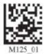
5 Minutes
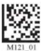
10 Minutes
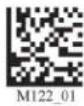
15 Minutes
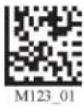
30 Minutes
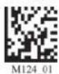
1 Hour
2 Hours
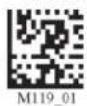
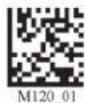
1.7.5 - Bluetooth Radio Out of Range Notification Settings
Scan the following codes to enable a beep or vibrate notification when the radio goes out of range:
Bluetooth - Out of Range
Bluetooth - Out of Range
Beep: On
Notify with Vibrate: On


Bluetooth - Out of Range
Bluetooth - Out of Range
Vibrate & Beep: On
Vibrate and/or Beep: Off (Default)


Note: This feature may also be utilized to remind users they are carrying a reader and help prevent users from walking away with a reader Bluetooth radio.
1.7.6 - Auto Save Last Bluetooth Address
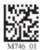
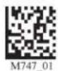
If the reader is saved in the proper RF communication mode, enabling this setting will allow the reader to automatically save the last device to which it was connected, removing the need to scan the save setting after scanning the QuickConnect code.
Enable Auto Save
Disable Auto Save (Default)

Save Settings
1.7.7 - Configuration for Belkin Bluetooth Manager Software (Version 1.4.2.10)
In this version of the Belkin Bluetooth Manager software, you must disable the authentication feature to connect a CR2. Follow the steps below:
- Double click on the Bluetooth icon in the system tray. In the My Bluetooth Places Screen, select Advanced Configuration.
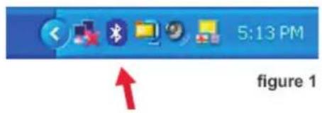
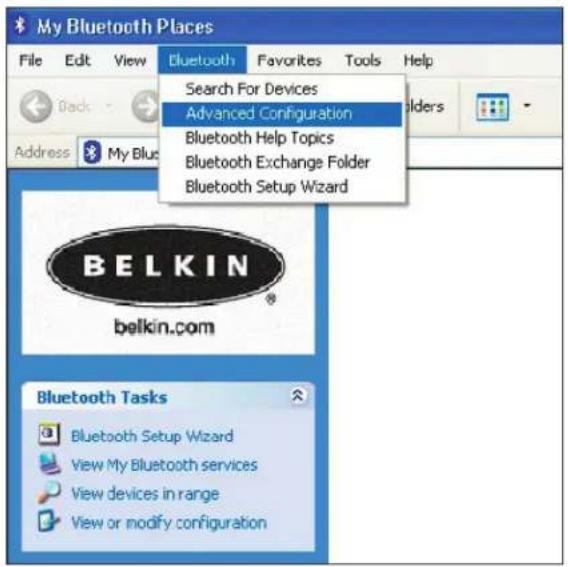
figure 2
- Select the Local Services tab and double click on the Bluetooth Serial Port. Inder the General tab unselect the Secure Connection box. This disables the encryption feature and allows the CR2 to connect to the Bluetooth adapter. Click Apply.
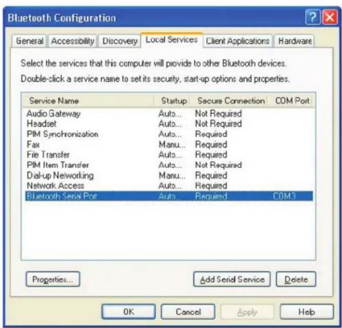
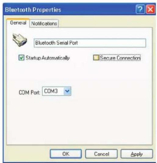
figure 4
figure 3
1.7.7 - Configuration for Belkin Bluetooth Manager Software (Continued)
- Your local service Bluetooth Serial Port profile should now read "Not Required"
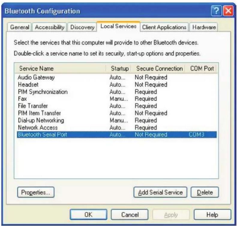
figure 5
- Open the "Accessibility" Tab and verify that "All Devices" are allowed to connect (this is the default setting). You should now be able to connect your CR2.
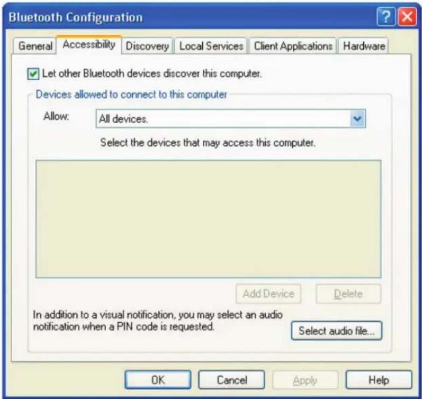
figure 6
1.7.8 - Configuration for Toshiba Bluetooth Stack Instructions (continued)
3a. Go to http://www.codecorp.com/bdaddr.php and create a QuickConnect code using the address from step 3. Use the CodeXML Router/2-way applications section if CodeXML Router will be installed. Else create a QuickConnect Code using the section for Serial Applications.
- Optional – To remove the Passkey dialogue when connecting, Select the Security TAB and Select Custom Level.
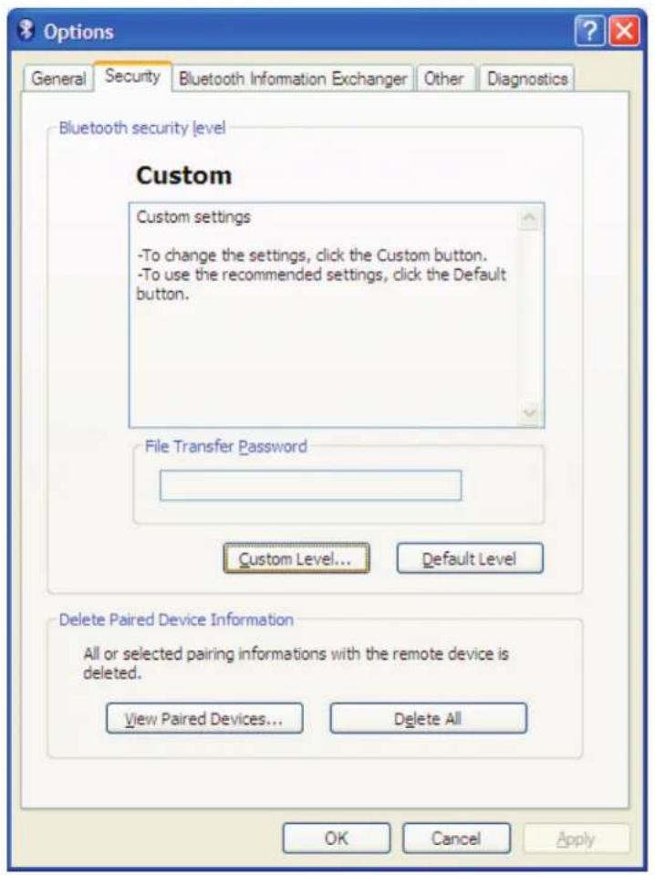
1.7.8 - Configuration for Toshiba Bluetooth Stack Instructions (continued)
4a. Uncheck the settings under the Security Setting of Serial Port (SPP).
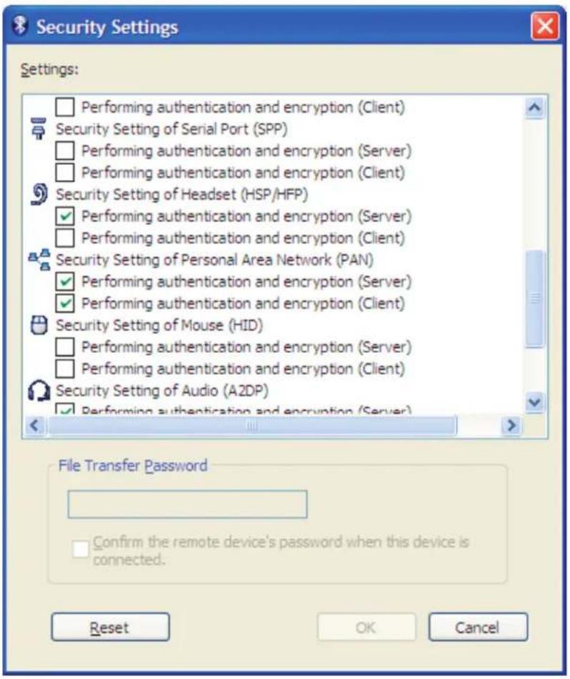
- Install the Code XML Router Software to the Device on the Appropriate COM Port. Reboot the PC and then scan your QuickConnect code to connect. Please note that the Toshiba Stack does not allow a device to connect until the Com Port is opened. CodeXML Router must be installed or the serial application must be started before the QuickConnect Code is read.
- Scan the QuickConnect Code generated in step 3. If step 4 was not done, Windows will prompt for a Passkey. The default Passkey is "12345678".
1.7.9 - Configuration for Microsoft Bluetooth Stack Instructions
-
Right click on the Microsoft Bluetooth Stack system tray icon, select "Open Bluetooth Settings".
-
Go to the "Hardware" tab and select the "Generic Bluetooth Radio" and then click "Properties". Next select the "Advanced" tab. Note the Address. For the example show below it is 00:17:9a:2b:69:bb.
![Bluetooth Devices Devices Options COM Ports Hardware Devices: Name Type Microsoft Bluetooth Enumerator Bluetooth... Generic Bluetooth Radio Device Properties Manufacturer: Cambridge Silicon Location: Location 0 (USB Device Device Status: This device is w Troubl OK Generic Bluetooth Radio Properties General Advanced Driver Radio Information Name: CODE_APTIF Address: [00.17.9s.2b.69.bb] Manufacturer Id: 10 HCI version 3, revision 1915 LMP version 3, subversion Default OK Cancel S/S_21_Pe... IHC C002640_00... usbFirmware... t.ht usbrid_106... Reader Setup Utility V002450_20... start 3:12 PM](/content/2026/05/859704/images/a127775e2cac0859955d3dc4e7dee6f556da0a11106e0572f00520744ef1d8d6.jpg)
1.7.9 - Configuration for Microsoft Bluetooth Stack Instructions (continued)
2a. Go to http://www.codecorp.com/bdaddr.php and create a QuickConnect code using the address from step 2. Use the CodeXML Router/ 2-way applications section if CodeXML Router will be installed, otherwise create a QuickConnect Code using the section for Serial Applications.
- Under "COM Ports" tab, select "Add". In Add COM Port dialog box, select Incoming, click OK. Windows Installs driver and create a Bluetooth COM Port. Note the COM port number.
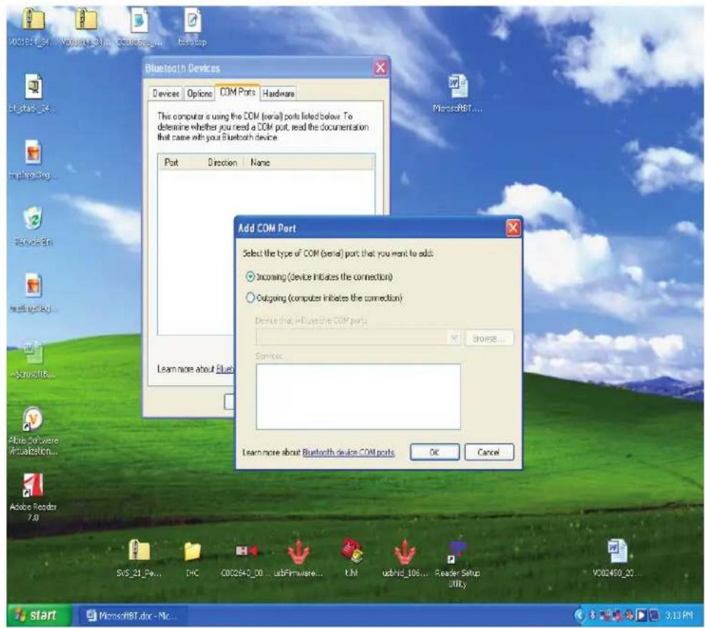
-
Install the Code XML Router Software to the Device on the Appropriate COM Port. Reboot the PC and then scan your QuickConnect code to connect. Please note that the Window Stack does not allow a device to connect until the Com Port is opened. CodeXML Router must be installed or the serial application must be started before the QuickConnect Code is read.
-
Scan the QuickConnect Code generated in step 3. Windows will prompt for a Passkey. The default Passkey is "12345678".
1.7.10 - Installing CodeXML Router Bluetooth Edition for Windows
- Insert the Code Router Bluetooth Edition for Windows CD into your PC's CD drive. The CD will automatically begin the installation process. When you get to the screen pictured below, please enter the CD Serial # Key found on the card included in the CD case.
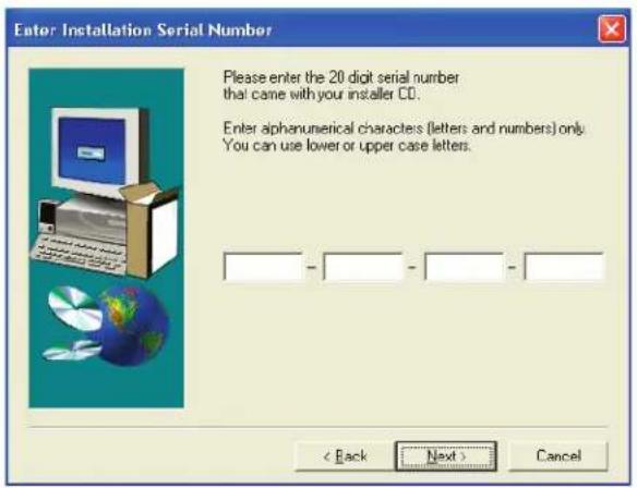
- When you get to the screen pictured below, please choose from the appropriate settings. For a description of each setting, please see Chapter 3. If connecting via Bluetooth radio, you will need to know the Virtual COM port number your Bluetooth software has assigned (see Frequently Asked Questions). If you wish to enable the AutoDownload feature please check the appropriate box in the next screen. Finish the installation process and restart your computer.
![Hardware and Application Interface Type Selection The Code Reader may be attached to Bluetooth Adapter Virtual Serial Port COH1: Serial Port COM1 Universal Serial DOS (USD) Application receive date through Keyframes Encoding Extended ASCII [default] Code page number Extended ASCII [default] UTF7 UTF8 Shift-JIS Code page number Code/All Client Application Serial Port COM1 < Back Next > Cancel](/content/2026/05/859704/images/3a3a23adce9e1bf9d0a779f5abc0ef2680b22ad30d282c25f61ffdf2ccd7a620.jpg)
- After restarting your computer, you will see a blue "arrows" icon in the system tray of your computer. CodeXML Router was successfully installed.

1.8 - CR2 Feedback Guide
The CR2 features two (2) LED's on the front of the unit. These LED's give feedback based on various function of the CR2 unit. Each LED has a small icon just underneath it that represents the following:


Memory / Connection Icon
Battery or Power Icon
The CR2 unit will automatically flash battery or power status every 15 seconds. Each LED can show three (3) colors; Green, Amber, or Red. The colors will vary depending on the message the unit is sending.
• Green = 50% - 100% capacity of battery
- Amber = 20% - 50% capacity of battery or 10% - 99% of memory available
- Red = 0% - 20% capacity of battery or no memory available
The CR2 also emits beeps or vibrates for user feedback. Please follow the table below to better understand your unit's feedback.
Normal Operation Feedback
| Memory/Connection LED | Battery LED | Sound | |
| CR2 Successfully Powers Up | Flash Green | Flash Green | 1 Beep |
| CR2 Successfully Enumerates with Host via USB Cable | None | Solid Green | 1 Beep |
| Attempting to Decode | None | Battery Status | None |
Normal Operation Feedback (con't)
| Memory/Connection LED | Battery LED | Sound | |
| Successful Decode and Data Transfer via cable | None | Solid Green | 1 Beep |
| Successful Decode and Data Store | Memory Status | None | 1 Beep |
| Batch Mode memory full | Solid Red | None | 3 Beeps |
| Configuration Code Successfully Decoded and Processed | None None | 1 Beep slight pause then 1 Beep | |
| Configuration Code Successfully Decoded But Was Not Successfully Processed | NoneNone | 6 Beeps |
Bluetooth Radio Feedback
| Memory/Connection LED | Battery LED | Sound | |
| Attempting to Connect | FlashesBlue | SolidGreen | None |
| Failed to Connect | None 4 Beeps | None | |
| Connected | Flashes BlueEvery 15 seconds | Flash Battery StatusEvery 15 seconds | None |
| Sending Data | Flashes Memory Status | None | None |
1.9 - Targeting and Reading Techniques
The CR2 utilizes digital camera technology to take a picture of a symbol. Once an image is captured, the CR2 utilizes advanced decoding algorithms to extract data from the captured image.
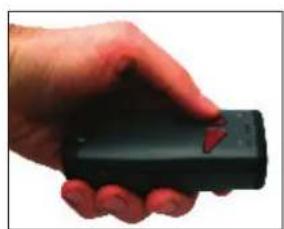
The CR2 is available as a palm-held unit or users may purchase a handle (available in various types).
The palm held unit features left and right triggers. These triggers may be programmed to perform various features. The reader is shipped with the left trigger and right trigger functioning as a decode symbol command.
Each handle has a trigger on the grip. The two triggers on the top of the unit also work when the handle is attached.
natural_image
Hand holding a black remote control device (no visible text or symbols)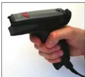
natural_image
Hand holding a black barcode scanner (no visible text or symbols)To read a symbol with the CR2:
- The CR2 features omnidirectional decoding. Center the symbol in any orientation within the laser dot aiming pattern (Figure 1.24).
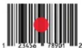

Figure 1.24
Note: The CR2 can read a symbol that is not centered; however the CR2 performs best when a code is centered. If two (2) bar codes are within the imager's decode zone, the CR2 will decode the symbol closest to the center of the aiming dot.
- The CR2 was developed to decode both very small 2-dimensional symbols and larger 1-dimensional symbols.
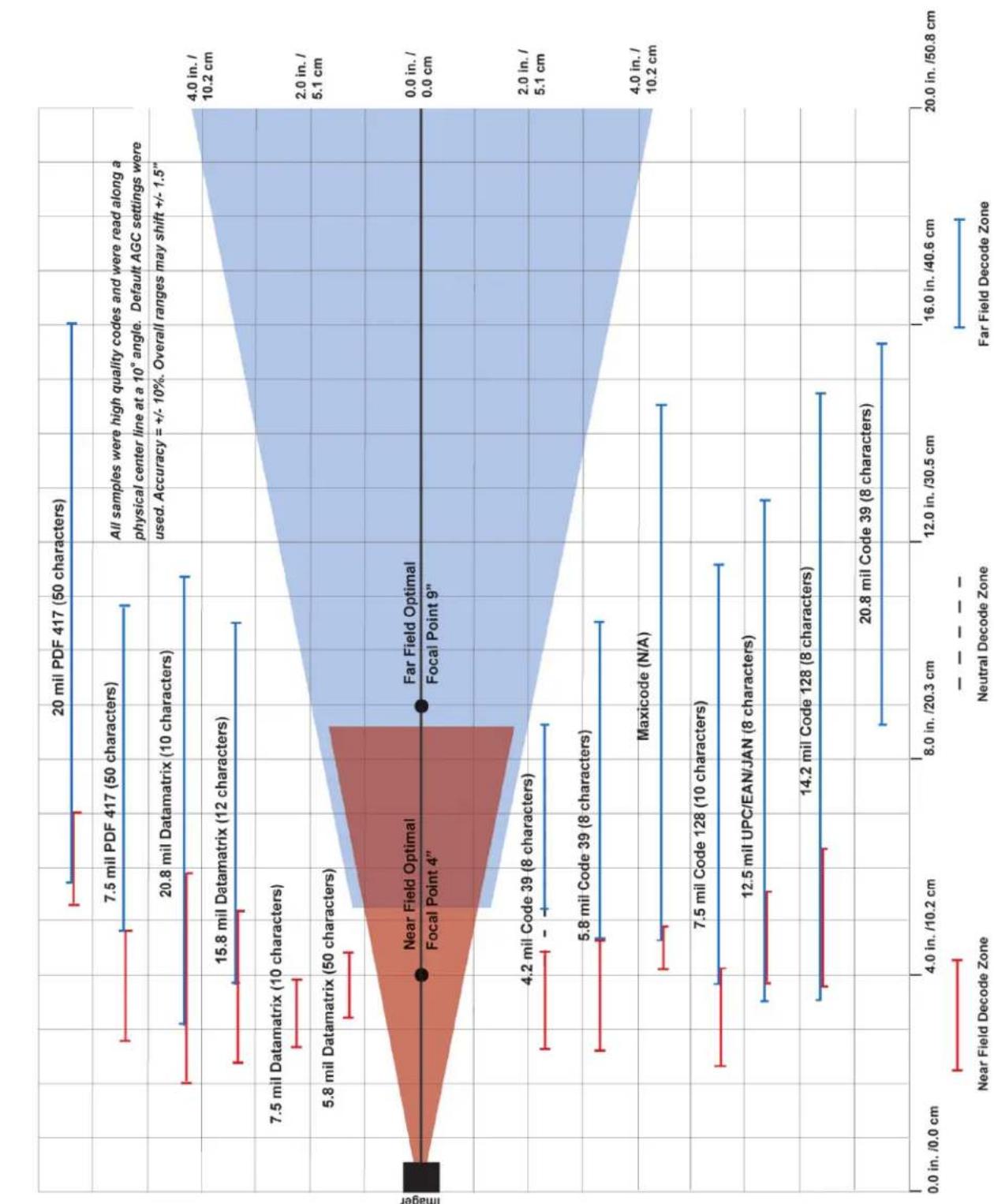
The unit has an innovative dual field decode zone. The CR2 DECODES BOTH ZONES SIMULTANEOUSLY. The unit has a lens focused on a near-field for smaller codes (optimal focal point is 4 inches) and one lens focused on a far-field for larger codes (optimal focal point 9 inches). To read smaller symbols move the CR2 closer to the symbol. To read larger symbols move the unit farther away from the symbol. The entire CR2 decode zone varies between two (2") and twenty (20+") or more inches.
-
Hold the CR2 still - DO NOT SWIPE OR MOVE THE READER. Press the trigger until the CR2 beeps, indicating the code has been successfully decoded.
-
The reader may be optimized to your specific environment by scanning codes in Chapter 2.
1.10 - Imager Field of View and Resolution
The CR2's dual field optical system may be modified based on your scanning environment. The CR2's megapixel imager may be set to the following three modes:
The 1.3 Million Pixel imager is divided into near field and far field decode zones. In each zone the resolution is 1024 x 640 pixels (see Figure 1.25). In this mode of operation the reader utilizes the highest resolution creating the widest working range on bar code and 2-dimensional symbols of all densities. The trade-off is the amount of time the reader spends processing the image. This time can be reduced by optimization functions:
If only the near field is used (small symbols), the far field image can be ignored. If only the far field is used (large symbols), the near field can be ignored. Further optimization may be obtained by "windowing" the field to a smaller area. Each focal area may be narrowed by enabling the windowing feature found in section 5.2.
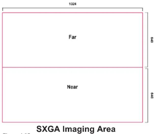
Figure 1.25
bar_line
| Imager | Distance (in. / cm) | Sample/Condition | | --- | --- | --- | | 20 mil PDF 417 (50 characters) | ~18.5 | - | | 7.5 mil PDF 417 (50 characters) | ~13.5 | - | | 20.8 mil Datamatrix (10 characters) | ~11.5 | - | | 15.8 mil Datamatrix (12 characters) | ~10.5 | - | | 7.5 mil Datamatrix (10 characters) | ~3.5 | - | | 5.8 mil Datamatrix (50 characters) | ~3.0 | - | | Near Field Optimal Focal Point 4" | ~4.0 | - | | Far Field Optimal Focal Point 9" | ~4.0 | - | | 4.2 mil Code 39 (8 characters) | ~6.0 | - | | 5.8 mil Code 39 (8 characters) | ~6.5 | - | | Maxicode (N/A) | ~12.0 | - | | 7.5 mil Code 128 (10 characters) | ~11.0 | - | | 12.5 mil UPC/EAN/JAN (8 characters) | ~12.5 | - | | 14.2 mil Code 128 (8 characters) | ~13.0 | - | | 20.8 mil Code 39 (8 characters) | ~15.0 | - | | All samples were high quality codes and were read along a physical center line at a 10° angle. Default AGC settings were used. Accuracy = +/- 10%. Overall ranges may shift +/- 1.5".Figure 1.26
Chapter 2 - Optimization and Trigger Programming
2.1 - Introduction
From the moment you turn on your CR2, you are taking full advantage of the dual path 1.3 megapixel imager, the 400 MHz processor. CR2 readers are able to read a wide range of symbology types and sizes, as well as a variety of printed media, within a wide range of environmental factors including light (natural or ambient lighting).
By defining if you are scanning large, small, high denisty or low density types of symbology(s), the CR2 has options that will maximize decoding speed.
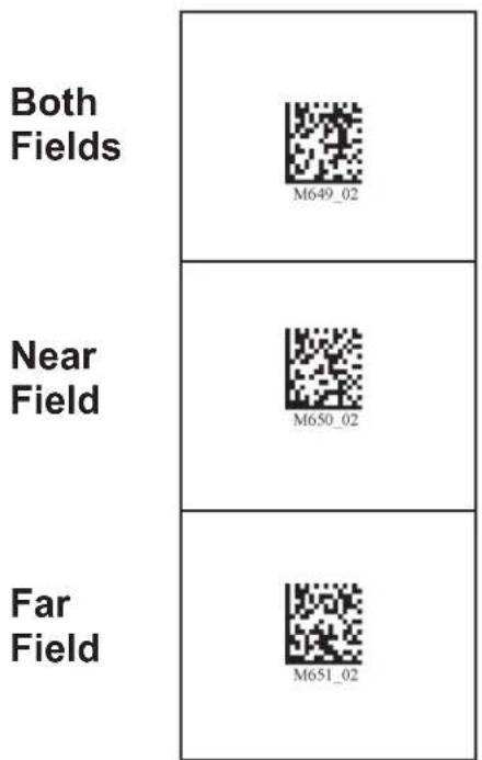
The chart below shows options that will improve performance based on parameters listed in each box.
SXGA
Both Fields
| SBHigh Density CodesStandard Density CodesSmall to Large Codes |
| SNHigh Density CodesSmall Size2D |
| SFStandard Density CodesMedium to Large Codes |
Near Field
Far Field
The CR2 is easily customizable; each trigger can be independently programmed for different behavior.
Near Field (NF): The closest optimal focal point of the CR2's two image fields. The Near Field can decode the highest density barcode. It has an optimal focal point of 4" (101.6 mm) away from the lens of the reader. See Figure 1.26 for optimal read distances.
Far Field (FF): The farthest field of the CR2's two image fields. It has an optimal focal point of 9" (228.6 mm) away from the lens of the reader with a 4" wide field of view at this point.
The following tables provide readable codes to program all or individual triggers to perform within different parameters. See Figure 1.26 for optimal read distances.
2.2 - Global Trigger Optimization Matrix
SXGA
Both Fields
Near Field
Far Field
M615 03
2.3 - Left Trigger Optimization Matrix
SXGA
Both Fields

Near Field

Far
Field

2.4 - Left Trigger Programming
Left Trigger Take Picture

M179 01
Note: If you program a trigger to another function, you will need to reset any performance code settings.
2.5 - Right Trigger Optimization Matrix
SXGA
Both Fields

Near Field

Far Field

2.6 - Right Trigger Programming
Right Trigger Take Picture

M186 01
Note: If you program a trigger to another function, you will need to reset any performance code settings.
2.7 - Handle Optimization Matrix
SXGA
Both Fields

Near Field

Far Field

2.8 - Handle Trigger Programming
Handle Trigger Take Picture

M154 04
Note: If you program a trigger to another function, you will need to reset any performance code settings.
2.9 - Continuous Trigger Optimization Matrix
Scanning codes in the matrix puts the reader into Continuous scan.
SXGA
2.10 - Continuous Scan
Off (Default) On

M141 02

M138 01
Note: This function is only recommended for cabled or short term use if battery is the only power supply. See section 2.11.1 for Sleep Time Out Settings.
2.11 - Continuous Scan Settings
2.11.1 - Continuous Scan - Sleep Time Out
Scan one of the codes below to set the amount of time a cabled CR2 will operate in continuous scan mode, without a decode, before entering sleep mode:
Cabled - 2 hours (Default) Cabled - Always

M136 01

M137_01
Scan one of the codes below to set the amount of time an uncabled CR2 will operate in continuous scan mode before entering sleep mode:
Uncabled - 5 minutes (Default) Uncabled - 15 Minutes Uncabled - 30 Minutes

M145 01

M146_01

M147_01
Note: This function is only recommended for short term use because of battery consumption.
2.11.2 - Continuous Scan - Trigger Delays
Scan the following codes to set delay time between scans:
0 Seconds (Default) 1 Second 3 Seconds

M142_01

M143 01

MI44 01
2.11.3 - Continuous Scan - Duplicate Scan Delay
Scan the following codes to set the delay time for reading duplicate codes:
0 Seconds (Default) 1 Second 3 Seconds

M222 01

M223_01

M224_01
2.12 - Motion Detection Scan Settings
Scan the following codes to set the reader to read when it detects motion in its scanning zone.
On Off (Default)

M701 01

M702 01

Save Settings
Chapter 3 - CR2 Programming: Symbology Settings
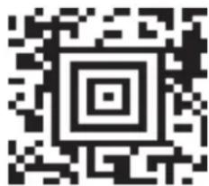
3.1 - Aztec Symbology
Scan the following codes to enable/disable Aztec symbology settings:
Aztec On

Aztec Off (Default)

Sample Aztec Code

3.2 - Codabar Symbology
Scan the following codes to enable/disable Codabar symbology settings:
Codabar On (Default)
Codabar Off
Sample Codabar


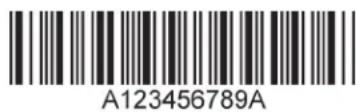
3.3 - Codablock F Symbology
Scan the following codes to enable/disable Codablock F symbology settings:
Codablock F On
Codablock F Off (Default) Sample Codablock F Code
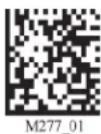
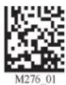
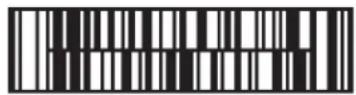
Note: When Codablock F and Code 128 decoding are enabled, there is some danger of mistakenly decoding a damaged Codablock F symbol as a Code 128 symbol. Therefore, Code 128 decoding should be disabled when Codablock F decoding is enabled.
3.4 - Code 11 Symbology
Scan the following codes to enable/disable Code 11 symbology settings:
Code 11 On (Default)
Code 11 Off
Code 11 Checksum 1 digit
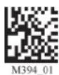
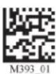
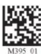
Code 11 Checksum 2 Digit Code 11 Checksum 1 Digit & Stripped from Result & Stripped from Result Code 11 Sample
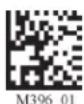

Save Settings
3.5 - Code 39 Symbology
Scan the following codes to enable/disable Code 39 symbology settings:
Code 39 On (Default)
Code 39 Off
Enable Checksum


Disable Checksum (Default)
Enable Checksum and Strip From Result


Code 39 Extended Full ASCII On Code 39 Extended Full ASCII Off (Default)


Code 39 Short Margin On
Code 39 Short Margin Off (Default)
Code 39 Trioptic On
Code 39 Trioptic Off
Sample Code 39 Code
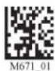
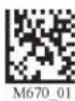
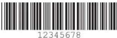
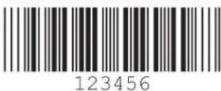
Sample Trioptic Code 39
3.6 - Code 93 Symbology
Scan the following codes to enable/disable Code 93 symbology settings:
Code 93 On (Default)
Code 93 Off
Sample Code 93 Code


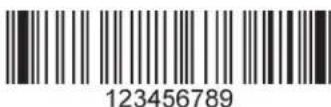
3.7 - Code 128 Symbology
Scan the following codes to enable/disable Code 128 symbology settings:
Code 128 On (Default) Code 128 Off

M283 01

M282 01
Code 128 Short Margin On
Code 128 Short Margin Off (Default)
Sample Code 128 Code

M392 01

M391 01
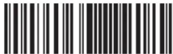
12345678912345
Note: When Codablock F and Code 128 decoding are enabled, there is some danger of mistakenly decoding a damaged Codablock F symbol as a Code 128 symbol. Therefore, Code 128 decoding should be disabled when Codablock F decoding is enabled.
3.8 - Composite Symbologies
Scan the following codes to enable/disable Composite symbology settings:
Composite On
Composite Off (Default)

M285 02

M284 02
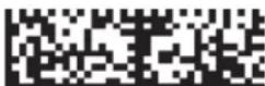
3.9 - Data Matrix Symbology
Scan the following codes to enable/disable Data Matrix symbology settings:
Rectangular Data Matrix On
Rectangular Data Matrix Off (Default)

M242 01

M241 01
Data Matrix Inverse On
Data Matrix Inverse Off (Default)

M239 01

M240 01
Enable improved reading capability for hard to decode datamatrix symbols.
Disable improved reading capability for hard to decode datamatrix symbols. (Default)

M744 01

M745 01
Sample Data Matrix Code
Sample Rectangular Data Matrix Code


Save Settings
3.10 - GoCode Symbology
GoCode is a miniature, two-dimensional (2-D) symbol. Developed to fit within a line of text, GoCode features a multi-dimensional, adaptable matrix pattern that may be reproduced on virtually any surface. GoCode is a private symbology and may be utilized by purchasing a runtime license through Code. GoCode has many significant advantages over all common linear barcodes and 2-D symbols. Please contact Code for more information on the benefits of utilizing a private symbology.
Sample GoCode
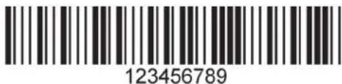
3.11 - Interleaved 2 of 5 Symbology
Scan the following codes to enable/disable Interleaved 2 of 5 symbology settings:
Int 2 of 5 On (Default)
Int 2 of 5 Off
Int 2 of 5 Two Digits On

M244 01

M243 01

M246 01
Int 2 of 5 Two Digits Off
Int 2 of 5 Four Digits On
Int 2 of 5 Four Digits Off

M245.02

M248 01

M247 01
Sample Int 2 of 5 Code
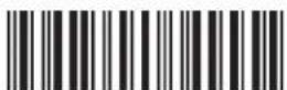
123456789
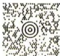
3.12 - Maxicode Symbology
Scan the following codes to enable/disable Maxicode symbology settings:
Maxicode On
Maxicode Off (Default) Sample Maxicode

M289 04

M288 01
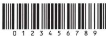
3.13 - Matrix 2 of 5 Symbology
Scan the following codes to enable/disable Matrix 2 of 5 symbology settings:
Matrix 2 of 5 On (Default)
Matrix 2 of 5 Off
Matrix 2 of 5 Sample


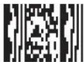
3.14 - Micro PDF417 Symbology
Scan the following codes to enable/disable micro PDF 417 symbology settings:
MicroPDF417 On
MicroPDF417 Off (Default)
Sample MicroPDF417


3.15 - MSI Plessy Symbology
Scan the following codes to enable/disable MSI Plessy symbology settings:
MSI Plessy On
MSI Plessy Off (Default)
Sample MSI Plessy


3.16 - NEC 2 of 5 Symbology
Scan the following codes to enable/disable NEC 2 of 5 symbology settings:
NEC 2 of 5 On
NEC 2 of 5 Off (Default)


3.17 - Optical Character Recognition (OCR)
The Code Reader can read Optical Character Recognition (OCR) texts. The following codes can be used to enable/disable this feature. Fonts supported include Passport, ISBN, Price, MICR13, and a user defined template:
Disable OCR (Default) Enable OCR
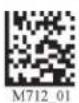

Purchase of OCR license required.

Save Settings
3.18 - PDF 417 Symbology
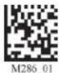
Scan the following codes to enable/disable PDF 417 symbology settings:
PDF 417 On (Default)
PDF417 Off
Macro PDF 417 On


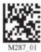
Macro PDF 417 Off (Default)
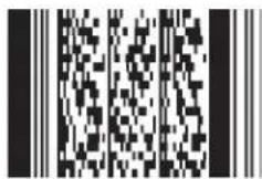
Sample PDF 417 Code
3.19 - Pharmacode
For an explanation of Pharmacode settings and all programming codes please refer to Appendix G of the CR2 User Manual. You may download the Appendix G at:
http://www.codecorp.com/manuals.html
3.20 - Postal Symbologies
All postal code default settings are OFF. Scan the following codes to enable the appropriate Postal symbology:
Note: If you wish to change which Postal code is activated, you MUST first scan the disable all postal codes symbol and then scan your desired symbology.
Australian Post On
Japan Post On
KIX

Planet On
Postnet On
Postnet and Planet On

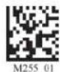
Disable All
Royal Mail On
Postal Codes (Default)
Sample Postnet Code
4-State CB On (Intelligent Mail)


3.21 - QR Code Symbology
Scan the following codes to enable/disable QR Code symbology settings:
QR Code On

QR Code Off (Default)

Enable Checksum

Both Inverse and Standard On
Disable Checksum (Default)
QR Code Inverse On


All QR On (includes Micro QR) Inverse QR and Micro QR On


Sample Micro QR
Sample QR Code
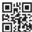

3.22 - GS1 data bar ( formerly RSS) Symbology
Scan the following codes to enable/disable GS1 data bar (formerly RSS) symbology settings:
GS1 data bar Limited On
Truncated On
GS1 data bar 14 Stacked On


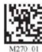
All GS1 data bar On
All GS1 data bar Off
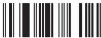
GS1 data bar Expanded On (Default)

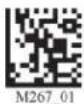

Sample GS1 data bar 14 Code
Sample GS1 data bar Limited Code

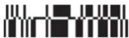
Sample GS1 data bar 14 Stacked Code
Sample GS1 data bar 14 Truncated Code



Save Settings
3.23 - Telepen Symbology
Scan the following codes to enable/disable Telepen symbology settings:
Telepen On - Default
Telepen Off
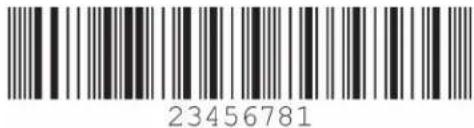
Sample Telepen


3.24 - UPC/EAN/JAN
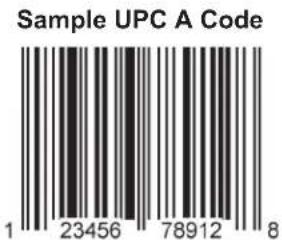
Scan the following codes to enable/disable UPC/EAN/JAN symbology settings:
UPC On (Default)
UPC Off
UPC Short Margin Enabled


UPC Short Margin Disabled (Default)
UPC Extension On
UPC Extension Off


Chapter 4 - Reader Feedback and Special Settings
4.1 - Volume and Vibration Settings
Scan the following codes to set vibration mode:
Vibrate On / Beep On
M107 01
Vibrate On / Beep Off
M109_01
Vibrate Off / Beep On (Default)
M108_01
Scan the following codes to set your reader's volume:
Beep Off

M110 01
Beep Low
Beep High (Default)

M111_01

M112_01
4.2 - Code Readability Index
The Readability Index provides a measurement of a specific symbol's ease or difficulty to be decoded by the CR2. The Readability Index is specific to the CR2, and should not be confused with a verification quality measurement.
The Readability Index is a blend of information obtained from the internal operations of the decoding algorithm pertaining to contrast, symbology construct, error detection, forward error correction (if applicable), and other symbology-specific characteristics.
The Readability Index is a score on a scale of 01 (very poor) to 100 (very readable). Due to differences based on motion, skew, reflection, focus, and ambient lighting, the Readability Index on the same symbol may vary somewhat from read to read. However, a poor contrast or damaged symbol will score lower than a high contrast undamaged symbol. The Readability Index can be used as a quick check on the reliability of label generation or marking systems. When used in conjunction with the CR2 stand (or fixed mount positioning) which fixes the distance from the reader to the symbol, and constant ambient light, the Readability Index provides a symbol quality assurance tool and check point for feedback to an overall label or marking quality control system.
The Readability Index is enabled by first reading a CodeXML rule into the permanent CR2 Memory:
Code Readability Index Rule: Readability Index Output Enable: Readability Index Output Disable:
M061_02

M062 02

M063 02
Each time a data symbol is read, the index will be output, followed by a comma, (,) followed by the decoded data. The reader will store the rule and reset, but will not output the Readability Index until the Readability Index Output Enable code is read. The Reader will continue to output the Readability Index upon every read until disabled, either by reset or by reading the Readability Index Output Disable code.
4.3 - Laser Settings
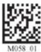
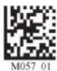
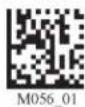
Scan the following codes to turn laser targeting on/off:
On (Default)
Off


Scan one of the following codes to set the brightness of the CR2 laser.
High (Default)
Medium
Low
4.4 - Reader Power Off Settings
Scan the following codes to set the amount of time before a reader powers off:
1 Hour
2 Hours - Default
4 Hours


4.5 - Reader ID and Firmware Version
To find out the Reader ID and firmware version, open a text editor program (i.e., Notepad, Microsoft Word, etc.) and read the following code:
Reader ID and Firmware

You will see a text string indicating your firmware version and CR2 ID number (see below):
Xap/iVVVVWWWWXXXXSSSSSSSSSPXX-XX+XXX
Xap/i - Code Internal ID (not applicable)
VVVV is the application firmware version number
WWWW is the bootloader firmware version number
XXXX is the radio firmware version number
SSSSSSSSS Reader's serial number (ten digits)
P is "A" if running firmware is the application, "B" if BootLoader
XXX-XX+XX - Internal ID (not applicable)
Example: Xap/i3000300006040010002363A06D-SD+SQ
Note: Code will periodically release new firmware for CR2 readers. For information on latest firmware versions, call Code at (801) 495-2200. To upgrade firmware, please visit our website at http://www.codecorp.com/codesupport/html and follow instructions provided.
4.6 - Reader Settings Lock
To lock or unlock the current settings on your reader please scan the codes below:
Reader Settings Locked Reader Settings Unlocked


NOTE: Prefix and Suffix programming codes, memory transfer and delete commands, "Clear All CodeXML Rules" and "Suffix -Erase/None" commands are not locked by this feature.
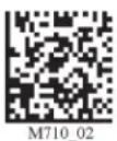
4.7 - Lock-out Link Mode
This mode can be used to establish a permanent connection between the reader and a CodeXML modem,
Prepare the reader to communicate in 'RF Comm Mode' by scanning the QuickConnect code on the paired modem to which you wish to establish a permanent link. Listen for the single beep to verify the connection acknowledgement. Scan the Lockout Link Mode code (see below). Set appropriate timeout settings, if applicable (see Section 1.6.5).
To reassign a permanent connection to a different reader, scan the unlock link code. Using the 'new' reader' follow the directions outlined in the previous paragraph.
Lockout Link Mode
Unlock Link Mode

Chapter 5 - Advanced Decode Performance
5.1 - Set Targeting Tolerances
The targeting tolerance is the zone around the laser which is eligible for decoding. The values of each of the following codes are the percent tolerance based on the size of the barcode. As the targeting tolerance becomes smaller the targeting laser must be more centered in the symbol being read. Conversely, as the targeting tolerance gets larger there is less precision needed with the targeting laser. If there is more than one decodable code in the field of the, the symbol closest to the targeting laser will be decoded.
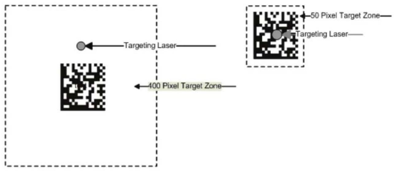
flowchart
graph TD
    A["Targeting Laser"] --> B["50 Pixel Target Zone"]
    C["Targeting Laser"] --> D["50 Pixel Target Zone"]
    E["400 Pixel Target Zone"] --> F["Targeting Laser"]
50 Most Accurate 75 100 125

M189 01

M190 01

M191_01

M192 01
1600 (Default)
150 200 400 Least Accurate

M193_01

M195_01

M194_01

M196 01
5.2 - Windowing
If only one size of bar code is being scanned in an application, the CR2 can be optimized to reduce processing time by adjusting the viewing area within the field of view of the image.
By reducing the vertical window value of the imager to 200 pixels, 1D codes are processed more quickly. Because only a horizontal strip of a 1D code is needed to be decoded, using a narrow strip of the imager is all that is needed. The area above and below the 200 pixels, which is always in the center of the imager, is ignored. This approach reduces the number of pixels that must be processed.
Windowing can also improve the processing time of 2D codes.
You may negatively impact reader performance if the window size is too small. If it is necessary to have the reader farther away than normal to read the code, the window may be too small.
Reading other types of codes, especially large codes, may be difficult while using this setting.
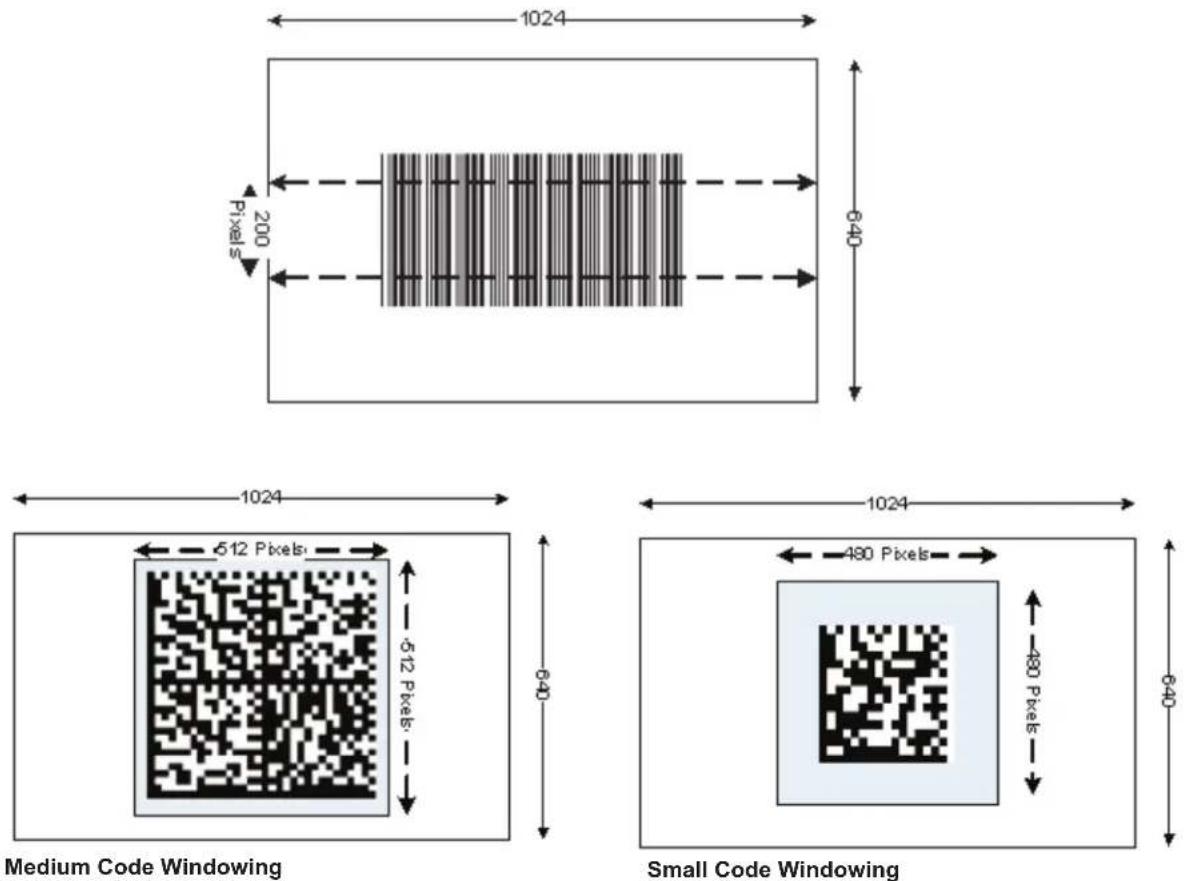
Users may optimize the CR2 decode zone if their application only requires one bar code format. If the size and density of the bar codes to be scanned are consistent, please select the setting below that best describes your environment.
1-Dimensional Codes ONLY (1024 x 200 pixels)
M209 01
Caution: It may be more difficult to read other codes while in this setting. You must have the reader farther away than normal.
Small 2-Dimensional Codes (480 x 480 pixels) Medium 2-Dimensional Codes (512 x 512 pixels)
M210 01
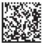
M211 01
Large 2-Dimensional Codes (640 x 640 pixels)
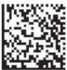
M212 01
Reset to Default Setting (1024 x 640 pixels)
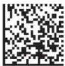
M213 01
5.3 - Mirror Decoding
Scan the following codes to enable/disable the mirroring feature:
On
Off (Default)

M182 01

M181 02
Note: The Mirroring feature allows the CR2 to read codes as they are seen through a mirror (inversed 180°). If the Mirroring feature is enabled, non-mirrored reading ability will be disabled.
Chapter 6 - Adding a Prefix or Suffix and Reader Text Commands
6.1 - Prefix Settings
If you scan the following codes, you will lose any unsaved settings. Make sure to save settings on your reader before scanning the prefix codes. If you scan more than one prefix you will receive each scanned prefix in your scanned data; (i.e., if you scan comma prefix twice, you will get two comma prefixes). Scan the following codes to set appropriate prefix:
Prefix - Comma
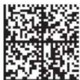
M159 02
Prefix - Space
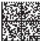
M164 02
Prefix - Tab (Keyboard Mode)
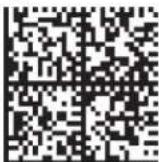
M166 01
Prefix - Tab (Serial)
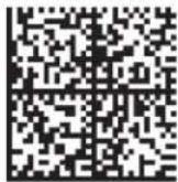
M218 02
Prefix - Erase
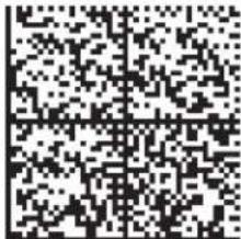
M404 01
Prefix - Carriage Return Line Feed
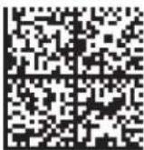
M214_02
Note: If you require a special configuration, please contact Code at (801) 495-2200 or email appeng@codecorp.com.
6.2 - Suffix Settings
If you scan the following codes, you may lose your current settings. Make sure to save settings on your reader before scanning the Suffix codes. If you scan more than one suffix you will receive each scanned suffix in your scanned data; (i.e., if you scan comma suffix twice, you will get two comma suffixes). Scan the following codes to set appropriate suffix:
Suffix - Carriage Return (Serial)
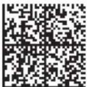
M168 04
Suffix - Comma
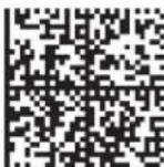
M160_04
Suffix - Line Feed (Serial)
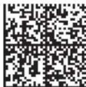
M169 04
Suffix - Carriage Return
Line Feed (Serial)
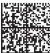
M170 04
Suffix - Space
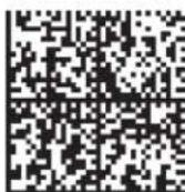
M165 04
Suffix - Enter (Keyboard Mode)
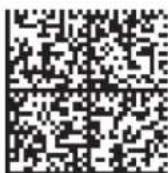
M161 04
Suffix - Tab (Keyboard Mode)
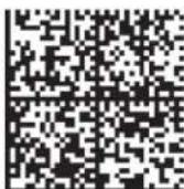
M167 04
Suffix - Tab (Serial)
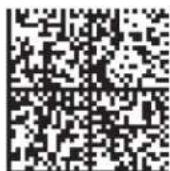
M219 04
Suffix - Erase
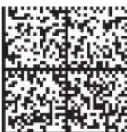
M405 02
6.3 - Erase Prefix and Suffix Settings
Scan the following codes to erase all prefix and suffix data.
Erase Prefix & Suffix Data
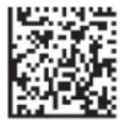
M406 02
6.4 - Reader Text Commands
Enabling Reader Text Commands allows the CR2 to accept text commands via RS-232 or RF communication. Scan the following codes to enable/disable reader text commands:
Reader Text Commands On
Reader Text Commands Off - Default

M198 01

M197 02
Note: Text commands can only be sent to the reader when it is active. Refer to Reader-Host Interface Control Document for more information.
Chapter 7 - CR2: Maintenance and Troubleshooting
7.1 - Reset Reader to Factory Defaults
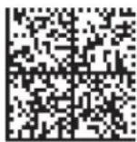
Scan the following codes to reset reader:
Reset to USB Factory
Reset to PS/2 Factory
Reset to RS-232 Factory
Default Settings
Default Settings
Default Settings
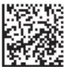
M049 03
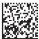
M060 03
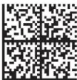
M418 02
Reset to RF One Way
Bootloader Mode
Factory Default Settings
M684 01

M692_01
Bootloader mode is utilized to download new version of bootloader firmware.
Clear All CodeXML Rules
Prefix & Suffix
Clear All Stored Data
Save Settings

M052_01

M071 01

M188 02
7.2 - General Safety Information
Repairs and Adjustments - Only those individuals authorized by Code should attempt to make repairs or adjustments to CR2 equipment. If the reader casing is opened the warranty is voided.
Power Supply - Use only the power supply provided for use with each specific unit when operating Code equipment.
Accessories - Only those accessories approved by Code (see page 3) should be utilized with Code equipment. Non-compliance with any of the above may result in:
• Injury to individuals handling the equipment;
• Damage to the equipment; and
- Voiding of the maintenance contract.
Lasers - The CR2 utilizes a laser FOR TARGETING PURPOSES ONLY. If the laser is activated, do not stare into the beam. See pg i for further information regarding laser warnings.
Lithium Ion Battery - Warning: Charge the battery with Code cables ONLY. Do not open battery, dispose of in fire, or short circuit - it may ignite, explode, leak, or get hot causing personal injury.
7.3 - Warranty
Code Corporation's Code Reader 2.0 carries a three year limited warranty as described herein.
Customers may purchase a one or two year extension to this warranty. Please contact a Code representative for more information.
Limited Warranty
Code manufactures its hardware products in accordance with industry-standard practices. Code warrants its products will be free from defects in materials and workmanship, provided that the products are used under normal operating condition intended by the Manufacturer. This warranty is provided to the original owner only and is not transferable to any third party. This warranty is subject to any and all accompanying disclaimers, limitations and other terms of this section.
Terms of Warranty
Products with serial numbers, such as but not limited to CR2 reader units, radios, CodeXML modems, battery chargers, stands and power supplies are warranted for three years from date of shipment. Batteries and battery handles carry a two year warranty, or until battery capacity after recharge is less than sixty percent of new, whichever is shortest. Non-serialized items, such as but not limited to handles and cables, carry a 90-day limited warranty.
Exclusions
No warranty herein contained or set out shall apply to any product (i) which has been repaired, altered or tampered with unless done or approved by Code, (ii) which has not been maintained in accordance with any operating or handling instructions supplied by Code, (iii) which has been subjected to unusual physical or electrical stress, immersion in fluids, puncture, crushing, misuse, abuse, power shortage, improper power supply such as incorrect voltage or wrong polarity, negligence or accident, or (iv) which has been used other than in accordance with the product operating and handling instructions. Preventive maintenance is the responsibility of the customer and is not covered under this warranty.
Warranty Coverage and Procedure
During the warranty period, Code will repair or replace defective products returned to Code's service center in the US. For worldwide warranty service call Code Warranty Support at 1-801-495-2200.
If warranty service is required, Code will issue a Return Material Authorization Number. Products must be shipped in the original or comparable packaging, with shipping and insurance charges prepaid. Code will pay for shipping and insurance of repaired or replacement products worldwide. Code will use new or refurbished parts at its discretion and will own all parts removed from repaired products. Customer will pay for any pre-shipped replacement product in case it does not return the replaced product to Code within 7 days of receipt of the replacement product. The process for return and customer's charges will be in accordance with Code's Exchange Policy in effect at the time of the exchange.
Customer accepts full responsibility for its software and data including the appropriate backup thereof. Repair or replacement of a product during warranty will not extend the original warranty term. Code's Customer Service organization offers an array of service plans, such as on-site, depot, or phone support, that can be implemented to meet customer's special operational requirements and are available at a substantial discount during warranty period.
General
EXCEPT FOR THE WARRANTIES STATED ABOVE, CODE DISCLAIMS ALL WARRANTIES, EXPRESS OR IMPLIED, ON PRODUCTS FURNISHED HEREUNDER, INCLUDING WITHOUT LIMITATION IMPLIED WARRANTIES OF MERCHANTABILITY AND FITNESS FOR A PARTICULAR PURPOSE AND NON-INFRINGEMENT. The stated express warranties are in lieu of all obligations or liabilities on part of Code for damages, including without limitation, special, indirect, or consequential damages arising out of or in connection with the use or performance of the product. Seller's liability for damages to buyer or others (regardless of the form of action, whether by contract, warranty, tort, malpractice, and/or otherwise) resulting from the use of any product, shall in no way exceed the purchase price of said product. In no event shall Code be liable for any consequential, special, indirect, incidental or punitive damages, or for any loss of profits, revenue or data, even if Code has been advised of the possibility thereof.
7.4 - CR2 Accessories
Please visit www.codecorp.com for more information on Code accessories.
7.5 - Frequently Asked Questions
For a complete list of Frequently Asked Questions, please visit: http://www.codecorp.com/faq.htm
7.6 - CR2 Maintenance
The CR2 device operates efficiently and reliably and needs only a minimum of maintenance to operate. A few tips are given below for maintenance suggestions.
Cleaning the CR2 Window
The CR2 window should be clean to allow the best performance of the device. The window is the clear plastic piece inside the head of the reader. Do not touch the window. Your CR2 uses CMOS technology that is much like a digital camera. A dirty window may stop the CR2 from reading codes.
If the window becomes dirty, clean it with a soft, non-abrasive cloth or a facial tissue (no lotions or additives) that has been moistened with water. A mild detergent may be used to clean the window, but the window should be wiped with a water moistened cloth or tissue after using the detergent.
The CR2 display screen and housing may be cleaned in the same way.
For applications that require cleaning with disinfectant, please use products with the following ingredients:
1) Isopropyl Alcohol
2) Ethyl Alcohol (Denatured Grade)
Code does not recommend using bleach.
Technical Support and Returns
For returns or technical support call Code Technical Support at (801) 495-2200. For all returns Code will issue an RMA number which must be placed on the packing slip when the reader is returned.
- Statement of Agency Compliance
- Laser/LED Radiation
- Code Reader 2.0 User Manual
- Table of Contents
- Chapter 1 - Getting Started .... 1
- Chapter 2 - Optimization and Trigger Programming .... 30
- Chapter 3 - CR2 Programming: Symbology Settings 37
- Chapter 4 - Reader Feedback and Special Settings 46
- Chapter 5 - Advanced Decode Performance .... 51
- Chapter 6 - Adding a Prefix or Suffix and Reader Text Commands .... 55
- Chapter 7 - CR2: Maintenance and Troubleshooting .... 58
- Chapter 1 - Getting Started
- - Introduction
- - Unpacking
- - Reader Battery Installation
- - Attaching Handles
- H1 - Handle
- H2 - Ruggedized Cabled Handle
- BH1 or BH2 Battery Handle
- - Batch Operation
- - Introduction
- Feedback
- Transferring and Deleting Data
- Auto Transfer Buffer Memory
- RS-232 Considerations
- - Cabled Operation
- 1.6.1- Introduction
- - CR2 as a USB Keyboard
- - Additional USB Communication Settings
- - Keyboard Support
- US English (Default)
- Alternative OS
- (Windows CE/MAC/Unix/Linux)
- - PS/2 Cable Installation Guide
- - RS-232 (Serial) Cable Installation Guide
- - Additional RS-232 (Serial) Communication Data Bit Settings
- - Additional RS-232 (Serial) Communication Baud Rate Settings
- - Additional RS-232 (Serial) Communication Parity Settings
- - Cabled Reader - Time Out Settings
- - Bluetooth Radio Operation
- - Introduction
- Connecting With A QuickConnect Code
- To connect your reader, use the following steps:
- - Bluetooth Radio Operation (continued)
- Radio Range and Transferring Data
- RF Additional Bluetooth
- Permanently Establishing a Connection
- Disconnecting from the Device
- Bluetooth Disconnect
- Reconnecting to the Device
- - Bluetooth Radio Auto Connect
- Bluetooth Radio
- - Bluetooth Radio Auto Disconnect
- - Bluetooth Radio Time Out Settings
- - Bluetooth Radio Out of Range Notification Settings
- - Auto Save Last Bluetooth Address
- - Configuration for Belkin Bluetooth Manager Software (Version 1.4.2.10)
- - Configuration for Belkin Bluetooth Manager Software (Continued)
- - Configuration for Toshiba Bluetooth Stack Instructions (continued)
- - Configuration for Microsoft Bluetooth Stack Instructions
- - Configuration for Microsoft Bluetooth Stack Instructions (continued)
- - Installing CodeXML Router Bluetooth Edition for Windows
- - CR2 Feedback Guide
- Memory / Connection Icon
- Battery or Power Icon
- - Targeting and Reading Techniques
- - Imager Field of View and Resolution
- Chapter 2 - Optimization and Trigger Programming
- - Introduction
- SXGA
- Both Fields
- Near Field
- Far Field
- - Global Trigger Optimization Matrix
- - Left Trigger Optimization Matrix
- - Left Trigger Programming
- - Right Trigger Optimization Matrix
- - Right Trigger Programming
- - Handle Optimization Matrix
- - Handle Trigger Programming
- - Continuous Trigger Optimization Matrix
- - Continuous Scan
- - Continuous Scan Settings
- - Continuous Scan - Sleep Time Out
- - Continuous Scan - Trigger Delays
- - Continuous Scan - Duplicate Scan Delay
- - Motion Detection Scan Settings
- Chapter 3 - CR2 Programming: Symbology Settings
- - Aztec Symbology
- - Codabar Symbology
- - Codablock F Symbology
- - Code 11 Symbology
- - Code 39 Symbology
- - Code 93 Symbology
- - Code 128 Symbology
- - Composite Symbologies
- - Data Matrix Symbology
- - GoCode Symbology
- - Interleaved 2 of 5 Symbology
- - Maxicode Symbology
- - Matrix 2 of 5 Symbology
- - Micro PDF417 Symbology
- - MSI Plessy Symbology
- - NEC 2 of 5 Symbology
- - Optical Character Recognition (OCR)
- - PDF 417 Symbology
- - Pharmacode
- - Postal Symbologies
- - QR Code Symbology
- - GS1 data bar ( formerly RSS) Symbology
- - Telepen Symbology
- - UPC/EAN/JAN
- Chapter 4 - Reader Feedback and Special Settings
- - Volume and Vibration Settings
- - Code Readability Index
- - Laser Settings
- - Reader Power Off Settings
- - Reader ID and Firmware Version
- - Reader Settings Lock
- - Lock-out Link Mode
- Chapter 5 - Advanced Decode Performance
- - Set Targeting Tolerances
- - Windowing
- 1-Dimensional Codes ONLY (1024 x 200 pixels)
- Small 2-Dimensional Codes (480 x 480 pixels) Medium 2-Dimensional Codes (512 x 512 pixels)
- Large 2-Dimensional Codes (640 x 640 pixels)
- Reset to Default Setting (1024 x 640 pixels)
- - Mirror Decoding
- Chapter 6 - Adding a Prefix or Suffix and Reader Text Commands
- - Prefix Settings
- - Suffix Settings
- - Erase Prefix and Suffix Settings
- - Reader Text Commands
- Chapter 7 - CR2: Maintenance and Troubleshooting
- - Reset Reader to Factory Defaults
- - General Safety Information
- - Warranty
- Limited Warranty
- Terms of Warranty
- Exclusions
- Warranty Coverage and Procedure
- General
- - CR2 Accessories
- - Frequently Asked Questions
- - CR2 Maintenance
- Cleaning the CR2 Window
- Technical Support and Returns
Brand : Code Corporation
Model : Reader 2.0
Category : Barcode Reader