
Logic Express 8 - Audio software APPLE - Free user manual and instructions
Find the device manual for free Logic Express 8 APPLE in PDF.

| Product Type | Audio Software |
| Version | 8 |
| Platform | Mac OS X |
| Supported Audio Formats | AIFF, WAV, SDII, CAF, Apple Loops, AAC, MP3 (import) |
| MIDI Support | Full MIDI recording, editing, and playback with external devices and software instruments |
| Number of Tracks | Unlimited audio and MIDI tracks |
| Included Software Instruments | Ultrabeat, ES1, ES2, EXS24 mkII, GarageBand instruments, over a dozen high-quality instruments |
| Effects | High-quality built-in effects including EQ, dynamics, reverb, delay, modulation, and more |
| Mixing | Full mixer with channel strips, sends, automation, and bouncing to stereo file |
| Notation | Score Editor with traditional music notation, printing, and export |
| Video Scoring | QuickTime movie integration, scene markers, synchronization |
| Automation | Track automation for volume, pan, plug-in parameters with multiple modes (Touch, Latch, Write) |
| File Interchange | GarageBand, OMF, AAF, OpenTL, XML, Standard MIDI Files |
| Apple Loops | Native support with Loop Browser, time-stretching, pitch-shifting |
| System Requirements | Mac with PowerPC G4/G5 or Intel processor, 1GB RAM, Mac OS X 10.4 or later |
Frequently Asked Questions - Logic Express 8 APPLE
User questions about Logic Express 8 APPLE
0 question about this device. Answer the ones you know or ask your own.
Ask a new question about this device
Download the instructions for your Audio software in PDF format for free! Find your manual Logic Express 8 - APPLE and take your electronic device back in hand. On this page are published all the documents necessary for the use of your device. Logic Express 8 by APPLE.
USER MANUAL Logic Express 8 APPLE
Apple Inc.
© 2007 Apple Inc. All rights reserved.
Under the copyright laws, this manual may not be copied, in whole or in part, without the written consent of Apple. Your rights to the software are governed by the accompanying software licence agreement.
The Apple logo is a trademark of Apple Inc., registered in the U.S. and other countries. Use of the "keyboard" Apple logo (Option-Shift-K) for commercial purposes without the prior written consent of Apple may constitute trademark infringement and unfair competition in violation of federal and state laws.
Every effort has been made to ensure that the information in this manual is accurate. Apple Inc. is not responsible for printing or clerical errors.
Note: Apple frequently releases new versions and updates to its system software, applications, and Internet sites. Images shown in this book may be slightly different to those displayed on your screen.
Apple Inc.
1 Infinite Loop
Cupertino, CA 95014-2084
408-996-1010
www.apple.com
Apple, the Apple logo, Bonjour, Final Cut, Final Cut Pro, FireWire, iMovie, iPod, iTunes, Jam Pack, Logic, Mac, MacBook, Macintosh, Mac OS, PowerBook, QuickTime, Soundtrack, and Ultrabeat are trademarks of Apple Inc., registered in the U.S. and other countries.
Finder, GarageBand, and Safari are trademarks of Apple Inc.
AppleCare is a service mark of Apple Inc., registered in the U.S. and other countries.
.Mac and iTunes Store are service marks of Apple Inc.
Adobe, the Adobe logo, Acrobat, the Acrobat logo, Distiller, PostScript, and the PostScript logo are trademarks or registered trademarks of Adobe Systems Incorporated in the U.S. and/or other countries.
Other company and product names mentioned herein are trademarks of their respective companies. Mention of third-party products is for informational purposes only and constitutes neither an endorsement nor a recommendation. Apple assumes no responsibility with regard to the performance or use of these products.
Contents
Preface 15 Logic Express 8: Documentation and Resources
16 Logic Express 8 Documentation Conventions
17 Logic Express Onscreen Help
17 Apple Websites
Chapter 1 19 An Introduction to Logic Express
20 Creating Music in Logic Express
23 The Basics: Projects and Regions
Chapter 2 27 Overview of the Logic Express Interface
28 A Tour of the Logic Express Interface
48 Common Features of Logic Express Windows
51 Interactions Between Arrange Window Areas
55 Using Logic Express Interface Elements
57 Using the Computer Keyboard
Chapter 3 59 Customizing Your Window Setup
59 Window Types
61 Opening and Closing Windows
63 Moving and Resizing Windows
65 Working at Different Hierarchy Levels
66 Selecting the Working Area
68 Zooming
71 Relationships Between Windows
73 Customizing the Transport Bar
74 Customizing the Arrange Window Toolbar
75 Hiding or Revealing the Inspector
75 Adjusting the Bar Ruler Display
77 Displaying Global Tracks
79 Using Screensets
Chapter 4 83 Setting Up Your System
83 Designing Your Music Production System
90 Connecting Your Audio and MIDI Devices
98 Using External MIDI Devices
98 Using External Audio Effects
99 Configuring Your Audio Hardware
Chapter 5 103 Navigating Your Project
103 Setting the Playhead Position
106 Using the Transport Buttons
107 Using Transport Key Commands
108 Using Cycle Mode
114 Using the Chase Events Function
116 Customizing the Transport Bar
Chapter 6 123 Working With Markers
124 Opening Marker Areas and Windows
125 Creating Markers
128 Selecting Markers
128 Deleting Markers
129 Naming Markers
131 Changing the Appearance of Marker Text
132 Editing Markers
134 Navigating With Markers
135 Customizing the Marker Display in the Marker List
Chapter 7 137 Working With Projects
137 Learning About Projects
139 Creating Projects
141 Opening Projects
143 Opening and Creating Projects Automatically
144 Importing Settings From Other Projects
145 Checking and Repairing Projects
146 Setting Project Properties
153 Managing Projects
155 Saving Projects
157 Closing and Quitting
Chapter 8 159 Basic Operations
159 Using the Mouse
160 Entering Numerical Values
161 Entering Text
162 Working With Key Commands
170 Working With Tools
176 Working With Help Tags
177 Using the Shortcut Menu
177 Selection Techniques
183 Working With the Clipboard
184 Undoing and Redoing Editing Operations
Chapter 9 187 Working With Tracks
189 Configuring the Track Header
190 Reclaiming Workspace Used by the Track Header
191 Creating Tracks and Channels
198 Deleting Tracks
198 Selecting Tracks
199 Rearranging Tracks
199 Naming Tracks
201 Assigning Tracks to Channels
203 Zooming Individual Tracks
204 Assigning Track Icons
205 Muting Tracks
207 Soloing Tracks
208 Record-Enabling Tracks
208 Freezing Tracks
212 Hiding Tracks
213 Protecting Tracks
214 Using Track Button Slide Activation
Chapter 10 215 Working With Instruments and Effects
216 A Quick Mixer and Channel Strip Primer
220 Inserting, Moving, and Removing Plug-ins
228 Loading and Removing Entire Channel Strip Configurations
232 Using the Plug-in Window
235 Common Plug-in Window Functions
242 Using the Library to Choose Plug-in Settings
243 Learning About Effect Routings
247 Working With Instruments
260 Working With ReWire Applications
261 Working With External Audio Effects
262 Using Plug-ins From Other Manufacturers
Chapter 11 265 Adding Pre-Recorded Media
265 Supported File Formats
266 About Pre-Recorded Media Types Supported by Logic Express
267 Accessing Media Files in the Browser
273 Finding Apple Loops in the Loop Browser
281 Adding and Removing Audio Files
290 Adding MIDI and Project Files
Chapter 12 291 Getting to Know Regions
291 What Are Regions?
295 MIDI and Audio Regions Compared
296 Handling Regions in the Audio Bin and Sample Editor
Chapter 13 307 Creating Your Arrangement
309 Making Region Edits Faster and Easier
319 Selecting Regions
320 Selecting Parts of a Region
322 Adding and Recording Regions
322 Removing and Restoring Regions
324 Moving Regions
328 Resizing Regions
334 Cutting, Copying, and Pasting Regions
335 Adding or Removing Song Passages
339 Repeating Regions
346 Dividing, Demixing, and Merging Regions
354 Using Folders
358 Creating Crossfades and Fades on Audio Regions
362 Setting Region Parameters
Chapter 14 367 Recording in Logic Express
367 Recording Audio
367 A Quick Overview of the Recording Steps
368 Preparations for Recording
377 Setting Up Track Channels
379 Making an Audio Recording
390 Handling Audio Recordings
391 Creating Comps
394 Managing Take Folders
396 Recording MIDI
396 Recording MIDI Regions in Real Time
402 MIDI Step Input Recording
407 Using the Caps Lock Keyboard
Chapter 15 409 Introduction to MIDI Editing
410 Opening the Editors
412 Hearing MIDI Events When Editing
412 Editing MIDI Events in the Arrange Area
413 Monitoring and Resetting MIDI Events
Chapter 16 415 Editing MIDI Events in the Piano Roll Editor
415 Learning the Piano Roll Editor Interface
418 Creating and Editing Note Events
432 Splitting Chords
433 Using Hyper Draw
434 Customizing the Piano Roll Editor
435 Piano Roll Editor Shortcuts
Chapter 17 437 Editing MIDI in the Hyper Editor
439 Creating and Editing Events in the Hyper Editor
448 Working With Event Definitions
455 Working With Hyper Sets
Chapter 18 459 Editing MIDI Events in the Event List
460 Learning and Using the Event List Interface
463 Selecting and Creating Events
466 Editing Events
468 Deleting and Muting Events
469 Soloing and Renaming Regions or Folders
469 Learning About Event Types
475 The Event Float Window
Chapter 19 477 Quantizing MIDI Events
478 Quantizing Regions
483 Event and Note Quantization
485 Creating Groove Templates
Chapter 20 491 Editing MIDI Events in the Transform Window
492 Choosing and Using Transform Sets
501 Using the Transform Window Parameters
508 Creating Your Own Transform Sets
508 Importing Transform Sets From Other Projects
509 Usage Examples
Chapter 21 515 Editing Audio in the Sample Editor
516 Playing Audio Files
518 Navigating Audio Files
519Changing the X and Y Axis Scales
521 Displaying the Waveform as Sample Bits
522 Making Selections
523 Copying, Pasting, Deleting, and Cutting
524 Destructive Audio Editing and Processing
529 Adjusting the Project Tempo
530 Sample Loop Functions
530 Undoing Editing Steps in the Sample Editor
531 Creating Manual Backups
533 Working With the Digital Factory
548 Using an External Sample Editor
Chapter 22 549 Removing Silent Passages From Audio Regions
549 How You Can Use Strip Silence
551 Using Strip Silence
Chapter 23 553 Adjusting the Tempo of Audio Regions
553 Automatic Tempo Matching
554 Setting the Project Tempo to Match an Audio Region
555 Time Stretching Regions
556 Using the Follow Tempo Function
Chapter 24 559 Managing Audio Files
559 Sorting, Grouping, and Renaming Files in the Audio Bin
564 Moving Audio Files
565 Copying or Converting Audio Files
566 Deleting Audio Files
567 Optimizing Audio Files
567 Saving Regions as Individual Audio Files
568 Exporting Tracks as Audio Files
569 Dealing With SDII Files
569 Finding and Replacing Orphaned Audio Files
Chapter 25 571 Mixing
573 Basic Mixing Steps
575 Channel Strip Elements
576 Setting Channel Strip Levels
579 Setting the Pan or Balance Control
580 Soloing and Muting Channels
582 Adding Effects: Using Inserts
582 Working With Sends
582 Working With Channel Strip Settings
583 Monitoring With Effect Plug-ins
583 Arming Channel Strips
583 Changing the Channel Input Format
583 Setting the Automation Mode
584 Handling Mixer Inputs and Outputs
584 Adjusting Elements of Multiple Channel Strips
586 Adjusting Channel Strips in Record or Playback Mode
587 Working With Groups
590 Channel Strip Types
598 Customizing the Mixer
603 Using the I/O Labels Window
Chapter 26 605 Working With Automation
606 Displaying Track Automation
609 Setting an Automation Mode
612 Writing Track Automation Data
613 Editing Track Automation in the Arrange Area
618 Editing Track Automation Data in an Event List
618 Writing Track Automation With External Controllers
620 Using Hyper Draw
624 Conversion of Automation Data
Chapter 27 625 Bouncing Your Project
626 Creating a Bounce
626 Routing Channels to an Output
627 Defining the Bounce Range
627 Using the Bounce Window
636 Setting the Bounce File Name and Folder
637 Bouncing and POW-r Dithering
Chapter 28 639 Creating Apple Loops
640 Creating Apple Loops in Logic Express
642 Creating Apple Loops in the Apple Loops Utility
643 Converting ReCycle Files into Apple Loops
644 Adding Apple Loops to the Loop Browser
645 Global Tracks and Apple Loops
647 Converting Apple Loops to Audio Files
648 Apple Loops and Sample Rates
Chapter 29 649 Project and File Interchange
650 Sharing Logic Express Data Over a Network
654 Backing Up Audio Files
655 Backing Up and Sharing Projects
656 Working With Standard MIDI Files
659 Importing GarageBand Projects
660 Working With OMF Files
661 Working With OpenTL Files
663 Opening, Importing, and Exporting AAF Files
664 Importing and Exporting Final Cut Pro XML Files
665 Exporting Regions
665 Exporting Tracks as Audio Files
Chapter 30 667 Advanced Tempo Operations
667 Tempo Display
668 Using the Tempo Track
672 Recording Tempo Changes
673 Adjusting the Tempo to Fit Audio Regions
673 Using the Tempo List
676 Using the Tempo Operations Window
679 Using the Tempo Interpreter
681 Using the Tempo Fader
Chapter 31 683 Beat Mapping Regions
684 Beat Mapping With MIDI Regions
686 Beat Mapping With Audio Regions
687 Beats From Region
688 Beat Mapping to Scene Markers
688 Beat Mapping to Markers
Chapter 32 689 Transposition With the Chord and Transposition Tracks
690 How MIDI Events and Apple Loops Are Transposed
691 Creating and Editing Transposition and Chord Events
693 Analyzing MIDI Regions
Chapter 33 695 Working With Notation
696 Learning About the Score Editor
702 Entering Notes and Symbols in the Score Editor
702 Real Time MIDI Recording
703 Step Input
704 Mouse Input (Using the Part Box)
707 Using Hyper Draw in the Score Editor
708 Working With the Part Box
711 Learning About Part Box Groups
721 Editing Notes and Symbols: Basic Operations
721 Using the Shortcut Menu
721 Changing Several Objects Simultaneously
722 Deleting Objects From the Score Editor
723 Moving or Copying Objects With the Mouse
726 Working With Aliases in the Score Editor
727 Changing the Graphical Position of Objects
728 Resizing Notes and Symbols
729 Editing Notes and Symbols: Advanced Operations
729 Editing Notes
735 Creating and Inserting Rests
736 Editing Clefs
738 Editing Slurs and Crescendi
740 Editing Repeat Signs and Bar Lines
742 Working With Text
742 Inserting Text
744 Editing Text
745 Using Musical Symbol Fonts
745 Learning About Text Styles
746 Working With Text Styles
747 Working With Global Text
749 Working With Automatic Text Objects
749 Creating Lyrics
751 Creating Chord Symbols
755 Working With Time and Key Signatures
756 Creating Time Signatures
757 Creating Key Signatures
757 Selecting Signatures
758 Copying Signatures
759 Editing Signatures
759 Deleting Signatures
760 Creating and Choosing Signature Alternatives
761 Transcribing MIDI Recordings
762 Default Settings for New MIDI Regions
763 Selecting Multiple Regions in the Score Editor
763 Display Parameters
769 Hidden MIDI Regions
769 Using Note Attributes to Change Individual Notes
775 Working With Staff Styles
796 Using Score Sets to Create Scores and Parts
804 Printing the Score
804 Preparing the Score Layout for Printing
808 Printing the Score
809 Exporting the Score as a Graphic File
809 Preparing the Export
809 Exporting the Score
810 Customizing the Score Editor's Appearance
810 Choosing a Color Mode
810 Displaying Folders
811 Displaying Global Tracks
811 Displaying Instrument Names
811 Project Settings for Score Display
812 Global Score Settings
816 Numbers & Names
820 Guitar Tab
824 Clefs & Signatures
826 Layout
828 MIDI Meaning
830 Colors
832 Score Preferences
Chapter 34 835 Working With Video
836 Using the Movie Window
837 Using the Video Track
838 Working With Scene Markers
839 Creating Scene Markers
840 Handling QuickTime Movie Audio Tracks
841 Video Project Settings
843 Video Preferences
Chapter 35 845 Synchronizing Logic Express
846 The Synchronization Master and Slave Relationship
846 Using External Synchronization
849 Synchronization Project Settings
859 Displaying and Using SMPTE Positions
861 MIDI Machine Control
863 Synchronization Problems and Solutions
Chapter 36 865 Working With Plug-in Latencies
865 About Latency
866 Working With the Low Latency Mode
867 Working With Plug-in Delay Compensation
Chapter 37 871 Working With Split Channel Audio File Formats
871 Importing Split Channel Files
872 Working With Split Stereo Files
873 Exporting Split Channel Files
Chapter 38 875 Working in the Environment
876 Using the Environment
876 An Introduction to the Environment
877 Working With Layers
880 Customizing the Environment Display
882 Working With Objects
886 The MIDI Signal Path
893 Common Environment Object Parameters
895 Exchanging Environments
899 The Environment Objects
899 Standard Instruments
901 Multi Instruments
915 Channel Splitter Object
916Arpeggiator
918Transformer Object
923 Delay Line Object
924 Voice Limiter Object
925 Chord Memorizer Object
927 Touch Tracks Object
930 Physical Input and Sequencer Input Objects
932 MIDI Click Object
933 Internal Objects
934 Alias
935 Ornament
936 Macros
938 Faders
957 Channel Strip Objects
Chapter 39 961 Project Settings and Preferences
962 Saving Project Settings and Preferences
962 Project Settings
962 Synchronization Settings
963 Metronome Settings
965 Recording Settings
967 Tuning Settings
973 Audio Settings
974 MIDI Settings
975 Score Project Settings
975 Video Project Settings
975 Assets Project Settings
976 Preferences
976 Global Preferences
981 Audio Preferences
987 MIDI Preferences
990 Display Preferences
993 Score Preferences
993 Video Preferences
993 Automation Preferences
994 Control Surfaces Preferences
994 Sharing Preferences
Appendix 995 Learning More, Service, and Support
996 AppleCare Service and Support Information
Glossary 997
Index 1029
Logic Express 8: Documentation and Resources
Logic Express 8 offers an extensive documentation collection that will help you to learn and make full use of all application features.
Further information about Logic Express, including data on updated versions and support texts, can be found on the Apple web site.
Logic Express 8 ships with the following documentation:
- Logic Express 8 User Manual: This book is the final arbiter on all things in Logic Express, and covers all areas of the program in detail, with the exception of plug-ins.
- Logic Express 8 Getting Started: This book is designed to quickly get you up and running with Logic Express.
- Logic Express 8 Control Surfaces Support: This document covers the use of control surfaces with Logic Express 8.
- Logic Express 8 Working With Apogee Hardware: This document covers the use of Apogee hardware in Logic Express 8.
- Logic Express 8 Instruments and Effects: This book covers the use of all Logic Express effect and instrument plug-ins. It does not cover the application-specific use of plug-ins—only the plug-in functions, parameters, and usage are discussed.
- Late-Breaking News: This document is published online and may be updated as new versions of Logic Express 8 are released, or new information becomes available
Important: All topics described in this manual were accurate at the date of writing. For up to date information on changes or additions made after writing, please refer to the Late-Breaking News document in the Logic Express Help menu, and to the Update Info, included with each Logic Express update.
Logic Express 8 Documentation Conventions
The following section introduces you to conventions used throughout the Logic Express 8 documentation.
Menu Functions
For functions that can be reached via hierarchical menus, the different menu levels are illustrated as follows: Menu > Menu entry > Function.
Important Entries
Some text will be shown as follows:
Important: Information on function or parameter.
These entries discuss a key concept or technical information that should, or must, be followed or taken into account. Please pay special attention to these entries.
Notes
Some sections provide additional information or tips that will assist your use of Logic Express. These are displayed as shown below:
Note: Information on function or parameter.
Key Commands
Many Logic Express functions can be activated or accessed with key commands—computer keyboard shortcuts. The key commands mentioned in this guide are based on the standard key command set.
Tips
A number of shortcuts, alternative methods, or general working tips are included throughout the documentation. These may help your workflow, or provide additional information on other uses for functions. Tips are shown as below:
Tip: Information on function or parameter.
Warnings
A few warning messages are included for functions that are destructive, and could result in irretrievable data loss, or could cause damage to your equipment. Warnings are displayed as follows:
Warning: Information on function or parameter.
Please pay special attention to these entries, as they can save you from making costly mistakes.
Logic Express Onscreen Help
The Logic Express Help incorporates the Logic Express 8 user documentation in electronic form. These documents have the advantage of being at your fingertips whenever you need them, and are searchable, making it quick to find the information you need.
- The Logic Express Help menu also provides additional features, including direct access to the Logic Express pages on the Apple website.
- A comprehensive bookmark list allows you to quickly choose (and tag) what you want to see, and navigates to the resource when the link is clicked.
Late-Breaking News
This document is published online and may be updated as new versions of Logic Express 8 are released, or new information becomes available.
To check for recent updates, choose Late-Breaking News from the Help menu. The Late-Breaking News PDF file is downloaded. If Safari is the default web browser for your system, the Late-Breaking News PDF file is displayed directly in Safari. Other web browsers may not have the ability to display PDF files directly, in which case the PDF file is downloaded to the default download location.
Apple Websites
There are a variety of discussion boards, forums, and educational resources related to Logic Express on the web.
Logic Express Websites
The following websites provide general information, updates, and support information for Logic Express, as well as the latest news, resources, and training materials.
For information about Logic Express go to:
http://www.apple.com/support/logicexpress
For information on Apple Training Programs go to:
http://www.apple.com/training
To provide comments and feedback to Apple about Logic Express, go to the Apple discussion forums:
http://discussions.apple.com/category.jspa?categoryID=156
Apple Service and Support Website
This is the place to go for software updates and answers to the most frequently asked questions for all Apple products, including Logic Express. You'll also have access to product specifications, reference documentation, plus Apple and third-party product technical articles.
To access Apple's Service and Support web page:
- Open your Internet browser, and type in http://www.apple.com/support.
Other Websites
- http://www.apple.com: Start at the Apple home page to find the latest information on Apple products.
- http://www.apple.com/quicktime: QuickTime is Apple's industry-standard technology for handling video, sound, animation, graphics, text, music, and 360-degree virtual reality (VR) scenes. QuickTime provides a high level of performance, compatibility, and quality for digital video delivery. Go to the QuickTime website for information on the types of media supported, a tour of the QuickTime interface, specifications, and more.
- http://www.apple.com/firewire: FireWire is one of the fastest peripheral standards ever developed, which makes it great for use with multimedia peripherals, such as audio interfaces, video camcorders, and the latest high-speed hard disk drives. Visit this website for information on the benefits of FireWire technology, FireWire software information, and details on third-party FireWire products.
- http://www.apple.com/pro: This website provides news, information, and other resources on seminars, events, and third-party tools used in web publishing, document design and printing, CAD, music and audio, desktop movies, digital imaging, modelling and animation, and the media arts.
- http://store.apple.com: Go here to buy software, hardware, and accessories direct from Apple. You can also find special promotions and deals that include third-party hardware and software products.
An Introduction to Logic Express
1
Logic Express is a sophisticated, fully-featured audio and MIDI application that provides all the tools you need to create professional-quality music productions.
Logic Express allows you to record audio and MIDI, edit audio loops plus MIDI and software instrument parts, add high-quality effects, and mix your music in stereo. The final mix can be exported to a standard audio file, or burned to an audio CD or DVD that can be played on any computer, home stereo, or imported into other applications and devices.
Some of the things you can do with Logic Express include:
- Record MIDI information via connected MIDI input devices, such as keyboards, and play back this information via any connected MIDI device (such as a synthesizer keyboard or module) or the integrated Logic Express software instruments.
- Create, arrange, and edit MIDI projects, and print out musical notation via a printer connected to your computer.
• Digitally record acoustic and electric instruments, or vocal performances, into your projects, and process these audio recordings with a huge array of built-in, real time effects.
• Make use of the integrated software instruments, including: Ultrabeat, ES1, ES2, EXS24 mkII, over a dozen high-quality GarageBand instruments, or third-party Audio Unit instruments. - Load projects or channel strips from GarageBand, and enhance them with the additional processing and editing possibilities afforded by Logic Express.
- Mix your MIDI and audio tracks, including effects and software instrument settings, via a sophisticated total recall mix automation system. Logic Express includes high-quality effects that you can use in your projects. You can also install and use third-party Audio Unit effects and instruments.
-
Bounce (mix down) all audio data, including instruments, effects and mix automation settings, to a stereo file for mastering or further processing.
-
Work in real time: You can work on Logic Express projects in real time; adding to, and editing audio and MIDI parts while the project is playing, and hearing the results of your changes immediately.
- Use existing loop libraries: Logic Express directly supports Apple Loops files, and is compatible with a wide variety of existing audio file types, including those created in ReCycle.
- Locate and preview files easily: The Media area, part of the Logic Express interface, provides powerful file browsing and search features, making it easy to locate audio files and other supported file types.
Creating Music in Logic Express
Logic Express can be used in a variety of ways, ranging from the simple to the incredibly sophisticated. The following section outlines a common workflow example that many projects adhere to. The structure of this manual will follow this basic workflow, where applicable.
Step 1: Creating a project
You begin working in Logic Express by creating a new project, or opening an existing one.
A project file contains MIDI data recordings plus information about the audio and other files used, including pointers to these files.
All files (audio, video, samples, and so on) can be saved in a project folder. All project files are automatically placed into appropriate sub-folders within the project folder.
More detail can be found in "The Basics: Projects and Regions" on page 23.
Step 2: Creating and importing your musical material
Getting musical material into Logic Express can basically be broken down into two methods:
- Making new audio or MIDI data recordings (the latter can be played back through either external MIDI synthesizers or software instruments).
- Importing existing audio recordings (audio files, samples, loops) or MIDI (and other file data) into your projects. You can import existing audio recordings by simply dragging them from the Media area, shown at the right of the Arrange window.
Recordings are made through suitable MIDI or audio hardware that is connected to, or installed in, your Macintosh.
MIDI recordings are used to trigger (play back through) either external MIDI devices, such as synthesizers, or internal software instruments. Software instruments are calculated on the Macintosh CPU, and played back through your audio interface or the Macintosh audio outputs. Not only can you record the notes of your performance, but you can also record and play back information such as synthesizer parameter changes—all in real time.
Audio recordings can be made by playing an instrument (such as a guitar) or singing into a microphone, as examples.
Step 3: Arranging and editing
Once your musical material has been imported or recorded into Logic Express, you will generally organize it into a "song structure". This is done in the main Logic Express window, called the Arrange window.
Musical material appears as rectangular blocks, known as regions. These regions run from left to right across the Arrange area, and are positioned on vertically stacked lanes, known as tracks. You may freely copy, repeat, loop, move, shorten, lengthen, or delete regions—either on a track, or across tracks. This grid-like layout and the use of building blocks (regions) makes it easy to see, and create, the overall song structure.
There will be many occasions where you'll need to perform more detailed edits to your MIDI or audio data recordings than is possible at the region level. Logic Express offers a number of editing windows that allow you to modify your musical material at a variety of levels. As examples of where this might be useful:
- You have made a recording of a great main vocal performance, but can hear a thud in the silent passages between two phrases, where the vocalist kicked the microphone stand. It probably goes without saying that this isn't a sound you'd like to have on the finalized CD. No problem. Simply edit the recording by inserting silence during the thud, or perhaps cut that portion out of the recording entirely.
- You have made a MIDI keyboard recording that is perfect but for one note that should have been a C, but is a B. No problem. You can simply drag the MIDI note event from B to C.
More detail can be found in "The Basics: Projects and Regions" on page 23.
Step 4: Mixing, automating, using plug-ins
Following the creation of your arrangement and any edits that may have been required, you would commonly move on to the mixing phase of your project. Mixing, as a term, generally refers to balancing the relative levels of each song component. Put another way, the main vocal needs to be louder than the bass, guitars, drums, and keyboards, thus allowing the lyrics to be heard.
Mixing also entails the use of audio effects, which change, enhance, or suppress particular song components, adding up to a unified and polished final product.
Logic Express features numerous effects that can be used to turn your basic song into a professionally finished project.
Logic Express enables you to record, or automate, changes you make to track, instrument, and effect parameters, such as volume, pan, filters, and other controls. This can be done in real time or offline—with the mouse or an external MIDI device. These changes play back when you play the project, and can be edited independently of the musical material. This is very useful for a number of reasons:
- You can only adjust one level or setting of a playback track, if using the computer mouse. The ability to record and play back multiple adjustments of all track elements allows for a sophisticated mix.
- Performances are rarely consistent. To clarify, a vocalist will often sing louder or softer during different sections of their performance, so you may need to even out these level changes over the course of the song, or to balance the soft and loud vocal sections against the musical backing.
- Song dynamics (the loud and soft sections of a song) benefit from animation. In other words, building the intensity of a song section can often be achieved by gradual or immediate level changes. Songs that are of a consistent level throughout tend to sound flat and lifeless.
Step 5: Exporting and bouncing
The final step of the Logic Express music creation process is exporting your final product. Logic Express allows you to produce a stereo file of your completed mix in a variety of audio file formats. This is achieved in the Bounce window; simply choose the desired outcome(s) in the available menus, and press the onscreen Bounce button. You can even burn a stereo mix directly to CD or DVD with one simple step.
The Basics: Projects and Regions
This section will provide you with an introduction to the basic elements and terminology of a Logic Express project. Detailed, step-by-step instructions on working with projects, regions, and events are provided in later chapters. If you are an experienced user, you may wish to skip ahead to “A Tour of the Logic Express Interface” on page 28.
Projects
You start working in Logic Express by creating a project, or opening an existing one. This is similar to using a word processing application, that requires a document to be opened before you can begin typing. Logic Express, like word processors, also allows you to have multiple documents (projects) open at the same time, and transfer media and other data between them.
A Logic Express project file contains all MIDI events and parameter settings, information about the audio and video files to be played, and all edits to MIDI and audio data.
It is important to note that the project file points to your audio and video files, which are stored as separate entities on disk. You have the choice of including these, and other file types, in the project folder.
This approach has two main benefits:
- Saving a project without its "assets" (audio, video, sample files, and so on) minimizes the memory requirements for project (and project backup) file storage.
- Saving a project with assets simplifies tasks such as archiving and transport to other Logic Express-based studios.
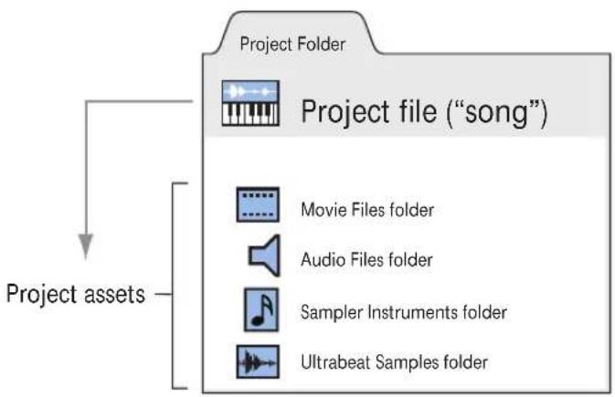
The Project Folder
A project can consist of the complete collection of files used, including the "song" (the project document) itself, song backups, all audio, sampler instruments, and samples for the EXS24 or Ultrabeat, and video.
These are collectively known as the project assets.
When you create a new project, a project folder is generated, named, and a hard disk location is specified. New recordings are automatically placed into an Audio Files subfolder within the project folder.
If you choose to include the project assets, further sub-folders will be created automatically. These can include Audio Files, Project Backups, Samples, Video, ReCycle, and Sampler Instruments folders.
The sub-folder structure of all projects is identical, making it easy and consistent to navigate both your projects and those of other Logic Express users.
flowchart
graph TD
    A["Project Folder"] --> B["Project file ("song")"]
    B --> C["Movie Files folder"]
    B --> D["Audio Files folder"]
    B --> E["Sampler Instruments folder"]
    B --> F["Ultrabeat Samples folder"]
    G["Project assets"] --> B
Regions
The main window of Logic Express is known as the Arrange window. This is the window that you first see when you open the application, and a project is loaded. This is also the window that is used for recording, editing, and arranging your projects. Your audio and MIDI files appear in the Arrange window as rectangular areas called regions. Audio files are represented by audio regions, MIDI files by MIDI regions.
Audio Regions and Audio Files
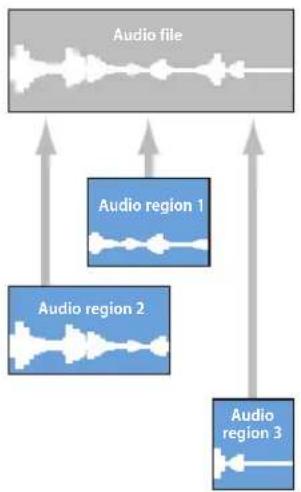
Audio regions simply refer to (point to) an underlying audio file. Audio regions are used as playback markers (start and end points) that can be as long as the entire audio file, or may only be a few seconds long, playing a small portion of the audio file that they point to.
flowchart
graph TD
    A["Audio file"] --> B["Audio region 1"]
    A --> C["Audio region 2"]
    A --> D["Audio region 3"]
    B --> E
    C --> F
    D --> G
Any audio file used in Logic Express is automatically linked to at least one audio region that is, by default, the length of the entire audio file.
You can freely create as many audio regions as you require. To give you an example of where this may be useful, imagine a live stereo drum track that runs for the duration of your project. During the second chorus, the drummer played perfectly, but was a little sloppy during all other chorus sections.
Logic Express allows you to create an audio region that points to the second chorus section of the overall (drum track) audio file, and use this perfect take in multiple places in the project.
This is achieved by creating one audio region (that points to chorus 2 in the drum track audio file), and copying it to each position that the chorus occurs in the Arrange area.
A great benefit of working with audio regions, rather than audio files is that they use very little memory, whereas multiple copies of the same section of the audio file would require a lot of hard disk storage space.
It is, of course, possible to directly edit, copy, and move audio files. This is achieved in the Sample Editor and Media area.
MIDI Regions and Events
MIDI regions, by comparison, actually contain MIDI data events. They are not related to information stored in external files. MIDI regions can be saved as individual files, but they can also be, and generally are, stored as part of the project.
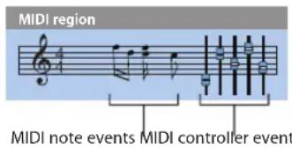
The MIDI data events stored within MIDI regions include; note, controller, program change, and other information. These data events represent MIDI performances that you have recorded into Logic Express. MIDI performances are generally created with a MIDI keyboard, but can certainly be generated with MIDI controllers, MIDI guitars, your computer keyboard or the mouse.
MIDI data events can be affected as a group by processing the MIDI region that contains them. Such processing includes; transposition, quantization (timing correction, which is similar to the spell checker of a word processor, when dealing with the language of music), timing delays, and more.
You can also edit individual events within a MIDI region. This is achieved by opening the region in one of the MIDI editors. These windows allow you to precisely alter the position, length, and pitch of MIDI note events. Other MIDI event types can also be altered in various ways. You may freely enter MIDI data with your MIDI keyboard, the mouse, and/or computer keyboard in these editors.
More information on MIDI and MIDI event types can be found in Chapter 15, "Introduction to MIDI Editing," on page 409.
Overview of the Logic Express Interface
2
The Logic Express interface features several areas, each specialized for particular tasks. The main workspace is the Arrange window, which can incorporate all areas and editors.
This chapter introduces you to the Arrange window. You'll learn how it interacts with other Logic Express windows and editors. Detailed information about these editors and their functions can be found in cross referenced chapters.
You are encouraged to open Logic Express to view these windows and familiarize yourself with them. Click and explore the various parts of the Logic Express interface as they are discussed. This will give you a feel for where things are, a brief overview of what they do, and how they work with each other.
To open Logic Express:
In the Finder or Dock, double-click the Logic Express icon in the Applications folder.

When you open Logic Express for the first time, the Templates dialog is displayed, allowing you to select a template for the project type you want to create (for more information on the New dialog, see "Creating Projects" on page 139). The layout of the Logic Express interface depends on the chosen template.
A Tour of the Logic Express Interface
The following section will introduce you the various elements of the Logic Express interface. This is principally a “getting to know you” exercise, where the fundamentals of each area are covered. Full details on all options, functions, and uses are covered in dedicated chapters that appear later in the user manual.
The Arrange Window
The Arrange window can incorporate all working areas and editors. It features a Toolbar at the top and a Transport bar at the bottom.
You have the choice of displaying additional areas, as follows:
- Editing area, horizontally tiled, below the Arrange area.
• Media or Lists area, vertically tiled, right of the Arrange (and editing) area. - Inspector, vertically tiled, left of the Arrange (and editing) area.
If an area is not visible, clicking on the appropriate Toolbar or Arrange area button will open it, and resize any existing areas to accommodate the new area.
Tip: Many of the editor and other areas can also be opened as separate windows, independent of the Arrange window. This is done in the Window menu (or with the corresponding key commands).
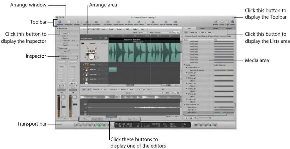
- Arrange area: This is where you record audio and instrument parts as regions, and arrange these audio and MIDI regions into a song structure.
- Media or Lists area: Use the various tabs to locate and preview audio files (Browser tab), select effects, instruments, and their settings (Library tab), and more, when the Media button in the Arrange Toolbar is clicked. When the Lists button is clicked, you have the choice of viewing MIDI events (Event List), tempo events (Tempo List), and more. You can also enable the Media or Lists area via the Arrange window View menu (or use the corresponding key commands).
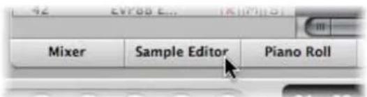
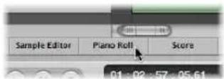
- Editing area: You can open or close the Mixer, Piano Roll Editor, Hyper Editor, Score Editor, or Sample Editor directly in the Arrange window by clicking any of the buttons along the lower edge of the Arrange area. These windows allow you to precisely modify, delete, or add different types of data.
- Transport bar: Used to navigate through your project. The current playback, recording, or editing position is indicated by the playhead—the thin, vertical line that appears in all Logic Express windows that offer real time display of playback—namely the Arrange and editor windows.
- Inspector: Used to set track and region parameters when working in the Arrange area, or the parameters of the editing window with key focus. As examples:
- Clicking the Score Editor area at the bottom of the editor area shows all scoring symbols in the Inspector.
- Clicking the Hyper Editor area displays the parameters of the currently selected hyper definition (selected row in the Hyper Editor window).
The Arrange Toolbar
The Toolbar appears at the top of the Arrange window. It contains buttons for frequently used commands.

The Toolbar can be customized to include buttons that show the Inspector, Media, and Lists areas, create new tracks, add audio files, and other common functions. For more information, see "Customizing the Arrange Window Toolbar" on page 74.
The Transport Bar
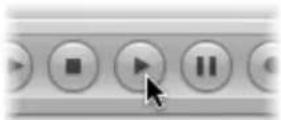
The Transport bar spans the entire lower edge of the Arrange window. You can use it to move through your project and start recording. It contains buttons that will be immediately familiar if you've used a tape recorder or CD/DVD player, such as Play, Rewind, Pause, and so on. The Transport bar also incorporates a number of features that simplify tasks you will perform in Logic Express, such as recording over a repeatedly cycled section, or listening to a part in isolation.
The Transport bar consists of three parts:

- Transport buttons: Used to navigate your project.
- Display area: Provides information that helps with project navigation.
- Mode buttons: Enable advanced recording and playback functions.
You can alter the Transport bar by adding or removing buttons and displays, providing faster access to the functions you need most often. You can also open an independent SMPTE or Bar display window. For more information, see "Customizing the Transport Bar" on page 73.
Arrange Area
The Arrange area is shown directly below the Toolbar. It is used to record, import, collate, and organize MIDI and audio data containers, known as regions, in a project.

- Bar ruler: A linear bar divided into bar and beat segments. The Bar ruler can also display time in hours, minutes, seconds, and finer divisions. It offers a number of facilities that can be used to mark project sections for different playback and recording tasks. More detail in Chapter 5, "Navigating Your Project," on page 103.
- Arrange grid: This where all MIDI and audio regions are displayed on horizontal lanes, called tracks, aligned to time positions in a grid-like layout.
- Track list: This is where you set the destination channel strip for playback of the MIDI or audio regions on each horizontal track lane. The headers of each track list lane can display the track name, icons, and several track buttons.
Media Area
The Media area can be opened or closed by clicking on the Media button in the Toolbar. The Media area is where you manage all files associated with your project, including audio, video, and plug-in settings. It has four tabs:
• Audio Bin: Helps you to manage all audio files used in the project.
- Loop Browser: Used to search for loop files (Apple Loops, for example).
- Library This is where you search for (and can directly assign) plug-in, channel strip, and MIDI instrument settings.
- Browser: Used to search for all Logic Express related files.
Getting to Know the Audio Bin
The Audio Bin shows all audio files used in the project. You can picture the Audio Bin as an audio file catalog for the project. It also provides an overview of regions that are derived from each audio file.
You can define new, edit, delete, or rename existing audio files and regions in the Audio Bin. All audio files and regions can be dragged directly from the Audio Bin into the Arrange area, where you can edit, move, and copy them. You can also add files that aren't yet used in the arrangement to the Audio Bin, allowing easy access during song construction.
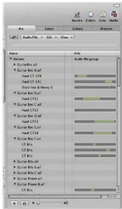
- Name column: Displays all audio files in the current project by name. The disclosure triangle to the left of the file name reveals all regions associated with the selected audio file.
- Info column: Displays audio file and region information. Horizontal bars indicate the overall audio file length. Colored sections of these bars indicate the location and size of regions within the audio file. Additional data, including the sample rate, bit depth, mono or stereo status, and file size are also shown in the Info column. Mono files are identified by a single circle symbol, stereo files by a double, interlocked circle symbol.
- Play button: Click to hear the selected audio file or region. Click a second time to stop playback.
- Loop button: Click to hear the selected audio file or region repeatedly. Click a second time to stop playback.
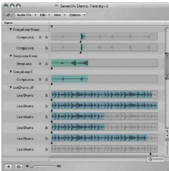
When you open the Audio Bin as an independent window, and resize it, the Audio Bin's Info column can display waveform overviews of audio files and regions.
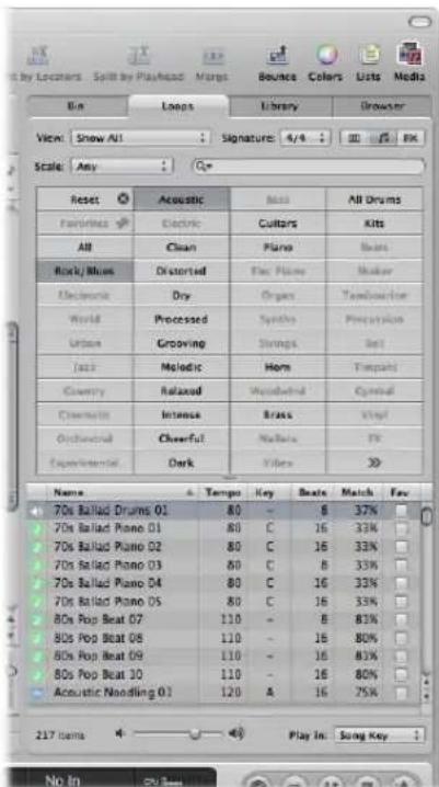
Getting to Know the Loop Browser
The Loop Browser is designed to make finding Apple Loops intuitive and fast.
You can search for loops by using keywords, perform text searches, preview loops, view information about loops, and limit the display to loops from a specific Jam Pack or loop library. Matching files are displayed in the Search Results list. When you find files you want to use, you can add them to your project by dragging them into the Arrange area.
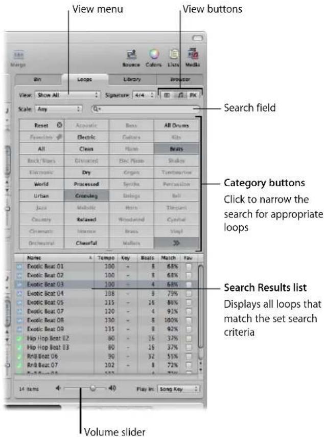
The Loop tab has three views: Column view, Music view, and Sound Effects view. The default Music view displays 54 buttons, each featuring a musically-related category. Simply click on the desired buttons in the matrix to narrow your search for appropriate Apple Loops. Activated buttons are highlighted.
The Sound Effects view offers effect-related category buttons such as Explosions, Foley, or People.
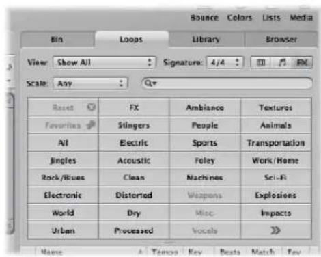
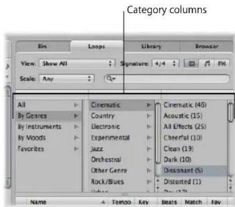
Column view offers a standard Mac OS X column file menu that is hierarchically separated into All, By Genres, By Instruments, By Moods, and Favorites search criteria.
- View buttons: Click to switch between the three views. The left button switches to Column view, the second button (featuring the note icon) switches to Music view, and the third button (featuring the FX icon) switches to Sound Effects view.
• View pop-up menu: Restricts displayed loops to a specific loop library. - Search field: Type text in the field to display files with names that contain the search text string.
- Category buttons (Music and Sound Effects view only): Click to display files which match the category in the Search Results list.
- Category columns (Column view only): Choose a category column to display its subcategories.
- Search Results list: Displays all loops that match the search criteria.
• Volume slider: Adjusts the playback level of the selected file.
Getting to Know the Library
The Library is a powerful tool that you can use to access the following file types.
• Channel strip settings (.cst)
- Plug-in settings (.pst)
- EXS instruments (.exs)
- Environment instruments, and programs or banks of MIDI instruments created in the Audio MIDI Setup utility
• ReWire MIDI instruments, and active ReWire hosts
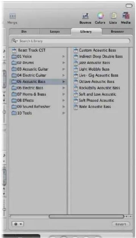
The Library automatically displays setting files that match the selected channel strip type and section (Channel Strip Settings menu, Insert slot, Instrument slot). A white frame indicates the selected section of the Arrange channel strips.
You can browse for files by opening folders, or search by performing text searches. Matching setting files are displayed in the Search Results list. When you find a file you want to use, you can load it by simply selecting it.
Getting to Know the Browser
The Browser allows you to navigate to, or search for all file types that can be used in Logic Express, enabling easy access to (and use) of this data during production. It displays the following file types on any connected media volume:
- Logic project files
- Song files of older Logic versions
- GarageBand projects
- All project interchange file formats Logic Express is compatible with (OMF, AAF, OpenTL, XML, MIDI files)
- Audio files
- QuickTime movies
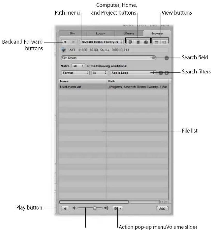
- Back and Forward buttons: Move through previously viewed levels of the folder hierarchy.
-
Path pop-up menu: Displays the levels of the file path to the current location, allowing you to move back to a previous level.
-
Computer button: Displays the contents of the local hard disk, optical drive, and other storage media connected to your computer, if applicable.
- Home button: Displays the contents of your home directory.
- Project Folder button: Displays the contents of the current project folder.
• View buttons: Switches the file list between column and list view modes. - Search field: Type text in the field to display files with a name that contains the search text. In addition to searching for files by name, you can search by other criteria (further information stored with your files). Click the plus button to display additional search filters. Logic Express always searches at the displayed location.
- Search filters: Use the menus to narrow down your search to specific file types, file formats, date, size, and other criteria.
- File list: Displays Logic-related files and folders at the current location. In column view, you can browse folder contents by clicking the desired folders.
- Action pop-up menu: Choose menu items to add a selected audio file to the Audio Bin, or show the file location in the Finder.
• Volume slider: Adjust the playback volume. - Play button: Click to play the selected audio file.
Lists Area
The Lists area can be opened or closed by clicking the Lists button in the Toolbar. It provides four independent tabs that show a listing of the following types of data:
• Event List: Displays regions or MIDI events.
- Marker List: Lists all markers in your project.
- Tempo List: Displays all tempo changes.
• Signature List: Shows all time signature and key change events in the project.
The list tabs are well suited for a number of precise editing tasks, and when a complete view of all data is required.
Getting to Know the Event List
The Event List presents a list of all events in your project, such as MIDI note events or region start events. Use it whenever you need to make precise alterations to recorded data, and where the graphic display of the other editors is not as well-suited to the task. You can restrict the types of events that are shown, making it easier to find specific event types.
The Event List can display two types of data: Region related or event related. The information that is displayed depends on the current hierarchy level—in other words, whether you are viewing information at the Arrange level, or looking inside one or more MIDI regions in the Arrange area. Further information about the display hierarchy can be found in “Working at Different Hierarchy Levels” on page 65.
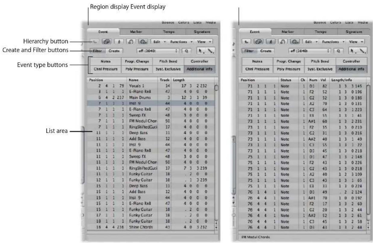
- Hierarchy button: Click to move up one level in the Event List hierarchy. This allows you to see all regions in the current project.
-
Create and Filter buttons: Determine the function of the event type buttons. When you enable the Create button, clicking the event type button adds the selected event type. When you activate the Filter button, you can use the event type buttons to filter specific event types from the display. This merely hides the events from the display, it does not affect playback.
-
Event type buttons: Click to filter specific event types from the display, or add them (depending on the status of the Create and Filter buttons).
- List area: Shows the actual list of events or regions, separated into columns. Details in Chapter 18, "Editing MIDI Events in the Event List."
Getting to Know the Marker List
The Marker List displays all markers in the project. You can use it to create new markers, edit existing ones, and to select markers for text editing. It also serves as a navigation aid—you can click on a marker name to jump to (move the playhead to) a marker position.
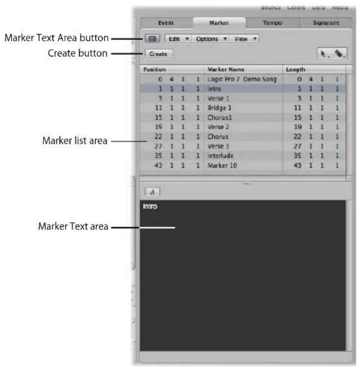
- Create button: Creates a new marker.
- Marker list area: Displays all markers in your project.
- Marker Text Area button: Click to display the optional Marker Text area, allowing you to enter or edit marker text.
- Marker Text area: Enter text for the selected marker here.
Getting to Know the Tempo List
The Tempo List displays all tempo changes in the project. You can also use it to create new tempo events, or to edit existing ones.
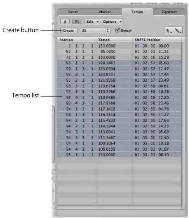
- Create button: Click to create a new tempo event.
- Tempo list: Displays all tempo changes, and their positions in the project.
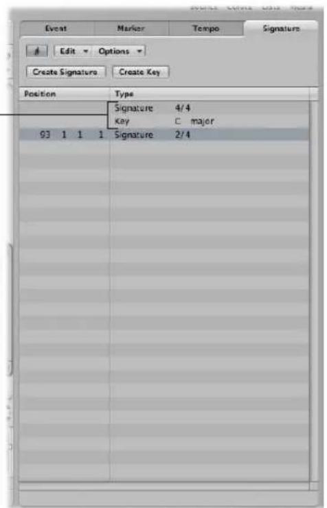
Getting to Know the Signature List
The Signature List shows all time and key signature events in the project. Score symbols, if present in the score of the project, are also shown. These include: Repeat signs and double bar lines (including end of score events), half/short bar lines, hidden bar lines and manually inserted bar lines.
You can use the Signature List to create, copy, move, and delete time and key signature events.
The initial time and key signature of the project is always displayed at the top of the list, without bar position indicators.
The Inspector
The Inspector can be displayed or hidden by clicking on the Inspector button in the Toolbar. The Inspector content depends on the area in key focus: Either the Arrange or one of the editing areas below it. The following screenshot shows the Inspector when the Arrange area is in key focus.
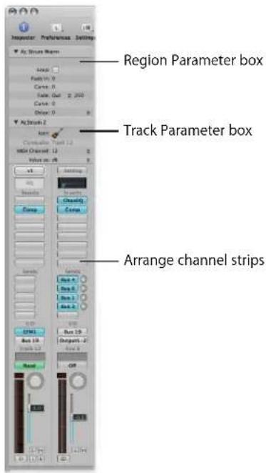
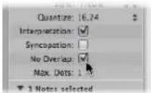
- Region Parameter box: Used to set playback parameters, such as transposition and quantization, for individual regions on track lanes. None of the parameters in the Region Parameter box actually alter the original data in the region. They only affect the way the region (and events within the region) are played back. These parameter alterations occur in real time, as the region is played. Clicking on the small triangle to the left of the name shows or hides the contents of the box.
- Track Parameter box: Used to alter various aspects of track channel strips. All regions on the track lane will be affected by any changes made here (as all regions are routed through this channel strip). Clicking on the small triangle to the left of the name shows or hides the contents of the box. Closing the box provides room for the elements below.
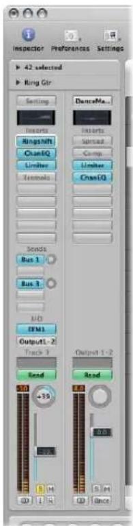
- Arrange channel strips: The left-hand channel strip controls the output of the selected arrange track. The right-hand channel strip can vary, dependent on actions performed in the left channel strip. As examples, the right channel strip can display the first aux or output destination channel strip for the left-hand channel strip. This facility makes it quick and easy to set up flexible effects and audio routing schemes. It also provides an at-a-glance view of processing and routing for the selected arrange track, and you can access all of the mixer channel functions (volume, pan, sends, inserts, and so on) directly from the Arrange area. Any adjustments you make to a track's Arrange channel strip will be reflected in the corresponding Mixer channel strip, and vice-versa.
Note: The horizontal size of the Inspector can not be altered. In situations where the area in key focus does not provide a parameter area, the Inspector for the Arrange area is displayed.
As the Inspector updates to display the parameters of the window with key focus, usage details are found in the chapters for each window.
The Editing Area
You can open the Mixer, Sample Editor, Piano Roll Editor, Score Editor, and Hyper Editor directly in the Arrange window by clicking the corresponding button at the bottom of the Arrange window. Here's a brief overview of what each window offers.
Getting to Know the Mixer
The Mixer is where you mix your project. Each track is played back through a channel strip. You can adjust the level and pan position of a channel strip, add effects, mute and solo tracks, and send the output of a channel strip to other channel strip types, such as output and auxiliary channels.
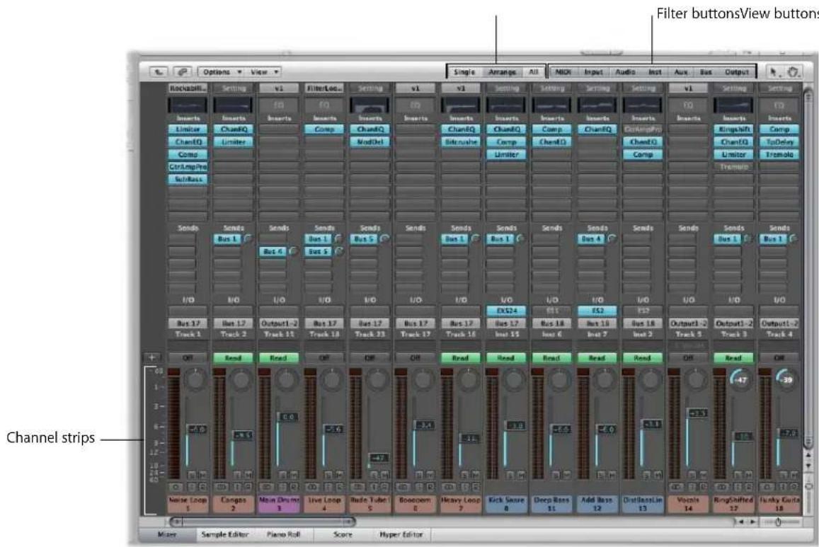
- Channel strips: Use the channel strip controls to adjust the level and other aspects of the audio signal played through the channel strip.
- View buttons: Switch the Mixer between the Single, Arrange, and All Mixer views, limiting the Mixer view to channel strips required for the task at hand.
- Filter buttons: Filter the display of specific channel strip types.
Full details can be found in Chapter 25, "Mixing," on page 571.
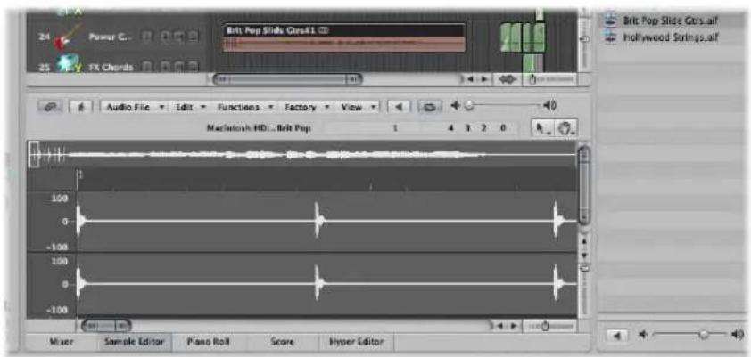
Getting to Know the Sample Editor
The Sample Editor displays the contents of audio files as waveform graphics. You can use the Sample Editor to precisely edit audio files (and regions). The Sample Editor also features a number of useful destructive processing tools—these allow you to time stretch and pitch shift audio, change sample rates, extract MIDI grooves from the audio, and even quantize audio.
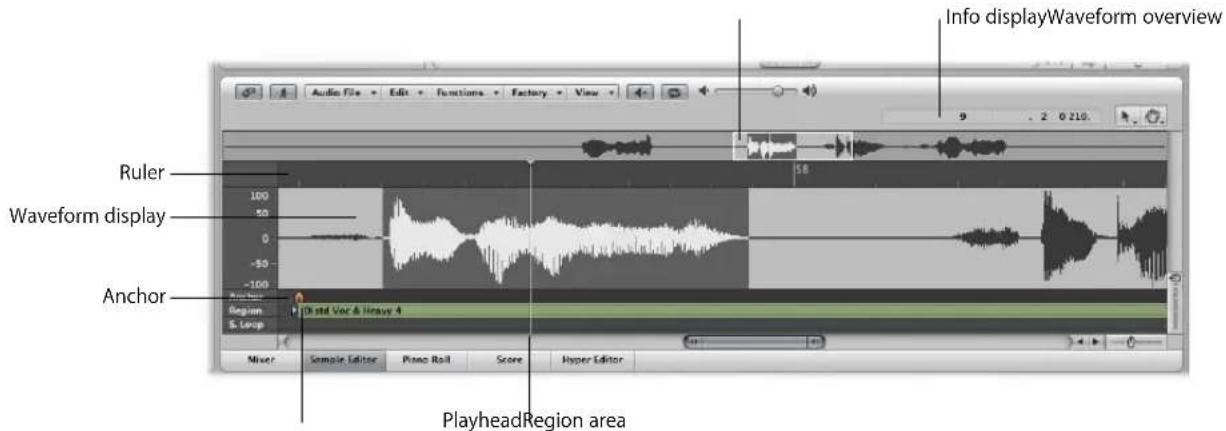
- Ruler: Shows the position of the region in the arrangement. If you have not yet added the audio file to the arrangement, the position marker lines are dotted, indicating no time connection exists.
- Info display: Shows the start point and length of the selected area.
- Waveform overview: Displays a miniature view of the entire waveform. The white frame shows the extent of the section visible in the waveform display. The dark gray frame shows the currently selected area.
- Waveform display: Provides a detailed waveform display. If you're dealing with a stereo file, both channels are displayed, with the left side on top, and the right side below. Left of the waveform display is the amplitude scale.
- Playhead: The gray line in the waveform display shows the current position of the playhead.
- Anchor: Sets a temporal reference point for an audio region. When you move a region in the Arrange area, Logic Express displays the position of the anchor in the help tag, and snaps the region's anchor to the selected Snap menu grid division.
- Region area: Edit this beam to adjust the length of the region.
Getting to Know the Piano Roll Editor
The Piano Roll Editor displays MIDI notes as beams on a grid. The piano keyboard to the left is aligned with the note pitches represented by each beam. Note length is indicated by the relative length of each beam. Note position is displayed from left to right—a ruler and vertical grid lines make it easy to see where notes begin and end. Note velocity (how hard a note is struck, and usually how loud) is indicated by color.
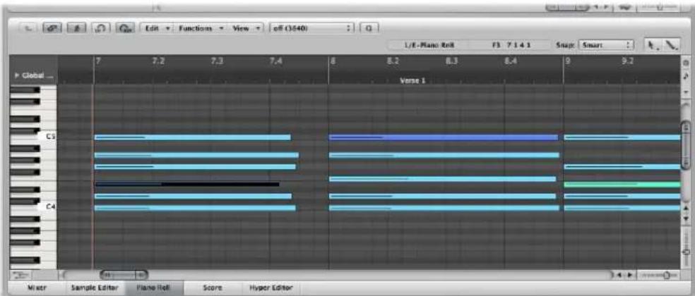
Full details can be found in Chapter 16, "Editing MIDI Events in the Piano Roll Editor," on page 415.
Getting to Know the Score Editor
The Score Editor uses traditional music notation to display the MIDI note events (plus pedal and other event types) of MIDI regions. You can insert and edit MIDI note events in staffs, and use musical symbols to clarify their meaning in this editor. Text, such as lyrics, titles, and comments, can also be integrated into the score. The Print function allows you to print complete scores, with staff numbers only limited by the paper size.
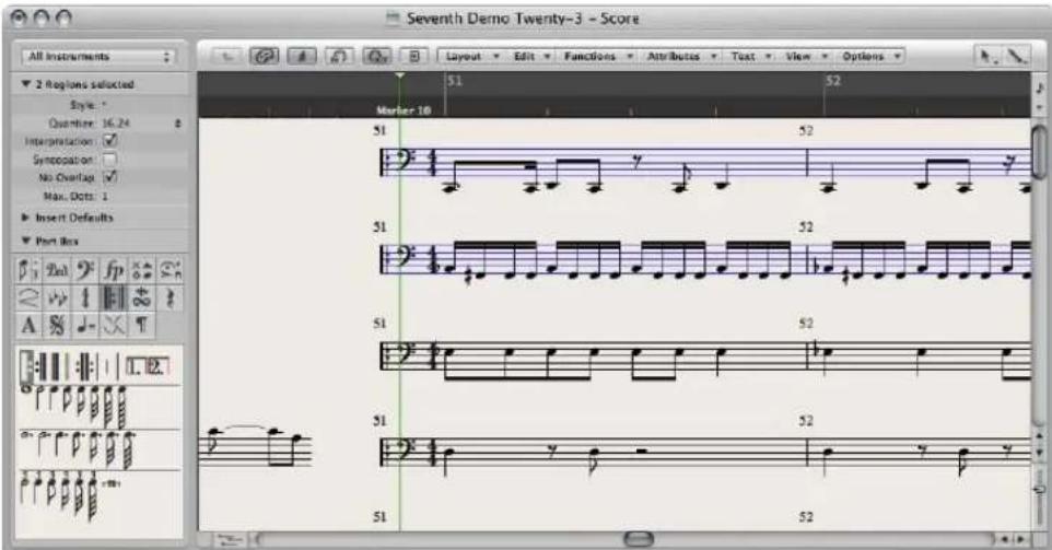
Details on Score Editor use can be found in Chapter 33, "Working With Notation," on page 695.
Getting to Know the Hyper Editor
The Hyper Editor displays MIDI note or controller events as vertical beams, placed along a user-defined time grid. This makes the Hyper Editor the ideal place to:
- Add or edit controller data, such as note velocities. It makes some editing tasks—such as data scaling—much faster.
- Quickly create and edit MIDI drum parts.
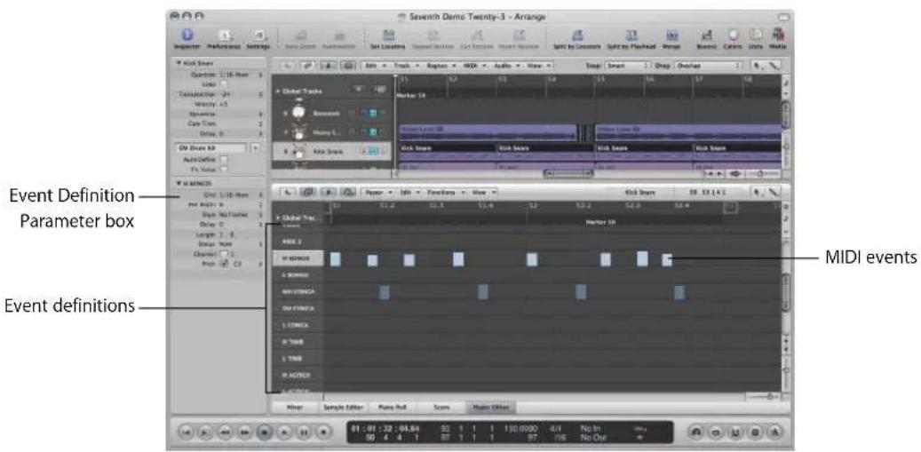
- Event definition: Each horizontal row (or lane) provides an event definition, which determines the type of event displayed/affected. When you select a row in the name column, its event definition is shown in the Inspector's Event Definition Parameter box.
- MIDI events: Each MIDI event is represented by a vertical beam, aligned with a particular time position. The value of the controller, or velocity of the note, is indicated by the height of the beam. Taller beams indicate higher values.
Common Features of Logic Express Windows
All Logic Express windows, including the Arrange area, feature a number of common elements. This consistent approach between windows makes your life easier, as you will find these elements in the same place throughout the application.
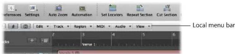
Local Menu Bars
A window's local menu bar contains buttons that access functions which are specific to the window. As an example, the Score Editor provides an enharmonic shift function, which is relevant to notation, but not to Piano Roll editing.
Tool Menus
The tools available in the Tool menus of each window are specific to tasks performed in the window. As examples: the Arrange area provides tools for different arrangement tasks, such as cutting or moving regions, and automation editing. The Score Editor provides tools used for score layout, and tasks such as voice separation.
The left Tool menu assigns the default tool. The right menu assigns a secondary tool. A further tool menu will appear if the right mouse button is not assigned to other tasks. For more information, see "Working With Tools" on page 170.
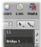
Catch, Link, and Hierarchy Buttons
Most windows contain Catch, Link, and Hierarchy buttons. These are used to tie or associate Logic Express windows, and can aid in navigating through different levels of your song structure. As an example of where this is useful, if you click on a MIDI region in the Arrange area, the contents of a linked window (the Piano Roll editor, for example) will update immediately to show the events within the region.

Scroll Bars
Vertical and horizontal scroll bars are shown at the right and bottom edges of the window. These enable you to view sections that fall outside the visible display area.

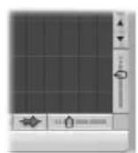
Zoom Sliders
Vertical and horizontal sliders are shown at the bottom right corner of the window. These allow you to horizontally or vertically resize the contents of the window, enabling a closer or more distant view of data.
Bar Ruler
All linear editing windows feature a Bar ruler at the top. The position of regions and events within a project are aligned with Bar ruler positions. The Bar ruler displays markers and locators, and reflects time signature changes. It also indicates three important operational modes—solo, recording, or synchronized.
Global Tracks
All linear editing windows also feature global tracks, which are displayed just below the Bar ruler, when opened. Click the disclosure triangle to the left of the Bar ruler (labeled Global Tracks) to view the global tracks.
- Marker track: Contains markers, which are used to identify bar positions and parts of the project. Their length, text, and color can be edited freely (for details, see "Working With Markers" on page 123).
- Tempo track: Contains all tempo changes in the project. For further information, see "Using the Tempo Track" on page 668.
- Beat Mapping track: Allows you to assign the desired bar position to any musical event (both MIDI notes and distinct accents in audio regions). This makes it possible to adjust the musical timeline to the original timing of a MIDI or audio region that has been recorded rubato (free time, including speeding up and slowing down), or just without a metronome click. The audible outcome remains unchanged, but the resulting display will fit the musical timeline.
- Signature track: Contains the basic key of the project, along with all time and key signatures, as they are displayed in the Score Editor.
- Chord track: Contains chord symbols that can be derived from MIDI regions or created with the mouse. These chord symbols may also be inserted into the score. The root notes of the chords determine the transposition (pitch shifting) of all Apple Loops, and can also affect the playback of MIDI regions.
• Transposition track: Shows global transposition events. It is linked to the progression of the chord root notes in the Chord track: Changing a chord root will be reflected in the Transposition track, and vice-versa.
- Video track: Displays frames of a QuickTime movie as thumbnails that are perfectly synchronized with the music, making it ideal for film scoring. Cuts in the movie can be automatically detected and marked.
Interactions Between Arrange Window Areas
The Arrange window contains various sections that interact with each other. These provide you with access to all files, editing methods, track and channel parameters in one place, making your workflow much faster. Please follow the steps outlined below to learn how these Arrange window elements work in harmony, to accelerate music production.
To see how Arrange window areas interact:
1 Open the Media area by clicking the Media Browser button in the Toolbar.
2 Click the Browser tab, then browse to a folder that contains audio files.
3 Click-hold the audio file name, and drag it onto an audio track lane in the Arrange area.
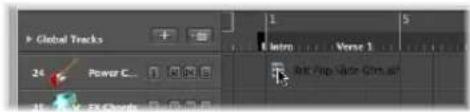
Release the mouse button when the help tag displays position 1 1 1 1. A region will be created in the Arrange area.
4 Click the Sample Editor button at the bottom of the Arrange area.
The Sample Editor is shown, displaying the contents of the region you just created in the Arrange area.
5 Click the Audio Bin tab.
The Audio Bin contains the audio file you just added to the project.
6 Click the Loops tab, then click a category button to see matching loops in the Loops tab's Search Results list.
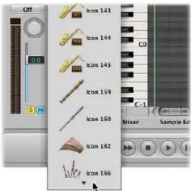
7 Select a loop with a green icon and drag it to a software instrument track in the Arrange area.
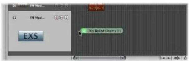
Release the mouse button when the help tag displays position 1 1 1 1. A MIDI region will be created in the Arrange area.
Tip: If no software instrument track exists, you can also drag the Apple Loop from the Loop Browser directly into the blank Arrange area (or below existing tracks). A track and corresponding channel strip (including instrument and effect settings) are automatically created, and the Apple Loop is loaded.
8 Click the Piano Roll button at the bottom of the Arrange area.
The Piano Roll Editor is shown, displaying the contents of the region you just created in the Arrange area.
9 Move the playhead to the beginning of your project by clicking the Go to Beginning button in the Transport bar.

10Play your project by clicking the Play button in the Transport bar.
You will hear the audio file and instrument loop you added to the project. You may like the melody of the software instrument loop, but not its sound. Utilize the Library to assign another sound to the software instrument track.
11Select the software instrument track, then click the Inspector button.
The left channel strip displays the software instrument and effect(s) of the selected track.
12Click the Library tab, and browse through the displayed channel strip settings.
As this is a software instrument track/channel strip, only software instrument channel strip settings are shown in the Library.
13 Select one of the channel strip settings to load it.
14 Start playback again to audition the new sound.
Using Logic Express Interface Elements
You can access all of the buttons, switches, sliders, and menus discussed above with the mouse and computer keyboard. Use of these Logic Express interface elements is outlined below:
Checkboxes and Buttons
Checkboxes are square boxes that are turned on when you click them, in order to activate an option (or function). Click the checkbox a second time to turn it off, and deactivate the option.
Some buttons behave in a similar fashion, where the function they represent is temporarily enabled (while the button is pressed, and usually illuminated).
A second click on the button will disable the function. Good examples of these types of buttons include the Mute and Solo buttons.
A different type of checkbox is the round radio button. A number of grouped buttons (each representing a different option) are available, and you need to select one of them. They differ from checkboxes and other button types in that only one of them can be activated at any given time. A good example are the Type radio buttons in the New Tracks dialog.
Pull-Down and Pop-Up Menus
Pull-down menus open when you click on the desired menu item. Pop-up menus open when you click on certain input fields or buttons.
In some menus, an arrow is shown beside one or more items, indicating a sub-menu. To choose an item from a sub-menu, move the mouse in the direction of the arrow, and then move vertically over the desired item. Click to activate the chosen command or setting.
If you wish to select an item that is outside the visible section of the menu, move the mouse over the arrow at the top or bottom edge of the menu. The menu will scroll.
Shortcut Menus
Shortcut menus (also called contextual menus) are accessed by Control-clicking or right-clicking in different areas of various Logic Express windows. These offer a number of selection, editing, and other area-specific commands, providing quick access to commonly used functions.
Note: Right-click functionality is dependent on the Right Mouse Button: Opens Shortcut Menu option being chosen in the Logic Express > Preferences > Global > Editing tab.
Using the Computer Keyboard
You can access most Logic Express functions with key commands. Whenever this manual mentions a key command, this refers to a function or option that can be accessed with a computer keyboard keystroke (or keystroke combination, such as pressing both the Control and W keys on your keyboard).
Use of key commands, rather than the mouse, can greatly accelerate your Logic Express workflow. Throughout this manual, you will encounter a number of practical usage examples, often in step form, that include the default key commands for particular functions.
It is recommended that you follow the steps outlined in the manual, and make use of these default key commands while familiarizing yourself with Logic Express. Not only will this help you to remember them, but will also aid you in developing good (and faster) working practices from the outset.
Once you have a good understanding of Logic Express fundamentals, and how you like to work, you can freely assign your own set of key commands. Logic Express functions and options that can be assigned to key commands can also be assigned to MIDI commands, sent from your MIDI controller. More details on these advanced topics can be found in “Working With Key Commands” on page 162.
Customizing Your Window Setup
3
Logic Express allows you to customize your window setup to fit both your working style and the task at hand.
While you will perform most of your work in the Arrange, you can open different combinations of windows (even several of the same type) and adjust each individually. It is also easy to save different window arrangements (called screensets, discussed in "Using Screensets" on page 79), and recall them by pressing a key.
All open windows in a project are constantly updated as they follow the position of the playhead. Alterations made in one window are immediately reflected in all other open windows. As an example, if the pitch of a note event is changed in the Score Editor, this change is instantly shown in an open Piano Roll Editor window.
This chapter outlines how you can customize and save your overall window setup. The display options of individual windows or editors are not covered in this chapter.
Window Types
There are two different types of windows in Logic Express: normal windows and floating windows.
Normal Windows
You can open as many normal windows as desired, including several of the same type. Even though the contents of all windows are constantly updated, only one window ever has the status of being the top, or active window. This is the window that is in the foreground when several normal windows overlap, or are shown alongside each other. It is referred to as having "key focus".
Key focus windows can be recognized by a title bar that is illuminated, and black title bar text (the project name).
To assign key focus to a window or area, do one of the following:
- Click on the window title bar, or within the working area.
Take care with the latter, as you may accidentally insert an event or region, if the Pencil tool is active in the window.
- Choose Window > Cycle Through Windows (or use the corresponding key command).
This assigns key focus to the next open window, if it is fully obscured by other windows.
The Arrange window can obviously incorporate several other windows in different areas. These can be given key focus by clicking the background or title bar of the window (the area of the Arrange you want to use), or by using a tool in the window.
Tip: You can also use Tab or Shift-Tab to cycle through the Arrange window areas: Tab cycles forward, Shift-Tab cycles backwards.
The main characteristic of the key focus window (or area of the Arrange window) is that key commands only affect this window, and not any of the others.
Handling Background Windows
Background windows are not fully obscured, and are identified by a dimmed title bar (they can be positioned next to the top window, or tiled underneath it) and a faded name.
In background windows, you can not only observe changes, but make almost any kind of change, without needing to give the window key focus before making alterations.
Independent tool selection is memorized for each window, allowing you to directly edit the contents of any window, whether it has key focus or not. As soon as any such edits are made, the window is automatically made the key focus window. As an example, an Arrange window with Piano Roll and Event List editor visible: the Pointer is active in the Arrange area, the Pencil tool is active in the Piano Roll, and the Eraser tool is active in the Event List editor. The tool automatically becomes active as you drag the mouse cursor across the boundaries of each area in the Arrange window.
Floating Windows
Floating windows are so named because they always float in the foreground, even above the key focus window (opening numerous float windows inevitably leads to them covering each other—just click on the desired one to move it to the foreground).
In general, most of the Logic Express helper windows, such as the Preferences or Project Settings windows, are floating windows.
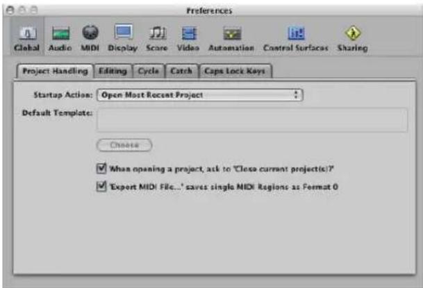
Floating windows are usually recognizable by their narrower, gray title bar (except the plug-in window, which has a different title bar style). Mouse operations performed in floating windows behave in the same way as in normal windows.
Opening and Closing Windows
You can open all main Logic Express windows by choosing the window type (Arrange, Score, and so on) in the Window menu. Each window type has a corresponding key command that opens the window, without using the mouse. As examples, Command-1 opens the Arrange window, Command-2 opens the Mixer, and so on. The key command designations are shown beside each window name in the Window menu. It is highly recommended that you learn and use these key commands, rather than the mouse, as they will speed up your workflow.
You can open multiple windows of the same type, if required. This may be useful when you want to individually display and alter the contents of several regions in a particular editor type.
You can also open all Logic Express editors in the Arrange window by clicking the buttons at the bottom of the Arrange window.
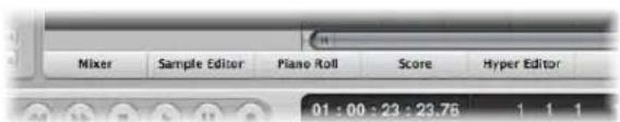
Double-clicking an Arrange audio region opens the Sample Editor at the bottom of the Arrange window. Double-clicking an Arrange MIDI region opens the default editor at the bottom of the Arrange window. You can determine the default editor with the "Double-clicking a MIDI region opens" menu in the Global preferences window. Option-double-click on a region to open the default editor as a separate window.
The Toggle ... Window key commands allow you to define one key command to open or close the window, or area of the assigned type in the active Arrange window. If the window is not available as an Arrange window area, it will be opened as an independent window. As examples in the Arrange window: You can open and close (toggle) the Lists and Media areas with the Toggle File Browser, Toggle Library, and so on key commands.
You can close the window with key focus (usually the topmost, or foreground window) by choosing File > Close in the main menu bar (or by using the Close Window key command, default: Command-W).
Windows can also be closed by clicking the close symbol at the top left.
Option-click the close symbol to close all windows of the active project.
Note: If you close all open windows of a project, Logic Express assumes that you want to close the project, and asks if you want to save your changes.
Moving and Resizing Windows
You can move and resize all open windows individually, even across multiple monitors. You can also alter the size of all window elements that feature the resize bar.
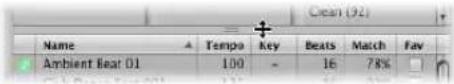
The size relationship of the editing and Arrange areas within the Arrange window can also be adjusted, by clicking between them, and dragging vertically. The cursor changes to a Resize pointer. The vertical height of the Mixer area is memorized independently. All other editing areas share the same height.
You can not resize the other Arrange window elements (the Inspector and Media or Lists area). You may only open or close these areas.
Here is an example of a possible window setup: Imagine you want to edit the MIDI notes of various MIDI regions. You may want to increase the height of the Piano Roll Editor to work at a high zoom level, thus decreasing the height of the Arrange area. You would then reduce the Arrange area zoom level, as it only needs to be used for region selection duties.
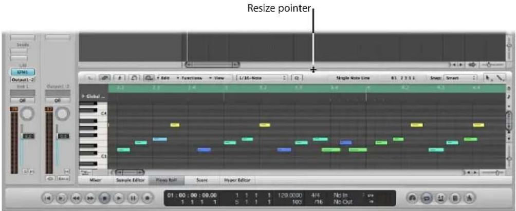
To move a window:
- Click-hold the title bar and drag the window to the desired position.
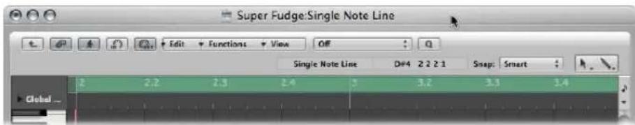
To adjust the size of a window, do one of the following:
- Drag the lower right-hand corner of the window, as with any window in the Finder.
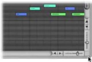
natural_image
Screenshot of a digital audio workstation interface with track controls and playback controls (no readable text or symbols)■ Position the mouse pointer over the window edge. When the mouse pointer turns into the Resize pointer, drag in the desired direction.
To adjust the size of window elements:
1 Move the mouse over the resize bar.
2 When the mouse pointer turns into the Resize pointer, drag the window element in the desired direction.
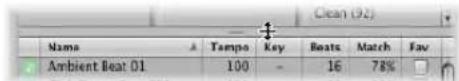
To maximize a window, do one of the following:
■ Select the window, the choose Window > Zoom.
- Click the zoom button (the right-most button of the three window controls) in the top left corner of the window title bar.
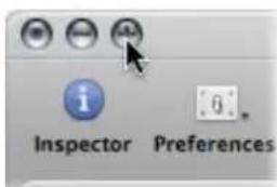
A second click on the icon will restore the original window size.
To minimize a window, do one of the following:
- Select the window, then choose Window > Minimize (or use the corresponding key command, default: Command-M).
- Click the minimize button (the middle button of the three window controls) in the top left corner of the window title bar.
This places an icon (minimized version of the window) in the Dock. The window can be restored by clicking on the icon in the Dock.
Working at Different Hierarchy Levels
Logic Express allows you to view projects at an overview level (Arrange level) and also at the microscopic level (editor level). These different hierarchical levels are designed for different types of tasks, such as arranging project sections or refining instrument parts, as examples. In many cases, you can switch between these different display levels directly, without needing to open or access another window.
Clicking the Hierarchy button in the top left corner of a window or window area moves the displayed view up one level (generally to the Arrange level).
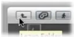
Note: Double-clicking on the background of the editing area of a window also moves up one display level.
About Display Levels in the Editors
Normally, the editors are at the lowest display level, which shows individual events within the selected region.
In the Piano Roll and Hyper Editors, a step up the display hierarchy will show the events of all regions in the Arrange area.
Clicking the Hierarchy button in the Event List moves you up one level in the display hierarchy, just like the other editors. In the Event List, however, the display remains much the same but shows a list of regions, rather than a listing of individual events—along with region positions, names, track numbers, and lengths. The MIDI region that you were just editing will be selected within the list of region names.
Double-clicking on a MIDI region (or using the Go Into Folder or Region key command) returns you to the lowest display level, and shows the contents of the MIDI region.
Double-clicking on an audio region opens it in the Sample Editor.
In the Score Editor, clicking on the Hierarchy button takes you to the higher display level. Unlike the other editors, individual events can also be edited while in higher display levels in the Score Editor. Double-clicking on a staff (at an empty point), reverts to a lower display level.
Selecting the Working Area
The scroll bars at the right and bottom edges of a window enable you to move through the working area in either the vertical or horizontal dimension.
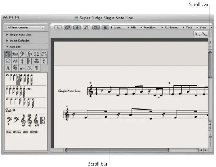
You can move the visible section by clicking the arrows, or dragging the scroller. There are two points to note:
- The size relationship of the scroller to the overall scroll bar length corresponds to the size of the visible section of the window, in relation to the overall window size.
• The visible section changes as you move the scroller.
Use the Page Up, Page Down, Page Left, and Page Right key commands to scroll one page up, down, left, or right, as if you had clicked in the gray area (in the scroll bar) above or below the vertical scroller, or to the left or right of the horizontal scroller.
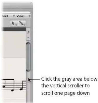
The Page Top, Page Bottom, Page Left-Most, and Page Right-Most key commands move the visible section of the working area to the top, bottom, left, or right, just as if you had grabbed one of the scrollers, and moved it to one of its extreme positions.
In the Arrange area, Event List, Hyper and Piano Roll Editors, View > Scroll to Selection moves the visible section of the edit window to the first set of selected events. This function is available as a key command which works in the key focus window.
To scroll both vertically and horizontally at the same time, do one of the following:
- Press Shift-Control, click-hold the Arrange window background, then drag in the desired direction.
- Click-hold the Arrange window background with the third mouse button (the mouse wheel, for example), then drag in the desired direction.
The distance of the mouse pointer position from the initial clicked position determines the scrolling speed.
Note: This only works if you haven't assigned the third mouse button to a global command, such as Expose, for example,
Zooming
The zoom controls are used to zoom in and out on the working display area. Selection of different zoom values reduces or increases the size of events or regions in the displayed screen section. This allows you to:
- See more events or regions in the same amount of screen space (zoom out).
• See a detailed display of events or regions (zoom in).
While zooming, the top-left (selected) event or region is kept in the visible area of the screen. In other words, the first selected region or event will be retained in the zoomed window. If no selected region or event is visible, zooming is centered around the playhead. It the playhead isn't visible, the current center of the window will be retained.
The horizontal and vertical zoom controls are located to the bottom-right of the working area of the window.
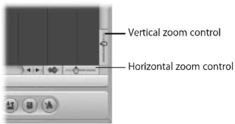
To zoom out:
- Click on the more closely spaced bars to decrease the zoom level.
To zoom in:
- Click on the widely spaced bars to increase the zoom level.
You can drag the zoom sliders to step through several zoom levels. Any relative size differences between tracks will be retained when zooming.
Command-clicking a value in the zoom control sets the zoom slider to the respective zoom level.
Zooming With the Scroll Bars
The scroll bars not only allow you to move through your arrangement and editing windows. They can also be used for zooming.
To zoom with the scroll bars:
- Click-hold on the zoom handles at either end of the scroll bar, and drag:
- Up or down on the vertical scroll bar.
- Left or right on the horizontal scroll bar.
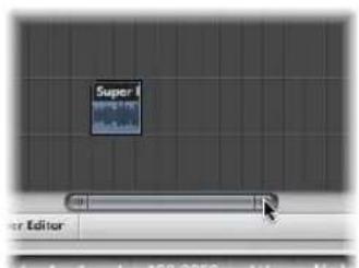
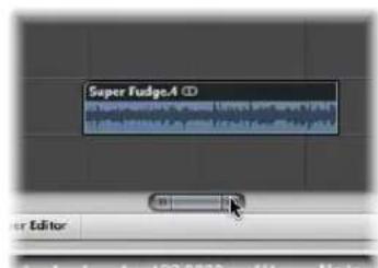
As you drag, the window contents will be zoomed.
Zooming the Waveform of Audio Regions
The Arrange area offers a unique Waveform Zoom tool, found to the left of the horizontal zoom slider. This allows you to visually resize the waveform, making it easier to determine hit points, which can be useful for some editing tasks.
To zoom the waveform of audio regions:
1 Click-hold on the Waveform Zoom button, and a slider is shown.
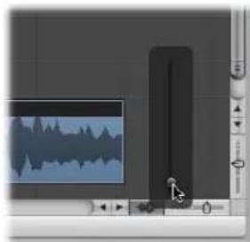
natural_image
Software interface showing audio editing with a waveform display and control panel (no readable text or symbols)2 Drag the slider, and as you do so, the waveform shown in all audio regions is increased or decreased in size.
An active Waveform Zoom button is displayed in dark gray. Click it to switch off the Waveform Zoom display.
Note: This is a purely visual function. The amplitude (level) of the waveform is not affected.
Storing and Recalling Zoom Settings
You can store three different zoom settings for each window via use of the Save as Zoom 1–3 key commands. Use the Recall Zoom 1–3 key commands to recall your zoomed settings. These commands only apply to the active window or window area.
Zooming in on One Section of the Screen
To enlarge a section of the screen to fill the whole window, rubber band select the desired area with the Zoom tool.
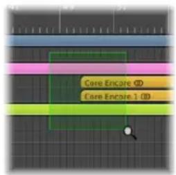
You can do this repeatedly, if you need to zoom in further.
Tip: You can access the Zoom tool when other tools are selected by holding Control-Option.
Reverting to the Previous Zoom Setting
Click on the window background with the Zoom tool. This will return the zoom level to the original setting, or will backtrack through previous zoom steps if the tool was used multiple times.
Zoom Navigation Key Commands
You can set, and recall, up to thirty zoom level and window scroll-bar positions for each window. These allow you to navigate through a number of window zoom levels, and scroll bar positions, making repetitive editing tasks much faster.
You can use the following commands to zoom selected events, or a region defined by the locators, to fit the screen. The use of all zoom commands creates a new step in the navigation path.
- Zoom to fit Selection vertically and horizontally, store Navigation Snapshot: Displays the current selection as large as possible, and saves it in the navigation path.
- Zoom to fit Selection horizontally, store Navigation Snapshot: Displays the current selection as large as possible horizontally, and saves it in the navigation path.
- Zoom to fit Locators, store Navigation Snapshot: Displays the current locator area as large as possible, and saves it in the navigation path.
The navigate key commands allow you to recall the previous or next zoom settings.
- Store Navigation Snapshot: The current zoom and scroll bar (window position) settings are saved as a step in the navigation path.
- Navigation: Back: Recalls the previous step in the navigation path.
- Navigation: Forward: Advances to the next step in the navigation path.
As an example of where the navigation path commands could be useful, imagine cutting and pasting sections of an audio region to several other locations, in a project with hundreds of tracks. One step in your navigation path would be a zoomed view of the audio region. Another step could be a vertically zoomed in version of several tracks (the target tracks for the pasted region sections). A further step could be a horizontally zoomed out section of the project, allowing you to paste the region segments to a later position.
Note: There are no default key commands for most of these navigation options, so you will need to assign them in the Key Commands window. Choose Logic Express > Preferences > Key Commands and type "nav" in the Find field. This will display the entries described above. For more information about assigning key commands, refer to "Assigning Key Commands to Computer Keys" on page 166.
Relationships Between Windows
Logic Express allows you to independently link or unlink windows, providing you with flexible viewing options. This enables you to set up two Event List windows for example, with one showing Arrange regions, and the other showing the contents of the regions. You can simply click on the desired region name to update the contents of the second event list.
The two buttons at the top left of most windows determine its relationship to:
• The playhead position (Catch)
- Other windows (No Link, Same Level Link, or Content Link)
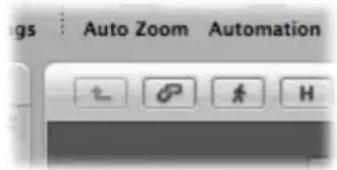
Catch
Enable the Catch button to ensure that the visible section of a window follows the playhead during playback or recording.
If the button is disabled, the display does not update, even when the playhead moves past the right edge of the visible portion of the window.
The "Catch when Logic starts" (Logic Express > Preferences > Global > Catch) option enables Catch mode whenever you press Play or Pause.
The "Catch when moving playhead" preference enables Catch mode whenever you move the playhead.
Scroll in Play
The View menus of all windows that display time horizontally (Arrange area, Score Editor, Piano Roll Editor, and Hyper Editor) offer the View > Scroll in Play setting. If the Catch function of the window is also activated, the playhead will remain in the middle of the window, while the background scrolls smoothly from right to left.
No Link, Same Level Link, and Content Link Modes
These display options allow you to define how information is shown when working with related editor windows.
To set any of these modes:
■ Control-click (or right-click) the Link button, and choose the required mode from the menu.
- No Link: Unlinks the window from others.
- Same Level Link: When activated in a given window, this window always displays the same contents as the key focus window. The display updates whenever the selection (of data) in the key focus window changes. Here's an example: Imagine the key focus window is a Piano Roll Editor. In Same Level Link mode, the Score Editor and Event List will display the same data in another form.
- Content Link: This mode results in the window always showing the contents of the region selected in the key focus window. The display is therefore always one level below that of the top window. Here's a Content Link example: If the Arrange area is the active window, any opened MIDI editor window will show the events of the selected MIDI region. Selecting a different MIDI region in the Arrange area will update the display of the linked editor to show the contents of the newly-selected region. You could also use Content Link mode in one Arrange area, to display the folder contents of another Arrange area.
Tip: You can also quickly switch between these modes by clicking the Link button: clicking it once switches between No Link and Same Level Link mode. Double-clicking the Link button switches to Content Link mode.
The symbol on the Link button reflects the chosen display mode:
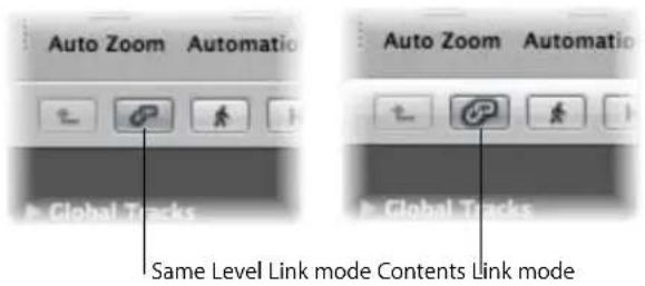
Content Catch Mode
Content Catch mode is commonly used in the Arrange area, with linked MIDI editor windows updating to show the events within the MIDI region that is currently being played (on the selected Arrange track).
Initially, this is equivalent to Content Link mode, but when the playhead reaches the next region on the same track, the contents of this region are then displayed.
To enable Content Catch mode:
1 Click the Catch button to turn it on.
2 Control-click (or right-click) the Link button, and choose Content Link mode.
Customizing the Transport Bar
You can customize the Transport bar by adding or removing buttons and displays, allowing access to the functions you need most often. This in turn, has an impact on the size of the Transport window. You can also open an independent SMPTE or Bar display window. For more information, refer to "Customizing the Transport Bar" on page 116.
Customizing the Arrange Window Toolbar
You can customize the Toolbar by adding buttons for the commands you use most often. You can also configure the display to show only the button's icons, or only their labels.
To add a button to the Logic Express Toolbar:
1 Control-click (or right-click) the Arrange window Toolbar, and choose Customize Toolbar from the shortcut menu.
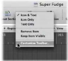
2 Drag the buttons you want to add from the Customize Toolbar dialog to any empty area along the top of the window.
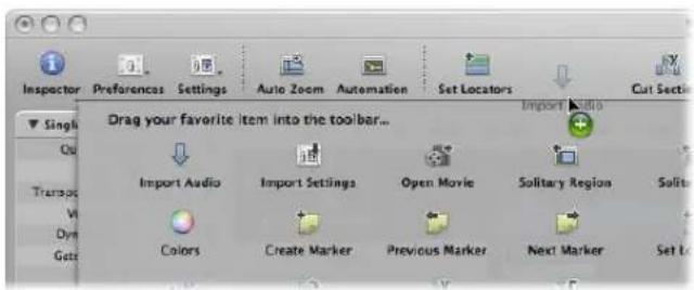
If you drag a button to a location between two existing buttons, they will move to make space for the new button.
Note: You may also choose to drag the entire default set from the bottom of the Customize Toolbar dialog, if your customizations don't work out as well as you'd hoped.
3 Click Done when finished.
To remove a Toolbar button:
■ Control-click (or right-click) the desired button, then choose Remove Item from the menu.
To change the appearance of Toolbar items:
- The shortcut menu and Show menu in the Customize Toolbar dialog also allow you to view Toolbar items as Icon & Text, Icon Only, or Text Only. Simply choose the preferred viewing option.
When you resize the Arrange window, the Toolbar may not offer enough space to keep all buttons visible.
To keep a Toolbar button visible when you resize the Arrange window:
■ Control-click (or right-click) the desired button, then choose Keep Item Visible from the menu.
Hiding or Revealing the Inspector
You can hide the entire Inspector area to the left of the Arrange and editor windows, providing more workspace for regions, events, and other data.
To hide or show the Inspector in the Arrange window, either:
- Click the Inspector button in the Toolbar.
- Choose View > Inspector (or use the Hide/Show Inspector key command).
To hide or show the Inspector in the editing windows:
- Choose View > Inspector (or use the Hide/Show Inspector key command).
If there is not enough vertical room to display all areas of the Inspector, you can click the disclosure triangles to hide the individual boxes.
Adjusting the Bar Ruler Display
You can switch the Bar ruler between four display modes:
• Time: Displays a SMPTE time ruler, divided into hours, minutes, seconds, and frames.
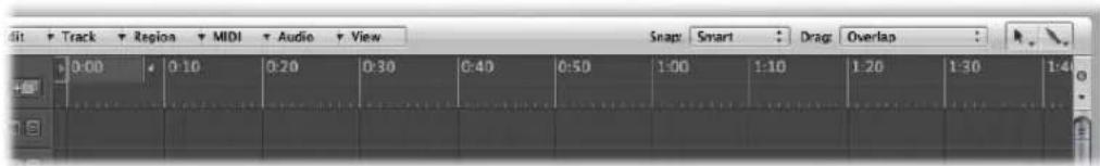
- Bar: Displays a Bar ruler, divided into bars, beats, divisions, and ticks. Dependent on the zoom settings (see "Zooming" on page 68), the bars are shown at the top edge in units of 1, 4, 8, or 16. Time signature changes are also shown here. In the bottom third, there is a vertical line for each bar. The shorter lines represent one beat, but are not always visible (depending on the zoom setting).
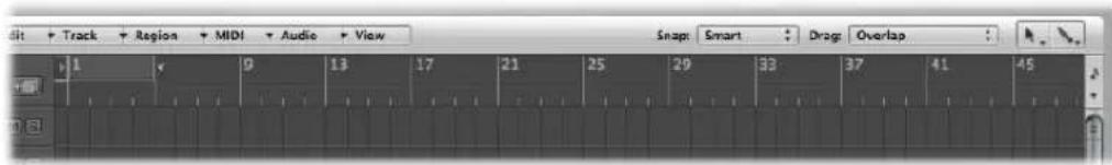
- Bar and Time: Displays the Bar ruler above the SMPTE ruler.
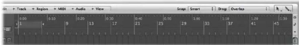
• Time and Bar: Displays the SMPTE ruler above the Bar ruler.
To set the Bar ruler display mode:
- Click on the small down arrow icon to the right of the Bar ruler, and choose the desired display mode in the shortcut menu.
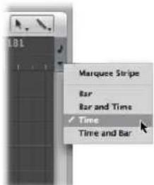
The Marquee Stripe setting hides or shows the marquee stripe—a tool used for selection tasks. For further information see "Selecting Parts of a Region" on page 320.
You can also use the following key commands to switch the ruler display:
- Event Position and Length in SMPTE Units: Switches between the Bar and SMPTE ruler if one ruler is displayed, and switches the position of the Bar and SMPTE ruler if both are displayed.
• Secondary Ruler: Switches the display of the second ruler.
Displaying Global Tracks
All linear editing windows can display global tracks just below the Bar ruler. You can limit the display to particular global tracks, resize, and move them.
To hide or show global tracks, do one of the following ways:
- Click the Global Tracks disclosure triangle to the left of the Bar ruler.
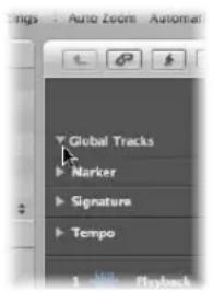
-
Choose View > Global Tracks (or use the Toggle Global Tracks key command).
■ Use one of the following key commands: -
Hide All Global Tracks
• Show All Global Tracks
Showing and Hiding Individual Global Tracks
By default, the global Marker, Signature, and Tempo tracks will be visible when you use any of the methods above to open the global tracks lanes.
To hide or show particular global tracks:
1 Do one of the following:
- Control-click (or right-click) anywhere in the global tracks header area, and choose Configure Global Tracks from the shortcut menu.
- Choose View > Configure Global Tracks (or use the Configure Global Tracks key command).
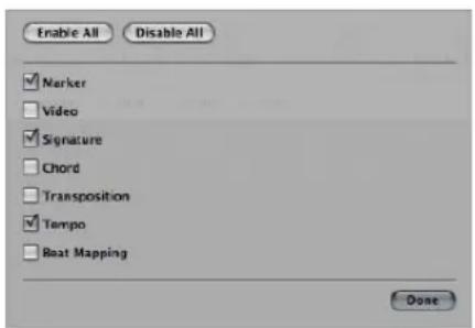
2 Do one of the following in the Configure Global Tracks dialog:
- Click the corresponding checkboxes to display or hide each global track type.
- Click the Enable All or Disable All buttons to show or hide all global tracks, respectively.
The choices made in the Configure Global Tracks dialog only affect the active window. Each window can have an independent global track display configuration.
Note: You can also assign, and use, any of the following Toggle key commands for each individual global track: Marker, Transposition, Chord, Signature, Tempo, Beat Mapping, and Video. This will have an immediate impact, and will not open the Configure Global Tracks dialog.
Resizing and Moving Global Tracks
You can resize global tracks individually, and can resize the entire global tracks area.
To resize individual global tracks, do one of the following:
- Click the disclosure triangle in the upper left corner of each global track.
The track height is expanded and additional controls become visible. A further click on the triangle reduces the track height.
- Position the mouse pointer over the lane dividers between global tracks in the header area, then drag up or down.
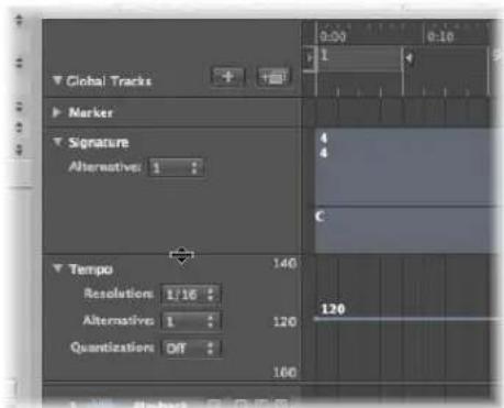
To resize the entire global tracks area:
- Position the mouse pointer over the dividing line between the global tracks and the Arrange tracks, then drag up or down.
To change the order of global tracks:
- Grab anywhere (except on the control elements) in the header area of the global track you want to move, and drag up or down.
The display order of global tracks is saved independently for each window.
Tip: If the Track Protect buttons are visible (View > Configure Track Header > Protect Buttons), you can prevent unintentional changes to individual global tracks by clicking on the corresponding Protect button.
Using Screensets
You will position windows in a way that suits your working methods. This layout of various windows, including the display size, zoom levels, and position of each window (and other settings) is called a screenset. Once defined, you can save, and freely switch between different screensets, much as you might swap between different computer monitors.
Saving and Recalling Screensets
Screensets are numbered from 1 to 99 (using only the 1 to 9 computer keys—the 0 key is assigned to the Stop command by default).
You don't need to save screensets with an explicit command. It happens automatically, as soon as you switch to another screenshot. Thus, without any effort, your current working view is always stored as the current screenshot.
To create a screenset:
1 Press a numerical key, say 7.
For two-digit screensets, hold down Control while entering the first digit.
2 Arrange your windows as desired, including changes to zoom settings, relationship of the Arrange area and editor areas, open or closed Inspector and Media or Lists areas, and so on.
Note: When you choose a screenshot number that has not been saved, a maximized Arrange window opens.
To recall, or switch between screensets, do one of the following:
■ Input the number of the desired screenset (1 to 9).
For two-digit screensets, hold down Control while entering the first digit.
- Choose the desired screenshot from the Screenshot menu.
■ Use the Next Screenshot or Previous Screenshot key commands.
Recalling Screensets 1 to 9 via Key Commands
Screensets 1 to 9 can be recalled by freely-defined key commands, not only the number keys on your computer keyboard. This allows you to use the number keys for other purposes, such as opening or closing windows. The 1 to 9 key commands are called Recall Screenshot 1 (... 9, respectively) in the Key Commands window.
Sequencer Controlled Screenshot Switching
You can automatically switch screensets through the use of meta event # 49—just add it to a MIDI region in the Event List.
To switch a screenset automatically:
1 Select the MIDI region into which you want to insert the meta event.
2 Set the playhead to the point where you'd like the screenset to change.
3 Click the Create button in the Event List, then click the Meta Events button.
The inserted meta event has a default value of 50 (Project Select).
4 Alter the number in the Num column from 50 to 49.
This changes the name to screenset.
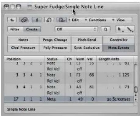
5 Input the desired screenshot number in the Val column.
You can stop screenset switching by muting the MIDI region that contains the meta 49 event.
Protecting, Copying, Renaming, and Deleting Screensets
Logic Express allows you to protect, copy, rename, and delete a screenshot, making it easy to manage screensets.
To prevent the current screenset from being altered:
- Choose Screensets > Lock Screenshot (or use the Lock/Unlock Current Screenshot key command, default: Shift-L).
A bullet appears in front of the screenset number to indicate that it is locked. Reuse the key or menu command to unlock the screenset.
Important: The File > New command deactivates all screenset locks.
To copy screensets:
1 Switch to the screenshot you would like to copy, and choose Screensets > Duplicate (or use the corresponding key command).
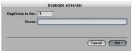
2 In the Duplicate Screenshot window that opens: Type in the target screenshot number (the screenshot number that you want to copy to), and enter a name.
To rename the current screenset:
- Choose Screensets > Rename (or use the corresponding key command), and type the desired name in the Rename Screenshot window.
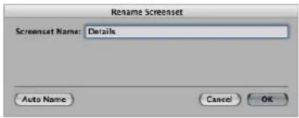
Click the Auto Name button to automatically name the screenset. This defaults to the visible window names ("Arrange/Piano Roll" or "Arrange/Mixer" as examples). The name is automatically updated whenever a window or view is opened or closed.
To delete the current screenset:
- Choose Screensets > Delete (or use the corresponding key command).
Importing Screensets From Another Project
You can import screensets from another project.
To import all screensets from another project:
1 Open the Import Settings window by doing one of the following:
- Choose File > Project Settings > Import Settings (or use the Import Settings key command).
- Click the Settings Toolbar button, then choose Import Settings from the pop-up menu.
2 In the Import dialog, click the Screensets option.
3 Browse to, and select, the desired source project (the one that you wish to import from).
4 Click Open (or double click on the source project name).
The settings are imported into the active project.
Reverting to Saved Screensets
The Revert to Saved Screenshot (or the corresponding key command) resets your screen to its original state—prior to changing any aspect of the current screenshot.
Setting Up Your System
4
Logic Express automatically finds and configures supported audio and MIDI hardware when first installed and run. There are many circumstances where you may wish to enhance or extend this basic automatic configuration.
This chapter will help you to optimize your hardware for use with Logic Express. It also includes a lot of background information about components your music production system can incorporate. If you're new to Logic Express, and would like to get "hands on" with the application, please skip ahead. You can always return to the following sections when considering the addition of a device to your system, but this isn't essential to know before using Logic Express.
Designing Your Music Production System
Your music production system can incorporate far more than your computer and Logic Express software.
A complete Logic Express studio could conceivably consist of any, or all, of the following components:
- A Macintosh computer and related peripherals, such as a mouse or other pointing device, keyboard, displays, and so on
• Audio and MIDI interfaces
• External MIDI sound generators, such as samplers and synthesizers - External audio devices, such as mixers, audio converters, pre-amplifiers, channel strips, effects units, and more
-
External MIDI control surfaces and keyboards. Even external MIDI-controlled lighting can be driven by Logic Express.
• Amplification and speakers -
Additional software that runs alongside, and integrates with, Logic Express. This includes a range of ReWire applications and audio or MIDI software.
- Additional effect and instrument plug-ins, including those that are DSP-accelerated, such as PowerCore.
Read this section if considering components that you want to integrate into your Logic Express music production system. If you already have all components, and their integration meets your needs, feel free to skip this section.
Computer
This section outlines several computing factors that you should consider for your Logic Express system. System requirements are covered in the Before You Install document, found in the Documentation folder of the Logic Express installation discs.
Note: System requirements may change between Logic Express releases, so you should always check the Apple website and the latest Before Your Install document included with Logic Express updates.
How Fast Your Computer Should Be
Audio processing is complex, so the general rule is: the more powerful your computer, the better. This involves not only the speed of the CPU(s) of your Macintosh, but also includes larger main memory sizes, the speed of busses, and the general efficiency of communication with connected devices.
A Portable or Fixed Studio?
You may be wavering between a desktop or portable Macintosh as the basis for your Logic Express system, or perhaps considering the viability of a laptop machine for on-the-road composition. The good news is that portable Macintosh computers are ideal for Logic Express use. They offer excellent audio and MIDI hardware expansion capabilities in the form of FireWire and USB connectors, and are fast enough to allow extensive software instrument and effect use. Due to the power-saving nature of portable computers, slower hard disk drives are usually included, resulting in a lower track count than is possible with a desktop equivalent.
Obviously, desktop computers offer additional expansion slots, extending the range of MIDI and audio hardware possibilities, and can incorporate multiple processors. CPU and hard disk speeds are generally higher, thus allowing higher track playback counts, and the simultaneous use of more software instruments and effects.
Tip: If you have both a portable and desktop Macintosh, you can easily transfer projects and other data between them.
Hard Drives and Storage Locations
Music production generates a huge number of large files. These include samples for audio instruments, loop libraries, audio recordings, video files, and more.
Consider buying a separate, large capacity hard drive (or several) for your audio files and sample libraries.
You should also look at a reliable, high-capacity backup system, and should automate your backup routine, preferably as a daily occurrence.
Audio and MIDI Interfaces
An audio interface is required—to get sound signals into, and out of, your computer. A MIDI interface is required for MIDI input and output signals.
When using optional audio and MIDI interfaces, you should install their drivers before starting Logic Express. This will allow Logic Express to find and use these devices at startup.
Audio interfaces should be supported by a Core Audio driver and MIDI interfaces should be supported by a Core MIDI driver. Check with the manufacturer of your equipment for details on Mac OS X support.
Audio Interface
When an analog audio signal arrives at the inputs of your audio interface, it must be converted into digital information before the computer can deal with it. This process is called analog to digital conversion and is handled by the analog to digital converter of the audio interface.
There are countless optional audio interfaces available, and at least as many ways that they can be set up and used with Logic Express and external audio gear. Given the differing requirements and working methods of people across the world, there is no one size fits all audio interface solution. In the simplest scenario, you would use the internal audio interface of your computer to monitor and record audio.
When choosing an audio interface, ensure that it is certified to run on Macintosh hardware. If the device requires a driver, check that it is compatible with the Mac OS X version required by Logic Express.
Logic Express supports input from digital audio interfaces up to a maximum sample rate of 192 kHz, and a maximum bit depth of 24 bits.
Full details on setting up your audio interface hardware, including information on optimizations, drivers, and more can be found in "Configuring Your Audio Hardware" on page 99, and the topic areas that follow this section.
MIDI Interface
Your Macintosh computer does not provide MIDI in or outputs. If you want to use MIDI devices equipped with MIDI ports, a MIDI interface is required for communication with your computer. MIDI interfaces are generally connected to your Macintosh USB ports. Some MIDI interfaces require the installation of driver software, and others are automatically recognized by your Macintosh.
Note: Many modern MIDI devices, particularly keyboards, include a USB or FireWire connection port that enables MIDI (and audio, in some cases) communication with your computer. Such devices do not require an additional MIDI (or audio) interface. Some require the installation of driver software, and others are automatically recognized by Mac OS X. Check the websites of MIDI device manufacturers for further information.
Types of MIDI Devices
A vast array of MIDI equipped devices exist. These include MIDI keyboards and sound modules, control surfaces, effect processors, mixers, lighting controllers, and more.
MIDI Keyboard
The most likely candidate for inclusion in your Logic Express system will be a MIDI keyboard. MIDI keyboards are used to input note (and controller) information into Logic Express. Some MIDI keyboards are simply input devices (often called controller keyboards) and some also include their own synthesis engines (synthesizer and sampling keyboards). Logic Express can be used to record keyboard performances as MIDI data, and can play them back through any connected MIDI device or internal software instrument.
If you don't have a MIDI keyboard handy, don't fret! Logic Express offers the Caps Lock Keyboard, which allows you to use the computer keyboard for MIDI note entry. See "Using the Caps Lock Keyboard" on page 407.
Control Surfaces
Control surfaces are hardware devices that feature a variety of controls, which can include faders, rotary knobs, switches, and displays. These controls can be mapped to functions in Logic Express, allowing you to change parameters with more precision and speed than is possible when using your mouse and computer keyboard. You can also control multiple parameters at the same time. Detailed information on the setup and use of control surfaces can be found in the Control Surfaces Support manual.
Synthesizers and MIDI Controlled Effects
Logic Express provides plenty of software instruments and effects, and can also act as a host for Audio Unit plug-ins from other manufacturers. More information on the use of plug-in instruments and effects can be found in Chapter 10, "Working With Instruments and Effects," on page 215.
You can also incorporate hardware MIDI instruments and MIDI controlled effects units to your Logic Express music production system. These are connected via a MIDI interface, using MIDI cables (see "Connecting Your Audio and MIDI Devices" on page 90).
MIDI controlled effects units do not process MIDI data. Rather, they are audio processors (such as reverb or multi-effect devices) that can be controlled via MIDI messages. This allows you to automate the parameters of these devices—such as delay time or flanger speed—from Logic Express.
Typically, you would connect all external devices, such as synthesizers and MIDI controlled effects units, to either your audio interface or a hardware mixing console. MIDI controlled effects units would be connected in a send/return loop, using either:
- A pair of audio ins and outs (or auxiliary in/out, if available) on your audio interface
- An auxiliary in/out (sometimes called FX send/return) pair on your mixing console
Both methods allow the use of Logic Express's In/Out plug-in, enabling you to freely route audio information through the external effects unit—and the MIDI connection provides control over the effects parameters. In many ways, this is much like using one of Logic Express's internal effect plug-ins.
Note: It is only practical to use the In/Out plug-in for external device routing when you're using an audio interface equipped with multiple in and out ports.
Both MIDI instruments and effects will allow remote patch (preset) selection from Logic Express. This (and control) information can be stored as part of Logic Express project files, ensuring perfect playback from your MIDI devices the next time the project is loaded.
Ancillary Audio Devices
No discussion of a Logic Express audio system would be complete without covering a number of options that you should seriously consider, in order to make the most of the application.
Audio Playback System
Your audio interface provides inputs and outputs between the real world and your computer. When performing audio playback, the audio interface translates computer data into something you can hear and understand—sound and music.
To facilitate this, an amplifier and speakers are required. You can certainly use headphones, connected to the headphone jack of your audio interface, or the home hi-fi to monitor Logic Express playback, but this is not recommended in the long term.
You should look at a dedicated set of reference monitors (speakers), and a matching reference amplifier. Many monitoring systems today have powered speakers, negating the need for a separate amplifier.
Note: Reference monitors are specially designed speakers that offer a flat frequency response across a wide range (usually 20 Hz to 20 kHz). These are not your average home hi-fi speakers, and are usually only available from professional music and studio equipment dealers.
This type of system is recommended due to the precision it offers. Logic Express is capable of delivering CD or higher quality audio, and creating your mixes on a home hi-fi will generally result in music that is not properly balanced.
Put another way, most home hi-fi speakers tend to enhance particular areas of the frequency spectrum, resulting in mixes that have too much bass, mid, or treble frequency when played back on other systems. Reference monitors and amplifiers are designed to provide a flat frequency response, avoiding emphasis of particular areas of your mix. This translates to a final product that will sound good (or at least, passable) on most monitoring systems—car stereos, home hi-fis, portable players, and so on.
Headphones
A good set of studio headphones is handy for particular tasks, such as precise EQ-ing and sample editing. Given the design of most headphones, and the fact that they're used so close to the ears, most people find that headphone mixes tend to be too bright or too bass-heavy.
As such, they are not recommended for general monitoring duties, but they are useful tools nonetheless. If you are recording groups of people, you will probably need several pairs of headphones, a headphone distribution amplifier, and a mixing console.
Tip: You should not use headphones for longer than ten or twenty minutes at a time, as they can cause listening fatigue, resulting in you making poor choices for your mix.
Audio Mixing Consoles
The inclusion of an audio mixer—analog or digital—is heavily based on your typical studio use. It is also dependent on the number of inputs and outputs provided by your audio interface and your working preferences.
To explain, if you are most likely to record bands, several MIDI synthesizers, or drum kits in your studio, you will need numerous microphone and line-level inputs to simultaneously record the performances of the musicians and vocalists in the group.
Microphone inputs differ from line level inputs in that they provide power (known as phantom power), which is used to amplify the incoming signal from condenser microphones.
Multiple mixer outputs and a headphone distribution amplifier are also beneficial in group recording situations, as different signals can be sent to each performer. As examples: a click track to the drummer, a light drum mix and click track to the bass player, a composite mix to the vocalist and guitarist, with a touch of reverb for the singer, and so on. This different strokes approach is commonly used, as it facilitates the best performances from each group member.
Mixers can also include several auxiliary or bus channels that can be used to simplify a number of jobs. As examples, sending different signals (or mixes, if you like) to multiple locations—such as a front of house P.A. and a multitrack recorder, adding individual effects to multiple channels, re-routing processed audio back to a different position in the signal path and much more.
Many of these mixing tasks can be performed with a multi input/output audio interface—using Logic Express (and the interface control software, if applicable) to adjust levels and routings. The catch-22 with this is twofold: it is not as immediate as physically moving a slider or knob on a mixing console, and your computer generally needs to be turned on, to allow control. To balance the equation, you can add a control surface to your Logic Express system, enabling hands-on operation. On the latter point, a number of current audio interfaces can be used in standalone mode, but the problem of level control remains unless the computer is turned on.
Microphones
If you are recording acoustic performances—spoken, sung, or played—into Logic Express, you need one or more microphones. The array of microphones available these days is mind-boggling, but to simplify things, they basically fall into two categories: condenser and dynamic.
- In general terms, condenser microphones are more sensitive, and are commonly used for vocal recording. They are also used for ambience recording, and for instruments such as guitars and woodwinds.
- Dynamic microphones are often used for recordings with high sound pressure levels (loud signals, in other words), such as drums and percussion.
Ultimately, either microphone type can be used for any recording job, but each will offer a distinct advantage—sonically—in different recording situations. To further clarify, both condenser and dynamic microphones come in a variety of forms, with many specifically designed for the recording of certain instruments. As such, there's no one size fits all microphone for every recording you will make, so purchasing or hiring several microphones for different projects is advisable.
Note: Condenser microphones require power to function. This can be provided by a separate pre-amplifier or a phantom powered mixing console.
Connecting Your Audio and MIDI Devices
You need to connect your external audio and MIDI devices to your computer to allow communication between Logic Express and the devices. The following section introduces you to Macintosh expansion capabilities, audio and MIDI cabling, and other things you should consider when connecting audio and MIDI interfaces to your system.
Computer Expansions
Current Macintosh computers offer the following expansion capabilities, which can be used for audio and MIDI interfaces:
- FireWire
- USB
• PCI
- ExpressCard
Note: Data transfer rates discussed in the following sections are theoretical maximums. In real-world use, this will be reduced due to system overheads. In general, protocols with faster theoretical maximums will deliver data more quickly than slower protocols.
FireWire (IEEE 1394)
FireWire is a professional and consumer standard that can be used for both audio and MIDI devices, plus hard disks and other peripherals. It combines fast data-transfer rates, high storage capacities, and plug-and-play connection. All current Macintosh computers offer FireWire connectors, and a number of FireWire audio and MIDI interfaces are available. FireWire 1.0 transfers data at 400 MBits per second. FireWire 2.0 transfers data at 800 MBits per second.
There are two kinds of FireWire connectors: a 4-pin connector (typically found on video equipment, such as camcorders) and a 6-pin connector (used for computer and audio equipment).
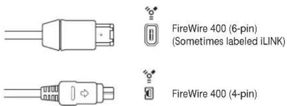
USB (Universal Serial Bus)
USB is a consumer standard used for computer peripherals and other devices. USB 1.1 offers a much lower data-transfer rate than FireWire (11 Mbits per second). USB 2.0, however, transfers data at 480 MBits per second. It supports plug-and-play operation and the ability to connect several devices in sequence (daisy-chaining). Some USB devices draw their power over the USB cable, while others require a separate power connection. USB 2.0 ports are included on all current Macintosh computers.
There are two kinds of USB connectors:
- A connector, typically used to connect a device to a USB hub.
- B connector, typically used to connect devices together, and also to connect a device to a computer.
Note: USB audio interfaces should always be directly connected to your computer, not via a hub or to the computer's display, keyboard, or another peripheral.

PCI
PCI (Peripheral Component Interconnect) interfaces, unlike FireWire and USB interfaces, require the installation of a dedicated card in your computer. PCI provides extremely high bandwidth and fast data-transfer rates, allowing you to record and play back large numbers of files at the highest possible sample rates and bit depths.
ExpressCard
ExpressCard is an updated version of PC Card (PCMCIA) or CardBus, found on MacBook Pro computers. ExpressCard is much like the PCI interfaces described above, but the cards slide into a slot on the outside of your notebook. Express Cards and PC Cards available include audio interfaces, hard disks, networking, and SCSI interfaces, wireless adapters, and more.
Audio Cabling
The following types of audio cables and connectors are usually used on professional and consumer audio equipment:
• XLR
• 1/4-Inch audio and 1/8-Inch miniplug
- RCA (Cinch)
- Toslink
- AES-EBU, S/PDIF, ADAT
XLR
XLR cables and connectors are used on professional-quality microphones, monitors, and other musical equipment. They provide a high-quality, balanced signal at a +4 dB level.
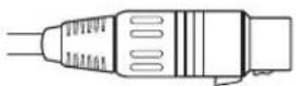

XLR connector (balanced)
1/4-Inch Audio
1/4-inch connectors (sometimes called phono or phone plugs) are used on a wide variety of professional and consumer musical equipment, including musical instruments and amplifiers, speakers, and external effects devices. They can be either balanced or unbalanced. Some devices require Tip-Ring-Sleeve (TRS) connectors. These three-contact connectors are used for balanced mono signals and unbalanced stereo signals.


1/4-inch Tip-Ring Sleeve (TRS) connector


1/4-inch Tip-Sleeve (TS) connector
1/8-Inch Miniplug
Miniplug connectors are used for audio input and output to computers, and on some consumer electronic devices, particularly portable ones.
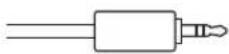

Stereo miniplug connector (unbalanced)
RCA (Cinch)
RCA connectors are used on consumer audio equipment such as home stereo systems and video cassette recorders.

RCA connector (unbalanced)
AES/EBU, S/PDIF, and ADAT
The AES/EBU, S/PDIF, and ADAT protocols provide a digital connection between professional and consumer audio equipment, including audio interfaces, DAT (digital audio tape) machines, mixing consoles, hardware samplers, and more.
Toslink optical digital connector
S/PDIF and AES/EBU provide two channels of audio, and ADAT optical provides eight channels of audio. You can use optical TOSLINK connectors to carry digital audio streams between S/PDIF and ADAT components.
Connecting Your Audio Interface
Logic Express supports plug and play for audio interfaces, making it possible to connect and switch on a new audio interface while Logic Express is running. An alert appears when you connect a new device, and will prompt you to select and confirm the audio interface and driver that you would like to use.
All digital audio interfaces can be susceptible to latency—a noticeable delay between the time the audio signal is produced, and when you hear it. You should always attach your audio interface directly to the computer, rather than through a hub, or daisy-chaining it through another device. Doing so can cause an unacceptable amount of latency, particularly with slower USB 1.1 devices.
MIDI Cabling
MIDI is an abbreviation for Musical Instrument Digital Interface—a universal 5-pin connection standard and computer language—that allows communication between MIDI devices.

MIDI Connector
Connecting Your MIDI Keyboard and Modules
If using a simple MIDI master keyboard, without internal tone generation facilities, you only need to connect the MIDI Out port of the keyboard to a MIDI In port on your MIDI interface—using a MIDI cable.
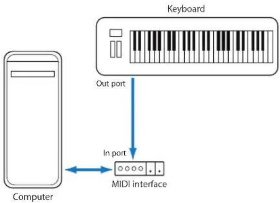
flowchart
graph TD
    A["Computer"] -->|Out port| B["Keyboard"]
    B -->|In port| C["MIDI interface"]
    C <--> A
If the keyboard can generate its own sounds, you should also connect the MIDI Out port of the MIDI interface to the keyboard MIDI In port. If your MIDI interface offers more than one MIDI output, connect any other tone generators (or other MIDI devices, such as control surfaces that require bi-directional MIDI communication) to these.
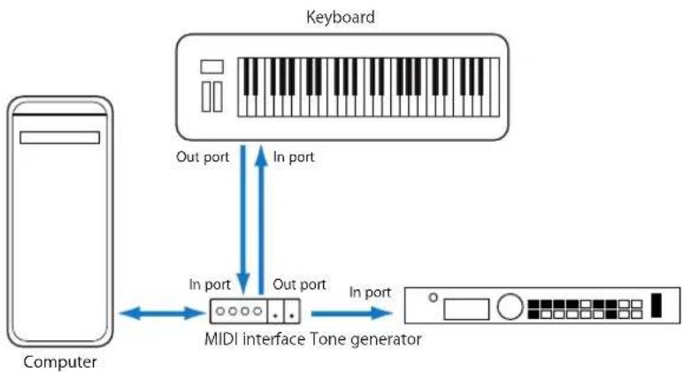
flowchart
graph TD
    A["Computer"] -->|In port| B["MIDI interface Tone generator"]
    B -->|Out port| C["Keyboard"]
    C -->|In port| B
    B -->|Out port| A
If the MIDI interface connected to your computer only offers one MIDI output, you need to connect the MIDI In of the second tone generator to the keyboard MIDI Thru port. A third device can be connected to the MIDI Thru of the second unit, and so on.
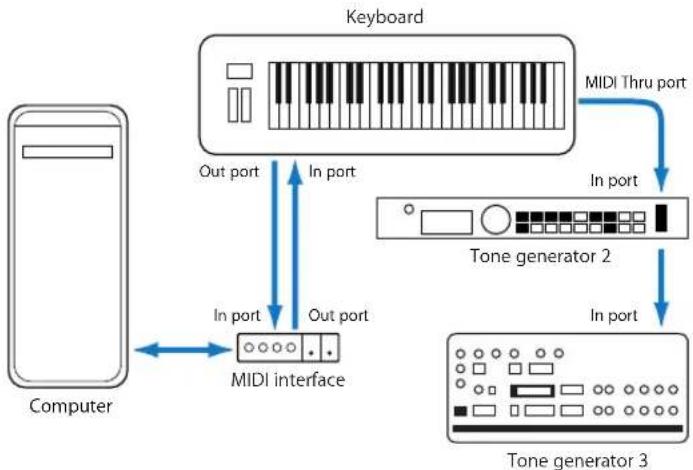
flowchart
graph TD
    A["Computer"] -->|In port| B["MIDI interface"]
    B -->|Out port| C["Keyboard"]
    C -->|In port| D["Tone generator 2"]
    D -->|In port| E["Tone generator 3"]
    C -->|MIDI Thru port| D
The MIDI Thru port replicates the signals coming into the MIDI In port of the device. It is preferable to use a direct connection from the computer MIDI Out to a device, rather than chaining too many units, one after the other. Doing so can cause timing problems in the chain, if numerous MIDI commands are sent quickly. This is due to the slight delays introduced by each MIDI In to MIDI Thru transaction. As such, a multi input/output MIDI interface is recommended in studios with several MIDI tone generators and controllers.
Using Multi-Channel MIDI Devices
Most modern MIDI tone generators can simultaneously receive MIDI data on multiple MIDI channels (multi-timbral MIDI devices). Each MIDI channel can be assigned a tone/sound, such as piano, strings, bass, and so on.
To take full advantage of the capabilities of each connected multi-timbral device, you need to use separate MIDI Out ports (from the computer MIDI interface to the MIDI In ports) for each device. To explain further, imagine a scenario where:
- There are four MIDI tone generators that are capable of receiving data on multiple channels.
- All devices can receive on all 16 MIDI channels
- There is only one MIDI Out from the computer, and all devices are daisy-chained via MIDI Thru to MIDI In connections
Logic Express is capable of channelizing MIDI data (routing it to MIDI channels 1 to 16) and is also capable of sending this channelized data to specific MIDI Out ports. Unfortunately, in the scenario above, there is only one MIDI Out port available.
As such, all data sent on MIDI channel 1 will be sent to all four of the daisy-chained MIDI tone generators. Each MIDI tone generator will play the incoming data with the sound assigned to channel 1, which may be:
- Bagpipes on module 1
• A drumkit on module 2
• A helicopter effect on module 3 and so on
While this would be colorful, it would hardly be musical, unless your tastes lean towards the avante-garde. The same applies to the other 15 MIDI channels.
MIDI, as you can see from the example, can be separated onto 16 different channels, but it can't be separated between devices, unless a multi output MIDI interface is used.
Using the scenario above, but substituting a single output MIDI interface with a 4 output MIDI interface—connected from MIDI Out ports A, B, C, and D—to the respective MIDI In ports of each device. There are no MIDI Thru connections, which allows Logic Express to assign and send:
- A recording/performance on MIDI channel 1 to port A/module 1.
- A separate recording/performance—also on MIDI channel 1—can be sent to port B/module 2.
- A further recording/performance on MIDI channel 1 to port C/module 3, and so on with subsequent channels and modules.
In effect, having a multi output MIDI interface is somewhat like having more MIDI channels. In this scenario, it would be like having 64 independent MIDI channels—with 16 channels per port (A, B, C, and D).
Not only does this allow you to play up to 64 different sounds simultaneously through your tone generators, it also allows full MIDI control for each channel of each device. This becomes increasingly important when arranging and orchestrating such a large number of instrument parts.
If your computer offers several MIDI inputs, you can connect the MIDI outputs of other MIDI expanders and controllers to it.
USB MIDI Keyboards
If using a MIDI keyboard fitted with a USB connector, you don't require a separate MIDI interface, as it is already built into the keyboard. Just be sure to install the driver, if needed, and connect the keyboard to your computer with a USB cable. Some modern USB keyboards and controllers are automatically recognized by Mac OS X.
Separating a MIDI Keyboard From Its Sound Generator
If your MIDI keyboard has an internal sound source, it is important that you stop the keyboard from generating sounds directly from its own keyboard.
To explain: If you buy a new keyboard that is to be used without a sequencer, and connect it to an amplifier, you would expect the device to make a sound when you press its keys—in other words, the keyboard is directly connected to the sound generator.
When using the MIDI keyboard with Logic Express, however, this is not desirable. In this situation, the keyboard is used as a computer input device, and Logic Express will pass the incoming performance information back to the keyboard's sound generator (or to an internal software instrument or another connected sound module, if you wish).
If the direct connection between the keyboard and its tone generator isn't cut, this will result in a doubling of each note—one played directly from the keyboard to the internal tone generator, and another sent through Logic Express back to the tone generator.
Not only does this cause a phased sound, but it also halves the polyphony of the keyboard's tone generator. In situations where you want to control or record another sound module or software instrument with your keyboard, you would hear both the keyboard sound (due to the direct keyboard to tone generator connection) and the sound of the software or MIDI instrument. This is why the keyboard must be separated from its own internal sound generator.
This function is known as Local Off, and is set directly on your keyboard. Don't worry about losing the ability to use the tone generator of your keyboard. Logic Express will still be able to communicate with your keyboard tone generator just like any other connected, keyboardless, sound module or software instrument.
Note: If you cannot find the Local Off function in the MIDI menu of your keyboard, consult its manual on sequencer use. Some keyboards allow you to select from: Local, MIDI, or Both for each of their Parts (individual MIDI channels/sounds in multi-timbral MIDI devices). The MIDI setting, if applicable to your keyboard, is the equivalent of Local Off.
Using External MIDI Devices
Logic Express recognizes all MIDI devices set up in the Audio MIDI Setup (AMS) utility, the integrated audio and MIDI configuration tool of Mac OS X. You can find the AMS utility in the Applications/Utilities folder. For more information on use, see the AMS Help.
The Library tab displays all MIDI devices found by the AMS utility (separated into MIDI channels, if multi-channel devices) when an External MIDI track is selected. You can simply select the desired MIDI device/sub-channel to assign it to the track.
You can configure external MIDI devices in the Inspector. For more information, see "Standard Instruments" on page 899, "Multi Instruments" on page 901, and "Mapped Instruments" on page 907.
Using External Audio Effects
If you want to send audio to an external (MIDI controlled) audio effect device, you need to insert the In/Out plug-in into one of the Insert slots of the audio channel you want to process. For further information, see "Working With External Audio Effects" on page 261.
Note: It is only practical to use the In/Out plug-in for external device routing when you have an audio interface equipped with multiple in and out ports.
Configuring Your Audio Hardware
To use particular audio interfaces with Logic Express, the driver for the device needs to be installed, activated, and configured correctly. Drivers are software programs that enable various pieces of hardware and software to be used with Mac OS X. This allows the device to be recognized by applications, such as Logic Express, and enables data routing between software and hardware, in a format understood by both.
Selecting, activating, and configuring a particular audio driver in Logic Express is achieved in the Audio Devices preferences.
To open the Audio Devices preferences, do one of the following:
- Choose Logic Express > Preferences > Audio (or use the Open Audio Preferences key command), then click the Devices tab.
- Click the Preferences Toolbar button, choose Audio from the pop-up menu, then click the Devices tab.
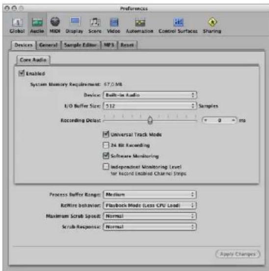
In Mac OS X, all audio devices are accessed via Core Audio, an integral part of the operating system. Core Audio is a high-performance, low-latency audio system that allows audio interface hardware to be used by several applications at the same time.
Logic Express is compatible with all audio hardware that offers a Core Audio driver.
Setting Up Core Audio Devices
Logic Express automatically recognizes any installed Core Audio hardware, and will use the default settings—as defined in the Audio MIDI Setup utility (Applications/Utilities/Audio MIDI Setup). It can, however, be advantageous to optimize the settings for your individual hardware setup, particularly if you use several audio interfaces or a multiple input/output device. This is done in the Logic Express > Preferences > Audio > Core Audio tab.
Enabled
Click this box to enable the Core Audio driver.
Note: In situations where the preferred hardware is unavailable, such as when your audio interface is not connected (or is turned off), Logic Express will automatically select the built-in audio hardware of your Macintosh.
System Memory Requirement
The amount of free RAM required (outside the memory assigned to Logic Express) is indicated here. The requirement value changes as you alter the parameters described below.
Device
Allows you to choose between any installed Core Audio device, including the internal sound hardware. This also includes aggregate audio devices, consisting of several audio interfaces. See the Audio MIDI Setup Help for information on aggregate devices.
I/O Buffer Size
This parameter determines the size of the buffer used by the audio hardware—for both input and output. The smaller the buffer size, the less latency you will encounter when monitoring while recording, or using software instruments.
Some points to note:
- As this parameter value is reduced, it places a higher strain on the CPU(s) of the system.
- There may be a point where the selected I/O Buffer Size is too small for your system, and begins to affect playback. This usually takes the form of clicks, pops, and crackles in your audio.
- You should, therefore, aim for the lowest possible I/O Buffer Size value that doesn't introduce these types of artefacts.
Tip: If you find a higher I/O Buffer Size setting provides suitably low latency during record monitoring and software instrument playback, you should use it. This will minimize the impact on the CPU(s) of your system.
Recording Delay
This parameter allows you to delay the recording of audio by a certain fixed value, helping you to compensate for any information delays that are caused by the audio driver.
Note: You should not normally need to touch this parameter.
Universal Track Mode
Universal Track Mode is switched on by default. It allows you to play back stereo and mono regions on a single track. It should be left on.
24 Bit Recording
When this setting is turned on, Logic Express can record 24 bit files. 20 or 24 bit recordings offer a significant improvement in the available dynamic range, but require high quality peripheral components such as microphones and pre-amps, not to mention high quality analog to digital/digital to analog converters.
20 and 24 bit files use one and a half times the disk space of comparable 16 bit files.
Note: Turning on this parameter only makes sense if you are actually using a 20 or 24 bit interface.
Software Monitoring
This option allows you to switch Software Monitoring (listening to the actual input signal) on or off. In most situations, you should leave it on.
Note: When Software Monitoring is active, the audio signal is processed via software—and a certain amount of audible delay (commonly referred to as latency) is inevitable.
If you are listening to the recorded signal through your mixing console, or your audio interface supports hardware monitoring, you should switch this option off.
Independent Monitoring Level for Record Enabled Channel Strips
Turn on this checkbox to enable the use of an independent monitoring level for record enabled audio channel strips. After record-enabling a track, you can adjust the fader to the desired level. The original level will be restored when you turn off the record-enable button.
Note: Adjustments to the fader do not affect the recording level, they only affect the monitoring level.
Process Buffer Range
This parameter determines the size of the buffer used to compute mixes and effects. You can choose between Small, Medium, and Large buffer sizes.
Note: Larger buffer sizes increase latency. Dependent on CPU speed, buffer sizes that are too small might compromise real time audio processing.
ReWire Behavior
Use this menu to configure the ReWire behavior when sending MIDI data to a ReWire compatible software instrument:
- Playback Mode: Use when playing back MIDI tracks via ReWire. This setting requires less CPU power.
- Live Mode: Use when playing a ReWire instrument live. This setting uses more CPU resources, but has lower latency.
Maximum Scrub Speed
This pop-up menu allows you to set the maximum scrubbing speed. You can choose between the following options:
- Normal: The normal playback speed is used for scrubbing.
- Double: The scrubbing playback speed is twice as fast.
Scrub Response
This menu determines the reaction time for audio scrubbing. Choose the value that works best for your system configuration. Options are: Slow, Normal, Fast, Faster.
Navigating Your Project
5
In this chapter, you will learn how to play, repeat, and move to different parts of your projects.
Logic Express offers a number of methods to control playback and navigate to different sections of your project.
You can use the Transport bar, key commands, the Bar ruler, and can also take advantage of markers to tag sections of your project, and quickly move between them. The playhead indicates the current playback position.
This chapter concentrates on the use of the Transport bar and Bar ruler for navigation. Information on the use of markers can be found in Chapter 6, "Working With Markers," on page 123.
Setting the Playhead Position
The playhead is a vertical line which indicates the current position in all horizontal, time-based windows.
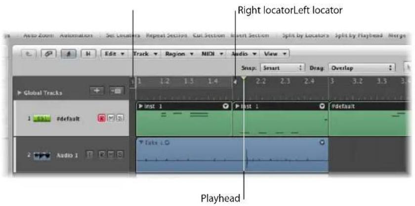
To place the playhead in the Bar ruler:
- Click the desired position in the lower third of the Bar ruler.
Double-clicking on the bottom third of the Bar ruler repositions the playhead, and also toggles between playback (or record) and stop modes.
The top of the Bar ruler contains two locators which are shown as a semi-transparent gray stripe when inactive, and a green stripe when Cycle mode is active. The start point of the stripe is determined by the left locator position, and the end point, by the right locator position. You'll learn more about the use of locators for playback and recording duties in this, and following, chapters.
Setting the Playhead With the Position Display
The Transport bar's Position display shows the current playhead position in two formats:
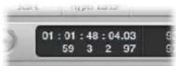
- SMPTE Time: The upper row displays the playhead position in SMPTE time format; hours : minutes : seconds : frames / subframes.
- Musical division of time: The lower row displays the playhead position in bars, beats, division, and ticks.
A beat corresponds to the denominator in the time signature.
The division value is set in the Transport bar, below the time signature.
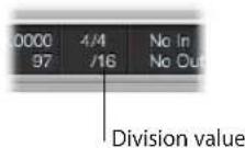
A tick is the smallest possible bar sub-division—it is equal to 1/3840th of a note.
To set the playhead position in the Position display, do one of the following:
- Click-hold on any of the numbers in the Position display, and move the mouse up or down.
■ Double-click on either display field, and then type in a new position.
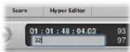
The playhead will move to match the display position.
Adjusting the first number in the Bar display will move the playhead by bars, and by hours in the SMPTE display.
Adjusting the second number will move by beats in the Bar display, and by minutes in the SMPTE display, and so on at increasingly small divisions with the other values shown in the Position display.
When typing in a full position, using the Bar display, for example, you should type in the following manner:
- 3 Space 3 Space 2 Space 2, Enter key to exit text entry mode.
• 3.3.2.2, Enter key to exit text entry mode.
If you simply type in 3322, followed by the Enter key, the playhead will be moved to bar 3322, rather than bar 3, beat 3, division 2, tick 2. The advantage of this approach is that you can quickly navigate to the beginning of a bar by simply inputting the first digit.
Setting the Playhead at a Marker
If you have labeled a passage with a marker, clicking anywhere on the marker while holding down Option, positions the playhead at the start of the marker. If Logic Express is stopped, Command-double-clicking on it begins playback at the start of the marker.
Adjusting the Size of the Playhead
You can adjust the thickness of the playhead in the General Display preferences.
To adjust the playhead display:
1 Open the Display preferences by doing one of the following:
- Choose Logic Express > Preferences > Display (or use the Open Display Preferences key command).
- Click the Preferences Toolbar button, then choose Display from the menu.
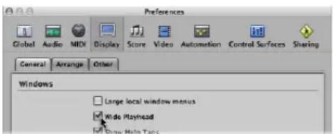
2 Click the General tab, and turn on the Wide Playhead checkbox.
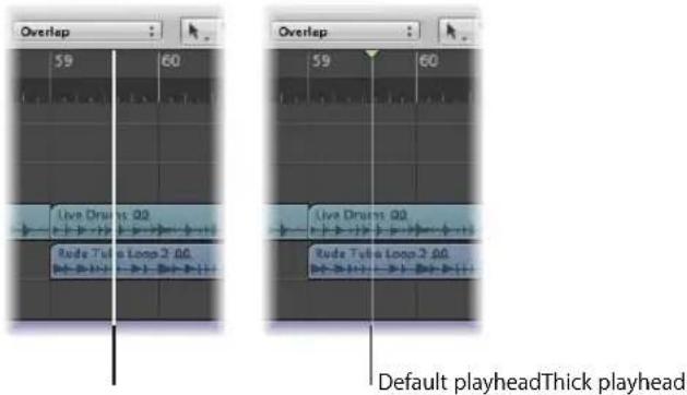
Using the Transport Buttons
You can use the transport buttons in the Transport bar to control playback, or to set the playhead position. You can click the buttons to activate or deactivate functions, or better yet, make use of the corresponding key commands (computer keyboard shortcuts) to speed up your workflow.
Note: The screenshot below shows all transport buttons. The buttons available in the Transport bar of your project may differ, as you can customize the Transport bar. For further information see "Customizing the Transport Bar" on page 116.
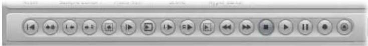
From left to right:
- Go to Beginning: Moves the playhead to the beginning of the project. Default key command: Return.
- Go to Position: Opens a dialog that allows you to type in the desired playhead (target) position numerically.
- Go to Left Locator: Moves the playhead to the left locator position.
- Go to Right Locator: Moves the playhead to the right locator position.
- Go to Selection Start: Moves the playhead to the start point of the first selected region or event in the active window. Default key command: Shift-Return.
- Play from Beginning: Starts playback at the beginning of the project.
- Play from Left Window Edge: Plays from the leftmost point of the visible display area in the active window.
- Play from Left Locator: Moves the playhead to the left locator position, and begins playback.
- Play from Right Locator: Moves the playhead to the right locator position, and begins playback.
- Play from Selection: Moves the playhead to the start point of the selected regions or events, and begins playback. Default key command: Shift-Enter.
- Rewind and Fast Forward: A click on either button will move the playhead one bar forward or backward. Command-clicking moves the playhead to the next or previous marker. Click-holding either button will rewind or fast-forward. Click-holding (on either button) and dragging to the left or right will shuttle forward or backwards (both buttons allow forward/reverse shuttling when used in this way).
- Stop: Stops recording or playback. Clicking the Stop button a second time moves the playhead to the project start point, or to the left locator position, if Cycle mode is active. Default key command: 0.
- Play: Starts playback at the current playhead position, or from the left locator position when in Cycle mode. Default key command: Enter.
- Pause: Pauses recording or playback, until you click either the Pause or Play button.
- Record: Click to begin recording (if a track is record-enabled). Default key command: *. Control-click or right-click the button to open the Recording menu.
- Capture Recording: Allows the most recent performance to be kept, even if Logic Express was not in record mode while you were playing.
Note: All of the transport button key commands listed above—with the exception of Rewind and Fast Forward—use the numeric keypad of your computer keyboard.
Using Transport Key Commands
There are a number of transport functions that are only available as key commands. Most of the key commands for these functions are not assigned by default, so you will need to set up key commands for them. See "Assigning Key Commands to Computer Keys" on page 166.
- Play or Stop: Switches between playback and stop, depending on the play or stop status when the command is used. Default key command: Space bar.
Tip: The Space bar can be used to start or stop playback of audio files or regions in the Sample Editor, Audio Bin, and Loop Browser, when these windows have key focus. This makes it a handy key command to remember!
- Play from Previous Bar: Starts playback at the beginning of the previous bar.
- Stop and Go to Left Locator: Stops playback, and moves the playhead to the left locator position.
- Go to Last Play Position: Moves the playhead to the last position reached with a positioning command, or direct positioning of the playhead, using the mouse or ruler.
- Stop and Go to Last Play Position: As above, but stops playback.
- Shuttle Rewind and Shuttle Forward: Repeated key presses will increase the winding speed. Repeated hits of the opposing shuttle key will slow down the shuttle speed, and eventually change the winding direction. Shuttle disables Cycle mode. Shuttling is halted by the Stop command.
- Go to Selection End: Moves the playhead to the end of the first selected region or event in the active window.
Note: There are also as a large number of Go To key commands for markers available. For further information, see "Navigating With Markers" on page 134.
Using Cycle Mode
You can use Cycle mode to repeatedly play a selected passage. This is useful for:
- Practicing, before making a recording
• Recording individual tracks consecutively - Editing events
- Recording multiple takes
- Composing a section of a project (a verse or chorus, for example)
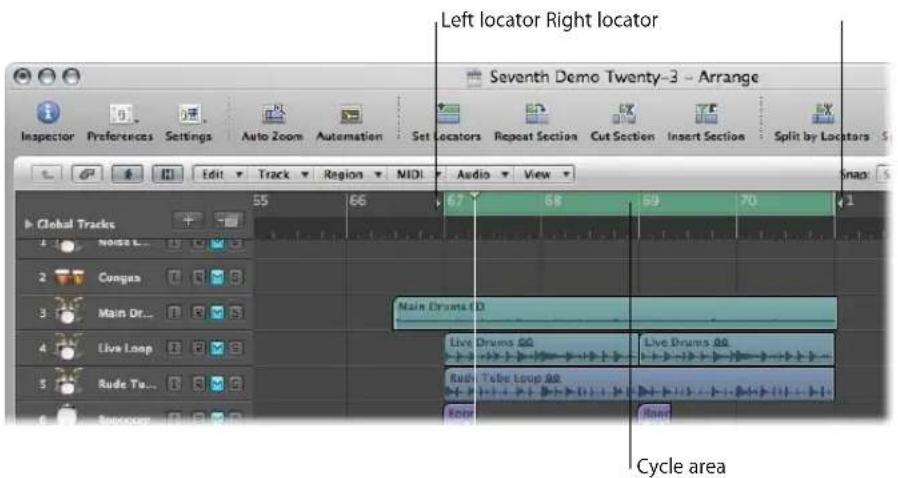
The cycle area is defined by the position of the left and right locators. When Cycle mode is active, it is shown as a green stripe in the top part of the Bar ruler.
To switch Cycle mode on and off, do one of the following:
- Click the Cycle button in the Transport bar (or use the Cycle Mode key command).
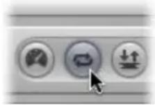
- Click on the top part of the Bar ruler (on the gray locator stripe).
How Logic Express behaves in Cycle mode:
- The playhead jumps from the end of the cycle to the beginning.
- The Play command starts playback from the beginning of the cycle.
- To start playback from another position, hit Pause twice, or Pause and then Play.
- At the cycle jump point, you can use the Chase Events function—File > Project Settings > MIDI > Chase > Chase on Cycle Jump. For more information about chasing events, see “Using the Chase Events Function” on page 114.
- You can determine the way recording works in Cycle mode, by using the various options in the File > Project Settings > Recording pane.
Defining the Cycle
There are a number of different ways to define a cycle. You can:
- Directly draw the cycle in the Bar ruler (effectively setting the left and right locator positions).
- Use the Transport Locator displays.
- Create a cycle based on selected regions.
- Create a cycle based on markers.
Defining and Adjusting a Cycle in the Bar Ruler
Click-hold in the top third of the Bar ruler, and define the desired cycle area by dragging the mouse from left to right.
The cycle area appears as a green stripe in the Bar ruler, and Cycle mode is automatically switched on.
To move the cycle:
- Grab the green cycle stripe in the middle (the cursor will turn into a hand), and drag it to the left or right.
Two lines extend down the screen from the beginning and end points of the cycle. These make it easy to align the cycle with regions in the Arrange area, or events in the Piano Roll Editor.
To resize the cycle:
- Grab the handles (triangles) at either end of the cycle to move the start or end points (you can even do this while Logic Express is running.).
Note: You can set either the start or end point of a cycle (whichever is closest) by Shift-clicking the desired position in the Bar ruler. This works even when the stripe is outside the visible range, or Cycle mode is switched off.
When you set the size of a cycle graphically in the Bar ruler, its start and end points (and therefore, overall size) is quantized to the setting chosen in the Snap menu. For more information, see "Snapping Region Edits to Time Positions" on page 309.
Defining a Cycle With the Transport Locator Displays
You can enter the locator positions—therefore setting the cycle boundaries—numerically in the Transport bar Locator display. The locators are shown to the right of the Position display: The top value denotes the left locator position, and the bottom one, the right locator position.
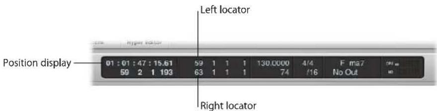
To define the locator positions in the Transport, do one of the following:
- Double-click on either locator display field, and directly type in a left or right position value.
Type in all bar, beat, sub-beat, and tick values (using space or a period between numbers), and press Return to close the entry box and set the locator.
Note: You can quickly set the locator to the beginning of a bar by simply inputting the first digit.
- Click-hold on any of the left or right locator number fields in the Transport, and move the mouse up or down.
The corresponding cycle boundary (if shown in the Bar ruler) will move to match.
Using the Transport Bar Mode Buttons to Define Locators
You can use the following commands, available as Transport bar buttons, to define the locator positions. You can click on the buttons to activate or deactivate functions, or better yet, make use of the corresponding key commands (computer keyboard shortcuts) to speed up your workflow.
Note: The screenshot below shows all relevant buttons. The buttons available in the Transport bar of your project may differ, as you can customize the Transport bar. For further information see "Customizing the Transport Bar" on page 116.
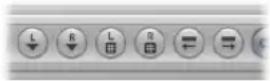
- Set Left Locator and Set Right Locator: These allow you to directly enter either of the locator points in a dialog. Also available as key commands.
- Set Left Locator by Playhead and Set Right Locator by Playhead: The current playhead position is used to define the left or right locator value.
- Move Locators Forward by Cycle and Move Locators Backwards by Cycle Length: Move the cycled passage by its own length. Also available as key command.
Using Regions or Events to Define a Cycle
You can use the following key commands to set the locators at the start and end points of selected regions or events:
- Set Locators by Regions/Events: Sets the locators at the start and end points of the selected regions or events.
- Set Locators and Play: Sets the locators at the start and end points of the selected regions (or events) and starts playback.
- Set Rounded Locators by Regions/Events: Rounds the position of the locators to the barline that is nearest to the beginning and end points of the selected regions or events.
- Set Rounded Locators and Play and Set Rounded Locators and Record: Rounds the position of the locators to the barline that is nearest to the beginning and end points of the selected regions or events, and starts playback or recording.
- Set Rounded Locators and Cycle Play and Set Rounded Locators and Cycle Record: Rounds the position of the locators to the barline that is nearest to the beginning and end points of the selected regions or events, and switches to cycle play or record mode.
Defining a Cycle With Markers
Dragging a marker into the top part of the Bar ruler creates a cycle with the marker's length. Details on creating and using markers is covered in Chapter 6, "Working With Markers," on page 123.
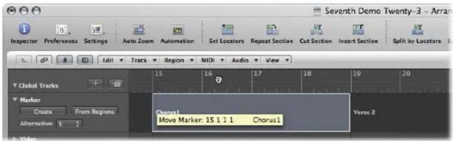
You can also use one of the following key commands:
- Set Locators by Marker and Enable Cycle: Sets the cycle to the currently selected marker and activates Cycle mode. The length of the cycle is determined by the marker length.
- Set Locators by Next Marker and Enable Cycle: Sets the cycle to the next marker and activates Cycle mode.
- Set Locators by Previous Marker and Enable Cycle: Sets the cycle to the previous marker and activates Cycle mode.
Note: These commands are ideally suited for repeating passages during live performances. Define markers for all parts of the project that you might want to repeat in this way during your performance.
Skip Cycle
You can skip a passage in play mode, which is useful for trying out the musical effect of various transitions, from one song section to another, without needing to physically move regions. This is a very handy feature when arranging.
Skip Cycle is also useful when editing, to leave out parts of the project that you don't want to be affected by the edit.
To set up a skip cycle, do one of the following:
- Drag the Skip Cycle area from right to left in the Bar ruler.
If a (normal) Cycle area already exists, you can swap the left and right locator by clicking the Swap Left and Right Locators button in the Transport bar (or using the Swap Left and Right Locator key command).
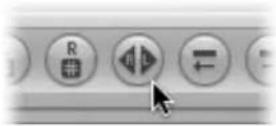
The Skip Cycle area is shown as a green candy striped area in the Bar ruler.
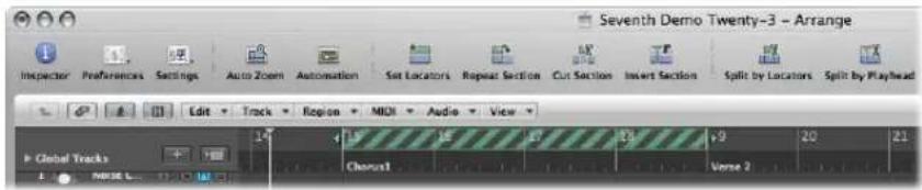
When the playhead reaches the right locator position, it skips to the left locator (in essence, the right and left locators swap positions).
Using the Chase Events Function
If you start playback in the middle of a project, some events might not be heard (such as notes, sustain pedal events, and pitch bend events that start before the point where playback begins). Using the Chase Events function, you can have Logic Express analyze the project and include some or all of these events when the project plays back.
To set up the Chase Events function:
1 Open the MIDI project settings by doing one of the following:
- Choose File > Project Settings > MIDI (or use the corresponding key command).
- Click the Settings Toolbar button, then choose MIDI.
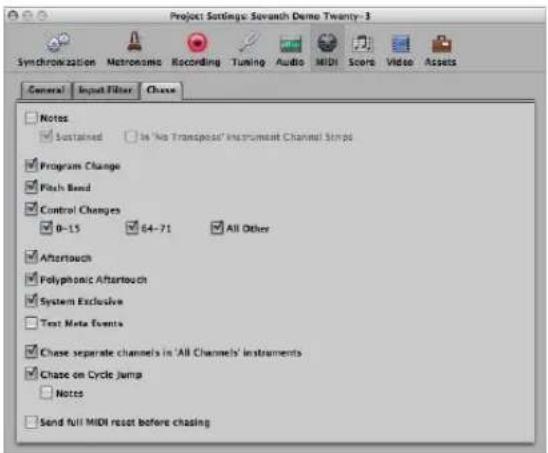
2 Click the Chase tab, then turn on the checkboxes of all events the Chase Events function should look for before the playback start point. You can choose from:
• Notes: Any notes due to start playing at the playback start point.
- Sustained: Any notes that are still playing at playback start point—due to a sustain pedal event.
- In "No Transpose" Instrument Channel Strips: Instrument channel strips (particularly drums) can be assigned No Transpose status in the Inspector. This is a playback parameter, which would be ignored if the region containing the instrument notes was started mid-way through.
- Program Change: Any program changes in regions that fall across the playback start point will be sent, when this checkbox is turned on.
- Pitch-bend: Pitch bend events that immediately precede the playback start point will be sent.
- Control changes 0–15, 64–71, All Other: Click to search for continuous controllers 0 to 15, continuous switch controllers 64 to 71, or all other controllers.
- Aftertouch: Click to look for monophonic (channel) aftertouch messages.
• Polyphonic Aftertouch: Turn on to scan for polyphonic aftertouch messages.
- System Exclusive: The most recent SysEx message before the playback start point is transmitted.
- Text Meta Events: The most recent Text Meta Event message before the playback start point is transmitted.
- Chase separate channels in 'All Channels' instruments: Multi-instruments (found in the Environment) have a global channel, and can have up to 16 MIDI sub-channels. Turn on this option to scan for events on each MIDI sub-channel, rather than the global multi-instrument channel.
- Chase on Cycle Jump: Scans for, and sends, all event types if the cycle start and end points fall across regions.
- Notes: Limits cycle jump scan to note events.
- Send full MIDI reset before chasing: Sends a MIDI reset message before chasing, ensuring that all MIDI devices being triggered are set to their defaults.
There is a potential problem when chasing notes that are used to trigger a drum loop in a sampler. Unless you are lucky enough to start the MIDI region precisely at the beginning of the sample loop, the sample will be triggered at the wrong time and will, therefore, be played out of sync with other regions (at least until the next trigger note).
The problem occurs because most samplers can only play samples from the beginning, and cannot synchronize them to the beat when started in the middle.
To avoid triggering a sampler's drum loops when chasing note events:
1 Activate the No Transpose parameter of your drum loop instrument, in the Track Parameter box of the Inspector.
2 Turn off the In 'No Transpose' Instrument Channel Strips option in the Project Settings > MIDI > Chase tab.
These settings prevent your sampler's drum loops from playing until they reach the next trigger note, whenever the project jumps to a new position.
The No Transpose parameter actually prevents transposition by the region playback parameters, which is also not desirable for drum sounds or loops.
Customizing the Transport Bar
The Transport bar offers a default set of buttons, displays, and sliders. These are the most commonly used, and most useful, options for the majority of users.
You, however, may need to regularly access particular functions that are not part of the default set, due to:
- The type of project you are working on; a film soundtrack, for example.
• A unique working style
- A desire to have everything at your fingertips
Whatever the motivation, you can easily customize the Transport bar to meet your needs.
Hiding and Showing Transport Bar Functions
You can hide or show different parts of the Transport bar independently. This in turn, allows you to control the width of the Transport bar.
You should limit the Transport bar to functions you actually need to access regularly, or better yet, configure and memorize all of the corresponding transport or mode key commands. This will allow you to expand the display area of the Transport bar, providing more at-a-glance information.
Note: If you want all commands and options to be visible in the Transport bar, you will need either a second computer monitor, or a single monitor with an exceptionally high horizontal resolution.
Tip: Logic Express allows an unlimited number of Transport bar windows to be simultaneously opened. Additional Transport bar windows can be individually customized, allowing you to view and access additional functions that will not fit on the standard Transport bar at the bottom of the Arrange window. Customized Transport bars (and other windows) can be saved as part of a screenet.
To customize the Transport bar:
1 Control-click (or right-click) the Transport bar, and choose Customize Transport Bar from the menu.
2 Turn on or turn off the desired functions by clicking on the checkboxes in the Customize dialog.
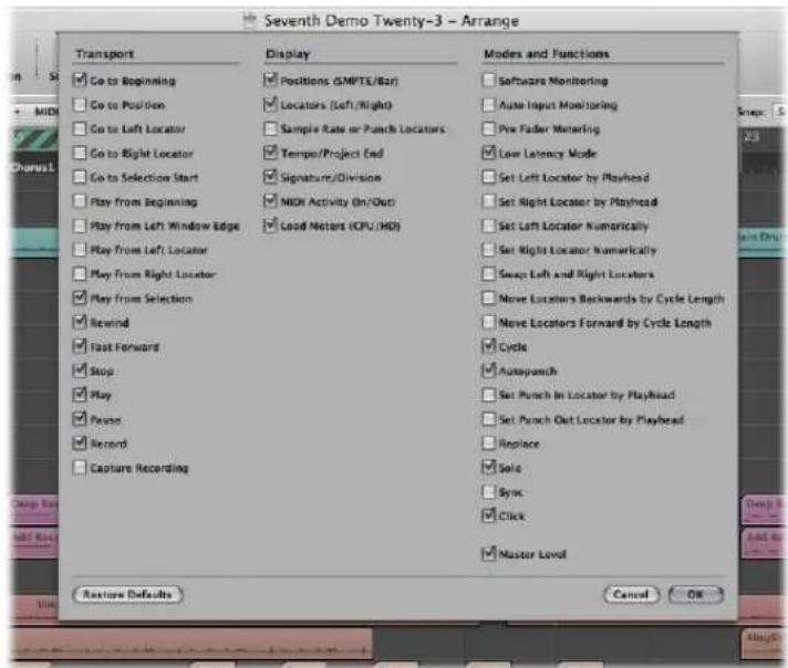
Transport Buttons
This area contains checkboxes for buttons that literally transport the playhead through the project. Please see "Using the Transport Buttons" on page 106 (in this chapter) for an explanation of the individual functions and commands.
Display Area
This section primarily serves to inform you of the playhead and locator positions, but can also be used to navigate through the project.
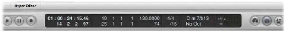
- Positions (SMPTE/Bar): Indicates the current position of the playhead. The top row shows the position in SMPTE format (hours : minutes : seconds : frames), the bottom row in bars, beats, divisions, and ticks.
- Locators (Left/Right): The top row indicates the left locator position, the bottom row the right locator position. Locators are used to define a particular section of the project for a number of recording or playback tasks.
- Sample Rate or Punch Locators: Shows the current project sample rate, or punch recording in/out locators (when punch recording mode is enabled). As with other Transport bar display fields, you can set the sample rate or punch locators with the mouse or via direct numerical entry.
- Tempo/Project End: The Tempo display indicates the current playback or recording speed. The Project End display shows the total number of bars or time. It behaves as stop playback/recording marker for the project.
- Signature/Division: The (Time) Signature display indicates the current playback or recording time signature in a standard musical format; 4/4, 5/4, and so on. The Division display determines the current display (and editing) resolution. A value of /16 means that a 4/4 bar is divided into 16 sub-sections, or 4 sub beats for each beat in the bar.
- MIDI Activity (In/Out): Displays incoming and outgoing MIDI data. The MIDI In display (top) will show chord names for incoming MIDI note data.
- Load Meters (CPU/HD): Click to show CPU load and hard disk throughput load meters. Double-click to open the load meters as a separate window.
Modes and Functions
The mode buttons and Master Level slider to the right are used for several advanced recording and playback functions, including repeating project sections, soloing, and punch recording. The buttons do not immediately trigger an action. Rather, they switch operating states. The relevant button will illuminate to indicate that the mode is activated.

- Software Monitoring: Enables software monitoring, allowing you to process external sources via Logic Express effects. It also enables you to hear external sources while recording.
- Auto Input Monitoring: Automatically allows you to hear external sources at the audio inputs.
- Pre Fader Metering: Switches all of the mixer channel meters between pre-fader (the Level fader on each channel) and post fader modes (when turned off).
- Low Latency Mode: Enables Low Latency mode, allowing you to limit the amount of delay (latency) caused by some effects.
- Set Left Locator and Set Right Locator: These allow you to directly enter either of the locator points in a dialog. Also available as key commands.
-
Set Left Locator by Playhead and Set Right Locator by Playhead: The current playhead position is used to define the left or right locator value.
-
Move Locators Forward by Cycle and Move Locators Backwards by Cycle Length: Move the cycled passage by its own length.
- Move Locators Left by Cycle: Retains the existing cycle, but moves it to the left by the cycle length. As an example, if the cycle is 4 bars long, and spans bars 12 to 16, using this command will move the cycle four bars to the left, resulting in a cycle from bar 8 to 12.
- Move Locators Right by Cycle: As above, but moves the cycle to the right.
- Cycle: Enables or disables repeated playback or recording over a project section. The cycle boundaries are reflected (or set) by the left and right locator values.
- Autopunch: Enables or disables a recording start and end point. It is commonly used in conjunction with the left and right autopunch locators to automatically record over a particular project section. This method is often used to fix a mistake in a vocal or instrumental recording.
- Set Left Autopunch Point by Playhead: The current playhead position is used to define the left autopunch locator value.
- Set Right Autopunch Point by Playhead: The current playhead position is used to define the right autopunch locator value.
- Replace: Enables a new recording to overwrite an existing recording.
- Solo: Only selected regions are played, all other regions are muted.
- Sync: Activate to synchronize Logic Express with an external source (make Logic Express the synchronization slave to another device). Control-click or click-hold this button to open the Synchronization menu.
- Click: Used to turn the Logic Express internal metronome on and off. Control-click or click-hold this button to open the Metronome menu.
- Master Level: Click to display a volume slider at the right of the Transport bar. This slider is directly tied to the Master channel in the Mixer, and acts as a master level control for all audio and software instrument tracks.
Using a Giant SMPTE or Bar Display
You can configure the Transport bar to display a giant SMPTE or Bar display in place of the standard Transport bar display area.
Alternately, you can spawn a new giant SMPTE or bar display window.
To replace the standard Transport bar display area with a SMPTE or bar display:
■ Control-click the display area of the Transport bar, and choose Big Bar Display or Big SMPTE Display, as required.
The Transport display area will be replaced with the chosen big display.

Repeat the step above to return to the standard display.
To open a new SMPTE or bar display window:
■ Control-click the display area of the Transport bar, and choose Open Giant Bar Display or Open Giant SMPTE Display, as required.
A new, floating, transparent window will open.
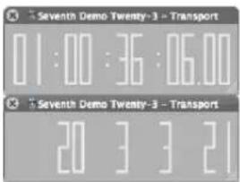
This can be freely positioned and resized.
To resize the SMPTE or bar display window:
1 Move the cursor over one of the edges, or lower corners.
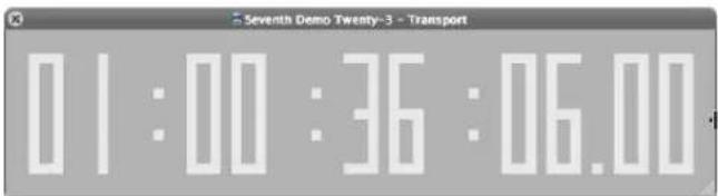
2 When the cursor changes into a Resize pointer, click-drag into the desired direction.
To close the chosen giant display, click the close icon at the top left of the window.
Note: Logic Express allows an unlimited number of Transport (and Giant SMPTE or Bar Display) windows to be simultaneously opened.
Customizing the Bar, SMPTE, and Tempo Display
You can customize the Bar, SMPTE, and Tempo display in the Display preferences.
To customize the Bar, SMPTE, or Tempo display:
1 Open the General Display preferences by doing one of the following:
- Choose Logic Express > Preferences > Display (or use the Open Display Preferences key command).
- Click the Preferences Toolbar button, then choose Display from the menu.
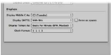
2 Choose one of the following settings in the Clock Format menu:
- Clock Format 1 1 1 1
- Clock Format 1.1.1.1
- Clock Format 1 1 1 0
- Clock Format 1.1.1.0
- Clock Format 1 1._ 1
- Clock Format 1.1._1
- Clock Format 1 1._0
- Clock Format 1.1._0
3 Choose one of the following settings in the Display SMPTE menu:
- With Bits: Subframes (SMPTE bits 0 to 79) are shown.
- Without Bits: Subframes are not shown.
- With Quarter Frames: Quarter frames are shown.
- As Feet Frames, 35 mm film: The display is displayed in feet and frames, for 35 mm film.
- As Feet Frames, 16 mm film: The display is displayed in feet and frames, for 16 mm film.
- With Milliseconds: The frame fractions are displayed in milliseconds instead of SMPTE bits (also called subframes). Don't forget that this value is dependent on the frame rate: at 25 fps, a frame is 40 milliseconds long, at 30 fps, approximately 33 ms.
- With Samples: Frame fractions are shown as sample values.
- With Frames and Samples: Both fractional frame and sample values are shown.
4 Turn on the Zeros as spaces checkbox if you want zero values to appear as blank spaces, rather than the number 0 in SMPTE time displays.
5 Choose one of the following settings in the Display Tempo As menu:
- Beats Per Minute (BPM, Maelzel): Beats per minute, to four individually adjustable decimal places.
- BPM without Decimals: Beats per minute, with no decimal places.
- Frames Per Click with Eights: Frames per beat with eighths. After the value, you will see fpc.
- Frames Per Click with Decimals: Frames per beat, to four decimal places. Take care, this display can easily be confused with the bpm display.
Working With Markers
The main purpose of markers is to tag different parts of a project, and to enable the quick selection of these parts for playback, editing, and arranging.
Markers serve as a kind of project road map, representing the form of a project graphically.
You can see and edit markers in the following window areas:
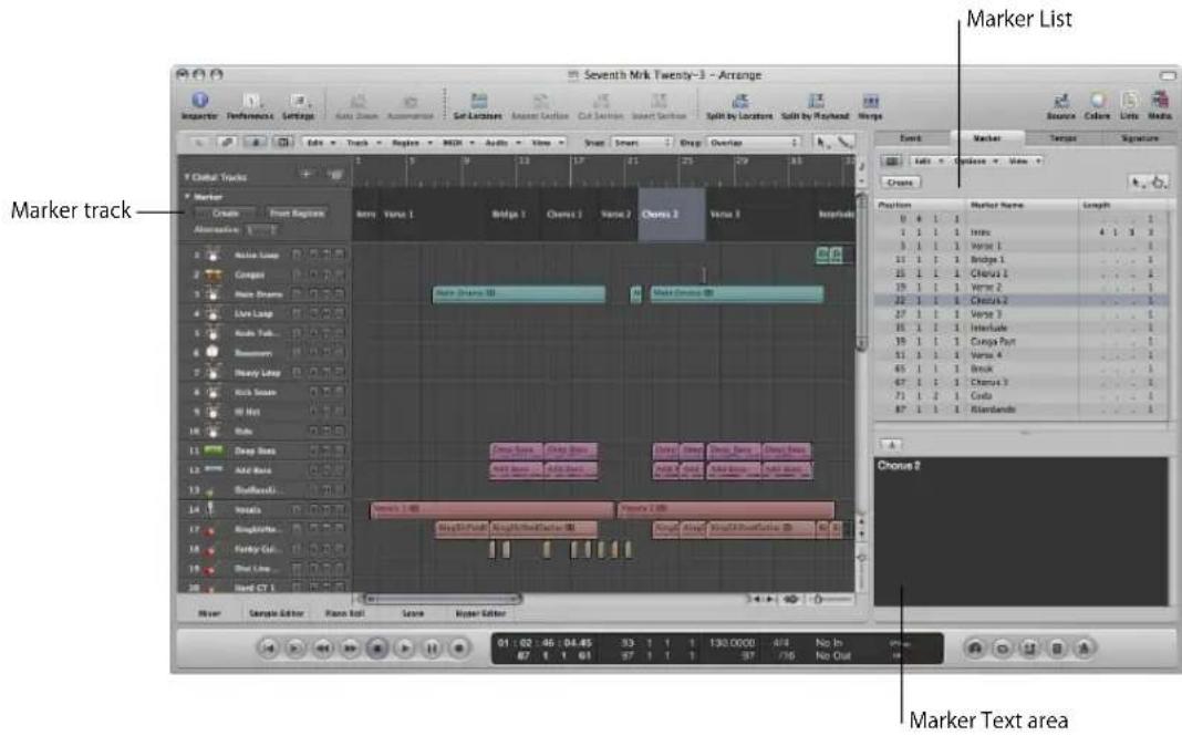
- Marker track: Displays markers as (optionally) colored sections. If the Marker track is hidden, you can see markers as short text strings in the Bar ruler of all linear editing windows. The main advantage of the Marker track over the marker display in the Bar ruler, is that it allows you to select, copy, move, or resize markers directly with the mouse. Click the disclosure triangle in the upper left corner of the Marker track name column to expand the track height, thereby displaying additional controls. You can freely adjust the lower border of the Marker track by dragging it up or down with the mouse.
- Marker List: Lists the names of all markers, inclusive of bar position and length information.
- Marker Text area and Marker Text window: Show text associated with a marker. This makes markers suitable for use as notepads, allowing text comments to be saved with the project. Marker text can be typed in, and edited, as you would in any text editor. The Cut, Copy, Paste, Clear, and Select All commands can be used to import or export text to and from other software applications (such as word processors).
Apart from the text functions, markers can also be regarded as storage areas for locator positions—each of which can be individually named.
Opening Marker Areas and Windows
As mentioned in the chapter introduction, there are many ways to interact with, create, and delete markers in Logic Express.
To open the Marker track:
1 Click the disclosure triangle in the Global Tracks header area.
2 Click the disclosure triangle for the Marker track.
You can also assign, and use, the Toggle Marker Track key command.
To open the Marker List, do one of the following:
- Click the Lists button in the Arrange Toolbar, then click the Marker tab (or use the Toggle Marker List key command).
- Choose Options > Marker > Open Marker List (or use the Open Marker List key command).
Note: Double-clicking a marker (with the Pointer tool) in the Marker track toggles the List area. The clicked marker is selected in the list.
To open the Marker Text window:
- Option-double-click on any marker in the marker track with the Pointer tool. The clicked marker is selected in the list.
Note: Ensure that you do not (Option--)double-click in the Marker track with the Pencil tool selected, or a new marker will be created.
The Marker Text window is also available at the bottom of the Marker List window. It is known as the Marker Text area in the Marker List window.
Using the Marker Shortcut Menus
Many marker selection, editing, and other commands can be accessed by Control-clicking (or right-clicking) anywhere in the marker areas. Make use of this to accelerate your workflow.
Note: The right-click shortcut menu can only be accessed if the Right Mouse Button: Opens Shortcut Menu pop-up menu option is chosen in the Logic Express > Preferences > Global > Editing tab.
Creating Markers
You can create markers at any project position. The following section describes all marker creation options.
To create a marker at the beginning of the nearest bar, do one of the following:
In the Marker track:
- Set the playhead to the desired position, then click the Create button.
- Select the Pencil tool, and click at the desired position.
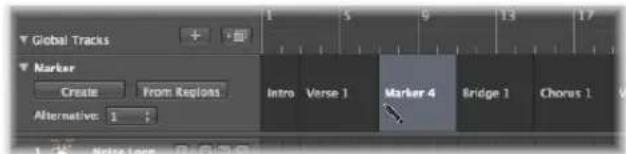
In the Bar ruler: Place the Pointer over the lower third of the Bar ruler, and Option-Command-click at the desired project position. This only works if the Marker track isn't displayed.
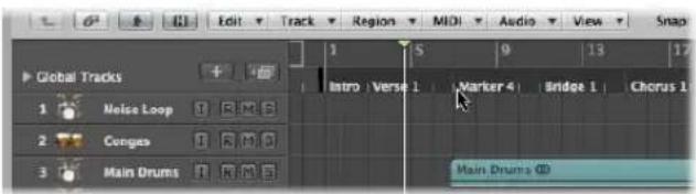
In the Marker List:
- Choose Options > Create.
- Select the Pencil tool, and click in the Marker List.
- Click the Create button in the Marker List.
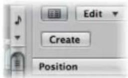
In any window: Choose Options > Marker > Create from the main menu bar (or use the Create Marker key command).
The marker is created at the beginning of the nearest bar. If a marker already exists at a bar position (or up to a quarter note before or after it), no new marker will be created.
The length of the marker automatically extends to the start point of the next marker, or to the end of the project or folder, if no ensuing markers exist.
Tip: You can use the Create Marker key commands to add markers on the fly during playback.
To create a marker that is not rounded to the nearest bar:
In any window: Choose Options > Marker > Create Without Rounding (or the Create Marker Without Rounding key command).
■ In the Marker List: Choose Options > Create Without Rounding.
To create a marker and determine its position:
- Click the beginning or end of the Marker List's marker area with the Pencil tool, then input the desired position in the position input field.
To create markers at the positions of all currently selected regions:
In the Marker track: Click the From Regions button, or drag a region from an Arrange track onto the Marker track.
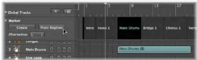
- Choose Options > Marker > Create by Regions from the main menu bar (or use the Create Markers by Regions key command).
Markers created in these ways are automatically assigned the names, bar position, length and color of the regions they are derived from.
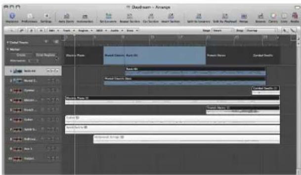
To create a marker that corresponds exactly to the length and position of a cycle:
- Drag the cycle down into the Marker track or into the lower third of the Bar ruler.
Dragging the cycle in the Bar ruler is limited to either horizontal or vertical movements. This ensures that you do not accidentally:
- Move the cycle when creating markers (by dragging the cycle into the lower third of the Bar ruler or into the Marker track).
- Create markers when moving the cycle area.
The following explains how marker movements and the cycle interact:
- When dragging the cycle to the marker area in the Bar ruler, the pointer turns into a hand with up/down arrows. As soon as you move the pointer horizontally in the marker area of the Bar ruler, the pointer becomes a hand (without arrows). The Copy Cycle to Marker action is canceled.
- If you first move the cycle horizontally, and then try to drag it to the Marker area of the Bar ruler, no Marker is created.
- When you hold Shift, after click-holding on the cycle, the cycle can be moved horizontally, and then dragged to the marker area in one go.
Note: When you hold Shift, before clicking on the cycle, the nearest cycle border is set to the clicked position.
To copy a marker:
In the Marker track: Option-drag the marker, or use the standard Copy (Command-C) and Paste (Command-V) commands.
In the Marker List: Use the standard Copy and Paste commands.
Selecting Markers
You can use the usual selection techniques to select markers. For more information, see "Selection Techniques" on page 177.
Deleting Markers
You can delete markers at any time. Once deleted, they no longer appear in the Bar ruler, Marker track, Marker List, or Marker Text window.
To delete markers:
■ Do one of the following in the Marker track and Marker List:
- Click the markers with the Eraser tool. - Select the markers, then choose Edit > Delete (or use the corresponding key command, default: Backspace).
In the Bar ruler: Grab the marker you want to delete, and drag it out of the Bar ruler. Release the mouse button when the cursor turns into a hand holding two arrows.
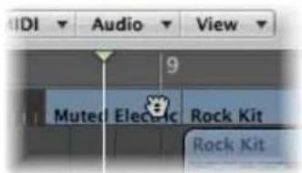
- At the current project position: Choose Options > Marker > Delete (or use the Delete Marker key command).
Naming Markers
Newly created markers are automatically named "Marker ##" (unless derived from regions, as described above). The "##" indicates a numerical value which reflects the order of appearance of the markers along the Bar ruler (resulting in "Marker 1", "Marker 2", and so on). The allocated number is dependent on the actual order of all markers in the project, including markers that have been renamed.
Automatically assigned names can be changed directly in the Bar ruler, Marker track, Marker List, or in the Marker Text window.
The length of the name displayed in the Marker track, Bar rule, and Marker List depends on available screen space, or the position of the following marker.
If you want to edit a marker name when creating it, hold Control-Option-Command while clicking on the desired Marker track position: A text field will open, allowing you to type the desired name. Press Return to complete the naming operation. You can also Control-Shift-Command-double-click the Bar ruler (if the Marker track isn't visible).
To edit a marker name in the Bar ruler:
1 Do one of the following:
- Choose Options > Marker > Quick Edit Marker (or use the corresponding key command).
- Shift-Control-double-click on the marker.
2 Type the desired name in the text field.
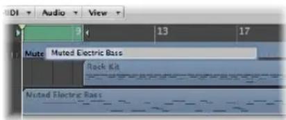
To edit a marker name in the Marker track:
1 Do one of the following:
- Choose Options > Marker > Quick Edit Marker (or use the corresponding key command).
- Select the Text tool, then click a marker.
- Shift-Control-double-click on the marker.
2 Type the desired marker name in the text field.
To edit a marker name in the Marker List:
1 Click the desired marker in the Marker Name column.
2 Click and/or drag anywhere on the "Marker #" entry in the Marker Text area at the bottom of the window, and type in the desired name. As you type, the text shown in the Marker Name column (and Marker Track) will update.
To edit a marker name in the Marker Text window:
- Open the marker in the Marker Text window, then type the marker text in.
Any normal computer keystroke (with or without Shift held) will be interpreted as text input if the Marker Text window is the window with key focus, even if a key command is defined for the key.
The first paragraph in the window will be used as the marker name.
Note: If you use Return to create paragraphs in the Marker Text window or area, the first paragraph of the text will be displayed in a separate title line (of the marker) in the Marker track.
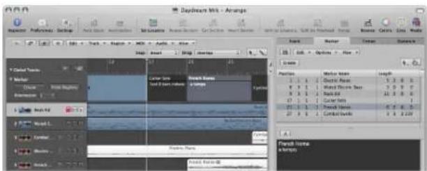
Unlike the marker display in the Bar ruler, all text below the first paragraph will also be displayed in the Marker track, depending on available space (you might want to change the height of the Marker track to view all text). This can be used for musical or technical notes, as an example. In this scenario, the marker color is only shown in the title line, with the remaining text displayed white on gray.
Changing the Appearance of Marker Text
You can change the appearance of marker text in the Marker Text window and area. You can assign a different font, size, and style to any selected portion of the marker text. All fonts installed on your system can be used. Different colors can be assigned to all, or selected parts, of the text, and to the Marker Text window and area background.
To change the appearance of marker text:
1 Select the marker text you want to change.
2 Click the Font button in the Marker Text window or Marker Text Area of the Marker List window.
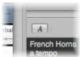
3 Choose the desired settings in the Font window.
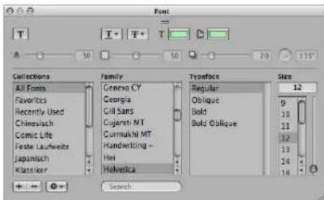
Editing Markers
Markers can be edited in various ways. Common tasks include changing marker positions, coloring markers, and adjusting marker lengths.
To change the position of a marker, do one of the following:
In the Marker track: Drag it to the left or right.
In the Bar ruler: Command-drag the marker to the left or right.
In the Marker List: Use the mouse as a slider on the bar position display, or double-click on a position value and enter the new value with the computer keyboard.
Note: The smallest movements that can be achieved in the Marker track and Bar ruler are dependent on the division setting in Transport area, the Snap menu setting, and the horizontal Zoom level (including sample accurate placement at the highest zoom levels). Watch the help tag for precise feedback on movements. The alternative for fine position adjustments is the Marker List.
There are times where you will want to protect markers from being moved. Thankfully, Logic Express has a feature that preserves the absolute time position of events.
To protect the position of selected markers:
1 Choose Options > Lock SMPTE Position in the Marker List (or use the corresponding key command).
This locks (fixes) the SMPTE position of markers. To indicate this status, a lock symbol is displayed at the beginning of the marker name.
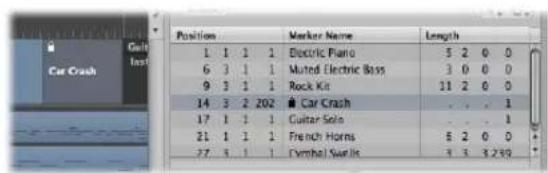
These markers always retain their absolute time position: if the project tempo is changed, the bar positions will change to keep the markers at the same SMPTE positions.
Tip: You can also lock/unlock the SMPTE positions of markers from the Arrange area's Region menu, and the Functions menu of the Piano Roll and Hyper Editor windows, if you enable the display of global tracks.
To unprotect the position of selected markers:
- Choose Options > Unlock SMPTE Position in the Marker List (or use the corresponding key command).
Note: You can not unlock the SMPTE position of scene markers (see "Working With Scene Markers" on page 838).
To change the length of a marker:
In the Marker track: Place the Pointer over the desired marker border. When the cursor changes to a Resize pointer, drag the marker border to the desired position.
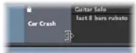
In the Marker List: Use the mouse as a slider on the bar position display, or double-click on a position value and enter the new value with the computer keyboard.
The marker border can also be the beginning of the subsequent marker, especially if the length of the second marker hasn't been defined. Markers cannot overlap.
To adjust a marker to fit a cycle:
- Drag a cycle onto an existing marker (with a right or left border—or both—that falls inside the cycle boundaries).
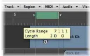
Dragging the cycle area in the Bar ruler is limited to either horizontal or vertical movements. This ensures that you do not accidentally:
- Move the cycle when creating markers (by dragging the cycle into the lower third of the Bar ruler or into the Marker track).
- Create markers when moving the cycle.
Tip: When you hold Shift, after click-holding on the cycle, the cycle can be moved horizontally, and then dragged onto a marker in one go.
Note: When you hold Shift, before clicking on the cycle, the nearest cycle border is set to the clicked position.
To assign a color to a marker:
- Select a marker in the Marker track, choose View > Colors, then click the desired color in the palette.
If dark colors are used, the marker text will automatically be shown in an inverse color. If you create markers from regions, the corresponding marker uses the region color.
Navigating With Markers
You can navigate through your project with markers. This is useful when you want to quickly jump to—and edit regions or events—at a specific project position, for example.
To move the playhead to a marker, do one of the following:
In the Marker track: Press Option and click the marker.
In the Bar ruler: Press Command and click the marker.
In the Marker List: Click on a marker with the Finger tool.
Tip: If you press Option and click a marker in the Marker List with the Finger tool, the locators are set to the beginning and end points of the selected marker.
■ Use the Go to Marker Number 1 to 20 key commands (20 different commands).
The marker numbers in these commands refer to the (serial) order of all markers in the project.
- Use the Go to Marker key command to open a window that allows you to type in any marker number.
This will move the playhead to the beginning of the chosen marker.
To move to the next or previous marker:
■ Use the Go to Previous Marker and Go to Next Marker key commands).
The locators are set to the beginning and end points of the selected marker.
To start playback at a marker start position, do one of the following:
In the Bar Ruler: Command-double-click on a marker.
In the Marker List: Click-hold on a marker with the Finger tool.
Logic Express continues playing until the mouse button is released.
To create a cycle from a marker, do one of the following:
- Drag a marker up into the top third of the Bar ruler.
This will set a cycle with the same position and length as the marker. If Logic Express is stopped when performing this action, the playhead will be placed at the start point of the cycle.
- Select the marker, then use one of the following key commands:
- Set Locators by Marker and Enable Cycle
- Set Locators by Previous Marker and Enable Cycle
- Set Locators by Next Marker and Enable Cycle
Customizing the Marker Display in the Marker List
There are two display options for marker position and length in the Marker List:
- View > Event Position and Length in SMPTE Units: Switches the marker position and length display between bar positions and SMPTE time positions.
- View > Length as Absolute Position: Switches the marker length display between actual (relative) length and (absolute) display of the marker's end position (shown as a bar position).
Working With Projects
7
Logic Express projects provide flexible options for storing and retrieving your music productions.
This chapter will provide you with information on all aspects of creating and handling Logic Express projects.
Learning About Projects
Logic Express requires a project to be opened or created before you can begin working. This is similar to using a word processing application, that requires a document to be opened before you can begin typing. Logic Express, like word processors, also allows you to have multiple documents (projects) open simultaneously.
A project file is the main Logic Express document type. It contains all MIDI events and parameter settings (apart from the preferences and key commands) plus information about the audio and video files to be played. It is important to note that a project file points to your audio and video files, which are stored as separate entities on disk. The audio and video files are not saved with the project.
When you create a new project (or use the Save function, in general), you can choose to also save all associated files (assets).
Logic Express creates a project folder that contains the project file, along with separate folders for files used in the project (audio files and so on).
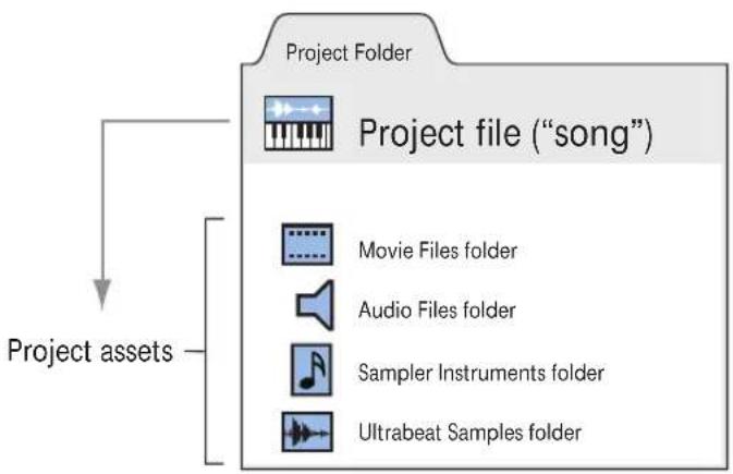
flowchart
graph TD
    A["Project Folder"] --> B["Project file ("song")"]
    B --> C["Movie Files folder"]
    B --> D["Audio Files folder"]
    B --> E["Sampler Instruments folder"]
    B --> F["Ultrabeat Samples folder"]
    G["Project assets"] --> B
The choice of saving projects without assets minimizes the memory requirements for project storage, allowing you to transport them easily to other Logic-based studios—either physically or as email attachments. This also means that the project will not be able to load the referenced audio and video files when moved, unless these other file types are also moved (the project is saved with its assets, in other words).
Project folders help you to keep track of your work: they ensure that all files related to a particular project are neatly saved in one location. This makes it easy to back up and transfer projects between computers or disks, and helps to avoid embarrassing problems such as missing audio files, or samples that you need to search for, or reconstruct, in the studio.
Creating Projects
You start working in Logic Express by creating a new project.
To create a project:
1 Choose File > New (or use the corresponding key command; default assignment: Command-N).
2 Choose the desired template in the Templates dialog.
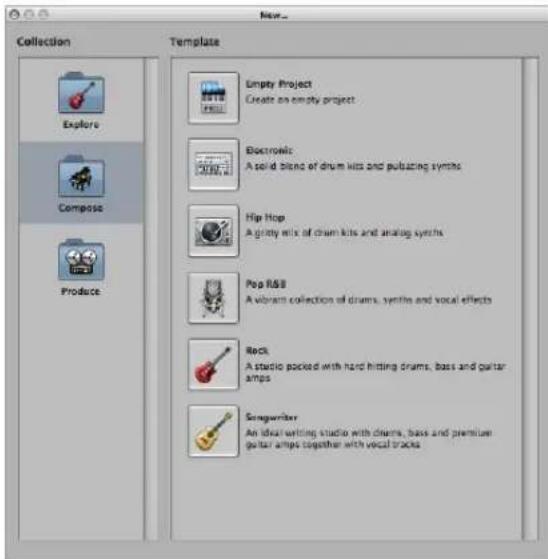
The Templates dialog is broken down into two areas: Collection and Template.
- Click a collection folder to display the associated template in the Templates area.
- Click a template to load it. A Save As dialog will automatically launch.
3 Browse to the location where you want to store the project, then type a name for the project in the name field.
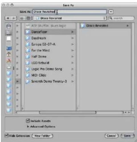
4 Click the Include Assets checkbox if you wish to include the audio and other files in the project folder (see "Handling Project Assets" on page 152).
Tip: It is recommended that you enable the Include Assets checkbox, as this makes the project "safe," allowing you to move or copy the project folder without losing any file references that point to items within the folder.
5 Click the Advanced Options disclosure triangle to view, and choose the file types you would like to save in the project folder.
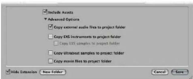
You can change these settings at any time by choosing File > Project Settings > Assets. Details on these project assets are found in "Handling Project Assets" on page 152.
6 Click Save.
- A named folder—containing several sub-folders, dependent on selections made in steps 3 and 4—is created at the target location.
- By default, an Audio Files sub-folder is created within the project folder, even if you have not turned on the Include Assets checkbox. This folder is used for any new audio recordings.
- Also by default, the audio recording path is automatically routed to the new Project/Audio Files sub-folder.
If you decide not to create a project folder in the first instance but would like to at a later stage, simply choose the Save As command.
Tip: You can quickly create an empty default project by holding Option while choosing File > New.
Opening Projects
Logic Express requires a project to be opened before you can commence working.
A project can also consist of data created in other applications, including songs from earlier versions of Logic Express or Final Cut Pro XML files, as examples.
To open an existing project, do the following:
1 Choose File > Open (or use the corresponding key command, default: Command-O).
If a project is already loaded, you will be asked if the currently-loaded project should be closed or not. You can disable this prompt by unchecking the Logic Express > Preferences > Global > Project Handling > "When opening a project, ask to 'Close current project(s)?" option.
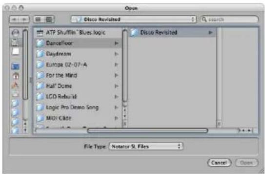
The Open dialog features a File Type menu, which allows you to choose from the following options:
- All Logic Document Types: Displays all document types supported by Logic Express
- Logic Projects: Projects created with current or earlier Logic versions
• GarageBand Projects: Projects created in GarageBand - Notator SL Songs: Songs created in C-Lab/Emagic Notator or Creator SL
- MIDI Files: Standard MIDI files in either format 0 or 1
-
AAF Files: Advanced Authoring Format used by other DAW applications such as Pro Tools.
-
OMF Interchange Files: Open Media Framework files used by other DAW applications such as Pro Tools
- OpenTL Files: OpenTL (Open Track List) files used in devices such as Tascam hard disk recorders
- XML (Final Cut Pro): An open source standard, supported by Final Cut Pro and Soundtrack Pro
For more information about the individual file types, see Chapter 29, "Project and File Interchange," on page 649.
2 To limit your view to certain file types in the file selector box, choose the desired file type in the File Type menu. Choose All Logic Document Types to see, and access, all supported file types.
3 Browse to, and select, the desired file, then click Open.
To open a recent project:
- Choose the project name directly from the File > Open Recent menu.
This bypasses the Open dialog. You can clear all items in the Open Recent menu by choosing Clear Menu.
Tip: If you set the Startup Action in the Project Handling preferences to the Open Most Recent Project option, Logic Express loads your last project automatically on startup (see "Opening and Creating Projects Automatically" on page 143).
Opening Projects Using Drag and Drop
Projects and Standard MIDI files can be opened by dragging them from the Finder into the Arrange area. The mouse cursor position—when the mouse button is released—determines the placement of the imported file.
This includes the position (rounded to the nearest bar) and destination of the first track. For more information about Standard MIDI files, take a look at "Working With Standard MIDI Files" on page 656.
You can also open a Logic Express project or MIDI file by dragging it onto the Logic Express icon in the Dock.
Opening Pre Version 8 Songs
You can open Logic 5, Logic 6, and Logic 7 songs in Logic Express 8. When loading a song or project created in a pre-version 8 Logic variant, the format will be converted to the version 8 format. A Save As dialog will open, allowing you to save the project with a new name. The original version song will be retained.
Important: Projects saved in Logic Express 8 are not backward-compatible with older Logic Express versions.
Switching Between Multiple Projects
You can open several projects simultaneously, allowing you to copy or move data between them, or perhaps to compare different versions of one project.
To switch between projects:
- Choose the project name at the bottom of the Window menu—the active project is marked with a tick.
Opening and Creating Projects Automatically
You can configure Logic Express to open or create projects automatically—on startup—by choosing a startup action in the Logic Express > Preferences > Global > Project Handling tab.
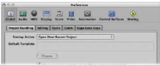
- Do Nothing: As the name suggests, this does nothing. Logic Express is opened and requires you to create a new project, or open an existing project or template.
- Open Most Recent Project: Automatically opens the project you were working on when you last quit Logic Express.
- Open Existing Project: Automatically shows the Open dialog, allowing you to browse for an existing project.
- Create New Project from Template: Automatically opens the Templates dialog.
- Create New Empty Project: Automatically loads an empty project and opens the Save As dialog, allowing you to name and save your project.
- Create New Project using Default Template: Automatically opens the default template, and launches the Save As dialog, allowing you to name and save your project.
To determine the default template:
1 Click the Choose button below the Default Template field in the Project Handling preferences tab.
2 Browse to, and choose, the desired template (or project).
The full path and name of the chosen template or project is displayed in the Default Template field. You can assign any template or project as the default template.
Importing Settings From Other Projects
You can import the following settings from other projects:
- Screensets
- Transform sets
- Hyper sets
- Score sets
- Score staff styles
- Score settings (all project settings that pertain to the score, such as Numbers & Names or Clefs & Signatures.)
- Score text styles
To import settings from another project:
1 Choose File > Project Settings > Import Settings (or use the Import Settings key command).
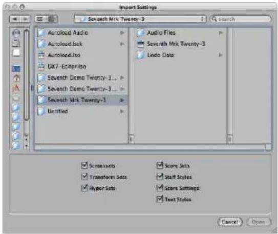
2 Select the desired settings by clicking the checkboxes at the bottom of the Import Settings window.
3 Browse to, and select, the desired source project (the one that you wish to import from).
4 Click Open (or double click on the source project name).
The settings are imported into the active project.
Checking and Repairing Projects
On occasion, you may need to know how many regions are in a project, how much memory is being used, and so on. This data is available in the Project Information window. Very rarely, a project may become corrupted due to driver or memory conflicts, or may feel sluggish. Should any corruptions occur, a warning message will advise you of the existence and nature of the problem. These problems can generally be rectified in the Project Information window.
To open the Project Information window:
- Choose Options > Project Information.
| Type | Objects | Events | Memory |
| MIDI Regions | 155 | 12620 | 417860 |
| Audio Regions | 37 | 285850 | |
| Tempo Alternatives | 1 | 20 | 1470 |
| Internal Objects | 2 | 14 | |
| Signature Alternatives | 1 | 4 | |
| Environment Objects | 85 | 0 | 88116 |
| Transform Settings | 1 | 978 | |
| Undo Steps | 31 | 282660 | |
| Staff Styles | 31 | 19844 |
The Project Information window also provides the Reorganize Memory function which allows you to increase the amount of free memory, and to rectify a number of potential project corruptions or problems.
To reconfigure the memory:
- Click the Reorganize Memory button in the Project Information window.
At the same time, the current project will be checked for any signs of damage, structural problems, and unused blocks.
If any unused blocks are found—which normally shouldn't happen—you will be able to remove these, and repair the project.
Note: This reorganization is also carried out automatically after saving or loading a project. A common (and good) use of this feature is to free up memory after closing a project, if two or more projects were open prior to the close operation.
Setting Project Properties
Following the creation of a project, a number of project properties should be checked, and changed if necessary. This is a great working practice as it will limit any morning after corrections that will need to be made later, such as sample rate conversions on a hundred or more audio files! This section outlines the project properties that you should take into consideration before commencing any work.
Setting the Sample Rate
The project's sample rate determines the number of samples Logic Express uses for audio playback. When you add or record audio files to your project, the sample rate of these files is automatically matched to the project sample rate.
Important: The "Convert audio file sample rate when importing" project setting must be active for automatic sample rate matching. You can turn on this setting in the File > Projects Settings > Assets pane.
To set the project sample rate, do one of the following:
- Choose File > Project Settings > Audio (or use the Open Audio Project Settings key command), then choose the desired sample rate in the Sample Rate menu.
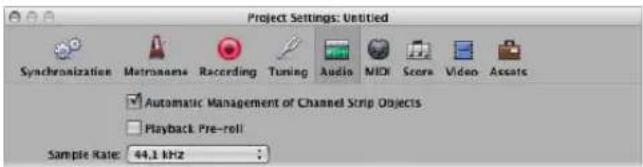
- Click the Sample Rate display in the Transport bar, then choose the desired sample rate from the pop-up menu.
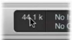
Note: If your Transport bar does not include the Sample Rate display, Control-click on it and choose Customize Transport Bar in the pop-up menu. Turn on the Sample Rate or Punch Locators checkbox in the Customize Transport Bar dialog.
You may find that audio files in your project do not match the newly selected sample rate. The playback of files that do not match the project's sample rate is slower (file's sample rate is higher) or faster (file's sample rate is lower) than it should be.
To match a file's sample rate with the project sample rate, you can:
- Use the Audio Bin's Copy/Convert File command, then replace the file in the project.
Logic Express performs a real time, native sample rate conversion. Any sample rate available in Logic Express (via Audio > Sample Rate) can be used for the conversion—even if your audio hardware does not support the selected sample rate.
The native software sample rate conversion facility matches the sample rate of any audio hardware, thereby allowing the playback of projects on virtually any audio system—even if the hardware is—in sample rate terms—not compatible. Nothing is lost in the process. Any internal processing and bouncing is always performed at the original sample rate, and at the highest quality, even in cases where the hardware does not support a particular sample rate. This facility allows you to work on projects originally created on high-end audio systems, with lower-end setups.
Example: A project was created with audio hardware set to operate at 96 kHz. Moving this project to a notebook computer, or setup that does not support the original project's sample rate, will commonly result in the wrong playback speed. The native real time sample rate conversion facility will counteract this effect, allowing correct playback of the project on the laptop, at any sample rate.
Note: High sample rates not only eat drive space, but also result in more CPU load.
Setting the Project Tempo
You can set the basic project tempo in the Transport, the Tempo track, or the Tempo List. Logic Express displays tempo as quarter notes per minute, or beats per minute (bpm). It ranges from 5 to 9999 bpm, and is adjustable to four decimal places after the whole value.
To set the project tempo, do one of the following:
- Click-hold the Transport tempo value and drag up or down, or double-click the tempo field, then type a new value.
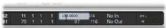
- Click-hold the tempo value in the Tempo List and drag up or down, or double-click the tempo field, then type a new value.
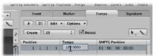
- Open the Tempo track, and drag the tempo line up or down with the Pointer tool.
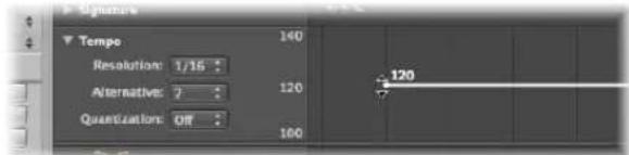
For more information about advanced tempo operations, please refer to Chapter 30, "Advanced Tempo Operations," on page 667.
Setting the Project Time Signature
The time signature defines how many beats a bar contains in the Bar ruler and what note value constitutes one beat.
Time signatures do not affect the playback of your project, but determine the editing grid in the Arrange area and MIDI editors as you can see in the following images. Both show the same MIDI region, with the first at a time signature of 2/8, and the second at 6/8.
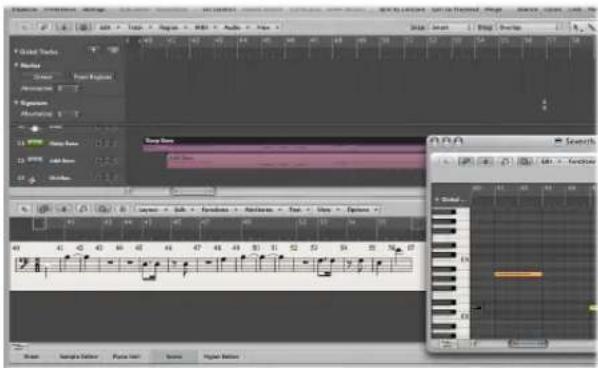
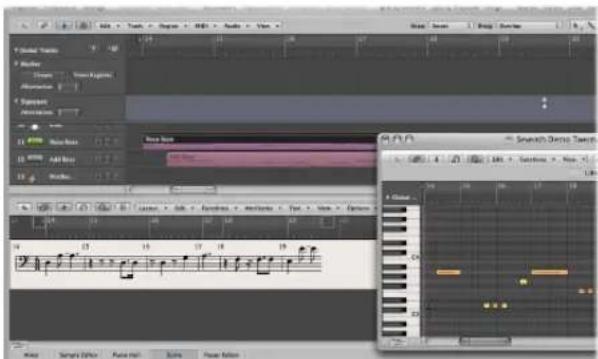
You can set the time signature of the project in the Transport, the Signature List, or the Signature track. The Transport displays the time signature in the following format: numerator : bar denominator : division value.
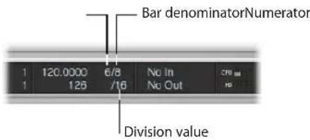
The division value defines the division in all position displays (such as in the event editors), and forms the grid for various length and placement operations. The division value is normally set to 1/16 notes, but has a value range of 1/4 to 1/192 note. If the note value of the division is equal to or greater than the bar denominator, the third value of the position display is automatically removed.
Tip: You can use the Set Next Higher/Lower Division key command to switch to the next highest or lowest division.
The tempo indicator in the Transport window always relates to quarter notes, even if eighth notes are chosen as the denominator for the time signature.
To change the time signature, do one of the following:
- Click-hold on either of the Transport time signature values and drag up or down, or double-click the numbers in the field, and type a new value.
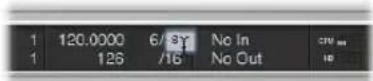
- Click-hold the value in the Signature List and drag up or down, or double-click the signature value, then type in a new value.
- Open the Signature track, and double-click the value shown. Set the Numerator and Denominator values (and other settings, if desired).
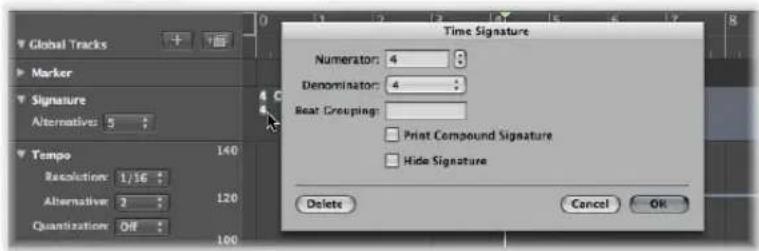
For more information on time signatures, refer to "Working With Time and Key Signatures" on page 755.
Setting the Start and End Points of a Project
A project normally starts at position 1 1 1 1. You can move the project start point to an earlier position, allowing upbeats or program change commands to be played before the first downbeat.
To define a project's start point:
- Drag the project start marker in the Bar ruler to the left or right.
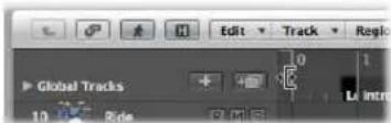
To define a project's end point, do one of the following:
- Drag the project end marker in the Bar ruler to the left or right.
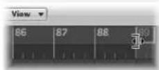
- Set the desired value in the Transport bar's numerical Project End display.
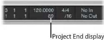
Note: If your Transport bar does not include the Project End display, Control-click on it and choose Customize Transport Bar in the pop-up menu. Turn on the Tempo/Project End checkbox in the Customize Transport Bar pane.
As soon as Logic Express reaches the project end point, it will stop automatically, except when recording. In this situation, the project end point is automatically moved to the end of the recording.
Setting the Basic Project Playback Level
You can set the basic project playback level by dragging the Master Level slider found at the right of the Transport bar (if your display is of a sufficient width). This slider is directly tied to the Master channel in the Mixer, and acts as a master level control for all audio and software instrument tracks.
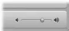
Important: This slider not only sets the playback level of your project, but also affects the overall level of your mix.
Click the speaker symbol to the right of the Master Level slider to set the master slider to 0 dB.
Click the speaker symbol to the left of the Master Level slider to turn on Dim Level mode: This sets the playback volume to the Dim Level value set in the Logic Express >Audio > General preferences.
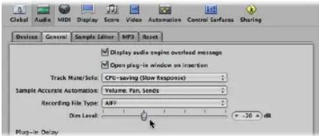
Click the button again to deactivate Dim Level mode, and set the playback level to the current Master Level slider value.
Adjusting Project Settings
The project settings encompass a number of options that can have a dramatic impact on the behavior of Logic Express. Project settings are saved independently with each project, which means that different projects can have different project settings. You can change project settings at any time, but it is generally best if you start off with the required settings, as this will make your workflow smoother.
To open the project settings, do one of the following:
- Choose the desired File > Project > Settings (Synchronization, MIDI, Score, and so on) menu entry (or use the corresponding key command).
- Click the Settings button in the Toolbar, then choose the desired menu entry.
Detailed information on all project settings can be found in "Project Settings" on page 962.
Handling Project Assets
The project settings also include an Assets tab. If you saved your project with its assets, you can use this tab to determine how files imported from external locations (locations outside the project folder) should be handled.
To open the Assets project settings, do one of the following:
- Choose File > Project Settings > Assets (or use the Open Assets Project Settings key command).
- Click the Settings button in the Toolbar, then choose Assets from the pop-up menu.
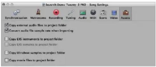
- Turn on any of the copy checkboxes to copy the respective file types into the project folder.
- Turn on the "Convert audio file sample rate when importing" checkbox to automatically convert the sample rate of all imported files (with a different sample rate) to match the project sample rate.
- If you turn off the Copy EXS Samples to Project Folder option, only EXS instrument files will be copied to the project folder when saving, not the samples associated with the EXS instrument files.
Files are only copied into the project folder when the project is saved.
Once saved, the project is "safe," allowing you to move or copy the entire project folder without losing any references that point to files within the folder.
Managing Projects
This section outlines some housekeeping that may be required to keep your projects in great shape.
Copying or Moving a Project Folder
A project folder can be freely moved or copied to another location by using any of the standard operating system methods. This is great for archiving and transport of projects to other studios or facilities.
All files in the target (copy) folder will still be found correctly, provided that they are all in the root (or sub-folders of) the project folder—audio files are found in the Audio Files sub-folder, samples in the Samples sub-folder, sampler instruments in the Sampler Instruments sub-folder, and so on.
Cleaning Up Projects
Should there be any unused project files in your project folder, make use of the File > Project > Clean Up command. If any unused files are found, the following dialog will be displayed:
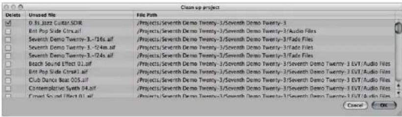
Turn on the checkboxes in the first column to choose files for removal. The name and path of the file to be deleted is shown in the last two columns.
Only files with active checkboxes in the first column will be deleted. All unchecked entries will remain as they are.
If multiple rows are selected, a click on any checkbox will switch all selected rows to the new state (either checked or unchecked).
Note: The Clean Up command will only delete unused files (all types, except movie files). Clean Up takes into account the project currently loaded, and all other Logic Express project files in the project folder—only files that are not used by any of these projects will be displayed in the Clean up list.
Consolidating Project Settings
If your project contains files that are not in the correct sub-folders within the project folder, you can use the Consolidate command to automatically organize them into the standardized project file structure.
To consolidate your project:
1 Choose File > Project > Consolidate (or use the Consolidate Project key command).
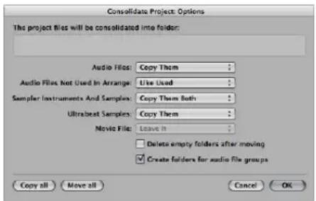
2 Choose the desired menu option for the different file types in the Consolidate dialog, to either move, leave, or copy the existing files.
The two shortcut buttons at the lower left of the window make project consolidation quick and easy.
- Click Copy All to set all menus to the copy option.
- Click Move All to set all menus to the move option.
3 Activate the "Delete empty folders after moving" checkbox to remove the empty folders in the source project, after files have been moved to the target project.
4 Activate the "Create folders for audio file groups" checkbox to create group folders within the Audio Files sub-folder of the target project.
The groups must first be created in the Audio Bin of the source project. See “Grouping Files in the Audio Bin” on page 561.
5 Press OK, when you're done.
ReCycle Import Handling in Projects
EXS instruments created via a ReCycle import are placed in a Sampler Instruments/ReCycle sub-folder of the project folder. All audio data generated by a ReCycle import is placed in the ReCycle Audio folder, alongside the project file.
Note: This happens automatically and can't be changed. If no project folder exists, ReCycle files are saved in \~Music/Logic/ReCycle Audio.
Saving Projects
When you choose File > Save (or use the corresponding key command, default: Command-S), the current project will be saved—with its current name intact.
If you don't wish to overwrite the most recent version of the project file saved with this name (which will happen if you use File > Save or Command-S), make use of the File > Save As or File > Save a Copy As commands. In the ensuing file selector dialog, you can enter a new name for the project, set Assets as desired, (and select a new directory or even create a new folder).
- File > Save As: The next time you save using the straight Save (Command-S) command, the new file name and path will be used.
- File > Save a Copy As: The next time you save with the straight Save (Command-S) command, the existing file name and path will continue to be used. The copy is a replica of the existing project, stored in a different location. It does not update the file save path. Save a Copy As is ideal for archiving and moving data.
Automatic Backup Files
When you save a project, Logic Express will automatically make a safety copy (a backup) of the project file. Backup files are saved in the project folder, and are named after the project, but feature the "\~" character after the project name.
Reverting to the Saved Version
Any time you make a mistake, you can undo it by choosing Edit > Undo (Command Z).
If you have made some really serious blunders (as unlikely as that may be), or you decide that in the 15 minutes since you last saved, your creative efforts have resulted in material too unpleasant to describe politely, you may find the File > Revert to Saved function (or the corresponding key command) very helpful. This replaces the current project with the previously saved version.
Saving a Project as a Template
You can save a project as template, creating starting points for new projects. Not all projects have the same needs, so customizing several projects to meet these needs offers an ideal starting point for different jobs. As examples:
- A template that is software instrument-focused, for dance music projects. This would feature 32 software instrument tracks, and say eight audio tracks.
- An audio track-centric template, featuring say 64 audio tracks, would be ideal for live recording.
- A specific live performance template that makes the job of quickly switching between parts faster, or perhaps makes heavy use of Environment processing.
- Several scoring templates for: choirs, a rock band, symphony orchestra, string quartet, jazz combo, and so on.
- A template containing modified synchronization settings for control of ADAT hardware.
- A template for video work: This would typically contain a video track plus specific dialog, foley, and music tracks.
- A second video template could be used for jobs where the video is running on an external video tape machine that is synchronized with Logic Express via SMPTE.
Screensets can be customized for each template, or you can make use of the File > Project Settings > Import Settings command to copy them between templates.
To save a project as a template:
- Choose File > Save as Template (or use the Save as Template key command), then type in the desired name.
The project will be saved in the \~/Library/Application Support/Logic/Project Templates folder. The next time you open the Templates dialog, you will see your template in the My Templates collection, below the factory template collections.
You can create collections under My Templates by creating sub-folders in the \~/Library/Application Support/Logic/Project Templates folder. This can be done in the Finder, or with the Create Folder button in the Save As Template dialog. When all user templates are placed in sub-folders, the sub-folder names will be shown below the factory collections.
Tip: You can add a descriptive text to your templates by adding a comment to the project file in the Finder. The Templates dialog displays the icon assigned to a template file, making it easy for you to change a template's icon. For more information on how to add a comment to a file, or change the icon of a file, see the Finder Help.
Closing and Quitting
Following the creation or playback of a project, you'll want to close it and Logic Express. Here's how you do it:
To close the currently active project:
- Choose File > Close Project (or use the corresponding key command, default: Option-Command-W).
If you have made any changes since the last save operation, Logic Express will ask you if the project should be re-saved before closing, to preserve any changes you have made.
To close the open window:
- Choose File > Close (or use the corresponding key command, default: Command-W).
This will only close the uppermost window, not the whole project. The project will only be properly closed when all windows are closed.
To quit the application:
- Choose Logic Express > Quit Logic Express (or use the corresponding key command, default: Command-Q).
If you've made changes, but haven't saved them, you will be asked if you want to do so before quitting (press Enter to save).
If multiple projects are open, you will be asked if you want to review any changes, or simply close and discard any changes.
The Close Project without Saving key command closes the currently active project without saving it—and you will not be asked to do so. This command was included at the request of many experienced Logic Express users. Please only use it if you're sure that this is what you want to do.
Basic Operations
8
The following chapter will introduce you to the basic operating, selection, and editing techniques available in Logic Express.
You will learn about input techniques, correcting errors, and a number of shortcuts and features that will accelerate your workflow, and assist you while learning about Logic Express.
Using the Mouse
If you're unfamiliar with mouse use in Logic Express, which differs from mouse use in other applications, the following section will be of use. It outlines how the mouse can be used in Logic Express. If you're comfortable with mouse use in Logic Express, skip ahead to the next section.
Clicking
Place the mouse pointer on the element (region, event, button, menu, input field, and so on) and press the mouse button once.
Double-Clicking
The same as clicking on an element, but you press the mouse button twice—in quick succession. You can set a suitable interval between clicks in the System Preferences (Keyboard & Mouse pane).
Grabbing or Clicking and Holding
The same as clicking on an element, but you keep the mouse button held down.
Moving or Dragging
Grab the element, and move the mouse (keeping the mouse button held down) to the desired position.
Right-Clicking
The same as clicking, but you press the right mouse button, if available. This will open a shortcut menu, open the toolbox, or select an assigned tool.
Modifier-Clicking or Dragging
Many commands, functions, additional tools, or finer adjustments are accessed by holding a modifier key: Control, Shift, Option, or Command while clicking or dragging. As examples: Option-dragging a region will copy it. Option-clicking on a fader or knob will reset it to its default, or centered, value.
Mouse Wheel Events
You can use the mouse wheel to scroll vertically in Logic Express. There are also some modifiers supported:
- If you press Command, the mouse wheel scrolls horizontally.
- If you press Option, the mouse wheel zooms in or out vertically.
- If you press Option-Command, the mouse wheel zooms in or out horizontally.
- If you press Option-Control, the mouse wheel zooms in or out in both directions.
Note: Logic Express also supports mice that feature an x and y axis on one scroll wheel (such as the Apple Mighty Mouse). On a 2 axis mouse, the Command modifier (that switches a single axis mouse between horizontal and vertical orientation) is not used.
Mouse as a Slider
You can set most numerical parameters (even note values or names) by grabbing the parameter value, and moving the mouse up or down. If the parameter consists of several separate numbers (project position, for example), you can adjust each number individually using this method.
Entering Numerical Values
You can use numerical input in many areas of the program. Double-clicking a numerical parameter value opens an input field. The existing value is highlighted, and ready to be overwritten by a new entry. This method is ideal for quickly setting a parameter value in the Inspector, or instantly navigating to a bar, when used in the Transport. As a usage example of the latter, double-click on the Position display in the Transport, and type in 45, followed by the Return key. This will move the playhead to the beginning of bar 45.
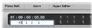
You can also use the mouse to make a partial selection in an input field, so that only the highlighted part is overwritten. As long as the input field is open, the computer keyboard may only be used for data entry, and may not be used for key commands (with the exception of the main menu functions).
Here are some of the possible methods. You can type in:
• Decimals: 1, 01, 2, 3, 4, 127, ...
• Hexadecimals: \1, \01, \2, \3, \A, \0A, \$7F
- Notes: "C3", "C#3", "Cb3", "C##2" (equivalent to D2), "Dbb2" (equivalent to C2). If you double-click on the note "E3", you can enter a decimal value such as "64" or a hex value of "\$40" instead of the note name.
- ASCII Code: You can also input numbers as ASCII code: just place a ` or " in front of the selected key, and the ASCII code will be input as a number.
As an example: "! results in a value of 33; "a results in a value of 97.
This function is particularly useful for entering text in SysEx strings.
Arithmetical Operations
In many parts of Logic Express, mathematical operations can also be used to change values. As examples:
- You can subtract from the existing value by entering “-5”.
- You can sum two values by entering "38+17".
- You can multiply two values by entering "7*8".
- You can divide two values by entering "80/5".
Canceling Numerical Input
You can cancel numerical input by entering no text at all, and pressing Enter or Return.
Entering Text
You can input text names in the same way as numbers, but you only need to click once on a name field to allow input. You can directly click on a region (or Mixer channel strip) with the Text tool to rename it.
Any number of selected objects (such as regions) can be assigned the same name. If the name ends with a number, this number will automatically be incremented by 1 for each subsequent object. This allows you to quickly, and uniquely, name all of the regions on a track, for example.
Note: To turn off automatic numbering, place a space after the number at the end of the name you type in. All selected objects will then end with the same number. This may be useful for identifying all main vocal regions recorded in another session, for example (rename to "mainvox 030707", followed by the space, to identify the regions by date).
Working With Key Commands
You can execute nearly every Logic Express function with a key command or MIDI message. Whenever this manual mentions a key command, this refers to a function, command, or option that can be accessed by either: a computer keyboard keystroke (or keystroke combination—such as Option-R—which opens the Recording project settings), or a MIDI message.
Use of key commands, rather than the mouse, can greatly accelerate your workflow. Throughout this manual, you will encounter a number of practical usage examples, often in step form, that include the default key command assignments for particular functions.
Tip: It is recommended that you make use of these default key commands while getting to know the application, by following the steps outlined in the guide. Not only will this help you to remember them, but will also aid in developing good (and faster) working practices from the outset.
Once you have a good understanding of Logic Express fundamentals, and how you like to work, you can freely assign your own key command set—for functions that you use most often.
The Key Commands window is used to assign Logic Express functions to computer keyboard keys, or to MIDI messages. This allows you to completely customize the application to suit your own working style.
Note: A number of functions are only available as key commands. Some of these may not have a default key command assignment. In such cases, you will need to create a suitable key command, in order to make use of the function.
If you're new to Logic Express, and would like to get "hands on" with the application, please skip ahead to "Working With Tools" on page 170. You can always return to the following section when you're ready to create or customize your own key command set, but this isn't essential to know before using Logic Express.
Saving Key Commands
Your personal key assignment sets are stored in a separate file located in \~Library/Application Support/Logic/Key Commands. You should:
- Make a backup of your user-defined key command set at another hard disk location before changing any key commands.
- Make a backup on removable media (a CD-ROM or USB flash drive, for example), or on a networked Macintosh (using Bonjour) or a .Mac account (see "Sharing Logic Express Data Over a Network" on page 650). These back up options make it easy to transfer your key commands when using Logic Express on another computer.
Whenever you install Logic Express updates, your personal key commands will remain unaltered.
Note: Almost all key commands are user-definable. Some of the default assignments for standard commands such as Undo, Save, Quit, New, Open, Cut, Copy, and Paste follow Mac OS X conventions, and probably shouldn't be altered. Some keys are "hard-wired" to specific functions or commands, and can not be changed. These are dimmed in the key command listing, to indicate this fixed status. See the section below.
Special Keys
Some keys have special functions:
- The Shift, Control, Option, and Command modifier keys can only be used in conjunction with other keys.
- The Backspace key has the fixed "delete selected objects" function. It can only be assigned to another function in conjunction with the modifier keys.
- The key combinations assigned to the commands in the main menu bar can be reassigned, but it is generally recommended that you leave them at their defaults. The key command assignment is displayed after the main menu items. As examples: Command-1 opens the Arrange window, Shift-L locks the current screenset.
- The Plus and Minus keys are assigned to the Increase/Decrease Last Parameter by 1 key commands. As the name suggests, this will increase or decrease any selected parameter value in single units.
- Using Shift in conjunction with the Plus and Minus keys accesses the Increase/Decrease Last Parameter by 10 key commands.
The Key Commands Window
The Key Commands window is used to assign Logic Express functions to computer keyboard keys or MIDI messages. This allows you to completely customize the application to suit your working style.
To open the Key Commands window, do one of the following:
- Choose Logic Express > Preferences > Key Commands (or use the Open Key Commands key command, Option-K).
- Click the Preferences Toolbar button, then choose Key Commands from the shortcut menu.
Tip: Pressing Control—and choosing a command in a menu—opens the Key Commands window, with the respective command selected. This also works with shortcut menus.
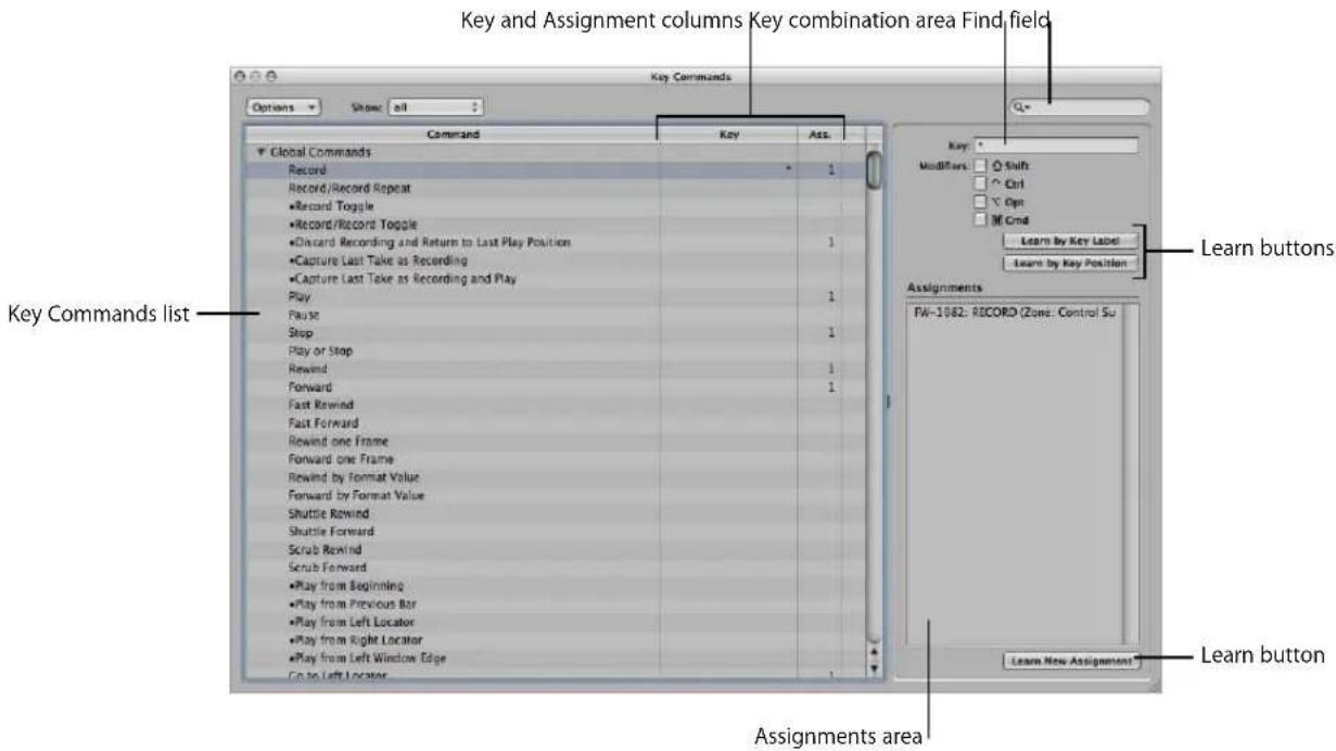
- Key Commands list: Lists all available key commands. The bullet indicates key commands that are not available as menu items.
• Key and Assignment column: Show the currently assigned key, and MIDI message (if applicable). - Find field: Use this to find key commands by name or partial name.
• Key combination area: Displays the key combination associated with the selected key command. - Assignments area: Displays the control surface assignment associated with the selected command.
- Learn buttons: Use these to teach Logic Express to use a particular key, or key combination, to perform a function.
Key Command Groups and Hierarchies
The global key commands are always functional, regardless of the currently active window. Non-global commands require the corresponding window to have key focus (in the foreground, or on top of other windows). This allows you to assign the same key command (or combination of keys) to different functions in different windows.
Important: There is a hierarchy of key command classes, which are not merely separated into global and local key commands. As an example, there is a key command class that applies to all windows that display regions. This class has higher priority than global key commands, but a lower priority than local (Arrange, Score, Piano Roll, and so on) window key commands.
Choosing Key Command Sets
The Options menu offers commands that allow you to switch between key command sets, or import and export them. This is particularly useful if you need to work temporarily on another user's Logic Express system; allowing use of your personal key assignments, without altering the settings of the other system.
- Options > Preset menu: Displays all key command sets saved in the \~Library/Application Support/Logic/Key Commands folder, allowing you to quickly switch between key command sets.
- Options > Import Key Commands: Opens a file selector box, allowing you to import key command sets from any folder location. The existing file (on the target system) is automatically saved as a *.bak file. This file contains the old key commands. You don't need to restart Logic Express to begin using the new key command set.
- Options > Export Key Commands: Opens a file selector box, allowing you to save the current key command assignments to any desired location.
Browsing Key Commands
Key commands are grouped into various categories. You can extend or collapse groups by clicking the respective disclosure triangle.
The Options > Expand All command displays the contents all key command groups. Options > Collapse All hides the contents of all key command groups.
When you expand key command groups, your key command selection may no longer be visible. You can quickly return to the selected key command by choosing Options > Scroll to Selection. When the list has key focus, you can use a key command (or key command combination) to select the associated function in the list.
Finding Key Commands
You can use the Key Command window's Find field to find key commands by name or partial name:
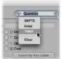
- The search is performed as you enter text. There is no need to press the Return key, unless you wish to retain a history of key command searches.
- The Cancel button to the right (that appears as soon as any text is entered) clears any entered text, and displays all key commands.
- The Find menu to the left (the magnifying glass) retains a history of recently used search terms. The Clear menu item erases the Find history.
Note: The Find history is limited to searches that were completed by pressing the Return key.
Assigning Key Commands to Computer Keys
This section shows you how you assign particular computer keyboard keys to Logic Express functions.
To assign a function to a key:
1 Select the desired command in the Command column.
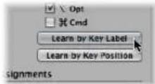
2 Activate the Learn by Key Label button.
3 Press the desired key, along with the desired modifier key or keys (Shift, Control, Option, or Command).
4 If you want to make another assignment, repeat steps 1 to 3.
5 Deactivate the Learn by Key Label button.
The Learn by Key Position function works in the same way, but differs in that it's not just a reference to an ASCII code that is stored, but the actual scan code of the key that is pressed.
In practice, this means that you can, for example, assign different commands to the number keys on the numeric keypad and the number keys above the keyboard.
This also means that the key position remains the same if you switch between different operating system language settings, or different keyboards. As an example, using a scan code for a function assigned to the Y key on an English keyboard would function in the same way if you switched to a German keyboard—which has a Z key in the same position as the Y key on an English keyboard.
The only disadvantage is that the key code (a number), rather than the ASCII symbol, is displayed in the Key Commands window. The ASCII symbol is more useful for reference purposes.
To clarify the difference between these two functions, here's a short comparison:
- If you use the Learn by Key Label function, and define only one key command for the key, it will be used, no matter which of the two keys (either number 7 key, for example) is pressed.
- If you use the Learn by Key Position function, and define two key commands (one for the alphanumeric keyboard, one for the numeric keypad), then the appropriate key command will be used (one for each number 7 key, for example).
Using Existing Key Commands
In circumstances where an existing local key command combination is used, when assigning a new global key command, the following warning message will appear:
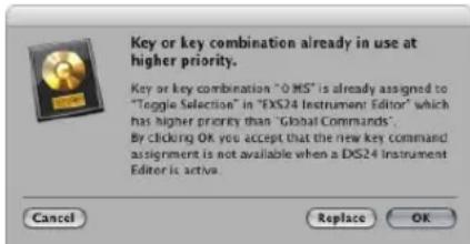
You have three options: Cancel, Replace, or OK.
- Cancel: Does not alter existing assignments.
- Replace: Replaces the existing shortcut (assigned to the chosen key command combination) with the selected function.
- OK: Assigns the key command combination to the selected function, while retaining the existing key command or function.
To delete key assignments:
1 Select the function with a key assignment that you'd like to delete.
2 Activate the Learn by Key Label or Learn by Key Position button.
3 Press Backspace.
4 To erase more assignments, repeat the first and third steps.
5 Deactivate the Learn by Key Label or Learn by Key Position button.
Assigning Key Commands to Control Surfaces
The Learn New Assignment button allows you to assign control surface messages to particular commands—effectively teaching Logic Express to understand these messages.
To learn a controller assignment:
1 Click the Learn New Assignment button.
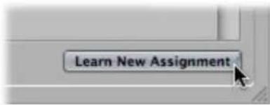
2 Select the command in the Command column.
3 Send the desired MIDI message from your controller.
The Assignments field displays the learned assignment. This may show one or all of the following:
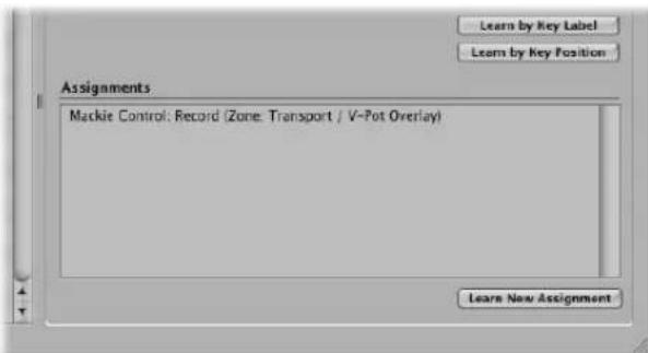
- The name of the control surface—or the MIDI string, if the assignment is from an unsupported control surface.
• The name of the control.
• The zone and mode that the assignment belongs to, if applicable.
Note: The Learn New Assignment button is automatically turned off when the entire message has been received. This avoids reception of further messages (that may be) sent by the device when you release the button. To ensure reliable reception, hold the button for a short period before releasing it.
4 If you want to make another assignment, repeat steps 2 and 3.
If you want to assign functions—other than key commands—to a control surface, make use of the Controller Assignments window. You can open it by double-clicking on a row in the assignment section, or choosing Logic Express > Preferences > Control Surfaces > Learn Assignment for xxx command (Open Controller Assignments key command). This is detailed in the Control Surfaces Support manual.
Initializing Key Assignments
You can reset all key commands to their default assignments. You will lose your existing key command assignments, so ensure that you have created a copy of your key commands file before doing so.
To initialize all key command assignments:
- Choose Options > Initialize all Key Commands in the Key Commands window.
Printing a Key Command List
You can use the Options > Copy Key Commands to Clipboard function to copy your key command assignments into the Clipboard as text. From here, it's a simple matter of pasting the results into any word processor, formatting as desired, and printing them out.
The Copy to Clipboard command only copies the currently visible key command assignments. You could, therefore, export a certain group of key commands (those containing a particular character string, for example). What you see in the window display is exactly what's exported.
The Copy to Clipboard command only copies the currently visible key command assignments into the Clipboard
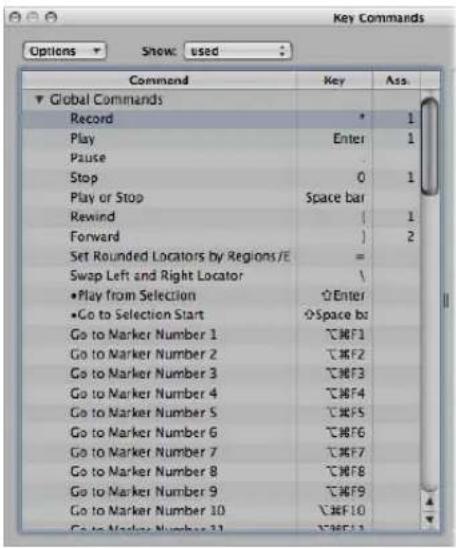
![Key Commands.rtf Styles Spacing Lists Global Commands Record Record/Record Repeat •Record Toggle •Record/Record Toggle •Discard Recording and Return to Last Play Position •Capture as Recording •Capture as Recording and Play Enter Play . Pause 0 Stop Space bar Play or Stop [ Rewind ] Forward Fast Rewind Fast Forward Rewind one Frame Forward one Frame Rewind by Division Value Forward by Division Value Shuttle Rewind Shuttle Forward Scrub Rewind Scrub Forward •Play from Beginning •Play from Previous Bar •Play from Left Locator](/content/2026/05/859464/images/d3e7e7833a1fda1918e506c87692d16e4fd9c7c7d0006249feb5bdf9ea1081a8.jpg)
Working With Tools
Each editor provides different tools—that are suitable for the tasks performed in the window.
Tools are only effective in the working area of the window in which they are chosen. You can define individual tools for each window.
A tool (the Scissors, for example) basically affects the regions or events that you click on. If multiple regions are selected, they are all affected by the tool (the Scissors would cut all selected regions at the same playhead position).
Tools are accessed in the Tool menus, found at the upper-right corner of all windows that allow direct region, event, or file editing and handling operations.
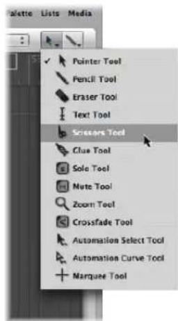
You may freely assign at least two tools—one in each Tool menu. In some windows, additional tool menus may appear after two tools have been assigned.
To assign the left-click (or default) tool:
- Click the left Tool menu to open it, and choose the desired tool.
To assign the Command-click (alternate) tool:
- Click the right Tool menu, and choose the desired tool.
When editing regions, events, or files, both tools are available at the mouse pointer position. The left menu tool is active by default.
To switch between the default and alternate tools:
1 Hold down Command to activate the alternate (right menu) tool.
2 Release the Command key to revert to the default (left menu) tool.
The mouse pointer adopts the shape of the active tool, allowing you to instantly identify it by looking at the cursor graphic.
Assigning the Right Mouse Button
If you have a suitable mouse, you can also assign the right mouse button to any of the following:
• A third tool
- Tool menu
- Shortcut menu (default)
To set the behavior of the right mouse button:
1 Open the Global preferences by doing one of the following:
- Choose Logic Express > Preferences > Global (or use the corresponding key command).
- Click the Toolbar Preferences button, then choose Global from the pop-up menu.
2 Click the Editing tab, then choose the desired setting from the Right Mouse Button pop-up menu.
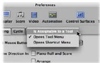
- Is Assignable to a Tool: When this option is selected, a third Tool menu appears (to the right of the default and alternate Tool menus) in the working window. Choose the appropriate menu item to assign the right mouse button tool. Right-clicking activates the third tool in the working window.
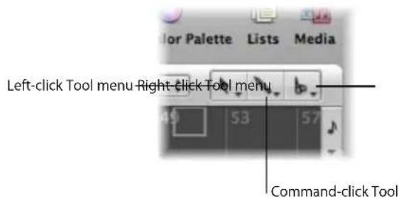
- Opens Tool Menu: Right-clicking in the working area of the active window opens the Tool menu at the mouse cursor position. Simply choose the desired tool by clicking on it. When the Tool menu is open, you can also use the key shown next to a tool to select it.
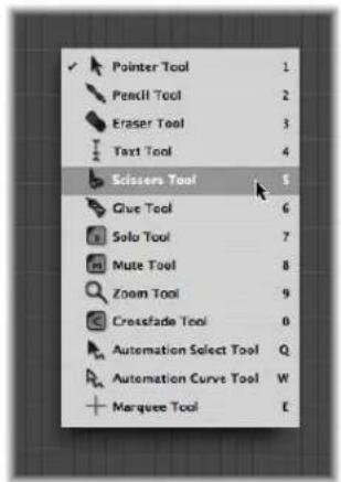
- Opens Shortcut Menu: Right-clicking in the working area of the active window will display a menu that offers a number of area-specific selection and editing commands (see "Using the Shortcut Menu" on page 177).
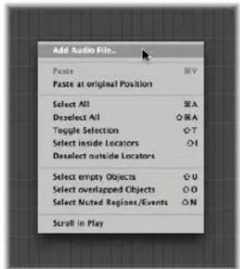
Using Key Commands to Select Tools
You can also use the following key commands to select tools:
- Set Next Tool and Set Previous Tool: Switch to the neighboring tool in the active window.
- Show Tool menu: Open the Tool menu at the cursor position. When the Tool menu is open, you can also use one of the number keys shown next to a tool to select it. (default key command: Esc)
- Set X tool: You can select each tool via a specific key command. Key commands assigned to a specific tool switch between this tool, and the previously selected tool.
Learning About Common Tools
The following section describes the most common tools available in Logic Express. Tools that are specific to particular editing windows are covered in the respective chapters.
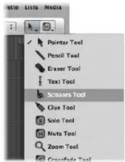
Pointer Tool
The Pointer is the default tool when Logic Express is first opened. The mouse cursor also takes on this shape outside the working area, when making a menu selection or entering a value.
Within the working area, you can use the Pointer tool for:
- Selecting individual or multiple events, regions, or other elements by clicking on them. See "Selection Techniques" on page 177.
- Moving (by grabbing and dragging)
- Copying (by Option-dragging)
- Changing lengths (by grabbing the bottom right or left corner and dragging)
- Looping regions (by grabbing the upper right corner, and dragging)
Pencil Tool
The Pencil is used to add new regions or events. You can also select, drag, loop regions, and alter the length of regions or events while the Pencil tool is active.
Eraser Tool
The Eraser deletes selected regions or events. When you click a region or event with the Eraser, all of the currently selected regions or events are deleted (as if you had used Backspace). The Eraser can also delete an unselected region or event by clicking on it.
Text Tool
The Text tool is used to name regions, or add text to a musical score.
Scissors Tool
The Scissors tool is used to split regions and events, allowing individual sections to be copied, moved, or deleted.
Glue Tool
The Glue tool performs the reverse operation of the Scissors tool. All selected regions or events are merged into a single region or event.
Solo Tool
Click-holding a region with the Solo tool allows you to listen to the selected region or event in isolation. Moving the mouse horizontally also outputs (scrubs) any events the cursor touches.
Mute Tool
Clicking an event or region with the Mute tool prevents it from playing. You can unmute the region or event by clicking it a second time with the Mute tool. If multiple regions or events are selected, the mute status of the clicked region or event applies to all selected regions or events.
Zoom Tool
The Zoom tool allows you to zoom (up to the full window size) by making a rubber-band selection. You can revert to the normal zoom level by clicking on the window background with this tool. You can also access the Zoom function—even when other tools are active—by holding down Control-Option.
Working With Help Tags
A help tag appears just below the mouse cursor position—for as long as the mouse button is held down—when using many of the tools. The help tag provides useful feedback on the operation you are performing.
Note: You must enable the Logic Express > Preferences > Display > General > Show Help Tags option in order to view help tags during editing operations.
During operations involving regions, the help tag will look something like this:
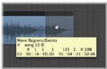
From left to right (and from top to bottom), the values indicate:
• Name of the operation.
- Mouse (or region) position.
- Region/event name.
- Track number.
• Length of the region.
During operations involving events, the help tag looks something like this:
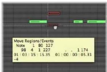
From left to right, the values indicate:
• Name of the operation.
- Mouse (or event) position.
- Event type.
• Event MIDI channel.
- First data byte (note pitch, for example).
• Second data byte (note velocity, for example).
• Event length (note length, for example).
Using the Shortcut Menu
Control-clicking anywhere in the Arrange, Piano Roll Editor, and all List Editors, launches a shortcut menu (also known as the context menu) that can be used for a number of selection and editing tasks.
The shortcut menus differ between (and within) windows, based on both the selection status of events or regions within the window, and also the type of information that the editor deals with.
The items that appear in the menu will update to reflect the current context. As examples in the Arrange area:
- An Arrange window with no regions or no selected regions: A number of Select and Paste commands, plus Scroll in Play are available.
- With one or more regions selected in the Arrange: Cut, Copy, and Delete, Nudge, Lock/Unlock SMPTE Position and Region Name and Color commands become available.
Note: You can always access the shortcut menu with a Control-click, but can also make use of the right mouse button to open it. To do so, ensure that the Right Mouse Button: Opens Shortcut Menu pop-up menu item is chosen in the Preferences > Global > Editing tab.
Selection Techniques
Whenever you want to perform an operation on one or more regions or events (or other elements, such as Mixer channel strips), you first need to select them. Selected elements, regions, or events are: displayed in an inverted color scheme, with a highlighted name, or will flash (note events in the Score Editor, for example).
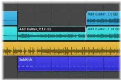
A region or event selected in one window will also be selected in all other windows that display that region or event. As examples, a note event selected in the Piano Roll Editor will also be selected in the Score Editor and Event List. The region that contains the selected event will also be selected in the Arrange area.
Changing the window with key focus doesn't affect the selection (as long as you don't click on the window background, which deselects everything). Be sure to click on window title bars when switching between windows.
Tip: Don't forget about the Zoom functions when making your selections, as high zoom levels can make precise selections much simpler.
Selecting Individual Regions, Events, and Other Elements
You can select individual regions or events (or other elements, such as Mixer channel strips) by clicking on them with the Pointer tool.
You can deselect them by clicking on the window background, or by selecting another region, event, or element.
The Select Next Region/Event key command (default assignment: Right Arrow key) and the Select Previous Region/Event key command (default assignment: Left Arrow key) provide a quick way to step between (and individually select) regions or events.
In the Arrange area, pressing any letter key selects the first region with a name that begins with the chosen letter (as in the Finder), provided that no key command is assigned to this key.
Selecting Several Regions, Events, and Other Elements
You will often need to select multiple regions, events, or other elements, in order to move, process, or copy them, for example.
To select all regions, events, or elements in a window:
- Choose Edit > Select All (or use the corresponding key command, default: Command-A)
To deselect all regions, events, or elements in a window:
- Choose Edit > Deselect All (or use the corresponding key command, default: Shift-Command-A)
To select several non-contiguous regions, events, or elements in a window:
■ Shift-click on them, one-by-one.
As subsequent regions or events are selected, the previous selections are retained.
Making Horizontal Selections
Horizontal selections can be made in a number of editing windows, allowing you to quickly select all regions, or events that are horizontally aligned on a lane.
To select all regions on a track in the Arrange area, do one of the following:
- Click on the track name in the track list.
- Choose Edit > Select All Following of Same Track (or use the corresponding key command). All regions following (after) the selected region will be selected.
To select all events (of a specified event definition) in the Hyper Editor, do one of the following:
■ Click on the event definition name.
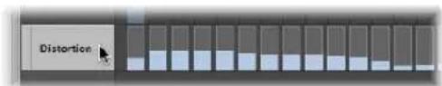
- Choose Edit > Select All Following of Same Pitch (or use the corresponding key command). All events after the selected event will be selected.
To select all notes of a certain pitch in the Piano Roll Editor, do one of the following:
- Click the relevant key on the Piano Roll keyboard.
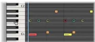
- Choose Edit > Select All Following of Same Pitch (or use the corresponding key command).
Important: The selection techniques covered above only affect regions or events that fall within the cycle area defined in the Bar ruler, when Cycle mode is on.
Making Rubber-Band Selections
To select consecutive regions or events (or other elements, such as Mixer channel strips), click on the background and drag a rubber-band over them.
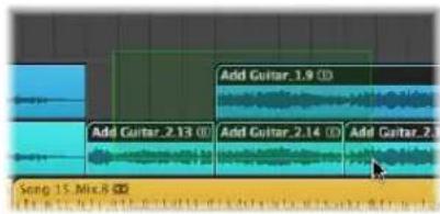
All regions or events touched, or enclosed, by the rubber-band (shaded area) will be selected.
Switching the Selection Status
When you make any selection (including by rubber-band or horizontal selection) while holding down Shift, the active selection status of the regions or events will be reversed.
You can also reverse the selection status of all regions or events by using Edit > Toggle Selection (default key command: Shift-T).
As an example: If you want to select all regions in a project, with the exception of a few, you can first select the regions that you do not want to choose, and then use the Toggle Selection command.
Selecting Following Regions or Events
To select all regions or events that follow the currently selected region or event (or, if none are currently selected, to select all regions or events after the playhead position), choose Edit > Select All Following (default key command: Shift-F).
To add the following region or event to your selection:
■ Use the Toggle Next Region/Event key command (default: Shift–Right Arrow)
To add the previous region or event to your selection:
■ Use the Toggle Previous Region/Event key command (default: Shift–Left Arrow).
Selecting Regions or Events Within the Locators
Choose Edit > Select Inside Locators (default key command: Shift-I) to select all regions or events lying wholly, or partly, inside the locator positions.
Edit > Deselect Outside Locators (or the corresponding key command) deselects all regions or events outside the locators. Region or event selections within the locator boundaries are unchanged.
Selecting Specific Regions and Events
You can use the following commands to select regions or events that match a specific condition, or have a particular characteristic.
- Edit > Select Empty Regions (default key command: Shift-U): Use to select all empty regions.
- Edit > Select Overlapped Regions/Events: Use to select all overlapping regions or events.
- Edit > Select Muted Regions/Events (default key command: Shift-M): Use to select all muted regions or events.
- Edit > Select Equal Colored Regions/Events (default key command: Shift-C): If you have selected a region or event of a certain color, you can use this command to select all regions or events of the same color. This is a useful option when replacing song sections and other group editing tasks.
- Deselect All Regions Except on Selected Track key command: Deselects any regions not on the currently selected track. This command is especially handy when used after other special selection commands—limiting the effects of ensuing commands to the recording track.
Selecting Similar or Identical Objects, Regions, or Events
If you have selected a region, event, or Environment object, you can use the Edit > Select Similar Objects/Regions/Events function to select all similar regions, events, or objects (default key command: Shift-S).
The Select Equal Regions/Events/Object function selects all identical objects, regions, or events (default key command: Shift-E).
The table outlines the differences between similar and identical (equal) objects.
| Element Similar Identical | ||
| Region | Region type (audio or MIDI) | MIDI regions: Identical content and sizeAudio region: All regions of the same length and position |
| Controller events | Controller number equal, any data byte (control value) | Controller number and data byte (control value) equal |
| Note event | Note equal, any octave Note and octave equal | |
| Environment object | Same object type (e.g. fader) | Same fader type (e.g. text) |
Selecting Events With the Same MIDI Channel
Following selection of an event, you may select all other events that share the same MIDI channel by using the Edit > Select Equal Channels command (default key command: Shift-K).
As an example: Imagine you're editing a MIDI region that contains volume and pan controller information for 16 MIDI channels.
To select all events on channels 1 and 3:
1 Shift-select one event on channel 1 and another event on channel 3.
2 Choose Edit > Select Equal Channels (or use the corresponding key command, default: Shift-K).
All other events on these two channels will be selected.
Selecting Regions or Events With an Equal Subposition
You can select all regions and events with a certain relative position, such as all snare drums on the off-beat. Select a region or event at the desired relative position, and choose Edit > Select Equal Subpositions (default key command: Shift-P). All regions or events with the same relative position will be selected.
Accelerating Edit Operations With Selection Commands
As you can see, there are many different ways to make selections, based on different criteria. These can be used to speed up many editing operations, in conjunction with key commands. Here are a few examples:
If you want to delete all similar regions, events, or objects, make your selection and use the Delete Similar Object key command.
Conversely, if you want to keep all similar regions, events, or objects, and delete all others, use the Delete but Keep Similar Objects key command.
You can use the Event Channel +1 key command or the Event Channel -1 key commands to alter the channel number of the selected event (or events) by one, making it easy to reassign it/them to another MIDI channel.
Working With the Clipboard
The Clipboard is an invisible area of memory, into which you can cut or copy selected information (such as regions or events), allowing them to be pasted to a different location.
The Clipboard is universal, which means that it can be used to exchange information between projects.
All of the following options are available in the Edit menu.
Cut
All selected elements are removed from their current position, and placed in the Clipboard. Any existing content in the Clipboard is overwritten in the process (default key command: Command-X).
Copy
A copy of all selected elements is placed in the Clipboard. The selected elements are left in place. As with Cut, the contents of the Clipboard are overwritten (default key command: Command-C).
Paste
All content from the Clipboard is copied into the window with key focus. The Clipboard contents are not erased in the process (default key command: Command-V).
Paste at Original Position
This command works in a similar way to Paste, but the regions or events in the Clipboard are always pasted to the position they were originally cut from, regardless of the current playhead position (which is where regions or events would be placed with the standard Paste function).
Paste Replace
This function only works in the Arrange and editor windows. It resembles Paste, but all existing regions or events in a given location are replaced by the regions or events being pasted.
Warning: When using this function, all regions or events that lie within the time period occupied by the regions or events on the Clipboard are erased.
Undoing and Redoing Editing Operations
A simple change of mind or editing mistake is an inevitable part of music production. Fortunately, you can backtrack your edits easily in Logic Express—by using the Undo command to reverse your previous editing operation.
To undo your last step:
- Choose Edit > Undo (default key command: Command-Z) immediately after making the error.
Virtually all edits, including moves, deletions, renaming, parameter changes, creation of new events, regions, or channels, and more, can be undone.
The Number of Undo Steps setting in the Logic Express > Preferences > Global > Editing tab determines the maximum number of possible undo steps.
The Undo History is saved with the project, making it available when reopened.
To open the Undo History window:
- Choose Edit > Undo History (or use the corresponding key command, default: Option-Z).
| Undo History | |||
| Number | Action | Date | Time |
| 1 | Hyper Editing in " SubKick" | 01.12.2006 | 14:10:31 Uhr |
| 2 | Hyper Editing in " SubKick" | 01.12.2006 | 14:10:33 Uhr |
| 3 | Drag P-Press in " SubKick" | 01.12.2006 | 14:10:36 Uhr |
| 4 | Drag P-Press in " SubKick" | 01.12.2006 | 14:10:38 Uhr |
| 5 | Delete Track in " Basic" | 01.12.2006 | 14:18:10 Uhr |
| 6 | Delete Track in " Basic" | 01.12.2006 | 14:18:10 Uhr |
| 7 | Delete Track in " Basic" | 01.12.2006 | 14:18:11 Uhr |
| 8 | Delete Track in " Basic" | 01.12.2006 | 14:18:11 Uhr |
| 9 | Copy and Drag "Add Guitar_1.1" in " Basic", Size | 01.12.2006 | 14:23:33 Uhr |
| 10 | Length Change, Size = 47 kB | 01.12.2006 | 14:23:34 Uhr |
| 11 | Split Regions "Add Guitar_1.15" in " Basic", Size | 01.12.2006 | 14:23:41 Uhr |
| 12 | Split Regions "Add Guitar_1.17" in " Basic", Size | 01.12.2006 | 14:23:43 Uhr |
| 13 | Split Regions "Add Guitar_1.19" in " Basic", Size | 01.12.2006 | 14:23:44 Uhr |
| 14 | Delete "Add Guitar_1.18" in " Basic" | 01.12.2006 | 14:23:48 Uhr |
| 15 | Length Change, Size = 51 kB | 01.12.2006 | 14:23:57 Uhr |
| 16 | Drag "Add Guitar_1.16" in " Basic", Size = 31 kB | 01.12.2006 | 14:23:59 Uhr |
| 17 | Delete "Add Guitar_1.16" in " Basic" | 01.12.2006 | 14:24:01 Uhr |
| 18 | •Event Transpose + 1 " Fe#l" in " SubKick" | 01.12.2006 | 14:24:45 Uhr |
| 19 | •Event Transpose + 1 " G#l" in " SubKick" | 01.12.2006 | 14:24:47 Uhr |
| 20 | •Event Transpose - 1 " G#l" in " SubKick" | 01.12.2006 | 14:24:48 Uhr |
| 21 | •Event Transpose + 1 " Fe#l" in " SubKick" | 01.12.2006 | 14:24:52 Uhr |
| 22 | Velocity Change "SubKick" in " Basic" | 01.12.2006 | 14:25:04 Uhr |
| 23 | Velocity Change "SubKick" in " Basic" | 01.12.2006 | 14:25:09 Uhr |
| 24 | Copy and Drag "SubKick" plus 1 in " Basic" | 01.12.2006 | 14:25:19 Uhr |
| 25 | Drag "SubKick" in " Basic" | 01.12.2006 | 14:25:24 Uhr |
| 26 | Drag "SubKick" in " Basic" | 01.12.2006 | 14:25:27 Uhr |
| 27 | Hyper Draw in " Audio 2" | 01.12.2006 | 14:25:48 Uhr |
| 28 | Hyper Draw "Volume" in " Audio 2" | 01.12.2006 | 14:25:50 Uhr |
| 29 | Hyper Draw "Volume" in " Audio 2" | 01.12.2006 | 14:25:53 Uhr |
| 30 | Hyper Draw "Volume" in " Audio 2" | 01. 12. 2006 | 14 : 26 : 30Uhr |
The Undo History shows you a list of all actions that can be undone. The most recent step (editing operation), which will be the first to be undone, is selected.
To undo or redo multiple steps:
- Click on any entry to undo or redo all steps between the clicked and highlighted entries.
To undo or redo an isolated step:
■ Command-click on the desired step.
This will undo or redo an isolated step—without influencing all steps between the clicked and highlighted entries.
To erase the Undo History:
- Choose Edit > Delete Undo History.
Warning: Please take care with this command. No undos or redos are possible for the deleted steps, once the Undo History has been erased.
Working With Tracks
9
Tracks contain the audio regions and MIDI regions of a project.
Tracks are listed from top to bottom in the Arrange track list and extend horizontally across the Arrange area in lanes.
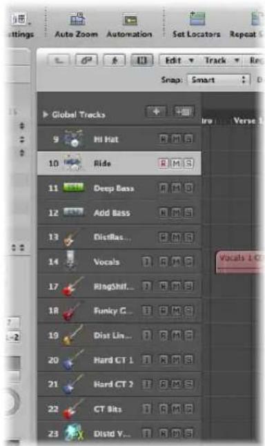
Each track is assigned to a particular channel in the Mixer. In other words, the output of a track is sent to a channel strip. If a track is not sent to a channel strip, regions on it will not be heard.
Note: The exception to this rule is folder tracks. For more information about folders, see "Using Folders" on page 354.
Once assigned to a particular type of mixer channel, the functionality of the track is limited as follows:
| Track type Assigned to Mixer Track used for |
| Audio Audio channels Playback, recording, and automation of audio regions. |
| Instrument Instrument channels Playback, recording, and automation of MIDI data sent to software instruments |
| MIDI MIDI channels Playback, recording, and automation of MIDI data sent to external MIDI devices |
| Folder Not assigned Used as lanes for folder regions. Folder regions are simply containers for other regions, and are not assigned to a Mixer channel. |
As you can see, each track type handles different sorts of data and has a special purpose. This is due to the routing of each track to a specific channel type in the Mixer.
The parameters of a track are displayed in the Inspector's Track Parameter box.
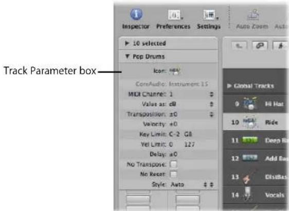
Important: The parameters belong to the channel strip (or object) the track is routed to, not to the track per se, so if you alter the parameters here, it will affect all tracks assigned to this channel strip.
Most of the functions described in this chapter are identical for external MIDI, software instrument, and audio tracks.
In addition to these track types, there are also tracks with very specific functions, such as global tracks. Global tracks—found at the top of linear editing windows—are used to view and edit global events, such as tempo, which affect all tracks in the arrangement. These track types are not covered in this chapter.
Configuring the Track Header
The track header of each track (shown in the Arrange area's track list) can display a number of buttons beside the track name and icon. By default, this includes the Record Enable, Mute, and Solo buttons on all tracks, with the Input Monitoring button also shown on audio tracks.
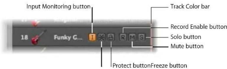
You can use the Track Configuration dialog to show or hide these, and other, track header elements.
To determine the elements that are shown in the track header:
1 Open the Track Configuration dialog by doing one of the following:
- Choose View > Configure Track Header in the Arrange area.
- Control-click on any track header in the track list, then choose Configure Track Header from the pop-up menu.
2 Enable the desired track header elements in the Track Configuration dialog.
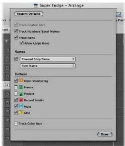
- Track Control Bars: Turn this on to view the track control bars. These bars indicate tracks that are accessed by control surfaces connected to your system. Each control surface can be assigned a different color in the Device parameter box. For more information, see the Control Surfaces Support manual.
- Track Numbers/Level Meters: Turn on this checkbox to display a track's number. During playback, a small level meter replaces the track number. For external MIDI or software instrument tracks, this meter indicates the velocity of the recording, and turns red to denote a maximum velocity value. For audio tracks, the level meter denotes the output level.
- Track Icons: Click to display or hide the track icons in the track header.
- Names section: Use the menus in this section to determine the names displayed in the track header. For more information, see "Naming Tracks" on page 199.
- Buttons section: Activate the checkboxes of the buttons you want to display in the track header.
- Track Color Bars: Turn on this checkbox to show a thin color strip at the right edge of each track. This is a visual aid that can help you to keep track of regions that have been moved between tracks.
Reclaiming Workspace Used by the Track Header
Obviously, enabling all of the buttons, icons, track names, and so on can result in a lot of information being shown in the track header.
To see all of this information, you can resize the track list, by dragging the top left corner of the Arrange area. The mouse cursor will change to a resize icon.
The downside of resizing the track list is that this reduces your working space in the Arrange and editing areas.
To reclaim a little more room to move, you can hide the entire Inspector area to the left of the Arrange and editor windows, providing more workspace for regions, events, and other data.
To hide or show the Inspector in the Arrange window, do one of the following:
- Click the Inspector button in the Toolbar.
- Choose View > Inspector (or use the Hide/Show Inspector key command, default: 1).
Creating Tracks and Channels
If you want to record or play back MIDI, software instrument, or audio data in Logic Express, you must first create a track. Corresponding channel strips are automatically created in the Mixer.
If channels of a particular type (audio channels, for example) already exist in the Mixer, newly created tracks will be assigned to these matching channels.
Important: Some of the track creation options create new channels, and others do not. Each is used for a different type of task. These commands have been separated below, and are separated by a line in the Track menu of the application.
To explain a little further:
- You create 8 new audio tracks in the Arrange area of a project that has 24 audio channels already set up in the Mixer.
• These new audio tracks are assigned to audio channels 1 to 8 in the Mixer. - You create a further 16 audio tracks as your project develops. These are assigned to audio channels 9 to 24 in the Mixer.
- If no, or not enough, channels of the matching type exist in the Mixer, they are automatically created when you create new tracks.
- You need a further 8 audio tracks to complete your project, but have used all 24 Mixer audio channels. No problem. Simply create the extra 8 audio tracks, and Logic Express will automatically generate the corresponding audio channels in the Mixer. These tracks (25 to 32) will automatically be assigned to audio channels 25 to 32.
Note: The automatic creation of corresponding channels applies to all track types—up to the maximum allowable number of channels!
This restriction is in the hundreds for audio and instrument channels, and in the thousands for MIDI channels. Your computer is likely to run out of processing power well before you reach this limit for each channel type.
Tip: Given the simplicity and speed of creating new channels—by creating tracks—there's no need to create hundreds of channels of each type in the Mixer before you start making music.
Track and Channel Creation Commands
The commands and methods discussed in this section will create both tracks and corresponding channel strips.
To create one or more new tracks (and channels):
1 Do one of the following:
- Choose Track > New in the Arrange area's local menu bar (or use the Create New Tracks key command).
- Click the Create Track button (the button with the plus icon above the track list).
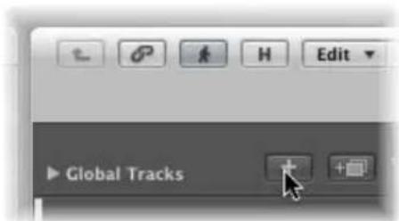
2 In the New Tracks dialog that launches, choose the type, and type in the number, of tracks you want to create.
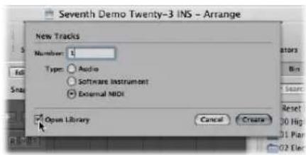
3 Activate the Open Library checkbox (if not already enabled) to automatically open the Library tab in the Media area. This allows you to immediately select settings for the track type that you have created.
4 Click Create.
The new track is created at the currently selected track position, and all ensuing tracks (below it) are moved down the track list.
Using the New Tracks Dialog
The New Tracks dialog offers different options for each track type, when generating tracks. These are outlined below.
External MIDI Track Creation in the New Tracks Dialog
External MIDI tracks offer no additional options, but if External MIDI is chosen in the New Tracks dialog, the following applies:
- A new MIDI multi instrument object will be created in the Environment for the first track, and the track will be assigned to sub-channel 1.
- Subsequent tracks will be assigned to sub-channels of the MIDI multi instrument object (up to the maximum of 16).
- If more than 16 External MIDI tracks are created, they will automatically roll-around to channel 1, 2, 3, and so on. These can be freely reassigned to any sub-channel. If you have more than one MIDI port available on your system, you can reassign additional tracks (above the first 16) to a second MIDI multi instrument object.
- A channel strip is automatically generated in the Mixer for each sub-channel of each MIDI multi instrument object.
Tip: Once tracks are created, you can quickly reassign them to the sub-channels of any MIDI multi instrument object with the Library, or by Control-clicking on the track list, and making your choice from the Reassign Track Object menu.
Full details on setting up external MIDI sound modules and keyboards are found in "Setting Up External MIDI Instruments" on page 247.
Audio Track Creation Options in the New Tracks Dialog
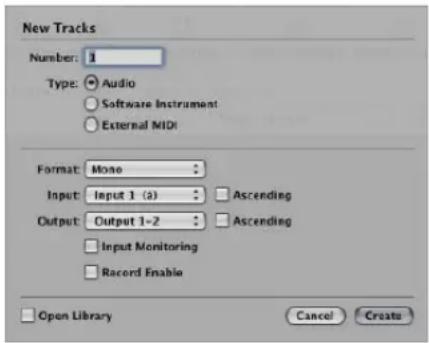
- Driver: This pop-up menu allows you to select the audio hardware driver that you wish to use for your newly-created tracks. If you use only one hardware playback device, this menu won't appear.
- Format: Choose Mono or Stereo in this pop-up menu, to create multiple mono or stereo audio tracks.
- Input: Choose the desired input or input pair.
- Ascending checkbox: Enable to assign these inputs—in order, from lowest to highest—to each track, when multiple tracks are created. This option has no effect when a single track is created. Should you create more tracks than you have inputs—creating 8 tracks, when using a 4 input device, for example—tracks 1 and 5 will be assigned to Input 1, tracks 2 and 6 will be assigned Input 2, tracks 3 and 7 will be assigned Input 3, tracks 4 and 8 will be assigned Input 4.
- Output: Choose the desired output or output pair.
- Input Monitoring and Record Enable checkboxes: Activate to switch on the track's Input Monitoring and Record Enable buttons. This is handy if you intend to start recording immediately after track creation, for example.
Software Instrument Track Creation Options in the New Tracks Dialog
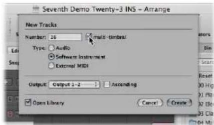
- Multi-timbral checkbox: Turn on to create up to 16 tracks with ascending MIDI channel settings (starting from MIDI channel 1, on the first track, MIDI channel 2 on the second track, and so on).
• These tracks are independent of the first track, and can be individually automated, have different regions, and so on, but all tracks are associated with (and routed through) the same instrument channel in the Mixer.
- As such, the software instrument inserted into the instrument channel must be multi timbral (capable of playing different sounds on different MIDI channels) for this option to be useful. None of the included Logic Express instruments are multi timbral.
- Output: Choose the desired output or output pair.
Transferring a Channel Strip Setting to a New Track
You can create a new track that uses the same channel strip assignment and settings as the selected track. This is a quick and easy way to create a duplicate of an existing track and channel strip, without replicating the data on the track.
To transfer the channel assignment to a new track:
1 Select the source track (the one with the channel strip and settings that you want to duplicate).
2 Do one of the following:
- Choose Track > New with Duplicate Setting in the Arrange area.
- Click the Duplicate Track button above the track list in the Arrange area.
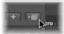
Logic Express creates the new track that uses the same channel assignments and settings directly below the source track. The data on the track (if any exists) is not duplicated.
If you want to copy a track, inclusive of any data, but do not want to copy the channel strip, please see "Copying Tracks and Moving Regions" on page 197.
Tip: You can double-click in the empty space below the track header of the last track, to create a new track. This will be of the same type as the selected track.
Creating Tracks by Adding Apple Loops
You can also create tracks by dragging Apple Loops from the Loop Browser directly into a blank Arrange window area. A track and corresponding channel strip are automatically created, and the Apple Loop is loaded. For more details on adding Apple Loops, see "Finding Apple Loops in the Loop Browser" on page 273.
Creating Tracks by Adding Audio Files
You can also create tracks by dragging audio files from the Media Browser directly into a blank Arrange area. A track and corresponding channel strip are automatically created, and a region (that is the full length of the audio file) is added to the new Arrange track. The audio file (and corresponding region) is also automatically added to the Audio Bin.
Track Creation Commands
The commands and methods discussed in this section only create new tracks. The current (selected track) channel strip is used as the target for the new track.
Creating a Track With the Same Channel Assignment
There may be situations where you would like to have multiple copies of a track that address the same Mixer channel.
As an example: You may want to create multiple tracks that address a software instrument, such as the EXS24 mkll, with a drum kit loaded. Each track can contain MIDI regions that trigger individual drum sounds (kick, snare, hi-hat, and so on). Having a separate track for each sound allows you to independently mute or solo sounds in the kit.
Tip: Use a multi output version of the EXS24 mkII if you want to individually process each sound in the drum kit with different effects.
To create a track with the same channel strip or instrument assignment:
1 Select the track you want to copy.
2 Do one of the following:
- Choose Track > New with Same Channel Strip/Instrument command (default key command: Control-Return) to create a new track below the selected track.
- Use the Append Track to Track List key command to create a new track at the bottom of the track list.
Creating a Track With the Next Channel Assignment
The Track > New with next MIDI Channel command (default key command: Shift-Control-Return) creates a new track below the selected track, and assigns the next instrument or MIDI channel to it. If the MIDI channel of the currently selected track channel is 16, the first channel is re-used.
This command is dimmed if audio tracks (or tracks that don't provide a MIDI channel parameter, such as those assigned to aux channels) are selected.
Creating Tracks With the Next Channel Strip/MIDI Channel
The Track > New with Next Channel Strip/Instrument command can either create a new track, or both a new track and a new channel strip. The behavior of the command is dependent on the selected track type:
- If the selected track is an audio or software instrument track: The command creates a new track below the selected track, and assigns the next channel strip to it. If no next channel strip exists, it is automatically created.
- If the selected track is a MIDI track: The command behaves exactly as Track > New with next MIDI Channel: A new track is created, and assigned to the next MIDI channel.
Copying Tracks and Moving Regions
Hold down Option when moving a track vertically (click-drag the track number) to create a copy of the track at the destination position. All selected regions on the source track are moved to the new track.
Note: If you hold down Option before grabbing the track number, no further regions on the track will be selected. If no regions were selected in the first place, an empty track (assigned to the same channel as the original track) is created at the destination position.
If the Cycle function is switched on, all regions within the cycle are moved from the old track to the new track. The musical result is unchanged, as the new track is a copy, and therefore inherits the channel strip output setting of the source track.
In other words, only one channel strip is used for multiple tracks. This allows you to double-track parts to thicken them up. It also makes tasks such as creating unison voicings (an octave apart) simple and quick for software or MIDI instrument tracks.
To do this, Option-drag the regions on the destination track to replicate/restore them on the source track.
Note: Altering the level (or other parameters) of the channel strip, regardless of which track is selected, will affect all tracks routed to the channel strip.
Creating Tracks for Overlapping Regions
The Track > New for Overlapped Regions function creates new tracks for wholly or partly overlapped regions. The regions are redistributed across the newly created tracks. The number of new tracks is equal to the number of overlaps. All tracks use the same channel assignment as the original track.
As above, only one channel strip is used for all tracks.
Creating Tracks for Selected Regions
The Track > New for Selected Regions function creates a new track for the selected regions on a track. The selected regions are moved to the new track, and removed from the source track. All new tracks use the same channel assignment as the original track.
If you use this command when multiple regions are selected across several tracks, a new track will be created for each source track. As an example:
- Two regions are selected on track a, one region is selected on track b, four regions are selected on track c.
- Following use of the command, the two regions on track a are moved to the newly created track a copy, the region on track b is moved to b copy, and the four regions of track c to c copy.
- If you want to create individual tracks for the two track a regions (now on track a copy), simply select the a copy track, which will automatically select all regions on the track, and repeat the command.
Deleting Tracks
If you delete a track, the channel strip assigned to the track is also deleted, and removed from the Mixer (unless assigned to another track that is in use).
To delete a track, do one of the following:
■ Select the track, then choose Track > Delete.
Tip: If no regions are selected in the Arrange area, you can delete the selected track by pressing Backspace.
- Grab the track, and remove it from the track list by dragging it to the left.
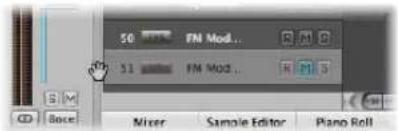
To delete all tracks that do not contain regions:
- Choose Track > Delete Unused in the Arrange area.
Selecting Tracks
You can select a track by clicking on its name or icon in the track list.
This selects all regions on the track (or selects the regions that fall within the defined cycle, if Cycle mode is turned on).
Tip: If you Option-click a track, the track will be selected without affecting the existing selection of regions (on the selected, or other, tracks).
You can also use the following two key commands to select the track above or below the selected track in the track list:
- Select Next Track (default assignment: Up Arrow key)
- Select Previous Track (default assignment: Down Arrow key)
Rearranging Tracks
You may want to shuffle the position of tracks in the track list on occasion, to visually group related tracks (string section or percussion parts, for example).
To change the position of a track in the track list:
- Move the cursor over the track number. When the mouse pointer changes to a hand graphic, click the track number, and drag it up or down the track list. When you've reached the desired position, release the mouse button.
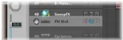
Subsequent tracks (if any) will be moved down the screen.
You can also sort tracks by choosing one of the following commands in the Track > Sort Tracks By menu:
- MIDI Channel
- Audio Channel
- Output Channel
- Instrument Name
- Track Name
Naming Tracks
In the Track Configuration dialog, you can determine which of the following names are displayed in the track header:
- Track Name: This option allows you to manually enter a track name in the track list.
• Channel Strip Setting Name - Software Instrument Setting Name
- Channel Strip Name
• Channel Strip Type and Number
- Automatic Track Name: This option (the default) intelligently names the track, based on the following actions, and order:
- If you enter a track name manually, the track name is displayed.
- If you loaded a channel strip setting or software instrument, the name of the channel strip setting or software instrument is displayed.
- If you did none of the above, the channel strip name is displayed.
To determine the track names you want to view:
1 Open the Track Configuration dialog by doing one of the following:
- Choose View > Configure Track Header in the Arrange area.
- Control-click on any track header in the track list, then choose Configure Track Header from the pop-up menu.
2 Choose the desired track name option in the first pop-up menu.
3 Enable the checkbox of the second pop-up menu to view two track names, then choose the desired name option.
The option chosen in the first pop-up menu is always shown to the left if both names are shown, divided by a line.
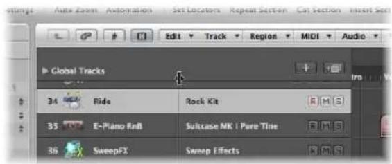
You can move this dividing line by dragging the mark at the top of the track list.
To create a track name:
- Choose Track > Create Track Name, then type in the text input field that appears.
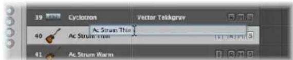
If the track name is already visible in the track header: Double-click on the channel strip name in the track list, then type in the text input field that appears.
The new track name is displayed in place of the channel strip name, and will be used as the default name for newly recorded regions.
The name of the channel strip (that the selected track is routed to) is also shown in the Track Parameter box of the Inspector. You can rename the channel strip by clicking on the name.
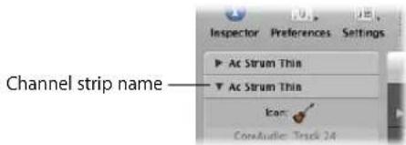
To delete a track name, do one of the following:
- Choose Track > Delete Track Name.
- Double-click on the track name to open the track name input box, and press Backspace to delete the name.
The track (instrument or audio) channel strip name will then be used as the default name shown in the track list (and for newly recorded regions).
Important: AutoName must be selected in the Track Configuration header for this functionality to work.
Assigning Tracks to Channels
In general, you will create new tracks when you want to record or play back new regions. Corresponding channel strips are automatically created in the Mixer.
In some situations, however, you may want to reassign an existing track to a different channel strip. As an example, reassigning the output of a software instrument track to another instrument channel strip. The MIDI regions on the track will be played back through the inserted software instrument plug-in of the second channel strip.
To reassign a track to a specific channel strip:
■ Control-click the track icon or name, and choose the desired destination for the track in the hierarchical Reassign Track Object menu.
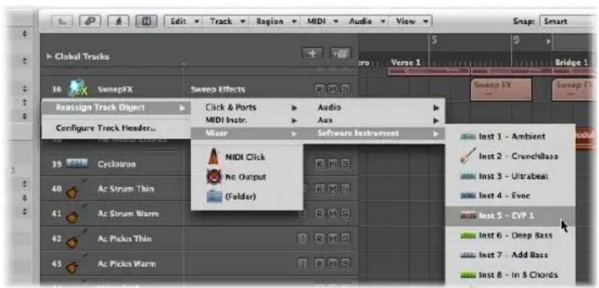
- If you want to use a track for audio region recording or playback, choose an Audio >Audio Track channel strip as the track destination.
- If you want to use a track for MIDI region recording or playback (via a software instrument), choose an Audio > Instrument channel strip as the track destination.
- If you want to use a track for MIDI region recording or playback (via a MIDI sound generator), choose a MIDI Instr. > Model/Instrument name channel strip as the track destination.
Assigning Tracks to Environment Objects
Strictly speaking, tracks don't need to be routed to an instrument or audio channel strip, as you can assign any Environment object as the track destination. The track data could conceivably be sent to a fader object, or directly to a MIDI port, as examples.
Environment objects are software representations of individual data processing elements. As examples of Environment objects; arpeggiators, knobs, faders, chord memorizers, channel splitters, and many more. These individual objects can be connected with each other, using virtual cables. The end result of cabling multiple objects is real time processing and manipulation of MIDI (and some audio) data. This can be as simple as a fader to control the volume of a connected MIDI synthesizer, or a complex rhythm generator or step sequencer—which exists as a virtual machine within the Environment. This machine can be called into service whenever you need it. (For more information, see Chapter 38, "Working in the Environment," on page 875.)
Obviously, audio signals would not be understood by a MIDI sound module, so there is no point in routing a track that contains audio regions to an instrument channel strip, or vice-versa.
To globally reassign multiple tracks that share a channel strip destination:
- Hold down Option when reassigning a track channel strip, then confirm the dialog by clicking the Reassign All Tracks button.
The new track destination (reassigned channel strip) will be used for every track that shared the original track destination in the current project (including tracks in folders). As an example:
- Tracks 1 to 4 are assigned to instrument channel 6.
- You Option-reassign one of these tracks to instrument channel 15.
- Tracks 1 to 4 will be reassigned to instrument channel 15.
Special Destinations
In addition to the normal channel strips, there are two other possible track output destinations:
- No Output: Tracks assigned as No Output send no data. This can be useful in situations where you want to store data (such as SysEx) that you don't wish to send from Logic Express.
- Folder: This setting is used when you want the track to play a folder region (see "Using Folders" on page 354). Normal regions will not play on a track set up for folder playback.
Zooming Individual Tracks
Tracks in the Arrange area can be zoomed individually—in conjunction with, or independent of, the global zoom tools (and waveform zoom tool) for the window. There is a default zoom setting for tracks, which is automatically chosen when a window is first opened. This is a good compromise between visibility of text and regions, and working space in the Arrange area.
To zoom in or out on a track:
1 Move the Pointer to the bottom left corner of a track.
The mouse pointer will change to an index finger.
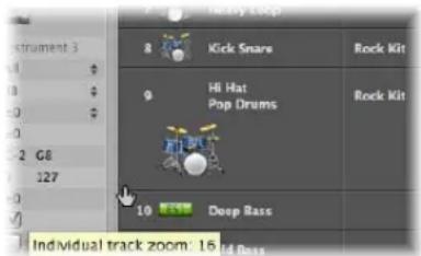
2 Click and drag to zoom in or out on this track.
The individual track zoom factor, compared to the overall window zoom level, is shown in the help tag while the mouse button is held.
Tip: You can zoom all MIDI or audio tracks of your project at the same time by pressing Command when zooming. Pressing Shift when zooming a track resets all tracks to the default zoom setting.
Zooming the Selected Track Automatically
You can use the View > Auto Track Zoom setting (also available as a key command) to automatically enlarge the currently selected track. Use the technique described above to set the desired zoom level on a track. Any subsequently selected track will automatically zoom to this level.
Zooming Tracks With Key Commands
You can assign, and use, the following key commands to zoom tracks:
- Individual Track Zoom In and Individual Track Zoom Out: Increases or decreases the "individual track zoom" factor of the selected track by one.
- Toggle Individual Track Zoom: Switches the selected track between its individual zoom level and the window zoom level. This would be useful for zooming in on a track to edit its automation data. After editing, use the Toggle Individual Track Zoom key command to return to the original zoom level.
- Individual Track Zoom Reset: Resets the selected track to the window zoom level.
- Individual Track Zoom Reset for All Tracks: Resets all zoomed tracks to the window zoom level.
Assigning Track Icons
Logic Express offers high resolution, scalable (from 128 x 128 pixels downwards), and user-definable track icons.
To assign an icon to a track:
- Click-hold on an existing track icon in the track header or in the Track Parameter box, and choose the desired icon from the menu.
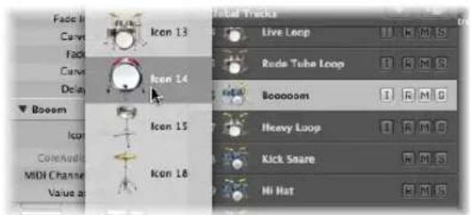
Note: The Track Icons checkbox must be turned on in the Track Header Configuration dialog for icons to be visible. Activate the Allow Large Icons checkbox to display large track icons. Large icons are automatically resized and repositioned when tracks are zoomed.
Creating Your Own Icons
You can create your own icons for tracks. User created icons are saved in the following folder: \~/Library/Application Support/Logic/Images/Icons.
These icons must have the following attributes:
- 128 x 128 pixels in size
• An alpha channel for transparency - Must be saved in the portable network graphics format (with the .png suffix)
- Must be given a file name that starts with a three-digit number
Note: If this number is identical to the number of one of the built-in Logic Express icons, the icon found in the user folder is given priority.
You also have the option of directly replacing the built-in Logic Express icons, which are found in the /Contents/Resources/Images folder in the Logic Express package.
To open the Logic Express package:
- Right-click the Logic Express icon in the Finder, and choose the Show Package Contents item from the pop-up menu.
Muting Tracks
You can use a track's Mute button to stop it from playing. Use the Track Header Configuration window to show or hide the track Mute buttons.
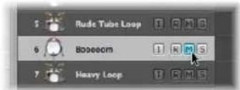
Mute states can be independent for tracks and channel strips, through use of the respective M buttons in the track header, or corresponding channel strip (Arrange or Mixer).
The behavior of these buttons depends on the Track Mute/Solo setting chosen in the Logic Express > Preferences > Audio > General tab:
- Fast (Remote Channel Strips): Clicking a channel strip's Mute button switches the state of the associated track button, and vice-versa.
- CPU-saving (Slow Response): Choose to save processing resources, and to make the track Mute buttons independent of the corresponding channel strips.
Note: The Mute states of multiple tracks that are routed to the same channel strip are linked: Muting the channel strip mutes all associated tracks.
Muting When the Mute Buttons Are Hidden
If the Mute buttons are hidden—to save space—you can still mute a track to the left of the track number.
If you move the mouse to the left edge of the track list by the track number, the mouse pointer turns into a hand; a brief mouse click mutes the track (or cancels the mute if the track is already muted). Muted tracks are indicated by a bullet beside the track name.
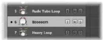
You can also use the Toggle Track Mute key command (default: Control-M) to mute a track.
Muting Multiple Tracks
If you hold Command while clicking a Track Mute button, all Track Mute buttons that match the status (muted or unmuted) of the clicked button are also switched. As an example: If you click an unmuted Track Mute button, this track and all other unmuted tracks are muted.
You can also use the Toggle Track Mute of all Tracks of Folder key command.
Muting Multiple Tracks With the Same Channel Strip Destination
If you mute a track while holding Command-Option, all tracks assigned to the same track destination channel strip (including those in folders) are muted.
You can also use the Toggle Track Mute of all Tracks with Same Instrument of Project key command.
You can also click-hold the Mute button of one track, and drag the mouse up or down. The Mute buttons of all swiped tracks will switch to the same state.
Soloing Tracks
Both MIDI and audio tracks (and folders) offer Track Solo buttons. Soloing a track isolates it while playing—and mutes all other tracks. Use the Track Header Configuration window to show or hide the Track Solo buttons.
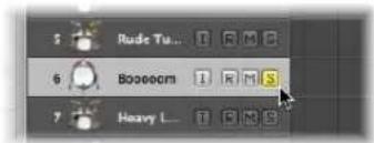
In a practical, musical situation, it can be useful to hear several tracks in isolation (bass and drum parts, for example) to make it easier to fit other musical parts.
Connecting the Track Solo and Channel Strip Solo Buttons
Solo states can be independent for tracks and channel strips, through use of the respective S buttons in the track header, or corresponding channel strip (Arrange or Mixer).
The behavior depends on the Track Mute/Solo setting chosen in the Logic Express > Preferences > Audio > General tab:
- Fast (Remote Channel Strips): Clicking a channel strip's Solo button switches the state of the associated track button, and vice-versa.
- CPU-saving (Slow Response): Choose to save processing resources, and to make the Track Solo buttons independent of the corresponding channel strips.
Note: The Solo states of multiple tracks that are routed to the same channel strip are linked: Soloing the channel strip, soloes all associated tracks.
Soloing Tracks in CPU-saving Mode
If the Track Mute/Solo preference is set to CPU-saving (Slow Response), activating any Track Solo button enables Solo Lock mode, and adds all regions on that track to the Solo Lock group. (Solo Lock mode locks the solo status of all selected regions—for full details, see "Using Solo Lock" on page 315.) The Transport Solo button turns yellow and displays a padlock icon to indicate Solo Lock mode.
Deactivating a Track Solo button removes all regions on the track from the Solo Lock group and—in cases where no other track's Solo button is active—disables Solo Lock.
Disabling the global Solo (Lock) button on the Transport, sets all individual Track Solo buttons to the Off position.
Soloing When the Track Solo Buttons Are Hidden
If the Track Solo buttons are hidden—to save space—you can still solo a track with the Solo button on the Transport bar.
Simply press the Transport Solo button, and click on the desired track.
Soloing Multiple Tracks
If you hold down Shift while the Transport Solo button is active, and click on the desired track names, you will solo them (when the track Solo buttons are hidden).
If you hold any modifier (except Control) while clicking on a Solo button in the track list, all tracks in the currently-selected display level are soloed. If they were already soloed, they will be unsoloed.
You can also click-hold the Solo button of one track, and drag the mouse up or down. The Solo buttons of all swiped tracks will switch to the same state.
Record-Enabling Tracks
You can use a track's Record Enable button to arm a track for recording. For more information about enabling tracks for recording, see Chapter 14, "Recording in Logic Express," on page 367.
Freezing Tracks
The Freeze function saves almost 100% of the CPU power required for software instrument and effect plug-in calculations. You can individually freeze audio or software instrument tracks.
About the Freeze Function
Internally, Freeze performs individual offline bounce processes for each frozen track. All plug-ins of a track (including software instrument plug-ins, if applicable, along with all related automation data) are rendered into a freeze file.
As long as a track is frozen—following the freeze process—the freeze file will play back in place of the original track (and its CPU-hungry plug-ins). The original track and plugins are temporarily deactivated, and use no CPU resources.
Tip: The Freeze facility also works with DSP hardware such as the PowerCore, LiquidMix, Duende, and UAD devices. This enables you to combine Logic Express instruments and effects with those provided by the DSP hardware—even if the processing capacity of your computer, the DSP hardware, or both, are exceeded.
The Freeze function always bounces the complete channel signal. If you are using more than one track for the same audio or instrument channel in the Arrange, then all (sub)tracks of this channel will be frozen, and cannot be edited independently. In other words, it is the channel strip that is frozen, not the track.
When to Freeze a Track
In real-world situations, Freeze allows you to:
- Use additional effect plug-ins or software instruments in further audio or instrument tracks, which would normally be impossible as it would exceed the CPU processing limits of your computer.
- Play back projects created on computers with greater CPU power.
Freeze is designed to circumvent very CPU-intensive processes, which are generally outlined as follows (from highest to lowest demand):
- Software instruments with a complex voice architecture
- Plug-ins with a complex structure (reverbs, filter banks, or FFT-based effects)
- Software instruments with a simple voice architecture
- Software sampler with active filter
- Software sampler with inactivate filter
- Plug-ins with a simple structure
If your computer is able to calculate all active processes in real time, it's unnecessary to freeze tracks.
Freeze is recommended whenever your system processing power runs short and one, or multiple, existing tracks with CPU-intensive software instrument or effect plug-ins are in a finalized state, or at least seem to require no further changes for the meantime—in other words, a close to final mix.
As long as a track is frozen, its CPU usage is reduced to that of a high resolution audio playback track, without any effect plug-ins inserted—regardless of the number, or processing demands, of the plug-ins that were originally used on the track.
How to Freeze a Track
It's extremely easy to freeze a track: simply activate the Freeze button—the button that features a small ice crystal icon (white when active). Use the Track Header configuration window to show or hide the Track Freeze buttons.
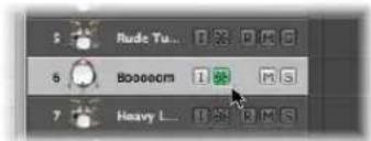
If you hold Command while clicking on a Freeze button in the track list, all tracks that contain data in the currently-selected display level (or folder) will be frozen. If the Freeze buttons were already enabled, they will be disabled.
You can also click-hold the Freeze button of one track, and drag the mouse up or down. The Freeze buttons of all swiped tracks will switch to the same state.
Logic Express will create freeze files after receiving the next Play command. This allows you to activate the Freeze buttons of multiple tracks, and render their freeze files in one go.
You can abort freeze processes by pressing Command-Period—in this scenario, the portion of the frozen tracks that has already been rendered will remain in the freeze files, and will be used for playback. Frozen tracks will remain silent beyond this point.
What Happens During a Freeze
During the Freeze process, the playhead will follow the currently rendered position. A floating progress bar window is also displayed.
Freeze files are always rendered between the project start and end marks—it is recommended that you check the project end mark in the Bar ruler before starting a Freeze process.
Tip: You should adjust the end mark of the project to include feedback-dependent delay repetitions or reverb tails. Empty areas (digital zero) at the end of freeze files are automatically removed after the Freeze process.
The freeze process uses 100% of available CPU power. If, for example, a track uses 40% of the CPU for real time plug-in calculations, its freeze file will be created two and a half times faster than the real time playback speed. If the original track uses 100% of the CPU power, the freeze process will happen in (approximately) real time—even if offline bouncing is used.
Working With Frozen Tracks
Once a track is frozen:
- It is not possible to cut and rearrange freeze files in any way, nor is it possible to mix the freeze files with their originals on a single track—you can use one or the other, not both!
- It is also not possible to record audio on frozen tracks. In fact, the Record Enable button is hidden when a track is frozen.
- You can not edit any instrument or plug-in parameters (or related automation data).
You can, however, still edit the following parameters of frozen tracks:
• Effect send levels and destinations
- Panorama parameters
• Volume, mute, and solo
This includes automation data for these parameters.
Whenever you try to edit forbidden parameters of frozen tracks, (such as plug-in parameters that were rendered into the freeze file), Logic Express will display an error message:
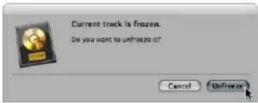
To unfreeze and edit a track:
1 Click Unfreeze to deactivate the Freeze button of the track.
The freeze file will be deleted.
Note: The track will now use the amount of CPU processing power that it originally required, if you press Play.
2 You can now perform your edits, and activate the Freeze button again, if required.
Freeze Files
The temporary freeze files are saved in a folder named Freeze Files which is created in the root directory of your project folder. You usually won't need to access these freeze files directly.
Logic Express manages these freeze files automatically in the background: They are created during the Freeze process, will play back in place of the original tracks (as long as these tracks are frozen), and will be deleted as soon as the Freeze button of the corresponding track is turned off.
Refresh Freeze Files
The Options > Audio > Refresh All Freeze Files command refreshes the current freeze files. This may become necessary when global changes are made that also affect the playback of the frozen tracks (tempo changes, for example).
Hiding Tracks
If there are tracks in the Arrange area that do not need to be visible (useful when working on very large arrangements), you can use the Hide Track function to hide them. Hidden tracks play back as per usual.
There is a global Hide View button in the upper left corner of the Arrange area. This is the H button to the right of the Catch button.

To hide tracks:
1 Click the Hide View button to activate the Hide Track function.
Small Hide (H) buttons will appear on each track.
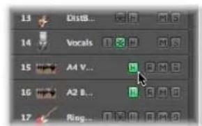
2 Turn on the individual Hide buttons on the desired tracks.
3 Click the global Hide View button, and all tracks (with enabled Hide buttons) will disappear from the Arrange window.
The H in the global Hide View button appears highlighted, denoting that one or more tracks (with active Hide buttons) are hidden.
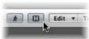
To show hidden tracks:
■ Simply re-activate the Hide View button when you wish to see the hidden tracks again.
Hide Menu and Key Commands
There are a couple of menu functions and key commands that relate to the Hide Tracks feature.
Even when the global Hide View button is deactivated, you can still hide an individual track with the View > Hide Current Track and Select Next Track command (default key command: Control-H).
View > Unhide all Tracks (default key command: Shift-Control-H) will reset the Hide buttons of each track, making them all visible.
Note: Hiding tracks does not affect their playback in any way. You can also link the Hide functions of all tracks belonging to a group by selecting Hide in the Group Property Settings (for further information on groups, see "Working With Groups" on page 587). Another thing to keep in mind is that there is no Unhide Selected Arrange Track key command because there is no way that you can select a hidden Arrange track—it is hidden, after all ...
Protecting Tracks
Tracks can be protected, thus preventing any alterations:
- Existing regions (and their contents) cannot be altered.
- No recording is possible on protected tracks.
- New regions cannot be created on protected tracks.
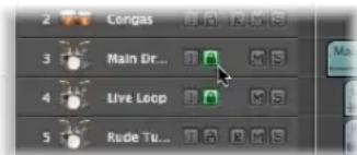
If the Track Protect button is not visible in the track list, you can switch it on via the Track Header configuration window.
Clicking the Track Protect buttons toggles between locked and unlocked mode.
Command-clicking a Track Protect button in the track list will protect all tracks in the currently-selected display level (or folder). If tracks were already protected, they will be unprotected.
Using Track Button Slide Activation
Track buttons on arrange tracks (Solo, Mute, Hide, Track Protect, Freeze) support slide activation, which is similar to running your finger across several channel strip buttons on good hardware mixing consoles.
As a usage example of slide activation in Logic Express, click-hold on the Mute button of one track, and drag the mouse up or down. The Mute buttons of all swiped tracks will switch to the same state.
Simply drag over the Mute buttons of the same tracks to undo the Mute.
Working With Instruments and Effects
Logic Express offers an extensive range of software instruments and effect processing plug-ins that are inserted into channel strips. You can also make use of external MIDI instruments and effects units.
This chapter covers all important steps required for instrument and effect use in Logic Express.
- Inserting, deleting, and bypassing plug-ins
- Loading and removing entire channel strip plug-in configurations
• Using the plug-in window header - Choosing and managing plug-in settings
- Setting up and using external MIDI instruments and effects
- Setting up and using external ReWired applications and instruments
The relationship of Arrange window tracks and channel strips is covered at the beginning of Chapter 9, "Working With Tracks," and is also touched on here.
Some additional background information on plug-in routing, and use of plug-ins from other manufacturers is also included in this chapter.
Detailed coverage of the included instrument and effect plug-ins—including the use of all plug-in parameters—can be found in the Logic Express 8 Instruments and Effects manual.
A Quick Mixer and Channel Strip Primer
Before discussing the use of plug-ins, a basic understanding of some key channel strip functions is required. Full details on all channel strip and Mixer functions can be found in Chapter 25, "Mixing," on page 571.
The Mixer and Arrange channel strips deal with audio and instrument (software or MIDI) tracks shown in the Arrange window, plus auxiliary and output channels. Each track in the Arrange is represented and controlled by a channel strip. Put another way, the Arrange tracks are routed to specific channel strips:
• Audio channel strips control audio tracks.
- Instrument channels control instrument tracks (software instrument plug-ins are inserted into the Instrument slot of instrument channels).
- External MIDI channels control external MIDI tracks. Data on these tracks is routed to a MIDI output port and channel, for control of MIDI sound modules and keyboards. Either the entire instrument or MIDI sub-channels can be represented and controlled.
Mixer channels are generated automatically when you create new audio, instrument, or external MIDI tracks in the Arrange window.
The Arrange channel strips, shown at the bottom of the Inspector, display the audio or instrument channel strip of the selected track on the left hand side, and the primary (first) destination for this channel strip on the right hand side.
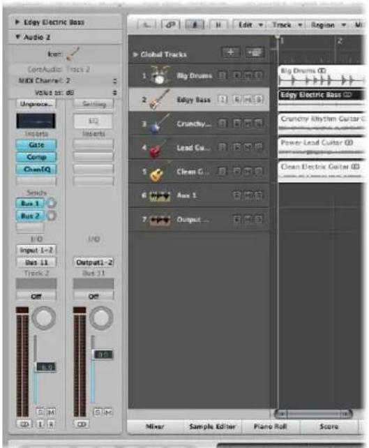
The destination will be either:
- An output channel strip, which represents a physical audio output (or output pair) of your audio interface.
- An auxiliary channel strip (this is where you insert send effects).
For example, if send 1 of the left-hand channel strip is routed to auxiliary channel 4, the fourth auxiliary channel strip will be shown. Clicking Send slot 2 on the left-hand channel strip (routed to auxiliary 7) will update the right-hand channel to show the seventh aux channel strip. Selection of a particular output in the Output slot of the left-hand channel strip will display the chosen output channel strip to the right. If the left-hand channel strip is simply routed to an output channel, the output channel strip is shown by default.
You will perform most plug-in insertion, channel routing, and channel configuration tasks as part of your creative workflow in the Arrange window. As such, you should use the Arrange channel strips for all related functions discussed in this chapter, rather than accessing the Mixer.
The Arrange channel strip (for the selected track) is a "mirror" of its counterpart in the Mixer. You can view it as a remote control for this Mixer channel, if you like.
Tip: As a shortcut, you can open the Mixer by double-clicking the icon of any track in the Arrange track list. The corresponding channel strip (of the clicked track) will be selected in the Mixer.
Before continuing, there are three main things you need to know about audio or instrument channel strips: the channel input format, the Pan control, and the Level fader.
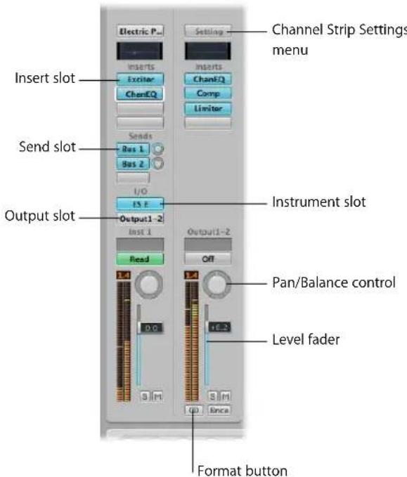
Setting the Channel Input Format
The channel input format determines the mono or stereo status of the channel.
Note: Software instrument and external MIDI channels do not have a format button.
The chosen input format has an impact on two things:
- The plug-ins shown on the channel strip will be available as:
- Mono to mono or mono to stereo versions on mono channel strips.
- Stereo to stereo versions on stereo channel strips.
- The Pan control determines the position of the channel signal in the stereo field.
- On mono channels (this includes left and right input format channels), the Pan control determines the left/right position of the signal.
- On stereo channels, the Pan control determines the balance between the left and right channel signals.
To set the channel strip input format for the selected audio track:
- Click-hold the button directly below the level meter on the Arrange channel strip, and choose the desired input format from the menu.
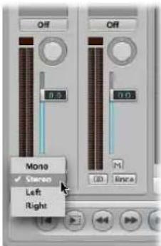
Tip: On a stereo or mono channel, you can simply click the button to switch between mono or stereo.
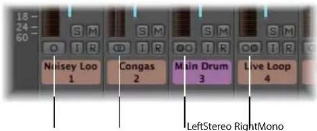
- Mono: One circle represents a mono input format. The level meter shows a single column.
- Stereo: Two, interlocked circles represents a stereo input format. The level meter divides into two independent columns when a stereo input format is chosen.
- Left: Two circles, left one filled, indicates a left channel input format. When this input format is chosen, the channel strip only plays the left channel of an audio file.
- Right: Two circles, right one filled, indicates a right channel input format. When this input format is chosen, the channel strip only plays the right channel of an audio file.
Setting the Channel Pan or Balance and Playback Level
You use the Pan control and Level fader to set a channel's pan position and playback level.
To set the pan position (for mono input format channels) or balance (for stereo format channels), do one of the following:
- Click-hold on the center of the Pan control, and drag vertically.
- Drag upwards to move the pan or balance towards the right channel.
- Drag downwards to move the pan or balance towards the left channel.
- Option-click on the center of the Pan control to reset it to the center position.
To set the playback level, do one of the following:
■ Vertically click-drag the Level fader handle.
- Option-click on the handle to reset it to the center (0.0 dB) position.
How Mono and Stereo Effects are Handled
You can insert mono and stereo instances of effects into channel strips.
Only versions of the plug-in that match the channel strip input format can be inserted (mono to mono or mono to stereo plug-in versions in mono input format channels, for example).
To insert plug-ins that do not match the channel format:
■ Option-click a channel Insert slot.
The Plug-in menu will display all formats the plug-in has to offer, rather than being limited to the matching format. Any down or up mixing that may be necessary happens automatically.
Inserting, Moving, and Removing Plug-ins
Plug-ins are, broadly speaking, broken down into two categories:
- Software instruments, which respond to MIDI note messages
- Audio effects, which do not respond to MIDI note messages
The Audio Units format also offers two further plug-in types:
- Generators
- MIDI controlled effects
As the name suggests, Generator Audio Unit plug-ins generate audio signals. In contrast to software instruments, however, they do not require a MIDI note message to be triggered.
Audio Unit MIDI controlled effects can be controlled via MIDI, unlike standard audio effect plug-ins. As such, they are used differently.
Where Different Plug-in Types Can Be Used
- Effect plug-ins can be placed in the Insert slots of all audio channel strip types (audio, instrument, auxiliary, output).
- Software instruments can only be inserted into instrument channel strips. These channel strips feature an Instrument slot, directly above the Output slot, which is used for software instrument insertion.
- Audio Unit Generators can only be inserted into instrument channel strips.
- Audio Unit MIDI controlled effects are inserted into the Instrument slot of instrument channels. The audio signal that you would like to process is then selected via the plug-in's Side Chain menu.
To insert an effect plug-in:
1 Click a channel strip Insert slot.
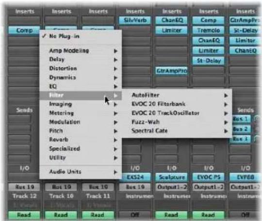
The Plug-in-menu appears, showing all available effect plug-ins, sorted into different categories.
2 Browse through the different levels of the menu and choose a plug-in name by clicking on it. This will load a plug-in version that matches the chosen channel strip input format.
You also have the option of choosing a mono or mono to stereo version of the plug-in, for example, by clicking on the appropriate entry.
Logic Express effects are displayed in various categories such as Delay and Reverb, Audio Unit effects can be found in the corresponding sub-menus (these sub-menus are only displayed if plug-ins in these formats are installed on your system).
To insert a software instrument, Audio Unit Generator, or MIDI controlled effect:
- Click the Instrument slot of an Instrument channel strip, and choose the desired software instrument, Audio Unit Generator, or MIDI controlled effect (name and type) from the Plug-in menu.
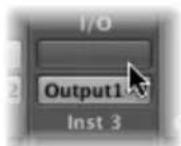
Tip: You can simply choose an instrument name to insert the instrument in stereo on a stereo format channel.
The plug-in window of the chosen instrument, effect, or generator is opened automatically. If you do not want the plug-in window to open automatically after insertion, turn off the "Open plug-in window on insertion" preference in the Logic Express > Preferences > Audio > General tab.
You can adjust all plug-in parameters in the plug-in window. For further information please read the section on "Adjusting Plug-in Parameters" on page 233.
To remove a plug-in:
- Click the desired Insert or Instrument slot, and choose No Plug-in from the menu.
To replace a plug-in:
- Click on the Insert slot, and browse to the desired plug-in type.
Accessing Multiple Instrument Outputs
Logic Express supports the multiple outputs of the EXS24 mkII, Ultrabeat, and all Audio Unit instruments.
One or more Multi Output options may be displayed in addition to the Mono and Stereo versions shown in the Instrument Plug-in menu.
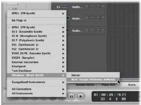
The Plug-in menu offers additional information about an output configuration. As examples:
- Instrument Name: Multi Output (2 x stereo, 4 x mono)
- Instrument Name: Multi Output (4 x stereo)
Note: Not all instruments (Logic Express or third-party) are multi-output capable. If the instrument does not provide a Multi Output option, it is not equipped with multiple output facilities.
To insert and set up a multi output instrument:
1 Choose the desired multi output instance in the Plug-in menu.
- The first two outputs of a multi output instrument are always played back as a stereo pair by the instrument channel that the plug-in is inserted into.
• Additional outputs (3 and 4, 5 and 6, and so on) are accessed via aux channel strips.
2 Within the instrument interface, you will need to set up the output routing for individual sounds or samples. This is generally done via a menu, that shows entries such as: Main, 3-4, 5-6, and so on.
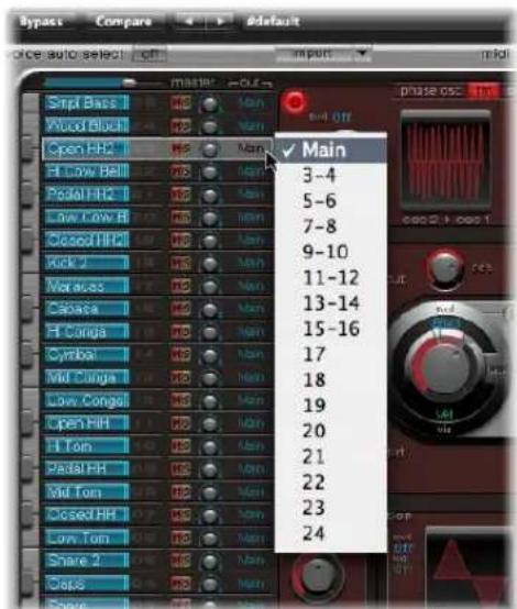
3 Open the Mixer, and click the + button of the instrument channel that you have inserted the multi output instrument in (Ultrabeat, for example).
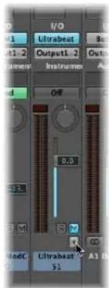
Note: The + button only appears on multi output instrument channels.
An aux channel strip appears to the right of the instrument channel, already assigned to the inserted multi output instrument.
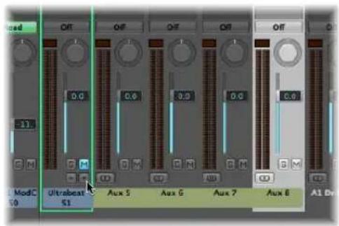
4 Repeatedly click the + button to create more aux channels, for all stereo or mono outputs available to the instrument plug-in.
You should only create as many aux channels as required for the number of outputs used by the multi output instrument.
Following the creation of the first aux channel strip for your multi output instrument, a – button appears beside the + button.
Click the - button to remove aux channels.
Using the Channel EQ
The Channel EQ is an insert effect, like any other. In most mixing situations, it is used as the first effect on a channel, allowing you to sculpt the sound of the channel signal before applying other effect types.
To insert the Channel EQ, do one of the following:
- On channel strips where Insert slot 1 is not used: Double-click the EQ area on the upper portion of the channel strip to place the Channel EQ in the first Insert slot.
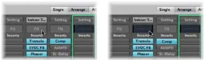
The EQ area will change to a thumbnail view of the Channel EQ display. The thumbnails provide an overview of the EQ settings used in each individual channel.
- On channel strips where Insert slot 1 is used: Option-double-click the EQ area to insert the Channel EQ as the first plug-in, and move all existing plug-ins of the channel strip one slot down (and redirecting their automation data accordingly, if necessary).
Double-clicking the EQ area on channel strips with an occupied Insert slot 1 will insert the Channel EQ into the next available (unused) slot.
You may freely insert the Channel EQ into any desired Insert slot as per other plug-ins. You'll find it in the EQ section of the Plug-in menu. It should be noted that only the first (topmost) Channel EQ is displayed as a thumbnail graphic in the EQ area.
More information about the parameters of the Channel EQ can be found in the Logic Express 8 Instruments and Effects manual.
Moving Effects and Instruments
You can use the Hand tool to move effects and instruments between channel strips.
To move a plug-in to another Insert or Instrument slot:
1 Open the Mixer and choose the Hand tool.
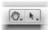
2 Select the plug-in name (shown on a blue label) in any used Insert or Instrument slot, and drag it to the desired (unused) target slot.
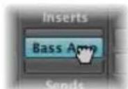
During the drag and drop operation, the potential destination is displayed as an orange rectangle (empty slot) or line (when placing an effect between two Insert slots, see below).
To copy a plug-in to another slot:
- With the Hand tool selected, Option-drag the plug-in name from any used slot to the desired unused target slot.
To swap an effect plug-in with another in the same channel strip:
- With the Hand tool selected, drag the effect plug-in name from any used Insert slot to the desired used target slot.
This will swap the plug-in slot positions. As an example, on a channel strip with a reverb, chorus, and delay inserted into slots 1 through 3, respectively; dragging the slot 1 plug-in to slot 3 will place the reverb in slot 3, and the delay will be moved to slot 1. It goes without saying that altering effects positions will change the sound of the channel.
Note: When the Hand tool is used to drag plug-ins between channel strips, the existing plug-in on the destination channel is replaced, not swapped.
To place an effect plug-in between two Insert slots:
1 Select the Hand tool.
2 Click-drag the plug-in name of any used Insert slot between two used Insert slots, and release the mouse button.
The effect is inserted into a newly created slot between the two used slots. The effects below the drop position (new slot) are shifted down by one.
Note: If all 15 Insert slots are used, you can not insert any further plug-ins into the channel, unless replacing an existing plug-in.
Using the Hand Tool With Modifiers
The Hand tool is the second default tool in the Mixer. Pressing Command while clicking switches from the Pointer tool to the Hand tool, allowing you to move plug-ins by Command-dragging them. Option-Command-drag plug-ins to copy them. You can also use the Hand tool in the Arrange channel strip by pressing Command when the cursor is placed over an Instrument or Insert slot.
Loading and Removing Entire Channel Strip Configurations
The Library tab in the Media area allows you to load and save multiple plug-ins (inclusive of their parameter settings) into a channel strip.
You can also do the same thing by clicking on the Settings button found at the top of channel strips.
You can use this facility in a number of ways, such as:
- Setting up and storing complex multi-effect configurations—on any type of channel.
- Setting up particular routing configurations for use with multi-output software instruments.
- Copying a routing or effect configuration between projects.
• The rapid creation of new project templates.
Channel strip settings (CST files) are channel type specific. Put another way, instrument channels feature a number of instrument settings (or presets), such as Bright Pop Piano and Hard Flanging Clav, separated into instrument, GarageBand, and Jam Pack categories. Audio channels offer effect routings optimized for particular instrument, vocal, and other processing tasks. Similarly, output and auxiliary channels provide channel strip settings for particular mastering or sweetening processes.
To load a channel strip setting with the Settings menu:
1 Click the Settings button at the top of a channel strip.
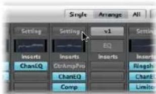
A menu appears, displaying all channel strip settings available for the channel strip type.
2 Browse to, and select the desired setting by clicking on its name.
To load a channel strip setting with the Library tab:
1 First, select the channel strip that you wish to use (in the Mixer, or by selecting an Arrange track).
2 Click the Library tab in the Media area to view the Library. Click the Arrange Toolbar Media button if the area is not visible.
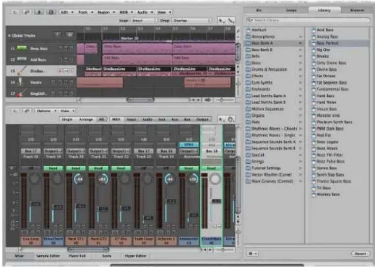
The Library displays all channel strip settings available for the selected channel strip, sorted into category menus.
3 Browse through the category menus, then click on the desired setting name to insert all associated plug-ins into the selected channel strip.
To reset a channel strip setting:
- Choose Reset Channel Strip from the Channel Strip Settings menu.
To return to the previously loaded channel strip setting:
- Click the Revert button at the bottom of the Library tab.
To delete a channel strip setting:
- Choose Delete Channel Strip Setting from the Channel Strip Settings menu.
To select the next or previous channel strip setting, do one of the following:
-
Click the Setting button and choose the Previous or Next Channel Strip Setting command.
■ Use one of the following key commands: -
Next Channel Strip Setting
• Previous Channel Strip Setting - Next Channel Strip or Plug-in Setting or EXS Instrument
- Previous Channel Strip or Plug-in Setting or EXS Instrument
This will load the previous or next channel strip setting shown in the list. This feature is handy when trying to find the right delay or clavinet sound, for example.
To copy and paste a channel strip setting:
- Click the Setting button and choose the Copy or Paste Channel Strip Setting item from the menu, as applicable.
You can also use the Copy Channel Strip Setting and the Paste Channel Strip Setting key commands.
Note: When you paste channel strips (instead of loading them), the Level fader, Panorama Send Level, and all routing destinations are also set according to the channel strip setting in the Clipboard.
To save a channel strip setting:
1 Click the Setting button and choose Save Channel Strip Setting As (or use the corresponding key command).
2 In the Save Channel Strip Setting As dialog, select the appropriate sub-folder (if applicable), and type in a name for the channel strip setting.
As there are different classes of channel strips, a number of channel type specific sub-folders are available in the Channel Strip Settings folder. These sub-folder structures are reflected in the Settings menu for each type of channel strip:
Please do not attempt to change the Channel Strip Settings folder structure. But you may create a new folder, if desired, and save into it. If no folder is selected, the saved channel strip setting will be shown directly in the Channel Strip Setting menu, below the functions.
You can remotely switch between channel strip settings by sending MIDI program change messages. This allows you to select your favorite sounds (consisting of a complete channel strip setting that can contain a software instrument and effect plugins) by pushing a button on your MIDI keyboard. This facility is named channel strip performances, and is designed for live use of Logic Express.
Important: Only program change messages sent on MIDI channel 1 will switch between Channel Strip Performances. All program change messages sent on other MIDI channels are forwarded to Audio Units instruments, if applicable.
Channel strip performances can be used for all audio channel strip types. They are saved in the Performances subfolder (in \~/Library/Application Support/Logic/Channel Strip Settings/Channel Strip name). The performance names start with the corresponding program change number (as examples: 001Piano, 045FlangeGuitar, 111ArcoCelloHall). There are 128 performances (corresponding to 128 available program change events).
To create a performance setting:
1 Configure a channel strip that you would like to have available as a performance (by opening a channel strip setting from the factory library and making changes according to your needs, for example).
2 Click the Setting button, then choose Save as Performance.
3 In the ensuing dialog, enter a performance name, choose a program change number, and click OK.
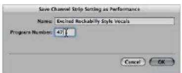
4 Send the program change number from your MIDI controller.
When a channel strip receives a program change message (on MIDI channel 1) that corresponds to an assigned performance number, it will load this performance.
Note: If an unassigned program change value is sent, the channel strip ignores the message, and the currently loaded channel strip performance setting remains in place.
All saved performance settings appear in the Performances folder of the Channel Strip Settings menu.
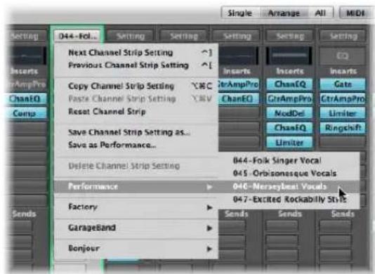
Using the Plug-in Window
Hands-on operation of plug-ins takes place in the plug-in window. This window allows access to all plug-in parameters. Each instance of a plug-in has its own plug-in window, allowing each to have discrete settings.
The plug-in window is automatically opened when you insert a plug-in. This behavior can be overridden by turning off the "Open Plug-in window on insertion" checkbox in the Logic Express > Preferences > Audio > General tab.
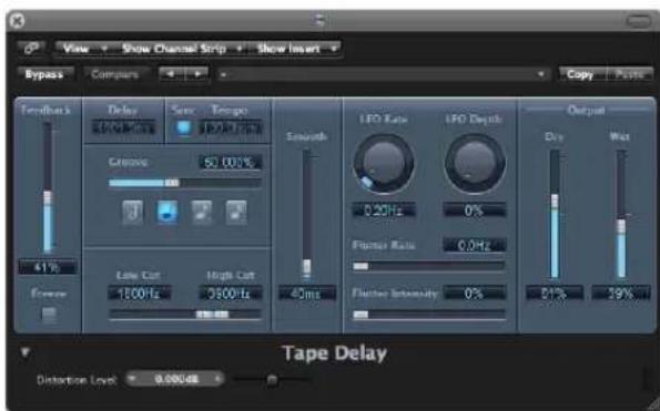
To close a plug-in window:
- Click on the X icon at the top left of the plug-in window.
Note: Closing the plug-in window does not deactivate the plug-in.
To open a closed plug-in window:
- Double-click on an assigned Insert or Instrument slot (the name of the plug-in is shown on the slot).
To hide or show all open plug-in windows:
■ Use the Hide/Show All Plug-in Windows key command (default: V).
Adjusting Plug-in Parameters
This section briefly touches on interaction with common parameter elements you will find in Logic Express plug-in windows. Full details on the parameters of each individual plug-in can be found in the Logic Express 8 Instruments and Effects manual.
To switch plug-in window buttons:
- Click on the button.
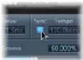
It switches to the next or previous option, or will be turned on or off.
To adjust a parameter slider:
- Click-hold anywhere on the slider and drag up, down, left, or right.
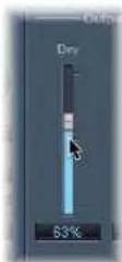
Command-click anywhere in the slider's value range to set it to the clicked value.
To adjust rotary knobs:
- Click-hold on the center of the rotary knob and drag the mouse up and down.
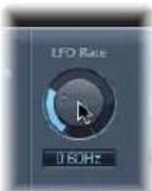
- Command-click anywhere in the value circle surrounding the knob to set it to the clicked value.
To adjust numerical fields, do one of the following:
- Click-hold on the numerical value and drag up or down.
- Input numerical values with the keyboard, by clicking (or double-clicking) in the field, and typing.
If there are up and down arrows alongside such panels, click them to increment or decrement the value by one step. - If the numerical panel opens a pop-up menu of values, choose the desired one.
To reset any parameter to its default (or centered) value:
- Option-click on it.
To make finer parameter adjustments:
- Hold Shift before clicking and dragging a control.
You can also use the mouse wheel or keyboard to adjust Logic Express plug-in parameters.
To adjust plug-in parameters with the mouse wheel:
1 Select the desired Logic Express plug-in parameter by clicking on it.
2 Move the mouse wheel.
Tip: You can also use the mouse pad of a MacBook or PowerBook instead of the mouse wheel.
To adjust plug-in parameters with the keyboard:
- Select the desired Logic Express plug-in parameter, then do one of the following:
- Press the plus key to increase the parameter value.
- Press the minus key to decrease the parameter value.
Common Plug-in Window Functions
The header area at the top of the plug-in window is common to all plug-ins. It offers a number of important functions for plug-in use.
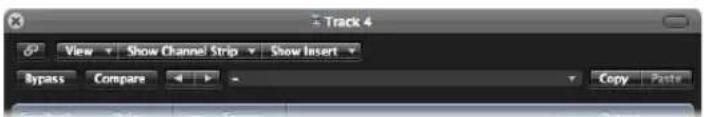
To hide or show the plug-in window header:
- Click the icon at the top right of the plug-in window.
Linking the Plug-in Window
The button to the extreme left (with a chain on it) is called the Link button.
When the Link Button Is Switched On
- A single plug-in window will be used to display all opened plug-ins. Each time you open a new plug-in, the window will update to reflect the newly chosen plug-in.
- Choosing a different Arrange track will update an open plug-in window to display the corresponding slot number of the newly-selected track/channel strip.
As an example:
- Track 1, assigned to instrument channel strip 1, has an ES1 instance loaded (in the Instrument slot).
- Track 11, assigned to instrument channel strip 2, has an EXS24 mkII instance loaded.
- Switching between tracks 1 and 11 will automatically update the plug-in window to show the ES 1 or EXS24 mkII, respectively.
When the Link Button Is Switched Off
You can open several plug-in windows simultaneously, and these will not update to reflect any track or plug-in choices you may make. Each open plug-in window will, of course, continue to show all parameter updates and changes.
Turning Link off is handy when you want to compare the settings of two plug-ins, or adjust the parameters of several open plug-in windows at the same time.
Bypassing Plug-ins
If you want to deactivate a plug-in, but don't want to delete it or remove it from a channel, you can bypass it. Bypassed plug-ins do not drain system resources.
To bypass a plug-in, do one of the following:
- Click on the Bypass button at the left of the plug-in window header.
- Option-click the appropriate Insert or Instrument slot on the desired channel strip (in the Mixer or Inspector).
The Insert slot of the bypassed plug-in turns from blue to gray, indicating that the plug-in is currently bypassed.
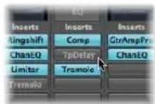
Using the Settings Functions
All current plug-in parameter settings are stored with the project file, and are automatically recalled the next time it is loaded. You can also save and recall any changes you make to plug-in parameters. These are stored and recalled as individual settings (or presets, if you prefer) via the Settings area.
The Settings area appears to the right of the Bypass button.
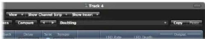
- Next and Previous Setting buttons: Click to load the previous or next plug-in setting.
- Settings field: Displays the name of the current plug-in setting. Click to access the Settings menu.
- Compare button: Click to compare a changed plug-in setting with the setting saved with the project.
- Copy and Paste buttons: Click to copy or paste a plug-in setting.
To load a setting:
1 Open the Settings menu (of the plug-in window, not the Channel Strip Settings menu) by clicking the Settings field.
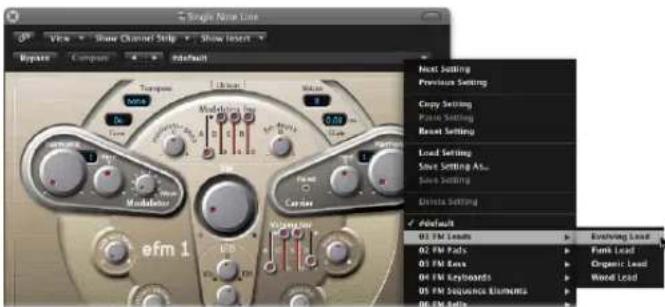
2 Do one of the following:
- Browse to, and choose the setting you want to use from the menu or category submenus.
- Choose the Load Setting command. When used, a file selector box will open. Only settings for compatible plug-in types are shown. Each plug-in has its own set of parameters, and therefore its own file format.
Note: You can also choose plug-in settings from the Library tab of the Media area in the Arrange window. See "Using the Library to Choose Plug-in Settings" on page 242.
To choose the next or previous setting, do one of the following:
In the plug-in header, click the left arrow to choose the previous setting, or the right arrow to choose the following setting.
■ Make use of the following key commands:
- Next Plug-in Setting
• Previous Plug-in Setting
• Next Plug-in Setting or EXS Instrument
• Previous Plug-in Setting or EXS Instrument - Next Channel Strip or Plug-in Setting or EXS Instrument
• Previous Channel Strip or Plug-in Setting or EXS Instrument
To replace a setting, do one of the following:
■ Browse to, and choose the setting you want to use from the Plug-in settings menu.
- Choose the Load Setting command, and choose the desired setting from the file selector box.
Replacing Setting-Compatible Plug-ins
When you replace a plug-in with another plug-in that is setting-compatible, the new plug-in automatically uses the setting of the replaced plug-in.
As an example: When you replace an ES2-based GarageBand instrument with the ES2, the inserted ES2 uses the same setting as the replaced ES2-based GarageBand instrument. It also works for most EXS-based GarageBand instruments, with two exceptions: Hybrid Morph and Hybrid Basic.
To compare changed plug-in parameters with the original settings:
1 Make adjustments to the desired plug-in parameters.
2 Click the Compare button to switch between the originally loaded (with the project) and tweaked parameter settings.
This feature allows you to audition your audio or instrument track playback through two variations of a plug-in. The tweaked version can be saved as a new plug-in setting via the Settings menu, if you decide to keep it.
The Compare button compares the tweaked setting with the reference setting that was stored when you last saved your project—even if you have saved the setting since opening the project.
This approach means that you can quickly change the reference setting by saving the project.
To revert to a plug-in's default setting:
- Choose Reset Setting in the Settings menu.
To copy the current plug-in parameters:
- Click the Copy button in the plug-in header (or choose Copy Setting in the Settings menu).
This copies all parameter settings into a plug-in settings Clipboard, which is independent from the global Logic Express Clipboard.
To paste copied plug-in parameters:
- Click the Paste button in the plug-in header (or choose Paste Setting in the Settings menu).
Note: This only works between plug-ins of the same type (two Compressor instances, for example). Some plug-ins, such as the ES2 and some ES2-based GarageBand instruments, have a number of shared parameters, allowing you to freely copy and paste parameter settings between them (see "Switching the Contents of the Plug-in Window" on page 239).
To save a setting, do one of the following in the Settings menu:
- Choose Save Setting: Saves the current plug-in parameter values as the setting. This will overwrite the existing setting.
- Choose Save Setting As: Allows you to name and save a setting, inclusive of a folder location. You may also create a new folder in the Save As dialog, if you wish.
Note: The folder location (existing or newly-created) must be in the associated plug-in folder. As an example, you could save a setting called Euro Lead in the Lead Synths subfolder of the ES2 folder.
To create a default setting:
■ Save a setting called #default in the Settings folder of any plug-in type.
It will always be loaded when that plug-in type is opened. The #default setting is also useful as a starting point when creating new plug-in settings, or fallback position when you've been experimenting.
To delete a setting:
- Choose Delete Setting in the Settings menu.
Switching the Contents of the Plug-in Window
You can reassign any open plug-in window—in two different ways—via the Show Channel Strip and Show Insert menus:
- Click the Show Channel Strip menu to switch the plug-in window between all channels that use the same plug-in. If you have inserted the ES2 on tracks 1 and 6, for example, you can switch between these channel strips and adjust the parameters of each ES2 instance, respectively.
- Click the Show Insert menu to switch between the plug-in slots of the selected channel. As an example, if a particular channel uses an equalizer and an ES2 plug-in, you can switch between these plug-ins.
Switching the Plug-in Window View Mode
Plug-in parameters can be viewed in two forms: Controls view and Editor view. The Editor view shows the plug-in's graphical interface, if it offers one.
The Controls view displays all plug-in functions as a set of horizontal sliders, with numerical fields to the left of each parameter. These fields are used for both the display and entry of data values.
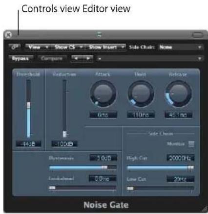
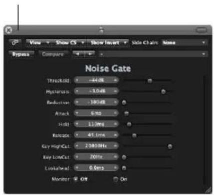
To switch between view modes:
- Choose the Controls or Editor item in the plug-in header's View menu.
Side Chaining Plug-ins
All plug-ins that support side chain inputs, feature an additional Side Chain menu at the right of the plug-in window header. This allows you to route any audio channel, input channel, or auxiliary channel into the plug-in, via a side chain.
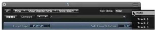
You can also route an instrument channel as the side chain signal by following these steps:
1 Create a send to an aux channel (say Aux 3) on the instrument channel (Instrument 5, for example).
2 On the audio channel that you want to process, choose the selected aux channel (Aux 3) in the plug-in Side Chain menu.
Once the side chain input is chosen, the plug-in processes the audio of the channel it is inserted in, using the trigger impulses provided by the side chain.
The signal peaks of the side chain input (the sent instrument signal), combined with the Threshold parameter of the plug-in, determine when the plug-in is triggered.
Some Side Chaining Examples
- A sustained pad sound is sent through a noise gate, which is triggered by a drum track being used as the side chain input signal. This results in a rhythmic pad sound which follows the signal peaks of the drum track.
- A noise gate inserted into a bass guitar channel is triggered by the kick drum track via the side chain. This can tighten the timing of the bass guitar, as it follows the kick drum signal.
- Side chains can also be used to blend a music mix with a voice-over. To achieve this, the mix needs to be routed through a compressor which, in turn, is side chained, using the voice-over track. In this type of setup, the music becomes softer when the narrator is speaking, and louder, when not. The effect is also known as ducking. Please note that in order for this to function, the Automatic Gain Make-up or Auto Gain control (if applicable to the compressor plug-in) must be disabled.
Hiding and Showing Extended Parameters
Some Logic Express plug-ins may have additional parameters that don't appear in the Editor view (the graphical interface of the plug-in).
This is indicated by a disclosure triangle that appears at the bottom left of the plug-in window.

If no disclosure triangle is visible, the plug-in has no additional parameters.
To hide or reveal the extended parameters:
- Click the disclosure triangle at the bottom of the plug-in window.
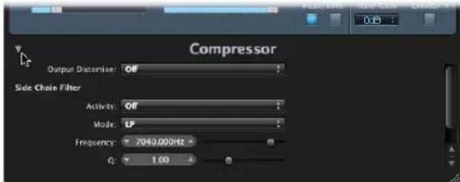
Using the Library to Choose Plug-in Settings
An alternative to using the Settings menu found in the plug-in window header is the Library tab of the Media area.
To load a plug-in setting from the Library:
1 Click the Media button on the Arrange window Toolbar, if the Media Area is not visible, then click the Library tab.
2 Select the Arrange track that is routed to the channel strip that you want to adjust the settings of.
3 Click the Insert or Instrument slot of the desired plug-in on the Arrange channel strip.
A white frame indicates the Library focus.
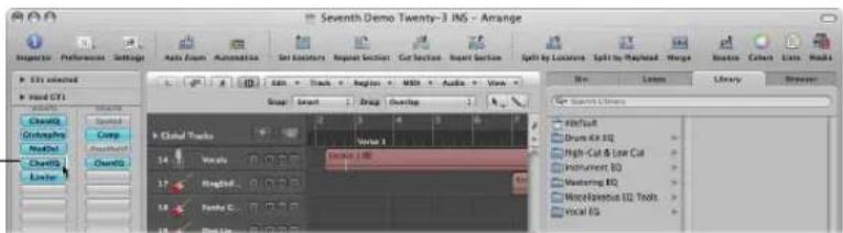
The Library displays all settings available for the chosen plug-in type, sorted into category menus. As examples for the Compressor plug-in: Drum Compressors, Instrument Compressors, Vocal Compressors.
4 Click the appropriate category menu, then click on the desired setting name to change the setting for the selected plug-in.
Note: You can click the Revert button to return to the previous plug-in setting.
5 Clicking on further Insert or Instrument slots, if used, will update the Library tab to show all settings for the chosen plug-in type.
6 If you click on an unused Insert or Instrument slot, the plug-in menu will be shown, as usual. Choose a plug-in and the Library tab will update to reflect your selection.
Library Folder and Menu Structure
Each plug-in type has a specific sub-folder (named after the plug-in) which is automatically created in the Plug-In Settings folder. Further sub-folders, used for categories, can be created inside these sub-folders.
These folder structures are reflected in the Library tab (and Settings menu) for each plug-in. The Plug-In Settings folders are located in the following locations:
- \~/Library/Application Support/Logic: User-defined or edited plug-in settings are stored here.
• /Library/Application Support/Logic: Factory settings are always stored here.
Plug-in settings are identified by the pst file extension.
Learning About Effect Routings
There are two ways of sending audio to effects: via an insert, or via an aux send.
Insert Effects
When a plug-in is inserted directly into a channel, it is termed an insert effect. All of the signal is processed, or put another way, 100% of the signal flows through the effect. This one hundred percent behavior is suitable for equalizers or dynamic effects, such as compressors.
If you have enough processing capacity, you can use up to 15 insert effects on each channel strip.
By default, only two Insert slots are shown on channel strips. An extra blank Insert slot is automatically created, as soon as all of the currently displayed Insert slots are used, up to the maximum allowed.
Put another way, if you insert an effect plug-in into Insert slot 2, a third slot will be shown automatically. If you insert a plug-in into slot 3, a fourth will be shown, and so on.
Send Effects
When you use send effects, a controlled amount of the signal is sent to the effect. Sends are typically used for effects that you want to apply to several signals at the same time.
Send effects are also called bus effects, bus send or bus returns, auxiliary send or auxiliary returns, or simply send or returns.
In Logic Express, the send effect is placed in an Insert slot of an aux channel. The signals of the individual channels that you want to process are sent to this aux channel, using a bus. The amount of signal is controlled by a Send knob on each channel. The audio is processed by the effect inserted in the aux channel, and is mixed with the stereo output.
The primary advantage of this approach, over inserting effects on tracks, is efficiency. This method allows multiple channels to be processed by one inserted effect, which saves vast amounts of processing power (and your time) when compared with the alternative of inserting the same effect directly into multiple channels.
Another bonus is that you can quickly switch between wet and dry versions of all channels that are sent to an aux channel, by simply bypassing the effect on the aux.
Similarly, you can completely change the effects configuration for multiple sent channels by choosing different effects for the aux channel.
For computationally-intensive effects such as reverb, it's always advisable to insert them into an aux channel. Chorus, flanger, and delay effects should also be inserted into an aux, if they are going to be used on more than one track.
In some cases, however, it may make musical sense to patch an effect such as a delay or chorus, directly into the Insert slot of an individual channel. This allows you to use precise settings, and colors, on individual elements of your mix.
The golden rule is that you should use whatever sounds right in your mix. There are no restrictions as to where effects may be used in Logic Express.
To send a channel signal to an aux:
1 Click on a Send slot (of an audio channel, for example), and choose a bus from the menu.
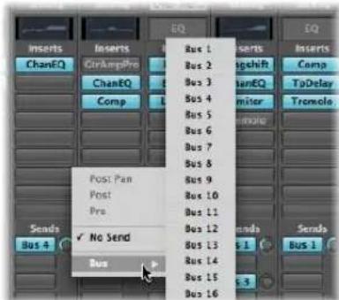
2 Drag the Send knob to set the amount of signal that you would like to send to the aux channel.
As you do so, the (send amount) value will be shown on the Send slot.
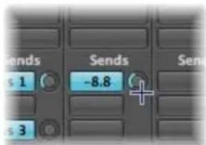
The send amount, when set to 100%, routes the entire signal from the audio or instrument channel to the auxiliary destination channel (see Pre and Post information below).
3 Insert the desired effect plug-ins, and set the required level, pan, and output settings for the destination aux channel.
Tip: This is easiest to accomplish with the Arrange channel strips in the Inspector: The left channel strip is the source (the audio channel from the example), and the right channel strip is the destination (the aux channel) for the source. If you work in the Mixer, you can double-click a Send slot to jump to the allocated aux channel.
To remove a send:
- Click an active Send slot, then choose No Send from the menu.
To bypass a send:
■ Option-click the Send slot.
The Send slot background turns gray.
To normalize (reset) the send level:
■ Option-click on the Send knob.
This resets the send level to 0 dB.
Post, Post Pan, and Pre Fader Aux Sends
Sends can be positioned either before (pre) or after (post) the (source) channel strip level fader.
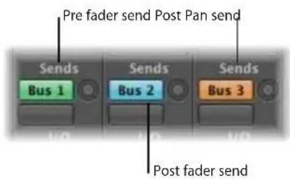
A post fader signal level, routed to a send, changes along with volume fader movements. If you are using the send to route a signal from the channel to a reverb inserted on an auxiliary channel, this means that the relationship between the original signal and the effect signal remains constant. When you pull the channel's volume fader all the way down, the reverb disappears as well. This setting is generally the most useful, and is the default in Logic Express.
If a send is set to pre fader mode, the level of the signal routed to the send remains constant, regardless of any volume fader movements on the source channel. The signal is still fed to the selected aux channel—even if the source channel's volume fader is completely pulled down. Pre fader sends are mainly used for monitoring tasks; headphone monitoring in the studio, or foldback monitoring on stage. Pre fader sends are also useful when you want to hear the effect signal in isolation (without the original signal). The equalizer still affects the sends in pre fader mode (pre fader, post EQ).
If you choose Post Pan, the signal is not only post fader, but also post pan. This means that the pan position of the send signal on the aux (which needs to be stereo or multi-channel) will follow the Pan/Balance position of the channel strip.
To select one of these options in Logic Express:
- Click on a used Send slot, and choose Post Pan, Post, or Pre at the top of the menu.
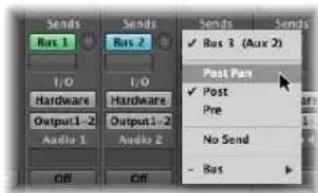
Parallel and Series Send Routings
When multiple effects are inserted into a channel strip, they are said to be routed in series. This term refers to the serial nature of the effects chain, where the output of one effect is fed into the input of the next, and so on.
When a channel strip is routed to multiple auxiliary channels via sends—with reverb, chorus, and delay effects assigned to aux channels 1, 2, and 3, respectively—it is said to be a parallel routing.
This means that the output of the channel strip is split, and routed to three separate effects; one on each auxiliary channel strip. These three independent signals are sent back from the respective aux channels, and recombined into an output stream from the channel strip.
You can also direct the audio signal from the auxiliary channel strips to individual output channels (or other aux channels)—independently, or in combination with—the mixed channel strip output.
Further possibilities are afforded by combining both series and parallel routings for individual channels.
Why would you route a channel strip to multiple auxiliary channels, routed back to the channel, to outputs, or to further aux channels?
Put simply, the sonic results of each, or combined, approaches can be very different. So start exploring and experimenting!
Working With Instruments
This section deals with the use of software instruments and external MIDI sound generators.
Both software and external MIDI instrument tracks are handled in an almost identical fashion. In fact, the MIDI regions on tracks routed to either type of channel (software instrument or External MIDI) can be used interchangeably.
You can also completely reassign a track routed to an external MIDI synthesizer to one using software instruments, or perhaps copy the data of an external MIDI track to a software instrument track, resulting in layered playback of the part through both instruments.
Software instruments use instrument channel strips. MIDI instruments use External MIDI channel strips.
ReWired instruments are handled through auxiliary channel strips. Set up and use of ReWired instruments is covered in "Working With ReWire Applications" on page 260.
Tip: Many of the set up and routing tasks described in this section can be done once, and saved with a template. This means that all of these preliminary tasks can be bypassed the next time you load the template, so you can concentrate on creating music. Please see "Saving a Project as a Template" on page 156 for more information.
Setting Up External MIDI Instruments
There are several ways that you can set up, and use, external MIDI keyboards and modules with Logic Express. The best way to illustrate these is with working examples. Please follow the steps outlined below.
To create a new external MIDI instrument from the Arrange:
1 Click the New Tracks button (the plus sign above the track list) in the Arrange window.
2 Choose the External MIDI option, and click the Create button.
Note: The Open Library checkbox in the New Tracks dialog is turned on by default. Leave it alone, as the Library tab (that automatically opens) will make your life much easier.
A new track will be created in the track list, assigned to GM Device 1.
When you create a new External MIDI track in a project, Logic Express will automatically generate a new External MIDI Multi Instrument object. This is placed on the MIDI Instr. layer of the Environment window.
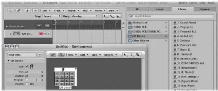
Choose Window > Environment to take a look at this object (see Chapter 38, "Working in the Environment," on page 875 for details).
Another thing that happens in the background is the automatic creation of Mixer channel strips for each of the Multi Instrument sub-channels. Click the Mixer button at the bottom of the Arrange window, and click the All button in the Mixer menu bar. You'll see 16 channel strips, assigned to GM Device 1 to 16 (plus a couple of others for audio channels).
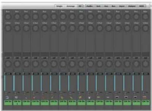
To the right of the Arrange area, you'll see the Library tab. It shows a list of your MIDI ports and other objects. Among the items listed, you'll see the GM Device.
3 Click GM Device in the left column of the Library tab, and you'll see 16 entries in the right column: 1 (Grand Piano), 2 (Polysynth), and so on.
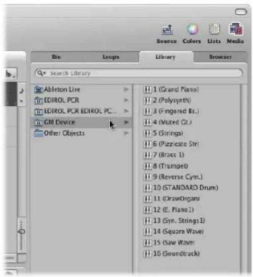
4 Click the disclosure triangle to the left of the GM Device 1 entry in the Inspector (if the Track parameter box is not already open). If the Inspector isn't visible, click the Inspector button in the Arrange Toolbar.
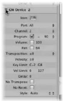
There are two parameters of particular note here: Port and Channel (see "Setting External MIDI Channel Parameters" on page 254).
5 Click on All beside the Port parameter. You will see all of your MIDI interface Out ports listed. As examples: Port 1 (Unitor 8), Port 2 (Unitor 8), MIDI1 (mLan Network). If you choose a specific Port, say Port 1 (Unitor 8), the GM Device Multi Instrument object will be routed to this specific MIDI port. This mirrors the port listing shown in the left column of the Library tab.
6 You'll note that the Channel parameter is set to 1. Create a few new External MIDI tracks by following steps 1 and 2. You'll note that these new tracks are called GM Device 2, GM Device 3, GM Device 4, and so on. Click on each of these tracks in the track list, and keep an eye on the Channel parameter in the Track Parameter box of the Inspector. Each of these tracks is routed to a sub-channel of the GM Device Multi Instrument object. The selection of each track is mirrored by the 16 sub-channel entries shown in the right column of the Library tab.
It is important to note that Logic Express did not create a new Multi Instrument object for each new External MIDI track. Rather, it assigned each subsequent track to sub-channels of the GM Device Multi Instrument object. You can create up to 16 tracks that are assigned on a one-to-one basis with each sub-channel of a Multi Instrument Object.
So, what happens if you need more channels, for more external MIDI synthesizers and modules?
You have a couple of options. The easiest way is to use the Library tab to reassign newly created tracks to particular MIDI ports and channels.
To reassign tracks to channels with the Library tab:
1 Create a few new External MIDI tracks in the Arrange window, following steps 2 and 3 in the example above.
2 Click on a track, and then click on a Port and sub-channel entry in the Library tab.
- If you choose a sub-channel of the GM Device you will reassign the selected track to this sub-channel.
- If you choose a sub-channel of a different MIDI Port, the track will be reassigned accordingly (Unitor 8 Port 5, sub-channel 4 as an example). Take a look at the new Multi Instrument object (Unitor 8 Port 5) in the Environment.
Note: The first time you do this for each port or sub-channel, a new multi instrument object will be created in the Environment (along with corresponding Mixer channels). Once objects have been created for all ports, the reassignment of tracks to ports or channels does not create new objects.
An alternative to using the Library tab for multi instrument object creation is the Environment.
To create a new external MIDI instrument in the Environment:
1 Open the Environment window by choosing Window > Environment (or using the corresponding key command, default: Command-8).
2 This should default to the MIDI Instr. layer, but if not, click the down arrow to the left of the Link button, and choose the MIDI Instr. entry.
3 Click the New menu, and take a look at the commands available. These are all environment objects that you can create. For now, choose Multi Instrument.
4 The newly created multi instrument object is called (Multi Instr.). You can rename it later (usually after your synthesizer name; JV5080, Microwave, and so on).
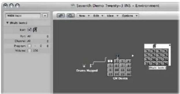
- You will note that there are diagonal lines running through each of the 16 sub-channel boxes.
- Also note that the Port and Channel parameters are shown to the left of the Environment window.
5 Click on the Port menu, and choose a new MIDI Out port for the Multi Instr. object. Ensure that this is a different port to that used by the GM Device object.
6 The last step is to activate each sub-channel. To do so, simply click on each sub-channel box. As you do so, the diagonal line will disappear from each.
7 Click the Mixer button at the bottom of the Arrange window, and you'll see 16 new (Multi Instr.) channel strips.
Tip: Once an object has been created in the Environment (using any of the methods described), you can Control-click on track names in the track list. Choose the desired port and sub-channel from the Reassign Track Object menu to quickly reassign tracks.
Setting Channel Parameters for Instruments
When you choose a track that is assigned to either a MIDI or software instrument channel strip, the Inspector's Track Parameter box displays the parameters outlined in this section.
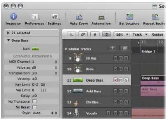
Changes to these parameters affect the entire channel strip, and all tracks routed to the channel strip are affected. This is an important distinction to make, as some parameters, such as transposition are available as both a channel and region parameter. To put this into context, imagine a project with 6 tracks routed to the EXS24 mkII (with a drum kit loaded) on instrument channel 1. You would like to transpose the snare drum part (played by regions on track 2) by two semitones. This will trigger a different snare drum sample.
- If you use the Region parameter box Transposition parameter for all regions on track 2, things will go according to plan.
- If you use the Track (Channel) parameter box Transposition parameter, the entire EXS24 mkII drum kit (Instrument channel 1) will be affected. This will result in all regions on the 6 tracks being played back by other drum samples.
Common Instrument Parameters
The following parameters are available for both software instrument and MIDI instrument channel strips.
Icon
The icon used by the instrument can be changed to suit your tastes or needs. Simply click the icon, and choose another from the menu. A default icon is used for all internal Logic Express instruments when inserted, so you can instantly recognize an EXS24 mkll or ES1 track.
Transposition
The Transposition parameter allows you to define the number of semitones that all note events will be transposed by, on output. Negative values transpose downwards.
Velocity
The Velocity parameter allows you to increase or decrease the note on velocities of all note events by an amount between -99 and 99.
Key Limit
The two note values of the Key Limit parameter define a pitch range. All notes outside this range are ignored by the instrument.
Vel Limit
The two values of the Vel Limit parameter define a velocity range. All notes with a velocity that falls outside this range will not be played by the instrument.
Delay
The Delay parameter causes all MIDI events to be sent early or late, by the defined number of ticks (range: from -99 to 99). This allows you to compensate for any differences in reaction time between your various MIDI devices, or to create offsets between channels.
If you're after rhythmic delay effects on individual parts, use the Region Parameter box Delay, as this allows for longer delay times, and does not affect the channel playback timing (all regions on the track, or other tracks routed to the same channel).
No Transpose
Turn on the No Transpose parameter to protect all MIDI regions (on any tracks routed to this channel) from transposition. In other words, the Region Parameter box Transpose parameter is ignored. This is very useful for instruments assigned to drum or other multi-timbral samples, as transposition will change the sounds (rather than merely the pitches) of these instruments.
No Reset
Turn on the No Reset parameter to prevent reset messages from being sent to this channel. This can be useful if controllers are being used for non-musical purposes, such as mixer automation. The Logic Express > Preferences > MIDI > Reset Messages tab determines what reset messages are normally sent, but these messages are not sent to No Reset instruments.
Style
Whenever a MIDI region is created on one of the tracks routed to a given channel, it will be assigned the staff style set in the Style pop-up menu. If Auto is chosen, Logic Express will pick an appropriate style based on the pitch range of the notes in the region.
Tip: You can change a MIDI region's staff style at any time in the Display Parameter box of the Score Editor.
Setting Software Instrument Channel Parameters
The following parameters are specific to instrument channel strips.
MIDI Channel
This parameter sets the MIDI channel used by the software instrument.
Value as
This switches the channel strip displays (meters and other parameters) between decibel (dB) and numerical (Num) values. The decibel display is the default.
Setting External MIDI Channel Parameters
The following parameters are specific to External MIDI channel strips.
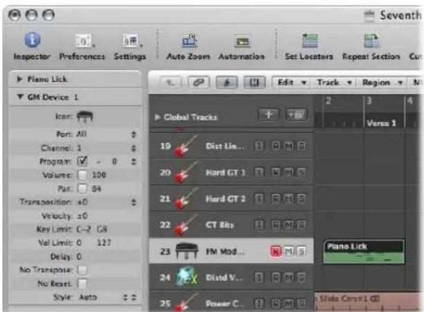
MIDI Channel and Port Connection
The Port parameter defines the physical MIDI output that data is sent to. Your MIDI sound module is connected to this MIDI output connector.
The MIDI channel is set with the Channel parameter. This defines the channel used for MIDI output by the instrument track, allowing your "real" instrument to receive the data.
Setting the MIDI Channel: Multi Instruments
You can also alter the MIDI channel of an external MIDI instrument part by choosing another sub-channel of the current multi instrument.
A sub-channel is one of 16 possible MIDI channels or parts that can be played by a multi instrument object. It goes without saying that the external MIDI synthesizer (represented by the multi instrument object) needs to be capable of playing on more than one MIDI channel for sub-channel selection to be useful.
You can't actually change the receive channel of a sub-channel in the multitimbral synthesizer. This is only possible in a few models (and is not particularly useful when using Logic Express, at any rate).
If the MIDI channel is set to All, you can edit the parameters of the whole multi instrument object. A useful facility for globally changing the MIDI port (Port A, B, and so on), for example.
Program, Volume, and Pan
The Program, Volume, and Pan parameters transmit program changes, volume controller (CC #7), and pan controller (CC #10) information.
If the respective box is unchecked, the default value of the MIDI device itself is used.
A program change (a preset or patch number in your MIDI module) may be selected on the right, via a pop-up menu. When dealing with multi instrument sub-channels, sounds can be selected from a pop-up menu by name.
As an alternative, you can double-click on the track name (GM Device 1, for example). This launches the Multi Instrument window.
![Milk (Music List) Device Name: (Oral Event) Back: The Bank specified. Names of Book 0 sound Open Short Device Name: Audio Message: Contact 32 Project Names: Grand Piano Bright Piano ElectricGrand Honey/Trunk/Pro. E. Piano E. Piano Harperchord Clavon Ceratina Gastpanola Music Box Vibraphony Macromba Xylophone Turbular Bell Racimer [ ] (On-Draw program names for channel 28 Acoustic Aurora Aurora Aurora Aurora Aurora Aurora Aurora Aurora Aurora Aurora Aurora Aurora Aurora Aurora Aurora Aurora Aurora Aurora Aurora Aurora Aurora Aurora Aurora Aurora Aurora Auroral Auroral Auroral Auroral Auroral Auroral Auroral Auroral Auroral Auroral Auroral Auroral Auroral Auroral Auroral Auroral Auroral Auroral Auroral Auroral Auroral Auroral Auroral Auroral Auroral Auronal Auronal Auronal Auronal Auronal Auronal Auronal Auronal Auronal Auronal Auronal Auronal Auronal Auronal Auronal Auronal Auronal Auronal Auronal Auronal Auronal Auronal Auronal Auronal Auronal Auroral](/content/2026/05/859464/images/dfc6b730d8beb97a8033e7f7fe0699e7a150c100d7377af59e1eb996e6dc5f2d.jpg)
Simply click on the name of the sound (synthesizer patch) that you want to use. Click the close button at the top left to exit the window, or press Command-W. More details on this window, including customization of patch names, can be found "Using the Multi Instrument Window" on page 904.
To the right of the program number, there is an extra parameter which is used for Bank Select. If your sound source receives Bank Select messages (MIDI controller #0 or #32—check your synth manual for format details), you can switch between different banks, each containing a maximum of 128 sounds.
For more on the other instrument parameters, see "Standard Instruments" on page 899.
Adding Program Change, Volume, and Pan Settings to a MIDI Region
The MIDI > Insert Instrument MIDI Settings as Events command allows you to insert the program change, volume, and pan settings (from the Track Parameter box in the Inspector) as actual MIDI events into one, or more, selected MIDI regions. The events are placed a quarter note before the beginning of the relevant MIDI regions. Only the activated (checked) settings in the Track Parameter box(es) are added as events. If any events of the same kind already exist in the region(s), they are overwritten.
The values of the Program, Volume, and Pan parameters will not be updated every time such control change events are played back. These parameters are initial values, when you load a project, or choose the MIDI > Insert Instrument MIDI Settings as Events command—before you begin to record mixer automation data.
Processing External MIDI Instruments With Effects
You can route external MIDI sound generators through the Logic Express Mixer, allowing you to process them with Logic Express effects. This is achieved through use of the External Instrument plug-in. Ideally, you will use a multi input and output audio interface, to avoid constant re-patching of devices.
To process external MIDI instruments with effects:
1 Connect the output (or output pair) of your MIDI module with an input (pair) on your audio interface.
Note: These can be either analog or digital connections if your audio interface and effects unit are equipped with either, or both.
2 Create an instrument channel.
3 Click the Instrument slot, and choose External Instrument from the pop-up menu.
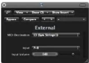
4 Choose the MIDI Destination from the menu in the External (instrument) plug-in window.
The MIDI Destination menu will show all sub-channels of all multi instruments in the Environment.
5 Choose the input (of your audio interface) that the MIDI sound generator is connected to from the Input pop-up menu.
6 Adjust the Input Volume, if necessary.
7 Insert the desired effects in the Insert slots of the channel.
As the track is routed to an instrument channel (which is being used for an external MIDI sound module), it behaves just like a standard software instrument track, which means that you can record and play back MIDI regions on it—with the following benefits:
- You can take advantage of the sounds and synthesis engine of your MIDI module, with no overhead on your Macintosh CPU (apart from the effects used on the channel).
- You can use insert effects, obviously, but can also use Send effects by routing the Instrument channel to aux channels.
- You can bounce your external MIDI instrument parts—with or without effects—to an audio file, in real time. This makes the creation of a mix, inclusive of all internal and external devices and tracks, a one step process.
Note: You can not use the Freeze function on such tracks, nor can you perform an offline bounce.
Playing Software Instruments
Software instrument plug-ins respond to MIDI note messages, whereas effect plug-ins do not.
The output signal of a software instrument is fed into the input (the Instrument slot) of the instrument channel strip, where it can be processed via inserted effect plug-ins, or sent to busses.
Logic Express supports up to 255 discrete instrument channels. The number of software instruments that you can run simultaneously is dependent on the computer processing resources available.
Following the insertion of an instrument plug-in, the instrument channel can be driven by a recorded MIDI region, or direct MIDI input—playing your MIDI keyboard, in other words!
Switching Instruments to Software Instrument Live Mode
When you select a (software) instrument track, it does not immediately switch into live or performance mode. You must send a MIDI event before live mode is activated, but this takes around 100 milliseconds to engage, which is more than enough to destroy the timing of your first played note.
If you require perfect timing for the first played note, you need to send silent MIDI events in advance; press the sustain pedal, make a small move of the pitch bender or modulation wheel as examples. This will switch on live mode.
Why Live Mode is Necessary
Live mode instruments need to stay in live mode while the audio engine is running (when Logic Express is in play or record mode), as switching a software instrument track out of live mode will create a gap (or noise) in the audio stream. Obviously, this is unacceptable.
Software instruments that are live (ready for playing) require considerably more CPU power than those that are merely playing back existing regions. If the act of selecting a software instrument track automatically activated live mode, switching between multiple instrument tracks would compound the problem, possibly resulting in CPU overloads.
The Record button of selected software instrument tracks gives visual feedback of the current state of a software instrument:
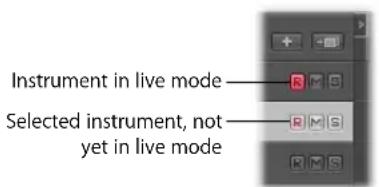
Saving Software Instrument Processing Resources
The Bounce function allows the entire instrument track to be recorded as an audio file. This bounced audio file can then be used (as an audio region) on a standard audio track, allowing you to reassign the available processing power for further software instrument tracks. For details, please refer to Chapter 27, "Bouncing Your Project," on page 625.
You can also make use of the Freeze function to capture the output of a software instrument track, again saving processing power. For details, please refer to "Freezing Tracks" on page 208.
Tuning Software Instruments
The File > Project Settings > Tuning > Software Instrument Pitch parameter remotely controls the main tuning parameter for all software instruments (the ES1 or EXS24 mkII, for example) by ±50 Cents.
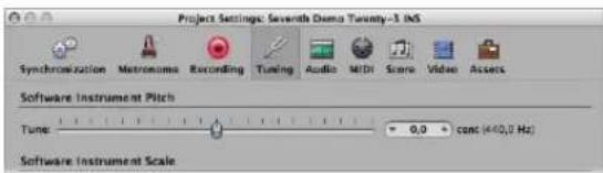
By default, it is set to concert pitch A at 440 Hz. Simply drag the slider to the desired value. As you do so, the cent and Hz values will update.
Note: Some Audio Unit instruments do not recognize this remote command.
No Hermode Tuning
Logic Express allows all software instruments to be globally tuned to different tempered scales, including Hermode Tuning (see "What Is Hermode Tuning?" on page 970). There may, however, be occasions where you want individual software instruments to be exempt from this global tuning system.
When File > Project Settings > Tuning > Hermode Tuning is active, a No HMT checkbox is visible in the Inspector Parameter boxes of all instrument channels.
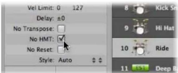
Simply click in this box to prevent the selected software instrument from following the global Hermode Tuning scale.
A software instrument track with an active No HMT checkbox will be played back at equal temperament.
This facility is ideal for an EXS drum kit that you don't want tuned like your melodic software instrument parts, for example.
Working With ReWire Applications
Logic Express acts as a host for ReWired applications such as Ableton Live and Propellerhead Reason.
Important: Start Logic Express first, and then start your ReWire application(s).
When these applications are run alongside Logic Express, synchronized audio information is routed out of them in to aux channel strips in the Logic Express Mixer, where it can be combined with other tracks, run through effects and bounced to new audio files.
In essence, the output of these ReWired programs is handled in much the same way as you would deal with internal Logic Express audio data. Synchronization is automatic, so you don't really need to do much to ReWire the applications, apart from setting up aux channels, if desired.
Beyond routing the outputs of ReWired applications into Logic Express, you can also directly play, record, and play back the software instruments available in these programs. Propellerhead Reason, for example, is the software equivalent of a rack of synthesizers and samplers.
You can directly play each synthesizer in the Reason rack, and can record these parts as MIDI regions on Logic Express tracks, much as you would with Logic Express's internal, or external MIDI, instruments.
To access a ReWired instrument:
1 Create an External MIDI track in the Arrange window.
2 Double-click the ReWire application name in the Library tab (Reason or Ableton Live, for example).
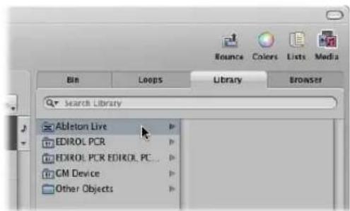
This will launch the ReWired application, and a list of all available ReWire instruments appears in the Library.
3 Click the desired instrument track in the Library.
To manually set up an aux channel for ReWire use:
1 Click the Mixer button at the bottom of the Arrange window. In the Mixer window, choose Options > Create New Auxiliary Channel Strips.
2 Create as many aux channel strips as required, with the appropriate Format, Input, and Output settings. For this example, create a stereo channel strip, routed to Input/Outputs 1-2.
3 Choose the desired ReWire channel in the Input menu of the aux channel strip.
Individual RW Channel entries are available in the Channel menu. These can be assigned individually, to allow each ReWired channel to be routed to a particular aux channel in the Logic Express Mixer. This provides extended mixing and processing options.
Setting the ReWire Behavior
In Logic Express > Preferences > Audio > Devices, you can choose between the following modes when using ReWired applications:
- Playback Mode (Less CPU Load): Use this mode when streaming channels via ReWire. This setting requires less CPU power, and should be used when playing back tracks in ReWired applications.
- Live Mode (Higher CPU Load): Use this mode when you want to play a ReWire instrument (an instrument running in an external ReWired application) in real time. This setting requires more CPU resources, but reduces latency, ensuring that the ReWired instrument is playable.
Working With External Audio Effects
You can use external audio effects units in a similar way to the internal Logic Express effects. This is achieved with the I/O plug-in, in conjunction with a multi input/output audio interface.
To integrate and use an external effects unit in Logic Express:
1 Connect an output (or output pair) of your audio interface with the input (pair) on your effects unit.
2 Connect the output (or output pair) of your effects unit with an input (pair) on your audio interface.
Note: These can be either analog or digital connections if your audio interface and effects unit are equipped with either, or both.
3 Click an Insert slot of the channel you want to process with the external effects unit, and choose Utility > I/O.
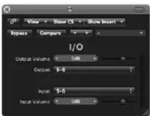
4 In the I/O plug-in window, choose both the Output and Input (shown as numbers) that your effects unit is connected to.
5 Adjust the Input or Output volume as required.
When you start playback, the signal of the audio channel will be processed by the external effects unit.
Some Tips for Using External Effects
Some audio interfaces feature their own routing software, which you may need to use to set up the chosen inputs and outputs for this type of use. Please consult the documentation provided by your audio interface manufacturer.
Most hardware effects units are MIDI controlled. If this is the case with your effects unit, you can connect its MIDI input and output cables to your MIDI interface. This enables you to choose effects presets, and may also allow you to remotely control, record, and automate the parameters of the effects unit from Logic Express.
Using Plug-ins From Other Manufacturers
Logic Express can act as a host for (compliant, correctly installed and authorized) Audio Unit effect and instrument plug-ins from other manufacturers.
Important: Logic Express can not act as a host for plug-ins in VST or RTAS format.
There are, however, utilities such as the VST to Audio Unit Adapter
(http://www.fxpansion.com), that "wrap" Mac OS X versions of VST plug-ins to create virtual Audio Units. Once wrapped, most of these plug-ins behave, and can be used, just like Audio Units.
Loading Presets
Many plug-ins from other manufacturers use a proprietary storage format for their presets (the equivalent of Logic Express plug-in settings).
In most cases, a separate Preset (or similarly named) menu will be available in the plugin interface. Once loaded, you can save any of these presets as a Logic Express setting.
In all cases, the global Compare, Copy, and Paste options of the plug-in window header will work as they do with the native plug-ins of Logic Express.
Working With the Audio Units Manager
Logic Express uses the Apple AU Validation Tool to ensure that only plug-ins which fully comply with the Audio Unit specification are used in Logic Express. This minimizes problems that may be caused by third-party Audio Unit plug-ins.
The validation process takes place automatically when:
- Logic Express is first opened.
- An updated version of Logic Express is installed.
- You install new Audio Unit plug-ins, or update existing ones.
You can see the results of the validation scan (for all Audio Unit and "wrapped" VST plug-ins) in the Audio Units Manager.
To open the Audio Units Manager:
- Choose Logic Express > Preferences > Audio Units Manager in the main menu bar (or use the Start Audio Units Manager key command).
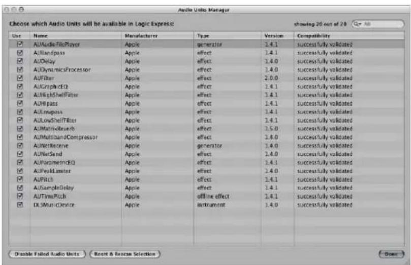
The results of the test are shown in the Compatibility column.
Important: The first thing you should do is check the manufacturer's website for updated versions of Audio Units plug-ins that fail validation.
Manually Enabling Plug-ins
Audio Units plug-ins that failed the validation test, can be manually enabled by activating the checkboxes in the Logic column—but be aware that these plug-ins can cause problems.
If you encounter problems with manually activated failed plug-ins, click the Disable Failed Audio Units button.
Warning: Use of plug-ins that have failed the validation can negatively affect the test results of subsequently scanned plug-ins. They can also prevent Logic Express from launching, cause it to quit unexpectedly, or even lead to data loss (destroyed project files)!
Disabling Plug-ins
The Audio Units Manager also allows you to disable Audio Units plug-ins that you don't want to use in Logic Express, even if they pass the validation scan. Simply uncheck the corresponding checkbox in the Logic to disable any plug-in. You can store your choice of Audio Units plug-ins by clicking the Done button.
Click the Reset & Rescan Selection button to rescan a selection of plug-ins, after installing plug-ins/updaters or moving components in the Finder, while Logic Express or the Audio Units Manager are open. They will be enabled automatically, if they pass the validation scan.
Note: If you press Control-Shift while opening Logic Express, the Audio Units Safe mode will be used: Only plug-ins that pass the validation test will be available; manually activated plug-ins that failed the validation test will not be available.
Adding Pre-Recorded Media
Pre-recorded media plays an important role in modern audio production. Combining existing audio loops and other files provides a quick method for laying down song foundations.
Logic Express ships with a large collection of audio loops, offering a great starting point for many of your projects. This chapter explains how you can add pre-recorded media in Logic Express, including audio and MIDI files, Apple Loops, and other common loop formats.
Supported File Formats
Logic Express allows you to access any digitally stored audio recordings (audio files) on your hard drives, in the most common Macintosh, and several other, file formats.
Audio files imported into a Logic Express project can be at any supported bit depth and sample rate. Logic Express supports bit depths of 16, 20, and 24 bits, and sample rates of 44.1, 48, 88.2, 96, 176.4, and 192 kHz. Logic Express can use the file's sample rate, or can perform a real time sample rate conversion (see "Setting the Project Tempo" on page 147).
In addition to audio files, Logic Express can also import MIDI and project information.
You can add the following pre-recorded media file types to a Logic Express project:
- WAV (including Broadcast Wave), AIFF, and SDII (Sound Designer II) files
• CAF
- MP3 files
- Apple Lossless files
• AAC (MPEG Layer 4) files
- Apple Loop files (audio and software instrument types)
• ReCycle audio (REX, RCY)
Logic Express can also import Standard MIDI files (type 0 and 1), GarageBand, OMF Interchange, AAF, OpenTL, and XML files. These file types are usually used to exchange projects, however, and are therefore outside the scope of this chapter. Full details on importing these file types can be found in Chapter 29, "Project and File Interchange," on page 649.
About Pre-Recorded Media Types Supported by Logic Express
The following section describes all media file types supported by Logic Express.
WAVE and AIFF Files
Wave (WAV) and Audio Interchange File Format (AIFF) audio files are very similar. They can be stored at different bit depths (16 and 24 bit are supported by Logic Express), in mono or stereo, and at sample rates up to 192 kHz.
Logic Express also supports Broadcast Wave files, which can contain time stamp information. Files that provide time stamp information can be recognized by a clock symbol, shown alongside the audio region name in the Audio Bin window.
The file extension of broadcast wave files is .wav, allowing them to be read by any application that supports the standard wave file format. In such programs, the additional Broadcast Wave file information is ignored.
Core Audio Format Files
Core Audio Format (CAF) files are containers that support integer and float PCM formats, A-law, u-law, and a number of others including AAC and the Apple Lossless Audio Codec (ALAC). Unrestricted file sizes are possible, at high sample rates and bit depths.
Sound Designer
Sound Designer I and II (SDII) audio files are similar in structure to AIFF files, and can contain time stamped region information. Use of Sound Designer format files can make transfers between Logic Express and Digidesign Pro Tools software more convenient.
MP3, Apple Lossless, and AAC
MP3 and AAC files contain compressed audio information. They are usually far smaller than equivalent WAV, AIFF, or SDII files. This reduction in file size is due to different encoding techniques that "throw away" some of the audio information. As a result, MP3 and AAC files do not sound as good as their WAV, AIFF, or SDII audio counterparts, dependent on the source audio material.
Apple Lossless files also contain compressed audio information. As the name suggests, the compression used (ALAC) does not discard audio information in the same fashion as MP3 files. The sound of the compressed audio file is identical to the original recording.
Apple Loops
Apple Loops are audio files that contain additional identification information; time and date, category, mood, key and tempo, amongst others. They also contain a number of transient markers, which break them down into small time slices. The standout advantage of Apple Loop audio files is their ability to automatically match the tempo and key of a Logic Express project.
A second Apple Loop file type is also supported by Logic Express. These contain MIDI note information that triggers a musical phrase or riff. The motif will be played, as is, when these types of Apple Loops are added to an audio track. When added to an instrument track in Logic Express, however, the MIDI note information can be edited, as you would with any MIDI region.
ReCycle
ReCycle (REX, RCY) files are generated in Propellerhead ReCycle software. These are similar to Apple Loop audio files, in that they contain a number of slices, and match the project tempo. When imported, a small folder that contains several regions—one for each slice—is created. Each of these slice regions can be handled like any audio region. ReCycle files, unlike Apple Loop files, do not follow the project key.
Standard MIDI Files
Standard MIDI files (SMF) are, as the name suggests, a standard file format used in MIDI sequencers. They can be read and saved in Logic Express. SMFs may contain note, lyric, controller, and SysEx data. They are added to MIDI or software instrument tracks in Logic Express.
Accessing Media Files in the Browser
You first need to locate your audio and other files, before you can add them to your projects. The Browser is your first port of call for browsing, previewing, and searching for pre-recorded media.
Note: While all supported media types can be accessed in the Browser, Apple Loops are best handled in the Loop Browser. Usage is covered in "Finding Apple Loops in the Loop Browser" on page 273.
To access the Browser in the Arrange window:
- Click the Media button in the Arrange Toolbar, then click the Browser tab (or use the Toggle File Browser key command).
To open the Browser as independent window:
- Choose Window > File Browser (or use the Open File Browser key command).
Navigating in the Browser
You can switch the Browser between two views: List and Browser view.
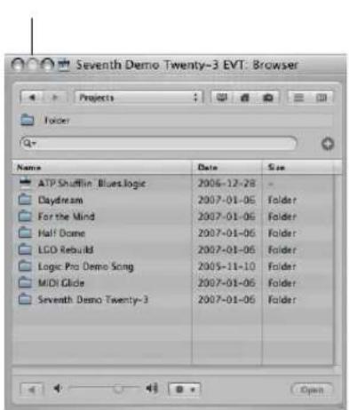
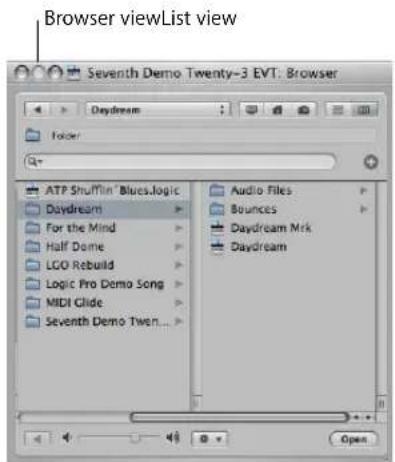
- List view displays folders and their contents in a list. You enter a folder by double-clicking it.
- Browser view exposes the contents of a folder in new frames to the right of the selected folder. You only need to click once on a folder to enter it.
To switch between List and Browser view:
- Click on the Browser button to access the Browser view. Click on the List button to access List view.
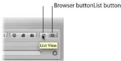
Navigation in the Browser is much like using the Mac OS X Finder. The method of navigation is the same for all file types. The the bookmark buttons, Path menu, and Back and Forward buttons aid navigation.
To navigate in the Browser using the bookmark buttons:
- Click one of the bookmark buttons: Computer, Home, or Project.
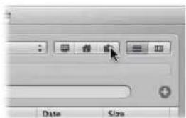
- Computer: Shows all volumes (hard disks, CDs, or DVDs) in, or attached to, the computer.
• Home: Shows all folders in your home folder. - Project: Shows the contents of your project folder.
To navigate in the Browser using the Path menu:
1 Click the Path menu to display the path taken to the current folder or file.
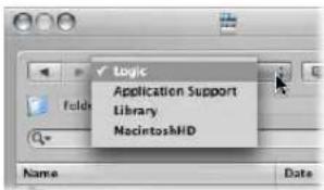
2 Click one of the entries in the Path menu to navigate back to clicked folder.
To step backwards or forward through the navigation history:
- Click the Back button or the Forward button.
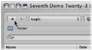
Searching for Files in the Browser
The Browser tab features a very sophisticated (and fast) search facility. You can use it to find any type of file supported by Logic Express, on local or network attached storage devices.
To perform a basic search in the Browser:
1 Click the Path menu (alone, or in conjunction with the bookmark buttons) to determine what you'd like to search; a particular folder, the entire hard drive, user root, the computer, and so on.
Restricting the search to a particular folder or volume speeds things up.
2 Type the search term into the Search field and press Return.
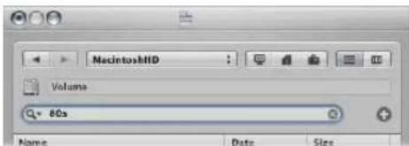
As an example, typing in 80s, with Macintosh HD chosen in the Path menu will result in a number of Apple Loop files being displayed in the view area.
To sort the search results:
- Click on any of the column titles to sort the file list by name, date, or size.
Tip: You can resize columns by dragging the vertical lines between column titles.
To clear a search term:
- Click on the small X icon at the right-hand side of the Search field.
To view recent search terms:
1 Click the magnifying glass icon at the left-hand side of the Search field.
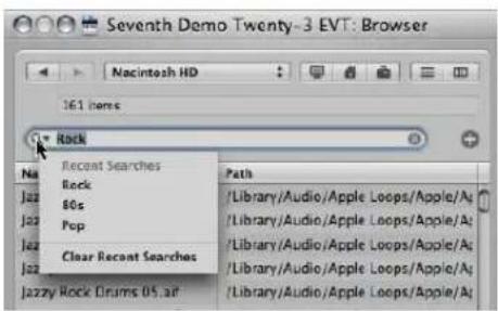
2 Choose any search term from the menu to display the search results.
To clear all recent search terms:
- Click the magnifying glass icon at the left-hand side of the Search field, and choose Clear Recent Searches from the menu.
To perform an advanced search:
1 Click the Path menu (alone, or in conjunction with the Computer, Home, and Project buttons) to determine what you'd like to search.
2 Click on the + icon to the right of the Search input field.
This will expand the search area. The menus shown in the expanded search area are used to narrow down, or restrict, your search to specific file types, file formats, date, size, and other criteria.
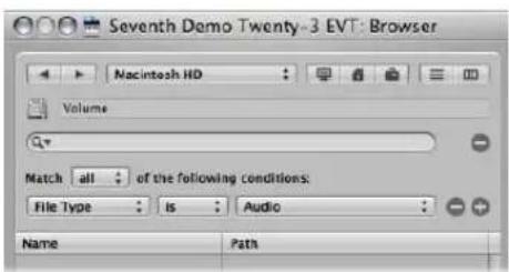
By default, the Match menu specifies that all of the advanced search conditions that you specify must be met, in order to display matching files. You can set the Match menu to any if you want to display all files that match one of the specified conditions.
3 Click the File Type menu, and change this to Format.
Note that the right-hand menu updates (AIFF is displayed) to reflect the left-hand menu selection.
4 Click the + icon to the right of the AIFF menu.
A further set of search condition menus is shown below.
5 Click the File Type menu in this second row of search conditions, and change this to Length.
The updated right-hand field and menu displays 30.0 sec.
6 Highlight the 30.0 field, and type in 8.
7 Now click on the Search field, input the desired term, and press Return.
A much shorter list of AIFF files, with a length of 8 seconds, and a name that contains the search term will be shown.
To remove a single advanced condition row:
- Click on the – icon beside the row.
This feature is handy when you've been a little too specific in your searches, and have received no search results.
Note: The row is hidden and deactivated, rather than removed completely. It can be restored by clicking on the + icon to the right of the row.
To return to a basic search, when several advanced condition rows are shown:
- Click the – icon to the right of the Search input field.
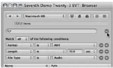
All advanced condition rows will be hidden.
To restore all advanced search condition rows:
- Click the + icon to the right of the Search input field.
Further Information on Conditional Searches
It goes without saying that searching for a particular file in the Browser can be much faster than navigating to it. You can define up to ten advanced condition rows to refine your searches. The search rows offer the following conditions.
First menu Second menu Additional menus/fields
| Comment contains, does not contain, is, is not, starts with, ends with | Input field |
| File Type is, is not Menu, in which you can choose between Audio, Movie, Project. | |
| Format is, is not Menu, in which you can choose between the following options: AIFF, Apple Loop, WAV (BWF), Apple Lossless, AAC, MP3, CAF, Sound Designer I, Sound Designer II, Logic Project, MIDI File, ReCycle, OMF File, AAF File, Open TL File, XML File, Notator SL SongNote that AIFF format searches do not include Apple Loops. | |
| Length is, is not, is less than, is greater than | Numerical input fieldAdditional menu in which you can choose between seconds, minutes, and hours. |
| Modified Date is, is not, after, before Input field | |
| Name contains, does not contain, is, is not, starts with, ends with | Input field |
| Sample Rate is, is not, is less than, is greater than | Menu, in which you can choose between the following options: 44.1 kHz, 48 kHz, 88.2 kHz, 96 kHz, 176.4 kHz, 192 kHz. |
| Size is, is not, is less than, greater than | Input fieldAdditional menu, in which you can choose between bytes, kilobytes, megabytes, gigabytes, terabytes. |
| Bit Depth is, is not, is less than, is greater than | Menu, in which you can choose between 8 Bit, 16 Bit, and 24 Bit. |
Finding Apple Loops in the Loop Browser
The Loop Browser only displays Apple Loop format files. You can search for Apple Loops, using key words for instrument, genre, mood, and other descriptors. You can also browse for Apple Loops in the Loop Browser.
In comparison with standard audio loops, Apple Loops have a significant advantage: they can contain additional information that Logic Express uses for a variety of purposes, including automatic time and pitch shifting, indexing, and searching.
Two important data types that Apple Loops may include are; metadata tags and transient markers. Logic Express uses metadata tags to help locate files when using the Search features of the Loop Browser. Transient markers indicate where beats occur in the file. Logic Express uses this information, in conjunction with the metadata tags, to match the file's tempo and key to the project tempo and key, thus ensuring the best possible playback quality. This functionality allows you to play back several Apple Loops simultaneously, and have them sound good, even if they have different tempos and keys.
To access the Loop Browser in the Arrange window:
- Click the Media button in the Arrange Toolbar, then click the Loop tab (or use the Toggle Loop Browser key command).
To open the Loop Browser as an independent window:
- Choose Window > Loop Browser (or use the corresponding key command).
Green and Blue Apple Loops
The Loop Browser contains two types of Apple Loops: those featuring a blue sound wave icon and others with a green note icon.
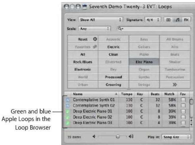
Both contain audio data, and both can contain additional information for time stretching, transposition, indexing, and searching.
Green and blue Apple Loops can be added to audio tracks, or directly to an empty Arrange area or track. In the Arrange area, they look like normal audio regions, but can be easily identified by the Apple Loop symbol in the upper right corner. They differ from standard audio regions in that they follow the project key and tempo.
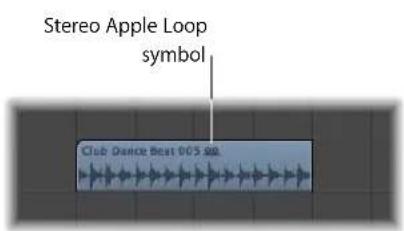
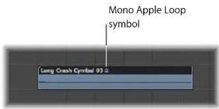
You can drag blue (audio) Apple Loops directly into a blank Arrange window (with no tracks), or to a blank area below existing tracks. An audio track and corresponding channel strip are automatically created, and the Apple Loop region (that is the full length of the file) is placed on the track. In addition, the Apple Loop file is added to the Audio Bin, and a corresponding region is automatically created.
Green Apple Loops are known as Software Instrument Apple Loops (SIALs). They differ from the blue (audio) Apple Loops in that they also contain a MIDI region plus software instrument and effect settings.
When Software Instrument Apple Loops are placed on instrument tracks, the region shown in the Arrange area can be edited just like other MIDI regions, including individual note editing.
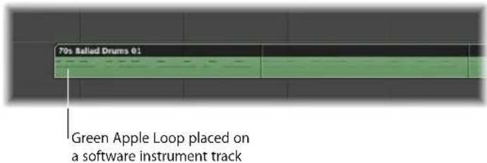
If dragged onto a blank instrument track (one with an empty channel strip), the corresponding instrument and effect(s) settings are automatically inserted.
You can also drag Software Instrument Apple Loops directly into a blank Arrange window (with no tracks), or to a blank area below existing tracks. An instrument track and corresponding channel strip are automatically created, and the Apple Loop is loaded (the instrument is inserted into the instrument channel, along with any effects, and the Apple Loop region is placed on the track).
When you place Software Instrument Apple Loops on audio tracks, they are imported as audio regions (and behave like blue Apple Loops). Processing load is reduced when green Apple Loops are added to audio tracks.
Note: Blue Apple Loops will not play if placed on instrument tracks.
Before Browsing or Searching for Apple Loops
When thousands of loops are installed on your hard disks, this can make finding a particular Apple Loop a rather daunting prospect. Fortunately, a number of options allow you to restrict your searching or browsing results with a number of key criteria.
These can be used in conjunction with each other, and directly affect the results of the browsing and search facilities available in the Loop Browser.
To limit the loop display to a particular Jam Pack or other category:
- Choose the desired setting from the View menu. You can choose between:
- Show All: Choose this default option to display all Apple Loops on your system. This option is handy if you are unable to locate a loop that you know is installed and indexed on your system, but do not know what Jam Pack it belongs to.
- My Loops: Choose this option to display all Apple Loops in the \~/Library/Audio/Apple Loops/User Loops/Single Files folder (\~ denotes the user name).
- Shared Loops on my Mac: Choose this option to display all Apple Loops in the /Library/Audio/Apple Loops/User Loops/Single Files folders. This setting is only visible if Apple Loops are shared with GarageBand on your system.
- GarageBand: Choose this option to display all Apple Loops installed with GarageBand.
- Jam Pack x: Choose this option to display all Apple Loops from a specific Jam Pack. Jam Packs are professionally-created genre or instrument-specific Apple Loop collections, available from Apple.
- Vendor x: Choose this option to display all Apple Loops from a specific third-party vendor.
- Other: Choose this option to display all loops that you manually added to the loop library by dragging them into the Loop Browser.
To limit the Loop Browser display to a particular scale:
- Click the Scale pop-up menu, and choose from: Any, Minor, Major, Neither, and Good for Both.
Use of these options limits the search for Apple Loops to the selected scale type, within the chosen category. As an example, if Country, Acoustic, and Relaxed categories were selected, you would be presented with twenty or so files that matched your choices. Selection of the Minor Scale setting would reduce this list to ten possible Apple Loops, making the task of auditioning and selecting the most appropriate material faster.
To limit the Loop Browser display to a particular time signature:
- Choose the desired time signature from the Signature pop-up menu.
Browsing for Apple Loops
There are three browsing views available in the Loop Browser. These are the: Column view, Music view, and Sound Effects view.
To switch between browsing modes:
- Click on one of the view buttons at the top right of the Loop Browser.
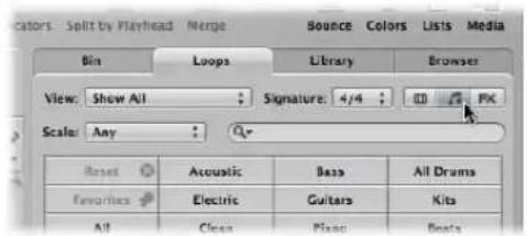
The left button activates Column view, the middle button activates Music view, and the third button, Sound Effects view.
The Music view displays a matrix of 54 buttons, each featuring a musically-related category. The Sound Effects view offers effect-related category buttons such as Explosions, Foley, or People.
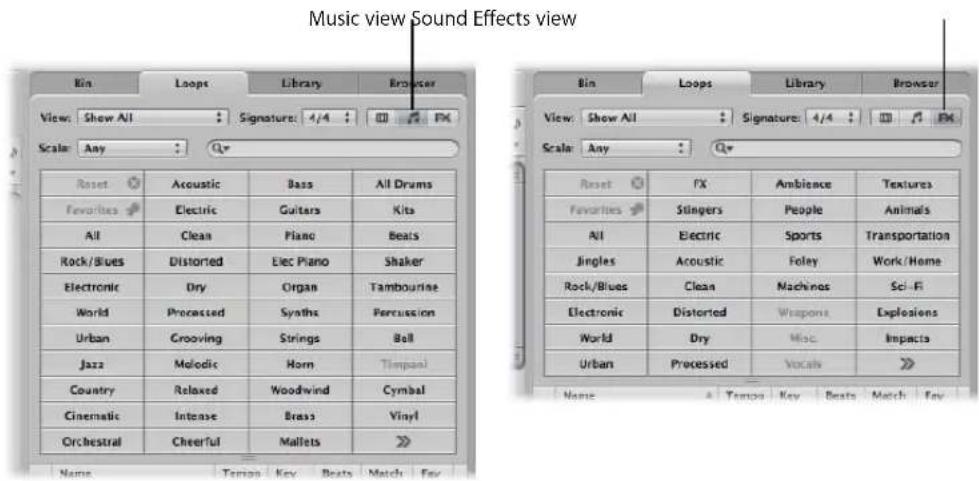
Column view offers a standard Mac OS X column file menu that is hierarchically separated into All, By Genres, By Instruments, By Moods, and Favorites search criteria.
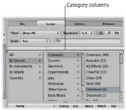
To browse for Apple Loops in Column view:
1 Click on any of the category folders shown in the left column of the folder view area. In this example, By Genres is chosen.
2 Click on Electronic in the second column.
3 Click on Beats in the third column.
The value in brackets indicates the number of files that fall into this sub-category (Beats). The files are shown in the file list below.
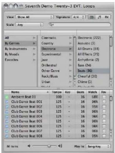
To browse for Apple Loops in Music and Sound Effects view:
1 Click on any of the category buttons.
The file list displays all Apple Loops that fall into the chosen category. The number of matching files is shown at the bottom of Loop Browser.
2 Click another category button.
The file list updates to display all Apple Loops that fall into both categories.
3 Click on other category button to further refine categorization.
The number of files that match all three criteria (Guitars, Acoustic, and Country) will be further reduced.
Note: A second click on any chosen category button will deselect it.
As you can see from this example, the use of multiple category buttons makes it easy to restrict the number of Apple Loops that are shown in the file list. This, in turn, makes the task of finding an Apple Loop that has a particular vibe or flavor much simpler.
To clear all category selections:
- Click the Reset button to clear all selected category buttons.
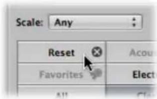
You can replace a displayed category via the shortcut menu that opens when you Control-click (or right-click) on any category button.
To customize the Music or Sound Effects view:
■ Control-click (or right click) on any category button, then choose from:
• Genre: This sub-menu offers musical categories, such as: Rock/Blues and Electronic.
- Instruments: Bass, FX, Vocals, and the Textures and Jingles settings are available, amongst others.
- Descriptors: The items in this sub-menu cover the mood of Apple Loops, and include Dark, Relaxed, Grooving, and others.
Auditioning Apple Loops in the Loop Browser
Regardless of the browsing (or searching) method used to find Apple Loops, you can preview the results in the Loop Browser.
To audition Apple Loops:
1 Click on any file name in the search results list.
It will automatically start playing in a continuous loop.
2 Click on another file name, and it will start playback.
The Apple Loop that was playing will stop. Only one Apple Loop can be auditioned at a time.
To adjust the playback level:
- Drag the level fader at the bottom of the file view area.
To adjust the playback key:
- Click the "Play in:" menu to the right of the level fader at the bottom of the file view area, and choose the desired key.
This defaults to the project key, but you can also choose to audition the loop in its original key or any key from C to B.
To stop playback:
- Click on the speaker icon to the left of the selected Apple Loop name.
Sorting Apple Loops in the Loop Browser
You can sort the results of your search or browsing in the Loop Browser:
- Click on any of the column titles to sort the list of results by: Name, Match, Tempo, Key, and so on.
| Rock/Blues Distorted Elec Piano | |||||
| Name | Tempo | Key | Beats | Match | Fav |
| Steel String Slide 06 | 130 | G | 16 | 100% | |
| Steel String Slide 05 | 125 | G | 16 | 96% | |
| Steel String Slide 04 | 125 | G | 16 | 95% | |
| Folk Mandellin 03 | 125 | G | 16 | 95% | |
- Click on the arrow in any selected column title to sort the list in ascending or descending alphabetical, match percentage, tempo, key, beat, or favorite order.
Tip: You may freely swap column positions by click-dragging on the column name field, and moving it left or right. Column widths may be resized by click-dragging on the vertical lines that separate the column name fields.
Creating a Collection of Your Favorite Apple Loops
The Fav (Favorites) column offers a checkbox for every displayed loop. Simply check this box to add the loop to the Favorites category.
| Name | Tempo | Key | Seats | Match | Fav |
| Steel: String Slide 07 | 140 | G | 16 | 85% | |
| Folk Mandolin 02 | 115 | G | 16 | 85% | |
| Acoustic Slide 03 | 110 | G | 16 | 81% | |
| Acoustic Picking 21 | 110 | G | 16 | 81% |
This facility is ideal for compiling a collection of Apple Loops that you use regularly. As a producer of dance-floor music, you may often construct projects by starting with drum loops. You could conceivably have a basic four on the floor kick pattern, eighth and sixteenth note hi-hats, two or four beat snare or clap patterns, and so on, and use these favorite loops as a groove construction kit—at least while creating your shell arrangement.
These loops can be easily replaced or added to as your project advances, but the use of favorites may form a great starting point for many of your songs.
Searching for Apple Loops
The Search field is used to find Apple Loops by name or partial name. It works in conjunction with the options discussed in "Before Browsing or Searching for Apple Loops" on page 275.
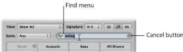
To search for an Apple Loop:
■ Type the desired search term into the Search text field, and press the Return key.
The search term can be alphabetical or numerical. Any files that match your search term will be displayed in the file list.
The Cancel button to the right (which appears as soon as any text is entered) clears any entered text. It also clears the search history.
The Find menu to the left (the magnifying glass) retains a history of recently used search terms. Click on it to select a previous search term.
Adding and Removing Audio Files
You can add audio directly to the Arrange area, or to the Audio Bin, using any of the methods covered in this section.
- The Audio Bin acts as a central repository for all audio files added to the project, whether or not they are used in the Arrange area. This is useful for keeping all takes associated with the project in one location, even if not all are actually used in the final production.
- When you add audio files to the Arrange area, they are automatically added to the Audio Bin—and they appear as audio regions in your arrangement. These regions have a default length that encompasses the entire audio file. You can resize, cut, and move these regions as desired in the Arrange area.
All methods outlined in this section can be used to import: WAV, AIFF, CAF, MP3, SDII, AAC, Apple Lossless, and Apple Loop files.
Apple Loops offer a few special features when added to your arrangement. For details see "Green and Blue Apple Loops" on page 273.
ReCycle files are handled differently. Details in "Adding ReCycle Files to Your Project" on page 288.
Adding Audio Files to Your Arrangement
You can use any of the following methods to add audio files directly to your arrangement:
- You can Shift-click at any position on an Arrange audio track with the Pencil tool.
- You can use the Import Audio File command.
- You can simply locate (browse to or search for) the desired file names in the Browser, Audio Bin, or Loop Browser—or the Mac OS X Finder—and drag them into the Arrange area. Double-clicking a file name in the Browser will add the file at the current playhead position on the selected arrange track.
To add audio files to your arrangement using the Pencil tool:
1 Select the Pencil tool in the Arrange area.
2 Shift-click an audio track at the desired Arrange area position.
3 Browse to, and select the file that you wish to insert in the Open File dialog.
4 Click the Play button to preview the selected audio file.
The Play button is renamed to Stop. Press it to halt playback.
5 Click the Open button to add the file to the selected track, at the clicked position, in the Arrange area.
To add audio files to your arrangement using the Import Audio File command:
1 Select an audio track in the Arrange area.
2 Choose File > Import Audio File (or use the Import Audio File key command).
3 Browse to, and select the file that you wish to insert in the Open File dialog.
4 Click the Play button to preview the selected audio file.
The Play button is renamed to Stop. Press it to halt playback.
5 Click the Open button to add the file to the selected track, at the playhead position, in the Arrange.
To add an audio file to your arrangement by dragging:
- Drag the desired file directly onto an audio track in the Arrange area from either the Browser, Loop Browser, or the Finder.
You can drag audio files onto all track types, but playback is only possible on audio tracks.
With Automatic Track and Channel Creation
You can drag audio files directly into a blank Arrange window (with no tracks), or to a blank area below existing tracks. An audio track and corresponding channel strip are automatically created, and an audio region (that is the full length of the file) is placed on the track. In addition, the file is added to the Audio Bin, and the corresponding region is automatically created.
To add multiple audio files to your arrangement by dragging:
1 Shift-click contiguous files, or Command-click non-contiguous audio files in the Audio Bin, Finder, or Browser.
2 Drag them to the desired Arrange area position, and release the mouse button.
Note: If adding files from the Audio Bin, you can also use the Audio File > Add File to Arrange menu item. The playhead position determines where the first audio region is created.
3 Select any of the following options shown in the Add Selected Files to Arrange dialog:

- Create new tracks: Creates new tracks (and audio channel strips) for each dragged file.
- Use existing tracks: Sequentially places the dragged files (as regions) onto existing tracks, starting with the currently selected track. As an example, if three audio files are dragged into the Arrange area (where track 4 is selected), the first file will be placed on track 4, and the following two files will be placed on tracks 5 and 6.
- Place all files on one track: Does just this, with all files being placed sequentially (one after the other) on the track they are dragged on.
- Copy audio file names to track names: Uses the file names to rename tracks. This option is only available when used in conjunction with the "Create new tracks" and "Use existing tracks" functions.
- Create new audio regions: Adds the files to the Arrange area, and creates a new audio region for each. A numeric value will be appended to each audio region in the Arrange area, and a new region will be created for each file in the Audio Bin. As an example, a region called folk-04 will become a new region called folk-04.1. The original region will be retained in the Audio Bin (and Arrange, if used).
Adding and Removing Project Audio Files
The Audio Bin acts as a central repository for all audio files added to the project, whether or not they are used in the Arrange area. This is useful for keeping all takes associated with the project in one location, even if not all are actually used in the final production.
All audio file addition methods covered above will automatically place the files in the Audio Bin. For methods that add files directly to the Arrange area, a region associated with the file is automatically created in the Audio Bin.
The Audio Bin also provides facilities that allow you to add files to your project (into the Audio Bin), and from the Audio Bin into the Arrange area.
To use the Browser or Finder to add audio files to your project:
1 Shift-click contiguous files, or Command-click non-contiguous audio files in the Finder or Browser.
2 Drag them into the Audio Bin, and release the mouse button.
Note: If adding files from the Browser, you can also choose Add Selected Audio File to Bin in the action menu.
To use the Audio Bin to add one or more files to your project:
1 Choose Audio File > Add Audio File (or use the Add Audio File key command).
The Audio Bin file selector box opens.
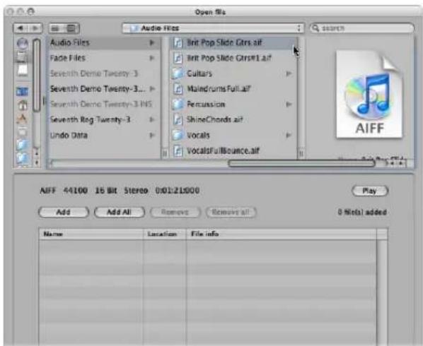
2 Browse to, and select, an audio file.
You may audition it by clicking the Play button.
3 Click the Add button.
The file is shown in the file view area below.
4 Browse to, and select, another audio file, and click the Add button.
5 Repeat the process until all desired files are in the file view area.
6 If you accidentally add a file, select it in the file view area, and click the Remove button.
Note: You can also add all files in a folder by selecting the folder and clicking the Add All button. If you accidentally add all files from the wrong folder, press the Remove All button to remove them from the list. This does not remove them from the hard disk.
7 Click Done to add the selected files to the Audio Bin.
Note: Files that have already been added to the Audio Bin are dimmed, and can not be selected. This helps to avoid confusion, and duplication.
To remove one or more files from the current project:
1 Select the file names in the Audio Bin
2 Press Backspace.
This deletes the file from the project, but not from the hard disk.
The only way that you can totally remove an audio file from a project is in the Audio Bin. Removing an audio region in the Arrange (Eraser tool, pressing Backspace) does not remove it from the project—it merely removes the reference to the audio file.
Warning: Take extreme care when using the Audio File > Delete File(s) command (or key command, default: Control-Backspace). This not only deletes the selected file from the project, but also from the hard disk! Deleted audio files are moved to the Trash—where they remain until you empty the Trash.
A Note on Importing Compressed Audio Files
Logic Express allows you to directly play back the following compressed audio file formats:
- AAC
- Compression format: MPEG4 AAC
- Sample rates: 8 kHz, 11.025 kHz, 12 kHz, 16 kHz, 22.05 kHz, 24 kHz, 32 kHz, 44.1 kHz, 48 kHz, 64 kHz, 88.2 kHz, or 96 kHz
• MP3
• 44.1 kHz files
- Stereo files encoded at 48 or higher kbps, mono files encoded at 32 or more kbps
- iTunes/Logic encoded files
- Apple Lossless files
These files are not automatically converted when imported into Logic Express. The compressed audio file is added to the Arrange area, and a region that encompasses the complete audio file is created. You can edit this region in the same fashion as a normal audio region in the Arrange area: You can cut it, loop it, rename it, and so on.
Note: It is not possible to assign fades to compressed audio files, nor can you destructively edit them.
Audio regions that point to compressed audio files are denoted by the following symbol:
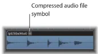
You can convert compressed AAC, MP3, and Apple Lossless audio files by doing one of the following:
- Select the audio regions pointing to the desired audio file in the Arrange area, then choose Audio > Convert Regions to New Audio Files in the local Arrange area menu (or use the Convert Regions to New Audio Files key command;
The part of the audio file spanned by the audio region is converted to a new audio file.
- Select the audio files in the Audio Bin, then choose Audio File > Copy/Convert File(s) in the local Audio Bin menu (or use the Copy/Convert File(s) key command).
Important: Compressed audio files protected by the DRM (Digital Rights Management) scheme can not be opened in Logic Express. Music bought in the iTunes Store is usually protected by DRM.
Overview Calculation
When you add an audio file to your project, Logic Express will automatically create an overview of the audio file. This is a graphic file that is used to display the waveform.
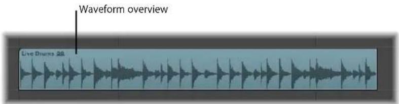
The calculation of audio file overview data is shown in a window. This calculation occurs in the background, allowing you to continue working with Logic Express.
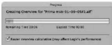
Enabling the "Faster overview calculation" option considerably speeds up the calculation, at the cost of slowing down other operations, but not blocking user interaction completely. Logic Express remembers the state of the "Faster overview calculation" option between projects.
You can manually refresh the overview of selected files with Options > Audio > Refresh Overview(s) in situations where you have replaced file recordings (and used regions), or made edits in an external sample editor.
Adding ReCycle Files to Your Project
ReCycle is the name of a software application from manufacturer Propellerhead, which mainly serves as an editing and production tool for loops (repeatedly cycled audio files). ReCycle uses specific file formats that can be imported, and used directly by Logic Express, or ReCycle files can be converted to Apple Loops.
Note: You need to install the REX Shared Library (© Propellerhead Software) when using ReCycle files within Logic Express. For more information on ReCycle files, see the Propellerhead website.
Logic Express can import the following ReCycle file formats:
- Old ReCycle file: These files have the suffix .rcy. The abbreviation for this file type is RCSO.
- Old ReCycle export file: These files have the suffix .rex. The abbreviation for this file type is REX.
- ReCycle 2.0 file: These files have the suffix .rx2. The abbreviation for this file type is REX2.
To import a ReCycle file into the Arrange area:
1 Select the ReCycle file you want to import by doing one of the following:
- Choose File > Import Audio File and select a ReCycle file instead of an AIFF, SDII, MP3, or WAV audio file.
- Shift-click on an audio track with the Pencil tool and select a ReCycle file.
- Drag a ReCycle file from the Finder onto an audio track.
2 Choose the desired settings in the Import ReCycle file dialog, then click OK.
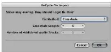
- Don't Fix: Imports the file as is. All slices of the file will overlap, to match the tempo of Logic Express.
- Add tracks: Distributes the slices across multiple audio tracks, allowing you to adjust the position or delete slices freely. The "Number of Additional Audio Tracks" field determines how many tracks are used for the distribution of the slices. These tracks are in addition to the original track that the ReCycle file was added to.
- Crossfade: All slices of the file are imported to the same track, and are automatically crossfaded. The length of the crossfade is determined by the value (shown in milliseconds) displayed in the Crossfade Length field.
- Render into single file: This function writes all ReCycle slices into a single audio file. The current Logic Express project tempo is used for the rendering process.
- Render to Apple Loop: Imports the ReCycle file as an Apple Loop.
If you do not import the ReCycle file as an Apple Loop or audio file, Logic Express will create a ReCycle file folder on an audio track. This folder contains slices (you can view them as miniature regions in the folder) of the ReCycle file at appropriate positions.
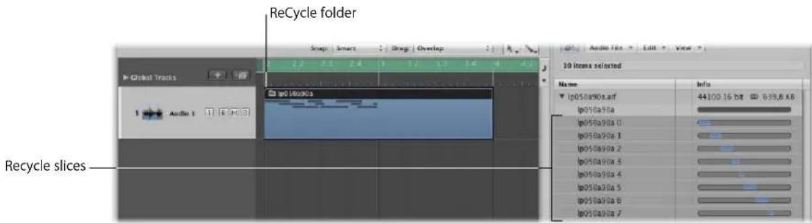
Each of these slices references the same audio file, which can be found in the Audio Bin.
Note: If you move the ReCycle file folder to another audio track, the audio channel strip destination (of the track inside the folder) will not change accordingly! You will need to open the folder and change the audio channel strip destination manually, to hear the ReCycle audio data.
To convert a ReCycle file to an Apple Loop, do one of the following:
■ Use the Render to Apple Loop option in the ReCycle file import dialog.
- Choose the Convert ReCycle Files/Folders to Apple Loops command in the Browser's Tool menu.
The latter option allows you to choose one or more folders in the Browser, and perform a batch conversion on all ReCycle files contained in them.
Moving Audio Between Logic Express and ReCycle
You can transfer data from Logic Express to ReCycle, and back, without using any file selector dialogs.
To copy audio regions into the Clipboard for use in ReCycle:
1 Select an audio region in the Arrange area.
2 Choose Audio > Copy as ReCycle Loop in the Arrange menu.
The data of the selected audio region is copied into the Clipboard.
3 Use the "Paste as new Document" command in ReCycle to create a new ReCycle document (containing the audio data selected in the Arrange area).
Note: The size of the transferred audio region is limited to 10 MB, which should be sufficient for most ReCycle loops (an eight bar stereo loop in 4/4 at 70 bpm uses approximately 5 MB, for example).
To paste ReCycle loops from ReCycle into the Arrange area:
1 Use the Copy Loop command in ReCycle.
This copies the loop currently being edited in ReCycle into the Clipboard.
2 Choose Audio > Paste ReCycle Loop in the Arrange menu to paste this loop into the Arrange area.
The result is the same as the ReCycle file import options.
Adding MIDI and Project Files
You can also add MIDI and project files (such as OMF Interchange, AAF, OpenTL, and XML files) to your arrangement. These file types are usually used to exchange projects, however, and are therefore outside the scope of this chapter. Full details on importing these file types can be found in Chapter 29, "Project and File Interchange," on page 649.
Getting to Know Regions
12
When audio or MIDI files are added to, or recorded in, the Arrange area, they are displayed as regions.
This chapter covers the similarities and differences between audio and MIDI regions, and provides advanced information on region handling. Details on using regions to construct your songs can be found in Chapter 13, "Creating Your Arrangement," on page 307.
What Are Regions?
Audio and MIDI data handling is very similar in the Arrange area, via rectangular blocks called regions. These blocks are graphical representations of data. Audio regions represent audio data. MIDI regions represent MIDI data.
Audio Regions and Audio Files
Audio regions simply refer to (point to) an underlying audio file. Audio regions are merely used as playback markers (start and end points) that can be as long as the entire audio file, or may only be a few seconds long, playing a small portion of the audio file that the (region) start and end markers encompass.
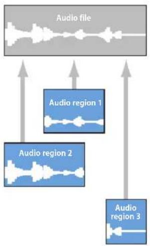
flowchart
graph TD
    A["Audio file"] --> B["Audio region 1"]
    A --> C["Audio region 2"]
    A --> D["Audio region 3"]
    B --> E
    C --> F
    D --> G
Any audio file used in Logic Express (added to the project, and therefore the Audio Bin) is automatically linked to at least one audio region that defaults to the length of the entire audio file.
Audio regions contain a temporal reference point called the anchor. When you move an audio region, it's not the start point that is displayed in the help tag (as with MIDI regions)—it is the anchor point.
You can freely create as many audio regions as needed. To give you an example of where this may be useful, imagine a live stereo drum track that runs for the duration of your project. During the second chorus, the drummer played perfectly, but was a little sloppy during all other chorus sections. Logic Express allows you to create an audio region that points to the second chorus section of the overall (drum track) audio file, and use this perfect take in multiple places in the project.
This is achieved by creating one audio region (that points to chorus 2 in the drum track audio file), and copying it to each position that the chorus occurs in the Arrange area.
A great benefit of working with audio regions, rather than audio files is that they use very little memory, whereas multiple copies of the same section of the audio file would require a lot of hard disk storage space.
It is, of course, possible to directly edit, copy, move, and manage audio files. This is achieved in the Sample Editor and Audio Bin. Details found in Chapter 24, "Managing Audio Files," on page 559.
MIDI Regions and Events
MIDI regions actually contain MIDI data events. They are not related to information stored in external files. MIDI regions can be saved as individual files, but they can also be, and generally are, stored with the Logic project.

The MIDI data events stored within MIDI regions can include; note, controller, system exclusive, and other information. These data events represent MIDI performances that you have recorded or imported into Logic Express. MIDI performances are generally created with a MIDI keyboard, but can certainly be generated with MIDI controllers, MIDI guitars, your computer keyboard or the mouse.
MIDI data events can be affected as a group by processing the MIDI region that contains them. Such processing—which takes place in the Inspector Region Parameter box—includes; transposition, quantization, timing delays, and more.
You can also edit individual events within a MIDI region. This is achieved by opening the region in one of the MIDI editors available in Logic Express. These editors allow you to precisely alter the position, length, and pitch of MIDI note events. Other MIDI event types can also be altered in various ways. You can also enter MIDI data with your MIDI keyboard, the mouse, or computer keyboard in these editors.
Folder Regions
A folder is a region that can contain other regions, much like a folder in the Finder can contain other folders or files.
One way to visualize a folder is as a project within a project. A folder can contain as many tracks, featuring regions, as required.
A folder is placed on a track assigned to a folder in the track list, rather than an instrument or audio track. Folder regions look like MIDI regions, but have a folder icon before the folder name.

When opened, folders look just like the Arrange area and track list of a project.
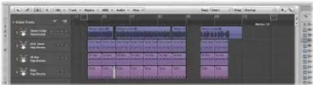
Cloned and Alias Regions
Aliases can be created for MIDI regions and folder regions. A MIDI or folder region alias is like an alias in the Finder. It looks like a region, but contains no actual data. It is just a reference to the data of the original region—a virtual reflection of the original. You can easily recognize an alias because its name is written in italics.
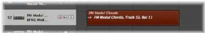
If the data in the original (source) region is altered, this immediately affects all aliases of the region. Each alias has independent region parameters, however.
Clones can be created for audio regions (by Option-Shift-dragging). These are comparable to MIDI region aliases, but differ in that adjustments to the start or end points of any cloned region will affect all other cloned regions in the same way. Adjustments to the source region do not affect clones.
You can, of course, create independent copies of audio regions (by Option-dragging), which can be adjusted without affecting other copies or the source region.
Please see Chapter 13, "Creating Your Arrangement," on page 307, for further details.
MIDI and Audio Regions Compared
The following overview sums up the main differences between audio and MIDI regions. There are some notes at the bottom of the table to clarify the most important points.
Feature MIDI Regions Audio Regions
| Composed of discrete data Yes No. Audio regions are just references to parts of audio files. | ||
| Can be named Yes Yes | ||
| Loop option available Yes Yes | ||
| Quantize parameter available Yes No, but the position of regions themselves can be quantized, using the Event List (when at the Arrange display level). You can also quantize audio files destructively in the Sample Editor. | ||
| Transposition parameter available Yes No, but you can use the Time Machine and Pitch Shifting functions (in the Sample Editor and Arrange). Audio Apple Loops can be transposed. | ||
| Velocity parameter available Yes No | ||
| Dynamics parameter available Yes No | ||
| Gate Time parameter available Yes No | ||
| Delay parameter available Yes Yes | ||
| Can be freely positioned | Yes Yes | |
| Left or right corner edit | Yes Yes, and this affects the audio region, but not the position of the audio waveforms relative to the time axis of the sequencer | |
| Can be cut with the Scissors tool | Yes Yes, creates a new audio region. | |
| Can have aliases made of them | Yes Yes, although these are known as cloned (audio) regions, to differentiate them from alias (MIDI) regions. | |
| Left corner may be dragged to conceal data at beginning | No | Yes |
| Have a variable musical reference point | No | Yes, a variable anchor. This affects all regions derived from a given audio file, and can change the position of the audio, relative to the time axis of the sequencer |
| Can be turned off with the Mute function | Yes | Yes |
| Can be placed in folders | Yes Yes | |
| Can be soloed | Yes Yes | |
Naturally, some of the Inspector playback parameters (such as Transposition) that can be applied to MIDI events have no effect on audio signals. Equivalent operations for most of these are available as destructive edit operations in the Sample Editor.
The fundamental functions (such as a freely determinable position and length, the ability to create complex arrangements with the aid of folders, and the ability to name, mute, and solo) are generally available to all types of regions (MIDI regions, audio regions, folder regions, or copies of these, and alias or cloned regions).
Handling Regions in the Audio Bin and Sample Editor
You can use the Audio Bin to manage your regions and to make rough edits to the region (or regions) associated with an audio file. The graphic display in the Audio Bin is optimized for quick and simple organization of audio files and regions.
The finest resolution for positioning the region start and end markers, or the anchor, is limited to 256 sample steps in the Audio Bin. This is usually adequate, particularly if search zero crossings is switched on.
On occasion, however, you will need to make very accurate adjustments—down to the individual sample word level. Drum loops are a good example. The Sample Editor is best-suited to these types of precision editing tasks.
To open the Sample Editor for a particular region:
■ Double-click on the region in the Audio Bin or Arrange area.
The Sample Editor will open—with the entire region selected.
Managing Regions in the Audio Bin
The Audio Bin lists all audio files and regions that have been added to or recorded in your project.
This section covers region handling options available in the Audio Bin tab and the Audio Bin window.
The audio file operations and options of the Audio Bin are discussed in Chapter 24, "Managing Audio Files," on page 559, although some of the basics are covered here.
Which Audio Bin Should You Use?
The Audio Bin tab is ideal for quickly adding files to the Arrange area, as it doesn't obscure your workspace. A bar is shown for each audio file, which represents the overall length of the file. A colored area within the bar represents the region length. Tasks such as resizing or moving regions within the audio file can not be performed in the Audio Bin tab. If you need to make these types of adjustments, use the Audio Bin window.
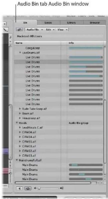
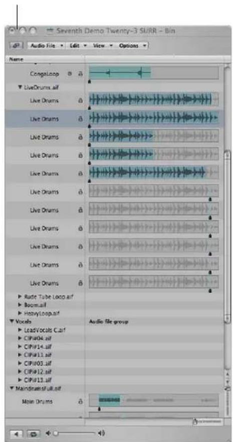
The Audio Bin window, which can be freely resized, displays audio files as waveform graphics. Regions within audio files are highlighted. Further file details, including the full file path, are shown in the Audio Bin window. Also displayed is the Options menu, which contains the Strip Silence command.
In short, the Audio Bin tab is best-suited to tasks such as adding audio files and regions while creating your arrangement. The Audio Bin window is your first port of call for audio file and region management tasks.
To open the Audio Bin tab:
- Click the Audio Bin tab in the Media area of the Arrange window.
To open the Audio Bin:
- Choose Window > Audio Bin (or use the corresponding key command, default: Command-9).
To view a region associated with an audio file:
- Click the disclosure triangle beside the audio file name.
All regions are listed below the parent audio file name.
- Regions that are used in the Arrange area are indicated by a colored bar to the right of the region name. The bar color is derived from the Arrange region color. The length of the region (colored section) is shown proportionately against the audio file bar.
- Regions that are not used in the Arrange area are gray.
To see all regions in the Audio Bin, do one of the following:
- Choose View > Show All Regions (or use the Show All Regions key command).
- Option-click the disclosure triangle beside any audio file.
This instantly displays all regions—of all audio files in the Audio Bin.
Choosing View > Hide all Regions (using the corresponding key command), or a second Option-click (on any audio file disclosure triangle) will hide all regions.
To sort an audio file's regions:
■ Select the desired audio file, then choose View > Sort Regions By:
- Start Point: The regions are sorted according to their time position in the audio file.
- Length: The regions are sorted according to their respective lengths.
- Name: The regions are sorted alphabetically. This is the default setting.
To change the length display of regions in the Audio Bin window:
- Choose one of the following settings in the View > Show Length As menu:
• None: The length is not displayed.
- Min : Sec : Ms: Displays the absolute time of the region in hours, minutes, seconds, and milliseconds.
- Samples: Displays the number of sample words in the region.
- SMPTE Time: Displays the SMPTE length, which unlike absolute time, uses frames and bits in place of milliseconds.
- Bars/Beat: The region is displayed in musical units: bars : beats : divisions : ticks. If the project tempo, time signature, or division settings are altered, the display is automatically recalculated.
To check the number of times a region is used in your arrangement:
■ Activate the View > Show Region Use Count setting.
Creating and Removing Regions
When you add an audio file to your project, Logic Express automatically creates a region that encompasses the entire file length. You can create as many regions as desired from the same audio file. There are no length limitations to regions, as long as they don't exceed the length of the source audio file.
Creating multiple regions from the same audio file is beneficial for many tasks, such as using different portions of a vocal take that spans the length of the project, for example.
You can create regions in the Audio Bin, the Sample Editor, and the Arrange. This section concentrates on the Audio Bin and Sample Editor options.
Note: Full details on all Arrange window region editing options are found in Chapter 13, "Creating Your Arrangement," on page 307.
To create a region from an audio file in the Audio Bin, either:
- Select the desired audio file in the Audio Bin, then choose Audio File > Add Region (or use the Add Region key command, default: Control-R).
- Choose Edit > Copy (Command-C) in the main menu bar, then choose Edit > Paste (Command-V).
The new region will appear below the existing region(s) in the list.
Each region is assigned a unique numerical appendix. As an example, organ.wav is the parent audio file. The automatically created region is simply called organ, and newly created regions are called organ.1, organ.2, and so on.
To create a region from an audio file in the Sample Editor:
- Choose Edit > Create New Region (Command-R).
The newly created region will appear in the Audio Bin list.
To delete a region from the Audio Bin, do one of the following:
■ Select one or more regions, and press Backspace.
Removing a region does not remove the parent audio file.
To remove an audio file from the current project:
1 Select the audio file name (not a region name) in the Audio Bin.
2 Choose Audio File > Delete Files (or use the corresponding key command).
This deletes the file from the project, but not from the hard disk.
Warning: If any of the deleted regions exist in the Arrange area, they will be removed as well. You should, therefore, be careful when deleting a region (or parent audio file). The Undo function is always available, however, should you inadvertently remove a required region.
Auditioning Regions in the Audio Bin
The playback modes outlined below only apply to regions in the Audio Bin (when the window has key focus), and have no effect on project playback.
To play an entire region:
1 Highlight the region name in the list.
2 Click the speaker button at the bottom of the Audio Bin (or press the Space bar) to start playback.
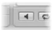
Click the button (or press the Space bar) again to stop playback.
Note: The Environment's Prelisten channel is used for monitoring in the Sample Editor. You can access the Prelisten channel in the Environment's Mixer layer—you can find it to the right of the highest numbered audio channel strip.
To loop region playback:
- Click the loop playback button (featuring the circular arrow symbols) at the bottom of the Audio Bin. Click the button a second time to stop looped playback.
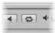
To play a region from a specific position in the Audio Bin window:
- Click-hold the desired region in the region display or with the mouse.
A speaker icon replaces the mouse pointer.
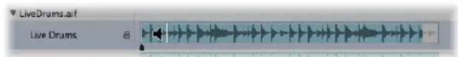
Playback starts at the click point. This allows you to play specific sections. Playback stops as soon as you release the mouse button.
Note: This only works in the Audio Bin window.
Resizing a Region
You can resize regions in the Audio Bin window, the Sample Editor, and the Arrange. This section concentrates on the Audio Bin and Sample Editor options.
Note: Full details on all Arrange window region editing options are found in Chapter 13, "Creating Your Arrangement," on page 307.
To resize a region in the Audio Bin window, do one of the following:
- Click-hold the lower third of the left or right region boundary, and drag in the desired direction.
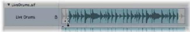
To precisely resize a region:
- Drag the start or end points of regions in the Sample Editor, not the Audio Bin, when accuracy is required. Ensure that Edit > Search Zero Crossings is disabled for the Sample Editor (see below).
The small markers on the lower edge of the Sample Editor's waveform display provide direct access to the boundaries of the region.
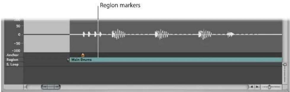
Snapping Edits to Zero Crossings
If Edit > Search Zero Crossings is switched on, adjustments to the start or end positions of a region are snapped to the nearest point where the wave form crosses the zero axis. Put another way, there are certain crossover points in a sample (a drum loop, for example) that are closely matched in level to other points in a sample. If two closely matched points are used for the start and end points of the sample, the loop will play back without noticeable glitches in the audio.
When adjusting the start point, the area preceding the selected point is scanned for a smooth crossover point. When adjusting the end point, the area that follows the region is scanned for a smooth crossover point.
To snap audio edits to zero crossings:
1 Click on the title bar of either the Audio Bin or Sample Editor to give the window key focus.
2 Enable Edit > Search Zero Crossings (or use the Search Zero Crossings key command).
Note: The Search Zero Crossings option can be set independently for the Sample Editor and Audio Bin.
Moving a Region Within an Audio File
You can also move an entire region within an audio file in the Audio Bin window.
To move the region area within the audio file:
1 Position the cursor over the center of a region.
2 When the cursor turns into a two-headed arrow, drag the region to the left or right.
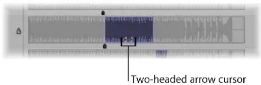
Note: If you want to adjust the boundaries of the region without moving the anchor (see next section), hold down Option during the operation. This applies to moving the start or end points, as well as moving the whole region.
Editing the Audio Region Anchor
The anchor is the temporal reference point of an audio region. When you move an audio region, it's not the start point that is displayed in the help tag (as with MIDI regions)—it's the anchor point.
In many cases, the anchor should be placed on the amplitude peaks, rather than at the start of the sound's attack phase. A good example would be recordings of brass instruments, which may take some time to build to a peak. Moving the anchor to these peaks forces the region to snap to the grid of your arrangement, using the anchor as the pivot point. The flexible zoom settings allow you to be as precise as needed, going right down to the level of single bits, at the highest magnification factor.
As another example, to guarantee perfect synchronization between a one-bar drum loop and MIDI regions, the anchor must be assigned to a well-defined musical point. If the loop begins with a significant level peak (say a kick drum beat), set the anchor to the point where the volume of that beat is at its precise peak.
Whenever you record audio or add an audio file, the anchor and region start points are always at the beginning of the audio file. Moving the region start point also moves the anchor, as the anchor can not precede the region's start position.
You can edit the anchor of a region in the Audio Bin window and Sample Editor. The anchor is represented by a black indicator (orange in the Sample Editor) below the region waveform.
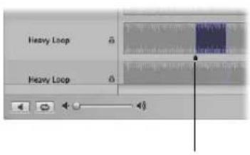
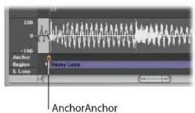
To move the anchor in the Sample Editor or Audio Bin window:
- Grab the small indicator below the region, then move the anchor to the desired position.
Any changes to the anchor point will change the relative position of the audio region in the project. Given that the start point of a region is the default position for the anchor, you must also take care when changing the region start point.
Protecting the Anchor Point When Moving the End Position
If you move the start or end points of a region past the anchor point, the anchor point will also move. This is often not what you want to happen!
Hold down Option while moving the end marker to prevent the anchor from moving.
Note: The anchor can never be to the left of (before) the region start point, so it will move if you drag the region start past the anchor (to the right), even with Option pressed.
Updating Arrange Position
When you change the anchor point in the Sample Editor, you can use the Compensate Region Position feature to ensure that the position of a given audio region stays at the same place in the arrangement.
To switch the Compensate Region Position feature on or off:
1 Click on the title bar of the Sample Editor, to ensure that it has key focus.
2 Choose Edit > Compensate Region Position.
- If Compensate Region Position is active, moving the anchor won't change the audible result. Moving the anchor in the Sample Editor will lead to the same result as dragging the region start point in the Arrange area.
- If Compensate Region Position is not active, moving the anchor changes the position of audio regions in the Arrange area. The region will shift in relation to the time axis, while the anchor remains tied to the same bar value, and is marked by a dotted line.
Protecting Regions
You can protect regions against accidental alterations to start and end points, or the anchor position, by locking them in the Audio Bin window.
To protect region start, end, and anchor positions:
In the Audio Bin window, click the padlock icon beside a region to close (lock) it. Click a second time to unlock the region.
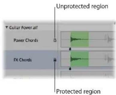
If locked, you can play the region, but can't edit it.
Warning: Don't confuse this function with delete protection: A protected (locked) region can still be deleted!
The Audio Bin tab shows the status of locked audio regions (in the column between the file/region Name and Info columns), but you can't lock or unlock audio regions in the Audio Bin tab.
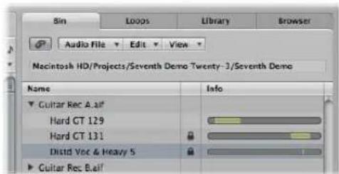
Creating Your Arrangement
Once you have added your audio and MIDI regions to the Arrange area, you can edit and reorganize them to create an overall arrangement, or song.
The Arrange area provides a visual overview of your song structure: it shows when audio and MIDI regions start to play, and their duration. You control when and how regions play by moving, cutting, copying, resizing, and joining them in the Arrange area.
Regions are positioned horizontally—on track lanes that run from left to right in the Arrange area. Their positions along these lanes determine when they play, aligned with the Bar (and Time) ruler along the top of the window.
The track lanes are stacked vertically, creating a grid of track lanes and particular bar or time positions.
To view the Arrange area grid:
■ Enable the Grid setting in the Arrange area's View menu.
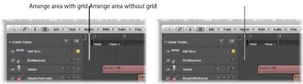
You may also wish to enhance the grid contrast by altering the color of the Arrange area background.
To alter the Arrange area background color:
1 Open the Display preferences by doing one of the following:
- Choose Logic Express > Preferences > Display (or use the Open Display preferences key command).
- Click the Preferences button in the Arrange Toolbar, and choose Display from the menu.
2 Click the Arrange tab in the Preferences window.
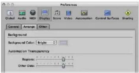
3 Choose Bright in the Background Color menu.
4 Alternately, choose Custom from the menu, and click the color field to the right.
5 In the Colors window that launches: Use the mouse on the color palette wheel, contrast and opacity sliders to create a custom color.
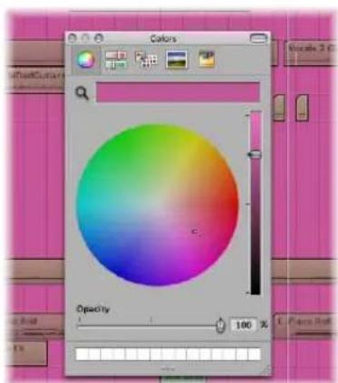
6 Click the close button at the top left to exit the Colors window and assign your custom Arrange area background color.
Most arranging and editing techniques work identically for both audio and MIDI regions. Apple Loops are also handled in a similar fashion. Where handling differs, variations are pointed out in the appropriate sections of this chapter.
All operations described with a pluralized heading (regions, for example), apply to one or more selected region(s).
Making Region Edits Faster and Easier
This section provides information on several options that can accelerate and simplify region editing, helping you to focus on the musical aspects of your arrangement.
Snapping Region Edits to Time Positions
You move and resize regions in the Arrange area because you want them to start and end at a specific point in time. As an example: In a music-based project, you may want to align the start points of regions with measures and beats.
Logic Express offers a snap feature that automatically aligns region start and end points to a selected grid value, when you move or resize them.
Tip: Turn on the View > Grid menu item, as this will help you to visualize how the Snap menu items automatically align regions to specific grid positions.
To snap regions to a grid:
- Choose one of the following values in the Snap menu at the top of the Arrange area:
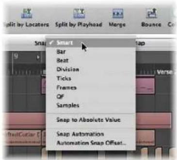
- Smart: Edit operations will snap to the nearest bar, beat, sub beat, and so on, dependent on the current Bar ruler division value, and the zoom level.
• Bar: Edit operations will snap to the nearest bar. - Beat: Edit operations will snap to the nearest beat in a bar.
- Division: Edit operations will snap to the nearest division value (this is the time signature shown in the Transport and Bar ruler).
- Ticks: Edit operations will snap to the nearest clock tick (1/3840th of a beat).
- Frames: Edit operations will snap to the nearest SMPTE frame.
• OF (Quarter Frames): Edit operations will snap to the nearest SMPTE quarter frame. - Samples: Edit operations will snap to the nearest sample.
Note: Sample accurate editing is directly tied to the zoom level. If the zoom level is insufficient, sample-accurate edits are not possible. Make use of the Zoom slider at the bottom of the Arrange window, and take advantage of the Save and Recall Zoom Setting key commands to speed up your workflow.
The Snap functionality is relative, which means that the edit operation will be snapped to the nearest bar, beat, and so on—retaining the region's distance from its original position. As an example, if a region is placed at position 1.2.1.16, and you move this region forward to around bar 2 (with the Snap menu set to Bar), it will automatically snap to position 2.2.1.16—rather than 2.1.1.1 (the bar 2 start point). You can override relative snaps with the Snap to Absolute Value option.
To snap to an absolute, not relative, position:
- Choose the Snap to Absolute Value option in the Snap menu.
A tick will appear to the left of this function name when enabled. This feature works in conjunction with the chosen snap grid division.
To explain, if Bar is chosen in the Snap menu, when Snap to Absolute Value is active, moving a region (from position 1.2.1.16) to around bar 2 will result in it being snapped to position 2.1.1.1 (the bar 2 start point), rather than its relative position (2.2.1.16).
The Snap menu setting applies to the following edit operations:
- Moving and copying regions.
- Resizing regions.
- Cutting regions.
- Moving, adding, and resizing markers.
- Setting cycle boundaries.
Overriding the Snap Grid
You can temporarily override the snap grid, allowing finer edits and adjustments.
To override the snap grid:
- Hold Control while performing the editing operation.
- The division value chosen in the Transport (1/16, for example) determines the editing grid scale at lower zoom levels (macroscopic or wide view).
- If the zoom level is higher (microscopic or close up view), holding Control while editing will scale by a certain factor.
- Hold Control-Shift while performing the editing operation:
- The editing grid switches to ticks if editing at lower zoom levels (macroscopic or wide view).
- At higher zoom levels (microscopic or close up view), the editing grid will switch to samples.
Notes on the Relationship Between the Zoom Level and Snap Menu Setting
In cases where the zoom level is so high (microscopic), that the chosen Snap value would result in extremely large movements or edits, the Snap value is temporarily dimmed, and Smart snap is used instead.
In cases where the zoom level is extremely low (macroscopic), and a fine Snap value (such as Division or Frames) is chosen, normal mouse movements will result in larger grid units. In these situations, either alter the zoom level, or hold Control to actually use the chosen Snap value.
Using Control-Shift breaks the 1:1 relationship between mouse cursor and region (or edit tool) movements. This means that you may need to move the mouse a long way (horizontally) to make the region (or edit tool) move one pixel. Watch the help tag for exact numerical readouts.
Imagine you want to shorten a region in a 4/4 bar so that the 4 is played, but not the "4 and" of the last bar.
To shorten a region by one division value when Snap is set to Beat:
1 Horizontally zoom the screen display until you can see quarter notes in the Bar ruler.
2 Grab the bottom right corner of a region, and move the mouse to the left, until the region is shortened by one quarter note.
3 Press Control, and move the mouse carefully to the right, until the region has become one division longer.
While you're doing this, the help tag shows the region start position, track number, and the current length of the region in bars, beats, divisions, and ticks. The three right-hand numbers should be 3 1 0.
Using Drag Modes
Logic Express provides several drag modes that determine the behavior of regions when you edit them. You can set the drag mode in the Drag menu, available in the Arrange area and several other editor windows.
Note: The Drag menu options discussed in this section refer to regions. The behaviors outlined below (for regions) are identical for dragged events in the editor windows. The Drag menu setting of the Arrange and each editor window is independent.
To change the drag mode:
- Choose one of the following settings in the Drag menu:
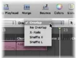
- Overlap: This mode is the default, and allows you to drag a region over another one. The original region borders are preserved.
- No Overlap: Use in situations where you don't want regions to overlap. In this mode, the first region (the one positioned earlier on the track) will be reduced in length so that no overlap occurs.
- X-Fade: In this mode, Logic Express automatically crossfades two audio regions when they are moved to an overlapping position.
Note: This option does not work for MIDI regions or Apple Loop regions.
- Shuffle L and Shuffle R: Choose to automatically align regions (to the left or right, respectively) when you move, resize, or delete them.
- When you use Shuffle R (or Shuffle L), moving a region to the right (or left) aligns the region end point with the start point of the following region, ensuring that there is no space between the two regions.
- Regions that are dragged over each other will swap positions.
- When deleting regions, the remaining regions (those left or right of the deleted region) are moved to the left or to the right by the length of the deleted region.
- If a region is stretched or shortened when either Shuffle option is active, the other regions on the track will be moved to accommodate the new length.
- In Shuffle L mode, the right side of the region will be stretched or shortened, and the regions to the right of the edited region will be moved.
- In Shuffle R mode, the left side of the region will be stretched or shortened, and the regions to the left of the edited region will be moved. The regions that precede the edited region can only be moved as far as the project start point. If the stretching of a region results in preceding regions being forced to the project start point, and exceeding the space available, the edited region will overlap the existing content.
Note: Only one audio region can be played at a time through a track's channel strip. When two audio regions overlap each other on a track, the later region has priority.
Scrubbing Your Arrangement
Scrubbing allows you to hear the audio and MIDI signals of regions at the playhead position, helping you to find a particular sonic event. This makes it easy to zero in on a particular kick or snare hit, for example, before cutting an audio region.
Note: Before MIDI scrubbing can occur, you need to turn on File > Project Settings > MIDI > General > Scrubbing with Audio in Arrange.
To scrub your project:
1 Set a zoom level that provides the best view of the section you want to scrub (turning on View > Region Content may be useful).
2 Enable the Pause button on the Transport.
3 Grab the playhead in the Arrange or Bar ruler, and move it back and forth through the parts of the project you want to hear, at the speed you want to scrub the section (or use the Scrub Rewind and Scrub Forward key commands).
Audio and MIDI data playback is perfectly synchronized when scrubbing.
Note: Scrubbing is automatically activated when you're dividing regions (with the Scissors tool) in the Arrange, making it easier to identify the cut position.
Scrubbing Particular Regions
The following list outlines the relationship between scrubbing and region selection:
- If no regions are selected, all regions are scrubbed.
- If you select a specific audio region, only it will be scrubbed.
- If you rubber-band or Shift-select audio regions on different tracks, only the selected audio regions are scrubbed.
- MIDI regions (software and external MIDI) are always scrubbed, regardless of the selection status (provided that the Scrubbing with Audio in Arrange project setting is active).
- The Mute or Solo (see next section) status of all tracks and regions has an effect on what you hear when scrubbing, so you can make use of them to scrub audio parts in isolation (or with particular software or external MIDI instrument tracks).
MIDI Controlled Scrubbing
The Scrub by MIDI value (-2-) function (available in the Controller Assignments Editor; see the Logic Express 8 Control Surfaces Support manual) is designed to allow scrubbing via external MIDI control. You can assign any MIDI controller number to this function. Data bytes over 64 scrub forwards, and those under 64, scrub backwards.
Muting Regions
Often, when arranging, you'll want to test musical ideas by muting certain regions.
To mute or unmute individual or selected regions, do one of the following:
- Select the Mute tool, then click the desired regions with the Mute tool.
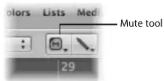
- Select the desired regions with the Pointer tool, then use the "Mute/unmute selected Notes/Regions/Folders" key command (default: M).
Muted regions are indicated by a dot that precedes the region name.
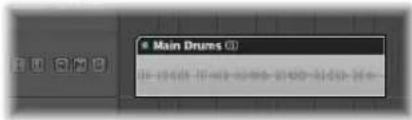
Clicking muted regions with the Mute tool, or selecting them and using the "Mute/ unmute selected Notes/Regions/Folder" key command reverses this state (unmuting).
Soloing Regions
Soloing allows you to hear one or more selected regions in isolation, making it easier to identify particular elements that may need to be edited.
To solo a region with the Solo tool:
1 Select the Solo tool.
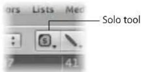
2 Click-hold on the desired region with the Solo tool.
The region (outlined in yellow) will be heard in isolation from the click point, until you release the mouse button, which will stop solo playback.
To solo several regions with the Solo tool:
1 Rubber-band or Shift-select the desired regions.
2 Click-hold on any of the selected regions with the Solo tool.
To scrub with the Solo tool:
1 Select the Solo tool, then drag the mouse horizontally.
2 Release the mouse button to end solo scrubbing.
To solo one or more regions using Solo mode:
1 Click the Solo button in the Transport (or use the Solo Mode key command, default: S).
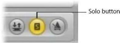
When the Solo function is activated, the Bar ruler is shaded in yellow, making it easy to see that Solo mode is engaged.
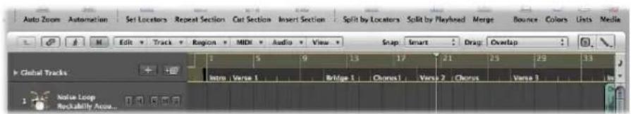
2 Rubber-band or Shift-select the regions you want to solo with the Pointer tool. Selected regions have a yellow outline.
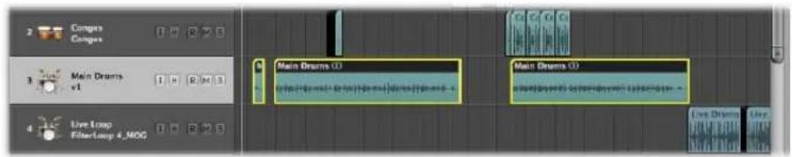
Click the Transport Solo button again (or use the Solo Mode key command) to turn off Solo mode, and hear all regions again.
Using Solo Lock
On occasion, you may want to lock the solo status of several regions. As an example, this would be especially useful when you want to make changes to the playback parameters of a region, while listening to a specific group of soloed tracks.
To retain the solo status of several selected regions (can be done in play mode):
1 Select several regions with the Pointer tool.
2 Option-click the Transport Solo button (or use the Set Solo Lock Mode key command, default: Option-S) to lock the soloed status of the selected regions.
The Transport Solo button displays a padlock icon to indicate Solo Lock mode.
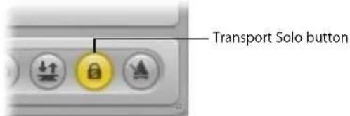
The Reselect Solo-Locked Regions key command (default: Shift-Option-S) selects all currently solo-locked regions. This command is very useful if you want to remove several regions from your solo-locked selection.
Naming a Region
Identifying regions by name can make arranging much easier. This can be done on a per-region basis, or you can name several regions simultaneously.
To name a region with the Text tool:
1 Select the Text tool.
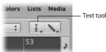
2 Click on a region with the Text tool.
A text input box will appear.
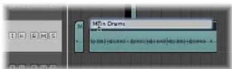
3 Type in the desired name and press Return, or click another region or the Arrange area background to exit the text input box.
To name a region using the Region Parameter box:
1 Click the top line of the Region Parameter box in the Inspector.
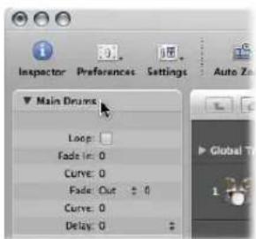
This line displays the name of the selected region. A text input field appears, allowing you to edit the region name.
2 Type in the desired name.
3 Press Return, or click anywhere outside the text input box to exit text input mode.
To assign the same name to multiple regions:
1 Select a group of regions (rubber-band or Shift-click) with the Pointer tool.
2 Do one of the following:
- Select the Text tool, then click any of the selected regions with the Text tool.
- Click the top line of the Region Parameter box (displaying x selected: x indicates the number of selected regions).
A text input box will appear.
3 Type in the desired name and press Return, or click another region or the Arrange area background to exit the text input box.
All regions are assigned the same name.
To assign a name with incrementing numbers to multiple regions:
■ Follow the steps outlined above, but end the name with a number.
As an example, bassline 1. All selected regions are assigned the same name, but are incrementally numbered (bassline 1, bassline 2, bassline 3, and so on).
Region numbering follows the temporal (time) positions of regions within the project, so renaming the region on bar 8 as bassline 1 (when seven regions are selected in the preceding bars) will still result in each region being numbered sequentially from bar 1 through to 8 as bassline 1, bassline 2, and so on.
If you want all regions to end with the same number:
■ Perform the same steps, but press Space after the number.
This is useful for identifying takes made on a particular date, for example—bassline 030806.
You can name regions after the track on which they are placed.
To assign regions the name of their parent track:
1 Select the track name in the track list.
All regions on the track are automatically selected.
2 Choose Region > Track Names to Regions (or use the Track Names to Region key command, default: Shift-Option-N) in the Arrange area.
The track name is assigned to all selected regions.
Assigning Colors to Regions
Color is useful for identifying sections of your arrangement, or particular track types.
Newly recorded or added regions initially adopt the color of the track channel strip.
By default:
• Audio track channel strips are blue.
- Software instrument channel strips are green.
- ReWire and external MIDI channel strips are red.
- Auxiliary, Input, and Output channel strips are yellow.
To change the color of one or more regions:
1 Select the desired regions (rubber-band or Shift-click, for example).
2 Do one of the following:
- Click the Colors button in the Arrange Toolbar.
- Choose View > Colors in the Arrange area (or use the corresponding key command, default: Option-C).
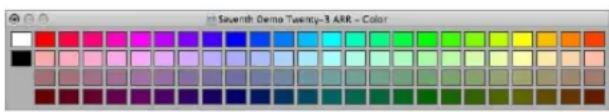
3 In the Color palette that opens, click on the desired color.
- If you'd like to create a custom color: Double-click on any color square in the Color palette to open the Colors window: Use the mouse on the color wheel, contrast, and opacity sliders to create a custom color. Click the OK button to replace the color square in the Color palette, and exit the Colors window.
Note: Custom colors are memorized, and are available for all projects.
To assign channel strip colors to regions:
1 Select the desired regions.
Tip: If all regions are on a single track, click the track name in the track list to select all regions.
2 Choose Region > Channel Strip/Instrument Colors to Regions (or use the Channel Strip/Instrument Colors To Regions key command, default Shift-Option-C).
This replaces the colors of all selected regions with the colors of the corresponding channel strips.
Tip: This feature is handy after copying or moving regions between tracks, when you may find that the Arrange area resembles a patchwork quilt.
Using the Shortcut Menu
Many selection, editing, and other commands can be accessed by Control or right-clicking anywhere in the Arrange area. Make use of this to accelerate your workflow.
Note: Right-click functionality is dependent on the Right Mouse Button: Opens Shortcut Menu option being chosen in the Logic Express > Preferences > Global > Editing tab.
Selecting Regions
You must select a region before you can perform any edits, functions, or operations on it. You can select a single or multiple regions, including regions on different tracks and of different types. When selected, a black bar runs across the upper portion of the region to indicate its selected status.
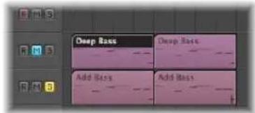
Logic Express provides a number of sophisticated selection methods. For more information on this, please refer to "Selection Techniques" on page 177.
Selecting Parts of a Region
You can use the Marquee tool or marquee stripe to make selections inside, or across portions of, existing regions. Within the selected area, you can perform almost all Arrange editing options, including deletions, moves, cuts, and copies. The selected area will become a new region once an operation is applied.
Using the Marquee Tool
The Marquee tool, which looks like a crosshair, allows you to select and edit parts of one or more regions.
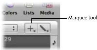
To use the Marquee tool:
1 Select the Marquee tool.
2 Click-hold on the Arrange area background or on regions to begin your selection, which is indicated by a shaded selection rectangle.
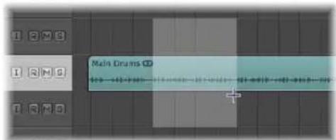
3 Drag the marquee rectangle to make selections—independent of existing region boundaries.
4 Release the mouse button.
Only the area that falls inside the marquee is selected.
To adjust an existing marquee selection:
- Hold Shift to alter the current marquee selection from either the left or right side, or up or down.
Using the Marquee Stripe
The marquee stripe is a thin yellow line that can be displayed at the top of the Bar ruler. You can directly drag in this area to create a marquee selection.
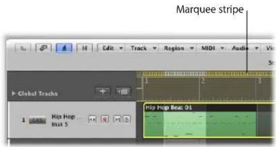
To activate the marquee stripe:
- Click the note icon at the right-hand end of the Bar ruler, and choose the Marquee Stripe setting from the menu.
To make a marquee selection:
- Click-drag in the marquee stripe area to create a marquee selection on all Arrange tracks.
To remove the marquee stripe selection:
- Click outside the marquee stripe.
Common Marquee Functions
You can use the following commands both when working with the Marquee tool or marquee stripe.
To set locators with a marquee selection:
- Choose the Region > Set Locators by Regions function (or key command).
This sets the locators to the marquee selection boundaries, rather than the whole region.
To remove all parts of regions outside the marquee selection:
■ Use the Crop Regions outside Marquee Selection key command.
This removes all unselected areas from regions which are partly marquee-selected.
If your selected area falls between musically relevant values, the marquee selection will automatically snap to the nearest musically relevant position. The snap resolution is determined by the current Snap menu setting.
To snap to the finest possible resolution in the chosen snap mode:
■ Hold Control-Shift while making your marquee selection.
This will snap to ticks or samples when editing MIDI or audio regions, dependent on the current zoom level (see "Overriding the Snap Grid" on page 310).
To snap to the division value shown in the Transport:
- Hold Control while making your marquee selection.
As above, the zoom level can impact on this.
Adding and Recording Regions
It goes without saying that adding and recording regions is essential for song creation. Given the extensive region and file import options available, and the advanced recording techniques possible with Logic Express, please refer to the following chapters:
- "Adding Pre-Recorded Media" on page 265.
- "Recording in Logic Express" on page 367.
Removing and Restoring Regions
As you work on a project, you may decide that a region no longer fits into your arrangement. You can remove regions by deleting them from the Arrange area.
Note: Removing audio regions and MIDI regions from the Arrange has different consequences (see "Restoring Removed Regions" on page 323).
To remove a region from your arrangement, do one of the following:
- Click the region with the Eraser tool.
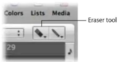
- Select the desired region with the Pointer tool, then choose Edit > Delete (or press Backspace).
To remove multiple regions from your arrangement:
1 Select the desired regions with the Pointer tool.
2 Do one of the following:
- Click one of the selected regions with the Eraser tool.
- Choose Edit > Delete (or press Backspace).
To remove all muted regions from your arrangement:
1 Select all muted regions by choosing Edit > Select Muted Regions/Events (or using the Select Muted Regions/Events key command, default: Shift-M).
2 Do one of the following:
- Click one of the regions with the Eraser tool.
- Choose Edit > Delete (or press Backspace).
To delete all selected regions, and automatically select the next one:
1 Select the region (or regions) you want to delete.
2 Use the Delete and Select Next Region/Event key command.
All selected regions are deleted, and the next (obviously, not deleted) region is automatically selected.
Restoring Removed Regions
Although similarly handled for most editing operations, audio and MIDI regions are treated differently when removed from the Arrange window.
- Audio regions are merely removed from arrangement, not from the project. They remain in the Audio Bin, and can be restored from here, or with the Undo functions.
- MIDI regions are deleted. They can be restored by using the Edit > Undo History function.
Restoring Removed Audio Regions
When you remove an audio region that you have recorded since opening the project, Logic Express will ask if you also want to delete the corresponding audio file. This avoids the unnecessary wastage of hard disk space that would occur if bad takes and unwanted recordings were retained.
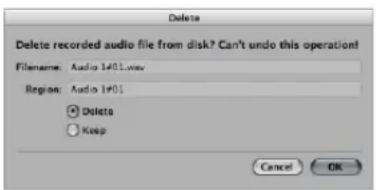
If the recording was made beforehand (a pre-recorded file), and imported into the current project, this dialog box will not appear. This prevents you from accidentally deleting valuable recordings (that may be used in other projects).
Note: When you remove a pre-recorded audio file from your project (by pressing Backspace in the Audio Bin), all regions that point to the file are also removed. The only way to restore the file to the project is by manually adding it to the Audio Bin.
To restore a deleted audio region, either:
- Choose Edit > Undo History, and click on the appropriate step.
■ Manually add it back into the Arrange area from the Audio Bin.
Moving Regions
You can move regions horizontally on tracks, and vertically between tracks. You can also move regions between two Arrange windows, or even between different projects.
To move one or more regions:
■ Select the desired regions and drag them to a new position.
Dragged regions automatically snap to increments defined by the Snap menu setting (see "Snapping Region Edits to Time Positions" section on page 309). If dragged over other regions, the Drag menu setting will have an impact on behavior.
To move regions precisely (overriding the Snap menu setting):
- Hold Control while dragging regions, to move them in steps of one division (in sixteenths, for example).
- Hold Control-Shift while dragging regions, to move them by single ticks or samples (remember that the maximum resolution is zoom dependent).
Moving Regions Between Projects
If you move a region from one project into the Arrange area of another, the region is automatically copied, in much the same way that Mac OS X automatically copies files when dragged and dropped between hard disks.
Limiting Region Movements
You can limit the initial movement of regions to either the horizontal or vertical axis. To do so, activate the Logic Express > Preferences > Global > Editing > Limit Dragging to One Direction In Arrange checkbox. If your first movement is to the left or right after grabbing a region, you can only move it on the horizontal plane. If you actually wanted to move it between tracks, release the mouse button, reselect the region, and drag it up or down.
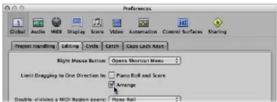
Note: You can override this direction limiting preference by pressing Shift while moving regions.
Changing the Playback Position of Regions Numerically
You can edit the playback position of a region (and its length) numerically. This can be done in the Event List, configured to view regions at the Arrange level (see "Changing the Event List View Level" on page 460).
To move regions by adjusting positions in the Event List:
1 Open the Event List by doing one of the following:
- Choose Window > Event List.
- Click the Lists button in the Arrange Toolbar, and click the Event List tab.
- Choose Options > Open Event Float (or use the Open Event Float key command).
This opens a new single line Event List window, set to the Arrange level view.
2 Click on the Hierarchy button in the top left corner of the Event List (not applicable to the Event Float window—a miniature Event List) to move up one level in the hierarchy.
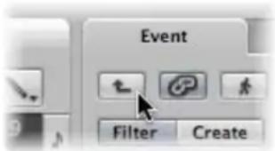
3 Edit the desired region's Position value. As you select regions in the Arrange area, the Event List (or Event Float) window will update to reflect this selection.
Tip: You can instantly move a region start point to the beginning of a bar by typing in a value, and pressing Return. As an example, typing in 9 will move the selected region to the beginning of bar 9. Typing in 112 will move the region to bar 112. Typing in 1 space 1 space 2 will move the region to bar 1, beat 1, sub-beat 2.
You can display the start position of regions as SMPTE values in the Event List and Event Float windows. This is especially handy if you work with video or film.
To display region positions in SMPTE values, either:
- Click the note icon button to the left of the first (or only, in the case of the Event Float window) region event.
The icon will change to a clock, and the SMPTE position and length of the event will be shown. - Turn on the View > Event Position and Length in SMPTE Units setting in the Event List (or use the corresponding key command).
This enables you to set the required SMPTE positions when synchronizing music to picture.
You can also display, and adjust, the end points of regions as a SMPTE time value. To do this, choose View > Length as Absolute Position in the Event List.
Moving Regions to the Current Playhead Position
You can use the Pickup Clock (Move Event to Playhead Position) key command to move the selected region (or the first of several selected regions) to the current playhead position. If more than one region is selected, all subsequent regions are moved.
Note: If you use this command on audio regions, the anchor of the region is placed at the current playhead position (see "Editing the Audio Region Anchor" on page 303).
Moving Audio Regions Back to Their Original Record Positions
You can move any selected audio region back to its original recorded position by choosing Audio > Move Region to Original Record Position (or using the Set Region(s) to Recording Position key command).
Note: This command only works if the audio file includes a time stamp. Examples of time stamped files include those recorded in the current project, and imported Broadcast Wave or SDII files. Time stamped files are indicated by a clock symbol to the right of the file name in the Audio Bin window (not Audio Bin tab).
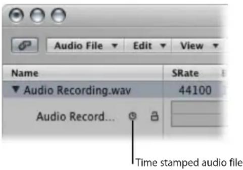
Nudging Regions
You can use the following key commands to nudge (move to the right or left) selected regions by the corresponding grid amount:
- Nudge Region/Event Position Right by SMPTE Frame
• Nudge Region/Event Position Left by SMPTE Frame
• Nudge Region/Event Position Right by 1/2 SMPTE Frame - Nudge Region/Event Position Left by 1/2 SMPTE Frame
• Nudge Region/Event Position Right by 5 SMPTE Frames - Nudge Region/Event Position Left by 5 SMPTE Frames
• Nudge Region/Event Position Right by SMPTE Bit
• Nudge Region/Event Position Left by SMPTE Bit
• Nudge Region/Event Position Right by Tick
• Nudge Region/Event Position Left by Tick
• Nudge Region/Event Position Right by Division
• Nudge Region/Event Position Left by Division
• Nudge Region/Event Position Right by Beat
• Nudge Region/Event Position Left by Beat
• Nudge Region/Event Position Right by Bar
• Nudge Region/Event Position Left by Bar
• Nudge Region/Event Position Right by Nudge Value
- Nudge Region/Event Position Left by Nudge Value
The selected regions are shifted one step right (+1) or left (-1), by whatever unit is referred to in the particular command name.
Shifting the Playback Position of Regions
The Delay parameter in the Region Parameter box of the Inspector allows you to shift the playback position of regions on a track. Positive values correspond to a delay (laid-back playing style or dragging), and negative values cause a pre-delay (driving or rushing the music).
The Delay amount is shown in milliseconds or note values, dependent on the View > Delay menu setting. You can also use the "Delay in ms" key command to switch the display.
To delay or advance all selected regions on a track:
- Set the Region Parameter box Delay parameter to the desired value.
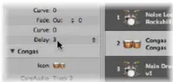
The Delay parameter in the Inspector is mainly used for creative musical purposes, such as rhythmically offsetting musical parts (regions). It can also be used to fix timing problems that may occur for a variety of reasons. Some examples of these are:
- The attack phase of the sound is too slow. A good musician will automatically compensate for this by playing the notes slightly early. With very slow sounds, you may need a pre-delay of over 100 ms to even them out.
- The sound generator is reacting too slowly to the incoming note-on messages. Older multitimbral sound generators often take tens of milliseconds before outputting a voice.
- The delay in output is not constant, as it is dependent on the order of notes arriving at the external MIDI sound generator. You should therefore try pre-delaying rhythmically important tracks by as little as one tick—it can work wonders on timing!
Moving Regions to a Track
The Region > Move Selected Regions to Current Track command (also available as a key command, default: Shift-Command-T) moves all selected regions (from different tracks) onto the selected track. The time positions of all regions are retained.
Resizing Regions
You can reduce or extend the length of any region by dragging the start or end point of the region, thus determining what part of the source (audio file or MIDI events) is played back in your project.
The data in regions is never deleted when they are reduced in length; playback simply stops at the end of the region.
To resize a region:
1 Select the Pointer or Pencil tool, then place the cursor over the lower left or right hand corner.
The cursor changes to a Resize pointer.
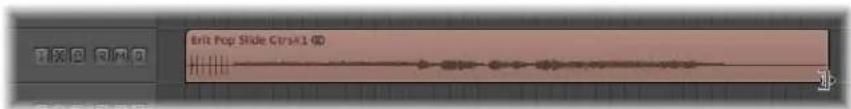
2 Click the corner and drag to the left or right.
Note: If Hyper Draw or automation is enabled, you'll need to grab the left or right sides of the region title area.
To simultaneously resize two adjacent regions (using the Junction pointer):
1 Select the Pointer or Pencil tool, then place the cursor over the upper left or right hand corners of two side-by-side regions.
The cursor changes to the Junction pointer.
Note: If there is a gap between the regions, the Loop tool will be shown when the mouse pointer is moved over the upper right corner of the earlier region.
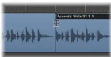
2 Click-drag to the left or right.
Both regions will be resized accordingly, with no gaps between them.
Note: You cannot make an audio region longer than the underlying audio file when using either of the resize operations covered above.
Adjusting the Start Point of Audio Regions
Adjusting the start point of an audio region may also move the region anchor point, thus affecting its temporal reference point, and making it play back out of sync with other tracks. It is better, and simpler, to move the entire region to the right, if you want playback to start later.
If you actually want to cut out the early portion of the region, you have several options, such as:
• Marquee selection and muting.
• Cutting and muting or deleting.
- Creating a new region, and resizing it in the Audio Bin window.
- Using the Sample Editor to resize, and replace, the Arrange region.
To resize an Arrange audio region from the Sample Editor:
- Directly edit the start and end markers (in the Region row at the bottom of the Sample Editor window); this affects the size of the corresponding Arrange region immediately.
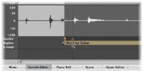
To resize and replace an Arrange audio region from the Sample Editor:
1 Select the desired portion of the audio file in the Sample Editor by dragging directly across the waveform display.
2 Choose Edit > Selection → Region (or use the corresponding key command).
This enables you to define an audio passage as a selection, and then convert it to a region, in place of the originally selected region.
You can also do the reverse ...
To resize the Sample Editor selection from the Arrange:
1 Select the desired region in the Arrange (presumably of a different length to the current Sample Editor selection).
2 Click the Sample Editor title to make sure that the Sample Editor has key focus
3 Choose Edit > Region → Selection (or use the corresponding key command).
Adjusting the Grid to Zero Crossings
If Audio > Search Zero Crossings is turned on, any length adjustments to audio region start or end points will snap to the nearest zero crossing point of the waveform.
The disadvantage of this option is that altered start or end points never land exactly on the selected musical grid.
Should this ever cause a problem, you can simply switch off the Audio > Search Zero Crossings setting. The primary reason for activation of the Search Zero Crossings setting, is that it prevents clicks and pops at region start and end points.
Adjusting the Start or End Point of MIDI Regions
You can move the left corner beyond the first event in a MIDI region—which hides events from the beginning of the MIDI region, but these hidden events will continue to play back.
If you actually want to remove the information from the start of a MIDI region, you need to cut it and mute or delete the new start segment (new MIDI region).
The hide facility is useful in situations where you might want to trigger MIDI controller events (such as sustain) before the musical phrase begins, but do not want to use a MIDI region that doesn't fit into the current Arrange grid (based on bars), as this would make arrangement far more complicated.
Note Handling Options When Changing MIDI Region Lengths
The Clip Length setting in the Extended Region Parameters (only visible if the View > Extended Region Parameters setting is turned on in the Arrange area) determines whether:
- Notes sounding when the region ends are abruptly cut off (active)
- Notes should be played to their normal end point (inactive: default), regardless of where the region ends
The point of this function is to allow you to alter the length of the last notes in a region directly from the Arrange area, by adjusting the length of the MIDI region. Clip length has no effect on folder regions.
Making Multiple Regions the Same Length
You can change the length of multiple regions to the same absolute amount, making them the same length, even if originally a different size.
To make all selected regions the same absolute length:
- Hold Option-Shift while changing the length with the Pointer tool.
Setting Region Start and End Points to the Playhead Position
You can move the start or end point of a selected region to the current playhead position with the following key commands:
- Set Region/Event Start to Playhead Position
- Set Region/Event End to Playhead Position
Note: The anchor point is also moved when using Set Region/Event Start to Playhead Position on an audio region.
Adjusting Region Lengths to Fit Other Regions
On occasion, you may want to reduce or extend the length of all regions on a track, or between locators, ensuring that they directly adjoin each other without gaps.
To reduce the length of overlapping regions on a track:
1 Select the overlapping regions on a track, or select all regions on a track by clicking the track name in the track list.
2 Choose Region > Remove Overlaps (or use the Remove Overlaps key command).
This function searches all selected regions in a track for overlaps. If an overlap is found, the earlier (in time) region is reduced in length, thus removing the overlap.
You can "tie" selected region(s), making them end exactly at the start point of the next region on the track.
To tie regions (removing gaps between regions):
1 Select the regions you want to tie.
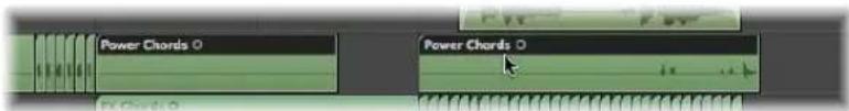
2 Choose Region > Tie Regions by Length Change (or use the corresponding key command).
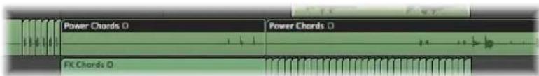
The selected regions are increased in length, making them end exactly at the start point of the next region on the track.
You can limit the length change to all selected regions within the locator boundaries.
To tie selected regions between locators:
1 Set the left and right locator positions by doing one of the following:
- Drag from left to right across the desired portion of the Bar ruler.
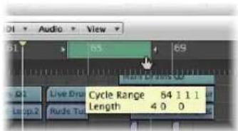
- Set the desired value in the Transport's Locator fields.
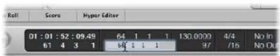
2 Select the desired regions within the locator boundaries.
Tip: You can quickly select all regions inside the locators by choosing Edit > Select Inside Locators (or using the corresponding key command, default: Shift-I).
3 Choose Region > Tie Regions within Locators (or use the corresponding key command).
This function lengthens all selected regions (within the locator boundaries), closing the gaps between them. The last region on each track (within the locator boundaries) is not affected.
Time Stretching the Contents of a Region When Changing Length
In normal use, the position of events within MIDI regions is not affected by changes to the region length. Similarly, changes to audio region lengths have no impact other than starting and stopping playback at particular song positions.
You can, however, time stretch or compress the contents of regions when altering their length.
To time stretch or compress the position of events within a MIDI region:
■ Option-drag the end of a MIDI region.
The events within the region are stretched or compressed, proportionately, by the amount that the MIDI region is altered in length.
You can make a rhythmic MIDI region play in half-time by stretching it to twice the original length, or in double-time by shortening it to half the original length.
To time stretch or compress audio regions:
- Option-drag the end of an audio region.
This stretches or compresses the audio by the amount that the region is altered in length, and replaces the original region with a new PCM audio file (in the original file format, or AIFF, if the original was not PCM).
Note: The current Snap menu setting has an impact on length changes.
You can make an audio region play at half-speed by stretching it to twice the original length, or at double-speed by shortening it to half the original length. Great for Darth Vader or Munchkin impressions.
You can choose the time stretch/compression algorithm used for this function in the Arrange area's Audio > Time Machine Algorithm menu. Details on each algorithm are found in "Using the Time and Pitch Machine" on page 534.
Time Stretching or Compressing Multiple Regions
Modifier keys have an impact on how time stretching or compression works when multiple regions are selected. The following table outlines all modifier options, and their impact (or otherwise) when multiple region lengths are changed:
Modifier Result
| None Same absolute length change, no time correction | |
| Shift Same absolute end position, no time correction | |
| Option Same absolute length change, with time correction | |
| Option-Shift Same absolute region length, with time correction | |
| Control | Can be used after clicking for finer resolution length changes, but can not be used in conjunction with Option, no time correction |
MIDI Region-Specific Length Change Operations
The following functions only apply to MIDI regions.
To round a MIDI region start point to a bar:
■ Use the MIDI > Snap Region Start to Bar command (or the corresponding key command) to round the start point of the selected MIDI region to the nearest bar.
Adjusting the Length of MIDI Regions to Fit Contents
The MIDI > Set Optimal Region Sizes Rounded by Bar command (or the corresponding key command, default: Control-B) reduces or increases the length of a selected MIDI region, making it just large enough to contain the events (or regions, if a folder) within it. The region borders are rounded to the nearest bar.
Hold down Option when using this function to round the region borders to the nearest denominator value (or use the Set Optimal Region Sizes rounded by denominator key command).
Cutting, Copying, and Pasting Regions
You can select, remove, or replicate one or more regions from one part of an arrangement to another. In fact, you can use the Cut, Copy, and Paste commands between the arrangements of two projects, if you wish.
To cut a region:
- Select the region, then choose Edit > Cut (or use the Cut key command, default: Command-X).
This removes the region from the Arrange and places it in the Clipboard.
To copy a region (method 1):
- Option-drag the region to the desired Arrange position.
If Hyper Draw or automation is enabled, you'll need to grab the region name area in order to copy it.
To copy a region (method 2):
1 Select the region, then choose Edit > Copy (or use the Copy key command, default: Command-C).
This copies the selected region to the Clipboard.
2 Set the desired playhead position by clicking on the Bar ruler.
3 Choose Edit > Paste (Command-V) to paste the contents of the Clipboard into the Arrange. The paste will occur on the selected track at the playhead position.
If several regions are selected, their relative time and track positions are retained.
To paste a region at the same position as the copied region:
- Select the track you want to paste the region into, then choose Edit > Paste at Original Position (or use the Paste at original Position key command).
Logic Express inserts the copied region into the selected track, at the same position as the source region. This is useful if you want to copy a region to the same spot on a different track, to independently process or thicken the part, for example. This function is also ideal for creating layered MIDI and/or software instrument parts.
Information About Copied Regions
Copied regions are actually true, independent replicas of original regions. Changes made to a parent region will not affect child copies.
If you want this type of behavior—where changes to the parent region affect child regions—make use of the Loop function (see "Looping Regions" on page 344), or create cloned or alias regions (see "Repeating Regions" on page 339).
When you copy an audio region, a new region is automatically created in the Audio Bin. The new region will retain the name of the original, with a sequential number added. As an example, kickingloop.1 will be the name of a region copy, if the original region is called kickingloop. A second copy will be named kickingloop.2, a third kickingloop.3, and so on.
Adding or Removing Song Passages
There are many occasions where you will want to remove an entire passage from an arrangement—a chorus or verse, which encompasses the regions of all tracks between bars 16 and 20, for example. All existing regions, bar changes, tempo changes, and global score symbols (from bar 21 onwards) are moved 4 bars to the left, closing the gap left by the cut operation.
You can also insert a gap into your arrangement—creating several blank bars, for use as a middle eight, to create space for another chorus or verse, or perhaps a bridge. As with cutting time, all existing tempo changes and so on are moved accordingly (to the right by the number of inserted bars).
You can, of course, simply use the standard Edit menu Cut, Copy, and Paste commands to remove or re-use a section of your arrangement, such as a chorus, from one location to another.
You can limit changes to a few selected regions as well. If you choose to do this, rather than moving all regions within a song section, you need to decide whether or not any bar changes, tempo changes, and global score symbols should also be shifted. This is done in the dialog box shown below.
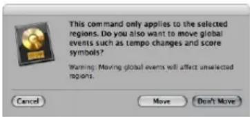
Press Return if you do not want to move tempo changes and global score symbols.
The abovementioned global edit is performed on all regions, when used. These functions are otherwise restricted to tracks that contain selected regions (or at least those that fall between the locator points).
Using the Arrange Section Editing Buttons
The Arrange Toolbar features a number of section editing buttons that can be used to perform some of the operations covered below. Whenever these Toolbar buttons are used, the operation will affect all regions that fall between the locators, regardless of the selection status of regions in this area. If you want to perform these operations on selected regions within the locators, you should not use the Arrange Toolbar buttons. Make use of the appropriate Region > Cut/Insert Time menu command (or key command), after making your region selection.
To insert a gap into the arrangement, using the locators (the cycle length):
1 Set the left and right locator positions by doing one of the following:
- Drag from left to right across the desired portion of the Bar ruler.
- Set the desired values in the Transport's Locator fields.
2 Select the regions you want to move by the cycle length. If no selection is made (or you use the Insert Silence button, in a customized Arrange Toolbar), all regions that fall between the locators will be affected.
3 Choose Region > Cut/Insert Time > Insert Silence Between Locators (or use the corresponding key command).
- For selected regions that are longer than the cycle length: This cuts them at the left locator position, and moves the second region (newly-created from the cut) to the right right locator position, creating a gap between the regions.
- For selected regions that fall wholly within the locators: Regions which began at the left locator position now begin at the right locator position.
- For a combination of partially and wholly selected regions that fall within the locators: The encompassed section will be cut, and moved to the right locator position.
You can also remove empty space between selected regions, creating seamless joins between them.
To remove gaps between regions:
1 Select the desired regions.
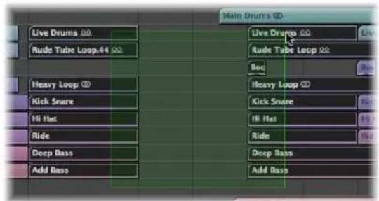
2 Choose Region > Tie Regions by Position Change (or use the Tie Regions by Position Change key command).
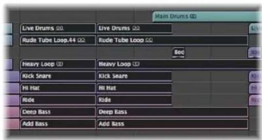
The first region remains unchanged, and all subsequent regions are moved to the left.
Note: You can use this feature to speed up the playback of spoken word recordings that have been processed with strip silence (by closing the gaps between words).
To remove a section of your arrangement, using the locators:
1 Set the locators to span the section you want to remove (bar 5 to 8, for example).
2 To cut all regions that fall between the locators: Click the Cut Section button in the Arrange Toolbar, or use the Region > Cut/Insert Time > Snip: Cut Section Between Locators (or corresponding key command).
3 To cut selected regions that fall between the locators: Choose Region > Cut/Insert Time > Snip: Cut Section Between Locators (or use the corresponding key command).
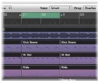
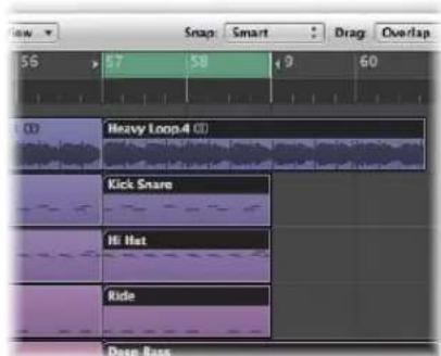
Any regions that span the cycle area (as an example, a 16 bar long region that starts at bar 1, and ends at the start of bar 17) are cut.
The section between the locators (bars 5 to 8) is deleted from all selected regions (in fact, it is copied to the Clipboard and removed from the arrangement).
All regions to the right of the right locator are moved to the left by the length of the cycle (4 bars). This includes newly-created regions that result from the operation.
To use the example 16 bar region. It is cut into two regions:
• One spanning bars 1 to 4.
• The other is now an 8 bar long region that is placed from bar 5 to the start of bar 13.
Tip: The Snip command is ideal for situations where you want to remove an entire section of your arrangement, such as a chorus.
To insert a cut section into your arrangement:
1 Follow the steps outlined above.
2 Set the playhead to the position that you want to insert the cut section.
3 Either click the Insert Section button in the Arrange Toolbar (to affect all tracks, regardless of selection), or choose Region > Cut/Insert Time > Splice: Insert Snipped Section at Playhead.
All selected regions are cut at the left locator, and a passage of one cycle length is inserted. Regions currently in the Clipboard are then pasted at the playhead position.
Tip: The Splice command is perfect when you want to insert a part (a chorus, for example) at another point in your arrangement. To ensure all tracks are shifted, including tempo, time signature changes, and markers, please select everything beforehand (with Command-A or Shift-I).
To repeat a section of your arrangement, using the locators:
1 Set the locators to span the section you want to repeat (bar 5 to 8, for example).
2 Select the regions that you want to repeat. If no selection is made (or you use the Repeat Section button in the Arrange Toolbar), all regions that fall between the locators will be affected.
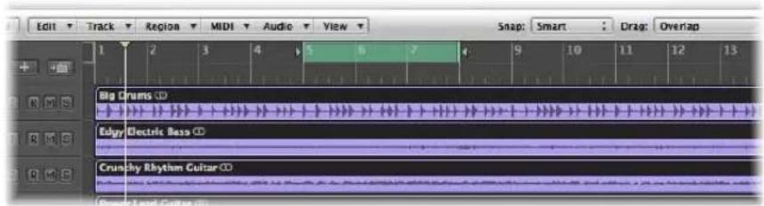
3 Choose Region > Cut/Insert Time > Snip: Repeat Section Between Locators (or use the corresponding key command).
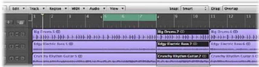
The portions of all regions that are wholly, or partially, encompassed by the locators will be copied, and pasted to the right locator position.
Repeating Regions
Logic Express provides a number of ways to repeat a region, through use of loops, aliases, and clones. These options make arranging faster and simpler.
Using MIDI Region Aliases
An alias in Logic Express is like an alias in the Finder. It looks like a region, but contains no actual data. It is just a reference to the data of the original region—a virtual reflection of the original.
The Relationship Between Parent and Alias Regions
If the data in the original region is altered, this immediately affects all aliases of the region. As examples of how aliases can be used:
- If a riff or phrase reoccurs throughout an arrangement, it's quicker to use aliases, rather than creating copies of the original region.
- If a part is not quite right, you only need to alter the original, and the correction will automatically take effect throughout the whole arrangement.
If, however, you want to alter a detail at one point in the arrangement (a pitch shifted verse, for example), you can turn that particular alias into an independent region (a region copy).
Aliases do have a level of independence from their parent region:
- Aliases have their own set of region parameters.
- Aliases can be individually named. Alias region names are shown in italics. If you name an alias region, its parent region name will be shown below the alias name (provided that the zoom level is adequate).
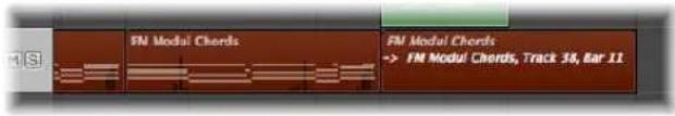
Any changes made to the parent region name will be reflected on all alias regions.
Note: MIDI region aliases can not be edited. If you double-click on an alias,
Logic Express assumes that you either; want to edit the original, or turn the alias into a real region. A dialog asks whether you want to create and edit a real copy, or to edit the original.
Creating MIDI Region Aliases
Aliases can be created for MIDI regions and folders. The term region only refers to MIDI regions and folders in this section.
Note: Only cloned audio regions (or independent region copies) can be created for audio regions (see the "Cloning Audio Regions" section on page 342).
To create an alias, do one of the following:
■ Option-Shift-drag the region to the desired position for the alias.
- Select the track you want to create the alias on, position the playhead, select the region you want to create an alias from, then choose MIDI > Alias > Make (or use the Make Alias key command).
The alias appears on the selected track, beginning at the current playhead position.
If several regions are selected, their relative time and track positions are retained. The selected track is the destination track for the first region along the time line.
You can also use the Repeat Regions command (see "Making Multiple Copies of Regions" on page 343).
Reassigning MIDI Region Aliases
You can assign a new original region to an existing alias. This is exceptionally handy for arranging tasks where the structure is right, but the part is wrong. You can certainly copy a region to the appropriate position on a new track, create an alias, mute the existing region, and hit play, or use the far simpler method below:
To re-assign an alias:
1 Select both the alias and the intended new original region.
2 Choose MIDI > Alias > Re-Assign (or use the Reassign Alias key command).
Searching for an Original or Alias
If you have forgotten where the original is for a certain alias, you can search for it.
To find and select the original region of an alias:
- Select the alias, and choose MIDI > Alias > Select Original (or use the Find Original of Alias key command).
To find any aliases you've made from a region:
- Choose MIDI > Alias > Select All Aliases of Region (or use the corresponding key command, default: Shift-A).
All existing aliases will be found, and selected.
Selecting and Deleting Orphan Aliases
If you delete a source region that one or more aliases were derived from, Logic Express will display the following warning message:
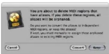
- Cancel: Click to cancel the erase procedure.
- Convert: Click to change all alias MIDI regions into real copies.
- Keep: Click to delete the parent region, and retain all (orphaned) alias regions. Although such orphan aliases serve no useful purpose, Logic Express doesn't automatically delete them, as you might decide to re-assign them to new originals at a later stage.
If your project file contains several unneeded aliases, you can quickly tidy up by selecting and deleting all orphan aliases.
To select all orphan aliases:
- Choose MIDI > Alias > Select All Orphan Aliases (or use the Select All Orphan Aliases key command).
To delete all orphan aliases:
- Choose MIDI > Alias > Delete All Orphan Aliases (or use the Delete All Orphan Aliases key command).
Converting an Alias into a Real Region
You can use MIDI > Alias > Convert to a Region Copy (or the Convert Alias to a Region Copy key command) to make a real region from an alias; its contents will be identical to those of the original region referenced by the alias, but its playback parameters will be those of the alias. As a real region, you may freely edit it (or the original parent region, without affecting the new real region).
Note: You can also double-click an alias to produce a dialog that asks whether you want to create and edit a real copy, or to edit the original.
Cloning Audio Regions
You can create another version of an audio region in the Arrange area—a cloned region, if you will—which is comparable to a MIDI region alias.
To create a cloned region:
■ Hold Option-Shift while dragging an audio region.
Whenever you adjust the start or end points of any of these cloned regions, all other cloned regions will also be adjusted in the same way.
To make several cloned regions independent of each other:
- Select the desired (cloned) regions and choose Audio > Convert Regions to New Regions (or use the corresponding key command, default: Option-Command-R) in the Arrange area.
Cloned regions that are made independent in this way can have their start or end points altered, without all other cloned regions being affected.
To convert several selected regions into audio files:
1 Choose Audio > Convert Regions to New Audio Files (or use the corresponding key command, default: Option-Command-F).
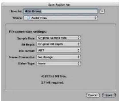
2 In the dialog: Set the desired sample rate, bit depth, file format, stereo conversion, and dither type for the destination files.
The new audio files are created in the same folder as your original audio file. The files are also added to the Audio Bin, and all references to these new arrange regions are changed—to correspond with the newly created files.
These newly created files can be independently edited, allowing you to reverse, time stretch, and more, without affecting other regions based on the same original file.
Making Multiple Copies of Regions
You can make multiple copies of both audio and MIDI regions using the Repeat Regions command.
To make multiple copies of a region:
1 Select the region you want to make multiple copies of.
2 Choose Region > Repeat Regions in the Arrange area menu (or use the Repeat Regions/Events key command).
3 Set the following parameters in the Repeat Regions/Events window:
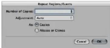
- Number of Copies: This is where you enter the number of copies (excluding the original).
- Adjustment: Choose whether you want a copy to begin at the end of the original (setting: None), or whether you want the start point to be quantized (to the bar, beat, tick, and so on).
- As: Copies/Aliases or Clones: Here you set whether the repeats are copies, aliases (MIDI regions), or clones (audio regions) of the original.
Looping Regions
The Loop function enables you to repeat a region automatically, without needing to copy it. A looped region will repeat until it encounters another region on the same track, or the project ends. A loop will also terminate at the end marker of a folder, if the looped region is inside a folder (see "Using Folders" on page 354).
Loop repeats are displayed as extended segments of the original region. Each segment is the same length as the original region, and will change if the length of the original region is changed.
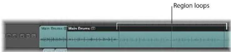
Tip: If you want to create polyrhythmic structures, try experimenting with the length of the original region.
To loop a region with the Loop parameter:
1 Select the region in the Arrange area.
2 Click (turn on) the Loop option in the Region Parameter box of the Inspector (or use the Toggle Loop key command, default: L).
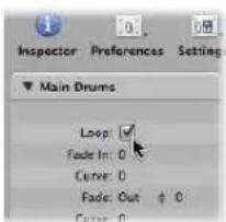
The region is looped until it encounters another region on the same track (or the project or folder ends).
To turn off the Loop parameter:
- Click the Loop option in the Region Parameter box (or use the Toggle Loop key command, default: L).
To loop a region with the mouse:
1 Move the cursor to the end of the region that you want to loop.
The cursor will change into a circular arrow (the loop length editing tool) when positioned in the upper area of the region.
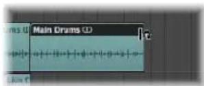
2 Click-hold and drag the end of the region to the right, as desired, to set the length of the looped region.
The loop repeats are shown as segments (of the same length as the original region) within the overall looped region. The Loop parameter of the Region Parameter box is automatically enabled.
Note: Deactivation of the Loop parameter resets the manually created loop length. The next time the Loop parameter is used, the region is repeated until it encounters another region on the same track or the end of the project (or folder) is reached.
The cursor will only turn into the circular arrow (and offer the loop length editing functions), when the track is of sufficient height. Use any of the zooming options to resize.
If you want to select the looped region (to move it, for example), click in the lower half of the looped area, or Shift-click in the upper loop area.
Note: Most of the other tools can also be used to set the loop length (they take on the circular arrow shape when held over the top right of regions). You should use the Pointer tool, however, as clicking the wrong spot on a region with the Eraser tool selected will delete the region, rather than set the loop you intended to create.
Loop repetitions are merely pointers to the original region. They can not be transposed and don't have any playback parameters in the Region Parameter box, shown in the Inspector. Only a real region (or a copy) offers playback parameters and may be transposed. If you'd like to use different playback settings for each of the loop repetitions, you need to turn them into real copies.
To convert an existing loop into a real copy:
1 Select the original region.
2 Choose Region > Loops > Convert to Real Copies (or use the corresponding key command, default: K). New regions will replace the loop repeat segments.
The advantage of real copies is that they can be independently resized. This may be useful in situations where you would like to resize a few loop copies among hundreds that span the song length.
To convert a loop into aliases or clones:
1 Select the original region.
2 Choose Region > Loops > Convert to Aliases (or use the corresponding key command). MIDI region loop repeats are converted into aliases. Audio region loop repeats are converted into cloned audio regions.
As such, any alterations to the length of the original region affect all aliases and cloned regions.
Dividing, Demixing, and Merging Regions
There are often occasions where some portions of regions may be suitable for use, and others may not be. This section concentrates on functions that help you to split regions and reuse portions of them (or entire regions) to create new, combined regions.
Tip: Don't forget the Marquee tool (see "Selecting Parts of a Region" on page 320) for similar region editing tasks.
Dividing Regions
You can divide one or more selected regions with the Scissors tool.
To divide one or more regions:
1 Make your region selections.
2 Select the Scissors tool.
3 Click-hold on the desired regions.
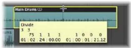
The help tag shows the current divide position.
4 Release the mouse button.
All selected regions are cut at the position shown in the help tag.
When selecting a cut point with the Scissors tool, you can move backwards and forwards in steps of one division. The grid is based on the Snap menu setting.
To make finer resolution divisions (overriding the current Snap value):
- Hold Control after you have selected the region with the Scissors to divide in the division value (1/16th, 1/32nd, and so on, as shown in the Transport).
- Hold Control-Shift to divide regions with even more precision (ticks or samples).
The newly created segments of an audio region are named after the original, with a sequential number appended to the end of the name.
Divided MIDI regions are named after the original, with no sequential numbering. Each MIDI region resulting from the division is independent and contains data.
To divide a region into several portions with the same length:
■ Hold Option while cutting a region with the Scissors tool.
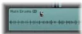
A plus symbol appears next to the Scissors tool, and the help tag shows Divide Multiple.
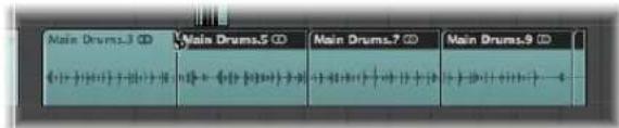
The selected region will be cut into several pieces—each the same length as the first segment.
As an example: To divide a 16-bar region into eight 2-bar regions, cut the region at the start of bar 3, while holding down Option.
To divide regions at the locator positions:
1 Set the left and right locator positions as desired.
2 Select the regions you want to divide within the locator boundaries.
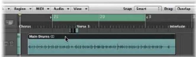
3 Choose Region > Split/Demix > Split Regions by Locators (or use the corresponding key command).
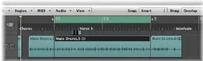
All selected regions located wholly, or partly, between the locators are cut at the left and right locator positions. All regions created between the locator positions as a result of the split operation, are then automatically selected.
Tip: You can achieve the same effect by defining a cycle with the mouse in the Bar ruler, while holding down Command.
To divide regions at the playhead position:
1 Select the regions you want to divide.
2 Choose Region > Split/Demix > Split Regions by Playhead (or use the corresponding key command).
This splits all selected regions exactly at the playhead location.
Tip: To cut at the nearest bar, use the Split Regions/Events by Rounded Playhead Position key command.
Handling Overlapping Notes in Divided MIDI Regions
If any notes in a divided MIDI region overlap other notes by more than a 1/16 note, the following dialog will appear:
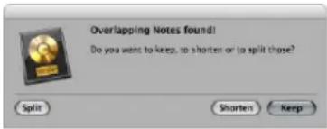
- Keep: Click to leave all notes unaltered. The MIDI region is cut as expected, but you can end up with notes in the left-hand half (earlier region) that are much longer than the MIDI region containing them. Such notes will play normally, unless Clip Length is enabled (see "Note Handling Options When Changing MIDI Region Lengths" on page 330).
- Shorten: Truncates (shortens) all overlapping notes, so that they end at the point where the original MIDI region was divided.
- Split: Divides overlapping notes across the two MIDI regions; two notes are created, with the same pitch and velocity as the original, and with the same total length as the original note.
About Zero Crossings When Dividing Audio Regions
The Audio > Search Zero Crossings setting in the local Arrange menu has no effect when dividing audio regions, using any of the methods outlined above.
Audio > Search Zero Crossings, when enabled, only applies to alterations of the start or end point of a region, not divide operations.
If you want to automatically divide an audio file into multiple regions, make use of the Strip Silence function.
Dividing Audio Regions With Strip Silence
The Audio > Strip Silence function in the Arrange menu launches a window which allows you to slice an audio recording into different audio regions. This division is based on analysis of amplitude levels within the audio file. A detailed description of this function can be found in Chapter 22, "Removing Silent Passages From Audio Regions," on page 549.
Merging Regions
You can merge two or more selected regions (of the same type—audio or MIDI) into a single region, making region handling easier, or as a creative option.
To merge two or more regions with the Glue tool:
1 Select the Glue tool.
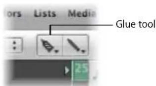
2 Click the regions that you wish to merge (if necessary, use Shift during selection).
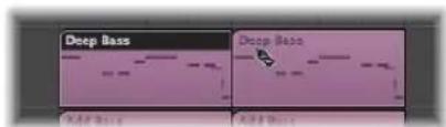
To merge two or more regions with the Merge Regions command:
1 Select the regions you'd like to merge with the Pointer tool.
2 Choose Region > Merge > Regions (or use the corresponding key command).
This merges all selected regions, even those on different tracks, into a single region.
To create several merge files—each on their own track:
1 Select the regions that you want to merge on each track with the Pointer tool.
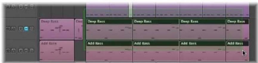
Shift-clicking, rubber-band selection, or Command-A may be useful for this.
2 Choose Region > Merge > Regions per Tracks (or use the corresponding key command).
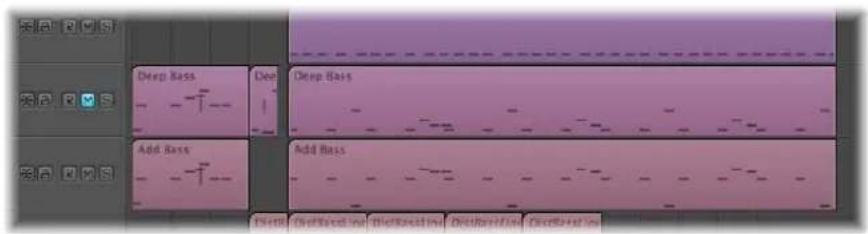
The selected regions are combined into one region per track. As an example, tracks 1 to 4 have regions that you'd like to merge. Make your region selections in each track lane, press Shift-J, and four merged regions will be created—one for each track.
What Happens When MIDI Regions Are Merged
When you merge MIDI regions:
• All events from each individual MIDI region retain their original time positions.
- The new (merged) MIDI region adopts the name and track of the first (along the time line) of the original MIDI regions.
- The Transposition, Velocity, and Dynamics region parameters—if not identical in all selected regions—are normalized before the merge. This means that all parameter values are written as data changes for each region before the merge. The parameters of the newly created (merged) MIDI region are all set to neutral (default) values.
- If one of the region parameters (the Transposition value, for example) is set identically in all selected regions, that value is preserved in the Region Parameter box for the merged region, and the events remain unchanged from their original values.
Note: Be aware that the individual MIDI channels of events (if applicable) are replaced by the MIDI channel of the current track Instrument channel strip.
Merging Audio Regions
Merging audio regions is a non-destructive operation, as Logic Express always creates a new file for the merged audio material (sometimes called a mixdown).
This new audio file is stored (in the project folder) on your hard drive and is automatically added to the Audio Bin. The merged region replaces the original regions.
No Mixdown Situation
If there are several regions (mono or stereo) in a row on the same track, which have been cut out of one region with the Scissors tool, no mixdown happens. In this situation, a single region is simply created over the entire area. This delivers the desired result, without using any additional disk space.
Note: Logic Express can recognize associated regions, even if there are gaps between them. The determining factor is that the relative position of the regions in the Arrange corresponds to the relative position of the regions in the underlying audio file.
No mixdown occurs when you try to mix two regions on tracks that are panned to opposite sides, as the two resulting mixdown files would be identical to the original audio files (in the areas used for the regions).
Genuine Mixdown With Clipscan
If you combine audio data (in regions) from two or more tracks, the current pan and volume values for the individual tracks will define the pan and volume settings in the new audio file.
If you want to combine both sides of a stereo audio file (a mono channel on each of two tracks), first set the pan controls of the component mono sides to hard left and hard right, respectively.
Following the digital clipping scan (Clipscan) and completion of the mixdown, Logic Express replaces the previously selected regions with one region that contains the entire mixed-down audio file.
You can use the Edit > Undo function (Command-Z) to restore the original audio regions, if desired. If you do so, you'll be asked if you'd like to keep, or delete, the newly created mixed audio file. If you decide to keep it, it will remain in the Audio Bin, and can be further used and processed.
During a mixdown, the 32-Bit resolution Clipscan function ensures that the highest possible level is maintained, without clipping.
Mixdown of Audio Regions on a Track
If several overlapping audio regions are selected on a single track, no mixdown occurs. You are asked to create a new audio file, which is named after the first region on the track. The selected regions are then mixed together, with no changes to volume, and without clip scanning.
If there are empty sections between two regions, these are added into the new audio file—as silent passages.
Audio Crossfades in Digital Mixdown
The Digital Mixdown supports crossfades between selected regions.
The crossfade parameters are defined in the General Audio preferences tab, which can be opened either by choosing Logic Express > Preferences > Audio > General (or the Audio Crossfade Options for Merge key command).
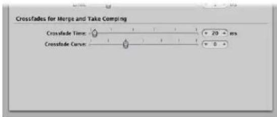
There are two faders:
- Crossfade Time [ms]: This is the length of the entire crossfade. To switch off the crossfade, set this value to zero.
- Crossfade Curve: To obtain a linear crossfade, set this value to zero. Other values (positive or negative), produce various exponential fades. The fade-outs and fade-ins are always symmetrical, to avoid deviations in level. The preset values are: Time = 0 ms, Curve = 0 (linear).
Demixing MIDI Regions
You can split MIDI regions (or Standard MIDI File Formats 1 or 0) by event channels or note pitches.
To split MIDI regions by event channels:
1 Select the desired MIDI regions.
2 Choose Region > Split/Demix > Demix by Event Channel (or use the corresponding key command)
Logic Express searches the selected MIDI regions for events with different MIDI channels.
- A separate MIDI region, containing all matching events, is created for every MIDI channel that is found.
• Each of these regions is created on a track with an instrument channel that matches the MIDI channel. - If no such tracks exist, new tracks are created for each channel.
To split MIDI regions by note pitches:
1 Select the desired MIDI regions.
2 Choose Region > Split/Demix > Demix by Note Pitch (or use the corresponding key command).
Logic Express searches the selected MIDI regions for notes with different note numbers.
• A different MIDI region of the same length is created for every note number found
• Tracks are created for these MIDI regions, and all are assigned to the same channel strip as the original MIDI region.
This feature is especially useful for separating drum parts that have been recorded into Logic Express from a drum machine—where all notes are on the same MIDI channel. Each note region can then be assigned to another channel strip, or perhaps some can be deleted, to thin out the original drum pattern.
Using Folders
A folder is a region that can contain other regions, much like a folder in the Finder can contain other folders or files. In principle, you can edit folders as you would edit MIDI regions.
One way to visualize a folder is as an arrangement within an arrangement. A folder can contain as many tracks, featuring regions, as required. A closed folder looks like a MIDI region, but is placed on a track assigned to a folder in the track list, rather than a channel strip.
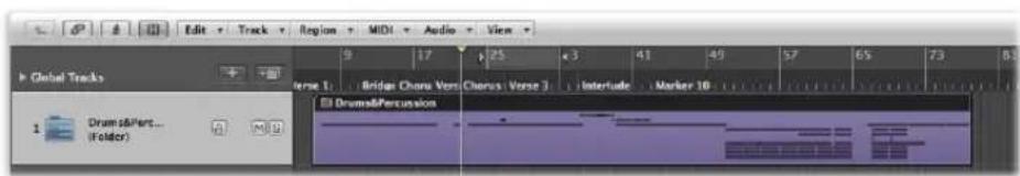
When opened, folders look just like the Arrange area and track list in a project.
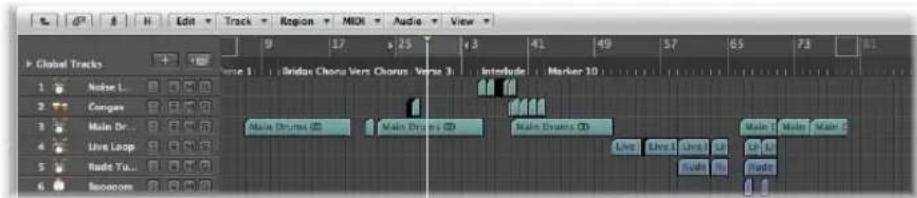
All regions in the folder are routed to, and played by, the channel strips set in the folder's track list—as they would at the top level of the Arrange window.
Note: If you drag a folder to a track that is set to an instrument channel strip, its entire contents (all MIDI regions within the folder) are played by this instrument. This usually only makes sense if the folder contains tracks for a given instrument or instrument type, such as a drum kit or generic string sound. This could be a quick way of listening to a string arrangement, if some of the intended sound sources are unavailable, for example.
As examples; a brass section folder could contain trumpet, saxophone, and trombone tracks, or perhaps 14 tracks of drum instruments, which you may want to treat as a single drum pattern region.
In the same way, your entire project, including all tracks and regions, could itself be a folder, appearing as a gray beam in an arrangement. In this way, you could arrange several projects for a concert.
This is not all that folders can do. You can use folders to represent song choruses and verses, for example. As in the Finder, you can place as many folders as you like within other folders, and within yet more folders (for the instrument groups within the different parts of the song, as an example), with no limit to the number of levels you can create.
Another possible use might be to store different arrangements of a project in different folders, allowing you to switch between them rapidly.
Packing and Unpacking Folders
You can pack selected regions into a folder, or create an empty folder and add regions to it.
To pack selected regions into a folder:
1 Select the desired regions.
2 Choose Region > Folder > Pack Folder (or use the corresponding key command, default: Command-F).
This places all selected regions into a folder. Logic Express creates a track, and places the folder region on it. If an existing folder track is selected, Logic Express copies the regions into this folder.
If no region is selected, Logic Express creates an empty folder. It contains no regions—just tracks assigned to all channel strips from the current level.
To unpack a folder:
1 Select the folder.
2 Choose one of the following commands:
- Choose Region > Folder > Unpack Folder command. The Arrange window will update to display the contents (the tracks and regions) of the folder.
- Choose Region > Folder > Unpack Folders (Create New Tracks), or use the corresponding key command.
Logic Express will create new tracks on the same level that the folder was located on (below the former folder track).
- Choose Region > Folder > Unpack Folders (Use existing tracks).
The regions contained within it are placed on tracks assigned to appropriate channel strips.
Entering and Exiting Folders
Once you have packed a folder, you will generally enter and exit it to alter data, as your arrangement grows. You can easily differentiate when inside, or outside of the folder display in the Arrange window:
- When at the top Arrange level (outside the folder), the folder itself will be visible on a track, the Arrange window title bar will show the project name, and the Hierarchy button is grayed out.
- When inside a folder, the folder track can't be seen, the Arrange title bar will show the project name, followed by the folder name (Untitled: Chorus Folder, for example), and the Hierarchy button will not be grayed out.
To enter a folder, do one of the following:
■ Double-click the folder region.
- Select the folder you want to enter, then use the Go Into Folder or Region key command.
You should ensure that the folder is selected before using the command. If a MIDI region is selected, the Event List editor (showing the MIDI region content) is opened.
Double-clicking on a folder track name in the track list opens the Mixer.
To exit a folder, do one of the following:
- Double-click on the (folder) Arrange area background (or use the Go Out of Folder or Region key command).
- Click the Hierarchy button at the left end of the Arrange window menu bar. The help tag shows Leave Folder.
This will move you one level up the display hierarchy, and the contents of the Arrange window (showing the closed folder) will be visible.
Adding and Removing Regions
You can easily add regions to, or remove regions from, an existing folder. This is fairly commonplace as you will often experiment with your arrangement, and find that you need to add or remove parts.
To move regions into a folder:
- At the top level of the Arrange hierarchy (outside the folder): Drag the desired regions onto the folder, at the desired position.
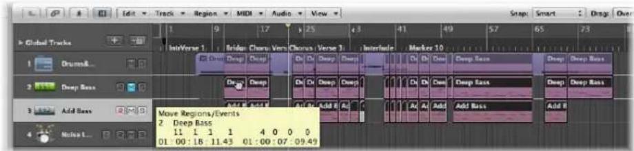
If the folder does not already contain a track that uses the same channel as the source region, Logic Express creates one. If it does, this channel will be used. When you enter the folder, you will see the dragged regions at the drop position.
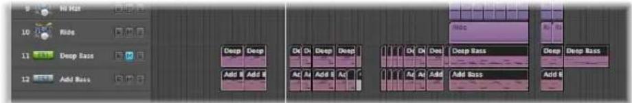
To drag individual regions out of folders:
1 Open a second Arrange window from the Window menu, or with the default key command: Command-1.
2 Enter the folder that you want to remove the region from in one of the two Arrange areas.
3 Drag the region from the folder into the other Arrange area.
You can also cut a region from a folder, using the Edit > Cut command. This transfers the region to the Clipboard. You can then copy the region to the desired Arrange Arrange area position using the Edit > Paste command.
Creating an Alias Folder
You can create a copy of a folder that contains aliases and clones of the regions in the original folder. The advantage is that, within this folder, you can (for example) mute regions, and alter program, instrument, or playback parameters, as desired. This provides you with an alternate mix folder—don't forget that folders can be muted and soloed, like other regions—allowing you to quickly switch between different arrangement versions.
To create an alias folder:
1 Select a folder.
2 Choose MIDI > Alias > Make but Copy Folder.
Creating Crossfades and Fades on Audio Regions
You will often create fade ins or fade outs on audio regions, or use crossfades to smoothly segue between two adjacent (or overlapping) audio regions on a track.
The latter type of fade, the crossfade, can be performed automatically on overlapping audio regions by Logic Express.
To enable automatic crossfades:
- Simply choose the X-Fade setting in the Drag menu (see "Using Drag Modes" on page 311).
The other fade types—fade ins and fade outs—as well as crossfades can be manually created with the Crossfade tool, or the Fade parameters in the Region Parameter box of the Inspector.
Tip: You should make use of both methods, as each has advantages. When combined, the process of creating and editing fades is quicker and easier.
You can simultaneously adjust the fade parameters for all selected audio regions.
Note: These fade parameters are non-destructive (they don't change the original audio file), as opposed to the fade functions available in the Sample Editor.
Creating Fades With the Fade Tool
As you'd perhaps expect, a fade in starts at the beginning, and a fade out occurs at the end of an audio region. Fades are only visible if you are sufficiently zoomed in to see the waveform in the audio region.
Important: You can not create fades on Apple Loop files, represented as regions in the Arrange window. In fact, the Fade parameters are not shown in the Inspector when an Apple Loop region is selected.
To create a fade in or fade out:
1 Select the Crossfade tool.
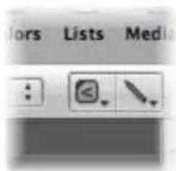
2 Click-drag over the start or end point of an audio region.
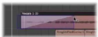
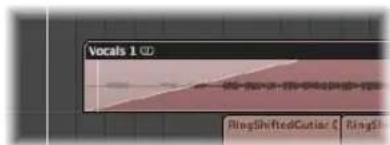
This creates a fade in or fade out. The length of the fade drag area determines the length of the fade, so a longer drag area will result in a longer fade time, and a shorter drag area, a quick fade.
To create a crossfade between two files:
- Drag over the end point of one audio region, or the start point of the following region with the Crossfade tool.
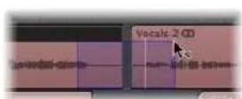
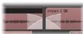
This works, even if the two sections don't directly adjoin each other.
To delete a fade:
- Option-click on an existing fade area with the Crossfade tool.
To change an existing fade:
- Simply drag over the start or end point of a region with the Crossfade tool. The curve shape (see below) of the previous fade is retained.
To adjust the fade curve shape:
- Hold Control and Shift while using the Crossfade tool.
In the example below, a positive Curve is shown for both the fade in and fade out.
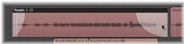
In the example below, a negative Curve is shown for the fade in, and a linear fade (no curve) is shown for the fade out.
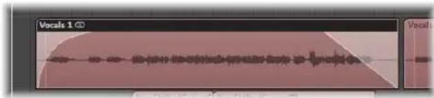
Creating and Modifying Fades in the Region Parameter Box
You can also create and edit fades in the Region Parameter box.
To create a fade or crossfade:
1 Select the desired regions.
2 Set the desired value for the Fade In or Fade Out setting in the Inspector. Use the mouse as a slider, or double-click and type in the desired value.
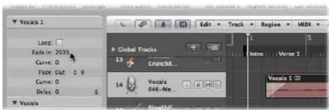
As you do so, a fade is created at the beginning or end of the selected regions.
Note: The fade value determines the length of the fade, so a higher value results in a longer fade time, and a low value, a short fade.
To delete a fade:
■ Set the Fade In or Fade Out parameter to 0.
To change an existing fade:
■ Edit the Fade In or Fade Out value.
To adjust the fade curve shape:
■ Edit the Curve value in the Region Parameter box.
The fade curve is instantly reflected in the region.
Changing the Fade Type
If you click the Fade Type menu (the up/down arrow beside the Fade parameter in the Inspector), you'll see four options:
- Out (default): Creates a standard fade out whenever the Fade tool or Fade parameter is used.
- X: Crossfades the selected region with the following region when you use the Fade tool or Fade parameter.
- EqP: Results in an Equal Power crossfade. This minimizes volume dips between audio regions, resulting in a more even crossfade between regions that may be slightly different in level.
- X S: Delivers an S-curve crossfade. The fade curve, as the name suggests, is S shaped.
Note: The latter three options can only be applied to two consecutive regions.
You should also note that the Fade In (and corresponding Curve) parameters are made redundant when any of the X, EqP, or X S options is chosen.
Deleting Fade Files
Use of the Options > Audio > Delete All Fade File command deletes the fade file. No information will be lost by doing this, because Logic Express automatically creates a new fade file the next time playback is started, based on the fade parameters of each audio region.
Fading Apple Loops
Apple Loops do not support fades, so you can't directly assign a fade to them. As you can't apply fades to an Apple Loop, no fade parameters are displayed in the Region Parameter box when an Apple Loop is selected.
If you'd like to achieve a fade effect, you need to export the Apple Loop (choose File > Export > Region as Audio file in the main menu bar). Import this file into the Arrange area and apply the fade to it.
Setting Region Parameters
The parameters displayed in the Inspector's Region Parameter box depend on the region type selected in the Arrange area. There are parameters that are:
• Available for audio and MIDI regions.
- Only available for audio regions.
- Only available for MIDI regions.
Note: The MIDI region parameters also apply to folders, and globally affect all MIDI regions within them.
Common Audio and MIDI Region Parameters
There are only two common parameter which are available when either audio or MIDI regions are selected.
Loop
The playback of all region types can be continuously repeated by activating the Loop checkbox, or through use of the Loop tool (see "Looping Regions" on page 344).
Delay
The playback of all region types can be delayed or advanced (this can be a positive or negative value) by ticks, or a musical format variable. As examples: 1/96, 1/16, 1/192, and so on (for more information, see "Shifting the Playback Position of Regions" on page 327).
There are also some default behaviors of the Region Parameter box:
MIDI Thru: MIDI Region Defaults
If no region is selected, the upper line of the Region Parameter box will display MIDI Thru. Any live MIDI input (in stop mode, as well as during recording or playback) will be played with the settings chosen here. When you record a new MIDI region, the settings in the MIDI Thru Parameter box are carried across to the new MIDI region's Parameter box. The MIDI Thru Parameter box can be viewed as an adjustable default Parameter box.
The MIDI Thru parameters can be adjusted when no regions are selected. Click on the Arrange window background to deselect all regions.
Note: The Set Track & MIDI Thru Parameters by Region/Folder key command allows you to set the MIDI Thru parameters to match those of a selected MIDI region. This action also selects the region's track.
Editing Several Regions Simultaneously
If several regions are selected, the number of selected regions is displayed, in place of a region name. If you alter any region parameter, all selected regions will be affected. If a given parameter is set differently in the individual regions, a * appears in the Parameter field. You can alter this parameter for all selected regions, and the value differential will be retained (relative alteration). If you want to set all selected regions to the same value, hold down Option while changing the value (absolute alteration).
Audio Region Parameters
Audio region parameters vary, dependent on the type of audio region selected: basically this is broken down into Apple Loops or standard audio regions.
The Fade parameters are only available when standard audio regions are selected.
When Apple Loops (either green or blue) are added to audio tracks, the Follow Tempo and Transposition parameters are shown.
Follow Tempo
This parameter (on by default) allows Apple Loops to follow the project tempo.
Transposition
This parameter adjusts the pitch of the Apple Loop audio region up or down by the chosen amount.
MIDI Region Parameters
If you select a MIDI region (on a software or external MIDI track), the Region Parameter box displays the following MIDI region specific parameters.
These parameters are also shown when a green Software Instrument Apple Loop is added to a track routed to an instrument channel (the Apple Loop instrument is loaded into the Instrument slot of the channel strip).
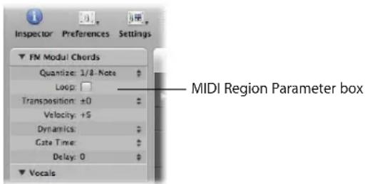
Quantize
All note events contained in the MIDI region are time corrected to the (quantize) grid format chosen in the menu. Full details on all quantization functions available in Logic Express are found in Chapter 19, "Quantizing MIDI Events," on page 477.
Transposition
All note events contained in the MIDI region are transposed up or down by the selected amount during playback. Even complete folders can be instantly transposed in this way. If several individual MIDI regions within the folder have already been transposed, the relative differences between them are retained.
If you want to transpose by octaves, click on the arrows to the right of the Transposition parameter. This opens a pop-up menu that allows direct octave transpositions.
To guard against drum notes, and so on being transposed, an instrument channel's Parameter box contains a No Transpose checkbox. If you activate this option, the transpose parameter is ignored in all MIDI regions played by this instrument channel strip (including green Apple Loops added to tracks routed to instrument channels).
Velocity
All notes in the relevant MIDI region are offset by the selected value. Positive values add to the originally recorded velocity, and negative ones subtract from it, although naturally it is impossible to go outside the limits defined by the MIDI Standard (0–127). If you select a velocity offset that exceeds the maximum or minimum possible value for a particular note, that note will play at the extreme possible range. As an example, a setting of +20 will cause a note with a velocity of 120 to play at 127.
Dynamics
This parameter also affects the velocity values of notes, but instead of adding or subtracting a fixed amount, the differences between soft and loud notes (the dynamics) are increased or decreased. This works in a similar way to a compressor or expander. Values above 100% expand the dynamics, thereby increasing the difference between loud and soft, while values below 100% compress the dynamics, reducing the differences between loud and soft.
The Fixed setting causes all notes to be transmitted at a velocity value of 64. When used in conjunction with the Velocity parameter (see above), it is possible to set any fixed velocity value.
Gate Time
The term gate time stems from the technology used in analog synthesizers, and refers to the time between pressing and releasing a key. This parameter affects the absolute note duration or length. This should not be confused with the musical note value, which normally refers to the amount of time until the next note. The practical effect is to make the notes in the region more staccato or legato. The parameter range is related to the original note lengths. Fix produces extreme staccato. Values below 100% shorten the note lengths. Values above 100% lengthen the notes. The “legato” setting produces a completely legato effect for all notes, no matter what their original lengths, eliminating all space between notes in the affected region. If this is used on a folder, all notes in all MIDI regions in the folder will be affected.
Fixing MIDI Region Parameters
You can normalize the MIDI region parameter settings of all selected MIDI regions and folders with the MIDI > Region Parameters > Normalize Region Parameters command.
This means that all settings are actually written as data, and playback parameters revert to normal values. The audible result remains the same. The Loop parameter and extended MIDI region parameters are not affected. Use of this function is effectively like saying “make these MIDI region/instrument parameter values permanent.” In most circumstances, it is better not to do this, as leaving the original data untouched provides more flexibility. This includes unlimited opportunities to change your mind about MIDI region edits.
Normalize and MIDI Channels
As per the Merge function or the Glue tool, the Normalize function is intelligent in the way it handles stored MIDI channel numbers. If all stored events have the same MIDI channel number, the channel will be changed to that of the Instrument assigned to the current track. If the events are on different channels, Logic Express will ask whether or not you would like to convert the event channels.
The following Normalize options are also available in the MIDI > Region Parameters menu:
- Normalize without Channel: Leaves the stored channel number untouched.
- Normalize without Channel & Delay: Leaves the stored channel number and Delay parameters untouched.
If the playback Instrument has a channel setting of All, or you're dealing with a completely different type of Environment object (a channel splitter used as A-Playback for example), the stored MIDI channel numbers are also unaffected by the usual Normalize function.
Note: If you're editing MIDI regions that appear as notation on a polyphonic staff style, it is recommend to use the Normalize without Channel function, as the event channel is used to assign notes to individual polyphonic voices in the Score Editor.
Recording in Logic Express
14
This chapter covers all aspects of audio and MIDI recording in Logic Express.
You will learn how to set up Logic Express for audio and MIDI recording, and how to make use of several workflow features. These include cycle, multiple take, and punch recording methods.
Recording Audio
This section covers all information related to audio recording. Given the similarities in recording methods and region handling for both audio and MIDI data, many of the general audio recording techniques may also apply to MIDI recordings. MIDI-specific recording information is covered in "Recording MIDI", from page 396 onwards.
A Quick Overview of the Recording Steps
The basic steps required to create an audio recording are listed below. Detailed descriptions of each step follow the overview.
To create an audio recording:
1 Check the setup of your recording system (see the ensuing section) to ensure that your hardware and software are communicating correctly.
2 In the Arrange track list: Select the name of the audio track that you want to record to. The corresponding channel strip is shown in the Inspector.
3 Set the desired channel strip format.
4 Click-hold the Input slot of the channel strip, and choose the appropriate inputs of your audio interface from the pop-up menu.
5 Arm the track by clicking the Record Enable button.
6 Drag the Level fader of the armed channel to the desired position, to set the monitoring level.
Note: The Software Monitoring checkbox must be enabled in the Audio preferences to hear incoming audio through Logic Express (whether you are recording or not).
7 Click the Record button on the Transport, and start playing or singing.
8 Press Stop to end recording.
Preparations for Recording
You should check the setup of your system prior to recording.
Make sure that any sound source you plan to use in your recording session—a mixer, CD player, or microphone, for example—is connected to the audio inputs of your system, and is working correctly.
Check the hardware settings that are important for recording—such as the I/O buffer setting. Please refer to "Configuring Your Audio Hardware" on page 99 for details.
The quality, or precision, of the recorded audio file is directly tied to the sample rate and bit depth (and the quality of the converters in the audio hardware). All audio files are recorded at the project's sample rate. You should ensure that the chosen sample rate (see below) fits your needs.
You should also ensure that the preferred file type (AIFF, WAV, SDII, CAF) is chosen in the Recording File Type menu of the Logic Express > Preferences > Audio > General preferences.
When you record audio into Logic Express, the following happens:
- An audio file is created on the hard disk.
- An audio region, which represents the entire recorded audio file, is automatically created on the selected Arrange track.
- The audio file (and region) are added to the Audio Bin. The audio file will also appear in the Browser.
Setting the Sample Rate
You should set the sample rate when you start a project, and should avoid making changes to this after-the-fact.
Note: Any audio that does not match the project sample rate is automatically converted when it is imported, if the "Convert audio file sample rate" option in the Assets project settings is switched on.
To set a project's sample rate, do one of the following:
- Choose File > Project Settings > Audio (or use the Open Audio Project Settings key command), and choose the desired sample rate in the Sample Rate menu.
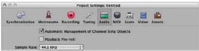
- Click the Sample Rate display in the Transport bar, and choose the desired sample rate from the pop-up menu.
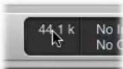
If you can't see the Sample Rate display, this is probably because it has been replaced with the punch locators. Disable the Cycle button on the Transport bar to view the Sample Rate display. Another possibility is that you have not switched on the Sample Rate or Punch Locators checkbox in the Customize Transport Bar dialog.
The Importance of the Sample Rate
Digital audio plays at a different speed when played at a non-matching sample rate. Digital audio needs to play at its original sample rate, or be converted to a different one, before playback at another sample rate. To explain; when a file which was created by sampling 96,000 times per second (96 kHz sampling rate), is played back at a rate of 48,000 samples per second, it will play back slowly (half the speed).
In general, any bounces created for use within a project should be at the project's original sample rate. You will gain nothing by bouncing at 96 kHz but then importing and converting to 44.1 kHz.
When finished with your project, bounce it at the desired sample rate. As suggestions for different situations:
- If the bounced file is destined for an audio CD (assuming you're not sending it to an external studio or application for mastering), there's no need to go any higher than 44.1 kHz, as this is the standard CD sampling rate.
- If you work in the film or television industry, you will probably use the 48 kHz sampling rate for audio.
- If recording classical or jazz groups (smaller ensembles), or archiving 75 year old recordings, you may find some benefits to recording at 96kHz or higher.
Playback of 96 kHz (or higher rate) audio files places a far greater throughput burden on your system, and uses much more hard disk space. Recording at a 44.1 kHz sampling rate and 24 bit depth is recommended for most situations.
Setting the Bit Depth
Logic Express defaults to 16 bit audio file recording. If you have suitable audio hardware, 24 bit recordings offer a significant improvement in the available dynamic range. 24 bit files use one and a half times the disk space of comparable 16 bit files.
If you require 24 bit recording:
1 Open the Audio preferences by doing one of the following:
- Choose Logic Express > Preferences > Audio (or use the Open Audio Preferences key command).
- Click the Preferences button in the Arrange Toolbar, then choose the Audio command.
2 Click the Devices tab, then click the Core Audio tab.
3 Turn on the 24 Bit Recording option.
Setting Up the Metronome
If you would like to hear the metronome (click) while recording, you can set this up in the Metronome project settings.
To open the Metronome project settings, do one of the following:
- Choose File > Project Settings > Metronome (or use the Open Metronome Project Settings key command).
- Click the Settings button in the Arrange Toolbar, and choose Metronome from the pop-up menu.
■ Control-click the Metronome button in the Transport, and choose Metronome Settings from the pop-up menu.
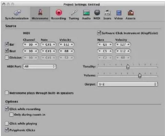
The Metronome Project Settings window combines all settings for:
- A software instrument metronome sound source called KlopfGeist, which is turned on by default. You can disable it with the Software Click Instrument (KlopfGeist) checkbox.
- The Environment's MIDI Click object (see "MIDI Click Object" on page 932). You can specify the MIDI Port it is sent to (All, by default). To turn off the MIDI metronome output, choose Off in the MIDI Port pop-up menu.
You can use these click sources in isolation, or in combination with each other.
KlopfGeist is a software instrument found in the Plug-in menu of Instrument slots. KlopfGeist is inserted into instrument channel 128, by default. Logic Express will automatically create instrument channel 128 (with KlopfGeist inserted) when the KlopfGeist checkbox is turned on. Theoretically, any other Logic Express or third-party instrument could be deployed as a metronome sound source—using instrument channel 128. For more information about the KlopfGeist instrument, please refer to the Instruments and Effects manual.
To set up the metronome for recording:
1 Define when you want to hear the metronome click: on every bar, beat, or division by activating the corresponding (Bar, Beat, and Division) checkboxes.
2 Turn on the "Click while recording" option (it is active by default). Also set the "Only during count-in" and "Click while playing" options to meet your needs. It is suggested that you leave the Polyphonic Clicks option enabled, as this allows for overlapping clicks.
3 Click the Recording button at the top of the Project Settings window, to open the Recording project settings.
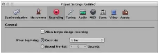
4 Enable the Count-in radio button (active by default).
5 Choose the desired count-in period that will precede recording. These options are available in the pop-up menu.
- None: The recording begins with no count-in.
- x Bars: X bars of count-in.
- x/4 : The count-in time signature may be set here. These settings are useful when the count-in (and, presumably the recording) falls across a bar line.
For more information on the Metronome project settings, please see "Metronome Settings" on page 963.
Using Software Monitoring
The Software Monitoring function allows you to monitor incoming audio through any effects plug-ins that are inserted into an armed audio channel. Audio inputs must be assigned on the record-enabled tracks for software monitoring functionality.
The effect plug-ins are monitored but not recorded. This can be useful during a recording session. As an example: During vocal recording, many singers prefer hearing their performance with a little reverb, but the track is recorded dry (without effects).
To monitor a track with effect plug-ins during recording:
1 Turn on the Logic Express > Preferences > Audio > Devices > Core Audio > Software Monitoring option.
Note: No monitoring of any kind will occur if this option is switched off for the currently active audio hardware.
2 Insert the desired effect into the audio channel, arm the track, and start recording.
The effect will be part of the monitor mix, but will not be recorded.
Auto Input Monitoring
If Auto Input Monitoring is switched on, you will only hear the input signal during the actual recording—before and afterwards, you'll hear the previously recorded audio on the track, while the sequencer is running. This helps you to judge punch in and punch out points when punch recording. If Auto Input Monitoring is switched off, you will always hear the input signal. Auto Input Monitoring, when switched on, also allows you to hear the input source when Logic Express is stopped, making it easy to set levels.
To switch auto input monitoring on, do one of the following:
- Choose Options > Audio > Auto Input Monitoring from the main menu bar (or use the Toggle Auto Input Monitoring key command).
■ Control-click the Record button in the Transport, and turn on the Auto Input Monitoring setting in the pop-up menu.
There are a couple of circumstances that can be problematic when using auto input monitoring with record-enabled tracks:
- Singers cannot hear themselves while Logic Express is in play or record mode. All they can hear is the old recording. Switch off Auto Input Monitoring in this situation.
- The track cannot be heard, even though Logic Express is not in record mode. Switch on Auto Input Monitoring to hear audio on the track.
Depending on the situation, both options can be useful. Normally, Auto Input Monitoring will be turned on, and only switched off in specific circumstances.
Using the Input Monitoring Buttons
You can use the Input Monitoring buttons to monitor audio tracks that are not armed. Simply enable the Input Monitoring button on an audio track (or channel strip in the Arrange or Mixer windows). This works when Logic Express is stopped or playing.
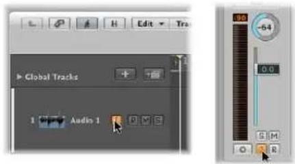
To determine what signal (input) is monitored:
- Choose the appropriate input (or input pair) from the Input slot menu of the corresponding audio channel strip.
Tip: As a general workflow tip, you can leave the Input Monitoring button turned on, before, after, and during recording. When the Input Monitoring button is switched on, the Record Enable button or Auto Input Monitoring facility do not affect software monitoring. When punch recording, however, you should use the Auto Input Monitoring function rather than the Input Monitoring buttons.
Possible Problems With Input Monitoring
You should note that input monitoring always involves a little latency. Latency is entirely dependent on the audio hardware's capabilities, and driver settings. In certain configurations, you may be best served by not monitoring through Logic Express at all, thus obtaining the best possible timing. Route the signal that you want to record directly to headphones or the monitoring amplifier for monitoring purposes (and to the audio interface inputs, for recording). You won't accidentally overdrive your A/D converters, as the input level meters of Logic Express will display a clip warning if an overload occurs.
Setting the Monitoring Level
If the Independent Monitoring Level (for Record Enabled Channel Strips) preference in the Logic Express > Preferences > Audio > Devices > Core Audio tab is enabled, an independent monitoring level is available when an audio channel is record enabled. After arming the track, set the fader to the desired level. The original playback level will be restored when the channel's Record button is disabled.
Important: The Level fader only controls the playback (or monitoring) level, not the recording level, when a track is record enabled. Recording levels must be set externally—on your mixer, or at the original sound source. Care must be taken when setting input levels, as digital audio will clip when overloaded. Clipping results in a particularly harsh, metallic distortion, so unless you have a penchant for heavier musical styles, overloading the inputs isn't recommended (see "Understanding the Clip Detector" on page 578)!
Setting the Recording Folder
You should define a target (on your hard disks) for audio data before recording.
Note: If you save your project with its assets, Logic Express saves your project file (the "song") into a project folder. The project folder contains an automatically created "Audio Files" folder—which is used as the default recording folder.
If you prefer to save your projects without assets, however, the following section will be of interest.
You can set a different "recording" folder for each project. You define the recording folder in the Recording project settings.
To define the recording folder:
1 Open the Recording project settings by doing one of the following:
- Choose File > Project Settings > Recording (or use the Open Recording Project Settings key command).
- Click the Settings button in the Arrange Toolbar, and choose Recording from the pop-up menu.
- Control-click the Record button, and choose Recording Settings from the pop-up menu.
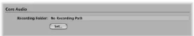
2 Click the Set button to open a file selector, and browse to the desired recording folder.
Maximum Recording Size
The AIFF and SDII file formats can not handle audio file recordings larger than 2 GB. For 16 bit, 44.1 kHz stereo files, this equals a recording time of about 3 hours and 15 minutes.
The WAV file format can not handle audio file recordings larger than 4 GB. For 16 bit, 44.1 kHz stereo files, this equals a recording time of about 6 hours and 30 minutes.
If the size of your recording will exceed these limits, you should choose CAF as the recording file type. CAF can handle the following recording times:
- About 13 hours and 30 minutes at 44.1 kHz
- About 6 hours at 96 kHz
- About 3 hours at 192kHz
The bit depth and channel format (mono or stereo) do not affect the maximum recording size of CAF files.
You can define the preferred file type in the Recording File Type menu of the Logic Express > Preferences > Audio > General preferences.
Audio Recording Names
The track name is used as the default file name for a recording. Subsequent recordings made on this track will be assigned an ascending numerical suffix. "Audio 1" will be named "Audio 1_01", "Audio 1_02", and so on. If the track is not named, the name of the channel strip that the track is routed to will be used. You can rename tracks in the Arrange track list and Mixer windows (see "Naming Tracks" on page 199 and "Renaming Tracks in the Mixer Window" on page 601).
Setting Up Track Channels
If you want to make adjustments to audio channel strips, you can do it directly in the Arrange channel strip. You can also use the Mixer window to adjust channel strip settings. Full details in "Setting Channel Strip Levels" on page 576.
Making Mono or Stereo Recordings
Logic Express allows you to make mono or stereo recordings.
To switch the recording format of a channel:
- Click-hold the Format button of the channel strip, and choose the desired format from the pop-up menu.
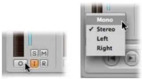
The symbol on the button indicates the current status as follows:
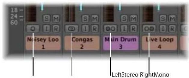
- Mono: One circle represents a mono input format. The level meter shows a single column.
- Stereo: Two, interlocked circles represents a stereo input format. The level meter divides into two independent columns when a stereo input format is chosen.
- Left: Two circles, left one filled, indicates a left channel input format. When this input format is chosen, only the left channel of a stereo audio file is played back. The level meter shows a single column.
- Right: Two circles, right one filled, indicates a right channel input format. When this input format is chosen, only the right channel of a stereo audio file is played back. The level meter shows a single column.
Enabling One or More Tracks for Recording
Audio tracks must be manually record-enabled (armed) before recording, just as you would with tracks on a tape recorder. The Record Enable button turns red to indicate this armed state.
You can only make audio recordings on armed tracks, irrespective of which track name is selected in the Arrange track list.
If several Arrange tracks are routed to the same channel strip ("Audio 1", for example), the new audio file will be recorded to the selected track (routed to "Audio 1"). If none are selected, audio will be recorded to the first (top) of these tracks.
Space is reserved on the hard disk for armed tracks, and will no longer be available for Undo files. For this reason, Logic Express will automatically disarm audio tracks when editing in the Sample Editor, or if the hard disk is nearly full.
Important: You can only activate the Record Enable buttons of audio tracks that have a unique input. Simultaneous arming of multiple tracks that use the same input (selected in the Input slot) is not possible.
To enable one or more audio tracks for recording, do one of the following:
- Click the Record Enable button on the desired track (or tracks) in the track list.
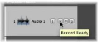
- Click the Record Enable button of all track channels (in the Mixer) that you wish to record to.
- Select the desired track (or tracks) in the Arrange area and use the Record Enable Track key command.
Note: If these buttons are not visible in the track list, choose View > Configure Track Header. In the dialog, click the Record Enable checkbox. If this checkbox is active, but the switch is still not visible, you should activate the relevant audio hardware in Logic Express > Preferences > Audio > Audio Hardware & Drivers.
To disable a record enabled track:
- Click the (illuminated) Record Enable button a second time in either the track list or Mixer.
To disarm all record enabled tracks:
- Option-click on the flashing Record Enable button of any record-enabled track channel.
Enabling Simultaneous MIDI and Audio Track Recording
There may be occasions where you want to simultaneously record audio and MIDI tracks—perhaps to capture a live band recording, with the keyboard player using one or more Logic Express software instruments.
You can simultaneously record to multiple MIDI tracks and several audio tracks (see "Recording on Multiple MIDI Tracks" on page 400).
Note: You can only activate the Record Enable buttons of audio tracks that have a unique input. Simultaneous arming of multiple tracks that use the same input (selected in the Input slot) is not possible.
To enable multiple audio and MIDI tracks for recording:
1 Click the Record Enable button on the audio tracks you want to record to.
2 Click the Record Enable buttons of the MIDI tracks.
Making an Audio Recording
Logic Express offers several recording modes or methods, that are suited to different recording situations and tasks. These are:
- Standard recording: Arm a track and click the Transport bar's Record button.
- Take recording: Much like standard recording, but multiple recordings over the same section of a single track are automatically packed into "take folders."
- Punch recording: You can manually or automatically "punch-in" and "punch out" at particular project positions, allowing you to record over an existing region.
- Replace recording: Generally combined with punch recording mode, where the new recording replaces the original recording (or a portion of it).
All recording modes can work in conjunction with Cycle mode, allowing you to record over a continuously repeated section of your project.
Standard Recording With a Count-in
You can start recording at any point in a project by setting the playhead to the desired location. Presuming that the recording tracks are correctly set up (the desired audio hardware inputs are connected, adjusted, and selected as the input source on the channel), and the track is armed:
To start recording:
- Click the Record button on the Transport or (or use the Record key command, default: *).
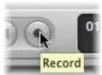
The count-in x defined in File > Project Settings > Recording is heard. Any audio present during the count-in will be recorded. During recording, a progress indicator displays the remaining recording time and the elapsed time.
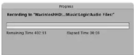
To stop recording:
- Click the Stop button on the Transport.
Logic Express will automatically create an audio region in the Arrange area, and will create an overview of the audio file. This is a graphic file that is used to display the waveform. You can play the new recording while the overview is being created.
Note: If you paused recording (by pressing the Pause button), you can resume the recording by clicking the Record, Pause, or Play button. Recording begins at the current playhead position.
Advanced Recording Commands
Several advanced recording commands can make the recording process much faster. You should take advantage of these, as applicable, during your recording sessions.
- Record: The (default) Record command initiates recording. When used while recording, it does nothing, and recording continues. You will need to press Stop to end the recording (default key command: Asterisk key on numeric key pad).
- Record/Record Toggle: When used while recording, recording is temporarily suspended, but playback continues. Use this command again, to resume recording from the current playhead position.
- Record/Record Repeat: When used while recording, the running recording is deleted, the playhead is moved back to the (recording) start position, and a new recording begins immediately.
- Discard Recording and Return to Last Play Position: This key command discards the running recording, deletes the corresponding files from the Audio Bin, and moves the playhead back to the last play position (default key command: Command-Period).
It differs from Record/Record Repeat in that it doesn't automatically start a new recording immediately. This allows talkback communication while Logic Express is stopped. You will need to manually start a new recording (with any "Record" command).
Configuring the Transport Bar's Record Button
You can change the Transport bar's Record button functionality from Record (default) to Record Toggle, or Record Repeat.
To configure the Transport bar's Record button:
■ Control-click the Record button, and choose the desired option from the menu.

The active command is indicated by a checkmark.
Recording Takes
Logic Express provides advanced take management facilities. A take is a part (a guitar solo, for example) that is performed and recorded multiple times. You can record several consecutive versions of a solo, and pick the best take, for example. Takes are usually created by recording in Cycle mode, but can also be created by simply recording over existing regions.
Takes also form the basis for comping tasks, where the best performances (from several takes) are compiled into a single "super take". This comp(ilation) will be used as the final version of your take. Full details on comping are found in "Creating Comps" on page 391.
The preparation for take recording is identical to that for audio recording. No special setup is required, so you can start take recording as you would for any audio recording. See "Standard Recording With a Count-in" on page 380.
The first take appears as an audio region, as per usual. Once a recording takes place over an existing region (the second pass of a cycle recording ends, and the third cycle begins, or you manually stop recording after the first bar, for example), a take folder is created.
• The whole recording (all takes) is stored as a single audio file.
- The take folder only occupies a single track (but it can be opened, more on this shortly).
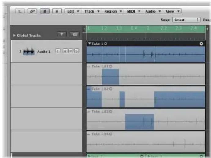
Note: Take folders are only created when Replace mode is disabled (which is the default).
How Take Folder Recording Works
This section outlines how takes are handled in different recording circumstances.
Recording Over a Region
When you record over an existing region, a take folder is created—the longer of the two regions determines the take folder size.
When cycle recording:
- Manually stopping a recording inside the first bar of a cycle repeat (a four bar recording is stopped half-way through bar one, on the fourth pass of a cycle recording, as an example) will result in this small section being discarded.
Logic Express assumes you stopped recording a little late, and views this as an "accidental" recording. - Manually stopping a recording after the first bar of a cycle repeat (a four bar recording is stopped half-way through bar two, on the fourth pass of a cycle recording, as an example) will automatically create a "comp" consisting of the last take and the second last take.
Note: Take recordings that are longer than one bar, but not the full length of the take folder (or region) are automatically "comped."
Recording Over a Take Folder
When you record over an existing take folder, the new recording is added to the take folder (and selected for playback).
- If the new recording starts earlier or ends later, the take folder extends to match its size.
- If the new recording starts later or ends earlier, a new comp is created, consisting of the former take or comp, supplemented by the new recording.
Recording Over Multiple Take Folders
When recording over multiple existing take folders—placed one after the other on a track lane—the new recording is split at the beginning of each take folder (after the first take).
• Each section will be assigned as a new take in each take folder.
- Earlier take folders are extended in length until they reach the start point of the ensuing take folder (if there is a gap between take folders).
Adding Existing Recordings to Take Folders
While not a recording function per-se, you can also drag and drop other recordings (regions or audio files) onto an existing take folder:
- If the dragged region is of the same length as the take folder, it will be added as a new take. The new region will be selected for playback.
- If the dragged region is longer than the take folder, the take folder is resized. The new region will be selected for playback.
- If the dragged region is shorter than the take folder, a new comp will be created. The new comp consists of the former take or comp, supplemented by the new region.
Important: Take folders are only created when a recording has been made. If you attempt to drag a region onto another region that was originally imported (not recorded), this will not create a take folder. You can, however, "pack" a take folder from any selected regions—recorded or imported (see "Packing a Take Folder" on page 395).
Viewing the Contents of the Take Folder
You may need to access the contents of the take folder during take recording (to delete a take, for example).
To open a take folder, do one of the following:
- Click the disclosure triangle on the upper left corner of a take folder.
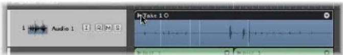
■ Double-click the take folder.
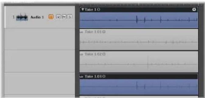
The contents of the take folder will be displayed on temporary Arrange track sub lanes—below the take folder itself. The most recently completed (or nearly completed) take is selected by default. The selected take will be heard during playback.
To select different takes when viewing an open take folder:
- Click on the corresponding take header.
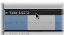
To select different takes when viewing a closed take folder:
- Choose the desired take from the Take menu, that opens when you click the arrow at the top right corner of the take folder.
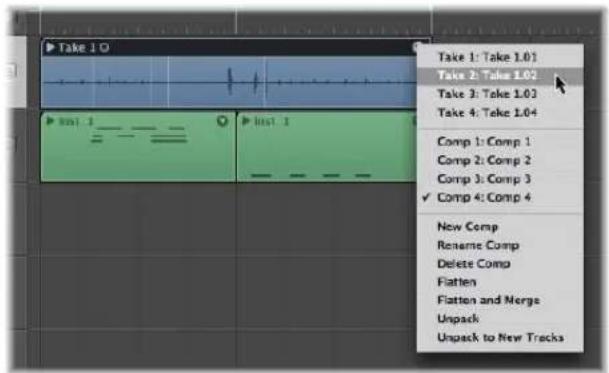
The waveform data of the selected take is displayed in the take folder.
Creating Comps in Real Time
You can mark good take sections while recording, resulting in a perfect comp immediately after recording has finished.
To mark a good take during recording:
■ Use the Select Previous Section for Realtime Comping key command.
This places a (non-visible) tag in the current take, at the position the key command was used. All audio that preceded use of the key command is tagged as a good take, which will be used in the final comp.
Multi Track Take Recording
Take recording (and comping) is also possible when recording multiple tracks.
Usually, the take folders on multiple tracks are edited independently, but they can be handled as a group. Simply add multiple tracks to an Edit Group (use the Group menu on the respective channel strips, and enable the Editing group property, see "Defining Group Settings" on page 588).
When grouped in this way, all take editing is synchronized between all member tracks. Any of the take folders can be opened, and any edits or comps performed in the open folder are immediately reflected in all other take folders at the same position (on tracks in the edit group).
Ideally, you should group tracks before recording, or at least before comping. You can, however, group tracks after editing one or two of them. This can be useful when a few take folder comps need special attention, but all following edits will be applied to all takes in the group.
Note: If you attempt to edit one of the (pre-group) edited tracks, Logic Express will offer to remove it from the edit group.
Coloring Takes While Recording
Selected take folders (or take regions in an open take folder) can be independently colored, as you would with standard regions or folders, when Logic Express is not recording.
When recording is taking place, however, changing the color of the take folder will color the take region (being recorded), not the folder!
Punch Recording
Punch recording is a term used to describe overwriting a portion of a previously recorded passage while Logic Express is running, in order to fix a mistake in an otherwise good recording. You "punch-in" just before the mistake, then "punch out" of the recording, once the mistake is corrected (you've recorded over it).
This allows you to play a recording up to a certain point, make a new recording over a section of the original, and continue playback in one continuous process. The ability to hear the part you want to replace (within the context of the music that precedes it) enables you to capture a better feel with your punch recording.
Logic Express offers two ways to punch record:
- You can use a key command to engage recording while in playback mode (this is commonly known as punching “on the fly”).
- You can use the Autopunch feature of Logic Express to start and stop recording at predefined punch-in and punch-out points.
Note: Only record-enabled tracks are affected by punch recording.
Punch on the Fly
The Punch on the Fly feature allows you to engage recording while in playback mode—in real time, or “on the fly.”
This function is technically difficult to perform for hard disk recorders, due to the unavoidable delay involved in switching between read and write modes (creating a file and so on). To avoid this delay, you need to switch on Punch on the Fly mode, which readies Logic Express for a recording at any time.
In practice, “recording” is happening in the background from the moment you start playback—when Punch on the Fly mode is active.
To punch in to a recorded passage on the fly:
1 Switch on the Punch on the Fly mode by doing one of the following:
- Control-click the Record button in the Transport, and switch on Punch on the Fly in the ensuing pop-up menu.
- Choose Options > Audio > Punch on the Fly in the main menu bar (or use the Toggle Punch on the Fly key command).
2 Start playback and use the Record Toggle key command at the point where you want to start recording.
Audio recording will start immediately. Recording can be halted at any time, by pressing Stop or by using the Record Toggle key command a second time. If you use the latter option, recording ends, but playback will continue.
Note: You can also use the Record Toggle key command when Logic Express is not in Punch on the Fly mode, but this will cause a delay when switching between playback and recording modes.
Pre-Programmed Punch-Recording
Autopunch describes the automatic activation and deactivation of recording at predefined positions. The advantage of the Autopunch function is that you can concentrate on your playing, rather than controlling Logic Express. Another advantage is that starting and stopping recordings can be set far more precisely than would be possible if you manually activated and deactivated record mode.
The Autopunch function can be used for audio, instrument, or MIDI tracks.
To record in Autopunch mode:
1 Turn on the Autopunch button in the Transport.
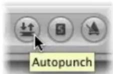
The left and right autopunch locators serve as punch-in and punch-out points. The Autopunch recording area is indicated by a red stripe in the middle third of the Bar ruler.
If both Cycle and Autopunch modes are active, you will see a pair of locators in the Autopunch area. Two stripes are shown in the Bar ruler; the top (green) one represents the Cycle area, and the bottom (red) one, the Autopunch area. These can be adjusted independently.
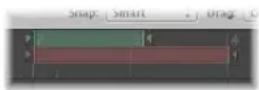
2 Set the Autopunch area by doing one of the following:
- Use the autopunch locator fields in the Transport to set the Autopunch area numerically. Please note that the Sample Rate or Punch Locators setting in the Customize Transport Bar dialog must be active, before you can see and set the Autopunch locators (to the right of the standard locators).
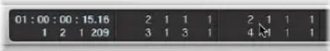
- Alter the Autopunch range graphically in the Bar ruler, just as you would with a cycle.
3 Place the playhead at any position before the punch-in point.
4 Start recording.
5 Stop recording.
A region that exactly matches the length of the autopunch stripe will be created. Any audio input received before the punch-in or after the punch-out points streams through Logic Express as per usual, but is not recorded.
Logic Express will begin recording about a bar before the punch-in locator. This allows the start point of the region to be adjusted later, enabling you to hear the lead-in, if desired.
You can also recover the beginning of the recording if the performer slightly anticipates the autopunch area. Any such adjustments to the lead-in portion of the region do not change the position of the recording, relative to the time axis of the project.
Recording automatically begins at the punch-in locator, following the count-in, even if the playhead is positioned after the right locator when recording starts.
If Autopunch is enabled during recording, the Record button will flash while the playhead is outside the area encompassed by the punch in/out locators. This indicates that no recording is currently taking place.
Combining Cycle and Autopunch Recording
If you want to improve a difficult part of a certain passage, you can use a combination of the Cycle and Autopunch functions. Cycle mode recording allows you to practice as many times as you like before performing the final take. On each cycle pass, only events or audio that falls within the autopunch stripe is recorded. This allows you to make use of the preceding song section to "get into the groove."
Recording With Skip Cycle
If Skip Cycle is switched on, the cycle area is bypassed during recording.
Replace Mode Recording
In Replace mode, newly recorded data is stored in a new region, as per a standard recording. In addition, any existing region on the destination track is cut at the punch in and out points of the recording, and data between these points is deleted.
To activate Replace mode:
■ Switch on the Replace button on the Transport.

Combining Cycle and Replace Recording
When cycle recording in Replace mode, existing regions (or portions of them) are only deleted during the first cycle pass—from the punch-in point to either; a punch-out point or the end of the cycle.
When the second cycle pass begins, recording continues, but no further regions (or portions of them) are deleted. If you want to replace the end of an existing region, you don't need to stop recording before the second cycle pass begins: the start of the existing region remains intact.
Handling Audio Recordings
After creating one or more recordings, you may wish to delete one or more of them, or perhaps merge or create a comp with several takes. These types of tasks are often performed immediately after recording.
Region editing and arrangement tasks are discussed in Chapter 13, "Creating Your Arrangement."
A Note About Tempo and Audio Recordings
Audio recordings made in a given project can follow the project tempo by enabling the Follow Tempo checkbox in the Region Parameter box (for more information, see "Using the Follow Tempo Function" on page 556).
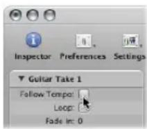
Note: Follow Tempo is not available for take folders. If you want a take folder recording to follow the project tempo, you need to flatten and merge it (see "Flatten and Flatten and Merge" on page 394).
Audio regions created in another project, or audio files imported from another application, can not automatically adjust to the project tempo (the Follow Tempo checkbox is not shown in the Region Parameter box).
Such audio files have a fixed playback rate, and can only be matched to new tempos by doing one of the following:
- Time stretching or compressing the files (or regions): Logic Express's time compression/expansion algorithms only permit you to match audio to new tempos when the tempo differences involved are relatively small; if you try to significantly change the tempo of your recordings, audio quality may be compromised (see "Time Stretching Regions" on page 555).
- Changing the audio files into Apple Loop format files. This file type makes transposition and time stretching tasks much easier (see Chapter 28, "Creating Apple Loops," on page 639).
Deleting Audio Recordings
Deleting an audio region is handled a little differently for files that are recorded in the current session, and those that are imported from an earlier session.
To delete an audio region that you have recorded since opening the project:
■ Select the audio region, and press Backspace.
A dialog asks if you also want to erase the corresponding audio file. This saves hard drive space used by bad takes and unwanted recordings.
To delete an audio recording that was made before the current session:
■ Select the audio region, and press Backspace.
This will only remove the audio region from the arrangement, not the audio file (from the Audio Bin). No dialog appears. This prevents you from accidentally deleting recordings that may be used in other projects.
If you actually want to delete the corresponding audio file, you can do so by choosing Audio File > Delete File(s) in the Audio Bin. The deleted audio files remain in the Trash until you empty the Trash.
Creating Comps
Compiling various sections of different takes is known as comping or creating a comp. Logic Express provides special options which fundamentally streamline this standard editing practice by allowing comps to be created without having to make cuts or mute tracks and regions.
The different take sections of a comp are automatically crossfaded between each other, in accordance with the default crossfade settings. These are defined in the General Audio preferences tab. You can quickly open this tab via the Audio Crossfade options for Merge and Take Comping key command.
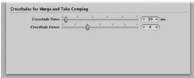
Typically, you will double-click on a take folder to open, and edit, it. You can, however, perform many comp editing operations when the take folder is closed (see below).
To compile sections of different takes, do one of the following:
In an opened take folder, select the desired take sections by click-dragging over them with the Pointer tool.
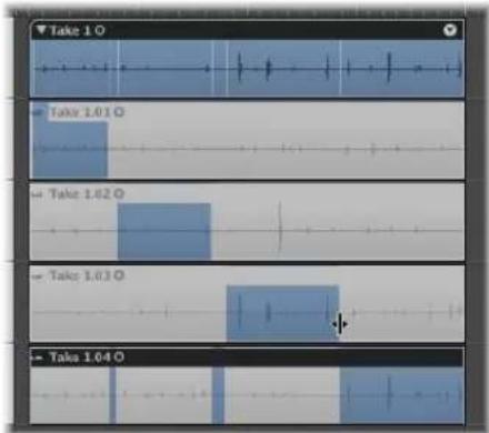
As a result of Logic Express's innovative Quick Swipe Comping feature, selecting a section in one take automatically deselects the same section in all other takes. Only one take track in a take folder can play at any given point in time.
The top track in the take folder displays a composite waveform overview of all selected take sections. The vertical lines in the waveform overview indicate the transitions between different takes.
In a closed take folder, you can quickly replace a take section by Control-clicking the folder section, and choosing a different take from the pop-up menu.
Important: Before performing any edits on a comp, you should save it (see below). Any subsequent changes will automatically create a new comp.
To edit a comp:
- Change the borders of the existing take sections by click-dragging the start or end points (the length change icon is shown).
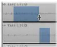
When you extend a section (move the beginning to the left or move the end to the right), adjacent selections in other takes are automatically shortened.
When you shorten a section (move the beginning to the right or move the end to the left), adjacent sections on different take tracks are automatically extended. This ensures that you do not create silence between different sections
Dragging the edge while holding Shift shortens the section without extending adjacent sections on different takes. The cursor turns into a Resize pointer.
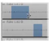
This allows you to create breaks (silence between different sections).
Tip: You can listen to your comp edits in real time by creating a cycle that spans the comp folder, and starting playback.
To move the selected comp area to the left or right:
- Click-drag it (a two headed arrow icon is shown).
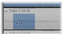
To move a selected comp area to another take:
- Click on the waveform of an unselected area to move the existing "comp" from another take.
This is a quick way to compare a comp area on one take with the same comp area on another take.
To remove a comp selection:
Shift-click the comp.
To remove all comp sections from a take:
- Shift-click in the region header of a take.
If the take does not contain any comp selections, all unselected areas in other takes are selected in the take you clicked.
To remove a complete take from a take folder, do one of the following:
- Select it by clicking in its track header, then choose Delete Take from the Take Folder menu (or press Backspace).
- Click it with the Eraser.
To store a comp, do one of the following:
- Close the take folder by clicking its disclosure triangle in the upper left corner.
- Choose New Comp from the Take Folder menu.
The comp is stored in the Takes and Comps menu (and is given a default name "Comp nn").
To rename a comp or take:
- Choose Rename Comp or Rename Take (dependent on whether a comp or take is selected) from the Takes and Comps menu.
Type the desired name in the dialog that opens.
Managing Take Folders
The following section outlines a number of commands that can be performed on take folders. These don't affect the playback result, but do have an impact on editing options.
Flatten and Flatten and Merge
The Take Folder menu—accessed by clicking the arrow at the top right corner of the take folder—allows you to flatten and merge take folders.
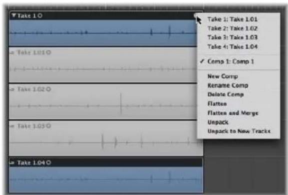
- Flatten: Replaces the take folder with regions that represent the current comp selections. This allows you to move individual sections back or forth in time.
- Flatten and Merge: Creates a new audio file which replaces the take folder in the Arrange. The newly created audio file exactly matches the size of the take folder (independent of the start position of the first region or end position of the last region).
Note: It is not possible to merge take folders as you would merge regions (with the Glue tool, for example). The reason for this is that the number of takes and comps would multiply, making edits difficult, if not unusable.
Opening Take Folders in the Sample Editor
It is possible to open take regions in the Sample Editor, but they are locked, making it impossible to move the anchor or redefine start or end points.
Such actions would destroy take timing if made in the Sample Editor, but you can perform fine edits of start and end points in the Arrange, when zoomed in. The timing of individual sections can be adjusted after the take folder has been "flattened."
Packing a Take Folder
The Arrange menu Region > Folder > Pack Take Folder command creates a take folder for multiple selected regions. Each region appears as an individual take in the resulting take folder.
- If the selected regions are located on different tracks (using different channel strips), the playback result may change (a take folder uses a single channel strip). The channel strip (and track) of the topmost "packed" track is used for take folder playback. If the topmost track is muted, the next unmuted track will be chosen for playback.
- If the selected regions are placed after each other on a single track, the take folder will default to one automatically created comp. Playback is unaffected. If only one region is "packed," it is selected as the take, and no comp is created.
In situations where the newly created take folder overlaps other (initially unselected) regions (which would change the playback result of these unselected regions), Logic Express creates a new audio track for the take folder.
Unpacking Take Folders
The Arrange menu offers the following two commands:
- Region > Folder > Unpack Take Folder
- Region > Folder > Unpack Take Folder to New Tracks
These commands are also available in the take folder menu (where they only affect that folder, not all selected take folders).
Both commands replace the (or all) selected take folder(s) with new audio tracks for each take and each comp. The order of takes and comps shown in the take folder menu is mirrored by the track order.
The Unpack command uses the same (the original) channel strip for all new tracks. All take/comp regions (except the originally activated one) are muted, ensuring that the playback result is unchanged.
The New Tracks command uses different channel strips for each new track, but automatically assigns the original channel strip setting to all of them. None of the takes/comps are muted—all play simultaneously—again ensuring that the playback result is not changed.
Recording MIDI
MIDI regions are used on (software) instrument and external MIDI tracks. MIDI regions are recorded in real time, or by using a number of "step input" methods.
To record MIDI regions in Logic Express, you need to either:
- Connect a MIDI keyboard to your computer. For more information on this, please refer to "Connecting Your MIDI Keyboard and Modules" on page 94.
- Activate the Caps Lock Keyboard by pressing the Caps Lock key. For more information, see "Using the Caps Lock Keyboard" on page 407.
- You can also use MIDI Step Input to "record" notes into Logic Express, one at a time. Full details in "MIDI Step Input Recording" on page 402.
MIDI recording works similarly to audio recording. There are only a few differences you need to be aware of. These are outlined in the following sections.
General recording info such as recording commands, configuration of the Transport bar. Recording button, setting count-ins, and so on, is covered in "Recording Audio", from page 367 onwards.
Recording MIDI Regions in Real Time
You can record a single MIDI region or multiple MIDI take regions on a track. If recording multiple MIDI take regions, they can be reviewed after recording, and used as you see fit. You can also assemble a composite MIDI region by using segments of several MIDI regions.
You can also simultaneously record multiple MIDI regions on multiple MIDI tracks. See "Recording on Multiple MIDI Tracks" on page 400, for more information.
To record a single MIDI region:
1 Select the instrument or external MIDI track that you want to record on.
Note: These track types are automatically record-enabled when selected.
2 Move the playhead to the point that you want to start recording.
3 If you would like to hear the metronome while recording, Control-click the Metronome button in the Transport bar, and activate the Click While Recording setting in the menu.
For further information on metronome use, see "Setting Up the Metronome" on page 371.
4 Click the Transport bar's Record button (or press the asterisk key on the numeric keypad; the default Record key command) to start recording.
Recording starts at the playhead position (following a count-in, if enabled in the Recording project settings), and ends when you click the Stop or Play button.
A MIDI region is created on the selected track. The MIDI region begins at the start of the bar in which the first event was recorded, and stops at the end of the bar in which the last event was recorded.
You can change the record track, without stopping recording—just select a new track with the mouse, or the Select Previous/Next Track key commands (default key assignments: Up or Down Arrow).
To record several MIDI takes in Cycle mode:
1 Open the Recording project settings by doing one of the following:
- Choose File > Project Settings > Recording (or use the Open Recording Project Settings key command, default: Option-Asterisk)
- Click the Settings button in the Arrange Toolbar, and choose Recording from the menu.
2 Choose "Create take folders" in the Overlapping recordings menu (see "How MIDI Take Recording Works" on page 398).
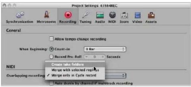
3 Set a cycle by dragging from left to the right in the Arrange Bar ruler (or use the locator fields in the Transport).
4 Start recording.
5 Allow Logic Express to continue running.
After reaching the right cycle boundary, the playhead will jump back to the left cycle boundary. Logic Express will create a new MIDI take folder.
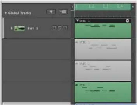
A new take track is automatically created inside the take folder for every cycle repetition.
Each previous take track is automatically muted while recording. When you stop recording, you can listen to the individual takes in the take folder by selecting them.
How MIDI Take Recording Works
Activation of the "Create take folders" option in the "Overlapping recordings" menu has the following effects:
- Recording over an existing MIDI region will create a MIDI take folder.
- Recording over an existing MIDI take folder will add a MIDI take to it.
- Recording over multiple existing MIDI regions will merge them (per track) before creating the take folder. All existing MIDI regions will appear as the first take, while new recordings will appear as the second, third, and so on takes.
- Recording over multiple existing MIDI take folders will flatten them individually, and merge them per track, before creating a new take folder (which spans the combined length of all take folders). All material which existed prior to recording will appear as the first take, with subsequent recordings appearing as the second, third, and so on takes.
Note: All takes that were not playing in the take folders (which existed prior to recording) are lost, although Undo is possible.
Only the actual recording of MIDI events qualifies them as overlapping. To provide an example: Imagine you are recording over existing take folders 1, 2, and 3. You don't play any MIDI events before the start, or after the end of take folder 2. This will result in the new recording being added as further take of take folder 2. Logic Express will even tolerate Note Off events in the first bar of take folder 3, without merging the take folders (2 and 3).
Important: MIDI take folders do not have the comping functionality available to audio take folders. The MIDI Take Folder menu does not provide the New Comp or Flatten and Merge commands. For information on the other commands in the MIDI Take Folder menu, see "Packing a Take Folder" on page 395 and "Flatten and Flatten and Merge" on page 394.
Recording into or Replacing a Selected MIDI Region
You can incorporate newly recorded data into an existing (and selected) MIDI region. This works in both normal and cycle record modes.
To combine several recording takes into one MIDI region:
- Choose the "Overlapping recordings: Merge with selected regions" option in the File > Project Settings > Recording tab.
To replace the events in a MIDI region recording:
- Choose the "Overlapping recordings: Merge with selected regions" option in the File > Project Settings > Recording tab, and turn on the Transport's Replace button.
This will replace the events in existing (and selected) MIDI regions with newly recorded events.
You can also use the Merge/Replace combination in conjunction with the Autopunch and Cycle functions.
To limit merge recording to Cycle mode:
- Choose the "Overlapping recordings: Merge only in Cycle record" option in the File > Project Settings > Recording tab.
MIDI region recording will behave as per usual, with new regions created for each recording. When the Transport's Cycle button is turned on, however, all MIDI region recording will result in a single, merged region.
Retrospective Recording of MIDI Regions
If you played a great solo while playback was running, but weren't in record mode—don't worry. Simply use the Capture as Recording key command. All events you played (after the last playhead change) will be added to the recorded MIDI region—just as if you had been in record mode.
Note: If you move the playhead before executing this command, the next incoming event will delete all previously played events (and your solo will be lost forever).
Recording on Multiple MIDI Tracks
You may occasionally want to record multiple MIDI tracks at the same time. Often, this will be data recorded from an external sequencer, or played from a keyboard that is split across multiple MIDI channels.
You can also simply play the same MIDI channel information from your keyboard, but record it to multiple tracks. One reason why you would do this is to create layered instrument parts.
To record regions on several MIDI tracks:
■ Switch on the Record Enable buttons of the tracks you wish to record to.
Note: Selecting an external MIDI or instrument track which is not record-enabled will turn off the record-enabled status of all other external MIDI or instrument tracks. Record-enabled audio tracks are not affected.
There are two operating modes available for simultaneous recording of multiple MIDI tracks: Layer or Multiplayer recording.
- When Layer Recording: Incoming MIDI events are sent to all record-enabled MIDI tracks. You can listen to all selected instruments before, and during, recording.
- A MIDI region is created on the selected track after recording.
- Aliases of the MIDI region on the selected track are recorded on the other tracks. The advantage of this approach is that any subsequent edits to the "parent" MIDI region will affect all aliases, ensuring that all layered tracks remain identical.
- When Multiplayer Recording: Incoming MIDI events are distributed to the various record-enabled tracks, in accordance with transmitted MIDI channel numbers.
- The channel of the incoming event must correspond to the channel of a record-enabled track, in order for this functionality to work.
- If no track with a corresponding channel number is found, the event will be routed, and recorded, onto the selected track.
You should ensure that each of your MIDI controllers transmit on different channels. If this is not possible, simply use different inputs on your MIDI interface, and change the MIDI channel of each input, using a transformer object between the Physical Input and Sequencer Input (see "Physical Input and Sequencer Input Objects" on page 930).
To switch from the Layer recording mode (default) to Multiplayer recording mode:
- Switch on the File > Project Settings > Recording > "Auto demix by channel if multitrack recording" option.
Switching Instruments to Software Instrument Live Mode
When you select a (software) instrument track, it does not immediately switch into live or performance mode. You must send a MIDI event before live mode is activated, but this takes around 100 milliseconds to engage, which is more than enough to destroy the timing of your first played note.
If you require perfect timing for the first played note, you need to send silent MIDI events in advance; press the sustain pedal, make a small move of the pitch bender or modulation wheel as examples. This will switch on live mode. Fur further information, see "Why Live Mode is Necessary" on page 258.
Filtering MIDI Input
The MIDI protocol can contain a broad range of MIDI messages, beyond note-on and note-off messages. These include controller information such as pitch bend, modulation, and aftertouch (pressure) commands.
There may be situations where you don't want to record all information being sent by your MIDI controllers. This is done with several "MIDI filters" that allow you to define what event types will be accepted or rejected at the sequencer input.
To filter incoming MIDI events:
1 Choose File > Project Settings > MIDI, and click the Input Filter tab.
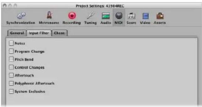
2 Enable the checkboxes that correspond with the MIDI event types that you would like to filter at the Logic Express sequencer input.
Switching MIDI Thru Off
When an External MIDI instrument track is selected in the Arrange, its Record Enable button is automatically switched on, and the instrument will pass events through the computer (MIDI Thru function). You can switch off the MIDI Thru function by simply deactivating the Record Enable button.
There are, however, situations where you may want to record to a track that is not automatically routed to a MIDI port. As an example, when performing a system exclusive (SyEx) dump from a device. While many MIDI devices require a bi-directional (in and out) MIDI connection to allow this type of communication, some devices will react strangely to incoming data (sent from Logic Express's MIDI Thru). This can result in data loss.
If you want to record a memory dump from a device that is problematic when connected bi-directionally, disable the instrument's MIDI Thru function.
To assign an instrument with a permanently disabled MIDI Thru function:
1 Open File > Project Settings > MIDI > General
2 Choose the desired instrument in the Instrument Without MIDI Thru Function menu.
MIDI Step Input Recording
The Step Input functions allow you to insert MIDI notes when Logic Express is not in a real time recording mode.
Step Input enables you to create note runs that may be too fast for you to play, or may be useful if replicating sheet music, but you don't sight read. You can use either one or more of the following for step entry:
• The Step Input Keyboard
- Keyboard Input key commands
- A MIDI keyboard
• The computer keyboard (Caps Lock Keyboard)
Notes are inserted at the current playhead position using all input modes. You can, and should, combine methods to make full use of the features that each option offers. Here is an example: You can set the note length in the Step Input Keyboard window, insert notes via a MIDI keyboard and position the playhead with key commands.
Use the mouse while familiarizing yourself with the Step Input Keyboard. To make the most of it, however, you will need to learn and use the Step Input key commands.
These provide a number of navigation and note entry options, such as step forward/back and rest insertion, which are not available to the Step Input Keyboard. See "Step Input With Key Commands" on page 404.
Activating MIDI Step Input Mode
MIDI Step Input mode is available in the Event List, Piano Roll, and Score Editors.
To activate Step Input mode:
- Click the In button found next to the local menu bar of the Event List, Piano Roll, or Score Editor.
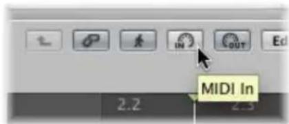
Disengage the button to exit Step Input mode.
Using the Step Input Keyboard
You can open the Step Input Keyboard window by choosing Options > Step Input Keyboard.
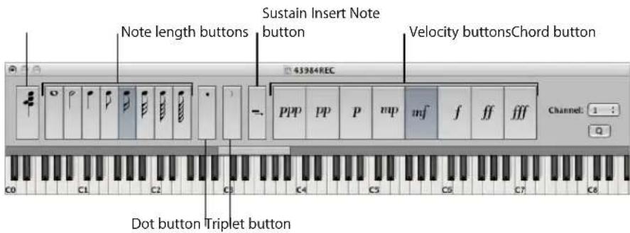
- Keys: Click to insert a note of the desired pitch. The insert range bar above the keyboard updates to display the selected octave.
- Note length and velocity buttons: Determine the length or velocity of the inserted note. There are eight velocity values—represented by the traditional volume indicators ppp, pp, p, mp, mf, f, ff, and fff. These correspond to MIDI velocity values 16, 32, 48, 64, 80, 96, 112, and 127, respectively.
- Triplet button: Click to make the next three notes you enter a triplet group. The rhythmic value of the triplets is based on the currently selected note value.
- Dot button: Works in a similar way as the Triplet button. A pair of complementary notes will be inserted: a dotted eighth and a sixteenth note, for example.
- Sustain Inserted Notes button: Lengthens the selected (usually the most recently inserted) note by the selected note length value (the active note length button).
-
Quantize button: Quantizes the start of the next inserted note to the nearest bar or beat line. Positioning of the playhead is critical when using this option.
-
Channel field: Determines the MIDI channel of an inserted note. The channel settings of individual notes usually have no effect on the playback channel, and therefore the sound, of the MIDI region. The channel settings of individual notes are mainly used for polyphonic score display.
- Chord button: When active, you can insert notes of different pitches and lengths. These are "stacked" at the same position, resulting in a chord. The playhead does not advance until the Chord button is deactivated.
To insert a note with the Step Input Keyboard:
1 Open the MIDI region in the editor you wish to work in.
2 Move the playhead to the desired insert location.
3 Set the buttons for note length, velocity, and other parameters as desired.
4 Click on the desired key in the Step Input Keyboard to insert a note of the key's pitch.
A note of the chosen pitch, note length, and velocity is inserted. The playhead will automatically advance to the end of the inserted note. The following note can be inserted immediately, following the step above.
Chord mode prevents the playhead from moving after the insertion of a note, allowing you to insert as many notes as desired at the same bar position.
To insert several notes at the same bar position:
- Turn on Chord mode by switching on the Chord button at the far left of the window (or using the Chord Mode key command), then follow the procedure outlined above.
A second click on the Chord button (or Chord mode key command) will deactivate Chord mode (this should be done before inserting the last note into the chord), and the playhead will advance as per usual, after note insertion.
Step Input With Key Commands
Note input with Step Input key commands follows the same principles as input via the Step Input Keyboard. Where it differs is that key commands are used for all functions, rather than choosing pitch, velocity, note length, and so on with mouse clicks.
All step input key commands are user definable. They can be found in the Keyboard Input folder of the Key Commands window.
Note: It is also possible to enter note data in real time with the computer keyboard (see "Using the Caps Lock Keyboard" on page 407).
Pitch Key Commands
The twelve "Note C" to "Note B" key commands insert a note of the selected pitch—with the set length and velocity—at the current playhead position, in the selected MIDI region. Use the Chord Mode key command if you wish to insert chords. You can disable Chord mode with the same key command.
Rather than assigning key commands to all twelve pitches, you also have the option of defining key commands for the seven pitches of the C major scale. These can be used in conjunction with the Next Note Will be Sharp and Next Note Will be Flat key commands, allowing you to insert the other pitches.
When creating a system for these key command assignments, two approaches seem most obvious:
- Lay out these commands on the computer keyboard to resemble a piano keyboard (C D E F G A B in one row, next to each other and C# D# F# G# A# above these at corresponding positions).
- Assign alphabetical keys to pitches of the C major scale—in accordance with their note names—especially when the second approach mentioned above is used.
Octave Range Key Commands
The octave of an inserted note depends on the current position of the insert range bar. There is a small horizontal bar (that spans one octave) above the piano keyboard in the Step Input Keyboard. The chosen note will always be inserted inside the range indicated by this bar.
This bar continuously changes its position in accordance with the last inserted note: The center of the insert range bar is always aligned with the last inserted note. The next note will be inserted within this octave range—unless the range bar is moved via key commands or with the mouse.
An example: If a G is inserted immediately after inserting a C, the G will be placed below the C. Inserting the C places the insert range bar between G (left end) and F# (right end), with the C in the center. Regardless of which note is chosen next, it will always be inserted inside this range. The range bar will, however, move as further notes are inserted, with the (range bar) center always aligned to the most recently inserted note.
Further key commands allow you to place the range bar in different octaves: Octave 0 to Octave 6, and also Octave +1 / - 1 / +2 / - 2 , which moves the range bar up or down one or two octaves. The range bar can also be moved with the mouse.
Note Length and Velocity
Note Length and Velocity are determined before a pitch command is used to actually insert a note. The currently selected values can be seen in the Step Input Keyboard window.
Rests, Correction, Moving Forward and Back
The Rest key command moves the playhead forward (in accordance with the currently set note value) without inserting a note, thereby creating a rest.
The Step Backwards and Step Forward key commands also move the playhead forward or back by the length of the selected note value.
The Delete key command will delete the most recently inserted note, and move the playhead back to the position where the note (previously) began. This allows for quick corrections—another note can be inserted immediately, replacing the erased one.
Triplets, Dotted Note Groups
The Next Three Notes are Triplets key command is self-explanatory. The rhythmic value of the triplets corresponds to the currently selected note value in the Step Input Keyboard window. If an eighth note is selected, an eighth note triplet will be created. After three notes have been inserted, binary values will be inserted, unless the command is reused.
The Next Two Notes are a Dotted Group key command works in a similar way. The special thing about this key command is that a pair of notes that complement each other will be inserted: a dotted eighth and a sixteenth note, for example.
Interaction With Other Key Commands
If Step Input mode (the In button) is activated in the Score, Piano Roll, or Event List editors, these key commands have priority over all other key commands.
This means that you may assign keys or key combinations to these functions, even if these keys/key combinations are already assigned to other functions. As long as Step Input mode is active, these key assignments will apply; if Step Input mode is switched off, any other assignments (for the same keys) will have priority.
Note: As you can use key assignments that are already in use for other functions, care should be taken to avoid using keys that are assigned to functions that you might also want to use when working in Step Input mode. As an example, the Space bar is used for Play/Stop/Continue, so assigning it to rest entry could be problematic.
Using a MIDI Keyboard for Step Input
Note input via MIDI works as per input via the Step Input Keyboard (see "Using the Step Input Keyboard" on page 403). Obviously, you press keys on your real-world MIDI keyboard, rather than clicking on-screen keyboard notes.
MIDI note velocity information (how hard you strike the keys on your MIDI keyboard) is sent when using MIDI Step Input.
Chords can be inserted by simply playing the chord on the MIDI keyboard. You don't need to switch on Chord mode in order to insert a chord.
It is recommended that you keep the Step Input Keyboard window open when first using these functions, to make the learning process easier. Once familiar, you can leave the Step Input Keyboard window closed as it is an aid, not a requirement, for MIDI step input.
It is also recommended that you make use of the Input key commands (see "Step Input With Key Commands" on page 404) to quickly switch values such as the note length, or to determine the insert position.
Using the Caps Lock Keyboard
The Caps Lock Keyboard enables you to use the computer keyboard as a real time virtual MIDI keyboard. It can also be used for MIDI Step Input. This makes it ideal for situations where no external MIDI or USB keyboard is available, such as when travelling with your portable Macintosh computer.
The Caps Lock Keyboard spans more than ten octaves, and even includes support for sustain and velocity information.
To enable the Caps Lock Keyboard:
■ Press the Caps Lock key on your computer keyboard.
An illuminated Caps Lock LED indicates that it is active.
It goes without saying that many keys will have different functions, overriding their usual key command assignments, while in this mode.
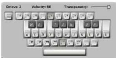
This is the English version of the Caps Lock Keyboard—other language versions will appear, dependent on your Mac OS X Keyboard setting.
The Escape key sends an All Notes Off command, should you encounter hanging notes.
The numeric keys (above the QWERTY keyboard) are used to define the octave for the MIDI keyboard.
The two rows below the numeric keys function as counterparts for MIDI keyboard keys, starting with the note C, assigned to the alphabetical A key (or Q, as would be the case if using a French keyboard, for example).
See the black and white keys in the image above for details.
The lowest row of letter keys sets the velocity for MIDI notes. There are preset values—ranging from pianissimo to forte fortissimo. Each value can be finely adjusted via the two keys to the right of this row (these are assigned to the comma and period keys on an English QWERTY keyboard). This keyboard configuration allows you to send any MIDI velocity value from 1 to 127.
The Space bar provides a Sustain function—played with your thumbs rather than your feet. You can freely trigger new notes or switch between octave or velocity values while notes are sustained.
The current octave and velocity values of MIDI notes are displayed at the upper edge of the Caps Lock Keyboard window. A Transparency fader is also available for this window, making visualization clearer or allowing the window to be “ghosted” over the background.
Caps Lock Keyboard Preferences
The Enable Caps Lock Keys option allows you to completely enable or disable the Caps Lock Keyboard functionality.
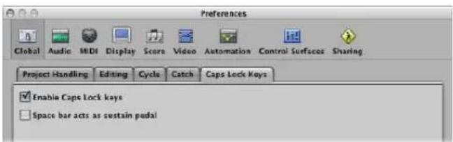
Should you wish to use the Space bar key command to start, stop, or continue Logic Express playback, rather than as the Sustain function for the Caps Lock Keyboard (when active), you can disable the "Space bar acts as sustain pedal" option.
Additional Caps Lock Keyboard Info
Due to technical limitations of computer keyboards, a maximum number of six notes can be played simultaneously. There are further limitations regarding timing precision, and when trying to play certain note clusters (which are musically unusual, at any rate).
Please keep in mind the original intention of this facility—as a useful aid when composing on a train or plane—not as a full-on replacement for a real MIDI keyboard.
Introduction to MIDI Editing
15
This chapter provides an overview of where you can best edit different types of MIDI events in Logic Express.
Logic Express offers several MIDI event editors: the Score, Piano Roll, and Hyper Editors, and the Event List and Transform window. Each editor provides a different view of MIDI events and offers unique editing functions. These differences make particular MIDI editing tasks easier, and you will often switch between multiple editors to get a part just right. The following outlines the strengths of each editor:
- Score Editor: Used to create printed notation. Ideal if you like working with dots, dashes, and lines.
- Piano Roll: Perfectly suited for making changes to the pitch and length of MIDI note events. Note events are represented as horizontal rectangles on a grid. The length of the rectangle is directly proportional to the note length. The pitch of the note is indicated by the vertical position of the rectangle, with higher notes being placed towards the top of the screen.
• Hyper Editor: Useful for creating MIDI drum parts, and altering the levels of individual note events. It can also be used to create and edit MIDI controller information, allowing you to draw curves that result in a filter sweep in an external synthesizer, for example.
• Event List: Shows all MIDI event types as a list. This is the go to editor when you need to make precise changes to any aspect of a MIDI event. - Transform window: This is not really an editor, in the same way that the other windows are. You use the Transform window for MIDI processing tasks, using mathematical variables. While this might sound a little overwhelming, you can use the Transform window to create a crescendo in a region, double or halve the speed of notes in a region, and more. Many processes are available as presets, or you can create your own.
Important: You can not perform any event editing operations—in the Arrange area or the editors—unless the MIDI data resides in a MIDI region that exists in the Arrange area!
Opening the Editors
All editors can be opened from the Window menu. This launches the editor in a separate window.
To open an editor from the Window menu:
- Choose the editor window name from the Window menu (or use the corresponding key command).
Editor window Default key command
| Event List |
| Score Editor Command-3 |
| Transform Command-4 |
| Hyper Editor Command-5 |
| Piano Roll Editor Command-6 |
In general, you'll access the editors directly in the Arrange window, but it can be useful to have multiple copies of the same editor open at the same time. As an example: Two Event Lists—one set to display at the Arrange level (showing regions), and the other displaying events within the regions. When you click on region names in the Arrange level Event List, the contents of the selected region are updated and shown in the other Event List window.
To access the Score, Piano Roll, and Hyper Editor in the Arrange window, either:
- Click the appropriate button at the bottom of the Arrange window editing area.
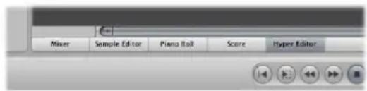
The contents (the events) of the selected MIDI region are shown in the selected editor window.
■ Double-click on a MIDI region (see below).
You can use the Toggle Score Editor, Toggle Piano Roll, and Toggle Hyper Editor key commands. The repeated use of the key command will open or close (toggle) the chosen editor at the bottom of the Arrange window.
Tip: Hold Option while double-clicking a MIDI region, to open the chosen editor in a separate window.
To access the Event List in the Arrange window, do one of the following:
- Click the Lists button at the right-hand side of the Arrange window Toolbar, then click the Event List tab.
■ Use the Toggle Event List key command (default assignment: E).
■ Double-click on a MIDI region (see below).
The contents (the events) of the selected MIDI region are shown in the Event List, to the right of the Arrange window.
To define the editor accessed by double-clicking on a MIDI region:
1 Open the Global preferences by doing one of the following:
- Choose Logic Express > Preferences > Global (or use the Open Global Preferences key command).
- Click the Preferences button in the Arrange Toolbar, and choose Global from the menu.
2 In the Editing tab, choose the preferred editor in the "Double-clicking a MIDI Region opens" pop up menu.
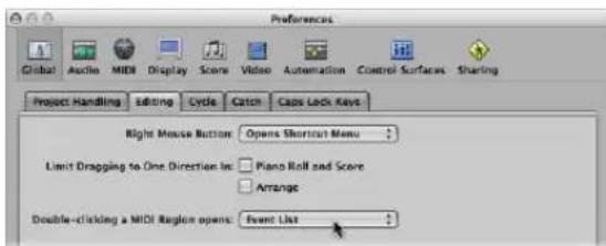
To access the Transform window, either:
- Choose Window > Transform (or use the corresponding key command, default: Command-4).
■ When in a MIDI editing window: Choose Functions > Transform.
Hearing MIDI Events When Editing
It goes without saying that MIDI editing is made much easier if you can hear every event and edit you make, whether you are scrolling through the Event List (automatic selection) or transposing a note by dragging it.
To hear MIDI event edits in real time:
- Click the MIDI Out button at the top left of each editor window.
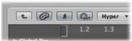
This is an independent setting for each editor, which will transmit MIDI events whenever they are added, selected, or edited.
Editing MIDI Events in the Arrange Area
You can not perform any event editing operations—in the Arrange area or the editors—unless the MIDI data resides in a MIDI region that exists in the Arrange area (although you can use the Clipboard functions to create a MIDI region in the Arrange).
To create an empty MIDI region:
- Click at the desired position in the Arrange area with the Pencil tool.
This inserts an empty MIDI region, allowing you to manually enter events into it.
In general, event-level editing can not be performed on regions in the Arrange area, but there are a few exceptions. In some cases, it may actually be more efficient to perform your edits (or operations) on MIDI regions in the Arrange area, rather than in a MIDI editor. As examples:
- Altering note lengths by resizing the region (see "Note Handling Options When Changing MIDI Region Lengths" on page 330).
- Deleting or moving portions of regions (and therefore the events) with the Marquee tool.
- Adjusting the playback of all events in a region by altering the region playback parameters.
Copying Events via the Clipboard in the Arrange Area
You can use the Clipboard to add MIDI events directly to the selected track in the Arrange area, at the current playhead position. This also works for events from another project.
To copy MIDI events in the Arrange area:
1 Select the events you want to copy in one of the event editors.
2 Choose Edit > Copy (or use the Copy key command, default: Command-C).
3 Select the track (and MIDI region, if applicable) you want to copy the events to.
4 Choose Edit > Paste (or use the Paste key command, default: Command-V).
Logic Express adds the Clipboard contents (MIDI events) to the selected MIDI region.
Note: If no MIDI region is selected, Logic Express will create a new MIDI region on the selected track, at the current playhead position.
Monitoring and Resetting MIDI Events
The top line of the Transport bar's MIDI Activity display shows the last MIDI message received. The bottom line shows the most recently transmitted MIDI message. The monitor is mainly used for checking MIDI connections.
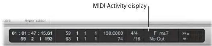
When Logic Express receives more than one MIDI note simultaneously; the respective, held intervals (between notes) are interpreted and displayed as chords.
To switch off stuck notes:
- Click on the lower MIDI Activity display section, or click the Stop button twice in rapid succession.
In both cases, reset messages are sent, as defined in Logic Express > Preferences > MIDI > Reset Messages.
On occasion, MIDI modules continue to sound, even when no note data is being sent to them. This indicates that your sound sources have not responded to the All Notes Off messages sent by Logic Express.
To stop hung notes:
- Double-click on the MIDI Activity display in the Transport bar (or use the Send Discrete Note Offs key command).
Separate Note Off messages will be sent for every note, on all channels of every MIDI port, which should do the trick!
To stop unwanted modulation:
- Choose Options > Send to MIDI > Reset Controllers (or use the corresponding key command).
This transmits control change message #121, with a value of 0 (reset all controllers), on all MIDI channels and outputs used by defined instruments. This neutralizes all MIDI controllers, such as modulation or pitch bends.
To set all MIDI channels to their maximum volume:
- Choose Options > Send to MIDI > Maximum Volume (or use the corresponding key command).
This transmits a control change message #7 (main volume), with a value of 127, on all MIDI channels and outputs used by defined instruments.
To send all program, volume, and pan settings from all external MIDI instrument Parameter boxes:
- Choose Options > Send to MIDI > Used Instrument MIDI Settings (or use the corresponding key command).
This resets your sound sources, if unexpected program changes occur mid-performance.
To automatically send instrument settings after loading a project:
- Turn on the "Send After Loading Project: Used Instrument MIDI Settings" option, in the File > Project Settings > MIDI > General tab.
Editing MIDI Events in the Piano Roll Editor
The Piano Roll Editor shows the note events of a MIDI region as horizontal rectangles. This resembles the holes cut in paper pianola rolls.
The Piano Roll Editor can display the MIDI note events of one MIDI region, or all MIDI regions in a folder or project, if desired (see "Displaying and Editing Multiple MIDI Regions" on page 417). You will generally work on one region at a time in the Piano Roll Editor, however.
Learning the Piano Roll Editor Interface
MIDI note events are represented by horizontal rectangles, aligned on a grid of horizontal and vertical lines.
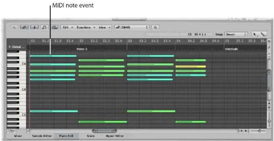
- The horizontal placement of note events indicates their temporal (bar, beat, and subbeat) positioning within the region, and project.
- The vertical position of note events indicates their pitch, with those nearer the top of the Piano Roll grid being higher in pitch. Chords are displayed as a vertical stack of note rectangles. The alignment of notes in chords is not always identical, as not all notes in a chord may be struck, or end, at the same time.
- The length of MIDI note events is directly related to the length of the rectangles, so notes such as; hemidemisemiquavers (1/64th note), quavers (1/8th note), crotchets (1/4 note), minims (1/2 note), whole notes, and so on can be easily recognized.
Making Use of the Grid
The grid provides a valuable reference for note lengths: You can see both the start and end positions of note events, aligned with the time values shown in the Bar ruler. This simplifies note length editing.
The default grid lines shown are:
- A black line at every bar and beat.
- A light gray line at every division value (you can alter the division value in the Transport).
You can alter the appearance of this grid and other aspects of the Piano Roll Editor (see "Customizing the Piano Roll Editor" on page 434).
The vertical keyboard on the left side of the Piano Roll Editor indicates note pitches. Horizontal black lines run across the screen between notes B and C, and notes E and F. These lines are very helpful when transposing notes by dragging them up or down.
Understanding Note Velocities
Each note event features a horizontal line that runs through the rectangle. The length of the line—in relation to the total length of the note—corresponds to the velocity value of the note (up to the maximum value of 127). Velocity denotes how hard the MIDI keyboard was struck when the note was recorded. This also usually indicates how loud the note is, within the range of 127 possible values, with 127 being the "loudest."
The Piano Roll Editor also indicates note velocities with different colors.
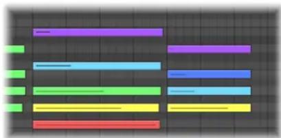
natural_image
Abstract color-coded horizontal bars on a dark grid background (no text or symbols)This makes it very easy to see the overall range of (and individual note) velocities in a MIDI region. As you change the velocity of MIDI notes, the color of selected notes changes in real time.
Note: When View > Region Colors is activated, the notes will be displayed in the color of the MIDI regions that contain them. This makes notes easier to identify when viewing the notes of multiple regions.
Displaying and Editing Multiple MIDI Regions
The Piano Roll Editor can simultaneously display the contents of all MIDI regions in a folder, all regions in a project, or several selected MIDI regions.
You can freely select note events that belong to different MIDI regions, and process, move, or resize them as required. A help tag indicates the number of selected events and parent MIDI regions. As an example: 8/2 means that eight notes are selected from two MIDI regions.
To show the note events of all MIDI regions in a project:
- Ensure that View > Show Selected Regions Only is switched off, then double-click on the background of the Piano Roll Editor.
The start point of each MIDI region is indicated by a vertical line of the same color as the MIDI region itself.
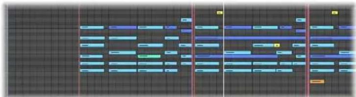
natural_image
Pure electrical circuit lines without any symbolsDouble-click on a note event to revert to a display of the contents of a single parent MIDI region (the region that contains the note).
To limit the display to note events of selected MIDI regions:
■ Switch View > Show Selected Regions Only on.
This restricts the Piano Roll display to the note events of MIDI regions selected in the Arrange area. Logically, this hides the events of non-selected regions, making multi-region editing simpler.
Creating and Editing Note Events
Handling note events in the Piano Roll Editor is very similar to region handling in the Arrange area. Many of the same techniques used to lengthen, cut, and move regions apply to note events, so you should find much of this section familiar.
Snapping Edits to Time Positions
You move and resize events in the Piano Roll Editor because you want them to start and end at a specific point in time.
Logic Express offers a snap feature that automatically aligns event start and end points to a selected grid value, when you move or resize them.
To snap events to a grid:
- Choose one of the following values in the Snap menu at the top of the Piano Roll window:
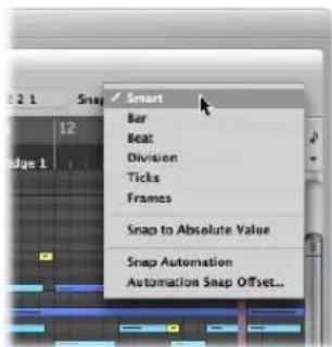
- Smart: Edit operations will snap to the nearest bar, beat, sub beat, and so on, dependent on the current Bar ruler division value and the zoom level.
• Bar: Edit operations will snap to the nearest bar. - Beat: Edit operations will snap to the nearest beat in a bar.
- Division: Edit operations will snap to the nearest division (this is the time signature shown in the Transport and Bar ruler).
- Ticks: Edit operations will snap to the nearest clock tick (1/3840th of a beat).
- Frames: Edit operations will snap to the nearest SMPTE frame.
The Snap functionality is relative, which means that the edit operation will be snapped to the nearest bar, beat, and so on—retaining the event's distance from its original position. As an example, if an event is placed at position 1.2.1.16, and you move it to around bar 2 (with the Snap menu set to Bar), it will automatically snap the event to position 2.2.1.16—rather than 2.1.1.1 (the bar 2 start point). You can override relative snaps with the Snap to Absolute Value option.
To snap to an absolute, not relative, position:
- Choose the Snap to Absolute Value setting in the Snap menu.
A tick will appear to the left when enabled. This feature works in conjunction with the chosen snap grid format.
To explain, if Bar is chosen in the Snap menu, when Snap to Absolute Value is active, moving an event (from position 1.2.1.16) to around bar 2 will result in it being snapped to position 2.1.1.1 (the bar 2 start point), rather than its relative position (2.2.1.16).
The Snap menu setting applies to the following edit operations:
- Moving and copying events
- Resizing events
- Cutting events
- Moving, adding, and resizing markers
- Setting cycle boundaries
You can temporarily override the snap grid, allowing finer edits and adjustments.
To override the snap grid:
■ Hold Control while performing the editing operation.
The division value chosen in the Transport (1/16, for example) determines the editing grid scale.
■ Hold Control-Shift while performing the editing operation:
The editing grid switches to ticks.
Using the Info Display
The Piano Roll Editor's info display indicates the current position and pitch of the mouse pointer within the region.
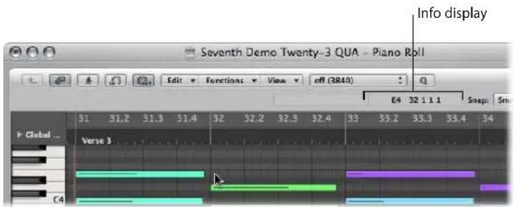
You should refer to this real time display whenever making a selection.
Tip: Activate the MIDI Out button next to the Piano Roll Editor's local menu bar to hear your edits as you make them.
Using the Shortcut Menu
Many selection, editing, and other commands can be accessed by right-clicking anywhere in the Piano Roll Editor. Make use of this to accelerate your workflow.
Note: The right-click shortcut menu can only be accessed if the Right Mouse Button: Opens Shortcut Menu pop-up menu option is chosen in the Logic Express > Preferences > Global > Editing tab.
Selecting Notes
You must select note events before you can edit them. The usual selection methods—clicking, Shift-clicking, and rubber-band selection with the Pointer tool also apply to the Piano Roll Editor.
The following selection options—unique to the Piano Roll Editor—are also available:
To select all notes of the same pitch in a MIDI region:
- Click the corresponding key of the onscreen keyboard.
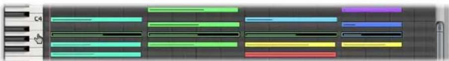
This is similar to selecting all regions on a track lane, by clicking on the track name.
To select a range of note pitches in a MIDI region:
- Click-drag over the desired key range of the onscreen keyboard.
All MIDI notes that fall within this pitch range are selected.
The info display will show the number of selected notes. The MIDI region name is shown beside the number of selected notes. As an example: 3/Piano means three notes are selected from a MIDI region called Piano.
When you select multiple overlapping notes, the info display shows the chord name.
When no notes are selected, the info display shows the name of the most recently selected MIDI region.
Creating Notes
You will often create note events with the mouse in the Piano Roll Editor; to replace a deleted note or to add a note to a chord or region. This facility is also handy when a keyboard is unavailable, or even when one is available, but it's faster to insert a note with the mouse.
You can also create note events with your computer keyboard. Details in "Using the Step Input Keyboard" on page 403.
To create a note event:
1 Select the Pencil tool.
2 Click at the desired position in the Piano Roll Editor.
The note that is created will match the length of the most recently inserted note.
To create a note event of the desired length:
- Click-hold at the desired position in the Piano Roll Editor with the Pencil tool, then drag to the right or left.
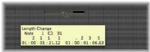
A help tag will indicate the length change in real time.
Finer adjustments can be made by holding down Option or Control while altering the note length (see "Snapping Edits to Time Positions" on page 418).
To replicate an existing note at another position or pitch:
1 Click the original note with the Pencil tool.
2 Click at the desired Piano Roll Editor position with the Pencil tool.
The new note length and velocity will be identical to the original note.
Deleting Notes
You can delete selected notes by pressing Backspace, or clicking on them with the Eraser.
To delete notes, do one of the following:
■ Select the Eraser tool, then click on the desired note.
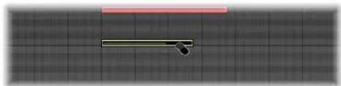
natural_image
Simple diagram with a horizontal line and a small black arrow on a grid background (no text or symbols)- Select the desired notes, then click one of the selected notes with the Eraser (or press Backspace).
This deletes all selected events.
To delete similar or equal events:
1 Select one of the notes you want to delete.
2 Choose Edit > Select Similar Events or Edit > Select Equal Events (notes of the same pitch, for example), and then delete the selected events by pressing Backspace.
For more information about similar and equal events, see "Selecting Similar or Identical Objects, Regions, or Events" on page 181.
You can also delete events by choosing one of the Delete MIDI Events commands from the Piano Roll Editor's local menu bar.
To delete doubled events:
- Choose Functions > Delete MIDI Events > Duplicates (or use the Delete Duplicated Events key command, default: D).
Any events occurring twice or more at the same position (and pitch) are deleted, allowing one to remain.
Points to Note About Duplicated, Identical, and Similar Events
Duplicated events may have different second data bytes (velocity, aftertouch, or controller values); Logic Express only looks at the event type and position, when determining whether or not two or more events are duplicated.
Events of the same type, but on different MIDI channels, are not viewed as being identical.
The "same time position" includes two notes which are output simultaneously because of the current quantization setting. Full details on all quantization options are covered in Chapter 19, "Quantizing MIDI Events."
To delete events inside or outside the locators:
1 Set the left and right locator positions as desired.
2 Do one of the following:
- Choose Functions > Delete MIDI Events > Inside Locators.
- Choose Functions > Delete MIDI Events > Outside Locators.
This deletes all events between or outside the locator positions.
When copying events or reducing the length of MIDI regions, events can sometimes end up outside the limits of a MIDI region. These technically still belong to this MIDI region, although they won't be played or heard.
To delete events outside the MIDI region:
- Choose Functions > Delete MIDI Events > Outside Region Borders.
To delete unselected events within the selection:
- Choose Functions > Delete MIDI Events > Unselected Within Selection.
All unselected notes between the (start point of the) first, and the (end point of the) last selected note are deleted.
To delete all selected events and select the next one:
1 Select the event you want to delete.
2 Use the Delete and Select Next Region/Event key command.
Restoring Deleted Notes
Accidental deletions of one or more notes, or a simple change of mind or editing mistake is an inevitable part of song creation. Fortunately, you can backtrack your edits easily in Logic Express. You also have the option of simply recreating an event with the Pencil tool.
To undo the last note editing step or deletion:
- Choose Edit > Undo from the main menu, or press Command-Z immediately after making the error.
To undo or redo multiple steps:
1 Choose Edit > Undo History. This launches the Undo History window. The most recent editing step (at the bottom of the list) is highlighted.
2 Click on any entry to undo or redo all steps between the clicked and highlighted entries. All steps are animated during this process.
Important: A Redo list is not displayed until an Undo operation has been performed. The Redo list appears below the Undo items. The first item that can be redone is indicated by gray text.
To undo or redo an isolated step:
1 Command-click on the desired step. A warning dialog will launch.
2 Click Apply to undo or redo the step. Click Cancel to abort the step.
This will undo or redo an isolated step without influencing all steps between the clicked and highlighted (most recent) entries.
Moving Notes
You can move selected notes by grabbing them (near the middle) and dragging them. If you move notes vertically, they will be transposed, and if you move them horizontally, they will be moved in time.
The current position and pitch are shown in a help tag while dragging. The deviation from the original pitch is shown as a positive or negative number of semitone steps at the bottom left of the help tag. The original pitch remains in the info display of the Piano Roll Editor.
When you move notes horizontally, they snap to the division defined in the Snap menu (you can alter this setting at any time).
To make finer adjustments:
1 Select the desired notes.
2 Press Control, and drag the notes to the desired position.
The resolution of the drag steps is dependent on the current Snap menu setting and zoom level (see "Snapping Edits to Time Positions" on page 418).
Alternately, you can follow the procedure above, but press Control-Shift as you drag to move the notes in tick steps, completely overriding the Snap menu setting.
To limit note movements to one direction:
1 Open the Global preferences by doing one of the following:
- Choose Logic Express > Preferences > Global (or use the Open Global Preferences key command).
- Click the Preferences button in the Arrange Toolbar, and choose Global from the menu.
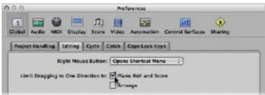
2 In the Editing tab, enable the Limit Dragging to One Direction in Piano Roll and Score option.
When active, this option helps you to avoid accidental transpositions of notes when moving them horizontally, or changing the position of notes when you're trying to change their pitch. The initial movement—vertical or horizontal—restricts further movements to this plane, while the mouse button is held. Release the mouse button and click on the event to move in the other direction.
Moving Events via Key Commands
Editing can be greatly accelerated by assigning, and using, the following key commands to move one or more events.
• Nudge Region/Event Position Right by SMPTE Frame
• Nudge Region/Event Position Left by SMPTE Frame
• Nudge Region/Event Position Right by 1/2 SMPTE Frame
• Nudge Region/Event Position Left by 1/2 SMPTE Frame
- Nudge Region/Event Position Right by 5 SMPTE Frames
- Nudge Region/Event Position Left by 5 SMPTE Frames
- Nudge Region/Event Position Right by SMPTE Bit
• Nudge Region/Event Position Left by SMPTE Bit
• Nudge Region/Event Position Right by Tick
• Nudge Region/Event Position Left by Tick
• Nudge Region/Event Position Right by Division
• Nudge Region/Event Position Left by Division
• Nudge Region/Event Position Right by Beat
• Nudge Region/Event Position Left by Beat
• Nudge Region/Event Position Right by Bar
• Nudge Region/Event Position Left by Bar
• Nudge Region/Event Position Right by Nudge Value
- Nudge Region/Event Position Left by Nudge Value
The selected events are shifted one step right or left, by whatever unit is referred to in the particular command name.
Including Non-Note MIDI Events
Turn on Functions > Include Non-Note MIDI Events setting to tie other data (such as pitch-bend, modulation, aftertouch, or poly pressure) in a region to the region's notes. This may be useful when a region contains note-related controller data that you want to copy or move.
Changing the Length of Notes
You can use the Pointer, Finger, or Pencil tool to alter note lengths.
Tip: It's advisable to use the Pointer or Finger tool, as these avoid the accidental creation of new notes, which is possible with the Pencil tool.
To alter the end point (and length) of a note:
1 Position the Pointer, Finger, or Pencil tool over the lower right-hand edge of a note event. The tool icon will change to a length change icon when positioned correctly.
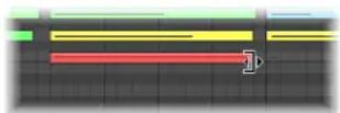
2 Drag the event to the required length. A help tag will inform you about the precise end point and length of the note while dragging.
Tip: It can sometimes be difficult to grab the bottom right corner of very short notes. In this situation, you should use the Finger tool, which allows you to grab notes anywhere, in order to alter their end point (and therefore, length).
To change the start point (and length) of a note:
- Position the Pointer or Pencil tool over the lower left-hand edge of a note event, and drag it to the desired start position.
Note: The original end point of the note is retained when adjusting the start point.
Altering the Lengths of Several Notes Simultaneously
You can adjust the lengths of several selected notes at once (in a chord, for example), by simply altering the length of one of them. The relative differences between the (selected) note lengths will be maintained.
To set the same end point for several notes:
- Press Shift while altering the length of one of the selected notes.
To make several notes the same length:
- Hold Option-Shift while dragging one of several selected notes
Setting Note Start and End Points to the Playhead Position
You can move the start or end point of one or more selected notes to the playhead location with the following key commands:
- Set Region/Event Start to Playhead Position
- Set Region/Event End to Playhead Position
Advanced Note Length Functions
The Functions > Note Events sub-menu in the Piano Roll Editor menu bar contains commands that change the length of selected notes. These changes are influenced by the notes surrounding or overlapping them. This is ideal for tidying up the start and end points of notes.
To remove note overlaps:
1 Select the notes you wish to affect.
2 Choose one of the following commands in the Functions > Note Events submenu (these commands are also available as key commands):
- Note Overlap Correction (selected/any): This command removes overlaps for all selected notes, regardless of whether the following overlapped notes are selected or not.
- Note Overlap Correction (selected/selected): This command removes overlaps for all selected notes, but only if the following overlapped notes are selected.
- Note Overlap Correction for Repeated Notes: This command removes overlaps for all selected notes, but only if the following overlapped notes have the same note number (are of the same pitch).
The Overlap Correction functions view vertically stacked notes (notes in the same location, but of different pitches) as a chord. A dialog will indicate that the overlapping notes appear to be part of a chord, and you will be asked to choose one of the following options:
- Keep: Simultaneously-sounding notes will be reduced in length (moved to the same end point).
- Delete: Simultaneously-sounding notes will be removed, leaving a monophonic line behind.
- Shorten: Simultaneously-sounding notes will be individually reduced in length, resulting in a number of short notes in a monophonic line remains.
To make notes legato:
1 Select the notes you wish to affect.
2 Choose one of the following commands in the Functions > Note Events submenu:
- Note Force Legato (selected/any): This command forces legato for (lengthens) all selected notes, regardless of whether the following note is selected or not.
- Note Force Legato (selected/selected): This function forces legato for all selected notes, but only if the following note is selected.
The end of the MIDI region is treated as a non-selected note:
- Note Force Legato (selected/any) lengthens the last note to the end point of the MIDI region.
- Note Force Legato (selected/selected) does not alter the length of the last note.
If Logic Express finds a chord, the following dialog is shown:
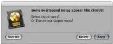
- Click the Delete button to erase any incorrect notes in a poorly played monophonic line.
- Click the Keep button to even out (shorten) the start points and durations of all (intentionally played/recorded) notes in chords.
To convert sustain pedal events to note lengths:
- Choose the Functions > Note Events > Sustain Pedal to Note Length command.
All sustain pedal events (controller #64) used on selected note events are analyzed, and the note events are actually increased in length. This increase matches the controller #64 (sustain pedal) off message position.
The pedal events (controller #64 on and off) are erased after use of this command.
Copying or Moving Notes
You can copy selected notes by pressing Option and dragging the notes to the desired position.
Tip: You can use this method to copy or move notes between two Piano Roll Editor windows (showing different regions, for example), or even between the Piano Roll Editor windows of different projects.
You can also use the Clipboard to copy and move notes:
- Edit > Copy (or Command-C) copies notes into the Clipboard.
- Edit > Cut (or Command-X) moves the notes into the Clipboard.
- Edit > Paste (or Command-V) pastes them at the current playhead position, at their original pitch.
Advanced Note Copy and Move Options
You can also perform advanced copy and move operations within the Piano Roll Editor. These allow you to directly swap events, or to merge a group of notes from one section of a region to the same, or another, region, as examples.
To copy or move a range of MIDI events:
1 Define the area that you want to move or copy with the left and right locators.
As an optional step: Select the track you want to copy the events to, if you want to copy or move the events to another track.
2 Set the playhead to the desired insert position.
3 Choose Functions > Copy MIDI Events. The Copy MIDI events dialog opens.
4 Choose the desired settings in the Copy MIDI Events dialog:
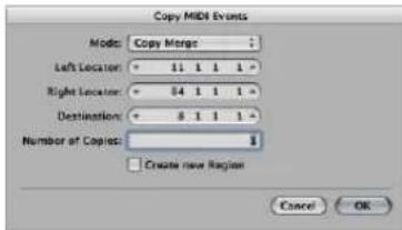
- Mode menu: Determines how MIDI events are copied or moved. You can choose from the following options:
- Copy Merge: The copied data is blended with any data present at the destination position.
- Copy Replace: The data at the destination position is deleted, and replaced with the copied data.
- Copy Insert: All data at the destination position is moved to the right, by the length of the source area.
- Move Merge, Move Replace, Move Insert: These three modes work similarly to the Copy modes, but actually move the selected events, removing them from their original positions.
- Rotate: The source events are moved to the destination position. The data that was previously at the destination position, and the data that falls between the source and destination positions are all moved towards the source position. This rotates the data around a central pivot point (halfway between the source and destination positions).
- Direct Swap: Exchanges the source data with data of the same length, starting at the target position. This allows you to swap the notes in bar 1 of a four bar MIDI region with the notes in bar 3 of the same region, for example.
- Remove: Removes the MIDI data from the source region, but leaves the region at its original position.
- Left Locator and Right Locator: These enable you to edit the source area you defined with the left and right locators.
- Destination: Defines the destination position independently of the playhead position.
• Number of Copies: Defines the number of copies. - Create New Region: When set to on, a new MIDI region is created at the destination position. It contains the copied (or moved) events.
Protecting the Position of Events
There are times where you will want to protect certain events from being moved. As an example, several note events may be used to trigger footstep samples that match an actor walking down a corridor, in a video soundtrack.
You have already created the music for this scene, but have been asked to increase the tempo to match several cuts of different camera angles in the corridor. Obviously, a change in the tempo will move the events, resulting in out of sync footstep samples. Thankfully, Logic Express has a feature that preserves the absolute time position of events.
To protect the position of one or more selected events:
- Choose Functions > Lock SMPTE Position (or use the corresponding key command).
This ensures that events that fall at a particular absolute time position: 1 hour, 3 minutes, 15 seconds, 12 frames, for example, will remain at this position when tempo changes are made.
To unprotect the position of one or more events:
- Choose Functions > Unlock SMPTE Position (or use the corresponding key command).
Changing the Velocity of Notes
Note velocity is usually tied to the level of the note, and given the use of color to indicate different velocities, you can quickly identify the "loud" and "soft" notes in a region.
Note: Velocity can also be used as a controller for other synthesizer parameters, such as filter resonance or cutoff, either alone or in conjunction with level. As such, you may find that changes to note velocity not only affect the level of the note, but also tonality.
To alter the velocity value of a note:
1 Choose the Velocity tool.
2 Click-hold, and vertically drag on a note.
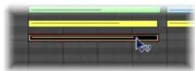
A help tag will indicate the velocity value of the note you have clicked on. This value changes as you drag.
If the MIDI Out function is switched on (and it should be!), the note will be output as you alter the velocity.
All selected notes can be altered simultaneously; the differences in their respective velocity values will be retained. If the velocity value of any of the selected notes reaches an extreme value (0 or 127), none of the other selected notes can be adjusted further.
You can override this behavior by holding Option while dragging. This allows you to continue altering the velocity values until the selected (clicked) note reaches an extreme value. It goes without saying that this will alter the velocity relationship of this note to the other notes.
To assign the same velocity value to all selected notes:
- Hold down Option-Shift while dragging on one of the notes with the Velocity tool.
Muting Notes
The Piano Roll Editor features a Mute tool that allows specific notes in a MIDI region to be muted.
To mute/unmute a note:
- Click the note with the Mute tool.
Muted notes are grayed out (shown without color).
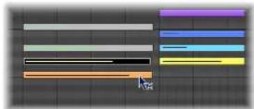
natural_image
Abstract color bar design with horizontal bars and a cursor pointer on a grid background (no text or symbols)To mute or unmute all notes of a particular pitch in a MIDI region:
- Click on a piano key to the left of the Piano Roll Editor with the Mute tool.
This will mute or unmute all notes of that particular pitch, which is ideal for muting the high-hats in a MIDI region that is triggering an entire drum kit, for example.
To mute or unmute multiple notes:
- Select the desired notes, then click one of the selected notes with the Mute tool
The Select Muted Regions/Events key command is also available in the Piano Roll Editor. It allows the selection of all muted notes in a MIDI region. The next logical operation would be to delete these muted notes by pressing Backspace.
Splitting Chords
These functions divide chords horizontally (by pitch), making the Piano Roll Editor the ideal place to perform chord splitting tasks.
To select the top or bottom note of one or more selected chords:
- Choose Functions > Note Events > Select Highest Notes to select the highest notes in the chords.
- Choose Functions > Note Events > Select Lowest Notes to select the lowest notes in the chord(s).
The latter command may be perfect for separating a walking bass line in a piano region, as an example. Once separated, the lowest notes can be cut and pasted into a new region, which is played on a track assigned to an EXS24 mkII Upright Bass instrument channel.
Note: Select Highest Notes and Select Lowest Notes are purely selection commands, which can be used in conjunction with any of the editing commands, such as Cut, to move a voice into another MIDI region, as per the example above.
To assign individual note pitches to different MIDI channels:
1 Select the note pitch(es) you want to affect by clicking on the Piano Roll keyboard.
- Shift-click to select multiple non-contiguous pitches.
- Drag across the keyboard to select a range of contiguous pitches.
2 Choose Functions > Note Events > Voices to Channels.
Logic Express assigns MIDI channel numbers (in ascending order) to individual note pitches in the selected MIDI region. The highest note pitch in each chord will be assigned as MIDI channel 1, the next note down in each chord channel 2, and so on.
Note: Use of these commands results in changes to the MIDI region, which will contain information spread across multiple MIDI channels, following the operation.
Regions split in this way enable you to create a new MIDI region for each note by using the Region > Split/Demix > Demix by Event Channel menu option in the Arrange window.
Each region created from this process can then be assigned to a different track (and channel), allowing different instruments to be assigned for each voice.
For more information on the Functions > Note Events > Assign Channels Based on Score Split command, see "Using a Split Point" on page 787.
Using Hyper Draw
You can directly create and edit MIDI controller information in the Piano Roll Editor. These types of edits are made easier when you can see the notes that will be affected.
To view and create controller events:
1 Open a Hyper Draw display in the Piano Roll Editor by doing one of the following:
- Choose the desired View > Hyper Draw command.
- Click the Hyper Draw button at the lower-left corner of the Piano Roll Editor, then choose the desired MIDI controller by clicking the arrow button to the left.
The selected controller type (volume, for example) is shown in a gray field below the Piano Roll grid.
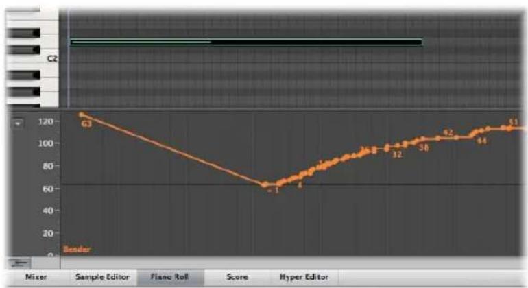
line
| Marker | Value | |---|---| | 63 | 120 | | -1 | 60 | | 4 | 65 | | 32 | 70 | | 38 | 80 | | 92 | 90 | | 44 | 100 | | 51 | 110 | Mixer Sample Editor Piano Roll Score Hyper Editor2 Click at different points in the gray area to create Hyper Draw nodes.
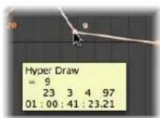
A connecting line is automatically created between the nodes.
To resize the Hyper Draw area:
- Grab, and vertically move the dividing line that separates it from the Piano Roll grid area.
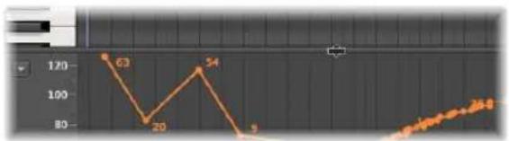
line
| Point | Value | |-------|-------| | 1 | 63 | | 2 | 20 | | 3 | 54 | | 4 | 9 | | 5 | 46.8 |For more information see "Using Hyper Draw" on page 620.
Customizing the Piano Roll Editor
The View menu offers various options that allow you to customize the display of the Piano Roll Editor.
- Bright Background: Switches between a bright and dark background.
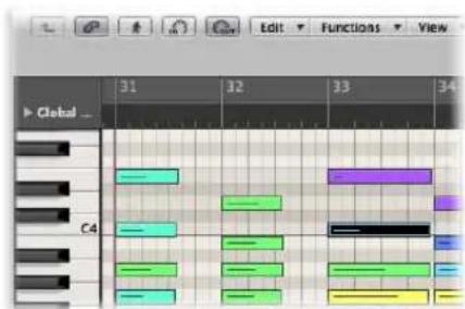
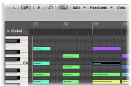
- Piano Roll Colors: Opens the Display preferences, allowing you to adjust the colors of the Piano Roll grid, background, lines, and so on for both the bright, and dark background views. For further information see "Other Preferences" on page 992.
Piano Roll Editor Shortcuts
The Piano Roll Editor also provides a way to “quick-launch” the Event List and Score Editor.
To quickly open the Event List:
■ Double-click on any event.
The Event List will be shown in the Media area to the right of the Arrange window. If already open, the contents of the parent region (of the note selected in the Piano Roll Editor) will be displayed.
Note: If using an independent Piano Roll Editor window, double-clicking an event will launch an independent Event List window.
To quickly open the Score Editor:
- Option-double-click on any event.
The Score Editor will open in a new window. The Piano Roll Editor will remain docked in the Arrange window's editing area.
Editing MIDI in the Hyper Editor
You can use the Hyper Editor to view and edit different MIDI event types, shown as vertical beams along a timeline within a region.
Each beam represents an event. The value of the event is denoted by its height, providing an at-a-glance view of one, or dozens, of different events and their values.
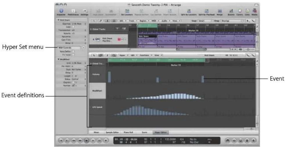
Each MIDI event type, be it a note or MIDI controller, is arranged from top to bottom in horizontal lanes, much like the track lanes shown in the Arrange area. The location of each event within the region is vertically aligned with a Bar ruler position.
Each lane offers individual display and other parameters, that are assigned and adjusted in the Inspector.
The type of event shown, and controlled, on each lane is freely configurable. This is done by setting an event definition (see "Working With Event Definitions" on page 448) for each lane in the Inspector.
You can save groups of event definitions (several lanes that you have defined) as hyper sets (see "Working With Hyper Sets" on page 455). Hyper sets are accessed via an Inspector menu.
The Hyper Editor features two default hyper sets: MIDI Controls and the GM Drum Kit. The MIDI Controls hyper set provides hyper definition lanes for Volume, Pan, Modulation, and several other commonly used controller types. The GM Drum Kit hyper set offers lanes that match the note names of the General MIDI (GM) drum map. This is perfect for creating drum (or other instrument) parts, by pencilling or drawing in note events. This is similar to the use of pattern-based drum machines, where each beat is manually entered on a grid.
To switch between the default MIDI Controls and GM Drum Kit hyper sets:
- Click the arrow button next to the Hyper Set Name field in the Inspector, then choose the desired hyper set from the pop-up menu.
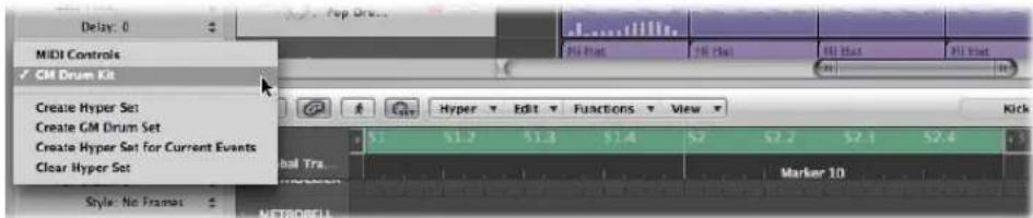
This is also how you switch between any hyper sets that you create. Each hyper set can be named, making it easy to select the one you need.
These event definition and hyper set facilities allow you to customize the Hyper Editor, with only the required MIDI event types being displayed. As an example: Imagine you have recorded a synthesizer lead MIDI region. You could create a hyper set that contained several customized event definition lanes for the note events in the region.
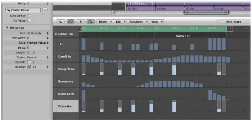
Each note event lane in the example is restricted to the display and control of a single note pitch. By default, each beam that represents note events can be adjusted in level, by dragging vertically with the Pointer tool. Within the same hyper set, you could create two event definition lanes that control the filter cutoff and filter resonance parameters of the lead synthesizer, enabling you to create or precisely edit filter tweaks.
Creating and Editing Events in the Hyper Editor
The Hyper Editor, like the other MIDI editors, can be used for event input duties. In some situations, manual entry of note and controller events is more efficient than performing and recording them. One example would be the creation of 1/16th note hi-hats in a region when the tempo is 160 bpm, which would be difficult to play.
You can, of course, record events with a MIDI keyboard, and then refine your performances in the Hyper Editor.
Changing the Grid and Beam Display
The Grid parameter in the Event Definition Parameter box of the Inspector is important when creating events in the Hyper Editor. Newly created events are automatically added at grid positions. This makes it easy to create a drum pattern, with 4 divisions on one lane, 8 divisions on another lane, and 16 divisions on another lane; assigned to kick, snare, and hi-hat sounds, for example.
To define the Grid value for the selected event definition lane:
- Choose the desired grid type in the Event Definition Parameter boxes' Grid parameter menu.
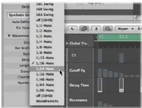
Any events that you add will automatically snap to the nearest grid position. The positions of existing events are not affected.
Tip: When editing or constructing complex rhythm patterns, it can be useful to create several event definitions (see "Selecting and Creating Event Definitions" on page 448) for one drum note, each with a different quantization grid. As an example, if there are two lanes for a snare drum, one with a 1/16th and the other with a 1/96th grid, you can use the Pencil tool to add individual hits in the coarser grid, and drum rolls in the finer grid.
When defining the Grid parameter to add a succession of controllers use the motto, "as coarse as possible, and as fine as necessary" to minimize data output. Logic Express can deal with very large amounts of data, but unfortunately the same cannot be said of MIDI itself.
You can also alter the width and style of event beams to make event creation and editing easier.
To set the width of event beams:
- Choose the desired Pen Width menu value in the Event Definition Parameter box.
The exact event position is always marked by the left edge of the beam, regardless of the beam width.
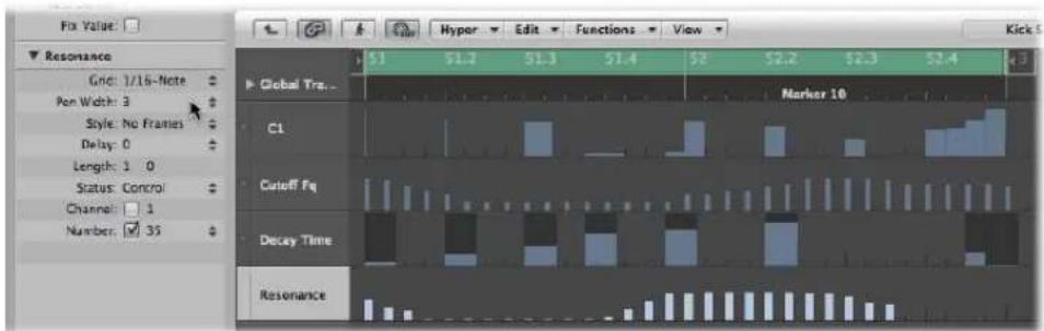
When you set the Pen Width parameter to Note Length, note event beams are displayed at their actual length. The Status parameter must be set to Note for this to work!
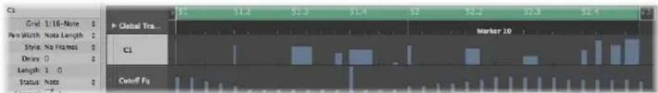
To change the style of beams displayed:
- Choose the desired setting in the Style menu.
- No Frames: Shows the value of the event as a colored beam.
- Framed Values: Shows a hollow frame beam that is the full height of the event definition lane. The value of the event is displayed as a colored beam within the frame beam.
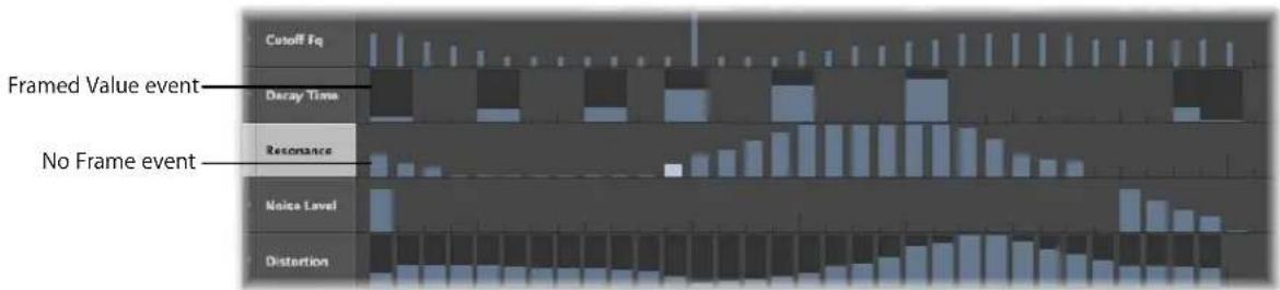
Creating Events
The Hyper Editor provides several unique methods for the creation (and editing) of MIDI events.
To add an event:
1 Choose the Pencil tool.
2 Click at the desired time position, on the appropriate event definition lane.
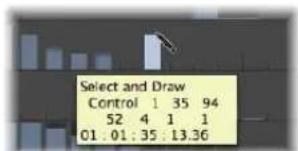
3 Drag up or down to alter the event value before you release the mouse button.
To add multiple events:
- With the Pencil tool, drag horizontally over the desired time position on the appropriate event definition lane.
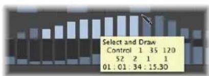
bar
| Select and Draw | Control | | :--- | :--- | | 1 | 52 | | 1 | 2 | | 1 | 1 | | 1 | 1 | | 1 | 01:01:34:15.30 |This results in a freehand curve of new events that follows the (vertical and horizontal) Pencil tool movements in the lane.
To create multiple events in a linear fashion:
1 Select the Line tool.
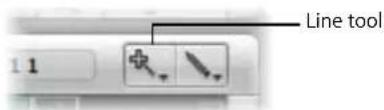
2 Click at the desired position, on the appropriate event definition lane.
A help tag appears, showing the exact position and event value in the top line.
3 Move the mouse to the desired end point of the line (to the right or left).
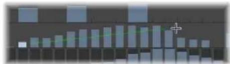
bar
| Category | Value | |---|---| | Bar 1 | 10 | | Bar 2 | 15 | | Bar 3 | 20 | | Bar 4 | 25 | | Bar 5 | 30 | | Bar 6 | 35 | | Bar 7 | 40 | | Bar 8 | 45 | | Bar 9 | 50 | | Bar 10 | 55 | | Bar 11 | 60 | | Bar 12 | 65 | | Bar 13 | 70 | | Bar 14 | 75 | | Bar 15 | 80 | | Bar 16 | 85 | | Bar 17 | 90 | | Bar 18 | 95 | | Bar 19 | 100 | | Bar 20 | 105 | | Bar 21 | 110 | | Bar 22 | 115 | | Bar 23 | 120 | | Bar 24 | 125 | | Bar 25 | 130 | | Bar 26 | 135 | | Bar 27 | 140 | | Bar 28 | 145 | | Bar 29 | 150 | | Bar 30 | 155 | | Bar 31 | 160 | | Bar 32 | 165 | | Bar 33 | 170 | | Bar 34 | 175 | | Bar 35 | 180 | | Bar 36 | 185 | | Bar 37 | 190 | | Bar 38 | 195 | | Bar 39 | 200 | | Bar 40 | 205 | | Bar 41 | 210 | | Bar 42 | 215 | | Bar 43 | 220 | | Bar 44 | 225 | | Bar 45 | 230 | | Bar 46 | 235 | | Bar 47 | 240 | | Bar 48 | 245 | | Bar 49 | 250 | | Bar 50 | 255 | | Bar 51 | 260 | | Bar 52 | 265 | | Bar 53 | 270 | | Bar 54 | 275 | | Bar 55 | 280 | | Bar 56 | 285 | | Bar 57 | 290 | | Bar 58 | 295 | | Bar 59 | 300 | | Bar 60 | 305 | | Bar 61 | 310 | | Bar 62 | 315 | | Bar 63 | 320 | | Bar 64 | 325 | | Bar 65 | 330 | | Bar 66 | 335 | | Bar 67 | 340 | | Bar 68 | 345 | | Bar 69 | 350 | | Bar 70 | 355 | | Bar 71 | 360 | | Bar 72 | 365 | | Bar 73 | 370 | | Bar 74 | 375 | | Bar 75 | 380 | | Bar 76 | 385 | | Bar 77 | 390 | | Bar 78 | 395 | | Bar 79 | 400 | | Bar 80 | 405 | | Bar 81 | 410 | | Bar 82 | 415 | | Bar 83 | 420 | | Bar 84 | 425 | | Bar 85 | 430 | | Bar 86 | 435 | | Bar 87 | 440 | | Bar 88 | 445 | | Bar 89 | 450 | | Bar 90 | 455 | | Bar 91 | 460 | | Bar 92 | 465 | | Bar 93 | 470 | | Bar 94 | 475 | | Bar 95 | 480 | | Bar 96 | 485 | | Bar 97 | 490 | | Bar 98 | 495 | | Bar 99 | 500 | | Bar100 (Bar) | -100 |As you do so, you will see the line trailing behind the Line tool pointer, with the exact position and event value shown in a help tag.
4 Click at the desired end point to create several event beams, aligned along the line.
New events are created at each grid position (in accordance with the Grid parameter), within the line start and end points.
To create or alter a linear series of events in sections:
■ Follow the steps above, but hold Shift when clicking at the end point position.
This immediately draws another line from the end point of the original line.
To create new events when other events already exist in a lane:
■ Follow the procedure above, and hold down Option when you click for the last time.
The values of existing events in the area between the line start and end points are aligned along the line (creating a crescendo, for example). New events are created at every (unoccupied) grid value.
Using a Fixed Value When Creating Events
The Fix Value checkbox in the Inspector, when on, prevents any event value from being altered with the Pointer or Pencil tools.
This is ideal when adding events with the Pencil, as all are assigned the value of the previously-selected event. This allows you to draw a succession of events with the same value. Perfect for drawing in a row of 16th note hi-hats, for example.
To assign a fixed event value:
1 Enable the Fix Value checkbox in the Inspector.
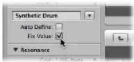
2 Click any existing event with the Pencil tool to use its value as a preset.
In fix value mode, it is impossible to alter an event value by clicking on it.
Note: When adding events with the Line tool in fix value mode, the preset value is always used as the starting value of the line.
Changing the Length of Added Notes and Events
You can use the Length parameter to set the length of events (this primarily applies to note events) to be added, measured in divisions (the left number), and ticks (the right number).
You should avoid the use of small tick values. Many MIDI devices do not respond quickly enough when note on/note off messages are sent in quick succession, resulting in no note being heard.
Selecting Events
You can use any of the usual selection techniques (see "Selection Techniques" on page 177), with the following differences:
To select individual events:
■ Hold Shift, and click on the desired events.
To select several contiguous events:
■ Hold Shift, and make a rubber band selection.
Ensure that you do not click on any events. If you simply click or drag with the Pointer tool, the selected event values will be changed, so make sure Shift is held!
To select all events on a lane:
- Click the event definition name.
To select all events on multiple lanes:
Shift-click on the appropriate event definition names.
Deleting Events
Events can be deleted individually by clicking on them with the Eraser tool. The following techniques cover deletion of multiple events.
To delete several contiguous events in a lane:
- Drag across the events with the Eraser tool.
To delete several non-contiguous events:
- Select the events you want to remove, then press Backspace.
To delete similar or equal events:
1 Select one of the notes you want to delete.
2 Choose Edit > Select Similar Events or Edit > Select Equal Events (notes of the same pitch, for example), and then delete the selected events by pressing Backspace.
For more information about similar and equal events, see "Selecting Similar or Identical Objects, Regions, or Events" on page 181.
You can also delete events by choosing one of the Delete MIDI Events commands from the Hyper Editor's local menu bar. For further information, see "Deleting Notes" on page 421.
Restoring Deleted Events
Accidental deletions of one or more events, or a simple change of mind or editing mistake is an inevitable part of song creation. Fortunately, you can backtrack your edits easily in Logic Express. You also have the option of simply recreating an event with the Pencil tool.
To undo the last event editing step or deletion:
- Choose Edit > Undo from the main menu, or press Command-Z immediately after making the error.
To undo or redo multiple steps:
1 Choose Edit > Undo History.
This opens the Undo History window. The most recent editing step (at the bottom of the list) is highlighted.
2 Click on any entry to undo or redo all steps between the clicked and highlighted entries.
All steps are animated during this process.
Important: A Redo list is not displayed until an Undo operation has been performed.
The Redo list appears below the Undo items. The first item that can be redone is indicated by gray text.
To undo or redo an isolated step:
1 Command-click on the desired step.
A warning dialog will open.
2 Click Apply to undo or redo the step. Click Cancel to abort the step.
This will undo or redo an isolated step without influencing all steps between the clicked and highlighted (most recent) entries.
Changing Event Values
Events can be altered individually or as a group. When adjusted as a group, the absolute differences between the event values remain constant.
To alter individual event values:
- Grab the event beam (with the Pointer or Pencil tool), and drag vertically.
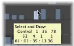
The current value is shown in a help tag as you drag.
To alter several contiguous event values:
- Drag across the events with the Pointer tool.
The current value is shown in a help tag as you drag across each event.
To alter the values of multiple events:
1 Use any of the selection techniques discussed above to select the events you want to edit.
2 Grab one of the grouped (and highlighted) beams, and drag vertically.
The values of all events are adjusted. If any of the beams in the group reaches the maximum or minimum value, you will not be able to go any further in that direction.
To adjust event values when one grouped event has reached an extreme value:
If you hold Option while doing so, you can keep raising or lowering the values of all events in the group, until the grabbed event beam reaches the maximum or minimum value.
Moving and Copying Events
Events can be moved or copied to other positions in the same, or other, lanes. When moved or copied between lanes, the event values are retained, but are converted to the target event definition. As an example, moving several events from the Volume lane into the Pan lane will result in the Volume values being used for Pan position changes.
To move selected events:
■ Hold Shift, and drag to the desired position and lane.
As you do so, a help tag will inform you of the position, event definition type and value (if applicable).
Moving Events via Key Commands
Editing can be accelerated by assigning, and using, the following key commands to move one or more events.
• Nudge Region/Event Position Right by SMPTE Frame
- Nudge Region/Event Position Left by SMPTE Frame
• Nudge Region/Event Position Right by 1/2 SMPTE Frame
• Nudge Region/Event Position Left by 1/2 SMPTE Frame
• Nudge Region/Event Position Right by 5 SMPTE Frames
• Nudge Region/Event Position Left by 5 SMPTE Frames
- Nudge Region/Event Position Right by SMPTE Bit
• Nudge Region/Event Position Left by SMPTE Bit
• Nudge Region/Event Position Right by Tick
• Nudge Region/Event Position Left by Tick
• Nudge Region/Event Position Right by Division
• Nudge Region/Event Position Left by Division
• Nudge Region/Event Position Right by Beat
• Nudge Region/Event Position Left by Beat
• Nudge Region/Event Position Right by Bar
• Nudge Region/Event Position Left by Bar
• Nudge Region/Event Position Right by Nudge Value
• Nudge Region/Event Position Left by Nudge Value
The selected events are shifted one step right (+1) or left (-1), by whatever unit is referred to in the particular command name.
To copy selected events:
- Hold Option, and drag to the desired position and lane.
As you do so, a help tag will inform you of the position, event definition type and value (if applicable).
You can also use the Clipboard to copy and move notes:
- Edit > Copy (or Command-C) copies notes into the Clipboard.
- Edit > Cut (or Command-X) moves the notes into the Clipboard.
- Edit > Paste (or Command-V) pastes them at the current playhead position, at their original pitch.
You can also perform advanced copy and move operations within the Hyper Editor. These allow you to directly swap events, or to merge a group of events from one section of a region to the same, or another, region, as examples. For more information, see "Advanced Note Copy and Move Options" on page 428.
Protecting the Position of Events
There are times where you will want to protect certain events from being moved. As an example, several note events may be used to trigger footstep samples that match an actor walking down a corridor, in a video soundtrack. You have already created the music for this scene, but have been asked to increase the tempo to match several cuts of different camera angles in the corridor. Obviously, a change in the project tempo will move the events, resulting in out of sync footstep samples. Thankfully, Logic Express has a feature that preserves the absolute time position of events.
To protect the position of one or more selected events:
- Choose Functions > Lock SMPTE Position (or use the corresponding key command). This ensures that events that fall at a particular absolute time position: 1 hour, 3 minutes, 15 seconds, 12 frames, for example, will remain at this position when tempo changes are made.
To unprotect the position of one or more events:
- Choose Functions > Unlock SMPTE Position (or use the corresponding key command).
Working With Event Definitions
The event definition determines the event type shown on each Hyper Editor lane. Events are shown as vertical beams on each lane, aligned with a particular time position in the Bar ruler.
There are many ways of altering the way the beams are displayed, making it easier to create or adjust particular event types (see "Changing the Grid and Beam Display" on page 439). You can also alter the grid resolution for each event definition lane in a hyper set, which is very useful when creating drum patterns. The height and horizontal size of the lanes is adjusted with the zoom bars.
Selecting and Creating Event Definitions
You can select an event definition by clicking the name column with the Pointer or Pencil tool.
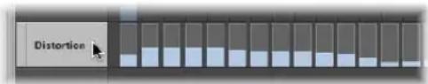
This allows you to create new definitions, and to view and change the event definition parameters in the Inspector (see "Changing Event Definitions" on page 451).
To select multiple event definitions:
Shift-click on each event definition with the Pointer or Pencil tool.
You can make concurrent changes to the parameters of several selected event definitions (see "Adjusting Multiple Event Definitions Simultaneously" on page 453).
To create a new event definition:
1 Select an event definition lane by clicking on one of the names shown.
The selected lane is highlighted.
2 Choose Hyper > Create Event Definition (or use the corresponding key command, default: Option-Command-N).
This creates a new event definition lane. The original, and all subsequent, event definition lanes are moved downwards. The new event definition parameters are identical to the originally selected event definition.
3 Adjust the event definition parameters in the Inspector (more on this shortly).
You can use the Auto Define feature to automatically create event definitions for specific event types in your project.
To create an event definition for a specific event:
1 Select the desired event type (controller #71 Resonance, for example) in one of the other MIDI editors.
Tip: The Event List is highly recommended for this task as it can display all MIDI event types.
2 Enable the Auto Define checkbox in the Hyper Editor's Inspector (or use the Toggle Auto Define key command, default: Control-A).
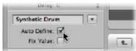
3 Choose Hyper > Create Event Definition in the Hyper Editor (or use the Create Event Definition key command, default: Option-Command-N).
If the hyper set already contains a matching event definition (controller #71 Resonance, from the example), Logic Express won't create a superfluous double definition. The existing event definition is moved into the visible area of the Hyper Editor in this situation.
Note: Don't forget to switch off Auto Define immediately after completing your input. If you don't do this, you may inadvertently select an event type in another editor, and this will be used as the basis for new event definitions. This could be frustrating, and surprising, when using the Control-Return key command, in particular, to create new definitions.
To create several event definitions at once:
1 Select the events that you want to create event definitions for in one of the other MIDI editors.
As above, the Event List is recommended.
2 Do one of the following
- Choose Hyper > Create Multiple Event Definitions (or use the corresponding key command), then click the Selected button in the dialog.
- Choose Hyper > Create Hyper Set for Current Events (or use the corresponding key command).
This creates a new hyper set that contains event definition lanes for each of the selected event types. This is especially useful for quick hyper set creation of all HyperDraw (MIDI controller) events in a region. Open the Event List, filter the note events, select all remaining events, and use Hyper > Create Hyper Set for Current Events.
To create event definitions for all event types in a region:
1 Select the region.
2 Choose Hyper > Create Multiple Event Definitions (or use the corresponding key command).
3 Click the All button in the dialog to confirm that you want to create event definitions for all types of events in the region.
Tip: It's a good idea to create a new hyper set before creating a group of new definitions. For more information, see "Creating a Hyper Set" on page 455.
Copying, Deleting, and Rearranging Event Definitions
The following functions make the creation and organization of hyper sets much easier and faster.
To copy an event definition between two hyper sets:
1 Select the event definition that you want to copy.
2 Choose Hyper > Copy Event Definition (or use the corresponding key command, default: Control-C).
3 Switch to the destination hyper set, by choosing the hyper set name in the pop-up menu at the top of the Inspector.
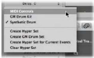
4 Choose Hyper > Paste Event Definition (or use the corresponding key command, default: Control-V).
To delete event definitions:
- Select the desired event definitions, then choose Hyper > Delete Event Definition (or use the corresponding key command, default: Control-Backspace).
To reorganize the order of event definition lanes:
- Grab the name of the event definition you want to move, and drag it (vertically) to the desired position.

Changing Event Definitions
You use the Event Definition Parameter box in the Inspector to alter the settings of the selected event definition lane. The most important parameters are Status (and First Data Byte). All display related parameters are covered in "Changing the Grid and Beam Display" on page 439. Information on all other parameters is found later in this section.
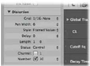
Altering the Event Status
The event status determines the type of event controlled by each event definition lane. Click-hold the arrows to the right of the Status line, and choose one of the following from the pop-up menu:
- Fader: To define a fader event lane. Fader event data can be used to control any possible parameter (except channel volume and pan, which use controllers). Fader data can also be used to create meta events.
- Meta: To define a meta event lane. Meta events are internal Logic Express commands that can perform tasks such as screenshot switching.
- Note: If you want to define a lane for a particular note pitch (perfect for drum programming).
• Control: If you want to define a MIDI controller lane. - C- Press (Channel Pressure): To define a lane for channel pressure (also known as aftertouch, a feature of many synthesizers that adds vibrato, for example, when you press down on MIDI keyboard keys that are already held).
- P-Press (Polyphonic Pressure): As above, but each note can be independently modulated.
- Program Change: To define a lane that is used to create and send MIDI program change events, allowing you to switch between sounds (electric piano and clavinet, for example) midway through a region.
- Pitch Bend: To define a lane for pitch bend information.
Important: The choice made in the Status line directly affects the behavior (and appearance) of the First Data Byte parameter.
As an example, if Note is chosen in the Status parameter line, you can use the first data byte to determine the pitch (MIDI note number) of the selected event definition lane. If the MIDI region is played by a mapped instrument, a pop-up menu of input note names (drum sound names) appears here.
Using the First Data Byte Parameter
The First Data Byte checkbox and menu is shown on the bottom row of the Event Definition Parameter box in the Inspector. You use them to determine the value of the first data byte (of the displayed event type).
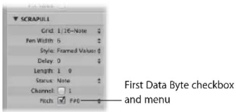
The First Data Byte checkbox determines whether or not events with the defined first data byte should be displayed (if on), or whether the setting should be ignored (if off). In the case of note events, the velocity values of all notes (regardless of pitch) would be displayed in the relevant event definition lane.
The name of the First Data Byte parameter reflects the chosen Status parameter, as follows:
- Fader, Meta, Control, Program: Number is shown as the First Data Byte.
- Note, P-Press: Pitch is shown as the First Data Byte.
- C-Press and PitchBd: The First Data Byte is dimmed, as it has no function.
If Control is chosen in the Status line, you can use a pop-up menu shown in the First Data Byte parameter line, to determine the controller type (controller number).
Similarly, if Meta or Fader are chosen in the Status line, the First Data Byte menu determines the meta or fader event type (meta or fader message number).
If channel aftertouch (C-Press), or program change events (Program) are chosen in the Status line, the First Data Byte parameter setting is ignored, and the first data byte is displayed as a beam height.
When pitch bend data (PitchBd) is chosen in the Status line, the First Data Byte parameter setting is also ignored, because both data bytes are used to display the beam height.
Naming an Event Definition
The name of the selected event definition is shown beside the disclosure triangle in the Event Definition Parameter box in the Inspector. This is mirrored in the name column in the Hyper Editor.
To name an event definition:
- Click on the name to open a text entry field, type in the desired name, then press Return.
Note: If you define a named MIDI controller, or a note from a mapped instrument in the Status and First Data Byte parameter lines, the relevant name will be offered as a preset.
Note: Altering a note name in the event definition also alters the corresponding note name in the mapped instrument.
Delaying Events
The Inspector's Delay parameter is very useful for drum programming (flams, for example), as only individual event types or note numbers are affected. It is also useful for tightening up or sliding notes in a region, without resorting to quantization.
To delay or advance the selected event definition:
- Set the Delay parameter to the desired value.
Position changes are immediately reflected by the events in the lane. New events (inserted when a grid was active) are offset from the grid positions by the Delay parameter value.
Tip: In general, you should transmit controller data slightly before or after note events, to improve the timing of notes. In other words, place controllers before (use a negative Delay value) the grid positions of the notes lying exactly on the grid positions.
MIDI Channel
Next to Channel, you'll see a checkbox, and to the right of this you can set a MIDI channel number, by dragging vertically. If you click this box (turn it on), the display is restricted to events on the set channel. If the box is unchecked, the channel parameter is ignored, and matching events on all channels are displayed.
Adjusting Multiple Event Definitions Simultaneously
Just as you can adjust the parameters for several MIDI regions at once, you can set the parameters of several event definitions simultaneously. Select several event definitions in the name column, by holding down Shift and clicking on them. You can also use Hyper > Select All Event Definitions to select all event definitions, and then deselect some of them by Shift-clicking on them.
Any alterations you make in the Event Definition Parameter box will affect all selected event definitions.
Converting Event Definitions
You can redefine an event definition (along with all events). The values of the events are retained, but the event type is changed to the new event definition.
To convert an event definition and all events:
1 Select the event definition you want to convert.
2 Do one of the following:
- Choose Hyper > Convert Event Definition (or use the corresponding key command).
- Double-click on the name column of the event definition that you want to convert.
3 Choose the desired settings in the Convert Definition dialog, and press the Convert button.
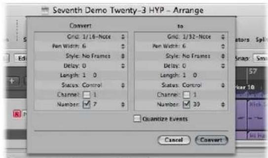
On the left (Convert), you can see the parameters of the selected event definition, and on the right you can define the parameters of the destination event type. The current settings (of the source) are used as default values for the destination.
Enable the Quantize Events checkbox to quantize the event positions to the Grid value chosen in the right-hand parameter field. If any Delay value is shown on the right, this is taken into account by the quantization.
If you simply open the Convert Definition dialog, change the Grid value in the right-hand field, turn on the Quantize Events checkbox (and make no further alterations), the event positions of the selected event definition lane will be quantized.
Working With Hyper Sets
You can store a combination of simultaneously displayed event definitions as a hyper set. When a hyper set is saved, the vertical zoom setting of the Hyper Editor is stored (this determines the number of event definitions that can be displayed simultaneously). You can save as many hyper sets as you need in each project.
The commands discussed in this section are available directly in the Hyper Set menu, shown in the Inspector. Simply click the Hyper Set menu, and choose the desired command to create or clear hyper sets.
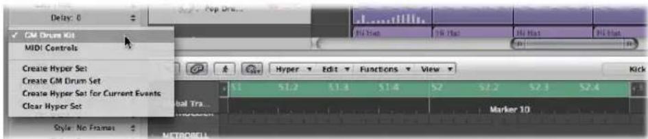
Creating a Hyper Set
To create a new hyper set, choose Hyper > Create Hyper Set (or use the Hyper Set menu, or corresponding key command). The preset event definition in the new hyper set is the volume controller (#7). Any alterations that you make, such as adding or redefining event definitions, or adjusting the vertical zoom setting, are automatically stored in the current hyper set (as with screensets).
Choose Hyper > Create Hyper Set for Current Events (or use the Hyper Set menu, or corresponding key command) to create a new hyper set, consisting of the currently selected event types.
Creating a GM Drum Hyper Set
General MIDI has an established keyboard assignment pattern (a MIDI note map) for drum and percussion sounds. This mapping standard is often followed in non GM, GS, or XG compliant sound modules, samplers, and synthesizers. In some cases, however, you will need to make a few changes.
As the Hyper Editor is ideally suited for drum track creation and editing, you may wish to create a hyper set that is specifically tailored for your drum sets, including the correct drum names and hi hat modes.
To create a hyper set for a GM drum kit:
- Choose Hyper > Create GM Drum Set (or use the Hyper Set menu, or respective key command).
You can change the names, positioning, and hi-hat modes of each event definition (drum or percussion lane) in the hyper set. See "Naming an Event Definition" on page 452, for information on renaming each drum sound in your kit, if it doesn't match the GM mapping standard.
Using Hi Hat Mode
In hi hat mode, event definitions can be grouped together. Only one event from each group can be played at any Bar ruler position. This function is typically used to prevent different hi hat notes (open, closed, pedal) from being inserted at the same time position. This mirrors the real world behavior of hi-hats, which can't be simultaneously opened and closed.
1 Click the dot shown to the left of the desired name column (kick 1, for example).
2 Click the dot shown to the left of other (adjacent) name columns (kick 2, for example).
A dotted line links the two instrument lanes in the left-hand edge of the column.
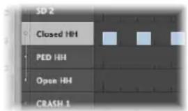
3 Click the dots of each lane to switch off hi hat mode.
All lanes in a hi hat group must be vertically adjacent to each other. If you want to group several events in non-adjacent lanes, simply move them by dragging the names up/down the Hyper Editor window.
If you add an event to any lane in a hi hat group, all existing events at this time position are deleted.
You can create as many hi hat groups as needed in a hyper set, but they must all be separated by at least one line in which hi hat mode is switched off.
Naming a Hyper Set
By default, a new hyper set is named MIDI Controls or GM Drum Kit.
To re-name a hyper set:
- Double-click the name shown in the Hyper Set menu of the Inspector, type in the desired name and press Return.
Clearing and Deleting a Hyper Set
Clearing a hyper set resets a hyper set to its default, containing the preset event definition for the volume controller.
To clear the current hyper set:
- Choose Hyper > Clear Hyper Set (or use the Hyper Set menu, or corresponding key command).
To delete the current hyper set:
- Choose Hyper > Delete Hyper Set.
Loading a Hyper Set
You can switch the Hyper Editor display to the desired event types by loading a saved Hyper Set.
To load a hyper set:
- Click the Hyper Set menu in the Inspector, and choose the desired hyper set from the pop-up menu.
Editing MIDI Events in the Event List
The Event List is the most powerful, flexible, and complete MIDI editor in Logic Express.
All MIDI event types are displayed as an alphanumeric list in the Event List. All aspects of events—start and end points, length, channel, and values—can be altered in this window.
You can view all events in one or more regions, and can filter the list to restrict this view to one or more event types, such as notes, pitch bend events, or both, for example. This makes the selection and editing of events faster and simpler.
The Event List also offers a number of advanced selection criteria that can be used in conjunction with, or independent of, the view filters. These allow you to select all equal or similar events, among others.
As a practical example of where these facilities could be used: Imagine a lead synthesizer solo that spans eight bars. You went crazy with the pitch bend while recording, but have found that every pitch bend event with a value of 55 sounds out of tune with the pad sound on another track. Filter the view so that only pitch bend events are visible, select one of the events with a value of 55, and choose Edit > Select Equal Regions/Events (Shift-E). All pitch bend events with a value of 55 are selected, allowing you to simultaneously change their values, or delete them.
As with the other MIDI editors, you can also create events directly in the Event List.
Learning and Using the Event List Interface
All functions and options are shown at the top of the Event List area. The events themselves are shown in the list area below.
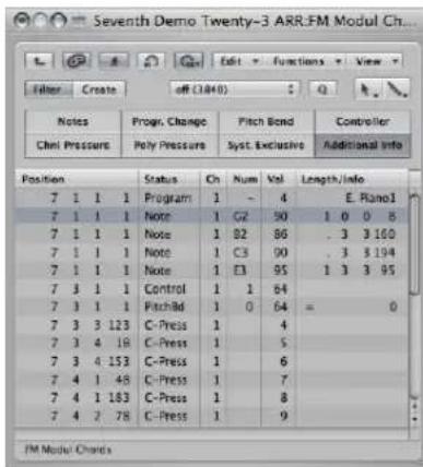
To open or close the Event List, either:
- Press the E key (the default Toggle Event List key command).
- Click the Lists button at the top right of the Arrange Toolbar, and click the Event tab, if it's not already active.
The lists area is displayed (or hidden, if already open) on the right side of the Arrange window. The active tab is memorized when the lists area is closed.
Changing the Event List View Level
By default, the Event List will show all events in the selected MIDI region or regions. The Event List can also display a list of all regions (and folders) in the Arrange window.
To view a list of Arrange regions (and folders):
- Click the Hierarchy button at the top left of the Event List window.
This button is only accessible when the Event List view is showing the contents of a region (it's showing events, in other words).
To view the events within a region:
■ Double-click on the name of the region with the Pointer tool.
Its contents (the events) are shown in the list.
Note: It is possible to pack folders within folders in the Arrange window. Simply use the procedures outlined above multiple times to navigate up or down through the most complex folder hierarchy.
Filtering Event Types
When viewing events in the selected MIDI region or regions, you can make use of the event type buttons to filter the display. These buttons hide specific event types from the list below, thus limiting the view to events that you want to edit.
Important: All selection, editing, and processing functions performed in the Event List only affect the displayed events, which protects any non-visible events from changes you may make.
To filter the event view:
1 Click the Filter button to turn on filter mode.
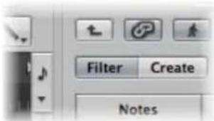
2 Click the desired event type buttons (Notes, Pitch Bend, and so on).
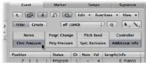
Events which match the active buttons will disappear from the list display.
Enhancing the Display of Events
The Event List display is normally restricted to one line per event. When the Additional Info button is on, however, all information stored along with the event is also shown.
This is particularly important for editing SysEx messages. When examining note events in the Event List, you will also notice Rel Vel (release velocity or note off messages), which can be directly edited.
| Notes | Progr. Change | Pitch Bend | Controller | ||||||
| ChrI Pressure | Poly Pressure | Syst. Exclusive | Additional Info | ||||||
| Position | Status | Ch | Num | Vel | Length/Info | ||||
| 20 | 4 | 3 | 121 | Note Rel Vel | 1 | C4 off | 123 | ... 1 25 | |
| 20 | 4 | 4 | 1 | Note Rel Vel | 1 | C44 off | 102 | ... 142 | |
Score layout information is also included in the list when additional info is shown. You can edit this in the Event List if you wish, but it is handled far more efficiently in the Score Editor.
Note: The Additional Info button is only visible when the Filter button is on. Once activated, the enhanced event list will be shown (in Filter or Create mode) until the Additional Info button is turned off.
Viewing Events Outside the Display Area
You will often find that the number of events shown in the list exceeds the amount of screen space. The list will automatically scroll when the Logic Express transport is engaged, and the event at (or nearest to) the playhead position being indicated by a white line.

Note: The Catch button must be turned on for the Event List to automatically scroll through events during playback or recording.
To view events outside the display area, try the following:
- Use the event type buttons to filter the list, thus reducing the number of displayed events.
- Drag the scroll bar to the right of the list area.
- Choose View > Scroll to Selection (or use the corresponding key command).
Using the Shortcut Menu
Many selection, editing, and other commands can be accessed by right-clicking anywhere in the Event List. Make use of this to accelerate your workflow.
Note: The right-click shortcut menu can only be accessed if the Right Mouse Button: Opens Shortcut Menu pop-up menu option is chosen in the Logic Express > Preferences > Global > Editing tab.
Selecting and Creating Events
You can use any of the standard selection techniques in the Event List: individual selection by clicking on events, multiple selection using the rubber band, or both of these (without altering the previous selection), in conjunction with the Shift key. Full details on all selection techniques are discussed in “Selection Techniques” on page 177.
Tip: When selecting events with the Pointer, you should click on the event name in the Status column, to avoid any unintentional parameter alterations.
To make a selection (and navigate the list) with the Left or Right Arrow key:
- Press the Left Arrow key to select the previous event, or the right Arrow key to select the next event. Hold down the respective Arrow key to scroll through the list.
To select multiple events with the arrow keys:
- Hold Shift and press the Left or Right Arrow keys. Keep the Arrow key held down to select multiple events (with Shift held).
Note: If the MIDI Out button is switched on (it is on by default), every newly selected event will be played. This allows you to scroll (or play) through the list and audibly monitor events as they are selected.
Refining Event Selection
First up, use of the event type buttons to filter the list of displayed events will make selection faster and easier.
You can use these filter buttons alone, or in conjunction with, specific selection commands available in the Edit menu and as key commands. These include:
- Select All (default key command: Command-A): Selects all visible events.
- Select All Following (default key command: Shift-F): Selects all events after (below) the currently selected event.
- Select Inside Locators (default key command: Shift-I): Selects all events that fall within the locator boundaries.
- Select Overlapped Regions/Events: Selects all events that overlap one another. This is usually the end of one event, and the start of the following event.
- Select Muted Regions/Events (default key command: Shift-M): Selects all muted events. This selection command is usually a precursor for deletion (Backspace).
- Select Similar Regions/Events (default key command: Shift-S): Selects all C#3 note events, for example.
- Select Equal Regions/Events (default key command: Shift-E): Selects identical events (same event type, and value).
- Select Equal Channels (default key command: Shift-K): Selects events on the same MIDI channel.
- Select Equal Subpositions (default key command: Shift-P): Selects events that start at the same position.
Details on what constitutes equal or similar events can be found in "Selecting Similar or Identical Objects, Regions, or Events" on page 181.
Creating Events
The Event List accepts real time and step recording of MIDI events, as described in Chapter 14, "Recording in Logic Express," on page 367. You can also manually add events.
To add an event manually:
1 Move the playhead to the desired insert position.
The current playhead position will be used as the insert position if not moved.
2 Click the Create button.
3 Click the desired event type button.
The event is added at the playhead position, and is automatically selected.
Important: Events can only be created in an existing region. If no region is selected, or exists, on the selected Arrange track, an alert is shown.
To duplicate an existing event:
1 Click on the original (source) event name in the Status column with the Pencil tool.
| Chnl Pressure | Poly Pressure | Syst. Exclusive | Additional Info | ||||||||
| Position | Status | Ch | Num | Val | Length/Info | ||||||
| 7 | 1 | 1 | 1 | Note | 1 | G2 | 90 | 1 | 0 | 0 | 8 |
| 7 | 1 | 1 | 1 | Note | 1 | B2 | 86 | 3 | 3 | 3 | 160 |
| 7 | 1 | 1 | 1 | Note | 1 | C3 | 90 | 3 | 3 | 3 | 194 |
2 An input box appears—use it to enter the position for the duplicate event. If you press Return, the duplicate will appear at the same position as the original.
| Position | Status | Ch | Num | Val | Length/Info | ||||||
| 7 | 1 | 1 | 1 | Note | 1 | G2 | 90 | 1 | 0 | 0 | 8 |
| 7 | 1 | 1 | 1 | Note | 1 | G2 | 90 | 1 | 0 | 0 | 8 |
| 7 | 1 | 1 | 1 | Note | 1 | B2 | 86 | 3 | 3 | 160 | |
The duplicate function is useful for creating a copy of an event with a different value. As an example, creating one or more notes of a particular length and velocity at the same position as another note. You could then alter the Pitch (Num column) of the duplicate notes to create a chord, or a new chord voicing.
To add one or more events from the Clipboard:
1 Following a copy operation from another editor, choose Edit > Paste (default key command: Command-V).
2 A position input box will appear, allowing you to type in a destination position for the first event. If you press Return, the original position of the first event is retained and used. The relative positions of other copied events are maintained.
Important: The position input box is unique to the Event List. Pasted events are not automatically added at the playhead position, as is the case in the graphical editors.
Copying and Moving Events
You can perform advanced copy and move operations within the Event List. These allow you to directly swap events, or to merge a group of notes from one section of a region to the same, or another, region, as examples. For more information, see "Advanced Note Copy and Move Options" on page 428.
Protecting the Position of Events
There are situations where you will want to protect certain events from being moved. As an example, several note events may be used to trigger footstep samples that match an actor walking down a corridor, in a video soundtrack.
You have already created the music for this scene, but have been asked to increase the tempo to match several cuts of different camera angles in the corridor. Obviously, a change in the project tempo will move the events, resulting in out of sync footsteps. Thankfully, Logic Express has a feature that preserves the absolute time position of events.
To protect the position of one or more selected events:
- Choose Functions > Lock SMPTE Position (or use the corresponding key command).
This ensures that events that fall at a particular absolute time position: 1 hour, 3 minutes, 15 seconds, 12 frames, for example, will remain at this position when tempo changes are made.
To unprotect the position of one or more events:
- Choose Functions > Unlock SMPTE Position (or use the corresponding key command).
Editing Events
The list area features several columns: Position, Status, Ch(annel), Num(ber), Val(ue), and Length/Info: These columns display all details of all event types. In most cases, you can directly edit the data displayed (with the exception of the Status column, which merely indicates the event type).
Not all columns are used for every type of event. As examples, system exclusive messages are not MIDI channel specific, so the Ch(annel) column is unused. Channel and polyphonic pressure messages have no length, so the Length/Info column is left blank.
In some instances, clicking on the information in the Num(ber) or Val(ue) column will open a pop-up menu, allowing you to choose an option. As an example, clicking on the Num(ber) column of a MIDI controller event (Control is shown in the Status column) will open a pop-up menu of numbered and named standard MIDI controller types. These include: Controller numbers 3 = Solo, 7 = Volume, 10 = Pan, and so on.
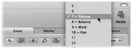
Full details on the different event types, the parameters shown in the columns, and the impact of changes—on both the event itself, and other columns—is found in "Learning About Event Types" on page 469.
Changing the Position and Length of Events
The units shown in the Position and Length/Info columns represent bars, beats, divisions, and ticks. Counting begins at 1 for each unit (first bar, first beat, first division, first tick: 1 1 1 1), and continues until it is carried over to the next largest unit.
Numerical input starts from the left (which means you can simply enter the bar number, and press Return, if you want to move an event to the beginning of a specific bar, when typing in a value). The units can be separated by either spaces, dots, or commas, allowing you to type: 3.2.2.2 or 3, 2, 2, 2 or 3 space 2 space 2 space 2.
Note: For the sake of clarity, when the length begins with one or more zeros, a period (“.”) is used in place of the zeros. The minimum possible length is 1 tick (… 1) not 0 ticks, as simultaneously switching a note (or other event) on and off wouldn’t make sense!
To move an event in time, either:
- Double-click on the position indicator (in the Position column), and type in a new position. Press Return to exit the position entry field.
- Click-hold on the specific position unit, and drag vertically. Release the mouse button when you're done.
If another editor, such as the Piano Roll is open, you will see the note event move as you change the value. As soon as you alter the position of an event, the list is automatically re-sorted. The currently selected event remains highlighted.
To change the length of an event:
■ Use either of the methods above in the Length/Info column.
Changing the Appearance of the Position and Length Columns
Not every project is bar/beat oriented. These View menu commands may make changing the position and length of events much easier when you're working with film or video, for example.
- View > Event Position and Length in SMPTE Units: Choose to display the position and length columns in SMPTE units.
- View > Length as Absolute Position: Allows you to make the length display show the absolute position of the note off event, rather than its length from the note on position.
- View > Relative Position: If active, the event positions don't refer to their absolute location within the project, but to their relative positions within the MIDI region (their distance from the start of the MIDI region).
Altering Event Values
Event parameter values can be changed by using the mouse as a slider or with text input, as per changes to position or length—on the values shown in the Val(ue), Num(ber) or Ch annel) columns.
You cannot directly alter the event type in the Status column.
To alter the event type, either:
- Choose Functions > Transform to open a Transform window, and transform the event.
See Chapter 20, "Editing MIDI Events in the Transform Window."
- Add an event of the desired type, and delete the original event.
If a parameter of one of several selected events is altered, it will affect the same parameter in all events within the selection group. When you alter parameter values in a group of selected events, the relative differences between parameter values remain unchanged.
Parameter values can only be altered until the (same) parameter value of one of the selected events has reached its maximum or minimum value.
To override the maximum or minimum value limitation:
- Option-drag on the value, or press Return to confirm a numerical input.
This allows you to continue altering a parameter value in a multiple selection, even when one of the selected events has reached its maximum or minimum value.
To set a parameter to the same value for all selected events:
- Hold Shift-Option, while using the mouse as a slider, or press Return to confirm a numerical input.
Note: It is possible to select different event types, and simultaneously alter the Num(ber) or Val(ue) parameters. Needless to say, this can lead to unexpected, and disastrous, results. It is highly recommended that you make use of the event filtering buttons to hide non-matching event types. The enhanced selection functions may also be of use when creating or editing groups of events.
Deleting and Muting Events
These two functions go hand in hand. It stands to reason that you will often want to remove events that you have muted.
To mute or unmute a note event:
- Click a note event with the Mute tool.
A dot appears in the Status column of muted note events.
The Edit > Select Muted Regions/Events command is also available in the Event List. It allows the selection of all muted notes in a MIDI region, making them easy to delete.
To delete events, do one of the following:
- Click them with the Eraser tool.
- Select the events, using any of the techniques and functions discussed earlier, and press Backspace.
- Choose one of the commands in the Functions > Delete MIDI Events menu.
- Duplicates (default key command: D): Erases all duplicate events.
- Inside or Outside Locators: Erases all MIDI events within/outside the locators.
- Outside Region Borders: Erases all MIDI events that completely fall outside the region borders, which can happen when regions are resized.
- Unselected Within Selection: Erases all unselected MIDI events within a selection, such as between locators.
Soloing and Renaming Regions or Folders
Although the Solo tool can be used to hear events in isolation, it is most useful when viewing a list of Arrange window regions and/or folders (Event List at Arrange-level view).
To solo a region, folder (or event):
- Choose the Solo tool from the Tool menu, and click-hold on the region or folder name (or event) in the Status column.
The playhead will automatically jump to the beginning of the selected region or folder (or event), and soloed playback will start.
To rename a region or folder:
1 Choose the Text tool from the Tool menu, and click on the region or folder name in the Status column.
2 Type in the desired name, and press Return to exit the text field.
The corresponding region or folder is renamed in the Arrange window.
Note: The Text tool has no effect on events, as these cannot be renamed.
Learning About Event Types
This section covers the different types of events that can be viewed, and changed, in the Event List.
Note Events
Note events are used to trigger (play) software instruments and external MIDI sound modules or keyboards.
| Position | Status | Ch | Num | Val | Length/Info | |||||
| 7 | 1 | 1 | 1 | Note | 1 | C3 | 90 | . | 3 | 3 194 |
| 7 | 1 | 1 | 1 | Note | 1 | E3 | 95 | 1 | 3 | 3 95 |
| 7 | 3 | 3 | 123 | C-Press | 1 | 4 | ||||
- Num(ber): MIDI note number (or pitch). The range is from C -2 (note #0) to G8 (note #127). Middle C is note #60. It's known as C3 in MIDI terminology. On some keyboards and synthesizer modules (notably those made by Korg and Roland), the note range is from C -1 (note #0) to G9 (#127). Middle C is called C4 on such devices. The Display Middle C As menu in the Logic Express > Preferences > Display tab allows you to alter the display to match your device.
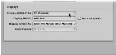
- Val(ue): Velocity of a note from 1 to 127. The zero value (0) acts as a note off message, and cannot be used.
- Length/Info: Length of the note. Although MIDI can only transfer note on or note off messages, Logic Express actually stores the position and length of all notes, which makes them easier to access musically. The note off message is generated automatically during playback.
If the edited MIDI region is played through a mapped instrument, the names defined for each individual note appear in the Status column. A small note symbol to the left of each name aids in identifying these named events as note events.
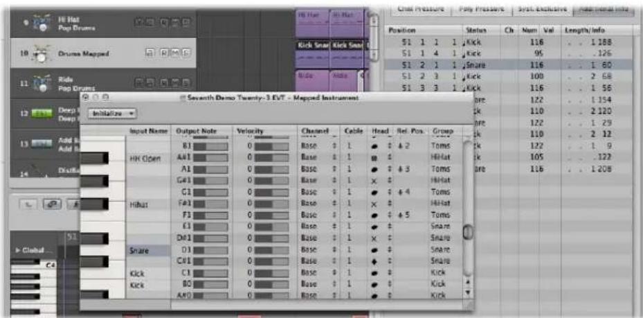
Viewing and Changing Note Release Velocity
You can edit the release velocity of a note event when the Additional Info button is active.
To view release velocity data:
■ Turn on the Additional Info button (only available in filter mode).
Control Change Events
These event types are used to transfer MIDI controller information (modulation, sustain, volume, and pan, as examples) to software instruments or external MIDI keyboards and modules.
| Position | Status | Ch | Num | Val | Length/info | |||
| 7 | 1 | 1 | 1 | Control | 1 | 1 | 127 | |
| 7 | 1 | 1 | 1 | Control | 1 | 8 | 127 | Balance |
| 7 | 1 | 1 | 1 | Control | 1 | 7 | 127 | Volume |
- Num(ber): The number of the controller. Each MIDI controller (such as the modulation wheel or sustain pedal) is assigned a specific Continuous Controller (CC) number (CC#1 or CC#64 respectively). This can vary from device to device. Several controllers (apart from the two above) are defined in the same way by most manufacturers; these standardized controllers include volume (CC#7) and pan (CC#10).
- Length/Info: Shows the name of standardized controllers defined in the MIDI Specification.
- Val(ue): Value of the controller. Continuous controllers have a range of 0 to 127. Switch controllers (CC#64—CC#90) transfer two states: off (val = 0) and on (any value between 1 and 127).
Pitch Bend Events
Pitch bend events are used to continuously vary the pitch. They are usually generated by a centered pitch bend wheel or joystick on your keyboard.
| Position | Status | Ch | Num | Val | Length/Info | ||||
| 3 | 2 | 3 | 93 | PitchBd | 1 | 0 | 63 | - | 128 |
| 3 | 2 | 3 | 187 | PitchBd | 1 | 0 | 64 | = | 0 |
| 3 | 2 | 3 | 187 | PitchBd | 1 | 0 | 64 | = | 0 |
- Num(ber): Fine pitch bend division (LSB: Least Significant Byte). Many keyboards transmit a value of 0. If the pitch bend wheel has an 8-bit resolution, you will see values of 0 or 64 in this column.
- Val(ue): The effective pitch value (MSB: Most Significant Byte), ranging from 0 to 127. A value of 64 corresponds to the half-way setting of the wheel.
- Length/Info: The 14-bit value is displayed in this column as a decimal figure ranging from -8192 to 8191 (if your keyboard transmits 14-bit pitch bend data). The value in this column may be edited in the usual ways.
Program Change Events
Program change events transmitted to connected MIDI devices are used for patch (preset or setting) selection. These may be sounds in a synthesizer, programs in an effects unit, or snapshots in an automated mixing desk, as examples.
| Position | Status | Ch | Num | Val | Length/info | |||
| 3 | 1 | 1 | 1 | Program | 1 | - | 4 | E. Piano1 |
- Val(ue): A program number between 0 and 127.
• Some manufacturers (such as Yamaha) number the programs in their devices from 1 to 128, not 0 to 127. If you have devices that follow this numbering protocol, you will need to subtract 1 from the program number shown on the device itself, when adding or altering a program change event.
- Other manufacturers use various methods of dividing internal memory locations into groups (or banks), and sounds. The most common is divisions into 8 groups of 8 sounds, each numbered 1 to 8. These devices respond to program numbers 0 to 63 by addressing storage locations 11 to 88. The instruction manuals for these devices should contain conversion tables to assist you.
- Num(ber): Bank select. Normally you will see this symbol (−), which means no bank select message will be sent. If you assign a number between 0 and 126, a bank select event is sent before the program change event.
This allows you to address the different sound banks (preset, internal, card, and so on) of connected MIDI keyboards and modules. The synthesizer must be able to recognize controller 32 as bank select, but unfortunately this standard is not used by all manufacturers.
If you have any problems with bank select, check your synthesizer's manual to see whether, and how, it responds to bank select commands.
Note: You can change the type of bank select messages sent by Logic Express (see "Defining Custom Bank Selects" on page 906), if necessary for your devices.
Aftertouch Events
Aftertouch (or channel pressure) events are generated by a mechanical pressure sensor beneath some MIDI keyboards. These events can be used to modulate the synthesizer sound. All note events on a particular MIDI channel are affected. This means that applying pressure to one note in a held chord will affect all notes in the chord.
| Position | Status | Ch | Num | Val | Length/Info | ||||
| 7 | 3 | 3 | 123 | C-Press | 1 | 4 | |||
| 7 | 3 | 4 | 18 | C-Press | 1 | 5 | |||
| 7 | 3 | 4 | 153 | C-Press | 1 | 6 | |||
- Num(ber): This column is unused, as aftertouch events only have one data byte.
- Val(ue): Displays the amount of pressure on the keyboard (0 to 127).
Poly Pressure Events
Poly(phonic) pressure events are generated by mechanical pressure sensors beneath each individual key on some MIDI keyboards. The resulting sound modulation only affects the particular note that is pressed harder (after the initial keystrike). Only a few keyboards offer this capability.
| Position | Status | Ch | Num | Val | Length/Info | ||||
| 21 | 2 | 1 | 169 | P-Press | 1 | E3 | 27 | ||
| 21 | 2 | 1 | 182 | P-Press | 1 | E3 | 34 | ||
| 21 | 2 | 1 | 188 | P-Press | 1 | A2 | 35 | ||
| 21 | 2 | 1 | 202 | P-Press | 1 | E3 | 38 | ||
- Num(ber): Displays the MIDI note name (C3, G4, and so on).
- Val(ue): Displays the amount of pressure on the key (0 to 127).
SysEx Events
System exclusive data (SysEx) is unique to individual MIDI devices. You can record these events by using the dump utilities of your synthesizers. This enables you to save patch information, or other data, outside of the MIDI device (in a Logic project or MIDI file). The arrows in front and behind EOX are used to add or remove bytes.
| Position | Status | Ch | Num | Val | Length/info | ||||
| 3 | 1 | 1 | 1 | SysEx | 4 | 0 | 0 | Moog | |
| 4 | 1 | 1 | 1 | SysEx | 4 | 0 | 0 | Moog | |
| 5 | 1 | 1 | 1 | SysEx | 4 | 0 | 0 | Moog | |
Warning: Editing SysEx Events requires a thorough understanding of the data format used by the MIDI device in question. Incorrect edits can lead to the corruption, or loss, of sound or other data.
SysEx Data in Hex Format
You can choose whether SysEx data is displayed in hexadecimal or decimal, in the Event List or the SysEx fader editors, with the View > SysEx in Hex Format command.
Hexadecimal digits are preceded by a \$ symbol in Logic Express.
For more information on manually programming a SysEx message, read "SysEx Faders" on page 952.
Meta Events
Meta events are control messages that are specific to Logic Express. They are used to automate specific Logic Express functions, and to organize and arrange Score Editor elements (particular notation symbols and formatting) which can't be represented by MIDI events.
| Position | Status | Ch | Num | Val | Length/Info | |||||
| 11 | 1 | 1 | 1 | Meta | 1 | 62 | 0 | Score Symbol | ||
| 0 | 0 | 0 | 0 | 105 | ||||||
| 11 | 1 | 1 | 1 | Meta | 1 | 81 | 3 | Octave | ||
| 0 | 0 | 0 | 0 | 0 | ||||||
| 0 | 0 | 0 | 0 | 127 | ||||||
| 0 | 0 | 0 | 0 | 0 | ||||||
| 13 | 1 | 2 | 1 | Meta | 1 | 66 | 19 | Trill | ||
The Num(ber) determines the meta event function, and Val(ue) determines the value that is sent. You should only ever insert and edit the following Num(ber) column values in the Event List.
- Num = 47 (Send Byte to MIDI): This sends the track instrument any byte value (Val) between 0 and 255 (\00–\FF). As a usage example of this meta event; if you send 246 as the byte, this is equivalent to a MIDI tuning request message. The display will show Send Byte \$F6. Only use this meta event if you know what you're doing—if you don't, your sound modules and synths may start to behave very oddly indeed.
- Num = 48 (Switch Fader): This will send MIDI events to a particular output number (Val) on a cable switcher (see the Environment chapter for details). You first need to connect a cable between a track instrument and the cable switcher in question.
- Num = 49 (Go to screenshot): This event selects a screenshot. Val determines the screenshot number.
- Num = 50 (Project Select): This event will switch projects on a MIDI data filer/player. Val determines the stored project number.
- Num = 51 (Go to Marker): When this event is sent, playback will jump to another marker. Val determines the marker number.
- Num = 52: This meta event stops playback.
Meta events can also be generated by fader objects in the Environment.
The Event Float Window
The Event Float window provides information on the currently selected event (or region), and can be compared to a single line of the Event List. You can edit all parameters in this window.
To open an Event Float window:
- Choose Options > Event Float in the main menu bar.
You can also use the Toggle Event Float key command.
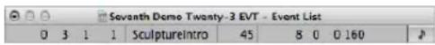
- The start point of the selected event or region in bars, beats, divisions, and ticks
- The type or name of the selected event or region
- The recorded MIDI channel and first data byte (if an event), the name of notes, and the second data byte (if it exists for the event type)
- Length of the selected event or region in bars, beats, divisions, and ticks
To switch the Event Float between SMPTE time and the bar/beat display:
- Click the note symbol (to the left).
Quantizing MIDI Events
Quantization is the rhythmic correction of notes to a specific time grid. Any inaccurately played notes are moved to the nearest position on this grid.
As an example, if the shortest notes in a passage are 1/16th notes, you would use 1/16th quantization to move all notes to their ideal rhythmic position on the grid. This will only work, however, if no note was played more than 1/32nd from an ideal position. Any very loosely played notes will be moved 1/16th later or earlier than the desired position.
Unquantized note events
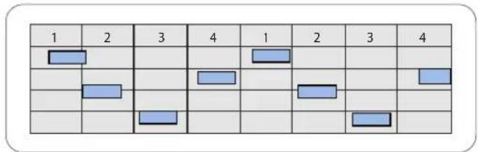
Quantized note events, aligned to the nearest beat position
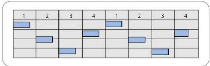
You have the choice of quantizing complete MIDI regions or individual events:
- Region-based quantization affects all note events in a MIDI region. It is used on MIDI regions in the Arrange area.
- Event-based quantization can be applied to any individual MIDI event (not only note events) within a MIDI region. Individual event quantization is performed in the MIDI editors.
Important: Event-based quantization destructively alters the position of all MIDI event types, except note events.
Quantizing Regions
You can quantize selected MIDI regions by changing the value of the Quantize parameter in the Region Parameter box of the Inspector. Region-based quantization only works on notes, not on other MIDI data event types, such as MIDI controllers.
The Quantize parameter determines the division of the quantization grid. The extended region parameters contain advanced quantization parameters, allowing you fine-tune the quantization grid.
Important: The (region) Quantize parameter is non-destructive. It adjusts the playback positions of notes in the region on-the-fly when Logic Express is in play (or record) mode. It does not actually move the notes permanently.
To change the quantization grid division:
- Set the Quantize parameter in the Inspector's Region Parameter box to the desired value.
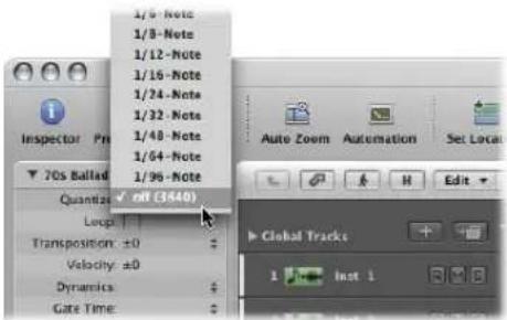
You can also step through the available Quantize values, one at a time, with the Set Quantize Parameter to Next Value and Set Quantize Parameter to Previous Value key commands.
This can be done at any time, including when Logic Express is in play (or record) mode. The new value is immediately used to alter note playback positions.
The Quantize grid options are:
- Quantization Off: The Off setting plays the notes at the finest possible timing resolution: 1/3840 note, which is unquantized playback, in practical terms.
- Normal Quantization: The 1/1, 1/2, 1/4, 1/8, 1/16, 1/32, and 1/64 note settings quantize the MIDI region to the equivalent note value.
- Triplet Quantization: The 1/3, 1/6, 1/12, 1/24, 1/48, and 1/96 note settings quantize the MIDI region to triplet note values. A 1/6 note is equivalent to a quarter triplet, 1/12 note to an eighth triplet, 1/24 note to a sixteenth triplet and 1/48 note to a thirty-second triplet.
- Mixed Quantization: The 8 & 12 setting corresponds to eighths and eighth triplets, 16 & 12 to sixteenths and eighth triplets and 16 & 24 to sixteenths and sixteenth triplets. Mixed quantization always applies to both note values, and requires greater playing precision when recording.
- Odd Quantization: The 9-Tuplet setting denotes novetuplets (1 bar = 9 beats), 7-Tuplet is septuplets (1 bar = 7 beats), 5-Tuplet/4 is quarter quintuplets (1 bar = 5 beats), and 5-Tuplet/8 is eighth quintuplets (1 bar = 10 beats).
- Swing Quantization: The 8F, 8E, 8D, 8C, 8B, 8A, and 16F to 16A Swing settings delay the position of every second point in the quantization grid by a fixed percentage. The 8 or 16 denotes an eighth or sixteenth note quantize value. You can also manually alter the swing factor of any quantize value (see "Fine-Tuning the Quantization Grid" on page 480).
Quantize setting Swing percentage
| 8F or 16F 71% |
| 8E or 16E 66% |
| 8D or 16D 62% |
| 8C or 16C 58% |
| 8B or 16B 54% |
| 8A or 16A 50% |
If you want to quantize various parts of a MIDI region differently:
1 Divide the MIDI region with the Scissors tool, and use different quantization settings on each segment (each new region).
2 You can then recombine the segments of the original region with the Glue tool.
This maintains the quantize values of each segment.
An alternate method is to perform event-level quantization in the MIDI editing windows (see "Event and Note Quantization" on page 483).
Some Points to Note When Using Region Quantization
The quantization grid always begins at the start of a MIDI region. If the MIDI region does not start at the beginning of a bar, neither does the quantization grid. If you alter the start point of a MIDI region, you also alter the quantization grid.
Important: Unlike other region playback parameters (Delay, Transposition, and so on), Quantize affects the way notes are displayed in the MIDI editors. This allows you to see the effect of the chosen Quantize value by looking at the note positions in the Piano Roll Editor, for example.
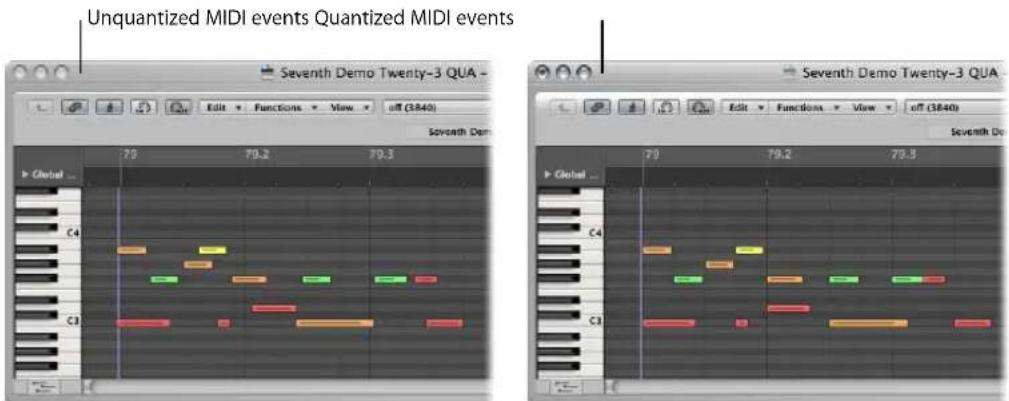
Region quantization affects the whole MIDI region. To quantize individual notes or other event types, use event quantization in one of the editors (see "Event and Note Quantization" on page 483).
Fine-Tuning the Quantization Grid
You can use the extended region parameters to fine-tune your quantization grid. This provides a number of additional facilities that allow you to create and apply a swing or other quantize feel to your MIDI and software instrument parts.
To view the extended region parameters:
- Choose View > Extended Region Parameters.
Once enabled in one window, the extended region parameters are available to all MIDI editing windows, provided that the Inspector is open.
The following quantization options appear below the standard set of region parameters. They can be applied to any quantization value (except Off).
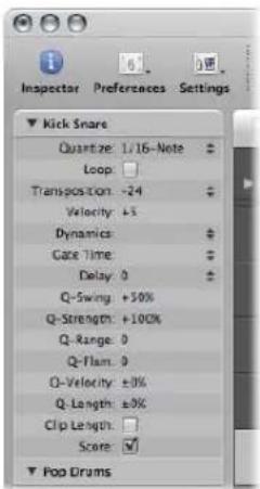
- Q-Swing: This percentage value alters the position of every second point in the current quantization grid. Values over 50% delay the beats. Values under 50% pre-delay them. The most practical settings fall between 50% and 75%, imparting a swing feel to strictly quantized (or tightly-played) MIDI regions.
- Q-Strength: This percentage value determines how far a note is shifted towards the nearest grid position. 100% results in full quantization, 0% leaves the note at its recorded position.
- Q-Range: Q-Range is a very musical quantization strategy that requires a certain amount of technical musical prowess. It is ideal for recordings which already have the right groove, but are too hurried or laid back in places. It allows you to retain the original feel, but positions the rhythmic center precisely in the groove. A value of 0 means that every note is quantized. If you enter negative Q-Range values, only notes that fall outside the set range are moved to ideal quantization grid positions; while notes closer to an ideal position remain unquantized. This moves the most poorly played notes (those outside the range) to perfect timing positions on the quantization grid, or at least towards these positions, depending on the Q-Strength setting.
Tip: To obtain the best Q-Range results, use a low, even quantize value, such as 1/4 note. Set the Q Range parameter to compensate for the maximum error in the recording.
- Q-Flam: Notes with the same time position (chords) are spread out by this parameter. Positive values produce an ascending (upwards) arpeggio, negative values a descending (downwards) arpeggio. The position of the first note (either the bottom or top note, assuming all notes start at the same position) in the arpeggio is unaltered.
- Q-Velocity: This parameter (expressed as a percentage) determines the amount that the velocity values of quantized notes are affected by the velocity values of a template MIDI region (see "Creating Groove Templates" on page 485). At a value of 0%, the notes retain their original velocity. At 100%, they adopt the velocity values of the template. Negative values alter the velocity, making the deviation from the template even greater.
- Q-Length: This parameter (also expressed as a percentage value) determines how the lengths of quantized notes are affected by the equivalent note lengths (notes at the same position) of a template MIDI region. A value of 0% has no effect, while at 100%, the notes adopt the exact note lengths of the template region. Negative values alter note lengths further, resulting in a more significant deviation from the template.
Making Quantization Permanent
In the same way that other region parameters can be normalized, the quantization settings can also be applied permanently to one or more regions. The Apply Quantization Settings Destructively function is especially well suited to pre-quantization.
As an example, if a recorded MIDI region cannot be quantized to a 16D Swing value without producing a few incorrectly timed notes, quantize it to 1/16th notes and then use Apply Quantization Settings Destructively. You can now use swing quantization on this cleaned-up version of the MIDI region.
As another example: If you are recording a hi-hat pattern consisting of 1/16 notes and one single 1/32 note, first play the rhythm (quantized to 1/16 notes) without the 1/32 note and choose Apply Quantization Settings Destructively. You can now raise the Quantization parameter value to 1/32 notes, and add the extra note without incorrectly quantizing any badly-played 1/16 notes.
To permanently quantize a region:
1 Choose the desired quantization settings (including extended region parameter quantize options, if desired).
2 Choose the MIDI > Region Parameters > Apply Quantization Settings Destructively command, or use the equivalent key command (default: Control-Q).
Note: Once this is done, it is impossible to revert to the original recording, unless you use Undo immediately after performing the operation (or use the Undo History).
Event and Note Quantization
The menu bar of the Piano Roll Editor and Event List offer a Quantization menu and Quantize button. This is a separate quantization function, which can be applied to selected events, rather than entire regions.
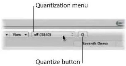
The Piano Roll Editor also offers a Quantize tool.
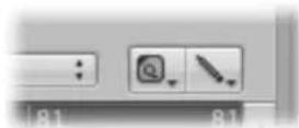
Further quantize operations are also available in the Transform window. These can be applied to events in one or more selected regions that match very specific criteria. Details in Chapter 20, "Editing MIDI Events in the Transform Window."
Note: Event-level quantization irreversibly alters the positions of all event types, with the exception of notes. Note events can be returned to their original record positions.
A Special Note About Quantization in the Score Editor
The primary purpose of the Score Editor is to produce readable (and printable) notation. While you can certainly edit MIDI note data in the Score Editor, and quantize it with the Quantize tool (or Functions > Quantization menu commands), it is best to perform individual note quantize operations in the Piano Roll or Event List editors.
The Quantize parameter shown in the Inspector of the Score Editor serves a purely graphical function. It alters the way notes are displayed, but does not affect note playback in any way.
To quantize events in a region (Piano Roll and Event List):
- Choose the desired quantization value in the Quantization menu.
This menu provides the same grid values available in the Quantization menu of the Region Parameter box, shown in the Arrange window.
■ Do one of the following, dependent on the options available in the window:
- Choose Functions > Quantize Selected Events, or use the corresponding key command (Score, Piano Roll, and Event List Editors).
- Select the events that you want to quantize, then click the Quantize button (Piano Roll and Event List Editors). The most recently selected (or active) quantize value is used on all selected events.
- Select the Quantize tool, then click all notes you want to quantize (Score and Piano Roll Editors). The most recently selected (or active) quantize value is used on all selected notes.
To set a quantize value with the Quantize tool:
1 Click-hold on a single note (or a selected group of notes) with the Quantize tool, and the Quantization menu will open at the clicked position.
2 Choose the desired quantization value for the event(s).
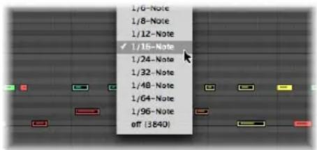
To rubber band select, and quantize, several note events at once:
- Click-hold on the background of the Score or Piano Roll Editor with the Quantize tool, and drag across the desired notes.
The most recently selected (or active) quantize value is used on all selected notes.
To return note events to their original positions:
1 Select all notes you want to undo the quantization for.
2 Do one of the following, dependent on the options available in the editor:
- Choose Functions > De-Quantize, or use the De-Quantize key command (Score, Piano Roll, and Event List Editors).
- Choose the Off setting in the Quantization menu, then click the Quantize button (Piano Roll and Event List Editors).
- Option-click the Quantize button (Piano Roll and Event List Editors).
- Option-click on one of the selected notes with the Quantization tool (Score and Piano Roll Editors).
Important: Use of region-based quantization after you have individually quantized note events within a MIDI region will override your event-based quantizations, so take care! It may be worthwhile writing such changes into the region by following the instructions outlined in "Making Quantization Permanent" on page 482. This way, all of your hard work creating a number of individual event quantizations will not be lost by quantizing the wrong region.
Creating Groove Templates
You can create quantization grids based on the rhythms of other MIDI regions. These are referred to as groove templates. Groove templates make it possible to capture the small timing deviations which give a MIDI region its feel, and apply them to other MIDI regions.
You can even take the feel from an audio region, and apply it to a MIDI region, helping a MIDI clavinet part to sit well with a funk guitar Apple Loop, for example (see "Creating an Audio to MIDI Groove Template" on page 487).
To create your own groove template:
1 Select the MIDI region you want to create a groove template from.
Tip: As a rule of thumb, two-bar MIDI regions work particularly well as models for this function, but you can use MIDI regions of any length. Make sure that the source MIDI region actually contains a note at every desired quantization value.
2 Choose Options > Groove Templates > Make Groove Template (or use the Make Groove Template key command).
This creates a quantization template which appears in the Quantization menu of the Piano Roll and Event List Editors, and the Region Parameter box of the Inspector, when in the Arrange window.
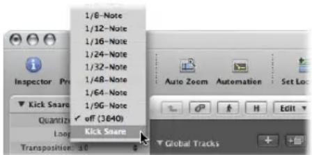
Groove templates are named after the MIDI region they were derived from.
In essence, this command transforms the exact timing of notes in the selected MIDI region into a groove template that can be accessed, and used, like any Quantization menu value.
Important: The source MIDI region used for a groove template must remain in your project! If you delete the source region from the project, the groove template name is not removed from the Quantization menu, nor can you use this quantization value. If chosen, nothing will happen.
To remove groove template entries from the Quantization menu:
1 Select the source MIDI region in the Arrange area.
2 Choose Options > Groove Templates > Remove Groove Template from List (or use the corresponding key command).
This deletes the selected source MIDI region from the list of possible quantization templates, thus removing it from the Quantization menu. It does not remove the region.
Using Groove Templates Across Projects
If you wish to create and retain a number of quantization templates for use in several projects, follow these steps:
To use a groove template in several projects:
1 Copy or create your source MIDI regions in one project.
2 Name these regions as desired, with the Text tool.
3 Use the Options > Groove Templates > Make Groove Template function on each source region.
4 Pack all of these regions into a folder (and rename the folder to Grooves, for example).
5 Use File > Save As Template.
Use this template as your project starting point, whenever you wish to access these quantization templates.
Importing Groove Templates
You can also import third-party groove templates, such as those made by the Canadian firm WC Music Research (DNA Groove Templates).
To import third-party groove templates:
1 Choose Options > Groove Templates > Import DNA Groove Templates (or use the corresponding key command).
2 Select the desired DNA Groove Templates in the file selector, then click Import.
The groove templates are added to the Quantization menu.
The the quantization templates are saved with the project and can be used, even when the project is played on another computer that doesn't have the corresponding DNA Groove Templates on its hard disk.
Creating an Audio to MIDI Groove Template
You can create MIDI groove templates from digital audio material. This allows you to extract the feel from drum loops or rhythmic samples (Apple Loops are the obvious example), and use the resulting groove template to quantize MIDI regions.
Note: You should switch off the Edit > Search Zero Crossings option in the Sample Editor window menu.
To extract a MIDI groove template from a one bar drum loop:
1 Add the drum loop audio region to the Arrange area using any of the methods discussed in Chapter 11, "Adding Pre-Recorded Media," on page 265.
2 Double-click on the region to open the Sample Editor, or select the Sample Editor tab at the bottom of the Arrange window.
3 Choose Factory > Audio to MIDI Groove Template (default key command: Control-M).
4 Choose the desired settings in the Audio to MIDI Groove Template tab:
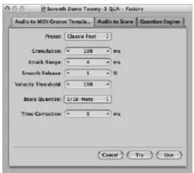
- Preset menu: This menu contains various presets for the Audio to MIDI parameters, which are suited to specific types of audio material. You can use these presets as starting points for your own processing.
-
Granulation (ms): Use Granulation to determine the time span of louder components in the audio material. Logic Express uses these peak signals (or transients) to derive information for velocity points in the groove template. The most useful values are usually between 50 and 200 milliseconds, depending on the tempo of the audio material.
-
Attack Range (ms): This tells Logic Express how long the attack phases of the sounds in the audio material are. As examples of how you might use this parameter; drum and percussion instruments have short attack times of less than 20 ms, while string instruments have longer attack phases. The best values for the majority of instruments are usually between 5 and 40 ms; with most around 20 ms.
- Smooth Release (%): This parameter is specifically designed to process audio material that contains sounds with a long release or reverb tail. This makes it easier to convert these sounds into suitable quantization points. The value you choose here should generally be between 0 and 5%, except when processing passages that contain sustained notes, distorted guitars, or similar sounds.
- Velocity Threshold: This parameter sets the threshold level. All signals that fall below this value are ignored. In most cases, you should choose a value of 1, except when processing very dense, loud material with soft background noises.
- Basis Quantize: This function enables you to add artificial trigger points at positions where there are no trigger points present. Groove templates created with this method are suitable in situations where you need more quantization points than are contained in the audio material. The automatic identification of trigger points in the audio material is not affected by use of this parameter.
- Time Correction: This parameter allows you to compensate for any time delays that may occur when external samplers or synthesizers are triggered by MIDI notes. These time delays are sometimes very noticeable, particularly if the connected device is playing a MIDI region (that was quantized with an Audio-to-MIDI groove template) at the same time as the original audio material. You should be able to compensate for this effect by using settings between -20 ms and 0 ms.
At the bottom of the Sample Editor, you'll see three fields labeled: Audio, Quantize, and Result.
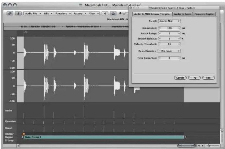
• Audio: Displays the quantization points identified in the audio file.
- Quantize: Shows the quantization points selected as the Basis Quantize.
- Result: Shows the quantization positions in the new groove template, which are produced by the combination of the two values above.
5 Click on any audio trigger point to prevent it from being transferred to the template. Manually selected (unused) points will be dimmed.
6 Click the Try button in the Audio to MIDI Groove Template to apply the new groove template to all selected MIDI regions,
7 Listen to the results.
8 Adjust the parameters until you are happy with the resulting groove, and then click Use.
This saves the new groove template, and adds it to the bottom of the Quantization menu. The quantize template name is derived from the audio file name.
Editing MIDI Events in the Transform Window
20
The Transform window allows you to define a set of conditions and operations that are used to select, and alter, specific MIDI events.
The Transform window is so-named because it transforms MIDI events—based on conditions, operations, and values chosen by you—into different types of events, or events with different values.
The Transform window is immensely powerful, and is the ideal tool for edits that would otherwise be impossible (or at least, incredibly tedious). As an example, imagine an orchestral project that has been sent to you to work your magic on. The individual violin and viola parts were recorded with a different string library, and feature aftertouch information (in 200 MIDI regions!) that introduces a weird pitch modulation, and some sample layer switching artefacts when played with your string samples. After looking at this aftertouch information, you discover that only a small range of values are causing the problem. You have a few options; edit your sampler instruments, manually strip out all aftertouch information (region by region, or globally, thus losing the performance benefits that the aftertouch information provides) or alter the problematic values in the Transform window. Option three sounds like the way to go!
A number of preset transform sets are available for many common editing tasks. These may be all you'll ever require, but should the need arise, you can freely create and save your own transform sets, and recall them later.
Tip: The Environment contains a similar transformer object that you can use for real time transformations of MIDI events. For details, see the information on the "Transformer Object" on page 918.
To open the Transform window, do one of the following:
- Choose Window > Transform from the main menu bar (or use the corresponding key command, default: Command-4).
If you want to transform events (that you have selected in one of the MIDI editors) choose a preset from the Functions > Transform menu.
You can certainly choose the Window > Transform command while you are in a MIDI editor, but you will need to manually select a preset.
Choosing and Using Transform Sets
At the top left of the Transform window, you will find a Presets menu. The first fourteen items in the menu are write-protected presets. These presets provide templates for common editing tasks, such as; creating crescendos or fixing note lengths.
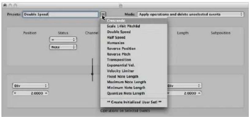
You can temporarily change the used parameters of a preset, but all changes will be discarded when you exit the preset.
Dependent on your needs, it may be worthwhile spending some time creating your own transform sets. These can be freely configured and saved as part of a project (Doing this in your template projects makes your transform sets available in all projects). Your transform sets will appear at the bottom of the Presets menu (see "Creating Your Own Transform Sets" on page 508).
To use a transform preset:
1 Select the MIDI regions or events that you want to transform.
2 Click the arrow button to the right of the Preset menu, and choose a transform set from the pop-up menu.
Note: You can create a new transform set by choosing **Create Initialized User Set!** in the Preset menu, but more on this later.
3 In the Mode menu, choose how you want to transform the selected events within the regions.
4 Set the desired selection conditions.
5 Define the operations you want to perform.
Note: You can click on the "Hide unused parameters" checkbox (turn it off) to show all conditions and operations, allowing you to make more advanced choices.
6 Do one of the following:
- Click the Select Only button to select all events that meet the selection conditions. The events will not be transformed. You can use this option to refine your selection, and ensure that your conditions only affect the events that you truly want to transform.
- Click the Operate Only button to transform all selected events, in accordance with the operations settings (The selection conditions have no effect). This is useful if you want to edit events that you've already selected manually.
- Click the Select and Operate button to select all events that match the conditions, and transform them as per the Operations settings.
Note: The number of selected regions and events (that match the conditions) are displayed above the selection and operation buttons.
Learning About the Transform Presets
This section covers the purpose of the fourteen transform presets, and provides tips on their use.
Crescendo
Used to gradually increase the velocities of a group of notes from low to high values (or vice versa—decrescendo or diminuendo).
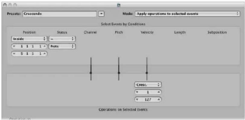
- Select the area (Position column) that contains the note events that you want to perform a crescendo on.
- Set the desired velocity values in the Operations area, ranging from 1 to 127.
- If you want a less dynamic crescendo, set a smaller value range.
- To perform a diminuendo, set a higher value in the top Velocity field, and a lower value in the bottom field.
Scale 14 Bit PitchBd
Scales pitch bend data, keeping the 14 bit information intact. The length of pitch bend events is expressed as a decimal value ranging from -8192 to 8191, and this is the 14 bit information that is retained.
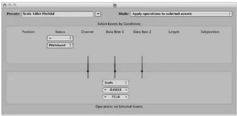
- Choose the desired multiplication factor for the fine pitch bend (LSB) and effective pitch values (MSB) in the top value field shown in the Operations area
- Set the (14 bit) value in the lower field, which is then added to the scaled (multiplied) events.
Double Speed
Doubles the tempo by halving event positions and lengths. By default, the Div(ision) value fields for the Position and Length operations are set to 2.0000.
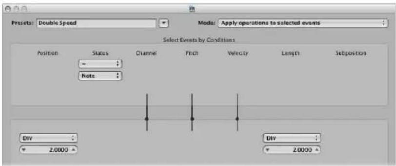
Change the values in both fields to 4.000 to quadruple the tempo.
This preset is a great creative option for drum regions. The following example presumes that a “four-on-the-floor” kick, snare, hi-hat, and other percussion sounds region is being viewed in the Hyper Editor.
To experiment with the Double Speed preset in the Hyper Editor:
1 Click on the name column of one of the drum sounds.
This selects all note events of a particular pitch in the region.
2 Change the Length field to a value that does not match the Position field, or vice versa.
3 Repeat the steps with other drum or percussion sounds.
This can lead to interesting polyrhythms that you may not have thought of.
As you can see from this example, you can use the same transform operation multiple times on the same region, and can also combine the different transform presets to achieve an end result, by using them one after the other.
Half Speed
Halves the tempo by doubling event positions and lengths. The Mul(tiply) value fields for the Position and Length operations are set to 2.0000 by default.
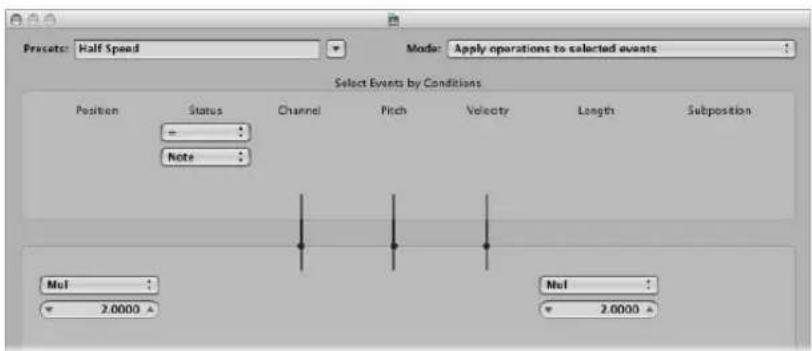
Set both Mul operation value fields to 1.5000 to reduce the tempo by around a third.
Humanize
Adds a random value to the position, velocity, and length of selected note events. This preset is useful on rhythmic parts, such as clavinet or piano accompaniments, and drum and percussion regions (or events). It can add life to strictly quantized material, or notes that were manually entered (see "MIDI Step Input Recording" on page 402).
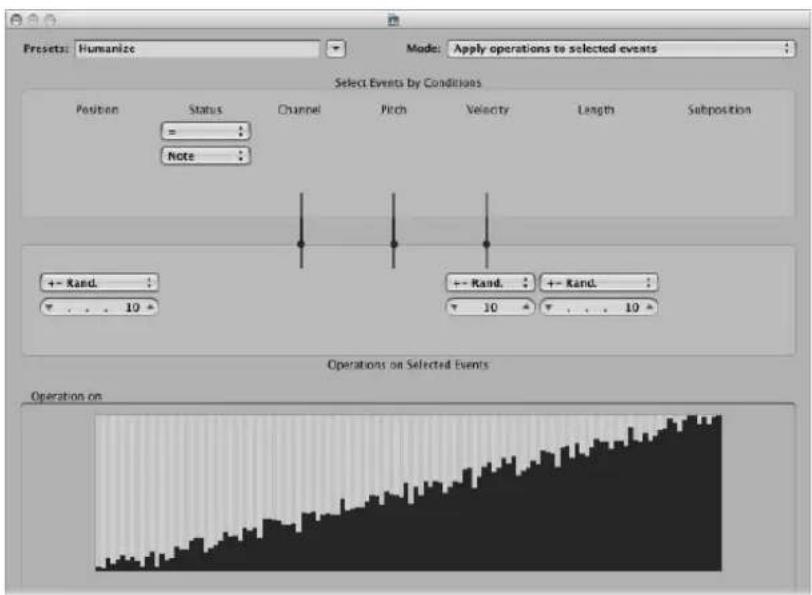
Alter the values for Position, Velocity, or Length to increase or decrease the random factor for each of these event parameters.
Reverse Position
Reverses the positions of events (usually notes) within a section.
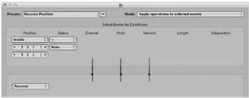
Change the Position condition values to alter your selection range.
Reverse Pitch
Inverts the pitch of all note events.
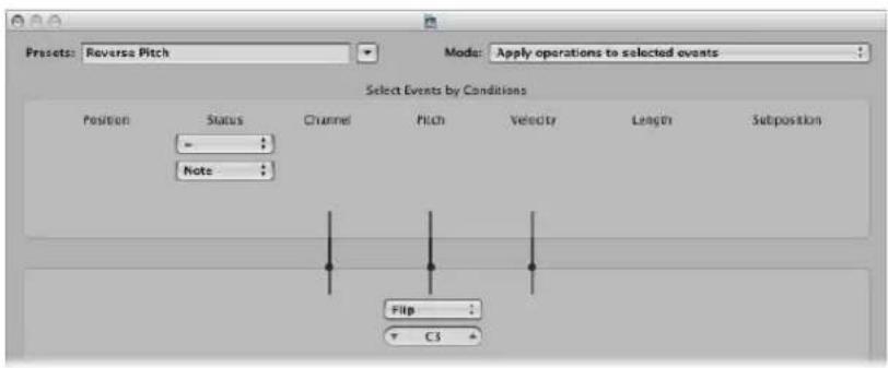
Change the Flip operation value to set a pivot point note number, around which note event pitches will be reversed.
Transposition
Transposes all note events.
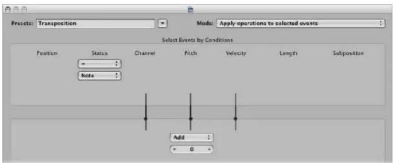
- Change the Add operation value to the desired amount (in semitone steps).
- You can achieve downward transpositions by setting a negative value in this field.
Exponential Velocity
Alters the scaling of the velocity curve. This preset is of particular use on software or MIDI instrument parts. Velocity is generally used to control the initial volume of instruments, but is often used to trigger filter envelopes, making the sound brighter or darker. Transforming regions is much faster than changing the velocity scaling or filter parameters of your MIDI or software instruments.
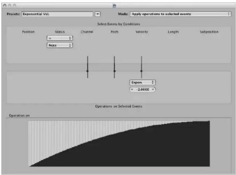
Change the Velocity value field in the Operations area to change the velocity curve. This is instantly reflected in the map area below.
Velocity Limiter
Limits the velocity to a maximum value. This is perfect for transforming instrument parts that are too strident, by limiting the velocity.
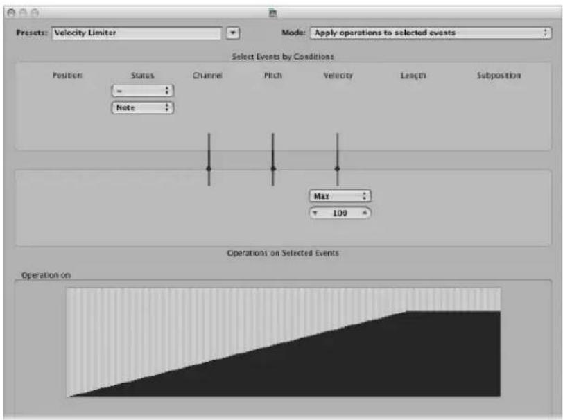
Change the Max operation field value to limit the velocity to a maximum value. This is instantly reflected in the map area below.
Fixed Note Length
Creates constant note lengths. Useful on many instruments, particularly drums and other rhythmic parts, such as pianos, clavinets, and basses.
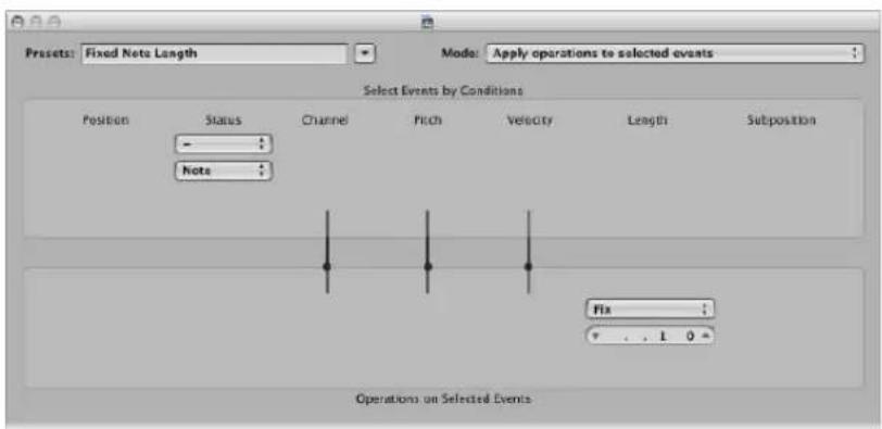
Change the Length value field in the Operations area to change the lengths of all selected events to the chosen length. Both shorter and longer events are changed to match the length value you have defined.
Maximum Note Length
Sets the maximum length of all note events.
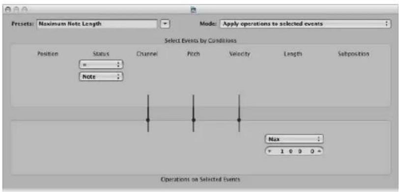
Change the Length value field in the Operations area to define the maximum note length. Existing note lengths—which are shorter than the length defined here—are retained. Events that are longer than the defined value are shortened.
Minimum Note Length
Sets the minimum note length.
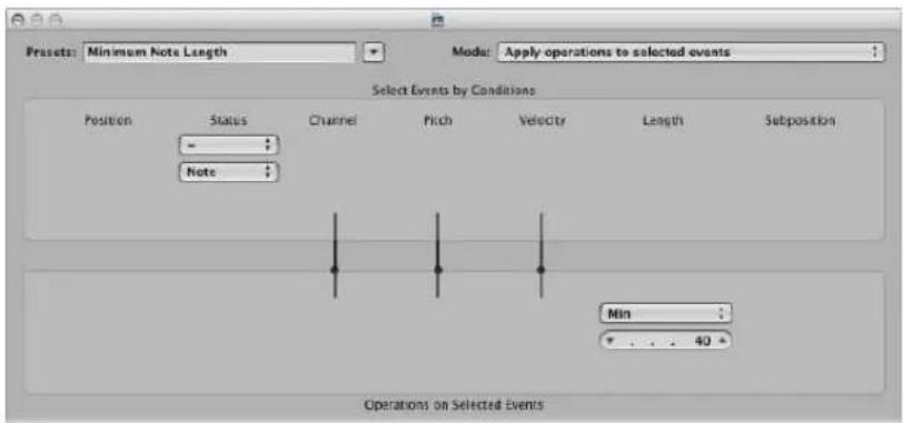
Change the Min value field in the Operations area to define the minimum note length. Existing note lengths—that are longer than the length defined here—are retained. Note events that are shorter than the defined value are increased in length.
Quantize Note Length
Quantizes the note length. This preset actually quantizes the note end position.
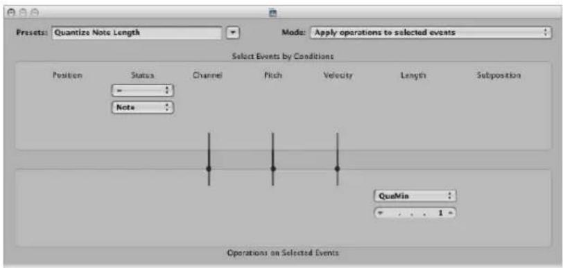
Change the Length value field—in the Operations area—to define the length that note end positions will be quantized to.
Using the Transform Window Parameters
This section discusses the use of the individual Transform window elements, providing an overview of what each option does. Examples towards the back of the chapter (see "Usage Examples" on page 509) will give you an idea of how each can be used, but these are only the tip of the iceberg. Ultimately, your imagination and creativity are the only restrictions on how MIDI events can be manipulated in the Transform window.
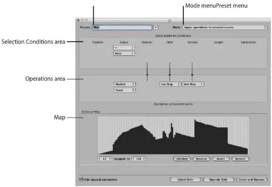
Global Parameters
These parameters globally affect the Transform window appearance and operating mode.
- Mode menu: Choose one of the following settings menu options to determine how events are transformed.
- Apply operations to selected events: Choose this mode to apply the operations to all selected events. The selected events are determined by the selection conditions.
- Apply operations and delete unselected events: Choose this mode to transform the selected events, and delete all non-selected events. Only events that match the selection conditions will remain after the transform operation. This mode allows you to use the Transform window as a programmable filter—where only events that match the conditions survive.
- Delete selected events: Choose this mode to delete selected events. This mode enables you to use the Transform window as a programmable erase function. All events that match the conditions are deleted, and all other events remain unchanged. The operation settings are irrelevant in this mode.
- Copy selected events, then apply operations: Choose this mode to retain the selected events in their original form, copy them, and apply the operations.
- Preset menu: Choose one of the transform presets or one of your own transform sets.
- "Hide unused parameters" checkbox: Hides all unused menus in the Selection Conditions and Operations areas. This provides a better overview of the settings in use. It also prevents you from making accidental alterations.
Setting the Selection Conditions
You can define conditions that determine which events are selected for transform operations. This done in the Selection Conditions area of the Transform window.
Each column represents a different MIDI event parameter.
- Position: Determines the time position of the event, referenced to the start point of the MIDI region (not the start point of the project).
- Status: Determines the event type.
- Channel: Recorded MIDI channel of the event.
- Data Byte 1/Pitch: First data byte (controller number) or note pitch.
- Data Byte 2/Velocity: Second data byte (controller value) or note velocity.
Note: The parameters displayed in the Data Byte fields are dependent on the chosen Status menu setting. Certain Status menu settings will not show the Data Byte fields at all!
• Length: Length of the note or event.
- Subposition: Time position of the event, within a bar.
The condition is considered to be fulfilled when an event matches the defined effective range, and values, of all event parameters. These ranges and values are determined in the pop-up menus and fields found under each of the event parameter columns.
To choose the event type:
- Click on the Status pop-up menu to determine which events will be selected. You have a choice of just two settings here:
- All: All event types fulfil the condition.
- =: A further pop-up menu is displayed below the Status pop-up menu, in which you can define the desired event type. These include: note, poly pressure, control change, program change, channel pressure, pitch bend, meta, and fader.
To set all other selection conditions:
- Click on the desired pop-up menus (in each column that is needed) to define the selection criteria for events.
One or two value fields will appear below the pop-up menu, unless Map is chosen. You can assign one of the following value conditions for each of the parameter columns:
- “=”: The event must be equal to the value in the field, for the condition to be fulfilled. As an example, only note C#3 events will meet the condition.
- Unequal: The event must not be equal to the value in the field, for the condition to be fulfilled. All events that are not C#3 will meet the condition, for example.
- Smaller/Equal (<=): The event value must be less than, or equal to, the value in the field (a note velocity less than, or equal to 98, for example) for the condition to be fulfilled.
- Larger/Equal (>=): The event value must be larger than, or equal to, the value in the field (a note pitch higher than, or equal to C#3, for example), for the condition to be fulfilled.
- Inside: The event must fall within the value range (of event positions or note pitches, for example) of both fields, for the condition to be fulfilled.
- Outside: The event must be outside the value range (of event positions or note pitches, for example) of both fields, for the condition to be fulfilled.
- Map: Most conditions are numerical relationships, and the condition is met if the incoming MIDI event value satisfies the condition. The last condition, Map, works a little differently. Two numerical parameters are specified, and the incoming value is first converted by the map, to create a mapped value. The mapped value is then compared with the two parameters to see if it falls inside them. Incoming events with a mapped value that falls within the range will fulfil the condition—all other events will not fulfil the condition (see "Using the Map" on page 506).
To set the values for a selection condition:
■ Use the mouse as a slider, or directly type the desired value into the field.
Defining Operations
The Operations area is used to define the changes you would like to make—to events that meet the selection conditions. As with the selection condition pop-up menus, you choose an operation in the appropriate event parameter columns. One or two value fields may appear, dependent on the chosen operation.
To define the operation for the status event parameter column:
- Click the pop-up menu, and choose one of the following operations for the Status condition:
- Thru: The event type passes through unaltered.
- Fix: The event type is altered. Choose a new event type in the pop-up menu that appears below the Status Operations menu. Choices include; fader, meta, note, poly pressure, control change, program change, channel pressure, or pitch bend. This effectively converts one type of event to another.
Note: When you convert note events, two events are created: one for the note on event, and one for the note off event.
- MapSet: Choosing this setting means that events which match the Status condition (note events, for example) are used to control the map of a subsequent operation—in the Channel, Data Byte 1, Data Byte 2, and Length columns.
- The Data Byte 1 value selects the position in the map.
- The Data Byte 2 value determines the value at this map position.
Internally, Logic Express sends a meta event pair: #123 for the position, and #122 for the value at this position. These types of meta events can also be created in other ways.
To define the operation for all other event parameter columns:
- Choose one of the following operations for the Channel, First or Second Data Byte, and Length columns (as required). One or more value fields will appear below the respective operations pop-up menus.
- Thru: The event passes through unaltered.
- Fix: Fixes the event parameter to the set value. You could use this to set the pitch of all note events to a specific note value, making it easy to convert a bass groove into a hi-hat pattern, for example.
- Add: Adds the value to events. As an example, a value of 8 could be added to all incoming note velocity events, thus making the notes louder.
- Sub: Subtracts the value from events. You could use this to reduce all controller 10 (Pan) events, thereby narrowing the stereo spread of an electric piano part, for example.
- Min: Parameter values lower than the defined value are replaced (by this value). Larger parameter values are not altered. You could use this to replace all note velocity messages below 45, thereby reducing the dynamic range of a MIDI region—or put another way, making the soft notes louder.
- Max: Parameter values that exceed the set value are replaced by it. Smaller event parameter values remain unaltered. This could be used to restrict filter resonance modulation events above a value of 100, for example, resulting in a softer filter sound.
- Flip: All parameter values that match the conditions are reversed around a pivot point (the value defined here). Events above this value are moved by the same distance below it and vice versa. As an example, you could move a note from E3 to G#2, if the pivot point value was set to C3. Effectively, the E3 event, which is 4 (pitch) values above the C3 pivot point is flipped to 4 values below (G#2). This can also be used to reverse selected note positions around a particular bar or beat, as another example.
- Mul: The parameter value is multiplied by the set value (accurate to four decimal places). The effect, and use, of this operation is best illustrated by the Half Speed preset.
- Div: The parameter value is divided by the set value (accurate to four decimal places). The effect, and use, of this operation is best illustrated by the Double Speed preset.
- Scale: The parameter value is multiplied by the top value, and the bottom value is then added. This is a combination of Mul and Add. If you enter a negative number here, values can be subtracted from—rather than added to—the value resulting from the multiplication.
- Range: Parameter values outside the set value range are replaced by the values of the (range) limits (combination of Min and Max).
- Random: Random values are generated within the set limits.
- +—Rand.: A random value between zero and the set value (positive or negative) is added.
- Reverse: The parameter value is reversed within its value range (no value can be set here).
- Quantize: The parameter value is quantized to a multiple of the set value.
- Qua & Min: Like Quantize, but the quantization does not fall below the set value (a combination of the Quantize and Min functions, with the same set value).
- Expon.: The parameter value is scaled exponentially. The extreme values (0 and 127) remain unaltered. The set value determines the shape of the curve. Positive values result in the exponential scaling of data (increasing input values remain lower for longer, and then rise quickly), and negative values result in the logarithmic scaling of data (decreasing input values remain higher for longer, and then drop off more quickly).
-
Crescendo: This only works if the Inside Position selection condition is selected (crescendos need start and end points.). Crescendo creates a smooth alteration of the current parameters, between the set value boundaries.
-
Rel.Cres: This only works if the Inside Position selection condition is selected. The effect is similar to that achieved by Crescendo, but the previous values of the parameters being altered are taken into account when the crescendo is created, preserving the relative feel of the original.
- Use Map: The set map will be used when this operation is selected (see below).
To set the values for an operation:
■ Use the mouse as a slider, or directly type the desired value into the field.
Using the Map
128 vertical bars reflect the full MIDI value range (from 0 to 127), and provide a visual overview of the transformation.
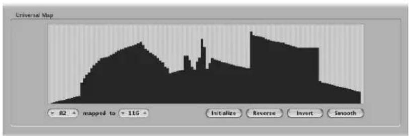
Essentially, each bar represents a particular MIDI value—which can be mapped to a different value. The type of event, and operations, are determined in the Selection Conditions and Operations areas.
To give you an example that may help your understanding:
• Each of the bars could represent a MIDI note number (from 0 to 127) value.
- By default, there is a 1:1 relationship for each bar, where value 1 = value 1, value 15 = value 15, and so on, throughout the 128 bars. Applying this to MIDI note numbers, bar 60 = C3 (middle C), bar 61 would represent C#3, bar 62 = D3 , and so on.
The default and mapped values are shown in the two fields to the lower-left of the map graphic.
- You can alter these values directly in the fields, or by dragging any of the bars vertically. As you do so (using either method), the corresponding field/bar is updated.
- If you alter the bar 60 (middle C) value to show 72 in the "mapped to" field, this value will be remapped accordingly when the transform operation is applied.
This will result in all MIDI note number 60 messages being transformed into MIDI note number 72 messages (if you're a mathematics whiz, you will have worked out that this would effectively transpose all C3 notes to C4).
Some Points to Note About the Map
The map is only visible when chosen in one of the Operations pop-up menus. Appropriate selection conditions must also be set, or the map will not be shown.
The map is universal, which means that it remaps one MIDI value to another.
It does not know what type of MIDI data is sent to it. It is only concerned with the value of the data.
This means that one map can be used to simultaneously alter the pitch, velocity, and length values of incoming note events, for example.
Exchanging Parameter Values
You can re-route the value of each of the three event parameters: Channel, Data Byte 1, and Data Byte 2 to the value of a different parameter from this group.
To replace the source (Condition value) with the target parameter value:
- Click the dots on the lines between the Selection Conditions and Operations areas.
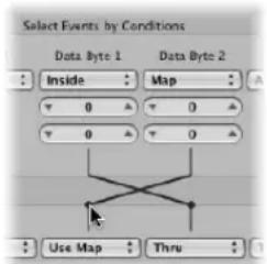
Repeated clicks will cycle between different targets.
Note: The value is exchanged before the operation is performed.
Creating Your Own Transform Sets
You can store your own transform settings in a user transform set.
To create a user transform set:
1 Choose **Create Initialized User Set** from the Presets pop-up menu.
2 Set the desired conditions.
3 Set the desired operations.
4 Switch on the "Hide unused parameters" checkbox. This helps to avoid changes to conditions and operations that aren't required for (or may mess up) your transform set.
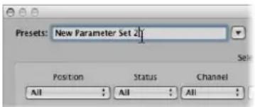
5 Click on New Parameter Set (Number) in the Presets menu. Type in a new name for your transform set.
This transform set will now appear at the bottom of the Presets list in all Transform windows—for this project! You should consider saving your user transform sets in one or more template projects. This way, they will always be available to you in all future projects.
Tip: Renaming an existing transform set creates a new transform set that is identical to the original. The existing (source) transform set is retained.
Importing Transform Sets From Other Projects
You can import transform sets from other projects, allowing fast access to a transform preset you created earlier. This facility also makes it easy to add existing transform sets to new template projects.
To import all transform sets from another project:
1 Choose File > Project Settings > Import Settings from the main menu bar (or use the corresponding key command, default: Option-Command-I).
2 Clear all checkboxes—except Transform Sets—at the bottom of the Import Settings dialog.
3 Browse to, and select, the project that contains the transform sets you want to import.
4 Click the Open button, and the transform sets will be imported into the current project. The names of these imported transform sets are retained, and added to the bottom of the Presets list.
5 Repeat the steps above to import transform sets from other projects.
6 Save your project or template.
Usage Examples
The following section provides several usage examples for the Transform window.
To add a mod wheel controller event (#1), with a value that matches the note's velocity:
This is automatically placed one tick after each note start and end, thus avoiding potential conflicts with the note events themselves.
1 Choose the following settings in the Transform window:
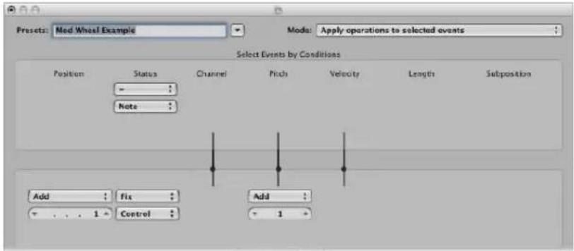
- Mode menu: Copy selected events, then apply operations
- Selection Conditions area: Set Status to Note.
-
Operations area
-
Set Position to Add and enter a value of 1 in the field below it.
- Set Status to Fix and choose Control in the menu below it.
Note: When you convert MIDI note events to controller events, two controller events are created: one for the note on event, and one for the note off event.
- Set Pitch to Fix and enter a value of 1 in the field below it. This means "the first data byte receives the value of 1" (the first data byte defines the controller number for controller events, and mod wheel events happen to be #1).
If you analyze these settings, you'll see that all note events will be selected for operation. A copy of each will be made, then moved 1 tick later than the original, and converted to CC#1 (mod wheel)—with a value that corresponds to the velocity of the original note. This is because the second data byte (Vel) is left unaltered.
2 Click Select and Operate.
To create a transform set that fixes all note velocities to a defined amount:
1 Select **Create Initialized User Set** from the Preset pop-up menu.
2 Set the Status menu in the Selection Conditions area to "="
3 Choose Note from the pop-up menu below.
4 Choose the Fix setting in the Velocity menu of the Operations area.
5 Change the amount to 127 in the value field below the Velocity menu.
To convert MIDI note events to MIDI controller 1 events:
1 Choose the following settings in the Transform window:
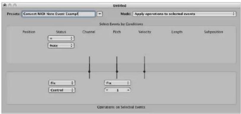
- Mode menu: Apply operations to selected events.
- Selection Conditions area: Set Status to Note.
- Operations area:
- Set Status to Fix, and choose Control in the menu below it.
Note: When you convert MIDI note events to controller events, two controller events are created: one for the note on event, and one for the note off event.
- Set Pitch to Fix, and enter a value of 1 in the field below it.
2 Click Select and Operate.
To randomly change the pitch of MIDI note events:
1 Choose the following settings in the Transform window:
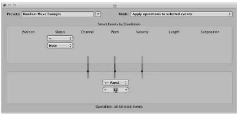
- Mode menu: Apply operations to selected events,
- Selection Conditions area: Set Status to Note.
- Operations area: Set Pitch to +-Random, and set the max deviation from the root note in the field below. If you set a value of 12, you'll achieve a deviation of one octave up and one down (two octaves, around the root note, in other words).
2 Click Select and Operate.
Tip: To restrict the randomness to one direction—up or down, as opposed to both—use the other Random Option, which limits the range that notes fall into.
To make note selections for edit operations:
1 Choose the following settings in the Transform window:
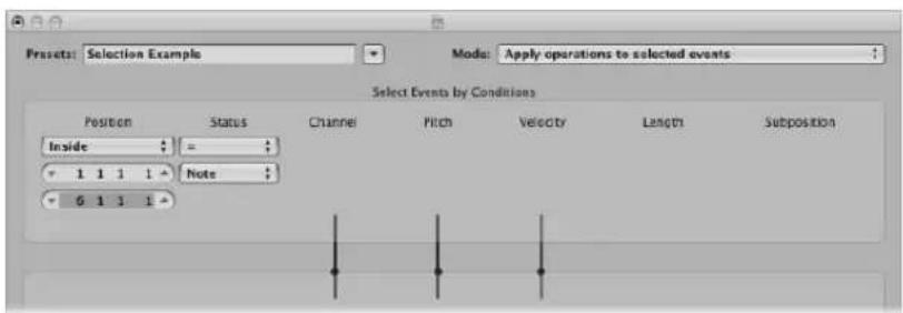
- Selection Conditions area:
- Set Status to Note.
- Set Position to Inside, and choose the desired range.
2 Click the Select Only button.
All notes in the defined range will be selected for you to cut, move, or whatever ...
To delete volume events (MIDI CC#7) from a MIDI region:
1 Choose the following settings in the Transform window:
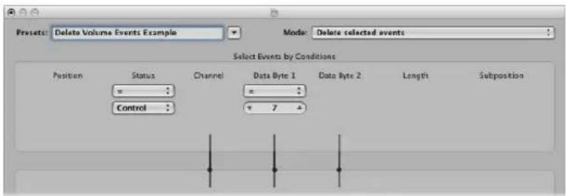
- Mode menu: Delete Selected Events.
- Selection Conditions area:
- Set Status to Control.
- Set Data Byte 1 to a value of 7.
2 Click Select And Operate.
To delete all controller events from a region:
1 Choose the following settings in the Transform window:
- Mode menu: Delete selected events.
- Selection Conditions area: Set Status to Control.
2 Select the MIDI region you want to transform, then click Select and Operate.
To create an ascending pitch pattern from notes of one pitch:
1 Choose the following settings in the Transform window:
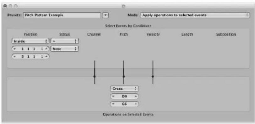
- Mode menu: Apply operations to selected events.
- Selection Conditions area:
- Set Status to Note.
- Set Position to Inside, and define the desired range (Cresc. only works if the Inside Position selection condition is chosen, as crescendos need start and end points).
- Operations area: Set Pitch to Cresc., and enter a value of D0 and G6 in the fields below.
2 Click Select and Operate.
Editing Audio in the Sample Editor
You can precisely select, refine, and process audio recordings in the Sample Editor.
The Sample Editor allows you to make incredibly accurate adjustments to audio files, right down to individual samples. This makes it the ideal tool for the removal of pops and clicks in audio material, or setting accurate crossover points for looped playback.
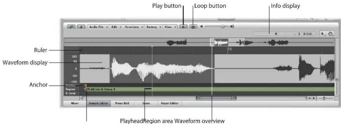
The Sample Editor also features a number of audio processing tools, collectively known as the Digital Factory. These include time stretching and pitch shifting, audio quantization, and extraction of pitch and rhythmic information from audio—which can be applied to other audio or MIDI parts.
Other sample manipulation processes, such as; reversal, automatic slicing of audio—based on silent areas, and setting optimal levels are also available.
Important: All edits and processes performed in the Sample Editor are destructive! This means that the audio file is actually altered. While you can certainly undo edits and processing commands, you should get into the habit of working on copies of your audio files, rather than the originals. It's better to be safe, than sorry.
Playing Audio Files
There are various ways to play back the audio sections visible in the Sample Editor, allowing you to hear audio during edits. Playback occurs independently of the project playhead position. If you'd like to hear the selected audio passage in the context of the project, just use the Transport playback controls, as usual.
The Mixer's Prelisten channel is used for monitoring in the Sample Editor. You can access the Prelisten channel in the Environment Mixer layer—you can find it to the right of the highest numbered audio channel strip.
Basic Playback Commands
As mentioned above, audio playback in the Sample Editor is independent of the project playhead position. This enables you to hear the audio in a number of ways, making selection and editing tasks simpler.
To start playback in the active selection area:
- Click on the Play button (or use the Play/Stop Selection key command).
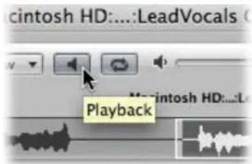
If you double-click at any position on the ruler, the audio file will play back from this point, to the end of the current selection. If you double-click on a point beyond the selected area, the audio file will play until its end point is reached.
To continuously repeat the selected area:
1 Click the Loop button next to the Play button.
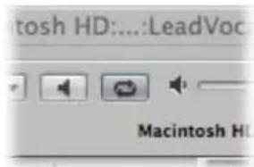
When you turn this on, the currently selected audio section will cycle continually when playback is engaged.
2 Click on the Play button (or use the Play/Stop Selection key command).
You can change the start and end points of the selected area while looped playback is happening. This makes it easy to edit the start and end points of a drum loop, for example, until it loops perfectly. When you're satisfied with the loop, you can make the selected area a new region with the Edit > Selection → Region function.
To control playback with the overview:
■ Simply click-hold at the point you want playback to begin. Release the mouse button to stop playback.
You can also start monitoring from any position by double-clicking on the overview.
To scrub audio:
- Click-hold on the ruler and move the mouse.
The audio playback will follow the speed and direction of your mouse movements.
Advanced Playback Commands
You can use the following key commands for a number of advanced playback options:
- Play/Stop All (default: Shift-Control-Option-Space bar): Plays back the whole audio file, regardless of the current selection area.
- Start/Stop Region: Toggles between playback of the audio file's region start and end points—regardless of the selection area.
- Play/Stop Region to Anchor (default: Shift-Control-Space bar) and Play/Stop Region from Anchor (default: Control-Option-Space bar): These key commands allow you to check the region anchor position, by listening to the parts just before and after the anchor.
Navigating Audio Files
The Sample Editor offers a number of navigation facilities that make it easy to move to, and enhance the view of, specific parts of an audio file—making selection and editing far simpler, faster, and more accurate.
The scroll bars along the bottom and right edges of the Sample Editor scroll through the detailed waveform display in the usual way.
The zoom controls are also used in the same fashion as in other windows.
Click on the overview to display the area surrounding the Sample Editor playhead in the detailed waveform display. The overview always displays the entire audio file, regardless of the zoom level (and selected area) shown in the waveform display.
Quickly Navigating to Specific Positions in Audio Files
If you're trying to reach a specific point in the audio file, some of the commands listed below may also be of use to you. These are available in the Sample Editor's Edit menu, and as key commands.
- Go to Selection Start (default key command: Left Arrow key)
- Go to Selection End (default key command: Right Arrow key)
- Go to Region Start
- Go to Region End
- Go to Region Anchor (Down Arrow key)
To navigate to the loudest point in an audio file:
- Choose Functions > Search Peak (or use the corresponding key command, default: Shift-P) to scan the currently selected region for the sample bit with the greatest amplitude value.
The playhead is placed on this bit in the waveform display.
To navigate to silent passages in your audio file:
- Choose Functions > Search Silence (or use the corresponding key command, default: Shift-S) to scan the selected audio file (or selection area) for sections containing silence (digital zero).
The playhead is moved to the start point of the first silent section.
This command can be used repeatedly, to select and remove, or modify, silent sections in your audio files.
Changing the X and Y Axis Scales
The Sample Editor's vertical Y axis scale can show the waveform amplitude in percentage units or in sample units.
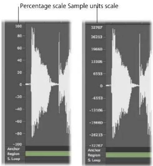
line
| Sample Units Scale | Value | | ------------------ | --------- | | 32767 | -32767 | | 26213 | -32767 | | 19660 | -32767 | | 13106 | -32767 | | 6553 | -32767 | | 0 | -32767 | | -6553 | -32767 | | -13106 | -32767 | | -19660 | -32767 | | -26213 | -32767 |To display the amplitude scale in sample units:
■ Enable the View > Amplitude Sample Value setting.
To display the amplitude scale in percentage units:
■ Enable the View > Amplitude Percentage setting.
You can also access the amplitude view settings by Control-clicking on the amplitude scale itself.
The horizontal X axis (the ruler) shows the course of the audio file over time.
To change the time (horizontal) scale:
- Choose one of the following scaling units in the View menu or the time scale shortcut menu (Control-click on the ruler):
- View > Samples: Displays the sample word number from the beginning of the project or audio file.
- View > Min : Sec : Ms: Shows the scale in Hours : Minutes : Seconds : Milliseconds, from the beginning of the project or audio file.
• View > SMPTE Time: Shows the scale in SMPTE time in Hours : Minutes : Seconds : Frames). - View > Bars/Beats: Shows the scale in bars, beats, divisions, and ticks, just like the Bar ruler in other windows. The zero point is represented by "1 1 1 1", but lengths are measured from "0 0 0 0".
Note: Changes to display format options affect the information shown in the help tag, and the info display.
Absolute and Relative Time
The different axis scales in the Sample Editor can be displayed in two ways:
- By reference to the time axis of the project (absolute position)
- By reference to the beginning of the audio file (relative position)
The units in the ruler (between the overview and the waveform display) are displayed with dotted lines when viewing the relative position.
To enter the relative display mode, do one of the following:
■ Open the Sample Editor from the Audio Bin.
■ Activate Link mode in the Sample Editor, and select a region in the Audio Bin.
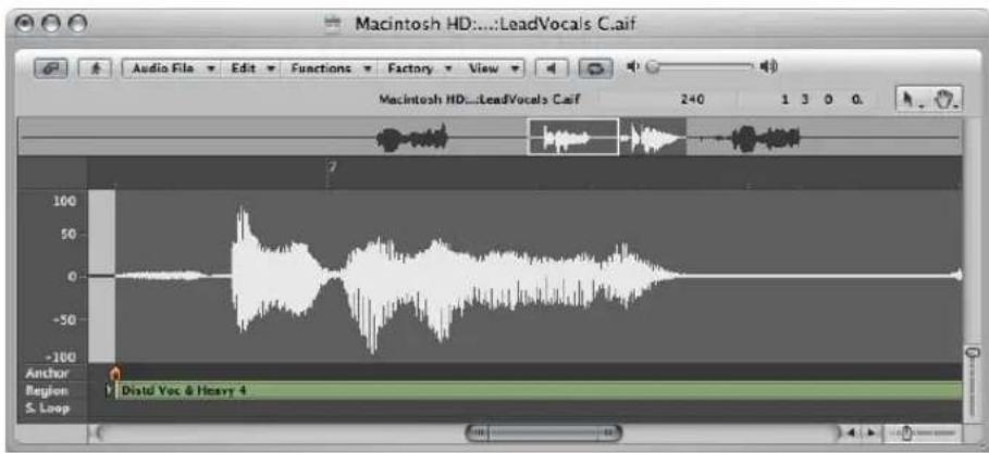
The beginning of the section is automatically assigned to the zero value, or in bar/beat terms, position: 1 1 1 1. The position marker lines are dotted, indicating no time connection exists.
Note: This will not necessarily match the actual playhead position. The calculation of all remaining musical sections uses the current project tempo at corresponding positions.
To enter the absolute display mode, do one of the following:
■ Open the Sample Editor from the Arrange window.
■ Activate Link mode in the Sample Editor, and select a region in the Arrange area.
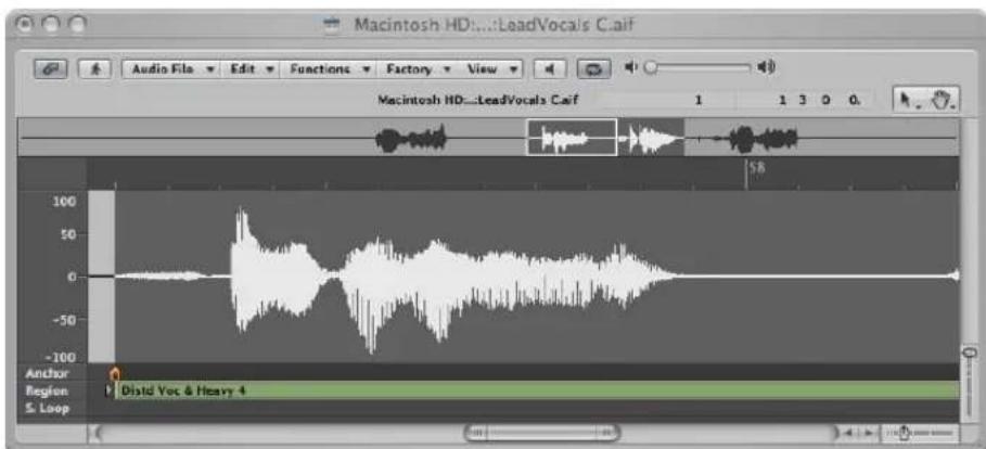
Time is measured from the start of the project, which is assigned a value of zero (or position: 1 1 1 1 in bar/beat terms). In this viewing mode, the absolute (project) time is shown in the ruler.
Displaying the Waveform as Sample Bits
You can switch from the usual representation of the waveform to one that shows the structure of the recorded digital data—at high magnification levels on the detailed waveform display. This viewing mode is useful when eliminating clicks and pops from your recordings, for example.
To display the waveform as sample bits:
■ Enable the View > Show as Sample & Hold.
Making Selections
Sample Editor commands only affect the currently selected area of the audio file. The start point, and length, of the current selection area are shown in the info display above the overview.
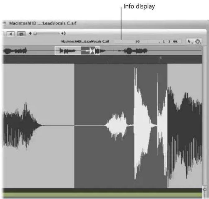
The format of the information shown in the start point and length display fields matches the chosen View menu display settings.
Tip: Make use of the navigation options discussed in the previous section to accelerate selection.
To select the entire audio file:
- Choose Edit > Select All (or use the corresponding key command, default: Command-A).
To select a particular section of an audio file:
- Click-hold on the start or end of the area you want to select in the waveform display, and drag to the right or left.
The start point and length are displayed (as sample words) in a help tag while making your selection.
To change the start or end point of an existing selection area:
- Shift-click on a selection area to change its start or end point.
The proximity of your click—to the beginning or end of the selection—determines whether you change the start or end point boundary. The closest one wins ...
Tip: If you hold down Option-Shift, the more distant selection boundary is changed (rather than the nearer).
To move the selection area:
- Option-click, and drag to shift the whole selection, without changing its length.
To define the selection area using a region:
1 Select a region in the Audio Bin or Arrange area.
2 Choose Edit > Region → Selection.
This function is useful if you want to reselect the entire region for cycled playback, after performing a number of edits, for example.
The reverse can also be done, allowing you to redefine the length of an existing region by choosing Edit > Selection → Region.
Copying, Pasting, Deleting, and Cutting
Once you have selected an area of an audio file, you can use the usual Cut, Copy, Paste, and Delete commands in the Edit menu to cut, copy, paste, or remove the selected area.
Important: All of these commands (except Copy) actually change the data of the audio file itself; in other words, they behave destructively.
Cut
Cuts a selected passage out of an audio file, and copies it to the Clipboard. All following audio sections move forward (towards the start point of the audio file) to fill the gap.
Copy
Copies a selected passage to the Clipboard, leaving the selected area in its original location.
Paste
Inserts the contents of the Clipboard at the clicked position. All audio data that follows the paste (insert) point is moved back (towards the end of the audio file) to make room for the Clipboard contents.
Warning: Anything selected at the time of the paste is deleted, and replaced by the Clipboard contents.
Delete
Erases the selection, without placing it in the Clipboard. All data beyond the deleted passage is moved forwards (towards the start point of the audio file) to fill the gap.
Destructive Audio Editing and Processing
The following section covers the use of several standard audio processing commands and tasks. These include normalizing, reversing, fading, and changing the level of audio files. Advanced audio processing options are discussed in "Working With the Digital Factory" on page 533.
You are normally asked to confirm all sample editing functions executed with a key command.
To disable this safety feature:
- Turn off the Preferences > Audio > Sample Editor > Warning before processing function by key command checkbox.
Correcting Pops and Clicks With the Pencil
The Pencil tool allows you to correct clicks and pops or clipping, by manually drawing in the detailed waveform display.
To correct pops and clicks with the Pencil:
1 Navigate to the desired section of the waveform by clicking on the overview.
Tip: Pops and clicks are often the loudest part of an audio file, so you may find the Functions > Search Peak command useful when looking for them.
2 Use the zoom controls to magnify the section of the waveform that you want to correct.
3 Use the Arrow tool to scrub the audio around the pop or click.
This will help you to identify exactly where you need to draw.
4 Select the Pencil tool, and drag from left to right (including up or down movements) to draw in a new shape to the waveform spike. The edges of drawn sections are automatically smoothed. Press Option to affect both sides of stereo waveforms.
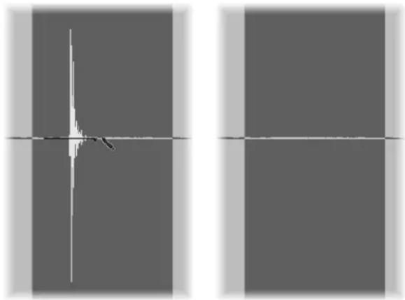
natural_image
Abstract grayscale image with two vertical panels and a central crosshair, no text or symbols present.As long as the mouse button is held down, the drawn waveform can be replaced by the original waveform—by moving the mouse to the left.
Changing the Level of an Audio File
You can use the Change Gain command to change the level of an audio file. You would typically use it on an entire audio file, but can certainly boost portions of it.
To raise or lower the level of the selected audio file (or area) by a specific amount:
1 Choose Functions > Change Gain.
2 Choose the desired settings in the Change Gain dialog:
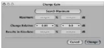
- Set the required level change by clicking on the up or down arrows, or by directly typing in either Change Relative field. You have a choice of a percentage or decibel increase or decrease.
- Click on the Search Maximum button to search for the highest peak level. This automatically sets a value that is used to alter the level of the audio file. The Results in Absolute fields displays the maximum level that will be achieved by changing the gain (by the amount shown in the Change Relative fields).
3 Click Change (or press Return) to perform the gain change.
Important: You should never make a gain change that results in a value over 100%, as this will result in digital clipping.
Fading Audio Files
You can destructively fade in or out on entire, or selected areas of, audio files. The fade-in or out time is determined by the current selection area within the audio file.
To create a fade in or fade out:
1 Use any of the selection techniques outlined earlier in the chapter to determine the length of the fade-in or fade-out area.
- Fade-in: Volume is set to zero at the start point of the selection area, and the fade-in occurs over the length of the selection.
- Fade-out: Volume is set to zero at the end point of the selection area, and the fade-out occurs over the length of the selection.
2 Do one of the following:
- Choose Functions > Fade In (default key command: Control-I) to create a fade in.
- Choose Functions > Fade Out (default key command: Control-O) to fade passages out automatically.
Tip: If you use the Silence function (see "Silencing an Audio File Section" on page 527) to remove unwanted background noise from silent passages, small jumps in volume can sometimes appear at the silence start and end points. In this situation, zoom in, and select a small area surrounding (just before and after) the start point of the signal, then use the fade-in function.
To adjust the fade curves:
1 Open the Functions Settings window by choosing Function > Settings.
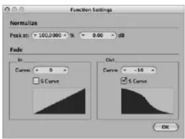
2 Edit the Curve value to change the shape of the fade-in or fade-out curve.
3 Turn on the S Curve checkbox if you want to create s-shaped curves.
These settings are automatically stored in the Preferences when Logic Express is closed, and apply to all projects.
Tip: Common fades (such as a fade-out at the end of a track) can also be achieved with Mixer, automation, or Hyper Draw functions. The Arrange window Crossfade tool offers a further, flexible, non-destructive fade option (see "Creating Crossfades and Fades on Audio Regions" on page 358).
Silencing an Audio File Section
You can use the Silence command to set all amplitude values to zero, rather than removing (with Cut or Delete) all data from the selected area of an audio file. This function is generally used to silence unwanted background noise in quiet passages.
To silence the selected area of an audio file:
- Choose Functions > Silence (or use the corresponding key command, default: Control-Backspace).
Reversing the Selected Area of an Audio File
The Reverse command is most commonly used on an entire audio file, to reverse a cymbal sound, for example. It can also be used as a creative option on selected portions of audio files. As an example, the reverb tail at the end of a file can be reversed, copied, and pasted to the beginning of the file.
To reverse the selected area of the audio file:
- Choose Functions > Reverse (or use the corresponding key command, default: Shift-Control-R)
Trimming Audio Regions
You can use the Trim command to remove unimportant passages (generally silence) from the start and end of your audio files. Trim can also be used to remove portions of audio files that are not used by regions.
To erase all unselected portions of an audio file:
- Choose Functions > Trim (or use the corresponding key command: Control-T)
Important: Make sure that the areas you are about to delete do not contain any regions that you may need. Regions outside the selection area will be lost. Portions of regions that fall partly outside the selection area are also removed, resulting in a length reduction of the region. If any such regions are being used in the Arrange area, a warning dialog will give you the option of cancelling the trim command.
Normalizing Audio Files
Normalization is a process that raises the maximum level of a digital signal to a specified amount—typically to its highest possible level, without introducing distortion.
Tip: The start and end points for the section being normalized should generally not fall within a continuous section of audio, as this will result in abrupt increases in volume after normalization. The start and end points should therefore be located in sections that occur just after, or before, musical gaps.
To normalize the selected area in an audio file:
- Choose Functions >Normalize (or use the Normalize key command, default: Control-N).
Logic Express finds the point with the highest volume in the current selection area, and determines how far this is from the maximum possible level. The level of the selected area is then raised by this amount. The dynamic relationships of sample levels within the audio passage remain unaltered.
You can set the desired maximum level in the Function Settings window, which you can open by choosing Functions > Settings (or by clicking the Settings button in the Normalize dialog).
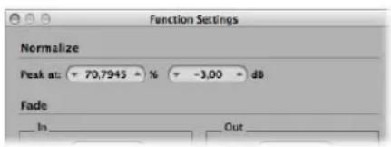
Set the desired maximum level (as a percentage or in decibels) in one of the Peak at fields.
Tip: You should not choose 100% (0 dB) in these fields, as this may result in clipping should you wish to increase the gain of the overall signal afterwards, say with an EQ. As a good rule of thumb, you should leave yourself at least 3 to 6 dB of headroom, to allow for further audio processing tasks, such as mixing and effects processing.
These settings are automatically stored in the Preferences when Logic Express is closed, and apply to all projects.
Reversing the Phase of a Selection Area
You will find the Invert command extremely useful for correcting phase cancellation errors, or when several out of tune signals (or several signals processed through chorus effects), are to be mixed down to mono.
To completely reverse the phase of all currently-selected audio material:
- Choose Functions > Invert.
All negative amplitude values become positive, and vice versa.
Note: This doesn't audibly change the file, if heard in isolation. The process depends heavily on the audio material.
Tip: You can also use the Invert function to decode mono/stereo recordings, but it's far easier to use the Direction Mixer plug-in for this task. For more information on this plug-in, see the Logic Express 8 Instruments and Effects manual.
Removing DC Offsets
Some audio interface hardware can layer direct current (DC) over the audio signal. This results in a vertical shift in the waveform position, which can be clearly seen in the Sample Editor.
During playback, this can cause crackling sounds at the start and end of the audio region.
To center the waveform around the zero amplitude line:
- Choose Functions > Remove DC Offset.
Adjusting the Project Tempo
Just like automatic tempo matching functions in the Arrange, the Functions > Adjust Tempo by Selection and Locators command adjusts the project tempo, in accordance with the current locator positions and selection area in the Sample Editor.
The operation is similar to the Arrange function (see "Setting the Project Tempo to Match an Audio Region" on page 554); but only applies to the selected area of the audio file in the Sample Editor, rather than the overall length of the region.
Sample Loop Functions
The Edit > Sample Loop → Selection, Edit > Selection → Sample Loop, and Edit > Write Sample Loop to Audio File functions are ideal for use with the EXS24 mkll sampler. Please see the Logic Express 8 Instruments and Effects manual for details on the EXS24 mkll.
They can also be used to generate audio files that contain the loop settings in the file header. This allows you to make full use of these files in any application that can read the loop information in the file header.
Simply use either selection command to choose an area of the open audio file, and the Write command to save an audio file—inclusive of loop information—stored in the file header.
Undoing Editing Steps in the Sample Editor
Almost all of the Sample Editor functions are destructive, and change the files stored on your hard drive. You can, of course, use the Undo function should things go awry.
To compare (or undo) your edits with the original audio file:
Choose Edit > Undo (or use the corresponding key command, default: Command-Z).
As the Undo function in the Sample Editor works independently from the rest of the program, you can try out an edit in the arrangement, and make changes there. As soon as you open the Sample Editor again (or make it the key focus window), the Undo function is available for the last destructive sample edit.
Data altering processes can be cancelled while underway by pressing Command-period. The audio file will be retained in its original state, even if it appears that a portion of the editing function has occurred.
Setting Undo Preferences
You can configure the Sample Editor's undo functionality in the Logic Express > Preferences > Audio > Sample Editor tab:
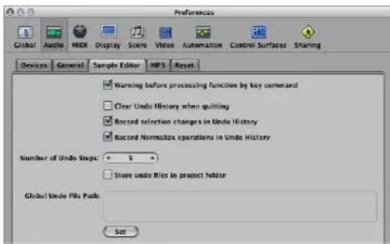
- Clear Undo History when quitting: Switch this on to automatically delete the Undo History for all edited audio files, when you quit Logic Express.
- Record selection changes in Undo History: Switch on if you wish to undo and redo changes to selected areas in the Sample Editor.
- Record Normalize operations in Undo History: Turn off if you don't want to create any undo files once the Normalize function is invoked. As normalization is generally the last step in sample editing, this parameter (if active) can destroy the undo history. As a safety feature, a warning pops up if an undo history exists (and the switch is on), providing you with the opportunity to create an undo file.
• Number of Undo Steps: Sets the maximum number of undo steps. - Store undo files in project folder: Switch this parameter on (on by default) if you would like the Undo History to be stored in a sub-folder of the current project.
- Global Undo File Path: All Undo History files are saved into a global location (a user-defined folder) if the "Store undo files in project folder" option is not switched on.
Creating Manual Backups
You can make manual backups of the file you're editing, or replace it with a backup version at any time—using a variety of functions.
Although the Undo History and standard Undo functions are available, it's a good working practice to create backups before processing or editing. This provides a safety copy of your precious audio recordings, should something unexpected happen, due to a processing error or other unforeseen event.
To duplicate the audio file you're working on:
- Choose Audio File > Create Backup (default key command: Command-B)
This creates a copy of the audio file (with the extension .dup) in the same folder as the source file.
To revert to a backup file:
- Choose Audio File > Revert to Backup (default key command: Shift-Command-B).
This function completely replaces the current audio file with the backup (provided one exists, of course).
Important: You can not reverse this function with Undo.
To save a copy with a different name—to the location of your choice:
1 Choose Audio File > Save A Copy As.
2 Choose the desired settings in the Save A Copy As dialog:
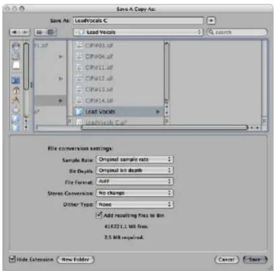
You can set the desired sample rate, bit depth, file format, stereo conversion, and dither type for the destination file. The dialog also features an "Add resulting files to Audio Bin" option, allowing you to add the file to the Audio Bin, following the save.
3 Browse to the location (hard drive and folder) that you want to store the audio file in, then type a name for the audio file in the name field.
4 Click the Save button.
To save the selected area as a new audio file:
- Choose Audio File > Save Selection As (or use the corresponding key command, default: Shift-Command-S).
The Save Selection As dialog offers the same file conversion menus as the Save A Copy As dialog. You can also choose to add the file to the Audio Bin, following the save.
Working With the Digital Factory
The Sample Editor features a number of audio processing tools, collectively known as the Digital Factory. These include time stretching and pitch shifting, audio quantization, and extraction of pitch and rhythmic information from audio—which can be applied to other audio or MIDI regions or events.
You access the Digital Factory functions via the Sample Editor's Factory menu. The Digital Factory functions have number of common aspects, outlined below:
- Digital Factory processes only affect the selected area of an audio file. The selected area of the audio file is replaced by the processed audio material.
- You can play the file while a Factory process is taking place. This will slightly slow down processing. A progress bar is displayed during processing.
- Some Digital Factory functions offer a Prelisten button that provides a rough idea of the expected result. (Not available for all digital audio hardware).
The Digital Factory functions are divided into two categories, and window types—Machines (large float window) and Functions (small float window).
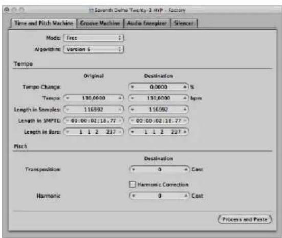
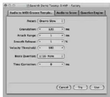
Each function has its own tab. This allows you to quickly switch between the functions contained in a window by clicking the corresponding tab.
Using the Time and Pitch Machine
You can use the Time and Pitch Machine to radically alter the time structure of audio files, including time compression or expansion, and pitch transposition. When changing the pitch, you can also correct any alteration of the formants. Pitch shifting without formant correction causes a phenomenon commonly known as the Mickey Mouse effect.
The Technology of the Time and Pitch Machine
The Time and Pitch Machine analyzes the spectral components and dynamics of the digital audio material, and processes the result. The algorithm endeavors to retain as much spectral and dynamic information as possible, and minimizes phase variations. In stereo files, the phase relationship between the left and right channels is fixed, and not altered. Doubled sound events are kept to a minimum.
You should, however, bear in mind that apart from resampling (transposition), the Time and Pitch Machine has to achieve the “physically impossible”: When a sample is lengthened, information needs to be invented. This should be as realistic as possible. Conversely, when a sample is shortened, information has to be cut out. This cut information should be as unimportant to the overall character of the sound as possible. Lengthening is more difficult than shortening, and if you have a choice, it’s better to speed up a drum loop than to slow it down.
There's always a small deviation between the set stretch or compression factor, and the actual result. This is because the algorithm needs some freedom to optimize the spectral and dynamic integrity (the sound quality). The deviation from the set value is only a few milliseconds (or fractions of a bpm). This shouldn't present a problem, as the absolute deviation is independent of the length of the processed section. Put another way, this means the deviation is no greater in longer files.
To open the Time and Pitch Machine, do one of the following:
- Choose Factory > Time and Pitch Machine (or use the corresponding key command, default: Control-P).
- Click the Time and Pitch Machine tab if another Digital Factory processor is visible.
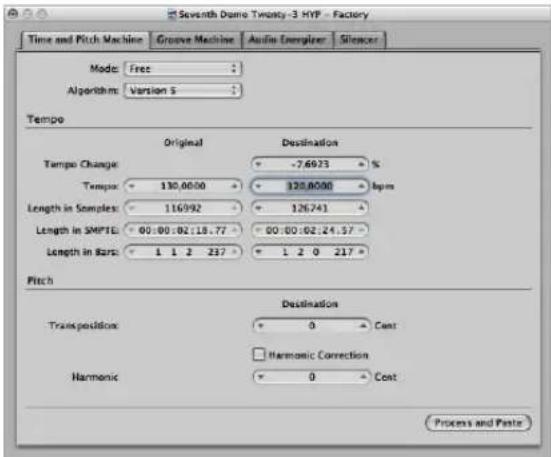
You don't need to enter, or adjust, all of the Time and Pitch Machine parameters to get a good result. Most are linked, so an adjustment to the Tempo parameter will result in changes to the Length values, and vice-versa.
Choosing the Mode and Algorithm
The Time and Pitch Machine's Mode and Algorithm menus define the operating mode, and algorithm, used when performing the time stretch or pitch shift.
Time and Pitch Machine Modes
You can choose between Free and Classic (default) in the Mode menu.
- Free is the most common setting when using the Time and Pitch Machine. It results in a free compression/expansion or transposition of the audio material, where the pitch and tempo are completely independent of one another.
- The Classic mode is for situations where you want to transpose a selected region, and also affect its tempo. This produces an effect that you're probably familiar with, as it simulates the sound of changing tape speed. This mode changes the pitch, sonic character, and playback speed of the audio material.
Time and Pitch Machine Algorithms
The Algorithm menu allows you to choose the algorithm that is best suited to the audio material you want to process. Your choices are:
- Version 5: This algorithm was inherited from Logic 5. It can be used on most types of audio material, and has a particular color, which may be useful as a creative option.
- Any Material: This is the most universal algorithm. It is able to handle most material.
- Monophonic: A specialized algorithm for monophonic material—an individual voice, brass, or woodwind instrument, for example.
- Pads: Use this algorithm on polyphonic material with harmonic content—choirs or string sections are good examples.
- Rhythmic Material: Use this algorithm on rhythmic material—can be drums and percussion, but less obviously; rhythm guitar, clavinet, and piano comp parts.
- Beats Only: This algorithm perfectly maintains the timing of percussive material. It should be your first choice for all kinds of dry drum loops.
- Universal: This high-quality algorithm is able to handle any kind of audio material, and is generally recommended for most time stretching tasks. The following two algorithms can, however, deliver better results in cases where the audio material exactly matches the outlined specifications.
- Complex: Choose this algorithm to obtain natural sounding results when time stretching complex musical material—orchestral music or final mixes.
- Percussive: The Percussive algorithm perfectly maintains the timing of rhythmic material, making it a good choice for drum loops and percussive, non-harmonic signals. In comparison to the Beats Only algorithm, the Percussive algorithm is better suited for percussive material that has been processed through a reverb (or contains a long tail). This may also apply to percussive playing styles, such as a staccato electric piano or clavinet parts. Beats Only may be the better alternative for dry drum recordings.
Support of Third Party Algorithms
Logic Express allows you to access the pitch shift and time stretch algorithms of the following third party plug-ins in the Time and Pitch Machine:
- Serato: Pitch'n Time
- Izotope: Radius
Note: These algorithms can only be accessed in the Time and Pitch Machine if the corresponding Audio Unit plug-ins are installed, and authorized, on your system.
Tempo Parameters
The Tempo section is divided into two columns. The left column (Original) displays the current values of the selected area in the audio file. The right column (Destination) is used to set the desired target values.
Tempo Change (%)
Determines the tempo alteration, displayed as a percentage (no original value is shown).
Tempo
Displays the tempo in bpm (beats per minute). Ensure that you set the right length in bars, or the correct original tempo will not be shown on the left!
Length in Samples
Displays the length of the selected area in samples.
Length in SMPTE
Displays the length of the selected area in SMPTE time format.
Length in Bars
Displays the length of the selected area in musical values (bars, beats, divisions, and ticks). If you have already adjusted the project tempo to match the region that you're about to edit, the original value will automatically be set correctly. If not, you need to manually enter the original length here.
Pitch Parameters
You use the pitch parameters to determine the amount of transposition in cents, and also the strength of harmonic correction, if used.
Transposition (Cent)
Transposition of the sound material in 1/100th semitone units (cents). A value of 100 will result in an upwards transposition by one semitone. A value of -1200 will result in the audio material being transposed down an octave.
Harmonic Correction
The entire spectral structure is shifted when audio is transposed. During this process, not only is the fundamental pitch transposed, but all of the resonances (formants) are shifted as well—as though the whole instrument or singer is being reduced or enlarged. This, of course, is not natural. Voices transposed up will sound like Mickey Mouse, or like Darth Vader if transposed down.
You can use the Harmonic Correction feature of the Time and Pitch Machine to correct this unnatural spectral shifting of formants.
Turn on the Harmonic Correction checkbox to correct the formants that define the timbre (sonic character). In other words, the formants in the transposed material are not changed.
This means that the original timbre (or the physical size of the resonance body) is maintained, resulting in a more natural sounding transposition. The only trade-off is that calculation takes more time.
Note: The quality of Harmonic Correction is heavily dependent on the source material, because the algorithm has to make intelligent decisions between tonal and atonal components of the recording, and handle them separately. This is not an exact science, and is more accurate on monophonic material than complex stereo material, but you can certainly use it on a complete mix. The phase correlation of stereo recordings is maintained.
Harmonic
If Harmonic Correction is turned on, you can also use the Harmonic (Shift) parameter to independently alter timbre. The units are shown in cents—100 cents per semitone.
- If you select the same value in both the Harmonic and Transposition fields, no correction occurs, and the result is as if Harmonic Correction is switched Off.
- If you set Harmonic to zero, the formants don't change. This avoids the unwanted side effects of traditional pitch shift algorithms.
Tip: If you need to find the exact transpose value by trial and error, switch off Harmonic Correction. As soon as you've found the right transposition value, do an independent Harmonic Correction, with the same value, in a second step.
Shifting Formants Without Transposition
You can also use Harmonic Correction to shift the formants without transposition. This means you can alter the physical size of the sound source's resonance body—to give female voices a male character and vice versa, for example—while keeping the pitch in tune.
This remarkable effect (sometimes known as gender-bending) allows you to change sounds so that they appear to have been made by unusually small or large instruments. It is useful for beefing-up thin or brittle sounding parts, such as guitars, or instruments and vocals that were recorded through a microphone with a limited frequency response.
As a usage example on a vocal part: If you set Harmonic Shift to -300, and the Transposition value to zero, the sonic character of the singer will be changed as though transposed three semitones down—but without an actual transposition in pitch. This means that a musical C remains a C, but the timbre of the vocal becomes darker.
Using the Groove Machine
You can use the Groove Machine to alter the feel, swing, or groove of digital audio material, in percentage steps. Put another way, the Groove Machine can quantize straight audio!
You can also strictly quantize audio that "grooves a little too much" with the Quantize Engine (see "Using the Quantize Engine" on page 547).
Important: Before you open the Groove Machine, make sure that the tempo of Logic Express exactly matches that of the selected audio material, or the Groove Machine won't work accurately. You can, however, set the tempo and length directly in the Groove Machine, using the Corresponds with Tempo and To Bar Length parameters.
To open the Groove Machine, do one of the following:
- Choose Factory > Groove Machine in the Sample Editor (or use the corresponding key command).
- Click the Groove Machine tab if another Digital Factory processor is visible.
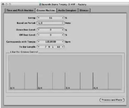
Swing
This parameter is used to set the swing factor. At 50% there is no change—you will generally achieve the best results with values around 55% to 65%.
Based on Period
You can determine whether the audio material should be edited (quantized) on the basis of eighth note, or sixteenth note swing.
Down Beat Level and Off Beat Level
You use this parameter to determine whether the down beats (or off beats) in the audio material should be raised or lowered. Positive values increase the level, negative values reduce the level. Bear in mind that raising the level of normalized audio material can cause distortions (particularly on the down beats, which are usually louder).
Corresponds with Tempo
If you change this value, you will set the project tempo at the current playhead position.
To Bar Length
Use this parameter to define the length of the selected audio material in musical values (bars, beats, divisions, and ticks).
Using the Audio Energizer
The purpose of the Audio Energizer is to increase the perceived volume of audio material, while altering the sound as little as possible, and without causing clipping. Digital distortion (which would be the inevitable result of simply increasing the level) is avoided by using this algorithm.
You could compare the effect to an analog tape which has been saturated with a high recording level. The distortion factor and effect on the audio material is much lower than that of analog tape saturation, however.
Here's an example of the effect. If a normalized audio file (audio data which is already at the maximum dynamic range) is processed with the Audio Energizer, and played back through an audio channel: the channel meter will show a higher level, indicating increased average energy in the signal, but the peak level display will not change, as the maximum signal level has not been altered.
Note: If the material contains anomalies such as noise, these will also be increased, and can become audible. If necessary, you can process the energized audio file with the Silencer (use a low setting), or make use of the Denoiser effect plug-in.
To open the Audio Energizer, do one of the following:
- Choose Factory > Audio Energizer in the Sample Editor (or use the corresponding key command).
- Click the Audio Energizer tab if another Digital Factory processor is visible.
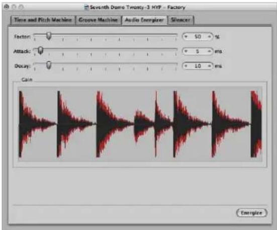
Factor
Set the amount of average level boost. A value of 0% means no alteration, while higher values produce an increase in energy. The setting you make here will depend on the audio material, situation, and personal taste.
- Begin by trying values in the 40 to 100% range.
• Values below 10% will have little effect.
- Values over 100% can lead to undesirable alterations in the sound, depending on the material.
- Values over 200% are not recommended with normalized files, because they will have detrimental effects on the sound and its dynamics. They can also greatly increase the required computation time. On non-normalized audio data, however, even high values can be effective because the overall level is initially increased to its maximum, without affecting the dynamic range.
Attack and Decay
These parameters control the steepness of the algorithm's filter. Try values of 2 to 4 times the default, if the result sounds too digital or raw. This can happen if smaller elements among the main events in the signal are boosted. As an example, the reverb portion of a sound can become louder.
Using the Silencer
The Silencer consists of two component functions which can be used separately, or in conjunction:
- Noise Reduction lowers the level of any noise in the signal, such as tape noise.
- Spike Reduction tries to identify and reduce signals such as pops or clicks.
You will probably use Noise Reduction more often than Spike Reduction.
To open the Silencer, do one of the following:
- Choose Factory > Silencer from the Sample Edit or menu (or use the corresponding key command).
- Click the Silencer tab if another Digital Factory processor is visible.
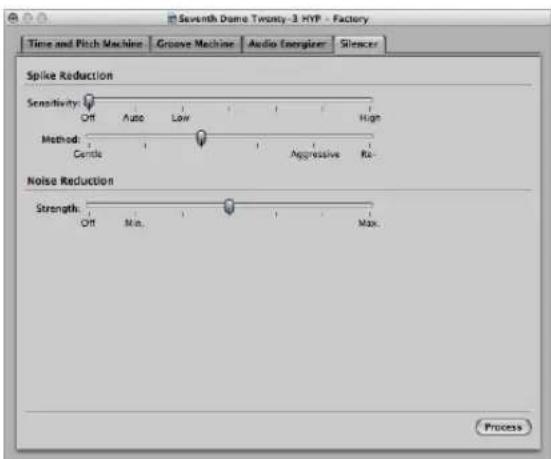
Noise Reduction
The purpose of Noise Reduction is to reduce the noise components of the signal, and also affect the main signal, particularly the high frequency elements.
The process is single ended, meaning it affects material which is already recorded, and there is no need to decode the signal during playback. This means that even noise present in the original signal can be processed.
To use noise reduction:
1 Turn the Spike Reduction function off, by moving the Sensitivity slider to the extreme right.
This ensures that only the Noise Reduction function is used.
2 Drag the Strength slider to the desired position.
- Off means no edit.
- Min is the smallest possible edit. Values closer to Min have a small effect.
- Max results in the maximum possible reduction of the noise component.
The "correct" value depends on the quality of the material, and your own personal taste. Good quality material should be edited using Min or values close to it. You will probably only notice minor changes in the sound. Bad (noisy) quality material should be processed at higher values, or even Max. If the setting is too high, the treble component of the signal will be reduced.
3 Click the Process button to execute the function.
Note: The Silencer function is optimized for normalized data. Low level material should be normalized before processing.
Spike Reduction
The aim of Spike Reduction is to identify and reduce signals such as pops, clicks, or digital spikes, in order to reconstruct a hypothetical original signal.
To use spike reduction:
1 Turn the Noise Reduction function off, by moving the Strength slider to the extreme right.
This ensures that only the Spike Reduction function is active.
2 Drag the Sensitivity slider to the desired position. This parameter determines the threshold level used for the recognition of spikes (loud bits) in the audio file.
- When set to High (sensitivity), relatively small signal spikes are identified.
- When set to Auto, the threshold is controlled automatically. Useful on most material.
- Use Low to identify most signal peaks as spikes.
3 Drag the Method slider to determine how spikes are processed.
- Gentle is the weakest algorithm, and only slightly smooths the original signal.
- Aggressive is the strongest, and has a very noticeable impact on the audio.
- The Re-build setting completely replaces the (often unusable) original signal with an artificially generated estimate of the original signal, at the identified points. This synthesized signal is created by analyzing the audio material surrounding these points.
All of these algorithms filter the original signal at the identified spike points.
4 Click the Process button to execute the function.
Experiment with the parameters. If the Sensitivity slider is set to High (or close to it), there's a danger that very sharp transients in the main signal will be identified as spikes. Depending on the audio material, it's sometimes impossible for the Silencer to distinguish between signals you want to keep, and signals you want to eliminate. This is particularly the case if the decision between spike or main signal is merely a matter of taste—with some click-like bass drum sounds, for example. The attack phase of these sounds can have similar characteristics to static on vinyl records.
Tip: Don't forget that pops and clicks can also be manually removed with the Pencil tool, if the Silencer doesn't produce satisfactory results.
Converting Audio to MIDI: Using Audio to Score
This function transforms a monophonic audio recording into musical notation, by creating a MIDI region that corresponds to the recorded melody. This allows you to play a MIDI sound module in unison with an audio recording or—transposed—as a second voice.
Note: This function is best-suited to producing melody notes from a clearly sung non-legato vocal line. It works best on unprocessed (no effects) audio.
To open and use the Audio to Score function:
1 Select the destination MIDI or software instrument track in the Arrange window.
The MIDI region generated by the Audio to Score function will be placed on this track.
2 In the Sample Editor, choose Factory > Audio to Score (or use the corresponding key command).
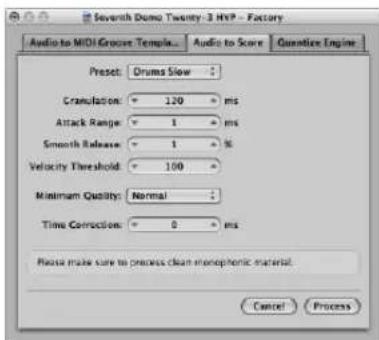
3 Set the desired parameter values in the Audio to Score tab.
4 Click the Process button.
A Score Editor window, containing the transcription of the audio file, opens automatically.
Setting the Audio to Score Parameters
The following section outlines the parameters you can set in the Audio to Score tab.
Preset
This menu contains various presets for the Audio to Score parameters, which are suited to specific types of audio material. You can use these presets as starting points for your own processing.
There are also four User presets. Choose any of the User 1–4 presets, and make the desired parameter changes. They will be memorized.
Granulation
Use Granulation to determine the time span of louder components in the audio material. Logic Express uses these peak signals (or transients) to discriminate between notes that it should—or should not—analyze. The most useful values are usually between 50 and 200 milliseconds, depending on the tempo of the audio material.
Attack Range
This tells Logic Express how long the attack phases of the sounds in the audio material are. As examples of how you might use this parameter: drum and percussion instruments have short attack times of less than 20 ms, while string instruments have longer attack phases. The best values for most instruments are usually between 5 and 40 ms; with most around 20 ms.
Smooth Release
This parameter is specifically designed to process audio material that contains sounds with a long release or reverb tail. This makes it easier to convert these sounds into notes. The value you choose here should generally be between 0 and 5%, except when processing passages that contain sustained notes, distorted guitars, or similar sounds.
Note: The quality of the Audio to Score results will benefit from non-legato performances, so the audio material should contain few, if any, reverb or release tails, if you can avoid them.
Velocity Threshold
This parameter sets the threshold level. All signals that fall below this value are ignored. In most cases, you should choose a value of 1, except when processing very dense, loud material with soft background noises.
Minimum Quality
You can choose between normal or high quality processing in this pop-up menu.
- The Normal setting is more tolerant of audio trigger points that aren't perfectly in tune, but it can generate wrong notes.
- When set to High, only audio trigger points of a clearly identifiable pitch will be accepted and used. Indistinct trigger points are replaced by notes with a pitch of C3 and MIDI channel 3. These are labeled as an “undetected mark.”
When analyzing audio material containing clearly identifiable pitches, you will find that good results can be obtained from either setting.
Time Correction
This parameter allows you to compensate for any time delays that may occur when external samplers or synthesizers are triggered by MIDI notes. These time delays are sometimes very noticeable, particularly if the connected device is playing a MIDI region (that was generated by the Audio to Score function) alongside the original audio material. You should be able to compensate for this effect by using settings between -20 ms and 0 ms.
Your parameter settings are stored in the Logic Express preferences.
A few tips on getting the best results from the Audio to Score function:
- You will only get good results with clearly identifiable, monophonic audio material. Solo voices, strings, and piano can be easily analyzed, as can any recordings with distinct pitches.
- Experiment with different parameter settings for data processing. Be prepared to make several attempts, to determine the optimum settings for a particular audio recording.
Using the Quantize Engine
This Digital Factory function allows you to use a MIDI region template (within reason), to quantize an audio recording.
This is done by using a dynamic time compression or expansion algorithm. The function is similar to the Groove Machine, except that the quantize template can reflect values other than just 8th or 16th note swing grooves. Even user-defined MIDI grooves can be used!
To use the Quantize Engine on an audio region:
1 Select the audio region that you want to quantize in the Arrange area.
2 In the Sample Editor, choose Factory > Quantize Engine.
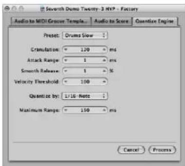
3 Set the desired parameters in the Quantize Engine tab.
4 Click the Process button.
Setting the Quantize Engine Parameters
The parameters available to the Quantize Engine are almost identical to those available for the Audio to Score function (see "Converting Audio to MIDI: Using Audio to Score" on page 544). This section only outlines the parameters that differ from the Audio to Score function.
Preset
Choose a preset that best matches the characteristics of the audio material.
Quantize by
Click on this pop-up menu to set the required quantization grid. The same values available for MIDI data (including user quantization templates) are found here.
Maximum Range
This is where you set the maximum time (in milliseconds) that an audio peak can deviate from a quantization point—in the chosen quantization grid template (Quantize by menu).
- Small values are suitable for quantizing audio material with a similar groove.
- Large values allow you to use a quantization grid that deviates more from the original groove of the audio material. This, however, increases the risk of misinterpretation.
Start by experimenting with smaller values for the Maximum Range parameter (as small as possible, and as large as necessary).
Audio to MIDI Groove Template
For detailed information on the Audio to MIDI Groove Template function, see "Creating an Audio to MIDI Groove Template" on page 487.
Using an External Sample Editor
You can configure Logic Express to open an audio region or file in an external sample editing application.
To use an external sample editing application:
- Click the Set button below the Logic Express > Preferences > Audio > Sample Editor > External Sample Editor preference.
A file dialog opens, allowing you to browse for, and select an external sample editing program.
To open a selected audio file in the external sample editor:
- Choose Options > Audio > Open in “name of external sample editor” (or use the corresponding key command).
Removing Silent Passages From Audio Regions
22
You can use the Strip Silence function to automatically remove silent passages from audio regions.
The basic premise of the Strip Silence process is simple: all amplitude values below a threshold value are interpreted as silence, and removed. New regions are created from the remaining passages.
How You Can Use Strip Silence
Strip Silence is the ideal tool for the following tasks:
Removing Background Noises
The most conventional use for Strip Silence is simulation of the classic noise gate effect. When used on long recordings with numerous gaps—such as vocals or instrumental solos—you can obtain better results by setting a low threshold value. Background noise is removed, without affecting the main signal.
- For short percussive regions (drum loops), you can simulate time compression/expansion by simply altering the tempo.
- You can even quantize the individual segments in an audio recording.
Creating Segments of Spoken Recordings
You can use Strip Silence to divide long spoken passages into several convenient segments, like sentences, words, or syllables. For film synchronization or jingles, you can move or reposition the speech segments by simply dragging them around in the Arrange area.
Tempo changes allow you to simulate a time compression or expansion effect, as the syllables automatically move closer together, or further apart.
Creating Segments for Drum Loops
Dividing drum loops into small segments is a good way of perfectly synchronizing them. As an example, in audio passages where the bass drum and snare are completely separate, you can often use Strip Silence to isolate each individual beat.
Optimizing Synchronization Over Long Time-Spans
Different computers, different synchronization sources (internal or SMPTE code), different tape machines and—in theory—even different samplers or hard disk recording systems, will exhibit slight variations in clock speed. Changing just one component can lead to a loss of synchronization between recorded audio material and MIDI. This is particularly applicable to long audio regions.
This is another situation where the Strip Silence function can help, by creating several shorter audio regions, with more trigger points between the audio and MIDI events.
As an example, you can use this method to roughly split up a whole audio file, and then divide the new regions, using different parameters. The new regions can then be processed again with the Strip Silence function—and so on.
Optimizing Files and Regions
Automatic region creation from an audio file that contains silent passages, such as a single vocal take that runs the length of a project. The unused regions or portions of the audio file can be deleted, saving hard disk space, and simplifying (file and) region management.
Extracting Audio Files From a Disc
Many sample library discs (CD or DVD) contain thousands of audio recordings stored as AIFF or WAV files. Strip Silence can be used to split these into individual regions, which can be used directly in the Arrange area. Regions can also be converted into individual audio files (samples), which can be used in the EXS24 mkll.
Using Strip Silence
This section outlines the steps, and parameters, involved in the Strip Silence process.
To remove silent passages from a selected region:
1 Do one of the following:
- In the Arrange area, choose Audio > Strip Silence (or use the Strip Silence key command, default: Control-X).
- In the Audio Bin window, choose Options > Strip Silence (or use the Strip Silence key command, default: Control-X).
2 In the Strip Silence window, set the following parameters by using the mouse as a slider, direct numerical entry, or clicking on the up and down arrows.
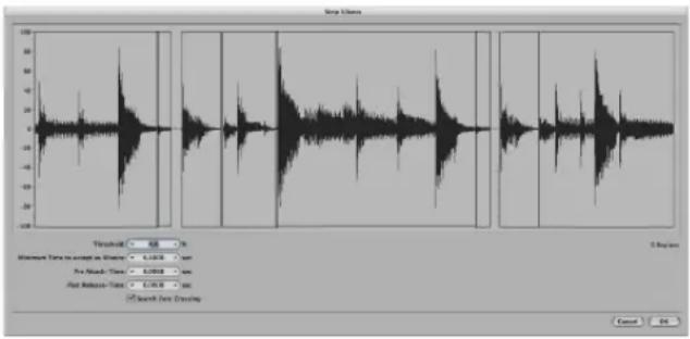
- Threshold: Use this to define the amplitude level (shown as a percentage) that a passage must exceed, in order to be defined as a region. In terms of the number and length of regions created by the process, this is the most important parameter. As a general rule: a higher Threshold value leads to numerous short regions. Low values create fewer large regions.
- Minimum Time to accept as Silence: Use this to define the length of time that a section must be below the Threshold value, before it is considered a gap. Very small values tend to increase the number of regions, because even short dips in amplitude are interpreted as silence. Higher values prevent sections of audio from being interrupted by fluctuating amplitudes.
-
Pre Attack Time: You can add a defined amount of pre-roll to the beginning of all regions created by the Strip Silence process, if desired. High threshold values prevent any amplitudes with slower attack times from being chopped. This function is useful for non-percussive material such as vocals, wind instruments, strings, and so on. Overlaps are permitted—the pre-delayed start point of a region can extend back to the end of the previous region—but only if the Threshold value is not exceeded. The Pre Attack Time doesn't affect the anchor position, which means the absolute position of the audio data (in the project) is retained.
-
Post Release Time: Use this parameter to define an automatic release time for the end points of all regions. You can avoid abrupt cut offs to amplitudes that fade out gradually (particularly if you have set a high Threshold value). As examples: Cymbals, open hi hats, snares with long reverb tails, vocals, and so on. The Post Release Time parameter does not allow overlaps. This means that region end points cannot extend beyond the start point of the following region. Adjusting the Post Release Time doesn't affect the anchor position, which means the absolute position of the audio data (in the project) is retained.
- Search Zero Crossings: Turn on this checkbox to automatically snap the region start and end points to the nearest waveform zero crossings.
Note: Depending on the audio material, all parameters can have an effect on the number and division of regions. You may need to experiment a little to obtain the desired results. Every time you alter a parameter, the graphic display of the region changes accordingly.
3 Click OK.
If you selected a region that is used in the Arrange area, a dialog asks if you want to replace the original region in the Arrange area with the new regions.
4 Do one of the following:
- If you want to replace the region in the Arrange area with regions created by the Strip Silence function, click Replace or press Return. This ensures that the relative timing of the individual audio segments remains unaltered.
- If you only want the new regions to appear in the Audio Bin, click No. You can then add them to the Arrange window, using any of the methods available.
Automatic Anchor Creation
When you create new regions with Strip Silence, a separate anchor—based on the division value set in the Transport (1/16, 1/8, and so on)—is automatically created for each new region.
These rounded anchor values are shown in the help tag when you move any of the newly created regions, rather than an absolute anchor point that is placed at a particular sample position.
If you require this sort of precision, open the regions in the Sample Editor, and adjust the anchor point manually.
Adjusting the Tempo of Audio Regions
23
The length of imported audio regions and the project tempo are directly linked. If you change the tempo at a particular project position, the length of regions at, and after, this position will change.
You won't hear a difference in the playback speed of the imported audio, but all MIDI or software instrument regions will be out-of-sync with all audio regions. Audio regions that are lengthened (by increasing the tempo) may overlap with other regions on the same track, resulting in the earlier region being played in full, at the expense of the front end of the following region. All audio region loop lengths (set with the Inspector Loop parameter) will change, resulting in irregular loops, and strange polyrhythms between tracks.
Fortunately, Logic Express has a few tricks up its sleeve that can circumvent these problems.
Automatic Tempo Matching
The following audio files will automatically match the project tempo, and will follow any tempo changes made in the global Tempo track (see "Using the Follow Tempo Function" on page 556).
• Audio recordings made in Logic (7.0 and above)
- Apple Loop files
• Audio bounces made in Logic (7.0 and above)
• Audio files exported from Logic (7.0 and above)
Imported ReCycle files can also follow the project tempo (see "Adding ReCycle Files to Your Project" on page 288).
All other imported audio requires adjustment of either the region or the project tempo. You also have the option of converting imported audio to Apple Loops.
To convert a selected audio region into an Apple Loop, please use either of the following options:
- Choose Region > Add to Apple Loops Library in the Arrange area.
This method sets transients that are based on the project's tempo information. For more details, see "Creating Apple Loops in Logic Express" on page 640.
- Choose Audio > Open in Apple Loops Utility in the Arrange area.
This functionality allows you to set the transients manually—independent of the project tempo. More information can be found in "Creating Apple Loops in the Apple Loops Utility" on page 642).
Setting the Project Tempo to Match an Audio Region
You can adjust your project's tempo to match the tempo of an audio region. The length of the region remains constant, but the sequencer tempo is varied automatically.
Imagine you have imported a drum loop that is exactly one bar long, but you don't know the drum loop's tempo. When added to the Arrange area, and the project tempo does not match that of the drum loop, you'll see that the drum loop is shorter or longer than one bar. You can use the Adjust Tempo using Region Length command to set the project tempo to match that of the audio loop
To match the project tempo to an audio region:
1 Select the audio region that you want to match the project tempo to, in the Arrange area.
2 Create a cycle in the Bar ruler.
This should closely match the length of the region—usually to the nearest bar.
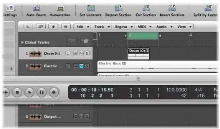
3 Choose Options > Tempo > Adjust Tempo using Region Length and Locators (or use the corresponding key command, default: Command-T).
A dialog will ask if you want to change the tempo of the entire project, or create a tempo change for the section of the project occupied by the selected region.
4 Do one of the following:
- Click Globally to adjust the tempo of the complete project to the audio region.
- Click Create to create a tempo change that spans the length of the audio region.
The project tempo is recalculated to conform with the audio length (and locators).
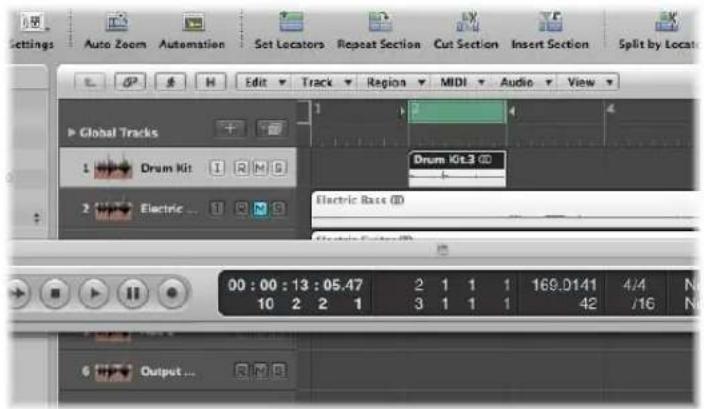
Time Stretching Regions
Logic Express allows you to change the length of audio regions (without changing their pitch) directly in the Arrange area—using menu or key commands.
When applying these functions to a region in the Arrange area, a new file—consisting of the resulting material—will be created, leaving the original intact. Both new and old files are accessible in the Audio Bin.
Logic Express offers different time stretching and compression algorithms in the Arrange area's Audio > Time Machine Algorithm menu. The different algorithms are best suited for particular types of musical material. For more information, see "Using the Time and Pitch Machine" on page 534.
Note: You can also time stretch selected audio regions directly in the Sample Editor, using the Time and Pitch Machine.
To adjust the region length to match the locator positions:
1 Set the left and right locator positions.
2 Choose Audio > Adjust Region Length to Locators to stretch or compress the selected audio region to fit between the locators.
The region start point is not changed by this function—so it doesn't matter if the locators are not directly above the region.
To adjust the region length to the nearest bar:
- Choose Audio > Adjust Region Length to Nearest Bar.
This adjusts the length of the selected region to the closest whole bar.
This function is ideal for fitting previously trimmed drum loops into projects where there is a small tempo discrepancy between loop and project.
Using the Follow Tempo Function
Audio files recorded in Logic Express can follow the project tempo—inclusive of tempo changes—set in the global tracks.
Note: These audio files can also follow the first key signature set in the global tracks. For more information, see "Working With Time and Key Signatures" on page 755.
As an example: If you record a bass solo at 100 bpm, you can change the project tempo to 120 bpm and the bass solo will automatically be played back at the new tempo.
The function works with all audio files that were recorded in, or bounced/exported from, Logic Express.
The function only works in the parent project (the project the audio files were created in). If you drag a file recorded in a given project to another project with the Finder, the file can not follow the project tempo.
Bounced or exported files can only follow the project tempo if the "Add resulting files to Audio Bin" option was enabled in the Export or Bounce window—prior to the bounce or export.
Files copied between two projects retain the ability to follow the project tempo.
The project's tempo information is used to tag the beats in the recording. The function works best if your audio files match the project tempo as precisely as possible. The longer your audio files are, the more RAM is required for this functionality to work properly.
To make recorded audio files follow the project tempo (and first key signature):
- Select the audio region in the Arrange area, and turn on the Follow Tempo option in the Region Parameter box in the Inspector.
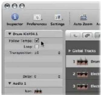
The Follow Tempo option is synchronized for all regions that make use of the same audio file.
All audio files that follow the project tempo (and first key signature) are indicated by the following symbols in Logic Express:
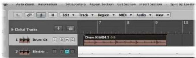
Note: The Follow Tempo option does not create an Apple Loop! Remember: Apple Loops follow chord changes—should you record a solo over an arrangement consisting of Apple Loops with transposition changes over time, you might want to enable Follow Tempo for your solo, but you won't be happy with the double transpositions that will occur ...
Managing Audio Files
24
Most audio file management takes place in the Audio Bin. Several individual file management functions are found in the Sample Editor and Arrange window.
This chapter covers all audio file management facilities available in Logic Express. These options help you to keep track of your audio files, and make tasks such as file copying, moving, renaming, and backing up both easy and efficient.
Details on audio region handling is found in Chapter 11, "Adding Pre-Recorded Media," and Chapter 13, "Creating Your Arrangement."
Sorting, Grouping, and Renaming Files in the Audio Bin
The Audio Bin lists all audio files in your project, along with information about file sampling rate, bit depth, format (mono/stereo), and size. It is the ideal place to sort, rename, copy, or move your audio files.
Note: Detailed information on the methods used to add audio files to the Audio Bin (and your project) are found in "Adding and Removing Audio Files" on page 281.
Sorting Audio Files
Information on every currently loaded audio file is shown in the Info column of the Audio Bin. You can switch this display on or off by choosing View > Show File Info.
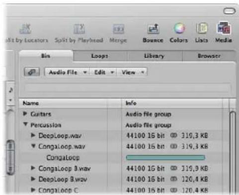
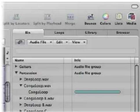
To sort audio files:
- Choose any of the following View > "Files sorted by" criteria to reorganize the listing of audio files:
- None: The audio files are listed in the order that they were loaded or recorded.
- Name: The audio files are listed in alphabetical order.
- Size: The audio files are listed by size, with larger files at the top of the list.
- Drive: The audio files are sorted by storage medium (the hard disk, removable drive, or partition they are stored on).
- Bit Depth: The audio files are listed by Bit depth, in decreasing order.
- File type: The audio files are listed by file type (AIFF, WAV, SDII, MP3, and so on).
Tip: You can quickly sort all audio files by name by clicking the Name column header.
Grouping Files in the Audio Bin
You can group audio files together, making handling of large numbers of files easier and faster. In the image, you will see a Guitars and Vocals group, with several files in each.
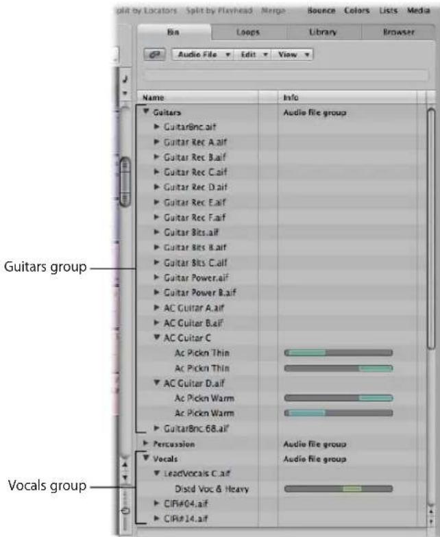
This separation into categories simplifies handling, particularly if all files are similarly named. As an example, audio imported from another application may be named "audio01", "audio02", "audio03", and so on, regardless of whether a vocal, guitar, or drum part. When creating a large arrangement, grouping files into categories can be a life-saver.
To group audio files:
1 Select the files you want to group in the Audio Bin.
2 Choose View > Create Group (or use the Create Group key command).
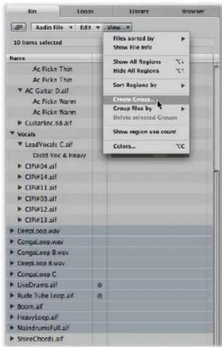
3 Type the desired group name in the Group Name field (labeled "Enter name for new group"), then press Return.
To group audio files by their location, attributes, or selection status:
1 Select the files you want to group in the Audio Bin.
2 Do one of the following:
- Choose View > Group Files by > Location to create groups that are alphabetically sorted by the names of the parent folders of selected files. These folder names are automatically used as group names.
- Choose View > Group Files by > File Attributes to create groups based on the attributes of selected files (file type, stereo/mono, Bit depth). Group names are displayed as a summary of the file attributes ("16 bit AIFF Stereo", for example).
- Choose View > Group Files by > Selection In Arrange to create groups based on regions selected in the Arrange area. Group names are based on the first of the selected regions.
Note: If existing groups have been created, a dialog will ask if you want to add all files to one of these groupings, thereby deleting the existing groups, or if you would like to only add files that are not yet group members. Click the appropriate button.
To open or close one or more groups:
- Click on the disclosure triangle to the left of a group name to open or close it.
- Option-click on the disclosure triangle to the left of any group name to open or close all groups.
To select all files in a group:
- Option-click on a group name to select all files in the group.
To delete a group:
- Select the desired group, then choose View > Delete selected Groups (or press Backspace).
The audio files of deleted groups reappear in the upper level of the Audio Bin list.
Renaming Audio Files
To rename audio files in the Audio Bin, just double-click the file name in the list. A text input box will appear, allowing you to type in a new name.
Important: Before renaming audio files, you should check if the audio file that you want to rename is used by another project. If it is, do not rename the file, or it won't be found or played by other projects that use the file.
Logic Express helps you in these situations:
- Logic Express alters the name of an audio file in all currently opened projects that use this file.
- Logic Express also renames any backup files on the same drive.
If you rename a stereo file, Logic Express automatically assigns the new name to up to five files (both the mono files used in Logic Express, their backups, and the stereo file). In this situation, it's a good idea to store all files in the same location.
Note: You can freely rename regions whenever you like, but you should note that regions named after their parent audio files automatically adopt the new name of renamed audio files. This does not occur when regions have been given a new name.
Moving Audio Files
The Audio Bin's Audio File > Move File(s) command (default key command assignment: Control-M) enables you to move selected audio files to another location on your system.
If the source drive or partition is the same as the target drive or partition, the files are simply moved to the other folder. This is a very quick and convenient way of organizing the drive and the project.
This function is useful when you want to move all audio files used in a project to a new folder, for example.
To move all used audio files to a new folder:
1 Choose Edit > Select Used from the Edit menu.
This selects all audio files (in the Audio Bin) that are being used in the Arrange area.
2 Choose Audio File > Move File(s) in the Audio Bin menu.
An alert will indicate the number of files to be moved.
3 Click the Move button.
4 In the ensuing file selector box, select the desired folder (or create a new one), then click Save. All audio files used in the Arrange area are saved in the selected folder.
Warning: Be very careful when using this function as files are removed from their original location. Other projects may use the same audio files. This can lead to you being prompted to search for the files that were moved when opening other projects (see "Finding and Replacing Orphaned Audio Files" on page 569).
It may be useful to choose the Audio File > Show Files in Finder command before moving any audio files. This command opens a Finder window that displays the path and location of the selected files. The folder name or notes or other files in the folder may provide clues as to whether or not it's safe to move the files. If you're not sure, it's better to use the Copy/Convert command (see below).
Tip: Logic Express updates the path information for all open projects that use a given audio file. This makes projects easier to manage when moving audio files. Following the movement of files to the new location, save each open project to update all audio file storage references.
Copying or Converting Audio Files
You can create copies of audio files in a different hard disk (or other storage medium) location. The source files remain in their original storage location, unlike the Move File(s) function discussed above.
To copy or convert audio files in the Audio Bin:
1 Select the desired file or files.
Note: You can not use this command to convert compressed multi-channel files (AAC, ALAC, MP3).
2 Choose Audio File > Copy/Convert File(s) in the Audio Bin.
3 Choose the desired settings in the Save A Copy As dialog:
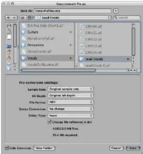
You can set the desired sample rate, bit depth, file format, stereo conversion, and dither type for the destination file.
4 Browse to, and choose the target folder for the new audio files. You may also create a new folder, by clicking the New Folder button.
5 If you're only copying one file, you can enter a name for the new audio file. When simultaneously copying several audio files, existing file names are used for the copies derived from them. The Hide Extension checkbox hides or shows file extensions (wav, aif, and so on) in the Save As field.
6 Click the Change file reference in Bin option to replace the audio file used in the project with the copied file.
If unchecked, both the copy and original audio file are shown in the Audio Bin (the original is still used for any regions).
7 Click the Save button.
Note: If a file of the same name exists in the target location, Logic Express asks whether or not you want to replace it. Click Replace to do so, or type in a different name, and click Save.
To copy or convert audio files in the Sample Editor:
1 Choose Audio File > Save A Copy As.
2 Choose the desired settings in the Save A Copy As dialog.
You can set the desired sample rate, bit depth, file format, stereo conversion, and dither type for the destination file. The dialog also features an "Add resulting files to Audio Bin" option, allowing you to add the file to the Audio Bin, following the save.
3 Browse to the location where you want to store the audio file, then type a name for the audio file in the name field.
4 Click the Save button.
Deleting Audio Files
Audio files are displayed and organized by Mac OS X in exactly the same way as all other Macintosh files. You can therefore delete or copy them in the Finder. This has the following disadvantages, however:
- You may not know if an audio file is needed in a project, when using the Finder for deletions.
- Deleted audio files can not be found when you load a project. This results in orphaned files (and regions) in the Audio Bin and Arrange area regions which refer to the missing audio file (see "Finding and Replacing Orphaned Audio Files" on page 569).
Important: For these reasons, you should only perform audio file deletions in the Audio Bin.
To delete audio files in the Audio Bin:
1 Select the audio files that you want to delete.
2 Choose Audio File > Delete File(s) or (or use the corresponding key command, default: Control-Backspace).
An alert message, informing you of the number of audio files about to be deleted, will appear.
3 Click Cancel to abandon the deletion process, or click Delete to move the audio files into the Trash.
Optimizing Audio Files
Beyond deleting unused audio files, Logic Express also allows you to delete unused portions of audio files. This usually frees up a lot of wasted space on the hard disk.
To delete sections of audio files that are no longer used in the project:
1 Select the audio files that you want to optimize in the Audio Bin.
The Edit > Select Used menu should be your first port of call. Optimize Files can be used on any number of audio files.
2 Choose Audio File > Optimize Files (or use the corresponding key command, default: Control-O) in the Audio Bin.
The following happens during the Optimize Files function:
- Logic Express determines which (file) segments are not contained in any of the regions used in the Arrange area.
• These segments are deleted, and the remaining portions of the audio file (those used by regions) are retained. These file segments are aligned side-by-side in the file.
Note: For safety reasons, the Optimize Files function uses a pre and post roll area of one second of audio data before and after each (used) region.
• The regions in the Audio Bin are redefined.
• The project is automatically saved.
Warning: As this process physically deletes data from the storage medium, it cannot be undone.
Saving Regions as Individual Audio Files
You can create one (or more) independent audio files from selected regions in the Audio Bin and Arrange area.
To convert selected regions into independent audio files:
1 Do one of the following:
- Choose Audio File > Save Region(s) As in the Audio Bin.
- Choose Audio > Convert Regions to New Audio Files in the Arrange area (or use the corresponding key command, default: Option-Command-F).
- Choose File > Export Region as Audio File in the main menu bar (or use the corresponding key command).
2 Choose the desired settings in the ensuing dialog boxes.
3 Browse to, and choose the target folder for the new audio files. You may also create a new folder, by clicking the New Folder button.
4 If you're only saving one region, you can enter a name for the new audio file. The Hide Extension checkbox hides or shows file extensions (wav, aif, and so on) in the Save As field.
5 Click the Save button.
Note: If you want to simultaneously save several regions as audio files, you should name the regions before using the Save Region(s) as command, as existing region names are applied to the audio files derived from them.
Exporting Tracks as Audio Files
It is also possible to export one or more tracks (all audio regions on tracks) to a new audio file, or several audio files—one for each Arrange track.
To export all audio regions on a track to a new audio file:
1 Click on the desired track name.
2 Choose File > Export > Track as Audio File from the main menu bar (or use the corresponding key command, default: Command-E).
3 Provide a name and destination, and make other choices in the Save As dialog, then click Save.
To export all tracks to several new audio files:
1 Choose File > Export > All Tracks as Audio Files (or use the corresponding key command).
2 Make your choices in the Save As dialog, and click Save.
Exported audio files are named after the source tracks, so if track 1 is called "Drums," track 2 "Bass," track 3 "Guitar," the resulting files will be named accordingly.
Dealing With SDII Files
Logic Express allows you to access the regions in SoundDesigner II files. (The SDII data format lets you store region definitions).
You can import the regions of SDII files into the Audio Bin. This is useful if you want to play regions from a long recording made in Pro Tools.
To import SDII regions:
1 Select an audio file in the Audio Bin.
2 Choose Audio File > Import SDII Regions (or use the corresponding key command, default: Control-I).
Logic Express also allows you to export one or more selected regions (in an audio file) from the Audio Bin into an SDII file.
To export all regions from an audio file to an SDII region:
1 Select the desired audio files in the Audio Bin.
2 Choose Audio File > Export SDII Regions (or use the corresponding key command, default: Control-E).
Finding and Replacing Orphaned Audio Files
Sometimes, Logic Express can't find a file which was previously used in the project. This could be due to one of the following:
- You have not connected the relevant hard disk, or you have renamed the volume.
- You have stored the files in a different volume, or moved them to another volume.
- You have renamed the files in the Finder, or renamed them in the Audio Bin of another project.
- You have deleted the files.
In these situations, Logic Express opens the following dialog.
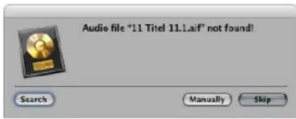
You can respond in any of the following ways:
- Search: The current volume is searched for filenames. If the search is unsuccessful, Logic Express asks you if you want to search other volumes for these files. This enables you to assemble projects, even if you have copied or moved the relevant files onto other media.
- Skip: Use this function if you know that this audio file no longer exists, or was renamed. This button changes to Skip All if further audio files aren't found.
- Manually: You can manually define where to search for the file. A file selector, containing the names of the audio files being searched for, appears onscreen.
If more than one file with a matching name is found, you can select the correct file in a dialog box.
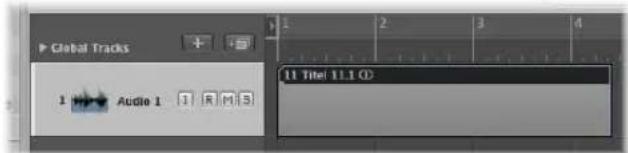
If Logic Express can not find one or more audio files—when skipping them during the search process, for example—the regions are shown as blank gray areas.
To assign a replacement file later on:
1 Do one of the following:
- Double-click the relevant region in the Arrange area.
- Choose Audio File > Update File Information in the Audio Bin.
2 Click Locate in the dialog, and a file selector box opens, allowing you to load the desired audio file.
Once you're happy with the project arrangement, the Mixer is used to refine the overall sound, levels, and spatial positioning of your tracks.
This chapter covers the use of the Mixer, and also touches on automation facilities. The latter forms an integral part of Logic Express's mixing facilities, with detailed information available in Chapter 26, "Working With Automation," on page 605.
To open the Mixer area of the Arrange window:
- Click the Mixer tab at the bottom of the Arrange window (or use the Toggle Mixer key command).
Tip: As a shortcut, you can open the Mixer area by double-clicking the icon of any track in the Arrange track list. The corresponding channel strip (of the clicked track) will be selected in the Mixer.
To open the Mixer as a separate window:
- Choose Window > Mixer (or use the matching key command, default: Command-2).
The Mixer displays channel strips that correspond with audio and instrument (software or MIDI) tracks shown in the Arrange area, plus the master channel, auxiliary, and output channels. Additional channel strip types, such as busses and inputs, can also be shown, but their inclusion is primarily for compatibility with projects created in earlier Logic Express versions.
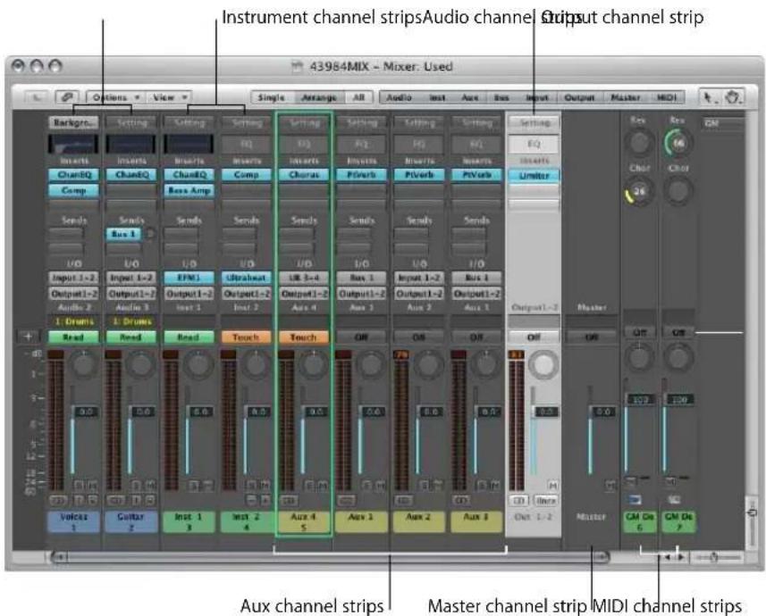
• Audio channel strips control audio tracks. Data on audio tracks (audio regions) is routed to audio channels.
- Instrument channels control instrument tracks (software instrument plug-ins are inserted into the Instrument slot of instrument channels). Data on instrument tracks (MIDI regions) is routed to instrument channels.
- External MIDI channels control "external MIDI" tracks. Data on these tracks (also MIDI regions) is routed to a MIDI output port and channel, for control of MIDI sound modules and keyboards. Either the entire instrument or MIDI sub-channels can be represented and controlled.
- Auxiliary channels act as "send/returns" or output destinations for instrument and audio channel strips, or other auxiliary channels.
- Output channels represent the physical outputs of your audio interface, and act as a destination for audio, instrument, and auxiliary channels.
- The master channel strip is a global level control for all output channels. You can view it as the main volume control for Logic Express.
Important: Mixer channels are generated automatically when you create new audio, instrument, or external MIDI tracks in the Arrange window, provided that File > Project Settings > Audio > Automatic Management of Channel Strip Objects is turned on (it is turned on by default, and should be left on in most cases).
If several Arrange tracks address the same instrument channel, the instrument is represented by a single channel in the Mixer (this behavior can be overridden by the Same Instrument Tracks setting in the local View menu).
Basic Mixing Steps
Generally speaking, mixing takes place in the following order (although there are always exceptions to this):
- Set the relative levels and pan positions for each channel strip, to control the volume relationships between your project's parts (regions on tracks), and where they are positioned in the stereo field.
- Sculpt the sound of each part (if needed) with equalization, which enables you to precisely alter the tone or color of each channel. You will probably need to revisit step 1, as EQ-ing generally has an impact on levels, and possibly on phase relationships.
- Once the basic sound and levels are as you like them, the mix can be polished with effect processes, such as the addition of reverb or chorus to your musical parts. Once again, you may need to revisit step 1.
- You may find that some parts will benefit from real time changes to levels, effects, or instrument settings. This is best achieved with track automation.
- The last phase—which is not a mixing task, per se—is to render or "bounce" your project to one or more files. This aspect is covered in Chapter 27, "Bouncing Your Project," on page 625.
In your normal workflow, you will access the Mixer or Arrange channel strips to insert software instruments and effects, and set relative levels and pan positions—both before and after recording musical parts. This type of Mixer or Arrange channel strip usage during the creative phase of your project helps you to build an arrangement and rough mix, where basic levels and sounds are set.
Once all parts have been recorded, you would typically move onto the mixing phase of your project. This is when you focus your efforts on refining the sound of each musical element, to create a unified mix. This generally follows the order outlined above, but your approach, or the project, may differ.
You will regularly find that the settings chosen for instruments and effects can be improved by changing a few parameters, to "tighten up" parts, or provide a looser feel, or perhaps to radically change the tonal color of the chorus, for example. You may often completely swap one instrument sound for another, replace effects configurations for tracks, or use tracks without effects ("dry"). You may also set up complex routings to one or more auxiliary channels, or perhaps set up "mastering" processors on output channels (see "Channel Strip Types" on page 590).
Tip: Make use of the save facility often during mixing, to provide backups, should you lose your way. Backups also provide a great comparison point, and are a good guide for whether or not your mix is heading in the right direction.
In many situations, you will find mix automation of use. Logic Express provides a flexible automation system that enables you to mute, bypass, solo, and alter all channel parameters, including those of any inserted effects and software instruments. Use of automation can provide motion to parts of the mix, and is very useful for “evening out” overly dynamic performances, or making less dynamic performances more lively. Automation can be viewed as someone “riding the faders” on a hardware mixing console (and all effects units and synthesizers in the studio), albeit with many more hands.
Automation should be considered an integral part of the mixing process, but if your mix doesn't need it, you can certainly "set and forget" your Mixer settings.
As you can see, the Logic Express Mixer can be used in a traditional way, but you will probably find yourself accessing it (or the Arrange channel strips) throughout all project phases.
Channel Strip Elements
The controls displayed on a channel strip vary with the channel strip type.
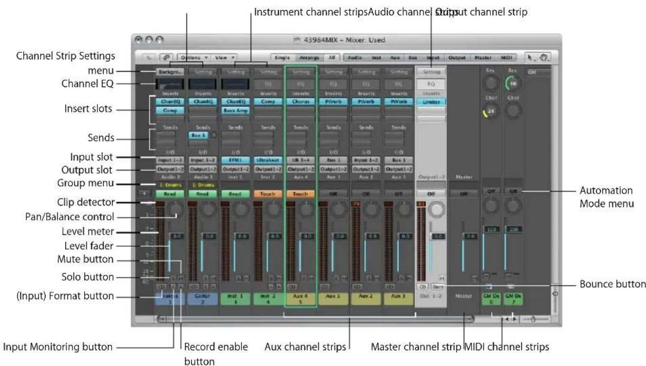
The table below indicates the elements that are available in each channel strip type (MIDI channel strips are not listed, as they work differently. See "MIDI Channel Strips" on page 594). Details on individual channel strip types, and their general roles in the Mixer, can be found in "Channel Strip Types" on page 590.
Element Audio Instrument Aux Output Master
| Channel Strip Settings menu X X X X X | |||
| Channel EQ X X X X | |||
| Insert slots X X X X | |||
| Sends X X X | |||
| Input slot X X X | |||
| Output slot | X X X | ||
| Group menu | X X X X | X | |
| Automation Mode menu | X | X X X X | |
| Pan/Balance control | X | X X X | |
| Level meter | X | X X X | |
| Clip detector | X | X X X | |
| Level fader | X | X X X X | |
| Mute button | X X X | X X | |
| Solo button | X | X X | |
| (Input) Format button | X | X | |
| Input Monitoring button | X | ||
| Record Enable button | X | ||
| Bounce button | X | ||
Two additional channel types not shown in the table—input and bus (see "Channel Strip Objects" on page 957)—are primarily retained for compatibility with projects created in earlier Logic Express versions.
Setting Channel Strip Levels
You use the Level fader of a channel strip to set its playback or monitoring volume. The segmented level meters of the channel strip display the level in real time. The clip detector above the level meter shows you the available headroom of a track in decibels (dB).
To set the playback, or monitoring level of a channel strip:
- Drag the Level fader of the desired channel up or down
The maximum boost is +6 dB. You can reset the Level fader to 0 dB (90) by Option-clicking on it.
If the Independent Monitoring Level (for Record Enabled Channel Strips) preference of the Logic Express > Preferences > Audio > Devices > Core Audio tab is enabled, an independent monitoring level is available when an audio channel is record enabled. For further information, see "Setting the Monitoring Level" on page 375.
Quickly Switching Between Two Levels
You can use the following key commands to switch the level of all channel strips of a specific type between two different level values. Each channel may be set to any value for both toggle positions, allowing you to quickly switch between two basic mixes.
- Mute/Unmute Audio Channel Strips
- Mute/Unmute Input Channel Strips
- Mute/Unmute Auxiliary Channel Strips
- Mute/Unmute Output Channel Strips
Understanding the Channel Strip Meters
All channel strips feature segmented level meters that display the playback or input monitoring level. When you arm an audio track, in preparation for recording, the associated Mixer channel meter displays the input (incoming audio) level.
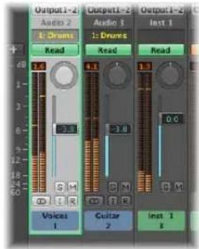
The colors of the level meter segments provide an at-a-glance overview of individual channel monitoring levels. Signals in the amber and yellow zones are safe, and will not clip the channel output. Signal peaks that trigger the red segments of the meters are considered "hot" levels, but the occasional peak is nothing to worry about, unless the clip detector is continually or regularly lit (see section below).
Peak values are "held" on the level meter display for a few seconds, making them easier to read. The most recent maximum (peak) level is always reliably displayed.
The level meters can be switched between a Sectional dB-linear scale, and an Exponential scale. Exponential provides higher display resolution in the upper range. Sectional dB-linear provides the best possible display resolution across the entire level range. Both metering systems display a range from -60 to 0 dBfs.
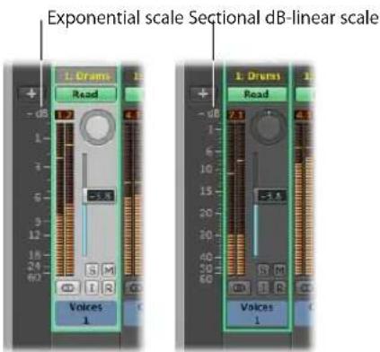
1 Open the Display preferences by doing one of the following:
- Choose Logic Express > Preferences > Display (or use the corresponding key command).
- Click the Preference Toolbar button, then choose Display from the menu.
2 Click the General tab, then choose the desired value in the Scale menu.
Understanding the Clip Detector
The Clip Detector above the level meter shows you the available headroom of a track in dB.
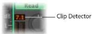
When a signal clips, the Clip Detector turns red; the value shown indicates the amount that the peak level (the loudest bit) of the signal needs to be reduced, in order to prevent clipping.
The peak value is shown once the entire signal has been played, and provides a guide that should be used to set the Level fader of the channel.
Clipping occurs when too much (too loud a) signal is fed through a channel strip, thereby exceeding the limit of what can be accurately reproduced, resulting in a distorted sound known as clipping.

Up to +6 dB will be shown. If a track clips now and then, it doesn't really matter—as long as the master channel (output destination for the channel) doesn't clip. Clicking on any clip detector will reset all clip detectors. The Clear Overload Flag in Audio Channel Display key command has the same effect.
To avoid clipping:
1 Look at the Clip Detector value of a channel strip that is clipping (lit red).
As an example, 1.5 dB is shown on the Clip Detector when the Level fader is set to a value of 0.0 dB.
2 Grab the Level fader, and reduce it to a value of -1.5 or so.
Tip: You may find that a Level fader value of -1.2 sounds "best" in the context of the overall mix, and only clips once (by 0.3 dB) during playback. As mentioned, this is nothing to worry about, and you should use your ears, rather than your eyes as a guide.
Setting the Pan or Balance Control
Mono channels feature a Pan control, which determines the position of a signal in the stereo image. Stereo channels, on the other hand, display Balance controls. The Balance control differs from the Pan control in that the former controls the relative levels of two signals (Left and Right) at their outputs. The latter merely apportions one signal between two outputs.
To adjust the Pan or Balance control:
■ Grab the control and drag up and down, or to the left or right.
Option-click on the Pan or Balance control to reset it to the centered (0) position.
Soloing and Muting Channels
Soloing or muting channels enables you to hear musical parts in isolation, or in conjunction with other selected parts. This simplifies particular tasks, such as setting precise equalization parameters.
Soloing Channels
All channel strips feature a Solo button (denoted by an S).
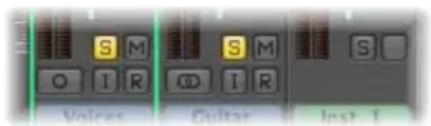
Click it to mute all other channel strips.
The solo button turns yellow, and the M on the Mute buttons of all muted (non-soloed) channels will flash.
Note: MIDI channels are not muted.
You can solo several channels by clicking on their respective Solo buttons.
Option-clicking a previously unsoloed channel releases other active Solo buttons, allowing the selected channel to be heard in isolation.
Option-clicking any activated Solo button disables the solo status of all channel strips.
Using Solo Safe
If you want to hear the signal of a soloed channel with any send effects, the effect return channels (the auxiliary channels used for the sends) obviously can't be muted, as they constitute part of the signal path. The same applies when you solo an effect return signal (an aux channel). All channels fed into the effect (aux channel) are muted, but their effect sends remain open, ensuring that the effect continues to receive a signal.
Logic Express intelligently scans the entire signal path, and leaves the effect return channels open.
This automatic mute-suppression only applies to the internal effect returns. If you are using external effect units via aux channels, the scan will keep the effect master sends open. Logic Express cannot, however, know which of the channels you are using as effect returns for external effect units. You need to manually switch these channels to solo safe—which prevents them from being muted when you solo another channel.
Better yet, make use of the I/O plug-in when you want to use external effects units. This allows you to use external effects just as you would use internal ones. For more information, see "Working With External Audio Effects" on page 261.
To make a channel strip solo safe:
■ Control-click an inactive Solo button.
The channel strip is not muted when you solo another channel. Solo safe status is indicated by a red slash on the solo button.
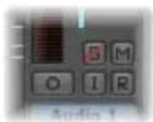
A second Control-click defeats the solo safe status.
Muting Channels
You can mute any channel strip by clicking the Mute button (marked with an M). Pressing the button a second time restores the previous level.
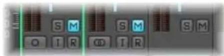
You can mute several channels by clicking on their respective Mute buttons.
Option-clicking a channel Mute button in the Mixer will activate the corresponding Track Mute button in the Arrange. A second click will deactivate the Track Mute button.
Note: When the Audio > General > Track Mute/Solo preference is set to Fast, clicking a channel Mute button will always activate the corresponding Track Mute button in the Arrange.
Why Track and Channel Muting is Independent
The separation of track and associated channel mute functionality is included because multiple tracks can be routed to the same channel strip.
As an example, an EXS24 mkll drum kit inserted in an instrument channel may have several Arrange tracks routed to it; each playing a different sound (kick, snare, cymbals, and so on).
The ability to view "same instrument track" channels in the Mixer enables you to independently mute each instrument in the "kit."
Adding Effects: Using Inserts
Insert slots are shown, and used, in the same way on all channel strip types (except the master channel strip). If you have enough computer processing capacity, you can insert up to 15 effect plug-ins per channel strip. An extra blank Insert is created, as soon as all of the currently displayed Insert slots are used, up to the maximum allowed.
Software instrument plug-ins are inserted much like effect plug-ins, but they can only be inserted into the Instrument slot of instrument channels. For full details on adding instrument and effect plug-ins, see "Inserting, Moving, and Removing Plug-ins" on page 220.
Working With Sends
The Mixer provides auxiliary channel strips, which are used as effect send/returns. Each individual channel strip can be routed via one or more send/returns (auxiliary channel strips), in addition to being routed to a particular output. This allows each channel strip to share the effects processor connected to the mixer's send/returns (inserted in the auxiliary channel strip, in the Logic Express Mixer). Full details about working with send effects can be found in "Send Effects" on page 243.
Working With Channel Strip Settings
The Channel Strip Settings menu allows you to load and save the entire routing configuration of a single channel strip, including all loaded plug-ins and settings. This feature is covered in "Loading and Removing Entire Channel Strip Configurations" on page 228.
Monitoring With Effect Plug-ins
The Software Monitoring function allows you to hear incoming audio through effects plug-ins inserted into an armed audio channel. Audio inputs must be assigned on these record-enabled tracks for software monitoring functionality. You can also use the Input Monitoring buttons to monitor audio tracks that are not armed. Simply enable the Input Monitoring button on a channel strip. This works when Logic Express is stopped or playing.
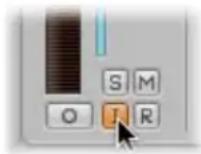
Software monitoring is especially handy in Logic Express setups without an external mixer, and is useful during an overdub session, for example. For further information, see "Using Software Monitoring" on page 373.
Arming Channel Strips
You will generally "arm" audio tracks in the Arrange window by clicking the Record Enable button of an audio track. This button corresponds to the Record Enable button of audio channel strips in the Mixer.
Record Enable button appearance Status/comments
Flashing red Armed
Constantly illuminated (solid red) Recording
For more information on recording, see Chapter 14, "Recording in Logic Express," on page 367.
Changing the Channel Input Format
The Format button determines the input format (mono or stereo) of a channel.
For further information, see "Setting the Channel Input Format" on page 218.
Setting the Automation Mode
You can set the automation mode of a channel strip in the Automation menu. For full details on all automation modes, and use of the automation system, please see Chapter 26, "Working With Automation," on page 605.
Handling Mixer Inputs and Outputs
The Input slot of audio channel strips allows you to choose the physical inputs of your audio hardware. This input (or input pair) supplies an audio signal to the track when recording.
If Input monitoring is switched on, the signal of this audio input will be routed to the output chosen in the Output menu, when the track is record enabled.
Note: Do not confuse the Input slot with the input format of channel strips. They are different things entirely.
Output Routing and Sub Groups (Using Aux Channels)
The slot directly below the Input slot determines where the signal of the channel strip will be sent. The number of available outputs is determined by the audio hardware in use.
You can select between output channels and aux channels, which can function as mixer subgroups. If the channel strip is mono, the aux will also be mono, but can be set to stereo. If both aux and channel strip are stereo, the entire (Mixer) signal flow will be in stereo.
Hold Option while selecting the inputs or outputs of a single channel to change all selected channel strips to the same input/output. Please note that inputs are only changed on (selected) channel strips of the same status: mono or stereo. This facility allows you to easily select a common input source for all (selected, stereo) audio tracks, for example.
Tip: Double-clicking on the Output slot of any audio channel will jump to the assigned Output channel fader, accelerating navigation in the Mixer.
Adjusting Elements of Multiple Channel Strips
You can select multiple channel strips in the Mixer. Once selected, all channels behave as a temporary group, allowing you to quickly adjust a number of settings on all selected faders by performing an operation on one of the grouped faders.
Logic Express also offers the group functionality for channel strips (see "Working With Groups" on page 587), but this method is often much quicker than setting up groups for many operations.
To select multiple channel strips, do one of the following:
- Shift-click the desired channel strips.
- Click a channel background and drag over the desired channel strips (drag horizontally across multiple channel strips over the word Inserts, or I/O text, for example).
These selection methods work on all channel types (instrument, audio, aux, and so on).
To deselect multiple channels, do one of the following:
- Click on any unselected channel or on the Mixer window background.
- Select a previously unselected track in the Arrange window.
As with individual controls on a single channel, Option-clicking a fader or knob resets the control to a neutral value. As examples: Option-clicking a Level fader sets it (and all grouped faders) to 0 dB, Option-clicking Send knob 3 sets it (and the third Send knob of all grouped channels) to 0 dB (90).
To adjust the Level slider on all selected channels:
- Drag the Level slider of any selected channel.
All level changes are relative and logarithmic. To explain: Movements are dB-proportional, with the mix ratio of the selected channels remaining constant. Put another way, if channel 1 is set to 90 dB and channel 2 is set to 60 dB, reducing either Level fader will retain the relative distance between the channels:
- At half the original level, channel 1 will be at 45 dB and channel 2 at 30 dB.
- At a quarter of the original level, channel 1 will be at 22.5 dB and channel 2 at 15 dB, until both channels simultaneously arrive at 0 dB.
- When either channel is returned to its original value, the 60/90 dB relationship will be restored.
To adjust the Pan or Balance knob on all selected channels:
- Drag the Pan or Balance knob on any selected channel.
All Pan or Balance knobs change accordingly (changes are relative).
To adjust the mute or solo status of all selected channels:
- Click the Mute or Solo button on any selected channel.
The buttons of all selected channels will mirror the status of the clicked button.
To adjust the Record Enable button of all selected channels:
- Click the Record Enable button on any selected channel.
The Record Enable buttons of all selected channels (typically, audio channels) will switch to the new mode. You should note that only channels with different input sources can be recorded enabled simultaneously.
To adjust the Send level of all selected channels:
- Drag the Send level knob on any selected channel.
All Send level knobs of the corresponding Send slots change accordingly (relative changes).
To adjust the send destination of all selected channels:
- Click on any of the selected channel's unused Send slots, and make your choice from the list of Bus destinations (aux channels).
The corresponding Send slots of all selected channels will be routed to the chosen destination.
To adjust the inserts of all selected channels:
- Click on any of the selected channel's unused Insert slots, and make your choice from the list.
The selected effect will be inserted into the corresponding Insert slot on all selected channels.
To adjust the input and output routing of all selected channels:
- Click on any selected channel's Input or Output slot, and make your choice from the list.
All selected channels will be set to the chosen input or output.
To adjust the automation mode and group setting of all selected channels:
- Click any selected channel's Automation mode or Group menu, and make your selection from the list. All selected channels will be switched to the chosen setting.
Important: You can only perform the multi-channel (insert) Send and Insert options if no active Send or Insert is in the same slot on any selected channel. In other words, ensure that all selected channels have an unused Send 3, or Insert slot 4, for example, before using this facility.
Adjusting Channel Strips in Record or Playback Mode
You can prevent the track selection from changing, when making an adjustment to a channel. This can be done while Logic Express is in recording or playback mode, allowing you to adjust a particular Mixer channel, even if a different track is being recorded.
To prevent the track selection from changing when recording:
- Make sure the Mixer's Options > Change Track in Record Mode setting is disabled.
To prevent the track selection from changing when playing back your project:
- Make sure the Mixer's Options > Change Track in Playback Mode setting is disabled.
Working With Groups
The Group slot allows you to assign a channel strip to a group.
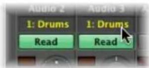
A group combines multiple channel strips, linking some of their properties—their volume faders and Mute buttons, for example. If multiple audio tracks (with individual choir voices) are assigned to one group, changing the volume of one choir track changes the volume of all choir tracks. Individual level relationships—at the time the channels were assigned to the group—are retained.
The Group Settings allows you to define the behavior of each group. As an example, you could define a group that links the selection of channels in the Arrange window, thereby linking all edit operations you perform on grouped tracks.
You can create up to 32 groups. Each channel can be a member of multiple groups.
To assign a channel to a group:
1 Click the Group slot to open the Group menu.
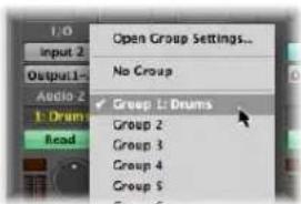
2 Choose one of the 32 groups.
When you choose an inactive group number, the Group Settings window will open automatically (see next section). Individual channels can belong to more than one group.
To add a channel to an additional group:
■ Press Shift while choosing a group in the Group menu.
The Group slot displays all groups a channel is assigned to.
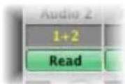
To remove a channel from a group:
1 Click the Group slot to open the Group menu.
2 Choose No Group.
To alter the settings of an active group number:
1 Click the Group slot to open the Group menu.
2 Choose Open Group Settings.
To quickly assign the most recent group setting to another channel strip:
- Press Option and click the Group display of the desired channel strip.
The most recently accessed Group setting—including overlapping groups—will be applied to the current channel, without opening the Group menu.
Defining Group Settings
You can define the behavior of each group in the Group Settings window.
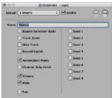
- Enable checkbox: Click to completely enable or disable a group. Disabled groups appear in black.
- Name field: Click to name the selected group. As examples: Strings, Drum Sub-Mix, and so on.
- Region Selection (Edit) checkbox: Selecting a region on one group member track selects the same horizontal range of all group member tracks.
- Track Zoom checkbox: Zooming an individual group member track will zoom all member tracks.
- Hide Track checkbox: Hiding an individual group track will hide all group member tracks.
- Record Enable checkbox: Clicking the Track Record Enable button of an individual track in a group will switch on/off the Track Record Enable button of all group member tracks.
Important: Multiple track channel strips can only be simultaneously record enabled if they use different inputs.
- Automation Mode checkbox: Changing the automation mode of an individual track in a group will change the automation mode for all group members.
- Channel Strip Color: Changing the color of one group member channel will assign this color to all group member channels. Using color makes it easier to identify the string or brass sections, for example.
- Volume checkbox: Changing the volume fader of one group member channel will change the volume of all member channels—while maintaining the level relationships between them. Use a volume fader with a high initial setting, if possible, as this will allow you a greater range of movement, and therefore, control.
- Mute checkbox: The mute status of all member channels is synchronized, with all group members being muted or unmuted if one group channel is muted/unmuted.
- Pan checkbox: The panorama setting of all member channels is linked. As per volume, their initial relationships are maintained.
- Send 1 to 8 checkboxes: You can link the Send knobs individually for Send slots 1 to 8. Different initial levels will be maintained.
A Note on Group Automation
Any group member can act as a master for mix automation of an automated parameter, such as volume. When an automation parameter value is written, the corresponding value of all other group members is also written, depending on their automation mode (Touch or Latch, for example). The data is written individually for each channel. As a result, you can disable the group later, without affecting the automation of any group member—and can obviously edit or change channels individually, once removed from the group.
Disabling Groups Temporarily (Group Clutch)
It is possible to temporarily disable all group parameter links—in order to change the volume of an individual channel, for example.
To temporarily disable all groups:
- Choose Options > Group Clutch (or use the Toggle Group Clutch key command, default assignment: Command-G).
As long as the group clutch is active, all group displays will change color—from yellow (normal) to a light gray (clutch active, all groups temporarily disabled).
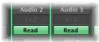
Channel Strip Types
Channel strips are the building blocks of the Mixer. In the following section, you will learn about the differences between channel strip types, and how you can use them.
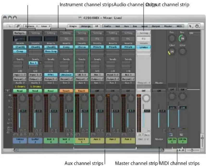
Audio Channel
The audio channel strip is used for playback and recording of the audio signals (in regions) on Arrange window audio tracks. You can control all sonic elements of audio tracks with the audio channel strip.
Instrument Channel
The instrument channel strip allows you to use, and control, software instruments in Logic Express. Currently, the included Logic Express and GarageBand software instruments and Audio Unit compatible instruments, including the QuickTime synthesizer (DLS Music Device) are supported.
Logic Express allows the simultaneous use of up to 255 discrete instrument channel strips, dependent on available CPU resources and system RAM.
The Instrument slot of the instrument channel (just above the Output slot) serves as the insert point for software instruments. Simply click on the Instrument slot and choose the name of the instrument plug-in from the menu.
After inserting a software instrument plug-in, the instrument channel can be accessed, or driven, if you prefer, by MIDI regions on one or more Arrange window tracks. These tracks are routed to the instrument channel.
Software instruments inserted into an instrument channel can, of course, also be played directly from a MIDI keyboard, provided that a corresponding Arrange track (one that is routed to the instrument channel) is selected.
The instrument channel type can also receive MIDI data from other sources, such as Environment objects. This is useful for creating sound layers of hardware MIDI instruments and software instruments, arpeggiating the instrument, and more.
Accessing Multiple Software Instrument Outputs
Logic Express supports the multiple outputs of the EXS24 mkII, Ultrabeat, and all Audio Unit instruments. One or more multi output options may be displayed in addition to the mono and stereo versions shown in the Instrument Plug-in menu.
The first two outputs of a multi output instrument are always played back as a stereo pair by the instrument channel that the plug-in is inserted into. Additional outputs (3 and 4, 5 and 6, and so on) are accessed via auxiliary channels. Please see "Accessing Multiple Instrument Outputs" on page 223 for more information on how to set up multi output instruments.
Auxiliary Channel
Auxiliary (or aux) channels can be used as send returns, sub groups, and as additional destination channels for multi-channel (multi output: software) instrument channels. When you assign aux channels (as sends, for example), more are automatically made available. To explain: When four aux channels are in use, a fifth is automatically created when assigned.
Creating Auxiliary Channels
Typically, you will create aux channels as you need them. There are three ways to do this:
- An aux channel is created automatically when a send assignment is made from a channel strip.
- When a multi output instrument, such as the EXS24 mkII is inserted into an instrument channel, several aux channel assignments are made "behind-the-scenes." It is up to you to create the required number of aux channel strips. This is done by clicking on the plus button ("+") at the bottom of the instrument channel. Each time you click it, a new aux channel strip is created (and automatically assigned to particular instrument outputs).
- The third way to create aux channels is by clicking on the plus button at the left-hand side of the Mixer window, or by choosing Options > Create New Auxiliary Channel Strips. Both methods launch the dialog shown below.
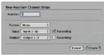
This is very similar to the New Tracks dialog shown in the Arrange window.
Simply type in the desired number, set the required format, input and output routings, and click the Create button. The Input and Output Ascending checkboxes, when active, result in multiple, sequentially assigned or routed auxiliary channels being created. To explain, if you type 6 into the Number field, and assign Bus 2 in the Input menu (Ascending checkbox active) 6 aux channels—assigned to busses 2 through to 7—will be created. The same applies for the Output pop-up menu.
Note: The number of physical inputs and outputs shown in these menus is limited by your audio hardware.
Manually Choosing the Input Source for Aux Channels
The input source of an aux channel can be selected with the Input menu. Possible input sources are:
- Buses—when the aux channel is used as a send return (see below).
- Inputs (dependent on the available physical inputs of the audio interface in use).
- Software instrument outputs provided by instrument plug-ins (Logic or Audio Unit): These additional outputs are only available to multi output instruments, inserted into an instrument channel (see "Accessing Multiple Instrument Outputs" on page 223).
Using Aux Channels as Send Returns
The Send slot on audio and instrument channels is used to route part (or all) of the signal to an auxiliary channel. Effects such as reverb and delay are generally inserted into aux channels when used as effect send/returns.
Aux channels can also be set as the input source for other aux channels. When used in this way, the sends of these aux channels can be returned on additional aux channels, allowing the construction of complex effect routings. (In most cases, you won't want to monitor the signal twice, so set the respective aux channel output assignments to "No Output").
Note: When an aux channel is used as a send/return destination from another channel strip, the Input menu will display Bus (number).
Using Aux Channels for External Audio Processing
You can route audio signals to external devices via the individual outputs of the audio hardware. This allows you to change their level and pan settings, and apply plug-ins, if you wish. This is achieved through use of the I/O plug-in.
The advantage of inserting the I/O plug-in into an aux channel, is that any effects units (or hardware mixing consoles) integrated into the Logic Express Mixer, become available to all track and instrument channels via sends.
Using Aux Channels as Subgroups
Aux channels can be used as subgroup channels, which control the level of several audio channels at once. As an example, all drum tracks or all different vocal takes could be routed to a stereo aux channel, allowing control of their overall level—while still retaining the relative differences between the individual channels.
Simply choose the desired aux channel as the output destination for the channels you want to include in the subgroup.
As auxes can also be routed to other auxes, several effect returns (sends) can be routed to the same subgroup, in order to adjust the level of all effects in the mix at once. This approach makes it much easier to handle the mixdown (particularly if automated).
To record the signal of a particular subgroup (for later use as a stereo track in the arrangement), route the "subgroup" aux to an unused output channel, and use the Bounce function (see "Bouncing Your Project" on page 625).
Output Channels
Output channels represent the physical audio outputs of your audio interface. These channels are used to adjust the overall level and stereo balance (or pan position, if a mono output channel) of all track or instrument channels routed into them. The number of available output channels is determined by the audio interface in use.
The Insert slots of output channels allow signal processing during the mastering process (bouncing), as well as during normal playback. Typical “mastering” tools are the compressors, de-essers, and equalizers. Due to technical reasons, you can only use plug-ins that don’t require mono to stereo conversions. In other words, you can use stereo to stereo plug-ins on stereo output channels, and mono to mono plug-ins on mono output channels.
Output channels also provide the Bounce button. For more information, see "Bouncing Your Project" on page 625.
Master Channel
The master channel strip changes the gain of all output channels. It acts as a separate attenuator stage; the level relationships between output channels are not affected. This is very helpful as a proportional output volume control.
In some cases, you might want to prevent individual output channels from being controlled by the master channel—outputs used as effect sends to external hardware devices, for example. Simply switch such output channels to Solo Safe mode by Control-clicking their Solo button, and they won't be affected by the master channel.
Moving the master channel fader does not affect the position of output channel faders, but rather, the signal levels directly. These level changes are reflected in the level meters of each output channel.
Tip: The Transport bar also offers a master fader. This is a remote control for the master channel strip shown in the Mixer, which allows quick and easy control of the overall level from the Arrange window.
MIDI Channel Strips
This section deals with the MIDI channel strips of the Mixer, as well as those of the GM Mixer (see "GM Mixer" on page 911).
The MIDI channel strips work as remote controls for the mixing parameters of your MIDI-controlled sound modules and synthesizers (volume and pan, for example).
Important: The controls send MIDI Control Change messages. They do not control any audio signal flow within Logic Express.
Switch on all settings in the View > MIDI Track Components menu of the Mixer, so you can see all of the parameters described below. The basic channel Level, Pan, and Mute controls are always shown on MIDI channel strips.
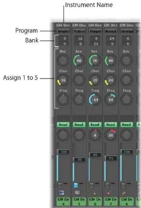
- Instrument Name: Displays the name of the instrument object assigned to the MIDI channel strip.
- Program button: Allows you to select a sound by name—click it to open a menu that contains all GM sound names. Each channel has its own menu.
- Bank fields: If your sound source "understands" bank select events, you can choose the bank number for each of the MIDI channels. The lower value sends controller value 32, and the upper value sends controller value 0; this is for MIDI instruments that have 127 × 127 banks. You can use several different bank select formats (see "Defining Custom Bank Selects" on page 906), if your device does not use the standard controller 0/32 messages. Please remember that not all synthesizers support bank select events.
- Assign 1 to 5: Choose to display up to five knobs that you can freely assign to any MIDI controller number.
Adjusting the Level of a Channel
The Level fader controls the output level of a MIDI channel. Adjusting it sends controller #7 via your MIDI interface.
To adjust the output level of a channel:
■ Drag the Level fader up or down.
Muting a Channel
The Mute button switches the volume of the channel between zero and the current Level fader position. In practice, this means that if the button is "down," the channel is muted. If you switch the Mute button off, the current Level fader position (and value) is used.
To mute or unmute a channel:
- Click the Mute button of the desired channel.
Controlling the Pan Position
The Pan knob allows you to directly control the pan position of the sound. Controller 10 is sent via your MIDI interface.
To control the pan position of a sound:
1 Click-hold the Pan knob.
2 Move the mouse up and down or left and right. The knob moves according to the mouse position.
Resetting Controls
Clicking a fader or knob while holding Option resets the value to a neutral value. The neutral value is zero for all controls except the following:
• Volume (Controller 7): Default value is 100.
- Panorama (Controller 10), Balance (Controller 8), Resonance (Controller 71), Release Time (Controller 72), Attack Time (Controller 73), and Cutoff Frequency (Controller 74): All have a default value of 64 (center position).
Sending Other Controllers
You can send any controller data (different MIDI Continuous Controllers)—to control different parameters of your sound source—with each of the Assign 1 to 5 knobs.
To assign a controller to one of the knobs:
1 Click on the label above the knob.
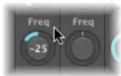
2 Choose the desired controller from the menu.
Here's a description of the pre-defined General MIDI functions. Not all MIDI instruments will understand these controllers:
- Reverb (Controller Number 91): Controls the reverb level. The further right you turn the knob, the louder the effect signal becomes.
- Chorus Depth (Controller Number 93): This knob controls the depth of the chorus effect. The further right you turn the knob, the stronger the effect becomes.
- LPF Frequency (Controller Number 74): This knob controls the overtone content of the sound. Higher values make the sound brighter.
Saving and Restoring MIDI Channel Strip Settings in the Mixer
The Mixer MIDI channel settings directly affect the Track Parameter box shown in the Arrange window Inspector. The current settings of all channel strips are saved with the project.
If the active settings of your sound module are not maintained when you switch it off (some devices reset to "default" values), any Logic Express Mixer settings that affect the unit will be lost. Thankfully, Logic Express Mixer settings are automatically restored (and transmitted to all MIDI devices) when you reload the project.
On occasion, however, this may not happen, due to MIDI communication issues with some devices. In this situation, you can manually resend the Logic Express MIDI channel strip settings by choosing the Options > Send All MIDI Mixer Data command.
Extended GM, GS, and XG Functions
In addition to the GM Standard, there are extended standards created by Roland (GS) and Yamaha (XG).
GS and XG mode allow you to select different effect programs, and to control the level of the reverb and chorus effects.
To display the GS or XG effects:
■ Enable the Add GS/XG Effects setting in the Mixer's View menu.
The GS/XG configuration control is displayed on the right of the Mixer window, allowing you to select different effect programs.

To configure GS or XG effects:
1 Choose the desired standard in the first menu.
Depending on your selection, the controllers for the extended effects will appear.
2 Select the desired reverb or chorus effect from the second menu.
3 Program the desired reverb or delay time (Time parameter).
Moving to Particular Types of Channel Strips
You can choose one of the commands in the View > Scroll To menu to scroll the Mixer display to the selected channel type, when multiple channel types are visible. This feature is handy when your Mixer view contains dozens, or hundreds, of channel strips.
To move to specific channel strip types:
- Choose the desired command in the View > Scroll To menu (Outputs, for example).
The entire Mixer view will be shifted, to display the first of these channels at the right of the visible Mixer window area.
Customizing the Mixer
The Mixer offers the Single, Arrange, and All Mixer views. You can use these views to restrict the display to channel strips that you actually need for the current mixing task. This accelerates and simplifies your workflow.
The Arrange and All views can work in conjunction with the channel strip filter buttons, allowing you to filter specific channel strip types. You can use different filter button settings for both views.
Working With Single, Arrange, and All View
You can use the Single, Arrange, and All buttons in the Mixer's menu bar (or the Cycle Through Mixer Modes (Single, Arrange, All) key command) to switch the Mixer between the views:
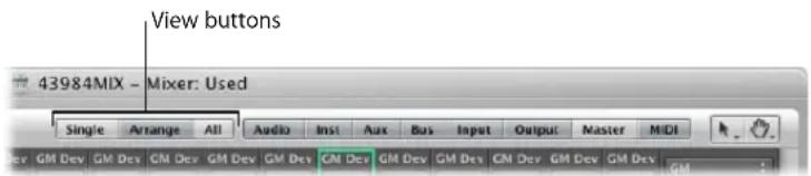
- Single View: The Mixer display is limited to the selected arrange track, and its signal flow—if the Add Signal Flow Channel Strips setting in the View menu is active.
- Arrange view: Displays all channel strips that correspond to tracks (audio, instrument, or external MIDI) used in the Arrange window—and their signal flow. The signal flow channel strips are only displayed if the View menu's Add Signal Flow Channel Strip setting is active.
- All View: The Mixer displays all MIDI instruments and all audio channel strips that exist in your project.
Single View
In Single view, the Mixer display is limited to the selected arrange track, and its signal flow:
- If applicable: The channel strip which is used as the input source of an audio track.
- The channel strip which is assigned to the selected arrange track.
- If the selected track is a multi output software instrument: The aux channel strips assigned to the individual output signals are displayed beside the software instrument channel strip. These are placed in ascending order, in accordance with the output number.
- All aux channel strips, with other auxes as their input source—used as send destinations for the arrange track's channel strip (or other displayed auxes)—are shown in an ascending order that follows aux channel numbering.
- All output channel strips used as a routing destination for the Arrange track's channel strip (or other displayed channel strip) are shown in an ascending order that follows output numbering.
Note: The signal flow channel strips are only displayed if the View menu's Add Signal Flow Channel Strip setting is active.
Arrange View
The Arrange view displays the signal flow of all channel strips that correspond to tracks (audio, instrument, or external MIDI) used in the Arrange window.
The entire signal flow is laid out from left to right:
- All channel strips that are assigned to Arrange tracks are shown in ascending order.
- Aux channel strips—used for the individual output signals of multi output software instruments—are displayed beside the software instrument channel strip. These are placed in ascending order, in accordance with the output number. An auxiliary channel with outputs 3 and 4 will be to the left of an aux channel routed to outputs 7 and 8, for example.
- All aux channel strips with buses as the input source—used as send or routing destinations for other channel strips used in the Arrange, or displayed in the Mixer—are shown in an ascending order that follows bus numbering.
- All output channel strips which are used as send or routing destinations for other channel strips (used in the Arrange, or displayed in the Mixer) are shown in an ascending order that follows output numbering.
The signal flow channel strips are only displayed if the View menu's Add Signal Flow Channel Strip setting is active.
You can use the following two settings in the View menu to further refine the Arrange view:
- Other Tracks: Enable to show (or disable, to filter) track channels that do not offer any mixing parameters, such as volume or pan control. These “other tracks” include the No Output and Metronome tracks. This is useful for setting the level and routing assignment for the Metronome, with the latter option being handy if you need to provide a click track to a specific output (for a musician or synchronization purposes).
- Same Instrument Tracks: Enable to show (or disable, to filter) Arrange window tracks that address the same instrument channel strip. These tracks have redundant settings for volume, pan, and so on (as they address the same channel strip), so it's usually unnecessary to display more than one channel strip for each track.
All View
The All view can display channel strips that don't exist in the track list of the Arrange area. In this situation, it's impossible to select such tracks for recording.
To automatically create a track for a selected channel strip in the Arrange area:
- Choose Options > Create Arrange Track for Selected Channel Strip in the Mixer's menu bar.
This command is primarily intended for use with aux or output channel strips, which are not usually shown in the Arrange, but may be needed for automation purposes.
Note: This function can not be used to duplicate Arrange tracks: If the selected channel strip is already available as an Arrange track, the Arrange track will be selected, and shown in the visible window area.
Refining the Mixer View
You can use the channel strip filter buttons to limit the display of the Mixer to particular types of channels.
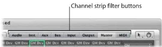
These buttons work in conjunction with the Arrange and All views discussed above. You can use different filter button settings for both views:
- Click a button to enable or disable the view of this channel strip type.
- Option-click a button to enable it, and to disable all other buttons (all other channel strip types).
Customizing the Display of Channel Strips
You can individually switch the display of the following audio channel strip components on or off, by enabling or displaying the corresponding setting in the View menu:
- EQ Thumbnails
- Inserts
- Sends
• I/O - Track Name
- Track Number
You can also switch the display of the MIDI channel strip components on or off, by enabling or disabling the respective setting in the View > MIDI Track Components menu:
- Instrument name
• Program (change numbers)
• Bank (select numbers) - User-defined knobs (Assign 1 to 5)
You can also choose to hide or show the track name and track number of all channel types, thus creating more space onscreen.
Renaming Tracks in the Mixer Window
Presuming that View > Track Name is enabled in the Mixer window, double-clicking the display of the track name (or channel strip name, which is used as the default track name) opens a text field. Type in a new track name, or change an existing one, and press Return to exit the text field.
Assigning Colors to Channel Strips
The Colors option in the View menu launches a Color palette that allows you to assign colors to channels. These color assignments are also reflected by Arrange window regions, and simplify the task of mixing (particularly groups).
To assign a color to a selected channel strip:
- Choose View > Colors, and click on the desired color in the palette. Close the palette by clicking the close button at the top left.
You can define custom colors by double-clicking on any color in the palette. A Color wheel will open, allowing you to define the hue. Click OK to replace the selected color square of the palette.
Displaying Folder Tracks
The Mixer can display the channel strips associated with the contents of folder tracks, or tracks on the highest Arrange window display level.
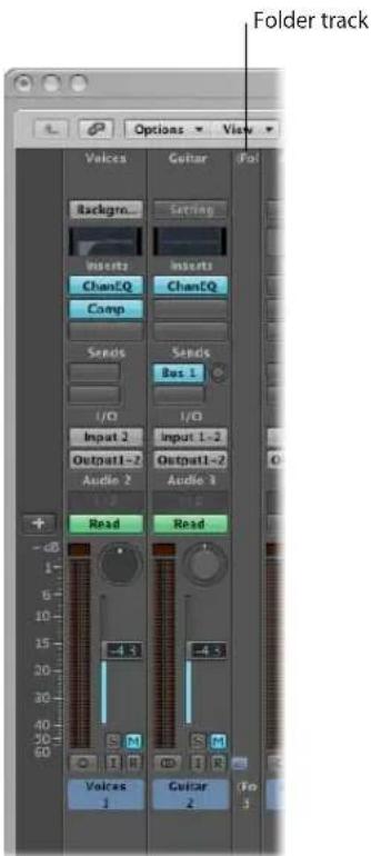
If a folder track is selected—or the Arrange is showing the contents of a folder when you open the Mixer—it will only show the channel strips associated with the tracks within the folder.
If you click the Hierarchy button (to the left of the Mixer Link button), you will switch the Mixer display up to the next level in the Arrange hierarchy; in this case, the level containing the folder.
Double-clicking the folder channel will return to displaying the channels within the folder. The View > Folder Tracks option must be switched on for this to work.
Using the I/O Labels Window
You can use the I/O Labels window to define names for all channel strip Input, Output, and Send menu items, which can be used in place of defaults such as; "Input 1" or "Output 8".
To open the I/O Labels window:
■ Do one of the following:
- Choose Options > Audio > I/O Labels in the main menu bar.
- Choose Options > I/O Labels in the Mixer window.
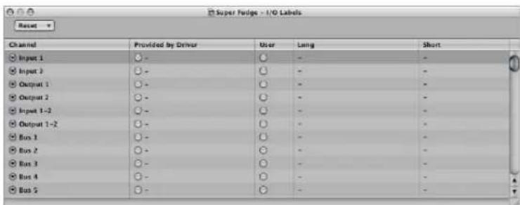
I/O labels are valid for all projects. These labels are stored in a separate file, located in the \~/Library/Application Support/Logic folder. The file is called "IOLabels xxx", with "xxx" being the name of the hardware.
To create new I/O labels for the Input, Output, and Send menus of channel strips:
1 Click the button in the User column, aligned on the Channel row (Output 1-2, for example).
2 Double-click the "-" in the Long (name) column and type in a new name for Output 1-2. MLAN 1-2, for example. Click outside the row, or press Return.
3 Repeat the process for the Short (name) column. Type in 1-2, for example.
The short name is used in the Send slots.
Output 1-2, if used, will be replaced with MLAN 1-2 in the Output menu slot of all channel strips.
To revert to default channel I/O labels, do one of the following:
- Click the corresponding button in the Channel column.
- Choose the desired Reset menu command to reset the following channel strip types to their "default" names (as shown in the Channel column):
- All Labels
- Input Labels
- Output Labels
- Bus Labels
To use the I/O labels provided by the hardware driver:
- Click the corresponding button in the Provided by Driver column.
Working With Automation
26
Logic Express features a sophisticated, yet simple to use, track-based automation system that allows you to create and play back fully automated mixes.
Mix automation refers to recording, editing, and playing back the movements of faders, knobs, and switches on a mixing console—providing real time control of volume, pan, EQ, and aux send controls, amongst others.
You can automate all mix functions in Logic Express, without restriction. This also applies to all plug-ins—the parameters of all effects and software instruments, plus all third-party plug-ins can be totally automated.
Automation is independent of MIDI and audio regions, and takes place on Arrange window tracks.
Automation is also independent of the play or record status of Logic Express, allowing you to create automation at any time.
The Logic Express track automation system is sample accurate, which is precise, but very processor-intensive. You can partially or completely switch off the sample accurate mode in the Sample Accurate Automation menu of the Logic Express > Preferences > Audio > General tab.
Note: You can also use MIDI controller values to automate parameters. This is done on a per region basis, and is known as Hyper Draw (see "Using Hyper Draw" on page 620).
Displaying Track Automation
Track automation data is displayed on a transparent gray shaded area—an automation track—that runs the length of your project. The audio waveforms of audio regions, and notes in MIDI regions, can be seen at a reduced contrast level in the shaded area.
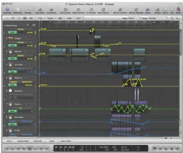
The automation data is represented by colored curves, dots (known as nodes) and lines that are shown in the gray area.
Numerical values are also automatically displayed at each node on automation tracks. Numerical values are context-sensitive—which means the centered pan position is displayed as 0 (not 64), and volume is displayed in dB, as examples.
To display track automation in the Arrange area, do one of the following:
- Choose View > Track Automation in the Arrange area (or use the View Track Automation key command, default: A).
- Click the Automation button in the Toolbar (if visible).
The gray automation area appears on all tracks, and the Automation Parameter menu is displayed in the track header. This allows you to choose the visible automation parameter. It is automatically set to Volume.
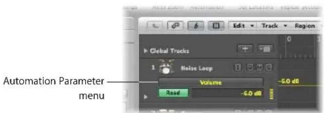
Automation can only be displayed when a track is of a sufficient height. Turning on track automation will automatically set a suitable vertical zoom level.
To resize one or more tracks:
- Click-drag the lower-left corner of a track header (the track list) to resize it. Alternately, you can use the vertical zoom bars to resize all tracks, if automation is not visible.
This can happen if you have manually resized a track, or changed the zoom level after activating automation.
Displaying Different Automation Parameters
You can choose the parameter that you wish to view, and edit, in the Automation Parameter menu. This appears below track names in the Arrange track list.
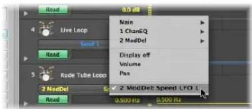
This can be the volume fader, pan pot, or any other parameter of the track's channel strip. The parameters are represented by different preset colors when displayed as a curve in the automation track. As examples:
• Yellow for Volume automation
• Green for Pan automation
• Orange for Solo automation
Only parameters which actually control something in the selected track's channel strip (or its plug-ins) are displayed in the Automation Parameter menu. Parameters that already exist in the track (as automation data) are displayed in bold lettering in the menu.
To choose an automation parameter:
- Click on the Automation Parameter menu, and browse to the desired parameter.
A sub-menu is shown for each plug-in inserted in the channel strip. These are numbered and named after the slot position and plug-in (1 EXS24, for example). Further sub-menus may be shown inside the plug-in menus. Volume, Pan, Solo, Mute, and Bypass are shown in the Main sub-menu.
To hide all automation parameters on a track:
- Click on the Automation Parameter menu, and choose Display Off.
To hide all automation parameters on all tracks, do one of the following:
- Choose View > Track Automation (or use the View Track Automation key command, default: A).
- Click the Automation button in the Toolbar (if visible).
Viewing the Automation Data of Multiple Parameters
The automation track shows all automation data (not only the currently active parameter) at a lower contrast level. Volume is a muted yellow, Pan is a muted shade of green, and so on.
To change the transparency level of regions and automation data:
- Adjust the Regions and Other Data sliders in the Automation Transparency section of the Logic Express > Preferences > Display > Arrange tab.
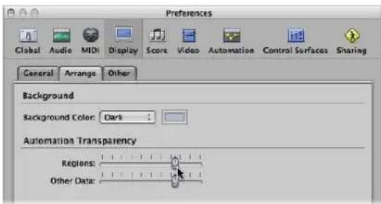
You also have the option of viewing each automation parameter on its own sub-track, making it easier to see what is being controlled.
To view automation data on sub-tracks:
- Click the disclosure triangle to the lower left of a track name.
This opens a separate automation sub-lane, below the track.
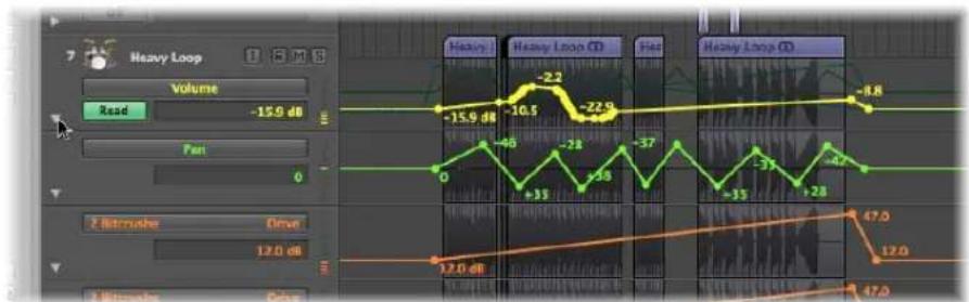
Logic Express will automatically set the automation parameter type of the new automation lane to a type that's already recorded, but not currently shown. The active automation parameter remains on the top track. Repeated clicks on the disclosure triangle will open further automation sub-tracks.
To view all recorded automation data on sub-tracks:
- Option-click the (closed) triangle to open up to 30 automation sub-tracks, which will display existing (already recorded) automation data.
Only as many automation sub-tracks as required will open, so if you have recorded automation data for ten parameters, nine sub-tracks will be opened. The active automation parameter remains on the top track.
Option-click the open triangle to collapse all automation sub-tracks. The automation data remains active, and will play if the automation mode of the main track is not set to Off or Write—even if the track is not visible.
Setting an Automation Mode
Automation modes determine how automation tracks are handled. Essentially, automation is either: off, being read, or being written. You can independently choose the automation mode for every channel strip.
To set the automation mode for a track, do one of the following:
- Choose the desired mode in the track header's Automation Mode menu.
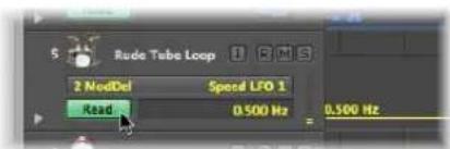
- Choose the desired mode in the Automation Mode menu on a channel strip—in either the Mixer or Arrange channel strip.

To set the same automation mode for all tracks:
- Press Option, and choose the desired automation mode in the Automation Mode menu in the Mixer or Arrange channel strip.
To set the same automation mode for selected channel strips:
1 Choose the desired channel strips by Shift-clicking on their names in the Mixer.
2 Choose the desired automation mode in the Automation Mode menu of one of the selected channel strips.
Setting the Automation Mode Via Key Commands
You can also set the automation mode with the following key commands.
- Toggle Current Track Automation Off/Read
- Set Current Track to Automation Read
- Toggle Current Track Automation Touch/Read
- Toggle Current Track Automation Latch/Read
- Toggle Current Track Automation Write/Read
- Set All Tracks to Automation Off (default: Shift-Control-Command-O)
- Set All Tracks to Automation Read (default: Shift-Control-Command-R)
- Set All Tracks to Automation Touch (default: Shift-Control-Command-T)
- Set All Tracks to Automation Latch (default: Shift-Control-Command-L)
- Set All Tracks to Automation Write
Choosing Automation Modes
You can choose from the following automation modes in any channel strip:
Off
Off will disable the current track automation data without deleting it. No automation data will be written, read, or played back. If the current automation mode is Off, any edits to track automation data in the Arrange area will automatically switch the automation mode to Read. This ensures that the data, as currently edited, will be played.
Given that track automation can be recorded during playback mode, Off is the default setting, as any mix automation recording may prove disconcerting while arranging.
Read
Read mode will automate the current track, using the existing automation data.
The data can not be changed by moving the channel strip controls, or using an external automation controller, when in Read mode.
Touch
Touch mode plays back automation data in the same fashion as Read mode.
Should a channel strip or an external (touch-sensitive) automation controller be touched, the existing track automation data of the active parameter will be replaced by any controller movements—for as long as the fader or knob is touched. When you release the controller, the automation parameter will return to its original (recorded) value. The time required by a parameter to return to its previously recorded setting, is set via Logic Express > Preferences > Automation > Ramp Time.
Touch is the most useful mode for creating a mix, and is directly comparable to “riding the faders” on a hardware mixing console. It allows you to correct and improve the mix at any time, when automation is active.
Latch
Latch mode basically works like Touch mode, but the current value will replace any existing automation data, after releasing the fader or knob—when Logic Express is in playback (or record) mode.
To finish, or to end parameter editing, stop playback (or recording).
Write
In Write mode, existing track automation data is erased as the playhead passes it.
If you move any of the Mixer's (or an external unit's) controls, this movement will be recorded—if you don't, existing data is simply deleted as the playhead passes it.
Warning: Be careful with Write mode (and its settings), to ensure that you don't erase your pan, bus, and plug-in automation data by mistake, if your intention was only to erase volume fader information!
To determine the type of data that should be erased:
- Enable the desired checkboxes in the "Write Automation for" section of the Logic Express > Preferences > Automation tab.
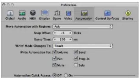
The Write Mode Changes To menu determines the mode that Logic Express switches to after a Write operation has been executed.
You'll rarely need the Write mode when working with the track automation features of Logic Express. It's mainly there to complete the selection of automation modes. It's easier to erase automation data by choosing Options > Track Automation > Delete All Automation Data of Current Track (or Delete All Automation Data of All Tracks, respectively).
In earlier analog mix automation systems, Write mode was the only way to erase automation data from tape when beginning a new project. The Options > Track Automation > Write to End and Write to Right Locator commands are self explanatory. One writes track automation data to the end of the project, and the other to the right locator position.
Writing Track Automation Data
You have the following write options for track automation data:
- Move any fader or control of the selected channel strip with the automation mode set to Touch, Latch, or Write. In real world usage, you'll rarely (if ever) use the destructive Write mode, which erases all automation data. The standard write modes are Touch and Latch.
- Choose a parameter in the Arrange track list, and move the value slider to the right of the track list, with one of the write modes turned on.
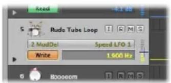
- Move the faders or knobs of a connected hardware controller, with one of the write modes turned on (see "Writing Track Automation With External Controllers" on page 618).
- Use the Pointer or Pencil tool to draw your automation data.
When one of the write modes is active, you can record track automation data when Logic Express is in record or play mode. The Arrange window track selection or audio record ready status is irrelevant. Whatever you touch or move will be recorded, when a channel strip is set to one of the write modes. The movement of Mixer controls (when in a write mode) can be used to overwrite or edit existing automation data, in real time.
When Logic Express is in stop mode, the automation write modes are ignored, and no data is written if the fader is moved. There is, however, one exception: If there are no dynamic changes (no automation data), the current fader setting becomes valid for the whole project. This is the default behavior for all mix parameters, when you start a fresh project.
Editing Track Automation in the Arrange Area
You can edit track automation data directly in the Arrange area.
Selecting Automation Nodes and Lines
You can use the Automation Select tool to rubber band any selection (of nodes) in the automation data.
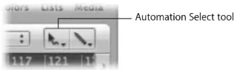
- Click on a region to select all currently visible automation events that fall within the region borders.
- Shift-click to select other areas, in addition to an existing selection. This enables you to simultaneously edit non-contiguous selections.
- Shift-click on a node—in front, or following a selected area—to extend the current selection.
You can also select nodes with the Pointer tool:
- Shift-click on a node to toggle selection (of the node).
- Shift-click on a line to toggle selection (of the line).
- Click outside of all track automation lanes (on the Arrange area background) to deselect all automation data.
- Click-drag a selected area to move all selected nodes (and connecting lines). Moved automation data will automatically erase any data which exists in the destination area.
- Shift-dragging allows rubber-band selection. The selected area will toggle.
- Option-clicking, when no automation data is selected, will select all data behind (following) the current mouse position, allowing you to drag this selection.
- Option-double-clicking, when no automation data is selected, will select all data.
Creating Automation Nodes
Click on, or just outside, an automation line (not on a node) with the Pointer or Pencil to create a new node.
The very first click in an empty automation track creates a new node at that position, and another node at the beginning of the track. This ensures that you can't create parameter controls with gaps in the middle of a region, and have full control over the parameter from the beginning of the automation track.
To freely draw automation:
■ Draw the desired automation lines (and curves) with the Pencil tool.
Nodes will be created along the line.
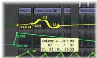
line
| Time | Value | |---|---| | 01:02:01 | -18.5 dB | | 01:02:01 | 82 | | 01:02:01 | 1 | | 01:02:01 | 2 | | 01:02:01 | 81 | | 01:02:01 | 16.53 | | 01:02:01 | -46 | | 01:02:01 | -159 dB | | 01:02:01 | -10.5 dB | | 01:02:01 | -2.2 dB | | 01:02:01 | -22.6 dB | The chart displays a waveform with labeled amplitude values and corresponding frequency values (Hz). The data is presented in a table format with labels for 'Heavy' and 'Heavy Loop' on the top axis.To create a new node on each side of a rubber band area:
- Option-Shift-click and drag with the Pointer tool to make a rubber band selection. This creates a new node on each side of the rubber band area.
Tip: With Option-Control-Shift held, two new nodes will be created on each side.
To create nodes at region borders:
■ Select the desired region and choose either of the following commands:
- Options > Track Automation > Create 2 nodes at region border. This creates one node at each end of the selection area.
- Options > Track Automation > Create 4 nodes at region border. This creates two nodes at each end of the selection area.
Deleting Track Automation Data
You can choose one of the following commands in the Options > Track Automation menu (or the corresponding key command) to delete track automation data:
- Delete currently visible Automation Data of Current Track: Removes the active automation parameter data (default key command assignment: Control-Command-Backspace).
- Delete All Automation Data of Current Track: Removes all types of automation data from the selected track (default key command assignment: Shift-Control-Command-Backspace).
- Delete Orphan Automation Data of Current Track: Removes all orphaned automation data from the selected track. Automation data can be orphaned when copied between tracks.
- Delete All Automation Data of All Tracks: Removes all types of automation data from all tracks.
You can also delete multiple nodes by doing one of the following:
- Shift–Option–double-click anywhere on an automation track to open a dialog that allows all automation data (of the current type) to be deleted. This is as per the Delete All Automation Data of Current Track command.
- Press Backspace to delete a selection of automation nodes. Ensure that no regions are selected when using this function. Any selected regions will also be deleted!
To delete a single node:
- Click on it with the Pencil or Eraser tool.
Copying, Moving, and Changing Automation Data
Following the creation or selection of automation nodes and lines, you can easily change things to meet you needs.
To move or copy automation data:
- Select the nodes or lines you want to move, then drag them to the left or right.
- Option-drag the selection to copy it to a different location.
Note: Both operations will delete all nodes in the destination area.
It's possible to move regions with, or independent from, track automation data.
To move regions with, or without, automation data:
- Choose the desired Move Automation with Regions option in Logic Express > Preferences > Automation:
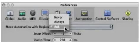
- Never: Does not move automation when you move regions.
- Always: Always moves automation when you move regions. The automation data area encompassed by the region boundaries is moved.
- Ask: A dialog will prompt you to move the automation data—or leave it where it is—whenever you move a region.
To copy or convert the automation data of one parameter to another:
1 Select the automation parameter that you want to copy, or convert, in the Automation Parameter menu.
2 Command-click on the Automation Parameter menu and choose a destination parameter.
A dialog will ask if you want to convert, or "copy and convert," the source parameter data into automation data for the destination parameter. A "copy and convert" results in the source parameter automation data being retained, and replicated for the destination parameter.
You can use the Automation Curve tool to bend the line between two nodes, or any selection.
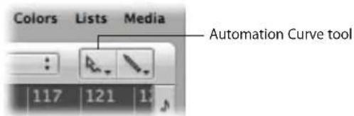
To bend an automation line:
- Drag the desired automation line with the Automation Curve tool.
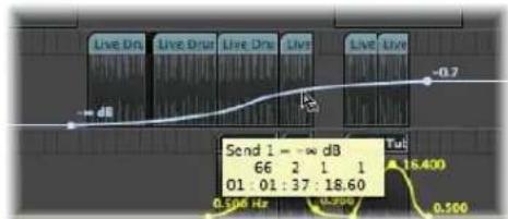
Tip: This function is also available when using the standard Pointer tool, by pressing Option-Control.
Relative and Absolute Value Changes of Selections
There are two choices available when changing the values of several selected nodes:
- Clicking on a line or node enables you to change all values by the same absolute amount.
- Clicking outside a line, within the selected area (a node or outside a node), changes all values proportionately, by a percentage value.
Editing Automation Data With the Track Header's Value Displays
Command-clicking on either the value fader or numerical value display in the track list with the Pointer allows the following:
- A Command-click selects all (current parameter) automation data of the track.
- Command-dragging scales all (current parameter) automation data of the track.
Snapping Automation to Grid Positions
You can snap both track-based and HyperDraw (region-based) automation to grid positions.
To automatically snap automation nodes to the chosen Snap grid value:
■ Enable Snap Automation in the Snap menu.
Note: Automation edits always snap to an absolute position, regardless of whether or not the Snap to Absolute Value option is enabled.
Offsetting Automation
Although automation in Logic Express can be sample-accurate, it may be affected by audio hardware latencies, excessive CPU loads, or plug-in delays. To ensure that your automation happens “on-the-money,” you can move it slightly forwards or backwards in time (if Snap Automation is enabled).
To offset your automation when Snap Automation is active:
1 Open the Automation preferences by doing one of the following:
- Choose Automation Snap Offset in the Snap menu.
- Choose Logic Express > Preferences > Automation (or use the corresponding key command).
- Click the Preferences Toolbar button, then choose Automation from the menu.
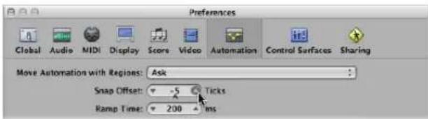
2 Adjust the (Automation) Snap Offset parameter in tick values (these can be either positive or negative).
All automation, on all tracks (or regions containing HyperDraw automation), will be offset by the chosen number of ticks.
Editing Track Automation Data in an Event List
Logic Express allows track automation data to be altered in a dedicated event editor window, which can only be opened via the Automation Event List key command (default: Control-Command-E).
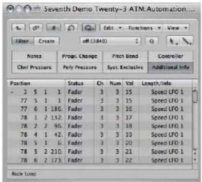
Each automation event is displayed as a MIDI controller event, and can be adjusted in length, value, and so on.
Tip: If you launch another Arrange window (Command-1) while the Automation Event List window is open, you will see all automation data as folder regions in a separate Arrange window. These can be handled just like MIDI regions, but only affect automation data.
Note: This functionality generally won't be required in most automation editing situations, but is there if you need it.
Writing Track Automation With External Controllers
Logic Express provides support for a number of dedicated control surfaces that make writing and editing track automation data fast, efficient, and easy. Dependent on the facilities available, you can simultaneously write automation data for several channels, or multiple plug-in parameters. Full details on all supported devices can be found in the Logic Express 8 Control Surfaces Support manual.
Any MIDI controller—such as the modulation wheel, or a front panel slider or knob on your MIDI keyboard—can be used to write automation data. You can use one such controller for all automation writing duties (see below), or can assign individual controllers (if available on your MIDI keyboard) to different parameters (see the Logic Express 8 Control Surfaces Support manual).
Using Automation Quick Access
The Automation Quick Access feature makes track automation extremely fast and simple if you only have one hardware MIDI controller available (one fader on your MIDI keyboard, or maybe just the modulation wheel). You can use this single hardware controller to access (and automate) the currently active automation parameter of the selected track in the Arrange window.
To set up Automation Quick Access:
1 Open the Automation preferences, by doing one of the following:
- Choose Logic Express > Preferences > Automation (or use the Open Automation Preferences key command, default: Option-A).
- Click the Preferences button in the Toolbar, and choose Automation from the menu.
2 Enable Automation Quick Access, by clicking the On button in the Automation Quick Access section.
A dialog will prompt you to assign the desired controller.
3 Click the Assign button and slowly move the hardware controller that you'd like to use for Automation Quick Access. Ensure that it's moved through its entire range.
4 Confirm your selection, by clicking the Done button below the Off/On buttons in the Automation Quick Access section.
The Done button turns into a Learn Message button. Clicking the Learn Message button allows you to assign a new controller for Automation Quick Access.
A click on the Edit button opens the Controller Assignments Editor, where you can assign the desired controller manually. See the Logic Express 8 Control Surfaces Support manual for more information.
Once set up, you will have hardware control over the active automation parameter on the current Arrange track.
Enabling and Disabling Automation Quick Access
Should you choose the modulation wheel for Automation Quick Access, you might want to switch between using it for Automation Quick Access and normal modulation wheel duties—as MIDI controller 1.
This is most efficiently done with the Toggle Automation Quick Access key command (default: Control-Option-Command-A).
Using Hyper Draw
Hyper Draw works much like track automation, with a couple of key differences:
• Hyper Draw data is restricted to MIDI regions.
• Hyper Draw data uses MIDI controller values (rather than the internal meta events used by the track automation system), which are represented as lines between nodes.
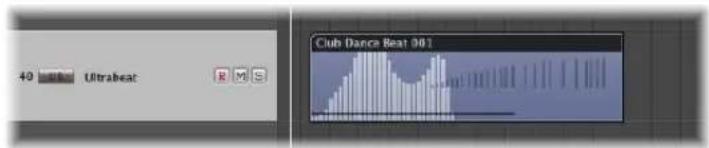
You can edit nodes and lines in a similar way to track automation data.
You can record MIDI controller events in real time on MIDI tracks—or use Hyper Draw to create and edit controller events in the Arrange area, Piano Roll, and Score Editor. The Hyper Editor is purpose-built for MIDI controller editing, providing more precision and flexibility than the Hyper Draw options of other windows.
Numerical MIDI controller values are automatically displayed as Hyper Draw nodes. These values are context-sensitive—the centered pan position is displayed as 0 (not 64), and volume is displayed in dB, as examples. If no events exist, Logic Express will automatically create a horizontal line (of the current value, if available).
You can use any of the 127 MIDI controller values to automate parameters such as volume or pitch, for example.
To activate Hyper Draw for the currently selected regions or events in the Arrange area, Piano Roll, or Score Editor:
- Choose the desired event type directly from the View > Hyper Draw menu:
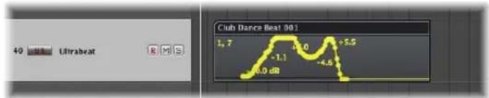
The chosen event type is displayed as a controller number, or by name, in the upper left corner of the Hyper Draw area. You can choose different Hyper Draw parameters for each MIDI region in the Arrange, if needed. You can use multiple types of Hyper Draw information for each region.
If activated in the Piano Roll or Score Editor, a gray Hyper Draw section is displayed below the editing area.
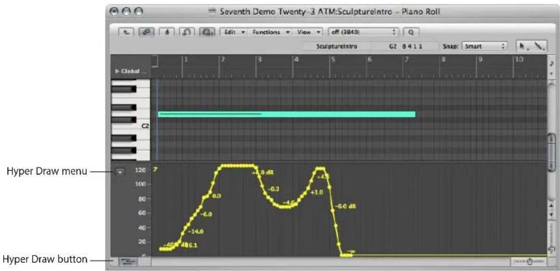
The Piano Roll and Score Editor feature a Hyper Draw button at the lower left corner. Click this button to open or close the Hyper Draw section. When the gray Hyper Draw area is visible, you can choose the desired controller type from the menu (Down Arrow) shown to the left of the Hyper Draw scale.
To switch off Hyper Draw:
Choose View > Hyper Draw > Disable.
To set the MIDI Channel:
- Choose the desired channel number from the View > Hyper Draw > Channel submenu.
The chosen channel number will also be displayed alongside the event type.
To define other MIDI controllers in Hyper Draw:
- Choose View > Hyper Draw > Other, and select the number of the controller and the MIDI channel in the Hyper Draw window.
Use this option if you want to use Hyper Draw to edit a controller that isn't directly available in the Hyper Draw menu.
Using the Autodefine Mode
The Autodefine mode sets the Hyper Draw parameters automatically, making the first event in the region visible.
Autodefine is not limited to switching the Hyper Draw display to the first incoming controller, but it can also respond to other types of events as well. It responds in this order:
- Controller
- Aftertouch
- Pitch Bend
- Program Change
- Note Velocity
Recording of MIDI Automation Data
You can record MIDI automation just like regular MIDI events. Logic Express must be in Record mode to capture this type of automation.
To record MIDI automation data, do one of the following:
- Move any Environment fader to record the fader's MIDI events to the currently selected track. For more information see "Recording and Playback of Fader Movements" on page 942.
- Record events via external MIDI controllers, such as the modulation wheel or filter cutoff control of your MIDI synthesizer, for example.
Editing MIDI Automation Data
As MIDI automation data consists solely of MIDI events, you can edit it just like any other MIDI events, using the Event List, Hyper Editor, or the Transform window.
Using the Note Velocity Mode
Hyper Draw also offers the Note Velocity mode, which is perfect for creating crescendos or diminuendos across a range of notes. You can use it at any point in a region (on a note in the Piano Roll window, for example).
To use the Note Velocity mode:
1 Choose View > Hyper Draw > Note Velocity.
Piano Roll Editor in Note Velocity mode
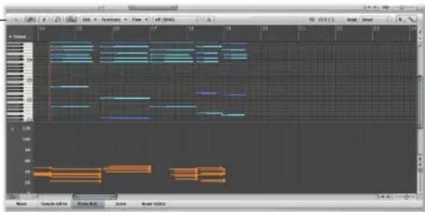
2 Click, and hold until you see the (Start Line) help tag, and release the mouse button. The (End Line) help tag is shown, along with a green line, which can be visually positioned onscreen. Keep an eye on the help tag while moving the line.
3 Click at the desired end point—both vertical and horizontal—to automatically scale all note velocities, aligned with the inserted line.
Note: Use of this mode only makes sense when the region actually contains notes.
The Note Velocity Line tool works in different modes:
- Absolute: With no modifier key pressed, the velocity of notes will be changed to match the values of the line.
- Relative: Command-click, the original and new note velocity will be analyzed. The resulting velocity is an average of both values.
- Just Selected: With Option pressed, only selected notes will be affected.
Both Relative and Just Selected modes can be combined.
Using Hyper Draw Key Commands
The following Arrange window key commands can speed up use of Hyper Draw:
• Hyper Draw: Disable
• Hyper Draw: Volume
- Hyper Draw: Pan
• Hyper Draw: Modulation
• Hyper Draw: Pitch Bend
• Hyper Draw: Note Velocity
• Hyper Draw: Other ...
• Hyper Draw: Autodefine
Conversion of Automation Data
You can convert track automation data into MIDI controller events (Hyper Draw data, in other words), and vice-versa. This allows you to move control data from regions in the Arrange area to the track-based automation system, or the reverse. This is useful for mirroring the Hyper Draw information—being used to control filter cutoff (on an external MIDI synthesizer)—with an identical automation curve that controls the Intensity parameter of a Flanger plug-in on an Apple Loop drum track, as an example.
To convert region controller events to track automation:
1 Select the region.
2 Choose one of the following commands in the Options > Track Automation menu:
- Move Current Region Data To Track Automation: Moves the currently visible MIDI controller data (volume, for example) of the selected region to the track automation system.
- Move All Region Control Data To Track Automation: Moves all MIDI controller data of the selected region to the track automation system.
To convert track automation data into controller events:
1 Select the region that you want to copy the controller events into.
2 Choose one of the following commands in the Options > Track Automation menu:
- Move Current Track Automation Data To Region: Converts the active track automation parameter into MIDI controller events, and copies it to the selected region.
- Move All Track Automation Data To Region: Converts all track automation parameters into MIDI controller events, and copies them to the selected region
Note: Only track automation data that falls within the boundaries of the selected region is converted.
Bouncing Your Project
27
You can render all, or specific, channels to one or more audio files, and even burn directly to CD or DVD with the Bounce function.
Output channels feature Bounce buttons.
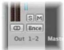
Bounces for output channels 1 and 2 can also be initiated by choosing File > Bounce from any Logic Express window (although the Arrange would be the most appropriate).
The Bounce process allows you to create an audio file (in several different file formats simultaneously, if desired) based on all channel strips routed to the selected output channel.
All parameters, including volume, pan, and effects are recorded as part of the bounced file. Automation, if used, also impacts on the resulting bounce file.
Bouncing takes place in either real time, or faster than real time (offline bounce).
Once bounced, files can be:
- Reused in Logic Express, either creatively, or to save processing resources by replacing (or bypassing) the regions, instruments, and effects on source channels.
• Used in other applications or devices. This makes it easy to send your files to mastering facilities, use them on the Internet (on web pages, or in the iTunes Store, for example), or even upload them to your iPod.
- Burned directly to CD or DVD (this can actually be done directly from the Bounce window, making bouncing and burning a one step process).
Creating a Bounce
This section outlines the basic steps required to create a bounced audio file. Detailed descriptions of each step follow.
To create a bounce file:
1 Route all channels that you want to bounce to a particular output channel (see the following section).
2 Define the desired bounce range (see "Defining the Bounce Range" on page 627).
3 Do one of the following:
- Click the Bounce button on the desired output channel.
- Choose File > Bounce from the main menu bar to bounce output channels 1 and 2.
4 Set the parameters in the Bounce window (see "Using the Bounce Window" on page 627).
5 Enter a destination name (and folder) for the bounced file (or files).
6 Press the Bounce (or Bounce & Burn) button in the Bounce window.
Note: Mono bouncing is possible when the output channel is set to mono. In this situation, a mono audio file is generated.
Routing Channels to an Output
If you're only routing one or two channels to a particular output channel strip, simply click the Output slot of the channels, and choose the desired output channel from the pop-up menu.
To route a number of channels to an output channel strip:
1 Rubber-band select (or Shift-select) the desired channels.
2 Click the Output slot of one of the selected channels, and choose the desired output channel.
All selected channels will be routed to the chosen output channel strip.
Defining the Bounce Range
Before bouncing, it is best to define a range of your project that you would like to bounce.
The default values for the Start and End position fields in the Bounce window will encompass the entire Logic Express project if no regions are selected, or the Cycle function is inactive.
- If the Cycle function is engaged, the bounce start and end positions will match the locator positions.
- If a selection (of one or more regions) is made in the Arrange window, the bounce start and end positions will match the selected area.
Note: You can manually set the bounce start and end positions in the Bounce window, if none of the options above are appropriate.
Using the Bounce Window
Following the range definition, press the Bounce button on the output channel, or choose File > Bounce. This will open the Bounce window.
Global Bounce Window Options
Several global options are available in the Bounce window, regardless of the file types being bounced.
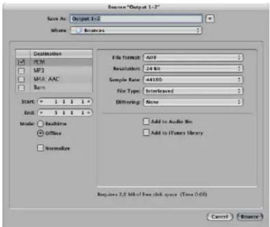
Destination
You can choose from several destination file formats for your audio bounce:
- PCM file: SDII, AIFF, (Broadcast) Wave, or CAF format
- Compressed file: MP3 or M4A: AAC
All options are activated by simply clicking in the desired checkboxes. You can select multiple checkboxes, if you wish. If you do so, multiple files will be created, with the appropriate file extension: filename.aif, filename.mp3, filename.m4a.
If you click on the destination name, rather than click the checkbox, you can set a number of preferences in the panel to the right. As examples:
- PCM, MP3, and M4A: AAC files can be individually bounced and added to the iTunes library if "Add to iTunes library" is turned on in the sub-pane (for each format).
- PCM files in SDII, AIFF, Wave, or CAF format: Can be added to the Audio Bin if the Add to Audio Bin checkbox is enabled in the PCM sub-pane.
Note: All bounced wave file recordings are in Broadcast Wave format.
To burn a DVD or CD:
1 Click the Burn name (Burn: CDDA or Burn: DVD-A) to view the panel to the right.
2 Choose CDDA or DVD-A from the Mode menu, dependent on the type of disc you want to burn.
3 Click the Burn:CDDA destination checkbox to enable disc burning after the bounce. The Bounce button will be renamed to Bounce & Burn when Burn is selected.
Note: When Burn is selected, you may see a dialog informing you about changes to stereo interleaved files. This is dependent on other settings made in the dialogs for each file type.
Start and End Position
These fields define the boundaries of the project segment that you want to write to the bounced file. The defaults for these fields are set in the following way:
- If the Cycle function is engaged, they will be set to the locator positions.
- If a selection is made in the Arrange window, they will be set to the selected area.
- If neither of the above is valid, they will encompass the entire Logic Express project.
In any case, you can adjust the start and end positions manually. As an example, should you want to take into account a MIDI sound module (mixed via an aux channel) that falls outside the bounce start and end positions.
Tip: It's often a good idea to set the end position of the bounce a little bit past the end of the last region. This ensures that reverb tails and echoes from delay plug-ins are not chopped off. The amount of extra time needed will, of course, depend on the effect settings used.
As you adjust the Start and End position parameters, you are shown the hard disk space requirements for the bounced file above the Cancel and Bounce button.
(Bounce) Mode
• Realtime: Creates the bounce file in real time. Use it whenever you wish to bounce audio and instrument tracks, plus external MIDI sound sources that are routed into the Logic Express Mixer via aux channels.
- Offline: Accelerates the bounce process—depending on the complexity of your arrangement, and available CPU processing power. It also allows you to bounce arrangements that would normally exceed the processing power of your CPU, if trying to play them in real time.
Note: Offline bouncing is limited to internal sources (audio or instrument tracks). External MIDI tracks and audio channel inputs are deactivated during offline bounces.
DSP-based audio hardware can not make use of offline bouncing due to the nature of its stream-oriented technology (these devices only work in real time, in other words).
Other software applications that are fed into your Logic Express Mixer via ReWire can be bounced offline.
Normalize
Turn on this option if you want to normalize your files before the bounce. Normalizing scans the incoming audio for the highest amplitude peak. The level of this peak is increased to the maximum possible level (without clipping), and all other incoming audio is also increased by this amount.
PCM Options in the Bounce Window
Choose the PCM name (and activate the checkbox) in the Destination pane to access the following options:
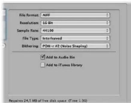
File Format
Choose from the SDII, AIFF, (Broadcast) Wave, or CAF format.
PCM files in these formats can be automatically added to the Audio Bin by enabling the Add to Audio Bin checkbox.
Resolution
This is where you define the resolution of the bounced file. The options are 16 Bit (for CD delivery), 8 Bit (for multimedia productions,) or 24 Bit (for mastering to DVD).
Sample Rate
This menu allows you to choose the sample rate for your bounced audio file(s). Options range from 11,025 to 192,000 Hz, and include the three most commonly used sample rates: 44,100 (CD-DA), 48,000 (DAT), and 96,000 (DVD).
File Type
You can choose between Split (for use in Pro Tools), or Interleaved (for further use in Logic Express, or for CD writing software).
Note: Choosing Split disables Burn, if chosen in the Destination pane.
Dithering
Dithering is recommended when bouncing 24 bit recordings into 16 bit files.
"Add to" Options
The Add to Audio Bin option adds the bounced PCM file(s) to the Audio Bin.
The Add to iTunes library option adds the bounced PCM file to the iTunes library.
Note: iTunes does not support SDII or CAF format files. If the File Format menu is set to SDII or CAF, this checkbox is dimmed, and can't be used.
MP3 Options in the Bounce Window
Logic Express allows the bouncing of MP3 (MPEG-2, Layer-3) format files. This well-known data reduction format for digital audio signals was developed by the Fraunhofer Institute, and allows high compression rates while maintaining reasonable audio quality (depending on the compression rate). MP3 is a widely used standard for audio file exchange via the Internet.
Due to the fact that encoding an MP3 file equates to a loss of audio quality, you should not use MP3 files during production if you have access to the same audio data in linear formats such as: AIFF, WAV, or SDII.
Bounced PCM files are also used for encoding to MP3/M4A: AAC. It should be noted that this occurs before dithering takes place.
Note: Should the selected sample rate be higher than 48 kHz, a temporary copy of the bounced PCM file is created—with an automatic sample rate conversion to 48 kHz before encoding. This conversion takes place because the MP3 format does not support sampling rates higher than 48 kHz.
If the PCM option is disabled in the Destination pane, a temporary PCM file is bounced as a source for encoding to MP3/M4A: AAC and/or burning to a CD—in accordance with the options selected in the PCM page.
Choose the MP3 name (and activate the checkbox) in the Destination pane to access the following options:
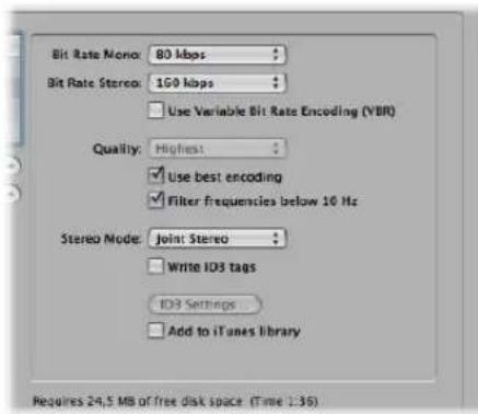
Bit Rate (Mono/Stereo)
MP3 bit rates are selectable between 32 kbps and 320 kbps, but default to 80 kbps mono, and 160 kbps stereo. These rates offer acceptable quality and good file compression.
To enhance audio quality, provided you can afford the extra file size, choose:
• 96 kbps for mono streams
• 192 kbps for stereo streams
You can, of course, choose even higher rates, but the quality improvement afforded by bit rates above 96/192 kbps is nominal.
Use Variable Bit Rate Encoding (VBR)
Variable Bit Rate encoding compresses simpler passages more heavily than passages that are (more) harmonically rich, generally resulting in better quality MP3 files.
Unfortunately, not all MP3 players can accurately decode VBR-encoded MP3s, which is why this option is turned off by default. If you know that your target listeners can decode VBR-encoded MP3s, you can switch this option on.
Quality
Keep this set to Highest (the default) whenever possible. Reducing the quality accelerates the conversion process, but at the expense of audio quality.
Use Best Encoding
Again, like the Quality parameter, if you uncheck this option, you will gain encoding speed at the price of audio quality. This should always be kept on, unless conversion time is an issue.
Filter Frequencies Below 10 Hz
When this option is checked (the default), frequencies below 10 Hz (which are usually not reproduced by speakers, and are not audible to human ears at any rate) will be removed. This leaves slightly more data bandwidth for the frequencies that we can hear, resulting in an improvement of the perceived quality. Only uncheck this option if you're experimenting with subsonic test tones, or exporting MP3s for whales!
Stereo Mode
You can select Joint Stereo or Normal stereo mode. Depending on the original file, these settings may (or may not) offer any audible difference. Experiment with both settings to determine your preference.
Write ID 3 Tags/ID3 Settings
When the Write ID3 Tags option is enabled, ID3 tags are written to the file.
These tags can be edited/configured in a dialog which you can open by clicking the ID3 Settings button.
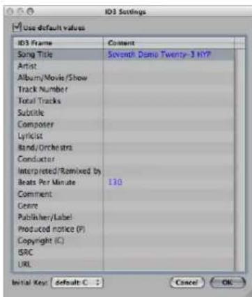
All entries are made by double-clicking on the desired Content column fields to the right of the corresponding ID 3 Frame column entry, and typing in your text.
Enable the Use default values checkbox (on by default) to display default settings for certain Content column entries. As examples, the Project Title and Tempo (Beats Per Minute) are automatically filled in.
Enabling the "Use default values checkbox" also sets the Initial Key: menu to the first entry shown in the global Signature track. This will be "default:C" if no key has been set for the project.
You may freely choose another key from the menu.
Add to iTunes Library
The Add to iTunes library option adds the encoded MP3 file to the iTunes library.
M4A: AAC Format Options
Choose the M4A: AAC name (and activate the checkbox) in the Destination field to access the following options:
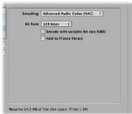
Encoding
Choose Advanced Audio Codec (AAC) or Apple Lossless to determine how your .m4a (commonly referred to as MP4) file will be encoded. Both encoding algorithms provide high quality audio, with the AAC format using a higher compression ratio, resulting in smaller file sizes.
Bit Rate
You can choose a rate between 16 kbps and 320 kbps.
Note: This parameter is only available when the AAC Codec is chosen.
Encode With Variable Bit Rate (VBR)
Variable Bit Rate encoding compresses simpler passages more heavily than passages that are (more) harmonically rich, generally resulting in better quality files.
Unfortunately, not all media players can accurately decode VBR-encoded files, which is why this option is turned off by default. If you know that your target listeners can decode VBR-encoded files, you can switch this option on.
Note: This parameter is only available when the AAC Codec is chosen.
Add to iTunes Library
The Add to iTunes library option adds the encoded file to the iTunes library.
Should the selected sample rate be higher than 48 kHz, a copy of the bounced PCM file is created—with an automatic sample rate conversion to 48 kHz before encoding. This conversion takes place because the M4A: AAC format does not support sampling rates higher than 48 kHz.
Burn Options
Choose the Burn: (CDDA or DVD-A) name (and activate the checkbox) in the Destination pane to access the following options:
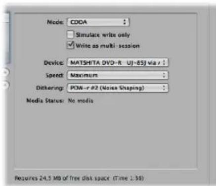
Logic Express can directly burn Red Book audio to blank CDs or DVD-Audio to blank DVDs.
- When CDDA is chosen: If the selected sample rate (chosen in the PCM panel) is higher than 44.1 kHz, a copy of the bounced PCM file is created—with an automatic sample rate conversion to 44.1 kHz before encoding. This conversion takes place because the CD Audio format (Red Book) does not support sampling rates higher than 44.1 kHz.
- When DVD-A is chosen: Any sample rate up to 192 kHz can be used for stereo files.
Simulate Write Only
The "Simulate write only" option, as the name suggests, simulates a CD/DVD burn, but does not write data to the blank media. This can be used either alone, or in conjunction with, the "Write as multi session" option (if burning a CD).
Write As Multi Session (Only Available When CDDA is Chosen in the Mode Menu)
The "Write as multi session" option allows you to add a data session to the same CD at a later date—to add the project folder, for example.
Device
This menu allows you to choose between any recognized CD/DVD burners connected to your system.
Note: If your system contains multiple burners, the first one detected is chosen as the default.
Speed
The first time you use the Speed pull-down menu, a request is made to the burning mechanism, which may take a while. Once the scan is complete, you may freely select from the available speeds.
Dithering (Only Available When CDDA is Chosen in the Mode Menu)
Use of the Dithering parameter is recommended when bouncing 24 bit recordings into 16 bit files.
Note: If you attempt to switch the PCM Resolution to 16 Bit when in DVD-A Burn Mode, DVD burning is automatically disabled (following a warning).
Bounce & Burn
Clicking the Bounce & Burn button initiates the bounce, and burns the audio to CD or DVD.
Note: Following confirmation of the file location(s), you may encounter further dialogs that will ask if you want to overwrite existing files. Use these as required.
Media Status and Information Fields
The Media Status field indicates the type of media in the chosen Device.
The field below indicates the current PCM page settings (if applicable).
A further field, above the Cancel and Bounce & Burn button, indicates the amount of disk space required, and the time (length, shown in hours, minutes, and seconds) of the bounce area.
Note: You can not directly alter any information shown in these areas.
Setting the Bounce File Name and Folder
By default, bounce files are:
- Named after the chosen output channel strip (the Bounce button you clicked), or Output 1-2, if the Bounce window was opened with the File > Bounce command.
- Saved in the Bounces sub-folder of the project folder, but you can choose any folder on any Volume.
To set the bounce file name and folder:
1 Simply type the desired file name in the Save As: field to change the default file name, and choose another folder, if you like.
2 Click the New Folder button at the lower left of the Bounce window to create a new folder, if desired.
3 Click the Bounce (or Bounce and Burn) button.
All files (if multiple files are created) are saved in the chosen folder, and assigned the name you entered, with appropriate file extensions: wav, aif, m4a, and so on.
Bouncing and POW-r Dithering
Logic Express provides you with the professional POW-r dither algorithm, designed to convert 24 bit recordings to 16 bit files—as required for CD burning, for example.
POW-r (Psychoacoustically Optimized Wordlength Reduction) is licensed from the development team of the POW-r Consortium LLC.
POW-r dithering can be applied when:
- Bouncing audio files to disk
- Exporting OMF files (see "Exporting OMF Files" on page 660).
POW-r offers three distinct dithering modes.
• None No dithering is applied.
- POW-r #1: Uses a special dithering curve to minimize quantization noise.
- POW-r #2: (Noise Shaping): Uses additional noise shaping over a wide frequency range, which can extend the dynamic range of the bounced file by 5 to 10 dB.
- POW-r #3: (Noise Shaping): Uses additional, optimized noise shaping, which can extend the dynamic range by 20 dB within the 2 to 4 kHz range—the range the human ear is most sensitive to.
Note: Noise Shaping minimizes the side effects caused by bit reduction. It does this by moving the quantization noise spectrum to the frequency range above 10 kHz—the range the human ear is least sensitive to. Technically, this process is known as spectral displacement.
The dithering mode which will sound best to you is primarily dependent on the audio material, and your personal taste. Audition the audio material with each of the dithering modes to determine the right setting. In some cases, you may find that the best results are achieved by using no dithering at all!
Important: Dithering the same audio signal multiple times should be avoided.
Creating Apple Loops
28
You can save both audio and software instrument regions as Apple Loops in Logic Express.
For audio regions, a default set of transients—based on the project's tempo information—is automatically created. For more information on this method, see the following section.
You can also use the Apple Loops Utility to create Apple Loops from audio regions. The Apple Loops Utility is a companion application to Logic Express that allows you to manage metadata tags and transients in audio files. The Apple Loops Utility offers sophisticated tag editing functions for audio files. You can, for example, set the transients manually—independent of the project tempo (for more information, see “Creating Apple Loops in the Apple Loops Utility” on page 642). The Apple Loops Utility does not allow you to create Software Instrument Apple Loops (SIALs).
Which Tool to Use, and When to Use it?
As mentioned above, Logic Express offers Apple Loop creation facilities, and the separate Apple Loops Utility also allows you to construct your own Apple Loops.
You have a fairly simple decision path to follow:
- If you want to create an Apple Loop based on an audio file that matches the project tempo, use the Apple Loop creation utilities available in Logic Express.
- If you want to create a Software Instrument Apple Loop (SIAL), use the Apple Loop creation utilities available in Logic Express.
- If you want to create a non-looped Apple Loop based on an audio file that does not match the project tempo, use the Apple Loop creation utilities available in Logic Express. Non-looping Apple Loops (or one-shots) do not follow the project tempo and key. This is useful if you want to add discrete, non-musical sounds (such as sound effects) to the loop library, which should not be altered by the tempo and key properties.
- If you want to create a looped Apple Loop based on an audio file that does not match the project tempo, use the Apple Loops Utility.
Read the following section if you want to create Apple Loops in Logic Express. Information on "Creating Apple Loops in the Apple Loops Utility" can be found on page 642.
Creating Apple Loops in Logic Express
When you save a region as an Apple Loop in Logic Express, the region is added to the loop library and appears in the Loop Browser, allowing its use in other projects.
The tempo information of the project is used to tag the transients of user-created Apple Loops. This function works best if your audio files match the project tempo as precisely as possible.
Note: User-created Apple Loops behave exactly like the Apple Loops that ship with Logic Express, GarageBand, and Jam Packs: They follow the tempo of your project and match the project key (as defined by the initial key signature). Apple Loops will also follow any chord transpositions in the Chord track. For further information, see the section on "Global Tracks and Apple Loops" on page 645.
To create an Apple Loop in Logic Express:
1 Select the desired audio or software instrument region in the Arrange area.
2 Choose Region > Add to Apple Loops Library in the local Arrange menu.
3 In the Add Region to Apple Loops Library dialog:
- Type in a name for the loop, choose the scale, genre, instrument category, instrument name, and appropriate mood descriptions—to simplify searches.
- Set the file type, which can be One-shot or Looped. If the length of the audio file is not precisely trimmed to contain a number of whole bars, One-shot is selected automatically, and the file type buttons are dimmed (and inaccessible).
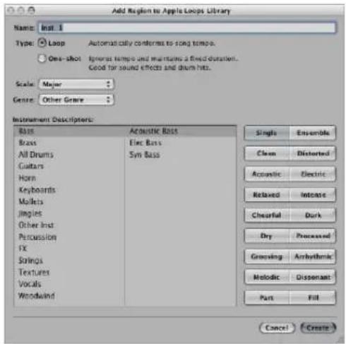
Note: One-shots do not follow the project tempo and key. This is useful if you want to add discrete, non-musical sounds (such as sound effects) to the loop library. It would generally not be desirable to have such sounds affected by the tempo and key properties of the project. These types of loops still contain metadata tags, allowing easy searching and categorization in the Loop Browser.
4 Click Create.
The loop is added to the Loop Browser. It will be stored in \~/Library/Audio/Apple Loops/User Loops/SingleFiles. You can find it by using the category buttons, menus, or by typing the (whole or partial) name in the Search field. If you drag the loop into the Arrange area, the Apple Loops symbol is shown beside the file name.
As one-shots are handled like normal audio files, the usual stereo or mono region symbol is shown alongside the file name (rather than the Apple Loops symbol).
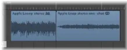
If you want to create a looped Apple Loop from an audio file that does not match the project tempo, you should use the Apple Loops Utility. The Apple Loops Utility allows you to define the intended length of the loop, regardless of the project tempo, by manually setting the Number of Beats and Time Signature tags.
Note: The Apple Loops Utility only works with audio regions—not with MIDI regions on instrument tracks. For further information about the Apple Loops Utility, see "Creating Apple Loops in the Apple Loops Utility" on page 642.
You can also adjust the project tempo to the file length. Logic Express offers an automatic function that matches the length of an audio region with the intended musical length. The length of the region remains constant, but the sequencer tempo is varied automatically, with the region playing back at the intended length.
To adjust the project tempo to an audio file:
1 Create an audio region that spans the complete audio file.
2 Construct a cycle in the Arrange window Bar ruler. Set the length to match the intended musical length of the region. As an example: If the audio region is one bar long, set a cycle length of one bar.
3 Choose Options > Tempo > Adjust Tempo using Region Length and Locators from the main menu bar (or use the corresponding key command, default: Command-T).
The tempo is recalculated, and the region (and the referenced audio file) matches the project tempo.
Send Effects in Software Instrument Apple Loops
If you create a SIAL from a region on a software instrument track that uses sends to bus effects, and then drag the saved loop to another (empty) instrument track, the new loop will sound different to the original source region. This happens because the effects sends in the original track are not saved with the loop.
Logic Express does not automatically assign effects to busses, because doing so would potentially interfere with bus configurations that you've already set up in your project. Effects that are inserted directly into the software instrument channel will, however, be automatically recalled when the loop is dragged into the Arrange area from the Loop Browser.
You can use one of the following options to ensure that loops created from software instrument regions will sound the same as the original regions:
- Drag your SIAL (the original of which was assigned to bus sends) to an audio track instead of an instrument track. When you create a software instrument loop, the audio file that is rendered will include any bus processing. This will sound identical to the original.
- When creating a loop from a software instrument region, you should directly insert all effects needed to reproduce the desired sound into the instrument's channel strip. This will allow all sound elements to be faithfully recreated when you add the loop to an instrument track.
- When using SIALs on an unassigned channel strip, manually set up the sends and bus effects needed to reproduce the sound of the original region.
Creating Apple Loops in the Apple Loops Utility
The Apple Loops Utility provides sophisticated functions for creating Apple Loops from audio regions. It can detect transients present in an audio file, and you can add markers for additional transients. You can also move these transient markers to new locations.
To create an Apple Loop in the Apple Loops Utility:
1 Select an audio region in the Arrange area.
2 Choose Audio > Open in Apple Loops Utility from the local Arrange menu (or use the Open in Apple Loops Utility key command).
If the length of your audio file does not match the beats, the following dialog appears:
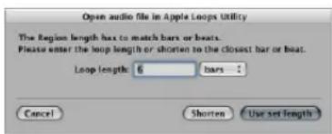
There are two possible reasons for the wrong length:
- The audio recording was recorded at the project tempo, but not cut correctly. In this situation, you can reduce the length of the recording, via the dialog.
- The loop uses a different tempo. In this case, you can set the length of the audio loop in the "Loop length" box and choose "Use set length".
For more information on the Apple Loops Utility, please refer to the Apple Loops Utility User Manual.
Converting ReCycle Files into Apple Loops
Logic Express allows you to convert ReCycle files into Apple Loops. You can either import ReCycle files as Apple Loops or convert multiple ReCycle files with the Batch Convert function found in the Browser.
To import single ReCycle files as Apple Loops:
1 Initiate a ReCycle import by using the same options as for audio files:
- Choose File > Import Audio File (or use the Import Audio File key command). You can also Shift-click an audio track with the Pencil (or Command-Shift-click with the Pointer tool).
Select the desired ReCycle loop in the ensuing file selector box.
- Drag the ReCycle loop from the Browser onto an audio track.
- Drag the ReCycle loop from the Finder onto an audio track.
2 Choose the Render into Apple Loop setting in the Fix menu of the ensuing ReCycle File Import dialog.
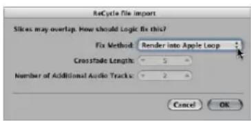
The ReCycle loop is converted to an Apple Loop (the slice points are converted to transient positions) and copied to the \~/Library/Audio/Apple Loops/User Loops/Single Files folder. The Apple Loop is added to your Logic Express project. You can find it in the Audio Bin.
As an alternative, you can use the Batch Convert function found in the Browser to simultaneously convert multiple ReCycle files into Apple Loops.
To convert multiple ReCycle files into Apple Loops:
1 Select the desired ReCycle files in the Browser.
2 Open the action menu, and choose Convert ReCycle Files/Folder to Apple Loops.
3 In the ensuing file selector box, select a location for the converted files.
The ReCycle files are converted to Apple Loops (the slice points are converted to transient positions) and copied to the chosen location.
Adding Apple Loops to the Loop Browser
Logic Express must index Apple Loops before they are shown in the Loop Browser. Loops can reside in any directory, but you need to tell Logic Express where to find them.
To add Apple Loops to the Loop Browser:
1 Open a Finder window alongside Logic Express.
2 Navigate to the folder that contains the Apple Loops.
3 Select the Apple Loops in the folder and drag them into the Loop Browser.
The loops are added to the Apple Loops library and indexed. When this process is finished, the loops will be available directly in the Loop Browser.
If you drag a single loop to the Loop Browser, the loop will be copied to \~/Library/Audio/Apple Loops/User Loops/SingleFiles.
If you drag a folder of loops that are located on the same drive and partition as the Loop Browser, the loops will be left at their current location, and an alias of the folder will be created in \~/Library/Audio/Apple Loops/User Loops.
If the loops are located on a different drive or partition, you'll be asked whether you want to copy them to the loop library, or index them at their current location (loops added from optical media will always be copied).
- If you choose to copy them, the folder containing the loops will be copied to \~/ Library/Audio/Apple Loops/User Loops/.
- If you choose to index them at their current location, an alias to the folder will be created in \~/Library/Audio/Apple Loops/User Loops/.
Acid Loops in the Loop Browser
The Loop Browser also displays Acid Loops. Acid Loops don't contain tags like Apple Loops. In Acid Loops, this information is derived from the surrounding folder structure (especially the names of folders), which must comply with certain standards. This means that it's not possible to drag an individual Acid Loop file into the Loop Browser.
As such, you need to drag the entire CD (or folder) that contains the Acid Loops into the Loop Browser.
Global Tracks and Apple Loops
You can use the global tracks to change global events such as tempo, time signature, and key during a project. The following section summarizes how these changes in the global tracks affect the playback of Apple Loops.
Tempo and Beat Mapping Track
Apple Loops adjust automatically to the tempo of these tracks.
Signature Track
Apple Loops can contain information about their original key, and can be transposed automatically. They will be played back at the project key by default, which is defined by the first key signature event. No distinction is made between major and minor keys for these global transposition functions; in fact, only the root of the initial key signature is relevant for playback of Apple Loops.
Note: When you change the key signature after importing Apple Loops, the playback of SIALs is not affected. They behave like normal MIDI regions. The playback of MIDI regions is not affected by key signature changes, only the display in the Score Editor!
The playback transposition for Apple Loops is controlled by the root note of chords in the Chord track. These root notes determine the global playback transposition—relative to the current key signature—shown in the Signature track. If no chords are available in the Chord track, the global playback key for Apple Loops is determined by the very first key signature in the Signature track (default: C major).
Chord Track
The root notes of chords in the Chord track determine the transposition (pitch shifting) of all Apple Loops.
The Change Display Only mode does not work with Apple Loops used on audio tracks. This shouldn't pose a problem, as you won't normally need this function when working with Apple Loops. There is one exception, however: some Apple Loops contain chord progressions. These chord progressions are not displayed in the Chord track.
Unfortunately, you can't use the Chord track's Change Display Only mode to match the displayed chords to what is actually being heard. All changes in the Chord track will affect the transposition of (audio, not instrument) Apple Loops. Activating the Change Display Only option doesn't help.
There is, however, a solution:
1 Cut the (audio) Apple Loop at the precise positions of any chord changes.
2 Match the chords displayed in the Chord Track with the chord progression in the cut Apple Loop files by manually entering the chords of each section in the Chord track. The individual Apple Loop parts will then be transposed accordingly.
3 Enter the inverted Transposition values of the chord root note changes in the Region Parameter box of each section, so that playback of the Apple Loop parts will match the original Apple Loop file.
As an example, assuming a default project key of C:
- The (audio) Apple Loop contains a chord progression with root notes of: C, F, G, and C. Cut it at these chord change positions. This will result in four regions.
- Enter C, F, G, and C at the corresponding positions in the Chord track. Assuming the original key is C, this is equivalent to a transposition of the second region by +5 and the third region by +7 semitones. If you played the entire part at this point, the original audio material would be transposed by the amounts just entered in the Chord track, which isn't what you want!
- Set the Transposition value of the second region to -5, and of the third region to -7 in their respective Region Parameter boxes.
Playback of the whole part will now sound as it did before the cuts, and the correct chords are displayed in the Chord track.
Transposition Track
Transposition events are closely linked to the progression of the chord root notes in the Chord track: Changing a chord root will be reflected in the Transposition track and vice-versa. Any alteration or creation of a transposition event will generate or alter the corresponding chord in the Chord track. All Apple Loops and MIDI regions will be pitch-shifted accordingly.
Note: Standard audio regions (audio regions that are not Apple Loops) will not be affected. Nor will Apple Loops that do not have a Key definition (drum loops, for example).
The global Transpose track transposes Apple Loops used on audio tracks by a maximum of ±36 semitones. This is a designed limitation, as Apple Loops don't sound that great when transposed over a greater range. This is also true for the Transposition parameter of the Region Parameter box.
Apple Loops Transpose to the Wrong Octave
Transposing an Apple Loop to a higher pitch may result in the loop being played back at a lower pitch, and vice-versa.
Example: If an Apple Loop is transposed to sound seven semitones higher, it will actually play back five semitones lower. This is harmonically-correct transposition, but it's probably not to the intended octave.
Transposing audio material is a technically complicated process which always implies a certain loss in quality. The greater the transposition range, the more significant the loss in quality. This is why Apple Loops are always transposed by the smallest possible value.
You should note that sound quality is dependent on the transposition amount of the Apple Loop's original key—not the project key, which defines the zero line of the Transposition track. As an example; if the project key is already five semitones above the original key of an Apple Loop, setting the transposition value to +2 will transpose the Apple Loop downwards by ten semitones. This is because the transposition value is only five semitones below its original key (rather than seven semitones above it).
In the classical European music system, an octave is divided into 12 semitones. As +7 semitones is harmonically equal to -5 semitones, a value of -5 is used as the transposition amount. The same happens with other settings: A transposition value of -9 will result in +3, and +12 will result in ±0. The use of the nearest harmonically equal transposition option is based on delivering the best sonic results, with smaller transpositions being desirable.
Converting Apple Loops to Audio Files
When you convert an Apple Loop into an audio file, the resulting file may not play at the project's current tempo and key settings. Rather, the new audio file will play at the original tempo and key of the Apple Loop.
This happens when you select an Apple Loop and choose Audio > Convert Regions to New Audio Files from the local Arrange menu, and change the File Format parameter in the ensuing window from “Original file type” to either WAVE or SDII. This creates a copy of the original Apple Loop file, but without the transient and category tags. The lack of these tags restricts file playback to the originally recorded tempo and key of the Apple Loop—not the tempo and key of the project.
If you want to turn an Apple Loop into an audio file that uses the project's tempo and key settings, select the loop (or loops) and choose File > Export > Region as Audio File. Be sure to select the "Add resulting files to Audio Bin" checkbox to use the new file in your current project.
This will export the Apple Loop as a new audio file with all plug-in effect processing of the track/channel on which the Apple Loop is placed. To export the Apple Loop without these effects, bypass them before exporting the region.
You should note that although this new file will play at your project's current tempo and key, it can't follow subsequent tempo or key changes like other Apple Loops; such files are fixed at the project tempo and key—in use when the file was exported.
Tip: If you enable the Follow Tempo option for the audio file, it will follow the project tempo and the first key signature set in the global tracks. For further information, see "Using the Follow Tempo Function" on page 556.
Apple Loops and Sample Rates
The method used to convert the sample rate of audio files also applies to Apple Loops. This sample conversion method also includes correction of transient positions.
To convert the sample rate of an Apple Loop:
1 Select the desired Apple Loop in the Audio Bin.
2 Choose Audio File > Copy/Convert File(s) from the local menu (or use corresponding key command, default: Control-C).
3 Choose the desired sample rate (and all other file conversion settings) in the ensuing dialog, select the folder location, then click Save.
If the "Change file reference in Bin" option is activated, the sample rate converted Apple Loop is automatically added to the project. It will follow the project tempo and key changes (provided that the Key tag was set in the original loop).
Note: If a new Apple Loop is created, it will need to be indexed to make it visible in the Loop Browser. Loops can reside in any directory, but you need to tell Logic Express where to find them.
You will probably not need to convert Apple Loops as often as standard audio files when working with Logic Express, as Apple Loops offer a major advantage: If the sample rate of your project is changed, the playback speed of all Apple Loops currently used in the project will automatically be adapted to the newly selected sample rate.
Project and File Interchange
29
Moving project data between programs and devices in your own, or external, studios is commonplace these days.
Unfortunately, not every application or device talks the same language.
Logic Express is compatible with a huge number of applications and devices, courtesy of advanced export and import facilities that allow you to use parts of, or entire, projects in other applications, such as Final Cut Pro and Pro Tools. Even hardware devices, such as workstation keyboard sequencers and digital recorders are supported.
Logic Express can export and import the following file formats:
- Audio files (derived from regions or tracks): These can be saved in WAV, AIF, SDII, Apple Lossless, MP3, and AAC formats.
- GarageBand projects
- OMF (Open Media Framework, also known as OMFI—Open Media Framework Interchange)
• AAF (Advanced Authoring Format) - OpenTL (Open Track List)
- Final Cut Pro XML
• MIDI Files (derived from selected, or all, MIDI regions)
Logic Express makes it easy to create a complete project archive. This simplifies transfers to other storage media, and transport to other users or facilities—either physically or via a network.
You can also share settings information with other Logic Express users on a local or remote network.
Sharing Logic Express Data Over a Network
Logic Express allows you to share or back up your data over a network, making it easier to collaborate on projects with other Logic Express users. This can be:
• Via a local network—using Bonjour.
• Over the Internet—using .Mac (requires a .Mac account).
You can share and back up the following data types:
- Plug-in settings
- Channel strip settings
• Key command Sets
Note: Due to potential licensing issues with sample libraries, you can not share EXS instruments or Ultrabeat settings.
Setting Sharing Preferences
You use the Sharing preferences to define which settings you want to share, and to back up your data on .Mac.
To open the Sharing preferences, do one of the following:
- Choose Logic Express > Preferences > Sharing
- Click the Preferences button in the Arrange Toolbar, then choose Sharing from the menu.
- Click the Action menu at the bottom of the Library and choose Sharing Preferences.
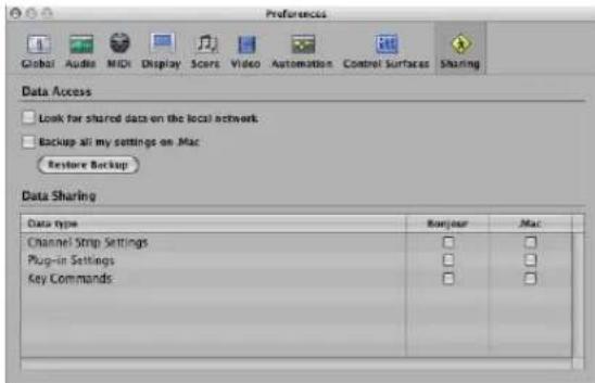
Sharing is essentially broken down into two tasks:
• Data Access: Browse your, or other user, data on a local network or a .Mac account.
• Data Sharing: Share your data over a local network or via a .Mac account.
You can access data shared on a .Mac account even when the user who provided the data is not online.
When data is shared over a local network, the user who provided the data—or more accurately, the computer (user account) that the shared data originated from—must be online.
To share your data:
■ Turn on the appropriate checkboxes in the Bonjour or .Mac columns.
- .Mac column: All settings of the enabled type on your personal iDisk in /Public/MusicAudioData are shared.
- Bonjour column: All settings of the enabled type in the corresponding \~/Library/Application Support/Logic folders are shared.
Note: Your .Mac URL can be accessed through a web browser, if you want to browse outside of Logic Express. Typically, this address will take the following form: http://idisk.mac.com/DOTMACUSERNAME/Public/MusicAudioData
To access shared data on the local network:
- Turn on the "Look for shared data on the local network" checkbox.
This will automatically search the local network for the \~/Library/Application Support/Logic folders of all networked machines.
To create a backup of your personal data on your .Mac account:
■ Turn on the Backup all my settings on .Mac checkbox.
This creates a copy of all of your settings data on .Mac, as a personal backup solution.
Note: The sharing master can be different to the one used for backups. To explain: You may have a studio computer that is the master for backups, and also use a MacBook to share (and edit) data while on the road.
Backup (and sharing) via .Mac uses a simple and straightforward push/pull concept: Data being backed up (or shared) always overwrites the data that exists on the .Mac account.
- When you backup to .Mac for the first time, the machine being used becomes the master of the .Mac content.
- When you try to back up/share data from another computer, a warning dialog explains that only the master machine can "push" data. This dialog includes an option to make the current machine the new master.
- When you switch off the Backup all my settings on .Mac preference on the master machine, all backup data is removed from .Mac and the "master" is set as undefined.
Note: When you switch off the Backup all my settings on .Mac preference, all backup data is removed from the .Mac account.
To restore a backup of your personal data:
1 Click the Restore Backup button.
A confirmation dialog will launch.
2 Click the Restore button to replace your existing settings and key commands with the .Mac backup.
Note: If the Restore process is interrupted for some reason (network problems), the pre-restore data is retained, ensuring that you don't wipe out all of your settings, or end up with a partially restored collection. The same behavior occurs when one of the folders on the .Mac account is empty.
Sharing Settings Data in the Library
When you share plug-in settings or channel strip settings by turning on the appropriate Sharing preferences checkboxes, additional indicators are displayed in the Library tab, to the left of folder and setting file icons:
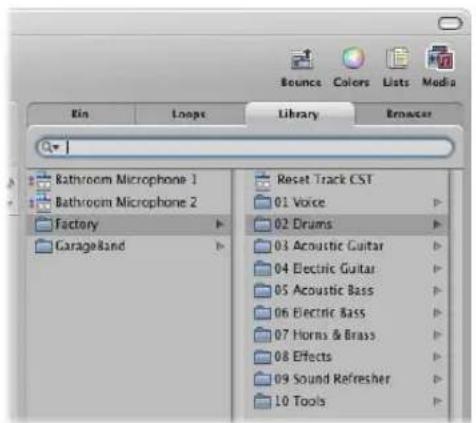
• .Mac sharing is indicated by a blue dot.
- Bonjour sharing is indicated by a red dot.
By default, all items of the matching data type (plug-in or channel strip settings) are marked as shared.
To disable or enable sharing on a per setting or folder basis:
- Control-click on individual settings or folders, and turn on or turn off the Share via Bonjour and Share via .Mac options as applicable.
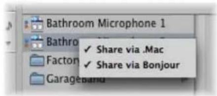
Note: When the sharing status of a folder is turned on or off for either Bonjour or .Mac, all items in the folder are switched to the same state.
Settings shared by other users appear as follows in the Library:
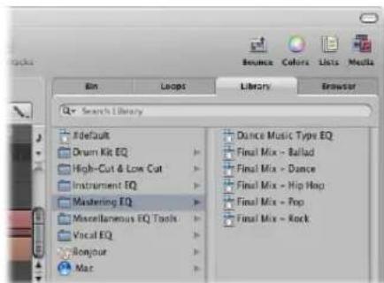
- Bonjour folder: Shows all shared settings on the local network.
• .Mac folder: Shows all settings of .Mac accounts you are connected to.
To connect to a .Mac account:
1 Choose Connect to .Mac in the Action menu of the Library.
2 Do the following in the Connect to .Mac account:
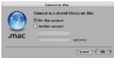
- Select the .Mac account you want to connect to. You have the choice of your own account (this accesses the backup folder) or another account (which accesses the Public folder).
- Input the name of the .Mac account.
Tip: You can access your own public .Mac folder by choosing another account, and typing in your own user name.
3 Click OK when you are done.
Note: Data accessed through .Mac is downloaded in an on demand fashion, and is only stored (on the local hard disk) if you decide to do so. This is similar to settings which exist in a project, but are not saved as files on the hard disk.
To disconnect the active .Mac account:
- Choose Disconnect .Mac in the Action menu of the Library.
This allows you to connect to another account, or to perform a local refresh or other operation, without impacting on the .Mac data.
To refresh the Library:
- Choose Refresh Library in the Action menu of the Library.
This refreshes both the local library and the .Mac accounts you are connected to.
Sharing Key Commands
You can access shared key command sets in the Key Commands window.
To browse for shared key command:
- Choose Options > Presets, then browse the .Mac or Bonjour folders.
Backing Up Audio Files
The backup functions available in the Audio Bin and Sample Editor create a duplicate of the selected audio file (or files) in the same storage location as the originals. Backup files inherit the name of the source file, and are easily identified by the ".dup" file extension.
To create a backup of one or more selected files in the Audio Bin:
- Choose the Audio File > Backup File(s) command. Click the Duplicate button in the dialog.
Back up (duplicate) files can be directly added to the Audio Bin (or Arrange), just as you would with the original audio files.
To create a backup of the selected file in the Sample Editor:
- Choose the Audio File > Create Backup command (or use the corresponding key command, default: Command-B). Click the Create button in the dialog.
Use this feature before performing a destructive editing operation in the Sample Editor, as it provides a "fallback" position if the audio processing produces undesirable results.
To restore the backed up file in the Sample Editor:
- Choose the Audio File > Revert to Backup command (or use the corresponding key command, default: Shift-Command-B). Click the Paste button in the dialog.
Backing Up and Sharing Projects
Project folders help you to keep track of your work: they ensure that all files related to a project are neatly saved in one location. This makes it easy to back up your projects and enables easy transfer between computers. This avoids problems such as missing instruments, audio files, or samples that you need to search for, or reconstruct, in the studio.
The File > Save as Project function allows you to save a project with all associated files. These are collectively known as the project assets.
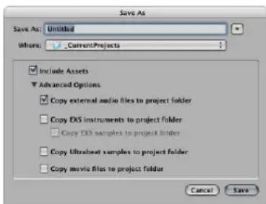
Activation of the Include Assets checkbox in the Save As dialog will include the file types chosen in the Advanced Options.
The Advanced Option checkboxes determine how files imported from external locations (locations outside the project folder) should be handled.
They either:
- Stay where they are (if the respective "Copy" checkbox is turned off).
- Or are copied into the project folder (if the "Copy" checkbox is turned on).
To choose the desired project assets:
- Turn on the "Copy external audio files to project folder" checkbox to create copies of these files in your project folder.
- Turn on the "Copy EXS instruments to project folder" and "Copy EXS samples to project folder" checkboxes do just that. If you turn off the "Copy EXS samples to project folder" option, only EXS instrument files will be copied to the project folder when saving, not the samples associated with the EXS instrument files.
- Turn on the "Copy Ultrabeat samples to project folder" checkbox to create copies of these files in the project folder.
- Turn on the "Copy movie files to project folder" checkbox if you want to copy the QuickTime movie used in the project.
Files are only copied into the project folder when the project is saved.
Once saved, the project is "safe," allowing you to move or copy the entire project folder without losing any references that point to files within the folder.
To access the project asset checkboxes at any time, do one of the following:
- Choose File > Save As.
- Choose File > Project Settings > Assets (or use the corresponding key command).
- Click the Settings button in the Arrange Toolbar, then choose Assets from the menu.
Working With Standard MIDI Files
Standard MIDI files are not specific to a particular sequencing program, hardware sequencer, or type of computer. They contain the following information:
- MIDI events, including time positions and channel assignments
- Names of the individual tracks
- Names and positions of markers
- Tempo changes
- Copyright marks
Logic Express allows you to import, open, and export Standard MIDI file formats 0 and 1:
- Format 0 contains all data in one track.
- Format 1 can contain multiple tracks, each with independent data.
Neither format recognizes any division of a track (into several MIDI regions, for example).
Opening and Importing Standard MIDI Files
An import only loads MIDI region data (notes, controller, SysEx, pitchbend, specific meta events) into an opened project, with global data (such as tempo events, signatures, chords, track names, SMPTE start, and so on) being ignored.
Important: If you want to load all information contained in a MIDI file, you must open it.
To import a MIDI file at the playhead position, do one of the following:
- Choose File > Import from the main menu bar (or use the Import key command), then select the desired MIDI file in the ensuing file selector box.
- Locate and select the MIDI file in the Browser, then click the Import button.
The MIDI file is placed at the playhead position, rounded to bars.
To import a MIDI file at the mouse position:
- Drag the desired MIDI file from the Browser or Finder into the Arrange area.
The mouse position—when the mouse button is released—determines the position (rounded to the nearest bar) and destination of the first track in the imported file.
To open a MIDI file:
1 Choose File > Open from the main menu bar (or use the Open key command), then select the desired MIDI file in the ensuing file selector box.
Note: If you choose the MIDI files option in the File Type menu, only MIDI files will be displayed in the file selector box.
If a project is loaded, a dialog will ask if you want to create a new environment or copy the current environment for the MIDI file.
2 Do one of the following:
- Click Copy to replicate the existing environment. The tracks of the MIDI file are automatically assigned to suitable instruments.
- Click New to load the environment of the default project template.
The MIDI file is loaded as a new project that contains all MIDI events—inclusive of time positions and channel assignments, names of individual tracks, names and positions of markers, tempo changes, and copyright marks. The copyright mark is read as marker text.
Note: As a default behavior, Logic Express will automatically create software instrument tracks for each MIDI track, and assign an appropriate GarageBand instrument to each, when you open a MIDI file. If you want to use external MIDI tracks for each MIDI track, press Option while opening the MIDI file.
Saving Standard MIDI Files
If you want to play a Logic MIDI project on another sequencer, you can do so by saving it as a Standard MIDI file. Consult the manual of the other sequencer to determine what Standard MIDI file formats it supports.
Due to limitations of the Standard MIDI file format (in comparison to the Logic project format), you need to prepare your Logic project for export by following these steps:
To prepare all MIDI regions for a Standard MIDI file export:
1 Select all MIDI regions by choosing Edit > Select All (or using the Select All key command, default: Command-A),
2 Neutralize all playback parameters by choosing MIDI > Region Parameters > Normalize Region Parameters in the Arrange area (or use the Normalize key command, default: Control-N).
3 Convert all playback quantization by choosing MIDI > Region Parameters > Apply Quantization Settings Destructively (or use the respective key command, default: Control-Q)
4 Convert all aliases into real copies by choosing MIDI > Alias > Convert to a Region Copy (or using the Convert Alias to a Region Copy key command).
5 Convert all loops into real copies by choosing Region > Loops > Convert to Real Copies (or using the Convert Loops to Real Copies key command, default: K).
6 Convert all MIDI regions on each track into a continuous MIDI region by choosing Region > Merge > Regions per Tracks (or use the Merge Regions per track key command).
Note: As Standard MIDI file type 0 format files can only save one MIDI region, you must also merge all MIDI regions into one if you want to export in file format 0. You can do this by choosing Region > Merge > Regions.
7 Insert all instrument MIDI settings as events by choosing MIDI > Insert Instrument MIDI settings as Events.
To save MIDI regions as a Standard MIDI file:
1 Select all of the required MIDI regions.
2 Choose File > Export > Selection as MIDI File (or use the Export Selection as MIDI File key command, default: Command-E).
3 Choose the destination directory, enter the desired name, then click Save. The selected MIDI regions are saved as a Format 1 MIDI file.
Note: Remember that most hardware sequencers can only read MS-DOS formatted disks, so limit your file name to an 8.3 character name. As an example: "proj0001.MID".
To save a MIDI region in file format 0:
- Enable the “Export MIDI File…’ saves single MIDI Regions as Format 0” checkbox in the Project Handling tab of the Global preference pane (Logic Express > Preferences > Global).
When this preference is turned on, choosing File > Export > Export Selection as MIDI File when only one MIDI region is selected will automatically export the region as file format 0 MIDI file.
Importing GarageBand Projects
You can open a GarageBand project in Logic Express just as you would open a Logic Express project. The GarageBand project translates 1:1 into Logic Express:
- Logic Express will automatically create the required number, and type, of tracks to mirror those used in the GarageBand project.
- The project uses the tempo of the GarageBand project.
- The initial key signature is set in accordance with the "project key" of the GarageBand project.
- Software instrument parts will be played by GarageBand instruments in Logic Express. GarageBand instruments are automatically installed with Logic Express. Further to this, any mixing data and effects (plus their settings) used by software instruments or Apple Loops-based tracks in GarageBand will also be imported into Logic Express.
- The Channel Strip settings of GarageBand translate 1:1 into Logic Express—with the nice exception that you can now access the individual plug-ins that are inserted into a GarageBand channel strip.
- The two bus effects of GarageBand (Reverb and Echo) are also translated when opened in Logic Express. They are replaced by the PlatinumVerb and Echo on busses 1 and 2.
Once the GarageBand project is loaded into Logic Express, you may freely change parts, mixing levels, instrument, and effect parameters as in any Logic Express project.
Note: You can not open Logic Express projects in GarageBand, nor can you export a Logic Express project in a format that can be read by GarageBand (apart from as an audio file).
Working With OMF Files
The OMF file format is typically used to exchange data with Digidesign Pro Tools software. The OMF format only supports the exchange of audio data (audio media and the use of this audio media in a project)—MIDI and automation data is ignored when using the export functions.
Exporting OMF Files
m To export the current project as an OMF file, choose File > Export > Project as OMF File (or use the Export Project as OMF File key command).
Choose the required options in the dialog that launches:
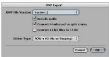
 OMF File Version: You can choose to export the file in OMF Version 1 or Version 2 format. You will usually choose Version 2 here. Version 1 is only useful for backwards compatibility with older software versions.
A Include audio: Turn this on to integrate all exported audio files into the OMF file itself. This can result in a very large file, and can make file export times lengthy. Turn off this checkbox to only write file references to the OMF file.
Note: If the later option is chosen and you wish to copy the OMF file to another hard disk, you will need to ensure that all referenced audio files are also copied.
 Convert interleaved to split stereo: As some applications don't support interleaved stereo files, Logic Express can convert interleaved stereo files to split stereo (when exporting an OMF file for a Pro Tools session, for example). Turn on this checkbox if this is the desired behavior.
Note: This only works if the "Include audio" option is turned on.
 Convert 24 bit files to 16 bit: Turn on this option to convert all 24 bit files to 16 bit, using the chosen dithering type. This might be necessary when using older versions of Pro Tools.
 Dithering: When exporting 24 bit recordings as 16 bit audio files that are included in the OMF file, dithering is recommended (see "Bouncing and POW-r Dithering" on page 637).
Importing and Opening OMF Files
The following procedure is identical for both importing and opening OMF files. Importing copies the OMF data into the current project, whereas opening an OMF file will create a new project.
To import or open an OMF file:
1 Do one of the following:
- Choose File > Import (or use the corresponding key command, default: Command-I).
- Choose File > Open (or use the corresponding key command, default: Command-O).
- Locate the Open TL file in the Browser, then click the Open button.
2 Choose the desired OMF file from the file selector box.
Tip: If you choose the OMF files option in the File Type menu, only files with the ".TL" extension will be shown.
After choosing and confirming the file import, a further dialog allows you to define the target location for audio data extracted from the OMF file.
3 Choose an existing folder (this defaults to the open project folder), or create a new one.
The OMF file is imported into the currently open project. New audio tracks are generated for every track contained in the OMF file, and the audio parts are placed appropriately on these tracks (as regions).
Working With OpenTL Files
The OpenTL format is mainly used for data exchange with Tascam hard disk recorders, such as the MX2424. It only supports the exchange of audio data (audio media and the use of this audio media in a project)—MIDI and automation data is ignored when using the export functions.
Exporting OpenTL Files
1 To export the current project's audio in the OpenTL format, choose File > Export > Project as OpenTL File.
2 This will launch a file selector dialog, where you can specify the destination folder, and file name, of the resulting OpenTL file. After confirming this dialog, Logic Express will ask if you want to create a dedicated folder for the OpenTL export.
3 Click Create to have all exported files placed in one folder, which is named after the exported file. This is the convention used by the Tascam MX recorders, so it is recommended.
4 Next, Logic Express will ask if the project's SMPTE start time should be added to event start positions. In this scenario, audio parts in the resulting OpenTL file will have the same SMPTE start time as in the Logic project. If you click Don't Add, the part positions are calculated relative to the project start position (an audio part that starts at bar 1 will have a start time of 00:00:00:00.00).
5 At the next step, Logic Express will ask if a copy of all audio files should be made. You should choose Make Copy if you want to copy the resulting OpenTL file, including all audio data, to another hard disk.
Logic Express will then create two sub-folders in the folder that contains the OpenTL file: namely Audio Files and Track Files (which is the suggested structure for OpenTL exports). The Audio Files folder will contain copies of all exported audio files. If you choose Don't Copy, the file references in the OpenTL file will point to the original audio files.
Opening and Importing OpenTL Files
The following procedure is identical for both importing and opening OpenTL files. Importing copies the OpenTL data into the current project, whereas opening an OpenTL file will create a new project.
To import or open an OpenTL file:
1 Do one of the following:
- Choose File > Import (or use the corresponding key command, default: Command-I).
- Choose File > Open (or use the corresponding key command, default: Command-O).
- Locate the Open TL file in the Browser, then click the Open button.
2 Choose the desired OpenTL files from the file selector box. Note that if you choose the Open TL files option in the File Type menu, only files with the ".TL" extension will be shown.
3 Dependent on where the first event in the imported project starts, one of the following dialogs will appear:
- If the first event in the imported project starts at a time greater than 1 hour: Set SMPTE start time of project so that events start at the same SMPTE time as they do in the imported project?
Choose Set if you want the SMPTE start time of the project to be changed accordingly, or click Don't Set if you don't want to change the SMPTE start time of the project.
- Should the first audio part found by the OpenTL import have a start time greater than zero (less than zero is impossible), but less than 1 hour:
Set the start time of first imported event to start of project?
If you choose Set, the first audio part imported will be placed precisely at the project start position.
This solves the problem of the project on the Tascam machine starting at a large time value, but less than 1 hour (such as 59 minutes). In this situation, you can't immediately see the imported audio parts because they may be imported beyond the project's end point, and almost certainly outside the visible window area.
Opening, Importing, and Exporting AAF Files
AAF (Advanced Authoring Format) is used by other DAW applications such as Pro Tools. You can use it to import multiple audio tracks, inclusive of references to tracks, time positions, and volume automation.
To export the current project as an AAF file:
1 Choose File > Export > Project as AAF File (or use the Export Project as AAF File key command).
2 In the Save AAF File As dialog, choose the following pop-up menu options:
• Sample Rate: Choose 44.1 kHz, 48 khz, 88.2 kHz, or 96 kHz.
- Bit Depth: Choose either 16 or 24 bit.
- File Format: Choose WAVE or AIFF.
- Dither Type: Choose None or any of the three POW-r algorithms (see "Bouncing and POW-r Dithering" on page 637).
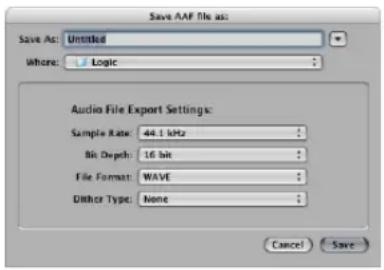
3 Choose a location, enter a name for the file, then click OK.
The export includes all used regions, inclusive of track and position references, and volume automation.
To import an AAF file:
■ Do one of the following:
- Choose File > Import (or use the Import File key command), then choose the AAF file in the Import dialog.
- Locate the AAF file in the Browser, then click the Open button.
To open an AAF file:
1 Choose File > Open.
2 Choose the AAF file in the Open dialog.
Importing and Exporting Final Cut Pro XML Files
The Final Cut Pro XML format is used to import and export audio data between Final Cut Pro and Logic Express. The Final Cut Pro XML format supports automation data.
To export the current project as a Final Cut Pro/XML file:
- Choose File > Export > Project to Final Cut Pro/XML.
This will launch a standard file selector dialog, allowing you to name the export file.
Note: Audio Instrument tracks are always bounced to audio files. MIDI tracks are ignored. Bouncing will automatically switch to real time mode, if necessary (such as when an I/O or External Instrument plug-in is used).
To import Final Cut Pro XML files, do one of the following:
- Choose File > Import, then choose the file in the Import dialog.
- Locate and select the file in the Browser, then click the Open button.
Changing or Retaining the Final Cut Pro Sample Rate
The XML import procedure allows you to retain the sample rate of audio files used in your Final Cut sequences. If you import sequences that use audio files with different sample rates, the following dialog appears:
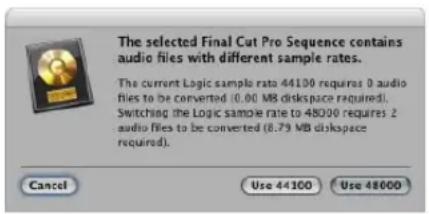
Click one of the buttons to choose if you want to:
- Alter the sample rate of your Logic Express project to match all imported Final Cut sequence audio files.
- Retain the sample rate of your Logic Express project. All Final Cut sequence audio files that use a sample rate that differs from the selected one are converted.
Note: A Final Cut sequence is an arrangement of video, audio, and graphic clips, edit information, and effects—which combined, create a movie. Use of XML to import Final Cut sequences into Logic Express allows you to exchange multiple audio tracks, with all positional region information, region names, volume and pan automation data, retained.
Exporting Regions
The File > Export menu also features several Export functions for regions and tracks. These allow you to render audio or software instrument tracks with all active effects and automation data (except volume and pan) into a new audio file.
Note: Rendering with no volume and pan automation is generally desirable, as the export functions are most commonly used to transfer your tracks or regions to an external application for processing, mixing, or editing.
To export an audio or software instrument region as an audio file:
1 Select the region in the Arrange area.
2 Choose the File > Export > Region as Audio File command in the Arrange area.
3 Choose the desired options by clicking on the pop-up menus in the Save Region As dialog.
4 Use the file selector to browse to, and choose the target folder for the new audio files. You may also create a new folder, by clicking the New Folder button.
5 Enter a name for the new audio file. The Hide Extension checkbox hides or shows file extensions (wav, aif, and so on) in the Save As: field.
6 Click the "Add resulting files to Audio Bin" checkbox if you want to add the file(s) to the Audio Bin, following the save.
7 Click the Save button.
Exporting Tracks as Audio Files
It is also possible to export one or more tracks (all audio or software instrument regions on one or more tracks) to a new audio file, or several audio files—one for each Arrange track.
To export all audio or software instrument regions on a track to a new audio file:
1 Click on the desired track name.
2 Choose File > Export Track as Audio File.
3 Provide a name and destination, and make other choices in the Save As dialog, then click Save.
To export all audio or software instrument tracks to several new audio files:
1 Choose File Export All Tracks as Audio Files. No track selection is required.
2 Make your choices in the Save As dialog, and click Save.
Exported audio files are named after the source track(s), so if track 1 is called "Drums," track 2 "Bass," track 3 "Guitar," and so on, the resulting files will be named accordingly.
Advanced Tempo Operations
30
Logic Express provides several different tools and methods for the creation and editing of tempo events.
This chapter discusses these tools, and covers the relationship between tempo events and MIDI and audio regions.
Tempo can be changed or edited in the Transport bar, the global Tempo track, the Tempo List (in the Lists area), with the Tempo fader in the Environment, or with the Tempo Operations window. In most cases, the global Tempo track or Tempo List will be your first port of call.
Tempo Display
The current tempo (at the playhead position) is always displayed on the Transport bar, even if you're using programmed tempo changes or external synchronization.
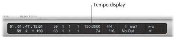
To set a constant project tempo:
■ Use the mouse as a slider or double-click, and directly type in a value, on the Tempo field.
To change the format of the tempo display:
- Open the Logic Express > Preferences > Display > General preferences tab, and choose the desired item from the Display Tempo As pop-up menu.
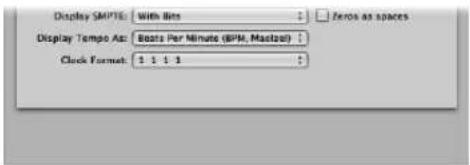
Using the Tempo Track
Tempo changes are controlled by tempo events, which are stored in a special Tempo track. This track can be displayed in the Arrange, Piano Roll, Hyper, and Score Editor windows. The Tempo track applies to the whole project. The tempo track also determines the relationship between incoming time code and the current playhead position.
To view the Tempo track, do one of the following:
- Choose View > Global Tracks (or use the corresponding key command, default: G).
- Click the disclosure triangle to the left of the Bar ruler in any of the linear editing windows.
Note: By default, the global Marker, Signature, and Tempo tracks will be visible when you use any of the methods above to open the global tracks lanes. If the Tempo track is not visible, you can configure the global track display to fit your needs. For more information, see "Showing and Hiding Individual Global Tracks" on page 77.
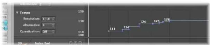
The Tempo track displays tempo changes as nodes: dots connected by lines. By default, these dots are followed by horizontal lines that continue to the next node, which is aligned with a project position (shown in the Bar ruler). At this point, a vertical line is connected to the node of the ensuing tempo change. This creates a series of hills and valleys that represent the project tempo.
Note: The tempo will be indicated numerically (in bpm) alongside each node, if the vertical height of the Tempo track is adequate.
To resize the Tempo track:
- Drag the horizontal line that separates the Tempo track lane from the editing window or the global track (Transposition, for example) above it.
Creating and Deleting Tempo Change Events
You can create tempo change events by inserting them into the Tempo track at the desired project position.
To insert a tempo change event, do one of the following:
■ Double-click at the desired position with the Pointer tool.
- Click at the desired position with the Pencil tool.
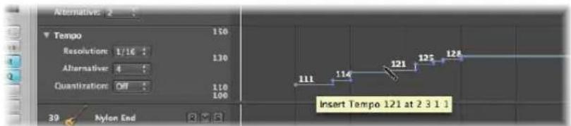
Keep an eye on the help tag when using the Pencil tool, and don't release the mouse button until the intended tempo and position are indicated. No help tag appears when the Pointer double-click method is used.
- Hold Control-Option-Command and click at the desired position in the Tempo track.
A text field opens, allowing you to type in the desired bpm value. Press Return, and a tempo event of this value will be created.
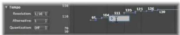
To delete a tempo change, do one of the following:
- Select it, by either clicking the node itself or the line to the right, then choose Edit > Delete (or press Backspace).
■ Double-click on the node with the Pointer Tool.
- Click on the node with the Eraser tool.
Creating Tempo Curves
To create a continuous transition between two tempi, click-hold and drag the tip of the right angle line (the corner) above or below the second node.
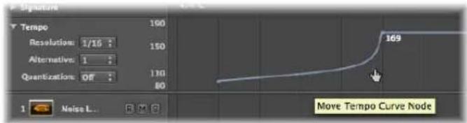
A curve or diagonal line will result (a Move Curve Node help tag is shown), which can be dragged as desired—horizontally and vertically—to alter the curve shape. You'll find that this is quite similar to drawing track automation curves with the mouse.
To make a tempo curve more, or less, precise:
- Choose the desired value from the Resolution pop-up menu in the Tempo track to define the number of tempo changes that are actually performed when using curves.
When set to 1/16, there will be four tempo changes per quarter note, 1/1 will only generate one tempo change per bar, which will result in a coarser transition. A different resolution can be defined for each node.
To delete a tempo curve:
- Click the handling node (at the tip of the right angle) with the Eraser tool, or double-click on it with the Pointer.
Moving, Altering, and Copying Tempo Changes
To move a tempo change event, grab the node (or the line to the right) and drag it left or right.
To make finer tempo change movements:
■ Hold Shift while dragging the desired node left or right.
To move the selected tempo event to the current playhead position:
■ Use the Pickup Clock Position key command.
To change the value of a tempo change event:
■ Simply drag the node (or line) up or down. A help tag will display the tempo value.
The display range (the scale shown to the left) of the tempo track is automatically adjusted when you choose a value that exceeds the current minimum or maximum value (see below).
Note: To prevent unintentional changes, nodes are restricted to either vertical or horizontal movement for each operation. Put another way, you can either change the value or position of a tempo change event, but not both at once.
To copy a tempo change event, do one of the following:
■ Hold Option, while dragging a node.
Use the standard Copy and Paste procedure (via the Edit menu or the corresponding key command). The playhead will determine the target position for the first pasted event.
To copy or move multiple tempo events:
Shift-click or rubber-band select (while pressing Control), and drag all nodes to the target position.
Note: Any tempo events at the target positions will be replaced by the moved or copied events.
Adjusting the Display Range
The display range for tempo events is, as mentioned above, adjusted automatically. Dragging a node beyond the current maximum or minimum scale boundaries will result in an automatic adjustment of the range.
To manually define the maximum and minimum ranges of the tempo display, do one of the following:
- Grab the maximum and minimum values in the tempo scale and drag them vertically.
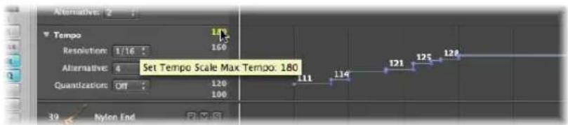
■ Double-click on either range value and type the desired numerical value into the text field.
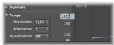
These user-defined values are displayed in yellow. If you want to return to the automatic scaling mode, use the procedure described above, and leave the text fields empty.
Switching Between Tempo Alternatives
The Alternative pop-up menu in the Tempo track allows you to switch between different tempo maps. Put another way, you can create up to nine different tempo track versions per project, and switch between them.
The original tempo track is automatically assigned to Alternative 1.
To create an alternate tempo map:
- Choose an unused number (2 through to 9), and create the desired tempo events.
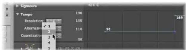
This will be a blank tempo map, that contains one tempo event at the beginning of the project.
To copy all tempo events from one tempo alternative to another:
- Hold Option, and choose the target tempo alternative from the pop-up menu.
This creates a replica tempo map, which can be adjusted slightly, allowing you to experiment with small tempo variations, while retaining a fallback map.
The Relationship Between the Tempo and Beat Mapping Track
Actions performed in the Beat Mapping track result in changes to the Tempo track. These include alterations to existing, or the creation of new, tempo change events.
Given this behavior, you should avoid making changes in the Tempo track after using Beat Mapping functions. If you do so, the timing derived from the Beat Mapping functions will be destroyed. For more information about the Beat Mapping track, see Chapter 31, "Beat Mapping Regions," on page 683.
Recording Tempo Changes
All tempo alterations made when Logic Express is in record mode are automatically stored as tempo events on the Tempo track. These events can be created with external MIDI controllers, the Environment tempo fader, or external synchronization signals. You can edit recorded tempo events in the Tempo track or one of the tempo editors, discussed later in this chapter.
To enable tempo change recording:
- Turn on the "Allow tempo change recording" checkbox in File > Project Settings > Recording.
Adjusting the Tempo to Fit Audio Regions
The Options > Tempo > Adjust Tempo using Region Length and Locators command adjusts the project tempo, by creating a tempo change event at the start point of the selected audio region. This ensures that the length of the selected audio region exactly matches the distance between the locators.
For more information on this function, see "Setting the Project Tempo to Match an Audio Region" on page 554.
Using the Tempo List
The Tempo List displays all tempo events in your project. You can open the Tempo List in the Arrange window, and as independent window.
To open the Tempo List, do one of the following:
- Click the Lists button in the Arrange Toolbar, then click the Tempo tab (or use the Toggle Tempo List key command).
- Choose Options > Tempo > Open Tempo List (or use the Open Tempo List key command).
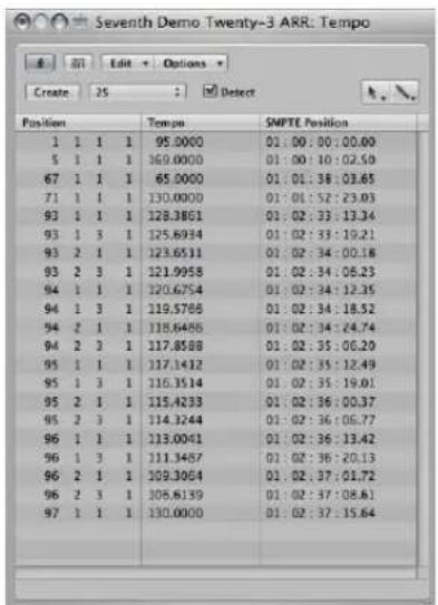
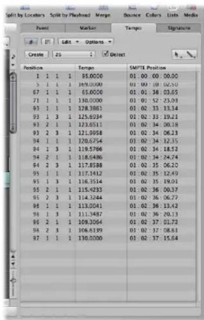
Creating and Editing Events in the Tempo List
The layout, and way you use the Tempo List, are very similar to the Event List. The following section only outlines the most important Tempo List operations. For more information on general (and identical) Event List operations, see Chapter 18, "Editing MIDI Events in the Event List," on page 459.
To create a tempo event in the Tempo List:
1 Move the playhead to the desired project position.
2 Click the Create button, or click below the bottom tempo event with the Pencil tool.
A tempo event (which uses the current project tempo value) appears. You can alter the value in the Tempo column.
To delete a tempo event in the Tempo List, do one of the following:
- Click the tempo event with the Eraser tool.
- Select the tempo event, then choose Edit > Delete (or press Backspace).
To change the position of a tempo change event:
- Use the mouse as a slider, or double-click and directly type in the desired values in the Position or SMPTE columns.
To move any selected tempo event to the current playhead position:
■ Use the Pickup Clock Position key command.
To copy tempo changes from a passage:
1 Set the locators to the passage containing the correct tempo change.
2 Choose Edit > Select Inside Locators.
3 Copy the tempo events to the Clipboard (Command-C).
4 Deselect all tempo events (by clicking the background).
5 Paste the tempo events from the Clipboard (Command-V).
6 The paste position will default to the current playhead position, but this can be changed. A position input box appears alongside the first of the pasted tempo events, allowing you to alter the bar position. If the first tempo change is not at the start of the bar in the passage, be sure to alter the bar number, and leave the beat, sub beat, and frame or tick values unaltered.
7 Press Return. The copied tempo changes will be selected, and you can undo the operation if necessary.
Using the Shortcut Menu
Many selection, editing, and other commands can be accessed by Control-clicking or right-clicking anywhere in the window. Make use of this to accelerate your workflow.
Note: Right-click functionality is dependent on the Right Mouse Button: Opens Shortcut Menu option being chosen in the Logic Express > Preferences > Global > Editing tab.
Alternative Tempo Lists
You can use up to nine different Tempo List variations per project. This is useful in projects with tempo changes, as it allows you to:
- Temporarily slow down the tempo when recording MIDI regions.
- Temporarily disable tempo changes.
- Try out different tempo variations.
To switch between the different Tempo Lists:
- Choose Options > Tempo Alternatives, and choose the desired Tempo List.
Synchronization and Video Options
The Tempo List window features a SMPTE Frame Rate menu and Detect checkbox. By default, the Detect checkbox is turned on, which means that Logic Express will automatically detect the frame rate of incoming synchronization signals.
As a general rule, this is ideal when working with external video and film playback devices.
When working with a video file stored on a connected hard disk, Logic Express will (generally) not be receiving an external synchronization signal. Even in this situation, you can leave the Detect checkbox turned on.
When Logic Express is the master synchronization device, however, you do not want it to accept incoming time code signals. In this situation, turn off the Detect checkbox, and choose a suitable rate from the Frame Rate pop-up menu.
Note: The Detect checkbox mirrors the "Auto detect format of MTC" project setting, and the Frame Rate menu mirrors the Sync project setting menu of the same name. For more information, see Chapter 35, "Synchronizing Logic Express," on page 845.
Using the Tempo Operations Window
The Tempo Operations window is used to edit existing tempo changes, and to create new ones. The window automatically displays the area you've selected for editing, and changes are displayed graphically, in real time, as the tempo curve is processed, so you can see what's happening.
To open the Tempo Operations window:
- Choose Options > Tempo > Tempo Operations from the main menu bar (or use the Open Tempo Operations key command.
■ Control-click the Sync button in the Transport bar (if visible), then choose Open Tempo Operations from the shortcut menu.
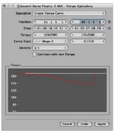
Choosing a Tempo Operation
The Operation menu provides several interesting tempo change editing functions, which also alter the sync reference. The lock symbol allows certain parameters to be fixed, preventing them from being changed.
Create Tempo Curve
The Create Tempo Curve operation lets you create numerous tempo change events with just a few parameters, and provides a smooth overall change in tempo.
To create a tempo change in the Tempo Operations window:
1 Use the Position or Time fields to define the area that the tempo change should take place across: the left field sets the curve start point and the right field, the curve end point.
2 Enter the desired start and end tempos in the Tempo line.
3 Select the desired curve type.
Three kinds of tempo curves are available from the Curve Type menu. Each of these offers a Curvature parameter (the field to the right of the Curve Type menu), which determines if the tempo should speed up or slow down, dependent on whether positive or negative curvature values are entered.
4 Adjust the Curvature parameter.
5 Alter the concentration of graphical tempo events with the Density parameter.
Values of 1/8 and finer should only be used if really necessary (with very slow or fast tempo changes, for example). Don't select a resolution higher than 1/8 or finer, just to make the curve look smoother. This results in an unnecessary amount of processing, and the creation of more tempo events than are needed.
Tip: Watch the graphic display, as you change the values: The displayed tempo curve (which is calculated from the tempo settings you've made) is shown in red.
Note: The "Continue with new Tempo" checkbox determines whether the original tempo resumes after the tempo curve ends (unchecked), or the new tempo (the last tempo change event in the curve) is maintained (checked).
6 Click Apply when you are done.
Create Constant Tempo
The Create Constant Tempo operation creates a constant tempo in any selected area. The default setting assigns an average tempo for the selected project section (based on existing tempo change events).
If you want to remove all tempo variations between two points, without changing the SMPTE time for the right-most position, just click the Apply button.
Don't forget the "Continue with new Tempo" checkbox, which retains the new tempo or returns to the initial tempo.
Scale Existing Tempo Changes
The Scale Existing Tempo operation alters existing tempo changes proportionally (scales them). This enables you to speed up an entire project section, without losing the relationships between any subsequent tempo changes within the area. Scaling is done by percentage. Positive percentage values speed up sections, and negative ones slow them down.
Stretch Existing Tempo Curve
The Stretch Existing Tempo Curve operation stretches or compresses an existing tempo curve. The Position or Time parameters are used to define the start point of the area that you want to change. You can then enter either the new end point of the tempo curve as a bar position or SMPTE value, or set a Stretch value for the curve (as a percentage).
Thin Out Existing Tempo Changes
The Position or Time fields define the start and end points of the area to be processed. Density determines the number of tempo events that will remain per bar after processing. You can select values between one tempo change event per bar (1/1) and 32 per bar (1/32).
Randomize Tempo
Use the Position or Time parameters to define the start and end points of the area to be processed. Use Randomize to determine the amount of deviation from the current tempo, in beats per minute (bpm).
Density defines how often the new tempo events will occur. You can select values between one per bar (1/1), and 32 times per bar (1/32).
Using the Tempo Interpreter
You can use the computer keyboard or incoming MIDI events to set the project tempo. Put another way, Logic Express will chase a manual synchronization signal (also known as human sync). This method of synchronization is fairly loose, in that if the manual sync impulses stop coming in, Logic Express will continue at the last tempo it received.
You use the Tap Tempo command to generate tempo timing events, by literally tapping a computer or MIDI keyboard key.
To enter manual synchronization mode, do one of the following:
- Choose Manual in the Sync Mode menu of the File > Project Settings > Synchronization > General tab.
- Turn on the "Auto enable external sync" checkbox (on by default) in the Project Settings > Synchronization > General tab.
If Logic Express "hears" a Tap Tempo command, it will automatically follow this tempo.
The parameters that control how Logic Express responds to tap tempo commands can be found in the Tempo Interpreter window.
To open the Tempo Interpreter window, do one of the following:
- Choose Options > Tempo > Tempo Interpreter (or use the Tempo Interpreter key command).
- Control-hold on the Transport's Sync button (if visible), and choose the Open Tempo Interpreter item.
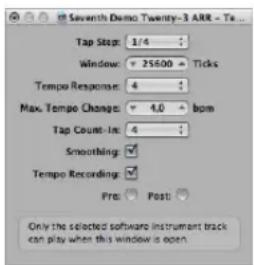
Note: Only the selected software instrument track, and all external MIDI tracks, can play when the Tempo Interpreter window is open.
Changing the Tempo Interpreter Parameters
You will find the following parameters in the Tempo Interpreter window.
Tap Step
This parameter sets the note value that Logic Express will assign to manual taps. You will achieve the best results with larger, rather than smaller, values. 1/4 note usually works well.
Window
This parameter determines the time span (or window) that tap notes can be entered (set in ticks, or 1/3840 note). Only taps made within this time window are used to determine the tempo. Any taps outside it are ignored.
- The narrower the window, the more effectively Logic Express will be able to withstand the influence (on the tempo) of any taps that fall between the note values—set with the Tap Step parameter.
- The larger the window is set, the easier it becomes to create drastic tempo changes.
- If you set the window parameter to 0, the tap window will disappear altogether, and all taps will be accepted as tempo-determining information. Logic Express will also come to a halt, if taps are not generated.
Tempo Response
This parameter sets the sensitivity to tempo changes: the larger the value, the greater the sensitivity. You should set this value to 4, for most situations. If you find that your tap timing is imprecise, but want Logic Express to play at a relatively constant tempo, reduce this value to 2 or so.
Max. Tempo Change
Use this parameter to set the maximum tempo change possible per tap (in bpm). To obtain the most regular, or even tempo curve, follow this rule: set the smallest possible value (in other words, only as large as necessary).
Tap Count-In
This sets the number of taps used as a count-in. Logic Express will start following the tempo on the first tap after the count-in taps.
Smoothing
Switching on this function smooths out jumps in tempo, resulting from incoming taps (which could prove useful when using Logic Express live). You should switch it off, if you want Logic Express to follow your taps precisely and quickly.
Tempo Recording
The Tempo Recording function creates a tempo list that follows your taps, when in record mode. This Option should normally be switched off.
Pre and Post
These are the ways your tap signals are displayed:
• Pre: Displays every incoming tap.
- Post: Displays every accepted tap that occurs within the time window (as defined by the Window parameter), or close to, or on, a tap step.
The Pre/Post tap signals flash yellow if the taps are within the allowed range, and red if they are out of range.
Using the Tempo Fader
You can create a real time tempo fader in the Environment window by choosing New > Fader > Specials > Tempo Control. This fader can control the project tempo (using Meta event #100). There is no need to connect this fader to anything, unless you want to record its output.
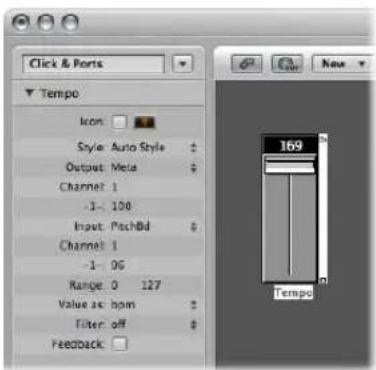
A tempo fader has a range of possible values from 50 to 177 bpm. External MIDI data can be used to control it, with an input value of 0 resulting in a tempo of 50, and an input value of 127, resulting in a tempo of 177.
If you place a tempo fader between the Physical Input and Sequencer Input objects in the Environment, you will be able to:
- Record tempo changes.
• Control the tempo with any desired MIDI event types.
This way, new Tempo track data can be recorded intelligently. The original tempo data will only be erased in areas that actually contain tempo changes.
If a tempo fader is moved during playback or recording, all data defined in the Tempo List is switched off, until Logic Express is stopped.
Movements of a tempo fader are ignored when external SMPTE sync is active. A tempo fader can therefore be used to deactivate the sync reference during playback or recording, if you wish.
Note: The tempo fader's Parameter box displays pitch bend events as the Input definition (by default). This allows control of the project tempo with your keyboard's pitch bend wheel.
Beat Mapping Regions
31
You will generally play to a metronome click when recording in Logic Express. There are, however, instances where you'll want to record without a click, playing rubato, or at least not at a strict tempo throughout.
Another situation may be where you have an existing audio recording—that wasn't recorded to a metronome click, and therefore contains slight tempo variations—that you want to add additional tracks to. In this scenario, the Beat Mapping track helps to make the display of these free recordings rhythmically meaningful. It does this by defining the bar positions of existing musical events, without changing their absolute time position, thereby preserving the audible result with its original timing.
Musical events, in this context, refer to:
• MIDI notes in MIDI regions.
• Transients in audio regions—which correspond to the beginning of strongly accented notes.
Beat mapping involves two steps: First, you graphically connect musical events to the desired bar positions in the Beat Mapping track—by drawing lines between them with the mouse (a more detailed description of this procedure follows). Logic Express will automatically insert a tempo change event for each of these bar position locations. This results in the note/event being played at its previous absolute time position, despite its altered bar position. A beat mapped Logic Express project will contain the same tempo variations as the original recording.
Presuming accurate beat mapping, everything will be in time with the metronome tempo, affording you a number of advantages for further project development:
- The metronome click can be used when recording additional regions.
- Quantize functions can be applied to newly recorded regions.
-
Loops (both MIDI and Apple Loops) will automatically adjust to the tempo when used in the arrangement.
-
MIDI regions recorded without a click will be displayed in a musically meaningful way in the Score Editor.
• Additional MIDI regions can also be created via the Step Input function, without sounding too stiff. This looser feel is due to the parts being played back with all of the tempo changes created by the beat mapping process.
By default, the global Marker, Signature, and Tempo tracks are visible when you enable the display of global tracks. If the Beat Mapping track is not displayed, choose View > Configure Global Tracks, and enable the Beat Mapping checkbox. For detailed instructions, see "Showing and Hiding Individual Global Tracks" on page 77.
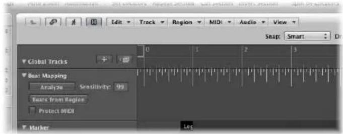
Beat Mapping With MIDI Regions
The following section takes a look at the beat mapping procedure in the Arrange window. Beat mapping is also possible in the Piano Roll, Score, and Hyper Editor windows, where you have the added advantage of directly seeing the corresponding notes. To use (or test) beat mapping, you'll need at least one MIDI region that doesn't fit the current tempo. You can simply record one without a metronome click, if none are available.
In the upper part of the Beat Mapping track, you can see a ruler which contains a graphical representation of musical bars, beats, and sub-divisions. These reflect the division value set in the Transport bar (and are also dependent on the current zoom level).
To allocate note events to particular bar positions:
1 Select the regions that you want to use for beat mapping. Once selected, short horizontal lines will appear at the lower edge of the Beat Mapping track. These represent the notes in the selected regions.
2 Start from the left. At the first bar position you want to assign to a MIDI note: Click-hold at the exact position in the Bar ruler.
A yellow vertical line will appear.
3 With the mouse button still held, drag the cursor down towards the line that represents the chosen note.
A second, slightly darker, yellow line—which is still connected to the same position in the Bar ruler—will appear. This line will follow the movement of the mouse cursor into the lower part of the track, forming an angle. Once this line is connected to the desired note, release the mouse button.
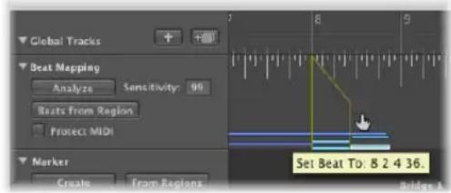
Logic Express will automatically calculate, and insert, a tempo change—which can be seen in the Tempo track. This ensures that the allocated note (and all other notes) will be played back at the same absolute time position as before, despite their altered bar positions.
4 Move from left to right, adjusting further events along the time axis, to obtain the best beat mapping results.
If you make a mistake, you can erase any beat allocation by: double-clicking on it, using the Eraser tool, or by selecting it and pressing Backspace. Take care when using Backspace, to avoid the accidental deletion of other currently selected events or regions.
To erase all beat allocations, click anywhere in the track header of the Beat Mapping track (except on the buttons and menus). This selects all data in the track, allowing you to press Backspace to delete all events.
Note: If you want to draw a connecting line from a bar position to a particular position in the original recording—where no note exists—hold Control while drawing the connecting line with the mouse. This will allow the line to snap to any sub-division.
Beat Mapping With Audio Regions
This works in a similar fashion to that described above for MIDI regions. The main difference is that Logic Express must first analyze audio regions in order to find rhythmically prominent spots, which can subsequently be linked to a bar position. Logic Express searches for transients when analyzing audio regions. Transients are positions where the audio recording becomes a lot louder—over a very short time span (a signal spike, in other words). This is typical of drum recordings, but the analysis of other instruments or complete mixes (depending on the musical context), can also produce usable results.
To detect transients in an audio region:
- Select the desired audio region, and click the Analyze button in the track header of the Beat Mapping track.
Following analysis, the transients are displayed as small vertical lines at the bottom of the Beat Mapping track. The remaining steps of the beat mapping procedure are as described above for MIDI regions.
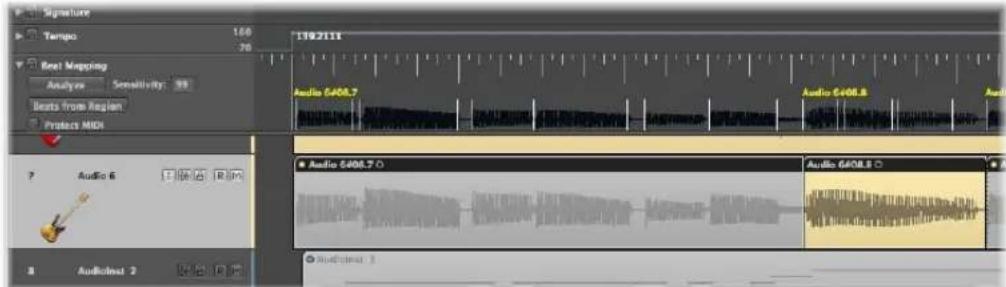
It is also possible to analyze several selected audio regions at once. An alternative method for audio region analysis is to drag them directly onto the Beat Mapping track.
Improving Beat Mapping Accuracy
The Detection Sensitivity value field in the track header allows you to retrigger the analysis procedure if the results are not as expected. A higher Detection Sensitivity setting will detect more transients, which can be useful if dealing with less distinct accents in the music (such as soft drums in a loud mix). On the other hand, a higher Detection Sensitivity setting might lead to the detection, and display, of transients that have no meaning for the rhythmic structure of a region. In general, you should begin with a lower Detection Sensitivity setting, and only switch to a higher setting if obvious rhythmic elements in the music aren't recognized correctly.
Note: The detection ability is independent of the overall volume of an audio region. In other words, the results will be the same if you normalize a region.
On occasion, your recordings may contain (MIDI note) events that fall onto musically useful positions, and should remain there when beat mapping is used for audio recordings. Such situations are catered for by the inclusion of the Protect MIDI option, found in the track header of the Beat Mapping track. Simply activate this option to keep existing MIDI events at their current positions when beat mapping.
Beats From Region
The Beats from Region button in the Beat Mapping track header activates an automatic Beat Mapping method that uses a self-recorded metronome region.
To use the automatic Beat Mapping feature:
1 Create, or use an existing instrument track.
2 Insert the KlopfGeist instrument (or perhaps the EXS24 mkll with an appropriate sound, such as a closed hi-hat or cross-stick).
3 Record a one note per beat metronome click that fits the music in the existing regions. If some of the metronome region notes are not in time with the original recording, you can edit their positions in any of the MIDI editors—in order to get them in sync with the music.
4 Select the metronome region, and click the Beats from Region button.
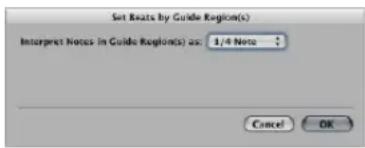
5 Choose the most appropriate note value in the Set Beats by Guide Region(s) dialog (default: 1/4 Note), and click OK to perform the beat mapping operation.
Logic Express will map all beats to the notes in this region, and insert tempo changes to preserve the original timing, starting with the first beat in bar one. Although the audible result doesn't change, the music will be displayed correctly—with regard to bar positions.
Beat Mapping to Scene Markers
If the global Video track is visible, a QuickTime movie is loaded, and the Detect Cuts function (in the Video track) is used, the detected scene markers appear as available mapping positions (vertical lines) at the bottom of the Beat Mapping track. You can easily define a scene cut position as the first downbeat of a bar—by allocating it to the bar position, as described above.
Beat Mapping to Markers
If the Marker track is visible, you can use the desired marker as a mapping position (vertical line at the bottom of the Beat Mapping track) by clicking on it. Shift-click to assign multiple markers as beat mapping positions. Once done, you can hide the Marker track.
Transposition With the Chord and Transposition Tracks
32
You can use the Transposition and Chord tracks to alter the playback transposition of MIDI events and Apple Loops over time.
The Transposition track contains nodes that are connected by vertical and horizontal lines. Each node represents a global transposition event, which determines the global transposition value—until the playhead reaches the next transposition event during playback.
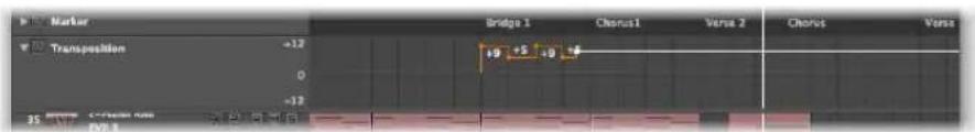
Transposition events are closely linked to the chord root notes in the Chord track: If you create or alter a transposition event, the amount of pitch shift will immediately be reflected by the chord root notes in the Chord track—and vice versa.
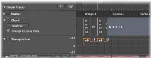
The zero position of the Transposition and Chord track is determined by the current key signature in the Signature track. If the key signature changes during a project, the zero position of the Transposition and Chord tracks change accordingly.
How MIDI Events and Apple Loops Are Transposed
Transposition events (and their chord counterparts) pitch-shift MIDI events and Apple Loops.
MIDI Events
Transposition events change the actual MIDI events themselves. As an example: If you create a MIDI region that contains a C3 note event, copy the MIDI region, and then create a transposition event of +2 at the start of the copied MIDI region, the transposition event changes the note event to a D3.
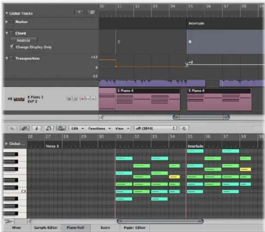
Despite this data change to events, the Transposition track works non-destructively, as you can change the transposition of MIDI events multiple times. Imagine that you copied the D3 of the example above to a position where the Transposition track is set to +2; the MIDI event will be played back as D3. But if the Transposition track is set to a different playback interval at the target position, the MIDI event will be pitch-shifted to the new playback transposition.
Transposition events only affect MIDI events already in your project. They do not affect MIDI events that you create or record after editing the transposition events.
MIDI events will only be transposed if the No Transpose checkbox is turned off in the respective Track Parameter boxes.
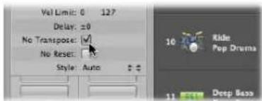
Apple Loops
Apple Loops can contain information about the key they are in, and can be transposed automatically. Regular audio regions (audio regions that are not Apple Loops) are not affected. Nor will Apple Loops that do not have a key definition (drum loops, for example). For full details, see the Chord track description in the Apple Loops chapter, on page 645.
Creating and Editing Transposition and Chord Events
Creating and editing of transposition events works similar to standard MIDI events.
To create a transposition event in the Transposition track, do one of the following:
- Click with the Pencil tool at the desired position in the Transposition track.
- Hold Control-Option-Command, click the desired position in the Transposition track, enter the desired transposition value in the text field, then press Return.
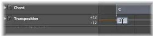
A transposition event of the typed value will be created at the clicked position.
To change the transposition value of a transposition event, select it by clicking it, then drag it up or down.
To create a chord event in the Chord track:
- Click with the Pencil tool at the desired position in the Chord track, then define in chord symbol in the Define Chord dialog.
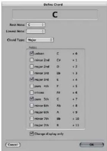
If you want to edit a chord event, just double-click on it. The Define Chord dialog will open, allowing free changes to the chord symbol properties.
To select a chord or transposition event:
- Click the chord or transposition event with the Pointer tool.
Use Shift-click or the rubberband selection method to select multiple events.
To move a chord or transposition event along the timeline:
■ Select the event, then drag it to the left or right.
Watch the help tag during these procedures to see the exact transposition value and bar position of that particular event.
To delete a transposition or chord event, do one of the following:
■ Select it by clicking it with the Pointer, then press Backspace.
- Click the event with the Eraser tool.
Transposition events can be copied using the standard Copy and Paste procedure or by dragging them with the mouse while holding Option.
You can also copy or move multiple transposition events simultaneously, which can be useful for repeated project sections
Analyzing MIDI Regions
You can use the Analyze button in the Chord track to analyze the chords in a MIDI region. Select the desired MIDI region (preferably one containing complete chords) and click the Analyze button in the Chord track header. The MIDI region will be analyzed, with the resulting chords appearing in the Chord track. This also works for several subsequent regions. Alternatively, you can drag the desired regions onto the Chord track.
Note: Keep in mind that the chords in the Chord track are events, which affect the playback transposition of MIDI events and Apple Loops. Make sure that you only use the Chord track if you're serious; once you use it, it always affects your composition. As an example: When you analyze your project, then copy a region without copying the chord track events. You should not use it if you only want to display the chords in your project; in which case, you should use the Marker track or the Score Editor text chord symbols.
Working in the Change Display Only Mode
You might come across situations where there are incorrect or missing chords in the Chord track. As an example: You record a MIDI region, select it, and use the Chord track's Analyze button. Normally this should work fine, as the analysis algorithm is rather intelligent and knows all about harmonics. If the result of the analysis process is not as expected—and doesn't comply with your recording—Logic Express provides you with an easy solution: The Chord track's Change Display Only mode. If you activate this mode by clicking the Change Display Only option in the Chord track, you will be able to adjust the chords to match what you're actually hearing (the transposition events in the Transposition track are adapted accordingly). All changes applied to chords in the Chord track (while the Change Display Only mode is active) will have no result on the playback of the corresponding MIDI regions—these changes will only adapt the chords displayed in the Chord track to match the chords played in the MIDI region.
The Change Display Only mode does not work with Apple Loops used on audio tracks. For further information, see the Chord track description in the Apple Loops chapter on page 645.
Inserting Chord Symbols in the Score
The chord symbols displayed in the Chord track can be inserted into the Score Editor (and printed):
To insert chords from the Chord track into the Score Editor:
- Select the staff that you would like to use for the chord symbols in the Score Editor, then choose Functions > Insert Chords From Global Chord Track.
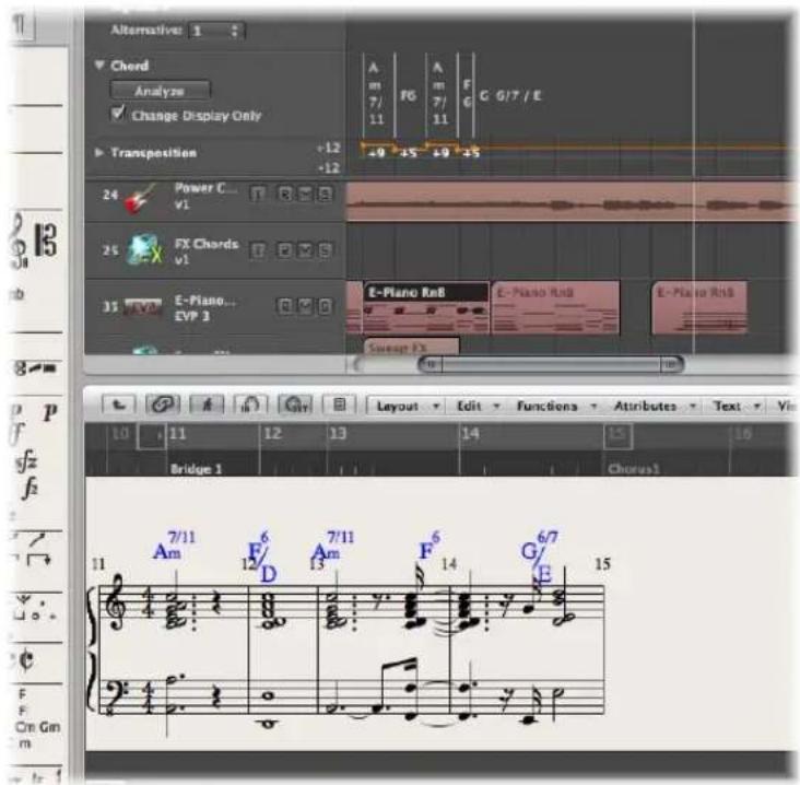
Inserted chord symbols are displayed in blue (printout will be black), and can only be moved within the boundaries of the chord on the Chord track. Double-clicking such a chord will launch the Define Chord dialog of the Chord track.
Working With Notation
33
The Score Editor allows you to view and edit MIDI regions as traditional music notation.
This chapter covers the tools and features available for score and lyric entry, editing, layout, and printing. Following a general Score Editor overview, you'll learn how to:
- Input notes, musical symbols, and text in the score.
- Use the extensive display settings to transcribe MIDI recordings.
- Edit notes and musical symbols in your score.
- Lay out and print your score.
- Customize the Score Editor display.
This chapter will not teach you music theory, nor how to read or write music notation. Its purpose is to introduce you to the way Logic Express allows you to create, edit, lay out, and print music—in notation form.
Learning About the Score Editor
The Score Editor displays MIDI regions as staffs, played by track instruments.
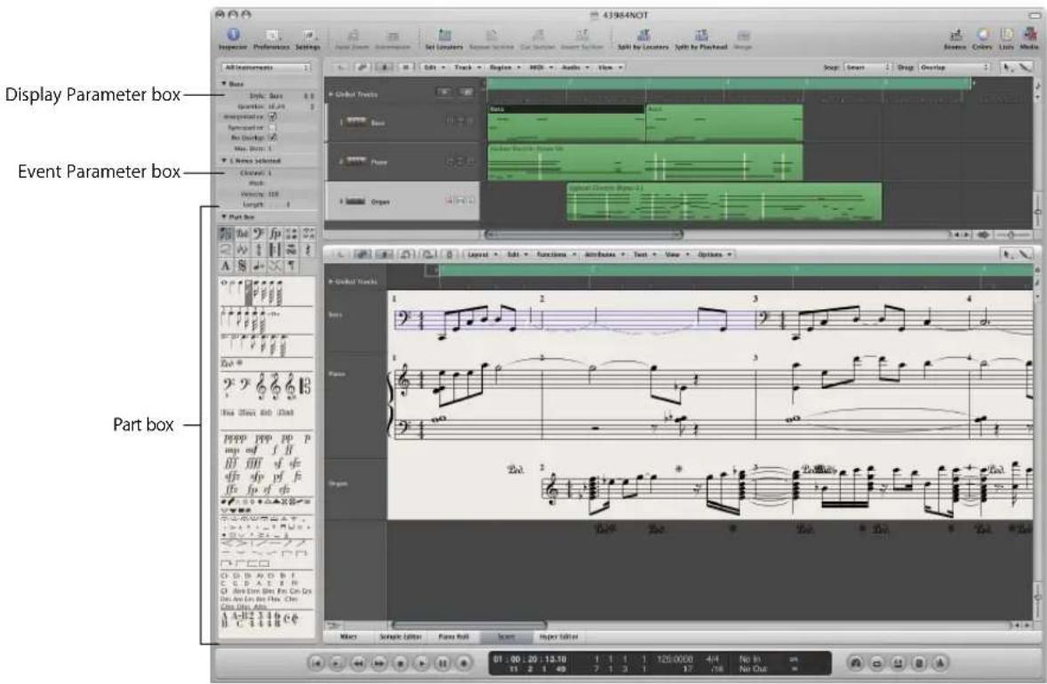
Each staff or (Arrange area) track can contain an unlimited number of MIDI regions. If the MIDI regions on one track directly follow one another in the Arrange area (with no gaps between them), they are displayed as one continuous staff in the score—unless you have limited the view to a single MIDI region, by engaging Content Link mode.
Selected MIDI regions are displayed with blue staff lines, unless this option is deactivated in the Score preferences (see "Score Preferences" on page 832). This makes it easy to identify the currently selected part.
A High Level Workflow Example
This section is designed to provide an overview of how you would approach the creation of a musical score in Logic Express.
Step 1: Getting Notes into the Score
There are basically three ways you can do this:
• Real time recording from your MIDI keyboard (see "Recording MIDI" on page 396).
- Step recording, using either your MIDI keyboard or the Caps Lock keyboard (see "MIDI Step Input Recording" on page 402).
- Manual entry with the computer keyboard or mouse (discussed later in this chapter).
As mentioned earlier, the Score Editor displays the contents of MIDI regions, which act as containers for note (and other) events. As such, you need to create, and select, a MIDI region in the Arrange area if you'd like to work in the Score Editor.
- Click the Score tab at the bottom of the Arrange window to view the Score Editor area, or choose Window > Score (default key command assignment: Command-3) to open a Score Editor window. The currently selected track or region will be displayed as a staff.
- Double-click on the background of the Score Editor (with the Pointer tool) if you would like to see the regions of all MIDI tracks (software and external MIDI) as staffs.
Step 2: Using the Display Settings to Create Readable Notation
Logic Express interprets MIDI regions for the score display, using a variety of user-defined methods.
Note events are obviously represented as crotchets, quavers, and so on. Spaces between notes are represented as rests. Sustain pedal data can also be represented in your score.
Your goal should be to retain the feel of real time recordings (if this is how you added note data to Logic Express), while still rendering a score that is readable by other musicians.
If you like the sound of playback, but not the way the score looks, you can usually obtain the desired results by changing a few settings in the Display Parameter box (see "Transcribing MIDI Recordings" on page 761), and the overall Score project settings.
- Display Parameter box: The parameters of the Display Parameter box mainly affect the rhythmic display of selected MIDI regions. They only apply to the score display, and do not affect the playback of MIDI regions. They can be different for each region. Some of these (region-based) parameters can be overridden for individual notes, by using note attributes.
- Project settings: You can set general display options that affect the whole project in the Score project settings window (see "Project Settings for Score Display" on page 811). These include spacing between notes, page margins, line thickness, display of instrument names, bar and page numbers, and a lot more.
Important: Score display parameters have absolutely no effect on MIDI playback, just on the way MIDI data is shown in the Score Editor. This separate notation display system allows you to adjust the look of the notation, without changing the original MIDI region data (and therefore, the performance).
You can further control the display by selecting or creating staff styles, text styles, and score sets, that best fit your music.
- Staff styles exist for most common single and multi-staff types, and can be chosen from the Display Parameter box's Style menu. These include: Piano, Guitar, Horn in Eb, Organ, and even Drum styles. Simply choose the one that best represents the instrument part as notation. If none of the existing styles are appropriate, you can easily create your own (see "Working With Staff Styles" on page 775).
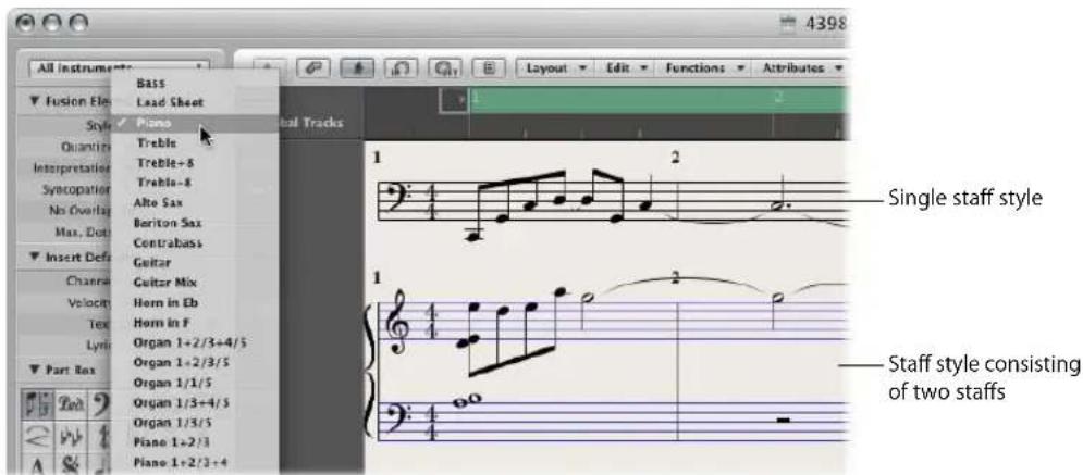
- Score sets allow you to determine which instruments are displayed (and printed) in a score. You can include as many (or few) of the existing track instruments into a score set as you wish (see "Using Score Sets to Create Scores and Parts" on page 796). This makes it easy to create separate sheet music for the violinists, or french horn players, for example.
- Text styles are used to control several different text elements of your score, such as: the title, lyrics, copyright information, instrument names, and so on. Each of these text elements can be assigned a font style, size, and more within the overall text style (see "Working With Text" on page 742).
Step 3: Editing Note Events
Even with all of the display options discussed above, you may need to adjust the appearance of some notes. This is done with the functions in the Note Attributes menu. These commands allow you to adjust individual note events, allowing enharmonic shifts, accidentals, ties, beaming, and much more.
This facility can also be used on multiple selected notes, which is useful on those rare occasions when the display settings don't deliver the desired results.
Step 4: Inputting Events, Symbols, and Text
Few scores consist solely of note (and rest) events.
The Part box contains a number of symbols (pedal markings, slurs, and so on) that can be inserted into the score by dragging them into position with the mouse. The Part box also contains all types of note events, clefs, bar line markers, and more. Again, these can easily be added by drag and dropping (see "Working With the Part Box" on page 708).
Rests are usually displayed automatically in Logic Express, and don't need to be manually inserted—but can be, if needed—from the Part box (see "Creating and Inserting Rests" on page 735).
The entry of lyrics, title, and other text elements is performed from the Part box, or with the Text tool (see "Working With Text" on page 742).
Step 5: Editing the Whole Score
Once you've recorded or inserted all (or most) of the notes and symbols into your score, and edited individual elements, the next step is to polish the score's layout.
This would typically include use of tools to reposition staffs, and changing the Score project settings—to adjust the number of bars per line, set page margins, and more. All project layout options are discussed in “Project Settings for Score Display” on page 811.
Layout work is done in Page view, which displays as many facing pages as possible (dependent on the size of the Score Editor window and current zoom level).
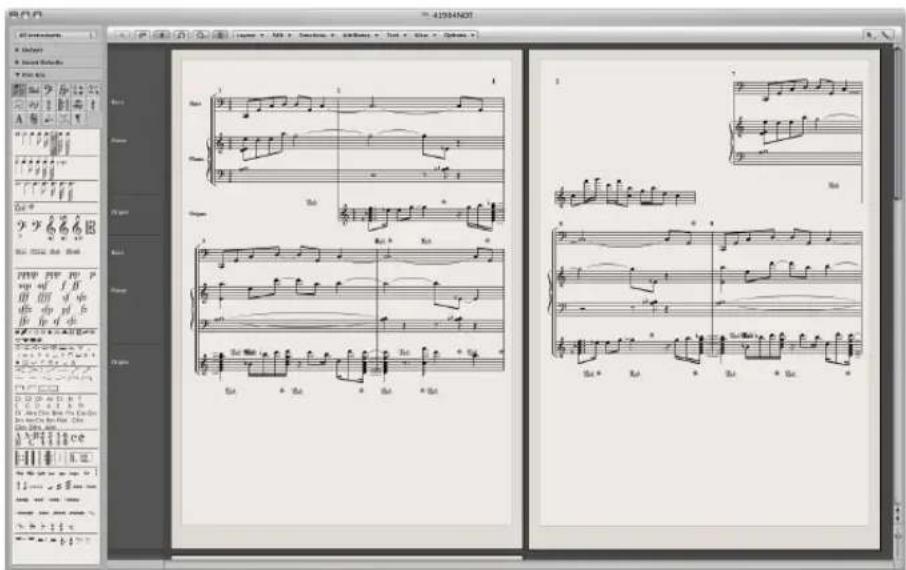
To switch between the default score display (called the linear view) and Page view: Click the Page view button (to the left of the Layout menu button).
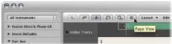
Tip: You should use the linear view for editing, as screen redraws are much faster, especially on slower computers. Page view should only be used for layout work, in preparation for printing. Further details on Page view can be found in "Customizing the Score Editor's Appearance" on page 810.
Step 6: Printing a Score
The last step is printing your score. The printed result always corresponds to what you see in the Score Editor window (Page view must be activated).
To print the score:
1 Choose File > Print (or use the corresponding key command, default: Command-P). This opens the Print dialog.
2 Choose the desired printing options (including printing to PDF), and click the Print button.
Before printing, you may want to activate Print view, which shows the page margins onscreen.
To activate Print view:
- Choose View > Page Display Options > Print View (only accessible when Page view is active).
More information can be found in "Printing the Score" on page 804.
Entering Notes and Symbols in the Score Editor
You can add notes and symbols in the following ways:
• Real time MIDI recordings (notes and sustain pedal markings only).
- MIDI step input (notes only). This can be done with the computer, or a MIDI keyboard.
- Dragging notes or symbols from the Part box to the staff.
- Fast input of symbols by assignment to selected notes with key commands. These are available for some symbols which are attached to notes (accents, jazz symbols, and so on), and slurs or crescendi. Information on key commands is shown throughout the chapter, where applicable.
- Hyper Draw (see "Using Hyper Draw in the Score Editor" on page 707) allows you to insert and edit MIDI events that aren't normally displayed in the Score Editor, such as continuous controller data (volume, pitch bend, and so on).
The display of input notes (and symbols) depends on the Score Editor's display settings, especially those in the Display Parameter box (see "Transcribing MIDI Recordings" on page 761), and the note attributes (see "Using Note Attributes to Change Individual Notes" on page 769).
MIDI playback is also influenced by the settings in the Region Parameter box and Track Parameter box. Settings in the Environment may also affect MIDI playback, if configured to do so.
Real Time MIDI Recording
Although real time MIDI recordings are usually made in the Arrange area, you can also start recording directly from the Score Editor. You must first select the destination track in the Arrange area's track list. This can be done directly from the Score Editor, by clicking on a staff associated with the desired track. If no MIDI regions exist on the track, you will need to switch to the Arrange area for recording, because the track won't be displayed in the score (the Score Editor only shows regions and folders). More information about MIDI recording can be found in "Recording MIDI" on page 396.
Step Input
Step input in the Score Editor works in the same way as other editor windows (see "MIDI Step Input Recording" on page 402).
The Score Editor (and Piano Roll Editor), however, allows the content of several regions to be displayed, and edited, at once. This results in some differences regarding step input:
- The MIDI region that you want to insert notes into must be selected (click on the staff). If no staff is visible, you must first create an empty MIDI region in the Arrange area.
- Simultaneous step input into several regions is not possible. If more than one MIDI region is selected, the notes will be only be inserted into one of them.
- If several MIDI regions follow one another on the same arrange track (even those with gaps in-between them), you can step input notes from one MIDI region to the next. As soon as the playhead reaches the beginning of the next MIDI region, Logic Express will automatically insert the notes into it.
Preparing for step input:
1 Make the following adjustments to the display settings for the selected MIDI region:
- Interpretation should be turned off (see "Interpretation" on page 766).
- The Display Quantize setting should be set to the smallest note value that you intend to insert (see "Quantize" on page 763).
2 Set the first playhead insert position by Option-clicking the staff at the desired point. The selected position is displayed in the help tag while the mouse button is pressed.
This function is especially helpful in Page view, where no Bar ruler is displayed.
Note: You can only set the playhead position when the sequencer is stopped.
Mouse Input (Using the Part Box)
A staff must exist before notes, symbols, and text elements (called objects in the following sections) can be inserted. Each staff (including empty staffs) represents one or more regions.
To input notes or symbols with the mouse:
1 Select an object in the Part box (see "Selecting Part Box Objects" on page 709).
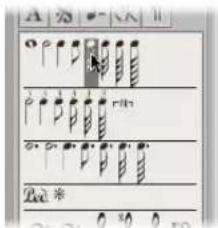
2 Do one of the following:
- Drag it to the desired staff position, and release the mouse button.
- Select the Pencil tool in the Toolbox and click at the desired staff position. If you click-hold the mouse button, you will insert the previously selected symbol.
As a positioning aid, you will see a help tag while the mouse button is held. Drag until the desired position is shown in the help tag, and release the mouse button. The help tag is especially important for positioning when working at smaller zoom levels.
When working in full score view (when more than one MIDI region is displayed), and inserting objects between the staffs (such as dynamic symbols), you should make sure that these symbols have been inserted into the desired MIDI region. The target MIDI region is automatically selected (blue staff lines) once the object has been inserted. You can also see the name of the selected region in the top line of the Display Parameter box.
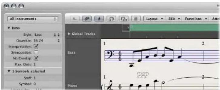
Tip: It's generally better to change to single staff display (linear view) when inserting objects that are positioned between staffs—especially lyrics.
Although it doesn't matter which MIDI region (staff) an object belongs to in full score mode (as they stay where they are placed), such objects can be displayed with the wrong instrument, when single instrument parts are later displayed and printed.
To switch to single region display:
■ Double-click the desired MIDI region (staff).
To switch back to the full score display:
■ Double-click in the empty space below or above the staff.
This displays the full score, including all MIDI regions in the project.
For full details on all Part box objects and features, see "Working With the Part Box" on page 708.
MIDI Channel and Velocity of Inserted Objects
The MIDI channel, and velocity, of objects inserted with the mouse are determined by the Insert Defaults settings in the Event Parameter box. These are visible (and can be edited), when no object is selected.
To display the Insert Defaults settings:
- Click anywhere on the background of the working area.
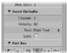
When inserting events into a staff which uses a polyphonic staff style (see "Adding Staffs to a Staff Style" on page 781), only MIDI channels that correspond to those of the voices can be used.
Many symbols display a MIDI channel in the Event List. For most objects, the MIDI channel determines the staff (theoretically, up to 16) that the symbol belongs to, in polyphonic staff styles.
Note: If this parameter is set to a value that exceeds the number of staffs in the staff style, the symbol will disappear.
Insert Quantization
To make positioning of notes and symbols easier, objects can only be inserted at certain bar positions:
- There is an invisible note positioning grid. Imagine the whole bar—beginning at beat one—is filled with notes of the chosen value. As an example: In an empty 4/4 measure, half notes can only be inserted on beats one and three, eighth note triplets only on the first, second, or third eighth note triplet of every beat.
- All binary and dotted values can be inserted at any position of an automatically displayed rest. This means that if there is an eighth note on (count) one, you can insert a quarter or a dotted quarter note at the second eighth's position. In this situation, Interpretation must be disabled in the Display Parameter box, to allow the display of the eighth note rest on the "and" of beat one (see "Interpretation" on page 766). The Syncopation setting determines how the inserted note is displayed, in this example.
- Symbols (except those directly attached to notes) can be inserted at any Quantization parameter grid position. For hybrid quantization values (such as 8,12), the insert quantization is determined by the binary value (1/8 in this example).
Simultaneous Input of Objects into Several Regions
Press Shift to insert an object from the Part box into all currently selected regions—at the same position. The help tag shows Insert Multi while you're doing this. This technique allows you to insert notes, symbols, and even text elements, into several regions at once.
You may make the multiple MIDI region selection in either the Arrange area or the Score Editor. Shift-click all desired regions or staffs, or use the rubber band selection method.
Following selection, the top line of the Display Parameter box will indicate the number of staffs (regions) that have been chosen.
Note: Key changes, signature changes, and global signs are automatically inserted into all staffs of the project, and can not be inserted into individual, selected staffs.
Using Hyper Draw in the Score Editor
You can directly create and edit MIDI controller information in the Score Editor. These types of edits are made easier when you can see the notes that will be affected.
To view and create controller events:
1 Open a Hyper Draw display in the Score Editor by doing one of the following:
- Choose the desired View > Hyper Draw command.
- Click the Hyper Draw button at the lower-left corner of the Score Editor, then choose the desired MIDI controller by clicking the arrow button to the left.
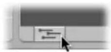
The selected controller type (volume, for example) is shown in a gray field below the Score Editor area. An event value scale is displayed in the instrument name column if View > Instrument Names is activated.
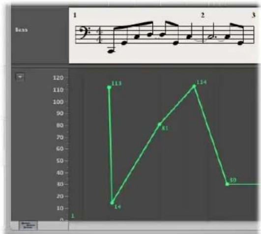
line
| Time | Value | |------|-------| | 1 | 113 | | 2 | 14 | | 3 | 81 | | 4 | 114 | | 5 | 39 |2 Click at different points in the gray area to create Hyper Draw nodes. A connecting line is automatically created between the nodes.
To resize the Hyper Draw area:
- Grab, and vertically move the dividing line that separates it from the Score Editor area.
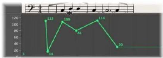
line
| Point | Value | |---|---| | 1 | 1 | | 2 | 113 | | 3 | 16 | | 4 | 109 | | 5 | 81 | | 6 | 114 | | 7 | 30 |For more information see "Using Hyper Draw" on page 620.
Note: Hyper Draw can only be activated in linear score view, and when a single MIDI region is displayed. If you switch to another mode (Page view, or full score), the Hyper Draw area disappears. The view settings are stored, however, so when you return to single MIDI region and linear view, the previous Hyper Draw setting is recalled.
Working With the Part Box
The objects available in the Part box (notes, symbols, text objects) are organized into groups. The top section contains small squares, with each representing a group. You can view this as the group menu, if you like. All groups (with all available symbols) are shown in a panel below.
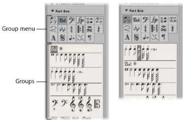
To change the arrangement of groups:
- Click on one of the squares in the group menu.
The corresponding group moves to the top of the panel, allowing easy access to its symbols.
Note: Any symbol can be selected and inserted from any group panel, at any time. The group rearrangement function simply makes it easier to work with the Part box, especially on smaller screens, or when using small Score Editor windows.
To lock Part box group positions:
- Choose View > Partbox > Lock Group Positions.
Choose the command a second time to unlock group positions.
To show only the symbols of the currently selected group in the Part box:
■ Disable the View > Part box > Show All Groups setting.
Selecting Part Box Objects
You can select any Part box object (a note, slur, clef, or whatever) by simply clicking on it. If a particular object group isn't visible in the Part box, click on the corresponding square in the group menu to move the desired object group to the top of the panel.
To select an object directly from the group menu:
- Click-hold on one of the squares that represent the Part box groups, and choose the desired object from the shortcut menu that appears.
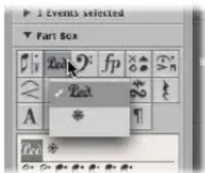
To open a small Part box group window:
■ Double-click on one of the group menu squares.
This opens a small floating window that contains all objects in the group. This palette window can be freely moved. Objects can be dragged directly from palette windows into any position in the score. You can simultaneously open as many palette windows as needed.
Note: Unlike the regular Part box, the selected object is not highlighted in the palette windows.
The palettes can have different shapes, depending on the modifier pressed while opening a floating palette with a double-click:
- Normal (Control)
- Vertical (Option)
• Horizontal (Command)
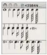
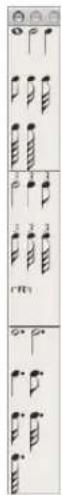
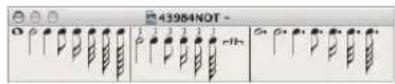
The default shape of palette windows (opened with a simple double-click) can be predefined in the Logic Express > Preferences > Score > Floating Palette View pop-up menu.
Selecting Part Box Objects With Key Commands
The following unassigned key commands select the corresponding note values in the Part box. These can then be quickly inserted with the Pencil tool:
- Partbox: 1/1 Note
- Partbox: 1/2 Note
- Partbox: 1/4 Note
- Partbox: 1/8 Note
- Partbox: 1/16 Note
- Partbox: 1/32 Note
If you execute any of these key commands more than once, the following applies:
- Twice in succession, the corresponding triplet value is selected.
- Three times selects the dotted value.
- Four times returns to the original value.
Further key commands can also change the selection inside the Part box:
- Next Partbox Symbol and Previous Partbox Symbol: The Next Partbox Symbol key command selects the symbol to the right of the selected object. The Previous Partbox Symbol key command selects the object to the left. When the last object in a group is reached, selection cycles back to the first object in the group.
- Next Partbox Group and Previous Partbox Group: The Next Partbox Group key command selects the object group below the current (selected) one. Previous Partbox Group moves one group up. The most recently selected object within each group is retained when switching between groups.
Note: As the group display can be reordered, the current display order of groups determines the previous and next group.
Learning About Part Box Groups
The following section provides a basic overview of the individual part box groups. Detailed information on note and other object editing (as applicable) is found in "Editing Notes and Symbols: Basic Operations" on page 721.
Notes
The group menu square that represents notes, in the top section of the Part box, is divided into three parts: notes, dotted notes, and triplet notes. These correspond to three note object groups.

To move the note, dotted note, or triplet note group to the top of the group panel:
- Click on the corresponding symbol (note, dot, or 3) within the note square.
Inserting any of these symbols creates a MIDI note event, of the exact note length value. For display purposes, however, all of these MIDI notes are interpreted by Logic Express as if they were recorded in real time.
Adjust the Display Parameter box settings to correctly display inserted notes. See the Display Parameter box section in "Transcribing MIDI Recordings" on page 761.
Sustain Pedal Symbols
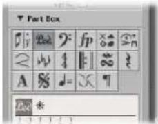
These two symbols are the only score symbols—apart from notes—that directly represent MIDI events (MIDI controller #64, sustain pedal on and off), and thus affect MIDI playback. Logic Express intelligently inserts the on or off version of the symbol, depending on the status of the type that preceded it (a sustain off always follows a sustain on, and vice versa).
Clefs
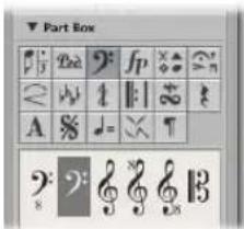
The clefs in the Part box are generally intended for clef changes in the middle of a part, for a short section of the music. An example would be cello or bassoon parts, when the part changes to a higher register. Inserted clefs change the score display, starting at the precise insert position (which can even be in the middle of a bar).
Note: You shouldn't use the Part box clefs to change the clef of a whole MIDI region. In this situation, choose an appropriate staff style (see "Working With Staff Styles" on page 775) for the region.
Dynamic Symbols
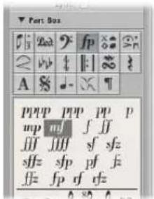
These symbols can be inserted at any position in the score. They are purely graphic symbols, and have no effect on the playback of regions they are placed in.
Note Heads
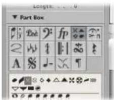
If you drag one of these symbols onto a note, the note head changes to that of the selected symbol. If multiple notes are selected, dragging the note head onto any one of the notes will attach it to all notes in the selection. Altered note heads do not affect MIDI playback.
If you want to return an altered note head to a standard display, use the same method, with the black, round note head selected.
Invisible Note Heads
Use of the gray note head will make a note's head, and associated ties, invisible. This note is displayed with a gray note head onscreen, allowing further edits. Nothing but the stem will be visible in the printout.
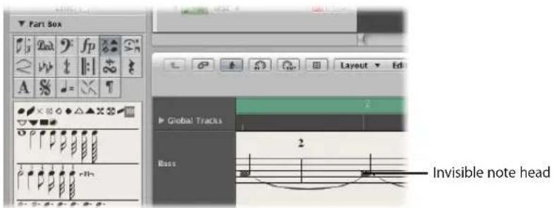
If you combine this feature with Attributes > Stem > Hide, you can completely hide these notes in the printed score.
Symbols Attached to Notes
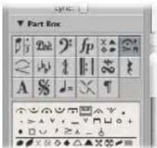
This group contains symbols which usually only refer to one note at a time. This includes fermatas, accents, phrasing symbols, and bow markings, for example (trills are in a separate group).
To assign any of these symbols to a note:
- Drag the desired symbol onto a note head (watch the help tag to ensure accurate placement).
These symbols are automatically positioned when assigned to a note. They also move with their parent notes, when transposed or otherwise graphically altered.
To insert a symbol that remains independent of any note:
■ Press Option during insertion.
This allows you to place a fermata above an automatically created rest, for example.
Note: The symbols in this Part box group can affect the velocity and playback length of notes they are assigned to.
If you want these symbols to affect playback:
- Define the effect of each symbol, separately, in File > Project Settings > Score > MIDI Meaning (see "MIDI Meaning" on page 828).
Slurs, Crescendi
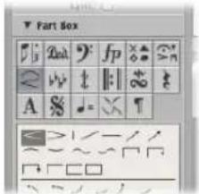
These symbols are graphic only, and have no impact on MIDI playback.
To insert a slur or crescendi object:
1 Drag it to the intended (left) starting point.
After insertion, the object remains selected, and small black square handles are visible at its end points (or along its length, in the case of slurs).
2 Grab and drag these handles to change the object's shape
You can also use several key commands to quickly input slurs, crescendo, and decrescendo symbols. For details on these, and editing options, see "Editing Slurs and Crescendi" on page 738.
Key Signatures
Key signatures inserted in the Score Editor (or global Signature track or Signature List) affect all instruments on all display levels. This is reflected both visually and in MIDI playback.
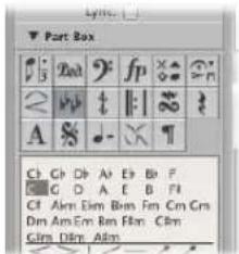
Natural symbols are automatically displayed with a new key signature, when necessary (when changing from A flat major to F major or A major, for example).
The display of key signatures and key signature changes depends on:
- The Score project settings in the Clefs & Signatures tab (see "Clefs & Signatures" on page 824).
- The Key parameter in the Staff Style window (for each staff style).
Detailed information about key signatures can be found in "Working With Time and Key Signatures" on page 755.
Time Signatures
Time signatures inserted in the Score Editor globally affect all MIDI regions, on all display levels. Time signature changes only affect the display, however, not playback.
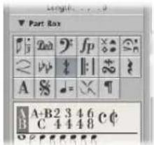
Apart from 2/4, 3/4, 4/4, 6/8, and the alternative display options for 4/4 and 2/2, there are also Part box objects for freely-definable time signatures (A/B), and compound time signatures (A+B/C). When you insert one of these, the Time Signature dialog box opens, allowing you to set the desired time signature. For more information see "Working With Time and Key Signatures" on page 755.
Repeat Signs and Bar Lines
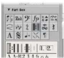
These objects can be inserted at any visible bar position (at the position of any graphically displayed note or rest). Usually, however, these objects are inserted at the beginning or end of bars.
In this situation, they replace the regular bar line (except first and second ending symbols). They are global symbols, and are displayed in all staffs, on all display levels.
Note: These symbols are purely visual, and have no impact on MIDI playback.
Details on editing these symbols is found in "Editing Repeat Signs and Bar Lines" on page 740.
Trills, Tremolo, and so on
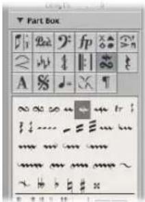
The symbols in this group can be positioned anywhere, and are not attached to notes. The trill line and arpeggio lines can be set to any length, by dragging their end points. The trill line can also span line breaks.
The accidental symbols in this Part box group are purely graphical, and do not affect the MIDI playback of notes. They are mainly intended as a supplement to trill symbols.
Rests, Bar Repeat Signs
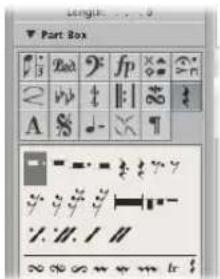
Rests are displayed automatically in Logic Express. The way this works is pretty straightforward: existing notes and automatic rests always add up to complete bars, that match the given time signature.
Note: The only exception to this is when a staff style with a deactivated rest display (Hide Rest) or with beat slashes (instead of rests) is used.
In certain situations, you might want to insert rests manually. These manually inserted rests (also called user rests) can be used if you don't like the way a particular automatic rest is displayed. See "Creating and Inserting Rests" on page 735.
Text Objects, Chord Symbols
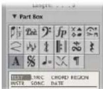
You will find descriptions of the extensive range of text objects and chord symbols in "Working With Text" on page 742.
D.S., D.C., Segno, Coda Signs
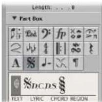
These symbols can be inserted at any position in the score. They are graphic symbols, and do not affect MIDI playback. They can be resized with the Resize tool.
Tempo and Swing Symbols
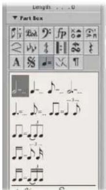
You can insert these symbols at any position. The font, size, and style of the tempo indicator is determined in the Text Style window (see "Working With Text Styles" on page 746).
The tempo indicator value is automatically derived from the playback tempo at the corresponding bar position.
Note: The tempo indicators in the Transport bar and the Tempo List always refer to quarter notes, even if a time signature with another denominator is used. As such, the displayed tempo differs, depending on the symbol being used.
Jazz Symbols
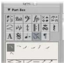
Jazz symbols, as the name suggests, are typically used for Jazz notation. They generally indicate a particular playing technique or style, emphasis, or mode.
To assign any of these symbols to a note:
- Drag the desired symbol onto a note head (watch the help tag to ensure accurate placement).
These symbols are automatically positioned when assigned to a note. Additional space is created as needed, to avoid overlaps with other notes or symbols. Jazz symbols also move with their parent notes, when transposed or otherwise graphically altered.
Jazz symbols can also be inserted with the Attach Symbol: Jazz 1–6 key commands. The numbers (1 to 6) indicate the positions of the symbols in the Part box (from top left to bottom right).
To insert a jazz symbol that remains independent of any note:
■ Press Option during insertion.
These unattached symbols can be moved freely; and unlike normally inserted jazz symbols, do not affect the spacing of notes.
Page Break and Line Break Symbols
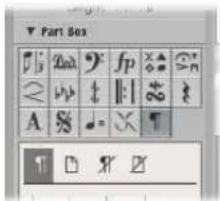
Break symbols (and No Line Break and No Page Break objects) can be inserted as events. Once inserted, they can not be moved automatically (when you alter the Layout project settings, resize the window, and so on).
You can overrule the Line Break, Page Break, No Line Break, and No Page Break events with the Layout tool.
Line breaks and individual staff margins can be determined for each score set, and also for each of the extracted parts.
Editing Notes and Symbols: Basic Operations
This section covers basic editing methods that are used in the Score Editor. For general MIDI editing information, please refer to Chapter 15, "Introduction to MIDI Editing," on page 409.
Using the Shortcut Menu
Many selection, editing, and other commands can be accessed by Control-clicking in the Score Editor. Make use of this shortcut menu to accelerate your workflow.
Note: The shortcut menu can also be accessed with a right-mouse click if the Right Mouse Button: Opens Shortcut Menu option is chosen in the Logic Express > Preferences > Global > Editing tab.
The shortcut menu contents change when different objects are selected. The Score Editor provides the following shortcut menu types:
- Notes
- Clefs
• Key signatures - Time signatures
- Bar lines
- Background
Changing Several Objects Simultaneously
If several objects are selected, this is indicated in the Event Parameter box title line, as follows: "X Notes/Symbols/Events/Texts/Chords selected". "X" indicates the number of selected objects. The terms Notes, Texts, and Chords are only used if the current selection is limited to objects of that particular type.
If—as in most cases—parameter fields are visible while multiple events are selected, all corresponding values can be edited simultaneously. When the “*” value is shown, it indicates that the selected objects have different values for that particular parameter. There are different options for changing these values:
- Relative change (preserving differences): Grab the “*” with the mouse, and use the mouse as a slider. The value shown during this process belongs to the first of the selected objects. The other objects are altered by the same amount (while retaining their relative values). You can also double-click the value, and insert the desired change (a number with a plus or minus in front of it) in the entry field (see above).
- Absolute Change (all values set to an equal value): Press Option during the procedure described above: as soon as you move the mouse, the parameter is set to the same value for all selected objects. This enables you to set all notes of a chord to the same length or velocity, or set all selected objects to the same height (Vertical Pos), as examples.
To set the vertical and horizontal position of all selected objects to the same value:
■ Use any of the following key commands.
- Align Object Positions Vertically
- Align Object Positions Horizontally
- Align Object Positions (affects both parameters)
These key commands set all objects to the value of the first selected object. If only one object is selected when you use one of these key commands, a dialog will ask if the parameters of all similar objects should be set to the same value.
This affects all displayed regions and instruments.
Tip: This is very useful for aligning lyrics and chord symbols.
Deleting Objects From the Score Editor
You can only delete events that are actually displayed in the Score Editor. As an example, if you erase notes from a real-time recording in the Score Editor, MIDI controller events or pitch bend data that was recorded with these notes will not be deleted.
To delete an object, do one of the following:
- Click the object with the Eraser tool.
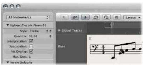
■ Select the object, then choose Edit > Delete (or press the Backspace key).
Note: Repeat signs and special bar lines cannot be selected. They can only be deleted with the Eraser tool.
Moving or Copying Objects With the Mouse
You can move or copy notes and symbols with the mouse, just as in the Piano Roll Editor.
Note: It's easy to unintentionally change a symbol's bar position with the Pointer tool. Choose the Layout tool to limit changes to an event's vertical and horizontal position. See "Changing the Graphical Position of Objects" on page 727.
To move a symbol or note with the mouse:
- Select one or more notes or symbols, then drag it to the desired position.
To copy a symbol or note with the mouse:
- Select one or more notes or symbols, press Option, then drag it to the desired position.
Watch the help tag during this process. It shows the operation (drag or copy), the current difference from the original position (transpose and time shift), and the current cursor position (bar position and—for notes—pitch).
You can simultaneously move or copy objects from different regions/staffs. Each event will be moved/copied to its new position, within the original (source) MIDI region.
Note: You can not use the Option-drag method to copy or move events between MIDI regions in the Score Editor. You can, however, copy and paste (see "Copying Objects via the Clipboard" on page 724) between regions/staffs.
To restrict movement to one direction (vertical or horizontal):
■ Hold Shift while dragging.
There is also a general preference for this: Logic Express > Preferences > Global > Editing > Limit Dragging to One Direction In: Piano Roll and Score.
The Impact of the Display Quantization Parameter
Movement along the time axis (horizontal) is affected by the display quantization grid (Quantize) setting.
If a hybrid quantize value is selected (16,24 for example), the grid corresponds to the binary value (16, in this example).
- If note positions are not aligned with this time grid (because they were recorded in real time), their relative offset is retained when they are moved or copied.
- This allows you to move or copy unquantized passages within the Score Editor, without losing the original feel of the performance.
Moving Objects With Key Commands
A group of key commands are found in the Nudge Region/Event Position section of the Key Commands window. These functions move all selected objects (by various steps) along the time axis. The following Nudge commands are the most useful for score work:
- Nudge Region/Event Position Left by Bar and Nudge Region/Event Position Right by Bar: Moves the selected notes forward or back one bar.
- Nudge Region/Event Position Left by Beat and Nudge Region/Event Position Right by Beat: Moves the selected notes forward or back one beat.
- Nudge Region/Event Position Left by Division and Nudge Region/Event Position Right by Division: Moves the selected events forward or back one division step (as set in the Transport).
Moving Global Symbols and Symbols Attached to Notes
You can not copy or move the following symbols in the Score Editor:
- Global symbols, such as repeat signs, time and key signature changes—except in the Signature List and Signature track (see "Working With Time and Key Signatures" on page 755)—and global text elements (headers and so on).
- Symbols directly attached to notes, such as accents, fermatas, note heads, and so on.
Copying Objects via the Clipboard
When you copy objects via the Clipboard, the first object is pasted at the target bar position. The relative positioning of other copied objects (to the first object) is retained.
You can simultaneously paste the Clipboard contents into several regions, at the original position.
To paste the Clipboard contents into several regions:
1 Select all desired regions (either in the Arrange area, or Score Editor), by Shift-clicking all desired staffs/regions, or rubber banding adjacent regions.
The Display Parameter box (see "Transcribing MIDI Recordings" on page 761) title line always indicates the number of regions that are currently selected.
2 Choose Edit > Paste Multiple (or use the Paste Multiple key command.)
Automatic Insert Quantization
When you paste (or paste multiple) objects from the Clipboard, the position of the first inserted event is automatically quantized, in accordance with the current division value (set in the Transport bar). As an example, if the current bar position is 4.1.1.37, and the division value is set to 1/16, the pasted object will be inserted at position 4.1.1.1, whether it's a note or a symbol. When the Clipboard contains more than one object, their relative positions from the first object are retained.
If you don't want this behavior (because you want to preserve the unquantized timing of the original), you are better served by other copy methods.
Pasting Passages at the Same Time Position
You can use the Paste at Original Position and Paste Multiple at Original Position commands to quickly copy passages from one MIDI region to another—at the same time position. No insert position is required, and no automatic insert quantization takes place.
To copy an entire musical passage to the same time position in another region:
1 Select the notes and symbols of the passage.
2 Select the staff you want to paste the passage to.
3 Choose Edit > Paste at Original Position (or use the Paste at Original Position key command).
The notes and symbols are pasted at the position they were originally copied from, regardless of the current playhead position.
The Paste Multiple at Original key command works in a similar way, but allows you to paste a musical passage to the staffs of other instruments. All destination staffs need to be selected before the Paste Multiple command is executed.
Tip: You can use these commands in combination with the Select Similar function, to quickly copy all dynamic symbols from one staff into other staffs/instruments, for example.
Repeating Events
The Repeat Events command is especially useful for copying complete bars (or multiple copies), without setting any bar positions.
As an example, to copy a bar that begins with a rest on one:
1 Select all notes and symbols.
2 Choose Edit > Repeat Events (or use the Repeat Regions/Events key command).
3 Insert the number of desired copies, set Adjustment to Bar, and press Enter.
For more information on the Repeat Events command, please refer to "Making Multiple Copies of Regions" on page 343.
Working With Aliases in the Score Editor
Alias is a term used for dependent MIDI regions and folders in the Arrange area. Alias regions mirror other MIDI regions and folders at different positions. Wherever an alias exists, it acts as a playback marker that points to the parent (original) MIDI region or folder. It is actually the parent region (or folder) that is played back.
Aliases are also displayed in the Score Editor, and can be printed. The display of aliases can be switched on in the Global tab of the Score project settings (File > Project Settings > Score > Global).
An alias can be assigned a different staff style (see "Working With Staff Styles" on page 775) to its parent region. As an example, imagine a melody that you would like played in unison by several instruments:
- This can be done quickly by creating several aliases of a regular MIDI region (the melody).
- Different staff styles can be used for each of the different instruments, including transposing staff styles (as examples, Horn in Eb, Alto Sax, and so on).
- If you decide to change something in the melody, you don't need to edit all copies (aliases) of it. Just make the change in the parent MIDI region, which will automatically be reflected in all aliases.
Editing Aliases
You can directly edit the notes and symbols in an alias if the Allow Alias Editing checkbox in File > Project Settings > Score > Global is switched on.
Note: Changes to aliases alter the data of the original MIDI region (and all aliases created from it), because only the original region can actually contain MIDI data.
If Allow Alias Editing is switched off and you try to edit an alias, this dialog appears. Choose the appropriate option:
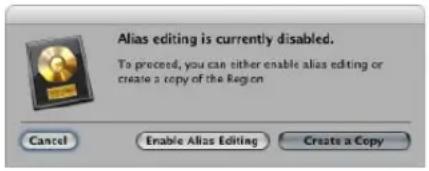
- Cancel: The aliases and original MIDI region are not changed.
- Enable Alias Editing: Alias editing is enabled; remember that this actually edits the parent MIDI region.
- Create a Copy: A copy of the original MIDI region replaces the selected alias. You can edit the notes independently of the original MIDI region, as the selected alias is now a real region.
Changing the Graphical Position of Objects
You can change the graphical position of objects to improve the layout of your score (by creating space for a grace note, for example).
Using the Layout Tool
The Layout tool is used to graphically move events in the Score Editor, in order to optimize the display, without altering the timing of MIDI events.
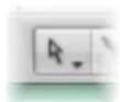
- Symbols and text: When symbol or text objects are moved with the Layout tool, the bar position is retained. The Horizontal Position and Vertical Position parameters, however, are changed (as indicated in the help tag during the process).
- Notes: The Layout tool can only edit the horizontal position of a note in relation to its bar position, not its vertical position. Dragging the note to the right or left changes the displayed distance from the adjacent notes or rests. The bar position (and playback) are unaltered.
Note: The bar position determines playback timing—as this is the actual MIDI event position. Remember that the Score Editor is primarily designed to deliver notation, and that most (but not all) editing functions are graphical, rather than physical, in nature.
Changing the Graphical Position of Symbols and Text
You can change the graphical position of Score Editor objects in the Event Parameter box by editing the Vertical Pos. and Horizontal Pos. parameters.
- Vertical Pos.: Determines the vertical position (height) above or below the staff. Zero means a position exactly on the top line of the staff, in most cases. Positive values are above, negative values below it. In staff styles with more than one staff, the Staff parameter determines the staff that the Vertical Position parameter refers to.
- Horizontal Pos.: Determines the horizontal offset of the object's bar position. A value of zero corresponds to the left edge of a note, at that particular position.
Tip: To adjust a number of selected symbols to the same height above (or below) the staff, use the Align Object Positions Vertically key command.
Changing the Graphical Position of Independent Score Symbols
You can use the following key commands to move any score symbol that can be positioned independently of notes or staffs, as well as text events and chord symbols:
- Nudge Position Up
- Nudge Position Down
- Nudge Position Left
- Nudge Position Right
These functions do not alter the bar position of the affected symbols and text events. They alter the Horizontal Position and Vertical Position parameters by ±1 .
Resizing Notes and Symbols
You can change the size of any notes, and most symbols, with the Resize tool.
To change an object's size:
- Grab the object with the Resize tool, and move the mouse up or down.
■ Double-click it with the Resize tool (and click OK in the dialog).
To reset an object to its original size:
Editing Notes and Symbols: Advanced Operations
This section covers more advanced usage of notes and other objects in the Part box.
Editing Notes
Given the different types of notes (tuplets, dotted, grace notes, and so on), this section outlines a number of note-related editing operations that will help you to get your score looking just right.
Note: If your editing requirements extend beyond those covered in this section, see "Using Note Attributes to Change Individual Notes" on page 769.
Editing the Velocity, Length, or Pitch of a Note
You can edit the velocity, length, or pitch of one or more selected notes in the Score Editor.
To change a note's velocity, do one of the following:
- Select the note, then edit the Velocity parameter displayed in the Event Parameter box.
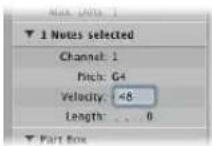
- Grab one (or several) notes with the Velocity tool, and move the mouse up or down.
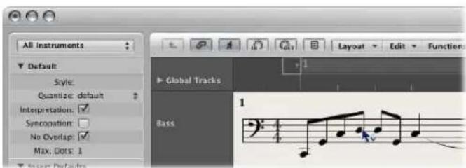
The value change can be seen in the help tag, and can also be heard if the MIDI Out button is activated.
Tip: Grabbing a note with the Pointer tool—while holding down Option-Control—activates the Velocity tool, saving you a trip to the Tool menu. Once you release these modifier keys, the cursor returns to its previous shape and function.
To change the length of a note:
■ Select the note, then do one of the following:
- Edit the Length parameter in the Event Parameter box (shown as bars, beats, and ticks).
- Use one of the Nudge Region/Event Length key commands.
To change the pitch of a note:
■ Select the note, then do one of the following:
- Drag it to the desired staff line (keep an eye on the help tag).
- Edit the Pitch value in the Event Parameter box.
- Use the Event Transpose +1 or the Event Transpose -1 key command.
Allowing Diatonic Input Only
If your composition falls into a consistent key, you should turn on the Diatonic Insert feature: it helps you to place notes at the correct pitch—by limiting input to notes that are diatonically correct, for the current key.
To turn on the Diatonic Input feature:
- Choose Options > Diatonic Insert in the Score Editor.
Notes can be altered chromatically, once they have been inserted.
Note: If you protect (lock) your screensets, this function's setting will also be locked.
Creating Tied Notes
Notes which are displayed as several graphical notes, connected with ties, only represent one actual MIDI note event.
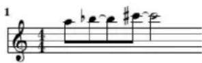
Ties can not be inserted directly into Logic Express, but are created and displayed automatically, in accordance with the length of the MIDI note. As such, you need to approach the creation of ties as follows:
To create tied notes:
1 Insert a shorter note value than the one you want to insert.
2 Change the note length in the Event Parameter box, the Event List, or the Event Float window.
To change the tied note display with a user rest:
If you don't like the way particular tied notes are displayed, you can change the display by inserting a user rest at the position you want to see a graphic note.
The rest's length is not important, but you should use a shorter one (an eighth note rest), if possible. Watch the help tag, for exact positioning. As soon as the rest is inserted, it will no longer be visible in the score display, but the note display will change accordingly.
Note: If you want to delete, or change the position of a (now invisible) user-inserted rest, use the Event List.
To change the up/down direction of a tie:
- Choose the desired setting in the Attributes > Ties menu.
Creating and Editing N-Tuplets
The symbol for N-tuplets is found in the triplet group. N-tuplets are groups of notes that are evenly spaced (by condensing or expanding them) over a specific time period. The most common tuplet is the triplet, a group of three notes. As an example: A group of three eighth notes played within the space of one quarter note.
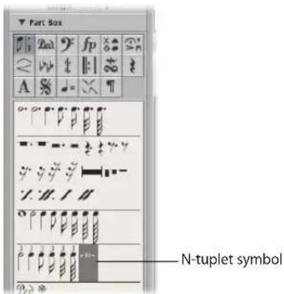
Dependent on the situation, Logic Express usually recognizes and notates regular triplets correctly. This requires that you choose an appropriate display quantize value in the Display Parameter box (see "Quantize" on page 763). You need to use the N-tuplet object for the display of other N-tuplets.
To change the display of existing notes:
1 Drag the N-tuplet symbol onto the first note.
The target note must be indicated in the help tag, before you release the mouse button. The Tuplet window will open, allowing you to define the N-tuplet attributes:
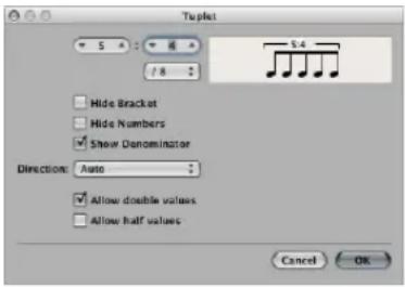
- Tuplet note number: The number of tuplet notes is defined in the upper left field.
- Tuplet denominator: The value shown in the upper right numerical field.
- Tuplet note values: Choose from 1/8, 1/16, 1/32 (and so on) tuplets.
- Hide Bracket: The bracket is not displayed.
- Hide Numbers: The N-tuplet's number will not be printed. It will, however, be displayed in parentheses. This is necessary for further edits to the N-tuplet.
- Show Denominator: The N-tuplet display also contains the denominator (the second number in the dialog box). This is 5:4 in the example above.
- Direction: The direction of the bracket and number. Auto refers to the setting in the staff style being used.
- Allow Double Values: If this option is activated, N-tuplets can contain note values that are twice as long as the regular tuplet value.
- Allow Half Values: If this option is activated, N-tuplets can contain note values that are half the length of the regular tuplet value.
Tip: Most changes made to the parameters listed above are reflected in the tuplet graphic.
2 Define the required settings in the Tuplet window.
In the example above, five tuplet eighth notes should be displayed, in place of four regular eighth notes.
3 Click OK.
In the score, the above would correspond to:
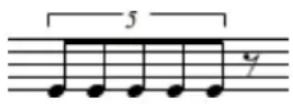
To insert N-tuplets with the mouse:
1 Insert the first note at the desired position.
2 Drag the N-tuplet symbol onto it.
If you hold down Option as you insert the N-tuplet symbol, the most-recently inserted N-tuplet settings will be used, without the dialog.
3 Define the required settings in the N-tuplet window.
The display will initially show a series of rests—the number of which corresponds to the N-tuplet value. You can insert other notes at these rest positions. Simply select a note value which approximately matches the length of the desired N-tuplet notes.
If you want to hear these notes played back with legato phrasing, and the notes are too long or too short, you will need to change their (MIDI) lengths. The fastest way to do this is to select all notes, and then choose Functions > Note Events > Note Force Legato (Selected/Any). You can also use the corresponding key command.
The method described above also allows you to create N-tuplets which contain rests or syncopated note values (double length).
Tip: If you want an N-tuplet to begin with a rest, you first need to insert a user rest from the Part box, then drag the N-tuplet symbol onto the rest. Automatically displayed rests can not function as starting points for N-tuplets.
To edit tuplets:
- Double-click the N-tuplet number, then select the desired settings in the Tuplet window.
To delete a tuplet, do one of the following:
- Click the tuplet number with the Eraser.
■ Double-click the N-tuplet number, then click the Delete button in the Tuplet window.
Using Artificial N-Tuplets to Bypass Display Quantization
You can bypass the display quantization value by using hidden, artificial N-tuplets.
As an example, if there is a single 32nd note run in a MIDI region that otherwise only contains eighth notes or longer values, you can set (Display) Quantize to 1/8, and drag the N-tuplet symbol onto the first note of the 32nd figure.
In the resulting dialog box, use the 8:8/32 setting, with Hide Brackets and Hide Numbers checked. The number (8) will be visible on screen, but not in the printout.
Although this is not the way that tuplets are normally used, it is a handy way to force the display of runs (of shorter notes—1/32nd notes, in this case), with a display Quantize value set for longer note values (1/8 notes, in this example).
Creating Grace Notes and Independent Notes
Independent notes are notes that aren't included in the automatic rhythmic (and graphic) display calculation of a measure, but are still played back via MIDI. There are two types:
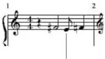
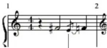
Independent grace note Independent note
- Independent: These are displayed at their original length, as long as they are binary or dotted note values that can be displayed as a single (not tied!) note. After insertion, you can change the stem direction, enharmonic interpretation, accidental distance, and note head, using the Note Attributes functions (see "Using Note Attributes to Change Individual Notes" on page 769).
- Independent Grace: These are always displayed as miniature eighth notes, with a slash across the stem, and a tie. The tie direction, stem direction, enharmonic interpretation, accidental distance, and note head can be changed.
Both types of independent notes can only appear as single notes—without beams to other notes.
To convert regular notes to independent notes (and vice versa):
- Select the desired notes, then choose Attributes > Independent > Independent or Independent Grace, or use the corresponding key commands.
Choose Attributes > Independent > Not Independent to convert independent notes back into regular notes.
To insert an independent note directly:
- Option-select a note from the Part box, and drag it to the desired position.
Independent grace notes cannot be inserted directly. They need to be created by converting regular or independent notes.
In most situations, you will need to create additional space between the grace note and the note it is associated with. The best way to do this is with the Layout tool, which can be used to move the main note away from the grace note (see "Using the Layout Tool" on page 727).
Tip: If you want to create beamed grace notes, try using a polyphonic staff style (see "Adding Staffs to a Staff Style" on page 781) with no rests displayed for the second voice. Assign the desired grace notes to the second voice, and resize them with the Resize tool.
Creating and Inserting Rests
In certain situations, you may want to insert rests manually. These manually inserted rests (also called user rests) can be used if you don't like the way a particular automatic rest is displayed. As examples: to avoid dotted rests, or for the syncopated display of rests, even when Syncopation (see "Syncopation" on page 767) is turned off.
In rhythmic display terms, user rests behave like notes—with enabled Syncopation and disabled Interpretation parameters (see "Interpretation" on page 766). User rest interpretation is affected by the display quantize setting (see "Quantize" on page 763), just as notes are.
Properties of User Rests
- They replace automatic rests, but unlike automatic rests, are listed as events in the Event List. These events have a MIDI channel and a velocity value. The velocity value determines their vertical position in the staff (normal middle position is achieved with velocity value 64).
- They can be moved vertically. Automatic rests can not be moved.
- They can be resized with the Resize tool. Automatic rests can not be resized.
Using Multi Bar Rests
Rests with a duration of several bars can be indicated by these two symbols.
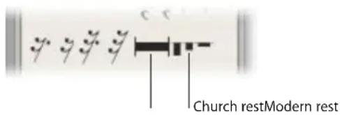
These are most suitable for single instrument parts.
Note: In the full score view (where multiple regions/staffs are displayed), they are only visible when all staffs contain multi bar rests at the same position.
To insert church or modern rests, either:
- Choose the desired rest type from the Rests Part box, and click at the desired position with the Pencil tool.
- Drag the desired rest type (from the Part box) to the required position.
Church rests (the older form of display) default to a length value of 2 bars.
The default length of normal multi bar rests is Auto (a value of 0 in the Event List). The duration of the rest is automatically calculated with respect to the position of the next note, user rest, or global symbol (repeat signs, double bar lines, and so on).
To change the rest type or duration:
■ Double-click on the rest symbol in the score with the Pointer tool.
In the dialog that opens, choose the shape (modern or church) and activate or deactivate the automatic length function. You can only determine the length (in the Bars field), if Auto Length is switched off.
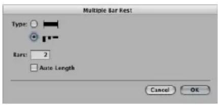
Note: Church rests can not be longer than nine bars. If this length is exceeded, the modern symbol automatically replaces the church rest.
Multi bar rests can not be moved with the mouse. You can, however, change their bar position in the Event List or Event Float window. You can also alter the length of the rest (shown in the VAL column) in these windows.
Using Beat Slashes
Beat slashes can be used in place of automatic rests, or they can be manually inserted. Both single and double slashes (commonly used to indicate a pause) are available in the Part box.
You can freely place slashes on top of the staff.
Editing Clefs
The clefs in the Part box are intended for clef changes in the middle of a part, for a short section of the music. Inserted clefs change the score display, starting at the precise insert position (which can even be in the middle of a bar).
Note: If you need to change the clef of the entire region, choose an appropriate staff style (see "Working With Staff Styles" on page 775).
When you insert a C-clef, please watch the help tag carefully, as this clef can be positioned at five different heights, depending on the register (alto, tenor clef, and so on).
The four symbols below the clefs do exactly what you expect them to: they mark a section to be played either one or two octaves higher (or lower). The length of the section can be edited after insertion, by grabbing the end of the line and moving it horizontally.
To change an existing clef:
1 Double-click the clef.
2 Select the desired clef in the selection box shown below.
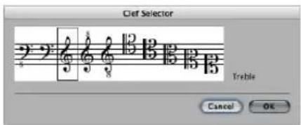
Note: The same applies to the basic clef of a region, but changing this clef affects the staff style itself, as well as all regions that use the same staff style.
To change the size of clef changes:
1 Open the Clefs and Signatures project settings by doing one of the following
- Choose Layout > Clefs and Signatures (or use the Settings: Clefs and Signatures key command).
- Choose File > Project Settings > Score (or use the corresponding key command), then click the Clefs and Signatures tab.
- Click the Settings Toolbar button, choose Score from the menu, then click the Clefs and Signatures tab
2 Choose the desired value in the Smaller Clef Changes menu.
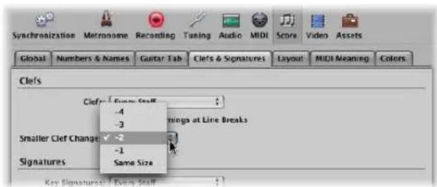
All clefs, except the first one in every staff, will be reduced in size, depending on the value chosen here. This will happen regardless of whether the clef changes are the result of a different staff style in the same staff, or clefs have been inserted from the Part box.
Editing Slurs and Crescendi
Given their nature, slur and crescendi objects are edited in a very different way to other Part box symbols.
Fast Slur and Crescendo Input With Key Commands
You can use the following key commands to quickly input slurs, crescendo, and decrescendo symbols:
- Insert: Slur Up
- Insert: Slur Down
- Insert: Crescendo
- Insert: Decrescendo
These commands place the corresponding object below or above (Slur Up) the currently selected notes. The start point is determined by the first selected note—and the length of the object, by the most recently selected note. The shape, and vertical position, of each object is determined by the settings of the most recently edited object—of the same type.
Changing the Position
All objects can be moved by simply click-dragging the mouse from the object's left hand starting point. The last six objects in the group are moved by click-dragging each of their corners (handles) separately.
Changing the Length of Symbols
All of these symbols can be as long as desired, and can be displayed (in several parts) across line and page breaks.
- As an example, if you want to extend a slur to a position which is not visible in the Score Editor (in linear view), you can grab its right end, and pull the cursor to the right border of the Score Editor—the score will automatically scroll. As soon as the desired end position for the slur appears in the window, move the mouse a little to the left, to stop scrolling. Now position the end of the slur. It is important that you do not release the mouse button during the entire process.
- In Page view, you can simply drag the right end to the desired destination in one of the lower staffs. The slur will be displayed in several sections. The same principle applies to the other symbols in this group.
- The length of these objects can also be changed in the Event List or Event Float, by changing the numerical length parameter. The end point is moved horizontally by this procedure. Slanted objects, such as arrows, will be displayed at a correspondingly varied angle.
- The length can exceed the end of the MIDI region—it's possible to drag the right end of a crescendo object to a position in the next MIDI region on the same track.
Particular Attributes of Certain Symbols
- Crescendo: The tip determines the general position. At the upper right end, length and opening angle can be adjusted. At the lower right, length and overall angle can be altered.
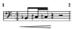
- Decrescendo: At the upper left end you can alter the bar position, and opening angle. At the lower left end, bar position, and overall angle can be set. At the tip (right end), vertical position and length are adjusted.
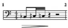
- Lines and arrows: Can be moved (in their entirety) by dragging the start point. At the other end, length and overall angle can be altered. The slanted line symbol denotes a line that can be altered freely. The other two line objects (vertical and horizontal) can only be extended in the corresponding direction.
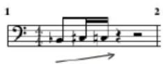
- Slurs: Slurs have five editing points, used to change their shape. The last two slur symbols in the slur group are mainly intended for slurs across staffs (in piano parts).
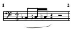
Note: These are slurs, not ties (see "Creating Tied Notes" on page 730). Ties cannot be inserted manually, but are displayed automatically if a MIDI note's length requires it.
Editing Repeat Signs and Bar Lines
Repeat signs and bar lines cannot be moved with the mouse. You can, however, move these symbols (along with time and key signatures) to a certain extent, in the Arrange window.
Once a region is selected in the Arrange window, alterations to its end point (or position) will affect existing repeat signs and bar lines in the score. Inserting, deleting, and moving key and/or time signatures in the Arrange window global tracks also have an impact on these score elements.
To delete repeat signs and bar lines:
- Click them with the Eraser tool.
Invisible Bar Lines
The dotted bar line is invisible in the printout. When used in conjunction with hidden time signature changes, this enables you to create bars and musical passages which don't seem to have a fixed meter. Another use for the invisible bar line is to force a graphical split of a note into two notes connected with ties—in all staffs of a score simultaneously—if it is inserted in the middle of a bar.
To hide all automatically displayed bar lines:
■ Activate the Hide Bar Lines checkbox in the File > Project Settings > Score > Clefs and Signatures tab.
This only affects automatic bar lines. Manually inserted bar lines, double bar lines, and so on will still be displayed and printed, regardless of the preference setting.
1st and 2nd Endings
Following the insertion of one of the repeat endings, text entry mode is automatically activated. The default text is "1." and "2.". If suitable, confirm with Return. If unsuitable, you can freely enter any text into these brackets. The bracket which defaults to "2." is open—without a vertical end line, like the "1." ending.
As the text can be changed, you also can create a 2nd ending with a vertical line, for example. The font, text size, and style of these numbers or text elements is set in the Text Styles window (see "Working With Text Styles" on page 746). To edit the text, double-click directly on it, which activates text entry mode, indicated by a flashing text cursor.
A 1st or 2nd ending can be moved by dragging its upper left corner. The length can be changed by dragging the right end. If a repeat ending is selected, it can be deleted by pressing Backspace.
First and second endings are only displayed on staffs with bar lines that aren't connected to the staff above.
The Alternate Repeat Symbols (for the whole project) option in File > Project Settings > Score > Global activates a real book style display of repeat signs.
Bar Repeat Signs
The one or two bar repeat symbols replace all notes and rests in the corresponding measures. All other symbols remain visible. This does not affect MIDI playback, so hidden notes can still be heard. These signs can only be moved in the Event List or Event Float window.
Double Repeat Sign
The double repeat sign behaves as expected, unless it is positioned at a line break. In this situation, it is automatically displayed as two back to back repeat signs.
Working With Text
You can use text for a number of purposes in musical notation: to add performance indications or display chord notation, as examples. Each text object in the Part box serves a specific purpose:
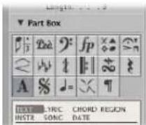
- Standard text object: Use to add standard text. The basic functions for moving the cursor, deleting parts of the text, and so on, are as per most word processors.
- Lyrics object: Use to quickly add lyrics to a song. The cursor position is automatically moved from note to note.
- Chord object: Use to add chord notation.
- Automatic Text objects: Use to display text that is updated automatically. There are four automatic text objects:
- Region: Drag this object onto the staff to automatically display the region name.
- Instr: Drag this object onto the staff to automatically display the instrument name.
- Song: Drag this object onto the staff to automatically display the project name.
- Date: Drag this object onto the staff to automatically display the current date.
Inserting Text
You can add text in the same way as other score symbols: By dragging the desired object from the Part box to the score. Alternately, you can use the Text tool to enter text.

To insert text in the score:
1 Select the desired text object in the Part box.
2 Do one of the following:
- Drag the text object to the desired position.
- Select the Text tool (or use the Set Text Tool key command), then click at the desired position.
A flashing text cursor appears at the target position. (If you choose one of the automatic text objects, the respective text will be inserted automatically.)
3 Enter the desired text with the computer keyboard.
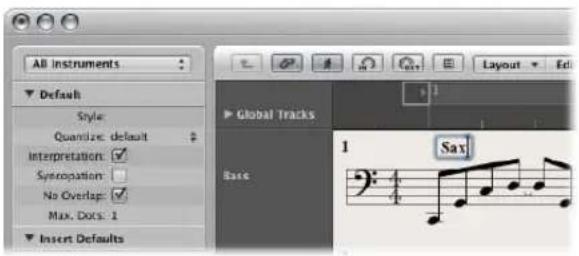
As long as you are in text entry mode (indicated by the flashing text cursor), you can click at any position in the text field. You can select parts of the text by dragging the mouse in the text field, and apply the usual Cut, Copy, or Paste commands. Press Return, or click anywhere outside the text field, to exit text entry mode.
Each text object (except text in the header, or at—or outside—the page margins) is saved as a meta event within a particular MIDI region, at a certain bar position. This position can be seen in the help tag, as you insert the text object. Text events are also visible in the Event List, allowing you to change their position, but not the text itself.
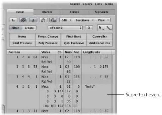
Tip: You can simultaneously add text to several staffs. This is handy if you want to insert the text "accelerando al fine," for example, into all instruments. Text entry into several staffs at once works as per other objects (see "Simultaneous Input of Objects into Several Regions" on page 706).
Editing Text
In general, you can edit text objects in the same way as other objects (see "Editing Notes and Symbols: Basic Operations" on page 721). If a text object is selected, you can set its parameters in the Event Parameter box. If you want to edit the text itself, either click on it with the Text tool, or double-click on it with the Pointer tool. The flashing text cursor will appear.
To set the selected text font, size, and face:
- Choose Text > Fonts, then make the desired settings in the Fonts window.
Setting Special Text Object Parameters
You can set the following options for the selected text object in the Event Parameter box:
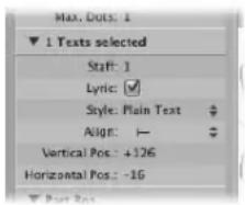
Staff
Only relevant in multiple staff styles. It determines the staff that the text object is assigned to. The Vertical Pos. parameter indicates the vertical distance to the top line of the staff. The Horizontal Pos. indicates the graphical horizontal deviation of the selected text object from its actual bar position (also in relation to the Align parameter).
Lyric
Defines the text object as a lyric event (song text). If a lyric event is placed at the same bar position as a note (above or below it), the horizontal distance to the previous and subsequent notes or rests is automatically expanded, providing enough space for the text.
Note: This checkbox can not be used on automatic text objects.
Style
Determines the text style of the selected text object.
Align
Determines the horizontal alignment of a text object. The first three settings relate to the bar position, the last five to the position on the page.
Using Musical Symbol Fonts
Musical symbol fonts do not contain letters. They only contain musical symbols (such as special percussion symbols). You can use text objects (set to a musical symbol font) to freely create, and position, musical symbols anywhere in the score.
Learning About Text Styles
All text elements refer to user-definable format settings called text styles. A text style contains all text attributes, such as font, size, and style, which saves you the time and effort of manually setting them whenever you insert a new text object.
About the Text Styles Window
All text styles used in a project are listed in the Text Styles window. This window allows you to edit existing text styles, or create new ones.
To open the Text Styles window, do one of the following:
- Choose Text > Text Styles in the Score Editor.
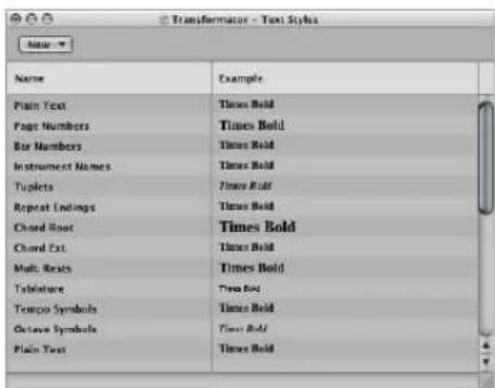
The first twelve lines contain the default text styles, which exist in every project (but can be edited, according to your needs). Below these, you will find user-created text styles. User text styles are saved with the project file, allowing them to be different for each project.
Each line shows the name, and an example, of the text style. Double-clicking the Example line opens the Font window, allowing you to edit both the default and user text styles. Any fonts installed on your system can be used.
About the Default Text Styles
The default text styles have been designed for specific text elements, and are automatically assigned when inserted.
- Plain Text: This is the default setting for regular text.
- Page Numbers, Bar Numbers, Instrument Names: The text styles for automatic page and bar numbering, and display of instrument names. These functions are described in the Numbers & Names section (see "Numbers & Names" on page 816). These styles can also be edited in the Numbers & Names tab of the Score project settings window. Changes in either window automatically updates the settings in the other window, and affects the entire project.
- Tuplets: This text style is used for triplet and other tuplet numbers.
- Repeat Endings: The text style for anything written into the repeat ending boxes (usually just numbers, but text can also be entered).
- Chord Root, Chord Extension: Used for the display of chord symbols. The Root covers the root and (optional) extra bass note in chord symbols. The Chord Extension is used for everything else.
- Multiple Rests: The text style for the number above multiple rests.
- Tablature: Used for the display of fret numbers in guitar tablature (see "Guitar Tab" on page 820).
- Tempo Symbols: Used for the display of numbers in tempo symbols (see "Tempo and Swing Symbols" on page 718).
- Octave Symbols: Used for the display of octave symbols (see "Octave Symbol Parameters" on page 826).
Working With Text Styles
This section outlines how you can create, edit, and assign text styles.
To create a new text style:
- Choose New > New Text Style in the Text Styles window.
A new line appears below the bottom text style entry, allowing you to define the attributes of the new text style. The names of any new style can be edited in the text entry field, which opens when you double-click on the name of the text style.
To assign a text style to a text object:
1 Select the text object.
2 Choose the desired text style from the Style pop-up menu in the Event Parameter box.
Importing Text Styles From Other Projects
You can add text styles created in another project to the current project.
To import text styles from another project:
1 Choose File > Project Settings > Import Settings.
2 Click the Text Styles checkbox at the bottom of the Import Settings window. Uncheck all other settings types, if you don't wish to import them.
3 Browse to the project that contains the text styles you want to import.
4 Click Open, and all user text styles from the selected project will be added to the current project.
Working With Global Text
Global text objects appear in all score sets of a project (score, parts, and so on), although they are inserted just once.
Score sets determine which instrument tracks are included in the score display. Each project can contain as many score sets as required. Full details on score sets can be found in "Using Score Sets to Create Scores and Parts" on page 796.
The position of global text does not relate to bar positions (unlike regular text objects), but is defined as a graphic position on the page. Given this behavior, global text can only be inserted and seen in Page view. The most obvious example of a global text object is a song name (in the page header).
To create global text:
- Insert text into one of the following areas of the page:
- In the header space (which is set in Layout > Global Format).
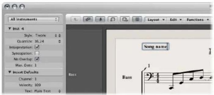
- Outside, or directly on, any of the page margin lines.
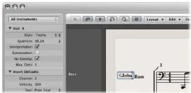
Text objects inserted in one of these areas are automatically made global.
Positioning of Global Text
Following insertion into one of the margin areas, global text can be moved anywhere on the page. The Pointer tool only allows vertical movement of global text objects. Hold down Option to move global text horizontally.
Global Text Parameters
When a global text object is selected, the Event Parameter box contains some additional parameters:
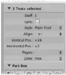
Pages
Defines the pages that the global text object will be displayed on. You can choose between the following options:
• 1: The text will only be displayed on the first page.
• 2: The text will be displayed on all pages except the first one.
- Odd: The text will be displayed on all pages with odd numbers.
- Even: The text will be displayed on all pages with even numbers.
- All: The text will be displayed on all pages.
Zone
The margin area that the text belongs to/is associated with: You can choose between Top, Header, Side, and Footer.
Align
Although alignments relating to bar positions are shown in the pop-up menu, they cannot be selected here.
Working With Automatic Text Objects
The text group in the Part box contains four objects which represent names that are automatically displayed, if inserted:
- REG (Region/Folder): Displays the name of the current display level. This can be a MIDI region, a folder, or even the name of the project file (on the highest level).
- INSTR (Instrument): Displays the name of the currently displayed instrument or score set (see "Using Score Sets to Create Scores and Parts" on page 796).
- SONG: Displays the name of the project file.
- DATE: Displays the current date (at the time of printout).
These automatic text objects can be inserted as both global text (in the margin areas), or as text objects that are related to a bar position (in one of the staffs/regions). As an example: You can insert the INSTR object as a global object—to display the name of the current score set on all pages. The appearance, and exact positioning, of these objects can be set in the Event Parameter box.
Creating Lyrics
The text group in the Part box contains an object named LYRIC, which allows you to create lyrics—aligned to note events. When you use the LYRIC object to input text, pressing Tab moves the text cursor to the beginning of the next MIDI note.
To create lyrics:
1 Do one of the following:
- Drag the lyric object below the first note of the melody.
- Select the lyric object in the Part box, then click at the position of the first note with the Text tool.
Note: Watch the help tag: each lyric object must be at the same bar position as the note it belongs to (taking display quantization into account).
2 Enter the text for the first note—and press Tab, not Return—which automatically moves the text cursor to the beginning of the next MIDI note.
If a MIDI note is displayed as several tied (graphic) notes, press Shift-Tab to move the cursor to the next graphic note. This allows you to write several syllables below one longer note. This method enables you to enter all lyrics in one process, although each syllable is saved as an independent lyric object.
Editing lyrics is just like editing regular text. The Event Parameter box displays the same parameters (the Lyric checkbox is activated).
Apart from the fact that cursor movement is bound to notes in lyric input mode, the only difference between regular text objects and lyric objects is that the latter affect the distance between the notes they are assigned to. This provides enough space for the text to be displayed properly, without overlapping. If the text (or text style) is changed later on, the note distance will be recalculated accordingly.
To convert a standard text object to lyrics:
- Select the text, and click the Lyric checkbox in the Text Event Parameter box.
Setting All Words and Syllables to the Same Height
If you don't enter the lyrics in one continuous process, it is unlikely that the lyric objects will be set to the same vertical position (they won't be aligned).
To quickly align all Lyric objects:
1 Select at least one lyric object.
2 Choose Edit > Select Similar Objects, which will select all lyric objects.
3 Use the Align Object Positions Vertically key command.
Note: You do not want to use this method if there are multiple lines of lyrics for different verses. Doing so would set them all to the same height.
Several Verses Written Below Each Other
You can assign multiple lyric objects to the same note, allowing you to insert several verses for a song, one below the other.
To create several verses for the same note:
1 Drag the first lyric object to the position of the desired note, then input the first verse.
2 Drag the second lyric object to the same note position below the first verse, and type in the second verse.
As long as you remain in fast lyric input mode, all lyric objects for the second verse will stay at the same height as the initial object—in this case, the first word of the second verse.
Working in Single MIDI Region Display Mode
It is important that lyric objects are assigned to the right MIDI region, if you're working in a full score display (remember: selected staffs are displayed with blue staff lines). It's generally recommended that you insert lyrics in linear view, and single MIDI region display mode—especially if inserting more than one verse. Linear view also makes it easier to rubber band select several lyric objects, to change their positions, for example.
Creating Chord Symbols
Chord symbols are text objects designed for fast chord entry. Logic Express uses special text attributes to display chord symbols, and also offers additional editing tools.
To create a chord symbol:
1 Do one of the following:
- Drag the chord object from the Part box to the desired position in your score.
- Select the chord object in the Part box, then click at the desired position with the Text tool.
- Select any text object in the Part box, then Option-click at the desired position with the Text tool.
Note: Ensure that you insert chord objects at the correct bar position. Watch the help tag while inserting the chord object.
2 Enter the text for the chord.
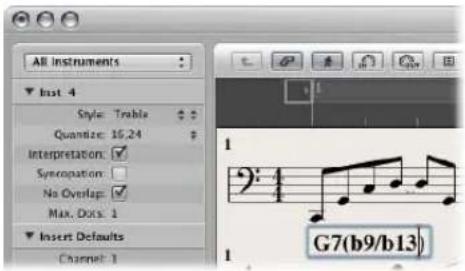
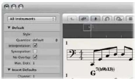
A chord symbol can include a root note, a separate bass note, and two lines of extensions. As you enter the text for the chord in the Score Editor, you can influence the way the inserted text is distributed:
- First, enter the root, then the extensions, then—after typing a slash—the (optional) additional bass note.
- As soon as you enter a number, everything following it will be placed in the upper extension line. If you write "G7(b9/b13)", the whole "7(b9/b13)" will be placed in the upper line, and the lower line remains blank.
- If you write letters before a number (FMAJ7/9, for example), Logic Express places the letters in the lower line, and everything after the first number, in the upper line.
- You can influence this automatic placement by entering a comma in the text: everything before the comma will be placed in the lower line, and everything after it, into the upper line. Only one comma can be used. Blank spaces can be entered, to create additional horizontal space between the extension and the root.
To edit a chord symbol, do one of the following:
■ Double-click on the root, then edit the chord symbol in the Chord Symbol window.
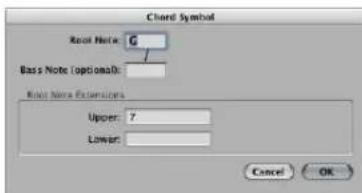
There are four entry fields for the different parts: one for the root, one for an additional bass note, and two for extensions—which are placed above each other.
■ Double-click directly on one of the extensions.
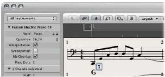
A text cursor will appear in the extension line, allowing you to edit the extension as per regular text.
The appearance of chord symbols can be edited in the Text Styles window (see "Working With Text Styles" on page 746), by changing the text styles assigned to the chord root and extensions.
To change the appearance of chord symbols:
1 Open the Text Styles window by choosing Text > Text Styles in the Score Editor.
2 Edit the text style for the chord root (named Chord Root)—and for the extensions (named Chord Extensions)—as desired.
Inputting Several Chord Symbols
If you want to insert several chord symbols into the same staff, there is a shortcut (similar to the lyric input mode) available. Following text entry of the first chord, press Tab, rather than Return. The text cursor automatically moves to the position of the next (displayed) note or rest. Enter the desired chord and repeat the process, or press Tab several times, to move to the target position for the next chord symbol.
Tip: If you want to insert one chord per bar into a very busy part, it's much faster to create an empty MIDI region, and enter the desired chords into it (the cursor moves to the next bar when you press Tab in empty regions). Following chord entry, you can either merge the MIDI region with the original MIDI region in the Arrange area, or copy and paste all chords at once.
Enharmonically Changing Chord Symbols
You can change the roots of chord symbols enharmonically. Only additional bass notes need to be edited directly in the Chord Symbol window. When changing a chord enharmonically, the chord's spelling changes, but the pitches of the chord notes remain identical. As an example: When changing the "Gb7" enharmonically, it becomes "F#7".
To enharmonically change the root of chord symbols:
1 Select the chord.
2 Do one of the following:
- Choose Attributes > Accidentals > Enharmonic Shift: # (or use the Enharmonic Shift: # key command, default: Shift-H).
- Choose Attributes > Accidentals > Enharmonic Shift: b (or use the Enharmonic Shift: b key command, default: Shift-B).
Transposition of Chord Symbols
Chord symbols inserted into transposing staff styles are automatically transposed, just like notes. Further to this, if the Transposition parameter (for playback transposition) in the Region Parameter box is changed, all chord symbols in the MIDI region will be affected accordingly.
German Chord Symbols: H Instead of B
If you choose one of the German Chord Symbol settings in the Chord Symbol Language menu of the Score project settings' Global tab, the note B in all chord symbols is displayed with its German name H. The English B flat is written as B or Bb, when German chord symbols are displayed.
Note: The German (H, B, F#) setting is activated automatically, as soon as the letter H is used during chord symbol input.
Graphical Position of Chord Symbols
Each chord symbol is stored at a certain bar position in a MIDI region (there will often also be a note at that same bar position).
The Event Parameter box Align option determines which part of the chord symbol is aligned to the bar position: the left edge, center, or right edge of the letter representing the chord root. The setting for newly inserted chord symbols is always "def.": this default alignment matches the setting chosen in the Chord Symbol Alignment menu—found in the Layout tab of the Score project settings.
Rhythm Section Parts
Typically, rhythm section parts are notated with chord symbols and beat slashes. If you want to create this type of part, choose a staff style with a Rest parameter set to Slash. For more information, see "Rest" on page 786.
Working With Time and Key Signatures
Signatures are global events, which affect all tracks in your project. You can view and edit time and key signatures in the Signature track, in the Signature List, and in the Score Editor.
Note: The Signature track must be visible—and must not be protected—in order to select and copy signatures.
To view the Signature track:
- Choose View > Global Tracks.
By default, the global Marker, Signature, and Tempo tracks will be visible when you enable the display of global tracks. If the Signature track is not visible, choose View > Configure Global Tracks, and enable the Signature checkbox.
To view the Signature List:
- Shift-double-click in the Signature track.
- Choose Options > Open Signature/Key Change List Editor.
The Signature List displays time and key signatures in a list style editor, along with other global score symbols such as repeat signs, double bar lines, and so on.
Time Signatures
A time signature determines the number of beats in a bar (shown in the Bar ruler), thus defining the editing grid in the Arrange area and MIDI editors. A time signature does not affect the playback of audio or MIDI regions.
Time signatures do, however, affect the score display. All functions reliant on the chosen time signature and bar positions (such as MIDI metronome click or Transform window functions) are affected—if bar positions are used to restrict a function to a certain part of the project.
Key Signatures
Key signature changes only affect the display of MIDI notes in the Score Editor—they do not have an effect on MIDI playback. The first key signature, however, affects the playback of audio Apple Loops. For more information, see “Global Tracks and Apple Loops” on page 645.
You can create as many key signatures as you wish. If your project already contains other key signature changes, any newly inserted key signature will change the key from the insertion point forward—until the next key signature change is reached.
You can store up to nine signature alternatives in the Signature track.
Creating Time Signatures
You can create as many time signatures as needed in a project.
To create a time signature change, do one of the following:
■ Move the playhead to the target bar, and set the new time signature in the Transport bar.
In the Score Editor, drag the desired time signature from the Part box to the target bar position.
- Set the Signature track to a sufficient height, so that it displays both the key and time signature areas. Click the target bar in the Signature track's time signature area with the Pencil tool, then choose the desired settings in the Time Signature dialog.
Note: If you perform this procedure when the track height is reduced, a time signature change will be created.
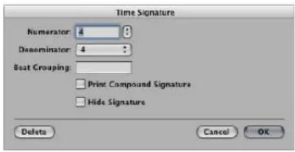
- The Beat Grouping entry field allows you to determine the grouping of beats in compound time signatures. It is sufficient to enter the numbers—223, for example. This becomes "2+2+3" automatically. The total number of beats in the bar is calculated automatically by the sum in this field. The Print Compound Signature checkbox needs to be activated, in order to display the defined grouping as the nominator. If not activated, only the total sum will be displayed as the numerator. Beat Grouping, however, affects the way the notes are beamed together—in both cases. You can also change the automatic beaming in normal time signatures. In 4/4-time "1+1+1+1" produces four beamed groups (one for every beat), instead of the two groups displayed as a default.
- Activate the Hide Signature checkbox to hide the corresponding time signature change in the printout. The signature will still be displayed onscreen, but it will be crossed out, and won't be included in the calculation of spacing between notes and symbols. As a result, signatures may overlap notes on the screen, but not in the printout. This function can be used for notating cadenza-like passages, that contain more notes than would normally fit the time signature.
- Click the Create Time Signature button in the Signature List.
Creating Key Signatures
You can create as many key signatures as needed in your project.
To create a key signature, do one of the following:
- Click the desired position in the Signature track's key signature area with the Pencil tool, then choose the desired key in the Key Signature window.
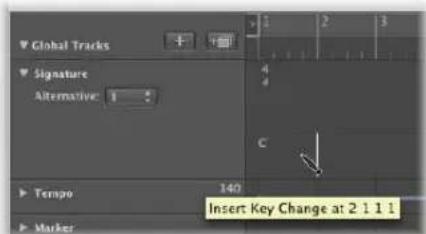
Note: You can disable the use of double flats and sharps by activating the "Disable bb, x" checkbox.
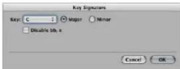
In the Score Editor, double-click on the desired staff, between the clef and time signature, then choose the desired key in the Key Signature window. You can also drag the desired key signature from the Part box to the appropriate bar position.
- Click the Create Key Signature button in the Signature List.
Selecting Signatures
You can select signatures in the Signature List and Signature track by clicking them. Multiple selections are possible by Shift-clicking.
In the Signature track—you can even select multiple signatures in conjunction with regions, which is very useful when you want to copy or move complete parts of a song (along with signature changes). The Edit > Select Inside Locators command can be helpful in this situation.
Copying Signatures
You can copy time signatures and key signatures in the Signature List, or Signature track. It is also possible to copy all time and key signatures from one project to another.
Subsequent signatures are inserted at bar positions that correspond to their original distance from the first copied signature.
To copy signatures in a project via drag and drop:
- Press Option, then drag the signature (in the Signature track) to the target bar position.
To copy signatures in a project via the Clipboard:
1 Select the time and key signatures in the Signature Editor or Signature track by clicking on them (Shift-click for multiple selections).
2 Choose Edit > Copy (Command-C) to copy them to the Clipboard.
3 Do one of the following:
- In the Signature track: Move the playhead to the desired insert position, then choose Edit > Paste (Command-V).
- In the Signature List: Choose Edit > Paste (Command-V), type in the desired insert position in bar position box, then close the box by pressing Return.
To copy signatures between projects:
1 Select the desired signatures in the Signature track or Signature List.
2 Choose Edit > Copy (or press Control-C).
All signature changes of the source project are copied to the Clipboard.
3 Switch to the desired target project.
4 Activate the Signature track or Signature List, then choose Edit > Paste (or press Control-V).
The copied meter changes are pasted into the target project.
Note: As any copied time and key signature changes are mixed with those of the destination project when pasted, this procedure should only be used to copy such changes to a blank project (one that contains no time and key signature changes, except the initial settings).
Editing Signatures
You can edit existing signatures in the Score Editor and Signature track by double-clicking on them. The Time or Key Signature window appears, allowing you to make the desired changes. Moves are achieved by selecting, and dragging, signatures.
Editing Time Signatures by Cutting and Merging Bars
You can use the Scissors tool in the Signature track to cut bars. As an example; to divide one 5/4 measure into a 3/4 and a 2/4 measure, cut it at the fourth beat of the 5/4 bar.
If you make a cut in the middle of a bar—in a section where the time signature doesn't change—two corresponding shorter measures will be inserted, with the original time signature resuming after the cut.
Likewise, it is also possible to merge two subsequent measures into one longer measure, by using the Glue tool in the Signature track.
Deleting Signatures
You can delete all signatures in a project, except the initial time and key signature.
To delete a signature, do one of the following:
- Select the signature in the Score Editor, Signature List, or Signature track, then choose Edit > Delete (or press Backspace).
Tip: To erase all time signature events, choose Edit > Select Similar Objects after selecting a signature, then press Backspace.
- Click the signature with the Eraser tool in the Score Editor, Signature List, or Signature track.
Creating and Choosing Signature Alternatives
Signature alternatives are just that: alternative versions of all signatures on the signature track.
To create an alternative signature track:
1 Choose a number from the Alternative pop-up menu on the Signature track.
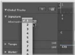
If the signature track is not tall enough to show the Alternative menu, drag the lower lane line.
2 Insert the desired signatures, using the methods outlined above.
No save operation is necessary.
To switch between signature alternatives:
- Choose the desired number from the Alternative pop-up menu.
All MIDI regions are affected, resulting in the appropriate changes to your score.
Transcribing MIDI Recordings
In this section, you'll learn how to use the Score Editor's display parameters to correctly notate your performances.
Traditional music notation is only an approximate description of the musical content in a piece. The actual performance depends heavily on the interpretation of notes by musicians. Quarter notes, for example, are hardly ever held for exactly one beat.
The rhythmic interpretation of MIDI regions (recorded in real time, to a metronome click) presents a similar problem, especially when you consider that Logic Express records MIDI events at a resolution of 960 ticks per quarter note. Nobody will play a downbeat at the exact time of the metronome click.
The Score Editor's display parameters allow you to adjust the appearance of notation, without changing the playback (and feel) of the original MIDI region. You can use different display settings for each region.
As such, it's important that you have some idea of what your printed music should look like. This will help to determine the display settings that will best fit your music.
If you can't seem to find the appropriate display parameters for a particular MIDI region, divide the region with the Scissors tool. This will leave MIDI playback unaltered, but allows you to assign different display parameters (display quantization) for each of the shorter regions that result from the cut operation.
Even though these divided regions are separate, they adjoin each other, and will be displayed as a continuous staff in the score.
As a general working tip, you should merge MIDI regions (or insert blank regions) to fill the gaps between MIDI regions before altering the display settings. The Score Editor will display nothing if no region is present, resulting in blank spaces in your score.
Default Settings for New MIDI Regions
If a new MIDI region is created with the Pencil tool in the Arrange area, or through MIDI recording, Logic Express applies a set of default parameters to it. These defaults can be seen and edited in the Display Parameter box, when no MIDI region (no staff) is selected. The title line shows Insert Defaults to indicate this status. These settings will remain as set, until you quit Logic Express, but can be changed at any time.
Click on any empty spot on the Score Editor background to display the Insert Defaults. Edit any of the parameters as desired—Set Quantize to the value that you will use for most regions in the project, for example. From this point on, all new regions will automatically use these settings when created. If Quantize is set to “default”, the display Quantize setting of newly recorded or created regions will match the division value shown in the Transport bar.
Note: The default setting for staff styles (Style) is not defined here. This is separate for each track, and is set in the bottom line of the Arrange area's Track Parameter box.
Simultaneously Changing the Settings of Several Selected MIDI Regions
The top line of the Display Parameter box indicates the number of regions or objects (if the selection includes folders) currently selected ("3 Regions sel.", for example), instead of the MIDI region name. If these regions have differing values for any of the parameters, a "*" will be displayed in the corresponding parameter line. If you change this value, all selected regions will be set to the same value for that particular parameter.
Selecting Multiple Regions in the Score Editor
You can use two special functions to select multiple regions in the Score Editor:
- Click on the title line in the Display Parameter box to select all regions that are visible in the current display.
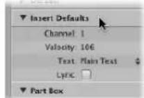
- Click an instrument name, in the column between the parameters and score, to select all regions for that particular instrument track (even regions spread across different tracks that are assigned to the same software or MIDI instrument channel), at the current display level. Remember, the instrument name column is only displayed if View > Instrument Names is activated.
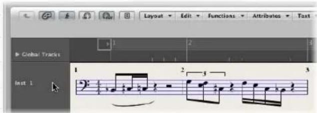
Display Parameters
This section outlines all of the display parameters available in the Score Editor. To reiterate the point, these only affect the appearance of events in the score, not the playback of events!
Quantize
This parameter applies visual quantization to notes: it determines the shortest note value that can be displayed in the currently selected MIDI region (exception: artificial N-tuplets, see "Creating and Editing N-Tuplets" on page 731).
As an example: If you insert a short note, such as a 32nd note, it can only be displayed at its original length if Quantize is set to 32 or shorter. If Quantize is set to 8, the 32nd note will be displayed as an eighth note (although it will still be played back as a 32nd note).
The Quantize value is selected from a pop-up menu, which contains all available display quantization options.
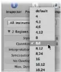
Among these are binary quantizations (displayed as one binary value—16 or 128), and hybrid quantizations (two values combined, a binary and a ternary value—16,24 or 32,96 as examples).
Binary values always correspond to the note value with the same denominator—as an example: 32 corresponds to thirty-second notes, and so on. Ternary values refer to triplets. Here is a list of the ternary values, and their corresponding triplet values:
Quantize setting Corresponding note length
| 3 1/2-note triplets |
| 6 1/4-note triplets |
| 12 1/8-note triplets |
| 24 1/16-note triplets |
| 48 1/32-note triplets |
| 96 1/64-note triplets |
| 192 1/128-note triplets |
| 384 1/256-note triplets |
When binary display quantizations are used, automatic triplets are not displayed at all (except for triplets inserted with the mouse, using an N-tuplet object).
Important: Therefore, a hybrid quantization value must be assigned to the Quantize parameter, to enable the automatic display of triplets.
Quantize Default Setting
The Quantize parameter's Default option can only be set with the Insert Defaults (see "Default Settings for New MIDI Regions" on page 762). It cannot be set to its Default value in existing regions. If Default is chosen, the Quantize setting of any new MIDI region will be dependent on the current division value in the Transport. In this situation, the Quantize value will always be a hybrid value: The division value currently set in the Transport window plus—in the case of a binary division value—the next highest ternary value. In the case of a ternary division value—the binary value, which is divisible by that particular ternary value.
As examples: A global division value of 1/8 will result in an 8,12 Quantize setting for new regions, a global division value of 1/12 will become a 4,12 Quantize value, a global division value of 1/16 will result in a Quantize value of 16,24, 1/24 in 8,24, and so on.
Note: If a particular Quantize value has already been set in the Insert Defaults, all new regions will be assigned this value, regardless of the division value in the Transport bar. You may, of course, change any of these values at any time.
Choosing a Quantize Value for Swing Notation
For regular swing notation, 8,12 should be used as Quantize parameter. This enables the display of eighth-note triplets, and also displays two uneven notes on one beat (dotted eighth and sixteenth), as regular eighth notes.
For double-time passages containing sixteenth notes, you either need to:
- Cut the MIDI region in the Arrange area, and assign a higher quantize value to the new MIDI region (that contains the double-time figure).
- Use hidden artificial N-tuplets for the sixteenth notes (see "Creating and Editing N-Tuplets" on page 731).
For swinging sixteenth notes (shuffle funk, hip hop, and so on), the same principle applies. In this case, Quantize would be set to 16,24.
Fixing the Score Quantize Value
The Functions > Quantization > Fix Displayed Note Positions and Fix Displayed Note Positions and Durations commands can be used to fix the display quantization of all MIDI events in the project. These commands may be useful for exporting projects (complete with display quantize settings) to other notation programs that don't feature display quantization.
Interpretation
If Interpretation is enabled, notes are generally displayed with longer length values than their actual length, in order to avoid short rests. Short notes on a downbeat in 4/4 time, for example, are displayed as quarter notes. The score becomes less precise as a result, but is easier to read.
If Interpretation is disabled, note lengths are displayed as close as possible to their real values, as determined by the Quantize value. In the following example, the same MIDI region is shown twice, the first with Interpretation disabled, the second enabled:
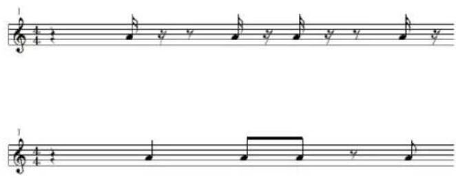
The Interpretation function is intended to produce an easy-to-read score display of real time recordings. You should generally switch it off when using step or mouse input.
You can use note attributes to switch Interpretation on and off for each individual note, overriding the Display Parameter box setting (see "Using Note Attributes to Change Individual Notes" on page 769).
To switch interpretation on or off for a selected note, do one of the following:
- Choose Attributes > Interpretation, then choose the desired setting.
- Double-click the note, then choose the desired setting in the Note Attributes window.
■ Use one of the following key commands: - Default Interpretation
- Force Interpretation
- Defeat Interpretation
Syncopation
If Syncopation is enabled, each (MIDI) note will be notated as one graphic note (not displayed as several tied notes), regardless of position—if possible. (This also depends on the Max. Dots setting, see below.) If this isn't possible, the note is graphically divided into the minimum possible number of notes, connected by ties.
This facility is usually used for the display of syncopated notes. The following example shows the same two bars displayed differently, the first with Syncopation disabled, then enabled:
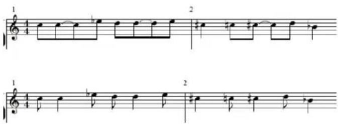
Syncopation can also be enabled and disabled for each note, independent of the Display Parameter box setting. This can be via note attributes (see "Using Note Attributes to Change Individual Notes" on page 769).
If an unwanted display of ties and notes results from the Syncopation function, it is possible to change the graphic display of notes connected with ties.
- Insert a user rest from the Part box (preferably a short one, but the length isn't important) at the bar position where you want the tie subdivided.
Once the rest is inserted, it will disappear, but the note display will change. The inserted rest can only be seen and edited in the Event List.
This trick works for all notes, not just syncopated ones (see "Creating Tied Notes" on page 730). In polyphonic staff styles, the MIDI channel of the rest and the corresponding note must be identical.
No Overlap
No Overlap, when turned on, prevents the overlapped display of notes in melodies that are played with an exaggerated legato. The displayed length of notes is truncated (shortened) to the beginning of the next note (unless a polyphonic staff style is used—see "Working With Staff Styles" on page 775 for details). Notes beginning simultaneously (chords, in other words) are displayed with the (note) length of the shortest note in the chord.
When set to off, the score display shows the lengths of the notes fairly precisely. The music is definitely harder to read this way, however.
The effect can be seen in the following example, which shows the same MIDI region, first without, then with, overlap correction:
No Overlap should only be deactivated in rare cases. If, for example, a piano player arpeggiates a chord and holds the notes, the score displays the following result with No Overlap on:
Although you can't see that all notes continue to sound here, the result looks like this if No Overlap is deactivated:
The solution typically involves switching No Overlap on, and using sustain pedal markings. Logic Express will automatically display pedal markings if notes are recorded in real time with a MIDI keyboard, and sustain pedal.
Max Dots
This parameter determines the maximum number of dots that Logic Express will allow for the display of single notes. Unwanted dotted notes or rests can be changed by inserting user rests (which remain invisible, if notes). Take a look at the information on changing the way notes with ties are displayed (see "Creating Tied Notes" on page 730).
Score
This parameter is accessed via the Arrange window's Region Parameter box (only visible if the View > Extended Region Parameters setting is enabled). If Score is set to Off here, the MIDI region will not be displayed in the score at all. This is mainly used to prevent the score display of particular regions—namely those that only contain MIDI events which can't be displayed in the score, such as controller or SysEx data.
Hidden MIDI Regions
In some situations, certain MIDI regions will not be displayed in the Score Editor.
- Muted MIDI regions, if Hide Muted Regions is enabled in the Global tab of the Score project settings.
- MIDI regions on muted tracks, if Hide Muted Tracks is activated in the Global tab of the Score project settings.
- MIDI regions with a Score parameter set to "off" in the extended region parameters.
Using Note Attributes to Change Individual Notes
You can use note attributes to set individual display parameters for each note, regardless of the settings in other windows and boxes.
You can set the following note attributes:
- Form of the note head, and note size.
• Horizontal position. - Change of accidental distance.
- Enharmonic changes.
- Settings for interpretation and syncopation, independent of the settings in the Display Parameter box.
- Stem direction, tie direction, and beaming, independent of the settings in the staff style being used.
- Display as an independent note, which excludes the note from the measure's overall rhythmic calculation.
You can change note attributes in the Note Attributes window, via the Attributes menu, or the respective key commands.
Note: Please ensure that the Note Attributes setting is chosen in the "Double-click note to open" menu of the Logic Express > Preferences > Score window. It is on by default.
To change note attributes, do one of the following:
■ Double-click a note head to launch the Note Attributes window.
Only one note can be changed at a time in the Note Attributes window.
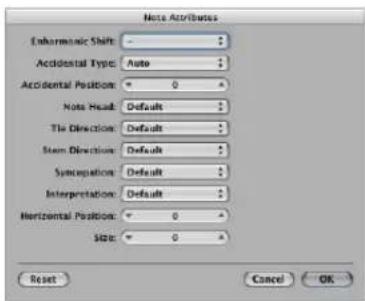
- Select one or more notes, and choose the desired command from the Attributes menu.
The Attribute menu (and corresponding key commands) allows a group of selected notes to be assigned new attributes.
You can also change specific note attributes via the Part box, and with tools.
The following section lists all note attributes, and provides information on accessing and altering various attribute options.
Changing Note Heads
The default setting for note heads is normal (round and black).
To change the attributes of a note head, do one of the following:
- Drag the desired note head from the Part box to the respective note.
- Choose the desired note head from the Note Head menu in the Note Attributes window.
Changing Note Sizes
The default note size is set with the Size parameter in the Staff Style window.
To change a note's size, do one of the following:
- Click-hold the note with the Resize tool and drag up (increase) or down (decrease).
- Choose the desired size in the Size menu of the Note Attributes window.
Changing the Horizontal Position of Notes
You can set the horizontal position of each note, individually.
To change a note's horizontal position, do one of the following:
- Click-hold the note with the Layout tool, and drag to the left or right.
- Choose the desired value in the Horizontal Position menu of the Note Attributes window.
Changing the Position of Accidentals
This note attribute defines the deviation from the Acc./Note Distance value, chosen in the Layout tab of the Score project settings.
To change the accidental distance from the note:
- Choose the desired value in the Accidental Position menu of the Note Attributes window.
Changing the Display of Accidentals
By default, the display of accidentals depends on the chosen key signature.
To change the display of accidentals, do one of the following:
- Choose the desired value in the Enharmonic Shift or Accidental Type menu (see list of settings below) of the Note Attributes window.
- Choose the desired value from the Attributes > Accidentals menu.
You can choose between the following display options:
- Default Accidental: The display of accidentals depends on the chosen key signature.
- Enharmonic Shift: #: Converts G flat to F sharp, or F to E sharp, for example.
- Enharmonic Shift: b : Converts D sharp to E flat, or B to C flat, for example.
- Flats To Sharps: Similar to Enharmonic Shift #, but leaves notes without flats unaltered (useful for multiple selection).
- Sharps To Flats: Similar to Enharmonic Shift b, but leaves notes without sharps unaltered (useful for multiple selection).
- Force Accidental: Forces the display of accidentals (and naturals).
- Hide Accidental: Displays the note without accidentals (MIDI playback is not affected).
- Guide Accidental: Forces the display of the accidentals (and naturals) in parentheses.
■ Use one of the following key commands:
- Default Accidentals
- Enharmonic Shift: #
- Enharmonic Shift: b
- Flats To Sharps
- Sharps To Flats
- Force Accidental
- Hide Accidental
- Guide Accidental
Changing the Stem Direction and Length
By default, a note's stem direction and length depends on the respective setting in the Staff Style window.
To change a note's stem direction and length:
- Choose the desired value in the Stem Direction menu of the Note Attributes window.
Note: The stem length can not be changed in the Note Attributes window.
- Choose the respective item in the Attributes > Stems menu.
- Default: The stem direction is set in accordance with the default (staff style) setting.
- Up: The note's stem is forced upwards.
- Down: The note's stem is forced downwards.
- Hide: Hides a note's stem, and the corresponding beam or flag.
- Stem End: Default Length: Default setting.
- Stem End: Move Up: Moves the stem end upwards. Depending on the direction, this shortens or lengthens the stem.
- Stem End: Move Down: As above, but moves the stem end downwards.
■ Use one of the following key commands:
- Stems: default
- Stems: up
- Stems: down
- Stems: hide
- Stem End: Default Length
- Stem End: Move Up
- Stem End: Move Down
Changing the Beaming of Notes
By default, the beaming of notes depends on the chosen time signature, the Beat Grouping setting in the Time Signature dialog, and on the staff style's Beam parameter.
To change the beaming of notes, do one of the following:
- Choose one of the following items in the Attributes > Beaming menu:
- Beam Selected Notes: Forces a beam to the following note.
- Unbeam Selected Notes: Interrupts the beam to the following note.
- Default Beams: Uses the default setting.
■ Use one of the following key commands:
- Beam Selected Notes
- Unbeam Selected Notes
- Default Beams
Changing the Voice or Staff Assignment
You can change the voice or staff assignment for cross staff beaming in the Attributes >Ties menu (see "Advanced Staff Style Usage" on page 790).
You can choose between the following options (requires a polyphonic multi staff style):
- Default Staff: According to voice assignment.
- Staff Above Voice: Moves the selected notes to the staff above the assigned voice.
- Staff Below Voice: Moves the selected notes to the staff below the assigned voice.
Changing the Tie Direction
By default, the tie direction is set in accordance with the setting in the Staff Style window.
To change a note's tie direction, do one of the following:
- Choose the desired setting in the Attributes > Ties menu.
- Choose the desired tie direction in the Tie Direction menu of the Note Attributes window.
■ Use one of the following key commands: - Ties: default
- Ties: up
- Ties: down
Changing the Syncopation of Notes
By default, note syncopation is set in accordance with the setting in the Display Parameter box.
To change a note's Syncopation setting, do one of the following:
- Choose the desired setting in the Attributes > Syncopation menu.
- Choose the desired setting in the Syncopation menu of the Note Attributes window.
■ Use one of the following key commands: - Default Syncopation
- Force Syncopation
- Defeat Syncopation
Changing the Interpretation of Notes
By default, note interpretation matches the setting chosen in the Display Parameter box.
To change a note's Interpretation setting, do one of the following:
- Choose the desired setting in the Attributes > Interpretation menu.
- Choose the desired setting in the Interpretation menu of the Note Attributes window.
■ Use one of the following key commands:
- Default Interpretation
- Force Interpretation
- Defeat Interpretation
Changing the Independent Status of a Note
Notes are not displayed as independent notes by default.
To change the independent status of a note, do one of the following:
- Choose the desired setting in the Attributes > Independent menu:
- Independent Grace: The note is displayed as a single (independent) grace note.
- Independent: The note is displayed independent of the rhythmic context.
- Not Independent: The note is displayed in the regular rhythmic context.
■ Use one of the following key commands:
- Not Independent
- Independent
- Independent Grace
Changing the Color of a Note
You can assign different colors to individual notes, in accordance with the three color palettes.
To assign a color to a note:
1 Select the note.
2 Choose one of the 16 colors in the Attributes > Colors menu.
You can also enable the Velocity or Pitch Color mode in this menu. Pitch colors can be diatonically or chromatically mapped. Note velocity colors match particular MIDI velocity ranges.
You can edit the 16 color options of the Attributes menu, the Velocity, and Pitch, colors in the Color tab of the Score project settings. For more information see "Colors" on page 830.
Note: As note attributes, these settings have priority over the staff style settings, but they only apply if the color mode is set to Normal in the Score Editor's View > Colors menu.
Resetting Note Attributes
You can reset all note attributes to their default settings by choosing Attributes > Reset All Attributes (or using the Reset Note Attributes key command).
Warning: Take care when doing this: all symbols directly attached to notes (accents, fermatas, jazz symbols, and so on) will be deleted when you reset note attributes!
Working With Staff Styles
Staff styles store multiple attributes, such as the clef, staff size, vertical distance between staffs, instrument transposition, and so on. It's simply a case of choosing a new staff style to alter the score layout of any existing, or newly created, MIDI region. The chosen staff style has no effect on MIDI playback. It only affects the way Logic Express displays the score.
On occasion, the included set of predefined staff styles will not meet your needs, and you will need to create your own. This is done in the Staff Styles window (see "Creating Your Own Staff Styles" on page 778).
Staff styles are saved with the project file, allowing different staff styles in different projects.
Tip: Create some empty template projects with (among other things) the staff styles, and other score settings, that you would normally use as a basis for your work.
Assigning Staff Styles to MIDI Regions
You can assign a different staff style to each individual MIDI region. In most circumstances, the predefined staff styles will meet your needs (see the table below). Changing staff styles enables you to quickly:
- Create parts for transposing instruments.
- Display the same MIDI region at different sizes—perhaps to print out a full score, and individual parts for the different instruments.
- Change between different display forms in one staff. This would be done by cutting a MIDI region, and assigning different staff styles to the resulting shorter regions. This might be used to alternate between passages that are completely transcribed, and improvised passages—using only beat slashes and chord symbols—for example.
To assign a staff style (predefined or user-created) to a MIDI region:
1 Select the MIDI region.
2 Choose the desired staff style from the Style parameter pop-up menu in the Display Parameter box.
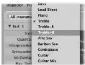
You can also simultaneously assign a staff style to several selected regions.
Automatic Staff Style Assignment
When you create a new MIDI region, either by making a real time recording or with the Pencil tool in the Arrange area, the MIDI region will be assigned the staff style selected in the bottom line of the Track Parameter box.
When you create template projects, or begin work on a new project, you may wish to change these settings for tracks that are likely to use a specific staff style. This ensures that regions recorded on these tracks will immediately be displayed with the correct staff style
If Auto Style is chosen in the bottom line of the Track Parameter box, every new MIDI region will automatically be assigned a staff style that fits the register of the recorded notes. In other words, a Bass staff style will be selected automatically if your region consists of notes played in a low octave. Similarly, two-handed parts will be assigned a Piano staff style.
Note: Auto Style can only be chosen in the Arrange area's Track Parameter box, and does not appear in the list of staff styles in the Score Editor's Display Parameter box.
Predefined Staff Styles
Logic Express contains a number pre-defined staff styles. The table lists them all, and their parameters:
| Staff style Clef type Transposition | |||
| Bass Bass clef — | |||
| Lead Sheet Treble clef — | |||
| Piano (two staffs) Treble/Bass clef — | |||
| Treble | Treble | clef | — |
| Treble +8 Treble (+8) clef -1 octave | |||
| Treble -8 Treble (-8) clef +1 octave | |||
| Alto Sax | Treble clef Eb (+9) | ||
| Baritone Sax | Bass clef Eb (+21) | ||
| Contrabass | Bass (-8) clef | +1 octave | |
| Guitar | Tablature | display | — |
| Guitar Mix (Tablature display and one staff) | Tablature display/Treble (-8) clef | — | |
| Horn in Eb Treble clef Eb (-3) | |||
| Horn in F Treble clef F (+7) | |||
| Organ 1+2/3+4/5 (3 staffs) | Treble/Bass/Bass clef | — | |
| Organ 1+2/3/5 (3 staffs) | Treble/Bass/Bass clef | — | |
| Organ 1/1/5 (3 staffs) | Treble/Bass/Bass clef | — | |
| Organ 1/3+4/5 (3 staffs) | Treble/Bass/Bass clef | — | |
| Organ 1/3/5 (3 staffs) | Treble/Bass/Bass clef | — | |
| Piano1+2/3 (2 staffs) | Treble/Bass clef — | ||
| Piano1+2/3+4 (2 staffs) | Treble/Bass clef — | ||
| Piano 1/3 (2 staffs) | Treble/Bass clef — | ||
| Piano1/3+4 (2 staffs) | Treble/Bass clef — | ||
| Piccolo | Treble clef | -1 octave | |
| Soprano Sax | Treble clef Bb (+2) | ||
| Tenor Sax | Treble clef Bb (+14) | ||
| Trumpet in A | Treble clef A (+3) | ||
| Trumpet in Bb | Treble clef Bb (+2) | ||
| Viola | Alto clef | — | |
| Violoncello Bass clef — | |||
| # Drums Percussion Clef | Mapped | ||
Creating Your Own Staff Styles
You can create new staff styles, and edit, delete, and duplicate existing staff styles in the Staff Style window.
A staff style includes the following editable parameters:
• Number of staffs (for the display of one MIDI region).
- For polyphonic, multiple staff styles: configuration of brackets and bar lines that connect the staffs.
- For every staff: Staff size, distance to the next (higher and lower) staffs, number of independent (polyphonic) voices in the staff, clef, display transposition, key signature on/off.
- For every independent (polyphonic) voice: Automatic rest display on/off, stem direction of notes, tie direction, direction of N-tuplet brackets and numbers, beaming.
- MIDI channel assignment for the voice, or definition of a split point pitch—for separation of the different voices, note color, number of staffs used to display a MIDI region (usually one, but two when using the Piano styles, and three when using the Organ styles), the clefs, and display transposition.
To open the Staff Style window:
- Choose Layout > Staff Styles (or use the Open Staff Style Window key command).
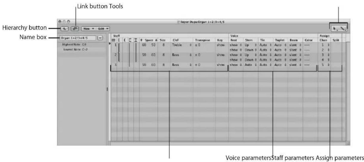
- Link Button: If the Link button is activated while the Staff Style window is open, you will always see the parameters of the currently selected MIDI region's staff style. If you switch to a different MIDI region, the Staff Style window will reflect the new selection.
- Hierarchy button: Click to switch the Staff Style window between single staff style view and list views (the latter shows a list of all available staff styles).
- Tools: Contains the Pointer tool, the Pencil tool (for creating new staffs and voices) and the Eraser tool (for deleting staff styles, staffs, or voices).
- Name box: The field shows the name of the selected staff style. Click the arrow button next to it to open a pop-up menu that lists all styles available in the current project. Switch to another staff style by choosing the desired entry
- Staff parameters: The parameters for staffs. Each line below the word Staff represents one staff in the score display.
- Voice parameters: The parameters for independent voices. Each line below the word voice represents one independent voice. The term voice only relates to the simultaneous display of rhythmically independent, polyphonic passages in the music—not the number of notes that can be displayed simultaneously. One voice can consist of as many simultaneous notes (chords) as desired. Only notes which should be displayed as rhythmically independent (from the other notes in the same staff) need to be assigned to separate voices.
- Assign parameters: The parameters for the assignment of notes to the different voices. Every staff can contain several independent voices (up to 16), but one voice can not be displayed across different staffs. Therefore, a staff style must contain at least as many voices as staffs.
The Staff Style window features the single staff style view shown above, and a list view. The list view is mainly intended for copying staff styles between projects (see below), or for deleting styles.
| Score Style | Type | Range | Size | Transposition |
| Bass | normal | C-2 | C8 | |
| Lead Sheet | normal | C-2 | C8 | |
| Plano | normal | C-2 | C8 | |
| Treble | normal | C-2 | C8 | |
| Treble+B | normal | C-2 | C8 | |
| Treble-B | normal | C-2 | C8 | |
| Alto Sax | normal | C-2 | C8 | |
| Baiton Sax | normal | C-2 | C8 | |
| Contrabass | normal | C-2 | C8 | |
| Guitar | normal | C-2 | C8 | |
| Giatar Mix | normal | C-2 | C8 | |
| Horn in Eb | normal | C-2 | C8 | |
| Horn in F | normal | C-2 | C8 | |
| Organ 1+2/3+4/5 | normal | C-2 | C8 | |
| Organ 1+2/3/5 | normal | C-2 | C8 | |
| Organ 1/1/5 | normal | C-2 | C8 | |
| Organ 1/3+4/5 | normal | C-2 | C8 | |
| Organ 1/3/5 | normal | C-2 | C8 | |
| Plano 1+2/3 | normal | C-2 | C8 |
To switch the Staff Style window to list view, do one of the following:
■ Double-click in the empty space below the parameters to switch to the list view.
Another double-click on one of the listed staff styles switches to the single view of that particular Style.
- Click on the Hierarchy button to the left of the menu line.
Creating a New Staff Style
In single view, you can create a new staff style by choosing New > Single Staff Style or New > Dual Staff Style. The parameters of styles created this way are very basic, and need to be edited (see below) to meet your requirements, in most cases.
The default name of styles created in this fashion is "*New Style". A double-click on the name box opens a text entry field, where any name can be typed in.
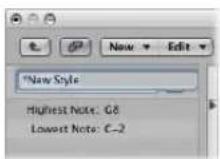
Creating New Staff Styles Based on Existing Ones
You'll often need a new staff style that is almost identical to an existing one. In this situation, just make a copy of the close style, and edit the copy.
To copy a staff style, do one of the following:
- Choose New > Duplicate Style in the Staff Style window's single view.
- Click the arrow button next to the Staff Style window's Name box, then choose ****DUPLICATE!**** in the pop-up menu.
Tip: You can copy the current staff style, and assign it to a selected MIDI region in one go: Select the desired MIDI region in the Score Editor, click the Style parameter in the Display Parameter box, then choose the “****DUPLICATE!****” command in the Staff Style pop-up menu.
Any of these methods will result in a new style—named after the staff style it is derived from—with "*copied" appended to its name. This text can be edited in the name box of the Staff Style window.
Adding Staffs to a Staff Style
You can add a staff to your staff style. This allows you to create a two-staff piano style from a single staff style, for example.
Each staff is represented by a number in the first column. These numbers are assigned automatically, and cannot be changed.
To add a staff to a staff style:
- Determine the staff insert position by clicking in the narrow column to the left of the staff numbers in the Staff Style window, then choose New > Insert Staff.
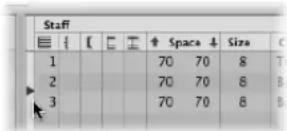
The new line is inserted at the insert mark (>) position.
Adding Voices to a Staff Style
You will need polyphonic staff styles (staff styles with independent voices) to display rhythmically different melodic lines in the same staff (typical for choirs). Theoretically, you can create up to 16 independent voices in a staff style.
To add a voice to a staff style:
- Choose New > Insert Voice.
The new voice will be inserted at the insert mark (>) position, set with a click in the narrow column to the left of the staff numbers (this is important if you want to insert a new voice between existing voices).
The newly inserted voice will inherit the parameters of the voice above it. These can be freely edited. The staff field in the first column remains empty.
The default project contains a number of polyphonic staff styles for piano (Piano 1+2/3+4, for example) and church organ (Organ 1+2/3+4/5, with three staffs, for example).
Copying Voices or Staffs into Other Staff Styles
You can copy one (or several) voices and staffs, inclusive of their parameters, into other staff styles.
To copy a voice or staff into another staff style:
1 Select the voices or staffs you want to copy, by dragging the mouse vertically in the margin column to the left of the staff numbers.
The selection will be indicated by a dark gray vertical beam.
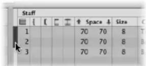
2 Choose Edit > Copy (or use the Copy key command, default: Command-C).
3 Switch to the target staff style that you want to paste these voices into (this also works between different projects).
4 Set the insert mark, then choose Edit > Paste (or use the Paste key command, default: Command-V).
Note: If a voice is selected in the destination staff style (indicated by a black beam in the left column), it will be replaced by the pasted voices.
Copying Staff Styles Between Projects
At some point, you'll probably want to use staff styles that exist in another project.
To import all staff styles from another project:
1 Choose Options > Import Settings in the Score Editor (or use the Import Settings key command).
2 In the Import Settings window, select the project that contains the desired staff styles, activate the Staff Styles checkbox (and disable all other settings that you don't want to import), and click Import.
This imports all staff styles from another project into the current one.
To copy particular staff styles from other projects:
1 In the project that contains the staff styles you want to copy: Open the Staff Style window (single view will be shown).
2 Double-click in the space below the staff style parameters to show a listing of all staff styles.
3 Select the desired staff styles.
4 Choose Edit > Copy (or use the Copy key command, default assignment: Command-C).
5 Open the Staff Style window in the target project.
6 Choose Edit > Paste (or use the Paste key command, default assignment: Command-V).
Automatic Staff Style Copying
If you copy a MIDI region from one project to another, and the staff style used by the original MIDI region doesn't exist in the target project file, it is automatically copied, along with the MIDI region.
Deleting Voices or Staffs From a Staff Style
To delete voices or staffs from a staff style, select them and press Backspace, or choose Edit > Delete.
Deleting Staff Styles
You can delete staff styles in both the single view, and list view. The latter allows you to select, and delete, several staff styles simultaneously.
To delete a staff style in single view:
- Choose New > Delete Style.
To delete multiple staff styles in List view:
Shift-click the (un)desired staff styles, then choose Edit > Delete (or press the Backspace key).
Tip: In list view, you can use the Edit > Select Unused command, to select all staff styles that are currently not assigned to any regions or track instruments in the project.
Changing Staff Style Parameters
Once you have created or imported a staff style, and set the desired number of voices and staffs, you can edit the following parameters in the Staff Style window.
Name
Double-clicking on the name box to the left of the staff and voice columns allows you to input the desired staff style name.
About Key Range
Notes that fall outside the key range (defined to the left of the Staff Style window) are not displayed in the Score Editor. This allows you to hide notes that are used for key switching duties (as an example, VSL sample libraries loaded into the EXS24 mkll).
Brackets and Bar Line Connections
You can only edit this parameter in styles with multiple staffs: It lets you determine which staffs are bracketed (two bracket types available) or connected by bar lines (only at the beginning of each staff line, or at every bar line). Simply click-drag in the corresponding column until you see the appropriate display, for any of these connections.
| Staff | |||||||
| ↑ | Space ↓ | Size | Clef | ||||
| 1 | 60 | 50 | 8 | Treb | |||
| 2 | 50 | 60 | 8 | Bass | |||
| 3 | 50 | 60 | 8 | Bass | |||
If a staff style consists of more than two staffs, the brackets and bar lines can be set to only connect certain parts of the overall staff style—they can be interrupted in-between staffs. If you want to delete any connections, grab the symbol at its end (bottom), and drag it up, until it disappears.
Space
These values determine the distance to the next (higher and lower) staff, or the page margins, for the top and bottom staffs in a full score.
The first value increases or decreases the space above staffs, and the second value, the space below staffs.
This parameter is helpful when you need to create additional space above or below a staff, allowing symbols to be inserted between staffs.
You can also change the vertical distance above the staff directly in the score, by dragging the staff up or down (at the clef).
The distance below the staff can also be edited in the score, but only for the bottom staff in the score display, or if only one staff is displayed. The bottom line of the score display area is dragged with the mouse.
These editing procedures change the settings of the corresponding staff style. All regions which use the same staff style will be affected.
Size
Use this parameter to determine the size of the staff, and the notes and symbols (including slurs and ties) it contains.
There are 16 sizes available (0–15). Here are some size recommendations:
- For regular instrument parts and lead sheets, use size 7 or 8.
- The staff size you should use in full scores depends on the number of staffs in the score, and the size and format of the paper being used. When using A4 or US letter paper: full orchestra: 2, big band: 3, wind quintet: 4.
Note: The size of all staffs in a score set can also be affected by the Scale parameter (see "Using Score Sets to Create Scores and Parts" on page 796) in the Score Set window. This makes it possible to use the same sizes for both the whole score, and parts of a piece.
Clef
You can select the clef to be used in the staff style from a pop-up menu. This menu offers some special options, in addition to the usual clefs:
- Drum.0 to Drum.8: Staffs with 0 to 8 lines and a neutral percussion clef. The relationship of MIDI note pitches to the top line of all staffs corresponds to the top line in a regular bass clef (A2). No accidentals will be displayed in these drum staffs. Drum.0 also omits any ledger lines. These clefs are often used in mapped drum styles (see "Drum Notation With Mapped Staff Styles" on page 792), where the vertical position of a note on the staff doesn't correspond to pitch, but is determined by different drum map parameters.
- no clef.0 to no clef.8: Is like the Drum.0 to Drum.8 staffs, but without a clef.
- TAB Guitar ... and TAB Bass ...: 12 different options for displaying notes as guitar or bass tablature. Tablature tuning sets are defined and edited in the Tablature window (Layout > Guitar Tablature).
Transpose
The display transposition, measured in half steps up or down. This parameter does not affect MIDI playback. If a staff contains chord symbols, these will also be transposed accordingly. If the Automatic Key Transposition project setting, in the Clefs & Signatures tab is activated (which is the default), key signatures will also be transposed (with one exception, see next paragraph).
Key
If this parameter is set to Hide, the corresponding staff is displayed without a key signature. All sharps and flats are indicated directly beside notes. This parameter will usually be set to show the key signature. The Hide option is mainly used for transposed french horn parts, which are sometimes written without a key signature.
Note: The Automatic Key Transposition project setting affects the whole project, but still indicates the non-transposed basic key signature. Hide Key suppresses any key signature display.
Rest
The automatic rest display can be switched off (Hide), or set to display beat slashes (slash) instead of rests. This is useful for rhythm section parts, and improvised solos. In this situation, the number of slashes per bar is determined by the nominator in the time signature (4 slashes in 4/4-time, 6 slashes in 6/8-time, and so on). Inserted notes and symbols are still displayed, but automatic rests are only shown if shorter than one beat. You can insert user rests manually, to replace individual beat slashes, if needed.
Stem
This controls the direction of stems. The default setting is Auto. Up or Down forces all stems, regardless of pitch, in the corresponding direction. Hide makes all stems (and beams and flags) invisible.
Tie
Determines the vertical direction of automatically displayed ties. The default setting is Auto. Up or Down forces all ties in the corresponding direction.
Tuplet
Controls the direction of N-tuplet brackets and numbers. The default setting is Auto. Up or Down forces all N-tuplet brackets and numbers in the corresponding direction. Hide prevents the automatic display of triplet brackets and numbers. In this situation, the numbers are still displayed in brackets on the screen, to allow edits to these triplets. These bracketed numbers will not appear, however, on the printout.
If you set this parameter to Hide, you can still make particular triplets visible: Double-click on the bracketed number (3) to open a tuplet dialog box. If you close this box by clicking OK, you will convert the automatically displayed triplet to a forced triplet, which will be displayed in accordance with the parameters set in the dialog box.
Beam
Controls the appearance of beams. The default Slant setting allows slanted beams. Horiz. only allows horizontal beams. Vocal prevents the display of beams, as is typical in classical vocal parts, where notes are only displayed with flags.
Color
Sets the color of the voice's notes. The color options are: Black ("---"), Pitch, Velocity, and the 16 colors of the user palette (see "Colors" on page 830).
These settings only affect regions if the View > Colors > Normal item is enabled in the Score Editor (default setting).
Assign Parameters
The Chan and Split parameters of the Staff Style window are covered in the following section on note assignment.
Assigning Notes to Voices and Staffs
You can use two different methods for assigning notes to voices and staffs: by defining a fixed split point, or MIDI channels for each voice of a staff.
Using a Split Point
You can use a fixed split point to assign notes to voices. This is a defined pitch, which determines the absolute border between two voices. Notes above it, or at the same pitch, are assigned to the upper voice. Notes below it are assigned to the lower cross the border. Quite often, in real life situations, the border between voices needs to be flexible. A piano piece's right hand part may dip below middle C (the defined split point), or the left hand may go above. It's not possible to notate this properly using a fixed split point, but you can use this facility to create an almost right version.
To separate voices by split point:
In the Staff Style window's Split column, choose the desired note pitch.
Using MIDI Channels
You can use MIDI channels (Chan) to assign notes to voices. Every note belongs to the voice that “owns” its MIDI channel. The different MIDI channels have no impact on MIDI playback, as the playback channel is determined by the Track Parameter box setting (Arrange window). Given the use of MIDI channels for voice assignment, notes that aren’t assigned to channels will not be displayed at all. This can, however, be used to your advantage, as it allows you to exclude certain notes from the display (improvised parts, trill notes, and so on).
To separate voices by MIDI channel:
In the Staff Style window's Chan column, assign the desired MIDI channel to each voice.
When you use MIDI channels to assign notes to staffs or voices:
- You can edit the MIDI channel in the same way as for all other events: by selecting the events and changing the MIDI channel in the Event Parameter box or the Event List.
- You can quickly change the MIDI channel of selected note events with the Event Channel +1 and Event Channel -1 key commands. These can be especially useful when used in combination with the Select Next Region/Event and Select Previous Region/Event key commands, which allow you to move the selection from note to note.
In addition, you can also use Score Editor functions designed to speed up the process of changing the MIDI channel settings of notes, in order to assign them to the desired voices: These include the Auto Split preference and the Voice Separation Tool.
Splitting MIDI Channels Automatically
If you record polyphonic voices as separate passes in real time, you can set your keyboard or MIDI controller to the appropriate MIDI channel for each voice. This saves you from editing the channels after the fact. The same applies to step input.
Alternately, you can automatically split MIDI notes using the "Auto split notes in multi staff chord styles" Score preference.
If this is activated, and the default staff style in the selected Track Parameter box is a polyphonic style, all played notes are automatically assigned MIDI channels that match the staff style's voice assignments. Notes at, and above, the split point are assigned the channel of the first voice. Notes below are assigned the second voice's channel (this feature only works for two voices at a time). This creates a rough, but usable, voice assignment, which can be edited later.
To split regions that have already been recorded:
1 Select the region.
2 Choose Functions > Note Events > Assign Channels based on Score Split (or use the corresponding key command).
This assigns the region's notes to voices in the staff style—according to the Auto Split pitch in the Score preferences.
Using the Voice Separation Tool
The Voice Separation tool allows you to draw a separation line between notes on a staff, thereby assigning them to the MIDI channels of the voices. MIDI channels have to be pre-defined for each of the voices that you want to separate. This is because Logic Express needs to know which MIDI channels are assigned to each note.
To use the Voice Separation tool to change the MIDI channel of notes:
1 Select the Voice Separation tool.
2 Draw a line (between notes) where you want to separate the voices.
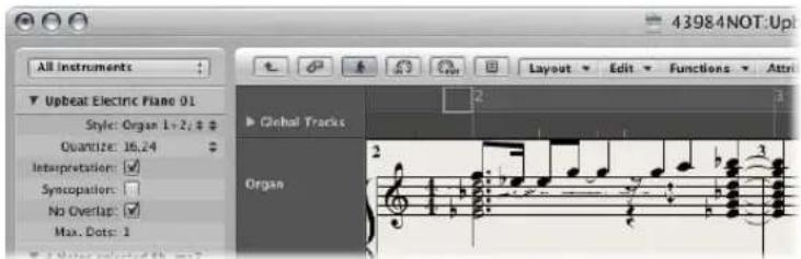
Notes below the line are moved to the MIDI channel below their current assignment.
3 If you make a mistake, just move the mouse back slightly to the left
This erases the separation line to the right of the tool, allowing you to try again.
Staff Style Examples
The following sections illustrate how you can use the staff style facilities to meet specific notation needs.
Creating a Staff Style for Two Independent Voices
If there are two independent voices throughout the piece, the parameters might be set as follows: Stem, Tie, and N-tuplet direction are set to Up for the top voice and Down for the bottom voice. Note that even with these general parameters, note attributes (see "Using Note Attributes to Change Individual Notes" on page 769) can be changed for each note. Both voices are displayed with automatically displayed rests (Rest parameter: Show).
Creating a Single-Staff Style With Optional Polyphony
Sometimes you need to add a second voice to a staff that usually only requires one voice, in order to properly notate a short, rhythmically-independent passage. This is not uncommon with orchestral scores, where the unison part for a group of instruments is temporarily separated from the other parts.
One solution is to use a staff style with a main voice and a secondary voice. The parameters for the main voice should be set as per a non-polyphonic style. The secondary voice is set to channel 16, and is displayed without automatic rests:
- The stem, tie, and tuplet directions for the main voice are set to Auto, which is necessary for the proper notation of unison parts. No MIDI channel is defined for the main voice, so all notes with a channel other than 16 will be assigned to the main voice. As long as no notes or rests with MIDI channel 16 are used, the score display looks the same as with a simple, non-polyphonic staff style.
- For the second voice, the stem, tie, and tuplet direction parameters are set to Down, and the automatic rest display is deactivated (Hide). Only MIDI channel 16 note events will be assigned to this voice.
The following additional steps are necessary to improve the score's appearance:
- Rests in the second voice need to be inserted manually where needed. The MIDI channel of inserted rests must match the second voice's channel (16, in this case). This can be edited in the Event List.
- In the polyphonic passages, the stems of the main voice need to be forced upwards by selecting the corresponding notes, and changing their individual stem parameters (see "Using Note Attributes to Change Individual Notes" on page 769).
An advantage of this approach is that you don't need to worry about MIDI channels during recording or input, and notes won't disappear unintentionally. There is, however, the disadvantage that the Voice Separation tool cannot be used to assign notes to voices.
Other applications for this method would include the display of beamed grace notes, occasional polyphony in a guitar part, or the indication of rhythmic accents above or below beat slashes in rhythm section parts.
Don't forget that you can add further voices to a staff, to display more complex parts (up to 16).
Advanced Staff Style Usage
This section contains information on a number of features, techniques, and tips that will help you to make better use of the staff styles functions.
Mouse Input in Polyphonic Staff Styles
Mouse input into polyphonic staff styles is very easy, if you activate View > Explode Polyphony (also available as a key command). This forces all voices to be displayed on separate staffs, regardless of staff style settings (the other voice parameters remain valid).
If you insert a note into a staff style that uses MIDI channels for voice separation, it is automatically assigned the corresponding MIDI channel (of the staff that you add the note to). Following input, turn off the Explode Polyphony setting. This will display all voices correctly in one staff, as per the staff style settings.
You can, of course, also insert notes directly into polyphonic staffs without activating the Explode Polyphony setting. In this situation, inserted notes are assigned the MIDI channel set in the Insert Defaults of the Event Parameter box (but only if that particular channel is used by one of the voices in the staff).
Changing the Staff Assignment of Symbols
There is a Staff parameter in the Event Parameter box, for most symbols inserted into multiple staff styles. This parameter determines which staff the symbol belongs to.
Cross Staff Beaming
Music for keyboard instruments or harp (which is notated in two staffs) sometimes contains passages where notes in the upper and lower staff (played by the left and right hand) are connected with a beam, to emphasize the continuing musical phrase.
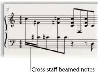
In the Score Editor, notes can only be connected with beams if they belong to the same voice. Notes that belong to the same voice, however, will be displayed in the same staff. You will need to use the Score Editor's Staff Assignment commands to display same voice notes in separate staffs.
As an example: The following screenshot depicts a piano passage, displayed in the Piano staff style. The notes in the upper staff belong to voice one, using MIDI channel one. The notes in the lower staff belong to voice two, using MIDI channel two. Imagine that you want to connect the eight notes in the first bar with beams, to emphasize the continuing musical phrase.
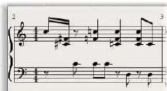
To beam notes that do not belong to the same staff:
1 Change the voice assignments for the notes that you want to connect with beams (in the lower staff) by doing one of the following:
- Draw a line below these notes with the Voice Separation tool.
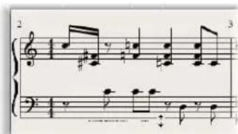
- Select all notes, and change their MIDI channel to match that of the upper voice (in the Event Parameter box).
All notes are displayed in the upper staff, probably accompanied by a lot of ledger lines.
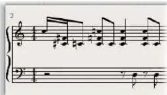
2 Select the notes that you want to define a beaming connection for, then choose Attributes > Beaming > Beam Selected (or use the corresponding key command).
3 Select the notes that you want displayed in the bottom staff, and choose Attributes > Voice/Staff Assignment > Staff below Voice (or the corresponding key command).
This moves all selected notes down to the lower staff, although they still remain part of the upper voice.
You could also use the reverse approach—first assigning all notes to the lower voice, then moving some notes to the upper staff with Attributes > Voice/Staff Assignment > Staff Above Voice.
To display all selected notes in their original staff, use Attributes > Voice/Staff Assignment > Default Staff.
Rest Display
As always, rests are displayed automatically in Logic Express, as per the Rest settings in the staff style. Given the cross-staff beaming situation described above, however, most (or all) notes belong to the voice of the top staff, and the lower staff will contain rests—some even at positions occupied by notes. To avoid this potential issue, you should use a staff style where the automatic rest display is deactivated for the bottom staff's voice. Wherever rest display is desired, insert it/them from the Part box, with the mouse.
Drum Notation With Mapped Staff Styles
In MIDI regions that are assigned to drum instruments, each MIDI note usually triggers a different sound. If such MIDI regions are displayed with a regular staff style, you'll see notes with no apparent relationships to the sounds represented by them.
If you want to notate these musically meaningless pitches as a readable drum part—which uses special percussion note heads—you should use mapped instruments and mapped staff styles.
Mapped staff styles allow you to assign individual voices to drum groups. Drum groups use specific drum notation head shapes to display note events. You can define the respective drum note head shapes in a Mapped Instrument window.
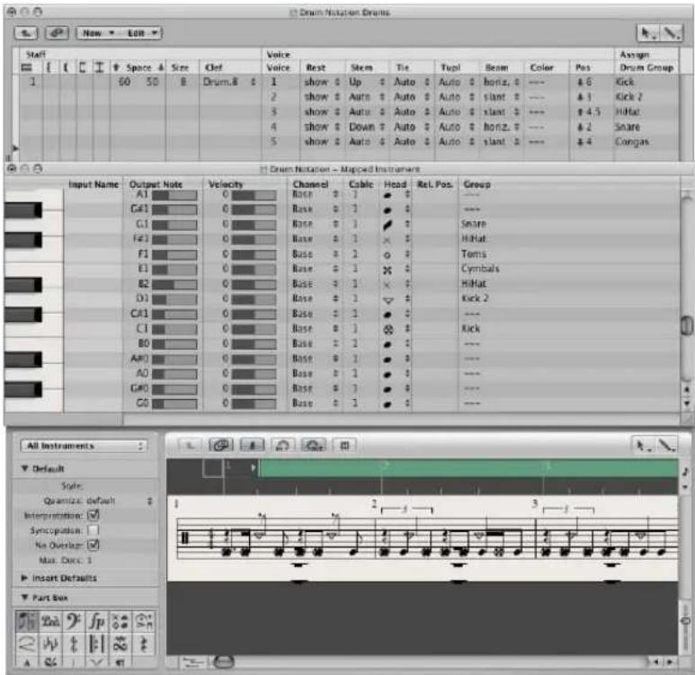
The best way to create drum notation for an existing MIDI region, is to open the Score Editor (to display the MIDI region), the Mapped Instrument window, and the Staff Style window. This way, you can directly see how parameter changes affect the score display.
Prior to defining the details of a mapped staff style, you should set up all drum groups, note head shapes, and relative note position parameters in the Mapped Instrument window.
To create a mapped staff style for drum notation:
1 Create a mapped instrument in the Environment (see "Mapped Instruments" on page 907), then double-click its icon.
The Mapped Instrument window opens. Its default settings correspond to the General MIDI drum note assignments, but they can be edited.
In the columns to the far right, there are three parameters relevant to notation:
2 In the Head menu, choose the shape of the note head for notes triggered by this particular pitch.
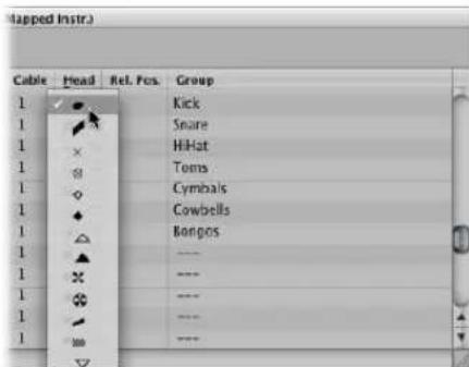
A note must be assigned to a drum group to be displayed in a mapped staff style. If it's not, it won't be visible.
3 Choose a drum group in the Group menu.
A number of groups are pre-defined for the most commonly used drum sounds (Kick, Snare, Hi-Hat, Toms, Cymbals, and so on).
Note: If you want to define a new drum group for another instrument sound (such as tambourine), choose New Group in the pop-up menu, and double-click on this entry to name the new drum group.
4 Set the Rel. Pos. (relative position) parameter as desired.
The Rel. Pos. parameter assigns the note to a line in the staff. The note position is relative to the top line of the staff. Integer values make the note fall on a line, fractional values result in a note position between two lines.
Note: Positions can also be influenced in the Staff Style window, but this affects all notes of a particular drum group.
These options allow you to have two different MIDI notes (different bass drum sounds, for example) displayed in the same way in the score, or on the same line, but with different note heads.
5 Create a new mapped staff style by choosing New > Mapped Style in the Staff Style window, and inserting all desired staffs, voices, and drum groups—as described above, and in "Working With Staff Styles" on page 775.
| Staff | Voice | Assign | ||||||||||||||||
| Voice | Rest | Stem | Tie | Tusl | Beam | Color | Pos | Drum Group | ||||||||||
| 1 | 60 | 50 | 8 | Dram.8 | 1 | show # | Up # | Auto # | Auto # | horiz. # | --- | & 6 | Click | |||||
| 2 | show # | Auto # | Auto # | Auto # | slant. # | --- | & 3 | Click 2 | ||||||||||
| 3 | show # | Auto # | Auto # | Auto # | slant. # | --- | # 4.5 | Hitat | ||||||||||
| 4 | show # | Down # | Auto # | Auto # | horiz. # | --- | & 2 | Snare | ||||||||||
| 5 | show # | Auto # | Auto # | Auto # | slant. # | --- | & 4 | Congas | ||||||||||
- Staff section: Everything is identical to non-mapped staff styles (with the exception of the missing Transpose and Key parameters, which wouldn't make sense here).
- Voice section: Below Voice (in the top header line), you'll see a separate Voice column, where the different voices are numbered automatically. The staff style shown above contains one staff with five independent voices.
- The horizontal lines display the Staffs-Voices-Drum Groups hierarchy, indicating the borders between these elements. Each drum group belongs to the voice at the same horizontal position. The Pos parameter affects the vertical positioning of all notes in the corresponding drum group. The value shown here is an offset—which is added to, or subtracted from—the relative positions (if defined for individual notes in the Mapped Instrument window).
Mapped staff style names are preceded by the # character in the Staff Styles window.
Using Multiple Drum Maps in a Project
If you are using several MIDI instruments with different drum assignments, you can create a separate drum map (in the Mapped Instrument window) for each instrument. The list of drum groups, however, is the same for all instruments in a project. This enables you to display different drum tracks with the same mapped staff style. All snare drums, for example, will be displayed in the same way.
To override this behavior:
1 Create additional drum groups (Kick2, Snare2, and so on).
2 Create a second mapped staff style to display these drum groups.
Using Score Sets to Create Scores and Parts
You can use score sets to determine which instrument tracks should be included in the score display. Each project can contain as many score sets as required. Score sets allow you to:
- Produce both the full score and individual parts (such as particular groups of instruments).
- Arrange the (vertical) order of instrument tracks in the score, independent of the order of tracks in the Arrange area.
- Assign a name (and an abbreviated name, if desired) to each instrument track, which will be displayed and printed as instrument names in the score.
- Determine which staffs will be connected by brackets or bar lines.
- Exclude the display of tracks that are only relevant for playback, but not for the score (tracks that only contain MIDI controller data, for example).
- Simultaneously reduce or enlarge all staffs in each staff set, by using the Scale parameter. This allows you to use the same staff styles for printout of full scores and individual parts.
- Select from two different parameter sets (Score or Part) for page margins, header space height, vertical distance between staff systems, and the maximum number of bars per line.
The Relationship Between Score Sets and Display Modes
A score set will only be shown as defined if an appropriate display mode is chosen. Content Link and Content Catch only allow the display of one MIDI region at a time, making them unsuitable for work with score sets. It's usually best to deactivate Link, once the desired score set is fully displayed. If only one MIDI region is displayed, double-click below the staff, which will display the full score, then deactivate Link.
Tip: It is possible to work with several open Score Editor windows, each showing different display levels or different score sets.
Choosing a Score Set
A score set is chosen in the Inspector's Score Set menu.
Click the menu to show all available score sets. New projects will only show the All Instruments score set which will display all instruments—dependent on the display level.
The Score Set Window
You can create and edit score sets in the Score Set window.
To open the Score Set window, do one of the following:
- Choose the Open Score Set window command in the Score Set menu (or use the Open Score Set window key command, default: Control-Command-I).
- Choose Layout > Score Sets in the Score Editor.
If you open the Score Set window when the default All Instruments score set is selected, a warning indicates that the All Instruments score set cannot be edited.
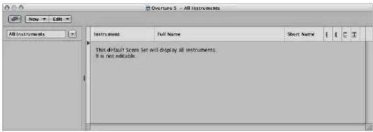
Name of Score Set
You can edit the name of a score set by double-clicking on the name in the left column of the Score Set window, which opens a text entry field.
Insert Mark
The narrow column to the left allows you to set an insert mark (>) with a mouse click, or make multiple selection marks by dragging the mouse vertically.
Instrument
This column is used to determine which instruments are included in the score set, and their (vertical) order of appearance in the score. Track instrument icons are also displayed in this column, at the highest zoom level.
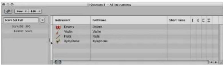
Full Name
A click on any line in this column opens an entry field that contains the default "@(reference)". If you don't change this, the name of the track's instrument will be used as the name for the instrument in the score. As the track's instrument name is often identical to the corresponding synthesizer patch (Solo Strings High, for example), you'll probably want to assign another name here. This name is automatically displayed in the score as the full name: "Violin 1", for example. Display parameters for instrument names are set in the Numbers & Names tab of the Score project settings (see "Numbers & Names" on page 816).
Short Name
You can also define an abbreviated name for each instrument, which is used if Short Names is selected in the 1st Staff and Other Staffs pop-up menus of the Numbers & Names tab, in the Score project settings.
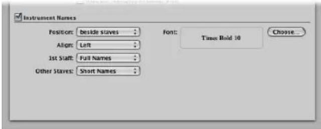
Brackets and Bar Lines
You can define which staffs in the score set are connected by brackets or bar lines (either at the beginning of each staff, or throughout), in the last four columns. Any of these connections can be set by dragging vertically in the column, until you see the appropriate display.
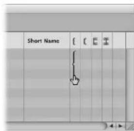
Brackets and bar lines can also be interrupted between staffs, enabling you to form groups of connected instruments in a score. If you want to delete a line or bracket, grab the corresponding symbol at its end point (bottom), and drag it upwards, until it disappears. You can use the same method to shorten lines.
Bar line connections can also be edited directly in the score. Just click on the upper end of a bar line to connect it to the next (higher) staff. Repeating the procedure disconnects the bar lines.
Creating and Deleting Score Sets
When you open a Score Editor window, while several regions are selected in the Arrange area, Logic Express automatically creates and displays a score set that only contains the instruments of the selected regions.
You can also use one of the following methods to create a score set manually.
To create an empty score set:
- Choose New > New Empty Set in the Score Set window.
You can insert the desired instruments into the empty score set, one-by-one.
To create a copy of the currently selected score set:
- Choose New > Duplicate Set in the Score Set window.
To create a score set for all selected instruments:
1 Select at least one MIDI region for all instrument tracks you want to include in the score set.
2 Choose Layout > Create Score Set from Selection (or use the corresponding key command) in the Score Editor.
Logic Express creates and displays a new score set, which consists of all instruments used by the currently selected MIDI regions.
Score sets created this way are automatically named after the instruments they contain.
To create a score set that contains all instrument tracks used in the Arrange window:
In the Score Set window, choose New > New Complete Set.
Tip: If several instruments or staffs use the same MIDI sound for playback (with the same MIDI channel on the same MIDI instrument), and you want to display these staffs with different instrument names in the score, you need to create a separate track instrument for each staff, in the Arrange area.
All score sets are saved with the project file.
To delete a score set:
- Select the score set in the Score Set window, then choose New > Delete Set.
Editing Score Sets
Once you have created a score set, you can change the assignment of instrument entries, add instruments, or change their order.
To assign another instrument to an existing score set entry:
- Click-hold the name of the instrument you want to replace in the Instrument column, then choose the desired instrument from the pop-up menu.
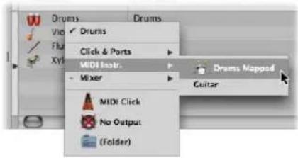
To add an instrument to the middle of the list:
- Set the insert mark to the desired position, then choose New > Add Instrument Entry.
A new instrument entry is added at the insert mark.
To add an instrument at the bottom of the list:
■ Double-click below the instrument list.
A new instrument entry is added at the bottom of the list.
Reordering Instruments
You can use the usual Cut, Copy, and Paste commands to reorder the instrument entries in a score set. If pasted, they will be placed at the insert mark position, which must be set beforehand.
Scaling Score Sets
You can scale any score set to a desired size between 50 and 200 percent of the original size.
To scale a score set:
- Select the score set in the Score Set window, then set the Scale parameter to the desired value.

The Scale parameter affects:
- All staffs
• The distance between the staffs - All symbols associated with staffs (all notes, rests, and other symbols)
• All local text, including lyrics - Slur and Tie thickness
The Scale parameter does not affect global text objects (header text, text inserted outside the margins) and text such as page numbers, and so on.
Scaling doesn't take place on instrument parts that were created by Option-clicking on the Score Set menu—and choosing the instrument from the pop-up menu (as described below, see "Filtering Single Instruments" on page 802). As such, you can use the same staff styles for full scores and parts: in extracted parts, the staffs will appear at their original size, in the full score, their size is defined by the Scale parameter.
Note: The All Instruments set can not be edited (and therefore, can not be scaled), so you'll need to create a dedicated score set for the full score, in most cases.
Creating Separate Layouts for Parts and Score
You can use separate layout parameters for the full score, and parts, in the Global tab of the Score project settings. The Format parameter in the Score Set window determines which layout parameters a score set uses.
To create separate layout parameters for the full score, and parts:
1 Open the Global Score project settings by choosing File > Project Settings > Score (or using the Open Score Project Settings key command), then click the Global tab.
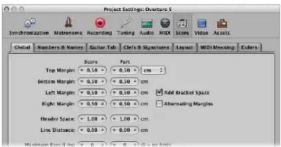
The Global tab offers separate page layout parameters for score and parts.
2 Set the separate score and part layout parameters as desired.
To determine the layout parameters used by a score set:
In the Score Set window, choose the desired setting from the Format menu.
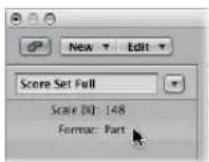
For the default All Instruments set, the score settings will always be used, except when a single MIDI region is displayed. In this situation, the part settings will be used.
Filtering Single Instruments
You can quickly extract a single instrument from the score, by choosing it from the pop-up menu that appears when you Option-click on the Score Set menu.
This way, you don't need to create a score set for every instrument, in order to produce parts. You should note, however, that only the track instrument names will be used as instrument names in the score. So, if you use this method for printout of your parts, you will see the real instrument names of the Arrange window track instruments.
Importing Score Sets From Other Projects
You can import score sets from other projects.
To import score sets from other projects:
1 Choose File > Project > Import Settings (or use the Import Settings key command, default: Option-Command-I).
2 In the Import Settings window:
a Select the project you want to import the score sets from.
b Select the Score Sets option.
c Click Open.
Logic Express imports all score sets from the selected project into the current project.
Printing the Score
This section covers the display options available when readying a score for printing, and also concentrates on a number of global layout facilities that will help you to get the score (and your sheet music) looking just right.
Preparing the Score Layout for Printing
This (and the following) section outlines a number of changes you can make to the overall score layout. These primarily involve display customizations, and use of the Score project settings or preferences. Full details on all "Project Settings for Score Display" on page 811, and "Score Preferences" on page 832.
Using Page View
You should use Page view for layout work, when preparing for printing. In Page view, Logic Express automatically displays as many facing pages as possible, dependent on the size of the Score Editor window and current zoom level.
To switch to Page view:
- Choose View > Page view in the Score Editor (or use the corresponding key command).
- Click on the Page View button in the Score Editor's upper left corner.
You should use linear view for editing, as screen redraws are much faster, especially on slower computers.
You can jump directly to any page, using the View > Go to Page menu item (or corresponding key command), when working in Page view mode. The playhead is automatically set to the beginning of the selected page, unless the sequencer is running when you choose the command. In this situation, Catch mode will be turned off.
Additional Page Display Options
The View > Page Display Options menu offers a number of additional settings that are useful for printing or layout tasks.
- Print View: Print view shows the score as it will be printed. Print view can only be activated when Page view is active.
• Show Margins: Displays page margins onscreen. These are not printed. - Show Pages in Pairs: As the name suggests, this shows facing pages. This setting is reliant on the zoom settings, and score scale.
- Show Page Rulers: Displays a horizontal and vertical ruler (in centimeters or inches) that makes precise layout tasks easier.
Note: The yellow area on the screen represents the printable area (which also depends on the printer being used), not the actual sheet of paper. The grayish yellow area surrounding the page—in Print view—shows how the page will actually be printed.
Setting Breaks
You can set line, link, and page breaks individually for each score set, and also for each of the extracted parts. Logic Express saves breaks with the project file.
Line Breaks
The automatic line break calculations are based on the Spacing and Max.Bars/Line settings in the Global Score project settings. The Maximum Bars/Line project setting determines the maximum number of bars Logic Express will allow in one staff or staff system. You can override the automatic line break with the Layout tool (when in Page view). You can also create a line break by inserting the Link Break symbol in any view mode, using the standard insert methods.
As an example, you can set Maximum Bars/Line to 6, and still move additional bars into a line with the Layout tool. Any subsequent lines will contain no more than six bars. The full number of bars set here will only be displayed if the spacing settings are low enough to allow the proper display of that many bars.
Note: Dragging more bars into a line than would be displayed when employing the automatic line break function can result in overlapping notes and symbols!
To move one or more bars of a staff system down into the next staff:
In Page view, grab the bar with the Layout tool, and drag it down (the mouse icon changes to a hand with a downwards-pointing thumb), then release the mouse button.
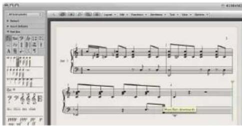
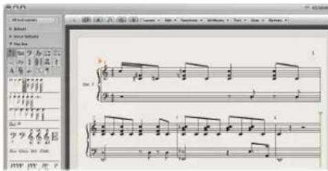
The bar is moved to the next staff system, and the remaining bars in the line are distributed evenly over the entire width of the page.
You also can move the first bars of a staff upwards into the preceding staff, by dragging them up with the Layout tool.
Preserving Manual Line Breaks
When you move a bar with the Layout tool, as described above, all manually edited line breaks in subsequent lines are deleted, and the (automatic) line breaks are recalculated from that line downwards. If you want to prevent this, perhaps because you only want to change one detail and keep the other staffs as they were, hold Option while moving the bars with the Layout tool. Line breaks edited in this way will only affect the two (directly concerned) staff systems. All other staff systems are unchanged.
Page Breaks
You can use the Page Break symbols to insert a page break. This moves all bars that follow the page break insertion point to the following page. All preceding, and following, bars are automatically adjusted in accordance with the Score project settings (discussed in the Line Breaks section above). All staffs in the score are affected.
Editing Local Margins
You can move the left and right margin of each individual staff system with the Layout tool, so that they do not align horizontally with the page margins. Like manual line breaks, these local margins are also saved as part of the current score set, allowing different settings for each score set.
To move the left and right margin of a staff system:
1 Turn on the following settings in the Score Editor's View menu:
- Page View
• Page Display Options > Print View
• Page Display Options > Show Margins
2 Click-hold (with the Layout tool) a little inside the beginning or end of the staff, and drag to the left or right.
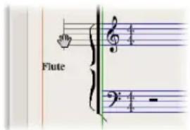
During this process, Left/Right Staff Margin will appear in the help tag.
Note: When altering margins, Logic Express automatically adapts the number of bars per line (unless you have manually adjusted line breaks beforehand): if the line is shortened, bars may be moved down to the next line, depending on the Spacing parameters in the Global tab of the Score project settings (see "Global Score Settings" on page 812).
To realign a changed staff margin with the other staffs:
■ Double-click at its end (or beginning) with the Layout tool.
To delete all line breaks and (locally) changed margins in the current score set:
- Choose Layout > Reset Line Layout.
Changing the Margin and Header Values in Page Print View
You can change the Margin and Header Space project settings directly with the mouse in Page Print view.
To change the margin and header space values with the mouse:
1 Turn on the following settings in the Score Editor's View menu:
- Page View
• Page Display Options > Print View
• Page Display Options > Show Margins
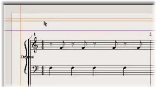
2 Set the margin values by dragging the orange lines.
3 Set the header space value by dragging the purple line.
This only affects the setting (score or part) which is currently displayed.
Printing the Score
The printout of scores created in Logic Express is identical to the Score Editor's Page view display. The following items are not printed, but are visible on the screen:
- The dashed lines that represent page and header margins, and borders between staff systems.
- Mouse cursor and playhead
- Colors (page margins, staff lines of selected MIDI regions)
- Hidden time signature changes
- Hidden note heads (displayed in gray on the screen) and their ties
- Hidden bar lines (displayed as dashed lines on the screen)
- Hidden N-Tuplet numbers
To print your score:
1 Choose the appropriate paper size and format in the File > Page Setup window.
2 Ensure that the Score Editor (containing the intended print view) is the active window.
3 Start printing by choosing File > Print (or using the corresponding key command, default: Command-P).
A dialog box, which may vary slightly from printer to printer, is shown. Choose from the available options, such as which page numbers you would like to print, the number of copies, or click the PDF button to "print to" (Save as) a PDF file.
4 Make your selections, and click the Print button.
You should work at high zoom levels when doing layout work that requires precision, such as positioning symbols and text elements.
It's very easy to switch back and forth between a normal and enlarged view of the display, by using the Zoom tool (shortcut: rubber band selection while holding down Control, to enlarge the selected area).
Using External Symbol Fonts for Display and Printout of Notes and Symbols
You can use the Sonata font from Adobe™, the Jazzfont, and the Swingfont (not included with Logic Express), instead of the internal Logic Express score font, for display and printout of notes and symbols. The external font must be properly installed on your system. Activate Logic Express > Preferences > Score > "Use external symbol font (if available)" and choose the font you wish to use in the corresponding pop-up menu.
Exporting the Score as a Graphic File
You can save a part of a Logic Express score page (or a whole page) as an image (PDF format), or copy it into the Clipboard. This allows you to paste it into graphic editing programs, or documents created in word processing or desktop publishing applications.
Preparing the Export
Before you export the score as an image, you should choose the appropriate Camera Tool settings in the Logic Express > Preferences > Score pane.
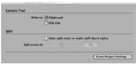
Write to:
- Clipboard: The image is copied to the Clipboard, and can be pasted directly into other applications, without saving it as a separate file.
- PDF File: The image will be saved as a PDF file. A file selector box allows you to assign a file name and path—when the Camera tool is used to take a snapshot of the score.
Exporting the Score
You use the Camera tool to export the score as an image file.
To export the score as an image:
1 Select the Camera tool.
2 Drag across the desired score section. A selection rectangle is shown as you do this.
As soon as you release the mouse button, Logic Express creates a PDF file (or copies the selection to the Clipboard—see option above), encompassing the area you dragged the Camera tool over.
Note: This function is only available in Page view.
Customizing the Score Editor's Appearance
The following section outlines the various options for changing the general appearance of the Score Editor. The different view modes can accelerate editing, or are required for particular operations.
Choosing a Color Mode
The settings in the Score Editor's View > Colors menu set the color mode for the active Score Editor window. These settings have priority over all other color settings.
- Normal: Colors are assigned in accordance with the color settings in staff styles and note attributes. As long as these settings haven't been changed in new projects, this will result in a regular black and white printout—and black notes on a yellow background onscreen.
- Show Pitch: Applies colors in accordance with note pitches. The colors of notes can be edited in the Layout > Colors window. This window also allows you to determine whether notes with accidentals will match the color of those without accidentals, or if each note in the chromatic scale will have its own color.
- Show Velocity: Applies eight different colors, in accordance with MIDI velocity. These colors can also be edited in Layout > Colors.
- Show Voice Assignment: Assigns different colors to different voices. This only makes sense in staff styles that contain more than one voice. This mode employs the colors of the user palette, which can also be found and edited in Layout > Colors.
- Force Black & White: Does exactly what the name implies. This mode is useful when color options have been used in staff styles, or have been assigned to notes using note attributes—but you want to print a regular black and white score—and then return to the colored display.
Displaying Folders
If the current display level allows more than one MIDI region to be viewed simultaneously (linked or unlinked), the View > Explode Folders setting will affect how things are shown: unlike the other editor windows, the Score Editor can display (or even print) the contents of different display (Folder) levels at once.
If the current display level contains folders, their contents are also displayed in the score.
Note: If this setting is not activated, folders will appear as gray beams in linear view, and won't be shown at all in Page view.
Displaying Global Tracks
Enable the View > Global tracks setting to view the global tracks in the Score Editor. You can only enable this setting in linear view mode. The Configure Global Tracks command allows you to choose which global track types are shown.
Displaying Instrument Names
Enable the View > Instrument Names setting to show the names of (used) track instruments, to the left of the score display.
Project Settings for Score Display
There are seven pages of score-related project settings. You can switch between these and other project settings, by using the tabs at the top of the Project Settings window.
These settings affect the whole project (in all score sets). They are saved with the project file, allowing each project to have different settings.
You can import the Score project settings from another project into the current project.
To import Score project settings:
1 Do one of the following:
- Choose File > Project Settings > Import from the main menu bar (or use the Import Settings key command, default: Option-Command-I).
- Choose Options > Import Settings in the Score Editor.
2 In the Import Settings window, choose the Score Settings option, then click Import (unchecked all other settings that you don't want to import).
This imports all Score project settings into the current project.
Global Score Settings
The Global Score project settings define global formatting options such as page margins, spacing between notes, bars per line, and more.
To open the Global Score project settings, do one of the following:
- Choose File > Project Settings > Score in the main menu bar (or use the Open Score Project Settings key command), then click the Global tab (if not already displayed).
- Click the Settings button in the Arrange Toolbar, choose Score from the menu, then click the Global tab.
- Choose Layout > Global Format in the Score Editor.
■ Use the Settings: Global Format key command (default: Control-Option-Command-F).
■ Double-click on the page margins in Page view.
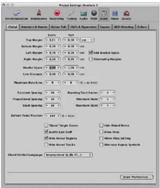
Distance values can be displayed in inches or centimeters in the Global Score settings tab.
To switch the distance value display between inches and centimeters:
- Choose the respective value in the pop-up menu at the top of the Global Score settings tab.
Settings that affect the general page layout (margins, for example) can be set independently for a part or the full score. This is indicated by the two input boxes. This allows you to print out single voices with a page layout that differs from the full score (see "Creating Separate Layouts for Parts and Score" on page 802).
The following sections describe the settings in detail.
Top, Bottom, Left, and Right Margin
These values show the margin distances to the outer border of the printable area on the page. A “Top Margin 0.0 inches” value means that printing will start as close to the top of the paper as the selected printer driver will allow. This also means that the size of the printable area can vary between printers, although the difference should be minimal.
Margins are only visible in Page Print view, where they are displayed as orange lines on the screen. These lines are not printed. It is also possible to change them directly in the score, by dragging them with the Pointer or Layout tool.
Add Bracket Space
Creates additional space between the left margin line and the beginning of staffs, for braces and brackets. If this option is deactivated, staffs will be aligned directly along the left margin line.
Alternating Margins
If activated, the left and right page margin settings will be swapped on every second page. This can be useful if a score is going to be bound as a book: the inner margin usually needs to be a little bigger than the outer one. It's possible that the opposite might be preferable, in cases where extra space is needed for remarks that may be added to the score at a later date.
Header Space
Defines the height reserved for headers, between the top margin of the first page, and the top margin of the first staff on the page (as per the assigned staff style).
Note: Text objects inserted directly into this area automatically become global text elements (see "Working With Global Text" on page 747), and are displayed as headers in all score sets (full scores and parts).
This value can also be changed directly in the score, by dragging the purple line above the first staff.
Line Distance
Defines additional vertical distance between staff systems (single, multiple, or bracketed staffs can constitute a system) on the same page. It applies to full scores, as well as single staff parts.
Maximum Bars/Line
This parameter can be useful when using small spacing values (see below), to prevent too many bars from being displayed on one line. The number set here limits the number of bars that can be displayed per line.
Note: This setting can be overridden when using the Layout tool to change line breaks (see "Setting Breaks" on page 805).
Constant Spacing and Proportional Spacing
These parameters determine the amount of horizontal distance between notes.
- Constant Spacing affects the distance from note to note, regardless of rhythmic value.
- Proportional Spacing takes the note durations into consideration.
If you only use Proportional Spacing (and set Constant to 0), every bar receives (more or less) the same amount of (horizontal) space. A whole note uses as much space as four quarter notes. In the opposite situation (high constant value, proportional value is set to 0), the distance from one note to the next is always the same, regardless of note duration. A half note takes the same amount of space as an eighth note. Other factors, such as accidentals, ties, and so on, are also considered for note distance calculations.
The settings you should use depend on both your personal preference, and the style of the piece. You should aim for a good balance between these two parameters, so try different combinations when working on the final score layout.
Slash Spacing
This is the distance parameter for slashes (used in staff styles that display beat slashes instead of automatic rests). This is especially important when inserting notes into staffs that display slashes. As an example, musical styles such as funk use a lot of sixteenth notes, so you are likely to choose a higher slash distance than you would for music that doesn't go beyond eighth notes. This way, the proper relationships between notes and passages (containing only slashes and chord symbols) can be maintained.
Beaming Slant Factor, Minimum Slant, and Maximum Slant
These three parameters affect the slant angle of beams. As with the Spacing parameters, these parameters work together. Appropriate settings need to be found by trying different combinations. The final settings will vary, depending on the style of the music, and on personal preference.
- Beaming Slant Factor: Determines the general amount of beam slanting, in relation to the intervals of the notes connected by beams.
- Minimum Slant: Determines the minimum interval of notes that causes beams to be slanted.
• Maximum Slant: Determines the maximum beaming slant angle.
These parameters work relatively to a particular scoring situation, which is why no explicit settings can be given. Again, it is essential to try different combinations when working on the final layout of a piece.
Default Pedal Position
This determines the vertical position of automatic pedal symbols (those created when you use the MIDI sustain pedal during a real time recording). If this parameter is set to zero, recorded MIDI sustain pedal events are hidden in the score. Pedal marks that you manually insert from the Part box are not affected by this parameter.
"Open" Single Staffs
Displays single staffs without vertical lines at their start point (left side of the clef).
Justify Last Staff
Lengthens the last line (the last staff system, in full scores) to the right page margin.
Hide Muted Regions, Hide Muted Tracks, and Hide Muted Notes
Excludes muted regions, or regions on muted tracks, or muted notes, from the score display. If these options are not activated, muted tracks, regions, and notes will be displayed in the score, even though they won't be heard during MIDI playback.
Show Alias
Switches the display of aliases (see "Working With Aliases in the Score Editor" on page 726) in the score on or off.
Allow Alias Editing
Switches alias editing on or off (see "Working With Aliases in the Score Editor" on page 726).
Alternate Repeat Symbols
If this option is activated, all repeat signs in the project will be displayed with real book style brackets.
Chord Symbol Language
This pop-up menu allows you to choose between
- International (B, Bb, F#, ...): Default setting
• German (H, B, F#, ...): B → H, Bb → B
• German (H, Bb, F#, ...): B → H, Bb → Bb
• German (H, B, Fis, ...): C# → Cis, Eb → Es, and so on ...
• Roman (Do, Re, Mi, ...): CDEFGAB → Do Re Mi Fa So La Ti
In all Chord Symbol Language formats, the current format is also accepted for the input of new chords.
The #, b, x, and bb characters are also active in the German (H, B, Fis, ...) mode, allowing for quick entry. In the Roman format, the second root string character can be omitted (typing D7 or Do7 in Roman mode will both result in Do 7).
Changing the Chord Language automatically affects all chord symbols in the project. It is not possible to mix chord languages.
Numbers & Names
These settings affect the automatic display of page numbers, bar numbers, and instrument names in the score.
To open the Numbers & Names Score project settings:
- Choose File > Project Settings > Score in the main menu bar (or use the Open Score Project Settings key command), then click the Numbers & Names tab (if is not already displayed).
- Click the Settings button in the Arrange Toolbar, choose Score from the menu, then click the Numbers & Names tab.
- Choose Layout > Numbers & Names in the Score Editor.
■ Use the Settings: Numbers & Names key command.
■ Double-click on any bar or page number.

Automatic page and bar number display, and automatic display of instrument names can be switched on and off for the whole project—by activating or deactivating the corresponding checkboxes in this tab.
For each of these options, you can set the font, size, and face by clicking the Choose button.
The corresponding text styles in the Text Styles window (see "Working With Text Styles" on page 746) are automatically updated if you edit these settings.
Page Number Parameters
The Page Numbers checkbox must be activated for the following parameters to have an effect.
Horizontal Position
Alters the horizontal alignment on the page. Choose from:
• Alternating: Alternating, beginning on the right side.
- Left, Right, or Centered: These are self-explanatory.
- Rev. Alternating: Alternating, beginning on the left side.
Vertical Position
Alters the vertical alignment on the page. You can choose either: Top or Bottom.
Page Offset
This value is added to each actual page number, for display purposes. This can be useful when writing a piece consisting of several parts, which are saved as separate project files. To retain continuous page numbers throughout the score, you can set this parameter to the number of pages contained in all preceding parts (project files).
Horizontal Distance
The horizontal distance from the outermost printing position on the page. This is only relevant for page numbers with the Horizontal Position parameter set to Alternating or Rev. Alternating.
Vertical Distance
The vertical distance to the highest or lowest printing position on the page (dependent on whether Vertical Position is set to Top or Bottom).
Hide 1st Page Number
Prevents the display (and printout) of the page number on the first page (all others are displayed and printed).
Prefix
Allows you to enter text which will be displayed with every page number.
Example: If you use the prefix Page—the word Page, followed by a space and the actual page number—will be displayed on each page. This means that page three will display Page 3. If you want the page number in the middle of the prefix, you need to use the # symbol as a variable for the page number. An example: “- pg.# -” on the second page prints as “- pg.2 -”.
You can also use the following text symbols to include automatically generated text in the prefix:
- "\i" for the score set name.
- "\n" for the project (file) name.
- "\s" for the name of the currently shown display level, which can be the MIDI region or folder name (or even the project name, on the highest level).
- "\d" for the current date (at the time of printout).
Bar Number Parameters
The Bar Numbers checkbox must be activated for the following parameters to have an effect. Bar numbers can be placed above or below bar lines, and at the beginning of the line, above or below the clef (they are automatically moved to a position where they won't overlap the clef).
Horizontal Position
Choose either: At Bar Line or At Bar Center.
Vertical Position
The height above the staff. If a negative value is set here, the bar numbers are placed below the staff.
Step
This value controls the interval (in bars) between the display of bar numbers. A value of 4, for example, results in bar numbers at the first, fifth, ninth bar, and so on. If you only want bar numbers to be displayed at the beginning of each staff line, set this parameter to 0.
Bar
This value is added to all actual bar numbers, for display.
Start With
Automatic numbering begins at the bar indicated here.
Hide Bar Numbers in Linear View
Does exactly what it says. Linear view refers to non-Page view.
Count Multiple Rests
Displays the first and last bar number below multiple rests. This makes sense if a negative Vertical Position value is chosen, causing bar numbers to be shown below staffs.
Show at Double Bars
Displays bar numbers at every double bar line and repeat sign, independent of the chosen Step setting. As an example, if Step is set to 0 (and Double Bars is activated) bar numbers will be displayed at the beginning of each staff line, and above or below all double bar lines and repeat signs.
Top/Bottom Staff only
In full scores, the bar number is only displayed above the top staff, if this option is activated (a negative Vertical Position value results in the number being shown below the bottom staff).
Instrument Name Parameters
The Instrument Names checkbox must be activated for the following parameters to have an effect. These parameters determine the appearance of names—defined for instruments in the score set (see "Using Score Sets to Create Scores and Parts" on page 796) window—in both the full name and short name columns. If nothing is defined here, or if All Instruments is used as the current score set, the names of the track instruments (as displayed in the Arrange window) will be used in the score.
Position
Choose from above or beside staffs.
Align
This refers to the space preceding staffs. Choose either: Left (at the left margin), or Right (at the right margin).
1st Staff
Choose one of the following to display the instrument name at the first staff: No Names, Short Names, or Full Names.
Other Staffs
As above, for other staffs.
Guitar Tab
Guitar tablature is an alternative method of notating music for fretted string instruments—especially for guitar and electric bass—but also for other fretted instruments, with four to six strings (or courses of strings).
In this system, the horizontal lines represent the strings of the instrument. Notes are always written on the line/string at which they are played. The fret numbers are shown instead of regular note heads.
Logic Express automatically converts notes into tablature, if a staff style containing a Clef parameter set to one of these tuning sets, is used. The exact characteristics of these tuning sets are determined in the Guitar Tablature tab.
To open the Guitar Tablature tab, do one of the following:
- Choose File > Project Settings > Score in the main menu bar (or use the Open Score Project Settings key command), then click Guitar Tab (if not already displayed).
- Click the Settings button in the Arrange Toolbar, choose Score from the menu, then click Guitar Tab.
- Choose Layout > Guitar Tablature.
■ Use the Settings: Guitar Tablature key command.
■ Double-click on the TAB clef, at the beginning of any staff that uses tablature in the score.
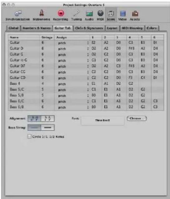
Twelve different tuning sets can be defined. Each of them corresponds to one line in this tab. The regular guitar and bass tunings are already included as defaults (first line and last five lines), as are some of the more common guitar tunings.
Parameters Available for Every Tuning Set
- Name: Can be changed in the text entry field that opens when you double-click on the Name field.
- Strings: Number of strings (four, five, or six)
- Assign: The method Logic Express uses for automatically assigning notes to strings (see Assign section below).
- 1 to 6: The pitches that the open strings are tuned to.
Other Common Parameters:
- Font button: Click to choose a font, font size, and face for the display of fret numbers.
- Alignment buttons: Click to determine the alignment of numbers to the stem: You can choose: to the side, or centered.
- Bass String buttons: Click to determine the display of the lowest string. It may be the same as other strings, or slightly thicker.
- Circle 1/1, 1/2 Notes checkbox: If this option is activated, half and whole notes will be displayed with a circle around the fret number. As the note head is always a number, there would be no visible difference between a half note and a quarter note, if this parameter wasn't available.
Determining the Assign Method
As most notes can be played at different positions (frets) on different strings, the Assign parameter performs an essential role. In most cases, the MIDI channels of the individual notes determine the string assignment.
Note: The MIDI channel parameter of an individual note has no impact on MIDI playback. The playback channel is determined in the track instrument's Parameter box in the Arrange window.
Click in the Assign column (for the corresponding Tuning Set), and choose from the following string assignment options:
Pitch
Logic Express assigns each note to the string on which it is playable, at the lowest possible position. In order to influence the string assignment, there is a rule (in Pitch mode only) that a note's fret position cannot be lower than its MIDI channel.
This method is generally used when notes are recorded from a MIDI keyboard:
- An A3 (on MIDI channel 1) is displayed on the second fret of the G string. If you want the note to be displayed at a higher position (to correctly display the proper fingering of a passage), you need to set its channel to 3 or higher.
- This means that the fret position cannot be lower than 3, so the note will be displayed at the D string's seventh fret.
- If the channel is between 8 and 12, the A3 is assigned to the A string on the 12th fret, and to the low E string (17th fret) for channels 13 to 16.
If you want to force even higher positions, you'll need to use one of the other assignment modes.
Channel
In this mode, the number of the string (1 to 6, counted from the lowest string) simply corresponds to the MIDI channel. Channels 7 to 16 are assigned to the highest string.
Inv. Channel
Like Channel, but counted from the highest string (1) to the lowest (6 and above). This way of numbering the strings is generally used in traditional guitar literature.
Note: As most Guitar-to-MIDI-Converters send notes (played on different strings) on different MIDI channels, the Channel and Inv. Channel modes are suitable if you're using a MIDI guitar to record MIDI regions. The tablature notation is displayed exactly as the music was played during recording.
Inv. Channel -1 and Inv. Channel -2
These modes should be used when recording and notating electric bass parts with Guitar-to-MIDI-Converters.
- “-2” is designed for four-string bass.
- “-1” is designed for five-string bass (with an additional high B string).
The principle is the same as Inv. Channel mode, but the number of the MIDI channel is reduced by 1 or 2, in order to properly convert the channels for bass string assignment.
The string assignment for a four-string bass will be 3 to 6, and 2 to 6 (counted from highest to lowest string in both cases) for a five-string bass, just as with guitar strings that sound one octave higher. Notes on channel 1 will be assigned to the highest string.
Further Information on Tablature Notation
In all of these assign modes, notes below the lowest string are not displayed at all.
A further point to note is that notes can generally only be assigned to strings on which they are actually playable (F2 can only be played on the lowest string of a guitar, so the channel assignment is completely ignored in this case.
You can create a two-staff style that displays the MIDI region twice: once using regular music notation, and once as tablature. The indicated split point can be ignored in this situation. A default style for this (named Guitar Mix) is found in the Logic Express default project.
You cannot insert clef changes in tablature staffs. If you want to change between tablature and regular notation in the same staff, you need to cut the MIDI region, and assign the desired staff styles to the resulting regions.
Guitar tablature relates to a regular treble clef. If you use the octave-transposing treble clef (Treble-8) for guitar notation (as done in most guitar music, and in the example), you need to set the tablature's Transpose parameter to +12 in the Staff Style window.
Clefs & Signatures
These are general display options for clefs, key signatures, and time signatures.
To open the Clefs and Signatures project settings, do one of the following:
- Choose File > Project Settings > Score in the main menu bar (or use the Open Score Project Settings key command), then click the Clefs & Signatures tab (if is not already displayed).
- Click the Settings button in the Arrange Toolbar, choose Score from the menu, then click the Clefs & Signatures tab.
- Choose Layout > Clefs & Signatures.
■ Use the Settings: Clefs and Signatures key command.
- Option-double-click on any clef or time signature in the score.
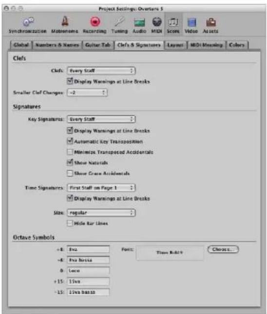
Common Parameters
The following display parameters are available for clefs, key signatures, and time signatures:
- Every Staff
- First Staff on Every Page
- First Staff on Page 1
- Hide All
- Display Warnings at Line Breaks: This causes warning clefs, time signatures, or key signature changes to be displayed at the end of a staff or staff system—if the actual change is at the beginning of the subsequent staff or staff system.
Smaller Clef Changes
Clef changes (whether caused by a change of staff style, or by a new clef inserted from the Part box) can be displayed at a smaller size than the clefs at the beginning of staffs, depending on this setting.
Automatic Key Transposition
This setting enables the automatic transposition of key signatures in transposing staff styles. It will usually be activated. An exception would be for the notation of atonal music. If deactivated, all sharps and flats are displayed directly with the notes.
Note: There is a similar option in the Staff Style window (Key parameter), which allows you to switch off the key signature for individual staff styles, or even for individual staffs in multi-staff styles.
Minimize Transposed Accidentals
This enables the use of enharmonically changed key signatures, if this results in a signature with fewer accidentals. As an example, if a piece is written in B major (5 sharps), the Bb instruments are notated in Db major (5 flats) instead of C# major (7 sharps).
Note: Logic Express does not display key signatures with more than seven flats or sharps, whether this option is activated or not.
Show Naturals
This displays naturals at key signature changes, where preceding accidentals are no longer valid (when changing from E major to G major, or to C minor, for example).
Show Grace Accidentals
If this option is activated, courtesy accidentals are automatically displayed. This means: wherever a diatonic note is altered by an accidental, another accidental (a natural symbol, in many cases) will be displayed when that note appears (unaltered) in a subsequent bar.
Size
This parameter alters the appearance of the meter (often much larger, for conducting purposes) on the staff. It is expressed as regular and percentage values.
Single systems will show both numbers (4/4, for example) on the system. Double systems will show the upper number on the upper system, lower number on the lower system.
Hide Bar Lines
This option allows you to hide all bar lines, which can be useful for educational material, gregorian plain chant notation, and other special situations.
Only automatically displayed bar lines are hidden, so it's still possible to insert bar lines from the Part box, including the regular bar line, which will be displayed and printed.
Octave Symbol Parameters
These settings enable you to edit the text string (and text formatting) of the different octave symbols. Simply click on the appropriate field, and type in the desired text. Click the Choose button to select a different font, font face, or size.
Layout
The Layout tab is where you can define a number of display settings for the whole project, such as staff line thickness, stem length, distance between notes and ties, or notes and dots, and so on.
To open the Layout project settings, do one of the following:
- Choose File > Project Settings > Score in the main menu bar (or use the Open Score Project Settings key command), then click the Layout tab (if is not already displayed).
- Click the Settings button in the Arrange Toolbar, choose Score from the menu, then click the Layout tab.
- Choose Layout > Extended Layout Parameters.
■ Use the Settings: Extended Layout key command.
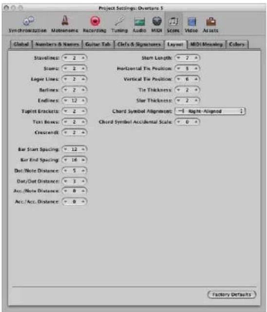
Line Thickness Parameters
The first eight parameters determine the line thickness of the following objects: staff lines, stems, ledger lines, bar lines, repeat and end lines, tuplet brackets, text boxes (for boxed text styles), and crescendi/decrescendi (this last parameter also affects line objects and arrows).
Note: If you have a high resolution printer, you should try to use smaller line thickness settings (2, or maybe even 1). Smaller staff lines, in particular, look much better. The other parameter settings are more a matter of personal preference. These changes are only visible at high zoom levels on the screen. To really judge the results, try some printouts with different settings.
Other Parameters
- Bar Start Spacing and Bar End Spacing: Changes the relative distance between the first and last note of a bar, and the preceding or subsequent bar line. Please note: Changing the default settings of these parameters only makes sense if rather extreme values have been chosen for the general Spacing parameters in the Global Score project settings tab.
- Dot/Note Distance and Dot/Dot Distance: Determines the distance between the note heads and dots, for dotted notes. Dot/Dot Distance refers to double dotted notes.
- Acc./Note Distance: Allows you to globally alter the horizontal distance of accidentals from the corresponding note heads. The default setting should only be changed if very small values are used for the Spacing parameters, which results in a tiny distance between notes. This global setting can also be combined with the Accidental Distance parameter of individual notes, in the Note Attributes window.
- Acc./Acc. Distance: Allows you to globally alter the horizontal distance between several accidentals, in chords.
- Stem Length: This determines the default setting for stem length.
- Horizontal Tie Position and Vertical Tie Position: Determine the distances between note heads and related ties (which are displayed automatically).
- Tie Thickness: Determines the thickness of ties.
- Slur Thickness: Determines the thickness of slurs.
Note: The Slur and Tie Thickness parameters are affected by the Scale parameter in score sets, and the Size parameter in staff styles.
- Chord Symbol Alignment: Determines the general horizontal alignment of chord symbols—with an Align parameter set to def (default)—in relation to their bar position.
- Chord Symbol Accidental Scale: Changes the accidental size, in relation to the font size setting: Positive values result in an increased size, negative values in a diminished size of chord symbol accidentals.
Click the Factory Defaults button to reset all parameters to their default settings.
MIDI Meaning
The settings in the MIDI Meaning tab determine if, and to what extent, the insertion of the listed symbols affect the MIDI playback of notes (that these symbols are attached to).
To open the MIDI Meaning tab, do one of the following:
- Choose File > Project Settings > Score in the main menu bar (or use the Open Score Project Settings key command), then click the MIDI Meaning tab (if is not already displayed).
- Click the Settings button in the Arrange Toolbar, choose Score from the menu, then click the MIDI Meaning tab.
- Choose Layout > MIDI Meaning.
■ Use the Settings: MIDI Meaning key command.
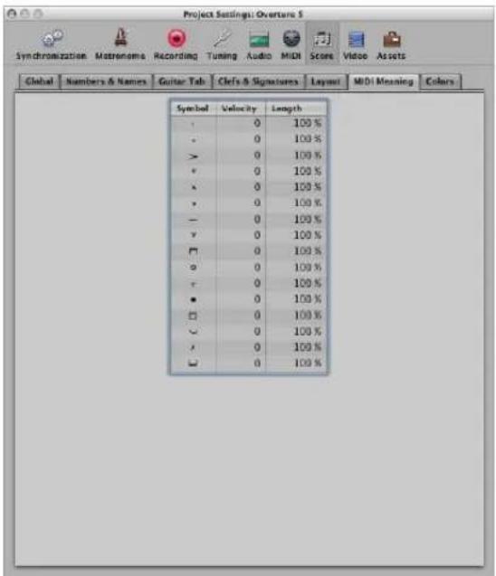
Two parameters can be determined for each symbol. These symbols change the MIDI output of all notes they are attached to:
- Velocity: This value is added to, or subtracted from, the original velocity value of the corresponding note.
- Length: The original note length is shortened by the percentage chosen here. This only affects the playback of the note, not the score display. The note length change can be seen in the Event Parameter box or in the Event List.
How the MIDI Meaning Functions Works
The MIDI Meaning functions are most useful when you're inserting notes with the mouse. This makes it possible to work as if writing music on paper.
- First, you write/insert the notes. They will all have the same velocity, and identical rhythmic note values will have exactly the same length.
- Accents and phrasing marks are then attached to some of the notes, which changes the velocity and ( playback) length of these notes.
This makes playback sound much more realistic and alive.
The default settings in the MIDI Meaning tab (in new projects) are 0 for velocity, and 100% (no change) for length. If you don't change these values, the symbols will remain purely graphical, and will not affect MIDI playback.
If you record your regions in real time (from a keyboard), it's better to leave these settings at the defaults, as the notes probably already sound the way you want them to.
Important: If you do use MIDI Meaning, you need to adjust the settings before you begin to insert accents and so on. This is because the settings have no influence on accents and phrasing marks that have already been inserted.
Once set, the velocity and length of notes will be changed as soon as you attach one of these symbols to a note. When you delete the symbol, note velocity and length are reset to their initial values.
Colors
The Colors tab determines the color palette for the currently active project.
To open the Colors tab, do one of the following:
- Choose File > Project Settings > Score in the main menu bar (or use the Open Score Project Settings key command), then click the Colors tab (if is not already displayed).
- Click the Settings button in the Arrange Toolbar, choose Score from the menu, then click the Colors tab.
- Choose Layout > Colors.
■ Use the Settings: Score Colors key command.
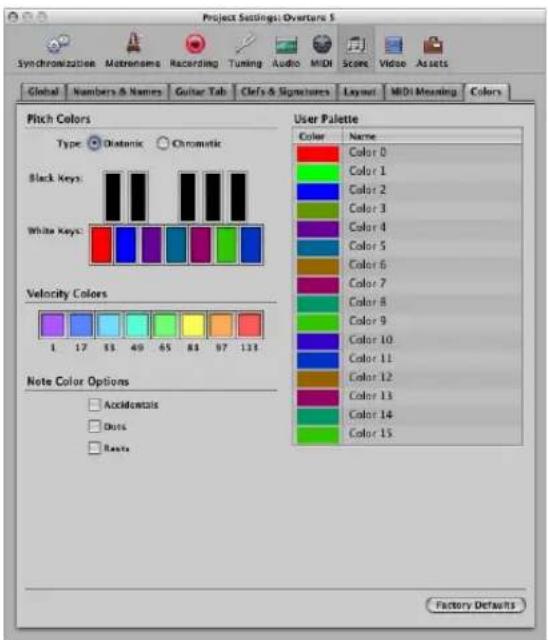
The color palettes are used by different color modes (see "Choosing a Color Mode" on page 810). Clicking on any color opens the standard Colors window, allowing this particular color to be changed.
Colors are saved with the project, and can be different for each project.
There are three palettes, and some additional options in this window:
- Pitch Colors: Each note of the octave is assigned a color. They are arranged like piano keys. The Diatonic and Chromatic radio buttons determine whether there are twelve or seven different colors.
- Velocity Colors: These eight colors are applied in accordance with the MIDI velocity of notes, from left (minimum) to right (maximum).
- User Palette: These colors can be freely edited and named, using the text entry boxes beside them. These names are displayed as color options in different color selection menus (staff styles, note attributes).
- Note Color Options: These options determine whether accidentals, dots, and rests, are displayed in color (according to their note associations), or in black. Rest colors only apply to user rests, which are mainly used in polyphonic staff styles.
- Factory Defaults: Click this button to reset all changes you have made in the Colors window.
Score Preferences
The Score preference settings are global, and affect all project files. They can, however, be changed at any time, with an immediate effect on all open projects. All preferences are automatically saved when you exit Logic Express.
To open the Score preferences, do one of the following:
- Choose Logic Express > Preferences > Score from the main menu bar (or use the Open Score Preferences key command).
- Click the Preferences button in the Arrange Toolbar, and choose Score.
- Choose Options > Open Score Preferences in the Score Editor.
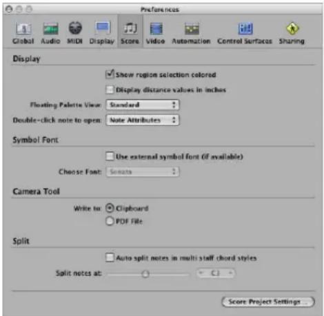
- Show region selection colored: If this option is activated, the staff lines of the currently selected MIDI region are displayed in color (blue). All other regions are displayed with black staff lines. This can be useful when changing the display parameters of regions, as the parameters in the Display Parameter box only affect the currently selected regions. If this option is turned off, all staffs are displayed in black, whether selected or not.
- Display distance values in inches: This relates to the measurement units in the project settings and page rulers (Page view only), which can be in inches or centimeters. If not selected, the Page view defaults to centimeters.
- Floating Palette View: This menu defines the default shape of Part box palette windows (see "Selecting Part Box Objects" on page 709).
- Double-click note to open: This setting determines the window that will open when you double-click on a note head: Note Attributes, Event List, Hyper Editor, or Piano Roll Editor.
-
Use external symbol font (if available): This option enables the use of external fonts in the score (see "Printing the Score" on page 804).
-
Choose Font: This pop-up menu allows you to choose from any installed scoring (symbol) fonts, such as the Sonata font.
- Camera Tool: Write to: Choose either the Clipboard or a PDF File as the destination for image exports with the Camera tool (see "Exporting the Score as a Graphic File" on page 809).
- Split preferences: The "Auto split notes in multi staff chord styles" preference is only relevant if the chosen default staff style (on the recording track) is polyphonic, and is using MIDI channels for voice assignment. In this situation, newly recorded notes are automatically saved with the different MIDI channels used in the corresponding staff style. They are allocated as per the split point set with the "Split notes at" preference.
Working With Video
34
Logic Express allows QuickTime movie files to be synchronously viewed, making film and TV scoring quick and easy.
You can open a QuickTime movie in a separate Movie window, or can display the single frames of a QuickTime movie in the global Video track. When a movie is opened in a project, the upper part of the Inspector shows a closed Movie area—which can be opened by clicking the disclosure triangle.
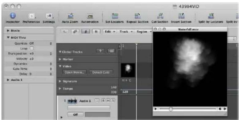
Movie playback follows the playhead position, and vice-versa, in the Inspector movie area, and the Movie window.
Note: You will need a fast hard disk, and fast Macintosh, to ensure smooth movie playback. If you want to record and edit your own QuickTime movie (using iMovie or Final Cut Pro or Express) from a video recorder or digital camera, you may need specialized hardware.
Important: You can not record or edit video in Logic Express. You can, however, replace the soundtrack of a movie file—with music, foley, and dialog arranged in Logic Express.
To open a QuickTime movie, do one of the following:
- Choose Options > Movie > Open Movie command (or use the corresponding key command, default: Option-Command-O).
- Click the Open Movie button in the global Video Track.
- Click at any position on the Video track with the Pencil tool.
- Locate and select the movie file in the Browser, then click the Open button.
The video is opened in the floating Movie window, in its correct aspect ratio.
Note: Only one QuickTime movie can be opened in a project! Using the Open Movie command in a project that already contains a movie, reopens a Movie window with the same film clip. This is particularly useful if you want to open the video clip in a different screenset. Choosing the command—while the Movie window is open—launches a file selector box, allowing you to choose a new movie file.
To remove a movie from a project:
- Choose Options > Movie > Remove Movie.
All references to the movie are deleted from the project.
Using the Movie Window
You can drag the position slider at the bottom of the Movie window, or use the QuickTime transport buttons to the right, to navigate to any position in the video file. Logic Express (the playhead) will "chase" to the corresponding project position. All QuickTime transport functions interact with those of Logic Express.
natural_image
Grayscale abstract image with diffuse cloud-like shapes, no visible text or symbolsResizing the Movie Window
You can resize the Movie window by dragging its lower right corner.
Control-clicking the movie itself (the actual image) opens a shortcut menu, where you can set various image formats.
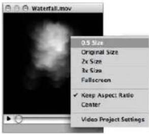
You can also select one of the following:
• Original Size: Displays the movie in its original size.
• Fullscreen: Expands the Movie window to fill the full screen.
- Keep Aspect Ratio: If enabled, the proportions of the image are retained when resizing the Movie window.
• Center: Choosing this option places the video image in the center of your screen.
Using the Video Track
The global Video track displays the loaded QuickTime movie as thumbnails. If the Video track is not visible, see "Showing and Hiding Individual Global Tracks" on page 77.
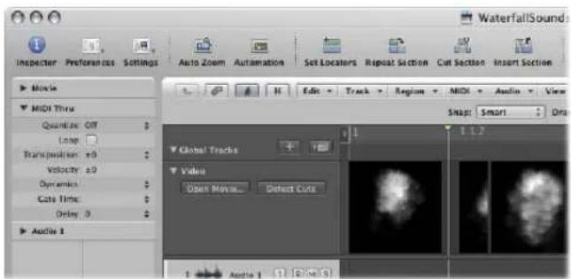
The number of frames displayed in the Video track depends on the track height, and the zoom level of the window. All frames are aligned left, with only the very last frame aligned to the right. This guarantees that you can always see at least the first and last frames of a video, independent of the current zoom level. Given the left alignment of frames, the left margin of a frame will always be displayed at the exact position of that particular frame (except the very last frame in the movie).
Changing Video Track Settings
The settings of the Video track can be adjusted in Logic Express > Preferences > Video.
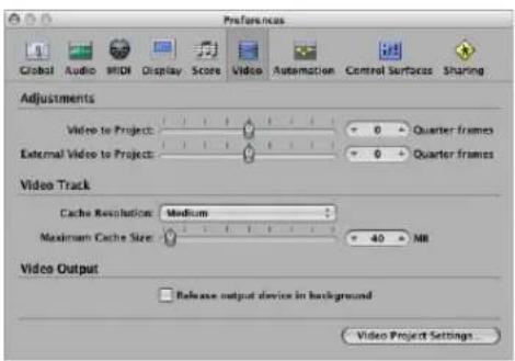
- Cache Resolution pop-up menu: Choose the resolution of the thumbnails held in the temporary internal memory (cache). Higher resolutions display more detail, but take up more space in the cache.
- Maximum Cache Size slider: Sets the amount of memory reserved for the thumbnail cache. 40 MB is recommended for medium resolution. Use a higher value for higher resolutions. The cache memory will only be used when actual movie data is displayed.
Working With Scene Markers
Scene markers are SMPTE-locked markers: They remain at the same absolute time position, regardless of any tempo changes, and they are automatically deleted if the current movie is removed from the project. Scene markers are identified by a movie frame symbol.
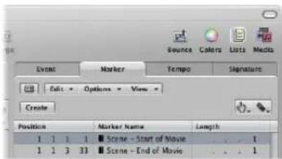
Creating Scene Markers
You can use the Create Scene Markers function to search the movie for significant content changes (scene cuts), and automatically generate scene markers for each of them.
The Create Scene Markers function uses a fixed threshold value, which works quite well for most types of movies (cartoons, real life, CGI, and so on).
To search a movie for scene cuts, do one of the following:
- Choose the desired movie range in the Options > Movie > Create Scene Markers menu.
The Auto Range setting follows the decision path outlined below, when determining which part will be evaluated:
- Marquee selection.
- Cycled project part.
- Selected regions.
- All—if none of the above criteria are met.
To quickly search a movie for scene cuts, using the Auto Range setting:
- Click the Detect Cuts button in the Video track.
■ Use the Create Scene Markers (Auto Range) key command.
To remove scene markers, do one of the following:
- Choose the desired command in the Options > Movie > Remove Scene Markers menu.
■ Use the Remove all Scene Markers (Auto Range) key command.
Converting Scene Markers
You can use the Marker List to convert a scene marker into a standard marker, and vice versa.
To convert a scene marker into a normal marker:
- Select the scene marker in the Marker List, and choose Options > Convert to Standard Marker.
To convert a normal marker into a scene marker:
- Select the marker in the Marker List, and choose Options > Convert to Scene Marker.
Handling QuickTime Movie Audio Tracks
Once a movie has been opened in a project, you can make use of the Import Audio from Movie, or Export Audio to Movie commands—found in the Options > Movie menu.
You can adjust the audio level and output device in the Video project settings (see "Changing the Sound Output Device and Level" on page 842).
Importing Audio Tracks From QuickTime Movies
Choose Options > Movie > Import Audio from Movie to open a dialog that allows you to select the desired audio tracks of the movie file.
Once you've made your selection, and clicked OK, the selected audio tracks will be bounced to an AIFF file, and placed in the Audio Bin. The movie name will be retained, and used for the resulting audio files.
Note: When extracting audio from a movie file that only contains a single audio track, the selection dialog is made redundant. Use of the Import Audio from Movie command will automatically import the audio (as an AIF file), and add it to the Audio Bin.
You can also use the Options > Movie > Import Audio to Arrange function, which places the extracted audio (as a region) on the selected Arrange window track.
Exporting Audio to QuickTime Movie
You can export audio from the part of your project that is encompassed by the QuickTime movie—to the movie file itself—effectively overwriting the original movie soundtrack. This is useful for sending a rough mix of your film soundtrack to other members of the production team, for example.
To export your project to the QuickTime movie:
1 Choose Options > Movie > Export Audio to Movie.
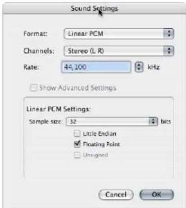
2 Choose the desired format options for the bounced audio file, and click OK.
3 In the ensuing file selector box, enter a name and target folder for the movie, and click Save.
A dialog appears, allowing you to choose which of the original movie's audio tracks should be used in the new movie.
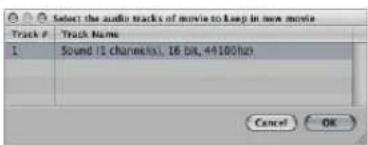
4 Select the audio track that you want to retain in the new movie, then click OK.
The QuickTime movie is exported to the selected folder; it contains all selected audio tracks—plus the part of your project that is encompassed by the start and end points of the QuickTime movie.
Video Project Settings
In the Video project settings, you can define the video output, determine the video sound output, and offset the video from the project.
To open the Video project settings, do one of the following:
- Choose File > Project Settings > Video (or use the corresponding key command, default: Option-V).
- Click the Settings button in the Arrange Toolbar, and choose Video from the menu.
■ Control-click the Movie window, then choose Video project settings.
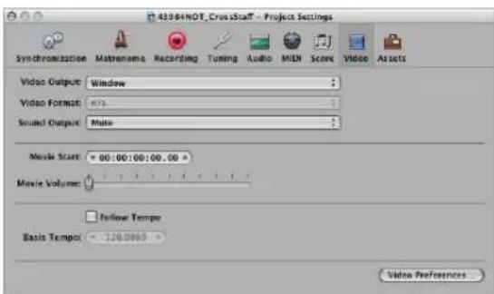
Choosing the Video Output
The Video Output pop-up menu (in the Video settings tab) allows you to choose from the following output modes:
- Window: Outputs the QuickTime video file to a Movie window.
- DVCPRO HD: Choose this option to output the QuickTime video file to a DVCPRO HD device, which is connected to your system.
- Digital Cinema Desktop: Choose this option to preview your video on any available display unit that is connected to an AGP graphics card. (Displays connected to a PCI graphics card cannot be used by Digital Cinema Desktop.) If you have two computer displays, one can be used to view the Logic Express interface, while the other can be used as a dedicated video monitor.
- FireWire: Choose this mode to output QuickTime movies from your project to a FireWire device (your FireWire DV device must be connected at the time). For technical reasons, only QuickTime movies in DV format are supported.
Changing the Format of Video Output
When either the Digital Cinema Desktop or FireWire options are chosen as the Video Output, the Video Format pop-up menu can be accessed.
- Digital Cinema Desktop mode offers three choices: Preview, Full Screen, and Raw.
- FireWire mode offers several PAL and NTSC format options, at different frame rates and resolutions. Choose the most appropriate format for your project.
Changing the Sound Output Device and Level
The Video settings tab offers three choices in the Sound Output pop-up menu:
- Mute: The audio track of the video file is disabled.
- System Sound: The audio track of the video is played through the System Sound device (as defined in the Audio MIDI Setup utility).
- External Device: Choose this option to route the audio track of the video file to an external device. In general, you would be most likely to use this option when FireWire is selected in the Video Output pop-up menu.
The Movie Volume slider sets the level of the video file audio track.
Offsetting Video From a Project
You can directly enter the SMPTE offset value in the Movie Start field. This is independent of the SMPTE offset for the project.
This enables you to work from bar one (1 1 1 1 in the Transport), even if the video time code—at a particular point in the video—is several minutes into the movie file. Put simply, this makes your life easier when creating a soundtrack for all, or part of, a movie file.
You can fine-tune the offset of internal and external video in the Video preferences. These globally affect all projects (see "Video Preferences" on page 993).
Click the Video Preferences button in the Video settings tab to open the Video preferences.
Activating Follow Tempo
Turn on the Follow Tempo checkbox and set a basis tempo in the field below to make the QuickTime movie run at the chosen tempo value until it receives a tempo change message (from the Tempo track).
Video Preferences
The Video preferences determine how Logic Express handles video memory and video hardware settings. You can also make timing adjustments here.
To open the Video preferences, do one of the following:
- Choose Logic Express > Preferences > Video (or use the corresponding key command).
- Click the Preferences button in the Arrange Toolbar, and choose Video from the pop-up menu.
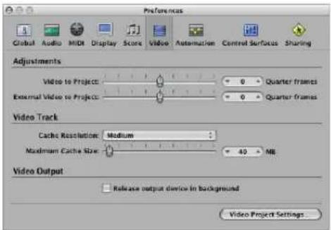
- Adjustments: Video to Project: A global setting for fine tuning the start point of a movie.
-
Adjustments: External Video to Project: The same setting as above, but for external FireWire Video devices. This setting compensates for the latency of the video hardware in use, if applicable.
-
Video Track: Cache Resolution: Resolution of the thumbnails kept in the temporary internal memory (cache). Higher resolutions display more detail, but take up more space in the cache.
- Video Track: Maximum Cache Size: Amount of memory reserved for the thumbnail cache. 40 MB is recommended for medium resolution. For higher resolutions use a higher value. This section of reserved memory will only be occupied when actual movie data is displayed.
- Video Output: Release output device in background: Enable this checkbox to release the chosen output device (set in the Video Project Settings), when it is not being used in Logic Express.
• Video Project Settings: Click to open the Video Project Settings window.
Synchronizing Logic Express
35
Logic Express can be synchronized with external hardware and software via a number of different synchronization protocols.
This chapter discusses the use of Logic Express—as both synchronization master and slave—in a number of different situations.
Logic Express supports the following synchronization protocols:
- MIDI Time Code (MTC): Translation of a SMPTE time code signal into a MIDI standard time code signal.
- MIDI Clock: Short MIDI message for clock signals. It is used to provide a timing pulse between MIDI devices. Logic Express can send MIDI Clock signals to synchronize external devices. It can not receive MIDI Clock synchronization signals.
- SMPTE time code: An audio signal that is translated into MTC by some MIDI interfaces, such as the Unitor8.
- Word Clock: This is a signal that is carried by all digital audio interface formats (ADAT, FireWire Audio, S/P-DIF, AES-EBU, T-DIF). It is used to maintain the timing integrity of sample words in audio signals that are transmitted digitally between Logic Express and external hardware or software.
- ReWire: Logic Express can act as a ReWire host. It acts as the master synchronization source for ReWire-enabled applications such as Reason and Ableton Live. This chapter does not cover the use of Logic Express as a ReWire host (see "Working With ReWire Applications" on page 260 for more information).
Tip: Logic Express also supports manual or "human" sync, when slaved. This is not a synchronization protocol per-se, but enables Logic Express to follow tempo changes in real time. As an example, it could chase a live drummer. See "Using the Tempo Interpreter" on page 679 for more information.
The Synchronization Master and Slave Relationship
In all synchronization situations, regardless of the simplicity or complexity of your studio configuration, the following rules apply:
- There can only be one synchronization master.
- The synchronization master sends time code information (synchronization signals) to one or more synchronization slaves.
Logic Express is capable of acting as master or slave, as are many devices.
Important: In many (if not most) cases, you will need to manually set each synchronization-capable device—including Logic Express itself—to act as master or slave. If you don't do this, there will be multiple master devices in your system, which will result in synchronization errors.
Using External Synchronization
When you first open Logic Express, manual synchronization mode is automatically switched off—and Logic Express is in Internal Sync (master) mode. Activation of the Transport bar's Sync button synchronizes Logic Express to the chosen synchronization source.
If Logic Express is running by itself (no devices or applications capable of synchronization are in use), or is acting as the synchronization source, it is the synchronization master device. In this situation, the Transport bar's Sync button should not be activated.
The Transport bar Sync button is not displayed by default.
To view the Transport bar Sync button:
1 Control-click on the Transport bar, then choose Customize Transport Bar from the shortcut menu.
2 Activate the Sync checkbox towards the bottom of the Modes and Functions column (right-hand column), and click OK.
Using the Sync Button
You can use the Sync button to turn external synchronization on or off at any time, without changing the selected synchronization source. This allows you to temporarily disengage Logic Express (running as a slave) from an external synchronization master device. This could prove useful if you need to quickly edit a MIDI region while the external synchronization source (tape machine, VTR, and so on) is still running, for example.
When Logic Express Is Running as a Slave
The Transport bar Sync button is lit/depressed, when active.
Click the upper (MIDI In) section of the MIDI Activity display—while receiving an external synchronization signal—to view the frame rate of incoming MIDI time code.
Note: When you click the Record button during external synchronization, Logic Express enters record mode, but does not actually start recording until it detects an external time code signal.
Accessing Synchronization Settings With the Sync Button
Control-click the Transport bar Sync button to open a shortcut menu, where the following options are available:
- Setting the type of external synchronization.
- Determining whether or not MMC commands (see "MIDI Machine Control" on page 861) should be transmitted by the Transport buttons of Logic Express, allowing remote control of MIDI-controlled tape machines.
- Direct access to the Synchronization settings.
- Direct access to the tempo editors (see "Advanced Tempo Operations" on page 667).
MTC Interpretation
As the MIDI standard only supports four of the six commonly used time code formats (the 30 fps and 29.97 fps formats are not differentiated in the MIDI specification), Logic Express needs to decide which format is intended, when it encounters incoming time code.
Incoming MTC (MIDI Time Code) is interpreted as follows:
• 24 fps is interpreted as 24 fps.
• 25 fps is interpreted as 25 fps.
• 30 fps drop frame is interpreted as 29.97 drop fps.
• 30 fps is interpreted as 29.97 fps.
You can, however, manually set the format in the File > Project Settings > Synchronization > General > Frame Rate pop-up menu.
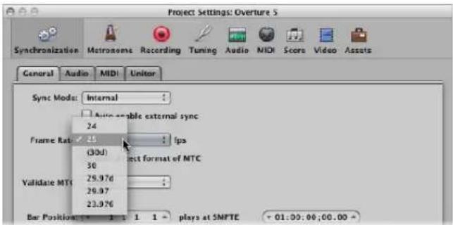
Note: MIDI Time Code (MTC) is the MIDI equivalent of the audio-based SMPTE (Society of Motion Picture and Television Engineers) time code format.
Synchronization Project Settings
The Synchronization project settings allow you to specify all parameters relevant for synchronization.
To open the Synchronization project settings, do one of the following:
- Choose File > Project Settings > Synchronization from the main menu bar (or use the Open Synchronization Settings key command, default: Option-Y).
- Click the Settings button in the Arrange Toolbar, then choose Synchronization from the pop-up menu.
■ Control-click the Sync button in the Transport bar, and choose Synchronization Settings from the pop-up menu.
The Synchronization project settings consists of four tabs:
- General: This tab contains the major synchronization settings, used when running Logic Express as a synchronization slave. For further information, see the section below.
• Audio: This tab contains all parameters relevant to synchronizing audio and MIDI. - MIDI: This tab configures Logic Express to send time code via MIDI, when it is in play or record mode. This enables you to synchronize external slave devices to Logic Express, which acts as the master.
- Unitor: This tab is used to set the major synchronization parameters for the Unitor8 MIDI interface.
General
The General tab of the Synchronization project settings offers the following synchronization parameters (used when running Logic Express as a slave).
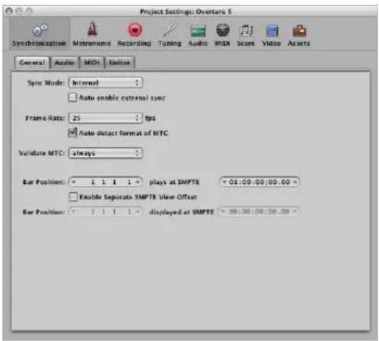
Sync Mode
This parameter defines the master (time code type) that Logic Express is synchronized to:
- Internal: The internal timer of Logic Express. Logic Express is the master. External devices can be synchronized via MIDI Clock or MTC (the relevant settings are made in the MIDI tab).
- MTC: MIDI Time Code mode. Logic Express runs as a slave. MIDI time code can either arrive at a MIDI in port, or be generated by a MIDI interface that translates it from incoming SMPTE time code (the Unitor8, for example).
- Manual: Tempo Interpreter mode. Manual synchronization or human sync mode. Logic Express runs as a slave to impulses that are recognized as valid beats by the Tempo Interpreter. The Tempo Interpreter can be controlled by MIDI events, or a key on the computer keyboard. See "Using the Tempo Interpreter" on page 679.
Auto Enable External Sync
When this option is activated, Logic Express runs as the master (Internal sync mode), until it receives a synchronization signal—either in the form of MTC, or from the Tempo Interpreter.
Logic Express automatically locks to the first synchronization signal it receives.
Important: Ensure that different synchronization signals don't arrive simultaneously—remember that there can only be one time code master!
Frame Rate
This is where you set the frame rate (in fps, frames per second). This frame rate applies to both transmitted and received time code.
Frame rate Typically used for
| 24 fps Film, high definition video. |
| 25 fps PAL video/television broadcasts. |
| 30 fps (drop frame) NTSC video/television broadcast; rarely used. |
| 30 fps High definition video; early black-and white NTSC video; older rate that is rarely used today. |
| 29.97 fps (drop frame) NTSC video/television broadcasts. |
| 29.97 fps Standard definition NTSC. |
| 23.976 fps 24 fps slowed down by 99.9%, which facilitates easier transfer of film to NTSC video. |
Note: In drop frame formats, certain frames are left out (this follows a regular pattern). To distinguish between formats, those without dropped frames are sometimes referred to as "nd" or "non drop".
Auto Detect Format of MTC
This checkbox, when active, analyzes the incoming time code and automatically sets the correct frame rate. You should generally leave this option switched on.
Please note that it is not possible to automatically distinguish between the 29.97 and 30 fps MTC frame rates because:
- The MTC standard does not allow a distinction.
- A measured rate of 30 fps could also be 29.97 fps time code running too fast, and vice versa.
Logic Express automatically interprets frame rates of "approximately 30 fps" as either 29.97 (drop frame) or 30 fps (non drop), depending on whether or not the drop frame format is used. This interpretation will usually be correct, because these two formats are used as a standard.
"Auto detect format of MTC" only switches to 29.97 (drop frame) or 30 fps (non drop) if one of the other conventional formats was previously set. If you want to synchronize Logic Express to one of these unconventional frame rates, you need to define the format manually. This setting will not be altered by the "Auto detect format of MTC" function.
Validate MTC
The Validate MTC menu allows you to specify how often Logic Express checks for incoming time code, in order to ensure synchronization integrity. In general, you should leave this menu option on the "always" setting.
There are some devices, however, that generate time code pulses that may require a specific number of frames to be set, in order to maintain synchronization. The "never, Jam Sync" setting basically sets Logic Express to free-wheel if the synchronization signal is lost. In other words, Logic Express will run on its own internal clock (at the most recently received tempo) if the synchronization pulse is lost. This approach ensures that recording will continue, even if the incoming timing pulse fails.
SMPTE Offset (Top Bar Position Row)
This is where you set the SMPTE offset for the project. As songs don't always need to start precisely at bar 1, you can select any bar position to be played at the set SMPTE time.
The default is Bar Position: 1 1 1 1 plays at SMPTE 01:00:00:00.
The SMPTE offset of 01:00:00:00 (one hour) is normally used, because it allows you to pre-roll an amount of time code.
SMPTE View Offset (Lower Bar Position Row)
If you want to see the absolute time from the start of the project in the time display, rather than the actual SMPTE time, select the Enable Separate SMPTE View Offset checkbox.
Then choose Bar Position 1 1 1 1 displayed at SMPTE 00:00:00:00 (preset). If necessary, you can set other view offset values here.
The Tempo List always shows the real SMPTE time, never the SMPTE View Offset. The SMPTE View Offset is used in all other windows (including the Transport).
Tip: It is a common practice in many video (and audio) post production houses to set a one hour SMPTE offset (01:00:00:00). This avoids a problem commonly referred to as midnight, where a pre-roll passes through SMPTE time 00:00:00:00, which causes issues with some tape machines (such as the ADAT).
Audio
Use the Audio tab of the Synchronization project settings to keep your audio and MIDI tracks synchronized.
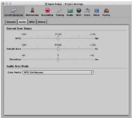
Current Sync Status
- MTC (fps): This real time display shows the deviation between the incoming MTC, and its nominal frame rate. If the deviation is significant, make sure that the right frame rate is set in the General tab of the Synchronization project settings. If in doubt, set the frame rate to 24 fps and switch on "Auto detect format of MTC". If the frame rate is correct, you can use this display to adjust the tape speed of the master machine to the nominal value (the same speed used when the time code was recorded). Adjust the varipitch control on the master machine, until the slider is centered.
- Sample Rate (Hz): This display shows the deviation of the sample rate from its nominal value. You should note that some audio hardware will not allow any variation in the sample rate.
- Deviation (ms): This display shows the current phase deviation of the Word Clock from the time code master—in other words, the deviation between audio and MIDI. Varying time code signals shown in this display indicate how Logic Express regulates the sample rate of the hardware, when in MTC Continuous sync mode. Even large time code variations result in no deviation between audio and MIDI synchronization. Your audio hardware must be capable of continuously variable sample rates, for this to function. Small deviations between audio and MIDI are unavoidable, because MIDI can (and should) follow the time code master directly.
Note: The real time sample rate conversion facility of Logic Express allows it to follow an external MTC signal (MTC Continuous), while maintaining the correct audio playback pitch and speed. This even works when recording in MTC-slave mode.
Audio Sync Mode
This is where you define how your audio hardware should be synchronized to an external time code master.
Not all audio hardware can work in every sync mode described below. This is particularly dependent on whether or not the hardware's sample rate can be controlled.
You can choose the following options in the Core Audio menu:
- MTC Continuous (default): Audio regions are started in sync, and the sample rate is continuously regulated to match variations in the time code master signal. Even very long audio regions stay in sync in this mode.
- MTC Trigger + Auto Speed Detection: Similar to MTC Trigger (see below), but the tempo of the time code master is constantly monitored while Logic Express is running. The next time you start Logic Express, it will use an adapted sample rate. This mode keeps long regions in better sync with the time code master, although not as closely as MTC Continuous. It does, however, use a constant sample rate, which is not affected by variations in the time code master signal.
- MTC Trigger: Audio regions are started in sync, but are then played at a constant sample rate, regardless of any variations in the time code master signal. Logic Express always uses the set nominal sample rate (44.1, 48, 88.2, 96, 192 kHz). This mode is suitable when it is vital to retain the absolute pitch of a recording. If the speed of the time code master deviates from the nominal value, you may need to split long audio regions into shorter sections.
- External or Free: Logic Express has no influence on the sample rate. The audio hardware is responsible for ensuring that the position and sample rate of audio regions match. This mode is only advisable if you are sure that the Word Clock and time code master are running in sync—by using an external SMPTE or Word Clock synchronizer, for example.
MIDI
The MIDI tab of the Synchronization project settings configures Logic Express to send time code via MIDI, when running (record or play mode). This enables you to synchronize external devices as slaves to Logic Express, which acts as the master.
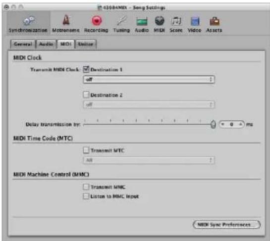
Transmit MIDI Clock
The checkboxes activate transmission of MIDI Clock. The two Destination menus allow you to determine two discrete MIDI output ports for the MIDI Clock signal.
Every time you start, a Song Position Pointer (SPP) message is also sent. As not all devices can process SPP, the MIDI system real time Continue message is also sent. The exception to this is when you start at position 1 1 1 1. In this situation, the real time Start message is sent.
MIDI Clock can easily be sent with other normal MIDI events (notes, controllers). When using multi-port MIDI interfaces (such as the Unitor8), better timing is achieved by sending MIDI Clock to All ports, rather than to several individual ports.
If MIDI Clock is transmitted to all ports, the events are only sent once from the computer to the interface. If you address individual ports, one event needs to be sent for each port, placing a higher strain on the bandwidth of all ports.
Delay Transmission By
This parameter allows you to delay the transmission of MIDI Clock signals. Negative values mean that the MIDI Clock signal is transmitted earlier. This enables you to compensate for any reaction delays in external MIDI Clock slaves.
Transmit MTC (MIDI Time Code)
The checkbox activates transmission of MIDI time code. The menu determines the MIDI output port for the MTC signal.
If you can avoid it, you shouldn't send MTC to all ports, as it is very data-intensive. If possible, use a MIDI port that isn't being used for anything else.
Transmit MMC (MIDI Machine Control)
Turn on this checkbox to enable transmission of MIDI Machine Control (see "MIDI Machine Control" on page 861). These commands are then sent whenever you operate the transport functions (Start, Stop, Rewind, and so on) of Logic Express.
MMC is normally used when Logic Express is running as a slave to an external master (such as an ADAT), and you want to control the external master's transport functions from Logic Express. Logic Express therefore acts as MMC master, and MTC slave simultaneously.
If you want to use the external master's transport controls, you don't need to use MMC. In this situation, Logic Express will follow the MTC master as a slave.
You can also use MMC to place tracks on the MMC slave device into record-enabled mode.
Listen to MMC Input
If this checkbox is activated, Logic Express can be controlled by MMC (MIDI Machine Control) and so-called Full Frame Messages.
Logic Express recognizes these commands when listening to MMC Input:
- Play
- Deferred Play
- Stop
Deferred Play is a special command for mechanically slow synchronization slaves such as reel-based tape recorders. Rather than having the machine play immediately, it is asked to reach the desired SMPTE position before playback is started. You'll find no difference in Logic Express's response to the Play and Deferred Play commands, as Logic Express can locate to any position almost instantly.
Logic Express ignores these messages when incoming external MTC (MIDI Time Code) commands are detected.
Logic Express also obeys Full Frame Messages, and sets the playhead to a new location, without starting playback. Once again, incoming MTC data has higher priority, if conflicting information is received.
Some synchronizers send Full Frame Messages (instead of MTC) to locate the slave device (Logic Express in this case) to a new position, without implicitly starting playback. This is useful when in slow shuttle or single frame advance modes with video machines, because the slave device is perfectly located, without being in playback mode.
MIDI Sync Preferences Button
The MIDI Sync Preferences button opens the Sync tab of the MIDI preferences (see "MIDI Preferences" on page 987).
Unitor
The Unitor tab of the Synchronization project settings is used to set the major synchronization parameters for the Unitor8 MIDI interface.
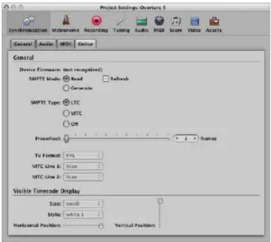
SMPTE Mode
You can instruct the Unitor8 to read or write SMPTE. You must switch from Read (the default) to Generate, and set the frame rate and SMPTE start time in the General tab (top Bar Position row).
Click the Refresh checkbox to enable refresh mode, where fresh time code is generated—in sync with received time code. Refresh mode works with both VITC and LTC (see below).
You should always use refresh mode whenever you need to copy an LTC track, because you cannot directly copy LTC without a considerable loss of quality. When copying entire multitrack tapes, you should patch all tracks directly, but refresh the time code track via the Unitor8.
Note: You should only use refresh mode if you are copying time code.
SMPTE Type
This is where you define the SMPTE format that you want to use:
- LTC: Longitudinal (also called Linear) Time Code is written to a tape track.
- VITC: Vertical Interval (or Vertically Integrated) Time Code is written invisibly to a video tape.
Freewheel
You can set the freewheel time (in frames) for LTC and VITC. The freewheel parameter affects the SMPTE reader, and specifies how long the synchronizer continues transferring MTC to the sequencer, after time code ceases to be read.
Long freewheel times can maintain synchronization, even if there are drop outs in the time code, but they also increase the reaction time of Logic Express—after the time code master stops. In practice, you should set a value that is as large as necessary (for sustained operation), and as small as possible (to reduce waiting times).
TV Format
Allows you to define the television format for time code burn-in:
- PAL: The video format used in Europe, South America, most Asian and African countries, and Oceania. If you are working with video in SECAM format (used in France and French-speaking nations in Africa), select PAL.
• NTSC: The video format used in the USA, Central America, Japan, and Canada.
VITC Line 1, VITC Line 2
VITC is written into two lines of the video picture, which are normally invisible. The lines should not be adjacent, and are usually situated between 12 and 20.
If the Scan option is enabled, the VITC lines are automatically recognized. You should only enter the lines manually if there are problems with Scan mode.
Visible Time Code Display
The parameters allow you to set the position, size, and style of the time code counter window, which is burned-into the video picture.
Displaying and Using SMPTE Positions
The Bar ruler of each linear editing window can independently display a SMPTE time ruler or bar/beat ruler. For further information, see "Adjusting the Bar Ruler Display" on page 75.
Choosing View > Event Position and Length in SMPTE Units in the Event List switches the display of all positions and lengths to SMPTE times, rather than bar/beat values.
Positioning Objects to Frames (Pickup Clock)
You can use the Pickup Clock (Move Event to Playhead Position) key command to move selected objects (an individual event, tempo event, or a region, as examples) to the current playhead position.
To position objects to frames:
1 Set the playhead position to the required SMPTE time, by going to a specific frame of the film in the Video track, for example.
Note: In addition to the usual position commands, you can also use the Rewind One Frame and Forward One Frame key commands to move one frame backwards or forwards.
2 Select the object that you want to place at this time position.
3 Use the Pickup Clock (Move Event to Playhead Position) key command to align the start point of the object with this time position.
The Pickup Clock & Select Next Event key command selects the next object, after the first object is moved.
Note: When using Pickup Clock with audio regions, it is the region's anchor (not the region start point) that is moved to the playhead position.
Fixing Objects to Frames
In situations where you're working with synchronized film, you often want specific sound effects to play at a specific SMPTE time, rather than a particular bar position.
If the tempo of the piece needs to be altered at a later stage, the SMPTE time location of events that have already been positioned will change. The Lock SMPTE Position function prevents this from happening.
You can SMPTE-lock individual events in the Event List, or entire regions (along with all events they contain). Objects locked to a SMPTE position display a small padlock symbol in front of their name.
To lock an object to its current SMPTE position:
1 Select the desired object.
2 Do one of the following:
- In the Event List, Hyper and Piano Roll Editor: Choose Functions > Lock SMPTE Position.
- In the Arrange window: Choose Region > Lock SMPTE Position.
- Use the Lock SMPTE Position key command.
Note: Copies of locked objects do not preserve their locked status, whether copied or pasted via the Clipboard, or by Option-dragging.
To unlock the SMPTE position of a locked object:
1 Select the desired object.
2 Do one of the following:
- In the Event List, Hyper and Piano Roll Editor: Choose Functions > Unlock SMPTE Position.
- In the Arrange window: Choose Region > Unlock SMPTE Position.
- Use the Unlock SMPTE Position key command.
All selected objects that were locked to their SMPTE position are now fixed to their current bar position, just like normal events. This means they can be shifted by any future tempo changes. The padlock symbol in front of the name disappears.
Positioning Bars to Frames
If you want a particular bar in the project to coincide with a specific SMPTE time, you need to alter the tempo of the preceding passage.
The following procedure will save you from having to do this by trial and error:
1 Open the Tempo List (see "Using the Tempo List" on page 673).
2 Create a tempo event at the desired bar position.
3 Set the desired time position for this tempo event in the SMPTE Position column.
The preceding tempo event is automatically adjusted, to generate the correct bar and time position for the inserted tempo event.
4 You can then delete the tempo event you inserted, if you want to keep the same tempo for the following passage.
MIDI Machine Control
MMC is a set of MIDI commands that Logic Express uses to control the transport functions of any MMC-capable tape machine. The recording process can also be controlled and automated from Logic Express via MMC. This tape machine then provides the SMPTE signal that Logic Express uses as a synchronization source (with Logic Express as the slave).
You can control connected devices from Logic Express by using the normal transport functions (including direct positioning and cycle jumps). Don't forget that Logic Express needs to wait for the connected device to finish rewinding or forwarding. If MIDI Machine Control is enabled, dragging the playhead will send MMC Locate commands continuously, until the mouse button is released.
To switch on MMC, do one of the following:
■ Control-click the Transport bar Sync button and enable the MIDI Machine Control (MMC) setting in the shortcut menu.
- Choose File > Project Settings > Synchronization, and enable the Transmit MMC option in the MIDI tab.
Logic Express supports up to 64 MMC tracks, allowing devices such as the Alesis ADAT to be operated via MIDI machine control.
Each Arrange track can act as a tape (control) track, by selecting an instrument with the tape deck icon (#305).
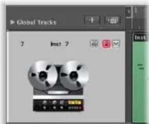
You only need to create one instrument with the tape deck icon, and you may then assign that same instrument to as many tracks as needed, to control your external recorder. It's a good idea to group these tracks together in their own folder. These tracks must be placed at the top of the Arrange window track list. If you pack them into a folder, this must be the first track in the list.
The tape deck icon is the only icon that actually affects the way an object behaves. All other icons are purely graphical in nature.
If the tape track is the current record track, the following functions apply:
- Selecting the tape track switches the corresponding track on the tape machine to record ready, and deactivates the record ready status of any other tracks. To select several tracks for recording, use Shift when clicking.
- The Record button in the Transport bar sends the record strobe command to the tape machine. This also puts Logic Express into MIDI record mode, and sends an MMC Play command to the tape machine. Logic Express doesn't start until it receives time code back from the MMC device.
- If you use the Autopunch function, the tape machine goes into record mode at the punch in locator, and stops recording at the punch out locator positions.
- If you click on any track—not just a tape track—while holding down Control-Shift, you can individually toggle the record ready status for each track of the tape machine (selected tracks are switched on, and non-selected tracks are switched off). Control-clicking on a track switches all other tracks out of record ready mode. If the current record track was assigned a tape deck icon (see above), you must not use the Control modifier.
- The Record Toggle key command is used to toggle record status, if a tape track is the currently selected record track.
- Following an MMC-controlled recording, Logic Express automatically creates an empty MIDI region on the tape track. This is to let you know that a recording has taken place on the tape machine. This applies to all MMC recordings, including those controlled by the Autopunch function. If you activate several tape tracks (by Shift-clicking), the corresponding number of regions are created. If a MIDI region with an identical start point already exists on a tape track, no new MIDI region is created on that track. This avoids overlapping regions.
- A double stop command sets the project back to the beginning.
The MMC Record Buttons also offer you a simple way to arm tracks on your tape machine with Logic Express (see "MMC Record Buttons" on page 914).
You should finish all MMC-controlled recordings with Stop or Space. Some tape machines react differently to a series of MMC Record commands. Sometimes, this can result in Logic Express showing a track as recording, when the tape is actually playing back (or even worse, the opposite situation). As such, you should always finish a recording with Stop or Space, just to be on the safe side.
Synchronization Problems and Solutions
Given the number of different synchronization types that are available, and different implementations by various manufacturers, you may occasionally encounter timing issues when running Logic Express synchronously with other devices or applications. This section will help you to overcome some common synchronization problems.
Faulty Digital Synchronization
If Logic Express is synchronized to external Word Clock (Audio Sync Mode: External or Free), you must ensure that a valid digital signal is always available. If you encounter error messages such as "Sample Rate xxx kHz recognized" it may be that the DAT recorder (or whatever clock source you have connected to your audio hardware's digital input) does not transmit Word Clock in stop or pause mode (or has switched itself off).
Faulty Synchronization to an External Tape Machine
Create a new project, make a new recording and see if that does the trick. Why? If an old recording on tape was not properly synchronized to time code, you won't be able to use it. One basic rule: the playback situation must be identical to the recording situation.
If everything is working fine with the new recording, this means the present setup is okay. Next, check whether anything has changed in your global setup. Has the frame rate changed? Has the tape speed changed? If you have changed a 30 fps setting, try variations such as 30 drop or 29.97.
If MIDI and Audio Are not Synchronized
Open the File > Project Settings > Synchronization > Audio tab and select the MTC Continuous or MTC Trigger + Auto Speed Detection mode.
If your audio hardware doesn't support either mode, you should cut extremely long regions into shorter sections.
If MIDI and SMPTE Are not Synchronized
Check all frame rate settings. The frame rate of all connected devices must be identical, including the time code on the tape machine, the synchronizer, and in Logic Express itself.
Some synchronizers encode the wrong frame rate in MTC. In this situation, open the Tempo Editor, switch off the Detect option, and set the correct frame rate manually.
Working With Plug-in Latencies
36
Audio processed through plug-ins is subject to small timing delays, known as latency.
Fortunately, Logic Express provides a number of advanced features that can compensate for these timing differences, ensuring that all track and channel output is perfectly synchronized.
This chapter discusses the technical aspects of plug-in latency, and how to circumvent these timing anomalies in Logic Express.
About Latency
Each digital process—plug-in processing, changing the volume or pan level, and so on—adds an amount of latency (a small delay). Each of these processing latency values is added to each other.
To explain, a software instrument running inside Logic Express will only have an output latency, because it is generated inside the application. An audio recording that is being monitored in real time will have both an input, and an output, latency. These two values are summed, resulting in an overall monitoring latency figure.
Each process—such as the use of an effect plug-in, for example—will also add an amount of latency, which is combined with the input and output latency figure, dependent on whether a software instrument or audio channel is in use. As an example, if a recorded vocal is routed through a compressor effect (with a 10 millisecond latency) and the audio interface output latency is 40 milliseconds, the total latency figure would be 50 milliseconds (10 + 40 = 50). If three plug-ins (reverb, chorus, and compressor, for example) that also introduced a 10 millisecond latency were used for this track, the latency would be 70 milliseconds (10 + 10 + 10 + 40 = 70).
The audio interface input and output latency is handled by the settings in the Logic Express > Preferences > Audio > Devices tab (see "Configuring Your Audio Hardware" on page 99). Internal latencies introduced by plug-ins are dealt with in a different way, which is the focus of this chapter.
Working With the Low Latency Mode
The Low Latency mode allows you to limit the maximum delay time caused by plugins. Plug-ins will be bypassed to ensure that the maximum delay that can occur across the entire signal flow (of the current track) remains under the chosen value. The Low Latency mode is extremely useful when you need to play a software instrument (or to monitor through an audio channel) when plug-ins with high latencies are already in use—at any point in the signal flow for the selected track/channel.
To set the maximum delay time allowed in Low Latency mode:
1 Choose Logic Express > Preferences > Audio, then click the General tab.
2 Set the Limit slider to the desired value.
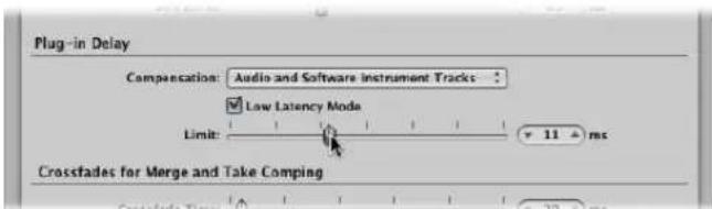
To activate Low Latency mode, do one of the following:
- Click the Low Latency Mode button in the Transport bar.

■ Switch on the Low Latency Mode checkbox in the General Audio preferences tab.
This limits the latency generated by plug-ins to the value set with the Limit slider. Plugins will be bypassed, ensuring that the maximum delay that can occur across the entire signal flow (of the current track's signal path) remains under the Limit slider value.
- Bypassed plug-ins may be on the selected track, any auxes in the signal path, or even output channels.
- Plug-ins with the highest latencies will be bypassed first.
Note: The sound may change in Low Latency mode. Depending on the plug-ins in use, the changes can be anything from subtle to dramatic. If plug-ins being used do not exceed the total latency limit, there will be no audible difference.
Working With Plug-in Delay Compensation
The Compensation menu in the Logic Express > Preferences > Audio > General tab allows you to either disable plug-in delay compensation (Off), or activate it for:
• Audio and software instrument tracks.
- All channels (audio, instrument, aux, output, bus, and ReWire).
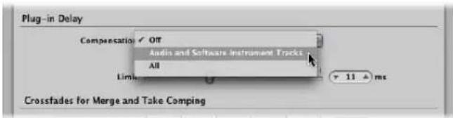
About Plug-in Delay Compensation
Logic Express provides plug-in delay compensation for all channels: If activated, Logic Express compensates for latency introduced by plug-ins, ensuring that audio routed through such plug-ins is synchronized with all other audio.
Logic Express achieves this by calculating the amount of latency caused by plug-ins, and then delaying audio streams by an appropriate amount—or shifting instrument and audio tracks forward in time. The compensation method depends on the type of channel that the latency-inducing plug-in is inserted into.
- If latency-inducing plug-ins are inserted into aux or output channels (or ReWire channels, if used), Logic Express delays all other audio streams by an appropriate amount.
- If latency-inducing plug-ins are inserted into audio or instrument channels, Logic Express automatically shifts these tracks forward in time. The advantage of this method is that other channels (that do not contain latency-inducing plug-ins) do not need to be delayed.
As an example: Imagine a simple song with a few bass, guitar, vocal, and drum tracks. The bass track is routed through an audio channel that contains an effect that introduces a latency of 10 ms. All guitar tracks are routed to an aux channel that contains several inserted effects. The combined latency introduced by these effects is 30 milliseconds (ms). The vocals are routed through another aux channel that has a set of effects that introduce 15 ms of latency. The drum tracks are routed straight to the main outputs, without being routed through any effects. If latencies were not compensated for, the drum tracks would play 30 ms ahead of the guitar tracks. The bass track would play 20 ms ahead of the guitar track, but 10 ms behind the drums. The vocals would play 15 ms before the guitar track, but 15 ms behind the drums and 5 ms behind the bass. Needless to say, this isn't ideal.
With plug-in delay compensation set to All, Logic Express shifts the bass track forward by 10 ms, thus synchronizing the bass and drum tracks. Logic Express will then delay both streams routed to the output channel by 30 ms, aligning them with the guitar tracks. The aux channel that the vocals are streamed to is also delayed by 15 ms, aligning it with the drum and guitar streams (in other words, the 15 ms delay is increased to 30 ms). The precise calculations required for each stream are handled automatically.
Track Uncompensated Compensated
| Bass (effect directly inserted in audio channel) | 10 ms delay | 10 ms → (audio channel) then ← 30 ms (output channel) |
| Guitars (routed to aux 1) 30 ms delay Not changed. | ||
| Drums (direct to output) No delay 30 ms ← (output channel) | ||
| Vocal (routed to aux 2) | 15 ms delay | 15 milliseconds ← (aux channel 2) |
As you can see in the table, all output is effectively delayed by 30 milliseconds—to match the largest amount of compensation required (by the effects in aux channel 1, which the guitar tracks are routed to). This has the effect of perfectly aligning all tracks routed to the output, and circumventing any delays introduced by plug-ins, regardless of where they are used in the signal path.
Plug-in Delay Compensation Limitations
Plug-in delay compensation works seamlessly during playback and mixing. The delay that is introduced—to compensate for latency-inducing plug-ins in output and auxiliary channels—can be applied to non-delayed streams, before they are played back. Instrument and audio tracks (that contain latency-inducing plug-ins) can also be shifted forward in time, before playback starts.
There are, however, some limitations if you use plug-in delay compensation with live tracks. Shifting pre-recorded instrument and audio tracks forward in time is possible when the audio is streaming live. So, recording while plug-in delay compensation is set to instruments and tracks will work fine—as long as you do not try to record through latency-inducing plug-ins: A live track can not be shifted forward in time (as Logic Express can't position live audio before it happens!).
Important: Delaying a live stream, in order to synchronize it with other delayed audio channels is not possible.
This may lead to problems if you decide to make further recordings after setting plug-in delay compensation to All, and inserting latency-inducing plug-ins in auxes and outputs. If Logic Express needs to delay streams to compensate for plug-in latencies, you will be listening to delayed audio streams while recording. As such, your recording will be late by the number of samples that the audio streams were delayed by.
For these same reasons, you may encounter increased latency if playing software instrument tracks live, when plug-in delay compensation is set to All. This issue can be mitigated to some extent by using the Low Latency mode (see "Working With the Low Latency Mode" on page 866).
Dealing With Latency Issues
To avoid these potential pitfalls, you should try to complete any audio and software instrument recording before inserting latency-inducing plug-ins. If you need to record a software instrument or audio track after setting up a latency-inducing signal routing, the following procedure will help you to get around any possible problems.
To record after setting up a latency-inducing signal routing:
1 Switch the plug-in delay compensation setting from All to Audio and Software Instrument Tracks in the Logic Express > Preferences > Audio > General tab.
You can also use the Toggle Plug-in Delay Compensation: All/Audio and Instrument Tracks key command to quickly switch compensation between All or only Audio and Software Instrument Tracks.
The Audio and Software Instrument Tracks plug-in delay compensation method shifts tracks that contain latency-inducing plug-ins forward in time—so any audio and instrument tracks that contain such plug-ins will be synchronized with non-delayed tracks. There is only one exception: Live tracks can not be shifted forward in time.
The next step is to eliminate any latency introduced by plug-ins in your recording track.
2 Bypass any latency-inducing plug-ins on the recording track by Option-clicking on the respective Insert slots.
In the Audio and Software Instrument Tracks plug-in delay compensation mode, bypassing plug-ins eliminates the latency that they create. Latency caused by plug-ins in audio and software instrument tracks is compensated for.
The last thing to do is to get around the latency introduced by plug-ins on aux and output channels.
3 Bypass any latency-inducing plug-ins on auxes and outputs.
At this point, all audio streams will be synchronized, allowing you to proceed with your recording.
When you've finished recording, re-enable all latency-inducing plug-ins, and switch the delay compensation setting to All.
Note: In the All mode, bypassing plug-ins on busses, auxes, and outputs will not eliminate the latency that they create. You must actually remove these plug-ins from the Insert slots to eliminate latency.
If you are recording audio, another strategy would be to disable the Software Monitoring checkbox in the Logic Express > Preferences > Audio > Drivers tab. This would necessitate monitoring your recording via an external mixer. When Logic Express is not providing software monitoring of incoming audio, it can correctly position audio recordings—even when full delay compensation is active. Obviously, you can't use external monitoring when recording software instruments.
Note: As Logic Express has no direct control over the audio outputs of external devices, plug-in delay compensation can not work for MIDI tracks that trigger external sound modules. If you activate full plug-in delay compensation and insert latency-inducing plug-ins, external MIDI signals will be out of sync with the delayed audio streams. Logic Express allows you to circumvent this issue with the External Instrument plug-in: Insert it (as you would insert a software instrument plug-in on instrument channels) to route the audio outputs of your external MIDI devices to the inputs of your audio hardware—and monitor them through Logic Express. This enables you to compensate for the delays of any audio streams coming from MIDI devices during playback.
Working With Split Channel Audio File Formats
37
You can store multi-channel audio as interleaved or split channel audio files.
An interleaved audio file contains all channel information, stored in an alternating single "stream." For stereo files, this would be left channel, right channel, left, right, and so on.
Split channel audio files couple separate audio files, allowing you to deal with each channel (file) independently. For stereo files, two separate files are created, where one file contains the left channel samples, and the other file contains the right channel samples. The files are generally identified by a .L and .R suffix. The two files are linked, and are edited as a pair.
Logic Express, and most other audio applications, support the import and recording of interleaved files when using Core Audio hardware.
A handful of audio applications (including Pro Tools) only support split file formats, and will automatically separate interleaved files when you import them.
Tip: You should use interleaved audio files if your audio hardware supports them. Split channel audio files require significantly more hard disk I/O performance.
Importing Split Channel Files
Nothing special needs to be done to import either split or interleaved files into Logic Express. What happens when you do import such files is slightly different, however.
When split stereo files are imported, they are automatically converted to interleaved files. If you want to add several split stereo files simultaneously, Logic Express asks whether all files should be converted at once. (When you load a Logic Pro project that contains split stereo files, the split stereo files are not converted.)
Working With Split Stereo Files
Logic Express treats split stereo audio files with a name that ends in .L or .R as stereo files. This applies to all file management functions, such as Rename, Create, or Revert to Backup. The following list outlines how split stereo files are handled in Logic Express:
- When you select an independent mono file (one side of a split stereo file "pair") in the file selector box, both channels are imported. Split stereo regions are indicated by the stereo symbol: two adjoining circles.
- You can see both files in the Audio Bin. They have the same name—apart from the channel suffix (L and R). If you rename one channel of a split stereo audio file, the other channel file is automatically renamed as well. This also applies when renaming regions associated with the files.
- File edits performed in the Sample Editor apply equally to both files.
- If you use the Add Region command to create a new region, Logic Express does this for both audio files.
- Any alteration made to either region is automatically mirrored by the other. This applies to region start point, end point, and anchor position changes.
- If the region of either file is moved into (or within) the Arrange area, the other region is also moved.
Converting Split Stereo Files to Interleaved Stereo
You can convert two (split stereo) audio files into an interleaved stereo file—in the SDII, AIFF, or WAV format. This is useful if you want to use a split stereo file in another application, such as the WaveBurner CD mastering software, which only supports interleaved files.
To convert split stereo files into interleaved stereo files:
1 Select the audio files in the Audio Bin.
2 Choose Audio File > Copy/Convert File(s).
3 Choose Split to Interleaved in the Stereo Conversion menu.
4 Type in the desired file name, browse to a folder location, then click Save.
Note: This only works for split stereo files. You can't use these commands to combine two mono files into a stereo file.
Exporting Split Channel Files
You can bounce stereo files from Logic Express—in interleaved or split stereo formats.
Essentially, there is only one parameter of importance for creating split format files in the Bounce window: Choose Split in the File Type pop-up menu.
Full details on all Bounce window options are found in Chapter 27, "Bouncing Your Project," on page 625.
When Would You Create an Interleaved or Split Bounce File?
- Interleaved bounce: Do this when you want to use the file in another audio application that supports interleaved files (most audio applications or devices do).
- Split channel bounce: Perform when you want to use the file in Pro Tools software, or another application that only supports the split stereo format.
Working in the Environment
38
The Environment controls all MIDI input and output, and also allows you to integrate and process the data of MIDI and software instruments.
This chapter will help you to understand how the Environment window works, and how to use objects to alter MIDI data in real time.
It is not essential to know about—or even open—the Environment window in order to make music with the instruments of Logic Express or your external MIDI sound generators and keyboards.
When you create new instrument or external MIDI tracks (as discussed in "Working With Instruments" on page 247), Logic Express automatically generates Mixer channels, and will also create and configure any Environment objects that are needed for basic input and output.
Note: This also true of audio tracks (and other audio channel types, such as auxiliaries and outputs), but you will rarely need to access these objects in the Environment, as you have full control over them in the Mixer and Arrange channel strips.
If your needs don't extend further than basic access and control of your external MIDI devices, then this chapter will be of little interest. As a recommendation, however, it may be worthwhile exploring the "Multi Instruments" section on page 901. Some small customizations to these objects can make your workflow much easier and faster.
Beyond basic MIDI input and output handling, the Environment can be used to alter MIDI data in real time, enabling you to create processing machines, such as virtual rhythm generators and step sequencers, or complex synthesizer editors.
This processing can be done on any MIDI data, which means that you can manipulate both external MIDI instruments and your software instrument channels.
Ultimately, it's up to you to decide how to, or indeed if, you use any of the Environment's facilities.
Using the Environment
This section outlines all general concepts and techniques needed to use the Environment. If you require detailed descriptions of the Environment objects, please see "The Environment Objects" on page 899.
An Introduction to the Environment
The Environment refers to the virtual environment of Logic Express inside your computer. It was developed to allow complete control over your MIDI setup.
The Environment window provides a virtual view of your MIDI studio. It can include:
- Physical Input and Sequencer Input objects, which represent the physical MIDI inputs of your MIDI interface and the Logic Express input.
- Instrument objects, which are virtual representations of each MIDI device (synthesizers and samplers, as examples) in your MIDI rig.
- Numerous other objects, such as faders, knobs, switches, arpeggiators, and more. These are used to create new data, or to control and modify the MIDI signal flow in real time.
You determine the MIDI signal flow by connecting Environment objects with virtual cables.
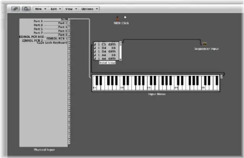
The connection of objects with virtual cables makes it easy to follow the signal flow, but also allows near limitless routing and MIDI data processing possibilities. Use your imagination, and logically plan (and implement) the signal path, to take advantage of the functionality offered by each object type. If you can think of a way to manipulate your MIDI data, you can do it in the Environment!
Most objects can be remotely controlled by other MIDI events (using the sliders or modulation wheel of your keyboard, for example). You can even record these movements, if you wish.
In addition, there are specialized objects which can split a MIDI signal into different channels, make pre-programmed alterations, or even re-route the signal path. These enable you to use the same MIDI data (note events, for example) for several processes, or can be used to provide controller keyboard functionality to the most basic MIDI keyboard.
As you might imagine, the Environment can quickly fill up with a large number of objects. To keep things organized, you can assign them to different display levels, referred to as layers. Think of these layers as being different, partial views of the overall Environment. Naturally, you can easily connect objects between different layers.
To open the Environment window:
- Choose Window > Environment (or use the corresponding key command, default: Command-8).
You can also use the Toggle Environment key command to:
- Bring an open Environment window to the front
- Open an Environment window.
- Close an Environment window, if it is the active window.
Working With Layers
Layers are display levels of the Environment window. They allow you to view and work with specific groups of related objects (all instrument objects, for example), rather than dealing with all Environment objects at the same time. The name of the current layer is displayed in the Layer menu.
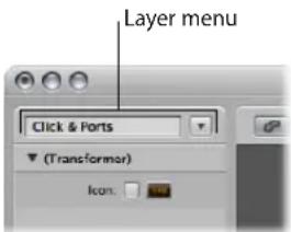
The distribution of objects across different layers has no effect on their functionality—it's simply a better way to organize (potentially thousands of) objects. There are two exceptions:
- Objects in the Global Objects layer also appear on all other layers.
- The All Objects layer shows a list of all Environment objects.
To switch between layers:
- Click the arrow button next to the Layer menu, and choose the desired layer from the menu.
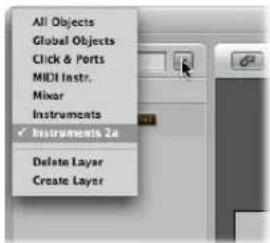
To switch back to the most recently opened layer:
- Choose Options > Go to Previous Layer (or use the Go to Previous Layer key command) in the Environment.
To create a new layer, do one of the following:
- Choose Create Layer from the Layer menu (or use the corresponding key command).
- Choose Options > Layer > Create.
The new, empty layer called "(unnamed)" is inserted above the currently selected layer.
To name a layer:
1 Click on the layer name field, and type in the desired name.
2 Press return to confirm the new name and exit text entry mode.
To delete a layer, do one of the following:
- Choose Delete from the Layer menu to remove the current (displayed) layer from the list.
- Choose Options > Layer > Delete (or use the Delete Layer key command).
An alert appears, to warn against the unwitting deletion of all objects on the layer. Click Delete to complete the operation.
The position (and existence) of the first two layers—All Objects and Global Objects—is protected, and they can not be deleted:
- All Objects: This layer displays all objects in the Environment. The objects in this layer are normally shown as a list.
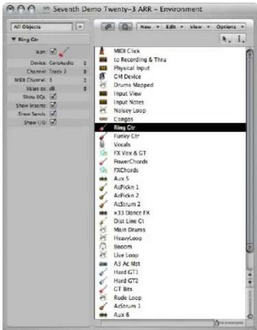
- If you turn off the Logic Express > Preferences > Display > Other > "Allow 'All Objects' layer" option, the All Objects layer will disappear from the Layer menu. Enable this preference if you need access to the All Objects layer.
- You can choose the Options > Go to Layer of Object command, in the Environment menu, to switch to the selected object's layer.
- Global Objects: You can place objects that you want to be visible in all layers in the second layer from the top. These will appear at the same position in all layers. It is recommended that you place as few objects as possible on this layer, due to the on-screen clutter that global objects can create.
Customizing the Environment Display
You can customize the display of the Environment, using the options in the View menu.
To hide the Inspector, which contains the Layer menu and Object Parameter box:
- Choose View > Inspector (or use the corresponding key command, default: 1).
This will create more room onscreen for the Environment workspace display.
To view objects graphically or as a list:
- Choose View > By Text to switch between the graphical display of objects to a listing.
Cables are not shown in the list display. This type of display is most useful in the All Objects layer.
Customizing the Display of Cables
You can arrange your Environment objects more clearly by hiding cables, or coloring them.
To hide or show cables:
- Choose View > Cables to display or hide cables between objects.
This also hides or shows the positioning bar (used for moving and resizing) to the right of some object types.
Tip: You can prevent the accidental alteration of the position, size, and cable connections of all objects by choosing View > Protect Cabling/Positions.
If the cabling and object positions are protected, and the cables are hidden, the background color changes. This usually looks better for virtual mixing desks and fader setups.
To view colored cables:
■ Enable the View > Colored Cables setting.
Cable colors are derived from the color of the source object (the object that the cable runs from, into another object).
To assign a color to the selected object:
- Choose View > Colors (default key command: Option-C), and click on the desired color in the Color palette.
Double-click on any color in the palette to open the Colors window, which allows you to define custom colors.
These color edits are stored in the preferences file, and are available for all projects. The color of an Environment object is used as the default color for any newly created region in the Arrange window.
Viewing a Frameless Environment Window
There may be occasions where you would like to have access to particular Environment objects while working in the Arrange window. As an example, a few buttons that are used to control a tape machine.
Rather than needing to open (or indeed viewing) a full Environment window every time you need to control the tape machine, you can create a mini window that floats on top of other windows.
Typically, this would be the approach:
1 Create a new layer.
2 Create the objects, cable them if necessary, and adjust their parameters as needed.
3 Reposition the objects, and resize the Environment window so that it is just large enough to accommodate the objects.
4 Choose View > Frameless Floating Window.
This will create the mini Environment window, which floats above other windows.
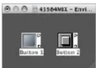
5 Position it as desired (above the Arrange window would be the most obvious use), and press Shift-L to lock this as a screenshot.
6 Simply choose this screenshot to access to the tape controls whenever you need them.
Working With Objects
As with all windows, you interact with onscreen elements and data by using different tools. The Environment window Tool menus offer the standard Pointer, Pencil, and Eraser tools found in other windows. These are used to select, create, and delete objects in the Environment. In addition, the following tools are available in the Environment:
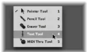
- Text tool: Clicking an object with the Text tool allows you to rename it. Click anywhere outside the text field, or press Return, to complete the naming operation.
- MIDI Thru tool: Clicking an object in the Environment with the MIDI Thru tool assigns the object to the selected track in the Arrange window.
Creating and Deleting Objects
Choose an object type from the New menu to create an object of this type on the current layer. You can also use the corresponding key commands.
Clicking on a layer background with the Pencil tool creates a new instrument object.
To delete objects, do one of the following:
- Click the object with the Eraser tool.
- Select all objects you want to delete, and choose Edit > Delete (or press Backspace).
Moving Objects
You can move objects by grabbing their icon or name, and dragging them to the desired position on the layer. The surface of keyboard and fader objects is used for their operation. You must therefore either grab the name (if available), or the positioning bar to the right of the object in order to move them. If you hold down Shift, you can also grab keyboard or fader objects by their surface.
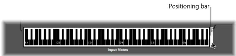
Note: You can Shift-click on any Environment object to select, and move it. When doing so, remember to first deselect any other selected objects by clicking on the layer background, to avoid moving them as well.
Moving Objects Between Layers
The Layer menu and the Clipboard allow you to move objects between layers. You can also open a second Environment window, and drag the objects to the desired layer.
To use the Layer menu to move objects to a different layer:
1 Select the desired objects.
2 Hold down Option, and select the desired layer in the Layer menu.
This moves the selected objects to the chosen layer.
To use the Clipboard to move objects to a different layer:
1 Select the objects that you want to move and choose Edit > Cut (or use the corresponding key command, default: Command-X).
2 Switch to the destination layer.
3 Make sure that no objects are selected (by clicking on the layer background).
4 Choose Edit > Paste (or use the corresponding key command, default: Command-V).
Note: If any objects are selected when attempting to paste objects to the current layer, a dialog asks if you want to "Replace current selection? No/Replace". If you press Enter or click Replace, the selected objects will be replaced by the objects in the Clipboard. The existing cabling remains intact.
To drag objects to a different layer:
1 Open a second Environment window that displays the target layer.
2 Select the objects you want to move in the first Environment window, and drag them from one window to the other.
Tip: You can also use this method to copy objects between layers (by holding Option).
Copying Objects
You can copy an object on a layer by Option-dragging it with the Pointer tool.
To copy an object between layers using the Clipboard:
1 Select the objects that you want to move and choose Edit > Copy (or use the corresponding key command, default: Command-C).
2 Switch to the destination layer.
3 Make sure that no objects are selected (by clicking on the layer background).
4 Choose Edit > Paste (or use the corresponding key command, default: Command-V).
Cabling is preserved; so groups of objects copied in this way will be connected in the same way as the originals (When you copy a single object, only its output cables are preserved).
Note: If any objects are selected when attempting to paste objects to the current layer, a dialog asks if you want to "Replace current selection? No/Replace". If you press Enter or click Replace, the selected objects will be replaced by the objects in the Clipboard. The existing cabling remains intact.
To use drag and drop to copy objects to a different layer:
1 Open a second Environment window that displays the target layer.
2 Select the objects you want to copy in the first Environment window, press Option, and drag them from one window to the other.
Tidying Up Moved or Copied Objects
Objects can be freely placed, which is flexible, but can lead to overlaps or misalignments—particularly when pasting between layers. Fortunately, you can quickly clean up object positions.
To snap objects to a grid:
■ Enable View > Snap Positions to align the objects to an invisible grid.
It's a good idea to leave snap positions switched on. You only need to switch it off if you want to manually move an object by a few pixels.
You can also use the following key commands to move all selected objects one pixel in the relevant direction, even when the grid is switched on:
- Object Move Left
- Object Move Right
- Object Move Up
- Object Move Down
To align several selected objects horizontally or vertically:
- Choose Options > Clean up > Align Objects (or use the corresponding key command).
The top left object stays where it is. The position of the next object determines whether the objects are aligned in a column or a row. If it is to the right of the top left object, all objects are aligned horizontally (row). If it is below the top left object, all objects are aligned vertically (column).
To align selected objects to the invisible grid:
- Choose Options > Clean up > Positions by Grid.
Adjusting the Size of Objects
You can adjust the size of fader, keyboard, and monitor objects by grabbing and dragging the bottom right corner (just as with windows).
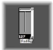
Changing sizes when multiple objects are selected (by rubber-banding or Shift-clicking) will alter each object's size, while preserving their sizes, relative to each other.
To set the size of the selected object to its default value:
- Choose Options > Clean up > Size by Default.
You can also use the following key commands to decrease or increase the width or height of all selected objects by 1 pixel
- Object Width -1 Pixel
- Object Width +1 Pixel
- Object Height -1 Pixel
- Object Height +1 Pixel
Special Selection Commands
You can make moving and copying tasks faster and easier by using the selection commands outlined below.
Selecting All Used Instruments
The Edit > Select Used Instruments function selects all objects that are assigned to the selected track in the Arrange window (or tracks that contain regions), or are connected to such objects via cables.
Selecting All Unused Instruments
The Edit > Select Unused Instruments function selects all objects that are neither used in the Arrange window (as tracks which contain regions), nor connected to any such objects via cables.
Selecting Cable Destination or Origin Objects
The Edit > Select Cable Destination command highlights the destination object of a selected cable connection. This is particularly useful in two cases:
- The destination object is on a different layer. You can use the function to select and display the destination object (and layer).
- When in the list display (View > By Text), you can locate the destination object of a source object, because selecting the source object also selects its cable connections.
This function allows you to follow the cabling from one (serially-cabled) object to the next. If several objects are connected in parallel, or several cable connections are selected, the path of the top cable is followed.
The Edit > Select Cable Origin command essentially performs the reverse task, where the MIDI signal flow is back-tracked to the source (or origin) object. This is particularly useful for troubleshooting, or when you want to make changes to a number of serially cabled objects (by changing the original).
Toggling Your Selection
Just as in the Arrange and editor windows, you can change the status of any selected objects in the current layer by choosing Edit > Toggle Selection.
The MIDI Signal Path
Before any MIDI events received at your computer's MIDI inputs can be recorded by Logic Express, there must be a connection between two Environment objects, namely the:
- Physical Input object: This represents the MIDI In port(s) of your MIDI interface.
- Sequencer Input object: This represents the door in to Logic Express for incoming MIDI events.
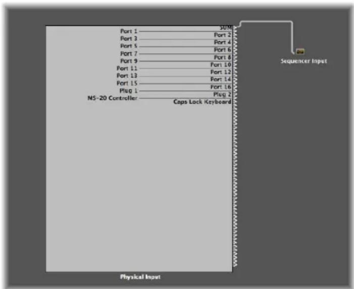
In Logic Express, incoming MIDI events (which arrive at the Sequencer Input object) are always directed to the selected track in the Arrange area's track list, where they can be recorded in MIDI regions.
The events played by the track region are mixed with incoming events (if any), and sent to the Environment object that the track is routed to.
From here (the multi instrument object), the events are directed to a MIDI output (see "Creating Direct Output Assignments" on page 888).
You can insert objects into the signal path between the Physical Input and the Sequencer Input object if you wish (a MIDI monitor object, for example, which allows you to see incoming MIDI events).
You can also insert objects between the Arrange track, and its destination object, enabling other Environment processing. The Arrange track itself is not represented by an Environment object, but you can use the Track Assignment menu to route the track's output to an Environment object.
As an example, the output of an Arrange track (the note events in a MIDI region) routed to (software) instrument channel 1 can be arpeggiated. To do this, you would create an arpeggiator object (this will be easiest on the Mixer layer of the Environment), assign the arpeggiator to the Arrange track (Control-click the track header to access the Track Assignment menu, and browse to the arpeggiator object), then cable the arpeggiator out to instrument channel 1.
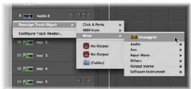
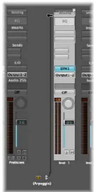
On playback, the note events in the region will be processed by the arpeggiator object, and routed (via the cable) into the instrument channel, which plays back the processed (arpeggiated) MIDI note data.
Creating Direct Output Assignments
You can create a direct output connection to a physical MIDI output from any of the following object types:
- Instrument
- Multi Instrument
- Mapped Instrument
- Touch Tracks
• GM Mixer
• MIDI Metronome Click
To make a direct output connection:
- Click the Port menu in the object's Parameter box, and choose the desired MIDI output.
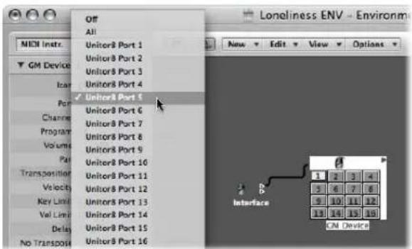
The Port menu lists all MIDI Outputs, plus the following options.
- The Off setting completely disables the connection to the MIDI interface port.
- The All option routes the object's output to all available MIDI ports. This may be useful if the device is sending a pulse, for example.
Note: If you have a MIDI interface with more than one output port (or even several interfaces which can be stacked), you can set up a direct connection to one of the individual ports (1 to 63) of that (or those) interfaces.
Any object with a directly assigned output is indicated by a white triangle on its right-hand side. The triangle is hollow when there is no direct assignment.
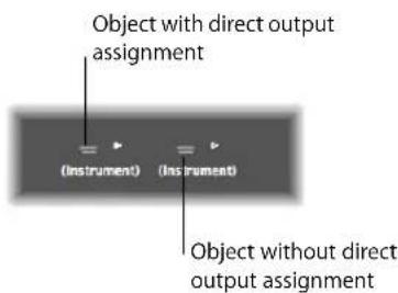
Cabling
The cabling between Environment objects provides control over the entire MIDI signal path. A cable is normally shown as a gray or colored line between a source and destination object.
Cables are assigned the same color as the source object, which makes following the signal path much easier. You can, however, switch off cable coloring, and render them in gray with the View > Colored Cables function.
Objects always have an (invisible) input on the left, and an output on the right-hand side. The output of an object is shown as a small triangle, pointing to the right.
To make a connection between two objects—method 1:
1 Click-hold the triangle of the source object.
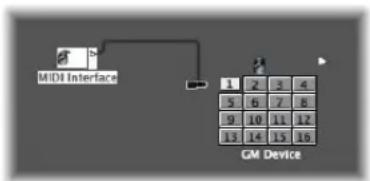
flowchart
graph TD
    A["1"] --> B["2"]
    B --> C["3"]
    C --> D["4"]
    E["5"] --> F["6"]
    F --> G["7"]
    G --> H["8"]
    I["9"] --> J["10"]
    J --> K["11"]
    K --> L["12"]
    M["13"] --> N["14"]
    N --> O["15"]
    O --> P["16"]
The mouse pointer turns into a plug (patch cord) that represents a cable connection coming from the object's output.
2 Move the cable plug over the destination object, and release the mouse button when the object is highlighted (this happens automatically when you touch it).
A cable connection will be created between the two objects.
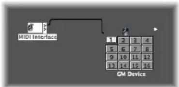
flowchart
graph TD
    A["MIDI Interface"] --> B["CM Device"]
    B --> C["1 2 3 4"]
    B --> D["5 6 7 8"]
    B --> E["9 10 11 12"]
    B --> F["13 14 15 16"]
If the source object has already been directly assigned to a MIDI output port, a dialog will ask if you want to replace the direct assignment. You have three options:
- Cancel: The connection is not made, and the direct output assignment of the source object remains intact.
- No: Your cabling takes place, but the direct output assignment remains intact. This means that the source object is connected to two destinations—one to another object via the cable, and one via the direct output assignment.
- Remove: Your cabling occurs, and the direct output assignment is removed (This is the default selection, because you generally won't want an object connected to two different destinations).
To make a connection between two objects—method 2:
1 Option-click the triangle, which will open a hierarchical menu.
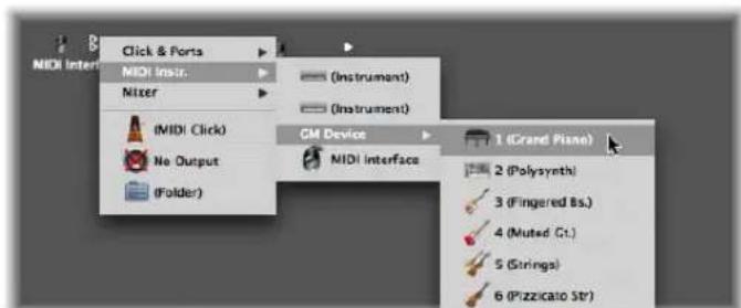
2 Browse to the layer that the destination object is on, and choose the object name.
A cable connection will be created between the two objects.
This method is ideal for creating connections between layers, but can also be useful when a large number of closely-spaced objects exist on a single layer.
You can also open a second Environment window (showing the destination layer), and connect the objects graphically between the windows.
A cable connection to another layer looks like this:
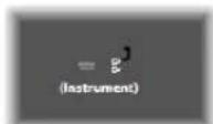
To remove a cable connection, do one of the following:
- Click the cable with the Eraser.
■ Select the cable and press Backspace. - Grab the cable, and plug it back into (drag it over) the triangle of the source object.
- Use Edit > Clear Cables Only to remove all selected cables, without also clearing any objects that happen to be selected.
This is handy when you want to clear all cables leading to (or from) one or more objects, given that selecting objects also selects all associated cable connections.
Making Multiple Cable Connections
There is no limit to the number of cables that you can plug in to a destination object. All MIDI signals are mixed at the object's input.
To make multiple output connections from an object:
1 Connect the object to the desired destination object, following one of the two methods outlined above.
Once an output from an object is used (cabled to another object), another output triangle automatically appears.
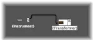
2 Use the second output triangle to create a second cable connection to a further destination object.
Once this is done, a third output triangle will appear, and so on.
Some objects have special outputs, and are exceptions to this rule. This includes channel splitters (see "Channel Splitter Object" on page 915), which features several—functionally different—outputs. Other special objects include cable switchers (see "Cable Switchers" on page 950) and the Physical Input object (see "Physical Input and Sequencer Input Objects" on page 930). In these objects, each output can only be used once.
To route the signal of the special output objects outlined above to several destinations:
1 Create a monitor object (see "Monitor Object" on page 915) by choosing New > Monitor.
2 Plug the cable from the desired object output into the monitor object.
3 Cable from the monitor object to as many other destinations as you'd like.
The monitor object allows you to view the MIDI events flowing through it.
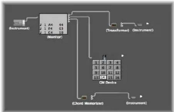
flowchart
graph TD
    A["(Instrument)"] --> B["Monitor"]
    B --> C["(Transformer)"]
    C --> D["CM Device"]
    D --> E["(Chord Memorizer)"]
    D --> F["(Instrument)"]
To select a common destination for several existing cables:
1 Select the cables.
Tip: If the cables are already connected to a common destination, the simplest way of doing this is to select the destination object.
2 Next, grab one of the cables and plug it into the new destination object.
The following dialog is shown:
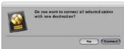
3 Click Connect, or press Enter.
Cabling Serially and in Parallel
You can cable objects in series or in parallel. Cabling objects in series is handy for quickly connecting groups of faders used to control a MIDI mixing console, for example.
To cable a group of objects serially:
■ Select all objects you want to cable, then choose Options > Cable serially.
The objects will be cabled in series, starting with the top-left object.
To cable a group of the same type of object (transformers, faders, and so on) to a common destination:
1 Cable one of the source objects to the destination.
2 Select the destination object and choose Edit > Copy.
3 Select the other objects that you want to connect to the same destination, and choose Options > Apply Buffer Template to > Cable(s).
You can copy more complex cabling configurations this way, too. Just ensure that the type(s) of objects in the group that you wish to copy matches the type(s) of objects in the group that you apply the buffer template to.
Common Environment Object Parameters
Each Environment object has several parameters that control its operation. These parameters can be viewed and changed in the Object Parameter box, shown in the Inspector when an object is selected.
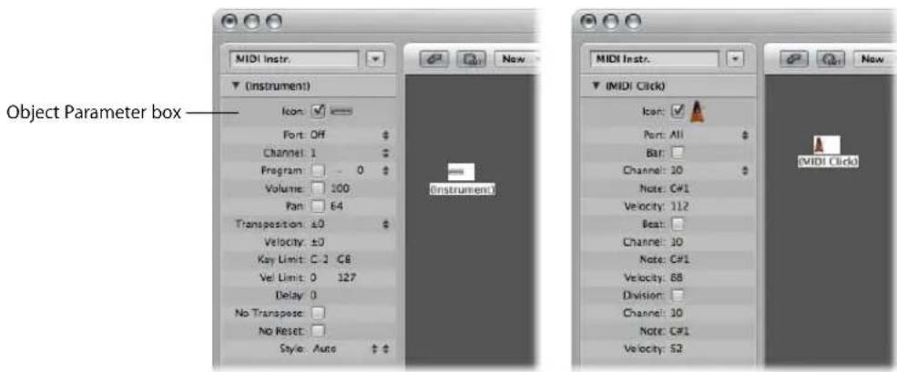
The Object Parameter box also appears in the Arrange window Inspector when you select a track assigned to the object. These are the same parameters—changes in one location will be reflected in the other. There is one type of object, however, that differs slightly in this regard: the audio channel strip.
A cut down Object Parameter box is shown for audio channel strips when displayed in the Arrange window. The full parameter set for these objects is only available in the Mixer layer of the Environment window. The differences are as follows:
- Icon checkbox is removed.
- Device menu function is removed (display only).
- Channel is renamed to Type/#: The menu function is removed (display only).
- Show EQs: Removed (always displayed in Arrange channel strips).
-
Show Inserts: Removed (always displayed in Arrange channel strips).
-
Show Sends: Removed (always displayed in Arrange channel strips).
- Show I/O: Removed (always displayed in Arrange channel strips).
There are two main reasons why the Arrange and Environment representations of audio channel strips differ: to save onscreen space, and to provide the tools you need for music creation, rather than setup tasks.
This separation is made even clearer—for all audio, instrument, and external MIDI channels—by the use of two terms throughout the manual:
- Track Parameter box (in the Arrange window, to illustrate that the channel is controlling the corresponding track).
- Object Parameter box (in the Environment, where you are interacting with the underlying object).
Opening and Closing the Object Parameter Box
By clicking the triangle at the top left, you can hide all parameters except the object name and type. This reduces the box to its minimum vertical size.
You can also hide or show the Inspector by choosing View > Inspector (default key command: 1).
Common Parameters
The following parameters are shared by all object types:
Name
The name of the object is shown next to the triangle, and can be selected for editing by clicking on it. You can also edit the name by clicking directly on the object with the Text tool.
Object Type
The object type is shown in brackets, and cannot be edited.
Display Filter for the Track Assignment Menu
Turn on the checkbox beside Icon to make the object visible in the Arrange area's Track Assignment menu (see "Assigning Tracks to Environment Objects" on page 202). This is obviously useful for instrument objects, but can also be handy for other objects such as arpeggiators, touch tracks, and chord memorizers.
Once made visible, you can Control-click an Arrange track, and reassign the track to one of these objects. The object, in turn, can be routed into an instrument channel, for example.
The upshot of this, is that selecting an arpeggiator object (routed into a software instrument channel) in the track list, results in a real time arpeggiation of the instrument sound when you play chords on your keyboard while Logic Express is running.
Objects not in the Track Assignment menu can still be assigned to tracks by dragging them from the Environment onto the track list, or by using the Environment's MIDI Thru tool.
If you move a multi instrument object into the track list, the selected sub-channel is set as the track instrument. If no sub-channel is selected, all initialized (sub-channels that are not crossed out) sub-channels are set for the destination track, and the tracks below that. If there are no tracks below the destination track, new tracks are automatically created and assigned to sub-channels of the multi instrument object.
If the checkbox is not active, the object and its icon will still appear in the Environment. You should only activate the icon checkbox if the object will be used as a track destination.
Icon
Click the icon in the Object Parameter box to choose an icon to represent the object in the Environment and Arrange window track list.
Exchanging Environments
One of the main advantages of the Environment is the ability to customize Logic Express to fully control your MIDI studio. This can, however, present a problem when sharing projects with other musicians, or using different studio setups.
It also presents a problem when you return to older projects after you've changed your studio. Logic Express offers several functions to make these transitions as easy as possible.
Whenever you want to exchange Environments between projects, there is a source project containing the desired Environment, and a destination project with an Environment that you want to change.
The destination Environment must be in memory, and must be the active project (one of its windows must be active). The source project can also be in memory, or it can be a file on your hard drive (or any other media).
- If there are two projects in memory, Logic Express will assume the active project is the destination, and the other project is the source.
- If there are more than two projects in memory, Logic Express will assume the active project is the destination, and the most recently active of the other projects is the source.
- If there is only one project in memory, Logic Express will launch an Open dialog, allowing you to select the source project when importing an Environment.
Importing, Replacing, and Swapping Environments
This section covers the different types of Environment import procedures that can be performed in Logic Express.
Importing Single Purpose Environments
A single purpose Environment patch might be an editor for a specific piece of MIDI equipment, an Environment for a single MIDI processing task (such as a MIDI LFO), or a complex arpeggiator/delay line configuration.
To import an Environment patch contained on a single layer:
1 Choose Options > Import Environment > Layer.
2 Choose the desired layer in the dialog that appears.
This layer—inclusive of all objects on the layer—will be inserted in the destination project, at the same layer position (the same place in the Layer pop-up menu) that it occupied in the source project. Any existing layers will be shifted as needed.
You can also move selections of Environment objects (inclusive of cabling) between projects by dragging or copy and pasting. This is made even simpler by first combining the objects into a macro.
To import an Environment patch that is spread across several Environment layers:
- Choose Options > Import Environment > Merge.
All Environment objects from the source project will be added to the Environment of the destination project.
One thing to watch out for here is that merged objects will be placed on the same layer as their source, which can create a mess if objects already occupy that layer in the destination project.
To avoid this issue, create blank layers (in the destination project) at the same layer positions of the source project, before importing.
Something to be careful of in both cases, is the treatment of unique objects in the Environment, including the Physical Input and Sequencer Input objects. If imported, they will replace their counterparts in the destination Environment and any cables leading into them will be lost.
It is best to temporarily delete these from the source Environment, before importing.
Another thing to be aware of is that when you import an object, all objects cabled from the imported object are also imported.
Replacing an Older Environment With a Current One
If you have only added things to the Environment, but not deleted anything, you can update older projects by choosing Options > Import Environment > Update.
Only the new objects will be imported—the older objects (along with their cabling and track assignments) will remain in place.
Swapping Environments
In the complex situation where you want to swap the Environment of one MIDI setup with the Environment of another, Logic Express offers three options:
- Replace by Port MIDI/Channel: This option replaces all objects in the destination project with objects that address the same port and MIDI channel in the source project.
- Replace by Name: This option replaces all objects in the destination project with objects of the same name in the source project. This affords you some degree of control, by renaming objects in the source project accordingly.
- Total Replace: This completely replaces the destination project's Environment with the source project's Environment. If you use this option, you'll have plenty of work to do, including reassigning Arrange window tracks to objects, but sometimes it's the only way!
Note: This complex task involves a lot of guess work on Logic Express's part, and the results almost always require some manual fine tuning on your part.
Replacement by Assignment
The most flexible (and most time consuming) method of exchanging Environments is to manually choose whether each Environment object is kept, deleted, or replaced. If you choose to replace an object, you must also define the replacement object. This method is accessed via Options > Import Environment > Custom.
When you select custom import, an Environment window listing all objects in the destination Environment is shown in a column on the left, and the chosen action for each object is shown in a column on the right.
You can assign the replacements one at a time, by clicking on items in the right hand list and selecting the desired replacement object from a pop-up menu. This menu includes all objects in the track list of the source project.
Alternately, you can select one or more rows in the list, and make a choice from the Import menu. In addition to keep and delete, this menu offers several automated selection techniques, as described below.
The first Import menu option is Import Environment using current Assignment. No importing can take place until you make this selection. The other choices (including the pop-menus in the right column) determine how things will be imported.
Import Options
The last two items on the Import menu provide additional options for the import process:
- Import > Copy Layer Names: The layer names of the source (second) Environment are transferred to the current one.
- Import > Copy selected Objects from 2nd Environment: All objects selected in the source Environment are copied into the destination Environment, even if they don't appear on the assignment list.
Automatic Assignment Functions
The assignment functions described below are immediately applied to all selected rows in the import list. The assignments appear in the right column, and all rows are then deselected.
- Import > Assign as 'Keep': These objects are unaltered.
- Import > Assign as 'Delete': These objects are deleted.
- Import > Assign by Identical: These objects are assigned to objects from the source project that match the type, icon, name, port, and MIDI channel. objects with the same Unique ID have priority.
Logic Express maintains an internal list of all Environment objects. An object's position in the list is its Unique ID—as long as the object is not deleted, its Unique ID never changes.
When objects are deleted, their position in this list becomes available for a new object.
Whenever an object is added to the Environment, it is placed in the first available position on the list (if there are no empty positions, it is added to the end of the list).
- Import > Assign by Unique ID: Objects are assigned to objects from the source project with the same Unique ID. This option is useful for updating an Environment when objects have only been added.
- Import > Assign by Port/MIDI Channel: Objects are replaced by objects with the same Port/MIDI channel. If a match can't be found for an object, an object set to Port 0 and the same MIDI channel is assigned. If a match still can't be found, an object with the same MIDI channel is assigned.
- Import > Assign by Name: Objects are replaced by objects with the most similar name (At least 80% of the name must be the same).
- Import > Assign by Icon/Name: as above, except the object icons must also match.
The Environment Objects
This section covers each type of Environment object in detail, outlining what each is designed to do, and how to use the parameters of the object.
Standard Instruments
Logic Express provides standard instrument objects to handle MIDI devices that only use one MIDI channel (typically, older synthesizers, MIDI controlled effect units or drum machines). Standard instruments transmit MIDI data on a single MIDI channel.
To create a standard instrument, do one of the following:
- Choose New > Instrument (or use the New Standard Instrument key command).
- Click the Environment background with the Pencil tool.
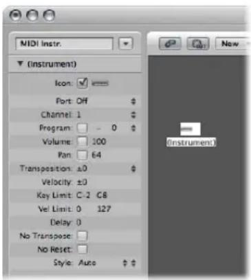
A standard instrument is created, and its parameters are displayed in the Inspector. Here, you can set a number of playback parameters, including program bank and number, initial volume and pan, transposition, velocity scaling, and MIDI delay.
Port
Use to set a direct connection to one of your MIDI output ports. Remember that you can also directly cable an instrument object to (or from) other Environment objects, allowing MIDI processing.
Channel
Sets the MIDI channel for the instrument's output. If you set this parameter to All, all events will be sent with their original channel settings.
Program, Volume, and Pan
The Program, Volume, and Pan parameters transmit program changes, volume controller (#7), and pan controller (#10) data.
No data will be sent until you activate the corresponding checkbox. If the box is already activated, any value alterations will be sent immediately, and the values will also be sent whenever the track is selected.

To the left of the program number, directly to the right of the checkbox, you'll see the Bank Select parameter. If your MIDI sound source recognizes bank select messages (check the device manual), you will be able to switch between sound banks. If your sound source responds to the standard Bank Select message (Controller #32), you will be able to use this parameter directly. If not, you may define your own Bank Select commands (see "Defining Custom Bank Selects" on page 906).
Transposition
Defines the number of semitones that all note events will be transposed by, on output. Negative values transpose downwards.
Velocity
Allows you to increase or decrease the note on velocities of all note events, by an amount between -99 and 99.
Key Limit
The two note values of the Key Limit parameter define a pitch range. All notes outside this range will be ignored by the instrument when it plays a MIDI region. In other words, this range of notes will not be played.
Vel Limit
The two values of the Vel Lim parameter define a velocity range. All notes with a velocity that falls outside this range will not be played by the instrument.
Delay
The Delay parameter causes all MIDI events to be sent early or late. This allows you to compensate for any differences in reaction time between your various MIDI devices. Use the region Delay parameter (in the Track Parameter box shown in the Arrange) to create rhythmic delay effects, as this allows longer delay times.
No Transpose
If the No Transpose parameter is active, all regions on any tracks played by this instrument object are protected from transposition. In other words, the transpose region parameter is ignored. This is very useful for instruments assigned to drum or other samples—mapped across the keyboard on a single MIDI channel—as transposition will trigger different sounds (rather than pitches) in these instruments.
No Reset
If the No Reset parameter is active, no reset messages will be sent to the instrument. This can be useful if controllers are being used for non-musical purposes, such as when using the instrument object for mixer automation tasks. The Logic Express > Preferences > MIDI > Reset Messages settings determine what reset messages are sent. These messages are not sent to No Reset instruments.
Style
The Style parameter can be set to any of the available staff styles. Whenever a region is created on one of the instrument's tracks, it will be assigned the staff style displayed here. If the Auto style is chosen (the default), Logic Express will pick an appropriate style based on the pitch range of the notes in the region. For more information on staff styles, see "Working With Staff Styles" on page 775.
Multi Instruments
A multi instrument is like a collection of 16 standard instruments (see above) in one package.
There is a separate sub-instrument (or sub-channel, if you prefer) that mirrors the 16 MIDI channels—as indicated by the numbered squares on the multi instrument object. Clicking on any of these numbered squares selects the corresponding sub-channel, and displays its parameters in the Object (or Track) Parameter box.
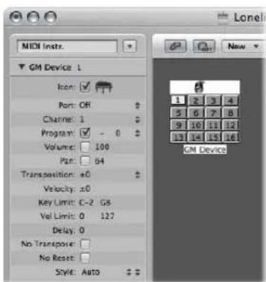
Each sub-instrument has a complete set of instrument parameters (identical to those outlined in the Standard Instrument section).
Multi instruments have 15 name banks—each of which can hold 128 preset names. All sub-instruments share the 15 banks of program names, and use the same format for their bank select message. All sub-instruments of a multi instrument use the same output port.
You will generally use multi instrument objects to address multi-timbral hardware synthesizers or samplers. A multi-timbral sound module is one that can receive on several MIDI channels at once—playing back a different sound on each channel.
As most modern MIDI devices are multi-timbral, the multi instrument will probably be the most commonly used instrument object in your Environment.
To create a new multi instrument object:
- Choose New > Multi Instrument (or use the New Multi Instrument key command).
The Multi Instrument Parameter Box
The multi instrument parameters are, as mentioned, identical to those of the standard instrument object (see "Standard Instruments" on page 899). The settings you make here apply globally to all sub-channels.
To view the multi instrument parameter box:
- Click the icon or name field at the top of the multi instrument object.
This selects the whole multi instrument object, allowing you to set the Port parameter, for example.
Activating and Selecting Sub-Instruments
To select a sub-instrument (to address a specific MIDI channel number within the multi instrument), click the appropriately numbered square (button) on the multi instrument object. The first time you click it, the sub-instrument is activated, making it available in the Track Assignment menu of the Arrange track list (accessed by Control-clicking a track). To avoid menu clutter, you should only activate as many sub-instruments as you actually need, or the external MIDI device supports.
As with any other Environment object, you can remove sub-instruments from the Track Assignment menu, by deactivating the Icon checkbox in the Object Parameter box. The button for the sub-instrument channel will be shown with a diagonal line through it when deactivated.
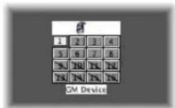
In the above screenshot, sub-instrument 1 is selected, sub-instruments 1 to 8 are activated, and sub-instruments 9 to 16 have been removed from the Track Assignment menu.
Note: If you want to select the entire multi instrument (to reassign the Port parameter, for example), rather than a particular sub-instrument channel, click the top edge (icon) or name field of the multi instrument object.
The Sub-Instrument's Parameter Box
The sub-instrument parameters are the same as those of standard instrument objects (see "Standard Instruments" on page 899). The only parameter you can not change is the MIDI channel.
If you try to change the channel, you'll see the following warning:
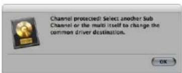
You can, however, change the channel in the Arrange window's Track Parameter box to any sub-instrument of the multi instrument, and the track will be assigned to the selected sub-instrument. This allows you to redirect the (regions on the) track to another sub-instrument, making it easy to play multiple parts with a particular channel/sound.
Note: If you change the Output port parameter of any sub-instrument, this will affect the entire multi instrument and all other sub-instruments.
Cabling Directly to a Sub-Instrument
To connect the output of an Environment object directly to the input of a sub-instrument, Option-click the source object's output triangle and choose the sub-instrument in the Track Assignment menu (see "Cabling" on page 889).
Note: You can not drag a cable to a sub-instrument. Any dragged cables can only be connected to the entire multi instrument object, not one of its sub-instrument channels.
Using the Multi Instrument Window
Double-clicking a multi instrument opens the Multi Instrument window:
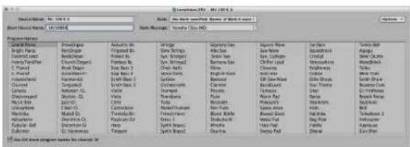
Device Name and Short Name
At the top left, under Device Name, you can enter the full name of the multi instrument. Directly below, under Short Device Name, you can also enter a short name. This short name is used in the Arrange window track list, when the program name is displayed.
Depending on whether or not you have activated the sub-instrument's Program parameter, the following information will appear in the Arrange area's track list:
- The name of the multi instrument and channel number (if the parameter is not activated).
- The short name, channel number, and program name (if the parameter is activated).
Program Names
There are 128 program names in the Multi Instrument window. A total of 15 banks of 128 program names are available. There are several ways of entering program names:
- By double-clicking on the name (via the text input field).
-
By copying (via the Clipboard) from a different multi instrument, or from a word processing program. The Clipboard functions for a whole sound bank are available in the Options pop-up menu.
-
First, copy the program numbers or General MIDI names to the Clipboard, and add them to a word processor document.
-
You can then edit the names and copy the whole section back again.
-
If you want to use program numbers instead of names, choose Init Names as Numbers from the Options menu.
- If you want to use General MIDI program names, choose Init General MIDI Names. If the Use GM Drum Program Names for Channel 10 checkbox at the bottom of the window is activated, the standard GM drum set names will be shown in the Program menu of the Parameter box for sub-instrument 10.
If the Program box in the selected sub-instrument's Parameter box is checked, you can send a program change message by selecting a program name in the Multi Instrument window.
Banks
The Bank pop-up menu allows you to choose one of 15 available sound banks (0 to 14). The top item (No Bank specified. Names of Bank 0 used.) can be used if your sound generator does not understand bank select messages, or only has 128 sound programs.
• Bank 0 is always initialized.
- The first time you choose one of the banks numbered 1 to 14, you will be asked whether or not you want to initialize this bank.
• Non-initialized banks use the names of the equivalent program numbers from bank 0.
Note: You should only initialize additional banks if you want to enter program names for those banks, because each initialized bank uses more memory.
In the pop-up menu to the right, labeled Bank Message, you can define the MIDI events that are sent when you switch between the banks of the multi-instrument.
Different bank select formats are used by different MIDI instrument manufacturers—please consult your MIDI instrument's manual to see whether or not it supports bank select messages, and if so, what format it uses.
With modern synths, there's a good chance the format will match one of the top items in the menu: either controller# 32 or controller# 0. There are also presets to accommodate several of the more common types of synth. If your synth doesn't use one of the formats listed, see the following section on defining your own bank select commands.
Defining Custom Bank Selects
Logic Express provides 15 bank numbers (0 to 14) for each standard instrument, multi instrument (including sub-instruments), or mapped instrument object. You can create custom lists, consisting of as many events (of any kind, even SysEx) as you wish—for each of these banks.
Whenever you change the bank manually, or send a standard bank change message from Logic Express, the entire list for that bank will be transmitted to your sound module.
To set up custom bank select messages:
1 Select the instrument you want to define bank select messages for.
2 Choose Options > Define Custom Bank Messages.
A window similar to the Event List will open, with a single, default, bank select message for banks 0 to 15. (The default used is a MIDI controller #0 message, with a value equal to the bank number).
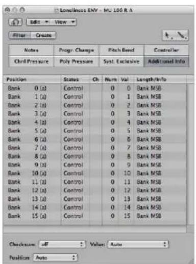
You can create MIDI events here as you would in the Event List, by cutting, copying, inserting, and editing (see Chapter 18, "Editing MIDI Events in the Event List," on page 459). The only difference is that you enter the desired bank number, rather than a time position.
The letter in parentheses next to the bank number allows you to control the order of transmission, when a bank select requires more than one message.
If there are no events defined for a particular bank, a standard bank select message will be sent for that bank.
For bank messages that need a channel (MIDI controller messages, for example), the channel of the instrument is used. This feature is especially useful for multi instruments, as you only need to create one set of bank messages for all 16 sub-instruments. If an instrument's channel is set to All, channel 1 is used.
Note: The custom bank select information becomes part of the instrument, and is automatically copied with it, should you replicate the instrument object.
Mapped Instruments
This instrument is particularly useful for drum instruments or any drum-mode MIDI device. A drum-mode device has different sounds assigned to different MIDI notes, but only uses a single MIDI channel. As examples, a drum kit loaded into the EXS24 mkII, or MIDI channel 10 of a GM-compliant sound module, or a drum machine.
To create a new mapped instrument:
- Choose New > Mapped Instrument (or use the New Mapped Instrument key command).
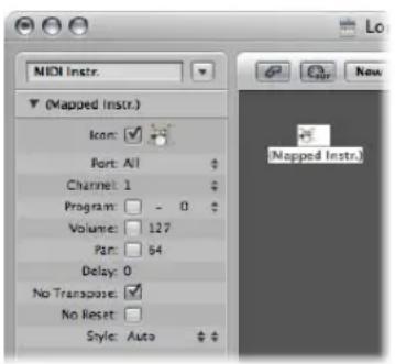
A mapped instrument is used just like a standard instrument, but each individual input note can be:
- Named (snare, hi hat, and so on)
- Mapped to an output note
-
Given a velocity offset
-
Assigned its own MIDI channel
- Sent to one of up to 16 output cables (this allows you to create a single instrument that addresses multiple sound sources).
- Given its own notation parameters: note head shape, relative vertical position in the staff, and drum group assignment (see "Drum Notation With Mapped Staff Styles" on page 792.
The mapped instrument's parameters are a subset of the standard instrument (see "Standard Instruments" on page 899) parameters. The missing settings are available on a note-by-note basis in the Mapped Instrument window.
Using the Mapped Instrument Window
To open the Mapped Instrument window, double-click on the mapped instrument icon. The rows correspond to input notes, and the columns contain the various parameters available for each note. The window is automatically opened when creating a new mapped instrument.
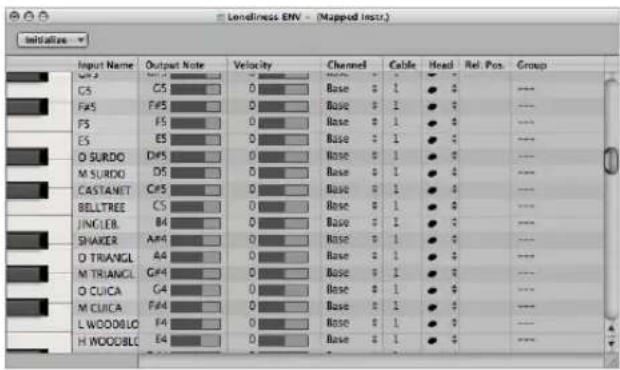
Keyboard (Selecting Notes)
The keyboard on the left represents the input notes. It can be played by clicking on it. You can also select individual notes or note ranges, by dragging the mouse over the notes you want to use. To select multiple notes, Shift-click on them. Any value alterations will apply to all selected notes.
Input Name
In the first column, you can click on the input note name (E6, for example), and type in a name of up to 12 characters. Press Return or click outside the text entry field to confirm the new name.
You can initialize the names of the selected notes to:
- Pitch descriptions (C#3, for example) by choosing Initialize > Names as Notes.
- The names of GM Standard drum sounds by choosing Initialize > Names as General MIDI.
If a MIDI region (on a track routed to a mapped instrument object) is displayed in the Piano Roll Editor, the names of the notes being played will appear on the vertical keyboard.
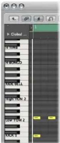
Output Note
This column is used to set the output note. This is done by either:
- Double-clicking on the note description and editing the text
- Dragging the beam to the right of the output note name.
MIDI notes are sent while changing the value, allowing you to hear what you're doing.
Use the Initialize > Output Notes command to match the output notes of the selected pitches to the input note pitches.
Velocity
Used to set a velocity offset which is added to, or subtracted from, the velocity of the incoming note. Click-hold the number and drag the mouse up or down to create a velocity offset. You can also click the desired point on the beam.
Initialize > Output Velocities resets all velocity offsets to 0 (no offset).
Channel
Sets the MIDI channel of individual notes. This allows you to play individual sounds from different drum sets in the same sound generator.
You will normally use the Base setting. This means that the notes are sent on the channel set in the mapped instrument's Parameter box. If you choose All in the Parameter box, the channel information of the incoming notes is used. This is useful if you want to place the mapped instrument after a multi instrument or standard instrument in the signal path.
To set all selected notes to Base, choose Initialize > Output Channels.
Cabling Mapped Instruments
You can send individual notes from a mapped instrument object to (up to) 16 different output cables, enabling you to play sounds from different sound sources. If you select a cable that doesn't exist, the note will not be sent out.
Initialize > Output Cables resets all cables to #1 (the top outlet of the Mapped Instrument).
Notation Parameters
The last three columns define the notation parameters of individual notes.
- Head: This pop-up menu allows you to change the note head.
- Rel. Pos: This field is used to alter the relative position of the note on the staff. This does not alter the pitch, only the vertical positioning of the note head on a staff in the Score Editor. Simply click-hold and drag vertically to alter the note position.
- Group: As the mapped instrument object is typically used for percussion instruments, click-holding the Group field opens a menu of grouped drum families: Kick, Snare, and so on. MIDI sound modules can have drum sounds mapped across 127 possible notes, which would result in an interesting staff (to say the least!). Assign several related percussion sounds (tom drums, for example) to the Toms group to place all related sounds on a single staff line. As with the relative position, the pitch of grouped notes is not affected by grouping them on a single line.
Choosing Initialize > Score Parameters neutralizes the settings of the Head, RelPos., and Group parameters.
GM Mixer
The GM mixer is a collection of 16 fader modules, configured to emulate a virtual mixing desk for 16 MIDI channels. Each module has controls for volume, mute, preset, bank, and four assignable knobs (one of which is typically used for pan). There are optional controls for standard XG and GS effects.
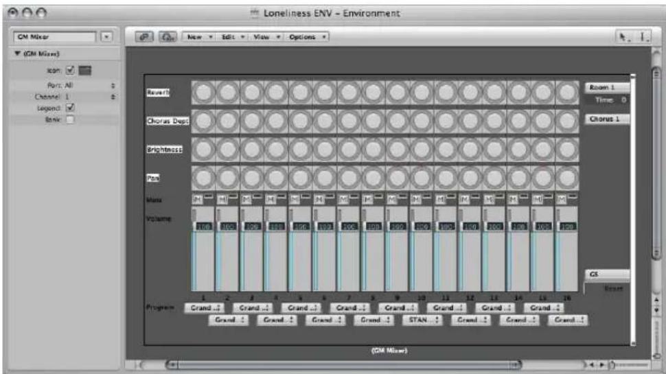
To create a new GM mixer:
- Choose New > GM Mixer.
The GM mixer is intended for controlling the 16 channels of a MIDI device which conforms to the GM, XG, or GS standard. This includes the GM set of 128 program names (with variation banks for XG or GS), MSB/LSB bank select messages, and standard controller names (#1 for mod wheel, #2 for breath, #7 for volume, #10 for pan, #11 for expression, and so on).
The Parameter Box of the GM Mixer
Most of the GM mixer's set up is done in the mixer itself, but there are also a few parameters in its Parameter box.
Port and Channel
Like the instrument and multi instrument objects, the GM mixer can also have a direct MIDI output connection. It is set with the Port parameter.
The Channel parameter determines the channel number of the lowest GM mixer module. You can use this (coupled with resizing the GM mixer) to create sub-mixers for any continuous string of MIDI channels (1 to 4, for example).
Legend
The Legend parameter switches the display of the legend along the left edge of the GM Mixer on and off.
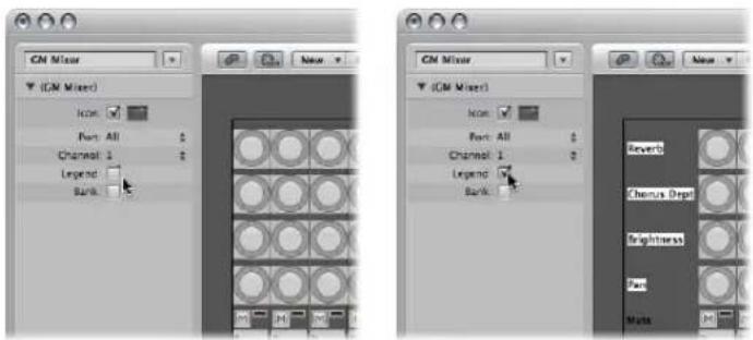
The Legend not only indicates what the rows of controls do, it is used to set the function of the top four rows of knobs. After the GM mixer is set up, you can hide the legend to save space.
Bank
The Bank parameter hides or shows the bank MSB/LSB display at the bottom of the GM mixer. You can save space by hiding the bank display, unless you need to select program banks numerically.
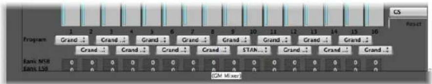
Working With the GM Mixer Channel Strips
The MIDI channel strips work as a remote control for the mixing parameters of the controlled sound modules and synthesizers (volume and pan, for example).
Choosing a Program or Bank
If your sound source understands bank select events, you can choose the bank number with the Bank parameter field at the bottom of each channel strip (only visible if Bank parameter in Object Parameter box is enabled). Please remember that not all synthesizers support bank select events. You can use several different bank select formats (see "Defining Custom Bank Selects" on page 906).
The Program button allows you to select a sound by name—click it to open a menu that contains all GM sound name. Each channel has its own menu.
Adjusting the Level of a Channel
The Level fader controls the output level of a MIDI channel. Adjusting it sends controller 7 via your MIDI interface.
To adjust the output level of a channel:
- Drag the Level fader up or down.
Muting a Channel
The Mute button switches the volume of the channel between zero and the current Level fader position. In practice, this means that if the button is down, the channel is muted. If you switch the Mute button off, the current Level fader position (and value) is used.
To mute or unmute a channel:
- Click the Mute button of the desired channel.
Assigning the Knobs to Controllers
You can assign any controller to each of the knobs.
To assign a controller to one of the knobs:
1 Click on the label next to the knob.
2 Choose the desired controller from the menu.
Extended GM, GS, and XG Functions
In addition to the GM Standard, there are extended standards created by Roland (GS) and Yamaha (XG).
GS and XG mode allow you to select different effect programs, and to control the level of the reverb and chorus effects.
To display the GS or XG effects:
- Choose the GS or XG setting in the menu in the mixer's lower right corner.
The GS/XG configuration control is displayed on the right side of the Mixer, allowing you to select different effect programs.
To configure GS or XG effects:
1 Choose the desired standard in the first menu.
Depending on your selection, the controllers for the extended effects will appear.
2 Select the desired reverb or chorus effect from the second menu.
3 Program the desired reverb or delay time (Time parameter).
Resetting All Controllers
The Reset button transmits a GS On or XG On command, and resets all controllers to neutral positions. This allows you to reset all connected sound modules to their standard settings, and begin a mix from scratch.
MMC Record Buttons
The MMC record buttons object allows you to control the record enable status of external MMC-compatible recording devices (see "MIDI Machine Control" on page 861).
To create an MMC record buttons object:
- Choose New > MMC Record buttons.
Resizing the object allows you to determine the layout and number of track record buttons.
Enable the Extra checkbox in the Parameter box to display the "V TC A1 A2" extra tracks:
• V for Video
- TC for Time code
• A1 for Aux Track 1 (or A)
• A2 for Aux Track 2 (or B)
Keyboard
You can use a keyboard object to create notes with the mouse. A keyboard object also displays all notes passing through it. In this sense, you can think of it as a real time, MIDI note-on monitor. Although you can record the output of the keyboard in Logic Express, its main purpose is for testing and monitoring in the Environment.
To create a keyboard object:
- Choose New > Keyboard (or use the New Keyboard key command).
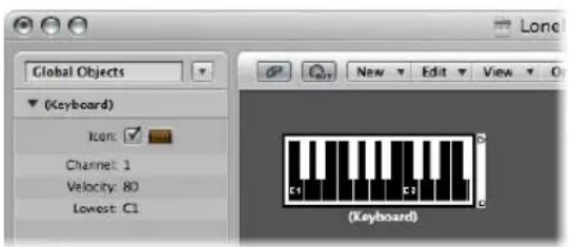
Apart from the Icon parameter, you can also set the following in the Object Parameter box:
- MIDI channel
- Velocity: Determines a fixed velocity value for all notes.
- Lowest: Defines the octave of the lowest note on the keyboard object. You can resize the keyboard to control its range above the lowest note.
Monitor Object
A monitor objects displays all events (MIDI and meta) passing through it. It remembers the last 32 events, with the newest events shown at the bottom of the list. You can resize it to show from 1 to 32 events. Clicking anywhere in the body of the monitor clears all events.
To create a monitor object:
- Choose New > Monitor (or use the New Monitor key command).
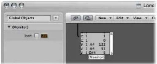
Monitors are very handy as both testing and branching devices. When coupled with objects that have functionally different outputs (channel splitters and mapped instruments, for example), monitor objects can be used to attach more than one output cable to the same function.
Channel Splitter Object
A channel splitter routes MIDI events by channel. Every MIDI event received at the channel splitter input is automatically routed to the output that corresponds to its MIDI channel.
If no cable is connected to the corresponding output channel, the event is re-routed to the SUM output (at the top).
To create a new channel splitter object:
- Choose New > Channel Splitter (or use the New Channel Splitter key command).
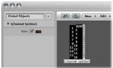
Arpeggiator
An arpeggiator object turns chords into arpeggios. It plays the currently held notes—individually—in a selectable pattern (up, down, random, and so on), and at a selectable speed that ranges between whole-notes and 768th-notes.
To create a new arpeggiator:
- Choose New > Arpeggiator (or use the New Arpeggiator key command.
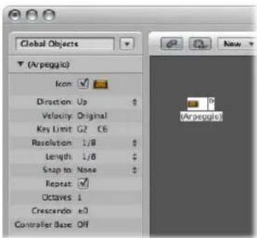
An arpeggiator features parameters for direction, velocity, speed (Resolution), note length, start quantize (Snap), repeats, octaves, and velocity offset (Crescendo). All parameters can be MIDI controlled in real time, which adds immensely to its versatility.
To use an arpeggiator object, you must place it in the MIDI signal path, and Logic Express must be running. (For technical reasons, the arpeggiator resets on cycle jumps).
Typically, you would assign an arpeggiator to an Arrange track, and cable its output to an instrument. You can, of course, insert it where needed in the MIDI signal path.
Once set up, you can use the arpeggiator with live MIDI input, or for MIDI region playback. You can also record the output of the arpeggiator by cabling it into the Sequencer Input object.
If you do this, be sure you either record to a no output track, or break the arpeggiator's connection to a MIDI output.
The Arpeggiator Parameter Box
The Parameter box of an arpeggiator contains the following parameters:
Direction
Determines the direction of the arpeggiated chord. You can choose between the following settings:
- Up: Lowest note to highest note.
-
Down: Highest note to lowest note.
-
Up/Down: Up and down—highest and lowest notes repeat.
- Auto: Up or down, depending on whether the second chord note arrived before, or after, the first chord note.
- Up/Down2: Up and down—highest and lowest notes don't repeat.
- Random: Notes play in random order.
- All: All notes play at once (useful when Repeat is on).
Velocity
Determines the velocity values of the arpeggiated notes. You can choose between the following settings:
• 1 to 127: Fixed velocities
- Original: The velocities of the recorded notes are retained.
- Random: Random velocities between 1 and the original value.
Key Limit
This is where you can define the pitch range for the chord arpeggiation. Any chord notes outside this range are passed directly to the output. This is useful when you want to solo above, or play a bass line below an arpeggiated chord.
Resolution
This is where you set the rhythmic note value (the speed in note divisions) of the arpeggio. The None setting deactivates the arpeggiator.
Length
This is where you define the length of the arpeggiated notes. The Original setting retains the lengths of incoming (or recorded) notes.
Snap To
Unless this value is set to None, the arpeggiator will wait for Logic Express to reach the next indicated note division before starting the arpeggio. This is useful for rhythmically synchronizing the arpeggio with other MIDI data.
Repeat
Enabling this option continues the arpeggio for as long as the chord is held down. If the option is disabled, the arpeggio will only play through once.
Octaves
The arpeggio can be repeated over 1 to 10 octaves.
Crescendo
The velocity value set here is added every time the arpeggio is repeated (if the Repeat parameter is turned on, of course).
Controller Base
All ten parameters of the arpeggiator object can be remote-controlled with MIDI continuous controller events. The Controller Base parameter determines the controller number for the first parameter (Direction). The other parameters will be controlled by subsequent controller numbers.
When Controller Base is set to Off, MIDI control of the arpeggiator is disabled.
Transformer Object
You can use a transformer object to select, filter, and alter MIDI events in real time.
Transformers can also process meta events, as long as they are not the meta events that affect transformers. These particular meta events change the transformer, rather than being processed by it. For more information, see "Controlling the Condition and Operation Values via Meta Events" on page 922.
To create a new transformer object:
- Choose New > Transformer (or use the New Transformer key command).
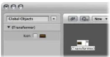
How the Transformer Object Works
A transformer object checks whether or not an incoming event matches certain conditions. If it does, then certain operations are carried out.
Events which do not meet the conditions may pass unchanged to the output, or may be discarded.
The transformer can also make copies of matching events before altering them, and can split the selected (matching) events from the unselected ones, via its two top cables.
You must place the transformer in the MIDI signal path in order to use it.
If you wish to alter the output of an instrument, for example:
1 Cable the instrument output into the transformer (removing the instrument's internal port assignment in the process).
2 You will need to create a New > Instrument, and assign it to the desired MIDI output port.
3 Cable the output of the transformer object into this newly created instrument (which, in essence, is simply acting as a MIDI output port.
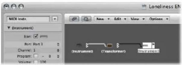
Configuring a Transformer Object
Double-clicking a transformer icon opens the Transformer window, where you can set the conditions and operations.
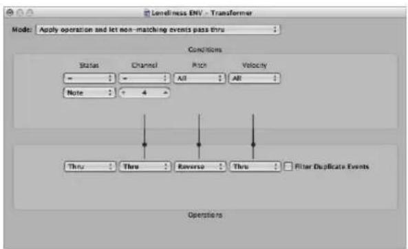
Setting the Operation Mode
Use the pop-up menu at the top of the Transformer window, to define how a transformer handles MIDI events. You can choose between the operation modes outlined below.
Apply operation and let non-matching events pass thru
MIDI events that match the condition are processed. MIDI events that don't conform to the condition are passed thru.
Apply operation and filter non-matching events
MIDI events that conform to the condition are processed. MIDI events which do not conform to the condition are not passed through.
Filter matching events
All MIDI events which match the condition are filtered out. MIDI events that don't conform to the condition are passed through.
Copy matching events and apply operation
All MIDI events which conform to the condition are copied, and the copy is processed. The original and transformed copy (plus any MIDI events that don't conform to the condition) are passed through. The unchanged original is parsed (processed) before the transformed copy.
Copy matching events and apply operation (reverse order)
This is the same as above, except the original is parsed after the processed copy. You might want to use this when converting note events to pan controllers, for example. This causes the pan message to be sent before the note. (Many synths don't alter the pan position of notes that are currently playing).
Condition splitter (true → top cable)
Events that match the conditions are altered by the operations, and sent to a transformer's top output. Events that don't match the conditions are sent, unaltered, to a transformer's second output. Do not use the other outputs—as nothing ever appears there.
Alternating split
Events entering the transformer will be alternated between the top two outlets. No conditions or operations apply.
SysEx mapper (data byte 1 → position, data byte 2 → value)
This transformer mode is used to create and edit SysEx messages. The Transformer window operations are replaced by value fields that allow you to enter the structure of the SysEX message—including its length, whether or not a checksum is required, and the values of bytes you don't want to change in real time.
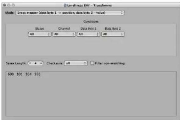
In the Conditions area, you select the type of MIDI event that will affect the data bytes in the SysEx message. (Typically, you'll use MIDI controller events.) Incoming MIDI events will then change the SysEx message data bytes, according to the following rules:
- The data byte 1 value sets the position of the data byte.
- The data byte 2 value sets the value of the data byte.
-
The channel controls the action to be taken:
-
Channel 1: The changed SysEx message is sent.
- Channel 2: The changed SysEx message is not sent.
- Channel 3: The unchanged SysEx message is sent.
- Channels 4 to 16: No meaning (reserved for future use).
The "Filter non-matching" checkbox prevents incoming MIDI events (that don't control the SysEx message) from being passed through. Typically, you will want this feature turned on, to prevent interloping controller data from invading the SysEx data stream.
Track Automation Splitter (true → to cable)
If the condition matches, incoming events will be sent to the track automation of the object connected to the top cable of the transformer—after passing through the Operation field. With the appropriate Operation field settings, incoming MIDI data is transformed into Fader event data—allowing the automation of any possible parameter of the connected Mixer object. Exception: Channel volume and channel pan uses Control events.
Defining Conditions and Operations
The conditions and operations are the same as those found in the Transform window. For more information, see "Editing MIDI Events in the Transform Window" on page 491. The only differences arise from the fact that a transformer objects work in real time and therefore, position and note length have no useful meaning.
Editing Pitch Bend Events
A transformer object can process 14-bit pitch bend events, which contain two discrete data bytes: If byte 1 is changed (by addition or scaling with the -1- operation), the change will also affect the second byte.
Set the Data Byte 2 operation to Thru to ensure that 14-bit pitch bend data is processed properly.
Controlling the Condition and Operation Values via Meta Events
You can control the values of any transformer conditions or operations by using meta events. Meta events are internal Logic Express messages—their form is similar to MIDI controller events, but they have no MIDI meaning, they never leave Logic Express, and control internal Logic Express parameters.
Like MIDI controller events, meta events have two data values: The first one indicates the type of meta event (49 to 127, but not all are used), and the second one is the event value (0 to 127).
Meta events 122 to 127 affect transformer parameters.
- Meta event #127 sets the first (top) operation value.
- Meta event #126 sets the second (bottom) operation value (if available).
- Meta event #125 sets the first (top) condition value.
- Meta event #124 sets the second (bottom) condition value (if available).
Note: Transformers can also process meta events, as long as they are not the meta events listed above.
Note that all numerical condition and operation parameters that are used (conditions not set to All and operations not set to Thru) will be affected by the same meta event. The status condition and operation are not affected by meta events.
If you want to set numerical parameters individually, or leave some fixed, use separate transformers in series.
- Meta event #123 sets the transformer map position.
- Meta event #122 sets the transformer map value for the current map position. (Use meta event #123 to set the position first).
Note: You can use a transformer's Map Set operation to create these two meta events simultaneously. When the operation status is set to Map Set, the Data Byte 1 parameter specifies the map position, and the Data Byte 2 parameter specifies the map value at that position (a meta event #122 is sent with the Data Byte 1 value, followed by a meta event #123 with the Data Byte 2 value).
You can create meta events with a fader object; you can transform MIDI events into meta events with a transformer, and you can add meta events to a MIDI region from the Event List. When you use a fader, set the Output definition to meta, then set the Data Byte 1 value to the meta event number.
You can remote-control any fader by changing its Input definition, allowing you to use faders (as well as other transformers) to convert MIDI events to meta events—for remote-control of transformers.
Delay Line Object
A delay line object repeats (echoes) MIDI events passing through it—at intervals ranging from one tick to 256 whole notes.
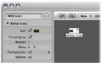
To create a new delay line object:
- Choose New > Delay Line.
As with the arpeggiator, you will need to place a delay line object in the MIDI signal path, and Logic Express must be in play mode. The echoes of each incoming event are sent—sequentially—to each cabled output of the delay line object; event 1 to cable 1, event 2 to cable 2, and so on. Obviously, if only one cable is connected, then all events are sent to this output.
The delay line can send up to 99 repeats, at intervals ranging from one tick to 256 whole notes. You can also suppress the original note events.
The Delay Line Parameter Box
The delay line's Parameter box offers the following parameters:
Thru Original
If this parameter is turned on, the original events are passed thru. If the parameter is turned off, the original events are suppressed—which means that only the echoes will be heard.
Repeats
Defines the number of event repeats. The 0 setting switches the delay line off.
Delay
The delay time between the individual repeats. The left value is in divisions, and the right value in ticks.
Transposition
Defines the transposition of note events per repeat.
Velocity
Defines the change in the velocity values of note events per repeat.
Voice Limiter Object
A voice limiter object restricts the number of MIDI notes (1 to 32) that can be held simultaneously.
It does this by note stealing—newly arriving notes will cause (some of the) currently held notes to be turned off, once the voice limit is reached.
To create a new voice limiter:
- Choose New > Voice Limiter (or use the New Voice Limiter key command).
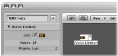
Normally, you will assign a voice limiter to an Arrange track, and cable its output to the instrument object that you want to voice limit. Alternately, you could cable it between the instrument object that you want to voice limit and an instrument object used to represent a MIDI Out port.
Voice Limiter Parameters
The voice limiter's parameter box offers the following:
Voices
Defines the maximum number of voices that can be played simultaneously.
Priority
This is where you define which notes are stolen (are turned off) when the number of held notes exceeds the limit (determined by the Voices parameter).
- Top: The lowest (pitched) notes are turned off first.
- Bottom: The highest (pitched) notes are turned off first.
- Last: The earliest notes (those played first) are turned off first.
Chord Memorizer Object
A chord memorizer maps individual notes to chords. You can assign one chord to each pitch class (to C, C#, D, and so on).
The octave of the incoming note determines the octave of the resulting chord. A chord can have zero to twelve notes in it. (Zero and one note chords can be useful for creating scale-filters and scale-correctors).
The easiest way to use a chord memorizer is to connect its output to the instrument that you want to play the chords through, and assign it to an Arrange track. You can, of course, place it anywhere else in the MIDI signal path.
To create a new chord memorizer:
- Choose New > Chord Memorizer from the local Environment menu (or use the New Chord Memorizer key command).
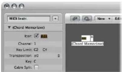
Setting Chord Memorizer Parameters
You can set the following parameters in a chord memorizer's Object Parameter box:
Channel
All chord notes will be sent to the defined channel.
Key Limit
Notes within this range are mapped to chords. Notes outside the range are passed through unaltered.
Transposition
The output chords are transposed by the amount set here. Example: If you map C to a chord consisting of CEG, and set Transposition to 1, then C will be mapped to C#FG#.
Key
The entire chord map is transposed by the amount set here. Example: If you map C to CEG, and set Key to 1, then C# will be mapped to C#FG#.
Cable Split
Enable to send all notes triggered by a chord assignment to different chord memorizer object outputs (different cables).
Working in the Chord Memorizer Window
Double-clicking on a chord memorizer opens the Chord Memorizer window, where you can set up chord definitions.
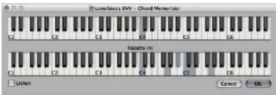
The top keyboard is used to input and display the incoming note, and the lower keyboard is used to input and display the assigned chords. Notes can be entered with the mouse, or a MIDI keyboard.
Remember to only use notes that fall within the Key Limit range on the top keyboard. Also remember that you can only define one chord for each of the 12 pitch classes (C, C#, D, and so on). You can, of course, use more than one chord memorizer object to define more chord types for each pitch class.
To enter chords with the mouse
1 Click the input note on the top keyboard.
All notes in the associated chord will be inverted on the bottom keyboard.
2 Click notes on the bottom keyboard until the inverted notes of the desired chord are shown.
You don't need to stay within the same octave as the input note.
When you have entered the desired notes for your chord, select another input note (on the top keyboard), or close the Chord Memorizer window.
To enter chords from your MIDI keyboard:
1 Play the input note.
2 Click the Listen checkbox in the Chord Memorizer window.
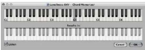
The lower keyboard is inverted, indicating its readiness to record.
3 Play the notes of the desired chord.
You can play them one at a time, or as a chord. If you make a mistake, deactivate the Listen checkbox, then activate it again to start over.
When you've entered the desired notes for your chord, deactivate the Listen checkbox and play a new input note, or close the Chord Memorizer window.
Touch Tracks Object
A touch tracks object allows you to trigger MIDI regions or folders with single notes. This can be used to create a new arrangement in real time, ideal for live performances.
You can not use touch tracks to trigger audio. In the following section, any references to regions mean folders and MIDI regions, not audio regions. Despite this limitation, you could conceivably load your audio regions (as files) into the EXS24 mkII, and trigger it with a touch tracks object.
To create a touch tracks object, do one of the following:
- Drag a MIDI region or folder from the Arrange area into the Environment.
- Choose New > Touch Tracks from the Environment menu.
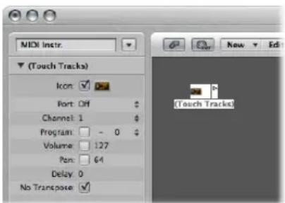
To use a touch tracks object, do one of the following
- Assign the touch tracks object to an Arrange track.
- Place the touch tracks object anywhere in the MIDI signal path.
Here are some things to remember:
- Only the touch tracks input has meaning—trigger notes must appear here. Although the object features an output triangle, it has no use, as events never appear here.
- MIDI regions and folders triggered by touch tracks play exactly as they would from the Arrange window—they play back through the instruments assigned to their tracks.
- Logic Express must be running for touch tracks to work.
Using the Touch Tracks Window
You open the Touch Tracks window by double-clicking on a touch tracks object.
| Input Name | Group | Region/folder | Transpos | Velocity | Trigger | Start |
| C5 | 1 | (unassigned) | 1 | 1 | 1 | 1 |
| B4 | 1 | (unassigned) | 1 | 1 | 1 | 1 |
| A4 | 1 | (unassigned) | 1 | 1 | 1 | 1 |
| A4 | 1 | (unassigned) | 1 | 1 | 1 | 1 |
| C4 | 1 | (unassigned) | 1 | 1 | 1 | 1 |
| C4 | 1 | (unassigned) | 1 | 1 | 1 | 1 |
| F4 | 1 | 1 (Mapped Instr.) | 1 | off # Multi Gate # | ||
| E4 | 1 | (unassigned) | 1 | 1 | ||
| D4 | 1 | (unassigned) | 1 | 1 | ||
| D4 | 1 | (unassigned) | 1 | 1 | ||
| C4 | 1 | (unassigned) | 1 | 1 | ||
| C4 | 1 | (unassigned) | 1 | 1 | ||
| B3 | 1 | (unassigned) | 1 | 1 | ||
| A3 | 1 | (unassigned) | 1 | 1 | ||
This window is similar to the Mapped Instrument window (see "Mapped Instruments" on page 907)—the input note is selected via the keyboard on the left, and the output region assignment and parameters are set in the columns of the corresponding row.
A vertical gray line means that the setting is the same as the line above. If you change a vertical gray line that is above another vertical gray line, the lower one will change to display its previous value (it will no longer be the same as the line above.)
Region Note Assignment
Dragging a MIDI region or folder into the Environment automatically creates a touch tracks object. All notes (initially) trigger this region. Middle C plays the region or folder at its original pitch, and all other notes transpose it—relative to middle C.
In the Input Name column, you can see the input notes, and to the right, in the Region/ Folder column, the names of the assigned regions or folders. On the vertical keyboard to the left, you can select individual notes or pitch ranges, by dragging across several keys. If you then drag a MIDI region or folder from the Arrange window, it will only be assigned to the selected note (or note range).
Group
Groups behave as they do in the Hyper Editor—when you trigger a region, any other (currently playing) region in the same group will stop.
The Off setting means that the region is not assigned to any group.
Transpos (Transposition)
When you drag a region to a key in the Touch Tracks window, that key triggers the region at its original pitch (without transposition). If you want to transpose the region, you can set the amount in the Transpos column.
If a key range is selected when you drag the region into the Touch Tracks window, incremental transpositions will automatically be set for adjacent keys (within the key range).
When you create a touch tracks object by dragging a region into the Environment, C3 triggers the region at its normal pitch, and all other keys trigger it—transposed relative to C3.
Velocity
In the Velocity column, you can set the sensitivity of regions to the velocity value of the trigger note: by 100% (very sensitive), 50% (somewhat sensitive) or off (not velocity sensitive).
Trigger Modes
The Trigger column determines how region playback is handled:
- Multi: Playing the trigger note starts the region. Playing it again restarts the region, without stopping playback of the originally triggered version.
- Single: Playing the trigger note once starts the region. Playing it again stops playback, and restarts the region.
- Gate: The region plays until the trigger note is released (or until the region ends).
- Gate Loop: The region loops until the trigger note is released.
- Toggle: Playing the trigger note starts the region. Playing it again stops playback.
- Toggle Loop: Playing the trigger note starts region looping. Playing it again stops playback.
Start
This column allows you to quantize region start and stop. Free means no quantization. The Next 1/16, Next 1/4, or Next 1/1 settings start or stop the region at the next 1/16 or 1/4 note, or at the beginning of the next bar, when a trigger note is played.
Delay
This column allows you to assign a delay to the region start point. The delay is set on the right side of the column in ticks, or on the left side in note values.
You can use both Delay and Start to make regions start at any position in the measure. As an example: Set Start to 1/1 and Delay to 480 ticks to commence playback at the second 8th note in the measure.
Physical Input and Sequencer Input Objects
The Physical Input object represents the physical inputs of your MIDI interface; the Sequencer Input object represents the MIDI input of Logic Express. You can only have one of each of these objects in the Environment.
To create a Physical Input object:
- Choose New > Physical Input.
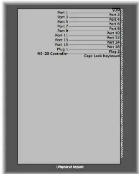
To create a Sequencer Input object:
- Choose New > Sequencer Input.
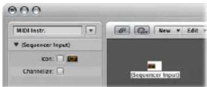
To make use of an existing object, drag it onto the relevant layer. This will not affect its cabling.
Physical Input Object
The Physical Input object receives MIDI signals from the inputs of the MIDI interface(s) connected to your computer. This object has a total of 65 outputs.
The outputs follow the input assignment of all connected MIDI interfaces. The top output (SUM) carries the MIDI events for all individual outputs that are not cabled separately.
Remote control events are intercepted at the Physical Input object, and are not passed through to its outputs. As such, remote control events will not reach the Environment, or be recorded on Arrange window tracks.
Sequencer Input Object
MIDI events arrive at Arrange window tracks thru the Sequencer Input object. If nothing is cabled into the Sequencer Input object, nothing can be recorded in Logic Express.
Typically, the Physical Input object is cabled directly to the Sequencer Input object but other objects can be inserted between them. Typical candidates are a monitor, keyboard, or cable switcher object—feeding various processors such as an arpeggiator, a delay line, and so on.
You can also cable the output of simple or complex Environment processes into the Sequencer Input object, in order to record the processed signal.
By default, the Sequencer Input object records on the MIDI channel (or channels) that the keyboard or MIDI controller (which is sending the MIDI events) is set to.
If you activate the Sequencer Input object's Channelize parameter, the MIDI channel assigned to the MIDI object (of the selected Arrange track) is used, and recorded. This effectively means that if your keyboard is set to MIDI channel 7, and the Arrange track object is set to MIDI channel 3, all incoming data will be channelized to (and recorded on) MIDI channel 3.
MIDI Click Object
The MIDI Click object is used to create note events at bar, beat, and division intervals. These can be sent to either a MIDI port or the internal speaker.
To create a MIDI Click object:
- Choose New > MIDI Metronome Click in the local Environment menu.
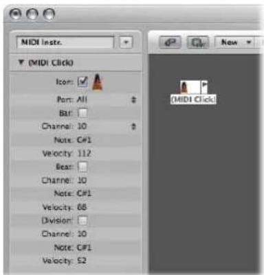
Each project can have only one MIDI Click object. You only need to create a MIDI Click object if the one that existed when the project was created has been deleted.
There is a button on the Transport bar that turns the MIDI click on and off.

A Control-click on this button will allow you to open the File > Project Settings > Metronome (see "Metronome Settings" on page 963). In this pane, you can also set the MIDI click to play during recording or playback. This dialog mirrors the settings in the Parameter box of the MIDI Click object: Checkboxes for Bar, Beat, and Division allow you to generate note events separately for bars, beats, and divisions. The Channel, Note, and Velocity parameters define the MIDI channel, note number, and velocity of generated notes. The MIDI Port parameter allows you to set a direct output port for the metronome.
Internal Objects
Internal objects include instruments located inside your Macintosh (such as software synthesizers and other musical applications). Although communication with sound sources inside the computer does not actually use MIDI, it still conforms to the MIDI communication protocol.
Internal objects have an input, but no output. They therefore act like extra output ports, which are hard-wired to the relevant sound generator (software instrument or application).
Apple QuickTime
The QuickTime system extension offers a software-based GM sound generator. The QuickTime Musical Instruments file must be present on your system.
To create a virtual representation of the QuickTime synth:
- Choose New > Internal > Apple QuickTime.
This software synth is 16-part multi-timbral. As usual, you can switch sounds via program changes; these are arranged according the GM table. Channel 10 is always set to drum sounds, with GM key assignments. The QuickTime synthesizer reacts to notes and program change commands, as well as to pitch bend ( ±2 semitones) and the main volume controller (#7).
The first note is used to initialize the relevant MIDI channel of the QuickTime synthesizer, and is not played.
ReWire
You can use ReWire objects to send MIDI data to ReWire compatible applications and their software instruments. To connect to a ReWire compatible software instrument, first open Logic Express and then the ReWire application. When shutting down, first quit the ReWire application, then Logic Express.
You can use the Library to create ReWire objects automatically (see Chapter, "Working With ReWire Applications," on page 260).
To manually create a ReWire object in the Environment:
- Choose New > Internal > ReWire.
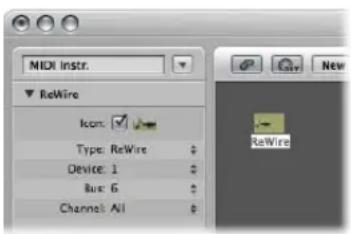
Apart from common parameters, the ReWire object offers three settings:
- Device: This setting refers to the ReWire application(s) that Logic Express can connect to. If one or more ReWire applications are running, it will display the names of these applications.
- Bus: Lets you choose the ReWire Bus from all available ReWire busses. If a ReWire application provides bus names, they will be shown. If using Reason, the names of the instruments available in the Reason Rack will be shown from Bus 6 upwards, in place of numbers.
- Channel: Sets the MIDI channel of the ReWire object.
Alias
You can create an alias of any Environment object, and it will behave exactly like the original. In the case of faders, the alias has its own value—which can be different to the value of the original object. This is particularly useful if using text faders, as they consume a lot of memory—if you need several text faders of the same name, make several aliases of one original object.
To create an alias of any object:
■ Select the object, then choose New > Alias.
Aliases can be reassigned with meta events. A special fader, known as the alias assigner (which works something like the cable switcher), is used to accomplish this.
To create an alias assigner:
- Choose New > Fader > Specials > Alias Assigner.
This will create a meta fader, with a -1- definition set to 46.
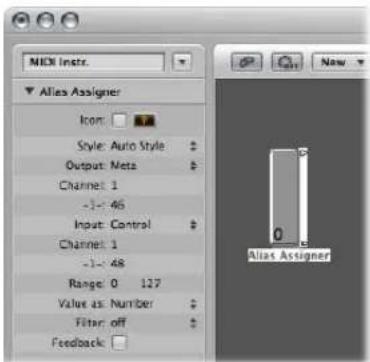
To use the alias assigner, cable its top output to the alias, and cable subsequent outputs to the various originals that you want to assign to the alias. If you set the alias assigner's maximum range to match the number of originals and its minimum range to 1, you can then connect the next cable to a new alias, and subsequent cables to originals for the alias. In this way, the alias assigner can be used to assign multiple aliases simultaneously.
One situation where you might use an alias assigner is when switching a delay line alias between different originals (different delay line objects), each set to different delay times. This method is one of several ways to provide MIDI control over delay time.
Alias Parameters
Aliases share the parameters of their parent (original) objects, but they also have their own, special parameters:
Reference
The Reference menu is used to select the original on which the alias is based.
Channel
The Channel parameter re-channelizes all events (except fader events) leaving the alias to the selected channel. If the Channel setting is All, existing channelized events are not changed.
For faders, the Channel parameter causes the alias to act as if the original fader's Input and Output definitions are both set to the specified channel. (An All setting results in no change.)
Share Name and Share Size
These two parameters do just what they say—when checked, the alias shares the size and name of the original. If unchecked, it can be resized and given its own name.
Copying Aliases
If you copy an alias, you will create a new alias of the same original. If you select and copy both an alias and its original, you will create a copy of the original with its own, separate alias.
Ornament
Ornaments are simply solid backgrounds behind other Environment objects. An ornament never covers other objects, allowing you to continue to select multiple objects by rubber-banding them, without selecting the ornament itself.
To create an ornament:
- Choose New > Ornament.
Macros
Macros are not actually Environment objects. Rather, they are collections of other Environment objects and their cabling.
To create a new macro:
- Select all Environment objects that you wish to include, then choose New > Macro. Logic Express will enclose all selected objects in a frame with a gray background.
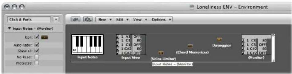
If some of the objects selected when creating a macro have cables leading to unselected objects, these cables will be deleted when the macro is created. A warning will notify you of this. In this situation, the macro is made from a copy of the original selection of objects, and the original collection of objects remains unchanged.
Macros are limited in size—the limit is dependent on the memory usage of the individual objects within the macro. This limit is typically between 100 and 200 objects.
You can nest macros—a macro can contain other macros as objects.
To unpack a macro:
■ Double-click any empty (blank) section of the macro object.
This reverts the macro back into its component objects and cables.
Macros have a lot in common with standard Environment objects—you can connect cables to and from them, they can be resized, they have their own parameters and icon, they can be chosen as destinations in the Arrange window track list, and they can be copied or dragged between Environment layers (including between projects).
Defining a Macro's Input and Output
As a macro is a collection of objects, individual objects need to be specified as the macro's input and output. This can be done in two ways: by name or by default.
- If you name one object "Macro-In", and another "Macro-Out", these will automatically become the macro's input and output.
- If there is no object named "Macro-In", the upper-leftmost object will become the macro's input.
- If there is no object named "Macro-Out" then the lower-rightmost object will become the macro's output.
Cables leading into the macro deliver events to the macro's input object, and cables leading from the macro's outlets carry events leaving the macro's output object.
Macro Parameters
Macros have the following parameters:
Auto Fader
If you select a group of faders, and create a macro from them, checking this box will make them behave as if they were cabled serially.
Show All
This checkbox determines which objects remain visible when integrated into a macro. When checked, all objects will be visible (assuming the macro is not resized to hide some of them). When unchecked, only fader, monitors, ornament, and keyboard objects will be visible. You can change this checkbox at any time.
No Reset
This checkbox, when active, prevents the macro from responding to reset messages (set in Preferences > MIDI > Reset Messages).
Protected
Enable to protect a macro. Protected macros can not be unpacked, so ensure that you've made a copy of the objects and cabling before creating a protected macro.
Faders
Faders are used to send MIDI events by clicking or click-dragging on them. Faders come in different forms (knobs, sliders, numerical, and buttons). Fader objects respond to incoming MIDI events.
To create a new fader:
- Choose New > Fader.
A sub-menu appears, where you may select the style of fader you want. There's also a sub-menu at the bottom named Special, used to select various special fader types (cable switcher, meta-fader, and so on).
The style of a fader determines its onscreen appearance (slider, knob, menu, numerical), and how it responds to the mouse (click and drag, double-click and type a number, click, and select from a menu).
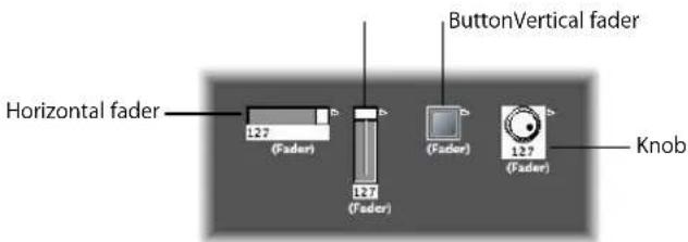
The auto style fader—the default style if you create a fader with a key command—changes styles as you alter its shape and size.
The type of fader determines what events the fader sends out and responds to. In two cases, however, the fader doesn't send out events at all:
- The cable switcher routes events to its different outputs. Clicking on a cable switcher object makes it step sequentially through the outputs.
- The alias assigner changes the references (to an original, or parent object) of fader aliases.
In general, a fader's style is completely independent of its type. A cable switcher can look like a button, a knob can send out MIDI or meta or SysEx events, and so on. The one exception is the vector style fader—these behave in a special way, by sending out two (or four, in special cases) messages at a time, depending on the mouse location within their 2-dimensional, vector window.
Don't worry about selecting the wrong fader style or type from the New menu—you have complete control of a fader's style and type via the Object Parameter box.
Fader Operation
Normally, you'll grab the surface of a fader, and drag it vertically or horizontally, depending on its style. When using the fader itself as a slider, values may jump in larger increments, depending on the size of the fader and dragging speed. You can also change values in single steps by dragging on the slider or knob while holding down Control.
Some of the fader styles have numerical displays. When there is a numerical display, you can double-click it, and type in the desired values. When you drag on any of the sliders or knobs, the series of values that are sent out depends on the fader size and scrolling speed—not every consecutive value is sent out at smaller sizes. If you drag slowly on the numerical field, however, you will send consecutive values.
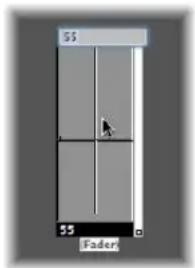
Knobs can be dragged either vertically or horizontally.
Buttons only send two values, the lowest and highest of their range set in the Object Parameter box. You change a button's state by clicking on it.
The default appearance of the text fader is like a value field that can be scrolled. Double-click to open a window that allows you to enter text for each menu position. Enable the Behaves as Menu checkbox to use the text fader as a pop-up menu.
A vector fader allows you to scroll in two directions, and sends out two values—one corresponding to the vertical position, and the other to the horizontal position.
Working With Object Groups
When building a virtual mixing desk or synthesizer control panel in the Environment, you often need to deal with large groups of fader objects which have the same size, regular spacing, or a similar definition.
To save time on the definition and alignment of these groups, you can choose (one or more) objects as prototypes (templates) by copying them into the Clipboard (Edit > Copy). You may then apply certain characteristics of these template objects to selected objects.
To transfer the size of the prototypes to the selected objects:
- Choose Options > Apply Buffer Template to > Size.
To transfer the alignment template of selected objects:
- Choose Options > Apply Buffer Template to > Position.
The selected target objects will be positioned at the top left corner of the Environment layer, in accordance with the layout of the template.
The Options > Apply Buffer Template to > Position and Size command combines both of the above functions.
Definition
The Options > Apply Buffer Template to > Definition function transfers the parameters of a copied template to all selected objects. If several templates of the same type are available, the one that is closest in size is used.
The Options > Apply Buffer Template to > "Definition, channel increment" increases the channel number from object to object, beginning with the top left object. It is not necessary for the selected objects to have the same Input or Output definition as the template.
The Options > Apply Buffer Template to > "Definition, number increment" increases the first data byte of the definition (controller number, for example).
Cabling Serially
The Options > Cable serially function connects all selected objects in series, beginning with the object at the top left.
Names With Numbers
If you name one object in a selected group of objects with a name that ends in a numeral, the remaining objects will adopt the name, but with sequentially increasing numbers. As an example: Selecting several objects and naming one of them "Object 1" will result in the ensuing objects being renamed as "Object 2", "Object 3", "Object 4", and so on.
Special Functions
This section outlines several behaviors and commands that enhance the use of fader objects.
Temporarily Grouping Faders
If you (rubber-band, or Shift-click) select several faders, and move one of them, all selected faders will move proportionately.
As long as all faders remain selected, their relative positions will be retained (even after one or more of the faders has reached its minimum or maximum position).
- Option-dragging any fader in the group changes all values in a linear fashion (the absolute value differences are maintained).
- Shift-Option-dragging any fader in the group changes all faders to the same value.
Sending Fader Values
You can use Options > Send All Fader Values (or the corresponding key command) to make all fader objects send their current values.
Use Options > Send Selected Fader Values (or the corresponding key command) to make all selected fader objects send their current values.
Use of these commands in conjunction with the Record/Pause mode allows you to record a snapshot of all current fader positions. This is especially useful for virtual mixing desks, or synthesizer panels.
The File > Project Settings > MIDI > General > "Send After Loading Project: All fader values" option automatically sends all fader values after a project is loaded.
Resetting Fader Values
Choose Options > Reset Selected Faders to set all selected fader values to zero, and transmit this data.
Recording and Playback of Fader Movements
As with the channel strips in the Mixer, you can record fader object movements to tracks, and play them back.
Recording Fader Movements
You don't need any special cabling to record the data generated by a fader. All data generated by faders is recorded on the selected track when Logic Express is in record or record/pause mode.
Playing Back Fader Movements
Any fader will react to incoming events that match its Input definition. The fader must, of course, be in the MIDI signal path.
Typically, you would accomplish this by cabling the track instrument into the fader.
For fader object automation tasks, however, it is useful to create a new (standard) instrument for the sole purpose of fader automation. Ensure that the instrument:
- Has no direct MIDI output.
- Uses the Channel setting All.
- Is connected to the first fader in any chain of serially-cabled faders (if cabled this way).
Fader Styles
The fader's style is shown in the line under the icon. It can be changed by clicking on the current style name, and selecting the new style from the pop-up menu.
Remember that a fader's style does not usually affect its function—you can select the most convenient style for the desired use of the object.
The following section provides notes on some of the fader styles.
Vertical/Mute
This is exactly like the Vertical 4 fader style, with an added mute button.
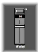
When you click the mute button, the fader sends an event (with a value of 0) that matches the Output definition.
- The fader's movements are not sent while the mute button is on.
- The current fader value is sent when you turn the mute switch off.
Buttons
Button style faders can only send two possible values: the minimum and maximum values of their range.
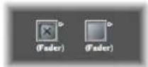
- When on, the maximum value is sent.
- When off, the minimum value is sent.
If the minimum and maximum range parameters are set to the same value, the button sends this value each time it is clicked.
Text
Text faders function like numerical faders, but can display text for each of the 128 possible MIDI values (0 to 127). Double-clicking on the surface of a text fader opens the Text Fader window.
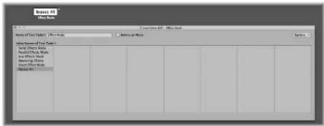
- Clicking on a position in this window will cause the corresponding fader value to be sent. (This is similar to selecting programs by name in the Multi Instrument window).
- Double-click on a position in the window to type in the desired text. By default (when you create a text style fader), the text positions contain numerical values. You can use this feature to create numerical style faders with colored backgrounds.
Clipboard Functions
The Options menu at the top right of the Text Fader window provides Cut, Copy, and Paste functions. You can use these facilities to transfer the entire list of names to a text editor, for more convenient editing.
- Empty lines (and lines that only contain spaces) are ignored.
- If you want to insert blank positions in the list, use Option–Space bar.
Behave as Menu
Click the Behave as Menu checkbox to make the text fader act like a pop-up menu. When this box is unchecked, the text fader acts like a scrolling menu.
Text Fader Range
The Range parameter determines the number of names that can be entered into a text style fader object. If you set a text style fader's range to 0, 1 you can only enter two values.
You should always set the minimum necessary range for a text fader, as this saves memory. In any case, remember that the first name corresponds to the lowest value in the range (not necessarily 0), and the last name corresponds to the highest value (not necessarily 127).
If you force a text fader to a value outside its range (with MIDI input) it will display “---” for values below its range and “+++” for values above. The one exception is when the fader's range is 0/1: In this case, all values above 1 will display the name for value 1.
Fader Functions: MIDI Events
Each fader has an Input and an Output definition.
- The Input definition determines the types of MIDI events that can remote control the fader (the event types it reacts to).
- The Output definition determines the types of MIDI events the fader sends out.
A fader can, therefore, convert one type of MIDI event to another.
Most MIDI events consist of three bytes.
- The first byte indicates the type and channel of the MIDI event (a note on channel 3, for example).
- The second byte indicates the first data value (the pitch of a note event, for example).
- The third byte indicates the second data value (the velocity of a note event, for example).
A few MIDI events only use two bytes (program change and aftertouch). Some objects, such as Faders (and Transformers) always provide for 3 bytes, with the second byte being discarded when these special, 2-byte messages are received.
Fader parameters are provided for setting the message type, MIDI channel, and the first data value. Note that the message type and MIDI channel are actually combined in the resulting MIDI event. The second data value is determined by the fader setting, or if the fader is being remotely MIDI-controlled, by the incoming MIDI event.
The Input and Output Definition Parameters
These are used to define the Input and Output parameters:
- Output (or Input): Defines the event type.
- Channel (1 to 16): Defines the MIDI channel of the event.
- -1- (0 to 127): Defines the first data byte of the event. In some cases, such as pitch bend, this is an actual data value. In other cases (MIDI controllers), this indicates the controller type (volume, pan, and so on, as examples). In other cases, such as aftertouch, this byte is unused.
Setting the -1- Parameter and Fader Position
This section outlines each of the -1-parameter options, and explains how the fader position affects them (for both the Input and Output definitions):
- Note On: The -1- parameter sets the pitch, and the fader position sets the velocity. This is most useful as an Input definition—for trapping specific notes and converting them to other MIDI events, or simply monitoring their velocity. If you move a fader with an Output definition set to Note On, a note-off MIDI event will immediately follow the note-on. This might be useful for creating onscreen drum pads from button style faders, for example.
- P -Press: The -1- parameter sets the pitch, and the fader position sets the amount of Poly Pressure (key pressure or polyphonic aftertouch).
- Control: The -1- parameter sets the MIDI controller number (the controller type), and the fader position sets the controller value. The controller type can actually be selected by name, via the pull-down menu that appears when you click-hold on the -1- parameter.
- Program Change: The -1- parameter is ignored. The fader position determines the program number.
- C-Press: The -1- parameter is ignored. The fader position sets the channel pressure (monophonic aftertouch) amount.
- PitchBd: The -1- parameter sets the pitch bend LSB, and the fader position sets the MSB. Typically, you would set the -1- parameter to 0, and use the fader to control the coarse pitch bend amount. A -1- setting of 0, and a fader position of 64 results in no pitch bend.
SysEx and Switcher/Meta are special functions of the faders.
Fader Functions: Range, Val As
These parameters determine the minimum and maximum values of a fader, and how the fader displays these values.
Range
The range parameter contains two numbers—the left one sets the lowest possible fader value, and the right one sets the highest. Note that these limits can be exceeded by MIDI remote control. When the fader style is a button, the range determines the in and out position values of the button.
For text style faders, the first name always corresponds to the low end of the range, and subsequent names correspond to incremental range values, up to the top range. The number of names that can be entered into the window is limited by the range.
Val As
This parameter determines the way that numerical values are displayed by the fader:
- Num: The fader value is displayed as a number (0 to 127).
- Pan: Fader value 64 is displayed as "0"; smaller values appear as negative numbers and larger values as positive numbers (-64 to 63).
- Hz, Oct, dB, ms: These display formats are tailored to various DSP functions.
- bpm: An offset of 50 is added to the fader value. This displays the correct tempo settings for the Special > Tempo Control fader.
If none of the above formats is suitable, consider using a text style fader, and entering the desired display values as text. Examples include: percentages, note names, and program names.
Fader Functions: Filter
This parameter provides various filtering options for MIDI events:
Off
All incoming MIDI events are allowed to pass through. All events that match the input definition are converted, in accordance with the output definition.
Other
All MIDI events that do not correspond to the input definition are filtered. All events that match the input definition are converted in accordance with the output definition, and allowed to pass through.
Match
All MIDI events that match the input definition are filtered, all others are allowed to pass.
All
All incoming MIDI events are filtered.
Thru
All MIDI events coming from the Physical Input object are filtered. This is the same as turning off all events coming from Logic Express (from regions or the Environment).
Use this filter mode to prevent MIDI feedback, by blocking incoming MIDI events from being sent back out.
Shot
When the fader is moved with the mouse, only the final value (the value when the mouse button is released) is sent.
14 Bit
• Used in conjunction with pitch bend, this allows 2-byte (fine tuning) pitch bend events.
- Used with controller messages, this causes the fader to send two MIDI controller messages—one for the MSB (Most Significant Byte) and one for the LSB (Least Significant Byte).
Note: The fader's Input and Output definitions must be the same or the 14 Bit setting will not work.
For controllers, the MSB uses the Input definition controller number, and the LSB uses the controller number 32 higher. This conforms to the MIDI standard for sending 14-bit controller data.
When this filter setting is chosen, the fader's Range can be set to a maximum value of 16,383. A fader value of 8192 represents no pitch bend.
Feedback
When the Feedback parameter is turned off (unchecked), the fader will automatically prevent feedback loops resulting from circular cabling (the fader remembers when a specific MIDI event has passed through it and will not allow it to pass through again).
In some instances, you may want to enable feedback—to allow a MIDI event to change a Cable Switcher's position after it has passed through the switch, for example. Checking the Feedback checkbox will allow this.
Vector Fader
Vector faders function like joysticks—they can be moved in two dimensions: up/down and left/right. Each dimension generates its own MIDI events, so each time you change the position of the crosshair with the mouse, two MIDI events are sent.
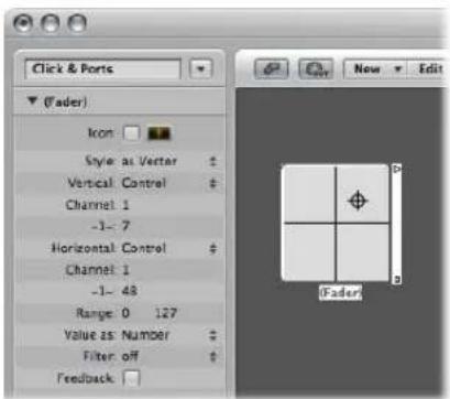
Most faders have Input and Output definitions (see "Fader Functions: Range, Val As" on page 946) which determine the MIDI events sent by the fader (Output), and those it reacts to (Input).
The vector style fader replaces these with Vert and Horz definitions, which determine the MIDI events that correspond to vertical and horizontal motion. If corresponding MIDI events are received by the vector style fader, its crosshair display will update accordingly.
4-Channel Vector Mode
If you set a vector fader's Vert and Horz definitions to the same MIDI event (the same MIDI controller and channel), the vector fader will send out four MIDI events each time the crosshair is moved.
These will be the same MIDI event (a controller, for example), sent on four consecutive MIDI channels, starting with the channel set in the Vert definition.
• Upper-left for the lowest channel (channel 3, for example)
• Upper-right (channel 4)
- Lower-left (channel 5)
- Lower-right (channel 6)
The values of these MIDI events corresponds to the proximity of the crosshair to the vector fader's four corners:
• In the center, all channels receive a value of 32.
- At the corners, the corresponding channel receives a value of 127 and all remaining channels receive a value of 0 (if using the default range of 0 to 127).
If you alter the range, the center and corners will behave differently, with the four values always totalling 125.
Special Faders Overview
The Environment provides a number of special fader objects that are purpose-built to perform certain functions.
Switchers, Alias Assigners, and Meta Faders
These are two types of faders that do not generate MIDI events. They share the same Output definition type, either: Switch (see "Cable Switchers" on page 950) or Meta, depending on the current -1- value setting:
- If the -1-value is 48, the fader will be a cable switcher
- If the -1- value is 46, the fader will be an alias assigner (see "Meta Event Faders" on page 951).
- If the -1- value is any other value, the fader will send out meta messages (see "Meta Event Faders" on page 951) of a type that corresponds to the -1- value.
To create a cable switcher, either:
- Choose New > Fader > Specials > Cable Switcher.
- Change an existing fader's Output definition to Switch/Meta, and set its -1- value to 48.
To create an alias assigner, either:
- Choose New > Fader > Specials > Alias Assigner.
Change an existing fader's Output definition to Switch/Meta, and set its -1- value to 46.
To create a meta type fader, either:
- Choose it from the New > Fader > Specials menu.
- Change an existing fader's Output definition to Switch/Meta, and set its -1- value to the desired meta event number.
Cable Switchers
Cable Switcher objects route events, rather than generating them. Any kind of MIDI or meta event can be routed by a cable switcher. The only exception is events that match the cable switcher's Input definition. These events will change the switch position (the routing), rather than passing through the cable switcher.
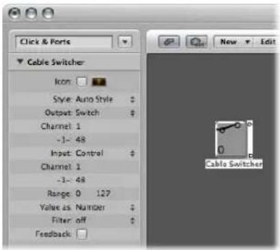
A cable switcher can be assigned to any fader style. It is practical to use the text fader style, as it allows you to label the switcher's various routes. Use the Auto-style to actually display the switch routing, as shown here.
A cable switcher can have up to 128 separate cable outputs—a new output is generated each time an existing output is cabled to another object. You can click on an auto-style cable switcher to step through the outlets (including the last, uncabled one).
Incoming events that match the cable switcher's Input definition will change the switch position to that of the incoming data value. (If the data value is greater than the number of switch positions, the last, uncabled outlet will be selected).
Data values of 126 and 127 have a special effect:
- An event with a value of 127 increases the output number. If you're on the switcher's last output when this event is received, you'll jump back to the first output. This is just like clicking on the fader.
- An event with a value of 126 decreases the output number. If you're on the switcher's first output when this event is received, you'll jump to the last output.
Meta Event Faders
Meta faders generate special meta events, which are used to control certain Logic Express functions, but have no MIDI meaning, and are never sent to the MIDI output.
In some cases (such as Go to Screenshot, Go to Project, and so on), you do not need to cable meta faders into another object for them to work. Even in these cases, you can use cabling to process meta events in the Environment, and alter their effect.
In the majority of cases, however (Set fader range minimum, Bang!, Set Transformer Operation Minimum, and so on), the meta fader must be cabled to the object being affected.
Here's a quick summary of the currently implemented meta events that can be generated by faders:
| Meta event Controlled Logic Express function | |
| 46 Assign Alias | |
| 49 Go to Screenset | |
| 50 Go to Project | |
| 51 Go to Marker | |
| 52 Stop Playback | |
| 96 Set fader range minimum | |
| 97 Set fader range maximum | |
| 98 Set the fader value without sending. | |
| 99 Bang! Causes the fader to re-send its current value. The bang data value can be used to make the fader increment-without-rollover (127), decrement-without-rollover (125), increment-with-rollover (123) or decrement-with-rollover (121). Use values one less than those shown, to have the bang" passed through to all connected faders. | |
| 100 | Tempo Control (see "Using the Tempo Fader" on page 681) |
| 122 Set transformer map value for the currently selected map position. | |
| 123 Select transformer map position. | |
| 124 Set transformer condition maximum (bottom) parameter, if any. (This applies to all conditions not set to All). | |
| 125 Set transformer condition minimum (top) parameter, if any. (This applies to all conditions not set to All). | |
| 126 Set transformer operation maximum (bottom) parameter, if any. (This applies to all operations not set to Thru). | |
| 127 Set transformer operation minimum (top) parameter, if any. (This applies to all operations not set to Thru). | |
For more on Meta events 124 to 127, read the section on Remote Controlling the Condition and Operation Values (see "Transformer Object" on page 918).
Go to Marker, Screenshot, or Project
Choosing New > Fader > Special > Go to Marker creates a fader which allows you to enter a marker number (Meta event 51).
The playhead moves instantly to the chosen marker number. Markers are numbered sequentially, throughout the project, even if you have renamed them (from the default numbers assigned when each marker was created).
Choosing New > Fader > Special > Goto Screenshot creates a Screenshot fader (Meta event 49), allowing you to switch to the screenshot number chosen with the fader.
Meta event 50 has no effect within Logic Express, but you can use it to switch between songs on an external hardware sequencer.
Meta event 52 allows you to interrupt playback at any position.
Note: To make the most efficient use of these faders, we recommend that you limit the value range to suit your particular circumstances. As an example, to limit the faders to the number of screensets, projects, or markers you're actually using.
SysEx Faders
The SysEx fader type is slightly different to other fader types. It allows you to create a list of MIDI events that will be sent whenever the fader is moved or remote controlled.
You can enter the messages that you want to send in a window that resembles the Event List. The positions of events in the list only control the order in which they are sent—they are not sent at specific times, nor with any delay between them.
The SysEx fader type is primarily designed to send MIDI System Exclusive (SysEx) messages—messages that are exclusive to individual manufacturers' MIDI devices. There are a number of features in the SysEx fader window (see below) that facilitate the creation of SysEx messages.
Note: SysEx faders can actually be used for any kind of MIDI event, making them handy for sending ordered batches of messages, such as mixer or control panel snapshots—with one click of the mouse.
You can also specify SysEx as an Input definition, but this has limited usefulness because the incoming message (presumably SysEx) must be very short, in order to be recognized. This is a side-effect of the fact that SysEx messages can be of any length, and Logic Express must break them into small packets, to avoid interrupting other MIDI activities.
Opening the SysEx Fader Window
When you set a fader's Output or Input definition to SysEx, the SysEx fader window automatically opens. You can also open this window at any time by double-clicking on the word SysEx in the fader's Parameter box.
An important thing to remember about the SysEx fader is that only selected events will have their value altered by the fader value, when the SysEx fader window is closed. Events that are not selected will be sent exactly as they appear in the window.
The value shown in the Val column (of selected events) is altered, if normal MIDI events (controllers, program change, aftertouch, and so on).
For SysEx messages, you can determine:
- Which bytes are altered
- The format (MSB/LSB, BCD, nibbles, and so on) of the value
You can also specify a checksum format, if necessary.
Creating a SysEx Message
There are two ways of entering SysEx messages in the SysEx fader window. One way is to have the fader learn the SysEx string.
To learn a SysEx string:
1 Click the MIDI In button at the top left of the SysEx window. If the button is pressed, this means it is ready to receive incoming MIDI data.
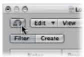
2 Alter the parameter on your device.
3 The corresponding SysEx message will be displayed and the MIDI In button will switch off automatically.
Another way is to type the SysEx string into the event list. (Consult your MIDI device manual for SysEx documentation). Use of this method qualifies you as a confirmed MIDI freak.
To manually enter SysEx strings:
■ Enable the Create button, then click the SysEx button.
A generic SysEx message appears.
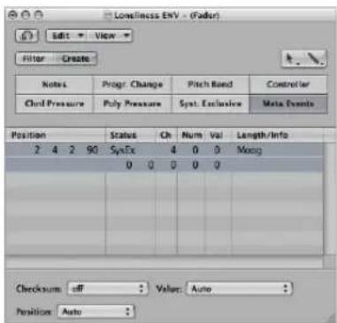
- The first data byte in the top line (directly after the word SysEx in the Num column) is the manufacturer's ID. This may be several data bytes long (as there are more than 128 manufacturers of MIDI devices).
- The manufacturer's ID is usually followed by a device type ID, an individual device ID, a data type ID (which could be several bytes) and, if necessary, the number of the multi-timbral sub channel, the identification number(s) of the sound parameters plus the value of the sound parameter. There are no uniform standards that apply here.
- Data bytes are normally input as decimal numbers. To enter them in hex, place a \$ in front of values when you type them in. View > SysEx in Hex Format allows you to see all values in hexadecimal.
- The last data byte (the EOX indicating the end of the SysEx message) is entered automatically by Logic Express. The number of data bytes in the SysEx message can be decreased or increased by clicking the plus and minus symbols before and after the word
.
Although you can have any number of messages (of any kind) in the SysEx fader's event list there is only one fader value, and all selected messages will adopt this value.
You can use a similar method to create any kind of MIDI or meta event in the SysEx fader window. Command-clicking any of the eight event type buttons (note, program number, pitch bend, controller, channel pressure, poly pressure, SysEx, and meta event) creates a new event of that type. Meta events can be created by using the expanded view button—featuring the 0's and 1's on its face.
Setting the SysEx Data Format
The terms SUM for the checksum and VAL for the fader value being sent are displayed within the SysEx string.
To set the checksum and value of a SysEx event:
1 Select the events you want to alter.
2 Choose the desired options in the Checksum and Value menus (found in the lower right corner of the window) to set the format of these bytes.
Checksum Format
A checksum can be created in any of the following formats:
- Roland
- Yamaha
- Regular Checksum
- 2's complement
- 1's complement
If you don't know which one works with your MIDI device, try "off" (= no checksum) first or "2's complement".
Value Byte Position
Position allows you to determine the position of the value byte. This position is specified in bytes, counted from the end of the message: "last" refers to the position directly before the EOX byte, "Last-1" indicates the byte before that, and so on.
Auto ensures that the value byte is inserted at the last position in the SysEx string if no checksum was selected, or—if a checksum value was entered—that the value is inserted as the second to last byte.
Value Byte Format
Value option Result
| Auto The value is sent as one byte if the value range maximum is 127 or less. If the maximum is higher than 127, the value is sent as two bytes, the MSB (most significant byte) first. |
| One Byte The value is sent as one byte. |
| MSB/LSB The value is sent in two bytes, with the MSB (most significant byte) first. |
| LSB/MSB The value is sent in two bytes, with the LSB (least significant byte) first. |
| BCD 4 LSB The value is sent as Binary Coded Decimal in four bytes, in the order 1, 10, 100, 1000. |
| BCD 4 MSB The value is sent as Binary Coded Decimal in four bytes, in the order 1000, 100, 10, 1. |
| 2 Nibbles L The value is sent in two nibbles, with the least significant nibble first. |
| 3 Nibbles L The value is sent in three nibbles, with the least significant nibble first. |
| 4 Nibbles L The value is sent in four nibbles, with the least significant nibble first. |
| 2 Nibbles M The value is sent in two nibbles, with the most significant nibble first. |
| 3 Nibbles M The value is sent in three nibbles, with the most significant nibble first. |
| 4 Nibbles M The value is sent in four nibbles, with the most significant nibble first. |
| 2 ASCII M The value is sent in two nibbles, the most significant nibble first; the nibbles are sent in ASCII format for the hex value. As an example, the value $7F (= 127 in decimal) will be transmitted as a 7 and F. |
| 3 ASCII M same as 2 ASCII M, but in 3 nibbles. |
| 4 ASCII M same as 2 ASCII M, but in 4 nibbles. |
The unused bits of the transfer in nibbles (X in 0XXXNNNN) are sent with the information at the relevant positions of the SysEx strings. If you want to transfer these deleted bits, you will need to enter zeros in the SysEx string.
Channel Strip Objects
The Environment's channel strip object (see "Channel Strip Types" on page 590) is the building block of the Environment's Mixer layer, the Mixer window, and the Arrange channel strips.
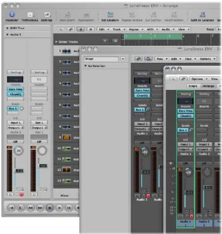
The audio and (software) instrument tracks you see in the Arrange window are actually routed to channel strip objects on the Environment Mixer layer.
The Mixer channel strips and Arrange channel strips are simply remote controls for the underlying channel strip objects in the Environment Mixer layer. Their inclusion in these other windows makes your workflow faster and easier.
As mentioned near the beginning of this chapter, the Arrange channel strips are cut down versions of the corresponding channel strip objects in the Environment. The channel strips shown in the Mixer window are more configurable, but the only place you can access all channel strip options is the Environment Mixer layer.
Important: If File > Project Settings > Audio > Automatic Management of Channel Strip objects is active (it is on, by default), you can not create channel strips in the Environment. This setting, when active, means that use of the track and channel creation options in the Arrange window will automatically create a corresponding channel strip object in the Environment (and therefore, remote control channel strips in the Mixer and Arrange).
In a general music-making sense, you will not need to access the underlying channel strips shown in the Environment. In fact, the only time you will open the Environment Mixer layer is when you need to reconfigure channel strips at a system level; re-routing them to different audio hardware, or perhaps to other applications.
Although channel strip objects are not part of the MIDI signal flow, they still allow MIDI messages to control aspects of audio and software instrument playback in Logic Express. Any MIDI object can be cabled into a channel strip object, thereby feeding control data into it.
Channel Strip Parameters
When you click on a channel strip of any type (audio, instrument, aux, output, master, and input or bus channels, discussed below), the following common parameters are accessible:
Icon
Enable the checkbox to make the channel strip accessible in the Arrange Track Assignment menu (Control-click the track list).
Choose the desired icon for the channel strip from the pop-up menu accessed by clicking on the icon.
Device
Click the visible device name (CoreAudio, for example) to reassign the selected channel strips to a different hardware device.
Channel
Click the visible channel name (Audio 1, for example), and choose the channel strip type from the sub-menus. This is how you can reassign a (newly-created or existing) channel strip object (an audio channel strip is the default for new objects) to other channel strip types. You can choose from:
- Audio: The default channel strip type, used as the destination for Arrange audio tracks.
- Input: Primarily used for compatibility with projects created in earlier Logic Express versions (see "Input Channel" on page 959).
-
Aux: Auxiliary channel strip, used as send returns for all channel strips (via Sends), as sub-group channels, and as individual output destinations for multi-channel software instruments (EXS24 mkll, for example).
-
Instrument: Used as the destination for Arrange (software) instrument tracks.
- Output: These channel strips represent the physical outputs of your audio interface. You can choose either mono or stereo (paired) outputs.
- Bus: Primarily retained for compatibility with projects created in earlier Logic Express versions. The functions of bus objects are performed with (the more flexible) aux channel strips in Logic Express 8.
- Master: Only one master channel can exist in a project. This is the master volume control for all channel strip types (except external MIDI channel strips).
MIDI Channel
Allows you to choose a MIDI channel which can be used to control the channel strip.
Value As
Choose from either dB (decibels) or Value (a numerical range). This simply affects the appearance of meters and other displays on the channel strip.
Show Options
Enable the corresponding checkbox to show EQs, Inserts, Sends, and I/Os on the selected channel strip(s).
Input Channel
You can only create input channel strip objects in the Environment. In general, you will not need to do so, as all audio hardware inputs are automatically seen by audio channel strips, and can be monitored and recorded.
It is primarily included for compatibility with older Logic Express versions, and for use with certain audio hardware devices. The Input channel strip allows you to directly route and control signals from your audio hardware's inputs. Once an Input channel is assigned to an audio channel, it can be monitored and recorded directly into Logic Express, along with its effect plug-ins.
The signal is processed—inclusive of plug-ins even while Logic Express is stopped. In other words: Input channels can behave just like external hardware processors. Aux sends can be used pre or post-fader.
Input channels can be used as live inputs that can stream audio signals from external sources (such as MIDI synthesizers and sound modules) into a stereo mix (by bouncing an output channel).
Note: An alternative to using input channels in this way is the use of the I/O plug-in, or simply click the Input Monitoring button on an audio channel strip (and choose the input(s) you want to monitor—or record—via the Input slot).
Bus Channel
You can only create bus channel strip objects in the Environment. In general, you will not need to do so, as all audio bussing (send/return routing via the Send slots of channel strips) is handled by aux channel strips.
It is primarily included for compatibility with older Logic Express versions, and for use with certain audio hardware devices.
Note: File > Project Settings > Audio > Automatic Management of Channel Strip Objects must be deactivated if you want to create Input channel strips (it is on, by default).
Prelisten Channel Strip
The Environment's Prelisten audio channel strip is used for monitoring in the Sample Editor, Audio Bin, Loop Browser, and Browser. It is created automatically in each project—you can find it to the right of the highest numbered audio channel strip.
Project Settings and Preferences
39
The project settings and preferences allow you to define many basic operating parameters for Logic Express. This section explains each of these options.
Unless otherwise indicated, the descriptions of the various parameters apply when the selection box beside the option is checked (in other words, when it's active).
Project settings and preferences are accessible via the File > Project Settings and Logic Express > Preferences menu items (plus several other access methods, outlined throughout the chapter). When either is selected, a Preferences or Project Settings window will be launched.
Each window features a number of icons and tabbed panes. These behave much like menus and sub-menus. To adjust a given preference, simply select the desired icon, then the appropriate tab. Once the panel or window is shown, activate or deactivate the preference or setting, or make your selection from a pop-up menu. Close the window once you've made your selections.
In some instances, you will find a button that links to related parameters in the Project Settings window, while you are in the Preferences window (and vice-versa). Clicking on this button will open the Project Settings window, and will automatically select the relevant pane. As an example, the Logic Express > Preferences > MIDI > Sync tab features a MIDI Sync Project Settings button. Clicking this button will open the Project Settings > Synchronization > MIDI tab.
Both the Project Settings and Preferences windows can be visible at the same time, making set up of operating parameters faster and clearer.
Some of these can also be reached directly from Logic Express's local menus (in the Score Editor, for example), or from the Transport buttons, via shortcut menus.
Saving Project Settings and Preferences
The project settings are stored with the project file. If you want to start Logic Express with certain settings, simply adjust the desired settings in your default template, and save it.
Project settings can be transferred between projects, through the use of several import functions. You can use these to accelerate template creation, or when you would like to integrate aspects (such as score text styles) from another project into the one you're currently working on. For details on all project import options, see "Importing Settings From Other Projects" on page 144.
The preferences are automatically saved whenever you quit Logic Express. There are two preference files (one for Logic Express, and one for control surfaces), which are stored in the \~/Library/Preferences/Logic folder. Logic Express preference files begin with "com.apple.logic".
Note: All choices made in the Project Settings window are specific to the saved project. All items selected in the Preferences window globally affect all projects.
Project Settings
Project settings, as mentioned, are saved with each project, which means that different projects can have different project settings. You can save your preferred settings in a default template, which can be used to automatically create a new project when you open Logic Express.
To specify the project options when Logic Express is opened:
1 Open the Logic Express > Preferences > Global > Project Handling tab.
2 Choose the desired behavior from the Startup Action pop-up menu.
To start Logic Express with a specific project:
■ Double-click on a specific project file in the Finder.
As an alternative, you can choose the Open Existing Project setting in the Startup Action menu discussed above. When you open Logic Express by clicking on the application icon, a file selector box is automatically displayed, allowing you to choose the desired project.
Synchronization Settings
All Synchronization project settings are described in the Synchronization chapter (see "Synchronizing Logic Express" on page 845).
Metronome Settings
The Metronome project settings combine all speaker click, MIDI click, and KlopfGeist—a virtual metronome sound source—parameters. (See the KlopfGeist chapter in the Logic Express 8 Instruments and Effects manual for details). KlopfGeist can be used in addition to, or in place of, the speaker and MIDI click sources.
To open the Metronome project settings, do one of the following:
- Choose File > Project Settings > Metronome (or use the corresponding key command).
- Click the Toolbar Settings button, then choose Metronome from the menu.
■ Control-click the Metronome button in the Transport bar, and choose Metronome Settings from the shortcut menu.
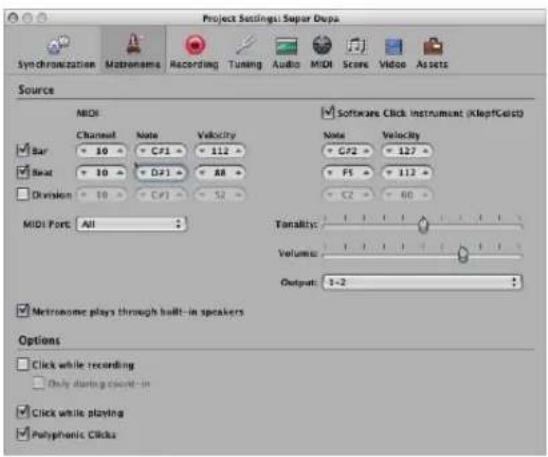
MIDI Click Settings
The MIDI Click settings mirror those in the Parameter box of the MIDI Click object:
- Bar, Beat, and Division checkboxes: Switch on to generate separate note events for bars, beats, and divisions.
- Channel, Note, and Velocity parameters: Define the MIDI channel, note number, and velocity of generated notes.
- MIDI Port menu: Allows you to set a direct MIDI output port (or all ports) for the metronome.
- Metronome plays through built-in speakers: This sends the metronome click to the computer's loudspeaker. The System Preferences > Sound pane must be set to Internal Speakers (Port: Built-in Audio) in order for the speaker click function to work.
Software Click Instrument (KlopfGeist) Settings
- Software Click Instrument (KlopfGeist) checkbox: Click to activate or deactivate the KlopfGeist metronome. It is active by default.
- Bar, Beat, and Division checkboxes: Switch on to generate separate note events for bars, beats, and divisions.
- Note and Velocity parameters: Define the note number, and velocity, of generated notes.
- Tonality slider: Changes the sound of the virtual metronome from a short click to a pitched percussion sound, similar to a wood block or claves.
- Volume slider: Sets the output level of the virtual click sound.
- Output menu: Provided the audio hardware used by Logic Express offers more than two outputs, this menu allows you to route the KlopfGeist metronome sound to a different set of hardware outputs.
Note: KlopfGeist is a software instrument found in the Plug-in menu of instrument channels. KlopfGeist is inserted into instrument channel 128, by default. Logic Express automatically creates instrument channel 128 (and inserts KlopfGeist) when the Software Click Instrument (KlopfGeist) checkbox is activated. Theoretically, any other Logic Express or third-party software instrument could be used as a metronome sound source—on instrument channel 128.
Other Settings
In addition to the MIDI Click object and KlopfGeist settings, the Metronome project settings pane also offers the following options:
- Click while recording: The metronome click is automatically switched on for recording. This is the same as activating the Metronome button in the Transport bar during recording.
- Only during count-in: When this option is active, the recording click is only audible during the project count in, and is then switched off.
- Click while playing: The metronome click is automatically switched on for playback. This is the same as activating the Metronome button in the Transport bar during playback.
- Polyphonic Clicks: The metronome sends notes, as defined for: bars, beats, and divisions. As an example, two or three notes may be sent simultaneously at the beginning of each measure. If this option is unchecked, the metronome will only transmit one note at a time.
Recording Settings
The Recording project settings determine how Logic Express responds while in record mode.
To open the Recording project settings, do one of the following:
- Choose File > Project Settings > Recording (or use the corresponding key command, default: Option- *).
- Click the Toolbar Settings button, then choose Recording from the menu.
■ Control-click the Record button in the Transport bar, then choose Recording Settings from the menu.
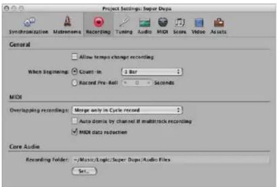
Allow Tempo Change Recording
All tempo changes made while in record mode are recorded. For details on editing these tempo recordings, please see Chapter 30, "Advanced Tempo Operations," on page 667.
When Beginning: Count In
If enabled, the pop-up menu allows you to set the desired count in period that precedes a recording.
• None: The recording begins with no count in.
- x Bar: X bars of count-in.
- x/4: The count-in's time signature may be set here. These settings are useful when the count-in falls across a bar change.
When Beginning: Record Pre-Roll
If enabled, this parameter allows you to set a pre-roll time in seconds and milliseconds. When recording, this value will be deducted from the current project position.
Overlapping Recordings
This pop-up menu provides the following settings:
- Create take folders: As the name suggests, a new take folder is created when recording over an existing MIDI region. Details on take recording and handling are covered in "Recording MIDI Regions in Real Time" on page 396.
- Merge with selected regions: Newly-recorded data is merged with all selected regions, to form a single region. This takes place after each recording is completed.
- Merge only in Cycle record: When recording in Cycle mode, this function merges the data recorded in all cycle passes into a single region. If not in Cycle mode, each newly-recorded MIDI region will be independent (not merged).
Auto Demix by Channel if Multi Track Recording
This setting switches between the Layer recording and Multi-player recording modes. See "Recording on Multiple MIDI Tracks" on page 400.
MIDI Data Reduction
Controller events are thinned out during recording, to reduce the data load on the MIDI bus during playback. This improves the timing of dense arrangements when using interfaces with only a few MIDI ports. The function actually reduces the duration of controller events, using an intelligent algorithm which retains the value at the end of a series of controller messages.
Recording Folder
This setting is only really applicable if you prefer to record all audio data into a single location. If your working methods are geared towards projects, all recordings (and other project assets) are saved in the project folder itself. To set a universal recording folder, click the Set button, and choose or create a new folder location in the file selector box.
Tuning Settings
Logic Express includes a real time tuning system, for use with the included software instruments. You can configure the tuning system in the Tuning project settings.
To open the Tuning project settings, do one of the following:
- Choose File > Project Settings > Tuning (or use the corresponding key command).
- Click the Toolbar Settings button, then choose Tuning from the menu.
About Tuning
Before looking at the Tuning settings, some basics and background information.
About Alternate Tunings
The twelve tone scale used in Western music is a development that took centuries. Hidden in-between these twelve notes are a number of other microtones—different frequency intervals between tones.
To explain, by looking at the harmonic series: Imagine that you have a starting (or fundamental) frequency of 100 Hz (100 vibrations per second). The first harmonic is double that, or 200 Hz. The second harmonic is found at 300 Hz, the third at 400 Hz, and so on. Musically speaking, when the frequency doubles, pitch increases by exactly one octave (in the 12 tone system). The second harmonic (300 Hz) is exactly one octave—and a pure fifth—higher than the fundamental frequency (100 Hz).
From this, you could assume that tuning an instrument so that each fifth is pure would be the way to go, right? In doing so, you would expect a perfectly tuned scale, as you worked your way from C though to the C above or below. Close, but no cigar.
To simplify this example: Imagine that you are tuning an instrument, beginning with a note called C at a frequency of 100 Hz (a real C would be closer to 130 Hz). The first fifth would be tuned by adjusting the pitch until a completely clear tone is produced, with no beats (beats are cyclic modulations in the tone). This will result in a G at exactly 150 Hz. This is derived from this calculation:
- The fundamental (100 Hz) x 3 (= 300 Hz for the second harmonic).
- Divided by 2 (to drop it back into the same octave as your starting pitch).
This frequency relationship is often expressed as a ratio of 3:2.
For the rest of the scale: Tune the next fifth up: 150 × 3 = 450 . Divide this by 2 to get 225 (which is more than an octave above the starting pitch, so you need to drop it another octave to 112.5).
Note Frequency (Hz) Notes
| C 100 x 1.5 divided by 2. | ||
| C# 106.7871 Divide by 2 to stay in octave. | ||
| D 112.5 Divide by 2 to stay in octave. | ||
| D# | 120.1355 | Divide by 2 to stay in octave. |
| E | 126.5625 | Divide by 2 to stay in octave. |
| F (E#) | 135.1524 | |
| F# | 142.3828 | Divide by 2 to stay in octave. |
| G 150 (x 1.5) divided by 2. | ||
| G# | 160.1807 | |
| A | 168.75 | |
| A# | 180.2032 | |
| B | 189.8438 | |
| C 202.7287 | ||
As you can see from the table above, there's a problem!
Although the laws of physics dictate that the octave above C (100 Hz) is C (at 200 Hz), the practical exercise of a (C to C) circle of perfectly tuned fifths results in a C at 202.7287 Hz. This is not a mathematical error. If this was a real instrument, the results would be clear.
To work around the problem, you need to choose between the following options:
• Each fifth is perfectly tuned, with octaves out of tune.
- Perfectly tuned octaves with the final fifth (F to C) out of tune.
It goes without saying that detuned octaves are more noticeable to the ears.
The Comma
The difference between a perfectly tuned octave, and the octave resulting from a tuned circle of fifths, is known as the comma.
Over the centuries, numerous approaches have been tried to solve this mystery, resulting in a range of scales (before arriving at equal temperament—the 12 tone scale).
Other historical temperaments that have been devised emphasize different aspects of harmonic quality. Each compromises in some way or another. Some maximize pure thirds (Mean Tone) while others emphasize pure fifths, at the expense of the thirds (Kirnberger III, for example).
Every temperament has its own character, and a given piece of music may sound fine in one key, but awful in another. Transposing a piece to a new key can completely change its character.
Careful attention must be paid to the selection of temperaments for authentic performances of historic keyboard music. The wrong choice could result in an unsatisfactory and historically inaccurate musical experience.
About Equal Temperament
Equal temperament takes the tuning error (the comma), and spreads it equally between each step of a chromatic scale. The result is actually a scale of equally mis-tuned intervals, with no interval grossly out of tune, but none in perfect tune. Equal temperament has become the de-facto standard for two main reasons:
- Convenience: Retuning an instrument to a temperament that is better suited for a particular piece of music is a hassle. Many instruments are not capable of being alternately tuned (fretted string instruments, for example).
- Portability: All Western musical pieces can be performed (adequately) on an instrument tuned to equal temperament. Obviously, some of the nuances may be missing in pieces that were originally performed in another temperament.
What Is Hermode Tuning?
Hermode Tuning automatically controls the tuning of electronic keyboard instruments (or the Logic Express software instruments) during a musical performance.
In order to create clear frequencies for every fifth and third interval, in all possible chord and interval progressions, a keyboard instrument would require far more than 12 keys per octave.
Hermode Tuning can help with this problem: it retains the pitch relationship between keys and notes, while correcting the individual notes of electronic instruments—ensuring a high degree of tonal purity. This process makes up to 50 finely graded frequencies available per note, while retaining compatibility with the fixed tuning system of 12 notes per octave.
How Hermode Tuning Works
Frequency correction takes place on the basis of analyzed chord structures.
The positions of individual notes in each chord are analyzed, and the sum of each note's distance to the tempered tuning scale is zeroed. In critical cases, different compensation functions help to minimize the degree of re-tuning—at the expense of absolute purity, if necessary.
As an example:
• The notes C, E, and G form a C Major chord.
- To harmonically tune these, the third (the E) needs to be tuned 14 cents higher (a cent is 1/100th of a tempered semitone) and the fifth (the G), needs to be 2 cents higher.
It should be noted that Hermode Tuning is dynamic, not static. It is continuously adjusted in accordance with the musical content. This is done for the following reason:
As an alternative to tempered, or normal, tuning—fifth and third intervals can also be tuned to ideal frequency ratios: the fifth to a ratio of 3:2, the major third to 5:4. Major triads will then sound strong.
With clean (scaled) tuning, Hermode Tuning changes the frequencies to values that are partly higher or partly lower.
Tuning Project Settings
The Tuning project setting parameters are listed below.
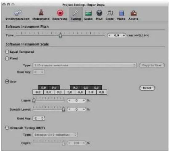
Tune
This parameter determines the global tuning of all software instruments. The default is concert pitch A (440 Hz). Detuning is in cent (1/100th of a semitone) steps.
Alternate Tuning Scales
Activation of alternate tuning scales is achieved by clicking the appropriate radio button in the Software Instrument Scale section. The selected tuning scale is saved with the project when saved, and reloaded the next time the project is opened.
Equal Tempered
This mode (active by default) disables any tuning, and uses an equal tempered scale.
Fixed Tuning
This mode activates a number of fixed tuning scales and keys. The Type pop-up menu offers the most important historic tuning scales, and a few others.
The Root Key menu allows you to choose a global key (C-B) for the chosen scale. This provides an easy way to reference the chosen scale to any root note.
Fixed Tuning mode tunes musical keys (to different degrees) for scaled tuning systems, and delivers a key signature character. To explain:
- When playing mostly white keys (in the Pure setting, and with C as the root key), C major will be the main focus, and tuning will be scaled to that chord.
- An A major chord that is played immediately after a C major (and is therefore subject to C major scaled tuning) will be affected somewhat by the scaled tuning effect, but will not sound completely tempered. If you normally play polyphonic music, this mode (when using the Pure setting) will sound most pleasing to your ears.
The Fixed Tuning scales are ideal for a number of Baroque and Medieval instruments, and styles of music.
User
Each semitone can be detuned (moved away) from equal temperament in semitone steps. To do so, just click-drag—vertically—on each semitone box until the desired value is reached.
Alternately, you can double-click in each semitone box, and type in a value. Press Enter or click on another box to exit the text entry mode.
The Reset button resets all of your tuning adjustments to their default values.
The Stretch Lower and Upper sliders can be used to stretch the tuning in the bass and treble, to simulate the stretched tuning of some instruments (acoustic pianos, for example).
- Stretch Lower determines the deviation (from the equal-tempered scale) in the bass end of the sound. The higher the value, the further down the low notes are tuned. A setting of 0 results in an equal-tempered scale tuning.
- The Stretch Upper parameter does the same in the treble end of the sound.
Hermode Tuning (HMT)
As all tuning requirements cannot be satisfied simultaneously with any one Hermode Tuning setting, different modes can be selected in the Type menu. Further to this, degrees of effect between 0% and 100% can be set with the Hermode Tuning Depth slider.
You can choose between the following settings in the Type menu:
- Classic (3/5-all): This mode proves a broad, and regular, tuning of pure 5ths and 3rds. In cases of conflict, the degree of purity is temporarily reduced. This mode can be used for all types of music. The value of the Depth parameter indicates the degree of the 5th and 3rd purity. A setting of 100% determines maximum purity. A 10% value is the lowest purity setting. Off sets the tuning to an equal tempered scale.
- Pop/Jazz (3/5/7-all): 5ths, 3rds, and 7ths are changed in this mode. It is great for Pop and Jazz styles, especially when using sustained chords. It is less suitable for polyphonic music, as the de-tuning of the natural 7th is significant. This mode should always be used with a Depth of 90% or 100% , as other values will render the natural 7th acoustically ineffective.
- Baroque (3/5-adaptive): This mode tunes pure 5ths and 3rds—with changing characteristics. In tonal music, with a clear harmonic center, the middle chords are tuned very purely, whereas more distant chords are tuned with less purity. If the harmonic center becomes unclear, all chords are tuned with equal purity. As with the other mode parameters, a Depth value of 100% determines the highest purity, and a value of 10%, the lowest purity.
Audio Settings
The Audio project settings determine audio-specific project parameters.
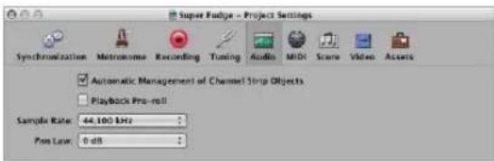
Automatic Management of Channel Strip Objects
This option (active by default) makes setting up, and using, tracks and channel strips a transparent experience. It automatically creates and manages channel strips when new tracks are created. You should only deactivate this setting when you need to make manual changes to channel strips in the Environment window.
Playback Pre-Roll
When this option is enabled, all start commands force Logic Express to start playback a little earlier (shifted to the left). The exact pre-roll value is dependent on the current delay compensation value for plug-ins. This option ensures that transients which fall exactly on the start position are played back correctly. If this option is disabled, transients that fall precisely on the start position can be missed, or seem to fade in.
Sample Rate
Choose the desired sample rate for the project in this pop-up menu.
Pan Law
The Pan Law value determines the amount of volume reduction on signals that are panned to the center position. You can choose from the following settings:
- 0 dB: Signals will seem louder when panned to the center position, in comparison with extreme left or right pan positions.
- -3 dB: A full scale signal (0 dBfs) will have a level of -3 dB when panned to the center position.
- -3 dB compensated: A full scale signal (0 dBfs) will have a level of 0 dB when panned to the center position (or +3 dB when panned to extreme left or right positions).
MIDI Settings
The MIDI project settings determine the behavior of the MIDI inputs and outputs. The MIDI project settings comprise the General, Input Filter, and Chase tabs.
General Tab
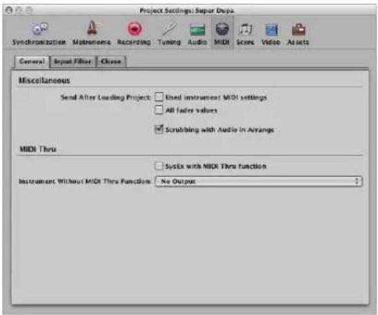
Send After Loading Project
- Used instrument MIDI settings checkbox: Sends the active instrument MIDI settings automatically after loading a project (see "Adding Program Change, Volume, and Pan Settings to a MIDI Region" on page 256).
- All fader values checkbox: Sends all Environment fader values automatically, once a project is loaded.
Scrubbing with Audio in Arrange
You must enable this setting if you want to simultaneously scrub MIDI and audio regions in the Arrange window.
SysEx with MIDI Thru function
Incoming SysEx messages are passed through the computer to the MIDI outputs, along with other MIDI data. This is particularly important when using hardware programmers, as you can immediately monitor parameter changes to the synthesizer you are editing.
If you want to record SysEx dumps, do not select this checkbox. It rarely makes sense to divert dumps through the computer unless you want to record a dump, and simultaneously transmit it to a second device of the same type.
Instrument Without MIDI Thru Function
The instrument selected here will not pass events through the computer, when the instrument is assigned to the selected Arrange track. Normally, you would set the No Output instrument here (it is chosen by default).
If your master keyboard does not have a Local Off setting, you can use this feature to avoid unwanted note doubling when recording:
- With multi timbral sound sources, assign the instrument (usually channel 1) which plays the part that is heard when playing with the computer turned off.
- With mono timbral sound sources, assign the instrument which represents the sound generating part of your master keyboard.
In either case, you should turn down the volume control of your master keyboard whenever you are recording tracks for any other instrument.
It is possible to disable MIDI Thru for any MIDI track in the Arrange window, by simply disabling the Record Enable button beside the track name.
Input Filter Tab
The Input Filter tab is used to screen certain event types at the sequencer input. For further information on the individual checkboxes, see "Filtering MIDI Input" on page 401.
Chase
The Chase MIDI project settings tab (see "Using the Chase Events Function" on page 114) offers a number of checkboxes that determine which event types are chased. If a checkbox is ticked, it indicates that chase events is activated for that event type.
Score Project Settings
All Score project settings are described in "Project Settings for Score Display" on page 811.
Video Project Settings
All Video project settings are described in "Video Project Settings" on page 841.
Assets Project Settings
The project assets refer to all audio files, EXS instruments, and other data associated with the project. Ideally, you should save all project assets with the project file, but may prefer not to. Full details on project handling, including information on the Assets project settings, is found in "Working With Projects" on page 137.
Preferences
The settings made in the Preferences window are saved in a general preference file, stored in the \~/Library/Preferences/Logic folder. Preference settings apply to all projects.
A separate preference file, also stored in the same location, is made for control surfaces.
Note: You can't open either preference file directly. Any changes must be made in Logic Express.
If you accidentally or intentionally erase the preference files, Logic Express will create new preferences files the next time it is opened. All parameters will be reset to their default values.
To initialize all preferences (but not your key commands) directly in Logic Express:
- Choose Logic Express > Preferences > Initialize All Except Key Commands (or use the corresponding key command).
Global Preferences
The Global preferences contain the Project Handling, Editing, Cycle, Catch, and Caps Lock Keys tabs.
To open the Global preferences, do one of the following:
- Choose Logic Express > Preferences > Global (or use the corresponding key command).
- Click the Preferences button in the Arrange Toolbar, and choose Global from the popup menu.
Tip: You can also use the default Open Preferences key command to open the Preferences window (the most recently accessed preference pane is shown).
Project Handling Preferences
The Project Handling preferences determine how Logic Express handles projects.
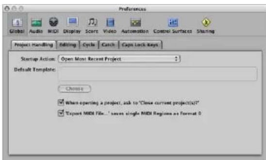
Startup Action
The Startup Action menu allows you to choose from a number of project options—that happen automatically when Logic Express is opened. You can choose from:
- Do Nothing: As the name suggests, this does nothing. Logic Express is opened and requires you to create a new project, or open an existing project or template.
- Open Most Recent Project: Automatically opens the project you were working on when you last closed Logic Express.
- Open Existing Project: Automatically shows the Open dialog, allowing you to browse for an existing project.
- Create New Project from Template: Automatically opens the Templates dialog.
- Create New Empty Project: Automatically loads an empty project and opens the Save As dialog, allowing you to name and save your project.
- Create New Project using Default Template: Automatically opens the default template, and launches the Save As dialog, allowing you to name and save your project.
You can determine the default template by clicking the Choose button below the Default Template field. The full path and name of the chosen template or project is displayed in the Default Template field. You can assign any template or project as the default template.
When Opening a Project, Ask to "Close Current Project(s)?"
Whenever you load a new project before closing the old one, a dialog box will appear, and ask whether or not the current project should be closed. If this option is left unchecked, you will not be asked the question, and the current project will remain open.
'Export MIDI File...' Saves Single MIDI Regions as Format 0
If only one MIDI region is selected when you make use of the File > Export > Selection as MIDI File command, the contents of the region are saved in MIDI file format 0. This file format is guaranteed to be compatible with every MIDI file player.
Editing Preferences
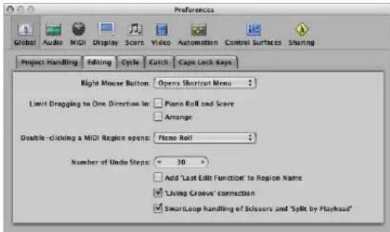
- Right Mouse Button: This pop-up menu determines the right mouse button behavior, assuming you have a suitable mouse. By default, this is assigned to Opens Shortcut Menu (which can also be accessed by Control-clicking with the left mouse button).
The Is Assignable to a Tool setting allows any tool to be assigned to the right mouse button. The Opens Tool menu setting does just that, when the right mouse button is clicked. - Limit Dragging to One Direction In: Piano Roll and Score: When this checkbox is turned on, you can only move notes in one direction (horizontally or vertically), per operation, when editing in the Piano Roll or Score Editors. This means that a note may be either transposed, or moved in time, but not both at once. This prevents accidental alterations of one or the other parameter.
- Limit Dragging to One Direction In: Arrange: This restricts the direction you can move regions (including folders) in the Arrange area, in a similar way to, and for the same reasons, as the option above.
- Double-clicking a MIDI Region opens: This menu determines the editor that is opened when you double-click on a MIDI region in the Arrange area. Settings are the Score, Event, Piano Roll (default), and Hyper Editors.
• Number of Undo Steps: Determines the number of undo steps. - Add 'Last Edit Function' to Region Name: After performing any edit operation (cutting, for example), the description of the edit operation is added to the name of the region (or resulting regions).
- 'Living Groove' Connection: When active, this option breaks the living connection between a MIDI region and a quantization template derived from it (if applicable). If the MIDI region is edited, this has no effect on the quantization template. If there is no check in the box, editing the original MIDI region will also alter the quantization template, which will in turn affect all MIDI regions that are quantized with this template.
- SmartLoop handling of Scissor and 'Split by Playhead': This option determines how Logic Express handles the cutting of looped regions.
- If you activate the option, you can cut the looped area of regions (using the Scissors or Marquee tool, or Split by Playhead commands). Logic Express automatically creates regions after—and, if necessary—before the cut, ensuring that these areas remain identical. This allows you to split looped regions without altering playback in the looped area.
- If the "SmartLoop handling of Scissor and Split by playhead option is switched off, you can not cut looped areas. Cutting the looped region itself deactivates the Loop parameter in the Region Parameter box.
Cycle Preferences
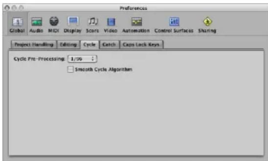
- Cycle Pre-Processing: In order to ensure a smooth cycle jump (from the end point of a cycle back to the start point of a cycle), the cycle jump is processed slightly before its actual position. This preference allows you to change the pre-processing time. A value of 1/96 is chosen by default, which should be suitable for most uses.
- Smooth Cycle Algorithm: This improves the timing of cycle jumps, making it easier to set the length of sample loops while in Cycle mode—although this is somewhat mitigated through the use of Apple Loops. If your computer has a very slow CPU, this setting reduces the processing requirements for graphic operations. In general, you'll want to keep this on, whenever possible, especially if you're working in a style which involves frequent cycling of musical sections. If you find that your cycled sections are not as smooth as you'd like (assuming that your loops are actually perfect), you might achieve better results by disabling this parameter.
Catch Preferences
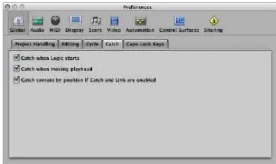
- Catch when Logic starts: Every time you start playback (including paused playback), the Catch function is automatically switched on, in all windows.
- Catch when moving playhead: Activation of this option ensures that whenever you move the playhead, the Catch function is automatically switched on. This makes it easier to perform edits—as moving the playhead in the Arrange will be reflected in the open editor window, and vice-versa.
- Catch content by position if Catch and Link are enabled: If the Catch and Link buttons are active (Content Catch mode), the contents of the region at the current playhead position are shown. If this option is turned off, the window view still follows the playhead position within the displayed region, but does not update to show the contents of subsequent regions as the playhead passes them (in play or record mode).
Caps Lock Keys Preferences
Full details on the use of your computer keyboard for MIDI note entry is discussed in "Using the Caps Lock Keyboard" on page 407. The Caps Lock Keys preferences are covered in "Caps Lock Keyboard Preferences" on page 408.
Audio Preferences
The Audio preferences contain the following tabs:
• Devices
- General
- Sample Editor
• MP3
- Reset
To open the Audio preferences, do one of the following:
- Choose Logic Express > Preferences > Audio (or use the corresponding key command).
- Click the Preferences button in the Arrange Toolbar, and choose Audio from the pop-up menu.
Device Preferences
The Device preferences determine how your audio interface hardware is addressed by Logic Express. Details are found in "Configuring Your Audio Hardware" on page 99.
General Audio Preferences
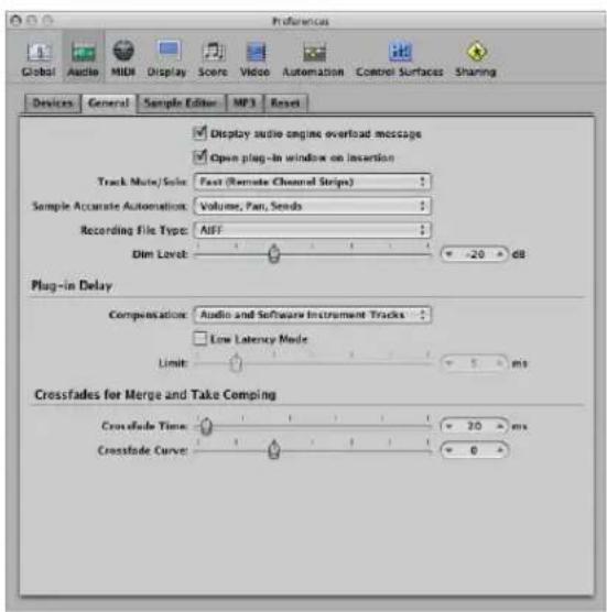
Display Audio Engine Overload Message
If switched off, playback will simply stop in an overload situation instead of displaying an alert box.
Open Plug-in Window on Insertion
With this setting on, the window of an effect or software instrument plug-in is automatically opened after inserting it in the appropriate channel strip slot.
Track Mute/Solo
This menu determines the linking relationship of the Track Mute and Solo buttons with the corresponding channel strip buttons.
- Fast (Remote Channel Strips): Clicking a channel strip's Mute or Solo button switches the state of the associated track button, and vice-versa.
- CPU-saving (Slow Response): Choose to save processing resources, and to make the track Mute and Solo buttons independent of the corresponding channel strip buttons.
Sample Accurate Automation
As the name implies, sample accurate automation is the most precise type of automation. It places higher overheads on system resources, which may affect performance (dependent on the nature of your projects, and available computing power). This is most likely to happen during heavy project sections—where a lot of software instruments and effects are in use. Logic Express offers three settings:
- Off: Minimal overhead on system performance for automation playback. Automation is less precise when this setting is active.
• Volume, Pan, Sends: Only these parameters are automated with sample accuracy. - Volume, Pan, Sends, Plug-in Parameters: All of these parameters are automated with sample accuracy. Please note: Not all Audio Unit plug-ins can be automated in this way.
Recording File Type
Lets you the determine the file type for recorded audio. The settings are:
- SDII: The SDII (Sound Designer II) file format can not handle audio recordings larger than 2 GB.
- AIFF: The AIFF file format can not handle audio recordings larger than 2 GB.
- WAVE (BWF): Most common audio format on Windows PCs. Files are stored as Broadcast Wave files, which contain time stamp information in the file header. The WAV file format can not handle audio file recordings larger than 4 GB:
- CAF: Choose this setting if you are going to record files larger than 4 GB in size. For more information, see "Maximum Recording Size" on page 376.
Dim Level
This slider enables you to set a discrete level for the Dim function, accessible with the Master Level slider on the Transport. You can set a dim level from 0 dB to -30 dB. The level chosen here is used when the Dim function is activated.
Plug-in Delay Compensation
Plug-in delay compensation is useful for software effect plug-ins, and is particularly important for DSP accelerator hardware (TC PowerCore, Universal Audio UAD-1, as examples). It compensates for audio delays that can be introduced when using plugins.
A pop-up menu allows you to activate plug-in delay compensation for either:
• Audio and software instrument tracks.
- All (Audio, instrument, auxiliary, and output channels).
You can also turn off compensation entirely. Details are found in "Working With Plug-in Delay Compensation" on page 867.
Low Latency Mode Checkbox and Limit Slider
You need to turn on the Low Latency Mode checkbox, in order to activate Low Latency mode, and to use the Limit slider. The Limit slider determines a maximum amount of allowable delay that can be caused by plug-ins when Low Latency mode is enabled (by clicking the Low Latency Mode button on the Transport). In Low Latency mode, plug-ins are bypassed, to ensure that all delays (across the entire signal flow of the current track) remain under the Limit slider value. This is useful when you want to play a software instrument with several latency-inducing plug-ins inserted in the channel. For more information, see “Working With the Low Latency Mode” on page 866.
Crossfade Time
Determines a default time value for all crossfade operations in the Arrange area.
Crossfade Curve
Determines a global curve type for all crossfade operations in the Arrange area.
Sample Editor Preferences
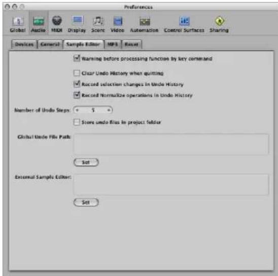
- Warning before processing function by key command: Switch this on if you want to be warned before carrying out a destructive edit in the Sample Editor—using a key command. This gives you the opportunity to cancel the edit operation, before altering the data.
- Clear Undo History when quitting: Switch this on to automatically delete the Undo History for all edited audio files, when you close Logic Express.
- Record selection changes in Undo History: Switch this on if you wish to undo and redo changes to selected areas in the Sample Editor.
- Record Normalize operations in Undo History: Disable this setting if you don't want to create undo files once the Normalize function is invoked.
• Number of Undo Steps: Determines the maximum number of undo steps that are retained.
- Store undo files in project folder: Activate this preference if you would like the edited audio files to be stored in a sub-folder of the current project. This is switched on by default if the project is saved with its assets.
- Global Undo File Path: All files (used by the Undo History) are saved into a global location—a user-defined folder—if the "Store undo files in project folder option" is not switched on. Click the Set button, and browse to the desired folder.
- External Sample Editor: You can use an external application for sample editing operations, effectively replacing the Logic Express Sample Editor. Click the Set button, and browse to the desired application.
MP3 Preferences
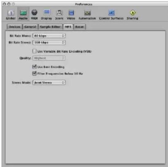
- Bit Rate (Mono/Stereo): The bit rates are selectable between 32 kbps and 320 kbps, but default to 80 kbps mono, and 160 kbps stereo. These rates offer acceptable quality and good file compression. If you can afford the extra file size, you should select 96 kbps for mono, and 192 kbps for stereo streams. These will deliver better audio quality. You can, of course, choose even higher rates, but the quality improvement in bit rates above 96/192 kbps is minimal.
- Use Variable Bit Rate Encoding (VBR): Variable Bit Rate encoding compresses simpler passages more heavily than harmonically rich passages, generally resulting in better quality MP3s. Unfortunately, not all MP3 players can accurately decode VBR-encoded MP3s, which is why this option is off by default. If you know that the audience for your MP3 can decode VBR-encoded MP3s, you can switch this option on.
- Quality: Keep this set to Highest whenever possible. Reducing the quality will accelerate the conversion process, but at the expense of audio quality. This option is only accessible when the VBR checkbox is turned on.
- Use Best Encoding: Again, like the Quality parameter, if you uncheck this option, you will gain encoding speed at the price of audio quality. This should always be left on, unless conversion time is an issue.
- Filter Frequencies Below 10 Hz: When this option is checked, frequencies below 10 Hz (which are usually not reproduced by speakers, and are not audible to human ears at any rate) are removed, leaving slightly more data bandwidth for the frequencies which humans can hear, resulting in an improvement in perceived quality. Only uncheck this option if you're experimenting with subsonic test tones, or exporting MP3s for whales.
- Stereo Mode: You can choose between Joint Stereo or Normal Stereo in this pop-up menu. Depending on the original file, these settings may (or may not) offer any audible difference. Experiment with both settings to determine your preference.
Reset Preferences
Activate the appropriate checkboxes for "Control 64 off (Sustain)", "Control 1 (Modulation) to zero", and "Pitch Bend to center position" to send reset messages of the specified type to all active instrument channels.
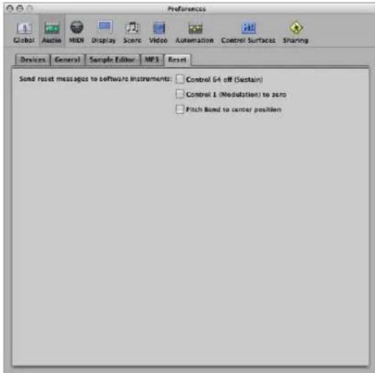
This can be useful if you are encountering hung notes, or are finding that controller settings are incorrect when in Cycle mode (or when returning to the beginning of a section or the project start point).
MIDI Preferences
These tabs determine how Logic Express communicates with your MIDI interface and other applications or devices. All active Core MIDI drivers are automatically made available to Logic Express. There is no need for further settings.
To open the MIDI preferences, do one of the following:
- Choose Logic Express > Preferences > MIDI (or use the corresponding key command).
- Click the Preferences button in the Arrange Toolbar, and choose MIDI from the pop-up menu.
General Preferences
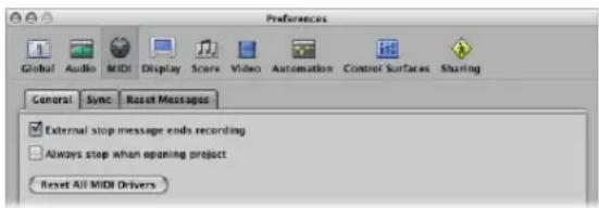
- External stop message ends recording: If you are using external synchronization, and the time code stops while recording, record mode is switched off. If this checkbox is turned off, Logic Express stops, but remains in record mode (record mode is paused).
- Always stop when opening project: With this setting on, a project will always be opened in stop mode, even if it was saved in play mode.
- Reset All MIDI Drivers: Click to reset all MIDI drivers. This can help if you experience MIDI communication problems.
Sync Preferences
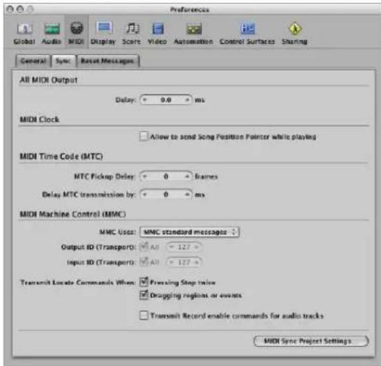
- All MIDI Output Delay field: Delays or advances the MIDI output for all ports, allowing you to compensate for any timing differences between MIDI tracks and audio or (software) instrument tracks.
- MIDI Clock: Allow Song Position Pointer while playing: Song Position Pointer data is not normally sent while the sequencer is in play mode (this is in accordance with the MIDI Standard). This option allows Logic Express to send SPP while the sequencer is running. The advantage is that external devices can also follow Logic Express in Cycle mode. If your external devices cannot process SPP, you should switch this option off. If your devices can follow MTC (MIDI Time Code), you should leave this option unchecked, and use the MTC functions of Logic Express.
- MTC Pickup Delay: This parameter should generally be set to zero, to ensure the quickest possible pickup time while Logic Express is in MTC (MIDI Time Code) sync mode. There are, however, some devices which seem to transmit imprecise MTC commands when first started. As a result, synchronization may be unreliable, and there could be an offset every time synchronization is established. In such situations, you can set a delay time before incoming MTC is picked up. Essentially, Logic Express will ignore the incoming MTC commands that occur in this time period. A (frame) value of 25 to 30 corresponds to a delay of about a second, depending on the frame rate. Use this parameter when synchronized to hard disk recorders and other devices, if synchronization doesn't appear to be consistent.
- Delay MTC Transmission by: This parameter allows you to delay the transmission of MIDI time code. Negative values result in MTC being transmitted earlier. This facility enables you to compensate for any reaction delays (to incoming MIDI time code) in external MTC slave devices.
- MMC Uses: This menu allows you to choose between the following settings:
- MMC standard messages: The MIDI MMC specification is strictly followed.
- Old Fostex Format: The old Fostex format is used for MIDI Machine Control.
- Output ID (Transport): The All checkbox sends MMC to all ports. The field to the right allows you to specify an output port ID.
- Input ID (Transport): The All checkbox sends MMC to all ports. The field to the right allows you to specify an input port ID.
- Transmit Locate Commands When: Pressing Stop twice: This checkbox enables transmission of MMC Locate commands when the Stop command is pressed twice (on the Transport Stop button, or with the Stop key command).
- Transmit Locate Commands When: Dragging regions or events: If this option is enabled and Logic Express is stopped (not in Play or Record mode), MMC locate commands are sent with the position of a region that is dragged in the Arrange area.
- Transmit Record enable commands for audio tracks: If this option is enabled, MMC record enable/disable commands are also sent when audio tracks are record enabled (armed) or disabled. In addition, any received MMC Record enable commands will set the record enable status of audio tracks.
- MIDI Sync Project Settings: Click this button to open the MIDI Sync Project Settings window.
Reset Messages Preferences
This tab is only included for compatibility with older MIDI hardware. Logic Express handles MIDI Reset Messages automatically and intelligently, so you should generally make sure that all of these options are switched off (this the default).
All selected checkboxes will send a reset message—for the selected controller type—to all MIDI outputs. This reset message is sent on cycle jumps and when playback begins, but the use of these options shouldn't be necessary.
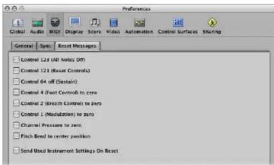
Display Preferences
These preferences alter the general appearance of Logic Express.
To open the Display preferences, do one of the following:
- Choose Logic Express > Preferences > Display (or use the corresponding key command).
- Click the Preferences button in the Arrange Toolbar, and choose Display from the pop-up menu.
General Preferences
This tab allows you to alter the appearance of several on screen components that are used throughout the program.
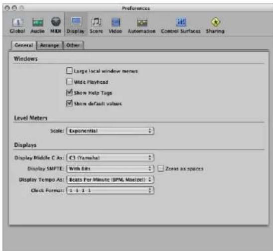
Windows Section
- Large local window menus: The title and items of the local menus are displayed in the normal System font. If unchecked, a smaller font is used.
- Wide Playhead: A thicker playhead is used in all windows.
• Show Help Tags: This enables help tags throughout Logic Express. As the mouse cursor hovers over parameters and tools, a small pop-up description (and/or value) of the item will appear onscreen. When editing, the function name, region or event name/number, position and parameter values are shown. - Show default values: When enabled, this option will display default values for parameters in help tags. This makes it easier to determine the amount of variance from the default value.
Level Meters Section
- Scale menu: Switches level meters between a Sectional dB-linear scale, and an Exponential scale. Exponential provides higher display resolution in the upper range of the meter. Sectional dB-linear provides the best possible display resolution across the entire level range.
Displays Section
- Display Middle C As Menu: This menu affects the description of notes in the editors. The bottom C on a five-octave keyboard (note # 36) is labeled C1, and middle C (note # 60) is labeled C3. According to this standard, the lowest MIDI note (note # 0) is called C -2. This is the official standard used by most manufacturers. Use of the C3 (Yamaha) setting will set Logic Express to this standard mode. Should you select the C4 (Roland) setting, the bottom C on a five-octave keyboard is labeled C2, and middle C is labeled as C4. In this standard, the lowest MIDI note is C -1.
- Display SMPTE Menu, Display Tempo As, and Clock Format Menu: You can use these menus to customize the Bar, SMPTE, and Tempo display in the Transport bar. For further details, see "Customizing the Bar, SMPTE, and Tempo Display" on page 121.
Arrange Preferences
These preferences specifically affect the appearance of the Arrange area.
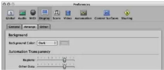
- Background Color: Choose one of three Arrange background color settings: Dark, Bright, and Custom. When the latter is chosen, you can set the custom color by clicking the color field to the right. This will open the Colors window, where you may define a custom color for the Arrange background.
- Automation Transparency: Regions: Higher values increase the color intensity of regions—in comparison to the track automation lane.
- Automation Transparency: Other Data: Brightens the display of (non-active) automation data. Note that this functionality is dependent on the zoom level of the region.
Other Preferences
These preferences affect the appearance of specific windows.
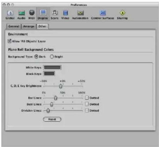
Environment: Allow 'All Objects' Layer
A layer, showing every object in your Environment, is accessible from the Layer menu in the Environment. If this checkbox is not active, the All Objects layer will not be available.
Piano Roll Background Colors: Background Type
These radio buttons allow you to select a dark or bright Piano Roll Editor background color.
Piano Roll Background Colors: Color Setup Panel
The Piano Roll Editor features a grid that follows the pattern of the keyboard keys shown on the left hand side. The parameters in this recessed panel can alter the colors of the Piano Roll Editor grid, background, lines, and so on—for both the bright and dark background views.
- White Keys: Double-click on the color field to open the Colors window. Select or determine the desired color for the grid lines, aligned with the white keyboard keys.
- Black Keys: As above, for the black keyboard keys.
- C, D, E Key Brightness: This slider allows you to intensify the brightness of these specific keys in all octaves, making transposition easier by providing a consistent reference point.
- Bar Lines/Dotted: Determines the transparency of the bar lines. The Dotted checkbox changes the appearance of the solid bar line to a dotted line.
- Beat Lines/Dotted: As above for beat lines.
- Division Lines/Dotted: As above for division lines.
- Reset: This button resets all user changes to default values.
Score Preferences
The Score Preferences are described in detail in the Score chapter (see "Score Preferences" on page 832).
Video Preferences
All Video preferences are covered in the Video chapter (see Chapter, "Video Preferences," on page 843).
Automation Preferences
The Automation preferences globally affect all automation tracks.
To open the Automation preferences, do one of the following:
- Choose Logic Express > Preferences > Automation (or use the corresponding key command).
- Click the Preferences button in the Arrange Toolbar, and choose Automation from the pop-up menu.
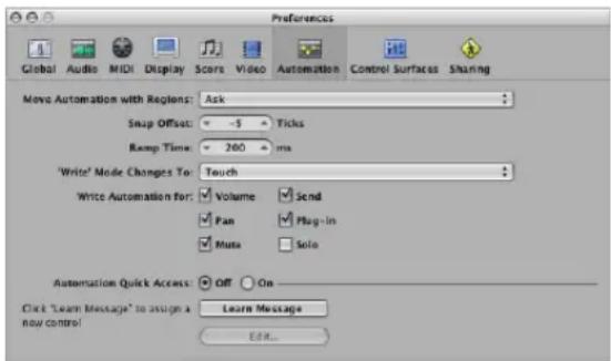
- Move Automation with Regions: Determine what happens to track automation data when you move regions. You can choose between Never, Always, and Ask.
- Snap Offset: This parameter enables a specific number of ticks to be added to, or subtracted from, the current snapped position of all automation data (as set in the Arrange window Snap menu).
- Ramp Time: Determines the time required by a parameter to return to its previously recorded setting.
- 'Write' Mode Changes To: Determines the mode that faders automatically switch to once track automation data recording has been completed.
- Write Automation for: The checkboxes in this section determine the types of track automation data that can be written in Touch, Latch, and Write modes.
- Automation Quick Access: These parameters are discussed in detail in the Automation Quick Access section (see "Using Automation Quick Access" on page 619).
Control Surfaces Preferences
The Control Surface preferences are discussed in the Control Surfaces Support document.
Sharing Preferences
The Sharing preferences are covered in "Setting Sharing Preferences" on page 650.
Learning More, Service, and Support
If your Apple Computer needs service, take it to an Apple Authorized Service Provider or contact Apple for service. You can find more information about your computer through online resources, onscreen help, or the System Profiler.
Online Resources
For online service and support information, go to http://www.apple.com/support. Choose your country from the pop-up menu. You can search the AppleCare Knowledge Base, check for software updates, or get help from Apple's discussion boards.
Onscreen Help
You can often find answers to your questions, as well as instructions and troubleshooting information, in Logic Express Help. Choose Help > Logic Express Help.
System Profiler
Use System Profiler to get information about your computer. System Profiler shows you which hardware and software is installed, the serial number and operating system version, how much memory is installed, and more. To open System Profiler, choose Apple ( Apple ) > About This Mac from the menu bar and then click More Info.
AppleCare Service and Support Information
Your Apple software comes with 90 days of telephone support. If you need assistance, AppleCare telephone support representatives can help you with installing and opening applications, and with basic troubleshooting. Call the support center number nearest you. Have the date of purchase and your Apple software registration number ready when you call.
After your 90 day complimentary support period, you can purchase AppleCare Professional Audio Support which delivers a year of support for Logic Express. For more information, call the support center or visit the website address for your country listed below.
Note: Your 90 days of complimentary telephone support begins on the date of purchase. Telephone fees may apply.
Country Phone Website
| United States 1-800-275-2273 www.apple.com/support | ||
| Australia (61) 133-622 www.apple.com/au/support | ||
| Canada (English) 1-800-263-3394 www.apple.com/ca/support | ||
| Canada (French) 1-800-263-3394 www.apple.com/ca/fr/support | ||
| Ireland (353) 1850 946191 www.apple.com/ie/support | ||
| New Zealand | 00800-7666-7666 www.apple.com/au/support | |
| United Kingdom | (44) 0870 876 0753 | www.apple.com/uk/support |
For a complete list, go to http://www.apple.com/contact/phone_contacts.html.
Telephone numbers are subject to change, and local and national telephone rates may apply.
Glossary
AAC Abbreviation for Advanced Audio Codec. A compression and decompression algorithm and file format for audio data.
AAF Abbreviation for Advanced Authoring Format. A cross-platform project exchange file format that you can use to import multiple audio tracks, inclusive of references to tracks, time positions, and volume automation.
accelerando A gradual increase in tempo (see tempo).
AD converter or ADC Short for analog to digital converter; a device that converts an analog signal to a digital signal.
ADAT Abbreviation for Alesis Digital Audio Tape. The ADAT is an eight track digital multitrack cassette recorder that uses an S-VHS video tape to record audio at 16 or 20 bit depth.
ADAT optical Optical interface for parallel transmission of eight audio channels via fiber-optic cable. It is a well-established standard for digital multi-channel interfaces.
AES/EBU Short for Audio Engineering Society/European Broadcasting Union. This association has a standard transmission format for professional stereo digital audio signals called AES/EBU. The format is similar to S/P-DIF, but uses balanced line drivers at a higher voltage. Depending on the type of devices involved, AES/EBU and S/P-DIF coaxial interfaces can communicate directly.
aftertouch MIDI data-type generated by pressure on keys after they have been struck. There are two types: Channel aftertouch, the value of which is measured by a full length keyboard sensor. It affects all played notes. Polyphonic aftertouch (rare) is individually measured and transmitted for each key. Aftertouch is also known as key pressure or pressure sensitivity.
AIFF Abbreviation for Audio Interchange File Format. A cross-platform file format supported by a large number of digital audio and video editing applications. AIFF audio can use a variety of bit depths, most commonly 16 and 24 bit.
AKAI Common sample data format that the EXS24 mkll is compatible with.
ALAC Abbreviation for Apple Lossless Audio Codec, an encoding/decoding algorithm that delivers lossless audio compression.
alias A pointer to a MIDI region in the Arrange area. An alias does not contain any data. It simply points to the data of the original MIDI region. You can create an alias by Shift-Option-dragging the original MIDI region to a new location. An alias can not be edited directly. Any change to the original region will be reflected in the alias.
aliasing A digital artefact that occurs when the sample material contains frequencies higher than one-half of the sample rate.
amplifier Device which increases the level of a signal.
amplitude This term is used to describe the amount of a signal. If you have an audio signal, amplitude refers to the volume of the sound, measured in decibels (dB).
amplitude peak The loudest point of an audio signal.
analog signal A description of data that consists of an endlessly varying voltage level, that represents audio information. Analog signals must be digitized, or captured, for use in Logic Express. Compare with digital.
anchor point The start point of the audio file that an audio region is based on. Also see Sample Editor.
Apple Loops An audio file format, commonly used for recurring rhythmic musical elements or elements suitable for repetition. Apple Loops contain tags and transients that are used by Logic Express for time stretching and pitch shifting tasks. These tags also allow you to quickly locate files by instrument, genre, or mood in the Loop Browser.
Apple Loops Utility The Apple Loops Utility allows you to create your own Apple Loops. To use the Apple Loops Utility, select an audio region in the Arrange and choose Audio > Open in Apple Loops Utility.
Arrange area The primary working space of Logic Express. It is used to record, edit, move, and arrange the audio and MIDI regions of a project. Also used for automation recording and playback.
Arrange window The primary working window of the application. It also shows the Arrange area (see above), and can incorporate all other working areas and editors.
ASCII Acronym for American Standard Code for Information Interchange. Standard computer character set, allowing computers to deal with text characters. When you type ASCII characters from the keyboard, the computer interprets them as binary so they can be read, manipulated, stored, and retrieved. Also see scan code.
attack Start phase of a sonic event. Also part of an envelope (see envelope).
attenuate The act of lowering the level of an audio signal (see boosting and cutting).
Audio Bin Window (or tab in the Media area of the Arrange window) used for project audio file and region management, and conversion, tasks. See Media area.
audio file Any digital recording of sound, stored on your hard drive. You can store audio files in the AIFF, WAV, Sound Designer II (SDII), and CAF formats in Logic Express. All recorded and bounced WAV files are in Broadcast Wave format.
audio interface Device used to get sound into and out of your computer. An audio interface converts digital audio data, sent from your computer, into analog signals that speakers can broadcast. In the other direction, an audio interface converts analog signals (such as a vocal performance) into digital audio data that can be understood by your computer.
Audio MIDI Setup (AMS) The Audio MIDI Setup (AMS) utility is used to configure the audio and MIDI input and output devices connected to your computer. Logic Express uses the settings defined in the Audio MIDI Setup utility, which can be found in the Applications/Utilities folder.
audio region Chosen area of an audio file which can be placed on audio tracks in the Arrange, just like a MIDI region can be placed on MIDI tracks. Audio regions are aliases (or pointers) to portions of audio files. They can be as short as a single sample, or the full length of the underlying audio file. Logic Express allows you to edit audio regions without affecting the original audio file. Also see region and MIDI region.
audio track A track in the Arrange window that is used for playback, recording, and editing of audio regions. It is routed to an audio channel in the Mixer.
audio channel strip Channel strip in the Mixer, used as a target for audio tracks in the Arrange. All data on the audio track is automatically routed to the audio channel strip that was assigned in the Arrange track list.
Audio Units (AU) Audio Units is the standard Mac OS X format for real time plug-ins. It can be used for audio effects, software instruments, and Generators. The Audio Unit format is incorporated into the operating system, and installed Audio Unit plug-ins can be simultaneously accessed by all applicable programs. Logic Express supports all Audio Unit format plug-ins.
Auto Track Zoom Function in the View menu that automatically enlarges the currently selected track.
Autopunch button Button (with the up/down arrows) in the Transport, used to activate the Autopunch function.
- Contents
- Preface 15 Logic Express 8: Documentation and Resources
- Chapter 1 19 An Introduction to Logic Express
- Chapter 2 27 Overview of the Logic Express Interface
- Chapter 3 59 Customizing Your Window Setup
- Chapter 4 83 Setting Up Your System
- Chapter 5 103 Navigating Your Project
- Chapter 6 123 Working With Markers
- Chapter 7 137 Working With Projects
- Chapter 8 159 Basic Operations
- Chapter 9 187 Working With Tracks
- Chapter 10 215 Working With Instruments and Effects
- Chapter 11 265 Adding Pre-Recorded Media
- Chapter 12 291 Getting to Know Regions
- Chapter 13 307 Creating Your Arrangement
- Chapter 14 367 Recording in Logic Express
- Chapter 15 409 Introduction to MIDI Editing
- Chapter 16 415 Editing MIDI Events in the Piano Roll Editor
- Chapter 17 437 Editing MIDI in the Hyper Editor
- Chapter 18 459 Editing MIDI Events in the Event List
- Chapter 19 477 Quantizing MIDI Events
- Chapter 20 491 Editing MIDI Events in the Transform Window
- Chapter 21 515 Editing Audio in the Sample Editor
- Chapter 22 549 Removing Silent Passages From Audio Regions
- Chapter 23 553 Adjusting the Tempo of Audio Regions
- Chapter 24 559 Managing Audio Files
- Chapter 25 571 Mixing
- Chapter 26 605 Working With Automation
- Chapter 27 625 Bouncing Your Project
- Chapter 28 639 Creating Apple Loops
- Chapter 29 649 Project and File Interchange
- Chapter 30 667 Advanced Tempo Operations
- Chapter 31 683 Beat Mapping Regions
- Chapter 32 689 Transposition With the Chord and Transposition Tracks
- Chapter 33 695 Working With Notation
- Chapter 34 835 Working With Video
- Chapter 35 845 Synchronizing Logic Express
- Chapter 36 865 Working With Plug-in Latencies
- Chapter 37 871 Working With Split Channel Audio File Formats
- Chapter 38 875 Working in the Environment
- Chapter 39 961 Project Settings and Preferences
- Logic Express 8: Documentation and Resources
- Logic Express 8 offers an extensive documentation collection that will help you to learn and make full use of all application features.
- Logic Express 8 Documentation Conventions
- Menu Functions
- Important Entries
- Notes
- Key Commands
- Tips
- Warnings
- Logic Express Onscreen Help
- Late-Breaking News
- Apple Websites
- Logic Express Websites
- Apple Service and Support Website
- To access Apple's Service and Support web page:
- Other Websites
- An Introduction to Logic Express
- Logic Express is a sophisticated, fully-featured audio and MIDI application that provides all the tools you need to create professional-quality music productions.
- Creating Music in Logic Express
- Step 1: Creating a project
- Step 2: Creating and importing your musical material
- Step 3: Arranging and editing
- Step 4: Mixing, automating, using plug-ins
- Step 5: Exporting and bouncing
- The Basics: Projects and Regions
- Projects
- The Project Folder
- Regions
- Audio Regions and Audio Files
- MIDI Regions and Events
- Overview of the Logic Express Interface
- 2
- To open Logic Express:
- A Tour of the Logic Express Interface
- The Arrange Window
- The Arrange Toolbar
- The Transport Bar
- Arrange Area
- Media Area
- Getting to Know the Audio Bin
- Getting to Know the Loop Browser
- Getting to Know the Library
- Getting to Know the Browser
- Lists Area
- Getting to Know the Event List
- Getting to Know the Marker List
- Getting to Know the Tempo List
- Edit Options
- Getting to Know the Signature List
- The Inspector
- The Editing Area
- Getting to Know the Mixer
- Getting to Know the Sample Editor
- Getting to Know the Piano Roll Editor
- Getting to Know the Score Editor
- Getting to Know the Hyper Editor
- Common Features of Logic Express Windows
- Local Menu Bars
- Tool Menus
- Catch, Link, and Hierarchy Buttons
- Scroll Bars
- Zoom Sliders
- Bar Ruler
- Global Tracks
- Interactions Between Arrange Window Areas
- To see how Arrange window areas interact:
- Using Logic Express Interface Elements
- Checkboxes and Buttons
- Pull-Down and Pop-Up Menus
- Shortcut Menus
- Using the Computer Keyboard
- Customizing Your Window Setup
- 3
- Logic Express allows you to customize your window setup to fit both your working style and the task at hand.
- Window Types
- Normal Windows
- Handling Background Windows
- Floating Windows
- Opening and Closing Windows
- Moving and Resizing Windows
- To move a window:
- To adjust the size of window elements:
- To minimize a window, do one of the following:
- Working at Different Hierarchy Levels
- About Display Levels in the Editors
- Selecting the Working Area
- Zooming
- To zoom out:
- To zoom in:
- Zooming With the Scroll Bars
- To zoom with the scroll bars:
- Zooming the Waveform of Audio Regions
- To zoom the waveform of audio regions:
- Storing and Recalling Zoom Settings
- Zooming in on One Section of the Screen
- Reverting to the Previous Zoom Setting
- Zoom Navigation Key Commands
- Relationships Between Windows
- Catch
- Scroll in Play
- No Link, Same Level Link, and Content Link Modes
- To set any of these modes:
- Content Catch Mode
- To enable Content Catch mode:
- Customizing the Transport Bar
- Customizing the Arrange Window Toolbar
- To add a button to the Logic Express Toolbar:
- To remove a Toolbar button:
- To change the appearance of Toolbar items:
- To keep a Toolbar button visible when you resize the Arrange window:
- Hiding or Revealing the Inspector
- To hide or show the Inspector in the Arrange window, either:
- To hide or show the Inspector in the editing windows:
- Adjusting the Bar Ruler Display
- To set the Bar ruler display mode:
- Displaying Global Tracks
- Showing and Hiding Individual Global Tracks
- To hide or show particular global tracks:
- Resizing and Moving Global Tracks
- To resize the entire global tracks area:
- To change the order of global tracks:
- Using Screensets
- Saving and Recalling Screensets
- To create a screenset:
- Recalling Screensets 1 to 9 via Key Commands
- Sequencer Controlled Screenshot Switching
- To switch a screenset automatically:
- Protecting, Copying, Renaming, and Deleting Screensets
- To prevent the current screenset from being altered:
- To copy screensets:
- To rename the current screenset:
- To delete the current screenset:
- Importing Screensets From Another Project
- To import all screensets from another project:
- Reverting to Saved Screensets
- Setting Up Your System
- 4
- Designing Your Music Production System
- Computer
- How Fast Your Computer Should Be
- A Portable or Fixed Studio?
- Hard Drives and Storage Locations
- Audio and MIDI Interfaces
- Audio Interface
- MIDI Interface
- Types of MIDI Devices
- MIDI Keyboard
- Control Surfaces
- Synthesizers and MIDI Controlled Effects
- Ancillary Audio Devices
- Audio Playback System
- Headphones
- Audio Mixing Consoles
- Microphones
- Connecting Your Audio and MIDI Devices
- Computer Expansions
- FireWire (IEEE 1394)
- USB (Universal Serial Bus)
- PCI
- ExpressCard
- Audio Cabling
- XLR
- 1/4-Inch Audio
- 1/8-Inch Miniplug
- RCA (Cinch)
- AES/EBU, S/PDIF, and ADAT
- Connecting Your Audio Interface
- MIDI Cabling
- Connecting Your MIDI Keyboard and Modules
- Using Multi-Channel MIDI Devices
- USB MIDI Keyboards
- Separating a MIDI Keyboard From Its Sound Generator
- Using External MIDI Devices
- Using External Audio Effects
- Configuring Your Audio Hardware
- To open the Audio Devices preferences, do one of the following:
- Setting Up Core Audio Devices
- Enabled
- System Memory Requirement
- Device
- I/O Buffer Size
- Recording Delay
- Universal Track Mode
- Bit Recording
- Software Monitoring
- Independent Monitoring Level for Record Enabled Channel Strips
- Process Buffer Range
- ReWire Behavior
- Maximum Scrub Speed
- Scrub Response
- Navigating Your Project
- 5
- Setting the Playhead Position
- To place the playhead in the Bar ruler:
- Setting the Playhead With the Position Display
- To set the playhead position in the Position display, do one of the following:
- Setting the Playhead at a Marker
- Adjusting the Size of the Playhead
- To adjust the playhead display:
- Using the Transport Buttons
- Using Transport Key Commands
- Using Cycle Mode
- Defining the Cycle
- Defining and Adjusting a Cycle in the Bar Ruler
- To move the cycle:
- To resize the cycle:
- Defining a Cycle With the Transport Locator Displays
- To define the locator positions in the Transport, do one of the following:
- Using the Transport Bar Mode Buttons to Define Locators
- Using Regions or Events to Define a Cycle
- Defining a Cycle With Markers
- Skip Cycle
- To set up a skip cycle, do one of the following:
- Using the Chase Events Function
- To set up the Chase Events function:
- To avoid triggering a sampler's drum loops when chasing note events:
- Hiding and Showing Transport Bar Functions
- To customize the Transport bar:
- Transport Buttons
- Display Area
- Modes and Functions
- Using a Giant SMPTE or Bar Display
- Customizing the Bar, SMPTE, and Tempo Display
- To customize the Bar, SMPTE, or Tempo display:
- Working With Markers
- Opening Marker Areas and Windows
- To open the Marker track:
- To open the Marker List, do one of the following:
- To open the Marker Text window:
- Using the Marker Shortcut Menus
- Creating Markers
- To copy a marker:
- Selecting Markers
- Deleting Markers
- To delete markers:
- Naming Markers
- To edit a marker name in the Bar ruler:
- To edit a marker name in the Marker track:
- To edit a marker name in the Marker List:
- To edit a marker name in the Marker Text window:
- Changing the Appearance of Marker Text
- To change the appearance of marker text:
- Editing Markers
- To protect the position of selected markers:
- To unprotect the position of selected markers:
- To change the length of a marker:
- To adjust a marker to fit a cycle:
- To assign a color to a marker:
- Navigating With Markers
- To move to the next or previous marker:
- To start playback at a marker start position, do one of the following:
- To create a cycle from a marker, do one of the following:
- Customizing the Marker Display in the Marker List
- Working With Projects
- 7
- Logic Express projects provide flexible options for storing and retrieving your music productions.
- Learning About Projects
- Creating Projects
- To create a project:
- Opening Projects
- To open an existing project, do the following:
- To open a recent project:
- Opening Projects Using Drag and Drop
- Opening Pre Version 8 Songs
- Switching Between Multiple Projects
- To switch between projects:
- Opening and Creating Projects Automatically
- To determine the default template:
- Importing Settings From Other Projects
- To import settings from another project:
- Checking and Repairing Projects
- To open the Project Information window:
- To reconfigure the memory:
- Setting Project Properties
- Setting the Sample Rate
- To set the project sample rate, do one of the following:
- Setting the Project Tempo
- Setting the Project Time Signature
- To change the time signature, do one of the following:
- Setting the Start and End Points of a Project
- To define a project's start point:
- To define a project's end point, do one of the following:
- Setting the Basic Project Playback Level
- Adjusting Project Settings
- To open the project settings, do one of the following:
- Handling Project Assets
- To open the Assets project settings, do one of the following:
- Managing Projects
- Copying or Moving a Project Folder
- Cleaning Up Projects
- Consolidating Project Settings
- To consolidate your project:
- ReCycle Import Handling in Projects
- Saving Projects
- Automatic Backup Files
- Reverting to the Saved Version
- Saving a Project as a Template
- To save a project as a template:
- Closing and Quitting
- To close the currently active project:
- To close the open window:
- To quit the application:
- Basic Operations
- 8
- Using the Mouse
- Clicking
- Double-Clicking
- Grabbing or Clicking and Holding
- Moving or Dragging
- Right-Clicking
- Modifier-Clicking or Dragging
- Mouse Wheel Events
- Mouse as a Slider
- Entering Numerical Values
- Arithmetical Operations
- Canceling Numerical Input
- Entering Text
- Working With Key Commands
- Saving Key Commands
- Special Keys
- The Key Commands Window
- Key Command Groups and Hierarchies
- Choosing Key Command Sets
- Browsing Key Commands
- Finding Key Commands
- Assigning Key Commands to Computer Keys
- To assign a function to a key:
- Using Existing Key Commands
- To delete key assignments:
- Assigning Key Commands to Control Surfaces
- To learn a controller assignment:
- Initializing Key Assignments
- To initialize all key command assignments:
- Printing a Key Command List
- Working With Tools
- To assign the left-click (or default) tool:
- To assign the Command-click (alternate) tool:
- To switch between the default and alternate tools:
- Assigning the Right Mouse Button
- To set the behavior of the right mouse button:
- Using Key Commands to Select Tools
- Learning About Common Tools
- Pointer Tool
- Pencil Tool
- Eraser Tool
- Text Tool
- Scissors Tool
- Glue Tool
- Solo Tool
- Mute Tool
- Zoom Tool
- Working With Help Tags
- Using the Shortcut Menu
- Selection Techniques
- Selecting Individual Regions, Events, and Other Elements
- Selecting Several Regions, Events, and Other Elements
- Making Horizontal Selections
- Making Rubber-Band Selections
- Switching the Selection Status
- Selecting Following Regions or Events
- Selecting Regions or Events Within the Locators
- Selecting Specific Regions and Events
- Selecting Similar or Identical Objects, Regions, or Events
- Selecting Events With the Same MIDI Channel
- To select all events on channels 1 and 3:
- Selecting Regions or Events With an Equal Subposition
- Accelerating Edit Operations With Selection Commands
- Working With the Clipboard
- Cut
- Copy
- Paste
- Paste at Original Position
- Paste Replace
- Undoing and Redoing Editing Operations
- To undo your last step:
- To open the Undo History window:
- To undo or redo multiple steps:
- To undo or redo an isolated step:
- To erase the Undo History:
- Working With Tracks
- 9
- Tracks contain the audio regions and MIDI regions of a project.
- Configuring the Track Header
- To determine the elements that are shown in the track header:
- Reclaiming Workspace Used by the Track Header
- Creating Tracks and Channels
- Track and Channel Creation Commands
- To create one or more new tracks (and channels):
- Using the New Tracks Dialog
- External MIDI Track Creation in the New Tracks Dialog
- Audio Track Creation Options in the New Tracks Dialog
- Software Instrument Track Creation Options in the New Tracks Dialog
- Transferring a Channel Strip Setting to a New Track
- To transfer the channel assignment to a new track:
- Creating Tracks by Adding Apple Loops
- Creating Tracks by Adding Audio Files
- Track Creation Commands
- Creating a Track With the Same Channel Assignment
- To create a track with the same channel strip or instrument assignment:
- Creating a Track With the Next Channel Assignment
- Creating Tracks With the Next Channel Strip/MIDI Channel
- Copying Tracks and Moving Regions
- Creating Tracks for Overlapping Regions
- Creating Tracks for Selected Regions
- Deleting Tracks
- Selecting Tracks
- Rearranging Tracks
- To change the position of a track in the track list:
- Naming Tracks
- To determine the track names you want to view:
- To create a track name:
- Assigning Tracks to Channels
- To reassign a track to a specific channel strip:
- Assigning Tracks to Environment Objects
- To globally reassign multiple tracks that share a channel strip destination:
- Special Destinations
- Zooming Individual Tracks
- To zoom in or out on a track:
- Zooming the Selected Track Automatically
- Zooming Tracks With Key Commands
- Assigning Track Icons
- To assign an icon to a track:
- Creating Your Own Icons
- To open the Logic Express package:
- Muting Tracks
- Muting When the Mute Buttons Are Hidden
- Muting Multiple Tracks
- Muting Multiple Tracks With the Same Channel Strip Destination
- Soloing Tracks
- Connecting the Track Solo and Channel Strip Solo Buttons
- Soloing Tracks in CPU-saving Mode
- Soloing When the Track Solo Buttons Are Hidden
- Soloing Multiple Tracks
- Record-Enabling Tracks
- Freezing Tracks
- About the Freeze Function
- When to Freeze a Track
- How to Freeze a Track
- What Happens During a Freeze
- Working With Frozen Tracks
- To unfreeze and edit a track:
- Freeze Files
- Refresh Freeze Files
- Hiding Tracks
- To hide tracks:
- To show hidden tracks:
- Hide Menu and Key Commands
- Protecting Tracks
- Using Track Button Slide Activation
- Working With Instruments and Effects
- A Quick Mixer and Channel Strip Primer
- Setting the Channel Input Format
- Setting the Channel Pan or Balance and Playback Level
- How Mono and Stereo Effects are Handled
- Inserting, Moving, and Removing Plug-ins
- Where Different Plug-in Types Can Be Used
- To insert an effect plug-in:
- To remove a plug-in:
- To replace a plug-in:
- Accessing Multiple Instrument Outputs
- To insert and set up a multi output instrument:
- Using the Channel EQ
- To insert the Channel EQ, do one of the following:
- Moving Effects and Instruments
- Using the Hand Tool With Modifiers
- Loading and Removing Entire Channel Strip Configurations
- To load a channel strip setting with the Settings menu:
- To load a channel strip setting with the Library tab:
- To reset a channel strip setting:
- To delete a channel strip setting:
- To copy and paste a channel strip setting:
- To save a channel strip setting:
- To create a performance setting:
- Using the Plug-in Window
- To close a plug-in window:
- To open a closed plug-in window:
- Adjusting Plug-in Parameters
- To adjust numerical fields, do one of the following:
- To reset any parameter to its default (or centered) value:
- To make finer parameter adjustments:
- To adjust plug-in parameters with the mouse wheel:
- To adjust plug-in parameters with the keyboard:
- Common Plug-in Window Functions
- Linking the Plug-in Window
- When the Link Button Is Switched On
- When the Link Button Is Switched Off
- Bypassing Plug-ins
- Using the Settings Functions
- To load a setting:
- To choose the next or previous setting, do one of the following:
- To replace a setting, do one of the following:
- Replacing Setting-Compatible Plug-ins
- To compare changed plug-in parameters with the original settings:
- To revert to a plug-in's default setting:
- To copy the current plug-in parameters:
- To paste copied plug-in parameters:
- To create a default setting:
- To delete a setting:
- Switching the Contents of the Plug-in Window
- Switching the Plug-in Window View Mode
- To switch between view modes:
- Side Chaining Plug-ins
- Some Side Chaining Examples
- Hiding and Showing Extended Parameters
- To hide or reveal the extended parameters:
- Using the Library to Choose Plug-in Settings
- To load a plug-in setting from the Library:
- Library Folder and Menu Structure
- Learning About Effect Routings
- Insert Effects
- Send Effects
- To send a channel signal to an aux:
- To remove a send:
- To bypass a send:
- To normalize (reset) the send level:
- Post, Post Pan, and Pre Fader Aux Sends
- To select one of these options in Logic Express:
- Parallel and Series Send Routings
- Working With Instruments
- Setting Up External MIDI Instruments
- To reassign tracks to channels with the Library tab:
- To create a new external MIDI instrument in the Environment:
- Setting Channel Parameters for Instruments
- Common Instrument Parameters
- Icon
- Transposition
- Velocity
- Key Limit
- Vel Limit
- Delay
- No Transpose
- No Reset
- Style
- Setting Software Instrument Channel Parameters
- MIDI Channel
- Value as
- Setting External MIDI Channel Parameters
- MIDI Channel and Port Connection
- Setting the MIDI Channel: Multi Instruments
- Program, Volume, and Pan
- Adding Program Change, Volume, and Pan Settings to a MIDI Region
- Processing External MIDI Instruments With Effects
- To process external MIDI instruments with effects:
- Playing Software Instruments
- Switching Instruments to Software Instrument Live Mode
- Why Live Mode is Necessary
- Saving Software Instrument Processing Resources
- Tuning Software Instruments
- No Hermode Tuning
- Working With ReWire Applications
- To access a ReWired instrument:
- To manually set up an aux channel for ReWire use:
- Setting the ReWire Behavior
- Working With External Audio Effects
- To integrate and use an external effects unit in Logic Express:
- Some Tips for Using External Effects
- Using Plug-ins From Other Manufacturers
- Loading Presets
- Working With the Audio Units Manager
- To open the Audio Units Manager:
- Manually Enabling Plug-ins
- Disabling Plug-ins
- Adding Pre-Recorded Media
- Pre-recorded media plays an important role in modern audio production. Combining existing audio loops and other files provides a quick method for laying down song foundations.
- Supported File Formats
- About Pre-Recorded Media Types Supported by Logic Express
- WAVE and AIFF Files
- Core Audio Format Files
- Sound Designer
- MP3, Apple Lossless, and AAC
- Apple Loops
- ReCycle
- Standard MIDI Files
- Accessing Media Files in the Browser
- To access the Browser in the Arrange window:
- To open the Browser as independent window:
- Navigating in the Browser
- To switch between List and Browser view:
- To navigate in the Browser using the bookmark buttons:
- To navigate in the Browser using the Path menu:
- To step backwards or forward through the navigation history:
- Searching for Files in the Browser
- To perform a basic search in the Browser:
- To sort the search results:
- To clear a search term:
- To view recent search terms:
- To clear all recent search terms:
- To perform an advanced search:
- To remove a single advanced condition row:
- To restore all advanced search condition rows:
- Further Information on Conditional Searches
- Finding Apple Loops in the Loop Browser
- Green and Blue Apple Loops
- Before Browsing or Searching for Apple Loops
- To limit the loop display to a particular Jam Pack or other category:
- Browsing for Apple Loops
- To switch between browsing modes:
- To browse for Apple Loops in Column view:
- To browse for Apple Loops in Music and Sound Effects view:
- To clear all category selections:
- To customize the Music or Sound Effects view:
- Auditioning Apple Loops in the Loop Browser
- To audition Apple Loops:
- To adjust the playback level:
- To adjust the playback key:
- To stop playback:
- Sorting Apple Loops in the Loop Browser
- Creating a Collection of Your Favorite Apple Loops
- Searching for Apple Loops
- To search for an Apple Loop:
- Adding and Removing Audio Files
- Adding Audio Files to Your Arrangement
- To add audio files to your arrangement using the Pencil tool:
- To add audio files to your arrangement using the Import Audio File command:
- To add an audio file to your arrangement by dragging:
- With Automatic Track and Channel Creation
- To add multiple audio files to your arrangement by dragging:
- Adding and Removing Project Audio Files
- To use the Browser or Finder to add audio files to your project:
- To use the Audio Bin to add one or more files to your project:
- To remove one or more files from the current project:
- A Note on Importing Compressed Audio Files
- Overview Calculation
- Adding ReCycle Files to Your Project
- To import a ReCycle file into the Arrange area:
- Moving Audio Between Logic Express and ReCycle
- To copy audio regions into the Clipboard for use in ReCycle:
- To paste ReCycle loops from ReCycle into the Arrange area:
- Adding MIDI and Project Files
- Getting to Know Regions
- 12
- When audio or MIDI files are added to, or recorded in, the Arrange area, they are displayed as regions.
- What Are Regions?
- Folder Regions
- Cloned and Alias Regions
- MIDI and Audio Regions Compared
- Handling Regions in the Audio Bin and Sample Editor
- To open the Sample Editor for a particular region:
- Managing Regions in the Audio Bin
- Which Audio Bin Should You Use?
- To open the Audio Bin tab:
- To open the Audio Bin:
- To view a region associated with an audio file:
- To see all regions in the Audio Bin, do one of the following:
- To sort an audio file's regions:
- To change the length display of regions in the Audio Bin window:
- To check the number of times a region is used in your arrangement:
- Creating and Removing Regions
- To create a region from an audio file in the Audio Bin, either:
- To create a region from an audio file in the Sample Editor:
- To delete a region from the Audio Bin, do one of the following:
- To remove an audio file from the current project:
- Auditioning Regions in the Audio Bin
- To play an entire region:
- To loop region playback:
- Resizing a Region
- To precisely resize a region:
- Snapping Edits to Zero Crossings
- To snap audio edits to zero crossings:
- Moving a Region Within an Audio File
- To move the region area within the audio file:
- Editing the Audio Region Anchor
- To move the anchor in the Sample Editor or Audio Bin window:
- Protecting the Anchor Point When Moving the End Position
- Updating Arrange Position
- To switch the Compensate Region Position feature on or off:
- Protecting Regions
- To protect region start, end, and anchor positions:
- Creating Your Arrangement
- Once you have added your audio and MIDI regions to the Arrange area, you can edit and reorganize them to create an overall arrangement, or song.
- To view the Arrange area grid:
- To alter the Arrange area background color:
- Making Region Edits Faster and Easier
- Snapping Region Edits to Time Positions
- To snap regions to a grid:
- To snap to an absolute, not relative, position:
- Overriding the Snap Grid
- To override the snap grid:
- Notes on the Relationship Between the Zoom Level and Snap Menu Setting
- To shorten a region by one division value when Snap is set to Beat:
- Using Drag Modes
- To change the drag mode:
- Scrubbing Your Arrangement
- To scrub your project:
- Scrubbing Particular Regions
- MIDI Controlled Scrubbing
- Muting Regions
- Soloing Regions
- To solo a region with the Solo tool:
- To solo several regions with the Solo tool:
- To scrub with the Solo tool:
- To solo one or more regions using Solo mode:
- Using Solo Lock
- Naming a Region
- To name a region with the Text tool:
- To name a region using the Region Parameter box:
- To assign the same name to multiple regions:
- To assign a name with incrementing numbers to multiple regions:
- If you want all regions to end with the same number:
- To assign regions the name of their parent track:
- Assigning Colors to Regions
- To change the color of one or more regions:
- To assign channel strip colors to regions:
- Selecting Regions
- Selecting Parts of a Region
- Using the Marquee Tool
- To use the Marquee tool:
- To adjust an existing marquee selection:
- Using the Marquee Stripe
- To activate the marquee stripe:
- To make a marquee selection:
- To remove the marquee stripe selection:
- Common Marquee Functions
- To set locators with a marquee selection:
- To remove all parts of regions outside the marquee selection:
- To snap to the finest possible resolution in the chosen snap mode:
- Adding and Recording Regions
- Removing and Restoring Regions
- Restoring Removed Regions
- Restoring Removed Audio Regions
- To restore a deleted audio region, either:
- Moving Regions
- To move one or more regions:
- To move regions precisely (overriding the Snap menu setting):
- Moving Regions Between Projects
- Limiting Region Movements
- Changing the Playback Position of Regions Numerically
- To move regions by adjusting positions in the Event List:
- To display region positions in SMPTE values, either:
- Moving Regions to the Current Playhead Position
- Moving Audio Regions Back to Their Original Record Positions
- Nudging Regions
- Shifting the Playback Position of Regions
- To delay or advance all selected regions on a track:
- Moving Regions to a Track
- Resizing Regions
- To resize a region:
- Adjusting the Start Point of Audio Regions
- To resize an Arrange audio region from the Sample Editor:
- To resize and replace an Arrange audio region from the Sample Editor:
- To resize the Sample Editor selection from the Arrange:
- Adjusting the Grid to Zero Crossings
- Adjusting the Start or End Point of MIDI Regions
- Note Handling Options When Changing MIDI Region Lengths
- Making Multiple Regions the Same Length
- Setting Region Start and End Points to the Playhead Position
- Adjusting Region Lengths to Fit Other Regions
- To reduce the length of overlapping regions on a track:
- To tie regions (removing gaps between regions):
- To tie selected regions between locators:
- Time Stretching the Contents of a Region When Changing Length
- To time stretch or compress the position of events within a MIDI region:
- To time stretch or compress audio regions:
- Time Stretching or Compressing Multiple Regions
- MIDI Region-Specific Length Change Operations
- To round a MIDI region start point to a bar:
- Adjusting the Length of MIDI Regions to Fit Contents
- Cutting, Copying, and Pasting Regions
- To cut a region:
- To copy a region (method 1):
- To copy a region (method 2):
- To paste a region at the same position as the copied region:
- Information About Copied Regions
- Adding or Removing Song Passages
- Using the Arrange Section Editing Buttons
- To insert a gap into the arrangement, using the locators (the cycle length):
- To remove gaps between regions:
- To remove a section of your arrangement, using the locators:
- To insert a cut section into your arrangement:
- To repeat a section of your arrangement, using the locators:
- Repeating Regions
- Using MIDI Region Aliases
- The Relationship Between Parent and Alias Regions
- Creating MIDI Region Aliases
- To create an alias, do one of the following:
- Reassigning MIDI Region Aliases
- To re-assign an alias:
- Searching for an Original or Alias
- To find and select the original region of an alias:
- To find any aliases you've made from a region:
- Selecting and Deleting Orphan Aliases
- To select all orphan aliases:
- To delete all orphan aliases:
- Converting an Alias into a Real Region
- Cloning Audio Regions
- To create a cloned region:
- To make several cloned regions independent of each other:
- To convert several selected regions into audio files:
- Making Multiple Copies of Regions
- To make multiple copies of a region:
- Looping Regions
- To loop a region with the Loop parameter:
- To turn off the Loop parameter:
- To loop a region with the mouse:
- To convert an existing loop into a real copy:
- To convert a loop into aliases or clones:
- Dividing, Demixing, and Merging Regions
- Dividing Regions
- To divide one or more regions:
- To divide regions at the locator positions:
- To divide regions at the playhead position:
- Handling Overlapping Notes in Divided MIDI Regions
- About Zero Crossings When Dividing Audio Regions
- Dividing Audio Regions With Strip Silence
- Merging Regions
- To merge two or more regions with the Glue tool:
- To merge two or more regions with the Merge Regions command:
- To create several merge files—each on their own track:
- What Happens When MIDI Regions Are Merged
- Merging Audio Regions
- No Mixdown Situation
- Genuine Mixdown With Clipscan
- Mixdown of Audio Regions on a Track
- Audio Crossfades in Digital Mixdown
- Demixing MIDI Regions
- To split MIDI regions by event channels:
- To split MIDI regions by note pitches:
- Using Folders
- Packing and Unpacking Folders
- To pack selected regions into a folder:
- To unpack a folder:
- Entering and Exiting Folders
- To enter a folder, do one of the following:
- To exit a folder, do one of the following:
- Adding and Removing Regions
- To move regions into a folder:
- To drag individual regions out of folders:
- Creating an Alias Folder
- To create an alias folder:
- Creating Crossfades and Fades on Audio Regions
- To enable automatic crossfades:
- Creating Fades With the Fade Tool
- To create a fade in or fade out:
- To create a crossfade between two files:
- To delete a fade:
- To change an existing fade:
- To adjust the fade curve shape:
- Creating and Modifying Fades in the Region Parameter Box
- To create a fade or crossfade:
- Changing the Fade Type
- Deleting Fade Files
- Fading Apple Loops
- Setting Region Parameters
- Common Audio and MIDI Region Parameters
- Loop
- MIDI Thru: MIDI Region Defaults
- Editing Several Regions Simultaneously
- Audio Region Parameters
- Follow Tempo
- MIDI Region Parameters
- Quantize
- Dynamics
- Gate Time
- Fixing MIDI Region Parameters
- Normalize and MIDI Channels
- Recording in Logic Express
- 14
- This chapter covers all aspects of audio and MIDI recording in Logic Express.
- Recording Audio
- A Quick Overview of the Recording Steps
- To create an audio recording:
- Preparations for Recording
- To set a project's sample rate, do one of the following:
- The Importance of the Sample Rate
- Setting the Bit Depth
- If you require 24 bit recording:
- Setting Up the Metronome
- To open the Metronome project settings, do one of the following:
- To set up the metronome for recording:
- Using Software Monitoring
- To monitor a track with effect plug-ins during recording:
- Auto Input Monitoring
- To switch auto input monitoring on, do one of the following:
- Using the Input Monitoring Buttons
- Possible Problems With Input Monitoring
- Setting the Monitoring Level
- Setting the Recording Folder
- To define the recording folder:
- Maximum Recording Size
- Audio Recording Names
- Setting Up Track Channels
- Making Mono or Stereo Recordings
- To switch the recording format of a channel:
- Enabling One or More Tracks for Recording
- To disable a record enabled track:
- To disarm all record enabled tracks:
- Enabling Simultaneous MIDI and Audio Track Recording
- Making an Audio Recording
- Standard Recording With a Count-in
- To start recording:
- To stop recording:
- Advanced Recording Commands
- Configuring the Transport Bar's Record Button
- To configure the Transport bar's Record button:
- Recording Takes
- How Take Folder Recording Works
- Recording Over a Region
- Recording Over a Take Folder
- Recording Over Multiple Take Folders
- Adding Existing Recordings to Take Folders
- Viewing the Contents of the Take Folder
- Creating Comps in Real Time
- To mark a good take during recording:
- Multi Track Take Recording
- Coloring Takes While Recording
- Punch Recording
- Punch on the Fly
- To punch in to a recorded passage on the fly:
- Pre-Programmed Punch-Recording
- To record in Autopunch mode:
- Combining Cycle and Autopunch Recording
- Recording With Skip Cycle
- Replace Mode Recording
- To activate Replace mode:
- Combining Cycle and Replace Recording
- Handling Audio Recordings
- A Note About Tempo and Audio Recordings
- Deleting Audio Recordings
- Creating Comps
- To edit a comp:
- To rename a comp or take:
- Managing Take Folders
- Flatten and Flatten and Merge
- Opening Take Folders in the Sample Editor
- Packing a Take Folder
- Unpacking Take Folders
- Recording MIDI
- Recording MIDI Regions in Real Time
- To record a single MIDI region:
- To record several MIDI takes in Cycle mode:
- How MIDI Take Recording Works
- Recording into or Replacing a Selected MIDI Region
- To combine several recording takes into one MIDI region:
- To replace the events in a MIDI region recording:
- To limit merge recording to Cycle mode:
- Retrospective Recording of MIDI Regions
- Recording on Multiple MIDI Tracks
- To record regions on several MIDI tracks:
- Filtering MIDI Input
- To filter incoming MIDI events:
- Switching MIDI Thru Off
- To assign an instrument with a permanently disabled MIDI Thru function:
- MIDI Step Input Recording
- Activating MIDI Step Input Mode
- To activate Step Input mode:
- Using the Step Input Keyboard
- To insert a note with the Step Input Keyboard:
- To insert several notes at the same bar position:
- Step Input With Key Commands
- Pitch Key Commands
- Octave Range Key Commands
- Note Length and Velocity
- Rests, Correction, Moving Forward and Back
- Triplets, Dotted Note Groups
- Interaction With Other Key Commands
- Using a MIDI Keyboard for Step Input
- Using the Caps Lock Keyboard
- To enable the Caps Lock Keyboard:
- Caps Lock Keyboard Preferences
- Additional Caps Lock Keyboard Info
- Introduction to MIDI Editing
- 15
- This chapter provides an overview of where you can best edit different types of MIDI events in Logic Express.
- Opening the Editors
- To open an editor from the Window menu:
- To access the Score, Piano Roll, and Hyper Editor in the Arrange window, either:
- To define the editor accessed by double-clicking on a MIDI region:
- Hearing MIDI Events When Editing
- To hear MIDI event edits in real time:
- Editing MIDI Events in the Arrange Area
- To create an empty MIDI region:
- Copying Events via the Clipboard in the Arrange Area
- To copy MIDI events in the Arrange area:
- Monitoring and Resetting MIDI Events
- To switch off stuck notes:
- To stop hung notes:
- To stop unwanted modulation:
- To set all MIDI channels to their maximum volume:
- To send all program, volume, and pan settings from all external MIDI instrument Parameter boxes:
- To automatically send instrument settings after loading a project:
- Editing MIDI Events in the Piano Roll Editor
- Learning the Piano Roll Editor Interface
- Making Use of the Grid
- Understanding Note Velocities
- Displaying and Editing Multiple MIDI Regions
- To show the note events of all MIDI regions in a project:
- To limit the display to note events of selected MIDI regions:
- Creating and Editing Note Events
- Snapping Edits to Time Positions
- To snap events to a grid:
- Using the Info Display
- Selecting Notes
- To select all notes of the same pitch in a MIDI region:
- To select a range of note pitches in a MIDI region:
- Creating Notes
- To create a note event:
- To create a note event of the desired length:
- To replicate an existing note at another position or pitch:
- Deleting Notes
- To delete notes, do one of the following:
- To delete similar or equal events:
- To delete doubled events:
- Points to Note About Duplicated, Identical, and Similar Events
- To delete events inside or outside the locators:
- To delete events outside the MIDI region:
- To delete unselected events within the selection:
- To delete all selected events and select the next one:
- Restoring Deleted Notes
- To undo the last note editing step or deletion:
- Moving Notes
- To make finer adjustments:
- To limit note movements to one direction:
- Moving Events via Key Commands
- Including Non-Note MIDI Events
- Changing the Length of Notes
- To alter the end point (and length) of a note:
- To change the start point (and length) of a note:
- Altering the Lengths of Several Notes Simultaneously
- To set the same end point for several notes:
- To make several notes the same length:
- Setting Note Start and End Points to the Playhead Position
- Advanced Note Length Functions
- To remove note overlaps:
- To make notes legato:
- To convert sustain pedal events to note lengths:
- Copying or Moving Notes
- Advanced Note Copy and Move Options
- To copy or move a range of MIDI events:
- Protecting the Position of Events
- To protect the position of one or more selected events:
- To unprotect the position of one or more events:
- Changing the Velocity of Notes
- To alter the velocity value of a note:
- Muting Notes
- Splitting Chords
- To assign individual note pitches to different MIDI channels:
- Using Hyper Draw
- To view and create controller events:
- To resize the Hyper Draw area:
- Customizing the Piano Roll Editor
- Piano Roll Editor Shortcuts
- To quickly open the Event List:
- To quickly open the Score Editor:
- Editing MIDI in the Hyper Editor
- To switch between the default MIDI Controls and GM Drum Kit hyper sets:
- Creating and Editing Events in the Hyper Editor
- Changing the Grid and Beam Display
- To define the Grid value for the selected event definition lane:
- To set the width of event beams:
- To change the style of beams displayed:
- Creating Events
- To add an event:
- To add multiple events:
- To create multiple events in a linear fashion:
- To create or alter a linear series of events in sections:
- To create new events when other events already exist in a lane:
- Using a Fixed Value When Creating Events
- To assign a fixed event value:
- Changing the Length of Added Notes and Events
- Selecting Events
- To select individual events:
- To select several contiguous events:
- To select all events on a lane:
- To select all events on multiple lanes:
- Deleting Events
- Restoring Deleted Events
- Changing Event Values
- To alter individual event values:
- To alter several contiguous event values:
- To alter the values of multiple events:
- To adjust event values when one grouped event has reached an extreme value:
- Moving and Copying Events
- To move selected events:
- To copy selected events:
- Working With Event Definitions
- Selecting and Creating Event Definitions
- To select multiple event definitions:
- To create a new event definition:
- To create an event definition for a specific event:
- To create several event definitions at once:
- Copying, Deleting, and Rearranging Event Definitions
- To copy an event definition between two hyper sets:
- To delete event definitions:
- To reorganize the order of event definition lanes:
- Changing Event Definitions
- Altering the Event Status
- Using the First Data Byte Parameter
- Naming an Event Definition
- To name an event definition:
- Delaying Events
- To delay or advance the selected event definition:
- Adjusting Multiple Event Definitions Simultaneously
- Converting Event Definitions
- To convert an event definition and all events:
- Working With Hyper Sets
- Creating a Hyper Set
- Creating a GM Drum Hyper Set
- To create a hyper set for a GM drum kit:
- Using Hi Hat Mode
- Naming a Hyper Set
- To re-name a hyper set:
- Clearing and Deleting a Hyper Set
- To clear the current hyper set:
- To delete the current hyper set:
- Loading a Hyper Set
- To load a hyper set:
- Editing MIDI Events in the Event List
- The Event List is the most powerful, flexible, and complete MIDI editor in Logic Express.
- Learning and Using the Event List Interface
- To open or close the Event List, either:
- Changing the Event List View Level
- To view a list of Arrange regions (and folders):
- To view the events within a region:
- Filtering Event Types
- To filter the event view:
- Enhancing the Display of Events
- Viewing Events Outside the Display Area
- Selecting and Creating Events
- To make a selection (and navigate the list) with the Left or Right Arrow key:
- To select multiple events with the arrow keys:
- Refining Event Selection
- To add an event manually:
- To duplicate an existing event:
- To add one or more events from the Clipboard:
- Copying and Moving Events
- Editing Events
- Changing the Position and Length of Events
- To move an event in time, either:
- To change the length of an event:
- Changing the Appearance of the Position and Length Columns
- Altering Event Values
- To alter the event type, either:
- To override the maximum or minimum value limitation:
- To set a parameter to the same value for all selected events:
- Deleting and Muting Events
- To mute or unmute a note event:
- To delete events, do one of the following:
- Soloing and Renaming Regions or Folders
- Learning About Event Types
- Note Events
- Viewing and Changing Note Release Velocity
- To view release velocity data:
- Control Change Events
- Pitch Bend Events
- Program Change Events
- Aftertouch Events
- Poly Pressure Events
- SysEx Events
- SysEx Data in Hex Format
- Meta Events
- The Event Float Window
- Quantizing MIDI Events
- Quantizing Regions
- To change the quantization grid division:
- If you want to quantize various parts of a MIDI region differently:
- Some Points to Note When Using Region Quantization
- Fine-Tuning the Quantization Grid
- To view the extended region parameters:
- Making Quantization Permanent
- To permanently quantize a region:
- Event and Note Quantization
- A Special Note About Quantization in the Score Editor
- To set a quantize value with the Quantize tool:
- To rubber band select, and quantize, several note events at once:
- To return note events to their original positions:
- Creating Groove Templates
- To create your own groove template:
- To remove groove template entries from the Quantization menu:
- Using Groove Templates Across Projects
- To use a groove template in several projects:
- Importing Groove Templates
- To import third-party groove templates:
- Creating an Audio to MIDI Groove Template
- To extract a MIDI groove template from a one bar drum loop:
- Editing MIDI Events in the Transform Window
- 20
- Choosing and Using Transform Sets
- To use a transform preset:
- Learning About the Transform Presets
- Crescendo
- Scale 14 Bit PitchBd
- Double Speed
- To experiment with the Double Speed preset in the Hyper Editor:
- Half Speed
- Humanize
- Reverse Position
- Reverse Pitch
- Exponential Velocity
- Velocity Limiter
- Fixed Note Length
- Maximum Note Length
- Minimum Note Length
- Quantize Note Length
- Using the Transform Window Parameters
- Global Parameters
- Setting the Selection Conditions
- To choose the event type:
- To set all other selection conditions:
- To set the values for a selection condition:
- Defining Operations
- To define the operation for the status event parameter column:
- To define the operation for all other event parameter columns:
- To set the values for an operation:
- Using the Map
- Some Points to Note About the Map
- Exchanging Parameter Values
- To replace the source (Condition value) with the target parameter value:
- Creating Your Own Transform Sets
- To create a user transform set:
- Importing Transform Sets From Other Projects
- To import all transform sets from another project:
- Usage Examples
- To create a transform set that fixes all note velocities to a defined amount:
- To convert MIDI note events to MIDI controller 1 events:
- To randomly change the pitch of MIDI note events:
- To make note selections for edit operations:
- To delete volume events (MIDI CC#7) from a MIDI region:
- To delete all controller events from a region:
- To create an ascending pitch pattern from notes of one pitch:
- Editing Audio in the Sample Editor
- You can precisely select, refine, and process audio recordings in the Sample Editor.
- Playing Audio Files
- Basic Playback Commands
- To start playback in the active selection area:
- To continuously repeat the selected area:
- To control playback with the overview:
- To scrub audio:
- Advanced Playback Commands
- Navigating Audio Files
- Quickly Navigating to Specific Positions in Audio Files
- To navigate to the loudest point in an audio file:
- To navigate to silent passages in your audio file:
- Changing the X and Y Axis Scales
- To change the time (horizontal) scale:
- Absolute and Relative Time
- Displaying the Waveform as Sample Bits
- Making Selections
- To select the entire audio file:
- To select a particular section of an audio file:
- To define the selection area using a region:
- Copying, Pasting, Deleting, and Cutting
- Delete
- Destructive Audio Editing and Processing
- To disable this safety feature:
- Correcting Pops and Clicks With the Pencil
- To correct pops and clicks with the Pencil:
- Changing the Level of an Audio File
- Fading Audio Files
- To adjust the fade curves:
- Silencing an Audio File Section
- To silence the selected area of an audio file:
- Reversing the Selected Area of an Audio File
- To reverse the selected area of the audio file:
- Trimming Audio Regions
- To erase all unselected portions of an audio file:
- Normalizing Audio Files
- To normalize the selected area in an audio file:
- Reversing the Phase of a Selection Area
- Removing DC Offsets
- Adjusting the Project Tempo
- Sample Loop Functions
- Undoing Editing Steps in the Sample Editor
- To compare (or undo) your edits with the original audio file:
- Setting Undo Preferences
- Creating Manual Backups
- To duplicate the audio file you're working on:
- To revert to a backup file:
- Working With the Digital Factory
- Using the Time and Pitch Machine
- The Technology of the Time and Pitch Machine
- Choosing the Mode and Algorithm
- Time and Pitch Machine Modes
- Time and Pitch Machine Algorithms
- Support of Third Party Algorithms
- Tempo Parameters
- Tempo Change (%)
- Tempo
- Length in Samples
- Length in SMPTE
- Length in Bars
- Pitch Parameters
- Transposition (Cent)
- Harmonic Correction
- Harmonic
- Shifting Formants Without Transposition
- Using the Groove Machine
- To open the Groove Machine, do one of the following:
- Swing
- Based on Period
- Down Beat Level and Off Beat Level
- Corresponds with Tempo
- To Bar Length
- Using the Audio Energizer
- Factor
- Attack and Decay
- Using the Silencer
- To open the Silencer, do one of the following:
- Noise Reduction
- To use noise reduction:
- Spike Reduction
- To use spike reduction:
- Converting Audio to MIDI: Using Audio to Score
- To open and use the Audio to Score function:
- Setting the Audio to Score Parameters
- Preset
- Granulation
- Attack Range
- Smooth Release
- Velocity Threshold
- Minimum Quality
- Time Correction
- Using the Quantize Engine
- To use the Quantize Engine on an audio region:
- Setting the Quantize Engine Parameters
- Quantize by
- Maximum Range
- Audio to MIDI Groove Template
- Using an External Sample Editor
- To use an external sample editing application:
- Removing Silent Passages From Audio Regions
- 22
- You can use the Strip Silence function to automatically remove silent passages from audio regions.
- How You Can Use Strip Silence
- Removing Background Noises
- Creating Segments of Spoken Recordings
- Creating Segments for Drum Loops
- Optimizing Synchronization Over Long Time-Spans
- Optimizing Files and Regions
- Extracting Audio Files From a Disc
- Using Strip Silence
- To remove silent passages from a selected region:
- Do one of the following:
- Click OK.
- Do one of the following:
- Automatic Anchor Creation
- Adjusting the Tempo of Audio Regions
- 23
- Automatic Tempo Matching
- Setting the Project Tempo to Match an Audio Region
- To match the project tempo to an audio region:
- Time Stretching Regions
- To adjust the region length to match the locator positions:
- To adjust the region length to the nearest bar:
- Using the Follow Tempo Function
- Managing Audio Files
- 24
- Sorting, Grouping, and Renaming Files in the Audio Bin
- Sorting Audio Files
- To sort audio files:
- Grouping Files in the Audio Bin
- To group audio files:
- To group audio files by their location, attributes, or selection status:
- To open or close one or more groups:
- To select all files in a group:
- To delete a group:
- Renaming Audio Files
- Moving Audio Files
- To move all used audio files to a new folder:
- Copying or Converting Audio Files
- To copy or convert audio files in the Audio Bin:
- To copy or convert audio files in the Sample Editor:
- Deleting Audio Files
- To delete audio files in the Audio Bin:
- Optimizing Audio Files
- To delete sections of audio files that are no longer used in the project:
- Saving Regions as Individual Audio Files
- To convert selected regions into independent audio files:
- Exporting Tracks as Audio Files
- To export all audio regions on a track to a new audio file:
- To export all tracks to several new audio files:
- Dealing With SDII Files
- To import SDII regions:
- To export all regions from an audio file to an SDII region:
- Finding and Replacing Orphaned Audio Files
- To assign a replacement file later on:
- To open the Mixer area of the Arrange window:
- To open the Mixer as a separate window:
- Basic Mixing Steps
- Channel Strip Elements
- Setting Channel Strip Levels
- To set the playback, or monitoring level of a channel strip:
- Quickly Switching Between Two Levels
- Understanding the Channel Strip Meters
- Understanding the Clip Detector
- To avoid clipping:
- Setting the Pan or Balance Control
- To adjust the Pan or Balance control:
- Soloing and Muting Channels
- Soloing Channels
- Using Solo Safe
- To make a channel strip solo safe:
- Muting Channels
- Why Track and Channel Muting is Independent
- Adding Effects: Using Inserts
- Working With Sends
- Working With Channel Strip Settings
- Monitoring With Effect Plug-ins
- Arming Channel Strips
- Record Enable button appearance Status/comments
- Changing the Channel Input Format
- Setting the Automation Mode
- Handling Mixer Inputs and Outputs
- Output Routing and Sub Groups (Using Aux Channels)
- Adjusting Elements of Multiple Channel Strips
- To adjust the Level slider on all selected channels:
- To adjust the Record Enable button of all selected channels:
- To adjust the send destination of all selected channels:
- To adjust the inserts of all selected channels:
- To adjust the input and output routing of all selected channels:
- To adjust the automation mode and group setting of all selected channels:
- Adjusting Channel Strips in Record or Playback Mode
- To prevent the track selection from changing when recording:
- To prevent the track selection from changing when playing back your project:
- Working With Groups
- To assign a channel to a group:
- To add a channel to an additional group:
- To remove a channel from a group:
- To alter the settings of an active group number:
- To quickly assign the most recent group setting to another channel strip:
- Defining Group Settings
- A Note on Group Automation
- Disabling Groups Temporarily (Group Clutch)
- To temporarily disable all groups:
- Channel Strip Types
- Audio Channel
- Instrument Channel
- Accessing Multiple Software Instrument Outputs
- Auxiliary Channel
- Creating Auxiliary Channels
- Manually Choosing the Input Source for Aux Channels
- Using Aux Channels as Send Returns
- Using Aux Channels for External Audio Processing
- Using Aux Channels as Subgroups
- Output Channels
- Master Channel
- MIDI Channel Strips
- Adjusting the Level of a Channel
- Muting a Channel
- Controlling the Pan Position
- To control the pan position of a sound:
- Resetting Controls
- Sending Other Controllers
- To assign a controller to one of the knobs:
- Saving and Restoring MIDI Channel Strip Settings in the Mixer
- Extended GM, GS, and XG Functions
- To display the GS or XG effects:
- To configure GS or XG effects:
- Moving to Particular Types of Channel Strips
- To move to specific channel strip types:
- Customizing the Mixer
- Working With Single, Arrange, and All View
- Single View
- Arrange View
- All View
- To automatically create a track for a selected channel strip in the Arrange area:
- Refining the Mixer View
- Customizing the Display of Channel Strips
- Renaming Tracks in the Mixer Window
- Assigning Colors to Channel Strips
- To assign a color to a selected channel strip:
- Displaying Folder Tracks
- Using the I/O Labels Window
- To open the I/O Labels window:
- Working With Automation
- 26
- Displaying Track Automation
- To display track automation in the Arrange area, do one of the following:
- To resize one or more tracks:
- Displaying Different Automation Parameters
- To choose an automation parameter:
- To hide all automation parameters on a track:
- Viewing the Automation Data of Multiple Parameters
- To view all recorded automation data on sub-tracks:
- Setting an Automation Mode
- To set the same automation mode for all tracks:
- To set the same automation mode for selected channel strips:
- Setting the Automation Mode Via Key Commands
- Choosing Automation Modes
- Off
- Read
- Touch
- Latch
- Write
- To determine the type of data that should be erased:
- Writing Track Automation Data
- Editing Track Automation in the Arrange Area
- Selecting Automation Nodes and Lines
- Creating Automation Nodes
- To freely draw automation:
- To create nodes at region borders:
- Deleting Track Automation Data
- To delete a single node:
- Copying, Moving, and Changing Automation Data
- To move or copy automation data:
- To move regions with, or without, automation data:
- To copy or convert the automation data of one parameter to another:
- To bend an automation line:
- Relative and Absolute Value Changes of Selections
- Editing Automation Data With the Track Header's Value Displays
- Snapping Automation to Grid Positions
- Offsetting Automation
- Editing Track Automation Data in an Event List
- Writing Track Automation With External Controllers
- Using Automation Quick Access
- To set up Automation Quick Access:
- Enabling and Disabling Automation Quick Access
- To switch off Hyper Draw:
- To set the MIDI Channel:
- To define other MIDI controllers in Hyper Draw:
- Using the Autodefine Mode
- Recording of MIDI Automation Data
- Editing MIDI Automation Data
- Using the Note Velocity Mode
- Using Hyper Draw Key Commands
- Conversion of Automation Data
- To convert region controller events to track automation:
- To convert track automation data into controller events:
- Bouncing Your Project
- 27
- Creating a Bounce
- To create a bounce file:
- Routing Channels to an Output
- To route a number of channels to an output channel strip:
- Defining the Bounce Range
- Using the Bounce Window
- Global Bounce Window Options
- Destination
- To burn a DVD or CD:
- Start and End Position
- (Bounce) Mode
- Normalize
- PCM Options in the Bounce Window
- File Format
- Resolution
- Sample Rate
- File Type
- Dithering
- "Add to" Options
- MP3 Options in the Bounce Window
- Bit Rate (Mono/Stereo)
- Use Variable Bit Rate Encoding (VBR)
- Quality
- Use Best Encoding
- Filter Frequencies Below 10 Hz
- Stereo Mode
- Write ID 3 Tags/ID3 Settings
- Add to iTunes Library
- M4A: AAC Format Options
- Encoding
- Bit Rate
- Encode With Variable Bit Rate (VBR)
- Burn Options
- Simulate Write Only
- Write As Multi Session (Only Available When CDDA is Chosen in the Mode Menu)
- Speed
- Dithering (Only Available When CDDA is Chosen in the Mode Menu)
- Bounce & Burn
- Media Status and Information Fields
- Setting the Bounce File Name and Folder
- To set the bounce file name and folder:
- Bouncing and POW-r Dithering
- Creating Apple Loops
- 28
- You can save both audio and software instrument regions as Apple Loops in Logic Express.
- Which Tool to Use, and When to Use it?
- Creating Apple Loops in Logic Express
- To create an Apple Loop in Logic Express:
- Click Create.
- To adjust the project tempo to an audio file:
- Send Effects in Software Instrument Apple Loops
- Creating Apple Loops in the Apple Loops Utility
- To create an Apple Loop in the Apple Loops Utility:
- Converting ReCycle Files into Apple Loops
- To import single ReCycle files as Apple Loops:
- To convert multiple ReCycle files into Apple Loops:
- Adding Apple Loops to the Loop Browser
- To add Apple Loops to the Loop Browser:
- Acid Loops in the Loop Browser
- Global Tracks and Apple Loops
- Tempo and Beat Mapping Track
- Signature Track
- Chord Track
- There is, however, a solution:
- Transposition Track
- Apple Loops Transpose to the Wrong Octave
- Converting Apple Loops to Audio Files
- Apple Loops and Sample Rates
- To convert the sample rate of an Apple Loop:
- Project and File Interchange
- 29
- Moving project data between programs and devices in your own, or external, studios is commonplace these days.
- Sharing Logic Express Data Over a Network
- Setting Sharing Preferences
- To share your data:
- To access shared data on the local network:
- To create a backup of your personal data on your .Mac account:
- To restore a backup of your personal data:
- Sharing Settings Data in the Library
- To connect to a .Mac account:
- To disconnect the active .Mac account:
- To refresh the Library:
- Sharing Key Commands
- To browse for shared key command:
- Backing Up Audio Files
- To create a backup of one or more selected files in the Audio Bin:
- To create a backup of the selected file in the Sample Editor:
- To restore the backed up file in the Sample Editor:
- Backing Up and Sharing Projects
- They either:
- To choose the desired project assets:
- To access the project asset checkboxes at any time, do one of the following:
- Working With Standard MIDI Files
- Opening and Importing Standard MIDI Files
- Saving Standard MIDI Files
- To prepare all MIDI regions for a Standard MIDI file export:
- To save MIDI regions as a Standard MIDI file:
- To save a MIDI region in file format 0:
- Importing GarageBand Projects
- Working With OMF Files
- Exporting OMF Files
- Importing and Opening OMF Files
- To import or open an OMF file:
- Working With OpenTL Files
- Exporting OpenTL Files
- Opening and Importing OpenTL Files
- To import or open an OpenTL file:
- Opening, Importing, and Exporting AAF Files
- To export the current project as an AAF file:
- To import an AAF file:
- To open an AAF file:
- Importing and Exporting Final Cut Pro XML Files
- To export the current project as a Final Cut Pro/XML file:
- To import Final Cut Pro XML files, do one of the following:
- Changing or Retaining the Final Cut Pro Sample Rate
- Exporting Regions
- To export an audio or software instrument region as an audio file:
- To export all audio or software instrument regions on a track to a new audio file:
- To export all audio or software instrument tracks to several new audio files:
- Advanced Tempo Operations
- 30
- Logic Express provides several different tools and methods for the creation and editing of tempo events.
- Tempo Display
- To set a constant project tempo:
- To change the format of the tempo display:
- Using the Tempo Track
- To view the Tempo track, do one of the following:
- To resize the Tempo track:
- Creating and Deleting Tempo Change Events
- Creating Tempo Curves
- To make a tempo curve more, or less, precise:
- To delete a tempo curve:
- Moving, Altering, and Copying Tempo Changes
- To make finer tempo change movements:
- To move the selected tempo event to the current playhead position:
- To change the value of a tempo change event:
- Adjusting the Display Range
- Switching Between Tempo Alternatives
- To create an alternate tempo map:
- To copy all tempo events from one tempo alternative to another:
- The Relationship Between the Tempo and Beat Mapping Track
- Recording Tempo Changes
- To enable tempo change recording:
- Adjusting the Tempo to Fit Audio Regions
- Using the Tempo List
- To open the Tempo List, do one of the following:
- Creating and Editing Events in the Tempo List
- To create a tempo event in the Tempo List:
- To delete a tempo event in the Tempo List, do one of the following:
- To change the position of a tempo change event:
- To move any selected tempo event to the current playhead position:
- To copy tempo changes from a passage:
- Alternative Tempo Lists
- To switch between the different Tempo Lists:
- Synchronization and Video Options
- Using the Tempo Operations Window
- To open the Tempo Operations window:
- Choosing a Tempo Operation
- Create Tempo Curve
- To create a tempo change in the Tempo Operations window:
- Create Constant Tempo
- Scale Existing Tempo Changes
- Stretch Existing Tempo Curve
- Thin Out Existing Tempo Changes
- Randomize Tempo
- Using the Tempo Interpreter
- To enter manual synchronization mode, do one of the following:
- To open the Tempo Interpreter window, do one of the following:
- Changing the Tempo Interpreter Parameters
- Tap Step
- Window
- Tempo Response
- Max. Tempo Change
- Tap Count-In
- Smoothing
- Tempo Recording
- Pre and Post
- Using the Tempo Fader
- Beat Mapping Regions
- 31
- Beat Mapping With MIDI Regions
- To allocate note events to particular bar positions:
- Beat Mapping With Audio Regions
- To detect transients in an audio region:
- Improving Beat Mapping Accuracy
- Beats From Region
- To use the automatic Beat Mapping feature:
- Beat Mapping to Scene Markers
- Beat Mapping to Markers
- Transposition With the Chord and Transposition Tracks
- 32
- How MIDI Events and Apple Loops Are Transposed
- MIDI Events
- Creating and Editing Transposition and Chord Events
- To create a chord event in the Chord track:
- To select a chord or transposition event:
- To move a chord or transposition event along the timeline:
- To delete a transposition or chord event, do one of the following:
- Analyzing MIDI Regions
- Working in the Change Display Only Mode
- Inserting Chord Symbols in the Score
- To insert chords from the Chord track into the Score Editor:
- Working With Notation
- 33
- The Score Editor allows you to view and edit MIDI regions as traditional music notation.
- Learning About the Score Editor
- A High Level Workflow Example
- Step 1: Getting Notes into the Score
- Step 2: Using the Display Settings to Create Readable Notation
- Step 3: Editing Note Events
- Step 4: Inputting Events, Symbols, and Text
- Step 5: Editing the Whole Score
- Step 6: Printing a Score
- To print the score:
- To activate Print view:
- Entering Notes and Symbols in the Score Editor
- Real Time MIDI Recording
- Step Input
- Preparing for step input:
- Mouse Input (Using the Part Box)
- To input notes or symbols with the mouse:
- To switch to single region display:
- To switch back to the full score display:
- MIDI Channel and Velocity of Inserted Objects
- To display the Insert Defaults settings:
- Insert Quantization
- Simultaneous Input of Objects into Several Regions
- Using Hyper Draw in the Score Editor
- Working With the Part Box
- To change the arrangement of groups:
- To lock Part box group positions:
- To show only the symbols of the currently selected group in the Part box:
- Selecting Part Box Objects
- To select an object directly from the group menu:
- To open a small Part box group window:
- Selecting Part Box Objects With Key Commands
- Learning About Part Box Groups
- Sustain Pedal Symbols
- Clefs
- Dynamic Symbols
- Note Heads
- Invisible Note Heads
- Symbols Attached to Notes
- 2a 2 f p x
- To assign any of these symbols to a note:
- Slurs, Crescendi
- To insert a slur or crescendi object:
- Key Signatures
- Time Signatures
- Repeat Signs and Bar Lines
- Trills, Tremolo, and so on
- Rests, Bar Repeat Signs
- Text Objects, Chord Symbols
- D.S., D.C., Segno, Coda Signs
- Tempo and Swing Symbols
- Jazz Symbols
- To insert a jazz symbol that remains independent of any note:
- Page Break and Line Break Symbols
- Editing Notes and Symbols: Basic Operations
- Changing Several Objects Simultaneously
- Deleting Objects From the Score Editor
- Moving or Copying Objects With the Mouse
- To move a symbol or note with the mouse:
- To copy a symbol or note with the mouse:
- To restrict movement to one direction (vertical or horizontal):
- The Impact of the Display Quantization Parameter
- Moving Objects With Key Commands
- Moving Global Symbols and Symbols Attached to Notes
- Copying Objects via the Clipboard
- To paste the Clipboard contents into several regions:
- Automatic Insert Quantization
- Pasting Passages at the Same Time Position
- Repeating Events
- Working With Aliases in the Score Editor
- Editing Aliases
- Changing the Graphical Position of Objects
- Using the Layout Tool
- Changing the Graphical Position of Symbols and Text
- Changing the Graphical Position of Independent Score Symbols
- Resizing Notes and Symbols
- To change an object's size:
- To reset an object to its original size:
- Editing Notes and Symbols: Advanced Operations
- Editing Notes
- Editing the Velocity, Length, or Pitch of a Note
- To change the length of a note:
- To change the pitch of a note:
- Allowing Diatonic Input Only
- To turn on the Diatonic Input feature:
- Creating Tied Notes
- To create tied notes:
- To change the tied note display with a user rest:
- To change the up/down direction of a tie:
- Creating and Editing N-Tuplets
- To change the display of existing notes:
- To insert N-tuplets with the mouse:
- To edit tuplets:
- To delete a tuplet, do one of the following:
- Using Artificial N-Tuplets to Bypass Display Quantization
- Creating Grace Notes and Independent Notes
- To convert regular notes to independent notes (and vice versa):
- To insert an independent note directly:
- Creating and Inserting Rests
- Properties of User Rests
- Using Multi Bar Rests
- To insert church or modern rests, either:
- To change the rest type or duration:
- Using Beat Slashes
- Editing Clefs
- To change an existing clef:
- To change the size of clef changes:
- Editing Slurs and Crescendi
- Fast Slur and Crescendo Input With Key Commands
- Changing the Position
- Changing the Length of Symbols
- Particular Attributes of Certain Symbols
- Editing Repeat Signs and Bar Lines
- To delete repeat signs and bar lines:
- Invisible Bar Lines
- To hide all automatically displayed bar lines:
- 1st and 2nd Endings
- Bar Repeat Signs
- Double Repeat Sign
- Working With Text
- Inserting Text
- To insert text in the score:
- Editing Text
- To set the selected text font, size, and face:
- Setting Special Text Object Parameters
- Staff
- Lyric
- Align
- Using Musical Symbol Fonts
- Learning About Text Styles
- About the Text Styles Window
- About the Default Text Styles
- Working With Text Styles
- To create a new text style:
- To assign a text style to a text object:
- Importing Text Styles From Other Projects
- To import text styles from another project:
- Working With Global Text
- To create global text:
- Positioning of Global Text
- Global Text Parameters
- Pages
- Zone
- Working With Automatic Text Objects
- Creating Lyrics
- To create lyrics:
- To convert a standard text object to lyrics:
- Setting All Words and Syllables to the Same Height
- To quickly align all Lyric objects:
- Several Verses Written Below Each Other
- To create several verses for the same note:
- Working in Single MIDI Region Display Mode
- Creating Chord Symbols
- To create a chord symbol:
- To change the appearance of chord symbols:
- Inputting Several Chord Symbols
- Enharmonically Changing Chord Symbols
- Transposition of Chord Symbols
- German Chord Symbols: H Instead of B
- Graphical Position of Chord Symbols
- Rhythm Section Parts
- Working With Time and Key Signatures
- To view the Signature track:
- To view the Signature List:
- Creating Time Signatures
- To create a time signature change, do one of the following:
- Creating Key Signatures
- To create a key signature, do one of the following:
- Selecting Signatures
- Copying Signatures
- To copy signatures in a project via drag and drop:
- To copy signatures in a project via the Clipboard:
- To copy signatures between projects:
- Editing Signatures
- Editing Time Signatures by Cutting and Merging Bars
- Deleting Signatures
- Creating and Choosing Signature Alternatives
- To create an alternative signature track:
- To switch between signature alternatives:
- Transcribing MIDI Recordings
- Default Settings for New MIDI Regions
- Simultaneously Changing the Settings of Several Selected MIDI Regions
- Selecting Multiple Regions in the Score Editor
- Display Parameters
- Quantize Default Setting
- Choosing a Quantize Value for Swing Notation
- Fixing the Score Quantize Value
- Interpretation
- Syncopation
- No Overlap
- Max Dots
- Score
- Hidden MIDI Regions
- Using Note Attributes to Change Individual Notes
- Changing Note Heads
- Changing Note Sizes
- Changing the Horizontal Position of Notes
- Changing the Position of Accidentals
- To change the accidental distance from the note:
- Changing the Display of Accidentals
- To change the display of accidentals, do one of the following:
- Changing the Stem Direction and Length
- To change a note's stem direction and length:
- Changing the Beaming of Notes
- To change the beaming of notes, do one of the following:
- Changing the Voice or Staff Assignment
- Changing the Tie Direction
- Changing the Syncopation of Notes
- Changing the Interpretation of Notes
- Changing the Independent Status of a Note
- Changing the Color of a Note
- To assign a color to a note:
- Resetting Note Attributes
- Working With Staff Styles
- Assigning Staff Styles to MIDI Regions
- Automatic Staff Style Assignment
- Predefined Staff Styles
- Creating Your Own Staff Styles
- To open the Staff Style window:
- Creating a New Staff Style
- Creating New Staff Styles Based on Existing Ones
- Adding Staffs to a Staff Style
- To add a staff to a staff style:
- Adding Voices to a Staff Style
- To add a voice to a staff style:
- Copying Voices or Staffs into Other Staff Styles
- To copy a voice or staff into another staff style:
- Copying Staff Styles Between Projects
- To import all staff styles from another project:
- To copy particular staff styles from other projects:
- Automatic Staff Style Copying
- Deleting Voices or Staffs From a Staff Style
- Deleting Staff Styles
- Changing Staff Style Parameters
- Name
- About Key Range
- Brackets and Bar Line Connections
- Space
- Size
- Clef
- Transpose
- Key
- Rest
- Stem
- Tie
- Tuplet
- Beam
- Color
- Assign Parameters
- Assigning Notes to Voices and Staffs
- Using a Split Point
- To separate voices by split point:
- Using MIDI Channels
- To separate voices by MIDI channel:
- Splitting MIDI Channels Automatically
- To split regions that have already been recorded:
- Using the Voice Separation Tool
- To use the Voice Separation tool to change the MIDI channel of notes:
- Staff Style Examples
- Creating a Staff Style for Two Independent Voices
- Creating a Single-Staff Style With Optional Polyphony
- Advanced Staff Style Usage
- Mouse Input in Polyphonic Staff Styles
- Changing the Staff Assignment of Symbols
- Cross Staff Beaming
- To beam notes that do not belong to the same staff:
- Rest Display
- Drum Notation With Mapped Staff Styles
- To create a mapped staff style for drum notation:
- Using Multiple Drum Maps in a Project
- To override this behavior:
- Using Score Sets to Create Scores and Parts
- The Relationship Between Score Sets and Display Modes
- Choosing a Score Set
- The Score Set Window
- To open the Score Set window, do one of the following:
- Name of Score Set
- Insert Mark
- Instrument
- Full Name
- Short Name
- Brackets and Bar Lines
- Creating and Deleting Score Sets
- To create an empty score set:
- To create a copy of the currently selected score set:
- To create a score set for all selected instruments:
- To create a score set that contains all instrument tracks used in the Arrange window:
- To delete a score set:
- Editing Score Sets
- To assign another instrument to an existing score set entry:
- To add an instrument to the middle of the list:
- To add an instrument at the bottom of the list:
- Reordering Instruments
- Scaling Score Sets
- To scale a score set:
- Creating Separate Layouts for Parts and Score
- To create separate layout parameters for the full score, and parts:
- To determine the layout parameters used by a score set:
- Filtering Single Instruments
- Importing Score Sets From Other Projects
- To import score sets from other projects:
- Printing the Score
- Preparing the Score Layout for Printing
- Using Page View
- To switch to Page view:
- Additional Page Display Options
- Setting Breaks
- Line Breaks
- To move one or more bars of a staff system down into the next staff:
- Preserving Manual Line Breaks
- Page Breaks
- Editing Local Margins
- To move the left and right margin of a staff system:
- To realign a changed staff margin with the other staffs:
- Changing the Margin and Header Values in Page Print View
- To change the margin and header space values with the mouse:
- To print your score:
- Using External Symbol Fonts for Display and Printout of Notes and Symbols
- Exporting the Score as a Graphic File
- Preparing the Export
- Write to:
- Exporting the Score
- Customizing the Score Editor's Appearance
- Choosing a Color Mode
- Displaying Folders
- Displaying Instrument Names
- Project Settings for Score Display
- To import Score project settings:
- Global Score Settings
- To open the Global Score project settings, do one of the following:
- To switch the distance value display between inches and centimeters:
- Top, Bottom, Left, and Right Margin
- Add Bracket Space
- Alternating Margins
- Header Space
- Line Distance
- Maximum Bars/Line
- Constant Spacing and Proportional Spacing
- Slash Spacing
- Beaming Slant Factor, Minimum Slant, and Maximum Slant
- Default Pedal Position
- "Open" Single Staffs
- Justify Last Staff
- Hide Muted Regions, Hide Muted Tracks, and Hide Muted Notes
- Show Alias
- Allow Alias Editing
- Alternate Repeat Symbols
- Chord Symbol Language
- Numbers & Names
- To open the Numbers & Names Score project settings:
- Page Number Parameters
- Horizontal Position
- Vertical Position
- Page Offset
- Horizontal Distance
- Vertical Distance
- Hide 1st Page Number
- Prefix
- Bar Number Parameters
- Step
- Bar
- Start With
- Hide Bar Numbers in Linear View
- Count Multiple Rests
- Show at Double Bars
- Top/Bottom Staff only
- Instrument Name Parameters
- Position
- 1st Staff
- Other Staffs
- Guitar Tab
- To open the Guitar Tablature tab, do one of the following:
- Parameters Available for Every Tuning Set
- Other Common Parameters:
- Determining the Assign Method
- Pitch
- Channel
- Inv. Channel
- Inv. Channel -1 and Inv. Channel -2
- Further Information on Tablature Notation
- Clefs & Signatures
- To open the Clefs and Signatures project settings, do one of the following:
- Common Parameters
- Smaller Clef Changes
- Automatic Key Transposition
- Minimize Transposed Accidentals
- Show Naturals
- Show Grace Accidentals
- Hide Bar Lines
- Octave Symbol Parameters
- Layout
- To open the Layout project settings, do one of the following:
- Line Thickness Parameters
- Other Parameters
- MIDI Meaning
- How the MIDI Meaning Functions Works
- Colors
- To open the Colors tab, do one of the following:
- Score Preferences
- To open the Score preferences, do one of the following:
- Working With Video
- 34
- To open a QuickTime movie, do one of the following:
- To remove a movie from a project:
- Using the Movie Window
- Resizing the Movie Window
- Using the Video Track
- Changing Video Track Settings
- Working With Scene Markers
- Creating Scene Markers
- Converting Scene Markers
- Handling QuickTime Movie Audio Tracks
- Importing Audio Tracks From QuickTime Movies
- Exporting Audio to QuickTime Movie
- To export your project to the QuickTime movie:
- Video Project Settings
- Choosing the Video Output
- Changing the Format of Video Output
- Changing the Sound Output Device and Level
- Offsetting Video From a Project
- Activating Follow Tempo
- Video Preferences
- To open the Video preferences, do one of the following:
- Synchronizing Logic Express
- 35
- Logic Express can be synchronized with external hardware and software via a number of different synchronization protocols.
- The Synchronization Master and Slave Relationship
- Using External Synchronization
- To view the Transport bar Sync button:
- Using the Sync Button
- When Logic Express Is Running as a Slave
- Accessing Synchronization Settings With the Sync Button
- MTC Interpretation
- Synchronization Project Settings
- General
- Sync Mode
- Auto Enable External Sync
- Frame Rate
- Auto Detect Format of MTC
- Validate MTC
- SMPTE Offset (Top Bar Position Row)
- SMPTE View Offset (Lower Bar Position Row)
- Audio
- Current Sync Status
- Audio Sync Mode
- MIDI
- Transmit MIDI Clock
- Delay Transmission By
- Transmit MTC (MIDI Time Code)
- Transmit MMC (MIDI Machine Control)
- Listen to MMC Input
- MIDI Sync Preferences Button
- Unitor
- SMPTE Mode
- SMPTE Type
- Freewheel
- TV Format
- VITC Line 1, VITC Line 2
- Visible Time Code Display
- Displaying and Using SMPTE Positions
- Positioning Objects to Frames (Pickup Clock)
- To position objects to frames:
- Fixing Objects to Frames
- To lock an object to its current SMPTE position:
- To unlock the SMPTE position of a locked object:
- Positioning Bars to Frames
- The following procedure will save you from having to do this by trial and error:
- MIDI Machine Control
- To switch on MMC, do one of the following:
- Synchronization Problems and Solutions
- Faulty Digital Synchronization
- Faulty Synchronization to an External Tape Machine
- If MIDI and Audio Are not Synchronized
- If MIDI and SMPTE Are not Synchronized
- Working With Plug-in Latencies
- 36
- Audio processed through plug-ins is subject to small timing delays, known as latency.
- About Latency
- Working With the Low Latency Mode
- To set the maximum delay time allowed in Low Latency mode:
- To activate Low Latency mode, do one of the following:
- Working With Plug-in Delay Compensation
- About Plug-in Delay Compensation
- Plug-in Delay Compensation Limitations
- Dealing With Latency Issues
- To record after setting up a latency-inducing signal routing:
- Working With Split Channel Audio File Formats
- 37
- You can store multi-channel audio as interleaved or split channel audio files.
- Importing Split Channel Files
- Working With Split Stereo Files
- Converting Split Stereo Files to Interleaved Stereo
- To convert split stereo files into interleaved stereo files:
- Exporting Split Channel Files
- When Would You Create an Interleaved or Split Bounce File?
- Working in the Environment
- 38
- The Environment controls all MIDI input and output, and also allows you to integrate and process the data of MIDI and software instruments.
- Using the Environment
- An Introduction to the Environment
- To open the Environment window:
- Working With Layers
- To switch between layers:
- To switch back to the most recently opened layer:
- To create a new layer, do one of the following:
- To name a layer:
- To delete a layer, do one of the following:
- Customizing the Environment Display
- To hide the Inspector, which contains the Layer menu and Object Parameter box:
- To view objects graphically or as a list:
- Customizing the Display of Cables
- To hide or show cables:
- To view colored cables:
- To assign a color to the selected object:
- Viewing a Frameless Environment Window
- Typically, this would be the approach:
- Working With Objects
- Creating and Deleting Objects
- To delete objects, do one of the following:
- Moving Objects
- Moving Objects Between Layers
- To use the Layer menu to move objects to a different layer:
- To use the Clipboard to move objects to a different layer:
- To drag objects to a different layer:
- Copying Objects
- To copy an object between layers using the Clipboard:
- To use drag and drop to copy objects to a different layer:
- Tidying Up Moved or Copied Objects
- To snap objects to a grid:
- To align several selected objects horizontally or vertically:
- To align selected objects to the invisible grid:
- Adjusting the Size of Objects
- To set the size of the selected object to its default value:
- Special Selection Commands
- Selecting All Used Instruments
- Selecting All Unused Instruments
- Selecting Cable Destination or Origin Objects
- Toggling Your Selection
- The MIDI Signal Path
- Creating Direct Output Assignments
- To make a direct output connection:
- Cabling
- To make a connection between two objects—method 2:
- Making Multiple Cable Connections
- To make multiple output connections from an object:
- To route the signal of the special output objects outlined above to several destinations:
- Cabling Serially and in Parallel
- To cable a group of the same type of object (transformers, faders, and so on) to a common destination:
- Common Environment Object Parameters
- Opening and Closing the Object Parameter Box
- Object Type
- Display Filter for the Track Assignment Menu
- Exchanging Environments
- Importing, Replacing, and Swapping Environments
- Importing Single Purpose Environments
- To import an Environment patch contained on a single layer:
- To import an Environment patch that is spread across several Environment layers:
- Replacing an Older Environment With a Current One
- Swapping Environments
- Replacement by Assignment
- Import Options
- Automatic Assignment Functions
- The Environment Objects
- Standard Instruments
- To create a standard instrument, do one of the following:
- Port
- Multi Instruments
- To create a new multi instrument object:
- The Multi Instrument Parameter Box
- To view the multi instrument parameter box:
- Activating and Selecting Sub-Instruments
- The Sub-Instrument's Parameter Box
- Cabling Directly to a Sub-Instrument
- Using the Multi Instrument Window
- Device Name and Short Name
- Program Names
- Banks
- Defining Custom Bank Selects
- To set up custom bank select messages:
- Mapped Instruments
- To create a new mapped instrument:
- Using the Mapped Instrument Window
- Keyboard (Selecting Notes)
- Input Name
- Output Note
- Cabling Mapped Instruments
- Notation Parameters
- GM Mixer
- The Parameter Box of the GM Mixer
- Port and Channel
- Legend
- Bank
- Working With the GM Mixer Channel Strips
- Choosing a Program or Bank
- To adjust the output level of a channel:
- To mute or unmute a channel:
- Assigning the Knobs to Controllers
- Resetting All Controllers
- MMC Record Buttons
- To create an MMC record buttons object:
- Keyboard
- To create a keyboard object:
- Monitor Object
- To create a monitor object:
- Channel Splitter Object
- To create a new channel splitter object:
- Arpeggiator
- To create a new arpeggiator:
- The Arpeggiator Parameter Box
- Direction
- Length
- Snap To
- Repeat
- Octaves
- Controller Base
- Transformer Object
- To create a new transformer object:
- How the Transformer Object Works
- If you wish to alter the output of an instrument, for example:
- Configuring a Transformer Object
- Setting the Operation Mode
- Apply operation and let non-matching events pass thru
- Apply operation and filter non-matching events
- Filter matching events
- Copy matching events and apply operation
- Copy matching events and apply operation (reverse order)
- Condition splitter (true → top cable)
- Alternating split
- SysEx mapper (data byte 1 → position, data byte 2 → value)
- Track Automation Splitter (true → to cable)
- Defining Conditions and Operations
- Editing Pitch Bend Events
- Controlling the Condition and Operation Values via Meta Events
- Delay Line Object
- To create a new delay line object:
- The Delay Line Parameter Box
- Thru Original
- Repeats
- Voice Limiter Object
- To create a new voice limiter:
- Voice Limiter Parameters
- Voices
- Priority
- Chord Memorizer Object
- To create a new chord memorizer:
- Setting Chord Memorizer Parameters
- Cable Split
- Working in the Chord Memorizer Window
- To enter chords with the mouse
- To enter chords from your MIDI keyboard:
- Touch Tracks Object
- To use a touch tracks object, do one of the following
- Using the Touch Tracks Window
- Region Note Assignment
- Group
- Transpos (Transposition)
- Trigger Modes
- Start
- Physical Input and Sequencer Input Objects
- To create a Physical Input object:
- To create a Sequencer Input object:
- Physical Input Object
- Sequencer Input Object
- MIDI Click Object
- To create a MIDI Click object:
- Internal Objects
- Apple QuickTime
- To create a virtual representation of the QuickTime synth:
- ReWire
- To manually create a ReWire object in the Environment:
- Alias
- To create an alias of any object:
- To create an alias assigner:
- Alias Parameters
- Reference
- Share Name and Share Size
- Copying Aliases
- Ornament
- To create an ornament:
- Macros
- To create a new macro:
- To unpack a macro:
- Defining a Macro's Input and Output
- Macro Parameters
- Auto Fader
- Show All
- Protected
- Faders
- To create a new fader:
- Fader Operation
- Working With Object Groups
- Definition
- Cabling Serially
- Names With Numbers
- Special Functions
- Temporarily Grouping Faders
- Sending Fader Values
- Resetting Fader Values
- Recording and Playback of Fader Movements
- Recording Fader Movements
- Playing Back Fader Movements
- Fader Styles
- Vertical/Mute
- Buttons
- Text
- Clipboard Functions
- Behave as Menu
- Text Fader Range
- Fader Functions: MIDI Events
- The Input and Output Definition Parameters
- Setting the -1- Parameter and Fader Position
- Fader Functions: Range, Val As
- Range
- Val As
- Fader Functions: Filter
- Other
- Match
- All
- Thru
- Shot
- Bit
- Feedback
- Vector Fader
- 4-Channel Vector Mode
- Special Faders Overview
- Switchers, Alias Assigners, and Meta Faders
- To create a cable switcher, either:
- To create an alias assigner, either:
- To create a meta type fader, either:
- Cable Switchers
- Meta Event Faders
- Go to Marker, Screenshot, or Project
- SysEx Faders
- Opening the SysEx Fader Window
- Creating a SysEx Message
- To learn a SysEx string:
- To manually enter SysEx strings:
- Setting the SysEx Data Format
- To set the checksum and value of a SysEx event:
- Checksum Format
- Value Byte Position
- Value Byte Format
- Channel Strip Objects
- Channel Strip Parameters
- Show Options
- Input Channel
- Bus Channel
- Prelisten Channel Strip
- Project Settings and Preferences
- 39
- The project settings and preferences allow you to define many basic operating parameters for Logic Express. This section explains each of these options.
- Saving Project Settings and Preferences
- Project Settings
- Synchronization Settings
- Metronome Settings
- MIDI Click Settings
- Software Click Instrument (KlopfGeist) Settings
- Other Settings
- Recording Settings
- Allow Tempo Change Recording
- When Beginning: Count In
- When Beginning: Record Pre-Roll
- Overlapping Recordings
- Auto Demix by Channel if Multi Track Recording
- MIDI Data Reduction
- Recording Folder
- Tuning Settings
- About Tuning
- About Alternate Tunings
- The Comma
- About Equal Temperament
- What Is Hermode Tuning?
- How Hermode Tuning Works
- As an example:
- Tuning Project Settings
- Tune
- Alternate Tuning Scales
- Equal Tempered
- Fixed Tuning
- User
- Hermode Tuning (HMT)
- Audio Settings
- Automatic Management of Channel Strip Objects
- Playback Pre-Roll
- Pan Law
- MIDI Settings
- General Tab
- Send After Loading Project
- Scrubbing with Audio in Arrange
- SysEx with MIDI Thru function
- Instrument Without MIDI Thru Function
- Input Filter Tab
- Chase
- Score Project Settings
- Assets Project Settings
- Preferences
- Global Preferences
- Project Handling Preferences
- Startup Action
- When Opening a Project, Ask to "Close Current Project(s)?"
- 'Export MIDI File...' Saves Single MIDI Regions as Format 0
- Editing Preferences
- Cycle Preferences
- Catch Preferences
- Caps Lock Keys Preferences
- Audio Preferences
- Device Preferences
- General Audio Preferences
- Display Audio Engine Overload Message
- Open Plug-in Window on Insertion
- Track Mute/Solo
- Sample Accurate Automation
- Recording File Type
- Dim Level
- Plug-in Delay Compensation
- Low Latency Mode Checkbox and Limit Slider
- Crossfade Time
- Crossfade Curve
- Sample Editor Preferences
- MP3 Preferences
- Reset Preferences
- MIDI Preferences
- To open the MIDI preferences, do one of the following:
- General Preferences
- Sync Preferences
- Reset Messages Preferences
- Display Preferences
- Windows Section
- Level Meters Section
- Displays Section
- Arrange Preferences
- Other Preferences
- Environment: Allow 'All Objects' Layer
- Piano Roll Background Colors: Background Type
- Piano Roll Background Colors: Color Setup Panel
- Automation Preferences
- Control Surfaces Preferences
- Sharing Preferences
- Learning More, Service, and Support
- Online Resources
- Onscreen Help
- System Profiler
- AppleCare Service and Support Information
- Glossary
Brand : APPLE
Model : Logic Express 8
Category : Audio software