
NTC-30WV - Router Netcomm - Free user manual and instructions
Find the device manual for free NTC-30WV Netcomm in PDF.


| Product Type | Outdoor HSPA+ WiFi Router with Voice |
| Brand | Netcomm |
| Model | NTC-30WV |
| Dimensions (without antennas) | 255 x 80 x 240 mm (LxWxH) |
| Weight (without mounting bracket and antennas) | 1750 g |
| Mounting Bracket Dimensions | 110 x 12 x 290 mm |
| Antenna Dimensions (each) | 180 mm length, 20 mm diameter, 60 g |
| Cellular Technology | HSPA+/UMTS/EDGE/GPRS with 3G module Sierra Wireless MC8704 |
| Max Data Speed (Down/Up) | 21 Mbps (HSDPA) / 5.76 Mbps (HSUPA) |
| WiFi Standard | IEEE 802.11b/g/n, 2.4 GHz, 2x2 MIMO, up to 300 Mbps |
| Security | WPA2-PSK (default), WPA, WEP, 802.1X |
| Interfaces | 1x RJ-45 10/100 (PoE), 1x RJ-11 (analog phone), 1x Mini USB console, SIM slot, 2x WiFi TNC, 2x 3G N-type, DC power port |
| Power Supply | Power over Ethernet (48V DC injector) or optional DC power supply (10m cable included) |
| Environmental Rating | IP67 (dust and water resistant) |
| Operating Temperature | -25°C to 75°C |
| Default LAN IP / Subnet | 192.168.1.1 / 255.255.255.0 |
| Default Admin Credentials | Username: admin, Password: admin (root account for full access: root/admin) |
| VPN Support | IPSec, PPTP Client, OpenVPN, GRE |
| Voice Features | CS Voice over 3G, call waiting, call forwarding, voicemail, conference call |
| Additional Management | Web GUI, SNMP, SMS diagnostics, TR-069, remote reboot |
| Package Contents | Router, 2x WiFi antennas, 2x 3G antennas, mounting bracket, wall screws, pole clamps, cable gland, ferrite core, security card, DC power cable 10m |
| Warranty | 1 year standard, extended available upon registration |
Frequently Asked Questions - NTC-30WV Netcomm
User questions about NTC-30WV Netcomm
0 question about this device. Answer the ones you know or ask your own.
Ask a new question about this device
Download the instructions for your Router in PDF format for free! Find your manual NTC-30WV - Netcomm and take your electronic device back in hand. On this page are published all the documents necessary for the use of your device. NTC-30WV by Netcomm.
USER MANUAL NTC-30WV Netcomm
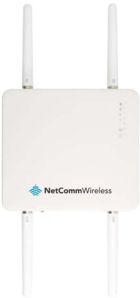
Outdoor HSPA+ WiFi Router with Voice
natural_image
White wireless router device with two 3D antennas and 'NetCommWireless' branding (no additional text or symbols visible)USER GUIDE
Copyright
Copyright© 2012 NetComm Wireless Limited. All rights reserved.
The information contained herein is proprietary to NetComm Wireless Limited. No part of this document may be translated, transcribed, reproduced, in any form, or by any means without prior written consent of NetComm Wireless Limited.

Please note: This document is subject to change without notice.
When this equipment has reached the end of its useful life, it must be taken to a recycling centre and processed separately from domestic waste.
The cardboard box, the plastic contained in the packaging, and the parts that make up this device can be recycled in accordance with regionally established regulations. Never dispose of this electronic equipment along with your household waste. You may be subject to penalties or sanctions under the law. Instead, ask for disposal instructions from your municipal government.
Please be responsible and protect our environment.
NetComm NTC-30WV
| DOCUMENT VERSION | DATE |
| 1.0- Initial document release | 09/10/2012 |
Table 1 - Document Revision History
Table of Contents
Overview 4
Product Introduction 6
Physical Dimensions and Indicators....7
NTC-30WV Default Settings 12
Implementation and Deployment Scenario ....14
Installation and Configuration of the NTC-30WV 15
Captive Power Terminal Block....16
Logging on via the web-based user interface....18
Status 19
Advanced Status 21
Internet Settings 23
Mobile Broadband....23
LAN 28
Routing 30
VPN 35
USSD 42
Wireless Settings 43
Basic 43
Advanced 51
MAC / IP / Port Filter....52
Station List....53
Services 54
Dynamic DNS....54
NTP 54
System Monitor 55
SNMP 56
SMS....57
Auto Dial 67
System....67
Log 67
Load / Save....68
Administration....72
System Configuration....73
TR-069....74
Logoff 75
Reboot 75
Technical Data....76
Additional Product Information....77
Appendix A: Tables....81
Legal and Regulatory 82
Overview
Introduction
This document details the process of installing the NTC-30WV as well as mounting and deployment advice. This advice will include a few demonstration deployments and an explanation of related technologies that are suitable for this Outdoor HSPA+ WiFi Router.
Target Audience
This document is expected to be utilised by system integrators or experienced hardware installers who are comfortable with all aspects of IP based networking and have an understanding of wireless based technologies.
Professional Installation Instructions
Please be advised that due to the unique functions supplied by this product, the device is intended for use with licensed third-parties only. The product will be distributed through controlled distribution channels and should be installed by trained professionals. It will not be sold directly to the general public through retail stores.
- Installation Personnel
This product is designed for specific applications and needs to be installed by qualified personnel who have RF and related rule knowledge. The general user shall not attempt to install or change the settings.
- Installation Location
The product shall be installed at a location where the radiating antenna can be kept at least 30cm from a nearby person in normal operation conditions to meet regulatory RF exposure requirements.
- External Antenna
Use only antennae which have been approved by NetComm Wireless Limited. Non-approved antennae may produce unwanted spurious or excessive RF transmitting power which may lead to the violation of FCC/IC limit and is prohibited.
- Installation Procedure
Please refer to the rest of this manual for further details.
- Warning
Please carefully select the installation position and make sure that the final output power does not exceed the limit set force in relevant rules. The violation of the rules could lead to serious federal penalties. The following maximum Transmit powers should be observed during configuration:
| PEAK TRANSMIT POWER | |
| 802.11b | 16.29 dBm |
| 802.11g | 23.98 dBm |
| 802.11n – 20 MHz | 24.51 dBm |
| 802.11n – 40 MHz | 24.06 dBm |
| AVERAGE TRANSMIT POWER | |
| 802.11b | 14.11 dBm |
| 802.11g | 13.32 dBm |
| 802.11n - 20 MHz | 13.38 dBm |
| 802.11n - 40 MHz | 13.21 dBm |
Table 2: Maximum Transmit Power Levels
Table 3: Average Transmit Power Levels
Prerequisites
Before continuing with the installation of your NTC-30WV, please confirm that you comply with the minimum system requirements below.
• An activated 3G SIM card.
• Device with a working Ethernet or wireless (802.11b/g/n) network adapter
• A Web Browser such as Internet Explorer, Mozilla Firefox, Opera, Safari etc.
Notation
The following symbols are utilised in this installation manual:

The following note requires attention

The following note provides a warning

The following note provides relevant information
Product Introduction
Product Overview
- Industrial-grade outdoor fixed wireless data gateway designed for rugged deployments in remote environments and industrial applications
• Ideal for providing primary and backup wireless connectivity over 3G UMTS networks
• Maximum data speed in downlink 21Mbps (HSDPA) and 5.76Mbps in uplink (HSUPA)
• Embedded high-performance 3G cellular modem supporting HSPA+/EDGE/GPRS
• IP67 and environmentally rated chassis to withstand extreme weather conditions
• Extended temperature tolerance in operation -25 to 75°C
• 2.4 GHz band wireless LAN access point with 2x2 MIMO antenna technology
• IEEE 802.11n standard for wireless data speeds up to 300Mbps - Ethernet 10/100 connectivity with Power over Ethernet Injector for universal deployment
• Analogue telephone connectivity (CS Voice) for complete landline replacement (optional configuration)
• Alternative DC power input available as a optional extra to suit diverse installation environments
• Built-in VPN clients for a secure connection over a public cellular network
Package Contents
The NTC-30WV series package consists of:
• NetComm NTC-30WV - Outdoor HSPA+ WiFi Router
• 2 x WiFi Antennas (N Type female)
• 2 x 3G Antennas (N Type female)
- Mounting Bracket
• 4 x Wall mounting screws (Diameter = 6mm, Length = 25mm)
• 4 x Mounting screws (Diameter = 6mm, Length = 14.85mm)
• IP67 Water-proof Plug Cable Gland
- Ferrite Core
• 2 x Hose Clamps for pole mounting
• Wireless Security Card
• Power DC cable 10m (open ended)
If any of these items are missing or damaged, please contact NetComm Support immediately by visiting the NetComm Support website at: http://www.netcommwireless.com/contact-forms/support
Product Features
The NetComm Wireless outdoor router (NTC-30WV) is designed to deliver high speed internet to homes and businesses with otherwise little to no Internet access available. The NTC-30WV is a robust 3G (HSPA+) router which can be pole or wall mounted and connects to a 3G network. The NTC-30WV features a powerful antenna system and wireless radio together in a single unit. This tight integration between the radio receiver and antenna system in an outdoor unit provides great benefits to signal strength compared with separated solutions involving signal degradation along lengthy antenna cabling.
The integrated telephone adapter connects a standard analogue phone handset to the NTC-30WV. It allows for phone calls to be made over the 3G UMTS network for a full landline replacement. The router integrates a powerful Sierra Wireless module (MC8704) and delivers download speeds of up to 21Mbps which is then transmitted via Ethernet to a WiFi router inside the property.
Power is delivered to the outdoor router via Power over Ethernet technology making installation quick and easy as there is no power source required at the outdoor mount point, and both power and data can be provided via a single cable from inside the property. With an IP67 rating, the device also withstands diverse temperature and weather environments.
Physical Dimensions and Indicators
LED Indicators
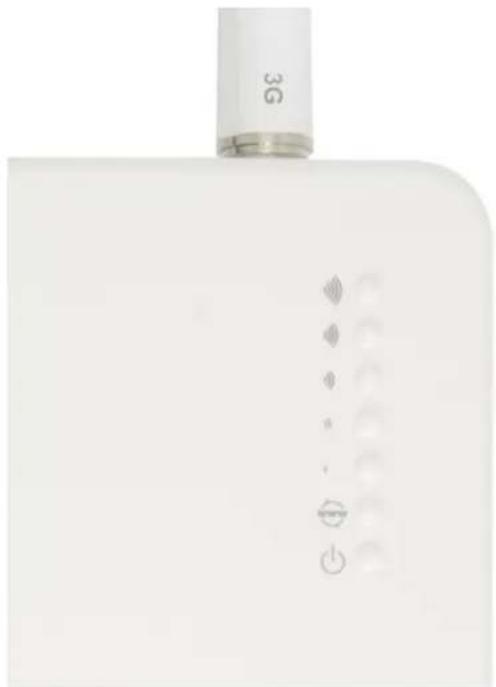
The NTC-30WV uses 7 LEDs to display the current system and connection status.
natural_image
White electronic device with 3G label and indicator lights (no readable text or symbols beyond branding)Figure 1 - NTC-30WV LED Indicators
| NTC-30WV | |||
| LED INDICATOR | ICON | COLOUR | DEFINITION |
| High Signal | (2000) | Green | High 3G Signal strength available. |
| Medium to High Signal | (8044) | Green | Medium to High 3G Signal strength available. |
| Medium Signal | (4746) | Green | Medium 3G Signal strength available. |
| Low to Medium Signal | (2853) | Green | Low to Medium 3G Signal strength available. |
| Low Signal | (###) | Green | Low 3G Signal strength available. |
| Internet | (8Y62) | Green | Router is currently connected to the Internet. |
| Power | (0ZAS) | Red | Unit is powered on. |
Table 4 - LED Indicators
The 5 LEDs also indicate whether the device is MEP locked, SIM is not inserted and if the SIM is PIN or PUK locked by flashing in certain patterns. Below is a table outlining the various LED flash sequences and their meanings.
| LED PATTERN | DESCRIPTION |
| All signal LEDs flash ON and OFF every 2 seconds | SIM not inserted |
| The signal LEDs flash in a pattern with one, three and 5 LEDs flashing in a sequence. | MEP Lock |
| The signal LEDs flash in a sequential order starting with the Low signal LED to the High signal LED. | SIM is PIN locked |
| The signal LEDs flash in a sequential order starting with the High signal LED to the Low signal LED. | SIM is PUK locked |
Physical Dimensions
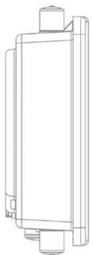
The following page lists the physical dimensions of the NTC-30WV, as well as the physical dimensions of the antennas and the included mounting bracket which can be used to attach the NTC-30WV to a pole or to provide a wall / ceiling mount.
natural_image
Technical line drawing of a mechanical component with mounting flanges (no text or symbols)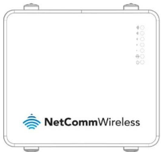
Figure 2 - NTC-30WV Dimensions
| NTC-30WV(WITHOUT ANTENNAS ATTACHED) | |
| Length | 255 mm |
| Depth | 80 mm |
| Height | 240 mm |
| Weight | 1750 g(w/o mounting bracket and antennas) |
Table 5 - Device Dimensions

natural_image
Pure geometric diagram with circles and rectangles inside a rectangle, no text or symbols presentFigure 3 - NTC-30WV Mounng Bracket
| NTC-30WV MOUNTING BRACKET | |
| Length | 110 mm |
| Depth | 12 mm |
| Height | 290 mm |
| Weight | 410 g(w/o NTC-30WV attached) |
Table 6 - Mounng Bracket Dimensions

Figure 4 - NTC-30WV Antenna
| NTC-30WV 3G AND WIFI ANTENNA | |
| Length | 180 mm |
| Diameter | 20 mm |
| Weight | 60 g(w/o NTC-30WV attached) |
Table 7 - Antenna Dimensions
Interfaces
The following interfaces are available on the NTC-30WV:
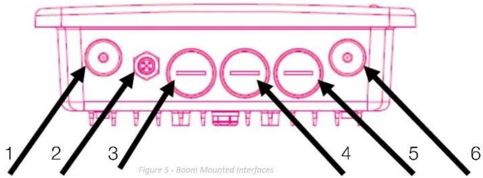
| ITEM | INTERFACE | FUNCTION |
| 1 | WiFi Antenna Connector (TNC) | Connect one of the WiFi antennas here. |
| 2 | DC Power Port | Connect the optional DC Power supply to the NTC-30WV. |
| 3 | 10/100Base-TX Ethernet RJ-45 (w/Auto MDX) Port | Connect the NTC-30WV to an Ethernet enabled device or Switch and deliver power through Power over Ethernet (PoE) technology. |
| 4 | RJ-11 Port. | An analogue phone handset can be connected to the RJ-11 to make calls over the 3G network. |
| 5 | Mini USB 2.0 Console Port | Connect a Mini USB cable to access the NTC-30WV console. |
| Reset | Reset the NTC-30WV to Factory Defaults. | |
| SIM Card Reader | Insert an active SIM to provide 3G connectivity. | |
| 6 | WiFi Diversity Antenna Connector (TNC) | Connect one of the WiFi antennas here. |
Table 8 - Boom Mounted Integrated Interfaces
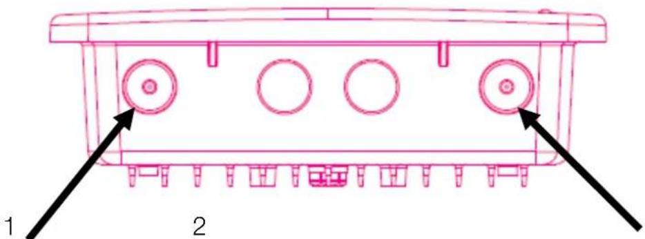
Figure 6 - Top Mounted Interfaces
| ITEM | INTERFACE | FUNCTION |
| 1 | 1 x 3G Main antenna connector (Type N) | Connect one of the 3G antennas here. |
| 2 | 1 x 3G Aux antenna connector (Type N) | Connect one of the 3G antennas here. |
Table 9 - Top Mounted Interfaces
NTC-30WV Default Settings
The following tables list the default settings for the NTC-30WV.
| LAN (MANAGEMENT) | |
| Static IP Address: | 192.168.1.1 |
| Subnet Mask: | 255.255.255.0 |
| Default Gateway: | 192.168.1.1 |
Table 10 - LAN Management Default Sengs
| WIRELESS (WIFI) | |
| SSID: | NetComm XXXX(where XXXX is 4 random numbers) |
| Security: | WPA2-PSK |
| Security Key: | XXXXXXXXX(whereXXXXXXXXX are 10 random characters) |
Table 11 – WiFi Default Sengs

For security purposes, it is recommended to change the Default SSID and Wireless Security Key.
| ADMIN MANAGER ACCOUNT | ROOT MANAGER ACCOUNT | ||
| Username: | admin | Username: | root |
| Password: | admin | Password: | admin |
Table 12 - Web Interface Default Sengs

Note: The admin manager account allows you to manage most of the settings of the router except functions such as Firmware Upgrade, Device Configuration Backup, Mobile Broadband Connection settings, and Reset to Factory Default Settings, which are privileged only to the root manager account. First time users should use the root manager account to configure Mobile Broadband settings.
Restoring Factory Default Settings
Restoring the NTC-30WV factory default settings will erase any configuration changes you have made. You may encounter situations where you need to restore the factory defaults on your router, such as:
• You have lost your username and password and are unable to login to the web configuration page.
• You are asked to perform a factory reset by support staff.
There are two methods you can use to restore factory default settings on your NTC-30WV:
• Using the web-based user interface
• Using the reset button on the interface panel of the router
Using the web-based user interface
In order to restore your router to its factory default settings, please follow these steps:
- Ensure that your NTC-30WV router is powered on (for at least 10 seconds);
- Use a paper clip or a pencil tip to depress the reset button for ten seconds and release. At this point, the reset is in progress. Do not power off the unit.
- Logon to the default web interface page at http://192.168.1.1 using root as the User Name and admin as the password. You will be re-directed into the gateway recovery mode. Select the System menu option and then click Load/Save. Press the Restore button to complete the factory reset.
- When the Power light returns to a steady red, the reset is complete. The default settings are now restored. The entire process takes about 45 seconds to complete.
Using the reset button on the interface panel of the router
Hold the reset button down until all LEDs on the front panel of the router stop flashing simultaneously and then release the button. The router will restore the factory default settings and reboot.
Once you have reset your NTC-30WV to its default settings you will be able to access the device's configuration web interface using http://192.168.1.1 with username admin and password admin.
Implementation and Deployment Scenario
The NTC-30WV is a robust 3G (DC-HSPA+) router that connects to the 3G network and is mounted either on the wall or a pole and positioned in an optimal position on the outside of a property. The NTC-30WV features a powerful antenna system and radio modem together in the one unit in an outdoor location. This tight integration between the radio receiver and antenna system in an outdoor unit provides great benefits to signal strength compared with alternate separated solutions involving signal degradation along lengthy antenna cabling.
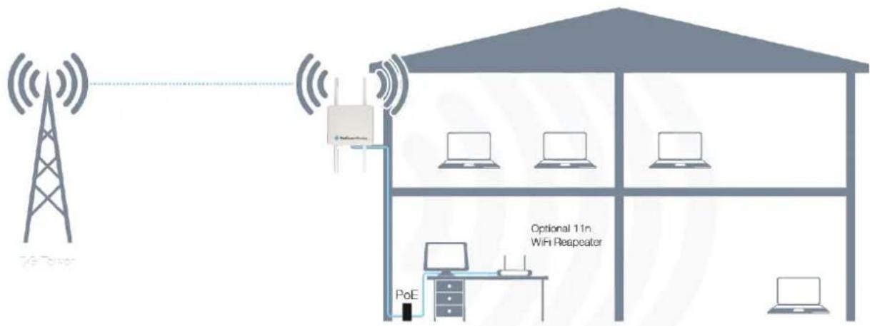
Figure 7 - Typical NTC-30WV Deployment - House
Power is delivered to the outdoor router via Power over Ethernet technology (as shown above) making installation quick and easy as there is no power source required at the outdoor mount point, and both power and data can be provided via a single cable from inside the property. With an IP67 rated enclosure, the device also withstands diverse temperature and weather environments. Utilising an 802.11n WiFi repeater further increases the WiFi range of the NTC-30WV meaning a wireless connection is possible in all corners of your house or property.
The NTC-30WV is able to be mounted either to a pole or secured directly to a wall, allowing flexibility in the choice of an installation location.
Installation and Configuration of the NTC-30WV
Hardware Installation
Please refer to the NTC-30WV Installation Guide (available from the NetComm Wireless website) for instructions on assembling, mounting and placing the NTC-30WV.
Powering the Router via DC Power Supply
Below is a diagram summarising the assembly when connecting via DC power supply. Please refer to page 7 of the Quick Start Guide for more detail on how to connect the NTC-30WV via DC Power Supply.
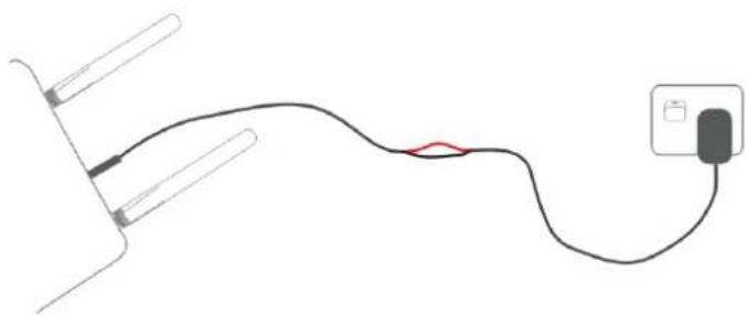
natural_image
Simple line drawing of a cable with wires and a plug, no text or symbols presentFigure 8 - Example of how to connect the NTC-30WV when connecng via DC power supply
Powering the Router via a Power over Ethernet (PoE) Cable (Optional)
Please refer to the Installation Guide for step-by-step instructions on connecting the devices.
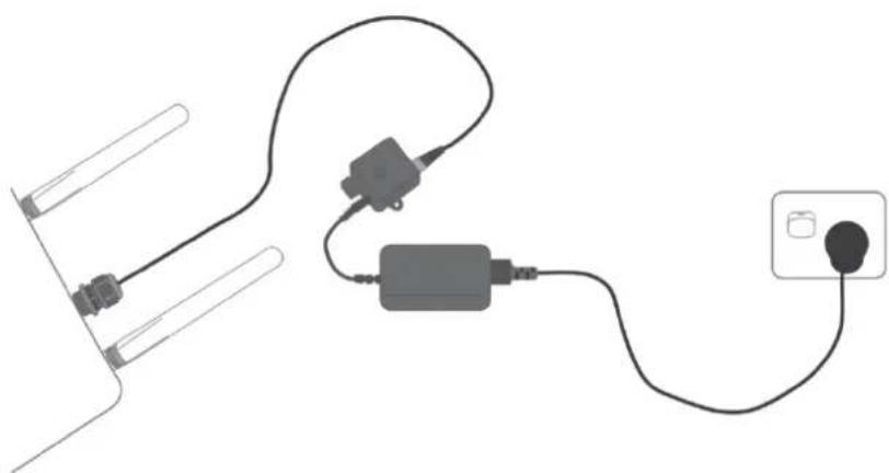
Below is a diagram summarising the assembly when connecting via optional Power over Ethernet cable.
natural_image
Pure electrical circuit lines without any symbolsFigure 9 – Example of how to connect the NTC-30WV when connecting via oponal Power over Ethernet (PoE) cable

Note: The DC Injector supplies 48V. Do not use this power supply for anything except for powering the outdoor gateway.
Captive Power Terminal Block
The following table displays the pin outs for the Locking Power Block on the PoE Injector.
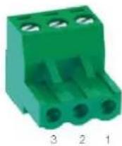
Figure 10 - Locking Power Terminal Black
| PIN | SIGNAL | DESCRIPTION |
| 1 | V+ | Voltage+ |
| 2 | GND | Ground |
| 3 | V- | Voltage- |
Table 13 - Locking Power Block Pin Outs
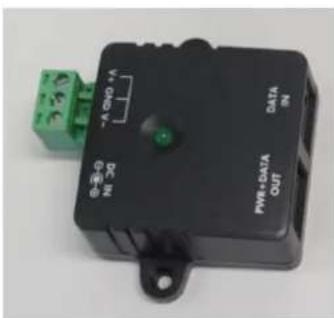
Figure 11 - Assembly of the PoE Injector and the Capve Terminal Block
Connecting wirelessly
- Ensure WiFi is enabled on your device (e.g. computer/laptop/smartphone).
- Scan for wireless networks in your area and connect to the network name that matches the Wireless network name configured on the NTC-30WV. The default wireless network name is printed on the security card included in the package.
- When prompted for your wireless security settings, enter the Wireless security key configured on the NTC-30WV.
- Wait approximately 30 seconds for the connection to establish.
Configuring the NTC-30WV
Logging on via the web-based user interface
To log in to the management console and view the status and make changes to your NTC-30WV, please follow the steps below:
- Open your web browser (e.g. Internet Explorer/Firefox/Safari) and navigate to http://192.168.1.1
- Enter the username and password configured during the first time setup and click the Submit button. The default username and password is admin if the details haven't been customized. Click the Submit button to continue.
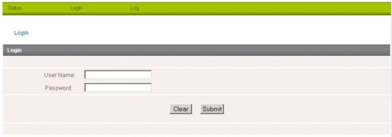
Figure 12 - Login prompt for the Web based User Interface
After logging in, the Status page is displayed.
Status
The status page provides system related information and is displayed when you login to the NTC-30WV management console. By default, the status page will show System Information, Ethernet Port Status, WWAN Status, IPsec Status and the 3G service connection details.
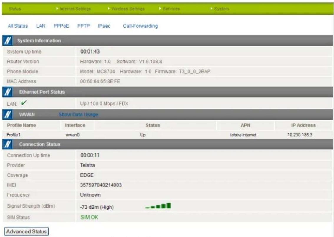
Figure 13 - The Status Page
| ITEM | DEFINITION |
| System Uptime | The current uptime of the router. |
| Router Version | The firmware version running on the router. |
| Phone Module | The type of phone module, the firmware version of the module and the current module temperature. |
| MAC Address | The MAC Address of the router which serves as a unique identifier of network devices. |
| Ethernet Port Status | The current speed and status of the Ethernet port. |
| WWAN | The current connection profile, Interface, status, APN, and local address of the WWAN connection. |
| IPsec | The current connection profile, Interface, status, Local LAN address, Remote Gateway address, Remote LAN address and the status of the IPsec connection. If none are configured, this should be empty. |
| Provider | The current 3G service provider detected. |
| Coverage | The type of 3G connection available for use. |
| IMEI | The IMEI of the router. |
| Frequency | The frequency band currently in use. |
| Signal Strength | The strength of the 3G signal detected |
| SIM Status | The status of the SIM currently inserted into the router. |
Table 14 - Status page items
To view the LAN, PPPoE or PPTP status individually, click on the links below the green menu bar. To view them all, click on the All Status link.

LAN
IP
192.168.1.1 / 255.255.255.0
MAC Address
02:00:88:CC:20:8D
Figure 14 - Status Page - LAN Details
| ITEM | DEFINITION |
| IP | The current LAN IP Address and Subnet Mask. |
| MAC Address | The current MAC Address of the LAN port. |
Table 15 - Status Page - LAN Details

PPPoE
PPPoE Status
DISABLED
PPPoE IP Address
N/A
Figure 15 - Status Page - PPPoE Details
| ITEM | DEFINITION |
| PPPoE Status | The current status of the PPPoE connection. |
| PPPoE IP Address | The current PPPoE IP Address in use. |
Table 16 - Status Page - PPPoE Details

PPTP
PPTP Status
DISABLED
PPTP IP Address
PPTP P-t-P
Figure 16 - Status Page - PPTP Details
| ITEM | DEFINITION |
| PPTP Status | The current status of the PPTP connection. |
| PPTP IP Address | The current PPTP connection IP Address. |
| PPTP P-t-P | The current PPTP Remote Gateway Address. |
Table 17 - Status Page - PPTP Details

IPSec
| No. | Profile Name | Interface | Local LAN | Remote Gateway | Remote LAN | Status |
Figure 17 - Status Page - IPSec Details
| ITEM | DEFINITION |
| No. | The IPsec tunnel number. |
| Profile Name | The name assigned to the IPsec profile. |
| Interface | The current interface used by the IPsec tunnel. |
| Local LAN | The local IP address making up one end of the IPsec tunnel. |
| Remote Gateway | The WAN gateway of the other end of the IPsec tunnel. |
| Remote LAN | The WAN IP Address that the IPsec tunnel is connecting to. |
| Status | The current condition of the IPsec tunnel. |
Table 18 - Status Page - IPSec Details

Call Forwarding Status
Call Waiting
Disabled
Unconditional Call
Disabled
Forwarding
Busy Call Forwarding
Enabled (-61101)
No-Reply Call Forwarding
Enabled (-61101)
Not Reachable Call
Enabled (+61101)
Forwarding
Figure 18 - Status Page - Call Forwarding Status Details
| ITEM | DEFINITION |
| Call Waiting | Displays the status of the call waiting function. |
| Unconditional Call Forwarding | Displays the status of unconditional call forwarding. Unconditional call forwarding is a forward placed on all calls as soon as they reach the phone, regardless of the status of the handset. |
| Busy Call Forwarding | Displays the status of the busy call forwarding function and the destination calls are forwarded to in the case where the phone is busy and an incoming call is received. |
| No-Reply Call Forwarding | Displays the status of the no-reply call forwarding function and the destination calls are forwarded to in the case that a call is received and goes unanswered. |
| Not Reachable Call Forwarding | Displays the status of the not reachable call forwarding function and the destination calls are forwarded to in the case that a call can't be routed to a handset. |
Table 19 - Status Page - Call Forwarding Status Details
Advanced Status
To view further information regarding the phone module onboard the gateway and the current connection press the "Advanced Status" button.
Status
▶ Internet Settings
Wireless Settings
Services
System
Status > Advanced Status
Module Information
| Phone Module | Model: MC8704Hardware: 1.0Firmware: T3_0_0_2BAP R474 CNSZXD00000128 2011/11/25 10:13:57 |
| Module Boot Version | T3_0_0_2BBT R474 CNSZXD00000128 2011/11/25 10:13:57 |
| Module PRIID | Revision: 1.0 PRI Part Number: 9901561 |
| System Up time | 00:47:13 |
Connection Status
| Provider | Telstra |
| Country Code | 505 |
| Network Code | 1 |
| Coverage | UMTS |
| Connection Status | Up |
| IMEI | 357597040214003 |
| Frequency | WCDMA850 |
| Signal Strength | -73 dBm |
| Signal Quality (Ec/lo) | -22 dB |
| Received Signal Code Power (RSCP) | -78 dB |
| HSUPA Category | 6 |
| HSDPA Category | 14 |
| SIM ICCID | 89610191498543000007 |
| Primary Scrambling Code (PSC) | 96 |
| Location Area Code (LAC) | 337 |
| Routing Area Code (RAC) | 0 |
| IMSI | 50501505013473874378 |
| Cell ID | 19796 |
| Channel Number | 4412 |
| ITEM | DEFINITION |
| Phone Module | The phone module name, hardware and firmware version |
| Module Boot version | The installed bootloader version of the phone module. |
| Module PRID | The Protocol ID of the phone module. |
| System Uptime | The time in minutes and seconds that the gateway has been up. |
| Provider | The current connection's 3G provider. |
| Country Code | Each country has a unique code that helps to identify the 3G network. |
| Network code | Each 3G provider has a unique network code for network identification purposes. |
| Coverage | The coverage type of 3G service the current connection is using. |
| Connection Status | The current status of the gateway's connection. |
| IMEI | The International Mobile Equipment Identity number unique to each cellular network device. |
| Frequency | The frequency of the current connection. |
| Signal Strength (dBm) | The signal strength of the 3G connection measured in decibels. |
| Signal Quality (Echo/Location) | A measurement of the portion of the received signal that is usable. This is basically the signal strength minus the signal noise level. |
| Received Signal Code Power (RSCP) | The power level of the signal on the current connection's particular channel. |
| SIM ICCID | The Integrated Circuit Card Identifier of the SIM card used. A unique number up to 19 digits in length. |
| Primary Scrambling Code (PSC) | The Primary Scrambling Code for the current signal. |
| Location Area Code (LAC) | The ID of the cell tower grouping the current signal is broadcasting from. |
| Routing Area Code (RAC) | The Routing Area Code is a subset of the Location Code and helps to identify the group of or individual cell towers the current connection is broadcasting from. |
| IMSI | The International Mobile Subscriber Identity is a unique identification for the current 3G connection. |
| Cell ID | A unique code that identifies the base station from within the Location Area of the current 3g signal. |
| Channel Number | The channel number of the current 3G connection. |
Figure 19 - Advanced Status Page
Table 20 - Advanced Status Page
Internet Settings
This section describes how to set up the router to initiate a WWAN connection. There are 2 different ways to set up a WWAN connection via PPP:
• Initiating the PPP Connection directly from the router (most common).
- Initiating the PPP Connection from a different PPP client (i.e. laptop or router) with the router running in transparent PPPoE mode.
Mobile Broadband
Connection
Click on the "Internet Settings" menu followed by "Mobile Broadband" and then the "Connection" menu item on the right.
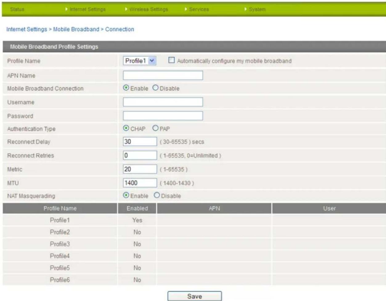
Figure 20 - Connecon Sengs
NetCommWireless
To connect using a Connection profile
The router supports multiple APN profiles; these profiles allow you to configure the settings that the router will use to connect to the 3G network. By default, the "Automatically configure my mobile broadband" option is selected. This automatically detects the most appropriate APN from the inserted SIM by querying a database on the router.
You can also manually enter the connection details by performing the following steps:
- Remove the check from the "Automatically configure my mobile broadband" box
- Select the profile that you wish to configure from the "Profile Name" drop down list.
- Enter the APN Name (Access Point Name) and if required, the username and password.
- Select Enable for the "Mobile Broadband Connection" option. If there is already another profile enabled you will need to select that profile first and disable it since only one profile can be used at a time.
- Select the Authentication Type.
- Enter the Reconnect Delay (if needed - the default should be suitable in most cases).
- Enter the number of Reconnection attempts the router should make.
- Enter the network metric for the connection.
- Select to enable or disable NAT Masquerading for the connection.
- Click Save.
To confirm successful connection
Click on the Status menu item at the top of the page to return to the Status page.
If the Mobile Broadband connection has been established successfully, the WWAN status will be "Up". The IP Address field shows the current IP address that the network has allocated for the router. The mobile broadband internet connection is now ready to use.
Restoring the Automatic Configuration option after manually configuring an APN profile
When you have manually configured an APN and want to have the router automatically configure your broadband connection again, you must first set "Mobile Broadband Connection" to Disable for that profile and then remove the APN Name from the "APN Name" field and click "Save". This is because the router saves the manually configured APN profile in flash memory and will always try to connect to that APN first regardless of whether "Automatically configure my mobile broadband" is enabled.
PPPoE
The PPPoE page is used to configure a transparent PPPoE connection. This can be used to provide a bridged connection. To enable PPPoE mode, firstly ensure the "Auto Connect" is disabled in all the profiles on the "Connection" configuration page by clicking on the "Internet Settings" menu followed by "Mobile Broadband" and then the "Connection" menu item on the right. Select each connection profile and disable the Auto Connection option then save the updated settings.

Internet Settings > Mobile Broadband > PPPoE

Figure 21 - PPPoE Sengs
- Select "Enable" to enable PPPoE.
- Specify the APN supplied by your 3G provider.
(Optional)
- Specify a "Service Name".
This is particularly useful if you have more than one PPPoE router or modem on a single Ethernet network.
Click "Save" to save your settings and enable PPPoE.
Band / Provider
The band settings page enables you to select which frequency band you will use for your connection and enables you to scan for available network operators in your area.
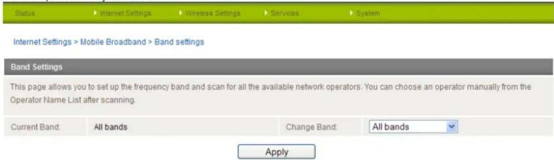
Figure 22 - Band / Provider Selecon
You may want to do this if you're using the router in a country with multiple frequency networks that may not all support HSPA. You can select the router to only connect on the network frequencies that suit your requirements. Select a band from the "Change Band:" drop down list.
The following band settings options are available:
WCDMA 900/2100
WCDMA ALL
GSM ALL
GSM 900/1800
All Bands
In most cases it is not necessary to change the default setting of "All bands". When "All bands" is selected, the router attempts to find the most suitable band based on the inserted SIM card.
You can also scan for available 3G service providers in your area by selecting "Manual" for the "Current Operator Selection Mode" and then clicking the scan button.

Figure 23 - Manual Operator Selecon
A list of the detected 3G service carriers in your area will be displayed. Select the most appropriate 3G service from the list shown and click "Apply".
The "Automatic" option is sufficient for most users. It will choose the most appropriate operator based on the inserted SIM card.
SIM Security
If the SIM card is locked you will need to unlock it with a PIN provided with your SIM card.
You can find out if the SIM is locked by viewing the SIM Status on the Status page:
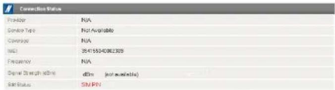
Figure 24 - SIM Security - Status Page Warning
If the SIM Status is "SIM PIN" as above then do the following:
- Click on the "Internet Settings" menu at the top of the page and then the "SIM Security" item from the WWAN (3G) menu item on the right.
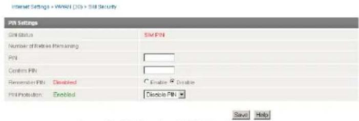
Figure 25 - SIM Security - SIM PIN Needed
- Enter the PIN code in the "PIN" field and then enter it again in the "Confirm PIN" field to confirm the PIN code.

Note: You can also select to "Remember PIN" so that entering the PIN code each time the SIM is inserted is not required. Alternatively you can also disable SIM PIN protection by selecting to "Disable PIN" from the "PIN Protection" drop down menu.
- Click Save.
Enter PUK
After three incorrect attempts at entering the PIN code, you are requested to enter a PUK code.

Note: You will need to contact your 3G provider to obtain this number.
Your carrier will issue you a PUK code to enable you to unlock the SIM and enter a new PIN code. Enter the new PIN and PUK codes and click Save.
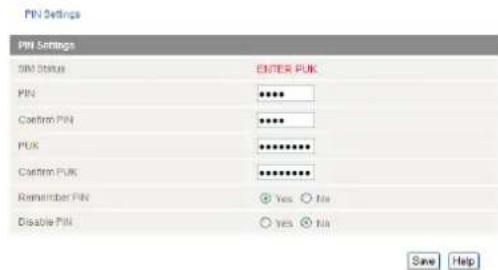
Figure 26 - SIM Security - SIM PUK Needed
Remember PIN
This feature allows the router to automatically send the PIN to the SIM each time the SIM asks for it (usually at power up). This enables the SIM to be PIN Locked (to prevent unauthorised re-use of the SIM elsewhere), while still allowing the router to connect to the cellular service.
When this feature is enabled the PIN entered by the user when they set the "Remember PIN" feature is encrypted and stored locally in the router. The next time the SIM asks the router for the PIN the router decrypts the PIN and automatically sends it to the SIM without user intervention.
When this feature is disabled and the SIM is PIN locked, the PIN must be manually entered via the router's configuration interface. This is clearly not desirable where the router is unattended.
LAN
IP Setup
The IP Setup page is used to configure the LAN Settings of the router and to enable or disable DNS Masquerade.
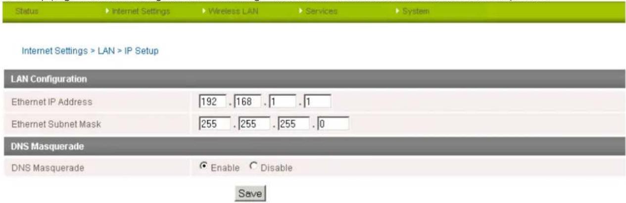
Figure 27 - IP Setup Sengs
The default IP of the Ethernet port is 192.168.1.1 with subnet mask 255.255.255.0.
To change this, enter the new IP Address and/or Subnet mask and click "Save".

Note: If the IP address has changed you will have to re-enter the new IP address configured in your browser to access the configuration pages.
DNS Masquerading
DNS masquerading allows the router to forward DNS requests to dynamically assigned DNS servers. Clients on the router's LAN can then use the router as a DNS server without needing to know of the dynamically assigned DNS servers assigned by the cellular network.
There should be no need to disable this feature in most cases, however, if you need to do so simply select "Disable" and click the Save button.
DHCP
The DHCP page is used to adjust the DHCP settings used by the router. The DHCP settings are then passed onto any device connecting via DHCP.
You can manually set the DHCP Start and End range, the DHCP Lease time, the default Domain name suffix, Primary and Secondary DNS Server, the Primary and Secondary WINS Server, as well as the NTP, TFTP and Option 150/Option 160 (VoIP options) settings.
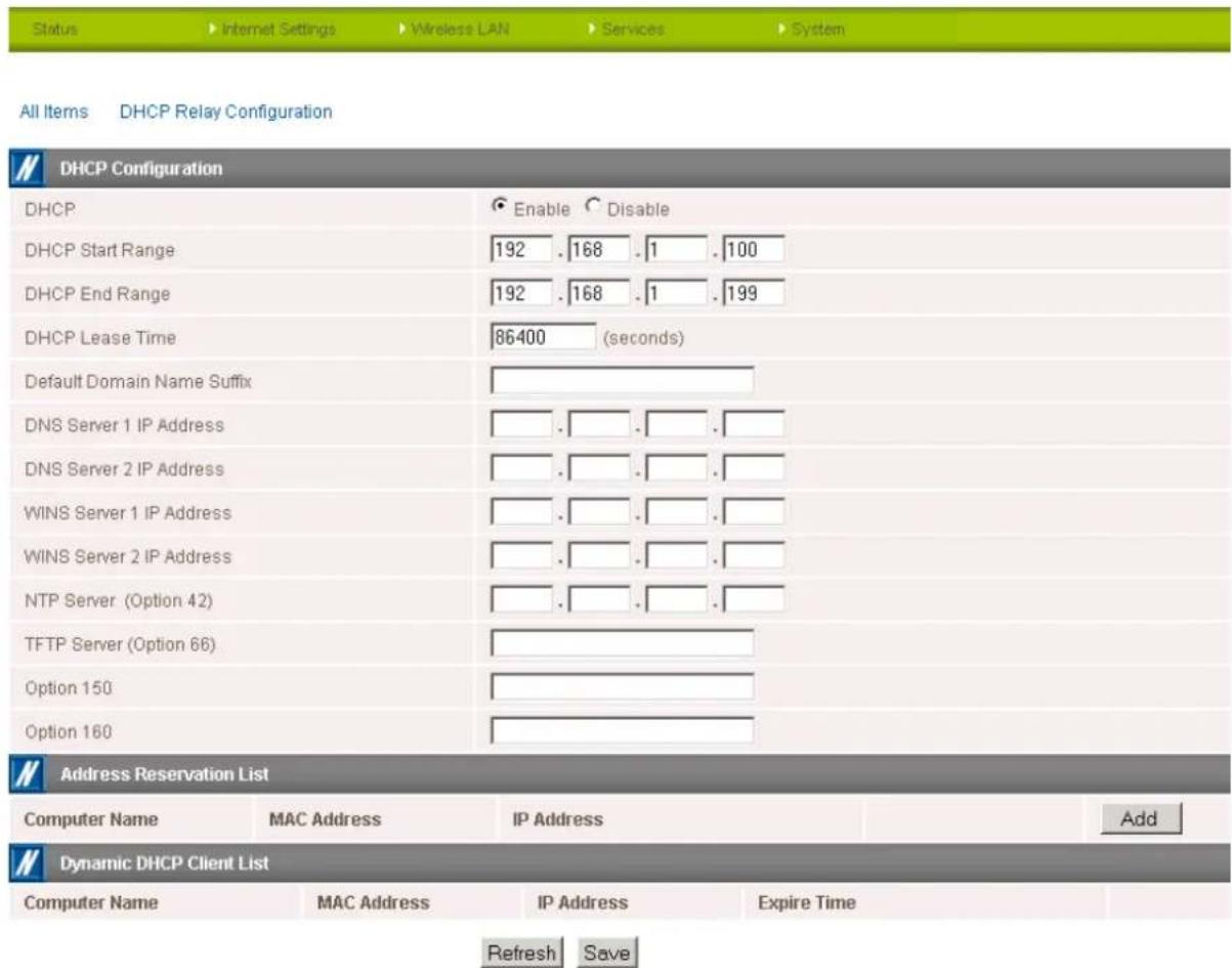
Figure 28 - DHCP Sengs
After entering the applicable details, click the "Save" button.
You can also assign a particular IP address to a specific device every time that device makes a DHCP request as follows:

Figure 29 - DHCP Sengs - Fixed Mapping
- Click the "Add" button.
- Enter a name for the computer or device into the "Computer Name" textbox.
- Enter the computer's or device's MAC address into the "MAC Address" textbox.
- Enter the IP address you wish to assign to the device in the IP Address text boxes.
- Select the Enable checkbox to enable the rule.
- Click the "Save" button to save the new settings.
Routing
Static
The Static Route page is used to add or delete static routes. Static routes can be used to facilitate communication between devices on different networks.
| Status | Internet Settings | Wireless Settings | Services | System | |||
| Internet Settings >Routing >Static | |||||||
| Enabled Profile List | |||||||
| Profile Name | Interface Name | IP Address | Default Route | NAT Masquerading | |||
| Enabled Profile List is empty | |||||||
| Static Routes | |||||||
| Item No. | (1-65535) Only required if you want to edit the existing mapping! | ||||||
| Route Name | |||||||
| Destination IP | . . . . . . . | ||||||
| Subnet Mask | . . . . . . . | ||||||
| Gateway IP | . . . . . . . | ||||||
| Network Interface | auto✓ | ||||||
| Metric | (0-65535) | ||||||
| Add | |||||||
| Item No. | Route Name | Destination IP | Subnet Mask | Gateway IP | Network Interface | Metric | |
| 0 | Static Route 1 | 192.168.1.3 | 255.255.255.0 | 192.168.1.1 | auto | 1 | Delete Entry |
| Active Routing Table | |||||||
| Item No. | Destination IP | Subnet Mask | Gateway IP | Network Interface | Metric | Flags | Ref Use |
| 0 | 192.168.1.0 | 255.255.255.0 | 0,0,0,0 | br0 | 0 | U 0 | 0 0 |
Figure 30 - Stac Route Sengs
Some routes are added by default by the router on initialisation such as the Ethernet subnet route for routing to a device on the Ethernet subnet. A PPP route is also added upon obtaining a WAN PPP connection.
Adding Static Routes
- Enter the required values in the fields (as shown above) for route being added.
- Click the "Add" button.

Note: You must increment the "Route no" by 1 for each route in the "Route no" field otherwise that route will be overwritten.
The Static Route will be displayed at the bottom of the Static Routes section.
Deleting Static Routes
Click the "Delete Entry" text (in blue).
RIP
RIP (Routing Information Protocol) is used for advertising routes to other routers. Thus all the routes in the router's routing table will be advertised to other nearby routers. For example, the route for the router's Ethernet subnet could be advertised to a Router on the PPP interface side so that a Router on this network will know how to route to a device on the router's Ethernet subnet. You will have to add the routes appropriately in the Static Routes section – see Adding Static Routes.

Note: Some routers will ignore RIP.
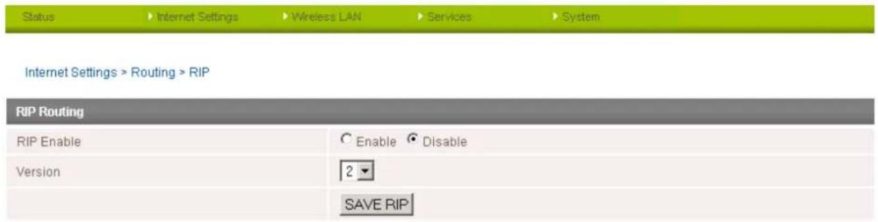
Figure 31 - RIP Sengs
- Click the Enable option on the RIP Page.
- Select the RIP version you wish to use.
- Click the "Save RIP" button to save the settings.
VRRP
Virtual Router Redundancy Protocol (VRRP) is a non-proprietary redundancy protocol designed to increase the availability of the default gateway servicing hosts on the same subnet. This increased reliability is achieved by advertising a "virtual router" (an abstract representation of master and backup routers acting as a group) as a default gateway to the host(s) instead of one physical router. Two or more physical routers are then configured to stand for the virtual router, with only one doing the actual routing at any given time. If the current physical router that is routing the data on behalf of the virtual router fails, an arrangement is made for another physical router to automatically replace it. The physical router that is currently forwarding data on behalf of the virtual router is called the master router.
Master routers have a priority of 255 and backup router(s) can have priority between 1 and 254.
A virtual router must use 00-00-5E-00-01-XX as its (MAC) address. The last byte of the address (XX) is the Virtual Router Identifier (VRID), which is different for each virtual router in the network. This address is used by only one physical router at a time, and is the only way that other physical routers can identify the master router within a virtual router.

Internet Settings > Routing > VRRP
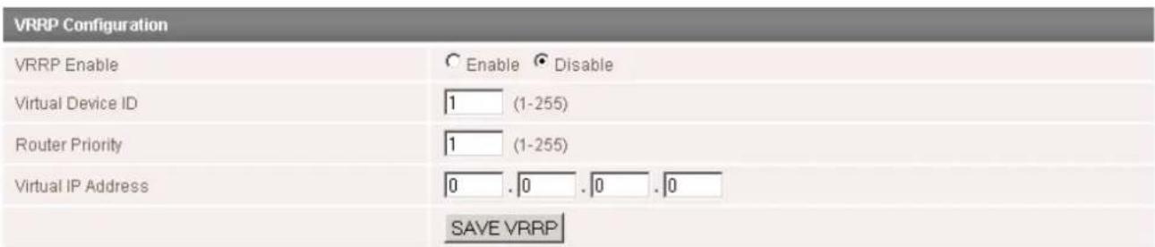
Figure 32 - VRRP Sengs
- Click Enable to activate the VRRP service.
- Enter an ID - this is the VRRP ID which is different for each virtual router on the network.
- Enter a priority - a higher value is a higher priority.
- Enter the VRRP IP address – this is the virtual IP address that both virtual routers share.
- Click the "Save VRRP" button.

Note: Configuring VRRP changes the MAC address of the Ethernet port and therefore if you want to resume with the web configuration you must use the new IP address (VRRP IP) or on a command prompt type: arp -d
NAT
The NAT page is used to configure the Network Address Translation rules currently in use on the router. The router is in NAT mode by default.
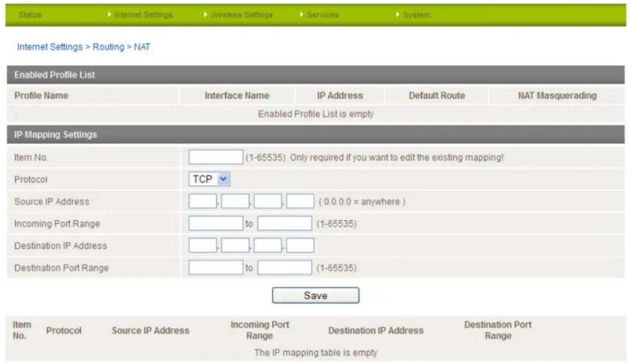
Figure 33 - NAT Sengs
This is only needed if you need to map inbound requests to a specific port on the WAN IP address to a device connected on the Ethernet interface, e.g. a web camera.
How to configure Port Forwarding
| OPTION | DEFINITION |
| Mapping no | Number to identify the port mapping, numbered from 1 to as many as needed. |
| Protocol | Specify the protocol to use for the port mapping. Options include TCP, UDP and All protocols. |
| Source IP Address | This field specifies either a “Friendly” IP address that is allowed to access the router or a wildcard IP address of 0.0.0.0 that allows all IP addresses to access the router. |
| Incoming Port Range | This field specifies the external port(s) to listen to. |
| Destination IP Address | The Local Area Network Address of device to forward inbound requests to. |
| Destination Port Range | The Local Area Network Port(s) to forward connections to. |
Table 21 - NAT Conguraon Items
- Enter the IP Mapping configuration information as appropriate.
- Click the "Save" button to save any changes to the settings.

Note: If the "Incoming Port Range" specifies a single port (as above) then the destination port can be set to any port. If the "Incoming Port Range" specifies a range of port numbers then the "Destination Port Range" MUST be the same as the "Incoming Port Range".
To delete a port forwarding rule, click on the corresponding "Delete Entry" link from the list of IP Mappings.
DMZ
The Demilitarised Zone (DMZ) enables a device to utilise a direct connection to the WAN. This means any incoming connections are forwarded directly to this device.
The DMZ page is used to specify the IP Address of the device to this feature.
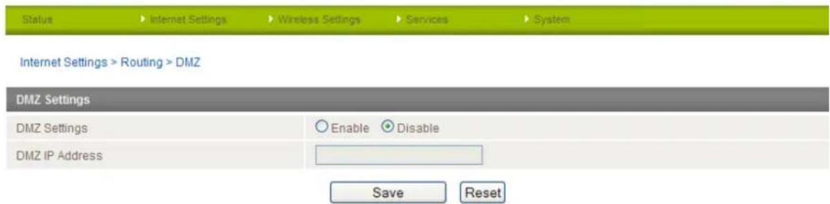
Figure 34 - DMZ Sengs
- Click the "Enable" button.
- Enter the IP Address of the device you wish to become the DMZ host.
- Click the "Save" button.
VPN
A Virtual Private Network (VPN) is a tunnel providing a private link between two networks or devices over a public network. Data to be sent via a VPN tunnel needs to be encapsulated and as such is generally not visible to public networks. The advantages of a VPN connection include:
• Data Protection
- Access Control
• Data Origin Authentication
Data Integrity
How to configure a VPN connection
Move your mouse over the Internet Settings menu and then move your mouse over VPN. You can select from the following types of VPN connection:
IPSec
PPTP-Client
OpenVPN
GRE
The following pages detail the configuration options available for the different VPN connection types.
IPSec
IPSec operates on Layer 3 of the OSI model and as such can protect higher layer protocols. IPSec is used for both Site to Site VPN and Remote Access VPN. The NTC-30WV Outdoor WiFi Router supports IPsec end points and can be configured with Site to Site VPN tunnels with third party VPN routers.
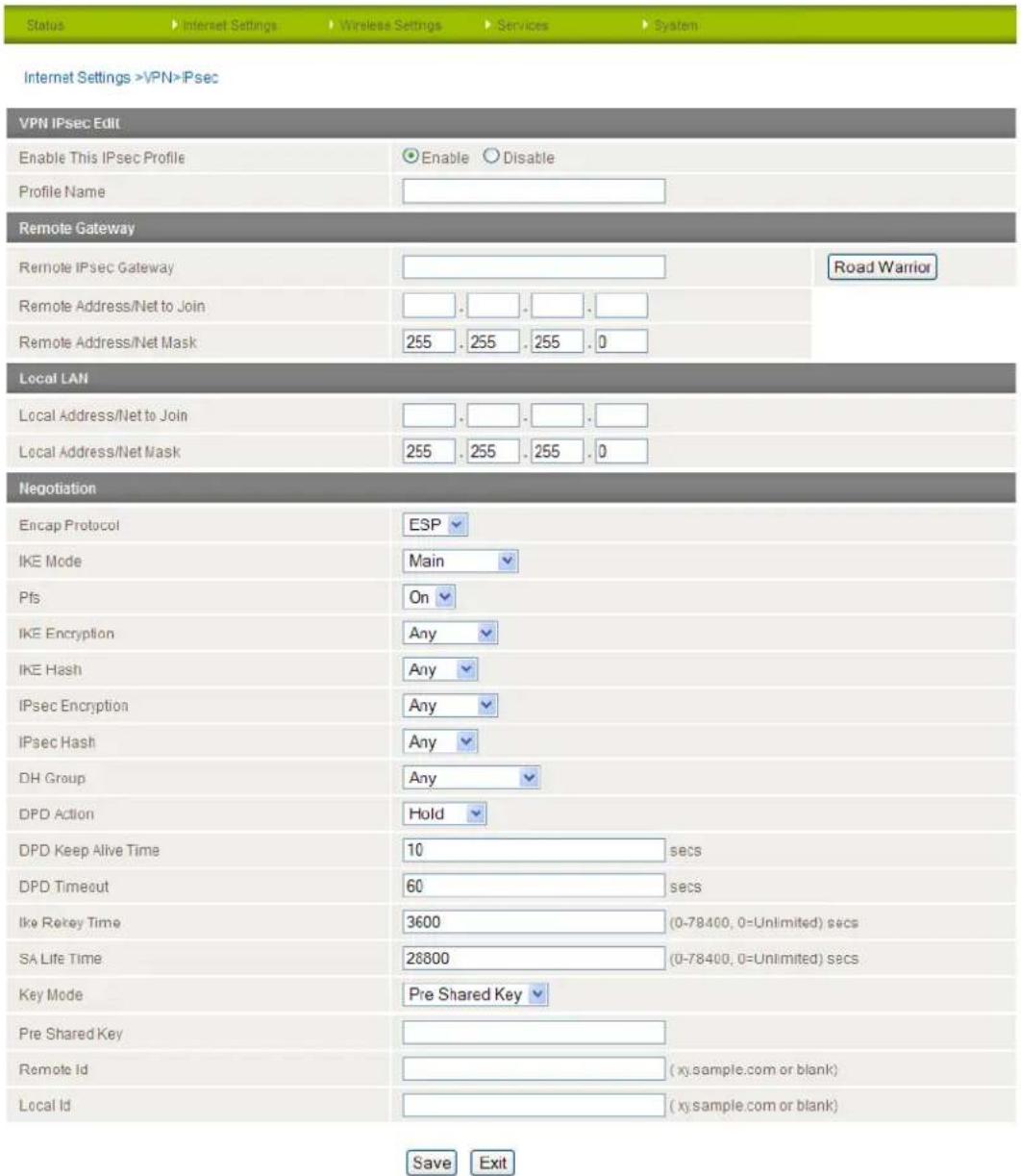
Figure 35 - VPN - IPSec Sengs page
Please view the IPsec field descriptions on the following page.
VPN - IPSec Field Descriptions
| ITEM | DEFINITION |
| Profile Type | Select the type of VPN connection to use. |
| Enable VPN | Enable or Disable the VPN connection. |
| Profile Name | A name used to identify the VPN connection. |
| Remote IPsec Gateway | The IP address that the IPsec server is running on. |
| Road Warrior | Click this to configure the VPN connection for Road Warrior (connection from a dynamic IP Address) use. |
| Remote Address/Net to Join | Enter the Remote IP address or Network for use on the VPN connection. |
| Remote Address/Net Mask | Enter the subnet mask in use on the remote network. |
| Local Address/Net to Join | Enter the Local IP address or Network for use on the VPN connection. |
| Local Address/Net Mask | Enter the subnet mask in use on the local network. |
| Encap Protocol | Select the encapsulation protocol to use with the VPN connection. |
| IKE Mode | Select the IKE mode to use with the VPN connection. |
| Pfs | Select whether or not to use PFS for the VPN connection. |
| IKE Encryption | Select the IKE encryption type to use with the VPN connection. |
| IKE Hash | Select the IKE Hash type to use for the VPN connection. |
| IPsec Encryption | Select the IPsec encryption type to use with the VPN connection. |
| IPsec Hash | Select the IPsec Hash type to use for the VPN connection. |
| DH Group | Select the appropriate DH Group for use with the VPN connection. |
| DPD Action | Select the appropriate DPD (Dead Peer Detection) Action to use on the VPN connection. |
| DPD Keep Alive Time | The time in seconds to keep alive a VPN tunnel where DPD has detected a dead peer. |
| DPD Timeout | The time in seconds before DPD will timeout. |
| IKE Rekey Time | Enter the appropriate IKE Rekey time for the VPN connection. |
| SA Life Time | Enter the appropriate SA Life time for the VPN connection. |
| Key Mode | Select the type of key mode in use for the VPN connection. You can select from:Pre Shared KeyRSA KeysCertificatesEach type of Key mode requires different configuration options. For more information, please refer to the VPN Document available from the NetComm Website. |
OpenVPN
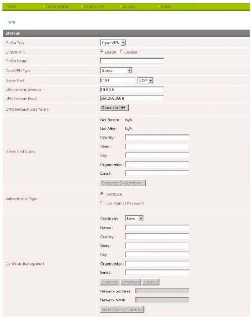
OpenVPN is an open source virtual private network (VPN) program for creating point-to-point or server-to-multi-client encrypted tunnels between host computers. It can traverse network address translation (NAT) and firewalls and allows authentication by certificate, pre-shared key or username and password. OpenVPN works well through proxy servers and can run over TCP and UDP transports. Support for OpenVPN is available on several operating systems, including Windows, Linux, Mac OS, Solaris, OpenBSD, FreeBSD, NetBSD and QNX.
Save Exit
Figure 36 - VPN Connecon Sengs - OpenVPN
| ITEM | DEFINITION |
| Profile Type | Select the type of VPN connection to use. |
| Enable VPN | Enable or Disable the VPN connection. |
| Profile Name | A name used to identify the VPN connection. |
| OpenVPN Type | Select the type of OpenVPN session to use. |
| Server Port | Enter the port the OpenVPN server is running on. |
| VPN Network Address | Enter the network address for use on the VPN connection. |
| VPN Network Mask | Enter the network mask for use on the VPN connection. |
| Diffie-Hellman parameters | Generate the server and client keys used by the VPN connection. |
| Server Certificates | Enter the applicable details to identify the OpenVPN server and create a CA certificate based on this information. |
| Authentication Type | Select the type of authentication in use for the VPN connection. You can select from:CertificateUser Name / PasswordEach type of Key mode requires different configuration options. For more information, please refer to the VPN Document available from the NetComm Website. |
Table 22 - OpenVPN Conguraon Items
PPTP-Client
The Point-to-Point Tunneling Protocol (PPTP) is a method for implementing virtual private networks using a TCP and GRE tunnel to encapsulate PPP packets. PPTP operates on Layer 2 of the OSI model and is included on Windows computers.
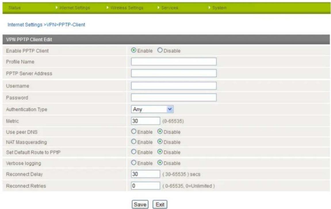
Figure 37 - VPN Connecon Sengs - PPTP
| ITEM | DEFINITION |
| Profile Type | Select the type of VPN connection to use. |
| Enable VPN | Enable or Disable the VPN connection. |
| Profile Name | A name used to identify the VPN connection. |
| VPN Server Address | The IP Address on which the VPN server is running. |
| Username | The username required to login to the VPN service. |
| Password | The password required to login to the VPN service. |
| Authentication Type | The authentication type required for connecting to the VPN service. |
| Metric | The route metric to apply to the VPN connection. |
| Use peer DNS | Select whether to use the VPN server DNS settings or not. |
| NAT Masquerading | Select whether to use NAT Masquerading for the VPN connection. |
| Set Default Route to PPTP | Make the VPN connection the default route for traffic to use. |
| Verbose Logging | Enable extended logging information for the VPN connection. |
| Reconnect Delay | The delay before attempting to reconnect to the VPN service. |
| Reconnect Retries | The number of times to attempt to reconnect to the VPN service. |
Table 23 - PPTP Conguraon Items
GRE
When you select GRE, a list of configured GRE VPNs is displayed. Click the "Add" button to configure a GRE VPN connection.
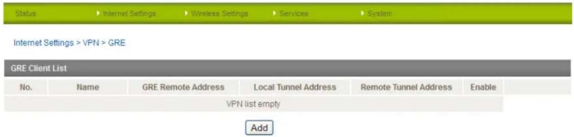
Figure 38 - GRE VPN List
Generic Routing Encapsulation (GRE) is a tunneling protocol developed by Cisco that works in conjunction with PPTP to create a virtual private network.
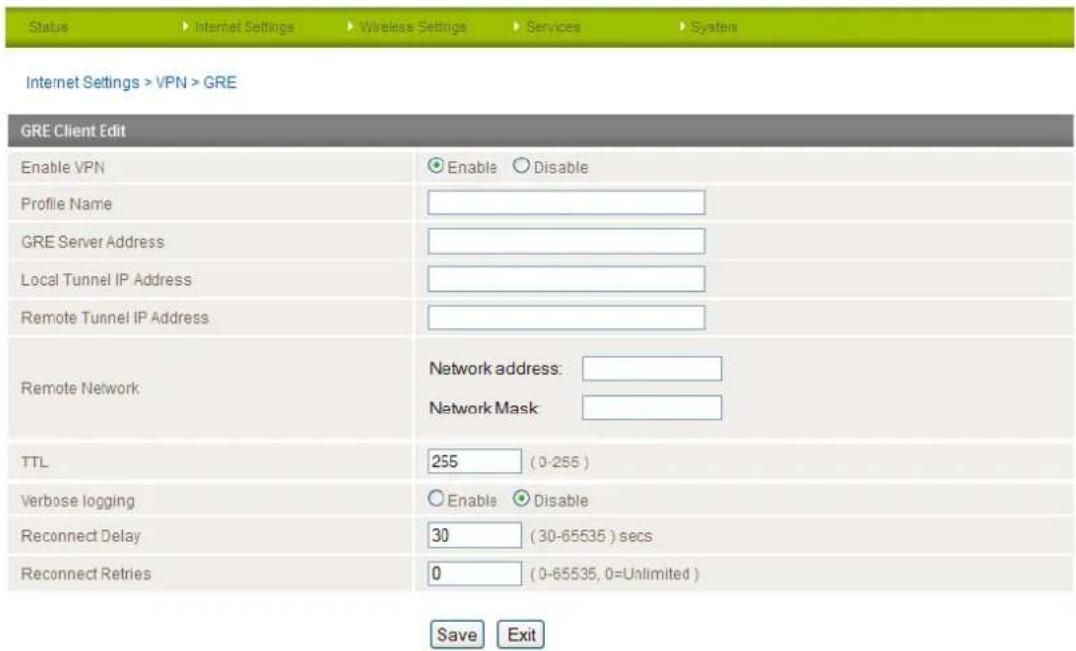
Figure 39 - GRE VPN Sengs
| ITEM | DEFINITION |
| Enable VPN | Enable or Disable the VPN connection. |
| Profile Name | A name used to identify the VPN connection. |
| GRE Server Address | The IP Address on which the GRE VPN server is running. |
| Local Tunnel IP Address | The Local IP address of the VPN tunnel. |
| Remote Tunnel IP Address | The Remote IP address of the other end of the VPN tunnel. |
| Remote Network | Enter the remote network address and subnet mask. |
| TTL | The Time To Live field, an 8-bit field used to remove an undeliverable data packet from a network to avoid unnecessary network traffic across the internet. The default value of 255 is the upper limit on the time that an IP datagram can exist. The value is reduced by at least one for each hop the data packet takes to the next router on the route to the datagram's destination. If the TTL field reaches zero before the datagram arrives at its destination the data packet is discarded and an error message is sent back to the sender. |
| Verbose Logging | Enable extended logging information for the VPN connection. |
| Reconnect Delay | The delay before attempting to reconnect to the VPN service. |
| Reconnect Retries | The number of times to attempt to reconnect to the VPN service. |
Table 24 - GRE VPN Sengs
USSD
The USSD page is used to send USSD (short SMS style) messages to the 3G service provider.
| Internet Settings > USSD | |
| USSD Service | |
| Network Messaging, also known as Unstructured Supplementary Service Data (USSD) is a protocol that can be used to communicate from your device to your service provider. Depending on which network you use for your mobile broadband service, this page can be used for a variety of network services such as balance checking, recharging a prepaid service, and many others. | |
| Network messaging can be initiated using special codes specified by your carrier for these various services. Once a special code is sent to the network, the network responds with the requested information. The response often includes instructions for sending additional follow-on messages allowing further functionality (e.g entering credit card information for a credit recharge). | |
| Please contact your network provider to learn which codes can be used on your network for features such as balance checking, recharge, etc | |
| To begin using this feature, please enter the dial string (e.g #100#) into the box below and click "Start Session". If you don't know which dial string to use, please contact your carrier, and ask them which dial codes are suitable for network services. | |
| Session Status | Inactive |
| Response from network | |
| Send Message | Enter USSD dial string here Start Session |
Figure 40 - USSD Messaging
USSD is a real-time messaging service usually utilised to perform mobile account related tasks such as the following:
- Checking available credit for a mobile service account.
- Obtaining more credit for a mobile service account.
- Verifying your mobile account information.
Enter the USSD message to be sent in the "Send Message" field at the bottom of the screen and then click "Start Session". Any responses from your 3G Service Provider will be displayed in the "Response from Network" box in the middle of the page. Please contact your 3G Service provider for a list of available USSD commands for your 3G service.
Wireless Settings
Basic
The basic configuration page is used to define the basic wireless settings for the NTC-30WV such as the SSID and the type of wireless security in use.
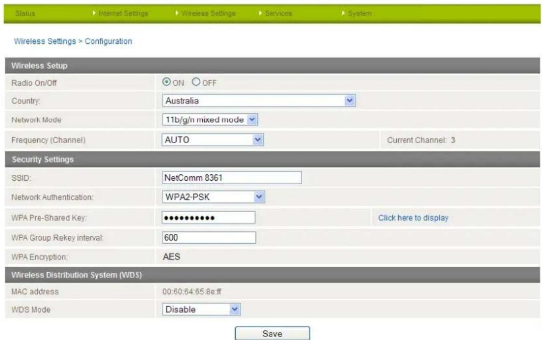
Figure 41 - Wireless Conguraon - Basic Sengs
| OPTION | DEFINITION |
| Radio On/Off | WiFi is turned on by default. Changing this option to OFF will turn OFF the wireless functionality on the NTC-30WV and you will not be able to connect wirelessly. |
| Country | Select the country where the router is operating. |
| Network Mode | Depending on the capability of your wireless device's wireless network card select the network mode to use. There are 5 available options. They are:11 b/g mixed mode11b only11g only11n only11 b/g/n mixed modeIf you are not sure which protocol to use set this option to 11 b/g/n mixed mode. |
| Frequency | The frequency or wireless channel that the router is broadcasting with. Recommended channels are 1, 6 or 11. |
| SSID | The SSID (Service Set Identifier) aka network name in use for the wireless network. |
| Network Authentication | The wireless security settings for the router. Please see below for further details. |
| WPA Pro-Shared Key | The wireless password in use by the router. |
| WPA Group Rekey interval | This is the time in seconds before a new key is generated. |
| WPA Encryption | The type of WPA encryption used with the wireless security settings. |
| MAC Address | The MAC Address of the Wireless Access Point. |
| WDS Mode | Set Wireless Distribution System (WDS) to enable or disable. |
Table 25 - Wireless Conguraon - Basic Conguraon Items
Click 'Apply' to save the settings.
Security Settings
You may choose from the following wireless security options:
- Open
- Shared
WPA
WPA-PSK
WPA2
WPA2-PSK
• WPA-PSK-WPA2-PSK
WPA1-WPA2
802.1x
WPA1/WPA2
WPA (WiFi Protected Access) authentication is suitable for enterprise applications. It must be used in conjunction with an authentication server such as RADIUS to provide centralized access control and management. It provides a stronger encryption and authentication solution.
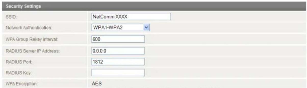
Figure 42 - Advanced View - WiFi Security Sengs - WPA1/WPA2
WPA-PSK/WPA2-PSK
A newer type of security is WPA-PSK (TKIP) and WPA2-PSK (AES). This type of security gives a more secure network compare to WEP. Use TKIP Encryption Type for WPA-PSK and AES for WPA2-PSK. After that, please enter the key in the Passphrase field. The key needs to be more than 8 characters and less than 63 characters and it can be any combination of letters and numbers.

Note that the configuration for WPA2, WPA-PSK-WPA2-PSK, WPA-PSK and WPA2-PSK is identical.
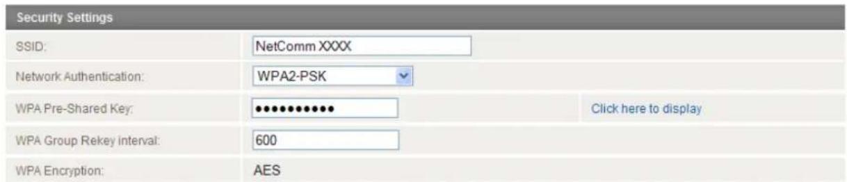
Figure 43 - Advanced View - WiFi Security Sengs - WPA-PSK/WPA2-PSK

Note: Your NTC-30WV uses WPA2-PSK by default. Check the Wireless Security Card or the device label on the bottom of the NTC-30WV for your default SSID and Security key to begin connecting your wireless devices.
802.1x
In order to use 802.1X security, you need to have a RADIUS server on your network that will act as the authentication server. Please type in the details for your RADIUS server in the fields required.
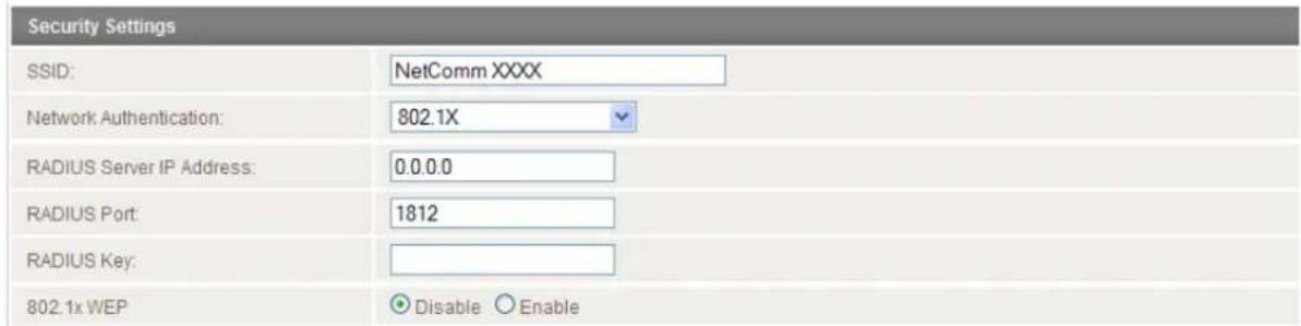
Figure 44 - Advanced View - WiFi Security Sengs - 802.1x

Note: After configuring wireless security, you also need to configure your wireless adapter to use the same security settings before you can connect wirelessly. Not all wireless adapters support WPA-PSK/WPA2-PSK/WPA/WPA2 security;
Please refer to your wireless adapter user guide for more details. It is strongly recommended to set up a simple wireless security such as WPA-PSK (when the wireless client supports WPA-PSK) in order to secure your network.
Most wireless adapters in computers and laptops support at least WEP and WPA.
WDS Mode
The NTC-30WV supports the configuration of a Wireless Distribution System (WDS). WDS allows you to expand your wireless network with multiple access points. There are two WDS modes available: Bridged Mode and Repeater Mode. In Bridged mode, the WDS access points communicate with each other but do not communicate with wireless clients. Bridged mode is best used in situations where the client machines connect via Ethernet cable. In Repeater mode, the WDS access points communicate with each other and with wireless clients.
Below is an example of how to configure two NTC-30WV routers to utilise the Repeater mode WDS feature. In this example, Access Point 1 is connected to a mobile broadband network and Access Point 2 and its clients will connect to the internet through Access Point 1.
Access Point 1 – Mobile Broadband Connected
- Establish a Mobile Broadband connection with Access Point 1:
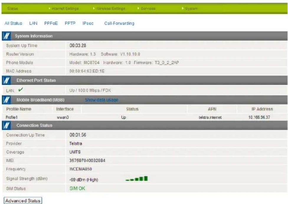
Figure 45 - WDS - Access Point 1 Status
- Configure the LAN IP Address of Access Point 1. In this example, it is set to the default address of 192.168.1.1:
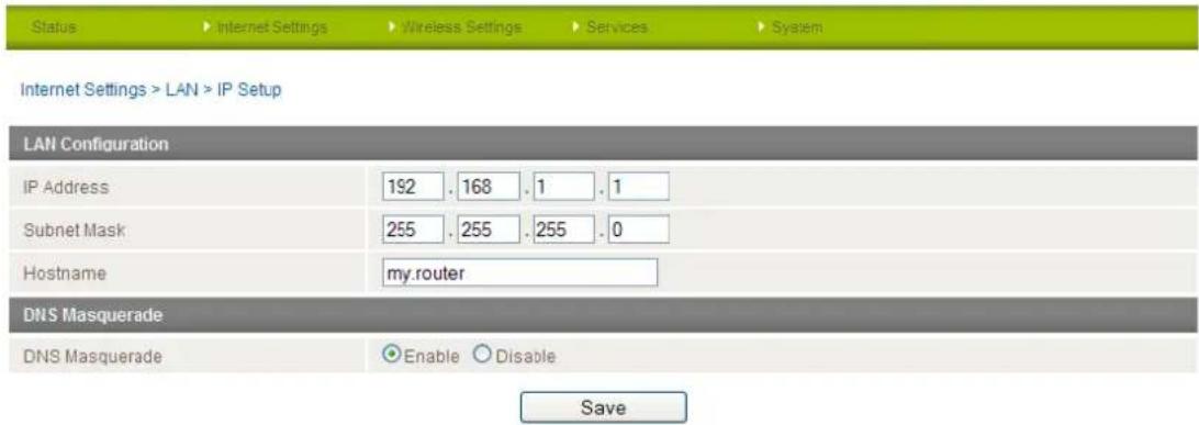
Figure 46 - WDS - Access Point 1 LAN IP Setup
- Enable the DHCP Server on Access Point 1:
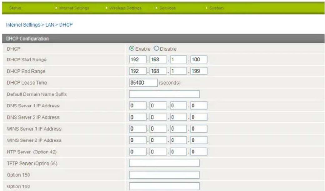
Figure 47 - WDS - Access Point 1 DHCP Server Sengs
- Click Wireless Settings and then Basic. Enter the required details as listed in the table below:
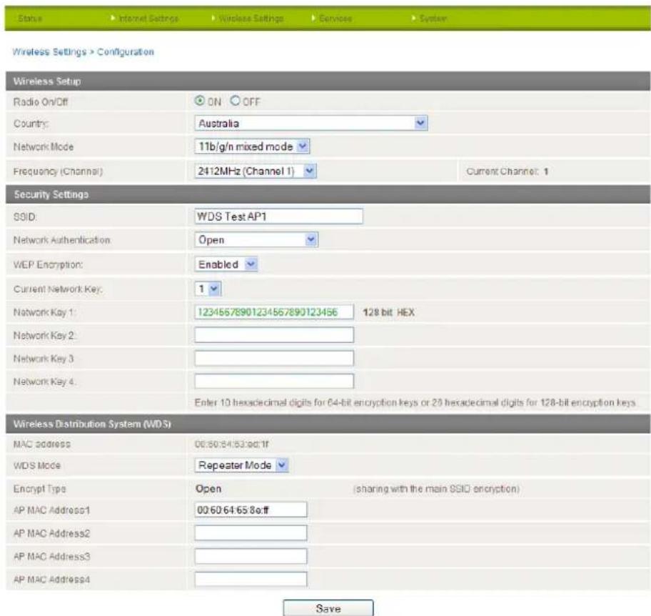
Figure 48 - WDS - Access Point 1 Repeater Mode Setup
| OPTION | DEFINITION |
| Radio On/Off | The Wireless Radio must be turned on in order to use WDS. Set this to ON. |
| Country | Select the country where the router is operating. |
| Network Mode | Depending on the capability of your wireless device's wireless network card select the network mode to use. There are 5 available options. They are:11 b/g mixed mode11b only11g only11n only11 b/g/n mixed modeIf you are not sure which protocol to use set this option to 11 b/g/n mixed mode. |
| Frequency (Channel) | The frequency or wireless channel that the router is broadcasting with. Recommended channels are 1, 6 or 11. You may use any channel except AUTO in order to use WDS. |
| SSID | The SSID (Service Set Identifier) or network name in use for the wireless network. |
| Network Authentication | The wireless security settings for the router. When using WDS, the network must be set to Open, however, you can secure it with WEP Encryption. |
| WEP Encryption | If you wish to use WEP Encryption for the WDS network, select Enabled. |
| Current Network Key | You can enter up to 4 network keys. Use this drop down list to select the active network key. |
| Network Key 1-4 | The network keys used to encrypt the network. Enter 10 hexadecimal digits for 64-bit encryption keys or 26 hexadecimal digits for 128-bit encryption keys. |
| MAC Address | This is the MAC Address of the wireless interface of the router. Enter this MAC Address into the client's configuration page to inform the client of the address of this router. |
| WDS Mode | Selects the WDS Mode to use. Available modes are Disabled, Bridged Mode and Repeater Mode. In this example we are using Repeater Mode which allows client machines to connect wirelessly. In Bridged Mode, an Ethernet connection to the client access point is required. |
| Encrypt Type | Shows the encryption method currently in use. When WDS Mode is in use, this must be Open. |
| AP MAC Address1-4 | Enter the MAC Address of Access Point 2 and any other client access points in to these fields to inform the server of their addresses. |
Table 26 - WDS Access Point 1 Repeater Mode Sengs
When you have entered the required information, click Save:
Access Point 2 – No connection to mobile broadband
- Access Point 2 will act as a repeater for and provide internet access to its clients through Access Point 1 and therefore does not require a Mobile Broadband connection to be established.
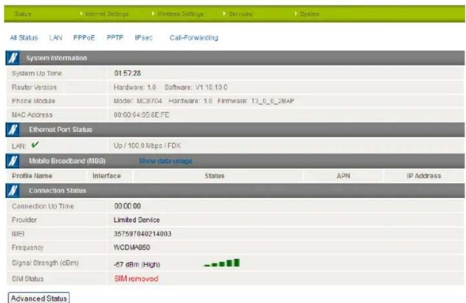
Figure 49 - WDS - Access Point 2 Status
- Configure the LAN IP Address of Access Point 2. In this example, it is set to the default address of 192.168.1.2:
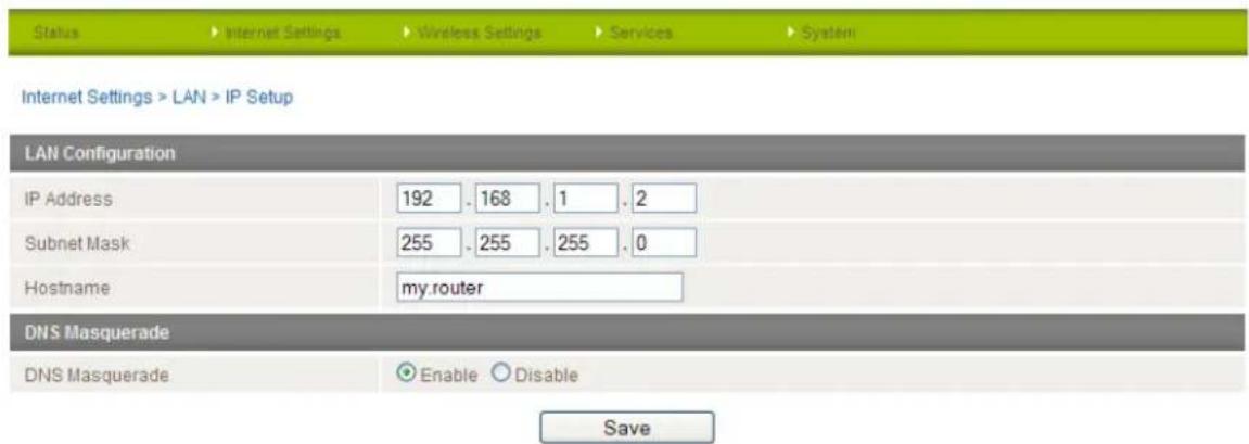
Figure 50 - WDS - Access Point 2 LAN IP Setup
7. Set the DHCP Server on Access Point 2 to Disable:
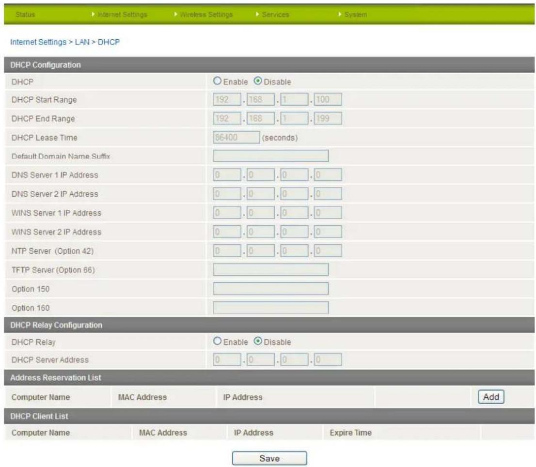
Figure 51 - WDS - Access Point 2 DHCP Sengs
- Under Wireless Setup, select the same frequency channel as you did for Access Point 1. Enter an SSID to identify Access Point 2 and set Network Authentication to Open. Copy the Network Authentication and WEP Encryption settings from Access Point 1. Set Access Point 2 to Repeater mode and enter the MAC address of Access Point 1 in the AP MAC Address1 field. The MAC address of Access Point 1 is listed on the same page under Wireless Settings > Basic under the Wireless Distribution System (WDS) section. When you have entered the required information, click Save:
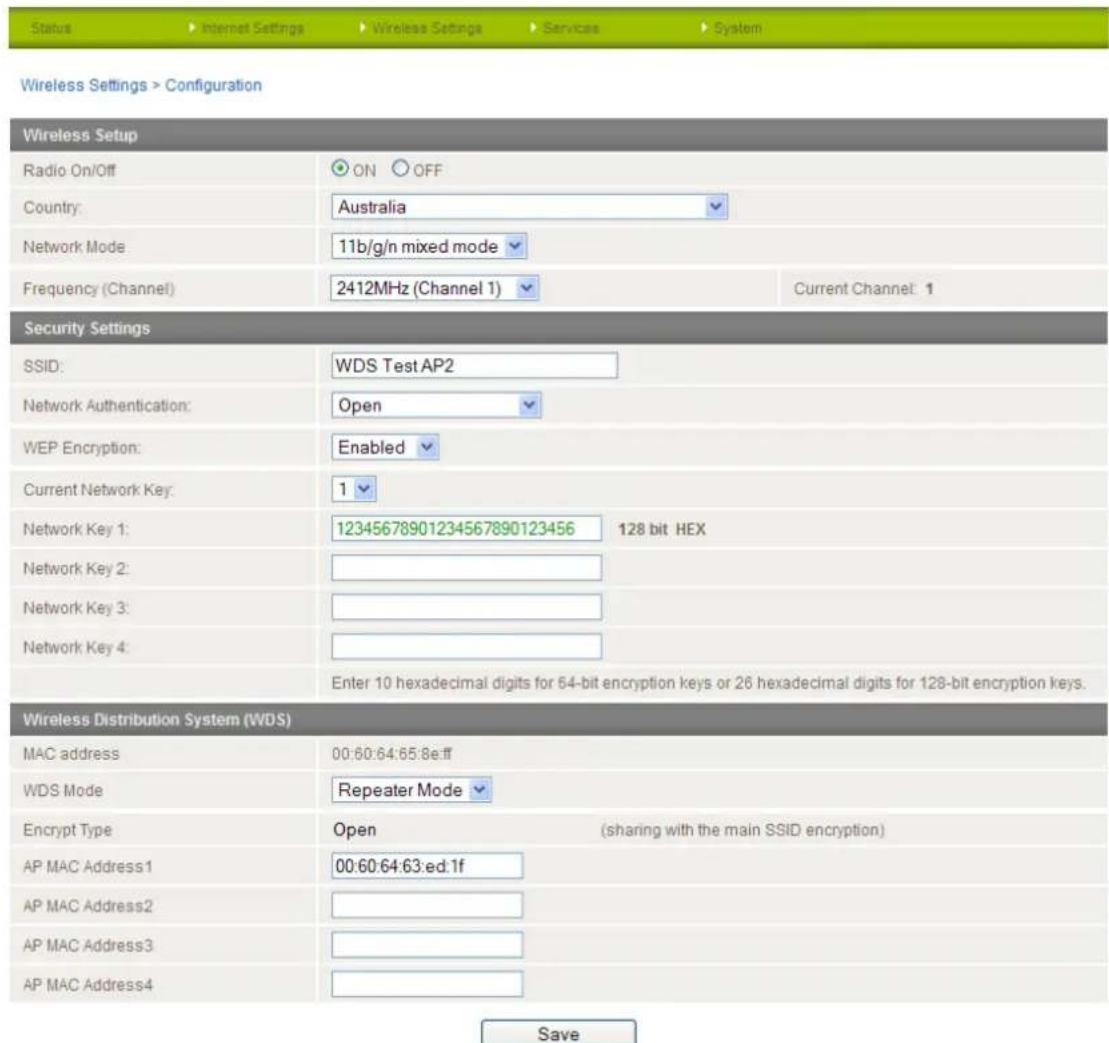
Figure 52 - WDS - Access Point 2 Repeater Mode Setup
The Wireless Distribution System setup is now complete.
Advanced
The Advanced page is used to modify the advanced wireless settings for the router. These settings should not be changed unless you are aware of what effect they will have.
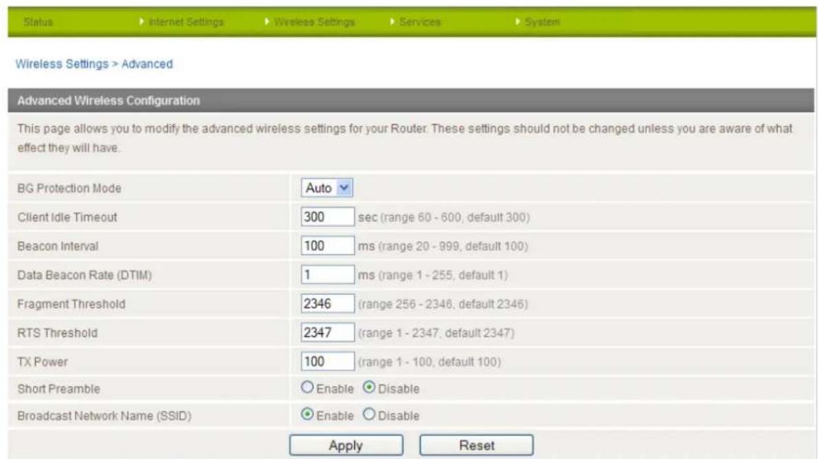
Figure 53 - Wireless Sengs - Advanced
| OPTION | DEFINITION |
| BG Protection Mode | A protective measure designed to prevent collisions among 802.11b/g modes. Mode options include Auto, On, or Off. |
| Client Idle Timeout | The time in seconds that a wireless client session can be idle before the gateway cancels the session and defines the wireless client as not connected. |
| Beacon Interval: | Interval of time in which the wireless gateway broadcasts a beacon which is used to synchronize the wireless network. |
| Data Beacon Rate (DTIM) | Enter a value in milliseconds between 1 and 255 for the Delivery Traffic Indication Message (DTIM). A DTIM is a countdown informing clients of the next window for listening to broadcast and multicast messages. |
| Fragmentation Threshold | This specifies the maximum size of a packet during the fragmentation of data to be transmitted. If you set this value too low, it will result in bad performance. |
| RTS Threshold | When the packet size is smaller than the RTS threshold, the wireless gateway will not use the RTS/CTS mechanism to send this packet. |
| TX Power | This determines the output power of the antenna. |
| Short Preamble | Enable or disable short preambles in use on the wireless network. Using short preambles should improve throughput, however some wireless network adapters must use long preambles. |
| Broadcast Network Name (SSID) | Use this to show or hide the SSID (wireless network name) of your router. |
Table 27 - Wireless Sengs - Advanced Conguraon Items
Click the "Save" button to save any changes to the settings.
MAC / IP / Port Filter
The Wireless LAN MAC / IP / Port filter feature ensures the network accessibility for the wireless client devices can be controlled. When the MAC/IP/Port filter is enabled with a default policy of "Accepted", the rules that are created indicate which packets to drop while all packets not listed are accepted. When the MAC/IP/Port filter is enabled with a default policy of "Dropped", the rules that are created indicate which packets to accept while all other packets not listed are dropped. You can create up to 20 rules to control wireless client access.
The HTTP port (80) is enabled by default, allowing access to the web user interface from any wireless client. If you want to restrict access to the web user interface, set this to "Disable" and create a rule to allow access to port 80 for at least one client so that you do not become locked out of the web user interface.
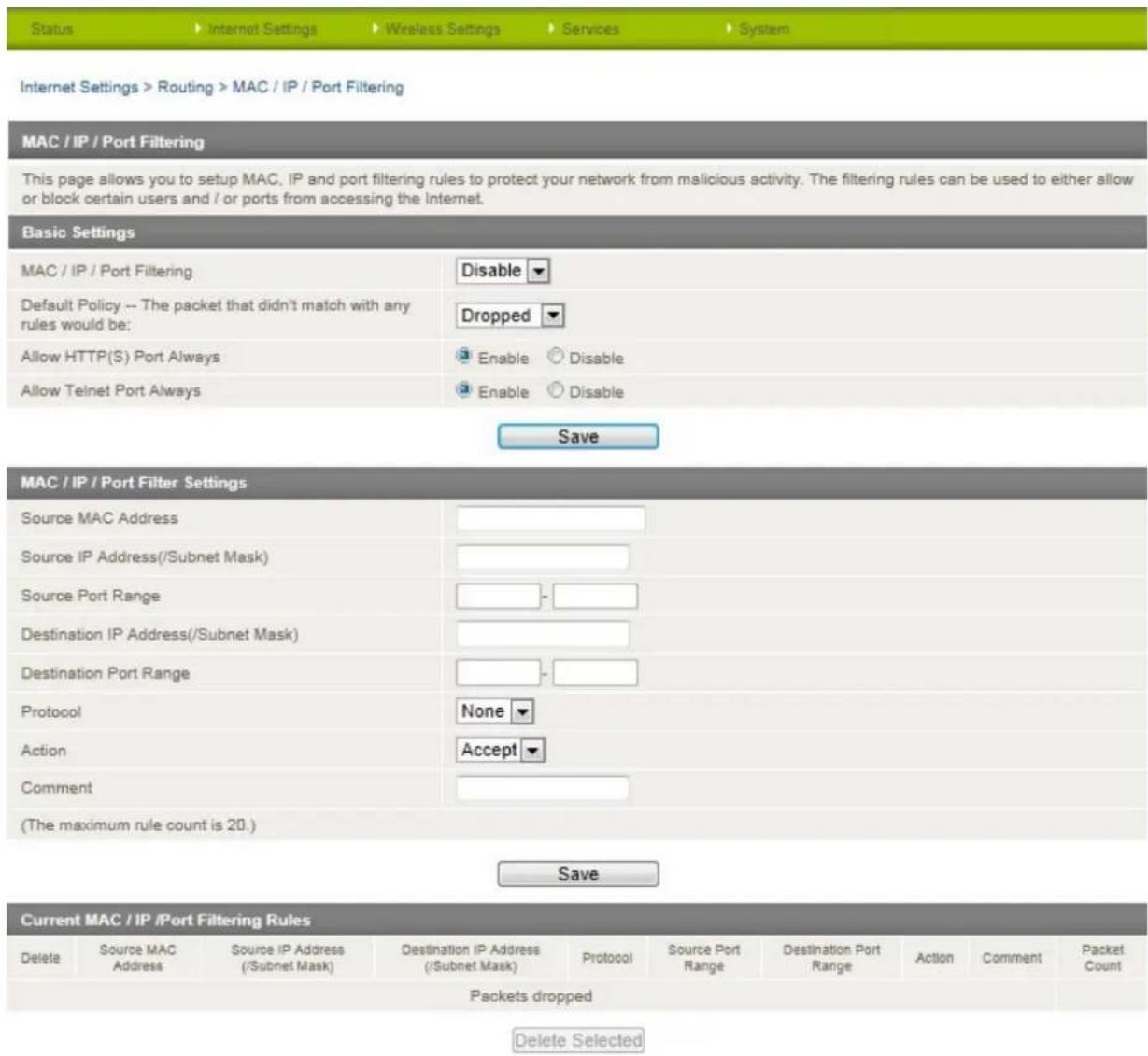
Figure 54 - Wireless Sengs - MAC / IP / Port Filter
Enter the required details for your rule and click "Save". The details of the rule appear in the bottom section of the screen. You can select individual rules and delete them.
Station List
The Station List page shows the number of devices currently connected to your NTC-30WV via WiFi. The MAC address, Host Name and IP address of these devices are displayed.
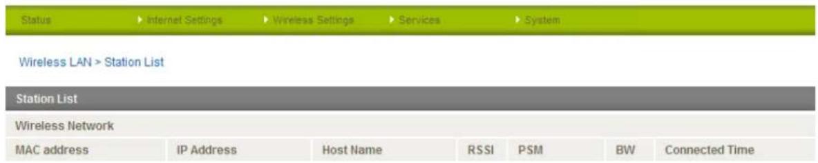
Figure 55 - Wireless Stoon List
Services
Dynamic DNS
The Dynamic DNS page is used to configure the Dynamic DNS feature of the router. There are a number of dynamic DNS hosts from which you can choose.
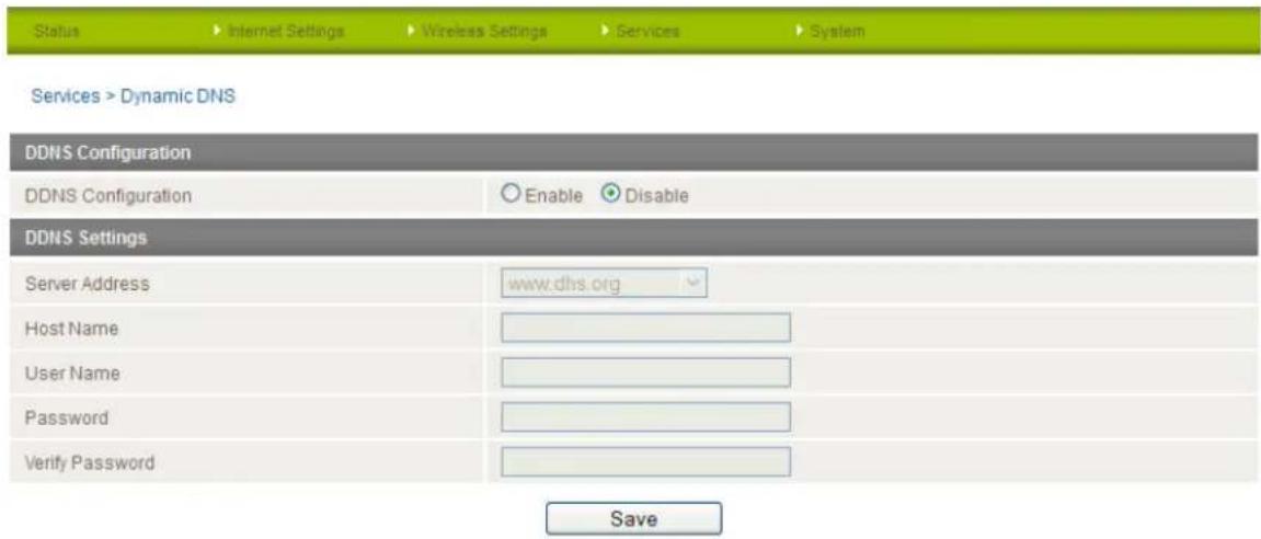
Figure 56 - DDNS Sengs
Dynamic DNS provides a method for the router to update an external name server with the current WAN IP address.
To configure dynamic DNS:
- Select the "Enable" option for the DDNS Configuration field.
- Select the Dynamic DNS service that you wish to use. Enter your dynamic DNS account credentials.
- Click the "Save" button to save any changes to the settings.
NTP
The NTP page is used to configure the local time zone and to select the NTP server used for synchronisation.
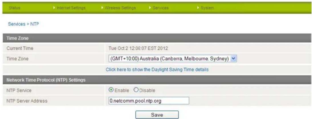
Figure 57 - NTP Sengs
The NTP (Network Time Protocol) settings allow your router to synchronise its internal clock with a global Internet Time server. This setting will affect functions such as System Log entries and Firewall settings where the current system time is displayed. You can use the default NTP server or enter one manually if required.
System Monitor
The System Monitor page is used to configure the behaviour of the Periodic Piing monitor function.
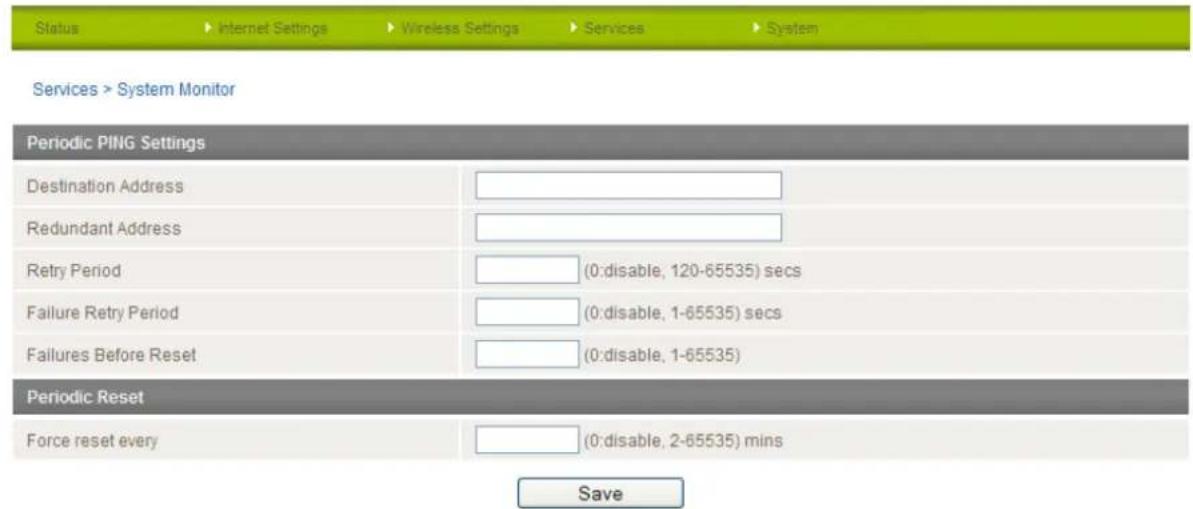
Figure 58 - System Monitor Sengs
The Periodic Ping Reset Monitor configures the router to transmit controlled ping packets to 2 specified IP addresses. Should the router not receive responses to the pings, the router will reboot.
This works as follows:
- After every "Periodic Ping Timer" configured interval, the router sends 3 consecutive pings to the "Destination Address".
- If all 3 pings fail the router sends 3 consecutive pings to the "Second Address".
- The router then sends 3 consecutive pings to the "Destination Address" and 3 consecutive pings to the "Second Address" every "Periodic Ping Accelerated Timer" configured interval.
- If all accelerated pings in step 3 above fail the number of times configured in "Fail Count", the router reboots.
- If any ping succeeds the router returns to step 1 and does not reboot.

Note: The "Periodic Ping Timer" should never be set to a value less than 60 seconds; this is to allow the router time to reconnect to the cellular network following a reboot.
How to disable the Periodic Ping Monitor
To disable the Periodic Ping Reset Monitor simply set to "Fail Count" 0.

Note: The traffic generated by the periodic ping feature is counted as chargeable usage, please keep this in mind when selecting how often to ping.
How to configure a Forced Reset
This facility is available by clicking on the "Services" menu followed by the "System Monitor" menu item on the right.
The router can be configured to automatically reboot after a period of time specified in minutes. While this is not necessary, it does ensure that in the case of remote installations, it will reboot the router if some anomaly occurs.
The default value is 0 which disables the Forced Reset Timer. The maximum value is 65535 minutes.
SNMP
The SNMP page is used to configure the SNMP features of the router.
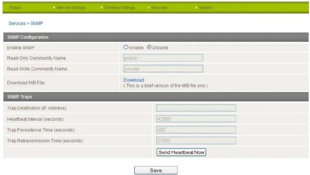
Figure 59 - SNMP Sengs
SNMP (Simple Network Management Protocol) is used to remotely monitor the router for conditions that may warrant administrative attention. It can be used to retrieve information from the router such as the signal strength, the system time, the interface status, etc.
To configure SNMP:
1. Select the "Enable" option for the Enable SNMP field.
2. Enter the Community Names or leave them as default.

Community names are used as a type of security to prevent access to reading and/or writing to the routers configuration. It is recommended to change the Community names to something other than the default when using this feature.
3. Click the "Save" button to save the new settings.
| ITEM | DEFINITION |
| Trap Destination (IP Address) | The IP Address SNMP data is to be sent to. |
| Heartbeat Interval (seconds) | The number of seconds between SNMP heartbeats. |
| Trap Persistence Time (seconds) | The length of time an SNMP trap persists. |
| Trap Retransmission Time (seconds) | The length of time between SNMP trap retransmissions. |
Table 28 - SNMP Conguraon Opons
You can also trigger an SNMP Heartbeat manually by clicking the "Send Heartbeat Now" button.
SMS
The SMS pages are used to perform functions using the built-in SMS tools application. The SMS Tools application offers basic SMS functionality such as sending a message, receiving a message and redirecting an incoming message to another destination. You can also utilise this feature to read and change run-time variables on the router.
Basic functionality supported:
- Ability to send a text message via a 3G network and store in permanent storage
- Ability to receive a text message via a 3G network and store in permanent storage
- Ability to forward incoming text messages via a 3G network to another remote destination which may be a TCP/UDP server or other mobile devices.
- Ability to read run-time variables from the device (e.g. uptime) and send result to a remote destination which may be a TCP/UDP server or other mobile devices.
- Ability to change live configuration on the device (e.g. connection APN).
- Ability to execute supported commands (e.g. reboot).
Setup
General SMS functionality is enabled by default. You can open the Setup page in order to configure additional settings. To do this, click on "Services", then "SMS" and then "Setup".
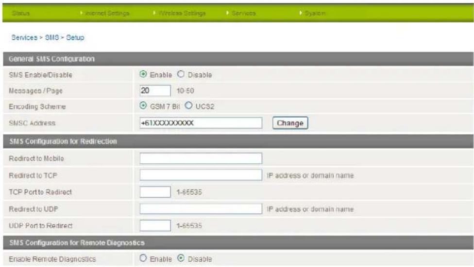

Figure 60 - SMS Funcon Setup
| OPTION | DEFINITION |
| Messages / Page | Enter the number of SMS messages to display per page. |
| Encoding Scheme | The encoding method used for SMS messages. |
| Redirect to Mobile | Forward incoming text messages to the remote destination defined. |
| Redirect to TCP | Forward incoming text messages to the remote TCP destination defined. |
| TCP Port to redirect | The TCP port on which to connect to the remote destination on. |
| Redirect to UDP | Forward incoming text messages to the remote UDP destination defined. |
| UDP Port to redirect | The UDP port on which to connect to the remote destination on. |
| Enable Remote Diagnostics | Enable diagnostics to be performed by a specially crafted SMS message. |
Table 29 - SMS Setup Conguraon Items
SMS Configuration for Redirection
Incoming text messages can be redirected to another mobile device and/or a TCP/UDP message server.
Redirect To Mobile
You can forward incoming text messages to a different destination number. This destination number can be another mobile phone or 3G router phone number. To disable the feature, simply delete the number in the 'Redirect to Mobile' field and click the "Save" button.
For Example:
If someone sends a text message and Redirect to Mobile is set to "0412345678", this text message is stored on the router and forwarded to "0412345678" at the same time.
Redirect to TCP & TCP Port, Redirect to UDP & UDP Port
You can also forward incoming text messages to a TCP/UDP based destination. The TCP or UDP server can be any kind of public or private server if the server accepts incoming text-based message.
The TCP/UDP address can be an IP address or domain name. The port number range is from 1 to 65535. Please refer to your TCP/UDP based SMS server configuration for which port to use.
For Example:
If someone sends a text message and Redirect to TCP is set to "192.168.20.3" and "2002", this text message is stored in the router and forwarded to "192.168.20.3" on port "2002" at the same time.
SMS Configuration for Remote Diagnostics
Enable Remote Diagnostics
Enable or disable the Remote Diagnostics feature. If this setting is enabled all incoming text messages are parsed and tested for if they contain Remote Diagnostics commands.
If Remote Diagnostics commands are found, the router executes those commands. This feature is disabled by default.

Note: It is possible to adjust settings and prevent your router from functioning correctly. If this occurs, you will need to perform a factory reset in order to restore normal operation.

It is highly recommended to enable security when utilising this feature.
New Message
The New Message page is used to send an SMS text message to multiple recipients.
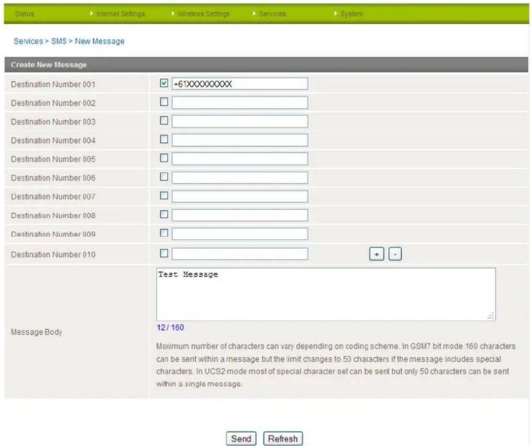
Figure 61 - New SMS Message
A new SMS message can be sent to a maximum of 100 recipients at the same time. After sending the message, the result is displayed next to the destination number as "Success" (in blue) or "Failure" (in red). By default, 10 recipient entry fields are shown on this page however you can increase or decrease this number by pressing the + or - button to the right of the last recipient entry field.
You can select to enable or disable individual message recipients by selecting the checkbox beside each entered number. After entering the required recipient numbers, type your SMS message in the "Message Body" field and then click the "Send" button.
Inbox / Outbox
You can check all sent SMS messages in the SMS Outbox or you can read, delete, reply or forward an SMS message to another mobile device from the SMS Inbox. You are also able to add the SMS message sender to the "White List" which is used to secure the Remote Diagnostics feature. Simply select the sender or recipient number and click the "Add White List" button.
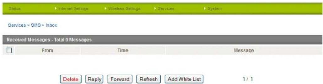
Figure 62 - SMS Inbox
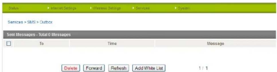
Figure 63 - SMS Outbox
Diagnostics
The Diagnostics page is used to configure the SMS Diagnostics and Command execution configuration. This enables you to change the configuration or check on the status of the router via SMS commands.
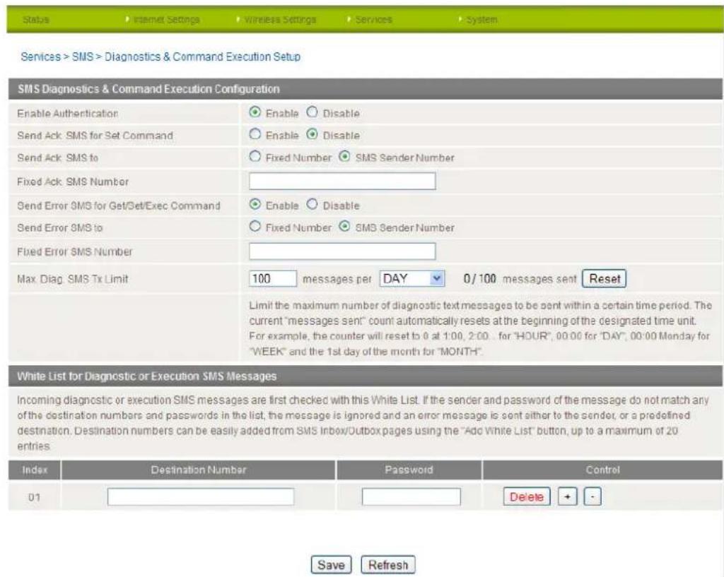
Figure 64 - SMS Diagnoscs Sengs
The following pages detail the configuration items available.
Enable Authentication
Enable or disable checking the sender's phone number against the allowed sender "White List" for incoming Diagnostics/Command Execution SMS messages.
If authentication is enabled, the router will check if the sender's number exists in the "White List". If it exists, the router then checks the password in the incoming message against the password in the "White List" for the corresponding sending number. If they match, the Diagnostics/Command is executed.
If the number does not exist in "White List" or the password does not match, the router does not execute the incoming Diagnostics/Command Execution SMS message.
This is enabled by default.

It is highly recommended to enable security when utilising the Diagnostics/Command Execution feature.
Send Ack. SMS for Set Command
Enable or disable sending an acknowledge message after execution of a "Set" command.
If disabled the router does not send any acknowledgement after execution of a "Set" command. This can be useful to determine if a command was received and executed by the router. This is disabled by default.
Send Ack. SMS to
Select destination to send an acknowledgement message to after the execution of a "Set" command.
If "Fixed Ack. SMS Number" is selected, the acknowledgement message will be sent to the predefined number in the "Fixed Ack. SMS Number" field.
If the SMS Sender Number is selected, the acknowledgement message will be sent to sender directly. The default setting is to use "SMS Sender Number".
Fixed Ack. SMS Number
Enter the destination number to which acknowledgement messages will be sent after the execution of a "Set" command.
Send Error SMS for Get/Set/Exec Command
Enable or disable the sending of an error message resulting from the execution of a Get/Set/Exec command.
If disabled, the router does not send any error notifications after the execution of a Get/Set/Exec command.
This function is disabled by default.
Send Error SMS to
Select the destination of the error messages from the execution of a Get/Set/Exec command.
If "Fixed Number" is selected, any error messages will be sent to the predefined number in the "Fixed Error SMS Number" field.
If "SMS Sender Number" is selected, any error messages will be sent to the sender directly.
The default setting is to use "SMS Sender Number".
Fixed Error SMS Number
The destination number to which error messages from the execution of a Get/Set/Exec command should be sent.
Max. Diag. SMS Tx Limit
You can set the maximum number of acknowledgement and error messages sent when an SMS Diagnostics and/or Command is executed. You can set the maximum limit on a per hour/day/week or month basis.
The default is to send a maximum of 100 messages per day.
You can check the current sent message count by looking next to the "Max. Diag. SMS Tx Limit" field. If the maximum number has been exceeded, you can also reset sent the message counter by pressing the "Reset" button.
The Total transmitted message count resets after a reboot or at the beginning of the time frame specified.

Note: Times displayed are in UTC format.
For Example:
- If the time frame is set to "HOUR" and the current time is "04:30", then the counter will reset to zero at "05:00".
- If time frame is set to "DAY" and current date and time is "04:30" 17 of March, then the counter will reset to zero at "00:00" 18 of March.
- If time period is set to "WEEK" and current date and time is "04:30" Saturday, then the counter will reset to zero at "00:00" on the coming Monday.
- If time period is set to "MONTH" and current date and time is "04:30" 17 of March, then the counter will reset to zero at "00:00" 1 of April.
White List
A maximum number of 20 entries can be stored in the router.
If Authentication is enabled, any incoming Diagnostics/Command Execution SMS messages are processed only if the sender's number exists in White List and the message password matches with the password specified in the White List.
One blank entry is shown by default and you can add or delete an entry by pressing the "+" or "-" button. The White List numbers and passwords can be cleared by pressing the "Delete" button.
To add an entry, simply enter the appropriate phone number and password and click "Save".
Message Storage for Diagnostic Messages
Diagnostic messages (Diagnostic commands, acknowledgements and error notification messages) sent to remote destination are stored in Inbox/Outbox.
Security
In order to provide security for SMS command execution, it is recommended that all SMS commands be subject to successful authentication against the White List as well as setting a password for each phone number entered.
This prevents unauthorised or accidental execution of SMS commands.
SMS Command format
Generic Format for reading variables:
get VARIABLE
PASSWORD get VARIABLE
Generic Format for writing to variables:
set VARIABLE=VALUE
PASSWORD set VARIABLE=VALUE
Generic Format for executing a command:
executeCOMMAND
PASSWORD executeCOMMAND
Replies
Upon receipt of successfully formatted, authenticated (if required) command, the gateway will reply to the SMS in the following format:
| TYPE | SMS CONTENTS | NOTES |
| Get Command | "VARIABLE=VALUE" | |
| Set Command | "Successfully set VARIABLE to VALUE" | Only sent if the acknowledgment message function is enabled |
| Execute Command | "Successfully executed command COMMAND" |
Table 30 - SMS Diagnosc Command Syntax
Where "VARIABLE" is the name of the value to be read
Where "VARIABLE (x)" is the name of another value to be read
Where "VALUE" is the content to be written to the "VARIABLE"
Where "COMMAND" is a supported command to be executed by the device (e.g. reboot)
Where "PASSWORD" is the password (if configured) for the corresponding sender number specified in the White List
Multiple commands can be sent in the same message, if separated by a semicolon.
For Example:
get VARIABLE1; get VARIABLE2; get VARIABLE3
PASSWORD get VARIABLE1; get VARIABLE2
set VARIABLE=VALUE1; set VARIABLE2=VALUE2
PASSWORD set VARIABLE1=VALUE1; set VARIABLE2=VALUE2; set VARIABLE3=VALUE3
If required, values can also be bound by an apostrophe, double apostrophe or back tick.
For Example:
"set VARIABLE='VALUE'"
"set VARIABLE="VALUE""
“set VARIABLE="VALUE"
"get VARIABLE"
A password (if required), only needs to be specified once per SMS, but can be prefixed to each command if desired.
"PASSWORD get Variable1"; "get VARIABLE2"
"PASSWORD set VARIABLE1=VALUE1"; "set VARIABLE2=VALUE2"
If the command sent includes the "reboot" command and has already passed the White List password check, the device keeps this password and executes the remaining command line after the reboot with this same password.
For Example:
"PASSWORD execute reboot; getVariable1"; "get VARIABLE2"
"PASSWORD execute reboot; PASSWORD get Variable1"; "get VARIABLE2"
Commands are case insensitive, however variable names and values are case sensitive.
List of valid commands (which can be used in conjunction with the execute command):
"pdpcycle", "pdpdown" and "pdpup" commands can have a profile number suffix 'x' added. Without the suffix specified, the command operates against the current active profile or last active profile.
| # | COMMAND NAME | DESCRIPTION |
| 1 | reboot | Immediately perform a soft reboot |
| 2 | pdpcycle or pdpcyclex | Disconnect (if connected) and reconnect the 3G connection. If a profile number is selected in the command, try to disconnect/reconnect the specified profile in case the profile is active. If no profile number is selected, try to disconnect/reconnect the current active profile. Reports an error if no profile number is selected and there is no currently activated profile. |
| 3 | pdpdown or pdpdownx | Disconnect the PDP. If a profile number is selected in the command, try to disconnect the specified profile in case the profile is active. If no profile number is selected, try to disconnect the current active profile. Reports an error if no profile number is selected and there is no currently activated profile. |
| 4 | pdpup or pdpupx | Reconnect the PDP. If a profile number is selected in the command, try to connect with the specified profile. If no profile number is selected, try to connect to the last active profile. The gateway will check the currently activated profile and disconnect this profile before executing the command. Reports an error if no profile number is selected and there is no stored last active profile number. |
Table 31 - List of Valid SMS Diagnosc Commands
The following table lists valid variables where "x" is a profile number (1-6). If no profile is specified, variables are read or written to for the current active profile. If a profile is specified, variable are read or written to for the specified profile number ('x').
| # | RDB VARIABLE NAME | SMS VARIABLE NAME | READ/WRITE | DESCRIPTION | EXAMPLE |
| 0 | link.profile.x.enablelink.profile.x.apnlink.profile.x.userlink.profile.x.passlink.profile.x.auth_typelink.profile.x.iplocallink.profile.x.status | profileorprofilex | RW | Profile | Read:(profile no,apn,user,pass,auth,iplocal,status)1,Telstra.internet,username,password,chap,202.44.185.111,upWrite:(apn, user, pass,auth)telstra.internet,username,password |
| 1 | link.profile.x.apn | apn or apnx | RW | APN | telstra. Internet |
| 2 | link.profile.x.user | username or usernameex | RW | 3G username | Guest, could also return "null" |
| 3 | link.profile.x.pass | password or password | RW | 3G password | Guest, could also return "null" |
| 4 | link.profile.x.auth_type | authtype or authtypex | RW | 3G Authentication type | "pap" or "chap" |
| 5 | link.profile.x.iplocal | wanip or wanipx | R | WAN IP address | 202.44.185.111 |
| 6 | wwan.0.radio.information.signal_strength | rssi | R | 3G signal strength | 65 dBm |
| 7 | wwan.0.imei | lmoi | R | IMEI number | 359102128941027512 |
| 8 | statistics.usage_current | usage | R | 3G data usage of current session | "Rx 500 bytes, Tx 1024 bytes, Total 1524 bytes" or "Rx 0 byte, Tx 0 byte, Total 0 byte" when wwan down |
| 9 | statistics.usage_current | wanuptime | R | Up time of current 3G session | 1 days 02:30:12 or 0 days 00:00:00 when wwan down |
| 10 | /proc/uptime | deviceuptime | R | Device up time | 1 days 02:30:12 |
| 11 | wwan.0.system_network_status.current_band | band | R | Current 3G frequency | WCDMA 850 |
Table 32 - List of SMS Diagnoses Variables
SMS Diagnostics Examples
The examples below demonstrate various combinations of supported commands. This is not a complete list. To obtain a complete list, please contact NetComm.
| DESCRIPTION | AUTHENTICATION | INPUT EXAMPLE |
| Send SMS to change APN | Not required | set apn1=Telstra.internetset apn2="3netaccecss" |
| Required | Password1234 set apn1=Telstra.internetPassword1234 set apn2=3netaccecss | |
| Send SMS to change the 3G username | Not required | set username='NetComm' |
| Required | Password1234 set username="NetComm" | |
| Send SMS to change the 3G password | Not required | set password='NetComm' |
| Required | Password1234 set password='NetComm' | |
| Send SMS to change the 3G authentication | Not required | set authtype='pap' |
| Required | Password1234 set authtype = pap | |
| Send SMS to reboot | Not required | execute reboot |
| Required | Password1234 execute reboot | |
| Send SMS to check the WAN IP address | Not required | get wanip |
| Required | Password1234 get wanip | |
| Send SMS to check the 3G signal strength | Not required | get rssi |
| Required | Password1234 get rssi | |
| Send SMS to check the IMEI number | Not required | get imei |
| Required | Password1234 get imei | |
| Send SMS to check the current band | Not required | get band |
| Required | Password1234 get band | |
| Send SMS to Disconnect (if disconnected) and reconnect the 3G connection | Not required | execute pdpcycle |
| Required | Password1234 execute "pdpcycle1" | |
| Send SMS to disconnect the 3G connection | Not required | execute pdpdown1 |
| Required | Password1234 execute "pdpdown1" | |
| Send SMS to connection the 3G connection | Not required | execute pdpup |
| Required | Password1234 execute pdpup1 | |
| Send multiple get command | Not required | get wanip; get rssi |
| Required | Password1234 get wanip; get rssi | |
| Send multiple set command | Not required | set apn1="3netaccecss"; set password1='NetComm' |
| Required | Password1234 set APN="3netaccecss"; set password=NetComm |
Table 33 - SMS Diagnoscs - Example Commands
Auto Dial
Use this page to configure the NTC-30WV to dial a pre-defined number when you lift the handset of an attached device. To use this function, set Enable Auto Dialling to "Enable" and type the number you want to dial when the handset is lifted.
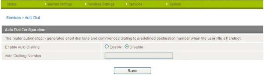
Figure 65 - Auto Dial sengs
System
Log
The Log page is used to download or display the current System Log of the router.

Download Log File
Figure 66 - System Log
The System Log enables you to troubleshoot any issues you may be experiencing with your router. You can use the "Display Level" drop-down list to select a message level to be displayed. The message levels are described in the table below.
| ITEM | DEFINITION |
| All | Display all system log messages. |
| Debug | Show extended system log messages with full debugging level details. |
| Info | Show informational messages only. |
| Notice | Show normal system logging information. |
| Warning | Show warning messages only. |
| Error | Show error condition messages only. |
Table 34 - System Log Detail Levels
You can also download the current System Log to your computer for off-line viewing. To do this, click the "Download Log File" link at the bottom of the page.
Load / Save

Note: the Load/Save menu is only available to users logged in to the router using the user name root. To perform Firmware upgrade, device configuration backup and reset the gateway to factory defaults, you need to login as the root user.
Settings
The settings page is used to backup or restore the router's configuration or to reset it to factory default settings.
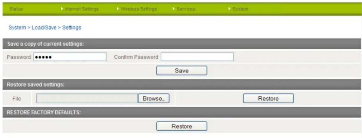
Figure 67 - Load / Save Canguroon Page

Note: In order to perform an update, you must be logged into the router as the root user (see the Remote Administration section for more details).
To save a copy of the router's configuration
Type the root manager password in both the Password and Confirm Password fields and click the Save button. You will be prompted to save a copy of the current settings from the router to your PC.

Note: The following conditions apply:-
It is NOT possible to edit the contents of the file downloaded; if you modify the contents of the configuration file in any way you will not be able to restore it later.
- You may change the name of the file if you wish but the filename extension must remain ".cfg"
To restore a copy of the router's configuration
- Click the "Browse..." button under the "Restore Saved settings:" section.
- Select the previously saved configuration file that you wish to restore to the router.
- Click the "Restore" button.
To restore the router's configuration to the factory defaults
Click the "Restore" button under the "Restore Factory Defaults" section to restore the router to factory default settings.
The router will then restart with the factory default configuration loaded.
Upload
The Upload page enables you to upload firmware files or user created application packages to the NTC-30WV.
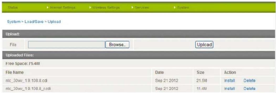
Figure 68 - Upload Page

Note: In order to perform an update, you must be logged into the router as the root user (see the Remote Administration section for more details).
Firmware upgrade
The firmware update process has two steps. The first step is to upload and install the system recovery image onto the router.
You can do this by clicking on the browse button and then to navigate to where the recovery image upgrade file is located on your computer.
Once you have selected the system recovery image file to use, click Upload to upload the file. You will then see a progress bar as shown in the screenshot below. The upload has finished when the status bar reaches 100%.
| Status | Internet Settings | Wireless LAN | Services | System |
| System > Load/Save > Upload | ||||
| Phase: | Upload | |||
| Percent Complete: | 12 % | |||
| Current Position: | 2288 / 19508 KBytes | |||
| Elapsed time: | 00:00:03 | |||
| Est Time Left: | 00:00:13 | |||
| Est Speed: | 1315 KB/s. | |||
Figure 69 - Local Firmware Upgrade - Upload Firmware
When the upload has completed, the screen should refresh and list the system recovery file you have just uploaded. Click on the "Install" link to the right of this.
Once you see "Done" shown as per the screenshot below, you can then boot into the system recovery mode to install the main system software.
Figure 70 - Local Firmware Upgrade - Firmware Update
Press and hold the reset button for approximately 5 – 10 seconds until the LEDs on the front of the router start to flash in an ON / OFF sequence and then release it. The router will now boot into the system recovery mode.
The second step is to upload and install the main system software image. To do this, open your web browser (e.g. Internet Explorer/Firefox/Safari) and navigate to http://192.168.1.1/
Click "Login" and type root in the Username and admin in the Password fields (without quotes). Then click on "Submit". The banner at the top of the page should be different to show that the router is currently in recovery console mode.

Figure 71 - Recovery Console Banner
To upload the main system software, click on "Application Installer" from the menu at the top of the page and then click on the browse button and navigate to where the main system image upgrade file is located on your computer.
Once you have selected the recovery image file to use, click Upload to upload the file. You will then see a progress bar as shown in the screenshot below. The upload has finished when the status bar reaches 100%.
| Status | Log | Application Installer | Settings | Reboot |
| Recovery Console > Upload | ||||
| Phase: | Upload | |||
| Percent Complete: | 30 % | |||
| Current Position: | 5880 / 19508 KBytes | |||
| Elapsed time: | 00:00:04 | |||
| Est Time Left: | 00:00:07 | |||
| Est Speed: | 2074 KB/s. | |||
Figure 72 - Recovery Console - Upload Firmware
When the upload has completed, the screen should refresh and show the file you have just uploaded. Click on the "Install" link to the right of this.
Once you see "Done" shown as per the screenshot below, click on "Reboot" at the top of the page and then click the Reboot button to restart the router.

Figure 73 - Recovery Console - Firmware Update
The router will confirm you want to restart and then start up with the new system software loaded.
Package Manager
The Package Manager page is used to provide details of any user installed packages on the router.
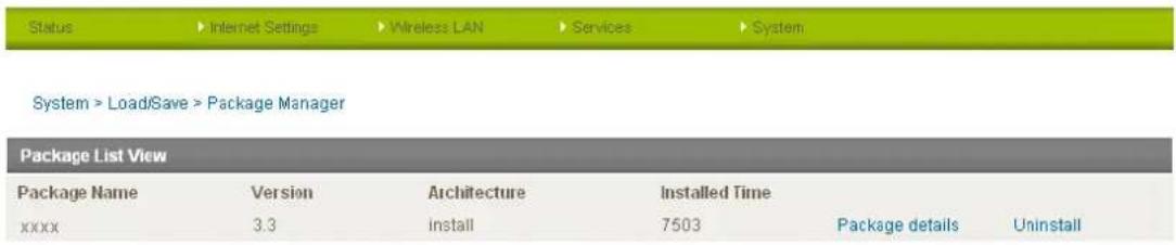
Figure 74 - Package Manager Items
The Package Name, Version, Architecture and Install time are shown while the package content details are available by clicking on the blue "Package Details" link.
Alternatively, if you want to remove a package, click the blue "Uninstall" link.

Note: For more information on creating software packages for the NTC-30WV, please refer to the SDK document available from the NetComm website.
Administration
The Administration page is used to enable or disable the firewall, remote administration, telnet access and ping responses.
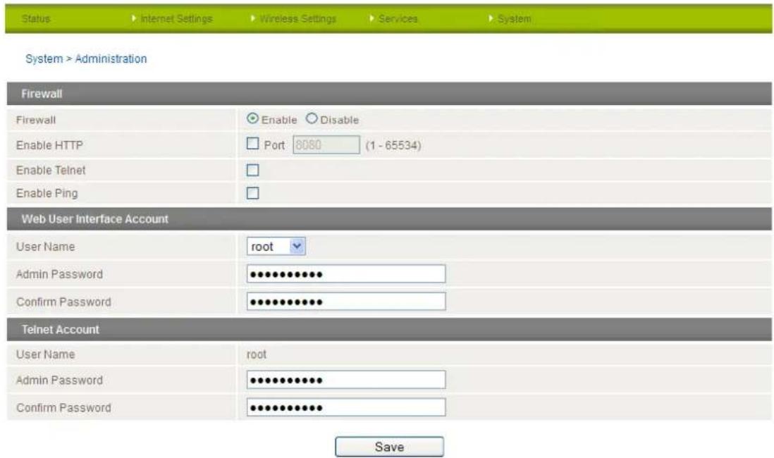
Figure 75 - Administraon Conguraon Items
| OPTION | DEFINITION |
| Firewall | Enable or disable the in-built firewall on the router. |
| Enable HTTP | Enable or disable remote HTTP access to the router. You can also set the port you would like remote HTTP access to be available on. |
| Enable Telnet | Enable or disable telnet (command line) access to the router. |
| Enable Ping | Enable or disable ping responses on the WWAN connection. |
| Web User Interface Account | |
| Username | Select the username you would like to change the password for. Root users have write permissions for both the root and admin accounts. Admin users can only update the admin password. |
| Password | Enter the new password for the selected user account. |
| Confirm Password | Re-enter the new password for the selected user account. |
| Telnet Account | |
| User Name | The Telnet Account settings are only available when logged into the router as the 'root' user. |
| Password | Enter the new password for the root telnet user account. |
| Confirm Password | Re-enter the new password for the root telnet user account. |
Table 35 - Administraon Conguroon Items

Note: The password will only be changed if you enter two matching passwords. It is not necessary to change the password if you are only changing the incoming port number.
To access the router's configuration pages remotely from a remote computer, perform the following steps:
- Open a new browser window (e.g. Internet Explorer, Firefox, Safari ...).
- In the address bar, enter the router's WAN IP address and assigned port number, e.g. "10.10.10.10: 8080".

Note: You can find the router's WAN IP address by clicking on the "Status" menu. The Local field in the WWAN section shows the router's WAN IP address.
Click "Login" and type admin or root in the Username and admin in the Password fields. Then click on "Submit".

Note: To perform functions like Firmware upgrade, device configuration backup and to restore and reset the router to factory defaults, you need to login as the root user.
System Configuration
The System configuration page is used to specify an external syslog server and the TCP Keepalive settings. The TCP Keepalive can be used to ensure the WWAN connection does not disconnect due to inactivity.
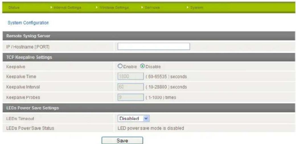
Figure 76 - System Conguraon Items
| OPTION | DEFINITION |
| IP / Hostname [:PORT] | The IP address and port of the external syslog server you would like logging information sent to. |
| TCP Keepalive Settings | |
| Keepalive | Enable or Disable the TCP Keepalive function. |
| Keepalive Time | The interval between the last packet sent and the first TCP keepalive packet being sent. |
| Keepalive Interval | The time between subsequent TCP Keepalive packets. |
| Keepalive Probes | The number of TCP Keepalive packets to send. |
| LEDs Power Save Settings | |
| LEDs Timeout | The length of time before the LEDs on the outside of the router turn off to save power. |
| LEDs Power Save Status | The status of the LED power saving function. |
Table 36 - System Conguraon Items
TR-069
The TR-069 (Technical Report 069) protocol is a technical specification also known as CPE WAN Management Protocol (CWMP). It is a framework for remote management and auto-configuration of end-user devices such as customer-premises equipment (CPE) and Auto Configuration Servers (ACS). It is particularly efficient in applying configuration updates across networks to multiple CPEs.
It uses a bi-directional SOAP/HTTP-based protocol based on the application layer protocol.
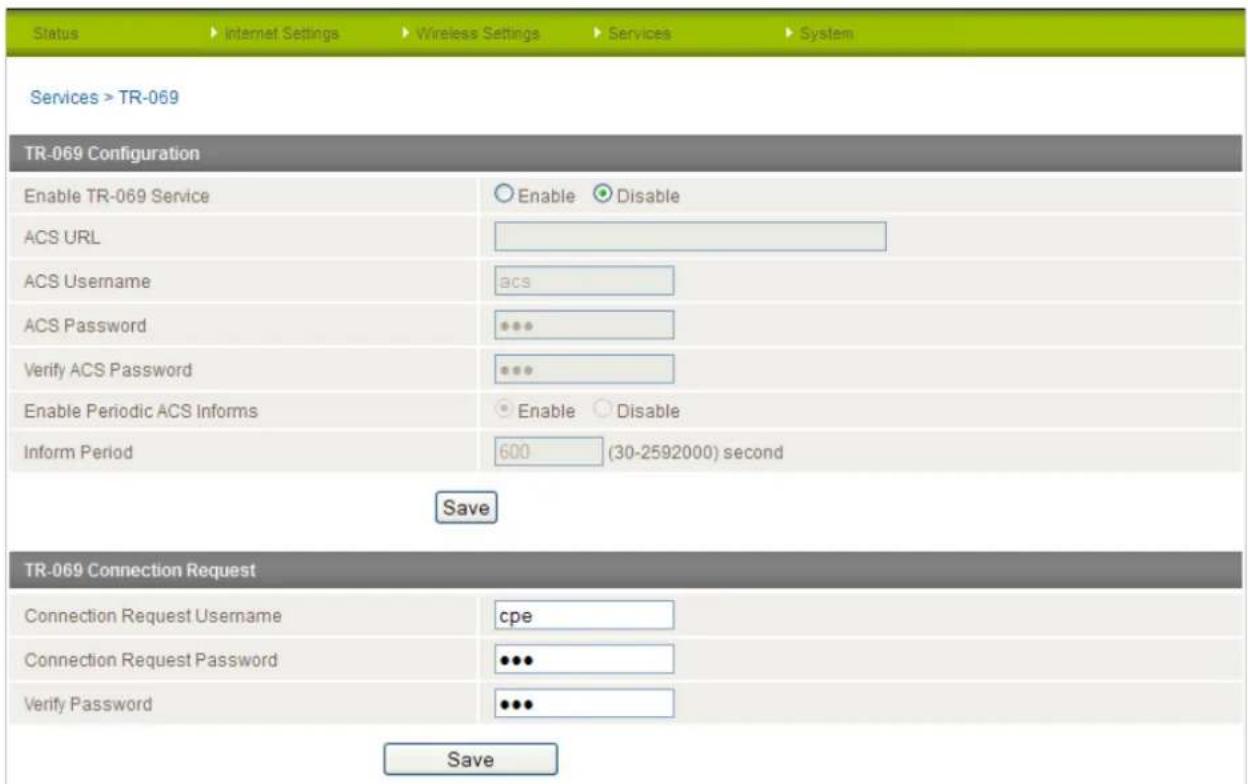
Figure 77 - System - TR-069
| OPTION | DEFINITION |
| Enable TR069 Service | This field provides the option to switch on or off the TR069 feature. .. |
| ACS URL | This field can be used to enter the domain name or IP address of the Auto Configuration Server (ACS) you wish to use. |
| ACS Password/Verify ACS Password | This field can be used to enter the password that the Auto Configuration Server (ACS) uses |
| Enable Periodic ACS Informs | Each session begins with the transmission of an Inform message from the ACS server. If able to the CPE device responds with an Inform Response message. A periodic Inform message verifies that each CPE device is capable of communicating and receiving updates from the ACS server |
| Keepalive Probes | The number of TCP Keepalive packets to send. |
| Inform Period | Enter the time in seconds between periodic Inform messages. The maximum time span possible is equivalent to more than 68 years. |
| Connection Request Username | Enter the TR-069 connection request username here. |
| Connection Request Password | Enter the TR-069 connection request password here. |
| Verify Password | Re-enter the TR-069 connection request password here and press the Save button. |
Table 37 - System - TR-069 Details
Logoff
The logoff item will log you out of your web configuration session.
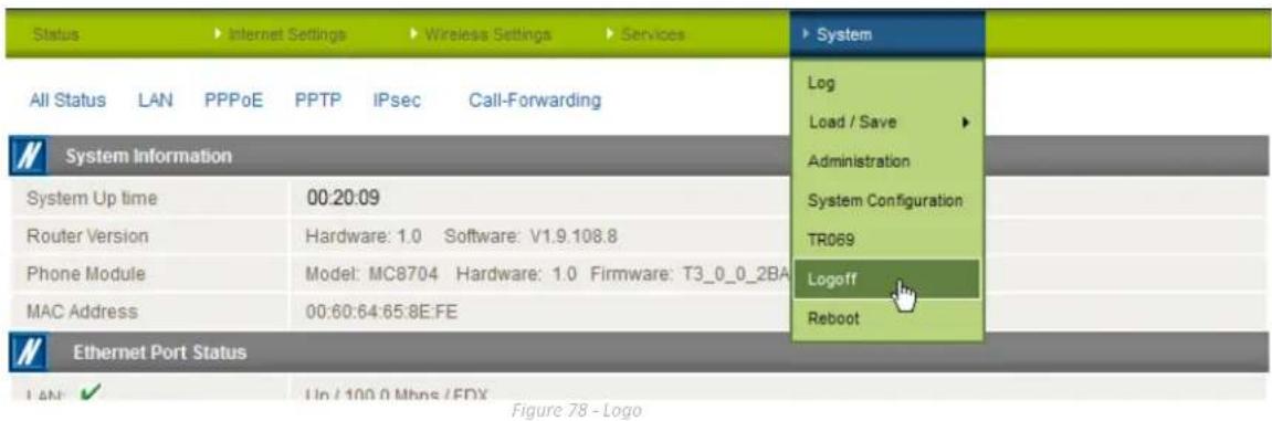
Reboot
The reboot item will reboot the router. This can be useful if you have made configuration changes you want to implement or want to reboot the router.
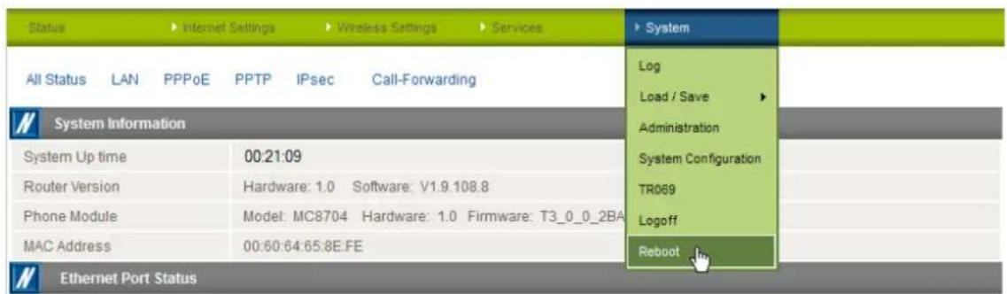
Figure 79 - Reboot Router
Technical Data
The following table lists the hardware specifications of the NTC-30WV.
| MODEL | NETCOMM NTC-30WV |
| Modem Module/Chipset | Sierra Wireless MC8704 |
| Memory | RAM: 64MB DRAMStorage: 256MB Flash |
| Operating System | Embedded Linux 2.6 |
| UMTS bands | Quad-Band: 850/900/1900/2100Mhz |
| GSM bands | Quad-Band: 850/900/1800/1900Mhz |
| Maximum Data Throughput / 3G Radio interface | Downlink: 42 Mbps (HSDPA Cat. 8); Uplink: 5.76 Mbps (HSUPA Cat. 6); EDGE MS Class 12: 236 kbps |
| Wireless Frequency | 2.4 - 2.438Ghz |
| Peak Data Rate (Wireless) | 300 Mbps (MIMO) |
| Wireless Security | WEP 64-bit, WEP 128-bit, WPA, WPA-PSK, WPA2-PSK, Mixed WPA-PSK/WPA2-PSK, TKIP, AES |
| Connectivity | 1 x RJ-45 Fast Ethernet 10/100Base-TX w/ Auto MDIX1 x Mini USB 2.0 Console Port1 x Optional Circular IP67 Power Connection (When PoE not used) |
| SIM Card Reader | 1 x Lockable SIM Card Tray Reader, Push to Release |
| Antenna connectors | Cellular: 2 x detachable TNC (1 x Main and 1 x Rx Diversity)WLAN: 2 x detachable TNC (1 x Main and 1 x Rx Diversity) |
| LED Indicators | 7 LEDs: Power, Network Service, 5 x Signal Strength |
| Operating Temperature | Normal Operating Temperature: -25 °C to 60 °CExtended Operating Temperature:Module: -25°C to +75°C (Reduced Performance) |
| Power input | DC-in Port: 9 - 28VPoE (IEEE 802.3af): 48V DCCAC/DC Power Adaptor: 100-240V AC to 12V DC/1.5A |
| Power Consumption | Standby Input Current: 110mA @ 12V DC3G Active Current: 300mA @ 12V DCMaximum Input Current: 560mA @ 12V DC |
| Dimensions & Weight | NTC-30WV: 255mm X 240mm X 80mm / 1750gMounting Bracket: 290mm X 110mm X 12mm / 410gAntennas: length = 180mm; diameter = 20mm / 60g |
| Regulatory Compliance | A-Tick (Australia), CE (Europe), FCC (USA), RoHS, Emark, IP67 Rating |
Table 38 - Technical Specifications for the NTC-30WV
Additional Product Information
Using the NTC-30WV to make and receive telephone calls
The NTC-30WV provides circuit switched voice services via a telephony line interface offering the ability to make and receive telephone calls via a regular analogue telephone using the 3G mobile network.

Note: Please refer to your mobile service provider for activation of your voice service and information about the call charges that apply.
Handset requirements
The NTC-30WV allows you to make telephone calls over the 3G network using a standard analogue telephone via the built in RJ-11 Phone port. Please refer to the documentation provided by the manufacturer of your analogue telephone for assistance with the operation of your telephone handset.
Maximum REN Loading
Please note that the line interface on the NTC-30WV is capable of supporting multiple analogue telephones connected via splitters. The ringer equivalence number (REN) for each line is 5. Therefore, a maximum of 5 handsets each with a REN number of 1 can be connected to the line port.
Before you start making any phone calls, make sure you have checked the following:
- You have an activated 3G SIM card inserted prior to powering on the NTC-30WV.
- Your NTC-30WV is powered on and in running condition.
- A working analogue telephone connected into the Line port.
- You hear the dial tone after lifting the handset.
How to place a call
To make a call, simply lift the handset and dial the number following the instructions provided by your telephone handset manufacturer.
How to receive a call
When an incoming call is received, the phone connected to the NTC-30WV will ring. Answer the telephone following the instructions provided by your telephone handset manufacturer to conduct the call.
If there is no phone connected to the NTC-30WV, all incoming calls will be transferred to Voicemail (if enabled on the device).
Answering an incoming call when on a call
Call waiting enables a 2nd incoming call to be received while you are on a call. To answer a call waiting call, perform a hook-flash (briefly depressing the hook button). The incoming call should then be answered. Upon hanging up or performing another hook-flash, you will be returned to the original telephone call.
Accessing voicemail
To access your voicemail, please dial *98 and follow the voice prompts.
NetCommWireless
Call feature codes
Quick Reference Table
The NTC-30WV supports a number of call feature codes for supplementary services.
| FEATURE | ACTIVATION | DEACTIVATION | STATUS |
| Caller ID | #31#(to block an individual call) | *31#(to unblock an individual call) | N/A |
| Call Waiting | *43# | #43# | *#43# |
| Call Forwarding Unconditional | *21*# | #21# | *#21# |
| Call Forwarding No Answer | *61*# | #61# | *#61# |
| Call Forwarding Busy | *67*# | #67# | *#67# |
| Call Forwarding Unreachable | *62*# | #62# | *#62# |
Table 39 - Additional Product Information - Call Feature Codes Quick Reference
Caller ID
Caller ID transmits a caller's number to the called party's telephone equipment when the call is being set up but before the call is answered. Where available, caller ID can also provide a name associated with the calling telephone number.
- To force Caller ID to be blocked for an outbound call, dial #31# followed by the number you wish to dial.
- To force Caller ID to be unblocked for an outbound call, dial *31# then follow the dialling number.
Call Waiting
Call waiting allows for indication and answering of an incoming telephone whilst an existing call is underway.
- To disable call waiting, dial #43#, and hang up after you hear 2 high pitch beeps.
- To enable call waiting, dial *43#, and hang up after you hear 2 low pitch beeps.
- To check the status of Call Waiting, dial *#43# or view the advanced status page of the management console.
(a) Call waiting is disabled if you hear 2 high pitch beeps.
(b) Call waiting is enabled if you hear 2 low pitch beeps.
Call forwarding (or call diverting), is a feature that allows an incoming call to be redirected to another number depending on the circumstances at the time of receiving the call.

Note: The Call Waiting feature will automatically turn off if you enable Call forwarding. Call Waiting will need to be enabled again after Call Forwarding is disabled.
Call Forwarding Unconditional
Call forwarding Unconditional will divert all incoming calls to a phone number that you desire.
- To enable Call Forwarding Unconditional, dial *21*
# (Where directory number is the number you wish to forward calls to - Hang up after you hear 2 low pitch beeps.
- To disable Call Forwarding Unconditional, dial #21#
- Hang up after you hear 2 high pitch beeps.
- To check the status of Call Forwarding Unconditional, dial *#21# or view the advanced status page of the management console.
(a) Call Forwarding Unconditional is disabled if you hear 2 high pitch beeps.
(b) Call Forwarding Unconditional is enabled if you hear 2 low pitch beeps.
Call Forwarding No Answer
Call forwarding No Answer will divert all incoming calls to a phone number that you desire only if the incoming call is not answered.
- To enable Call Forwarding No Answer, dial *61*
#
(Where directory number is the number you wish to forward calls to)
-
Hang up after you hear 2 low pitch beeps.
-
To disable Call Forwarding No Answer, dial #61#
-
Hang up after you hear 2 high pitch beeps.
-
To check the status of Call Forwarding No Answer, dial *#61# or view the advanced status page of the management console.
(a) Call Forwarding No Answer is disabled if you hear 2 high pitch beeps.
(b) Call Forwarding No Answer is enabled if you hear 2 low pitch beeps.
Call Forwarding Busy
Call forwarding busy will divert all incoming calls to a phone number that you desire only if your telephone is busy on another call. To enable Call Forwarding Busy, dial *67*
- Hang up after you hear 2 low pitch beeps.
- To disable Call Forwarding Busy, dial #67#
- Hang up after you hear 2 high pitch beeps.
- To check the status of Call Forwarding Busy, dial *#67# or view the advanced status page of the management console.
(a) Call Forwarding Busy is disabled if you hear 2 high pitch beeps.
(b) Call Forwarding Busy is enabled if you hear 2 low pitch beeps.
Call Forwarding Not Reachable
Call forwarding busy will divert all incoming calls to a phone number that you desire only if your telephone is unreachable by the network.
- To enable Call Forwarding Not Reachable dial *62*
#
(Where directory number is the number you wish to forward calls to) - Hang up after you hear 2 low pitch beeps.
- To disable Call Forwarding Not Reachable, dial #62#. Hang up after you hear 2 high pitch beeps.
- To check the status of Call Forwarding Not Reachable, dial *#62# or view the advanced status page of the management console.
(a) Call Forwarding No Answer is disabled if you hear 2 high pitch beeps.
(b) Call Forwarding No Answer is enabled if you hear 2 low pitch beeps.
Conference Call
This can be achieved by performing a hook-flash and then by dialling the third party.
Wait for the third party to answer your call and then perform another hook-flash to conference all the parties together.

Note: In order to activate a conference call, you will need to have originated both calls.
Troubleshooting
What do I do if I have no dial tone?
Please follow the procedure listed below:
- Check to make sure the phone is plugged into the line port of the NTC-30WV.
- Check to make sure you are using the correct cable (Cat-3 UTP Telephone Cable with RJ-11 plugs).
- Check to make sure the 3G signal strength indication lights on the front of the NTC-30WV are lit up.
- Check to make sure your 3G SIM card is activated and insert into your NTC-30WV properly.
- Check and see if you get the dial tone after rebooting your NTC-30WV.
I have noise interference during telephone calls. How can I fix this?
To resolve this issue, try the following:
- Verify that the RJ-11 cable is securely connected and not damaged.
- Try to remove any telephone splitters from the connection between your phone and the NTC-30WV.
- Try rebooting your NTC-30WV.
Appendix A: Tables
Table 1 - Document Revision History ......2
Table 2: Maximum Transmit Power Levels ....4
Table 3: Average Transmit Power Levels....5
Table 4 - LED Indicators....7
Table 5 - Device Dimensions ....9
Table 6 - Mounng Bracket Dimensions ....9
Table 7 - Antenna Dimensions ....10
Table 8 - Boom Mounted Integrated Interfaces....11
Table 9 - Top Mounted Interfaces....11
Table 10 - LAN Management Default Sengs ......12
Table 11 – WiFi Default Sengs ....12
Table 12 - Web Interface Default Sengs ....12
Table 13 - Locking Power Block Pin Outs....16
Table 14 - Status page items ....19
Table 15 - Status Page - LAN Details....20
Table 16 - Status Page - PPPoE Details....20
Table 17 - Status Page - PPTP Details ....20
Table 18 - Status Page - IPSec Details....20
Table 19 - Status Page - Call Forwarding Status Details ....21
Table 20 - Advanced Status Page 22
Table 21 - NAT Conguraon Items ....33
Table 22 - OpenVPN Conguraon Items ....39
Table 23 - PPTP Conguraon Items....40
Table 24 - GRE VPN Sengs....41
Table 25 - Wireless Configuraon - Basic Conguraon Items....43
Table 26 - WDS Access Point 1 Repeater Mode Sengs ....47
Table 27 - Wireless Sengs - Advanced Conguraon Items....51
Table 28 - SNMP Conguraon Opons....56
Table 29 - SMS Setup Conguraon Items....57
Table 30 - SMS Diagnosc Command Syntax 64
Table 31 - List of Valid SMS Diagnosc Commands....65
Table 32 - List of SMS Diagnoscs Variables ......65
Table 33 - SMS Diagnoscs - Example Commands....66
Table 34 - System Log Detail Levels....67
Table 35 - Administraon Conguraon Items....72
Table 36 - System Configuraon Items ....73
Table 37 - System - TR-069 Details....74
Table 38 - Technical Speciaons for the NTC-30WV 76
Table 39 - Additional Product Informaon - Call Feature Codes Quick Reference ....78
Legal and Regulatory
Intellectual Property Rights
All intellectual property rights (including copyright and trade mark rights) subsisting in, relating to or arising out this Manual are owned by and vest in NetComm Limited (ACN 002490486) (NetComm) (or its licensors). This Manual does not transfer any right, title or interest in NetComm's (or its licensors') intellectual property rights to you.
You are permitted to use this Manual for the sole purpose of using the NetComm product to which it relates. Otherwise no part of this Manual may be reproduced, stored in a retrieval system or transmitted in any form, by any means, be it electronic, mechanical, recording or otherwise, without the prior written permission of NetComm.
NetComm is a trademark of NetComm. All other trademarks are acknowledged to be the property of their respective owners.
Customer Information
The Australian Communications & Media Authority (ACMA) requires you to be aware of the following information and warnings:
-
This unit may be connected to the Telecommunication Network through a line cord which meets the requirements of the AS/CA S008-2011 Standard.
-
This equipment has been tested and found to comply with the Standards for C-Tick and or A-Tick as set by the ACMA. These standards are designed to provide reasonable protection against harmful interference in a residential installation. This equipment generates, uses, and can radiate radio noise and, if not installed and used in accordance with the instructions detailed within this manual, may cause interference to radio communications. However, there is no guarantee that interference will not occur with the installation of this product in your home or office. If this equipment does cause some degree of interference to radio or television reception, which can be determined by turning the equipment off and on, we encourage the user to try to correct the interference by one or more of the following measures:
-
Change the direction or relocate the receiving antenna.
-
Increase the separation between this equipment and the receiver.
-
Connect the equipment to an alternate power outlet on a different power circuit from that to which the receiver/TV is connected.
-
Consult an experienced radio/TV technician for help.
-
The power supply that is provided with this unit is only intended for use with this product. Do not use this power supply with any other product or do not use any other power supply that is not approved for use with this product by NetComm. Failure to do so may cause damage to this product, fire or result in personal injury.
Consumer Protection Laws
Australian and New Zealand consumer law in certain circumstances implies mandatory guarantees, conditions and warranties which cannot be excluded by NetComm and legislation of another country's Government may have a similar effect (together these are the Consumer Protection Laws). Any warranty or representation provided by NetComm is in addition to, and not in replacement of, your rights under such Consumer Protection Laws.
If you purchased our goods in Australia and you are a consumer, you are entitled to a replacement or refund for a major failure and for compensation for any other reasonably foreseeable loss or damage. You are also entitled to have the goods repaired or replaced if the goods fail to be of acceptable quality and the failure does not amount to a major failure. If you purchased our goods in New Zealand and are a consumer you will also be entitled to similar statutory guarantees.
Product Warranty
All NetComm products have a standard one (1) year warranty from date of purchase, however, some products have an extended warranty option (refer to packaging and the warranty card) (each a Product Warranty). To be eligible for the extended warranty option you must supply the requested warranty information to NetComm within 30 days of the original purchase by registering online via the NetComm Wireless web site at www.netcommwireless.com. For all Product Warranty claims you will require proof of purchase. All Product Warranties are in addition to your rights and remedies under applicable Consumer Protection Laws which cannot be excluded (see Section 3 above).
Subject to your rights and remedies under applicable Consumer Protection Laws which cannot be excluded (see Section 3 above), the Product Warranty is granted on the following conditions:
- the Product Warranty extends to the original purchaser (you / the customer) and is not transferable;
- the Product Warranty shall not apply to software programs, batteries, power supplies, cables or other accessories supplied in or with the product;
- the customer complies with all of the terms of any relevant agreement with NetComm and any other reasonable requirements of NetComm including producing such evidence of purchase as NetComm may require;
- the cost of transporting product to and from NetComm's nominated premises is your responsibility;
- NetComm does not have any liability or responsibility under the Product Warranty where any cost, loss, injury or damage of any kind, whether direct, indirect, consequential, incidental or otherwise arises out of events beyond NetComm's reasonable control. This includes but is not limited to: acts of God, war, riot, embargoes, acts of civil or military authorities, fire, floods, electricity outages, lightning, power surges, or shortages of materials or labour; and
- the customer is responsible for the security of their computer and network at all times. Security features may be disabled within the factory default settings. NetComm recommends that you enable these features to enhance your security.
Subject to your rights and remedies under applicable Consumer Protection Laws which cannot be excluded (see Section 3 above), the Product Warranty is automatically voided if:
- you, or someone else, use the product, or attempt to use it, other than as specified by NetComm;
- the fault or defect in your product is the result of a voltage surge subjected to the product either by the way of power supply or communication line, whether caused by thunderstorm activity or any other cause(s);
- the fault is the result of accidental damage or damage in transit, including but not limited to liquid spillage;
- your product has been used for any purposes other than that for which it is sold, or in any way other than in strict accordance with the user manual supplied;
- your product has been repaired or modified or attempted to be repaired or modified, other than by a qualified person at a service centre authorised by NetComm; or
- the serial number has been defaced or altered in any way or if the serial number plate has been removed.
Limitation of Liability
This clause does not apply to New Zealand consumers.
Subject to your rights and remedies under applicable Consumer Protection Laws which cannot be excluded (see Section 3 above), NetComm accepts no liability or responsibility, for consequences arising from the use of this product. NetComm reserves the right to change the specifications and operating details of this product without notice.
If any law implies a guarantee, condition or warranty in respect of goods or services supplied, and NetComm's liability for breach of that condition or warranty may not be excluded but may be limited, then subject to your rights and remedies under any applicable Consumer Protection Laws which cannot be excluded, NetComm's liability for any breach of that guarantee, condition or warranty is limited to: (i) in the case of a supply of goods, NetComm doing any one or more of the following: replacing the goods or supplying equivalent goods; repairing the goods; paying the cost of replacing the goods or of acquiring equivalent goods; or paying the cost of having the goods repaired; or (ii) in the case of a supply of services, NetComm doing either or both of the following: supplying the services again; or paying the cost of having the services supplied again.
To the extent NetComm is unable to limit its liability as set out above, NetComm limits its liability to the extent such liability is lawfully able to be limited.
FCC Regulations:
- This device complies with part 15 of the FCC Rules. Operation is subject to the following two conditions: (1) This device may not cause harmful interference, and (2) this device must accept any interference received, including interference that may cause undesired operation.
- This device has been tested and found to comply with the limits for a Class B digital device, pursuant to Part 15 of the FCC Rules. These limits are designed to provide reasonable protection against harmful interference in a residential installation. This equipment generates, uses and can radiated radio frequency energy and, if not installed and used in accordance with the instructions, may cause harmful interference to radio communications. However, there is no guarantee that interference will not occur in a particular installation. If this equipment does cause harmful interference to radio or television reception, which can be determined by turning the equipment off and on, the user is encouraged to try to correct the interference by one or more of the following measures:
-Reorient or relocate the receiving antenna.
-Increase the separation between the equipment and receiver.
-Connect the equipment into an outlet on a circuit different from that to which the receiver is connected.
-Consult the dealer or an experienced radio/TV technician for help.
Changes or modifications not expressly approved by the party responsible for compliance could void the user's authority to operate the equipment.
▶ RF Exposure Information
This device meets the government's requirements for exposure to radio waves.
This device is designed and manufactured not to exceed the emission limits for exposure to radio frequency (RF) energy set by the Federal Communications Commission of the U.S. Government.
- This device complies with FCC radiation exposure limits set forth for an uncontrolled environment. In order to avoid the possibility of exceeding the FCC radio frequency exposure limits, human proximity to the antenna shall not be less than 20cm (8 inches) during normal operation.
IC Regulations:
This device complies with Industry Canada license-exempt RSS standard(s). Operation is subject to the following two conditions:
(1) this device may not cause interference, and
(2) this device must accept any interference, including interference that may cause undesired operation of the device.
This Class B digital apparatus complies with Canadian ICES-003.
IC Radiation Exposure Statement:
This equipment complies with IC RSS-102 radiation exposure limits set forth for an uncontrolled environment. This equipment should be installed and operated with minimum distance 20cm between the radiator & your body.
The County Code Selection feature is disabled for products marketed in the US/Canada.
For product available in the USA/ Canada markets, only channel 1\~11 can be operated. Selection of other channels is not possible.
Contact
Address: NetComm Wireless Limited 18-20 Orion Road, Lane Cove NSW 2066 Sydney, Australia
ABN: 85 002 490 486
Website: www.netcommwireless.com
Phone: +61(0)2 9424 2070
Fax: +61(0)2 9424 2010
Email: sales@netcommwireless.com ; techsupport@netcommwireless.com

- Outdoor HSPA+ WiFi Router with Voice
- Copyright
- Table of Contents
- Overview
- Introduction
- Target Audience
- Professional Installation Instructions
- Prerequisites
- Notation
- Product Introduction
- Product Overview
- Package Contents
- Product Features
- Physical Dimensions and Indicators
- LED Indicators
- Physical Dimensions
- Interfaces
- NTC-30WV Default Settings
- Restoring Factory Default Settings
- Implementation and Deployment Scenario
- Installation and Configuration of the NTC-30WV
- Powering the Router via DC Power Supply
- Powering the Router via a Power over Ethernet (PoE) Cable (Optional)
- Captive Power Terminal Block
- Connecting wirelessly
- Configuring the NTC-30WV
- Status
- LAN
- PPPoE
- PPTP
- IPSec
- Call Forwarding Status
- Advanced Status
- Internet Settings
- Connection
- NetCommWireless
- To connect using a Connection profile
- To confirm successful connection
- Restoring the Automatic Configuration option after manually configuring an APN profile
- Band / Provider
- SIM Security
- Enter PUK
- Remember PIN
- IP Setup
- DNS Masquerading
- DHCP
- Static
- Adding Static Routes
- Deleting Static Routes
- RIP
- VRRP
- NAT
- DMZ
- OpenVPN
- PPTP-Client
- GRE
- USSD
- Wireless Settings
- Security Settings
- WPA1/WPA2
- WPA-PSK/WPA2-PSK
- 802.1x
- WDS Mode
- Set the DHCP Server on Access Point 2 to Disable:
- Advanced
- MAC / IP / Port Filter
- Station List
- Services
- To configure dynamic DNS:
- NTP
- This works as follows:
- How to disable the Periodic Ping Monitor
- How to configure a Forced Reset
- SMS
- Basic functionality supported:
- Setup
- SMS Configuration for Redirection
- Redirect To Mobile
- For Example:
- Redirect to TCP & TCP Port, Redirect to UDP & UDP Port
- SMS Configuration for Remote Diagnostics
- Enable Remote Diagnostics
- New Message
- Inbox / Outbox
- Diagnostics
- Enable Authentication
- Send Ack. SMS for Set Command
- Send Ack. SMS to
- Fixed Ack. SMS Number
- Send Error SMS for Get/Set/Exec Command
- Send Error SMS to
- Fixed Error SMS Number
- Max. Diag. SMS Tx Limit
- White List
- Message Storage for Diagnostic Messages
- Security
- Replies
- SMS Diagnostics Examples
- Auto Dial
- System
- Log
- Settings
- To restore a copy of the router's configuration
- Upload
- Firmware upgrade
- Package Manager
- Administration
- System Configuration
- TR-069
- Logoff
- Reboot
- Technical Data
- Additional Product Information
- Handset requirements
- Maximum REN Loading
- How to place a call
- How to receive a call
- Answering an incoming call when on a call
- Accessing voicemail
- Call feature codes
- Quick Reference Table
- Caller ID
- Call Waiting
- Call Forwarding Unconditional
- Call Forwarding No Answer
- Call Forwarding Busy
- Call Forwarding Not Reachable
- Conference Call
- Troubleshooting
- Appendix A: Tables
- Legal and Regulatory
- Intellectual Property Rights
- Customer Information
- Consumer Protection Laws
- Product Warranty
- Limitation of Liability
- FCC Regulations:
- IC Regulations:
- Contact
Brand : Netcomm
Model : NTC-30WV
Category : Router