NF10WV - Router Netcomm - Free user manual and instructions
Find the device manual for free NF10WV Netcomm in PDF.


| Product Type | Router / ADSL2+ Modem |
| Brand | Netcomm |
| Model | NF10WV |
| Dimensions (approx.) | 200 x 130 x 35 mm |
| Weight (approx.) | 0.3 kg |
| Power Supply | 12V DC, 1A |
| Wireless Standard | 802.11n (up to 300 Mbps) |
| WAN Interface | ADSL2+ (RJ-11) |
| LAN Interfaces | 4 x Fast Ethernet (RJ-45) |
| USB Port | 1 x USB 2.0 (for printer or storage) |
| Firewall | Stateful Packet Inspection (SPI) |
| VPN Support | PPTP, IPSec, L2TP |
| Quality of Service (QoS) | Supported |
| Maintenance | Wipe with dry cloth; avoid liquids |
| Safety | Keep away from water; unplug during storms |
| Spare Parts / Repairability | No user-serviceable parts; contact support |
| General Information | All-in-one ADSL router with wireless N and VoIP |
Frequently Asked Questions - NF10WV Netcomm
User questions about NF10WV Netcomm
0 question about this device. Answer the ones you know or ask your own.
Ask a new question about this device
Download the instructions for your Router in PDF format for free! Find your manual NF10WV - Netcomm and take your electronic device back in hand. On this page are published all the documents necessary for the use of your device. NF10WV by Netcomm.
USER MANUAL NF10WV Netcomm
VDSL/ADSL N300 WiFi Modem Router with VoIP
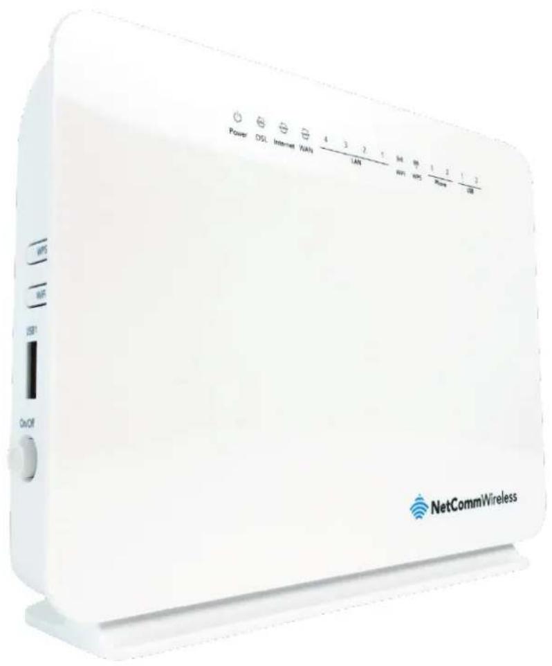
NF10WV
USER GUIDE
Copyright
Copyright © 2016 NetComm Wireless Limited. All rights reserved.
The information contained herein is proprietary to NetComm Wireless Limited. No part of this document may be translated, transcribed, reproduced, in any form, or by any means without prior written consent of NetComm Wireless Limited.
Trademarks and registered trademarks are the property of NetComm Wireless Limited or their respective owners. Specifications are subject to change without notice. Images shown may vary slightly from the actual product.

Note: This document is subject to change without notice.
Save our environment
When this equipment has reached the end of its useful life, it must be taken to a recycling centre and processed separately from domestic waste.
The cardboard box, the plastic contained in the packaging, and the parts that make up this device can be recycled in accordance with regionally established regulations. Never dispose of this electronic equipment along with your household waste. You may be subject to penalties or sanctions under the law. Instead, ask for disposal instructions from your municipal government.
Please be responsible and protect our environment.
This manual covers the following products:
NetComm Wireless VDSL/ADSL N300 WiFi Modem Router (NF10WV)
| DOCUMENT VERSION | DATE |
| 1.0 Initial document release | 29 March 2016 |
| 1.1 Added Ethernet Priority Marking description to SIP Advanced page. | 14 April 2016 |
| 1.2 Updated based on firmware version R5B019 | 26 September 2016 |
Table 1 - Document Revision History
Table of contents
Overview 5
Introduction....5
Target audience....5
Prerequisites....5
Notation 5
Welcome 6
Product overview....6
Package contents....6
Product features....7
Physical dimensions and indicators 8
LED indicators....8
Physical Dimensions and Weight....9
NF10WV Default Settings....9
Interfaces 10
Rear 10
Left Side....11
Safety and product care....12
Transport and handling 12
Installation and configuration of the NF10WV 13
Placement of your NF10WV 13
Avoiding obstacles and interference 13
Cordless phones 13
Choosing the "quietest" channel for your wireless network....14
Hardware installation....14
Connecting a client via Ethernet cable 14
Connecting a client wirelessly....14
Web based configuration interface....15
First-time setup wizard....15
ADSL 15
VDSL 16
Ethernet WAN....18
Device Info 20
Summary....20
WAN 21
Statistics 21
Route....24
ARP 24
DHCP 24
Advanced Setup....25
Layer2 Interface 25
WAN Service....27
LAN 31
NAT 33
Security 36
Parental Control....39
Quality of Service 41
Routing 43
DNS 45
DSL 46
UPnP 47
DNS Proxy 47
DLNA 48
Storage Service 48
Interface Grouping....49
IP Tunnel....50
IPSec 51
Multicast (IGMP Configuration) 52
Wireless 53
Basic....53
Voice....58
VoIP Status 58
SIP Basic Setting....58
SIP Advanced....60
SIP Extra Setting....62
SIP Star Code Setting....62
SIP Debug Setting 63
VoIP Functionality 64
Registering....64
Placing a Call....64
Anonymous call....64
Do Not Disturb (DND)....64
Call Return 64
Call Hold 64
Call Waiting 64
Blind Transfer 65
Consultative Transfer....65
Call Forwarding No Answer....65
Call Forwarding Busy 65
Call Forwarding All....65
Three-Way Conference....65
T38 Faxing 66
Pass-Through Faxing....66
Diagnostics 67
Diagnostics....67
Ethernet OAM....68
Diagnostics....69
Management....69
Settings....69
System Log....70
SNMP Agent 71
TR-069 Client 71
Internet Time 72
Access Control....72
Update Firmware....73
Reboot....74
Additional Product Information....74
Establishing a wireless connection....74
Windows 7....74
Windows 8/8.1/10....74
Mac OSX 10.6....74
Troubleshooting....76
Using the indicator lights (LEDs) to Diagnose Problems....76
Appendix: Quality of Service Setup Example....77
Reserving IP addresses....77
QoS Configuration Settings....78
High Priority QoS Queue Configuration....79
Low Priority QoS Queue Configuration 80
High Priority QoS Classification....80
Low Priority QoS Classification....82
Limiting the upstream rate....83
Limiting the downstream rate....84
Legal & Regulatory Information....85
Intellectual Property Rights....85
Customer Information 85
Consumer Protection Laws....85
Product Warranty 86
Limitation of Liability....86
Contact 87
Overview
Introduction
This manual provides information related to the installation, operation, and use of the NF10WV.
Target audience
The individual reading this manual is presumed to have a basic understanding of telecommunications terminology and concepts.
Prerequisites
Before continuing with the installation of your NF10WV, please confirm that you meet the minimum system requirements below.
An activated ADSL/VDSL or pre-configured WAN connection.
A computer with a working Ethernet adapter or wireless 802.11b/g/n capability and the TCP/IP Protocol installed.
A current version of a web browser such as Internet Explorer®, Mozilla Firefox® or Google Chrome™.
Notation
The following symbols are used in this manual:

Indicates a note requiring attention.

Indicates a note providing a warning.

Indicates a note providing useful information.
Welcome
Thank you for purchasing a NetComm Wireless VDSL/ADSL N300 WiFi Modem Router with VoIP. This guide contains all the information you need to configure your device.
Product overview
Fully featured VDSL2 / ADSL2+ Modem Router
4 x 10/100 Fast Ethernet LAN ports for wired connections
1 x 10/100/1000 Gigabit Ethernet WAN port for connection to fibre services
Wireless N Access Point for multiple high speed WiFi connections
2 x USB host ports – supports two USB storage devices for file sharing
NBN ready: carefully developed hardware and software features to ensure this device is optimised for use on the National Broadband Network
IPv6 ready for the next generation IP addressing
WPS button for simple setup of your wireless network
Package contents
The NF10WV package consists of:
1 x NetComm Wireless VDSL/ADSL N300 WiFi Modem Router with VoIP (NF10WV)
1 x Quick Start Guide
1 x 1.5m RJ45 Ethernet cable
1 x RJ11 Telephone cable
1 x WiFi security card
1 x Warranty card
1 x Power supply (12V/2A)
If any of these items are missing or damaged, please contact NetComm Wireless Support immediately by visiting the NetComm Wireless Support website at: http://www.netcommwireless.com/contact-forms/support
Product features
Featuring a VDSL2/ADSL2+ modem and a Gigabit WAN port, you can choose whether you connect to the Internet via DSL or a fibre service. If you don't have a fibre connection, the Gigabit WAN port will have you protected should you choose to update in the future. With uncertainty around the future of the NBN, NetComm Wireless will have you covered should the network connection switch to VDSL.
This router also includes 2 x USB host ports that can be used to connect USB devices so that their capabilities can be shared with all connected users. Connect a USB hard drive so that all files stored can be accessed and shared.
All of these features can be shared with multiple users via the built-in wireless access point or the four Ethernet LAN ports. The high speed Wireless N provides a signal strong enough to penetrate the far corners of a house and can connect all WiFi enabled devices, such as laptops, smartphones, gaming consoles, tablets and PCs. The four Fast Ethernet ports provide a wired connection that can be used to connect desktop computers, media devices or any Ethernet equipped product.

Note: Maximum wireless signal rate and coverage values are derived from IEEE Standard 802.11g, and 802.11n specifications. Actual wireless speed and coverage are dependent on network and environmental conditions included but not limited to volume of network traffic, building materials and construction/layout.
Physical dimensions and indicators
LED indicators
The NF10WV has been designed to be placed on a desktop. All of the cables exit from the rear for easy organization. The display is visible on the front of the NF10WV to provide you with information about network activity and the device status. See below for an explanation of each of the indicator lights.
| LED INDICATOR | ICON | COLOUR | DEFINITION |
| Power |  | Green | The NF10WV is powered on and operating normally. |
| Off | The power is off. | ||
| DSL |  | Off | No DSL signal detected. |
| Green Blinking | Synching | ||
| Green | DSL synchronized. | ||
| Internet | [XZSZ] | Green | The NF10WV is connected to an internet service. |
| Green Blinking | Data is being transmitted to or from the internet. | ||
| Off | The NF10WV is not connected to the internet. | ||
| WAN |  | Green | A device is connected to the Ethernet WAN port. |
| Green Blinking | Data is being transmitted to or from the WAN. | ||
| Off | No device is connected to the Ethernet WAN port. | ||
| LAN 1-4 | Green | A device is connected to the Ethernet LAN port. | |
| Green Blinking | Data is being transmitted to or from the Ethernet LAN port. | ||
| Off | No device is connected to the Ethernet LAN port. | ||
| WiFi |  | Green | WiFi is enabled. |
| Green Blinking | Data is being transmitted to or from the Wireless interface. | ||
| Off | WiFi is disabled. | ||
| WPS |  | Green | WPS is enabled |
| Green Blinking | WPS pairing is triggered. | ||
| Off | WPS is disabled. | ||
| USB 1 - 2 | Green | A USB hard drive is connected. | |
| Green Blinking | Data is being transmitted through the USB interface. | ||
| Off | No USB hard drive is connected to the USB interface. | ||
Physical Dimensions and Weight
The table below lists the physical dimensions and weight of the NF10WV.
| DIMENSIONS | |
| Width | 190 mm |
| Height | 146 mm |
| Depth | 54 mm |
| Weight | 326 grams |
NF10WV Default Settings
The following tables list the default settings for the NF10WV.
| LAN (MANAGEMENT) | |
| Static IP Address | 192.168.20.1 |
| Subnet Mask | 255.255.255.0 |
| Default Gateway | 192.168.20.1 |
| WIRELESS (WIFI) | |
| SSID | (Refer to the included Wireless Security Card) |
| Security | WPA2-PSK (AES) |
| Security Key | (Refer to the included Wireless Security Card) |
| NF10WV WEB INTERFACE ACCESS | |
| Username | admin |
| Password | admin |
Interfaces
Rear
The following interfaces are available on the NF10WV:
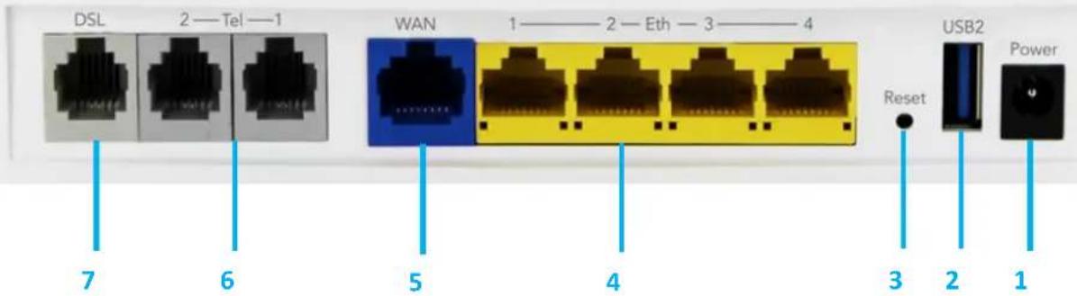
| NUMBER | INTERFACE | DESCRIPTION |
| 1 | Power supply jack | Connection point for the included power adapter. Connect the power supply here. |
| 2 | USB 2 | Connect an external USB hard drive here to use the NAS feature of the NF10WV. |
| 3 | Reset button | Reset unit to the default factory configuration by holding the Reset button down for 7 seconds or until all the LEDs turn off. |
| 4 | Ethernet 1 - 4 | Fast Ethernet LAN ports. Connect your Ethernet based devices to one of these ports for high-speed internet access. |
| 5 | WAN | Gigabit capable WAN port for connection to a WAN network. |
| 6 | Telephone 1 and 2 | Connect a regular telephone handset here for use with a VoIP account. |
| 7 | DSL | Use the provided RJ-11 cable to connect the router to the telephone line operating your xDSL service. |
Left Side
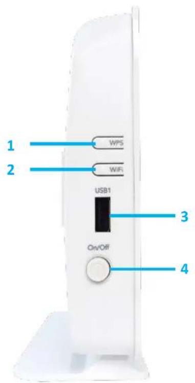
| NUMBER | INTERFACE | DESCRIPTION |
| 1 | WPS button | Press the WPS button to activate the WPS pairing function. The WPS feature is disabled by default, to enable it, refer to the Security section. |
| 2 | WiFi button | Press the WiFi button to turn the WiFi radio on or off. When the WiFi radio is off, the WiFi LED on the front panel turns off. |
| 3 | USB 1 | Connect an external USB hard drive here to use the NAS feature of the NF10WV. |
| 4 | Power button | Toggles the power on and off. |
Safety and product care
Your router is an electronic device that sends and receives radio signals. Please take the time to read this list of precautions that should be taken when installing and using the router.
Do not disassemble the router. There are no user-serviceable parts.
Do not allow the router to come into contact with liquid or moisture at any time. To clean the device, wipe it with a damp cloth.
Do not restrict airflow around the device. This can lead to the device overheating.
Do not place the device in direct sunlight or in hot areas.
Transport and handling
When transporting the NF10WV, it is recommended to return the product in the original packaging. This ensures that the product will not be damaged.

Note: In the event the product needs to be returned, ensure it is securely packaged with appropriate padding to prevent damage during courier transport.
Installation and configuration of the NF10WV
Placement of your NF10WV
The wireless connection between your NF10WV and your WiFi devices will be strong when they are in close proximity and have direct line of sight. As your client device moves further away from the NF10WV or solid objects block direct line of sight to the router, your wireless connection and performance may degrade. This may or may not be directly noticeable, and is greatly affected by the individual installation environment.
If you have concerns about your network's performance that might be related to range or obstruction factors, try moving the computer to a position between three to five meters from the NF10WV in order to see if distance is the problem.

Note: While some of the items listed below can affect network performance, they will not prohibit your wireless network from functioning; if you are concerned that your network is not operating at its maximum effectiveness, this check list may help.
If you experience difficulties connecting wirelessly between your WiFi Devices and your NF10WV, please try the following steps:
In multi-storey homes, place the NF10WV on a floor that is as close to the centre of the home as possible. This may mean placing the NF10WV on an upper floor.
Try not to place the NF10WV near a cordless telephone that operates at the same radio frequency as the NF10WV (2.4GHz).
Avoiding obstacles and interference
Avoid placing your NF10WV near devices that may emit radio "noise," such as microwave ovens. Dense objects that can inhibit wireless communication include:
Refrigerators
Washers and/or dryers
Metal cabinets
Large aquariums
Metallic-based, UV-tinted windows
If your wireless signal seems weak in some spots, make sure that objects such as those listed above are not blocking the signal's path (between your devices and the NF10WV).
Cordless phones
If the performance of your wireless network is impaired after considering the above issues, and you have a cordless phone:
Try moving cordless phones away from your NF10WV and your wireless-enabled computers.
Unplug and remove the battery from any cordless phone that operates on the 2.4GHz band (check manufacturer's information). If this fixes the problem, your phone may be interfering with the NF10WV.
If your phone supports channel selection, change the channel on the phone to the farthest channel from your wireless network. For example, change the phone to channel 1 and move your NF10WV to channel 11. See your phone's user manual for detailed instructions.
If necessary, consider switching to a 900MHz or 5GHz cordless phone.
Choosing the "quietest" channel for your wireless network
In locations where homes or offices are close together, such as apartment buildings or office complexes, there may be wireless networks nearby that can conflict with your wireless network. Your wireless adapter may include a utility to assist in scanning for the least congested network, otherwise you may be able to find another piece of software that can be used. These tools display a graphical representation of the wireless networks in range and the channels on which they are operating. Try to find a channel which is not as busy and does not overlap with another one. Channels 1, 6 and 11 are the only channels which do not overlap with one another and you should ideally choose one of these channels. Experiment with more than one of the available channels, in order to find the clearest connection and avoid interference from neighbouring cordless phones or other wireless devices.
Hardware installation
- Connect the power adapter to the Power socket on the back of the NF10WV.
- Plug the power adapter into the wall socket and switch on the power.
- Wait approximately 60 seconds for the NF10WV to power up.
Connecting a client via Ethernet cable
- Connect the yellow Ethernet cable provided to one of the ports marked 'LAN' at the back of the NF10WV.
- Connect the other end of the yellow Ethernet cable to your computer.
- Wait approximately 30 seconds for the connection to establish.
- Open your Web browser, and enter http://192.168.20.1 into the address bar and press enter.
- Follow the steps to set up your NF10WV.
Connecting a client wirelessly
- Ensure WiFi is enabled on your device (e.g. computer/laptop/smartphone).
- Scan for wireless networks in your area and connect to the network name that matches the Wireless network name configured on the NF10WV.

Note: Refer to the included Wireless Security Card for the default SSID and wireless security key of your NF10WV
- When prompted for your wireless security settings, enter the Wireless security key configured on the NF10WV.
- Wait approximately 30 seconds for the connection to establish.
- Open your Web browser, and enter http://192.168.20.1 into the address bar and press Enter.
- Follow the steps to set up your NF10WV.
Web based configuration interface
First-time setup wizard
Please follow the steps below to configure your NF10WV Wireless router via the web based configuration wizard.
Open a web browser and type http://192.168.20.1/ into the address bar at the top of the window.
At the login screen, type admin in the username and password field, then click the Login button.

Note: admin is the default username and password for the unit.

We highly recommend that immediately after initial installation you change the default passwords for admin, support and user access. You can do this from the Management -> Access Control -> Passwords page. See Access Control -- Access Controls - Passwords on page 72 for more information.
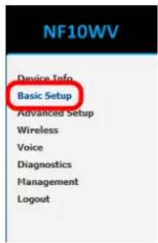
- Click on the Basic Setup menu item on the left side of the screen.
ADSL
a) Select ADSL and click the Next button.
Basic > Quick Setup > Internet Setup (Select one DSL mode)
This Wizard is designed to walk you through the basic information needed to set up your device
To continue, please select your WAN connection type.
ADSL
VDSL
Ethernet WAN
Next
b) Select either the PPPoE, PPPoA or Bridging for your internet connection as specified by your Internet Service Provider (ISP). Click the Next button.
Basic > Quick Setup > Wan Setup (Select one WAN mode)
Select the WAN mode for your internet connection as specified by your Internet Service Provider(ISF).
● PPP Over Ethernet (PPPoE)
○ PPP Over ATM (PPPoA)
○ Bridging
Back Next
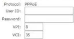
c) In the User ID and Password fields, enter the username and password assigned to you by your Internet Service Provider (ISP). Click the Finish button.
Basic > Quick Setup > ADSL only > PPPoE Information
Enter the User ID and Password assigned to you by your Internet Service Provider (ISP).
Back Finish
The account settings are saved and the NF10WV connects to the internet.
VDSL
a) Select either PPP over Ethernet (PPPoE), IP over Ethernet (IPoE) or Bridging depending on your Internet Service Provider's requirements.
Basic > Quick Setup > WAN Setup (Select one WAN mode)
Select the WAN mode for your Internet connection as specified by your Internet Service Provider(ISP).
● PPP Over Ethernet (PPPoE)
IP over Ethernet (IPoE)
○ Bridging
Back Next
b) Click Next to open a sequence of screens appropriate for the connection type selected.
PPP over Ethernet (PPPoE)
a) For PPP over Ethernet (PPPoE) select the VLAN option required by your ISP:
Basic > Quick Setup > VLAN Setup
Please select the correct VLAN option for your connection: If you are unsure, please contact your ISP
No VLAN Tag
○ VLAN Tag 10(For most New Zealand Customers)
Custom VLAN Tag
Back Next
No VLAN Tag – If you ISP does not require a VLAN tag, select this option and click Next to go to the next page
VLAN Tag 10 (for most New Zealand Customers) – If your ISP is in New Zealand, select this option and click Next to go to the next page, or
Custom VLAN Tag – enter a VLAN tag number 0 through 4094, and then click Next to go to the next page
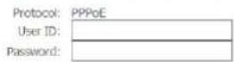
b) Enter the username and password supplied to you by your Internet Service Provider (ISP).
Basic > Quick Setup > VDSL only > PPPoE Information
Enter the User ID and Password assigned to you by your Internet Service Provider (TSP).
Back Finish
c) Click the Finish button when you have entered the required information.
IP over Ethernet (IPoE)
a) For IP over Ethernet (IPoE) either select the first option to automatically obtain the IP address details or manually enter the static IP address details as provided by your Internet Service Provider (ISP).
Basic > Quick Setup > VDSL only > IPoE Information
You can configure your IP over Ethernet(IPoE) settings as supplied by your Internet Service Provider(ISP). If your ISP supplied a static IP address, you can enter the details here. Otherwise, select "Obtain an IP address automatically".
Obtain an IP address automatically
Use the following Static IP address:
WAN IP Address:
WAN Subnet Mask:
WAN gateway IP Address:
Primary DNS server:
Secondary DNS server:
Back Next
b) Click Next to review the automatically retrieved settings, or settings that you have manually entered.
WAN Basic Setup - Summary
Make sure that the settings below match the settings provided by your ISP.
| Connection Type: | IPoE |
| NAT: | Enabled |
| Full Cone NAT: | Disabled |
| Firewall: | Enabled |
| IGMP Multicast: | Disabled |
| Quality Of Service: | Enabled |
Click "Apply/Save" to have this interface to be effective. Click "Back" to make any modifications.
Back Apply/Save
c) When you are satisfied that the settings are correct, click the Apply/Save button.
Bridging
a) The Bridging settings are summarised in the following page:
WAN Basic Setup - Summary
Make sure that the settings below match the settings provided by your ISP.
| Connection Type: | Bridge |
| NAT: | Disabled |
| Full Cone NAT: | Disabled |
| Firewall: | Disabled |
| IGMP Multicast: | Not Applicable |
| Quality Of Service: | Enabled |
Note: Creating DSL bridge will disable DHCP server, please manually configure your Network Adaptor.
Click "Apply/Save" to have this interface to be effective. Click "Back" to make any modifications.
Back | Apply/Save
b) When you are satisfied that the settings are correct, click the Apply/Save button.
Ethernet WAN
a) Connect an RJ45 Ethernet cable to the WAN port on the NF10WV. Connect the other end of the cable to your WAN service.
b) Select Ethernet WAN then click the Next button.
Basic > Quick Setup > Internet Setup (Select one DSL mode)
This Wizard is designed to walk you through the basic information needed to set up your device
To continue, please select your WAN connection type.
○ ADSL
○VDSL
Ethernet WAN
Next
b) Select the WAN mode for your internet connection as specified by your Internet Service Provider (ISP). Click the Next button.
Basic > Quick Setup > WAN Setup (Select one WAN mode)
Select the WAN mode for your internet connection as specified by your Internet Service Provider(ISP).
● PPP Over Ethernet (PPPoE)
IP over Ethernet (IPoE)
Back Next
PPP over Ethernet (PPPoE)
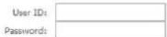
In the User ID and Password fields, enter the username and password assigned to you by your Internet Service Provider (ISP). Click the Finish button when you have entered the required details.
Basic > Quick Setup > Ethernet WAN only > PPPoE Information
Enter the User ID and Password assigned to you by your Internet Service Provider (ISP).
Back Finish
IP over Ethernet (IPoE)
If your ISP has supplied a static IP address, select Use the following Static IP address and enter the details, otherwise select Obtain an IP address automatically. Click the Next button.
Basic > Quick Setup > Ethernet WAN only > IPoE Information
You can configure your IP over Ethernet(IPoE) settings as supplied by your Internet Service Provider(ISP). if your ISP supplied a static IP address, you can enter the details here. Otherwise, select "Obtain an IP address automatically".
Obtain an IP address automatically
○ Use the following Static IP address
Back Next
The settings are displayed in a summary. Click Apply/Save to save them.
WAN Basic Setup - Summary
Make sure that the settings below match the settings provided by your ISP.
| Connection Type: | IPoE |
| NAT: | Enabled |
| Full Cone NAT: | Disabled |
| Firewall: | Enabled |
| IGMP Multicast: | Disabled |
| Quality Of Service: | Enabled |
Click "Apply/Save" to have this interface to be effective. Click "Back" to make any modifications.
Back Apply/Save
Device Info
Summary
When you log in to the router, the Device Info Summary page is displayed, giving a general overview of the status of the router and the WAN connection.
Device Info
| Manufacturer: | NetComm Wireless |
| Product Class: | NF10W |
| Serial Number: | 568747952610 |
| Build Timestamp: | 160112_1320 |
| Software Version: | NF10WV.NC.AU_R5B013.EN |
| Bootloader (CFE) Version: | 1.0.38-116.174 |
| DSL PHY and Driver Version: | A2pvI041d2.d26b |
| VDSL PROFILE: | No profile |
| Wireless Driver Version: | 7.14.89.14.cpe4.16L03.0-kdb |
| Voice Service Version: | Voice |
| Uptime: | 0D 0H 36M 26S |
This information reflects the current status of your WAN connection.
| Line Rate - Upstream (Kbps): | 0 |
| Line Rate - Downstream (Kbps): | 0 |
| LAN IPv4 Address: | 192.168.20.1 |
| Service connection type: | |
| Default Gateway: | |
| Primary DNS Server: | 0.0.0.0 |
| Secondary DNS Server: | 0.0.0.0 |
| LAN IPv6 ULA Address: | |
| Default IPv6 Gateway: | |
| Date/Time: | Thu Jan 1 00:36:27 1970 |
| ITEM | DEFINITION |
| Device Info | |
| Manufacturer | Indicates that NetComm Wireless is the manufacturer of this product. |
| Product Class | The model of the product. |
| Serial Number | The unique set of numbers assigned to the routers for identification purposes. |
| Build Timestamp | The date and time that the software running on the router was published. |
| Software Version | The current firmware version installed on the router. |
| Bootloader (CFE) Version | The current boot loader installed on the router. |
| DSL PHY and Driver Version | The driver version of the on-board DSL chip. |
| VDSL PROFILE | The VDSL profile in use. Supports 8a, 8b, 12a and 17a VDSL profiles. |
| DSL PHY and Driver Version | The current line driver installed on the router. |
| Wireless Driver Version | The current wireless driver installed on the router. |
| Uptime | The number of days, hours and minutes that the router has been running. |
| WAN connection | |
| Line Rate – Upstream (Kbps) | The current upstream speed of the DSL connection in Kbps. |
| Line Rate – Downstream (Kbps) | The current upstream speed of the DSL connection in Kbps. |
| LAN IPv4 Address | The current version 4 LAN IP address assigned to the router. |
| Service connection type | Displays whether the WAN connection is ADSL/VDSL or Ethernet WAN. |
| Default Gateway | The current default gateway of the WAN interface. |
| Primary DNS Server | The current primary DNS server in use |
| Secondary DNS Server | The current secondary DNS server is use. |
| LAN IPv6 ULA Address | The current IPv6 LAN IP address in use if assigned. |
| Default IPv6 Gateway | The current IPv6 default gateway if assigned. |
| Date/Time | The current date and time set on the router. |
WAN
The WAN page shows more detailed information related to the WAN interface configuration, including the firewall status, IPv4 and IPv6 addresses of the router.
WAN Info
| Interface | Description | Type | VLAN Mux ID | IPv6 | IGMP Pxy | IGMP Src Enbl | HLD Pxy | HLD Src Enbl | NAT | Firewall | Status | IPv4 Address | IPv6 Address |
| eth4.1 | ETH WAN | IPoE | Disabled | Disabled | Disabled | Disabled | Enabled | Enabled | Disconnected | 0.0.0.0 |
| ITEM | DEFINITION |
| Interface | The Interface of the WAN connection. |
| Description | The description of the WAN connection. |
| Type | The type of WAN connection. |
| VLAN Mux ID | Details the status of VLAN Mux ID if used. |
| IPv6 | The status of IPv6. |
| IGMP Pxy | Details the status of IGMP on each WAN connection. IGMP is only used with IP v4 connections. IGMP proxy enables the router to issue IGMP host messages on behalf of hosts that the router discovered through standard IGMP interfaces, allowing NAT transversal of Multicast traffic. |
| IGMP Src Enbl | Details the status of IGMP Src on each WAN connection. IGMP Sources function send a membership report that includes a list of IGMP source addresses. |
| MLD Pxy | Shows the status of the Multicast Listener Discovery protocol when IPv6 is in use. Multicast Listener Discovery (MLD) proxy enables the router to issue MLD host messages on behalf of hosts that the router discovered through standard MLD interfaces. |
| MLD Src Enbl | Details the status of MLD Src on each WAN connection. MLD Sources function can send a membership report that includes a list of MLD source addresses. |
| NAT | The NAT status of the WAN connection. |
| Firewall | The status of the router firewall across the WAN connection. |
| Status | The status of the WAN connection. |
| IPv4 Address | The current IP v4 address of the WAN connection. |
| IPv6 Address | The current IP v6 address of the WAN connection. |
Statistics
LAN
The Statistics – LAN page shows detailed information about the number of bytes, packets, errors and dropped packets on each LAN interface in both directions of communication.
Statistics - LAN
| Interface | Received | Transmitted | ||||||||||||||
| Total | Multicast | Unicast | Broadcast | Total | Multicast | Unicast | Broadcast | |||||||||
| Bytes | Packets | Errors | Drops | Bytes | Packets | Packets | Packets | Bytes | Packets | Errors | Drops | Bytes | Packets | Packets | Packets | |
| eth1 | 0 | 0 | 0 | 0 | 0 | 0 | 0 | 0 | 0 | 0 | 0 | 0 | 0 | 0 | 0 | 0 |
| eth2 | 0 | 0 | 0 | 0 | 0 | 0 | 0 | 0 | 0 | 0 | 0 | 0 | 0 | 0 | 0 | 0 |
| eth3 | 0 | 0 | 0 | 0 | 0 | 0 | 0 | 0 | 0 | 0 | 0 | 0 | 0 | 0 | 0 | 0 |
| eth0 | 1613299 | 15020 | 0 | 3 | 0 | 1517 | 12677 | 826 | 15363432 | 18473 | 0 | 0 | 0 | 1822 | 16228 | 423 |
| wI0 | 0 | 0 | 0 | 43 | 0 | 0 | 0 | 0 | 0 | 0 | 0 | 0 | 0 | 0 | 0 | 1 |
| wI0.1 | 0 | 0 | 0 | 0 | 0 | 0 | 0 | 0 | 0 | 0 | 0 | 0 | 0 | 0 | 0 | 0 |
| wI0.2 | 0 | 0 | 0 | 0 | 0 | 0 | 0 | 0 | 0 | 0 | 0 | 0 | 0 | 0 | 0 | 0 |
| wI0.3 | 0 | 0 | 0 | 0 | 0 | 0 | 0 | 0 | 0 | 0 | 0 | 0 | 0 | 0 | 0 | 0 |
Reset Statistics
| INTERFACE | DESCRIPTION | |
| Received/Transmitted | Bytes | Rx/Tx (receive/transmit) packets in bytes. |
| Packets | Rx/Tx (receive/transmit) packets. | |
| Errors | Rx/Tx (receive/transmit) packets with errors. | |
| Drops | Rx/Tx (receive/transmit) packets with drops. | |
Statistics – WAN Service
The Statistics – WAN Service page shows detailed information about the number of bytes, packets, errors and dropped packets on the WAN interface in both directions of communication.
Statistics - WAN
| Interface | Description | Received | Transmitted | ||||||||||||||
| Total | Multicast | Unicast | Broadcast | Total | Multicast | Unicast | Broadcast | ||||||||||
| Bytes | Packets | Errors | Drops | Bytes | Packets | Packets | Packets | Bytes | Packets | Errors | Drops | Bytes | Packets | Packets | Packets | ||
| eth4.1 | ETH WAN | 0 | 0 | 0 | 0 | 0 | 0 | 0 | 0 | 0 | 0 | 0 | 0 | 0 | 0 | 0 | 0 |
Reset Statistics
| INTERFACE | DESCRIPTION | |
| Received/Transmitted | Bytes | Rx/Tx (receive/transmit) packets in bytes. |
| Packets | Rx/Tx (receive/transmit) packets. | |
| Errors | Rx/Tx (receive/transmit) packets with errors. | |
| Drops | Rx/Tx (receive/transmit) packets with drops. | |
Statistics - xTM
The Statistics - xTM page shows details related to the xTM interface of the router.
Interface Statistics
| Port Number | In Octets | Out Octets | In Packets | Out Packets | In OAM Cells | Out OAM Cells | In ASM Cells | Out ASM Cells | In Packet Errors | In Cell Errors |
Reset
| INTERFACE | DESCRIPTION |
| Port Number | The port number used by the xTM interface. |
| In Octets | The number of data packets in octets received over the ATM interface. |
| Out Octets | The number of data packets in octets transmitted over the ATM interface. |
| In Packets | The number of data packets received over the ATM interface. |
| Out Packets | The number of data packets transmitted over the ATM interface. |
| In OAM Cells | Operation, Administration, and Maintenance (OAM) Cell is the ATM Forum specification for cells used to monitor virtual circuits. |
| Out OAM Cells | Operation, Administration, and Maintenance (OAM) Cell is the ATM Forum specification for cells used to monitor virtual circuits. |
| In ASM Cells | The number of Any Source Multicast (ASM) cells received over the interface. |
| Out ASM Cells | The number of Any Source Multicast (ASM) cells transmitted over the interface. |
| In Packets Errors | The number of packets with errors detected over the xTM interface. |
| In Cell Errors | The number of cells with errors detected over the xTM interface. |
Statistics - xDSL
The Statistics - xDSL page shows details related to the DSL interface of the router.
Statistics -- xDSL
| Mode: | ||
| Traffic Type: | ||
| Status: | Disabled | |
| Link Power State: | ||
| Downstream | Upstream | |
| Line Coding(Trellis): | ||
| SNR Margin (0.1 dB): | ||
| Attenuation (0.1 dB): | ||
| Output Power (0.1 dBm): | ||
| Attainable Rate (Kbps): | ||
| Rate (Kbps): | ||
| Super Frames: | ||
| Super Frame Errors: | ||
| RS Words: | ||
| RS Correctable Errors: | ||
| RS Uncorrectable Errors: | ||
| HEC Errors: | ||
| OCD Errors: | ||
| LCD Errors: | ||
| Total Cells: | ||
| Data Cells: | ||
| Bit Errors: | ||
| Total ES: | ||
| Total SES: | ||
| Total UAS: | ||
xDSL BER Test Reset Statistics
Route
The Route page displays any routes that the router has created.
Device Info - Route
Flags: U - up, ! - reject, G - gateway, H - host, R - reinstate
D - dynamic (redirect), M - modified (redirect).
| Destination | Gateway | Subnet Mask | Flag | Metric | Service | Interface |
| 192.168.20.0 | 0.0.0.0 | 255.255.255.0 | U | 0 | br0 |
ARP
Click ARP to display the address resolution protocol information.
This option can be used to determine which IP address / MAC address is assigned to a particular host. This can be useful when setting up URL filtering, Time of Day filtering or Static DHCP addressing.
Device Info -- ARP
| IP address | Flags | HW Address | Device |
| 192.168.20.2 | Complete | 2c:44:fd:12:3c:6e | br0 |
DHCP
Click DHCP to display the DHCP lease information.
Device Info -- DHCP Leases
| Hostname | MAC Address | IP Address | Expires In |
| 2c:44:fd:12:3c:6e | 192.168.20.2 | 21 hours, 23 minutes, 41 seconds |
You can use this to determine when a specific DHCP lease will expire, or to assist you with setting up Static DHCP addressing.
Advanced Setup
Layer2 Interface
ATM Interface
The ATM (Asynchronous Transfer Mode) interface page shows the settings of all available DSL ATM interfaces. ATM interface is used for ADSL connections.
DSL ATM Interface Configuration
Choose Add, or Remove to configure DSL ATM interfaces.
| Interface | VPI | VCI | DSL Latency | Category | Peak Cell Rate(cells/s) | Sustainable Cell Rate(cells/s) | Max Burst Size(bytes) | Min Cell Rate(cells/s) | Link Type | Connection Mode | IP QoS | MPAAL Precedence/Algorithm /Weight | Remove |
Add Remove
| FIELD | DESCRIPTION |
| Interface | This field shows the interface name. |
| VPI | This field shows the Virtual Path Identifier (VPI) value. For most Australia connections the VPI is 8, for most new Zealand connections the VPI is 0. Please refer to your ISP for correct value. |
| VCI | This field shows the Virtual Channel Identifier (VCI) value. For most Australia connections the VCI is 35, for most new Zealand connections the VCI is 100. Please refer to your ISP for correct value. |
| DSL Latency | The value of the DSL Latency. |
| Category | This field shows the ATM service classes. |
| Peak Cell Rate (cell/s) | The maximum number of cells that may be transferred per second over the ATM interface. |
| Sustainable Cell Rate (cell/s) | An average, long-term cell transfer rate on the ATM interface. |
| Max Bursl Size (bytes) | The maximum allowable burst size of cells that can be transmitted contiguously on the ATM interface. |
| Min Cell Rate (cell/s) | The minimum allowable rate at which cells may be transferred on the ATM interface. |
| Link Type | This field shows the type of link in use. |
| Connection Mode | This field shows the selected mode of connection. |
| IP QoS | This field shows the status of the Quality of Service (QoS) function. |
| MPAAL Proc/Alg/Wght | This displays data related to load balancing. |
| Remove | Select this field to remove the ATM configuration. |
To add an ATM interface, click the Add button. Enter the details as required by your Internet Service Provider and click the Apply/Save button.
![ATM PVC Configuration This screen allows you to configure a ATM PVC. VBI: 8 [0-249] VCI: 35 [32-65536] Select DSL Latency ✓ Padht (Fast) □ Padht (Interleave) Select DSL Link Type (LCA is for PPoG, IPoG, and Bridge.) ● BoA ○ PPoA ○ IPoA Encapsulation Mode: LLC/SNAP-BRIDGING Service Category: UBR Without PCR Minimum Call Rate: -1 [call/s] (-1 indicates no shaping) Select Scheduler for Queue of Equal Precedence as the Default Queue ● Weighted Round Robin ○ Weighted Pair Queuing Default Queue Weight: 1 [1-67] Default Queue Precedence: 0 [1-8] (lower value, Higher priority) VC WRR Weight: 1 [1-67] VC Precedence: 0 [1-8] (lower value, Higher priority) Note VC scheduling will be TP among unequal precedence VCs and WRR among equal precedence VC. For single output VC, this default queue precedence and weight will be used for arbitration. For multi-queue VC, its VC precedence and weight will be used for arbitration. Back Apply/Save](/content/2026/05/996218/images/5768120aa7377adc8484254cc89bf413ab9098bddfbeca7a3e0e4e4b69bcd1d0.jpg)
PTM Interface
The router can also establish DSL connections using PTM (Packet Transfer Mode). This page shows you an overview of the PTM interfaces and allows you to add or remove them.
PTM interface is used for VDSL connections.
DSL PTM Interface Configuration
Choose Add, or Remove to configure DSL PTM interfaces.


Click the Add button to create a new PTM interface. Enter the details as required by your Internet Service Provider and click the Apply/Save button.
PTM Configuration
This screen allows you to configure a PTM connection.
Select DSL Latency
Path0 (Fast)
□ Path1 (Interleaved)
Select Scheduler for Queues of Equal Precedence as the Default Queue
Weighted Round Robin
○ Weighted Fair Queuing
Default Queue Weight:
Default Queue Precedence:
Default Queue Minimum Rate:
Default Queue Shaping Rate
Default Queue Shaping Burst Size:



ETH Interface
The ETH interface page allows you to add or remove ETH WAN interfaces.
ETH WAN Interface Configuration
Choose Add, or Remove to configure ETH WAN interfaces.
Allow one ETH as layer 2 wan interface.
| Name | Connection Mode | Remove |
| eth4/eth4 | VlanMuxMode |

WAN Service
The WAN Service page displays the current Wide Area Network service setup and allows you to configure the router to connect to a larger network for Internet access.
WAN service require a preconfigured Layer 2 interface, be it ATM/PTM or Ethernet WAN.
Wide Area Network (WAN) Service Setup
Choose Add, Remove or Edit to configure a WAN service over a selected interface.
| Interface | Description | Type | VLAN 802.1p | VLAN Mux ID | IGMP Proxy | IGMP Source | NAT | Firewall | IPv6 | HLD Proxy | MLD Source | Remove | Edit | Action |
| eth1.1 | ETH WAN | Bridge | N/A | N/A | Disabled | Disabled | Disabled | Disabled | Enabled | Disabled | Disabled | edit | ||
| eth1.2 | ETH WAN | IPoE | N/A | N/A | Disabled | Disabled | Enabled | Disabled | Disabled | Disabled | Disabled | edit |
To add a WAN service, click the Add button. Use the drop down list to select the layer 2 interface to use for the WAN service and click the Next button.
WAN Service Interface Configuration
Select a layer 2 interface for this service
Note: For ATM interface, the descriptor string is (portId_vpi_vci) For PTM interface, the descriptor string is (portId_high_low)
Where portId=0 --> DSL Latency PATH0
tId=1 --> DSL Latency PATH1
portId=4 --> DSL Latency PATH0&1
low =0 --> Low PTM Priority not set
low =1 --> Low PTM Priority set
high =0 --> High PTM Priority not set
high =1 --> High PTM Priority set

Select a WAN service type, enter a Service Description, enter the 802.1P Priority and 802.1 VLAN ID then click the Next button. To disable VLAN tagging, place input value of -1. Refer to your ISP for VLAN information as required by your Internet Service Provider.
WAN Service Configuration
Select WAN service type:
● PPP over Ethernet (PPPoE)
IP over Ethernet
○ Bridging
□ Allow as IGMP Multicast Source
□ Allow as MLD Multicast Source
Enter Service Description: ETH WAN
For tagged service, enter valid 802.1P Priority and 802.1Q VLAN ID. For untagged service, set -1 to both 802.1P Priority and 802.1Q VLAN ID.
Enter 802.1P Priority [0-7]:
Enter 802.1Q VLAN ID [0-4094]:

Network Protocol Selection:

PPP over Ethernet
Enter the details as required by your Internet Service Provider and click the Next button.
PPP Username and Password
PPP usually requires that you have a user name and password to establish your connection. In the boxes below, enter the user name and password that your ISP has provided to you.
| PPP Username: | |
| PPP Password: | |
| PPPoE Service Name: | |
| Authentication Method: | AUTO |
| MTU[576-1492]: | 1492 |
| MSS: | 1452 |
Enable NAT
Enable Fulficone NAT
Enable Firewall
□ Dial on demand (with idle timeout timer)
□ PPP IP extension
□ Use Static IPv4 Address
Enable PPP Debug Mode
Bridge PPPoE Frames Between WAN and Local Ports
IGMP Multicast Proxy
Enable IGMP Multicast Proxy
Enable ICMP Multicast Source
Back Next
IP over Ethernet
Enter the details as required by your Internet Service Provider and click the Next button.
WAN IP Settings
Enter information provided to you by your ISP to configure the WAN IP settings.
Notice: If "Obtain an IP address automatically" is chosen, DHCP will be enabled for PVC in IPoE mode.
If "Use the following Static IPv4/IPv6 address" is chosen, enter the WAN IPv4/IPv6 address, subnet mask/prefix Length and interface gateway.
Obtain an IP address automatically
Option 55 Request List :
Option 58 Renewal Time:
Option 59 Rebinding Time:
Option 60 Vendor ID:
Option 61 IAID:
Option 61 DUID:
Option 77 User ID:
Option 125:
○ Use the following Static IP address
WAN IP Address:
WAN Subnet Mask:
WAN gateway IP Address:
Primary DNS server:
Secondary DNS server:
Disable
(e.g:1,3,6,12)
(hour)
(hour)
(8 hexadecimal digits)
(hexadecimal digit)
○ Enable
Back
Next
Select the NAT Translation settings as desired and click the Next button.
Network Address Translation Settings
Network Address Translation (NAT) allows you to share one Wide Area Network (WAN) IP address for multiple computers on your Local Area Network (LAN).
Enable NAT
Enable Fullcone NAT
Enable Firewall
IGMP Multicast
Enable IGMP Multicast Proxy
Enable IGMP Multicast Source
Back Next
Bridging
When you select bridging mode, a summary of the settings is displayed. Click Apply/Save to commit the settings.
WAN Setup - Summary
Make sure that the settings below match the settings provided by your ISP.
| Connection Type: | Bridge |
| NAT: | Enabled |
| Full Cone NAT: | Disabled |
| Firewall: | Enabled |
| IGMP Multicast Proxy: | Disabled |
| IGMP Multicast Source Enabled: | Disabled |
| MLD Multicast Proxy: | Disabled |
| MLD Multicast Source Enabled: | Disabled |
| Quality Of Service: | Disabled |
Click "Apply/Save" to have this interface to be effective. Click "Back" to make any modifications.
Back Apply/Save
Use the arrow buttons to move the interfaces required to the list on the left. Click Next.
Routing — Default Gateway
Default gateway interface list can have multiple WAN interfaces served as system default gateways but only one will be used according to the priority with the first being the highest and the last one the lowest priority if the WAN interface is connected. Priority order can be changed by removing all and adding them back in again.
Selected Default Gateway Interfaces

Available Routed WAN Interfaces
natural_image
Blank white rectangle with a thin border and corner markers (no text or symbols)Back Next
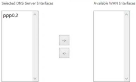
Use the arrow buttons to move the interfaces required as DNS Server interfaces to the left. The interface highest on the list has the highest priority as a DNS server. Click Next to continue.
DNS Server Configuration
Select DNS Server Interface from available WAN interfaces OR enter static DNS server IP addresses for the system. In ATM mode, if only a single PVC with IPoA or static IPoE protocol is configured, Static DNS server IP addresses must be entered.
DNS Server Interfaces can have multiple WAN interfaces served as system dns servers but only one will be used according to the priority with the first being the higest and the last one the lowest priority if the WAN interface is connected. Priority order can be changed by removing all and adding them back in again.
Select DNS Server Interface from available WAN interfaces:
○ Use the following Static DNS IP address:


A summary of your settings is displayed. Click Apply/Save to commit your settings to the router.
WAN Setup - Summary
Make sure that the settings below match the settings provided by your ISP.
| Connection Type: | PPPoE |
| NAT: | Enabled |
| Full Cone NAT: | Disabled |
| Firewall: | Enabled |
| IGMP Multicast Proxy: | Disabled |
| IGMP Multicast Source Enabled: | Disabled |
| MLD Multicast Proxy: | Disabled |
| MLD Multicast Source Enabled: | Disabled |
| Quality Of Service: | Disabled |
Click "Apply/Save" to have this interface to be effective. Click "Back" to make any modifications.
Back Apply/Save
LAN
IPv4 Autoconfig
The LAN window allows you to modify the settings for your local area network (LAN).
Local Area Network (LAN) Setup
Configure the Broadband Router IP Address and Subnet Mask for LAN interface, Group Name Default
IP Address:
132,168,20,1
Subnet mask
255.255.255.0
√ Enable IGMP Snooping
○ Standard Mode
Blocking Mode
Enable IGMP LAN to LAN Multicast:
Disable
(LAN to LAN Multicast is effective only when exist route mode WAN service which is connected and enable igmp proxy.)
□ Enable LAN side firewall
○ Disable DHCP Server
Enable DHCP Server
| Start IP Address: | 192.168.20.2 |
| End IP Address: | 192.168.20.254 |
| Primary DNS server | 192.168.20.1 |
| Secondary DNS server | 0.0.0.0 |
| Lassed Time (hour): | 24 |
Edit DHCP Option 60 Edit DHCP Option
Static IP Lease List: (A maximum 32 entries can be configured)
| MAC Address | IP Address | Remove |
| Add Entries | Remove Entries | |
○ Enable DHCP Server Relay
DHCP Server IP Address:
☐ Configure the second IP Address and Subnet Mask for LAN interface
Apply/Save
The following options are available to configure:
| PARAMETER | DEFINITION |
| IP Address | Enter the Local IP Address to use for the NF10WV. |
| Subnet Mask | Enter the subnet mask of the Local Network. |
| Enable IGMP Snooping | Enable IGMP Snooping and select the IGMP Snooping mode to use. Standard: allow all multicast traffic to LAN clients. Blocking: only allow multicast subscribed clients to receive multicast packets. |
| Enable LAN side Firewall | Enable the LAN side firewall to restrict traffic between LAN hosts. |
| Enable DHCP Server | Select to enable or disable the DHCP server and enter the start and end address for the DHCP IP Address pool. |
| Enable DHCP Server Relay | Disabled DHCP server, and relay all request to external server specified by the IP address. |
| Configure the second IP Address | This option enables you to set a secondary IP Address for the NF10WV |
You can also reserve DHCP Addresses for specific hosts as shown below:
DHCP Static IP Lease
Enter the Mac address and Static IP address then click Apply/Save.
MAC Address:
IP Address:
Apply/Save
To set a DHCP reservation, enter the MAC Address of the chosen host and IP to use and then click Apply/Save.
The NF10WV enables you to set the DHCP options which are provided to hosts attempting to connect to the DHCP server.
These options should not normally need to be set or changed. Click Apply/Save to save the new LAN configuration settings.
IPv6 Autoconfig
The IPv6 LAN Auto Configuration page allows you to configure settings pertaining to the IPv6 DHCP server.
IPv6 LAN Auto Configuration
Note:
1: Stateful DHCPv6 is supported based on the assumption of prefix length less than 64. Interface ID does NOT support ZERO COMPRESSION '1'. Please enter the complete information. For example: Please enter '0:0:0:2' instead of '1:2'.
2: Unique local address must start with "fd". The prefix and the address must be in same network and the prefix length must be 64.

Enable ULA Prefix Advertisement
IPv6 LAN Applications

Enable DHCPv6 Server

Stateless

Stateful
Start interface ID:
0:0:0:2
End interface ID:
0:0:0:254
Leased Time (hour):

Enable RADVD

Enable MLD Snooping

Standard Mode

Blocking Mode
Enable MLD LAN to LAN Multicast:
(LAN to LAN Multicast is effective only when exist. route mode WAN service which is connected and enable mid proxy.)

Enable Relay
Disable
Save/Apply
| OPTION | DEFINITION |
| Enable Unique Local Addresses and Prefix Advertisement | Enable the use of unique local addresses. The router will advertise the IPv6 prefix to new devices on the network. |
| Randomly Generate | Randomly generates the unique local addresses and the prefix. |
| Statically Configure | Enter a static IPv6 address for the router if one has been assigned to you by your Internet Service Provider. |
| IPv6 LAN Applications | Enable IPv6 DHCP server |
| Enable DHCPv6 Server and RADVD | The Router Advertisement Daemon (radvd) is an open-source software product that implements link-local advertisements of IPv6 router addresses and IPv6 routing prefixes using the Neighbor Discovery Protocol (NDP) as specified in RFC 2461. The Router Advertisement Daemon is used by system administrators in stateless auto-configuration methods of network hosts on Internet Protocol version 6 networks.When IPv6 hosts configure their network interfaces, they broadcast router solicitation (RS) requests onto the network to discover available routers. The radvd software answers requests with router advertisement (RA) messages. In addition, radvd periodically broadcasts RA packets to the attached link to update network hosts. The router advertisement messages contain the routing prefix used on the link, the link maximum transmission unit (MTU), and the address of the responsible default router. |
| Stateless | IPv6 hosts can configure themselves automatically when connected to a routed IPv6 network using Internet Control Message Protocol version 6 (ICMPv6) router discovery messages. This type of configuration is suitable for small organizations and individuals. It allows each host to determine its address from the contents of received user advertisements. It makes use of the IEEE EUI-64 standard to define the network ID portion of the address. |
| Stateful | This configuration requires some human intervention as it makes use of the Dynamic Host Configuration Protocol for IPv6 (DHCPv6) for installation and administration of nodes over a network. The DHCPv6 server maintains a list of nodes and the information about their state to know the availability of each IP address from the range specified by the network administrator. |
| Enable MLD Snooping | Select whether to enable or disable MLD Snooping on the router. The Multicast Listener Discovery (MLD) snooping function constrains the flooding of IPv6 multicast traffic on VLANs on the router. |
LAN VLAN Setting
This page allows you to specify a LAN port to apply VLAN tagging to.
Locate Area Network (LAN) interface Setup
Select a LAN port eth2/eth2
Enable VLAN Mode
| VLAN ID | Pbits | Remove |
| 0 |
Add Remove Apply/Save
Select the LAN port using the drop down menu, then click the Add button. Enter the VLAN ID and in the Pbits field, enter a value from 0-7 indicating the priority bits that dictates the priority of the VLAN. Click Apply/Save when you have finished.
NAT
Virtual Servers
A virtual server allows you to direct incoming traffic from the WAN side to the Internal server with a private IP address on the LAN side.
NAT -- Virtual Servers Setup
Virtual Server allows you to direct incoming traffic from WAN side (identified by Protocol and External port) to the Internal server with private IP address on the LAN side. The Internal port is required only if the external port needs to be converted to a different port number used by the server on the LAN side. A maximum 32 entries can be configured.
| Server Name | External Port Start | External Port End | Protocol | Internal Port Start | Internal Port End | Server IP Address | WAN Interface | LAN Loopback | Enable/Disable | Remove |
Add Sava/Apply Remove
Click the Add button to add a virtual server.
NAT -- Virtual Servers
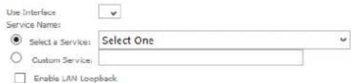
Select the service name, and enter the server IP address and click "Apply/Save" to forward IP packets for this service to the specified server.
NOTE: The "Internal Port End" cannot be modified directly. Normally, it is set to the same value as "External Port End". However, if you modify "Internal Port Start", then "Internal Port End" will be set to the same value as "Internal Port Start".
Remaining number of entries that can be configured;32
Server IP Address: 192.168.20.
Status:
Apply/Save
| External Port Start | External Port End | Protocol | Internal Port Start | Internal Port End | ||||||
| TCP | √ | |||||||||
| TCP | √ | |||||||||
| TCP | √ | |||||||||
| TCP | √ | |||||||||
| TCP | √ | |||||||||
| TCP | √ | |||||||||
| TCP | √ | |||||||||
| TCP | √ | |||||||||
| TCP | √ | |||||||||
| TCP | √ | |||||||||
| TCP | √ | |||||||||
| TCP | √ | |||||||||
Save/Apply
| FIELD | DESCRIPTION |
| Select a Service or custom Server | Select a pre-configured port forwarding rule or choose custom server to create your own port forwarding rule. |
| Server IP Address | Enter the IP address of the local server. |
| External Port Start | Enter the starting external port number (when custom server is selected). When a service is connected this field will be completed automatically. |
| External Port End | Enter the ending external port number (when custom server is selected). When a service is connected this field will be completed automatically. |
| Protocol | Options include TCP, UDP or TCP/UDP. |
| Internal Port Start | Enter the starting internal port number (when custom server is selected). When a service is connected this field will be completed automatically. |
| Internal Port End | Enter the ending internal port number (when custom server is selected). When a service is connected this field will be completed automatically. |
Click Save/Apply to save your settings when you have finished creating virtual servers.
Port Triggering
Some applications require specific ports in the Router's firewall to be open for access by remote parties. Port Triggering opens up the 'Open Ports' in the firewall when an application on the LAN initiates a TCP/UDP connection to a remote party using the 'Triggering Ports'.
The Router allows the remote party from the WAN side to establish new connections back to the application on the LAN side using the 'Open Ports'. A maximum 32 entries can be configured.
NAT - Port Triggering Setup
Some applications require that specific ports in the Router's firewall be opened for access by the remote parties. Port Trigger dynamically opens up the 'Open Ports' in the firewall when an application on the LAN initiates a TCP/UDP connection to a remote party using the 'Triggering Ports'. The Router allows the remote party from the WAN side to establish new connections back to the application on the LAN side using the 'Open Ports'. A maximum 32 entries can be configured.
Due to limited resources, port triggering feature has some limitation:
sum of the outports of all configuration entries <= 1000
sum of the imports of one configuration entry <= 1000
| Application Name | Trigger | Open | WAN Interface | Remove | ||||
| Protocol | Port Range | Protocol | Port Range | |||||
| Start | End | Start | End | |||||

To add a Trigger Port, press the Add button.
NAT - Port Triggering
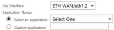
Some applications such as games, video conferencing, remote access applications and others require that specific ports in the Router's firewall be opened for access by the applications. You can configure the port settings from this screen by selecting an existing application or creating your own (Custom application)and click "Save/Apply" to add it. Remaining number of entries that can be configured:

| Trigger Port Start | Trigger Port End | Trigger Protocol | Open Port Start | Open Port End | Open Protocol | ||||||
| TCP | √ | TCP | √ | ||||||||
| TCP | √ | TCP | √ | ||||||||
| TCP | √ | TCP | √ | ||||||||
| TCP | √ | TCP | √ | ||||||||
| TCP | √ | TCP | √ | ||||||||
| TCP | √ | TCP | √ | ||||||||
| TCP | × | TCP | √ | ||||||||
| TCP | √ | TCP | √ | ||||||||
| TCP | √ | TCP | √ | ||||||||

| FIELD | DESCRIPTION |
| Select an Application or Custom Application | A user can select a pre-configured application from the list or select the Custom Application option to create custom application settings. |
| Trigger Port Start | Enter the starting trigger port number (when you select Custom Application). When an application is selected the port range values are automatically entered. |
| Trigger Port End | Enter the ending trigger port number (when you select Custom Application). When an application is selected the port range values are automatically entered. |
| Trigger Protocol | Options include TCP, UDP or TCP/UDP. |
| Open Port Start | Enter the starting open port number (when you select Custom Application). When an application is selected the port range values are automatically entered. |
| Open Port End | Enter the ending open port number (when you select Custom Application). When an application is selected the port range values are automatically entered. |
| Open Protocol | Options include TCP, UDP or TCP/UDP. |
DMZ Host
The NF10WV will forward IP packets from the Wide Area Network (WAN) that do not belong to any of the applications configured in the Virtual Servers table to the DMZ host computer.
Enter the computer's IP address and click Apply to activate the DMZ host. To deactivate the DMZ Host function clear the IP address field and press the Save/Apply button.
NAT - DMZ Host
The Broadband Router will forward IP packets from the WAN that do not belong to any of the applications configured in the Virtual Servers table to the DMZ host computer.
Enter the computer's IP address and click 'Apply' to activate the DMZ host.
Clear the IP address field and click 'Apply' to deactivate the DMZ host.
DMZ Host IP Address:

□ Enable LAN Loopback
Save/Apply
ALG
The Application Layer Gateway (ALG) is a feature which enables the router to parse application layer packets and support address and port translation for certain protocols. We recommend that you leave these protocols enabled unless you have a specific reason for disabling them.
ALG
Select the ALG below.
FTP Enabled
SIP Enabled
√ TFTP Enabled
H323 Enabled
√ IRC Enabled
√ Port Triggering Enabled
PPTP Enabled
IPSEC Enabled
√ RTSP Enabled
Save/Apply
Security
IP Filtering
The router supports IP Filtering which allows you to easily set up rules to control incoming and outgoing Internet traffic. The router provides two types of IP filtering: Outgoing IP Filtering and Incoming IP Filtering.
Outgoing IP Filtering Setup
By default, all outgoing IP traffic from LAN is allowed, but some IP traffic can be BLOCKED by setting up filters.
Choose Add or Remove to configure outgoing IP filters.

Outgoing IP Filtering
By default, the router allows all outgoing Internet traffic from the LAN but by setting up Outgoing IP Filtering rules, you can block some users and/or applications from accessing the Internet.
To delete the rule, click Remove checkbox next to the selected rule and click Remove.
To create a new outgoing IP filter, click Add. The Add IP Filter-Outgoing page will be displayed.
Add IP Filter -- Outgoing
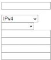
The screen allows you to create a filter rule to identify outgoing IP traffic by specifying a new filter name and at least one condition below. All of the specified conditions in this filter rule must be satisfied for the rule to take effect. Click 'Apply/Save' to save and activate the filter,
Filter Name:
IP Version:
Protocol
Source IP address[/prefix length]:
Source Port (port or port: port):
Destination IP address[/prefix length]:
Destination Port (port or port:port):
Apply/Save
Enter the following parameters:
| PARAMETER | DEFINITION |
| Filter Name | Enter a name to identify the filtering rule. |
| IP Version | Select the IP version to apply the filter to. |
| Protocol | Select the protocol type to block |
| Source IP Address/Subnet Mask | Enter the IP Address of the PC on the LAN to block |
| Source Port | Enter the port number used by the application to block |
| Destination IP Address/Subnet Mask | Enter the IP Address of the Remote Server to which connections should be blocked |
| Destination Port | Enter the destination port number used by the application to block |
Click Apply/Save to take effect the settings. The new rule will then be displayed in the Outgoing IP Filtering table list.
Incoming IP Filtering
By default, when NAT is enabled, all incoming IP traffic from WAN is blocked except for responses to requests from the LAN. However, some incoming traffic from the Internet can be accepted by setting up Incoming IP Filtering rules.
To delete the rule, click Remove checkbox next to the selected rule and click Remove.
To create a new incoming IP filter, click Add. The Add IP Filter-Incoming page will be displayed.
Add IP Filter - Incoming
The screen allows you to create a filter rule to identify incoming IP traffic by specifying a new filter name and at least one condition below. All of the specified conditions in this filter rule must be satisfied for the rule to take effect. Click 'Apply/Save' to save and activate the filter.
![Filter Name: IP Version: IPv4 Protocol Source IP address[/prefix length]: Source Port (port or port:port): Destination IP address[/prefix length]: Destination Port (port or port:port):](/content/2026/05/996218/images/725aad9decc51a4584d1c6c045cc557604993cecca02c17680c6d236a8eb4c2f.jpg)
WAN Interfaces (Configured in Routing mode and with firewall enabled) and LAN Interfaces Select one or more WAN/LAN interfaces displayed below to apply this rule.
Select All
√ pppoe_eth0/ppp0.1
br0/br0
Apply/Save
Enter the following parameters:
| PARAMETER | DEFINITION |
| Filter Name | Enter a name to identify the filtering rule |
| IP Version | Select the IP version to apply the filter to |
| Protocol | Select the protocol type to allow |
| Source IP Address/Subnet Mask | Enter the IP Address of the Remote Server from which to allow connections |
| Source Port | Enter the port number used by the application to allow |
| Destination IP Address/Subnet Mask | Enter the IP Address of the PC on the LAN to which connections should be allowed |
| Destination Port | Enter the destination port number used by the application to allow |
| WAN Interface | Select the WAN Interface to apply the filter to |
Click Save/Apply to take effect the settings. The new rule will then be displayed in the Incoming IP Filtering table list.
MAC Filtering
The NF10WV offers the ability to use MAC Address filtering on ATM PVCs. You can elect to block or allow connections based on MAC Address criteria. The default policy is to allow connections which match the criteria.
MAC Filtering Setup
MAC Filtering is only effective on ATM PVCs configured in Bridge mode. FORWARDED means that all MAC layer frames will be FORWARDED except those matching with any of the specified rules in the following table. BLOCKED means that all MAC layer frames will be BLOCKED except those matching with any of the specified rules in the following table.
MAC Filtering Policy For Each Interface(maximum 32 entries):
WARNING: Changing from one policy to another of an interface will cause all defined rules for that interface to be REMOVED AUTOMATICALLY! You will need to create new rules for the new policy.
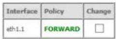
Change Policy
Choose Add or Remove to configure MAC filtering rules.

Add Remove
Click Add to enter a new MAC Address filter.
Add MAC Filter
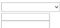
Create a filter to identify the MAC layer frames by specifying at least one condition below. If multiple conditions are specified, all of them take effect. Click 'Apply' to save and activate the filter.
Protocol Type:
Destination MAC Address:
Source MAC Address:
Frame Direction:
LAN<=>WAN
WAN Interfaces (Configured in Bridge mode only)
ETH WAN/eth1.1
Apply/Save
- Enter the Protocol type to which the filter should apply.
- Enter the Source and Destination MAC Address
- Enter the direction of the traffic to filter
- Select the WAN interface to which the filter should apply.
Click Apply/Save to save the new MAC filtering configuration.
Parental Control
The Parental Control feature allows you to take advanced measures to ensure the computers connected to the LAN are used only when and how you decide.
Time Restriction
This Parental Control function allows you to restrict access from a Local Area Network (LAN) connected device to an outside network through the router on selected days and at certain times. Make sure to activate the Internet Time server synchronization as described in the SNTP section, so that the scheduled times match your local time.
Access Time Restriction -- A maximum 16 entries can be configured.

Figure 1: Advanced - Parental Control - Time Restriction
To add a time restriction rule, press the Add button. The following screen appears.
Access Time Restriction
This page adds time of day restriction to a special LAN device connected to the Router. The 'Browser's MAC Address' automatically displays the MAC address of the LAN device where the browser is running. To restrict other LAN device, click the 'Other MAC Address' button and enter the MAC address of the other LAN device. To find out the MAC address of a Windows based PC, go to command window and type 'ipconfig /all'.
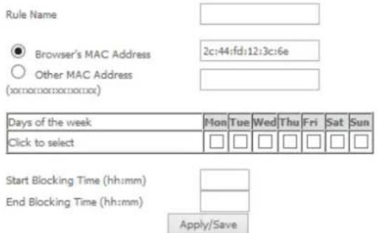
Figure 2: Advanced - Parental Control - Add Time Restriction
See the instructions below. Press the Apply/Save button to save a time restriction rule.
| FIELD | DESCRIPTION |
| Rule Name | A user defined name for the time restriction rule. |
| Browser's MAC Address | The MAC address of the network card of the computer running the browser. |
| Other MAC Address | The MAC address of a second LAN device or network card. |
| Days of the Week | The days of the week for which the rules apply. |
| Start Blocking Time | The time of day when the restriction starts. |
| End blocking time | The time of day when the restriction ends. |
Table 2: Advanced - Parental Control - Add Time Restriction Settings
URL Filter
With the URL filter, you are able to add certain websites or URLs to a safe or blocked list. This will provide you added security to ensure any website you deem unsuitable will not be able to be seen by anyone who is accessing the Internet via the NF10WV.
Select the 'To block' or 'To allow' option and then click Add to enter the URL you wish to add to the URL Filter list.
URL Filter -- Please select the list type first then configure the list entries. Maximum 100 entries can be configured.
URL List Type: ○ Black List ○ White List
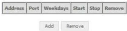
Figure 3: Advanced - Parental Control - URL Filter
Once you have chosen to add a URL to the list you will be prompted to enter the address. Simply type it in and select the Apply/Save button.
Parental Control - URL Filter Add
Enter the URL address and port number then click 'Apply/Save' to add the entry to the URL filter.

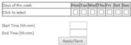
Figure 4: Advanced - Parental Control - Add URL Filter
Quality of Service
Quality of Service offers a defined level of performance in a data communications system - for example the ability to guarantee that video traffic is given priority over other network traffic to ensure that video streaming is not disrupted by other network traffic. This means that if you are streaming video and someone else in the house starts downloading a large file, the download won't disrupt the flow of video traffic.
QoS -- Queue Management Configuration
If Enable QoS checkbox is selected, choose a default DSCP mark to automatically mark incoming traffic without reference to a particular classifier. Click 'Apply/Save' button to save it.
Note: If Enable QoS checkbox is not selected, all QoS will be disabled for all interfaces.
Note: The default DSCP mark is used to mark all egress packets that do not match any classification rules.
Enable QoS
Select Default DSCP Mark No Change(-1)
Apply/Save
Figure 5: Advanced - Enable QoS
To enable QoS select the Enable QoS checkbox, and set the Default DSCP (Differentiated Services Code Point) Mark. Then press the Apply/Save button.
QoS Queue
QoS Queue Setup
In ATM mode, maximum 16 queues can be configured.
In PTM mode, maximum 8 queues can be configured.
For each Ethernet interface, maximum 4 queues can be configured.
For each Ethernet WAN interface, maximum 4 queues can be configured.
To add a queue, click theAdd button.
To remove queues, check their remove-checkboxes, then click theRemove button.
The Enable button will scan through every queues in the table. Queues with enable-checkbox checked will be enabled. Queues with enable-
checkbox un-checked will be disabled.
The enable-checkbox also shows status of the queue after page reload.
Note: Ethernet LAN queue configuration only takes effect when all the queues of the interface have been configured.

Figure 6: Advanced - QoS Queue Setup
Click the Add button to add a QoS Queue. The following screen is displayed.
QoS Queue Configuration
This screen allows you to configure a QoS queue and assign it to a specific layer2 interface. The scheduler algorithm is defined by the layer2 interface.
Name:
Enable:
Interface:

Enable
eth1(wan)
Queue Precedence:
1(SP) ▼ (lower value, higher priority)
- The precedence list shows the scheduler algorithm configured at each precedence level.
- Note that precedence level with SP scheduler may have only one queue.
- precedence level with WRR/WFQ scheduler may have multiple queues.
Apply/Save
Figure 7: Advanced - QoS - Add QoS Queue
The above screen allows you to configure a QoS queue entry and assign it to a specific network interface. Each of the queues can be configured for a specific precedence. The queue entry configured here will be used by the classifier to place ingress packets appropriately.
NOTE: Precedence level 1 relates to higher priority while precedence level 3 relates to lower priority.
The QoS Wlan Queue page displays a summary of the QoS configuration.
QoS Wlan Queue Setup
Note: If WMM function is disabled in Wireless Page, queues related to wireless will not take effects.
| Name | Key | Interface | Qid | Prec/Alg/Wght | Enable |
| WMM Voice Priority | 1 | w0 | 8 | 1/SP | Enabled |
| WMM Voice Priority | 2 | w0 | 7 | 2/SP | Enabled |
| WMM Video Priority | 3 | w0 | 6 | 3/SP | Enabled |
| WMM Video Priority | 4 | w0 | 5 | 4/SP | Enabled |
| WMM Best Effort | 5 | w0 | 4 | 5/SP | Enabled |
| WMM Background | 6 | w0 | 3 | 6/SP | Enabled |
| WMM Background | 7 | w0 | 2 | 7/SP | Enabled |
| WMM Best Effort | 8 | w0 | 1 | 8/SP | Enabled |
QoS Classification
QoS Classification Setup -- A maximum 32 entries can be configured.
To add a rule, click the Addbutton.
To remove rules, check their remove-checkboxes, then click the Removebutton.
The Enable button will scan through every rules in the table. Rules with enable-checkbox checked will be enabled. Rules with enable-checkbox un-checked will be disabled.
The enable-checkbox also shows status of the rule after page raised.
If you disable WMM function in Wireless Page, classification related to wireless will not take effects
| CLASSIFICATION CRITERIA | CLASSIFICATION RESULTS | ||||||||||||||||||||
| Class Name | Order | Class Interface | Ethernet Type | Source MAC/ Mask | Destination MAC/ Made | Source IP/ Prefix Length | Destination | NetMax/ Tpl.length | Protocol | Source Port | Destination | DSCP Check | 802.1P Check | TC Check | Queue Key | DSCP Mark | 802.1P Mark | TC Mark | Rate Limit(kbps) | Enable | Remove |

Click the Add button to configure network traffic classes.
Add Network Traffic Class Rule
This screen creates a traffic class rule to classify the ingress traffic into a priority queue and optionally mark the DSCP or Ethernet priority of the packet. Click 'Apply/Save' to save and activate the rule.
Traffic Class Name:
Rule Order:
Rule Status:
Specify Classification CriteriaA blank criterion indicates it is not used for classification.
Ingress Interface:
Ether Type:
Source MAC Address
Source MAC Mask:
Destination MAC Address
Destination MAC Mask:
Specify Classification Results (A blank value indicates no operation.)
Specify Egress Interface (Required):
Specify Egress Queue (Required):
- Packets classified into a queue that exit through an interface for which the queue
is not specified to exist, will instead egress to the default queue on the interface.
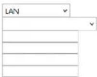
Mark 907.1p priority:
- Class non-vlan packets egress to a non-vlan interface will be tagged with VID 0 and the class rule p-bits.
- Class vlan packets egress to a non-vian interface will have the packet p-bits re-marked by the class rule p-bits. No additional vlan tag is added.
- Class non-vian packets egress to a vlan interface will be tagged with the interface VID and the class rule p-bits.
- Class vlan packets agree to a vlan interface will be additionally tagged with the packet VID, and the class rule p-bits.
Set Rate Limit(kbps):



The above screen creates a traffic class rule to classify the upstream traffic, assign queuing priority and optionally overwrite the IP header TOS (type of service) byte. A rule consists of a class name and at least one condition. All of the specified conditions in this classification rule must be satisfied for the rule to take effect.
Click the Apply/Save button to save and activate the rule.
Routing
The Default Gateway, Static Route, Policy Routing and Dynamic Route settings can be found in the Routing option of the Advanced menu.
Default Gateway
Select your preferred WAN interface from the available options.
Routing -- Default Gateway
Default gateway interface list can have multiple WAN interfaces served as system default gateways but only one will be used according to the priority with the first being the highest and the last one the lowest priority if the WAN interface is connected. Priority order can be changed by removing all and adding them back in again.
Selected Default Gateway Interfaces
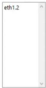

Available Routed WAN Interfaces

natural_image
Blank white rectangle with a thin gray border and corner arrows (no text or symbols)Select a preferred wan interface as the system default IPv6 gateway.
Selected WAN Interface
NO CONFIGURED INTERFACE
Apply/Save
Static Route
The Static Route screen displays the configured static routes. Click the Add or Remove buttons to change settings.
Routing - Static Route (A maximum 32 entries can be configured)

Add Remove
To add a static route rule click the Add button. The following screen is displayed.
Routing -- Static Route Add
Enter the destination network address, subnet mask, gateway AND/OR available WAN interface then click 'Apply/Save' to add the entry to the routing table.
IP Version:
Destination IP address/prefix length:
Interface:
Gateway IP Address:
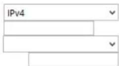
(optional: metric number should be greater than or equal to zero)
Metric:

Apply/Save
Enter the Destination Network Address, Subnet Mask, Gateway IP Address and/or WAN Interface. Then click Apply/Save to add the entry to the routing table.
Policy Routing
This function allows you to add policy rules to certain situations.
Policy Routing Setting - A maximum 7 entries can be configured.

Click the Add button to add a policy rule. The following screen is displayed.
Policy Routing Setup
Enter the policy name, policies, and WAN interface then click "Apply/Save" to add the entry to the policy routing table.
Note: If selected "IPoE" as WAN interface, default gateway must be configured.
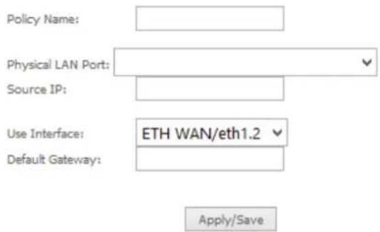
Figure 8: Advanced - Routing - Add Policy Route
Enter the details into the provided fields. The table below describes each field.
| FIELD | DESCRIPTION |
| Policy Name | A user defined name for the policy route. |
| Physical LAN Port | The LAN port to be used for the policy. |
| Source IP | The IP address of the LAN device involved with the policy. |
| Use Interface | Select the Interface that the policy will employ. |
| Default Gateway | Enter the gateway address. |
RIP (Routing Information Protocol)
To activate this option, select the Enabled checkbox.
To configure an individual interface, select the desired RIP version and operation, and select the Enabled checkbox for that interface. Click Apply/Save to save the configuration.
Routing - RIP Configuration
NOTE: RIP CANNOT BE CONFIGURED on the WAN interface which has NAT enabled (such as PPPoE).
To activate RIP for the WAN Interface, select the desired RIP version and operation and place a check in the 'Enabled' checkbox. To stop RIP on the WAN Interface, uncheck the 'Enabled' checkbox. Click the 'Apply/Save' button to start/stop RIP and save the configuration.

Apply/Save
DNS
DNS Server
This page allows you to enable automatic DNS settings detected from the Internet Service Provider or specify your own DNS server address manually.
UBS Server Configuration
Select DNS Server Interface from available WAN interfaces OR enter static DNS server IP addresses for the system. In ATM mode, if only a single PVC with IFOA or static IFOA protocol is configured. Static DNS server IP addresses must be ordered. DNS Server Telfaces can have multiple WAN interfaces served as system DNS servers but only one will be used according to the priority with the first being the highest and the last one the lowest priority if the WAN interface is connected. Priority order can be changed by removing all and adding them back in again.
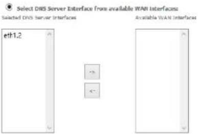
☐ Use the following Static DNS IP address:

Select the configured WAN interface for IPv6 DNS server information OR enter the static IPv6 DNS server Addresses. Note that selecting a WAN interface for IPv6 DNS server will enable DHCP Client on that interface.

Apply/Save
Dynamic DNS
The Dynamic DNS service allows a dynamic IP address to be aliased to a static hostname in any of a selection of domains, allowing the router to be more easily accessed from various locations on the internet. You will require a Dynamic DNS subscription from a Dynamic DNS provider.
Dynamic DNS
The Dynamic DNS service allows you to alias a dynamic IP address to a static hostname in any of the many domains, allowing your Broadband Router to be more easily accessed from various locations on the Internet.
Choose Add or Remove to configure Dynamic DNS.

Note: The Add/Remove buttons will be displayed only if the router has been assigned an IP address from the remote server.
To add a dynamic DNS service, click the Add button and the following screen will display.
Add Dynamic DNS
This page allows you to add a Dynamic DNS address from DynDNS.org or TZO.
D-DNS provider
DynDNS.org
Hostname
Interface
DynDNS Settings
Username
Password
Apply/Save
| FIELD | DESCRIPTION |
| D-DNS Provider | Select the dynamic DNS provider from the list. |
| Hostname | The name of the dynamic DNS provider. |
| Interface | Select the interface from the list. |
| Username | Enter the Dynamic DNS account username. |
| Password | Enter the Dynamic DNS account password. |
Table 3: Advanced - DNS - Add Dynamic DNS Account Settings
DSL
This page allows the user to modify the DSL modulation settings on the unit. By changing the settings, you can specify which DSL modulation that the modem will use.
DSL Settings
Select the modulation below.
Select the profile below.
G.Dmt Enablad
G. Its Enabled
T1/413 Enabled
ADSL2 Enabled
☑ AnnexL Enabled
ADSL2+ Enabled
□ AnneM Erabied
VDSL2 Enabled
√ Ita Enabled
☑ Ifb Enabled
☑ 8c Enabled
√ Id Enabled
12a Enabled
√ 12b Enabled
√ 17a Enabled
30a Enabled
USO
✅ enabled
Select the phone line pair below.
Inner pair
○ Outer pair
Capability
Bitwrap Enable
□ SRA Enable
Apply/Save Advanced Settings
For advanced DSL options press the Advanced Settings button.
DSL Advanced Settings
Select the test mode below.
Normal
○Reverb
○ Medley
○ No retrain
Ou
Apply Tone Selection
The DSL advanced settings relate to test mode settings. The default selection is 'Normal'.
ADSL Tone Settings
For ADSL Tone Settings select the 'Tone Selection' button on the DSL Advanced Settings page.
The frequency band of ADSL is split up into 256 separate tones, each spaced 4.3125kHz apart. With each tone carrying separate data, the technique operates as if 256 separate routers were running in parallel. The tone range is from 0 to 31 for upstream traffic and from 32 to 255 for downstream traffic. Do not change these settings unless you are directed by your Internet Service Provider.
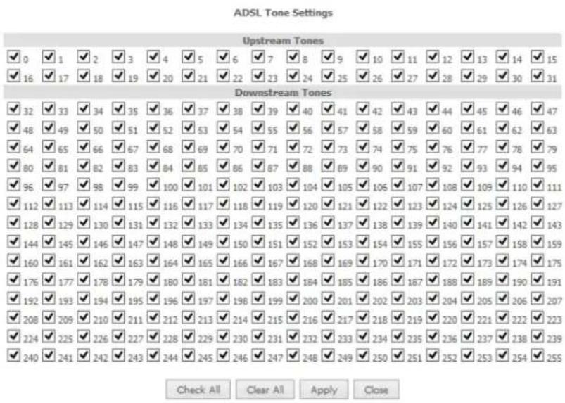
UPnP
Universal Plug and Play (UPnP) is a set of networking protocols that can allow networked devices, such as computers, printers, WiFi access points and mobile phones to automatically detect each other's presence on the network and establish functional network services for data sharing, communications, and entertainment. UPnP allow automatic port forwarding configuration form your UPnP devices.
UPnP Configuration
NOTE: UPnP is activated only when there is a live WAN service with NAT enabled.

Enable UPnP
Apply/Save
DNS Proxy
To enable DNS Proxy settings, select the corresponding checkbox and then enter the Host and Domain name, as in the example shown below. Click Apply/Save to continue.
DNS Proxy Configuration

Enable DNS Proxy
Host name of the Broadband Router:
NF10W
Domain name of the LAN network:
Home
Apply/Save
The Host name and Domain name are combined to form a unique label that is mapped to the router IP address. This can be used to access the user interface of the router with a local name rather than by using the router IP address. Eg. You can access your router by entering http://NF10WV into your web browser.
DLNA
The DLNA page allows you to enable or disable and configure the digital media server. This means you can have digital media stored on an external USB hard drive connected to the NF10WV and the router will make it accessible to other devices on your network.
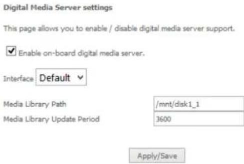
Select Enable on-board digital media server and then use the drop down list to select the Interface. In the Media Library Path field, enter the path to the media and then enter a period between media library updates in seconds. Click the Apply/Save button when you have finished.
Storage Service
The Storage Service options enable you to manage attached USB Storage devices and create accounts to access the data stored on the attached USB device.
Storage Device Info
The storage device info page displays information about the attached USB Storage device.
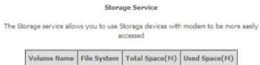
User Accounts
User accounts are used to restrict access to the attached USB Storage device.
To delete a User account entry, click the Remove checkbox next to the selected account entry and click Remove.
Click Add to create a user account.

Adding an account allows the creation of specific user accounts with a password to further control access permissions. To add an account, click the Add button and then enter the desired username and password for the account.
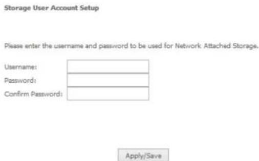
Interface Grouping
Port Mapping allows you to create groups composed of the various interfaces available in your router. These groups then act as separate networks.
To delete an Interface group entry, click the Remove checkbox next to the selected group entry and click Remove.
Interface Grouping -- A maximum 16 entries can be configured
Interface Grouping supports multiple ports to PVC and bridging groups. Each group will perform as an independent network. To support this feature, you must create mapping groups with appropriate LAN and WAN interfaces using the Add button. The Remove button will remove the grouping and add the ungrouped interfaces to the Default group. Only the default group has IP interface.
| Group Name | Remove | WAN Interface | LAN Interfaces |
| Default | eth1.1eth1.2 | eth2.0 | |
| eth3.0 | |||
| w0 | |||
| eth0.0 | |||
| eth4.0 |
Add
Remove
Click Add to create an Interface group.
Interface grouping Configuration
To create a new interface group:
1.Enter the Group name and the group name must be unique and select either 2. (dynamic) or 3. (static) below:
-
Select interfaces from the available interface list and add it to the grouped interface list using the arrow buttons to create the required mapping of the ports. Note that these clients may obtain public IP addresses
-
Click Save/Apply button to make the changes effective immediately.
Group Name:
WAN Interface used in the grouping
ETH WAN/eth1.1

Grouped LAN Interfaces

natural_image
Blank white image with a thin border and corner arrows (no text or symbols)
Available LAN Interfaces
eth0.0 eth2.0 eth3.0 eth4.0 wlan0
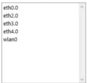
Apply/Save
Enter a group name and then use the arrow buttons to select which interfaces you wish to group. Click Apply/Save to save the Interface grouping configuration settings.
IP Tunnel
The IP Tunnelling feature allows you to configure tunnelling of traffic between IPv6 and IPv4 networks.
IPv6inIPv4
IP Tunneling -- 6in4 Tunnel Configuration
| Name | WAN | LAN | Dynamic | IPv4 Mask Length | 6rd Prefix | Border Relay Address | Remove |
Click the Add button to add a new tunnel.
IP Tunneling -- 6in4 Tunnel Configuration
Currently, only 6rd configuration is supported.
Tunnel Name
Mechanism:
Associated WAN Interface:
Associated LAN Interface:

Manual

Automatic
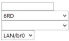
IPv4 Mask Length:
6rd Prefix with Prefix Length:
Border Relay IPv4 Address:
Apply/Save
IPv4inIPv6
IP Tunneling -- 4in6 Tunnel Configuration


Click the Add button to add a new tunnel.
IP Tunneling - 4in6 Tunnel Configuration
Currently, only DS-Lite configuration is supported.
Tunnel Name
Mechanism:
Associated WAN Interface:
Associated LAN Interface:

Manual

Automatic
Remote Address
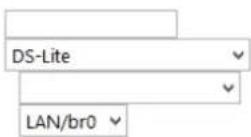
Apply/Save
IPSec
The NF10WV offers IPSec VPN tunnel functionality. To delete an IPSec entry, click the Remove checkbox next to the selected IPSec tunnel entry and click Remove.
IPSec Tunnel Mode Connections
Add, remove or enable/disable IPSec tunnel connections from this page.


Click Add to create a new IPSec tunnel connection.
IPSec Settings
IPSec Connection Name
new connection
IP Version:
IPv4
Tunnel Mode
ESP
Local Gateway Interface:
Select interface
Remote IPSec Gateway Address (IP or Domain)
0.0.0.0
Tunnel access from local IP addresses
Subnet
IP Address for VPN
0.0.0.0
Mask or Prefix Length
255.255.255.0
Tunnel access from remote IP addresses
Subnet
IP Address for VPN
0.0.0.0
Mask or Prefix Length
255,255,255.0
Key Exchange Method
Auto(IKE)
Authentication Method
Pre-Shared Key
Pre-Shared Key
key
Perfect Forward Secrecy
Disable
Advanced IKE Settings
Show Advanced Settings
Apply/Save
Figure 9: Advanced - IPSec
Enter the following parameters:
| PARAMETER | DEFINITION |
| IPSec Connection Name | Enter a name to identify the IPSec tunnel |
| Tunnel Mode | Select the applicable IPSec tunnel mode |
| Remote IPSec Gateway | Enter the IP Address of the IPSec server to connect to |
| Tunnel access from Local | Select which remote addresses local IPSec connections are able to access |
| IP Address from VPN | Enter the IP Address to be used locally for the IPSec tunnel |
| Subnet mask for VPN | Enter the subnet mask to be used locally for the IPSec tunnel |
| Tunnel Access from Remote | Select which local addresses remote IPSec connections are able to access |
| IP Address for VPN | Enter the IP Address to be used on the remote end for the IPSec tunnel |
| Subnet mask for VPN | Enter the subnet mask to be used on the remote end for the IPSec tunnel |
| Key Exchange Method | Select the type of IPSec exchange is to be used on the IPSec tunnel |
| Authentication Method | Select the applicable authentication for the IPSec tunnel |
| Pre-Shared Key | Enter the pre-shared key (if applicable) to grant access to the IPSec tunnel |
| Perfect Forward Secrecy | Select to use Perfect Forward Secrecy during key exchange for the IPSec tunnel |
| Advanced IKE Settings | Configure advanced IKE settings for the IPSec tunnel such as the encryption method or key life time |
After entering the required IPSec tunnel service settings, click Apply/Save to save the new IPSec Tunnel configuration settings.
Multicast (IGMP Configuration)
The Internet Group Management Protocol (IGMP) is a communications protocol used by hosts and adjacent routers on IP networks to establish multicast group memberships. IGMP is a protocol only used on the network between a host and the router. It allows a host to inform the router whenever that host needs to join or leave a particular multicast group. IGMP provides for more efficient allocation of resources when used with online gaming and video streaming.

IGNP Configuration
Enter IGMP protocol configuration fields if you want modify default values shown below.
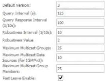
MLD Configuration
Enter MLD protocol (IPv6 Multicast) configuration fields if you want modify default values shown below.
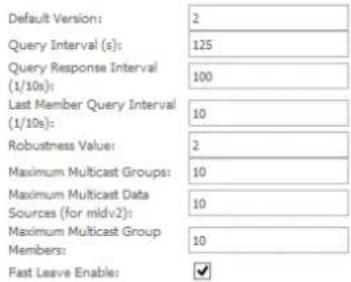
Apply/Save
| FIELD | DEFINITION |
| Default Version | The version IGMP in use by the router. |
| Query Interval | The hosts on the segment report their group membership in response to the router's queries. The query interval timer is also used to define the amount of time a router will store particular IGMP state if it does not hear any reports on the group. The query interval is the time in seconds between queries sent from the router to IGMP hosts. |
| Query Response Interval | When a host receives the query packet, it starts counting to a random value, less the maximum response time. When this timer expires, the host replies with a report, provided that no other host has responded yet. This accomplishes two purposes:a) Allows controlling the amount of IGMP reports sent during a time window.b) Engages the report suppression feature, which permits a host to suppress its own report and conserve bandwidth. |
| Last Member Query Interval | IGMP uses this value when router hears IGMP Leave report. This means that at least one host wants to leave the group. After router receives the Leave report, it checks that the interface is not configured for IGMP Immediate Leave (single-host on the segment) and if not, it sends out an out-of-sequence query. |
| Robustness Value | The robustness variable is a way of indicating how susceptible the subnet is to lost packets. IGMP can recover from robustness variable minus 1 lost IGMP packets. You can also click the scroll arrows to select a new setting. The robustness variable should be set to a value of 2 or greater. The default robustness variable value is 2. |
| Maximum Multicast Groups | The maximum number of multicast groups that the router can control at any one time. |
| Maximum Multicast Data Sources | The maximum number of data sources a multicast group can have. |
| Maximum Multicast Group Members | The maximum number of hosts a multicast group can have. |
| Fast Leave Enable | With IGMP fast-leave processing, which means that the router immediately removes the interface attached to a receiver upon receiving a Leave Group message from a IGMP host. |
Wireless
Basic
The Wireless Basic page allows you to enable the wireless network and configure its basic settings.
Wireless - Basic
This page allows you to configure basic features of the wireless LAN interface. You can enable or disable the wireless LAN interface, hide the network from active scans, set the wireless network name (also known as SSID) and restrict the channel set based on country requirements.
Click 'Apply/Save' to configure the basic wireless options.
Enable Wireless
Hide Access Point
□ Clients Isolation
□ Disable WMM Advertise
√ Enable Wireless Multicast Forwarding (WMF)
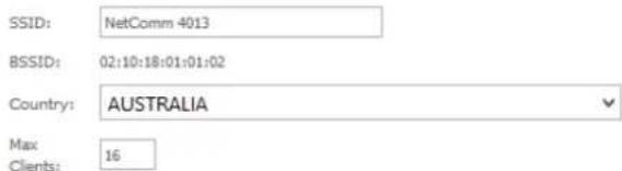
Wireless - Guest/Virtual Access Points:
| Enabled | SSID | Hidden | Isolate Clients | Enable WMM Advertise | Enable WMF | Enable HSPOT | Max Clients | BSSID |
| wI0_Guest1 | 16 | N/A | ||||||
| wI0_Guest2 | 16 | N/A | ||||||
| wI0_Guest3 | 16 | N/A |
Apply/Save
The following parameters are available:
| PARAMETER | DEFINITION |
| Enable Wireless | Select to enable or disable the wireless network function |
| Hide Access Point | Select to hide or display the wireless network when an SSID scan is performed |
| Clients Isolation | Select to prevent clients on the wireless network being able to access each other |
| Disable WMM Advertise | Select to prevent the NF10WV advertising its WMM function |
| Enable Multicast Forwarding (WMF) | Select to enable Wireless Multicast Forwarding. This can reduce latency and improve throughput for wireless clients |
| Max Clients | Enter the maximum number of wireless clients able to connect to the wireless network |
| Wireless Guest Network | Select to enable a separate Wireless Guest network, the same options are available for a Guest network as with the main system wireless network. |
Click Apply/Save to save the new wireless configuration settings.

Note: Hiding the network may leads to potential connection problems, a non-broadcast network is not undetectable, hiding a SSID is Security through obscurity.
Security
The NF10WV supports all encryptions within the 802.11 standard. The factory default is WPA2-PSK. The NF10WV also supports WPA, WPA-PSK, WPA2, WPA2-PSK. You can also select to enable WPS mode.
Wireless – Security
This page allows you to configure security features of the wireless LAN interface.
You may setup configuration manually
OR
through WiFi Protected Setup(WPS)
Note: When both STA PIN and Authorized MAC are empty, PBC is used. If Hide Access Point enabled or Mac filter list is empty with "allow" chosen, WPS2 will be disabled
WPS Setup
Enable WPS
Disabled
Manual Setup AP
You can set the network authentication method, selecting data encryption.
specify whether a network key is required to authenticate to this wireless network and specify the encryption strength.
Click 'Apply/Save' when done,
Select SS10;
NetComm 4013
Network Authentication:
WPA2 -PSK
Protected Management Frames:
WPA/WAPI passphrase:
WPA Group Rekey Interval:
WPA/WAPI Encryption:
WEP Encryption:
Disabled
●●●●●●●●●●
。
AES
Disabled
Apply/Save
The following parameters are available:
| PARAMETER | DEFINITION |
| Enable WPS | Select to enable or disable the WPS function of the NF10WV. |
| Select SSID | Select the SSID to apply the security settings to. |
| Network Authentication | Select the Wireless security type to use with the wireless network. |
| WPA/WAPI passphrase | Enter the security key to use with the wireless network. |
| WPA Group Rekey Interval | Enter the group rekey interval. This should not need to change. |
| WPA/WAPI Encryption | Select the type of encryption to use on the wireless network. |
| WEP Encryption | Select to utilise WEP encryption on the wireless network connection. |

Note: WPA with TKIP and Open WEP are no longer considered secure. WPA2 with AES is the most secure option.
Mixed WPA2/WPA (TKIP+AES) will provide maximum compatibility with legacy devices.
Click Apply/Save to save the new wireless security configuration settings.
MAC Filter
MAC Filter allows you to add or remove the MAC Address of devices which will be allowed or denied access to the wireless network. First use the Select SSID drop down list to select the wireless network you wish to configure, then select to either allow or deny access to the MAC addresses listed.
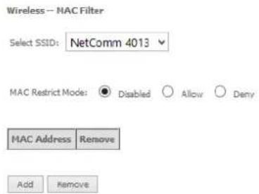
Click Add to add a MAC Address Filter.
Wireless -- MAC Filter Enter the MAC address and click 'Apply/Save' to add the MAC address to the wireless MAC address filters.
MAC Address:
Apply/Save
Enter the MAC Address to be filtered and click Apply/Save to save the new MAC Address filter settings. To delete a MAC filter entry, click the Remove checkbox next to the selected filter entry and click Remove.

Note: While giving a wireless network some additional protection, MAC filtering can be circumvented by scanning a valid MAC and then spoofing one's own MAC into a validated one, using MAC Filtering may lead to a false sense of security.
Wireless Bridge (Wireless Distribution Service)
Wireless Bridge allows you to configure the router's access point as a Wireless Distribution Service.
Wireless -- Bridge
This page allows you to configure wireless bridge features of the wireless LAN interface. Select Disabled in Bridge Restrict which disables wireless bridge restriction. Any wireless bridge will be granted access. Selecting Enabled or Enabled(Scan) enables wireless bridge restriction. Only those bridges selected in Remote Bridges will be granted access.
Click "Refresh" to update the remote bridges. Wait for few seconds to update. Click "Apply/Save" to configure the wireless bridge options.
Bridge Restrict:
Remote Bridges MAC Address:
Refresh Apply/Save
Select the mode for the Wireless Access Point built into the NF10WV. You can specify which wireless networks will be allowed to connect to the NF10WV by using the 'Bridge Restrict' option and then entering the applicable MAC Addresses of the other wireless access points.

Note: WPA/WPA2 encryption may not be compatible with other vendors, when operating in Wireless Bridge (WDS) mode.
Click Apply/Save to save the new wireless bridge configuration settings.
Advanced
Advanced Wireless allows you to configure detailed wireless network settings such as the band, channel, bandwidth, transmit power and preamble settings.
Wireless - Advanced
This page allows you to configure advanced features of the wireless LAN interface. You can select a particular channel on which to operate, force the transmission rate to a particular speed, set the fragmentation threshold, set the RTS threshold, set the wakeup interval for clients in power-save mode, set the beacon interval for the access point, set XPress mode and set whether short or long preambles are used.
Click 'Apply/Save' to configure the advanced wireless options.
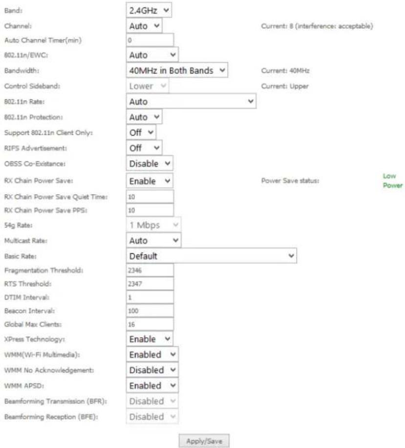
Click Apply/Save to save any changes to the wireless network settings configuration.
| PARAMETER | DEFINITION |
| Band | Shows your current frequency band. |
| Channel | Fill in the appropriate channel to correspond with your network settings. All devices in your wireless network must use the same channel in order to work correctly. This router supports auto channeling functionality. |
| Auto Channel Timer(min) | Specifies the timer of auto channelling. |
| 802.11n/EWC | Select disable 802.11n or Auto. |
| Bandwidth | Select the bandwidth for the network. In high wireless activity/interference environment, reduce band to 20MHz for better stability. |
| Control Sideband | If you select 20MHz in Both Bands you cannot select sideband does not work as you are not utilizing side bands. When you select 40MHz in Both Bands as the bandwidth and manual select channel, the following options will appear. Then you can select Lower or Upper as the value of sideband. As the control sideband, when you select Lower, the channel is 1~7. When you select Upper, the channel is 5~11. |
| 802.11n Rate | Select the transmission rate for the network. The rate of data transmission should be set depending on the speed of your wireless network. You can select from a range of transmission speeds, or you can select Auto to have the Router automatically use the fastest possible data rate and enable the Auto-Fallback feature. Auto-Fallback will negotiate the best possible connection speed between the Router and a wireless client. The default value is Auto. |
| 802.11n Protection | The 802.11n standards provide a protection method so 802.11b/g and 802.11n devices can co-exist in the same network without "speaking" at the same time. |
| Support 802.11n Client Only | Only stations that are configured in 802.11n mode can associate. |
| 54g Rate | Allows you to specify the maximum bandwidth of the 802.11g network. |
| Multicast Rate | Select the multicast transmission rate for the network. The rate of data transmission should be set depending on the speed of your wireless network. You can select from a range of transmission speeds, or you can select Auto to have the Router automatically use the fastest possible data rate and enable the Auto-Fallback feature. Auto-Fallback will negotiate the best possible connection speed between the Router and a wireless client. The default value is Auto. |
| Basic Rate | Select the basic transmission rate ability for the AP. |
| Fragmentation Threshold | Packets that are larger than this threshold are fragmented into multiple packets. Try to increase the fragmentation threshold if you encounter high packet error rates. Do not set the threshold too low, since this can result in reduced networking performance. |
| RTS Threshold | This value should remain at its default setting of 2347.Should you encounter inconsistent data flow, only minor reductions are recommended. Should you encounter inconsistent data flow, only minor reduction of the default value, 2347, is recommended. If a network packet is smaller than the preset RTS threshold size, the RTS/CTS mechanism will not be enabled. The Router sends Request to Send (RTS) frames to a particular receiving station and negotiates the sending of a data frame. After receiving an RTS, the wireless station responds with a Clear to Send (CTS) frame to acknowledge the right to begin transmission. The RTS Threshold value should remain at its default value of 2347. |
| DTIM Interval | (Delivery Traffic Indication Message) Enter a value between 1 and 255 for the Delivery Traffic Indication Message (DTIM.) A DTIM is a countdown informing clients of the next window for listening to broadcast and multicast messages. |
| Beacon Interval | A beacon is a packet of information that is sent from a connected device to all other devices where it announces its availability and readiness. A beacon interval is a period of time (sent with the beacon) before sending the beacon again. The beacon interval may be adjusted in milliseconds (ms). Default (100) is recommended. |
| XPress Technology | Select Enable or Disable. This is a special accelerating technology for IEEE802.11g. The default is Enabled. |
| WMM (Wi-Fi Multimedia) | Select whether WMM is enable or disabled. Before you disable WMM, you should understand that all QoS queues or traffic classes relate to wireless do not take effects. |
| WMM No Acknowledgement | Select whether ACK in WMM packet. By default, the 'Ack Policy' for each access category is set to Disable, meaning that an acknowledge packet is returned for every packet received. This provides a more reliable transmission but increases traffic load, which decreases performance. To disable the acknowledgement can be useful for Voice, for example, where speed of transmission is important and packet loss is tolerable to a certain degree. |
| WMM APSD | APSD is short for automatic power save delivery, Selecting enable will make it has very low power consumption. WMM Power Save is an improvement to the 802.11e amendment adding advanced power management functionality to WMM. |
Station Info
This page shows the MAC address of authenticated wireless stations that are connected to the NF10WV and their status
Wireless -- Authenticated Stations
This page shows authenticated wireless stations and their status.
MAC Associated Authorized SSID Interface
Refresh
Voice
This section explains how to configure the VoIP settings of the NF10WV.
VoIP Status
The Voice Status page displays the registration status of your SIP accounts and the total call time of each account.
Voice - Voice Status
Account denial will display "Disabled", registered successfully will display "Up", and unregistered will display "Down".
| SIP Account | Call Time | User Accounts | Registration Status | Hook Status | Call Status |
| 1 | 0:00:00 | Down | On Hook | Idle | |
| 2 | 0:00:00 | Down | On Hook | Idle |
Active call monitoring
| Calling number | Called number | Source IP | Destination IP | Port used | Duration | Direction | Packets sent | Packets received | Packets lost |
Call history:
| Index | Calling number | Called number | Source ID | Destination ID | Port used | Duration | Direction | Packets sent | Packets received | Packets lost | Timestamp |
SIP Basic Setting
The SIP Settings page is where you enter your VOIP service settings as supplied by your VOIP service provider (VSP). If you are unsure about a specific setting or have not been supplied information for a particular field, please contact your VOIP service provider to verify if this setting is needed or not.
![Voice -- SIP Basic Setting Bound Interface Name: Any_WAN Country : AUS - AUSTRALIA SIP local port(1-65535): 5060 SIP domain name*: (Note: Please leave this field blank unless required by your service provider) Use SIP Proxy. Use SIP Outbound Proxy. Use SIP Registrar. Use SIP Proxy2. Use SIP Outbound Proxy2. Use SIP Registrar1. SIP Account 1 2 Account Enabled ✓ ✓ Polarity Reverse Enable □ □ Authentication name Password Cid Name Cid Number codec-line 1 ptme[ms] priority enable codec-line 2 ptme[ms] priority enable G711U 20 √ 1 (1-100) ✓ G711U 20 √ 1 (1-100) ✓ G711A 20 √ 2 (1-100) ✓ G711A 20 √ 2 (1-100) ✓ G723_63 20 √ 3 (1-100) ✓ G723_63 20 √ 3 (1-100) ✓ G726_24 20 √ 4 (1-100) ✓ G726_24 20 √ 4 (1-100) ✓ G726_32 20 √ 5 (1-100) ✓ G726_32 20 √ 5 (1-100) ✓ G726_16 20 √ 6 (1-100) ✓ G726_16 20 √ 6 (1-100) ✓ G726_40 20 √ 7 (1-100) ✓ G726_40 20 √ 7 (1-100) ✓ G722 20 √ 8 (1-100) ✓ G722 20 √ 8 (1-100) ✓ Apply](/content/2026/05/996218/images/5661582b8e548f91cfe166ed7955c54a9db3726327d8173a65c7e4537d5e397a.jpg)
The individual fields shown above on the SIP Basic Settings page are explained in the following table.
| OPTION | DEFINITION |
| Bound Interface Name | Select the Interface that the VoIP account will use to make a connection to the VoIP Service Provider. |
| SIP Local Port | Set the SIP local port of the gateway, the default value is 5060. SIP local port is the SIP UA (user agent) port. |
| SIP domain name | Enter the SIP domain name or IP address of your VoIP Service Provider here. |
| Use SIP Proxy | Select the checkbox of Use SIP Proxy, if your DSL router uses a SIP proxy. SIP proxy allows other parties to call DSL router through it. When it is selected, the following fields appear. |
| SIP Proxy | The IP address of the proxy. |
| SIP Proxy port | The port that this proxy is listening on. By default, the port value is 5060. |
| Use SIP Outbound Proxy | Some network service providers require the use of an outbound proxy. This is an additional proxy, through which all outgoing calls are directed. In some cases, the outbound proxy is placed alongside the firewall and it is the only way to let SIP traffic pass from the internal network to the Internet. When it is selected, the following fields appear. |
| SIP Outbound Proxy | The IP address of the outbound proxy. |
| SIP Outbound Proxy port | The port that the outbound proxy is listening on. By default, the port value is 5060. |
| Use SIP Registrar | Select this option if required by your VoIP Service Provider. Enter the SIP Proxy Domain Name and SIP Proxy Port which is typically 5060. |
| SIP Registrar | The IP address of the SIP registrar. |
| SIP Registrar port | The port that SIP registrar is listening on. By default, the port value is 5060. |
| Account Enabled | If it is unselected, the corresponding account is disabled. You can not use it to initiate or accept any call. |
| Polarity Reverso Enable | Enable or disable this function. |
| Authentication name | Set the user name of authentication. |
| Password | Set the password of authentication. |
| Cid Name | User name. It is the Display Name. |
| Cid Number | Set the caller number. It must be a number of 0-9. |
| ptime | You can use it to set the packetization time (PT). The PT is the length of the digital voice segment that each packet holds. The default is 20 millisecond packets. If selecting 10 millisecond, packets improve the voice quality. Because of the packet loss, less information is lost, but more loads on the network traffic. |
| Priority | The priority of codec is declined from up to down. Codecs define the method of relaying voice data. Different codecs have different characteristics, such as data compression and voice quality. For Example, G723 is a codec that uses compression, therefore, it is good for use where the bandwidth is limited but its voice quality is not good as other codecs, such as the G711. If you specify none of the codecs, using the default value showed in the above figure, the DSL router chooses the codec automatically. |
After entering your VoIP settings press the Apply button. Select Management > Save/Reboot and press the Reboot button. Once the router restarts if there is a valid internet connection and the VoIP account settings are valid the VoIP service will start.
SIP Advanced
The SIP Advanced page allows you to configure settings that your VoIP service provider has enabled on your SIP account and if you have the appropriate call features and other functionality on your cordless or corded phone handsets.
![Voice -- SIP Advanced Setting Line 1 2 Call waiting ✓ ✓ Unconditionally Call forwarding number Busy Call forwarding number No Answer Call forwarding number Options Time 0 0 Forward unconditionally ✓ ✓ Forward on "lazy" ✓ ✓ Forward on "no answer" ✓ ✓ MWT □ □ Anonymous call blocking ✓ ✓ Anonymous calling ✓ ✓ Anonymous calling mode Display anonymous Display anonymous DIO □ □ Enable Call Return □ □ Call Transfer ✓ ✓ Call conference □ □ Warm Line ✓ ✓ Warm Line URL Warm Line Delay Timer 10 10 ---Fax Setting-- Fax Negotiate Mode: Auto_switch Bypass Codec: 6711_A □ Inable Tilt redundancy support □ Enable vbd redundancy support ---Settings-- ✓ Enable VAD support VAD mode in signal None □ Inable RTCP Flow Ctrl ✓ Enable Echo Cancellation □ Inabia # To ABCII ==SIP Timer Setting== Registration Expiry Timeout: 1650 Session Expires Timeout: 1800 Min Session Expiry Time: 30 (need >= 90s) ---Digitmap Setting-- 000[ *# ]X[0-9* ].# | **XX | *#X[0-9* ].# | *x[0-9* ].# | 00[1-9]xx.c | 014XXXXXXXXX | 016XXXXXX | XX | 0192X | 0198XXXXXXXXX | 0 [23478]XXXXXXXXX | 0500XXXXXXXXX | 11XX | 123X | 124XX | 1251XX | 1252XX | X | 1255X | 1256XXX | 1271X | 130XXXXXXXXX | 1802XXX | 189XX | 1[8-9]XXXXXXXXX | [2-9]XXXXXXXXX | 13 [1-9]XXX Voip Dialpan Settings ---Qen Setting-- DSOP for SIP DEFAULT (000000) DSOP for RTPS DEFAULT (000000) Ethernet Priority Marks -1 ---Payload Setting-- RFC2198 Payload Values: 125 (range 97~127) Onef Relay setting: RFC2833 payload value 138 (range 97~127) ---Call ID Setting== Caller ID send Delay Time: 800 (range 500~1500ms) Caller ID Message Type: FSK_MDMF FSK modulation Mode: BellcoreGen ---Transport Setting-- SIP Transport protocols UDP ---SIP Extends-- PRACK (100ml): SUPPORTED ---Service Offer Setting-- Complementary business models Local model Apply](/content/2026/05/996218/images/4ad7555400a0a65dc051192d1761f4687f5897a60e18bed80fe4c2049c98d9c6.jpg)
Figure 10: VoIP - Advanced - Service Provider
| OPTION | DEFINITION |
| Line | Displays the line number you want to configure |
| Call Waiting | Select this option for your phone if your VoIP Service Provider has enabled Call Waiting on your SIP account. |
| Unconditionally Call forwarding number | Select this option if your VoIP Service Provider has enabled Call Forwarding on your SIP account and you wish to use this feature. |
| Busy Call Forwarding Number | Enter the phone number to forward a call to if it arrives while the line is busy. |
| No Answer Call forwarding number | Enter the phone number to forward a call to if the call is not answered. |
| Forward On "busy" | Select this option if your VoIP Service Provider has enabled Call Forwarding on your SIP account and you wish to use this feature. |
| Forward On "No Answer" | Select this option if your VoIP Service Provider has enabled Call Forwarding on your SIP account and you wish to use this feature. |
| MWI (Message Waiting Indicator) | Select this option if your VoIP Service Provider has enabled MWI (Message Waiting Indicator) on your SIP account and you wish to use this feature. |
| Anonymous Call Blocking | Select this option if your VoIP Service Provider has enabled Anonymous Call Blocking on your SIP account and you wish to use this feature. |
| Anonymous Calling | Select this option if your VoIP Service Provider has enabled Anonymous Calling on your SIP account and you wish to use this feature. |
| Anonymous calling mode | When set to Display anonymous, the modem hides your caller ID. When set to All anonymous, the modem hides both caller ID and the SIP URL of the originating call. |
| DND (Do Not Disturb) | Select this option if your VoIP Service Provider has enabled DND (Do Not Disturb) on your SIP account and you wish to use this feature. Additionally, you must activate the feature using the handset to dial '78. DND is deactivated automatically if the handset is put in the off-hook position. |
| Enable T38 Redundancy Support | Select this function if you wish to send or receive faxes via VoIP and have a fax machine capable of using the T38 fax over VoIP protocol. |
| Enable VBD redundancy support | Select this checkbox to use the feature. |
| Enable VAD support | Enables the Voice Activated Detection function of the modem. |
| Enable RTCP Flow Control | Select this checkbox to use the feature. |
| Enable Echo Cancellation | Select this checkbox to use the feature. |
| Enable # To ASCII | Select this checkbox to use the feature. |
| Enable Reinjection Function | Select this checkbox to use the feature. |
| RFC2198 Payload Value (range 97-127) | Enter the RFC2198 payload value that the valid range is 96 ~ 127. |
| Registration Expire Timeout | Enter the registration expire timeout. |
| Session Expire Time | The interval of dialog refreshing time. |
| Min Session Expire Time | The minimum interval of dialog refreshing time. |
| VoIP DialPlan Setting | Set the VoIP dial plan. If user-dialed number matches it, the number is processed by the DSL router immediately. |
| DSCP for SIP | Set the DSCP for SIP. You can select it from the drop-down list. |
| DSCP for RTP | Set the DSCP for RTP. You can select it from the drop-down list. |
| Ethernet Priority Mark | This is the priority marking as per the 802.1p standard. Priority markings are carried in the VLAN tag.The following priority markings are valid settings:Background = 0 (lowest)Best Effort = 1Excellent Effort = 2Critical Applications = 3Video < 100ms latency and jitter = 4Voice < 10ms latency and jitter = 5Internetwork control = 6Network control = 7 (highest) |
| Dtmf Relay Setting | Set DTMF transmit method, which can be following values:- SIP Info: Use SIP INFO message to transmit DTMF digits.- RFC2833: Uso RTP packet to encapsulate DTMF events, as specified in RFC 2833.- InBand: DTMF events are mixed with user voice in RTP packet. |
| SIP Transport Protocol | Select the transport protocol to use for SIP signaling. Note that the SIP proxy and registrar need to support the protocol you select. |
| Enable Local Supplementary Service | Select the checkbox to enable the supplementary service settings by the telephone set. If you deselect the checkbox, the supplementary service can not be set by the telephone set. |
Table 4: VoIP - Advanced - Service Provider
SIP Extra Setting
This page displays additional settings related to the SIP service.
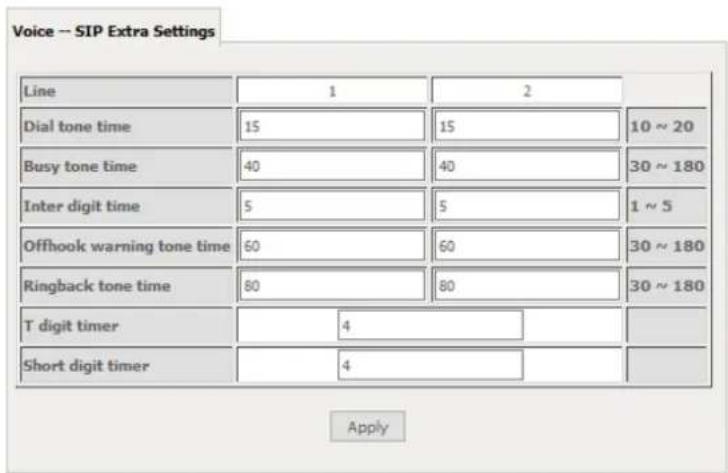
| PARAMETER | DEFINITION |
| Dial tone time | Dial tone duration. |
| Busy tone time | Busy tone duration. |
| Inter digit time | The valid range is 1 ~ 5. |
| Offhook warning tone time | Offhook warning tone duration. |
| Ringback tone time | Ringback tone duration. |
SIP Star Code Setting
The SIP Star Code Setting page provides you with the ability to configure the codes used to active and deactivate call features such as call forwarding and call waiting.
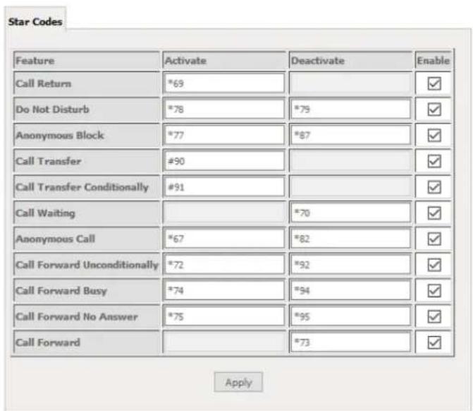
SIP Debug Setting
This page allows you to configure various settings regarding the logging levels of the SIP service.
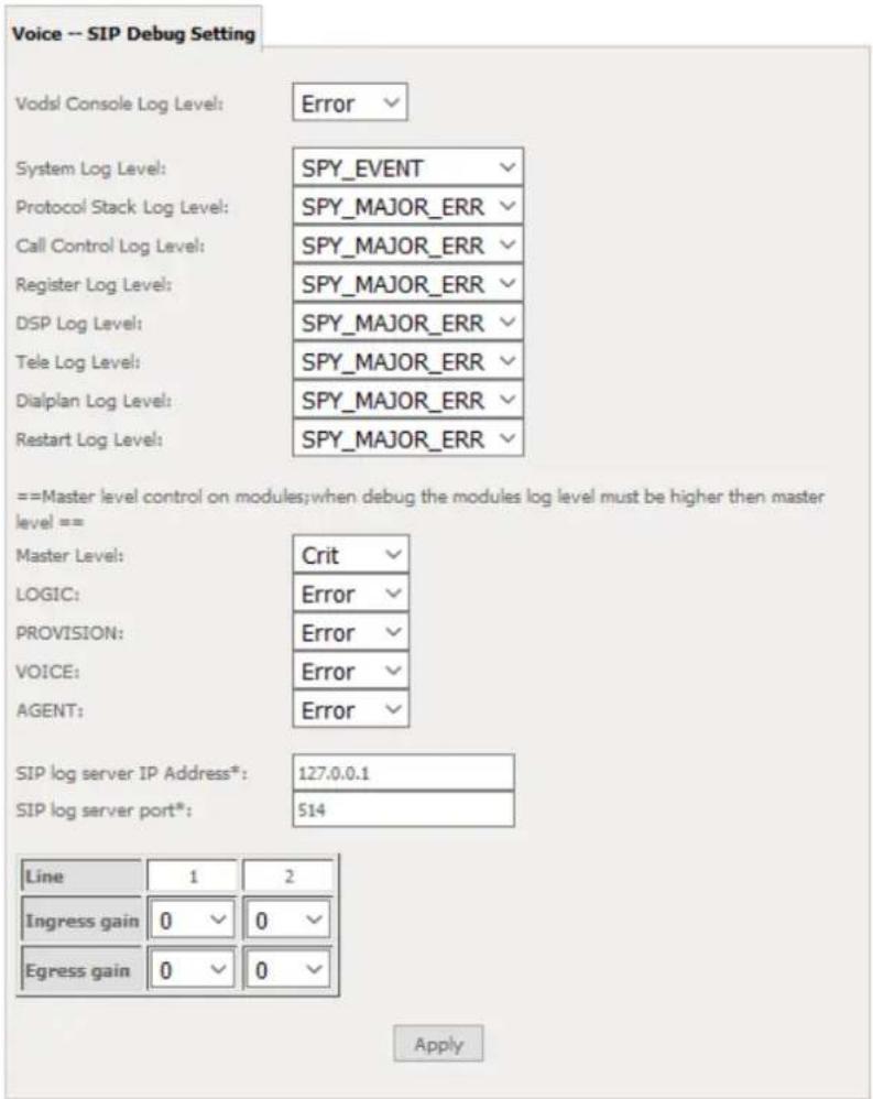
| OPTION | DEFINITION |
| SIP Log Server IP Address | Enter the IP address where the SIP Log data for the router's currently saved VoIP account settings will be sent to. |
| SIP Log Server port | Enter the port to be used for transmitting the SIP Log data for the router's currently saved VoIP account settings. |
| Ingress Gain | The incoming signal amplitude can be controlled with this field. Combined with the Egress gain a ratio can be expressed of input to output. The Ingress Gain setting can help improve the quality of the VoIP line, and can influence call volumes and help eliminate echoes. |
| Egress Gain | The outgoing signal amplitude can be controlled with this field. Combined with the Ingress gain a ratio can be expressed of input to output. The Egress Gain setting can help improve the quality of the VoIP line, and can influence call volumes and help eliminate echoes. |
VoIP Functionality
This section describes how to use the VoIP function of the DSL router in more detail. Some features involve 2 or 3 parties. In that case, note that all 3 parties have to be successfully registered.
Registering
Before using any VoIP functions, the DSL router has to register itself to a registrar. The DSL router also has to be configured with a proxy, which relays VoIP signaling to the next hop. In fact, many implementations integrate these two into one server, so in many case registrar and proxy refer to the same IP.
- Select the right interface to use for registering, depending on where proxy/registrar resides. If use WAN link, ensure that it is already up.
- Select the checkbox of Use SIP Registrar, and fill in the IP address and port with the right value.
- Fill the extension information: Authentication name, Password, Cid Name and Cid Number.
- Click Apply to take the settings into effect.
- TEL indicator of VoIP service should be on, indicating that SIP client is successfully registered.
Placing a Call
This section describes how to place a basic VoIP call.
- Pick up the receiver on the phone.
- Hear the dial-tone. Dial the extension of remote party.
- To end the dialing, wait for digit timeout, or just press # immediately.
- After the remote party answers the call, you are in voice connection.
Anonymous call
Anonymous call does not send the caller ID to the remote party. This is useful if you do not want others know whom you are.
- Enable Anonymous calling in the Voice--SIP Advanced Setting web page.
- Pick up the receiver on the phone.
- Dial *68 to enable anonymous call.
- Hook on the receiver, and dial another extension as you like. Now your caller ID information is blocked.
Do Not Disturb (DND)
If DND is enabled, all incoming calls are rejected. DND is useful if you do not want others to disturb you.
-
Enable DND in the Voice--SIP Advanced Setting web page.
-
Pick up the receiver on the phone.
-
Dial *78 to enable DND.
-
Hook on the phone. Now your phone rejects all incoming calls.
-
Hook off again to disable the DND.
Call Return
For incoming calls, the DSL router remembers the number of calling party.
-
Enable Call Return in the Voice--SIP Advanced Setting web page.
-
Press *69 to return a call.
-
Now you can make the call as if you have dialed the whole number.
Call Hold
Call hold enable you to put a call to a pending state, and pick it up in future.
-
Assuming you are in a voice connection, you can press FLASH to hold current call.
-
Now you can call another party, or press FLASH again to return to first call.
Call Waiting
Call waiting allows third party to call in when you are in a voice connection.
- Enable Call waiting in the Voice--SIP Advanced Setting web page.
- Pick up the phone attached to the DSL router.
- Press FLASH to switch to this call and the initial call put to hold automatically.
-
Press FLASH multi-times to switch between these two calls back and forth.
-
Assuming you are in a voice connection. When another call comes in, the DSL router streams a call waiting tone to your phone, indicating another call is available.
Blind Transfer
Blind transfer transfers the current call to a third party blindly, regardless of whether the transfer is successfully or not.
- Assume you have already been in a voice connection.
- Press FLASH to hold the first party.
- Dial #90 + third party number.
- Before the third party answering the call, hook on your phone.
- Now the first party takes over the call and he is in connection with the third party.
Consultative Transfer
Consultative transfer lets the third party answer the transferred call, and then hook on the transferring party. It' more gentle than blind transfer.
- Assume you have already been in a voice connection with a first party.
- Press FLASH to hold the first party.
- Dial #91 + third party number.
- After the third party answering the call, hook on your phone.
- Now the first party takes over the call and he is in connection with the third party.
Call Forwarding No Answer
If this feature enabled, incoming calls are forwarded to third party when you does answer them. It involves in two steps: setting the forwarding number and enable the feature.
- Enable Forward on "no answer" in the Voice--SIP Advanced Setting web page.
- When our phone does not answer the incoming call, the call is forwarded.
Call Forwarding Busy
If this feature enabled, incoming calls will be forwarded to third party when you busy. It involves two steps: setting the forwarding number and enable the feature.
- Set Busy Call forwarding number and enable Forward on "busy" in the Voice--SIP Advanced Setting web page.
- When our phone is busy, this call can be forwarded.
Call Forwarding All
If this feature enabled, incoming calls are forwarded to third party without any reason. It involves in two steps: setting the forwarding number and enable the feature.
- Set Unconditionally Call forwarding number and Forward unconditionally in the Voice--SIP Advanced Setting web page.
- All incoming calls are forwarded to the third party.
Three-Way Conference
Three-way conference enables you to invite a third party to a call, and every person in the conference is able to hear others' voice.
- Assume you are in connection with a first party.
- Press FLASH to put the first party on-hold.
- Dial a third party.
-
After the third party answers the call, press FLASH again to invite the first party.
-
Now all three parties are in a three-way conference.
T38 Faxing
To make T38 faxing, enable T38 support on the Web. After that, connect a fax machine to a FXS port of the DSL router. Now you can use it as a normal phone, and it is able to send or receive fax to or from other fax machines on the VoIP network. In the initial setup, faxing behaves like a normal call. After the DSL router detects the fax tone, it switch to T38 mode, and use it as the transmit approach.
Pass-Through Faxing
If T38 support is disabled, faxing uses normal voice codec as its coding approach. Therefore, this mode is more like normal phone calls.
Diagnostics
This page is used to test the connection to your local network, the connection to your DSL service provider, and the connection to your Internet service provider. You may diagnose the connection by clicking the Test button or click the Test With OAM F4 button. If the test continues to fail, click Help and follow the troubleshooting procedures.

Note: Your Internet service provider must support diagnostics features in order for correct DSL diagnostics results.
Diagnostics
The Diagnostics menu provides feedback on the connection status of the device. The individual tests are listed below. If a test displays a fail status:
- Click on the Help link and follow the troubleshooting procedures in the Help screen that appears.
- Now click Rerun Diagnostic Tests at the bottom of the screen to re-test and confirm the error.
- If the test continues to fail, contact Technical Support.
Diagnostics
The individual tests are listed below. If a test displays a fail status, click "Rerun Diagnostic Tests" at the bottom of this page to make sure the fail status is consistent. If the test continues to fail, click "Help" and follow the troubleshooting procedures.
| Test your LAN1 Connection: | PASS | Help |
| Test your LAN2 Connection: | FAIL | Help |
| Test your LAN3 Connection: | FAIL | Help |
| Test your LAN4 Connection: | FAIL | Help |
| Test your Wireless Connection: | PASS | Help |
Rerun Diagnostic Tests
| FIELD | DESCRIPTION |
| LAN# Connection | Pass: Indicates the Ethernet connection to your computer is connected to the LAN port of the router. Fail: Indicates that the router does not detect the Ethernet interface of your computer. |
| Test your Wireless Connection | Pass: Indicates that the wireless card is switched ON. Fail: Indicates that the wireless card is switched OFF. |
Ethernet OAM
The Ethernet OAM page provides administrators with operation, administration and management features.
Ethernet Link OAM (802.3ah)
Enabled
WAN Interface
OAM ID:
eth1
1 (positive integer)
Auto Event
Variable Retrieval
□ Link Event
Remote Loopback
Active Mode
Ethernet Service OAM (802.1ay / Y.1731)
Enabled 802.lag Y.1731
WAN Interface:
MD Level
MD Name:
MA ID:
Local MEP [D]
Local MED VLAN ID
□ CCM Transmission
Remote MEP ID:
eth1
0 ▼ [0-7]
Broadcom [e.g. Broadcom]
BRCN [e.g. BRCM]
1 [1-8191]
-1 [1-4094] (-1 means no VLAN tag)
-1 [1-8191] (-1 means no Remote MEP)
Loopback and Linktrace Test
Target MAC
Linktrace TTLi
The Ground Truth image displays a single, solid horizontal line. According to Rule 2 (UNDERSCORE & LINE RULES), this is a stylistic or background line, not a placeholder underscore. Therefore, the OCR result must ignore it and output nothing or only meaningful text. The provided OCR content is "____", which consists of four underscores. This is an incorrect interpretation of the line as a placeholder, violating the rule that stylistic lines must be ignored. The OCR has hallucinated underscores where none should exist based on the GT's visual context. Hence, the OCR result is inconsistent with the Ground Truth.
-1
[e.g. 02:10:18:amibb:cc]
[1-255] (-1 means no max hop limit)
| Loopback Result: | N/A | |||
| Linktrace Result: | N/A | |||
Sand Loopback Sand Linktrace
Apply/Save
Diagnostics
Ping
The ping test page lets you perform a ping to a remote IP address or hostname.
Ping Diagnostic
Please type in a host name or an IP Address. Click Submit to check the connection automatically.
Host Name or Ip Address:
Submit Cancel
Traceroute
The Traceroute page lets you perform a trace route to a remote IP address or host name.
Traceroute Diagnostic
Please type in a host name or an IP Address. Click Submit to trace the route.
Host Name or Ip Address:
Submit Cancel
Start/Stop DSL
This page lets you stop or start the DSL service for troubleshooting purposes.
Your DSL connection is down. Verify that your TELMEX Gateway is correctly connected to your phone line. If the problem persists, check your documentation.
Start/Stop DSL
This page enables you to start or stop your DSL line.
Your DSL connection is Down, it seems the phone line is not connected.
Start
Management
Settings
The Settings screens allow you to back up, retrieve and restore the default settings of your Router. It also provides a function for you to update your router's firmware.
Backup
The following screen appears when Backup is selected. Click the Backup Settings button to save the current configuration settings. You will be prompted for the location to save the backup file to on your PC.
Settings - Backup
Backup Broadband Router configurations. You may save your router configurations to a file on your PC.
Backup Settings
Update Settings
The following screen appears when selecting Update from the Settings submenu. By clicking on the Browse button, you can locate a previously saved filename as the configuration backup file. Click on the Update settings button to upload the selected file. Please allow up to 5 minutes for system updates
Tools – Update Settings
Update Broadband Router settings. You may update your router settings using your saved files.
Settings File Name: Browse... No file selected.
Update Settings
Factory Reset
The following screen appears when selecting Factory Reset from the Settings submenu. By clicking on the Restore Default Settings button, you can restore your Routers default firmware settings. Restore system settings will reboot your Router, please allow up to 2 minutes for restore and reboot.
Tools -- Restore Default Settings
Restore Broadband Router settings to the factory defaults.
The System log page allows you to view the log of the modem and configure the logging level also. To view the system log, click the View System Log button.
System Log
The System Log dialog allows you to view the System Log and configure the System Log options.
Click 'View System Log' to view the System Log.
Click 'Configure System Log' to configure the System Log options.
View System Log Configure System Log
To configure the system log, click the Configure System Log button. You can sent system log to remote server via selecting both, or remote under "Mode" option.
System Log -- Configuration
If the log mode is enabled, the system will begin to log all the selected events. For the Log Level, all events above or equal to the selected level will be logged. For the Display Level, all logged events above or equal to the selected level will be displayed. If the selected mode is 'Remote' or 'Both,' events will be sent to the specified IP address and UDP port of the remote syslog server. If the selected mode is 'Local' or 'Both,' events will be recorded in the local memory.
Select the desired values and click 'Apply/Save' to configure the system log options.
Log:
○ Disable ● Enable
Log Level:
Display Level:
Model
Apply/Save
SNMP Agent
The Simple Network Management Protocol (SNMP) allows a network administrator to monitor a network by retrieving settings on remote network devices. To do this, the administrator typically runs an SNMP management station program such as MIB browser on a local host to obtain information from the SNMP agent, in this case the NF1ADV (if SNMP is enabled). An SNMP ‘community’ performs the function of authenticating SNMP traffic. A ‘community name’ acts as a password that is typically shared among SNMP agents and managers.
SNMP - Configuration
Simple Network Management Protocol (SNMP) allows a management application to retrieve statistics and status from the SNMP agent in this device.
Select the desired values and click 'Apply' to configure the SNMP options.
SNMP Agent
● Disable ○ Enable
Read Community: Set Community: System Name: System Location: System Contact: Trap Manager IP:
Save/Apply
TR-069 Client
TR-069 enables provisioning, auto-configuration or diagnostics to be automatically performed on your router if supported by your Internet Service Provider (ISP).
TR-069 client - Configuration
WAN Management Protocol (TR-069) allows a Auto-Configuration Server (ACS) to perform auto-configuration, provision, collection, and diagnostics to this device.
Select the desired values and click 'Apply/Save' to configure the TR-069 client options.
√ Enable WAN Management Protocol (TR-069).
Inform
● Disable ○ Enable
Inform Interval:
ACS URL:
ACS Username:
ACS Password:
WAN Interface used by TR-069 client:
Display SOAP messages on serial console
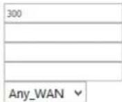
● Disable ○ Enable
□ Connection Request Authentication
Apply/Save Get RPC Methods
| FIELD | DESCRIPTION |
| Inform | Set to enable to activate TR-069 client settings. |
| Inform interval | Time in seconds that data is sent to the Auto-Configuration Server (ACS). |
| ACS URL | The address where the ACS server is located. |
| ACS User Name | The user name to access the ACS server. |
| ACS Password | The password to access the ACS server. |
| WAN Interface used by TR-069 Client | The connection used to send and receive data to the ACS server. |
Internet Time
The Internet Time page allows you to configure NTP time servers that the NF10WV router synchronises with in order to keep accurate time.
Time settings
This page allows you to the modem's time configuration.

Automatically synchronize with Internet time servers
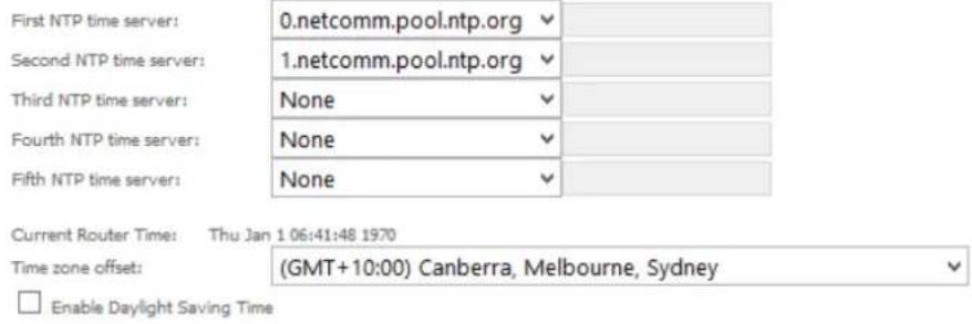
Apply/Save
Access Control
The Access Control option found in the Management drop down menu configures access related parameters in the following three areas:
Passwords
Services Control
Access Control is used to control local and remote management settings for your router.
Access Controls – Passwords
Access Control -- Passwords
Access to your DSL router is controlled through three user accounts:admin,support and user.
The username "admin" has unrestricted access to change and view configuration of your DSL Router.
The username "support" is used to allow an ISP technician to access your DSL Router for maintenance and to run diagnostics.
The username "user" can access the DSL Router, view configuration settings and statistics, as well as, update the router's software.
Use the fields below to enter up to 15 characters and click 'Apply/Save' to change or create passwords. Note: Password cannot contain a space.
Apply/Save
Usernames – The Username used determines the level of access to the device. There are three usernames and three levels of access:
admin is to be used for local unrestricted access control
support is to be used for remote maintenance of the device
user is to be used to view information and update device firmware
The username admin can be changed. Your new 'admin' username can contain up to 15 characters and cannot contain spaces. The usernames support and user cannot be changed.
Passwords – Initially the Password for each type of Username is the same word as the initial Username:
| INITIAL USERNAME | INITIAL PASSWORD |
| admin | admin |
| support | support |
| user | user |
The Password for each type of Username can be changed.
Passwords must be 15 characters or less with no spaces.
To change the password for a username:
- Enter the current Username into both the Username and New Username fields (for the admin username only you can enter a different New Username).
- Enter the Old Password
- Enter the New Password (it must be 15 characters or less with no spaces).
- Enter the same password into the Confirm Password field.
- Click the Apply/Save button
Access Controls -- Services
The Service Control List (SCL) allows you to enable or disable your Local Area Network (LAN) or Wide Area Network (WAN) services by ticking the checkbox as illustrated below. The following access services are available: FTP, HTTP, ICMP, SAMBA, SNMP, SSH, TELNET, and TFTP. Click the Apply/Save button after making any changes to continue.
Access Control -- Services
Services access control list (SCL) enable or disable the running services.
| Services | LAN | WAN | Port |
| HTTP | enable | enable | 80 |
| TELNET | enable | enable | 23 |
| SSH | enable | enable | 22 |
| FTP | enable | enable | 21 |
| TFTP | enable | enable | 59 |
| ICMP | enable | enable | 0 |
| SNMP | enable | enable | 161 |
| SAMBA | enable | enable | 445 |
Apply/Save
Update Firmware
The following screen appears when selecting the Update Software option from the Management menu. By following this screen's steps, you can update your modem's firmware. Manual device upgrades from a locally stored file can also be performed using the following screen.
- Obtain an updated software image file.
- Enter the path and filename of the firmware image file in the Software File Name field or click the Browse button to locate the image file.
- Click the Update Software button once to upload and install the file.
Tools - Update Firmware
Step 1: Obtain an updated firmware image file from your ISP.
Step 2: Enter the path to the image file location in the box below or click the 'Browse' button to locate the image file.
Step 3: Click the 'Update Firmware' button once to upload the new image file.
NOTE: The update process takes about 2 minutes to complete, and your Broadband Router will reboot.
Firmware File Name: Browse... No file selected.
Update Firmware
Reboot
This option reboots the NF10WV.
Click the button below to reboot the router.
Reboot

NOTE 1: It may be necessary to reconfigure your TCP/IP settings to adjust for the new configuration. For example, if you disable the Dynamic Host Configuration Protocol (DHCP) server you will need to apply Static IP settings.

NOTE 2: If you lose all access to your web user interface, simply press the reset button on the rear panel for 7 seconds to restore default settings.
Additional Product Information
Establishing a wireless connection
Windows 7
- Open the Network and Sharing Center (Start > Control Panel > Network and Sharing center).
- Click on "Change Adapter settings" on the left-hand side.
- Right-click on "Wireless Network Connection" and select "Connect / Disconnect".
- Select the wireless network listed on your included wireless security card and click Connect.
- Enter the network key (refer to the included wireless security card for the default wireless network key).
- You may then see a window that asks you to "Select a location for the 'wireless' network". Please select the "Home" location.
- You may then see a window prompting you to setup a "HomeGroup". Click "Cancel" on this.
- You can verify your wireless connection by clicking the "Wireless Signal" indicator in your system tray.
- After clicking on this, you should see an entry matching the SSID of your NF10WV with "Connected" next to it.
Windows 8/8.1/10
- Open the Network and Sharing Centre (Click on Start, Type "Network and Sharing Centre")
- Click on "Change adapter settings" on the left hand column.
- Right-click on Wireless Network Adaptor and select "Connect / Disconnect".
- Select the wireless network listed on your included wireless security card and click Connect.
- Enter the network key (refer to the included wireless security card for the default wireless network key).
- You can verify your wireless connection by clicking the "Wireless Signal" indicator in your system tray.
- After clicking on this, you should see an entry matching the SSID of your NF10WV with "Connected" under it.
Mac OSX 10.6
- Click on the Airport icon on the top right menu.
- Select the wireless network listed on your included wireless security card and click Connect.
- On the new window, select "Show Password", type in the network key (refer to the included wireless security card for the default wireless network key) in the Password field and then click on OK.
- To check the connection, click on the Airport icon and there should be a tick on the wireless network name.

Note: For other operating systems, or if you use a wireless adaptor utility to configure your wireless connection, please consult the wireless adapter documentation for instructions on establishing a wireless connection.
Troubleshooting
Using the indicator lights (LEDs) to Diagnose Problems
The LEDs are useful aides for finding possible problem causes.
Power LED
The Power LED does not light up.
| STEP | CORRECTIVE ACTION |
| 1 | Make sure that the NF10WV power adaptor is connected to the device and plugged in to an appropriate power source. Use only the supplied power adaptor. |
| 2 | Check that the NF10WV and the power source are both turned on and device is receiving sufficient power. |
| 3 | Turn the NF10WV off and on. |
| 4 | If the error persists, you may have a hardware problem. In this case, you should contact technical support. |
Web Configuration
I cannot access the web configuration pages.
| STEP | CORRECTIVE ACTION |
| 1 | Check that you have enabled remote administration access. If you have configured an inbound packet filter, ensure your computer's IP address matches it. |
| 2 | Your computer's and the NF10WV's IP addresses must be on the same subnet for LAN access. You can check the subnet in use by the router on the Network Setup page. |
| 3 | If you have changed the devices IP address, then enter the new one as the URL you enter into the address bar of your web browser. |
| 4 | If you are still not able to access the web configuration pages, reset the router to the factory default settings by holding the reset button down for 7 seconds or until the LEDs turn off. Navigate to 192.168.20.1 in your web browser and enter "admin" (without the quotes) as the username and password. |
The web configuration does not display properly.
| STEP | CORRECTIVE ACTION |
| 1 | Delete the temporary web files and log in again. In Internet Explorer, click Tools, Internet Options and then click the Delete Files ... button. When a Delete Files window displays, select Delete all offline content and click OK.(Steps may vary depending on the version of your Internet browser.) |
Login Username and Password
I forgot my login username and/or password.
| STEP | CORRECTIVE ACTION |
| 1 | Hold the Reset button down for 7 seconds or until all the LEDs turn off. The NF10WV restarts with factory default settings.You can now login with the factory default username and password "admin" (without the quotes) |
| 2 | It is highly recommended to change the default username and password. Make sure you store the username and password in a safe place. |
WLAN Interface
I cannot access the NF10WV from the WLAN or ping any computer on the WLAN.
| STEP | CORRECTIVE ACTION |
| 1 | Check the Wi-Fi LED on the front of the unit and verify the WLAN is enabled as per the LED Indicator section. |
| 2 | If you are using a static IP address for the WLAN connection, make sure that the IP address and the subnet mask of the NF10WV and your computer(s) are on the same subnet. You can check the routers configuration from the Network Setup page. |
Appendix: Quality of Service Setup Example
The following Quality of Service (QoS) settings offer a basic setup example, setting up 2 devices connecting to an NF10WV router, one with the highest priority for data and the other with the lowest priority for data. All other data packet traffic through the router assumes a default best effort setting.
Quality of Service refers to the reservation of bandwidth resources on the NF10WV router to provide different priorities to different applications, users or data flows or to guarantee a certain level of performance to a data flow.
In this implementation, QoS employs DSCP (Differentiated Services Code Point), a computer networking architecture that specifies a simple, scalable and course-grained mechanism for classifying and managing network traffic.
This example guide sets up QoS with two devices (PC and laptop) connecting via Ethernet cable to an NF10WV router. One device (PC) is assigned high priority traffic while the other device (laptop) is assigned a low priority. Before Quality of Service can be implemented, the first step involves reserving an IP address for each device, identified by their unique MAC addresses.
Reserving IP addresses
It is necessary to reserve an IP address for each of the devices connecting to the NF10WV router so that QoS settings can be managed for each device.
a) Navigate to http://192.168.20.1 in a web browser.
b) When prompted, enter admin as both the username and password.
c) Select Advanced Setup > LAN
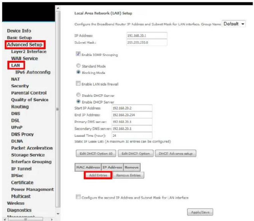
d) Click the Add Entries button.
e) Enter the MAC address of the computer/device you are connecting to the router. The MAC address is a 12 character set of numbers and letters (A-F), with every 2 characters separated by a colon.
f) Enter the IP address of the computer/device. This is the local address in the range of 192.168.20.x where x = a number between 2 and 254.
DHCP Static IP Lease
Enter the Mac address and Static IP address then click Apply/Save.
MAC Address:
IP Address:
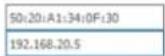
Apply/Save
g) Click the Apply/Save button.
h) Complete steps d) through g) for each device connected to the NF10WV router. Each entry will be listed in the Static IP Lease List as shown below.
Local Area Network (LAN) Setup
Configure the Broadband Router IP Address and Subnet Mask for LAN Interface, Group Name
Default
IP Address
Subnet mask
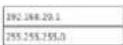
Enabling IGMP Snacking
Standard Mode
Blocking Mode
Enable COMP LIN to LIN
Multicast
(LAN to LAN Multicell is
accessing only on an external route mode WAN security
which is corrected and
enable lymph proxy.)
□ Enable LAN side firewall
○ Double DHCP Server
Enable DHCP Server
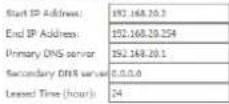
Edit DHCP Option 60 Edit DHCP Option DHCP Advance setup
Static IP Lease Lists (A maximum 32 entries can be configured)
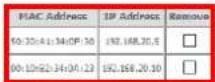
Add Entries Remove Entries
QoS Configuration Settings
a) Select Advanced Setup > Quality of Service
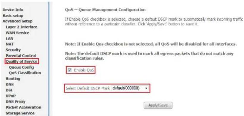
b) Select the Enable QoS option.
c) Select the Default DSCP Mark as default(000000).
d) Click the Apply/Save button.
High Priority QoS Queue Configuration
a) Select Advanced > Quality of Service > Queue Config.
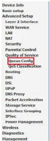
QoS Queue Setup
In ATM mode, maximum 16 queues can be configured. In PTM mode, maximum 8 queues can be configured. For each Ethernet interface, maximum 4 queues can be configured. If you disable WMM function in Wireless Page, queues related to wireless will not take effects
| Name | Key | Interface | Scheduler | Precedence | Weight | DSI Latency | PTM Priority | Enable | Remove |
| WMM Voice Priority | 1 | w/0 | SP | 1 | Enabled | ||||
| WMM Voice Priority | 2 | w/0 | SP | 2 | Enabled | ||||
| WMM Video Priority | 3 | w/0 | SP | 3 | Enabled | ||||
| WMM Video Priority | 4 | w/0 | SP | 4 | Enabled | ||||
| WMM Best Effort | 5 | w/0 | SP | 5 | Enabled | ||||
| WMM Background | 6 | w/0 | SP | 6 | Enabled | ||||
| WMM Background | 7 | w/0 | SP | 7 | Enabled | ||||
| WMM Best Effort | 8 | w/0 | SP | 8 | Enabled | ||||
| Default Queue | 37 | atm0 | SP | 8 | Path0 | ☐ |

b) Click the Add button.
QoS Queue Configuration
This screen allows you to configure a QoS queue and assign it to a specific layer2 interface. The scheduler algorithm is defined by the layer2 interface. Note: For SP scheduling, queues assigned to the same layer2 interface shall have unique precedence. Lower precedence value implies higher priority for this queue relative to others Click 'Apply/Save' to save and activate the queue.
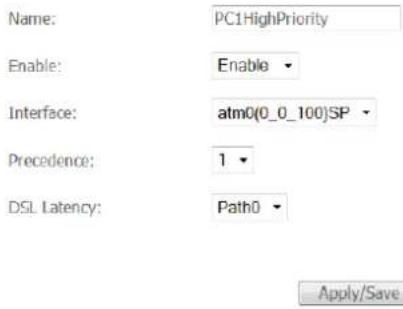
c) Enter a name of 15 characters or less to reflect the device that will have high priority QoS, e.g. PC1HighPriority.
d) Set the Enable option to Enable.
e) Set the Interface (Australian customers use atm0(0_8_35), NZ customers use atm0(0)0100)).
f) Enter a Precedence. For the highest priority, set it to 1. For the lowest priority use 3.
g) Set the DSL Latency as Path0.
h) Click the Save/Apply button.
Low Priority QoS Queue Configuration
a) Select Advanced > Quality of Service > Queue Config.
b) Click the Add button.
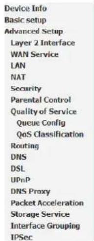
QoS Queue Configuration
This screen allows you to configure a QoS queue and assign it to a specific layer2 interface. The scheduler algorithm is defined by the layer2 interface. Note: For SP scheduling, queues assigned to the same layer2 interface shall have unique precedence. Lower precedence value implies higher priority for this queue relative to others Click 'Apply/Save' to save and activate the queue.
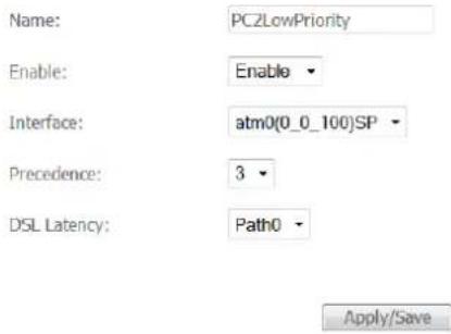
c) Enter a name of 15 characters or less to reflect the device that will have low priority QoS e.g. PC2LowPriority.
d) Set the Enable option to Enable.
e) Set the Interface (Australian customers use atm0(0_8_35), NZ customers use atm0(0)0100)).
f) Enter a Precedence. For the lowest priority, set it to 3. For the highest priority use 1.
g) Set the DSL Latency as Path0.
h) Click the Save/Apply button.
High Priority QoS Classification
a) Select Advanced > Quality of Service > QoS Classification.
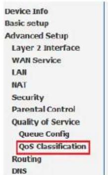
QoS Classification Setup -- A maximum 32 entries can be configured.
Choose Add or Remove to configure network traffic classes. If you disable WMM function in Wireless Page, classification related to wireless will not take effects
| CLASSIFICATION CRITERIA | ||||||||||||
| Class Name | Order | Class Intf | Ether Type | SrcMAC/ Mask | DstMAC/ Mask | SrcIP/ PrefixLength | DstIP/ PrefixLength | Proto | SrcPort | DstPort | DSCP Check | TOS Check |

b) Click the Add button.
![Device Info Basic setup Advanced Setup Layer 2 Interface WALL Service LAN NAT Security Parental Control Quality of Service Queue Config Qo5 Classification Routing DNS DSL UPnP DNS Proxy Packet Acceleration Storage Service Interface Grouping IPSec Power Management Wireless Diagnostics Management Add Network Traffic Class Rule The screen creates a traffic class rule to classify the upstream traffic, assign queue which defines the precedence bytes. A rule consists of a class name and at least one condition below. All of the specified conditions in this class 'Apply/Save' to save and activate the rule. Traffic Class Name: Rule Order: Rule Status: PC:HighPriority Last Enable Specify Classification Criteria A blank criterion indicates it is not used for classification. Class Interface: LAN Ether Type: IP (0x800) Source MAC Address: 50.20-A1:34:0F:30 Source MAC Mask: Destination MAC Address: Destination MAC Mask: Frame size range for signed interface(PRIME:TO): Source IP Address[/Mask]: 192.168.1.5 Destination IP Address[/Mask]: Differentiated Service Code Point (DSCP) Check: EF(1011:10) Protocol: TCP UDP/TCP Source Port (port or port:port): UDP/TCP Destination Port (port or port:port): Specify Classification Results Must select a classification queue. A blank mark or tag value means no change. Assign Classification Queue: pppca0&am0&Path0&Key35&Pie1 Mark Differentiated Service Code Point (DSCP): EF(1011:10) Mark 802.1p priority: 5 Tag VLAN ID [0-4094]: 0 Sat Rate Control(kbps): Apply/Save...](/content/2026/05/996218/images/a66b2babc1727a0769a72c22c56a8ade30fbf963ab46a29a1e83553b2129b2a5.jpg)
c) Enter a Traffic Class Name reflecting the High Priority QoS rule, e.g. PC1HighPriority.
d) Leave the Rule Order as Last.
e) Set the Rule Status to Enable.
f) Set the Class Interface according to how the device connects to the router. In the example above, LAN is selected. Other options are Wireless, Local and USB.
g) Set the Ether Type to IP(0x800). Other options include ARP(0x8086), lpv6(0x86DD), PPPoE_DISC(0x8863), 8865(0x8865), 8866(0x8866), 8021Q(0x8100).
h) Enter the Source MAC Address of the device, the unique 12 character signature with every 2 characters separated by a colon(:), that you previously entered to reserve the device's IP address.
i) Enter the Source IP Address of the device that you previously entered into the Static IP Lease List, in the range of 192.168.1.x In the example above the IP address is 192.168.1.5.
j) Enter a Destination MAC Address if the connection is to a single device. This is useful for VPN connections. If you wish the destination MAC address to be any address leave the field blank.
k) Enter a Destination IP Address if the connection is to a single device. This is useful for VPN connections. If you wish the destination IP address to be any address leave the field blank.
I) Enter a Destination Subnet Mask if you have entered a Destination MAC address and Destination IP address. This would normally be 255.255.255.0 unless your system administrator advises otherwise. If you have not entered a Destination MAC or IP address leave the field blank.
m) Set the Differentiated Service Code Point (DSCP) Check to EF(101110).
n) Set the Protocol to TCP. Other options include UDP, ICMP or IGMP.
o) Set "Assign Classification Queue" to Priority 1 (in the example above pppoa0&atm0&Path0&Key38&Pre1). Other options or priority 2 and 3. Priority 1 gives the highest priority with priority 3 being the lowest.
p) Set Mark Differentiated Service Code Point (DSCP) as EF(101110).
q) Set Mark 802.1p Priority as 5. In the scale 0-7, 0 is best effort, 6 and 7 are reserved for networking performance so set 5 as the highest priority.
r) Click the Apply/Save button.
Low Priority QoS Classification
a) Select Advanced > Quality of Service > QoS Classification.
b) Click the Add button.
![Device Info Basic setup Advanced Setup Layer 2 Interface WALL Service LAN IAT Security Parental Control Quality of Service Queue Config QuS Classification Routing DRS DSL UPnP DNS Proxy Packet Acceleration Storage Service Interface Grouping IPSec Power Management Wireless Diagnostics Management Add Network Traffic Class Rule The screen creates a traffic class rule to classify the upstream traffic, assign queue which defines the precedence byte. A rule consists of a class name and at least one condition below. All of the specified conditions in this class 'Apply/Save' to save and activate the rule. Traffic Class Name: Rule Order: Rule Status: PC2LowPriority: Last Enable Specify Classification Criteria A blank criterion indicates it is not used for classification. Class Interface: LAN Ether Type: IP (0x800) Source MAC Address: 00:10:62:34:0A:13 Source MAC Mask: Destination MAC Address: Destination MAC Mask: Frame size range for Bridged Interface(PROME:TO): Source IP Address[Mask]: 192.166.1.10 Destination IP Address[(Mask): Differentiated Service Code Point (DSCP) Check: AF11(0C10:10) Protocol: TCP UDP/TCP Source Port (port or port:port): UDP/TCP Destination Port (port or port:port): Specify Classification Results Must select a classification queue. A blank mark or tag value means no change. Assign Classification Queue: pppea0&atm0&Path0&Key39&Pie3 Mark Differentiated Service Code Point (DSCP): AF11(0C10:10) Mark 802.1p priority: 0 Tag VLAN ID [0-4094]: Set Rate Control(kbps): Apply/Save](/content/2026/05/996218/images/5869365d34af88511a46bfea4023c51d52e64f8a0c9fa837fb5b3f3939cbd450.jpg)
c) Enter a Traffic Class Name reflecting the High Priority QoS rule; eg. PC2LowPriority.
d) Leave the Rule Order as Last.
e) Set the Rule Status to Enable.
f) Set the Class Interface according to how the device connects to the router. In the example above LAN is selected. Other options are Wireless, Local and USB.
g) Set the Ether Type to IP(0x800). Other options include ARP(0x8086), lpv6(0x86DD), PPPoE_DISC(0x8863), 8865(0x8865), 8866(0x8866), 8021Q(0x8100).
h) Enter the Source MAC Address of the device, the unique 12 character signature with every 2 characters separated by a colon(:), that you previously entered to reserve the device's IP address.
i) Enter the Source IP Address of the device that you previously entered into the Static IP Lease List, in the range of 192.168.1.x. In the example above the IP address is 192.168.1.10.
j) Enter a Destination MAC Address if the connection is to a single device. This is useful for VPN connections. If you wish the destination MAC address to be any address leave the field blank.
k) Enter a Destination IP Address if the connection is to a single device. This is useful for VPN connections. If you wish the destination IP address to be any address leave the field blank.
I) Enter a Destination Subnet Mask if you have entered a Destination MAC address and Destination IP address. This would normally be 255.255.255.0 unless your system administrator advises otherwise. If you have not entered a Destination MAC or IP address leave the field blank.
m) Set the Differentiated Service Code Point (DSCP) Check to AF11(001010).
n) Set the Protocol to TCP. Other options include UDP, ICMP or IGMP.
o) Set "Assign Classification Queue" to Priority 3 (in the example above pppoa0&atm0&Path0&Key39&Pre3). Other options are priority 1 and 2. Priority 1 gives the highest priority with priority 3 being the lowest.
p) Set Mark Differentiated Service Code Point (DSCP) as AF11(001010).
q) Set Mark 802.1p Priority as 0. In the scale 0-7, 0 is best effort, 6 and 7 are reserved for networking performance so set 0 as the lowest priority.
r) Click the Apply/Save button.
s) You now have 2 Quality of Service rules implemented for 2 devices connecting to the NF10WV router.
| Device Info |
| Basic setup |
| Advanced Setup |
| Layer 2 Interface |
| WAN Service |
| LAN |
| NAT |
| Security |
| Parental Control |
| Quality of Service |
| Queue Config |
| QoS Classification |
| Routing |
| DNS |
| DSL |
| UPnP |
| DNS Proxy |
| Packet Acceleration |
| Storage Service |
| Interface Grouping |
| IPSec |
| Power Management |
| Wireless |
| Diagnostics |
| Management |
QoS Classification Setup – A maximum 32 entries can be configured.
Choose Add or Remove to continue network traffic classes.
If you disable WMM function in Wireless Page, classification related to wireless will not take effects
| CLASSIFICATION CRITERIA | CLASSIFICATION RESULTS | |||||||||||||||||||||
| Class Name | Order | Class Intf | Ether Type | SrcMAC/ Mask | DstMAC/ Mask | SrcIP/ Prefix.Length | DstIP/ Prefix.Length | Proto | SrcPort | DstPort | DSCP Check | TOS Check | B02.1P Check | Queue Key | DSCP Mark | TOS Mark | B03.1P Mark | VanID Tap | Rate Control | Frame size | Enable | Remove |
| PC1HighPriority | 1 | LAN | IP | 50:20:A1:34:0F:30 | 52:168.1.5 | TCP | EF | 38 | EF | 5 | 0 | ☑ | ☐ | |||||||||
| PC2LowPriority | 2 | LAN | IP | 00:10:B2:34:0A:23 | 52:168.1.10 | TCP | AP11 | 39 | AP11 | 0 | 0 | ☑ | ☐ | |||||||||

t) Select Management > Reboot. Click the Reboot button to restart the router and save the new settings.
u) To test your Quality of Service settings try running speed-tests (http://speedtest.net) on both PCs/devices simultaneously.
Limiting the upstream rate
a) By default, a QoS queue is created when a WAN interface is created but it is disabled by default. On the QoS Queue page, enable the queue for the appropriate WAN interface.
| Default Queue | 33 | atm0 | 1 | 8/WRR/1 | Path0 | ☑ |
b) On the QoS Classification page, add a rule to limit the upstream rate, for example:
Class Interface: LAN
Ether type: IP
Classification Results:
Class Queue: the queue that was enabled in Step 1
Set rate-limit: set according to your preference
Add Network Traffic Class Rule
This screen creates a traffic class rule to classify the ingress traffic into a priority queue and optionally mark the DSCP or Ethernet priority of the packet. Click 'Apply/Savo' to save and activate the rules.
Traffic Class Name:
Rule Order:
Rule Status:



Specify Classification Criteria (A blank criterion indicates it is not used for classification.)
Case Interface:
Ether Type
Source MAC Address
Source MAC Mask:
Destination MAC Address:
Destination MAC Mask:
Source IP Address[/Mask]:
Destination IP Address[/Mask]:
Differentiated Service Code Point (DSCP) Check:
Protocoli
Specify Classification Results (A blank value indicates no operation.)
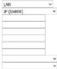

Specify Class Queue (Required):
- Packets classified into a queue that exit through an interface for which the queue
is not specified to exist, will instead egress to the default queue on the interface.
Mark Differentiated Service Code Point (DSCP):


Mark 302.1p priority:
- Class non-vlan packets agree to a non-vlan interface will be tagged with VID 0 and the class rule p bits.
- Class vlan packets egress to a non-vlan interface will have the packet p-bits re-marked by the class rule p-bits. No additional vlan tag is added.
- Class non-vlan packets agree to a vlan interface will be tagged with the interface VID and the class rule p-bits.
- Class vlan packets egress to a vlan interface will be additionally tagged with the packet VID, and the class rule p-bits
Set Rate Limit:


c) Click Apply/Save.
Limiting the downstream rate
a) Navigate to the QoS Queue page to add a queue for the LAN interface, for example:
QoS Queue Configuration
This screen allows you to configure a QoS queue and add it to a selected layer2 interface.
Name:
Enable:
Interface:


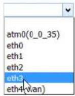
Apply/Save
b) On the QoS Classification page, add a rule to limit the downstream rate, for example:
Class Interface: the appropriate WAN interface
Classification Results:
Class Queue: the queue that was created on Step 1
Set rate-limit: set according to your preference
Add Network Traffic Class Rule
This screen creates a traffic class rule to classify the ingress traffic into a priority queue and optionally mark the DSCP or Ethernet priority of the packet. Click 'Apply/Save' to save and activate the rule.
Traffic Class Name:
Rule Order:
Rule Status
Specify Classification Criteria (A blank criterion indicates it is not used for classification.)
Class Interface:
Ether Type:
Source MAC Address
Source MAC Mask:
Destination MAC Address:
Destination MAC Mask:
Specify Classification Results (A blank value indicates no operation.)
Specify Class Queue (Required):
- Packets classified into a queue that exit through an interface for which the queue is not specified to exist, will instead agree to the default queue on the interface.
Mark \$02.1p priority:
- Class non-vlan packets egress to a non-vlan interface will be tagged with VID 0 and the class rule p-bits.
- Class vlan packets egress to a non-vlan interface will have the packet p-bits re-marked by the class rule p-bits. No additional vlan tag is added,
Class non-vlan packets egress to a vlan interface will be tagged with the interface VID and the class rule p-bits.
- Class vlan packets egress to a vlan interface will be additionally tagged with the packet VID, and the class rule p-bits.
Set Rate Limit:

Apply/Save
c) Click Apply/ Save
The QoS Classification table looks like this:
QoS Classification Setup - maximum 32 rules can be configured.
To add a rule, click the Add button.
To remove rules, check their remove-checkboxes, then click the Remove button.
The Enable button will scan through every rules in the table. Rules with enable checkbox checked will be enabled. Rules with enable checkbox unchecked will be disabled.
The enable-checkbox also shows status of the rule after page reload.
If you disable WWW function in Wireless Page, classification related to wireless will not take effects
| CLASSIFICATION CRITERIA | CLASSIFICATION RESULTS | ||||||||||||||||||||
| Class Name | Order | Class Interface | Ethernet Type | Source MAC/Mask | Destination MAC/Mask | Source IP/Prefix Length | Destination IP/Prefix Length | Protocol | Source Port | Destination Port | DSCP Check | TC Check | B02.1P Check | Queue Key | DSCP Mark | TC Mark | B02.1P Mark | Base Limit(kbps) | Enable | Remove | |
| Unknown | 1 | LAN | IP | 33 | 100 | ☐ | ☐ | ||||||||||||||
| Downstream | 2 | strnL1 | 25 | 100 | ☑ | ☐ | |||||||||||||||

Legal & Regulatory Information
Intellectual Property Rights
All intellectual property rights (including copyright and trade mark rights) subsisting in, relating to or arising out this Manual are owned by and vest in NetComm Wireless (ACN 002490486) (NetComm Wireless Limited) (or its licensors). This Manual does not transfer any right, title or interest in NetComm Wireless Limited's (or its licensors') intellectual property rights to you.
You are permitted to use this Manual for the sole purpose of using the NetComm Wireless product to which it relates. Otherwise no part of this Manual may be reproduced, stored in a retrieval system or transmitted in any form, by any means, be it electronic, mechanical, recording or otherwise, without the prior written permission of NetComm Wireless Limited.
NetComm, NetComm Wireless and NetComm Wireless Limited are a trademark of NetComm Wireless Limited. All other trademarks are acknowledged to be the property of their respective owners.
Customer Information
The Australian Communications & Media Authority (ACMA) requires you to be aware of the following information and warnings:
-
This unit may be connected to the Telecommunication Network through a line cord which meets the requirements of the AS/CA S008-2011 Standard.
-
This equipment incorporates a radio transmitting device, in normal use a separation distance of 20cm will ensure radio frequency exposure levels complies with Australian and New Zealand standards.
-
This equipment has been tested and found to comply with the Standards for C-Tick and or A-Tick as set by the ACMA. These standards are designed to provide reasonable protection against harmful interference in a residential installation. This equipment generates, uses, and can radiate radio noise and, if not installed and used in accordance with the instructions detailed within this manual, may cause interference to radio communications. However, there is no guarantee that interference will not occur with the installation of this product in your home or office. If this equipment does cause some degree of interference to radio or television reception, which can be determined by turning the equipment off and on, we encourage the user to try to correct the interference by one or more of the following measures:
i. Change the direction or relocate the receiving antenna.
ii. Increase the separation between this equipment and the receiver.
iii. Connect the equipment to an alternate power outlet on a different power circuit from that to which the receiver/TV is connected.
iv. Consult an experienced radio/TV technician for help.
- The power supply that is provided with this unit is only intended for use with this product. Do not use this power supply with any other product or do not use any other power supply that is not approved for use with this product by NetComm Wireless. Failure to do so may cause damage to this product, fire or result in personal injury.
Consumer Protection Laws
Australian and New Zealand consumer law in certain circumstances implies mandatory guarantees, conditions and warranties which cannot be excluded by NetComm and legislation of another country's Government may have a similar effect (together these are the Consumer Protection Laws). Any warranty or representation provided by NetComm is in addition to, and not in replacement of, your rights under such Consumer Protection Laws.
If you purchased our goods in Australia and you are a consumer, you are entitled to a replacement or refund for a major failure and for compensation for any other reasonably foreseeable loss or damage. You are also entitled to have the goods repaired or replaced if the goods fail to be of acceptable quality and the failure does not amount to a major failure. If you purchased our goods in New Zealand and are a consumer you will also be entitled to similar statutory guarantees.
Product Warranty
All NetComm Wireless products have a standard one (1) year warranty from date of purchase, however, some products have an extended warranty option (refer to packaging and the warranty card) (each a Product Warranty). To be eligible for the extended warranty option you must supply the requested warranty information to NetComm Wireless Limited within 30 days of the original purchase date by registering online via the NetComm Wireless web site at www.netcommwireless.com. For all Product Warranty claims you will require proof of purchase. All Product Warranties are in addition to your rights and remedies under applicable Consumer Protection Laws which cannot be excluded (see Consumer Protection Laws Section above).
Subject to your rights and remedies under applicable Consumer Protection Laws which cannot be excluded (see the Consumer Protection Laws Section above), the Product Warranty is granted on the following conditions:
- the Product Warranty extends to the original purchaser (you / the customer) and is not transferable;
- the Product Warranty shall not apply to software programs, batteries, power supplies, cables or other accessories supplied in or with the product;
- the customer complies with all of the terms of any relevant agreement with NetComm and any other reasonable requirements of NetComm including producing such evidence of purchase as NetComm may require;
- the cost of transporting product to and from NetComm's nominated premises is your responsibility;
- NetComm Wireless Limited does not have any liability or responsibility under the Product Warranty where any cost, loss, injury or damage of any kind, whether direct, indirect, consequential, incidental or otherwise arises out of events beyond NetComm's reasonable control. This includes but is not limited to: acts of God, war, riot, embargoes, acts of civil or military authorities, fire, floods, electricity outages, lightning, power surges, or shortages of materials or labour; and
- the customer is responsible for the security of their computer and network at all times. Security features may be disabled within the factory default settings. NetComm Wireless Limited recommends that you enable these features to enhance your security.
Subject to your rights and remedies under applicable Consumer Protection Laws which cannot be excluded (see Section 3 above), the Product Warranty is automatically voided if:
- you, or someone else, use the product, or attempt to use it, other than as specified by NetComm Wireless Limited;
- the fault or defect in your product is the result of a voltage surge subjected to the product either by the way of power supply or communication line, whether caused by thunderstorm activity or any other cause(s);
- the fault is the result of accidental damage or damage in transit, including but not limited to liquid spillage;
- your product has been used for any purposes other than that for which it is sold, or in any way other than in strict accordance with the user manual supplied;
- your product has been repaired or modified or attempted to be repaired or modified, other than by a qualified person at a service centre authorised by NetComm Wireless Limited; or
- the serial number has been defaced or altered in any way or if the serial number plate has been removed.
Limitation of Liability
This clause does not apply to New Zealand consumers. Subject to your rights and remedies under applicable Consumer Protection Laws which cannot be excluded (see the Consumer Protection Laws Section above), NetComm Wireless Limited accepts no liability or responsibility, for consequences arising from the use of this product. NetComm Wireless Limited reserves the right to change the specifications and operating details of this product without notice.
If any law implies a guarantee, condition or warranty in respect of goods or services supplied, and NetComm Wireless's liability for breach of that condition or warranty may not be excluded but may be limited, then subject to your rights and remedies under any applicable Consumer Protection Laws which cannot be excluded, NetComm Wireless's liability for any breach of that guarantee, condition or warranty is limited to: (i) in the case of a supply of goods, NetComm Wireless Limited doing any one or more of the following: replacing the goods or supplying equivalent goods; repairing the goods; paying the cost of replacing the goods or of acquiring equivalent goods; or paying the cost of having the goods repaired; or (ii) in the case of a supply of services, NetComm Wireless Limited doing either or both of the following: supplying the services again; or paying the cost of having the services supplied again.
To the extent NetComm Wireless Limited is unable to limit its liability as set out above, NetComm Wireless Limited limits its liability to the extent such liability is lawfully able to be limited.
Contact
Address: NETCOMM WIRELESS LIMITED Head Office
PO Box 1200, Lane Cove NSW 2066 Australia
Phone: +61(0)2 9424 2070
Fax: +61(0)2 9424 2010
Email: sales@netcommwireless.com techsupport@netcommwireless.com
- VDSL/ADSL N300 WiFi Modem Router with VoIP
- Copyright
- Save our environment
- Table of contents
- Overview 5
- Welcome 6
- Physical dimensions and indicators 8
- Interfaces 10
- Safety and product care....12
- Transport and handling 12
- Installation and configuration of the NF10WV 13
- Web based configuration interface....15
- Advanced Setup....25
- Quality of Service 41
- Wireless 53
- Voice....58
- Overview
- Introduction
- Target audience
- Prerequisites
- Notation
- Welcome
- Product overview
- Package contents
- Product features
- Physical dimensions and indicators
- LED indicators
- Physical Dimensions and Weight
- NF10WV Default Settings
- Interfaces
- Rear
- Left Side
- Safety and product care
- Transport and handling
- Installation and configuration of the NF10WV
- Placement of your NF10WV
- Avoiding obstacles and interference
- Cordless phones
- Choosing the "quietest" channel for your wireless network
- Hardware installation
- Connecting a client via Ethernet cable
- Connecting a client wirelessly
- Web based configuration interface
- First-time setup wizard
- ADSL
- VDSL
- PPP over Ethernet (PPPoE)
- IP over Ethernet (IPoE)
- Bridging
- Ethernet WAN
- Device Info
- Summary
- WAN
- Statistics
- LAN
- Statistics – WAN Service
- Route
- ARP
- DHCP
- Advanced Setup
- Layer2 Interface
- PTM Interface
- PTM Configuration
- ETH Interface
- ETH WAN Interface Configuration
- WAN Service
- WAN Service Interface Configuration
- WAN Service Configuration
- DNS Server Configuration
- WAN Setup - Summary
- IPv6 Autoconfig
- IPv6 LAN Auto Configuration
- IPv6 LAN Applications
- LAN VLAN Setting
- NAT
- Virtual Servers
- NAT -- Virtual Servers
- Port Triggering
- NAT - Port Triggering Setup
- NAT - Port Triggering
- DMZ Host
- ALG
- Security
- Outgoing IP Filtering
- Incoming IP Filtering
- MAC Filtering
- Parental Control
- Time Restriction
- Access Time Restriction
- URL Filter
- Quality of Service
- QoS Queue
- QoS Queue Setup
- QoS Queue Configuration
- QoS Classification
- Routing
- Static Route
- Policy Routing
- Policy Routing Setup
- RIP (Routing Information Protocol)
- Routing - RIP Configuration
- DNS
- DNS Server
- Dynamic DNS
- DSL
- ADSL Tone Settings
- UPnP
- DNS Proxy
- DLNA
- Storage Service
- User Accounts
- Interface Grouping
- IP Tunnel
- IPSec
- Multicast (IGMP Configuration)
- IGNP Configuration
- MLD Configuration
- Wireless
- Basic
- Wireless - Basic
- MAC Filter
- Wireless -- Bridge
- Advanced
- Wireless - Advanced
- Voice
- VoIP Status
- SIP Basic Setting
- SIP Advanced
- SIP Extra Setting
- SIP Star Code Setting
- SIP Debug Setting
- VoIP Functionality
- Registering
- Placing a Call
- Anonymous call
- Do Not Disturb (DND)
- Call Return
- Call Hold
- Call Waiting
- Blind Transfer
- Consultative Transfer
- Call Forwarding No Answer
- Call Forwarding Busy
- Call Forwarding All
- Three-Way Conference
- T38 Faxing
- Pass-Through Faxing
- Diagnostics
- Ethernet OAM
- Traceroute
- Start/Stop DSL
- Management
- Settings
- Backup
- Update Settings
- Factory Reset
- SNMP Agent
- TR-069 Client
- Internet Time
- Access Control
- Access Controls -- Services
- Update Firmware
- Reboot
- Additional Product Information
- Establishing a wireless connection
- Windows 7
- Windows 8/8.1/10
- Mac OSX 10.6
- Troubleshooting
- Appendix: Quality of Service Setup Example
- Reserving IP addresses
- QoS Configuration Settings
- High Priority QoS Queue Configuration
- Low Priority QoS Queue Configuration
- High Priority QoS Classification
- Low Priority QoS Classification
- Limiting the upstream rate
- Limiting the downstream rate
- c) Click Apply/ Save
- Legal & Regulatory Information
- Intellectual Property Rights
- Customer Information
- Consumer Protection Laws
- Product Warranty
- Limitation of Liability
- Contact
Brand : Netcomm
Model : NF10WV
Category : Router