
LW2110PK2B - Surveillance Camera Lorex - Free user manual and instructions
Find the device manual for free LW2110PK2B Lorex in PDF.


| Product Type | Wireless Digital Security Camera |
| Brand | Lorex |
| Model | LW2110PK2B |
| Video Resolution | VGA (640x480) up to 12 FPS; QVGA (320x240) up to 25 FPS |
| Night Vision Range | Up to 60 ft (18 m) |
| Wireless Range | Up to 150 ft (46 m) indoor, 450 ft (137 m) outdoor |
| Image Sensor | 1/4" Color CMOS |
| Lens | 5.1mm F2.8 |
| Viewing Angle | 50° (H) |
| Weatherproof Rating | IP66 |
| IR LEDs | 18 units (850nm) for night vision |
| Power Requirement | 12Vdc +/-10% |
| Power Consumption (Camera) | 200mA max with IR, 100mA max without IR |
| Power Consumption (Receiver) | 200mA max |
| Operating Temperature | 14°F to 122°F (-10°C to 50°C) |
| Wireless Technology | FHSS (Frequency Hopping Spread Spectrum) |
| Pairing | Pre-paired at factory; can be re-paired via buttons |
| Included Accessories | Camera, mounting stand, receiver, mounting screws, BNC/RCA adapter, 2 power adapters, 3ft BNC extension cable |
| Safety Certifications | FCC Part 15, IC RSS, ICES-003 Class B |
| Warranty | 1 year parts and labor |
| Care and Cleaning | Unplug before cleaning; use a damp cloth. Do not use liquid or aerosol cleaners. |
| General Safety | Do not expose to rain or moisture. Use only recommended power sources. Refer servicing to qualified personnel. |
Frequently Asked Questions - LW2110PK2B Lorex
User questions about LW2110PK2B Lorex
0 question about this device. Answer the ones you know or ask your own.
Ask a new question about this device
Download the instructions for your Surveillance Camera in PDF format for free! Find your manual LW2110PK2B - Lorex and take your electronic device back in hand. On this page are published all the documents necessary for the use of your device. LW2110PK2B by Lorex.
USER MANUAL LW2110PK2B Lorex
Wireless Digital Security Camera
Instruction Manual
English Version 3.0

natural_image
Two black LOREX security camera modules: one with antenna and antenna, the other with mounted sensor and antenna (no visible text or symbols)Thank you for purchasing this Lorex product.
This manual refers to the following products::
- LW2110 Series
- LW2110PK2
Please visit us on the web for the most current Manuals and Quick Start Guides. Additional Language Manuals may also be available at:
www.lorextechnology.com
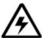
CAUTION
RISK OF ELECTRIC SHOCK DO NOT OPEN

CAUTION: TO REDUCE THE RICK OF ELECTRIC SHOCK DO NOT REMOVE COVER. NO USER SERVICABLE PARTS INSIDE.
REFER SERVICING TO QUALIFIED SERVICE PERSONNEL.

The lightning flash with arrowhead symbol, within an equilateral triangle, is intended to alert the user to the presence of uninsulated "dangerous voltage" within the products' enclosure that may be of sufficient magnitude to constitute a risk of electric shock.

The exclamation point within an equilateral triangle is intended to alert the user to the presence of important operating and maintenance (servicing) instructions in the literature accompanying the appliance.
WARNING: TO PREVENT FIRE OR SHOCK HAZARD, DO NOT EXPOSE THIS UNIT TO RAIN OR MOISTURE.
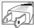
CAUTION: TO PREVENT ELECTRIC SHOCK, MATCH WIDE BLADE OF THE PLUG TO THE WIDE SLOT AND FULLY INSERT.
BEFORE YOU ST
THIS PRODUCT MAY REQUIRE PROFESSIONAL INSTALLATION
LOREX IS COMMITTED TO FULFILLING YOUR SECURITY NEEDS


• We have developed user friendly products and documentation. Please read the Quick Start Guide and User Manual before you install this product.
- Consumer Guides and Video Tutorials are available on our web site at www.lorextechnology.com/support
- If you require further installation assistance, please visit www.lorextechnology.com/installation or contact a professional installer.

natural_image
Portrait of a smiling man in a blue work uniform with arms crossed (no text or symbols visible)
- Please refer to the "Need Help" insert for technical support and customer care information.

- Please note that once the components of this product have been unsealed, you cannot return this product directly to the store without the original packaging.
AVANT DE COMMENCER
ANTES DE EMPEZAR
CE PRODUIT POURRAIT EXIGER UNE INSTALLATION PROFESSIONNELLE LOREX S'ENGAGE À SATISFAIRE VOS BESOINS SÉCURITAIRES
DO NOT RETURN THIS PRODUCT TO THE STORE
Please make sure to register your product at www.lorextechnology.com to receive product updates and information
3 Easy Ways to Contact Us:

natural_image
Man using a laptop in a minimalist room with white curtains (no text or symbols visible)Online:
Product Support is available 24/7 including product
information, user manuals, quick start up guides and FAQ's at
www.lorextechnology.com/support
To order accessories, visit
www.lorextechnology.com

natural_image
Side profile of a man in a meeting, hand near face, with laptop and coffee cup visible (no text or symbols)By Email:
Technical Support (for technical/installation issues)
support@lorexcorp.com
Customer Care (for warranty and accessory sales)
customerservice@lorexcorp.com
Customer Feedback
info@lorexcorp.com

natural_image
Woman smiling while talking on a phone at a desk with a computer and water bottle (no visible text or symbols)By Phone:
North America:
Customer Service: 1-888-425-6739 (1-888-42-LOREX)
Tech Support: 1-877-755-6739 (1-877-75-LOREX)
Mexico: 1-800-514-6739
International: +800-425-6739-0
(Example: From the UK, dial 00 instead of +)
Necesita Ayuda
COMUNÍQUESE PRIMERO
CON NOSOTROS
support@lorexcorp.com
O
customerservice@lorexcorp.com
customerservice@lorexcorp.com
Important Safeguards
In addition to the careful attention devoted to quality standards in the manufacture process of your video product, safety is a major factor in the design of every instrument. However, safety is your responsibility too. This sheet lists important information that will help to assure your enjoyment and proper use of the video product and accessory equipment. Please read them carefully before operating and using your video product.
Installation
- Read and Follow Instructions - All the safety and operating instructions should be read before the video product is operated. Follow all operating instructions.
- Retain Instructions - The safety and operating instructions should be retained for future reference.
- Heed Warnings - Comply with all warnings on the video product and in the operating instructions.
- Polarization - Do not defeat the safety purpose of the polarized or grounding-type plug.
A polarized plug has two blades with one wider than the other.
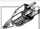
A grounding type plug has two blades and a third grounding prong.
The wide blade or the third prong are provided for your safety.
If the provided plug does not fit into your outlet, consult an electrician for replacement of the obsolete outlet.
- Power Sources - This video product should be operated only from the type of power source indicated on the marking label. If you are not sure of the type of power supply to your location, consult your video dealer or local power company. For video products intended to operate from battery power, or other sources, refer to the operating instructions.
- Overloading - Do not overload wall outlets of extension cords as this can result in the risk of fire or electric shock. Overloaded AC outlets, extension cords, frayed power cords, damaged or cracked wire insulation, and broken plugs are dangerous. They may result in a shock or fire hazard. Periodically examine the cord, and if its appearance indicates damage or deteriorated insulation, have it replaced by your service technician.
-
Power-Cord Protection - Power supply cords should be routed so that they are not likely to be walked on or pinched by items placed upon or against them, paying particular attention to cords at plugs, convenience receptacles, and the point where they exit from the video product.
-
Ventilation - Slots and openings in the case are provided for ventilation to ensure reliable operation of the video product and to protect it from overheating. These openings must not be blocked or covered. The openings should never be blocked by placing the video equipment on a bed, sofa, rug, or other similar surface. This video product should never be placed near or over a radiator or heat register. This video product should not be placed in a built-in installation such as a bookcase or rack unless proper ventilation is provided or the video product manufacturer's instructions have been followed.
- Attachments - Do not use attachments unless recommended by the video product manufacturer as they may cause a hazard.
- Camera Extension Cables – Check the rating of your extension cable(s) to verify compliance with your local authority regulations prior to installation.
- Water and Moisture - Do not use this video product near water. For example, near a bath tub, wash bowl, kitchen sink or laundry tub, in a wet basement, near a swimming pool and the like.
Caution: Maintain electrical safety. Power line operated equipment or accessories connected to this unit should bear the UL listing mark of CSA certification mark on the accessory itself and should not be modified so as to defeat the safety features. This will help avoid any potential hazard from electrical shock or fire. If in doubt, contact qualified service personnel.
- Accessories - Do not place this video equipment on an unstable cart, stand, tripod, or table. The video equipment may fall, causing serious damage to the video product. Use this video product only with a cart, stand, tripod, bracket, or table recommended by or sold with the video product. And product should follow the manufacturer instructions and use a mounting recommendation by the manufacturer

Service
- Servicing - Do not attempt to service this video equipment yourself as opening or removing covers may expose you to dangerous voltage or other hazards. Refer all servicing to qualified service personnel.
- Conditions Requiring Service - Unplug this video product from the wall outlet and refer servicing to qualified service personnel under the following conditions.
A. When the power supply cord or plug is damaged.
B. If liquid has been spilled or objects have fallen into the video product.
C. If the video product has been exposed to rain or water.
D. If the video product does not operate normally by following the operating instructions. Adjust only those controls that are covered by the operating instructions. Improper adjustment of other controls may result in damage and will often require extensive work by a qualified technician to restore the video product to its normal operation.
E. If the video product has been dropped or the cabinet has been damaged.
F. When the video product exhibits a distinct change in performance. This indicates a need for service.
- Replacement Parts - When replacement parts are required, have the service technician verify that the replacements used have the same safety characteristics as the original parts. Use of replacements specified by the video product manufacturer can prevent fire, electric shock or other hazards.
- Safety Check - Upon completion of any service or repairs to this video product, ask the service technician to perform safety checks recommended by the manufacturer to determine that the video product is in safe operating condition.
- Wall or Ceiling Mounting - The cameras provided with this system should be mounted to a wall or ceiling only as instructed in this guide, using the provided mounting brackets.
- Heat - The product should be situated away from heat sources such as radiators, heat registers, stoves, or other products (including amplifiers) that produce heat.
Use
- Cleaning - Unplug the video product from the wall outlet before cleaning. Do not use liquid cleaners or aerosol cleaners. Use a damp cloth for cleaning.
- Product and Cart Combination - Video and cart combination should be moved with care. Quick stops, excessive force, and uneven surfaces may cause the video product and car combination to overturn.
- Object and Liquid Entry - Never push objects for any kind into this video product through openings as they may touch dangerous voltage points or "short-out" parts that could result in a fire or electric shock. Never spill liquid of any kind on the video product.
- Lightning - For added protection for this video product during a lightning storm, or when it is left unattended and unused for long periods of time, unplug it from the wall outlet and disconnect the antenna or cable system. This will prevent damage to the video product due to lightning and power line surges.
General Precautions
- All warnings and instructions in this manual should be followed.
- Remove the plug from the outlet before cleaning. Do not use liquid aerosol detergents. Use a water dampened cloth for cleaning.
- Do not use the receiver in a humid or wet place.
- Keep enough space around the unit for ventilation. Slo ts and openings in the storage cabinet should not be blocked.

WARNING
STRANGULATION HAZARD:
Infants have STRANGLED in power cords. Keep power cords more than 3 feet away from cribs, bassinets, play yards and other safe sleep environments for infants.
TRANSMITTER FCC/IC NOTICE
FCC Transmitter Notice
This equipment has been certified and found to comply with the limits regulated by the FCC part 15, subpart C.
- This device complies with Part 15 of the FCC Rules. Operation is subject to the following two conditions: (1) this device may not cause harmful interference, and (2) this device must accept any interference received, including interference that may cause undesired operation.
IC Transmitter Notice
- This device complies with Industry Canada licence-exempt RSS standard(s). Operation is subject to the following two conditions: (1) this device may not cause interference, and (2) this device must accept any interference, including interference that may cause undesired operation of the device.
RECEIVER FCC/IC NOTICE
FCC Receiver Notice
This equipment has been tested and found to comply with the limits for a Class B digital device, pursuant to Part 15 of the FCC rules. These limits are designed to provide reasonable protection against harmful interference in a residential installation. This equipment generates, uses and can radiate radio frequency energy and, if not installed and used in accordance with the instructions, may cause harmful interference to radio communications. However, there is no guarantee that interference will not occur in a particular installation.
IC Receiver Notice
This Class B digital apparatus complies with Canadian ICES-003.
Operation is subject to the following two conditions:
1) This device may not cause harmful interference, and
2) This device must accept any interference received, including interference that may cause undesirable operation.
CANADIAN CLASS B STATEMENT: This digital device does not exceed the Class B limits for radio noise emissions from digital apparatus as set out in the interference-causing equipment standard entitled "Digital Apparatus," ICES-003 of the Department of Communications.
MODIFICATION: Any changes or modifications not expressly approved by the grantee of this device could void the user's authority to operate the device.
natural_image
Two black BLOREX security cameras with wireless antennas, one mounted and one connected (no visible text or symbols)• FHSS Digital Wireless Technology provides excellent image quality and clarity
- Simple installation. No video cable required (1)
- Connect multiple receivers to your surveillance recorder (DVR) to create a wireless surveillance solution [2]
- Easily connects to a TV/Monitor (RCA) or DVR (BNC)
• Night viewing up to 60ft (18m) (3)
• Install camera indoors or outdoors (4)
- Up to 150ft (46m) indoor / 450ft (137m) outdoor wireless range (5)
Receiver Features
- Compact receiver is easy to install and operate
• VGA (640x480) & QVGA (320x240) Resolution Supported (6) - Convenient Signal Strength Indicator
- Plug directly into a TV (RCA adapter included) or surveillance recorder or use a BNC extension cable (included) to position the wireless receiver in a more convenient location
Camera Features
• VGA Resolution Camera
• 60ft (18m) IR Night Vision (3)
- Auto infrared light filter ensures accurate color reproduction under any lighting condition
- Weather Proof Housing (IP66 rated) (4)
- Camera requires a wired connection to a power outlet. Power adapter included.
- Using multiple receivers in close proximity to each other may cause a slight slowdown in frame rate performance. Try to maintain at least a few inches of space between each receiver, 3ft. extension cable included.
- Stated IR illumination range is based on ideal conditions. Actual range and image clarity depends on installation location, viewing area and light reflection/absorption level of object.
- Not intended for submersion in water. Installation in a sheltered area recommended.
- Maximum wireless transmission range. Actual range dependant upon building materials and other obstructions in path of wireless signal.
- VGA mode has a resolution of 640 X 480 pixels; QVGA mode has a resolution of 320 X 240 pixels. Use VGA mode for best video performance. Use QVGA mode for a higher video frame rate.
Table of Contents
Getting Started 1
Wireless Receiver & Camera 2
Connecting The Camera.... 3
Camera Setup 3
Wireless Receiver Setup 5
Installing Multiple Wireless Cameras 6
Powering Multiple Receivers Using The Power Splitter Cable (LW2110PK2 only) ... 7
On-Screen Display 7
Pairing Cameras 8
Appendix A: System Specifications 9
Appendix B: About Digital Wireless Technology 10
Appendix C: Facts About Digital Wireless Cameras.... 11
Appendix D: Troubleshooting 13
Appendix E: Frequently Asked Questions 14
Appendix F: Extending Wireless Range.... 15
Getting Started
The system comes with the following components:
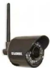
1 X WIRELESS CAMERA*

1 X CAMERA MOUNTING STAND

1 X WIRELESS RECEIVER*

1 X MOUNTING SCREW KIT

1 X BNC/RCA ADAPTER

natural_image
Electric power adapter with black cable and connector (no visible text or symbols)2 X POWER ADAPTERS* (FOR RECEIVER & CAMERA)

natural_image
Coiled black cable with two metallic connectors (no text or symbols visible)3FT/1M BNC FEMALE/BNC MALE EXTENSION CABLE
*Number of cameras and receivers may vary by model.
CHECK YOUR PACKAGE TO CONFIRM THAT YOU HAVE RECEIVED THE COMPLETE SYSTEM, INCLUDING ALL COMPONENTS SHOWN ABOVE.
Wireless Receiver & Camera


1 Wireless Antenna
2 Resolution button: Press to switch between VGA* and QVGA video resolutions.
3 Front LED: Glows green to indicate receiver is powered up.
4 Pairing Button: F or details, see "Pairing Cameras" on page 8.
5 BNC Connector: Connect the BNC connector to the DVR or BNC extension cable.
6 Pairing Button: F or details, see "Pairing Cameras" on page 8.
7 Camera Stand
*VGA mode has a resolution of 640 X 480 pixels; QVGA mode has a resolution of 320 X 240 pixels. Use VGA mode for best video performance. Use QVGA mode for a higher video frame rate.
Connecting The Camera

- Before you install the camera, carefully plan where and how it will be positioned, and where you will route the cable that connects the camera to the power adapter.
- Before starting permanent installation, verify its performance by observing the image on a monitor when camera is positioned in the same location/position where it will be permanently installed.
Installation Warnings
- Aim the Cameras to best optimize the viewing area: Select a location for the camera that provides a clear view of the area you want to monitor, which is free from dust, and is not in line-of-sight to a strong light source or direct sunlight.
- Avoid installing the cameras where there are thick walls or obstructions between the Cameras and the Receiver*.
- Select a location for the camera that has an ambient temperature between 14^ 122^ (-10°C\~50°C)
- For outdoor use, installation under a shelter is recommended.
*Avoid installing in a location which requires the wireless signal to pass through cement, concrete, and metal structures. This will reduce the range of transmission.
For details, see "Appendix C: Facts About Digital Wireless Cameras" on page 11.
Camera Setup
To install the camera:
1 Use the included mounting screws to mount the stand to the mounting surface:
- Mark the position of the screw holes on the wall
- Drill holes and insert the drywall plugs as needed
- Firmly attach the stand to the wall using the provided screws

natural_image
Technical illustration of a mechanical assembly with screwdriver and housing, showing alignment lines (no text or symbols)2 Twist the camera into the head of the stand (1).
Adjust the angle of the camera until the desired view is set. Tighten the thumbscrews to secure the desired camera position (2).

3 Connect the power cable from the camera to the Power Adapter. Plug the power adapter to an outlet or surge protector.

natural_image
Diagram showing connections between a power outlet, cable, and surveillance camera (no text or symbols present)Wireless Receiver Setup
To connect a wireless receiver to a surveillance recorder (DVR):
1 Connect the BNC connector on the receiver directly into an available video input.

natural_image
Black wireless router with antenna and ventilation slots (no visible text or symbols)
Make sure to first connect and power on the camera(s) before powering on the receiver; this will ensure a proper connection.
NOTE: If necessary, attach the 3ft (1m) BNC/BNC extension cable at one end to the receiver and at the other end to the surveillance recorder.
2 Connect the power cable from the receiver to the power adapter. Plug the power adapter into an outlet or surge protector.
NOTE: For instructions on powering multiple receivers, see "Powering Multiple Receivers Using The Power Splitter Cable (LW2110PK2 only)" on page 7.
To connect the wireless receiver to a TV or VCR:
1 Attach the included BNC/RCA adapter to the BNC connector on the receiver and plug the receiver directly into an available video input on the TV or VCR.

Rear panel of TV.
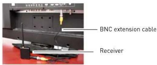

Make sure to first connect and power on the camera(s) before powering on the receiver; this will ensure a proper connection.
NOTE: If necessary, attach one end of the 3ft (1m) BNC/BNC extension cable to the receiver and at the other end attach the BNC/RCA adapter, then connect the BNC/RCA adapter to the viewing/recording device.
2 Co nnect the power cable from the receiver to the cable of the power adapter. Plug the power adapter into a local AC power outlet or surge protector.
Installing Multiple Wireless Cameras
When installing multiple digital wireless security cameras in the same environment (e.g. LW2110PK2 - 2 pack wireless cameras) maintain as much space as possible between the receivers using the included 3ft BNC extension cables, to optimize camera performance. See illustrations below for examples of recommended 2 and 4 receiver installations.
Scenario A: Two Wireless Cameras
- Plug one receiver directly into the back of the Digital Video Recorder. Connect the other receiver to the included 3ft BNC extension cable and plug into the Digital Video Recorder.

flowchart
graph TD
    A["Digital Video Recorder"] --> B["1"]
    B --> C["2"]
    C --> D["3"]
    C --> E["4"]
    D --> F["BNC Extension Cable"]
    E --> F
    style A fill:#f9f,stroke:#333
    style B fill:#ccf,stroke:#333
    style C fill:#cfc,stroke:#333
    style D fill:#fcc,stroke:#333
    style E fill:#cff,stroke:#333
Scenario B: Four Wireless Cameras
- Plug one receiver directly into the back of the Digital Video Recorder. Connect the other receivers to the included 3ft BNC extension cables and plug them into the Digital Video Recorder.

flowchart
graph TD
    A["Digital Video Recorder"] --> B["1"]
    B --> C["2"]
    C --> D["3"]
    D --> E["4"]
    E --> F["..."]
    style A fill:#f9f,stroke:#333
    style B fill:#ccf,stroke:#333
    style C fill:#cfc,stroke:#333
    style D fill:#fcc,stroke:#333
    style E fill:#cff,stroke:#333
    style F fill:#ffc,stroke:#333
    note right of F It is not recommended to install more than 4 digital wireless security cameras in the same environment to maintain optimal video frame rate performance.
NOTE: The receiver included does not support an extension to a range extender antenna. Should you require a wireless range extension, an accessory kit including an extendable receiver and wireless antenna is available at www.lorextechnology.com. For details, see "Appendix F: Extending Wireless Range" on page 15.
Powering Multiple Receivers Using The Power Splitter Cable (LW2110PK2 only)
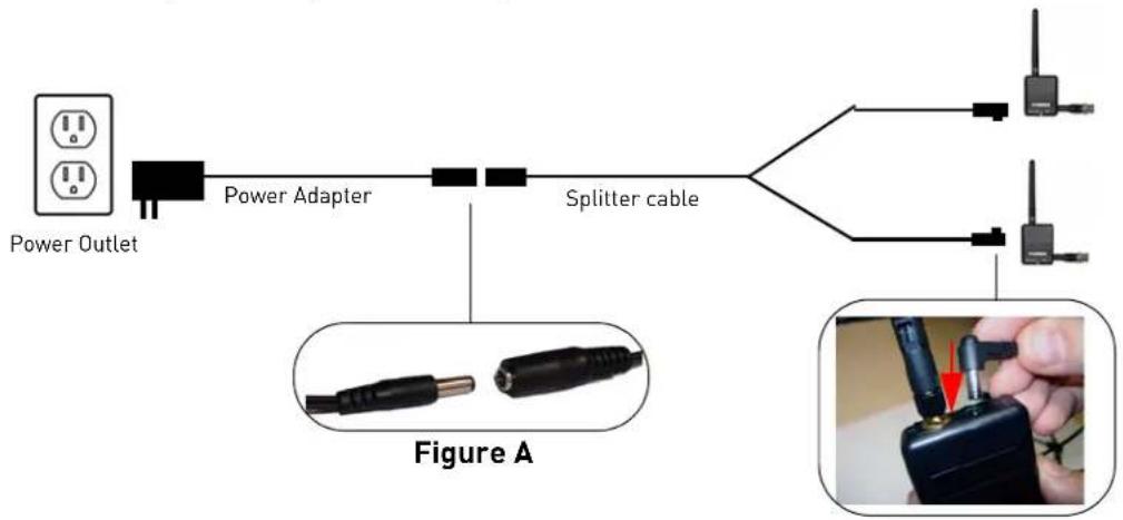
The power splitter cable allows you to connect two receivers to one power adapter.
To connect the power splitter cable to the receivers:
1 Connect the power adapter to the power splitter cable (see Figure A below).
2 Connect the ends of the power splitter cable to each of the receivers.
3 Co nnect the power adapter to a 120V power outlet.
flowchart
graph LR
    A["Power Outlet"] --> B["Power Adapter"]
    B --> C["Splitter cable"]
    C --> D["Device 1"]
    C --> E["Device 2"]
    D --> F["Image with red arrow indicating contact or disconnection"]
    E --> G["Image with black plug"]
On-Screen Display
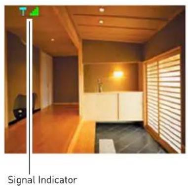

1 Signal Indicator: The signal indicator shows the strength of the signal being received from the camera. The number of bars in the signal indicator shows the strength of the signal. One or no bars indicates the signal is poor. Four bars indicate a very strong signal.
2 Status Indicator: The status indicator message "Connecting" appears when the receiver is trying to locate a camera.
ATTENTION: If the signal is low (e.g. 1 or 2 bars) adjust the antennas, or reposition the camera or receiver to improve signal strength.
Pairing Cameras
IMPORTANT
The camera and receiver have already been pre-paired at the factory, which means that they are exclusively communicating with each other. If for some reason the pairing is lost, follow these steps to pair up the camera and receiver.
To pair the camera to the receiver:
1 Make sure that the camera and receiver are both powered up.
2 On the receiver, press and hold the Pa iring button for 5 seconds to activate pairing function.
- The on-screen displays informs you that you have 30 seconds to press the pair button on the camera.
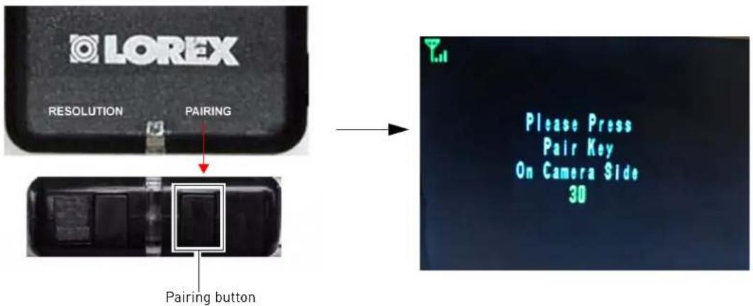
3 Press and hold the Pa ir button underneath the antenna on the back of the camera. You must press the Pair button on the camera within 30 seconds of pressing the Pair button on the Wireless Receiver. If pairing is successful, live video from the camera will immediately appear on the monitor.

Appendix A: System Specifications
Receiver Specifications
| Receiver | |
| Receiving Frequency Range | 2.400GHz~2.480GHz |
| RX Sensitivity | -81dBm |
| Demodulation | GFSK |
| Data Rate | 160 Kb/s |
| Supported Resolutions | VGA (640x480) up to 12 FPS or QVGA (320x240) up to 25 FPS |
| Power Requirement | 12Vdc +/-10% |
| Power Consumption | 200mA Max |
| Operating Temp Range | 14°F ~ 122°F-10° ~ 50°C |
FPS = Frames Per Second
Camera Specifications
| Camera | |
| Transmitting Frequency Range | 2.400GHz-2.480GHz |
| TX Power | 16dBm |
| Data Rate | 160 Kb/s |
| Modulation | GFSK |
| TX Range | 150ft [46m] indoor/ 450ft [137m] outdoor |
| Image Sensor Type | 1/4" Color CMOS Image Sensor |
| Effective Pixel | H: 640, V: 480 |
| Image Processing | Motion JPEG |
| Image Resolution | Up to 640 x 480 (VGA) |
| Lens | 5.1mm F2.8 |
| Viewing Angle | 50° (H) |
| AGC | On |
| AES | 1/60-1/62500 Sec. |
| Power Requirement | 12Vdc +/-10%. |
| Power Consumption | 200mA Max with IR LED, 100mA Max without IR LED. |
| Operating Temp Range | 14°F - 122°F-10° - 50°C |
| Environment Rating | IP66 |
| Built-in IR LED | 18 Units of IR LED (850nm type) for Night Vision |
| Built-in Auto IR Turn On/Off | CdS Drive Auto IR LED turn On/Off Circuit |
Appendix B: About Digital Wireless Technology
The Digital Wireless signal transmission type used by the Lorex LW2110 is also known as FHSS -Frequency Hopping Spread Spectrum. This type of signal results in a private, interference-free signal.
The 2.4GHz (2.400-2.480Ghz) band is being divided into sections or paths of 2MHz per section, and each second the transmission signal hops hundreds of times in a specified sequence within this frequency range. The overall bandwidth required for frequency hopping is much wider then 2MHz however because transmission occurs only on a small section of this bandwidth at any given time, the signal being transmitted does not suffer from greatly reduced signal degradation and also avoids blocked paths other devices who act as sources of competing signals. The strength of the signal being transmitted is set to be from 13.5-16dBm, which is much higher than the analog transmission signal allowed by authorities around the Globe.
When an image is captured by the camera it is instantly converted from an analog to digital signal and packaged into small packets. With each successful transmission via the 2 MHz paths discussed above, the packets of information containing images are delivered to the receiver and decoded into analog information. The information can then be displayed on devices that are connected to the wireless receiver (RX).
A device pairing process is required to synchronize the transmitter (TX, Camera) and the receiver (RX). This allows the transmitter and receiver to be on the same frequency and use the same algorithm for frequency hopping. This ensures that only the paired transmitter and receiver can maintain communication signal by hopping to the same frequency paths at the exact same time. As a result, the chance that other devices within the same frequency range are on the same frequency, at the same time and in the same order is vastly reduced. Note that the pairing process is already done at the factory for products that ship within the same packaging. Only when add-on devices are purchased is a pairing process required.
Appendix C: Facts About Digital Wireless Cameras
Wired VS Wireless Cameras
A wired camera has a video cable that transmits the video signal from the camera to a recording or viewing device.
A wireless camera does not use a video cable. Instead, it wirelessly transmits the video signal to a wireless receiver that is connected to your recording or viewing device. Although the typical digital wireless camera is priced slightly higher than a wired camera, wireless cameras can provide cost savings compared to standard wired setups. For example, wireless cameras do not require cabling to be run between the camera and the viewing / recording device, which reduces installation time and cost.
Does a wireless camera require power?
Yes. Wireless cameras require two power sources: one connected to the camera, and the other to the receiver.
How far can a wireless camera transmit a video signal?
In an open field (with line of sight), a typical wireless camera has a range between 250 to 450 feet. In a closed environment---such as an interior of a house---the wireless camera range is between 100 to 150 feet. The signal range varies depending on the type of building materials and/or objects the wireless signal must pass through.
Cubical walls, drywall, glass, and windows generally do not degrade wireless signal strength. Brick, concrete floors and walls degrade signal strength ^1 . Trees that are in the line of sight of the wireless camera and receiver may impact signal strength.
The signal range also depends on whether there are competing signals using the same frequency as the camera. For example, signals from cordless phones, routers may affect signal strength.
Range Limiting Factors ^1

Reflection
The signal reflects back

Scattering
The signal scatters back into multiple new signals

Refraction
The signal bends as it travels through an object (i.e glass window)

Diffraction
The signal changes direction as it passes around an object
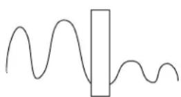
Attenuation
The signal strength weakens as it passes through an object
Signal Reduction Through Materials
Signal strength decreases as it passes through different types of material. Try to position your wireless camera and receiver in a location that does not pass through metal, or concrete blocks, which can significantly reduce signal strength (as shown in the table below).
| Material Signal Reduction (%) | |
| Plaster & Wood 10 - 30% | |
| Brick 30 - 50% | |
| Concrete Cinder Blocks 50 - 70% | |
| Metal & Metal Cladding 70 - 90% | |
NOTE: Signals that must pass through wet or moist materials (i.e. shrubs and trees) may be significantly reduced.
The stronger the signal strength, the higher the video frame rate. The lower the signal strength, the lower the video frame rate.

flowchart
graph LR
    A["Full signal strength\n(high frame rate)"] --> B
    B --> C["Low signal strength\n(low frame rate)"]
Are Digital Wireless Camera Signals Secure?
Yes. Lorex digital wireless products feature a wireless transmission method called FHSS -Frequency Hopping Spread Spectrum.
This type of signal is highly resistant to eavesdropping as it generates a channel hopping sequence using an algorithm generated by the receiver, which only the camera can follow through the "pairing" function. FHSS makes digital wireless signals secure, private, and interference free.
How many frames per second should I expect from a digital wireless camera?
Current Lorex digital wireless cameras offer 10 - 30 FPS (Frames Per Second) performance. Actual frame rate depends mainly on signal strength and resolution (see the chart above). Most digital wireless cameras support one or both of the following resolutions: QVGA, and VGA.
QVGA produces video at up to 30 FPS at 320x240 resolution.
VGA produces video at up to 10-12 FPS at 640x480 resolution.
How many wireless cameras can I install?
It is recommended to install a maximum of 4 (four) wireless cameras per system.
Appendix D: Troubleshooting
If you have problems with your System, there is often a quick and simple solution. Please try the following:
| Problem Solution | |
| There is no picture from a camera | Check power to the camera. Make sure the adapter is plugged in properly.Move the camera closer to the receiver. |
| The picture is dropping • Move the camera closer to the receiver.Try repositioning the camera, receiver, or both to improve the reception. | |
| The picture is or has become choppy | The picture may become choppy when experiencing a lower frame rate (e.g. 6 frames per second vs. a higher 12 frames per second).Try moving the camera closer to the receiver.Remove obstructions between the receiver and camera.Try switching to QVGA mode. Resolution will be reduced but video frame rate will increase. |
| The picture appears to be unsharp | When viewing on a large screen TV or monitor (especially high-definition televisions), the picture might seem unsharp as the camera is limited to VGA resolution (640x480 pixels), while the TV or monitor supports a much higher resolution.For best performance, use with TV/monitor PIP (Picture in Picture) function. Check your TV/Monitor product manual to see if this feature is available on your TV/Monitor. |
| The picture is white • Common situation known as "washout" or "white wash" where a strong light source is pointed at the camera lens. The camera lens is not harmed during a white wash.Do not point your camera towards a light source. | |
| The picture is pixelated • You may be in QVGA mode. Try switching to VGA mode by pressing the Resolution button on the receiver. | |
Appendix E: Frequently Asked Questions
Q: What is the maximum distance I can have between the camera and the receiver?
A: Typically 450 feet (137 m) with a clear line of sight in open space, or approximately 150 feet (46 m) in a house. Walls, studs, furniture will interfere with the range of wireless transmission.
Q: Why does my "wireless camera" have a power cable?
A: The term "wireless" refers to the lack of a video cable between the camera and the receiver. The camera still requires a power source.
Q: What does 'line-of-sight' mean?
A: 'Line-of-sight' means that there are no obstructions between the camera and receiver. Obstructions include walls, buildings, trees, and certain electronic devices. Materials containing moisture (i.e wet leaves) may also act as an obstruction.
Q: What is pairing?
A: Pairing is an electronic handshake between digital wireless devices. Pairing allows the devices to communicate exclusively with each other.
Q: Can digital wireless cameras be paired to more than one receiver?
A: No. Digital Wireless cameras can only be paired to one receiver. This is to prevent interception by 3rd parties, and prevents any other device from picking up the signal - this also means that you cannot pair one camera to multiple receivers.
Q: How can I extend the wireless range?
A: A range extender kit is available on www.lorexcctv.com. For details, see "Appendix F: Extending Wireless Range" on page 15.
Appendix F: Extending Wireless Range
The receiver included with the LW2110 series does not support range extender antennas. Should you require a wireless range extension, a range extender accessory kit is available.
Wireless range extension should be considered if you experience a low signal strength (1 or 2 signal bars) due to an extended distance between the receiver and camera, or because of objects preventing line of sight between the receiver and camera.
The range extender accessory kit includes a 20ft cable and a higher power indoor/outdoor antenna which allows you to reposition the antenna outdoors for direct line of sight with the camera OR simply to get around objects which are blocking the wireless signal (e.g. metal walls). Find an example below of a typical situation in which a range extender kit is used to achieve line of sight to improve signal strength.
Example 1: No line of sight
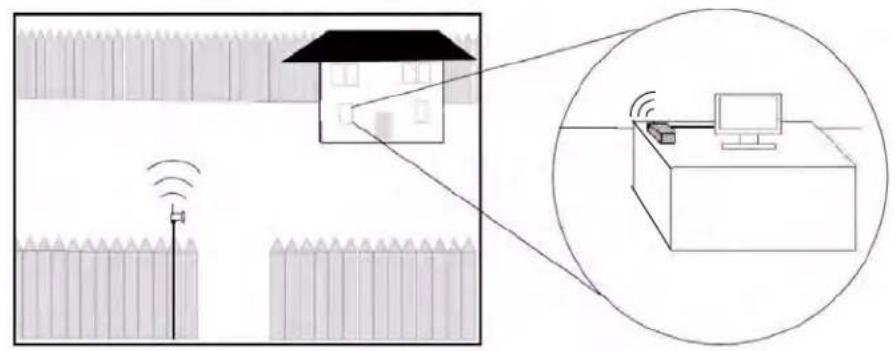
Example 2: Line of sight achieved through use of range extender

To order a range extender accessory kit, or to get more information, visit www.lorexcctv.com, and search for LW2110 Kit.
LOREX PRODUCT LIMITED WARRANTY
。
Lorex's responsibility under this, or any other warranty, implied or expressed, is limited to repair, replacement or refund, as set forth above. These remedies are the sole and exclusive remedies for any breach of warranty. Lorex is not responsible for direct, special, incidental, or consequential damages resulting from any breach of warranty or under any other legal theory including but not limited to, loss profits, downtime, goodwill, damage to or replacement of equipment and property and any costs of recovering, reprogramming or reproducing any program or data stored in or used with a system containing the Product CD-ROM or accompanying software. Lorex does not warrant that the software will operate with any other software except that which is indicated. Lorex cannot be responsible for characteristics of third party hardware or software which may effect the operation of the software included.
The purchaser may have other rights under state, provincial, or federal laws and where the whole or part of any item of this warranty is prohibited by such laws, it shall be deemed null and void, but the remainder of the warranty shall remain in effect.
All expressed and implied warranties are limited in duration to the limited warranty period. No warranties apply after that period. Some states do not allow limitation on
how long an implied warranty lasts, so this limitation may not apply to you. Some states do not allow the evolution or limitation of incidental or consequential
states do not allow the exclusion of limitation or incidental or consequential damages, so the above warranty may not apply to you. This limited warranty gives you specific legal rights and you may also have other rights that vary from state to
state.
Obtaining Service
In order to obtain service, please make sure that you have registered your product
on-line (www.lorexcctv.com) in the warranty registration section. Should the Product require service under this warranty, the Purchaser must provide Lorex with
a copy of his/her original, dated bill of sale; receipt or invoice, falling which Lorex will not perform any of its obligations under this warranty. If you return the Product
Will not perform any of its obligations under this warranty. If you return the Product and/or CD-ROM to Lorex, you must assume the risk of damage or loss during
shipment. You must use the original packaging or the equivalent, and you must pay postage.
To claim on this warranty, proceed with the following steps.
1 Pack the Product in a well-nadded sturdy carton.
- i). If the unit was purchased in the United States proceed as follows: a. Please contact our customer service department to obtain a return
a. Please contact our customer service department to obtain a return authorization number.
b. Return the unit to: Lorex Returns Schenker Logistics
2363 E. Perry Road, Suite 171, Dock Door 44
Plainsfield, IN 48168
ii). If the unit was purchased in Canadapceed as follows: a. Please contact our customer service department to obtain a return
authorization number.
b. Return the unit to: Lorex Service Center. 250 Royal Crest Court, Markham, Ont. L3R 3S1
iii) If the unit was purchased in Europe please visit:
www.lorexinternational.com for return instructions.
TOLL FREE CUSTOMER SUPPORT North America 1,000,401 CREEK (1,000,405,070)
Always use discretion when installing video and/or audio surveillance equipment especially when there is perceived privacy. Inquire regarding federal, state and/or local regulations applicable to the lawful installation of video and/or audio recording or surveillance. Party consent may be required.
Lorex warrants, to the original retail purchaser only (the "Purchaser"), that this item (the "Product") if properly used and installed, and where applicable, the CD-ROM on which the accompanying software is provided, is free from manufacturing defects in material and workmanship, provided the Product is used in normal conditions and is installed and used in strict accordance with the instructions contained. This warranty shall be for the following warranty periods (the "Warranty Period"); commencing on the date the Purchaser buys the Product at retail in an unused condition.
Parts and Labor: 1 year (Warranted parts do not include ____ Bulbs, LED's and Batteries)
Lorex's obligations under this warranty shall be limited to
• The repair and or replacement of the product by means of hardware and/or software (at option of Lorex);
• The replacement of any warranted parts found by Lorex to be defective in the Product or, in Lorex's sole discretion, the replacement of the Product found be Lorex to be defective.
• If Lorex is unable to repair or replace the Product or CD-ROM, refund the then-current value of the Product. Any replacement parts furnished by Lorex in connection with this warranty shall be warranted to the Purchaser for a period equal to the un expired portion of Warranty Period for the Product.
Warranty Exclusions This warranty does not apply to Bulbs, LED's and Batteries supplied with or forming part of the product. This warranty is invalidated if other than Lorex accessories are or have been used in or in connection with the Product or in any modification or repair is made to the Product by other than a service depot authorized by Lorex. This warranty does not apply to defects or damages arising by use of the Product in other than normal (including normal atmospheric, moisture and humidity) conditions or by installation or use of the Product other than in strict
accordance with the instructions contained in the Product's Owner's Manual. This warranty does not apply to defects in or damages to the Product caused by (i) negligent use of the Product, (ii) misuse, abuse, neglect, alteration, repair or improper installation of the Product, (iii) electrical short circuits or transients, (iv) Purchaser usage not in accordance with product installation. (v) use of replacement parts not supplied by Lorex (vi) improper Product maintenance, or (viii) accident, fire, flood or other Acts of God.
This warranty does not cover the performance or functionality of any computer software included in the package with the Product. This warranty only covers defects in the CD-ROM media such as a broken or a defect in the CD-ROM that would prevent the CD-ROM from being read by your personal computer's CD-ROM drive. Lorex makes no warranty that the software provided with the Product will function without interruption or otherwise be free of anomalies, errors or 'Bugs'. Lorex makes no warranty with regard to any software provided with the Product unless specifically set forth otherwise in a license agreement accompanying such software. This warranty does not cover any costs relating to removal or replacement of any Product; CD-ROM, or software installed on
Lorex reserves the right to make changes in design or to make additions to or improvements in its products without incurring any obligation to modify any product which has already been manufactured. Lorex will make every effort to provide updates and fixes to its software via its website. This warranty does not cover any alteration or damage to any other software that may be or may become resident on the users system as a result of installing the software provided. This warranty is in lieu of other warranties, express or implied, and Lorex neither assumes nor authorizes any person to assume for it any other obligation or liability in correction with the sale or service of the Product. In no event shall Lorex be liable for any special or consequential damages arising from the use of the Product or arising from the malfunctioning or non-functioning of the Product, or for any delay in the performance of this warranty due to any cause beyond its control.
This warranty shall not apply to the appearance or accessory items including, but not limited to cabinets, cabinet parts, knobs etc., and the uncrating, setup, installation or the removal and reinstallation of products after repair. Lorex does not make any claims or warranties of any kind whatsoever regarding the Product's potential, ability or effectiveness to prevent minimize. or in any way affect personal or property damage or injury. Lorex is not responsible for any personal damage, loss or theft related to the Product or to its use for any harm, whether physical or mental related thereto. Any and all claims or statements, whether written or verbal, by salespeople, retailers, dealers or distributors to the contrary are not authorized by Lorex, and do not affect this provision of this warranty.
natural_image
Exterior view of multiple security camera modules including ELOREX monitors, surveillance cameras, and a central monitor displaying a 21.5" touch monitor (no readable text or symbols on main devices)Enhance your security with genuine Lorex products and accessories.
Order whatever you need at www.lorextechnology.com or call 1-888-42-LOREX (1-888-425-6739)
Special offer Coupon: MLLLLDCG-CM-OOJICORN
Parking Lot
natural_image
Exterior view of a surveillance camera with mounted lens, surrounded by trees (no visible text or symbols)LBC6050
Office

natural_image
Interior view of a modern meeting room with chairs and ceiling lighting (no visible text or symbols)Restaurant

natural_image
Exterior view of a modern office building (no signage)LDC6050
Drive Way

natural_image
Exterior view of a black car parked in front of a stone building with a circular security camera (no visible text or symbols)CVC6950B
Home
natural_image
Woman in lab coat holding a monitor displaying surveillance camera images, with inset image of three surveillance cameras (no visible text or symbols)LW2702
PROTECT EVERYTHING THAT MATTERS
Add wired or wireless cameras to expand the "Envelope of Protection" for your business, your home and your family
Home Office

natural_image
Woman talking on phone next to a monitor displaying remote control room (no visible text or symbols)Convenience Store

natural_image
Interior of a bookstore with shelves, a person standing nearby, and an inset image of earphones (no visible text or symbols)LW2110
Front Door

natural_image
Interior scene with a person standing near a window, a wall-mounted device, and surveillance equipment (no visible text or symbols)LW2301
Nursery
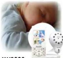
natural_image
Close-up of a baby wearing a white medical device with a circular display showing a photo (no visible text or symbols)LW2003
Backyard

natural_image
Outdoor security camera setup with outdoor umbrella, poolside table, and mounted sensors (no visible text or symbols)LW2201

- Wireless Digital Security Camera
- Instruction Manual
- CAUTION
- RISK OF ELECTRIC SHOCK DO NOT OPEN
- BEFORE YOU ST
- THIS PRODUCT MAY REQUIRE PROFESSIONAL INSTALLATION
- LOREX IS COMMITTED TO FULFILLING YOUR SECURITY NEEDS
- AVANT DE COMMENCER
- ANTES DE EMPEZAR
- CE PRODUIT POURRAIT EXIGER UNE INSTALLATION PROFESSIONNELLE LOREX S'ENGAGE À SATISFAIRE VOS BESOINS SÉCURITAIRES
- DO NOT RETURN THIS PRODUCT TO THE STORE
- Easy Ways to Contact Us:
- Online:
- By Email:
- By Phone:
- Necesita Ayuda
- COMUNÍQUESE PRIMERO
- CON NOSOTROS
- support@lorexcorp.com
- customerservice@lorexcorp.com
- Important Safeguards
- Installation
- Service
- Use
- General Precautions
- WARNING
- STRANGULATION HAZARD:
- TRANSMITTER FCC/IC NOTICE
- FCC Transmitter Notice
- IC Transmitter Notice
- RECEIVER FCC/IC NOTICE
- FCC Receiver Notice
- IC Receiver Notice
- Receiver Features
- Camera Features
- Table of Contents
- Getting Started 1
- Wireless Receiver & Camera 2
- Connecting The Camera.... 3
- Appendix A: System Specifications 9
- Appendix B: About Digital Wireless Technology 10
- Appendix C: Facts About Digital Wireless Cameras.... 11
- Appendix D: Troubleshooting 13
- Appendix E: Frequently Asked Questions 14
- Appendix F: Extending Wireless Range.... 15
- Getting Started
- Wireless Receiver & Camera
- Connecting The Camera
- Installation Warnings
- Camera Setup
- To install the camera:
- Wireless Receiver Setup
- To connect a wireless receiver to a surveillance recorder (DVR):
- To connect the wireless receiver to a TV or VCR:
- Installing Multiple Wireless Cameras
- Scenario A: Two Wireless Cameras
- Scenario B: Four Wireless Cameras
- Powering Multiple Receivers Using The Power Splitter Cable (LW2110PK2 only)
- To connect the power splitter cable to the receivers:
- On-Screen Display
- Pairing Cameras
- IMPORTANT
- To pair the camera to the receiver:
- Appendix A: System Specifications
- Appendix B: About Digital Wireless Technology
- Appendix C: Facts About Digital Wireless Cameras
- Wired VS Wireless Cameras
- Does a wireless camera require power?
- How far can a wireless camera transmit a video signal?
- Signal Reduction Through Materials
- Are Digital Wireless Camera Signals Secure?
- How many frames per second should I expect from a digital wireless camera?
- How many wireless cameras can I install?
- Appendix D: Troubleshooting
- Appendix E: Frequently Asked Questions
- Appendix F: Extending Wireless Range
- LOREX PRODUCT LIMITED WARRANTY
- 。
- PROTECT EVERYTHING THAT MATTERS
Brand : Lorex
Model : LW2110PK2B
Category : Surveillance Camera