
5 PIN 640 - Cooker FRANKE - Free user manual and instructions
Find the device manual for free 5 PIN 640 FRANKE in PDF.
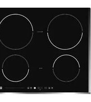


| Brand | Franke |
| Model | 5 PIN 640 |
| Product Type | Built-in Ceramic Glass Induction Hob |
| Available Models | FHBP 604 4I PW T XS, FHBP 803 3I T XS, FHFB 302 2I T, FHBP 603 3I T XS |
| Dimensions (mm) - FHBP 604 | 600 x 510 |
| Dimensions (mm) - FHBP 803 | 810 x 380 |
| Dimensions (mm) - FHFB 302 | 320 x 510 |
| Dimensions (mm) - FHBP 603 | 580 x 510 |
| Rated Voltage | 220-240 V~ or 380-415 V 2N~, 50/60 Hz |
| Power Supply Connection | Requires qualified technician; use H05RR-F or H07RN-F cable; circuit breaker with 3 mm contact gap |
| Number of Cooking Zones | 2, 3, or 4 induction zones depending on model |
| Total Power (kW) - FHBP 604 | 7.4 |
| Total Power (kW) - FHBP 803 | 6.7 |
| Total Power (kW) - FHFB 302 | 3.7 |
| Total Power (kW) - FHBP 603 | 6.7 |
| Control Type | Touch control electronic sensors |
| Power Levels | 9 levels plus extra powerful setting (P) and automatic (A) |
| Functions | Timer, child safety lock, remaining heat indicator, automatic pan recognition, safety switch-off, overheating protection |
| Installation Requirements | Worktop thickness 25-40 mm; cut-out dimensions vary by model; minimum distance to hood 700 mm; requires foam gasket |
| Cleaning | Use special ceramic-glass cleaners; avoid abrasive sponges; remove sugar spills immediately; use scraper for burnt residues |
| Compatible Cookware | Ferromagnetic cookware (steel, enamel, cast iron); minimum pan bottom diameter varies by zone |
| Weight (approx) | Not specified; estimated 8-12 kg depending on model |
Frequently Asked Questions - 5 PIN 640 FRANKE
User questions about 5 PIN 640 FRANKE
0 question about this device. Answer the ones you know or ask your own.
Ask a new question about this device
Download the instructions for your Cooker in PDF format for free! Find your manual 5 PIN 640 - FRANKE and take your electronic device back in hand. On this page are published all the documents necessary for the use of your device. 5 PIN 640 by FRANKE.
USER MANUAL 5 PIN 640 FRANKE
| FHBP 604 4I PW T XS | FHBP 803 3I T XS | FHFB 302 2I T | FHBP 603 3I T XS | |
| A | 600mm 810mm 320mm | 580mm | ||
| B | 510mm 380mm 510mm | 510mm | ||
| C | 560mm 790mm 307mm | 560mm | ||
| D | 490mm 360mm 497mm | 490mm | ||
| E | 50mm | 50mm | 50mm | 50mm |
| F | 10mm 10mm 10mm | 10mm | ||
| G | 50mm 50mm 50mm | 50mm | ||
| H | 5mm | 5mm | 5mm | 5mm |



CONNECTION OF THE HOB TO THE ELECTRICAL MAINS
FHFB 302 21 T
| LINEA | L | MARRONE |
| TERRA | 1/2 | GIALLO/VERDE |
| NEUTRO | N | BLU |
TECHNICAL CHARACTERISTICS
| Tipo | FHBP 604 4I PW T XS | FHBP 803 3I T XS |
| Dimensioni (mm) | 600x510 810x380 | |
| Tensione nominale | 220-240V~ o 380-415V 2N~, 50/60 Hz | |
| Tipo interruttori | Sensori elettronici | |
| Zone di cottura (∅, mm/kW) | ||
| Davanti a sinistra | 160 / 1,4 | 160 / 1,4 |
| Dietro a sinistra | 200 / 2,3 (P=3,0) | - |
| Centrale | - | 210 / 2,3 (P=3,0) |
| Dietro a destra | 200 / 2,3 (P=3,0) | - |
| Davanti a destra | 160 / 1,4 | 270 / 2,3 (P=3,0) |
| Potenza totale (kW) | 7,4 6,7 | |


Fig.1
Fig.2
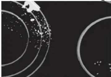
Fig.3
Fig.4
Fig.5
Touch Control Ceramic glass hob
OWNER'S MANUAL
MODEL
FHBP 604 4I PW T XS
FHBP 603 3I T XS
FHBP 803 3I T XS
FHFB 302 21 T
The Manufacturer strives for continuous improvements. For this reason, the text and illustrations in this book are subject to change without notice.
Dear customer!
The built-in ceramic-glass cooktop is intended for household use only. Materials used for packaging are nature friendly and may be recycled, deposited or destroyed without any threats to the environment. In order to recognize these features, all packing materials are marked with relevant symbols. Once your appliance has become obsolete and you do not intend to use it any longer, take adequate care not to litter the environment. Deposit your old appliance with the authorized depot dealing with used household appliances.
Instruction for use
Instructions for use have been prepared for the user, and describe the particulars and handling of the appliance. These instructions apply to different models from the same family of appliances, therefore you may find information and descriptions that may not apply to your particular appliance.
Installation instruction
The appliance should be connected to the power supply in accordance with the instructions from the chapter "Electrical connections" and in line with the standing regulations and standards. The connections should be carried out by a qualified personnel only.
Rating plate
The rating plate with basic information is located underneath the appliance.
Fire hazard protection
Appliances are allowed to be mounted on one side next to a high kitchen cabinet, the height of which may exceed that of the appliance. On the opposite side however, only a kitchen cabinet of equal height as the appliance is allowed.
Important warnings 20
Mounting the built-in cooktop 21
Connection to the power supply 22
Technical information 23
Hotplate function principle 24
Ceramic-glass cooktop 25
Hob control 26
Service menu/Manual configuration 29
Safety functions and error display 30
Cleaning and maintenance of ceramic-glass hob 31
TECHNICAL INSTRUCTIONS AND INSTALLATION
IMPORTANT WARNINGS
- The appliance may be built-in and connected to the power supply only by a qualified technician.
- Particular areas of the cooktop surface (adjacent to the hotplates) are hot during operation.
Prevent children from hanging around the appliance and warn them properly against the danger of burns.
- Hot oil ignites readily, so be sure to have the preparation of such food (fries) under constant control.
- Hotplates may not be left in operation empty, without any dishes on top.
- Never use the appliance for heating the ambience.
- Never use the ceramic-glass cooktop as a working surface. Sharp objects may damage the cooktop surface.
- Never place any metal objects upon the induction hotplate, such as knives, forks, spoons, pot lids, and the like, as they may get very hot.
- Preparation of food in aluminium or plastic cookware is not allowed. Never place any plastic objects or aluminium foil upon the cooktop surface.
- In case any other appliances are plugged in the electric mains close to the cooktop, prevent the contact of the plug cable with the hot cooking zones.
- Never keep any flammable or temperature sensitive objects, like cleaning agents, sprays, detergents, etc., below the appliance.
- Never use cracked or broken ceramic-glass cooktop. In case you notice any visible cracks on the surface, cut the power supply immediately.
- In case of any malfunctions, disconnect the appliance from the power supply and call service department.
- Do not use high-pressure steam cleaner or hot steam to clean the appliance.
- The appliance is manufactured in compliance with the relevant effective safety standards.
Nevertheless, we strongly recommend that persons with impaired physical, motorial, or mental capacity, or persons with inadequate experience or knowledge, do not use the appliance unless attended by a qualified person.
The same recommendation applies when the appliance is used by persons of less-than-legal age.
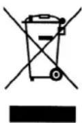
The symbol on the product or on its packaging indicates that this product may not be treated as household waste. Instead it shall be handed over to the applicable collection point for the recycling of electrical and electronic equipment. By ensuring this product is disposed of correctly, you will help prevent potential negative consequences for the environment and human health, which could otherwise be caused by inappropriate waste handling of this product. For more detailed information about recycling of this product, please contact your local city office, your household waste disposal service or the shop where you purchased the product.
MOUNTING THE BUILT-IN COOKTOP
Caution!
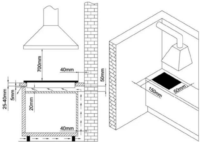
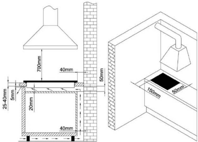
• To avoid any possible hazard, the appliance may be installed by qualified personnel only. - Panels and furniture lining of the kitchen cabinet receiving the hob must be treated with temperature resistant adhesives 100°C (otherwise they might be discoloured or deformed because of inadequate temperature resistance). - The cooking hob is intended for building into the worktop above the kitchen element of 600 mm width or more. • After the installation of built-in hob make sure that there is free access to the two fixing elements in front. - Suspended kitchen elements above the cooktop must be installed at such distance to provide enough room for comfortable working process. - The distance between the worktop and the hood must be at least such as indicated in the instructions for installation of the kitchen hood, but in no case it may be less than 700 mm. - The use of hard wood decorative borders around the worktop behind the appliance is allowed, in case the minimum distance remains as indicated on the installation illustrations. - Minimum distance between the built-in cooktop and rear wall is indicated at the illustration for the installation of the built-in cooktop.
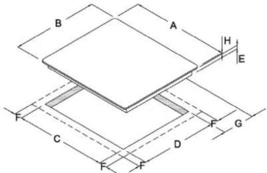
Built-in induction hob opening dimensions
| FHBP 604 4I PW T XS | FHBP 803 3I T XS | FHFB 302 2I T | FHBP 603 3I T XS | |
| A | 600mm 810mm 320mm | 580mm | ||
| B | 510mm 380mm 510mm | 510mm | ||
| C | 560mm 790mm 307mm | 560mm | ||
| D | 490mm 360mm 497mm | 490mm | ||
| E | 50mm | 50mm | 50mm | 50mm |
| F | 10mm 10mm 10mm 10mm | |||
| G | 50mm 50mm 50mm 50mm | |||
| H | 5mm | 5mm | 5mm | 5mm |


- Induction hob may be built into the 25 to 40 mm thick worktops.
- Bottom kitchen element must not have a drawer. It must be fitted with a horizontal plate 20 mm away from the worktop bottom surface. Space between the plate and the hob must be empty and no objects may be stored or kept there.
- Rear side of the kitchen element must also have a 50 mm high opening along the entire width of the element, and the front part must have an opening of no less than 5 mm.
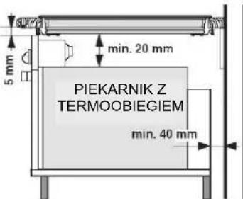
- Incorporation of the oven under the induction hob is permissible for ovens equipped with a cooling fan.
Installing the foam gasket

Installation procedure
Prior inserting the oven, it is necessary to remove the rear kitchen element panel in the area of the oven opening.
Equally, the front part of the element must have an opening of no less than 5 mm.
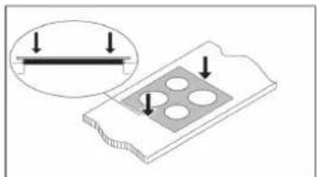
Before inserting the appliance into the opening in the kitchen worktop, the supplied foam gasket must be attached to the lower side of the glass ceramic (glass) cooking hob.
Do not install the appliance without the foam gasket!
The gasket should be attached to the appliance in the following way:
- Remove the protective film from the gasket.
- Then, attach the gasket to the lower side of the glass, approximately 2-3 millimetres from the edge.
- The gasket must be attached along the entire length of the glass edge and should not overlap at the corners.
- When installing the gasket, make sure that the glass does not come into contact with any sharp objects. The worktop must be placed absolutely horizontal.
- Suitably protect the edges of the cut aperture.
- Connect the cooking hob to the mains power supply (see instructions for the connection of the cooking hob to mains power supply).
- Insert the hob into the cut aperture.
- Press the hob firmly towards the worktop from above.


CONNECTION TO THE POWER SUPPLY
- Connections may be carried out by a qualified technician only. The earthing protection must comply with the standing regulations.
- Connection terminals are revealed when the connection box cover is removed.
- Prior to any attempted connection, check that the voltage indicated on the rating plate is in line with your home power supply.
- The rating plate is located underneath the appliance.
- The appliance is manufactured for use with the power supply voltage 220-240 V ~.
- The electric wiring should be equipped with a circuit breaker able to isolate the appliance from the mains in all points, with the distance between terminals of at least 3 mm in open position. This may be done by means of fuses, safety switches, etc.
- The connection should be selected in accordance with the declared charge capacity of the mains and the fuse power.
- Such appliances are allowed to be mounted on one side next to a high kitchen cabinet, the height of which may exceed that of the appliance. On the opposite side however, only a kitchen cabinet of equal height as the appliance is allowed.
- Upon the completion of installation, live wires and isolated cables must be adequately protected against accidental touching.
Basic adjustment of sensors to the ambience
Upon each connection to the power supply, the sensors of the appliance are automatically adjusted to the environment to ensure their proper function. All displays turn on and are fully illuminated for a few seconds.
During the adjustment procedure, the sensors must be free of any objects; otherwise, the adjustment procedure will be interrupted until such objects are removed from the sensor surface. During this period, the regulation of the cooktop is impossible.
Installation diagram

ATTENTION!
Before attempting any repairs on the appliance, disconnect the power supply. In accordance with the mains voltage, the appliance should be connected in line with the attached diagram.
The earthing wire (PE) must be connected to the terminal marked with the earthing symbol.
The connection cable must lead through the relief safety device, protecting it from accidental pulling out. Upon the completion of installation, switch all the hotplates on for about 3 minutes to check the proper functioning.
Connection may be carried out by means of:
- rubber coated connection cables, model H05RR-F with yellow-green earthing cable;
- rubber coated connection cables, model H07RN-F with yellow-green earthing cable.
FHBP 604 4I PW T XS - FHBP 803 3I T XS - FHBP 603 3I T XS
FHFB 302 21 T
TECNICAL INFORMATION
| Type | FHBP 604 4I PW T XS | FHBP 803 3I T XS |
| Width | 600x510 810x380 | |
| Rated voltage | 220-240 V~ or 380-415 V 2N~, 50/60 Hz | |
| Type of switch | Electronic sensors | |
| Cooking zones (∅, mm/W) | ||
| Forward left | 160 / 1.4 | 160 / 1.4 |
| Rear left | 200 / 2.3 (P=3.0) | - |
| Central | - | 210 / 2.3 (P=3.0) |
| Rear right | 200 / 2.3 (P=3.0) | - |
| Forward right | 160 / 1.4 | 270 / 2.3 (P=3.0) |
| Total power (W) | 7.4 6.7 | |
| Type | FHFB 302 2I T | FHBP 603 3I T XS |
| Width | 320x510 580x510 | |
| Rated voltage | 220-240V~ o 380-415V 2N~, 50/60 Hz | |
| Type of switch | Electronic sensors | |
| Cooking zones (∅, mm/W) | ||
| Forward left | 160 / 1.4 | 160 / 1.4 |
| Rear left | - | 200 / 2.3 (P=3.0) |
| Central | - | - |
| Rear right | - | - |
| Forward right | 200 / 2.3 (P=3.0) | 270 / 2.3 (P=3.0) |
| Total power (W) | 3.7 6.7 | |
P= EXTRA POWERFUL SETTING
Hotplate function principle
Appropriate cookware for induction hotplates

- The ceramic glass hob is fitted with three or four hotplates. The hob surface is completely flat and smooth, without edges to accumulate dirt.
- The hob is fitted with high power induction hotplates. Heat is generated directly at the bottom of the dish, where it is most needed, without any losses through the ceramic glass surface. This way the required extent of energy is considerably smaller compared to traditional heaters, which operate on radiation principle.
- The glass ceramic hotplate is not heated directly, but only by return heat transmitted by the dish. This heat figures as “remaining heat” after the hotplate is turned off. The induction hotplate generates heat from the induction coil, installed underneath the ceramic glass surface. The coil creates a magnetic field at the bottom of the dish (which can be magnetized) which in turn originates whirling flows of current which then heat the hotplate.
IMPORTANT!
In case sugar or other heavily sweetened substance is spilled on the hotplate, wipe it immediately and remove the sugar residues with a scraper although the cooking zone is still hot, otherwise the hotplate may be damaged.
Avoid cleaning the cooktop while the cooking zones are still hot, as you may damage the hob.
- Induction hotplate will function perfectly only if appropriate cookware is used.
- Dish should be in the middle of the hotplate during cooking.
- The appropriate cookware is the one which enables induction, for example steel, enamel or steel alloy cookware. Pots made from steel alloy with copper or aluminium bottom, or glass pots are inappropriate.
- If you use the pressure cooker (“economy pot”) keep it under close surveillance until proper pressure is obtained. Hotplate should first operate on maximum power, then follow the manufacturer’s instructions and use the appropriate sensor to decrease the power.
- When buying cookware, check if it bears the label "allows induction".
| Cooking zones Min. pan bottom ∅ Max. pan bottom ∅ | ||
| ∅ 160 mm ∅ 110 mm ∅ 160 mm | ||
| ∅ 200-210 mm ∅ | 150 mm ∅ 200-210 mm | |
| ∅ 250-270 mm ∅ | 180 mm ∅ 250-270 mm | |
Magnet test
Use a small magnet to test if the dish bottom is magnetic. Only dishes where the magnet sticks to the bottom are suitable for induction cooking.
Dish recognition
One of the great advantages of the induction hotplate is dish recognition. Even if there are no dishes upon the hotplate, or the dish diameter is smaller than the diameter of the relevant hotplate, there are no thermal energy losses. When the hotplate is on, the power indicator displays the letter "U". If you place a dish over that hotplate within the following 10 minutes, the hotplate recognizes the dish and turns on to the preset power value.
At the moment you remove the dish from the hotplate, power is suspended. If you place a smaller dish upon the hotplate and it is recognized, the hotplate will only use the amount of energy required to heat the dish according to its size.
The hotplate may be damaged if:
- it is turned on and left empty, or an empty dish is placed on it;
- you use clay dishes which leave scratches on the ceramic glass surface;
- you fail to wipe the dish bottom dry prior to placing it on the ceramic glass hotplate; heat induction is obstructed and the hotplate may be damaged;
- you fail to use the appropriate dishes that can be magnetized: steel dishes, enamel or steel alloy dishes; the induction hotplate will not function otherwise.
Power regulation
Heating power of the hotplates may be set at nine different levels. The following chart indicates illustrative use of each power setting.
| Power Setting | Purpose |
| 0 | Off, using remaining heat |
| 1-2 | Maintaining warm food, slow simmer of smaller quantities |
| 3 | Slow simmer (continuation of cooking after a powerful start-up) |
| 4-5 | Slow cooking (continuation) of larger quantities, roasting larger chunks |
| 6 | Roasting, browning |
| 7-8 | Roasting |
| 9 | Start of cooking, roasting |
| A | Automatic initial setting |
| P | Especially powerful setting for extremely large quantities of food |
ENERGY SAVING TIPS
- When buying cookware, be careful in selecting size: pot diameter usually refers to the top edge of the dish, which is often larger than the dish bottom.
- Steam-pressure pots (economic pots), which use pressure in a tightly sealed interior, are especially economic, and save both time and energy. Shorter cooking time leaves more vitamins in food.
- Always leave enough water in steam-pressure pots, otherwise it may result in overheating which may damage both the pot and the hotplate. Always cover the cookware with lids of appropriate size.
- Use a dish size that matches the quantity of food to be prepared. If you use an excessively large pot for a small amount of food, you will consume considerably more energy.
CERAMIC-GLASS COOKTOP

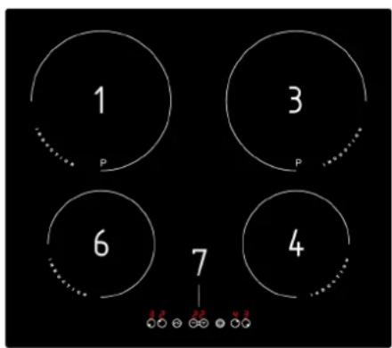


- Induction hotplate rear left
- Induction hotplate rear right
- Induction hotplate front right
- Induction hotplate central
- Induction hotplate front left
- Hob control panel
Hob control elements

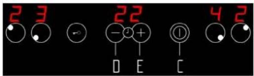
A. ON/OFF sensor of cooking zones B. Safety lock on/off and child lock sensor C. ON/OFF sensor of cooktop D. Sensor (-) of timer and cooking zone E. Sensor (+) of timer and cooking zone
Hob control
• After turning the ceramic glass hob on, all displays come on for a moment. The hob is ready for operation. - The hob is fitted with electronic sensors which are switched on if you touch the relevant circle for at least one second. • Each sensor activation is followed by a sound signal. - Avoid placing any objects on the sensor surface (possible error signalization Er03). • Always keep the sensor surface clean.
Activating the hob
Touch the ON/OFF sensor (C) for at least one second. The hob is now active, and all hotplate power indicators indicate »0«, decimal dot is flashing.

Now you need to select the next setting within 20 seconds, otherwise the hob switches off again.
Turning hotplates on
After turning the hob on using the ON/OFF sensor (C), within the next 20 seconds start one of the hotplates.
- Touch the desired hotplate sensor (A); its relevant power indicator shows "0".
- By touching sensors "+" (E) or "-" (D), set the desired cooking power from 1 to 9.

Continuously pressing the "+" (E) or "-" (D) sensors automatically increases or reduces the power level. Another way to change power in steps is by touching the relevant sensors intermittently.
Setting is always possible for one hotplate at a time. The power display shows "0" or "H", depending on the existing temperature of the hotplate (see Section Remaining Heat Indicator).
Switching hotplates off
You can also turn the hotplate off before the end of cooking and use the remaining heat, saving energy.
- The selected hotplate must be activated.
- Touch the hotplate sensor "-" (D) to set the power level to "0". After 10 seconds the hotplate is turned off.
Fast deactivation
- The selected hotplate must be activated.
- Press both (A of the selected hotplate) and (D) sensors simultaneously, and the hotplate is immediately switched off.

Switching the hob off
Locking the control unit / child safety lock
- The hob can be switched off any time by pressing the ON/OFF sensor (C).
By activating the child lock protection you can stop the operation of the appliance, i.e. the use of hotplates, protecting the children from accidental start and eventual injury.
Activating child lock
• The hob is active. - Press sensor (B) for at least 2 seconds. Timer's display shows the symbol (Γ0) steady. Child lock is now activated. - If hob is turned off by mistake, lock function is active still the next turn on.
Remaining heat indicator
Turning child lock off
- If the hob is switched off, turn the hob on by pressing the sensor (C). Timer's display shows the symbol (Γ0).
- Press sensor (B) for at least 2 seconds. Child lock is now off.
Glass ceramic hob also features remaining heat indicator "H". Hotplates are not heated directly, but through return heat radiating from the dish. As long as the symbol "H" is on after the hotplate was switched off, the remaining heat may be used for warming up food or for melting.
Even when the symbol "H" disappears, the hotplate may still be hot. Be careful of burns!
Extra powerful setting (hotplates marked "P")
Extra powerful setting may be additionally switched on for fast cooking on predisposed hotplates. This extra hotplate power is used for heating large quantities of food. After switching on, the extra power is activated for:
- 5 minutes, then automatically switches back on to the maximum normal level 9. During the time extra power is activated, the power of other hotplates is limited. This is indicated on the power display by intermittently flashing the selected cooking level and limited power for a few seconds.
Activating extra powerful setting
- First select the hotplate by touching its relevant sensor (A), and immediately after press the sensor (D) then press (E). Extra powerful setting is on, and power indicator displays symbol "P".
Premature turning off of extra powerful setting
Touch the desired hotplate sensor, and immediately after press the sensor »-« (D). Letter "P" disappears and the hotplate automatically switches to level 9.

Safety switch off
Maximum continuous operation of a particular hotplate is limited, and the duration is displayed in the above chart. When the hotplate is switched off by the safety mechanism, the indicator displays symbols "0", or "H" in case there is any remaining heat left.
In such cases switch the hotplate off by touching the relevant power setting sensor (D).
| Power setting 1 2 3 4 | 5 | 6 7 | 8 9 | ||||||
| Hours lapse prior safety switch off | 8 | 6 | 5 | 5 | 4 | 1.5 | 1.5 | 1.5 | 1.5 |
Example:
Set the hotplate to power level 5 and leave it operate for some time. If you do not change the above setting, the safety mechanism will switch the hotplate off after 4 hours.
Protection from overheating
Induction hotplate is also fitted with safety device against overheating which protects electronic parts from damages. This device operates on several levels. When temperature of the hotplate excessively rises, it switches on two-stage fan. If this is not enough, extra powerful heating is deactivated, and finally the safety device either reduces the heating power of certain hotplates or turns them off completely. When the hotplate cools off, the full power of hotplate is again available.
Timer
Timer facilitates the cooking procedure by setting the period of hotplate operation, and it can also be used as alarm timer.
Activating the timer
- Touch the hotplate ON/OFF sensor (A) of the relevant hotplate.
- By touching the »+« or »-« (E or D) sensor select the power setting from 1 to 9.
- Touch the timer ON/OFF sensors (D+E) to activate timer. Timer display indicates »00«.
- By touching sensors »+« or »-« (E or D) set the desired cooking time (from 01 to 99 minutes). After a few seconds the timer starts operating. The timer-controlled hotplate control lamp is on and blinking.

You can use the timer to set the exact cooking time for each hotplate at the same time. To speed up the timer setting, keep the relevant sensors »+« or »-« (E or D) constantly pressed.
Altering preset cooking time
- You can change the preset cooking time whenever you wish during the hotplate operation.
- Touch the hotplate ON/OFF sensor (A) to select the desired hotplate. The decimal dot is on.
- Touch the timer ON/OFF sensors (E+D) to activate the timer.
- By touching sensors »+« or »-« (E or D) set the new desired cooking time.
Remaining cooking time
You can display the remaining cooking time by touching the hotplate ON/OFF sensor (A) and then (E+D), or by activating (D+E) keys at the same time again and again. The time shown refers to the zone that displays the blinking dot.
The shorter residual time will always be shown on the timer's display:
- If the time is relative to a cooking zone, the decimal point will flash on its display.
- If the time is relative to the "alarm timer", there is no decimal point flashing.
Switching the timer off
When the preset time expires, a beep is heard which you can either turn off by touching any sensor or leave it to turn off automatically after 2 minutes. When the programmed time finishes, the cooking zone also turns off.
Switching the timer off before the preset time expires:
- Touch the hotplate ON/OFF sensor (A) to select the desired hotplate. The decimal dot is on.
- Touch the timer ON/OFF sensors (E+D).
- By touching the sensor »-« (D), set the cooking time to »00«. The timer function is off, but the hotplate continues to operate until you switch it off manually.
Alarm timer function

The timer can also be used as an alarm even if it is already employed in timer control of one of the hotplates. (The hob does not turn off.)
Timer setting
With the hob off:
- Touch the hob ON/OFF sensor (C) to activate the cooking hob.
- Touch the timer ON/OFF sensor (E+D) to activate the timer.
- By touching sensors »+« (E) or »-« (D), set the desired time.
Switching the alarm off
When the preset time expires, a beep is heard which you can either turn off by touching any sensor or leave it to turn off automatically after 2 minutes.
If you want to switch the timer off prior to expiry of the preset time:
With the hob off:
- Touch the hob ON/OFF sensor (C) to activate the cooking hob.
- Touch the timer ON/OFF sensor (E+D).
- By touching the sensor »-« (D) set cooking time to »00«. Alarm function is off.
Simultaneously touch both »+« and »-« (E+D) sensors and switch the timer off.
- During the time the alarm is activated, timer can be preset for any hotplate.
Service menu/ Manual configuration
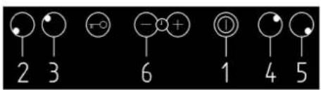
Prerequisites for configuration/deleting (configuration)
- All pans must be removed from cooking zones and one suitable for induction must be available. The size of this pan should be at least 80% of the largest inductor diameter to be configured (e.g. inductor ∅200mm→pot size>∅160mm)
- It's possible starting configuration/deleting within 2 minutes after connection to power mains. Touch control and all displays must be turned off.
Getting in configuration/deleting menu'
- Hold the minus key (6) pressed.
- Press all keys of cooking zones' selection anticlockwise, starting off with the first right one (5-4-3-2).
■ For 4 zones version the sequence is: (5-4-3-2)
■ For 3 zonesversion the sequence is: (4-4-3-2)
■ For 2 zones version the sequence is: (4-4-3-3)
• Every action is acknowledged by a signal tone:
# Only one "beep" → correct selection
# Double "beep" → wrong selection
- After the last action all induction displays turn on, where it's displayed:
"-" → it means configured zone
# "C" → it means NOT configured zone
Procedure of deleting configuration
After getting in configuration/deleting menu:
- Hold the minus key (6) pressed: "E" is displayed on the displays of all cooking zones. "E" keeps flashing until all cooking zones will be not configured.
- "C" will be displayed on all displays.
Procedure of configuration
After getting in configuration/deleting menu and completing deleting configuration:
(During configuration phase all displays of cooking zones display "C")
- Cooking zone to be configured can be selected by cooking zone's selection key.
- "C" will start flashing on the corresponding display.
- Within 20 seconds a pan must be placed on the corresponding zone in the way that the cooking zone can detect the correct position.
If within 20 seconds the cooking zone detects a pan, the symbol “-” will appear (cooking zone is correctly configured);
If after 20 seconds the cooking zone does not detect a pan, the letter "C" will appear; try the configuration procedure again from the first point.
This procedure must be applied to every cooking zone.
Configuration menu stops:
• Automatically after the configuration of all cooking zones.
- Manually by pressing the ON/OFF key (1), if you want to configure only certain cooking zones.
- If no key is pressed, the menu ends within 2 minutes.
At the end of it, it is advisable to test the hob to verify that the configuration is successful.
Safety functions and error display
| ERROR CODE | ERROR DESCRIPTION | INSTRUCTION MANUAL |
| C | The cooking zone can be configured if a static “C” is shown. | It's not an error, the user is in the service menu. A suitable pan must be placed on the relevant cooking zone. |
| C/- | The cooking zone will be configured if a blinking “C” is shown. After a successful configuration the relevant display shows “-”. When the “-” is not displayed please check the possible causes of the E/5. | It's not an error, the user is in the service menu. Wait for the symbol “-” or abort the configuration activities by pressing the select key and the“C” does not blink anymore. |
| E | A blinking “E” on each cooking zone indicates that all configs will be deleted. | It's not an error, the user is in the service menu. Manual configuration. |
| E2 | Temperature limits are excessed. Pot or glass temperature is too high. | System must cool down. If the problem persist, contact authorized center for technical assistance - specifying the error code. |
| E3 | Unsuitable pot, e.g. lost of the magnetic characteristics because of temperature in the bottom. Pot creates on the modul an improper operating point which can destroy devices. | The error is automatically cancelled after 8sec and the coking zone can be used again. In case of further upcoming errors the pot have to be changed. If the error comes without a pot on the cooking zone, contact authorized center for technical assistance - specifying the error code. |
| E4 | Unconfigured induction modul. (all induction modul answer to User Interface, but any element is related to the effected cooking zone). | Delete the hob configuration and activate the manual configuration. Start the User Interface service menu to configure the induction modul. If the problem persist, contact authorized center for technical assistance - specifying the error code. |
| E5 | No communication between User Interface and induction modul. No power supply of induction modul. Mal labeling. | Check power and lin connections if are ok. If the problem persist, contact authorized center for technical assistance - specifying the error code. |
| E6 | Main power disturbance. Failure in main power frequency detection. Over voltage. | Check main power voltage and frequency if are ok. If the problem persist, contact authorized center for technical assistance - specifying the error code. |
| E7 | Non assignable failure. | Contact authorized center for technical assistance - specifying the error code. |
| E8 | Fan failure, fan or control electronic is defect. | Contact authorized center for technical assistance - specifying the error code. |
| E9 | Defect T sensor on inductor. Sensor signal out of valid range; sensor or electronic is defect. | Contact authorized center for technical assistance - specifying the error code. |
| EA | Hardware defect of induction modul. Defect hardware device detected by the self check of the modul. | Contact authorized center for technical assistance - specifying the error code. |
| E/C | Configuration failure. 2 cooking zones are dedicated to the same element of the User Interface. | Erase the actual configuration. Manual configuration with service menu. |
| EH | Fixed sensor value (test function for T sensor on inductor). Not enough temperature change (10 K) within 5 min after switch the hob. | System must cool down. If the problem persist, contact authorized center for technical assistance - specifying the error code. |
| No Functionality and no displaying | Overvoltage on the switch mode power supply (no functionality). | Disconnect and correct the power connection. If the problem persist, contact authorized center for technical assistance - specifying the error code. |

Fig.1
Fig.2

Fig.3
Fig.4

Fig.5
Ceramic glass hob should be cleaned only when completely cooled down, preferably after each use, otherwise even the slightest stains remaining after cooking may burn into the hob surface with each following use.
For regular maintenance of ceramic-glass hobs, use special cleaning agents designed to create a protective film on the surface.
Before each use, wipe off dust and other particles from the hob, as they may scratch the surface (Fig. 1).
Caution: Using steel wool, abrasive cleaning sponges, and abrasive detergents can scratch the hob's surface. The surface may also be damaged by aggressive sprays and inappropriate liquid chemicals (Fig. 1 and 2).
Pattern marks can be erased by using aggressive cleaning agents or rough and damaged cookware bottoms (Fig. 2).
Minor stains can be removed with a moist soft cloth; after that, the surface should be wiped dry (Fig. 3).
Water stains can be removed with a gentle vinegar solution, but you must not wipe the frame with it (certain models only), as it may lose its shine. Never use aggressive sprays or limestone removers (Fig. 3).
Major stains can be removed with special ceramic-glass cleaners. Follow the manufacturer's instructions strictly.
Be careful to remove any residue of cleaning agents from the hob surface; otherwise, they will be heated during the next use and can damage the hob (Fig. 3).
Stubborn and burnt stains can be removed with a special ceramic-glass scraper. Be careful, however, not to touch the hotplate surface with the scraper handle (Fig. 4).
Handle the scraper with utmost care to avoid injuries!
Sugar and sugar-containing food may permanently damage the ceramic-glass hob surface (Fig. 5), so the remains of sugar and sugar-containing food must be scraped off the hob surface immediately, while the hotplates are still hot (Fig. 4).
Discoloration of the ceramic-glass hob has no effect whatsoever on its operation and stability. In most cases, it appears as a consequence of burnt-in food remains, or as a result of dragging pots and pans (especially those with aluminium or copper bottoms) across the surface, and such discoloration is rather hard to remove.
Note: All described faults are mostly aesthetic and do not directly affect the operation of the appliance. Remedy of such faults is not covered by warranty.
| FHBP 604 4I PW T XS | FHBP 803 3I T XS | FHFB 302 2I T | FHBP 603 3I T XS | |
| A | 600mm | 810mm | 320mm | |
| B | 510mm 380mm 510mm | 510mm | ||
| C | 560mm 790mm 307mm | 560mm | ||
| D | 490mm 360mm 497mm | 490mm | ||
| E | 50mm | 50mm | 50mm | |
| F | 10mm 10mm 10mm | 10mm | ||
| G | 50mm 50mm | 50mm | 50mm | |
| H | 5mm | 5mm | 5mm | 5mm |


FHFB 302 21 T
Fig. 1
Fig. 2

Fig. 3

Fig. 4
Fig. 5
| FHBP 604 4I PW T XS | FHBP 803 3I T XS | FHFB 302 2I T | FHBP 603 3I T XS | |
| A | 600mm | 810mm | 320mm | 580mm |
| B | 510mm 380mm 510mm | 510mm | ||
| C | 560mm 790mm 307mm | 560mm | ||
| D | 490mm 360mm 497mm | 490mm | ||
| E | 50mm | 50mm | 50mm | 50mm |
| F | 10mm 10mm 10mm | 10mm | ||
| G | 50mm 50mm 50mm | 50mm | ||
| H | 5mm | 5mm | 5mm | 5mm |



FHFB 302 21 T


Fig. 1
Fig. 2

Fig. 3

Fig. 4

Fig. 5
| FHBP 604 4I PW T XS | FHBP 803 3I T XS | FHFB 302 2I T | FHBP 603 3I T XS | |
| A | 600mm | 810mm | 320mm | 580mm |
| B | 510mm 380mm 510mm | 510mm | ||
| C | 560mm 790mm 307mm | 560mm | ||
| D | 490mm 360mm 497mm | 490mm | ||
| E | 50mm | 50mm | 50mm | 50mm |
| F | 10mm 10mm 10mm | 10mm | ||
| G | 50mm 50mm 50mm | 50mm | ||
| H | 5mm | 5mm | 5mm | 5mm |


CONNECTION OF THE HOB TO THE ELECTRICAL SUPPLY
FHFB 302 21 T
![graph LR A["SIEĆ ELEKTRYCZNA"] --> B["LINIA"] A --> C["UZIEMIENIE"] A --> D["ZEROWY"] B --> E["L"] C --> F["↓"] D --> G["N"] H["BRAZOWY"] --> I["ŻÓŁTY / ZIELONY"] J["NIEBIESKI"] --> K["PRZEWÓD ZASILAJĄ CY"]](/content/2026/05/858688/images/d711069e9c866d8ed292bae343707f769f92bc8f28ad7185b58873c29b46f6ce.jpg)
TECHNICAL DATA
Fig. 1
Fig. 2
Fig. 3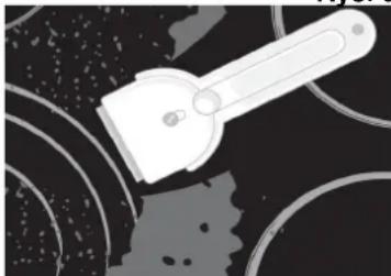
Fig. 4
Fig. 5
- CONNECTION OF THE HOB TO THE ELECTRICAL MAINS
- TOUCH CONTROL CERAMIC GLASS HOB
- OWNER'S MANUAL
- DEAR CUSTOMER
- INSTRUCTION FOR USE
- INSTALLATION INSTRUCTION
- RATING PLATE
- FIRE HAZARD PROTECTION
- TECHNICAL INSTRUCTIONS AND INSTALLATION
- IMPORTANT WARNINGS
- MOUNTING THE BUILT-IN COOKTOP
- CAUTION
- BUILT-IN INDUCTION HOB OPENING DIMENSIONS
- INSTALLING THE FOAM GASKET
- INSTALLATION PROCEDURE
- THE GASKET SHOULD BE ATTACHED TO THE APPLIANCE IN THE FOLLOWING WAY
- CONNECTION TO THE POWER SUPPLY
- BASIC ADJUSTMENT OF SENSORS TO THE AMBIENCE
- ATTENTION
- HOTPLATE FUNCTION PRINCIPLE
- APPROPRIATE COOKWARE FOR INDUCTION HOTPLATES
- IMPORTANT
- MAGNET TEST
- DISH RECOGNITION
- THE HOTPLATE MAY BE DAMAGED IF
- POWER REGULATION
- ENERGY SAVING TIPS
- CERAMIC-GLASS COOKTOP
- HOB CONTROL ELEMENTS
- HOB CONTROL
- ACTIVATING THE HOB
- TURNING HOTPLATES ON
- SWITCHING HOTPLATES OFF
- FAST DEACTIVATION
- SWITCHING THE HOB OFF
- LOCKING THE CONTROL UNIT / CHILD SAFETY LOCK
- ACTIVATING CHILD LOCK
- REMAINING HEAT INDICATOR
- TURNING CHILD LOCK OFF
- EXTRA POWERFUL SETTING (HOTPLATES MARKED "P")
- ACTIVATING EXTRA POWERFUL SETTING
- PREMATURE TURNING OFF OF EXTRA POWERFUL SETTING
- SAFETY SWITCH OFF
- EXAMPLE
- PROTECTION FROM OVERHEATING
- TIMER
- ACTIVATING THE TIMER
- ALTERING PRESET COOKING TIME
- REMAINING COOKING TIME
- SWITCHING THE TIMER OFF
- ALARM TIMER FUNCTION
- TIMER SETTING
- SWITCHING THE ALARM OFF
- SERVICE MENU/ MANUAL CONFIGURATION
- PREREQUISITES FOR CONFIGURATION/DELETING (CONFIGURATION)
- GETTING IN CONFIGURATION/DELETING MENU
- → IT MEANS CONFIGURED ZONE
- PROCEDURE OF DELETING CONFIGURATION
- PROCEDURE OF CONFIGURATION
- CONFIGURATION MENU STOPS
- CONNECTION OF THE HOB TO THE ELECTRICAL SUPPLY
Brand : FRANKE
Model : 5 PIN 640
Category : Cooker