VSX-1014 - AV receiver PIONEER - Free user manual and instructions
Find the device manual for free VSX-1014 PIONEER in PDF.

| Product Type | AV Receiver |
| Brand | Pioneer |
| Model | VSX-1014 |
| Dimensions (W x H x D) | 17.3 x 6.9 x 16.1 inches |
| Weight | 28 lbs (12.7 kg) |
| Power Supply | 120V, 60Hz |
| Power Consumption | 650W (Standby: 0.5W) |
| Audio Formats Supported | Dolby Digital, DTS, Dolby Pro Logic II |
| Number of Channels | 7.1 |
| Amplifier Output | 100W per channel (8 ohms, 20Hz-20kHz, 0.08% THD) |
| Inputs | Composite, S-Video, Component, Optical, Coaxial, Analog Audio |
| Outputs | Speaker terminals, Subwoofer pre-out, Headphone, Composite monitor |
| Video Processing | 1080i upscaling via HDMI (HDMI not confirmed; likely component) |
| Tuner | FM/AM with 30 presets |
| Remote Control | Included (batteries: 2x AA) |
| Additional Features | Auto MCACC calibration, Multi-zone support, Sleep timer |
| Care Instructions | Wipe with a soft, dry cloth; avoid solvents |
| Safety Notes | Do not expose to moisture or heat sources; unplug during storms |
| Spare Parts | Contact Pioneer support or authorized service centers |
| Repair Service | Refer to user manual for troubleshooting; professional repair recommended |
Frequently Asked Questions - VSX-1014 PIONEER
User questions about VSX-1014 PIONEER
0 question about this device. Answer the ones you know or ask your own.
Ask a new question about this device
Download the instructions for your AV receiver in PDF format for free! Find your manual VSX-1014 - PIONEER and take your electronic device back in hand. On this page are published all the documents necessary for the use of your device. VSX-1014 by PIONEER.
USER MANUAL VSX-1014 PIONEER
The lightning flash with arrowhead symbol, within an equilateral triangle, is intended to alert the user to the presence of uninsulated "dangerous voltage" within the product's enclosure that may be of sufficient magnitude to constitute a risk of electric shock to persons.
CAUTION
RISK OF ELECTRIC SHOCK DO NOT OPEN
CAUTION:
TO PREVENT THE RISK OF ELECTRIC SHOCK, DO NOT REMOVE COVER (OR BACK). NO USER-SERVICEABLE PARTS INSIDE. REFER SERVICING TO QUALIFIED SERVICE PERSONNEL.

The exclamation point within an equilateral triangle is intended to alert the user to the presence of important operating and maintenance (servicing) instructions in the literature accompanying the appliance.
D3-4-2-1-1 En-A
Thank you for buying this Pioneer product. Please read through these operating instructions so you will know how to operate your model properly. After you have finished reading the instructions, put them away in a safe place for future reference.
WARNING
Before plugging in for the first time, read the following section carefully.
The voltage of the available power supply differs according to country or region. Be sure that the power supply voltage of the area where this unit will be used meets the required voltage (e.g., 230V or 120V) written on the rear panel. D3-4-2-1-4_A_En
WARNING
To prevent a fire hazard, do not place any naked flame sources (such as a lighted candle) on the equipment. D3-4-2-1-7a_A_En
WARNING
This equipment is not waterproof. To prevent a fire or shock hazard, do not place any container filled with liquid near this equipment (such as a vase or flower pot) or expose it to dripping, splashing, rain or moisture. D3-4-2-1-3_A_En
VENTILATION CAUTION
When installing this unit, make sure to leave space around the unit for ventilation to improve heat radiation (at least 60 cm at top, 10 cm at rear, and 30 cm at each side).
WARNING
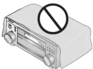
Slots and openings in the cabinet are provided for ventilation to ensure reliable operation of the product, and to protect it from overheating. To prevent fire hazard, the openings should never be blocked or covered with items (such as newspapers, table-cloths, curtains) or by operating the equipment on thick carpet or a bed. D3-4-2-1-7b_A_En
natural_image
Illustration of a portable radio with a prohibition symbol (no text or labels)Operating Environment
Operating environment temperature and humidity: +5 °C – +35 °C (+41 °F – +95 °F); less than 85 %RH (cooling vents not blocked) Do not install this unit in a poorly ventilated area, or in locations exposed to high humidity or direct sunlight (or strong artificial light) D3-4-2-1-7c_A_En
When disposing of used batteries, please comply with governmental regulations or environmental public instruction's rules that apply in your country/area. D3-4-2-3-1_En
NOTE: This equipment has been tested and found to comply with the limits for a Class B digital device, pursuant to Part 15 of the FCC Rules. These limits are designed to provide reasonable protection against harmful interference in a residential installation. This equipment generates, uses, and can radiate radio frequency energy and, if not installed and used in accordance with the instructions, may cause harmful interference to radio communications. However, there is no guarantee that interference will not occur in a particular installation. If this equipment does cause harmful interference to radio or television reception, which can be determined by turning the equipment off and on, the user is encouraged to try to correct the interference by one or more of the following measures:
– Reorient or relocate the receiving antenna.
– Increase the separation between the equipment and receiver.
- Connect the equipment into an outlet on a circuit different from that to which the receiver is connected.
- Consult the dealer or an experienced radio/TV technician for help.
D8-10-1-2_En
Information to User
Alteration or modifications carried out without appropriate authorization may invalidate the user's right to operate the equipment. D8-10-2
D8-10-2_En
CAUTION: This product satisfies FCC regulations when shielded cables and connectors are used to connect the unit to other equipment. To prevent electromagnetic interference with electric appliances such as radios and televisions, use shielded cables and connectors for connections. D8-10-3
D8-10-3a_En
If the AC plug of this unit does not match the AC outlet you want to use, the plug must be removed and appropriate one fitted. Replacement and mounting of an AC plug on the power supply cord of this unit should be performed only by qualified service personnel. If connected to an AC outlet, the cut-off plug can cause severe electrical shock. Make sure it is properly disposed of after removal. The equipment should be disconnected by removing the mains plug from the wall socket when left unused for a long period of time (for example, when on vacation).
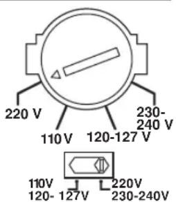
Voltage selector
You can find the voltage selector switch on the rear panel of multi-voltage models.
The factory setting for the voltage selector is 220V. Please set it to the correct voltage for your country or region.
• Saudi Arabia operates on 127V and 220V mains
voltage. Please set to the correct voltage before using.
- For Taiwan, please set to 110V before using.
- For Mexico, please set to 120-127V before using.
Before changing the voltage, disconnect the AC power cord. Use a medium size screwdriver to change the voltage selector switch.
TWO VOLTAGE SELECTORS
text_image
220 V 110 V 120-127 V 230- 240 V 110V 120-127V 220V 230-240VCAUTION
The ⬆STANDBY/ON switch on this unit will not completely shut off all power from the AC outlet. Since the power cord serves as the main disconnect device for the unit, you will need to unplug it from the AC outlet to shut down all power. Therefore, make sure the unit has been installed so that the power cord can be easily unplugged from the AC outlet in case of an accident. To avoid fire hazard, the power cord should also be unplugged from the AC outlet when left unused for a long period of time (for example, when on vacation).
This product is for general household purposes. Any failure due to use for other than household purposes (such as long-term use for business purposes in a restaurant or use in a car or ship) and which requires repair will be charged for even during the warranty period. K041_En
Contents
01 Before you start
Features 6
Checking what's in the box....6
Installing the receiver 7
Using the remote control 7
Loading the batteries 7
Operating range of remote control unit ..... 7
02 5 minute guide
Introduction to home theater 8
Listening to Surround Sound 8
Automatically setting up for surround sound
(MCACC)....11
Other problems when using the Auto MCACC Setup 13
Checking the settings on your DVD (or other) player....13
Playing a source....13
03 Connecting up
About cable types 14
Analog audio cables 14
Digital audio cables 14
Video cables....14
When making cable connections ..... 15
About the RS-232C connector 15
About the video converter 15
Connecting digital audio components. 16
Connecting analog audio components ..... 17
Connecting multichannel analog components ..... 17
Connecting video components....18
Connecting to the front panel video terminal.....18
Connecting antennas 19
FM wire antenna....19
AM loop antenna....19
Using an external antenna to improve FM reception 19
Connecting the speakers 21
Speaker terminals 22
Hints on speaker placement 22
AC power cord 23
Operating other Pioneer components ..... 23
04 Controls and displays
Front panel 24
Display 26
Remote control....27
05 Listening to your system
Auto playback 30
Listening in surround sound 30
Standard surround sound 30
Using the Home THX modes.... 31
Using the Advanced surround effects ..... 31
Dolby Pro Logic IIx Music settings 32
Neo:6 Music settings 32
Listening in stereo.... 32
Listening with Acoustic Calibration EQ 33
Choosing the input signal 33
Using the surround back channel (Extended mode) 34
Using the Virtual Surround Back mode (VirtualSB) 35
Using Loudness and Midnight listening.... 36
Enhancing dialog 36
Using the tone controls 36
Playing other sources.... 37
Selecting the multichannel analog inputs ..... 37
Using the sleep timer 37
06 The System Setup menu
Making receiver settings from the System Setup menu 38
Surround back speaker setting 38
Manual MCACC speaker setup 39
Fine Channel Level 40
Fine Channel Distance.... 40
Acoustic Calibration EQ. 41
Manual speaker setup 43
Speaker Setting 44
Crossover Network 45
Channel Level 45
Speaker Distance 46
07 Using the tuner
Listening to the radio 47
Improving FM stereo sound.... 47
Tuning directly to a station 47
Saving station presets 48
Naming station presets 48
Listening to station presets 48
08 Making recordings
Making an audio or a video recording 49
09 Controlling the rest of your system
Setting the remote to control other components .... 50
Selecting preset codes directly 50
Programming signals from other remote controls. . . 51
Erasing one of the remote control button settings. . . 52
Erasing all of the remote control presets ..... 52
Direct function 52
Confirming preset codes....52
Controls for TVs 53
Controls for other components 54
10 Other connections
Second Zone speaker B setup....55
Switching the speaker system ..... 55
Bi-amping your front speakers 56
Bi-wiring your speakers....56
Connecting additional amplifiers....57
Multi-room listening 57
Making multi-room connections ..... 57
Using the sub room controls 58
Using the i.LINK interface....59
About i.LINK....60
About PQLS rate control 60
Creating an i.LINK network 60
Switching components on and off using the
12 volt trigger 61
Using this receiver with a Pioneer plasma display. . . 61
Using the SR+ mode with a Pioneer plasma
display....62
11 Other Settings
The Input Assign menu 63
The Other Setup menu 65
Dynamic Range Control Setup 66
Dual Mono Setup 66
LFE Attenuator Setup.... 66
SR+ Setup for Pioneer plasma displays . . . . . . . 67
Multi Room Setup 67
12 Volt Trigger Setup 68
SACD Gain Setup 68
12 Additional information
Troubleshooting 69
Power....69
No sound....70
Other audio problems 71
Video 72
Settings 73
Display....73
Remote control.... 74
i.LINK interface.... 75
i.LINK messages.... 75
Resetting the main unit 76
Changing the frequency step. 76
Switching the speaker impedance 76
Changing the TV format setting.... 76
Surround sound formats 77
Dolby 77
DTS 77
About THX 78
Specifications 79
Cleaning the unit.... 79
Chapter 1: Before you start
Features
• High quality MOSFET design
This receiver offers high-quality discrete MOSFET configuration unique to Pioneer for low distortion, and generates equal amplifier power to all channels, eliminating the possibility of one channel dominating a particular sound field.
- Easy setup using Multichannel Acoustic Calibration (MCACC)
Setting up for home theater sound is as easy as connecting your speakers, a DVD player or other source, and your TV. The Auto Surround Setup provides a quick but accurate surround sound setup, while for complete surround sound control you still have access to the full range of surround sound settings.
• THX Select certified design
This receiver bears the THX Select logo, which means it has passed a rigorous series of quality and performance tests covering every aspect of the product. This includes testing of pre-amplifier and power amplifier performance and operation, and hundreds of other parameters in both the digital and analog domain, making your home theater experience as faithful as possible to what the director intended.
• Dolby Digital and DTS decoding, including Dolby Digital EX, Dolby Pro Logic IIx, DTS 96/24 and DTS-ES
Dolby Digital and DTS decoding brings theater sound right into your home with up to six channels of surround sound, including a special LFE (Low Frequency Effects) channel for deep, realistic sound effects.
The built-in Dolby Pro Logic IIx and DTS Neo:6 decoders not only provide full surround sound decoding for Dolby Surround sources, but will also generate convincing surround sound for any stereo source.
Also, with the addition of a surround back speaker, you can take advantage of the built-in Dolby Digital EX and DTS-ES decoders for six-channel surround sound.
- Easy-to-use LCD remote control
The remote control gives you not only complete control over every function of this receiver, but also over the main functions for other components in your home theater system. Using a system of preset codes, you can program the remote to operate a wide range of other equipment.
VSX-2014i-G model only:
• i.LINK digital interface
The i.LINK interface makes it possible to connect this receiver to i.LINK-equipped components, allowing you to enjoy high sampling rate (up to 192kHz) PCM multichannel digital audio from DVD-Audio and SACD discs, as well as digital audio from DVD-Video, CD and Video CD discs, all with a single cable.
- Seamless video conversion
With the Pioneer video converter, you can use a wide range of cables interchangeably, giving you more flexibility when making video connections.
Checking what's in the box
Please check that you've received the following supplied accessories:
- Setup microphone and stand
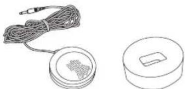
natural_image
Two technical line drawings: one showing a coiled cable with a small component, the other a circular device with a handle (no text or symbols)- Remote control unit
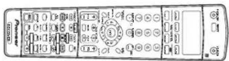
text_image
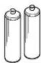
Power Control• AA/LR6 dry cell batteries x2
- AM loop antenna

- FM wire antenna

- Antenna adapter

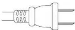
- Power cord
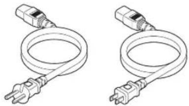
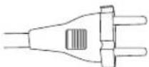
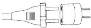
natural_image
Two identical line drawings of a coiled electrical plug with terminal connectors (no text or symbols)- Flat-bladed converter plug

• These operating instructions

Note
- The accessories will be different depending on the country of purchase. Where two power cords are included, make sure to use the cord appropriate for your country or region.
Installing the receiver
- When installing this unit, make sure to put it on a level and stable surface.
Don't install it on the following places:
-on a color TV (the screen may distort)
- near a cassette deck (or close to a device that gives off a magnetic field). This may interfere with the sound.
- in direct sunlight
- in damp or wet areas
- in extremely hot or cold areas
- in places where there is vibration or other movement
- in places that are very dusty
– in places that have hot fumes or oils (such as a kitchen)
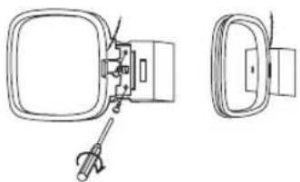
Using the remote control
Loading the batteries
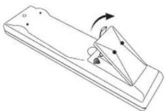
natural_image
Simple line drawing of a mechanical device with an arrow indicating rotation (no text or symbols)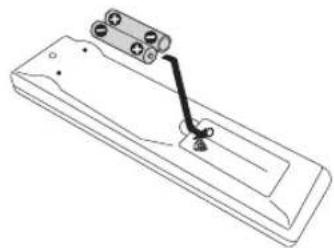
natural_image
Technical line drawing of a mechanical component with a lever and mounting bracket (no text or symbols)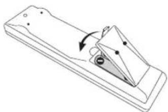
natural_image
Simple line drawing of a mechanical component with an arrow indicating rotation (no text or symbols)
Caution
Incorrect use of batteries may result in such hazards as leakage and bursting. Observe the following precautions:
- Never use new and old batteries together.
- Insert the plus and minus sides of the batteries properly according to the marks in the battery case.
- Batteries with the same shape may have different voltages. Do not use different batteries together.
- When disposing of used batteries, please comply with governmental regulations or environmental public instruction's rules that apply in your country or area.
Operating range of remote control unit
The remote control may not work properly if:
- There are obstacles between the remote control and the receiver's remote sensor.
- Direct sunlight or fluorescent light is shining onto the remote sensor.
- The receiver is located near a device that is emitting infrared rays.
- The receiver is operated simultaneously with another infrared remote control unit.
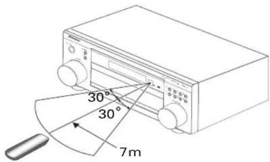
text_image
30° 30° 7mChapter 2:
5 minute guide
Introduction to home theater
You are probably used to using stereo equipment to listen to music, but may not be used to home theater systems that give you many more options (such as surround sound) when listening to soundtracks.
Home theater refers to the use of multiple audio tracks to create a surround sound effect, making you feel like you're in the middle of the action or concert. The surround sound you get from a home theater system depends not only on the speakers you have set up in your room, but also on the source and the sound settings of the receiver.
DVD-Video has become the basic source material for home theater due to its size, quality, and ease of use. Depending on the DVD, you can have up to seven different audio tracks coming from one disc, all of them being sent to different speakers in your system. This is what creates a surround sound effect and gives you the feeling of 'being there'.
This receiver will automatically decode Dolby Digital, DTS, or Dolby Surround DVD-Video discs, according to your speaker setup. In most cases, you won't have to make changes for realistic surround sound, but other possibilities (like listening to a CD with multichannel surround sound) are explained in Listening to your system on page 30.
Listening to Surround Sound
This receiver was designed with the easiest possible setup in mind, so with the following quick setup guide, you should have your system hooked up for surround sound in no time at all. In most cases, you can simply leave the receiver in the default settings. Note that the illustrations below show the VSX-2014i-G however, connections for the VSX-1014-S are the same.

Important
- Before making or changing any connections, switch off the power and disconnect the power cord from the AC outlet.
1 Hook up your DVD player.
For surround sound, you'll want to hook up using a digital connection from the DVD player to the receiver. You can do this with either a coaxial (recommended), or an optical connection (you don't need to connect both). If you hook up using an optical cable, you should refer to The Input Assign menu on page 63 to assign the optical input to DVD.
Use a video cord to connect the video output on your DVD player to the receiver using the jacks shown below.
2 Hook up your TV.
Use a video cord to connect your receiver to the TV using the jacks as shown below.
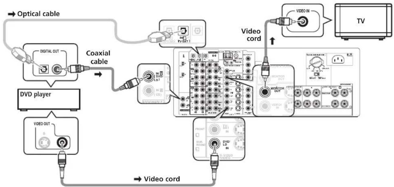
flowchart
graph TD
    A["Optical cable"] --> B["DVD player"]
    B --> C["Coaxial cable"]
    C --> D["Video cord"]
    D --> E["TV"]
    C --> F["Video OUT"]
    F --> G["Video cord"]
    G --> H["Monitor OUT"]
    H --> I["Video cord"]
    I --> J["Video IN"]
    J --> K["TV"]
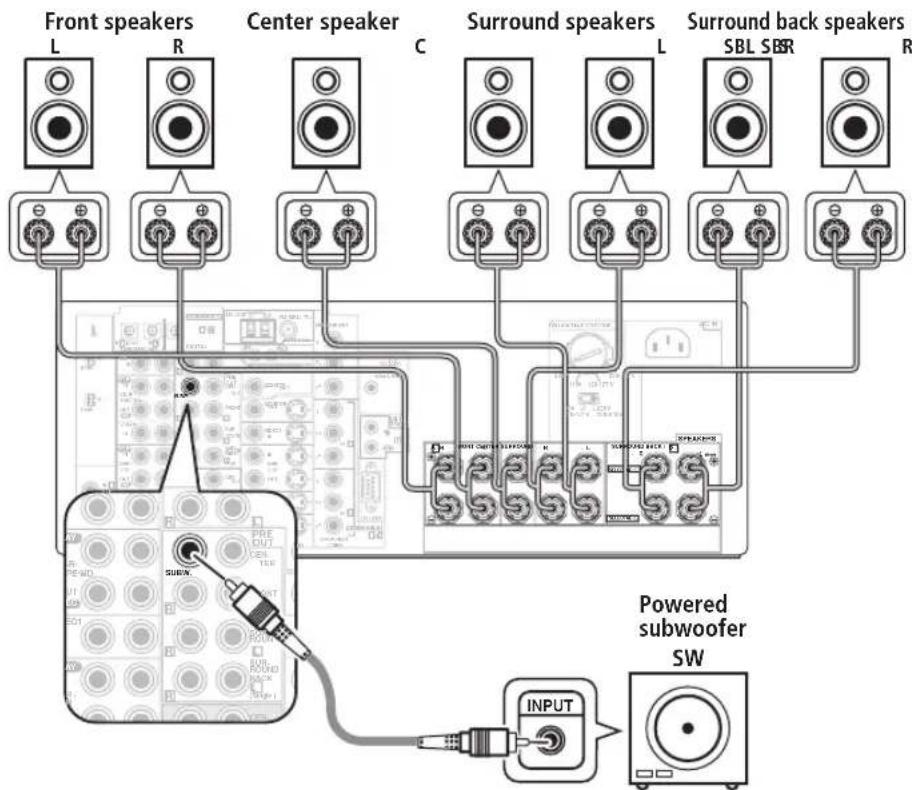
3 Connect your speakers.
A complete setup of eight speakers (including the subwoofer) is shown here but everyone's home setup will vary. Simply connect the speakers you have in the manner shown below. The receiver will work with just two stereo speakers (the front speakers in the diagram) but using at least three speakers is recommended, and a complete setup is best. Make sure you connect the speaker on the right to the right terminal and the speaker on the left to the left terminal. Also make sure the positive and negative (+/-) terminals on the receiver match those on the speakers. You can use speakers with a nominal impedance between 6–16Ω (please see Switching the speaker impedance on page 76 if you plan to use speakers with an impedance of less than 8Ω).
- If you only have one surround back speaker, hook it up to the surround back left (Single) terminal.

text_image
Front speakers L R Center speaker C Surround speakers L SBL SBR R Surround back speakers SBL SBR R Powered subwoofer SW INPUTCaution
• These speaker terminals carry HAZARDOUS LIVE voltage. To prevent the risk of electric shock when connecting or disconnecting the speaker cables, disconnect the power cord before touching any uninsulated parts.
- Make sure that all the bare speaker wire is twisted together and inserted fully into the speaker terminal. Use good quality speaker wire to connect the speakers to the receiver.
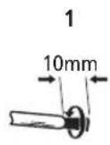
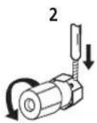
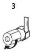
Make sure that the speaker cable you're going to use is properly prepared with about 10 mm of insulator stripped from each wire, and the exposed wire strands twisted together (fig. A).
To connect a terminal, unscrew the terminal a few turns until there is enough space to insert the exposed wire (fig. B). Once the wire is in position, tighten the terminal until the wire is firmly clamped (fig. C).
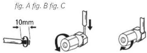
text_image
fig. A fig. B fig. C 10mmWhere you place the speakers will have a big effect on the sound. Place your speakers as shown below for the best surround sound effect. See Hints on speaker placement on page 22 for more on this.
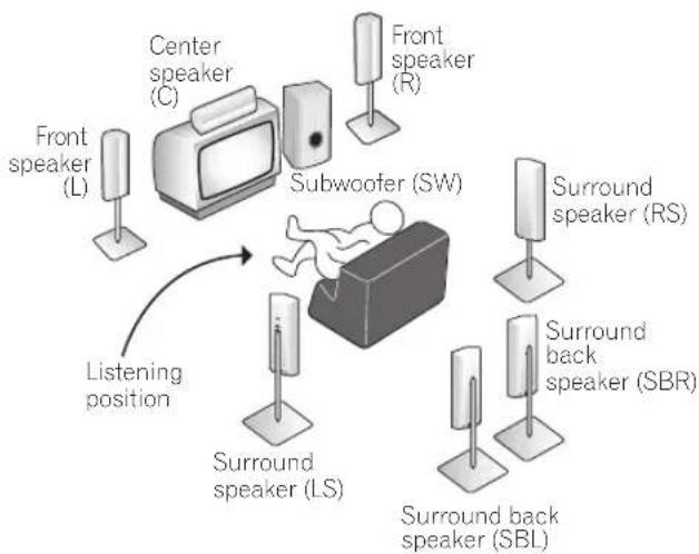
flowchart
graph TD
    A["Center speaker (C)"] --> B["Subwoofer (SW)"]
    C["Front speaker (L)"] --> B
    D["Front speaker (R)"] --> B
    E["Surround back speaker (SBR)"] --> B
    F["Surround back speaker (SBL)"] --> B
    G["Surround speaker (LS)"] --> B
    H["Listening position"] --> B
    I["Listening position"] --> B
4 Plug in the receiver and switch it on, followed by your DVD player, your subwoofer and the TV.
Make sure you've set the video input on your TV to this receiver. Check the manual that came with the TV if you don't know how to do this.
5 Use the on-screen automatic MCACC setup to set up your system.
See Automatically setting up for surround sound (MCACC) on the next page for more on this.
6 Play a DVD, and adjust the volume to your liking.
Make sure that DVD/LD is showing in the receiver's display, indicating that the DVD input is selected. If it isn't, press DVD/LD on the remote control to set the receiver to the DVD input.
In addition to the basic playback explained in Playing a source on page 13, there are several other sound options you can select. See Listening to your system on page 30 for more on this. See also Making receiver settings from the System Setup menu on page 38 for more setup options.
- If you're not familiar with the proper DVD settings, refer to Checking the settings on your DVD (or other) player on page 13.
Automatically setting up for surround sound (MCACC)
The Auto MCACC Setup measures the acoustic characteristics of your listening area, taking into account ambient noise, speaker size and distance, and tests for both channel delay and channel level. After you have set up the microphone provided with your system, the receiver uses the information from a series of test tones to optimize the speaker settings and equalization for your particular room.
Make sure you do this before moving on to Playing a source on page 13.

Important
- Make sure the microphone and speakers are not moved during the Auto MCACC Setup.
- Using the Auto MCACC Setup will overwrite any existing speaker settings in the receiver.
- Before using the Auto MCACC Setup the headphones should be disconnected and MULTI CH IN switched off.
- The receiver will automatically exit the current screen after three minutes of inactivity.

Caution
- The test tones used in the Auto MCACC Setup are output at high volume.
text_image
RECEIVER INPUT SELECT SOURCE DVD/ILD TV/SAT DRIVER TV CONT MULTI CONTROL CD CHINTIME TUNNER RECEIVER 1 2 3 4 5 6 7 8 9 D. ACCESS TOP MENU CLASS MENU DT/VIEW TADIE SAND SYSTEM SETUP RETURN GUIDE TV CONTROL + - + - + - TV/OL + - + - + - + - + - + - + - + - + - + - + - + - + - + -1 Switch on the receiver and your TV.
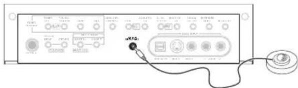
2 Connect the microphone to the MCACC SETUP MIC jack on the front panel.
Make sure there are no obstacles between the speakers and the microphone.
text_image
uR32Note that the illustration above shows the VSX-2014i-G however, connection for the VSX-1014-S is the same.
- Place the microphone on the supplied microphone stand (shown above) for the best results with the Auto MCACC Setup.
If you have a tripod, use it to place the microphone so that it's about ear level at your normal listening position. Otherwise, place the microphone at ear level using a table or a chair.
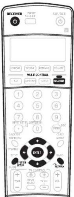
3 Press RECEIVER on the remote control, then press the SYSTEM SETUP button.
An on-screen display (OSD) appears on your TV. Use the ↑/↓/←/→ buttons and ENTER on the remote control to navigate through the screens and select menu items. Press RETURN to exit the current menu.
- Press SYSTEM SETUP at any time to exit the System Setup menu.
- VSX-1014-S only – If you find picture distortion, or the OSD doesn't appear, see Changing the TV format setting on page 76 and make sure the setting is correct for your country or region.
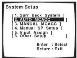
4 Select 'AUTO MCACC' from the System Setup menu then press ENTER.
text_image
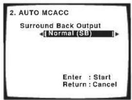
System Setup [1. Surr Back System ] [2. AUTO MCACC ] [3. MANUAL MCACC ] [4. MANUAL SP Setup ] [5. Input Assign ] [6. Other Setup ] Enter : Select Return : Exit5 Make sure 'Normal (SB)' is selected then press ENTER.
text_image
2. AUTO MCACC Surround Back Output [Normal (SB)] Enter : Start Return : Cancel- If you are planning on bi-amping your front speakers, or setting up a separate speaker system in another room, read through Surround back speaker setting on page 38 and make sure to connect your speakers as necessary before continuing to step 6.
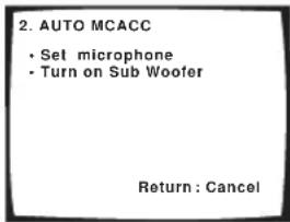
6 Follow the instructions on-screen.
text_image
2. AUTO MCACC • Set microphone • Turn on Sub Woofer Return : Cancel- Make sure the microphone is connected.
- If you're using a subwoofer, it is automatically detected every time you switch on the system. Make sure it is on and the volume is turned up.
• See below for notes regarding high background noise levels and other possible interference.
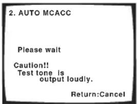
7 Wait for the Auto MCACC Setup to finish outputting test tones.
A progress report is displayed on-screen while the receiver outputs test tones to determine the speakers present in your setup. Try to be as quiet as possible while it's doing this.
text_image
2. AUTO MCACC Please wait Caution!! Test tone is output loudly. Return:Cancel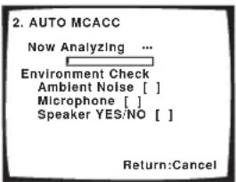
text_image
2. AUTO MCACC Now Analyzing ... Environment Check Ambient Noise [ ] Microphone [ ] Speaker YES/NO [ ] Return:Cancel- Do not adjust the volume during the test tones. This may result in incorrect speaker settings.
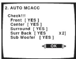
8 Confirm the speaker configuration in the OSD.
The configuration shown on-screen should reflect the actual speakers you have.
text_image
2. AUTO MCACC Check!!! Front [ YES ] Center [ YES ] Surround [ YES ] Surr Back [ YES X2 ] Sub Woofer [ YES ] OKIf the speaker configuration displayed isn't correct, use the ↑/↓ (cursor up/down) buttons to select the speaker and ←/→ (cursor left/right) to change the setting (and number for surround back). When you're finished, go to the next step.
If you see an error message (ERR) in the right side column, there may be a problem with the speaker connection. If selecting RETRY doesn't fix the problem, turn off the power and check the speaker connections.
9 Make sure 'OK' is selected, then press ENTER.
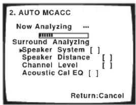
A progress report is displayed on-screen while the receiver outputs more test tones to determine the optimum receiver settings for channel level, speaker distance, and Acoustic Calibration EQ.
text_image
2. AUTO MCACC Now Analyzing ... Surround Analyzing ►Speaker System [ ] Speaker Distance [ ] Channel Level [ ] Acoustic Cal EQ [ ] Return:CancelAgain, try to be as quiet as possible while this is happening. It may take 3–8 minutes.
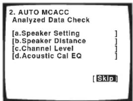
10 The Auto MCACC Setup has finished! Select 'Skip' to go back to the System Setup menu.
The MCACC indicator on the front panel will light to show the surround settings are complete.
text_image
2. AUTO MCACC Analyzed Data Check [a.Speaker Setting ] [b.Speaker Distance ] [c.Channel Level ] [d.Acoustic Cal EQ ] [Skip]The settings made in the Auto MCACC Setup should give you excellent surround sound from your system, but it is also possible to adjust these settings manually using the System Setup menu (see page 38).
- If you are using THX Certified speakers, confirm that all speakers are set to SMALL in Speaker Setting on page 44, and that the Crossover Network on page 45 is set to 80Hz.
You can also choose to view the settings by selecting individual parameters from the Analyzed Data Check screen:
- Speaker Setting – The size and number of speakers you've connected (see page 44 for more on this)
- Speaker Distance – The distance of your speakers from the listening position (see page 46 for more on this)
- Channel Level – The overall balance of your speaker system (see page 45 for more on this)
- Acoustic Cal EQ – Adjustments to the frequency balance of your speaker system based on the acoustic characteristics of your room (see page 41 for more on this)
Press RETURN after you have finished checking each screen. When you're finished, select Skip to go back to the System Setup menu.

Note
- If you leave an error message on the screen for over three minutes, or if you cancel the Auto MCACC Setup at any time, the receiver automatically exits and no settings will be made.
- Depending on the characteristics of your room, sometimes identical speakers with cone sizes of around 12cm will end up with different size settings. You can correct the setting manually using the Manual speaker setup on page 43.
- The subwoofer distance setting may be farther than the actual distance from the listening position. This setting should be accurate (taking delay and room characteristics into account) and generally does not need to be changed.
- Remember to disconnect the microphone after you've finished the Auto MCACC Setup.
Other problems when using the Auto MCACC Setup
If the room environment is not optimal for the Auto MCACC Setup (too much background noise, echo off the walls, obstacles blocking the speakers from the microphone) the final settings may be incorrect. Check for household appliances (air conditioner, fridge, fan, etc.), that may be affecting the environment and switch them off if necessary. If there are any instructions showing in the front panel display, please follow them.
- Some older TVs may interfere with the operation of the microphone. If this seems to be happening, switch off the TV when doing the Auto MCACC Setup.
Checking the settings on your DVD (or other) player
Before continuing, you may want to check the digital audio output settings on your DVD player and digital satellite receiver.
- Check that your DVD player/satellite receiver is set to output Dolby Digital, DTS and 88.2/96kHz PCM (2 channel) audio.
If there is an option for MPEG audio, set this to convert the MPEG audio to PCM.
If you connected the multichannel analog outputs of the player to this receiver, make sure that the player is set to output multichannel analog audio.

Note
- Depending on your DVD player or source discs, you may only get digital 2 channel stereo and analog sound. In this case, the receiver must be set to a multichannel listening mode (see Listening in surround sound on page 30 if you need to do this) if you want multichannel surround sound.
Playing a source
Here are the basic instructions for playing a source (such as a DVD disc) with your home theater system.
1 Turn on the power of the playback component (for example a DVD player), your TV and subwoofer (if you have one).
- If your source is the TV's built-in tuner, then switch to the channel you want to watch, otherwise make sure that the TV's video input is set to this receiver. (For example, if you connected this receiver to the VIDEO 1 jacks on your TV, make sure that the VIDEO 1 input is now selected.)
2 If the receiver isn't already on, press ⏻ RECEIVER to switch it on.
3 Change the receiver input to the source you want to play.
You can use the front panel input select buttons or the dedicated MULTI CONTROL buttons on the remote control.
4 Press AUTO SURR (remote control) and start playback of the DVD (or other component).
If you're playing a Dolby Digital or DTS surround sound DVD disc, you should hear surround sound. If you are playing a stereo source, you will only hear sound from the front left/right speakers in the default listening mode.
• See also Listening to your system on page 30 for more information on different ways of listening to sources.
5 Use the volume control (front panel or remote) to adjust the volume level.
- Turn down the volume of your TV so that all the sound is coming from the speakers connected to this receiver.
- 0dB is the volume level of a regular movie theater. Adjust the volume to your liking between -80dB (min) and +12dB (max).

Note
- If you need to manually switch the input signal type from digital to analog (stereo or multichannel), press SIGNAL SELECT (page 33).
- For more detailed surround sound setup, see The System Setup menu on page 38.
Chapter 3:
Connecting up

Important
- Before making or changing any connections, switch off the power and disconnect the power cord from the AC outlet.
About cable types
Analog audio cables
Use stereo RCA phono cables to connect analog audio components. These cables are typically red and white, and you should connect the red plugs to R (right) terminals and white plugs to L (left) terminals.
Analog audio cables
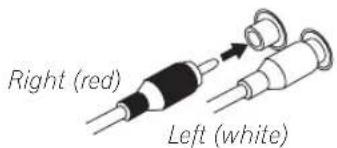
text_image
Right (red) Left (white)Digital audio cables
Commercially available coaxial digital audio cables or optical cables should be used to connect digital components to this receiver.
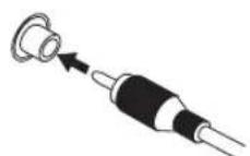
Coaxial digital audio cable
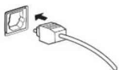
Optical cable
- When connecting optical cables, be careful when inserting the plug not to damage the shutter protecting the optical socket.
- When storing optical cable, coil loosely. The cable may be damaged if bent around sharp corners.
- You can also use a standard RCA video cable for coaxial digital connections.
Video cables
Standard RCA video cables
These cables are the most common type of video connection and should be used to connect to the composite video terminals. They have yellow plugs to distinguish them from cables for audio.
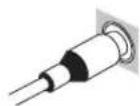
Standard RCA video cable
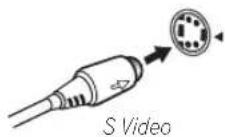
S-video cables
S-video cables give you clearer picture reproduction than standard RCA video cables by sending separate signals for the luminance and color.
Component video cables
Use component video cables to get the best possible color reproduction of your video source. The color signal of the TV is divided into the luminance (Y) signal and the color (PB and PR) signals and then output. In this way, interference between the signals is avoided.
Component video cables
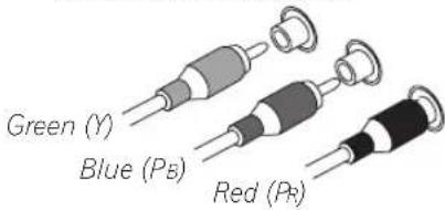
text_image
Green (Y) Blue (Ps) Red (Pb)When making cable connections
Be careful not to arrange cables in a manner that bends the cables over the top or around this unit. If the cables are laid on top of the unit, the magnetic field produced by the transformers in this unit may cause a humming noise to come from the speakers.
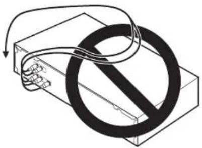
natural_image
Diagram of a device with a prohibition symbol overlaid, no text or labels presentAbout the RS-232C connector
VSX-2014i-G model only
The RS-232C connector on the rear panel is for future improvements.
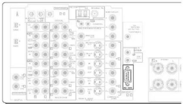
text_image
Electrical control panel diagram with labeled components and a highlighted component labeled 'M-1-200'About the video converter
VSX-2014i-G model only
The video converter allows you to connect various video sources using composite, S-video or component video connections and the signal will be output through all of the MONITOR OUT jacks (excluding multi-room). The only exception is component video input, which is only output from the component video output. Therefore, if you want to connect any source using component video, you must also connect your TV using component video. If several video components are connected to the same input function, the converter gives priority to component, S-video, then composite (in that order).
The following chart shows when the video signal will be converted from the various video inputs (left column) for output to the MONITOR OUT jacks (top row):
| Vidoterminal | MONITOR OUT | ||
| VIDEO(Composite) | S-VIDEO | COMPONENTVIDEO | |
| VIDEO IN(Composite) | √ | √ | √ |
| S-VIDEO IN | √ | √ | √ |
| COMPONENTVIDEO IN | × | × | ☑ |
- The mark above indicates that the component video input must be assigned before it will be output (see Assigning the component video inputs on page 64 for more on this).
- When recording video sources however, you won't be able to record sources connected to the component video inputs. With composite and S-video sources, they must be connected using the same type of video cable as you used to connect the recorder to the receiver.
- NTSC model – This feature is available with NTSC signals only. For a PAL signal, make sure you've used the same type of cable for your video component and monitor connections.
- PAL model – With NTSC sources, you will only be able to convert from S-Video to component video, and not vice-versa.
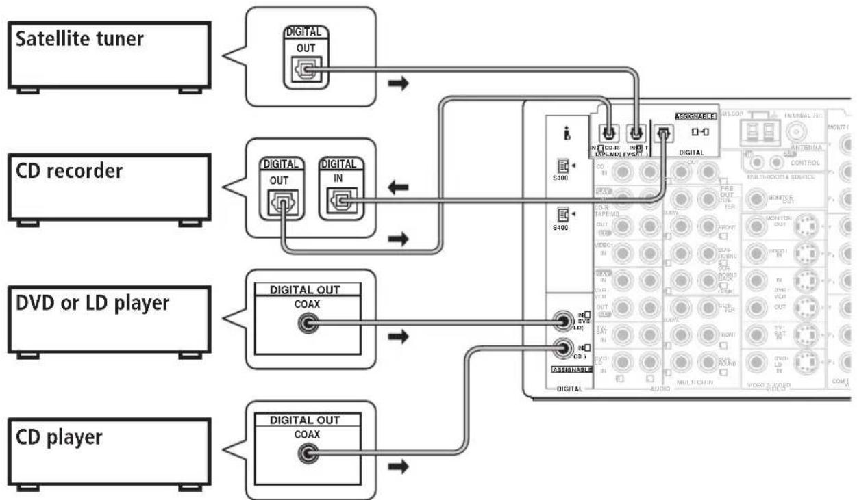
Connecting digital audio components
The easiest way to hook up this receiver for surround sound (Dolby Digital and DTS sources) is to use a digital input. You can do this by either coaxial or optical connections (you do not need to do both). The quality of these two types of connections is the same but since some digital components only have one type of digital terminal, it is a matter of matching like with like (for example, the coaxial output from the component to coaxial input on the receiver). This receiver has four digital inputs (two coaxial inputs and two optical inputs) on the rear panel. Connect your digital components as shown below.
There is one digital output jack which is marked DIGITAL OUT. If you connect this to the optical input on a digital recorder (for example an MD, DAT or CD-R) you can make direct digital recordings with this unit.
When connecting your equipment, always make sure the power is turned off and the power cord is disconnected from the AC outlet.
- The arrows indicate the direction of the signal.
flowchart
graph TD
    A["Satellite tuner"] --> B["Digital OUT"]
    C["CD recorder"] --> D["Digital OUT"]
    C --> E["Digital IN"]
    F["DVD or LD player"] --> G["Digital OUT COAX"]
    H["CD player"] --> I["Digital OUT COAX"]
    B --> J["Digital OUT"]
    D --> K["Digital IN"]
    G --> L["Digital OUT COAX"]
    I --> M["Digital OUT COAX"]
    J --> N["Digital OUT COAX"]
    K --> O["Digital OUT COAX"]
    L --> P["Digital OUT COAX"]
    N --> Q["Digital OUT COAX"]
    O --> R["Digital OUT COAX"]
    P --> S["Digital OUT COAX"]
    Q --> T["Digital OUT COAX"]
    R --> U["Digital OUT COAX"]
    S --> V["Digital OUT COAX"]
    T --> W["Digital OUT COAX"]
    U --> X["Digital OUT COAX"]
    V --> Y["Digital OUT COAX"]
    W --> Z["Digital OUT COAX"]
    X --> AA["Digital OUT COAX"]
    Y --> AB["Digital OUT COAX"]
    Z --> AC["Digital OUT COAX"]
    AA --> AD["Digital OUT COAX"]
    AB --> AE["Digital OUT COAX"]
Note that the illustration above shows the VSX-2014i-G however, connection for the VSX-1014-S is the same.

Note
- If your digital connections are different from the default settings, you should refer to The Input Assign menu on page 63 to assign the jacks to the proper component(s).
- If you have a have a DVD-Audio or SACD compatible player, see Connecting multichannel analog components on page 17. (VSX-2014i-G only – Also see Using the i.LINK interface on page 59.)
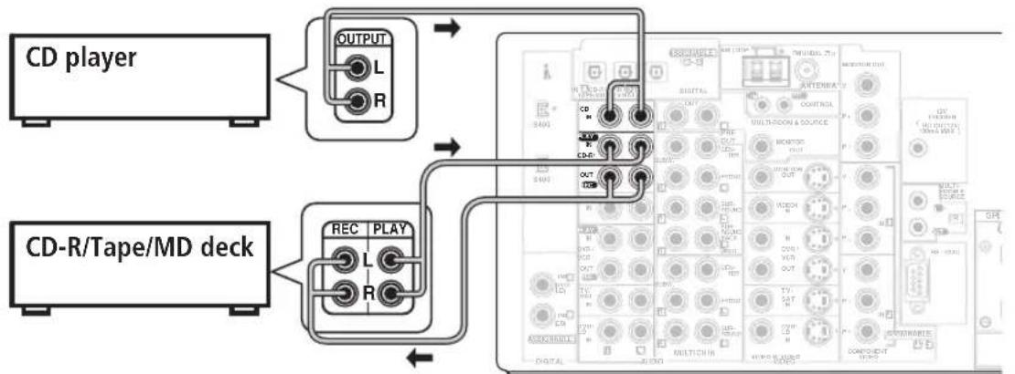
Connecting analog audio components
To begin set up, connect your analog audio components (such as a cassette deck) to the jacks. For components you want to record with, you need to hook up four plugs to the receiver (a set of stereo inputs and a set of stereo outputs), but for components that only play, you only need to hook up one set of stereo plugs. You must also hook up your digital components to analog audio jacks if you want to record to/from digital components (like an MD) to/from analog components. See page 16 for more on digital connections.
When connecting your equipment, always make sure the power is turned off and the power cord is disconnected from the AC outlet.
- The arrows indicate the direction of the audio signal.
flowchart
graph TD
    A["CD player"] --> B["OUTPUT L R"]
    C["CD-R/Tape/MD deck"] --> D["REC PLAY L R"]
    B --> E["OUTPUT L R"]
    D --> F["OUTPUT L R"]
    E --> G["Multi-Boxer & Source"]
    F --> H["Multi-Boxer & Source"]
    G --> I["Digital Audio"]
    H --> J["Digital Audio"]
    I --> K["Multi-Boxer & Source"]
    J --> L["Multi-Boxer & Source"]
Note that the illustration above shows the VSX-2014i-G however, connection for the VSX-1014-S is the same.

Tip
- If you don't plan on using the spare audio jacks for video components (for example, VIDEO1), you can use these for connecting another audio component, like a line-level turntable.
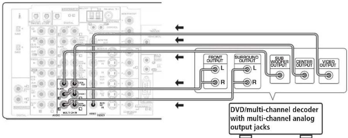
Connecting multichannel analog components
If you prefer to use a separate component for decoding multichannel formats such as DVD Audio and SACD, you can connect a decoder or a DVD player with multichannel analog outputs to the multichannel inputs of this receiver. Note that the multichannel input can only be used when MULTI CH IN is selected (see page 37).
When connecting your equipment, always make sure the power is turned off and the power cord is disconnected from the AC outlet.
- The arrows indicate the direction of the signal.
flowchart
graph TD
    A["DV/DVD/multi-channel decoder with multi-channel analog output jacks"] --> B["FRONT OUTPUT"]
    A --> C["SURROUND OUTPUT"]
    A --> D["SUB WOOFER OUTPUT"]
    A --> E["CENTER OUTPUT"]
    A --> F["VIDEO OUTPUT"]
    B --> G["FRONT OUTPUT L"]
    B --> H["SURROUND OUTPUT L"]
    B --> I["SUB WOOFER OUTPUT"]
    C --> J["FRONT OUTPUT R"]
    C --> K["SURROUND OUTPUT R"]
    C --> L["CENTER OUTPUT"]
    D --> M["VIDEO OUTPUT"]
    E --> N["FRONT OUTPUT L"]
    E --> O["SURROUND OUTPUT L"]
    E --> P["SUB WOOFER OUTPUT"]
    F --> Q["VIDEO OUTPUT"]
Note that the illustration above shows the VSX-2014i-G however, connection for the VSX-1014-S is the same.
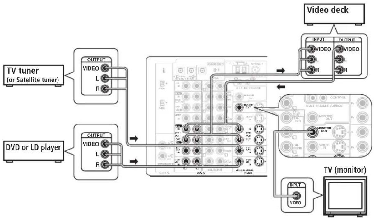
Connecting video components
Connect your video components to the jacks as shown below. With digital video components (like a DVD player), you must use the connections shown on this page for the video signal, but in order to hear a digital source (like a DVD) you should hook up the audio to a digital input (see page 16). It is also a good idea to hook up your digital components with analog audio connections (see page 17).
For better quality video, you can hook up using the component video jacks or the S-video jacks (quality descends in this order) on the rear of the receiver instead of the regular video jacks. (With the VSX-2014i-G, you can connect video components and your TV using different types of video cables. See About the video converter on page 15.)
When connecting your equipment, always make sure the power is turned off and the power cord is disconnected from the AC outlet.
• The arrows indicate the direction of the signal.
flowchart
graph TD
    A["TV tuner (or Satellite tuner)"] --> B["OUTPUT VIDEO L R"]
    C["DVD or LD player"] --> D["OUTPUT VIDEO L R"]
    B --> E["VIDEO OUT"]
    D --> F["VIDEO OUT"]
    E --> G["TV monitor"]
    F --> G
    G --> H["INPUT VIDEO"]
    H --> I["VIDEO"]
    style A fill:#f9f,stroke:#333
    style C fill:#f9f,stroke:#333
    style E fill:#ccf,stroke:#333
    style F fill:#ccf,stroke:#333
    style G fill:#cfc,stroke:#333
    style H fill:#fcc,stroke:#333
    style I fill:#ffc,stroke:#333
Note that the illustration above shows the VSX-2014i-G however, connection for the VSX-1014-S is the same.

Important
- VSX-2014i-G only – Make sure you don't connect your TV to the MONITOR OUT jacks for MULTI-ROOM & SOURCE located above the proper MONITOR OUT jacks.
- VSX-1014-S only – Make sure to use the same type of cable for your video connections as you used to connect your TV.
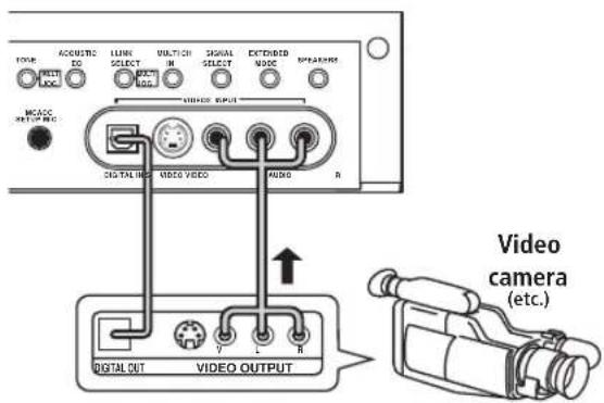
Connecting to the front panel video terminal
Front video connections are accessed via the front panel using the VIDEO2 button. There are standard audio/video jacks as well as an S-video jack and an optical input. Hook them up the same way you made the rear panel connections.
text_image
TYPE: ACQUOTIC LIME VOLTATION SIGNAL EXTENDED MODE: SELECT SELECT MODE MCACC OUTPUTING SIGNAL OUT VIDEO VIDEO R VIDEO OUTPUT VIDEO OUTPUT V L R Video camera (etc.)Connecting antennas
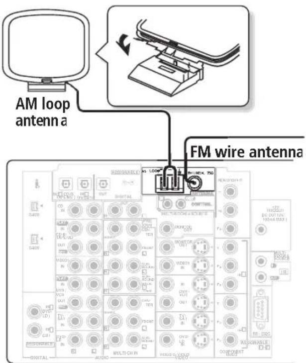
Connect the AM loop antenna and the FM wire antenna as shown below. To improve reception and sound quality, connect external antennas (see Using an external antenna to improve FM reception below). Always make sure that the receiver is switched off and unplugged from the wall outlet before making or changing any connections.
text_image
AM loop antenna a FM wire antenna S400 S400 DIGITAL AUDIO MULTI-CHIN VIDEO VIDEO RHO VOUT OUT OUT OUT OUT OUT OUT OUT OUT OUT OUT OUT OUT OUT OUT OUT OUT OUT OUT OUT OUT OUT OUT OUT OUT OUT OUT OUT OUT OUT OUT OUT OUT OUT OUT OUT OUT OUT OUT OUT OUT OUT OUT OUT OUT OUT OUT OUT OUT OUT OUTNote that the illustration above shows the VSX-2014i-G however, connection for the VSX-1014-S is the same.
FM wire antenna
Connect the FM wire antenna and fully extend vertically along a window frame or another suitable place that gives good reception.
AM loop antenna
Assemble the antenna and connect to the receiver as shown above. The ground terminal ( _7 ) helps reduce radio noise (it is not an earthing plug). Attach (if necessary) and face in the direction that gives the best reception.
natural_image
Technical line drawing of a mechanical component with two views (top and side), no text or symbols present.- Note that either wire can be inserted into the respective terminals when connecting.
Antenna snap connectors
Twist the exposed wire strands together and insert into the hole, then snap the connector shut.
text_image
10mmUsing an external antenna to improve FM reception
Use an antenna adapter to connect an external FM antenna using a coaxial 75Ω cable.
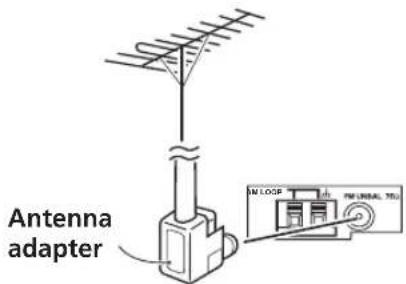
text_image
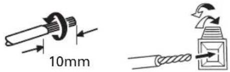
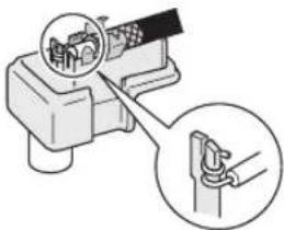
Antenna adapter IN LOOP FM LINEAL TBUAttaching the antenna adapter
Use the antenna adaptor to terminate the coaxial cable used with an external FM antenna.
1 Cut and strip the coaxial cable to the specification shown in the diagram.
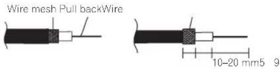
text_image
Wire mesh Pull backWire 10-20 mm5 92 Open the adaptor body by pulling apart the tabs on either side.

text_image
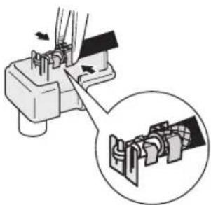
Tabs3 Insert the cable as shown, then use a pair of pliers to wrap the end of the wire around the binding post. Snip off the excess wire.
natural_image
Diagram of a mechanical device with a magnified inset showing a hand holding a spring (no text or symbols present)4 Use pliers to secure the cable by pinching the clamps together, as shown.
natural_image
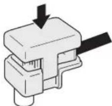
Diagram showing a mechanical assembly with arrows indicating direction, and a magnified inset of a bracket component (no text or symbols)5 Push the body cover back on.
natural_image
Mechanical component diagram showing a piston and lever assembly (no text or symbols)Using an external antenna to improve AM reception
Connect a 5–6m length of vinyl-coated wire to the AM antenna terminal without disconnecting the supplied AM loop antenna.
For the best possible reception, suspend horizontally outdoors.
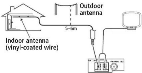
text_image
Outdoor antenna 5-6m Indoor antenna (vinyl-coated wire) FM LCD FM SIMICAL TELConnecting the speakers
A complete setup of eight speakers (including the subwoofer) is shown below, but everyone's home setup will vary. Simply connect the speakers you have in the manner shown below. The receiver will work with just two stereo speakers (the front speakers in the diagram) but using at least three speakers is recommended, and a complete setup is best for surround sound. If you're not using a subwoofer, change the front speaker setting (see Speaker Setting on page 44) to large.
Make sure you connect the speaker on the right to the right terminal and the speaker on the left to the left terminal. Also make sure the positive and negative (+/-) terminals on the receiver match those on the speakers.
- You can use speakers with a nominal impedance between 6–16 Ω (please see Switching the speaker impedance on page 76 if you plan to use speakers with an impedance of less than 8Ω).
Be sure to complete all connections before connecting this unit to the AC power source.
flowchart
graph TD
    A["Front speakers L"] --> B["Powered subwoofer SW"]
    C["Center speaker R"] --> B
    D["Surround speakers C"] --> B
    E["Surround back speakers L"] --> B
    F["Input"] --> G["Powered subwoofer SW"]
    B --> H["Switch block with labels like 'PRE-OUT', 'R', 'SBL', 'SBR', 'SW1', 'SW2', 'SW3', 'SW4', 'SW5', 'SW6', 'SW7', 'SW8'"]
    style B fill:#f9f,stroke:#333
    style C fill:#f9f,stroke:#333
    style D fill:#f9f,stroke:#333
    style E fill:#f9f,stroke:#333
    style F fill:#f9f,stroke:#333
    style G fill:#ccf,stroke:#333
S
Note that the illustration above shows the VSX-2014i-G however, connection for the VSX-1014-S is the same.

Caution
• These speaker terminals carry HAZARDOUS LIVE voltage. To prevent the risk of electric shock when connecting or disconnecting the speaker cables, disconnect the power cord before touching any uninsulated parts.
- Make sure no bare speaker wire is touching the back panel when the unit is switched on. The power may cut off as a safety measure.

Note
- If you only have one surround back speaker, hook it up to the surround back left (Single) terminal.
- If you are planning on bi-amping your front speakers, or setting up a separate speaker system in another room, read through Surround back speaker setting on page 38 and make sure to connect your speakers as necessary (these connections are explained in Other connections on page 55).
- If you are using a THX certified subwoofer use the THX INPUT jack on the subwoofer (if your subwoofer has one) or switch the filter position to THX on your subwoofer.
Speaker terminals
1 Twist exposed wire strands together.
2 Loosen speaker terminal and insert exposed wire.
Make sure that all the bare speaker wire is twisted together and inserted fully into the speaker terminal. Use good quality speaker wire to connect the speakers to the receiver.
3 Tighten terminal.
Hints on speaker placement
Speakers are usually designed with a particular placement in mind. Some are designed to be floorstanding, while others should be placed on stands to sound their best. Some should be placed near a wall; others should be placed away from walls. We have provided a few tips on getting the best sound from your speakers (following), but you should also follow the guidelines on placement that the speaker manufacturer provided with your particular speakers to get the most out of them.
- Place the front left and right speakers at equal distances from the TV.
- When placing speakers near the TV, we recommend using magnetically shielded speakers to prevent possible interference, such as discoloration of the picture when the TV is switched on. If you do not have magnetically shielded speakers and notice discoloration of the TV picture, move the speakers farther away from the TV.
- If you're using a center speaker, place the front speakers at a wider angle. If not, place them at a narrower angle.
- Place the center speaker above or below the TV so that the sound of the center channel is localized at the TV screen. Also, make sure the center speaker does not cross the line formed by the leading edge of the front left and right speakers.
- It is best to angle the speakers towards the listening position. The angle depends on the size of the room. Use less of an angle for bigger rooms.
- Surround and surround back speakers should be positioned 60 cm–90 cm higher than your ears and titled slight downward. Make sure the speakers don't face each other. For DVD-Audio, the speakers should be more directly behind the listener than for home theater playback.
- To achieve the best possible surround sound, install your speakers as shown below. Be sure all speakers are installed securely to prevent accidents and improve sound quality.
Caution
- If you choose to install the center speaker on top of the TV, be sure to secure it with putty, or by other suitable means, to reduce the risk of damage or injury resulting from the speaker falling from the TV in the event of external shocks such as earthquakes.
Overhead view of speaker setup
You can also refer to the 3-D speaker setup illustration on page 10.
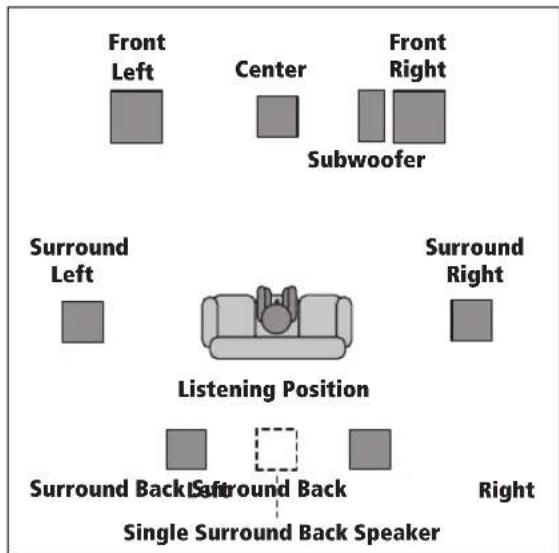
text_image
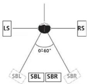
Front Left Center Front Right Subwoofer Surround Left Surround Right Listening Position Surround Back Single Surround Back Speaker RightThe diagrams below show suggested surround and surround back speaker orientation. The first diagram (fig. A) shows orientation with one surround back speaker (or none) connected. The second (fig. B) shows orientation with two surround back speakers connected.
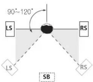
text_image
90°~120° LS RS LS SB RSfig. A
flowchart
graph TD
    A["LS"] --> B["Central Node"]
    C["RS"] --> B
    D["SBL"] --> B
    E["SBL"] --> B
    F["SBR"] --> B
    G["SBR"] --> B
    B --> H["0-60°"]
    style B fill:#f9f,stroke:#333
fig. B
- If you have two surround back speakers THX recommends placing them together and the same distance from your listening position.
3-D view of 7.1 channel speaker setup
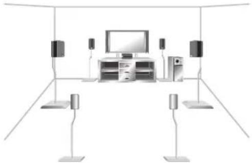
natural_image
Interior layout diagram of a modern home appliance with TV, speakers, and display units (no text or symbols)AC power cord
After you've finished making all connections, plug the receiver into an AC outlet. The type of cord and the plug converter which can be used depends on the power voltage in each region or country. Please make sure you use the correct cord and plug converter due to the possibility of fire or other hazard if used incorrectly (see below).
AC power cord and converter plug use
Region Plug type
| For European type region |
| Caution |
| Do not use this power cord set in Singapore and Malaysia. |
European two-pin plug
| For regions with two pin flat-bladed plug |
Caution
Do not use this power cord set in Taiwan.
European two-pin plug with two-pin flat-bladed converter plug
| For Taiwan exclusively |
| Caution |
For use in Taiwan only. In other areas, please do not use.
Taiwanese two-pin flat-bladed plug
- Make sure you have completely inserted the AC power cord into the AC IN inlet on the rear panel.
- Do not use any power cord other than the one supplied with this unit.
- This unit should be disconnected by removing the power plug from the wall socket when not in regular use (ex. when on vacation).
Power cord caution
- Handle the power cord by the plug. Do not pull out the plug by tugging the cord and never touch the power cord when your hands are wet as this could cause a short circuit or an electric shock. Do not place the unit, a piece of furniture, etc., on the power cord, or pinch the cord. Never make a knot in the cord or tie it with other cords. The power cords should be routed such that they are not likely to be stepped on. A damaged power cord can cause a fire or give you an electrical shock. Check the power cord once in a while. When you find it damaged, ask your nearest Pioneer authorized independent service company for a replacement.
Operating other Pioneer components
Many Pioneer components have SR CONTROL jacks which can be used to link components together so that you can use just the remote sensor of one component. When you use a remote control, the control signal is passed along the chain to the appropriate component.
Note that if you use this feature, make sure that you also have at least one set of analog audio or video jacks connected to another component for grounding purposes.
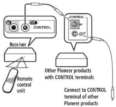
text_image
IN OUT CONTROL RECEIVER Remote control unit CONTROL IN OUT Other Pioneer products with CONTROL terminals Connect to CONTROL terminal of other Pioneer products
Note
- If you want to control all your components using this receiver's remote control, refer to Controlling the rest of your system on page 50.
- If you have connected a remote control to the CONTROL IN jack (using a mini-plug cable), you won't be able to control this unit using the remote sensor.
Chapter 4:
Controls and displays
Front panel
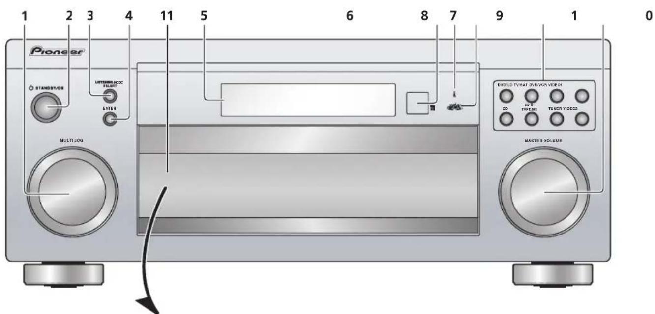
text_image
Pioneer STANDBYON LUTTERMEN/INOC SELECT ENTER MULTIJOG EVOLD TYBAT DVR/VOR VIDEO1 CD TAPIC MD TUNION VIDEOS2 MASTER VOLUMEVSX-2014i-G model
text_image
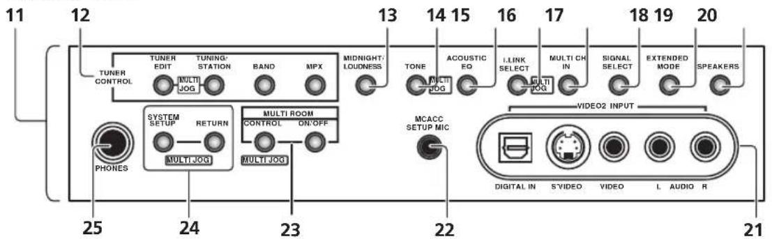
11 12 TUNER CONTROL TUNER EDIT TUNING/ STATION BAND MPX MIDNIGHT/ LOUDNESS 13 14 15 16 17 18 19 20 ACOUSTIC EQ I-LINK SELECT MULTI CH IN SIGNAL SELECT EXTENDED MODE SPEAKERS TONE MOLOG MULTI MOLOG SYSTEM SETUP RETURN MULTI ROOM CONTROL ON/OFF MULTI ROOM PHONES MCACC SETUP MIC VIDEO2 INPUT DIGITAL IN S\VIDEO VIDEO L AUDIO R 25 24 23 22 21VSX-1014-S model
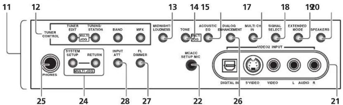
text_image
11 12 TUNER CONTROL TUNER EDIT TUNING/ STATION BAND MPX MIDNIGHT/ LOUDNESS 13 14 15 17 18 19 120 TONE ACOUSTIC EQ DIALOG ENHANCEMENT MULTI CH IN SIGNAL SELECT EXTENDED MODE SPEAKERS PHONES SYSTEM SETUP RETURN INPUT ATT FL DIMMER MCACC SETUP MIC VIDEO2 INPUT 25 24 28 27 22 26 21 DIGITAL IN S'VIDEO VIDEO L AUDIO R1 MULTI JOG dial
Use the MULTI JOG dial to select various settings and menu options.
2 ⏻ STANDBY/ON
Switches the receiver between on and standby.
3 LISTENING MODE SELECT
Use with the MULTI JOG dial to select the various listening modes (page 30).
4 ENTER
5 Character display
See Display on page 26.
6 Remote sensor
Receives the signals from the remote control.
7 i.LINK indicator (VSX-2014i-G model only)
Lights when an i.LINK-equipped audio component is selected (page 59).
8 MCACC indicator
Lights when Acoustic Calibration EQ (page 33) is on (Acoustic Calibration EQ is automatically set to ALL CH ADJUST after the Auto MCACC Setup (page 11) or EQ Auto Setting (page 41) is complete).
9 Input select buttons
Press to select an input source.
10 MASTER VOLUME dial
11 Front panel controls
To access the front panel controls, push gently on the lower third portion of the panel with your finger.
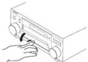
natural_image
Hand inserting a button into a device control panel (no text or symbols visible)12 TUNER CONTROL
TUNER EDIT
Use with the MULTI JOG dial to memorize and name stations for recall (page 48).
TUNING/STATION
Use with the MULTI JOG dial to select station presets and radio frequencies. (page 47).
BAND
Switches between AM and FM radio bands (page 47).
MPX
Press to receive a radio broadcast in mono (page 47).
Use Midnight when listening to movie soundtracks at low volume. Use Loudness to boost the bass and treble at low volume (page 36).
14 TONE
When the STEREO mode is selected, press this button to access the bass and treble controls, which you can then adjust with the MULTI JOG dial.
15 ACOUSTIC EQ
Press to select an Acoustic Calibration EQ setting (page 33).
16 i.LINK SELECT (VSX-2014i-G model only)
Use with the MULTI JOG dial to select unassigned i.LINK components (page 59).
17 MULTI CH IN
Press to select the component connected to the MULTI CH IN terminals (for example, a DVD-Audio player). See Selecting the multichannel analog inputs on page 37.
18 SIGNAL SELECT
Use to select an input signal (page 33).
19 EXTENDED MODE
Selects the surround back channel mode (page 34) or virtual surround back mode (page 35).
20 SPEAKERS
Use to change the speaker system (page 55).
21 VIDEO2 INPUT
See Connecting to the front panel video terminal on page 18.
22 MCACC SETUP MIC jack
Use to connect the supplied microphone.
23 MULTI ROOM controls (VSX-2014i-G model only) If you've made multi-room connections (see Multi-room listening on page 57) use these buttons to control the sub room from the main room (see Using the sub room controls on page 58).
24 System Setup menu controls
SYSTEM SETUP
Use with the MULTI JOG dial to access the System Setup menu (page 11, page 38, page 63).
RETURN
Press to confirm and exit the current menu screen.
25 PHONES jack
Use to connect headphones. When the headphones are connected, there is no sound output from the speakers.
26 DIALOG ENHANCEMENT (VSX-1014-S model only) Use to make dialog stand out when watching TV or a movie (page 36).
27 FL DIMMER (VSX-1014-S model only)
Dims or brightens the display. Switching the dimmer to lowest setting will also switch off the MCACC and i.LINK indicators.
28 INPUT ATT (VSX-1014-S model only)
Attenuates (lowers) the level of an analog input signal to prevent distortion.
Display
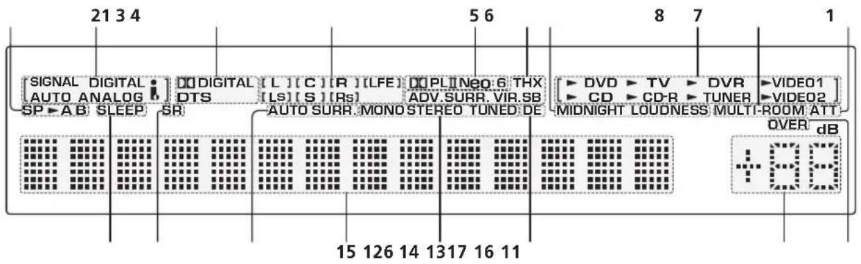
text_image
[SIGNAL DIGITAL AUTO ANALOG] DTS [L] [C] [R] [LFE] DPL Neo:6 THX [LV] [LS] [S] [Rs] ADV.SURR. VIR.SB [DV] TV DVR VIDEO1 SP A B SLEEP SR AUTO SURR MONO STEREO TUNED DE MIDNIGHT LOUDNESS MULTI-ROOM ATT 15 126 14 1317 16 11 OVER dB9
1 Speaker indicators (page 55)
Lights to indicate the current speaker system, A and/or B.
2 SIGNAL SELECT indicators
Lights to indicate the type of input signal assigned for the current component:
AUTO
Lights when AUTO signal select is on.
DIGITAL
Lights when a digital audio signal is detected.
ANALOG
Lights when an analog signal is detected.
i (VSX-2014i-G model only)
Lights when the currently selected input signal is input from the i.LINK connection.
3 Digital format indicators
DIGITAL
Lights when a Dolby Digital encoded signal is detected.
DTS
Lights when a DTS encoded signal is detected.
4 Program format indicators
These change according to which channels are active in Dolby, DTS, DVD-A and SACD sources.
LS, S and RS will light at the same time to indicate 6.1 channel sources.
- L – Left front channel
• C – Center channel - R - Right front channel
• LS – Left surround channel - S – Surround channel (mono) or surround back channel
• RS – Right surround channel
• LFE – Low frequency effects channel
5 Matrix decoding format indicators
DO PLII
This lights to indicate Pro Logic II / Pro Logic IIx decoding (see Listening in surround sound on page 30 for more on this).
Neo:6
When one of the Neo:6 modes of the receiver is on, this lights to indicate Neo:6 processing (see Listening in surround sound on page 30 for more on this).
6 Listening mode indicators
THX
Lights when one of the Home THX modes is selected.
VIR.SB
Lights during Virtual surround back processing.
ADV.SURR.
Lights when one of the Advanced Surround modes has been selected.
AUTO SURR.
Lights when the Auto Surround feature is switched on (see Auto playback on page 30).
When Midnight or Loudness listening is switched on, the corresponding indicator shows in the display.
8 Input source indicators
Light to indicate the input source you have selected.
9 MULTI-ROOM (VSX-2014i-G model only)
Lights when the multi-room feature is active (page 57).
10 ATT
Lights when INPUT ATT is used to attenuate (reduce) the level of the analog input signal.
11 OVER
Lights to indicate that the level of an analog source is too high. Use the attenuator (INPUT ATT) to reduce it.
12 Master volume level
Shows the overall volume level. -80dB indicates the minimum level, and +12dB indicates the maximum level.
13 DE
Lights when Dialog Enhancement (DIALOG E) is switched on (page 36).
14 TUNER indicators (page 47)
STEREO
Lights when a stereo FM broadcast is being received in auto stereo mode.
MONO
Lights when the mono mode is set using the MPX button.
TUNED
Lights when a broadcast is being received.
15 Character display
Displays various system information (for example, the reason an operation is not possible may flash in the display).
16 SR
Lights when the SR+ control mode has been switched on (see Using the SR+ mode with a Pioneer plasma display on page 62).
17 SLEEP
Lights when the receiver is in sleep mode (page 37).
Remote control
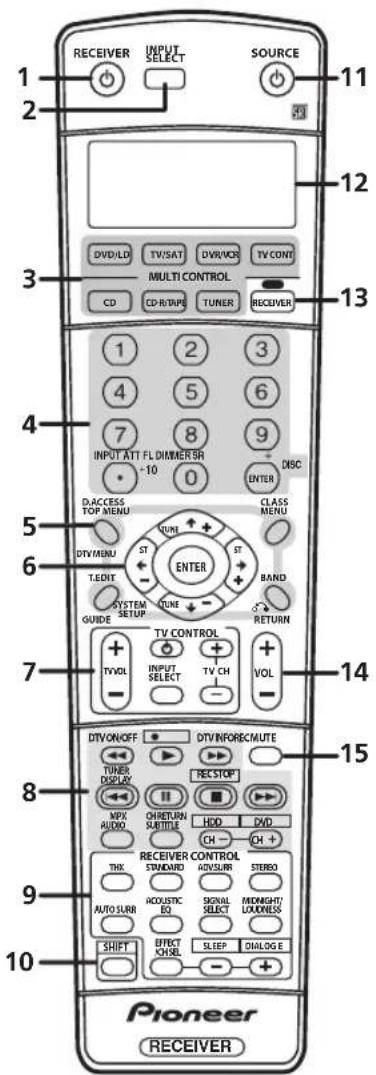
text_image
1 2 3 4 5 6 7 8 9 10 Pioneer RECEIVER 11 12 13 1 2 3 4 5 6 7 8 9 INPUT ATT FL DIMMER BR -10 0 DISC D. ACCESS TOP MENU CLASS MENU TIV/MENU ST ST T.EDIT SYSTEM SETUP TURE BAND GUIDE RETURN TV CONTROL + INPUT SELECT TV CH VOL - - - - - - - - - - - - - - - - - - - - - - - - - - - - - - - - - - - - - - - - - - - - - - - - - - - - - - - - - - - - - - - - - - - - - - - - - - - - - - - - - - - - - - - - - - - - - - - - - - - - - DTVON/OFF DTVINFORE/CMUTE TURER DISPLAY REC STOP MPX AUDIO OHRETURN SUBTITLE HDD DVD CH CH + RECEIVER CONTROL THX STANDARD HENSUM STUDIO AUTO SURN ACoustic EQ SIGNAL MIDNIGHT/ SELECT LUXNESS SHIFT EFFECT KWHL SLEEP DIALOG E - + Pioneer RECEIVER1 RECEIVER
This switches between standby and on for this receiver.
2 INPUT SELECT
Use to select the input source.
3 MULTI CONTROL buttons
Press to select control of other components (see Controlling the rest of your system on page 50).
4 Number buttons and other receiver/component controls
Use the number buttons to directly select a radio frequency (page 47) or the tracks on a CD, DVD, etc.
DISC (ENTER) can be used to enter commands for TV or DTV, and can also be used to select a disc in a multi-CD player.
The following are accessed by pressing the RECEIVER button first:
INPUT ATT
Attenuates (lowers) the level of an analog input signal to prevent distortion.
FL DIMMER
Dims or brightens the display. Switching the dimmer to lowest setting will also switch off the MCACC and i.LINK indicators.
SR+
Switches the SR+ mode on/off (page 62).
5 Tuner/component control buttons/SYSTEM SETUP
The following button controls (except SYSTEM SETUP) can be accessed after you have selected the corresponding MULTI CONTROL button (TUNER, DVD/LD, TV/SAT, etc.)
D. ACCESS
After pressing, you can access a radio station directly using the number buttons (page 47).
TOP MENU
Displays the disc 'top' menu of a DVD.
DTV MENU
Displays menus on a digital TV.
T. EDIT
Press to memorize and name a station for recall (page 48).
GUIDE
Displays the guides on a digital TV.
SYSTEM SETUP
(Press RECEIVER first to access)
Use to access the System Setup menu (see page 38).
CLASS
Switches between the three banks (classes) of radio station presets (page 48).
MENU
Displays the disc menu of DVD-Video discs. It also displays TV and DTV menus.
BAND
Switches between the tuner AM and FM bands (page 47).
RETURN
Press to confirm and exit the current menu screen (also use to return to the previous menu with DVDs or to select closed captioning with DTV).
6 ⇔→↓↑ (TUNE/ST +/-) /ENTER
Use the arrow buttons when setting up your surround sound system (see page 38). Also used to control DVD menus/options and for deck 1 of a double cassette deck player. Use the TUNE +/- buttons to find radio frequencies and use ST +/- to find preset stations (page 48).
7 TV CONTROL buttons
These buttons are dedicated to control the TV assigned to the TV CONT button. Thus if you only have one TV to hook up to this system assign it to the TV CONT MULTI
CONTROL button. If you have two TVs, assign the main TV to the TV CONT button (see page 50 for more on this).
TV
Use to turn on/off the power of the TV.
TV VOL +/-
Use to adjust the volume on your TV.
INPUT SELECT
Use to select the TV input signal.
TV CH +/-
Use to select channels.
8 Component control buttons
The main buttons (▶, ■, etc.) are used to control a component after you have selected it using the MULTI CONTROL buttons.
The controls above these buttons can be accessed after you have selected the corresponding MULTI CONTROL button (for example DVD/LD, DVR/VCR or TV/SAT (when connected to a DTV)).
DTV ON/OFF
Switches a digital TV on/off.
DTV INFO
Use to bring up information screens on a digital TV.
TUNER DISPLAY
Switches between named station presets and radio frequencies (page 48).
MPX
Switches between stereo and mono reception of FM broadcasts. If the signal is weak then switching to mono will improve the sound quality (page 47).
AUDIO
Changes the audio language or channel on DVD discs.
CH RETURN
Returns to the last channel selected with DTV, SAT and some TVs.
SUBTITLE
Displays/changes the subtitles included in multilingual DVD-Video discs.
CH +/-
Use to select channels when using a TV, VCR, DVR, etc.
These DVR controls can be accessed by pressing SHIFT:
● REC
Starts recording.
REC STOP
Stops recording.
HDD/DVD
These buttons switch between the hard disk and DVD controls for DVD/HDD recorders.
9 RECEIVER CONTROL buttons
THX
Press to select a Home THX listening mode (page 31).
STANDARD
Press for Standard decoding and to switch between the various Pro Logic IIx and Neo:6 options (page 30).
ADV. SURR
Use to switch between the various surround modes (page 31).
STEREO
Switches between direct and stereo playback. Direct playback bypasses the tone controls and any other signal processing for the most accurate reproduction of a source (page 32).
AUTO SURR
Press to have the receiver automatically detect what kind of source you're playing and select multichannel or stereo playback as necessary (page 30).
ACOUSTIC EQ
Press to select an Acoustic Calibration EQ setting (page 33).
SIGNAL SELECT
Use to select an input signal (page 33).
MIDNIGHT/LOUDNESS
Use Midnight when listening to movie soundtracks at low volume. Use Loudness to boost the bass and treble at low volume (page 36).
EFFECT/CH SEL
Press repeatedly to select a channel, then use - / + to adjust the level (page 45). Also adjusts the level of the Advanced Surround effects (page 31) as well as Dolby Pro Logic IIx Music (page 32) and Neo:6 Music parameters (page 32). You can then use the + and - buttons to make these adjustments.
+/-
Use to adjust the effect and channel levels, as well as to change Dolby Pro Logic IIx and Neo:6 Music parameter settings.
SLEEP (SHIFT & -)
Use to put the receiver in sleep mode and select the amount of time before the receiver turns off (page 37).
DIALOG E (SHIFT & +)
Use to make dialog stand out when watching TV or a movie (page 36).
10 SHIFT
Press to access the DVR controls (above the component control buttons) as well as some RECEIVER controls.
11 SOURCE
Press to turn on/off other components connected to the receiver (see page 50 for more on this).
12 Character display (LCD)
This display shows information when transmitting control signals.
The following commands are shown when you're setting the remote to control other components (see Controlling the rest of your system on page 50):
SETUP
Indicates the setup mode, from which you choose the options below.
PRESET
See Selecting preset codes directly on page 50.
LEARN
See Programming signals from other remote controls on page 51.
DIRECT F
See Direct function on page 52.
ERASE
See Erasing one of the remote control button settings on page 52.
RESET
See Erasing all of the remote control presets on page 52.
READ ID
See Confirming preset codes on page 52.
13 RECEIVER
Switches the remote to control the receiver (used to select the green commands above the number buttons (INPUT ATT, etc). Also use this button to set up surround sound (page 11, page 38).
14 VOL +/-
Use to set the listening volume.
15 MUTE
Mutes the sound or restores the sound if it has been muted (adjusting the volume also restores the sound).
Chapter 5:
Listening to your system

Important
- VSX-2014i-G model only – The listening modes and many of the features described in this section are not available when playing SACD or DVD-Audio discs using the i.LINK connection.

Tip
- The listening modes described below can also be selected using the front panel controls. Simply press LISTENING MODE SELECT repeatedly to access the modes you want, then use the MULTI JOG to select a particular listening mode (after five seconds the mode is automatically set).
Auto playback
There are many ways to listen back to sources using this receiver, but for the simplest, most direct listening option is the Auto Surround feature. With this, the receiver automatically detects what kind of source you're playing and selects multichannel or stereo playback as necessary.
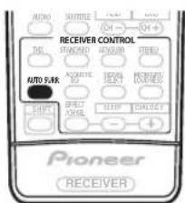
text_image
NOMO SHUTTER ON CH—OH+ RECEIVER CONTROL TALI STRONGER ONION TBE2 AUTO PURK ACCESS OFF SPRING OFFICE BLUE ONION Pioneer RECEIVER- While listening to a source, press AUTO SURR for auto playback of a source.
AUTO SURROUND shows briefly in the display before showing the decoding or playback format. Check the digital format indicators in the front panel display to see how the source is being processed.

Note
- Stereo surround (matrix) formats are decoded accordingly using Neo:6 CINEMA or Pro Logic IIx MOVIE (see Listening in surround sound below for more on these decoding formats).
- The Auto Surround feature is canceled if you connect headphones or select the multichannel analog inputs.
Listening in surround sound
Using this receiver, you can listen to any source in surround sound. However, the options available will depend on your speaker setup and the type of source you're listening to.
If you connected surround back speakers, see also Using the surround back channel (Extended mode) on page 34.
Standard surround sound
The following modes provide basic surround sound for stereo and multichannel sources.
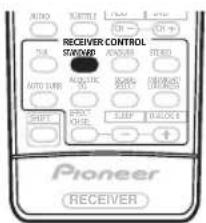
text_image
AUTO TURKEY ON ON + RECEIVER CONTROL STRAWB AVOCUMBER READS AUTO SURF ALABRIC RANGE DRAGON SHIFT AVOCUMBER SLIPP DOUBLE + Pioneer RECEIVER- While listening to a source, press STANDARD.
If necessary, press repeatedly to select a listening mode.
- If the source is Dolby Digital, DTS, or Dolby Surround encoded, the proper decoding format will automatically be selected and shows in the display.
With two channel sources, you can select from:
- Pro Logic IIx MOVIE – Up to 7.1 channel sound, especially suited to movie sources
- Pro Logic IIx MUSIC – Up to 7.1 channel sound, especially suited to music sources
- PRO LOGIC – 4.1 channel surround sound (sound from the surround speakers is mono)
- Neo:6 CINEMA – 6.1 channel sound, especially suited to movie sources
- Neo:6 MUSIC – 6.1 channel sound, especially suited to music sources
With multichannel sources, if you have connected surround back speaker(s) and have selected Extended
ON, you can select (according to format):
- Pro Logic IIx MOVIE – See above (only available when you're using two surround back speakers)
- Pro Logic IIx MUSIC – See above
- Dolby Digital EX – Creates surround back channel sound for 5.1 channel sources and provides pure decoding for 6.1 channel sources (like Dolby Digital Surround EX)
- DTS-ES – Allows you to hear 6.1 channel playback with DTS encoded sources

Note
- If the Extended mode (page 34) is switched to OFF, or the surround back speakers are set to NO (this happens automatically if the Surround back speaker setting on page 38 is set to anything but Normal (SB)), ☐☐ Pro Logic IIx becomes ☐☐ Pro Logic II (5.1 channel sound).
- In modes that give 6.1 channel sound, the same signal is heard from both surround back speakers.
Using the Home THX modes
THX and Home THX are technical standards created by Lucasfilm Ltd. for cinema and home theater sound. Home THX is designed to make home theater audio sound more like what you hear in a cinema.
Different THX options will be available depending on the source and the Extended mode setting (see Using the surround back channel (Extended mode) on page 34 for more on this).
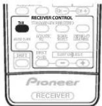
text_image
RECEIVER CONTROL TAL AUTO SWITCH AQUATIC RE MINI OFF SHIFT EFFECT ORDER SUPPORT ORDER Pioneer RECEIVER- Press THX to select a THX listening mode.
With two channel sources, select a matrix-decoding process for the THX CINEMA mode (see Listening in surround sound above for an explanation of each process):
• Pro Logic IIx MOVIE
- PRO LOGIC
- Neo:6 CINEMA
With multichannel sources, you can select (according to format):
- THX CINEMA – Gives you cinema-quality sound from your home theatre system using all the speakers in your setup
- THX Surround EX – Allows you to hear 6.1 or 7.1 channel playback with 5.1 channel sources
- Pro Logic IIx MOVIE – Especially suited to movie sources, this allows you to hear 7.1 channel playback with 5.1 channel sources (only available when you're using two surround back speakers)
- DTS-ES – Allows you to hear 6.1 channel playback with DTS encoded sources

Note
- You won't be able to use the THX options with 88.2/96kHz PCM or DTS 96kHz/24 bit sources, or with the headphones connected.
Using the Advanced surround effects
The Advanced surround effects can be used for a variety of additional surround sound effects. Most Advanced Surround modes are designed to be used with film soundtracks, but some modes are also suited for music sources. Try different settings with various soundtracks to see which you like.
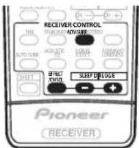
text_image
RECEIVER CONTROL THL TURAVES/INSURS AUTO SENS KOS-ADC HOLD EFFECT SHEEP DUDGE SHIFT PIONEER RECEIVER- Press ADV. SURR (ADVANCED SURROUND) repeatedly to select a listening mode.
- ADVANCED MOVIE – Simulates the relaxed environment of a movie theater, and is suitable for watching movies.
- ADVANCED MUSIC – Simulates the acoustic environment of a large concert hall and is suitable for music or musical sources.
- TV SURROUND – This mode produces surround sound for both mono and stereo TV sources. It is useful for older movies recorded with mono soundtracks.
- SPORTS – This is designed for sports programs with a lot of action, adding to the excitement by bringing background action to the forefront.
- GAME – Useful when playing video games. It works especially well with sound moving from left to right in game software with a lot of movement.
- EXPANDED – This mode is especially designed to give sound depth to stereo sources, and lets you hear two-channel (stereo) signals as simulated multichannel surround sound. Use with Dolby Pro Logic for a stereo surround effect. You can also use with Dolby Digital sources for a wider stereo field than the Standard modes.
- 7ch STEREO – This can be selected to give multichannel sound to a stereo source, using all of the speakers in your setup.
- PhonesSurround – When listening through headphones, you can still get the effect of overall surround.

Note
- Depending on the source and the sound mode you have selected, you may not get sound from the surround back speakers in your setup. For more on this, refer to Using the surround back channel (Extended mode) on page 34.
- If you press ADV. SURR when the headphones are connected, the PhonesSurround mode will automatically be selected.
- You can't use the Advanced Surround effects with 88.2/96kHz PCM or DTS 96kHz/24 bit sources.

Tip
- When an Advanced Surround listening mode is selected, the effect level can be adjusted in the range of 10 to 90 by pressing EFFECT/CH SEL (until EFFECT shows in the display). The effect level can be set for each Advanced Surround mode by pressing +/-.
Dolby Pro Logic IIx Music settings
When listening to 2-channel sources in Dolby Pro Logic IIx Music mode, there are three further parameters you can adjust: Center Width, Dimension, and Panorama.
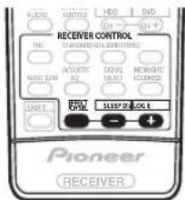
text_image
ASLIC PULSE HDD DVD RECEIVER CONTROL TWO RIO AVOCIVE RIO OFF SELECT NEWMNT ACCELER SHIFT SPEED OLOG E Pioneer RECEIVER1 With ' ☐☐ Pro Logic IIx MUSIC' mode active, press EFFECT/CH SEL repeatedly to select CENTER WIDTH, DIMENSION or PANORAMA.
- CENTER WIDTH – Provides a better blend of the front speakers by spreading the center channel between the front right and left speakers, making it sound wider (higher settings) or narrower (lower settings), (This is applicable only when using a center speaker.)
- DIMENSION – Adjusts the depth of the surround sound balance from front to back, making the sound more distant (minus settings), or more forward (positive settings).
- PANORAMA – Extends the front stereo image to include the surround speakers for a 'wraparound' effect.
2 Use the +/- buttons to adjust the setting.
Center Width is adjustable between 0 and 7 (default : 3); Dimension between -3 and +3 (default : 0); Panorama is On or Off (default : Off).
3 Press EFFECT/CH SEL again to adjust other settings.

Note
- If the Extended mode is switched off, ☐ Pro Logic IIx (above) becomes ☐ Pro Logic II (5.1 channel sound), however the above setting will still be effective.
Neo:6 Music settings
- Default setting: 2
When listening to 2-channel sources in Neo:6 Music mode, you can adjust the center image to create a wider stereo effect with vocals. Note that this is only available when using a center speaker.
1 With Neo:6 MUSIC mode active, press EFFECT/CH SEL repeatedly to select C. IMAGE.
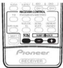
text_image
RECEIVER CONTROL NO. 100% 100% 100% AUTO SUB ACoustic ON/OFF SELECT ON/OFF SUPPORT SUBPLOGE Pioneer RECEIVER2 Use the +/- buttons to adjust the setting.
Adjust the effect from 0 (all center channel sent to front right and left speakers) to 5 (center channel sent to the center speaker only).
Listening in stereo
When you select STEREO or DIRECT, you will hear the source through just the front left and right speakers (and possibly your subwoofer depending on your speaker settings). Dolby Digital and DTS multichannel sources are downmixed to stereo.
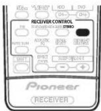
text_image
RECEIVER CONTROL Pioneer RECEIVER- While listening to a source, press STEREO for stereo playback.
Press repeatedly to switch between:
- STEREO – The audio is heard with your surround settings (such as channel level) and you can still use digital processing (such as the Midnight, Loudness, and Tone control functions).
- DIRECT – Bypass all effects and surround settings so that the audio remains as close to the source audio signal as possible.

Note
- If you switch on any signal processing features (for example, the Midnight listening mode or the tone controls) when DIRECT is selected, the receiver automatically switches to STEREO.
Listening with Acoustic Calibration EQ
- Default setting: OFF / ALL CH ADJ (after the Auto MCACC Setup or EQ Auto Setting)
You can listen to sources using the Acoustic Calibration Equalization set in Automatically setting up for surround sound (MCACC) on page 11 or Acoustic Calibration EQ on page 41. Refer to these pages for more on Acoustic Calibration Equalization.
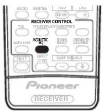
text_image
AUDIO SUBMITTLE + - CHINA + RECEIVER CONTROL SUSKMELON/AN SUBMETHNIC AUTO SWITCH ACoustic SHIFT EFFECT CONTROL SLEEP DRILLING - + Pioneer RECEIVER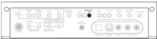
text_image
THYPO CONTROL WATER OUT WATER STATION SPRING RPS ACQUISIC TONG ACQUISIC SOUT MOUNTION RIP MOUNTION RIP POT ROLLING MOZZLE SPRING ACQUISIC SOUT ACQUISIC SOUT ACQUISIC SOUT ACQUISIC SOUT ACQUISIC SOUT ACQUISIC SOUT ACQUISIC SOUT ACQUISIC SOUT ACQUISIC SOUT ACQUISIC SOUT ACQUISIC SOUT ACQUISIC SOUT ACQUISIC SOUT ACQUIC SOUT ACQUISIC SOUT ACQUISIC SOUT ACQUISIC SOUT ACQUISIC SOUT ACQUISIC SOUT ACQUISIC SOUT ACQUISIC SOUT ACQUISIC SOUT ACQUISIC SOUT ACQUISIC SOUT ACQUISIC SOUT ACQUISIC SINCH2.2 INFLUCTION ACQUISIC INFLUCTION ACQUISIC INFLUCTION ACQUISIC INFLUCTION ACQUISIC INFLUCTION ACQUISIC INFLUCTION ACQUISIC INFLUCTION ACQUISIC INFLUCTION ACQUISIC INFLUCTION ACQUISIC INFLUCTION ACQUISIC INFLUCTION ACQUISIC INFLUCTION ACQUISICINFLUCTIONThe illustration above shows the VSX-2014i-G model.
- While listening to a source, press ACOUSTIC EQ. Press repeatedly to select between:
- ALL CH ADJ – No special weighting is given to any one channel.
- FRONT ALIGN – All speakers are heard in accordance with the front speaker settings.
- CUSTOM 1/2 – Custom settings
- OFF – Switches Acoustic Calibration EQ off.
The MCACC indicator on the front panel lights when Acoustic Calibration EQ is active.

Note
- You can't use Acoustic Calibration EQ when MULTI CH IN is switched on, and it has no effect when headphones are connected.
- If you switch on Acoustic Calibration EQ when DIRECT is selected, the receiver automatically switches to STEREO.
Choosing the input signal
You need to hook up a component to both analog and digital inputs on the rear of the receiver to select between input signals.
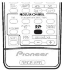
text_image
MIX AUTO CONTENTS HDD DVD CH- CH+ RECEIVER CONTROL STANDARD AUTO SMO STUDIO TICK ACQUISIC EQT SWEET SELECT MINISSIONAL STOCKS SHEET ELECTRIC SPEED DRUG E + Pioneer RECEIVER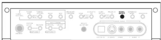
text_image
TOLER CONTROL TOLER UNIT RATIO MAX MWC PREMOUNT DESPRING ACQUISIO LINE OR MULTI CHILLI OCCOL INPUT CONTROL ON/OFF INVOICE INVOICE OUTPUT INVOICE OUTPUT RATIO COLD AIREX FROZEN FROZENThe illustration above shows the VSX-2014i-G model.
- Press SIGNAL SELECT to select the input signal corresponding to the source component.
Each press cycles through the options as follows:
- AUTO – The receiver selects the first available signal in the following order:
i (VSX-2014i-G only); DIGITAL; ANALOG. - ANALOG – Selects the analog inputs.
• DIGITAL – Selects the digital input.
• i (VSX-2014i-G only) – Selects the i.LINK input.
When set to DIGITAL or AUTO ☐ DIGITAL lights when a Dolby Digital signal is input, and DTS lights when a DTS signal is input.

Note
- This receiver can only play back Dolby Digital, PCM (32kHz–96 kHz) and DTS digital signal formats (including DTS 96kHz/24 bit). With other digital signal formats, set to ANALOG.
VSX-2014i-G only – If you are using the i.LINK connectors, DVD-A (including 192 kHz) and SACD are also supported.
- You may get digital noise when a LD or CD player compatible with DTS is playing an analog signal. To prevent noise, make the proper digital connections (page 16) and set the signal input to DIGITAL.
- Some DVD players don't output DTS signals. For more details, refer to the instruction manual supplied with your DVD player.
Using the surround back channel (Extended mode)
- Default setting: Extended ON
You can have the receiver automatically use 6.1 or 7.1 decoding for 6.1 encoded sources (for example, Dolby Digital EX or DTS-ES), or you can choose to always use 6.1 or 7.1 decoding (for example, with 5.1 encoded material). With 5.1 encoded sources, a surround back channel will be generated, but the material may sound better in the 5.1 format for which it was originally encoded (in which case, you can simply switch the Extended mode off).
The table below indicates when you will hear the surround back channel when playing various kinds of sources. (●=Sound plays through surround back speaker(s))
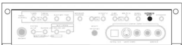
text_image
TIME CONTROL TURING TURING RADIO NPPY CTMP ACUATION MAXIMUM OUTPUT MAXIMUM OUTPUT MAXIMUM OUTPUT MAXIMUM OUTPUT MAXIMUM OUTPUT MAXIMUM OUTPUT MAXIMUM OUTPUT MAXIMUM OUTPUT MAXIMUM OUTPUT MAXIMUM OUTPUT MAXIMUM OUTPUT MAXIMUM OUTPUT MAXIMUM OUTPUT MAXIMUM OUTPUT MAXIMUM OUTPUT MAXIMUM OUTPUT MAXIMUM OUTPUT MAXIMUM OUTPUT MAXIMUM OUTPUT MAXIMUM OUTPUT MAXIMUM OUTPUT MAXIMUM OUTPUT MAXIMUM OUTPUT MAXIMUM OUTPUT MAXIMUM OUTPUT MAXIMUM OUTThe illustration above shows the VSX-2014i-G model.
- Press EXTENDED MODE (front panel) repeatedly to cycle the surround back channel options.
Each press cycles through the options as follows:
- Extended ON – 6.1 or 7.1 decoding is always used (for example, a surround back channel will be generated for 5.1 encoded material)
- Extended AUTO – Automatically switches to 6.1 or 7.1 decoding for 6.1 encoded sources (for example, Dolby Digital EX or DTS-ES)
- Extended OFF – Maximum 5.1 playback

Note
- You must have surround back speakers connected (and set to LARGEor SMALL in theSpeakerSetting on page 44) and the Surround back speaker setting on page 38 must be set to Normal (SB) to hear the surround back channel.
- You can't use the surround back channel with headphones, the STEREO / DIRECT mode.
- You can't hear the surround back channel with DTS 96kHz/24 bit or PCM 96/88.2kHz sources.
| Type of source | Extended mode | Standard / THX | Advanced surround | |||
| Multichannel sources | Stereo sources | |||||
| Pro Logic II x | Pro Logic | Neo:6 | ||||
| Dolby Digital EX/DTS-ES encoded multichannel source with 6.1ch surround | ON | ● | ● | |||
| AUTO | ● | ● | ||||
| Dolby Digital/DTS encoded multichannel source | ON | ● | ● | |||
| AUTO | ● | |||||
| Dolby Digital encoded stereo source; other digital stereo source | ON | ● | ● | ● | ||
| AUTO | ● | ● | ● | |||
| DTS encoded stereo source | ON | ● | ● | |||
| AUTO | ● | ● | ||||
| Analog 2-channel (stereo) source | ON | ● | ● | ● | ||
| AUTO | ● | ● | ● | |||
Using the Virtual Surround Back mode (VirtualSB)
When you're not using surround back speakers, selecting this mode allows you to hear a virtual surround back channel through your surround speakers. For example, you can choose to listen to sources with no surround back channel information (for example, 5.1 encoded material) with emulated 6.1 encoding (VirtualSB ON). Sometimes the material may sound better in the 5.1 format for which it was originally encoded. In this case you can have the receiver only apply this effect to 6.1 encoded sources like Dolby Digital EX or DTS-ES (VirtualSB AUTO), or you can simply switch it off (VirtualSB OFF).
The table indicates when you will hear the virtual surround back channel. (●=Virtual surround back channel is active)
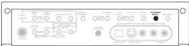
text_image
STANDARD CONTROL TYPE 1 TYPE 2 TYPE 3 STANDARD TYPE 4 STANDARD TYPE 5 STANDARD TYPE 6 STANDARD TYPE 7 STANDARD TYPE 8 STANDARD TYPE 9 STANDARD TYPE 10 STANDARD TYPE 11 STANDARD TYPE 12 STANDARD TYPE 13 STANDARD TYPE 14 STANDARD TYPE 15 STANDARD TYPE 16 STANDARD TYPE 17 STANDARD TYPE 18 STANDARD TYPE 19 STANDARD TYPE 20 STANDARD TYPE 21 STANDARD TYPE 22 STANDARD TYPE 23 STANDARD TYPE 24 STANDARD TYPE 25 STANDARD TYPE 26 STANDARD TYPE 27 STANDARD TYPE 28 STANDARD TYPE 29 STANDARD TYPE 30 STANDARD TYPE 31 STANDARD TYPE 32 STANDARD TYPE 33 STANDARD TYPE 34 STANDARD TYPE 35 STANDARD TYPE 36 STANDARD TYPE 37 STANDARD TYPE 38 STANDARD TYPE 39 STANDARD TYPE 40 STANDARD TYPE 41 STANDARD TYPE 42 STANDARD TYPE 43 STANDARD TYPE 44 STANDARD TYPE 45 STANDARD TYPE 46 STANDARD TYPE 47 STANDARD TYPE 48 STANDARD TYPE 49 STANDARD TYPE 50 STANDARD TYPE 51 STANDARD TYPE 52 STANDARD TYPE 53 STANDARD TYPE 54 STANDARD TYPE 55 STANDARD TYPE 56 STANDARD TYPE 57 STANDARD TYPE 58 STANDARD TYPE 59 STANDARD TYPE 60 STANDARD TYPE 61 STANDARD TYPE 62 STANDARD TYPE 63 STANDARD TYPE 64 STANDARD TYPE 65 STANDARD TYPE 66 STANDARD TYPE 67 STANDARD TYPE 68 STANDARD TYPE 69 STANDARD TYPE 70 STANDARD TYPE 71 STANDARD TYPE 72 STANDARD TYPE 73 STANDARD TYPE 74 STANDARD TYPE 75 STANDARD TYPE 76 STANDARD TYPE 77 STANDARD TYPE 78 STANDARD TYPE 79 STANDARD TYPE 80The illustration above shows the VSX-2014i-G model.
- Press EXTENDED MODE (front panel) repeatedly to cycle the virtual surround back channel options. Each press cycles through the options as follows:
- VirtualSB ON – Virtual Surround Back is always used (for example, on 5.1 encoded material)
- VirtualSB AUTO – Virtual Surround Back is automatically applied to 6.1 encoded sources (for example, Dolby Digital EX or DTS-ES)
- VirtualSB OFF – Virtual Surround Back mode is switched off

Note
- You can't use the Virtual Surround Back mode with headphones, or with the THX or STEREO / DIRECT modes.
- You can only use the Virtual Surround Back mode if the surround speakers are on and the Surr Back setting is set to NO in the Speaker Setting on page 44.
- You can't hear the virtual surround back channel with DTS 96kHz/24 bit or PCM 96/88.2kHz sources.
- The Virtual Surround Back mode cannot be applied to sources that do not have surround channel information.
| Type of source | VirtualSB mode | Standard | Advanced surround | |||
| Multichannel sources | Stereo sources | |||||
| Pro Logic II | Pro Logic | Neo:6 | ||||
| Dolby Digital EX/DTS-ES encoded multichannel source with 6.1ch surround | ON | ● | ● | |||
| AUTO | ● | ● | ||||
| Dolby Digital/DTS encoded multichannel source | ON | ● | ● | |||
| AUTO | ● | |||||
| Dolby Digital/DTS encoded stereo source; other digital stereo source | ON | ● | ● | ● | ● | |
| AUTO | ● | ● | ||||
| Analog 2-channel (stereo) source | ON | ● | ● | ● | ● | |
| AUTO | ● | ● | ||||
Using Loudness and Midnight listening
The Loudness listening feature can be used to get good bass and treble from music sources at low volume levels.
The Midnight listening feature allows you to hear effective surround sound of movies at low volume levels. The effect automatically adjusts according to the volume at which you're listening.
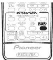
text_image
NO. 100 ON/OFF CHINESE HEDD SVD RECEIVER CONTROL STANDARD ACROSS REJECTED AUTO SWITCH ACQUISIC RQ RUNISH MINISSIONAL SHIFT EFFECTIVE SLIPPY CHANGE Pioneer RECEIVER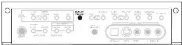
text_image
VOLT ON/OFF OFF ON/OFF ON/OFF ON/OFF ON/OFF ON/OFF ON/OFF ON/OFF ON/OFF ON/OFF ON/OFF ON/OFF ON/OFF ON/OFF ON/OFF ON/OFF ON/OFF ON/OFF ON/OFF ON/OFF ON/OFF ON/OFF ON/OFF ON/OFF ON/OFF ON/OFF ON/OFP ON/OFP ON/OFP ON/OFP ON/OFP ON/OFP ON/OFP ON/OFP ON/OFP ON/OFP ON/OFP ON/OFP ON/OFP ON/OFP ON/OFP ON/OFP ON/OFP ON/OFP ON/OFP ON/OFP ON/OFP ON/OFP ON/OFP ON/OFP ON/OFP ON/OF ON/OFP ON/OFP ON/OFP ON/OFP ON/OFP ON/OFP ON/OFP ON/OFP ON/OFP ON/OFP ON/OFP ON/OFP ON/OFP ON/OFP ON/OFP ON/OFP ON/OFP ON/OFP ON/OFP ON/OFP ON/OFP ON/OFP ON/OFP ON/OFP ON/OFO ON/OFO ON/OFO ON/OFO ON/OFO ON/OFO ON/OFO ON/OFO ON/OFO ON/OFO ON/OFO ON/OFO ON/OFO ON/OFO ON/OFO ON/OFO ON/OFO ON/OFO ON/OFO ON/OFO ON/OFO ON/OFO ON/OFO ON/OFO ON/OFO ON/OOFO ON/OF01 100000 10000 10000 10000 10000 10000 10000 10000 10000 10000 10000 10000 10000 10000 10000 10000 10000 1000The illustration above shows the VSX-2014i-G model.
- Press MIDNIGHT/LOUDNESS to switch between MIDNIGHT, LOUDNESS, and OFF.

Note
- You can't use MIDNIGHT/LOUDNESS with DTS 96kHz/24 bit or PCM 96/88.2kHz sources, or when MULTI CH IN, or one of the THX modes has been selected.
- If you switch on Loudness or Midnight listening when DIRECT is selected, the receiver automatically switches to STEREO.
Enhancing dialog
- Default setting: DIALOG E OFF
The Dialog Enhancement feature localizes dialog in the center channel to make it stand out from other background sounds in a TV or movie soundtrack.

text_image
WAL AVOC CHINESE CENTER HEDD IND RECEIVER CONTROL STANDARD PRESS WRITERED AUTO SUN ACQUISIC AIR SHEAT MOZZARE COOKING SHORT ONION SLIDE BLOCK SHEET Pioneer RECEIVER- Press SHIFT+DIALOG E to switch dialog enhancement on or off.

Note
- You can't use dialog enhancement with DTS 96kHz/24 bit or PCM 96/88.2kHz sources, or when one of the THX modes has been selected.

Tip
- VSX-1014-S model only – You can also switch Dialog Enhancement on or off using the front panel:
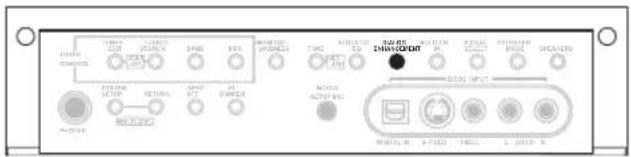
text_image
MOSA CONTROL MOSA RUSAS CHINOCENT MOSA RUSAS CHINOCENT MOSA RUSAS CHINOCENT MOSA RUSAS CHINOCENT MOSA RUSAS CHINOCENT MOSA RUSAS CHINOCENT MOSA RUSAS CHINOCENT MOSA RUSAS CHINOCENT MOSA RUSAS CHINOCENT MOSAM RUSAM CHINOCENT MOSAM RUSAM CHINOCENT MOSAM RUSAM CHINOCENT MOSAM RUSAM CHINOCENT MOSAM RUSAM CHINOCENT MOSAM RUSAM CHINOCENT MOSAM RUSAM CHINOCENT MOSAM RUSAM CHINOCENT MOSAM RUSAM CHINOCINT MOSAM RUSAM CHINOCINT MOSAM RUSAM CHINOCINT MOSAM RUSAM CHINOCINT MOSAM RUSAM CHINOCINT MOSAM RUSAM CHINOCINT MOSAM RUSAM CHINOCINT MOSAM RUSAM CHINOCINT MOSAM RUSAM CHINOCINT MOSAUsing the tone controls
Depending on what you are listening to, you may want to adjust the bass or treble using the front panel tone control.
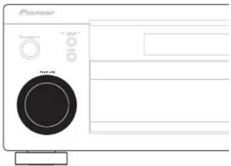
text_image
Pioneer Control 100% R431.09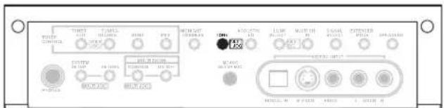
text_image
TRENT POWER CONCLOS TARELLA INFLUORES OFFICE PPT MOUNT INFLUORES 100V AC-DC AC-DC AC-DC AC-DC AC-DC AC-DC AC-DC AC-DC AC-DC AC-DC AC-DC AC-DC AC-DC AC-DC AC-DC AC-DC AC-DC AC-DC AC-DC AC-DC AC-DC AC-DC AC-DC AC-DC AC-DC AC-PC AC-PC AC-PC AC-PC AC-PC AC-PC AC-PC AC-PC AC-PC AC-PC AC-PC AC-PC AC-PC AC-PC AC-PC AC-PC AC-PC AC-PC AC-PC AC-PC AC-PC AC-PC AC-PC AC-PC AC-PC AC-PCI AC-PCI AC-PCI AC-PCI AC-PCI AC-PCI AC-PCI AC-PCI AC-PCI AC-PCI AC-PCI AC-PCI AC-PCI AC-PCI AC-PCI AC-PCI AC-PCI AC-PCI AC-PCI AC-PCI AC-PCI AC-PCI AC-PCI AC-PCI AC-PCI AC-PC AC-PC AC-PC AC-PC AC-PC AC-PC AC-PC AC-PC AC-PC AC-PC AC-PC AC-PC AC-PC AC-PC AC-PC AC-PC AC-PC AC-PC AC-PC AC-PC AC-PC AC-PC AC-PC AC-PC AC-IPC AC-IPC AC-IPC AC-IPC AC-IPC AC-IPC AC-IPC AC-IPC AC-IPC AC-IPC AC-IPC AC-IPC AC-IPC AC-IPC AC-IPC AC-IPC AC-IPC AC-IPC AC-IPC AC-IPC AC-IPC AC-IPC AC-IPC AC-IPC AC-IPC AC-IPCC M 4.5V/4.5V AC+ 5.0V/4.5V AC- 3.5V/4.5V AC+ 5.0V/4.5V AC- 3.5V/4.5V AC+ 5.0V/4.5V AC- 3.5V/4.5V AC+ 5.0V/4.5V AC- 3.5V/4.5V AC+ 5.0V/4.5V AC- 3.5V/4.5G M 4.5V/4.5V AC+ 3.5V/4.5G M 4.5V/4.5V AC- 3.5V/4.5G M 4.5V/4.5V AC- 3.5V/4.5G M 4.5V/4.5V AC- 3.5V/4.5G M 4.5V/4.5V AC- 3.5V/4.5G M 4.5V/4.5V AC- 3.5V/4.5G M 2.5V/4.5V AC- 3.5V/4.5G M 2.5V/4.5V AC- 3.5V/4.5G M 2.5V/4.5V AC- 3.5V/4.5G M 2.5V/4.5V AC- 3.5V/4.5G M 2.5V/4.5V AC- 3.ACT. 3.ACT. 3.ACT. 3.ACT. 3.ACT. 3.ACT. 3.ACT. 3.ACT. 3.ACT. 3.ACT. 3.ACT. 3.ACT. 3.ACT. 3.ACT. 3.ACT. 3.ACT. 3.ACT. 3.ACT. 3.ACT. 3.ACT. 3.ACT. 3.ACT. 3.ACT. 3.ACT. 3.ACT. 3.ACT.The illustration above shows the VSX-2014i-G model.
1 Press TONE to select the frequency you want to adjust.
Each press switches between BASS and TREBLE.
2 Use the MULTI JOG dial to change the amount of bass or treble as necessary.
The bass and treble can be adjusted from -6 to +6 (dB).
- Wait about five seconds for your changes to be input automatically.

Note
- You can only use the tone controls when STEREO/DIRECT is selected. DIRECT will switch to STEREO when the tone controls are used.
Playing other sources
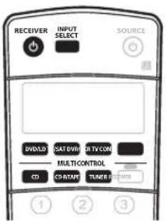
text_image
RECEIVER INPUT SELECT SOURCE DVD/LOD CAT/DWORD TV/CON MULTI CONTROL CD CO START TUNER CONTROL ① ② ③1 Turn on the power of the playback component.
2 Turn on the power of the receiver.
3 Select the source you want to playback.
Use the MULTI CONTROL buttons (or INPUT SELECT).
4 Start playback of the component you selected in step 1.
Selecting the multichannel analog inputs
If you have connected a decoder or a DVD player with multichannel analog outputs to this receiver (page 17), you must select the analog multichannel inputs for surround sound playback.
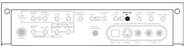
text_image
WALW 100V 200V 300V 400V 500V 600V 700V 800V 900V 1000V 110V 120V 130V 140V 150V 160V 170V 180V 190V 200V 210V 220V 230V 240V 250V 260V 270V 280V 290V 300V 310V 320V 330V 340V 350V 360V 370V 380V 390V 400V 410V 420V 430V 440V 450V 460V 470V 480V 490V 500V 510V 520V 530V 540V 550V 560V 570V 580V 590V 600V 610V 620V 630V 640V 650V 660V 670V 680V 690V 700V 710V 720V 730V 740V 750V 760V 770V 780V 790V 800V 810V 820V 830V 840V 850V 860V 870V 880V 890V 900V 910V 920V 930V 940V 950V 960V 970V 980V 990V 1000VThe illustration above shows the VSX-2014i-G model.
1 Make sure you have set the playback source to the proper output setting.
For example, you might need to set your DVD player to output multichannel analog audio.
2 Press MULTI CH IN on the front panel.
To cancel playback from the multichannel inputs, press MULTI CH IN once again.

Note
- When playback from the multichannel inputs is selected, you can't use the ACOUSTIC CAL EQ, DIALOG E, SIGNAL SELECT, INPUT ATT, TONE and MIDNIGHT/LOUDNESS buttons, as well as any of the listening modes (including STEREO/DIRECT and the Extended mode).
- When playback from the multichannel inputs is selected, only the volume and channel levels can be set.
- You can't listen to your speaker B (Second Zone) system during playback from the multichannel inputs.
Using the sleep timer
The sleep timer switches the receiver into standby after a specified amount of time so you can fall asleep without worrying about the receiver being left on all night. Use the remote control to set the sleep timer.
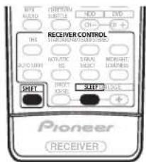
text_image
MIX ALABO SPECTRUM SUBTUM HDD DVD CH... DH+ RECEIVER CONTROL SPRING ON CHAPES ON CHAPES AUTO CHAPES NATRATIC SLC SIRAL MOUGHT COOKING SWEET SWEET PIONEER RECEIVER- Press SHIFT+SLEEP repeatedly to set the sleep time.
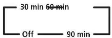
flowchart
graph LR
    A["Off"] --> B["60 min"]
    B --> C["30 min"]

Note
- You can check the remaining sleep time at any time by pressing SHIFT+SLEEP once. Pressing repeatedly will cycle through the sleep options again.
- The sleep timer affects the sub room when the multi-room feature is on.
- You can also switch off the sleep timer simply by switching off the receiver.
Chapter 6:
The System Setup menu
Making receiver settings from the System Setup menu
The following section shows you how to make detailed settings to specify how you're using the receiver (for example, if you want to set up two speaker systems in separate rooms), and also explains how to fine-tune individual speaker system settings to your liking.
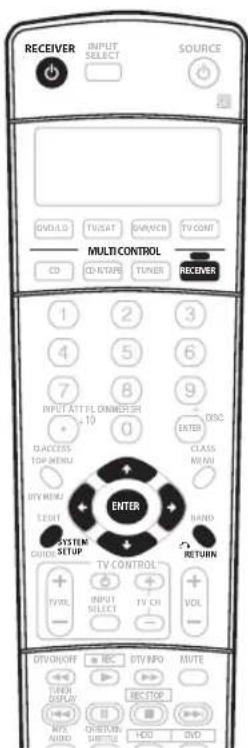
text_image
RECEIVER INPUT SELECT SOURCE DVD-ILD TV/SAT DIN/WR TV CONT Multi CONTROL CO CD-STAP TUNER RECEIVER 1 2 3 4 5 6 7 8 9 INPUT ATT FL DIMMER 3H 10 0 ACCESS TOP MENU CLASS MINI DTY MENU EIGHT MND SYSTEM QUICKS SETUP THY CONTROL TV/VOL INPUT SELECT TV CH VOL - - - + - + - + - + - + - + - + - + - + - + - + - + - + - + - + - + - + - + - + - + - + - + - + - + - + - + - + - + - + - + - + - + - + - + - + - + - + - + - + - + - + - + - + - + - + - + - + - + - + - + - + - + - + - + - + - + - + - + - + - + - + - + - + - + - + - + - + - + - + - + - + - + - + - + - + - + - + - + - + - + - + - + - + - + - + - + - + - + - + - + - + - + -1 Switch on the receiver and your TV.
Use the ⏻ RECEIVER button to switch on.
- If headphones are connected to the receiver, disconnect them.
2 Press RECEIVER on the remote control, then press the SYSTEM SETUP button.
An on-screen display (OSD) appears on your TV. Use the ↑/↓/↔/→ buttons and ENTER on the remote control to navigate through the screens and select menu items. Press RETURN to confirm and exit the current menu.
- Press SYSTEM SETUP at any time to exit the System Setup menu.
3 Select the setting you want to adjust.
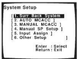
text_image
System Setup [1. Surr Back System [2. AUTO MCACC ] [3. MANUAL MCACC ] [4. MANUAL SP Setup ] [5. Input Assign ] [6. Other Setup ] Enter : Select Return : Exit- Surr Back System – Specify how you are using your surround back speakers (see Surround back speaker setting below).
- AUTO MCACC – This is a quick and effective automatic surround setup (see Automatically setting up for surround sound (MCACC) on page 11).
- MANUAL MCACC – Fine tune your speaker settings and customize the Acoustic Calibration EQ (see Manual MCACC speaker setup below).
- Manual SP Setup – Specify the size, number, distance and overall balance of the speakers you've connected (see Manual speaker setup on page 43).
- Input Assign – Specify what you've connected to the digital and component video inputs (see The Input Assign menu on page 63).
- Other Setup – Make customized settings to reflect how you are using the receiver (see The Other Setup menu on page 65).
Surround back speaker setting
- Default setting: Normal (SB)
There are several ways you can use the surround back speaker channels with this system. In addition to a normal home theater setup where they are used for the surround back speakers, they can be used for bi-amping the front speakers or as a separate speaker system in another room.
1 Select 'Surr Back System' from the System Setup menu.
See Making receiver settings from the System Setup menu above if you're not already at this screen.
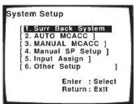
text_image
System Setup [1. Surr Back System [2. AUTO MCACC ] [3. MANUAL MCACC ] [4. Manual SP Setup ] [5. Input Assign ] [6. Other Setup ] Enter : Select Return : Exit2 Select the surround back speaker setting.
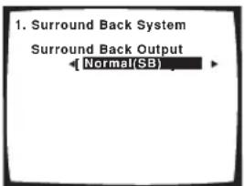
text_image
1. Surround Back System Surround Back Output ← Normal(SB)- Normal (SB) – Select for normal home theater use with surround back speakers in your main (speaker system A) setup.
- Second Zone – Select to use the (surround back) B speaker terminals to listen to stereo playback in another room (see Second Zone speaker B setup on page 55).
- Front Bi-Amp – Select this setting if you're bi-amping your front speakers (see Bi-amping your front speakers on page 56).
3 When you're finished, press RETURN.
You will return to the System Setup menu.
Manual MCACC speaker setup
You can use the settings in the Manual MCACC setup menu to make detailed adjustments when you're more familiar with the system. Before making these settings, you should have already completed Automatically setting up for surround sound (MCACC) on page 11.
You only need to make these settings once (unless you change the placement of your current speaker system or add new speakers).

Important
- For some of the settings below, you'll have to connect the setup microphone to the front panel and place it about ear level at your normal listening position. See Automatically setting up for surround sound (MCACC) on page 11 if you're unsure how to do this. Also see Other problems when using the Auto MCACC Setup on page 13 for notes regarding high background noise levels and other possible interference.
- If you're using a subwoofer, switch it on and turn up the volume to the middle position.
1 Select 'MANUAL MCACC' from the System Setup menu.
See Making receiver settings from the System Setup menu above if you're not already at this screen.
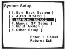
text_image
System Setup [1. Surr Back System ] [2. AUTO MCACC ] [3. MANUAL MCACC ] [4. Manual SP Setup ] [5. Input Assign ] [6. Other Setup ] Enter : Select Return : Exit2 Select the setting you want to adjust.
If you're doing this for the first time, you might want to make these settings in order.
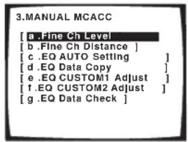
text_image
3.MANUAL MCACC [a .Fine Ch Level [b .Fine Ch Distance ] [c .EQ AUTO Setting ] [d .EQ Data Copy ] [e .EQ CUSTOM1 Adjust ] [f .EQ CUSTOM2 Adjust ] [g .EQ Data Check ]- Fine Ch Level – Make fine adjustments to the overall balance of your speaker system (see Fine Channel Level below).
- Fine Ch Distance – Make precise delay settings for your speaker system (see Fine Channel Distance on page 40).
The last five settings are specifically for customizing the parameters explained in Acoustic Calibration EQ below:
- EQ AUTO Setting – Measure the acoustic characteristics of your room and automatically adjust the frequency balance of your speaker system (see Setting the Acoustic Calibration EQ automatically below).
- EQ Data Copy – Copy Acoustic Calibration EQ settings for manual adjustment (see Copying your Acoustic Calibration EQ settings below).
- EQ CUSTOM1/2 Adjust – Make detailed manual adjustments to your custom Acoustic Calibration EQ settings (see Setting the Acoustic Calibration EQ manually on page 42).
- EQ Data Check – Check the ALL CH ADJUST, FRONT ALIGN and custom settings using the on-screen display (see Checking your Acoustic Calibration EQ settings on page 42).
Fine Channel Level
- Default setting: 0dB (all channels)
You can achieve better surround sound by properly adjusting the overall balance of your speaker system. The following setting can help you make detailed adjustments that you may not achieve using the Manual speaker setup on page 43.
1 Select 'Fine Ch Level' from the Manual MCACC setup menu.
The volume increases to the 0dB reference level.
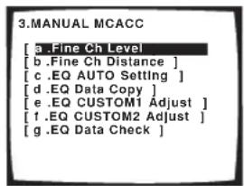
text_image
3.MANUAL MCACC [ a .Fine Ch Level [ b .Fine Ch Distance ] [ c .EQ AUTO Setting ] [ d .EQ Data Copy ] [ e .EQ CUSTOM1 Adjust ] [ f .EQ CUSTOM2 Adjust ] [ g .EQ Data Check ]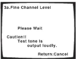
text_image
3a.Fine Channel Level Please Wait Caution!! Test tone Is output loudly. Return:Cancel2 Adjust the level of the left channel.
This will be the reference speaker level, so you may want to keep the level around 0dB so that you'll have plenty of room to adjust the other speaker levels.
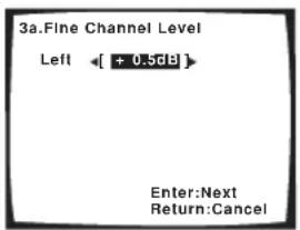
text_image
3a.Fine Channel Level Left ← [ + 0.5dB ] Enter:Next Return:Cancel• After pressing ENTER, test tones will be output
3 Select each channel in turn and adjust the levels (+/- 10dB) as necessary.
Use ←/→ (cursor left/right) to adjust the volume of the speaker you selected to match the reference speaker. When it sounds like both tones are the same volume, press ENTER to confirm and continue to the next channel.
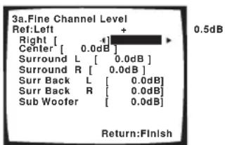
text_image
3a.Fine Channel Level Ref:Left + Right [ + ] Center [ 0.0dB ] Surround L [ 0.0dB ] Surround R [ 0.0dB ] Surr Back L [ 0.0dB ] Surr Back R [ 0.0dB ] Sub Woofer [ 0.0dB ] Return:Finish 0.5dB- For comparison purposes, the reference speaker will change depending on which speaker you select.
- If you want to go back and adjust a channel, simply use / (cursor up/down) to select it.
4 When you're finished, press RETURN.
You will return to the Manual MCACC setup menu.
Fine Channel Distance
- Default setting: 2.0 m (all channels)
For proper sound depth and separation with your system, it is necessary to add a slight bit of delay to some speakers so that all sounds will arrive at the listening position at the same time. The following setting can help you make detailed adjustments that you may not achieve using the Manual speaker setup below.
1 Select 'Fine Ch Distance' from the Manual MCACC setup menu.
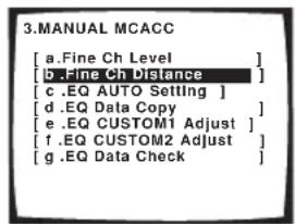
text_image
3.MANUAL MCACC [a.Fine Ch Level ] [d..Fine Ch Distance ] [c.EQ AUTO Setting ] [d.EQ Data Copy ] [e.EQ CUSTOM1 Adjust ] [f.EQ CUSTOM2 Adjust ] [g.EQ Data Check ]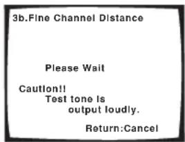
text_image
3b.Fine Channel Distance Please Wait Caution!! Test tone is output loudly. Return:Cancel2 Adjust the distance of the left channel from the listening position.
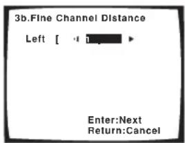
text_image
3b.Fine Channel Distance Left [ -1 ] ► Enter:Next Return:Cancel3 Select each channel in turn and adjust the distance as necessary.
Use / (cursor left/right) to adjust the delay of the speaker you selected to match the reference speaker. The delay is measured in terms of speaker distance from 0.1 to 9.0 meters.
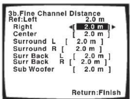
text_image
3b.Fine Channel Distance Ref: Left 2.0 m Right [ 2.0 m ] Center [ 2.0 m ] Surround L [ 2.0 m ] Surround R [ 2.0 m ] Surr Back L [ 2.0 m ] Surr Back R [ 2.0 m ] Sub Woofer [ 2.0 m ] Return:FinishListen to the reference speaker and use it to measure the target channel. From the listening position, face the two speakers with your arms outstretched pointing at each speaker. Try to make the two tones sound as if they are arriving simultaneously at a position slightly in front of you and between your arm span.

natural_image
Simple line drawing of a bowtie with a central circle and two empty rectangular boxes above (no text or symbols)When it sounds like the delay settings are matched up, press ENTER to confirm and continue to the next channel.
- For comparison purposes, the reference speaker will change depending on which speaker you select.
- If you want to go back and adjust a channel, simply use / (cursor up/down) to select it.
4 When you're finished, press RETURN.
You will return to the Manual MCACC setup menu.
Acoustic Calibration EQ
Acoustic Calibration Equalization is a kind of room equalizer for your speakers (excluding the subwoofer). It works by measuring the acoustic characteristics of your room and neutralizing the ambient characteristics that can color the original source material. This provides a 'flat' equalization setting. If you're not satisfied with the automatic adjustment, you can also adjust these settings manually to get a frequency balance that suits your tastes.
Setting the Acoustic Calibration EQ automatically
If you have already completed Automatically setting up for surround sound (MCACC) on page 11, ALL CH ADJUST and FRONT ALIGN (below) should already be set. Therefore, if you want to adjust your settings manually, you can skip to Setting the Acoustic Calibration EQ manually below.
1 Select 'EQ AUTO Setting' from the Manual MCACC setup menu.
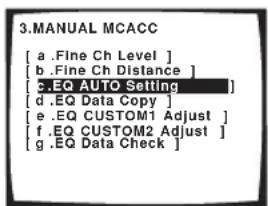
text_image
3.MANUAL MCACC [ a .Fine Ch Level ] [ b .Fine Ch Distance ] [ c.EQ AUTO Setting ] [ d .EQ Data Copy ] [ e .EQ CUSTOM1 Adjust ] [ f .EQ CUSTOM2 Adjust ] [ g .EQ Data Check ]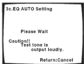
text_image
3c.EQ AUTO Setting Please Walt Caution!! Test tone is output loudly. Return:Cancel- Make sure the microphone is connected.
- If you're using a subwoofer, it is automatically detected every time you switch on the system. Make sure it is on and the volume is at the middle position.
- See Other problems when using the Auto MCACC Setup on page 13 for notes regarding high background noise levels and other possible interference.
2 Wait for the Auto MCACC Setup to finish.
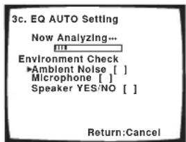
text_image
3c. EQ AUTO SETTING Now Analyzing... Environment Check ▶Ambient Noise [ ] Microphone [ ] Speaker YES/NO [ ] Return:Cancel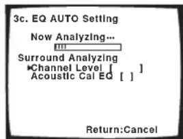
text_image
3c. EQ AUTO SETTING Now Analyzing... Surround Analyzing Channel Level [ ] Acoustic Cal EQ [ ] Return:CancelAs the receiver outputs test tones, the frequency balance is adjusted automatically for the following settings:
- ALL CH ADJUST – A 'flat' setting where all the speakers are set individually so no special weighting is given to any one channel.
- FRONT ALIGN – All speakers are set in accordance with the front speaker settings (no equalization is applied to the front left and right channels).
You will return to the Acoustic Cal EQ setup menu after the Acoustic Calibration Equalization is set.
Copying your Acoustic Calibration EQ settings
If you want to manually adjust the Acoustic Calibration EQ (see Setting the Acoustic Calibration EQ manually below), we recommend copying the ALL CH ADJUST or the FRONT ALIGN settings from the EQ AUTO setup above (or from Automatically setting up for surround sound (MCACC) on page 11) to one of the custom settings. Instead of just a flat EQ curve, this will give you a reference point from which to start.
1 Select 'EQ Data Copy' from the Manual MCACC setup menu.
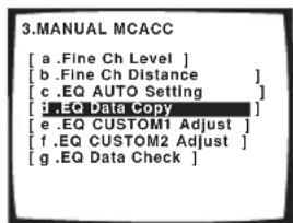
text_image
3.MANUAL MCACC [a .Fine Ch Level ] [b .Fine Ch Distance ] [c .EQ AUTO Setting ] [d .EQ Data Copy ] [e .EQ CUSTOM1 Adjust ] [f .EQ CUSTOM2 Adjust ] [g .EQ Data Check ]2 Select CUSTOM1 or CUSTOM2 then use the ←/→ (cursor left/right) buttons to select the setting you want to copy.
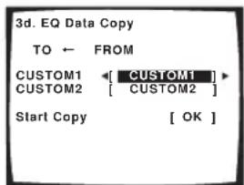
text_image
3d. EQ Data Copy TO ← FROM CUSTOM1 ← [ CUSTOM1 ] CUSTOM2 [ CUSTOM2 ] Start Copy [ OK ]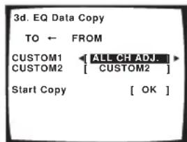
text_image
3d. EQ Data Copy TO ← FROM CUSTOM1 ALL CH ADJ. CUSTOM2 [ CUSTOM2 ] Start Copy [ OK ]- You can also copy from one custom setting to another. For more on the ALL CH ADJUST and FRONT ALIGN settings, see Setting the Acoustic Calibration EQ automatically above.
3 Select 'OK' to copy and confirm.
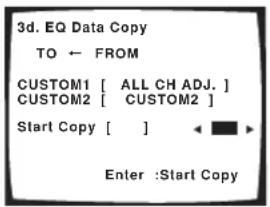
text_image
3d. EQ Data Copy TO ← FROM CUSTOM1 [ ALL CH ADJ. ] CUSTOM2 [ CUSTOM2 ] Start Copy [ ] Enter :Start CopySetting the Acoustic Calibration EQ manually
Before manually adjusting the Acoustic Calibration EQ, we recommend copying the ALL CH ADJUST or the FRONT ALIGN settings from the auto setup above (or from Automatically setting up for surround sound (MCACC) on page 11) to one of the custom settings. Instead of just a flat EQ curve, this will give you a reference point from which to start (see Copying your Acoustic Calibration EQ settings above for how to do this).
1 Select 'EQ CUSTOM1 Adjust or EQ CUSTOM2 Adjust' from the Manual MCACC setup menu.
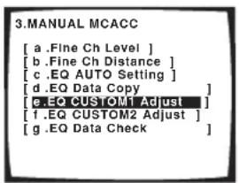
text_image
3.MANUAL MCACC [ a .Fine Ch Level ] [ b .Fine Ch Distance ] [ c .EQ AUTO SETTING ] [ d .EQ Data Copy ] [ e .EQ CUSTOM1 Adjust ] [ f .EQ CUSTOM2 Adjust ] [ g .EQ Data Check ]2 Select which method you would like to use to adjust the overall frequency balance.
It is best to choose whichever one you copied to the custom setting in Copying your Acoustic Calibration EQ settings above.
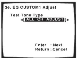
text_image
3e. EQ CUSTOM1 Adjust Test Tone Type [ALL CH ADJUST] Enter : Next Return : Cancel- ALL CH ADJUST – All the speakers can be set independently so no special weighting is given to any one channel. When adjusting, test tones will sound for each individual channel.
- FRONT ALIGN – Speakers are set in accordance with the front speaker settings. The sound of the test tone will alternate between the left front (reference) speaker and the target speaker.
3 Select the channel(s) you want and adjust to your liking.
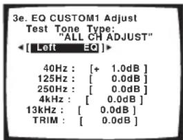
text_image
3e. EQ CUSTOM1 Adjust Test Tone Type: "ALL CH ADJUST" [ Left EQ ]> 40Hz : [ + 1.0dB ] 125Hz : [ 0.0dB ] 250Hz : [ 0.0dB ] 4kHz : [ 0.0dB ] 13kHz : [ 0.0dB ] TRIM : [ 0.0dB ]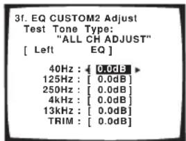
text_image
3f. EQ CUSTOM2 Adjust Test Tone Type: "ALL CH ADJUST" [ Left EQ ] 40Hz : [ 0.0dB ] 125Hz : [ 0.0dB ] 250Hz : [ 0.0dB ] 4kHz : [ 0.0dB ] 13kHz : [ 0.0dB ] TRIM : [ 0.0dB ]Use the / (cursor left/right) buttons to select the channel.
Use the ↑/↓ (cursor up/down) buttons to select the frequency and ←/→ (cursor left/right) to boost or cut the EQ. When you're finished, go back to the top of the screen and use the ←/→ (cursor left/right) buttons to select the next channel.
- The front speakers can't be adjusted if you selected FRONT ALIGN.
- The OVER indicator shows in the display if the frequency adjustment is too drastic and might distort. If this happens, bring the level down until OVER disappears from the display.

Tip
- Changing the frequency curve of one channel too drastically will affect the overall balance. If the speaker balance seems uneven, you can raise or lower channel levels using test tones with the TRIM feature. Use / (cursor up/down) to select TRIM then use / (cursor left/right) to raise or lower the channel level for the current speaker.
4 When you're finished, press RETURN.
You will return to the Manual MCACC setup menu.
Checking your Acoustic Calibration EQ settings
After you have completed an automatic or manual Acoustic Calibration EQ adjustment, you can check the ALL CH ADJUST, FRONT ALIGN and custom settings using the on-screen display.
1 Select 'EQ Data Check' from the Manual MCACC setup menu.
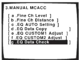
text_image
3.MANUAL MCACC [ a .Fine Ch Level ] [ b .Fine Ch Distance ] [ c .EQ AUTO Setting ] [ d .EQ Data Copy ] [ e .EQ CUSTOM1 Adjust ] [ f .EQ CUSTOM2 Adjust ] [ g .EQ Data Check ]2 Select the setting you want to check.
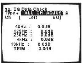
text_image
3g. EQ Data Check Type ← ALL CH ADJUST ↓ Ch [ Left EQ] 40Hz : 0.0dB 125Hz : 0.0dB 250Hz : 0.0dB 4kHz : 0.0dB 13kHz : 0.0dB TRIM : 0.0dB- It is useful to do this while a source is playing so you can compare the different settings.
3 Select the channels you want, pressing ENTER when you're finished checking each one.
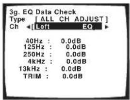
text_image
3g. EQ Data Check Type [ALL CH ADJUST] Ch ←[Left EQ ► 40Hz : 0.0dB 125Hz : 0.0dB 250Hz : 0.0dB 4kHz : 0.0dB 13kHz : 0.0dB TRIM : 0.0dB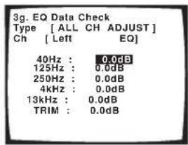
text_image
3g. EQ Data Check Type [ ALL CH ADJUST ] Ch [ Left EQ ] 40Hz : 0.0dB 125Hz : 0.0dB 250Hz : 0.0dB 4kHz : 0.0dB 13kHz : 0.0dB TRIM : 0.0dB4 When you're finished, press RETURN.
You will return to the Manual MCACC setup menu.
Manual speaker setup
This receiver allows you to make detailed settings to optimize the surround sound performance. You only need to make these settings once (unless you change the placement of your current speaker system or add new speakers).
These settings are designed to fine-tune your system, but if you're satisfied with the settings made in Automatically setting up for surround sound (MCACC) on page 11, it isn't necessary to make all of these settings.

Caution
- The test tones used in the System Setup are output at high volume (the volume increases to 0dB automatically).
1 Select 'Manual SP Setup' then press ENTER.
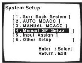
text_image
System Setup [1. Surr Back System ] [2. AUTO MCACC ] [3. MANUAL MCACC ] [4. Manual SP Setup ] [5. Input Assign ] [6. Other Setup ] Enter : Select Return : Exit2 Select the setting you want to adjust.
If you are doing this for the first time, you may want to adjust these settings in order:
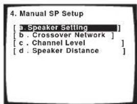
text_image
4. Manual SP Setup [a. Speaker Setting] [b. Crossover Network] [c. Channel Level] [d. Speaker Distance]- Speaker Setting – Specify the size and number of speakers you've connected (page 44).
- Crossover Network—Specify which frequencies will be sent to the subwoofer (see Crossover Network below).
- Channel Level – Adjust the overall balance of your speaker system (page 45).
- Speaker Distance – Specify the distance of your speakers from the listening position (page 46).
3 Make the adjustments necessary for each setting, pressing RETURN to confirm after each screen.
Speaker Setting
Use this setting to specify your speaker configuration (size, number of speakers). It is a good idea to make sure that the settings made in Automatically setting up for surround sound (MCACC) on page 11 are correct.
1 Select 'Speaker Setting' from the Manual SP Setup menu.
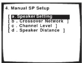
text_image
4. Manual SP Setup [a. Speaker Setting [b . Crossover Network ] [c . Channel Level ] [d . Speaker Distance ]2 Choose the set of speakers that you want to set then select a speaker size.
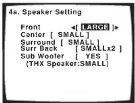
text_image
4a. Speaker Setting Front ←[ LARGE ]► Center [ SMALL ] Surround [ SMALL ] Surr Back [ SMALLx2 ] Sub Woofer [ YES ] (THX Speaker:SMALL)Use / (cursor left/right) to select the size (and number) of each of the following speakers:
- Front – Select LARGE if your front speakers reproduce bass frequencies effectively, or if you didn't connect a subwoofer. Select SMALL to send the bass frequencies to the subwoofer.
- Center – Select LARGE if your center speaker reproduces bass frequencies effectively, or select SMALL to send bass frequencies to the other speakers or subwoofer. If you didn't connect a center speaker, choose NO (the center channel is sent to the front speakers).
- Surround – Select LARGE if your surround speakers reproduce bass frequencies effectively. Select SMALL to send bass frequencies to the other speakers or subwoofer. If you didn't connect surround speakers choose NO (the sound of the surround channels is sent to the front speakers or a subwoofer).
- Surr Back – Select the number of surround back speakers you have (one, two or none). Select LARGE if your surround back speakers reproduce bass frequencies effectively. Select SMALL to send bass frequencies to the other speakers or subwoofer. If you didn't connect surround back speakers choose NO.
- Subwoofer – LFE signals and bass frequencies of channels set to SMALL are output from the subwoofer when YES is selected (see notes below). Choose the PLUS setting if you want the subwoofer to
output bass sound continuously or you want deeper bass (the bass frequencies that would normally come out the front and center speakers are also routed to the subwoofer). If you did not connect a subwoofer choose NO (the bass frequencies are output from other speakers).
Note
- If you selected Second Zone or Front Bi-Amp (in Surround back speaker setting on page 38) you can't adjust the surround back settings.
- If you select SMALL for the front speakers the subwoofer will automatically be fixed to YES. Also, the center and surround speakers can't be set to LARGE if the front speakers are set to SMALL. In this case, all bass frequencies are sent to the subwoofer.
- If the surround speakers are set to NO, the surround back speakers will automatically be set to NO.
- If you select one surround back speaker only, make sure that speaker is hooked up to the left surround back terminal.
- If you're using a THX speaker setup, confirm that all speakers are set to SMALL
3 When you're finished, press RETURN.
You will return to the Manual SP Setup menu.
Tip
- If you have a subwoofer and like lots of bass, it may seem logical to select LARGE for your front speakers and PLUS for the subwoofer. This may not, however, yield the best bass results. Depending on the speaker placement of your room you may actually experience a decrease in the amount of bass due low frequency cancellations. In this case, try changing the position or direction of speakers. If you can't get good results, listen to the bass response with it set to PLUS and YES or the front speakers set to LARGE and SMALL alternatively and let your ears judge which sounds best. If you're having problems, the easiest option is to route all the bass sounds to the subwoofer by selecting SMALL for the front speakers.
Crossover Network
- Default setting: 80Hz
This setting decides the cutoff between bass sounds playing back from the speakers selected as LARGE, or the subwoofer, and bass sounds playing back from those selected as SMALL. It also decides where the cutoff will be for bass sounds in the LFE channel.

Note
- For more on selecting the speaker sizes, see Speaker Setting above.
1 Select 'Crossover Network' from the Manual SP Setup menu.
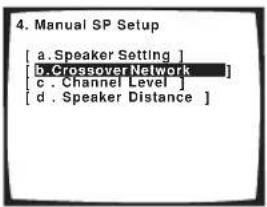
text_image
4. Manual SP Setup [a. Speaker Setting ] [b. Crossover Network ] [c. Channel Level ] [d. Speaker Distance ]2 Choose the frequency cutoff point.
Frequencies below the cutoff point will be sent to the subwoofer (or LARGE speakers).
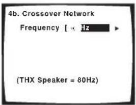
text_image
4b. Crossover Network Frequency [ × Hz ] (THX Speaker = 80Hz)3 When you're finished, press RETURN.
You will return to the Manual SP Setup menu.

Note
- If you're using a THX speaker setup, confirm that the crossover frequency is set to 80Hz.
Channel Level
Using the channel level settings, you can adjust the overall balance of your speaker system, an important factor when setting up a home theater system.
1 Select 'Channel Level' from the Manual SP Setup menu.
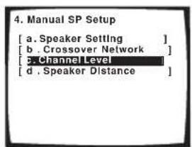
text_image
4. Manual SP Setup [a. Speaker Setting ] [b. Crossover Network ] [c. Channel Level ] [d. Speaker Distance ]2 Select a setup option.
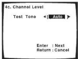
text_image
4c. Channel Level Test Tone ← Auto Enter : Next Return : Cancel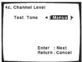
text_image
4c. Channel Level Test Tone ← Manua > Enter : Next Return : Cancel- Manual – Move the test tone manually from speaker to speaker and adjust individual channel levels.
- Auto – Adjust channel levels as the test tone moves from speaker to speaker automatically.
3 Confirm your selected setup option.
The test tones will start after you press ENTER.
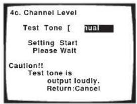
text_image
4c. Channel Level Test Tone [ nual Setting Start Please Wait Caution!! Test tone is output loudly. Return:Cancel4 Adjust the level of each channel using the ←/→ (cursor left/right) buttons.
If you selected Manual, use ↑/↓ (cursor up/down) to switch speakers. The Auto setup will output test tones in the order shown on-screen:
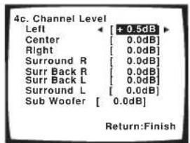
text_image
4c. Channel Level Left Center [ + 0.5dB ] Right [ 0.0dB ] Surround R [ 0.0dB ] Surr Back R [ 0.0dB ] Surr Back L [ 0.0dB ] Surround L [ 0.0dB ] Sub Woofer [ 0.0dB] Return:FinishAdjust the level of each speaker as the test tone is emitted.

Note
- If you are using a Sound Pressure Level (SPL) meter, take the readings from your main listening position and adjust the level of each speaker to 75 dB SPL (C-weighting/slow reading).
- The subwoofer test tone is output at low volumes. You may need to adjust the level after testing with an actual soundtrack.
5 When you're finished, press RETURN.
You will return to the Manual SP Setup menu.

Tip
- You can change the channel levels at any time by using EFFECT/CH SEL and +/- on the remote control. You can set separate levels for the listening modes (Standard, Home THX, Advanced and Stereo/Direct) as well as for the MULTI CH IN mode. However, the listening mode setting will be cleared if you use one of the setups (for example, the System Setup or Auto Setup) to set the channel levels at a later date.
Speaker Distance
For good sound depth and separation from your system, you need to specify the distance of your speakers from the listening position. The receiver can then add the proper delay needed for effective surround sound.
1 Select 'Speaker Distance' from the Manual SP Setup menu.
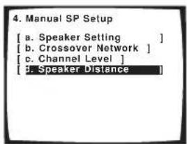
text_image
4. Manual SP Setup [ a. Speaker Setting ] [ b. Crossover Network ] [ c. Channel Level ] [ 3. Speaker Distance ]2 Adjust the distance of each speaker using the ←/→ (cursor left/right) buttons.
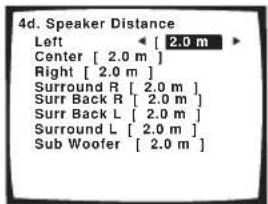
text_image
4d. Speaker Distance Left [ 2.0 m ] Center [ 2.0 m ] Right [ 2.0 m ] Surround R [ 2.0 m ] Surr Back R [ 2.0 m ] Surr Back L [ 2.0 m ] Surround L [ 2.0 m ] Sub Woofer [ 2.0 m ]You can adjust the distance of each speaker in 0.1 meter increments.
3 When you're finished, press RETURN.
You will return to the Manual SP Setup menu.

Tip
- For best surround sound, make sure the surround back speakers are the same distance from the listening position.
Chapter 7: Using the tuner
Listening to the radio
The following steps show you how to tune in to FM and AM radio broadcasts using the automatic (search) and manual (step) tuning functions. If you already know the frequency of the station you want, see Tuning directly to a station below. Once you are tuned to a station you can memorize the frequency for recall later—see Saving station presets on page 48 for more on how to do this.
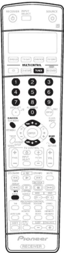
text_image
RECEIVER INPUT SELECT SOURCE DVD/50 TV/SAT OVERVIEW TV CORN MULTICONTROL CD CDA/TAPE TUNER RECEIVER 1 2 3 4 5 6 7 8 9 INPUT INT FLAMBER SRL DBOC 0 ENTER ACCESS TOP MENU TIME ↑ + D/T Guam ST ENTER T/DUT SYSTEM DATA SETUP TIME ↑ - TV CONTROL INPUT SELECT TV CH VOL + - VOL + - DV/ON/OFF REC DV/INFO MUTE PUMS DISPLAY UBC/STOP MPI SWITCH RIO DVD AUTO SWITCH RIO THE RECEIVER CONTROL STANDARD ACQUISI STUDIO AUTO SURF ACoustic PQ SIGNAL DIRECT WORKSHORT GROWTH SHIFT EFFECT VOLT SLEEP UNLOCK Pioneer RECEIVER1 Press the TUNER button to select the tuner.
2 Use the BAND button to change the band (FM or AM), if necessary.
Each press switches the band between FM and AM.
3 Tune to a station.
There are three ways to do this:
Automatic tuning
To search for stations in the currently selected band, press and hold TUNE +/- for about a second. The receiver will start searching for the next station, stopping when it has found one. Repeat to search for other stations.
Manual tuning
To change the frequency one step at a time, press TUNE +/-.
High speed tuning
Press and hold TUNE +/- for high speed tuning. Release the button at the frequency you want.
Improving FM stereo sound
If the TUNED or STEREO indicators don't light when tuning to an FM station because the signal is weak, press the MPX button to switch the receiver into mono reception mode. This should improve the sound quality and allow you to enjoy the broadcast.
Tuning directly to a station
Sometimes, you'll already know the frequency of the station you want to listen to. In this case, you can simply enter the frequency directly using the number buttons on the remote control.
1 Press the TUNER button to select the tuner.
2 Use the BAND button to change the band (FM or AM), if necessary.
Each press switches the band between FM and AM.
3 Press D.ACCESS (Direct Access).
4 Use the number buttons to enter the frequency of the radio station.
For example, to tune to 106.00 (FM), press 1, 0, 6, 0, 0. If you make a mistake halfway through, press D.ACCESS twice to cancel the frequency and start over.

Note
- If you find that you can't tune into stations successfully, the frequency step may not be suitable for your country/region. See Changing the frequency step on page 76 to switch the setting.
Saving station presets
If you often listen to a particular radio station, it's convenient to have the receiver store the frequency for easy recall whenever you want to listen to that station. This saves the effort of manually tuning in each time. This unit can memorize up to 30 stations, stored in three banks, or classes, (A, B and C) of 10 stations each. When saving an FM frequency, the MPX setting (see page 47) is also stored.
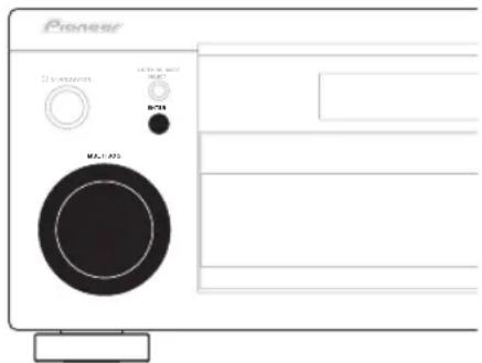
text_image
Pioneer D:\times\times\times\times\times\times\times\times\times\times\times\times\times\times\times\times\times\times\times\times\times\times\times\times\times\times\times\times\times\times\times\times\times\times\times\times\times\times\times\times\times\times\times\times\times\times\times\times\times\times\times\times A1-052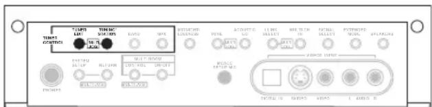
text_image
TENI CONTROL TENI LET TENI SIC (M) LPG MPS ACQUISIC RICH MINI MINI MINI MINI MINI MINI MINI MINI MINI MINI MINI MINI MINI MINI MINI MINI MINI MINI MINI MINI MINI MINI MINI MINI MINI MINI MINI MINI MINI MINI MINI MINI MINI MINIThe illustration above shows the VSX-2014i-G model.
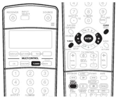
text_image
RECEIVER INPUT SELECT SOURCE DV/DVD TV/SAT/VIM/WR TV/OFF MULTI CONTROLS CO CHU/TPAC TUNER POWER 1 2 3 4 5 6 7 8 9 INPUT ATT FLOW/WR DIA/CES TOP MEND ST TIME T-TEXT ST TIME T-TEXT SETUP CLASS VOL TV CONTROL + - + - + - + - + - + - + - + - + - + - + - + - + - + - + - + - + - + - + - + - + - + - + - + - + - + - + - + - + - + - + - + - + - + - + - + - + - + - + - + - + - + - + - + - + - + - + - + - + - + - + -1 Tune to a station you want to memorize.
See Listening to the radio on page 47 for more on this.
2 Press T.EDIT (TUNER EDIT).
The display shows STATION MEMORY, then a blinking memory class.
3 Press CLASS to select one of the three classes then press ST +/- (STATION +/-) to select the station preset you want.
You can also use the number buttons or the MULTI JOG dial (front panel) to select a station preset.
4 Press ENTER.
After pressing ENTER, the preset class and number stop blinking and the receiver stores the station.
Naming station presets
For easier identification, you can name your station presets.
1 Choose the station preset you want to name.
See Listening to station presets below for how to do this.
2 Press T.EDIT (TUNER EDIT).
The display shows STATION NAME, then a blinking cursor at the first character position.
3 Input the name you want.
Choose from the following characters for a name up to four characters long.
ABCDEFGHIJKLMNOPQRSTUVWXYZ abcdefghijklmnopqrstuvwxyz 0123456789
$$ !" # \% \& ^ {\prime} () * +, -. /:: < = >? @ [ \backslash ] ^ {\wedge} _ {l } ^ {\sim} $$
- Use the MULTI JOG dial (front panel) or the ST +/- buttons (remote) to select characters.
- Press ENTER to confirm a character. If no character is input, a space is input.
- The name is stored when ENTER is pressed after choosing the fourth character.

Tip
- To erase a station name, simply repeat steps 1-3 and input four spaces instead of a name.
- Once you have named a station preset, you can press TUNER DISPLAY when listening to a station to switch the display between name and frequency.
Listening to station presets
You will need to have some presets stored to do this. See Saving station presets above if you haven't done this already.
1 Press TUNER to select the tuner.
2 Press CLASS to select the class in which the station is stored.
Press repeatedly to cycle through classes A, B and C.
3 Press ST +/- (STATION +/-) to select the station preset you want.
- You can also use the number buttons on the remote control to recall the station preset.

Note
- If the receiver is left disconnected from the AC power outlet for over a month, the station memories will be lost and will have to be reprogrammed.
Chapter 8: Making recordings
Making an audio or a video recording
You can make an audio or a video recording from the built-in tuner, or from an audio or video source connected to the receiver (such as a CD player or TV).
Keep in mind you can't make a digital recording from an analog source or vice-versa, so make sure the components you are recording to/from are hooked up in the same way (see Connecting up on page 14 for more on connections).
If you want to record a video source, you also need to use the same type of connection for the source as for the recorder. For example, you can't record a component hooked up to S-video jacks with a recorder hooked up to the composite video outputs (see page 18 for more on video connections).
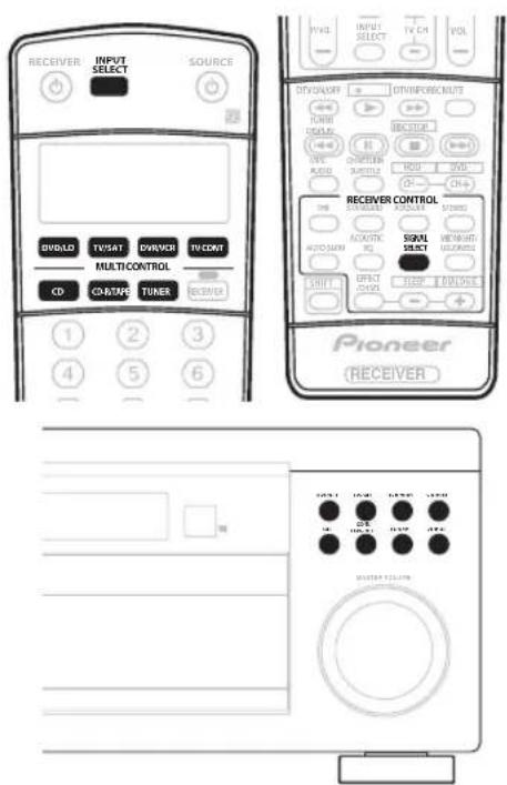
text_image
RECEIVER INPUT SELECT SOURCE DIVOLD TV/SAT DRIVE/ TV/CONT MULTI/CONTROL CD CO/TIME TUNER RECEIVER PIONEER RECEIVER CONTROL SIGNAL SELECT AQUANTIC RQ SINYL SELECT COLD RECEIVER PIONEER MASTER FILTER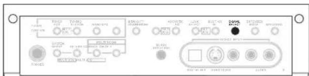
text_image
I/O TOMATO RATIO RATIO RATIO RATIO RATIO RATIO RATIO RATIO RATIO RATIO RATIO RATIO RATIO RATIO RATIO RATIO RATIO RATIO RATIO RATIO RATIO RATIO RATIO RATIO RATIO RATIO RATIO RATIO RATIO RATIO RATIO RATIO RATIO RATIOThe illustration above shows the VSX-2014i-G model.
1 Select the source you want to record. Use the MULTI CONTROL buttons (or INPUT SELECT).
2 Select the input signal (if necessary). Press SIGNAL SELECT to select the input signal corresponding to the source component (see page 33 for more on this).
3 Prepare the source you want to record. Tune to the radio station, load the CD, video, DVD etc.
4 Prepare the recorder. Insert a blank tape, MD, video etc. into the recording device and set the recording levels.
Refer to the instructions that came with the recorder if you are unsure how to do this. Most video recorders set the audio recording level automatically—check the component's instruction manual if you're unsure.
5 Start recording, then start playback of the source component.

Note
- The receiver's volume, balance, tone (bass, treble, loudness), and surround effects have no effect on the recorded signal.
- Some digital sources are copy-protected, and can only be recorded in analog.
- Some video sources are copy-protected. These cannot be recorded.
Chapter 9:
Controlling the rest of your system
Setting the remote to control other components
Most components can be assigned to one of the MULTI CONTROL buttons using the component's manufacturer preset code stored in the remote.
However, please note that there are cases where only certain functions may be controllable after assigning the proper preset code, or the codes for the manufacturer in the remote control will not work for the model that you are using.
If you can't find a preset code that matches the component you want to control, you can still teach the remote individual commands from another remote control (page 51).

Note
- TV codes (for example, codes for TV, CATV, Satellite TV or DTV) can only be assigned to the TV/SAT or TV CONT button.
- If you assign the TUNER function to another component, you will have to reassign it to the Pioneer preset code to use this receiver's built-in tuner.
- You can cancel or exit any of the steps by pressing RECEIVER. To go back a step, press RETURN.
• After one minute of inactivity, the remote automatically exits the operation.
Selecting preset codes directly
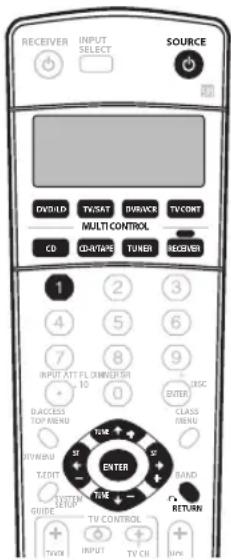
text_image
RECEIVER INPUT SELECT SOURCE D/OLD TV/SAT SURBACK TV/CONT MULTI CONTROL CO COUNTAGE TUNER RECEIVER 1 2 3 4 5 6 7 8 9 INPUT ATT FLOWSHISH 10 0 D/ACCESS TOP/MENU CLASS MENU TIME TAX TAX TAX TIME RAND RETURN GUIDE TV/CONTROL TV/OI INPUT TV CH OFF1 While pressing the RECEIVER button, press and hold the 1 button.
The remote LCD display shows SETUP.
2 Press the MULTI CONTROL button for the component you want to control.
The LCD on the remote displays the component you want to control.
- You can't assign the RECEIVER button.
3 Use ←/→ (cursor left/right) to select PRESET then press ENTER.
4 Use ↑/↓ (cursor up/down) to select the first letter of the brand name of your component then press ENTER.
This should be the manufacturer's name (for example, P for Pioneer).
5 Use ↑/↓ (cursor up/down) to select the manufacturer's name from the list then press ENTER.
6 Use ↑/↓ (cursor up/down) to select the proper code from the list, then try using this remote control with your component.
The code should start with the component type (for example, DVD 009). If there is more than one, start with the first one.
To try out the remote control, switch the component on or off (into standby) by pressing SOURCE ⏻. If it doesn't seem to work, select the next code from the list (if there is one).
- If you can't find or properly enter a preset code, you can still teach the remote individual commands from another remote control (see Programming signals from other remote controls below).
7 If your component is controlled successfully, press ENTER to confirm.
The remote LCD display shows OK.
Programming signals from other remote controls
If the preset code for your component is not available, or the available preset codes do not operate correctly, you can program signals from the remote control of another component. This can also be used to program additional operations (buttons not covered in the presets) after assigning a preset code.
1 While pressing the RECEIVER button, press and hold the 1 button.
The remote LCD display shows SETUP.
2 Press the MULTI CONTROL button for the component you want to control.
The LCD on the remote displays the component you want to control.
- You can't assign the RECEIVER button.
3 Use ←/→ (cursor left/right) to select LEARN then press ENTER.
PRES KEY shows in the LCD display.
• To exit or cancel press RECEIVER.
4 Point the two remote controls towards each other then press the button that will be doing the learning on this receiver's remote control.
PRES KEY starts flashing to indicate the remote is ready to accept a signal.
- The remote controls should be 3–5 cm apart.

5 Press the corresponding button on the other remote control that is sending (teaching) the signal to this receiver's remote control.
For example, if you want to learn the playback control signal, press and hold ▶ for a couple of seconds. The LCD display will show OK if the operation has been learned.
If for some reasons the operation hasn't been learned the LCD will display ERROR briefly and then display PRES
KEY again. If this happens, keep pressing the (teaching) button as you vary the distance between the two remotes, until the LCD display shows OK.
Certain buttons represent operations that cannot be learned from other remote controls. The buttons available are shown below:
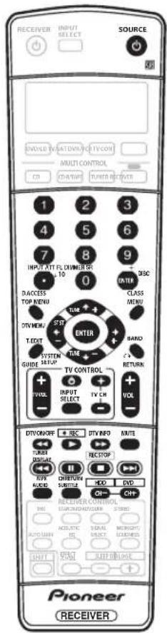
text_image
RECEIVER INPUT SELECT SOURCE SINEMA RELATION/VEV/CON MULTI CONTROL CD CHAPANE TURNER RECOVER 1 2 3 4 5 6 7 8 9 INPUT ATT FLX/VNEL/CP 10 0 DACKES TOP MENU T/DVIEW T.EDT SYSTEM GUIDE SETUP TIME ENTER CLASS MENU RAND RETURN TV CONTROL P/WL INPUT SELECT TV CH VOL DTV/ON/OFF REC DV/IND M/E TURER DISPLAY REC STOP APP AUDIO CHIR/TURN SUBTITLE HDD DVD RECEIVER CONTROL HOLDEN/MOZZUM STRONG AUTO SLINK ACoustics SIGNAL SPECTA LETTY START KEEP CLOSE Pioneer RECEIVER6 To program additional signals for the current component repeat steps 4 and 5.
To program signals for another component, exit and repeat steps 1 through 5.
7 Press the RECEIVER button to exit and store the operation(s).

Note
- Some commands from other remote controls cannot be learned, but in most cases the remotes just need to be moved closer together or farther apart.
- If the remote LCD shows ERROR, it may also mean the memory is full. See Erasing one of the remote control button settings below to erase a programmed button you're not using to free up more memory.
- TV CONTROL buttons (TV ⏻, TV VOL +/-, TV CH +/- and INPUT SELECT) can only be learned after selecting TV CONT.
Erasing one of the remote control button settings
This erases one of the buttons you have programmed and restores the button to the factory default.
1 While pressing the RECEIVER button, press and hold the 1 button.
The remote LCD display shows SETUP.
2 Press the MULTI CONTROL button corresponding to the button setting to be erased.
The LCD on the remote displays the component.
3 Use ←/→ (cursor left/right) to select ERASE then press ENTER.
The LCD display flashes PRES KEY.
4 Press and hold the button to be erased for two seconds.
The LCD display shows OK or NO CODE to confirm the button has been erased.
5 Repeat step 4 to erase other buttons.
6 Press the RECEIVER button when you're done.
Erasing all of the remote control presets
This will erase all preset remote control preset codes and programmed buttons.
1 While pressing the RECEIVER button, press and hold the 1 button.
The remote LCD display shows SETUP.
2 Press the DVD/LD MULTI CONTROL button.
3 Use ←/→ (cursor left/right) to select RESET then press and hold ENTER for about two seconds.
The LCD shows OK to confirm the remote presets have been erased.
Direct function
- Default setting: ON
You can use the direct function feature to control one component using the remote control while at the same time, using your receiver to playback a different component. This could let you, for example, use the remote control to set up and listen to a CD on the receiver and then use the remote control to rewind a tape in your VCR while you continue to listen to your CD player.
When direct function is on, any component you select (using the MULTI CONTROL buttons) will be selected by both the receiver and the remote control. When you turn direct function off, you can operate the remote control without affecting the receiver.
1 While pressing the RECEIVER button, press and hold the 1 button.
The remote LCD display shows SETUP.
2 Press the MULTI CONTROL button for the component you want to control.
The LCD on the remote displays the component you want to control.
3 Use ←/→ (cursor left/right) to select DIRECT F then press ENTER.
The LCD on the remote displays the component you want to control.
4 Use ↑/↓ (cursor up/down) to switch direct function ON or OFF then press ENTER.
The LCD shows OK to confirm the setting.

Note
- You can't use direct function with the TV CONT function.
Confirming preset codes
Use this feature to check which preset code is assigned to a MULTI CONTROL button.
1 While pressing the RECEIVER button, press and hold the 1 button.
The remote LCD display shows SETUP.
2 Press the MULTI CONTROL button of the component for which you want to check the preset code.
3 Use ←/→ (cursor left/right) to select READ ID then press ENTER.
The brand name and preset code appears in the display for three seconds.
Controls for TVs
This remote control can control components after entering the proper codes or teaching the receiver the commands (see Setting the remote to control other components on page 50 for more on this). Use the MULTI CONTROL buttons to select the component.
| Button(s) | Function Components | |
| TV ◊ | Press to switch the component assigned to the TV CONT button on or off. | Cable TV/Satellite TV/TV/DTV |
| INPUT SELECT | Switches the TV input. (Not possible with all models.) TV | |
| TV CH +/- | Selects channels. Cable TV/Satellite TV/TV/DTV | |
| TV VOL +/- | Adjust the TV volume. Cable TV/Satellite TV/TV/DTV | |
| SOURCE ◊ | Switches the DTV on or off. DTV | |
| Switches the TV or CATV between standby and on. Cable TV/Satellite TV/TV | ||
| ◀◀ | Switches the DTV on or off. DTV | |
| ▶▶ | Press to get information on DTV programs. DTV | |
| |◀◀ | Use to choose the BLUE commands on a DTV menu. DTV | |
| ▶▶| | Use to choose the YELLOW commands on a DTV menu. DTV | |
| || | Use to choose the GREEN commands on a DTV menu. DTV | |
| ■ | Use to choose the RED commands on a DTV menu. DTV | |
| AUDIO | Use to switch DTV audio tracks. DTV | |
| CH RETURN | Use to return to the previously selected channel. Cable TV/Satellite TV/TV/DTV | |
| DTV MENU | Press to display the DTV menu. DTV | |
| GUIDE | Use as the GUIDE button for navigating. | Cable TV/Satellite TV/TV/DTV |
| RETURN | Use to select RETURN or EXIT. | DTV |
| Number buttons | Use to select a specific TV channel. | Cable TV/Satellite TV/TV/DTV |
| +10 button | Use to add a decimal point when selecting a specific TV channel. | DTV |
| ENTER/DISC | Use to enter a channel. | Cable TV/Satellite TV/TV/DTV |
| MENU | Select different menus from the DTV functions. | DTV |
| Select the menu screen. | Cable TV/Satellite TV/TV | |
| ⇐⇒ ↑ ↓ & ENTER | Press to select or adjust and navigate items on the menu screen. | Cable TV/Satellite TV/TV/DTV |

Note
- The TV CONTROL buttons on the remote control are dedicated to control the TV assigned to the TV CONT button. Thus if you only have one TV to hook up to this system assign it to the TV CONT (MULTI CONTROL) button. If you have two TVs, assign the main TV to the TV CONT button.
Controls for other components
This remote control can control these components after entering the proper codes or teaching the receiver the commands (see Setting the remote to control other components on page 50 for more on this). Use the MULTI CONTROL buttons to select the component.
| Button (s) | Function Components | |
| SOURCE | Press to switch the component between standby and on. CD/MD/CD-R/VCR/DVD/LD/ | DVR player/Cassette deck |
| |◀◀ | Press to return to the start of the current track or chapter.Repeated presses skips to the start of previous tracks or chapters. | CD/MD/CD-R/DVD/LD player |
| Go back channels (channel -). DVR/VCR | ||
| ▶▶I | Press to advance to the start of the next track or chapter.Repeated presses skips to the start of following tracks or chapters. | CD/MD/CD-R/DVD/LD player |
| Go forward channels (channel +). VCR | ||
| II | Pause playback or recording. CD/MD/CD-R/VCR/DVD/LD/ | DVR player/Cassette deck |
| ▶ | Start playback. CD/MD/CD-R/VCR/DVD/LD/ | DVR player/Cassette deck |
| ▶▶ | Hold down for fast forward playback. CD/MD/CD-R/VCR/DVD/LD/ | DVR player/Cassette deck |
| ◀◀ | Hold down for fast reverse playback. CD/MD/CD-R/VCR/DVD/LD/ | DVR player/Cassette deck |
| ■ | Stops playback (on some models, pressing this when the disc is already stopped will cause the disc tray to open). | CD/MD/CD-R/VCR/DVD/LD/DVR player/Cassette deck |
| ● REC(SHIFT+▶) | Starts recording. To prevent accidental recording, this button must be pressed twice to take effect (the second press must be within 10 seconds of the first). | MD/CD-R/VCR/ DVR player/Cassette deck |
| REC STOP(SHIFT+■) | Stops recording. DVR player | |
| Number buttons | Directly access tracks on a program source. CD/MD/CD-R/VCR/LD player | |
| Use the number buttons to navigate the on-screen display. | DVD/DVR player | |
| +10 button | Selects tracks higher than 10. (For example, press +10 then 3 to select track 13.) CD/MD/CD-R/VCR/LD player | |
| ENTER/DISC | Chooses the disc. Multiple CD player | |
| Ejects the disc. MD player | ||
| Use as the ENTER button. VCR | ||
| Use as the CLEAR button. DVD | ||
| Displays the setup screen for DVR players. DVR player | ||
| Changes sides of the LD. LD player | ||
| TOP MENU | Displays the disc 'top' menu of a DVD player. | DVD/DVR player |
| MENU | Displays menus concerning the current DVD or DVR you are using. | DVD/DVR player |
| ↑ | Pauses the tape. | Cassette deck |
| ↓ | Stops the tape. | Cassette deck |
| ENTER | Starts playback. | Cassette deck |
| ↔/↔ | Fast rewinds/fast forwards the tape. | Cassette deck |
| ↔↔↑↓ & ENTER | Navigates DVD menu/options. | DVD/DVR Player |
| GUIDE | Press to access the DVD player setup screen. | DVD/DVR Player |
| CH +/- | Selects channels. VCR/DVD/DVR Player | |
| Selects tracks. | CD/MD/CD-R/Cassette deck | |
| AUDIO | Changes the audio language or channel. | DVD/DVR Player |
| SUBTITLE | Displays/changes the subtitles on multilingual DVDs. | DVD/DVR Player |
| HDD (SHIFT+CH-) | Switches to the hard disk controls when using a DVD/HDD recorder. | DVR Player |
| DVD (SHIFT+CH+) | Switches to the DVD controls when using a DVD/HDD recorder. | DVR Player |
Chapter 10:
Other connections
Caution
- Before making or changing the connections, switch off the power and disconnect the power cord from the power outlet. Plugging in components should be the last connection you make with your system.
- Be careful not to allow any contact between speaker wires from different terminals.
- You can use speakers with a nominal impedance between 6–16Ω (please see Switching the speaker impedance on page 76 if you plan to use speakers with an impedance of less than 8Ω).
Second Zone speaker B setup
After selecting Second Zone in Surround back speaker setting on page 38, you can use the speakers connected to the (surround back) B speaker terminals on the rear panel to listen to stereo playback in another room. See Switching the speaker system below for the listening options with this setup.
1 Connect a pair of speakers to the surround back speaker terminals on the rear panel.
Connect them the same way you connected your speakers in Connecting the speakers on page 21. Make sure to review Hints on speaker placement on page 22 when placing the speakers in another room.
2 Select 'Second Zone' from the 'Surr Back System' menu.
See Surround back speaker setting on page 38 to do this.

Note
- VSX-2014i-G model only – You can also use the multi-room feature to listen to stereo playback in another room. See Multi-room listening on page 57 for more on this.
Switching the speaker system
If you selected Second Zone in Surround back speaker setting on page 38, three speaker system settings are possible using the SPEAKERS button. If you selected Normal (SB) or Front Bi-Amp, the button will simply switch your main speaker system on or off. The options below are for the Second Zone setting only.
- Use the SPEAKERS button on the front panel to select a speaker system setting.
As mentioned above, if you have selected Normal (SB), the button will simply switch your main speaker system (A) on or off.
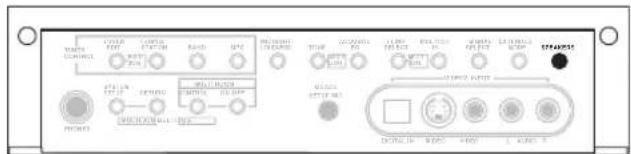
text_image
TAXA TAXA RAC NAT SPAR SPAR2025 TAXA RAC NAT SPAR SPAR2025 TAXA RAC NAT SPAR SPAR2025The illustration above shows the VSX-2014i-G model.
Press repeatedly to choose a speaker system option:
- SP▶A – Sound is output from speaker system A and the same signal is output from the pre-out terminals.
- SP▶B – Sound is output from the two speakers connected to speaker system B. Multichannel sources will not be heard. The same signal is output from the surround back channel pre-out terminals.
- SP▶AB – Sound is output from speaker system A (up to 5 channels, depending on the source), the two speakers in speaker system B, and the subwoofer. The sound from speaker system B will be the same as the sound from speaker system A (multichannel sources will be downmixed to 2 channels).
- SP▶ (off) – No sound is output from the speakers. The same sound is output from the pre-out terminals (including from your subwoofer, if connected) as when selecting speaker system A (above).

Note
- The subwoofer output depends on the settings you made in Manual speaker setup on page 43. However, if SP▶B is selected above, no sound is heard from the subwoofer (the LFE channel is not downmixed).
- Depending on the settings in Surround back speaker setting on page 38 output from the surround back pre-out terminals may change.
- All speaker systems (except Second Zone connections) are switched off when headphones are connected.
Bi-amping your front speakers
Bi-amping is when you connect the high frequency driver and low frequency driver of your speakers to different amplifiers (in this case, to both front and surround back terminals) for better crossover performance. Your speakers must be bi-ampable to do this (having separate terminals for high and low) and the sound improvement will depend on the kind of speakers you're using.
1 Connect your speakers as shown below.
This illustration below shows the connections for bi-amping your front left speaker. Hook up your front right speaker in the same way.
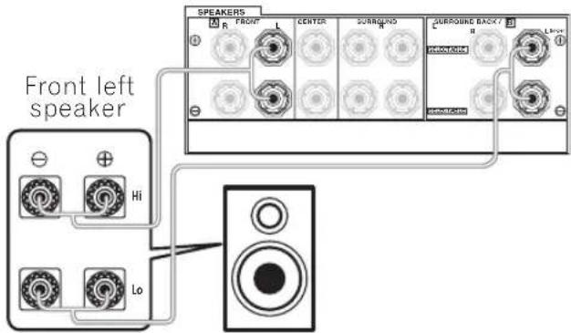
text_image
Front left speaker Hi Lo SPEAKERS R FRONT L CENTER SURROUND SURROUND BACK / L1-1 PREMENSIVE PREMENSIVESince both front and surround back speaker terminals output the same audio, it doesn't matter which set (front or surround back) is powering which part (Hi or Low) of the speaker.
- Make sure that the + / - connections are properly inserted.
2 Select the 'Front Bi-Amp' setting from the 'Surr Back System' menu.
See Surround back speaker setting on page 38 to specify how you're using the surround back speaker terminals.

Caution
- Most speakers with both Hi and Low terminals have two metal plates that connect the Hi to the Low terminals. These must be removed when you are bi-amping the speakers or you could severely damage the amplifier. See your speaker manual for more information.
- If your speakers have a removable crossover network, make sure you do not remove it for bi-amping. Doing so may damage your speakers.
Bi-wiring your speakers
The reasons for bi-wiring are basically the same as bi-amping, but additionally, interference effects within the wire could be reduced, producing better sound. Again, to do this your speakers must be bi-wireable (that is they must have separate terminals for the high and low frequencies). When bi-wiring, make sure you've selected Normal (SB) or Second Zone in Surround back speaker setting on page 38.
• To bi-wire a speaker, connect two speaker cords to the speaker terminal on the receiver.
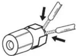
natural_image
Diagram of a mechanical component with two threaded pins and directional arrows indicating assembly (no text or symbols)
Caution
• Make sure you use a parallel (not series, which are fairly uncommon) connection when bi-wiring your speakers.
- Don't connect different speakers from the same terminal in this way.
Connecting additional amplifiers
This receiver has more than enough power for any home use, but it's possible to add additional amplifiers to every channel of your system using the pre-outs. Make the connections shown below to add amplifiers to power your speakers.

Important
- Before making or changing the connections, switch off the power and disconnect the power cord from the AC outlet.
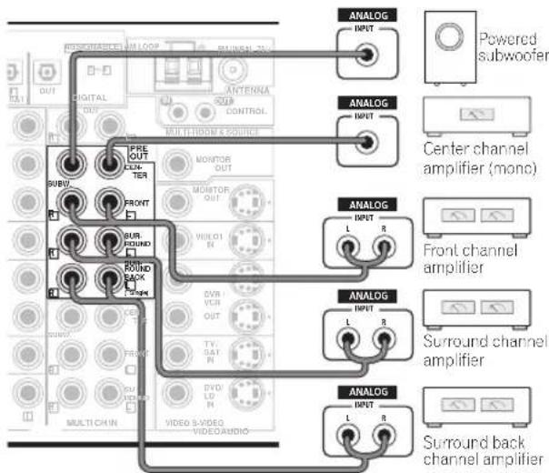
text_image
ANALOG INPUT POWERED subwoofer Center channel amplifier (mono) ANALOG INPUT L R Front channel amplifier ANALOG INPUT L R Surround channel amplifier ANALOG INPUT L R Surround back channel amplifier- You can use the additional amplifier on the surround back channel pre-outs for a single speaker as well. In this case plug the amplifier into the left (L (Single)) terminal only.
- The sound from the surround back terminals will depend on how you have configured the Surround back speaker setting on page 38.
- To hear sound only from the pre-outs, switch the speaker system to OFF, or simply disconnect any speakers that are connected directly to the receiver.
- If you're not using a subwoofer, change the front speaker setting (see Speaker Setting on page 44) to large.
Multi-room listening
VSX-2014i-G model only
When used together with an optional IR receiver, this receiver can power two independent systems in separate rooms. Different sources can be playing in both rooms at the same time or, depending on your needs, the same source can also be used. The main and sub rooms have independent power (the main room power can be off while the sub room is on) and the sub room can be controlled by this unit's remote control. You may need to specify your volume setting and IR receiver type in Multi Room Setup on page 67.
Making multi-room connections
It is possible to make these connections if you have a separate amplifier, TV, speakers, and an IR receiver for your sub room.
1 Connect the IR receiver sensor to the MULTI-ROOM & SOURCE IR IN jack on the rear of this receiver.
2 Connect a separate amplifier to the MULTI-ROOM & SOURCE OUT jacks and a TV monitor to the MULTI-ROOM & SOURCE MONITOR OUT jacks, both on the rear of this receiver.
You should have a pair of speakers attached to the sub room amplifier as shown in the illustration below.
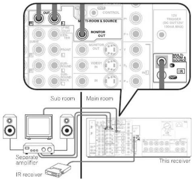
text_image
OUT R PRE OUT COM- TER SUBW FRONT R SUR- ROUND SUB- ROUND BACK R CONTROL P1 MONITOR OUT MONITOR OUT VIDEO1 IN IN P2 P3 P4 12V TRIGGER (DC DUT12V/ 100mA MAX) MULTI- ROOM & SOURCE N IR OUT Sub room Main room Separate amplifier IR receiver This receiver
Note
- Even if you don't have an IR receiver, you can make multi-room connections and use the front panel to control the sub room.
- It is not possible to hear the digital output of a component in the sub room. However, you can connect the analog outputs of your digital component into the receiver's (analog) input terminals to hear the component in the sub room.
- Since the video converter is not enabled for multi-room connections, you'll have to connect any video input source you want to watch in the sub room using standard RCA video cords.
- You can't use sound controls (such as the tone controls or Midnight listening) or any surround modes in the sub room. You can, however, use the features available with your sub room amplifier.
Using the sub room controls
You can use the remote to adjust the sub room volume and select sources from either the main room or the sub room. You can also do this using the front panel controls.

Important
- The receiver must be switched on (or in standby) in the main room to control the sub room.
- When someone is controlling the system from the main room you won't be able to control the sub room with the remote control.
- If you are using a Pioneer amplifier in the sub room, cover up the remote sensor to avoid changing the settings when controlling the sub room.
Using the remote control in the sub room
When controlling the sub room, make sure to hold down SHIFT while pressing the remote control buttons below.
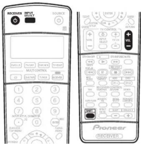
text_image
RECEIVER INPUT SELECT SOURCE VOLUUR TV/SAT SWITCH TV/INT Multi CONTROL CH DATA TUNER RECEIVERS 1 2 3 4 5 6 7 8 9 INPUT ATY FL DIMETER .10 DACKES TOP MENU KRC BITEX CLASS MENU OFF PIONEER RECEIVER TENET ENTER SARD SYSTEM SIDE RETURN TV CONTROL + INPUT SELECT TV CH + VOLT DIVOKOFF S DRY INFRAIC WATE TIME TINUS RECEIVER RANGE M HOLD CHD AUTO RUB ANGULS LEFT VOLT SHIFT SLIP CONTROL Pioneer RECEIVER1 Point the remote control at the IR receiver and press ⏻ RECEIVER.
This switches on the multi-room feature.
2 Press (SHIFT+) INPUT SELECT to select the input source you want to listen to in the sub room.
3 Use (SHIFT+) VOLUME +/- to adjust the volume.
You won't be able to adjust the volume if it is set to FIXED in the Multi Room Setup on page 67.
- You can only increase the volume to 0dB.
- In addition to the controls above, you can also use the CLASS. STATION +/- and number buttons when using the tuner.
Using the front panel multi-room controls
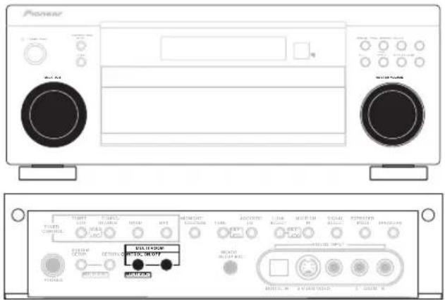
text_image
Pioneer MASCOT SOLVER MASCOT MASCOT MASCOT MASCOT MASCOT MASCOT MASCOT MASCOT MASCOT MASCOT MASCOT MASCOT MASCOT MASCOT MASCOT MASCOT MASCOT MASCOT MASCOT MASCOT MASCOT MASCOT MASCOT MASCOT MASCOT MASCAT MASCAT MASCAT MASCAT MASCAT MASCAT MASCAT MASCAT MASCAT MASCAT MASCAT MASCAT MASCAT MASCAT MASCAT MASCAT MASCAT MASCAT MASCAT MASCAT MASCAT MASCAT MASCAT MASCAT MASCAT MASCCAT MASCAT MASCAT MASCAT MASCAT MASCAT MASCAT MASCAT MASCAT MASCAT MASCAT MASCAT MASCAT MASCAT MASCAT MASCAT MASCAT MASCAT MASCAT MASCAT MASCAT MASCAT MASCAT MASCAT MASCAT MASC1 Press the MULTI ROOM ON/OFF button on the front panel.
The MULTI-ROOM indicator lights in the front panel display to indicate the multi-room control has been switched on.
2 Press CONTROL.
Make sure that any operations for the sub room are done while MR: (and the selected component) shows in the display. If this is not showing, the front panel controls affect the main room only.
3 Use the MULTI JOG dial to select the source.
Select between DVD/LD, TV/SAT, DVR/VCR, TUNER.
CD-R/TAPE/MD or CD (in that order).
- If you select TUNER, you can use the remote control to select a preset station (see Listening to station presets on page 48 if you're unsure how to do this).
4 Use the MASTER VOLUME dial to adjust the volume.
This is only possible if you selected the VARIABLE volume control in Multi Room Setup on page 67.
- You can only increase the volume to 0dB.
5 When you're finished, press CONTROL again to return to the main room controls.
You can also press the MULTI ROOM ON/OFF button on the front panel to switch off all output to the sub room.
- Even if you don't press CONTROL above, the system automatically switches back to the main room controls.

Note
- Multi-room can't be used when you're setting up the system (from the on-screen System Setup menu).
- You won't be able to switch the main room off completely unless you've switched off the multi-room control first.
- When the multi-room feature is switched on, you can also change the sub room input source with the front panel MULTI JOG dial, even when the main unit is in standby.
- Remote operation may not be possible if direct light from a strong fluorescent lamp is shining on the IR receiver remote sensor window.
- The tuner cannot be tuned to more than one station at a time. Therefore, changing the station in one room also changes the station in the other room. Please be careful not to change stations when recording a radio broadcast.
- The volume levels of the main and sub rooms are independent.
- When the MULTI ROOM OUT jacks are connected to a sub room amplifier with a remote sensor and Pioneer CONTROL terminals (page 23), both the IR receiver and the amplifier may receive remote control commands (making correct operation impossible) during multi-room operation. In this case, place the IR receiver and amplifier apart from each other, and point the remote control directly at the IR receiver during operation.
- If you don't plan to use the multi-room feature for awhile, turn off the power in both the sub and main rooms. Make sure the MULTI-ROOM indicator goes off.
- The sleep timer affects the sub room when the multi-room feature is on.
Using the i.LINK interface
VSX-2014i-G model only
If you have a component with an i.LINK connector, you can connect it to this receiver using an i.LINK cable.
Since the i.LINK interface does not transmit video signals, the video signal of i.LINK-connected components must be connected with other cables (see Connecting video components on page 18 for more on making video connections).
If you've already made video connections from the component, assign the i.LINK input to the function (DVD/LD, for example) corresponding to the video inputs to which you've connected (see Assigning the i.LINK inputs on page 64).
The two i.LINK connectors on the rear of your receiver are 4-pin connectors. Use a 4-pin, S400 i.LINK cable to connect i.LINK-equipped components.

Caution
- If your i.LINK connector comes into contact with metallic parts of the receiver other than the i.LINK terminal, an electrical short may occur. Some cables have metal parts that may touch the unit when connected. Please take care to use a suitable i.LINK cable only.

Important
- Please use 4-pin, S400 cables less than 3.5 meters long. Although longer ones are available, they may not work reliably.
- There may be cases where the PQLS/rate control function and/or the i.LINK audio does not work properly even when connected to i.LINK-compatible equipment.
- Do not connect/disconnect i.LINK cables or switch on/off any components connected using i.LINK when the receiver is on.
- Copy-protected 96kHz DVD-Video discs can be heard through the i.LINK connection, but they will be downsampled to 48kHz.
1 Use an i.LINK cable to connect one of the i.LINK connectors on this receiver to an i.LINK connector on your i.LINK component.
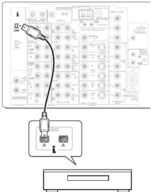
text_image
5400 S400 S400 S400 S400 S400 S400 S400 S400 S400 S400 S400 S400 S400 S400 S400 S400 S400 S400 S400 S400 A1/A2 B1/B2 C1/C2 D1/D2 E1/E2 F1/F2 G1/G2 H1/H2 I1/I2 J1/J2 K1/K2 L1/L2 M1/M2 N1/N2 O1/O2 P1/P2 Q1/Q2 R1/R2 S1/S2 T1/T2 U1/U2 V1/V2 W1/W2 X1/X2 Y1/Y2 Z1/Z2 A2/B2/B3/B4/B5/B6/B7/B8/B9/B10/B11/B12/B13/B14/B15/B16/B17/B18/B19/B20/B21/B22/B23/B24/B25/B26/B27/B28/B29/B30/B31/B32/B33/B34/B35/B36/B37/B38/B39/B40/B41/B42/B43/B44/B45/B46/B47/B48/B49/B50/B51/B52/B53/B54/B55/B56/B57/B58/B59/B60/B61/B62/B63/B64/B65/B66/B67/B68/B69/B70/B71/B72/B73/B74/B75/B76/B77/B78/B79/B80/B81/B82/B83/B84/B85/B86/B87/B88/B89/B90/B91/B92/B93/B94/B95/B96/B97/B98/B99- The arrow on the cable connector body should be lined up with the arrow to the right of the connector on the receiver for correct alignment. The i.LINK cable should be inserted straight into the connector so that it snaps easily into place. If not connected properly the receiver will not be able to recognize any connected components. Note that the i.LINK cable is fragile and can be broken easily if too much force is used when connecting.
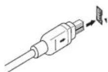
2 Assign the i.LINK component to the input you want, then make any necessary output settings on the component.
See Assigning the i.LINK inputs on page 64 to assign the component to an input on this receiver. Follow the operating instructions that came with the component to make any necessary output settings.
- Unassigned i.LINK components can be selected with the front panel i.LINK SELECT button or the INPUT SELECT button on the remote control.

Note
- You can connect several components together using i.LINK. See Creating an i.LINK network below.
About i.LINK
VSX-2014i-G model only
i.LINK is a trademark name for IEEE1394, a high-speed interface for digital audio, video and other data found on personal computers, digital camcorders, and other kinds of audio and audio/visual equipment. A single i.LINK connector can both send and receive data at the same time, so only one cable is required to connect components for two-way communication.
"i.LINK" and the "i.LINK" logo are trademarks of Sony Corporation.
About PQLS rate control
Pioneer's PQLS (Precision Quartz Lock System) technology provides high-precision digital audio from DVD-A, SACD and audio CD sources when you use the i.LINK interface. A precision quartz controller in this receiver eliminates distortion caused by timing errors (jitter), giving you the best possible digital-to-analog conversion from the digital source.
To take advantage of PQLS, you must have a player compatible with rate-control, and it must be switched on and connected to this receiver through the i.LINK network.
Creating an i.LINK network
Using i.LINK it is possible to chain up to 17 components together so that the digital audio and control signals from each component is available to other components in the network. With the addition of an i.LINK repeater, it's possible to connect up to 34 components.
i. LINK connectors come in 4-pin and 6-pin configurations. This player uses the 4-pin connection, but the two types can be mixed on a network.
This receiver is compatible with i.LINK Audio (A&M protocol) components, such as DVD players. Note that when connected to i.LINK MPEG-II TS equipment (such as a digital satellite tuner), i.LINK DV equipment (such as a DVD recorder or DV camcorder), or an i.LINK-equipped personal computer, audio and video signals are not transmitted, and connecting to these devices sometimes causes network interruptions. Check the operating instructions supplied with your other i.LINK components for compatibility information.
This receiver is DTCP (Digital Transmission Content Protection) compliant, so you can play DVD-A, DVD-Video, and SACD i.LINK audio.
When setting up an i.LINK network, it's important that the components form an open ended chain (fig. 1), or a tree (fig. 2).
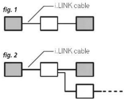
flowchart
graph TD
    A[" "] --> B[" "]
    B --> C[" "]
    D[" "] --> E[" "]
    E --> F[" "]
    G[" "] --> H[" "]
    H --> I[" "]
    J[" "] --> K[" "]
    K --> L[" "]
    M[" "] --> N[" "]
    N --> O["..."]
    style A fill:#ccc,stroke:#333
    style B fill:#ccc,stroke:#333
    style C fill:#ccc,stroke:#333
    style D fill:#ccc,stroke:#333
    style E fill:#ccc,stroke:#333
    style F fill:#ccc,stroke:#333
    style G fill:#ccc,stroke:#333
    style H fill:#ccc,stroke:#333
    style I fill:#ccc,stroke:#333
    style J fill:#ccc,stroke:#333
    style K fill:#ccc,stroke:#333
    style L fill:#ccc,stroke:#333
    style M fill:#ccc,stroke:#333
    style N fill:#ccc,stroke:#333
The system will not work if the connected components form a loop. If a loop is detected, the message LOOP CONNECT shows in the display. Figs. 3 and 4 show connections that form a loop.
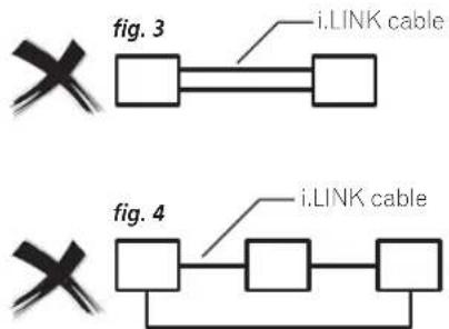
flowchart
graph TD
    A["×"] --> B["□"]
    B --> C["□"]
    D["×"] --> E["□"]
    E --> F["□"]
    G["□"] --> H["□"]
    H --> I["□"]
    J["□"] --> K["□"]
    K --> L["□"]
    M["i.LINK cable"] --> N["□"]
    O["i.LINK cable"] --> P["□"]
Another consideration when connecting i.LINK devices is the speed of the interface. At present there are three speeds; S100 (slowest), S200 and S400 (fastest). This receiver uses the S400 type. Although you can use components with different speeds together, we recommend connecting slower-speed components at the edge of the network if possible (shown by the shaded boxes in figs. 1 and 2). This will keep the network free of bottlenecks.
When used within an i.LINK network, this receiver must be on for the i.LINK connection to be maintained. Other components in the network may or may not maintain the connection in standby (none will when the power is completely off)—check the operating instructions supplied with individual components. Note that the audio may be momentarily interrupted if a component in the i.LINK network is switched on/off, or its i.LINK connection is switched on/off.
This product complies with the following i.LINK interface specifications:
1) IEEE Std. 1394a-2000, Standard for a High Performance Serial Bus
2) Audio and Music Data Transmission Protocol 2.0 Following the standard for AM824 sequence adaptation layers, the product is compatible with IEC60958 bitstream, DVD-A and SACD.
Switching components on and off using the 12 volt trigger
VSX-2014i-G model only
You can connect components in your system (such as a screen or projector) to this receiver so that they switch on or off using a 12 volt trigger when you select an input function. However, you must specify which input functions switch on the trigger using the System Setup menu (see 12 Volt Trigger Setup on page 68 to do this). Note that this will only work with components that have a standby mode.
- Connect the 12V TRIGGER jack of this receiver to the 12V TRIGGER of another component.
Use a cable with a mono mini-plug on each end for the connection.
• The trigger maximum power is DC OUT 12V/100mA.
After you've specified the input functions that will switch on the trigger, you'll be able to switch the component on or off just by pressing the input function(s) you've set on page 68.
Using this receiver with a Pioneer plasma display
If you have a Pioneer plasma display, you can use an SR+ cable (see note below) to connect it to this unit and take advantage of various convenient features, such as automatic video input switching of the plasma display when the input is changed.
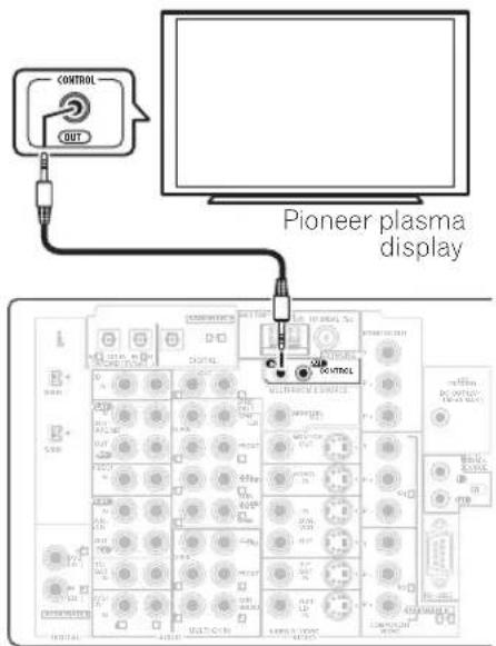
text_image
CONTROL OUT Pioneer plasma displayNote that the illustration above shows the VSX-2014i-G however, connection for the VSX-1014-S is the same.

Important
- If you connect to a Pioneer plasma display using an SR+ cable, you will need to point the remote control at the plasma display remote sensor to control the receiver. In this case, you won't be able to control the receiver using the remote control if you switch the plasma display off.
- Use a 3-ringed miniplug SR+ cable to connect the CONTROL IN jack of this receiver with the CONTROL OUT jack of your plasma display.
Before you can use the extra SR+ features, you need to make a few settings in the receiver. See SR+ Setup for Pioneer plasma displays on page 67 for detailed instructions.
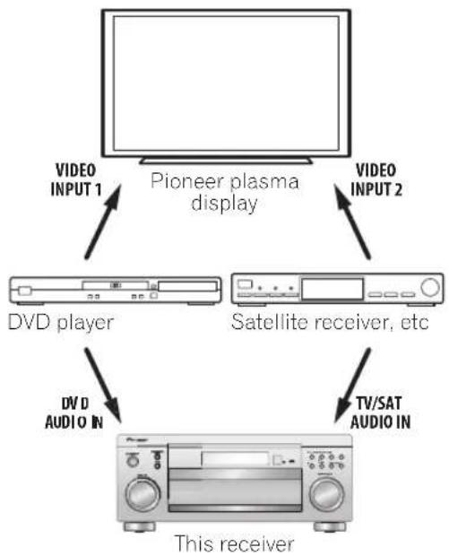
flowchart
graph TD
    A["Pioneer plasma display"] -->|VIDEO INPUT 1| B["DVD player"]
    A -->|VIDEO INPUT 2| C["Satellite receiver, etc"]
    B --> D["This receiver"]
    C --> D
    D -->|DV/D AUDIO IN| E["TV/SAT AUDIO IN"]
To make the most of the SR+ features, you should connect your source components (DVD player, etc.) in a slightly different way to that described in this chapter. For each component, connect the video output directly to the plasma display, and just connect the audio (analog and/or digital) to this receiver.

Note
- This receiver is compatible with all Pioneer plasma displays from 2003 onward.
- The 3-ringed SR+ cable from Pioneer is commercially available under the part number ADE7095. Contact the Pioneer Customer Support division for more information on obtaining an SR+ cable (you can also use a commercially available 3-ringed mini phone plug for the connection).
Using the SR+ mode with a Pioneer plasma display
When connected using an SR+ cable, a number of features become available to make using this receiver with your Pioneer plasma display even easier. These features include:
- On-screen displays when making receiver settings, such as speaker setup, MCACC setup, and so on.
- On-screen volume display.
- On-screen display of listening mode.
• Automatic video input switching on the plasma display.
• Automatic volume muting on the plasma display.
See also SR+ Setup for Pioneer plasma displays on page 67 for more on setting up the receiver.
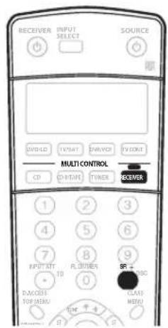
text_image
RECEIVER INPUT SELECT SOURCE CONTROL TYPICAL DRIVER TV COUNT Multi CONTROL CD CH/THY TIMER RECEIVER 1 2 3 4 5 6 7 8 9 INPUT ATT R. ORDER TD 0 SACOBER CLASS MENU TOK + 4 B 1 B1 Make sure that the plasma display and this receiver are switched on and that they are connected with the SR+ cable.
See Using this receiver with a Pioneer plasma display above for more on connecting these components.
2 To switch SR+ mode on/off, press RECEIVER, then the SR+ button.
The front panel display shows SR+ ON or SR+ OFF.

Note
- The automatic volume muting feature is enabled separately; see SR + Setup for Pioneer plasma displays on page 67.
Chapter 11:
Other Settings
The Input Assign menu
You only need to make settings in the Input Assign menu if you didn't hook up your digital equipment according to the default settings for the digital inputs, or if you have connected equipment using component video cables or VSX-2014i-G only) an i.LINK connection.
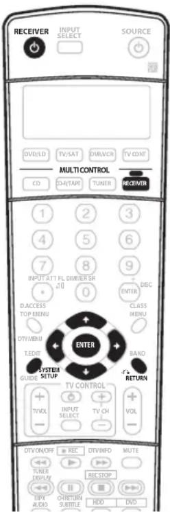
text_image
RECEIVER INPUT SELECT SOURCE DVD/LD TV/SAT DAR/NER TV CONT MULTI CONTROL CD CH/TAPE TUNER RECEIVER 1 2 3 4 5 6 7 8 9 INPUT ATT FL DIWIER SR 20 0 D. ACCESS TOP MENU DISC ENTER CLASS MENU DT/VEN/BU T.SDF/ ENTER SYSTEM GUIDE SETUP BAND RETURN TV CONTROL + - TVOL + - INPUT SELECT TV CH VOL DIV/ON/OFF + REC DIV/INFO MUTE TUNER DISPLAY REC STOP + - MPX ALDO CRETURN SUBTITLE HDD DVD1 Switch on the receiver and your TV.
Use the ⏻ RECEIVER button to switch on.
2 Press RECEIVER on the remote control, then press the SYSTEM SETUP button.
An on-screen display (OSD) appears on your TV. Use the ↑/↓/↔/→ buttons and ENTER on the remote control to navigate through the screens and select menu items. Press RETURN to confirm and exit the current menu.
3 Select 'Input Assign' from the System Setup menu.
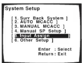
text_image
System Setup [1. Surr Back System ] [2. AUTO MCACC ] [3. MANUAL MCACC ] [4. MANUAL SP Setup ] [5. Input Assign ] [6. Other Setup ] Enter : Select Return : Exit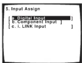
text_image
5. Input Assign [a. Digital Input ] [b. Component Input ] [c. i. LINK Input ]The illustration above shows the VSX-2014i-G OSD.
Assigning the digital inputs
- Default settings:
Digital-1 (optical) - TV/SAT
Digital-2 (optical) - CD-R
Digital-3 (coaxial) - DVD/LD
Digital-4 (coaxial) - CD
You only need to do this if you didn't hook up your digital equipment according to the default settings for the digital inputs (see above). This setting tells the receiver what digital equipment is hooked up to which terminal so the buttons on the remote correspond to what you have hooked up.
1 Select 'Digital Input' from the Input Assign menu.
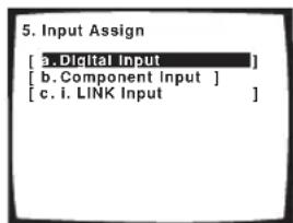
text_image
5. Input Assign [a. Digital Input ] [b. Component Input ] [c. i. LINK Input ]The illustration above shows the VSX-2014i-G OSD.
2 Select the number of the digital input to which you've connected your digital component.
The numbers correspond with the numbers beside the inputs on the back of the receiver.
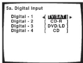
text_image
5a. Digital Input Digital - 1 ← [V/SAT] Digital - 2 [ CD-R ] Digital - 3 [ DVD/LD ] Digital - 4 [ CD ]3 Select the component that corresponds with the one you connected to that input.
Select between DVD/LD, TV/SAT, DVR, VIDEO1, CD-R, CD or OFF.
- Use the / (cursor left/right) buttons and ENTER to do this.
- If you assign a digital input to a certain function (for example, DVD/LD) then any digital inputs previously assigned to that function will automatically be switched off.
4 When you're finished, press RETURN.
You will return to the Input Assign menu.
Assigning the component video inputs
- Default settings:
Component 1 - OFF
Component 2 - OFF
If you used component video cords to connect your video equipment you must tell the receiver which device it is, or else you may see the S-video or composite video input instead of the component video signal.
1 Select 'Component Input' from the Input Assign menu.
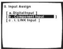
text_image
5. Input Assign [ a. DigitalInput ] [ B . Component Input ] [ c . i. LINK Input ]The illustration above shows the VSX-2014i-G OSD.
2 Select the number of the component video input to which you've connected your video component. Select between DVD/LD, TV/SAT, DVR, VIDEO1 or OFF.
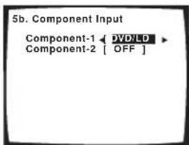
text_image
5b. Component Input Component-1 ← DVDLD Component-2 [ OFF ]- The numbers correspond with the numbers beside the inputs on the back of the receiver.
3 Select the component that corresponds with the one you connected to that input.
- Use the / (cursor left/right) buttons and ENTER to do this.
- Make sure you have connected the audio from the component to the corresponding inputs on the rear of the receiver.
- If you connect any source component to the receiver using a component video input, you should also have your TV connected to this receiver's component video MONITOR output.
4 When you're finished, press RETURN.
You will return to the Input Assign menu.
Assigning the i.LINK inputs
VSX-2014i-G model only
If you assign i.LINK-equipped components to an input (for example DVD/LD), you will be able to select both audio and video signals from i.LINK-equipped components using the corresponding MULTI CONTROL button.
1 Select 'i.LINK Input' from the Input Assign menu.
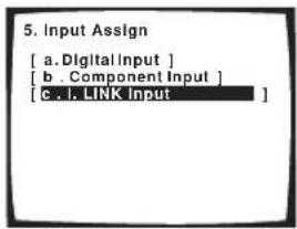
text_image
5. Input Assign [ a. DigitalInput ] [ b . ComponentInput ] [ c. l. LINK Input ]2 Select an i.LINK-equipped component.
When a number of i.LINK-equipped components are connected to your receiver, the i.LINK-equipped component you are looking for might be listed on additional display screens.
- If no i.LINK-equipped components are connected, you won't be able to assign any inputs.
- i.LINK is displayed after unassigned device names (e.g. DV-868AVi [i.LINK]).
- If a connected devices cannot output (playback) a source using the i.LINK connection, [- - - - ] is displayed after the input device name (e.g. DV-868AVi [- - - - ]). Non-compatible devices cannot be assigned to inputs.
- When the cables for an assigned input device become loose or the power is cut to the device, an asterisk (*) appears before the device name (e.g.
* DV-868AVi [DVD/LD]).
3 Select the component that you want to assign. Use the ↑/↓ (cursor up/down) buttons and ENTER
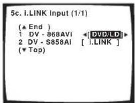
text_image
5c. I.LINK Input (1/1) (▲ End ) 1 DV - 868AVI ◀[DVD/LD]► 2 DV - S858AI [ I.LINK ] (▼ Top )When you assign an i.LINK-equipped video component, select the input source to which you have connected the video signal from the component.
- If you assign an i.LINK input to a certain function (for example DVD/LD) then any digital inputs previously assigned to that function will automatically be set to i.LINK (not assigned).
• The TUNER input cannot be assigned.
4 When you're finished, press RETURN.
You will return to the Input Assign menu.
The Other Setup menu
The Other Setup menu is where you can make customized settings to reflect how you are using the receiver.
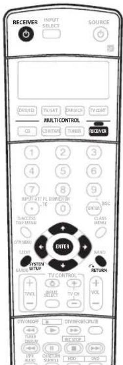
text_image
RECEIVER INPUT SELECT SOURCE DVD/SD TV/SAT BRANCH TV/DNT MULTI CONTROL CD OR ITAPE TUNER RECEIVER 1 2 3 4 5 6 7 8 9 INPUT UTT FL DRIVER SP 10 0 BDC ENTER CLASS MENU DANCE TOP MENU DTS/BIHDU LADY SYSTEM GUIDE SETUP EXIT MND RETURN TV CONTROL TV/CH VOL INPUT SELECT TV/CH - DTV/ON/OFF OUT/INFORE/CURRENT TURN DISPLAY REC/STOP MPI AUDIO RETURN STARTS HOC DWS1 Switch on the receiver and your TV. Use the ⏻ RECEIVER button to switch on.
2 Press RECEIVER on the remote control, then press the SYSTEM SETUP button.
An on-screen display (OSD) appears on your TV. Use the ↑/↓/←/→ buttons and ENTER on the remote control to navigate through the screens and select menu items. Press RETURN to confirm and exit the current menu.
3 Select 'Other Setup' then press ENTER.
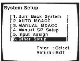
text_image
System Setup [1. Surr Back System ] [2. AUTO MCACC ] [3. MANUAL MCACC ] [4. Manual SP Setup ] [5. Input Assign ] [6. Other Setup ] Enter : Select Return : Exit4 Select the setting you want to adjust.
If you are doing this for the first time, you may want to adjust these settings in order:
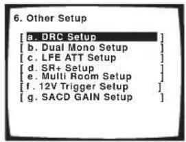
text_image
6. Other Setup [a. DRC Setup] [b. Dual Mono Setup] [c. LFE ATT Setup] [d. SR+ Setup] [e. Multi Room Setup] [f. 12V Trigger Setup] [g. SACD GAIN Setup]The illustration above shows the VSX-2014i-G OSD.
- DRC Setup – Specify the amount of dynamic range adjustment to Dolby Digital soundtracks (see Dynamic Range Control Setup below).
- Dual Mono Setup – Isolate one channel when listening to discs with dual mono encoding (see Dual Mono Setup below).
- LFE ATT Setup – Choose the attenuator level for the LFE channel (LFE Attenuator Setup below).
- SR+ Setup – Specify how you want to control your Pioneer plasma display (SR+ Setup for Pioneer plasma displays on page 67).
The following are available with the VSX-2014i-G model:
- Multi Room Setup – Specify your volume setting and IR receiver type for a multi-room setup (see Multi Room Setup on page 67).
- 12V Trigger Setup – Specify which components are switched on or off using the 12 volt trigger (see 12 Volt Trigger Setup on page 68).
- SACD GAIN Setup – Listen to high sound quality and greater detail with SACDs (see SACD Gain Setup on page 68).
5 Make the adjustments necessary for each setting, pressing RETURN to confirm after each screen.
Dynamic Range Control Setup
- Default setting: OFF
This setting specifies the amount of dynamic range adjustment to Dolby Digital and DTS movie soundtracks. You may want to use this when listening to surround sound at low volumes.
1 Select 'DRC Setup' from the Other Setup menu.
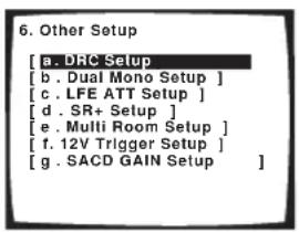
text_image
6. Other Setup [a. DRC Setup [b . Dual Mono Setup ] [c . LFE ATT Setup ] [d . SR+ Setup ] [e . Multi Room Setup ] [f . 12V Trigger Setup ] [g . SACD GAIN Setup ]2 Choose the setting that you want.
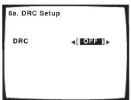
text_image
6a. DRC Setup DRC ←[OFF]- OFF – No dynamic range adjustment (use when listening at higher volume).
- MID – Mid setting.
- MAX – Dynamic range is reduced (loud sounds are reduced in volume while quieter sounds are increased).
3 When you're finished, press RETURN.
You will return to the Other Setup menu.
Dual Mono Setup
- Default setting: CH1
You can specify how dual mono encoded Dolby Digital soundtracks should be played. Dual mono is not widely used, but is sometimes necessary when two languages need to be sent to separate channels.
1 Select 'Dual Mono Setup' from the Other Setup menu.
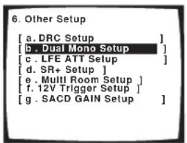
text_image
6. Other Setup [ a. DRC Setup ] [ b. Dual Mono Setup ] [ c. LFE ATT Setup ] [ d. SR+ Setup ] [ e. Multi Room Setup ] [ f. 12V Trigger Setup ] [ g. SACD GAIN Setup ]2 Choose the setting that you want.
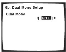
text_image
6b. Dual Mono Setup Dual Mono [ CH1 ]- CH1 – Only channel 1 is played
- CH2 – Only channel 2 is played
- CH1 CH2 – Both channels are played through the front speakers
3 When you're finished, press RETURN.
You will return to the Other Setup menu.

Note
- This setting works only with dual mono encoded Dolby Digital and DTS soundtracks.

Tip
- While the receiver is in standby (using the front panel), press the ⏻ STANDBY/ON button while holding down the TUNER EDIT button to change the dual mono setting.
LFE Attenuator Setup
- Default setting: ATT 0 dB
Some Dolby Digital and DTS audio sources include ultra-low bass tones. Set the LFE attenuator as necessary to prevent the ultra-low bass tones from distorting the sound from the speakers.
1 Select 'LFE ATT Setup' from the Other Setup menu.
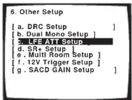
text_image
6. Other Setup [ a. DRC Setup ] [ b. Dual Mono Setup ] [ c. LFE ATT Setup ] [ d. SR+ Setup ] [ e. Multi Room Setup ] [ f. 12V Trigger Setup ] [ g. SACD GAIN Setup ]2 Choose the setting that you want.
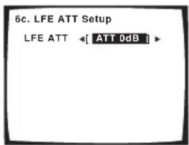
text_image
6c. LFE ATT Setup LFE ATT ←[ ATT 0dB ]- ATT 0dB – No limiting (recommended setting)
- ATT 10dB – 10dB of limiting
- LFE OFF – No sound from LFE channel
3 When you're finished, press RETURN.
You will return to the Other Setup menu.
SR+ Setup for Pioneer plasma displays
Make the following settings if you have connected a Pioneer plasma display to this receiver using an SR+ cable. Note that the number of function settings available will depend on the plasma display you've connected.
See also Using this receiver with a Pioneer plasma display on page 61 and Using the SR+ mode with a Pioneer plasma display on page 62.
1 Select 'SR+ Setup' from the Other Setup menu.
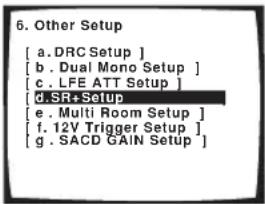
text_image
6. Other Setup [ a. DRC Setup ] [ b . Dual Mono Setup ] [ c. LFE ATT Setup ] [ d. SR+Setup ] [ e . Multi Room Setup ] [ f. 12V Trigger Setup ] [ g . SACD GAIN Setup ]2 Select the 'PDP Volume Control' setting you want.
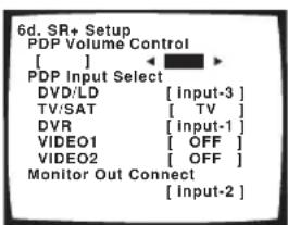
text_image
6d. SR+ Setup PDP Volume Control [ ] PDP Input Select DVD/LD [Input-3] TV/SAT [TV] DVR [input-1] VIDEO1 [OFF] VIDEO2 [OFF] Monitor Out Connect [Input-2]- OFF – The receiver does not control the volume of the plasma display
- ON – When the receiver is switched to one of the inputs that use the plasma display (DVD/LD, or another one of functions below), the volume on the plasma display is muted so only sound from the receiver is heard.
3 Assign any input source connected to the plasma display to the corresponding input number.
This matches the receiver's input source with a numbered video input on the plasma display. For example, assign DVD/LD to input-2 if you have connected the your DVD video output to video input 2 on the plasma display.
- The Monitor Out Connect should be set to the input that you've used to connect this receiver to your plasma display.
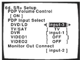
text_image
6d. SR+ Setup PDP Volume Control [ ON ] PDP Input Select DVD/LD [ input-3 ] TV/SAT [ TV ] DVR [ input-1 ] VIDEO1 [ OFF ] VIDEO2 [ OFF ] Monitor Out Connect [ input-2 ]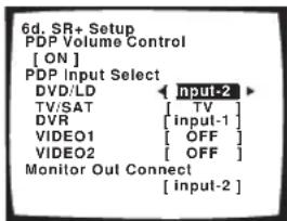
text_image
6d. SR+ Setup PDP Volume Control [ ON ] PDP Input Select DVD/LD Input-2 TV/SAT [ TV ] DVR [ input-1 ] VIDEO1 [ OFF ] VIDEO2 [ OFF ] Monitor Out Connect [ input-2 ]4 When you're finished, press RETURN.
You will return to the Other Setup menu.
Multi Room Setup
VSX-2014i-G model only
- Default setting: VARIABLE / Setting 1
If you've made multi-room connections (see Multi-room listening on page 57) you may need to specify your volume setting and IR receiver type.
1 Select 'Multi Room Setup' from the Other Setup menu.
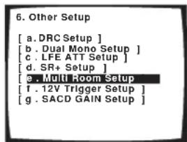
text_image
6. Other Setup [ a. DRC Setup ] [ b . Dual Mono Setup ] [ c . LFE ATT Setup ] [ d. SR+ Setup ] [ e . Multi Room Setup ] [ f . 12V Trigger Setup ] [ g . SACD GAIN Setup ]2 Select the volume level setting.
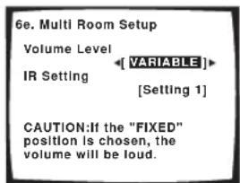
text_image
6e. Multi Room Setup Volume Level IR Setting [VARIABLE] [Setting 1] CAUTION:If the "FIXED" position is chosen, the volume will be loud.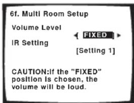
text_image
6f. Multi Room Setup Volume Level IR Setting FIXED [Setting 1] CAUTION:If the "FIXED" position is chosen, the volume will be loud.- VARIABLE – Use this setting if you've connected a power amplifier in the sub room (this receiver is simply being used as a pre-amp) and you will be using this receiver's controls to adjust the volume.
- FIXED – Use this setting if you've connected a fully integrated amplifier (such as another Pioneer VSX receiver) in the sub room and want to use that receiver's volume controls.
Caution
- With the FIXED setting, the source is sent from this receiver at maximum volume, so make sure the volume is quite low in the sub room at first and then experiment to find the correct level.
3 Select the type of IR receiver you're using.
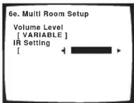
text_image
6e. Multi Room Setup Volume Level [ VARIABLE ] IR Setting [ ]- Setting 1 – Use this setting for most IR receivers.
- Setting 2 – Use this setting if the IR receiver you're using doesn't seem to work after selecting Setting 1.
4 When you're finished, press RETURN.
You will return to the Other Setup menu.

Note
- Some IR receivers may not work with this receiver. Check with your audio dealer for more information.
12 Volt Trigger Setup
VSX-2014i-G model only
- Default setting: OFF (all components)
After connecting a component the 12 volt trigger (see Switching components on and off using the 12 volt trigger on page 61), it switches on automatically when you select an input function set to switch the trigger on. Specify which input functions switch on the trigger below.
1 Select '12V Trigger Setup' from the Other Setup menu.
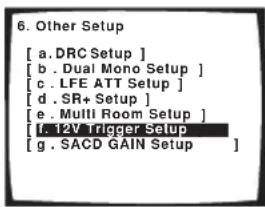
text_image
6. Other Setup [ a. DRC Setup ] [ b . Dual Mono Setup ] [ c . LFE ATT Setup ] [ d . SR+ Setup ] [ e . MUII Room Setup ] [ f . 12V Trigger Setup ] [ g . SACD GAIN Setup ]2 Select an input function and choose the setting that you want.
This should be the input function, that when selected, switches on the 12 volt trigger.
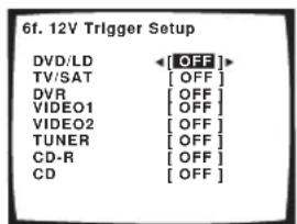
text_image
6f. 12V Trigger Setup DVD/LD [OFF] TV/SAT [OFF] DVR [OFF] VIDEO1 [OFF] VIDEO2 [OFF] TUNER [OFF] CD-R [OFF] CD [OFF]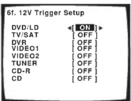
text_image
61. 12V Trigger Setup DVD/LD [ON] TV/SAT [OFF] DVR [OFF] VIDEO1 [OFF] VIDEO2 [OFF] TUNER [OFF] CD-R [OFF] CD [OFF]- OFF – 12 volt trigger is not activated for the selected component.
- ON – 12 volt trigger is activated for the selected component.
3 Repeat for as many input functions as you would like to set.
4 When you're finished, press RETURN.
You will return to the Other Setup menu.
SACD Gain Setup
VSX-2014i-G model only
- Default setting: 0dB
You can get more detail from SACDs by maximizing the dynamic range (during digital processing) using the SACD gain feature.
1 Select 'SACD GAIN Setup' from the Other Setup menu.
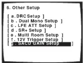
text_image
6. Other Setup [ a. DRC Setup ] [ b. Dual Mono Setup ] [ c. LFE ATT Setup ] [ d. SR+ Setup ] [ e. Multi Room Setup ] [ f. 12V Trigger Setup ] [ g. SACD GAIN Setup ]2 Switch the SACD gain between 0dB and 6dB.
For most SACD sources, selecting 6dB will result in high sound quality and greater detail. The level will be adjusted automatically for playback at the same volume.
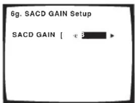
text_image
6g. SACD GAIN Setup SACD GAIN [ -3 ]3 When you're finished, press RETURN.
You will return to the Other Setup menu.

Note
- You shouldn't have any problems using this feature with most SACD discs, but if the sound distorts, it is best to switch the gain setting back to 0dB.
Chapter 12:
Additional information
Troubleshooting
Incorrect operations are often mistaken for trouble and malfunctions. If you think that there is something wrong with this component, check the points below. Sometimes the trouble may lie in another component. Investigate the other components and electrical appliances being used. If the trouble cannot be rectified even after exercising the checks listed below, ask your nearest Pioneer authorized independent service company to carry out repair work.
Power
| Symptom | Cause Remedy | |
| The power does not turn on. • The power plug is disconnected. • Connect the power plug to the wall outlet. | ||
| • The protection circuit may have been activated. | • Disconnect the power plug from the outlet, and insert again. | |
| The receiver suddenly switches off. | • The speaker wires are frayed or sticking out of the jack, and are touching the back of the receiver or another set of wires. | • Reinsert the speaker wires, making sure there are no stray strands of wire and that they are inserted fully. |
| • The receiver has a serious problem. • Unplug the receiver from the wall and call a Pioneer authorized independent service company. | ||
| During loud playback the power suddenly switches off. | • The protection circuit has been activated because the lowest actual impedance of the speakers (as opposed to the speakers rated impedance) is dangerously low. | • Turn down the volume.• When it's convenient, go to Acoustic Calibration EQ on page 41 and lower the 40 Hz and 125 Hz equalizer levels using the manual setting.• Turning the digital safety feature on may allow you to turn up the volume a little more. To switch between SAFETY ON and SAFETY OFF, put the receiver into standby, then press the STANDBY/ON button while holding down the SYSTEM SETUP button on the front panel. |
| The unit does not respond when the buttons are pressed. | • Static electricity caused by dry air. • Switch the unit off, then on again.• Disconnect the power plug from the outlet, and insert again. | |
| AMP ERR blinks in the display, then the power automatically switches off. The MCACC blinks and the power does not turn on. | • The receiver has a serious problem. • Do not try to turn on the receiver. Contact a Pioneer authorized independent service company for assistance. | |
| FAN STOP blinks in the display, then the power automatically switches off. | • Something is obstructing the fan. • Remove the obstruction and try switching the receiver back on. If the fan is still not working, or you can't remove the object, unplug the receiver from the wall and call a Pioneer authorized independent service company. | |
| • The fan is malfunctioning. • Unplug the receiver from the wall and call a Pioneer authorized independent service company. | ||
| OVERHEAT blinks in the display then the power automatically switches off. | • The internal temperature of the unit has become too high. | • After allowing the unit to cool down in a well-ventilated place, try switching the receiver back on. Make sure you follow the guidelines for improving heat dispersal in Ventilation on page 2. |
No sound
| Symptom | Cause Remedy | |
| No sound is output when an input source is selected.No sound output from the front speakers. | Improper connections.Make sure you have properly connected the component to the corresponding input on the back of the receiver (seeConnecting up on page 14). | |
| Sound is muted or the volume is turned down. | PressMUTEor adjust the volume accordingly. | |
| Speakers are turned off or selected improperly with the SPEAKERS switch. | PressSPEAKERTo select the proper speaker set (see Switching the speaker system on page 55). | |
| The input signal type is incorrect.Press | SIGNAL SELECTto select the proper input signal (seeChoosing the input signal on page 33). | |
| The multichannel analog inputs are selected. | PressMULTI CH INagain (see Selecting the multichannel analog inputs on page 37). | |
| The front speakers aren't connected properly. | See Connecting the speakerson page 21 to connect them properly. | |
| No sound from the surround or center speakers. | Speaker settings are incorrect. (for example, they have been set to NO). | Check you speaker settings inSpeaker Setting on page 44. |
| The surround and/or center levels are turned down. | Check the levels inChannel Level on page 45. | |
| The surround and/or center speakers are disconnected. | CheckConnecting the speakers on page 21 to make sure the speakers are connected correctly. | |
| STEREO listening mode has been selected. | Choose a surround listening mode (seeListening in surround soundon page 30). | |
| No sound from surround back speakers. | Surround back speakers are set to NO. | Set the surround back speakLARGE or SMALL(seeSpeaker Setting on page 44). |
| The Extended mode is switched to AUTO or OFF. | Set toExtended ON(see Using the surround back channel (Extended mode) on page 34). | |
| The source is not a 6.1 channel playback source. | Switch the Extended mode toExtended ON(see Using the surround back channel (Extended mode) on page 34) and choose a surround listening mode (seeListening in surround soundon page 30). | |
| The surround back speakers are disconnected. | CheckConnecting the speakers on page 21 to make sure the speakers are connected correctly. | |
| The surround back channel is on the 1 speaker setting, and your speaker is connected to the right channel output. | Connect the speaker to the surround back left channel output (Connecting the speakers on page 21). | |
| The Extended mode is switched to AUTO and the Dolby Surround EX / DTS ES software you're playing has no flag to indicate it is 6.1 compatible. | You can still listen with surround back sound by setting toExtended ON(Using the surround back channel (Extended mode) on page 34). | |
| No sound from subwoofer.The subwoofer is disconnected or switched off. | Connect or switch on the subwoofer (seeConnecting the speakerson page 21).Make sure the sleep function on your subwoofer isn't activated. | |
| The subwoofer's settings are incorrect.Set the subwoofer (see YES or PLUS.Speaker Setting on page 44) to | ||
| The crossover frequency is set too low.Set the crossover frequency to a (higher) frequency that matches your speaker characteristics (see Crossover Networkon page 45) | ||
| There is very little low frequency information in your source.Change your subwoofer setting to one of the following in theSpeaker Setting on page 44:Front:SMALL/ Subwoofer:YESFront:LARGE/ Subwoofer:PLUS | ||
| The LFE channel is switched off.SeeLFE Attenuator Setup on page 66 to adjust the setting. | ||
| The subwoofer's levels are too low.SeeChannel Levoion page 45 to check the speaker levels.Check the volume control on the subwoofer to make sure it is turned up. | ||
| No sound from one speaker. • The speaker setting has been set to NO. • Change the setting speaker Setting on page 44. | ||
| • The speaker level is too low. • Check the level in Channel Level on page 45. | ||
| • The speaker isn't connected properly. • Check Connecting the speakers on page 21 to make sure the speaker is connected correctly. | ||
| • The source has no sound output for that channel. | • By choosing an advanced effect listening mode (see Listening in surround sound on page 30), you may be able to create an extra channel for the speaker. | |
| Sound is produced from analog components, but not from digital ones (DVD, LD, CD-ROM etc.). | • The digital input assignment is wrong. • Assign the digital inputs correctly (see assigning the digital inputs on page 63). | |
| • The digital components aren't connected properly. | • Make sure you have properly connected the digital component to the corresponding input on the back of the receiver (see Connecting up on page 14). | |
| • The player is not compatible with the source you're using, or the player settings are incorrect. | • Choose a compatible source, or check the component's manual for the correct settings. | |
| • The digital output level has been turned down on a CD recorder or other component equipped with digital output level adjustment capability. | • Set the digital volume level of the player to full, or to the neutral position. | |
| • The multichannel analog inputs are selected. | • Press MULTI CH IN again (see Selecting the multichannel analog inputs on page 37). | |
| • The input signal type is set to ANALOG. | • Set the input signal type DIGITAL (see Choosing the input signal on page 33). | |
| No sound is output or a noise is output when Dolby Digital/DTS software is played back. | • A DVD player not compatible with Dolby Digital/DTS is being used. | • Make sure your DVD player is compatible with Dolby Digital/DTS. |
| • The settings on the DVD player are incorrect and/or the DTS signal output is turned off. | • Make sure the player's settings are correct and/or the DTS signal out is on. Refer to the instruction manual supplied with the DVD player. | |
| • The digital output level is turned down on a CD player or other component equipped with digital output level adjustment capability. (The DTS signal has been altered by the player, and cannot be read.) | • Set the digital volume level of the player to full, or to the neutral position. | |
Other audio problems
| Symptom Cause Remedy | |||
| Broadcast stations cannot be selected automatically, or there seems to be considerable noise in radio broadcasts. | FM broadcastsThe FM antenna is not fully extended or is poorly positioned.Weak radio signals. Connect an outdoor FM antenna (see page 19). | Fully extend the FM wire antenna, position for best reception, and secure to a wall. | |
| AM broadcastsThe AM antenna is poorly positioned. Adjust the direction and position for best reception.Weak radio signals. Connect an additional internal or external AM antenna (see page 19).Interference caused by other equipment (fluorescent lamp, motor, etc.). | Turn off the equipment causing the noise or move it away from the receiver.Place the antenna farther away from the equipment causing the noise. | ||
| A multi channel DVD source appears to be downmixed from 2 channels during playback. | The source is coming from something other than the MULTI CH IN jacks (for example, digital PCM output, etc.) | Check the MULTI CH IN connections (see Connecting multichannel analog components on page 17) and select the multichannel analog inputs with the MULTI CH IN button (see Selecting the multichannel analog inputs on page 37). | |
| Noise is output when scanning a DTS CD. | The scan function performed by the player slightly alters the digital information, making it unreadable. | This is not a malfunction, but be sure to turn the volume down to prevent the output of loud noise from your speakers. | |
| When playing a DTS format LD there is audible noise on the soundtrack. | The input signal type is set to ANALOG. | Set the input signal type is set to DIGITAL (see Choosing the input signal on page 33) | |
| Symptom | Cause Remedy | ||
| Can't record audio. • You are trying to make an analog recording from a digital signal, or a digital recording of an analog source. | • You can only record analog to analog, or digital to digital. | ||
| • The digital source is copy protected. • You can't record digital sources that have been copy protected. | |||
| • The analog REC jacks have not been connected properly. | • Check your analog connections (seeConnecting analog audio componentson page 17). | ||
| Subwoofer output is very low. • The speaker settings result in very little audio signal being sent to the subwoofer. | • To route more audio signal to the subwoofer, set it to PLUS or select SMALL for the front speaker setting (see Speaker Settingon page 44). | ||
| The signal is not downmixed when listening to a multichannel DVD-Audio disc (for example, you only hear the front left and right channels when listening in stereo). | • The disc is downmix prohibited. • This is not a malfunction. | ||
| Everything seems to be set up correctly, but the playback sound is odd. | • The speakers are out of phase. • Check that the positive/negative speaker terminals on the receiver are matched with the corresponding terminals on the speakers (seeConnecting the speakers on page 21). | ||
| Noise or hum can be heard even when there is no sound being input. | • There is electrical interference from another component or appliance. | • Check that personal computers or other digital components connected to the same power source are not causing interference. | |
| There seems to be a time lag between the speakers and the output of the subwoofer. | • The subwoofer channel can be delayed slightly if run through a low-pass filter. | • See Automatically setting up for surround sound (MCACC) on page 11 to set up your system again using MCACC (this will automatically compensate for a delay in the subwoofer output). | |
| The maximum volume available (shown in the front panel display) is lower than the +12dB maximum. | • The channel levels may have been adjusted. | • This is not a malfunction. If the levels in Channel Level on page 45 have been adjusted, the maximum volume will change accordingly. | |
Video
| Symptom Cause Remedy | ||
| No image is output when an input is selected. | The video connections are incorrect.Make sure the video component is connected correctly (see page 18). | |
| You are using component video connections for your source, but not for your TV.Using the video converter, video signals can be converted from a composite or S-video input to a component video output, but not vice-versa (VSX-2014i-G only). See About the video converter on page 15 for more on this. | ||
| You are using component video connections and the component video inputs are assigned incorrectly.Check Assigning the component video inputs on page 64 to make sure you're assigned the correct input. | ||
| The DVD/video player settings are incorrect.Set correctly. Refer to the instruction manual supplied with the DVD/video player. | ||
| The video input selected on the TV monitor is incorrect.Set correctly. Refer to the instruction manual supplied with the TV. | ||
| Even though the sub room monitor is connected properly, the multi-room feature is switched off.Press the MULTI ROOM&SOURCE ON/OFF button to switch it on. | ||
| The component video inputs are assigned to a video component connected only to the composite or S-Video terminals.Check Assigning the component video inputs on page 64 to make sure the component video assign for that video component is switched to OFF. | ||
| You connected your TV to the MULTI ROOM & SOURCE MONITOR OUT jack instead of the main MONITOR OUT jack.Connect the MONITOR OUT jack to the TV monitor (see Connecting video components on page 18). | ||
| Symptom | Cause Remedy | |
| The System Setup screen doesn't appear (or is displayed incorrectly). | Some TVs connected to the receiver with component video cables do not display the System Setup screen when the Color Burst feature is on. | When the receiver is in standby, switch to COLOR BURST OFF by holding down the front panel ACOUSTIC EQ button and pressing Ⓧ STANDBY/ON. (the current setting appears in the display). |
| The MONITOR OUT jack hasn't been connected.You connected your TV to the MULTI ROOM & SOURCE MONITOR OUT jack instead of the main MONITOR OUT jack. | Connect the MONITOR OUT jack to the TV monitor (see Connecting video components on page 18). | |
| VSX-1014-S model only – The TV format setting for your country or region is incorrect. | See Changing the TV format setting on page 76 to change the format setting to match your country or region. | |
| Can't record video. • You are trying to record a source connected to the component video jacks. | Connect the source component to either the composite video or the S-video jacks (see Connecting video components on page 18). | |
Settings
| Symptom Cause Remedy | ||
| The Auto MCACC Setupcontinually shows an error. | • The ambient noise level in the room is too high, or obstacles are blocking the setup microphone. | • Keep the noise level in the room as low as possible when using the Auto MCACC Setup (see Other problems when using the Auto MCACC Setup on page 13 for more on this). If the noise cannot be kept low enough, you will have to set up the surround sound manually (page 43). |
| After using the Auto MCACC Setup, the speaker size setting (LARGE or SMALL) is incorrect. | • There was some inaudible low-frequency noise in the room. | • The low-frequency noise could have been caused by an air conditioner or motor. Switch off all appliances in the room and rerun the Auto MCACC Setup. |
| The display shows KEY LOCK ON when you try to make settings. | • Your Pioneer dealer has enabled the key lock feature. | • Ask your Pioneer dealer to disable the key lock. |
| 12V TRG ERR blinks in the display. | • There is a problem with the 12V trigger connection. | • Turn the receiver off and check the 12V trigger connection. |
Display
| Symptom Cause Remedy | ||
| The display is dark or off. • The display is set to dark or off. • Press | FL. DIMMER on the remote control repeatedly to select a different brightness. | |
| After making an adjustment the display goes off. | • The display is set to off. • Press | FL. DIMMER on the remote control repeatedly to select a different brightness. |
| You can't get DIGITAL to display when using the SIGNAL SELECT button. | • There is a problem with the digital connections or the digital input is assigned incorrectly. | • Check your digital connections and/or assign the digital inputs correctly (see Assigning the digital inputs on page 63). |
| • The multichannel analog inputs are selected. | • Press MULTI CH IN again (see Selecting the multichannel analog inputs on page 37). | |
| The Dolby/DTS indicator doesn't light when playing Dolby/DTS software. | • The player is paused. • Press play. | |
| • The player's sound output settings are wrong. | • Set the player correctly (consult the manual that came with the player, if necessary). | |
| When playing a DVD-Audio disc, the DVD player display shows 96 kHz. However, the receiver's display does not. | • The audio from these discs is output from the analog audio jacks of the DVD player only; the receiver does not show the sampling rate of the input signal through the analog inputs. | • This is not a malfunction. See also the operating instructions that came with your DVD player. |
| During playback of a DTS 96/24 source, the display doesn't show 96kHz. | • The receiver's input signal type is set to analog. | • Set the receiver to AUTO or DIGITAL (see Choosing the input signal on page 33). |
| Symptom | Cause Remedy | |
| When playing Dolby Digital or DTS sources, the receiver's format indicators do not light. | No digital connection, or the digital connection is incorrect. | Check the digital audio connection (page 16). |
| The receiver's input signal type is set to analog. | Set the receiver to AUTO or DIGITAL (see Choosing the input signal on page 33). | |
| The DVD player is set to output Dolby Digital and/or DTS audio as PCM. | Check the settings on the player. Set the output for Dolby Digital and DTS (no PCM conversion). See also the operating instructions that came with your DVD player. | |
| The disc has several playback audio tracks; the one currently playing is actually PCM. | Switch the playback audio channel on your DVD player. See the operating instructions that came with your DVD player. | |
| When playing certain discs, none of the receiver's format indicators light. | The audio format of the disc is not 5.1/6.1 channel. | This is not a malfunction. Check the disc packaging for details of the audio formats available on the disc. |
| When playing a disc, the ☐☐ PL II or Neo:6 indicator lights on the receiver. | The input signal type is set to analog. | Set the receiver to AUTO or DIGITAL (see Choosing the input signal on page 33). |
| A two channel soundtrack is currently playing. | This is not a malfunction. Check the disc packaging for details of the audio formats available on the disc. | |
| The soundtrack currently playing is encoded using Dolby Surround. | This is not a malfunction. Check the disc packaging for details of the audio formats available on the disc. | |
| During playback of a Surround EX or DTS ES source on the Extended AUTO setting, the EX and ES indicators don't light, or the signal is not properly processed. | The source may be Dolby Surround EX / DTS ES software, but it has no flag to indicate it is 6.1 compatible. | Set to Extended ON (see Using the surround back channel (Extended mode) on page 34) then switch to the THX Surround EX or Standard EX listening mode (see Listening in surround sound on page 30). |
Remote control
Symptom Cause Remedy
| Cannot be remote controlled. • The remote control batteries have worn out. • Replace the batteries (see Loading the batteries on page 7). | |
| • Too far away or improper angle of operation. • Operate within 7 meters and a 30^ angle of the remote sensor on the front panel (seeOperating range of remote control unit on page 7). | |
| • There is an obstacle between the receiver and the remote control. • Remove the obstacle or move to another place. | |
| • Strong light such as fluorescent light is shining onto the unit's remote control sensor. • Avoid exposing the remote sensor on the front panel to direct light. | |
| • Something is plugged into theCONTROL INjack. • Unplug the cable from theCONTROL INjack and use remote normally (see Operating other Pioneer components on page 23). | |
| • VSX-2014i-G model only – The IR receiver type is mismatched with the setting. • Disconnect the IR receiver from the rear panel or set to the other IR receiver type (seeMulti Room Setup on page 67). | |
| Other components can't be operated with the system remote. | • The preset code settings are wrong. • Input the correct preset code. |
| • The batteries wore out and the system settings were cleared. • Reset the proper system settings. | |
| The SR cable is connected, but the connected components can't be operated with the remote. | • The SR cable hasn't been connected properly. • Reinsert the SR cable, making sure it's connected to the right jack (see Operating other Pioneer components on page 23). |
| • The rest of the component connections have not been made. • Make sure an analog connection has been made between the units. | |
| • The component you have hooked up is not a Pioneer product. • This feature only works with Pioneer products. | |
i.LINK interface
VSX-2014i-G model only
| Symptom | Cause Remedy | |
| No sound is output. • An output signal is not produced from the i.LINK connector on the source player. | • Refer to the manual that came with the source player. | |
| • The selected component is not compatible with i.LINK audio. | ||
| • The input signal is set to DIGITAL or ANALOG. | ||
| i.LINK indicator does not light up even when an i.LINK-equipped component is selected. | • The DIGITAL or ANALOG input signal is selected. | • Select i.LINK or AUTO using the SIGNAL SELECT button (see Assigning the i.LINK inputs on page 64). |
| • The i.LINK cable has become disconnected. | • Check all connections. | |
| • The i.LINK cable is too long. • Use a cable less than 3.5m long. | ||
| • The selected component does not correspond to the i.LINK Audio format. | • Refer to the manual for the selected component. | |
| • The component between the unit and the source player is turned off. | • When the source player is turned off or in standby, the output signal is not produced. Refer to the manual for the selected component. | |
| PQLS OFF or PQLS ON is displayed temporarily on your player and the sound output is discontinued. | • During playback through an i.LINK connection, if you change the settings for other i.LINK components, the sound will be discontinued momentarily. | • This is not a malfunction. |
| The program format indicators don't disappear when SACD playback stops. | • The program format indicators remain lit until another format source is input. | • This is not a malfunction. |
| You can't get i.LINK to display when using the SIGNAL SELECT button. | • i.LINK-equipped component(s) are not ready. | • Turn on the component(s). |
| • i.LINK input setting is incorrect. • Select the correct i.LINK input setting (see the i.LINK inputs on page 64). | Assigning | |
| After upgrading a component, it is not recognized and cannot be selected using the i.LINK connection. | • Depending on the upgrade process, certain components may cease to be recognized by the receiver. | • You may need to reset the i.LINK database memory in the receiver (use the front panel):With the receiver in standby, press Ⓧ STANDBY/ON while holding down RETURN. When you see DB CLEAR? appear in the display, press ENTER then SET UP to confirm. When you've reset the i.LINK database memory, DB CLEAR SET shows in the display. If DB ERROR is displayed, step through the procedure again. |
i.LINK messages
VSX-2014i-G model only
You may see the following messages displayed in the front panel display when using the i.LINK interface:
| Message Explanation | |
| BUS FULL | The i.LINK bus has reached its capacity and cannot transmit any more data. |
| CANNOT LINK 1 | The connection between the receiver and the selected i.LINK-equipped component is unstable. If the i.LINK cables appear to be connected properly and both the receiver and i.LINK-equipped component are on, switch both units off, then on again to re-establish the connection between them. |
| CANNOT LINK 2 | The receiver can't identify the selected i.LINK-equipped component. For example, the receiver may not be able to identify an i.LINK-equipped personal computer. |
| LINK CHECK | The receiver is checking the i.LINK network. It does this when components are added to, or removed from the network. The sound may be interrupted if this happens during playback. |
| LOOP CONNECT | The i.LINK network cannot function because the connected components form a loop. See Creating an i.LINK network on page 60 for more on this. |
| NO NAME | When an i.LINK-equipped component has no name, this message is displayed instead of the proper component name. |
| NO SIGNAL | A component is outputting an i.LINK signal that the receiver cannot reproduce. This receiver can only reproduce signals from i.LINK-Audio equipped components. See About i.LINK on page 60 for more on this. |
| Message | Explanation |
| PQLS OFF | This is displayed on a playback component when PQLS turns off during playback. The sound may be interrupted momentarily when this happens. |
| PQLS ON | This is displayed on a playback component when PQLS turns on during playback. The sound may be interrupted momentarily when this happens. |
| UNKNOWN | When an i.LINK-equipped component name cannot be recognized, this message is displayed instead of the proper component name. |

Note
- If the unit does not operate normally due to external effects such as static electricity disconnect the power plug from the outlet and insert again to return to normal operating conditions.
Resetting the main unit
Use this procedure to reset all the receiver's settings to the factory default. Use the front panel controls to do this.
1 Switch the receiver into standby.
2 While holding down the TONE button, press and hold the ⏻ STANDBY/ON button for about three seconds.
3 When you see RESET? appear in the display, press ENTER.
OK? shows in the display.
4 Press SYSTEM SETUP to confirm.
OK appears in the display to indicate that the receiver has been reset to the factory default settings.
Changing the frequency step
If you find that you can't tune into stations successfully, the frequency step may not be suitable for your country/region. Heres how to switch the setting:
1 Switch the receiver into standby.
2 While holding down the front panel BAND button, press ⏻STANDBY/ON.
The display shows the new setting:
- 9K STEP – For areas with an FM reception of 50kHz and AM reception of 9kHz
- 10K STEP – For areas with an FM reception of 100kHz and AM reception of 10kHz

Note
- If you're unsure of the correct frequency step for your region, consult your local Pioneer dealer.
Switching the speaker impedance
We recommend using speakers of 8Ω with this system, but it is possible to switch the impedance setting if you plan to use speakers with a 6Ω impedance rating.
- With the receiver in standby, press ⏻ STANDBY/ON while holding down the SPEAKERS button.
Each time you do this, you switch between the impedance settings:
- SP 6 OHM – Use this setting if your speakers are rated at 6Ω.
- SP 8 OHM – Use this setting if your speakers are rated at 8Ω or more.
Changing the TV format setting
VSX-1014-S model only
If the System Setup menu is not displayed correctly, it may be that the TV system is set incorrectly for your country or region.
- With the receiver in standby, press ⏻ STANDBY/ON while holding down the SIGNAL SELECT button.
The display shows the new setting (PAL or NTSC).
Surround sound formats
Below is a brief description of the main surround sound formats you'll find on DVDs, satellite, cable and terrestrial broadcasts, and video cassettes.
Dolby
The Dolby technologies are explained below. See www.dolby.com for more detailed information.

Dolby Digital
Dolby Digital is a multichannel digital audio coding system widely used in cinemas, and in the home for DVD and digital broadcast soundtracks. It can deliver up to six discrete audio channels, comprising five full range channels and a special LFE (low frequency effects) channel used mainly for deep, rumbling sound effects; hence the term "5.1-channel" Dolby Digital.
In addition to the format features above, Dolby Digital decoders offer downmixing for compatibility with mono, stereo and Dolby Pro Logic audio from a number of bit rates and channels. Another feature, called Dialog Normalization, attenuates programs based on the average level of dialog in a program relative to its peak level (also known as Dialnorm) in order to achieve uniform playback level.
Dolby Digital Surround EX
Dolby Digital Surround EX (the EX stands for EXtended) is an extension of Dolby Digital encoding whereby a surround back channel is matrixed into the surround left/right channels for 6.1 channel playback. This allows for compatibility with Dolby Digital 5.1 channel decoding, as well as for decoding using Dolby Digital EX.
Dolby Pro Logic IIx and Dolby Surround
Dolby Pro Logic IIx is an improved version of the Dolby Pro Logic II (and Dolby Pro Logic) decoding system. Using the innovative "steering logic" circuit, this system extracts surround sound from sources as follows:
- Dolby Pro Logic – 4.1 channel sound (mono surround) from any stereo source
- Dolby Pro Logic II – 5.1 channel sound (stereo surround) from any stereo source
- Dolby Pro Logic IIx – 6.1 or 7.1 channel sound (stereo surround and surround back) from two channel or 5.1(and 6.1) channel sources
With two channel sources, the ".1" subwoofer channel is generated by bass management in the receiver.
Dolby Surround is an encoding system which embeds surround sound information within a stereo soundtrack, which a Dolby Pro Logic decoder can then use for enhanced surround listening with greater sound detail.
Manufactured under license from Dolby Laboratories. "Dolby", "Pro Logic", "Surround EX" and the double-D symbol are trademarks of Dolby Laboratories.
DTS
The DTS technologies are explained below. See www.dtstech.com for more detailed information.

DTS Digital Surround
DTS Digital Surround is a 5.1-channel audio coding system from Digital Theater Systems Inc. now widely used for DVD-Video, DVD-Audio, 5.1 music discs, digital broadcasts, and video games. It can deliver up to six discrete audio channels, comprising five full range channels, including an LFE channel. Higher sound quality is achieved through the use of a low compression rate, and high rates of transmittance during playback.
DTS-ES
DTS-ES (the ES stands for Extended Surround) is a decoder that is capable of decoding both DTS-ES Discrete 6.1 and DTS-ES Matrix 6.1 encoded sources. DTS-ES Discrete 6.1 gives 'true' 6.1 channel sound, with a completely separate (discrete) surround back channel. DTS-ES Matrix 6.1 has a surround back channel matrixed into the surround left/right channels. Both sources are also compatible with a conventional DTS 5.1 channel decoder.
DTS Neo:6
DTS Neo:6 can generate 6.1 channel surround sound from any matrixed stereo source (such as video or TV) and from 5.1 channel sources. It uses both the channel information already encoded into the source, as well as its own processing to determine channel localization (with two channel sources, the ".1" subwoofer channel is generated by bass management in the receiver). Two modes (Cinema and Music) are available using DTS Neo:6 with two channel sources.
DTS 96/24
DTS 96/24 is an extension of the original DTS Digital Surround which offers high quality 96 kHz / 24-bit audio using a DTS 96/24 decoder. This format is also fully backward compatible with all existing decoders. This means that DVD players can play this software using a conventional DTS 5.1 channel decoder.
"DTS", "DTS-ES", "Neo:6" and "DTS 96/24" are trademarks of Digital Theater Systems, Inc.
About THX
The THX technologies are explained below. See www.thx.com for more detailed information.

THX Cinema processing
THX is an exclusive set of standards and technologies established by the world-renowned film production company, Lucasfilm Ltd. THX grew from George Lucas' personal desire to make your experience of the film soundtrack, in both movie theatres and in your home theatre, as faithful as possible to what the director intended. Movie soundtracks are mixed in special movie theatres called dubbing stages and are designed to be played back in movie theatres with similar equipment and conditions. This same soundtrack is then transferred directly onto Laserdisc, VHS tape, DVD, etc., and is not changed for playback in a small home theatre environment. THX engineers developed patented technologies to accurately translate the sound from the movie theatre environment into the home, correcting the tonal and spatial errors that occur. On this product, when the THX indicator is on, THX features are automatically added in Cinema modes (e.g. THX Cinema, THX Surround EX).
Re-Equalization
The tonal balance of a film soundtrack will be excessively bright and harsh when played back over audio equipment in the home because film soundtracks were designed to be played back in large movie theaters using very different professional equipment. Re-Equalization restores the correct tonal balance for watching a movie soundtrack in a small home environment.
Timbre Matching
The human ear changes our perception of a sound depending on the direction from which the sound is coming. In a movie theatre, there is an array of surround speakers so that the surround information is all around you. In a home theatre, you use only two speakers located to the side of your head. The Timbre Matching feature filters the information going to the surround speakers so that they more closely match the tonal characteristics of the sound coming from the front speakers. This ensures seamless panning between the front and surround speakers.
Adaptive Decorrelation
In a movie theatre, a large number of surround speakers help create an enveloping surround sound experience, but in a home theatre there are usually only two speakers. This can make the surround speakers sound like headphones that lack spaciousness and envelopment.
The surround sounds will also collapse into the closest speaker as you move away from the middle seating position. Adaptive Decorrelation slightly changes one surround channel's time and phase relationship with respect to the other surround channel. This expands the listening position and creates—with only two speakers—the same spacious surround experience as in a movie theatre.
THX Select
Before any home theatre component can be THX Select certified, it must incorporate all the features above and also pass a rigorous series of quality and performance tests. Only then can a product feature the THX Select logo, which is your guarantee that the Home Theatre products you purchase will give you superb performance for many years to come. THX Select requirements cover every aspect of the product including pre-amplifier and power amplifier performance and operation, and hundreds of other parameters in both the digital and analog domain.
THX Surround EX
THX Surround EX - Dolby Digital Surround EX is a joint development of Dolby Laboratories and the THX Ltd. In a movie theater, film soundtracks that have been encoded with Dolby Digital Surround EX technology are able to reproduce an extra channel which has been added during the mixing of the program. This channel, called Surround Back, places sounds behind the listener in addition to the currently available front left, front center, front right, surround right, surround left and subwoofer channels. This additional channel provides the opportunity for more detailed imaging behind the listener and brings more depth, spacious ambience and sound localization than ever before. Movies that were created using the Dolby Digital Surround EX technology, when released into the home consumer market may exhibit wording to that effect on the packaging. A list of movies created using this technology can be found on the Dolby web site at www.dolby.com.
Only receiver and controller products bearing the THX Surround EX logo, when in the THX Surround EX mode, faithfully reproduce this new technology in the home.
This product may also engage the "THX Surround EX" mode during the playback of 5.1 channel material that is not Dolby Digital Surround EX encoded. In such case the information delivered to the Surround Back channel will be program dependent and may or may not be very pleasing depending on the particular soundtrack and the tastes of the individual listener.
THX is a trademark or registered trademark of THX Ltd. Surround EX is a jointly developed technology of THX and Dolby Laboratories and is a trademark of Dolby Laboratories. Used under authorization. All rights reserved.
Specifications
Amplifier section
Maximum Output Power .....170 W/channel (1 kHz, THD 10.0%, 8Ω)
Continuous Power Output
Front. 130 W + 130 W (DIN 1kHz, THD 1%, 8Ω)
Center 130 W (DIN 1kHz, THD 1%, 8Ω)
Surround . . . . . . 130 W + 130 W (DIN 1kHz, THD 1%, 8Ω)
Surround back .. 130 W + 130 W (DIN 1kHz, THD 1%, 8Ω)
Rated Power Output. 100W+100W (20Hz-20kHz, 0.09%, 8Ω)
Audio Section
Input (Sensitivity/Impedance) LINE.... 335 mV/47 kΩ
Frequency Response LINE.....5 Hz to 100,000 Hz dB
Output (Level/Impedance) REC 335 mV/2.2 kΩ
Tone Control BASS .... ± 6 dB (100 Hz) TREBLE .... ± 6 dB (10 kHz) LOUDNESS.... +4/+2 dB (100Hz/10 kHz) (at volume position -40dB)
Signal-to-Noise Ratio (IHF, short circuited, A network) LINE.... 103 dB
Signal-to-Noise Ratio [DIN (continuous rated power output/50mW)] LINE....92/65 dB
Composite Video / S-Video Section
Input (Sensitivity/Impedance) 1 Vp-p/75 Ω
Output (Level/Impedance) 1 Vp-p/75 Ω
Signal-to-Noise Ratio 65 dB
Frequency Response 5 Hz to 10 MHz dB
Component Video Section
Input (Sensitivity/Impedance) 1 Vp-p/75 Ω
Output (Level/Impedance) 1 Vp-p/75 Ω
Signal-to-Noise Ratio 65 dB
Frequency Response 5 Hz to 40 MHz dB
FM Tuner Section
Frequency Range 87.5 MHz to 108 MHz
Usable Sensitivity ..... Mono: 15.2 dBf, IHF (1.6 μV/75 Ω)
50 dB Quieting Sensitivity .... Mono: 20.2 dBf Stereo: 41.2 dBf
Sensitivity (DIN) .... Mono: 1.1 μV (S/N 26dB) Stereo: 50 μV (S/N 46dB)
Signal-to-Noise Ratio .... Mono: 76 dB (at 85 dBf) Stereo: 72 dB (at 85 dBf)
Signal-to-Noise Ratio (DIN) .....Mono: 62 dB Stereo: 58 dB
Distortion .... Stereo: 0.6% (1 kHz)
Alternate Channel Selectivity ..... 70 dB (400 kHz)
Stereo Separation ....40 dB (1 kHz) Frequency Response ....30 Hz to 15 kHz ± 1dB Antenna Input ....75Ω unbalanced
AM Tuner Section
Frequency Range ..... 531 kHz to 1,602 kHz (9kHz step) 530 kHz to 1,700 kHz (10kHz step)
Sensitivity (IHF, Loop antenna) 350 μV/m
Selectivity 30 dB
Signal-to-Noise Ratio 50 dB
Antenna .... Loop antenna
Miscellaneous
Power Requirements AC 110/120–127/220/230–240 V, 50/60 Hz
Power Consumption 470 W In standby 0.67 W (220V/50Hz)
Dimensions 420 (W) × 173 (H) × 465 (D) mm
Weight (without package) VSX-2014i-G 15.6 kg VSX-1014-S 15.4 kg
Furnished Parts
Microphone (for Auto MCACC setup).... 1
Microphone stand.... 1
AA/LR6 dry cell batteries 2
Remote control 1
AM loop antenna 1
FM wire antenna 1
Antenna adapter....1
Flad-bladed converter plug 1
Power cord(s): VSX-1014-S....2 VSX-2014i-G (PAL model)....1 VSX-2014i-G (NTSC model)....2
These operating instructions

Note
- Specifications and the design are subject to possible modifications without notice, due to improvements.
Cleaning the unit
- Use a polishing cloth or dry cloth to wipe off dust and dirt.
- When the surface is dirty, wipe with a soft cloth dipped in some neutral cleanser diluted five or six times with water, and wrung out well, and then wipe again with a dry cloth. Do not use furniture wax or cleansers.
- Never use thinners, benzine, insecticide sprays or other chemicals on or near this unit, since these will corrode the surface.
Published by Pioneer Corporation.
Copyright © 2004 Pioneer Corporation.
All rights reserved.
PIONEER CORPORATION
4-1, Meguro 1-Chome, Meguro-ku, Tokyo 153-8654, Japan
PIONEER ELECTRONICS (USA) INC.
P.O. BOX 1540, Long Beach, California 90810-1540, U.S.A. TEL: (800) 421-1404
PIONEER ELECTRONICS OF CANADA, INC.
300 Allstate Parkway, Markham, Ontario L3R OP2, Canada TEL: 1-877-283-5901
PIONEER EUROPE NV
Haven 1087, Keetberglaan 1, B-9120 Melsele, Belgium TEL: 03/570.05.11
PIONEER ELECTRONICS ASIACENTRE PTE. LTD.
253 Alexandra Road, #04-01, Singapore 159936 TEL: 65-6472-7555
PIONEER ELECTRONICS AUSTRALIA PTY. LTD.
178-184 Boundary Road, Braeside, Victoria 3195, Australia, TEL: (03) 9586-6300
PIONEER ELECTRONICS DE MEXICO S.A. DE C.V.
Blvd.Manuel Avila Camacho 138 10 piso Col.Lomas de Chapultepec, Mexico,D.F. 11000 TEL: 55-9178-4270