
VEO 3T 235CP - Tripod Vanguard - Free user manual and instructions
Find the device manual for free VEO 3T 235CP Vanguard in PDF.


| Product Type | Tripod |
| Brand | Vanguard |
| Model | VEO 3T 235CP |
| Material | Carbon fiber |
| Maximum Height | 155 cm (61 in) |
| Minimum Height | 25 cm (10 in) |
| Folded Length | 45 cm (17.7 in) |
| Weight | 1.68 kg (3.7 lbs) |
| Load Capacity | 8 kg (17.6 lbs) |
| Number of Leg Sections | 4 |
| Leg Lock Type | Twist lock |
| Head Type | Ball head with panning function |
| Plate Type | Arca-Swiss compatible quick release plate |
| Spike Feet | Removable rubber feet with metal spikes |
| Center Column | Quick-flip, multi-angle center column |
| Additional Features | Monopod conversion, low-angle adapter, bubble level |
| Recommended Use | DSLR, mirrorless cameras, binoculars |
| Cleaning Instructions | Wipe with dry cloth; avoid solvents; clean locks with mild soap |
| Safety Warnings | Do not exceed max load; avoid extreme temperatures; tighten all locks before use |
| Spare Parts Availability | Replacement plates, leg locks, rubber feet available from Vanguard |
| Repairability | Modular design; user-serviceable leg sections; professional repair available |
Frequently Asked Questions - VEO 3T 235CP Vanguard
User questions about VEO 3T 235CP Vanguard
0 question about this device. Answer the ones you know or ask your own.
Ask a new question about this device
Download the instructions for your Tripod in PDF format for free! Find your manual VEO 3T 235CP - Vanguard and take your electronic device back in hand. On this page are published all the documents necessary for the use of your device. VEO 3T 235CP by Vanguard.
USER MANUAL VEO 3T 235CP Vanguard
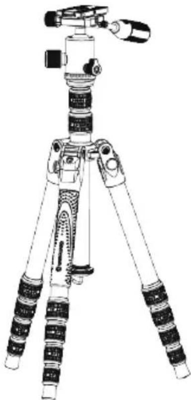
VEO 3T Tripod Series

natural_image
Line drawing of a tripped hairdryer with adjustable legs and head (no text or symbols)User Manual
VEO 3T 204ABP
VEO 3T 204CBP

natural_image
Line drawing of a tripod-mounted camera with adjustable legs and handle (no text or symbols)VEO 3T 235ABP
VEO 3T 235CBP
natural_image
Line drawing of a tripod-mounted camera with adjustable legs and head (no text or symbols)VEO 3T 265HABP
VEO 3T 265HCBP

Thank you for purchasing a Vanguard VEO 3T Tripod.
Crafted for the photographer who loves to travel, the VEO 3T Tripod offers a new breed of super lightweight, and compact usability. The VEO 3T tripod's patented, unique & innovative rapid column rotation feature allows it to fold into one of the smallest tripods making it the ideal companion for photographers looking to minimize luggage and maximize impact. Learn more and make the best use of your tripod by carefully reading the instructions below. Enjoy Photography with Vanguard!
① PART DESCRIPTION
A: 1/4" Camera Screw
B: Quick Shoe
C: Removable Telescopic Handle
D: Telescopic Handle Release Button
E: Quick Shoe Lock Knob
F: Friction Control Knob
G: Central Ball Head Lock Knob
H: Panning Locking Knob
I: Central Column Plate
J: Anti-Shock Rubber Ring
K: Second Section Central Column
L: Second Section Central Column Lock Knob
M: First Section Central Column
N: First Section Central Column Lock Knob
O: Leg Angle Adjustment Button
P: Rubber Grip Handle
Q: Monopod
R: Legs
S: Central Column Stop Cap
T: Retractable Hook
U: Twist Lock
V: Rubber Feet
W: Bubble Level
X: Quick Shoe Safety Pin
Y: Locking Set Screw M6
Z: Central Column Reversible
Head/Camera Screw Adaptor
Z-1: Handle Locking Screw
Z-2: Handle Holder Cap
Z-3: Washer
A1: Smartphone Holding Arm
B2: Upper Smartphone Clamp
C3: Smartphone Holding Arm Apart
D4: 1/4" Camera Screw Hole
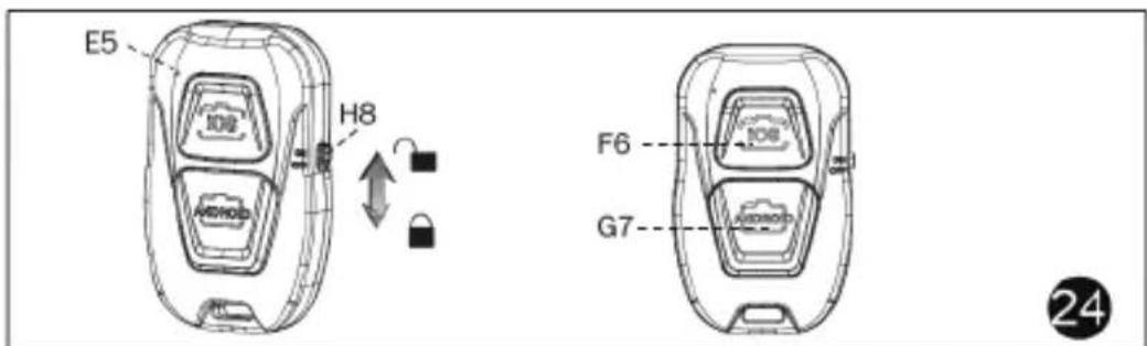
E5: Power Light
F6:IOS Button
G7:Android Button
H8:Power Switch
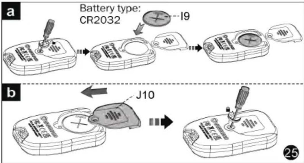
19:Battery-CR2032
J10:Battery Lid
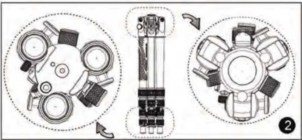
② To ensure perfect compactness and folding position of your tripod, please pay attention to the position of the head (as shown in figure 2).

③ REMOVING THE QUICK SHOE
Turn the quick shoe lock knob (E) counterclockwise as shown until the quick shoe is unlocked and removed, as shown in fig. 3.

④ ATTACH THE QUICK SHOE TO YOUR CAMERA
Line up the camera screw with your camera and insert. The quick shoe is fitted with a D-ring screw. Turn the D-ring clockwise until fully tightened, then place the quick shoe (B) on the head as shown in figure 4.
Note: In order to make the best use of the bubble level, we recommend it faces the camera screen when mounting on the head, as shown in figure 4.

⑤ SAFETY PIN
The safety pin helps to prevent your camera or equipment from accidentally falling when it is being adjusted.

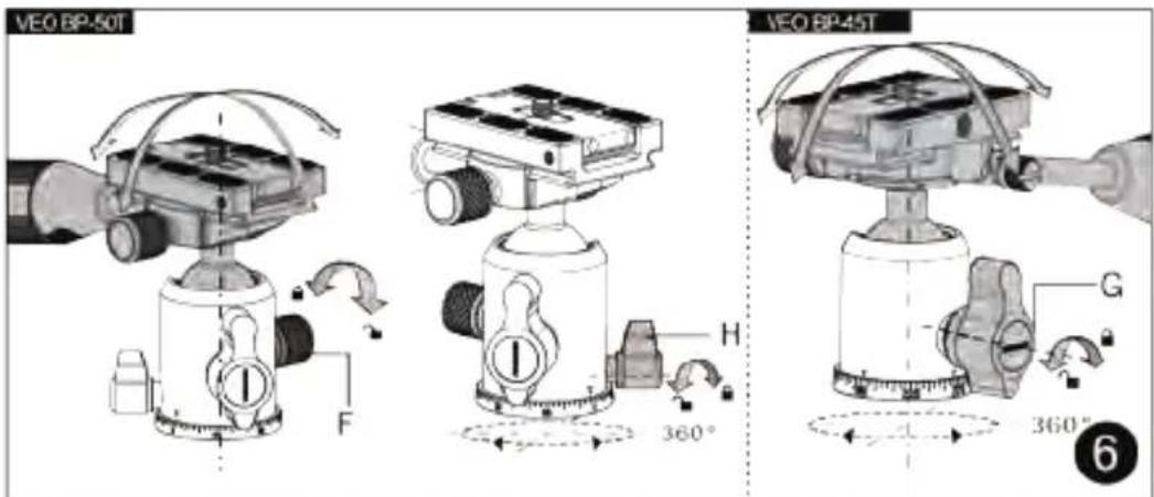
⑥ BALL HEAD MOVEMENT & LOCKED POSITION
To tilt the ball head, unlock the central locking knob on the ball head for camera positioning by turning (G) counterclockwise. Position the camera at the desired angle. Lock (G) by turning clockwise.
Note: tilting angle of VEO BP-45T is -91^(±1) to +35^(±1) , VEO BP-50T is -91^(±1) to +40^(±1) and VEO BP-120T is -91^(±1) to +40^(±1) .
Unlock the panning locking knob (H) by turning it counterclockwise. When paired with the ball head's bubble level, this panning function works well for 360° panoramic and VR Imaging.
If you need to increase ball head friction (VEO BP-50T only), turn the friction control knob (F) clockwise; decrease ball head friction by turning counterclockwise.

natural_image
Mechanical assembly diagram showing a tool interacting with a mechanical component (no text or symbols visible)
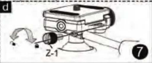
⑦ ASSEMBLING THE HANDLE
This unique ball head offers an option to connect a pan handle for smooth motion-controlled use with camera or sporting optics.
Step 1) Remove the handle holder cap (Z-2).
Step 2) Release the handle locking screw (Z-1) by turning counterclockwise as shown in fig.7a.
Step 3) Fix the washer (Z-3) to the handlebar to set position as shown in fig.7b.
Step 4) Line up the hole of the handle bar and the handle locking screw hole, insert the handle into corresponding socket to set position as shown in fig.7c.
Step 5) Screw the locking screw (Z-1) tighten to lock the handle in place as shown in fig.7d.
PLEASE ensure the handle locking screw is well fixed to the hole. The handle can not be moved and pulled out when the screw is tightened.
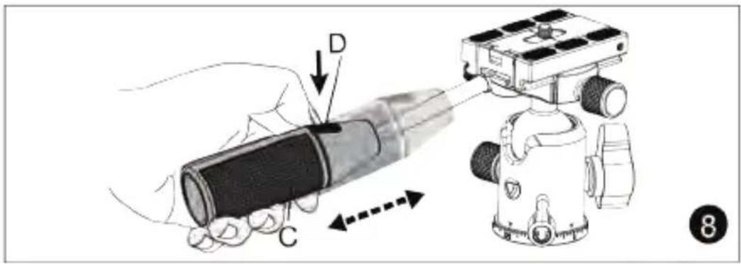
⑧ TELESCOPIC HANDLE
To extend the length of the handle, press handle release button (D) and pull handle out until stop position.
To contract the handle length to the minimum, press handle release button (D) and push back until stop position.

⑨ ANTI-SHOCK RUBBER RING
The Anti-shock rubber ring (J) helps to protect your equipment from potential damage when the central column is lowered too quickly.
⑩ CENTRAL COLUMN ADJUSTMENT
The center column of the tripod can be elevated to achieve the specific desired height for your equipment. Release the first section center column lock knob (L) by turning counterclockwise to elevate the first section of the center column, lock by turning clockwise until it is fully tightened. If required, turn the second section center column lock knob (N) counterclockwise to release the second section of the center column, lock until tightened by turning clockwise.


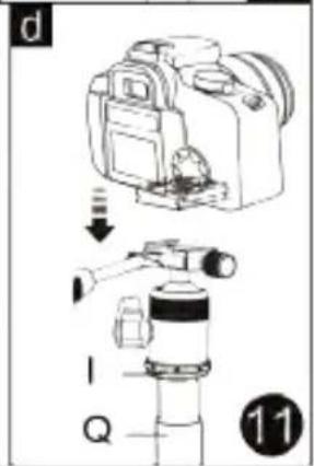
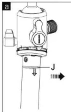
⑪ MONOPOD
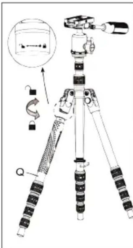
To use the monopod, grip the leg with the rubber grip and turn clockwise, the leg tube can be separated from just below the leg angle selector.
To release the central column plate:
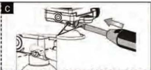
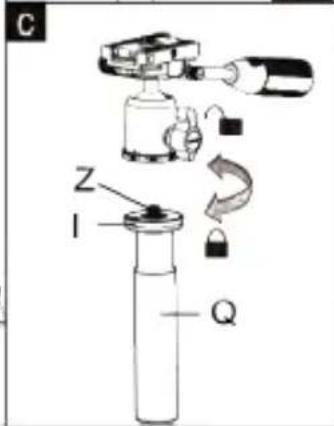
Use the hex wrench ② to release the stop screw (Y) by turning counterclockwise. Separate the plate of the central column from the central column tube by turning counterclockwise.
The plate of the central column with a dual side 1/4"-3/8" Head/Camera Screw Adaptor (Z) is used with the leg to create the monopod.
PLEASE NOTE: Some people like to use a monopod with and without the ball head. The choice is yours. Confirm the desired size 1/4"-20 or 3/8"-16. If you do not use the ball head you will most likely need to remove the QS from your camera and attach directly to the monopod. Double check the end of the dual side camera screw adapter you need before going to the next step.
a: Connect the plate to the monopod by turning clockwise. b: Line up the plate camera screw (Z) with the ball head and connect the ball head onto the plate (I).
c: Line up the 1/4"-20 camera screw with your camera and insert. Then place the quick shoe (B) on the ball head and tighten the lock knob.

⑫ USE CENTRAL COLUMN TO EXTEND MONOPOD HEIGHT
When converting to Monopod the central column can be utilized to extend the height.
a: Separate the monopod tube as specified in figure 12; Loosen the central column end cap (S) by turning clockwise;
b: Release the central column locking knob (L) and pull up the central column (K);
c: Connect the central column to the monopod tube by turning clockwise.

⑬ LEG ANGLE ADJUSTMENT
Press leg angle adjustment button (O) to adjust legs to any of the three preset angles (20, 50 and 80 degrees). Legs can be adjusted individually for uneven terrain and can be set to have a more customized position.
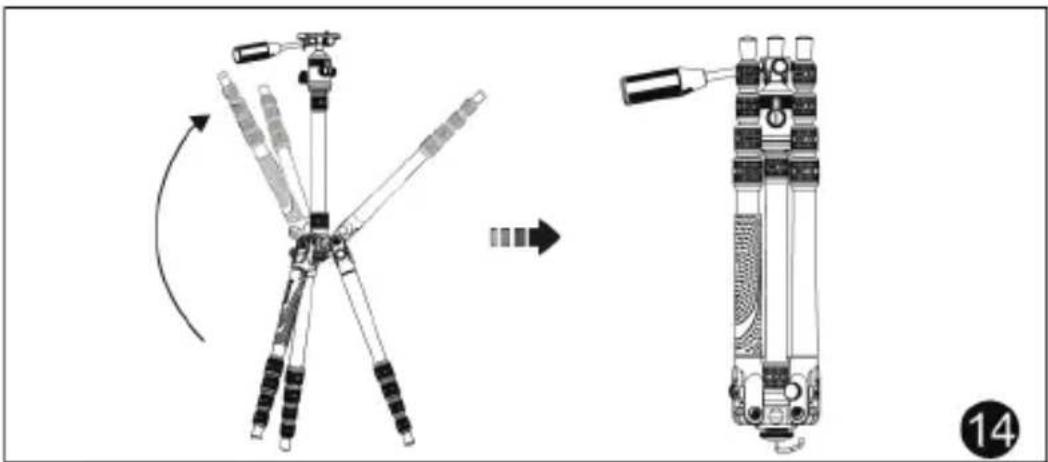
⑭ TO USE THE TRIPOD IN MACRO MODE WITH THE CENTRAL COLUMN
Step 1) Remove your camera from the top of the tripod. (You can keep your QS plate on your camera if desired at all times)
Step 2) Unlock the central column by turning the central column lock knob (L) counterclockwise.
Step 3) Pull up the center column (K) and bring to the top of the tripod.
Step 4) Invert the central column (K) 180°, push upwards and then lock the center column using the central column lock knob (L) by turning in a clockwise position.
Step 5) Attach your camera to the ball head while the column is inverted. See Fig. 2 Step 4.
Warning: When using the QFCC system for Macro photography, please remove your camera to prevent any potential damage to your equipment.


natural_image
Line drawing of a ball head assembly with no visible text or symbols⑮ BALL HEAD REMOVAL OR ATTACHING TO TRIPOD Removing the ball head:
a: Use the hex wrench ② to release set screw (Y) by turning counterclockwise.
b: Confirm panning locking knob (H) is locked, then turn the head counterclockwise.
Attention: Before you remove the ball head, please remove the camera or equipment first to prevent potential damage to your equipment.
When attaching the ball head, connect the ball head onto the tripod firmly first, and tighten the set screw (Y) with the hex wrench ②.

⑯ USING THE LOW ANGLE ADAPTOR (LAA)
Macro photography & low angle shoots will be very easy to do thanks to the low angle adaptor ④ (included).
a: Loosen the central column end cap (S) by turning clockwise.
b: Release the central column locking knob (N) and pull up the central column (K).
c: Attach the 3/8" screw adaptor ⑥ to the low angle adaptor ④.
Take the low angle adaptor ④, remove ball head from the central column and connect to the LAA.
NOTE: You may want to connect directly to the LAA and attach your camera directly on it. PLEASE be aware your camera movements will be limited.
d: Position the low angle adaptor into the central column hole on the canopy and tighten firmly by turning (N).
Warning: Use low angle adaptor ④ above canopy only, do not use in reverse position as shown in fig 16.
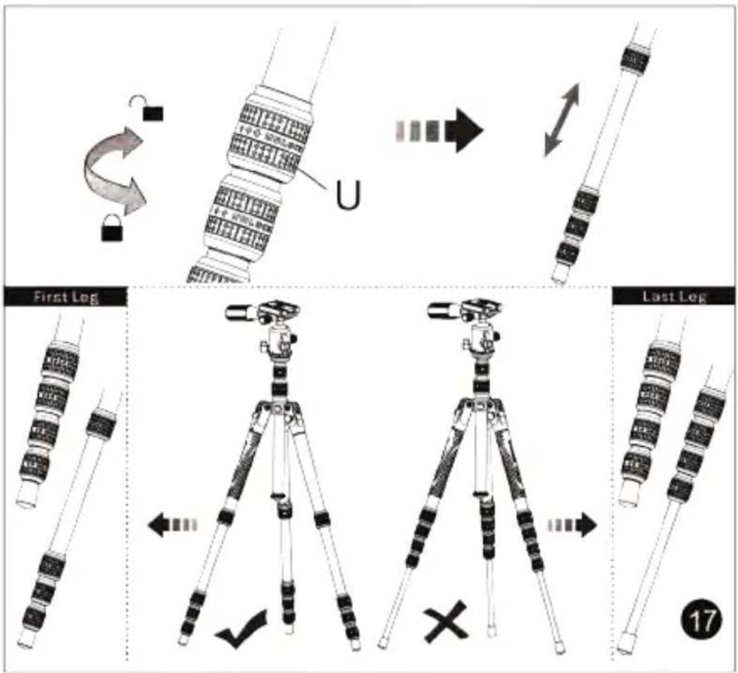
⑰ LEG EXTENSION ADJUSTMENT
To adjust the height of the legs, each one has telescopic sections that can be extended by releasing the lock (U).
Step 1) Open the legs.
Step 2) Release the leg sections successively by unlocking (U) clockwise. Always start from top down (thinnest section last) to reach the desired height. Using the larger leg section first will make your tripod more stable (as shown in figure 17).
Step 3) Lock (U) by turning counterclockwise until fully tightened.
Step 4) Proceed the same way for the two other legs and make sure all locks (U) are perfectly tightened to avoid the tripod from falling.
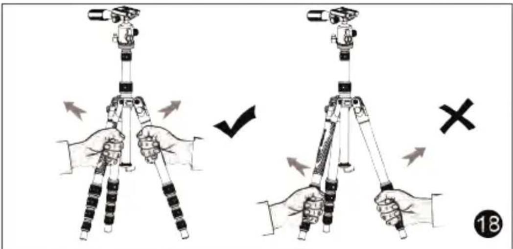
Attention: The correct grip position for using and moving the tripod can be seen in figure 18.
natural_image
Diagram showing a cylindrical object being processed with arrows, including a magnified view of the process (no text or symbols)⑲ RUBBER FEET TO SPIKED FEET
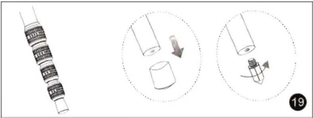
The rubber feet can be converted to spiked feet for using on different types of terrain (See fig. 19).
Spiked feet are included.
⑳ LOOSE LEG
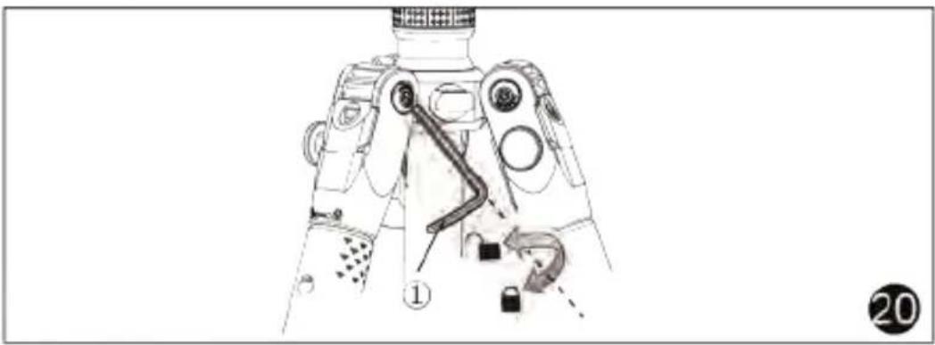
If by chance or over time a leg becomes loose, use an Allen wrench to tighten the bolts near the top of the spider cast (canopy). (Fig. 20) (4mm Allen Wrench ① included).

natural_image
Diagram of a device with a mechanical component inserted into a housing (no text or symbols visible)
natural_image
Technical illustration of a rectangular electronic component with labeled section A1 (no text or symbols beyond label)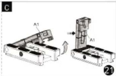
②1 How to use QS-72T
Remove the camera screw to prevent scratching the smartphone.
Raise the smartphone holding arm (A1) to a vertical position.

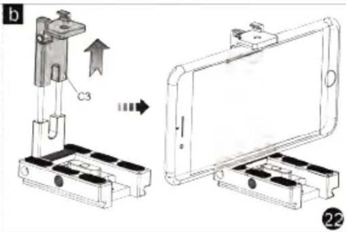
②2 Open the upper smartphone clamp (B2), then pull the smartphone holding arm apart (C3), and insert the smartphone into the clamp.
Note: when installing the mobile phone, the smartphone controls (such as volume and power) should not be caught in the clamp or base.

②3 a. The upper smartphone clamp (B2) includes a cold shoe mount that allows a suitable accessory, such as an LED light or a microphone, to be attached.
b. There is a 1/4" camera screw hole on the side of the quick shoe (D4) to mount a small support arm.
flowchart
graph TD
    A["Battery type: CR2032"] --> B["I9"]
    B --> C["J10"]

24 25 26 27 BLUETOOTH REMOTE CONTROL
Easy to Set Up, Easy to Use
Pairing your device:
Step 1) Turn on Phone Bluetooth Function.
Step 2) Turn On the bluetooth remote control (H8) by pushing the power switch to "ON". Select the "AB Shutter3" device in the phone to be connected, in few seconds it should be ready to use!
Step 3) When the mobile device is in photo or video shooting mode, press the shutter button to shoot.
Battery installation:
As shown in picture 25.
Mounting on tripod or monopod:
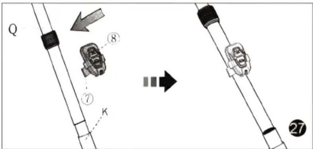
The remote control can be used with your tripod or monopod through the clamp, as shown in picture 26 and 27.
Monopod setting up is specified in picture 11 and 12.
Accessories

Accessories
VEO 3T series accessories include:
① Allen Wrench (used in tightening the loose leg)
② Allen Wrench (used in assembling / removing the ball head)
③ Tripod Bag
④ Low Angle Adaptor
⑤ Spiked feet (X3)
⑥ 3/8" Screw Adaptor
⑦ Remote Control Clamp
⑧ Bluetooth Remote Control
Battery warning:
Important Note: The Bluetooth remote control includes a CR2032 battery which can be dangerous, especially if swallowed. KEEP OUT OF REACH OF CHILDREN. Swallowing can lead to chemical burns, perforation of soft tissue, and death. Severe burns can occur within 2 hours of ingestion. Seek medical attention immediately.


natural_image
Icon of a person reading a book with an 'i' symbol on the cover (no text or symbols present)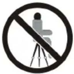
natural_image
Prohibition sign showing a person sitting on a tripod against a circle, no text or symbols present.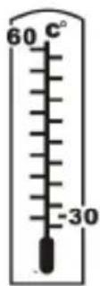

natural_image
Two symbolic illustrations: a black cloud with raindrops above and a gray umbrella below (no text or symbols)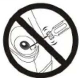
natural_image
No sign depicting a mechanical device crossed out by a diagonal line, no text or symbols present.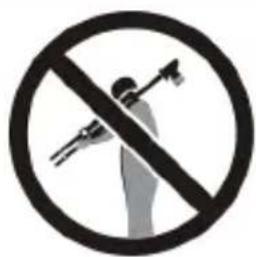
natural_image
Prohibition sign with a hand holding a tool, crossed out by a circle (no text or symbols)
natural_image
Prohibition sign depicting a car emitting steam, with no text or symbols beyond the circular and symbolic design.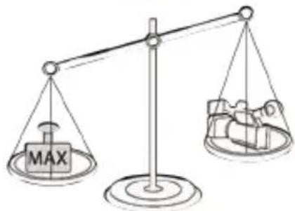

natural_image
Silhouette illustration of people using surveying equipment and a stroller (no text or symbols)Notes before use:
- Following the set-up of the tripod, confirm all legs are open and locked before mounting the camera. Failure to do so may cause the tripod to fall and the equipment to be damaged.
- Always comply with the weight restrictions. Going over the maximum load capacity may cause damage to equipment or personal injury.
- Ensure all individual knobs and locks are tight to avoid movement, as movement may result in equipment damage or personal injury.
- Carefully hold camera equipment stable when removing it from the tripod.
- Carrying your tripod:
a) After use, remove the camera; fold the tripod completely; and ensure the tripod handle faces out when folding.
b) DO NOT carry the tripod when the camera is still mounted.
- Cleaning your tripod:
a) When necessary, wipe tripod with a soft cloth and mild detergent. b) When used around salt water, first flush with clean water, then wipe with a dry soft cloth.

natural_image
Abstract black and white geometric logo with a stylized 'V' shape inside a circle (no text or symbols)VANGUARD
www.vanguardworld.com


- VEO 3T Tripod Series
- ① PART DESCRIPTION
- ⑤ SAFETY PIN
- ⑥ BALL HEAD MOVEMENT & LOCKED POSITION
- ⑦ ASSEMBLING THE HANDLE
- ⑧ TELESCOPIC HANDLE
- ⑨ ANTI-SHOCK RUBBER RING
- ⑩ CENTRAL COLUMN ADJUSTMENT
- ⑪ MONOPOD
- ⑫ USE CENTRAL COLUMN TO EXTEND MONOPOD HEIGHT
- ⑬ LEG ANGLE ADJUSTMENT
- ⑭ TO USE THE TRIPOD IN MACRO MODE WITH THE CENTRAL COLUMN
- ⑮ BALL HEAD REMOVAL OR ATTACHING TO TRIPOD Removing the ball head:
- ⑯ USING THE LOW ANGLE ADAPTOR (LAA)
- ⑰ LEG EXTENSION ADJUSTMENT
- ⑲ RUBBER FEET TO SPIKED FEET
- ⑳ LOOSE LEG
- ②1 How to use QS-72T
- 25 26 27 BLUETOOTH REMOTE CONTROL
- Pairing your device:
- Battery installation:
- Mounting on tripod or monopod:
- Accessories
- Battery warning:
- Notes before use:
- VANGUARD
Brand : Vanguard
Model : VEO 3T 235CP
Category : Tripod