
FS2TH - Thermostat Ferguson - Free user manual and instructions
Find the device manual for free FS2TH Ferguson in PDF.


| Product Type | Wi-Fi Thermostat |
| Brand | Ferguson |
| Model | FS2TH |
| Power Supply | 12-24V AC/DC, 1A |
| Compatibility | Conventional (gas/oil/propane/electric), heat pumps, dual fuel systems; up to 2H/2C |
| Wi-Fi | 2.4 GHz, WPA/WPA2, requires internet connection for smart features |
| Mobile App | Ferguson Home (iOS/Android) |
| Display | Touchscreen with backlight and night light |
| Temperature Range | 5°C to 35°C (41°F to 95°F) typical; setpoints configurable |
| Schedule | Up to 4 schedules (2 default: Home, Vacation); max 8 time periods per day |
| Fan Modes | Auto, On, Circulation |
| System Modes | Heat, Cool, Auto, Emergency Heat (heat pump only), Off |
| Dimensions | Approx. 120 x 120 x 25 mm (4.7 x 4.7 x 1 in) |
| Weight | Approx. 200 g (7 oz) |
| Included Accessories | Wall plate, screws, flat screwdriver, wire labels, connecting wire, user manual |
| Installation | Standard low-voltage wiring; requires C wire or alternative; professional installation recommended |
| Maintenance | Clean with soft dry cloth; do not use liquids or cleaners |
| Safety | Turn off power before installation; rated for indoor use only |
| Certification | CE (2014/53/EU) |
| Warranty | Contact manufacturer for details; support available at ferguson-digital.eu |
Frequently Asked Questions - FS2TH Ferguson
User questions about FS2TH Ferguson
0 question about this device. Answer the ones you know or ask your own.
Ask a new question about this device
Download the instructions for your Thermostat in PDF format for free! Find your manual FS2TH - Ferguson and take your electronic device back in hand. On this page are published all the documents necessary for the use of your device. FS2TH by Ferguson.
USER MANUAL FS2TH Ferguson
natural_image
Illustration of a medical or dental procedure setup with screws, a magnified view, and a tool (no text or symbols)natural_image
Simple line drawing of a screwdriver (no text or symbols on the object itself)

natural_image
Simple line drawing of a pencil (no text or symbols)
natural_image
Simple icon of a Wi-Fi signal symbol (no text or labels)Kompatybilność
natural_image
Line drawing of a hand touching a rectangular object (no text or symbols)
natural_image
Diagram showing a cross-shaped barrier with arrows indicating flow or force, no text or symbols presentnatural_image
Line drawing of a dual-chamber electric device with directional arrows indicating rotation (no text or symbols)natural_image
Hand holding smartphone to scan a card with two dental models (no text or symbols visible)natural_image
Diagram showing a device with a fan and a sensor emitting signals, no text or symbols presentflowchart
graph TD
    A["Power 12-24V 1A DC/AC"] --> B["RC"]
    A --> C["RH"]
    A --> D["G"]
    A --> E["W/E"]
    A --> F["Y"]
    A --> G["C"]
    A --> H["Y2"]
    A --> I["O/B/W2"]
    B --> J["Fan"]
    C --> J
    D --> K["Heating"]
    E --> K
    F --> K
    G --> L["Cooling"]
    H --> L
    I --> L

2 Harmonogram
3 Data i godzina

Ustawienia
Data i godzina
widok Programów


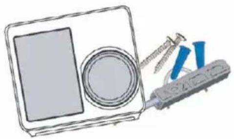
Contents of the package:

Wi-Fi Thermostat 1 piece

A set of screws 2 pieces

Flat screwdriver 1 piece

Wire labels 1 piece

Connecting wire 1 piece

User manual 1 piece
natural_image
Illustration of a medical or dental procedure setup with a tray, circular component, and screwdriver (no text or symbols)You may also need these tools:
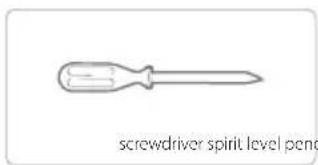
natural_image
Simple line drawing of a screwdriver with no text or symbols on the tool itself

natural_image
Simple line drawing of a pencil (no text or symbols)
natural_image
Simple icon of a Wi-Fi signal symbol (no text or labels)Compatibility
For conventional systems (gas/oil/propane/electric), heat pumps and dual fuel systems.
2-heating and 2-cooling > 1-heating and 1-cooling > heating only > cooling only
Heat pump with auxiliary and emergency heating
Installation
The FS2HT thermostat is designed to work with most standard low voltage 12-24 AC/DC heating and cooling systems, such as gas and oil furnaces, heat pumps and one or two stage systems.
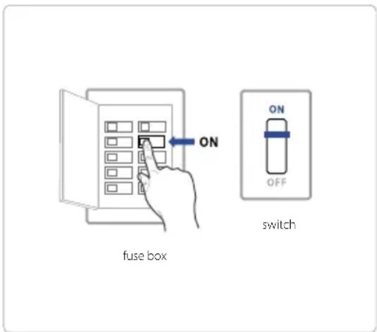
Step 1 - turn off the power
IMPORTANT: as this prevents the fuse from blowing in the equipment. To ensure that the power is off, change the temperature with the current thermostat and wait at least 5 minutes to ensure the system is OFF.

natural_image
Simple line drawing of an open electrical panel with multiple black modules and one blue module (no text or symbols)fuse box
or

switch
Step 2 - check if the system is turned off
Confirm that the system is off by turning on the heating (winter) or air conditioning (summer). Wait a few minutes - you shouldn't feel air coming out of the vents.

natural_image
Line drawing of a hand touching a rectangular object (no text or symbols)
natural_image
Diagram showing a cross-shaped barrier with arrows indicating flow or force, no text or symbols presentStep 3 - Remove the old thermostat from the wall stand
Most thermostats allow you to remove the main unit and provide access to the wall plate where the cable clamps are located. The thermostat can be removed by grasping and gently pulling. Some thermostats may have screws, buttons or latches.
NOTE: DO NOT disconnect any wires from the old thermostat in this step.

natural_image
Line drawing of a dual-chamber electric device with directional arrows indicating motion (no text or symbols)Step 4 - take a photo of the wiring
Take a clear photo of the existing wall plate wiring and make sure the wire terminal labels are clear enough to be read. This will be an important reference for the next step.
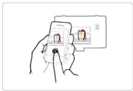
natural_image
Hand holding smartphone to scan a card with two dental models (no text or symbols visible)Step 5 - mark the wires
Label the wires of the old wall plate with the labels from our thermostat box.
NOTE: If an Rc or Rh wire is present, attach an R label to it.

Step 6 - Disconnect the wires and remove the old wall stand
Disconnect the wires from the old thermostat one by one, you may need a screwdriver to disconnect the wires from the terminals.
NOTE: Wrap the cords around a pen or pencil to prevent them from falling back into the hole in the wall.

natural_image
Diagram showing a device with a fan and a sensor emitting signals, no text or symbols presentStep 7 - Install the new wall stand
Use the screw kit (bolt and dowel) to mount the new wall plate. In most cases, the old mounting position can be used; if this is not possible, use a new kit. Be sure to check the alignment of the new wall tile before and after installing the wall tile.

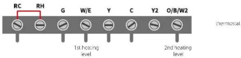
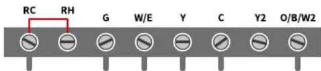
Use the photo you took earlier as a wire reference, the table below is a wiring diagram for common systems, make sure there is a C wire in your old thermostat system.
| Terminal Conventional system Heat pump system | ||
| RC Power for cooling Power for cooling | ||
| RH Power for heating Power for heating | ||
| C GND power/GND power | ||
| G Fan Fan | ||
| Y 1st degree of cooling | External heating1st heating level | |
| Y2 2nd degree of cooling | External heating2nd heating level | |
| W/E 1st heating level | 1 auxiliary stageemergency heating | |
| O/B/W2 | 2nd heating level | Switching connection (non-returnvalve) for the heat pump |
7 A - single-stage heat / two-stage furnace / C-duct boiler
7 B - Combined single stage heating and single stage cooling with C wire (remove pre-installed jumper) / refrigeration furnace and air conditioner

7 C - single stage / two stage heat pump with emergency heating and auxiliary heating with C wire

7 D - single-stage cooling / two-stage cooling - air conditioner

thermostat
7 E - Combined power system - single stage heat pump and single stage furnace with C wire
thermostat
7 F - Conventional system without C wire
Connect the heating or heating and cooling system according to the diagram.
NOTE: The thermostat has NO (Normally Open) control outputs, i.e. the control contacts are open during normal operation.

flowchart
graph TD
    A["Power 12-24V 1A DC/AC"] --> B["RC"]
    A --> C["RH"]
    A --> D["G"]
    A --> E["W/E"]
    A --> F["Y"]
    A --> G["C"]
    A --> H["Y2"]
    A --> I["O/B/W2"]
    B --> J["Fan"]
    C --> J
    D --> K["Heating"]
    E --> K
    F --> K
    G --> L["Cooling"]
    H --> L
    I --> L
Step 8 - Connect the wires to the new wall stand
Referring to the wiring diagram above, insert all wires vertically from the open socket to the appropriate terminal. Make sure each wire is inserted into the correct terminal (refer to the photo taken earlier if necessary).
Gently tug on the wires to make sure they are securely fastened.
Once all wires are securely connected, slide any excess wires back into the wall.

natural_image
Pure electrical connector diagram without any text, numbers, or symbolsStep 9 - Install the thermostat on the wall stand
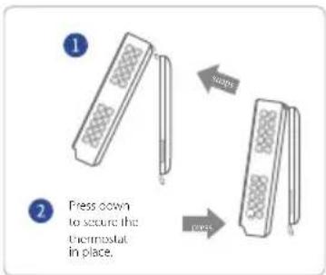
First, align the two tabs on the top of the thermostat with the top of the wall-stand, then gently press down and align the electrical rail with the terminals on the wall-stand.
Step 10 - Turn on the power and use
Turn on the switch that controls the heating and cooling system, the thermostat will turn on and you will be prompted to start setup. If you're having trouble installing your device or app, see the information below for help, or simply visit our websites to use the contact form.
Help
WWW: ferguson-digital.eu
EMAIL: expert@ferguson.pl
PHONE: +48 517 653 343
Main panel of the device

Initial setup of the device
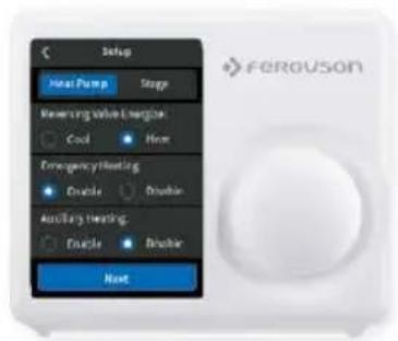
To get started with your new thermostat quickly and easily, the device will automatically guide you to the setup process when you turn it on for the first time.

Type of equipment
Select the type of heating device in your home from the available options:
Gas/oil/stove, electric heater, heat pump, dual fuel or no heating. Choose according to the heating system.

Below is a list of examples that can help you make the right choice:
NOTE: If you are not sure which option to choose, call +48 517 653 343.
If you have a stove or boiler:
- Select „Gas/Oil/Stove“ and tap „Settings“.
- Then select „Fan Settings" or "Level" depending on your personal fan control preferences.
- Tap "Next" at the bottom of the screen to continue.
If you have a heat pump:
- Select „Gas/Oil/Stove“ and tap „Settings“.
- Then follow the instructions on the screen.
- Tap "Next" at the bottom of the screen to continue.


If you have a dual fuel system:
- Select the "Dual Fuel" option and enter "Settings".
- Then follow the on-screen instructions to configure your fossil fuel heater settings.
- Tap "Next" at the bottom of the screen to continue.
- Then follow the on-screen instructions to configure the heat pump heater setting.

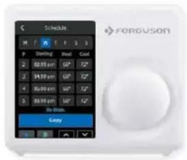
2 Schedule
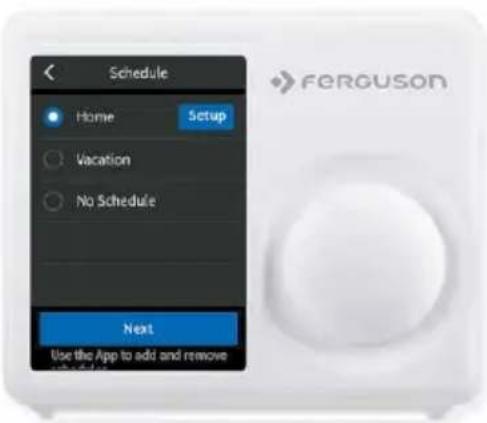
Only 2 schedules (Home and Vacation) will be available when working offline. However, this list can be expanded to a maximum of 4 schedules when a Wi-Fi connection is established.
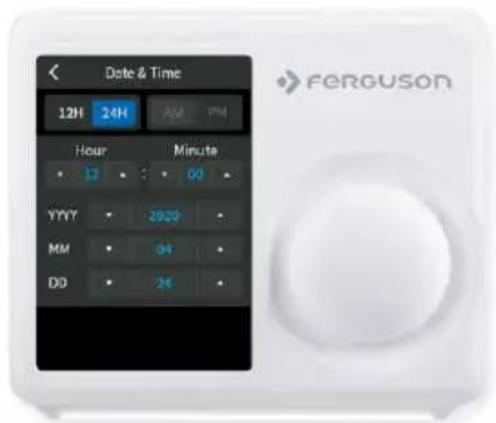
3 Date and time
ON DEVICE: Enter the current date and time in your location; once a device is registered or associated with a user account, the date and time on the device will automatically update to the current time associated with the user account.
4 Wi-Fi network configuration
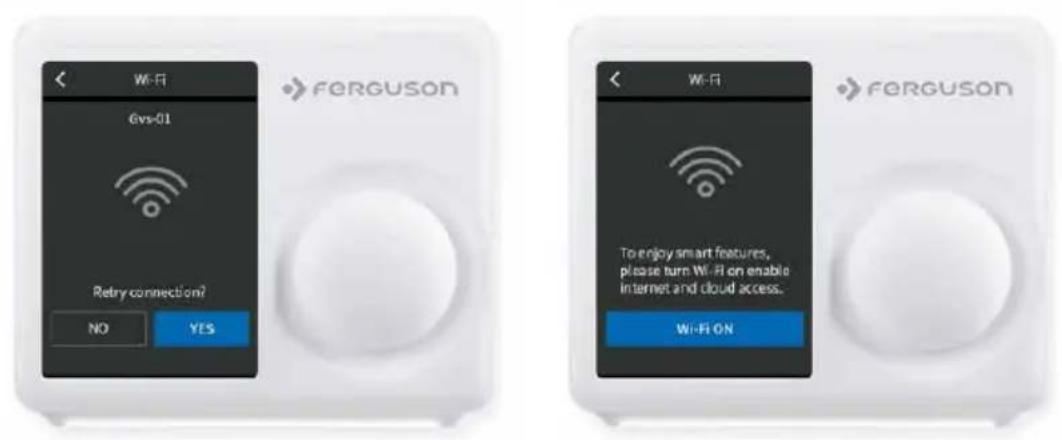
A reliable and stable Wi-Fi connection is required to use smart features such as remote control. Follow the on-screen instructions to complete the Wi-Fi setup.
When successfully connected to the Wi-Fi network, a success notification will be displayed on the registration screen. Follow the on-screen instructions to complete the setup. You can now add the device to your user account after downloading the mobile app and creating an account.

SCAN | Tap the Wi-Fi icon to go to the Wi-Fi setup screen, then tap the Scan icon to view a list of available Wi-Fi networks. Follow the on-screen instructions to complete the Wi-Fi setup.
MANUAL ENTRY | If the network is hidden, press the SSID button on the scan page to bring up an interface to enter your own SSID. Follow the on-screen instructions to complete the Wi-Fi setup.

Follow the instructions on the following pages to add the device to your account.
Possible causes of Wi-Fi connection failure:
- Wi-Fi signal is too weak or Wi-Fi is a 5G network;
- The SSID contains non-ASCII characters;
- Incorrect password;
- Wi-Fi works but your internet is down;
- Additional website authentication is required.
The account ID will appear after successful connection. This ID is for the network to which the device has been added.
For an unregistered device, a message will be displayed informing you that the device needs to be registered.


Automatic reconnection
If the device loses its connection to the wireless network, it will automatically try to reconnect every two minutes until a connection is established. Any manual thermostat network reconfiguration will stop automatic reconnect attempts.
Wi-Fi can be manually turned off or on. Disabling Wi-Fi will also disable your internet connection and all smart features, including remote access to your device from the mobile app.
Operating mode configuration
HVAC system settings depend on the type of system you are using, typical options are shown below:

Turn on cooling when the current temperature rises above the set point.
Turn on the heating when the current temperature drops below the set value.

Activate the heating or cooling system as needed to keep the house within the configured setpoint range.

ONLY use emergency or backup heat to maintain the heating setpoint. This option only appears if emergency heating is configured in the Equipment menu.
Turn off the system. When the system is off, only the current temperature will be displayed on the home screen.
On the thermostat:
Tap the system mode icon on the home screen to select the thermostat system mode from Cool, Heat, Auto, Emergency Heat, or Off.
Emergency Heat mode is only available when Heat Pump is selected as the heating type and Emergency Heat is enabled in the settings menu.

Fan configuration
The Fan menu displays the current setting of the furnace fan. Depending on your system, one or more of the following options are displayed:
On the thermostat:
Go to Main Menu > Fan, tap the Fan Mode icon on the home screen to select the thermostat system mode from Auto, On, and Circulation.

Force the fan to run continuously, regardless of scheduled programming.

Turn on the fan when the system is actively heating or cooling your home or to meet the minimum fan run time setting.

The fan will turn on and off according to the schedule programmed by the user (the circulation schedule can be programmed on the device and the application).

Adjusting the temperature:
You can change the scheduled temperature by touching “+” and “-” to change the blue/red number representing the cooling/heating set point.
When the thermostat is in auto mode, you need to set the heating and cooling setpoint first for the mode to operate in either heating or cooling mode.

Temporarily hold and maintain one temperature
To temporarily change a setpoint, use the n +” and n -” buttons on the thermostat or the dial, the thermostat will display the time it will hold next to the setpoint, and it will hold the new setpoint until the next scheduled setpoint.
If you want to maintain one temperature, adjust the set point using the „+“ and „-” buttons or the knob; then click „Hold“, the thermostat will hold this set point until you click „Cancel“ to cancel the temporary adjustment.

Settings menu
The Settings menu contains all setting options for the thermostat.
EZ Comfort
Here you will set the temperature values regardless of the program.

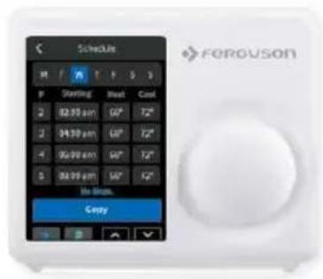
Schedule programming
There are only two default schedules: Home and Vacation - available for selection when the device is offline. If internet connection is established, you can have up to 4 schedules, please follow below steps to program:
1 Select "Schedule".
2 Select the type of day you want to edit: weekdays or weekend.
3 Select the setting you want to edit.
4 Adjust the setpoint with the up and down arrows.
5 Use the arrow in the upper left corner to save and return to the set points.
6 Continue to edit the set points as you see fit.
7 Use the arrow in the upper left corner to return to the "Schedule" screen.

Settings
Date and time
Set the date and time of the thermostat.
Screen
Choose brightness and off-screen time.
Night light
Select the brightness of the night light.
Temperature
Follow the on-screen instructions to set the temperature display unit (C/F) and temperature safety features.
Advanced settings
Designed for HVAC professionals who want to modify advanced features for better unit control.
Reset
Allow users to factory reset the device, it will clear all schedules and preferences that have been set.

Advanced settings
To access hardware configuration, click on Settings and use the scroll wheel to modify the default value as follows: Menu > Settings > Advanced Settings.
| Terminal Default Max Min Description | ||||
| Dead zone 1° F 2° F 0.5° F | The temperature range between the current temperature and the heating setpoint where heating or cooling is not enabled. | |||
| Fan delay 60s 120s 30s The fan continues to run after the mode is turned off. | ||||
| Minimum operating time | 180s 300s 60s | The minimum amount of system-on time after the device is turned on. | ||
| Cycle time 180s 300s 60s Waiting time between heating and cooling. | ||||
| Action time | / | / | / | See system operation time, heating, cooling, air filtration. |
| Sensor Calibration | 0° F | 10° F | -10° F | Ability to adjust temperature readings to improve sensor accuracy as the thermostat approaches the end of its life after years of use. |
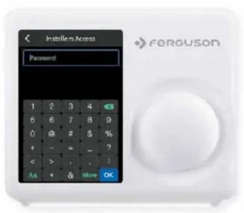
Installer access
To access Installer Access, click Advanced Settings, enter Professional Access Code and Action Code (in parentheses) to access the following settings.
Initial Settings (IS)
Use this code to repeat the initial setup process.
Sensor Calibration (SC)
Ability to adjust temperature readings to improve sensor accuracy as the thermostat approaches the end of its life after years of use.
Semsor Sensitivity (SS)
Ability to adjust the sensitivity of the thermostat sensor to changes in air temperature. The lower the level, the more often the system cycles to maintain the set point.
About
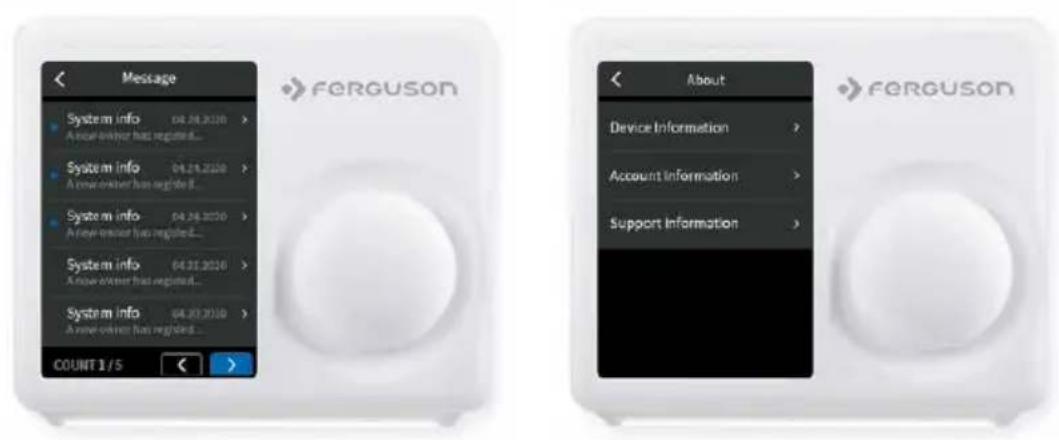
Displays a preview of the thermostat information.
Includes model number, MAC ID (uniquely identifies the thermostat), manufacturing date, firmware version, and support contact information.
Download the Ferguson Home app
First, after making sure your hardware is compatible, let's first download the app for your Android/iOS device.
There are three ways to download the Ferguson Home app on your Android/iOS device:
- Search "Ferguson Home" in Googleplay/Appstore to download;
- Scan the QR code below to download;
- Visit our official website ferguson-digital.eu and click App to download.
Download the Ferguson Home app for your Android device. To do this, scan the QR code.
Download the Ferguson Home app for your iOS device. To do this, scan the QR code.


Starting the thermostat in the Ferguson Home mobile application
- Download the Ferguson Home app from the App Store or Google Play
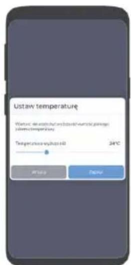
- After downloading the application, click "Register" to create an account in the application. Enter your phone number or e-mail address, which will be your login and password. Mark the necessary consents and click Approve. (fig.1)
- Make sure you have paired the thermostat with your WiFi network as instructed.
- Add the thermostat to the mobile app by clicking Add new device or + in the upper right corner of the screen.
- Have your thermostat's MAC ID and 4-digit confirmation code available in the thermostat interface. The confirmation code changes randomly each time you enter the view and expires after 180 seconds (3 minutes). If it expires, generate a new code.
- Enter the MAC ID number and the 4-digit confirmation code in the appropriate application windows or scan the QR code. Then enter your device name and click Confirm. (fig.2)
- The thermostat has been added to the Ferguson Home app.

fig. 1 fig. 2

Ferguson Home app - thermostat details

Ferguson Home app - Programs
The thermostat has 2 programs by default. The user can have up to 4 Programs defined.
- To add a Program, click Add Program in the program view window, enter a program name, and click Confirm.
- To set a Program as enabled, select the appropriate program and click the switch icon.
- To modify a Program, click the gear icon next to the program you want to change. After making changes, click Save.
Add a time range within the Program:
- Set the day for which you want to change the program.
- Click the "+" icon next to the selected day. Remember! The program can consist of min 2 and max. 8 time periods.
- Select the appropriate heating and cooling temperature and specify the start time of the time range, and then click Confirm.

Programs view

Program configuration
-
Edit the time range of the Program by clicking the pencil button next to the given time range. Confirm the changes with the Save button.
-
Deleting a time range requires clicking the trash can icon next to the selected range to be deleted.
Copy the scope of the Program to another day:
-
Select the day you want to copy to other days.
-
Click on the copy icon located next to the name of the selected day next to the „+” icon.
-
Select the days to which you want to copy the set Program from the day highlighted in red. To confirm, click Confirm.

copying Programs
Ferguson Home app - thermostat settings
Check in the application what parameters you can set in the Settings section.
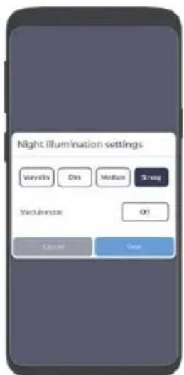
General settings will allow you to select the thermostat operating mode, specify the ventilation operating mode and define its operating program, turn on the night light and define its operating program.

operating mode

setting the ventilation setting the backlightsetting the
Notification settings allows you to enable/disable notifications that may come to your phone regarding temperatures, humidity and thermostat status.
Simplified declaration of conformity
Importer: Ferguson Sp. z o.o.
Dworska 1,61-619 Poznań
Name: Ferguson FS2TH
Device type: Wi-Fi Thermostat
The above-mentioned product complies with Directive 2014/53/EU of the European Parliament and of the Council of 16 April 2014 on the harmonization of the laws of the Member States concerning the making available on the market of radio equipment and repealing Directive 1999/5/EC.
Full Declaration of Conformity for download at: https://ferguson-digital.eu/declarations-of-conformity/?lang=en


setting notifications setting notifications
Notes
ferguson-digital.eu
- Kompatybilność
- Harmonogram
- Data i godzina
- Ustawienia
- Contents of the package:
- You may also need these tools:
- Compatibility
- Installation
- Step 1 - turn off the power
- Step 2 - check if the system is turned off
- Step 3 - Remove the old thermostat from the wall stand
- Step 4 - take a photo of the wiring
- Step 5 - mark the wires
- Step 6 - Disconnect the wires and remove the old wall stand
- Step 7 - Install the new wall stand
- F - Conventional system without C wire
- Step 8 - Connect the wires to the new wall stand
- Step 9 - Install the thermostat on the wall stand
- Step 10 - Turn on the power and use
- Help
- Initial setup of the device
- Type of equipment
- Below is a list of examples that can help you make the right choice:
- If you have a stove or boiler:
- If you have a heat pump:
- If you have a dual fuel system:
- Schedule
- Date and time
- Wi-Fi network configuration
- Automatic reconnection
- Operating mode configuration
- On the thermostat:
- Fan configuration
- Adjusting the temperature:
- Temporarily hold and maintain one temperature
- Settings menu
- EZ Comfort
- Schedule programming
- Settings
- Advanced settings
- Installer access
- Initial Settings (IS)
- Sensor Calibration (SC)
- Semsor Sensitivity (SS)
- About
- Download the Ferguson Home app
- Starting the thermostat in the Ferguson Home mobile application
- Ferguson Home app - Programs
- Ferguson Home app - thermostat settings
- Notes
Brand : Ferguson
Model : FS2TH
Category : Thermostat