CBF250 (2003) - Motorcycle Honda - Free user manual and instructions
Find the device manual for free CBF250 (2003) Honda in PDF.


| Type | Motorcycle |
| Brand | Honda |
| Model | CBF250 |
| Year | 2003 |
| Overall Length | 2,030 mm (79.9 in) |
| Overall Width | 745 mm (29.3 in) |
| Overall Height | 1,050 mm (41.3 in) |
| Wheelbase | 1,370 mm (53.9 in) |
| Dry Weight | 139 kg (306 lbs) |
| Engine Type | 4-stroke, single cylinder, OHC |
| Displacement | 249 cm³ (15.2 cu-in) |
| Bore x Stroke | 73.0 x 59.5 mm (2.87 x 2.34 in) |
| Compression Ratio | 9.3:1 |
| Fuel Tank Capacity | 16 ℓ (4.2 US gal, 3.5 Imp gal) |
| Engine Oil Capacity (after drain) | 1.5 ℓ (1.6 US qt, 1.3 Imp qt) |
| Spark Plug (standard) | CR8EH-9S (NGK) |
| Idle Speed | 1,400 ± 100 rpm |
| Front Tyre Size | 100/80-17M/C 52S |
| Rear Tyre Size | 130/70-17M/C 62S |
| Front Brake | Hydraulic disc |
| Rear Brake | Mechanical drum |
| Transmission | 6-speed, chain drive |
| Battery | 12V 6AH (maintenance-free sealed) |
| Headlight Bulb | 12V 60/55W |
Frequently Asked Questions - CBF250 (2003) Honda
User questions about CBF250 (2003) Honda
0 question about this device. Answer the ones you know or ask your own.
Ask a new question about this device
Download the instructions for your Motorcycle in PDF format for free! Find your manual CBF250 (2003) - Honda and take your electronic device back in hand. On this page are published all the documents necessary for the use of your device. CBF250 (2003) by Honda.
USER MANUAL CBF250 (2003) Honda
03/10/23 11:05:36 32KPF600_001

Honda CBF250
OWNER'S MANUAL
USO E MANUTENZIONE
MANUAL DEL PROPIETARIO


© Honda Motor Co., Ltd. 2003

03/10/23 11:05:44 32KPF600_002

IMPORTANT NOTICE
• OPERATOR AND PASSENGER
This motorcycle is designed to carry the operator and one passenger. Never exceed the maximum weight capacity as shown on the tyre information label.
- ON-ROAD USE
This motorcycle is designed to be used only on the road.
- READ THIS OWNER'S MANUAL CAREFULLY
Pay special attention to statements preceded by the following words:
▲WARNING
Indicates a strong possibility of severe personal injury or death if instructions are not followed.
CAUTION:
Indicates a possibility of personal injury or equipment damage if instructions are not followed.
NOTE: Gives helpful information.
This manual should be considered a permanent part of the motorcycle and should remain with the motorcycle when resold.

03/11/13 10:47:36 32KPF600_003

Honda CBF250
OWNER'S MANUAL
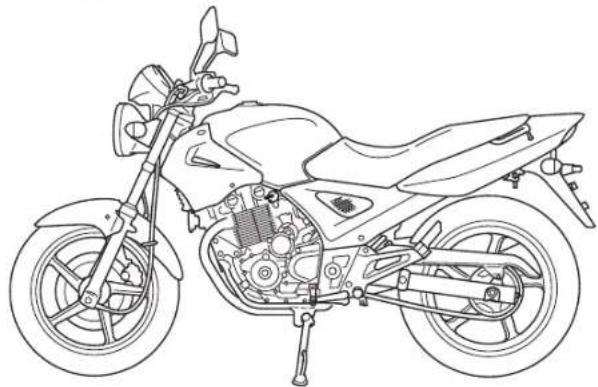
natural_image
Line drawing of a motorcycle showing internal components and suspension (no text or labels)All information in this publication is based on the latest production information available at the time of approval for printing. Honda Motor Co., Ltd. reserves the right to make changes at any time without notice and without incurring any obligation.
No part of this publication may be reproduced without written permission.

03/10/23 11:06:02 32KPF600_004

WELCOME
The motorcycle presents you a challenge to master the machine, a challenge to adventure. You ride through the wind, linked to the road by a vehicle that responds to your commands as no other does. Unlike an automobile, there is no metal cage around you. Like an airplane, a pre-ride inspection and regular maintenance are essential to your safety. Your reward is freedom.
To meet the challenges safely, and to enjoy the adventure fully, you should become thoroughly familiar with this owner's manual BEFORE YOU RIDE THE MOTORCYCLE.
When service is required, remember that your Honda dealer knows your motorcycle best. If you have the required mechanical "know-how" and tools, your dealer can supply you with an official Honda Service Manual to help you perform many maintenance and repair tasks.
Pleasant riding, and thank you for choosing a Honda!
- Following codes in this manual indicate each country.
| E | E | Holland Portugal France Spain Germany Armenia Switzerland |
• The specifications may vary with each locale.

UK Austria

03/10/23 11:06:05 32KPF600_005

OPERATION
Page
1 MOTORCYCLE SAFETY
1 Safe Riding Rules
2 Protective Apparel
3 Modifications
4 Loading and Accessories
7 PARTS LOCATION
10 Instruments and Indicators
Page
36 FEATURES
(Not required for operation)
36 Steering Lock
37 Helmet Holder
38 Seat
39 Document Compartment
40 Left Side Cover
41 Headlight Aim Vertical Adjustment
42 OPERATION
42 Pre-ride Inspection
43 Starting the Engine
46 Running-in
47 Riding
49 Braking
50 Parking
50 Anti-theft Tips
18 MAJOR COMPONENTS (Information you need to operate this motorcycle)
18 Brakes
23 Clutch
25 Fuel
29 Engine Oil
30 Tubeless Tyres
33 ESSENTIAL INDIVIDUAL COMPONENTS
33 Ignition Switch
34 Right Handlebar Controls
35 Left Handlebar Controls


03/10/23 11:06:08 32KPF600_006

MAINTENANCE
Page
51 MAINTENANCE
52 Maintenance Schedule
55 Tool Kit
56 Serial Numbers
57 Maintenance Precautions
58 Air Cleaner
59 Crankcase Breather
60 Engine Oil
64 Spark Plug
66 Throttle Operation
67 Idle Speed
68 Drive Chain
74 Front and Rear Suspension Inspection
75 Side Stand
76 Wheel Removal
81 Brake Pad Wear
82 Brake Shoe Wear
83 Battery
85 Fuse Replacement
88 Stoplight Switch Adjustment
89 Bulb Replacement
Page
95 CLEANING
97 STORAGE GUIDE
97 Storage
99 Removal from Storage
100 SPECIFICATIONS


03/10/23 11:06:19 32KPF600_007

MOTORCYCLE SAFETY
△WARNING
• Motorcycle riding requires special efforts on your part to ensure your safety. Know these requirements before you ride:
SAFE RIDING RULES
-
Always make a pre-ride inspection (page 42) before you start the engine. You may prevent an accident or equipment damage.
-
Many accidents involve inexperienced riders. Most countries require a special motorcycle riding test or license. Make sure you are qualified before you ride. NEVER lend your motorcycle to an inexperienced rider.
-
Many automobile/motorcycle accidents happen because the automobile driver does not "see" the motorcyclist. Make yourself conspicuous to help avoid the accident that wasn't your fault:
- Wear bright or reflective clothing. - Don't ride in another motorist's "blind spot."
- O b e y a l l n a t i o n a l a n d l o c a l l a w s a n d regulations.
- Excessive speed is a factor in many accidents. Obey the speed limits, and NEVER travel faster than conditions warrant.
• Signal before you make a turn or lane change. Your size and maneuverability can surprise other motorists.

03/10/23 11:06:27 32KPF600_008

- Don't let other motorists surprise you. Use extra caution at intersections, parking lot entrances and exits, and driveways.
- Keep both hands on the handlebars and both feet on the footpegs while riding. A passenger should hold on to the motorcycle or the operator with both hands and keep both feet on the passenger footpegs.
PROTECTIVE APPAREL
- Most motorcycle accident fatalities are due to head injuries: ALWAYS wear an approved motorcycle helmet. You should also wear a face shield or goggles as well as boots, gloves and protective clothing. A passenger needs the same protection.
- The exhaust system becomes hot during operation, and it remains hot for a while after stopping the engine. Be careful not to touch the exhaust system while it is hot. Wear clothing that fully covers your legs.
- Do not wear loose clothing which could catch on the control levers, footpegs, drive chain or wheels.

03/10/23 11:06:30 32KPF600_009

MODIFICATIONS
▲WARNING
- Modification of the motorcycle, or removal of original equipment, may render the vehicle unsafe or illegal. Obeyallnationalandlocalequipment regulations.


3


03/10/23 11:06:37 32KPF600_010

LOADING AND ACCESSORIES
▲WARNING
* To prevent an accident, use extreme care when adding and riding with accessories and cargo. Addition of accessories and cargo can reduce a motorcycle's stability, performance and safe operating speed. Never ride an accessory-equipped motorcycle at speeds above 130 km/h (80 mph). And remember that this 130 km/h (80mph) limit may be reduced by installation of non-Honda accessories, improper loading, worn tyres and overall motorcycle condition, poor road or weather conditions. These general guidelines may help you decide whether or how to equip your motorcycle and how to load it safely.
Loading
Cargo weight alone should not exceed: 14 kg (31 lbs) The weight of added accessories will reduce the maximum cargo weight you can carry.
- Keep cargo and accessory weight low and close to the center of the motorcycle. Load weight equally on both sides to minimize imbalance. As weight is located further from the motorcycle's center of gravity, handling is proportionally affected.

03/10/23 11:06:44 32KPF600_011

- Vehicle handling and stability can be adversely affected by loose cargo. Recheck cargo security and accessory mounts frequently.
- Do not attach large or heavy items (such as a sleeping bag or tent) to the handlebars, fork, or fender. Unstable handling or slow steering response may result.
Accessories
Genuine Honda accessories have been specifically designed for and tested on this motorcycle. Because the factory cannot test all other accessories, you are personally responsible for proper selection, installation, and use of non-Honda accessories. Always follow the guidelines under Loading, and these:
- Carefully inspect the accessory to make sure it does not obscure any lights, reduce ground clearance and banking angle, or limit suspension travel, steering travel or control operation.
- Large fork-mounted fairings or windshields, or poorly designed or improperly mounted fairings can produce aerodynamic forces that cause unstable handling. Do not install fairings that decrease cooling air flow to the engine.

03/10/23 11:06:48 32KPF600_012

- Accessories which alter your riding position by moving hands or feet away from controls may increase reaction time in an emergency.
- Do not add electrical equipment that will exceed the motorcycle's electrical system capacity. A blown fuse could cause a dangerous loss of lights or engine power.
- This motorcycle was not designed to pull a sidecar or trailer. Handling may be seriously impaired if so equipped.

6


03/10/23 11:06:54 32KPF600_013

PARTS LOCATION
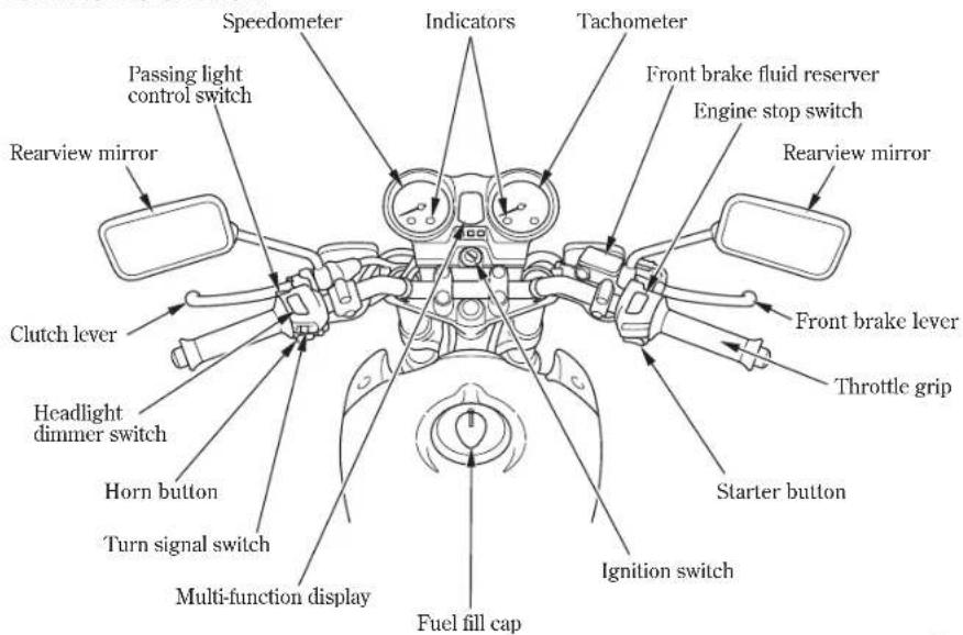
7


03/11/13 10:47:40 32KPF600_014

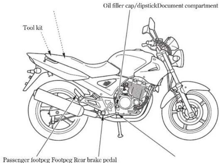
8


03/11/13 10:47:43 32KPF600_015

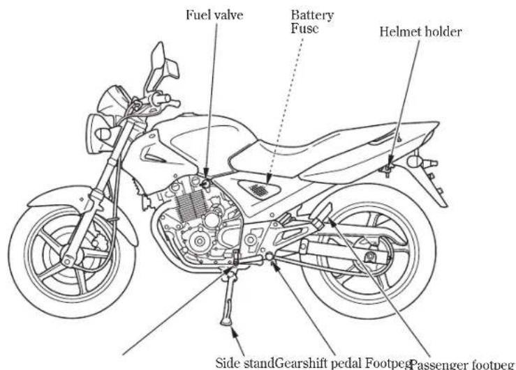

03/10/23 11:07:07 32KPF600_016

INSTRUMENTS AND
INDICATORS
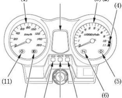
The indicators are contained in the
instrument panel. Their functions are described in the tables on the following pages.
(1)
(3)(2)
(1) Speedometer
(2) Multi-function display
(3) Tachometer
(4) Tachometer red zone
(5) Right turn signal indicator
(6) Neutral indicator
(7) RESET button
(8) MINUTE button
(9) HOUR button
(10) High beam indicator
(11) Left turn signal indicator
(7)(8)(9)(10)


03/10/23 11:07:11 32KPF600_017

| Function(Ref.No.) Description | ||
| (1) Speedometer | Shows riding speed.This shows your speed in kilometers per hour (km/h) and/or miles per hour (mph) depending on the type.The speedometer needle will swing to the maximum scale on the dial once when the ignition switch is turned ON. | |
| (2) Multi-function display | The display includes the following functions: | |
| Digital clock | ||
| Fuel gauge | ||
| Tripmeter | ||
| Odometer | ||

03/10/23 11:07:15 32KPF600_018
| (Ref. No.) Description Function | |
| (3) Tachometer | Shows engine rpm.The tachometer needle will swing to the maximum scale on the dial once when the ignition switch is turned ON. |
| (4) Tachometer red zone | Never allow the tachometer needle to enter the red zone, even after the engine has been broken in.CAUTION:• Running the engine beyond recommended maximum engine speed (the beginning of the tachometer red zone) can damage the engine. |
| (5) Right turn signal indicator (green) | Flashes when the right turn signal operates. |
| (6) Neutral indicator (green) | Lights when the transmission in neutral. |

03/10/23 11:07:18 32KPF600_019
| (Ref. No.) Description Function | |
| (7) RESET button | Resets the tripmeter to zero (0) (page 16). |
| (8) MINUTE button | Adjusts the minute of the digital clock (page 15). |
| (9) HOUR button | Adjusts the hour of the digital clock (page 15). |
| (10) High beam indicator (blue) | Light when the headlight is on high beam. |
| (11) Left turn signal indicator (green) | Flashes when the left turn signal operates. |

03/10/23 11:07:23 32KPF600_020

Initial Display
When the ignition switch is turned ON, the display will temporarily show all the modes and digital segments so you can make sure the liquid crystal display is functioning properly.
Both digital clock and tripmeter will reset if the battery is disconnected.
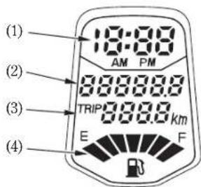
(1) Digital clock
(2) Odometer
(3) Tripmeter
(4) Fuel gauge

03/10/23 11:07:33 32KPF600_021

Digital clock
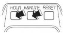
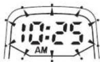
Shows hour and minute. To adjust time, proceed as follows :
- Turn the ignition switch ON.
- Press and hold both the HOUR () and MINUTE ( ) button for more then 2 seconds. The display will be set mode.
- To set the hour, press and release the HOUR button ()luntil the desired hour and AM/PM setting are displayed.
- To set the minute, press and release the MINUTE button () until the desired minute is displayed. The minute display will return to "00" when "60" is reached without affecting the hour display.
- Push the RESET button (3) to enter the time.
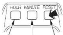
(1)
(3)(2)
(1) HOUR button
(2) MINUTE button
(3) RESET button

03/10/23 11:07:41 32KPF600_022

Tripmeter
The tripmeter shows mileage per trip.
To reset the tripmeter, push and hold the RESET button (1).

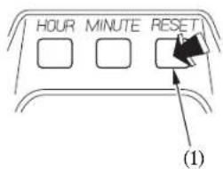
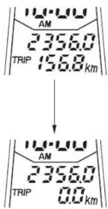
(1) RESET button

03/10/23 11:07:48 32KPF600_023

Fuel Gauge
The fuel gauge liquid crystal display () 1 shows the approximate fuel supply available in a graduated display. When the segment F goes on, the fuel tank capacity including reserve is:
16 ℓ (4.2 US gal, 3.5 Imp gal) When segment E ()2lashes, fuel will be low and yous hould refill the tank as soon as possible.
The amount of fuel left in the tank with the vehicle set upright is approximately: 2.9 ℓ (0.77 US gal, 0.64 Imp gal)
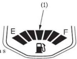
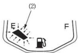
(1) Fuel gauge display (2) Segment E

03/10/23 11:07:54 32KPF600_024

MAJOR COMPONENTS
(Information you need to operate this motorcycle)
▲WARNING
* If the Pre-ride Inspection (page) is not performed, severe personal injury or vehicle damage may result.
BRAKES
Front Brake
This motorcycle has a hydraulic front disc brake.
As the brake pads wear, brake fluid level drops.
There are no adjustments to perform, but fluid level and pad wear must be inspected periodically. The system must be inspected frequently to ensure there are no fluid leaks.
If the control lever free travel becomes excessive and the brake pads are not worn beyond the recommended limit (page), 81
there is probably air in the brakesystem and it must be bled. See your Honda dealer for this service.

03/11/13 10:47:48 32KPF600_025

Front Brake Fluid Level:
▲WARNING
* Brake fluid may cause irritation. Avoid contact with skin or eyes. In case of contact, flush thoroughly with water and call a doctor if were exposed.
* KEEP OUT OF REACH OF CHILDREN.
CAUTION:
* Handle brake fluid with care because it can damage plastic and painted surfaces.
* When adding brake fluid, be sure the reservoir is horizontal before the cap yis remavedors brake fluid may spill out.
* Use only DOT 4 brake fluid from a sealed container.
* Never allow contaminants such as dirt or water to enter the brake fluid reservoir.

03/11/13 10:47:54 32KPF600_026

Brake fluid must be added to the reservoir whenever the fluid level begins to reach the LOWER level mark (). Remove the screws (2), reservoir cover ()3diaphragm plate ()4and diaphragm (). Fill the reservoir with DOT 4 BRAKE FLUID from a sealed container up to the UPPER level mark (6). Reinstall the diaphragm, diaphragm plate, and cover. Tighten the screws securely.
Other Checks:
Make sure there are no fluid leaks. Check for deterioration or cracks in the hoses and fittings.
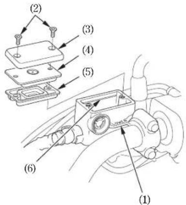
(1) LOWER level mark
(2) Screws
(3) Reservoir cover
(4) Diaphragm plate
(5) Diaphragm
(6) UPPER level mark

03/10/23 11:08:16 32KPF600_027

Rear Brake
Pedal Height Adjustment:
The stopper bolt () is provided to allow adjustment of the pedal height. To adjust the pedal height, loosen the lock nut () 2 and turn the stopper bolt. Tighten the lock nut.
Adjustment:
-
Place the motorcycle on its side stand.
-
Measure the distance the rear brake pedal (B) moves before the brake starts to take hold.
Free play should be:
20-30 mm (0.8-1.2 in)
If adjustment is necessary, turn the rear brake adjusting nut (4).
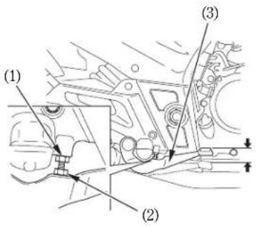
(1) Stopper bolt
(2) Lock nut
(3) Rear brake pedal
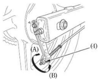
(4) Adjusting nut
(A) Decrease free play (B) Increase free play


03/10/23 11:08:22 32KPF600_028

- Apply the brake several times and check for free wheel rotation after the brake pedal is released.
NOTE:
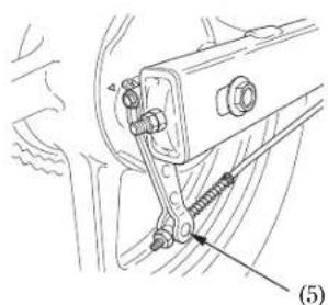
* Make sure the cut-out on the adjusting nut is seated on the brake arm pin () 5 after making final free play adjustment.
* If proper adjustment cannot be obtained by this method see your Honda dealer.
Other Checks:
Make sure the brake arm, brake rod, spring and fasteners are in good condition.

natural_image
Mechanical assembly diagram showing a bracket with bolts and a spring attached to a car (no text or symbols)(5) Brake arm pin
22

03/10/23 11:08:30 32KPF600_029

CLUTCH
Clutch adjustment may be required if the motorcycle stalls when shifting into gear or tends to creep; or if the clutch slips, causing acceleration to lag behind engine speed. Minor adjustments can be made with the clutch cable adjuster (4) at the lever (1). Normal clutch lever free play is: 10–20 mm (0.4–0.8 in)
- Pull back the rubber dust cover (). 2 Loosen the lock nut () and turn the clutch cable adjuster (). Tighten the lock nut (3) and check the adjustment.
- If the adjuster is threaded out near its limit or if the correct free play cannot be obtained, loosen the lock nut (3) and turn in the clutch cable adjuster () 4 completely. Tighten the lock nut () and install the dust cover.
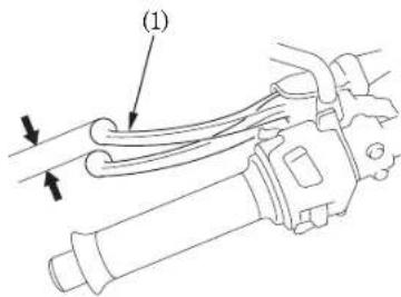
(1) Clutch lever
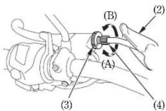
(2) Dust cover
(3) Lock nut
(4) Clutch cable adjuster
(A) Increase free play
(B) Decrease free play

03/10/23 11:08:37 32KPF600_030

- Loosen the lock nut () and turn the adjusting nut ( to obtain the specified free play. Tighten the lock nut () and check the adjustment.
- Start the engine, pull in the clutch lever and shift into gear. Make sure the engine does not stall and the motorcycle does not creep. Gradually release the clutch lever and open the throttle. The motorcycle should begin to move smoothly and accelerate gradually.
NOTE
* If proper adjustment cannot be obtained or the clutch does not work correctly, see your Honda dealer.
Other Checks:
Check the clutch cable for kinks or signs of wear that could cause sticking or failure. Lubricate the clutch cable with a commercially available cable lubricant to prevent premature wear and corrosion.
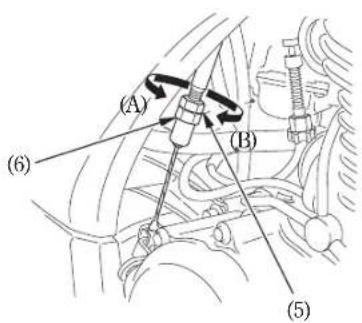
(5) Lock nut
(6) Adjusting nut
(A) Increase free play
(B) Decrease free play

03/10/23 11:08:44 32KPF600_031

FUEL
Fuel valve
The three way fuel valve() isoside near the carburetor.
OFF
With the fuel valve in the OFF position, fuel cannot flow from the tank to the carburetor. Turn the valve OFF whenever the motorcycle is not in use.
ON
With the fuel valve in the ON position, fuel will flow from the main fuel supply to the carburetor.
RES
With the fuel valve in the RES position, fuel will flow from the reserve fuel supply to the carburetor. Use the reserve fuel only when them a ins up p l y i s g o n e. R e soon as possible after switching to RES. The reserve fuel supply is:
2.5 ℓ (0.66 US gal, 0.55 Imp gal)
▲WARNING
To avoid running out of fuel that may result in a sudden stop, learn how to operate the fuel valve when riding the motorcycle.
* Be careful not to touch any hot engine parts while operating the fuel valve.
NOTE:
* Remember to check that the fuel valve is in the ON position each time you refuel. If the valve is left in the RES position, you may run out of fuel with no reserve.
ON
OFF
RES

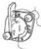
(1) Fuel valve

03/11/13 10:48:01 32KPF600_032

Fuel Tank
The fuel tank capacity including the reserve supply is:
16 ℓ (4.2 US gal, 3.5 lmp gal) To open the fuel fill cap (), insert the ignition key (2) and turn it clockwise. The fuel fill cap will pop up and can be lifted off. After refueling, to close the fuel fill cap, align the latch in the cap with the slot in the filler neck. Push the fuel fill cap into the filler neck until it snaps closed and locks. Remove the key. Use unleaded or low-lead petrol with a research octane number of 91 or higher. We recommend that you use unleaded petrol because it produces fewer engine and spark plug deposits and extends the life of exhaust system components.
CAUTION
* If "spark knock" or "pinking" occurs at a steady engine speed under normal load, change brands of petrol. If spark knock or pinking persists, consult your Honda dealer. Failure to do so is considered misuse, and damage caused by misuse is not covered by Honda's Limited Warranty.
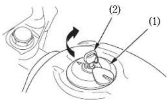
(1) Fuel fill cap
(2) Ignition key

03/10/23 11:08:57 32KPF600_033

△WARNING
* Petrol is extremely flammable and is explosive under certain conditions. Refuel in a well-ventilated area with the engine stopped. Donotsmoke or allow flames or sparks in the area where petrol is stored or where the fuel tank is refueled.
* Do not overfill the tank (there should be no fuel in the filler neck (3)). After refueling, make sure the fuel fill cap is closed securely.
* B e c a r e f u l n o t t o s p refueling. Spilled fuel or fuel vapor may ignite. If any fuel is spilled, make sure the area is dry before starting the engine.
* Avoid repeated or prolonged contact with skin or breathing of vapor. KEEP OUT OF REACH OF CHILDREN.
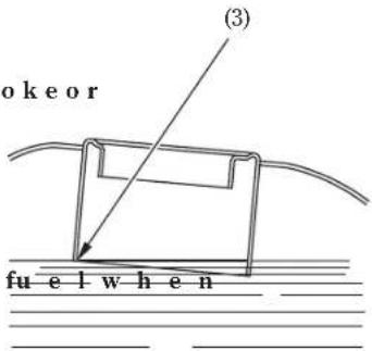
(3) Filler neck

03/10/23 11:09:02 32KPF600_034

Petrol Containing Alcohol
If you decide to use a petrol containing alcohol (gasohol), be sure it's octane rating is at least as high as that recommended by Honda. There are two types of "gasohol": one containing ethanol, and the other containing methanol. Do not use petrol that contains more than 10 % ethanol. Do not use petrol containing methanol (methyl or wood alcohol) that does not also contain cosolvents and corrosion inhibitors for methanol. Never use petrol containing more than 5 % methanol, even if it has cosolvents and corrosion inhibitors.
NOTE
* Fuel system damage or engine performance problems resulting from the use of fuels that contain alcohol is not covered under the warranty. Honda cannot endorse the use of fuels containing methanol since evidence of their suitability is as yet incomplete.
- Before buying fuel from an unfamiliar station, try to find out if the fuel contains alcohol. If it does, confirm the type and percentage of alcohol used. If you notice any undesirable operating symptoms while using a petrol that contains alcohol, or one that you think contains alcohol, switch to a petrol that you know does not contain alcohol.

03/10/23 11:09:10 32KPF600_035

ENGINE OIL
Engine Oil Level Check
Check the engine oil level each day before riding the motorcycle.
The level must be maintained between the up pe d ( ) and l o w er ( ) level m dipstick ( R
- Start the engine and let it idle for 35 minutes.
- Stop the engine and hold the motorcycle in an upright position on firm, level ground.
-
After 2 3-minutes, remove the oil filler cap/dipstick (3), wipe it clean, and reinsert the oil filler cap/dipstick without screwing it in. Remove the oil filler cap/dipstick. The oil level should be between the upper (1) and lower ()2level marks on the oil filler cap/dipstick.
-
If required, add the specified oil (see pages 60p to the upper level mark. Do not overfill.
- Reinstall the oil filler cap/dipstick. Check for oil leaks.
* Running the engine with insufficient oil can cause serious engine damage.
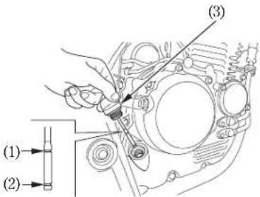
(1) Upper level mark
(2) Lower level mark
(3) Oil filler cap/dipstick

03/10/23 11:09:24 32KPF600_036

TUBELESS TYRES
This motorcycle is equipped with tubeless tyres, valves, and wheel rims. Use only tyres marked "TUBELESS" and tubeless valves on rims marked "TUBELESS TYRE APPLICABLE."
Proper air pressure will provide maximum stability, riding comfort and tyre life. Check tyre pressure frequently and adjust if necessary.
NOTE:
* Tyre pressure should be checked before you ride while the tyres are "cold".
- Tubeless tyres have some degree of selfsealing ability if they are punctured, and leakage is often very slow. Inspect very closely for punctures, especially if the tyre is not fully inflated.
| Tyre size | |
| Front 100/80-17M/C 52S Rear 130/70-17M/C 62S | |
| pressures kPa (kgf/cpsi) | Driver only Front 225 (2.25, 33) RearCold225e(2.25, 33) |
| Driver and one passenger Front 225 (2.25, 33) Rear 250 (2.50, 36) | |
| Tyre brand TUBELESS ONLY | PIRELLI Front MT 75 Rear MT 75 |


03/10/23 11:09:31 32KPF600_037

Check the tyres for cuts, em bRepladedydes before tread depth at the or other sharp objects. Check the rims for dents or deformation. If there is any center of the tyre reaches the following limit:
damage, see your Honda dealer for repair, replacement, and balancing.
| Minimum tread depth | |
| Front: | 1.5 mm (0.06 in) |
| Rear: | 2.0 mm (0.08 in) |
▲WARNING
* Improper tyre inflation will cause abnormal tread wear and create a safety hazard. Underinflation may result in the tyre slipping on, or coming off of the rim causing tyre deflation that may result in a loss of vehicle control.
NOTE:
* German law prohibits use of tyres whose tread depth is less than 1.6 mm.
* Operation with excessively worn ty res is h a z a r d o u s and will a d v e r s e l y affect traction and handling.

03/10/23 11:09:38 32KPF600 038

Tyre Repair/Replacement:
See your Honda Dealer.
▲WARNING
* The use of tyres other than those listed on the tyre information label may adversely affect handling.
- Do not install tube-type tyres on tubeless rims. The beads may not seat and the tyres could slip on the rims, causing tyre deflation that may result in a loss of vehicle control.
- Do not install a tube inside a tubeless tyre. Excessive heat build-up may cause the tube to burst resulting in rapid tyre deflation that may result in a loss of vehicle control.
- Replace the tyre if the sidewall is punctured or damaged. Sidewall flexing may cause repair failure and tyre deflation that may result in a loss of vehicle control.
▲WARNING
* To avoid possible repair failure and tyre deflation that may result in a loss of vehicle control, do not exceed 80 km/h (50 mph) for the first 24 hours, or 130 km/h (80 mph) at any time, after tyre repair.
- Proper wheel balance is necessary for safe, stable handling of the motorcycle. Do not remove or change any wheel balance weights. When wheel balancing is required, see your Honda dealer. Wheel balancing is required after tyre repair or replacement.
CAUTION:
- Do not try to remove tubeless tyres without special tools and rim protectors. You may damage the rim sealing surface or disfigure the rim.


03/11/13 10:48:10 32KPF600_039

ESSENTIAL INDIVIDUAL COMPONENTS
IGNITION SWITCH
The ignition switch () is below the indicator panel.
The headlight and taillights will come on whenever you turn the ignition switch ON. If your motorcycle is stopped with the ignition switch ON and the engine is not running, the headlight and taillights will still be on, resulting in battery discharge.
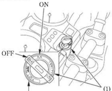
LOCK
(1) Ignition switch
| Key Position Function Key Removal | ||
| LOCK (steering lock) | Steering is locked. Engine and lights cannot be operated. | Key can be removed |
| OFF | Engine and lights cannot be operated. | Key can be removed |
| ON | Engine and lights can be operated. | Key cannot be removed |

03/10/23 11:09:53 32KPF600_040

RIGHT HANDLEBAR CONTROLS
Engine Stop Switch
The engine stop switch () is next to the throttle grip. When the switch is in the ○ (RUN) position, the engine will operate. When the switch is in the (OFF) position, the engine will not operate. This switch is intended primarily as a safety or emergency switch and should normally remain in the ○ (RUN) position.
If your motorcycle is stopped with the ignition switch ON and the engine stop switch ☒ (OFF), the headlight and taillight will still be on, resulting in battery discharge.
Starter Button
The starter button (2) is below the engine stop switch (1). When the starter button is pressed, the starter motor cranks the engine. If the engine stop switch is in the (OFF) position, the starter motor will not operate. See page for the starting procedure.
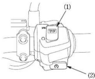
(1) Engine stop switch
(2) Starter button

03/10/23 11:10:02 32KPF600_041

LEFT HANDLEBAR CONTROLS
Headlight Dimmer Switch (1)
Push the dimmer switch to (HI) to select high beam or to (LO) to select low beam.
Turn Signal Switch (2)
Move to (I) to signal a left turn, (R) to signal a right turn. Press to turn signal off.
Horn Button (3)
Press the button to sound the horn.
Passing Light Control Switch (4)
When this switch is pressed, the headlight flashes on to signal approaching cars or when passing.
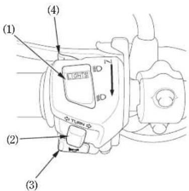
(1) Headlight dimmer switch
(2) Turn signal switch
(3) Horn button
(4) Passing light control switch

03/11/13 10:48:16 32KPF600_042

FEATURES
(Not required for operation)
STEERING LOCK
To lock the steering, turn the handlebars all the way to the left; turn the key () to 1 LOCK while pushing in. Remove the key. To unlock the steering, turn the key to OFF while pushing in.
▲WARNING
- Do not turn the key to LOCK while riding the motorcycle; loss of vehicle control will result.
To lock
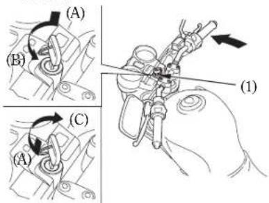
To unlock
(1) Ignition key (A) Push in
(B) Turn to LOCK
(C) Turn to OFF

03/11/13 10:48:22 32KPF600_043

HELMET HOLDER
The helmet holder () is on the left side below the seat. Insert the ignition key () 2 and turn it clockwise to unlock. Hang your helmet on the holder hook (). Burn the key counterclockwise to lock the holder and then remove the key.
▲WARNING
* The helmet holder is designed for helmet security while parked. Do not ride with a helmet attached to the holder; the helmet may interfere with safe operation and result in loss of control.
* As the helmet holder and seat lock are combined, confirm that locking is properly completed by lifting up the seat after using helmet holder.
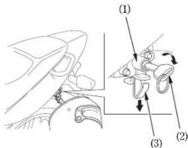
(1) Helmet holder
(2) Ignition key
(3) Holder hook

03/11/13 10:48:28 32KPF600_044

SEAT
To remove the seat () insert the ignition key into the seat lock () and turn it clockwise. Pull the seat lock lever () 3 downward to unlock the seat. Pull the seat back and up.
To install the seat, put in the hooks () 4 under the fuel tank and insert the prong (5) into the fuel tank stay (6).
Push forward and then down on the rear of the seat.
CAUTION:
* Be sure the seat is locked securely in position after installation.
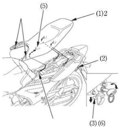
(1) Seat
(4) Hooks
(2) Seat lock
(5) Front Prong
(3) Lock lever
(6) Fuel tank stay

03/10/23 11:10:28 32KPF600_045

DOCUMENT COMPARTMENT
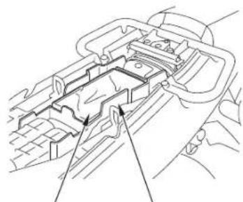
The document bag ()lis in the document compartment (2) under the seat.
This owner's manual and other documents should be stored in the document bag.
When washing your motorcycle, be careful not to flood this area with water.
Do not store gloves, rain gear, or other items under the seat. They might block the air cleaner intake opening and cause starting and driveability problems.
natural_image
Technical line drawing of a mechanical assembly with no visible text or symbols(2)(1)
(1) Document bag
(2) Document compartment

03/10/23 11:10:37 32KPF600_046

SIDE COVER
The leftside recover must be removed for
battery and fuse maintenance.
The right and left side covers can be removed in the same manner.
(3)
Removal:
- Remove the seat (page88).
- Remove the screws ( ).
- Pull out the hook (2) from the grommet (3).
Installation:
• Installation can be done in the reverse order of removal.
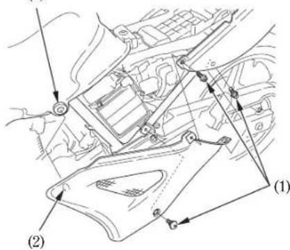
(2) Hook
(3) Grommet(1) Screws

03/10/23 11:10:42 32KPF600_047

HEADLIGHT AIM VERTICAL ADJUSTMENT
Vertical adjustment can be made by moving the headlight case (1) as necessary.
To move the headlight case, loosen the bolts (2.
Tighten the bolts after adjustment.
Obey local laws and regulations.
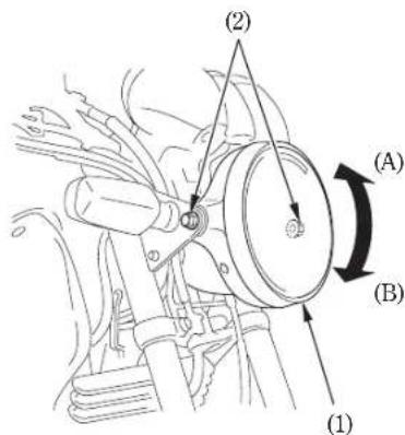
(1) Headlight case
(A) Up
(2) Bolts
(B) Down

03/10/23 11:10:57 32KPF600_048

OPERATION
PRE-RIDE INSPECTION
▲WARNING
* If the Pre-ride Inspection is not performed, severe personal injury or vehicle damage may result.
Inspect your motorcycle every day before you ride it. The items listed here will only take a few minutes to inspect, and in the long run they can save time, expense, and possibly your life.
- Engine oil level add engine oil if required (page 29). Check for leaks.
- Fuel level fill fuel tank when necessary (page 25Check for leaks
-
Front and rear brakes -echeck operation; make sure there is no brake fluid leakage. Adjust free play if necessary (pages 18-22).
-
Tyres check condition and pressure (pages 30-32).
- Drive chain check condition and slack (page 68). Adjust and lubricate if necessary.
- Throttle check for smooth opening and full closing in all steering positions.
- Lights and horn check that headlight, tail/brake light, turn signals, indicators and horn function properly.
- Engine stop switch—check for proper function (page 34).
- Side stand ignition cut-off system - check for proper function (page 75).
Correct any discrepancy before you ride. Contact your Honda dealer for assistance if you cannot correct the problem.


03/10/23 11:11:04 32KPF600_049

STARTING THE ENGINE
Always follow the proper starting procedure described below.
Before starting, insert the key, turn the ignition switch ON and confirm the following:
This motorcycle is equipped with a side stand ignition cut-off system. The engine cannot be started if the sides unless the transmission is in neutral. If the side stand is up, the engine can be started in neutral or in gear with the clutch lever pulled in. After starting with the side stand down, the engine will shut off if the transmission is put in gear before raising the side stand.
• The transmission is in NEUTRAL (neutral indicator light ON).
- The engine stop switch is at RUN. - The fuel valve is ON.
▲WARNING
* Never run the engine in an enclosed area. The exhaust contains poisonous carbon monoxide gas that can cause loss of consciousness and lead to death.
NOTE
* Do not use the electric starter for more than 5 seconds at a time. Release the starter button for approximately 10 seconds before pressing it again.

03/10/23 11:11:16 32KPF600_050

Starting Procedure
To restart a warm engine, follow the procedure for "High Air Temperature."
Normal Air Temperature
10^35^(50^95^)
- Pull the choke lever ()1back all the way to Fully ON (A), if the engine is cold.
- With the throttle closed, press the starter button.
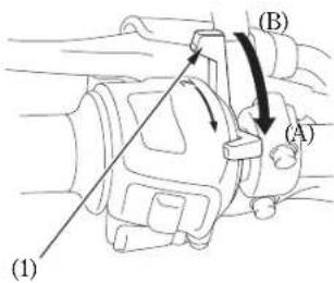
(1) Choke lever
(A) Fully ON
(B) Fully OFF
NOTE:
* Do not open the throttle when starting the engine with the choke ON. This will lean the mixture, resulting in hard starting.
3. Immediately after the engine starts, operate the choke lever (1) to keep fast idle at:
2,300-3,400 min ^-1 (rpm)
- About a half minute after the engine starts, push the choke lever () forward all the way to Fully OFF (B
- If idling is unstable, open the throttle slightly.


03/10/23 11:11:23 32KPF600_051

High Air Temperature
35^(95^) or above
- Do not use the choke.
- With the throttle slightly open, press the starter button.
Low Air Temperature
10^(50^) or below
- Follow steps under "Normal Air Temperature."
- When engine speed begins to pick up, operate the choke lever to keep fast idle at :
2,300 3,400 min ^-1 (rpm)
- Continue warming up the engine until it runs smoothly and responds to the throttle when the choke lever () is at Fully OFF (B
CAUTION
* Extended use of the choke may impair piston and cylinder wall lubrication and damage the engine.


03/10/23 11:11:27 32KPF600_052

If the engine fails to start after repeated attempts, it may be flooded with excess fuel. To clear a flooded engine, leave the engine stop switch on RUN and push the choke lever forward to Fully OFF (). Open the throttle fully and crank the engine for 5 seconds. If the engine starts, quickly close the throttle, then open it slightly if idling is unstable. If the engine does not start, wait 10 seconds, then follow the Starting Procedure.
RUNNING-INFlooded Engine
Help assure your motorcycle's future reliability and performance by paying extra attention to how you ride during the first 500 km (300 miles).
During this period, avoid full-throttle starts and rapid acceleration.


03/10/23 11:11:34 32KPF600_053

RIDING
▲WARNING
* Review Motorcycle Safety (pages1 - 6) before you ride.
NOTE:
* Make sure you understand the function of the side stand mechanism. (See MAINTENANCE SCHEDULE on page and explanation for SIDE STAND on page 75)
- After the engine has been warmed up, the motorcycle is ready for riding.
- While the engine is idling, pull in the clutch lever and depress the gearshift pedal to shift into 1st (low) gear.
-
Slowly release the clutch lever and at the same time gradually increase engine speed by opening the throttle. Coordination of the throttle and clutch lever will assure a smooth positive start.
-
When the motorcycle attains a moderate speed, close the throttle, pull in the clutch lever and shift to 2nd gear by raising the gearshift pedal.
This sequence is repeated to progressively shift to 3rd, 4th, 5th and 6th (top) gear. - Coordinate the throttle and brakes for smooth deceleration.
- Both front and rear brakes should be used at the same time and should not be applied strongly enough to lock the wheel, or braking effectiveness will be reduced and control of the motorcycle be difficult.
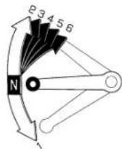

03/10/23 11:11:40 32KPF600_054

▲WARNING
NOTE:
* Do not downshift when traveling at a engine speed is near idle speed. Avoid speed that would force the end of or prolonged periods. overrev in the next lower gear; the rear wheel may lose traction, resulting in a possible loss of vehicle control.
CAUTION:
* Do not shift gears without disengaging the clutch and closing the throttle. The engine and drive train could be damaged by overspeed and shock.
* Do not tow the motorcycle or coast for long distances while the engine is off. The transmission will not be properly lubricated and damage may result.
* Do not ride over a curb or rub the wheel against an obstacle, as wheel damage may result.

03/10/23 11:11:48 32KPF600_055

BRAKING
- For normal braking, gradually apply both the front and rear brakes while downshifting to suit your road speed.
- For maximum deceleration, close the throttle and apply the front and rear brakes firmly. Pull in the clutch lever before coming to a complete stop to prevent stalling the engine.
▲WARNING
* Independent use of only the front or rear brake reduces stopping performance. Extreme braking may cause either wheel to lock, reducing control of the motorcycle.
* When possible, reduce speed or brake before entering a turn; closing the throttle or braking in mid-turn may cause wheel slip. Wheel slip will reduce control of the motorcycle.
▲WARNING
* When riding in wet or rainy conditions, or on loose surfaces, the ability to maneuver and stop will be reduced. All of your actions should be smooth under these conditions. Rapid acceleration, braking or turning may cause loss of control. For your safety, exercise extreme caution when braking, accelerating or turning.
* When descending a long, steep grade, use engine compression braking by downshifting, with intermittent use of both brakes. Continuous brake application can overheat the brakes and reduce their effectiveness.
- Riding with your foot resting on the brake pedal or your hands on the brake lever may actuate the brakelight, giving a false indication to other drivers. It may also overheat the brake, reducing effectiveness.

03/10/23 11:11:56 32KPF600_056

PARKING
-
After stopping the motorcycle, shift the transmission into neutral, turn the handlebar fully to the left, turn the ignition switch OFF and remove the key.
-
Use the side stand to support the motorcycle while parked.
CAUTION:
* Park the motorcycle on firm, level ground to prevent it from falling over.
* If you must park on a slight incline, aim the front of the motorcycle uphill to reduce the possibility of rolling off the side stand or overturning.
- Lock the steering to help prevent theft (page 36
ANTI-THEFT TIPS
-
Always lock the steering and never leave the key in the ignition switch. This sounds simple but people do forget.
-
Be sure the registration information for your motorcycle is accurate and current.
-
Park your motorcycle in a locked garage whenever possible.
-
Use an additional anti-theft device of good quality.
-
Put your name, address, and phone number in this Owner's Manual and keep it on your motorcycles at all times. Many times stolen motorcycles are identified by information in the Owner's Manuals that are still with them.
NAME:
ADDRESS:
PHONE NO:
50

03/10/23 11:12:00 32KPF600_057

MAINTENANCE
- The Required Maintenance Schedule specifies how often you should have your motorcycle served, and what things need attention. It is essential that your motorcycle be served as scheduled to retain its high level of safety, dependability, and emission control performance.
- These instructions are based on the assumption that the motorcycle will be used exclusively for its designed purpose. Sustained high speed operation, or operation in unusually wet or dusty conditions, will require more frequent service than specified in the MAINTENANCE SCHEDULE. Consult your Honda dealer for recommendations applicable to your individual needs and use.


03/10/23 11:12:09 32KPF600_058

MAINTENANCE SCHEDULE
The following Maintenance Schedule specifies all maintenance required to keep your motorcycle in peak operating condition. Maintenance work should be performed in accordance with standards and specifications of Honda by properly trained and equipped technicians. Your Honda dealer meets all of these requirements.
Perform the Pre-ride Inspection (page 42) at each scheduled maintenance period. 1: INSPECT AND CLEAN, ADJUST, LUBRICATE OR REPLACE IF NECESSARY
C: CLEAN R: REPLACE A: ADJUST I: LUBRICATE
| FREQUENCYITEM MONTH | COMES↓NOTE | × 1,000 km | ODOMETER READING NOTE (1)WHICHEVER | |||||||
| 1 | 6 | 12 | 18 | 24 | 30 | 36 | ||||
| 4 | 8 | 12 | 16 | 20 | 24 | |||||
| 6 | 12 | 18 | 24 | 30 | 36 | |||||
| * | FUEL LINE | I | I | I | ||||||
| * | FUEL STRainer SCREEN | C | C | C | C | C | C | |||
| * | THROTTLE OPERATION | I | I | I | ||||||
| * | CARBURETOR CHOKE | I | I | I | ||||||
| AIR CLEANER | (NOTE 2) | C | C | R | C | C | R | |||
| CRANKCASE BREATHER | (NOTE 3) | C | C | C | C | C | C | |||
| SPARK PLUG | R | R | R | |||||||
| * | VALVE CLEARANCE | I | I | I | ||||||
| ENGINE OIL | R | R | R | R | ||||||
| ENGINE OIL FILTER | R | R | R | R | ||||||
| * | ENGINE IDLE SPEED | I | I | I | I | I | I | I | ||
| * | SECONDARY AIR SUPPLY SYSTEM | I | I | I | ||||||

03/10/23 11:12:18 32KPF600_059

| ITEM\FREQUENCY | WHICHEVER →COMLES × 1,000 km | ODOMETER READING NOTE (1) | |||||||||
| 1 | 6 | 12 | 18 | 24 | 30 | 36 | REFER TO PAGE | ||||
| FIRST ↓ | × 1,000 mi | 0.6 | 4 | 8 | 12 | 16 | 20 | 24 | |||
| NOTE | MONTH | 6 | 12 | 18 | 24 | 30 | 36 | ||||
| DRIVE CHAIN | EVERY 1,000 km (600 mi) 1, L | 68 | |||||||||
| BRAKE FLUID | (NOTE 4) | I | I | R | I | I | R | 19 | |||
| BRAKE SHOE/PAD WEAR | I | I | I | I | I | I | 81, 82 | ||||
| BRAKE SYSTEM | I | I | I | I | 18, 81, 82 | ||||||
| * | BRAKE LIGHT SWITCH | I | I | I | 88 | ||||||
| * | HEADLIGHT AIM | I | I | I | 41 | ||||||
| CLUTCH SYSTEM | I | I | I | I | I | I | I | 23 | |||
| SIDE STAND | I | I | I | 75 | |||||||
| * | SUSPENSION | I | I | I | — | ||||||
| * | NUTS, BOLTS, FASTENERS | I | I | I | I | — | |||||
| ** | WHEELS/TYRES | I | I | I | — | ||||||
| ** | STEERING HEAD BEARINGS | I | I | I | I | — | |||||

03/10/23 11:12:24 32KPF600_060

* Should be serviced by your Honda dealer, unless the owner has the proper tools and service data and is mechanically qualified. Refer to the Official Honda Shop Manual.
** In the interest of safety, we recommend these items be serviced only by your Honda dealer.
Honda recommends that your Honda dealer should road test your motorcycle after each periodic maintenance is carried out.
NOTES: 1. At higher odometer readings, repeat at the frequency interval established here.
- Service more frequently if the motorcycle is ridden in unusually wet or dusty areas.
- Service more frequently when riding in rain or at full throttle.
- Replace every 2 years, or at indicated odometer interval, whichever comes first. Replacement requires mechanical skill.


03/10/23 11:12:30 32KPF600_061

TOOL KIT
The tool kit (1) is under the seat.
Some roadside repairs, minor adjustments and parts replacement can be performed with the tools contained in the kit.
- Tool bag
• Sparkplugwrench
• 24 mm Box end wrench
• 10 12 mm Open end wrench
• 14 M mm Open end wrench
• No. 2 Phillips screwdriver
• No. 2 Screwdriver - Extension bar
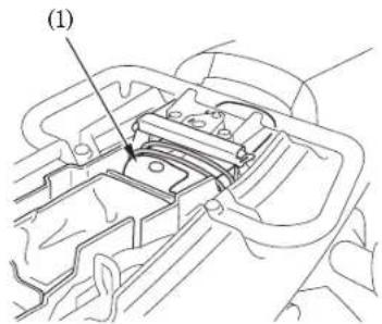
(1) Tool kit


03/10/23 11:12:37 32KPF600_062

SERIAL NUMBERS
The frame and engine serial numbers are required when registering your motorcycle.
They may also be required by the engine number ()2s stamped on the when ordering replacement parts. left side of the crankcase.
Record the numbers here for your reference.
The frame number () is stamped on the right side of the steering head.
FRAME NO. ENGINE NO.
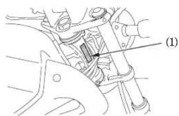
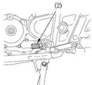
(1) Frame number 56
(2) Engine number


03/10/23 11:12:42 32KPF600_063

MAINTENANCE PRECAUTIONS
▲WARNING
* If your motorcycle is overturned or involved in a collision, inspect control levers, cables, brake hoses, calipers, accessories, and other vital parts for damage. Do not ride the motorcycle if damage impairs safe operation. Have your Honda dealer inspect the major components, including frame, suspension and steering parts, for misalignment and damage that you may not be able to detect.
* Stop the engine and support the motorcycle securely on a firm, level surface before performing any maintenance.
▲WARNING
* Use new, genuine Honda parts or their equivalent for maintenance and repair. Parts which are not of equivalent quality may impair the safety of your motorcycle.


03/10/23 11:12:49 32KPF600_064

AIR CLEANER
(Refer to the maintenance precautions on page 57
The air cleaner should be serviced at regular intervals (page). Service more frequently when riding in unusually wet or dusty areas.
- Remove the seat (pag38 ).
- Remove the air cleaner housing cover (2) by removing two screws (1)
- Take out the air cleaner element () and clean the air cleaner element using compressed air from the outside, or replace it if necessary.
- Install the air cleaner element.
- Install the removed parts in the reverse order of removal.
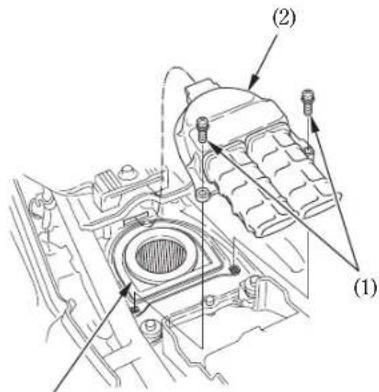
(3)

(1) Screws
(2) Air cleaner housing cover
(3) Air cleaner element

03/10/23 11:12:56 32KPF600_065

CRANKCASE BREATHER
(Refer to the maintenance precautions on page 57
- Remove the crankcase breather tube plug (1) from the tube and drain deposits into a suitable container.
- Reinstall the crankcase breather tube plug.
NOTE:
* Service more frequently when riding in rain, at full throttle, or after the motorcycle is washed or overturned. Service if the deposit level can be seen in the transparent section of the drain tube.
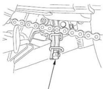
natural_image
Mechanical linkage assembly diagram showing chain links and a bracket (no text or labels)(1)
(1) Crankcase breather tube plug

03/10/23 11:13:03 32KPF600_066

ENGINE OIL
(Refer to the maintenance precautions on page 57
Engine Oil
Good engine oil has many desirable qualities. Use only high detergent, quality motor oil certified on the container to meet or exceed requirements for API Service Classification SE, SF or SG.
Viscosity:
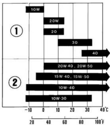
Viscosity grade of engine oil should be based on average atmospheric temperature in your riding area. The following provides a guide to the selection of the proper grade or viscosity of oil to be used at various atmospheric temperatures.
bar
| Scenario | Temperature Range (°C) | | :--- | :--- | | ① | 10W | | ① | 20W | | ① | 20 | | ① | 30 | | ② | 40 | | ② | 20W-40, 20W-50 | | ② | 15W-40, 15W-50 | | ② | 10W-40 | | ② | 10W-30 |(1) Single grade (2) Multi grade

03/10/23 11:13:11 32KPF600_067

Engine Oil and Filter
Engine oil quality is the chief factor affecting engine service life. Change the engine oil as specified in the maintenance schedule (page 52
NOTE:
- Change the engine oil with the engine at normal operating temperature and the motorcycle on its side stand to assure complete and rapid draining.
- To drain the oil, remove the oil filler cap and oil drain plug (1) and sealing washer (2).
▲WARNING
* A warmed-up engine and the oil in it are hot; be careful not to burn yourself.
- After the engine oil has been drained out, hold the motorcycle upright for 10 15 seconds to assure complete draining.
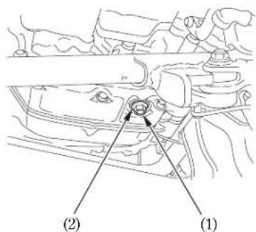
(1) Oil drain plug
(2) Sealing washer

03/10/23 11:13:18 32KPF600_068

- Remove the oil filter bolts (), &il filter cover (4) and oil filter (5).
- Check that the oil filter cover O-ring () 6 is in good condition and then install the new oil filter. Use the Honda oil filter or an equivalent filter specified for your model. Other filters not specified for your model may not filter impurities properly.
- Install the filter with the rubber seal () 7 facing out, away from the engine. You will see 'OUT-SBDE' filter body, near the seal.
CAUTION:
* Improper installation of the oil filter can cause serious engine damage.
6. Reinstall the oil filter cover, making sure the bolts are tightened securely.
Oil Filter Bolt Torque:
12 N·m (1.2 kgf·m, 9 lbf·ft)
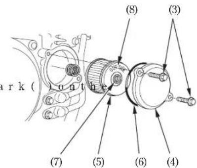
(3) Oil filter bolts
(4) Oil filter cover
(5) Oil filter
(6) O-ring
(7) Rubber scal
(8) OUT-SIDE mark

03/10/23 11:13:26 32KPF600_069

- Check that the sealing washer on the
drainplugisingoodcond the plug. Replace the sealing washer every other time the oil is changed, or each time if necessary.
Oil Drain Plug Torque:
29 N·m (3.0 kgf·m, 22 lbf·ft)
- Fill the crankcase with the recommended grade oil; approximately:
1.5 ℓ (1.6 US qt, 1.3 Imp qt)
-
Install the oil filler cap/dipstick.
-
Start the engine and let it idle for 3 - 5 - minutes.
-
Stop the engine and check that the oil level is at the upper level mark on the dipstick with the motorcycle upright on firm, level ground. Make sure there are no oil leaks.
NOTE
- When running in very dusty conditions, oil changes should be performed more frequently than specified in the maintenance schedule.
NOTE:
and does displace of used engine oil in a manner that is compatible with the environment. We suggest you take it in a scaled container to your local recycling center or service station for reclamation. Do not throw it in the rubbish or pour it on the ground or down a drain.
CAUTION:
* Used engine oil may cause skin cancer if repeatedly left in contact with the skin for prolonged periods. Although this is unlikely unless you handle used oil on a daily basis, it is still advisable to thoroughly wash your hands with soap and water as soon as possible after handling used oil.

03/10/23 11:13:38 32KPF600_070

SPARK PLUG
(Refer to the maintenance precautions on page 57
Recommended plugs:
Standard: CR8EH 9S (NGK)
For extended high speed riding: CR9EH-9S (NGK)
- Disconnect the spark plug cap () from the spark plug.
- Clean any dirt from around the spark plug base. Remove the spark plug using the plug wrench (2) furnished in the tool kit.
- Inspect the electrodes and center porcelain for deposits, erosion or carbon fouling. If the erosion or deposit is heavy, replace the plug. Clean a carbon or wet-fouled plug with a plug cleaner, otherwise use a wire brush.
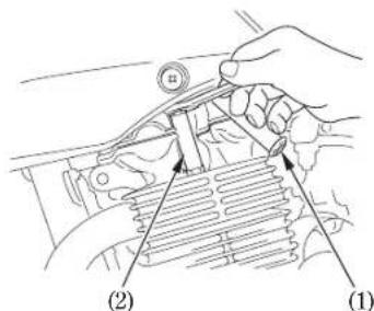
(1) Spark plug cap (2) Plug wrench

03/10/23 11:13:46 32KPF600_071

- Check the spark p3l u g gap
wire-type feeler gauge. If adjustment is necessary, bend the side electrode (4) carefully.
The gap should be:
0.80 0.90 mm (0.031 0.035 in)
Make sure the plug washer is in good condition.
5.) With the plug washer attached, thread the spark plug in by hand to prevent cross-threading.
-
Tighten a new spark plug 1/2 turn with a spark plug wrench to compress the washer. If you are reusing a plug, it should only take 1/8 1/4 turn after the plug seats.
-
Reinstall the spark plug cap.
CAUTION:
* The spark plug must be securely tightened. An improperly tightened plug can become very hot and possibly damage the engine.
* Never use a spark plug with an improper heat range. Severe engine damage could result.

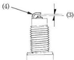
(3) Spark plug gap
(4) Side electrode


03/10/23 11:13:54 32KPF600_072

THROTTLE OPERATION
(Refer to the maintenance precautions on page 57
- Check for smooth rotation of the throttle grip from the fully open to the fully closed position at both full steering positions.
- Measure the throttle grip free play at the throttle grip flange. The standard free play should be approximately:
2.0-6.0 mm (0.08-0.24 in)
To adjust the free play, loosent the lock nut (1) and turn the adjuster (2).
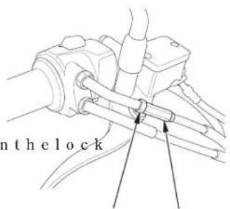
(1) (2)
(1) Lock nut
(2) Adjuster

03/10/23 11:14:01 32KPF600_073

IDLE SPEED
(Refer to the maintenance precautions on page 57
The engine must be at normal operating temperature for accurate idle speed adjustment. Ten minutes of stop-and-go riding is sufficient.
NOTE
- Do not attempt to compensate for faults in other systems by adjusting idle speed. See your Honda dealer for regularly scheduled carburetor adjustments.
- Warm up the engine, shift to neutral and place the motorcycle on it side stand.
- Adjust idle speed with the throttle stop screw (1).
Idle Speed (In neutral):
1,400 ± 100 min ^-1 (rpm)
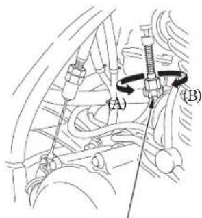
(1)
(1) Throttle stop screw
(A) Increase
(B) Decrease

03/10/23 11:14:11 32KPF600_074

DRIVE CHAIN
(Refer to the maintenance precautions on page 57
The service life of the drive chain is dependent upon proper lubrication and adjustment. Poor maintenance can cause premature wear or damage to the drive chain and sprockets.
The drive chain should be checked and lubricated as part of the Pre-ride Inspection (page 12) Under severe usage, or when the motorcycle is ridden in unusually dusty or muddy areas, more frequent maintenance will be necessary.
- Roll the motorcycle forward. Stop. Check drive chain slack. Repeat this procedure several times. Drive chain slack should remain constant. If the chain is slack only in certain sections, some links are kinked and binding. Binding and kinking can frequently be eliminated by lubrication.

Inspection:
-
Turn the engine off, place the motorcycle on its side stand and shift the transmission into neutral.
-
Check slack in the lower drive chain run midway between the sprockets. Drive chain slack should be adjusted to allow the following vertical movement by hand:
15-25 mm (0.6-1.0 in)
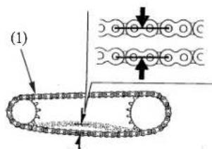
(1) Drive chain

03/10/23 11:14:16 32KPF600_075

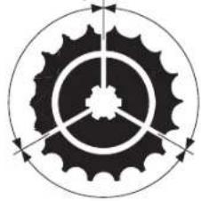
- Roll the motorcycle forward. Stop and place it on its side stand. Inspect the drive chain and sprockets for any of the following conditions:
DRIVE CHAIN
*Damaged Rollers
*Loose Pins
*Dry or Rusted Links
*Kinked or Binding Links
*Excessive Wear
*Improper Adjustment
*Damaged or Missing O-rings SPROCKETS
*Excessively Worn Teeth
*Broken or Damaged Teeth
A drive chain with damaged rollers, loose pins, or missing O-rings must be replaced. A chain which appears dry, or shows signs of rust, requires supplementary lubrication. Kinked or binding links should be thoroughly lubricated and worked free. If links cannot be freed, the chain must be replaced.
Damaged Sprocket
Teeth
Worn Sprocket
Teeth
REPLACE REPLACE
natural_image
Circular gear diagram with concentric rings and directional arrows, no text or symbols presentNormal Sprocket Teeth
GOOD

03/10/23 11:14:23 32KPF600_076

Adjustment:
Drive chain slack should be checked and adjusted, if necessary, every 1,000 km (600 miles). When operated at sustained high speeds or under conditions of frequent rapid acceleration, the chain may require more frequent adjustment.
(3)
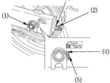
(1) Axle nut
(2) Lock nut
(3) Drive chain adjusting nut
(4) Index mark
(5) Rear edge of adjusting slot
If the drive chain requires adjustment, the procedure is as follows:
- Place the motorcycle on its side stand with the transmission in neutral and the ignition switch off.
- Loosen the axle nut (1).
- Loosen the lock nuts () &n both right and left swingarm.
- Turn both adjusting nuts () and equal number of turns until the correct drive chain slack is obtained. Turn the adjusting nuts clockwise to tighten the chain, or counterclockwise to provide more slack. Adjust the chain slack at a point midway between the drive sprocket and the rear wheel sprocket. Rotate the rear wheel and recheck slack at other sections of the chain.
Chain slack should be:
15-25 mm (0.6-1.0 in)

03/10/23 11:14:31 32KPF600_077

- Check rear axle alignment by confirming the chain adjuster index marks () 4 against the rear edge () of the adjusting slots.
Both left and right marks should correspond. If the axle is misaligned, turn the left or right adjusting nut until the marks correspond on the rear edge of the adjusting slots and recheck chain slack.
- Tighten the axle nut to :
88 N·m (9 kgf·m, 65 lbf·ft)
-
Tighten the adjusting nuts lightly, then tighten the lock nuts by holding the adjusting nuts with a spanner.
-
Recheck drive chain slack. Rear brake pedal free play is affected when repositioning the rear wheel to adjust drive chain slack. Check rear brake pedal free play and adjust as necessary (page 21
▲WARNING
* If a torque wrench is not used for this installation, see your Honda dealer as soon as possible to verify proper assembly.
CAUTION:
- Damage to the bottom part of the frame may be caused by excessive drive chain slack of more than: 50 mm (2.0 in)


03/10/23 11:14:36 32KPF600_078

Wear inspection:
Check the chain wear label when adjusting the chain. If the red zone () 6n the label aligns with the rear edge of the axle washer (7) after the chain has been adjusted to the proper slack, the chain is excessively worn and must be replaced. The proper slack is: 15 25 mm (0.6 1.0 in)
Replacement Chain:
D.I.D 520 106 LE
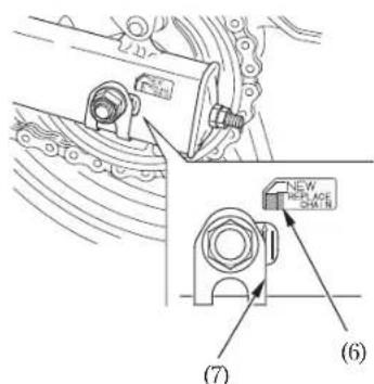
(6) Red zone
(7) Rear edge of the axle washer

03/10/23 11:14:45 32KPF600_079

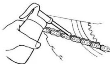
Lubrication and cleaning:
Lubricate every 1,000 km (600 miles) or sooner if chain appears dry.
The O-rings in this chain can be damaged by steam cleaning, high pressure washers, and certain solvents. Clean the side surfaces of the chain with a dry cloth. Do not brush the rubber O-rings. Brushing will damage them. Wipe dry and lubricate only with SAE 80 or 90 gear oil. Commercial chain lubricants may contain solvents which could damage the rubber O-rings.
CAUTION:
- The drive chain on this motorcycle is equipped with small O-rings between the link plates. These O-rings retain grease inside the chain to improve its service life. However, special precautions must be taken when adjusting, lubricating, washing, and replacing the chain.
natural_image
Illustration of a hand using a chain to chain breakers, no text or symbols present
03/10/23 11:14:51 32KPF600_080

FRONT AND REAR SUSPENSION INSPECTION
(Refer to the maintenance precautions on page 57
-
Check the fork assembly by locking the front brake and pumping the fork up and down vigorously. Suspension action should be smooth and there must be no oil leakage.
-
Swingarm bearings should be checked by pushing hard against the side of the rear wheel while the motorcycle is on a support block. Free play indicates worn bearings.
-
Carefully inspect all front and rear suspension fasteners for tightness.

03/10/23 11:14:58 32KPF600_081

SIDE STAND
(Refer to the maintenance precautions on page 5.7
Perform the following maintenance in accordance with the maintenance schedule.
Functional Check:
- Check the spring (1) for damage or loss of tension and the side stand assembly for freedom of movement.
-
Check the side stand ignition cut-off system:
-
Sit astride the motorcycle; put the side stand up and the transmission in neutral.
- Start the engine and with the clutch lever pulled in, shift the transmission into gear.
- Lower the side stand. The engine should stop as you put the side stand down.
If the side stand system does not operate as described, see your Honda dealer for service.
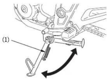
(1) Side stand spring

03/10/23 11:15:05 32KPF600_082

WHEEL REMOVAL
(Refer to the maintenance precautions on page 57
NOTE:
- This motorcycle is equipped with a side stand only. Therefore, if front or rear wheel removal is required, it will be necessary to raise the center of the motorcycle with a jack or other firm support. If none is available, see your Honda dealer for this service.
Front Wheel Removal
- Raise the front wheel off the ground by placing a support block under the engine.
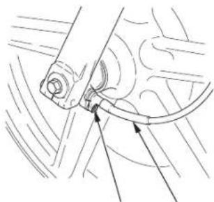
- Disconnect the speedometer cable (1) by removing the speedometer cable set screw (2).
natural_image
Technical line drawing of a mechanical assembly with no visible text or symbols(1)(2)
(1) Speedometer cable
(2) Speedometer cable set screw


03/10/23 11:15:11 32KPF600_083

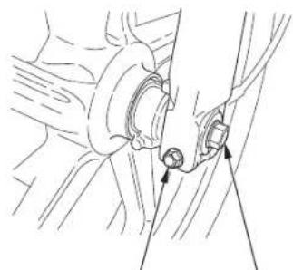
- Remove the front axle bolt ()3 and then loosen the axle pinch bolt (4).
- Remove the front wheel.
NOTE:
* Do not depress the brake lever when the wheel is off the motorcycle. The caliper pistons will be forced out of the cylinders with subsequent loss of brake fluid. If this occurs, servicing of the brake system will be necessary. See your Honda dealer for this service.

natural_image
Technical line drawing of a mechanical assembly with no visible text or symbols(4) (3)
(3) Front axle bolt
(4) Axle pinch bolt

03/10/23 11:15:20 32KPF600_084

Installation Notes:
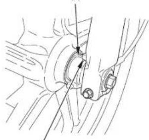
- To install the front wheel assembly, install the brake disc between the brake pads taking care not to damage the brake pads and insert the axle through the left fork leg.
- Make sure that the lug (5) on the fork leg is contacting the lug (6) on the speedometer gear box. Tighten the front axle bolt and axle pinch bolts to specified torques.
Front axle bolt torque:
59 N·m (6.0 kgf·m, 44 lbf·ft)
Axle pinch bolts torque:
22 N·m (2.2 kgf·m, 16 lbf·ft)
- After installing the wheel, apply the brake several times and then check if the wheel rotates freely. Recheck the wheel if the brake drags or if the wheel does not rotate freely.
⚠ WARNING
* If a torque wrench was not used for installation, see your Honda dealer as soon as possible to verify proper assembly. Improper assembly may lead to loss of braking capacity.
(6)
natural_image
Technical line drawing of a mechanical assembly with no visible text or symbols(5)
(5) Lug
(6) Lug

03/10/23 11:15:31 32KPF600_085

Rear Wheel Removal
- Raise the rear wheel off the ground by placing a support block under the engine.
-
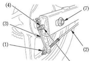
Remove the rear brake adjusting nut (), disconnect the brake rod () from the brake a 8m ( ) by pushing do rear brake pedal.
-
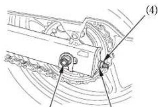
Loosen the drive chain lock nuts () and adjusting nuts (5.
- R e m o v e t h e r e a6 r a x l e n u t () w h i l e holding the rear axle at the other end with a wrench.
5: Rull out the rear axle shaft (7). - Remove the drive chain from the drive sprocket by pushing the rear wheel forward.
- Remove the rear wheel.
(5)
(6)
(5)
(1) Adjusting nut
(2) Brake rod
(3) Brake arm
(4) Lock nuts
(5) Adjusting nuts
(6) Rear axle nut
(7) Rear axle shaft

03/10/23 11:15:39 32KPF600_086

Installation Notes:
- Reverse the removal procedure.
- Make sure that the lug () on the swingarm (10) is located in the slot (8) in the brake panel. Rear axle nut torque: 88 N·m (9 kgf·m, 65 lbf·ft)
- Adjust the brake (page) and drive chain (page 68
- Apply the brake several times and check for free wheel rotation after the brake pedal is released.
▲WARNING
* If a torque wrench was not used for installation, see your Honda dealer as soon as possible to verify proper assembly. Improper assembly may lead to loss of braking capacity.
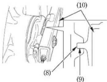
(8) Slot
(9) Lug
(10) Swingarm

03/10/23 11:15:45 32KPF600_087

BRAKE PAD WEAR
(Refer to the maintenance precautions on page 57
Brake pad wear depends upon the severity of usage, the type of riding, and road conditions. (Generally, the pads will wear faster on wet and dirty roads.)
Inspect the pads at each regular maintenance interval (page)53
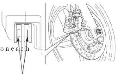
Front Brake
Check the wear indicator mark() one each pad.
If either pad is worn to the wear indicator mark, replace both pads as a set. See your Honda dealer for this service.
(1)
(1) Wearindicatormark

03/10/23 11:15:51 32KPF600_088

BRAKE SHOE WEAR
(Refer to the maintenance precautions on page 57
The rear brake is equipped with a brake wear indicator.
When the brake is applied, an arrow () 1 attached to the brake arm () moves toward a reference mark () on the brake panel () If the arrow aligns with the reference mark on full brake, the brake shoes must be replaced. See your Honda dealer for this service.
NOTE:
- When the brake service is necessary, see your Honda dealer. Use only genuine Honda parts or its equivalent.
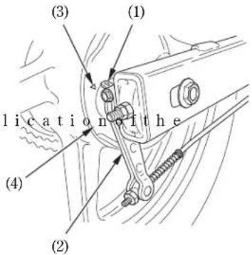
(1) Arrow
(3) Reference mark
(2) Brake arm
(4) Brake panel

03/10/23 11:16:00 32KPF600 089

BATTERY
(Refer to the maintenance precautions on page 57
It is not necessary to check the battery electrolyte level or add distilled water as the battery is a maintenance-free (sealed) type. If your battery seems weak and/or is leaking electrolyte (causing hard starting or other electrical troubles), contact your Honda dealer.
CAUTION
* Removing the battery cap strip can damage the cap strip and result in leaks and eventual battery damage.
* When the motorcycle is to be stored for an extended period of time, remove the battery from the motorcycle and charge it fully. Then store it in a cool, dry place. If the battery is to be left in the motorcycle, disconnect the negative cable from the battery terminal.
▲WARNING
* The battery gives off explosive gases; keep sparks, flames, and cigarettes away. Provide adequate ventilation when charging or using the battery in an enclosed space.
*The battery contains sulfuric acid (electrolyte). Contact with skin or eyes may cause severe burns. Wear protective clothing and a face shield.
- If electrolyte gets on your skin, flush with water.
- If electrolyte gets in your eyes, flush with water for at least 15 minutes and call a physician immediately.
* Electrolyte is poisonous. - If swallowed, drink large quantities of water or milk and follow with milk of magnesia or vegetable oil and call a physician.
* KEEP OUT OF REACH OF CHILDREN.

03/10/23 11:16:06 32KPF600_090

Battery Removal:
- Remove the left side cover (page 40).
- Remove the bolt (1) and battery holder (2).
- Disconnect the negative () terminal lead ()3from the battery first, then disconnect the positive ()+terminal lead (4).
- Pull out the battery (§ from the battery box.
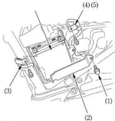
(1) Bolt
(2) Battery holder
(3) Negative (−) terminal lead
(4) Positive (+) terminal lead
(5) Battery

03/10/23 11:16:14 32KPF600_091

FUSE REPLACEMENT
(Refer to the maintenance precautions on page 57 Never use a fuse with a d
When frequent fuse failure occurs, it usually indicates a short circuit or an overload in the electrical system. See your Honda dealer for repair.
CAUTION:
* Turn the ignition switch OFF before checking or replacing the fuses to prevent accidental short-circuiting.
▲WARNING
rating from that specified. Serious damage to the electrical system or a fire may result, causing a dangerous loss of lights or engine power.
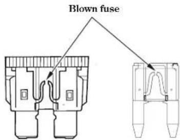

03/11/13 10:49:55 32KPF600_092

Fuse box:
The fuse box is located behind the left side cover. The specified fuse are: 5A, 10A
- Remove the seat (page 38).
- Remove the left side cover (page 40).
- Open the fuse box cover (1).
- Pull out the old fuse and install a new fuse. The spare fuses (2) are located in the fuse box.
- Close the fuse box cover and install the left side cover and the seat.
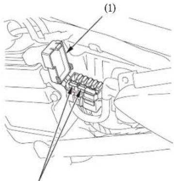
(2)
(1) Fuse box cover
(2) Spare fuses

03/10/23 11:16:26 32KPF600_093

Main fuse:
The main fuse ()lis located behind the left side cover. The specified fuse is: 30A
- Remove the seat (pag38).
- Remove the left side cover (page 40).
- Disconnect the wire connector ()2of the starter magnetic switch.
- Pull out the old fuse and install a new fuse. The spare fuse () 3s located under the starter magnetic switch holder.
- Reconnect the connector and install the seat and left side cover.
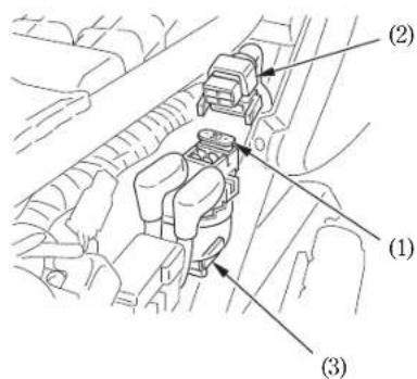
(1) Main fuse
(2) Wire connector
(3) Spare fuse

03/10/23 11:16:31 32KPF600_094

STOPLIGHT SWITCH
ADJUSTMENT
(Refer to the maintenance precautions on page 57
Check the operation of the stoplight switch (1) at the right side behind the engine from time to time.
Adjustment is done by turning the adjusting nut (2). Turn the nut in the direction () if the switch operates too late and in direction (B) if the switch operates too soon.
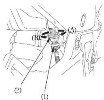
(1) Stoplight switch
(2) Adjusting nut

03/10/23 11:16:39 32KPF600_095

BULB REPLACEMENT
(Refer to the maintenance precautions on page 57
▲WARNING
* The light bulb becomes very hot while the light is ON, and remain hot for a while after it is turned OFF. Be sure
toletitcooldownbeforeservicing. CAUTION:
* Do not put finger prints on the headlight bulb, as they may create hot spots on the bulb and cause it to break.
Wear clean gloves while replacing the bulb.
If you touch the bulb with your bare hands, clean it with a cloth moistened with alcohol to prevent its early failure.
NOTE:
* Be sure to turn the ignition switch OFF when replacing the bulb.
* Do not use bulbs other than that specified.
* After installing a new bulb, check that the light operates properly.


03/11/13 10:50:02 32KPF600_096

Headlight Bulb
-
headlight case.
-
Gently pull the lower end of the headlight (2) forward and remove the headlight.
- Disconnect the connectors (3)
- Remove the seat rubber (4).
- Remove the headlight bulb (5) while pressing down on the pin (6).
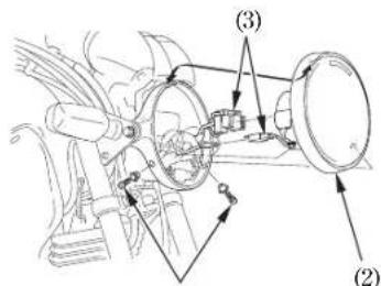
(1)
(1) Screws
(2) Headlight
(3) Connectors
- Install a new bulb in the reverse order of removal. Remove the two screws (1) from the • Install the dust cover with its "TOP" mark facing up.
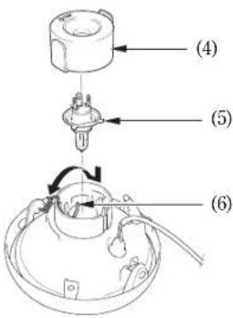
(4) Seat rubber (5) Headlight bulb (6) Pin
90


03/10/23 11:16:50 32KPF600_097

Position Light Bulb
- Remove the headlight () (page).96
- Pull out the socket (3.
- Slightly press the bulb () and turn it counterclockwise.
- Install a new bulb in the reverse order of removal.
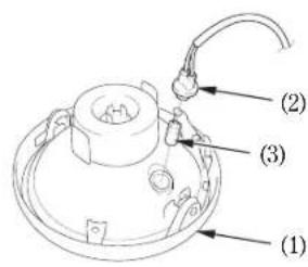
(1) Headlight
(2) Socket
(3) Position light bulb

03/10/23 11:16:57 32KPF600_098

Stop/Taillight Bulb
-
Remove the taillight lens () by 1 removing the two screws (2).
-
Slightly press the bulb () and turn it counterclockwise.
- Install a new bulb in the reverse order of removal.

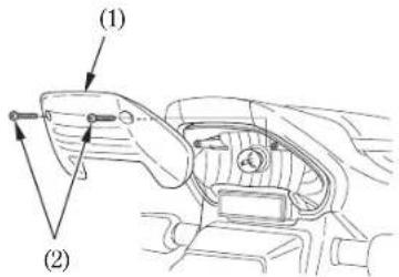
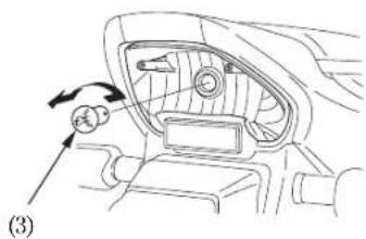
(1) Taillight lens
(2) Screws
(3) Bulb

03/10/23 11:17:04 32KPF600_099

Front/Rear Turn Signal Bulb
-
Remove the turn signal lens () by 1 removing the screw (2).
-
Turn the socket () counterclockwise, then pull it out.
- Pull out the bulb (4) without turning.
- Install a new bulb in the reverse order of removal.

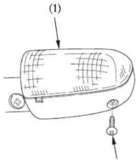
(1) Turn signal lens
(2) Screw
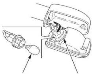
(4)
(3)(2)
(3) Socket
(4) Bulb


03/10/23 11:17:09 32KPF600_100

License Light Bulb
- Remove the license light lens () by 1 removing the screws (2).
- Pull out the bulb (3) without turning.
- Install a new bulb in the reverse order of removal.
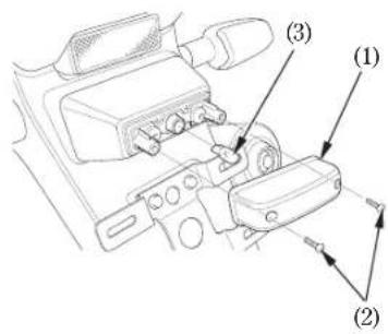
(1) License light lens
(2) Screws
(3) Bulb

b3/10/23 11:17:21 32KPF600_101

CLEANING
Clean your motorcycle regularly to protect the surface finishes and inspect for damage, wear, and oil or brake fluid leakage.
CAUTION:
* High pressure water (or air) can damage certain parts of the motorcycle.
Avoid spraying high pressure water (typical in coin-operated car washes) at the following areas:
Wheel Hubs
Ignition Switch
Carburetor
Brake Master Cylinder
Instruments
Handlebar Switches
Muffler Outlet
Under Fuel Tank
Drive Chain
Under Seat
Headlight
- After cleaning, rinse the motorcycle thoroughly with plenty of clean water. Strong detergent residue can corrode alloy parts.
NOTE:
- Clean the headlight lens, meter lens and other plastic parts using a cloth or sponge dampened with a solution of mild detergent and water. Rub the soiled area gently rinsing it frequently with fresh water.

03/10/23 11:17:27 32KPF600_102

- Dry the motorcycle, start the engine, and let it run for several minutes.
▲WARNING
- Braking efficiency may be temporarily impaired immediately after washing the motorcycle. Anticipate longer stopping distance to avoid a possible accident.
-
Test the brakes before riding the motorcycle. Several applications may be necessary to restore normal braking performance.
-
Lubricate the drive chain immediately after washing and drying the motorcycle.
Painted Aluminum Wheel Maintenance Aluminum may corrode from contact with dirt, mud, or road salt. Clean the wheels after riding through any of these substances. Use a wet sponge and mild detergent. Avoid stiff brushes, steel wool, cleaners containing abrasives or chemical compounds.
After washing, rinse with plenty of water and dry with a clean cloth.
Apply touch-up paint to the wheels where damage has resulted.


03/10/23 11:17:35 32KPF600_103

STORAGE GUIDE
Extended storage, such as for winter, requires that you take certain steps to reduce the effects of deterioration from non-use of the motorcycle. In addition, necessary repairs should be made BEFORE storing the motorcycle; otherwise, these repairs may be forgotten by the time the motorcycle is removed from storage.
STORAGE
- Change the engine oil and filter.
- Lubricate the drive chain (page)73
- Empty the fuel tank into an approved petrol container using a commercially available hand siphon or an equivalent method. Spray the inside of the tank with an aerosol rust-inhibiting oil.
Reinstall the fuel fill cap on the tank.
NOTE
• If storage will last more than one month, carburetor draining is very important, to assure proper performance after storage.
▲WARNING
* Petrol is extremely flammable and is explosive under certain conditions. Perform this operation in a well-ventilated area with the engine stopped. Do not smoke or allow flames or sparks in the area where petrol is drained or stored and where the fuel tank is refueled.


03/10/23 11:17:42 32KPF600_104

-
To prevent rusting in the cylinder, perform the following:
-
Remove the spark plug cap from the spark plug. Using tape or string, secure the cap to any convenient plastic body part so it is are positioned away from the spark plug.
- Remove the spark plug from the engine and store it in a safe place. Do not connect the spark plug to the spark plug cap.
- Pour a tablespoon (15 20-cm ^3 ) of clean engine oil into the cylinder and cover the spark plug hole with a piece of cloth.
- Crank the engine several times to distribute the oil.
-
Reinstall the spark plug and spark plug cap.
-
Remove the battery. Store in an area protected from freezing temperatures and direct sunlight. Slow charge the battery once a month.
- Wash and dry the motorcycle. Wax all painted surfaces. Coat chrome with rustinhibiting oil.
- Inflate the tyres to their recommended pressures. Place the motorcycle on blocks to raise both tyres off the ground.
- Cover the motorcycle (don't use plastic or other coated materials) and store in an unheated area, free of dampness with a minimum of daily temperature variation. Do not store the motorcycle in direct sunlight.

03/10/23 11:17:47 32KPF600_105

REMOVAL FROM STORAGE
- Uncover and clean the motorcycle. Change the engine oil if more than 4 months have passed since the start of storage.
- Charge the battery as required. Install the battery.
- Drain any excess aerosol rust-inhibiting oil from the fuel tank. Fill the fuel tank with fresh petrol.
- Perform all Pre-ride Inspection checks (page 12) Test ride the motorcycle at low speeds in a safe riding area away from traffic.

04/02/05 15:57:17 32KPF600_106

SPECIFICATIONS
DIMENSIONS
| Overall length | 2,030 mm (79.9 in) |
| Overall width | 745 mm (29.3 in) |
| Overall height | 1,050 mm (41.3 in) |
| Wheelbase | 1,370 mm (53.9 in) |
WEIGHT
Dry weight 139 kg (306 lbs)

CAPACITIES
| Engine oil After draining | 1.5 ℓ (1.6 US qt, 1.3 Imp qt) |
| After draining and oil filter change | 1.5 ℓ (1.6 US qt, 1.3 Imp qt) |
| After disassembly | 1.8 ℓ (1.9 US qt, 1.6 Imp qt) |
| Fuel tank | 16 ℓ (4.2 US gal, 3.5 Imp gal) |
| Passenger capacity | Operator and one passenger |

03/10/23 11:18:03 32KPF600_107

ENGINE
Bore and stroke
Compression ratio
Displacement
Spark plug
Standard
For extended high speed riding
73.0 59.5 mm (2.87 2.34 in)
9.3:1
249 cm³ (15.2 cu-in)
CR8EH 9S (NGK)
CR9EH 9S (NGK)
Sparkpluggap
Idle speed
Valve clearance (Cold)
0.80 θ:90 mm (0.031 0:θ35 in)
1,400 100 min ^-1 (rpm)
Intake 0.12 mm (0.005 in)
Exhaust 0.15 mm (0.006 in)

04/02/05 15:57:26 32KPF600_108

CHASSIS AND SUSPENSION
| Caster | 25° |
| Trail | 99 mm (3.9 in) |
| Tyre size, front | 100/80 17M/C 52S |
| Tyre size, rear | 130/70 17M/C 62S |
POWER TRANSMISSION
| Primary reduction | 3.100 |
| Gear ratio, 1st | 2.769 |
| 2nd | 1.882 |
| 3rd | 1.333 |
| 4th | 1.083 |
| 5th | 0.923 |
| 6th | 0.814 |
| Final reduction | 2.846 |

03/10/23 11:18:23 32KPF600_109

ELECTRICAL
Battery
Generator
12V 6AH
0.204 kW/5,000 min ^-1 (rpm)
LIGHTS
Headlight
Tail/stop light
Turn signal light Front
Rear
12V 60/55W
12V 5/21W
12V+6W 2×
12V+6W 2×

FUSE
Main fuse
Other fuses
30A
5A, 10A

03/10/23 15:07:17 3LKPF600_001

Honda CBF250

USO E MANUTENZIONE
© Honda Motor Co., Ltd. 2003


03/10/23 15:07:25 3LKPF600_002

AVVISO IMPORTANTE
• GUIDATORE E PASSEGGERO
natural_image
Line drawing of a motorcycle showing internal components and suspension (no text or labels)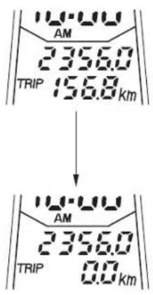
(1) Tasto RESET

03/10/23 15:09:24 3LKPF600_023

(4) Dado registro
natural_image
Technical line drawing of a mechanical assembly with bolts and a spring (no text or symbols)Altri controlli:
natural_image
Technical line drawing of a mechanical component with arrows indicating assembly or connection points (no text or symbols present)(2)(1)
(1) Leva dell'aria
(A) Apertura completa
(B) Chiusura completa
NOTA:
natural_image
Technical line drawing of a mechanical assembly with no visible text or symbolsnatural_image
Mechanical linkage assembly diagram showing chain links and a valve (no text or labels)(1)

natural_image
Technical line drawing of a mechanical assembly with no visible text or symbols(2) (1)
natural_image
Technical line drawing of a mechanical assembly with no visible text or symbols(1) (2)

natural_image
Pure mechanical gear diagram with no text, numbers, or symbolsnatural_image
Illustration of a hand using a chain tag to interact with a chain, no text or symbols present
03/10/23 15:16:14 3LKPF600_080

natural_image
Technical line drawing of a mechanical assembly with no visible text or symbols(1)(2)

natural_image
Technical line drawing of a mechanical assembly with two arrows indicating connection points (no text or symbols present)(4) (3)
NOTA:
natural_image
Technical line drawing of a mechanical assembly with no visible text or symbols(5)


natural_image
Technical line drawing of a mechanical assembly with no visible text or symbols(1)

Freno anteriore
(2)
(1)
natural_image
Diagram of a car interior showing a valve and fan mechanism (no text or symbols)(4)
(3)(2)
(3) Presa
(4) Lampadina


b3/10/23 15:18:29 3LKPF600_100

Luce della targa
03/10/24 09:12:08 35KPF600_001

Honda CBF250

MANUAL DEL PROPIETARIO
© Honda Motor Co., Ltd. 2003




03/10/23 16:15:38 35KPF600_002

AVISO IMPORTANTE
• CONDUCTOR Y PASAJERO
03/11/13 11:02:58 35KPF600_003

Honda CBF250
MANUAL DEL PROPIETARIO
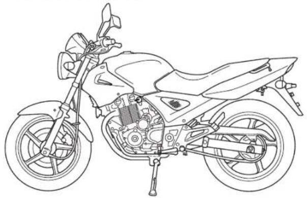
natural_image
Line drawing of a motorcycle showing internal components and suspension (no text or labels)03/10/23 16:16:39 35KPF600_012

03/11/13 11:03:01 35KPF600_014


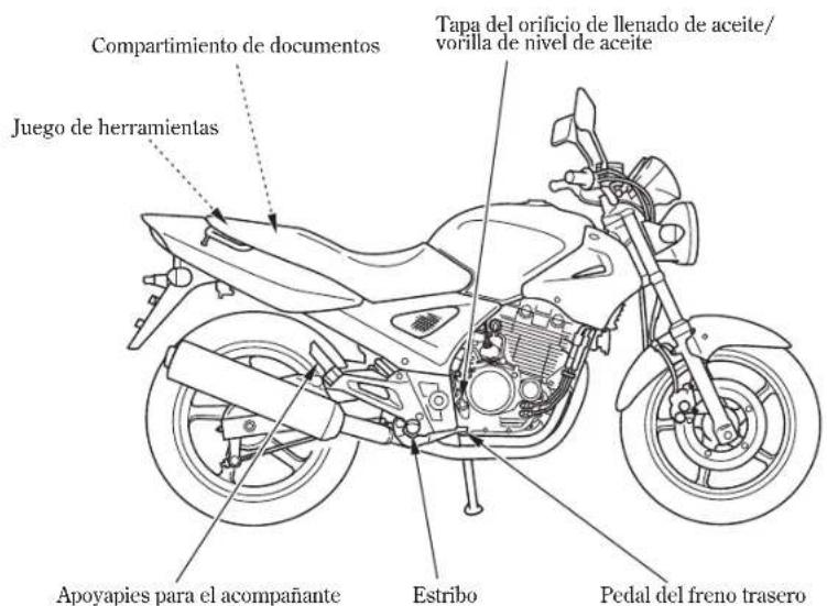
03/11/13 11:03:05 35KPF600_015

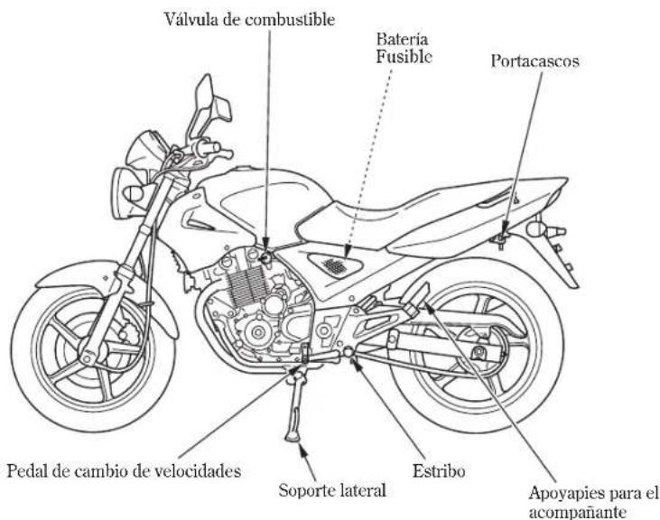
(7) (8) (9) (10)


03/10/23 16:17:02 35KPF600_017

03/10/23 16:17:06 35KPF600_018

03/10/23 16:17:09 35KPF600_019
03/10/23 16:17:25 35KPF600_021

Reloj digital
03/10/23 16:17:31 35KPF600_022

Totalizador parcial
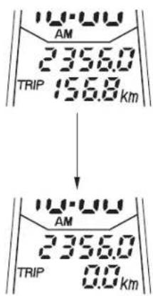
(1) Botón RESET

03/10/23 16:17:37 35KPF600_023

03/10/23 16:17:43 35KPF600_024

COMPONENTES PRINCIPALES
03/11/13 11:03:11 35KPF600_025

03/11/13 11:03:17 35KPF600_026

natural_image
Mechanical assembly diagram showing a bracket with springs and connecting rods (no text or symbols)03/11/13 11:03:25 35KPF600_032

03/11/13 11:03:33 35KPF600_039

03/11/13 11:03:39 35KPF600_042

CARACTERÍSTICAS
03/11/13 11:03:45 35KPF600_043

PORTACASCOS
natural_image
Technical line drawing of a mechanical component with no visible text or symbols(2)(1)
(1) Bolsa de documentos
(2) Compartimiento de documentos

03/10/23 16:20:26 35KPF600_046

TAPA LATERAL
(1) Caja del faro
(2) Pernos
(A) Arriba
(B) Abajo

03/10/23 16:20:42 35KPF600_048

OPERACIÓN
NOTA:
03/10/23 16:21:06 35KPF600_051

03/10/23 16:21:19 35KPF600_053

CONDUCCIÓN
ADVERTENCIA
03/10/23 16:21:24 35KPF600_054

ADVERTENCIA
03/10/23 16:21:30 35KPF600_055

FRENADO
03/10/23 16:21:43 35KPF600_057

MANTENIMIENTO
natural_image
Technical line drawing of a mechanical assembly with no visible text or symbols(2) (1)
natural_image
Technical line drawing of a mechanical assembly with no visible text or symbols(1) (2)

(1) Contratuerca (2) Regulador

03/10/23 16:23:41 35KPF600_073

RALENTÍ
natural_image
Mechanical gear diagram with concentric circles and directional arrows (no text or symbols)Rueda dentada normal
s de t BUENO

03/10/23 16:24:02 35KPF600_076

Ajuste:
natural_image
Pure geometric lines and shapes without any text, numbers, or symbols


03/10/23 16:24:10 35KPF600_077

(7)

natural_image
Illustration of a hand using a chain tag to interact with a spring (no text or symbols)PRECAUCION
natural_image
Technical line drawing of a mechanical assembly with no visible text or symbols(1)(2)

(1) Cable del velocímetro
(2) Tornillo de ajuste del cablevelocimetro

03/10/23 16:24:43 35KPF600_083

natural_image
Technical line drawing of a mechanical assembly with no visible text or symbols(4) (3)
NOTA:
(8) Ranura
(9) Lengüeta
(10) Horquilla oscilante

03/10/23 16:25:17 35KPF600_087

DESGASTE DE PASTILLAS DEL FRENO
natural_image
Technical line drawing of a mechanical assembly with no visible text or symbols(1)

Freno delantero
03/11/13 11:00:53 35KPF600_092

Caja de fusibles:
(4)
(3)(2)
(3) Llave
(4) Bombilla

03/10/23 16:26:50 35KPF600_100

Luz de la matrícula
03/10/23 16:27:02 35KPF600_101

LIMPIEZA
03/10/23 16:27:08 35KPF600_102

03/10/23 16:27:16 35KPF600_103

GUÍA PARA GUARDAR LA MOTOCICLETA
03/10/23 16:27:43 35KPF600_107

MOTOR
Calibre y carrera
Para largos recorridos
aaltavelocidad
73,0 59,5 mm
9,3:1
249 cm ^3
CR8EH 9S (NGK)
CR9EH 9S (NGK)
03/10/23 16:28:00 35KPF600_109

SISTEMA ELÉCTRICO
Batería
Generador
12V 6AH
0,204 kW/5.000 min ^-1 (rpm)
LUCES
Faro
- Honda CBF250
- OWNER'S MANUAL
- USO E MANUTENZIONE
- MANUAL DEL PROPIETARIO
- IMPORTANT NOTICE
- • OPERATOR AND PASSENGER
- - ON-ROAD USE
- - READ THIS OWNER'S MANUAL CAREFULLY
- ▲WARNING
- CAUTION:
- WELCOME
- OPERATION
- Page
- MAINTENANCE
- MOTORCYCLE SAFETY
- △WARNING
- SAFE RIDING RULES
- PROTECTIVE APPAREL
- MODIFICATIONS
- LOADING AND ACCESSORIES
- Loading
- Accessories
- INSTRUMENTS AND
- INDICATORS
- Initial Display
- Digital clock
- Tripmeter
- Fuel Gauge
- MAJOR COMPONENTS
- BRAKES
- Front Brake
- Front Brake Fluid Level:
- Other Checks:
- Rear Brake
- Adjustment:
- NOTE:
- CLUTCH
- NOTE
- FUEL
- Fuel valve
- OFF
- ON
- RES
- Fuel Tank
- CAUTION
- Petrol Containing Alcohol
- ENGINE OIL
- Engine Oil Level Check
- TUBELESS TYRES
- Tyre Repair/Replacement:
- ESSENTIAL INDIVIDUAL COMPONENTS
- IGNITION SWITCH
- RIGHT HANDLEBAR CONTROLS
- Engine Stop Switch
- Starter Button
- LEFT HANDLEBAR CONTROLS
- Headlight Dimmer Switch (1)
- Turn Signal Switch (2)
- Horn Button (3)
- Passing Light Control Switch (4)
- FEATURES
- (Not required for operation)
- STEERING LOCK
- HELMET HOLDER
- SEAT
- DOCUMENT COMPARTMENT
- SIDE COVER
- Removal:
- Installation:
- HEADLIGHT AIM VERTICAL ADJUSTMENT
- PRE-RIDE INSPECTION
- STARTING THE ENGINE
- Starting Procedure
- Normal Air Temperature
- High Air Temperature
- Low Air Temperature
- RUNNING-INFlooded Engine
- RIDING
- BRAKING
- PARKING
- ANTI-THEFT TIPS
- MAINTENANCE SCHEDULE
- TOOL KIT
- SERIAL NUMBERS
- FRAME NO. ENGINE NO.
- MAINTENANCE PRECAUTIONS
- AIR CLEANER
- CRANKCASE BREATHER
- Viscosity:
- Engine Oil and Filter
- SPARK PLUG
- THROTTLE OPERATION
- IDLE SPEED
- DRIVE CHAIN
- Inspection:
- Wear inspection:
- Lubrication and cleaning:
- FRONT AND REAR SUSPENSION INSPECTION
- SIDE STAND
- Functional Check:
- WHEEL REMOVAL
- Front Wheel Removal
- Installation Notes:
- ⚠ WARNING
- Rear Wheel Removal
- BRAKE PAD WEAR
- BRAKE SHOE WEAR
- BATTERY
- Battery Removal:
- FUSE REPLACEMENT
- Fuse box:
- Main fuse:
- STOPLIGHT SWITCH
- ADJUSTMENT
- BULB REPLACEMENT
- Headlight Bulb
- Position Light Bulb
- Stop/Taillight Bulb
- Front/Rear Turn Signal Bulb
- License Light Bulb
- CLEANING
- STORAGE GUIDE
- STORAGE
- REMOVAL FROM STORAGE
- SPECIFICATIONS
- DIMENSIONS
- WEIGHT
- CAPACITIES
- ENGINE
- ELECTRICAL
- LIGHTS
- FUSE
- AVVISO IMPORTANTE
- • GUIDATORE E PASSEGGERO
- Altri controlli:
- NOTA:
- Freno anteriore
- Luce della targa
- AVISO IMPORTANTE
- Reloj digital
- Totalizador parcial
- COMPONENTES PRINCIPALES
- CARACTERÍSTICAS
- PORTACASCOS
- TAPA LATERAL
- OPERACIÓN
- CONDUCCIÓN
- ADVERTENCIA
- FRENADO
- MANTENIMIENTO
- RALENTÍ
- Ajuste:
- PRECAUCION
- DESGASTE DE PASTILLAS DEL FRENO
- Freno delantero
- Caja de fusibles:
- Luz de la matrícula
- LIMPIEZA
- GUÍA PARA GUARDAR LA MOTOCICLETA
- MOTOR
- SISTEMA ELÉCTRICO
- LUCES
Brand : Honda
Model : CBF250 (2003)
Category : Motorcycle