
UTD1025CL - Mètre Uni-T - Free user manual and instructions
Find the device manual for free UTD1025CL Uni-T in PDF.


| Product Type | Handheld Digital Storage Oscilloscope with Multimeter |
| Brand | Uni-T |
| Model | UTD1025CL |
| Bandwidth | 25 MHz |
| Sampling Rate | 200 MS/s (real-time) |
| Channels | 1 (oscilloscope), plus multimeter inputs |
| Display | 3.5-inch TFT LCD, 320x240 pixels, color/black-white |
| Dimensions (WxHxD) | 199 x 118 x 49 mm |
| Weight (net) | 0.9 kg |
| Power Supply | DC 9V/1.5A adaptor; internal 7.4V 3600mAh rechargeable Li-ion battery (up to 8 hours) |
| Input Impedance (oscilloscope) | 1 MΩ ±2% in parallel with 12 pF |
| Max Input Voltage (oscilloscope) | 300 V (DC + AC peak), CAT II |
| Multimeter Functions | DC/AC voltage (400 mV to 400 V), DC/AC current (up to 10 A with current divider), resistance (400 Ω to 40 MΩ), capacitance (51.2 nF to 100 μF), diode, continuity |
| Safety Rating | CAT III 600 V (multimeter), CAT II 300 V (oscilloscope), Pollution Degree 2 |
| Accessories Included | Power adaptor, probe (1x 10:1), multimeter test leads, UT-M07 current divider (10A), USB cable, carrying bag, CD with software, manual |
| Maintenance | Clean with soft cloth dampened with water or mild detergent; avoid solvents; recharge battery every 3 months when stored |
| Spare Parts / Repairability | Battery pack replaceable by qualified personnel; fuse replaceable for current measurements; probe and test leads consumable |
| Calibration Period | Recommended once per year |
| Operating Temperature | 0 °C to +40 °C |
| Storage Temperature | -20 °C to +60 °C |
Frequently Asked Questions - UTD1025CL Uni-T
User questions about UTD1025CL Uni-T
0 question about this device. Answer the ones you know or ask your own.
Ask a new question about this device
Download the instructions for your Mètre in PDF format for free! Find your manual UTD1025CL - Uni-T and take your electronic device back in hand. On this page are published all the documents necessary for the use of your device. UTD1025CL by Uni-T.
USER MANUAL UTD1025CL Uni-T
Hello! Thanks for you choosing the brand new UNI-T device. In order to use the instrument correctly, please read the manual thoroughly and especially the Safety Notes part before using the device. If you have read through the manul, you are recommended to keep the menu properly with the instrument together or at the place you can read anytime in order to read it in the process of future use.
UNI-T®
UTD1000L User Manual
Contents
Item
Page
Chapter1 Safety Information.... 1
Safety Terms and Symbols.... 1
General Safety Overview 2
Chapter2 UTD1000L Series Oscilloscope Overview .... 4
UTD1000L Series Oscilloscope Introduction 4
UTD1000L Series Oscilloscope Accessories 5
UTD1000L Series Oscilloscope Key Features.... 5
Chapter3 Connections to the Oscilloscope....6
General Check....6
Checking for any damage due to the transit.... 6
Checking the Accessories.... 6
Checking the Whole Oscilloscope.... 7
Connection Interfaces....7
Compensation Output Connection....8
Front Panel and Keypad.... 8
Chapter 4 Using Basic Oscilloscope Functions.... 12
About the Chapter.... 12
Powering on the Oscilloscope.... 12
UNI-T®
UTD1000L User Manual
Item
Page
Describing the Display.... 12
Resetting the Oscilloscope.... 14
Using Functional Menus.... 14
Hiding Menus 15
Making Connections for Probe Compensation .... 15
Compensating the Probe 12
Setting Vertical & Horizontal Systems and Trigger Level Manually..... 17
Vertical System 17
Horizontal System.... 18
Autoset for Waveform Display.... 19
Full Autoset for Input Signal.... 20
Run/Stop Data Acquisition. 21
Setting Frequency Counter 22
Adjusting Screen Intensity.... 22
Saving Bitmap.... 23
Using Online Help.... 23
Setting Single Trigger 24
UNI-T®
UTD1000L User Manual
Item
Page
Viewing Oscilloscope Status 24
Checking Oscilloscope System Information.... 26
Making Auto Measurements.... 26
Measuring All parameters.... 26
Using AVG Mode for Smoothing Waveforms 29
Using Peak Detect Mode for Pulse Peak Display.... 29
Observing Waveforms with use of Persistence 30
Selecting AC Coupling 30
Inverting the Waveform Display 31
Autoset for Signals with DC Offset.... 32
Chapter 5 Using the Multimeter.... 35
About the Chapter 35
Connections to the Multimeter.... 35
Display Indicators.... 35
Making Multimeter Measurements.... 36
Measuring Resistance.... 36
Testing Diodes.... 37
UNI-T®
UTD1000L User Manual
Item
Page
Testing for Continuity.... 37
Measuring Capacitance.... 38
Measuring DC Voltage 38
Measuring AC Voltage 39
Measuring DC Current with UTD1000CL 39
Measuring AC Current with UTD1000CL 41
Measuring DC Current with UTD1000DL 43
Measuring AC Current with UTD1000DL 47
Data Hold 51
Making Relative Measurement 51
Selecting Auto Manual Ranging 52
Chapter 6 Using the Oscilloscope in Details.... 53
About the Chapter.... 53
Setting Vertical System 53
UTD1000CL Channel Setup.... 53
UTD1000DL Channel Setup.... 56
Setting Probe Factor.... 59
UNI-T®
UTD1000L User Manual
Item
Page
Setting Horizontal System.... 59
Changing Timebase 59
Moving Waveforms Horizontally 59
Zooming in out Waveforms 60
Adjusting Trigger Hold Off 61
Setting Trigger System 62
Common Setting 64
Edge Trigger 65
Pulse Width Trigger 66
Video Trigger 67
Slope Trigger 68
Setting Acquisition Mode 71
Setting the Display 72
Setting Auto Measurements 74
Recording and Storage 80
UNI-T®
UTD1000L User Manual
Item
Page
Recording 80
Storage....83
Recalling 84
Making Cursor Measurements 86
Interface Setup 88
Utility Setup 89
Executing Mathematic Functions 91
Autoset 96
Chapter 7 Troubleshooting 97
The Oscilloscope cannot power on.... 97
The Oscilloscope turns off just a few seconds later after powered on 97
Measuring voltage amplitude is 10 times larger or smaller than exactvalue 97
No waveform displays after acquiring signals.... 97
UNI-T®
UTD1000L User Manual
Item
Page
The waveform does not display steadily.... 97
There is no display after pressing down RUN/STOP button..... 98
The display slows down after having applied AVG mode for a while.98
The waveform display has a stair-stepping shape.... 98
Chapter 8 Service and Suppor 99
Updating Program 99
Preparations before Update 99
Update Conditions 99
Program Update 99
Chapter 9 Appendixes ...... 102
AppendixA Technical Specifications 102
Appendix B Maintenance 11 1
UNI-T®
UTD1000L User Manual
Chapter 1 Safety Information
Safety Terms and Symbols
Terms in the manual
Following terms may appear in this manual:
Warning: a Warning specifies conditions and actions that may pose hazards to the user.
Caution: a Caution identifies conditions and actions that may cause damage to the product or other properties.
Terms on the product
Following terms may show on the product:
DANGER indicates any injury hazard immediately accessible as you read the marking.
WARNING indicates any injury hazard not immediately accessible as you read the marking.
CAUTION indicates any damage may happen to the product or other properties
Symbols on the product
Following symbols may show on the product:
Symbols on the product
The following symbols might be on the product:

High Voltage

Refer to the manual

Measuring Ground Termina
UNI-T®
UTD1000L User Manual
General Safety Overview
The oscilloscope is strictly designed and manufactured as per safety/compliances: GB4793 safety requirements for electronic measuring instruments, IEC61010-1, Overvoltage CAT III 600 V and Pollution Degree II
Please review following safety precautions to avoid personal injury or any damage to this product or any products connected to it. Operate the product as specified to prevent any potential hazards. Only the qualified personnel can perform the servicing procedures.
Warning: To avoid electric shock or fire, use only the power adaptor specified for the Oscilloscope and certified for the power grid by the country of use.
Warning: If the Oscilloscope terminals are input with voltages higher than 42V (30 Vrms), to avoid personal electric shock :
- Use only the insulated voltage probe, test leads and power adaptor supplied or specified by UNI-T for this Oscilloscope Series.
- Please check multimeter test leads, oscilloscope probe and other accessories for any mechanical damage. Please make the replacement if any damage is found.
- Remove all unused test leads, probe and other accessories.
- Insert the power adaptor first into AC socket before connecting it to the Oscilloscope
- Do not input voltages higher than 300V into scope terminals under CAT II measuring environment working voltage applied into multimeter terminals must not exceed V 600 under CAT theasuring environment.
- Do not apply working voltage higher than rated values on the Oscilloscope
UNI-T®
UTD1000L User Manual
- Use only the accessories supplied for the Oscilloscope do not use them if any damages are found.
- Do not plug any metal object into the connectors
● Use the Oscilloscope as specified. - Rated voltage value mentioned in “Warning” is the working voltage limit for the power adaptor It represents Vrms 50-60Hz) when applying AC sinewave.
Only qualified staff can perform the servicing.
Check all terminals ratings: To avoid fire or electric hazard, please observe all ratings and symbols on the Oscilloscope. Read through the manual for details before making connections to the Oscilloscope
Do not operate with suspected failure: Please have it checked by qualified servicing staff if you doubt the product does not work normally.
Do not operate in damp environment.
Do not operate in explosive environment
Keep the product surface clean and dry
UNI-T®
UTD1000L User Manual
Chapter 2 UTD1000L Series Oscilloscope Overview UTD1000L Series Oscilloscope Introduction
UTD1000L Handheld Digital Storage Oscilloscope Hereinafter referred to as The “Oscilloscope combines digital scope and multimeter functions just into one tool. The ease-of-use feature, excellent technical indicators and multi-functions offered the Oscilloscope can get your work done much faster.
The series offers four models for your option:
| Type | Bandwidth | Sampling velocity | Channel count |
| UTD1025CL | 25MHz | 200MS/s | Single channel |
| UTD1050CL | 50MHz | 200MS/s | Single channel |
| UTD1025DL | 25MHz | 250MS/s | Dual Channel |
| UTD1050DL | 50MHz | 250MS/s | Dual Channel |
UTD1000L Series Oscilloscopes offer users a simple and clear front panel that helps to perform primary operations a, design you often get used to and can save you a great amount of time to learn about the Oscilloscope In order to speed up calibrations and measurements, pressing AUTO button can make the oscilloscope display proper waveforms and settings directly. Meanwhile the Oscilloscope offers \$SHIFT button to combine with other buttons to further operate the menus much easier. Beside ease of use, this series outstands itself with superb performance and powerful functions, such as remarkable trigger and analysis ability, making it easy to capture and analyze the waveforms high definition Display and math function, ensuring a very clear and fast view on waveforms and finding out the signal problem.
UNI-T®
UTD1000L User Manual
UTD1000L Series Oscilloscope Accessories
Unpack the carton and you will see following
accessories should be included :
| No. | Instruction | Standarc configuration |
| 1 | UNI-T oscilloscope | ● |
| 2 | Power Adaptor, 1 pc | ● |
| 3 | UTD1000CL Standard Probe, pt ; UTD1000DL Standard Probe pcs 2 | ● |
| 4 | Multimeter Test Leads, 2pcs (one red, one black) | ● |
| 5 | UTD1000CL standard UT-M07(10A current divider module ), pcs ; UTD1000DL standard UT-M04 4A current divider module ), pc UT-M10 (mA current module ), pc | ● |
| 6 | Oscilloscope probe adjusting tool, 1pc | ● |
| 7 | USB wire , 1pc | ● |
| 8 | Operating Manual ,pt | ● |
| 9 | CD (for communication software between PC and the Oscilloscope), 1pc | ● |
| 10 | carrying bag, 1pc | ● |
UTD1000L Series Oscilloscope Key Features
Scope
- Totally Auto Scale ; Vertical Scale and Timebase automatically adjusted with the signal and without any manual interference ;
- Unique and powerful Auto Setup, quick and accurate to set up for signals with any DC component;
● Wider voltage measuring range ; Coupled with 10 probe with attenuation up to 200V/div ;
● Isolated USB for much safer communication ;
● Color, & White black display for your option perfect for use outdoors with strong sunshine.
● Intelligent local or network software update - Unique waveform record, storage and recall functions
● High-resolution and high-contrast color LCD
UNI-T®
UTD1000L User Manual
● 8 hours of continuous battery operation for UTD1000CL and 6 hours for UTD1000DL
- UTD1000CL:19 types of auto measurements
- UTD1000DL:22 types of auto measurements
● Simple Printscreen function
● Multilingual help information
Multimeter
● 3999 display count
● Voltage, current, resistance, diode, capacitance, continuity measurements offered
● Measure current up to 10A (UTD1000DL 4A max.)
- Extremely low internal resistance designed for current measurement ensuring better measuring accuracy.
- Independent multimeter and scope functions in one tool
Chapter 3 Oscilloscope Connection
General Check
It is recommended that you should proceed following inspections when you get a new UT1000L series oscilloscope.
Checking for any damage due to the transit
Contact UNI-T dealership or local UNI-T office immediately if the packing carton or foamed plastic cushion is seriously damaged.
Checking the Accessories
The accessories supplied for the Oscilloscope are listed in the section “UTD1000L Series Oscilloscope Accessories Hereinbefore. Please refer to the section and check if any accessory is missing.
Please contact UNI-T dealership or local UNI-T office if there is any damage or missing item.
UNI-T®
UTD1000L User Manual
Checking the Whole Oscilloscope
If the Oscilloscope is found damaged externally or it does not work normally or pass any performance test, contact our UNI-T dealership or local UNI-T office If the product is damaged due to the transit , keep the package and inform the shipping agency and UNI T dealership, UNI-T will arrange the maintenance or replacement for you Oscilloscope Connections
Connection Interfaces
See Figure 3-1 for the Oscilloscope connection interfaces
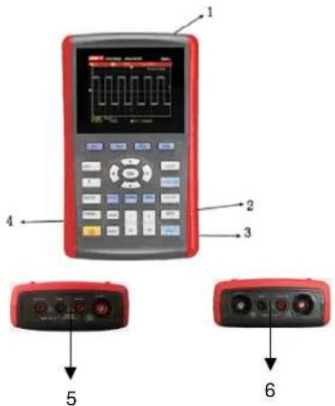
Figure 3-1 Oscilloscope Connection Interfaces
UNI-T®
UTD1000L User Manual
Description:
- Input terminals for scope channels
- USB Connection port
- The port to connect power adaptor for AC power supply and battery charge.
- Output terminal for probe compensation
5.UTD1000CL multimeter input terminals - UTD1000DL multimeter input terminals
Compensation Output Connection
Connect to the output 1(kHz)3V terminal as shown below for the Oscilloscope probe compensation.
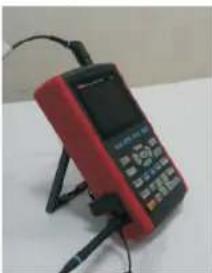
natural_image
Red and black electronic device with attached cables (no visible text or symbols)Picture Compensation Signal Output Connection of the Apparatus
Front Panel and Keypad
Learn about the Oscilloscope front panel and buttons shown in Figure 3-3:
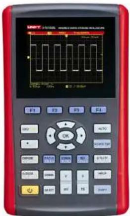
Figure 3-3 UTD1000L Series Front Panel
UNI-T®
UTD1000L User Manual

: To power on off the Oscilloscope
F1 F4
: To set up the submenus

: To toggle between Scope (DSO) and multimeter (DMM) modes.

: Press this button to access ACQUIRE (sample mode)menu if under DSO mode press SHIFT first and then this button to access intensity, with help of right and left arrow buttons, you can change screen brightness. If under DMM mode pressing this button can access voltage measurement menu.

: Press this button to access DISPLAY (Display mode) menu if under DSO mode; or press SHIFT first and then this button to access CONFIGURE interface configuration menu pressing this button under DMM mode to access current measurement menu.

: Press this button under DSO mode to access MEASURE auto measurement) menu or press SHIFT first and then the button to access COURSOR cursor measurement)menu if under DMM mode press the button to access resistance measurement menu and measure resistance diode continuity/ capacitance.
CHANNEL
In DSO mode press it to access CHANNEL menu for UTD1000CL ; repeatedly press to toggle between two channel menus for UTD1000DL

: In DSO mode, press the button to access FFT menu for UTD1000CL; or press the button and then F1 button to toggle between FFT and MATH menus for UTD1000DL. Press SHIFT first and then the button to access STATUS display.
UNI-T®
UTD1000L User Manual

: In DSO mode, press to access RECORD (waveform record) menu or press SHIFT first and then the button to access STORAGE menu.

: Under DSO mode, press to set up SINGLE single trigger function press first SHIFT and then the button to access REF waveform recall) menu.

: Under DSO mode, press to automatically set up the waveform press SHIFT first and then the button to switch on full autoset function The Oscilloscope can automatically adjust the ranges to obtain optimal waveform based on the input signal without any manual interference.

: Under DSO mode, press to start/stop data acquisition if under DMM pr , ess the button to lock measuring readings on the screen .

: Under DSO mode, press to access

TRIGGER menu or press SHIFT first and then the button to access UTILITY menu;
: Under DSO mode, press to access HORIZONTAL menu or press SHIFT first and then the button to open HELP information.

Combine with other buttons to select function options

: Timebase: To change scan rate, ranging from 50s/div 10ns/div for 25MHz – bandwidth models and 50s/div 5ns/div for 50MHz bandwidth models and stepping in 1-2-5 Press s to access relatively slower scan rate or ns to "speed up.

Vertical Scale: To change vertical scaling, ranging from 5mV/div 20V/div and stepping in 1-2-5 Press V to žbořin in current vertical scale or mV tõ " zoom out.
UNI-T®
UTD1000L User Manual
SELECT
: To toggle between vertical position and trigger level if, vertical position is chosen vertical reference cursor turns solid then you can move waveforms vertically with Up and Down buttons. Press SELECT again to make trigger level cursor solid, and also use Up and Down buttons to adjust trigger point location Under MEASURE menu, this button is used to confirm selected parameters, or it is to toggle between Cursor 1 & 2 under cursor measurement.

: Arrow and OK buttons OK button is used to hide display current menu under DMM mode it is used to confirm if current divider has been properly connected when making A current measurement.
Shortcut Buttons Description:
SHIFT OK: To save current interface into internal memory which can be exported externally by PQ which has been loaded with the Oscilloscope software.
SHIFT AUTO: to open full autoset function in which the Oscilloscope can automatically adjust vertical scale and horizontal timebase based on the input signal so that the optimal waveform can be obtained without any manual operation.
SHIFT F1/F2 F3:F4 □ To open main trigger menu
UNI-T®
UTD1000L User Manual
Chapter 4 Using Basic Oscilloscope Functions About the Chapter
This chapter only briefs users on basic functions of the Oscilloscope for example how to use menus and execute basic operations not, a step by step introduction on all functions .
Powering on the Oscilloscope
UTD1000L Series can be powered by the : battery and power adaptor. The power supply voltage from the adaptor is DC9V/1.5A. To operate the Oscilloscope normally please use the power adaptor specified for the Oscilloscope Press Power button and SHIFT light illuminates for 3 seconds, then the Oscilloscope logo appears, indicating the Oscilloscope has already turned on.
Describing the Display
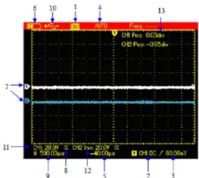
Figure 4-1 Display Interface
Besides the waveform, there are still a lot of details about the waveform and oscilloscope control settings on the screen:
- Trigger source status:
CH1 /CH2: indicates you can adjust the waveform of this channel
UNI-T®
UTD1000L User Manual
REF: indicates you can adjust the recalled waveform.
FFT: indicates you can execute FFT operation on the waveform
- Trigger coupling :
AC ac-coupled
DC dc-coupled
HF high frequency reject
-
Trigger level readout
-
Trigger status:
ARMED The Oscilloscope is acquiring all pre-trigger data and ignores all trigger events ;
READY The Oscilloscope has acquired all pretrigger data and is ready to trigger ;
TRIG'ED The Oscilloscope has detected out one trigger and is acquiring posttrigger data
STOP The Oscilloscope has stopped acquiring waveforms
AUTO The Oscilloscope is in auto mode and acquires wave forms without trigger ;
SCAN The Oscilloscope continuously
acquires and displays waveforms under scan mode.
-
The time readout that indicates how far the trigger point is from the central point ;
-
The power supply indicator:
The Oscilloscope is powered by the battery;
The Oscilloscope is powered by DC power adaptor.
-
The marker for ground reference point for displayed waveforms ;
-
1 indicates probe attenuation factor for the channel is 1 × ;
-
The readout for main timebase setting;
-
Connected to PC icon
-
Readout for the current vertical scale factor
-
Waveform Invert Indicator that indicates that the waveform is reversely displayed horizontal midline.
-
Position readout from the channel reference marker to the horizontal line on the screen
UNI-T®
UTD1000L User Manual
Resetting the Oscilloscope
To reset the Oscilloscope to the default, do the following :
- Press SHIFT button, shift icon displays on the upper right corner of the screen;
- Press UTILITY button and four options shows on the bottom display :
- Press F2 button to select the default setup. Then the Oscilloscope is set to the default settings;
Note: Pressing up arrow button can also set the Oscilloscope to the default when powering on.
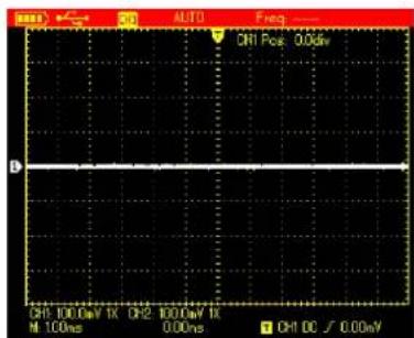
Figure 4-2 Default Setup
The Default setup is as follows:
| Functions | Default Setup |
| Acquire Mode | Norma |
| SEC/DIV | 1ms/div |
| VOLT/DIV | 100mV/div |
| Trigger Coupling | DC |
| Channel Status | CH2 Off (1000DL series) |
| Trigger Mode | Auto |
| Display Format | Vector |
| Persist Time | Auto |
| Display Style | Classic |
| Manual Display | Manual |
Using Functional Menus
The procedures below show you how to select functions with use of oscilloscope menus;
- Press any functional button on the keypad, then corresponding options will show on the bottom display, you can select one of these options with use of F1 F4 After that, press OK □button to hide functional menus:
UNI-T®
UTD1000L User Manual
- For the buttons printed with multiple functions, if you want to choose one of these functions, please press SHIFT button first, accompanied by shift icon on upper right corner of display, then press the corresponding button to obtain the function you want.
Hiding Menus
Press down OK button to hide all button icons and menus. To display menus or button icons, press OK again.
Note: To set up auto hiding time for menus, please find corresponding option in CONFIGURE menu.
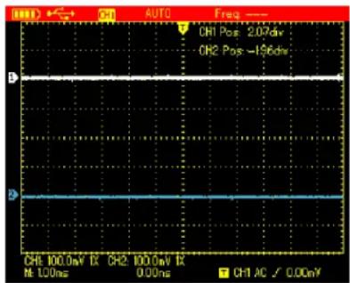
Figure 4-3 Hiding Menus
Making Connections for Probe
Compensation
Connect the signal as follows:
- Connect the probe connector to the
Oscilloscope input terminal and switch probe factor to 10 on the probe
- You also need to set up probe factor on the
Oscilloscope this factor changes vertical scale
UNI-T®
UTD1000L User Manual
and ensures the accuracy for measurements. To set up the probe factor on the Oscilloscope, press CHANNEL button then F3 to set probe factor to 10 ×.
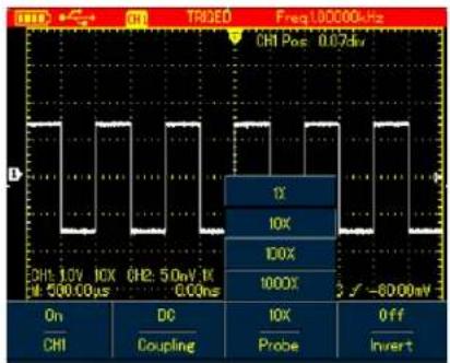
Figure 4 Adjusting Probe Factor
- Conect the probe to the output terminal for probe compensation on the Oscilloscope, press AUTObutton, after several seconds, squarewave displays 1kHz, 3Vpp-Peak to Peak, Value See Figure 4-5.
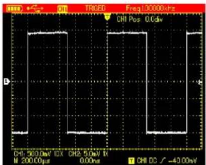
Figure 4-5 Squarewave Signal from the Oscilloscope Itself Compensating the Probe
You need to compensate the probe whenever connecting it to channels for the first time so as to match the probe to the input channel. Uncompensated probe may cause deviation or error to the measurement. To compensate the probe, do the following :
- First of all, set p probe factor on the Oscilloscope to 10 turn the switch to 10 on the probe
UNI-T®
UTD1000L User Manual
then connect the probe connector to the oscilloscope input channel and the probe tip to compensation output terminal ;
- Then execute AUTO
- Observe the displayed waveform

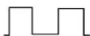
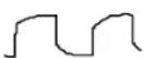
Over compensation correct compensation under compensation
If the displayed waveform is under-or over-compensated as indicated above, use the adjusting tool with non-metal handle to adjust the variable capacitor on the probe until correctly compensated waveform shows.
Warning: To avoid any electric shock when measuring the high voltage with use of the probe, please ensure the probe wire is perfectly insulated, and do not touch any metal part of the probe while connecting to the high voltage source.
Setting Vertical&Horizontal Systems and Trigger Level Manually
Vertical System
Press V \~ mV buttons to adjust the vertical scale(VOLT/DIV) and display waveform with proper size on the screen;
When channel cursor turns solid press Up and Down button to adjust ground reference point that can allow the waveform to display at proper location ;
UNI-T®
UTD1000L User Manual
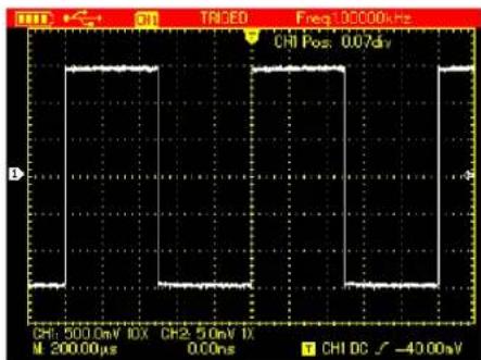
Figure 4-6 Moving Waveforms Vertically Note: Use SELECT button to toggle between vertical position and trigger level.
Horizontal System
Press down s ns buttons to change the timebase and the timebase readout in status bar will vary accordingly. The horizontal scan rate ranges from 5ns-50s/div 10 ns 50s/div for 25MHz bandwidth models) and steps in 1-2-5-
Press Right and Left arrow buttons to adjust the horizontal location of the trigger point which can allows to observe more pretrigger data ;
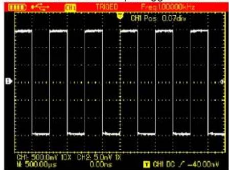
Figure 4-7 Adjusting Horizontal Timebase
UNI-T®
UTD1000L User Manual
Trigger Level Autoset for Waveform Display
When trigger level cursor turns solid use Up and Down arrow buttons to adjust trigger level location.
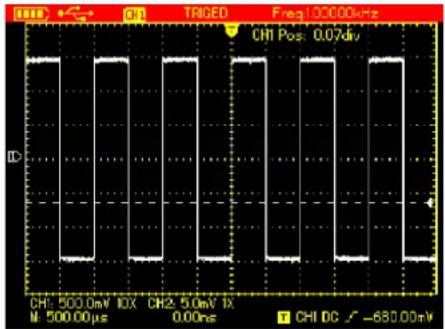
Figure 4-8 Adjust Trigger Level
Note: Use SELECT button to toggle between vertical position and trigger level for the channel. Following chapter will offer more details about the operation mentioned above
UTD1000L Series is designed with autoset function that can automatically adjust the vertical scale, scan timebase and trigger mode based on the input signal until the optimal waveform can be obtained. To apply the autoset function, the tested signal should have a frequency at ≥slant 20Hz and duty cycle > % ;
Under AUTOSET mode, the coupling mode of the channel is closely connected to DC autoset; When DC autset is set to off all signals in the channel is AC-coupled. If DC autoset is on, the channel will choose the current setting as coupling mode, when the current setting is DC coupling, the signal will be DC-coupled and vice versa. For example:
- Input 1kHz 2Vpp sine signal into two channels set coupling mode for both channels to DC, press Shift+UTILITY and then F3 to set
UNI-T®
UTD1000L User Manual
set DC autoset to off. If AUTOSET is applied, the coupling mode is switched to AC mode.
- Input 1kHz 2Vpp sine signal into two channels then set AC coupling for one channel and DC mode to the other When AUT∅SET is applied the coupling modes for both channels keep unchanged.
Full Autoset for Input Signal
UTD1000L can offer creative auto function to capture input signal With this function applied, the Oscilloscope varies ranges accordingly based on the input signal until the proper waveform display can be obtained without any manual interference.
To perform autoset function, do the following:
- Press \$SHIFT button, the shift icon shows on upper right corner of the screen
- Press AUTO button when A icon displays on the screen, autoset function has already turned on;
Note: When the model is UTD1000DL and both of its two channels have signals, the signal from the trigger source channel will be automatically displayed and the other channel will turn off under autoset mode if there is only one channel input with signals this channel signal will be automatically selected and displayed no matter which channel has been chosen as the trigger source.
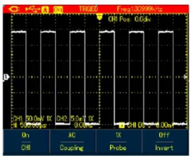
Figure 4-9 Full Autoset
UNI-T®
UTD1000L User Manual
Note: Run/Stop Data Acquisition
- Under autoset mode trigger mode is set to "Aüto. and cannot change
- Once you are in autoset mode following settings are forced to execute :
(1) The Oscilloscope will switch into main timebase status if the current display isn't under this status;
(2)The coupling mode will be set to AC mode and allows no change .
3. Any adjustment on the vertical scale or horizontal timebase of the Oscilloscope that has changed waveform vertical or horizontal location will make the Oscilloscope automatically exit autoset mode.
To stop the data acquisition :
- Press RUN/STOP button, the Oscilloscope stops data acquisition and STOP indicates on the upper display;
- Repress RUN/STOP then the oscilloscope will restart the acquisition .
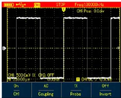
Figure 4-10 Stop Data Acquisition
UNI-T®
UTD1000L User Manual
Setting Frequency Counter
To switch on the frequency counter in models such as UTD1000CL do the following :
-
Press SHIFT button, and shift icon shows on upper right corner of screen ;
-
Press UTILITY button to display utility menu ;
-
Press F3 button to set the frequency counter to "On"
Note: The frequency counter of UTD1000DL defaults at On status
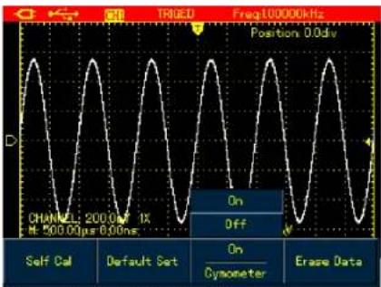
Figure 4-11 1000CL Trigger Frequency Counter
Adjusting Screen Intensity
To adjust the intensity of the screen, do the following :
-
Press SHIFT button, and shift icon shows on upper right corner of screen ;
-
Press ACQUIRE button and select backlight menu;
-
Press F1 to switch on backlight intensity bar ;
-
Press Left and Right arrow buttons to adjust the intensity to proper value;
-
Press F1 to switch off the backlight intensity bar.
Note: Press down AUTO button, the backlight intensity bar will switch off automatically
UNI-T®
UTD1000L User Manual
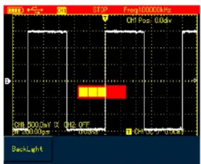
Figure 4-12 Adjusting Backlight Intensity
Saving Bitmap
To save bitmap do the following :
- Press \$HIFT, and shift icon shows on upper right corner of screen ;
- Press OK button, bitmap then will immediately be saved to the internal memory.
Note: through control software loaded in PC, the
bitmaps can be exported to PC in BMP format and be saved up to 10sets.
Using Online Help
To use built-in help information do the following :
- Press \$HIFT and shift icon shows on the right corner of screen ;
- Press HELP button, H icon shows on the upper display, indicating Help function has already turned on;
- Then you can press corresponding menu buttons to check detail information ;
- To turn off this function, repeat Step1 and 2.
UNI-T®
UTD1000L User Manual
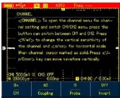
Figure 4-13 Help System
Setting Single Trigger
To set trigger mode to Single directly do the following :
- Press SINGLE button, the Oscilloscope will be set under single trigger mode immediately.
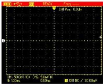
Figure 4-14 Single Trigger
UNI-T®
UTD1000L User Manual
Viewing Oscilloscope Status
To view the current status of the Oscilloscope, do the following :
- Press \$SHIFT button and shift icon shows on upper right corner of screen ;
- Press \$STATUS button, current settings of the Oscilloscope will be displayed on the screen
- To turn off the information repeat Step 1 and 2
Note: Press down AUTO button, status information will then automatically turn off.
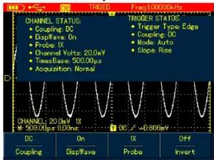
Figure 4 A15TD1000CL Status Information
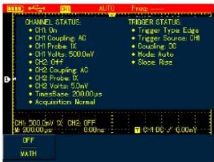
Figure 4-15B UTD1000DL Status Information
UNI-T®
UTD1000L User Manual
Checking Oscilloscope System Information
To check the system configuration of the Oscilloscope do the following :
- Press SHIFT and shift icon shows on upper right corner of screen ;
- Press CONFIGURE button to switch on display configuration menu;
- Press F4 button, then details such as oscilloscope model, version will show on the screen;
- Press F1 button to switch off the displayed window.
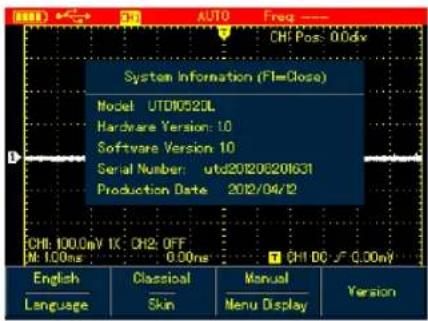
Figure 4-16 System Information
Making Auto Measurements
There are two kinds of auto measurements available in the Oscilloscope Measure all or customized parameters. Maximum 4 parameters can be selected if you want to customize your own measurements.
UNI-T®
UTD1000L User Manual
Measuring All Parameters
To measure automatically all parameters, do the following :
-
Press MEASURE button to display measurement menu;
-
For UTD1000CL press F1 button press F2 for UTD1000DL), then the screen will show measurement results for all parameters.
Note:
1) Switching between different signal sources in UTD1000DL will change the parameters accordingly for channels ;
2) If the signal is input into only one channel of UTD1000DL the rise delay fall delay and phase parameters will not be measured when this channel is chosen as the signal source; or the signal source is set to the channel without signal input, no parameter measurement will be made.
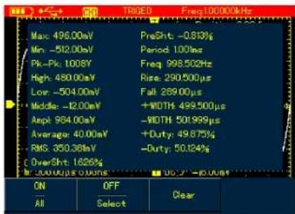
Figure 4-AUTD1000CL measures all parameters
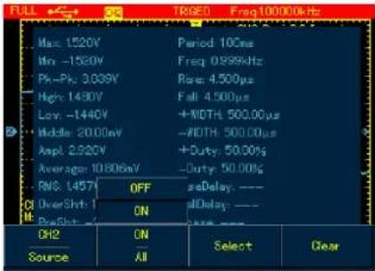
Figure 4-17B UTD1000DL measures all parameters
UNI-T®
UTD1000L User Manual
Measuring Customized Parameters
To measure customized parameters do the following :
- Press MEASURE button to display measurement menu ;
-
For UTD1000CL press F2 button F3 for □ UTD1000DL the screen will display measurement paremeters available for your selection ;
-
Press Arrow Buttons to select the desired parameters, indicated in different color;
- Press SELECT button to confirm, the selected parameter will automatically show on the screen. You can select up to 4 parameters.
- To turn off the menu press F2 in UTD1000CL for F3 in UTD1000DL ). Note: For UTD1000DL use F1 to select signal source to be measured.
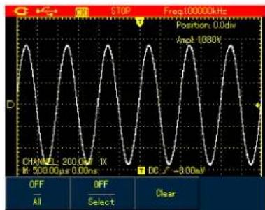
Figure 4 A8JTD 1000 Customized Measurement
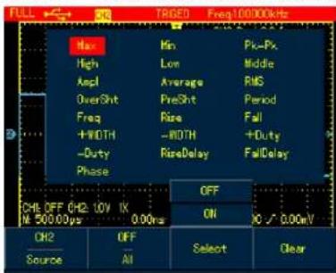
Figure 4-18B UTD1000DL Customized Measurement
UNI-T®
UTD1000L User Manual
Using AVG mode for Smoothing Waveforms
To smooth the waveforms do the following :
- Press ACQUIR button to display sample mode;
- Press F1 button to set sample mode to AVG
- Press Left and Right arrow buttons to set AVG number to 16. Then measurement results will show after the Oscilloscope has averaged the data for 16 times.
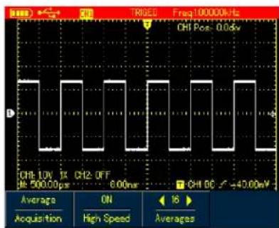
Figure 4-19 Smoothing with 16 times AVG Mode
Using Peak Detect Mode for Pulse Peak Display
This function can be used to display waveforms at 50 ns or wider (Pulse Peak or other asynchronous waveform).
- Press ACQUIR button to display sample mode menu;
- Press F1 button to set sample mode to Peak Detect.
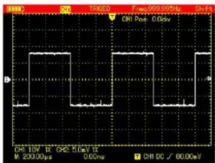
Figure 4-20 Sampling with Peak Detect Mode
UNI-T®
UTD1000L User Manual
Observing Waveforms with use of Persistence Selecting AC Coupling
Select the Persistence function if you want to observe continuously the dynamic signals.
- Press DISPLAY button to show Display Mode menu;
- Keep pressing F4 button to select between 1sec, 3sec, 5sec, Infinite or Auto options If . display mode is set to Infinite dynamic signals will be kept on the screen When set to Auto , the Persistence function will turn on accordingly
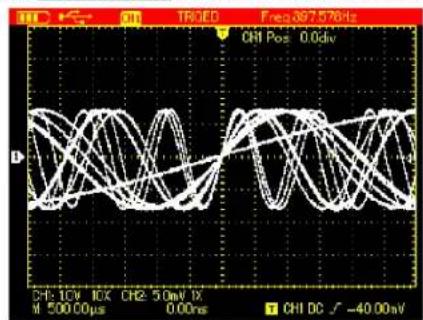
Figure 4-21 Persistent Display for Seconds
The screen displays both AC and DC voltages if the oscilloscope is set under DC coupling. If only the small AC signal mixed in the DC signal is expected to display, please select AC coupling mode. To select AC coupling do the following g:
- Press CHANNEL button to display Channel menu;
- Press F1 button( F2 for UTD1000DL to set Coupling to AC .
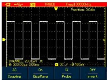
Figure 4-22A UTD1000CL AC Coupling
UNI-T®
UTD1000L User Manual
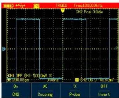
Figure 4-22B UTD1000DL AC Coupling Inverting the Waveform Display
To invert the waveform on the display, do the following:
-
Press CHANNEL button to display Channel menu;
-
Press F4 button to set Invert to on then the waveform on the screen will be displayed reversely.
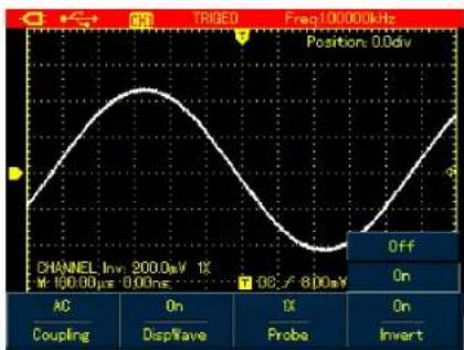
Figure 4-23A UTD1000CL Inverted Waveform
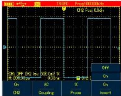
Figure 4-23B UTD1000DL Inverted Waveform
UNI-T®
UTD1000L User Manual
Autoset for Signals with DC Offset
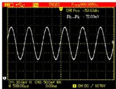
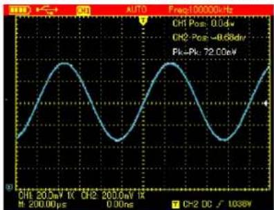
UTD1000L Series is designed with powerful autoset function that makes it possible to perform fast and accurate measurement in DC - coupled mode for signals with any DC component. Position parameter on upper right display of screen: This parameter stands for position readout for the channel reference marker that moves from horizontal central line, if it is positive value, it indicates the channel marker is above the horizontal central line and the negative one is for the marker below the horizontal central line. To work out the final DC offset, first move the waveform to the center of the screen, then multiply the Position value by current amplitude range readout that is final DC offset result you want . For example:
Connect UTD1000CL channel with 70mVpp AC sine signal mixed with 1.1V DC offset, set the channel to DC coupling, then perform AUTO function the waveform in Figure 4 24A will
show on the screen. On the display, Position readout 53.63div indicates the channel reference marker moves 53.63div downward from the horizontal central line The current amplitude range is 20mV/div so, DC offset readout 20mV/div 53×63div =1.0726V
Vpp readout: 72mV means the AC peak to - - peak value of the signal You can also directly read out the DC level through AVG value.
AVG value: 1.0726V which stands for the signal DC level. Through all parameters mentioned above, the signal can be understood very easily. Note: For UTD1000DL models CH1 and CH2 are both set to DC coupling when inputting the signal above then perform the AUTO function after that, also move the waveform to the center of the display(See Figure4-24B and then calculate DC offset with use of Position readout and current amplitude range value).
UNI-T®
UTD1000L User Manual
line
| Parameter | Value | | --------- | --------- | | CHI Pos | -53.63μV | | PIk | 72.00μV | | CHI DC | 1076V |Figure 4-24A UTD1000CL Setup for Signals with DC Offset
line
| Parameter | Value | | --------------- | --------- | | CHI Pos | 0.0dB | | CH2-Pos | -0.68eV | | Fk-Pc | 72.00eV |Figure 4-24B UTD1000DL Setup for Signals with DC Offset
As for traditional oscilloscope, it needs hard work to complete the task, for it has to set the coupling to AC mode first to measure out the AC parameters, and then reset the coupling to DC mode, manually adjust vertical scale and use the cursor to work out DC parameters, see figures as below:
UNI-T®
UTD1000L User Manual
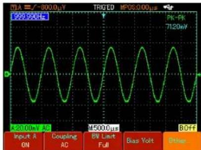
Figure 4 A25 Parameter Measurement
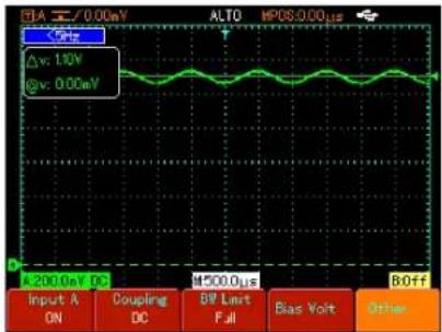
Figure 4-26 DC Parameter Measurement
With the comparison shown above it is very clear that UTD1000L series is designed with a powerful ability to measure signals at much faster speed and in a more visual way.
UNI-T®
UTD1000L User Manual
Chapter 5 Using the Multimeter About the Chapter
This chapter introduces the multimeter functions built in the Oscilloscope; examples are also offered to illustrate how to use the menus and the basic measurements. To switch from Oscilloscope mode to Multimeter mode press DMM DSO button to access DMM mode, the display screen will change into multimeter interface accordingly.
Connections to the Multimeter
UTD1000CL provides three multimeter input terminals COM matched to A/min banana plugs of test leads. One 10A current divider UT-M07 is also used in the measurements.
UTD1000DL has two multimeter input terminals COM, matched to 4-mm banana plugs of test leads One UT M04 (4A current divider) and one UT-M10 mA current module are also
offered to use in the measurements
Display Indicators
Description:
- Battery Indicator
- AUTO Autoset indicator
- Indicators for Measurement Types: DC Voltage Measurement AC Voltage Measurement DC Current Measurement AC Current Measurement Resistance Measurement Diode Test
Continuity Test Capacitance Measurement
-
Relative Measurement
-
working statusIndicator HOLD Freeze the display
-
Main Display for Measuring Values
-
Manual Ranging Indicator
UNI-T®
UTD1000L User Manual
Making Multimeter Measurements
Press DSO/ DMM button to access DMM mode, the display then enters into the multimeter interface. Multimeter functions are ready to use at the moment.
Measuring Resistance
To measure resistance do the following:
- Press down R button to set measurement type to Resistance.
- Plug test lead connectors into multimeter input terminals Black to COM and Red to V/Ω).
- Connect test leads respectively to the resistor under test, then take resistance readings.
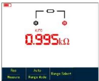
Figure 5-1 Measuring Resistance
UNI-T®
UTD1000L User Manual
Testing Diodes Testing for Continuity
To test the diode do the following :
- Press R button to set the measurement type to Resistance.
- Press F1 button to select Diode option.
- Plug test lead connectors into multimeter input terminals (Black to COM and Red to V/Ω). V/Ω
- Connect test leads to the tested diode, then forward voltage drop reading for the diode displays accompanied by the measurement unit V.
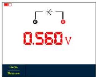
Fgiure 5-2 Testing Diode
To check the continuity do the following :
- Press R to set the measurement type to Resistance.
- Press F1 button to select Continuity
- Plug test lead connectors into multimeter input terminals (Black to COM and Red to ).
- Connect test leads to tested points The . multimeter will beep if tested resistance between tested points is lower than 70 .
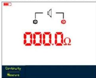
Figure 5-3 Testing for Continuity
UNI-T®
UTD1000L User Manual
Measuring Capacitance
To measure capacitance do the following :
- Press R to set the measurement type to Resistance.
- Press F1 button to switch measurement type to Capacitance.
- Plug test lead connectors into multimeter input terminals (Black to COM and Red to V/Ω).
- Connect test leads to the capacitor under test, then take the reading.
Note: To ensure the accuracy, please use the relative mode if test capacitance is <5 nF.
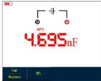
Figure 5-4 Measuring Capacitance
Measuring DC Voltage
To measure DC voltage do the following :
- Press down V button to set measurement type to DC Voltage.
- Plug test lead connectors into multimeter input terminals (Black to COM and Red to V/Ω).
- Connect test leads respectively to tested points, then take DC voltage reading.
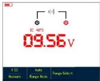
Figure 5-5 Measuring DC Voltage
UNI-T®
UTD1000L User Manual
Measuring AC Voltage Measuring DC Current with UTD1000CL
To measure AC voltage do the following :
- Press ☑ button to set measurement type to DC Voltage.
- Press F button to select AC Voltage option.
- Plug test lead connectors into multimeter input terminals (Black to COM and Red to V/Ω).
- Connect test leads respectively to tested points, then take AC voltage reading.
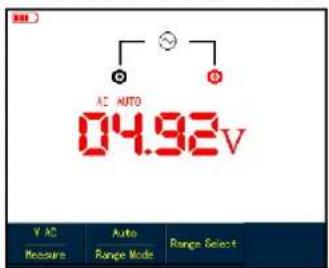
Figure 5-6 Measuring AC Voltage
To measure DC current lower than 4mA, do the following :
- Press ☐ button to set measurement type to DC Current, measurement unit is μA, you can use F3 to toggle between μAmA and A ranges the default is mA
- Plug test lead connectors into input terminals (Black to COM and Red to A /mA)
- Connect test leads to tested points then take DC current reading .
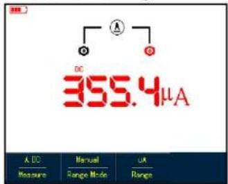
Figure 5-7 Measuring DC Current lower than 4mA
UNI-T®
UTD1000L User Manual
To measure DC current lower than 400mA, do the following :
- Press I button to set measurement type to DC Current.
- Press F3 button to select mA range, and measurement unit will be mA .
- Plug test lead connectors into input terminals (Black to COM and Red to mA/A / )
- Connect test leads to tested points then, take DC current reading.
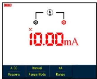
Figure 5-8 Measuring DC Current lower than 400mA
To measure DC current greater than 400mA, do the following:
- Press I button to se measurement type to DC Current.
- Press F3 button to select A range, the measurement unit will change into A accordingly.
3.Plug10A Current divider module U ( T-M07 into input terminalsCOM and mAuMen), connect black and red test lead connectors respectively to the module UT-M07) - Connect test leads to tested points than, take the DC current reading .
Warning: If test leads are connected to COM and A / mA without use of 10A Current divider module UT-M07 when measuring current greater than 400mA , the fuse in the product will be burnt out. Please have the fuse replaced by qualified personnel if the incident happens
UNI-T®
UTD1000L User Manual
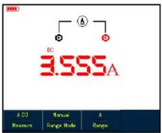
Figure 5-9 Measuring DC Current Greater Than 400mA Measuring AC Current with UTD1000CL
To measuring AC current lower than 4mA :
-
Press I button to set measurement type to AC Current the measurement unit is You μA, can use F3 button to select between μA, mA and A ranges the default is μA.
-
Plug test lead connectors into input terminals (Black to COM and Red to A / mA)
-
Connect test leads to tested points then, take the AC current reading.
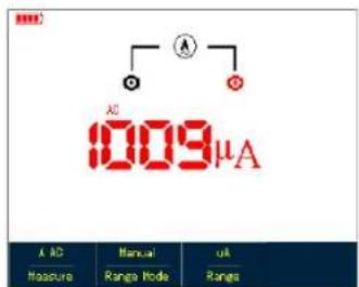
Figure 5-10 Measuring AC Current Lower Than 4mA To measure AC current lower than 400mA, do the following:
- Press ☐ button to set measurement type to AC Current,
- Press F3 button to select mA range, and the measurement unit will show mA accordingly
- Plug test lead connectors into input terminals (Black to COM and Red to mAA / ).
- Connect test leads to tested points, then take the AC current reading .
UNI-T®
UTD1000L User Manual
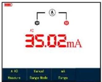
Figure 5-11 Measuring AC Current Lower than 400mA
To measure AC current greater than 400mA, do the following :
- Press I button to set measurement type to AC Current,
- Press F3 button to select A range, and the measurement unit will change into A accordingly.
- Plug 10ACurrent divider module(UT-M07 into Input terminalsCOM and mAuthen,
insert black and red test leads properly into the module
- Connect test leads to tested points then, take the AC current reading .
Warning: If test leads are connected to COM and without Ause of 10A Current divider module UT-M07 when measuring current greater than 400mA, the fuse in th e product will be burnt out Please have the fuse replaced by qualified personnel if the incident happens
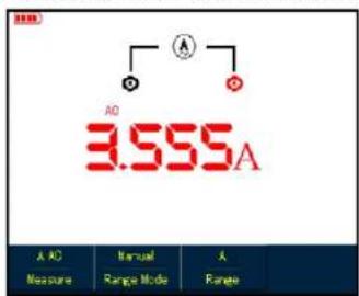
Figure 5-12 Measuring AC Current Greater than 400mA
UNI-T®
UTD1000L User Manual
Measuring DC Current with UTD1000DL
To measure DC current equal to or lower than 1mA, do the following:
-
Press button to set measurement type to DC Current the measurement unit is you pan use F3 to toggle between mA and A ranges the default is mA
-
Plug mA current module (UT-M10) into input terminals COM and then turn the switch on the module to uA range .
-
Insert black and red test leads correspondingly into Black and Red terminals on the module
-
Then connect test leads to tested points than take the DC current reading .
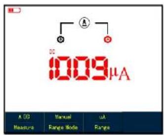
Figure 5-13 Measuring DC Current Equal to or Lower than 1mA
UNI-T®
UTD1000L User Manual
To measure DC current within 1mA 40mA do the following :
- Press I button to set measurement type to DC Current.
- Press F3 to select mA range the measurement unit will change into mA accordingly.
- Plug mA current module (UT-M10) into input terminalsCOM and the Vourn the switch on the module to 40mA range .
- Insert black and red test leads correspondingly into Black and Red terminals on the module.
- Then connect test leads to tested points than take the DC current reading .
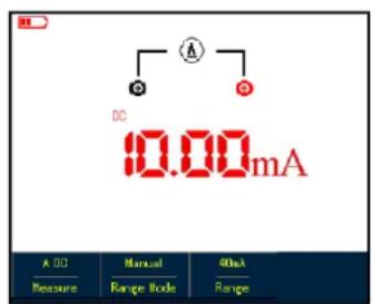
Figure 5-14 Measuring DC Current Lower than 40mA
UNI-T®
UTD1000L User Manual
To measure DC current within 40mA-400mA do the following :
-
Press [button] to set measurement type to DC Current.
-
Press F3 to select mA range, and the measurement unit will display mA accordingly.
-
Plug mA current module (UT-M10 into input terminalsCOM and then turn the switch on the module to 400mA range
-
Insert Black and Red test leads correspondingly into Black and Red terminals on the module.
-
Then connect test leads to tested points than take the DC current reading .
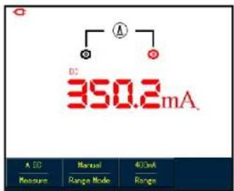
Figure 5-15 Measuring DC Current within 40mA-400mA
UNI-T®
UTD1000L User Manual
To measure DC current greater than 400mA do, the following :
- Press I button to set measurement type to DC Current.
- Press F3 to select A range, and the measurement unit will display A accordingly.
- Plug 4A current module UT-M04 into input terminals COM and then , insert test leads properly into the module.
- Connect test leads to tested points, then take DC current reading.
Warning: If test leads are directly connected to V/Ω and COM terminals without use of 4A current module UT-M04 when measuring the current greater than 400mA the fuse in the product will be burnt out Please have the fuse replaced by qualified personnel if the incident happens.
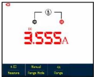
Figure5-16 Measuring DC Current Greater than 400mA
UNI-T®
UTD1000L User Manual
Measuring AC Current with UTD1000DL
To measure AC current equal to or lower than 1mA, do the following :
-
Press I button to set measurement type to AC Current the measurement unit is You μA. can use F3 button to select between mAμA, and A ranges the default is μA.
-
Plug mA current module (UT-M10 properly into input terminals COM and the W/Orn the switch on the module to uA range
-
Insert Black and Red test leads correspondingly into Black and Red terminals on the module.
-
Connect test leads to tested points, then take the AC current reading.
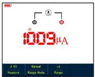
Figure 5-17 Measuring AC Current Equal to or Lower than 1mA
UNI-T®
UTD1000L User Manual
To measure AC Current within 1mA-40mA, do the following :
- Press I button to set measurement type to AC Current,
- Press F3 to select mA range, the measurement unit will change into mA accordingly.
2.Plug mA current module UT-M10 properly into input terminals COM and the W/turn the switch on the module to 40mA range Insert Black and Red test leads correspondingly into Black and Red terminals on the module. - Connect test leads to tested points, then take the AC current reading.
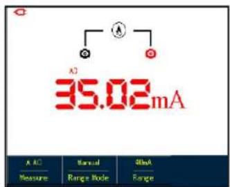
Figure 5-18 Measuring AC Current Lower than 40mA
UNI-T®
UTD1000L User Manual
To measure AC Current within40mA-400mA do the following :
- Press I button to set measurement type to AC Current,
- Press F3 to select mA range, the measurement unit will change into mA accordingly.
- Plug mA current module (UT-M10) properly into input terminals COM and then, turn the switch on the module to 400mA range .
- Insert Black and Red test leads correspondingly into Black and Red terminals on the module.
- Connect test leads to tested points, then take the AC current reading.
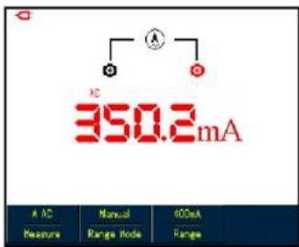
Figure 5-19 Measuring AC Current within40mA-400mA
UNI-T®
UTD1000L User Manual
To measure AC Current greater than 400mA, do the following :
- Press I button to set measurement type to AC Current,
- Press F3 to select A range, the measurement unit will change into A accordingly.
- Plug 4A current divider module (UT-M04) properly into input terminals COM and V/Ω, then insert Black and Red test leads correspondingly into the module.
- Connect test leads to tested points, then take the AC current reading.
Warning: If test leads are connected to V/Ω and COM terminals without use of 4A current module UT-M04 when measuring the current greater than 400mA, the fuse in the product will be burnt out. Please have the fuse replaced by qualified personnel if the incident happens.
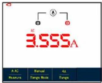
Figure 5-20 Measuring AC Current Greater than 400mA
UNI-T®
UTD1000L User Manual
Data Hold Making Relative Measurement
You can freeze the displayed readings any time as you want.
- Press RUN/STOP to freeze measuring values and HOLD icon blinks on the display.
- Repress RUN / STOP to restore the measurement.

Figure 5-21 Freezing Measurement Values
Relative measurement displays a current measuring result relative to the specific reference value.
Refer to capacitance measurement in relative mode. First of all you need to obtain a reference value:
- Press R button to set measurement type to Resistance.
- Press F1 button to select Capacitance option
- Connect test leads to input terminals (Black to COM and Red to V/Ω)
- Wait until the reading becomes stable, then press F2 button to access the relative mode, △ icon shows on the upper display and the reference value appears just below icon △
- Connect test leads to the capacitor under test, then take capacitance reading on the display
UNI-T®
UTD1000L User Manual

Figure 5-22 Measuring Capacitance in Relative Mode
Selecting Manual Auto Ranging
The multimeter defaults at auto mode. To access manual ranging, operate as follows:
- Press V or R button, and measure mode option is AUTO.
- Press F2 to select manual measure mode then the ranging mode will change into Manual
status accordingly.
- Under manual ranging mode, keep pressing F3 button to reach up to the highest range, after that, then the selected range jumps directly to the lowest range and circulates again. The currently selected range shows just above measuring readings.
- Press F2 button, Auto icon shows on left upper display in dicating the multimeter has returned to full autoset mode .
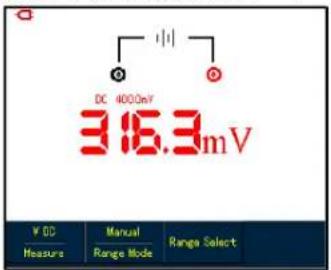
Figure 5-23 Manual Ranging
UNI-T®
UTD1000L User Manual
Chapter 6 Using the Oscilloscope in Details
About the Chapter
This chapter offers a step-by-step introduction on UTD1000L Series functions Detail information about functional buttons on the front panel and operation examples are included here. It is recommended that you should read through this chapter in order to get more and systematic knowledge of the Oscilloscope.
Setting Vertical System
UTD1000CL Channel Setup
The channel is designed with independent setup menu, press CHANNEL button to display the operating menu shown as below:
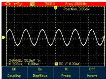
Figure 6-1A Channel Setup Menu
UNI-T®
UTD1000L User Manual
See Channel Menu in Following Table:
Table 6-1A
| Coupling | DCACGround | AC&DC components passDC component is blockedDisplay DC level when the channel input terminal is equivalently grounded |
| Wave Display | OnOff | To display the channel waveformTo turn off the channel waveform display |
| Probe Factor | 1×10×100×1000× | Select one of them to match to the probe, to ensure accurate reading.Four types are available:1 18 100 1000 ×、×. |
| Invert | OffOn | To display the waveform normally.To invert the waveform display |
UNI-T®
UTD1000L User Manual
Moving Waveform Vertically
When UTD1000CL channel marker turns solid press Up and Down arrow buttons to move the waveform vertically.
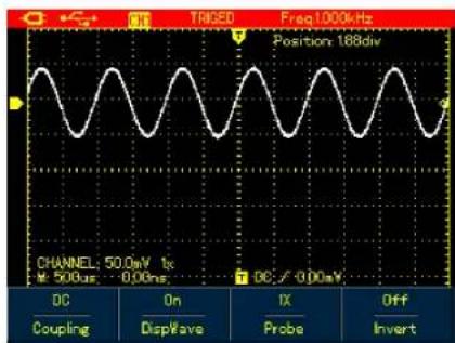
Figure 6 2A Moving Waveform Vertically
Note: if the channel marker is internally empty press SELECT button to access the solid status before moving the waveform vertically.
Setting waveform display
Open the channel menu, and then press F2 button to turn on/off waveform display
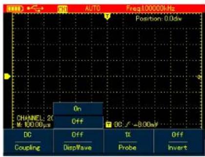
Figure 6 3A Turn off Waveform Display
UNI-T®
UTD1000L User Manual
Set Probe Factor UTD1000DL Channel Setup
To match with the probe factor on the probe, you need to set up corresponding factor in channel menu. For example, the probe factor is 10:1, please set Probe option in the menu to 10 ×. Do the same setting for other selected probe factor in order to ensure accurate voltage reading.
Under channel menu, press F3 under channel menu to set up probe factor . Probe Attenuation Factor VS Menu Option, see following table:
Table 6-2A
The channels have their own setup menus. Repeat pressing CHANNEL to toggle between CH1 and CH2 menus and display corresponding menu options as shown below:
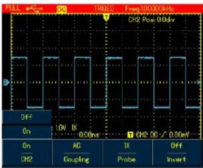
Figure 6-1B Channel Menu Se tup
UNI-T®
UTD1000L User Manual
Please see channel menu in the following table:
Table 6-1B
| Channel | OffOn | Turn off CH1 or CH2 waveformTurn on CH1 or CH2 waveform |
| Coupling | DCACGND | AC&DC components passDC component is blockedDisplay DC level when the channel input terminal is equivalently grounded |
| ProbeFactor | 1×10×100×1000× | Select one of them to match to the probe, to ensure accurate reading.Four types are available : 1×0.100×1000 ×、 × . |
| Invert | OffOn | To display the waveform normally.To invert the waveform display |
UNI-T®
UTD1000L User Manual
1.Moving Waveform Vertically Setting Waveform Display
Use Up and Down buttons to move the current waveform vertically when the channel marker becomes solid. If you want to move the waveform from another channel, please press CHANNEL button again before moving the waveform.
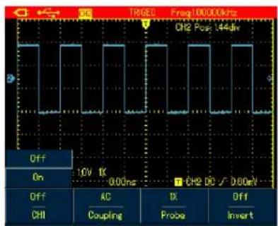
Figure 6-2B Moving Waveform Vertically
Press CHANNEL button to toggle between different channels. In the channel menu press F1 submenu button to turn on/off the waveform of the current channel. In order to on/off another channel waveform, you need to press CHANNEL button again before pressing F1 button
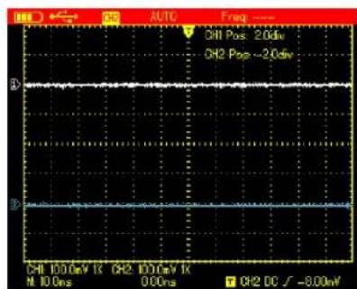
Figure 6-3B Turn on Waveform Display for Dual Channels
UNI-T®
UTD1000L User Manual
Setting Probe Factor
To match with the probe factor on the probe, you need to set up corresponding factor in channel menu. For example, the probe factor is 10:1 , please set Probe option in the menu to 10 ×. Do the same setting for other selected probe factor in order to ensure accurate voltage reading .
Under channel menu, press F3 to set up probe factor To set up probe factor for another channel please press CHANNEL again and then the F3 button.
Probe Attenuation Factor VS Menu Option, see following table:
Table 6-2B
Press s/ns button slow down or speed up the scan rate from 10ns or 5ns/div 50s/div . Notes: For 25MHz bandwidth models 10ns/div \~ 50s/div 50MHz bandwidth Models 5ns/div: \~ 50s/div .
Moving Waveforms Horizontally
Press Left and Right buttons to adjust pretrigger depth. The trigger location is usually set at horizontal center on the screen. With the adjustment you can observe div pretrigger and delay data Through moving the waveform horizontally, more trigger information can be viewed, which let users know more about pretrigger situation. For instance, by observing and analyzing pretrigger data of glitches occurring in circuit start up you can trace down the cause to the glitches .
UNI-T®
UTD1000L User Manual
Press HORIZONTAL button to switch on horizontal menu refer to the following figure
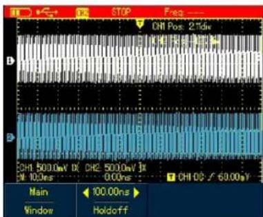
Figure 6-4 Horizontal Setup Menu
There are two options in horizontal menu: Window and Hold-Off
Zooming in out Waveforms
Switch on horizontal menu and press F1 button to zoom in one segment of the waveform. The timebase for expanded window shouldn't be lower than that of main window. Note: Timebase faster than 100ns cannot enter into expanded window
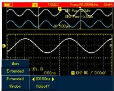
Figure 6-5 Screen Display under Window Zoom
UNI-T®
UTD1000L User Manual
Under window zoom function there are two separate display zones as indicated in the figure above. The upper part is for the original waveform. Press OK button and then use Left and Right buttons to select the waveform to be expanded on the left or right, or enlarge or narrow down the selected zone with s/ns button .
The lower display is for the expanded waveform corresponding to the selected original zone. One point worth mentioning is that compared with the main timebase, the expanded timebase has improved the resolution for the waveform display (See Figure 6-5). Since the displayed waveform cor responds to the selected zone of upper part, using s ns button to narrow down the selected zone can enable the expanded waveform to have better timebase namely a higher waveform amplification factor in a horizontal direction.
Adjusting Trigger Hold Off
Switch on horizontal menu, use Right and Left buttons to adjust hold-off time (100ns-1.5s It) can be applied to observe complex waveforms (eg: burst). Hold-off time is to adjust data acquisition period of the oscilloscope to stay in a integral multiple related to the period of complex waveform so that the Oscilloscope and complex waveform can synchronize. For example, apply tested combined signals into Ch1. Press HORIZONTAL to turn on horizontal menu, then press Right and Left buttons to adjust the hold-Off time until displayed waveform become stable See Figure 6-6 :
UNI-T®
UTD1000L User Manual
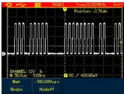
Figure 6-6 Trigger Hold Off
Note:
- The trigger hold-off time can be adjusted only when horizontal menu displays.
- Generally hold-off time is a little smaller than "Big Period for instance for RS232 communication signal waveform hold off - time should be a little larger than start edge time of each frame in order to easily observe the waveform .
Setting Trigger System
Trigger system determines when the Oscilloscope starts to acquire data and display waveforms. Once the trigger is properly set, the Oscilloscope can transform unstable signal into meaningful waveform. When the acquisition starts the Oscilloscope continuously acquires enough data to fill the pretrigger portion that is displayed to the left of trigger point. Then the trigger occurs, the Oscilloscope will continue to acquire enough data to fill the posttrigger waveform to the right of trigger point. [TRIGGER] button is designed to set up the Oscilloscope trigger functions.
TRIGGER Trigger menu button Trigger Level: to set up signal voltage that corresponds to the trigger point.
Press TRIGGER button to turn on trigger menu as indicated in the figure below, then press F1 button to switch between different trigger types. Press F2 to select trigger source.
UNI-T®
UTD1000L User Manual
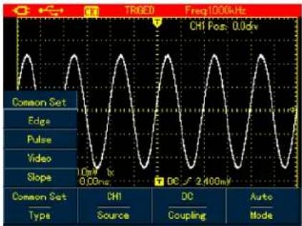
Figure 6-7 Trigger Menu
Trigger Controls
Four trigger types are available: edge, video, pulse width and slope, every of which is coupled with different functional menu There is still one type common setting used to set up trigger source, trigger coupling and trigger modes.
Edge Trigger: Trigger on rising or falling edge You can adjust trigger level to change vertical
location on the edge for trigger point that is the cross point between trigger level line and the signal edge on the screen.
Pulse Width Trigger: Trigger when the pulse width of trigger signal reaches up to preset trigger conditions.
Video Trigger: Trigger on fields or lines of standard video signal.
Slope Trigger: Use the rise or fall speed rate of the signal as trigger condition . Check details for different kinds of trigger menus
UNI-T®
UTD1000L User Manual
Common Setting
Common Setting is used to set up common trigger items, refer to the table below for details:
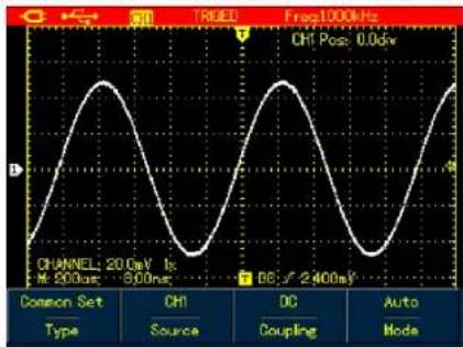
Figure 6-8 Trigger -- Common
Table 6-3
| Menu | Settings | Description |
| Type | Common | to set up common trigger items |
| Source | CH1CH2 | Set CH1 satrigger sourceSet CH2 as trigger source |
| Coupling | ACDCHF Reject | DC component is blockedDC &AC components passReject high frequencycomponent 80kHz |
| Mode | AutoNormal | The Oscilloscope automatically acquires data when no trigger signal has been detected.Acquire waveform only when the trigger condition is met; |
Note:
To set up the common setting, shortcuts are also available to execute the operation:
-
Press SHIFT button, Shift icon displays on right upper corner of the screen;
-
Press F1 F2 F3 F4 button to display common setting menu.
UNI-T®
UTD1000L User Manual
Edge Trigger
Edge trigger is to trigger on trigger threshold value of signal edge. Please see the table below for edge trigger menu :
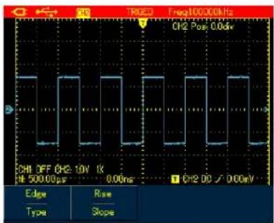
Figure 6-9 Trigger-Edge Type
Table 6-4
| Menu | Settings | Description |
| Type | Edge | Set trigger Type to Edge |
| Slope | Rise | Set to trigger on rise edge of signal. |
| Fall | Set to trigger on fall edge of signal. |
UNI-T®
UTD1000L User Manual
Pulse Width Trigger
It determines the trigger time based on pulse width, which helps you to capture abnormal pulse by setting specific pulse width conditions.
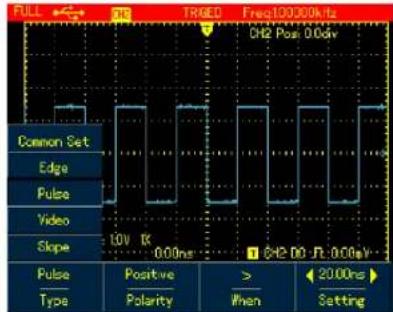
Figure 6-10 Trigger Pulse Wdith Type
Table 6-5
| Menu | Settings | Description |
| Type | Pulse Width | Set trigger Type to Pulse Width |
| Polarity | Positive Negative | Set positive pulse width as trigger signal. Set negative pulse width as trigger signal. |
| Qualifier | = < > | Trigger when input pulse width equals to set value; Trigger when input pulse width is less than set value; Trigger when input pulse width is greater than set value; |
| Time | --- | To set up pulse width time value,use Left and Right arrow buttons to set the value when the menu is displayed. |
UNI-T®
UTD1000L User Manual
Video Trigger
Trigger on fields or lines of NTSC or PAL standard signals if video trigger is selected
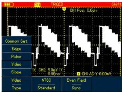
Figure 6-11 Trigger Video Type
Table 6-6
| Menu | Settings | Description |
| Type | Video | Set trigger Type to Video . |
| Format | PALNTSC | Trigger on PAL format video signal .Trigger on NTSC format video signal . |
| Syn | All LinesOdd FieldEven Field | Trigger synchronically on all lines.Trigger on odd fields.Trigger on even fields . |
UNI-T®
UTD1000L User Manual
Slope Trigger
Trigger occurs only after rise or fall speed rate meets set value.
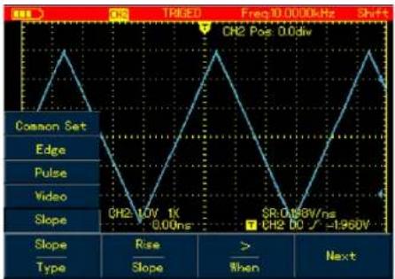
Figure 6-12 Trigger Slope Type (Page 1)
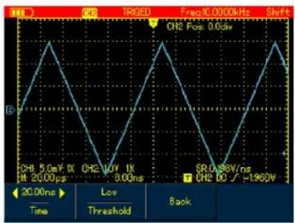
Figure 6-13 Trigger Slope Type Page(2)
UNI-T®
UTD1000L User Manual
Table 6-7
| Menu | Settings | Description |
| Type | Slope | Set trigger Type to Slope |
| Slope Type | RiseFall | Trigger on rising edge that traverse between thresholds.Trigger on falling edge between thresholds |
| Qualifier | > | Trigger When the slope is greater than the set value of slew rate. |
| < | Trigger When the slope is less than the set value of slew rate. | |
| = | Trigger When the slope equals to the set value of slew rate. | |
| Next | ---- | Page 2 of Slope Menu |
| Slew Rate | ---- | To set up slew rate value, use Left and Right arrow buttons to pulse width time when the menu is displayed. |
| Threshold | LowHighLow&High | Use Up and Down buttons to move low-level thresholdUse Up and Down buttons to move High-level thresholdUse Up and Down buttons to move low-and high-level thresholds. |
| Back | ---- | To return to Page 1 of Slope Menu. |
UNI-T®
UTD1000L User Manual
Term Explanation
- Trigger Source Input channel is used as the trigger source
■ Input Channel: Input channel (CHI) is the most commonly used trigger source. For the channel selected as the trigger source, it should be switched on before it works normally.
2. Trigger Mode: decide what the oscilloscope will do when no trigger event occurs. Three trigger modes are offered: Auto, Normal and Single.
■ Auto: The system automatically acquires data even there is no signal input and therefore displays scan reference line on the screen; when the trigger occurs it converted into trigger scanning and synchronizes with the signal on its own . Note: The Oscilloscope will go into SCAN mode if waveform scan rate is set at 50ms/div or lower timebase.
■ Normal : Under this mode, the Oscilloscope
acquires the waveform only after the trigger conditions are met. It stops to acquire and keeps waiting if no signal is input Once the trigger occurs, the scan starts.
■ Single: You just need to press RUN button if under single mode then the Oscilloscope waits to trigger. It begins to acquire and display all acquired waveforms once single-shot trigger signal is detected, after that, it stops
3. Triggered Coupling which kind of components through the trigger circuits The types include: DC, AC and Hf Reject.
■ DC: passes through all components of the signal
■ AC blocks DC component and attenuate signals at 10Hz
■HF Reject: attenuates high frequency component at 80kHz
UNI-T®
UTD1000L User Manual
- Pretrigger/Delay Trigger : Capture data before /after the trigger event The trigger is usually located at the horizontal center point on the screen, for example, you can observe 6div pretriger and delay information adjusting the waveform horizontally can let you view on more pretrigger information Pretrigger can indicate what the waveform is like before the trigger event. So this function can make it easy, for instance, to find out the cause of glitches in start moment of circuits through observing and analyzing pretrigger data .
Setting Acquisition Mode
Press ACQUIRE button to access acquisition mode, see the following table :
Table 6-8
| Menu | Settings | Description |
| Mode | NormalPeak DetectAVG | Set to normal samplingSet to Peak Detect modeSet to AVG sampling mode |
| AVG Number(only displayec under AVG mode) | 2 256 | To set AVG times stepping in multiples of two, that is from 2,4 8 , 16,32 64 128 256 to 512,turnLeft and Right arrow buttons to change average times in displayed menu . |
Note:
- Use no rmal mode when you observe single shot signal.
- Please select Peak mode if you want to observe signal envelope and also to avoid any mix-up
UNI-T®
UTD1000L User Manual
Term Explanation
Normal Mode: The Oscilloscope samples the signals at equal time interval to create the waveform on the display.
Peak Detect: Under this mode, the Oscilloscope uses Max. and Min. values detected in each sampling interval to form waveform on the display It is suitable to capture and display narrow pulse which may probably be neglected if using Normal mode. However the noise under Peak Detect sounds louder.
AVG Mode: The Oscilloscope captures certain numbers of waveforms and calculates their average values that will be used to form waveforms on the display. This mode can reduce random noise
Fast Acquisition: it only acquires points for Min memory dep th required for display which can shorten the hold off time between each acquisition and realize superb capture rate It can significantly increase the possibility to find out rarely seen issue.
Setting the Display
Press DISPLAY button to access display menu, please refer to the follow table:,
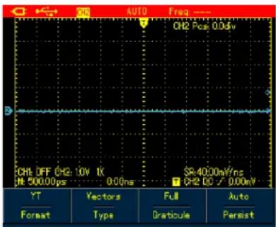
Figure 6-14 Waveform Display Setup
UNI-T®
UTD1000L User Manual
Table 6-9
| Menu | Settings | Description |
| Format | YTXY | To display relationship between voltage(vertical) and time(Horizontal).X-Y display mode using Ch1 signal to form X axis and Ch2 signal for Y axis (applicable only for dual channel model ) |
| Format | VectorDots | Connect sample dots and displayDirectly display sample dots |
| Graticule | FullGridCross Hair | To set the graticule of waveform display zone to Full, Grid and Cross Hair mode |
| Persist | Off1s3s5sInfinite | Update the waveforms at normal rate.Update after waveform data is hold for 1 second.Update after waveform data is hold for 3 seconds.Update after waveform data is hold for 5 seconds.Waveform data is kept on the screen, new data, if any co be added into the disp lay continuously. |
UNI-T®
UTD1000L User Manual
Term Explanation:
Display Format: VECTOR Display fills out all blanks between neighboring points DQT Display just shows sample points .
Update Rate: The times that the oscilloscope updates the waveforms per second. it reflects how fast the Oscilloscope could allow you to observe signal dynamic change.
Y-T Mode In this mode Y axis represents voltage and X axis for the time
Slow Scan Mode: When the timebase is set at 50ms/div or lower the Oscilloscope will enter into slow scan mode This mode is applied to observe low frequency signal It is recommended that channel coupling is set to DC.
Setting Auto Measurements
The section below introduces in details the powerful auto measurement function owned by the Oscilloscope Press MEASURE button to open auto measurement menu, see the table below:
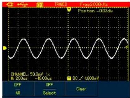
Figure 6-15A UTD1000CL Auto Measurement Menu
UNI-T®
UTD1000L User Manual
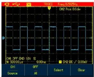
Figure 6-15B UTD1000DL Auto Measurement Menu
Table 6-10
| Menu | Settings | Description |
| Source | CH1 | Select CH1 as the signal source. |
| CH2 | Select CH2 as the signal source. | |
| All | ON | To measure all parameters. |
| OFF | Turn on auto measurement function. | |
| Select | ON | To select the parameters to be measured by using SELECT button.The selected parameter will be displayed on the screen. Max.4 items can be chosen at a time . |
| OFF | Turn off customized parameter selection box | |
| Clear | ---- | To clear the displayed customized parameter |
UNI-T®
UTD1000L User Manual
Case 1: To display all measurement parameters of the displayed channel, do the following :
- Press MEASURE button to open parameter measurement menu :
- Press F1 of UTD1000CL F2 of UTD1000DL to set All option to On ;
Then all measurement parameters display on the screen. See the Figures below:
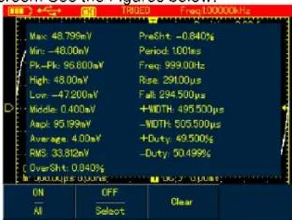
Figure 6-16A UTD1000CL measures all parameters
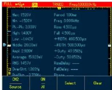
Figure 6-16B UTD1000DL measures all parameters
Case 2: To measure Vpp and Amplitude parameters do the following :
- Press MEASURE to open parameter measurement menu ;
- Press F2 of UTD1000CL F2 of UTD1000DL button to open parameter selection box ;
- Press Arrow Buttons t o select Vpp parameter
UNI-T®
UTD1000L User Manual
- With Vpp parameter chosen press SELECT
to confirm and one marker will appear on the front of Vpp parameter to indicate it has been successfully selected the parameter will show on the display accordingly.
5.Do the same to select Amplitude parameter - Press SELECT to confirm one marker also show on the front of Amplitude parameter and then the parameter displays on the screen.
- Press F2 of UTD1000CL F3 of UTD1000DL
to turn off parameter selection box ; See the following figures for Vpp and Amplitude parameters displayed on the upper right part of screen:
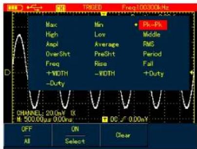
Figure 6-17 Select Vpp Parameter
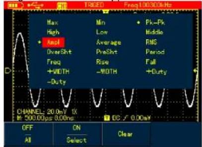
Figure 6-18 Select Amplitude Parameter
UNI-T®
UTD1000L User Manual
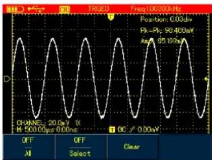
Figure 6-19 Display Selected Parameters Note: Parameter selection is to measure parameter immediately. There are 19 types of parameter measurements for UTD1000CL and 22 types available in UTD1000DL Under general circumstances not all parameters but just some of them are required to be measured. Therefore the users can customize their measurements as expected. The software can select up to 4 parameters displayed on the screen.
Auto Parameter Measurements
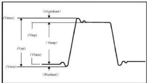
Figure 6-20 Voltage Measurement The voltage parameters that the Oscilloscope can automatically measure include: Maximum Value (Vmax) : Voltage measured from the highest point of waveform to the zero ground Minimum Value Vmin) : Voltage measured from the lowest point to the ground Top Value (Vtop) : Voltage measured from the flat top to the ground.
UNI-T®
UTD1000L User Manual
Base Value (Vbase) : Voltage measured from the base of the waveform to the ground
Middle Value (Vmid) : a half of amplitude value
Peak-to-Peak Value (Vpp): Voltage measured from the highest point to the lowest point of waveform
Amplitude (Vamp) : Votage measured from the top to the base of the waveform
Overshoot: (Maxi/Top Amplitudex100%
Preshoot : (Min-Low)/Amplitudex100%
Average Value : The arithmetic mean over one cycle in the waveform
RMS Value (Vrms) : Effective value, the root mean square voltage over one cycle in AC signal waveform that corresponds to DC voltage with equal generated energy calculated in this cycle.
line
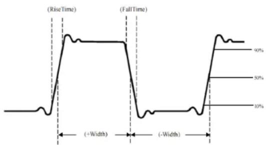
| Time Phase | Value | | ---------- | ----- | | RiseTime | 90% | | FallTime | 10% | | Width | -80% |Figure 6-21 Time Measurement
UNI-T®
UTD1000L User Manual
The time parameters the Oscilloscope can automatically measure contain:
RiseTime : The time required to rise from 10% to 90% of waveform amplitude .
FallTime : The time required to fall from 90% to 10% of waveform amplitude .
Positive Pulse Width (Width):
The distance between the mid 50% amplitude points of a positive pulse .
Negative Pulse Width (Width):
The distance between the mid (50%) amplitude points of a negative pulse.
Rising Delay: The delay time between rising edges from A to B
Falling Delay: The delay time between falling edges from A to B
Positive Duty Cycle (Duty): the ratio of positive pulse width to the period.
Negative Duty Cycle (Duty): the ratio of negative pulse width to the period.
Recording and Storage Recording
Press RECORD button to open waveform record menu.There are two independent menus shown as below :
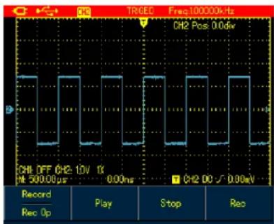
Figure 6-22 Waveform Record Menu
UNI-T®
UTD1000L User Manual
Set up as the following table:
Table 6-11 Record Menu
| Menu | Settings | Description |
| Wave Record | Record | To turn on/off waveform record function. |
| Play | ---- | To play recorded waveform |
| Stop | ---- | To stop recording or playing waveforms |
| Record | ---- | To begin the recording. |
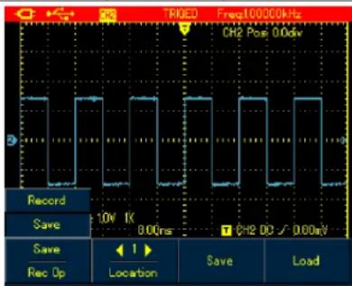
Figure 6-23 Save Menu for Recorded Waveforms
Table 6-12 Save Menu for Recorded Waveforms
| Menu | Settings | Description |
| Wave Record | ---- | There are 1-5 location options available, use arrow buttons to select when the menu displays |
| Save | ---- | To save recorded waveform to internal memory. |
| Recall | ---- | To recall the waveform record that is saved in internal memory |
Note: You can also save the recorded waveform to PC using the control software and play it on PC.
Case 1: To record channel waveforms and save them to the internal memory, do the following:
- Press RECORD button to access record menu:
- Press F1 to set to Record option ;
- Press F4 to begin recording. To stop recording, press F3 button ;
UNI-T®
UTD1000L User Manual
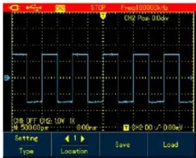
Figure 6-25 Setting Waveform Storage Menu
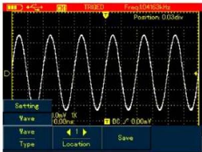
Figure 6-26 UTD1000CL Waveform Storage Menu
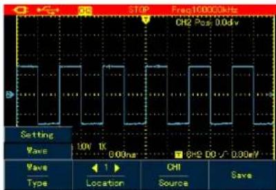
Figure 6-26B UTD1000DL Waveform Storage Menu Set up the storage menu as follows:
Table 6-13
| Menu | Settings | Description |
| Type | SetupWaveforms | To save current setups of menus;To save channel waveforms |
| Location | 1-20 | Use arrow buttons to select storage location. |
| Source | CH1CH2 | To select the channel of the saved waveform. |
| Save | ---- | To save the selected items. |
| Recall(refer to the following section for recall setup) | ---- | To recall the saved parameters when the menu is on. |
UNI-T®
UTD1000L User Manual
- Press F1 to set to Save option;
- Use Arrow Buttons to set the location to 1;
- Press F\$ to save the recorded waveform,
"Saving shows on the screen When .
"Saving icon disappears it indicates the waveforms have already been saved into internal memory.
Note: Model UTD1000CL can record up to 300 screens of waveforms, and it is up to 150 for Model UTD1000DL. If following operations are performed during recording the recording will stop .
■ Press RUNSTOP/SINGLE button ;
■ Press AUTO or SHIFT+AUTO button
■ Turn Timebase range to access SCAN mode.
Case 2: To recall recorded waveform in Case 1 from the internal memory and rep lay it do the following :
- Press RECORD to access record menu
- Press F1 to set to Save option;
- Press Arrow Buttons to set Location to 1
- Press F4 to begin recalling, loading ..." indicates on the screen after the loading
finishes Load Success indicates
- Press F1 to set to Record option;
- Press F2 button to begin playing the recalled waveforms automatically, press F3 to stop or use Arrow Buttons to select the waveform to be played.
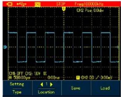
Figure 6-24 Replay Waveform Record Storage
To store the waveforms, do the following
- Press SHIFT button, and shift icon shows on upper right part of screen ;
- Press STORAGE button to a access storage menu;
UNI-T®
UTD1000L User Manual
Recalling
To recall the waveforms, press SHIFT button and shift icon shows on the upper right part of screen; then press REF to access waveform recall menu.
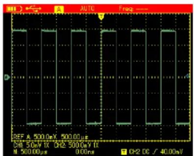
Figure 6-27 Recall Reference Waveforms
Set up as shown in the following table
Table 6-14
Table 6-14
| Menu | Settings | Description |
| Ref Wave | REF A | Model UTD1000CL default at REFA option |
| REF B | UTD1000DL can recall REFA or REFB individually or both of them at the same time . | |
| Location | 1-20 | Use Right and Left buttons to select the location to be recalled. |
| Recall | ---- | To begin the recalling |
| Clear | ---- | For Model UTD1000CL, it's used to turn off recalled waveform; For Model UTD1000DL, it's used to turn off current waveform( REFA or REFB ) |
UNI-T®
UTD1000L User Manual
Case 1 To save and recall channel waveforms to the internal channel:
Saving Waveforms
- Press SHIFT and shift icon shows on upper right part of screen ;
- Press STORAGE to access storage menu ;
- Press F1 to set Type to Waveform ;
- Press Left&Rightbuttons to set Location to 1; press F3 to select target Source Only (available in UTD1000DL)
- Press F3 of UTD1000CL to save and also F3 button for UTD1000DL then storage success shows on the display, indicating the waveform has been successfully saved into the Oscilloscope;
Recalling Waveform
- Press SHIFT, shift icon shows on upper right part of display.
- Press REF to access waveform recall m enu;
- Press F1 of UTD1000DL to select between REFA or REFB UTD1000CL defaults at REFA;
- Press Left & Right arrow buttons to set Location to 1 ;
- Press F3 to recall, Load Success will show to indicate the waveform has been successfully displayed on the screen too;
- Press F4 to turn off the current reference waveform.
UNI-T®
UTD1000L User Manual
Making Cursor Measurements
To make cursor measurements, do the following:
- Press SHIFT and shift icon shows on upper right part of display.
- Press CURSOR to access cursor menu ;
- Press F2 of UTD1000DL to choose the channel for cursor measurement (No selection for UTD1000CL, it defaults at CH1)
- Press F1 to set up measuring type. There are two options available for measuring Type in cursor menu: Voltage and Time. When measuring voltage, use SELECT and arrow buttons to adjust the locations of two cursors in order to measure parameter, do the same with measurement
Voltage/Time Measurement Tips : Cursor 1 and Cursor 2 shows simultaneously on the screen , use arrow buttons to remove the cursors and press SELECT to choose and adjust the desired one. Displayed readout is the voltage or time
between two cursors
When the cursor function turns on, measuring values can be automatically shown on upper left corner of the display.
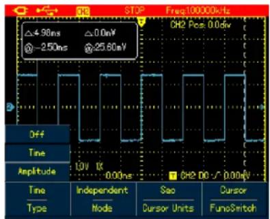
Figure 6-28 Cursor Menu for Time Measurement
UNI-T®
UTD1000L User Manual
Table 6-15
| Menu | Settings | Description |
| Type | Time | Use the cursor to measure the time |
| Mode | Independent Tracking | Move each cursor independentlyMove two cursors simultaneously and keep t unchanged |
| Vertical Unit | Sec Hz | measurement parameter is time measurement parameter is frequency |
| Func Switch | Channel | Use arrow buttons to set the target to channel waveform;Use arrow buttons to set the target to trigger level;Use arrow buttons to set the target to the cursors press SELECT to select between Cursor 1 and Cursor 2. |
| Trigger | ||
| Cursor |
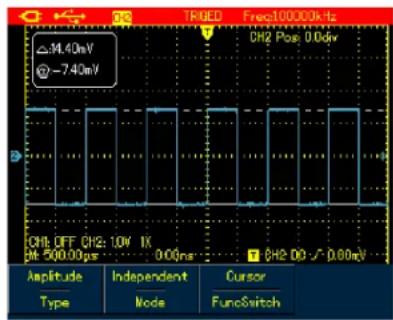
Figure 6-29 Cursor Menu for Voltage Measurement
UNI-T®
UTD1000L User Manual
Table 6-16
| Menu | Settings | Description |
| Type | Voltage | Use the cursor to measure the voltage |
| Mode | Independent Tracking | Move each cursor independentlyMove two cursors simultaneously and keep V unchanged |
| Func Switch | Channel | Use arrow buttons to set the target to channel waveform; |
| Trigger | Use arrow buttons to set the target to trigger level ; | |
| Cursor | Use arrow buttons to set the target to the cursors, pressSELECTto select between Cursor 1 and Cursor 2. |
Interface Setup
To set up the display interface for the Oscilloscope, do the following:
- Press \$SHIFT shift icon shows on uppert right corner of display .
- Press CONFIGURE to enter into display configuration menu;
UNI-T®
UTD1000L User Manual
Table 6-17
| Menu | Settings | Description |
| Language | Multilingual | To select the desired language |
| Style | Classic, Traditional, Modern, White&Black | To select display style |
| Menu Display | ---- | To set up waiting time before the manual turns off: 5s,10s , 20s,Manual Manual the—menu will not turn off automatically,use OK to turn it on/ off. |
| System Info | ---- | To display oscilloscope model hardware version, software version, etc; |
Utility Setup
To set up the display interface for the Oscilloscope, do the following:
-
Press \$HIFT shift icon shows on upper right corner of the display ;
-
Press UTILITY to access Utility menu.
Menu Setup shown as in the following table
UNI-T®
UTD1000L User Manual
Table 6-18
| Model UTD1000CL | ||
| Function menu | Settings | Description |
| Self-Calibr | ---- ---- | The Oscilloscope will calibrate the system automatically. |
| Default | ---- ---- | The Oscilloscope returns to factory default status. |
| Freq Counter | On/Off | Turn on /off trigger frequency counter. |
| Clear | ---- ---- | Clear saved or recorded waveforms or settings in the Oscilloscope, etc; |
| Model UTD1000CL | ||
| Function menu | Settings | Description |
| Self-Calibr | ---- ---- | The Oscilloscope will calibrate the system automatically. |
| Default | ---- ---- | The Oscilloscope returns to factory default status. |
| DC Autoset | On/Off | Turn on/off DC signal self-identification function |
| Clear | ---- ---- | Clear saved or recorded waveforms or settings in the Oscilloscope, etc; |
Key Points :
Self-Calibration: You need to run this operation to avoid any measurement error arising from environment change. To ensure an accurate calibration please power on the Oscilloscope and warm it up for minutes.
Full Autoset : The Oscilloscope can automatically adjust its ranges based on the input signal to present users optimal waveform without any manual interference.
UNI-T®
UTD1000L User Manual
Executing Mathematic Functions
- For Model UTD1000CL, there is only FFT operation available refer to following displayed menu:
To execute FFT operation, do the following:
- Press MATH to open math menu ;
- Press F1 to turn on FFT operation.
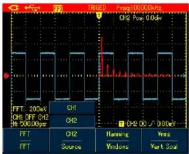
Figure 6-30 UTD1000CL FFT Operation
Table 6-19
| Function menu | Settings | Description |
| FFT | On Off | Turn on/off FFT function. |
| Source | CH1 | CH1 is the default channel for FFT operation. |
| Window | Hanning Hamming Blackman Rectangle | Set to Hanning window. Set to Hamming window. Set to Blackman window. Set to Rectangle window. |
| Vertical Unit | Linear dBV | To set vertical unit to linear or dBV |
UNI-T®
UTD1000L User Manual
- For Model UTD1000DL both FFT and
MATH functions are offered :
Math Operation: It is to execute simple
(+,-,×,÷) math operations on CH1 and
CH2 waveforms .
To perform Math or FFT operation, do the following:
- Press MATH to turn on mathematic menu
- Press F1 to Set Type to Math
- Press F1 again to switch to FFT type ;
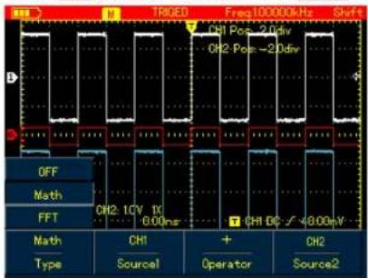
Figure 6-31 UTD1000DL MATH Operation
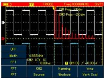
Figure 6-32 UTD1000DL FFT Operation
UNI-T®
UTD1000L User Manual
Set up Math and FFT menus as follows:
Table 6-20
| Type | Settings | Description | |
| OFF | - - | Turn off MATH function | |
| Math | Source 1 | CH1 | Set CH1 as Source 1 of Math operation |
| CH2 | Set CH2 as Source 1 of Math operation | ||
| Operator | + | Source1 Source 2 | |
| - | Source 1 Source 2 | ||
| × | Source 1 Source 2 | ||
| ÷ | Source 1 Source 2 | ||
| Source 2 | CH1 | Set CH1 as Source 2 of Math operation | |
| CH2 | Set CH2 as Source 2 of Math operation | ||
| FFT | Source | CH1 | Set the source to CH1 |
| CH2 | Set the source to CH2 | ||
| Window | Hanning | Set to Hanning window | |
| Hamming | Set to Hamming window | ||
| Blackman | Set to Blackman window | ||
| Rectangle | Set to Rectangle window | ||
| Vertical Unit | Linear dBV | To set vertical unit to linear or dBV | |
UNI-T®
UTD1000L User Manual
FFT Spectrum Analysis
FFT (Fast Fourier Transform algorithm) mode can convert time domain (YT) into Frequency domain for signal waveform graph, which helps to easily observe signals of following kinds:
- Harmonic component and distortion in the measurement system.
- Characterize noises in DC source
- Analyze the virbration
FFT Operation Tips
Signals with DC components or bias may cause error or deviation to FFT waveform components. In order to reduce DC component, you can set coupling to AC mode. And you can set ACQUIRE type to AVG to lower down random noise or mixed overlapped frequency component in repetitive or single pulse event.
Select FFT Window
Suppose YT waveforms repeats constantly and the Oscilloscope then performs FFT on limited length record. When the period numer are integer, YT waveform at the start and finish points share same amplitude values and will not cause any interruption to the waveform. If it is non-integral, the start and finish amplitude are different, and high-frequency transient interruption will happen at joint points, which is called leakage in frequency domain. To avoid the leakage, FFT mode will multiply original waveform with one window function to force the start and finish values all go to 0. Refer to following windows for details:
UNI-T®
UTD1000L User Manual
Table 6-21
| FFT Window | Features | Best Applications |
| Hanning | Compared with rectangle type, it has better amplitude accuracy and less so for frequency resolution. | Used to measure sine, periodic and narrowband random noises. |
| Hamming | Frequency resolution for Hamming is a little better than that of Hanning. | Used to measure transient or short pulse; and for signals whose signal levels before and after the event are greatly different. |
| Blackman | Offers best amplitude accuracy and worst for the frequency resolution. | Mainly for measuring single frequency signals and looking for higher order harmonics |
| Rectangle | Offer best frequency resolution, but worst for the amplitude accuracy. No big change before and after adding window function. | Applicable for measuring transient or short pulse, the signal levels before and after the event are approximately equal. And also for measuring equal-amplitude sinewave with very close frequencies, broadband random noise with relatively slow changing spectrum. |
Term Explanation
FFT Resolution: defined as Quotient between sample rate and operation points. When operation points are fixed, the lower sample rate is, the better FFT resolution will be.
NYQUIST Frequency : For waveforms with highest frequency f, it at least needs to apply 2f sample rate in order to recreate original waveform. It is called NYQUIST principle f is NYQUIST frequency and 2f is NYQUIST sample rate.
UNI-T®
UTD1000L User Manual
Autoset
Autoset is used to simplify the operations. Press AUTO button and then the Oscilloscope will automatically adjust vertical factor and timebase range based on the waveform amplitude and frequency until the waveform displays steadily on the screen. System settings for Autoset function are shown in the following table:
Table 6-22
| Functions | Settings |
| Acquire Mode | Normal Sample |
| Display Type | YT |
| SEC/DIV | Adjust based on signal frequency |
| VOLT/DIV | Adjust based on signal amplitude |
| Trigger Type | Edge |
| Trigger Level | central point of signal |
| Trigger coupling | DC |
| Trigger Slope | Rise |
| Trigger Mode | Auto |
UNI-T®
UTD1000L User Manual
Chapter 7 Troubleshooting
The Oscilloscope cannot power on :
The battery may run out. Try to power on the
Oscilloscope again with use of the power adaptor. If the instrument still doesn't work, please contact UNI-T for the service.
The Oscilloscope turns off a few seconds later after powered on:
The battery may run out. Check if the low battery indicator appears on the screen. If it does, please recharge it.
Measuring voltage amplitude is 10 times larger or smaller than exact value :
Make sure channel attenuation factor is consistent with probe factor on the applied probe.
No waveform displays after acquiring signals:
- Make sure the probe is properly connected to the connection wire.
- Make sure the connection wire is correctly attached to BNC channel connector
- Make sure the probe is properly connected to the tested object.
-
Make sure there are signals generated from the tested object you can connect the channel that can produce signals to the suspected channel and verify the cause)
-
Restart the acquisition
The waveform does not display steadily:
- Check if trigger source that has been set up in trigger menu is the same with actual input channel
- Check trigger type Edge type is generally selected for common signals use video trigger type for video signals. Only when proper trigger
UNI-T®
UTD1000L User Manual
type has been set up can the waveform display steady.
- Try to change Coupling to HF Reject to filter out the high-frequency interference noise in the signal.
There is no display after pressing down RUN STOP button :
- Check if Trigger Mode in trigger menu is Normal or Single and trigger level has gone beyond waveform ranges. If they are, set trigger level to the middle or set trigger Mode to AUTO
- Or you can press AUTO to automatically finish the setup mentioned above .
The display slows down after having applied AVG mode for a while:
-
If AVG number go above 32 times, it is normal for the oscilloscopes to display at a relatively low rate.
-
Reduce AVG number
The waveform display has a stair-stepping shape:
- It is normal situation, it may be caused by lower horizontal ti mebase, increasing the timebase can improve the horizontal resolution and the display
- If display type is VECTOR, links between sample points could probably result in stair-stepping shape. Change display type to Dots can solve the problem.
UNI-T®
UTD1000L User Manual
Chapter 8 Service and Support
Updating Program
Contact UNI-T or log into our website to obtain the latest program package, unzip the package and apply the Oscilloscope program update system to update the Oscilloscope so as to ensure your oscilloscope has the latest version of firmware issued already by UNI-T
Preparation before Update
-
Turn on your oscilloscope, press CONFIGURE button and select system information option so as to obtain details about the Oscilloscope model, hardware version, software version, etc.
-
Make sure the program package you get from UNI-T company or website has the same model number and hardware version with the Oscilloscope to be updated. The version should be higher than the current version.
Update Conditions
-
The update program must have the same product model with that of your oscilloscope.
-
The update program must be consistent with your oscilloscope on hardware version
- The update program version must be higher than or equal to that of your oscilloscope.
Program Update
- Properly install the Oscilloscope software into your PC as instructed in communication software users manual
- Copy the program package(extension is upp ) into PC. You can download from UNI-T website and contact UNI-T company directly to get the package.
- Connect the Oscil loscope to PC with USB cable, then click to run the software choose corresponding oscilloscope model and click 【ENTER】 in pop-up interface, the software interface will appear. Click Connect button on the interface to begin communication between PC and the Oscilloscope. With this connection finished, there will be an indication that USB has been connected successfully.
UNI-T®
UTD1000L User Manual
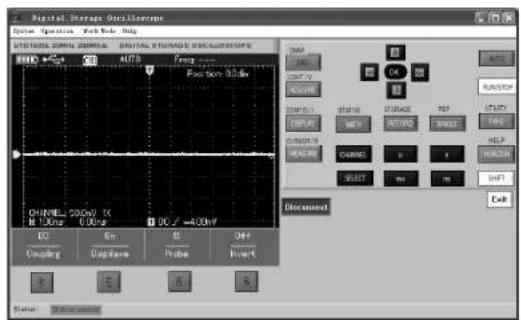
Figure 8-1 Connect to PC
- Choose from the software menu Action → 【Program Update then select the copied program package on dialogue box and confirm OK. The Oscilloscope then begins the update and reads “The Oscilloscope is preparing the update, please wait … .”
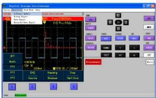
Figure 8-2 Program Update
- The Oscilloscope will read "update has succeeded!" on the screen after the update has finished. Do not do any operation on the Oscilloscope at the moment, please repower it on to complete the program update.
UNI-T®
UTD1000L User Manual
Notes:
- When the program package doesn't adapt to the Oscilloscope, PC reads "the update file is incorrect, please check!", then the Oscilloscope then stops the update and keeps the previous program version unchanged.
- If the Oscilloscope was disconnected to PC or powered off or PC has been shut down during update, the update would stop and leave the previous program unchanged.
UNI-T®
UTD1000L User Manual
Chapter 9 Appendixes
Appendix A Technical Specifications
Unless otherwise specified, the technical specifications are all applicable for 10× probe and UTD1025L Oscilloscope First of all the Oscilloscope must satisfy two following conditions in order to meet those specifications :
■ The Oscilloscope must run continuously for more than 30 minutes in regulated working temperature.
■ Users have to execute “self-calibration procedure in UTILITY menu if operating temperature is 5 or above higher than specified range All specifications are warranted except items marked with “Typical”
Technical Specifications:
Oscilloscope
| Acquisition mode | |
| Acquisition mode | Real-time acquisition |
| Acquisition rate | UTD1025CL UTD1050CL 200MS/sUTD1025DL UTD1050DL 250 / |
| Acquisition | Acquisition , Peak Detect, AVG, Fast Acquisition (UTD1000DL |
| AVG value | All channels can acquire simultaneously up to N times, N can be selected from 2, 48, 16 32 64, 128 and 256 |
UNI-T®
UTD1000L User Manual
| Input | |
| Input Coupling | DC AC GND |
| Input Impedance | 12% MΩPF in parallel ; |
| Probe Attenuation Factor | 1X,10X,100X,1000X |
| Max.Input Voltage | 300V DC AG Peak, 1MΩut Impedance ) |
| Interchannel Delay typical | 50ps |
| Horizontal | |
| Waveform Interpolation | sin(x)/x |
| Record Length | UTD1000CL 1:5M,1000DD 3M |
| Memory Depth | 12K |
| Max.Input Voltage | UTD1025CL UTD1025DL 10ns/div-50s/divUTD1050CL UTD1050DL : 5ns div 50s divStepping in 1-2-5 |
| Sample Rate and Delay . Accuracy | ±50ppm(any time interval ≥1ms) |
| Interval Time (△÷ Measuring Accuracy (Full BW | SINGLE: ± 1( sampling interval time 50ppmXreadings 0 6ns. >16AVGs: ± 1( sampling interval time ±100ppmXreadings ±0 4ns) |
UNI-T®
UTD1000L User Manual
| Vertical | |
| A/D Converter(A/D) | 8-bit resolution |
| Vertical Scale(V/div) | 5mV/div 20V/div (at BNC ort) |
| Offset Ranges | 5mV/div 100mV/div 1.2V 200mV/div 1V/div 24V : ± :2V/div 20V/div 240V ; |
| Analog Bandwidth | UTD1025CL UTD1025DL: 25MHz; UTD1050CL UTD1050DL: 50MHz |
| LF Response(AC Coupled dB3) | ≤10Hz(at BNC) |
| Rise Time | UTD1025CL UTD1025DL: ≤14ns; UTD1050CL UTD1050DL ≤7ns |
| DC Gain Accuracy | For vertical Sensitivity 5mV/div:±4%(Normal or AVGvertical Sensitivity from 10mV/div~20V/div:±3% ( Normal or AVG |
| DC MeasurementAccuracy(AVG mode) | Where vertical offset equals zero and N≥16:±(4%×Readings+0.1div +mV and select 5mV div±(3%×Readings+0.1div+1mV) and select 10mV/div~20V/div;±(3%× Readings+0.1div+1mV)and select bewteen 10mV/div ~20V/div.Where vertical offset does not equal to zero and N≥16:±|3%×(Readings Vertical offset value )1%×Vertical offset Value) □0.2divAdd 2mV if setting between 5mV/div to 200mV/div; Add 50mV if settings from 200mV/div to 20div / |
| Voltage Difference(△÷)Measuring Accuracy AVG Mode) | Under same settings and ambient conditions, calculate voltage difference(μbetween any two points just after capturing ≥16 wavforms and working out average values. Equation:±(3%×readings+0.05div) |
UNI-T®
UTD1000L User Manual
| Trigger | |
| Trigger Sensitivity | ≤slant 1 div |
| Trigger Level Range | ± 10 div from screen center point |
| Pre-Trigger | Normal/Sweep Mode, Pre-trigger/Delay Trigger, Pre-trigger Depth Adjustable |
| Hold-Off Range | 100ns - 1.5s |
| Edge Trigger | |
| Edge Type | Rise, fall |
| Pulse Width Trigger | |
| Trigger Mode | (> ≤slant , Positive Pulse Width , ( Negative Pulse Width |
| Pulse Width Range | 20ns-10s |
| Video Trigger | |
| Trigger Sensitivity (Video typical) | 2divs Peak-to-Peak Value |
| Video Format and Line/Field Frequency | Support standard PALSC and □, line number 625fNTRS~ ( and 1~625(PAL |
| Slope Trigger | |
| Trigger Conditions | <, > = |
| Slew Rate | 40pV/ s ~1.6kV/ s |
UNI-T®
UTD1000L User Manual
| Measurements | ||
| Cursor | Manual Mode | Cursor Voltage Difference(ΔV), Cursor Time Difference ΔT reciprocal(Hz)(1/ΔT) |
| Auto Mode | Cursor allowed to display in auto mode | |
| Auto Measurements | UTD1000CL: Peak-to Peak Amplitude Max, Min, Top Point, Bottom Point, Middle, AVG,RMS Overshoot, Preshoot, Frequency period Rise Time, Fall Time, Positive Negative Pulse Width, Positive &Negative Duty Cycle total 19 types UTD1000DL: apartfrom 19 types the model offer another three parameters Rise Delay Fall Delay Phase | |
| Customized Parameter Measurement | Up to 4 types at a time | |
| Mathematics | UTD1000CL FFT UTD1000DL Math and FFT | |
| Storage | Screens: 10sets; Waveforms: 20 sets, Settings:20 types, | |
| Waveform Recording | Store 5 sets of waveform records. UTD1000CL: recording 300 screens 1000Drecording screens 150 | |
| FFT | Window | Hanning,Hamming,Blackman,Rectangular |
| Sample Points | 1024 points | |
| NYQUIST Pattern (UTD1000DL) | Phase Difference | ±3degrees |
Multimeter
The specified accuracy is valid over the temperature range 18^ C to 28^ C
Add 10 % of specified accuracy for each degree C below 18°C or above 28°C
UNI-T®
UTD1000L User Manual
DC Voltage:
Input Impedance : 10MΩ
Max.Input Voltage: DC400V。
| Range | Resolution | Accuracy |
| 400.0mV | 0.1mv | ±(1%+5 digits) |
| 4.000V | 1mv | |
| 40.00V | 10mv | |
| 400.0V | 100mv |
AC Voltage:
Input Impedance: 10MΩ
Max.Input Voltage: 400V AC RMS
Frequency Range 40Hz \~ 400Hz.
Display: RMS of sinewave
| Range | Resolution | Accuracy |
| 400.0mV | 0.1mv | ±(1.2%5 digits) |
| 4.000V | 1mv | |
| 40.00V | 10mv | |
| 400.0V | 100mv |
UTD1000CL DC Current
Max. Input DC Current DC10A
| Range | Resolution | Accuracy |
| 350 A0μ | 0.1μA | ±(1.2% 5 digits) |
| 40.00mA | 10μA | ±(1% 5 digits |
| 400 0mA | 0.1mA | |
| 10.00AMeasure with UT-M07(10A current divider module) | 10mA | ±(1.5% 5 digits) |
UTD1000CL AC Current
Max.Input AC Current: AC 10A RMS
Frequency Range 40Hz 400Hz
| Range | Resolution | Accuracy |
| 350.A0μ | 0.1μA | ±(2%-5 digits) |
| 40.00mA | 10μA | ±(1.5% 5 digits) |
| 400 0mA | 0.1mA | |
| 10.00AMeasure with UT-M07(10A current divider module) | 10mA | ±(2.5% 5 digits) |
UNI-T®
UTD1000L User Manual
UTD1000DL DC Current :
Max. Input DC Current DC4A
| Range | Resolution | Accuracy |
| 999.9μAMeasure with UT-M10(mA current module | 0.1μA | ±(1.2% 5digits) |
| 40.00mAMeasure with UT-M10(mA current module | 10μA | ±(1% 5digits) |
| 400.0mAMeasure with UT-M10(mA current module | 0.1mA | |
| 4.00AMeasure with UT-M04(4A current divider module) | 10mA | ±(1.5% 5digits) |
UTD1000DL AC Current
Max.Input AC Current: AC 4A RMS
Frequency Range 40Hz\~400Hz
| Range | Resolution | Accuracy |
| 999.9μAMeasure with UT-M10(mA current module | 0.1μA | ±(2%-5digits) |
| 40.00mAMeasure with UT-M10(mA current module | 10μA | ±(1.5%-5digits) |
| 400.0mAMeasure with UT-M10(mA current module | 0.1mA | |
| 4.00AMeasure with UT-M04(4A current divider module) | 10mA | ±(2.5%-5digits) |
UNI-T®
UTD1000L User Manual
Resistance
| Range | Resolution | Accuracy |
| 400.0 Ω | 0.1Ω | ±(1.2% 5 digits) |
| 4.000k Ω | 1Ω | |
| 40.00k Ω | 10Ω | |
| 400.0k Ω | 100Ω | |
| 4.000MΩ | 1kΩ | |
| 40.00MΩ | 10kΩ | ±(1.5% 5 digits) |
Capacitance
| Range | Resolution | Accuracy |
| 51.20nF | 10pF | ±(3% 5digits) |
| 512.0nF | 100pF | |
| 5.120uF | 1nF | |
| 51.20μF | 10nF | |
| 100μF | 1μF |
Diode:
Voltage Readout: 0V\~1.5V
Continuity Test:
Resistance value for discontinuity: the >75 ,
beeper doesn't sound
Resistance value for good circuit continuity:≤70Ω, continuous beeping :
| Display | |
| Displat Type | 3.5inch, TFT LCD |
| Display Resolution | 320Horizontal RGB 240Vertical pixels |
| Display Color | Color/Black&White |
| Waveform Display Zone | Horizontal: 12div, 25dot/div;Vertical: 8div 25dot div/ |
| Backlight Brightness | Adjustable |
| Backlight Intensity | 300nit |
| Language | Multilingual |
| Interface | |
| Standard | UTD1000CL:UT M07(10A current divider module)pcs one USBcable UTD1000DL:UT M04 4A current divider module), 1pcs, one UT-M10(mA curren module), 1pcs;USB cable pcs |
| Optional | — — |
UNI-T®
UTD1000L User Manual
| Power Adaptor | |
| Mains Voltage | 100~220 V AC rms,45~440Hz |
| Output Voltage | 9 VDC |
| Output Voltage | 4A |
Battery 7.4 V m360 chargeable lithium
batter UTD:1000CL hour battery life
UTD1000DL hour-battery life
| Environment | |
| Temperature | Operating: 0 40 ~+ °C |
| Non-operation: 620°C ~+ °C | |
| Cooling Method | Naturally cooled down |
| Humidity | +35°C :≤90%+35°C ~ +40°C :≤60% |
| Altitude | Operating:3,000m |
| Naturally cooled down 5,000m | |
| Mechanic specifications | ||
| Dimensions(Reference Data) | 199mm ×118mm ×49mm | |
| Weight(Net Weight) | Packing not included | 0.9kg |
| Packing Included | 2.3kg | |
| IP Degree |
| IP2X |
| Calibration Period |
| one time for each year |
UNI-T®
UTD1000L User Manual
Appendix B Maintenance
1. General Service
Do not store or place the Oscilloscope in places that may get its LCD exposed to direct sunshine for a long time. Do not let spray agent, liquid and solvent stick onto the Oscilloscope or probe so as to avoid any damage to the Oscilloscope or probe
Cleaning
Check the Oscilloscope and its probe as actual operation requires. Clean the Oscilloscope surface as follows:
- Clean dust on the Oscilloscope and probe surface with soft cloth. Avoid any scratch to LCD transparent protective layer.
- Clean with soft cloth damped with water or mild agent, no water drop is allowed to occur. Do not use any corrosives or abrasives. Disconnect the power supply before cleaning.
Warning: To avoid any short circuit or even personal injury resulted from residual water, please
make sure the Oscilloscope is totally dry before powering it on
2. Storing the Oscilloscope
To store the Oscilloscope for a long term, you need to charge the batteries before storing it.
3. Charging Batteries
The battery may not be fully charged during the delivery, it must take four hours to fully charge the battery. The battery can work for 8 hours after full charge.
When powered by the battery, the Oscilloscope indicates battery working status on the upper part of screen.battery indicator s may include:
☐ ☐ ☐ ☐ ☐ ☐ ☐ ☐ ☐ ☐ ☐ ☐ ☐ ☐ ☐ ☐ ☐ ☐ ☐ ☐ ☐ ☐ ☐ ☐ ☐ ☐ ☐ ☐ ☐ ☐ ☐ ☐ ☐ ☐ ☐ ☐ ☐ ☐ ☐ ☐ ☐ ☐ ☐ ☐ ☐ ☐ ☐ ☐ ☐ ☐ ☐ ☑
UNI-T®
UTD1000L User Manual
Caution:
To avoid over-heating when charging the battery, environment temperature shouldn't exceed allowable rated value(0 40°C \~ + )
Note:
There is no danger involved even the Oscilloscope has been connected to the charger for a long time, for instance, during the whole weekend, for the Oscilloscope can automatically switch into very slow charging status.
Replacing Lithium Battery Pack
The battery pack doesn't need the replacement under general circumstances. If necessary, please have the battery pack replaced by qualified personnel and use new battery with the same specifications.
UNI-T®
UTD1000L User Manual
This user manual may be revised without prior notice.
UNI-T®
UTD1000L User Manual
Manufacturer:
Uni-Trend Technology (China) Limited
No 6, Gong Ye Bei 1st Road
Songshan Lake National High-Tech Industrial
Development Zone, Dongguan City
Guangdong Province
China
Postal Code:523 808
Headquarters:
Uni-Trend Group Limited
Rm901, 9/F, Nanyang Plaza
57 Hung To Road
Kwun Tong
Kowloon, Hong Kong
Tel: (852) 2950 9168
Fax: (852) 2950 9303
Email: info@uni-trend.com
http://www.uni-trend.com


- UNI-T®
- Contents
- Item
- Page
- Chapter 1 Safety Information
- Safety Terms and Symbols
- Terms in the manual
- Terms on the product
- Symbols on the product
- General Safety Overview
- Chapter 2 UTD1000L Series Oscilloscope Overview UTD1000L Series Oscilloscope Introduction
- UTD1000L Series Oscilloscope Accessories
- UTD1000L Series Oscilloscope Key Features
- Scope
- Multimeter
- Chapter 3 Oscilloscope Connection
- General Check
- Checking for any damage due to the transit
- Checking the Accessories
- Checking the Whole Oscilloscope
- Connection Interfaces
- Description:
- Compensation Output Connection
- Front Panel and Keypad
- SELECT
- Shortcut Buttons Description:
- Chapter 4 Using Basic Oscilloscope Functions About the Chapter
- Powering on the Oscilloscope
- Resetting the Oscilloscope
- Using Functional Menus
- Hiding Menus
- Making Connections for Probe
- Compensation
- Setting Vertical&Horizontal Systems and Trigger Level Manually
- Horizontal System
- Trigger Level Autoset for Waveform Display
- Full Autoset for Input Signal
- Note: Run/Stop Data Acquisition
- Setting Frequency Counter
- Adjusting Screen Intensity
- Saving Bitmap
- Using Online Help
- Setting Single Trigger
- Viewing Oscilloscope Status
- Checking Oscilloscope System Information
- Making Auto Measurements
- Measuring All Parameters
- Note:
- Measuring Customized Parameters
- Using AVG mode for Smoothing Waveforms
- Using Peak Detect Mode for Pulse Peak Display
- Observing Waveforms with use of Persistence Selecting AC Coupling
- Autoset for Signals with DC Offset
- Chapter 5 Using the Multimeter About the Chapter
- Connections to the Multimeter
- Display Indicators
- Making Multimeter Measurements
- Measuring Resistance
- Testing Diodes Testing for Continuity
- Measuring Capacitance
- Measuring DC Voltage
- Measuring AC Voltage Measuring DC Current with UTD1000CL
- Measuring DC Current with UTD1000DL
- Measuring AC Current with UTD1000DL
- Data Hold Making Relative Measurement
- Selecting Manual Auto Ranging
- Chapter 6 Using the Oscilloscope in Details
- About the Chapter
- Setting Vertical System
- UTD1000CL Channel Setup
- Moving Waveform Vertically
- Setting waveform display
- Set Probe Factor UTD1000DL Channel Setup
- 1.Moving Waveform Vertically Setting Waveform Display
- Setting Probe Factor
- Moving Waveforms Horizontally
- Zooming in out Waveforms
- Adjusting Trigger Hold Off
- Setting Trigger System
- Trigger Controls
- Common Setting
- Edge Trigger
- Pulse Width Trigger
- Video Trigger
- Slope Trigger
- Term Explanation
- Setting Acquisition Mode
- Setting the Display
- Term Explanation:
- Setting Auto Measurements
- Recording and Storage Recording
- Recalling
- Saving Waveforms
- Recalling Waveform
- Making Cursor Measurements
- Interface Setup
- Utility Setup
- Key Points :
- Executing Mathematic Functions
- FFT Spectrum Analysis
- FFT Operation Tips
- Select FFT Window
- Autoset
- Chapter 7 Troubleshooting
- The Oscilloscope turns off a few seconds later after powered on:
- Measuring voltage amplitude is 10 times larger or smaller than exact value :
- The waveform does not display steadily:
- There is no display after pressing down RUN STOP button :
- The display slows down after having applied AVG mode for a while:
- The waveform display has a stair-stepping shape:
- Chapter 8 Service and Support
- Updating Program
- Preparation before Update
- Update Conditions
- Program Update
- Notes:
- Chapter 9 Appendixes
- Appendix A Technical Specifications
- Technical Specifications:
- Appendix B Maintenance
- General Service
- Cleaning
- Storing the Oscilloscope
- Charging Batteries
- Caution:
- Replacing Lithium Battery Pack
Brand : Uni-T
Model : UTD1025CL
Category : Mètre