
UT243 - Mètre Uni-T - Free user manual and instructions
Find the device manual for free UT243 Uni-T in PDF.


| Product Type | Power and Harmonics Clamp Meter |
| Brand | Uni-T |
| Model | UT243 |
| Category | Meter |
| Dimensions | 303 x 112 x 39 mm |
| Weight | 601 g |
| Power Supply | 4 x 1.5V alkaline batteries |
| Display | 4-digit LCD, max count 9999 |
| AC Voltage (True RMS) | 150V, 300V, 600V ranges; Accuracy ±(1.2%+5); Resolution 0.1V |
| AC Current (True RMS) | 50A, 250A, 1000A ranges; Accuracy ±(2%+5); Resolution 0.1A (50A/250A), 1A (1000A) |
| Active Power | Up to 600kW single-phase, 1800kW total three-phase; Accuracy ±(3%+2) |
| Frequency | 40Hz~80Hz; Accuracy ±(0.5%+5); Resolution 0.01Hz |
| Harmonic Analysis | Up to 20th harmonic; Voltage and current THD-R, THD-F, and individual harmonics |
| Phase Sequence Detection | Yes (UT243 only); Positive, negative, and default phase |
| Data Storage | Up to 999 groups (single/continuous) |
| USB Interface | Yes (UT242/243); For data transfer and software |
| Safety Rating | CAT III 600V; Double insulation (Class II) |
| Accessories Included | Test leads (red, black, blue, yellow), batteries, manual, USB cable, software CD |
| Auto Power Off | Programmable: 10, 20, 30 minutes or off |
Frequently Asked Questions - UT243 Uni-T
User questions about UT243 Uni-T
0 question about this device. Answer the ones you know or ask your own.
Ask a new question about this device
Download the instructions for your Mètre in PDF format for free! Find your manual UT243 - Uni-T and take your electronic device back in hand. On this page are published all the documents necessary for the use of your device. UT243 by Uni-T.
USER MANUAL UT243 Uni-T
UNI-T®
UT241/242/243 OPERATING MANUAL
CONTENTS
- Safety Warning 1
- Technical specifications 3
- Key function 13
- Proposition before measurement 10
- Preparation before measurement----16
- Measurement function of electric energy----16
- Harmonic measurement function 37
9、Setup mode----45
1Batterplacement 47
1 Maintenance 48
UNI-T
UNI-T®
1. Safety Warning
The instrument shall be designed according to safety standard of Safety Requirements for Electronic Measurement Products" (IEC61010-1). The manual includes guaranteeing safety status of instruments for safe use, warnings and safety statutes which must be executed by users. Please read following instructions before use:
● LCD will display warning symbol if measured voltage exceeds AC 30V. Be sure to operate carefully and finger also cannot longer than testing pen.
● It is not allowed to measure voltage which is higher than permissible input value.
- Please inspect instrument and testing pen before use. Measurement is not allowed under following circumstances: Nude testing pen, damaged shell without LCD.
● It is not allowed to operate the instrument for wet surface or hand of operator.
- It is not allowed to open cell cover during measurement
● Guarantee power off for instruments when opening cell cover.
- Instruments cannot meet safety standards until use with testing pen together. Be sure to replace testing pen with the same model and electric dimension if testing pen shall be replaced due to damage.
● Instruments cannot be exposed in wet locations with strong light, high temperature.
● Please clean instrument shell by wet cloth or cleaner.
● Please store after drying when instrument is wet.

Warning
Please read the operation manual especially safety content carefully before using instruments!
| Please refer to manual for important safety marks. | |
| HV danger | |
| Grounding | |
| Duplex insulation (for Class II safety equipment) | |
| Battery under-voltage |
2. Characteristics
UT240 series of digital three-phase forcipiform power/harmonic meter is a portable intelligent power/harmonic measuring instrument. It has integrated functions such as ampere meter voltmeter, power measurement instrument and harmonic analysis meter, etc. With powerful measurement and data treatment software, instrument consists of voltage, current, power and harmonic channels and micro single-chip machine system. It can be used for measurement, calculation & display of parameters such as voltage, current, active power, apparent power, inactive power, power factor, phase location angle, electric energy statistics, frequency, phase sequence, total harmonic distortion rate and harmonic components, etc with stable performance and convenient operation. It is especially suitable to measurement & repair of site power equipment and power supply wires as well as evaluation of electric energy quality of power grid. With portable forcipiform structure, the instrument has little volume and light weight. User can carry with it to facilitate measurement. Such series of digital forcipiform three-phase power/harmonic meters are also your ideal choice for three-phase power measurement and quality an analysis of electric energy.
UNI-T
UNI-T®
- Please design and produce according to international standard of EN61010-1 and international safety code of EN61010-2-032 by abiding by safety standard of duplex insulation of CAT III 600V strictly.
- Adopt power measurement system which consists of chips by new high-performance and large-capacity chip microprocessor and the latest special high-precision chips used for power measurement with high integration level and reliable performance. They can be used to realize multiplex control, complex calculation and measurement display functions of power/harmonic measurement system by large-capacity software.
- Input measurement of three-phase three-wire, three-phase four-wire and single-phase wires
- Measurement of true effective value
● To measure active power, inactive power and apparent power which contains harmonics for 20 times correctly
● To measure total harmonic distortion rate of voltage/current signals for at most 20 times and harmonic components of various orders correctly
● To provide USB communication record interface and special WINDOWS window image software.
● Note: UT241 has no this function.
● To facilitate instrument operation by automatic range conversion circuit and panel key.
3. Technical specifications
Tolerance limit: ±(a% of reading + word quantity); Warranty period: 1 year
Ambient temperature: 23.5
Ambient humidity: 45-75%RH
AC voltage (true effective value)
| Range | Accuracy | Resolution | Input impedance |
| 150V | ±(1.2%+5) | 0.1V | 5MΩ |
| 300V | ±(1.2%+5) | 0.1V | |
| 600V | ±(1.2%+5) | 0.1V |
The maximum permissible overload protection voltage:600V(r.m.s)
Frequency
| Range Accuracy | Resolution | |
| 40Hz~80Hz | ±(0.5%+5) | 0.01Hz |
AC current (true effective value)
| Range Accuracy | Resolution | |
| 50A | ±(2%+5) | 0.1A |
| 250A | ±(2%+5) | 0.1A |
| 1000A | ±(2%+5) | 1A |
The maximum permissible overload protection current: :1000A
UNI-T®
UNI-T®
Active power W=V A>COS φ)
Power factor RF = W/VA
| Range Accuracy | Resolution | Measurement conditions | |
| 0.3-1Inductive or capacitive | ± 0.022 | 0.001 | The minimum measurement current is 10A.The minimum measurement voltage is 45V. |
| 0.3-1Inductive or capacitive | Only for reference | Measurement current is less than 10A ormeasurement voltage is less than 45V. | |
The maximum permissible overload protection voltage:600V r.m.s
The maximum permissible overload protection current:1000A r.m.s
UNI-T®
UNI-T®
Phase location angle ( PG = acos(PF) )
| Range Accuracy | Resolution | Measurement conditions | |
| 0^ 360^ | ± 2^ | 1° | The minimum measurement current is 10A. The minimum measurement voltage is 45V. |
| 0^ 360^ | Only for reference | Measurement current is less than 10A or measurement voltage is less than 45V. | |
The maximum permissible overload protection voltage 600V r.m/s
The maximum permissible overload protection current:1000A r.m.s
Electric energy (kWh)
| Range Accuracy | Resolution | |
| 1--9999kWh | ± (3%+2) | 0.001kWh (MAX) |
The maximum permissible overload protection voltage:600V r.m.s
The maximum permissible overload protection current:1000A r.m.s
Phase sequence judgment (only UT243 has this function)
| Phase sequence judgment | Positive sequence detection | Testing conditions: (50Hz~60Hz)ACV: The minimum value is 30V and the maximum value is 500V. |
| Negative sequence detection | ||
| Default phase detection | Testing conditions: (50Hz~60Hz)ACV: The minimum value is 50V and the maximum value is 500V. |
● Display: 4 bits of LCD with the maximum counting of 9,999 and multiplex display
● Range selection: Automatic range Over-range display: OL
● Automatic shutdown function: Machine will power off automatically for operation failure within period designated by measurement ending (except electric energy gear); Automatic power-off period also shall be set under setup mode.
● Measurement function of the maximum/minimum value (of voltage, current, active power and inactive power measurement)
● Measurement function of total three-phase power
● Measurement of total harmonic distortion rate and single-harmonic component
● Data retention function
● White backlight function
● Storage function: The maximum value is 999 groups for single/continuous record of data readback
●USB interface communication function
● Sampling speed: twice/second
● Power: 4 alkaline batteries of 1.5V
● Storage temperature:-20 70°C \~ ℃/Altitude:2000m
● Dimension:303x112x39(mm)
● Weight: 601g
UNI-T®
UNI-T®
Fittings:
User's Manual----1 manual
Alkaline battery----4 batteries
(Red, black, blue and yellow) testing wires ----4 wires
(Red, black, blue and yellow)---- 4 wires
Tool kit and colorful box---- 1 respectively
USB communication interface wire 1 (only for UT242/243)
Optic disk 1 (only for UT242/243)
4. Instrument Layout
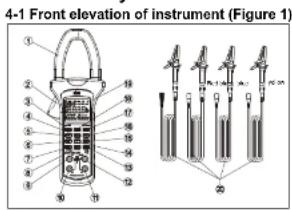
Figure 1
910
- Current clamp mouth
- Trigger
- POWER key
- key
- MENU key (electric energy function selection key)
- LOAD key
- SELECT key (phase location selection key and total power measurement selection key)
- \key
- V3 end (the 3rd phase location of measurement input end)
- V2 end (the 2nd phase location of measurement input end)
- V1 end (the 1st phase location of measurement input end)
- COM end: public end
- MAX/MIN key
- CLEAR/ key (summation key)
- SAVE key
- HARM key (harmonic function selection key)
- UT241: HOLD key; UT242/243: LIGHT/HOLD key
- UT241: LIGHT key; UT242/243:USB key
- LCD 20. (Red, black, blue and yellow) testing pens
UNI-T
UNI-T®
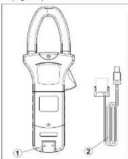
4-2 Bottom view of instrument (Figure 2)
natural_image
Technical line drawing of a handheld device with two labeled parts (no text or symbols present)Figure 2
-
Infrared interface slot;
-
USB communication interface wire (only for UT242/243)
11 12
- LV symbol of battery
- Full symbol for data save
- Data retention symbol
- Opening symbol of automatic power-off function
- Symbol of the 3rd phase location
- Symbol of the 1nd phase location
- Unit of the 1
- Minute unit 17. Qm/s of
- Symbol of the minimum value
- Symbol of true effective value
- Sine symbol
- Cathode symbol
- Data retention symbol 27. UV-wearing symbol
-
HV warning symbol
-
Resetting symbol of data save
- USB communication symbol
- Phase sequence judgment symbol
- Symbol of total three-phase power
- Symbol of the 2nd phase location
- Main parameter unit
- Second clock unit
- Hour unit
- Symbol of the 2nd auxiliary parameter
- Symbol of the maximum value
- Cosine symbol
- AC symbol
- Callout symbol of data save
UNI-T
UNI-T®
5. Key function
POWER
Press POWER key for a long time for bootstrap and restore function gear during previous power-off automatically after bootstrap. Press the key for a short time under bootstrap status for power-off.
●HOLD(UT241)
Press the key for a short time to keep display data; HOLD/LIGHT(UT242/243) Press the key for a short time to keep display data or press backlight ON/OFF key for a long period.
Function menu selection key: Please select active power (kW)+voltage(V)+current(A), apparent power (kVA)+voltage(V)+current(A), inactive power(kVar)+voltage(V)+current(A), power factor (COS) +voltage(V) + current(A), reverse power factor (SIN) +voltage(V) +current(A), phase location angle( ) +voltage(V) +current(A), frequency(Hz) +voltage(V) +current(A), electric energy(kWh) +active power(kW) +statistic period and phase sequence judgment in sequence. (Only UT243 has this function.)
●HARM
Press the key for a short time to enter into harmonic measurement mode with switchover circulation for total voltage harmonics to total wave distortion rate, total voltage harmonics to fundamental wave distortion rate, voltage harmonics, total current harmonics to total wave distortion rate, total current harmonics to fundamental wave distortion rate and current harmonics. Press the key for a long time to alter harmonic frequency mode temporarily under harmonic mode for invalidation after power-off.
15 14
Press backlight ON/OFF key for a long time.
USB UT242/UT243
Press USB communication ON/OFF key for a long time.
- LOAD
Press LOAD key for a short time once to enter into single LOAD data status and press it again to exit LOAD status. Press LOAD key for a long time to enter into continuous circulation LOAD data status and press it again to exit LOAD status.
●SELECT
Phase A, B & C and total phase power selection key
●SAVE
Press the key for a short time once to record data. To record data continuously when pressing SAVE key for a long time and press it for a short time to exit continuous SAVE status. LCD will display FULL symbol to show that RAM is full of data when displaying data save quantity of 999. Next group of data cannot be saved until pressing CLEAR key for a long time to eliminate data in RAM.
● ∑CLEAR
Press key for a short time during measurement in active power/apparent power/inactive power function gear to calculate and save power for the 1st phase of currently measured measurement result. Measure the 2nd phase of power and press key again to calculate and save the 2nd phase of data power. Measure the 3rd
UNI-T®
UT241/242/243 OPERATING MANUAL
Phase of power and press “Σ” key to calculate and save the 3rd phase of data power. Press SELECT key to enter into total power measurement status so that LCD can display three-phase total power (namely, total active power/total apparent power/total inactive power). Press the key for a short time in electric energy gear to begin electric energy statistic function again; Press the key for a long time to eliminate saved data; Press the key for a short time to restore ex-factory setup under setup mode.
- △ key Display next saved data under single LOAD data mode; Increase harmonic order under harmonic measurement mode; Alter setup data under setup mode; - ∇ key Display previous saved data under single LOAD data mode; Decrease harmonic order under harmonic measurement mode; Alter setup data under setup mode; - MAX/MIN Press the key for a short time to enter into the maximum/minimum mode under measurement mode of active power and apparent power. It also can be switched over between the maximum value, the minimum value and current value. Press the key for a long time to exit the maximum/minimum mode;
UNI-T®
UT241/242/243 OPERATING MANUAL
6. Preparation before measurement
(1) Press POWER key for 1 second for bootstrap and preset it to gear during previous shutdown during bootstrap.
(2) Under-voltage symbol of “☐” on LCD means that battery is almost used up for replacement.
7 Measurement function of electric energy
Circulate and switch over following measurement modes of electric energy parameters by pressing MENU key
7.1 Active power (kW)+Voltage (V) +Current measurement (A)
1) Press MENU key to select gear of "active power (kW)+voltage (V)+current (A)";
2) Jaw shall be fixed to measured conduits in corresponding phase locations. That is, user shall measure a certain phase of three-phase circuit so that jaw is on corresponding conduit.
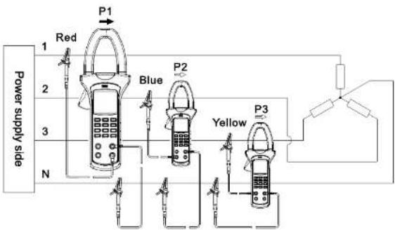
3) (As shown in Figure 4), "V1" end/red testing pen, "V2" end/blue testing pen and "V3" end/yellow testing pen shall be connected to every phase of firing line of three-phase load respectively during load measurement of three-phase four-wire system. "COM" end/black testing pen also shall be connected to zero wire of three-phase load.
UNI-T
UNI-T®
flowchart
graph TD
    A["Power supply side"] --> B["Red"]
    A --> C["Blue"]
    A --> D["Yellow"]
    B --> E["P1"]
    C --> F["P2"]
    D --> G["P3"]
    E --> H["Output"]
    F --> I["Output"]
    G --> J["Output"]
Figure 4 Power measurement of three-phase four-wire system
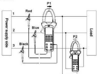
(As shown in Figure 5), connect V1 end/red testing pen, V2 end/blue testing pen and COM end/black testing pen to every firing line of three-phase load respectively during load measurement of three-phase three-wire system. V3 end/yellow testing pen also cannot be measured.
flowchart
graph TD
    A["Power supply side"] -->|1| B["Red"]
    A -->|2| C["Blue"]
    A -->|3| D["Black"]
    B --> E["P1"]
    C --> F["P2"]
    D --> G["Load"]
    E --> H["Measurement Device"]
    F --> I["Measurement Device"]
Figure 5 Power measurement of three-phase three-wire system
UNI-T®
(As shown in Figure 6), connect one of V1, V2 & V3 ends which correspond to 3 phase locations and 2 testing pens of COM end to firing line and zero line of measured wires during measurement of 2 single-phase wires.
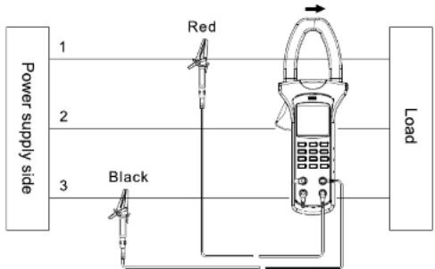
Figure 6 Power measurement of single-phase two-wire system
UNI-T®
- As shown in Figure 7-1, please select SELECT Key to select the 1st phase location when adopting three-phase four-wire system for load so as to display active power, voltage and current of phase location .
- As shown in Figure 7-2, please press key to measure total three-phase power. Current measured power of the 1st phase location also shall be calculated and saved.
● As shown in Figure 7-3, please press SELECT key to select the 2nd phase location of ☐. It also can display active power, voltage and current of phase location of ☐. - As shown in Figure 7-4, please press key to measure total three-phase power. Current measured power of the 2nd phase location also shall be calculated and saved.
● As shown in Figure 7-5, please press SELECT key to select the 3rd phase location. It also can display active power, voltage and current of phase location of 8.

Figure 7-1

Figure 7-2

Figure 7-3

Figure 7-4

Figure 7-5
UNI-T®
UT241/242/243 OPERATING MANUAL
- As shown in Figure 7-6, please press "key" to measure total three-phase power. Current measured power of the 3rd phase location also shall be calculated and saved.
● As shown in Figure 7-7, total three-phase active power can be displayed by pressing SELECT key finally.
● Measurement operation of the 1st and 2nd phase locations is the same as that of three-phase four-wire system. As shown in Figure 7-8, total three-phase active power can be displayed by pressing SELECT key after tripping the 3rd phase location of measurement.
5) The maximum range is 600kW for single-phase active power to display OL symbol if exceeding the range. The maximum range is 1,800kW for total three-phase active power. It also will display OL symbol if exceeding the range.
6Display will show MAX symbol by pressing MAX/MIN key so as to display the maximum active power, voltage and current during measurement. Please press MAX/MIN key to show MIN symbol on LCD and display the minimum active power during measurement. Please press MAX/MIN key so that MAX and"MIN symbols flicker together. It can display current value and record the maximum value and the minimum value at the same time during measurement. Please press the key for a long time to exit the maximum/minimum value mode.
21 22

Figure 7-6

Figure 7-7

Figure 7-8
UT241/242/243 OPERATING MANUAL
Note:
1 Please do not measure AC voltage of more than 600 v.r.s and AC current of 1000A(v.r.s).
2) “Σ” key does not effect without signal input or during single-phase display of “OL” symbol.
3 Only current measurement value can be calculated and saved. The maximum value and the minimum value cannot be calculated or saved.
4) Total power cannot be measured until under active power, apparent power and inactive power gears.
7.2 Apparent power (kWA)+Voltage(V)+Current (A)
1 Please press MENU to select Apparent power (kWA)+Voltage (V)+Current (A) gear;
2 Jaw shall be fixed to measured conduits in corresponding phase locations. That is, user
shall measure a certain phase of three-phase circuit so that jaw is on corresponding conduit.
3 Please refer to Figure 4, 5 & 6 of UT240 manual for wiring of three-phase four-wire system, three-phase three-wire system or single-phase two-wire system.
- As shown in Figure 8-1, please press SELECT key to select the 1st phase location of for three-phase four-wire system of load. It can display apparent power, voltage and current of phase location of .
- As shown in Figure 8-2, please press key to measure total three-phase power. Current measured power of the 1st phase location also shall be calculated and saved.

Figure 8-1

Figure 8-2
UNI-T
UT241/242/243 OPERATING MANUAL
- As shown in Figure 8-3, please press SELECT key to select the 2nd phase location. It also can display active power, voltage and current of phase location of ⚫.
- As shown in Figure 8-4, please press key to measure total three-phase power. Current measured power of the 2nd phase location also shall be calculated and saved.
- As shown in Figure 8-5, please press SELECT key to select the 3rd phase location. It also can display active power, voltage and current of phase location of 3.
- As shown in Figure 8-6, please press key to measure total three-phase power. Current measured power of the 3rd phase location also shall be calculated and saved.
● As shown in Figure 8-7, total three-phase active power can be displayed by pressing SELECT key finally.

Figure 8-3

Figure 8-4

Figure 8-5

Figure 8-6

UNI-T®
UT241/242/243 OPERATING MANUAL
● Measurement operation of the 1st and 2nd phase locations is the same as that of three-phase four-wire system. As shown in Figure 8-8, total three-phase apparent power can be displayed by pressing SELECT key after tripping the 3rd phase location of measurement.

Figure 8-8
5) The maximum measuring range is 600kWA for single-phase apparent power to display "OL" symbol if exceeding the range. The maximum range is 1,800KWA for total three-phase apparent power. It also will display "OL" symbol if exceeding the range.
6 Display will show MAX symbol by pressing MAX/MIN key so as to display the maximum active power, voltage and current during measurement. Please press MAX/MIN key to show MIN symbol on LCD and display the minimum active power during measurement. Please press MAX/MIN key so that MAX and MIN symbols flicker together. It can display current value and record the maximum value and the minimum value at the same time during measurement. Please press the key for a long time to exit the maximum/minimum value mode.
Note:
Please do not measure AC voltage of more than 600 (r.m.s) and AC current of 1000A(r.m.s).
UNI-T
UNI-T®
7.2 Inactive power(kWar)+Voltage(V)+Current(A)
1 Press MENU key to select inactive power (kWar)+voltage(V)+current(A)
2 Jaw shall be fixed to measured conduits in corresponding phase locations. That is, user shall measure a certain phase of three-phase circuit so that jaw is on corresponding conduit.
3 Please refer to Figure 4, 5 & 6 of UT240 manual for wiring of three-phase four-wire system,
three-phase three-wire system or single-phase two-wire system.
4 As shown in Figure 9-1, please press SELECT key to select the 1st phase location of 4 for three-phase four-wire system of load. It can display apparent power, voltage and current of phase location φ.
As shown in Figure 9-2, please press 'kE' to measure total three-phase power. Current measured power of the 1st phase location also shall be calculated and saved.
As shown in Figure 9-3, please press SELECT key to select the 2nd phase location. It also can display active power, voltage and current of phase location of 2.
- As shown in Figure 9-4, please press key to measure total three-phase power. Current measured power of the 2nd phase location also shall be calculated and saved.

Figure 9-1

Figure 9-2

Figure 9-3

Figure 9-4
- As shown in Figure 9-5, please press SELECT key to select the 3rd phase location. It also can display active power, voltage and current of phase location of \$.
- As shown in Figure 9-6, please press key to measure total three-phase power. Current measured power of the 3rd phase location also shall be calculated and saved.
● As shown in Figure 9-7, total three-phase active power can be displayed by pressing SELECT key finally.
● Measurement operation of the 1st and 2nd phase locations is the same as that of three-phase four-wire system. As shown in Figure 9-8, total three-phase inactive power can be displayed by pressing SELECT key after tripping the 3rd phase location of measurement.
5 The maximum measuring range is 600kW ar for single-phase inactive power to display OL symbol if exceeding the range. The maximum range is 1,800K W ar for total three-phase active power. It also will display OL symbol if exceeding the range.

Figure 9-5

Figure 9-6

Figure 9-7

Figure 9-8
UNI-T
UNI-T
6 Display will show MAX symbol by pressing MAX/MIN key so as to display the maximum active power, voltage and current during measurement. Please press MAX/MIN key to show MIN symbol on LCD and display the minimum active power during measurement. Please press MAX/MIN key so that MAX and MIN symbol's flicker together. It can display current value and record the maximum value and the minimum value at the same time during measurement. Please press the key for a long time to exit the maximum/minimum value mode.
Note:
Please do not measure AC voltage of more than 600 r.m.s. and AC current of 1000A (r.m.s).
7.2 Power factor cos( ) + Voltage (V)+ Current (A)
- Press MENU to select gear of Power factor (cos( ) + Voltage (V)+ Current (A) ;
2) Jaw shall be fixed to measured conduits in corresponding phase locations. That is, user shall measure a certain phase of three-phase circuit so that jaw is on corresponding conduit.
3 Please refer to Figure 4, 5 & 6 of UT240 manual for wiring of three-phase four-wire system, three-phase three-wire system or single-phase two-wire system.
4 As shown in Figure 10-1, please press SELECT key to select the 1st phase location of for load of three-phase four-wire system. It also can display power factor (cos( ), voltage (V) and current (A) for phase location .

Figure 10-1
- As shown in Figure 10-2, please press SELECT key to select the 2nd phase location when adopting three-phase four-wire system for load so as to display active power, voltage and current of phase location of Q.
- Please press SELECT key to select the 3rd phase location of ♂ for load of three-phase four-wire system. It also can display power factor (cos(φ), voltage (V) and current (A) for phase location of ♂.
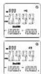
Figure 10-2
Figure 10-3
Measurement operation of the 1st and 2nd phase locations is the same as that of three-phase four-wire system after tripping the 3rd phase location of measurement.
5) There is no measurement function of the maximum/minimum value for this function gear.
Note:
Please do not measure AC voltage of more than 600V r.m.s and AC current of 1000A r.m/s.
UNI-T
UNI-T
7.5 Phase location angle ( )+Voltage (V)+Current (A)
1 Press MENU to select gear of Phase location angle ( ) + Voltage (V) + Current (A);
2 Jaw shall be fixed to measured conduits in corresponding phase locations. That is, user shall measure a certain phase of three-phase circuit so that jaw is on corresponding conduit.
3. Please refer to Figure 4, 5 & 6 of UT240 manual for wiring of three-phase four-wire system, three-phase three-wire system or single-phase two-wire system.
4 As shown in Figure 11-1. please press SELECT key to select the 1st phase location of \for three-phase four-wire system of load. It also can display apparent power, voltage and current of phase location of \.

Figure 11-1
- Please press SELECT key to select the 2nd phase location of @ shown in Figure 11-2. It also can display apparent power, voltage and current of phase location of @.

Figure 11-2
- Please press SELECT key to select the 3rd phase location of \shown in Figure 11-3. It also can display apparent power, voltage and current of phase location of \.

Figure 11-3
Measurement operation of the 1st and 2nd phase locations is the same as that of three-phase four-wire system after tripping the 3rd phase location of measurement.
29 30
5) There is no measurement function of the maximum/minimum value for this function gear.
Note:
Please do not measure AC voltage of more than 600V r.m.s and AC current of 1000A r.mis.
7.6 Voltage frequency (Hz)+Voltage (V)+Current (A)
1) Press MENU key to select gear of frequency + voltage + current; "
2) Jaw shall be fixed to measured conduits in corresponding phase locations. That is, user shall measure a certain phase of three-phase circuit so that jaw is on corresponding conduit.
3) Please refer to Figure 4, 5 & 6 of UT240 manual for wiring of three-phase four-wire system, three-phase three-wire system or single-phase two-wire system.
4) As shown in Figure 12-1, please press SELECT key to select the 1st phase location of for three-phase four-wire system of load. It also can display apparent power, voltage and current of phase location of .

Figure 12-1
- Please press SELECT key to select the 2nd phase location of shown in Figure 12-2. It also can display apparent frequency, voltage and current of phase location of .

Figure 12-2
UNI-T
UNI-T
- Please press SELECT key to select the 3rd phase location of \shown in Figure 12-3. It also can display frequency, voltage and current of phase location of \.

Figure 12-3
Measurement operation of the 1st and 2nd phase locations is the same as that of three-phase four-wire system after tripping the 3rd phase location of measurement.
5) There is no measurement function of the maximum/minimum value for this function gear.
Note:
1) It is not allowed to measure AC voltage of more than 600V r.m.s and AC current of 1000A r.m.s.)
2 Not frequency of current signals but that of voltage signals shall be measured.
7.6 Electric energy (kWh)+Active power (kW)+Time (h:m:s)
1 Press MENU key to select gear of electric energy (kWh)+active power(kW)+time (h:m:s);
2) Jaw shall be fixed to measured conduits in corresponding phase locations. That is, user shall measure a certain phase of three-phase circuit so that jaw is on corresponding conduit.
3 Please refer to Figure 4, 5 & 6 of UT240 manual for wiring of three-phase four-wire system, three-phase three-wire system or single-phase two-wire system.
51 32
- As shown in Figure 13, please press SELECT key to select phase locations of 2.3 to display current power of measured load for corresponding phase locations, current statistic period and current accumulated electric energy on LCD.

Figure 13-1
Accumulated electric energy increases gradually with time. User can press HOLD key to lock measurement value and measurement time display when reading electric energy for a certain period. However, instrument will continue to accumulate measurement time. Please press HOLD key once again after reading data to continue to measure accumulated electric energy. Measurement time display will turn to current measurement time value and electric energy function will not stop until function conversion to positions of other gears. The maximum testing quantity of electric energy is 9999kWh. Display will show OL's symbol after exceeding the value. The maximum statistic period of electric energy also cannot exceed 99 hours.
4 There is no measurement function of the maximum/minimum value for this function gear. 5 Press CLEAR key to reset time and accumulated electric energy to begin counting & measurement again.
UNI-T
UNI-T®
7.8 Phase Sequence Detection
1 As shown in Figure 14. press MENU to select gear of voltage (V)+voltage (V)+voltage (V) Insert red testing pen into V1 jack, blue testing pen into V2 jack, yellow testing pen into V3 jack and black testing pen into COM jack and connect 4 testing pens to measured power, three-phase load and grounding end.
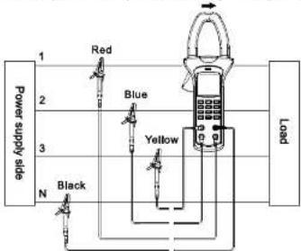
flowchart
graph TD
    A["Power supply side"] -->|1| B["Load"]
    A -->|2| C["Red"]
    A -->|3| D["Blue"]
    A -->|N| E["Black"]
    A --> F["Yellow"]
    A --> G["Black"]
Figure 14
1 As shown in Figure 15, 16 & 17, instrument will display phase sequence detection result for load loop of three-phase four-wire system.

Figure 15 Any phase of voltage is less than 30V.
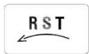
Figure 18 Inverted sequence Figure 17 Positive sequence
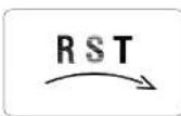
2 Positive sequence layout is shown in following figure. As shown in Figure 18, LCD can display positive sequence detection result when connecting ^aV1 , ^bV2 and V3^ jacks to Phase A, B & C if three-phase voltage exceeds 50V.
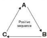
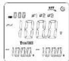
Figure 18
UNI-T
UNI-T®
| Jack | |||
| V1 | V2 | V3 | |
| Phase locationA, B & C | A | B | C |
| B | C | A | |
| C | A | B | |
| Detection result | Positive sequence | ||
3 Inverted sequence layout is shown in following figure. As shown in Figure 19, LCD can display inverted sequence detection result when connecting V1, 'V2 and"V3 " jacks to Phase A, B & C if three-phase voltage exceeds 50V.
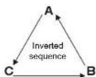
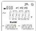
Figure 19
| Jack | |||
| V1 | V2 | V3 | |
| Phase locationA, B & C | A | C | B |
| B | A | C | |
| C | B | A | |
| Delection result | Inverted sequence | ||
55 36
4 LCD will display default phase detection result if certain phase of voltage is less than 50V or without signal for three-phase four-wire system load. As shown in Figure 20, symbols of corresponding phases will not be displayed on LCD.
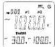
Figure 20 Default phase of the 2nd phase
Note:
Detection voltage range of positive and inverted sequence is 30V-500V. Voltage range without default phase is 50V-500V.
UNI-T®
UT241/242/243 OPERATING MANUAL
8. Harmonic measurement function
Press HARM key for circulation switchover of following harmonic measurement functions. 3 frequency modes, namely, "AUTO", "50Hz" and "60Hz" can be selected for a 11 h harmonic measurement functions respectively. User can press HARM key for a long time to alter frequency mode temporarily during measurement. (Instrument will restore default mode after power-off.) Default frequency mode also can be set under setup mode. (Please refer to Clause 9.3: Default frequency mode setup for SE3 harmonic function for difference of 3 frequency modes.)
8.1 Total voltage harmonics for full wave distortion rate (V THD-R)
It will measure and display effective value of total harmonics of single-phase voltage to full wave distortion rate, harmonic order and corresponding orders of harmonic voltage for load of three-phase four-wire system.
Measurement steps: Press HARM key to enter into measurement mode of total voltage harmonics to total wave distortion rate firstly after bootstrap and connect voltage signal of measured phase to voltage input end of instrument by probe and connect zero wire to COM end. As shown in Figure 14, connect phase wire to any port of V1/V2/V3 and press SELECT key so that measurement port can be consistent with input port.
UNI-T®
UT241/242/243 OPERATING MANUAL
As shown in Figure 21, LCD will display current harmonic order (with auxiliary display in left lower corner), total voltage harmonics for full wave distortion rate (with auxiliary display in right lower corner) and effective value of harmonic voltage (with main display in the middle) respectively.
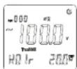
Figure 21
User can press key to increase harmonic order or press key to reduce harmonic order. It also will display effective value of various voltage harmonic components correspondingly.
UNI-T®
UNI-T®
8.2 .Total voltage harmonics for fundamental wave distortion rate
It will measure and display effective value of total harmonics of single-phase voltage to fundamental wave distortion rate, harmonic order and corresponding orders of harmonic voltage for load of three-phase four-wire system.
Measurement steps: Press HARM key to enter into measurement mode of total voltage harmonics to total wave distortion rate firstly after bootstrap and connect voltage signal of measured phase to voltage input end of instrument by probe and connect zero wire to COM end. As shown in Figure 20, connect phase wire to any port of V1/V2/V3 and press SELECT key so that measurement port can be consistent with input port. As shown in Figure 22, LCD will display current harmonic order (with auxiliary display in left lower corner), total voltage harmonics for full wave distortion rate (with auxiliary display in right lower corner) and effective value of harmonic voltage (with main display in the middle) respectively.
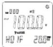
Figure 22
User can press /key to increase harmonic order or press Key to reduce harmonic order. It also will display effective value of various voltage harmonic components correspondingly.
59 40
It will measure and display effective value of various harmonics of single-phase voltage to fundamental wave distortion rate, harmonic order and corresponding orders of harmonic voltage for load of three-phase four-wire system.
Measurement steps: Press HARM key to enter into measurement mode of voltage harmonic components after bootstrap and connect voltage signal of measured phase to voltage input end of instrument by probe and connect zero wire to COM end. As shown in Figure 20, connect phase wire to any port of V1/V2/V3 and press SELECT key so that measurement port can be consistent with input port. As shown in Figure 23, LCD will display current harmonic order (with auxiliary display in left lower corner), effective value of harmonic voltage (with main display in the middle) and percentage of effective value of harmonic component for effective value of fundamental wave (with auxiliary display in right lower corner) respectively.
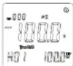
Figure 23
User can press /key to increase harmonic order or press key to reduce harmonic order. It also will display effective value of various voltage harmonic components and percentage for fundamental wave correspondingly.
UNI-T
UNI-T®
8.4 Total current harmonics for full wave distortion rate
It will measure and display effective value of total harmonics of single-phase current to full wave distortion rate, harmonic order and corresponding orders of harmonic current under the mode.
Measurement steps: As shown in Figure 24, please press HARM key to enter into measurement mode of total current harmonics for full wave distortion rate firstly after bootstrap. Please loosen binding clip and clamp them into current loop cables of measured phase, and loosen and guarantee excellent closing of binding clip.
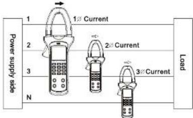
Figure 24
As shown in Figure 25, user can press SELECT key to select No. of any measurement port to display current harmonic order (with auxiliary display in left lower corner), total current harmonics to full wave distortion rate (with auxiliary display in lower right corner) and effective value for harmonic current (with main display in the middle) on LCD respectively.
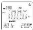
Figure 25
User can press /key to increase harmonic order or press key to reduce harmonic order. It also will display effective value of various current harmonic components.
UNI-T®
UNI-T®
8.5. Total current harmonics for fundamental wave distortion rate
It will measure and display effective value of total harmonics of single-phase current to fundamental wave distortion rate, harmonic order and corresponding orders of harmonic current under the mode.
Measurement steps: As shown in Figure 24, please press HARM key to enter into measurement mode of total current harmonics for full wave distortion rate firstly after bootstrap. Please loosen binding clip and clamp them into current loop cables of measured phase and loosen and guarantee excellent closing of binding clip. As shown in Figure 26, user can press SELECT key to select No. of any measurement port to display current harmonic order (with auxiliary display in left lower corner), total current harmonics to full wave distortion rate (with auxiliary display in lower right corner) and effective value for harmonic current (with main display in the middle) on LCD respectively.
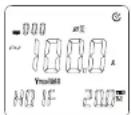
Figure 26
User can press /key to increase harmonic order or press Key to reduce harmonic order. It also will display effective value of various current harmonic components.
45 44
It will measure and display effective value of total harmonics of single-phase current to fundamental wave distortion rate, harmonic order and corresponding orders of harmonic current under the mode.
Measurement steps: As shown in Figure 24, please press HARM key to enter into measurement mode of total current harmonics for full wave distortion rate firstly after bootstrap. Please loosen binding clip and clamp them into current loop cables of measured phase and loosen and guarantee excellent closing of binding clip. As shown in Figure 27, user can press SELECT key to select No. of any measurement port to display current harmonic order (with auxiliary display in left lower corner), effective value of harmonic current (with main display in the middle) and percentage of effective value of current harmonic component to fundamental wave (with auxiliary display in right lower corner) on LCD respectively.
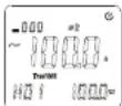
Figure 27
User can press /key to increase harmonic order or press key to reduce harmonic order. It also will display effective value of various current harmonic components.
UNI-T®
UNI-T®
9、Setup mode
User can press SELECT key for bootstrap and entry into setup mode. User can set automatic power-off time (SE1), automatic backlight OFF time (SE2) and default frequency mode of harmonic function (SE3) under setup mode. User also can press SELECT key for a short time for SE1 & SE2 switchover and SE2 setup functions.
User shall press SAVE key to save setup and enter into normal measurement mode after setup. He also can press CLEAR key for a short time under setup mode to restore ex-factory default setup. He also shall press SAVE key for saving.
9.1 Setup of SE1 automatic power-off time
As shown in Figure 28, user can press SELEST key for bootstrap and entry into setup mode. User also can press SELECT key for switchover to SE 1 setup.
Automatic power-off time can be set as follows by pressing UP or DOWN key:
1.10m: 10 minutes
2. 20m: 20 minutes
3. 30m: 30 minutes
4. OFF: Automatic power-off function is OFF.

Figure 28
9.2 Setup of automatic OFF time of SE2 backlight
As shown in Figure 29, user can press SELEST key for bootstrap and entry into setup mode.
He also can press SELECT key for switchover to SE 2 setup.
Automatic backlight OFF time can be set as follows by pressing
UP or DOWN key:
1.10s: 10 seconds
2. 20s: 20 seconds
3. 30s: 30 seconds
4. OFF: Without automatic backlight OFF

Figure 29
9.3. Setup of default frequency mode of SE3 harmonic function
As shown in Figure 30, user can press SELEST key for bootstrap and entry into setup mode.
He also can press SELECT key for switchover to SE 3 setup
Default frequency mode of harmonic function is as follows by pressing UP or DOWN key:
- 50Hz can be used as current signal frequency for fixed
measurement; - 60Hz can be used as current signal frequency for fixed
measurement; - AUTO: Actual frequency of current measurement signal can be gained automatically for measurement;

Figure 30
UNI-T
UNI-T
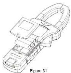
10 Battery replacement (shown in Figure 31)
natural_image
Technical line drawing of a mechanical clamp or clamp device (no text or symbols)Warning
Guarantee instrument power-off and ensure that testing pen is not connected to any measured circuit before replacing battery and opening rear cover of instrument to avoid electric shock. Be sure that rear cover has been tightened or not before using instrument. Only battery of the same model or electric dimension can be replaced.
47 48
“☐” symbol shows on LCD means that load voltage of battery is less than the minimum voltage to guarantee measurement tolerance limit and instrument will prompt battery replacement. Please replace battery according to following steps:
(1) Cut off testing circuit for testing pen, press POWER key for power-off and remove testing pen from input jack.
(2) Open call cover of instrument and remove old battery and replace 4 new batteries of 1.5V. Please pay attention to polarity of anode and cathode. New and old batteries also cannot be mixed.
(3) Inset the cell cover;
11. Maintenance
(1) Cleaning shell: Please clean the surface by dipping soft cloth or sponge by clean water.
(2) It is strictly prohibited to dip instrument into water to avoid damage of testing instrument.
(3) Please dry and store instruments if they are wet.
(4) Please submit instruments to qualified repair personnel or designated repair department for calibration or repair if required.
UNI-T®
UT241/242/243 OPERATING MANUAL
UNI-T®
UT241/242/243 OPERATING MANUAL
The Operating Manual will change without notice!
UNI-T.
UNI-TREND TECHNOLOGY (CHINA) CO., LTD.
No8, Gong Ye Bei 1st Road.
Songshan Lake National High-Tech Industrial
Development Zone, Dongguan City.
Guangdong Province, China Tel: 166-7691 8572 3889
http://www.unHend.com




- UNI-T®
- CONTENTS
- UNI-T
- Safety Warning
- Characteristics
- Technical specifications
- Fittings:
- Instrument Layout
- Key function
- Preparation before measurement
- Measurement function of electric energy
- Active power (kW)+Voltage (V) +Current measurement (A)
- Inactive power(kWar)+Voltage(V)+Current(A)
- Note:
- Power factor cos( ) + Voltage (V)+ Current (A)
- Phase location angle ( )+Voltage (V)+Current (A)
- Voltage frequency (Hz)+Voltage (V)+Current (A)
- Electric energy (kWh)+Active power (kW)+Time (h:m:s)
- Phase Sequence Detection
- Harmonic measurement function
- Total voltage harmonics for full wave distortion rate (V THD-R)
- .Total voltage harmonics for fundamental wave distortion rate
- Total current harmonics for full wave distortion rate
- Total current harmonics for fundamental wave distortion rate
- 9、Setup mode
- Setup of SE1 automatic power-off time
- Setup of automatic OFF time of SE2 backlight
- Setup of default frequency mode of SE3 harmonic function
- Warning
- Maintenance
- UNI-T.
Brand : Uni-T
Model : UT243
Category : Mètre