
UT267B - Mètre Uni-T - Free user manual and instructions
Find the device manual for free UT267B Uni-T in PDF.


| Product Type | Intelligent Three-Phase Digital Phase Volt-Ampere Meter |
| Dimensions | 196 mm × 92 mm × 54 mm |
| Weight | Meter: 550 g (battery included); Each current clamp: 170 g; Test leads: 250 g |
| Power Supply | DC 9V (6 × 1.5V AA alkaline dry battery) |
| Display | LCD, 240 × 160 dots, with adjustable backlight |
| Voltage Range | AC 0.00 V – 600 V (auto-range) |
| Current Range | AC 0.0 mA – 20.0 A (auto-range) |
| Phase Angle Range | 0.0° – 360° |
| Frequency Range | 45 Hz – 65 Hz |
| Power Measurement | Active, reactive, apparent power up to 12 kW/kVAR/kVA |
| Power Factor Range | -1 to +1 |
| Accuracy (Voltage/Current) | ±(1.5% + 3 digits) |
| Accuracy (Phase Angle) | ±1° |
| Accuracy (Power) | ±(3% + 3 digits) |
| Data Storage | 500 sets |
| Interface | RS232 serial port for PC connection |
| Auto Power Off | After 15 minutes of inactivity |
| Safety Standards | IEC61010-1 CAT II 600V, Pollution Degree 2 |
| Withstand Voltage | AC 1000 V/50 Hz for 1 min between circuit and housing |
| Input Impedance (Voltage) | 2 MΩ |
| Battery Life | 10 hours (backlight on), 16 hours (backlight off) |
| Accessories Included | 3 current clamps, 4 test leads (yellow, green, red, black), RS232 cable, software CD, 6 AA batteries, user manual, warranty card |
| Maintenance | Clean jaw surfaces with soft cloth and lubricant (e.g., WD-40); avoid corrosive or rough materials |
Frequently Asked Questions - UT267B Uni-T
User questions about UT267B Uni-T
0 question about this device. Answer the ones you know or ask your own.
Ask a new question about this device
Download the instructions for your Mètre in PDF format for free! Find your manual UT267B - Uni-T and take your electronic device back in hand. On this page are published all the documents necessary for the use of your device. UT267B by Uni-T.
USER MANUAL UT267B Uni-T

P/N:110401103632X DATE:2018.06.26 REV.2
UNI-T®
-
Overview 6-
II. Electrical Symbols -8-
III. Technical Specifications 9 -
Reference and Operating Conditions—9
-
General Specifications—41—
- General Differences and Performance Indexes under Reference Conditions—16—
IV. Structure of Meter—17
V. Operating Instructions 18
- Power On/Off-18-
- Backlight Control—18—
1
UNI-T
Thank you for purchasing our product UT267B intelligent three-phase digital phase volt-ampere meter (also known as three-phase digital volt -ampere meter). In order to use the product properly, please follow instructions below:
----Please read user manual carefully
---Strictly follow safety rules and notes mentioned in this manual
◆ Please use the meter carefully under any circumstance.
◆ Pay attention to word labels and symbols on front and back panels.
◆ Please check there is no missing, damaged or exposed parts before use.
◆ Do not test voltage higher than 600V.
◆ Do not use the meter if back and battery covers are not well placed.
◆ Please ensure test leads are firmly connected.
◆ Do not use the meter or change the battery if it is moisture-affected.
3
UNI-T®
- It is prohibited to test on inflammable and dangerous sites
◆ Remove test wires away from measured objects before disconnection with the meter; do not touch input terminals in case of electric shock.
◆ Keep the meter away from strong electromagnetic environment to ensure normal operation.
◆ The operation will be invalid if simultaneously press two buttons or more.
◆ Stop using the meter if the shell or test wire is found with any fracture and metal exposure.
Do not place and store the meter on sites with high temperature, moisture, dew and strong sunlight.
◆ The meter and current jaw should be regularly maintained and keep clean; any corrosive or rough cloth is not allowed to clean the jaw.
◆ To avoid electric shock happens to current clamp, especially its adjoining surface
4
UNI-T®
◆ The meter is designed with auto power off function.
◆ Remove away the battery if not used in long period and ensure right polarity when changing battery.
◆ Please know well specified measuring scope and working environment of the meter
- Only authorized personnel can use, discharge, calibrate and repair the meter.
◆ Stop using the meter and pack immediately for the authorized treatment if further operation will cause any potential risks
◆ “⚠” is safety warning symbol, requiring users to strictly follow safety instructions in the manual.
◆ “☐” is a caution mark, requiring full attention should be paid to the safe operation.
5
UNI-T
UT267 intelligent three-phase digital phase volt-ampere meter (there-phase digital phase volt-ampere meter) comes out from hard efforts of our developers and is a fully automatic, multi-purpose, digital and intelligent meter specially designed for on-site measurement and with following features: high accuracy, high stability, low power consumption and easy operation. Without cutting off measured circuits, it can measure three-phase AC voltage and current, phase angles between voltages, currents or both, frequency, phase sequence, active, reactive and apparent power, power factor, sum of current vector; it is able to identify wiring groups of transformers, inductive and capacitive circuits as well as secondary circuits and bus differential protection system measurement; it also can read out differential protection phase between CT units, check and ensure correct wiring of kilowatt-hour meter, good conditions of wiring equipments, ect, which all together turn this kind of 6
meter a safe, accurate and convenient new electric instrument offered for electric inspectors.
The meter, designed with latest materials for shell pattern and anti-vibration, anti-skidding, high-insulation protection jacket, can offer 240dots×160dots and dynamic display together with vector diagram indication, thus presenting users luxurious and elegant exterior structure. It is equipped with RS232 and available for data storage of 500 sets which transferred into PC through system software for further online real-time monitoring, history lookup, dynamic display, data readout, save, report and printing, ect.
This kind of meter is also known as three-phase digital phase volt-ampere meter, multi-purpose three-phase digital phase volt-ampere meter, automatic phase volt-ampere meter, tri-clamp digital phase volt-ampere meter, phase volt-ampere meter, three-phase electrical parameter tester. It can fully enjoy functions from intelligent dual-clamp phase volt-ampere meter and general machinery dual-clamp digital phase volt-ampere meter, which is applied in
UNI-T®
electric power, petrochemical, metallurgy, railway, factories and mining, R&D institutes, metrological department. It is particularly needed in electric charging and relay protection system, electric power calculation, check and monitoring from power supply remarketing departments as well as electric installment, relay protection, differential inspection, start-up testing, power transformation check, electrical training, skill competition performed by technical department.
II. Electrical Symbols
| Extreme danger! The operator must strictly observe safety rules to avoid electric shock, personal injury or accidents | |
| Danger! The operator must follow safety rules to avoid electric shock, personal injury or accidents. | |
| Warning! Strictly adhere to safety rules to avoid any personal injury or equipment damage. |
8
III. Technical Specifications
- Reference and Operating Conditions
| Impact factors | Reference conditions | Operating Conditions | Notes |
| Ambient Temperature | 23^ C ± 1^ C | -1040~ ℃ | _____ |
| Ambient Humidity | 40%-60% | <80% | _____ |
| Waveform | Sine wave Sine wave | = 0.01 | |
| Frequency | 50HZ-1HZ | 45HZ 65HZ | _____ |
| Working Voltage | 9V 0.1V | 9V±1.5V | _____ |
9
UNI-T®
| Current AmplitudeWhen measuring frequency phase sequence | 200mA 3mA | 10mA-20A | ---- |
| Voltage Amplitude when measuring frequency phase sequence | 100V 10V | 10V-600V | ---- |
| Current Amplitude when measuring power factor | 200mA 3mA | 20mA-20A | ---- |
| Voltage Amplitude when measuring power factor | 100V 10V | 10V-600V | ---- |
| Exterior Electromagnetic Field | Avoided | ||
| Measured Test lead Location | Placed on geometric center of the jaw | ||
10 11
- General Specifications
| Functions | To measure three-phase AC voltage, current, phase between two voltages, currents or both, frequency, phase sequence, active and reactive power, apparent power, power factor, sum of current vector; to differentiate wiring groups of transformer, inductive and capacitive circuits; to test secondary circuits and bus differential protection system, to read out differential protection relation between CT units; to check and ensure correct wiring and good conditions of wiring equipments. |
| Power | DC9V Alkaline Dry Battery (1.5V AA·6) |
| Range(Fully Automatic) | Voltage: AC 0.00V 600V |
| Current: AC 0.0mA 20.0A | |
| Phase Angle:0.0 360-9 ° |
UNI-T®
| Power Factor: 0.001 | |
| Sum of Current Vector: 1mA | |
| Phase Sequence | Normal: U1,U2,U3 or I1,I2,I3 cursor flashes from left to rightReverse: U1,U2,U3 or I1,I2,I3 Cursor flashes from right to left |
| Data Storage | 500 sets |
| Rs232 Interface | With RS232,all data transferred into PC for further data management and analysis |
| Connection line | RS232 connection line,1.8 meters long |
| Power Consumption | Max 80mA consumed with backlight on, 10 hours for battery life |
| 50mA with backlight off, 16 hours for battery life | |
| Display Mode | LCD display, 240dots×160dots |
| Meter Size | Long × Wide Thick 196mm 92mm 54mm |
| Backlight | Available, used in dark site and at night |
UNI-T®
UNI-T®
| Measuring Speed Rate | About 2 seconds per time |
| Data Hold | Press [HOLD] button to maintain data, indicated by HD symbol |
| *Auto Power Off | Auto power off to reduce power loss 15mins later after power on |
| Voltage Measurement | Low battery icon displays when voltage under 7.2 V, to remind changing battery. |
| The meter:550g (battery included) | |
| Quality | Sharp Current Clamp:170g 3× |
| Test Wire:250g | |
| Testing Wire Length | 1.5m |
| Clamp Wire Length | 2m 5mm |
14 15
| Working Temperature and Humidity | -1040-80%Rh< |
| Storage Temperature and Humidity | -1060-70%Rh< |
| Input Impedance | Input impedance for measuring voltage: 2M Ω |
| Withstand Voltage | meter circuits and shell, able to withstand AC voltage1000V/50Hz for 1mins when input Sine wave |
| Insulation | For circuits and protected shell≥400M Ω |
| Structure | Double Insulation, coupled with vibration-proof insulation jacket |
| Applicable Safety Rules | IEC61010-1 CAT II600V, IEC61010-031, IEC61326, Pollution Class2 |
The meter flashes before automatically power off and continues to work with ON button pressed down.(15 minutes as a working period)
UNI-T®
- General Differences and Performance Indexes under Reference Conditions.
| Items | Range | Resolution | General Difference |
| Voltage | AC 0.00V-600V | 0.01V | ±(1.5%rdg+3dgt) |
| Current | AC 0.0mA-20.0A 0.1mA | ±(1.5%rdg+3dgt) | |
| Phase Angle | 0.0°360 0.1° | ° | ±1° |
| Active Power | 0.0W-12kW | 0.1W | ±(3%rdg+3dgt) |
| Reactive Power | 0.0VAR-12kVAR | 0.1VAR | ±(3%rdg+3dgt) |
| Apparent Power | 0.0VA-12kVA | 0.1VA | ±(3%rdg+3dgt) |
| Frequency | 45HZ-65HZ | 0.01HZ | ±(2%rdg+3dgt) |
| Power Factor | -1+1 0.001 | ±0.03 |
Notes1: Phase angle differences should be less than under the working conditions, is for phase angle tolerance between 5mA 10mA 16.17
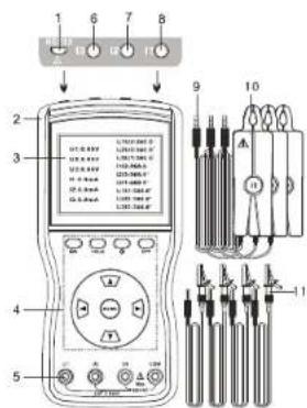
- USB-RS232 Interface
- Vibration-Proof Insulation Jacket
- LCD Display
- Functional Button Zone
- Three-Phase Voltage Input Terminals
- Current Input Terminal 13
- Current Input Terminal I2
- Current Input Terminal I1
- Current Clamp Output Plug
- Sharp Current Jaw
- Voltage Input Testing Cables
UNI-T
V. Operating Instructions
Note:
- Please carefully check if there are damaged parts or not before safe use.
- Do not use the meter on dangerous sites.
● Install the battery according to the manual. -
Do not simultaneously press 2 buttons or more in case of invalid operation.
-
Power On/Off
Press ON to power on and LCD displays. Press OFF button to power off, the meter will automatically power off 15 minutes later after power on.
- Backlight Control
Press 📋 button after power on to control the backlight, which is suitable in dark sites and at night.
- Data Hold and Storage
Press HOLD button to maintain displayed data under measuring status, 18
indicated by HD icbn, press again to cancel the operation. The meter will automatically save and number current data while maintaining the data, indicated by group serial number such as S.001. Max 500 sets of data is available for the meter, displayed by FULL if the number is achieved.
- Data Access and Exit
Press MENU to enter into data access status during measurement, indicated by RD icon, then data lookup starts from R 001 press "Up button to increment by 1, Down button to decrement by 10 and Left to exit this status and return to measuring mode.
- Data Delete
Press Right button when still under data access data to enter into data delete option, then Left or Right button to move the cursor to select YES of NO; next* MENU button for confirmation or exit, finally returning to measuring mode.
UNI-T
The meter will automatically enter into voltage, current, phase display measuring modes (Figure A) after power on; then press Down button to go into display modes of active and reactive power, apparent power, power factor, frequency, three-phase current vector measurement (Figure B); or Right button to access phase sequence status (Figure C); Left button to display vector gram (Figure D); or Up button to back to voltage, current, phase measuring mode. Particularly to mention is that three-phase power and power factor in figure B correspond to those of U1I1, U2I2, U3I3.
| Electric Shock, Danger! Only trained and authorized staff is allowed to operate and should strictly observe safety rules, to avoid any damage to the meter or personal injury in case of electric shock. | |
| Danger! Do not measure voltage above 600V, to avoid any damage to the meter or personal injury in case of electric shock | |
| Danger! Do not measure current above 20A which may damage the meter! | |
| Connect wires as indicated in the manual and avoid wrong insert between I1, I2 and I3 | |
| Disconnect test wires with measured circuits before pulling them out of the meter after measurement. | |
| Phase measuring relations: U1U2, U2U3, U3U1, I1I2, I2I3, I3I1, U1I1, U2I2, U3I3, the former phase of signal always precedes the latter. |
22
| Voltage terminals U1, U2, U3 are named the same with red marks on current clamps. | |
| The Current clamping direction should accord with those of red marks during phase measuring |
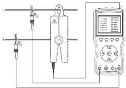
This meter can measure three-phase voltage and current, phase angle between voltages, currents and both, frequency, active and reactive power, apparent power, power factor, three-phase sum of current vector, and also differentiate phase sequence, inductive and capacitive circuits, ect. Testing wire connection is shown as below:
1. Single Phase Measuring:
Connect measured voltage lines L, N to yellow U1 and black COM terminals, then current clamp I1 grasping L line. It also works by choosing Green U2, black COM, I2 or red U3, black COM and I3.
23
UNI-T
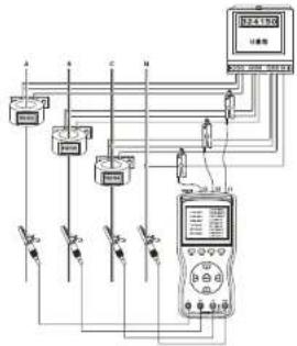
2. Three-Phase Four-Wire Measuring:
Connect yellow UA, green UB, red UC and black N correspondingly to terminals yellow U1, green U2, red U3 and black COM on the meter, then get current clamps I1, I2, I3 grasp measured IA, IB, IC.
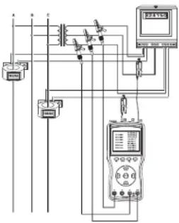
3. Three-Phase Three-Wire Measuring:
Connect measured voltage lines to yellow UA, red UC and Green UB correspondingly to terminals of the mete yellow U1, red U3 and black COM, then get current clamps I1, I3 grasp measured IA and IC. Reference connection figure shown as below.
It is possible to differentiate among inductive and capacitive load, phase sequence and the polarity during measuring. If U111 phase angle is displayed ranging from 0°90°; it measured load will be diagnosed as inductive; it is capacitive load with scope from 270°360°; it is positive phase sequence and has the same polarity with phase angles all close to 120°; otherwise positive phase sequence and reverse polarity is obtained with phase angle 24
close to 120 and 300 (It may caused by wrong current clamping or wiring connection), other conditions will be identified as reverse phase sequence (absence of phase not considered).
Under phase sequence measuring mode, U1, U2, U3 or I1, I2, I3 are considered as positive phase sequence with cursor flashing from left to right side; and if the other way, U1, U2, U3 or I1, I2, I3 cursor move from right to left side. If corresponding cursor does not flash, it is likely that phase may be absent or signal amplitude is too low.
UNI-T®
Connection Figures shown as below:
- Single --Phase Voltage, Current, Phase Angle, Frequency, Power Measurement:
26 27
- Three-phase Four-Wire Voltage, Current, Phase Angle and Sequence, Frequency, Power and Power Factor Measurement:
flowchart
graph TD
    A[" meters "] --> B[" sensor 1 "]
    A --> C[" sensor 2 "]
    A --> D[" sensor 3 "]
    A --> E[" sensor 4 "]
    A --> F[" sensor 5 "]
    B --> G[" meter 1 "]
    C --> H[" meter 2 "]
    D --> I[" meter 3 "]
    E --> J[" meter 4 "]
    F --> K[" meter 5 "]
    G --> L[" meter 6 "]
    H --> M[" meter 7 "]
    I --> N[" meter 8 "]
    J --> O[" meter 9 "]
    K --> P[" meter 10 "]
    L --> Q[" meter 11 "]
    M --> R[" meter 12 "]
    N --> S[" meter 13 "]
    O --> T[" meter 14 "]
    P --> U[" meter 15 "]
    Q --> V[" meter 16 "]
    R --> W[" meter 17 "]
    S --> X[" meter 18 "]
    T --> Y[" meter 19 "]
    U --> Z[" meter 20 "]
    V --> AA[" meter 21 "]
    W --> AB[" meter 22 "]
    X --> AC[" meter 23 "]
    Y --> AD[" meter 24 "]
    Z --> AE[" meter 25 "]
UNI-T®
- Three-Phase Three-Wire Voltage, Current, Phase Angle, Phase Sequence, Frequency, Power and Power Factor Measurement:
8. Data Transmission to PC
The accessory RS232 connection line is used for communication of the meter with PC. With the meter power on and the software running, several following operations such as history lookup, data recall, save, report sheet, history printing can all be performed. The more data the meter saves, more time it will take to read out. History data can be saved in Txt or Excel format.
VI. Battery Replacement

Note:
- Please ensure correct polarity when installing the battery, otherwise it causes damage to the meter
● It is prohibited to change batteries on dangerous sites - You must use Qualified alkaline dry battery (1.5V AA>6)
● New and old batteries are not allowed to combine for use
UNI-T
- Low battery icon will be displayed with power supply below 7.2V, please timely change batteries and do as below:
- Press OFF button to power off.
- Use cross-shaped screwdriver to loosen one bolt away from the battery cover and open it.
- Replace old batteries with new ones and ensure right polarity is selected.
- Close the battery cover and tighten the bolt.
- Press ON button to check if the battery is successfully replaced, if not, repeat operations from the second step.
- Take the battery out if the mete is not in use for long time.
UNI-T®
VII. Other Items and Notes:
- Exclusiveness of Current Clamps
There are three current clamps attached to every meter, which can not be exchanged for the other meters. Current clamps should be prevented from any crush and kept clean in order to ensure reliability when closing up to measure. - Maintenance of Current Clamps
Please clean up clamp jaw surface after measurement, soft cloth coupled with lubricant (eg: WD-40 lubricant) instead of rough cloth or the corrosive are expected to use for the clearing. Please clean again just before use. - The meter can be used to measure secondary circuits and low voltage loop, however, not suggested to measure current in high-voltage circuits in case of electric shock.
- Three-Phase Four-Wire (phase angle under three-phase load balance) 32 33
- Three-phase Three-Wire (phase angle under three-phase load balance):
| Phase Relations Phase Value Phase | Relations Phase Value | ||
| Uab-Ucb | 300° | Ia-Ic | 240° |
| Uab-Ia | 30° | Ucb-Ic | 330° |
UNI-T
- Three-Phase Four-Wire and Three-Phase Three-Wire Vectorgrams
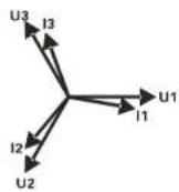
Three-Phase Four-Wire
Vectorgram
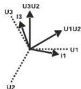
Three-Phase Three-Wire
Vectorgram
Note:
If current clamps or current wires are incorrectly attached, the displayed phase difference will be 180^ , that is to increment by 180 based on reference values above.
34 35
| The Meter | 1 |
| Giftbox | 1 |
| Current Clamps | 3 |
| System Software Disk | 1 |
| RS232 Cable | 1 (1.8 meters) |
| Test leads | 4 (one for each type: yellow, green, red, black ) |
| Battery | 6 PCS (Alkaline dry battery:1.5V AA) |
| User Manual, Warranty Card, Product Certificate | 1 |
UNI-T
The manual information is subject to changes without prior notice.
36
UNI-T.
UNI-TREND TECHNOLOGY (CHINA) CO., LTD.
No6. Goo Ye Bei 1st Road
Songshan Lake National High-Tech Industrial
Development Zone, Duonquan City.
Guangdong Province, China
Guangdong Province, China Tel: (85-760) 8572-3999
tel: (86-769) 6572 3555 http://www.uni-trad.com
http://www.sse.com.cn
37




Brand : Uni-T
Model : UT267B
Category : Mètre