
CL220 - Light COLBOR - Free user manual and instructions
Find the device manual for free CL220 COLBOR in PDF.


| Product Type | Video Light |
| Brand | COLBOR |
| Model | CL220 |
| Color Rendering Index (CRI) | 97+ |
| Color Temperature Range | 2700K - 6500K (±200K) |
| Beam Angle | ≈120° (light base), ≈45° (with reflector) |
| COB Output Power | 220W |
| Max Power Consumption | 250W |
| Working Voltage | DC 48V 5.2A |
| Cooling Mode | SMART / QUIET / PERFORMANCE |
| Body Material | Aluminum Alloy + ABS |
| Dimensions (L×W×H) | 212 × 128 × 219 mm |
| Weight (with light base) | 1570 g |
| Operating Temperature | -10°C to 40°C |
| Mount | Bowens Mount (reflector included) |
| Light Effects | Fire, CCT Chase, Pulsing, TV, Explosion, Faulty Bulb, Welding, Strobe, Lightning, S.O.S |
| Wireless Control | COLBOR STUDIO App (via Bluetooth) |
| Group Control | Up to 15 groups (A–O) |
| Battery Compatibility | V-port battery (via optional VM3), max 50% brightness with single 14.8V battery |
| Package Contents | CL220 light, reflector, carrying bag, COB cover, 3m power cable, power adapter, warranty card |
| Safety Warnings | Keep away from liquids, do not cover ventilation, do not look directly at light, use only provided adapter |
Frequently Asked Questions - CL220 COLBOR
User questions about CL220 COLBOR
0 question about this device. Answer the ones you know or ask your own.
Ask a new question about this device
Download the instructions for your Light in PDF format for free! Find your manual CL220 - COLBOR and take your electronic device back in hand. On this page are published all the documents necessary for the use of your device. CL220 by COLBOR.
USER MANUAL CL220 COLBOR
natural_image
Line drawing of a CL220 COLBOR camera with lens and trigger mechanism (no text or symbols on the device itself)CL220 Video Light User Manual
Thank you for choosing COLBOR product. Please read this manual carefully before use and follow all instructions mentioned herein.
Caring For Your COLBOR Product
- Keep corrosive chemicals, liquids and heat source away from the product to prevent mechanics damage.
• The product is not waterproof. - Do not leave the product unattended while in use. Keep out of reach of children.
- Do not handle with wet hands. Do not touch the hot COB surface.
- Please do not block the ventilation and do not look at the light directly when it is on.
- Do not attempt to disassemble or modify the product. Doing so voids warranty.
- Please have the product checked or repaired by authorized technicians if any malfunctions happened.
- Disconnect from the power supply when it is not in use.
- Do not cover, inverted COB and radiator for high temperature, do not cover, inverted, do not touch the lamp holder and radiator vent with your hands when the product in use.
- Do not use any power adapter of other products to avoid the lamp malfunction.
- Malfunction may be caused by dropping, impact of external force.
- Failure to follow all the instructions may result in mechanics damage.
• Our company reserves the right of final interpretation of the product. - Product design and specifications are subject to change without prior notice.
Power Connection
- You must use the power adapter that comes with the product rather than other adapters to avoid damaging the lamp. The positive and negative connections of the power adapter interface (DC OUT) and the lamp power interface (DCIN) are shown below:


Product Instructions


① LED Display Screen
② EFF Mode Button
③ EFF Rate Option Button
④ Color Temperature Option Button
⑤ Setting Button
⑥ Color Temperature Control Knob
⑦ Brightness Control Knob
⑧ DC 48V Power Port
⑨ Power Button
⑩ Bowens Mount
⑪ COB Lamp Beads
⑫ Lamp Angle Adjustment Locking Grip
⑬ Bracket
⑭ Air Outlet
⑮ NATO Slideway
⑯ Air Inlet
⑰ Lamp Grip
⑱ Soft Light Cover Hole
⑲ Soft Light Cover Hole Screws
⑳ Bracket Screw
Light Installation
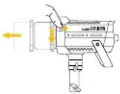
1. Removal of lamp cap protection cover
Hold the COB cover with the Bowens Mount tenon and rotate it as the direction of the arrow.
★ Note: Be sure to remove COB protective cover and COB protective film before use.
2. Installation and removal of reflector
Installation of reflector: Align the reflector with the groove around the lamp head and clip it in, turn the reflector as the direction of the arrow, and the reflector installation will be completed after the top rod rebounds.
Removal of reflector: Under the instructions of "Lamp Cap Protection Cover Removal".

natural_image
Diagram of a speaker emitting sound waves into a device (no text or symbols visible)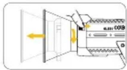
natural_image
Diagram of a device emitting a laser beam, showing light path and component layout (no text or symbols)3. Installation and fixation of light
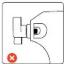
Rotate the lamp holder screw until the inner wall not shielded and put the product on the top of the lamp holder to tighten the bracket screw for fixation. Adjust the lamp body irradiation Angle and tighten the lamp holder Angle grip fixed.

natural_image
Pure electrical circuit lines without any symbols√
Screw out, the inner wall of the bracket without any shelter

natural_image
Pure electrical circuit lines without any symbols×
Halfway the screw out The screw is not out at all

natural_image
Pure electrical circuit lines without any symbols×
4. Install the soft light cover
Insert the handle of the soft light umbrella into the umbrella hole. After adjustment, lock the cover hole screw.

natural_image
Simple line drawing of a mechanical component or tool with no visible text or symbolsScrew out, the inner wall of the soft light cover without shelter
natural_image
Simple line drawing of a mechanical component with a red X mark (no text or symbols)The screw is not out at all
5. Power Connection
(1) Mount the power adapter
Do not suspend the power adapter in the air. Use wire rings to hang it on the lamp stand.
(2) Power with power adapter
Connect the power adapter, align the pin with the DC power interface of the lamp body, and then power through the cable after stable.
(3) Power cord storage
Please turn off the lamp before unplugging the power cord. When unplug the power cable, hold down the safety lock on the connector before removing it. If unlocked, do not forcibly remove the power supply.

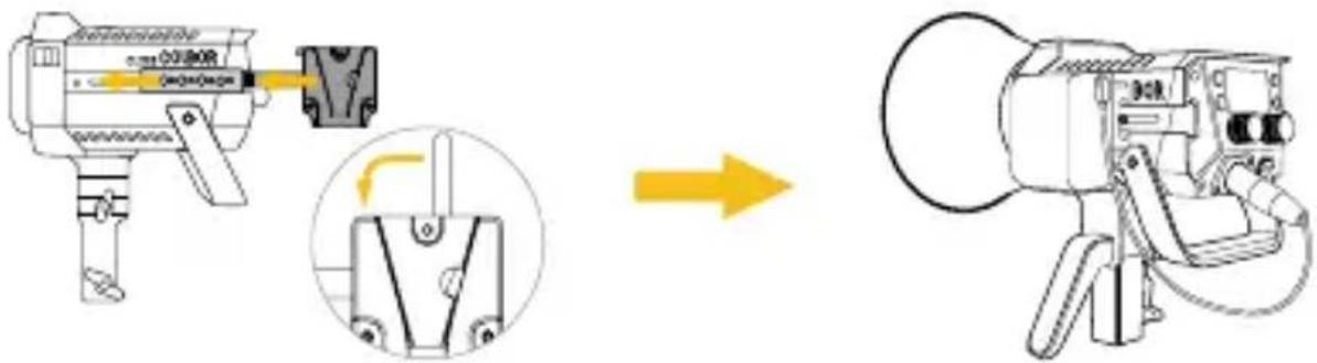
(4) Power with V-port battery
Mount the V-port battery to the lamp by complimentary the NATO expansion bar with VM3 (optional), and then connect the D-tap to XLR power cable to start the lamp.
Note:
* For one 14.8V battery powering, the maximum brightness is 50% of full power.
* When battery runs low, the brightness will adjust accordingly for protecting the power cord from overheating due to excessive current.
* Dual V-port battery mobile power supply solution is recommended.
Operation Instructions
- Please remove the COB protective cover before using the light.
- Turn on the lamp: After confirming that the power connection is normal, press the switch to “-”, and the screen will display the brand and product module, and then enter the operation interface. (Default mode: CCT)
- Turn off the lamp: press the switch to "o" to turn off the power switch.
1. Status Icon Description
![(•) Ws A® [A] RESP. SHARP LANG. EN Product INFO.](/content/2026/05/852957/images/56c7a8ef08814f4bf0ada536ac0afedfef8016fdfd567f65fcecc8b095cc47a3.jpg)
| 1 APP Connection Status Icon | |
| • <> (••) | After selecting wireless connection in Settings menu, the icon will be displayed dynamically. |
| (••) | The icon is always on to indicate successful pairing with mobile APP.The icon disappears to indicate mobile APP pairing failure, or the product is unpaired. |
| 2 Fan Status Icon | |
| s | Smart Mode. The product will adjust the fan speed according to the internal detected temperature to ensure that it is in optimal working condition. |
| q | Quiet Mode. The fan keeps running at low speed for minimum noise, and overheating protection will be activated if the product temperature is higher than the alarm value. |
| p | Performance Mode. Fan runs at the highest speed to ensure heat dissipation. |
| 3 Group Status Icon | |
| NULL | None grouping status. The product defaults to the factory status, and will not be affected by other groups. |
| AT | A stands for Group A. There are fifteen groups (A~O). T stands for Tx. |
| AR | A stands for Group A. There are fifteen groups (A~O). R stands for Rx. |
| ATR | A stands for Group A. There are fifteen groups (A~O). TR stands for TxRx. |
| 4 Product Overheated Alarm Icon | |
| [8!] | If the icon flashes, it means that the internal temperature of the product is too high, and cooling measures need to be taken. If the icon disappears, it means that the operation is normal. |
2. CCT Mode (Short press CCT Mode Button to enter)

Color Temperature Control Knob

Turn the knob clockwise or anti-clockwise to adjust color temperature (CCT) from 2700K\~6500K

Press down the knob to quickly switch the preset color temperature to 2700K, 3200K, 4000K, 5600K, and 6500K
Brightness Control Knob

Turn the knob clockwise or anti-clockwise to adjust brightness (DIM) from 0%\~100%

Press down the knob to quickly switch the preset brightness to 0%, 25%, 50%, 75%, and 100%
* Rolling the knob will enlarge the current setting parameter value, and it will automatically return to the main screen after 1.5 seconds of no operation
3. EFF Mode (Short press EFF Mode Button to enter)
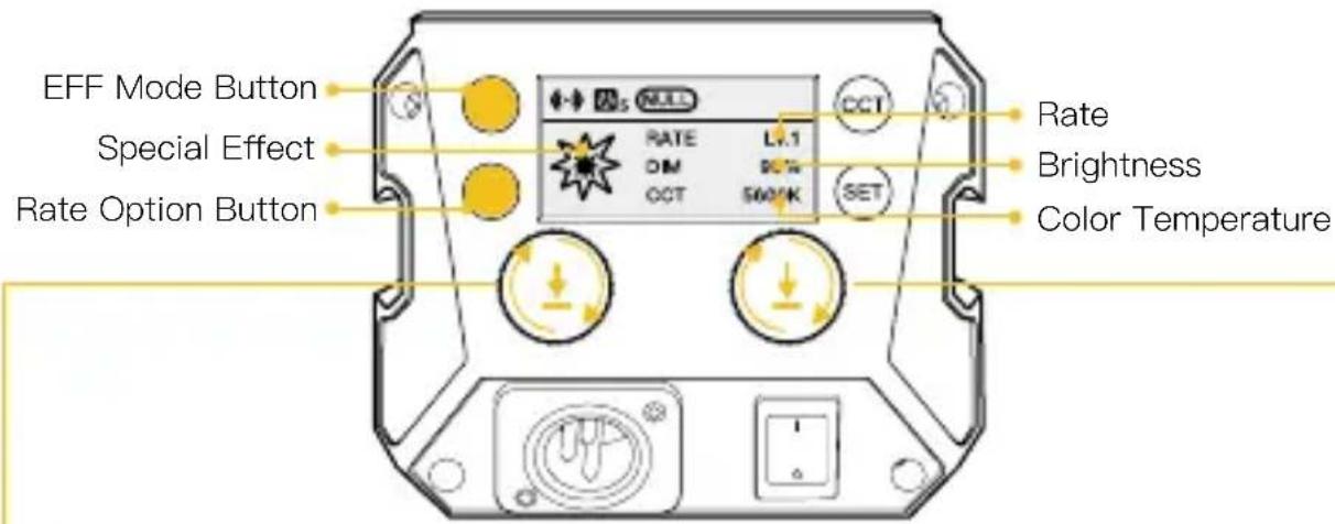
Color Temperature Control Knob

Turn the knob clockwise or anti-clockwise to adjust color temperature (CCT) from 2700K\~6500K

Press down the knob to quickly switch the preset color temperature to 2700K, 3200K, 4000K, 5600K, and 6500K
Brightness Control Knob

Turn the knob clockwise or anti-clockwise to adjust brightness (DIM) from 0%\~100%

Press down the knob to quickly switch the preset brightness to 0%, 25%, 50%, 75%, and 100%
Light Effect Mode (EFF) Button

Press to switch light effect: Fire → CCT Chase → Pulsing → TV → Explosion → Faulty Bulb → Welding → Strobe → Lightning → S.O.S
| EFF |  Fire Fire | RATE: Lv.1 – Lv.5DIM: 0%–100%CCT: 2700K–6500K |  Faulty Bulb Faulty Bulb | RATE: Lv.1 – Lv.5DIM: 0%–100%CCT: 2700K–6500K |
 CCT Chase CCT Chase | RATE: Lv.1 – Lv.5DIM: 0%–100%CCT: LOCK | [6T7S]Welding | RATE: Lv.1 – Lv.5DIM: 0%–100%CCT: 2700K–6500K | |
 Pulsing Pulsing | RATE: Lv.1 – Lv.5DIM: 0%–100%CCT: 2700K–6500K |  Strobe Strobe | RATE: Lv.1 – Lv.5DIM: 0%–100%CCT: 2700K–6500K | |
 TV TV | RATE: Lv.1 – Lv.5DIM: 0%–100%CCT: LOCK |  Lightning Lightning | RATE: Lv.1 – Lv.5DIM: 0%–100%CCT: 2700K–6500K | |
 Explosion Explosion | RATE: Lv.1 – Lv.5DIM: 0%–100%CCT: 2700K–6500K |  S.O.S S.O.S | RATE: LOCKDIM: 0%–100%CCT: 2700K–6500K |
4. Setting
- Short press the setting button to enter settings menu.
- Turn the brightness control knob clockwise or anti-clockwise to choose setting.
- Press the setting botton to adjust corresponding setting (Short press the setting botton to adjust the wireless connection mode).
| Settings Options | ||
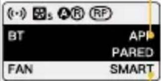 | Wireless Connection | APP/Remote ControlLong press the setting button for pairing (One mode for each time) |
| Fan Mode | SMART/ QUIET/ PERFORMANEC SMART: The product will detect the current internal temperature to adjust the fan speed by itself.QUIET: The fan will run at low speed. If the product temperature reaches the alarm value, it will start the power-off protection mechanism.PERFORMANEC: Fan runs at the highest speed to ensure heat dissipation. | |
 | Group NULL/ A~O | (NULL by default) |
| Communication | TX/ RX/ TXRX (TX by default) | |
| Curve | LINEAR, L.CURVE, E.CURVE, S.CURVE. | |
 | Response | SHARP/ SMOOTH(SMOOTH by default) |
| Initial brightness setting | Default、0%、25%、75%、100% | |
| Language | EN/ CN | |
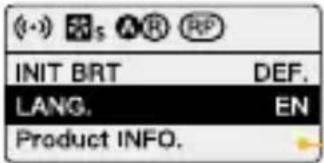 | Product INFO. | Short press the setting botton to enter the production information interface. Press the setting botton again to go back to settings menu.1 Hardware Version2 Firmware Version3 Protocol Version4 MAC Address |
5. APP Connection & Light Control
Scan the QR code, or search "COLBOR STUDIO" in app store to download the app for light control.

CL220 Pairing:
- Press the setting button and enter the pairing mode. Short press the setting button to choose "APP", then long press the setting button for 3 seconds for pairing.
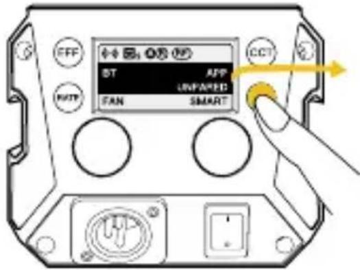
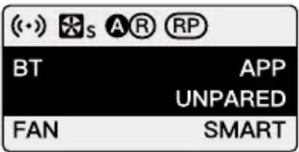
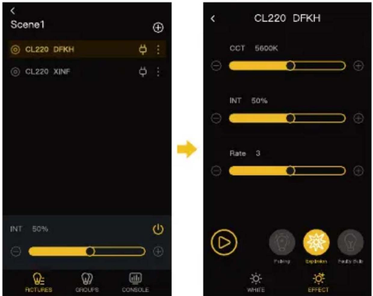
- Open the APP and click the “+” on the upper right, then click the scene one and click the + on the upper right. Showing CL220 means successfully pairing.

- Click the CL220 for control.
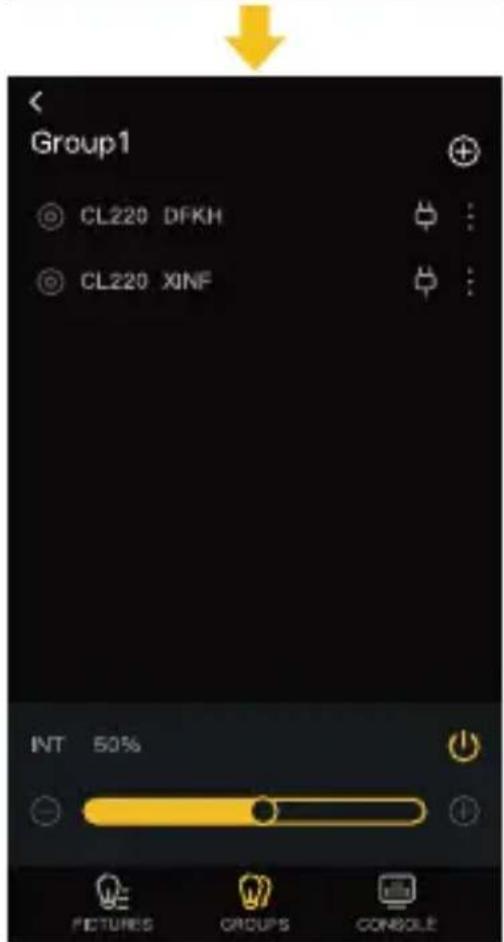
CL220 Group Control:
- After successfully pairing the CL220, click the group then click the “+” on the top right. Choose the light for grouping and click the confirm bottom. Showing Group One means successfully grouping.


- Click the group for lighting control.

natural_image
Line drawing of a three-bladed COUBOR camera with attached sensor components (no text or symbols)
Equipped with a NATO extension bar and an NQD quick-release device, the lights can be spliced together, and up to three lights can be spliced.
Specifications
| Color Rendering Index | 97+ |
| Color Temperature Range | 2700K–6500K (±200K) |
| Beam Angle | ≈∠ 120° Reflector ≈∠ 45° |
| Illumination | See the Form 1 Below |
| COB Output Power | 220W |
| Power | 250W (Max) |
| Light Working Voltage | DC 48V 5.2A |
| Cooling Mode | SMART/ QUIET/PERFORMANEC |
| Connector | Three Core Cannon Head( 2 For Active, And 1 For Negative) |
| Body Material | Aluminum Alloy+ABS |
| Light Dimension (mm) | 212*128*219mm |
| Light Weight | 1570g (Light Base Included) |
| Operating Temperature | -10~40°C |
Package List

natural_image
Technical line drawing of a mechanical device with no visible text or symbolsCL220 Video Light x1

natural_image
Simple line drawing of a funnel-shaped object with a base and two small protrusions at the bottom (no text or symbols)Reflector (Bowens Mount) x1 (not included in CL220 Lite)

Carrying Bag x1 (not included in CL220 Lite)
COB Cover x1
natural_image
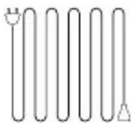
Pure electrical circuit lines without any symbols3m Plum Tail Cable x1

natural_image
Simple line drawing of a medical or electrical device with a bulb, coiled tube, and plug (no text or symbols)Power Adapter (with Wire Lanyard) x1
Warranty Card x1
NB3.58 (Optional) x1
Power adapters may vary according to sales region.
WARRANTY
Warranty Period
Thank you for purchasing COLBOR products.
- Customers are entitled to free replacement or repair service in case of quality defect(s) found in the product under normal use within 30 days upon receipt of the product.
- Original COLBOR products are entitled to 12-month limited warranty service. The warranty period begins on the date of purchase of brand new, unused products by the first end-user.
Within the warranty period, if product defect or failure is attributable to material defection or technological problem, the defective product or defective part will be repaired or replaced without charge (service and materials fee).
Warranty Exclusions and Limitations
- Faults resulted from inappropriate use of a product without following its operation specification
- Artificial damage, e.g. crash, squeeze, scratch, soaking, exposing to rain or damp
3.Modifications to a product by its user or a third party without prior written consent of COLBOR, e.g. replacement of element or circuit, label alteration - The code on product is inconsistent with that of warranty certificate, or the code on the product or warranty certificate is altered or torn off
- All consumable accessory attached to a product, like cable, cover
- Faults as a result of force majeure, such as fire, flood, lightning, etc.
Warranty Claim Procedure
- If failure or any problem occurs to your product after purchase, please contact a local agent for assistance, or you can always contact COLBOR's customer service through email.
- Please retain your sales receipt and warranty certificate as proof of purchase. If any of these documents is missing, only sales return or chargeable service will be provided.
- If the COLBOR product is out of the warranty coverage, the service and the parts cost will be charged.
Form 1
Illumination
| 1m | 5m3mCCT | ||||
| 2700K | Light Base | LUX | 8020 | 1250 | 569 |
| FC | 745 | 116 | 53 | ||
| Reflector | LUX | 44200 | 4210 | 1720 | |
| FC | 4100 | 391 | 160 | ||
| 3200K | Light Base | LUX | 8130 | 1330 | 594 |
| FC | 772 | 123 | 55 | ||
| Reflector | LUX | 46300 | 420 | 1800 | |
| FC | 4310 | 411 | 167 | ||
| 4300K | Light Base | LUX | 8840 | 1420 | 636 |
| FC | 822 | 132 | 59 | ||
| Reflector | LUX | 50100 | 4760 | 1940 | |
| FC | 4650 | 422 | 180 | ||
| 5600K | Light Base | LUX | 9430 | 1480 | 666 |
| FC | 876 | 138 | 62 | ||
| Reflector | LUX | 52700 | 5020 | 1950 | |
| FC | 4900 | 467 | 181 | ||
| 6500K | Light Base | LUX | 9340 | 1510 | 686 |
| FC | 877 | 140 | 64 | ||
| Reflector | LUX | 54000 | 5100 | 2080 | |
| FC | 5010 | 474 | 193 | ||
The data is given from testing in a laboratory baesed on BHR45.
Guangzhou Zhiying Technology Co., Ltd
Room 2401, 24 / F, South Tower, Lisheng Plaza, No. 68 Huadi Avenue, Liwan District, Guangzhou, China, 510000
support@colborlight.com
www.colborlight.com


- CL220 Video Light User Manual
- Caring For Your COLBOR Product
- Power Connection
- Product Instructions
- Light Installation
- Removal of lamp cap protection cover
- Installation and removal of reflector
- Installation and fixation of light
- Install the soft light cover
- Power Connection
- Power with V-port battery
- Note:
- Operation Instructions
- Status Icon Description
- CCT Mode (Short press CCT Mode Button to enter)
- Color Temperature Control Knob
- Brightness Control Knob
- EFF Mode (Short press EFF Mode Button to enter)
- Light Effect Mode (EFF) Button
- Setting
- APP Connection & Light Control
- CL220 Pairing:
- CL220 Group Control:
- Package List
- WARRANTY
- Warranty Period
- Warranty Exclusions and Limitations
- Warranty Claim Procedure
- Guangzhou Zhiying Technology Co., Ltd
Brand : COLBOR
Model : CL220
Category : Light