
UT502C - Mètre Uni-T - Free user manual and instructions
Find the device manual for free UT502C Uni-T in PDF.


| Type of product | Insulation Resistance Tester (Megohmmeter) |
| Brand | Uni-T |
| Model | UT502C |
| Test voltage | 500V |
| Insulation resistance range | 0.1MΩ - 2000MΩ |
| Accuracy (insulation) | ±(3%+5d) |
| Voltage measurement | AC/DC up to 600V |
| Continuity test | Yes, with buzzer |
| Backlight | Yes |
| Data hold | Yes |
| Low battery indication | Yes |
| Auto power off | Yes, after 15 minutes |
| Safety rating | CAT III 600V |
| Power supply | 6 x 1.5V AA batteries |
| Dimensions | 202 x 96 x 55 mm |
| Weight | Approx. 550 g (with batteries) |
| Display | Large LCD with 1999 counts |
| Cleaning | Wipe with dry cloth; do not use solvents |
| Accessories included | Test leads, alligator clips, carrying case |
| Warranty | 1 year |
Frequently Asked Questions - UT502C Uni-T
User questions about UT502C Uni-T
0 question about this device. Answer the ones you know or ask your own.
Ask a new question about this device
Download the instructions for your Mètre in PDF format for free! Find your manual UT502C - Uni-T and take your electronic device back in hand. On this page are published all the documents necessary for the use of your device. UT502C by Uni-T.
USER MANUAL UT502C Uni-T
natural_image
Abstract geometric pattern composed of gray squares forming a cross shape (no text or symbols)P/N:110401110429X
UNI-T®

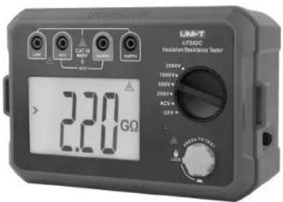
UT501C/UT502C
Insulation Resistance Tester
User Manual
Preface
Thank you for purchasing this brand new product. In order to use this product safely and correctly, please read this manual thoroughly, especially the safety notes.
After reading this manual, it is recommended to keep the manual at an easily accessible place, preferably close to the device, for future reference.
Limited Warranty and Liability
Uni-Trend guarantees that the product is free from any defect in material and workmanship within one year from the purchase date. This warranty does not apply to damages caused by accident, negligence, misuse, modification, contamination or improper handling. The dealer shall not be entitled to give any other warranty on behalf of Uni-Trend. If you need warranty service within the warranty period, please contact your seller directly.
Uni-Trend will not be responsible for any special, indirect, incidental or subsequent damage or loss caused by using this device.
Table of Contents
- Overview 4
- Safety Instructions 4
-
Technical Specifications 5
3.1 UT501C Insulation Resistance Test Index 5
3.2 UT502C Insulation Resistance Test Index 6
3.3 Voltage Test Index 6
3.4 Functions and Features 5 -
External Structure 7
-
LCD Description 8
-
Button and Rotary Switch Functions 9
-
AC Voltage Test 9
-
Insulation Resistance Test 10
-
Common Connection Methods of Insulation Resistance Test 11
9.1 Cable Insulation Resistance Test 11
9.2 Transformer Insulation Resistance Test 12
-
Battery replacement and switch to power supply mode 14
-
Maintenance 15
1. Overview
UT500 series digital insulation resistance testers, with their new design, large scale integrated circuit and digital circuit, are utilized to measure insulation resistance, alternating voltage and other parameters. This series of testers have features of complete functions, high accuracy, stable performances, comfortable and reliable operation. The tester is used in maintenance, test and verification for various electrical equipment and is applicable to measure insulation resistance of transformer, motor, cable, switch, electric appliances, etc.
2. Safety Instructions
The Tester is designed and manufactured according to safety requirements of electronic measuring apparatus and IEC61010-1 safety standards. It conforms to double-insulation overvoltage standard (CAT III 600V) and safety standards of pollution degree II. The protection supplied by the Tester can be compromised or lost if you do not observe the operating instructions to use the Tester.
Symbols description 1:
| Danger | Identify conditions that could cause severe or fatal harm. | |
| Warning | Avoid electric shock hazard. | |
| Caution | Avoid damage to the Tester and make accurate measurement. |
Danger
- Do not measure in circuits with voltage above AC 750V.
- Do not test in flammable places. Sparks may cause an explosion.
- Never use the Tester if its surface or the operator's hands are wet.
- Do not touch the live part of test probe during measurement.
- Never open the battery cover during measurement.
- Do not touch the circuit under test when measuring insulation resistance.
Warning
- Stop using the Tester if it behaves abnormally (such as bare test lead, damaged tester).
- Be cautious when the test is conducted under voltage above 30Vrms, 42.4Vacrms or 60Vdc, such voltages may pose a shock hazard!
- Do not replace the battery in damp environments.
- Ensure secure connection between all test leads and test ports of the Tester.
- Please switch off the Tester and remove the test leads before replacing the batteries.
- Please read the user manual before use.
- Observe the requirements of user manual in any situation. Keep the manual at easily accessible place for future reference.
- Misoperation can cause accident and damage to the Tester during measurement.
Caution
- Before measuring insulation resistance, the circuit to be tested must be fully discharged and separated with other power circuits.
- If the test leads appear damaged, replace them by test leads with same model and electric specification.
- Stop using the Tester when the symbol □ indicates low battery. If the Tester is not used for an extended period of time, please store the Tester after removing the battery.
- Do not use or store the Tester in high temperature, high humidity, flammable, explosive or strong magnetic field environments.
Symbols description 2:
| A | Possible electric shock |
| D | Double or reinforced insulation |
| DC | Direct current |
| AC | Alternating current |
| ⊥ | Earth (ground) terminal |
3. Technical Specifications
Error limit: ± (a% Reading+ Number of digit), one year warranty. Ambient temperature: (23±5) °C Ambient humidity: 45%\~75%
3.1 UT501C Insulation Resistance Test Index
| Voltage rating | 100V | 250V | 500V | 1000V |
| Measurement range | 0.00MΩ~100MΩ | 0.00MΩ~500MΩ | 0.00MΩ~2.00GΩ | 0.00MΩ~5.00GΩ |
| Open-circuit voltage | DC 100V+10% | DC 250V+10% | DC 500V+10% | DC 1000V+10% |
| Test current rating | Loaded at 100KΩ, 1.0mA~1.1mA | Loaded at 250KΩ, 1.0mA~1.1mA | Loaded at 500KΩ, 1.0mA~1.1mA | Loaded at 1MΩ, 1.0mA~1.1mA |
| Short-circuit current | < 2.0mA approximately | |||
| Accuracy range | 0.00MΩ~99.9MΩ: ±(3%+5); 100MΩ~5.00GΩ: ±(5%+5) | |||
5
3.2 UT502C Insulation Resistance Test Index
| Voltage rating | 250V | 500V | 1000V | 2500V |
| Measurement range | 0.00MΩ~500MΩ | 0.00MΩ~2.00GΩ | 0.00MΩ~5.00GΩ | 0.00MΩ~20.0GΩ |
| Open-circuit voltage | DC 250V+10% | DC 500V+10% | DC 1000V+10% | DC 2500V+0% |
| Test current rating | Loaded at 250KΩ, 1.0mA~1.1mA | Loaded at 500KΩ, 1.0mA~1.1mA | Loaded at 1MΩ, 1.0mA~1.1mA | Loaded at 2.5MΩ, 1.0mA~1.1mA |
| Short-circuit current | < 2.0mA approximately | |||
| Accuracy range | 0.00MΩ~99.9MΩ: ±(3%+5); 100MΩ~9.99GΩ: ±(5%+5); 10.0GΩ~20.0GΩ: ±(10%+5) | |||
3.3 Voltage Test Index
| Alternating Voltage | |
| Test range | 30V-750V (50Hz/60Hz) |
| Resolution | 1V |
| Accuracy | ±(2%+3) |
3.4 Functions and Features
• Auto-range function.
- Auto power off function. The Tester powers off automatically after 10 minutes of inactivity.
- Data hold: The data hold function is enabled when measuring the insulation resistance function, it is disabled for AC voltage measurement.
- The measured insulation resistance itself is charged (>30V), the symbol will flash when insulation resistance test function is turned off.
- After starting up, full display will appear on the LCD for about 1 second, display screen: 80.0*50.0mm visible area, maximum display is "9999".
- Low battery indication: when the battery power is ≤slant 7 ± 0.2V , the symbol lights up; when the battery power is ≤slant 6.4V , the symbol flashes 10 times and the Tester shuts down automatically.
- Powered by adapter (without charging function): the symbol is displayed in priority when charged by adapter, battery symbol is not displayed.
- Overrange Indication: Overrange indication for insulation resistance measurement is “>110MΩ”, “>550MΩ”, “>2.20GΩ”, “>5.50GΩ”, or “>22.0GΩ”; overrange indication for AC voltage is “>750V AC”.
UNI-T.
UT501C/UT502C User Manual
UT501C/UT502C User Manual
UNI-T.
- Auto backlight function: the backlight lights up for about 5 seconds when the Tester is turned on. The backlight automatically turns on when measurement starts for insulation resistance test, and it automatically turns off when the measurement stops. The backlight function is disabled for AC voltage measurement.
- Red warning light: the light is on when high voltage is output.
- Operating condition: temperature: 0°C-35°C; humidity: ≤75%RH; altitude: ≤2000m.
- Storage condition: -20°C\~60°C, humidity: ≤80%RH.
- External dimension: 183.5(L)×115(W)×74mm(D).
- Power supply: 6×1.5V AA alkaline batteries or dedicated power adapter (Optional),
(Model: XZF48-15600D; Input: AC 230V\~50Hz 90mA; Output: DC 15V 0.6A)
• Weight: 0.6kg (including batteries). - Accessories: test leads, alligator clips, user manual, carrying bag, strap.
4. External Structure
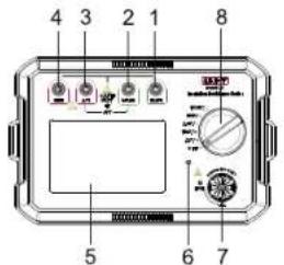
1) EARTH: Terminal for insulation resistance sampling test
2) GUARD: Negative input terminal for voltage test lead
3) ACV: Positive input terminal for AC voltage test lead
4) LINE: Terminal for high voltage output test lead
5) Liquid Crystal Display
6) High voltage output warning indicator
7) Insulation resistance test buttons
8) Functional rotary switch
9) UT501C alligator clip
10) UT501C test probe
11) UT502C alligator clip
12) UT502C test lead
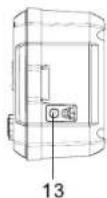
13) Power adapter port




5. LCD Description
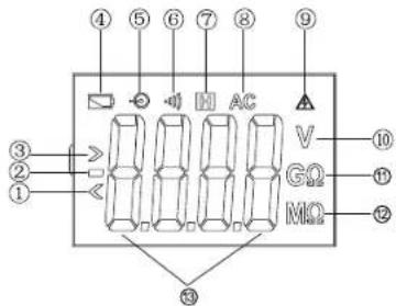
| 1 | Less than | 8 | Alternating current |
| 2 | Negative value | 9 | High voltage alarm |
| 3 | Greater than | 10 | Voltage unit |
| 4 | Battery symbol | 11 | Insulation resistance unit (GΩ) |
| 5 | Powered by adapter | 12 | Insulation resistance unit (MΩ) |
| 6 | Audible and visual alarm symbol | 13 | Displayed value |
| 7 | Data hold |
6. Button and Rotary Switch Functions
- Turn on/off high voltage measurement with "TEST".
- Turn the rotary switch to ACV position for AC voltage measurement.
- UT501 rotary switch can be turned to 100V/250V/500V/1000V position, and UT502C rotary switch can be turned to 250V/500V/1000V/2500V position, selected desired output voltage for insulation resistance measurement.
- The Tester shuts down automatically after 10 minutes of inactivity. To reboot the Tester, turn the rotary switch from OFF to desired position (The Tester can be turned on at functional position by connecting the adapter or plugging the battery).
7. AC Voltage Test
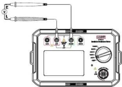
Both UT501C and UT502C have AC voltage measurement functions. Do not measure AC voltage over 750V to avoid damage to the Tester. Considering external interference during AC voltage test, ACV and GUARD test probes can be used to short-circuit for zero calibration. The figure and AC voltage measurement steps are shown as below:
(1) Turn the rotary switch to ACV position for AC voltage measurement.
(2) Connect red test lead to "ACV" input terminal, and connect black test lead to "GUARD" input terminal.
Caution
- Do not input AC voltage over 750Vrms. It's possible to display higher voltage, but it may damage the Tester or pose a shock hazard.
- Disconnect the test lead from measured circuit and remove them from the input terminal after all measurement operations are completed.
- Do not conduct test with battery cover opened, otherwise it may pose an electric shock.
8. Insulation Resistance Test
Caution
- Two test leads must be separated during measurement.
- Clamp the insulation resistor before high voltage output.
- Do not short-circuit two test leads at high voltage output.
- Do not conduct test with battery cover opened, otherwise it may pose an electric shock.
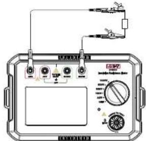
1. Press the functional knob to select a test voltage
(1) Before measuring insulation resistance, the circuit to be measured must be fully discharged and separated from power circuit.
(2) Connect red test lead to "LINE" input terminal, and connect black test lead to "EARTH" input terminal.
(3) Connect red and black alligator clips to the measured circuit, the voltage is output from LINE terminal.
2. Continuous measurement operation
After selecting a test voltage, press and rotate TEST to LOCK position for continuous measurement, output insulation resistance test voltage, the indicator lights up red. After the test is completed, press and rotate TEST button to unlock and stop the test.
Caution
- Make sure that the circuit to be tested is fully charged, do not measure live devices or circuits.
- Do not touch the circuit after the test is completed, the capacitance stored in the circuit can pose electric shock.
- Disconnect the test lead from the connected circuit, do not touch by hands until test voltage is fully discharged.
- Do not conduct test with battery cover opened, otherwise it may pose an electric shock.
9. Common Connection Methods of Insulation Resistance Test
9.1 Cable Insulation Resistance Test
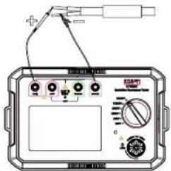
A. Common two-wire measurement connection method
Test whether there is leakage current in the two conductors of the same cable. Connect the two ports of the insulation resistance test to the metal body of the two conductors in the same cable. Measure the insulation resistance between the two conductors. As shown below:
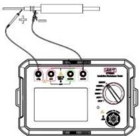
B. Common single-wire measurement connection method
Measure the resistance value between the conductor wire and the bare metal wire to determine whether there is leakage current in the conductor. As shown below:
9.2 Transformer Insulation Resistance Test
A. Test of Insulation Resistance between Primary Winding and Secondary Winding Grounding
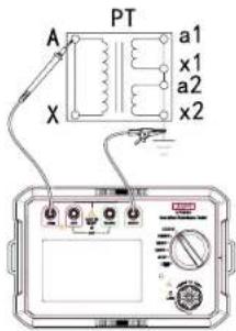
B. Test of Insulation Resistance between Primary Winding Grounding and Secondary Winding
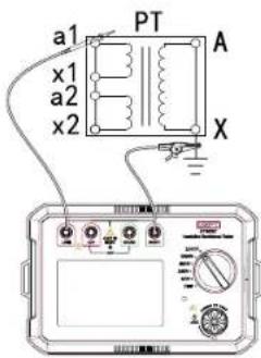
C. Test of Insulation Resistance between Secondary Windings
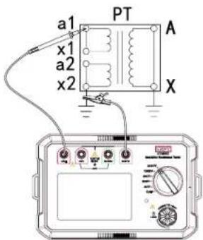
D. Test of Winding and Magnetic Core
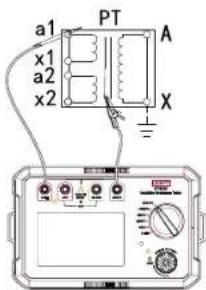
10. Battery Replacement and Adapter Power Supply
| Low voltage symbol | Battery voltage |
| ≤slant 7V |
Follow the steps below to replace the batteries:
(1) To avoid electric shock, turn the functional rotary switch to OFF position to power off the Tester and remove test leads before replacing the batteries.
(2) Unscrew and remove the battery cover to replace with 6pcs 1.5V AA alkaline batteries.
(3) Tighten the screws after the replacement.
Caution
- Do not mix new and old batteries.
• The same brand of battery is recommended. - Pay attention to the battery polarity when installing batteries.
- Do not measure if the battery compartment is open.
Powered by adapter:
(1) Power off the Tester and remove all test leads before switching batteries and power adapter.
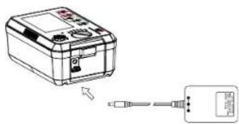
(2) Use dedicated power adapter only (Model: XZF48-15600D).
(3) Connect the power adapter to the power port of the Tester before measurement. As shown below:
natural_image
Diagram showing a device connected to a digital display unit (no text or symbols present)11. Maintenance
Clean the Tester housing:
- Wipe the Tester housing with a soft cloth or sponge dampened with clear water. Do not use abrasives or solvents.
- Do not immerse the Tester in water to avoid damage. If water gets into the Tester accidentally, please have it repair by a professional.
- If the Tester is wet, allow time for drying before storing it.
● Have a qualified professional or designated department repair or service the Tester.
The contents of this manual are subject to change without notice.
UNI-T.
UNI-TREND TECHNOLOGY (CHINA) CO., LTD.
No.6, Gong Ye Bei 1st Road,
Songshan Lake National High-Tech Industrial
Development Zone, Dongguan City,
Guangdong Province, China




- Preface
- Limited Warranty and Liability
- Table of Contents
- Overview
- Safety Instructions
- Danger
- Warning
- Caution
- Technical Specifications
- Functions and Features
- UNI-T.
- External Structure
- LCD Description
- Button and Rotary Switch Functions
- AC Voltage Test
- Insulation Resistance Test
- Press the functional knob to select a test voltage
- Continuous measurement operation
- Common Connection Methods of Insulation Resistance Test
- Cable Insulation Resistance Test
- Transformer Insulation Resistance Test
- Battery Replacement and Adapter Power Supply
- Maintenance
Brand : Uni-T
Model : UT502C
Category : Mètre