
UT533 - Mètre Uni-T - Free user manual and instructions
Find the device manual for free UT533 Uni-T in PDF.


| Product Type | Insulation Multimeter (True RMS) |
| Model | UT533 |
| Display | 6000 count LCD |
| AC Voltage Range | 6.000V to 1000V |
| DC Voltage Range | 6.000V to 1000V |
| DC Millivolt Range | 60.00mV to 600.0mV |
| AC Current Range | 60.00mA to 600.0mA |
| DC Current Range | 60.00mA to 600.0mA |
| Resistance Range | 600.0Ω to 40.00MΩ |
| Capacitance Range | 10.00nF to 100.0μF |
| Frequency Range | Up to 1MHz |
| Temperature Range (UT533 only) | -40°C to 537°C (-40°F to 998°F) |
| Insulation Test Voltages | 50V, 100V, 250V, 500V, 1000V |
| Insulation Resistance Range | 0.1MΩ to 2.00GΩ |
| Safety Rating | CAT III 1000V, CAT IV 600V |
| Power Supply | 6 × AA (AM3/LR6) batteries, ~2450mAh |
| Dimensions | 97mm × 202mm × 46mm |
| Weight | Approx. 505g (including batteries) |
| Auto Power Off | After 15 minutes of inactivity |
| Low Battery Indication | Icon on display |
| Fuse Protection | 1A/240V fast fuse, high breaking capacity |
| Cleaning | Damp cloth with mild detergent; no abrasives or solvents |
| Spare Parts | Test leads, short leads, alligator clips, K-type thermocouple (UT533), batteries, fuse |
| Repairability | Battery and fuse replaceable by user; internal circuit not alterable |
| General Information | True RMS measurement, insulation testing, data storage (up to 99 sets) |
Frequently Asked Questions - UT533 Uni-T
User questions about UT533 Uni-T
0 question about this device. Answer the ones you know or ask your own.
Ask a new question about this device
Download the instructions for your Mètre in PDF format for free! Find your manual UT533 - Uni-T and take your electronic device back in hand. On this page are published all the documents necessary for the use of your device. UT533 by Uni-T.
USER MANUAL UT533 Uni-T
P/N:110401103678X DATE:2018.06.26 REV.4
UNI-T®
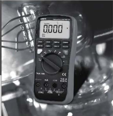
UT531
UT532
UT533
Users Manual
Insulation
Resistance
Multimeters
UNI-T®
UT531/UT532/UT533 : USERS MANUAL
Table of Contents
Title Page
Introduction 5
Safety Information 5
Unpacking Inspection 9
The Meter Structure 10
Rotary Switch Positions 11
Buttons 13
Understanding the Display 17
Making Basic Measurements 20
Measuring AC Voltage 20
Measuring DC Voltage 23
Measuring DC Millivolts 25
Measuring Resistance and Capacitance 27
● Measuring Resistance 27
● Measuring Capacitance 29
Testing for Continuity 31
Testing Diodes 33
Measuring AC or DC Current 35
Measuring Frequency 38
Measuring Temperature 40
Testing Insulation 42
UNI-T®
UT531/UT532/UT533 : USERS MANUAL
Title Page
Cleaning 45
Replacing the Batteries 46
Replacing the Fuse 48
Specifications 49
Electrical Specifications 50
AC Voltage Measurement 50
DC Voltage Measurement 51
DC Millivolts Measurement 51
AC Current Measurement 51
DC Current Measurement 52
Ohms Measurement 52
Capacitance 52
Diode Test 53
Continuity Test 53
Temperature Measurement 53
Frequency Measurement 54
- At mV ≈ Range 54
- At DCV/ACV Range 55
Insulation Specifications 55
- UT531 55
- UT532 56
- UT533 57
UNI-T®
UT531/UT532/UT533 : USERS MANUAL
List of Tables
| Table | Title | Page |
| 1. | Symbols | 8 |
| 2. | Unpacking Inspection | 9 |
| 3. | Rotary Switch Selections | 12 |
| 4. | Buttons | 14 |
| 5. | Display Indicators | 18 |
| 6. | General Specifications | 49 |
UNI-T®
UT531/UT532/UT533 : USERS MANUAL
List of Figures
Figure Title Page
- The Meter Structure — 10
- Rotary Switch 11
- Buttons 13
- Display Indicators----17
- Measuring AC Voltage 20
- Measuring DC Voltage 23
- Measuring DC Millivolts 25
- Measuring Resistance 27
- Measuring Capacitance 29
- Testing for Continuity 31
- Testing Diodes 33
- Measuring AC or DC Current 35
- Measuring Frequency 38
- Measuring Temperature 40
- Testing Insulation 42
- Replacing the Fuse and Battery 46
UNI-T®
UT531/UT532/UT533 : USERS MANUAL
Introduction
The UNI-T Models UT531, UT532 and UT533 are battery-powered, true RMS insulation multimeters (hereafter "the Meter") with 6000 count display.
The Meter measures or tests the following:
● AC/DC voltage and current
- Resistance
● Voltage and current frequency
Diode
- Continuity
- Capacitance
● Temperature (Model 532 and UT533 only)
• Insulation Testing
Safety Information
These Meters meet CAT III 1000V and CAT IV 600V IEC61010 standards: in pollution degree 2 and double injection.
CAT III: Distribution level, fixed installation, with smaller transient overvoltages than CAT IV.
UNI-T®
UT531/UT532/UT533 : USERS MANUAL
CAT IV: Primary supply level, overhead lines, cable systems etc.
Use the Meter only as specified in this users manual. Otherwise protection provided by the Meter may be impaired. See Table 1 for a list of symbols used on the Meter and in this manual.
A ⚠Warning identifies hazardous conditions and actions that could cause bodily harm or death.
A ⚠️ Caution identifies conditions and actions that could damage the Meter, the equipment under test, or cause permanent loss of data.
Warning
To avoid possible electric shock or personal inquiry, follow these guidelines:
- Use the Meter only as specified in this manual or the protection provided by the Meter might be impaired.
- Do not use the Meter or test leads if they appear damaged, or if the Meter is not operating properly. If in doubt, have the Meter serviced.
● Always use the proper terminal, switch position, and range for measurements before connecting Meter to circuit under test.
UNI-T®
UT531/UT532/UT533 : USERS MANUAL
- Verify the Meter's operation by measuring a known voltage.
- Do not apply more than the rated voltage as marked on the Meter, between the terminals or between any terminal and earth ground.
- Use caution with voltages above 33V ac rms, 46.7V ac Peak, or 70V dc. These voltages pose a shock hazard.
- Replace the battery as soon as the low battery indicative ( [+] ) appears.
- Disconnect circuit power and discharge all high-voltage capacitors before testing resistance, continuity, diodes, or capacitance.
- Do not use the Meter around explosive gas or vapor.
- When using the test leads, keep your fingers behind the finger guards.
- In order to comply with the safety standard, the Meter must be used along with the included test leads. Any damages of the test lead, must replace it with the same model number and specification.
- Remove test leads from the Meter before opening the Meter case or battery door. Never operate the Meter with the cover removed or the battery door open.
- Comply with local and national safety requirements when working in hazardous locations.
- Under the influence of Radio-Frequency Electromagnetic Field & Conducted Radio-Frequency Electromagnetic Field phenomenon. The captioned model have a magnificent error in function measurement. It will be back to normal when the interference is removed.
UNI-T®
UT531/UT532/UT533 : USERS MANUAL
- Use proper protective equipment, as required by local or national authorities when working in hazardous areas.
- Avoid working alone.
- User only the replacement fuse specified or the protection may be impaired.
- Check the test leads for continuity before use. Do not use if the readings are high or noisy.
- Do not use current terminals or current range to test voltage.
Table 1. Symbols
| ☐ | Double Insulated | ± | Earth Ground |
| ~ | AC (Alternating Current) | DC (Direct Current) | |
| ▶ | Diode | + | Battery (Low battery when shown on display) |
| ··· | Continuity Buzzer | ≈ | AC or DC (Alternating Current or Direct Current) |
| CE | Conforms to Standard of European Union | ||
UNI-T®
UT531/UT532/UT533 : USERS MANUAL
Unpacking Inspection
Open the package case and take out the Meter. Check the following items carefully to see any missing or damaged part:
Table 2. Unpacking Inspection
| Users Manual | 1 piece |
| Test Lead | 1 pair |
| Short Lead | 1 pair |
| Alligator Clip | 1 pair |
| K type thermocouple (UT532 and UT533 only) | 1 piece |
| Batteries AA (AM3/LR6) | 6 pieces |
In the event you find any missing or damage, please contact your dealer immediately.
UNI-T®
UT531/UT532/UT533 : USERS MANUAL
The Meter Structure
- Front Housing
- LCD Display
- Functional Buttons
- Rotary Switch
- Input Terminals
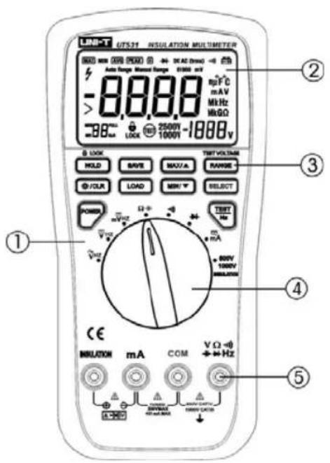
Figure 1. The Meter Structure
UNI-T®
UT531/UT532/UT533 : USERS MANUAL
Rotary Switch Positions
Turn the Meter on by pressing the POWER button. Use the BLUE button to select any rotary switch alternate functions (labeled with blue letters). Rotary switch selections are shown in Figure 2 and described in Table 3.
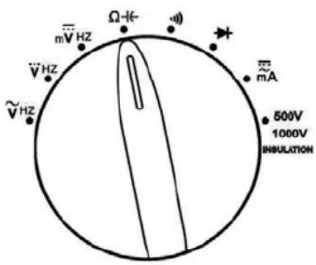
Figure 2. Rotary Switch
Table 3. Rotary Switch Selections
| Switch Position | Measurement Function |
| V~ | AC voltage from 60mV to 1000V. |
| V--- | DC voltage 1mV to 1000V. |
| mV--- | DC mV 0.01mv to 600mV |
| (UT532 and UT533 only) | Temperature from -40°C to +537°C (-40°F to +998°F). Celsius is the default temperature measurement unit. |
| Ω-H | Ohms from 0.1 to 40M.Capacitance from 0.01nF to 100μF. |
| -)) | Continuity test. Beeper turns on at <30 |
| →+ | Diode test. There is no ranging in this function. |
| mA≈ | DC mA from 0.01mA to 600mA (600mA overload for 2 minutes maximum)AC mA from 3mA to 600mA (600mA overload for 2 minutes maximum). |
| insulation | Press to perform insulation testUT531: From 0.5M to 600M. Select 500V and 1000V testing voltage.UT532: From 0.2M to 2G. Select 250V, 500V and 1000V testing voltage.UT533: From 0.1M to 2G. Select 50V, 100V, 250V, 500V and 1000V testing voltage. |
UNI-T®
UT531/UT532/UT533 : USERS MANUAL
Buttons
Use the buttons to activate features that augment the function selected with the rotary switch. The buttons are shown in Figure 3 described in Table 4.
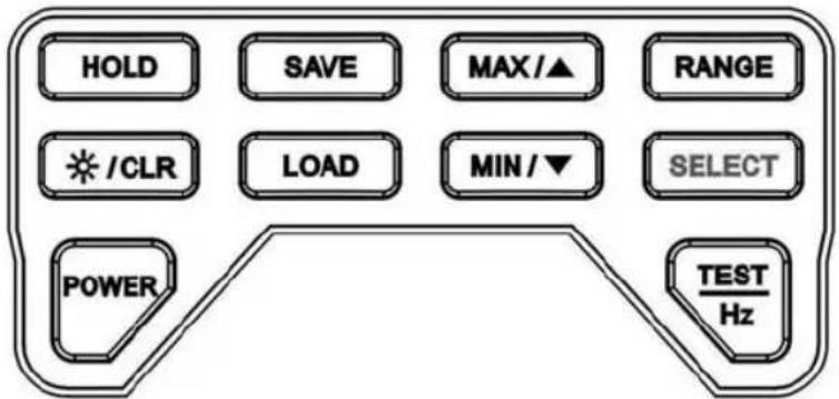
Figure 3. Buttons
UNI-T®
UT531/UT532/UT533 : USERS MANUAL
Table 4. Buttons
| Button | Description |
| POWER | Press POWER to turn on the Meter. Press and hold POWER to turn off the Meter |
| HOLD | In insulation Test mode, this schedules a test lock the next time you press TEST on the Meter. The test lock acts to hold down the button until you press HOLD or TEST again to release the lock.In order measurement mode: Press to freeze the displayed value. Press again to release the display. |
| */CLR | Press and hold the button to clear the stored data. Press the button to turn the backlight on and off. |
| SAVE | Press this button to store the single record. Press and hold this button to store data continuously. Press SAVE again to exit continuous data storing mode.The maximum number of data store is 99 sets. The Meter displays FULL when it reaches the maximum. Press CLR to clear the stored data in order to store next set of data |
UNI-T®
UT531/UT532/UT533 : USERS MANUAL
Table 4. Buttons
| Button | Description |
| LOAD | Press this button once to recall the stored value. Press or to recall the previous or next stored value. Press LOAD again to exit data recall mode.Press and hold this button to recall the stored data continuously. Press LOAD again to exit.After entering the Load mode, it is not allowed to turn the rotary switch to enter to measuring mode. You can only enter the measuring mode after exiting the Load mode. |
| MAX /▲ | In Measurement mode, except buzzer, diode and insulation test, press to start retaining maximum value.In Load, each press to go back to the previous stored reading |
| MIN /▼ | In Measurement mode, except buzzer, diode and insulation test, press to start retaining minimum value.In Load, each press to recall the next stored reading. |
| RANGE | In Insulation Test mode, press to select different testing voltage.In other mode, except buzzer and diode, press to change Ranging |
UNI-T®
UT531/UT532/UT533 : USERS MANUAL
Table 4. Buttons
| Button | Description |
| RANGE | mode from Auto to Manual Ranging mode. Press and hold to return to Auto Ranging mode. |
| SELECT | Functions as a shift key. Press to access orange functions on the rotary switch. |
| Initiates an insulation test when the rotary switch is on the INSULTION position. Causes the Meter to source (output) a high voltage and measure insulation resistance. | |
| InMeasurement mode, activate frequency measurement. |
UNI-T®
UT531/UT532/UT533 : USERS MANUAL
Understanding the Display
Display indicators are shown in Figure 4 and described in Table 5.
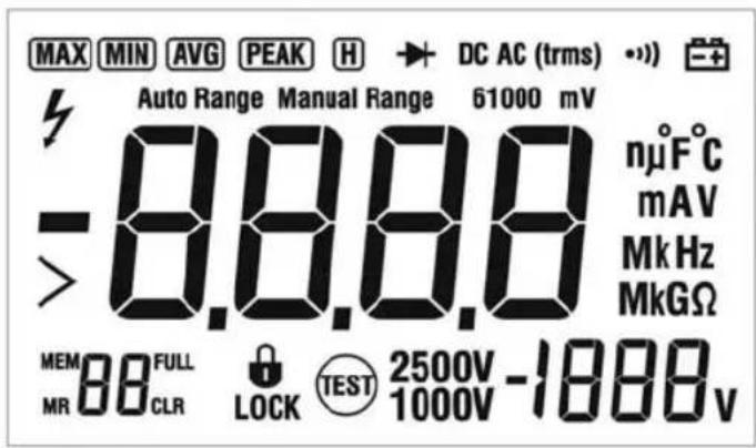
Figure 4. Display Indicators
UNI-T®
UT531/UT532/UT533 : USERS MANUAL
Table 5. Display Indicators
| Indicator | Description |
| MAX | Indicates maximum reading has been selected. |
| MIN | Indicates minimum reading has been selected. |
| H | Indicates display hold is active |
| Diode test function is selected | |
| DC AC | AC / DC Voltage or Current measurement |
| trms | True RMS measurement |
| -») | Continuity test function is selected |
| Low battery. Indicates when it is time to replace the battery.⚠WarningTo avoid false readings, which could lead to possible electric shock or personal injury, replace the battery as soon as the low battery indicator appears | |
| High voltage warning | |
| Auto Range | Auto ranging mode |
| Manual Range | Manual ranging mode |
UNI-T®
UT531/UT532/UT533 : USERS MANUAL
Table 5. Display Indicators
| Indicator | Description |
| 61000mV | Display range in use |
| — | Negative symbol |
| > | Greater than symbol |
| 8888 | Primary display |
| MEM | Data store symbol |
| MR | Data recall symbol |
| "88. | The number of stored data |
| FULL | When the number of stored data reaches 99, the display will show FULL.When the number of stored data is full, press CLR to clear up the stored data before storing another set of data |
| CLR | Clear up the stored data |
 | Indicates a test lock will be applied the next time you press TEST on the Meter. The test lock acts to hold down the button until you press HOLD or TEST again. |
| 2500V1000V | Source voltage rating for insulation test.UT531: 500V and 1000V ranges available.UT532: 250V, 500V and 1000V ranges available.UT533: 50V, 100V, 250V, 500V and 1000V ranges available. |
| ·1888v | Secondary Display |
| Measurement units |
UNI-T®
UT531/UT532/UT533 : USERS MANUAL
Making Basic Measurements
Measuring AC Voltage (see figure 5)
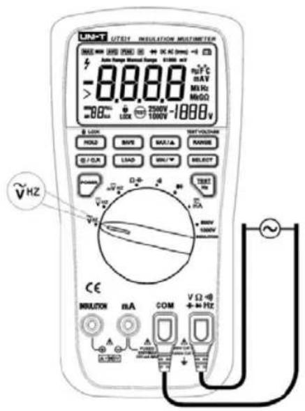
Figure 5. Measuring AC Voltage
UNI-T®
UT531/UT532/UT533 : USERS MANUAL
Warning
To avoid harm to you or damages to the Meter from electric shock, please do not attempt to measure voltages higher than 1000V although readings may be obtained.
The AC Voltage ranges are: 6.000V, 60.00V, 600.0V and 1000V. If over the range, it displays"OL". To mesaure AC voltage, connect the Meter as follows:
- Insert the red test lead into the VΩ→Hz terminal and the black test lead into the COM terminal.
- Set the rotary switch to V\~.
- Connect the test leads across with the object being measured. The measured value shows on the display.
- The displayed value is True RMS.
UNI-T®
UT531/UT532/UT533 : USERS MANUAL
Note:
- If the value of voltage to be measured is unknown, set the Meter to autoranging or use the maximum measurement position 1000V and reduce the range step by step until a satisfactory reading is obtained.
- In each range, the Meter has an input impedance of 10MΩ. This loading effect can cause measurement errors in high impedance circuits. If the circuit impedance is less than or equal to 10kΩ, teh error is negligible (0.1% or less).
- When DC voltage measurement has been completed, disconnect the connection between the testing leads and the circuit under test, and remove the testing leads away from the input terminals of the Meter.
UNI-T®
UT531/UT532/UT533 : USERS MANUAL
Measuring DC Voltage (see figure 6)
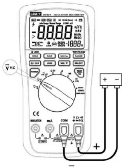
Figure 6. Measuring DC Voltage
UNI-T®
UT531/UT532/UT533 : USERS MANUAL
Warning
To avoid harm to you or damages to the Meter from electric shock, please do not attempt to measure voltages higher than 1000V although readings may be obtained.
The DC Voltage ranges are: 6.000V, 60.00V, 600.0V and 1000V. If over the range, it displays "OL". To measure DC voltage, connect the Meter as follows:
- Insert the red test lead into the VΩ -I(→) Hz terminal and the black test lead into the COM terminal.
- Set the rotary switch to V...
- Connect the test leads across with the object being measured. The measured value shows on the display.
Note:
- If the value of voltage to be measured is unknown, set the Meter to autoranging or use the maximum measurement position 1000V and reduce the range step by step until a satisfactory reading is obtained.
- In each range, the Meter has an input impedance of 10MΩ. This loading effect can cause measurement errors in high impedance circuits. If the circuit impedance is less than or equal to 10kΩ, teh error is negligible (0.1% or less).
- When DC voltage measurement has been completed, disconnect the connection between the testing leads and the circuit under test, and remove the testing leads away from the input terminals of the Meter.
UNI-T®
UT531/UT532/UT533 : USERS MANUAL
Measuring DC Millivolts (see figure 7)
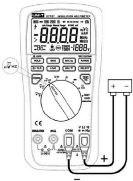
Figure 7. Measuring DC Millivolts
UNI-T®
UT531/UT532/UT533 : USERS MANUAL
Warning
To avoid harm to you or damages to the Meter from electric shock, please do not attempt to measure voltages higher than 500V, otherwise you cannot obtain correct reading.
The DC Millivolts ranges are: 60.000mV and 600.0mV. If over the range, it displays "OL". To mesaure DC Millivolts, connect the Meter as follows:
- Insert the red test lead into the VΩ-I↔Hz terminal and the black test lead into the COM terminal.
- Set the rotary switch to mV...
- Connect the test leads across with the object being measured.
The measured value shows on the display.
Note:
● The maximum input impedance is 4000MΩ.
- When DC Millivolts measurement has been completed, disconnect the connection between the testing leads and the circuit under test, and remove the testing leads
UNI-T®
UT531/UT532/UT533 : USERS MANUAL
Measuring Resistance and Capacitance • Measuring Resistance (see figure 8)
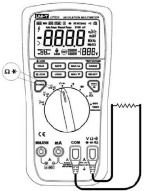
Figure 8. Measuring Resistance
UNI-T®
UT531/UT532/UT533 : USERS MANUAL
Warning
To avoid electric shock, injury, or damage to the Meter, disconnect circuit power and discharge all high-voltage capacitors before testing resistance.
The Resistance ranges are 600.0Ω, 6.000kΩ, 60.00kΩ, 600.0kΩ, 6.000MΩ and 40.00MΩ
To measure resistance, connect the Meter as follows:
- Insert the red test lead into the VΩ-H→Hz terminal and the black test lead into the COM terminal.
- Set the rotary switch to . Resistance measurement is default or press SELECT button to select measurement mode.
- Connect the test leads across with the object being measured.
The measured value shows on the display.
Note:
- When Resistance measurement has been completed, disconnect the connection between the testing leads and the circuit under test, and remove the testing leads away from the input terminals of the Meter.
UNI-T®
UT531/UT532/UT533 : USERS MANUAL
● Measuring Capacitance (see figure 9)
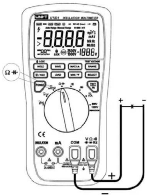
Figure 9. Measuring Capacitance
UNI-T®
UT531/UT532/UT533 : USERS MANUAL
Warning
To avoid electric shock, injury, or damage to the Meter, disconnect circuit power and discharge all high-voltage capacitors before testing capacitance. Use the DC Voltage function to confirm that the capacitor is discharged.
The Capacitance ranges are 10.00nF, 100.0nF, 1000nF, 10.00μF and 100.0μF
To measure capacitance, connect the Meter as follows:
- Insert the red test lead or red short lead with alligator clip into the VΩ→Hz terminal and the black test lead or black short lead with alligator clip into the COM terminal. If the capacitor being tested has polarity, connect the positive into the VΩ→Hz terminal and the negative into the COM terminal
- Set the rotary switch to -IF. Press SELECT button to select capacitance measurement mode
- Connect the test leads across with the object being measured.
The measured value shows on the display.
Note:
- When Capacitance measurement has been completed, disconnect the connection between the testing leads and the circuit under test, and remove the testing leads away from the input terminals of the Meter.
UNI-T®
UT531/UT532/UT533 : USERS MANUAL
Testing for Continuity (see figure 10)
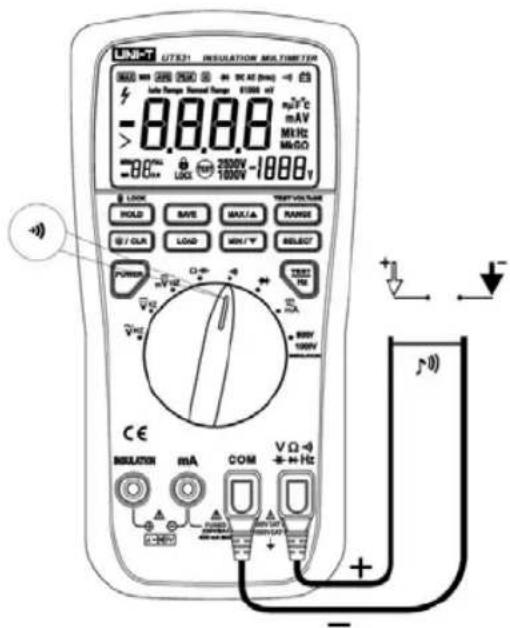
Figure 10. Testing for Continuity
UNI-T®
UT531/UT532/UT533 : USERS MANUAL
Warning
To avoid electric shock, injury, or damage to the Meter, disconnect circuit power and discharge all high-voltage capacitors before testing continuity.
To measure capacitance, connect the Meter as follows:
- Insert the red test lead into the VΩ-H→Hz terminal and the black test lead into the COM terminal.
- Set the rotary switch to .
- Continuous audible tone for test resistance below 30Ω
Note:
- When Continuity measurement has been completed, disconnect the connection between the testing leads and the circuit under test, and remove the testing leads away from the input terminals of the Meter.
UNI-T®
UT531/UT532/UT533 : USERS MANUAL
Testing Diodes (see figure 11)
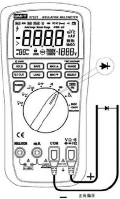
Figure 11. Testing Diodes
UNI-T®
UT531/UT532/UT533 : USERS MANUAL
Warning
To avoid electric shock, injury, or damage to the Meter, disconnect circuit power and discharge all high-voltage capacitors before testing diodes.
To measure diode, connect the Meter as follows:
-
Insert the red test lead into the VΩ-I(→Hz) terminal and the black test lead into the COM terminal.
-
Set the rotary switch to ↗.
-
For forward voltage drop readings on any semiconductor component, place the red test lead on the component's anode and place the black test lead on the component's cathode.
The measured value shows on the display.
Note:
- In a circuit, a good diode should still produce a forward voltage drop reading of 0.5V to 0.8V; however, the reverse-voltage drop reading can vary depending on the resistance of other pathways between the probe tips.
- Connect he test leads to the proper terminal as said above to avoid error display. The LCD will display OL indicating diode being tested is open or polarity is reversed.
● The unit of diode is Volt (V), displaying the forward voltage drop readings. - When Diode measurement has been completed, disconnect the connection between the testing leads and the circuit under test, and remove the testing leads away from the input terminals of the Meter.
UNI-T®
UT531/UT532/UT533 : USERS MANUAL
Measuring AC or DC Current (see figure 12)
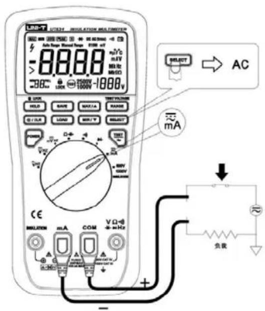
Figure 12. Measuring AC or DC Current
UNI-T®
UT531/UT532/UT533 : USERS MANUAL
Warning
To avoid personal injury or damage to the Meter:
- Never attempt to make an in-circuit current measurement when the open-circuit potential to earth is greater than 600V.
- Inspect Meter's fuses before testing. Broken fuses may damage to the Meter or hurt yourselves
- Use the proper terminals, switch position, and range for your measurement.
- Never place the probes in parallel with circuit or component when the leads are plugged into the current terminals.
The current ranges are 60.00mA and 600.0mA.
To measure current, connect the Meter as follows:
- Insert the red test lead into the mA terminal and the black test lead into the COM terminal.
- Set the rotary switch to mA ≈. DC Current is default. Press SELECT to toggle to AC current measurement mode.
- Connect the test leads across with the object being measured. The measured value shows on the display.
- AC Current displays True RMS value.
UNI-T®
UT531/UT532/UT533 : USERS MANUAL
Note:
- If the value of current to be measured is unknown, set the Meter to autoranging or use the maximum measurement position 600.0mA and reduce the range step by step until a satisfactory reading is obtained.
- For safety sake, when measuring high current, each measurement time must be less than 10 seconds with an interval more than 15 minutes.
- When Current measurement has been completed, disconnect the connection between the testing leads and the circuit under test, and remove the testing leads away from the input terminals of the Meter.
UNI-T®
UT531/UT532/UT533 : USERS MANUAL
Measuring Frequency (see figure 13)
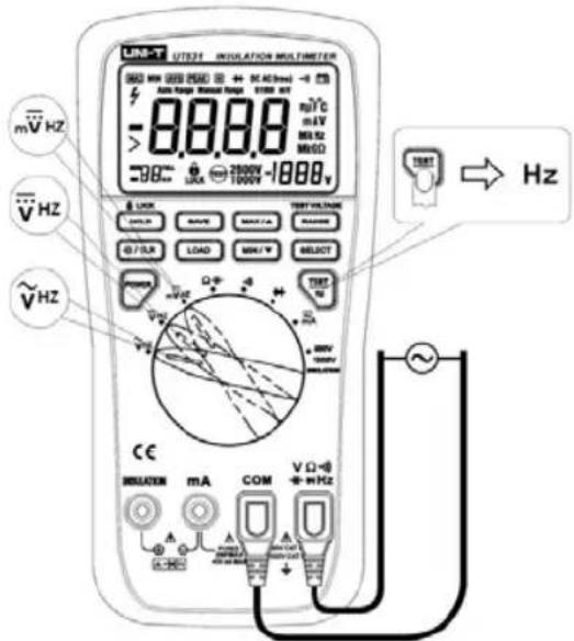
Figure 13. Measuring Frequency
UNI-T®
UT531/UT532/UT533 : USERS MANUAL
- Press Hz button to select frequency measurement mode at m V\~ or V\~ or V=Press Hz to exit frequency measurement mode and return to the previous meauremnet mode.
● The maximum range of frequency is 1MHz. - The signal attenuation is different from different measuring position and range. Therefore the required signal input amplitude and range may be different from different measuring position and range.
- It is recommended to use mV...range which has higher input sensitivity.
- If the input amplitude is higher than 1Vrms, it is required to use V== or V\~. to carry out the measurement.
- When using current range to measure frequency, it is required to input singal more than 30% of full range. The reading obtained is only for reference.
Note:
- When Frequency measurement has been completed, disconnect the connection between the testing leads and the circuit under test, and remove the testing leads away from the input terminals of the Meter.
UNI-T®
UT531/UT532/UT533 : USERS MANUAL
Measuring Temperature (UT532 and UT533 only) (see figure 14)
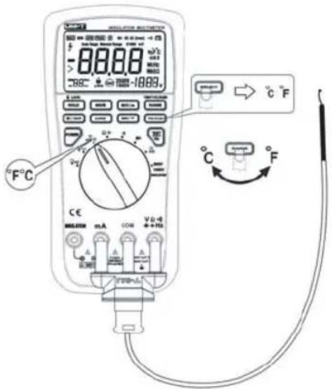
Figure 14. Measuring Temperature
UNI-T®
UT531/UT532/UT533 : USERS MANUAL
Warning
To avoid risk of shock do not connect thermocouple to electrically live circuits.
Caution
To avoid possible damage to the Meter or other equipment, remember that while the Meter is rated for -40^ to 537^ ( -40^ to 998^ ), the included K-type thermocouple is rated for 260^ ( 500^ ). For temperature out of that range, use a higher rated thermocouple.
To measure temperature, connect the Meter as follows:
- Insert the red thermocouple into the VΩH→ terminal and the black thermocouple into the COM terminal.
- Set the rotary switch to mV.
- Press SELECT to choose temperature range.
- Press RANGE to toggle between degrees Celsius (°C) or degrees Fahrenheit (°F).
- Place the thermocouple to the object being measured.
The measured value shows on the display.
UNI-T®
UT531/UT532/UT533 : USERS MANUAL
Testing Insulation (see figure 15)
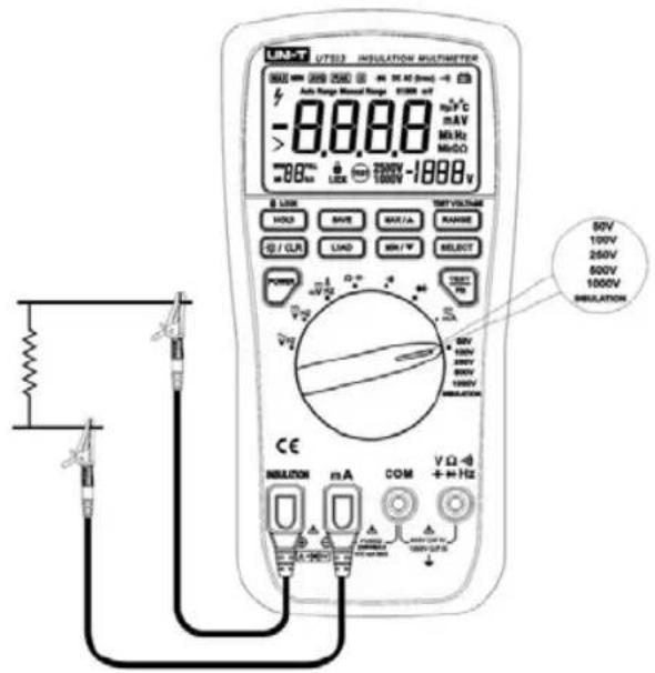
Figure 15. Testing Insulation
UNI-T®
UT531/UT532/UT533 : USERS MANUAL
Warning
Make sure the circuit to be tested is dead before taking measurement. Never measure the insulation resistance of live equipment or circuit. Never touch the circuit after measurement, as the capacitance to be saved on the circuit may cause electric shock.
Insulation tests should only performed on dead circuits. Check the fuse before testing.
To measure insulation resistance, set up the Meter as shown in Figure 15 amd follow the steps below:
- Insert the red short lead with alligator clip in the INSULATION input terminal and the black short lead with alligator clip in the mA input terminal.
- Turn the rotary switch to INSULATION position.
- Press RANGE to select he voltage.
- Connect the probes to the circuit to be measured. There are two methods to start the insulation test:
UNI-T®
UT531/UT532/UT533 : USERS MANUAL
- Press HOLD button to disable LOCK mode. Press and hold TEST to start the insulation test until TEST button is released
-
Press HOLD button to enter LOCK mode. Press TEST once to start the insulation test until pressing HOLD or TEST again to release LOCK mode.
-
Push and hold TEST button to start the test, the secondary display shows the test voltage applied to the circuit under test. The high voltage symbol along with a primary display showing the resistance in MΩ or GΩ. The TEST icon appears on the lower portion of the display.
-
When releasing the TEST button, LCD will not appear TEST icon. The resistance reading appears on the primary display until a new test is started or a different function or range is selected.
UNI-T®
UT531/UT532/UT533 : USERS MANUAL

Caution
The following improper operating procedure may force the Meter to power off automatically. To avoid the danager of electric shock and damage to the Meter:
- Replace batteries as soon as battery indicator is on. Initiating high voltage when the battery indicator is on, which may force the Meter to power off.
- Must connect the probe to the circuit being measured before initiating high voltage.
- When under high voltage mode, never turn the rotary switch to other position.
- The testing time of small resistor or short circuit cannot exceed 20 seconds.
- At insulation testing mode with testing voltage initiated, auto power off feature will be disabled until un-initiating the testing voltage.
Cleaning
- Periodically wipe the case with a damp cloth and mild detergent. Do not use abrasives or solvents. Dirt or moisture in the terminals can affect readings.
● Turn the Meter off when it is not in use. - Do not use or store the Meter in a place of humidity, high temperature, explosive, inflammable and strong magnetic field.
- The internal circuit of the Meter shall not be altered at will to avoid damage of the Meter and any accident.
UNI-T®
UT531/UT532/UT533 : USERS MANUAL
Replacing the Batteries
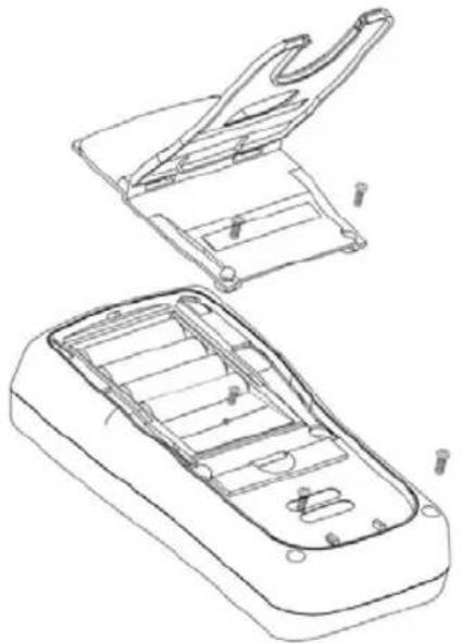
Replace the batteries as shown in Figure 16. Follow the steps below to replace the batteries.
natural_image
Technical line drawing of a vehicle chassis with open and closed compartments (no text or symbols)Figure 16. Replacing the Fuse and Battery
UNI-T®
UT531/UT532/UT533 : USERS MANUAL
Warning
To avoid shock, injury, or damage to the Meter:
-
To avoid false readings, which could lead to possible electric shock or personal injury, replace the batteries as soon as the battery indicator 📋 appears.
● Turn the Meter off and remove the testing leads from the terminals. -
Remove the two screws from the battery door by using a standard screwdriver.
- Open the battery door.
- Remove and replace the batteries. 6pcs of AA (AM3/LR6), standard capacity around 2450mAh.
- Rejoin the case bottom and battery compartment, and reinstall the screw.
UNI-T®
UT531/UT532/UT533 : USERS MANUAL
Replacing the Fuse
Replace the fuse as shown in Figure 16. Follow the steps below to replace the batteries.

Warning
To avoid shock, injury, or damage to the Meter:
- Use ONLY fuses with the amperage and voltage specified.
- Turn the Meter off and remove the testing leads from the terminals.
- Remove the two screws form the battery door, two screws from the case bottom, one screw at he back of the battery.
- Open the battery door and the case bottom
- Remove the fuse by gently prying one end loose, and take out the fuse from its bracket.
- Install ONLY replacement fuses with identical amperage and voltage specified: F1A 240V
- Rejoin the battery door and the case bottom, and reinstall the screws.
- Do not operate the Meter with the case opened.
Replacement of the fuse is seldom required. Buring of a fuse always results from improper operation.
Specifications
Table 6. General Specifications
| Maximum Voltage Applied to any Terminal | 1000V rms |
| mA Input Terminal | 1A / 240V Fast Fuse, High breaking capacity Fuse |
| Maximum Display | 6000, Updates 5 times per second |
| Operating Temperature | 0°C ~40°C (32°F~104°F) |
| Storage Temperature | -10°C ~50°C (14°F~122°F) |
| Relative Humidity | ≤75% @ 0°C to below 31°C≤50% @ 31°C to above 40°C |
| Altitude | Operating: 2000 meterStorage: 10000 meter |
| Batteries | Six AA 1.5V batteries AM3/LR6 (standard capacity around 2450mAh) |
| Low battery | LCD display |
| Auto Power Off | The Meter will be automatically off when the Meter is not in use for more than 15 minutes |
| Size | 97mm x 202mm x 46mm |
| Weight | Around 505 g (including batteries) |
UNI-T®
UT531/UT532/UT533 : USERS MANUAL
Electrical Specifications
Accuracy: ±(a % of rdg + b digits), guarantee for 1 year.
Operating Temperature: 23°C±5°C
Relative Humidity: <75%
AC Voltage Measurement
| Range | Resolution | Accuracy | Input Protection | |
| 50Hz ~60Hz | 60Hz ~ 1kHz | |||
| 6.000V | 1mV | ± (1%+3) | ± (2%+3) | 1000V ≈ |
| 60.00V | 10mV | |||
| 600.0V | 100mV | ± (2%+6) | ||
| 1000V | 1V | ± (2%+3) | ||
Remarks:
• Input Impedance: ≥10MΩ
● Displays effective value of sine wave
● Frequency Response: 50Hz\~1kHz
UNI-T®
UT531/UT532/UT533 : USERS MANUAL
DC Voltage Measurement
| Range | Resolution | Accuracy | Input Protection |
| 6.000V | 1mV | ± (0.3%+4) | 1000V ≈ |
| 60.00V | 10mV | ||
| 600.0V | 100mV | ||
| 1000V | 1V |
Remark:
• Input Impedance: ≥10MΩ
DC Millivolts Measurement
| Range | Resolution | Accuracy | Input Protection |
| 60.00mV | 10μV | ± (0.4%+4) | 600Vp |
| 600.0mV | 100μV |
Remark:
● Input Impedance: ≥4000MΩ
AC Current Measurement
| Range | Resolution | Accuracy | Input Protection |
| 60.00mA | 10μA | ± (1.5%+2) | Fuse, Fast, 1A, 240V |
| 600.0mA | 100μA |
UNI-T®
UT531/UT532/UT533 : USERS MANUAL
Remark:
- Displays True RMS value.
● Frequency Response 50Hz \~ 1kHz
DC Current Measurement
| Range | Resolution | Accuracy | Input Protection |
| 60.00mA | 10μA | ± (1.0%+2) | Fuse, Fast, 1A, 240V |
| 600.0mA | 100μA |
Ohms Measurement
| Range | Resolution | Accuracy | Input Protection |
| 600.0Ω | 0.1Ω | ± (0.9%+2) | 600Vp |
| 6.000kΩ | 1Ω | ||
| 60.00kΩ | 10Ω | ||
| 600.0kΩ | 100Ω | ||
| 6.000MΩ | 1kΩ | ||
| 40.00MΩ | 10kΩ | ± (1.5%+3) |
UNI-T®
UT531/UT532/UT533 : USERS MANUAL
Capacitance Measurement
| Range | Resolution | Accuracy | Input Protection |
| 10.00nF | 10pF | ±(3%+5) | 600Vp |
| 100.0nF | 100pF | ||
| 1000nF | 1nF | ||
| 10.00μF | 10 nF | ||
| 100.0μF | 100nF |
Diode Test
• Resolution: 1mV
● Input Protection: 500Vp
- Open circuit voltage: around 3V
● Display approximate forward voltage drop nearest value.
Continuity Test
● Continuity Indication: Continuous audible tone for test resistance below 30Ω.
- Open Circuit Voltage: around 3V
● Input Protection: 500Vp
● Resolution: 0.1Ω
Temperature Measurement (UT532 and UT533 only)
| Range | Resolution | Accuracy | Input Protection |
| -40°C~537°C | 1°C | ± (1%+10) | 600Vp |
| -40°F~998°F | 2°F | ± (1%+18) |
Frequency Measurement
- At mV... Range
| Range | Resolution | Accuracy | Input Protection |
| 60.00Hz | 0.01Hz | ± (0.1%+3) | 600Vp |
| 600.0Hz | 0.1Hz | ||
| 6.000kHz | 1Hz | ||
| 60.00kHz | 10Hz | ||
| 600.0kHz | 100Hz | ||
| 1.000MHz | 1kHz |
Remark:
- Input Sensitivity:
≤When 100kHz: ≤100mV rms
≥ 30mV rms
When 100kHz: ≥100mV rms
≤30V rms
UNI-T®
UT531/UT532/UT533 : USERS MANUAL
- At DCV/ACV Range
| Range | Accuracy | Input Protection |
| 10Hz~100kHz | ± (0.1%+3) | 600Vp |
Remark:
● Input amplitude: ≥ 600mV rms
Insulation Specifications
• UT531
| Testing Voltages | Measurement Range | Resolution | Accuracy |
| 500V(0% to 20%) | 0.5MΩ ~99.9MΩ | 0.1MΩ | ± (3%+5) |
| 100MΩ ~ 500MΩ | 1MΩ | ||
| 1000V(0% to 20%) | 4.0MΩ ~ 99.9MΩ | 0.1MΩ | |
| 100MΩ ~ 600MΩ | 1MΩ |
Remark:
● Short-Circuit Test Current less than 2.0mA
UNI-T®
UT531/UT532/UT533 : USERS MANUAL
• UT532
| Testing Voltages | Measurement Range | Resolution | Accuracy |
| 250V(0% to 10%) | 0.2MΩ ~ 99.9MΩ | 0.1MΩ | ± (3%+5) |
| 100MΩ ~ 250MΩ | 1MΩ | ||
| 500V(0% to 20%) | 0.5MΩ ~ 99.9MΩ | 0.1MΩ | |
| 100MΩ ~ 500MΩ | 1MΩ | ||
| 1000V(0% to 20%) | 4.0MΩ ~ 99.9MΩ | 0.1MΩ | |
| 100MΩ ~ 999MΩ | 1MΩ | ||
| 1.00MΩ ~ 2.00GΩ | 10MΩ | ± (5%+5) |
Remark:
● Short-Circuit Test Current less than 2.0mA
UNI-T®
UT531/UT532/UT533 : USERS MANUAL
• UT533
| Testing Voltages | Measurement Range | Resolution | Accuracy |
| 50V(0% to 10%) | 0.1MΩ ~ 50.0MΩ | 0.1MΩ | ± (3%+5) |
| 100V(0% to 10%) | 0.1~100.0MΩ | 0.1MΩ | |
| 250V(0% to 10%) | 0.2MΩ ~ 99.9MΩ | 0.1MΩ | |
| 100MΩ ~ 250MΩ | 1MΩ | ||
| 500V(0% to 20%) | 0.5MΩ ~ 99.9MΩ | 0.1MΩ | |
| 100MΩ ~ 500MΩ | 1MΩ | ||
| 1000V(0% to 20%) | 4.0MΩ ~ 99.9MΩ | 0.1MΩ | |
| 100MΩ ~ 999MΩ | 1MΩ | ||
| 1.00GΩ ~ 2.00GΩ | 10MΩ | ± (5%+5) |
Remark:
● Short-Circuit Test Current less than 2.0mA
* END **
UNI-T®
UT531/UT532/UT533 : USERS MANUAL
UNI-T.
UNI-TREND TECHNOLOGY (CHINA) CO., LTD.
No6. Gong Ye Bei 1st Road.
Songshan Lake National High-Tech Industrial
Development Zone, Dongguan City,
Guangdong Province, China
Tel: (86-769) 8572 3888
http://www.uni-trend.com




- UNI-T®
- Table of Contents
- Title Page
- List of Figures
- Introduction
- Safety Information
- Warning
- Unpacking Inspection
- The Meter Structure
- Rotary Switch Positions
- Buttons
- Understanding the Display
- Making Basic Measurements
- Note:
- Measuring Resistance and Capacitance • Measuring Resistance (see figure 8)
- UT531/UT532/UT533 : USERS MANUAL
- Caution
- Cleaning
- Replacing the Batteries
- Replacing the Fuse
- Specifications
- Electrical Specifications
- Remarks:
- Remark:
- Diode Test
- Continuity Test
- - At DCV/ACV Range
- Insulation Specifications
- UNI-T.
Brand : Uni-T
Model : UT533
Category : Mètre