
UT268B - Mètre Uni-T - Free user manual and instructions
Find the device manual for free UT268B Uni-T in PDF.


| Type de produit | Intelligent 3-Phase Voltammeter (Digital Clamp Meter) |
| Marque | Uni-T |
| Modèle | UT268B |
| Dimensions (L×l×H) | 187 × 191 × 51 mm |
| Poids | Voltmètre : 450 g (batterie incluse), pince ampèremétrique : 440 g × 3, cordon de test : 250 g |
| Alimentation | Batterie lithium rechargeable 3,7 V |
| Affichage | Écran LCD 71 × 52 mm avec rétroéclairage |
| Plage de tension | AC 0,00 V ~ 600 V |
| Plage de courant | AC 0,0 mA ~ 1000 A |
| Plage de phase | 0,0° ~ 360,0° |
| Plage de fréquence | 45,00 Hz ~ 65,00 Hz |
| Plage de puissance active | 0,0 W ~ 600 kW |
| Plage de puissance réactive | 0,0 VAR ~ 600 kVAR |
| Plage de puissance apparente | 0,0 VA ~ 600 kVA |
| Facteur de puissance | -1 ~ +1 |
| Stockage des données | 500 groupes |
| Arrêt automatique | 15 minutes |
| Rétroéclairage | Oui |
| Indication de batterie faible | Oui |
| Port USB | Oui, pour transfert de données et charge |
| Normes de sécurité | IEC61010-1 CAT III 600 V, IEC61010-031, IEC61326, Pollution class 2 |
| Accessoires inclus | Voltmètre, mallette de transport, 3 pinces ampèremétriques, 4 cordons de test (jaune, vert, rouge, noir), chargeur + câble USB, manuel d'utilisation |
| Nettoyage | Utiliser un chiffon doux, éviter les produits corrosifs |
Frequently Asked Questions - UT268B Uni-T
User questions about UT268B Uni-T
0 question about this device. Answer the ones you know or ask your own.
Ask a new question about this device
Download the instructions for your Mètre in PDF format for free! Find your manual UT268B - Uni-T and take your electronic device back in hand. On this page are published all the documents necessary for the use of your device. UT268B by Uni-T.
USER MANUAL UT268B Uni-T
natural_image
Abstract geometric pattern of gray squares arranged around a central square (no text or symbols)UNI-T®
UNI-TREND TECHNOLOGY (CHINA) CO., LTD.
No.6, Gong Ye Bei 1st Road,
Songshan Lake National High-Tech Industrial
Development Zone, Dongguan City,
Guangdong Province, China
UNI-T®
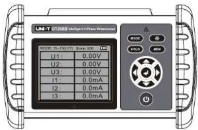
Intelligent 3-Phase Voltammeter
UT268B
Operating Manual

Contents
I. Safety Information ......2
II. Introduction ...... 3
III. Basic Functions Introduction ...... 3
IV. Electrical Symbols ....3
V. Technical Specifications ....4
- Basic Operating Conditions......4
- Rated Operating Conditions....4
- General Specifications ....4
- Performance Specifications....6
VI. External Structure 7
VII. Operating Instructions 8
- Power On/Off 8
- Data Hold/Cancellation/Storage 8
- Data Viewing/Exit 8
- Data Deletion 8
- Display Mode Switching 9
- Testing 9
VIII. Battery Charging 12
IX. Others 12
X. Packing List 13
I. Safety Information
Thank you for purchasing the product. Before first use, please thoroughly read and strictly follow the safety information and precautions listed in the user manual, to avoid electric shock or personal injury.
◆ The product is used for live working, for the sake of your safety, please follow the national safe production regulations and safe operation procedures.
◆ Please pay attention to the labeled words and symbols at the front and rear panels.
◆ Check if the product and its accessories are complete. Do not use if damage, exposure or broken wire occurs. It is forbidden to use if rear cover and battery cover are not closed in place. Stop use if metal exposure (caused by cracking of casing or test lead) occurs during use.
◆ Do not measure voltage over 600V. Do not use under strong electromagnetic fields. It is forbidden to conduct test in places with inflammable and dangerous substances.
◆ Be sure that the plug of the lead connects with terminal tightly, and that the direction is correct when performing phase test. Remove the test lead from measured conductor before disconnecting the test lead with the voltammeter. Do not make contact with the terminal by hand, to avoid electric shock.
◆ Do not operate the product by wet hand. Avoid rain from dripping on the product. It is forbidden to use in damp state.
◆ Do not place or keep the product in environments with high temperature, high humidity, dew or direct sunlight for a long time.
◆ Keep the product surface clean and dry. Do not use clean the product by corrosives or coarse materials, please wipe the current clamp mildly by soft cloth (i.e. glasses cloth) dipped with rust-proof dehumidifying lubricant.
◆ Please refrain the voltammeter and the current clamps from impact and dropping.
◆ Use the product in specified measurement range and operating environments.
◆ Use, disassembly, calibration and maintenance must be performed by authorized qualified personnel.
◆ The safety warning symbol “⚠️” in the user manual identifies that the operator must perform safe operation according to the instructions.
◆ The danger symbol “⚡” in the user manual identifies that the operator must strictly perform safe operation according to the instructions.
II. Introduction
The Digital 3-Phase Voltammeter, the latest product in clamp meter series, is a digitalized, multifunctional, high-precision and intelligent multi-parameter industrial-frequency measurement instrument. Designed with latest microprocessor technology and digital signal processing technology, UT268B can measure industrial-frequency parameters (i.e. voltage, RMS current, active/reactive power, apparent power, industrial frequency, power factor, phase relation, and others) in direct AC sampling method, identify transformer connection section and inductive and capacitive circuits, test secondary loop and bus differential protection system, display phase relations between current transformers under differential protection, and check if the wiring of electric energy meter is correct. By using clamp current transformer, this voltammeter can perform measurement without disconnecting from measured conductor, making it a safe, accurate and portable electric power meter.
Digital 3-Phase Voltammeter, also known as intelligent 3-Phase Voltammeter, Multifunctional 3-Phase Voltammeter, Digital Clamp Voltammeter, etc., is suitable for use in electric power, petrochemical industry, metallurgy, railway, industrial and mining enterprises, scientific and research institute, metrology service, electric energy charging system, relay protection system, and more.
III. Functions Introduction
- Devised with large screen with high-brightness backlight, to clearly display working state and testing parameters.
- The ability to measure 3-phase voltage, current, phase, frequency, active power, reactive power, apparent power, power factor, and overall power.
- Can be used to measure grid frequency and phase sequence.
- The function of phase measurement under small current of 5mA allows for checking wire connection without load.
- Automatically identify transformer winding and capacitive and inductive loads; and identify wrong connection of 3P3W and 3P4W.
- Static storage function to enable store 500 groups of data at most.
IV. Electrical Symbols
 | Extremely dangerous! The operator must follow the safety information strictly, otherwise it may present a risk of electric shock, which can cause personal injury or death. |
 | Danger! The operator must follow the safety information strictly, otherwise it may present a risk of electric shock, which can cause personal injury or death. |
 | Warning! The operator must follow the safety information strictly, otherwise it can cause personal injury or product damage. |
| ~ | Alternating Current (AC) |
| Direct Current (DC) | |
| Double Insulated |
V. Technical Specifications
1. Basic Operating Conditions
1) Ambient temperature: (23±5)°C
2) Ambient humidity: (45\~75)% RH
3) Waveform of measured signal: Sinusoidal wave, =0.02
4) Frequency of measured signal: (50±0.2)HZ
5) Location of measured current-carrying conductor at the clamp jaws: At center
6) Current amplitude when measuring phase frequency, phase sequence, power and power factor: 5A±0.2A
7) Voltage amplitude when measuring phase frequency, phase sequence, power and power factor: 220V ± 20V
8) Electromagnetic interference to external-reference frequency: Shall be avoided.
2. Rated Operating Conditions
1) Ambient temperature: (-15 +45)^ C
2) Ambient humidity: (0\~90)% RH
3) Operating altitude: <1500 m
4) Waveform of measured signal: Sinusoidal wave, =0.05
5) Frequency of measured signal: 45\~65HZ
6) Current amplitude when measuring phase frequency, phase sequence, power and power factor: 20mA\~1000A
7) Voltage amplitude when measuring phase frequency, phase sequence, power and power factor: 20V\~600V
8) Location of measured current-carrying conductor at the clamp jaws: Any location
3. General Specifications
| Functions | Measure 3-phase AC voltage, current, phase between voltages, phase between currents, phase between voltage and current, frequency, phase sequence, active power, reactive power, apparent power, power factor, and current vector sum; identify transformer connection section, inductive circuit, and capacitive circuits; and test secondary loop and bus differential protection system, display the phase relation between differentially-protected CTs of each group, check if the wiring of electric energy meter is correct, repair equipment of measured line, etc. |
| Power supply | DC 3.7V large-capacity rechargeable lithium battery |
| Power consumption | 250mA at most with backlight lit up (battery working duration: >5 hours) |
| Display mode | LCD display (71×52 mm) |
| Voltammeter dimensions | 187*191*51 mm (Length*Width*Thickness) |
| Voltage range | AC 0.00V~600V |
| Current range | AC 0.0mA~1000A |
| Phase range | 0.0°~360.0° |
| Frequency range | 45.00Hz~65.00Hz |
| Active power range | 0.0W~600Kw |
| Reactive power range | 0.0W~600kVAR |
| Apparent power range | 0.0W~600kVA |
| Power factor range | -1~+1 |
| 3-phase overall power | 3-phase overall power, overall apparent power, overall reactive power and over power factor are displayed in the line “T”. |
| Current vector sum | 0mA~3000A |
| Resolution | Voltage: AC 0.01V |
| Current: AC 0.1mA | |
| Phase: 0.1° | |
| Frequency: 0.01Hz | |
| Active power: 0.1W | |
| Reactive power: 0.1VAR | |
| Apparent power: 0.1VA | |
| Power factor: 0.001 | |
| Current vector sum: 1mA | |
| Phase sequence | If the phase sequence of “U1, U2 and U3” or “I1, I2 and I3” is positive, then the cursor flashes from left to right in order; if negative, then from right to left. |
| Testing rate | About 2 seconds per time |
| Data hold | When the button “HOLD” is pressed during test, the data will be held and the symbol “HOLD” is displayed. |
| Data storage | 500 groups of data |
| USB port | Upload stored data to computer via USB port, so as to analyze and manage data. |
| Auto power off | To reduce power consumption, the voltammeter powers off automatically 15 minutes after it is powered on. |
| Backlight function | Used in dark environments and at night. |
| Voltage detection | If the battery voltage is lower than 3.0V, the low battery symbol is displayed to indicate charging in time. |
| Product weight | Voltammeter: 450 g (including battery) |
| Large-caliber current clamp: 440 g × 3 | |
| Test lead: 250 g | |
| Length of test lead length | 1.5 m |
| Length of current clamp lead | 2 m |
| Operating temperature and humidity | -10°C~40°C; <80%RH |
| Storage temperature and humidity | -10°C~60°C; <70%RH |
| Input impedance | 2 M (the input impedance of testing voltage) |
| Withstand voltage | Apply 1000V/50Hz sinusoidal AC voltage between voltammeter circuit and casing for one minute. |
| Insulation | 100M (between voltammeter circuit and casing) |
| Structure | Double-insulated |
| Applicable safety regulations | IEC61010-1 CAT III 600V, IEC61010-031, IEC61326, Pollution Class 2 |
4. Performance Specifications
| Type | Range | Resolution | Basic error |
| Voltage | AC 0.00V~9.99V | 0.01V | ± (1.5%rdg+3dgt) |
| AC 10.0V~99.9V | 0.1V | ± (1.5%rdg+3dgt) | |
| AC 100V~600V | 1V | ± (1.5%rdg+3dgt) | |
| Current | AC 0.0mA~9.9mA | 0.1mA | ± (1.5%rdg+3dgt) |
| AC 10.0mA ~99.9mA | 0.1mA | ± (1.5%rdg+3dgt) | |
| AC 100mA ~999mA | 1mA | ± (1.5%rdg+3dgt) | |
| 1.00A~10.00A | 10mA | ± (1.5%rdg+3dgt) | |
| 10.0A~100.0A | 0.1A | ± (1.5%rdg+3dgt) | |
| 100A~1000A | 1A | ± (1.5%rdg+3dgt) | |
| Phase | 0.0°~360° | 0.1° | ±1° |
| Frequency | 45Hz~65Hz | 0.01Hz | ±0.1Hz |
| Power factor | -1~+1 | 0.001 | ±0.03 |
Note 1: The phase error is ±3^ under operating condition (For current amplitude below 30mA, the phase error will be doubled).
| Current | Voltage range | ||
| 10.0V~100.0V | 100V~600V | ||
| Current range | 10.0mA~99.9mA | 0.0100 KW | 0.0600 KW |
| 100mA~999mA | 0.1000 KW | 0.6000 KW | |
| 1A~9.99A | 1.0000 KW | 6.0000 KW | |
| 10A~99.9A | 10.000 KW | 60.000 KW | |
| 100A~1000A | 100.000 KW | 600.000 KW | |
| Accuracy: | ± (3%+3dgt) | ||
| Resolution: | <10.000 KW: 0.0001 KW10.000 KW: 0.001 KW | ||
| Current | Voltage range | ||
| 10.0V~100.0V | 100V~600V | ||
| Current range | 10.0mA~99.9mA | 0.0100 KVAR | 0.0600 KVAR |
| 100mA~999mA | 0.1000 KVAR | 0.6000 KVAR | |
| 1A~9.99A | 1.0000 KVAR | 6.0000 KVAR | |
| 10A~99.9A | 10.000 KVAR | 60.000 KVAR | |
| 100A~1000A | 100.000 KVAR | 600.000 KVAR | |
| Accuracy: | ± (3%+3dgt) | ||
| Resolution: | <10.000 KVAR: 0.0001 KVAR10.000 KVAR: 0.001 KVAR | ||
| Current | Voltage range | ||
| 10.0V~100.0V | 100V~600V | ||
| Current range | 10.0mA~99.9mA | 0.0100 KVA | 0.0600 KVA |
| 100mA~999mA | 0.1000 KVA | 0.6000 KVA | |
| 1A~9.99A | 1.0000 KVA | 6.0000 KVA | |
| 10A~99.9A | 10.000 KVA | 60.000 KVA | |
| 100A~1000A | 100.000 KVA | 600.000 KVA | |
| Accuracy: | ± (3%+3dgt) | ||
| Resolution: | <10.000 KVA: 0.0001 KVA10.000 KVA: 0.001 KVA | ||
VI. External Structure
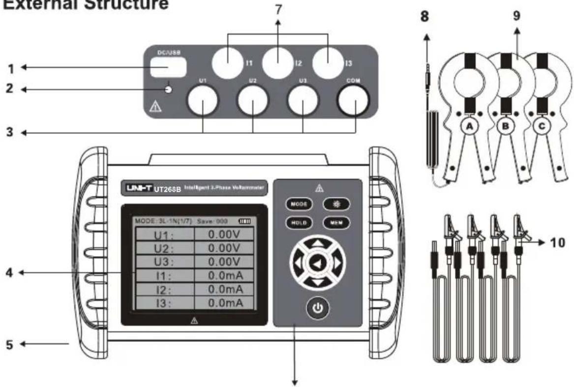
- USB transfer/charging port
- Charging indicator light
- 3-phase voltage input ports
- LCD display
-
Rubber-insulated protective cover
-
Functional buttons
- 3-phase current input ports
- Plug of current clamp
- Large-caliber current clamps
- Test leads of voltage input
VII. Operating Instructions
| Please check if any component of the voltammeter is damaged, do not use in case any damage is found. | |
| It is forbidden to use the voltammeter in dangerous places. |
1. Power On/Off
Press “” to power on/off the voltammeter. The voltammeter powers off automatically 15 minutes after it is powered on.
2. Data Hold/Cancellation/Storage
When the button “HOLD” is pressed under testing mode, the displayed data is held and the symbol “HOLD” is displayed. Press HOLD to disable data hold. When the voltammeter holds data, it performs automatic numbering, stores the data held currently, and displays the numbering of groups (i.e. “Save: 002”). 500 groups of data can be stored at most, the symbol “FULL” appears if storage is full.
3. Data Viewing/Exit
When the button “MEM” is pressed, the voltammeter enters data viewing mode and displays the symbol “Read”. Start reading data from Group “Save: 001”. Press “ ” to read data at an increment of 1, long press “ ” to read data at an increment of 10. Press “ ” to read data at a decrement of 1, long press “ ” to read data at a decrement of 10. Press “ ” and “ ” to cycle through voltage/current and phase, active power, reactive power, apparent power, power factor, frequency, and storage. Press “MEM” to exit data viewing mode and return to testing mode.
4. Data Deletion
Under data viewing mode or testing mode, long press "HOLD" to enter data deletion mode, press " " to select "YES" or " " to select "NO", then return to testing mode after selected.
5. Testing Modes Switching
Power on the voltammeter to enter voltage and current testing mode (Figure 1). Press "MODE" to switch between "3P3W" and "3P4W" modes. Press " " and " " to switch testing modes between phase, active power, reactive power, apparent power, power factor, frequency, phase sequence, and vector diagram (Figure 2, 3, 4, 5, 6 and 7). Active power, reactive power, apparent power and power factor shown in Figure 4 and 5 are corresponding powers and power factor of U1I1, U2I2 and U3I3.
| MODE:3L-1N(1/7) Save:000 | |
| U1: | 0.00V |
| U2: | 0.00V |
| U3: | 0.00V |
| I1: | 0.0mA |
| I2: | 0.0mA |
| I3: | 0.0mA |
(1)
| MODE:3L-1N(2/7) Save:000 | |
| U1U2: | 360.0° |
| U2U3: | 360.0° |
| U3U1: | 360.0° |
| I1I2: | 360.0° |
| I2I3: | 360.0° |
| I3I1: | 360.0° |
(2)
| MODE:3L-1N(3/7) Save:000 | |
| U1I1: | 360.0° |
| U2I2: | 360.0° |
| U3I3: | 360.0° |
(3)
| MODE:3L-1N(4/7) Save:000 | ||
| P/KW | Q/KVAR | |
| 1: | 0.0000 | 0.0000 |
| 2: | 0.0000 | 0.0000 |
| 3: | 0.0000 | 0.0000 |
| T: | 0.0000 | 0.0000 |
| FREQ: 00.00Hz | ||
(4)
| S/KVA | PF | |
| 1: | 0.0000 | 1.000 |
| 2: | 0.0000 | 1.000 |
| 3: | 0.0000 | 1.000 |
| T: | 0.0000 | 1.000 |
| In: 0.000A | ||
(5)
| MODE:3L-1N(6/7) Save:000 | ||
| U1 | U2 | U3 |
| ● | ● | ● |
| I1 | I2 | I3 |
| ● | ● | ● |
(6)
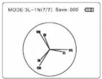
(7)
6. Testing
 | Electrified! Danger! The operation must be performed by authorized trained personnel. The operator must follow the instructions strictly, otherwise it can pose a risk of electric shock, which may cause personal injury or equipment damage. |
| Danger! Do not measure voltage line over 600V, otherwise it can pose a risk of electric shock, which may cause personal injury or equipment damage. | |
| Danger! Do not measure any line over 1000A, otherwise it may cause equipment damage. |
| Please perform wiring strictly according to the user manual. Do not connect I1, I2 and I3 inversely. | |
| Please remove the test leads from measured line before disconnecting the test leads with the voltammeter. |
| The phase relations of the voltammeter is: U1U2, U2U3, U3U1, I1I2, I2I3, I3I1, U1I1, U2I2 and U3I3, the previous signals exceed the next ones for all the phases. | |
| The U1, U2 and U3 terminals and the right arrows at the corresponding current clamps are the same-polarity ends. | |
| For phase testing, the direction of current flowing into the clamp shall be consistent with the direction of arrow at the clamp. |
The voltammeter measure 3-phase AC voltage and current, phase between voltages, phase between currents, phase between voltage and current, frequency, active power, reactive power, apparent power, power factor, 3-phase current vector sum, and identify phase sequence, inductive and capacitive circuits, etc.
Wiring of tests:
Single-phase testing: Connect the measured voltage lines L and N with U1 YELLOW and COM BLACK terminals correspondingly, then the current clamp I1 clamps the measured line L. "U2 GREEN, COM BLACK and I2" or "U3 RED, COM BLACK and I3" can also be connected.
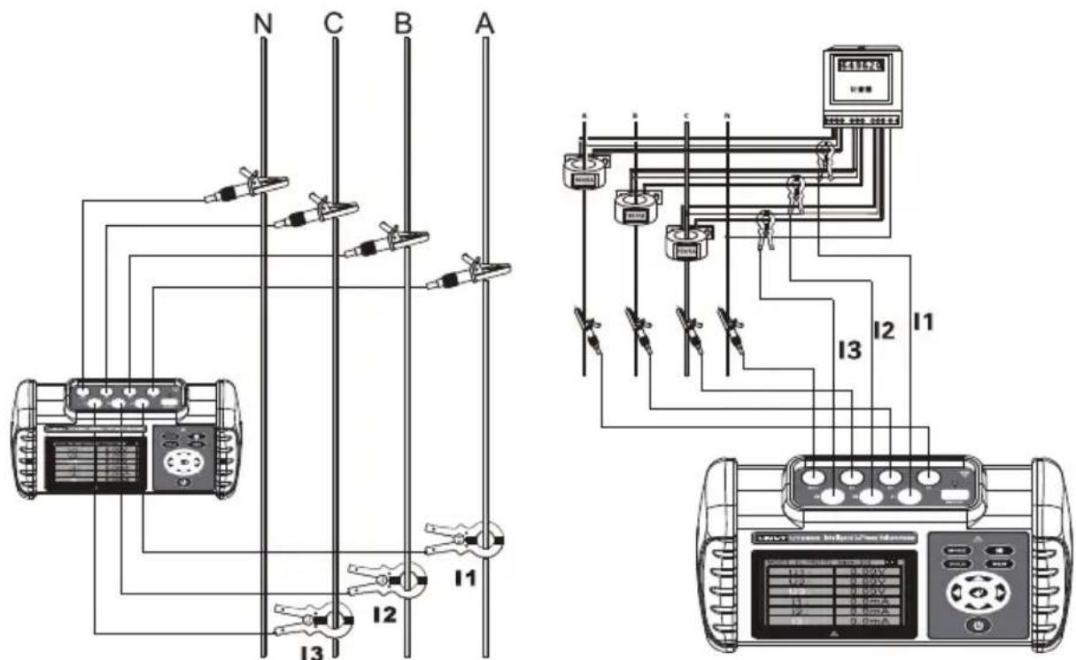
3-phase 4-wire testing: Connect the measured voltage lines UA YELLOW, UB GREEN, UC RED and N BLACK with U1 YELLOW, U2 GREEN, U3 RED and COM BLACK terminals correspondingly, then the current clamps I1, I2 and I3 clamp the measured lines IA, IB and IC correspondingly.
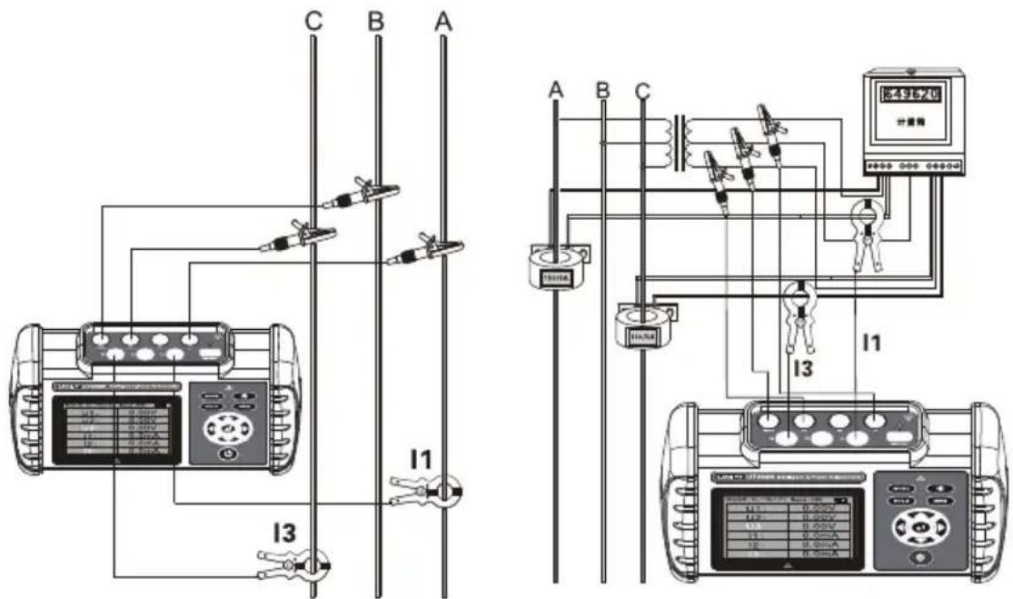
3-phase 3-wire testing: Connect the measured voltage lines UA YELLOW, UC RED and UB GREEN with U1 YELLOW, U3 RED and COM BLACK terminals, then the current clamps I1 and I3 clamp the measured lines IA and IC correspondingly. See “Reference wiring diagrams”.
Inductive and capacitive loads, phase sequence and polarity can be identified according to the phase relations. If the phase of U1I1 is between 0.0 and 90.0, then the measured load is inductive; if between 270.0 and 360.0, then capacitive. If the phase is approximate to 120.0, then the phase sequence is positive and the polarity is same; if approximate to 120.0 and 300.0, then positive and opposite (the current clamp may be in reverse direction or the measured line may be connected inversely); the phase sequence is negative for other phase values (phase loss is not considered).
Under phase sequence testing mode, if the phase sequence of "U1, U2 and U3" or "I1, I2 and I3" is positive, then the cursor flashes from left to right in order; if negative, then from right to left; if the corresponding cursor of "U1, U2 and U3" or "I1, I2 and I3" is not lit up, phase loss may occur or the signal amplitude may be too low.
Reference wiring diagrams:
Measure single-phase voltage, current, phase, frequency, power, etc.
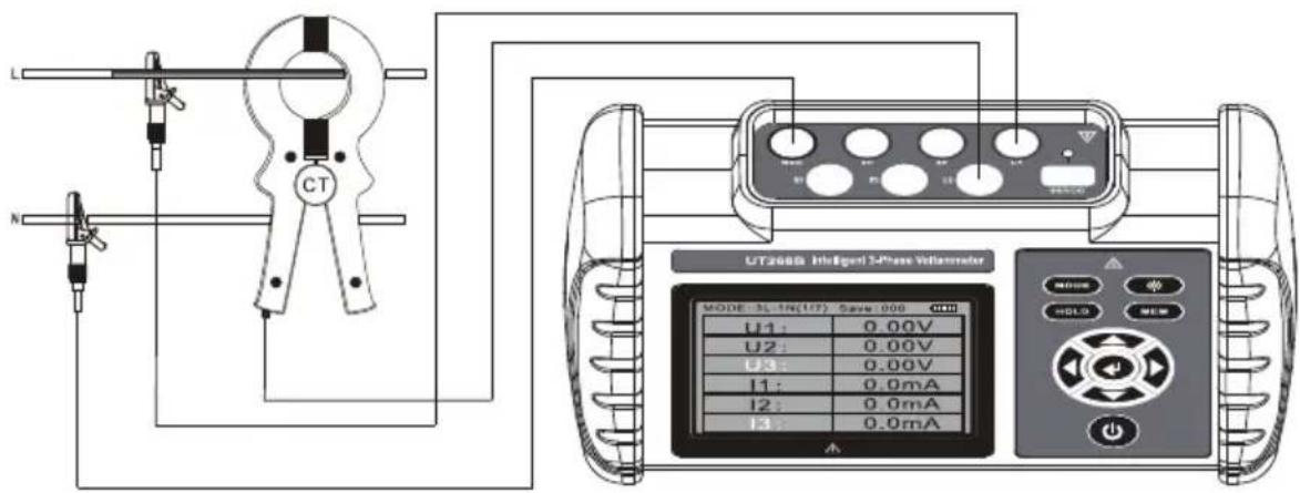
Measure 3-phase 3-wire voltage, current, phase, phase sequence, frequency, power, power factor, etc.
Measure 3-phase 4-wire voltage, current, phase, phase sequence, frequency, power, power factor, etc.
VIII. Battery Charging
| Use the original 5V charger only, do not use other high-voltage chargers, otherwise it may damage the voltammeter. | |
| Please charge the voltammeter once a month if it is not used for a long time. |
- If the power voltage of the voltammeter is lower than 3V, the symbol "☐" appears to indicate low battery, in such case, please charge the battery immediately (the indicator light is lit up green if the battery is fully charged).
IX. Others
1. Dedicated current clamps
The three current clamps are only used for the voltammeter supplied, do not apply them with other voltammeters. Do not reverse the sequence of the three current clamps, otherwise error will be increased. Prevent the current clamp from dropping and impact. Keep the clamp jaws clean. Be sure the clamp jaws close in place.
2. The maintenance of current clamps
Clear dust at the clamp jaws after use, do not clean with coarse materials or corrosives. Please mildly wipe the clamp jaws by using soft cloth and lubricant (i.e. WD-40 lubricant). Please also perform cleaning before testing.
-
The voltammeter is used to test secondary and low-voltage loops (Do not measure current of high-voltage line to prevent electric shock).
-
3-phase 4-wire (phase with 3-phase load balanced)
| Phase relation | Phase value | Phase relation | Phase value |
| Ua-Ub | 120° | Ia-Ib | 120° |
| Ub-Uc | 120° | Ib-Ic | 120° |
| Uc-Ua | 120° | Ic-Ia | 120° |
- 3-phase 3-wire (phase with 3-phase load balanced)
| Phase relation | Phase value | Phase relation | Phase value |
| Uab-Ucb | 300° | Ia-Ic | 240° |
| Uab-Ia | 30° | Ucb-Ic | 330° |
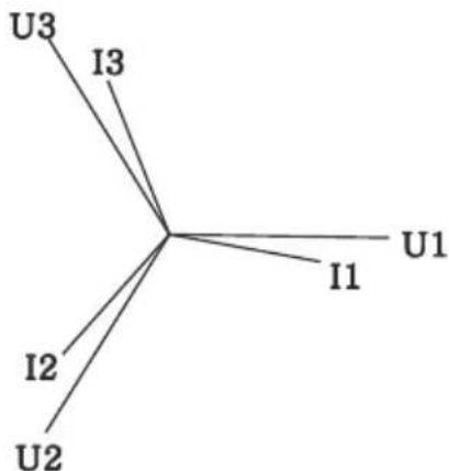
- 3-phase 4-wire vector diagram and 3-phase 3-wire vector diagram:
flowchart
graph TD
    U1 --> I1
    U1 --> I2
    U1 --> I3
    U2 --> I2
    U2 --> I3
    U3 --> I3
3-phase 4-wire vector diagram
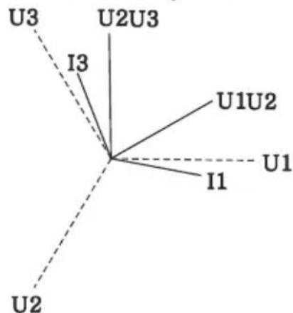
3-phase 3-wire vector diagram
 | If the current clamp is in reverse direction or the current line is connected reversely, there will be a difference of 180° with the displayed phase value, that is, 180° is added to the standard values shown above. |
X. Packing List
| Voltammeter | 1 pcs |
| Carrying box | 1 pcs |
| Current clamp | 3 pcs |
| Test lead | 4 pcs (1 pc for yellow, green, red and black respectively) |
| Charger + USB cable | 1 set |
| User manual | 1 pcs |
The content of this user manual cannot be used as a reason for using the product for special purposes.
The company is not responsible for other losses caused by use.
The company reserves the right to modify the contents of the user manual. If there are changes, no further notice will be given.




- UNI-T®
- Contents
- Safety Information
- Introduction
- Functions Introduction
- Technical Specifications
- Basic Operating Conditions
- Rated Operating Conditions
- General Specifications
- Performance Specifications
- Operating Instructions
- Power On/Off
- Data Hold/Cancellation/Storage
- Data Viewing/Exit
- Data Deletion
- Testing Modes Switching
- Testing
- Wiring of tests:
- Battery Charging
- Others
- Dedicated current clamps
- The maintenance of current clamps
- Packing List
Brand : Uni-T
Model : UT268B
Category : Mètre