
Smart Thump ST16-20 - Meter Megger - Free user manual and instructions
Find the device manual for free Smart Thump ST16-20 Megger in PDF.


| Product Type | Cable Fault Locator / TDR |
| Brand | Megger |
| Model | Smart Thump ST16-20 |
| Dimensions (H x W x D) | 210 x 120 x 60 mm (8.3 x 4.7 x 2.4 in) |
| Weight | 0.6 kg (1.3 lb) |
| Power Supply | Rechargeable NiMH battery, 8.4V |
| Battery Life | Up to 20 hours typical operation |
| Display | Graphical LCD, 128 x 64 pixels |
| Measurement Range | Up to 20 km (12.4 miles) on low-loss cable |
| Resolution | 0.1 m (0.3 ft) |
| Pulse Amplitude | Selectable, up to 100V into 50Ω |
| Measurement Modes | TDR, Pulse Echo, Resistance, Fault Distance |
| Output Connector | BNC female |
| Memory | Stores up to 100 traces |
| Data Transfer | USB, optional Bluetooth |
| Protection Class | IP54 (splash and dust resistant) |
| Safety Standards | IEC 61010-1, CAT II 300V |
| Operating Temperature | -10°C to +50°C (14°F to 122°F) |
| Languages | Multilingual (EN, FR, DE, ES, etc.) |
| Included Accessories | Test leads, charger, shoulder strap, user manual |
| Warranty | 1 year |
| Maintenance | Clean with a damp cloth; avoid solvents |
| Repairability | Repairable by authorized Megger service centers |
Frequently Asked Questions - Smart Thump ST16-20 Megger
User questions about Smart Thump ST16-20 Megger
0 question about this device. Answer the ones you know or ask your own.
Ask a new question about this device
Download the instructions for your Meter in PDF format for free! Find your manual Smart Thump ST16-20 - Megger and take your electronic device back in hand. On this page are published all the documents necessary for the use of your device. Smart Thump ST16-20 by Megger.
USER MANUAL Smart Thump ST16-20 Megger
Portable Fault Locating System
SMART THUMP ST16
Read this entire manual before operating.
Megger.
Valley Forge Corporate Center
2621 Van Buren Avenue
Norristown, PA 19403-2329
U.S.A.
610-676-8500
www.megger.com
Megger.
Portable Fault Locating System
SMART THUMP ST16
User Manual

Copyright© 2016 by Megger. All rights reserved.
No part of this handbook may be copied by photographic or other means unless Megger have beforehand declared their consent in writing. The content of this handbook is subject to change without notice. Megger cannot be made liable for technical or printing errors or shortcomings of this handbook. Megger also disclaims all responsibility for damage resulting directly or indirectly from the delivery, supply, or use of this matter.
The information presented in this manual is believed to be adequate for the intended use of the product. If the product or its individual instruments are used for purposes other than those specified herein, confirmation of their validity and suitability must be obtained from Megger. Refer to the warranty information below. Specifications are subject to change without notice.
WARRANTY
Products supplied by Megger are warranted against defects in material and workmanship for a period of one year following shipment. Our liability is specifically limited to replacing or repairing, at our option, defective equipment. Equipment returned for repair must be shipped prepaid and insured. Contact your local MEGGER representative for instructions and a return authorization (RA) number. Please indicate all pertinent information, including problem symptoms. Also specify the serial number and the catalog number of the unit. This warranty does not include batteries, lamps or other expendable items, where the original manufacturer's warranty shall apply. We make no other warranty. The warranty is void in the event of abuse (failure to follow recommended operating procedures) or failure by the customer to perform specific maintenance as indicated in this manual.
| Local Megger Offices | ||
| Australia | Canada | France |
| Megger Pty LimitedUnit 1, 11-21 Underwood RoadHomebushNSW 2140T: +61 (0)2 9397 5900F:+61 (0)2 9397 5911 | 110 Milner Avenue Unit 1Scarborough OntarioM1S 3R2 CanadaT: 1 416 298 6770F: 416 298 0848 | 23 rue Eugène HenaffZA du Buisson de la Couldre78190 TRAPPES T: 01 30 16 08 90F: 01 34 61 23 77 |
| Germany India Kingdom of Bahrain | ||
| SebaKMTDr. Herbert Iann Str. 696148 Baunach / GermanyT: +49 9544 680F: +49 9544 2171 | Megger (India) Pvt Limited501 Crystal Paradise MallOff. Veera Desai RoadAndheri (W)Mumbai 400053T: +91 22 26740468F: +91 22 26740465 | P.O. Box 15777Office 81, Building 298Road 3306, Block 333ManamaKingdom of Bahrain.T: +973 177 40 620F: + 973 177 20 975mesales@megger.com |
| Kingdom of Saudi Arabia South Africa Sweden | ||
| PO Box 1168Khobar 31952T: +966 3889 4407F: +966 3889 4077mesales@megger.com | PO Box 22300Glen Ashley 4022DurbanSouth AfricaT: +27 (031) 5646578F:+27 (031) 5637990 | Megger Sweden ABEldarvägen 4Box 2970SE-187 29 TÄBYSWEDENT: +46 8 510 195 00F: +46 8 510 195 95 |
| Switzerland United Kingdom (Dover) | ||
| Megger Schweiz AGOb. Haselweg 6305727 OberkulmAargauT: +41 62 768 20 30F: +41 62 768 20 33 | Megger LimitedArchcliffe RoadDover CT17 9ENT: 01304 502101F: 01304 207342 | |
| United States(Dallas) | United States(Valley Forge) | United States(College Station) |
| 4271 Bronze Way,Dallas, Texas 75237-1019 USAT: 1-800-723-2861F: 1-214-331-7399 | Valley Forge Corporate Centre2621 Van Buren AvenueNorristown, PA 19403 USAT: 610 676 8500F: 610-676-8610 | 4064 State Highway 6 SouthCollege Station, TX 77845 USA T: 979-690-7925F: 979-690-0276 |
Megger.
Table of Contents
1 SAFETY....1
Precautions....1
Warning and Caution Notices....1
Working with the Product....2
Operating Personnel 2
Repair and Maintenance 2
General Cautions and Warnings ....2
Intended Application....2
What to Do if Equipment Malfunctions....3
2 TECHNICAL DESCRIPTION....5
System Description ....5
Functional Description 5
Product Models....5
Features 6
Scope of Delivery....6
Available Accessories 7
Technical Data....7
Control Elements, Indicators and Connectors....9
Power Supply 11
Battery Operation 11
AC Line Operation....12
3 SETTING UP THE SYSTEM 13
Connection Diagram.... 14
Connection Sequence 14
4 OPERATING INSTRUCTIONS....15
Power on the System 15
Basics of Operation.... 15
Operation with Rotary Knob....15
High Voltage Control....16
Safety Circuit....16
Introduction.... 16
Conditions of the Safety Circuit 17
User Modes 17
System Settings (only accessible in Expert Mode).... 18
5 HOW TO PERFORM A TEST....21
Detecting and Locating a Cable Fault in a Shielded Medium Voltage Power Cable 21
Locating a Faulty Cable Section (Sectionalizing) 21
Locating a Cable Fault (shielded MV power cable)....25
How to Pre-Locate the Fault....26
How to Pinpoint the Fault (shielded MV power cable)....31
Detecting a Sheath Fault OR a Ground Fault in an Unshielded, Low Voltage Cable (both must be directly buried)....32
How to Pinpoint a Sheath Fault OR a Ground Fault in an Unshielded Low Voltage Cable (both must be directly buried)....34
6 CUSTOMIZE TDR FEATURES (applicable to TDR and ARM Mode) 37
Introduction....37
Customized TDR Features 38
Completing the Operation....41
7 ADVANCED SYSTEM SETTINGS 43
How to Edit the Cable List....43
Introduction 43
XML Structure of a Cable List File....43
How to Edit the Cable List....44
How to Setup Customer-Specific TDR Features....45
How to Use EasyPROT Software to Plot DC HIPOT/Sheath Test Data....47
8 CARE and MAINTENANCE 49
Maintenance....49
Storage 49
APPENDIX 1 - Overview of TDR Features....51
Receiving Instructions
-
Check the equipment received against the packing list to ensure that all materials are present. Notify Megger of any shortage. Email your local Service Representative or send to VFCustomerSupport@Megger.com.
-
Examine the equipment for damage received in transit. If damage is discovered, file a claim with the carrier at once and notify Megger, giving a detailed description of the damage.
-
Prior to operation, check for loosened hardware or damage incurred during transit. If these conditions are found, a safety hazard is likely, DO NOT attempt to operate equipment.
Please contact Megger as soon as possible.
Please check your delivery against:
a) your order
b) our advice note
c) the item delivered, and
d) the parts list
any shortages must be reported immediately.
Consultation with Megger
The present system manual has been designed as an operating guide and for reference. It is meant to answer your questions and solve your problems in as fast and easy a way as possible. Please start with referring to this manual should any trouble occur.
In doing so, make use of the table of contents and read the relevant paragraph with great attention. Furthermore, check all terminals and connections of the instruments involved.
Should any question remain unanswered, please contact:
VFCustomerSupport@Megger.com
Or
phone: +1.610.676.8500 (USA)
Megger.
1
SAFETY
Precautions
This manual contains basic instructions on commissioning and operating the SMART THUMP system. For this reason, it is important to ensure that the manual is available at all times to authorised and trained personnel. Any personnel who will be using the devices should read the manual thoroughly. The manufacturer will not be held liable for any injury or damage to personnel or property through failure to observe the safety precautions contained in this handbook.
Locally applying regulations have to be observed.
Warning and Caution Notices
Warning and caution notices are used throughout this manual where applicable. These notices appear in the format shown below and are defined as follows:

WARNING!
Warning, as used in this manual, is defined as a condition or practice which could result in personal injury or loss of life.

CAUTION
Caution, as used in this manual, is defined as a condition or practice which could result in damage to or destruction of the equipment or apparatus under test.
NOTE: The notes contain important information and useful tips for using the system. Failure to observe them can render the measuring results useless.
Working with the Product
It is important to observe the general electrical regulations of the country in which the device will be installed and operated, as well as the current national accident prevention regulations and internal company rules (work, operating and safety regulations).
After working with the equipment, make sure to de-energise, protect against re-energising, discharge, earth and short-circuit the instrument and installations that have been worked on.
Use genuine accessories to ensure system safety and reliable operation. The use of other parts is not permitted and invalidates the warranty.
Operating Personnel
This system and its peripheral equipment may only be operated by trained or instructed personnel. Anyone else must be kept away.
The system may only be installed by a trained or authorized electrician. In Germany DIN VDE 0104 (EN 50191), DIN VDE 0105 (EN 50110) and the German accident prevention regulations (UVV) define an electrician as someone whose knowledge, experience and familiarity with the applicable regulations enables him to recognize potential hazards.
Repair and Maintenance
Repairs and service must only be done by Megger or authorized service departments of Megger. Megger recommends having the equipment serviced and checked once per year at a Megger service location.
Megger also offers direct on-site support. Please contact our service office for more information
General Cautions and Warnings
Intended Application
Safe operation is only warranted if using the equipment for its intended purpose. Using the equipment for other purposes may result in bodily harm or death of the operator and damage the equipment itself and that of the involved test site.
The limits described under technical data may not be exceeded. Operating Megger products in environments, which feature high humidity in combination with condensation, may lead to flash-over, creepage, danger and damage. The
instruments should only be operated under tempered conditions. It is not allowed to operate Megger products in direct contact with humidity, water or near aggressive chemicals nor explosive gases and fumes.
What to Do if Equipment Malfunctions
The equipment may only be used when working properly. If irregularities or malfunctions appear which cannot be solved consulting this manual, the equipment must immediately be put out of operation and marked as not functional. In this case inform the person in charge who should inform the Megger service to resolve the problem. The instrument may only be operated when the malfunction is resolved.
Five Safety Rules
- The five safety rules must always be followed when working with HV (High Voltage):
- De-energize
■ Protect against re-energizing
■ Confirm absence of voltage
■ Ground and short-circuit
■ Cover close by energized components

Using cardiac pacemaker
Physical processes during operation of high voltage may endanger persons wearing a cardiac pacemaker when near these high voltage facilities
Fire fighting in electrical installations
- According to regulations, Carbon Dioxide (CO _2 ) is required to be used as extinguishing agent for fighting fire in electrical installations.
- Carbon Dioxide is electrically non conductive and does not leave residues. It is safe to be used in energized facilities as long as the minimum distances are maintained. A Carbon Dioxide fire extinguisher must be always available within electrical installations.
- If, contrary to the regulations, any other extinguishing agent is used for fire fighting, this may lead to damage at the electrical installation. Megger disclaims any liability for consequential damage. Furthermore, when using a powder extinguisher near high-voltage installations, there is a danger that the operator of the fire extinguisher will get an electrical shock from an ARC FLASH (voltage arc-over created by the powder dust cloud).
It is essential to observe the safety instruction on the extinguishing agent.
■ Applicable is DIN VDE 0132 in Germany

WARNING - Dangers when working with HV
Special attention and safety awareness is needed when operating HV equipment and especially non-stationary equipment. The regulations VDE 0104 about setting up and operation of electric test equipment, i.e. the corresponding EN 50191 as well as country-specific regulations and standards must be observed.
- The system generates a dangerous voltage of up to 16 kV during operation. This is supplied via a HV cable to the test object.
- The system may not be operated without supervision.
- Safety installations may not be by-passed nor deactivated.
- All metallic parts in close proximity of the test equipment must be grounded in order to avoid the build-up of hazardous electric surface charges.
2
TECHNICAL DESCRIPTION
System Description
Functional Description
The SMART THUMP is a compact, battery or AC operated fault location system typically to be used for fault locating of solid dielectric low voltage and medium voltage cables.
It is ideally suited for use in URD systems and also feeder cables. The main advantages of the SMART-THUMP are its solid HV performance, simple operation, automated fault locating process, operation in rainy conditions, weight and economics.
Beside proven prelocation technique (inductive ARM, current decoupling (ICE)), the SMART THUMP provides sectionalizing capability (trouble shooting in URD loop systems, North America), acoustic pinpointing with the integrated 1500 J surge generator as well as DC for breakdown detection, insulation resistance estimation and sheath testing and sheath locating (sheath locating requires optional receiver ESG-NT).
Product Models
Typically, the SMART THUMP is mounted on a hand truck and equipped with a lead-acid battery/inverter system.
The hand truck mounted version is also available as an C unit only (without battery/inverter system, but with an C isolation transformer).
The SMART-THUMP can be also permanently installed in a vehicle and is powered by the power circuit of the vehicle (via inverter), a generator system or optionally by an external battery with internal inverter.
When installed into a vehicle, the SMART-THUMP also offers an optional remotely operated configuration, with a separation of up to 8 ft between the control and HV units.
This manual covers all models of the SMART THUMP. If necessary, any differences are noted in the text.
Features
The SMART THUMP system combines the following features and functions as a single device:
- Quick Steps and Expert Mode (full feature mode), Automatic detection and localization of transformers
■ Automatic fault prelocation and localization with regard to the 2 closest transformers (optional Sectionalizing software)
■ Automatic cable end and fault detection and localization - DC test up to 16 kV with automatic breakdown detection and insulation resistance measurement
- Pinpointing of high resistance faults in surge mode
■ Sheath test with automatic breakdown detection
■ (Sheath) fault pinpointing (requires optional receiver ESG-NT) - Integrated safety circuit for user's safety (F-OHM safe grounding)
■ Optional external remotely operated safety device to shut off HV - Operation from internal battery / inverter or from an external AC or DC source
■ Sturdy and weatherproof enclosure for outdoor use
Scope of Delivery
The scope of delivery of the SMART THUMP system comprises the following components:
■ HV output cable hard wired
■ Safety Grounding cable
■ AC Power cord
- Owner's manual
Available Accessories
The following accessories can be ordered from Megger, if required:
| Accessories | Description | Item |
| Elbow adaptor with 14 mm female MC connector (NAFTA market) | Used to connect HV output cable | 865000100100000 (15 kV)865000200100000 (25 kV)865000300100000 (35 kV) |
| External safety device Safety | device with signal lamps, key switch and EMERGENCY OFF switch | 893024147 and 890024896 |
number
Technical Data
| Parameter | Value |
| DC Test voltage | 0 to 16 kV |
| Surge voltage | 0 to 8 / to16 kV, |
| Source current | 0 to 60 mA (up to 8 kV)0 to 30 mA (8 ... 16 kV) |
| Insulation measurement | 20 kΩ ... 10 MΩ |
| Surge energy | 1500 J at the maximum surge voltage of the respective surge levels (8 kV / 16 kV) |
| Power supply | 110 V to 230 V ±15%, 50 / 60 Hz |
| Battery | Internal lead-acid gel type battery (12 V / 74 Ah |
| Operating time battery | >90 min (pinpointing) |
| Power consumption | 700 W |
| Display | 640 x 480 pixel Transflective / high Brite TFT direct sunlight readable |
| Memory | >1000 traces |
| Interfaces | USB port |
| Measuring range (extended range) | 8000 m , 25,000 ft, (32km, 100000ft) |
| Measuring resolution | 0,8 m (2,5 ft) at 80 m/μs (250 ft/μs) |
| Max. sampling rate | 100 MHz |
| Update rate | 5 samples / second |
| Dynamic range | 64 db |
| Output impedance | 64 Ω |
| Operating temperature | 20 °C to +50 °C |
| Storage temperature | 25 °C to +70 °C |
| Dimensions (W x H x D) | 690 x 1165 x 600 mm |
| Weight | 145 kg, hand truck mounted incl. battery/inverter and 50ft (17m) each of HV and Safety Ground cable |
| Protection class(in accordance with IEC 61140) | I |
| Protection rating(in accordance with IEC 60529) | IP53 |
Control Elements, Indicators and Connectors
The SMART THUMP has the following control elements, indictors and connectors:
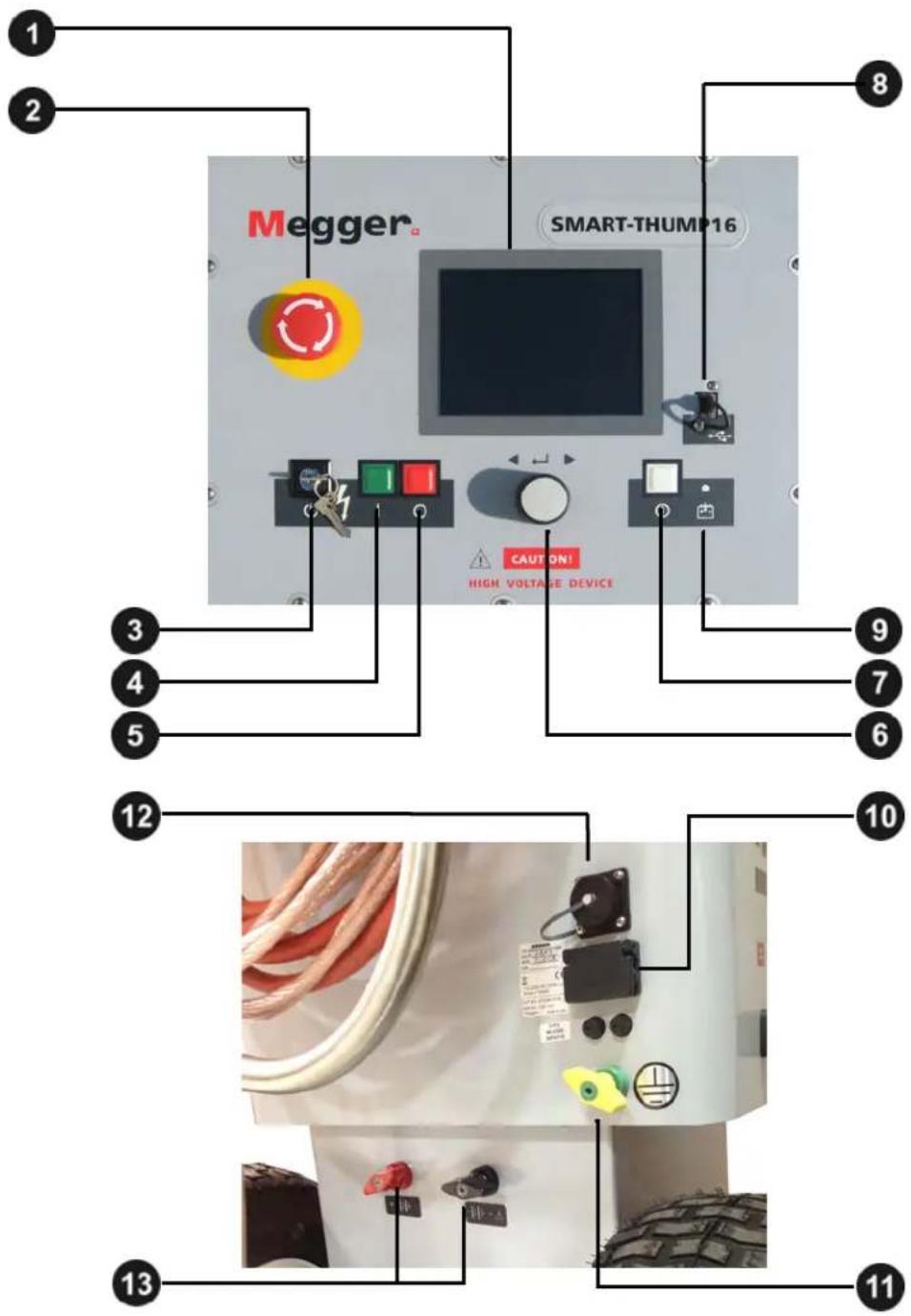
| Element | Description |
| 1 | Display |
| 2 | Emergency stop button |
| 3 | HV “interlock” key switch |
| 4 | “HV ON” button |
| 5 | “HV OFF” button |
| 6 | Rotary control knob |
| 7 | “ON / OFF” button |
| 8 | USB port |
| 9 | Charging status LED (yellow: charging | green: charging completed) |
| 10 | AC power connector |
| 11 | Safety ground connection |
| 12 | Jack for connecting external safety device (See page 7 'Available Accessories'). |
| 13 | Terminals for external 12 V DC power supply |
Power Supply
Battery Operation
Introduction
The SMART THUMP can be equipped with an internal battery. In this case there is no requirement for an AC line supply to operate the unit in the field. For a good trade-off between weight and operation time, the battery is sized for up to more than 400 capacitor discharges at 90% of full voltage which equals approximately 1 hour of thumping (pinpointing).
Battery Status and Automatic Shutoff
As long as more than 50% of the battery capacity is available, no battery icon is shown on the screen. As soon as the battery is discharged by more than 50%, the battery icon in the upper right corner of the screen starts flashing (not an active bar graph).
LOCATE
LOCATE

Battery capacity >50% Battery capacity <50%
To protect the battery from a deep discharge, the unit turns automatically off, if the battery is discharged too low for safe operation.
Low Battery!
Shutdown unit
Note: To find out whether the battery charge is sufficient for further use of the unit in the field, just turn the unit on and check if the battery symbol is visible on the main screen. If the symbol is visible you should strongly consider recharging the battery before using the unit or plan to operate off AC line power.
Backup Battery
If the internal battery is becoming drained while fault locating, any 12 V battery providing more than 50 A (e.g. a car battery) can be connected to the 12 V terminals order to extend the operation time or the unit must be connected to an AC source (see below AC Line Operation).
Charging
The battery automatically is being charged as soon as the SMART THUMP has been connected to 120/230 AC line power. Charging time on a fully drained battery is about 10 to 12 hours. The progress of the charging process is indicated by the battery charging status LED during charging, the LED lights yellow. It turns to green, when the battery is full and charging is finished.
NOTE: Always charge the battery immediately after use. Lead-acid batteries must always be kept in a charged condition. The battery life is longer with an almost fully charged battery rather than fully discharged one. Store the unit always at a full charge by keeping the charger connected while the unit is not in use (trickle charge).
AC Line Operation
As soon as the AC power cord is connected to the receptacle 10 the SMART THUMP and the AC line, the system is operating on AC power and being charged at the same time.
3
SETTING UP THE SYSTEM

WARNING - Safety instructions for setting up
- The guidelines to maintain occupational safety when operating a non-stationary test system often differ between network operators and it is not uncommon to use National regulations (like, i.e. the German BGI 5191) to be used as well.
Operator must inform him/her self about the guidelines applicable in the area of operation beforehand, and comply with specific work rules for non-stationary test systems. - Always follow the safety instructions (see Section 1 SAFETY) - in particular the five safety rules - before connecting to the cable to be tested.
- Before connecting the system to the cable to be tested, be sure that the cable has been tested for voltage, discharged / isolated and grounded tested in compliance with all OSHA & company safety procedures.
- Select a setup location which is sufficient for the weight and size of the system and insure that it stands securely. Always locate the system off to the side of the cable path, never on top of the cable path.
- When setting up the testing system, ensure that it does not impair the function of any other systems or components. If other systems and components have to be modified in order to set up and operate the test system, be sure to reverse these actions when the work is finished. Always take the special requirements of these systems and components into account and only carry out work on them after consulting and obtaining approval from whoever is in charge of them.
- Install protective equipment (such as railings, chains or bars) around the test site to block access to the danger zone and prevent the risk of touching live parts.
- Always operate the SMART THUMP system in a vertical position. Grounding and HV contacts both require a vertical orientation to ensure proper functioning as well as a "Fail Safe Position" in case of an AC or DC power failure or if the unit is shut off.
■ After receiving clearance, make sure that NO dangerous voltages can reach unprotected places or technical equipment. - As a matter of principle, all de-energized cables that are part of the test circuit shall be connected together and shorted to ground
Connection Diagram
The following figure shows the simplified connection diagram.

Connection Sequence
Connect the unit in the following order:
| Step | Description |
| 1 | Connect the safety ground lead to a reliable ground (e.g. station-ground, transformer ground rod. Do not drive a separate ground rod!). |
| 2 | Connect the HV return lead to the cable shield or the concentric neutral of the specific cable to be tested. The resistance between the HV return (operational ground) and the safety ground should be less than 5 Ω (check with ohmmeter, if questionable), if not the F-OHM safety feature will be activated, disabling the HV ON function or activating the HV OFF function.NOTE: The closer and better the HV return is connected to the shield / concentric of the cable to be tested, the better the TDR trace readings will be. |
| 3 | Connect the HV lead to the phase conductor to be tested (optional elbow adapter or vice-grip. (See 'Available Accessories' in Section 2). |
| 4 | Connect the supplied power cord to the connector the back of the unit and connect the other end to a power outlet.NOTE: If no power connection can be established, the unit can be operated from the internal battery, provided it is equipped with this feature and is properly charged. The unit also provides 2 battery terminals that are accessible from the out-side, which can be connected to an external battery |
| 5 | Only after all necessary connections have been made, the ground connection to the cable under test can be lifted. |
4
OPERATING INSTRUCTIONS
Power on the System
Once the "ON / OFF" button 7 pressed, the system starts up. After start-up, the system is in the 'Ready for operation' state and the main menu is displayed:
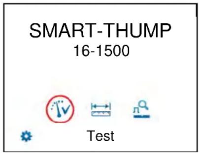
In this state, the high voltage source is still switched off and the high voltage output is grounded via a discharge resistor.
Basics of Operation
Operation with Rotary Knob
Navigation within the menus is done using the rotary knob 6 follows:
Turning
Selecting
Clicking
Confirming (“ENTER” function)
The currently selected menu item is identified by a red circle.


not selected selected
With the aid of the rotary knob, the individual menus can be accessed and values can be entered. If a selected menu item requires a value to be adjusted, the following dialog is displayed:
Voltage: 6.2kV

The value for the parameter can then be adapted by turning the rotary knob and clicking it again to confirm.
High Voltage Control
Before the start of the test, the user is prompted to enable high voltage. To do so, the green illuminated "HV ON" button (green) must be pushed. This lifts the discharge resistor and enables the generation of high voltage. The red illuminated "HV OFF" button signals that the HV output is now energized (hot) and the green button goes dark.
The activation of high voltage requires that all conditions of the safety circuit are met. See page 16 in Section Safety Circuit.
The high voltage can be switched off at any time during the course of the test by pushing the "HV OFF" button. The test is then immediately aborted and the system is placed in the 'Ready for operation' state. The high voltage power supply is turned off and the entire test circuit including the SMART-THUMP is discharged and grounded, which is indicated by the illumination of the light in the green push button.
Safety Circuit
Introduction
Once high voltage is turned on, the system's safety circuit continuously checks all safety-relevant parameters and switching operations of the system. Should the safety circuit detect a violation of the monitored thresholds / conditions while in high voltage mode, the system automatically switches the high voltage power
supply off and discharges and grounds the HV output. A message will be displayed on the LCD display which must be acknowledged before HV operation can be re-activated again.
Conditions of the Safety Circuit
The following conditions must be met in order to perform tests under high voltage:
■ The HV key switch 3 must be in the ⏻ position.
■ The emergency off button 2 must be unlocked (up).
- The F-Ohm safety circuit must have a loop resistance below 6.5 Ω (if resistance is higher, warning on LCD will be provided.
Note: If the HV application is disabled because of one or more of these conditions are not being met, they must be eliminated and the message must be acknowledged before HV ON can be enabled.
User Modes
The E-TRAY system platform offers two operational modes, to the operator, which are fully customer configurable:
■ QUICK STEPS mode:
This mode is tailored for the “everyday jobs” where the basic settings may need no or just minor adjustments. This is typically configured with a limited range of adjustment features and no access to the system settings.
■ EXPERT MODE:
This password-protected mode is recommended for experienced users. It offers the full range of adjustment features and access to the system settings, incl. the default settings.
For detailed information on how to switch modes, please refer to the next page
System Settings (only accessible in Expert Mode)
In order to change the system settings, EXPERT settings menu must be accessed.

from the main
These settings are only available, if the system is operated in Expert Mode. If this is not the case, the rotary knob must pushed down and held down shortly on any of the main menu icons until the system displays the prompt for the password, which is required to activate the Expert Mode. The default password is "0000" (can be changed – see below).
After activation of the EXPERT MODE, you are automatically forwarded to the system settings:
| Menu item Description | ||
| Leave EXPERT MODE | By leaving the expert settings through this menu item the new settings are saved and the system is switched to QUICK STEPS mode.The is no longer be displayed in the main menu which prevents unauthorized persons from changing the system and default settings. | |
| Date / Time | Date and time settings | |
| Language | Language settings | |
| Default Settings | ||
| >> Measurement unit | Length | Unit of the x-axis (Meter, Feet or Time).If set to Time, the actual runtime of the pulse is displayed and no conversion to length of cable is performed. |
| Rate | Only available, if Length is set to Meter or FeetRate refers to how the propagation velocity of the TDR pulse is specified. This can be done either relative to the speed of light (% of NVP) or in absolute units in μs (μsec = microseconds = 10-6sec). | |
| >> V/2 or NVP | Only available, if Length is set to Meter or FeetPropagation velocity of the cable under test can be expressed as percentage of speed of light (NVP), e.g. 0.53 corresponds to 53% of speed of light V/2 (half of the actual velocity of propagation) in m/μs | |
| >> Trigger delay time | Delay time between the time of flash-over at the fault and the time to trigger and capture the TDR trace. The delay time allows the flash-over to build up well before a measurement is done (ideally when the arc reaches it highest current).If Delay time too short: Flash-over is not fully developed and may cause poor or no reflections of the TDR pulse.If Delay time too long: Flash-over is extinguished already when TDR pulse arrives and reflection measurement is too late. Thus, the fault trace looks identical to reference trace.The default value for the ST16 is 700 μms. | |
| >> Automatic HV release | The way a HV test is started, automatic or manual.Automatic means that after initializing HV by pushing the HV ON button, HV will build up in the test mode or will charge the capacitor and fire as soon as voltage has been reached (typically preferred in North America).Manual means that in both situations the HV has to be manually “released”, once the preset level has been reached (typically preferred in Europe). | |
| Voltage selection | When set to Manual the unit will always default to 2kV as a starting level in all HV modes. The operator must then select the actual HV level in any operating mode and operation menu (Quick-Steps and Expert mode).When set to Automatic, the unit, when in Quick Steps mode only, will always fire a shot in ARC reflection at the full voltage (max. energy) and when in thump mode will go to maximum voltage (operator can down adjust). If a HIPOT/Breakdown test was performed before hand, then the unit will match the thump voltage to the breakdown voltage during the HIPOT test plus 4kV, i.e. breakdown 4kV, thump voltage will be set to 8kV. | |
| Sheath Test Limit | Units, which have the Sheath Test Option enabled, have a default test voltage that can be adjusted between 2 and 5kV. | |
| Continuous Testing | 1. When disabled, only DC HIPOT / breakdown tests can be performed.2. When enabled, DC HIPOT /Proof tests can be performed for up to 30 minutes and the data can be exported via USB stick and loaded on the EasyPROT software.3. Must be enabled to perform Sheath Tests. | |
| >> Set-up Start Marker | Procedure to adjust the start marker position to the end of the actual length of the HV output cable (typically on SMART-THUMP at the end of the 50ft (17m) HV output cable).The procedure is fully automatic and the operator is prompted when necessary!First a measurement is taken with the ends of the connection cable open. Then the gain setting is adjusted if needed and confirmed and a copy of the trace is frozen.A second trace is recorded with the ends of the connection cable shorted to each other, which should show a significant change. The marker is automatically placed on the position where both traces start to split.If required, the marker can be manually adjusted. This setting of the start marker will be stored as the default, if operator acknowledges the prompt,and should only be changed if the length of the connection cable is changed. | |
| Cable List | By means of the cable list the appropriate propagation velocity can be quickly adjusted / selected by identifying the type of cable to be testedCable list can be exported and imported which allows for example to edit an exported list (XML file) according to the preferences of the customer (see page 43) and then share it among all units of a customerThis submenu offers the following options: | |
| Set defaultMenu item to select the default cable list out of all available cable lists. Only the cable types of the default cable list can be accessed during measurement. | ||
| Menu item Description | ||
| Import from USB | Imports a cable list from an inserted USB drive. The cable list must be located in the CableLists folder. | |
| Export to USB | Exports the selected cable list to the CableLists folder on the USB drive. | |
| Remove cable list | Removes the selected cable list from internal memory. | |
| User mode | Menu item to select the User Mode which is the default after start-up.If set to Last, the unit starts up in last active mode, recommended is to set to QUICK STEPS. | |
| Backlight settings | Backlight timeout and contrast settings | |
| Time Out Settings | Minutes of inactivity after which the system is automatically shut down. | |
| Stored Traces | Menu item to export or delete all traces which have been stored in the internal memory.Exporting traces requires a USB flash drive plugged into the USB port 8ne traces are written into the EtrayTraces folder which is automatically created.The data can be viewed in any regular web browser by opening the index.html file which is also located in the EtrayTaces folder. | |
| System information | Displays the detailed hardware and software configuration of the unit. | |
| Change password | Menu item to change the password required to enable the EXPERT MODE. | |
| Customize TDR features | Menu item to configure the options which are available during measurement, See page 45. | |
| Return | By leaving the EXPERT MODE through this menu item, the new settings are saved. | |
5
HOW TO PERFORM A TEST
Detecting and Locating a Cable Fault in a Shielded Medium Voltage Power Cable
Locating a Faulty Cable Section (Sectionalizing)
Introduction
The sectionalizing technique is used to trouble shoot a distribution loop circuit in order to identify the faulted section, so it can be quickly switched out, and the rest of the circuit can be re-energized to provide service to all customers.
For this purpose, a LV reflection image is taken and scanned for impedance changes which are related to the cable end and transformers. A second reflection image of the TDR pulse is taken while an electrical arc is ignited by a sudden discharge of the charged capacitor at the fault location. This reflection is negative.
With both traces lying on top of each other, the fault location (position where the two traces diverge from each other) is identified and the transformers reflections provide the landmarks to identify the faulted cable segment. It will be switched out by pulling the elbows to the left and right side of the fault. Service to all customers is provided by closing the normally open point within the distribution loop.
2 Alternatives
The procedure called “Sectionalizing” in the configuration set up will work flow perform the following steps:
Pattern 1
- low voltage TDR trace to identify cable end (blue trace)
- low voltage trace to identify all transformers in the faulted (half) loop (blue trace)
■ high voltage trace to identify fault (negative reflection in red trace)
The procedure called "COMED" in the configuration set up will perform the following steps:
Pattern 2
- low voltage trace to identify cable end (blue trace)
■ high voltage trace to identify fault (negative reflection in red trace) - low voltage trace to identify all transformers leading up to the fault plus one additional transformer past the fault (blue trace) if there is a transformer past the fault
How to Determine the Faulty Section
Proceed as follows to perform sectionalizing according to Pattern 1:
| Step | Description |
| 1 |  Select the menu item from the main menu or from the submenu (depends on the system configuration). Select the menu item from the main menu or from the submenu (depends on the system configuration). |
Result: A LV pulse is fed into the cable. The reflection image is processed by the transformer identification software. After a few seconds, the reference trace which shows the distance to the cable end and, in addition, the approximate distance to each transformer is presented in the display. This reference trace is also called “live” trace as it is permanently refreshed. This reference trace is also called “live” trace as it is permanently refreshed. | |
| 2 | Compare the indicated transformers with the actual plans of the cable system.If necessary adjust the transformer search sensitivity and / or the propagation velocity in the options. See page Error! Bookmark not defined..NOTE: Sectionalizing is a transformer prediction algorithm based of impedance changes. If all transformers in a loop cause similar signatures the prediction works very well. If there are impedance changes for some other reasons (most likely joints) the software cannot tell them apart in every case. Please always check the distances to identify missing or "phantom" transformers. |
| 3 | Select ▶ to start the fault location. |
| 4 | Adjust the surge voltage and select √ to confirm the value (not required in automatic mode). |
| 5 | Press the green illuminated “HV ON” button 4 |
| 6 | Select ▶ to charge the surge capacitor (only ifmeasurement startoption is set to manual.See page 18). |
| Result:The capacitor is charged up to the selected voltage. | |
| 7 | Select ▶ to discharge capacitor (only ifmeasurement startoption is set tomanual(not required in automatic mode).See page 18. |
Result:A capacitor discharge (shot) is initiated.If a voltage breakdown takes place, the red fault trace is shown in the display. The red fault marker is automatically set to the position where both traces diverge from each other. The fault is referenced to the 2 closest transformers, which identify the cable section containing the fault. NOTE:If no trigger is received and, thus, no fault trace is shown, you may try to repeat the procedure with a higher surge voltage (if possible) by selecting themenu item. NOTE:If no trigger is received and, thus, no fault trace is shown, you may try to repeat the procedure with a higher surge voltage (if possible) by selecting themenu item. | |
| 8 | If necessary, adjust the display settings, TDR settings and marker position through the menu in order to uniquely identify the affected section.See page 38). |
How to Verify Whether it is Actually a Bad Section
The HIPOT test within the context of Sectionalizing is done to confirm, that the section of cable identified as bad during the Sectionalizing procedure can be verified to be actually bad. Proceed as follows to perform a HIPOT test after the identified cable section has been isolated at the 2 closest transformers:
| Step | Description | |
| 1 | Select the menu item from the main menu or from the submenu (depends on the system configuration). | |
| 2 | Adjust the test voltage and select to confirm the value. | |
| 3 | Press the green illuminated “HV ON” button 4 | |
| 4 | Select to start the test (only if measurement start option is set to manual. See “System Settings” on page 17). | |
| Result: The selected voltage is applied to the cable.During the rise of the voltage the maximum current of the HVPS will be displayed till the cable has been fully charged, at which time the current will drop down to the actual leakage current level. The insulation resistance is displayed. This scenario is observed if the cable has no insulation breakdown, otherwise the high voltage will be shut off when the flashover/breakdown occurs.Depending on whether or not a breakdown takes place during the test, one of the following results is presented in the display: | ||
| Breakdown at...kV | A voltage breakdown took place at the indicted test voltage. | |
| No Flash-over | The cable has successfully withstood the applied DC test voltage. If possible, repeat ( ) the test with higher voltage (do not exceed the maximum permissible voltage). | |
| Cable not chargeable | The cable could not be charged by the test voltage. This is typically due to a short (fault) in the cable. | |
| Low resistance at ...kV | The HV source cannot charge the cable beyond the indicated voltage value due to the very high leakage current level. | |
| 5 | Select to return to the main menu. | |
Locating a Cable Fault (shielded MV power cable)
How to Test the Dielectric Strength of the Cable
A HIPOT/breakdown test is used to test the dielectric strength of a cable and, if the test fails, to determine the breakdown voltage. For this purpose, a test voltage of up to 16 kV is applied to the cable under test.
Proceed as follows to perform a HIPOT test:
| Step | Description | |
| 1 | Select the menu item from the main menu or from the submenu (depends on the system configuration). | |
| 2 | Adjust the test voltage and select to confirm the value. | |
| 3 | Press the green illuminated "HV ON" button 4 | |
| 4 | Select to start the test (only if Measurement Start option is set to Manual. See section "System Settings" on page 17). | |
| Result: The selected voltage is applied to the cable.During the rise of the voltage the maximum current of the HVPS will be displayed till the cable has been fully charged, at which time the current will drop down to the actual leakage current level. The insulation resistance is displayed. This scenario is observed if the cable has no insulation breakdown, otherwise the high voltage will be shut off when the flashover / breakdown occurs.Depending on whether a breakdown takes place during the test, one of the following results is presented in the display: | ||
| Breakdown at...kV | A voltage breakdown took place at the indicted test voltage. | |
| No Flash-over | The cable has successfully withstood the applied DC test voltage. If required, repeat ( ) the test with higher voltage (do not exceed the maximum permissible voltage). | |
| Cable not chargeable | The cable could not be charged while the test voltage was applied. This may be due to a short on the cable. | |
| Low resistance at ...kV | The HV source cannot charge the cable beyond the indicated voltage value due to a very high leakage current level. | |
| 5 | Select to proceed with fault pre-location or to return to the main menu. | |
How to Pre-Locate the Fault
Arc Reflection Method (ARM)
For pre-location of high resistance fault the SMART THUMP applies the widely approved and well-known ARM (Arc Reflection Method).
Locating the fault becomes possible by comparing a reflection image taken with a LV pulse (reference trace) to a reflection image taken while the arc, ignited by sudden discharge of the charged capacitor, was present g at the fault location (fault trace). With this method, the two measured traces diverge at the position, where the arc caused a negative reflection of the TDR pulse, indicating the fault location.
Proceed as follows to pre-locate the cable fault:
| Step | Description | ||
| 1 |  | ||
Result:A LV pulse is fed into the cable. The reflection image with the determined distance to the cable end is presented in the display.Cable end most likely at 950ft This reference trace is also called “live” trace as it is permanently refreshed (blue color, a black color trace indicates a “frozen” or “saved” LV trace).Note:The software provides its best estimate for the cable end. If the trace beyond the flag “open at 950 ft” does not show any significant upwards or downwards reflection, then click to confirm. If there is a substantial reflection beyond this point, turn the rotary to the , click and adjust the end marker manually to where the end of the cable is visible, then click to save and confirm.Either the suggested or the manually adjusted cable end must be confirmed, otherwise unit will not display any distances. This reference trace is also called “live” trace as it is permanently refreshed (blue color, a black color trace indicates a “frozen” or “saved” LV trace).Note:The software provides its best estimate for the cable end. If the trace beyond the flag “open at 950 ft” does not show any significant upwards or downwards reflection, then click to confirm. If there is a substantial reflection beyond this point, turn the rotary to the , click and adjust the end marker manually to where the end of the cable is visible, then click to save and confirm.Either the suggested or the manually adjusted cable end must be confirmed, otherwise unit will not display any distances. | |||
| In case the software cannot determine the end of the cable, a message will be displayed stating “CABLE END NOT CLEARLY VISIBLE” and offering to proceed by “IGNORE” this fact.Do NOT acknowledge the IGNORE message, but turn to the icon asking to perform a manual adjustment of the End Marker by activating the END MARKER icon in the feature menu. After adjustment to identify the cable end manually, click again and acknowledge the manually identified cable end. | |||
Cable end not clearly visible | Cable end not clearly visible | Cable end not clearly visible | |
| 2 | Select to start the fault pre-location. | ||
| 3 | If required, the surge voltage can be adjusted through the menu item. Otherwise, the maximum surge voltage is automatically used, if default AUTOMATIC VOLTAGE CONTROL. | ||
| 4 | Press the green illuminated “HV ON” button 4 | ||
| 5 | Select to charge the capacitor (only if Measurement Start option is set to Manual. See page 18). | ||
| Result: The surge capacitor is charged up to 16 kV. | |||
| 6 | Select ▶ to discharge the capacitor (only if Measurement Start option is set to Manual. See page 18. | ||
Result: A capacitor discharge (shot) is initiated.If a breakdown / flashover takes place, the red fault trace typically has a strong negative reflection. The red fault marker is automatically set to the position where both traces diverge from each other. NOTE: If no trigger is received, no fault trace (red) is shown. Repeat the procedure with a higher surge voltage (if possible) by selecting the menu item.If the blue trace (TDR trace) and the red trace are either 100% matching or following each other very closely, the trigger has been activated, however no breakdown/flashover was detected - increase (→voltage or possibly good cable. NOTE: If no trigger is received, no fault trace (red) is shown. Repeat the procedure with a higher surge voltage (if possible) by selecting the menu item.If the blue trace (TDR trace) and the red trace are either 100% matching or following each other very closely, the trigger has been activated, however no breakdown/flashover was detected - increase (→voltage or possibly good cable. | |||
| 7 | If necessary, adjust the display settings, TDR settings and marker position through the menu in order to identify the fault distance as precisely as possible. See page 38. | ||
| 8 | Select ▶ to proceed with pinpointing or × to return to the main menu. | ||
Current Decoupling (ICE)
As an alternative way for pre-location of high resistance faults, the SMART THUMP provides the current decoupling method (ICE, Surge Pulse).
The capacitive discharge of the surge capacitor via the surge switch triggers and ignites the fault and causes it to a flash over. This flashover results in a travelling wave current on the HV return, which is inductively de-coupled and shown on the Reflectometer as a transient. Subsequently, an attenuated transient wave travels back and forth between fault and surge generator (standing wave)
By decoupling the current signal from the HV return, an oscillation is obtained where the period length corresponds directly to the fault distance.
Note: Fault distance includes length of HV output cable: deduct this length to get the distance to the fault going forward from the connection point, e.g. transformer, switchgear etc.
Proceed as follows to pre-locate the cable fault:
| Step | Description |
| 1 | Select the menu item from the main menu or from the submenu (depends on the system configuration). |
| 2 | Adjust the surge voltage and select to confirm the value. |
| 3 | Press the green illuminated “HV ON” button 4 |
| 4 | Select to charge the capacitor (only if Automatic High Voltage Release is disabled). See page 20. |
| Result: The capacitor is charged up to 16 kV. | |
| 5 | Select to discharge the capacitor (only if Automatic High Voltage Release is disabled). See page 20. |
| Result: A sudden capacitor discharge (shot) is initiated.If a voltage breakdown takes place, a red oscillating curve is shown in the display. | |
| NOTE: If no trigger is received and, thus, no fault trace is shown, you may try to repeat the procedure with a higher surge voltage (if possible) by selecting the menu item. | |
| 6 | If necessary, adjust the display settings, TDR settings and marker position through the menu in order to identify the fault distance as precisely as possible. See page 38. |
| 7 | Go into the simple options menu in order to measure out the distance. Use the cursorto select one peak first. Drop a marker at the cursor position and move the cursor to the next peak. The distance between the cursor and the marker is given on the screen. |
| 8 | Select to return to the main menu. |
How to Pinpoint the Fault (shielded MV power cable)
The thumping mode can be used to pinpoint a fault between two phase conductors or between a phase conductor and the neutral conductor or on unshielded cables between the phase conductor and earth ground..
The SMART THUMP serves as surge pulse generator to continuously feed high voltage pulses into the defective cable, producing voltage flash-overs (arcing) at the fault position. The fault can either be pinpointed using a magnetic / acoustic coincidence detector for best results or a simple acoustic detector with distinct and well understood limitations. The criterion for pinpointing with a simple acoustic detector is the greatest loudness of the flash-over noise at the fault location, or, in the case of a magnetic / acoustic coincidence measurement, the smallest propagation time difference between speed of light and speed of sound, where it is not the loudest sound, but the first after receiving the magnetic signal. The latter one is more accurate and can be used in all high resistance fault situations (e.g. Megger Digiphone Plus) and even for locating faults in conduit.
Proceed as follows to pinpoint the fault:
| Step | Description |
| 1 | Select the menu item from the main menu or from the submenu (depends on the system configuration). |
| 2 | Adjust the surge voltage and select to confirm the value. |
| 3 | Press the green illuminated “HV ON” button 4 |
| 4 | Select to start the thumping mode (only if Measurement Start option is set to Manual.See page 18. |
| Result:The capacitor is charged up and a discharge takes place after 5 seconds or, if the charging takes longer, right after the selected surge voltage has been reached.This process is then repeated until thumping is manually stopped.If required, you can adjust the surge voltage by selecting the menu item. | |
| 5 | Pinpoint the fault within the pre-located area with a surge wave receiver like the Megger Digiphone Plus.For detailed instructions, please refer to the user manual of the surge wave receiver. |
| 6 | Select to stop thumping. |
Detecting a Sheath Fault OR a Ground Fault in an Unshielded, Low Voltage Cable (both must be directly buried)
NOTE: The methods described to detect and pinpoint sheath faults in shielded cables or ground faults in unshielded cables assumes that in both situations the cables are direct buried; cables in conduit, especially PVC conduit, will not respond to this method.
IMPORTANT
In contrast to the connection diagram on page 14 the HV Output lead has to be connected to the cable shield (concentric neutral) which in turn has to be disconnected from the common bonding point on both ends of the specific cable to be tested. Consequently, the HV return lead has to be connected directly to the system ground or a separately driven ground rod.
Fault locating on unshielded, direct buried low voltage cables must be carried out in the sheath fault locating mode in order to ensure that the maximum voltage is limited to 5kV; in this case the HV out put cable is connected to the center conductor and the HV return to a driven ground rod.

natural_image
Two diagrams showing a cable with exposed copper wire and a rectangular component under test, marked with red X symbols (no text or labels present)The insulation of any high or medium voltage shielded power cable is protected from water ingress by a jacket made from XLPE or PVC. The Sheath test checks if the integrity of the jacket has been compromised, typically during installation.
With a sheath test the dielectric strength of the cable jacket can be tested by applying a DC voltage of up to 5 kV between the cable shield (concentric neutral) and ground. Any leakage indicates a fault in the jacket.
Proceed as follows to perform a sheath test:
| Step | Description | |
| 1 | Select the menu item from the submenu. | |
| 2 | Confirm the following two notices with √ | |
| 3 | Adjust the test voltage and select to confirm the value. | |
| 4 | Press the green illuminated “HV ON” button 4 | |
| 5 | Select to start the test (only if Measurement Start option is set to Manual. See “System Settings on page 17). | |
| Result: The selected voltage is applied to the cable shield.During the rise of the voltage the maximum current of the HVPS will be displayed till the cable has been fully charged, at which time the current will drop down to the actual leakage current level. The insulation resistance is displayed. This scenario is observed if the cable has no insulation breakdown, otherwise the high voltage will be shut off when the flashover / breakdown occurs.Depending on whether a breakdown takes place during the test, one of the following results is presented in the display: | ||
| Breakdown at ... kV | A voltage breakdown took place at the indicted test voltage. | |
| No Flash-over | The cable jacket has successfully withstood the applied DC test voltage.You can repeat the test using the menu item. | |
| Cable not chargeable | The cable shield could not be charged with the test voltage. This may be due to a short on the circuit (fault in the jacket). | |
| Low resistance at ... kV | The HV source failed to charge the cable shield beyond the indicated voltage value due to the very high leakage current level. | |
| 6 | Select to proceed with sheath fault pinpointing or to return to the main menu. | |
How to Pinpoint a Sheath Fault OR a Ground Fault in an Unshielded Low Voltage Cable (both must be directly buried)
Following a failed sheath test (see page Error! Bookmark not defined.) fault location of the sheath fault in direct buried cables based on the step voltage method (earth gradient method) can be performed with the SMART THUMP serving as HV pulse generator (limited to a voltage of 5 kV, see below) An additional receiver is required to read the strength and polarity of the earth gradient voltage (e.g. Megger ESG-NT) in order to pinpoint the sheath fault.
When approaching the fault position, the step voltage increases quickly and decreases to a zero reading directly over the fault and then will swing to a strong voltage of the opposite polarity.
Proceed as follows to pinpoint the sheath fault:
| Step | Description |
| 1 | Select the menu item from the submenu. |
| 2 | Confirm the following two notices with √ |
| 3 | Adjust the surge voltage and select to confirm the value. |
| 4 | Press the green illuminated “HV ON” button 4 |
| 5 | Select ▶ to start the sheath fault pinpointing mode. The Voltage Selection, Automatic should be disabled (see page 18) allowing you to select a voltage between 2 and 10 kV. If the Voltage Selection, Automatic is enabled, the maximum voltage is limited to 4 kV, Result:The capacitor is charged up and a discharge takes place after 5 seconds injecting a pulsed voltage signal into the cable.This process is then repeated until the process is manually stopped.If required, you can adjust the pulse voltage by selecting the menu item. Result:The capacitor is charged up and a discharge takes place after 5 seconds injecting a pulsed voltage signal into the cable.This process is then repeated until the process is manually stopped.If required, you can adjust the pulse voltage by selecting the menu item. |
| 6 | Pinpoint the sheath fault with an earth fault locator like the Megger ESG-NT.For detailed instructions, please refer to the user manual of the earth fault locator. |
| 7 | Select to stop pulsing. |
Megger.
6
CUSTOMIZE TDR FEATURES (applicable to TDR and ARM Mode)
Introduction
As soon as a trace has been recorded and is shown on the display, the operator can access the TDR Features in order to adjust the display and TDR settings in order to optimize the trace.
Depending on the system configuration, the TDR Features may be divided into simple options (menu item) and extended options (menu item). Simple options, easily available as icons, are placed along the bottom of the screen. Extended options are available from a scroll down sub menu.
NOTE: The selection of available features depends on the system configuration and the active user mode. All TDR features are configurable by the customer to best fit his requirements in both Quick Steps mode and Expert Mode.
In general, the majority of features listed will be made available when working in EXPERT MODE (see page 45); while in QUICK STEPS MODE typically only a selection of the most basic features is offered.
For detailed information on how to adjust the selection of available features to the customer's needs (for both modes) see page 4.5).
Customized TDR Features
The following table lists and describes all TDR features included in the system:
| Menu item Description | ||
 Adjust Gain Adjust Gain | Adjusts the gain setting. By doing so, the amplification of the received signal and, thus, the amplitude of the Y-axis can be adjusted.With an adjustment of the gain setting, the fault trace, if present, is erased and a new “live” trace is immediately recorded.NOTE: The unit adjusts the gain automatically; however the operator can set his own gain. Too much or too little gain makes the interpretation of the trace impossible! | |
 Change visible range Change visible range | Changes the displayed range. By doing so, the trace can be zoomed in and out. | |
| [GBDY]Change value of Cable Velocity | Allows manual adjustment of the velocity of propagation. While changing the velocity, the distance values (X-axis scaling) are immediately refreshed and adapted.This menu option is only effective, if the Rate parameter is set to Meter or Feet. See page 18.You may either manually adjust the value or automatically adopt the value by identifying /selecting a cable from the cable list. See page 19. | |
 Set / Move Cursor Set / Move Cursor | Changes the cursor position. By doing so, the distance value for any point on the trace (typically to the fault) can be obtained.You can also use the cursor to scroll along the X-axis in zoomed view.At first, a coarse adjustment is made and confirmed by pressing the rotary knob 6nce - subsequently, the position can be fine-tuned. | |
 Adjust the End Marker Adjust the End Marker | Allows the manual adjustment of the blue end marker.At first, a coarse adjustment is made and confirmed by pressing the rotary knob 6nce - subsequently, the position can be fine-tuned. | |
| Put Trace on Hold | Makes an exact copy (blue trace) of the “live” trace. | |
| NOTE: This function is very helpful when making a phase comparison on a 3 phase circuit. It is also very helpful when just using the TDR function on low voltage cables with 2 or 3 phases and by comparing them. Typically this will show the location of the fault in one of the phases provided the fault is either an “OPEN” or a “SHORT” or shows enough of an impedance change compared to the impedance of the cable. | ||
| Set Marker at Current Cursor Position | Places an additional marker (green) at the cursor position (red). As only one additional marker can be placed, the very last marker is erased every time the marker is placed on a new position. | |
| Save Current Trace | Saves the current screen view to the internal memory. | |
| Export, Recall or Delete Stored Traces | Enables you to export, recall and delete stored data from internal memory.By selecting All traces you can delete or export all traces which are currently stored in the internal memory.In case you want to select a specific trace, you need to select the recording date first. You are then allowed to scroll through preview pictures of all traces stored on this day.After you selected the desired trace(s), you can choose from the following options: | |
| Export | Copies the selected trace(s) to the EtrayTraces folder on the USB flash drive which has been plugged into the USB slot8The data can be viewed in any regular web browser by opening the index.html file which is also located in the EtrayTaces folder. | |
| Remove | Removes the selected trace(s) from internal memory. | |
| Recall | Displays the selected trace on the screen. The screen view can then be adjusted using any function which does not require the trace to be updated.By selecting, the loaded trace is closed and the last recorded trace is displayed again. | |
| Adjust Trigger Delay Time | Allows manual adjustment of the trigger delay time (see page 18). It synchronizes the HV pulse with the LV TDR pulse to a reflection measurement at the highest or closest to highest current of the arc occurring at the fault location.With an adjustment of the trigger delay time, the fault trace, if present, is erased and a new “live” trace is immediately recorded. Typical value for the ST16 is 700μs. | |
| Adjust Pulse Width | Allows manual adjustment of the pulse width.Pulse width is automatically selected as a function of cable length Narrow pulses lead to short ranges but at very high resolution. Wide pulses which provide lower resolution have to be used when measuring on long cables.With an adjustment of the pulse width, the fault trace, if present, is erased and a new “live” trace is immediately recorded. | |
| Change transformer sensitivity | Only applicable in combination with the sectionalizing software. Allows manual adjustment of the transformer search sensitivity. Decreasing or increasing the sensitivity has an effect on the number of transformers identified by the software,but will not change the position of the transformers relative to each other and the 2 cable ends.Note: The sectionalizing method is typically only used inNorth American URD loop type circuits! | |
| Find Transformers in Actually Trace | Allows manual start of the transformer search. | |
| Disable live trace/Enable live trace | Disables / enables continuous “live” trace recording.For most operators it is beneficial to “disable live trace”, which means the trace is always live and any adjustment becomes immediately visible. | |
Completing the Operation
After the fault location procedure has been finished switch off the system by pressing the "ON / OFF" button 7
The test object is to be grounded and shorted. Afterwards, the unit can be disconnected from the test object in accordance with the safety instructions below:
WARNING

Follow the five safety rules described on page 3.
Even if proper disconnection and discharging has taken place, system components which have been under voltage must only be touched, if they have been visibly shorted and grounded before hand.
Do not undo and or remove grounding and shorting measures until the time when the test object is put into operation again.
Megger.
7
ADVANCED SYSTEM SETTINGS
How to Edit the Cable List
Introduction
Cable lists are XML files which are stored in the internal memory and can be imported and exported (see page 19). By default, one cable list with a selection of prevalent cable types is pre-installed on the unit.
XML Structure of a Cable List File
The following example shows the XML structure of a cable list:
<?xml version="1.0" encoding="utf-8"?>
<cablelist name="Default" version="1">
<tabledef>
    <column attrName="TYPE">TYPE</column>
    <column attrName="MILS">MILS</column>
    <column attrName="KV">KV</column>
    <column attrName="GAUGE">GAUGE</column>
</tabledef>
<cable>
    <attr name="TYPE">EPR</attr>
    <attr name="MILS">220</attr>
    <attr name="KV">15</attr>
    <attr name="GAUGE">4/0</attr>
    <velocity>
    <value>286</value>
    <unit>feet/μs</unit>
    </velocity>
</cable>
...
</cablelist>
While the bolded parts must not be changed, there can be an arbitrary number of
The
<attr name="TYPE"> Cable type (mandatory / unique)
<attr name="MILS"> Area of the cable type (e.g. in kcmil or mm²) (optional)
<attr name="KV"> Rated voltage of the cable (optional)
<attr name="GAUGE"> Diameter of the cable type (e.g. American wire gauge value) (optional)
<velocity>
    <value> Value of the propagation velocity (mandatory)
    <unit> Unit of the propagation velocity in feet/μs or m/μs (mandatory)
</velocity>
How to Edit the Cable List
NOTE: Editing cable lists requires basic knowledge of the Extensible Markup Language (XML) standards. By altering the structure of the XML file during edit, the cable list would be rendered unreadable and useless.
Proceed as follows to adapt the list to your needs:
| Step | Action |
| 1 | Export the standard cable list to a USB flash drive (see page 19). |
| 2 | Open the XML document using a text editor with XML syntax highlighting (e.g. Notepad++). |
| 3 | You can now add new cable types by adding newelements to the file (see previous page). You may also change or remove existingelements. |
| 4 | Save the new cable list in the CableLists folder of the USB drive. |
| 5 | Import the new cable list into the unit. See page 19. |
| 6 | Set the new cable list as default cable list. See page 19. |
How to Setup Customer-Specific TDR Features
Thanks to the high level of configurability of the SMART THUMP, the TDR features for both, "EXPERT MODE" and "QUICK STEPS MODE", (see page 17) are customer configurable.
In order to create your own customer-specific settings, proceed as follows:
| Step | Action | |
| 1 | Enable the EXPERT MODE. See page 18. | |
| 2 | Access the expert settings via the menu item. | |
| 3 | Select the Customize TDR Features menu item. | |
| 4 | Select the Setup options menu item. | |
| 5 If you want to change the options of the QUICK STEPS mode... | If you want to change the options of the EXPERT MODE... | |
| 6 | Select the option you want to activate / deactivate. An overview table of all options can be found in appendix 1. | |
| 7 | Select one of the available options by rotating the rotary knob 6 | |
| Disabled | The option is not available in the selected user mode. | |
| Simple | The option is available in the Standard Options menu of the selected user mode. | |
| Extended | The option is available in the Extended Options menu of the selected user mode. | |
| 8 | Confirm the selection with √ | |
| 9 | If required, perform steps 6 to 8 for further options. | |
| 10 | The adjusted configuration can be shared among your units using the Export and Import functions of the Menu Locate Options menu. | |
How to Use EasyPROT Software to Plot DC HIPOT/Sheath Test Data
The SMART-THUMP allows recording and graphing of DC test data, either DC HIPOT test data or Sheath test data. Before switching the ST'16 on, insert USB drive into front panel. Then start the unit and conduct the particular test. After the test is finished, operator will be asked if he or she wants to export data. By clicking yes a .csv data set is written to the USB drive. It can be downloaded on to a laptop, which has the EasyPROT software installed. The EasyPROT software is available as an option for all E-TRAY products.
Megger.
8
CARE and MAINTENANCE
Maintenance
For installation and operation of the instrument it is not necessary to open the housing of the instrument. Opening the housing will void the warranty and liability of the manufacturer.
Connections and connectors must be tested according to all applying standards (international, national and company own). Keep connectors and connections clean.
Storage
If not in use, the system should be stored in a dust free and dry environment. Humidity (condensation) by itself or in combination with dust can reduce critical distances within the equipment, which are necessary to maintain safe high voltage performance.
Always store the unit at a full state-of-charge. Apply topping charge every six months.
Megger.
Appendix 1
Overview of TDR Features
See next page for complete chart.
| Option Recommended settings Your settings (mark with x) | QUICK STEPS mode | EXPERT MODE | |||||
| Disa. | Simp. | Ext. | Disa. | Simp. | Ext. | ||
| Cable Velocity (option to adjust the cable velocity) | QUICK STEPS: simpleExpert: simple | ||||||
| Xfmr sensitivity (option to adjust the transformer sensitivity) | QUICK STEPS: disabledExpert: simple | ||||||
| Delay time (option to adjust the trigger delay time) | QUICK STEPS: disabledExpert: extended | ||||||
| Disable live Trace (option to disable live trace recording) | QUICK STEPS: disabledExpert: extended | ||||||
| Graphic View (option to enable the graphical view) | QUICK STEPS: disabledExpert: disabled | ||||||
| Enable live Trace (option to enable live trace recording) | QUICK STEPS: disabledExpert: extended | ||||||
| Alphanumeric View (option to enable the alphanumeric view) | QUICK STEPS: disabledExpert: disabled | ||||||
| Opt Gain (for service purposes only) | --- --- | --- | --- | --- | --- | --- | |
| Search for Xfmr (option to start a transformer search) | QUICK STEPS: disabledExpert: simple | ||||||
| Gain (option to adjust the gain setting) | QUICK STEPS: disabledExpert: simple | ||||||
| Put Trace on hold (option to put live trace on hold) | QUICK STEPS: disabledExpert: simple | ||||||
| Adjust End Marker (option to adjust the end marker) | QUICK STEPS: disabledExpert: simple | ||||||
| Adjust Start Marker (option to adjust the start marker) | QUICK STEPS: disabledExpert: extended | ||||||
| Recall stored Traces (option to export, delete and recall traces) | QUICK STEPS: disabledExpert: simple | ||||||
| Cursor (option to move the cursor) QUICK STEPS: simpleExpert: simple | |||||||
| Additional Marker (option to place an additional marker) | QUICK STEPS: disabledExpert: simple | ||||||
| Pulse width (option to adjust the pulse width) | QUICK STEPS: disabledExpert: simple | ||||||
| Save trace (option to save the current trace) | QUICK STEPS: disabledExpert: simple | ||||||
| Save Fulltrace to USB (for service purposes only) | --- --- | --- | --- | --- | --- | --- | |
| Zoom In/Out (option to zoom the trace in and out) | QUICK STEPS: disabledExpert: simple | ||||||


- Portable Fault Locating System
- SMART THUMP ST16
- Megger.
- WARRANTY
- Table of Contents
- SAFETY....1
- TECHNICAL DESCRIPTION....5
- SETTING UP THE SYSTEM 13
- OPERATING INSTRUCTIONS....15
- HOW TO PERFORM A TEST....21
- CUSTOMIZE TDR FEATURES (applicable to TDR and ARM Mode) 37
- ADVANCED SYSTEM SETTINGS 43
- CARE and MAINTENANCE 49
- APPENDIX 1 - Overview of TDR Features....51
- Receiving Instructions
- Consultation with Megger
- 1
- SAFETY
- Precautions
- Warning and Caution Notices
- WARNING!
- CAUTION
- Working with the Product
- Operating Personnel
- Repair and Maintenance
- General Cautions and Warnings
- Intended Application
- What to Do if Equipment Malfunctions
- Five Safety Rules
- Using cardiac pacemaker
- Fire fighting in electrical installations
- WARNING - Dangers when working with HV
- 2
- TECHNICAL DESCRIPTION
- System Description
- Functional Description
- Product Models
- Features
- Scope of Delivery
- Available Accessories
- Control Elements, Indicators and Connectors
- Power Supply
- Battery Operation
- Introduction
- Battery Status and Automatic Shutoff
- Battery capacity >50% Battery capacity <50%
- Backup Battery
- Charging
- AC Line Operation
- 3
- SETTING UP THE SYSTEM
- WARNING - Safety instructions for setting up
- Connection Diagram
- Connection Sequence
- 4
- OPERATING INSTRUCTIONS
- Power on the System
- Basics of Operation
- Operation with Rotary Knob
- not selected selected
- High Voltage Control
- Safety Circuit
- Conditions of the Safety Circuit
- User Modes
- System Settings (only accessible in Expert Mode)
- 5
- HOW TO PERFORM A TEST
- Detecting and Locating a Cable Fault in a Shielded Medium Voltage Power Cable
- Locating a Faulty Cable Section (Sectionalizing)
- Alternatives
- Pattern 1
- Pattern 2
- How to Determine the Faulty Section
- How to Verify Whether it is Actually a Bad Section
- Locating a Cable Fault (shielded MV power cable)
- How to Test the Dielectric Strength of the Cable
- How to Pre-Locate the Fault
- Arc Reflection Method (ARM)
- Current Decoupling (ICE)
- How to Pinpoint the Fault (shielded MV power cable)
- Detecting a Sheath Fault OR a Ground Fault in an Unshielded, Low Voltage Cable (both must be directly buried)
- IMPORTANT
- How to Pinpoint a Sheath Fault OR a Ground Fault in an Unshielded Low Voltage Cable (both must be directly buried)
- 6
- CUSTOMIZE TDR FEATURES (applicable to TDR and ARM Mode)
- Customized TDR Features
- Completing the Operation
- WARNING
- 7
- ADVANCED SYSTEM SETTINGS
- How to Edit the Cable List
- XML Structure of a Cable List File
- How to Setup Customer-Specific TDR Features
- How to Use EasyPROT Software to Plot DC HIPOT/Sheath Test Data
- 8
- CARE and MAINTENANCE
- Maintenance
- Storage
- Appendix 1
- Overview of TDR Features
Brand : Megger
Model : Smart Thump ST16-20
Category : Meter