
FREJA 546 - Meter Megger - Free user manual and instructions
Find the device manual for free FREJA 546 Megger in PDF.


| Product Type | Three-Phase Relay Test Set |
| Dimensions (H x W x D) | 280 x 520 x 400 mm (11 x 20.5 x 15.7 in) |
| Weight | 22 kg (48.5 lb) |
| Power Supply | 85-264 V AC, 50/60 Hz, 1500 VA max |
| Voltage Output (per phase) | 0-300 V AC / 0-424 V DC, 150 VA |
| Current Output (per phase) | 0-32 A AC / 0-15 A DC, 150 VA |
| Phase Angle Range | 0° to 360°, resolution 0.01° |
| Frequency Range | 10-500 Hz (power), DC-10 kHz (voltage) |
| Measurement Accuracy | Voltage: 0.1% reading + 0.05% range; Current: 0.1% reading + 0.05% range |
| Display | Color LCD, touchscreen, 800x480 pixels |
| Main Functions | Steady-state and transient testing, harmonic analysis, ramp/ramp & hold, dynamic relay testing, impedance measurement |
| Data Storage | Internal memory (2 GB), USB host for external storage |
| Connectivity | USB, Ethernet, RS-232, optional GPS synchronization |
| Protection Class | IP20 (enclosure), overvoltage category II |
| Safety Standards | IEC 61010-1, IEC 61557-11 |
| Operating Temperature | 0°C to +50°C (32°F to 122°F) |
| Storage Temperature | -20°C to +60°C (-4°F to 140°F) |
| Humidity | Up to 95% non-condensing |
| Maintenance | Regular calibration (recommended annually), clean with dry cloth, inspect cables and connectors |
| Spare Parts & Repairability | Contact Megger authorized service centers; modular design for easy repair |
| Warranty | 3 years (standard), extendable |
Frequently Asked Questions - FREJA 546 Megger
User questions about FREJA 546 Megger
0 question about this device. Answer the ones you know or ask your own.
Ask a new question about this device
Download the instructions for your Meter in PDF format for free! Find your manual FREJA 546 - Megger and take your electronic device back in hand. On this page are published all the documents necessary for the use of your device. FREJA 546 by Megger.
USER MANUAL FREJA 546 Megger

FREJA Local
Stand-alone software for FREJA 500 Series
Model FREJA 536
Three-Phase relay test system
Model FREJA 543 / 546
Three-Phase relay test system
Model FREJA 549
Multi-Phase Relay Test System
USER GUIDE
Revision History
| Revision ECN # Date | ||
| 1 Initial Release 6/30/2015 | ||
| 2 32842 8/14/2015 | ||
| 3 32909 10/30/2015 | ||
| 4 33414 08/09/2017 | ||
| 5 33489 11/14/2017 | ||
| 6 33693 07/29/2019 | ||
| 7 33180 10/22/2020 |
This handbook must also be within reach when using the System.
This manual, as well as the hardware and software described in it, is furnished under license and may be used or copied only in accordance with the terms of such license. The content of this manual is furnished for informational use only, is subject to change without notice. Megger assumes no responsibility or liability for any errors or inaccuracies that may appear in this manual.
The information and data in this User Manual are proprietary. The equipment described herein may be protected by U.S. patents. Megger specifically reserves all rights to such proprietary information as well as rights under any patent, none of which is waived by the submission of this user manual.
Except as permitted by such license, no part of this publication may be reproduced, stored in a retrieval system, or transmitted, in any form or by any means, electronic, mechanical, recording, or otherwise, without the prior written permission of Megger.
Megger, the Megger logo are trademarks of Megger. All other trademarks are the property of their respective owners.
Notice to U.S. government end users. The hardware, software and documentation are “commercial items”, as that term is defined at 48 C.F.R. §2.101, consisting of “commercial computer software” and “commercial computer software documentation,” as such terms are used in 48 C.F.R. §12.212 or 48 C.F.R. §227.7202, as applicable. Consistent with 48 C.F.R. §12.212 or 48 C.F.R. §§227.7202-1 through 227.7202-4, as applicable, the commercial computer software and commercial computer software documentation are being licensed to U.S. government end users (1) only as commercial items and (2) with only those rights as are granted to all other end users pursuant to the terms and conditions set forth in the Megger standard commercial agreement for this software and hardware. Unpublished rights reserved under the copyright laws of the United States. The recipient, if a Government agency, acknowledges that this manual and the equipment described were procured with “Limited Rights” to technical data as described in ASPR 9-203 (b).
The FREJA 500 Series units include an RTOS-resident computer program. This program belongs to Megger and contains trade secret ideas and information of Megger.
Written and designed at Megger, 4545 W Davis Street, Dallas, Texas 75211.

WEEE
Waste Electrical and Electronic Equipment - The crossed out wheeled waste bin placed on Megger products is a reminder not to dispose of the product at the end of its life with general waste. Please utilize your Local WEEE collection facilities, or observe all applicable Local requirements.
Megger is registered in the UK as a Producer of Electrical and Electronic Equipment. The Registration No is WEE/DJ2235XR.
Printed in the USA.
@ 2021 Megger, all rights reserved.
Safety precautions
WARNING:
VOLTAGES GENERATED BY THIS INSTRUMENT CAN BE HAZARDOUS
This instrument has been designed for operator safety; however, no design can completely protect against incorrect use. Electrical circuits are dangerous and can be lethal when lack of caution and poor safety practices are used. There are several standard safety precautions that should be taken by the operator. Where applicable, IEC safety markings have been placed on the instrument to notify the operator to refer to the user manual for instructions on correct use or safety related topics. Refer to the following table of symbols and definitions.
Symbol Description
| --- | Direct Current |
| ~ | Alternating Current |
| ~ | Both direct and alternating current |
| ⊥ | Earth (ground) Terminal. There is a common chassis ground terminal located on the front panel (see Front panel under Description of Controls. |
| ⊕ | Protective Conductor Terminal |
| ⊥ | Frame or Chassis Terminal |
| | | On (Supply) |
| ○ | Off (Supply) |
| △ | Caution, risk of electric shock |
| △ | Caution (refer to accompanying documents) |
WARNING
Unde! no circumstances should the operator or technician attempt to open or service any Megger instrument while connected to a power source. Lethal voltages are present and may cause serious injury or death!
The following are some specific safety related items associated with the FREJA test system.
Read and understand all safety precautions and operation instructions before attempting to use this unit.
The purpose of this equipment is limited to use as described in this instruction manual. Should a situation arise that is not covered in the general or specific safety precaution please contact Megger regional representative or Megger, Dallas Texas.
Safety is the responsibility of the user. Misuse of this equipment can be extremely dangerous.
Always start with the power OFF, before connecting the power cord. Make sure outputs are off before attempting to make test connections.
Never connect the test set to energized equipment.
Always use properly insulated test leads. The optional test leads are rated for the continuous output ratings of the test system, and should be properly used and cared for. DO NOT use cracked or broken test leads.
Always turn the test system off before disconnecting the power cord.
DO NOT attempt to use the unit without a safety ground connected.
DO NOT attempt to use the unit if the power cord ground prong is broken or missing.
DO NOT use the test set in an explosive atmosphere.
The instrument must only be used by suitably trained and competent persons.
Observe all safety warnings marked on the equipment.
For safety related or other important topics, like the statement below, will be notated with the adjoined symbol. Read the topic carefully as it may relate either to the safe operation of the test system or the safety of the operator.
Under no circumstances should the operator put their hand or tools inside the test system chassis area with the test system connected to a power source. Lethal voltages are present and may cause serious injury or death!
Table of contents
Section
Page
FREJA Local 1
Stand-alone Software for FREJA 500 Series....1
Model FREJA 536....1
Three-Phase Relay Test System....1
Model FREJA 543 / 546 .... 1
Three-Phase Relay Test System....1
Model FREJA 549....1
Multi-Phase Relay Test System 3
Revision History 4
Safety Precautions....5
1.0 FREJA Local Introduction 31
1.1 FREJA Local - Touch View Interface 31
1.2 Terminology 31
1.2.1 Acronyms 31
1.2.2 Glossary of Terms 32
1.2.2.1 Pickup (Tap) 32
1.2.2.2 TDM (Time Dial Multiple) 32
1.2.2.3 Inst. (Instantaneous Tap).... 32
1.2.2.4 Reset Seconds 32
1.2.2.5 Time Delay.... 33
1.2.2.6 Test Multiple 33
1.2.2.7 Reach or Diameter....33
1.2.2.9 Expected Trip Time 33
1.2.2.10 Winding (1,2,3,4 etc.) Tap.... 33
1.2.2.11Percent(%)Slope 33
Table of contents
1.2.2.12 Percent (%) Harmonic 33
1.2.2.13 Percent (%) Prefault Seconds 34
2.0 FREJA Local – Touch View Interface 34
2.1 Configuration 35
2.1.1 Operation Modes 36
2.1.2 Battery Simulator 36
2.1.2.1 Last VIGEN is Battery 36
2.1.3 Display Versions (Information Screen) 36
2.1.3.1 Command button 36
2.1.4 Update Firmware 36
2.1.5 Auto Frequency 36
2.1.6 Deviation Alarm....36
2.1.7 Change State Immediately / Change on Zero Cross / Change on Master Zero 37
2.1.8 Standard Currents button 37
2.1.10 Ethernet (DHCP) IP Address....37
2.1.11 Advanced Mode - Convertible V/I Selection for Multi-Phase Current Output 37
2.1.12 ? Help button 38
2.1.13 Phase Angles 38
2.1.14 Default Settings Options 39
2.1.14.1 Save as Default....39
2.1.14.2 Restore Default....39
2.1.14.3 Restore Factory 39
2.1.14.4 Restore Factory Hot Environment....39
2.1.15 Fault (Phase) Labels....39
2.1.16 Language 39
2.1.17 Color Options....39
2.1.18 Symmetrical Components 40
Table of contents
2.1.19 Voltage Character....40
2.1.20 Set Date and Time....40
2.1.21 Logging 40
2.1.22 Adjust Screen Brightness 40
2.1.23 CT / PT Ratios 40
2.1.24 Low Level Outputs.... 41
2.1.24.1 Low Output Current Generator 0 - 50 mA / Rogowski....41
2.1.24.2 Low Voltage 43
2.1.25 Use PRO Header 45
2.1.26 Update Translations 45
2.1.27 Contact Names (Global) 45
2.1.28 Default As Found / As Left....45
2.1.29 ANSI / IEC button 45
2.1.30 Flyover Text button 45
2.1.31 Voltage Resolution (0.01) button 45
2.1.32 TCC Curve Import button 45
2.1.33 Multi-Instance button 45
2.1.34 Screen Exit 46
2.2 FREJA Local Setting Amplitudes, Phase Angle or Frequency....46
2.2.1 Numeric Keypad Entry 46
2.2.2 Include Channel in Ramping 46
2.2.3 Control Knob....47
2.2.4 Setting Default Voltage Outputs 47
2.2.5 Setting Default Current Outputs 47
2.3 Virtual Alphanumeric Keypad....47
2.4 FREJA Local File Management 48
3.0 FREJA Local – Basic Operating Descriptions....49
Table of contents
3.1 FREJA Local / PC Manual Test Screen 49
3.1.1 PC to FREJA connection button....49
3.1.2 Configuration button 49
3.1.3 Battery Simulator button 49
3.1.4 Report Options button 49
3.1.5 Relay Settings button....50
3.1.5.1 Relay Settings Import / Export Options 50
3.1.5.1.1 Read From Relay 50
3.1.5.1.1.2.2 Read From Modbus Relay with Ethernet Communications 52
3.1.5.1.2 Import XRIO File 53
3.1.20 Channel Amplitude, Phase Angle and Frequency buttons....75
3.2 Setting Phase Angle Relationships....75
3.3 Current Sources....77
3.3.1 Parallel Operation 78
3.3.1.1 Manual Test Screen - Single Phase – High Currents....78
3.3.2 Currents in Series Operation....80
3.4 Voltage Sources 81
3.4.1 Outputs Summed Together 81
3.4.2 3∅, 3-Wire, Open-Delta and T-Connection....82
3.4.2.1 Balanced Open Delta 82
3.4.2.1.1 Unbalanced Open Delta 83
3.4.3 30, 4-Wire, Y-Connection....84
3.5 Testing Relays with the FREJA Local Manual Test Screen 86
3.5.1 Simple Manual Pickup or Dropout Test....86
3.5.2 Simple Manual Timing Test....86
3.5.3 Simple Ramp Test 88
3.5.3.1 Configuring of Multiple Ramps....89
3.5.3.2 Stair Step Ramp Example 89
3.5.3.3 Pulse Ramp Example 90
3.5.3.4 Pulse Ramp Binary Search Example 91
3.5.3.5 EM (Electromechanical) Overcurrent Pickup Example 91
3.5.3.6 Instantaneous Pickup Example 93
3.5.4 Advanced Ramp Test....93
3.5.4.1 Setting Values....94
3.5.4.1.1 Show Pre-fault Conditions button....94
3.5.4.1.2 Show Ramp Start button 94
Table of contents
3.5.4.1.3 Show Ramp Increment button 94
3.5.4.1.4 Show Ramp End button....94
3.5.4.2 Smooth Ramp 94
3.5.5 Ramping Battery Simulator Output 94
3.5.6 Overcurrent Tests....95
3.5.6.1 Curve Selection Button....97
3.5.6.1.1 Manufacturer's Model Button 97
3.5.6.1.2 Relay's Curve and Direction per Element – Selection and Configuration 98
3.5.6.1.3 Run Test Screen 101
3.5.6.1.3.1 Change Test Button.... 102
3.5.6.1.3.2 Relay Settings Button 102
3.5.6.1.5.3 Battery Simulator Button.... 103
3.5.6.1.5.4 Binary Input Setting button 103
3.5.6.1.5.5 Report Options button 103
3.5.6.1.5.6 Run a Predefined Test button.... 103
3.5.6.1.6 Performing Tests.... 103
3.5.6.1.6.1 Phase Pickup Button.... 103
3.5.6.1.6.2 Phase Timing Button 103
3.5.6.1.6.3 Phase Instantaneous Button....104
3.5.6.1.6.4 Phase Directional Button 105
3.5.6.1.6.4.1 Phase Directional Shot Button.... 105
3.5.6.1.6.5 Ground Pickup Button 106
3.5.6.1.6.6 Ground Timing Button.... 106
3.5.6.1.6.7 Ground Instantaneous Button.... 106
3.5.6.1.6.8 Ground Directional Button 107
3.5.6.1.6.8.1 Ground Directional Shot Button.... 107
3.5.6.1.6.9 Ground Target and Seal-In Button.... 108
Table of contents
3.5.7 Testing Over Voltage Relays....109
3.5.7.1 Manufacturer Selection Button 110
3.5.7.2 Manufacturer's Model Button 111
3.5.7.3 Run Test Screen 111
3.5.7.3.1 Change Test Button.... 111
3.5.7.3.2 Relay Settings Button 112
3.5.7.3.3 Battery Simulator Button 112
3.5.7.3.4 Binary Input Setting button 112
3.5.7.3.5 Report Options button 112
3.5.7.3.6 Run Predefined Test button.... 112
3.5.7.4 Performing Tests....112
3.5.7.4.1 Phase Pickup Button.... 112
3.5.7.4.2 Phase Timing Button 113
3.5.7.4.3 Phase Instantaneous Button 113
3.5.8 Testing Under Voltage Relays....114
3.5.8.1 Manufacturer Selection Button 115
3.5.8.2 Manufacturer's Model Button 116
3.5.8.3 Run Test Screen 116
3.5.8.3.1 Change Test Button.... 116
3.5.8.3.2 Relay Settings Button 117
3.5.8.3.3 Battery Simulator Button 117
3.5.8.3.4 Binary Input Setting button 117
3.5.8.3.5 View Test Results button 117
3.5.8.3.6 Run Predefined Test button.... 117
3.5.8.4 Performing Tests....117
3.5.8.4.1 Phase Pickup Button.... 118
3.5.8.4.2 Phase Timing Button 118
Table of contents
3.5.9 State Sequencer Test.... 118
3.5.9.1 Reclosing Relay Testing 118
3.5.9.2 Transient Earth-Fault (TEF) Simulator 122
3.5.9.2.1 Transient Earth-Fault Relay Settings.... 123
3.5.9.2.2 Transient Earth-Fault Test Settings 124
3.5.9.2.3 Performing Transient Earth-Fault Test 124
3.6 Testing Impedance Relays 125
3.6.1 Common Settings 125
3.6.1.1 Tolerance Settings.... 125
3.6.1.2 Zone Trip Time Settings 126
3.6.1.3 DIRECTION Setting Button 126
3.6.1.4 Zones / Fault Selection Box 126
3.6.1.5 Ground Compensation Settings.... 126
3.6.1.6 CT / PT Ratios 128
3.6.2 Generic Characteristics....128
3.6.2.1 Generic MHO Setting Screen 128
3.6.2.1.1 MHO Load Encroachment Setting Screen 129
3.6.2.2 HALF MHO Setting Screen 129
3.6.2.3 QUAD Setting Screen 130
3.6.2.3.1 QUAD Load Encroachment Setting Screen 130
3.6.2.4 IEEE QUAD Setting Screen.... 131
3.6.2.4.1 IEEE QUAD Load Encroachment Setting Screen 132
3.6.3 Impedance Relay Library Files 132
3.6.4 MCE / RIO Files 133
3.6.5 Impedance - Click On Fault Configuration Screen.... 133
3.6.5.1 Prefault Dialog Box 134
3.6.5.2 Control Dialog Box 134
Table of contents
3.6.5.3 Ramp/Shot Options 134
3.6.5.4 CT / PT Ratios 135
3.6.5.5 Polar / Rectangular Plot Button.... 135
3.6.5.6 Auto Set Fault Times button 135
3.6.5.7 Ohms Per Phase / Per Loop button 135
3.6.5.8 Report Options button 135
3.6.5.8.1 Adding Z/t Chart to Report 136
3.6.6 Impedance - Click On Fault Test Screen 136
3.6.6.1 Home button.... 136
3.6.6.2 Configuration button 136
3.6.6.3 Battery Simulator button 136
3.6.6.4 Review Test Report button 137
3.6.6.5 Binary Input Setting button 137
3.6.6.6 Relay Settings Button 137
3.6.6.7 RIO button....137
3.6.6.8 Relay Library button....137
3.6.6.9 Zone Zoom button 137
3.6.6.10 Run Predefined Test button.... 137
3.6.6.11 Run Test button 137
3.6.6.12 Test All button 138
3.6.6.13 Help button.... 138
3.6.6.14 Change Search Mode button.... 138
3.6.6.14.1 IEC60255 Test Points Mode 138
3.6.6.14.2 Origin Test Points Mode 138
3.6.6.14.3 Shots Test Points option 139
3.6.6.15 Quick Test – Auto Generate Test Points.... 139
3.6.6.16 Clear Test Lines button 140
Table of contents
3.6.6.17 Clear Results button 140
3.6.6.18 Return to Characteristic Settings Screen button.... 141
3.6.6.19 Fault Selection button 141
3.6.7 Easy Z Impedance Relay Test....141
3.6.7.1 Easy Z Impedance Relay Setting and Test Screen.... 141
3.6.7.1.1 Binary Input Setting button 141
3.6.7.1.2 CT Earthing Position button 142
3.6.7.1.3 Configuration button.... 142
3.6.7.1.4 Report options button.... 142
3.6.7.1.5 Review Test Report button 142
3.6.7.1.6 Clear Test (s) button.... 142
3.6.7.1.7 Clear Test Results button 143
3.6.7.1.8 Test Method Selection Box 143
3.6.7.1.9 Fault Type Selection button 143
3.6.7.1.10 Ground Compensation 143
3.6.7.1.11 Fault Setting Fields.... 144
3.6.7.1.12 Pre-Fault, Fault, Post Fault dialog box.... 144
3.6.7.1.13 Impedance Ramp box 145
3.6.7.1.14 Impedance Test Screen 146
3.6.7.1.15 Impedance Plane Screen 146
3.6.8 Unknown Impedance Characteristic 146
3.6.8.1 Prefault Dialog Box 146
3.6.8.2 Control Dialog Box 147
3.6.8.3 CT / PT Ratios 147
3.6.8.4 Relay Button 147
3.6.8.5 Ramp Options 147
3.6.8.6 Search Options 148
Table of contents
3.6.8.7 Unknown Impedance Relay Test Screen 148
3.6.8.7.1 Home button.... 148
3.6.8.7.2 Configuration button....149
3.6.8.7.3 Battery Simulator button....149
3.6.8.7.4 Review Test Report button 149
3.6.8.7.5 Binary Input Setting button 149
3.6.8.7.6 Relay Settings Button 149
3.6.8.7.7 Zone Zoom button 149
3.6.8.7.8 Run Predefined Test button....149
3.6.8.7.9 Run Test button 149
3.6.8.7.10 Help button.... 150
3.6.8.7.11 Fault Selection button 150
3.6.9 Megger Characteristic Editor (MCE) 150
3.6.9.1 Distance Parameters Settings 150
3.6.9.1.1 System Settings 150
3.6.9.1.2 Tolerance settings.... 151
3.6.9.1.3 Grounding Factors.... 151
3.6.9.2 Device Parameters 151
3.6.9.3 Fault Selection Boxes 152
3.6.9.4 Impedance Plane Screen.... 152
3.6.9.5 Zone Selection Box 152
3.6.9.6 Segment #n....153
3.6.9.7 Add Segment button 153
3.6.9.8 Auto close button....153
3.6.9.9 Flip Operation button 154
3.6.9.10 Defining Impedance Operations Row 154
3.6.9.11 Creating Impedance Characteristics.... 155
Table of contents
3.7 Testing Transducers with the FREJA Local / Remote Software 156
3.7.1 Transducer Setup Screen 157
3.7.1.1 Nameplate Section 157
3.7.1.2 Type Selection Section 158
3.7.1.3 Test Settings Section 158
3.7.1.4 Input Range Section 159
3.7.1.5 Output Range Section 159
3.7.2 Transducer Test Screen....160
3.7.2.1 Output Section 160
3.7.2.2 Transducer Output Section 160
3.7.3 Testing Transducers.... 161
3.7.4 Saving Results.... 161
3.7.5 Watt / Var / Va / Power Factor Applications 161
3.7.5.1 Watt / VAR 1 Element....161
3.7.5.2 Power Factor 1 Element 162
3.7.5.3 Watt / VAR 1½ Element 164
3.7.5.4 Watt / VAR 2 Element....165
3.7.5.5 Watt / VAR 2½ Element 167
3.7.5.6 Watt / VAR 3 Element....168
3.7.5.7 Power Factor 3 Element 170
3.7.6 Single Phase Applications....171
3.7.6.1 AC and DC Voltage Transducers 171
3.7.6.2 AC and DC Current Transducers 172
3.7.6.3 Frequency Transducers 173
3.8 Meter Test....174
3.9 Testing Differential Relays 174
3.9.1 Transformer Nameplate.... 175
Table of contents
3.9.2 Transformer Differential Tests.... 183
3.9.2.1 Stabilization Test.... 183
3.9.2.2 Timing Test 184
3.9.2.3 Pickup Test....184
3.9.2.4 Slope Test 185
3.9.2.4.1 Characteristic Shot Test 186
3.9.2.5 Harmonic Block Test 187
3.9.2.6 Harmonic Shot Test 188
3.10 Synchronizer Test 188
3.10.1 Synchronizer Relay Settings and Configuration Screen 189
3.10.1.1 Device Nameplate – System Settings.... 189
3.10.2 Circuit Breaker Settings 189
3.10.3 Synchronization Characteristic Settings.... 189
3.10.4 Test Parameters 189
3.10.5 Synchronizer Characteristic Test Selection Screen.... 189
3.10.5.1 Configuration button.... 190
3.10.5.2 Battery Simulator button 190
3.10.5.3 Test Report button.... 190
3.10.5.4 Synchronizer Relay Settings and Configuration Screen button 190
3.10.5.5 Binary Input Setting button 190
3.10.5.6 Relay Library button 191
3.10.5.7 Predefined Test button 191
3.10.5.8 Run Test button.... 191
3.10.5.9 Run All Tests button 191
3.10.5.10 Help button.... 191
3.10.5.11 Quick Test option 191
3.10.5.12 Dynamic Points option 192
Table of contents
3.10.5.13 Origin Test Points option 192
3.11 Frequency Test 192
3.11.1 Frequency Relay Settings and Configuration Screen 192
3.11.1.1 Under Frequency Relay Test Settings 193
3.11.1.2 Over Frequency Relay Test Settings.... 194
3.11.1.3 df/dt ROCOF Relay Test Settings.... 196
3.11.1.4 VT and Relay Connections 197
3.11.1.5 Classic Timing Test Selection 197
3.11.1.6 Prefault Settings 197
3.11.2 Frequency Relay Test Screen 198
3.11.2.1 Configuration button.... 198
3.11.2.2 Battery Simulator button....198
3.11.2.3 Test Report button.... 198
3.11.2.4 Test List button 198
3.11.2.5 Return to Frequency Relay Test Settings Screen button.... 198
3.11.2.6 Run Predefined Test button.... 198
3.11.2.7 Run Test button....198
3.11.2.8 Help button....198
3.11.3 Frequency Relay Pickup Test Screen.... 199
3.11.4 Frequency Relay Timing Test Screen 199
3.11 COMTRADE Playback....199
3.12.1 COMTRADE Dialog Box 200
3.12.1.1 Processing a COMTRADE File 200
3.12.2 COMTRADE Test Screen 200
3.12.2.1 Home button....201
3.12.2.2 Configuration Screen button 201
3.12.2.3 Open COMTRADE File button....201
Table of contents
3.12.2.4 COMTRADE Waveform View button 201
3.12.2.5 Report Options button 201
3.12.2.6 Configure Timer button 201
3.12.2.7 Sample Rate 202
3.12.2.8 # Samples....202
3.12.2.9 Battery Simulator button 202
3.12.2.10 Start Now button 202
3.12.2.11 Binary Input Setting button 203
3.12.2.12 Run Predefined Test button 203
3.12.2.13 Run Test button 203
3.12.2.14 Help button 203
3.12.2.15 Pre Fault time window 203
3.12.2.16 Iterations window 203
3.12.2.17 Analog Voltage and Current Values 203
3.12.2.18 Digital Channels 204
3.12.3 Processing the COMTRADE File 204
3.12.3.1 Adding Digital channel playback 205
3.12.3.2 Viewing COMTRADE Playback Waveforms.... 205
3.12.3.2.1 Zoom and Cursor Controls....206
3.12.3.2.2 Cropping button 207
3.12.3.3 Saving Test.... 207
3.13 Power Swing and Out of Step Simulator....207
3.13.1 Power Swing Test Screen....207
3.14 SS1 File Playback....209
3.14.1 SS1 File Pre-Test Dialog Window 210
3.14.1.1 Run Immediately button....210
3.14.1.1.1 Run Test button....211
Table of contents
3.14.1.1.2 Run All button.... 211
3.14.1.1.3 View Results button 211
3.14.1.1.4 Go To Test Screen button 211
3.14.1.1.5 View / Edit Notes button 211
3.14.1.1.6 Help button....212
3.14.1.1.7 Edit Test Attribute Script button 212
3.14.1.1.8 Extended Actions List button 213
3.14.1.2 Wait on IRIG-B 214
3.15.1.1 IEC 61850 Relay Testing – General Description....215
3.15.2 MGC Menus....216
3.15.2.1 File Tab....216
3.15.2.1.1 Save....216
3.15.2.1.2 Save As.... 216
3.15.2.1.3 Open 216
3.15.2.1.4 Download Settings to Test Set.... 217
3.15.2.1.5 Exit 217
3.15.2.2 Edit Tab....217
3.15.2.2.1 Delete Selected GOOSE 217
3.15.2.2.2 Mark Unconfirmed (All GOOSE messages this tab) 217
3.15.2.2.3 Reset Binary Input Mapping.... 217
3.15.2.2.4 Reset Binary Output Mapping.... 217
3.15.2.2.5 Reset All Binary Input / Output Mappings (All GOOSE messages).... 217
3.15.2.2.6 Delete Current Tab 217
3.15.2.3 View Tab....217
Table of contents
3.15.2.3.1 Collapse All 218
3.15.2.3.2 Expand All 218
3.15.2.3.3 Open Log 218
3.15.2.4 Tools Tab 218
3.15.2.4.1 Capture 218
3.15.2.4.2 Import 218
3.15.2.4.3 Sort....218
3.15.2.4.4 Reset GOOSE Configuration 219
3.15.2.4.5 Select Network Device 219
3.15.2.4.6 Set Test Set IP 219
3.15.2.4.7 Preference 219
3.15.2.4.7.1 Full View.... 220
3.15.2.4.7.2 Easy View 220
3.15.2.4.7.3 FREJA 4xx Mode....220
3.15.2.4.7.4 SMRT / MPRT Mode 221
3.15.2.4.7.5 PC-GOOSER Mode 221
3.15.2.4.7.6 Expanded MPRT Mode 221
3.15.2.4.7.7 Bypass Test Set Connection.... 221
3.15.2.5 GOOSE Filter Options 221
3.15.2.5.1 Delete On Add To Filter 222
3.15.2.5.2 Filter Allows Update 222
3.15.2.5.3 VLAN ID....222
3.15.2.5.4 GOOSE Test Attribute ED. 1....223
3.15.2.6 Test Tab....223
3.15.2.6.1 IEC 61850-8-1 Ed. 1 Test....223
3.15.2.7 Help Tab 223
3.15.3 MGC Toolbar 223
Table of contents
3.15.3.1 SCL Button 224
3.15.3.2 C Button....224
3.15.3.3 DL Button 224
3.15.3.4 MERGE Button 224
3.15.3.5 COMPARE Button 224
3.15.3.6 Copy to MyGOOSE Button 224
3.15.3.7 New Search Button 224
3.15.4 Network Scanning....225
3.15.4.1 How to capture GOOSE Messages....225
3.15.4.2 How to Monitor GOOSE Messages.... 227
3.15.5 GOOSE Message Analysis 228
3.15.5.1 GOOSE Filter 228
3.15.5.2 MERGE 228
3.15.5.3 COMPARE 228
3.15.5.4 Confirmation....228
3.15.6 Merging of GOOSE messages....228
3.15.6.1 MERGE and COMPARE example....229
3.15.6.2 COMPARE example 233
3.15.7 Configuration....234
3.15.7.1 Mapping FREJA 5xx binary inputs to GOOSE messages (subscription)....235
3.15.7.2 Mapping FREJA 5xx binary outputs to GOOSE messages (publication)....237
3.15.7.3 Manipulating the IEC-61850 test service parameter in published GOOSE messages.... 238
3.15.7.4 Manipulating the IEC-61850 test attribute in the quality parameter in the published GOOSE messages by the FREJA 5xx....239
4.0 Upgrading FREJA Local Software....240
Addendum A FREJA 536 242
Safety Precautions....243
Table of contents
1.0 Operation 244
1.1 General Description 245
1.1.1 Top Panel 245
1.1.2 Front Panel....246
1.2 Input Power 247
1.2.1 Input Power Cord 247
1.3 Voltage Current Generator (VIGEN) Module 248
1.3.1. Convertible Voltage / Current Amplifier 248
1.3.2.Current Amplifier 248
1.4 Binary Inputs and Outputs....249
1.4.1 Binary Inputs....250
1.4.1.1 Start, Stop, and Monitor Gates 250
1.4.1.1.1 Dry Contacts Open....250
1.4.1.1.2 Dry Contacts Close 250
1.4.1.1.3 Application or Removal of AC or DC voltage 250
1.4.2 Binary Outputs....250
1.5 Battery Simulator 251
2.0 SETUP 251
2.1 Unpack System 251
2.1.1 Initial Start Up 251
2.2 Communication Ports 252
2.2.1 USB 2.0 Interface....252
2.2.2 PC / IN Ethernet Port 253
2.2.2.1 Setting FREJA IP Address for Operation with a PC 253
2.2.3 ISOLATED Ethernet Port 253
2.2.4 IEC61850/OUT Ethernet Port 254
2.2.4.1 Setting FREJA IP Address for Networks or IEC 61850 Operations 254
Table of contents
3.0 Current Sources....254
3.1 Parallel Operation 254
3.1.1 Manual Test Screen - Single Phase Up To 180 Ampere 255
3.2 Currents in Series Operation.... 256
4.0 Voltage Sources 257
4.1 Outputs Summed Together 257
4.2 30, 3-Wire, Open-Delta and T-Connection 257
4.2.1 Open Delta Connection....257
4.2.2 T-Connection 258
4.3 30, 4-Wire, Y-Connection....258
5.0 Warranty Statement 259
5.1 Preventive Maintenance 259
5.1.1 Examine the Unit 259
5.1.2 Updating FREJA 536 Firmware 260
6.0 Preparation for Reshipment....260
Addendum B FREJA 543/546 261
Safety Precautions....262
1.0 Operation 263
1.1 General Description 263
1.1.1 Top Panel 264
1.1.2 Front Panel....265
1.2 Input Power 266
1.2.1.Input Power Cord 266
1.3 Voltage - Current Generator (VIGEN) Module 267
1.3.1. Convertible Voltage / Current Amplifier 267
1.3.2. Current Amplifier 267
1.4 Binary Inputs and Outputs....268
Table of contents
1.4.1 Binary Inputs....269
1.4.1.1 Start, Stop, and Monitor Gates 269
1.4.1.1.1 Dry Contacts Open....269
1.4.1.1.2 Dry Contacts Close 269
1.4.1.1.3 Application or Removal of AC or DC voltage 269
1.4.2 Binary Outputs....270
1.5 Battery Simulator 270
2.0 SETUP 270
2.1 Unpack System 270
2.1.1 Initial Start Up 271
2.2 Communication Ports 271
2.2.1 USB 2.0 Interface....271
2.2.2 PC / IN Ethernet Port 272
2.2.2.1 Setting FREJA IP Address for Operation with a PC 272
2.2.3 ISOLATED Ethernet Port 273
2.2.4 IEC61850 / OUT Ethernet Port 273
2.2.4.1 Setting FREJA IP Address for Networks or IEC 61850 Operations....273
3.0 Current Sources 274
3.1 Parallel Operation 274
3.1.1 Manual Test Screen - Single Phase Up To 180 Ampere 274
3.2 Currents in Series Operation....276
4.0 Voltage Sources 276
4.1 Outputs Summed Together 276
4.2 3∅, 3-Wire, Open-Delta and T-Connection 277
4.2.1 Open Delta Connection....277
4.2.2 T-Connection 277
4.3 30, 4-Wire, Y-Connection 278
Table of contents
5.0 Warranty Statement 278
5.1 Preventive Maintenance 279
5.1.1 Examine the Unit 279
5.1.2 Updating FREJA 543/546 Firmware....279
6.0 Preparation for Reshipment....280
Addendum C FREJA 549 281
Safety Precautions....282
1.0 Operation 283
1.1 General Description 284
1.1.1 Top Panel 284
1.1.2 Front Panel.... 285
1.2 Input Power 286
1.2.1. Input Power Cord 286
1.3 Voltage - Current Generator (VIGEN) and Double-Current (DIGEN) Modules 287
1.3.1. Convertible Voltage / Current Amplifier 287
1.3.2.Current Amplifier....288
1.4 Binary Inputs and Outputs....288
1.4.1 Binary Inputs....289
1.4.1.1 Start, Stop, and Monitor Gates 289
1.4.1.1.1 Dry Contacts Open....289
1.4.1.1.2 Dry Contacts Close 289
1.4.1.1.3 Application or Removal of AC or DC voltage....289
1.4.2 Binary Outputs....290
1.5 Battery Simulator 290
2.0 SETUP 290
2.1 Unpack System....290
2.1.1 Initial Start Up....291
Table of contents
2.2 Communication Ports.... 291
2.2.1 USB 2.0 Interface Port 291
2.2.2 PC / IN Ethernet Port 292
2.2.2.1 Setting FREJA IP Address for Operation with a PC 292
2.2.3 ISOLATED Ethernet Port 293
2.2.4 IEC61850 / OUT Ethernet Port 293
2.2.4.1 Setting FREJA IP Address for Networks or IEC 61850 Operations....293
3.0 Current Sources 294
3.1 Parallel Operation 294
3.1.1 Manual Test Screen - Single Phase Up To 360 Amperes 294
3.2 Currents in Series Operation.... 296
4.0 Voltage Sources 296
4.1 Outputs Summed Together 296
4.2 30, 3-Wire, Open-Delta and T-Connection 297
4.2.1 Balanced Open Delta.... 297
4.2.2 T-Connection 298
4.3 30, 4-Wire, Y-Connection....298
5.0 Warranty Statement 299
5.1 Preventive Maintenance 299
5.1.1 Examine the Unit....299
5.2 Updating FREJA 549 Firmware 299
6.0 Preparation for Reshipment 300
1.0 FREJA Local Introduction
FREJA Local is a user friendly interface to control the Megger FREJA 500 Series relay test equipment. This manual contains the information that you will need in order to set up and use your FREJA Local software with the FREJA 500 series Relay Test Systems. How the unit operates, some of the different types of testing you can do, and how to save and view your test results with the FREJA Local software is described. It also covers running the FREJA Local using the PowerDB software on your PC.
1.1 FREJA Local - Touch View Interface

Figure 1. FREJA 500 Series Touch View Interface
- TFT LCD Color Display ① – this 8.5 inch touch panel display provides high resolution, and features Wide Viewing Angle Technology with high luminance for reading in direct sunlight.
- Control Knob ② – this knob will adjust values once the box location of the value to be changed is selected.
1.2 Terminology
The acronyms, terms, and definitions used throughout this manual are described below:
1.2.1 Acronyms
AC Alternating Current
CW Clockwise (rotation)
CCW Counter Clockwise (rotation)
DC Direct Current
GPS Global Position System
GUI Graphical User Interface
Hz Hertz
ID Identification
I/O Input / Output
kHz Kilo Hertz
LCD Liquid Crystal Display
LED Light Emitting Diode
MAG Magnitude
MTA Maximum Torque Angle
1.2.2 Glossary of terms
PC Personal Computer
ROM Read-Only Memory
RTS Relay Test System
TVI Touch View Interface
USB Universal Serial Bus
VAC Volts Alternating Current
VDC Volts Direct Current
VIGEN Voltage / Current Generator Module
VRMS Volts Root Mean Square
UUT Unit Under Test
1.2.2 Glossary of Terms
The FREJA Local display screens prompt the user to select, or set, various values. The values vary depending on the relay under test, and the relay setting screen. Many of the terms used are similar in nature and mean virtually the same thing regardless of the type of relay. For example, the term Time Dial is commonly used to define the time dial setting on the relay under test. The Time Dial could be on an overcurrent relay, or just as easily be on a under voltage relay. Unfortunately, some of the terms described here may apply to different types of relays in different ways, and thus may not cover every possible relay made. However, it is hoped that this glossary will help the user to understand every setting value on every relay setting screen.
1.2.2.1 Pickup (Tap)
A numerical value associated with a tap setting on the relay. Pickup or Tap is normally associated with a value of current, voltage, phase angle, frequency, watts or Ohms. It is used to define a setting value, pick up value, or minimum operating point, of the relay under test.
1.2.2.2 TDM (Time Dial Multiple)
A numerical value normally associated with a TIME CURVE, or defines the use of a specific time curve from a family of curves. Used when conducting a timing test. The TIME DIAL number also may be used in a Time-Curve algorithm in calculating the theoretical operating time of the relay under test.
1.2.2.3 Inst. (Instantaneous Tap)
A numerical value associated with a tap setting on the instantaneous element of the relay. Normally associated with a value of current or voltage, it is used to define a pick up value, or minimum operating point, of the instantaneous element of the relay under test.
1.2.2.4 Reset Seconds
It is a numerical value of time, normally associated with electromechanical relays. This is the amount of time required for the operating disk to reset. If multiple timing tests are conducted on a relay, the test system will wait the Reset Seconds value prior to applying the next timing test. Numerical relays also can have programmable reset times to coordinate with electromechanical relays.
Note, If the Reset Seconds is set too short, and the disk does not completely reset, then timing error will be introduced to the test.
1.2.2.5 Time Delay
It is a numerical value of time, normally associated with the minimum operating time of electromechanical instantaneous relays. This is the minimum amount of time delay associated with the closing of the instantaneous trip contacts. When a value is entered, a line will be drawn associated with the time entered in the trip characteristic display. If one of the test points selected by the user is for testing the instantaneous operation, it will be plotted with the other time delay trip points.
Note that numerical relays also can have programmable Time Delay settings associated with the instantaneous operation.
1.2.2.6 Test Multiple
A numerical value normally associated with conducting timing tests. Multiples are normally expressed in terms of whole numbers like 2, 3, 4, etc., times the Relay Pickup, or Tap, value of the relay under test. Fractions of test multiples may also be entered, and the appropriate test values and theoretical trip times will automatically be calculated. If no Reset Seconds (see 1.2.2.4) value is entered, then only one timing test point will be conducted when pressing the appropriate FREJA Local Blue Run Test button. If a Reset Seconds value is entered, after pressing the first Blue Run Test button the test system will perform all the Test Multiples in sequence waiting the Reset Seconds between applications of the entered Test Multiples.
1.2.2.7 Reach or Diameter
A numerical value expressed in Ohms. This value is used to determine the "distance", in Ohms, that the relay under test "sees" either into a line section or a generator.
A numerical value expressed in degrees. A value used in impedance relays to define the “maximum torque angle” or “line angle” setting of the relay under test (sometimes abbreviated as Ang.).
1.2.2.9 Expected Trip Time
A numerical value which expresses the operating time of the relay under test, normally used to specify a definite operating time for a given fault value in the testing of multi-zone distance relays.
1.2.2.10 Winding (1,2,3,4 etc.) Tap
A numerical value associated with the Winding Number i.e. 1, 2, 3, 4, etc., of a transformer differential relay, used to define the tap setting value and test for each winding.
1.2.2.11 Percentage (%) Slope
A numerical value which establishes the operating characteristic of a differential relay. The operating characteristic of the differential relay is a line, with a slope defined by the ratio of the operating and restraint values.
1.2.2.12 Percentage (%) Harmonic
A numerical value which establishes the percent of harmonic restraint for a harmonic restrained transformer differential relay. This value will be used to determine Pass / Fail during the Harmonic Restraint test.
1.2.2.13 Percent (%) prefault seconds
1.2.2.13 Percent (%) Prefault Seconds
It is a numerical value of time, normally associated with relays which require prefault values prior to applying the fault values. This is the amount of time required for the operating disk to set. to a "normal" operating state, or a microprocessor based relay to be properly polarized prior to applying the fault state. A couple of examples would be an electromechanical voltage relay, or a numerical distance relay. If multiple tests are conducted on a relay, the test system will apply the Prefault Seconds value prior to applying the next test value.
Note, if the Prefault Seconds is set too short, and the relay may not completely come to rest (if electromechanical), or be properly polarized, then an error will be introduced to the test.
2.0 FREJA Local - Touch View Interface
FREJA Local Touch View Interface is the manual control and user interface for the unit. All manual entries will be made through the touch screen unless the unit is connected to a personal computer.
During the power up sequence the test system automatically does a self-test to ensure everything is operating properly. Once the system has completed self-checks the Introduction Screen will appear, see the following figure.

Figure 2. Introduction Screen
Shortly afterward the screen will change to the manual test screen. The following figure is the power up manual test screen for a FREJA 536 unit.

other
| Current (A) | Voltage (V) | Current (°) | Voltage (V) | Current (Hz) | Voltage (Hz) | | :--- | :--- | :--- | :--- | :--- | :--- | | 0.000 | 0.00 | 0.00 | 60.000 | [icon] | [icon] | | 120.00 | 0.00 | 120.00 | 60.000 | [icon] | [icon] | | 240.00 | 0.00 | 240.00 | 60.000 | [icon] | [icon] | The image contains a schematic diagram of a circuit simulation with input/output labels and a color-coded legend indicating 'v' and 'o'.Figure 3. Manual Test Screen FREJA 536
In the upper left hand corner, click on the unit connection button and the PC version software will auto detect the unit connected and automatically set the IP address through the Ethernet port. On the PC version, the unit might not auto detect due to firewall settings. In this case the firewall can be turned off or you can enter the IP address directly using the PowerDB instrument configuration screen by clicking on the Instrument Setup icon on the PowerDB tool bar. From the Instrument Configuration Screen, shown in the following figure, click off the check mark in the Auto Discover Unit box.

Figure 4. PowerDB Instrument Setup Screen
Here the user can enter the IP address directly into the box highlighted in red. Also note that the IP address is also printed on the unit nameplate sticker. If the unit is on a network with a DHCP server, the user must use the Auto Discovery mode.
2.1 Configuration
Pressing the Configuration button will allow the user to configure both the FREJA hardware and FREJA Local for items such as language and phase angle rotation. Pressing this button will display the Configuration screen.
Note: The following button descriptions vary depending on hardware configuration, and if using the FREJA touch screen, or the PC version of the FREJA Local. See the following Configuration Screen example.

flowchart
graph TD
    A["Hardware"] --> B["Operation Modes"]
    B --> C["4 voltages - 3 currents @ 60 amps"]
    B --> D["4 voltages - 2 currents @ 120/60 amps"]
    B --> E["4 voltages - 1 current @ 180 amps"]
    B --> F["6 Currents (3 @ 60 amps, 3 @ 15 amps)"]
    B --> G["Display Connections As Test. (Disabled)"]
    H["System"] --> I["Hardware"]
    I --> J["Advanced Mode"]
    I --> K["Select Simulated Unit"]
    I --> L["Update Firmware"]
    I --> M["Display Versions"]
    N["Battery"] --> O["24 48 125 250"]
    O --> P["Last V to Battery (Disabled) 48"]
    Q["Communication"] --> R["Ethernet: DHCP"]
    R --> S["Force DHCP"]
    T["Max Amplitudes (Per Channel)"] --> U["Current Disabled Voltage Disabled"]
    V["Min. Fan Speed %"] --> W["OFF ON 40"]
Figure 5. FREJA Local Example Configuration Screen for FREJA 546
Note: the picture will change depending on the FREJA 500 Series Unit
Under Hardware Configuration, the user can select Operation Modes, Battery Simulator, Hardware, Output Configuration, and Communications, set Max Amplitudes, Enable IRIG, and adjust the Fan Speed. In the System Configuration, the user can select Primary Settings to be displayed on the test screens, select Rogowski outputs from the current channels, set how Phase Angles are displayed, set General Settings, Auto-Save work, and enter a Header bit map to personalize test reports. The following are descriptions of both Hardware and System settings.
2.1.1 Operation modes
2.1.1 Operation Modes
The user can select the output configuration. The connection picture will change with the selection indicating to the user how to connect the outputs. With the selection the FREJA Local display will also change in combination with the selected outputs. For example, if a user needs more than 60 amperes, the '4 Voltages – 1 Current @ 180 Ampere' option can be selected for the FREJA 546, and will allow the user to enter the value directly. The display will change to a single current channel and the value entered will automatically be distributed across all available current generators.
2.1.2 Battery Simulator
The user can either select one of the common battery voltage levels, or enter the desired voltage level in the window provided. Upon returning to the test screen the voltage value will be displayed in the Battery Simulator button Press this button to turn the output on / off. The button changes color with the change in output.
2.1.2.1 Last VIGEN is Battery
Selecting this button will convert the last voltage channel (normally #3) to a battery simulator.
2.1.3 Display Versions (Information Screen)
This button is found in the Hardware Section. Pressing this button will display serial numbers, firmware and driver versions, and build dates.
This information is useful when calling Megger for service or technical support related issues.
2.1.3.1 Command button
This button will open the Mini RTS Command Terminal. This window is used to send RTS commands to the unit, such as qc; (query the configuration of the unit). In addition, it is used to enable feature upgrades to the unit, such as IEC 61850 GOOSE Field Hardware Upgrade kit PN: 83646.
2.1.4 Update Firmware
This button is used to update the FREJA 500 firmware and / or the FREJA Local software.
2.1.5 Auto Frequency
In the default Auto Frequency position the FREJA will measure and determine the input frequency and automatically set the default output frequency to the line frequency. Other choices are 50 Hz, 60 Hz, Line Sync, 25 Hz, 16.667 Hz and Custom, so that the output frequency can be something other than the input line frequency. Selecting Line Sync the output phase angles are in a direct relationship with the positive going zero crossing of the input line frequency. Thus multiple FREJA 500 units can be synchronized together without needing a physical interconnection.
Note: The phase angle accuracy may vary as much as 2 degrees when in Line Sync Mode.
2.1.6 Deviation Alarm
This button is found in the Output Config. Section. This button turns the deviation alarm on and off. When the deviation alarm is on, if the output waveform has excessive deviation, the alarm will sound.
2.1.7 Change State Immediately / Change on Zero Cross / Change on Master Zero
2.1.7 Change State Immediately / Change on Zero Cross / Change on Master Zero
This button is found in the Output Config. Section. Unit defaults to the Immediate Mode where amplitudes, phase angles and frequency changes take place immediately upon command. The Zero Cross Mode is used to force all amplitude, phase angle or frequency changes to take place at the positive going zero crossing of the sine wave (normally used when testing frequency relays). Change on Master Zero – All phases will start on the Zero crossing of the Master Clock. All phases will change at the same time. This is useful when testing per IEC 60255.
2.1.8 Standard Currents button
This button is found in the Output Config. Section. There are two modes of operation for the current amplifier, Standard Currents, and High Burden / Current Amplifier Mode. The default Standard Currents mode, the high compliance voltage of 50 Volts is available down to 1 Ampere. When the output current drops below 1 Ampere the current amplifier changes ranges automatically and the compliance voltage drops to 15 Volts. If a high compliance voltage of 50 Volts is required for test currents below 1 Ampere, press the Current Amplifier Mode button. The Current Amplifier Mode provides high compliance voltage on the output current channels for test currents below 1 Ampere.
2.1.9 High Burden Voltage
This button is found in the Output Config. Section. Pressing the High Burden Voltage button enables the voltage amplifier to output up to 1 Ampere at 300 Volts.
2.1.10 Ethernet (DHCP) IP Address
As mentioned at the beginning of section, the PC version of the FREJA Local software will auto-detect the FREJA 500 series unit (the DHCP mode does not require the user to input an IP address). If the unit is on a network with a DHCP server, the user must use the Auto Discovery mode. Using the PC version of the FREJA Local software, pressing the DHCP button will produce the IP Address Dialog box. As mentioned previously, the IP address of the unit can be determined by looking at the unit nameplate sticker.

flowchart
graph TD
    A["Communication"] --> B["Ethernet: DHCP"]
    B --> C["Force DHCP"]
    C --> D["169.254.020.0"]
Figure 6. FREJA Local Configuration Screen Ethernet IP Address Dialog Box
2.1.11 Advanced Mode - Convertible V / I Selection for Multi-Phase Current Output
In the Hardware section of the Configuration Screen, click on the Advanced Mode button to access the number of voltage channels for conversion to currents. Should you need more than three, but less than six currents, press this button to select how many voltage channels to convert. For example, you need four currents, press the Advance button and set "1" in the box provided. Going back to the test screen Voltage Channel #1 will now be converted to a current channel.
2.1.12 ? Help button

other
| Current (A) | I (A) | φ (°) | f (Hz) | | :--- | :--- | :--- | :--- | | 11 | 0.000 | 0.00 | 60.000 | | 12 | 0.000 | 120.00 | 60.000 | | 13 | 0.000 | 240.00 | 60.000 | | VOLTAGE V (V) φ (°) f (Hz) | 0.000 | 0.00 | 60.000 | | VOLTAGE V (V) φ (°) f (Hz) | 69.00 | 0.00 | 60.000 | | VOLTAGE V (V) φ (°) f (Hz) | 69.00 | 120.00 | 60.000 | | VOLTAGE V (V) φ (°) f (Hz) | 69.00 | 240.00 | 60.000 |Figure 7. Voltage channel converted to current
Note that conversion of voltage channels starts with channel #1 and goes up. Therefore, selecting two convertible channels will result with voltage channels #1, and #2 being converted to currents leaving voltage channel #3 as a voltage output.
2.1.12 ? Help button
Press this button to access the built-in manual for help associated with the Configuration Screen.

Figure 8. System Settings Screen
2.1.13 Phase Angles
The Phase Angles control section can be found in the System Settings of the Configuration screen. Select the desired phase angle display for the Phase Vector Screen. The phase angle designations can be set to 0 to 360 degrees Lead / Lag, or ± 180 degrees (positive angles are leading). The rotation can also be set to either counterclockwise or clockwise rotation. The factory default is 0 - 360° lagging. Press the Phase Angle select button, and the following screen will appear.

Figure 9. Phase Angle Selection Screen
See section 3.2 for more details on setting phase angle relationships.
2.1.14 Default Settings Options
Found in the General Settings of the System settings; select this button to get access to the settings options of Save as Default, Restore Default, Restore Factory, Restore Factory Hot Environment default settings.

Figure 10. Default Settings Options
2.1.14.1 Save as Default
Press this button and all of the changes made to the Configuration Screen and most of the default values for all screens are now saved as the power up defaults.
Pressing this button provides the ability to restore the original system power up defaults.
2.1.14.3 Restore Factory
Pressing this button provides the ability to restore the original system factory power up defaults.
2.1.14.4 Restore Factory Hot Environment
Pressing this button provides the ability to restore the original system factory power up defaults for units used in a hot environment (settings for fan speed).
2.1.15 Fault (Phase) Labels
Found in the General Settings of the System settings; this button allows the user to set labels for each phase as displayed in the test report such as ABC, RST, L1L2L3, etc.
2.1.16 Language
Found in the General Settings of the System settings of the FREJA 500 series units; this button allows the user to select the desired display language. The factory default is American English, but may be changed to International English, French, Canadian French, Spanish, German, Korean, Russian, Simplified Chinese, Polish, or Turkish.
2.1.17 Color Options
Found in the General Settings of the System settings; press this button to adjust the colors of the vectors, backgrounds, lettering, etc.
2.1.18 Symmetrical Components
2.1.18 Symmetrical Components
Found in the General Settings of the System settings; pressing this button will change the vector display to show positive, negative and zero sequence vectors instead of amplitude and phase.
2.1.19 Voltage Character
Found in the General Settings of the System settings. The character used to define and label the voltage output channels can be either V or U. Press this button to change the character. Be sure to press the Save as Default button to save the changes.
2.1.20 Set Date and Time
Press this button to reset the Date and Time in the On-Board version of the FREJA 500 series units. This information is critical for saving tests and test results in the unit internal file manager. The PC version uses the PC time and date.
2.1.21 Logging
Select this button to log commands sent to the FREJA units from the FREJA Local software when using the On-Board display. This information can be useful to the Megger Technical Support Group when troubleshooting.
2.1.22 Adjust Screen Brightness
The brightness is adjustable on the On-Board display of FREJA 500 units. The display will always be visible since hardware limits the brightness from becoming too bright or too dark to be seen. Press this button and use the Control Knob to increase or decrease the brightness. For PC version use the PC screen control to adjust.
2.1.23 CT / PT Ratios
The FREJA Local software Configuration Screen includes the CT / PT Ratios setting button. This button is found in the Primary Settings section of the System Settings. Click or press on this button to open the following menu list.

Figure 11. CT / PT Ratios Input Selection Screen
Select either ANSI or IEC graphics. Enter the appropriate Voltage and / or Current Primary and Secondary Values. Press or click on the Disabled button to Enable the value setting(s). Upon returning to the manual test screen Primary Values such as kV and kA will be displayed, see the following figure.

other
| Current | Voltage | Current (kA) | Voltage (°) | Voltage (Hz) | | :--- | :--- | :--- | :--- | :--- | | 1 | V1 | 1.000 | 75.00 | 60.000 | | 2 | V2 | 1.000 | 195.00 | 60.000 | | 3 | V3 | 1.000 | 315.00 | 60.000 |Figure 12. Primary Values kV and kA output test screen
In the above figure a Primary 14.4 kV to 120 V secondary volts and 1 kA to 1 Ampere secondary current ratios were set. This allows the user to test relays using Primary Values displayed on the test screen, while applying the appropriate secondary values to the device under test.
2.1.24 Low Level Outputs
Application
Note:
The Low (0-50 mA), Rogowski and Low Voltage Modes require VIGEN's with hardware version 3.5.1 or higher. To determine hardware version go to the Configuration Screen and press the Display Versions button (see 2.3.1.3 Display Versions to find the hardware revision level).
The Low Level Outputs button is found in the Primary Settings section of the Configuration/System Settings. The button defaults to (Disabled). Press this button to see the following setting screen.

Figure 13. Low Level Setting Screen
2.1.24.1 Low Output Current Generator 0 - 50 mA / Rogowski
The current generator, hardware version 3.5.1 or higher, have the ability to provide very low current outputs ranging from 0 to 50 mA full scale, or be enabled to provide a low voltage output simulating a Rogowski coil or voltage divider output. Pressing or clicking on the Normal (60A) button will provide the following selection menu.
2.1.24.1 Low output current generator 0 - 50 mA / rogowski

Figure 14. Current Generator Low Output Selection List
Normal (60A) Mode
To return the current amplifier back to the normal operation, press or click on this button. Pressing the Balance button will balance all the phases to the same value.
Low (0-50mA) Mode
Pressing or clicking on this button will set the range of the current amplifier to the 50 mA range. With this range selected, the feedback loop will stay on down to test currents of 5 mA. This provides test capability for generator anti-motoring and Network relays, which can be set as low as 10 to 7.5 mA. Pressing the Balance button will balance all the phases to the same value.
Rogowski Mode
Application Note:
For testing devices that require Low-Level voltage signals simulating Rogowski coils, voltage dividers, or other similar devices requires the Megger model MLLF low-level filter interface, part number MLLF. For testing relays like the ABB REF61x and Siemens 7SJ8x, the low-level filter provides the interface between the relay test set converted low-level output terminals and the low-level signal interface cables to the relay under test. Connect the MLLF modules to the individual VIGEN channels and then connect the appropriate interface cable for the device under test, see the following example.
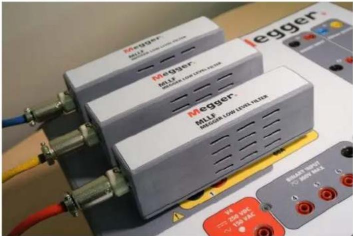
Figure 15. MLLF Megger Low Level Filter modules
Rogowski mosde will change the current channel from a current source to a voltage source. This will allow the current channel to simulate a low-level voltage source from a Rogowski coil. There are three ranges for the Rogowski outputs, 2, 10 and 40 Volts. Pressing the Balance button will balance all the phases to the same value.
Setting Ratio of Secondary Current to millivolt Output
Different Rogowski coils have different output levels. In the Rogowski Info screen the user sets the scale (or ratio) of the secondary current to millivolt output. This is used to adjust the ratio between the Rogowski coil millivolt outputs to an equivalent secondary current output. Enter the appropriate secondary current and associated mV output. Test values will be entered in secondary current values, with the appropriate millivolts applied to the relay under test. After entering the ratio of the secondary current to the millivolt output the user needs to enter the Amplitude and Phase Correction Factors.
Amplitude and Phase Correction Factors
In the Rogowski Screen the individual amplitude and phase corrections can also be set.
Rogowski:
SCALE: 1.00 A = 150.0 mV
| Gen Num | Enabled | Amplitude Correction (multiple) | Phase Correction (degrees) | Max Current (A) | |
| 1 | 2V Rogowski | 1.0000 | 0.00 | 13.333 | |
| 2 | 2V Rogowski | 1.0000 | 0.00 | 13.333 | |
| 3 | 2V Rogowski | 1.0000 | 0.00 | 13.333 |
Figure 16. Rogowski Amplitude and Phase Correction Factors
Different relays have different Rogowski amplitude and phase correction settings. Check your relay settings and enter the appropriate values in the windows provided. Pressing the Balance button will balance all the phases to the same value. Press or click on the green check mark to return to the Configuration screen, then press or click on the green check mark to return to the Main Test screen.
2.1.24.2 Low Voltage
Low Voltage Mode
The Low Voltage mode will change the voltage channel to a millivolt source. This will allow the voltage channel to simulate a low-level voltage source such as a Rogowski. Press the High (300V) button to select the Low (2V) Volt Rogowski, see figure below.
Rogowski:
SCALE: 1.00 A = 150.0 mV
| Gen Num | Enabled | Amplitude Correction (multiple) | Phase Correction (degrees) | Max Current (A) | |
| 1 | 2V Ragunski | 1.0000 | 0.00 | 13.333 | |
| 2 | 2V Ragunski | 1.0000 | 0.00 | 13.333 | |
| 3 | 2V Ragunski | 1.0000 | 0.00 | 13.333 |
Low Voltage:
SCALE: 1.00 V = 150.0 mV
| Gen Num | Enabled | Amplitude Correction (multiple) | Phase Correction (degrees) | Max Voltage (V) | |
| 1 | Low (2V) | 1.0000 | 0.00 | 13,333 | |
| 2 | Low (2V) | 1.0000 | 0.00 | 13,333 | |
| 3 | Low (2V) | 1.0000 | 0.00 | 13,333 | |
| 4 | Low (2V) | 1.0000 | 0.00 | 13,333 |

Figure 17. Selecting the 2V range for the Low Voltage Output
2.1.24.2 Low voltage
Application Note:
For testing devices that require Low-Level voltage signals requires the Megger model MLLF low-level filter interface, part number MLLF. Connect the MLLF modules to the individual VIGEN channels and then connect the appropriate interface cable for the device under test (note that there is an interface cable that includes 8 mm banana plugs).
Setting Ratio of Secondary Voltage to millivolt Output
Different Rogowski coils have different output levels. In the Low Voltage screen the user sets the scale (or ratio) of the secondary voltage to millivolt output. This is used to adjust the ratio between the Rogowski coil millivolt outputs to an equivalent secondary voltage output. Enter the appropriate secondary voltage and associated mV output. Pressing the Balance button will balance all the phases to the same value. After entering the ratio of the secondary voltage to the millivolt, output the user needs to enter the Amplitude and Phase Correction Factors.
Amplitude and Phase Correction Factors
In the Low Voltage Screen, the individual amplitude and phase corrections can also be set.
Low Voltage:
| Gen Num | Enabled | Amplitude Correction (multiple) | Phase Correction (degrees) | Max Voltage (V) | |
| 1 | Low (2V) | 1.0000 | 0.00 | 13.333 | |
| 2 | Low (2V) | 1.0000 | 0.00 | 13.333 | |
| 3 | Low (2V) | 1.0000 | 0.00 | 13.333 | |
| 4 | Low (2V) | 1.0000 | 0.00 | 13.333 |
Figure 18. Low Voltage Amplitude and Phase Correction Factors
Different relays have different amplitude and phase correction settings. Check your relay settings and enter the appropriate values in the windows provided. Press or click on the green check mark to return to the Configuration screen, then press or click on the green check mark to return to the Main Test screen.
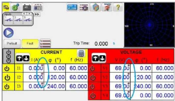
Figure 19. Low Level Outputs Enabled Symbol
After setting low-level outputs, and returning to the main test screen, a symbol will appear in the setting values window indicating that low-level outputs are enabled. To clear low-level outputs, return to the Configuration System screen and reset the output levels to their default values.
2.1.25 Use PRO Header
In the General Settings section of the System Configuration Screen, the button defaults to RTMS Header. If the user wants to use a PRO (custom) header on their test reports, click on the Use PRO Header button to change the header to a PRO (Custom) version.
2.1.26 Update Translations
In the General Settings section of the System Configuration Screen, click on the Update Translations button to access the internet and update the language translations in FREJA Local software (requires internet access).
2.1.27 Contact Names (Global)
In the General Settings section of the System Configuration Screen, the button defaults to (Global). The Global setting means that the user only needs to enter the name of the Binary Input(s) once and the name(s) entered will be used in all tests. For example, if you use "Trip" as the name for binary input #1, all other tests in FREJA Local/Remote binary input #1 will be labeled "Trip". To change the input name for every test individually, then click on the Contact Names (Global) button and it will change to (Test Specific).
2.1.28 Default As Found / As Left
In the General Settings section of the System Configuration Screen, the button defaults to (Empty). The user will need to select if they want, As Found, As Left, or As Found / As Left results displayed in the test report.
2.1.29 ANSI / IEC button
In the General Settings section of the System Configuration Screen, depending on the PC install selection, the button defaults to either IEC or ANSI. To change the default, press or click on this button. This button affects which test settings models will appear for various tests, i.e. Three Phase Transformer Differential.
2.1.30 Flyover Text button
In the General Settings section of the System Configuration Screen, this button defaults as enabled. The Flyover Text provides a descriptive text of the screen feature based upon the position of the pointer.
2.1.31 Voltage Resolution (0.01) button
In the General Settings section of the System Configuration Screen, this button changes the resolution of the voltage channels from the two decimal default setting of 0.01 to three decimal 0.001.
2.1.32 TCC Curve Import button
In the General Settings section of the System Configuration Screen, this button allows the user to import new or custom time curves to the Curve Library. Press this button and using the windows navigator, navigate to PowerDB.v1X.x and find the PdbCurveLib.crv file folder to paste a new / custom time curve. Contact Megger, or your Megger representative, if you have a curve or custom curve that you would like to have added to the curve library.
2.1.33 Multi-Instance button
In the General Settings section of the System Configuration Screen, this button allows the user to select multiple instances associated with Differential relays. For example, some generator differential protection relays also include transformer differential protection. With this button enabled, when the user goes to the Differential test they will be able to combine up to four different differential relays into one test result file.
2.1.34 Screen exit
2.1.34 Screen Exit
To exit the screen and return to the previous screen press the green check button 📊 you will see this same button on other screens).
2.2 FREJA Local Setting Amplitudes, Phase Angle or Frequency
Pressing an amplitude, phase or frequency button (right clicking if running on a PC) will display the following pop-up numeric keypad to enter the value you want to change.
2.2.1 Numeric Keypad Entry
The numeric keypad entry provides an interface to the user when entering values in the various screens. Touching a data entry window (Amplitude, Degree or Frequency) on the touch screen (right mouse click in the PC version) will activate the Numeric Keypad. Use the numeric keys to type in the value you want and press either the button or the Balance button. Pressing the clear all will clear the value you just entered. Pressing the clear last digit button will clear the least significant digit of the value in the display window.

Figure 20. Touch Screen Numeric Keypad
The button will enter the value and take you back to the test screen. Press the Balance button if you want all the voltage or currents values to be the same amount. If setting phase angles, and you want all three phases to be shifted the same amount from the defaulted values, enter the amount of phase shift desired in the A Phase window, and press For example, the default is 0, 120 and 240 degrees. Press on A phase current phase angle and enter 30, press and the test screen will now show 30, 150, 270 degrees. Pressing Cancel will return the user to the previous screen that is in use. Pressing Include channel in ramping will select that value to ramp when using the control knob.
2.2.2 Include Channel in Ramping
When this button is pressed the window around the channel magnitude is highlighted indicating that it is now set to be ramped manually using either the Control Knob on the front panel, or the up down arrows / mouse wheel on the PC keyboard (PC version). If the channel is already selected for ramping, this button will be labeled 'Remove channel from ramping'. The magnitude may now be ramped up or down using the default increment setting. If the user wants to ramp more than one channel, change the increment, or change the value to be ramped (Amplitude, Phase or Frequency), on the FREJA Local display screen press the Manual Ramp Options button (Control Knob or Up Down Arrows button) to display the following screen.

Figure 21. Channel Increment Selection Screen
INCREMENT- Select the desired increment. Color change will indicate the value selected.
CHANNEL – Select the desired channel(s). The channel button will change color indicating the selected channel(s) to be ramped.
MODE – Select Amplitude, Phase, Frequency, or Battery as the value to be ramped. Press or click on the green check button to return to the test screen. One click on the Control Knob or one press of the Up Down arrow on the PC keyboard will change the output by the Increment setting. If the Auto Increment button is selected FREJA Local will automatically select the increment depending on how fast the control knob is being rotated, the faster the rotation the larger the increment (does not apply when ramping the Battery Simulator).
2.2.3 Control Knob
The control knob will change the values after touching the display to highlight the value that requires ramping. Clockwise rotation increases and counterclockwise decreases. In the Auto Increment Mode the control knob uses a speed control algorithm to provide fine adjustment, with a slow rotation (one click equals 1 digit of the lowest increment level for the value being ramped), and a larger step adjustment with a faster rotation. The Control Knob can also be used to scroll up and down when viewing the test results in the Add Results and View Results screens, or when viewing the Help screen.
2.2.4 Setting Default Voltage Outputs
FREJA Local comes with factory default settings, which can be changed to suit the user. Using the numeric keypad entry as described above, select the first voltage channel and enter the desired phase to neutral (earth) value, for example; 67. Press the Balance button, the green check button, and all channels will now have a setting of 67 volts. Select the Configuration button, and then select Save as Default (see section 2.1.5.1 Save as Default). The next time the unit is powered up, the default voltage values will all be at 67 Volts.
2.2.5 Setting Default Current Outputs
Similar to setting the default voltage values, the Default Current may be changed to suit the user. Using the numeric keypad entry as described above, select the first current channel and enter the desired phase to neutral (earth) value, for example; enter 1, Press the Balanced button, and button, and all channels will now have a setting of 1 Ampere. Select the Configuration button, and then select Save as Default (see section 2.1.5.1 Save as Default). The next time the unit is powered up, the default current values will all be at 1 Ampere.
2.3 Virtual Alphanumeric Keypad
The virtual alphanumeric keypad allows the entry of ASCII text into the appropriate windows. This keypad is used to enter names for the binary inputs and outputs, names for each state in the Sequence Test, or file names in the file management screen.
2.4 FREJA local file management
![OK Cancel Clear 1 2 3 4 5 6 7 8 9 0 - = BKSP TAB q w e r t y u i o p [ ] \ CAPS a s d f g h j k l ; ' ENTER SHIFT z x c v b n m . . / SHIFT ALT SPACE](/content/2026/05/852528/images/d831eeff0e4c3a48615363acab6ffde4e0fbd2ee035a7c60661da8eb8f4ee3f5.jpg)
Figure 22. FREJA Local Keyboard
2.4 FREJA Local File Management
The file management display is used to access files stored in the FREJA 500 series unit's internal memory. This display will allow test files to be loaded, make or change directories, rename files and directories, delete files and directories that were created by the user. To access the File Management system, touch the File Folder top center of the test screen. This button only appears on the FREJA Local (not on PC version). It provides the user the ability to save tests, or open saved tests. If using the PC version users will have the PowerDB file system to save test (job) files (see PowerDB Help). For FREJA Local users' pressing on the File Folder presents the user with the following tool bar. It defaults with the Save Current Form File Folder highlighted.

Figure 23. File Folder Tool Bar
Note: Pressing the Power ON / OFF button ⏻ will power down the On-board display, but is not required for a safe shutdown.
Pressing the highlighted folder will provide the user with the following file explorer.

Figure 24. File Folder Explorer
Press in the File Name window and the user will be provided with the virtual keyboard to enter a file name. The file can then be saved to the internal memory or saved to a USB memory stick. This same window is also used to open saved files. To save results directly to a USB memory stick check the Save to USB button. To transfer test results from the unit to a USB memory stick use the up down blue colored buttons to selected the desired test result to be transferred, and then press on the USB button. To retrieve a test file from a USB memory stick press on the USB button to retrieve the selected file from the list of files that appear in the right hand window. To delete a file use the up down arrows to highlight the file, then press on the trash can button. The left pointing blue arrow is the exit button to go back to
3.0 FREJA local – basic operating descriptions
the test screen. To open an existing test file, from the File Folder tool bar, press the Open File Folder button. The user will be presented with the File Folder Explorer. Use the up down blue arrows buttons to highlight the desired file to be opened, and then press the Open File Folder button in the lower left corner. The user will be presented with a menu bar to open a New Test, or to open the file selected showing the date and time of the file saved. Pressing the date / time button will open the saved test. To view the saved results press the More button >in the upper right display next to the vector screen, then press the View Report button
3.0 FREJA Local – Basic Operating Descriptions
This section describes basic operating procedures for using FREJA Local with the FREJA 500 series units for such applications as basic pickup or dropout, basic timing test, paralleling current outputs, conducting harmonic restraint tests, series of potential sources to provide higher than rated potential, and forming various three phase voltage outputs.
3.1 FREJA Local / PC Manual Test Screen
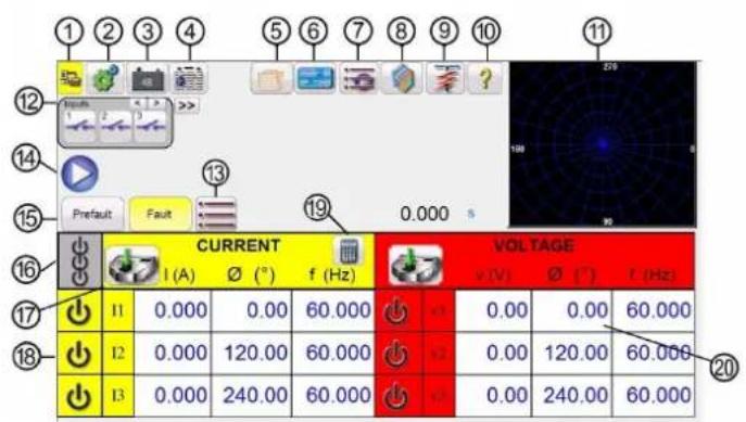
Figure 25. Manual Test Screen
3.1.1 ① PC to FREJA connection button

Click on the button and the PC will auto detect the FREJA unit connected and automatically set the IP address through the Ethernet ports. If the button shows two red X's it indicates that there is no communication to the FREJA. If the background color is yellow it indicates that the unit is 'on-line' and ready for operation. When connection is made (commands sent) the background color will change from yellow to green. When in other test screens a Home button

will appear. Pressing the Home button will return you to the manual test screen.
3.1.2 ② Configuration button

Press the button to go to tshe FREJA Local Configuration Screen. See Section 2.1 Configuration for more information of the Configuration Screen.
3.1.3 ③ Battery Simulator button

The Battery Simulator button – Turns the Battery Simulator ON and OFF by pressing the button, the background color changes red for ON and gray for OFF. The voltage to be applied is displayed in the button and can be changed by pressing the configuration button.
3.1.4 ④ Report Options button

This button will add the present test result to the report. It also displays the report and allows the user to name the test, enter limits, comments or deficiencies. Reports can be saved to the internal memory and transferred to PowerDB
3.1.5 Relay settings button
via a USB memory stick. Previous tests results can be loaded and the 'Retest' option can be used to repeat the test using the same parameters as the previous test.
3.1.5 ⑤ Relay Settings button

To access the nameplate data window press this button. Here the user can input import information relative to the relay under test such as manufacturer, model number, serial number, CT and PT information.
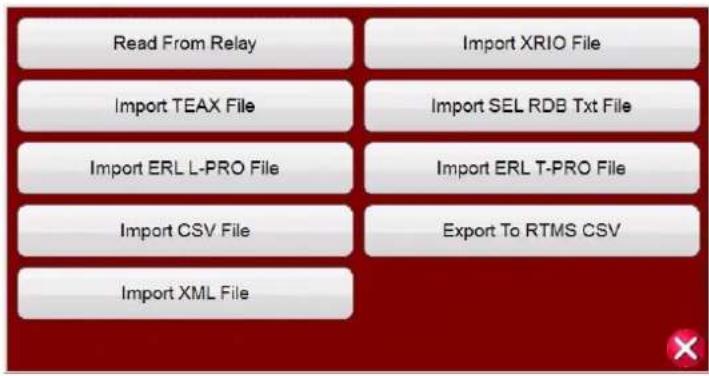
Figure 26. Pressing the Import / Export button provides options
3.1.5.1 Relay Settings Import / Export Options
3.1.5.1.1 Read from Relay: Press this button to import relay settings directly from the relay. The two formats supported are SEL Serial, and Modbus. The Modbus protocol is used for downloading settings from GE Multilin Type UR relays.
3.1.5.1.1.1 Read from SEL Relay: The first step is to establish communications with the relay under test. This will require the use of a USB serial port on either the PC, or the relay test system.
- Press or click on the SEL Relay button and the Generic SEL communication screen will appear similar to the following figure.
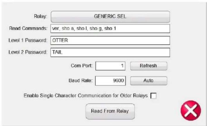
Figure 27. Generic SEL Communication Screen
Note that the typical default Read Commands, Passwords Level 1 and 2, and COM Port assignment and Baud rates are preset.
- Click on GENERIC SEL button to select the relay under test, see the following figure.

Figure 28. List of Available SEL Relays
- Select the relay under test. If the relay is unavailable, select GENERIC SEL.
- Read Commands row can be manually edited and can be found in the instruction manual of the relay in case special commands are required.
- Enter Level 1 and Level 2 Passwords if different from the default.
- Connect the SEL USB serial cable to the relay serial communication port.
- Select the desired Relay COM port for your PC or the relay test system. If the relay test system you are using is a FREJA 500 system use the highest COM Port number indicated. If using a PC select the appropriate COM Port for the USB serial adapter that you are using.
- Press or click on the Refresh button to detect the COM Port on which the relay is connected
- A dropdown will appear once the COM Port field is clicked.
- Choose the Baud Rate used by the relay and then press Read from Relay
- If FREJA Local is under simulation mode, a message will appear as shown below.

Figure 29. Simulation Setting Download Message
- Selecting Red Cross will attempt to read the settings from the relay.
- There will be a logging into relay message banner to indicate the handshaking process has started.
- Once all the settings are read from the relay, the user can then test the relay using the relay settings. In some relays there are hundreds of settings, so it may take several minutes to download all the settings depending on the baud rate.
3.1.5.1.1.2 Read From Modbus Relay:
Modbus read only works if there is already an existing setting with the Modbus address. If there is no setting available in the Software, new settings have to be created.
3.1.5.1.1.2.1 Read from modbus relay with serial communications:
- In order to create a new setting, press or click on the Edit Mode button to enable.
- Click or press on the Create a New Setting button to add a new setting, then provide a folder name, and a setting name of your choice.
- Click or press on Show Modbus button, and enter the address for the settings that need to be read.

Figure 30. Show Modbus settings
Typically, Scale = 1, Increment = 1, Number of Registers = 1 and Modbus Type = int, but they are all editable as per relay's instruction / communication manual
Note: Modbus Address in the Software are in decimal values
- Click the Edit Mode button again to disable and then click the Import / Export button to see all the setting options.
3.1.5.1.1.2.1 Read From Modbus Relay with Serial Communications:
- If using the serial port, connect a USB serial cable to the relay serial communication port. Press or click on the Modbus Relay button and a Modbus communication screen will appear similar to the following figure.

Figure 31. Modbus Serial Communication Screen
- Select the desired Relay COM port for your PC or the relay test system. If the relay test system you are using is FREJA 500 system use the highest COM Port number indicated. If using a PC select the appropriate COM Port for the USB serial adapter that you are using.
- Once the COM Port is assigned, press or click on the Read From Relay button.
3.1.5.1.1.2.2 Read from Modbus Relay with Ethernet Communications:
If using Ethernet port, press or click on the Serial button to change it to Ethernet and the following communication screen will appear.

Figure 32. Modbus Ethernet Communication Screen
-
Enter the Modbus address for the relay under test. Typically, it is either 1 or 254. It can be found in communication setup settings of the relay.
-
Enter the IP Address of the relay found under TCP / IP section of the relay Modbus settings.
-
Enter the TCP / IP Port number. It can also be found in the relay settings.
-
Press the Green check button to read settings from the relay.
If the settings are read successfully, the settings will appear, else 0 will appear indicating failure in communication.
3.1.5.1.2 Import XRIO File:
Press this button to import relay settings in the XRIO file format. XRIO files are created by software from various relay manufacturers. Some specific relays in the Relay Library include the ability to import the XRIO relay settings, and create the relay operating characteristics from these settings. A couple of examples are the ABB REL-670 V2.0.0, and Siemens 7SA632 V4.6. To import the relay settings using the XRIO import click on the relay manufacturer, click on the relay, i.e. Siemens, 7SA632 v4.6. Upon clicking on the relay, the Settings window will appear see the following figure. Click on the Import / Export button and navigate to the 7SA632 V4.6 XRIO file, and click on the file. A message window will appear informing you once the settings import has been completed.
| Setting Name | Value | Min Value | Max Value | Comments |
| Op. mode Z1 | Forward | Operating mode Z1 | ||
| R(Z1) Ø-Ø | 10.481 | 0.01 | 120 | R(Z1), Resistance for ph-ph-faults |
| X(Z1) | 3.046 | 0.01 | 120 | X(Z1), Reactance |
| RG(Z1) Ø-G | 17.601 | 0.01 | 120 | RG(Z1), Resistance for ph-gnd faults |
| Zone Reduction | 0 | 0 | 45 | Zone Reduction Angle (load compensation) |
Figure 33. Siemens Zone 1 XRIO Relay Settings Import
3.1.5.1.3 Import TEAX File:
Press this button to import relay settings in the Siemens TEAX file format
3.1.5.1.4 Import SEL RDB Txt File:
Press this button to import relay settings in the SEL Relay Data Base Text file format. This feature requires user to import the desired SEL RDB files, in advance, into a file folder under the MY Documents / PowerDB directory.
- Click Import SEL RDB Txt File button under Import / Export button
3.1.5.1.5 Import ERL L-PRO file
- Choose the setting file saved on your PC and click OPEN.
- A pop up message would appear shown in the next figure.

Figure 34. Create New Setting Message
- Green Check button – This button will add settings in addition to the existing settings (if already read and stored before). Red Cross button- This button will overwrite existing settings (if already read and stored before).
3.1.5.1.5 Import ERL L-PRO File:
Press this button to import relay settings in the ERL L-PRO relay file format.
3.1.5.1.6 Import ERL T-PRO File:
Press this button to import relay settings in the ERL T-PRO file format.
3.1.5.1.7 Import CSV File:
Press this button to import relay settings in the CSV file format. Different options are available, see the following figure.

Figure 35. Import CSV File Formats
RTMS CSV files are now Unicode encoded. Microsoft Excel only supports Unicode "csv" files with tab separators. To be able to open and edit the files in Excel, the Software now exports tab separated files instead of comma separated files. The RTMS CSV import is not backwards compatible with previous versions of the export.
3.1.5.1.8 Export RTMS to CSV File:
Press this button to export relay settings in the RTMS CSV file format. RTMS CSV Exports can export the active settings or the settings created during the previous import.
Figure 36. Export to RTMS CSV File Options
a. This can be used to find the mappings from the previous import that need to be added to the existing settings.
i. import from XRIO / Relay CSV / Read from relay etc.
ii. export "Previous Import Settings" to CSV
iii. find settings that weren't imported during the last import (Blue ? in the Software relay settings screens)
iv. find the setting in the csv file and copy the value in the "ImportMappings" column into the "Edit Import Mappings" on the setting
b. This can also be used in conjunction with the RTMS CSV Import to create new settings
i. import from XRIO / Relay CSV / Read from relay etc.
ii. export "Previous Import Settings" to CSV
iii. eliminate unwanted settings using Excel
iv. import RTMS CSV
| Name | Item Name | Parameters | Type | Variable | Sex | Male | Female | Gender | Age (years) | Age (years) | Gender | Age (years) | Age (years) | Gender |
| 1.0000000000000000000000000000000000000000000000000000000000000000000000000000000000000000000000000000 | 1/2 | 158 | 36 | 3.4-11.5, 4.9-22.5, 6.7-14.5, 8.5-21.5, 12.5-23.5, 16.5-27.5, 21.5-27.5, 28.5-33.5, 34.5-39.5, 44.5-49.5, 54.5-59.5, 64.5-69.5, 74.5-79.5, 84.5-89.5, 94.5-99.5, 104.5-111.5, 121.5-128.5, 138.5-144.5, 154.5-161.5, 168.5-175.5, 184.5-191.5, 211.5-218.5, 228.5-236.5, 244.5-251.5, 261.5-268.5, 278.5-286.5, 314.5-321.5, 331.5-338.5, 349.5-366.5, 376.5-383.5, 392.5-409.5, 426.5-434.5, 444.5-451.5, 462.5-469.5, 478.5-486.5, 494.5-501.5, 512.5-519.5, 529.5-536.5, 546.5-563.5, 563.5-571.5, 579.5-586.5, 616.5-623.5, 633.5-641.5, 649.5-667.5, 676.5-684.5, 713.5-721.5, 731.5-738.5, 749.5-766.5, 766.5-774.5, 784.5-791.5, 812.5-819.5, 829.5-836.5, 846.5-863.5, 863.5-871.5, 879.5-896.5, 916.5-923.5, 933.5-941.5, 949.5-966.5, 976.5-983.5, 992.5-1000 |
Figure 37. Example Excel RTMS CSV Export for Previous Imported Settings File
3.1.5.1.9 Import XML File:
Press this button to import relay settings from ZIV relays in the XML file format.
3.1.5.2 Relay Settings Import / Export Edit Mode Enabled:
There are two applications for the use of this button. One is to create new relay settings. The other application is to compare or edit imported settings.
3.1.5.2.1 Create new relay settings
3.1.5.2.1 Create New Relay Settings

Figure 38. Relay Settings Edit Mode
Pressing the Edit Mode Enabled button and then the Create a New Setting button will provide the figure above and will allow the user to create a new setting Group, and Setting Name. Pressing or clicking the Type window is to identify whether the setting is one of the following:
Float is a floating number indicating that a decimal value may be entered in the Relay Settings field. The number entered may also be an Integer with no decimal.
Integer is a number of whole value with no decimal. A decimal value placed in an Integer field in the Relay Settings will evoke an error message advising that an invalid entry has been attempted.
Enumeration is to create an enumeration of variables and or values for a drop list of valid Values in the Relay Settings. The list is entered in the Enum Options field with no spaces with each item separated by a comma.
String Enumeration is to enter the comma delimited list of values or string variables to be in the Values drop list in the Relay Settings. Default is a blank field and null for all other Data Types.
Entries may be: numeric 0.5, 0.6, 0.8, 1, 2, 3.0 or string Pass, Fail, Yes, No

Note: No spaces allowed for enumeration of values.
String is to set the variable Name as a non-numeric value. If a String is to have a value, it must be converted from String to Numeric values using Expressions.
To convert a string to a number:
c = val(b\$) results in the string
b\= 10\ being set to the number c = 10.
Pressing the Show Modbus button will provide the following setting screen.

Figure 39. Adding Modbus Settings
Modbus Address field is provided to enter the memory map address Addr given by the relay manufacturer.
3.1.5.2.2 Edit Imported Settings
Select the Edit Mode button, and then import the settings from a file. Upon importing the settings, the settings may appear as shown in the following example.
| Setting Name | Value | Min Value | Use Value | Comments |
| Line Angle | 60 | 30 | 89 | 1105 Line Angle(degrees) |
| x km | 0.001 | 0.001 | 1.9 | 1110 x' - Line Reactance per length unit (ohr) |
| Line Length km | 23.2 | 0.1 | 1000 | 1111 Line Length (km) |
| x mi | 0.0484 | 0.001 | 15 | 1112 x' - Line Reactance per length unit (c ?) |
| Line Length mi | 62.1 | 0.1 | 650 | 1113 Line Length (miles) |
| RE over RL Z1 | 0.42 | -0.33 | 7 | 1116 Zero seq. comp. factor RE/RL for Z1 |
| XE over XL Z1 | 0.54 | -0.33 | 7 | 1117 Zero seq. comp. factor XE/XL for Z1 |
| RE over RL Z1B TO Z5 | 0.42 | -0.33 | 7 | 1118 Zero seq. comp factor RE/RL for Z1B |
| XE over XL Z1B TO Z5 | 0.54 | -0.33 | 7 | 1119 Zero seq. comp factor XE/XL for Z1B |
| K0 Z1 | 1 | 0 | 4 | 1120 Zero seq. comp. factor K0 for zone Z1 |
| Angle K0 Z1 | 0 | -135 | 135 | 1121 Zero seq. comp. angle for zone Z1 (c ?) |
| K0 higher Z1 | 1 | 0 | 4 | 1122 Zero seq. comp. factor K0 higher zones >? |
| Angle K0 higher Z1 | 0 | -135 | 135 | 1123 Zero seq. comp. angle, higher zones >Z? |
Figure 40. Example Import Settings Edit Mode
If all the settings are properly mapped and imported, then a green check √will appear in the right side of the display next to the Edit function button. Only settings that are already in the settings list with non-empty mappings will be matched. If the setting ID is mapped but does not match with the imported file, then a ? will appear indicating there may be an issue with the imported setting value ID. If there is a blank next to the edit button means that a value was not mapped. Mappings are done searching up to three different nomenclatures, such as file name, group name, setting name, ID number, etc. This allows for different firmware versions for the same model of relay, where a file ID or setting nomenclature was changed. By pressing the Edit button, then using the Edit Import Mapping button the user can enter the new nomenclature or setting name.

Figure 41. Edit Import Mappings
Clicking on this button will provide the user with the Edit Mappings Screen, where up to three search nomenclatures might already be listed. Note: many are only one line. The software imports the relay settings using these nomenclatures. If the manufacturer, i.e. new firmware version release, changed the setting ID then the user can add the new setting ID below the other listed nomenclatures. The import mappings should be 1 mapping per line. See the following example.

Figure 42. Example of three lines of nomenclature
3.1.6 File folder button
After entering the new setting ID, go back and import the settings and the Blue ? should change to a green √
3.1.6 ⑥ File Folder button
To access the File Management system, touch the File Folder button top center of the test screen. This button only appears on the FREJA touch screen (not on PC version). It provides the user the ability to save tests, or open saved tests, see Section 2.4 File Management section for more information.
3.1.7 ⑦ Select New Test button
Press this button to access the list of tests that are available. The test menu is in two sections, Standard and Enhanced. The Standard section tests that are available are Ramping, Timing, Sequence, Impedance, Differential, Meter and for those units equipped with the Transducer Hardware Option the Transducer Test. The Enhanced section is only available in units with the Enhanced software enabled (see FREJA Ordering Information for details).

Figure 43. Standard and Enhanced Software Test Menu List
See the following descriptions.
The Simple Ramp button is used for doing pick up or drop out tests on any type of relay. It can be used to perform a general-purpose linear step ramp, pulse ramp, or pulse ramp binary search. The Advanced Ramp button allows the user to perform a continuously smooth ramp with x/s increment / second values, as well as other more complex ramps.
3.1.7.2 Timing Test buttons
There are three Timing Test buttons, I (Overcurrent) U / V (Over and Under Voltage). Press the appropriate button to
3.1.7.3 Sequencing 1,2,3..9 button
go to the desired Timing Test screen to easily test time overcurrent, over voltage and under voltage relays. The FREJA software has ANSI, IEEE and IEC standard time curve algorithms built-in. In addition, it includes time curves and time curve algorithms for hundreds of different specific relays selectable by manufacturer, relay model number, and curve shape (inverse, very inverse, definite time etc.).
3.1.7.3 Sequencing 1, 2, 3..9 button

Press this button to go to the Sequence Test screen used for testing reclosing type relays, setting up multiple vectors and general multi-state sequencing. It also includes Transient Earth Fault simulation, including intermittent transients.
3.1.7.4 Impedance buttons

Press the COF button to go to the Click on Fault relay test screen for testing impedance relays. Press the Easy-Z button for a quick test on an impedance relay. Press the Unknown Z button to test impedance relays where the impedance characteristic is unknown.
3.1.7.5 Differential buttons

Press this button to go to the Transformer Differential test screen for testing 3 Phase current, or 1 Phase differential relays. Press this button to go to the Generator Differential test screen. Press the button to go to the Motor Differential test screen.
3.1.7.6 Transducer button

Press this button to go to the Transducer test screen for testing single phase and three phase transducers. This software feature only works with units that have the Transducer Hardware Option installed.
3.1.7.7 Meter button

Press this button to go to the Meter test screen for testing the meter function of microprocessor based relays.
3.1.7.8 Synchronizer button

Press this button to go to the Synchronizer test screen for testing synchronizing and sync-check relays.
3.1.7.9 Frequency button

Press this button to go to the Frequency test screen for testing Frequency sensing relays.
3.1.7.10 COMTRADE button

Press this button to go to the COMTRADE test screen.
3.1.7.11 Power Swing button

Press this button to go to the Power Swing test screen.
3.1.7.1 SS1 button ss1
Pressing the SS1 test button provides access to test relays using an SS1 file from Aspen One-Liner or Electrocon CAPE power system simulation software products.
3.1.7.13 Megger GOOSE configurator button
3.1.7.13 Megger GOOSE Configurator button

Pressing the Megger GOOSE Configurator button provides access to the MGC software for testing IEC 61850 relays. This feature is enabled when ordering the IEC GOOSE Hardware license at purchase or as an upgrade. Optional stand-alone MGC Software is available to test and commission IEC61850 compliant devices. MGC stand-alone Software is part number: 1007-246
3.1.8 ⑧ Relay Library button
Pressing this button will turn the meter mode on (for displaying metered amplitudes). When the meter mode is on the touch screen will display the measured output amplitudes in real-time.
3.1.9 ⑨ Predefined Test button
Pressing the Predefined Test button provides access to Predefined Tests, created by either Megger or users, in Pdb Tst file structure, see the following example on a PC.

Figure 44. Preconfigured Test File Folders
These test plans can be more generic or very specific. Users can perform manual or automated tests, save them in the database, and then reselect them to reuse as a Predefined Test. If no tests have previously been executed, pressing this button will provide the following screen.

Figure 45. Preconfigured Test Screen
As an example, if the user had previously run tests for overcurrent relays, you might see something like the following example.

Figure 46. Preconfigured Tests for Overcurrent Relays
As shown in the above figure, the Test Groups is Overcurrent, and Tests are listed in the right half of the screen. The following are descriptions for the tools.
3.1.9.1 Run Test button
Press the Run Test button to execute the highlighted individual test
3.1.9.2 Run All button >>
Pressing the Run All button the user will see the following options.

Figure 47. Preconfigured Run All Options
3.1.9.3 View Results button
Press the View Results button to view the test report.
3.1.9.4 Go To Test Screen button
Press the Go To Test Screen button to go to the selected test.
3.1.9.5 View / Edit notes button
3.1.9.5 View / Edit Notes button

Press the View Edit Notes button to view the test notes or to add notes.

Figure 48. Test Notes Screen
Press the No Action button at the bottom of the note screen will provide options as shown in the following figure.

Figure 49. Test Notes and Display Action
The user can select to have the test notes displayed upon running the test, or not, or display for X number of seconds.
3.1.9.6 Help button ?
The Help button is sensitive to the test and will take the user to this section of the manual.
3.1.9.7 Edit Test Attribute Script button

Pressing this button will take the user to the Edit Test and Attributes screen as shown in the following figure.
3.1.9.8 Extended actions list button

Figure 50. Edit Test and Attributes Screen
If the test uses a script file, the script will appear in the screen. In the example above the test is a Megger test file, therefore, no script appears. The Group and Test names can be changed by the user. Checking the Optional button will exclude this test from Pass / Fail evaluation in the Test Report. Checking the New Page will add this test as a new page in the test report. Pressing the Change Sub form button will present the following options to the user.

Figure 51. Change Sub form Options in the Test Edit and Attributes Screen
Selecting any of the listed options will present the user with multiple lists of print labels.
3.1.9.8 Extended Actions List button

Pressing this button will provide a list of extended actions that the user may want to use, see the following.

Figure 52. Extended Action List
3.1.10 Help button
Here the user can duplicate a Group of tests, or Duplicate any individual test. Test can be Imported or Exported. The Group can be renamed. Test can be deleted, or edited. If the test has a script file it can Edited here.
3.1.10 ⑩ Help button ?
Pressing this button will provide Help for both software and hardware, including a hardware system reset.

Figure 53. Help List
For some test screens, the Help button is sensitive to the test. For example, in the Click On Fault Impedance test screen pressing the Help button will bring up information relative to testing impedance relays.
3.1.10.1 System Reset button
In addition to information regarding software and hardware, the Help will also provide a system Reset. Pressing the Reset button will reset the unit back to power up default settings. Use this button to reset the VIGEN's after they have alarmed off due to either a short circuit on the voltage channels, or an open circuit on the current channels.
3.1.11 ⑪ Phase Vector Screen
This display shows the phases and angles of the test values. Pressing on the screen display provides a full screen display of the test vectors with amplitudes and phase angles. Pressing it again reduces it back to its original size. If used with the Symmetrical Components (see Configuration button) the display will display the positive, negative and zero sequence component values.
3.1.12 ⑫ Binary Input Dialog Button
The Binary Inputs selection bar and More button ➤ The first three binary inputs are displayed showing their present state. Pressing binary input windows #2 and above will display the dialog box shown in Figure 54A. For conducting a timing test, pressing binary input #1 will display the dialog shown in Figure 54B.

Figure 54A Binary Input #2 Monitor Mode / 54B Binary Input #1 Time Trip Mode
Binary Input #2 in Monitor Mode is sensing for closing of normally open relay contacts, as displayed by the button in the Input Type window, or opening of normally closed relay contacts. When the contacts close the LED for the selected binary input on the connected unit will light up. If the Horn button is selected to ON, the horn will sound. If a normally closed contact opens the light on the connected unit will go out (with horn on, the horn will go off). To sense voltage press the Input Type contact button and it changes showing a DC / AC voltage sine wave. In Voltage Sensing Mode, the unit is sensing the application or removal of an AC or DC voltage. A programmable voltage threshold is available on binary inputs 1 & 2, with a programmable range from 2 to 150 volts AC / DC.

Figure 55. Programmable Voltage Setting Windows
The programmable threshold voltage default value is 10 Volts. Press or click in the setting window and enter the desired voltage threshold.
For Timing Tests press either binary #1, or press the Use as Trip (disabled) button in binary #2, and the dialog box changes to Use as Trip (enabled). The default settings are dry contacts as indicated by the Input Type, and Input Action defaults to show the Closing of the Normally Open contacts. To change to the opening of Normally Closed contacts press the Input Action button and it changes to show closed contacts opening. Pressing the Auto Off button will provide the user three selections; Voltage, Current, or Voltage & Current.
Figure 56. Auto Off Options
This provides auto off of the voltage, current or voltage & current channels upon tripping of the relay. For most timing applications the timer should be set to Latched Input (enabled) mode, which means the timer will stop on the first contact closure. The Latched Input (disabled) mode means if the contact bounce the timer will include the bounce time.
The Debounce time is set in milliseconds. The trip contacts must stay closed for the debounce time for the time test to
3.1.12.1 Binary more button
be true. If the contacts open in less than the set debounce time the timer will continue to run. Once the input condition is true then the time test will conclude. The trip time displayed will be the total test time less the debounce time.
3.1.12.1 Binary More button >>
Pressing or clicking on the more button (next to binary input buttons) reveals more Binary Input and Output options as well as more options regarding displayed values.
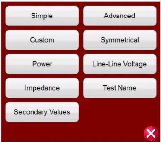
Figure 57. Binary Input and Output Options and Displayed Values
3.1.12.1.1 Simple Mode button:
The unit defaults to the Simple Mode where only 3 binary inputs are shown.
3.1.12.1.2 Advanced button:
Press or click on the Advanced button to reveal the first 7 Binary Inputs that are available and the first four Binary Outputs. Pressing the <> buttons will advanced the displayed binary inputs or outputs.
3.1.12.1.2.1 Harmonic Waveform selection button:
Press or click on the Waveform selection button to view the available programmable waveforms. The unit defaults to the number 1 position, which provides a sine wave with the fundamental power up default frequency. The user can define up to four waveforms, the default 1 (Fundamental), plus a Second (2), Third (3) and Fourth (4) Waveforms. All four waveforms will be summed together to create a complex waveform from any, or all, of the selected outputs. If no value is entered for the second, third or fourth waveforms then the output will simply be the Fundamental default frequency sine wave. Any amplitude, phase angle or frequency can be specified for each of the four waveforms. This feature is normally used when generating a second, third or fifth harmonic waveform when testing harmonic restraint transformer differential or generator neutral protection relays. When harmonics are present in the fundamental waveform, a harmonic button will appear in the selected channel(s). See the following figure.

To clear all harmonics either set the harmonic values to zero, or press the Clear All Harmonics button.
3.1.12.1.3 Custom button:
Allows users to customize values displayed by writing a script file.
3.1.12.1.4 Symmetrical button:
Symmetrical Values, Positive, Negative, and Zero sequence values will be displayed for both voltage and current next to the Vector Test screen, see Fault Calculator button for more information.
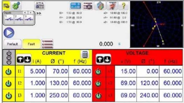
other
| Current (A) | 0.000 | 70.00 | 60.000 | | :--- | :--- | :--- | :--- | | I1 | 5.000 | 70.00 | 60.000 | | I2 | 1.000 | 130.00 | 60.000 | | I3 | 1.000 | 250.00 | 60.000 | VOLTAGE v (V) | 15.00 | 0.00 | 60.000 | | v1 | 69.00 | 120.00 | 60.000 | | v2 | 69.00 | 240.00 | 60.000 |Figure 58. Displayed Symmetrical Values for Phase to Ground Fault
3.1.12.1.5 Power button:
Power Values, S, P, Q and Power Factor (PF) values will be displayed depending on which channels are selected and what values for voltage, current and phase angles are set.

Figure 59. Example for Power Values Displayed
3.1.12.1.6 Phase to Phase Voltage button:
Phase-to-Phase Voltage values will be displayed.
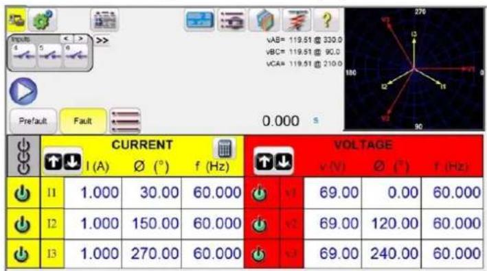
Figure 60. Example for Phase-to-Phase Voltage Values Displayed
3.1.12.1.7 Impedance button

Note: If you want the values displayed in the vector screen, select Phase-to-Phase Voltage in the
Configuration screen.
3.1.12.1.7 Impedance button:
Impedance values will be displayed, see Fault Calculator button for more information.
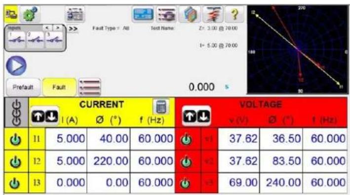
other
| Current (A) | Voltage (V) | Current (°) | Voltage (V) | Current (Hz) | Voltage (Hz) | | :--- | :--- | :--- | :--- | :--- | :--- | | 11 | 37.62 | 5.000 | 40.00 | 60.000 | 11 | | 12 | 37.62 | 5.000 | 220.00 | 60.000 | 12 | | 13 | 69.00 | 0.000 | 0.00 | 60.000 | 13 | | Fault Type = All Test Name: Z= 3.00 @ 70.00 I= 5.00 @ 70.00 270 180 80 11Figure 61. Example for Impedance Values Displayed
3.1.12.1.8 Secondary Values button:
With CT and PT ratios set in the System Configuration screen, selecting Secondary Values the calculated secondary values being applied will be displayed.

Figure 62. Example for Primary with Secondary Values Displayed
3.1.13 ⑬ Maximum Test Time / Prefault Time / Post Fault Time Settings button


Pressing this button will present a setting window, which allows the user to enter the amount of time in seconds that the Maximum Test Time, Prefault Fault and Post Fault Time values should be applied. In addition, when the Ramp On button is enabled the user can also set the selected channels to ramp up from the default values to the Prefault values at the selected Volts / second and Amperes / second. If the Ramp On is enabled, when the timing test is started, the outputs will turn on and start ramping up at the programmed ramp rate. Upon reaching the Prefault values the
time window will start counting down starting from the Prefault Time value. When the prefault time has lapse the Fault values will be applied to the relay under test and the Timer window will start counting until the relay trips. If the Auto off is turned off in the Binary Input (see 3.1.12), the Post Fault Time can be entered with the Enabling of the Turn all outputs off button in this screen. When the relay trips, the Timer will stop and display the operating time of the relay, and the outputs will stay on for the Post Fault Time value entered. If the Auto Off is enabled in the Binary Input configuration screen the outputs will turn off immediately after the operation (see 3.1.12 Binary Input Dialog Box section). If the relay has not tripped by the Maximum Test Time setting the test will stop and outputs will turn off automatically.
3.1.14 14 Run Test button
Pressing or clicking the Blue Run Test button will apply the prefault vector, start the countdown of the Prefault Time setting, then step to the Fault values and look for the relay under test to operate.
3.1.15 ⑮ Prefault / Fault buttons
Pressing these buttons will toggle and set the Prefault and Fault amplitudes, phase angles and/or frequencies. If the outputs are on, toggling between the two will apply the prefault and fault values repeatedly with each toggle. This is an especially helpful tool for the user who has to adjust mechanical contacts.
3.1.16 ⑯ All ON / All OFF button
Pressing or clicking on this button either turns all of the selected outputs ON, or if one or more of the outputs are ON, it will turn all of the outputs OFF. The center color of this button changes to green when one or more outputs are ON and indicates that pressing the button will turn all outputs off, with the exception of the Battery Simulator. To turn off the Battery Simulator press the Bat SIM button. This button is also used when ramping the battery simulator output.
3.1.17 ⑰ Manual Ramp Options button
If using the PC version the ↓↑ buttons will be displayed. On the FREJA touch screen the Control Knob button 🖱️ will be displayed. Pressing either of these two will present the user with a window to select the desired level of increment for manually ramping the outputs, the desired channel(s) to be ramped, and what is to be adjusted (amplitude, phase angle or frequency). If using the PC version use the keyboard up down arrow keys (or the mouse wheel) to manually adjust the selected value(s) at the desired increment level. On the FREJA unit, one click on the Control Knob equals the increment setting. When ramping phase angles, the Up arrow key ramps the phase angle in the counterclockwise direction, and the down arrow key ramps in the clockwise direction. If the Auto Increment button is selected the FREJA will automatically select the increment depending on how fast the control knob is being rotated; the faster the rotation the larger the increment.
3.1.18 ⑱ Channel ON / OFF Selector button
This button works in junction with the # ☐ All ON / OFF button. Pressing the button the center of the button changes color indicating the output is selected to turn ON. After pressing the All ON button turns the selected outputs on. Pressing the channel button individually turns the selected channels ON and OFF after the All ON / OFF button is ON. This allows the user to turn individual outputs ON and OFF without affecting other channels.
3.1.19 ⑲ Fault Calculator button
Pressing or clicking on the selected window will present the user with the Fault Calculator Input Screen.
3.1.19.1 Mode Selection button
Pressing or clicking on the Mode Selection button (upper left hand corner) reveals a selection list for different types of test options.
3.1.19.1.1 Overcurrent mode button
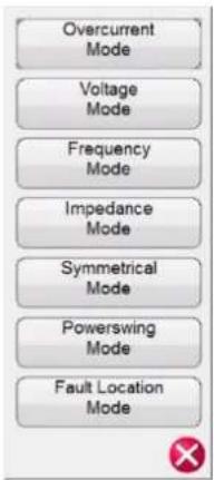
Figure 63. Mode Options
3.1.19.1.1 Overcurrent Mode button:
The default selection window will present Overcurrent Mode. There are two fields available to enter values, Normal (Prefault) and Fault Values. Enter in the provided windows the desired values of amplitude, and phase angle. Depending on the Selected Fault Type, upon pressing or clicking on the green check mark, the Fault values will appear in the appropriate value windows in the manual test screen. The user can also create 2nd, 3rd, 5th, and 7th harmonic current waveforms by entering the desired % harmonic in the windows provided. The harmonic waveform will appear in the window. See the following example.

Figure 64. Fault Calculator Harmonic Current Waveform
3.1.19.1.2 Voltage Mode button:
Press or click on the Voltage Mode button. There are two fields available to enter values, Heathy (Prefault) and Fault Values. Enter in the provided windows the desired values of amplitude, and phase angle (phase angle will be the A phase current relative to the A phase voltage). The user can create up to three harmonic voltage waveforms by entering the desired harmonic from the 2nd to the 15th and the % harmonic in the windows provided; see example waveform in the above figure for current mode. Depending on the Selected Fault Type, upon pressing or clicking on the green check mark, the Fault values will appear in the appropriate value windows in the manual test screen.
3.1.19.1.3 Frequency Mode button:
Press or click on the Frequency Mode button. The Fault (Frequency) Values entry window will be provided. Enter the desired fault frequency. The Prefault Frequency will be the default value.
3.1.19.1.4 Impedance Mode button:
Press or click on the Impedance Mode button. Pressing A Phase to ground fault the user will see the following screen.

Figure 65. Impedance Mode Input Screen
3.1.19.1.4.1 Fault Selection button:
Click or press this button to select the desired fault type, phase to ground, phase to phase or three phase fault.
3.1.20.1.4.2 Test Model button:
The input screen defaults to Constant Current test mode. In this screen the user simply inputs the Ohmic Reach of the relay, at the desired test angle. If the relay requires Prefault values prior to stepping to the fault values, the user will need to input the desired prefault current and load angle (Normal Values). Click or press the green check button to return to the test screen. Selecting Constant Voltage test mode will present the user with a similar input screen, where the user inputs the desired fault voltage. Selecting Constant Source Impedance the user will be presented with the following screen.
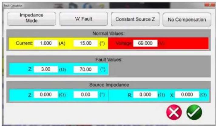
Figure 66. Impedance Mode, Constant Source Impedance
In this screen the user is required to input the source impedance and angle. The fault calculator will calculate the resistive and reactive values based upon the user inputs. Upon returning to the test screen the test values of fault voltage(s), current(s) and angles will be displayed.
3.1.19.1.4.3 Compensation button:
This button only appears when you select the Phase to Ground Fault type. Press or click on the Compensation Mode button to access the selection menu. There are three types of compensation formulas available, KN, Z0 / Z1, and RE / RL
3.1.19.1.5 Symmetrical mode button
XE / XL. Residual compensation factor, KN, is a complex number that is used to express the earth-return impedance, ZN, in terms of the positive-sequence impedance reach setting, Z1. This factor is calculated as:
$$ \mathbf {K N} = Z \mathbf {N} / Z 1 = (Z 0 - Z 1) / (3 Z 1) $$
Where: Z0 is the zero-sequence impedance polar reach of the zone
Z0 / Z1 Ratio = the complex ratio of Z0 / Z1, also referred to as K0 = Z0 / Z1
RERL XEXL are a pair of scalar factors. These factors affect the resistive reach and reactive reach, respectively, of some polygon characteristics. They are calculated as follows:
$$ \mathrm{RERL} = (\mathrm{RO} / \mathrm{R1} - 1) / 3 $$
$$ \mathrm{XEXL} = (\mathrm{X0} / \mathrm{X1} - 1) / 3 $$
Where:
$$ R 1 = \text { real part of } Z 1 $$
$$ X 1 = \text { imaginary part of } Z 1 $$
$$ R 0 = \text { real part of } Z 0 $$
$$ X 0 = \text { imaginary part of } Z 0 $$
3.1.19.1.5 Symmetrical Mode button:
Press or click on the Symmetrical button to access the Symmetrical input setting screen, see the following figure.

bar
| Sequence Value | Value | Direction (A) | Direction (°) | | :--- | :--- | :--- | :--- | | Zero Sequence Values: | 0.000 | 0.000 | 0.000 | | Zero Sequence Values: | 74.85 | 74.85 | 74.85 | | Zero Sequence Values: | 68.79 | 68.79 | 68.79 | | Positive Sequence Values: | 9.744 | 9.744 | 9.744 | | Positive Sequence Values: | 55.17 | 55.17 | 55.17 | | Positive Sequence Values: | 63.20 | 63.20 | 63.20 | | Negative Sequence Values: | 9.744 | 9.744 | 9.744 | | Negative Sequence Values: | 355.17 | 355.17 | 355.17 | | Negative Sequence Values: | 170.17 | 170.17 | 170.17 | The chart displays a single bar for each value in the table, with the 'Value' column indicating the magnitude of the bar at that position. The 'Direction' column is labeled as '(A)' or '(°)' to indicate direction of the bar.Figure 67. Symmetrical Input Setting Screen
To simulate unbalanced fault conditions, a set of 3-phase unbalanced currents or voltages may be resolved into 3 sets of balanced components of Positive, Negative, and Zero Sequence values. Zero Sequence currents and voltages occur as the result of a Phase to Ground Fault on the system. If testing for Zero Sequence enter the Zero Sequence Current or Voltage value into the screen above. Upon returning to the test screen the appropriate Current and / or Volte values will be displayed and ready for testing. Negative Sequence is a result of a three phase unbalance condition. Enter the desired negative Sequence values of Voltage and Current and upon returning to the test screen all the three phase values will, be calculated and displayed ready for testing.
3.1.19.1.6 Power Swing Mode button:
Press or click on the Power Swing Mode button to access the Power Swing input setting screen, see the following figure.

bar
| Metric | Value | | ---------------- | ----------- | | Nominal Values | f1: 60.000 (Hz) I | | Nominal Values | v1: 69.00 (V) | | Fault Values | f2: 58.000 (Hz) | | Fault Values | v2: 30.00 (V) | | Impedances | Zmin: 2.000 (Ω) | | Impedances | Zmax: 20.000 (V) |Figure 68. Power Swing Input Setting Screen
The Power Swing simulation tool uses two superimposing waveforms of similar frequencies to provide a smooth impedance ramp. This method is similar to a two-source model in that both sources have similar frequencies and amplitudes. The rate of change of impedance can be controlled as well as the minimum and maximum impedances, the number of pole slips, as well as the starting phase angle relationships
The next section will describe the values used to calculate the necessary test values and discuss how to implement a controlled power swing.
To apply a power swing, the following parameters need to be defined.
The Maximum Impedance, Z_max , of the Power Swing needs to be defined. This will be based on the outer most characteristic that is tracking the impedance. It is recommended that the maximum impedance be greater than the largest blinder / characteristic impedance, but not so large that the trajectory of the swing exits the characteristic prematurely.
The Minimum Impedance, Z_min , of the Power Swing also needs to be defined. This will be the minimum impedance point of the swing.
The Source Frequencies, f1 and f2, will determine how long of a duration a single power swing condition will be. The source frequencies will also factor in determining the rate of change of the trajectory of the impedance. The larger the difference in frequency between the two sources, the faster the swing, and the smaller the difference, the slower the swing.
The Starting Phase Angle (°) needs to be defined so that proper loading conditions can be simulated properly.
Here is how to create a power swing with a maximum impedance of 15 , a minimum impedance of 1 , a Source 1 Frequency (f1) of 60 Hz, a Source 2 Frequency (f2) of 59 Hz, and a starting Phase Angle of 0^ .
The first parameter calculated is how long a complete power swing cycle will take, tSwing. This is calculated using Eq.1.
Eq. 1 t Swing=1/(f 1 -f 2 ) (s)
Eq. 2 t Swing=1/(60-59)=1s
When applying this method to any type of test routine, tSwing should be the maximum time set for how long the swing should be applied. If multiple turns are desired, then maximum time would be the number of turns times t_swing .
3.1.19.1.7 Fault location mode button
A nominal voltage (V1) should be defined for the maximum impedance, and a fault voltage (V2) should be defined for the minimum impedance. Take care in choosing a fault voltage because some of the impedances could still be quite large, with large defined as around 15 or greater. If the fault voltage is too small, negative valued currents would end up being calculated to create the correct conditions. If that is the case, increase the fault voltage until the currents are at an acceptable level. For this example, the nominal voltage, V_nom , is 69 V line-to-ground, and the fault voltage, V_fault , is 30 V line-to-ground.
The value of V_fault can change depending on the impedance and the current required from the test set. The nomenclature of V_fault can also be a little misleading. A power swing event may not necessarily require the extreme values of traditional fault voltages. The swing of impedance may only go from a large value to a slightly smaller value. Such would be the case if the user wanted to swing from 89Ω to 50Ω. The required fault voltage would not be much less than what was required for starting impedance.
When starting in the prefault mode for testing, it is handy to be at the same current level as the starting current for the swing.
The time set for the Prefault duration is critical in that it is necessary for the waveform to end at the precise phase angle and magnitude that is equal to the start of the power swing event. The prefault phase angle of the current should be equal to the starting phase angle of the power swing. This will also ensure smoothness. In the following figure, the duration was set for 1 second, and the calculated time of one power swing was also calculated at 1 second. By setting the prefault to the same time as the calculated time of the power swing, a smooth transition is guaranteed in the waveforms.
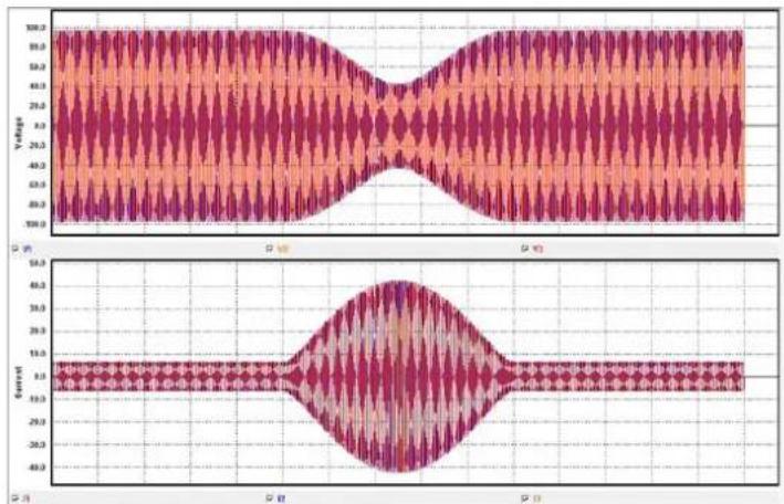
line
| Time (ms) | Voltage | Current | |-----------|---------|---------| | 0 | 100.0 | 15.0 | | 1 | 95.0 | 15.0 | | 2 | 85.0 | 15.0 | | 3 | 75.0 | 15.0 | | 4 | 65.0 | 15.0 | | 5 | 55.0 | 15.0 | | 6 | 45.0 | 15.0 | | 7 | 35.0 | 15.0 | | 8 | 25.0 | 15.0 | | 9 | 15.0 | 15.0 | | 10 | 10.0 | 15.0 | | 11 | 15.0 | 15.0 | | 12 | 25.0 | 15.0 | | 13 | 35.0 | 15.0 | | 14 | 45.0 | 15.0 | | 15 | 55.0 | 15.0 | | 16 | 65.0 | 15.0 | | 17 | 75.0 | 15.0 | | 18 | 85.0 | 15.0 | | 19 | 95.0 | 15.0 | | 20 | 100.0 | 15.0 | | 21 | 95.0 | 15.0 | | 22 | 85.0 | 15.0 | | 23 | 75.0 | 15.0 | | 24 | 65.0 | 15.0 | | 25 | 55.0 | 15.0 | | 26 | 45.0 | 15.0 | | 27 | 35.0 | 15.0 | | 28 | 25.0 | 15.0 | | 29 | 15.0 | 15.0 | | 30 | 10.0 | 15.0 | | 31 | 15.0 | 15.0 | | 32 | 25.0 | 15.0 | | 33 | 35.0 | 15.0 | | 34 | 45.0 | 15.0 | | 35 | 55.0 | 15.0 | | 36 | 65.0 | 15.0 | | 37 | 75.0 | 15.0 | | 38 | 85.0 | 15.0 | | 39 | 95.0 | 15.0 | | 40 | 100.0 | 15.0 | | 41 | 95.0 | 15.0 | | 42 | 85.0 | 15.0 | | 43 | 75.0 | 15.0 | | 44 | 65.0 | 15.0 | | 45 | 55.0 | 15.0 | | 46 | 45.0 | 15.0 | | 47 | 35.0 | 15.0 | | 48 | 25.0 | 15.0 | | 49 | 15.0 | 15.0 | | 50 | 10.0 | 15.0 | | Peak | - | - | | Low | - | - | | High | - | - | | Peak | - | - | | Low | - | - | | High | - | - | | Peak | - | - | | Low | - | - | | High | - | - | | Peak | - | - | | Low | - | - | | High | - | - | | Peak | - | - | | Low | - | - | | High | - | - | | Peak | - | - | | Low | - | - | | High | - | - | | Peak | - | - | | Low | - | - | | High | - | - | | Peak | - | - | | Low | - | -9 | | High | - | -9 | | Peak | - | -9 | | Low | - | -9 | | High | - | -9 | | Peak | - | -9 | | Low | - | -9 | | High | - | -9 | | Peak | - | -9 | | Low | - | -9 | | High | - | -9 | | Peak | - | -9 | | Condition | Value | | ----------- | ------- | | Low | -9 | | High | -9 | | Peak | -9 | | Low | -9 | | High | -9 | | Peak | -9 | | Low | -9 | | High | -9 | | Peak | -9 | | Low | -9 | | High | -9 | | Peak | -9 | | Low | -9 | | High | -9 | | Peak | -9 | | Low (Peak) | -9 | | Low (Current)| -9 | | Peak (Current)| -9 | | Low (Current)| -9 | | High (Current)| -9 | | Peak (Current)| -9 | | Low (Current)| -9 | | High (Current)| -9 | | Peak (Current)| -9 | | Low (Current)| -9 | | High (Current)| -9 | | Peak (Current)| -9 | | Low (Current)| -9 | | High (Current)| -9 | | Peak (Current)| -9 | | Low (Current)| -9 | | Low (Current)| -9 | | High (Current)| -9 | | Peak (Current)| -9 | | Low (Current)| -9 | | High (Current)| -9 | | Peak (Current)| -9 | | Low (Current)| -9 | | High (Current)| -9 | | Peak (Current)| -9 | | Low (Current)| -9 | | High (Current)| -9 | | Peak (Current)| -9 | | Lower Level (Current) < Peak - + Peak - + Peak - + Peak - + Peak - + Peak - + Peak - + Peak - + Peak - + Peak - + Peak - + Peak - + Peak - + Peak - + Peak - + Peak - + Peak - + PeakFigure 69. Three Phase Waveform Capture of a Power Swing
The time can also be set to a multiple of the swing duration. In this case, 2, 3, or 4 seconds would also work. A time of 0.5 seconds will not work.
3.1.19.1.7 Fault Location Mode button:
Press or click on the Fault Location Mode button to access the Fault Location input setting screen, see the following figure.
3.1.19.2 Fault type selection button
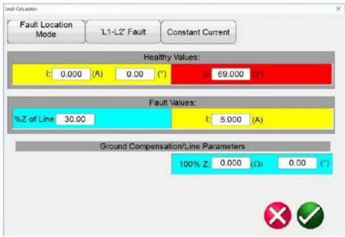
Figure 70. Fault Location Input Screen
Fault Location Mode will allow the user to enter % impedance of a line and the software will The Fault Locator will calculate the appropriate voltages, currents and phase angles to replicate the fault at the appropriate location based upon the % entered.
3.1.19.2 Fault Type Selection button
Pressing or clicking on the Fault Type Selection button reveals a selection list for different types of Fault test options.

Figure 71. Fault Types
User may select Phase to Earth (i.e. L1), or Phase to Phase (i.e. L1-L2), or Three Phase fault simulation (i.e. L1-L2-L3). All values calculated for the type fault selected will be automatically calculated and entered into the appropriate value windows.
3.1.20 ⑳ Channel Amplitude, Phase Angle and Frequency buttons
Pressing or clicking on the selected window will present the user with a numeric keypad and dialog box window for setting either individual values or setting multiple values swiftly and easily. For example, to change the default voltage values for all three phases, enter the desired voltage value in the entry window and then press the Balance button All of the values will change to the desired output voltage. The same is true for both Phase Angle and Frequency.
3.2 Setting Phase Angle Relationships
Consider each V/I Generator module as a vector generator. Each module has an internal zero reference to which it
3.2 Setting phase angle relationships
references its phase angle settings as displayed on the touch screen. This applies to phase angle settings between the voltage and current outputs. When setting a phase angle between two outputs, it is recommended that one output be set at 0^ and the other output be referenced to the 0^ . This is for operator convenience only. When setting an angle, the operator has a multiple of choices, depending on the Default Phase Angle setting, see 2.3.1.3. In the engineering world and in the following figures, the lagging diagram displays negative rotation and will create negative sequence components, while the Lead and +/-180 diagrams display positive rotation which is normal system activity.

radar
| Axis | Value | |---|---| | V1 | 0 | | V2 | 270 | | V3 | 90 | The chart displays a single data point for the 'Lead' category. Below it is a text box stating '0 - 360 Lead', '0,240,120 deg'. The arrow indicates a rotation around the origin.Figure 72. Positive Phase Rotation Diagrams
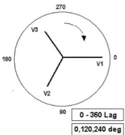
radar
| Axis | Value | |---|---| | V1 | 0 | | V2 | 90 | | V3 | 180 | | 270 | 270 | The chart displays a single data point at position 270, which is marked with an arrow pointing to it. Below the chart, a text box indicates '0 - 360 Lag' and '0,120,240 deg'.Figure 73. Negative Sequence Phase Rotation Diagrams

radar
| Axis | Value | |---|---| | V1 | 90 | | V2 | -90 | | V3 | 0 | | ±180 | ±180 | The chart displays a circular layout with three labeled axes (V1, V2, V3) and an arrow indicating the direction of rotation around the V1 axis. Below the chart is a formula defining the angle between 0 and ±180 degrees.Figure 74. Positive Phase Sequence Rotation Using ± 180°
For example, using 0-360 Lag (0, 120, 240) setting an angle of 30^ between the two outputs would look like:

The reference output is 0^ and the second output is rotated 30^ clockwise. In other words, the angle is lagging the referenced source by 30^ . Conversely, if the angle decreases in the counterclockwise direction from 359.9^ toward 0.0^ , for a setting angle of 300.0^ , the second output would look like:
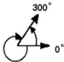
The reference output is 0^ and the second output is rotated to 60^ in the counterclockwise direction. In other words, the second output lags the reference output by 300^ or leads it by 60^ . The user may default to phase angles to ±180^ with the - (negative) angles lagging and the + (positive) angles leading. Therefore, to set an angle of +10^ leading, the vector relationship would be:

3.3 Current Sources
3.3.1 Parallel Operation
3.3.1 Parallel Operation
Each FREJA current amplifier is capable of providing 32 Amperes continuous, and can provide up to 60 amperes, per phase for 1.5 seconds for testing instantaneous trip elements. When more than 32 amperes single phase is required for long durations, or more than 60 Amperes for testing instantaneous elements, two or more current channels may be connected in parallel to provide 60 or 90 Amperes continuous, and up to 120 or 180 amperes for 1.5 seconds.
To parallel the current channels of the unit, perform the following:
If using the sleeved multi-lead current test leads, all of the black return leads are interconnected together inside the sleeve so they will all share the return current together. Connect each current channel to the relay under test (both red and black terminals to the load). Each Megger test lead is rated for 32 Amperes continuous. If using test leads other than those supplied by Megger ensure that the wire has sufficient size to carry the test current.
For the earth grounded common return (G or E) units, there is an internal common ground between the current channel return terminals. If using separate individual test leads, all of the return leads
will need to be common together at the load as shown in the following figure. By not connecting a return lead to all of the current channels in use, part or all of the return current will be for cedthrough the internal ground. That means with a three channel unit up to 180 Amperes could be forced through the internal common ground, and may cause damage to the internal common returns. Therefore, it is important that the parallel connections must be made at the relay. See the following figure.

flowchart
graph TD
    A["1"] --> B["3"]
    B --> C["2"]
    C --> D["1"]
    D --> E["FREJA 536 PROTECTIVE RELAY TEST SYSTEM"]
    style A fill:#f9f,stroke:#333
    style B fill:#ccf,stroke:#333
    style C fill:#cfc,stroke:#333
    style D fill:#fcc,stroke:#333
    style E fill:#ffc,stroke:#333
Figure 75. Parallel of Three Current Outputs (FREJA 536)
3.3.1.1 Manual Test Screen - Single Phase – High Currents
For FREJA 536 / 546 users, go to the Configuration screen and select the Operating Mode of 3/4 Voltages – 1 Current @ 180 Amperes. Note for other FREJA 500 models there are similar single channel options available. When you return to the manual test screen there will be one current channel displayed, as shown in the following figure.
3.3.1.1 Manual Test Screen - Single Phase – High Currents

Figure 76. Manual Test Screen – Single Phase High Current Operation
The FREJA Local software will automatically set all three currents in phase with each other and divide the current equally between the three current amplifiers. When setting an output, simply enter the value of the desired output current. For example, for an output of 75 Amperes, enter 75. If using a FREJA 536, each current amplifier will be providing 25 Amperes. The current can also be phase shifted. Simply enter the desired phase angle and all three currents will be phase shifted together.
If two current channels that are to be used in parallel, leave the unit in the default three phase configuration. Connect the two current outputs to the load as shown in the following figure.
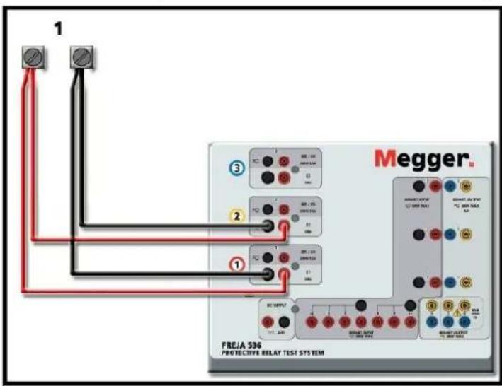
Figure 77. Two Currents in Parallel (on FREJA 536)
Set each channel to one-half of the output requirement. ▲ Be sure and set current channel #2 to 0 degrees so that it will be in-phase with current channel #1. With both current channels selected, turn output on by pressing or clicking on the Ⓔ ALL ON / OFF button. Always use the ALL ON / OFF button to turn both current channels on and off together. For manually ramping outputs, if using the PC version of the FREJA Local the ↑↓ buttons will be displayed. In the FREJA Local touch screen the Control Knob button 📁will be displayed. Pressing either of these two will present the user with a window to select the desired level of increment for manually ramping the outputs, the desired channel(s) to be ramped, and what is to be adjusted (amplitude, phase angle or frequency).
3.3.2 Currents in series operation
3.3.2 Currents in Series Operation
Each current amplifier in the FREJA units can produce up to a maximum of 50 Volts of compliance voltage at test currents up to 4 Amperes. For test currents less than 1 Ampere enable the High Burden Current Amplifier Mode feature in the Configuration screen, see 2.3.1.8. Two current channels may be connected in series in order to double the available compliance voltage. High impedance electromechanical ground (earth) overcurrent relays have always been difficult to test at high multiples of tap due to the winding impedance and saturation characteristics. The peak voltage required can exceed the maximum output voltage of one FREJA current output channel, depending on the required test current. By connecting two current outputs in series, the compliance voltage is doubled, providing higher test currents through the high impedance load.
There are two methods to series currents together. For the floating output, (F or C) models connect the two current amplifiers in a "push-push" configuration as shown in the following figure.

Figure 78. Series Two Currents with FREJA 536
The two current channels that are to be used in series set each to the same test current magnitude, and phase angle. Select both current channels, and turn output on by pressing or clicking on the BALL ON / OFF button. Always use the ALL ON / OFF button to turn both current channels on and off together. For manually ramping outputs, if using the PC version of the FREJA Local the ↑↓ buttons will be displayed. In the FREJA Local touch screen the Control Knob button will be displayed. Pressing either of these two will present the user with a window to select the desired level of increment for manually ramping the outputs, the desired channel(s) to be ramped, and what is to be adjusted (amplitude, phase angle or frequency).
To series the current channels of the common grounded returns (on the G or E model top cover the black return terminals are connected with a black line and the ground symbol), perform the following:
Connect the Red output terminals of the two current channels to the relay under test. Even though the two returns associated with the current channels are connected internally with the common returns, place a jumper externally as shown. This will ensure that the internal common leads will not be damaged should more than 32 Amperes be applied.

Figure 79. Series of Two Current Channels with SMRT36D Grounded Common Returns
NOTE: One current channel should be set to 0 degrees and the other current channel should be set to a phase angle of 180 degrees so that the two compliance voltages add across the load. DO NOT attempt to series more than two currents together on a grounded common returns unit.
The two current channels that are to be used in series set each to the same test current magnitude. Initiate the two current channels simultaneously by pressing the ALL ON / OFF button. Always use the ALL ON / OFF button to turn both current channels on and off together. For manually ramping outputs, if using the PC version of the Software the ↑↓ buttons will be displayed. On the FREJA 500 series On-board display, the Control Knob button 📋 will be displayed. Pressing either of these two will present the user with a window to select the desired level of increment for manually ramping the outputs, the desired channel(s) to be ramped, and what is to be adjusted (amplitude, phase angle or frequency).
3.4 Voltage Sources
3.4.1 Outputs Summed Together
Two voltage channels may be used to sum the voltage outputs to obtain higher than rated voltage provided the load is ungrounded. Connect the load between the voltage channel posts, set U1 Phase to 0° and set U2 Phase to 180°. The voltage outputs will add so the total voltage is the sum of the two voltage amplitudes, U1 and U2 as can be seen in the following diagram.

Note DO NOT attempt to series more than two voltage channels together, since the voltage leads are rated for a maximum of 600 Volts.
3.4.2 30, 3-Wire, open-delta and T-Connection

Figure 80. Series of Voltage Channels for FREJA 536
3.4.2 30, 3-Wire, Open-Delta and T-Connection
3.4.2.1 Balanced Open Delta
Two methods of obtaining a three-phase, three-wire voltage source are available. The Open-Delta configuration is the easier to use when a balanced three-phase source is required because the amplitude and phase relationship can be set directly. No calculations are necessary.
When using the Open-Delta configuration, it is suggested to use voltage channel #1, designated U1, and voltage channel #2, designated U2, while the COMMON binding post is designated V_g . With this arrangement, the magnitude and phase angle of the potentials can be easily calculated and set. For the balanced three-phase condition U1 and U2 are equal in magnitude and separated by an angle of 60^ . This is done by setting the U1 and U2 potentials equal in magnitude, setting 0^ on U1 and 300^ (60 degrees leading assuming that the default phase rotation is set to 360 Lag) on U2, see the following figure.
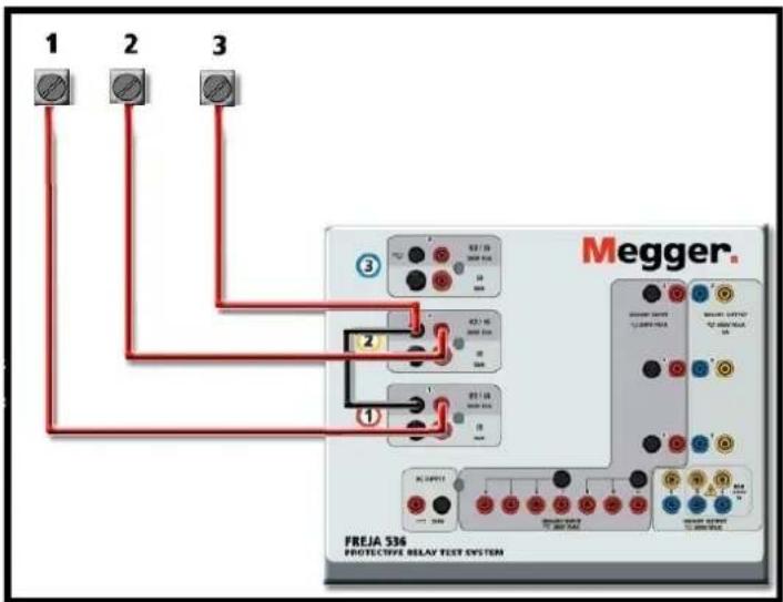
Figure 81. FREJA 536 Three Phase Open Delta Connections
3.4.2.1.1 Unbalanced open delta
When using the Open-Delta Configuration to set up a phase-to-phase fault, calculations' using the Law of Cosines is required to calculate amplitude and phase relationships. (See discussion under T-Connection for simulating unbalanced, phase-to-phase faults without need for calculations.)

Balanced 30 - Open Delta Connection
If V_f equals the desired test potential, then:
Set U1 = V _t ∠ 0°
Set U2 = V, ∠ 300° (360 Lag configuration)
3.4.2.1.1 Unbalanced Open Delta
When setting up an Unbalanced Open-Delta configuration, the desired phase-to-phase fault voltage, V1f is set using voltage channel #1 with its phase angle set to 0°. Phase-to-phase voltage V2f and its phase angle relationship for voltage channel #2, must be calculated using the Law of Cosines; where for any triangle the following formula applies:

The next figure shows the phase relationships between voltages and an example of the necessary calculation. For convenience the amplitude and the phase angle settings for the typical Vf fault magnitudes are tabulated.
From the Law of Cosines
for = (_22*V_3)
to -V_23^2 = (_122)^2 + (32 * 120)^2
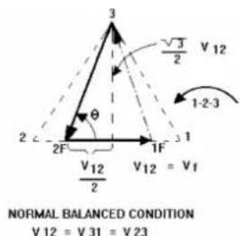
Settings for Typical Phase-to-Phase Fault Voltages
Figure 40 Open-Delta Unbalanced Phase-to-Phase Fault Voltages
The second method of obtaining a three-phase, three-wire voltage source is the so-called T-Connection. The method, shown in the following figure, is easier to use when obtaining an unbalanced, phase to phase fault simulation since it eliminates calculations. To reduce confusion when using the T-Connection, the voltage output #1 is designated Va and its phase angle set at 0°, voltage output #2 is designated Vb and its phase angle set for 180°, and voltage output #3 is designated Vc and its phase angle is set for 270°. Any combination of balanced three phase faults or unbalanced phase-to-phase fault conditions can be easily simulated. The following figure indicates these phase relationships.
NOTE: This method should not be used for very low fault voltages, or used on solid state relays that may be sensitive to this type of connection (i.e. 5 volts or less, or for testing ABB or Westinghouse type SKD relays).
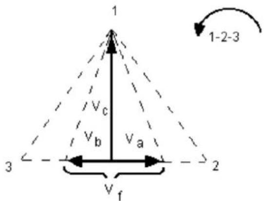
Balanced or Unbalanced Fault T-Connection.
$$ V _ {f} = \text { Desired Fault Voltage } $$
$$ V _ {a} = \frac {1}{2} V _ {f} 0 \angle $$
$$ V _ {b} = \frac {1}{2} V _ {f} \quad^ {\circ}. $$
$$ V _ {c} = \frac {\sqrt {3}}{2} 1 2 0 o r V _ {c} = 1 0 4 V \angle 2 7 0 ^ {\circ} $$
3.4.3 30, 4-Wire, Y-Connection
A three-phase, four-wire potential system can be provided using three output modules. The vector relationships are referenced below. This Y-Connection has the advantage of being able to supply a higher line-to-line voltage (1.73 x phase-to-neutral voltage). It is ideally suited for simulating phase-to-ground faults. Voltage channel #1 is designated as V_a with its phase relationship set for 0°. Voltage channel #2 is then designated as Vb and phase angle set for 120°. Finally, voltage channel #3 is designated Vc and phase angle set for 240° (for a 1-2-3 counter clockwise rotation). V_a V_b and V_c are connected to the voltage potential binding posts on the respective test sets.

flowchart
graph TD
    A["Vf"] --> B["N"]
    B --> C["1"]
    D["Vb"] --> B
    E["Vc"] --> B
    F["3"] --> G["1-2-3"]
    style A fill:#fff,stroke:#000
    style B fill:#fff,stroke:#000
    style C fill:#fff,stroke:#000
    style D fill:#fff,stroke:#000
    style E fill:#fff,stroke:#000
    style F fill:#fff,stroke:#000
    style G fill:#fff,stroke:#000
Balanced 30, 4 Wire Y-Connection
$$ V _ {f} = \text { Desired Fault Voltage } $$
$$ V _ {a} = \frac {\sqrt {3}}{3} V _ {f} 0 \angle $$
$$ V _ {b} = \frac {\sqrt {3}}{3} V _ {f} 1 2 0 \angle $$
$$ V _ {c} = \frac {\sqrt {3}}{3} V _ {f} 2 4 0 \angle $$

Note: If using the sleeved multi-lead voltage test leads (part number 2001-395), all of the black return leads are interconnected together inside the sleeve so they will all share the return together. Therefore, only one return lead is provided on the relay connection side of the sleeved leads (similar to the connections in the following figure).
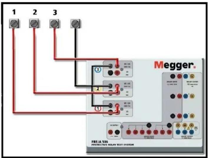
Figure 82. FREJA 536, Three Phase Four Wire Test Connections
3.5 Testing relays with the FREJA local manual test screen
3.5 Testing Relays with the FREJA Local Manual Test Screen

Figure 83. Manual Test Screen
The following tests are examples of how to use the FREJA Local Manual Test Screen for general test applications.
3.5.1 Simple Manual Pickup or Dropout Test
- Select the channel value(s) to be manually ramped by pressing the appropriate magnitude window(s). Using the numeric keypad as shown in Figure 20, enter the starting value.
- Connect the appropriate output terminal(s) for the selected channel(s) to be ramped.
- Connect the desired Binary Input terminal to sense the relay contacts closing or opening. Select the Binary Input ⑫ and set the appropriate sensing Continuity or Voltage modes (see Figure 54A).
- Press the Output Selector Adjustment button ⑰ and enter the increment, channel number(s), and whether Amplitude, Phase and Frequency. Note that the selected channel(s) should have a highlighted border around the magnitude window(s).
- Select the output(s) to be turned on by pressing the ON / OFF button 18 for the selected channel(s). Upon pressing the ON / OFF button the center will turn green indicating that the channel has been selected to turn on. Turn the selected output(s) on by pressing All ON / OFF button 16 . When the channel(s) turn on the channel window(s) turns green. Using either the Control Knob on the FREJA Local, or the PC up and down arrows, manually ramp the output(s) until the relay contacts either picks up or drops out, depending on the start value entered in Step 1.
- Turn the output(s) off by pressing the ON / OFF button(s), or press the ALL ON / OFF button. By not pressing the ALL ON / OFF button the channel(s) can be turned back on by pressing the channel ON / OFF button again. This provides the ability to toggle outputs on and off in order to observe contact movement at the pickup threshold.
- Press the Report Options button ④ if you would like to document this test in your report.
3.5.2 Simple Manual Timing Test
- Press the Prefault button ⑮, and set the desired Prefault duration in seconds in the window provided ⑬.
- Select the prefault channel(s) to be turned on by pressing the ON / OFF button(s) 18 . Set the Prefault value(s) by pressing the appropriate magnitude window(s) 19, and using the numeric keypad as shown in Figure 20, enter the Prefault value(s).
- Connect the appropriate output terminal(s) for the selected channel(s) to be used.
- Connect the desired Binary Input terminal to sense the relay trip contacts.
- Press the selected Binary Input ⑫, note Binary Input #1 is already set to Use as Trip (enabled). Set for the appropriate sensing Normally Open, Normally Closed, Voltage Applied, or Voltage Removed. If the Binary Input selected is set to monitor mode, Use as Trip (disabled), press or click on the button to change it to Use as Trip (enabled), see Figure 54B, and select Input Type and Input Action as desired. If it is desired to turn the outputs off
3.5.2 Simple manual timing test
when the relay trips press the Auto Off (disabled) button and select the desired channels to turn off.
- Press the Fault button, and set the desired fault value(s) by pressing the appropriate magnitude window(s), and using the numeric keypad.
- Press the Prefault button returning to the prefault settings. Turn the selected channels on by pressing the ALL ON / OFF ⑯ . The prefault outputs should now be on. Press the Blue Run Test button ⑭ . The Prefault countdown timer will start running. The outputs will change from prefault to fault value(s) and the timer will start running. When the relay trips, the Timer will stop indicating the trip time of the relay under test. Once the test has completed all outputs will be turned off if the auto off was enabled. If Auto Off was not enabled the user can input a Maximum Test Time or a Post Fault Time setting, see 3.1.14 Maximum Test Time / Prefault Time / Post Fault Time Settings button, and the outputs will automatically turn off as desired.
- To save the test result, press the Report Options button ④. The results have now been added to the report and the report is shown. Note that the values are not actually saved to file until you press the File Folder button and save them as previously defined. The user can now enter appropriate information relative to the test in the Test Report header.

Figure 84. Example PowerDB Report
If using the FREJA Local, use the Control Knob to scroll up and down to view all results. Note that there is a space in the upper right corner for company logos to provide a finished and professional look (see Configuration Screen). Also note the Options :Button just above the recorded results. Pressing this button the user will be presented with a number of possible choices for the recorded results.

Figure 85. Report Options Screen
3.5.3 Simple ramp test
The results can be moved up or down to change the order of the results presentation. The result can be deleted, or a retest performed by pushing the Blue Run Test button. In addition, the user can add or hide Comments or Deficiencies. Press either Close report to return to the test screen or press Cancel to return to the report. To exit the report, press the Check button in the top left corner or select the Options button followed by the 'Close Report' button.
3.5.3 Simple Ramp Test
The Ramp Test feature of the FREJA Local / Remote software may be used to automatically determine pickup or dropout of various types of relays. Press the Select New Test button to get access to the Ramp Test screens. The first option is the Simple Ramp test. After selecting Simple Ramp, if you want Advanced Ramp instead of Simple Ramp press or click on the more button and select Show Advanced Ramp.

other
| Channel | Current Amplitude (A) | Current Amplitude (Hz) | Current Amplitude (V) | Current Amplitude (V) | Current Amplitude (Hz) | Current Amplitude (V) | | :--- | :--- | :--- | :--- | :--- | :--- | :--- | | 1 | 0.000 | 0.00 | 0.00 | 0.00 | 60.000 | 0.00 | | 2 | 0.000 | 120.00 | 60.000 | 0.00 | 60.000 | 120.00 | | 3 | 0.000 | 240.00 | 60.000 | 0.00 | 60.000 | 240.00 | | 4 | 0.00 | 65% | 65% | 0.00 | 60.000 | 65% |Figure 86. Simple Ramp Test Screen
There are three additional buttons across the tool bar. The Report All button will include all ramps in the report. If not enabled, it will only record the last pick up or drop out value. The Binary Input button will open to the Binary Input dialog box; see 3.1.12 Binary Input Dialog button for setting descriptions. The Show / Edit Pretest notes button allows the user to view or edit test notes.
In the Channel To Ramp the user may select what is to be ramped. The screen defaults to Ramp Current Amplitude. Pressing this button provides the user with eight different options.

Figure 87. Value to be Ramp Selection Screen
3.5.3.1 Configuring of multiple ramps
The user may select voltage or current, Amplitude, Phase, Frequency or Symmetrical values. The channels selection directly under the Channel To Ramp button allows the user to select which channels will be ramped.
Once a value is selected to ramp the user must then choose which type of ramp (there are three to choose from).
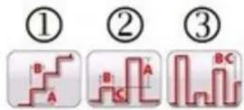
Figure 88. Simple Ramp Options
3.5.3.1 Configuring of Multiple Ramps
Multiple ramps may be performed to provide a finer resolution of the pick up or drop out value, by ramping up or down in large increments, then changing to a smaller increments on the second or third ramp. This is done by clicking on the Multiple Ramp button .Up to 24 ramps maybe performed for any pickup or drop out value. In this example, a double ramp will be programmed. Ramp 1 will use the default staring value of 85% of the Expected value. For this example, the output current will be ramped up in 0.1 Ampere increments in the first ramp. The second ramp will start when the monitored contacts close (Normally Open to Close). For the start of the second ramp, the user will need to click on the Multiple Ramp button and select Set # Ramps, and select two. To set the new starting value click on the 85% Start Value displayed in the test screen. A numeric keypad will appear with the lower bar labeled Start is Value (meaning the start value will be 85% of the Expected value. Click on the bar to see a list of start options, see the following figure.

Figure 89. List of Start Value Options
Start Value would be the same as the original Start Value, or 85% of Expected Value. Start is % Last Value would start at 85% of the last value where the monitored contacts closed. For this example, let us say the contacts closed at 5.5 Amperes. Therefore, the next start value would be 85% of 5.5, or 4.675 Amperes. If this is an electromechanical relay, this would cause the contacts to open slightly before the second ramp starts. To get a finer resolution, the user could select a smaller increment for the second ramp by clicking on the increment value, and thus start the second ramp with smaller increments. Start is Last Value the second ramp will start at where the contacts closed. This could be used to find the dropout, or ramp down until the contacts just open and then back up at a smaller increment to find the pickup with higher resolution.
3.5.3.2 Stair Step Ramp example
The first selection ① is the Stair Step Ramp will ramp the output by applying a value and then waiting a specific amount of time before incrementing it. The user can enter several setting values. Depending on what is being ramped the user must enter the Expected value of pickup by pressing or clicking on the Expected value as shown in the following figure. For example, to automatically ramp output current the user will, input Expected Amplitude(s), an Increment (A), and a Delay time in milliseconds (B). Three other values are also adjustable by the user. The start value, defaults to 85% of the Expected pickup value. The prefault duration defaults to 1 second. The stop value defaults to
3.5.3.3 Pulse ramp example
120% of the Expected pickup value. To change any value simply touch or click on the value.

other
| Step | Percentage | Value | |------|------------|-----------| | 1 | 85% | 85% | | 2 | 1 s | 1 s | | 3 | 0.01 A | 0.01 A | | 4 | 200 ms | 200 ms | | 5 | 120% | 120% |Figure 90. Stair Step Ramp Setting Example
In the above example, 5 Amperes was set as the Expected pickup value, with an Increment of 0.01 Amperes (A) and a Delay (B) time of 200 milliseconds between each increment. To start the auto ramp push the Blue Run Test button. The prefault current will start at 4.25 Amperes (85% of 5 Amperes), and will be applied for 1 second before ramping starts.
3.5.3.3 Pulse Ramp example
The second selection is for Pulse Ramp and will ramp the output, returning to the prefault condition between each increment.

bar
| Time (ms) | Current (A) | Duration (ms) | | :--- | :--- | :--- | | 1 s | End=0.1 A | 0 | | 400 ms | 85 % | 0 | | 400 ms | 120 % | 0 | | 400 ms | 200 ms | 0 | Expected=25 AFigure 91. Pulse Ramp Setting Example
First, set the desired prefault value in the appropriate window, i.e. load current. In the example above, the Expected pick up value is 25 Amperes. The Increment value is set to 0.1 A. There are two different time setting values, Dwell time and Pulse time. The Pulse time is the time that the incremented value will be applied before going back to the prefault vector state. In the above example, the value is 200 milliseconds. The output will then stay at the prefault value for the Dwell time, shown as 400 milliseconds above, before progressing to the next increment level until the relay operates. Press or click on the '1 Ramp' button! This allows the user to select the number of cascaded ramps to be performed. A common use for two ramps would be to set the increment level in large steps and then when the relay picks up reduce the output by a percentage of the pickup value. Ramping can then start, but at smaller increments until the relay picks up again, thus providing a finer resolution on the actual pickup point. This feature is used when doing instantaneous pickup tests. The output current, or voltage, can be incremented in large steps getting to the pickup point quickly. This reduces the test time, heating of the relay under test, and provides a very accurate test result.
3.5.3.4 Pulse ramp binary search example
This feature is also used when testing multi zone distance relays using three phase voltage and currents. Set the Pulse duration just long enough for the intended zone to operate. If you are not sure exactly where the pickup value of the relay is you can use the Pulse Ramp Binary Search ③ feature.
3.5.3.4 Pulse Ramp Binary Search example
The third selection ③ on the tool bar is Pulse Ramp Binary Search. The Pulse Ramp Binary Search is used to quickly determine the pickup value of a relay with a questionable or unknown set point or operating characteristic. More importantly, this feature is excellent for testing relays, which require a prefault condition prior to sensing a fault condition.

bar
| Time (ms) | Current (A) | Duration (ms) | | :--- | :--- | :--- | | 1 s | End=0.1 A | 0 | | 400 ms | 85 % | 0 | | 400 ms | 120 % | 0 | | 400 ms | 200 ms | 0 | Expected=25 AFigure 92. Pulse Ramp Binary Search Setting Example
The setting values are almost the same as the Pulse Ramp. However, instead of Increment value, the user defines the End Resolution of the final search increment. On execution, the control will incrementally search for the relay pickup starting with Prefault Value(s). The first output will be the Prefault setting(s), then pulsing to the Fault value(s). If an operation by the relay occurs within the Pulse Time, the Fault value(s) output will automatically increment down by 50% of the difference between the last operate and no-operate point. Like Pulse Ramp, the output toggles back and forth between the Prefault and the next Fault value(s). The bi-directional pickup and non-pickup operation keeps dividing back and forth very quickly until the End Resolution is reached. Once the end resolution is reached the final pickup value(s) will be displayed.
3.5.3.5 EM (Electromechanical) Overcurrent Pickup Example
This example will use three stair step ramps to determine the trip contact pickup point of an electromechanical overcurrent relay. The example relay has a tap setting of 5 Amperes. The Time Dial is set somewhere in the middle, and the trip contacts are Normally Open.
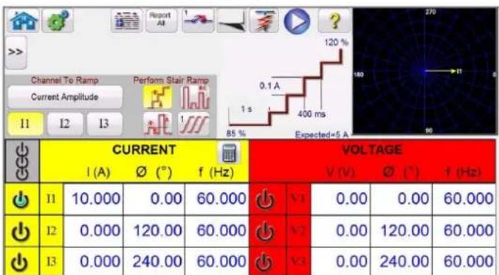
line
| Channel To Ramp Current Amplitude | I1 | I2 | I3 | 85% | 1 s | 400 ms | Expected=5 A | |---|---|---|---|---|---|---|---| | CURRENT | 1 (A) | Ø (°) | f (Hz) | V1 | 0.00 | 0.00 | 60.000 | | VOLTAGE | V (V) | Ø (°) | f (Hz) | V2 | 0.00 | 120.00 | 60.000 | | I1 | 10.000 | 0.00 | 60.000 | V3 | 0.00 | 240.00 | 60.000 | | I2 | 0.000 | 120.00 | 60.000 | V4 | 0.00 | 120.00 | 60.000 | | I3 | 0.000 | 240.00 | 60.000 | V5 | 0.00 | 240.00 | 60.000 |Figure 93. EM Overcurrent Pickup Example
3.5.3.4 Pulse ramp binary search example
Note that in the example above, current channel I1 is selected, and set to a value of 10 Amperes. A stair step ramp is selected with three ramps.
The basic operation of the test is that the test set will apply twice (10 Amperes) of the Expected value of 5 Amperes for a prefault duration of 1 second. This will allow the EM disk to turn and close the trip contacts. A longer prefault duration maybe required depending on the Time Dial setting. The test current will be dropped by a percentage (using the default setting of 85% ) of the expected value before ramping starts. This will cause the trip contacts to open, and the ramp up will start at a test current of 4.25 Amperes ( 85% * 5A ). Binary Input #1 is programmed for Normally Open contacts to close. The increment is set to 0.1 Ampere, with a delay between steps of 400 milliseconds.
The second ramp is programmed as follows.
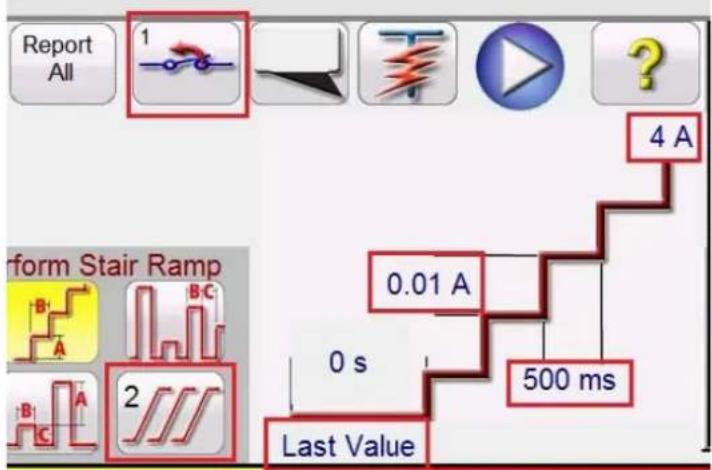
Figure 94. Second Ramp Settings
With the trip contacts closed it should be at a pickup value slightly greater than the Expected value of 5 Amperes. The second ramp is programmed to start ramping at the Last Value. It is programmed to start ramping down towards 4A as shown in the figure above. The increment for the second ramp is set to a value of 0.01A at a delay of 500ms between increments. Binary Input #1 is programmed to look for the trip contacts to open. With a smaller increment and longer delay between steps the trip contacts will just open before the third and final ramp begins.
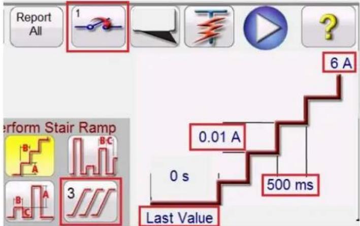
Figure 95. Third Ramp Settings
The third ramp is programmed to start ramping at the Last Value (where the contacts just opened). It is programmed to start ramping up towards 6A as shown in the figure above. The increment for the third ramp is set to a value of 0.01A at a delay of 500 ms between increments. Binary Input #1 is programmed to look for the trip contacts to close.
3.5.3.6 Instantaneous pickup example
When the relay trips the software will stop the ramp, turn the output off and report the pickup value. The user will have the option to Add to the Report.
3.5.3.6 Instantaneous Pickup Example
This example will use a pulse ramp to determine the trip contact pickup point of an instantaneous overcurrent relay. The example relay has a tap setting of 25 Amperes, and the trip contacts are Normally Open.

other
| Channel To Ramp Current Amplitude | Current Amplitude (A) | Current Amplitude (ms) | Current Amplitude (Hz) | Current Amplitude (V) | Current Amplitude (V1) | Current Amplitude (V2) | Current Amplitude (V3) | |---|---|---|---|---|---|---|---| | 1 | 0.000 | 0.00 | 60.000 | V1 | 0.00 | 0.00 | 60.000 | | 2 | 0.000 | 120.00 | 60.000 | V2 | 0.00 | 120.00 | 60.000 | | 3 | 0.000 | 240.00 | 60.000 | V3 | 0.00 | 240.00 | 60.000 |Figure 96. Instantaneous Pickup Example
The basic operation will apply a percentage (using the default setting of 85 %) of the Expected value when ramping starts (for the above example 21.25 Amperes). The increment is set to 0.5 Ampere, with a delay between steps of 400 milliseconds between pulses, with the fault current applied for 200 milliseconds duration. For relays with programmed delay associated with the instantaneous setting, the pulse duration time may need to be adjusted from the default of 200 milliseconds. In this example 0.5 Amperes is 2% of 25 Amperes, which should be acceptable in terms of resolution and accuracy. If a higher resolution or accuracy is required, then set the increment level to a smaller value. When the test starts the initial test current of 21.25 Amperes will be applied and the binary contacts should not be closed. The test current will drop back to 0 Amperes, then increment up again. It is important to note that the test current is returned to zero. If the device under test is an electromechanical "clapper" device, you want the moving element to drop back to its original position before applying the next incremented value. When the relay trips the software, will stop the ramp, turn the output off and report the pickup value. The user will have the option to Add to the Report.
3.5.4 Advanced Ramp Test

After selecting Advanced Ramp, if you want Simple Ramp instead of Advanced Ramp press or click on the more button and select Show Simple Ramp.
| CURRENT START VOLTAGE START | |||||||
| I (A) ∅ (°) f (Hz) | V (V) ∅ (°) f (Hz) | ||||||
| 11 | 0.000 | 0.00 | 60.000 | N1 | 0.00 | 0.00 | 60.000 |
| 12 | 0.000 | 120.00 | 60.000 | V2 | 0.00 | 120.00 | 60.000 |
| 13 | 0.000 | 240.00 | 60.000 | V3 | 0.00 | 240.00 | 60.000 |
Figure 97. Advanced Ramp Test Screen
3.5.4.1 Setting values
Advanced Ramp has similarities to the Simple Ramp. The primary differences are the Start, Increment, Stop values, and the addition of the Smooth Ramp.
3.5.4.1 Setting Values
Prefault, Ramp Start, Ramp Increment, and Ramp Stop values are entered by clicking on the appropriate button as shown in the following figure.

Figure 98. Advanced Ramp Settings
3.5.4.1.1 Show Prefault Conditions button
Press this button to select and enter the appropriate prefault values, including the prefault Time (the time that the prefault values will be applied prior to starting the ramp).
3.5.4.1.2 Show Ramp Start button
Press this button to select and enter the appropriate start ramp values. This value is where the ramping will start, which can be different from the prefault values.
3.5.4.1.3 Show Ramp Increment button
Press this button to select and enter the appropriate ramp increment values. If the smooth ramp is selected, the increments will be x/s, or increment / second as shown in the test screen as CURRENT's or VOLTAGE's. If the Stair Step or Pulse Ramp are selected it will read CURRENT INCREMENT or VOLTAGE INCREMENT.
3.5.4.1.4 Show Ramp End button
Press this button to enter the appropriate stop ramp values. This value is where the ramping will stop, regardless if the relay operated or not.
3.5.4.2 Smooth Ramp
The Smooth Ramp will ramp the output by applying a value based upon entry of an increment value / second. Depending on what is being ramped (Amplitude, Phase, or Frequency) the user must define the Start and Stop values being ramped. For example, to automatically ramp output current the user will, input Start and Stop Amplitudes, and an Increment Amperes / Second. Based upon the Start, Stop, and Increment / Sec settings, the software will automatically ramp values of the selected output which will result in a smooth ramp from the Start point to the Stop point.
3.5.5 Ramping Battery Simulator Output
-
On the FREJA Local display screen press the Manual Ramp Options button. In Channel Increment Selection Screen press or click on the Battery button. Select the desired increment level of the Battery Simulator, 1 or 5 volt increments. Press on the green check button.
-
Upon returning to the main test screen, note the Battery Simulator will be set for the value setting in the configuration screen. If another starting value is desired, go to the configuration screen and enter the starting value in the window provided, and press the green check button. For manual ramping press the \$ All ON / OFF
3.5.6 Overcurrent tests
button, note button turns green.
- Press the battery button and note that it changes to red indicating that the battery output is on, and it will have a yellow arrow through the box with the dc starting value to be ramped. Use the control knob (pc version use the cursor up down arrows or mouse control wheel) to vary the dc voltage output (clock wise increases the output). One click will equal the increment setting. To turn the battery simulator off, press the battery button. Note: If you have completed the test press the All ON / OFF button. Once the All ON / OFF button is off, the battery simulator can be turned on and off by pressing the battery button, but it cannot be varied.
3.5.6 Overcurrent Tests
By pressing the Overcurrent Timing button the Nameplate configuration screen will pop up.

Figure 99. Overcurrent Relay Tolerance Setup Screen
The user will see three buttons in the top of the screen:
- Electromechanical
- Include Pickup Tests
- Include Instantaneous Pickup Tests
The user can check one, two or all buttons or uncheck them in order to add or not to add the respective test button to the List of Tests to Run.



Figure 100. Test Selection buttons
When the Electromechanical button is checked, Include Target and Seal-In Tests button will appear and is available to be checked or leave it unchecked. If checked it provides the user the appropriate outputs necessary (typically 0.2 or 2A) to do a pickup and dropout test on an electromechanical overcurrent DC Target and Seal In relay.

Application Note: It is difficult to monitor the seal in contacts, therefore, it is up to the user to the contacts and press the SIM button when the seal in contacts close or open.
TOLERANCE Window
The user needs to enter the Manufacturer's Tolerance Specifications, which are found in the relay's user guide. The Absolute Error can be written in Seconds (s) or Cycles (Cy) by pressing on the button.
TEST window
The user needs to define the following:
3.5.6 Overcurrent tests
Prefault Time: Time duration for application of a Prefault current (for simulating load current)
Post fault Time: Amount of time the fault current will be applied after sensing trip (for breaker failure sensing).
Max On: Time the test will be performed (the maximum time the fault current will be applied)
Scaling: Used to scale for instantaneous currents greater than 60 Amperes (for FREJA). As an example, if the instantaneous setting is 75 Amperes, setting the scaling to 2 will result in a message appearing to parallel current channels 1 and 2 together. The test current will be divided equally between the two currents.
PT Connection: For voltage restrained overcurrent, enter Wye and Open Delta
Prefault Voltage Level: Enter the appropriate voltage level.
Plot vs. Multiple: The timing test will provide a graphic that will plot the Time vs. Multiples of Tap. Pressing the button will result in the graphic changing to Time vs. Current.
Once Tolerance and Test data are completed, pressing the green circle check button will take the user to the Elements setting window as shown below
ELEMENTS window
The user needs to define the Elements of the protective relay to be tested. The screen Defaults with Phase and Ground. Pressing the Number of Elements button will provide the user the ability to add up to 20 Elements, see the following figure.

Figure 101. Add up to 20 Elements
In the following example, two Elements were added, E3 and E4. Clicking in the E3 window shown below, type in Ph to Ph, and select the appropriate Phase to Phase elements (A-B, B-C, C-A). Clicking in the E4 window and type in 3 Phase, and select the Three Phase Element (ABC).

Figure 102. Selecting and Defining Multiple Elements

Figure 103. Phase Setting Screen
First, it should be noted that the Phase to Phase and Three Phase Element buttons in our previous example have been added to the row next to Phase and Ground buttons. Therefore, any Elements added will appear here to enter settings. Selecting the double ramp will open the Dropout value window as shown in the above example. Therefore, when performing the Phase Pickup test, both pickup and dropout tests will be performed.
3.5.6.1 Curve Selection button
Pressing the default ANSI / IEC curve button will provide access to all the overcurrent time curves. Curves include ANSI, IEC and IEEE Standard time curves as well Relay Manufacturers.

Figure 104. Time Curve Selection Screen
3.5.6.1.1 Manufacturer's Model button
Selecting a manufacturer will provide access to all models available for that manufacturer.
3.5.6.1.2 Relay's Curve and Direction per Element – Selection and Configuration

Figure 105. Relay Model by Brand Selection Screen
3.5.6.1.2 Relay's Curve and Direction per Element – Selection and Configuration
Press Definite Time to select the appropriate time curve for the relay under test.

Figure 106. Curve button location (Red boxed) for the GE SR745 Phase Screen

Figure 107. Available Curves List (Options depends on previously selected relay)
Press Direction button in Relay Settings Screen to select the element of protection, namely Directional (Forward or Reverse) and Bidirectional depending on type of relay under test.
3.5.6.1.2 Relay's Curve and Direction per Element – Selection and Configuration
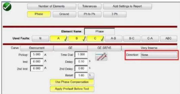
Figure 108. Direction button location (Red boxed) for the GE SR745 Phase Screen
Three options can be selected: None, Reverse and Forward.
Figure 109. Direction Options List
Leaving it defaulted to None, the user will be able to perform a test on a bidirectional relay (50 / 51).
Selecting Reverse or Forward button, user will be able to perform a test on a directional relay (67). MTA, Blinder and Reference Voltage options are available when one of these buttons is pressed. See the following figure.

Figure 110. Directional Parameters Screen
Directional: For testing directional overcurrent relays which require a voltage to be applied to polarize and close the directional element, click on the Direction button to provide the directional settings. The user needs to enter the desired fault voltage if required, and set the CT polarity (current in or out of polarity) by clicking on the following button

3.5.6.1.2 Relay's Curve and Direction per Element – Selection and Configuration
This will automatically set the phase angle relationship of either 0 or 180 degrees for the output current relative to the voltage fault.
Pickup: The user can select if there are both pick up and dropout tests by clicking on the Ramp button changing single ramp to double ramp up and down for pickup and dropout.

Reset Time: It is a numerical value of time, normally associated with electromechanical relays. This is the amount of time required for the operating disk to reset. If multiple timing tests are to be conducted on a relay, the test system will wait the Reset Seconds value prior to applying the next timing test. Numerical relays also can have programmable reset times to coordinate with electromechanical relays. User can define the Reset time interval among tests in seconds or cycles. The previous selection affects the Delay and 2nd Delay measurement unit.
Note, if the Reset Seconds is set too short, and the disk does not completely reset, then timing error will be introduced to the test. This note applies only for electromechanical relays.
Use Phase Compensation: Enable this button when performing single phase, or phase-to-phase tests on three phase relays, when you do not want to operate the ground element.
Apply Prefault Before Test: Enable this button to apply prefault voltage values for relays with directional elements to get proper polarization prior to applying the fault condition.
Reference V: Allows the user to define the reference voltage level and angle for directional elements. User can select phase to earth, phase to phase, or Zero sequence.
Figure 111. Phase Reference Selection buttons
Directional Ref: Defaults to Reference, where A Phase voltage will be reference angle in the phase angles displayed in the directional tests. Click or press on the Reference button will enable Actual, where angles displayed are based upon the phase tested, i.e. B Phase.
MTA (Maximum Torque Angle): The maximum torque angle (MTA) is defined as the angle by which the current applied to the relay must be displaced from the voltage applied to the relay to produce maximum torque.
The voltage reference is used to determine the polarizing signal for the overcurrent directional element. The signal polarizing will be determined by comparing the phase angle between the current from the phase and VA-B or VA-N, and set MTA angle in the relay.
| PHASE | OPERATING SIGNAL | POLARIZING SIGNAL Vpol | |
| ABC PHASE SEQUENCE | ACB PHASE SEQUENCE | ||
| A | Angle of Ia | Angle of Vbc × (Angle of MTA) | Angle of Vcb × (Angle of MTA) |
| B | Angle of Ib | Angle of Vca × (Angle of MTA) | Angle of Vac × (Angle of MTA) |
| C | Angle of Ic | Angle of Vab × (Angle of MTA) | Angle of Vba × (Angle of MTA) |

As figure shows for overcurrent directional will operate, when angle current reach the polarizing voltage, this polarizing voltage comes from VA-B reference voltage angle previously configured by user, plus MTA configured in the relay and the software.
$$ \mathrm{VPol} = \mathrm{VBC} \times (1 \angle \text { MTA }) = \text { Polarizing Voltage } $$
$$ I A = O p e r a t i n g C u r r e n t $$
$$ \mathrm{MTA} = \text { Element Characteristic Angle at } 3 0 ^ {\circ} $$
If user use a reference voltage angle VAG, the current operating will be calculated the same way than VAB reference voltage angle. The relay will operate by comparing the angle between current and polarizing voltage. One more time:
$$ \mathrm{VPol} = \text { VAN } \times (1 \angle \text { MTA }) = \text { Polarizing Voltage } $$
Blinders: Is the zone limited by the angles between VPol and the angles previously configured by user. Note there are two angles that the user can enter. They are defaulted to 90 and 0 degrees.
Once the Curve type and its parameters (Pickup, Time Dial, Inst, 2nd Inst, Delay, 2nd Delay) and Direction Type and its parameters (Reset, MTA, Blinders, Reference – Elements, Voltage and Angle) has been selected and configured, the user needs to press the Green Circle Check button

3.5.6.1.3 Run Test Screen
The depending on the Elements, by default the first test will start with the Phase Pickup.
Figure 112. Run Test Screen
Pressing this button the user will be presented with a list of available tests depending on what Elements were originally defined by the user.

flowchart
graph TD
    A["Phase Pickup"] --> B["Phase Timing"]
    C["Phase Instantaneous"] --> D["Phase Directional"]
    E["Neutral Pickup"] --> F["Neutral Timing"]
    G["Neutral Instantaneous"] --> H["Neutral Target and Seal In"]
    I["Neutral Directional"] --> J["Ground Pickup"]
    K["Ground Timing"] --> L["Ground Instantaneous"]
    M["Ground Target and Seal In"] --> N["Ground Directional"]
Figure 113. Example of Elements Test List
The user can execute them pressing the Run Single Test Arrow button, which opens the dialog box to choose among the options available. See the following figure.

Figure 114. Example Phase Element Test Selection Screen
This dialog box allows the user to perform phase test individually, or to perform Run All Phases Tests in a row.
3.5.6.1.3.2 ② Relay Settings button
Press this button to access selection of the Relay's Settings Screen. Here the user can adjust parameters such as Curve / Pick up / Time Dial / Instantaneous / Delay / Direction, etc.
3.5.6.1.5.3 Battery simulator button
3.5.6.1.5.3 ③ Battery Simulator button

The Battery Simulator button – Turns the Battery Simulator ON and OFF by pressing the button, the background color changes red for ON and gray for OFF. The voltage to be applied is displayed in the button and can be changed by pressing the configuration button
3.5.6.1.5.4 ④ Binary Input Setting button

Press this button to reveal the Binary Input Dialog box.
3.5.6.1.5.5 ⑤ Report Options button

Press or click on this button to view or delete current test results.
3.5.6.1.5.6 ⑥ Run a Predefined Test button

Pressing the Predefined Test button provides access to Predefined Tests, created by either Megger or users.
3.5.6.1.6 Performing Tests
The system is ready to select and perform tests. The following are example tests for Phase and Ground Elements. Based upon the values entered by the user in the settings screen, the software will automatically perform Pass √ or Fail × evaluation on all tests.
3.5.6.1.6.1 Phase Pickup button
Phase Pickup
Press this button to go to Phase Pickup Test Screen
Figure 115. Example Phase Pickup and Dropout Test Screen
This example includes the dropout test, see Figure 81 for example selection and settings.
3.5.6.1.6.2 Phase Timing button
Phase Timing
Press this button to go to Phase Timing Test Screen
3.5.6.1.6.3 Phase instantaneous bsutton

line
Manufacturer: GE Model/Curve GE SR745/Very Inverse Phase Timing (click on the row num. for options) | Multiplex of Top | Test Current (A) | Min Time (s) | Max Time (s) | A Time (s) | B Time (s) | C Time (s) | |---|---|---|---|---|---|---| | 1 | 2.00 | 10.00 | 6.297 | 6.900 | 6.333 | 6.318 | | 2 | 3.00 | 15.00 | 2.553 | 2.821 | 2.621 | 2.667 | | 3 | 5.00 | 25.00 | 1.235 | 1.385 | 1.263 | 1.248 | | 4 | | | | | | | Time (s) Multiplex of Top | Time (s) | | 1 2 3 4 5 6 7 8 9 10 11 12 13 14 15 16 17 18 19 20 21 22 23 24 25 26 27 28 29 30 31 32 33 34 35 36 37 38 39 40 41 42 43 44 45 46 47 48 49 50 51 52 53 54 55 56 57 58 59 60 61 62 63 64 65 66 67 68 69 70 71 72 73 74 75 76 77 78 79 80Figure 116. Example Phase Timing Test Screen
This screen allows the user to run phase time overcurrent test previously configured and see the test results. During the test the user will see the test time vector moving in real time at the desired test multiple. In the left hand side of the test screen the user will the test current being applied and the timer is running. When the relay trips the test time is recorded and the Pass / Fail evaluation is automatically displayed.
For the phase timing overcurrent test, the user can execute thee test by pressing the Run Single Test button , it opens the dialog box to choose among the options available. The user can change value of the test Multiple by clicking in the desired cell to change the value of multiple (times pickup). To add more test points the user presses or clicks in the blank Multiple window and enters the desired value. The software will automatically calculate the min and max allowable time based upon the manufacturer's time curve. If user runs a phase timing overcurrent test and the test reaches the max time on, then a text box will appear "max time on exceeded". The test example above shows only single-phase time elements. You can also have phase to phase and / or three phase timing tests depending on the user inputs.
3.5.6.1.6.3 Phase Instantaneous button
Phase Instantaneous
Press this button to go to Phase Instantaneous Test Screen
| # | Unit | Setting | Minimum | Maximum | Actual | ✓/✗ |
| (A) | (A) | (A) | (A) | |||
| 1 | A | 50.000 | 47.500 | 52.500 | 50.000 | ✓ |
| 2 | B | 50.000 | 47.500 | 52.500 | 50.000 | ✓ |
| 3 | C | 50.000 | 47.500 | 52.500 | 50.000 | ✓ |
Figure 117. Example Phase Instantaneous Test results
For phase instantaneous overcurrent tests, the user can execute them pressing the Run Single Test button, it opens the dialog box to choose among the options available. When user sets a current test higher than amplifier capability and try to run the test, a warning window will appear explaining why the test won't run. The user can reduce the test requirements or wire channels into a parallel connection. See figure below.
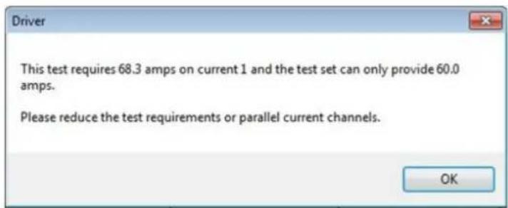
Figure 118. Warning Message
3.5.6.1.6.4 Phase Directional button
Phase Directional
Press this button to go to Phase Directional Test Screen

pie
Manufacturer: GE Model/Curve GE SR745/Very Inverse Phase Directional | # | m (mm) | Angle Setting (°) | Min. Angle (°) | Max. Angle (°) | Binder1 Angle (°) | Binder2 Angle (°) | Average Angle (°) | Actual Angle (°) | |---|---|---|---|---|---|---|---|---| | 1 | A | 70.00 | 65.00 | 75.00 | 159.76 | 339.76 | 248.76 | 69.78 | | 2 | B | 70.00 | 65.00 | 75.00 | 280.00 | 460.48 | 370.24 | 70.24 | | 3 | C | 70.00 | 65.00 | 75.00 | 399.76 | 580.60 | 490.18 | 70.18 | The image contains two charts: a pie chart for the angle measurement and a radar chart for the angular measurement.Figure 119. Phase Directional Test Screen
In this screen user can execute the Phase Directional test by pressing the Run Single Test button. In the right hand side of the test screen, the user will see the test phasor moving in real time, and in the left hand side see the actual test values changing. When the test is completed, the Max Angle of Torque (MTA) is calculated and displayed. Pass / Fail is indicated in the View Report by pressing the Reports Options button

3.5.6.1.6.4.1 Phase Directional Shot button
Press this button to go to Phase Directional Shot Test Screen. To create test points, click in the characteristic window above and below the directional characteristic. The following is an example with six test points, three above and three below the directional line.
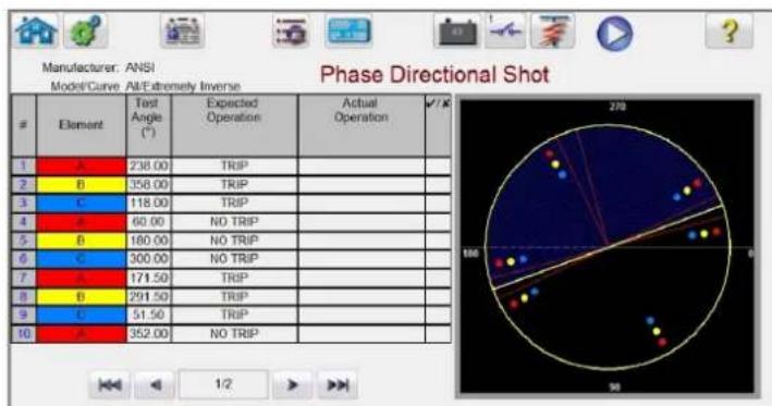
pie
Manufacturer: ANSI Model/Curve All-Extremely Inverse Phase Directional Shot | # | Element | Test Angle (°) | Expected Operation | Actual Operation | √/K | |---|---|---|---|---|---| | 1 | A | 238.00 | TRIP | | | | 2 | B | 358.00 | TRIP | | | | 3 | C | 118.00 | TRIP | | | | 4 | D | 60.00 | NO TRIP | | | | 5 | B | 180.00 | NO TRIP | | | | 6 | C | 300.00 | NO TRIP | | | | 7 | A | 171.50 | TRIP | | | | 8 | B | 291.50 | TRIP | | | | 9 | C | 51.50 | TRIP | | | | 10 | E | 352.00 | NO TRIP | | | The image contains two charts: a pie chart for 'Phase Directional Shot' showing the distribution of 'TRIP' values across categories, and a radar chart for '1/2' showing the same data points. The numbers above the charts are explicitly labeled as '270'.Figure 120. Phase Directional Shot Test Screen
3.5.6.1.6.5 Ground pickup button
This is a Trip or No Trip test. Up to 50 test points can be selected. Note that additional pages will be added with more test points. Execute the test by pressing the Blue Run Test button. When the test is completed, Pass / Fail is indicated in the right column with a √ or ✗. View Test Report by pressing the Reports Options button
3.5.6.1.6.5 Ground Pickup button
Ground Pickup
Press this button to go to Ground Pickup Test Screen

Figure 121. Example Ground Pickup Test
3.5.6.1.6.6 Ground Timing button
Press this button to go to Ground Timing Test Screen

line
Manufacturer: GE Model/Curve GE SR745/Very Inverse Ground Timing (click on the row num. for options) | Numbers | Test Current (A) | Min. Time (s) | Max. Time (s) | N Time (s) | ✓/X | |---|---|---|---|---|---| | 1 | 2.00 | 10.00 | 1.259 | 1.392 | 1.311 ✓ | | 2 | 3.00 | 16.00 | 0.511 | 0.587 | 0.530 ✓ | | 3 | 5.00 | 25.00 | 0.247 | 0.310 | 0.297 ✓ | | 4 | | | | | | Multiples Of Top Time (s)Figure 122. Example Ground Timing Test Screen
This screen allows user to run ground time overcurrent test previously configured and see the test results. During the test the user will see the test time vector moving in real time at the desired test multiple. In the left hand side of the test screen the user will the test current being applied and the timer is running. When the relay trips the test time is recorded and the Pass / Fail evaluation is automatically displayed.
For ground timing overcurrent test, the user can execute the test by pressing the Run Single Test button, it opensthe dialog box to choose among the options available. The user can change value of the test Multiple by clicking in the desired cell to change the value of multiple (times pickup). To add more test points the user presses or clicks in the blank Multiple window and enters the desired value. The software will automatically calculate the min and max allowable time based upon the manufacturer's time curve. If user runs a phase timing overcurrent test and the test reaches the max time on, then a text box will appear: "max time on exceeded". This means than object under test did not operate.
3.5.6.1.6.7 Ground Instantaneous button
Ground Instantaneous
Press this button to go to Ground Instantaneous Test Screen

Figure 123. Example Ground Instantaneous Test Screen
For ground instantaneous overcurrent tests, the user can execute the test by pressing the Run Single Test button, it opens the dialog box to choose among the options available. If a user sets a current test higher than amplifier capability and try to run the test, a warning window will appear explaining why it will not run the test (this is because the required test current value is higher than the amplifier capability). The user can reduce the single channel test current requirement or wiring into a parallel connection channels. See figure below.

Figure 124. Example Warning Message
3.5.6.1.6.8 Ground Directional button

Press this button to go to Ground Directional Test Screen
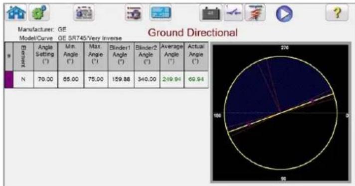
pie
Manufacturer: GE Model/Curve GE SR745/Very Inverse Ground Directional | # | M (R) | Angle Setting (°) | Min Angle (°) | Max Angle (°) | Blinder1 Angle (°) | Blinder2 Angle (°) | Average Angle (°) | Actual Angle (°) | |---|---|---|---|---|---|---|---|---| | N | 70.00 | 85.00 | 75.00 | 159.86 | 340.00 | 249.94 | 69.94 | 270 | 106 90Figure 125. Example Ground Directional Test Screen
In this screen user can execute the Ground Directional test by pressing the Blue Run Test button. In the right hand side of the test screen the user will see the test phasor moving in real time, and in the left hand side see the actual test values changing. When the test is completed, the Max Angle of Torque (MTA) is calculated and displayed. Pass / Fail is indicated in the View Test Report by pressing the Report Options button
3.5.6.1.6.8.1 Ground Directional Shot button

Press this button to go to Ground Directional Shot Test Screen. To create test points, click in the characteristic window above and below the directional characteristic. The following is an example with six test points, three above and three below the directional line.
3.5.6.1.6.9 Ground target and Seal-In button
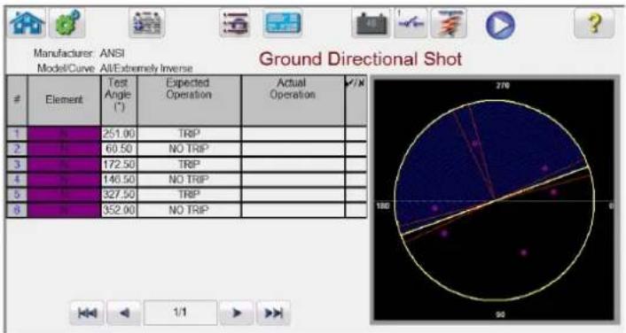
pie
Manufacturer: ANSI Model/Curve: All/Extremely Inverse | # | Element | Test Angle (°) | Expected Operation | Actual Operation | /N | |---|---|---|---|---|---| | 1 | Yes | 251.00 | TRIP | | | | 2 | No | 60.50 | NO TRIP | | | | 3 | Yes | 172.50 | TRIP | | | | 4 | No | 146.50 | NO TRIP | | | | 5 | Yes | 327.50 | TRIP | | | | 6 | No | 352.00 | NO TRIP | | | Ground Directional Shot 1/1Figure 126. Phase Directional Shot Test Screen
This is a Trip or No Trip test. Up to 50 test points can be selected. Note that additional pages will be added with additional test points. Execute the test by pressing the Blue Run Test button. When the test is completed, Pass / Fail is indicated in the right column with a √ or ✗. View Test Report by pressing the Report Options button 📄.
3.5.6.1.6.9 Ground Target and Seal-In button
Ground Target and Seal In
Press this button to go to Ground Target and Seal-In Test Run Screen

Figure 127. Example Ground Target and Seal In test screen
The software will show a warning message with the Connection Guidance that need to be verified prior to running the test. Since there are no readily available contacts to monitor, the user will be instructed to press the simulate button during this test when contacts close and open. Pressing the Blue Run Test button a message window will appear instructing the user to press the simulate button when the relay trip contacts close. DC current will then be applied to the DC target and seal-in unit. Another message will instruct the user to press the simulate button when the DC target drops / picks up. Another message will appear instructing the user to press the simulate button when the DC targets drops out as the DC current is lowered.
3.5.7 Testing Over Voltage Relays
Pressing the Over Voltage Timing button will go to the Relay Elements and Tolerance Setup Screen,
3.5.7 Testing over voltage relays

Figure 128. Relay Tolerance Setup Screen
The user will see three buttons on top of screen:
- Electromechanical
- Include Pickup Tests
- Include Instantaneous Pickup Tests
The user can check one, two or all buttons or uncheck them in order to add or not to add the respective test button to the List of Tests to Run.

Figure 129. Test Selection buttons
When Electromechanical button is checked, Include Target and Seal-In Tests button will appear and is available to be checked or leave it unchecked. If checked it provides the user the appropriate outputs necessary (typically 0.2 or 2A) to do a pickup and dropout test on an electromechanical DC Target and Seal In relay.

Application Note: It is difficult to monitor the seal in contacts, therefore, it is up to the user to have the contacts and press the SIM button when the seal in contacts close or open.
Tolerance Settings
The user needs to enter the Manufacturer's Tolerance Specifications, which are found in relay's user guide. The
Absolute Error can be written in Seconds (s) or Cycles (Cy) by pressing on the s button.
The user needs to define the following:
Prefault Time: Time duration for application of a Prefault voltage (for simulating normal condition)
Post fault Time: Amount of time the fault voltage will be applied after sensing trip.
Max On: Time the test will be performed (the maximum time the fault voltage will be applied)
Prefault Voltage Level: Enter the appropriate voltage level.
Plot vs. Voltage: The timing test will provide a graphic that will plot the Time vs. Voltage. Pressing the button will result in the graphic changing to Time vs. Multiples of Tap.
Once tolerance, test data are completed, pressing the green circle check button will take the user to the Phase setting window as shown below.
3.5.7.1 Manufacturer selection button
Number of Elements button
The user needs to define the elements of the protective relay to be tested. The screen has ten Elements windows available. Pressing the Elements button will display the following screen. Overvoltage is default, with nine of the Elements blank. If the relay has phase to phase and three phase over voltage elements, they can be easily added to the blank Element windows.

Figure 130. Overvoltage Phase Element Setting Screen
Selecting the double ramp will open the Dropout value window as shown in the above example. Therefore, when performing the Phase Pickup test, both pickup and dropout tests will be performed.
Tolerances button takes you back to the tolerance-setting screen.
3.5.7.1 Manufacturer Selection button
Pressing the default ABB / WEST curve button will provide access to the overvoltage time curves. Curves include Basler, GE and IEC Standard time curves.

Figure 131. Voltage Relay Manufacturer Selection Screen
3.5.7.2 Manufacturer's Model button
Selecting a manufacturer will provide access to all models available for that manufacturer.
Figure 132. Example ABB / WEST Relay Model Selection Screen
3.5.7.3 Run Test Screen
The depending on the Elements, by default the first test will start with the Phase Pickup.

Figure 133. Overvoltage Phase Pickup Test Screen
3.5.7.3.1 ① Change Test button
Pressing this button the user will be presented with a list of available tests depending on what Elements were originally defined by the user.

Figure 134. Example of Elements Test List
The user can execute them pressing the Run Single Test button, which opens the dialog box to choose among the options available. See the following figure.
3.5.7.3.2 Relay settings button

Figure 135. Example Phase Element Test Selection Screen
This dialog box allows the user to perform phase test individually, or to perform Run All Phases Tests in a row.
3.5.7.3.2 ② Relay Settings button

Press this button to access selection of the Relay's Settings Screen. Here the user can adjust parameters such as Curve / Pick up / Time Dial / Instantaneous / Delay, etc.
3.5.7.3.3 ③ Battery Simulator button

The Battery Simulator button – Turns the Battery Simulator ON and OFF by pressing the button, the background color changes red for ON and gray for OFF. The voltage to be applied is displayed in the button and can be changed by pressing the configuration button
3.5.7.3.4 ④ Binary Input Setting button

Press this button to reveal the Binary Input Dialog box.
3.5.7.3.5 ⑤ Report Options button

Press or click on this button to view or delete current test results.
3.5.7.3.6 ⑥ Run Predefined Test button

Pressing the Run Predefined Test button provides access to Predefined test plans, created by either Megger or users, in Pdb Tst file structure.
3.5.7.4 Performing Tests
The system is ready to select and perform tests. The following are example tests for Phase Elements. Based upon the values entered by the user in the settings screen, the software will automatically perform Pass √ or Fail × evaluation on all tests.
3.5.7.4.1 Phase Pickup button
Phase Pickup
Press this button to go to Phase Pickup Test Screen
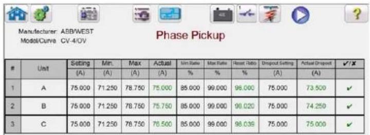
Figure 136. Example Phase Pickup and Dropout Test Screen
This example includes the dropout test.
3.5.7.4.2 Phase Timing button
Phase Timing
Press this button to go to Phase Timing Test Screen
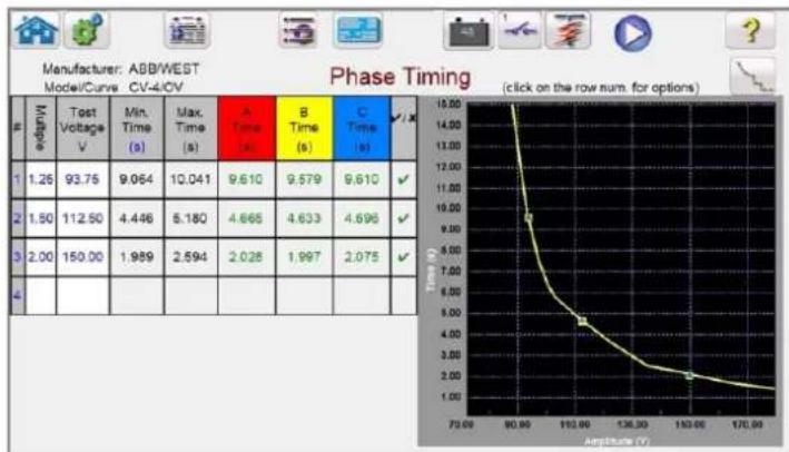
line
Manufacturer: ABB/WEST Model/Curve CV-4/0V Phase Timing | Amplitude (V) | 1.26 | 1.50 | 2.00 | | | :--- | :--- | :--- | :--- | :--- | | 70.00 | 93.75 | 112.50 | 150.00 | | | 80.00 | 9.064 | 4.446 | 1.989 | | | 110.00 | 9.610 | 4.665 | 2.594 | | | 130.00 | 9.579 | 4.633 | 2.028 | | | 150.00 | 9.610 | 4.696 | 2.075 | | The chart displays a single line graph of 'Time' (s) on the Y-axis against 'Amplitude (V)' on the X-axis, with values decreasing from left to right in the grid. The label 'Phase Timing' is marked at the top right corner.Figure 137. Example Phase Timing Test Screen
This screen allows the user to run phase time over voltage test previously configured and see the test results. During the test the user will see the test time vector moving in real time at the desired test multiple. In the left hand side of the test screen the user will see the test voltage being applied and the timer is running. When the relay trips the test time is recorded and the Pass √ / Fail × evaluation is automatically displayed.
For phase timing over voltage test, the user can execute them pressing the Run Single Test button. It opens the dialog box to choose among the options available. The user can change value of the test Multiple by clicking in the desired cell to change the value of multiple (times pickup). To add more test points the user presses or clicks in the blank Multiple window and enters the desired value. The software will automatically calculate the min and max allowable time based upon the manufacturer's time curve. If user runs a phase timing over voltage test and the test reaches the max time on, then a text box will appear "max time on exceeded". The test example above shows only single-phase time elements. You can also have phase to phase and / or three phase timing tests depending on the user inputs.
3.5.7.4.3 Phase Instantaneous button
Phase Instantaneous
Press this button to go to Phase Instantaneous Test Screen
3.5.8 Testing under voltage relays
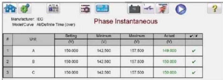
Figure 138. Example Phase Instantaneous Test results
For phase instantaneous over voltage tests, the user can execute them pressing the Run Single Test button opens the dialog box to choose among the options available.

3.5.8 Testing Under Voltage Relays
Pressing the Under Voltage Timing button will go to the Relay Elements and Tolerance Setup Screen,
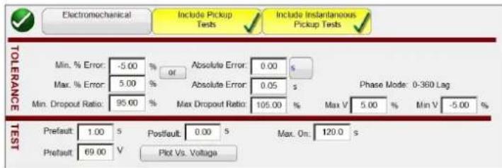
Figure 139. Under Voltage Relay Tolerance Setup Screen
The user will see three buttons on the top of the screen:
- Electromechanical
- Include Pickup Tests
- Include Instantaneous Pickup Tests
The user can check one, two or all buttons or uncheck them in order to add or not to add the respective test button to the List of Tests to Run.



Figure 140. Test Selection buttons
When the Electromechanical button is checked, Include Target and Seal-In Tests button will appear and is available to be checked or leave it unchecked. If checked it provides the user the appropriate outputs necessary (typically 0.2 or 2A) to do a pickup and dropout test on an electromechanical DC Target and Seal In relay.

Application Note: It is difficult to monitor the seal in contacts, therefore, it is up to the user to use the contacts and press the SIM button when the seal in contacts close or open.
Tolerance Settings
The user needs to enter the Manufacturer's Tolerance Specifications, which are found in relay's user guide. The
3.5.8.1 Manufacturer selection button
Absolute Error can be written in Seconds (s) or Cycles (Cy) by pressing on the button.
The user needs to define the following:
Prefault Time: Time duration for application of a Prefault voltage (for simulating normal condition)
Post fault Time: Amount of time the fault voltage will be applied after sensing trip.
Max On: Time the test will be performed (the maximum time the fault voltage will be applied)
Prefault Voltage Level: Enter the appropriate voltage level.
Plot vs. Voltage: The timing test will provide a graphic that will plot the Time vs. Voltage. Pressing the button will result in the graphic changing to Time vs. Multiples of Tap.
Once tolerance, test data are completed, pressing the green circle check button will take the user to the Phase setting window as shown below.
Number of Elements button
The user needs to define the elements of the protective relay to be tested. The screen has ten Elements windows available. Pressing the Elements button will display the following screen. Under voltage is default, with nine of the Elements blank. If the relay has phase to phase and three phase over voltage elements, they can be easily added to the blank Element windows.

Figure 141. Under Voltage Phase Element Setting Screen
Any Elements added will appear here, next to the Undervoltage button, to enter settings. Selecting the double ramp will open the Dropout value window. Therefore, when performing the Phase Pickup test, both pickup and dropout tests will be performed.
3.5.8.1 Manufacturer Selection button
Pressing the default ABB / WEST curve button will provide access to the under voltage time curves. Other Manufacturers include Basler, GE and IEC Standard time curves.
3.5.8.2 Manufacturer's model button

Figure 142. Voltage Relay Manufacturer Selection Screen
3.5.8.2 Manufacturer's Model button
Selecting a manufacturer will provide access to all models available for that manufacturer.

Figure 143. Example ABB / WEST Relay Model Selection Screen
3.5.8.3 Run Test Screen
The depending on the Elements, by default the first test will start with the Phase Pickup.

Figure 151. Run Test Screen
3.5.8.3.1 ① Change Test button
Pressing this button, the user will be presented with a list of available tests depending on what Elements were originally defined by the user.
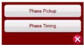
Figure 144. Example of Elements Test List
The user can execute them pressing the Run Single Test button, which opens the dialog box to choose among the options available. See the following figure.

Figure 145. Example Phase Element Test Selection Screen
This dialog box allows the user to perform phase test individually, or to perform Run All Phases Tests in a row.
3.5.8.3.2 ② Relay Settings button

Press this button to access selection of the Relay's Settings Screen. Here the user can adjust parameters such as Curve / Pick up / Time Dial / Instantaneous / Delay, etc.
3.5.8.3.3 ③ Battery Simulator button

The Battery Simulator button, turns the Battery Simulator ON and OFF by pressing the button. The background color changes red for ON and gray for OFF. The voltage to be applied is displayed in the button and can be changed by pressing the configuration button
3.5.8.3.4 ④ Binary Input Setting button

Press this button to reveal the Binary Input Dialog box.
3.5.8.3.5 ⑤ View Test Results button

Press or click on this button to view or delete current test results.
3.5.8.3.6 ⑥ Run Predefined Test button

Pressing the Run Predefined Test button provides access to Predefined test plans, created by either Megger or users, in Pdb Tst file structure.
3.5.8.4 Performing Tests
Phase Pickup
The system is ready to select and perform tests. The following are example tests for Phase Elements. Based upon the values entered by the user in the settings screen, the software will automatically perform Pass √ or Fail × evaluation on all tests.
3.5.8.4.1 Phase pickup button
3.5.8.4.1 Phase Pickup button
Press this button to go to Phase Pickup Test Screen
| # | Unit | Setting | Minimum | Maximum | Actual | ✓/✗ |
| (V) | (V) | (V) | (V) | |||
| 1 | A | 60.000 | 57.000 | 63.000 | 66.000 | ✗ |
| 2 | B | 60.000 | 57.000 | 63.000 | 66.000 | ✗ |
| 3 | C | 60.000 | 57.000 | 63.000 | 66.000 | ✗ |
Figure 146. Example UV Phase Pickup Test Screen
3.5.8.4.2 Phase Timing button Phase Timing
Press this button to go to Phase Timing Test Screen

line
Manufacturer: ABB/WEST Model/Curve CV_UV_(GEARED)/CV_UV_(GEA) Phase Timing (click on the row num for options) | Time (s) | Value | |---|---| | 1 | 0.88 | | 2 | 0.80 | | 3 | 0.70 | | 4 | | | | | | | | | | | | | | | | | | | | | | | | | | | | | | | | | | | | | | | | | | | | | | | | | | | - | | | | | | | | | | | | | | | | | | | | | | | | | | | | | | | | | | | | | | | | | | | | | | | | | | The chart displays a single line graph (likely a line graph) with X-axis labeled '时间' (time) and Y-axis labeled '数值' (value). The data series includes three distinct lines: a red line (labeled 'A'), a yellow line (labeled 'B'), and a green line (labeled 'C'). The line color corresponds to the value at each point in the table. The chart is annotated with 'Phase Timing' and ' click on the row num for options'.Figure 147. Example UV Phase Timing Test Screen
This screen allows the user to run phase time under voltage test previously configured and see the test results. During the test the user will see the test time vector moving in real time at the desired test multiple. In the left hand side of the test screen the user will the test voltage being applied and the timer is running. When the relay trips the test time is recorded and the Pass / Fail evaluation is automatically displayed.
For phase timing under voltage test, the user can execute them pressing the Run Single Test button. It opens the dialog box to choose among the options available. The user can change value of the test Multiple by clicking in the desired cell to change the value of multiple (times pickup). To add more test points the user presses or clicks in the blank Multiple window and enters the desired value. The software will automatically calculate the min and max allowable time based upon the manufacturer's time curve. If user runs a phase timing under voltage test and the test reaches the max time on, then a text box will appear "max time on exceeded". The test example above shows only single-phase time elements. You can also have phase to phase and / or three phase timing tests depending on the user inputs, as shown in Figure 146.
3.5.9 State Sequencer Test 123..9
3.5.9.1 Reclosing Relay Testing
These tests should be conducted in accordance with the manufacturers relay specifications.
Press the Select New Test button: Get access to the State Sequencer Test. Pressing the button on the
test menu takes the user to the Sequencer Test Screen defined in the following screen.

Figure 148. Sequencer Test Screen
Max States: There are up to 100 programmable states available in the Max States setting window. The default setting is 10. By default, there are seven states already predefined and labeled as Prefault, Trip1, Reclose 1, etc. up to End of Test in step 7. Press the Next Step sequence button to move forward one-step in the sequence. It is initially setup for a three shot trip-reclose to lockout scenario. Another test application is a developing fault scenario, or use to perform dynamic end-to-end tests. The user is free to change the labels, or use the default labels. With each state, the user may input values of voltage, current, phase angle, frequency and set the binary input sensing for each state. Both single pole and three-pole trip can be simulated. There are default values and binary settings for a single phase trip and reclose scenario already programmed in. The user can either use the defaults or change them to suit the test application, as well as extend or shorten the number of states.
Iterations: There are up to 99,999 iterations of the programmed sequence available. The default is set to 1.
Press the Configure Timer button 📋 to view the Timer Setup Configuration screen and Labels. The user can view and set where each timer starts and stops in association with each trip and reclose operation (see the following figure).

Figure 149. Sequence Timers Settings and Labels Screen
Note that the Total Time to Lockout is also included in the setting and indicates where the total timer starts and stops. This allows for 1, 2, 3, 4 or more shots to lockout including reclose times. To change the Start and Stop conditions, press or click the appropriate windows. Start or Stop can be set using either the change of State, or Post, or None, see the following start example.
3.5.9.1 Reclosing relay testing

Figure 150. Timer Conditional State Post Selector
Pressing State the user will be presented with the number of States that were previously set by the user. The user can start or stop the timer when the sequencer steps to that State. Pressing Post, the timer will start or stop based upon the change of the defined binary input Post #, see section 3.1.12 for use of the Binary Input Dialog box. If desired, enter the appropriate minimum and maximum trip and reclose times in the spaces provided. At the end of the test, the test results will include the min, max, and Pass / Fail determination for each state.
Return to the Sequence test screen, to set the conditions for each change of state. Press the Wait Any button directly under the Timeout window. The user will be presented with several selections to choose from. These are the conditions that the unit will take in order to determine when to change to the next state, or end the sequence, see the following menu selection.

Figure 151. State Sequence Conditional Setting Screen
Wait ms – The unit will wait the milliseconds entered in the window before changing to the next state in the sequence.
Wait Cycles – The unit will wait the Cycles entered in the window before changing to the next state in the sequence.
Wait Any (Continue) – Wait for any of the configured binary inputs to be true and then continue with the sequence. Note that an input can be configured for the Wait Any (OR) and Wait All (AND) conditions by clicking on the binary inputs.
Wait Any (Abort) – The unit will wait for any of the configured binary inputs to be true, and then continue with the sequence. If no binary inputs become true before the Timeout setting value, the test will be aborted.
Wait All (Continue) – Wait for all selected binary input conditions to become true, or the Timeout is exceeded before continuing to the next state.
Wait All (Abort) – Wait for all selected binary input conditions to become true, or the Timeout is exceeded before continuing to the next state. If all selected binary inputs have not become true by the Timeout setting value, abort the test.
Wait IRIG – Connect the IRIG-B time source to Binary Input #1. Binary Input #1 has the capability to decode the IRIG-B
3.5.9.1 Reclosing relay testing
time. Select the Wait IRIG, and enter the desire time to start the test. The unit will wait the IRIG Time entered in the IRIG window before changing to the next state in the sequence (used for end-to-end tests).
POP – Some GPS units have a programmable output voltage trigger port to start a timing sequence, such as an end-to-end test. Connect the POP (Programmable Output Pulse) port from a GPS receiver to Binary Input #1. Selecting this option will change Binary Input #1 to voltage input trigger with the threshold set at 4 Volts. Note: The voltage threshold can be set to as low as 2 volts if required.
End - If the relay under test makes it to this state, end the test.
Press the Copy Paste button to copy any State configuration and paste it into another State. This tool is especially useful when repeating states such as multiple trip / reclose tests.
Pressing the Reset Phase button restores the phase relationship of all selected generators for the selected State.
Application Note: Use of the Reset Phase button is recommended when performing an End-to-End test, so that both test systems are in the same known phase angle relationship at the start of the test. This is also useful when the frequency of a generator is changed from one state to another, its phase relationship to the other generators will be unpredictable. By restoring the phase relationship for the state change in frequency, the frequency change takes place at a known phase angle relationship to the other phases.
To set the Binary Outputs to simulate the 52a and / or 52b contacts press the Binary more button next to the Binary Inputs to expand the selection window. In the prefault state you may choose to have Binary Output 1 contact in the closed condition to simulate breaker closed. Click on Binary Output 1 and the binary output setting window will appear. The default setting is Open. Click on the Close Contact Button to simulate breaker closed. Note the Name in the window is defaulted to 1. The user is free to rename it to any value such as 52a. To rename the binary inputs or outputs, press or click in the Name window, and the virtual keyboard will appear. Up to six characters will appear in the binary window in the test screen. Press or click on the green check button to return to the test screen.

Figure 152. Binary Output Setting Screen
Once all of the Binary Inputs, Outputs, Prefault, Fault and Reclose settings are completed, the user can then press the Preview button to get a visual representation of the voltage and current outputs, as well as a visual of the binary inputs and outputs for each stage of the simulation. The following figures illustrate an example trip and reclose sequence.
3.5.9.2 Transient Earth-Fault (TEF) simulator
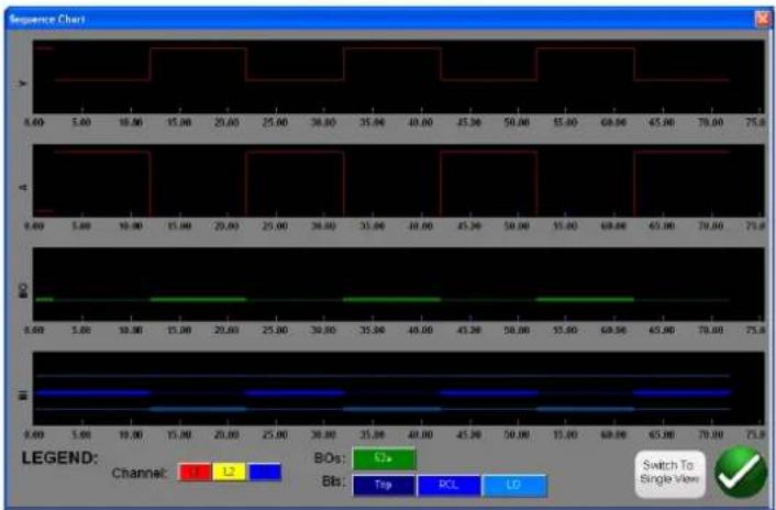
line
| Channel | Value | |---------|-------| | LE | 1 | | L | 2 | | BOS | C+, Bts: Trip, RCL, LO | | Switch To Single View | ✓ |Figure 153. State Sequence "Split View" Preview Screen
There are two views available to the user. One view is called the "Single View" where all the voltages, currents, binary inputs and outputs are overlaid. In the above figure a single phase 4 trip and reclose is shown in the "Split View", where the voltages, currents, binary inputs and outputs are split up like a fault recording. The red color is the magnitude of Channel 1(faulted phase) voltage and current outputs. The fat / thin lines represent the binary inputs and outputs per the colors defined in the legend. A "fat" line indicates contacts are closed, and a thin line indicates that the contacts are open. When the fault current is applied, you can see when the trip contacts closed and when the binary output contact opened. When the "breaker" opens you can see the current going to zero. When the breaker closes you see the current being reapplied and then repeat the trip and reclose cycle until lockout. The user can toggle back and forth between the two views by pressing the Switch to Single View / Split View button in the lower right corner of the screen. To exit this screen, press the green check button to return to the State Sequence screen.
To execute the test press the Blue Run Test button. Save and review test results as previously discussed.

Figure 154. Example Sequencer 4 Shot Trip and Reclose
3.5.9.2 Transient Earth-Fault (TEF) Simulator
The Transient Earth Fault simulator is designed for testing the directional operating characteristics of transient and intermittent transient earth fault relays by simulating residual current IO and residual voltage V0 transient signals. The intermittent test feature simulates intermittent transient faults found in compensated cable networks. These types of faults are typically caused by insulation breakdown. They can be repetitive, and very short in duration.
3.5.9.2.1 Transient Earth-Fault relay settings

Figure 155. Transient Earth-Fault Settings Screen
3.5.9.2.1 Transient Earth-Fault Relay Settings
The following are typical settings found in Transient Earth Fault relays and how they are interrelated to the TEF simulation.
Operation: On or Off
Operation Mode: There are two mode settings, Transient Mode and Intermittent Mode.
In the Transient Mode, when the relay detects the transient, and the V0 level meets the Voltage Start Value settings, the timing is activated. Timing continues until trip, or in case of a drop-off, the drop-off duration is shorter than the set Reset Delay Time setting.
In the Intermittent Mode, when the relay detects the transient, and the V0 level meets the Voltage Start Value settings, the timing is activated. When a required number of intermittent earth-fault transients set with the Peak Counter Limit setting are detected, without the function being reset (depends on the drop-off time set with the Reset Delay Time setting), the trip output is activated.
V_0 Signal Sel: There are two mode settings. Measured Mode will provide the simulated V0 output from voltage channel V_1 , which requires the user to connect V1 to the V0 input terminal of the relay. The Calculated Mode means the relay will measure the three voltage inputs and calculate the V0 present. Therefore, the software will apply three channels of voltage output to the relay, with the simulated output generating the required V_0 .
Directional Mode: The default setting is in the FORWARD direction. Pressing the button will present the user with two more selections, REVERSE, and NON-DIRECTIONAL. Selecting REVERSE will test the operating characteristic in the reverse direction. Selecting the NON-DIRECTIONAL will test dual characteristics, one in the forward and one in the reverse direction.
Operate Delay Time: Default time is 500 milliseconds. The relay will trip after Operate Delay Time and if the residual voltage meets the set Voltage Start Value or higher.
Voltage Start Value: Default setting is 0.2 x Vn.
Reset Delay Time: Default time is 500 milliseconds. The Reset Delay Time starts to elapse from each detected transient (peak). The relay operation resets if time between transients is more than Reset Delay Time.
Peak Counter Limit: Default setting is 2. The relay transient detector will determine when a transient peak is counted,
3.5.9.2.2 Transient Earth-Fault test settings
and when the number of transients meets or exceed this limit the relay operation will start. The maximum number the user can enter is 7. The No. of Transient States will automatically change in the Test Settings to match.
Min Operate Current: Default setting is 0.01 x In.
3.5.9.2.2 Transient Earth-Fault Test Settings
No. of Transient States: Defaults to a setting of 2. Enter the number of transients to be applied to the relay under test. This setting needs to equal, or exceed by one, the Peak Counter setting in the relay.
Transient Fault Time: Defaults to 10 milliseconds (ms). This is the time that the transient simulation will be applied.
Peak Fault Current: Default setting is 5 x In. This peak fault current that will be applied for each transient.
Peak Fault Voltage: Default setting is 5 x Vn. This peak fault voltage that will be applied for each transient.
Inom (sy): Default is 1 Ampere. This is secondary Amperes. Enter the desired secondary value.

Application Note: If using Primary Values see section 2.3.1.23, CT / PT Ratios for settings test values primary values.
Vnom (sy): Default is 57.74 Volts. This is secondary volts. Enter the desired secondary value.

Application Note: If using Primary Values see section 2.3.1.23, CT / PT Ratios for settings test values, primary values.
3.5.9.2.3 Performing Transient Earth-Fault Test
Theory of Operation
Upon pressing or clicking on the TEF button, the user will note that the TEF sequence test is already set for testing a relay programmed to sense 2 transient earth faults, with an instantaneous trip operation upon sensing the second transient. If the relay is programmed for sensing multiple short intermittent transients associated with cable faults, the Peak Counter in the Relay Settings may be set as high as 7, and the TEF test will automatically set the additional transient states.
With the Peak Counter default value of 2, if the Operating Time is set at 500ms, the Sequencer TEF test will generate two peaks within 500ms. With the Reset Time set at 500ms, with the first peak set at 10ms, and the second peak programmed to appear at 480ms, the relay should operate instantaneously upon sensing the second peak transient.
- Press or click on the TEF button.
- Enter the Relay Settings.
- Enter the appropriate Transient Fault Time in the Test Settings window.

Application Note: For cable fault simulations, the relay maybe set to sense Intermittent Earth Faults. Sure you set the appropriate Transient Fault Time for simulating intermittent faults.
- Set appropriate Peak Fault Current and Peak Fault Voltage values in the Test Settings.

cation Note: The default values are usually sufficient, but may need adjustments.
- Enter the appropriate system I nom and V nom values in the Test Settings.

Application Note: Some relays are set in Primary values, see section 2.3.1.23 CT / PT Ratios for test values using primary values.
- Press or click on the green check button. Depending on the V0 Signal Setting, the software will instruct the user to connect the test set voltage channel V1 to the relay V0 input terminal (for Measured V0), or V1, 2, and 3 to relay inputs V1, 2, and 3 (for Calculated V0). The user will also note that the software automatically selected either V1 for Measured, or all three voltage channels for Calculated.
- Connect the relay trip contacts the Binary Input #1. The user should note that the binary input is programmed for Normally Open contacts to close. If the trip contacts are something other than normally open dry contacts, see programming of binary inputs. The relay is now ready to test.
- Press or click on the Blue Run Test button to execute the test.
- Press or click on the Report Options button to review and save results.
3.6 Testing Impedance Relays
There are three methods provided in the software. The method providing the most flexibility and complete test capability is the Click on Fault (CoF) represented by the button. The second method is referred to as Easy Z represented by the button, providing a more manual approach to performing basic impedance relay tests. For testing impedance relays with unknown or undefined characteristics press the Unknown Impedance button. The first method discussed will be the Click on Fault.
Press the Select New Test button to get access to the Impedance Relay Click On Fault. Then press the Impedance Relay Click on Fault button. Select from; the Relay Library button, or the RIO button. Pressing the Relay Library will provide a library of relay specific characteristics by various manufacturers as well as Generic. Pressing the Generic button will provide a library of generic impedance relay characteristics to choose. Pressing the RIO button, characteristics that exist in RIO file formats may also be imported and used in the COF Test Screen. Pressing the Predefined Test button, the user can select from a list of predefined impedance relay tests that were previously saved to the database.
3.6.1 Common Settings
The following settings are common to both Generic and Relay Specific from the Relay Library.
3.6.1.1 Tolerance Settings

Figure 156. Tolerance Settings Dialog Box
Enter Maximum and Minimum Percentages, or enter the maximum and minimum Ohmic and Time values for Pass / Fail evaluation of the test results. Z = % of Impedance in Ohms, and Time values are in % of Expected Trip Time setting. Press on the Z Or, and / or, the t Or button, and the buttons will change to read Z Plus and t Plus, which will be a summation of the two values. When performing pickup tests using Pulse Ramp if a time is entered into the Expected Trip Time window the software will record the trip time as well as the pickup value.

Application Note: To save time, if the tolerance is the same for all zones, enter the tolerance values then press the Copy Zone, then press the Paste to All Zones.
3.6.1.2 Zone trip time settings
3.6.1.2 Zone Trip Time Settings
Enter expected trip time for each Zone of operation. Settings are defaulted in milliseconds. To change to Cycles click on the ms and it will change to cy for Cycles. When conducting reach tests using Pulse Ramp the software will capture the operating time of the pickup and compare to the expected trip time and provide pass / fail indication.
3.6.1.3 DIRECTION Setting button

The default setting is in the FORWARD direction. Pressing the button will present the user with four selections, OFF, FORWARD, REVERSE, (and with QUAD, NON-DIRECTIONAL). Selecting REVERSE will flip the operating characteristic over in the reverse direction. For QUAD test applications, selecting the NON-DIRECTIONAL will create dual characteristics for the selected zone, one in the forward and one in the reverse direction.
3.6.1.4 Zones / Fault Selection Box
Figure 157. Zone and Fault Type Selection Dialog Box
The user can select which Zone they wish to define, with up to 20 Zones selectable. When more than one Zone is defined; to view multiple zones all in the same graphic window press the multi-zone display button. When pressing this button the background color will change and you will see the multiple zones displayed in the impedance plane display. Touch the window again and it will return to single zone display format. The user can define LL- Phase to Phase fault, 3P- 3 Phase Fault, or LN- Phase to Ground fault.
Application Note: To save time, enter the reach and angle settings once. Then, use the Copy Zone button Copy Zone. Select one of the other fault types, and press the Paste Zone button and all of the values entered for the previous fault type will be entered for the other fault type. Note this should be limited to only same zone fault types. Selecting LN phase to ground will provide an additional button to enter the appropriate Ground Compensation factors, see Ground Compensation Settings.
3.6.1.5 Ground Compensation Settings

When a single-phase fault is selected, the Ground Compensation button will appear. In the Generic screen there are several types of compensation factors to choose from depending on the type of impedance characteristic.
For MHO and Half MHO, KN and Z0Z1 are available.
Residual compensation factor, KN, is a complex number that is used to express the earth-return impedance, ZN, in terms of the positive-sequence impedance reach setting, Z1. This factor is calculated as:
$$ \mathbf {K N} = \mathsf {Z N} / \mathsf {Z 1} = (\mathsf {Z 0} - \mathsf {Z 1}) / (3 \mathsf {Z 1}) $$
Where: Z0 is the zero-sequence impedance polar reach of the zone
Z0Z1 Ratio = the complex ratio of Z0 / Z1, also referred to as K0=Z0 / Z1
For QUAD (quadrilateral) there are: KN, Z0Z1, RE / RL XE / XL and R0 X0 R1 X1.
RE/RL XE / XL is a pair of scalar factors. These factors affect the resistive reach and reactive reach of some polygon characteristics.
$$ \mathbf {R E} / \mathbf {R L} = (\mathrm{R0} / \mathrm{R1} - 1) / 3 $$
$$ \mathbf {X E} / \mathbf {X L} = (X 0 / X 1 - 1) / 3 $$
R0 X0 R1 X1
Where:
$$ R 1 = \text { real part of } Z 1 $$
$$ X 1 = \text { imaginary part of } Z 1 $$
$$ R 0 = \text { real part of } Z 0 $$
$$ X 0 = \text { imaginary part of } Z 0 $$
Press the Ground Compensation button and the following settings window will appear.

Figure 158. Ground Compensation Settings Dialog Box
The default screen is for KN. To select other compensation values press the Type (KN) button. Where the compensation factors are part of the relay settings (such as the Relay Library AREVA Quadramho) the Compensation button will not be provided, but the values will be calculated based upon the actual relay settings. Enter the magnitude and angle for the appropriate compensation value, and the software will calculate the relay operating characteristic and appropriate test values in the test window.
3.6.1.6 CT / PT ratios
3.6.1.6 CT / PT Ratios

The Primary and Secondary buttons control the scaling in the impedance graph, and are associated with the CT and PT values entered. Enter the appropriate primary and secondary values. Press either the Primary or Secondary buttons and the Ohmic scaling will change in the impedance graph. The polarity of the CT can also be set in this window.
3.6.2 Generic Characteristics
Pressing the Generic Characteristics button will provide four options, MHO, Half Circle, QUAD (Quadrilateral), and IEEE QUAD.

Selection of the MHO will provide the Generic MHO Setting Screen.
3.6.2.1 Generic MHO Setting Screen

Figure 159. Generic MHO Setting Screen
There are three basic settings; REACH, ANGLE, and OFFSET that will define the relay operating characteristic. REACH is a value in Ohms. ANGLE is a value in degrees normally associated with the maximum torque angle, line, or characteristic angle setting of the relay. OFFSET is a value in Ohms indicating either positive or negative offset. Pressing the Load Encroachment Edit button will reveal the Load Encroachment settings screen.
3.6.2.1.1 MHO load encroachment setting screen
3.6.2.1.1 MHO Load Encroachment Setting Screen
For relays with Load Encroachment characteristics in the longer reaching zones of operation, pressing the Load Encroachment Edit button will reveal an appropriate settings dialog box.

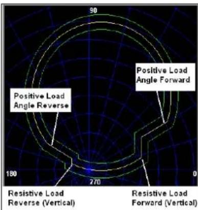
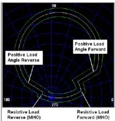
Figure 160. Load Encroachment Settings and Examples (Vertical, MHO)
The setting screen defaults to MHO characteristic. Press the Vertical button to select for a Vertical characteristic. To enable selective fault types, press the appropriate button. It will change to yellow background and a checkmark will appear in the box. Enter the appropriate Ohmic values and angles to achieve the desired characteristic.
3.6.2.2 HALF MHO Setting Screen

Figure 161. Half MHO Setting Screen
There are six basic settings; MAX REACH, ANGLE, OFFSET, OFFSET ANGLE, RIGHT BLINDER, and LEFT BLINDER that will define the relay operating characteristic. MAX REACH is a value in Ohms. ANGLE is a value in degrees normally associated with the maximum torque angle, line, or characteristic angle setting of the relay. OFFSET is a value in Ohms indicating either positive or negative offset. OFFSET ANGLE is a value in degrees, which may be different from the ANGLE setting. This setting is normally associated with the directional offset mho setting. RIGHT BLINDER and LEFT BLINDER are values in degrees associated with blinder elements along the right and left sides of the original half MHO characteristic, and are angles relative to the ANGLE setting (note the default of 90 degrees or a right angle relative to the ANGLE setting). Virtually any MHO / OHM type characteristic can be molded using a combination of the BLINDER values ranging from pie shape to something greater than a Half MHO up to an OHM characteristic.
3.6.2.3 QUAD setting screen
3.6.2.3 QUAD Setting Screen

Figure 162. Generic QUAD Setting Screen
There are eight basic settings; X, R, -X, -R, RCA, -X Angle, -R Angle, and Blinder Angle that will define the relay operating characteristic. X and R are values in Ohms associated with the X and R axis, in an RX Impedance plane. The R value is normally referred to as the Positive Resistive Reach. The X value is normally referred to as the Positive Reactance Reach. The – X and – R are values in Ohms associated with –X and – R setting when the DIRECTIONAL setting is either set to NON-DIRECTIONAL or REVERSE settings. The – R value is normally referred to as the Negative Resistive Reach, and the – X value is normally referred to as the Negative Reactance Reach. The RCA is a value set in degrees normally associated with the maximum torque angle, line angle, or positive impedance characteristic angle setting of the relay. The - X and – R Angles are values in degrees normally associated with the Directional Characteristic Angles. Blinder Angle is a value in degrees, sometimes referred to as the Tilt Angle or a variant of the Positive Reactance Angle.
3.6.2.3.1 QUAD Load Encroachment Setting Screen
For relays with Load Encroachment characteristics in the longer reaching zones of operation, pressing the Load Encroachment Edit button will reveal the following settings dialog box.

Figure 163. Example Load Encroachment Setting Screen for Generic QUAD
To enable selective fault types press the appropriate button. It will change to yellow background and a checkmark will appear in the box. Enter the appropriate Ohmic values and angles to achieve the desired characteristic.
3.6.2.4 IEEE QUAD Setting Screen

Figure 164. Generic IEEE QUAD Setting Screen
Sixteen settings can be used to define virtually any impedance relay polygon (QUAD) characteristic. The following are the characteristic nomenclatures and definitions.
PslmpRch Positive Impedance Reach - defines the positive reach in Ohms representing the line impedance.
PslmpAng Positive Characteristic Angle – this is the line impedance angle in the forward direction (first quadrant). This angle is measured counter clockwise from the positive R-axis.
PsReactAng1 Positive Reactance Angle 1 to the right of the line impedance – this angle is measured clockwise from the horizontal line going through the reactive reach on the X-axis. The area above the line is excluded from the operating area.
PsReactAng2 Positive Reactance Angle 2 to the left of the line impedance – this angle is measured counter clockwise from the horizontal line going through the reactive reach on the X-axis. The area above the line is excluded from the operating area.
PsRisRch Positive Resistive Reach – defines the positive resistive reach to limit the coverage for fault resistance and at the same time to limit the encroachment of the load impedance into the characteristic. The setting determines the reach on the R axis.
PsRisAng1 Positive Resistive Angle in the first quadrant – this angle is measured counter clockwise from the R-axis. The area right from the blinder is excluded from the operating area.
PsRisAng2 Positive Resistive Angle in the fourth quadrant – this angle is measured clockwise from the R-axis.
NgRisRch Negative Resistive Reach – defines the negative resistive reach. The setting determines the reach on the R axis.
NgRisAng1 Negative Resistive Angle 1 in the second quadrant – this angle is measured counter clockwise from the R-axis. The area left from the blinder is excluded from the operating area.
NgRisAng2 Negative Resistive Angle 2 in the third quadrant – this angle is measured counter clockwise from the R-axis. The area left from the blinder is excluded from the operating area.
NglmpRch Negative Impedance Reach – defines the impedance reach in the reverse direction.
NglmpAng Negative Characteristic Angle – this is the impedance angle in the reverse direction (third quadrant). This angle is measured counter clockwise from the positive R-axis.
3.6.2.4.1 IEEE QUAD load encroachment setting screen
NgReactAng1 Negative Reactance Angle 1 – this angle is measured clockwise from the horizontal line going through the negative reactance reach on the X axis. The area below the line is excluded from the operating area.
NgReactAng2 Negative Reactance Angle 2 – this angle is measured clockwise from the horizontal line going through the negative reactance reach on the X axis. The area below the line is excluded from the operating area.
DirChrAng1 Directional Characteristic Angle 1 – this is the directional characteristic angle in the fourth quadrant. This angle is measured counter clockwise from the positive R-axis.
DirChrAng2 Directional Characteristic Angle 2 – this is the directional characteristic angle in the second quadrant. This angle is measured counter clockwise from the positive R-axis.
3.6.2.4.1 IEEE QUAD Load Encroachment Setting Screen
For relays with Load Encroachment characteristics in the longer reaching zones of operation, pressing the Load Encroachment Edit button will reveal the following settings dialog box.

Figure 165. Example Load Encroachment Setting Screen for Generic IEEE QUAD
To enable selective fault types press the appropriate button. It will change to yellow background and a checkmark will appear in the box. Enter the appropriate Ohmic values and angles to achieve the desired characteristic.
3.6.3 Impedance Relay Library Files
Pressing the Impedance Relay Library button will provide a selection window containing relay specific impedance characteristics listed by relay manufacturer and Model identifier. Future software updates will include more relay specific library files; see Upgrading FREJA Local / Remote software for more information on downloading the software from the Megger website.
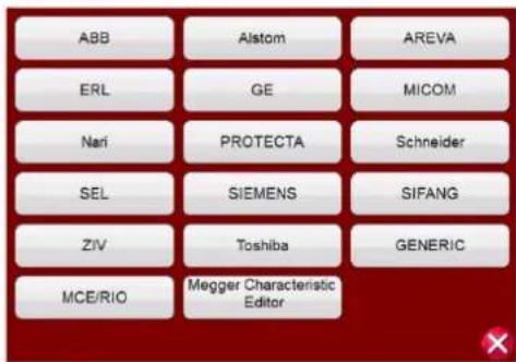
Figure 166. Relay Library Selection Screen
FREJA Local / Remote software supports the import of relay settings in various file formats; see section 3.1.6, Relay Settings Import. Relay setting import files supported in the Impedance Relay Test are; Read From Relay SEL Serial or GE Modbus, XRIO, TEAX, SEL RDB, ERL L-PRO, XML, and RTMS CSV files. If you do not have the relay settings in one of the previously mentioned file formats, enter the relay manufacturer's settings manually and the operating characteristic will be created from the settings entered. Note that specific relays have different characteristics depending on user input. Where a relay may have multiple characteristics, selection buttons are provided to choose from. For example, the Schweitzer model SEL 311 and General Electric UR D60 relays have a selection for either Mho or Quad characteristics. In the SEL 311 characteristic setting screen you have the added choice of Mho + Quad. The setting nomenclatures change with the selection of either Mho or Quad, and either Phase to Ground or Phase to Phase selections.
3.6.4 MCE / RIO Files
Pressing the MCE / RIO button will provide a selection window which may contain specific relays listed by relay manufacturer and / or Model identifier.
The Megger Characteristic Editor, MCE, is a tool for creating impedance relay operating characteristics using combinations of Lines, Arc's and / or MHO circles, see section 3.6.9. Impedance characteristics created using the MCE can be imported into the Click on Fault test screen, tested, and results saved. Impedance settings can be changed in the MCE for testing the same type of relay.
Various manufacturers create RIO files using relay, or relay test software. They may be considered to be Relay Impedance Objects, but are also allocated to other characteristics such as families of time-amplitude. RIO files constitute data for the characteristics of a particular relay with specific settings. Some or all the characteristic types may be created in the file and the characteristic relay settings will be included. I.e., the RIO files are relay specific to the settings of the relay when the RIO file is created; the discrete settings are neither displayed nor adjustable. If the settings are changed, a new RIO file will need to be created in order to test the relay. Once the relay is selected it will take the user to the Click on Fault Configuration Screen.
3.6.5 Impedance - Click on Fault Configuration Screen
After selection of either a Generic or a Library relay specific impedance characteristic, and entering the appropriate impedance settings for each of the specific Zones to be tested, press the green check button, which will take the user to the Click on Fault Configuration Screen.
3.6.5.1 Prefault dialog box
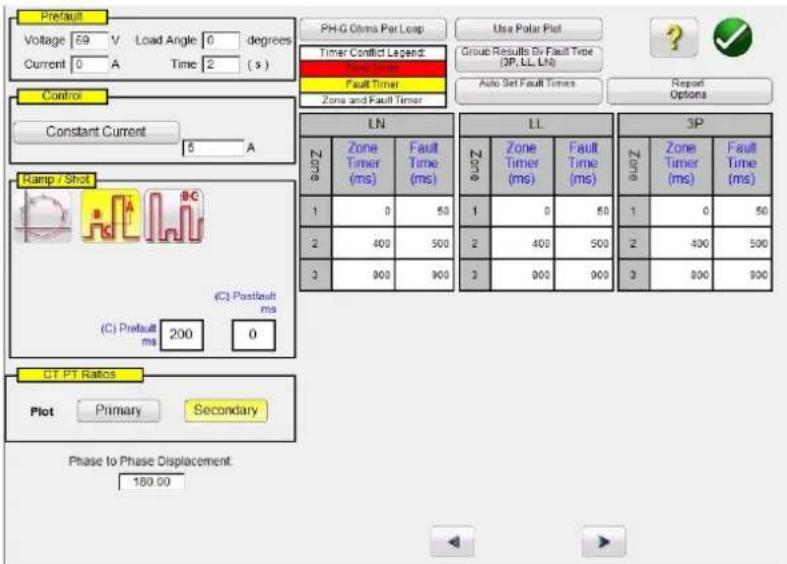
Figure 167. Impedance Relay, Click on Fault Configuration Screen
3.6.5.1 Prefault Dialog Box
The prefault values will be applied to the relay under test prior to ramping. If using Pulse Ramp the prefault values will be applied between each pulse increment. The Prefault Dialog box contains four edit fields:
Voltage – Enter a value of Voltage to be set
Current – Enter a value of Current to be set
Load Angle – Enter a value for a Load Angle to be set
Time – Enter the desired time prior to applying the first test point
3.6.5.2 Control Dialog Box
This dialog box provides the user with a selection of different methods to perform the tests. Some manufacturers require Constant Voltage and ramp current, some require Constant Current and ramp voltage. In addition, the user may also select Constant Source Impedance.
Constant Voltage - Enter the value of volts to be held constant for all Fault Types tests under execution. Default value is 5.0.
Constant Current - Enter the value of Amperes to be held constant for all Fault Types tests under execution. Default value is 1.0.
Constant Source Z - There are two forms of Source Impedance; Ohms and Angle ,or R and X. Enter the value of ohms and angle of source to be held constant for all Fault Types tests under execution, or enter the R and X values where;
R: the Cartesian resistive equivalent of the impedance [Z] and its angle Phi
X: the Cartesian reactive equivalent of the impedance [Z] and its angle Phi
3.6.5.3 Ramp / Shot Options
This dialog box provides three different ways to determine the operating characteristic of impedance relays. Shots are used to create one or more test points to replicate a fault at a particular magnitude and angle. Trip (inside the operating characteristic) and / or No-Trip (outside the operating characteristic) points may be selected for each Fault Type. Selection of the type of Ramp is dependent on the relay. To test Multi-Zone relays use either the Pulse Ramp or Pulse Ramp Binary Search. The software will automatically calculate the increment required in volts, Amperes and phase
angle. The Pulse Ramp and Pulse Ramp Binary Search also include a Prefault setting in milliseconds. This is the time that the prefault values will be applied between fault increments.
3.6.5.4 CT / PT Ratios
This dialog box provides user selection for plotting the operating characteristic in either Primary or Secondary Ohms.
3.6.5.5 Polar / Rectangular Plot button
This dialog box provides user selection for plotting the operating characteristic in either Polar or Rectangular coordinates.
3.6.5.6 Auto Set Fault Times button
This button works in conjunction with the Zone Timer settings window. You can change the Zone Trip and Fault Times by Pressing or clicking the appropriate setting window for the selected Zones. Pressing the Auto Set Fault Times button will automatically set the amount of time the fault will be applied to the relay. The Fault time is set in milliseconds, and automatically set to a value higher than the Expected Trip Time (just long enough for the zone being tested to operate, but not for other zones).
3.6.5.7 Ohms Per Phase / Per Loop button
This button works in conjunction with the Click On Fault Test Screen. For relays that use Loop Impedance Zero Sequence Compensation, press this button to read Ohms Per Loop to change the display to represent Ohms Per Loop. Note that for relays with imported settings this window could be grayed out.
3.6.5.8 Report Options button
This button allows the user to select what is displayed in the test report in terms of %error and Z/t timing results.

Figure 168. Report Options Selection Menu
% Error – Adds the % error of the selected test in the test screen and to the report page.
No % Error (ACTIVE) – Removes the % error from the selected test and from the report.
% Error & Relative Z – Recalculates the Theoretical Z and % Error based on Relative Z.
Add Z/t Chart (All Points) – Add relay operating times with zone impedance for all test points.
Add Z/t Chart (RCA Points) – Add relay operating times with zone impedance for RCA test points.
Add Z/t Chart (All Points, No NOOP) – Add relay operating times with zone impedance for all test points, do not include NOOP points.
Add Z/t Chart (RCA Points, No NOOP) – Add relay operating times with zone impedance for RCA test points, do not include NOOP points.
3.6.5.8.1 Adding Z/t chart to report
3.6.5.8.1 Adding Z/t Chart to Report
The Z/t Chart buttons allows the user to select to view the Z/t time chart, with different configurations, in the test results. See the following example test result where the three phase Z/t times are plotted.
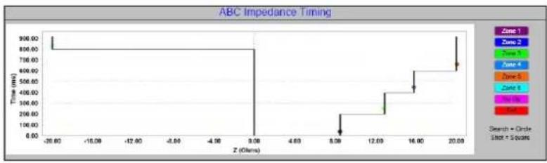
line
| Z (Ohms) | Time (ms) | | -------- | --------- | | -30.00 | 900.00 | | 9.08 | 900.00 | | 8.09 | 100.00 | | 12.09 | 400.00 | | 16.00 | 600.00 | | 20.00 | 900.00 |Figure 169. Relay operating time vs. zone impedance
3.6.6 Impedance - Click on Fault Test Screen
After selection of either a Generic or a Library relay specific impedance characteristic, and entering the appropriate impedance settings for each of the specific Zones to be tested, press the green check button, which will take the user to the Click on Fault Test Screen.

Figure 170. Impedance Relay, Click On Fault Test Screen
3.6.6.1 ① Home button

Pressing the home button will return you to the manual test screen.
3.6.6.2 ② Configuration button

Press the button to go to the STVI Configuration Screen. See Section 2.2.1 Configuration for more information of the Configuration Screen.
3.6.6.3 ③ Battery Simulator button

The Battery Simulator button – Turns the Battery Simulator ON and OFF by pressing the button, the color changes red
3.6.6.4 Review test report button
for ON and black for OFF. The voltage to be applied is displayed in the button and can be changed by pressing the configuration button.
3.6.6.4 ④ Review Test Report button

Press this button to review the test results.
3.6.6.5 ⑤ Binary Input Setting button

Press this box to reveal the Binary Input Dialog box.
The default settings are Binary Input 1, dry contacts as indicated by the Input Type, and Input Action defaults to show the Closing of the Normally Open contacts. To change the Input Type from dry contacts to Voltage, press the Input Type button, and it changes to voltage. To change to the opening of Normally Closed contacts press the Input Action button and it changes to show closed contacts opening. For timing the operating time of the impedance element the timer is defaulted to Latched Input enabled mode, which means the timer will stop on the first contact closure. Note the Debounce time is set to 2 milliseconds.
3.6.6.6 ⑥ Relay Settings button

Press this button to access selection of the Relay's Settings Screen. Here the user can adjust parameters
3.6.6.7 ⑦ RIO button
Pressing the RIO button will provide a selection window containing specific relays listed by relay manufacturer and Model identifier.
3.6.6.8 ⑧ Relay Library button

Pressing the Relay Library will provide a library of relay specific characteristics by various manufacturers. Pressing the Generic Characteristics button will provide a library of generic impedance relay characteristics to choose from.
3.6.6.9 ⑨ Zone Zoom button

Pressing this button will zoom in on the selected zone. Press it again and return to the normal test screen mode.
3.6.6.10 ⑩ Run Predefined Test button

Pressing the Run Predefined Test button provides access to Predefined test plans, created by either Megger or users, in Pdb Tst file structure.
3.6.6.11 ⑪ Run Test button

Pressing or clicking the Blue Run Test button will apply the Prefault vector for the specified Time, then step to the Fault
3.6.6.12 Test all button
values and look for the relay under test to operate using either a Pulse Ramp or Pulse Ramp Binary Search. Pressing this button will run all of the selected test points for the selected fault type, for all the selected zones.
3.6.6.12 ⑫ Test All button

Press the Test All button to automatically sequence through all defined tests, Phase to Ground, Phase to Phase, and Three Phase, for all zones.
3.6.6.13 ⑬ Help button ?
The Help button is sensitive to the test and will take the user to this section of the manual. It can also be used to reset the unit.
3.6.6.14 ⑭ Change Search Mode button

There are three modes to choose, Auto Generate, IEC 60255, and Origin Test Points. In the default auto generate mode the user may select any test line, at any angle, around the operating characteristic by clicking at a point outside and then inside the operating characteristic(s) to define the desired test line. When you select the first test line, the Auto Generate test point's button will appear. Press this button to reveal the auto generate test point options.

Figure 171. Test Points Selection Screen
The user may select the desired number of test points by pressing the Test Points button and select from the list. Then the user may select the desired phase rotation between the selected number of test points by pressing the Degrees to Rotate button. If none of the standard phase rotations meets the user's needs, press the Degrees to Rotate button in the list and enter the desired phase rotation in the window provided.
Press this button again to reveal the IEC60255 Test Points Mode. Press this button a third time to reveal the Origin Test Points Mode.
3.6.6.14.1 IEC60255 Test Points Mode

The IEC60255 Test Points option- In accordance with IEC 60255 standard click a point outside, then inside, the operating characteristic and the test line will be drawn perpendicular to the operating characteristic line. Press this button to reveal the Origin Test Points option.
3.6.6.14.2 Origin Test Points Mode

The Origin Test Points option - Click a point outside the operating characteristic and the test line will be drawn to the origin or the intercept of the R and X-axis. Press this button to return to the auto generate mode.
3.6.6.14.3 Shots test points option
3.6.6.14.3 Shots Test Points option

The Shots Test Points option – Used to create one or more points of test, each to replicate a fault at a particular magnitude and angle. Several Trip (inside the operating characteristic) and / or No-Trip (outside the operating characteristic) points may be selected for each Fault Type. The Test Point is the set of values listed both in Mag and Phase Angle, and in Cartesian values that are created in the Graph. Continued clicks will produce additional test points at the mouse locations. Note that when Test Points is selected, test points will be applied per the Impedance Configuration Settings screen, see 3.6.5.6 Auto Set Points Time. Also note that when you click on the Shots button % min max time windows appear, defaulting to ± 5% of the time set in the Impedance Configuration Setting screen, see the following figure.
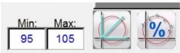
Figure 172. % Min Max Shots Time Settings
3.6.6.15 ⑮ Quick Test – Auto Generate Test Points

Pressing or clicking on this button will provide the following selection menu.
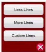
Figure 173. Quick Test - Auto Generate Test Line Options
Selecting Less Lines, three test lines will be drawn. One test line will be drawn at 0 degrees, another at 90 degrees, and one along the Line Angle setting in the Settings screen. Pressing or clicking on the More Lines button, up to nine test lines will be drawn. Any test line can be deleted and redrawn by the user as desired using the Run / Edit button. Custom Lines allows the user to define three test line angles. Press the Run / Edit button for the individual test point. The user will then be presented with the following option screen.

Figure 174. Run / Edit button Options
The user can; Edit the start impedance values, Run the selected test individually, Run the Remaining tests, or Delete the selected test. Press the red X to exit.
3.6.6.16 Clear test lines button
3.6.6.16 ⑯ Clear Test Lines button
Press this button to clear tests from the selected test screen. Pressing this button will provide a list of user options as follows,
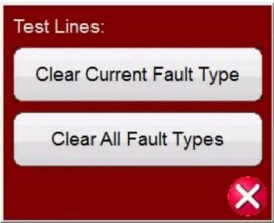
Figure 175. Clear Tests Options Screen
Clear Current Fault Type—Clears the currently selected test
Clear All Fault Types: Clears all tests associated with the Fault
Note: There is no going back; once you clear a test there is no way to recover the tests unless you have saved the test to the internal memory.
3.6.6.17 ⑰ Clear Results button
Press this button to clear test results. Pressing this button will provide a list of user options as follows,

Figure 176. Clear Tests Options Screen
Clear Current Results—Clears the currently selected test result
Clear All Results: Clears all test results associated with the test

Note: There is no going back; once you clear a test result there is no way to recover the test results you have saved the results to the internal memory.
3.6.6.18 Return to characteristic settings screen button
3.6.6.18 ⑱ Return to Characteristic Settings Screen button

Return to the relay characteristic setting screen button provides access back to the settings screen.
3.6.6.19 ⑲ Fault Selection button AB
This button provides user selection of the desired fault to be defined. The choices are Phase to Ground, Phase to Phase, and Three Phase.
3.6.7 Easy Z Impedance Relay Test
Pressing the Easy Z Impedance Relay test button provides the testing of relays directly from the so called impedance plane, where the conversion from the impedance into voltages and currents is automatically done by the FREJA Local / Remote software.
Selection of the Easy Z button will provide the following test screen.
3.6.7.1 Easy Z Impedance Relay Setting and Test Screen

Figure 177. Easy Z Setting and Test Screen
3.6.7.1.1 ① Binary Input Setting button

Press this box to reveal the Binary Input Dialog box.

The default settings are Binary Input 1, dry contacts as indicated by the Input Type, and Input Action defaults to show the Closing of the Normally Open contacts. To change the Input Type from dry contacts to Voltage, press the Input Type button, and it changes to voltage. To change to the opening of Normally Closed contacts press the Input Action button
3.6.7.1.2 CT earthing position button
and it changes to show closed contacts opening. For timing the operating time of the impedance element the timer is defaulted to Latched Input enabled mode, which means the timer will stop on the first contact closure. Note the Debounce time is set to 2 milliseconds.
3.6.7.1.2 ② CT Earthing Position button


If this button is selected, the simulated secondary current from test system will be in phase with the primary flow, which flows from the bus bar into the protected line.

If this button is selected, the simulated secondary current from test system will be 180 degrees shifted red to the same primary current used as reference. The two pictures below shows the output quantities from the system for the same impedance of 10 ohms at 85 degrees, single phase to earth fault, with the two possible CT ring combinations.

radar
| V1 | V2 | | --- | --- | | 10.00@0.0 | -120.0 | | 10.00@0.0 | -90 |3.6.7.1.3 ③ Configuration button

Press the button to go to the Configuration Screen. See Section 2.2.1 Configuration for more information of the Configuration Screen.
3.6.7.1.4 ④ Report options button

This button will add the present test result to the report. It also displays the report and allows the user to name the test, enter limits, comments or deficiencies. Reports can be saved to the On-board display's internal memory, and transferred to PowerDB via a USB memory stick. Previous tests results can be loaded and the 'Retest' option can be used to repeat the test using the same parameters as the previous test.
3.6.7.1.5 ⑤ Review Test Report button

Press this button to review the test results.
3.6.7.1.6 ⑥ Clear Test (s) button

Press this button to clear tests from the selected test screen. Pressing this button will provide a list of user options as follows,

Figure 178. Clear Tests Options Dialog Box
Clear Current – Clears the currently selected test
Clear All: - Clears all tests associated with the Fault

Note: There is no going back; once you clear a test there is no way to recover the test unless you have the test to the internal memory.
3.6.7.1.7 ⑦ Clear Test Results button

Press this button to delete test results.
3.6.7.1.8 ⑧ Test Method Selection Box
Constant | @ 1A
This dialog box provides the user with a selection of two different methods to perform the tests. Some manufacturers require Constant Voltage and ramp current, some require Constant Current and ramp voltage. The voltage and current phasors, as function of the set impedance and method are calculated according to specification IEC 60255-121.
Constant Voltage - Enter the value of volts to be held constant for all Fault Types tests under execution. Default value is 5.0 Volts.
Constant Current - Enter the value of Amperes to be held constant for all Fault Types tests under execution. Default value is 1.0 Ampere.
3.6.7.1.9 ⑨ Fault Type Selection button
Fault Type L1
This button provides user selection of the desired fault to be defined. The choices are Phase to Ground, Phase to Phase, and Three Phase. For phase to earth faults, the domain is the ohm / loop domain. For the Phase-Phase and Three-Phase faults, the impedance is represented in the ohm / phase domain.
3.6.7.1.10 ⑩ Ground Compensation
When a single-phase fault is selected, the Ground Compensation button will appear.
For MHO and Half MHO, KN and Z0Z1 are available.
Residual compensation factor, KN, is a complex number that is used to express the earth-return impedance, ZN, in terms of the positive-sequence impedance reach setting, Z1. This factor is calculated as:
$$ \mathbf {K N} = \mathrm{ZN} / \mathrm{Z1} = (\mathrm{Z0} - \mathrm{Z1}) / (3 \mathrm{Z1}) $$
Where: Z0 is the zero-sequence impedance polar reach of the zone
Z0Z1 Ratio = the complex ratio of Z0 / Z1, also referred to as K0 = Z0 / Z1
3.6.7.1.11 Fault setting fields
For QUAD (quadrilateral) there are: KN, Z0Z1, RE / RL XE / XL and R0 X0 R1 X1.
RE / RL XE / XL is a pair of scalar factors. These factors affect the resistive reach and reactive reach of some polygon characteristics.
$$ \mathrm{RE} / \mathrm{RL} = (\mathrm{R0} / \mathrm{R1} - 1) / 3 $$
$$ \mathrm{XE} / \mathrm{XL} = (\mathrm{X0} / \mathrm{X1} - 1) / 3 $$
R0 X0 R1 X1
Where:
$$ R 1 = \text { real part of } Z 1 $$
$$ X 1 = \text { imaginary part of } Z 1 $$
$$ R 0 = \text { real part of } Z 0 $$
$$ X 0 = \text { imaginary part of } Z 0 $$
3.6.7.1.11 ⑪ Fault Setting Fields
The Fault Setting Fields are where the value of the fault impedance is set by tapping on the field and entering the value with the keypad, or simply by tapping on the impedance plane window. It is possible to ramp with the knob any value of the fault impedance, see section "Impedance ramping".
3.6.7.1.12 ⑫ Pre-fault, Fault, Post-Fault dialogue box
Press the List button to open the Prefault, Fault, Post Fault settings dialog box.
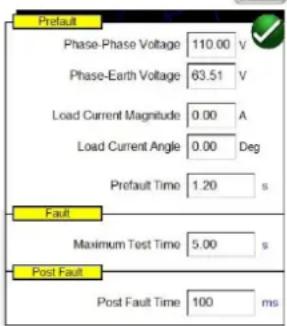
Figure 179. Prefault, Fault and Post Fault Settings box
Enter the conditions for the Prefault and Fault test. Enter the Phase-Phase, or Phase-Earth voltage, Load Current, and Load Current Angle, along with the Prefault Time.
Application Note: It is recommended to use Prefault current = 0 when testing distance protection relays, as the simulated power system is a radial feeder without any superimposed load, hence the simulation of the load current that will vanish during the fault condition is not a realistic representation of the power system. If you set the prefault and post fault time to zero, you can conduct the test manually by simply clicking in the test window.
Set the Fault Maximum Test Time. Upon pushing the Blue Run Test button, the fault will be applied to the relay until the
relay operates, or the Maximum Test Time expires.
Set the Post Fault Time. If the relay operates, faulty quantities are still injected for the Post Fault Time setting (in the example 100 ms) simulating circuit breaker opening time. After that the injection is stopped and the operate time is reported. If the relay doesn't operate, after Maximum Test Time setting expires (in the example 5 seconds) the fault injection is stopped and the result is given as "NOP" (No Operation).
Pressing or clicking the Blue Run Test button will apply the Prefault vector for the specified Time, then step to the Fault values and look for the relay under test to operate.
3.6.7.1.13 ⑬ Impedance Ramp box
Here you can ramp in the impedance plane by using the control knob, the up down arrow keys on the PC, or the mouse control wheel. Press or click on the control wheel button and the Impedance Ramp Selection box will appear. You can select the value to be ramped; Z, Phi, R or X and the increment size.
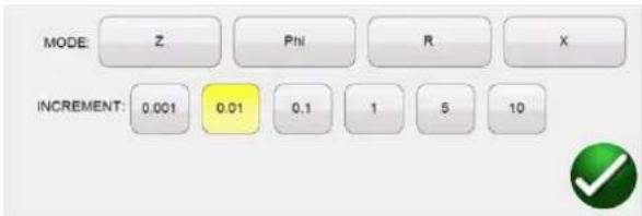
Figure 180. Impedance Ramp Selection box
There are two types of ramp, pseudo-continuous ramp or ramp of shots. The two ramp types may give different results, as in principle they implement two completely different testing methods. It is recommended to follow the relay manufacturer recommendation for the choice of the test method.
Pseudo-continuous ramp
Traditionally this is the method that is used to test the so called "static accuracy" of the relay, as the injected quantities will slowly change.
1] The pseudo-continuous ramp is activated by setting ZERO seconds for the Maximum Test Time in the prefault and fault settings.
2] Any parameter of the impedance can be manually slowly changed from the control knob, or up down arrows / mouse wheel on the PC. The parameter is chosen by tapping on it and selecting "Include Channel in Ramping" from the numerical keypad.
3] The step increment (or decrement) is chosen by pressing or clicking on the control wheel button.
4] The generation is activated by the ALL ON / OFF button

When relay starts or operates, the injection is stopped (if the binary input is used to stop the ramp).
Application Note: Make sure the time interval between the two steps is larger than the operating time of the zone being tested.
3.6.7.1.14 Impedance test screen
Ramp of shots (step ramp)
This method is not intended to test the static accuracy of the relay, as quantities are not slowly changed, but it is a good method to rapidly verify relay zone border settings without need to disable other distance protection zones, which is a common problem when using the pseudo-continuous ramp. This ramp is a succession of prefault and fault sequences.
- The ramp is activated by setting the Maximum Test Time in the Prefault and Fault settings box to a value different than ZERO.
- Any parameter of the impedance can be manually "step ramped" from the control knob, up down arrows on the PC, or the mouse control wheel. The parameter is chosen by pressing or clicking on the control wheel button and selecting "Include Channel in Ramping" from the numerical keypad.
- The step increment (or decrement) is chosen by pressing the control wheel button.
3.6.7.1.14 ⑭ Impedance Test Screen
This window shows the test vectors that are applied to the relay under test. With each ramp step you will see the test vector(s) change in amplitude and / or phase angle relationship.
3.6.7.1.15 ⑮ Impedance Plane Screen
This plane represents the ohm / loop domain for the phase-earth faults, and the ohm / phase domain for phase to phase and three-phase faults. By tapping on the screen it is possible to graphically enter the impedance values.
3.6.8 Unknown Impedance Characteristic

Figure 181. Unknown Impedance Characteristic Setting Screen
3.6.8.1 Prefault Dialog Box
The prefault values will be applied to the relay under test prior to ramping. If using Pulse Ramp the prefault values will be applied between each pulse increment. The Prefault Dialog box contains four edit fields:
Voltage – Enter a value of Voltage to be set
Current – Enter a value of Current to be set
Load Angle – Enter a value for a Load Angle to be set
Time – Enter the desired time prior to applying the first test point
3.6.8.2 Control Dialog Box
This dialog box provides the user with a selection of different methods to perform the tests. Some manufacturers require Constant Voltage and ramp current, some require Constant Current and ramp voltage. In addition, the user may also select Constant Source Impedance.
Constant Voltage - Enter the value of volts to be held constant for all Fault Types tests under execution. Default value is 5.0.
Constant Current - Enter the value of Amperes to be held constant for all Fault Types tests under execution. Default value is 1.0.
Constant Source Z - There are two forms of Source Impedance; Ohms and Angle, or R and X. Enter the value of ohms and angle of source to be held constant for all Fault Types tests under execution, or enter the R and X values where;
R: the Cartesian resistive equivalent of the impedance [Z] and its angle Phi
X: the Cartesian reactive equivalent of the impedance [Z] and its angle Phi
3.6.8.3 CT / PT Ratios
This dialog box provides user selection for plotting the operating characteristic in either Primary or Secondary Ohms.
3.6.8.4 Relay button
The user can input some basic knowledge, or best guess, of the relay to be tested.

other
Relay | Metric | Value | (degrees) | | :--- | :--- | :--- | | RCA Guess | 70 | (degrees) | | Maximum Forward Reach | 30 | (ohms) | | Maximum Reverse Reach | 0 | (ohms) | | Trip Time Ratio for New Zone | 115 | (%) |Figure 182. Relay Estimated Settings
There are three selections available for the relay type, MHO, QUAD, or NONE. The relay is either a Three Phase or Single Phase relay application. There are four best estimate settings. The RCA is a value set in degrees normally associated with the maximum torque angle, line angle, or positive impedance characteristic angle setting of the relay. Enter your best guess. Maximum Forward Reach is the estimated longest Ohmic reach of the relay in the forward direction. Maximum Reverse Reach is the estimated longest Ohmic reach of the relay in the reverse direction.
3.6.8.5 Ramp Options
This dialog box provides two different ways to determine the operating characteristic of impedance relays. Selection of the type of Ramp is dependent on the relay. To test Multi-Zone relays use the Pulse Ramp Search. The software will automatically calculate the increment required in volts, Amperes and phase angle. The Pulse Ramp Search also includes a Prefault Time setting in milliseconds. This is the time that the prefault values will be applied between fault increments. The Stair Step ramp will only determine the characteristic for a single zone relay. There is one common setting for either the stair step or pulse ramps, Max Trip Time. Enter the estimated maximum trip time of the longest reaching zone.
3.6.8.6 Search options
3.6.8.6 Search Options
The Search Options will determine how fast and to what resolution the characteristic is found. The Coarse Ramp Increment will determine the size of the step taken on the initial ramp. The Second Ramp Increment will determine the pickup value with higher resolution. The Min Operation Time is the time that the fault value will be applied before making the next increment. There are three options regarding the number of test lines associated with determining the operating characteristic.
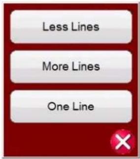
Figure 183. More, Less or One Test Line
More Lines will provide more test results with a better definition of the operating characteristic, but it may be too much data taking too long. Therefore, the Less Lines selection is made available, which may provide enough information to determine the operating characteristic. For fast determination select One Line, which may provide enough information to confirm your best estimate of the characteristic.
3.6.8.7 Unknown Impedance Relay Test Screen
after entering the best-estimated settings of the relay to be tested, press the green check button, which will take the user to the Test Screen.

Figure 184. Unknown Impedance Relay Test Screen
3.6.8.7.1 ① Home button

Pressing the home button will return you to the manual test screen.
3.6.8.7.2 ② Configuration button

Press this button to go to the STVI Configuration Screen. See Section 2.2.1 Configuration for more information of the Configuration Screen.
3.6.8.7.3 ③ Battery Simulator button

The Battery Simulator button – Turns the Battery Simulator ON and OFF by pressing this button, the color changes red for ON and black for OFF. The voltage to be applied is displayed in the button and can be changed by pressing the configuration button.
3.6.8.7.4 ④ Review Test Report button

Press this button to review the test results.
3.6.8.7.5 ⑤ Binary Input Setting button

Press this button to reveal the Binary Input Dialog box.
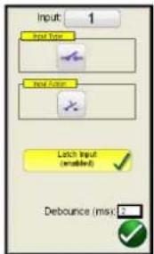
The default settings are Binary Input 1, dry contacts as indicated by the Input Type, and Input Action defaults to show the Closing of the Normally Open contacts. To change the Input Type from dry contacts to Voltage, press the Input Type button, and it changes to voltage. To change to the opening of Normally Closed contacts press the Input Action button and it changes to show closed contacts opening. For timing the operating time of the impedance element the timer is defaulted to Latched Input enabled mode, which means the timer will stop on the first contact closure. Note the Debounce time is set to 2 milliseconds.
3.6.8.7.6 ⑥ Relay Settings button

Press this button to access selection of the Relay's Settings Screen. Here the user can adjust parameters
3.6.8.7.7 ⑦ Zone Zoom button

Pressing this button will zoom in on the selected zone. Press it again and return to the normal test screen mode.
3.6.8.7.8 ⑧ Run Predefined Test button

Pressing the Run Predefined Test button provides access to Predefined test plans, created by either Megger or users, in Pdb Tst file structure,
3.6.8.7.9 ⑨ Run Test button

Pressing or clicking the Blue Run Test button will run the selected Ramp to determine the unknown characteristic. If conducting the Pulse Ramp it will apply the Prefault vector for the specified Time, then step to the Fault values and look for the relay under test to operate.
3.6.8.7.10 Help button
3.6.8.7.10 ⑩ Help button
The Help button is sensitive to the test. It will take the user to this section of the manual. It is also used to reset the unit.
3.6.8.7.11 ⑪ Fault Selection button ?
This button provides user selection of the desired fault to be tested. The choices are Phase to Ground, Phase to Phase, and Three Phase.
3.6.9 Megger Characteristic Editor (MCE) AB
The Megger Characteristic Editor, MCE, is a tool for creating impedance relay operating characteristics using combinations of Lines, Arc's and / or MHO circles. Virtually any impedance characteristic can be created using this tool, saved, and imported into the Click on Fault Impedance relay test screen.

Figure 185. Megger Characteristic Editor Distance Parameters Screen
3.6.9.1 ① Distance Parameters Settings
The Distance Parameters settings are the values used in defining the System, Tolerance, and Grounding Factors used for testing the relay. Some of these values are imported into the Click on Fault relay settings window.
3.6.9.1.1 System Settings
Impedance in Primary Values: Check the box provided if the values provided are in primary values. This provides for plotting the operating characteristic in Primary Ohms, when imported into FREJA Local / Remote Click on Fault test screen.
Line Length: Enter the line length in Ohms
Line Angle: Is a value set in degrees normally associated with the maximum torque angle, line angle, or positive impedance characteristic angle setting of the relay.
PT Connection: The pull-down button is associated with the PT Earthing / grounding towards the Line or towards the Bus. It defaults towards the Line. This defines how phase angles are calculated.
CT Start Point: The pull-down button is associated with the CT Earthing / grounding towards the Line or towards the Bus. It defaults towards the Line. This defines how phase angles are calculated.
3.6.9.1.2 Tolerance Settings
Time Relative: Enter the relative accuracy of the timing elements in the relay as a percentage. The default is 5%.
Time (Abs +): Enter timing accuracy in positive absolute error in milliseconds. The default is +50 ms.
Time (Abs -): Enter timing accuracy in negative absolute error in milliseconds. The default is - 50 ms.
Z (Relative): Enter the relative accuracy of the impedance-measuring element (in Ohms) in the relay as a percentage.
Z (ABS): Enter the impedance-measuring element in absolute value in Ohms.
3.6.9.1.3 Grounding Factors
For single phase to ground faults a pull-down selection list is available. For Mho characteristics KL and Z0 / Z1 are available. The residual compensation factor, KL, is a complex number that is used to express the earth-return impedance, ZN, in terms of the positive-sequence impedance reach setting, Z1. This factor is calculated as:
$$ \mathbf {K L} = \mathrm{ZN} / \mathrm{Z1} = (\mathrm{Z0} - \mathrm{Z1}) / (3 \mathrm{Z1}) $$
Where: Z0 is the zero-sequence impedance polar reach of the zone. Z0Z1 Ratio = the complex ratio of Z0 / Z1, also referred to as K0 = Z0 / Z1
For QUAD (quadrilateral) there are: KL, and RE / RL & XE / XL
RE / RL & XE / XL is a pair of scalar factors. These factors affect the resistive reach and reactive reach of some polygon characteristics.
$$ \mathbf {R E} / \mathbf {R L} = (\mathrm{R0} / \mathrm{R1} - 1) / 3 $$
$$ \mathbf {X E} / \mathbf {X L} = (\mathrm{X0} / \mathrm{X1} - 1) / 3 $$
Where:
$$ R 1 = \text { real part of } Z 1 $$
$$ X 1 = \text { imaginary part of } Z 1 $$
$$ R 0 = \text { real part of } Z 0 $$
$$ X 0 = \text { imaginary part of } Z 0 $$
Depending on which compensation factor is selected, different value boxes will appear for magnitudes and angles to be entered.
3.6.9.2 ② Device Parameters
The selection of this tab will present the following screen.
3.6.9.3 Fault selection boxes

Figure 186. Device Parameters Settings window
V Max: Use this to limit the amount of voltage that can be applied to the relay under test. The value defaults to 300 Volts, which is the maximum available voltage from a FREJA voltage amplifier.
V Primary: Enter the PT primary voltage level of the line being protected. This value will be imported into the Click on Fault CT PT settings windows, and provides for plotting the operating characteristic in either Primary or Secondary Ohms.
V Secondary: Enter the PT secondary voltage level being applied to the relay under test. This value will be imported into the Click on Fault CT PT settings windows, and provides for plotting the operating characteristic in either Primary or Secondary Ohms.
I Max: Use this to limit the amount of current that can be applied to the relay under test. The value defaults to 60 Amperes, which is the maximum available current from a FREJA current amplifier.
I Primary: Enter the CT primary current level of the line being protected. This value will be imported into the Click on Fault CT PT settings windows, and provides for plotting the operating characteristic in either Primary or Secondary Ohms.
I Secondary: Enter the CT secondary current level being applied to the relay under test. This value will be imported into the Click on Fault CT PT settings windows, and provides for plotting the operating characteristic in either Primary or Secondary Ohms.
3.6.9.3 ③ Fault Selection Boxes
The user can define LL - Phase-to-Phase fault, L1L2L3 - 3 Phase Fault, or LN - Phase to Ground fault.
3.6.9.4 ④ Impedance Plane Screen
By double - tapping on the screen it is possible to expand the screen. The screen can be expanded two times to get a better look at small impedance elements or segments. Double-tapping after two expansions will reduce the screen back to original size.
3.6.9.5 ⑤ Zone Selection Box
The user can add and define up to 20 Zones by pressing the button at the bottom of the box, or if the characteristic is a MHO circle the MHO button. One zone will be added each time it is pressed. The user can define LL - Phase-to-Phase fault, L1L2L3 - 3 Phase Fault, or LN - Phase to Ground fault for each zone. To disable the Zone, uncheck the Enable button. Zones can be created and either Enabled (default position), or Disabled (to be Enabled later).
Application Note: To save time, after defining the impedance characteristic use the Duplicate Zone button ☐. Select one of the other fault types, and all of the values entered for the previous fault type will be entered for the other fault type. Note this should be limited to only same zone fault types.
3.6.9.6 ⑥ Segment #n
Impedance characteristics can be created using lines, arcs, and / or MHO circle combinations defined by multiple segments. Combinations of MHO circles are relatively easy. Click on the + MHO button, input the Zone Reach in Ohms, input the Angle (normally the line angle), and if there is no Offset input the offset to 0 degrees. For all other impedance characteristics, click the pull-down Line (Cartesian) button to view available impedance segment elements, see the following figure.
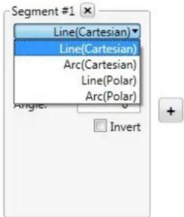
Figure 187. Impedance Segment Elements
Element selection line segments can be defined as follows.
Line (Cartesian): Used with relays that are defined using R and X values only, or combined segments using R and Z, see Line (Polar). Enter X and Y in Ohms with an Angle.
Line (Polar): Used with relays that are defined using Z values, or combined segments using Z and R values. Enter Z in Ohms, an angle Phi (where Z line crosses at a right angle), and an Angle (the "tilt" angle) of the line crossing Phi at the defined Ohmic Z value.
Arc (Cartesian): If the Arc is to be centered around the origin, leave X and Y at 0 Ohms, otherwise enter the X and / or Y Ohmic values to offset the MHO circle in the impedance plane. For the Radius, enter the Ohmic operating characteristic in Ohms. Start and Stop Angles are used to define arcs of less than 0 to 360 degrees. This will become more apparent when you add lines that intersect the arc. The CCW and CW may flip the arc 180^ depending on the defined intersecting line segment.
Arc (Polar): Enter Z in Ohms for the center of the locus at the angle Phi. For the Radius, enter the Ohmic operating characteristic in Ohms. Start and Stop Angles are used to define arcs of less than 0 to 360 degrees. This will become more apparent when you add lines that intersect the arc. The CCW and CW may flip the arc 180° depending on the defined intersecting line segment.
Invert: Check this box the invert the characteristic 180°.
3.6.9.7 ⑦ Add Segment button +
To add additional impedance segments press this button. There is virtually no limit as to how many segments can be added. Additional segment description boxes will be displayed to the right and then below Segment #1.
3.6.9.8 ⑧ Auto close button
When the Auto close button is checked, as each segment is added, the characteristic will start to "build" by the combining of the lines and / or arcs until the final segment is added, "closing" the characteristic shape. In the case of a Blinder or Ohm characteristic, define the line and angle, and do not check the Auto close button. This will extend the line to infinity.
3.6.9.9 Flip operation button
3.6.9.9 ⑨ Flip Operation button
Clicking the Flip Operation button will "flip" the impedance characteristic 180°.
3.6.9.10 ⑩ Defining Impedance Operations Row
Label: Click in the window to provide a label for the created impedance characteristic. It is recommended to limit the number of characters to 10.
Trip Time: Click in the window to enter the trip time in seconds. This information will be imported into the Click on Fault test screen and used in the test report. For operating times in milliseconds, enter the time in tenths, i.e. for 50 ms enter 0.05 seconds
Tripping pulldown button: Click on this button to reveal the following list.
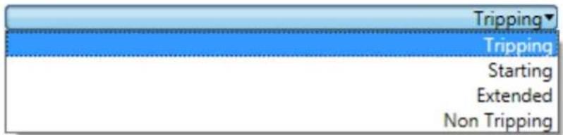
Figure 188. Defining Impedance Characteristic
Choose from this list to define what the impedance characteristic is, see the following descriptions.
Tripping: In most cases the impedance characteristic will be tripping.
Starting: Some relays have starting characteristics, where the relay will not start to make impedance measurements until the impedance has crossed the boundary of the starting characteristic, such as in power swing detection.
Extended: This is typically used when defining accelerated tripping or dynamic over-reach characteristics.
Non Tripping: Used to define a non-tripping impedance characteristic, i.e. blocking.
ALL pulldown button: Click on this button to reveal the following list.
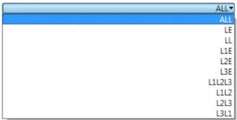
Figure 189. Defining Fault Type for Impedance Characteristic
Some relays may be designed for single phase, some for phase to phase, and some for three phase protection. Select which fault type the relay impedance characteristic is designed to protect.
3.6.9.11 Creating impedance characteristics
3.6.9.11 Creating Impedance Characteristics
The following example combines MHO circles, with ARCS and lines to create a 3 zone protection relay with load encroachment.
For this example, the following System Setting values were used;
Line Length: 50 Ohms
Line Angle: 85 degrees
Time Tolerance: 5% with ± 5 ms ABS
Z Relative: 5%
Z Absolute: 10 mOhms
Ground Compensation Factors: 720 mOhms, - 3.69 Degrees
The first two zones are MHO circles.
For Zone 1, Segment #1, select + Mho Circle. Application Note: Clicking on the + Mho button will add the Mho circle as Zone #2. Click on Zone #1 xbox and delete the default Zone #1, thus making your added Mho circle Zone #1. The reach was set to 10 Ohms, 0 Ohms offset, at a line angle of 85^ . The Label was changed to read Zone #1, the trip time was set to 50 ms, and defined as Tripping, ALL. The Zone is enabled and Auto close is checked.
For Zone 2, Segment #1, select + Mho Circle. The reach was set to 20 Ohms, 0 Ohms offset, at a line angle of 85°. The Label was changed to read Zone #2, the trip time was set to 100 ms, and defined as Tripping, ALL. The Zone is enabled and Auto close is checked.
Zone 3 will take a combination of two Arcs and a line to form a Mho characteristic with the load encroachment notch cut out.
- First step, we will need to describe the line associated with the load encroachment. Since this characteristic has a line through the origin, we will add a Cartesian Line with X and Y left at 0 Ohms, and insert the angle. In this example, an angle of 30^ is used. Note that the line is not drawn yet. Click on the Add Segment button +You will note that the line extends 30 degrees in the reverse direction. Click on the Invert button to flip the line 180^ in the forward direction.

Figure 190. Step 1, Load Encroachment Line Characteristic
3.7 Testing transducers with the FREJA local / remote software
- The second step is to define the Zone 3 Mho Characteristic using Arc Polar. Click on the Add Segment button + , and select Arc (Polar). The Arc Polar defaults to Z = 0.0 Ohms, Phi = 0 Degrees, and Radius = 1 Ohm. Therefore, what you will see is a half-moon characteristic centered on the origin, with a radius of 1 Ohm (a combination of the 30° line and the 1 Ohm circle at the origin).
- The next step is to set the forward reach of the Zone 3 characteristic. The forward reach will be a combination of Z, Phi, and Radius. We want the forward reach to be equal to 30 Ohms at the line angle of 85 degrees. Set Z = 15 Ohms, Phi = 85 degrees, and Radius = 15 Ohms. Z represents the offset of the loci 15 Ohms in the forward direction, combined with the 15 Ohms of the circle radius, results in a Zone 3 Mho of 30 Ohms at 85 degrees. What you see now is a partial Mho circle with a flat side caused by the line added in step 1.
![Magnet Diameter Chart On: 100 (ppm) Source Parameters: [Input Parameters] Symbol □ Intersection in Boundary Value □ Intersection in Boundary Value Line length: 30.0 Line height: 87.0 □ Connection Width: 2.6880 □ End Point: 0.0000 Distance: 5.0 Point Angle: 1.5 Point Angle x: 3.0 Point Angle y: 3.0 Point Angle z: 3.0 Balance Factor: 0.0000 □ Intersection in Boundary 4.0 deg 120cm 4.0 deg 2.000° Balance Factor: 0.0000 Balance Factor: 0.0000 Balance Factor: 0.0000 Balance Factor: 0.0000 Balance Factor: 0.0000 Balance Factor: 0.0000 Balance Factor: 0.0000 Balance Factor: 0.0000 Balance Factor: 0.0000 Balance Factor: 0.0000](/content/2026/05/852528/images/7f75ddc92df171c4045699b12dc57a5875044d8f005912ff50c11797ab56b10e.jpg)
Figure 191. Step 2, Load Encroachment Characteristic
- The final step is to add another Arc Polar that represents the forward reach of Zone 3 up to the notch cutout for the load encroachment. Click on the Add Segment button . Select Arc (Polar). Look closely and you will see a very small arc near the origin. This is a combination of the circle around the origin of 1 Ohm (recall the default settings) and the line from step 1. We now want to move the arc in the forward direction to represent Zone 3 operating characteristic with load encroachment set at 14 Ohms. Enter Radius = 14 Ohms. The Label was changed to read Zone #3, the trip time was set to 400 ms, and defined as Tripping, ALL. You should now see the completed Zone 3 with the load encroachment notch, see the following example figure.
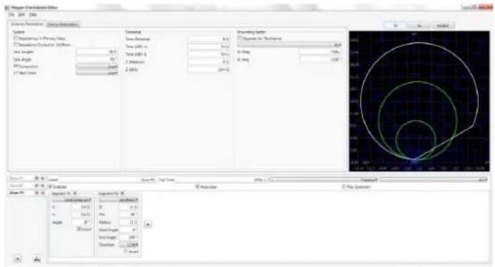
Figure 192. Example 3 Zone Impedance Characteristic with Load Encroachment
To save the created characteristic, click on File, Save As, give it a name. The impedance characteristic is now saved for use in the Click on Fault test screen.
3.7 Testing Transducers with the FREJA Local / Remote software
In conjunction with the Transducer Hardware Option in the FREJA units, the Transducer Test provides a quick approach to testing all types of single phase and three phase electrical transducers. The transducer hardware "T" option can either be ordered with the new test set or later as a factory hardware upgrade.
3.7.1 Transducer setup screen
Press the Select New Test button : target access to the Transducer Test. Then press the Transducer button . The Transducer Test Screen will appear.

Figure 193. Transducer Test Screen
The test screen defaults to three test points set at 5, 50, and 95 percent of Full Scale. To change the number of test
points, the percentage for each test point, or select the type of transducer to test, press the Settings button The Transducer Setup Screen will appear.


Figure 194. Transducer Setup Screen
This screen is used for selection of single phase or three-phase transducers such as; AC and DC Voltage, AC and DC Current, Frequency, Power (Watts), Reactive Power (VAR's), Apparent Power (VA) and Power Factor.
3.7.1 Transducer Setup Screen
The following are descriptions for each section within the Transducer Setup Screen.
3.7.1.1 Nameplate Section
In the description windows the operator enters descriptive information relative to the transducer to be tested. This information will be saved with the test results. The following describes the window entries.
Description: Input a short description of the transducer to be tested.
Manufacture: Input the name of the transducer manufacturer.
Model: Enter transducer model number.
Serial Number: Enter the serial number of the transducer.
3.7.1.2 Type selection section
3.7.1.2 Type Selection Section
The user may select from a variety of transducers, in the Type Section. Here the operator may select, by pressing or clicking the selection window, the type of transducer that he / she needs to test. In addition the user selects the output of the transducer, either a voltage or a current output by pressing the provided button (toggles between Voltage and Current).
Watt, VAR and VA transducers come in 1, 1½, 2, 2½ and 3 element configurations. Selecting the number of elements will automatically select the appropriate number of output voltages and currents needed to test the selected transducer. For example, selection of a single element Watt transducer, V1 and I1 sources will automatically be selected for you. In the case of a three-phase 3 element transducer V1,V2, V3, I1, I2 and I3 will be preselected for your use.
Selections available are:
Single Phase
Multi-Phase
AC Volts Watts / VAR / VA - 1½Element
AC Current Watts / VAR / VA - 2 Element
DC Volts Watts / VAR / VA - 2½ Element
DC Current Watts / VAR / VA / Power Factor - 3 Element
Frequency
Watts / VAR / VA / Power Factor - 1 Element
3.7.1.3 Test Settings Section
Some of the system default settings come from the Configuration Screen. The user can set the number of test points, the Settling Time, and when testing Watt, VAR, or VA whether to use Constant Current (and vary the voltage) or Constant Voltage (and vary the current).
# Of Test Points: The software automatically defaults to 3 test points, 0, 50, and 95 % of Full Scale. The user can select any number of points from 1 to 10. In the Test Screen the user can change the % of Full Scale for each test point from the preselected values.
Settling Time: This is the time delay, in seconds or milliseconds, the test system will wait before making it's first accuracy calculation and freeze the readings. If the transducer is self energized, the operator needs to allow enough time for the transducer to stabilize before making an accuracy calculation. The default time value is set in seconds. To set a setting time in milliseconds press or click on the blue colored s, and it will change to ms for milliseconds. For example, assume the transducer settling time is 1,000 milliseconds, or 1 second. The operator needs to enter a settling time of 1 second. When the test values are applied, the system will wait 1,000 milliseconds (1 second) before calculating the % error deviation. Then, the % error with pass / fail information is displayed and the test values are frozen. At this point the operator may choose to Stop the test and Save results.
Warmup Time: Many transducers require a warmup time before accuracy tests are performed. Enter the warmup time in seconds.
Constant Current: If the operator chooses Watt, VAR or VA in the Type window, a Full Scale voltage (based upon the current value entered) will automatically be calculated and entered for you. The value will be calculated based on the Watts, VAR or VA value entered in the Input Range Section. The current value will automatically default to 5 Amperes. The user is free to change the value to any desired fixed output current in the window provided.
Constant Voltage: Pressing the Constant Current button changes the output configuration to Constant Voltage. A
Full Scale current (based upon the voltage value entered) will automatically be calculated and entered for you. To change the value, press the display window and enter the desired voltage value.
Aux. Voltage: If the transducer uses an Auxiliary Voltage source for power, enter the voltage value here.
Power Factor: Pressing the Power Factor button in the Type window will provide default test values of 69 Volts and 1 Ampere in the Test Settings window. The Power factor test will be performed using these values unless the user changes them. To change the values, press the display windows and enter the desired voltage and current values.
3.7.1.4 Input Range Section
The operator inputs the full scale input range of the transducer to be tested. For example an AC Current Transducer may have a range of 0 to 1, or 0 to 5 Amperes. Enter the appropriate values for the transducer to be tested.
3.7.1.5 Output Range Section
Depending upon the type of output selected in the Type section, the tranducer will have either a dc voltage or dc milliampere output. The default settings are 0 to 10 Volts dc, and 4 to 20 milliamperes dc. It should be noted that Minimum Value could be a negative dc value. For example, -1 milliampere, or -10 Volts dc. It could also be a positive dc value, other than 0. The firmware will calculate the scaling factor based on the minimum and maximum values, and use this scaling factor to calculate the actual output from the transducer (in terms of Volts, Amperes, Watts etc).
Voltage or Current : The operator selects one by pressing or clicking the button associated with either the Voltage or Current in the Type window. If the Min. and / or Max. are different from the defaulted values, the operator touches the appropriate window and a numeric keypad will appear to enter the appropriate value(s). In the following example, the transducer is a Watt transducer. When Watt 3 Element was selected in the Select Transducer Type window, W (Watts) appears in the Transducer Input range window.
In this example, a value of 1500.0 was entered as the maximum input. The Output Range was set 0 to 1.00 milliamperes. Therefore, the scaling factor will be:
$$ 0 \mathrm{mA} = 0. 0 \text { Watts, and } 1. 0 0 0 \mathrm{mA} = 1 5 0 0. 0 \text { Watts or, } $$
$$ 1 \mathrm{mA} / 1 5 0 0. 0 \mathrm{W} = 0. 0 0 0 6 6 6 6 6 \mathrm{mA} / \text { Watt } $$
Therefore, if the transducer had a measured output of 0.250 mA, then the equivalent Watts output would be:
$$ 0. 2 5 0 \mathrm{mA} / 0. 0 0 0 6 6 6 6 6 \mathrm{mA} / \mathrm{W} = 3 7 5. 0 \text { Watts } $$
Tolerance: The accuracy value for the transducer is entered here. The default value is in Percent of Reading. To change to Percent of Range (or Full Scale) touch the Percent of Reading button. To enter another value, the user touches the value window and a keypad allows another value to be entered.
With all the values entered in the Transducer Setup Screen, to return to the Transducer Test Screen press the green check button at the bottom of the screen.
3.7.2 Transducer test screen
3.7.2 Transducer Test Screen

Figure 195. Transducer Test Screen
The Transducer Test Screen has three parts. The Output section where the test values to be applied to the transducer appear, the Transducer Output section where the DC Reading, % Error and Pass / Fail appear, and the Vector Section.
3.7.2.1 Output Section
When selecting the type of transducer to test in the Setting Screen, the appropriate outputs will automatically be selected for the user. For example, if an AC Voltage transducer had been selected, the V1 output selection button will have changed to green, and the defaulted voltage would appear. In the above example a single phase AC Voltage Transducer was selected, with a Full Scale Input of 100 Volts. The first default test point is 95% of Range. Therefore, a test value of 95 Volts appears for V1 output. The default frequency will also be preset. If a DC transducer had been selected, the Freq. Window for the selected voltage or current would read DC.
3.7.2.2 Transducer Output Section
In the following example, a 3 Element 1,500 Watt transducer was selected in the Setting Screen. It automatically defaults to 3 test points of 0, 50, and 95 % of Full Scale, note the calculated Watts to be applied. Pressing the Blue Run Test button will apply the test values as displayed in the Input column. This value will be used later to calculate % error and PASS / FAIL.

Figure 196. Example Power Transducer
The transducer output section displays the equivalent output in the select type value (Reading V, A, Watts, VA, etc.). Depending on the desired measurement set in the setting screen the % Error will be either of range, or of reading. From this the Pass / Fail will be determined and displayed.
3.7.3 Testing transducers
The accuracy is calculated as follows,
If the value displayed in the Accuracy window meets the Accuracy specification set in the Transducer Setup Screen, an affirmative PASS will be displayed. If it exceeds the setting specifications, a negative FAILED will appear.
3.7.3 Testing Transducers
- In the Transducer Setup Screen, enter the transducers specific data, such as manufacturer, model number and serial number.
- Select the transducer type to be tested.
- Enter the transducer's output in dc volts or milliamperes. Include the min. and max. values for the type of output, which correlates to the voltage or current. Input the transducer's accuracy value.
- Enter the transducer's settling, or response time in milliseconds (allow extra time for self powered transducers).
- Press the green check button at the top of the screen.
- Based on the type of transducer selected the appropriate outputs will have already been pre-selected for you. If you desire to test at some other value(s) than those preset, press the window for the value(s) you wish to change and a numeric keypad will appear. Using the keypad, enter the desired value(s).
- Connect the selected outputs to the appropriate transducer's input terminals.
- If the transducer requires an external power source (for the AUX. Power input), connect your external power source at this time.
- Press the Run Test button to execute a single test, or press the Run ALL to run all the tests. The outputs will turn on.
- Note the test result in the Transducer Output section of the window.
3.7.4 Saving Results
- With the test completed, the results and test file need to be saved to the internal solid-state disk. To do this, press the File button. This will take the user to the Save As window.
- Enter a file name, and press the Save As button. The test and data are now saved. See File Manager section for additional information.
3.7.5 Watt / Var / Va / Power Factor Applications
As previously described, Watt and VAR transducers come in 1, 1½, 2, 2½ and 3 Element configurations. In the Transducer Setup Screen, the operator is required to select what type of transducer is to be tested. Once selected, the FREJA Local / Remote software will make certain assumptions and calculations based on the number of elements selected. The following are detailed descriptions of the different elements and the calculations required to calculate Watts and / or VARs.
3.7.5.1 Watt / VAR 1 Element
The single element watt transducer requires 1 voltage and 1 current to test. The test set will automatically select the first voltage and current channels available, V1 and I1. The test will initially start at the default value voltage unless changed by the user (select constant voltage and enter the desired output voltage). For example, 120.0 Volts L-N. When the user inputs the Watts value in the Transducer Setup Screen, the firmware can calculate the required test current for full scale value. Since the default angle will be 0^ (zero degrees), the calculation is simple. The formula required to calculate Watts is,
3.7.5.2 Power factor 1 element
V1 * I1 * COS 0° = Watts
Example: The default voltage is 120.00 Volts AC, and the user inputs 500 Watts as Max. Value. The current required for full scale output from the transducer is,
120 * I1 * COS 0° = 500 Watts simplifying, I1 = 500 / 120, or I1 = 4.1667 Amperes
Note that the first default test point is set to 90% of Full Scale, which will result in a test current of 3.750 Amperes. Therefore, if the user wants to test at the full scale input of 500 Watts, in the Test Screen touch the percent full scale window and enter 100. The test should automatically show a test current value of 4.167 Amperes at an angle of 0^ . Note, the voltage is also in-phase with the current at 0^ . Also, note that the current is rounded up to 7 in the last digit displayed.
When the test is Started, the measured voltage and current outputs are displayed and the calculated Watts is based on the measured voltage and current outputs. This is the value that gets displayed in the 2nd column of the Transducer Output section. Another value of Watts gets calculated using the measured dc Volts or dc milliampere output as displayed in the 3rd column. The percent error will be displayed in the 4th column. Let us assume that in our example transducer, the output is in dc milliamperes. For this example, let us say that 1 milliampere of dc current is equal to the full scale output of 500 Watts. Therefore, the theoretical output Watts from the transducer would be 500 Watts, if the output current is 1 milliampere. For this example, let's say that the measured output voltage is 120.01 Volts, at 0°, and the measured output current is 4.166, Amperes, at 0.0°. The measured output Watts would be,
120.01 * 4.166 * COS 0.0 = 499.96 Watts
For this example, let's assume the measured output current from the transducer is 0.996 mA dc. Based on a Max. value of 1 mA equals 500 Watts, the displayed Watts in the Transducer Output section of the Transducer Test Screen should read 500 * 0.996 = 498.0 Watts
The Accuracy displayed in the Transducer Output section would be equal to the following, (498.0 - 499.96 / 499.96) * 100 = % accuracy or - 0.392 %
If this were a 0.5 % transducer, then the firmware would compare the accuracy values between the Setting Screen and the Test Screen and would display PASS in the Transducer Output section of the test screen. If this were a 0.2 %, then it would display FAILED.
Note: All of the calculations are very similar when testing VAR 1 Element transducers. The primary difference is replacing the COS function with the SIN function.
Note: Calculations for VA transducers are the same except there are no COS or SIN functions. Therefore, the apparent power (VA) calculation is simplified as Volts * Amperes. For example, for the calculation above the apparent power is,
120.01 * 4.166 = 499.96 VA
3.7.5.2 Power Factor 1 Element
The single element power factor transducer requires 1 voltage and 1 current to test. The test set will automatically select the first voltage and current channels available, V1 and I1. The test will initially start at the default values for
voltage and current. For example, 120 Volts L-N, and 5 Amperes. The Power factor transducer has a range of operation that correlates to the Leading or Lagging phase angle relationship between the voltage and current inputs. Therefore, when the user selects Power Factor 1 Element, the MIN and MAX nomenclature will change to read LEAD and LAG power factor values. The user is required to input the LEAD (MIN) and LAG (MAX) power factor values into the provided spaces (normally the same values, i. e. 0.5). The power factor is the trigonometric decimal equivalent value of the COS of the angle between the V1 voltage and I1 current. For example, when the user inputs the LEAD and LAG Power Factor values in the Transducer Setup Screen, the firmware can calculate the required test angles for full scale values. Thus for a LAG Power Factor value of 0.5, the current would need to lag the voltage by 60^ . The Lead and Lag phase angles require that the vector display be changed to show angles as 180^ . If the default angle representation is 0 to 360 LAG, then the angle between the voltage and current will be considered lagging (current lags voltage). In this situation, the typical test angles may vary between 0 to 90 degrees lag and 359.9 to 270 degrees lag (90 degrees leading). This could cause some confusion to the user. By forcing the display to 180^ simplifies the testing considerably. The test will start at unity power factor, or 0^ . Since the default angle will be 0^ (zero degrees), the calculation is simple. The formula required to calculate Power Factor is,
$$ \text { COS } \angle 0 ^ {\circ} = 1. 0 0 0 \text { Power Factor } \quad (\mathrm{V} 1 \angle 0 ^ {\circ}, \mathrm{I} 1 \angle 0 ^ {\circ}) $$
Example: The default voltage is 120.00 Volts and current is 5 Amperes AC, and the user inputs a Power Factor of 7 0.3 as LEAD and LAG Values. The angles required for full scale output from the transducer is,
$$ 0. 3 \text { Power Factor } = \text { COS } 7 2. 5 ^ {\circ} \text { or } + 7 2. 5 ^ {\circ} \text { LEAD and } - 7 2. 5 ^ {\circ} \text { LAG } $$
When the test is Started, the measured voltage and current outputs are displayed and the calculated Power Factor is based on the measured phase angle bewteen the voltage and current outputs. This is the value that gets displayed in the Transducer Test Screen under the Reading (V or mA) column.
Another value of Power Factor gets calculated using the measured dc Volts or dc milliampere output as displayed in the Transducer Output section. Let us assume that in our next example transducer, the output is in dc milliamperes. For this example, let us say that ±1 milliampere of dc current is equal to the full scale Power Factor of ±0.5 . Therefore, the theoretical range of output from the transducer would be -0.5 Power Factor, if the output current is -1 milliampere, to +0.5 Power Factor, if the output current is +1 milliampere. For this example, let's say that the measured output voltage is 120.0 Volts, at 0^ , and the measured output current is 5.000 Amperes, at a lagging angle of -30^ . The calculated Power Factor would be,
$$ \cos - 3 0 ^ {\circ} = - 0. 8 6 6 $$
For this example, let's assume the measured output current from the transducer is - 0.489 mA dc. Based on a Lead / Lag value of ± 1 mA equals ± 0.5 PF, the scaling would be equal to
$$ 0. 5 \mathrm{PF} = \cos 6 0 ^ {\circ} $$
1 mA / 60° or 0.016666 mA per degree.
Therefore, the displayed PF in the Transducer Output section of the Transducer Test Screen should read
- 0.489 mA / 0.016666 mA / Degree = -29.34 Degrees
$$ \mathrm{COS} - 2 9. 3 4 ^ {\circ} = - 0. 8 7 1 \mathrm{PF} $$
3.7.5.3 Watt / VAR 1½ element
Power factor transducer accuracies are stated in units of Power Factor, not in % error. Therefore, the Accuracy window for Power Factor transducers needs to change from % error to ±0.000 PF. The Accuracy displayed in the Transducer Output section would be equal to the following,
$$ 0. 8 7 1 - 0. 8 6 6 = + 0. 0 0 5 \mathrm{PF} $$
If this were a 0.01 PF transducer, then the firmware would compare the accuracy values between the Setting Screen and the Test Screen and would display PASS in the Transducer Output section of the test screen.
3.7.5.3 Watt / VAR 1½ Element
This transducer is normally used in single-phase, three wire applications, which requires 2 voltages and 2 currents to test. The test set will automatically select the first two voltage and current channels available, V1, V2, I1 and I2. The voltage input to the transducer is supplied with one voltage input terminal. However, we must take into account that the transducer is connected using a PT that is connected line to line. Thus the test will initially start at the default voltage value, that is set in the Default Setting Screen, for each Voltage output. However, the V2 output will be 180 degrees out of phase with V1, thus they add across the potential input of the transducer. For example, a default of 120 Volts L - N, means 240 Volts will be impressed across the transducer potential input terminals. Thus V1 will be set to 120 Volts at an angle of 0°, and V2 will be 120 Volts at 180°. I1 and I2 will be in-phase with their respective voltages (0° and 180°). When the user inputs the MAX. Watts value in the Transducer Setup Screen, the firmware can calculate the required test currents for full scale value.
The formula required to calculate Watts for 112 Element transducer is,
$$ V 1 * I 1 * \cos \varnothing + V 2 * I 2 \cos \varnothing = W a t t s $$
Example: The default voltage is 120.00 Volts AC, and the user inputs 1000 Watts as Max. Value. The current required for full scale output from the transducer is,
$$ 1 2 0 * I 1 * \cos 0 ^ {\circ} + 1 2 0 * I 2 * \cos 0 ^ {\circ} = 1 0 0 0 \text { Watts } $$
Since each phase contributes half of the power, we can simplify to,
$$ I 1 = 5 0 0 \text { Watts / } 1 2 0 \text { Volts, or } I 1 = I 2 = 4. 1 6 6 7 \text { Amperes } $$
Therefore, when the user inputs 1000 Watts in the MAX. value window, in the Test Screen the test set should automatically show a test current value for I1 of 4.167 Amperes at an angle of 0^ , and I2 will be 4.167 Amperes at an angle of 180^ . Note that the current is rounded up to 7 in the last digit displayed.
When the test is Started, the measured voltage and current outputs are displayed and the calculated Watts is based on the measured voltage and current outputs. This is the value that gets displayed in the Transducer Test Screen under the Output. Another value of Watts gets calculated using the measured dc Volts or dc milliampere output as displayed in the Transducer Output section. Let us assume that in our example transducer, the output is in dc milliamperes. For this example, let us say that 1 milliampere of dc current is equal to the full scale output of 1000 Watts. Therefore, the theoretical output Watts from the transducer would be 1000 Watts, if the output current is 1 milliampere. For this example, let's say that the measured output voltages are 120.00 Volts (V1 and V2) and the measured output currents are 4.166, Amperes, at 0°. The measured output Watts would be,
$$ 1 2 0. 0 0 * 4. 1 6 6 * \text { COS } 0 ^ {\circ} + 1 2 0. 0 0 * 4. 1 6 6 * \text { COS } 0 ^ {\circ} = 9 9 9. 9 4 \text { Watts } $$
For this example, let's assume the measured output current from the transducer is 0.998 mA dc. Based on a Max. value of 1 mA equals 1000 Watts, the displayed Watts in the Transducer Output section of the Transducer Test Screen should read 1000 * 0.998 = 998.00 Watts
The Accuracy displayed in the Transducer Output section would be equal to the following,
(998.0 - 999.98 / 999.98) * 100 = % accuracy or - 0.198 %
If this were a 0.2 % transducer, then the firmware would compare the accuracy values between the Setting Screen and the Test Screen and would display PASS in the Transducer Output section of the test screen.
Note: All of the calculations are very similar when testing VAR 1½ Element transducers. The primary difference is replacing the COS function with the SIN function.
3.7.5.4 Watt / VAR 2 Element
This transducer is normally used in three-phase, three wire delta application, which requires 2 voltages and 2 currents to test. Normally, the PT's and CT's are connected to A and C phases. The test set will automatically select two voltage and current channels, V1, V3, I1 and I3 (in the event that there is no V3 / I3 channel, then V2 and I2 will be used). The test will initially start at the default voltage value, that is set in the Default Setting Screen, for each Voltage output. Thus, for a default voltage setting of 120 volts, V1 will be set to 120 Volts at an angle of 0^ , and V3 will be 120 Volts at 300^ (delta connected PT's). This assumes that the default phase angle is 0 - 360 Degrees lag, and not ± 180 degrees. If the ± 180 degree phase angle option is used, then V3 will be at +60°. I1 and I3 will be phase shifted 30^ with their respective voltages, or I1 at 30^ lag and I3 at 270^ lag (or +90°). When the user inputs the MAX. Watts value in the Transducer Setup Screen, the firmware can calculate the required test currents for full scale value.
The formula required to calculate Watts for 2 Element transducer is,
$$ V 1 * \sqrt {3} * I 1 * (C O S 3 0 ^ {\circ} + \emptyset) + V 3 * \sqrt {3} * I 3 * (C O S 3 0 ^ {\circ} - \emptyset) = T o t a l W a t t s $$
Where is the incremental angular change between V1 and I1 and V3 and I3.
Example: The default voltage is 120.00 Volts AC, and the user inputs 1000 Watts as Max. Value. The current required for full scale output from the transducer is,
$$ 1 2 0 * \sqrt {3} * 1 1 * \cos 3 0 ^ {\circ} + 1 2 0 * \sqrt {3} * 1 3 * \cos 3 0 ^ {\circ} = 1 0 0 0 \text { Watts } $$
$$ I 1 = 5 0 0 \text { Watts } / (1 2 0 \text { Volts } * \sqrt {3} * \text { COS } 3 0 ^ {\circ}) \text { or } I 1 = 5 0 0 / 1 8 0. 0 0 $$
Since I1 = I3, then I1 and I3 will be 2.7777 Amperes each
Therefore, when the user inputs 1000 Watts in the MAX. value window, in the Test Screen the test set should automatically show a test current value for I1 of 2.777 Amperes at an angle of 30^ , and I3 will be 2.777 Amperes at an angle of 270^ (+ 90^ ).
When the test is Started, the measured voltage and current outputs are displayed and the calculated Watts is based on
3.7.5.4 Watt / VAR 2 element
the measured voltage and current outputs. This is the value that gets displayed in the Transducer Test Screen under the Output. Another value of Watts gets calculated using the measured dc Volts or dc milliampere output as displayed in the Transducer Output section. Let us assume that in our example transducer, the output is in dc milliamperes. In this example, let 1 milliampere of dc current be equal to the full scale output of 1000 Watts. For this example, let's say that the measured output voltages are 120.00 Volts (V1 and V3) and the measured output currents are 2.793 Amperes. The measured output Watts would be,
$$ 1 2 0. 0 0 * \sqrt {3} * 2. 7 9 3 * \cos 3 0 ^ {\circ} + 1 2 0. 0 0 * \sqrt {3} * 2. 7 9 3 * \cos 3 0 ^ {\circ} = 1 0 0 5. 4 8 \text { Watts } $$
For this example, let's assume the measured output current from the transducer is 1.001 mA dc. Based on a Max. value of 1 mA equals 1000 Watts, the displayed Watts in the Transducer Output section of the Transducer Test Screen should read 1000 * 1.001 = 1001.00 Watts
The Accuracy displayed in the Transducer Output section would be equal to the following,
$$ (1001.00 - 1005.48 / 1005.48) * 100 = \% \text { accuracy or } - 0.445 \% $$
If this were a 0.5 % transducer, then the firmware would compare the accuracy values between the Setting Screen and the Test Screen and would display PASS in the Transducer Output section of the test screen.
If the user adjusts the phase angle in the lagging direction by an additional 30^ , then the Watts output changes.
Using the formula,
$$ V 1 * \sqrt {3} * I 1 * (C O S 3 0 ^ {\circ} + \emptyset) + V 3 * \sqrt {3} * I 3 * (C O S 3 0 ^ {\circ} - \emptyset) = \text { Total Watts } $$
Where is the incremental angular change of 30^ between V1 and I1 and V3 and I3,
$$ 1 2 0. 0 0 * \sqrt {3} * 2. 7 9 3 * \text { COS } (3 0 ^ {\circ} + 3 0 ^ {\circ}) + 1 2 0. 0 0 * \sqrt {3} * 2. 7 9 3 * \text { COS } (3 0 ^ {\circ} - 3 0 ^ {\circ}) $$
then, Total Watts = 283.7099 + 580.5142 or 864.22 Watts
Note: All of the calculations are very similar when testing VAR 2 Element transducers. The primary difference is replacing the COS function with the SIN function. For the example above,
$$ 1 2 0. 0 0 * \sqrt {3} * 2. 7 9 3 * \text { SIN } (3 0 ^ {\circ} + 3 0 ^ {\circ}) + 1 2 0. 0 0 * \sqrt {3} * 2. 7 9 3 * \text { SIN } (3 0 ^ {\circ} - 3 0 ^ {\circ}) $$
then, 502.7397 + 0 = 502.74 VAR
Note: For apparent power, VA, transducers, the calculations remain the same, except there are no COS or SIN functions. For the example above,
$$ 1 2 0. 0 0 * \sqrt {3} * 2. 7 9 3 + 1 2 0. 0 0 * \sqrt {3} * 2. 7 9 3 = 1 1 6 1. 0 3 \mathrm{VA} $$
3.7.5.5 Watt / VAR 2½ Element
This transducer is normally used in three-phase, four wire Wye applications, which requires 2 voltages and 3 currents to test. The two voltages and three currents are all referenced to ground. The test set will automatically select two voltage and three current channels, V1, V3, I1, I2 and I3. The test will initially start at the default voltage value, that is set in the Default Setting Screen, for each Voltage output. Thus, for a default voltage setting of 120 volts, V1 will be set to 120 Volts at an angle of 0^ , and V3 will be 120 Volts at 240^ lagging. This assumes that the default phase angle is 0 - 360 Degrees lag, and not ± 180 degrees. If the ± 180 degree phase angle option is used, then V3 will be at +120^ . I1 and I3 will be in-phase with their respective voltages, or I1 at 0^ and I3 at 240^ lag (or +120^ ). I2 will be at 120^ lag (or -120^ ). When the user inputs the MAX. Watts value in the Transducer Setup Screen, the firmware can calculate the required test currents for full scale value.
The formula required to calculate Watts for 212 Element transducer is,
$$ V 1 * I 1 * (C O S \emptyset) + V 3 * I 3 * (C O S \emptyset) + V 1 * I 2 * (C O S 6 0 ^ {\circ} + \emptyset) + V 3 * I 2 * (C O S 6 0 ^ {\circ} - \emptyset) = \text { Total Watts } $$
Where is the incremental angular change between V1 and I1 and V3 and I3, with I2 changing at the same incremental angle as I1 and I3.
Example: The default voltage is 120.00 Volts AC, and the user inputs 1500 Watts as Max. Value. The current required for full scale output from the transducer is,
$$ 1 2 0 * I 1 * \text { COS } 0 ^ {\circ} + 1 2 0 * I 3 * \text { COS } 0 ^ {\circ} + V 1 * I 2 * (\text { COS } 6 0 ^ {\circ} + 0 ^ {\circ}) + V 3 * I 2 * (\text { COS } 6 0 ^ {\circ} - 0 ^ {\circ}) = 1 5 0 0 \text { Watts } $$
$$ I 1 = 5 0 0 \text { Watts } / (1 2 0 \text { Volts } * \text { COS } 0 ^ {\circ}) \text { or } I 1 = 5 0 0 / 1 2 0 $$
then I1, I2 and I3 will be 4.1667 Amperes each
Therefore, when the user inputs 1500 Watts in the MAX. value window, the test set should automatically show a test current value for I1 of 4.167 Amperes at an angle of 0^ , I2 will be 4.167 at 120^ ( -120^ ) and I3 will be 4.167 Amperes at an angle of 240^ (+ 120^ ). Note that the current is rounded up to 7 in the last digit displayed.
When the test is Started, the measured voltage and current outputs are displayed and the calculated Watts is based on the measured voltage and current outputs. This is the value that gets displayed in the Transducer Test Screen under the Output. Another value of Watts gets calculated using the measured dc Volts or dc milliampere output as displayed in the Transducer Output section. Let us assume that in our example transducer, the output is in dc milliamperes. In this example, let 20 milliamperes of dc current be equal to the full scale output of 1500 Watts. For this example, let's say that the measured output voltages are 120.02 Volts (V1 and V3) and the measured output currents are 4.166 Amperes. The measured output Watts would be,
$$ \begin{array}{l} 1 2 0. 0 2 * 4. 1 6 6 * 0 ^ {\circ} + 1 2 0. 0 2 * 4. 1 6 6 * \text {COS} 0 ^ {\circ} + 1 2 0. 0 2 * 4. 1 6 6 * (\text {COS} 6 0 ^ {\circ} + 0 ^ {\circ}) + 1 2 0. 0 2 * 4. 1 6 6 * (\text {COS} 6 0 ^ {\circ} - \ 0 ^ {\circ}) = \text {or} 5 0 0. 0 3 3 2 + 5 0 0. 0 3 3 2 + 2 5 0. 0 1 6 6 + 2 5 0. 0 1 6 6 \end{array} $$
1500.10 Watts
For this example, let's assume the measured output current from the transducer is 20.1 mA dc. Based on a Max. value of 20 mA equals 1500 Watts, the displayed Watts in the Transducer Output section of the Transducer Test Screen should read 1507.5 Watts
3.7.5.6 Watt / VAR 3 element
The Accuracy displayed in the Transducer Output section would be equal to the following,
(1507.5 - 1500.10 / 1500.10) * 100 = % accuracy or 0.493%
If this were a 0.5 % transducer, then the firmware would compare the accuracy values between the Setting Screen and the Test Screen and would display PASS in the Transducer Output section of the test screen.
If the user adjusts the phase angle in the lagging direction by 30^ , then the Watts output changes.
Using the formula,
V1 * I1 * (COS ∅) + V3 * I3 * (COS ∅) + V1 * I2 * (COS 60° + ∅) + V3 * I2 * (COS 60° - ∅) = Total Watts
Where is the incremental angular change of 30^ between V1 and I1 and V3 and I3 etc.,
then,
120 * 4.1667 * COS 30° + 120 * 4.1667 * COS 30° + 120 * 4.1667 * (COS 60° + 30°) + 120 * 4.1667 * (COS 60° - 30°) = 1299.05 Total Watts
Note: All of the calculations are very similar when testing VAR 2½ Element transducers. The primary difference is replacing the COS function with the SIN function. For the example above,
120 * 4.1667 * SIN 30° + 120 * 4.1667 * SIN 30° + 120 * 4.1667 * (SIN 60° + 30°) + 120 * 4.1667 * (SIN 60° - 30°) = 1250.01 VAR's
Note: All of the calculations are very similar when testing VA 2½ Element transducers. The primary difference is no COS or SIN functions. For the example above,
120 * 4.167 + 120 * 4.167 + 120 * 4.167 = 1500.12 VA
3.7.5.6 Watt / VAR 3 Element
This transducer is normally used in three-phase, four wire Wye applications, which requires 3 voltages and 3 currents to test. The three voltages and three currents are all referenced to ground. The test set will automatically select three voltage and three current channels, V1, V2, V3, I1, I2 and I3. The test will initially start at the default voltage value, that is set in the Default Setting Screen, for each Voltage output. Thus, for a default voltage setting of 120 volts, V1 will be set to 120 Volts at an angle of 0^ , V2 will be 120 Volts at 120^ lagging and V3 will be 120 Volts at 240^ lagging. This assumes that the default phase angle is 0 - 360 Degrees lag, and not ± 180 degrees. If the ± 180 degree phase angle option is used, then V2 will be at -120° and V3 will be at +120°. I1, I2 and I3 will be in phase with their respective voltages. When the user inputs the MAX. Watts value in the Transducer Setup Screen, the firmware can calculate the required test currents for full scale value.
The formula required to calculate Watts for 3 Element transducer is,
V1 * I1 * (COS ∅) + V2 * I2 * (COS ∅) + V3 * I3 * (COS ∅) = Total Watts
Where is the incremental angular change between V1 and I1, V2 and I2, V3 and I3.
Example: The default voltage is 120.00 Volts AC, and the user inputs 1500 Watts as Max. Value. The current required for full scale output from the transducer is,
$$ 1 2 0 * I 1 * \text { COS } 0 ^ {\circ} + 1 2 0 * I 2 * \text { COS } 0 + 1 2 0 * I 3 * \text { COS } 0 ^ {\circ} = 1 5 0 0 \text { Watts } $$
$$ I 1 = 5 0 0 \text { Watts } / (1 2 0 \text { Volts } * \text { COS } 0 ^ {\circ}), \text { or } I 1 = 5 0 0 / 1 2 0 $$
then I1, I2 and I3 will be 4.1667 Amperes each
Therefore, when the user inputs 1500 Watts in the MAX. value window, in the Test Screen the test set should automatically show a test current value for I1 of 4.167 Amperes at an angle of 0^ , I2 will be 4.167 at 120^ (-120°) and I3 will be 4.167 Amperes at an angle of 240^ (+120°). Note that the current is rounded up to 7 in the last digit displayed.
When the test is Started, the measured voltage and current outputs are displayed and the calculated Watts is based on the measured voltage and current outputs. This is the value that gets displayed in the Transducer Test Screen under the Output. Another value of Watts gets calculated using the measured dc Volts or dc milliampere output as displayed in the Transducer Output section. Let us assume that in our example transducer, the output is in dc milliamperes. In this example, let 20 milliamperes of dc current be equal to the full scale output of 1500 Watts. For this example, let's say that the measured output voltages are 120.01 Volts (V1, V2 and V3) and the measured output currents are 4.167, Amperes. The measured output Watts would be,
$$ 1 2 0. 0 1 * 4. 1 6 7 * 0 ^ {\circ} + 1 2 0. 0 1 * 4. 1 6 7 * \text { COS } 0 ^ {\circ} + 1 2 0. 0 1 * 4. 1 6 7 * \text { COS } 0 ^ {\circ} $$
$$ \text { or } 5 0 0. 0 8 1 6 + 5 0 0. 0 8 1 6 + 5 0 0. 0 8 1 6 = 1 5 0 0. 2 4 \text { Watts } $$
For this example, let's assume the measured output current from the transducer is 20.2 mA dc. Based on a Max. value of 20 mA equals 1500 Watts, the displayed Watts in the Transducer Output section of the Transducer Test Screen should read 1515.0 Watts
The Accuracy displayed in the Transducer Output section would be equal to the following,
$$ (1515 - 1500.24 / 1500.24) * 100 = \% \text { accuracy or } 0.984 \% $$
If this were a 0.5 % transducer, then the firmware would compare the accuracy values between the Setting Screen and the Test Screen and would display Test Failed in the Transducer Output section of the test screen.
If the user adjusts the phase angle in the lagging direction by 30^ , then the Watts output changes.
Using the formula,
$$ V 1 * I 1 * (C O S \emptyset) + V 2 * I 2 * (C O S \emptyset) + V 3 * I 3 * (C O S \emptyset) = \text { Total Watts } $$
3.7.5.7 Power factor 3 element
Where is the incremental angular change of 30^ between V1 and I1, V2 and I2, and V3 and I3 etc.,
then,
$$ 1 2 0. 0 1 * 4. 1 6 6 6 * \text { COS } 3 0 ^ {\circ} + 1 2 0. 0 1 * 4. 1 6 6 6 * \text { COS } 3 0 ^ {\circ} + 1 2 0. 0 1 * 4. 1 6 6 6 * \text { COS } 3 0 ^ {\circ} $$
$$ \text { or } 4 3 3. 0 4 1 8 + 4 3 3. 0 4 1 8 + 4 3 3. 0 4 1 8 = 1 2 9 9. 1 3 \text { Watts } $$
Note: All of the calculations are very similar when testing VAR 3 Element transducers. The primary difference is replacing the COS function with the SIN function. For the example above,
$$ 1 2 0. 0 1 * 4. 1 6 6 6 * \text { SIN } 3 0 ^ {\circ} + 1 2 0. 0 1 * 4. 1 6 6 6 * \text { SIN } 3 0 ^ {\circ} + 1 2 0. 0 1 * 4. 1 6 6 6 * \text { SIN } 3 0 ^ {\circ} $$
$$ \text { or } 2 5 0. 0 1 6 8 + 2 5 0. 0 1 6 8 + 2 5 0. 0 1 6 8 = 7 5 0. 0 5 \mathrm{VAR} ^ {\prime} \mathrm{s} $$
Note: All of the calculations are very similar when testing VA 3 Element transducers. The primary difference is no COS or SIN functions. For the example above,
$$ 1 2 0. 0 1 * 4. 1 6 6 6 + 1 2 0. 0 1 * 4. 1 6 6 6 + 1 2 0. 0 1 * 4. 1 6 6 6 = 1 5 0 0. 1 0 \mathrm{VA} $$
3.7.5.7 Power Factor 3 Element
The three element power factor transducer requires 3 voltages and 3 currents to test. The test set will automatically select the first three voltages and currents channels available, V1, V2, V3 and I1, I2, I3. The test will initially start at the default values for voltage and current that are set in the Default Setting Screen. For example, 120 Volts L-N, 5 Amperes at their respective phase separations of 120 Degrees (note that for three phase Power Factor transducers the transducer requires a balanced three-phase output). The calculated Power Factors will be based on the phase separation between V1 and I1. The Power factor transducer has a range of operation that correlates to the Leading or Lagging phase angle relationship between the voltage and current inputs. Therefore, when the user selects Power Factor 3 Element, the MIN and MAX nomenclature will change to read LEAD (+) and LAG (-) power factor values. The user is required to input the LEAD and LAG power factor values into the provided spaces (normally the same values, i.e. 0.5). The power factor is the trigonometric decimal equivalent value of the COS of the angle between the V1 voltage and I1 current. For example, when the user inputs the LEAD and LAG Power Factor values in the Transducer Setup Screen, the firmware can calculate the required test angles for full scale values. Thus for a LAG Power Factor value of 0.5, the current would need to lag the voltage by 60^ . The Lead and Lag phase angles require that the vector display be changed to show angles as ± 180^ . If the default angle representation is 0 to 360 LAG, then the angle between the voltage and current will be considered lagging (current lags voltage). In this situation, the typical test angles may vary between 0 to 90 degrees lag and 359.9 to 270 degrees lag (90 degrees leading). This could cause some confusion to the user. By forcing the display to ± 180^ simplifies the testing considerably. The test will start at unity power factor, or ± 0^ . Since the default angle will be 0^ (zero degrees), the calculation is simple. The formula required to calculate Power Factor is,
$$ \text { COS } \angle 0 ^ {\circ} = 1. 0 0 0 \text { Power Factor (V1 } \angle 0 ^ {\circ}, | 1 \angle 0 ^ {\circ}) $$
Example: The default voltage is 120.00 Volts and current is 5 Amperes AC, and the user inputs a Power Factor of ± 0.3 as LEAD and LAG Values. The angles required for full scale output from the transducer is,
$$ 0. 3 \text { Power Factor } = \text { COS } 7 2. 5 ^ {\circ} \text { or } $$
$$ + 7 2. 5 ^ {\circ} \text { LEAD and } - 7 2. 5 ^ {\circ} \text { LAG } $$
When the test is Started, the measured voltage and current outputs are displayed and the calculated Power Factor is based on the measured phase angle bewteen the voltage and current outputs. This is the value that gets displayed in the Transducer Test Screen under the Output.
Another value of Power Factor gets calculated using the measured dc Volts or dc milliampere output as displayed in the Transducer Output section. Let us assume that in our next example transducer, the output is in dc milliamperes. For this example, let us say that ±1 milliampere of dc current is equal to the full scale Power Factor of ±0.5 . Therefore, the theoretical range of output from the transducer would be -0.5 Power Factor, if the output current is -1 milliampere, to +0.5 Power Factor, if the output current is +1 milliampere. For this example, let's say that the measured output voltage is 120.0 Volts, at 0°, and the measured output current is 5.000 Amperes, at a lagging angle of -30°. The calculated Power Factor (displayed next to Power Factor 3 Element) would be,
$$ \mathrm{COS} - 3 0 ^ {\circ} = - 0. 8 6 6 \mathrm{PF} $$
For this example, let's assume the measured output current from the transducer is - 0.489 mA dc. Based on a Lead / Lag value of ± 1 mA equals ± 0.5 PF, the scaling would be equal to
$$ 0. 5 \mathrm{PF} = \cos 6 0 ^ {\circ} $$
1 mA / 60° or 0.016666 mA per degree.
Therefore, the displayed PF in the Transducer Output section of the Transducer Test Screen should read
- 0.489 mA / 0.016666 mA / Degree = -29.35 Degrees
$$ \mathrm{COS} - 2 9. 3 5 ^ {\circ} = - 0. 8 7 1 \mathrm{PF} $$
Power factor transducer accuracies are stated in units of Power Factor, not in % error. Therefore, the Accuracy window for Power factor transducers needs to change from % error to 0.000 PF. For the above example the Accuracy displayed in the Transducer Output section would be equal to the following,
$$ 0. 8 7 1 - 0. 8 6 6 = + 0. 0 0 5 \mathrm{PF} $$
If the accuracy of the transducer were a ± 0.01 PF, then the firmware would compare the accuracy values between the Setting Screen and the Test Screen and would display PASS in the Transducer Output section of the test screen.
3.7.6 Single Phase Applications
As previously described, transducers come in three-phase and single phase configurations. In the Transducer Setup Screen, the operator is required to select what type of transducer is to be tested. Once selected, the internal firmware will make certain assumptions and calculations based on the type of transducer selected. The following are detailed descriptions of the single phase AC Volts, AC Current, DC Volts, DC Current and Frequency transducers.
3.7.6.1 AC and DC Voltage Transducers
The single phase AC and DC voltage transducer requires 1 voltage output channel to test. The unit will automatically select the first voltage channel available, V1. The test will initially start at the default value voltage that is set in the Default Setting Screen. For example, 120 Volts L-N. When the user inputs the MAX. Volts value in the Transducer
3.7.6.2 AC and DC current transducers
Setup Screen, the firmware can set the required test voltage for full scale value. Note: to power up the amplifier of some transducers, V2 may be selected to provide the AC voltage source. Remember to select the proper output voltage for V2 (it will default to the MAX value in the setting screen). If V2 is not available, use another appropriate source.
Example: The default voltage is 120.00 Volts AC, and the user inputs 150 Volts AC as Max. Full Scale Value. When the user inputs 150 Volts in the value window, in the Test Screen the test set should automatically show a test voltage value of 135 Volts (default is at 90% of Full Scale) at an angle of 0^ . Note, the DC voltage transducer is identical, except instead of 50 or 60 Hz as the default output frequency, the display changes to read DC.
When the test is Started, the measured voltage output is displayed. This is the value that gets displayed in the Transducer Test Screen under the Output. Another value of Volts gets calculated using the measured dc Volts or dc milliampere output as displayed in the Transducer Output section. Let us assume that in our example transducer, the output is in dc milliamperes. For this example, let us say that 1 milliampere of dc current is equal to the full scale output of 150 Volts. Therefore, the theoretical output Volts from the transducer would be 150 Volts, if the output current is 1 milliampere. For this example, the user changed the default 90% to 100%, and let's say that the measured output voltage of the unit is 150.01 Volts.
For this example, let's assume the measured output current from the transducer is 0.999 mA. Based on a Max. value of 1 mA equals 150 Watts, the displayed AC Volts in the Transducer Output section of the Transducer Test Screen should read 150 × 0.999 = 149.85 Volts.
The Accuracy displayed in the Transducer Output section would be equal to the following,
$$ (149.85 - 150.01 / 150.01) * 100 = \% \text { accuracy or } - 0.106 \% $$
If this were a 0.2 % transducer, then the firmware would compare the accuracy values between the Setting Screen and the Test Screen and would display PASS in the Transducer Output section of the test screen.
Note: All of the calculations are very similar when testing DC Voltage transducers
3.7.6.2 AC and DC Current Transducers
The single phase AC or DC current transducer requires 1 current to test. The software will automatically select the first current channel available, I1. The test will initially start at the default value current that is set in the Default Setting Screen. For example, 5 Amperes. When the user inputs the MAX. Full Scale Current value in the Transducer Setup Screen, the firmware will automatically set the test current for full scale value. Note: to power up the amplifier of some transducers, V1 may be selected to provide the AC voltage source. Remember to select the proper output voltage for V1 (it will be set to the System Default value in the setting screen).
Example: The default current is 5 Amperes AC, and the user inputs 5 Amperes AC as Max. Full Scale Value. Therefore, when the user inputs 5 Amperes in the MAX. value window, the test set should automatically show a test current value of 5.000 Amperes at an angle of 0^ . Note, the DC current transducer is identical, except instead of 50 or 60 Hz as the default output frequency, the display changes to read DC.
When the test is Started, the measured test current output is displayed in the Transducer Test Screen under the Output. Another value of Current gets calculated using the measured dc Volts or dc milliampere output as displayed in the Transducer Output section. Let us assume that in our example transducer, the output is in dc milliampere. For this example, let us say that 20 milliampere of dc current from the transducer is equal to the full scale output of 5 Amperes. Therefore, the theoretical output Current from the transducer would be 5 Amperes, if the transducer output current is 20 milliampere. For this example, let's say that the measured output current is 5.001.
For this example, let's say that the measured output current from the transducer is 19.9991 mA. Based on a Max. value of 20 mA equals 5 Amperes, the displayed AC Amperes in the Transducer Output section of the Transducer Test Screen should read 4.9997 Amperes.
If, 20 mA = 5 Amperes or 0.25 A / 1 mA
Then, 19.99 mA * 0.25 A / mA = 4.9975 Amperes
The Accuracy displayed in the Transducer Output section would be equal to the following,
(4.9975 - 5.001 / 5.001) * 100 = % accuracy or - 0.0699 %
If this were a 0.15 % transducer, then the firmware would compare the accuracy values between the Setting Screen and the Test Screen and would display PASS in the Transducer Output section of the test screen.
Note: All of the calculations are very similar when testing DC Current transducers.
3.7.6.3 Frequency Transducers
The frequency transducer requires 1 voltage output channel to test. The software will automatically select the first voltage channel available, V1. The test will initially start at the default value voltage and frequency that is set in the Default Setting Screen. For example, 120 Volts L-N, 60.000 Hz. When the user inputs the MAX. Full Scale Frequency value in the Transducer Setup Screen, the firmware will calculate the required test frequency for full scale value.
Example: The default frequency is 60.00, and the user inputs 65 Hz as Max. Value. Therefore, when the user inputs 65 Hz in the MAX. value window, the test set should automatically show a test frequency value of 58.50 Hz (90% of Full Scale) at the default voltage value of 120 Volts. To test at Full Scale touch the 90% window and enter 100%. Entering 100 % the test frequency will change to Full Scale or 65 Hz.
When the test is Started, the measured voltage and frequency outputs are displayed. The output frequency is the value that gets displayed in the Transducer Test Screen under the Output. Another value of Frequency gets calculated using the measured dc Volts or dc milliampere output as displayed in the Transducer Output section. Let us assume that in our example transducer, the output is in dc Volts. For this example, let us say that 10 DC Volts is equal to the full scale output of 65 Hz. Therefore, the theoretical output Frequency from the transducer would be 65 Hz, if the transducer output voltage is 10 Volts DC. For this example, let's say that the measured output frequency is 65.00 Hz, and the measured transducer output voltage is 10.001 Volts. The measured transducer output Frequency would be,
If, 65.00 Hz = 10 Volts DC
Then, 65 / 10 = 6.5 Hz / V
V * 6.5 Hz / V = 65.0065 Hz
For this example, the displayed Hz in the Transducer Output section of the Transducer Test Screen should read 65.000 Hz.
The Accuracy displayed in the Transducer Output section would be equal to the following,
(65.0065 - 65.000 / 65.000) * 100 = % accuracy or - 0.01 %
3.8 Meter test
If this were a 0.02% transducer, then the firmware would compare the accuracy values between the Setting Screen and the Test Screen and would display PASS in the Transducer Output section of the test screen.
3.8 Meter Test
The Meter Test provides a quick and easy approach to testing the metering function of protective relays. To access the Meter Test, click on the Meter Transducer button on the Standard side of the Test list. The following test screen will appear.
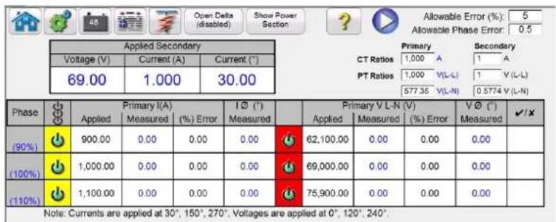
other
| Phase | Voltage (V) | Applied | Measured (%) | Current (*) | Measured (%) | Applied (%) | Measured (%) | Error (%) | |---|---|---|---|---|---|---|---|---| | (90%) | 69.00 | 900.00 | 0.00 | 0.00 | 0.00 | 62,100.00 | 0.00 | 0.00 | | (100%) | 1,000.00 | 1,000.00 | 0.00 | 0.00 | 0.00 | 69,000.00 | 0.00 | 0.00 | | (110%) | 1,100.00 | 1,100.00 | 0.00 | 0.00 | 0.00 | 75,900.00 | 0.00 | 0.00 | Note: Currents are applied at 30°, 150°, 270°; Voltages are applied at 0°, 120°, 240°. Allowable Error (%): 5 Allowable Phase Error: 0.5 Primary CT Ratios: 1,000 A PT Ratios: 1,000 V(L-L) 1 V(L-L) CT Ratios: 577.35 V(L-N) 0.5774 V(L-N) Secondary CT Ratios: 1,000 A PT Ratios: 1,000 V(L-L) 1 V(L-L) PT Ratios: 577.35 V(L-N) 0.5774 V(L-N)Figure 197. Meter Test Screen
The user simply selects the output channels similar to the manual vector test screen. Values can be in secondary (default) or Primary by clicking on the Primary Ratios windows and entering the CT and VT ratios (see Primary Ratios in the Configuration screen section for details). Enter the desired allowable error in % of reading in the window provided (be sure to take into consideration that this is the total error of the test set plus the error of the relay). Turn the outputs on by clicking on the Blue Run Test button Read and enter the metered values from the relay into the windows provided.
Press or click on the Show Power Section to reveal the power measurements as shown in the following figure.

Figure 198. Meter Test with Power Measurements
The software will automatically calculate the percent error. Click on the Test Report button to add the Meter test results to the test report.
3.9 Testing Differential Relays
The Differential Relay provides a quick and easy approach to testing three-phase Transformer, Motor, Generator, and single-phase Transformer, differential relays.
To access the Differential Relay Test press the Select New Test button next to the Relay Settings button

Press the Three Phase Transformer Differential Relay button to open the Three Phase Transformer Nameplate screen to enter information for the relay to be tested. It should be noted that the 1 Phase Transformer Differential settings screen is almost identical with the exception of the Change Connections buttons Labeled Use I1,2,3 and Use I4,5,6 changes to Use I1 and Use I2 respectively. There are two models to choose from, ANSI and IEC. You will find the selection button at the bottom left side of the window. Press the button to toggle between ANSI and IEC transformer models. Each model will present a transformer graphic commonly used for either North American, or European, style transformer protection. The values entered in the Transformer Nameplate will determine what values of current and phase angle relationships are applied to the relay in the tests.
Special Test Application Note: In the General Settings section of the System Configuration Screen, there is a button labeled Multi-Instances. This button allows the user to select multiple Differential relays to test and combine into one test result file. For example, some generator differential protection relays also include transformer differential protection. With the Multi-Instances button enabled, when the user selects the Differential test they will be see a list button to select the number of Instances (relays) they want to include in the test report.

Figure 199. Select (number of) Instances
For the example above, press 1 then select the first type of differential you want to test, i.e. 3 Phase Generator Differential. Input relay settings. Run the entire tests that you want for the relay. Then select the Home button and select the Select New Test button. For the second relay type i.e. 3 Phase Transformer Differential, press 2. Input relay settings. Run the entire tests for the second differential. When finished, press the Report Options button and all of the tests that were conducted will be listed by pages in the sequence in which they were performed.
3.9.1 Transformer Nameplate
The top half is the transformer model where the user selects the Transformer Primary and Secondary winding configurations, enters the Primary and Secondary Voltages ratings, CT ratios, the transformer MVA rating, enters the single phase pickup factor, selects if there are interposing CT's (and their associated CT Multiplier values), and enables lo (zero sequence) elimination when applicable. In the bottom half is the relay settings, bias equation selection window and slope selection window. Once these settings are entered, the software will automatically calculate and display the base currents in primary and secondary values for each winding. Note that throughout the tests, only secondary currents are considered. Primary currents will only be shown for informational purposes. These secondary base current values will be used to compute Amperes – Per Unit conversions.
3.9.1 Transformer nameplate

flowchart
graph TD
    A["115 V"] --> B["290 S A"]
    B --> C["100-409 A"]
    C --> D["876.75 A"]
    D --> E["Interposing CTs"]
    E --> F["1.00 V"]
    F --> G["CT Multiplier 3.49 A"]
    G --> H["Single Phase Pickup Factor 1.00"]
    H --> I["Use rt, Q, D"]
    E --> J["Current Tolerance 18 %"]
    E --> K["Trip Time Tolerance 19 % = 53 ms"]
    E --> L["Simulate Breaker NO"]
    E --> M["Use Reference Voltage NO"]
    E --> N["Harmosc Tolerance 17 %"]
    E --> O["Harmonic Ramp Made Ramp To No Operate"]
    E --> P["Nth Harmonic Control 30 % 2nd"]
    E --> Q["Normeter Current 30 %"]
    E --> R["Protected Object"]
    E --> S["Normstrate Format ANDI"]
    style E fill:#f9f,stroke:#333
    style F fill:#ccf,stroke:#333
    style G fill:#ccf,stroke:#333
    style H fill:#ccf,stroke:#333
    style I fill:#ccf,stroke:#333
    style J fill:#ccf,stroke:#333
    style K fill:#ccf,stroke:#333
    style L fill:#ccf,stroke:#333
    style M fill:#ccf,stroke:#333
    style N fill:#ccf,stroke:#333
    style O fill:#ccf,stroke:#333
    style P fill:#ccf,stroke:#333
    style Q fill:#ccf,stroke:#333
    style R fill:#ccf,stroke:#333
    style S fill:#ccf,stroke:#333
Figure 200. ANSI Transformer Nameplate Model with Interposing CT's and Io Elimination Selected
By entering the known values for the transformer and CT configurations, the software will automatically calculate the appropriate three-phase primary and secondary current values for testing the relay under test.
- Transformer Model Selection- Press to select the desired test model. Toggles between ANSI and IEC models.
- Enter the Transformer's Primary and Secondary voltages, MVA rating, and the Primary and Secondary Current Transformer data as specified by the relay. This includes CT ratios, CT polarities etc. If required, press or click on the vertical arrows to change CT polarity directions on both windings.
- Transformer Configuration Selection button . Press or click on this button to access the available selections for the primary and secondary winding configurations. Pressing on the button will provide the Primary Winding Selection box.

Figure 201. Primary Winding Selection Box
Press or click on the appropriate button that represents the primary winding. Available selections are Y, Yn (grounded
3.9.1 Transformer nameplate
Y), D (delta), Dn (grounded Delta), Z, Zn (grounded Z), or Compensated CT's. The letter 'n' signifies a neutral / earthed star-point in which a 1.5 constant will be applied to the single-phase tests. This is required for elimination of any zero sequence currents introduced when testing single phase to ground faults. The Compensated CT's selection tells the software to simulate externally connected CT's that perform all magnitude and phase compensation, therefore, no compensation, whether magnitude or phase will be applied internally by the software. After selecting the Primary Winding, the Secondary Winding Selection Box will appear.
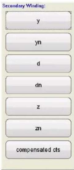
Figure 202. Secondary Winding Selection Box
Press or click on the appropriate button that represents the secondary winding. Available selections are y, yn (grounded Y), d (delta), dn (grounded Delta), z, zn (grounded Z), or compensated CT's. The Compensated CT's selection tells the software to simulate externally connected CT's that perform all magnitude and phase compensation, therefore, no compensation, whether magnitude or phase will be applied internally by the software. After selecting the Secondary Winding the Winding Clock Reference Selection Box will appear. Depending on your selection of the primary and secondary windings will determine which clock reference screen will appear. Your choices are 1,3,5,7,9, or 11o'clock if using a combination of Y, Delta or Z selections, or for Y – y / Delta – delta selections your choices are 0, 2, 4, 6, 8, 10, or 12 o'clock.
- The Interposing CT's button should be selected when interposing CT's are connected to the HV and LV windings of the relay, and are responsible for all Phase / Magnitude correction / compensation, and possible zero sequence (lo) elimination. When selecting interposing CT's the CT Multiplier window, item ^5 , will appear for the user to enter any appropriate CT multiplier values. The phase rotation of the output currents simulating the interposing CT's can be altered by pressing the arrow button. It will toggle between clockwise and counterclockwise rotation.
When selecting Interposing CT's, the Power System Vector Group Configuration should be selected based on this sample range of settings. For example, a Reyrolle MIB202 Numerical Bias Differential Relay with the following Interposing CT's Selection; HV (Yd1,- 30°) and LV (Yy0, 0°) requires a Vector Group Selection of Yd1, YNd1. Consult the relay manufacturer's instructional information to verify the appropriate vector group to be used for other possible Interposing CT Selections. If the manufacturer's information is not available the following guide is provided to assist the user in selecting an appropriate Transformer Vector Group.
3.9.1 Transformer nameplate
Transformer Vector Groups and Interposing CT Selection Guides
| Transformer Vector Groups HV Interposing CT Selection LV Interposing CT Selection | ||
| YNy0, Yy0, Ydy0, Yndy0, Yyn0, YNyn0, Ydyn0, Yndyn0, Dz0 | Ydy0, 0° Ydy0,0° | |
| Yd1,YNd1 Yd1, -30° Yy0,0° | ||
| Yd1, YNd1 + Grounding (Earthing) Transformer Yd1, | -30° Ydy0,0° | |
| YNy2, Yy2, Ydy2, Yndy2, Yyn2, YNyn2, Ydyn2, Yndyn2, Dz2 | Ydy2, -60° Ydy0,0° | |
| Yd3,YNd3 Yd3, -90° Yy0,0° | ||
| Yd3, YNd3 + Grounding (Earthing) Transformer Yd3, | -90° Ydy0,0° | |
| YNy4, Yy4, Ydy4, Yndy4, Yyn4, YNyn4, Ydyn4, Yndyn4, Dz4 | Ydy4, -120° Ydy0,0° | |
| Yd5,YNd5 Yd5, -150° Yy0,0° | ||
| Yd5, YNd5 + Grounding (Earthing) Transformer Yd3, | -150° Ydy0,0° | |
| YNy6, Yy6, Ydy6, Yndy6, Yyn6, YNyn6, Ydyn6, Yndyn6, Dz6 | Ydy6, -180° Ydy0,0° | |
| Yd7,YNd7 Yd7, -150° Yy0,0° | ||
| Yd7, YNd7 + Grounding (Earthing) Transformer Yd7, | -150° Ydy0,0° | |
| YNy8, Yy8, Ydy8, Yndy8, Yyn8, YNyn8, Ydyn8, Yndyn8, Dz8 | Ydy8, 120° Ydy0,0° | |
| Yd9,YNd9 Yd9, 90° Yy0,0° | ||
| Yd9, YNd9 + Grounding (Earthing) Transformer Yd9, | 90° Ydy0,0° | |
| YNy10, Yy10, Ydy10, Yndy10, Yyn10, YNyn10, Ydyn10, Yndyn10, Dz10 | Ydy10, 60° Ydy0,0° | |
| Yd11,YNd11 Yd11, 30° Yy0,0° | ||
| Yd11, YNd11 + Grounding (Earthing) Transformer Yd11, 30° Ydy0,0° | ||
| Dy1, Dyn1 | Yy0, 0° | Yd11, 30° |
| Dy1, Dyn1 + Grounding (Earthing) Transformer | Ydy0, 0° Yd11, 30° | |
| Dy3, Dyn3 | Yy0, 0° | Yd9, 90° |
| Dy3, Dyn3 + Grounding (Earthing) Transformer | Ydy0, 0° Yd9, 90° | |
| Dy5, Dyn5 | Yy0, 0° | Yd7, 150° |
| Dy5, Dyn5 + Grounding (Earthing) Transformer | Ydy0, 0° Yd7, 150° | |
| Dy7, Dyn7 | Yy0, 0° | Yd5, -150° |
| Dy7, Dyn7 + Grounding (Earthing) Transformer | Ydy0, 0° Yd5, -150° | |
| Dy9, Dyn9 | Yy0, 0° | Yd3, -90° |
| Dy9, Dyn9 + Grounding (Earthing) Transformer | Ydy0, 0° Yd3, -90° | |
| Dy11, Dyn11 | Yy0, 0° | Yd1, -30° |
| Dy11, Dyn11 + Grounding (Earthing) Transformer | Ydy0, 0° Yd1, -30° | |

- 10 Elimination button (enabled) . Press this button to enable the zero sequence elimination feature. For relays with neutral / earthed star-point connections, a 1.5 constant will be applied to the single-phase tests. This is required for elimination of any zero sequence currents introduced when testing single phase to ground faults. If the relay being tested does not adopt this approach, then lo elimination should be disabled.

It should be noted that some relay manufacturers have different zero sequence correction factors for single-phase faults, where the default constant of 1.5 does not apply (depending upon the transformer vector group see item above for even and odd vector groups). For example, single-phase faults in Siemens 7UT613 relay the even number vector groups' use 1.5, while the odd number vector groups' use 1.73. Consult the relay manufacturer's instructional information to verify the
pickup factors to be used. If you use a correction factor other than 1.5, you will need to disable the lo elimination and manually enter the appropriate factor in the window provided.
- Single Phase Pickup Factor - Once the vector groups are selected, the single phase pickup factors required to run single phase pickup tests are predetermined. If these settings do not match the relay's compensation factors, then the values should be adjusted from the input fields provided.
It should be noted that some of the relay manufacturers adopt their own pickup factors. Consult the relay manufacturer's instructional information to verify the pickup factors to be used.
- Relay and Test Settings – The values entered will be used to perform the tests and evaluate the results. Consult the relay manufacturer's instructional information to verify the settings and tolerances.
Pickup and Pickup Tolerance: Enter the appropriate Per Unit value for the pickup value, and its associated tolerance.
Trip Time and Trip Time Tolerance: Enter the appropriate trip time of the relay, and its associate tolerance.
Prefault Level: Is set in percent of Full Load Current as seen by the relay. Pick up and slope tests are performed using Pulse Ramp. This current will be applied to the relay prior to each pulse ramp increment for the Prefault Time duration.
Prefault Time: Is set in milliseconds. This will be the period of time that the Prefault currents will be applied prior to applying test values.
Off Delay: Is a time value set in milliseconds. When the relay operates, the software will extend the fault current for the off delay time entered to simulate the time delay associated with the breaker opening before the outputs go to zero. This is used for relays that sense for breaker failure by detecting the presence of fault current after issuing a trip. Enter the opening time of the breaker associated with the transformer being protected. If the operating time is unknown use the default time of 50 milliseconds.
Through Fault: Is set in percent of Full Load Current as seen by the relay on both the primary and secondary sides of the transformer.
2nd Harmonic Content: Enter the % of second harmonic restraint set in the relay.
Fault Duration: Is set in milliseconds. This will be the time that the incremental "fault" current will be applied to the relay during the pickup, slope, and harmonic restraint tests. Set the duration time long enough for the relay to operate, or leave at the default value.
Harmonic Tolerance: Is set in percent value, used to evaluate the pickup of the 2nd harmonic restraint element.
Nth Harmonic Content: For relays with more than one harmonic restraint, enter the order of the harmonic by pressing or clicking on the harmonic selection button, then press or click in the % window to enter the percent value of the harmonic.
- Slope Characteristic Selection button: Pressing this button will provide the following selection windows.
3.9.1 Transformer nameplate
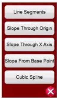
Figure 203. Slope Characteristics Selection Menu
The slope characteristics vary by manufacturer design. Five options provided cover the various designs. In addition, slope characteristics are also determined by the following settings
Pickup value: This represents the lower flat line of the graph and is the minimum differential current required for the relay to trip
Unrestrained Pickup value
Slope 1, and 2 start points and gradients (start points and gradients 3 and 4 appear when selecting Line Segments)
Slope setting
I Bias equation setting
Line Segments: The Line Segments option allows for virtually any slope characteristic design with up to four segments. When Line Segments is selected, the window provides up to four slope options. Setting values vary such as knee points and % slope. Check relay settings for actual setting values.
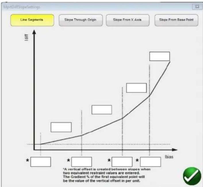
line
| Bias | Slope Difference | |------|------------------| | 0 | 0 | | 5 | ~2 | | 10 | ~4 | | 15 | ~6 | | 20 | ~8 | | 25 | ~10 | | 30 | ~12 | | 35 | ~14 | | 40 | ~16 | | 45 | ~18 | | 50 | ~20 | | 55 | ~22 | | 60 | ~24 | | 65 | ~26 | | 70 | ~28 | | 75 | ~30 | | 80 | ~32 | | 85 | ~34 | | 90 | ~36 | | 95 | ~38 | | 100 | ~40 |Enter knee point and slope values for each segment.
Slope Through Origin: The line starts at the origin and rises at the Gradient % setting. Slope Line 1 segment is defined by where the Slope 1 line intersects with the Minimum Pickup (represented by the lower flat line of the graph) and stops at the Slope Line 2 segment IBias (p.u.) setting in the Slope Line Segment window.
3.9.1 Transformer nameplate
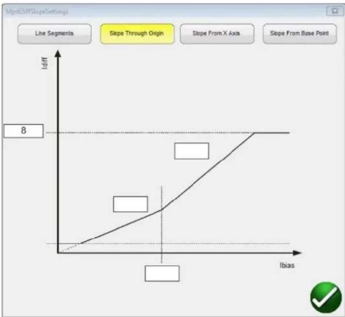
line
| Ibias | Idiff | |-------|-------| | 0 | 0 | | Low | Low | | High | 8 |Slope From X Axis: The line starts on the X Axis at the I restraint (pu) value entered in the Line Segment window and rises at the Gradient % setting. Slope Line 1 segment is defined by where the Slope 1 line intersects with the Minimum Pickup (represented by the lower flat line of the graph) and stops at the Slope Line 2 segment IBias (p.u.) setting in the Slope Line Segment window.
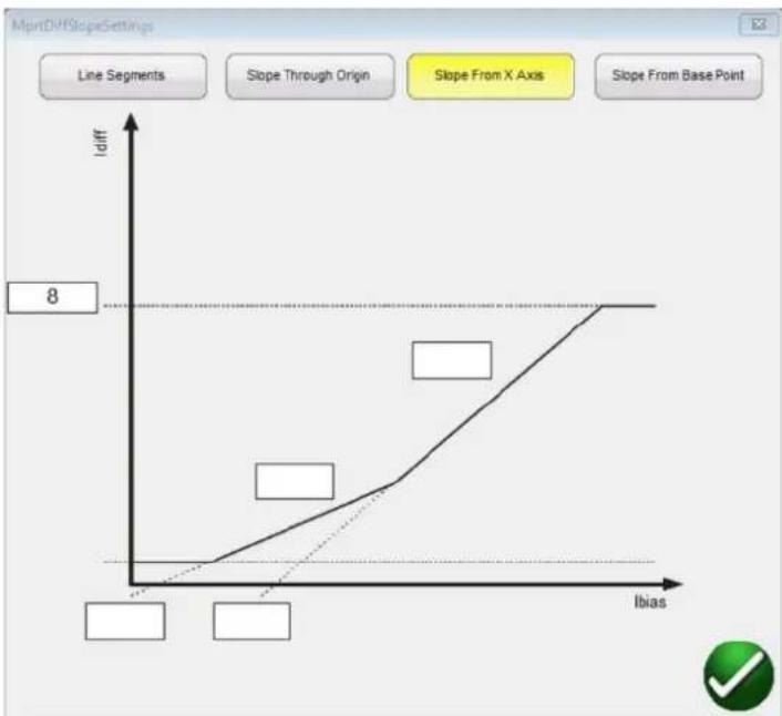
line
| Ibias | Idiff | |-------|-------| | Low | 0 | | Medium| 2 | | High | 8 |Slope From Base Point: The Slope 1 line segment starts where the X Axis I restraint (p.u.) value entered in the Line Segment window intersects with the Minimum Pickup (represented by the lower flat line of the graph) and rises at the Gradient % setting. Slope Line 1 segment stops where at the Slope Line 2 segment IBias (p.u.) setting in the Slope Line Segment window.
3.9.1 Transformer nameplate

line
| Ibias | Idiff | |-------|-------| | 0 | 0 | | 1 | 2 | | 2 | 4 | | 3 | 6 | | 4 | 8 |Cubic Spline: This characteristic is normally associated with the G.E. T60 or T35 relays. The Slope 1 and 2 settings express the slope of the operating characteristic as a function of differential current (Id) and restraint current (Ir). The Slope 1 line segment starts near the Pickup point and rises at the % slope gradient to Breakpoint 1. From Breakpoint 1 to Breakpoint 2 is the Cubic Spline Transition Region. Slope two starts at Breakpoint 2 and rises at the % slope gradient.
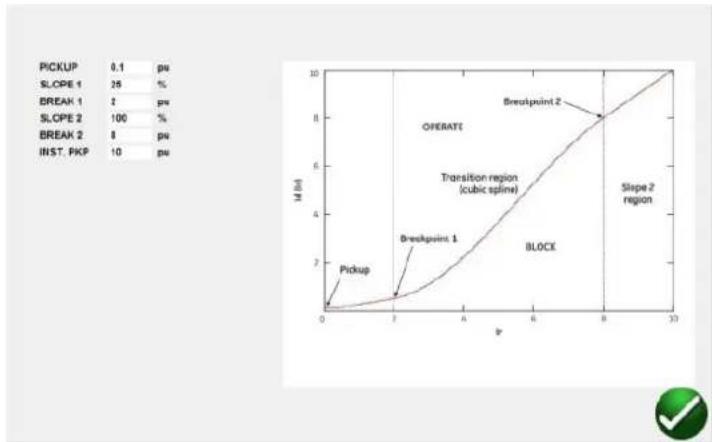
line
| Region | Slope (%) | Value | | :--- | :--- | :--- | | Breakpoint 1 | 1 | 0.5 | | Breakpoint 1 | 2 | 0.8 | | Breakpoint 1 | 3 | 1.2 | | Breakpoint 1 | 4 | 1.6 | | Breakpoint 1 | 5 | 2.0 | | Breakpoint 1 | 6 | 2.4 | | Breakpoint 1 | 7 | 2.8 | | Breakpoint 1 | 8 | 3.2 | | Breakpoint 1 | 9 | 3.6 | | Breakpoint 1 | 10 | 4.0 | | Breakpoint 2 | 0.1 | 0.5 | | Breakpoint 2 | 2 | 1.0 | | Breakpoint 2 | 5 | 2.0 | | Breakpoint 2 | 8 | 4.0 | | Breakpoint 2 | 10 | 8.0 | | Breakpoint 2 | Slope 1 | - | | Breakpoint 2 | Slope 2 | - | | Breakpoint 2 | Slope 3 | - | | Breakpoint 2 | Slope 4 | - | | Breakpoint 2 | Slope 5 | - | | Breakpoint 2 | Slope 6 | - | | Breakpoint 2 | Slope 7 | - | | Breakpoint 2 | Slope 8 | - | | Breakpoint 2 | Slope 9 | - | | Breakpoint 2 | Slope 10 | - | | Block | - | - | | Block | - | - | | Block | - | - | | Block | - | - | | Block | - | - | | Block | - | - | | Block | - | - | | Block | - | - | | Block | - | - | | Block | - | - | | Block | - | - | | Block | - | - | | Block | - | - | | Block | - | - | | Block | - | Not visible in chart label (not present in the image)- IBias Equation: Pressing or clicking on this button will present the user with a list of nine different biasing (restraint) equations. Different relay manufacturers use different methods for restraining the operation of the differential element. Consult the relay manufacturer's instructional information to verify which equation to use.
The following are some example relays and associated equations.
| Equation Manufacturer | |
| (|lp| + |ls|) SEL 487, SEL 787, Siemens 7UT5X and 7UT6X Series | |
| (|lp| + |ls|) / 2 SEL 387, SEL 587 | |
| Max |lp| or |ls| ABB RET670, GE Multilin SR 745 | |
| (lp + ls - Idiff) / 2 ZIV | |
-
Unrestrained Pickup: Enter the appropriate value for the unrestrained pickup in Per Unit.
-
Slope Characteristic Line Segment Definition Table: Depending on which Slope Characteristic was chosen, see ⑨ above, the number of slope lines will vary from 2 to 4, and the IBias pickup values will vary depending on whether the slope goes through the Origin or not. See the line descriptions above for examples.
3.9.2 Transformer differential tests
-
Harmonic Ramp Mode: User may select to ramp the percent of harmonic content in the fundamental up until the relay goes into restraint (Ramp To No Operate), or down to decrease the percent of harmonic until the relay drops out of restraint (Ramp To Operate).
-
Nominal Current: Press or click on the button to toggle between Current Transformer and Protected Object. Use to select either the calculated tap values, or the rated secondary current of the CT (use as balanced vector magnitudes during the stability test). If Protected Object is selected, W1 / W2 magnitudes will be calculated from MVA, KV, and CT settings. If Current transformer is selected, W1 / W2 magnitudes will be set at the rated secondary current of the CT, i.e. 1 or 5 Amperes.
-
Import Settings: Click here to access differential relay settings and import into the differential relay test template in XML file format. This feature is similar to the Impedance relay import of relay settings. It is designed to speed up the testing of differential relays and reduce errors. Presently imports the ZIV relay settings.
-
Add Settings to Report: Press or click on this button to include the relay settings into the test report.
-
ICT Correction button is used when testing Reyrolle Duo bias transformer protection relays with interposing current transformers. When the IEC model ① is selected, and the Interposing CT's ④ is selected, and the ICT Correction button ⑰ is selected Yes, the FREJA Local / Remote software will recalculate the CT Multiplier value using the ICT Correction. This calculation is used in all tests except the Stabilization test.
-
Relay Library button

Pressing the Relay Library button will provide a library of relay specific characteristics by various manufacturers. Selection from the list will automatically populate the appropriate Slope Characteristic, IBias Equation, and Slope Characteristic Line Segment Definition Table. The user may need to change some the defaulted values such as % Gradient settings, to fit the relay under test.
3.9.2 Transformer Differential Tests
When all the transformer and relay settings have been entered, press or clicks on the green check mark. The user will be taken to the first test screen, the Stabilization Test. To see a list of all the tests available, press or click on the Test List button

Figure 204. Test List
The user may select to perform any individual test by pressing the desired test button. After selection of the test, to execute any selected test press or click on the Blue Run Test button ☐ Press or click on the Blue Run All button and a list will be provided; Run All (Selected) Tests, Run All Remaining (Selected) Tests, Run All Differential Tests, or Run All Remaining Differential Tests.
The following is a description of each test.
3.9.2.1 Stabilization Test
The stability test verifies the relay being tested is stable for external 3-phase faults. Settings that affect stability test are:
3.9.2.2 Timing test
– Power transformer, current transformer, vector group combination settings: these settings will determine the correct magnitude and phase angles to be injected on all phases for both windings of the relay.
- Through Fault level- this sets the through fault percentage of the balanced currents applied to the relay. Setting this to 100% will inject 1x the rated current of winding1 and winding2. Setting this to 200% will inject 2x those values.
- Nominal Current in Use – The software will apply either the calculated tap values or the rated secondary current of the CT as balanced vector magnitudes during the stability test. If Protected Object is selected, W1 / W2 magnitudes will be calculated from MVA, KV, and CT settings. If Current transformer is selected, W1 / W2 magnitudes will be set the rated secondary current of the CT i.e. 1 or 5.
- Connect the appropriate output terminal(s) for the selected channel(s) to be used.
- Connect the desired Binary Input terminal to sense the relay trip contacts. Press the selected Binary Input. If the Binary Input is already set to Use as Trip (enabled), select for the appropriate sensing Normally Open, Normally Closed, Voltage Applied, or Voltage Removed.
- Press or click on the Blue Run Test button to run stability test. This will inject the balanced 3 phase currents based upon the Transformer and Vector Group settings. For a stable condition, the relay is not expected to trip. Enter the metered values from the relay and observe that they correspond to the injected values. Press or click on the Finish / Abort button (if the injected values do not correspond, press or click on Simulate Contact or Force Failure buttons). Note that the relay might not trip if the differential function has been turned off, or the injected values are not sufficient enough to produce the minimum differential current (this is also considered as a failed test even if the relay does not trip).
If the relay trips instantaneously, verify nameplate settings correspond to relay settings, verify connections are correct etc. To View the test result, press the Add to Reports button
3.9.2.2 Timing Test
Timing test verifies the relay being tested operates at the expected trip time for internal three phase faults or internal phase to earth faults. Settings that affect timing test are:
– Power transformer, current transformer, vector group combination settings: these settings will determine the correct magnitude and phase angles to be injected on all phases for both windings of the relay.
- Trip time – This is the expected trip time for the relay to operate. This value should be verified from the relay. If the relay does not trip, the software will inject the fault vector for 2* the expected trip time and then automatically stop the test.
- Prefault Level / Prefault Duration – these values configure the prefault vector that will be injected before fault vectors are applied.
-
Connect the appropriate output terminal(s) for the selected channel(s) to be used.
-
Connect the desired Binary Input terminal to sense the relay trip contacts. Press the selected Binary Input. If the Binary Input is already set to Use as Trip (enabled), select for the appropriate sensing Normally Open, Normally Closed, Voltage Applied, or Voltage Removed.
-
Press or click on the Blue Run Test button to run the Timing Tests. For the single phase tests, the fault vector will be applied on the phase being tested, while balanced (prefault) current vectors will be applied across the other phases. For the three phase tests, the test set will inject the fault vectors across all 6 phases.
-
To View the test result, press the Add to Reports button

3.9.2.3 Pickup Test
The pickup test verifies the minimum operate current of the differential relay. The test is performed using a Pulse Ramp, which applies the appropriate prefault value before the Ramping beings. The Pulse Ramp will return to the Prefault condition between each increment. Based on the settings of the relay, the Pulse Ramp begins at 85% of the expected
pickup value, applying the prefault and fault vectors appropriately until the relay trips. If this trip signal is detected within the tolerance ranges of the relay, a pass message will be displayed. If on first injection a trip signal is detected the ramp will return to 50% of the expected pickup value and run from there. If a trip signal is detected at 50% then a failure message is displayed.
Considerations to make before running the pickup test
- During the single-phase test, the selected vector group would have defined the single-phase pickup factors that will be used for the test. It is imperative that these values match the values that are specified by the relay manufactures' manual (Relay manufacturers may sometime defer from the Differential standard single-phase pickup factors).
- During the single-phase test, if the selected vector group has an earthed star-point on either or both of the windings, it is essential to select if the relay compensates for zero sequence currents introduced by the phase to ground fault. When zero sequence (lo elimination) is enabled a 1.5 factor is introduced to eliminate any zero sequence currents. If the relay does not perform zero sequence elimination this factor is not needed and should be disabled.
– During the three-phase test, the selected vector group would have defined the phase compensation values across all 6 phases. It is imperative that the vector group selected matches the vector group on the relay settings.
Settings that affect Pickup test
– Power transformer, current transformer, and vector group combination settings determine the tap current, which will be used to convert the Per Unit value to actual Amperes that is injected into the relay. The vector group settings will determine the single-phase pick up factors, which adjusts the Ampere value injected to compensate the vector magnitudes based on a wye, delta or zigzag-connected transformer.
- Pickup – This is minimum pickup Per Unit value required for the relay to operate. The search routine will begin from 85% of the minimum pickup and pulse ramp until it finds the operating point. If this value is not entered correctly in the settings screen, the search routine will be performed incorrectly.
- Prefault Level / Time – these values configure the prefault vector that will be injected before any fault vectors.
– Fault Duration – this setting defines the number of milliseconds the fault vector will be applied. Make sure that this value is slightly more than the operating time of the relay to ensure that the test set will see the trip contacts pickup.
-
Connect the appropriate output terminal(s) for the selected channel(s) to be used.
-
Connect the desired Binary Input terminal to sense the relay trip contacts. Press the selected Binary Input. If the Binary Input is already set to Use as Trip (enabled), select for the appropriate sensing Normally Open, Normally Closed, Voltage Applied, or Voltage Removed.
-
Press or click on the Blue Run Test button to run the Pickup Test. A menu list will be presented to the user to select which winding to test. For the single phase tests, the fault vector will be applied on the phase being tested, while balanced (prefault) current vectors will be applied across the other phases. For the three phase tests, the test set will inject the fault vectors across all 6 phases.
-
To View the test result, press the Add to Reports button

3.9.2.4 Slope Test
The slope test verifies the bias differential characteristic of the relay. For each value of the bias (restraint) value selected, a search-line routine finds the value of the pickup point necessary for the relay to operate. These values are plotted on the characteristic graph.
Settings that affect the Slope Test
– Power transformer, current transformer, vector group combination settings: these settings will determine the tap current, which will be used to convert the PU value to actual Amperes that is injected into the relay. The vector
3.9.2.4.1 Characteristic shot test
group settings will determine the phase compensation to be applied during the 3-phase fault test. The phase angles will be adjusted automatically during the search routine based on the clock group selected.
- I Bias Equation – the current magnitudes injected to the relay are calculated based on the bias formula the relay uses. The primary (I1) and secondary (I2) currents are calculated from Id and Ir simultaneously. Consequently, it is imperative the I Bias Equation selection matches the equation specified by the relay being tested.
- Slope setting - This defines the way the characteristic is drawn. It is important to select the appropriate slope settings in order to draw the appropriate theoretical characteristic for the relay.
- Prefault Level / Time – these values configure the prefault vector that will be injected before any fault vectors.
– Fault Duration – this setting defines the number of cycles the fault vector will be applied for.
Creating Search Lines
Upon selecting the Slope Test the user will be taken to the Slope Test Screen, which includes the graphic display of the relay Slope Characteristic. Click in the characteristic window to create a search line associated with the slope characteristic. The following is an example with four test lines drawn.

Note the blue limit lines in the above figure. This Slope Test Screen is based upon using a FREJA549 with six current channels capable of providing up to 60 Amperes each. Therefore, there is virtually no limit regarding the operating and restraint currents. If using a FREJA536 / 546 with the voltage channels converted to currents, a blue limit line will appear from the right side of the graphic which may cross the upper portion of the slope characteristic depending upon the relay settings. The second blue line indicates the limits regarding the maximum output current from the convertible channels, and shows area of the slope characteristic that can be tested.
If you mistakenly enter a test line and want to delete it press or click on the Run Edit button associated with the selected test #. The user will see a list of actions that can be done. One of the actions is Delete. Pressing the Delete button, the software will ask you to confirm that you want to delete the test(s).
-
Run all tests by either pressing or clicking on the Blue Run Test button 📄. To run individual tests press or click on the Run Edit button for the individual tests. When the test starts a red arrow test line will start ramping up the search line. Once the arrow enters the acceptable tolerance line the arrow will change color to green. When the relay operates, if the test point is within the acceptable min / max tolerance lines a green dot will appear, the % error will be displayed in the test table along with Pass declaration, and the test will move onto the next test line. If the test point is outside the acceptable tolerance a red X will appear, the % error will be displayed in the test table with the Fail declaration.
-
To View the test result, press the Add to Reports button

3.9.2.4.1 Characteristic Shot Test
The Characteristic Shot Test is similar to the Slope Test. However, instead of drawing test lines the user simply clicks above and below the characteristic line.
Creating Test Points
Upon selecting the Characteristic Shot Test, the user will be taken to the Slope Test Screen, which includes the graphic display of the relay Slope Characteristic. To create test points, click in the characteristic window above and below the slope characteristic. The following is an example with six test points, three above and three below the slope line.

line
Characteristic Shot Test (L1-L2-L3) | # | restraint (pu) | inoperate (pu) | W1 (A) | W2 (A) | √ / x | |---|---|---|---|---|---| | 1 | 2.30 | 1.00 | 7.03 | 6.28 | ✓ ... | | 2 | 2.60 | 0.30 | 6.90 | 8.54 | ✓ ... | | 3 | 5.30 | 2.50 | 16.44 | 14.12 | ✓ ... | | 4 | 7.20 | 3.50 | 22.47 | 19.00 | ✓ ... | | 5 | 6.20 | 1.90 | 17.95 | 16.30 | ✓ ... | | 6 | 8.30 | 2.80 | 24.35 | 24.06 | ✓ ... | Characteristics (bit): In/hearrest (gut)Figure 205 Slope Characteristic Shot Test Screen
Execute the test similar to the Slope Test described above.
3.9.2.5 Harmonic Block Test
The harmonic block test verifies the proper operation of the harmonic restraint element of the relay. The test is based upon the 2nd Harmonic Content (and / or Nth Harmonic Content) and Harmonic Tolerance entered in the settings. In the test screen the user can select individual phases for test as well as three phase test, either Primary or Secondary side of the transformer.
The Harmonic Block test is performed by applying a fundamental current equal to the Pickup setting, which will cause the relay to operate and close the trip contacts. The harmonic content will slowly be ramped up increasing the percent of harmonic until the relay goes into restraint. At that point the percent of harmonic is recorded.
Settings that affect the Harmonic Block test
– Power transformer, current transformer, and vector group combination settings determine the tap current, which will be used to convert the Per Unit value to actual Amperes that is injected into the relay. This will be the fundamental current applied at the start of the test.
- Prefault Level / Time – these values configure the prefault vector that will be injected before any fault vectors.
- Fault Duration – this setting defines the number of milliseconds the fault vector will be applied. Make sure that this value is slightly more than the operating time of the relay to ensure that the test set will see the trip contacts pickup.
- Harmonic Content – The search routine will begin from 85% of the expected restraint value and ramp the harmonic content up until it finds the restraint point. If this value is not entered correctly in the settings screen, the search routine will be performed incorrectly.
- Harmonic Tolerance - This value is used to determine Pass / Fail.
- Connect the appropriate output terminal(s) for the selected channel(s) to be used.
- Connect the desired Binary Input terminal to sense the relay trip contacts. Press the selected Binary Input. If the Binary Input is already set to Use as Trip (enabled), select for the appropriate sensing Normally Open, Normally Closed, Voltage Applied, or Voltage Removed.
3.9.2.6 Harmonic shot test

Application Note: The Prefault values will be applied prior to applying the harmonic block test. Make sure that all three-phase outputs are connected to the relay under test. When the ramp starts the PU Tap current will be applied, thus the relay will close the trip contacts. Therefore, set the binary input to sense Normally Closed (Trip) contacts to Open (Restraint). If using wetted contacts set the binary input to sense Voltage Removed.
-
Press or click on the Blue Run Test button to run the Harmonic Block Test. A menu list will be presented to the user to select which winding to test. For the single phase tests, the test current will be applied on the phase being tested, while zero current will be applied across the other two phases. For the three phase tests, the test set will inject the fault vectors across all 3 phases on the desired Winding (Primary or Secondary).
-
To View the test result, press the Add to Reports button

3.9.2.6 Harmonic Shot Test
The harmonic shot test is a GO / NO GO test to quickly verify the proper operation of the harmonic restraint element of the relay. The test is based upon the 2nd Harmonic Content (and / or Nth Harmonic Content) and Harmonic Tolerance entered in the settings. In the test screen the user can select individual phases for test as well as three phase test, either Primary or Secondary side of the transformer.
The Harmonic Shot test is performed by applying a 5% above the harmonic restraint pickup value to see if the relay will restrain, and then apply 5% below the harmonic restraint pickup value to see if the relay operates.
Settings that affect the Harmonic Shot test
– Power transformer, current transformer, and vector group combination settings determine the tap current which will be used to convert the Per Unit value to actual Amperes that is injected into the relay. This will be the fundamental current applied at the start of the test.
- Prefault Level / Time – these values configure the prefault vector that will be injected before any fault vectors.
– Fault Duration – this setting defines the number of milliseconds the fault vector will be applied. Make sure that this value is slightly more than the operating time of the relay to ensure that the test set will see the trip contacts pickup.
- Harmonic Content – If this value is not entered correctly in the settings screen, the test routine will be performed incorrectly.
- Connect the appropriate output terminal(s) for the selected channel(s) to be used.
- Connect the desired Binary Input terminal to sense the relay trip contacts. Press the selected Binary Input. If the Binary Input is already set to Use as Trip (enabled), select for the appropriate sensing Normally Open, Normally Closed, Voltage Applied, or Voltage Removed.

Application Note: The Prefault values will be applied prior to applying the harmonic block test. Make sure that all three phase outputs are connected to the relay under test. Set the binary input to sense Normally Open contacts to be Open (Restrain at +5%) and Close (Trip at -5%).
- Press or click on the Blue Run Test button to run the Harmonic Shot Test. A menu list will be presented to the user to select which winding to test. For the single-phase tests, the test current will be applied on the phase being tested, while zero current will be applied across the other two phases. For the three phase tests, the test set will inject the fault vectors across all 3 phases on the desired Winding (Primary or Secondary).
To View the test result, press the Add to Reports button

3.10 Synchronizer Test
The Synchronizer Test is only available for FREJA units, which have the Enhanced feature enabled. Pressing the Synchronizer test button provides the testing of synchronizing relays. These tests should be conducted in accordance with the manufacturers relay specifications.
3.10.1 Synchronizer relay settings and configuration screen
Selection of the Synchronizer button will provide the following Relay Settings and Configuration screen.
3.10.1 Synchronizer Relay Settings and Configuration Screen
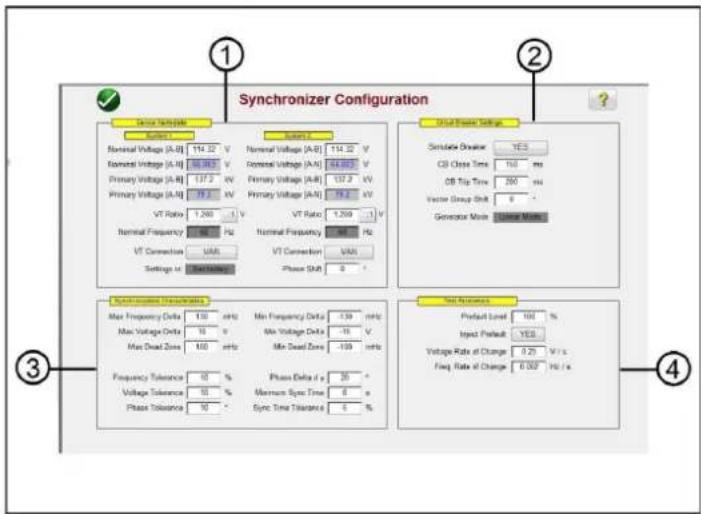
Figure 206. Synchronizing Relay Settings and Configuration Screen
3.10.1.1 ① Device Nameplate – System Settings
The relay test system voltage channels are used to simulate the two systems being synchronized together, as represented as System 1 and System 2. Enter the appropriate System Values in the windows provided. Note that if you enter the primary values and VT Ratios the software will automatically calculate the appropriate secondary voltages to be applied, and vice versa. Pressing or clicking on the VT Connection button will provide a list to select which voltage channels will be applied to the relay under test.
3.10.2 ② Circuit Breaker Settings
Press or click on the Simulate Breaker operation if you need to simulate the circuit breaker Closing or Opening. Enter the appropriate Breaker Close and Trip times in the windows provided. The Generator Mode is set to Linear Mode. The linear mode uses the dv/dt and df/dt to control the system outputs.
3.10.3 ③ Synchronization Characteristic Settings
Enter the relay settings into the windows provided. The Max and Min values represent the difference between System 1 reference values and System 2 test values. The Tolerance values are normally based upon the relays specifications.
3.10.4 ④ Test Parameters
If the relay requires Prefault values be applied prior to starting the test, press or click on the Inject Prefault button to select yes. As mentioned previously the linear mode uses the dv/dt and df/dt to control the system outputs. Based upon the relay settings, enter the appropriate Rate of Change for the Volts / Second and the Hz / Second.
3.10.5 Synchronizer Characteristic Test Selection Screen
After all the setting values have been entered, press or click on the Green check button, which will take you to the Test Selection Screen. In the test selection screen the user may select from three different tests, Quick Test, Dynamic Test, and Point of Origin test, or the user may create their own test lines by pressing or clicking on the test screen first outside and then inside the characteristic.
3.10.5.1 Configuration button

Figure 207. Synchronizer Characteristic Test Selection Screen
3.10.5.1 ① Configuration button

Press the button to go to the FREJA Local / Remote Configuration Screen. See Section 2.2.1 Configuration for more information of the Configuration Screen.
3.10.5.2 ① Battery Simulator button

The Battery Simulator button – Turns the Battery Simulator ON and OFF by pressing the button, the color changes red for ON and black for OFF. The voltage to be applied is displayed in the button and can be changed by pressing the configuration button.
3.10.5.3 ① Test Report button
Press this button to review the test results.
3.10.5.4 ① Synchronizer Relay Settings and Configuration Screen button

Return to the Synchronizer Characteristic Screen button provides access back to the relay and test settings screen.
3.10.5.5 ① Binary Input Setting button
Press this box to reveal the Binary Input Dialog box.

The default settings are Binary Input 1, dry contacts as indicated by the Input Type, and Input Action defaults to show the Closing of the Normally Open contacts. To change the Input Type from dry contacts to Voltage, press the Input Type Transducer button, and it changes to voltage. To change to the opening of Normally Closed contacts press the
3.10.5.6 Relay library button
Input Action Transducer button and it changes to show closed contacts opening. For timing the operating time of the synchronizing element the timer is defaulted to Latched Input enabled mode, which means the timer will stop on the first contact closure. Note the Debounce time is set to 2 milliseconds.
3.10.5.6 ⑥ Relay Library button
Reserved for future use; pressing the Relay Library will provide a library of relay specific characteristics by various manufacturers.
3.10.5.7 ⑦ Predefined Test button
Pressing the predefined test button, the user can select from a list of predefined frequency relay tests that were previously saved to the database.
3.10.5.8 ⑧ Run Test button
Pressing or clicking the Blue Run Test button will apply the Prefault vector for the specified Time, and then will run all the test lines on the test screen.
3.10.5.9 ⑨ Run All Tests button
Pressing the Run All Tests button will provide the user with a list to select which test(s) they desire to run, see the following figure.
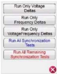
Since some relays only respond to only to f frequency change, the user can select to Run Only Frequency deltas.
To remove test lines associated with the V , press or click on the Run / Edit button located next to the test associated with the dV (V) test and select Delete from the menu. The same is true should the user desire to remove any other test line (s).
3.10.5.10 ⑩ Help button ?
Pressing this button will open the help associated with the Synchronizer test.
3.10.5.11 ⑪ Quick Test button
Four test lines will be drawn (two will ramp frequency, and two will ramp voltage). Any test lines can be deleted and redrawn by the user as desired using the Run / Edit button. Press the Run / Edit button for the individual test line. The user will then be presented with the following option screen.
3.10.5.12 Dynamic points option
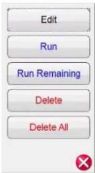
Figure 208 Run / Edit button Options
The user can; Edit the Start and End values, Run the selected test individually, Run the Remaining tests, Delete the selected test, or Delete All Tests. Press the red X to exit.
3.10.5.12 ⑫ Dynamic Points option
The Dynamic Points option provides eight test lines. It is similar to the Quick Test it provides an additional 4 test lines, one on each corner of the characteristic representing a dynamic ramp of both voltage and frequency.
3.10.5.13 ⑬ Origin Test Points option
The Origin Test Points option – Similar to the Dynamic Points options with 8 test lines, only the end point is the origin.
3.11 Frequency Test
The Frequency Test is only available for FREJA units which have the Enhanced Software feature enabled. Pressing the Frequency test button provides the testing of frequency sensing relays. These tests should be conducted in accordance with the manufacturers relay specifications.
Selection of the Frequency button will provide the following Relay Settings and Configuration screen.
3.11.1 Frequency Relay Settings and Configuration Screen

Figure 209. Frequency Relay Test Settings Screen
3.11.1.1 Under frequency relay test settings
There are three types of frequency relay test options, Under Frequency, Over Frequency, and df/dt. If your relay is Under frequency only, simply press or click on the Over and df/dt buttons to deselect these settings windows. Press the Add Settings to Report to add the relay and test settings to the final test report. The following are descriptions of each settings window.
3.11.1.1 ① Under Frequency Relay Test Settings
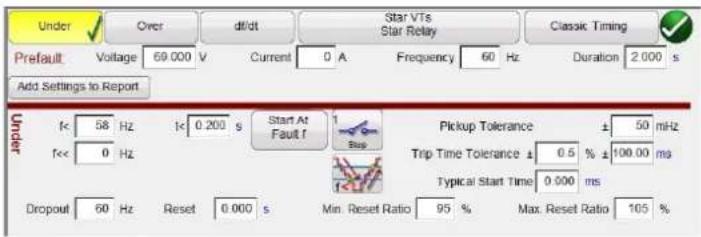
Figure 210. Under Frequency Relay Test Settings
f<: Enter the relay under frequency setting value for pickup.
t<: Enter the relay trip time setting value in seconds. Click on the s to change to cycles.
f<<: Enter the relay under frequency setting value for the fault frequency.
Start At Fault f: There are two buttons associated with the Timer Start; Start Timer At Pickup Frequency and Start Time with Binary Input.

Figure 211. Timer Start At Selection List
Starting the timer at pickup simply means that the timer will start running when the test frequency crosses through the pickup frequency point either as a ramp or as a step function. Starting the timer with binary input simply means the timer will be started from an external contact closing.
Stop: Press or click on the binary input Transducer button to select which binary input will be used to stop the timer, and select the Input Type and Input Action associated for the timer stop.
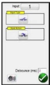
Figure 212. Binary Input Screen
The default settings are Binary Input 1, dry contacts as indicated by the Input Type, and Input Action defaults to show the Closing of the Normally Open contacts. To change the Input Type from dry contacts to Voltage, press the Input Type Transducer button, and it changes to voltage. To change to the opening of Normally Closed contacts press the Input Action Transducer button and it changes to show closed contacts opening. For timing the timer is defaulted to Latched Input enabled mode, which means the timer will stop on the first contact closure. Note the Debounce time is set to 2
3.11.1.2 Over frequency relay test settings
milliseconds.
Pickup Mode: Press or click on the Pickup Mode Transducer button 📄 to select the mode of ramping the outputs. There are two modes to select from. The default Transducer button is a single ramp down starting from the prefault frequency towards the fault frequency (f<<). The second selection is a double ramp down and back up button looking for pickup and dropout associated with multi-set point relays.
Pickup Tolerance: Enter the pickup tolerance of the relay under test in ± mHz.
Trip Time Tolerance: Enter the time tolerance of the relay under test. Two entries are available, ± % of time setting and ± ms. Note: changing the Prefault Duration time to Cycles will change the time tolerance to Cycles.
Typical Start Time: This is known time delay value associated with the relay under test. This time value is associated with the relay delay time in detecting the pickup frequency value over one or more cycles, and then making a decision to indicate the pickup or trip outputs. Typical values vary from 50 to 200 ms. This value is critical in making Pass / Fail determinations in Timing test results. The user should consult the relay manufacturer's documentation to know what value of time to enter into the window. Note: changing the Prefault Duration time to Cycles will change the start time to Cycles.
Reset Ratio: This is a min and max allowable tolerance associated with the dropout reset setting, which is associated with the double ramp pickup test. The post fault ramp will ramp back to the prefault condition, once the relay picks up it is in a trip state. The post fault ramp will be able to detect the relay dropout and record the dropout point. For under frequency relays the dropout will be a value slightly greater than the pickup setting. Check the relay manufacturer's literature to verify reset setting values and % tolerances for appropriate values.
3.11.1.2 ② Over Frequency Relay Test Settings
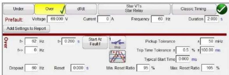
Figure 213. Over Frequency Relay Test Settings
f>: Enter the relay over frequency setting value for pickup.
t>: Enter the relay trip time setting value in seconds. Click on the s to change to cycles.
f>>: Enter the relay over frequency setting value for the fault frequency.
Start At Fault f: There are two buttons associated with the Timer Start; Start Timer At Pickup Frequency and Start Time with Binary Input.
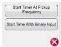
Figure 214. Timer Start At Selection List
3.11.1.2 Over frequency relay test settings
Starting the timer at pickup simply means that the timer will start running when the test frequency crosses through the pickup frequency point either as a ramp or as a step function. Starting the timer with binary input simply means the timer will be started from an external contact closing.
Stop: Press or click on the binary input Transducer button → to select which binary input will be used to stop the timer, and select the Input Type and Input Action associated for the timer stop.

Figure 215. Binary Input Screen
The default settings are Binary Input 1, dry contacts as indicated by the Input Type, and Input Action defaults to show the Closing of the Normally Open contacts. To change the Input Type from dry contacts to Voltage, press the Input Type Transducer button, and it changes to voltage. To change to the opening of Normally Closed contacts press the Input Action Transducer button and it changes to show closed contacts opening. For timing the timer is defaulted to Latched Input enabled mode, which means the timer, will stop on the first contact closure. Note the Debounce time is set to 2 milliseconds.
Pickup Mode: Press or click on the Pickup Mode Transducer button 📋 to select the mode of ramping the outputs. There are two modes to select from. The default button is a single ramp up starting from the prefault frequency towards the fault frequency. The second selection is a double ramp up and back down button looking for pickup and dropout associated with multi-set point relays.
Pickup Tolerance: Enter the pickup tolerance of the relay under test in ± mHz.
Trip Time Tolerance: Enter the time tolerance of the relay under test. Two entries are available, ± % of time setting and ± ms. Note: changing the Prefault Duration time to Cycles will change the time tolerance to Cycles.
Typical Start Time: This is known time delay value associated with the relay under test. This time value is associated with the relay delay time in detecting the pickup frequency value over one or more cycles, and then making a decision to indicate the pickup or trip outputs. Typical values vary from 50 to 200 ms. This value is critical in making Pass / Fail determinations in Timing test results. The user should consult the relay manufacturer's documentation to know what value of time to enter into the window. Note: changing the Prefault Duration time to Cycles will change the start time to Cycles.
Reset Ratio: This is a min and max allowable tolerance associated with the dropout reset setting, which is associated with the double ramp pickup test. The post fault ramp will ramp back to the prefault condition. Once the relay picks up it is in a trip state. The post fault ramp will be able to detect the relay dropout and record the dropout point. For an over frequency relay the reset ratio will be a value slightly less than the setting, but usually never greater than. Check the relay manufacturer's literature to verify reset setting values and % tolerances for appropriate values.
3.11.1.3 df/dt ROCOF relay test settings
3.11.1.3 ③ df/dt ROCOF Relay Test Settings

Figure 216. df/dt Test Setting screen
df/dt >: The rate of change is defined as the df/dt setting in Hz/s. Enter the relay Hz/s setting here. The change in frequency happens when the frequency passes through the positive going zero crossing of the voltage output waveform. The test limits the df/dt setting to a maximum value of 10Hz / sec. The test defaults to ramping the frequency up. Press on the frequency ramp button to change to the ramp frequency down button . Note: The sign of the Hz/s changes from a positive number to a negative number.
The frequency increment is calculated for each delay period prior to starting the dynamic ramp. The first step is defined by the prefault values, which are necessary to energize the relay before the fault condition. If we use a df/dt of -1 Hz/sec and want to ramp from 60 to 50 hertz, then the time would be ten seconds to go from 60 Hz. to 50 Hz.
T (Trip Time): Enter the trip time setting from the relay in seconds. Clicking on the s will change the time to CY for Cycles. Note: Changing the Duration setting from second to Cycles will automatically change this setting.
Pickup: Enter the Pickup setting value of the relay here. The pickup point indicates the frequency when the relay first detects the fault. Once the pickup point is reached the relay starts its timer and will trip.
Start Time At: There are two buttons associated with the Timer Start; Start Timer At Pickup Frequency and Start Time with Binary Input. Starting the timer at pickup simply means that the timer will start running when the test frequency crosses through the pickup frequency point either as a ramp or as a step function. Starting the timer with binary input simply means the timer will be started from an external contact closing.
Stop: Press or click on the binary input button 📄 to select which binary input will be used to stop the timer, and select the Input Type and Input Action associated for the timer stop.

Figure 217. Binary Input Screen
The default settings are Binary Input 1, dry contacts as indicated by the Input Type, and Input Action defaults to show the Closing of the Normally Open contacts. To change the Input Type from dry contacts to Voltage, press the Input Type button, and it changes to voltage. To change to the opening of Normally Closed contacts press the Input Action button and it changes to show closed contacts opening. For timing the timer is defaulted to Latched Input enabled mode, which means the timer will stop on the first contact closure. Note the Debounce time is set to two milliseconds.
Pickup Tolerance: Enter the pickup tolerance of the relay under test. Two entries are available, ± % of pickup setting and ± mHz.
Trip Time Tolerance: Enter the time tolerance of the relay under test. Two entries are available, ± % of time setting and ± ms.
Typical Start Time: This is known time delay value associated with the relay under test. This time value is associated with the relay delay time in detecting the pickup frequency value over one or more cycles, and then making a decision to indicate the pickup or trip outputs. Typical values vary from 50 to 200 ms. This value is critical in making Pass / Fail determinations in Timing test results. The user should consult the relay manufacturers' documentation to know what value of time to enter into the window.
3.11.1.4 ① VT and Relay Connections
Press or click on this button to access the Selection Type menu for the VT and Relay connections.

Figure 218. Select Injection Type Menu
3.11.1.5 Classic Timing Test Selection
Press or click on the Classic Timing test button to perform a step timing test where the output frequency is step changed from the prefault to the fault value. If Classic Timing is not enabled, then the timing test will be performed by ramping the frequency from the prefault value to the fault value at a pre-calculated ramp rate starting the timer at the Fault Frequency and stopping the timer upon relay trip contact sensing.
3.11.1.6 Prefault Settings
The Prefault Values will be the values applied to the relay for the specified Duration time. Duration time defaults to s for seconds. Click on the s to change it to CY for Cycles. Note that changing the duration time to Cycles also changes the Trip Time Tolerance and Typical Start Time to Cycles. It is necessary to apply the prefault values long enough to allow the relay to reach a state of equilibrium. For example, an electromechanical relay may require several seconds to allow the induction disk to rotate to a balanced state.
3.11.2 Frequency relay test screen
3.11.2 Frequency Relay Test Screen
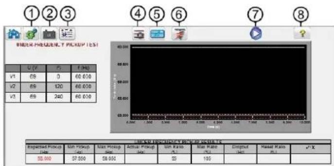
Figure 219. Frequency Relay Test Screen
3.11.2.1 ① Configuration button

Press the button to go to the Configuration Screen. See Section 2.2.1 Configuration for more information of the Configuration Screen.
3.11.2.2 ② Battery Simulator button

The Battery Simulator button – Turns the Battery Simulator ON and OFF by pressing the button, the color changes red for ON and black for OFF. The voltage to be applied is displayed in the button and can be changed by pressing the configuration button.
3.11.2.3 ③ Test Report button
Press or click on this button to review the test results.
3.11.2.4 ④ Test List button
Press or click on this button to View the available tests, i.e. Pickup or Timing.
3.11.2.5 ⑤ Frequency Relay Test Settings Screen button
Return to the Frequency Relay Test Settings Screen button provides access back to the relay and test settings screen.
3.11.2.6 ⑥ Run Predefined Test button
Pressing the run predefined test button, the user can select from a list of predefined frequency relay tests that were previously saved to the database.
3.11.2.7 ⑦ Run Test button
Pressing or clicking the Blue Run Test button will apply the Prefault vector for the specified Time, and then will run the selected test.
3.11.2.8 ⑧ Help button ?
Pressing this button will open the help associated with the Frequency test.
3.11.3 Frequency relay pickup test screen
3.11.3 Frequency Relay Pickup Test Screen
The Frequency Pickup test screen will display the Prefault Frequency starting values, the frequency ramp down or up, and the pickup point (green is Pass, red colored dot is Fail), see the following example Under Frequency test result. The injection table in the left hand side of the screen shows the actual fault frequency being applied during test; this is applicable for all tests.

line
UNDER-FREQUENCY PICKUP TEST | Time (s) | 0 (V) | (°) | T (Hz) | |---|---|---|---| | V1 | 69 | 0 | 60.000 | | V2 | 69 | 120 | 60.000 | | V3 | 69 | 240 | 60.000 | | Expected Pickup (Hz) | Min Pickup (Hz) | Max Pickup (Hz) | Actual Pickup (Hz) | Min Ratio (%) | Max Ratio (%) | Dropout (Hz) | Reset Ratio (%) | ✓ | |---|---|---|---|---|---|---|---|---| | 58.000 | 57.950 | 58.656 | 58.613 | 95 | 105 | 57.976 | 59.9361 | ✓ |Figure 220. Under Frequency Relay Pickup Test Result
3.11.4 Frequency Relay Timing Test Screen
There are two types of Timing Test available to choose. To do a Classic Timing test, press or click on the Classic button. The Classic test is a step test from the Prefault to a value slightly greater or less than the specified pickup value. The default Timing test is a ramp to fault frequency simulating an actual under or over frequency condition. The ramp starts at the Prefault frequency setting and then ramps up or down until a value slightly greater than or less than the Fault Frequency setting depending on the type of relay selected. Once the Fault frequency value threshold is crossed the relay timing starts. When the relay trips the timer stops. The user will see the Prefault duration, the duration of time associated with the ramping of the output frequency to the Fault frequency value, plus the operating time of the relay, see the following example for an Over Frequency Timing test.

line
OVER-FREQUENCY TIMING TEST | Voltage Level | U(V) | T(°) | T(Hz) | |---|---|---|---| | V1 | 69 | 0 | 60.000 | | V2 | 69 | 120 | 60.000 | | V3 | 69 | 240 | 60.000 | | Over Frequency Timing Results: Test Value (dB) | Expected Trip Time (s) | Min Trip Time (s) | Max Trip Time (s) | Trip Time (s) | Total Time (s) | ✓ X | |---|---|---|---|---|---|---| | 62.250 | 0.260 | 0.099 | 0.301 | 0.152 | 0.152 | ✓ | Over Freqency Timing ResultsFigure 221. Over Frequency Timing Test
3.12 COMTRADE Playback
The COMTRADE Playback is only available for FREJA units, which have the Enhanced Software feature enabled. Pressing the COMTRADE test button provides the capability of playing back transient waveform data from the FREJA relay test systems. In other words, it can recreate a fault (waveforms...) recorded by a Digital Fault Recorder, protective relays, or a simulated fault using software tools like the EMTP / ATP programs.
Selection of the COMTRADE button will provide the following COMTRADE dialog box.
3.12.1 COMTRADE dialog box
3.12.1 COMTRADE Dialog Box

Figure 222. COMTRADE Dialog Box
From this dialog box a user can convert digital fault recorder data in COMTRADE format to hexadecimal files compatible with FREJA waveform generators, select the channels and ranges to be uploaded to FREJA unit, and upload and output the waveforms.
3.12.1.1 Processing a COMTRADE File
The IEEE Power System Relaying Committee has established a standard called COMTRADE (common transient data exchange) see IEEE C37.111. In addition, the IEC has also adopted the standard as IEC 60255-24. The FREJA Local / Remote COMTRADE test feature uses the COMTRADE data either in the ASCII or Binary formats.
Processing a Configuration file involves the process of converting the data in COMTRADE ASCII or Binary format to FREJA-ready hexadecimal format.
Prior to creating a test the COMTRADE .cfg and .dat files need to be placed into a file folder on your PC or in the file memory of the STVI. The .cfg and .dat file must be in the same directory and have the same name prior to the file extension.
From the COMTRADE dialog box, click on the COMTRADE File button. The windows file navigator window will appear. Navigate to the Waveforms folder. Use this dialog box to select a COMTRADE configuration file and to convert the COMTRADE data to hexadecimal data.
3.12.2 COMTRADE Test Screen
When the file is selected, the program will automatically grab the first three channels of voltage and current and display the values in either primary or secondary values, depending on the ratios provided in the Configuration file (primary or secondary).

Figure 223. Example COMTRADE Playback Test Screen
The following is a brief description of the buttons and fields available in the COMTRADE test screen dialog box.
3.12.2.1 ① Home button

Pressing the Home button will return you to the manual test screen.
3.12.2.2 ② Configuration Screen button

Press the button to go to the Configuration Screen. See Section 2.2.1 Configuration for more information of the Configuration Screen.
3.12.2.3 ③ Open COMTRADE File button

Press the Open COMTRADE File button to go to the Waveform subdirectory to select a COMTRADE file.
3.12.2.4 ④ COMTRADE Waveform View button

Press the COMTRADE Waveform View button to preview the COMTRADE waveform and make any additional adjustments before downloading and playing the waveforms. It is recommended to view the waveform before applying prefault values.
3.12.2.5 ⑤ Report Options button

Once the test is completed, press Report Options button. This button will add the present test result to the report. It also displays the report and allows the user to name the test, enter limits, comments or deficiencies. Reports can be saved to the STVI's internal memory and transferred to PowerDB via a USB memory stick. Previous tests results can be loaded and the 'Retest' option can be used to repeat the test using the same parameters as the previous test.
3.12.2.6 ⑥ Configure Timer button

Press the Configure Timer button to view the Timer Setup screen and Labels. The user can view and set where each timer starts and stops (see the following figure).

Figure 224. Sequence Timers Settings and Labels Screen
Timer Start options provide the starting of multiple timers associated with a change of state on a timer post, Start on the beginning of Playback, start the position of the cursor on the waveform, start on trigger (normally associated with end-to-end test.
3.12.2.7 Sample rate
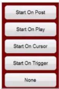
Figure 225. COMTRADE Timer Start Options
Timer Stop options provide selective timer stopping of multiple timers with a change of state on a timer post, or at the end of the test.
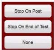
Figure 226. COMTRADE Timer Stop Options
3.12.2.7 ⑦ Sample Rate
The Sample Rate indicates the Sample Rate of the recorded data. The sample rate is taken from the configuration (.cfg) file. If no sample rate is shown in the configuration file (some relay COMTRADE files are missing the sample rate), FREJA Local / Remote will calculate it from the data file.
3.12.2.8 ⑧ # Samples
# Samples is the number of samples in the data (.dat) file.
3.12.2.9 ⑨ Battery Simulator button

The Battery Simulator button – Turns the Battery Simulator ON and OFF by pressing the button, the color changes red for ON and black for OFF. The voltage to be applied is displayed in the button and can be changed by pressing the configuration button.
3.12.2.10 ⑩ Start Now button
The Start Now button works in conjunction with the Blue Run Test button.

Figure 227. COMTRADE Start Now Options
Clicking or pressing the Start Now button will open a menu so that the user can select if they want the test to start
3.12.2.11 Binary input setting button
upon pressing or clicking on the Blue Run Test button, or a Contact change of state. There are two IRIGB Start options. The first option is to start upon a specific time as provided by the IRIG-B decoded time on binary input #1 (used for end-to-end tests). The second option is to start upon decoding the IRGIB + a Delay time. The delay time is associated with the delay of other manufactures relay test systems that are slower than the FREJA 500 systems. Selecting the Start IRIG button, upon pressing or clicking on the Blue Run Test button a window will appear showing the current UTC time decoded with the preset trigger time 1 minute into the future. Pressing or clicking on the green check button will set the trigger time as displayed.
3.12.2.11 ⑪ Binary Input Setting button

Press this button to reveal the Binary Input Dialog box.
3.12.2.12 ⑫ Run Predefined Test button

Pressing the run predefined test button, the user can select from a list of predefined relay tests that were previously saved to the database.
3.12.2.13 ⑬ Run Test button
Pressing or clicking the Blue Run Test button will download the waveforms, and based upon the Start Now Setting, the test set will apply the prefault vector, then step to the COMTRADE playback values and look for the relay under test to operate.
3.12.2.14 ⑭ Help button ?
Pressing this button will open the help associated with the COMTRADE test, as well as reset the system.
3.12.2.15 ⑮ Pre Fault time window
This allows the operator to "add" additional prefault cycles to the original fault record (needed for proper polarization of the relay). Pre Fault time defaults to S, seconds. Press or click on the S and it will change to Cy Cycles. When a prefault is selected, two additional fields appear. One for voltage and one for current. Match is the default setting, which means the prefault values of voltage and current will match the prefault values in the configuration / data files at the beginning of the recorded waveform. It is advisable that this be done after inspecting the waveform since it is possible that 0 values are at the start of the waveform. If the user does not wish to match the beginning of the waveform, then they can select Enter Amplitude, where the user can enter their own desired prefault values of voltages and currents. The values entered are peak values, because that is what is in the data files according to the standard. If the user wants to have RMS values, then they will need to multiply by 0.707.

NOTE: The number of cycles required for polarization varies. It is recommended that a minimum of 30 Cycles of prefault be added to the COMTRADE recording. Contact your relay manufacturer technical support, or review your relay manual for recommended prefault time settings.
3.12.2.16 ^16 Iterations window
The default value is "1". Upon pressing or clicking on the Blue Run Test button the test will execute one time. If you desire to cycle the relay through several iterations of the same fault, enter the desired number of iterative cycles as an integer number.
3.12.2.17 ⑰ Analog Voltage and Current Values
The software will display the first three analog channels as defined by the Configuration file. To select other channels, simply click or press in the name window provided and a list of available channels will be provided to select from. If your test system has more than three current channels, to select more channels simply click in the "blank" channel and select the next analog channel. Continue this selection process until all the desired channels are selected.
3.12.2.18 Digital channels
3.12.2.18 ⑱ Digital Channels
The digital channel Name defaults to blank. To playback digital channels, click in the window provided and the names of all the digital channels will be provide.
3.12.3 Processing the COMTRADE File
The analog values shown may be in Primary or Secondary Values as defined by the Configuration file. The PT and CT ratios are either automatically provided, or entered by the user, depending on the year of the COMTRADE standard file format. Files that follow the 1999 standard and later should have PT and CT ratios in the configuration (.cfg) file. However, not all manufacturers strictly follow the standard, and these ratios may be missing. If they are missing, and the data (.dat) file is in primary values, the user can manually enter PT and CT ratios to convert the primary to secondary values for the test set to play, see the following example.
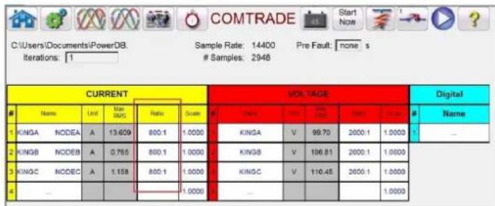
Figure 228. Locating Primary to Secondary Ratios in the Test Screen
To change a ratio, simply click in or press any ratio window provided and enter the ratio.

Figure 229. Changing Ratios Dialog Box
The software will ask if you want to Apply All or Apply To This Phase only. Upon pressing the appropriate application button, you will see the Maximum RMS voltage and / or current that will be applied during the test.

Also, take careful note of the Unit values, as some channels may be recorded in Primary and some in Secondary units. Sometimes the test currents will exceed the maximum of 32 Amperes per phase. The FREJA amplifiers can output fault currents of up to 60 Amperes for 1.5 seconds. Since most faults last less than a few cycles this will not be an issue upon playback. Test currents above 60 amperes is not allowed.
The primary use of the Scale is to adjust voltage and current channels proportionately together, so as not to change the "impedance" that a distance relay would "see". For example, after adjusting the outputs by entering the CT/PT ratios, let us assume that one output current is showing 70 amperes and the fault voltage is 30 volts. Since the current channels cannot playback more than 60 Amperes, the current values need to be adjusted down to 60 Amperes. Therefore, by adjusting the Scale to 0.8570 the user may lower the current to say 59.99 amperes. The user will need to lower all other outputs proportionately, thus reducing the fault voltage to 25.71 volts.
3.12.3.1 Adding digital channel playback
3.12.3.1 Adding Digital channel playback
To playback digital channels, click in the window provided and the names of all the digital channels will be provide.

Figure 230. Selecting Digital Channels for Playback
Click on the desired digital channels, which will be associated with the appropriate Binary Output channel, see the following example.
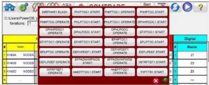
Figure 231. Assigning Three Digital Channels for Playback
Once all the appropriate channels have been selected, with proper ratios set, and scaling completed you have completed the creation of a test.
3.12.3.2 Viewing COMTRADE Playback Waveforms
To view the waveforms that will be played back press or click on Waveform button to see the following example.

Figure 232. Viewing Analog and Digital Channels for Playback
3.12.3.2.1 Zoom and cursor controls
The press the Relay Settings button (highlighted in red above) to return to the previous screen.
3.12.3.2.1 Zoom and Cursor Controls
Use the Zoom in and out buttons to zoom on the waveforms. The forward and backwards buttons will move the waveform along the time axis so that the user can view the whole waveform while zoomed in. If a cursor is selected, the forward and backward arrows will move the cursor. The Zoom Control button (highlighted in red) will toggle between zoom functions, and cursor selection, see the following example.

Figure 233. Selection of Zoom Control
The cursor selected shows the values of the channels selected above the window. The format is as follows: Cursor #, Sample #, Channel Selected, RMS Magnitude, RMS Angle, (Peak Magnitude, Phase Angle), Current Channel Selected, RMS Magnitude, RMS Angle, (Peak Magnitude, Phase Angle), Cursor to Cursor difference time in ms. The text is color-coded and will change depending on which phase is selected see the following example.

line
| Channel | Value | |---------|-------| | V1 | 82036V@27° | | I1 | -0.55A | | 343.5° | 343.5° | | 4.497A | 4.497A | | 160.8 ms| 160.8 ms |Figure 234. Using Cursors
3.12.3.2.2 Cropping button

The second to last button in the top row is the Cropping button. This will let you crop a waveform to what is between the cursors. If you press the Run Test button, it will only play back what is between the two cursors. To remove the crop press the crop button again.
3.12.3.3 Saving Test
To save the test click or press on the FILE tab and save as a PowerDB Test Template. When you want to run the test, with the test set powered up and ready, simply open the test template, and press the Blue Run Test button.
3.13 Power Swing and Out of Step Simulator
Press or click on the Power Swing button to access the Power Swing input-setting screen see the following figure.
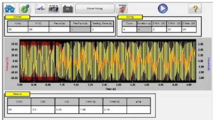
Figure 235. Power Swing Input Setting Screen
The Power Swing simulation tool is similar to the Power Swing tool in the Fault Calculator, which uses two superimposing waveforms of similar frequencies to provide a smooth impedance ramp. This method is similar to a two source model in that both sources have similar frequencies and amplitudes. For details regarding the theory and some equations associated with the Power Swing simulation, see section 3.1.19.1.6 Power Swing.
3.13.1 Power Swing Test Screen
The following is a brief description of the buttons and fields available in the Power Swing test screen dialog box.
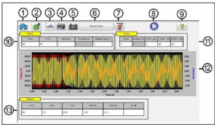
Figure 236. Example Power Swing Test Screen
3.13.1 Power swing test screen
- Pressing the Home button will return you to the manual test screen.
- Press the Configuration button to go to the FREJA Local / Remote software Configuration Screen.
- Press the Binary Input Setting button to reveal the Binary Input Dialog box.

The default settings are Binary Input 1, dry contacts as indicated by the Input Type, and Input Action defaults to show the Closing of the Normally Open contacts. To change the Input Type from dry contacts to Voltage, press the Input Type button, and it changes to voltage. To change to the opening of Normally Closed contacts press the Input Action button and it changes to show closed contacts opening. For timing the operating time of the relay power swing element the timer is defaulted to Latched Input enabled mode, which means the timer will stop on the first contact closure. Note the Debounce time is set to 2 milliseconds.
- Once the test is completed, press Add / Review Test Report button will add the present test result to the report. It also displays the report and allows the user to name the test, enter limits, comments or deficiencies. Reports can be saved to the STVI internal memory and transferred to PowerDB via a USB memory stick. Previous tests results can be loaded and the 'Retest' option can be used to repeat the test using the same parameters as the previous test.
- Battery Simulator button The Battery Simulator button turns the Battery Simulator ON and OFF. By pressing or clicking on the button, the color changes red for ON and grey for OFF. The voltage applied is displayed in the button, and can be changed by pressing the configuration button.
- The Power Swing button changes to Out of Step when pressed or clicked on. This changes the test-setting screen by removing the Mid Z Ohm setting for performing Out of Step tests.
- Predefined Test button . Pressing the predefined test button, the user can select from a list of predefined Power Swing or Out of Step relay tests that were previously saved to the database.
- Run Test button Pressing or clicking the Blue Run Test button will apply the prefault vector, then step to the Power Swing values and look for the relay under test to operate.
- Help button . ?
- Global window: Global Settings can affect setting values in the Swing and Results windows. The following are descriptions of each setting in the Global window.
Frequency (Hz): Nominal System Frequency in Hertz.
Voltage: Nominal Line to Ground System Secondary Voltage (V)
Period: Time Period of one complete power swing in seconds (s) This setting will be used to calculate the Global Prefault time in seconds, as well as the Duration time in seconds in the Swing Window.
Setting Time: This is the operating time of the relay in seconds. This setting will be used in the Results window to set the default Min and Max time evaluation values ( ± 5%). Note that the Min and Max values can be manually changed in the Results window.
- Swing window: Settings in the Swing window are associated with the Impedance Locus. The following are descriptions of each setting in the Swing window.
Turns: The number of times that the power swing will repeat around Zmid and Zmin.
Zmin: The minimum of the impedance locus (Ohms)
Zmid: This is the second maximum impedance during the power swing (Ohms)
Zmax: This is the starting impedance of the power swing (Ohms).
Application Note: Make sure that the Zmax is set greater than the power swing blinder setting by at least 1 Ohm. Setting Zmax to a very large ohm value can result with an unrealistic impedance locus approaching the relay impedance-operating characteristic at an undesirable angle. Starting the Zmax just outside of the power swing blinder element works best for this test application.
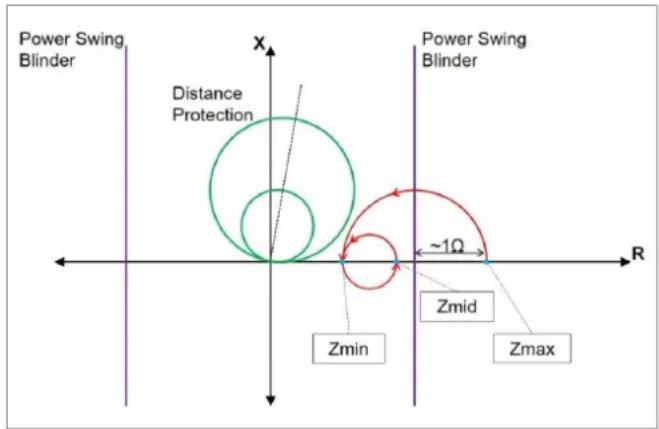
Figure 236. Power Swing Locus
When you press the Run Test button, the test will start with a prefault value for the prefault setting. After the prefault time is over, the power swing will begin. If there is only one turn defined, the power swing will begin at the point Zmax and proceed smoothly to Zmin. Once the impedance locus reaches Zmin, it will then continue to Zmid, and the test will end. For tests that have more than one turn, the impedance locus will then continue from Zmid and proceed to Zmin, and then back again to Zmid. This will continue based on the number of Turns setting.
Zmid can be set equal to Zmax if one loop is desired. Zmin cannot be equal to Zmid or Zmax.
- Power Swing Waveform: The Graphic window displays the power swing waveforms that will be played. If more than One Turn is specified the display will include each turn.
- Results Window: The Results window includes the Nominal voltage, the calculated test Current, the operating Time in seconds, the calculated Min and Max time values in seconds, and Pass / Fail based upon the recorded operating Time.
3.14 SS1 File Playback
SS1 File Playback is used for importing of State-Sequence Files (SS1) from ASPEN and CAPE power system simulation software programs. By modeling the power system using ASPEN or CAPE, the relay can be tested dynamically using realistic system test scenarios. Click on the SS1 button SS1 to open the windows file navigator window. Navigate to the SS1 folder (requires user to create the SS1 file folder, and place the SS1 files in the folder). Use this dialog box to select an SS1 file. FREJA Local / Remote software will read the SS1 file and create a dynamic state-sequence playback file using the Sequencer Test feature.
3.14.1 SS1 File Pre-Test dialog window

Figure 237. SS1 File Selection Navigator Window
3.14.1 SS1 File Pre-Test Dialog Window
The pre-test dialog window provides the user several selections on how to start the test, and what type of test report is desired. The following is the SS1 Pre-Test Dialog Box.
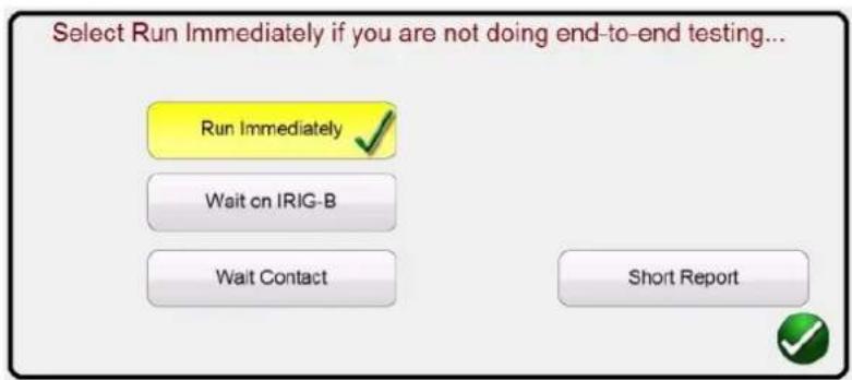
Figure 238. Example SS1 File Pre-Test Dialog Box
Using the SS1 file data, FREJA Local / Remote software will automatically create a State Sequence Test. Test currents, voltages, phase angles, and wait times defined in the SS1 file will appear in the Sequencer Test Screen. There are three Modes to select from, Run Immediately, Wait on IRIG-B, and Wait Contact. The Short Report button will only report the prefault and trip times. If unchecked, the test report will include all the prefault, fault test data, wait times, trip times, etc. For an End-To-End test, the Short Report maybe preferred.
3.14.1.1 Run Immediately button
The FREJA Local / Remote software defaults to the Run Immediately mode. All SS1 sequence tests run in the Sequencer test screen. Upon clicking or pressing the green check button, the Run / Edit Test Selection screen appears.

Figure 239. Example Run / Edit Test Selection Screen
As shown in the above figure, there is one Test Group, and Tests are listed in the right half of the screen for that group. The following are descriptions for the tools.
3.14.1.1.1 Run Test button

Press the Run Test button for the selected test to execute that individual test.
3.14.1.1.2 Run All button execute.

Pressing the Run All button the user will see the following options to select and
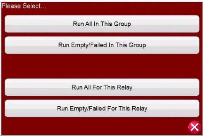
Figure 240. Predefined Run All Options
3.14.1.1.3 View Results button Press the View Results button to view the test report.
3.14.1.1.4 Go To Test Screen button Press the Go To Test Screen button to go to the selected test in the Sequencer test screen.
3.14.1.1.5 View / Edit Notes button Press the View Edit Notes button to view the test notes or to add notes.
3.14.1.1.6 Help button

Figure 241. Test Notes Screen
Press the No Action button at the bottom of the note screen will provide options as shown in the following figure.

Figure 242. Test Notes and Display Action
The user can select to have the test notes displayed upon running the test, or not, or display for X number of seconds.
3.14.1.1.6 Help button ? The Help button is sensitive to the test and will take the user to this section of the manual.
3.14.1.1.7 Edit Test Attribute Script button 📋. Pressing this button will take the user to the Edit Test and Attributes screen as shown in the following figure.
3.14.1.1.8 Extended actions list button
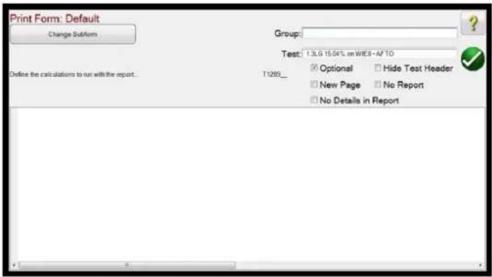
Figure 243. Edit Test and Attributes Screen
The Group and Test names can be changed by the user. Checking the No Report button will exclude this test from Pass / Fail evaluation in the Test Report. Checking the New Page will add this test as a new page in the test report. No Details in Report does not apply to SS1 tests. Pressing the Change Sub form button will present the following options to the user.

Figure 244. Change Sub form Options in the Test Edit and Attributes Screen
Selecting any of the listed options will present the user with multiple lists of print labels.
3.14.1.1.8 Extended Actions List button 📄. Pressing this button will provide a list of extended actions that the user may want to use, see the following.

Figure 245. Extended Action List
3.14.1.2 Wait on IRIG-B
Here the user can duplicate a Group of tests, or Duplicate any individual test. Test can be Imported or Exported. The Group can be renamed. Test can be deleted here. The Edit functions do not apply to SS1 test files.
3.14.1.2 Wait on IRIG-B
This start option is normally associated with conducting an End-To-End test. Connect the IRIG-B time source to Binary Input #1.
Note that Binary Input #1 is used to decode the IRIG-B time code. Therefore, connect the relay trip contacts to Binary Input #2. The FREJA Local / Remote software automatically selects Binary Input #2 for trip / timer stop.
Delay After Trigger contains an edit field for time adjustments to the FREJA 500 test set. The adjustments are to manipulate time in milliseconds for synchronization between test sets of different manufacturer or models involved in playback of the file Tests and States. If using only FREJA 500 units, no time adjustment is required. If using another test set from a different manufacturer on the other end of the line, the start time of the Megger test set will need to be adjusted to coincide with the start of the other unit. Contact your local Megger sales representative or technical support for more information.
Upon pressing or clicking on the Blue Run Test button, the following screen will appear.

Figure 246. Setting IRIG-B Trigger Time
The user can click or press the IRIG-B Time for Test window and enter an appropriate time to start the test, or can press or click on one of the two time setting buttons to automatically set the start time to be either +1 or +5 minutes into the future. It is vital that both test systems are set to the same time to start. When the IRIG-B start time is reached the test will start.
The Wait Contact is similar to the Wait IRIG-B. It can be used to start the test from an external dry contact, such as might be found on older GPS units. The same Delay After Trigger applies similar to that described above.
3.15 IEC 61850 Megger GOOSE Configurator (MGC)
The Megger GOOSE Configurator software (MGC) provides mapping of the binary inputs and outputs of the FREJA 5xx test set to the desired GOOSE messages. The GOOSE messages are read from available SCL (Substation Configuration Language) files or may be automatically detected by scanning the substation network in search of available published GOOSE messages. This scanning process is known as GOOSE “sniffing”. The MGC also provides advanced network troubleshooting tasks such as comparing the GOOSE messages available on the network with the GOOSE messages described in the SCL files with GOOSE MERGE / COMPARE functionality; this is also a powerful tool for validating the horizontal communication description (GOOSE) in the supplied SCD file at Factory Acceptance Tests (FAT) in IEC 61850 substations. This type of verification is also known as GOOSE Consistency Check.
An SCL file is an XML (Extensible Markup Language) file that describes the IEDs available in one IEC 61850 substation (SCD file) or can just describe only one single IEC 61850 device (ICD, CID files). In the SCL file there are several IEC 61850 information available (logical nodes in the IEDs, GOOSE messages sent by the IEDs, GOOSE messages received by IEDs, Reporting information to SCADA etc.).
3.15.1 GOOSE message description
3.15.1 GOOSE Message Description
GOOSE is an acronym for Generic Object Oriented System Event (GOOSE). A "GOOSE message" is an intentional simplification. In reality the GOOSE message is a digital frame (message) containing a lot of information, including the dataset. A dataset can contain different information like real values (analog GOOSE information, like RMS value of a measured quantity), integer values (e.g. BCD position of a power transformer tap changer), Boolean values (single point GOOSE information, e.g. the trip signal from the protection relay) and 2-bit string information (double point GOOSE information, e.g. the position of the circuit breaker). The MGC allows mapping of the binary information of the dataset (single point and double point) to the binary inputs and binary outputs of Megger relay test set.
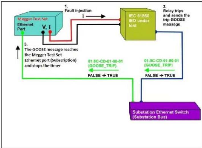
flowchart
graph TD
    A["Megger Test Set Ethernet Port"] -->|Fault injection I| B["IEC 61850 IED under test"]
    B -->|Relay trips and sends the trip GOOSE message| C["Substation Ethernet Switch (Substation Bus)"]
    C -->|False → TRUE| B
    B -->|01.0C-CD-01-00-01 (GOOSE_TRIP)| D["The GOOSE message reaches the Megger Test Set Ethernet port (Subscription) and stops the timer"]
    D -->|3. The GOOSE message reaches the Megger Test Set Ethernet port (Subscription) and stops the timer| A
    B -->|FALSE → TRUE| C
Figure 247. Trip test of an IEC 61850 IED with the IEC 61850 GOOSE interface.
3.15.1.1 IEC 61850 Relay Testing – General Description
The Megger relay test system is connected to the IEC 61850 station bus (or directly to the Ethernet port of the relay) and is programmed to map the trip GOOSE message from the tested IED to a chosen binary input. The mapped binary input is programmed to stop the timer of the Megger test set. This last action is done from FREJA Local / Remote software. For testing IEC 61850 relay applications, where the protection relay needs an external signal to allow protection functions (e.g. external direct inter-trip command, or external auto-recloser start, or breaker failure start), it is necessary to "energize" the IEC 61850 relay with a GOOSE message. The Megger relay test set, which is still connected to the IEC 61850 station bus, is now programmed to map a binary output to a defined GOOSE message that is published by the FREJA 5xx. The test set activates its binary output when the test requires it, which means that the GOOSE message changes its status from "0" (false) to "1" (true). In a practical situation both applications (publishing of a GOOSE message and subscription of a GOOSE message), are often used simultaneously.
3.15.2 MGC menus
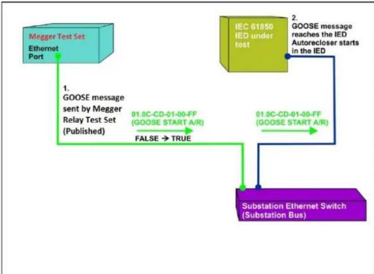
flowchart
graph TD
    A["Megger Test Set\nEthernet Port"] -->|1. GOOSE message sent by Megger Relay Test Set (Published)| B["01.0C-CD-01-00-FF\n(GOOSE START A/R)"]
    B -->|FALSE → TRUE| C["Substation Ethernet Switch\n(Substation Bus)"]
    D["IEC 61850\nIED under test"] -->|2. GOOSE message reaches the IED\nAutorecloser starts in the IED| E["01.0C-CD-01-00-FF\n(GOOSE START A/R)"]
    E --> C
Figure 248. External relay energization (auto-recloser start) test of an IEC 61850 IED with a FREJA 5xx equipped with the IEC 61850 GOOSE interface.
3.15.2 MGC Menus
The following are descriptions of the MGC Menus

Figure 249. MGC Tool Bar Menu
3.15.2.1 File Tab
3.15.2.1.1 Save
This option allows the user to save a *.mgc file. This file will contain all GOOSE messages used to configure the test set, and all the created tabs for GOOSE message sniffing, or for GOOSE messages imported from SCL files. The *.mgc file will also contain the mappings to binary inputs and outputs.
3.15.2.1.2 Save As
This is similar to save except it allows the user to create a new *.mgc file with a different name.
3.15.2.1.3 Open
Opens up an *.mgc file
3.15.2.1.4 Download settings to test set
3.15.2.1.4 Download Settings to Test Set
This function is used to download (writing) a mapping configuration to the test set.
3.15.2.1.5 Exit
Closes the MGC.
3.15.2.2 Edit Tab
All operations in this menu affects the GOOSE messages in the active tab. No changes will be done until the new configuration is downloaded. The following are descriptions of the Edit Tab Menu.
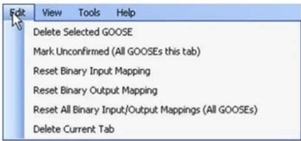
Figure 250. Edit Tab Menu
3.15.2.2.1 Delete Selected GOOSE
Will delete selected GOOSE message(s) from the active tab.
3.15.2.2.2 Mark Unconfirmed (All GOOSE messages this tab)
Will mark captured GOOSE messages as unconfirmed. This is helpful to determine if a particular GOOSE message is found within the network. All imported GOOSE messages from SCL files are unconfirmed.
3.15.2.2.3 Reset Binary Input Mapping
Will reset all mappings to binary inputs under the MyGOOSE tab.
3.15.2.2.4 Reset Binary Output Mapping
Will reset all mappings to binary outputs under the MyGOOSE tab.
3.15.2.2.5 Reset All Binary Input / Output Mappings (All GOOSE messages)
Will reset all mappings to binary inputs and outputs under the MyGOOSE tab.
3.15.2.2.6 Delete Current Tab
Will delete the visible tab. The MyGOOSE tab cannot be deleted.
3.15.2.3 View Tab
The following are descriptions of the MGC View Tab
3.15.2.3.1 Collapse All
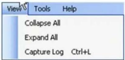
Figure 251. The View Tab Menu
3.15.2.3.1 Collapse All
If a GOOSE message is expanded, this command will collapse all GOOSE messages.
3.15.2.3.2 Expand All
Expand all will show all the properties of the GOOSE messages.
3.15.2.3.3 Open Log
This menu allows the user to view the log file containing all the user's and MGC operations.
3.15.2.4 Tools Tab
The following are descriptions of the Tools Menu Tab

Figure 252. Tools Tab Menu
3.15.2.4.1 Capture
Use to "sniff", i.e. capture, GOOSE messages from a network device. This will open the select network interface window (Ethernet port) if no interface has been selected previously in this session.
3.15.2.4.2 Import
Use to import GOOSE messages from an SCL type file. These files have an extension of .SCD, .CID, or .ICD (IEC 61850 standard, Edition 1). This will open up a browse window to select an SCL file to open.
3.15.2.4.3 Sort
Use to sort GOOSE messages in either descending or ascending order.
3.15.2.4.4 Reset GOOSE Configuration
Use to reset the test set GOOSE mapping configurations.
3.15.2.4.5 Select Network Device
Use to display window below allowing choosing of the Ethernet port of the PC that will be used to sniff (capture) the GOOSE messages and to communicate to the Megger test set. In normal situations, this PC Ethernet port connected to the front port of the test set.
![Choose a Network Device: com EtherLink PC: [795863C-F194-068-36800-BC782604548] OK Cancel](/content/2026/05/852528/images/e8ebcf1d5e04d1d465827d6731940cffae03166e0d287864b4d5eadf799d450e.jpg)
Figure 253. Selecting Ethernet Port
3.15.2.4.6 Set Test Set IP
Display window used to enter IP address of the front port of the Megger test set to allow the download of the GOOSE mapping.

Figure 254. Window for Setting IP address
3.15.2.4.7 Preferences
The following are descriptions of the Preferences career selections.

Figure 255. Preferences Screen Selections

NOTE: The SMRT / MPRT Mode also applies to the FREJA 5xx units.
3.15.2.4.7.1 Full view
3.15.2.4.7.1 Full View
In Full View all information associated to GOOSE messages will be shown. See the following example.
![IEC GOOSE[GOOSERLD0/LLN0GOG_B02][01-0C-CD-01-F0-02] IED(3) IEDName: GOOSER IEDName + LDName: GOOSERLD0 IED IP ADDRESS: 10.1.150.3 Attributes(11) GOOSE CONTROL BLOCK NAME: G_B02 GOOSE CONTROL BLOCK FULL NAME: GOOSERLD0/LLN0GOG_B02 DESCRIPTION: B02 GOOSE MAC-Address: 01-0C-CD-01-F0-02 VLANID: 1 (0x001) VLAN PRIORITY: 4 GOOSEID (GoID): MEGGER APP ID: 2 (0x0002) DATASET NAME: DS2 DATASET FULL NAME: GOOSERLD0/LLN0$DS2 Config Revision: 2 DataSet(2) [1] BOOLEAN (LD0.SP16GGI01.ST.Ind2.stVal) [2] BITSTRING (LD0.SP16GGI01.ST.Ind2.q length: 13)](/content/2026/05/852528/images/5c8ea9779943efd9c271402306e18f43f61614b59238c80fce8ff17427688d98.jpg)
Figure 256. Full View GOOSE Messages
3.15.2.4.7.2 Easy View
In Easy View the most used information associated to GOOSE messages will be shown. If not advanced GOOSE troubleshooting is performed, this is the suggested view for the user.
![IEC GOOSE[GOOSERLD0/LLN0GOG_B02][01-0C-CD-01-F0-02] IED(1) IEDName: GOOSER Attributes(4) GOOSE CONTROL BLOCK NAME: G_B02 GOOSE MAC-Address: 01-0C-CD-01-F0-02 APP ID: 2 (0x0002) DATASET NAME: DS2 DataSet(2) [1] BOOLEAN (LD0.SP16GGIO1.ST.Ind2.stVal) [2] BITSTRING (LD0.SP16GGIO1.ST.Ind2.q length: 13)](/content/2026/05/852528/images/32b52f2818209f725528239b24fb02174dc086720ba6381d54d6cfdd15618965.jpg)
Figure 257. Example of Easy View GOOSE Message
3.15.2.4.7.3 FREJA 4xx Mode
This allows MGC to work with Megger FREJA 4xx relay test sets.
The GOOSE messages will be assigned to FREJA 4xx binary inputs (subscription) and outputs (publication).
3.15.2.4.7.4 SMRT / MPRT Mode
This allows the MGC to work with FREJA 5xx units equipped with IEC 61850 interface. The GOOSE messages will be assigned to FREJA 5xx binary inputs and outputs.
3.15.2.4.7.5 PC-GOOSER Mode
This allows MGC to work with the general purpose IEC 61850 GOOSE test equipment, the GOOSER.
Note, the GOOSER product has been discontinued.
3.15.2.4.7.6 Expanded MPRT Mode
In this mode, all subscribed or published GOOSEs can be assigned to either binary inputs or outputs. If a GOOSE message contains various indications, then those particular indications can be mapped to either input or output. The following figure shows a GOOSE with indication one being mapped to input 6 and indication two being mapped to output 6. Notice in this mode it is difficult to determine whether a GOOSE is a published or subscribed. This type of application is not very common.
![MPRT IEC-61850 GOOSE Configurator - Expanded Contact GOOSE Mode File Edit View Tools Help SCL C DL MERGE Copy to MyGOOSE My GOOSE Capture GOOSE IEC GOOSE[MainLDInst/LLN0G0]gob01]D1-0C-CD-01-01... IEC GOOSE[BackupCPG/LLN0G1]GlucoseSet14]D1-0C- GOOSE Subscription GOOSE Publication BIN 6 BOUT 6 BIN 5](/content/2026/05/852528/images/b3e1c14383654c728774b317bed9038451114a648f11fc5e8f9033085a517876.jpg)
Figure 258. MPRT Expanded Mode Screen
3.15.2.4.7.7 Bypass Test Set Connection
Allows MGC to scan the network without having a test set as Secure Network Access Point.

Note: In this case the PC Ethernet port is directly connected to the substation bus. This operating mode is only for advanced users that have full control on the messages that the PC may eventually send on the substation bus. It is absolutely not recommended during maintenance testing, or anyway when the substation is in operation. If you are unsure, always connect your PC to the ISOLATED port of the Megger relay test equipment, and then connect the IEC 61850 port to the substation bus.
3.15.2.5 GOOSE Filter Options
GOOSE filter options allows the user to add GOOSE messages to the FILTER tab. In order to do it, select a GOOSE message, do right click on it and select "Add to GOOSE Filter".
3.15.2.5.1 Delete on add to filter

Figure 259. MGC GOOSE Filter Options Screen
3.15.2.5.1 Delete On Add To Filter
This option will remove selected GOOSE messages from the current tab when added to the FILTER tab.
3.15.2.5.2 Filter Allows Update
This option allows only the GOOSE messages in the FILTER tab to be captured / updated, with the next Capture operation. If not selected, the GOOSE messages in the FILTER tab will be ignored within the next Capture operation and will not be added / updated. Remove (delete) the Filter tab if you want to easily get rid of any filtering.
3.15.2.5.3 VLAN ID
In this window it is also possible to affect the GOOSE MERGE algorithm, and decide if some important parameters like the VLAN tag and the Test Attribute should be used to discriminate if two messages are equals or different. If selected, two GOOSE messages with different attributes will not be merged in a MERGE operation. This means that if one SCL-GOOSE and one sniffed-GOOSE are equal in all their parameters, but the VLAN tag is different, they will not be merged as they will be considered as different messages. If not selected, the VLAN attributes will be ignored in a MERGE operation.
3.15.2.5.4 GOOSE Test Attribute ED. 1.
If selected, two GOOSE messages with different value (True or False) of the Test Attribute will be considered different and will not be merged. This means that if one SCL-GOOSE and one sniffed-GOOSE are equals in all their parameters but different in the Test Attribute, they will not be merged. If not selected, the Test Attribute will be ignored by the MERGE algorithm. This means that if one SCL- GOOSE and one sniffed-GOOSE are equals in all their parameters but different in the Test Attribute, they will be considered equals and will be merged.
3.15.2.6 Test Tab
3.15.2.6.1 IEC 61850-8-1 Ed. 1 Test
With this menu, it is possible to manipulate the test service parameter and also to manipulate the test bits in the test quality attributes of the published GOOSE messages by the Megger relay test set.

Figure 260. IEC s61850 Ed.1 Test Selection Menu
3.15.2.7 Help Tab
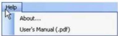
Figure 261. MGC Help Tab
About
The help option will display the version of the software.
User's Manual
Opens the user's manual (Acrobat Reader must be installed).
3.15.3 MGC Toolbar
The MGC buttons provide a shortcut to either importing or capturing a GOOSE message without navigating through the tool bar. The various buttons are shown in the following figure.
3.15.3.1 SCL button

Figure 262. MGC Tool Bar
3.15.3.1 SCL button
Import GOOSE messages from an SCL file.
3.15.3.2 C button
Capture (sniff) GOOSE messages from the network.
3.15.3.3 DL button
Download writing settings to test set.
3.15.3.4 MERGE button
This will merge captured and imported GOOSE messages into one tab.
3.15.3.5 COMPARE button
This button appears if a MERGE tab exists. It is possible to select two GOOSE messages from the MERGE tab and by clicking on COMPARE they will appear in a new tab with the list of the differences in the two selected GOOSE messages. This is helpful when the MERGE algorithm does not succeed with some messages in order to easily understand what are the differences. If there is no MERGE tab, this button is grayed.
3.15.3.6 Copy to MyGOOSE button
Copy a GOOSE message to MyGOOSE tab. The MyGOOSE tab is where all GOOSE messages are assigned to either binary inputs or outputs. Multiple selection is possible (SHIFT Click).
3.15.3.7 New Search button
Selecting this option opens a search dialog where it is possible to define parameters to search for GOOSE messages.

Figure 263 MGC Search Tab
<<Previous
This will jump to the previous match as defined in the search filter.
Next>>
This will jump to the next match as defined in the search filter.
3.15.4 Network Scanning
One way of determining the health of the system is by monitoring the network traffic. Station communication consists of many components of which GOOSE communication is one. Using MGC it is possible to scan the network for GOOSE communication and when wanted use this information to configure the Megger test system for subscription or publication of GOOSE messages. Scanning the network may also be of help when troubleshooting.
3.15.4.1 How to capture GOOSE Messages
Capturing GOOSE messages from the network is another method of importing them into the MGC software.
-
Connect the PC to the PC or ISOLATED port on the Megger relay test system. If using the MGC Onboard in the FREJA Local / Remote Enhanced software there is no need to connect a PC.
-
Connect the substation Ethernet switch (substation bus) to the Megger relay test set IEC 61850 port.
-
MGC application is then started.
3.15.4.1 How to capture GOOSE messages

Figure 264. Using the Capture button
- Click the button "C" (or use "Tools" – "Capture") MGC will ask which Ethernet port of the PC is expected to be used for the communication with MGC.

Note It is recommended to have the PC Ethernet port address compatible with the IP address of the Megger relay test set port.

Figure 265. Selecting PC Ethernet Port
Set the test set IP Address.

Figure 266. Setting Test set IP address
- After a device is selected, the "C" button will turn green and messages will start to appear as they are captured. A capture session will last until the C button is clicked once again.
- When the wanted GOOSE messages appear on the screen stop the scanning by clicking on "C" again.
All captured messages are displayed in green. Every time a captured session is initiated, a separate tab is created that will contain all the captured messages.
3.15.4.1 How to monitor GOOSE messages
![MEGGER IEC 61850 GOOSE Configurator File Edit View Tools Help SCL C MERGE Copy to MyGOOSE My GOOSE Capture GOOSE + IEC GOOSE[RET670_IECLD0/LLN0GOABB_T_DIST][01-0C-CD-01-00-01] + IEC GOOSE[RET670_IECLD0/LLN0GOACK_GOOSER][01-0C-CD-01-01-FF] + IEC GOOSE[RET670_IECLD0/LLN0GOABB_T_DIFF][01-0C-CD-01-00-02] + IED(2) + Attributes(10) + DataSet(5)](/content/2026/05/852528/images/abe3c9933d36177c1a477c9948d8113f02fa8440b6f415a528a38890f1ecb7e0.jpg)
Figure 267. Captured GOOSE Messages
3.15.4.2 How to Monitor GOOSE Messages
While running a Capture process, the MGC will show the state of the captured signals. Any change of state will be highlighted with color change of the signal, purple for off (false) and red for on (true).
![IEC GOOSE[RET670_SLLDO/LLNOS$GO16_TRIP_21][01-0C-CD-01-00-02] IEC GOOSE[RET670_SLLDO/LLNOS$GO16_ALLTRIPS][01-0C-CD-01-01-FF] IEC GOOSE[RET670_SLLDO/LLNOS$GO16_TRIP_97][01-0C-CD-01-00-01] ED(2) Attributes(10) DataSet(S) [1] BOOLEAN [True] [2] BOOLEAN [True] [3] BOOLEAN [True] [4] BOOLEAN [True] [5] BITSTRING (00000000000) IEC GOOSE[RET670_SLLDO/LLNOS$GO16_INTEGER][01-0C-CD-01-00-AA]](/content/2026/05/852528/images/e59fded8bad12fef32c26c59467e03ab22a2794b67d11315e5e48794c4d44026.jpg)
![IEC 61850 GOOSE Configurator File Edit View Tools Help SCL C CL MERISE Copy to MyGOOSE New Search > My GOOSE Capture GOOSE IEC GOOSE[RET670_SLLDO/LLN0GO:G_TRIP_21][01-0C CD-01-00-02] IEC GOOSE[RET670_SLLDO/LLN0GO:G_ALLTRIPS][01-0C CD-01-01-FF] IEC GOOSE[RET670_SLLDO/LLN0GO:G_TRIP_87][01-0C CD-01-00-01] ICD(2) Attributes(10) DataSet(5) [1] BOOLEAN [False] [2] BOOLEAN [False] [3] BOOLEAN [False] [4] BOOLEAN [False] [5] BISTSTRING (000000000000) IEC GOOSE[RET670_SLLDO/LLN0GO:G_INTEGER][01-0C CD-01-00-AA]](/content/2026/05/852528/images/537e3ca0deda780f713877cb9c498ecc6e26642dc658345e2437e21cb31b8dd3.jpg)
Figure 268. Example State Change of Captured GOOSE Messages
3.15.5 GOOSE message analysis
3.15.5 GOOSE Message Analysis
Many different types of messages are transported using the same network. The built-in sniffer in MGC helps by showing only GOOSE messages, and filtering out any other type of Ethernet messages. Even if this narrows down the amount of traffic that may need to be analyzed to some extent, there still may be a substantial amount of information that needs to be sorted out before getting down to the wanted details.
There are a number of tools that can be utilized in order to find the wanted information from the network,
i.e. VLAN ID warning dialog, Filter, Merge and confirmation.
3.15.5.1 GOOSE Filter
There can be large numbers of GOOSE messages in the network to be analyzed, and it may be cumbersome to do a full capture and find the wanted messages amongst all other messages. In this case the filter functionality can be used to filter out any other message than the ones under investigation. Filtering is done by selecting a GOOSE message from any tab, right-click on that message and select "Add To GOOSE Filter". This will add the message to a new tab, if not already there, called FILTER. Next time a capture is done only messages in the filter tab are captured. The settings for the filter can be found under Tools | Preferences | GOOSE Filter Options. Here it is also possible to select if the GOOSE message being added to the filter shall be removed from the tab from where it is selected. This may be useful in order to keep track of which messages have been analyzed.
3.15.5.2 MERGE
When capturing, there may be different GOOSE messages on the network than expected. This is where MERGE can be utilized in order to check if one GOOSE message on the network is different than one GOOSE message described on the SCL file. Merge compares the messages in a SCL file with a captured session. That is, when capturing messages from the network and importing a SCL file containing messages that should be available on the network, it is possible to see if the messages really are there and if a significant parameter of the messages has been changed. A more detailed description of how to use merge can be found in next section.
3.15.5.3 COMPARE
If the MERGE between two GOOSE messages doesn't succeed, it is because the two messages have some differences. It is possible to have information of all the differences between two GOOSE messages by selecting them (from the MERGED tab) and by clicking on COMPARE. This way it will be easy to understand what the difference between the GOOSE messages is. This difference is usually the cause of non-reception of a GOOSE message from some IEDs: there are some differences between the expected GOOSE (described in the SCL file) and the available GOOSE (published on the network).
3.15.5.4 Confirmation
All captured GOOSE messages are confirmed, i.e. they really exist on the network, and are thus marked with green color. All GOOSE messages imported from a SCL file are considered unconfirmed, and are colored black. When capturing GOOSE messages it may be difficult to see if a particular GOOSE message actually performs any operations. By marking the signal or the whole GOOSE message unconfirmed it is possible to see what signals actually have data that changes. If data changes the color of the GOOSE message will return to green color, otherwise it will remain colored black, which then means that the signal is not alive in the network even if the GOOSE message is present.
3.15.6 Merging of GOOSE messages
When analyzing the IEC 61850 GOOSE communication in a substation, it is assumed that the list of GOOSE messages detected from the network scanning is equal to the list of GOOSE messages listed in the SCL file describing the substation (SCD). Not only the list, but also the GOOSE attributes of the scanned GOOSE message and the SCL GOOSE message are to be the same. It may happen that the scanned GOOSE messages differ from the SCL file messages. These differences can bring failure in some IEDs to receive the GOOSE messages that "seem OK" from the network scanning point of view. The MGC application allows a "MERGE" of the network scanned GOOSE information with the
3.15.6.1 MERGE and COMPARE example
SCL file GOOSE information. If two GOOSE messages, one scanned and one in the SCL file, are exactly equal, then they are merged into one GOOSE message. If there any differences they are not merged. You can then verify the GOOSE messages that have not been merged and find the differences than can explain why some IEDs are not able to receive the published GOOSE messages.
3.15.6.1 MERGE and COMPARE example
In this example, there are two IEDS. The SCD file for the substation describes the GOOSE messages that both IEDs are expected to send:
![MEGGER IEC: 61850 GOOSE Configurator File Edit View Tools Help SCL C MERGE Copy to MyGOOSE My GOOSE Capture SCD file for the RET670 IED (ME) sod GOOSE IEC GOOSE[RET670_IECLD0/LLNOSGOIABB_T_DIST][01-0C-CD-01-00-01] IED(0) IEDName: RET670_IEC IEDName + LDName: RET670_IECLD0 IED IP ADDRESS: 10.1.150.3 Attributes(11) DataSet(5) IEC GOOSE[RET670_IECLD0/LLNOSGOIACK_GOOSER[01-0C-CD-01-01-FF] IED(0) IEDName: RET670_IEC IEDName + LDName: RET670_IECLD0 IED IP ADDRESS: 10.1.150.3 Attributes(11) DataSet(2) IEC GOOSE[RET670_IECLD0/LLNOSGOIABB_T_DIFF][01-0C-CD-01-00-02] IED(0) IEDName: RET670_IEC IEDName + LDName: RET670_IECLD0 IED IP ADDRESS: 10.1.150.3 Attributes(11) DataSet(5) IEC GOOSE[GOOSERLD0/LLNOSGOIGB_GOOSER[01-0C-CD-01-00-FF] IED(0) IEDName: GOOSER IEDName + LDName: GOOSERLD0 IED IP ADDRESS: 10.1.150.3 Attributes(11)](/content/2026/05/852528/images/d1ce404f1fb6ded08772250aa8e70ac173f1d3a20a2f0584735a5b0fec7ada6d.jpg)
The two IEDs are "RET670_IEC" and "GOOSER". The "RET670_IEC" is configured to send three GOOSE messages, as can be seen from the picture above. Only "RET670_IEC" is connected to the substation bus.
By scanning the substation bus the following GOOSE messages are detected:
3.15.6.1 MERGE and COMPARE example
![MEGGER IEC 61850 GOOSE Configurator File Edit View Tools Help SCL C MERGE Copy to MyGOOSE My GOOSE SCD file for the RET670 IED (ME).scd Capture GOOSE IEC GOOSE[RET670_IECLD0/LLN0GOABB_T_DIST][01-0C-CD-01-00-01] IED(2) IEDName + LDName: RET670_IECLD0 IED MAC ADDRESS: 00-80-82-79-35-08 Attributes(10) DataSet(5) IEC GOOSE[RET670_IECLD0/LLN0GOACK_GOOOSER][01-0C-CD-01-01-FI] IED(2) IEDName + LDName: RET670_IECLD0 IED MAC ADDRESS: 00-80-82-79-35-08 Attributes(10) DataSet(2) IEC GOOSE[RET670_IECLD0/LLN0GOABB_T_DIFF][01-0C-CD-01-00-02] IED(2) IEDName + LDName: RET670_IECLD0 IED MAC ADDRESS: 00-80-82-79-35-08 Attributes(10) DataSet(5)](/content/2026/05/852528/images/1d9346433e6bb2d8d179a6e2ac672abd0bf67199027145954ee95b7ab8535f70.jpg)
Figure 269. Captured GOOSE Messages

Note: In the published GOOSE messages, the single information "IED name" is not available, where "IED Name + LD Name" (IED name + Logical Device name) is used instead. This is because the (IED name + Logical Device name) is not published in the GOOSE message.
To do the "MERGE" between the scanned GOOSE messages and the SCL GOOSE messages, press the "MERGE" button. The result is shown below in the "MERGED" tab:
![MEGGER IEC 61850 GOOSE Configurator File Edit View Tools Help SCL C MERGE Copy to MyGOOSE My GOOSE SCD file for the RET670 IED (ME).scd Capture MERGED GOOSE IEC GOOSE[RET670_IECLD0/LLN0GOACK_GOOSER][01-0C-CD-01-01-FF] IEC GOOSE[RET670_IECLD0/LLN0GOABB_T_DIFF][01-0C-CD-01-00-02] IEC GOOSE[RET670_IECLD0/LLN0GOABB_T_DIST][01-0C-CD-01-00-01] IEC GOOSE[GOOSERLD0/LLN0GOGCB_GOOSER][01-0C-CD-01-00-FF] IEC GOOSE[RET670_IECLD0/LLN0GOABB_T_DIST][01-0C-CD-01-00-01]](/content/2026/05/852528/images/a4c4ff90654b36fcb217e8639d749973c8da4a0d5617a92f0e00fad36e1c5590.jpg)
Figure 270. Merged GOOSE Messages
3.15.6.1 MERGE and COMPARE example
You can see that two messages have been successfully merged (the button "M" indicates this). This means that these two messages are identical with the information on the SCD file: the IEDs in the substation are publishing the GOOSE messages exactly as it is configured in the SCD file. By "exploring" the first merged GOOSE message you can see that the MGC has Merged the SCL information with scanned data information.
![MEGGER: IEC-61850 GOOSE Configurator File Edit View Tools Help SCL C MERGE Copy to MyGOOSE My GOOSE SCD file for the RET670 IED (ME) add Capture MERGED GOOSE IEC GOOSE[RET670_IECLD0/LLN09GOO]ACK_GOOSER[01-0C-CD-01-01-FF] IED(4) IEDName: RET670_IEC IEDName = LDName: RET670_IECLD0 IED IP ADDRESS: 10.1.150.3 IED MAC ADDRESS: 00-80-82-79-35-08 Attributes(12) GOOSE CONTROL BLOCK NAME: ACK_GOOSER GOOSE CONTROL BLOCK FULL NAME: RET670_IECLD0/LLN09GOO]ACK_GOOSER DESCRIPTION: ABB GOOSE MAC Address: 01-0C-CD-01-01-FF VLANID: 1 (x001) VLAN PRIORITY: 6 GOOSEID (GoID): ABB ACK_GOOSER APP ID: 511 (x01FF) DATASET NAME: ACK_GOOSER DATASET FULL NAME: RET670_IECLD0/LLN09ACK_GOOSER Test: False Config Revision: 2 Needs Commissioning: False DataSet(2) [1] BOOLEAN (False) (LD0 SP16GGIO3.ST Ind.st/Val) [2] BITSTRING (00000000000) (LD0 SP16GGIO3.ST Ind.q length: 13) IEC GOOSE[RET670_IECLD0/LLN09GOO]ABB_T_DIFF[01-0C-CD-01-00-02] IEC GOOSE[RET670_IECLD0/LLN09GOO]ABB_T_DIST[01-0C-CD-01-00-01] IEC GOOSE[GOO]SERLD0/LLN09GOO]GCIB_GOOSER[01-0C-CD-01-00-FF] IEC GOOSE[RET670_IECLD0/LLN09GOO]ABB_T-DIST[01-0C-CD-01-00-01]](/content/2026/05/852528/images/7b2892fd49e89210df3bff6b48e58eea0baf1399dd5e281ecb493d8bba01ec3f.jpg)
Figure 271. Exploring the Merged GOOSE Messages
For this example the IED IP Address is only available in the SCL file (and not on the published message), while the MAC Address of the IED Ethernet port is only available on the published message (but not on the SCD file):
![GOOSE IEC GOOSE[RET670_IECLD0/LLN0GOACK_GOOSER][01-0C-CD-01-01-FF] IED(4) IEDName: RET670_IEC IEDName + LDName: RET670_IECLD0 IED IP ADDRESS: 10.1.150.3 IED MAC ADDRESS: 00-80-82-79-35-08](/content/2026/05/852528/images/4c8b31bcbc5aeaf895f1f8240a15c1c1f2a6e657893aefe2b45a5a770ab9886d.jpg)
Figure 272. IED IP Address in the SCL File
For the dataset, you can also see that the data object information (name of the single information in the dataset), only available on the SCD file, has been merged with the raw information (Boolean) available on the published message:
![[1] BOOLEAN (False) (LD0.SP16GGIO3.ST.Ind.st.Val) [2] BITSTRING (00000000000000) (LD0.SP16GGIO3.ST.Ind.q length: 13)](/content/2026/05/852528/images/738ec31925302345d03048ff3af0f92efdaeb8933933f3090a8a2b9d5a3a3142.jpg)
Figure 273. Merged Boolean Information
What is useful at this stage is that: the successful MERGE indicates that the published merged GOOSE messages
3.15.6.1 MERGE and COMPARE example
are in accordance to what has been configured in the SCL file, and the user has all the information that is useful to understand "what happens" in the substation. The "Boolean" indication for the dataset is not very meaningful, but when integrated with the SCL information "SP16GGIO3" it becomes more understandable that bit of the dataset represents the logical node SP16G-GIO, which is a standard IEC 61850 information. Moreover, there are indications from the "non-merged GOOSE messages".
To understand why the GOOSE messages have not been merged needs some IEC 61850 experience and some manual investigation. The system is already able to pinpoint on the strange GOOSE messages by not merging them. Let us have a look at the non-merged GOOSE messages.
![MEGGER IEC 61850 GOOSE Configurator File Edit View Tools Help SCL C MERGE Copy to MyGOOSE My GOOSE SCD file for the RET670 IED (ME).scd Capture MERGED GOOSE IEC GOOSE[RET670_IECLD0/LLN0GOACK_GOOSER][01-0C-CD-01-01-FF] IEC GOOSE[RET670_IECLD0/LLN0GOABB_T_DIFF][01-0C-CD-01-00-02] IEC GOOSE[RET670_IECLD0/LLN0GOABB_T_DIST][01-0C-CD-01-00-01] IEC GOOSE[GOOSERLD0/LLN0GOGCB_GOOSER][01-0C-CD-01-00-FF] IEC GOOSE[RET670_IECLD0/LLN0GOABB_T_DIST][01-0C-CD-01-00-01]](/content/2026/05/852528/images/8ed01022eb073d2ae691b8aacaedd6dd8cf39c42f18a14482c809573ac618988.jpg)
Figure 274. Merged and Non-Merged GOOSE Messages
The GOOSE with MAC Address "01-0C-CD-01-00-FF" is only available on the SCD file (in black color). It is hence not available on the station bus. The IED "GOOSER" (your relay test set) is not connected to the bus, thus it will not Merge with the SCL file. The message "01-0C-CD-01-00-01" is available on the bus (green color), and is in the SCL file. However, there is a difference in some data, so they are actually different. Why?
Let us explore the messages:
 IED(0) Attributes(11) GOOSE CONTROL BLOCK NAME: ABB_T_DIST GOOSE CONTROL BLOCK FULL NAME: RET670_IECLDG/LLN0&GO5ABB_T_DIST DESCRIPTION: Distance Trip GOOSE MAC-Address: 01-0C-CD-01-00-01 VLANID: 1 (x001) VLAN PRIORITY: 6 GOOSEIO (GoD): ABB APP ID: 1 (x0001) DATASET NAME: TRIP_ZM DATASET FULL NAME: RET670_IECLDG/LLN0&TRIP_ZM Config Revision: 6 DataSet(5) IEC GOOSE[GOO5ERLDG/LLN0&GO5GCB_GOO5ER](01-0C-CD-01-00-FF) IEC GOOSE[RET670_IECLDG/LLN0&GO5ABB_T_DIST](01-0C-CD-01-00-01) IED(2) Attributes(10) GOOSE CONTROL BLOCK FULL NAME: RET670_IECLDG/LLN0&GO5ABB_T_DIST GOOSE MAC-Address: 01-0C-CD-01-00-01 VLANID: 296 (x102) VLAN PRIORITY: 6 GOOSEIO (GoD): ABB APP ID: 1 (x0001) DATASET FULL NAME: RET670_IECLDG/LLN0&TRIP_ZM Test: False Confia Revision: 6](/content/2026/05/852528/images/e301fd57497e13191dfe4e941e1136e7749050e41d1cc07e4193d2db3c6b1b04.jpg)
Figure 275. Exploring GOOSE Messages
You can see that the published GOOSE (green color) has the VLAN of 256. The engineered GOOSE (SCL GOOSE, black color) has a VLAN of 1. This difference can cause the one IED configured to receive this GOOSE message, might not do that. The IED is configured from the SCL file, and the published GOOSE is different. Why the IED has published a GOOSE message with a different VLAN than indicated in the SCD file cannot be analyzed by the MGC application, and needs further investigation. One possibility is that the IED has been configured with a different version of SCD file, or maybe the IED has misinterpreted the information in the SCD file. What is important is to be able to easily know that some messages are not really the same. It is possible to select the two messages that have not been merged, and ask MGC to show the differences between them, by using the COMPARE button.
3.15.6.2 COMPARE Example
In the following example, we can see one MERGED tab, where some GOOSE messages have not been merged, see fig. below.
![MEGGER IEC 6185D GODSE Configurator File Edit View Tools Test Help SCL C MERGE COMPRE Copy to MyGOOSE New Search MYGOOSE Capture Substation SCD File acd MERGE GOOSE IEC GODOSE[Nr_18LD/LLN08GO&gcbBasicGse][01-0C-CD-01-00-AA] IEC GODOSE[Nr_16LD/LLN08GO&gcbBasicGse][01-0C-CD-01-00-AB] IEC GODOSE[Nr_17LD/LLN08GO&gcbBasicGse][01-0C-CD-01-00-AC] IEC GODOSE[Nr_18LD/LLN08GO&gcbBasicGse][01-0C-CD-01-00-AD] IEC GODOSE[Nr_18LD/LLN08GO&gcbBasicGse][01-0C-CD-01-00-AD]](/content/2026/05/852528/images/e66685cfb5c43ee84994a73235efa5cc88d2d29ed01e272c984326fb1331aa57.jpg)
Figure 276. Merged and Non-Merged GOOSE Messages
Select the two non-merged messages (SHIFT-select or CTR-select on both) and click on COMPARE, see the following figure.
![MEGGER IEC: 61850 GOOSE Configurator File Edit View Tools Test Help SCL C MERGE COMPARE Copy to MyGOOSE New Search MYGOOSE Capture Substation SCD File.scd ME COMPARE GOOSE IEC GOOSE[Nr_15LD0/LLN0&GO&gcb&BasicGse][01-0C-CD-01-0D-AA] IEC GOOSE[Nr_16LD0/LLN0&GO&gcb&BasicGse][01-0C-CD-01-0D-AB] IEC GOOSE[Nr_17LD0/LLN0&GO&gcb&BasicGse][01-0C-CD-01-0D-AC] IEC GOOSE[Nr_18LD0/LLN0&GO&gcb&BasicGse][01-0C-CD-01-0D-AD] IEC GOOSE[Nr_19LD0/LLN0&GO&gcb&BasicGse][01-0C-CD-01-0D-AO]](/content/2026/05/852528/images/5392a9da6cd723c64e73d12a7ba2a90cd863d462e8d8e2bf5a7e629fa121517b.jpg)
Figure 277. Comparing GOOSE Messages
You will get the new COMPARE tab, where the list of differences is shown, see the following figure.
3.15.7 Configuration
![MEGGER IEC 61850 GOOSE Configurator File Edit View Tools Test Help SCL C DL MERGE COMPRE Copy to MyGOOSE New Search MYGOOSE Capture Substation SCD File.scd MERGE COMPRE GOOSE GOOSE A (Capture)[Nr_1BLD0/LLN0GOgobBasicGee][01-0C-CD-01-00-AD] GOOSE B (SCL)[Nr_1BLD0/LLN0GOgobBasicGee][01-0C-CD-01-00-AD] GOOSE COMPARE IED(0) Attributes(1) Config Revision: GOOSE A:(1) GOOSE B:(2) DataSet(14) [1] STRUCT (3) [2] STRUCT (3) [3] STRUCT (3) [4] STRUCT (3) [5] STRUCT (3) [6] GOOSE A:(STRUCT) GOOSE B:(BOOLEAN) [7] BOOLEAN [8] BOOLEAN [9] BOOLEAN [10] BOOLEAN [11] BOOLEAN [12] BOOLEAN [13] BOOLEAN [14] GOOSE A:(BOOLEAN) GOOSE B (Not Available)](/content/2026/05/852528/images/564ed0f6870f40219df5b0eae02a4594c8f271c12cea68bdca47c92ab57a0eae.jpg)
Figure 278. Comparison Differences
What can be seen as result from the COMPARE is that the SCL GOOSE contains a longer dataset than the published GOOSE. Moreover, the Configuration Revisions of the two messages is different: one in the published GOOSE, and two in the SCL GOOSE. This means with the most probability that after the installation of the publisher IEDs, the horizontal communication of the substation has been changed for the GOOSE 01-0C-CD-01-00-AD. Its dataset has been modified and correctly the IEC 61850 engineering tool has incremented the configuration revision (from 1 to 2). The SCL file does not correctly describe the substation, and the IEDs should be loaded with the new IEC 61850 information contained in the given SCD file.
3.15.7 Configuration
FREJA 5xx test sets can subscribe to, or publish binary signals. Configuration has to be done in order for the Megger relay test set to know which input(s)-, or / and output(s) shall be mapped to what GOOSE messages. Configuration is done by copying the wanted GOOSE messages to the "MyGOOSE" tab in MGC.
The general procedure for configuring the Megger relay test system is to find out what signals are available either by importing an SCL file, or by capturing GOOSE messages on the network, copy the wanted GOOSE messages to the "MyGOOSE" tab in MGC, and assign binary inputs- and / or outputs as appropriate.
IEDs publish and / or subscribe to GOOSE messages primarily for bay communication. The SCL file for the station provides complete information on what GOOSE messages are available. Another way of finding out what is available is to capture the traffic of the network and search for specific messages. Capturing is good as long as there are only a few signals, but as the description of the signals is incomplete in the message it can be time consuming to figure out what actually is available. Therefore, it is usually better to do the configuration using the SCL file for the station where all information is included, i.e. SSD or SCD files.
3.15.7.1 Mapping FREJA 5xx binary inputs to GOOSE messages (subscription)
![NEGGER - IEC 61850 GOOSE Configurator - Mapping GOOSE for FRIJA.MGC File Edit View Tools Test Help SCL CNT HERSE CNT Copy to MyGOOSE New Search strGOOSE Capture GOOSE - IEC GOOSE/PRELETD_6CLDD/LLND900/SOOOSE_TFE[01-0C-CD-01-04] - IEC GOOSE/SENDER_RELDD/LLNNGO/SEND_G[01-0C-CD-01-01] Copy GOOSE to "My GOOSE Talk" (Ctrl+X) Delete Sort By Collapse All Expand All Capture From Network Connect Breaks Direct Mapping Connect Drivers Output Mapping Mark Unconfirmed (whole GOOSE) Add To GOOSE Filter GOOSE copied to "My GOOSE" tab.](/content/2026/05/852528/images/e773e1f885c9e79587fc85efa1db762809b9bd19ab1de9e1b0ff1fd76c197175.jpg)
Figure 279. Selecting a captured GOOSE for operation and Copy to MyGOOSE
![MCGDER: EC 61850 GOOSE Configurator - Mapping GOOSE for TREJA-MGC File Edit View Tools Test Help GOOSE EC: GOOSEENDER_0000-LLM0000000000000000000000000000000000000000000000000000000000000000000000000000000000000 GOOSE Subscription BN 1.2.3.4 Data (Set) [1] BOOLEAN (True) [2] BOOLEAN (False) [3] BOOLEAN (True) [4] BOOLEAN (False) [5] BTSTRING 6339999999999999999999999999999999999999999999999999999999999999999999999999999999999999999999999999999 GOOSE Subscription SOCSB Publication Test An (False) DS (T.O.P.T.) No Mapping- No Mapping- No Mapping- No Mapping- No Mapping- No Mapping- No Mapping- No Mapping- No Mapping- No Mapping- No Mapping- No Mapping- No Mapping- No Mapping- No Mapping- No Mapping- No Mapping- No Mapping- No Mapping- No Mapping- No Mapping- No Mapping- No Mapping- No Mapping- No Mapping- No Mapping- No Mapping- No Mapping- No Mapping- No Mapping- No Mapping- No Mapping- No Mapping- No Mapping- NOO NOO NOO NOO NOO NOO NOO NOO NOO NOO NOO NOO NOO NOO NOO NOO NOO NOO NOO NOO NOO NOO NOO NOO NOO NOO NOO NOO NOO NOO NOO NOO NOO NOO No OOOO OOOO OOOO OOOO OOOO OOOO OOOO OOOO OOOO OOOO OOOO OOOO OOOO OOOO OOOO OOOO OOOO OOOO OOOO OOOO OOOO OOOO OOOO OOOO OOOO OOOO OOOO OOOO OOOO OOOO OOOO OOOO OOOO OOOO](/content/2026/05/852528/images/1998835a117676bb75ba5cced54ccf89814b6deb43f0633c2e2116453232587a.jpg)
Figure 280. Mapping GOOSE Messages to Binary Inputs and Outputs
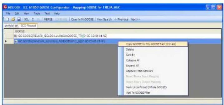
Figure 281. Selecting a GOOSE imported from an SCL-file for operation and Copy to MyGOOSE
![MEGGER IEC-6185D GOOSE Configurator - Mapping GODOSE for FRCJA.MGC File Edit View Tools Test Help SQL C DL MERCE COMPRET Copy to My GODOSE New Search MYSO000 SCD Field GOOSE IEC 0000S/SHDER_EI,LDG_LUN/MOS/SD_03(1-DC-CD-4-1-4F) EIDS Attouces(12) DataSet(S) [1]BOOLEAN LDG SMPTRC1 ST Op general [2]BOOLEAN LDG SMPTRC1 ST Op phA [3]BOOLEAN LDG SMPTRC1 ST Op phB [4]BOOLEAN LDG SMPTRC1 ST Op phC [5]BITSTRING LDG SMPTRC1 ST Op length: 13 GODOR Subscription GODOSE Publication Text BIN 1,2,3,4 - No Mapping - BIN 1 - No Mapping - BIN 2 - No Mapping - BIN 3 - No Mapping - BIN 4 - No Mapping -](/content/2026/05/852528/images/de568ee6b1ce86d18654b98c43aa45e1349f7e893252eee1efc48f0a8aafb0ea.jpg)
Figure 282. Mapping an Imported GOOSE in MyGOOSE
3.15.7.1 Mapping FREJA 5xx binary inputs to GOOSE messages (subscription)
This operation is necessary when the relay test set needs to react on some relay signals that in the conventional technology are relay contacts (trip, start power swing detected etc.) and in the IEC 61850 technology are represented by published GOOSE messages.
3.15.7.1 Mapping FREJA 5xx binary inputs to GOOSE messages (subscription)
The action that needs to be done is to map the GOOSE message to a specific binary input. Once this is done the relay test is carried out in the same way as for the conventional technology. The relay test set is instructed to be stopped (in case of a trip test) by the desired binary input, which is mapped to a GOOSE receive message.
In order to do the mapping of the GOOOSE dataset to the binary input the GOOSE message must be available on the "MyGOOSE" tab.
![MEGGER IEC 61850 GOOSE Configurator - Receiving a TRIP GOOSE for File Edit View Tools Test Help SCL C DL MERGE COMPARE Copy to MyGOOSE New Search MYGOOSE SCD File.scd GOOSE IEC GOOSE[REL670_IECLD0/LLN0GOGOOSE_TR][01-0C-CD-01-01-AB]](/content/2026/05/852528/images/08cfb07e240d935ad12beaaaa9624b2e80a966459a57864060e879474f991413.jpg)
Figure 283. Imported GOOSE in MyGOOSE for Mapping
The GOOSE message "MyGOOSE" tab contains a dataset, and the bits information of the dataset are actually mapped to a binary input, see the following step by step description.
1] Click the + to expand.
The dataset information is opened:
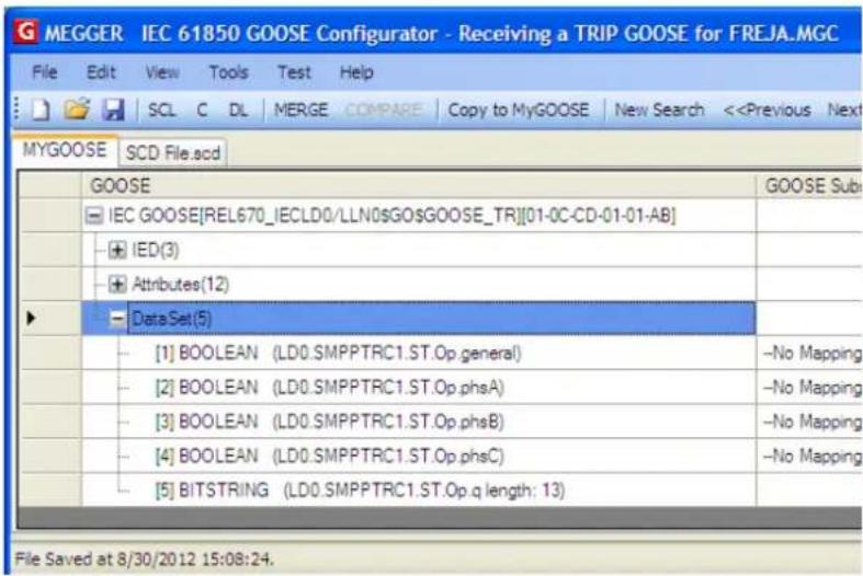
3.15.7.2 Mapping FREJA 5xx binary outputs to GOOSE messages (publication)
This operation is necessary when FREJA 5xx needs to activate some signals to the relay under test. A typical example is the acceleration carrier, or the start of the auto-recloser, or the start of the circuit breaker failure protection. In the conventional technology, this is done by activating the FREJA 5xx binary outputs that are connected to the relay binary inputs. For the IEC 61850 technology, a GOOSE message is sent by the FREJA 5xx into the protection device, and the value of the GOOSE message is associated to the status of the mapped binary output. When the output is open the GOOSE message has value "0" and when it is closed it has value "1". The mapping is done in the same way as it is done for the binary inputs except that the dataset bits are mapped from the column "GOOSE Publication".3.15.7.3 Manipulating the IEC-61850 test service parameter in published GOOSE messages
3.15.7.3 Manipulating the IEC-61850 test service parameter in published GOOSE messages
The test attribute (formally more known as "Test Service Parameter") of the GOOSE messages published by the FREJA 5xx can be manipulated from the menu "Test / IEC 61850-8-1 Ed. 1 Test", see figures below.  In the first half of the window shown above it is possible to manipulate the test service parameter of all GOOSE messages sent by the FREJA 5xx, which means that the messages are available under the MyGOOSE tab and are mapped to some binary outputs.  By choosing "Activate", all the test service parameters are set to True, no matter what their original value was, see the following figure.  By choosing "Deactivate", all the test service parameters are set to FALSE, no matter what their original state was.3.15.7.4 Manipulating the IEC-61850 test attribute in the quality parameter in the published GOOSE messages by the FREJA 5xx
By choosing "Reset" all the published GOOSE messages will have the test service parameter value according to the original value. If SCL-GOOSE it is FALSE, if it is a SNIFFED- GOOSE it depends on the value it had when the message was captured. By choosing "Keep current setting" no change is done on the value of the test service parameter of the published GOOSE messages. It is also possible to set the test service parameter individually for each published GOOSE message, and this can be done directly from the "MyGOOSE" tab, see following figure. 3.15.7.4 Manipulating the IEC-61850 test attribute in the quality parameter in the published GOOSE messages by the FREJA 5xx.
In the second half of the window (shown in "Manipulating the IEC-61850 test service parameter in pub) it is possible to manipulate the value of the test bit in the quality attribute of all GOOSE messages sent by the FREJA 5xx. By choosing "Activate", all the test bits in the quality attributes are set to True, no matter what their original value was, see the following figure.4.0 Upgrading FREJA local software
 By choosing "Deactivate", all the test quality bits are set to FALSE, no matter what their original state was. By choosing "Reset" all the published GOOSE messages will have the test quality bits set according to the original value. If SCL-GOOSE it is FALSE, if it is a SNIFFED-GOOSE it depends on the value it had when the message was captured. By choosing "Keep current setting" no change is done on the value of the test quality bits of the published GOOSE messages. It is also possible to set the test quality bit individually for each published GOOSE message, and this can be done directly from the "MyGOOSE" tab, see the following figure. 4.0 Upgrading FREJA Local software
Upgsrade via Megger Website
To download the newest FREJA Local software from the Megger website, Get the serial number of your unit. Go to WWW.Megger.com Log In. If you have not registered before you will need to do so first. Go to Software Downloads Click on FREJA. Read the instructions for FREJA Local / FREJA Remote Software Download. There will be two versions of the FREJA software at the bottom of the page. One is for your PC called FREJA Remote, and one is for the FREJA 500 unit called FREJA Local. For the FREJA 500 units click on the FREJA Local link.Upgrade via Compact Disk or USB Stick
Where internet access may not be available or blocked on your computer, Megger can provide a CD or a USB stick with the latest version of software on it. Contact your Local Megger representative to order a copy of the firmware.How To Download FREJA Local into the FREJA 500 Unit
USB Memory Stick: With the unit powered up, insert the USB memory stick into the USB port on the front of the unit. A window may appear offering the window navigator, press the Cancel button. From the FREJA Local default start up screen, press the Configuration button. From the Configuration screen press the Update Firmware button. A row of buttons will be presented, press the FREJA Local button and the unit will automatically upgrade the FREJA Local. Do not remove the USB stick until after the Microsoft "Hibernation" screen appears. Then the "FREJA Local" splash screen will appear. When complete, power down the unit. Wait about 5 to 10 seconds and power up the unit. Observe the display screen. When the default test screen appears, press the Configuration button, then press the Display Versions button and verify the version of the software upgrade. natural_image
Exterior view of a Freia 536 Protective Relay Test System (no visible text or symbols on the device body)Model FREJA 536
Megger relay testerSAFETY PRECAUTIONS
VOLTAGES GENERATED BY THIS INSTRUMENT CAN BE HAZARDOUS
This instrument has been designed for operator safety; however, no design can completely protect against incorrect use. Electrical circuits are dangerous and can be lethal when lack of caution and poor safety practices are used. There are several standard safety precautions that should be taken by the operator. Where applicable, IEC safety markings have been placed on the instrument to notify the operator to refer to the user manual for instructions on correct use or safety related topics. Refer to the following table of symbols and definitions.| Symbol Description | |
| === | Direct Current |
| ~ | Alternating Current |
| ~ | Both direct and alternating current |
| ⊥ | Earth (ground) Terminal. There is a common chassis ground terminal located on the front panel (see Front panel under Description of Controls. |
| ⊕ | Protective Conductor Terminal |
| ⊥ | Frame or Chassis Terminal |
| | | On (Supply) |
| ○ | Off (Supply) |
| △ | Caution, risk of electric shock |
| △ | Caution (refer to accompanying documents) |
WARNING:
Under no circumstances should the operator or technician attempt to open or service this instrument while connected to a power source. Lethal voltages are present and may cause serious injury or death!SAFETY PRECAUTIONS (Continued)
The following are some specific safety related items associated with the FREJA test system. Read and understand all safety precautions and operation instructions before attempting to use this unit. The purpose of this equipment is limited to use as described in this instruction manual. Should a situation arise that is not covered in the general or specific safety precaution please contact Megger regional representative or Megger, Dallas Texas.1.0 Operation
Safety is the responsibility of the user. Misuse of this equipment can be extremely dangerous. Always start with the power OFF, before connecting the power cord. Make sure outputs are off before attempting to make test connections. Never connect the test set to energized equipment. Always use properly insulated test leads. The optional test leads are rated for the continuous output ratings of the test system, and should be properly used and cared for. DO NOT use cracked or broken test leads. Always turn the test system off before disconnecting the power cord. DO NOT attempt to use the unit without a safety ground connected. DO NOT attempt to use the unit if the power cord ground prong is broken or missing. DO NOT use the test set in an explosive atmosphere. The instrument must only be used by suitably trained and competent persons. Observe all safety warnings marked on the equipment. For safety related or other important topics, like the statement below, will be notated with the adjoined symbol. Read the topic carefully as it may relate either to the safe operation of the test system or the safety of the operator. Under no circumstances should the operator put their hand or tools inside the test system chassis area with the test system connected to a power source. Lethal voltages are present and may cause serious injury or death!WEEE
The crossed out wheeled bin placed on Megger products is a reminder not to dispose of the product at the end of its life with general waste. Megger is registered in the UK as a Producer of Electrical and Electronic Equipment. The Registration No is WEE/DJ2235XR.1.0 Operation
The unit's design is a "modular" concept. All inputs and outputs are clearly marked and logically grouped so continual reference to the instruction manual should not be necessary once the operator is acquainted with the test system. The unit's Top Panel may appear different among units, depending on whether it has the optional Transducer Module installed. If the transducer module is installed Binary Input and Output #3 will be marked as the DC Voltage and Current input terminals.1.1 General Description
 Figure 196 Top Panel FREJA 536 (without Transducer Option)1.1.1 Top Panel
 1. Current Channels ① –The channels are numbered 1 to 3 from bottom to top. Phases A, B and C Current Channels are denoted by the I1, I2 and I3 labeled terminals. When the FREJA 536 voltage generators are converted to current generators, they will change on the FREJA Local display as U1 = I4, U2 = I5 and U3 = I6. For more details on the VIGEN output capabilities see section 1.4. 2. Voltage Channels ②—The channels are numbered 1 to 3 from bottom to top, with the topmost VIGEN numbered 3. Phases A, B and C Voltage Channels are denoted by the U1, U2 and U3 labeled terminals. 3. Binary Inputs ^3 – there are 10 Binary Inputs located on the top panel ③ and ④ . The 3rd Binary Input will be replaced with DC Input terminals if ordering the unit with the Transducer option. To serve a wide range of test applications the binary inputs have different voltage thresholds. For typical test applications binary inputs 1, 2 and 3 have a fixed threshold of 5 volts. For GPS End-to-End synchronized relay testing Binary 1 may be connected with a remote trigger pulse from a GPS satellite receiver for external initiation, or the output of an IRIG-B signal (see use of Wait IRIG-B input using the Sequencer test). There are an additional 7 binary inputs ⑦ . To monitor TTL signals binary inputs 4 through 6 have a fixed threshold of 3 volts. Binary inputs 7 and 8 have fixed thresholds of 5 volts, and binary inputs 9 and 10 have fixed threshold of 30 volts (for "noisy" test environments). In addition to serving as Timer / Monitor inputs, the Binary Inputs may be programmed to trigger binary output sequence(s). Binary Inputs can also be programmed using Boolean logic for more complex power system simulations. 4. Binary Outputs – there are 6 Binary Outputs located on the top panel ④, ⑤ and ⑥. The 3rd Binary Output will be replaced with DC Input terminals if ordering the unit with the Transducer option. Each Binary Output can be configured as Normally Open or Normally Closed contacts providing logic to the device under test. The Binary Outputs 1 to 4 ④ and ⑥ can switch up to 300 VAC or 250 VDC with 8 Amp continuous. The programmable wait duration is from 1 millisecond to 10,000 milliseconds. Binary Outputs 5 and 6 ⑤ are the high speed binary outputs have an AC / DC Voltage Rating of 400 V peak, Imax: 1 amp, with a Response Time: < 1ms typical. An LED indicates the status of the contact. ON indicates closed, and OFF indicates open. 5. Battery Simulator – the FREJA 536 provides a battery simulator ⑤ with a continuously variable dc output voltage from 10 to 250 Volts, at 100 Watts (4 Amperes Max) providing logic voltage for solid-state relays. When powered ON, the LED above the output terminals illuminates.1.1.2 Front panel
1.1.2 Front Panel:
 Figure 197 FREJA 536 Front Panel 1. Incoming Power / Line Cord ① – the input line cord, ground terminal, are mounted on the front panel of the test set.Input Line Cord
The test set is equipped with a line cord, which connects to the male connector on the front panel. Verify the input voltage rating on the front panel before connecting the line cord to the power source. 2. Earth Ground Jack ②- use this terminal to connect chassis ground to earth ground. A chassis ground (earth) point on the front panel is provided as an additional safety ground. 3. POWER ON / OFF Switch ③- used to switch unit on and off. 4. ISOLATED ④ For IEC 61850 testing connect IEC61850 / OUT port to the substation bus or to the relay under test to receive and send GOOSE messages. Connect the ISOLATED port to the PC. When used with the Megger GOOSE Configurator software, the FREJA 536 can provide high speed testing of IEC 61850 relays and substations by subscribing to GOOSE messages and mapping to the binary inputs. In addition, it can simulate system conditions such as circuit breaker operation by publishing GOOSE messages mapped to the FREJA 536 binary outputs. With the PC running Megger GOOSE Configurator and connected to the ISOLATED port, the operator can "sniff" the substation network from the IEC 61850 / OUT port through the ISOLATED port with the FREJA unit serving as the firewall. With this design the operator cannot accidentally trip off the substation or inflect a PC virus into the substation LAN. 5. PC / IN ⑤ Ethernet Port is the primary PC connection port for automated relay testing. This port supports MDI / MDI-X auto cross over configuration, which means both standard and "crossover" Ethernet cables may be used. Use this port for standard automated relay testing. This port provides the optimal method for downloading EMTP files, DFR streaming, and updating the unit's firmware as required. For multiple unit operation, the unit providing the OUT link is providing the master phase reference to all units "downstream". For multiple unit operation connect the OUT port to the downstream FREJA unit IN port. The FREJA Local will automatically configure when the units are powered up. 6. IEC61850 / OUT ⑥ Ethernet Port is a 10/100BaseTX port, and is primarily used to interconnect multiple FREJA units together for synchronous multi-unit operation. It is also be used to provide access to the substation IEC 61850 network. For multiple unit operation, the unit providing the OUT link is providing the master phase reference to all units "downstream". With the PC connected to the PC Port, the FREJA and the PC share the same Ethernet network connection, and thus will not have a secure isolation from each other. When testing IEC 61850 devices connect the PC to the ISOLATED Ethernet port to isolate the PC from the IEC 61850 substation bus.1.2 Input power
7. USB Interface ⑦ there are two type A ports available. This port is primarily used to update the firmware in the FREJA unit as well as update the FREJA Local software using a USB memory stick. It may also be used to download test results from the FREJA for download into another PC with Power DB software for storage or printing. In addition, the user can use a USB keyboard, as well as a mouse, in conjunction with the touch screen. Keyboard and / or mouse are not provided with the accessories. 8. USB (TO PC) Interface ⑧ – The (TO PC) USB Interface requires a Type B “downstream” connector, and is primarily used as a communication and control port when used with a PC and Megger software for automated relay testing. A USB cable is not provided with the test set or in the optional accessories. For computer control, an Ethernet cable is provided. However, should the user desire to use the USB port any standard USB A / B cable will work with the unit. May be used when isolation is required for a secure substation access between the FREJA and the IEC 61850 substation network.1.2 Input Power
The input voltage rating may be from 100 to 240 VAC, 10%, 50 / 60 Hertz. The maximum input power is 1800VA. The input is protected by a power ON / OFF switch / circuit breaker.1.2.1. Input Power Cord
Depending on the country, the power cord can come with a NEMA 5-15 male connector, a CEE 7/7 Schuko two prong connector, with International Color Coded pig-tail wires (light blue, brown and green with yellow stripe) with the insulation jacket stripped ready for installation of the appropriate male connector, or with UK power cord. Model FREJA 536 XXXXXXAXX comes with a NEMA power cord (part number 620000).  Model FREJA 536 XXXXXXEXXX comes with a Continental Europe power cord (part number 50425).  Model FREJA 536 XXXXXXIXXX comes with an International Color Code power cord. The cord, part number 15065, is ready for wiring to the appropriate plug (depending on country). The following colors apply, Brown = Line, Blue = Neutral and Green / Yellow = Ground. 1.3 Voltage Current generator (VIGEN) module
Model FREJA 536 XXXXXXUXXX comes with a UK power cord (part number 90002-989). UK Power Cord with IEC 60320 C13 Connector natural_image
Pure electrical plug diagram without any text or symbols1.3 Voltage - Current Generator (VIGEN) Module
Voltages and Currents are noted by the numbered box surrounding each output channel. All outputs are independent from sudden changes in mains voltage and frequency, and are regulated so changes in load impedance do not affect the output. Standard amplifier outputs are isolated or floating.1.3.1. Convertible Voltage / Current Amplifier
 The FREJA PowerV™ voltage amplifier provides a flat power curve from 30 to 150 Volts in the 150V range to permit testing of high current applications such as panel testing, or certain older electromechanical impedance relays.Voltage Range
Power / Current (Max)
30.00V 150VA @ 5.0A 150.00V 150VA Constant Output Power from 30 to 150 Volts 300.00V 150VA @ 0.5AVoltage Amplifier in Current Mode:
The FREJA 536 voltage amplifier is convertible to a current source with the following output capability. Output power ratings are specified in rms values and peak power ratings.Output Current Power
Max V
Duty Cycle
5 Amperes 150 VA (212 peak) 30.0 Vrms Continuous 15 Amperes 120 VA 8.0 Vrms 90 Cycles With a FREJA 536 unit, convertible channels in conjunction with the three main current channels, provides 6 currents for testing three phase current differential relays. When the voltage generators are converted to current generators, the FREJA Local display will change as current phases 4, 5 and 6. The voltage amplifier output is protected from short circuits and thermally protected against prolonged overloads. In case of a short circuit or a thermal overload, the amplifier will automatically turn off, and a message to the user will be displayed indicating which condition exists.1.3.2. Current Amplifier
 The FREJA current amplifier Constant Power Output feature delivers maximum compliance voltage to the load1.4 Binary Inputs and Outputs
constantly during the test, and range changing is done automatically, on-the-fly, under load. This ensures better test results, saves time by not having to turn the outputs off to change output taps or ranges, and unlike single range current amplifiers ensures a higher compliance voltage at lower test currents. Constant Power Output in many cases eliminates the need to parallel or series current channels together to test high burden relays. The following are typical output current and associated available compliance voltage values for the FREJA 536. The per channel output current and power ratings are specified in AC rms values and peak power ratings. Specified duty cycles are based upon typical room ambient temperature. Output Current Power Max V / Duty Cycle| 1 Ampere | 15 VA | 15.0 Vrms Continuous | |
| 4 Amperes | 200 VA (282 peak) | 50.0 Vrms Continuous | |
| 15 Amperes | 200 VA (282 peak) | 13.4 Vrms Continuous | |
| 32 Amperes | 200 VA (282 peak) | 6.67 Vrms Continuous | |
| 60 Amperes | 300 VA (424 peak) | 5.00 Vrms 90 Cycles | |
1.4.1 Binary inputs
1.4.1 Binary Inputs
The binary inputs are specifically designed to measure high speed operation of electro-mechanical, solid-state and microprocessor-based protection relays. All binary Inputs default to Monitor Mode, Contact change of state, latched OFF. If using the touch screen or FREJA Local to change a binary input from Contact change of state to Voltage Applied / Removed click on or touch the Input Type window and a sine wave will appear where the Contact icon was indicating. The input is now set for voltage sensing. To change the binary input from Monitor mode to Timer Mode, click on or touch the Use as Monitor button and the display window will change to show Use as Trip, Latched, meaning the binary input is now set to stop the timer upon sensing the first contact closure (if the Input Type is set for contact) or upon sensing voltage if the Input Type is set to Voltage Sensing.1.4.1.1 Start, Stop, and Monitor Gates
In the FREJA 536 there are ten identical, independent, programmable gate circuits that permit simple selection of the desired mode for timing or contact monitoring operation. To monitor operation of the contacts or trip SCR in the device under test, a light is provided for each gate. The gate circuit is isolated for voltage-sensing and can monitor solid-state logic signals. Each light will illuminate once contacts close or voltage is applied to the gate.1.4.1.1.1 Dry Contacts Open
Timer stops or a continuity indicator goes out at the opening of normally closed contacts, or when conduction through a semiconductor device, such as a triac or a transistor, is interrupted.1.4.1.1.2 Dry Contacts Close
Timer stops or a continuity indicator glows at the closing of the normally open contacts, or upon conduction through a semiconductor device such as a triac or a transistor.1.4.1.1.3 Application or Removal of AC or DC voltage
This will either start the Timer or stop the Timer. The continuity indicator will glow (application) or darkens (removal) upon the application or removal of either an AC or DC voltage. To serve a wide range of test applications the binary inputs have different voltage thresholds. For typical test applications binary inputs 1, 2 and 3 have a fixed threshold of 5 volts. To monitor TTL signals binary inputs 4 through 6 have a fixed threshold of 3 volts. Binary inputs 7 and 8 have fixed thresholds of 5 volts, and binary inputs 9 and 10 have fixed threshold of 30 volts (for "noisy" test environments). A higher threshold voltage helps to eliminate false triggers due to a noisy source. Lower thresholds allow starting and stopping of timer from TTL voltage signals. The allowable voltage applied is 5 to 300 Volts AC or 5 to 300 Volts DC, current limiting resistors provide protection.1.4.1.1.4 The Timer can be started when turning on any selected generators.
1.4.1.1.5 The Timer can be started simultaneously with a change in Frequency, Phase Angle, or Amplitude. Also, it can be started simultaneously with a Voltage or Current waveform step.1.4.2 Binary Outputs
Binary Outputs 1 and 2 are rated for 300 V AC / DC at 8 Amperes. Each Binary Output can be configured as normally open or normally closed contacts providing logic to the device under test. Binary Outputs 3 and 4 have a rating of 300 V AC / DC, 8 amperes and a maximum of 2000 VA breaking capacity (80 watts DC), with a response time of less than 10ms. Binary Outputs 5 and 6 are high speed and have an AC / DC voltage rating of 400 volts peak, 1 ampere and a response time typically less than 1ms. The contacts may be programmed to open or close, thus simulating circuit breaker operation. The programmable wait duration is from 1 millisecond to 10,000 milliseconds. A fused test lead (fused at 500 mA) is available as an optional accessory to help protect from blowing the internal fuse of binary outputs 5 & 6. The test lead is blue in color so that the user knows it applies to the blue binary outputs. The barrel holder of the test lead is CE marked with a 1000 V, CAT III rating, and marked FUSED 500 mA / 1000 V/ 50 KA.1.5 Battery Simulator
Figure 200 Battery Simulator (BAT SIM)
The FREJA 536 includes a battery simulator that provides a variable DC output from 10 to 250 VDC rated at 100 Watts, 4 Amperes max. User may select from normal setting values of 24, 48, 125, or 250 VDC, or enter the desired output voltage in the window provided, see the FREJA Local Configuration Screen. The output is variable using the Control Knob, or the PC up / down cursor arrows (see the FREJA Local section of the manual).CAUTION:
 NOTE: DC voltage is ON and available when the output is turned on using the touch panel or via command. Do not plug or insert any test lead into the BATTERY SIMULATOR binding out first connecting the test leads to the load!2.0 SETUP
2.1 Unpack System
Unpack the unit and check for evidence of any shipping damage. If there is any visual damage, immediately notify the freight carrier to make a damage claim, and notify Megger of the damage.CAUTION:
Potentially lethal voltages may be present on the output terminals. It is highly recommended the operator read the user manual thoroughly and have an understanding of the test set operation prior to turning power on.2.1.1 Initial Start Up
1. If using the FREJA Local PC version software, connect the PC / IN Ethernet Port on the FREJA unit to the PC Ethernet port. 2. Before connecting power to the unit, make sure the POWER ON / OFF Switch is in the OFF position (0). Plug the unit line cord into an appropriate power source and turn the POWER ON / OFF Switch to ON (1). As the FREJA unit goes through its power up sequence, in about a minute the FREJA Local power up screen will appear, then the manual start up screen will appear.2.2 Communication ports
2.2 Communication Ports
There are several communication ports. These ports are: two USB, and three Ethernet ports.  Figure 201 FREJA 536 Communication Ports2.2.1 USB 2.0 Interface
The USB Type A ports are intended for use with downloading new FREJA Local software, FREJA firmware, or stored PowerDB test results. A USB keyboard or mouse can also be used with the unit. USB TO PC Interface requires a Type B "downstream" connector, and is primarily used as a communication and control port when used with a PC and FREJA Win or FREJA Local PC version software for automated relay testing. It is recommended that you use the Ethernet port for high speed communication and control of the FREJA unit. To use the USB port will require the user to configure the PC com port for USB operation. Clicking on the Instrument Setup icon on the PowerDB tool bar, the Instrument Configuration Screen (shown in the following figure)  Figure 202 FREJA Local PC Version Instrument Configuration Screen provides the user with access to the PC Device Manager screen. Click on the Device Manager button and navigate to the USB Ports file directory. Since the FREJA 536 defaults to a baud rate of 115,200, the user will need to configure their USB output com port to match. Returning to the Instrument Configuration screen the user will need to check off the Use Ethernet check box, and set the Baud rate, Byte Size and Stop Bits as shown.2.2.2 PC / IN Ethernet Port
PC / IN Ethernet Port is the primary PC connection port for automated relay testing. This port supports MDI / MDI-X auto cross over configuration, which means both standard and “crossover” Ethernet cables may be used. Use this port for standard automated relay testing. This port provides the optimal method for downloading EMTP files, DFR streaming, and updating the unit’s firmware as required. For multiple unit operation, the unit providing the OUT link is providing the master phase reference to all units “downstream”. For multiple unit operation connect the OUT port to the downstream FREJA unit IN port. The FREJA Local software will automatically configure when the units are powered up.2.2.2.1 Setting FREJA IP Address for Operation with a PC
With the Ethernet cable supplied with the unit, connect the PC / IN Ethernet Port on the FREJA unit to the PC Ethernet port. Turn the test set on. As the FREJA unit goes through its power up sequence, in less than a minute the FREJA Local power up screen will appear. If using the PC version of the FREJA Local software it will auto-detect the FREJA unit connected to the PC. Once it auto-detects the unit, and determines the configuration of the FREJA unit connected, the Manual screen will appear. The unit might not auto detect due to firewall settings. In this case the firewall can be turned off or you can enter the IP address directly using the PowerDB instrument configuration screen by clicking on the Instrument Setup icon on the PowerDB tool bar. From the Instrument Configuration Screen, shown in the following figure, click off the check mark in the Auto Discover Unit box.  Figure 203 PowerDB Instrument Setup Screen Here the user can enter the IP address directly into the box highlighted in red. The IP address of the unit can be determined by counting the number of times the Binary Output led flashes at the end of boot up cycle (the address is 169.254. <#flashes>.0). If the unit flashed four times, the address would be 169.254.4.0. If the unit is on a network with a DHCP server, the user must use the Auto Discovery mode.2.2.3 ISOLATED Ethernet Port
For IEC 61850 testing connect IEC61850 / OUT port to the substation bus or to the relay under test to receive and send GOOSE messages. Connect the ISOLATED port to the PC. When used with the Megger GOOSE Configurator software, the FREJA unit can provide high speed testing of IEC 61850 relays and substations by subscribing to GOOSE messages and mapping to the binary inputs. In addition, it can simulate system conditions such as circuit breaker operation by publishing GOOSE messages mapped to the FREJA binary outputs. With the PC running Megger GOOSE Configurator and connected to the ISOLATED port, the operator can "sniff" the substation network from the IEC 61850 /OUT port2.2.4 IEC61850 / OUT ethernet port
through the ISOLATED port with the FREJA unit serving as the firewall. With this design the operator cannot accidentally trip off the substation or inflect a PC virus into the substation LAN.2.2.4 IEC61850 / OUT Ethernet Port
The IEC 61850 / OUT Ethernet Port is a 10/100BaseTX port, and is primarily used to interconnect multiple FREJA units together for synchronous multi-unit operation. It is also be used to provide access to the substation IEC 61850 network (when enabled). The FREJA 536 with the IEC 61850 option enabled provides selectable priority, VLAN-ID, and meets the IEC 61850-5 standard Type 1A, Class P 2/3, for high speed trip and reclose simulations. For multiple unit operation, the unit providing the OUT link is providing the master phase reference to all units “downstream”. With the PC connected to the PC Port, the FREJA and the PC share the same Ethernet network connection, and thus will not have a secure isolation from each other. When testing IEC 61850 devices connect the PC to the ISOLATED Ethernet port to isolate the PC from the IEC 61850 substation bus.2.2.4.1 Setting FREJA IP Address for Networks or IEC 61850 Operations
The FREJA 536 may be controlled over a network. This provides remote control of the FREJA 536 virtually over any distance allowing one PC to control at least two units simultaneously, such as in end to end testing. Connecting the FREJA 536 to a Local Area Network or a Wide Area Network could permit unauthorized operation of the unit. Through the PC IN Ethernet port, the FREJA 536 integrates into a network just like a PC or server. To use this feature requires the user to setup the IP configuration of the FREJA 536 for their LAN. Note that the FREJA 536 when turned on will automatically search for and acquire a network address if connected to a network. If it fails to automatically acquire an address check to make sure you are properly connected using a standard Ethernet cable. Do not use a "cross-over" Ethernet cable (a cross over cable is designed for use from your PC to the test set, not to a network). If the unit still fails to acquire an address then there may be other issues. This will probably require assistance from your company's information management department.3.0 Current Sources
3.1 Parallel Operation
Each FREJA current amplifier is capable of providing 32 Amperes continuous, and can provide up to 60 amperes for 1.5 seconds for testing instantaneous trip elements. When more than 32 Amperes single phase is required for long durations, or 60 Amperes for testing instantaneous elements, two or three current channels may be connected in parallel to provide 60 or 90 Amperes continuous. For higher single phase output currents three FREJA 536 channels can provide 180 Amperes for short durations. To parallel the current channels of the unit, perform the following: If using the sleeved multi-lead current test leads (part number 2001-396), all of the black return leads are interconnected together inside the sleeve so they will all share the return current together. Connect each current channel to the relay under test (both red and black terminals to the load). Each Megger test lead is rated for 32 Amperes continuous. If using test leads other than those supplied by Megger ensure that the wire has sufficient size to carry the test current. It is important that the parallel connections must be made at the relay. See the following figure.3.1.1 Manual test screen - single phase Up To 180 ampere
flowchart
graph TD
    A["1"] --> B["2"]
    B --> C["3"]
    C --> D["Megger"]
    D --> E["PROTECTIVE RELAY TEST SYSTEM"]
    style A fill:#f9f,stroke:#333
    style B fill:#ccf,stroke:#333
    style C fill:#cfc,stroke:#333
    style D fill:#fcc,stroke:#333
    style E fill:#ffc,stroke:#333
    style_F["IV. SPRPLY"] --> G["1"]
    G --> H["2"]
    H --> I["3"]
    I --> J["4"]
    J --> K["5"]
    K --> L["6"]
    L --> M["7"]
    M --> N["8"]
    N --> O["9"]
    O --> P["10"]
    P --> Q["11"]
    Q --> R["12"]
    R --> S["13"]
    S --> T["14"]
    T --> U["15"]
    U --> V["16"]
    V --> W["17"]
    W --> X["18"]
    X --> Y["19"]
    Y --> Z["20"]
3.1.1 Manual Test Screen - Single Phase Up To 180 Ampere
For ease of use and operator convenience, go to the Configuration screen and select the Operating Mode of 3 Voltages – 1 Current @ 180 Amperes. When you return to the manual test screen there will be one current channel displayed, as shown in the following figure.  Figure 205 Manual Test Screen – Single Phase Operation FREJA Local will automatically set all three currents in phase with each other and divide the current equally between the three current amplifiers. When setting an output, simply enter the value of the desired output current. For example, for an output of 75 Amperes, enter 75, while each current amplifier will be providing 25 Amperes. The current can also be phase shifted. Simply enter the desired phase angle and all three currents will be phase shifted together. If two current channels that are to be used in parallel, leave the unit in the default three phase configuration. Connect the two current outputs to the load as shown in the following figure.3.2 Currents in series operation
 Figure 206 Two Currents in Parallel Set each channel to one-half of the output requirement. Be sure and reset current channel #2 to 0 degrees so that it will be in-phase with current channel #1. With both current channels selected, turn output on by pressing or clicking on the ALL ON / OFF button. Always use the ALL ON / OFF button to turn both current channels on and off together. For manually ramping outputs, if using the PC version of the FREJA Local software the ↑↓ buttons will be displayed. If using the touch screen the Control Knob button will be displayed. Pressing either of these two will present the user with a window to select the desired level of increment for manually ramping the outputs, the desired channel(s) to be ramped, and what is to be adjusted (amplitude, phase angle or frequency).3.2 Currents in Series Operation
Two current channels may be connected in series in order to double the available compliance voltage. High impedance electromechanical earth (ground) overcurrent relays have always been difficult to test at high multiples of tap due to the winding impedance and saturation characteristics. The peak voltage required can exceed the maximum output voltage of one FREJA 536 current output channel, depending on the required test current. By connecting two current outputs in series, the compliance voltage is doubled, providing higher test currents through the load. Connect the two current amplifiers in a “push-push” configuration as shown in the following figure.  Figure 207 Series Two Currents The two current channels that are to be used in series set each to the same test current magnitude, and phase angle. Select both current channels and turn output on by pressing or clicking on the BALL ON / OFF button. Always use the ALL ON / OFF button to turn both current channels on and off together. For manually ramping outputs, if using the PC version of the FREJA Local the ↑↓ buttons will be displayed. If using the touch screen the Control Knob button will be displayed. Pressing either of these two will present the user with a window to select the desired level of increment for manually ramping the outputs, the desired channel(s) to be ramped, and what is to be adjusted (amplitude, phase angle or frequency).4.0 Voltage Sources
4.1 Outputs Summed Together
Two voltage channels may be used to sum the voltage outputs to obtain higher than rated voltage provided the load is ungrounded. Connect the load between the voltage channel posts, set U1 Phase to 0° and set U2 Phase to 180°. The voltage outputs will add so the total voltage is the sum of the two voltage amplitudes, U1 and U2 as can be seen in the following figures. flowchart
graph LR
    U1 <--> N
    N --> U2
4.2 3∅, 3-Wire, Open-Delta and T-Connection
See section 3.4.2 in the FREJA Local software for detailed descriptions and use of the Open-Delta and T-Connection.4.2.1 Open Delta Connection
The Open-Delta configuration is easy to use when a balanced three-phase source is required because the amplitude and phase relationship can be set directly. No calculations are necessary. When using the Open-Delta configuration, it is suggested to use voltage channel #1, designated U1, and voltage channel #2, designated U2, while the COMMON binding post is designated Vg. With this arrangement, the magnitude and phase angle of the potentials can be easily4.2.2 T-Connection
calculated and set. For the balanced three-phase condition U1 and U2 are equal in magnitude and separated by an angle of 60°. This is done by setting the U1 and U2 potentials equal in magnitude, setting 0° on U1, and 300° (60 degrees leading assuming that the default phase rotation is set to 360 Lag) on U2, see the following figure.  Figure 209 Three Phase Open Delta Connections4.2.2 T-Connection
The second method of obtaining a three-phase, three-wire voltage source is the so-called T-Connection. The method is easier to use when obtaining an unbalanced, phase-to-phase fault simulation since it eliminates calculations. To reduce confusion when using the T-Connection, the voltage output #1 is designated U1 and its phase angle set at 0°, voltage output #2 is designated U2 and its phase angle set for 180°, and voltage output #3 is designated U3 and its phase angle is set for 270. Any combination of balanced three phase faults or unbalanced phase-to-phase fault conditions can be easily simulated.  NOTE: This method should not be used for very low fault voltages, or used on solid state relays that are sensitive to this type of connection (i.e. 5 volts or less, or for testing ABB or Westinghouse type relays).4.3 30, 4-Wire, Y-Connection
A three-phase, four-wire potential system can be provided using three output modules. The Y-Connection has the advantage of being able to supply a higher line-to-line voltage (1.73 x phase-to-neutral voltage). It is ideally suited for simulating phase-to-ground faults. Voltage channel #1 is designated as U1 with its phase relationship set for 0°. Voltage channel #2 is then designated as U2 and phase angle set for 120°. Finally, voltage channel #3 is designated U3 and phase angle set for 240° (for a 1-2-3 counter clockwise rotation). U1, U2 and U3 are connected to the voltage potential binding posts on the respective test sets.  Note: If using the sleeved multi-lead voltage test leads (part number 2001-395); all of the black return are interconnected together inside the sleeve so they will all share the return together. Therefore, the return lead is provided on the relay connection side of the sleeved leads (similar to the actions in the following figure).  Figure 210 Three Phase Four Wire Test Connections If using separate individual test leads, the user must connect the associated voltage channels black common returns together as shown above.5.0 Warranty Statement
Megger warrants the product is free of defects in material and workmanship for a period of at least one (1) year from date of shipment. This warranty is non-transferable. This warranty is limited and shall not apply to equipment that has damage, or cause of defect, due to accident, negligence, and improper operation, faulty installation by the purchaser, or improper service or repair by any person, company or corporation not authorized by Megger. Megger will, at its' option, either repair or replace those parts and / or materials it deems to be defective. The warranty is in lieu of all other warranties, either expressed or implied on the part of Megger and in no event shall Megger be liable for the consequential damages due to the breach thereof.5.1 Preventive Maintenance
The unit utilizes surface mount technology (SMT) and other components which require little or no service except for routine cleaning, etc. The unit should be serviced in a clean atmosphere away from energized electrical circuits.5.1.1 Examine the unit every six months for:
Dust and Dirt To clean the unit, disconnect the power cord from the unit. Never use spray liquids or industrial cleaners. Some cleaning solvents can damage electrical components, and should never be used. Water and a mild soap may be used. Use a lightly damp cloth (not dripping wet) to wipe off the unit. A dirty heat sink can cause thermal overloads. Remove dust with dry, low pressure, compressed air. Either remove the module from the chassis or simply apply air forcing the dust away from the heat sink through the sides of the unit. Moisture Remove moisture as much as possible by putting the test set in a warm, dry environment.5.1.2 Updating FREJA 536 f4irmware
5.1.2 Updating FREJA 536 Firmware
Download Firmware Upgrade via Megger Website
To download the newest firmware from the Megger website, 1. Go to WWW.Megger.com 2. Log In. 3. Go to Software Downloads 4. Click on FREJA. Read the instructions on How to Download Firmware into FREJA 400 and 500 Series units. Scroll down the bottom of the page, and click on FREJA Firmware #.###. The firmware will be downloaded onto your PC as a zip file. Note: Using the FREJA 400 or 500 series front USB port to update the firmware using a memory stick is the fastest and most secure means of downloading the new firmware into the FREJA unit. If you are not allowed to use a memory stick to update the firmware, you can download the new firmware from a PC (using the FREJA Remote software) over the Ethernet port. If you select the USB stick method, the loader file (FREJA\_Firmware\_1.xxx.ldr) must be located under folders labeled Megger / Update on the root directory of the USB stick. USB Memory Stick: With the unit powered up, insert the USB memory stick into the USB port on the front panel of the FREJA 536. Press the Configuration Screen button, and then press the Update Firmware button in the Configuration Screen. At that point the user will be presented with the IP Address selection screen, with the serial number of the unit. Select the unit by touching the serial number and the upgrade process will automatically start. That's all there is to it. Observe the FREJA Local display screen, and the unit. At the completion of the download, the user will note the fans spin-up, and the LED's will be flashing rapidly on the FREJA unit, and the binary output contacts will be closing and opening rapidly with a clicking sound. There will be an instruction to reboot (turn off and back on) the test system. PC and FREJA Remote: If using the PC version FREJA Remote software, it is very similar to the USB Stick method. Upon clicking on the Update Firmware button, the familiar Windows Open File browser dialog box will appear. Using the Look In pull-down menu, navigate to where the new firmware was downloaded onto the PC, click on and open the file folder SMRT\_LDR (SMRT Loader). There you will find the new firmware file. Click on the file, and click on Open. You will be requested to select a unit from the IP Address screen. Select the unit by clicking on the serial number and the upgrade process will automatically start. At the completion of the download, the user will note the fans spin-up, and the LED's will be flashing rapidly on the FREJA unit, and the binary output contacts will be closing and opening rapidly with a clicking sound. There will be an instruction to reboot (turn off and back on) the test system. Note that after rebooting the FREJA unit, if using the PC version FREJA Remote you will have to restart the FREJA Remote on your PC in order to regain control of the FREJA unit.6.0 Preparation for Reshipment
Save the original shipping container for future use. The shipping container is designed to withstand the rigors of shipping via a common commercial carrier. For example, you may wish to reship your unit to Megger for an annual calibration recertification. Pack the equipment appropriately to prevent damage during shipment. If a reusable container is utilized, the unit will be returned in the same shipping container if it is in suitable condition. Add the Return Authorization Number to the address label of the shipping container for proper identification and quicker handling. NOTE Ship the equipment without nonessential items such as test leads, etc. These items are not needed by the factory to perform service. Model FREJA 543 / 546
Megger relay testerSafety precautions
SAFETY PRECAUTIONS
VOLTAGES GENERATED BY THIS INSTRUMENT CAN BE HAZARDOUS This instrument has been designed for operator safety; however, no design can completely protect against incorrect use. Electrical circuits are dangerous and can be lethal when lack of caution and poor safety practices are used. There are several standard safety precautions that should be taken by the operator. Where applicable, IEC safety markings have been placed on the instrument to notify the operator to refer to the user manual for instructions on correct use or safety related topics. Refer to the following table of symbols and definitions.| Symbol Description | |
| --- | Direct Current |
| ~ | Alternating Current |
| ~ | Both direct and alternating current |
| ⊥ | Earth (ground) Terminal. There is a common chassis ground terminal located on the front panel (see Front panel under Description of Controls. |
| ∅ | Protective Conductor Terminal |
| ⊥ | Frame or Chassis Terminal |
| | | On (Supply) |
| ○ | Off (Supply) |
| △ | Caution, risk of electric shock |
| ⚠ | Caution (refer to accompanying documents) |
WARNING:
Under no circumstances should the operator or technician attempt to open or service this instrument swill connected to a power source. Lethal voltages are present and may cause serious injury or death!SAFETY PRECAUTIONS (Continued)
The following are some specific safety related items associated with the FREJA test system. Read and understand all safety precautions and operation instructions before attempting to use this unit. The purpose of this equipment is limited to use as described in this instruction manual. Should a situation arise that is not covered in the general or specific safety precaution please contact Megger regional representative or Megger, Dallas Texas. Safety is the responsibility of the user. Misuse of this equipment can be extremely dangerous. Always start with the power OFF, before connecting the power cord. Make sure outputs are off before attempting to make test connections. Never connect the test set to energized equipment. Always use properly insulated test leads. The optional test leads are rated for the continuous output ratings of the test system, and should be properly used and cared for. DO NOT use cracked or broken test leads. Always turn the test system off before disconnecting the power cord. DO NOT attempt to use the unit without a safety ground connected. DO NOT attempt to use the unit if the power cord ground prong is broken or missing. DO NOT use the test set in an explosive atmosphere. The instrument must only be used by suitably trained and competent persons. Observe all safety warnings marked on the equipment. For safety related or other important topics, like the statement below, will be notated with the adjoined symbol. Read the topic carefully as it may relate either to the safe operation of the test system or the safety of the operator. Under no circumstances should the operator put their hand or tools inside the test system chassis area with the test system connected to a power source. Lethal voltages are present and may cause serious injury or death!WEEE
The crossed out wheeled bin placed on Megger products is a reminder not to dispose of the product at the end of its life with general waste. Megger is registered in the UK as a Producer of Electrical and Electronic Equipment. The Registration No is WEE/DJ2235XR.1.0 Operation
The unit's design is a "modular" concept. All inputs and outputs are clearly marked and logically grouped so continual reference to the instruction manual should not be necessary once the operator is acquainted with the test system. The unit's Top Panel may appear different among units, depending on whether it is a FREJA 543 or a FREJA 546, or if the unit has the optional Transducer Module installed. If the transducer module is installed Binary Input and Output #3 will be marked as the DC Voltage and Current input terminals.1.1 General Description
1.1.1 Top panel
 Figure 217 Top Panel FREJA 543 / 546 (546 Pictured)1.1.1 Top Panel
1. Current Channels ① –The channels are numbered 1 to 3 from bottom to top. Phases A, B and C Current Channels (I1, I2 and I3) are denoted by the black color terminals. When the FREJA 546 voltage generators are converted to current generators, they will change on the FREJA Local display as V1 = I4, V2 = I5 and V3 = I6. For more details on the VIGEN output capabilities see section 1.4. 2. Voltage Channels ②—The channels are numbered 1 to 3 from bottom to top, with the topmost VIGEN numbered 3. Phases A, B and C Voltage Channels (V1, V2 and V3) are denoted by the red color terminals. Phases A, B and C. When the FREJA 546 voltage generators are converted to current generators3, they will change on the FREJA Local display as V1 = I4, V2 = I5 and V3 = I6. For more details on the VIGEN output capabilities see section 1.4. 3. Binary Inputs ^4 – there are 10 Binary Inputs located on the top panel ③ and ⑦ . The 3rd Binary Input will be replaced with DC Input terminals if ordering the unit with the Transducer option. To serve a wide range of test applications the binary inputs have different voltage thresholds. For typical test applications binary inputs 1, 2 and 3 have a fixed threshold of 5 volts. For GPS End-to-End synchronized relay testing Binary 1 may be connected with a remote trigger pulse from a GPS satellite receiver for external initiation, or the output of an IRIG-B signal (see use of Wait IRIG-B input using the FREJA Local Sequencer test). There are an additional 7 binary inputs ① . To monitor TTL signals binary inputs 4 through 6 have a fixed threshold of 3 volts. Binary inputs 7 and 8 have fixed thresholds of 5 volts, and binary inputs 9 and 10 have fixed threshold of 30 volts (for “noisy” test environments). In addition to serving as Timer / Monitor inputs, the Binary Inputs may be programmed to trigger binary output sequence(s). Binary Inputs can also be programmed using Boolean logic for more complex power system simulations. 4. Binary Outputs ^6 – there are 6 Binary Outputs located on the top panel ④, ⑤ and ⑥. The 3rd Binary Output will be replaced with DC Input terminals if ordering the unit with the Transducer option. Each Binary Output can be configured as Normally Open or Normally Closed contacts providing logic to the device under test. The Binary Outputs 1 to 4 ④ and ⑥ can switch up to 300 VAC or 250 VDC with 8 Amp continuous. The programmable wait duration is from 1 millisecond to 10,000 milliseconds. Binary Outputs 5 and 6 ⑤ are the high speed binary outputs have an AC / DC Voltage Rating of 400 V peak, Imax: 1 amp, with a Response Time: < 1ms typical. An LED indicates the status of the contact. ON indicates closed, and OFF indicates open. 5. Uref - Auxiliary Output – the FREJA 543 / 546 provides a Uref - Auxiliary Output ⑧ with a continuously variable dc output voltage from 10 to 250 Volts, at 100 Watts (3.33 Amperes Max) providing logic voltage for solid-state relays, or use as a reference ac voltage source for synchronizing or polarization potential from 0 – 150 Volts, 100 VA. When powered ON, the LED above the output terminals illuminates.1.1.2 Front Panel:
 Figure 218 FREJA 543 / 546 Front Panel 1. Incoming Power / Line Cord ① – the input line cord, ground terminal, are mounted on the front panel of the test set.Input Line Cord
The test set is equipped with a line cord, which connects to the male connector on the front panel. Verify the input voltage rating on the front panel before connecting the line cord to the power source. 2. Earth Ground Jack ②—use this terminal to connect chassis ground to earth ground. A chassis ground (earth) point on the front panel is provided as an additional safety ground. 3. POWER ON / OFF Switch ③- used to switch unit on and off. 4. ISOLATED ④ For IEC 61850 testing connect IEC61850 / OUT port to the substation bus or to the relay under test to receive and send GOOSE messages. Connect the ISOLATED port to the PC. When used with the Megger GOOSE Configurator software, the FREJA can provide high speed testing of IEC 61850 relays and substations by subscribing to GOOSE messages and mapping to the binary inputs. In addition, it can simulate system conditions such as circuit breaker operation by publishing GOOSE messages mapped to the FREJA binary outputs. With the PC running Megger GOOSE Configurator and connected to the ISOLATED port, the operator can "sniff" the substation network from the IEC 61850 /OUT port through the ISOLATED port with the FREJA serving as the firewall. With this design the operator cannot accidentally trip off the substation or inflect a PC virus into the substation LAN. 5. PC / IN ⑤ Ethernet Port is the primary PC connection port for automated relay testing. This port supports MDI / MDI-X auto cross over configuration, which means both standard and "crossover" Ethernet cables may be used. Use this port for standard automated relay testing. This port provides the optimal method for downloading EMTP files, DFR streaming, and updating the unit's firmware as required. For multiple unit operation, the unit providing the OUT link is providing the master phase reference to all units "downstream". For multiple unit operation connect the OUT port to the downstream FREJA unit IN port. The FREJA Local will automatically configure when the units are powered up. 6. IEC61850 / OUT ⑥ Ethernet Port is a 10/100BaseTX port, and is primarily used to interconnect multiple FREJA units together for synchronous multi-unit operation. It is also be used to provide access to the substation IEC 61850 network. For multiple unit operation, the unit providing the OUT link is providing the master phase reference to all units "downstream". With the PC connected to the PC Port, the FREJA and the PC share the same Ethernet network connection, and thus will not have a secure isolation from each other. When testing IEC 61850 devices connect the PC to the ISOLATED Ethernet port to isolate the PC from the IEC 61850 substation bus. 7. USB Interface ⑦ there are two type A ports available. This port is primarily used to update the firmware in the FREJA as well as update the FREJA Local using a USB memory stick. It may also be used to download test results1.2 Input power
from the FREJA for download into another PC with Power DB software for storage or printing. In addition, the user can use a USB keyboard, as well as a mouse, in conjunction with the Touch Screen. Keyboard and / or mouse are not provided with the accessories. 8. USB (TO PC) Interface ⑧ – The (TO PC) USB Interface requires a Type B “downstream” connector, and is primarily used as a communication and control port when used with a PC and Megger software for automated relay testing. A USB cable is not provided with the test set or in the optional accessories. For computer control, an Ethernet cable is provided. However, should the user desire to use the USB port any standard USB A / B cable will work with the unit. May be used when isolation is required for a secure substation access between the FREJA and the IEC 61850 substation network.1.2 Input Power
The input voltage rating may be from 100 to 240 VAC, ± 10%, 50 / 60 Hertz. The maximum input power is 1800VA. The input is protected by a power ON / OFF switch / circuit breaker.1.2.1 Input Power Cord
Depending on the country, the power cord can come with a NEMA 5-15 male connector, a CEE 7/7 Schuko two prong connector, with International Color Coded pig-tail wires (light blue, brown and green with yellow stripe) with the insulation jacket stripped ready for installation of the appropriate male connector, or with UK power cord. Model FREJA 543 / 546 X0XXXXXXX comes with a North American power cord (part number 620000).  Model FREJA 543 / 546 X0XXXXEXXX comes with a Continental Europe power cord (part number 50425).  Model FREJA 543 / 546 X0XXXXIXXX comes with an International Color Code power cord. The cord, part number 15065, is ready for wiring to the appropriate plug (depending on country). The following colors apply, Brown = Line, Blue = Neutral and Green / Yellow = Ground. 1.3 Voltage - current generator (VIGEN) module
Model FREJA 543 / 546 X0XXXXUXXX comes with a UK power cord (part number 90002-989). UK Power Cord with IEC 60320 C13 Connector natural_image
Pure electrical plug diagram without any text or symbols1.3 Voltage - Current Generator (VIGEN) Module
Voltages and Currents are noted by the numbered box surrounding each output channel. All outputs are independent from sudden changes in mains voltage and frequency, and are regulated so changes in load impedance do not affect the output. Amplifier outputs are isolated or floating from ground and each other.1.3.1. Convertible Voltage / Current Amplifier
 The FREJA PowerV™ voltage amplifier provides a flat power curve from 30 to 150 Volts in the 150V range to permit testing of high current applications such as panel testing, or certain older electromechanical impedance relays.Voltage Range Power / Current (Max)
30.00V 150VA @ 5.0A 150.00V 150VA Constant Output Power from 30 to 150 Volts 300.00V 150VA @ 0.5AVoltage Amplifier in Current Mode:
The FREJA 546 voltage amplifier is convertible to a current source with the following output capability. Output power ratings are specified in rms values and peak power ratings.Output Current Power Max V Duty Cycle
5 Amperes 150 VA (212 peak) 30.0 Vrms Continuous 15 Amperes 120 VA 8.0 Vrms 90 Cycles With a FREJA 546 unit, convertible channels in conjunction with the three main current channels, provides 6 currents for testing three phase current differential relays. When the voltage generators are converted to current generators, the FREJA Local display will change as current phases 4, 5 and 6. The voltage amplifier output is protected from short circuits and thermally protected against prolonged overloads. In case of a short circuit or a thermal overload, the amplifier will automatically turn off, and a message to the user will be displayed indicating which condition exists.1.3.2. Current Amplifier
1.4 Binary inputs and outputs
The FREJA current amplifier Constant Power Output feature delivers maximum compliance voltage to the load constantly during the test, and range changing is done automatically, on-the-fly, under load. This ensures better test results, saves time by not having to turn the outputs off to change output taps or ranges, and unlike single range current amplifiers ensures a higher compliance voltage at lower test currents. Constant Power Output in many cases eliminates the need to parallel or series current channels together to test high burden relays. The following are typical output current and associated available compliance voltage values for the FREJA 543 and FREJA 546. The per channel output current and power ratings are specified in AC rms values and peak power ratings. Specified duty cycles are based upon typical room ambient temperature. Output Current Power Max V / Duty Cycle| 1 Ampere | 15 VA | 15.0 Vrms Continuous |
| 4 Amperes | 200 VA (282 peak) | 50.0 Vrms Continuous |
| 15 Amperes | 200 VA (282 peak) | 13.4 Vrms Continuous |
| 32 Amperes | 200 VA (282 peak) | 6.67 Vrms Continuous |
| 60 Amperes | 300 VA (424 peak) | 5.00 Vrms 90 Cycles |
1.4.1 Binary Inputs
The binary inputs are specifically designed to measure high speed operation of electro-mechanical, solid-state and microprocessor-based protection relays. All binary Inputs default to Monitor Mode, Contact change of state, latched OFF. If using the touch screen or FREJA Local to change a binary input from Contact change of state to Voltage Applied / Removed click on or touch the Input Type window and a sine wave will appear where the Contact icon was indicating. The input is now set for voltage sensing. To change the binary input from Monitor mode to Timer Mode, click on or touch the Use as Monitor button and the display window will change to show Use as Trip, Latched, meaning the binary input is now set to stop the timer upon sensing the first contact closure (if the Input Type is set for contact) or upon sensing voltage if the Input Type is set to Voltage Sensing.1.4.1.1 Start, Stop, and Monitor Gates
In the FREJA 543 / 546 there are ten ^7 identical, independent, programmable gate circuits that permit simple selection of the desired mode for timing or contact monitoring operation. To monitor operation of the contacts or trip SCR in the device under test, a light is provided for each gate. The gate circuit is isolated for voltage-sensing and can monitor solid-state logic signals. Each light will illuminate once contacts close or voltage is applied to the gate.1.4.1.1.1 Dry Contacts Open
Timer stops or a continuity indicator goes out at the opening of normally closed contacts, or when conduction through a semiconductor device, such as a triac or a transistor, is interrupted.1.4.1.1.2 Dry Contacts Close
Timer stops or a continuity indicator glows at the closing of the normally open contacts, or upon conduction through a semiconductor device such as a triac or a transistor.1.4.1.1.3 Application or Removal of AC or DC voltage
This will either start the Timer or stop the Timer. The continuity indicator will glow (application) or darkens (removal) upon the application or removal of either an AC or DC voltage. To serve a wide range of test applications the binary inputs have different voltage thresholds. For typical test applications binary inputs 1, 2 and 3 have a fixed threshold of 5 volts. To monitor TTL signals binary inputs 4 through 6 have a fixed threshold of 3 volts. Binary inputs 7 and 8 have fixed thresholds of 5 volts, and binary inputs 9 and 10 have fixed threshold of 30 volts (for "noisy" test environments). A higher threshold voltage helps to eliminate false triggers due to a noisy source. Lower thresholds allow starting and stopping of timer from TTL voltage signals. The allowable voltage applied is 5 to 300 Volts AC or 5 to 300 Volts DC, current limiting resistors provide protection. 1.4.1.1.6 The Timer can be started when turning on any selected generators. ^7 With the exception of a unit with the transducer option installed, which reduces the total number to nine 1.4.1.1.7 The Timer can be started simultaneously with a change in Frequency, Phase Angle, or Amplitude. Also, it can be started simultaneously with a Voltage or Current waveform step.1.4.2 Binary outputs
1.4.2 Binary Outputs
Binary Outputs 1 and 2 are rated for 300 V at 8 Amperes. Each Binary Output can be configured as normally open or normally closed contacts providing logic to the device under test. Binary Outputs 3 and 4 have a rating of 300 V AC / DC, 8 amperes and a maximum of 2000 VA breaking capacity (80 watts DC), with a response time of less than 10ms. Binary Outputs 5 and 6 are high speed and have an AC / DC voltage rating of 400 volts peak, 1 ampere and a response time typically less than 1ms. The contacts may be programmed to open or close, thus simulating circuit breaker operation. The programmable wait duration is from 1 millisecond to 10,000 milliseconds. A fused test lead (fused at 500 mA) is available as an optional accessory to help protect from blowing the internal fuse of binary outputs 5 & 6. The test lead is blue in color so that the user knows it applies to the blue binary outputs. The barrel holder of the test lead is CE marked with a 1000 V, CAT III rating, and marked FUSED 500 mA / 1000 V / 50 KA.1.5 Battery Simulator
 Figure 221 Uref - Auxiliary Output (Battery Simulator or Sync Reference Voltage) The FREJA 543 / 546 includes a Uref - Auxiliary Output that provides a variable DC output from 5 to 250 VDC rated at 100 Watts, 3.33 Amperes max. User may select from normal setting values of 24, 48, 125, or 250 VDC, or enter the desired output voltage in the window provided, see the FREJA Local Configuration Screen. Source may also be used as a synchronizing or polarization voltage providing 0 – 150 Volts AC at 100 VA. The output is variable using the Control Knob, or the PC up / down cursor arrows (see the FREJA Local section of the manual).CAUTION:
NOTE! AC or DC voltage is ON and available when the output is turned on using the touch panel or via software command. Do not plug or insert any test lead into the Uref binding posts without first connecting the test leads to the load!2.0 SETUP
2.1 Unpack System
Unpack the unit and check for evidence of any shipping damage. If there is any visual damage, immediately notify the freight carrier to make a damage claim, and notify Megger of the damage.CAUTION:
Potentially lethal voltages may be present on the output terminals. It is highly recommended the operator read the user manual thoroughly and have an understanding of the test set operation prior to turning power on.2.1.1 Initial Start Up
3. If using the FREJA Remote PC version software, connect the PC / IN Ethernet Port on the FREJA unit to the PC Ethernet port. 4. Before connecting power to the unit, make sure the POWER ON / OFF Switch is in the OFF position (0). Plug the unit line cord into an appropriate power source and turn the POWER ON / OFF Switch to ON (1). As the FREJA unit goes through its power up sequence, in about a minute the FREJA Local power up screen will appear, then the manual start up screen will appear.2.2 Communication Ports
There are several communication ports. These ports are: two USB, three Ethernet, and an optional Bluetooth wireless port.  Figure 222 FREJA 543 / 546 Communication Ports2.2.1 USB 2.0 Interface
The USB Type A ports are intended for use with downloading new FREJA Local software, FREJA firmware, or stored PowerDB test results. A USB keyboard or mouse can also be used with the unitl. USB TO PC Interface requires a Type B "downstream" connector, and is primarily used as a communication and control port when used with a PC and FREJA Win or FREJA Local PC version software for automated relay testing. It is recommended that you use the Ethernet port for high speed communication and control of the FREJA unit. To use the USB port will require the user to configure the PC com port for USB operation. Clicking on the Instrument Setup icon on the PowerDB tool bar , the Instrument Configuration Screen (shown in the following figure)2.2.2 PC / IN ethernet port
 provides the user with access to the PC Device Manager screen. Click on the Device Manager button and navigate to the USB Ports file directory. Since the FREJA 543 / 546 defaults to a baud rate of 115,200 the user will need to configure their USB output com port to match. Returning to the Instrument Configuration screen the user will need to check off the Use Ethernet check box, and set the Baud rate, Byte Size and Stop Bits as shown.2.2.2 PC / IN Ethernet Port
PC / IN Ethernet Port is the primary PC connection port for automated relay testing. This port supports MDI / MDI-X auto cross over configuration, which means both standard and "crossover" Ethernet cables may be used. Use this port for standard automated relay testing. This port provides the optimal method for downloading EMTP files, DFR streaming, and updating the unit's firmware as required. For multiple unit operation, the unit providing the OUT link is providing the master phase reference to all units "downstream". For multiple unit operation connect the OUT port to the downstream FREJA unit IN port. The FREJA Local software will automatically configure when the units are powered up.2.2.2.1 Setting FREJA IP Address for Operation with a PC
With the Ethernet cable supplied with the unit, connect the PC / IN Ethernet Port on the FREJA unit to the PC Ethernet port. Turn the test set on. As the FREJA unit goes through its power up sequence, in less than a minute the FREJA Local power up screen will appear. If using the PC version of the FREJA Local software it will auto-detect the FREJA unit connected to the PC. Once it auto-detects the unit, and determines the configuration of the FREJA unit connected, the Manual screen will appear. The unit might not auto detect due to firewall settings. In this case the firewall can be turned off or you can enter the IP address directly using the PowerDB instrument configuration screen by clicking on the Instrument Setup icon on the PowerDB tool bar □From the Instrument Configuration Screen, shown in the following figure, click off the check mark in the Auto Discover Unit box.  Figure 223 PowerDB Instrument Setup Screen Here the user can enter the IP address directly into the box highlighted in red. The IP address of the unit can be determined by counting the number of times the Binary Output led flashes at the end of boot up cycle (the address is 169.254. <#flashes>.0). If the unit flashed four times, the address would be 169.254.4.0. If the unit is on a network with a DHCP server, the user must use the Auto Discovery mode.2.2.3 ISOLATED Ethernet Port
For IEC 61850 testing connect IEC61850 / OUT port to the substation bus or to the relay under test to receive and send GOOSE messages. Connect the ISOLATED port to the PC. When used with the Megger GOOSE Configurator software, the FREJA unit can provide high speed testing of IEC 61850 relays and substations by subscribing to GOOSE messages and mapping to the binary inputs. In addition, it can simulate system conditions such as circuit breaker operation by publishing GOOSE messages mapped to the FREJA binary outputs. With the PC running Megger GOOSE Configurator and connected to the ISOLATED port, the operator can "sniff" the substation network from the IEC 61850 / OUT port through the ISOLATED port with the FREJA unit serving as the firewall. With this design the operator cannot accidentally trip off the substation or inflect a PC virus into the substation LAN.2.2.4 IEC61850 / OUT Ethernet Port
The IEC 61850 / OUT Ethernet Port is a 10/100BaseTX port, and is primarily used to interconnect multiple FREJA units together for synchronous multi-unit operation. It is also be used to provide access to the substation IEC 61850 network (when enabled). The FREJA 543 / 546 with the IEC 61850 option enabled provides selectable priority, VLAN-ID, and meets the IEC 61850-5 standard Type 1A, Class P 2/3, for high speed trip and reclose simulations. For multiple unit operation, the unit providing the OUT link is providing the master phase reference to all units "downstream". With the PC connected to the PC Port, the FREJA and the PC share the same Ethernet network connection, and thus will not have a secure isolation from each other. When testing IEC 61850 devices connect the PC to the ISOLATED Ethernet port to isolate the PC from the IEC 61850 substation bus.2.2.4.1 Setting FREJA IP Address for Networks or IEC 61850 Operations
The FREJA 543 / 546 may be controlled over a network. This provides remote control of the FREJA 543 / 546 virtually over any distance allowing one PC to control at least two units simultaneously, such as in end to end testing. Connecting the FREJA 543 / 546 to a Local Area Network or a Wide Area Network could permit unauthorized operation of the unit.3.0 Current sources
Through the PC IN Ethernet port, the FREJA 543 / 546 integrates into a network just like a PC or server. To use this feature requires the user to setup the IP configuration of the FREJA 543 / 546 for their LAN. Note that the FREJA 543 / 546 when turned on will automatically search for and acquire a network address if connected to a network. If it fails to automatically acquire an address check to make sure you are properly connected using a standard Ethernet cable. Do not use a "cross-over" Ethernet cable (a cross over cable is designed for use from your PC to the test set, not to a network). If the unit still fails to acquire an address then there may be other issues. This will probably require assistance from your company's information management department.3.0 Current Sources
3.1 Parallel Operation
Each FREJA current amplifier is capable of providing 32 Amperes continuous, and up to 60 amperes for 1.5 seconds for testing instantaneous trip elements. When more than 32 amperes single phase is required for long durations, or 60 Amperes for testing instantaneous elements, two or three current channels may be connected in parallel to provide 60 or 90 Amperes continuous. For higher single phase output currents three FREJA current channels can provide up to 180 Amperes for short durations. To parallel the current channels of the unit, perform the following: If using the sleeved multi-lead current test leads (part number 2001-396), all of the black return leads are interconnected together inside the sleeve so they will all share the return current together. Connect each current channel to the relay under test (both red and black terminals to the load). Each Megger test lead is rated for 32 Amperes continuous. If using test leads other than those supplied by Megger ensure that the wire has sufficient size to carry the test current.  Figure 224 Parallel of All Three Current Outputs3.1.1 Manual Test Screen - Single Phase Up To 180 Ampere
For ease of use and operator convenience, go to the Configuration screen and select the Operating Mode of 3 Voltages - 1 Current @ 180 Amperes. When you return to the manual test screen there will be one current channel displayed, as shown in the following figure.3.1.1 Manual test screen - single phase Up To 180 ampere
 Figure 225 Manual Test Screen – Single Phase Operation FREJA Local will automatically set all three currents in phase with each other and divide the current equally between the three current amplifiers. When setting an output, simply enter the value of the desired output current. For example, for an output of 75 Amperes, enter 75, while each current amplifier will be providing 25 Amperes. The current can also be phase shifted. Simply enter the desired phase angle and all three currents will be phase shifted together. If two current channels that are to be used in parallel, leave the unit in the default three phase configuration. Connect the two current outputs to the load as shown in the following figure.  Figure 226 Two Currents in Parallel Set each channel to one-half of the output requirement. Be sure and reset current channel #2 to 0 degrees so that it will be in-phase with current channel #1. With both current channels selected, turn output on by pressing or clicking on the ALL ON / OFF button. Always use the ALL ON / OFF button to turn both current channels on and off together. For manually ramping outputs, if using the PC version of the FREJA Local software the ↑↓ buttons will be displayed. If using the touch screen the Control Knob button will be displayed. Pressing either of these two will present the user with a window to select the desired level of increment for manually ramping the outputs, the desired channel(s) to be ramped, and what is to be adjusted (amplitude, phase angle or frequency).3.2 Currents in series operation
3.2 Currents in Series Operation
Two current channels may be connected in series in order to double the available compliance voltage. High impedance electromechanical earth (ground) overcurrent relays have always been difficult to test at high multiples of tap due to the winding impedance and saturation characteristics. The peak voltage required can exceed the maximum output voltage of one FREJA 543 / 546 current output channel, depending on the required test current. By connecting two current outputs in series, the compliance voltage is doubled, providing higher test currents through the load. Connect the two current amplifiers in a "push-push" configuration as shown in the following figure.  Figure 227 Series Two Currents The two current channels that are to be used in series set each to the same test current magnitude, and phase angle. Select both current channels and turn output on by pressing or clicking on the ALL ON / OFF button. Always use the ALL ON / OFF button to turn both current channels on and off together. For manually ramping outputs, if using the PC version of the FREJA Local the ↑↓ buttons will be displayed. If using the touch screen the Control Knob button will be displayed. Pressing either of these two will present the user with a window to select the desired level of increment for manually ramping the outputs, the desired channel(s) to be ramped, and what is to be adjusted (amplitude, phase angle or frequency).4.0 Voltage Sources
4.1 Outputs Summed Together
Two voltage channels may be used to sum the voltage outputs to obtain higher than rated voltage provided the load is ungrounded. Connect the load between the voltage channel posts, set U1 Phase to 0° and set U2 Phase to 180°. The voltage outputs will add so the total voltage is the sum of the two voltage amplitudes, U1 and U2 as can be seen in the following figures.  Note: For the floating commons the user must connect the associated voltage channels black common returns together, when series operation is required (see the following figure). Remove external commons when testing is completed. DO NOT attempt to series more than two voltage channels together, since the voltage leads are only rated for 600 Volts maximum.  Figure 228 Series of Voltage Channels4.2 30, 3-Wire, Open-Delta and T-Connection
See section 3.4.2 in the FREJA Local software for detailed descriptions and use of the Open-Delta and T-Connection.4.2.1 Open Delta Connection
The Open-Delta configuration is easy to use when a balanced three-phase source is required because the amplitude and phase relationship can be set directly. No calculations are necessary. When using the Open-Delta configuration, it is suggested to use voltage channel #1, designated U1, and voltage channel #2, designated U2, while the COMMON binding post is designated Vg. With this arrangement, the magnitude and phase angle of the potentials can be easily calculated and set. For the balanced three-phase condition U1 and U2 are equal in magnitude and separated by an angle of 60o. This is done by setting the U1 and U2 potentials equal in magnitude, setting 0° on U1, and 300o (60 degrees leading assuming that the default phase rotation is set to 360 Lag) on U2, see the following figure.  Figure 229 Three Phase Open Delta Connections4.2.2 T-Connection
The second method of obtaining a three-phase, three-wire voltage source is the so-called T-Connection. The method is easier to use when obtaining an unbalanced, phase to phase fault simulation since it eliminates calculations. To reduce confusion when using the T-Connection, the voltage output #1 is designated U1 and its phase angle set at4.3 30, 4-Wire, Y-Connection
0°, voltage output #2 is designated U2 and its phase angle set for 180°, and voltage output #3 is designated U3 and its phase angle is set for 270. Any combination of balanced three phase faults or unbalanced phase-to-phase fault conditions can be easily simulated. NOTE: This method should not be used for very low fault voltages, or used on solid state relays that may be sensitive to this type of connection (i.e. 5 volts or less, or for testing ABB or Westinghouse type SKD relays).4.3 30, 4-Wire, Y-Connection
A three-phase, four-wire potential system can be provided using three output modules. The Y-Connection has the advantage of being able to supply a higher line-to-line voltage (1.73 x phase-to-neutral voltage). It is ideally suited for simulating phase-to-ground faults. Voltage channel #1 is designated as U1 with its phase relationship set for 0°. Voltage channel #2 is then designated as U2 and phase angle set for 120°. Finally, voltage channel #3 is designated U3 and phase angle set for 240° (for a 1-2-3 counter clockwise rotation). U1, U2 and U3 are connected to the voltage potential binding posts on the respective test sets. Note: If using the sleeved multi-lead voltage test leads (part number 2001-395); all of the black return leads are interconnected together inside the sleeve so they will all share the return together. Therefore, only one return lead is provided on the relay connection side of the sleeved leads (similar to the connections in the following figure).  Figure 230 Three Phase Four Wire Test Connections If using separate individual test leads, the user must connect the associated voltage channels black common returns together as shown above.5.0 Warranty Statement
Megger warrants the product is free of defects in material and workmanship for a period of at least one (1) year from date of shipment. This warranty is non-transferable. This warranty is limited and shall not apply to equipment that has damage, or cause of defect, due to accident, negligence, and improper operation, faulty installation by the purchaser, or improper service or repair by any person, company or corporation not authorized by Megger. Megger will, at its' option, either repair or replace those parts and / or materials it deems to be defective. The warranty is in lieu of all other warranties, either expressed or implied on the part of Megger and in no event shall Megger be liable for the consequential damages due to the breach thereof.5.1 Preventive Maintenance
The unit utilizes surface mount technology (SMT) and other components which require little or no service except for routine cleaning, etc. The unit should be serviced in a clean atmosphere away from energized electrical circuits.5.1.1 Examine the unit every six months for:
| Dust and Dirt To clean the unit, disconnect the power cord from the unit. Never use spray liquids or industrial cleaners. Some cleaning solvents can damage electrical components, and should never be used.Water and a mild soap may be used. Use a lightly damp cloth (not dripping wet) to wipe off the unit.A dirty heat sink can cause thermal overloads. Remove dust with dry, low pressure, compressed air.Either remove the module from the chassis or simply apply air forcing the dust away from the heat sink through the sides of the unit. |
| Moisture Remove moisture as much as possible by putting the test set in a warm, dry environment. |
5.1.2 Updating FREJA 543/546 Firmware
Download Firmware Upgrade via Megger Website
To download the newest firmware from the Megger website, 1. Go to WWW.Megger.com 2. Log In. 3. Go to Software Downloads 4. Click on FREJA. Read the instructions on How to Download Firmware into FREJA 400 and 500 Series units. 5. Scroll down the bottom of the page, and click on FREJA Firmware #.###. The firmware will be downloaded onto your PC as a zip file. Note: Using the FREJA 400 or 500 series front USB port to update the firmware using a memory stick is the fastest and most secure means of downloading the new firmware into the FREJA unit. If you are not allowed to use a memory stick to update the firmware, you can download the new firmware from a PC (using the FREJA Remote software) over the Ethernet port. If you select the USB stick method, the loader file (FREJA\_Firmware\_1.xxx.Idr) must be located under folders labeled Megger / Update on the root directory of the USB stick. USB Memory Stick: With the unit powered up, insert the USB memory stick into the USB port on the front panel of the FREJA 543 or FREJA 546. Press the Configuration Screen button, and then press the Update Firmware button in the Configuration Screen. At that point the user will be presented with the IP Address selection screen, with the serial number of the unit. Select the unit by touching the serial number and the upgrade process will automatically start. That's all there is to it. Observe the FREJA Local display screen, and the unit. At the completion of the download, the user will note the fans spin-up, and the LED's will be flashing rapidly on the FREJA unit, and the binary output contacts will be closing and opening rapidly with a clicking sound. There will be an instruction to reboot (turn off and back on) the test system. PC and FREJA Remote: If using the PC version FREJA Remote software, it is very similar to the USB Stick method. Upon clicking on the Update Firmware button, the familiar Windows Open File browser dialog box will appear. Using the Look In pull-down menu, navigate to where the new firmware was downloaded onto the PC, click on and open the file folder SMRT\_LDR (SMRT Loader). There you will find the new firmware file. Click on the file, and click on Open. You will be requested to select a unit from the IP Address screen. Select the unit by clicking on the serial number and the upgrade process will automatically start. At the completion of the download, the user will note the fans spin-up, and the LED's will be flashing rapidly on the FREJA unit, and the binary output contacts will be closing and opening rapidly with a clicking sound. There will be an instruction to reboot (turn off and back on) the test system. Note that after rebooting the FREJA unit, if using the PC version FREJA Remote you will have to restart the FREJA Remote on your PC in order to regain control of the FREJA unit.6.0 Preparation for reshipment
6.0 Preparation for Reshipment
Save the original shipping container for future use. The shipping container is designed to withstand the riders of shipping via a common commercial carrier. For example, you may wish to reship your unit to Megger for an annual calibration recertification. Pack the equipment appropriately to prevent damage during shipment. If a reusable container is utilized, the unit will be returned in the same shipping container if it is in suitable condition. Add the Return Authorization Number to the address label of the shipping container for proper identification and quicker handling.  NOTE: Ship the equipment without nonessential items such as test leads, etc. These items are not by the factory to perform service. Model FREJA 549
Multi-Phase Relay Test SystemSafety Precautions
SAFETY PRECAUTIONS
WARNING:
VOLTAGES GENERATED BY THIS INSTRUMENT CAN BE HAZARDOUS This instrument has been designed for operator safety; however, no design can completely protect against incorrect use. Electrical circuits are dangerous and can be lethal when lack of caution and poor safety practices are used. There are several standard safety precautions that should be taken by the operator. Where applicable, IEC safety markings have been placed on the instrument to notify the operator to refer to the user manual for instructions on correct use or safety related topics. Refer to the following table of symbols and definitions.| Symbol | Description |
| == | Direct Current |
| ~ | Alternating Current |
| ~ | Both direct and alternating current |
| ⊥ | Earth (ground) Terminal. There is a common chassis ground terminal located on the front panel (see Front panel under Description of Controls. |
| ⊕ | Protective Conductor Terminal |
| ⊥ | Frame or Chassis Terminal |
| | | On (Supply) |
| ○ | Off (Supply) |
| △ | Caution, risk of electric shock |
| △! | Caution (refer to accompanying documents) |
SAFETY PRECAUTIONS (Continued)
The following are some specific safety related items associated with the FREJA test system. Read and understand all safety precautions and operation instructions before attempting to use this unit. The purpose of this equipment is limited to use as described in this instruction manual. Should a situation arise that is not covered in the general or specific safety precaution please contact Megger regional representative or Megger, Dallas Texas. Safety is the responsibility of the user. Misuse of this equipment can be extremely dangerous. Always start with the power OFF, before connecting the power cord. Make sure outputs are off before attempting to make test connections. Never connect the test set to energized equipment. Always use properly insulated test leads. The optional test leads are rated for the continuous output ratings of the test system, and should be properly used and cared for. DO NOT use cracked or broken test leads. Always turn the test system off before disconnecting the power cord. DO NOT attempt to use the unit without a safety ground connected. DO NOT attempt to use the unit if the power cord ground prong is broken or missing. DO NOT use the test set in an explosive atmosphere. The instrument must only be used by suitably trained and competent persons. Observe all safety warnings marked on the equipment. For safety related or other important topics, like the statement below, will be notated with the adjoined symbol. Read the topic carefully as it may relate either to the safe operation of the test system or the safety of the operator. Under no circumstances should the operator put their hand or tools inside the test system chassis area with the test system connected to a power source. Lethal voltages are present and may cause serious injury or death!1.0 Operation
The unit's design is a "modular" concept. All inputs and outputs are clearly marked and logically grouped so continual reference to the instruction manual should not be necessary once the operator is acquainted with the test system.1.1 General description
1.1 General Description
 Figure 237 Top Panel FREJA 5491.1.1 Top Panel
1. Current Generators ①-There six Current Channels (I1, I2, I3, I4, I5 and I6). They are numbered 1 to 6 from bottom to top. 2. Voltage Generators ②- There are four Voltage Channels (U1, U2, U3 and U4). They are numbered 1 to 4 from bottom to top. When the voltage generators are converted to current generators, they will change on the touch screen display as U1 = I7, U2 = I8, and U3 = I9. 3. Binary Inputs – There are 10 Binary Inputs located on the top panel ③ and ⑦. To serve a wide range of test applications the binary inputs have different voltage thresholds. For typical test applications binary inputs 1, 2 and 3 have a fixed threshold of 5 volts. For GPS End-to-End synchronized relay testing Binary 1 may be connected with a remote trigger pulse from a GPS satellite receiver for external initiation, or the output of an IRIG-B signal (see use of Wait IRIG-B input using the FREJA Local Sequencer test). There are an additional 7 binary inputs ⑦. To monitor TTL signals binary inputs 4 through 6 have a fixed threshold of 3 volts. Binary inputs 7 and 8 have fixed thresholds of 5 volts, and binary inputs 9 and 10 have fixed threshold of 30 volts (for “noisy” test environments). In addition to serving as Timer / Monitor inputs, the Binary Inputs may be programmed to trigger binary output sequence(s). Binary Inputs can also be programmed using Boolean logic for more complex power system simulations. 4. Binary Outputs – There are 6 Binary Outputs located on the top panel ④, ⑤ and ⑥. Each Binary Output can be configured as Normally Open or Normally Closed contacts providing logic to the device under test. The Binary Outputs 1 to 4 ④ and ⑥ can switch up to 300 VAC or 250 VDC with 8 Amp continuous. The programmable wait duration is from 1 millisecond to 10,000 milliseconds. Binary Outputs 5 and 6 ⑤ are the high speed binary outputs have an AC / DC Voltage Rating of 400 V peak, Imax: 1 amp, with a Response Time: < 1ms typical. An LED indicates the status of the contact. ON indicates closed, and OFF indicates open. 5. Battery Simulator ⑧—The FREJA 549 provides a battery simulator with a continuously variable dc output voltage from 10 to 250 Volts, at 100 Watts (4 Amperes Max) providing logic voltage for solid-state relays. When powered ON, the LED above the output terminals illuminates. 6. Transducer Input Terminals ⑨ - The FREJA 549 may have the optional transducer input terminals. The transducer hardware "T" option can either be ordered with the new test set or later as a factory hardware upgrade. If the unit is ordered without the optional inputs, the holes are plugged. The DC IN Volts range is ± 10 V DC. There are two ranges with the DC IN Amperes; ± 0 to 1 mA or ± 4 to 20 mA.1.1.2 Front Panel:
 Figure 238 FREJA 549 Front Panel 7. Incoming Power / Line Cord ① – the input line cord, ground terminal, are mounted on the front panel of the test set.Input Line Cord
The test set is equipped with a line cord, which connects to the male connector on the front panel. Verify the input voltage rating on the front panel before connecting the line cord to the power source. 8. Earth Ground Jack ② – use this terminal to connect chassis ground to earth ground. A chassis ground (earth) point on the front panel is provided as an additional safety ground. 9. POWER ON / OFF Switch ③ – used to switch unit on and off. 10. ISOLATED④ For IEC 61850 testing connect IEC61850 / OUT port to the substation bus or to the relay under test to receive and send GOOSE messages. Connect the ISOLATED port to the PC. When used with the Megger GOOSE Configurator software, the FREJA can provide high speed testing of IEC 61850 relays and substations by subscribing to GOOSE messages and mapping to the binary inputs. In addition, it can simulate system conditions such as circuit breaker operation by publishing GOOSE messages mapped to the binary outputs. With the PC running Megger GOOSE Configurator and connected to the ISOLATED port, the operator can "sniff" the substation network from the IEC 61850 / OUT port through the ISOLATED port with the FREJA serving as the firewall. With this design the operator cannot accidentally trip off the substation or inflect a PC virus into the substation LAN. 11. PC / IN ^5 Ethernet Port is the primary PC connection port for automated relay testing. This port supports MDI / MDI-X auto cross over configuration, which means both standard and "crossover" Ethernet cables may be used. Use this port for standard automated relay testing. This port provides the optimal method for downloading EMTP files, DFR streaming, and updating the unit's firmware as required. For multiple unit operation, the unit providing the OUT link is providing the master phase reference to all units "downstream". For multiple unit operation connect the OUT port to the downstream FREJA unit IN port. The FREJA Local software will automatically configure when the units are powered up. 12. IEC61850 / OUT ^⑥ Ethernet Port is a 10/100BaseTX port, and is primarily used to interconnect multiple FREJA 500 series units together for synchronous multi-unit operation. It is also be used to provide access to the substation IEC 61850 network. For multiple unit operation, the unit providing the OUT link is providing the master phase reference to all units "downstream". With the PC connected to the PC Port, the FREJA unit and the PC share the same Ethernet network connection, and thus will not have a secure isolation from each other. When testing IEC1.2 Input Power
61850 devices connect the PC to the ISOLATED Ethernet port to isolate the PC from the IEC 61850 substation bus. 13. USB Interface⑦ - There are two type A ports available. This port is primarily used to update the firmware in the FREJA unit as well as update the FREJA Local software using a USB memory stick. It may also be used to download test results from the FREJA unit for download into another PC with Power DB software for storage or printing. In addition, the user can use a USB keyboard, as well as a mouse, in conjunction with the FREJA Local software. Keyboard and / or mouse are not provided with the accessories. 14. USB (TO PC) Interface ^⑧ – The (TO PC) USB Interface requires a Type B “downstream” connector, and is primarily used as a communication and control port when used with a PC and Megger software for automated relay testing. A USB cable is not provided with the test set or in the optional accessories. For computer control, an Ethernet cable is provided. However, should the user desire to use the USB port any standard USB A / B cable will work with the unit. May be used when isolation is required for a secure substation access between the FREJA unit and the IEC 61850 substation network.1.2 Input Power
The input voltage rating may be from 100 to 240 VAC, ± 10%, 50 / 60 Hertz. The maximum input power is 1800VA. The input is protected by a power ON / OFF switch / circuit breaker.1.2.1. Input Power Cord
Depending on the country, the power cord can come with a NEMA 5-15 male connector, a CEE 7/7 Schuko two prong connector, with International Color Coded pig-tail wires (light blue, brown and green with yellow stripe) with the insulation jacket stripped ready for installation of the appropriate male connector, or with UK power cord. Model FREJA 549 XXXXXXXXX comes with a NEMA power cord (part number 620000). North American NEMA 5-15 Power Cord with IEC 60320 C13 Connector  Model FREJA 549 XXXXXXEXXX comes with a Continental Europe power cord (part number 50425). Power Cord with CEE 7/7 "Schuko" Plug and C13 Connector  Model FREJA 549 XXXXXXIXXX comes with an International Color Code power cord. The cord, part number 15065, is ready for wiring to the appropriate plug (depending on country). The following colors apply, Brown = Line, Blue = Neutral and Green / Yellow = Ground. International Color Coded "pig-tail" Wire with IEC 60320 C13 Connector 1.3 Voltage - Current Generator (VIGEN) and double-current (DIGEN) module
Model FREJA 549 XXXXXXUXXX comes with a UK power cord (part number 90002-989). UK Power Cord with IEC 60320 C13 Connector natural_image
Pure electrical plug diagram without any text or symbols1.3 Voltage - Current Generator (VIGEN) and Double-Current (DIGEN) Modules
Voltages and Currents are noted by the numbered box surrounding each output channel. All outputs are independent from sudden changes in mains voltage and frequency, and are regulated so changes in load impedance do not affect the output. Standard amplifier outputs are isolated or floating.1.3.1. Convertible Voltage / Current Amplifier
 The FREJA PowerV™ voltage amplifier provides a flat power curve from 30 to 150 Volts in the 150V range to permit testing of high current applications such as panel testing. The following outputs are provided.Voltage Range Power / Current (Max)
30.00V 150VA @ 5.0A 150.00V 150VA Constant Output Power from 30 to 150 Volts 300.00V 150VA @ 0.5A Voltage Amplifier in Current Mode: The voltage amplifier is convertible to a current source with the following output capability. Output power ratings are specified in rms values and peak power ratings.Output Current Power Max V Duty Cycle
5 Amperes 150 VA (212 peak) 30.0 Vrms Continuous 15 Amperes 120 VA 8.0 Vrms 90 Cycles With the FREJA 549 unit, convertible voltages channels in conjunction with the six main current channels can provide up to 10 currents. When the voltage generators are converted to current generators using the System Configurator, they will change on the touch screen display as current phases I6, I7, I8, and I9, leaving U4 voltage channel available as a synchronizing voltage source if required. If the configuration is selected to provide 10 currents, the convertible channel U4 will be labeled I10. The voltage amplifier output is protected from short circuits and thermally protected against prolonged overloads. In case of a short circuit or a thermal overload, the amplifier will automatically turn off, and a message to the user will be displayed indicating which condition exists.1.3.2.Current amplifier
1.3.2. Current Amplifier
 The FREJA current amplifier Constant Power Output feature delivers maximum compliance voltage to the load constantly during the test, and range changing is done automatically, on-the-fly, under load. This ensures better test results, saves time by not having to turn the outputs off to change output taps or ranges, and unlike single range current amplifiers ensures a higher compliance voltage at lower test currents. Constant Power Output in many cases eliminates the need to parallel or series current channels together to test high burden relays. The following are typical output current and associated available compliance voltage values. The per channel output current and power ratings are specified in AC rms values and peak power ratings. Specified duty cycles are based upon typical room ambient. Output Current Power Max V / Duty Cycle| 1 Ampere | 15 VA | 15.0 Vrms Continuous | |
| 4 Amperes | 200 VA (282 peak) | 50.0 Vrms Continuous | |
| 15 Amperes | 200 VA (282 peak) | 13.4 Vrms Continuous | |
| 32 Amperes | 200 VA (282 peak) | 6.67 Vrms Continuous | |
| 60 Amperes | 300 VA (424 peak) | 5.00 Vrms 90 Cycles | |
1.4 Binary Inputs and Outputs
 Figure 239 Binary Inputs and Outputs 1 and 2 Binary Inputs and Outputs are clearly marked and logically grouped. The Binary Inputs are used to monitor relay trip contacts for performing pickup and dropout tests as well as for performing timing functions. The Binary Outputs are used to simulate normally open / normally closed contacts for testing breaker failure schemes, or similar power system operations. In addition they may also be used to switches AC / DC voltages and currents.  Figure 240 Binary Inputs 4 to 10 and Binary Outputs 4 to 61.4.1 Binary Inputs
The binary inputs are specifically designed to measure high speed operation of electro-mechanical, solid-state and microprocessor-based protection relays. All binary Inputs default to Monitor Mode, Contact change of state, latched OFF. If using the touch screen or FREJA Local to change a binary input from Contact change of state to Voltage Applied / Removed click on or touch the Input Type window and a sine wave will appear where the Contact icon was indicating. The input is now set for voltage sensing. To change the binary input from Monitor mode to Timer Mode, click on or touch the Use as Monitor button and the display window will change to show Use as Trip, Latched, meaning the binary input is now set to stop the timer upon sensing the first contact closure (if the Input Type is set for contact) or upon sensing voltage if the Input Type is set to Voltage Sensing.1.4.1.1 Start, Stop, and Monitor Gates
In the FREJA 549 there are ten identical, independent, programmable gate circuits that permit simple selection of the desired mode for timing or contact monitoring operation. To monitor operation of the contacts or trip SCR in the device under test, a light is provided for each gate. The gate circuit is isolated for voltage-sensing and can monitor solid-state logic signals. Each light will illuminate once contacts close or voltage is applied to the gate.1.4.1.1.1 Dry Contacts Open
Timer stops or a continuity indicator goes out at the opening of normally closed contacts, or when conduction through a semiconductor device, such as a triac or a transistor, is interrupted.1.4.1.1.2 Dry Contacts Close
Timer stops or a continuity indicator glows at the closing of the normally open contacts, or upon conduction through a semiconductor device such as a triac or a transistor.1.4.1.1.3 Application or Removal of AC or DC voltage
This will either start the Timer or stop the Timer. The continuity indicator will glow (application) or darkens (removal) upon the application or removal of either an AC or DC voltage. To serve a wide range of test applications the binary inputs have different voltage thresholds. For typical test applications binary inputs 1, 2 and 3 have a fixed threshold of 5 volts. To monitor TTL signals binary inputs 4 through 6 have a fixed threshold of 3 volts. Binary inputs 7 and 8 have fixed thresholds of 5 volts, and binary inputs 9 and 10 have fixed threshold of 30 volts (for "noisy" test environments). A higher threshold voltage helps to eliminate false triggers due to a noisy source. Lower thresholds allow starting and stopping of timer from TTL voltage signals. The allowable voltage applied is 5 to 300 Volts AC or 5 to 300 Volts DC, current limiting resistors provide protection.1.4.2 Binary outputs
1.4.1.1.4 The Timer can be started when turning on any selected generators. 1.4.1.1.5 The Timer can be started simultaneously with a change in Frequency, Phase Angle, or Amplitude. Also, it can be started simultaneously with a Voltage or Current waveform step.1.4.2 Binary Outputs
Binary Outputs 1 through 4 are rated for 300 V AC / DC at 8 Amperes and a maximum of 2000 VA breaking capacity (80 watts DC), with a response time of less than 10ms. Each Binary Output can be configured as normally open or normally closed contacts providing logic to the device under test. Binary Outputs 5 and 6 are high speed and have an AC / DC voltage rating of 400 volts peak, 1 ampere and a response time typically less than 1ms. The contacts may be programmed to open or close, thus simulating circuit breaker operation. The programmable wait duration is from 1 millisecond to 10,000 milliseconds. A fused test lead (fused at 500 mA) is available as an optional accessory to help protect from blowing the internal fuse of binary outputs 5 & 6. The test lead is blue in color so that the user knows it applies to the blue binary outputs. The barrel holder of the test lead is CE marked with a 1000 V, CAT III rating, and marked FUSED 500 mA / 1000 V / 50 KA.1.5 Battery Simulator
 Figure 241 Battery Simulator (BAT SIM) The FREJA 549 includes a battery simulator that provides a variable DC output from 10 to 250 VDC rated at 100 Watts, 4 Amperes max. User may select from normal setting values of 24, 48, 125, or 250 VDC, or enter the desired output voltage in the window provided, see the FREJA Local Configuration Screen. The output is variable using the Control Knob, or the PC up / down cursor arrows (see the FREJA Local section of the manual).CAUTION:
 NOTE: DC voltage is ON and available when the output is turned on using the LCD touch panel or via software command. Do not plug or insert any test lead into the BATTERY SIMULATOR binding posts without first connecting the test leads to the load!2.0 SETUP
2.1 Unpack System
Unpack the unit and check for evidence of any shipping damage. If there is any visual damage, immediately notify the freight carrier to make a damage claim, and notify Megger of the damage.CAUTION:
Potentially lethal voltages may be present on the output terminals. It is highly recommended the operator read the user manual thoroughly and have an understanding of the test set operation prior to turning power on.2.1.1 Initial Start Up
1. If using the FREJA Remote PC version software, connect the PC / IN Ethernet Port on the FREJA 549 unit to the PC Ethernet port. 2. Before connecting power to the unit, make sure the POWER ON / OFF Switch is in the OFF position (0). Plug the unit line cord into an appropriate power source and turn the POWER ON / OFF Switch to ON (1). As the FREJA unit goes through its power up sequence, in about a minute the FREJA Local power up screen will appear, then the manual start up screen will appear.2.2 Communication Ports
There are several communication ports. These ports are: two USB, and three Ethernet ports.  Figure 242 FREJA 549 Communication Ports2.2.1 USB 2.0 Interface
The USB Type A ports are intended for use with downloading new FREJA Local, FREJA firmware, or stored PowerDB test results. A USB keyboard or mouse can also be used with the unit. USB TO PC Interface requires a Type B "downstream" connector, and is primarily used as a communication and control port when used with a PC and FREJA Win or FREJA Remote for automated relay testing. It is recommended that you use the Ethernet port for high speed communication and control of the FREJA unit. To use the USB port will require the user to configure the PC com port for USB operation. Clicking on the Instrument Setup icon on the PowerDB tool bar the Instrument Configuration Screen (shown in the following figure)2.2.2 PC / IN ethernet port
 Figure 243 Instrument Configuration Screen provides the user with access to the PC Device Manager screen. Click on the Device Manager button and navigate to the USB Ports file directory. Since the FREJA 549 defaults to a baud rate of 115,200, the user will need to configure their USB output com port to match. Returning to the Instrument Configuration screen the user will need to check off the Use Ethernet check box, and set the Baud rate, Byte Size and Stop Bits as shown.2.2.2 PC / IN Ethernet Port
PC / IN Ethernet Port is the primary PC connection port for automated relay testing. This port supports MDI / MDI-X auto cross over configuration, which means both standard and "crossover" Ethernet cables may be used. Use this port for standard automated relay testing. This port provides the optimal method for downloading EMTP files, DFR streaming, and updating the unit's firmware as required. For multiple unit operation, the unit providing the OUT link is providing the master phase reference to all units "downstream". For multiple unit operation connect the OUT port to the downstream FREJA unit IN port. The FREJA Local will automatically configure when the units are powered up.2.2.2.1 Setting FREJA IP Address for Operation with a PC
With the Ethernet cable supplied with the unit, connect the PC / IN Ethernet Port on the FREJA unit to the PC Ethernet port. Turn the test set on. As the FREJA unit goes through its power up sequence, in less than a minute the FREJA Local power up screen will appear. If using the PC version of the FREJA Local it will auto-detect the FREJA unit connected to the PC. Once it auto-detects the unit, and determines the configuration of the FREJA unit connected, the Manual screen will appear. The unit might not auto detect due to firewall settings. In this case the firewall can be turned off or you can enter the IP address directly using the PowerDB instrument configuration screen by clicking on the Instrument Setup icon on the PowerDB tool bar. From the Instrument Configuration Screen, shown in the following figure, click off the check mark in the Auto Discover Unit box.  Figure 244 PowerDB Instrument Setup Screen Here the user can enter the IP address directly into the box highlighted in red. The IP address of the unit can be determined by counting the number of times the Binary Output led flashes at the end of boot up cycle (the address is 169.254. <#flashes>.0). If the unit flashed four times, the address would be 169.254.4.0. If the unit is on a network with a DHCP server, the user must use the Auto Discovery mode.2.2.3 ISOLATED Ethernet Port
For IEC 61850 testing connect IEC61850 / OUT port to the substation bus or to the relay under test to receive and send GOOSE messages. Connect the ISOLATED port to the PC. When used with the Megger GOOSE Configurator software, the FREJA unit can provide high speed testing of IEC 61850 relays and substations by subscribing to GOOSE messages and mapping to the binary inputs. In addition, it can simulate system conditions such as circuit breaker operation by publishing GOOSE messages mapped to the FREJA binary outputs. With the PC running Megger GOOSE Configurator and connected to the ISOLATED port, the operator can "sniff" the substation network from the IEC 61850 /OUT port through the ISOLATED port with the FREJA unit serving as the firewall. With this design the operator cannot accidentally trip off the substation or inflect a PC virus into the substation LAN.2.2.4 IEC61850 / OUT Ethernet Port
The IEC 61850 / OUT Ethernet Port is a 10/100BaseTX port, and is primarily used to interconnect multiple FREJA 500 series units together for synchronous multi-unit operation. It is also be used to provide access to the substation IEC 61850 network (when enabled). The FREJA 549 with the IEC 61850 option enabled provides selectable priority, VLAN-ID, and meets the IEC 61850-5 standard Type 1A, Class P 2/3, for high speed trip and reclose simulations. For multiple unit operation, the unit providing the OUT link is providing the master phase reference to all units "downstream". With the PC connected to the PC Port, the FREJA and the PC share the same Ethernet network connection, and thus will not have a secure isolation from each other. When testing IEC 61850 devices connect the PC to the ISOLATED Ethernet port to isolate the PC from the IEC 61850 substation bus.2.2.4.1 Setting FREJA IP Address for Networks or IEC 61850 Operations
The FREJA 549 may be controlled over a network. This provides remote control of the FREJA 549 virtually over any distance allowing one PC to control at least two units simultaneously, such as in end to end testing. Connecting the FREJA 549 to a Local Area Network or a Wide Area Network could permit unauthorized operation of the unit. Through the PC IN Ethernet port, the FREJA 549 integrates into a network just like a PC or server. To use this feature requires the user to setup the IP configuration of the FREJA 549 for their LAN. Note that the FREJA 549 when turned on3.0 Current sources
will automatically search for and acquire a network address if connected to a network. If it fails to automatically acquire an address check to make sure you are properly connected using a standard Ethernet cable. Do not use a "cross-over" Ethernet cable (a cross over cable is designed for use from your PC to the test set, not to a network). If the unit still fails to acquire an address then there may be other issues. This will probably require assistance from your company's information management department.3.0 Current Sources
3.1 Parallel Operation
Each FREJA 549 current amplifier is capable of providing 32 Amperes continuous, and up to 60 amperes for 1.5 seconds for testing instantaneous trip elements. When more than 32 amperes single phase is required for long durations, or 60 Amperes for testing instantaneous elements, three or more current channels may be connected in parallel to provide 90 up 180 Amperes continuous, and from 180 up to 360 amperes for short durations. To parallel the current channels of the unit, perform the following: If using the sleeved multi-lead current test leads (part number 2001-396), all of the black return leads are interconnected together inside the sleeve so they will all share the return current together. Connect each current channel to the relay under test (both red and black terminals to the load). Each Megger test lead is rated for 32 Amperes continuous. If using test leads other than those supplied by Megger ensure that the wire has sufficient size to carry the test current. If using separate individual test leads, all of the return leads will need to be common together at the load as shown in the following figure. See the following figure.  Figure 245 Parallel of Three Current Outputs3.1.1 Manual Test Screen - Single Phase Up To 360 Amperes
For ease of use and operator convenience, go to the Configuration screen and select the Operating Mode of 4 Voltages – 1 Current @ 360 Amperes (a 4 channel configuration will offer 4 Voltages – 1 Current @ 240 Amperes). When you return to the manual test screen there will be one current channel displayed, as shown in the following figure.3.1.1 Manual Test Screen - Single Phase Up To 360 Amperes
| CURRENT | VOLTAGE | ||||||||
| U (V) | φ (°) | f (Hz) | |||||||
| I1 | 60.00 | 0.00 | 50.000 | U1 | 67.00 | 0.00 | 50.000 | ||
| U2 | 67.00 | 120.00 | 50.000 | ||||||
| U3 | 67.00 | 240.00 | 50.000 | ||||||
| U4 | 67.00 | 0.00 | 50.000 | ||||||
3.2 Currents in series operation
3.2 Currents in Series Operation
Two current channels may be connected in series in order to double the available compliance voltage. High impedance electromechanical earth (ground) overcurrent relays have always been difficult to test at high multiples of tap due to the winding impedance and saturation characteristics. The peak voltage required can exceed the maximum output voltage of one FREJA 549 current output channel, depending on the required test current. By connecting two current outputs in series, the compliance voltage is doubled, providing higher test currents through the load. Two current amplifiers in a "push-push" configuration are shown in the following figure.  Figure 248 Series of Two Currents The two current channels that are to be used in series set each to the same test current magnitude, and phase angle. Select both current channels and turn output on by pressing or clicking on the ALL ON/OFF button. Always use the ALL ON / OFF button to turn both current channels on and off together. For manually ramping outputs, if using the PC version of the FREJA Local the ↑↓ buttons will be displayed. Using the touch screen the Control Knob button will be displayed. Pressing either of these two will present the user with a window to select the desired level of increment for manually ramping the outputs, the desired channel(s) to be ramped, and what is to be adjusted (amplitude, phase angle or frequency).4.0 Voltage Sources
4.1 Outputs Summed Together
Two voltage channels may be used to sum the voltage outputs to obtain higher than rated voltage provided the load is ungrounded. Connect the load between the voltage channel posts, set U1 Phase to 0° and set U2 Phase to 180°. The voltage outputs will add so the total voltage is the sum of the two voltage amplitudes, U1 and U2 as can be seen in the picture below. flowchart
graph LR
    U1 <--> N
    U2 --> N
4.2 30, 3-Wire, Open-Delta and T-Connection
Initiate the two voltage channels simultaneously by pressing the ALL ON / OFF button. Always use the ALL ON / OFF button to turn both voltage channels on and off together. For manually ramping outputs, if using the PC version of the FREJA Local the ↑↓ buttons will be displayed. Using the touch screen the Control Knob button 📋 will be displayed. Pressing either of these two will present the user with a window to select the desired level of increment for manually ramping the outputs, the desired channel(s) to be ramped, and what is to be adjusted (amplitude, phase angle or frequency).  Figure 249 Series of two Voltage Channels4.2 30, 3-Wire, Open-Delta and T-Connection
See section 3.4.2 in the FREJA Local software for detailed descriptions and use of the Open-Delta and T-Connections.4.2.1 Balanced Open Delta
The Open-Delta configuration is the easy to use when a balanced three-phase source is required because the amplitude and phase relationship can be set directly. No calculations are necessary. When using the Open-Delta configuration, it is suggested to use voltage channel #1, designated U1, and voltage channel #2, designated U2, while the COMMON binding post is designated Vg. With this arrangement, the magnitude and phase angle of the potentials can be easily calculated and set. For the balanced three-phase condition U1 and U2 are equal in magnitude and separated by an angle of 60o. This is done by setting the U1 and U2 potentials equal in magnitude, setting 0° on U1 and 300o (60 degrees leading assuming that the default phase rotation is set to 360 Lag) on U2, see the following figure.4.2.2 T-Connection
 Figure 250 Three Phase Open Delta Connections4.2.2 T-Connection
The second method of obtaining a three-phase, three-wire voltage source is the so-called T-Connection. The method is easier to use when obtaining an unbalanced, phase-to-phase fault simulation since it eliminates calculations. To reduce confusion when using the T-Connection, the voltage output #1 is designated U1 and its phase angle set at 0°, voltage output #2 is designated U2 and its phase angle set for 180°, and voltage output #3 is designated U3 and its phase angle is set for 270. Any combination of balanced three phase faults or unbalanced phase-to-phase fault conditions can be easily simulated. NOTE: This method should not be used for very low fault voltages, or used on solid state relays that may be sensitive to this type of connection (i.e. 5 volts or less, or for testing ABB or Westinghouse type SKD relays).4.3 30, 4-Wire, Y-Connection
A three-phase, four-wire potential system can be provided using three output modules. This Y-Connection has the advantage of being able to supply a higher line-to-line voltage (1.73 x phase-to-neutral voltage). It is ideally suited for simulating phase-to-ground faults. Voltage channel #1 is designated as U1 with its phase relationship set for 0°. Voltage channel #2 is then designated as U2 and phase angle set for 120°. Finally, voltage channel #3 is designated U3 and phase angle set for 240° (for a 1-2-3 counter clockwise rotation). U1, U2 and U3 are connected to the voltage potential binding posts on the respective test sets. If using the sleeved multi-lead voltage test leads (part number 2001-395), all of the black return leads are interconnected together inside the sleeve so they will all share the return together. Therefore, only one return lead is provided on the relay connection side of the sleeved leads (similar to the connections in the following figure). flowchart
graph TD
    A["1"] --> B["2"]
    B --> C["3"]
    C --> D["4"]
    D --> E["5"]
    E --> F["6"]
    F --> G["7"]
    G --> H["8"]
    H --> I["9"]
    I --> J["10"]
    J --> K["11"]
    K --> L["12"]
    L --> M["13"]
    M --> N["14"]
    N --> O["15"]
    O --> P["16"]
    P --> Q["17"]
    Q --> R["18"]
    R --> S["19"]
    S --> T["20"]
    T --> U["21"]
    U --> V["22"]
    V --> W["23"]
    W --> X["24"]
    X --> Y["25"]
    Y --> Z["26"]
    Z --> AA["27"]
    AA --> AB["28"]
    AB --> AC["29"]
    AC --> AD["30"]
    AD --> AE["31"]
    AE --> AF["32"]
    AF --> AG["33"]
    AG --> AH["34"]
    AH --> AI["35"]
    AI --> AJ["36"]
    AJ --> AK["37"]
    AK --> AL["38"]
    AL --> AM["39"]
    AM --> AN["40"]
    AN --> AO["41"]
    AO --> AP["42"]
    AP --> AQ["43"]
    AQ --> AR["44"]
    AR --> AS["45"]
    AS --> AT["46"]
    AT --> AU["47"]
    AU --> AV["48"]
    AV --> AW["49"]
    AW --> AX["50"]
5.0 Warranty Statement
Megger warrants the product is free of defects in material and workmanship for a period of at least one (1) year from date of shipment. This warranty is non-transferable. This warranty is limited and shall not apply to equipment that has damage, or cause of defect, due to accident, negligence, and improper operation, faulty installation by the purchaser, or improper service or repair by any person, company or corporation not authorized by Megger. Megger will, at its' option, either repair or replace those parts and / or materials it deems to be defective. The warranty is in lieu of all other warranties, either expressed or implied on the part of Megger and in no event shall Megger be liable for the consequential damages due to the breach thereof.5.1 Preventive Maintenance
The unit utilizes surface mount technology (SMT) and other components which require little or no service except for routine cleaning, etc. The unit should be serviced in a clean atmosphere away from energized electrical circuits.5.1.1 Examine the unit every six months for:
Dust and Dirt To clean the unit, disconnect the power cord from the unit. Never use spray liquids or industrial cleaners. Some cleaning solvents can damage electrical components, and should never be used. Water and a mild soap may be used. Use a lightly damp cloth (not dripping wet) to wipe off the unit. A dirty heat sink can cause thermal overloads. Remove dust with dry, low pressure, compressed air. Either remove the module from the chassis or simply apply air forcing the dust away from the heat sink through the sides of the unit. Moisture Remove moisture as much as possible by putting the test set in a warm, dry environment.5.2 Updating FREJA 549 Firmware
Download Firmware Upgrade via Megger Website6.0 Preparation for reshipment
To download the newest firmware from the Megger website, 1. Go to WWW.Megger.com 2. Log In. 3. Go to Software Downloads 4. Click on FREJA. Read the instructions on How to Download Firmware into FREJA 400 and 500 Series units. 5. Scroll down the bottom of the page, and click on FREJA Firmware #.###. The firmware will be downloaded onto your PC as a zip file. Note: Using the FREJA 400 or 500 series front USB port to update the firmware using a memory stick is the fastest and most secure means of downloading the new firmware into the FREJA unit. If you are not allowed to use a memory stick to update the firmware, you can download the new firmware from a PC (using the FREJA Remote software) over the Ethernet port. If you select the USB stick method, the loader file (FREJA\_Firmware\_1.xxx.Idr) must be located under folders labeled Megger / Update on the root directory of the USB stick. USB Memory Stick: With the unit powered up, insert the USB memory stick into the USB port on the front panel of the FREJA 549. Press the Configuration Screen button, and then press the Update Firmware button in the Configuration Screen. At that point the user will be presented with the IP Address selection screen, with the serial number of the unit. Select the unit by touching the serial number and the upgrade process will automatically start. That's all there is to it. Observe the FREJA Local display screen, and the unit. At the completion of the download, the user will note the fans spin-up, and the LED's will be flashing rapidly on the FREJA unit, and the binary output contacts will be closing and opening rapidly with a clicking sound. There will be an instruction to reboot (turn off and back on) the test system. PC and FREJA Remote: If using the PC version FREJA Remote software, it is very similar to the USB Stick method. Upon clicking on the Update Firmware button, the familiar Windows Open File browser dialog box will appear. Using the Look In pull-down menu, navigate to where the new firmware was downloaded onto the PC, click on and open the file folder SMRT\_LDR (SMRT Loader). There you will find the new firmware file. Click on the file, and click on Open. You will be requested to select a unit from the IP Address screen. Select the unit by clicking on the serial number and the upgrade process will automatically start. At the completion of the download, the user will note the fans spin-up, and the LED's will be flashing rapidly on the FREJA unit, and the binary output contacts will be closing and opening rapidly with a clicking sound. There will be an instruction to reboot (turn off and back on) the test system. Note that after rebooting the FREJA unit, if using the PC version FREJA Remote you will have to restart the FREJA Remote on your PC in order to regain control of the FREJA unit.6.0 Preparation for Reshipment
Save the original shipping container for future use. The shipping container is designed to withstand the fingers of shipping via a common commercial carrier. For example, you may wish to reship your unit to Megger for an annual calibration recertification. Pack the equipment appropriately to prevent damage during shipment. If a reusable container is utilized, the unit will be returned in the same shipping container if it is in suitable condition. Add the Return Authorization Number to the address label of the shipping container for proper identification and quicker handling. NOTE: Ship the equipment without nonessential items such as test leads, etc. These items are not needed by the factory to perform service.Manufacturing sites
Megger Limited Archcliffe Road Dover Kent CT17 9EN ENGLAND T.+44 (0)1 304 502101 F. +44 (0)1 304 207342 Megger GmbH Weststraße 59 52074 Aachen Germany T.+49 (0) 241 91380 500 E. info@megger.de Megger USA - Valley Forge Valley Forge Corporate Center 2621 Van Buren Avenue Norristown Pennsylvania, 19403 USA T. 1-610 676 8500 F. 1-610-676-8610 Megger USA - Dallas 4545 West Davis Street Dallas 75211-3422 T.+1 214 333 3201 F. +1 214 331 7399 USsales@megger.com Megger AB Rinkebyvägen 19, Box 724, SE-182 17 DANDERYD T.08 510 195 00 E. seinfo@megger.com Megger Baker 4812 McMurry Avenue 80525 USA T.+1 970-282-1200 E. baker.sales@megger.com The company reserves the right to change the specification or design without prior notice. Megger is a registered trademark The Bluetooth ^® word mark and logos are registered trademarks owned by Bluetooth SIG, Inc and is used under licence. Part No: FREJA500\_Series\_ug\_en\_V07


- FREJA Local
- Model FREJA 536
- Model FREJA 543 / 546
- Model FREJA 549
- Revision History
- WEEE
- Safety precautions
- WARNING:
- WARNING
- Table of contents
- Section
- Page
- FREJA Local Introduction
- FREJA Local - Touch View Interface
- Terminology
- Acronyms
- Glossary of terms
- Pickup (Tap)
- TDM (Time Dial Multiple)
- Inst. (Instantaneous Tap)
- Reset Seconds
- Time Delay
- Test Multiple
- Reach or Diameter
- Expected Trip Time
- Winding (1,2,3,4 etc.) Tap
- Percentage (%) Slope
- Percentage (%) Harmonic
- Percent (%) prefault seconds
- FREJA Local - Touch View Interface
- Configuration
- Operation modes
- Battery Simulator
- Last VIGEN is Battery
- Display Versions (Information Screen)
- Command button
- Update Firmware
- Auto Frequency
- Deviation Alarm
- Change State Immediately / Change on Zero Cross / Change on Master Zero
- Standard Currents button
- High Burden Voltage
- Ethernet (DHCP) IP Address
- Advanced Mode - Convertible V / I Selection for Multi-Phase Current Output
- ? Help button
- Phase Angles
- Default Settings Options
- Save as Default
- Restore Factory
- Restore Factory Hot Environment
- Fault (Phase) Labels
- Language
- Color Options
- Symmetrical Components
- Voltage Character
- Set Date and Time
- Logging
- Adjust Screen Brightness
- CT / PT Ratios
- Low Level Outputs
- Application
- Note:
- Low Output Current Generator 0 - 50 mA / Rogowski
- Normal (60A) Mode
- Low (0-50mA) Mode
- Rogowski Mode
- Application Note:
- Setting Ratio of Secondary Current to millivolt Output
- Amplitude and Phase Correction Factors
- Rogowski:
- Low Voltage
- Low Voltage Mode
- Setting Ratio of Secondary Voltage to millivolt Output
- Use PRO Header
- Update Translations
- Contact Names (Global)
- Default As Found / As Left
- ANSI / IEC button
- Flyover Text button
- Voltage Resolution (0.01) button
- TCC Curve Import button
- Multi-Instance button
- Screen exit
- FREJA Local Setting Amplitudes, Phase Angle or Frequency
- Numeric Keypad Entry
- Include Channel in Ramping
- Control Knob
- Setting Default Voltage Outputs
- Setting Default Current Outputs
- Virtual Alphanumeric Keypad
- FREJA local file management
- FREJA local – basic operating descriptions
- FREJA Local / PC Manual Test Screen
- ① PC to FREJA connection button
- ② Configuration button
- ③ Battery Simulator button
- ④ Report Options button
- Relay settings button
- ⑤ Relay Settings button
- Relay Settings Import / Export Options
- Read From Modbus Relay:
- Read from modbus relay with serial communications:
- Read from Modbus Relay with Ethernet Communications:
- Import XRIO File:
- Import TEAX File:
- Import SEL RDB Txt File:
- Import ERL L-PRO file
- Import ERL L-PRO File:
- Import ERL T-PRO File:
- Import CSV File:
- Export RTMS to CSV File:
- Import XML File:
- Relay Settings Import / Export Edit Mode Enabled:
- Create new relay settings
- Edit Imported Settings
- File folder button
- ⑥ File Folder button
- ⑦ Select New Test button
- Timing Test buttons
- Sequencing 1,2,3..9 button
- Sequencing 1, 2, 3..9 button
- Impedance buttons
- Differential buttons
- Transducer button
- Meter button
- Synchronizer button
- Frequency button
- COMTRADE button
- Power Swing button
- SS1 button ss1
- Megger GOOSE configurator button
- ⑧ Relay Library button
- ⑨ Predefined Test button
- Run Test button
- Run All button >>
- View Results button
- Go To Test Screen button
- View / Edit notes button
- Help button ?
- Edit Test Attribute Script button
- Extended actions list button
- Help button
- ⑩ Help button ?
- System Reset button
- ⑪ Phase Vector Screen
- ⑫ Binary Input Dialog Button
- Binary more button
- Binary More button >>
- Simple Mode button:
- Advanced button:
- Harmonic Waveform selection button:
- Custom button:
- Symmetrical button:
- Power button:
- Phase to Phase Voltage button:
- Impedance button
- Impedance button:
- Secondary Values button:
- ⑬ Maximum Test Time / Prefault Time / Post Fault Time Settings button
- 14 Run Test button
- ⑮ Prefault / Fault buttons
- ⑯ All ON / All OFF button
- ⑰ Manual Ramp Options button
- ⑱ Channel ON / OFF Selector button
- ⑲ Fault Calculator button
- Mode Selection button
- Overcurrent mode button
- Overcurrent Mode button:
- Voltage Mode button:
- Frequency Mode button:
- Impedance Mode button:
- Fault Selection button:
- Test Model button:
- Compensation button:
- Symmetrical mode button
- Symmetrical Mode button:
- Power Swing Mode button:
- Fault location mode button
- Fault Location Mode button:
- Fault type selection button
- ⑳ Channel Amplitude, Phase Angle and Frequency buttons
- Setting Phase Angle Relationships
- Current Sources
- Parallel Operation
- Manual Test Screen - Single Phase – High Currents
- Currents in series operation
- Voltage Sources
- Outputs Summed Together
- 30, 3-Wire, open-delta and T-Connection
- Balanced Open Delta
- Unbalanced open delta
- 30, 4-Wire, Y-Connection
- Testing relays with the FREJA local manual test screen
- Simple Manual Pickup or Dropout Test
- Simple Manual Timing Test
- Simple ramp test
- Configuring of multiple ramps
- Stair Step Ramp example
- Pulse ramp example
- Pulse ramp binary search example
- EM (Electromechanical) Overcurrent Pickup Example
- Instantaneous pickup example
- Advanced Ramp Test
- Setting values
- Show Prefault Conditions button
- Show Ramp Start button
- Show Ramp Increment button
- Show Ramp End button
- Smooth Ramp
- Ramping Battery Simulator Output
- Overcurrent tests
- TOLERANCE Window
- TEST window
- ELEMENTS window
- Curve Selection button
- Manufacturer's Model button
- Relay's Curve and Direction per Element – Selection and Configuration
- Run Test Screen
- Unit Setting Min. Max Actual Max Rate Max Rate Next Rate Dropout Setting Actual Dropout ✓ X
- ② Relay Settings button
- Battery simulator button
- ③ Battery Simulator button
- ④ Binary Input Setting button
- ⑤ Report Options button
- ⑥ Run a Predefined Test button
- Performing Tests
- Phase Pickup button
- Phase Timing button
- Phase instantaneous bsutton
- Phase Instantaneous button
- Phase Directional button
- Phase Directional Shot button
- Ground pickup button
- Ground Pickup
- Unit Setting Minimum Maximum Actual ✓/✓
- Ground Timing button
- Ground Instantaneous button
- Ground Instantaneous
- Unit Setting Minimum Maximum Actual ✓/X
- Ground Directional button
- Ground Directional Shot button
- Ground target and Seal-In button
- # L
- Testing Over Voltage Relays
- Tolerance Settings
- Manufacturer selection button
- Number of Elements button
- Manufacturer's Model button
- Run Test Screen
- Unit Setting Min Max Actual Min Ratio Max Ratio Reset Rate Dropout Setting Actual Dropout ✓/X
- ① Change Test button
- Relay settings button
- ② Relay Settings button
- ③ Battery Simulator button
- ④ Binary Input Setting button
- ⑤ Report Options button
- ⑥ Run Predefined Test button
- Performing Tests
- Phase Pickup button
- Unit Setting Min. Max Actual Min Rate Max Rate Reset Ratio Dropout Setting Actual Dropout ✓/X
- Phase Timing button
- Phase Instantaneous button
- Testing under voltage relays
- Manufacturer selection button
- Manufacturer's model button
- Run Test Screen
- Unit Setting Min Max Actual Min Ratio Max Ratio Reset Ratio Dropout Setting Actual Dropout ✓/X
- ① Change Test button
- ② Relay Settings button
- ③ Battery Simulator button
- ④ Binary Input Setting button
- ⑤ View Test Results button
- ⑥ Run Predefined Test button
- Performing Tests
- Phase pickup button
- Phase Timing button Phase Timing
- State Sequencer Test 123..9
- Reclosing Relay Testing
- Timer Name Min (SEC) Max (SEC) Value (SEC) Start Condition Stop Overload
- Transient Earth-Fault (TEF) simulator
- Transient Earth-Fault relay settings
- Transient Earth-Fault test settings
- Performing Transient Earth-Fault Test
- Theory of Operation
- Testing Impedance Relays
- Common Settings
- Tolerance Settings
- Zone trip time settings
- DIRECTION Setting button
- Zones / Fault Selection Box
- Ground Compensation Settings
- R0 X0 R1 X1
- CT / PT ratios
- Generic Characteristics
- Generic MHO Setting Screen
- MHO load encroachment setting screen
- HALF MHO Setting Screen
- QUAD setting screen
- QUAD Load Encroachment Setting Screen
- IEEE QUAD Setting Screen
- IEEE QUAD load encroachment setting screen
- Impedance Relay Library Files
- MCE / RIO Files
- Impedance - Click on Fault Configuration Screen
- Prefault dialog box
- Control Dialog Box
- Ramp / Shot Options
- CT / PT Ratios
- Polar / Rectangular Plot button
- Auto Set Fault Times button
- Ohms Per Phase / Per Loop button
- Report Options button
- Adding Z/t chart to report
- Impedance - Click on Fault Test Screen
- ① Home button
- ② Configuration button
- ③ Battery Simulator button
- Review test report button
- ④ Review Test Report button
- ⑤ Binary Input Setting button
- ⑥ Relay Settings button
- ⑦ RIO button
- ⑧ Relay Library button
- ⑨ Zone Zoom button
- ⑩ Run Predefined Test button
- ⑪ Run Test button
- Test all button
- ⑫ Test All button
- ⑬ Help button ?
- ⑭ Change Search Mode button
- IEC60255 Test Points Mode
- Origin Test Points Mode
- Shots test points option
- ⑮ Quick Test – Auto Generate Test Points
- Clear test lines button
- ⑯ Clear Test Lines button
- ⑰ Clear Results button
- Return to characteristic settings screen button
- ⑱ Return to Characteristic Settings Screen button
- ⑲ Fault Selection button AB
- Easy Z Impedance Relay Test
- Easy Z Impedance Relay Setting and Test Screen
- ① Binary Input Setting button
- CT earthing position button
- ② CT Earthing Position button
- ③ Configuration button
- ④ Report options button
- ⑤ Review Test Report button
- ⑥ Clear Test (s) button
- ⑦ Clear Test Results button
- ⑧ Test Method Selection Box
- ⑨ Fault Type Selection button
- ⑩ Ground Compensation
- Fault setting fields
- ⑪ Fault Setting Fields
- ⑫ Pre-fault, Fault, Post-Fault dialogue box
- ⑬ Impedance Ramp box
- Impedance test screen
- Ramp of shots (step ramp)
- ⑭ Impedance Test Screen
- ⑮ Impedance Plane Screen
- Prefault Dialog Box
- Control Dialog Box
- CT / PT Ratios
- Relay button
- Ramp Options
- Search options
- Unknown Impedance Relay Test Screen
- ① Home button
- ② Configuration button
- ③ Battery Simulator button
- ④ Review Test Report button
- ⑤ Binary Input Setting button
- ⑥ Relay Settings button
- ⑦ Zone Zoom button
- ⑧ Run Predefined Test button
- ⑨ Run Test button
- Help button
- ⑩ Help button
- ⑪ Fault Selection button ?
- Megger Characteristic Editor (MCE) AB
- ① Distance Parameters Settings
- System Settings
- Tolerance Settings
- Grounding Factors
- ② Device Parameters
- Fault selection boxes
- ③ Fault Selection Boxes
- ④ Impedance Plane Screen
- ⑤ Zone Selection Box
- ⑥ Segment #n
- ⑦ Add Segment button +
- ⑧ Auto close button
- Flip operation button
- ⑨ Flip Operation button
- ⑩ Defining Impedance Operations Row
- Creating impedance characteristics
- Testing transducers with the FREJA local / remote software
- Transducer setup screen
- Percent
- Of Test Points: 3
- Nameplate Section
- Type selection section
- Single Phase
- Multi-Phase
- Test Settings Section
- Input Range Section
- Output Range Section
- Transducer test screen
- Output Section
- Transducer Output Section
- Testing transducers
- Saving Results
- Watt / Var / Va / Power Factor Applications
- Watt / VAR 1 Element
- Power factor 1 element
- Watt / VAR 1½ element
- Watt / VAR 2 Element
- Watt / VAR 2½ Element
- Watt / VAR 3 element
- Power factor 3 element
- Single Phase Applications
- AC and DC Voltage Transducers
- AC and DC current transducers
- Note: All of the calculations are very similar when testing DC Voltage transducers
- Frequency Transducers
- Meter test
- Testing Differential Relays
- Transformer Nameplate
- Unrestrained Pickup value
- Slope setting
- I Bias equation setting
- Transformer differential tests
- Stabilization Test
- Timing test
- Pickup Test
- Considerations to make before running the pickup test
- Settings that affect Pickup test
- Slope Test
- Settings that affect the Slope Test
- Characteristic shot test
- Creating Search Lines
- Creating Test Points
- Harmonic Block Test
- Settings that affect the Harmonic Block test
- Harmonic shot test
- Synchronizer Test
- Synchronizer relay settings and configuration screen
- ① Device Nameplate – System Settings
- ② Circuit Breaker Settings
- ③ Synchronization Characteristic Settings
- ④ Test Parameters
- Synchronizer Characteristic Test Selection Screen
- Configuration button
- ① Configuration button
- ① Battery Simulator button
- ① Test Report button
- ① Synchronizer Relay Settings and Configuration Screen button
- ① Binary Input Setting button
- Relay library button
- ⑥ Relay Library button
- ⑦ Predefined Test button
- ⑧ Run Test button
- ⑨ Run All Tests button
- ⑩ Help button ?
- ⑪ Quick Test button
- Dynamic points option
- ⑫ Dynamic Points option
- ⑬ Origin Test Points option
- Frequency Test
- Frequency Relay Settings and Configuration Screen
- Under frequency relay test settings
- ① Under Frequency Relay Test Settings
- Over frequency relay test settings
- ② Over Frequency Relay Test Settings
- df/dt ROCOF relay test settings
- ③ df/dt ROCOF Relay Test Settings
- ① VT and Relay Connections
- Classic Timing Test Selection
- Prefault Settings
- Frequency relay test screen
- ① Configuration button
- ② Battery Simulator button
- ③ Test Report button
- ④ Test List button
- ⑤ Frequency Relay Test Settings Screen button
- ⑥ Run Predefined Test button
- ⑦ Run Test button
- ⑧ Help button ?
- Frequency relay pickup test screen
- Frequency Relay Timing Test Screen
- COMTRADE Playback
- COMTRADE dialog box
- Processing a COMTRADE File
- COMTRADE Test Screen
- ① Home button
- ② Configuration Screen button
- ③ Open COMTRADE File button
- ④ COMTRADE Waveform View button
- ⑤ Report Options button
- ⑥ Configure Timer button
- Sample rate
- ⑦ Sample Rate
- ⑧ # Samples
- ⑨ Battery Simulator button
- ⑩ Start Now button
- Binary input setting button
- ⑪ Binary Input Setting button
- ⑫ Run Predefined Test button
- ⑬ Run Test button
- ⑭ Help button ?
- ⑮ Pre Fault time window
- 16 Iterations window
- ⑰ Analog Voltage and Current Values
- Digital channels
- ⑱ Digital Channels
- Processing the COMTRADE File
- Samples: 2948
- Name Unit Max RMS Ratio Scale # Name # Name
- Adding digital channel playback
- Viewing COMTRADE Playback Waveforms
- Zoom and cursor controls
- Cropping button
- Saving Test
- Power Swing and Out of Step Simulator
- Power Swing Test Screen
- SS1 File Playback
- SS1 File Pre-Test dialog window
- Run Immediately button
- Run Test button
- Run All button execute.
- Help button
- Extended actions list button
- Wait on IRIG-B
- IEC 61850 Megger GOOSE Configurator (MGC)
- GOOSE message description
- IEC 61850 Relay Testing – General Description
- MGC menus
- File Tab
- Save
- Save As
- Open
- Download settings to test set
- Exit
- Edit Tab
- Delete Selected GOOSE
- Mark Unconfirmed (All GOOSE messages this tab)
- Reset Binary Input Mapping
- Reset Binary Output Mapping
- Reset All Binary Input / Output Mappings (All GOOSE messages)
- Delete Current Tab
- View Tab
- Collapse All
- Expand All
- Open Log
- Tools Tab
- Capture
- Import
- Sort
- Reset GOOSE Configuration
- Select Network Device
- Set Test Set IP
- Preferences
- Full view
- Easy View
- FREJA 4xx Mode
- SMRT / MPRT Mode
- PC-GOOSER Mode
- Expanded MPRT Mode
- Bypass Test Set Connection
- GOOSE Filter Options
- Delete on add to filter
- Filter Allows Update
- VLAN ID
- GOOSE Test Attribute ED. 1.
- Test Tab
- IEC 61850-8-1 Ed. 1 Test
- Help Tab
- About
- User's Manual
- MGC Toolbar
- SCL button
- C button
- DL button
- MERGE button
- COMPARE button
- Copy to MyGOOSE button
- New Search button
- Network Scanning
- How to capture GOOSE Messages
- How to monitor GOOSE messages
- How to Monitor GOOSE Messages
- GOOSE message analysis
- GOOSE Filter
- MERGE
- COMPARE
- Confirmation
- Merging of GOOSE messages
- MERGE and COMPARE example
- COMPARE Example
- Configuration
- Mapping FREJA 5xx binary inputs to GOOSE messages (subscription)
- Mapping FREJA 5xx binary outputs to GOOSE messages (publication)
- Manipulating the IEC-61850 test service parameter in published GOOSE messages
- Manipulating the IEC-61850 test attribute in the quality parameter in the published GOOSE messages by the FREJA 5xx
- Manipulating the IEC-61850 test attribute in the quality parameter in the published GOOSE messages by the FREJA 5xx.
- Upgrading FREJA local software
- Upgsrade via Megger Website
- Upgrade via Compact Disk or USB Stick
- How To Download FREJA Local into the FREJA 500 Unit
- VOLTAGES GENERATED BY THIS INSTRUMENT CAN BE HAZARDOUS
- SAFETY PRECAUTIONS (Continued)
- Operation
- General Description
- Top Panel
- Front panel
- Front Panel:
- Input Line Cord
- Input power
- Input Power Cord
- Voltage Current generator (VIGEN) module
- Voltage - Current Generator (VIGEN) Module
- Convertible Voltage / Current Amplifier
- Voltage Range
- Power / Current (Max)
- Voltage Amplifier in Current Mode:
- Output Current Power
- Max V
- Duty Cycle
- Current Amplifier
- Binary Inputs and Outputs
- Binary inputs
- Start, Stop, and Monitor Gates
- Dry Contacts Open
- Dry Contacts Close
- Application or Removal of AC or DC voltage
- The Timer can be started when turning on any selected generators.
- Binary Outputs
- Battery Simulator
- Figure 200 Battery Simulator (BAT SIM)
- CAUTION:
- SETUP
- Unpack System
- Initial Start Up
- Communication ports
- USB 2.0 Interface
- PC / IN Ethernet Port
- Setting FREJA IP Address for Operation with a PC
- ISOLATED Ethernet Port
- IEC61850 / OUT ethernet port
- Setting FREJA IP Address for Networks or IEC 61850 Operations
- Current Sources
- Parallel Operation
- Manual test screen - single phase Up To 180 ampere
- Currents in series operation
- Voltage Sources
- Outputs Summed Together
- 3∅, 3-Wire, Open-Delta and T-Connection
- Open Delta Connection
- T-Connection
- 30, 4-Wire, Y-Connection
- Warranty Statement
- Preventive Maintenance
- Examine the unit every six months for:
- Updating FREJA 536 f4irmware
- Updating FREJA 536 Firmware
- Download Firmware Upgrade via Megger Website
- Preparation for Reshipment
- Input Power Cord
- Voltage Range Power / Current (Max)
- Output Current Power Max V Duty Cycle
- 30, 3-Wire, Open-Delta and T-Connection
- Updating FREJA 543/546 Firmware
- Voltage - Current Generator (VIGEN) and double-current (DIGEN) module
- Voltage - Current Generator (VIGEN) and Double-Current (DIGEN) Modules
- 1.3.2.Current amplifier
- Manual Test Screen - Single Phase Up To 360 Amperes
- Balanced Open Delta
- Updating FREJA 549 Firmware
- Manufacturing sites
Brand : Megger
Model : FREJA 546
Category : Meter