
MPX110 - Effects pedal LEXICON - Free user manual and instructions
Find the device manual for free MPX110 LEXICON in PDF.

User questions about MPX110 LEXICON
0 question about this device. Answer the ones you know or ask your own.
Ask a new question about this device
Download the instructions for your Effects pedal in PDF format for free! Find your manual MPX110 - LEXICON and take your electronic device back in hand. On this page are published all the documents necessary for the use of your device. MPX110 by LEXICON.
USER MANUAL MPX110 LEXICON
24-BIT DUAL CHANNEL PROCESSOR
User Guide
lexicon
H A Harman International Company
CE COMPLIANCE INFORMATION (FOR EUROPEAN MARKET)
EMC Directive 89/336/EEC and Amendment 92/31/EEC, Class B Digital Device.
EN 50081-1, Generic Emissions Standard for Residential, Commercial and Light Industrial Products.
(EN 55022/CISPR 22, Limits and Methods of Measurement of Radio Interference Characteristics Information Technology Equipment.) Warning: This is a Class B product. In a domestic environment this product may cause radio interference in which case the user may be required to take adequate measures.
EN 50082-1, Generic Immunity Standard for Residential, Commercial and Light Industrial Products.
(IEC 801-2, IEC 801-3, IEC 801-4)
This equipment has been tested and found to comply with the limits for a Class B digital device, pursuant to Part 15 of the FCC Rules. These limits are designed to provide reasonable protection against harmful interference in a residential installation. This equipment generates, uses and can radiate radio frequency energy and, if not installed and used in accordance with manufacturer's instructions, may cause harmful interference to radio communications. However, there is no guarantee that interference will not occur in a particular installation. If this equipment does cause harmful interference to radio or television reception, which can be determined by turning the equipment off and on, the user is encouraged to try to correct the interference by one or more of the following measures:
- Re-orient the receiving antenna.
- Increase the separation between the equipment and receiver.
- Connect the equipment to an outlet on a circuit different from that to which the receiver is connected.
-
Consult the dealer or an experienced radio/TV technician for help.
-
The use of shielded cables for connection of the monitor to the graphics card is required to ensure compliance with FCC regulations.
- Changes or modifications to this unit not expressly approved by the party responsible for compliance could void the user's authority to operate this equipment.

HA Harman International Company
Lexicon, Inc.
3 Oak Park
Bedford, MA 01730-1441 USA
Tel 781-280-0300
Fax 781-280-0490
www.lexicon.com
Customer Support
Tel 781-280-0300
Fax 781-280-0495 (Sales)
Fax 781-280-0499 (Service)
Lexicon Part No. 070-14956 | Rev 1 | 02/02
© 2002 Lexicon, Inc. All rights reserved.
This document should not be construed as a commitment on the part of Lexicon, Inc. The information it contains is subject to change without notice. Lexicon, Inc. assumes no responsibility for errors that may appear within this document.
Introduction
Lexicon
Introduction
US Important User Information. . . . . . . . . . iv
DE Wichtige Benutzerinformation ..... v
ES Información importante para el usuario ..... vi
FR Important - Informations Utilisateur ..... vii
IT Importanti informazioni per l'utente. . . . . . viii
PT Informações Importantes ao usuário ..... ix
Section 1: Getting Started
About the MPX 110....1-2
Highlights
Front Panel Overview 1-4
Rear Panel Overview 1-6
Connecting the Unit .... 1-8
Headphones • Footswitch
Setting Audio Levels. 1-10
Reinitialization 1-11
Section 2: Basic Operation
Adjust 2-2
Selecting Programs .... 2-2
SINGLE Programs • DUAL Programs • User Programs
Editing Programs 2-4
Storing Programs 2-4
Tap Tempo 2-5
Varying Rhythm • Audio Tap • Global Tempo
Bypass. 2-6
MPX 110
Introduction
Section 3: System Mode
Overview....3-2
System Mode Parameters & Functions ..... 3-3
Section 4: Program Descriptions
SINGLE Programs....4-2
Plate • Gate • Hall • Chamber • Ambience • Room • Tremolo • Rotary • Chorus • Flange • Pitch • Detune • Delay, Echo
Special FX 4-18
DUAL Programs 4-20
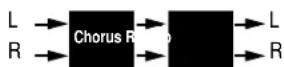
Effects Lvl/Bal • Flange-Delay • Pitch-Delay • Chorus-Delay • Delay-Reverb • Flange-Reverb • Pitch-Reverb • Chorus-Reverb
The Pitch Programs 4-36
User Programs 4-38
Section 5: MIDI Operation
Learn Mode. 5-2
Program Load Channel. 5-3
Program Change Messages .... 5-4 Loading Programs • Activating Bypass or Tap Functions
Learning Continuous Controllers. 5-6
Section 5: MIDI Operation (continued)
Clearing Learned Assignments ..... 5-7
MIDI Clock 5-8
MIDI Dumps 5-8
MIDI Sysex Messages 5-9
Permanent Patches 5-9
MIDI Implementation Chart 5-12
Appendix
Specifications. A-2
Declaration of Conformity ..... A-3
Index
US Important User Information
Lexicon is pleased to present its user guides on CD-ROM. By utilizing CD-ROM technology we are able to provide our documentation in multiple languages.
The printed edition of the user guide is in English only. The enclosed CD-ROM includes the user guide in multiple languages (French, German, Italian, Portuguese, and Spanish) in easy-to-use PDF format. The CD-ROM also includes Adobe® Acrobat® Readers for both PC and Macintosh platforms, enabling printing of all or any part of the documents. In addition, we have included dry audio tracks for product demonstrations. (Track 1 contains non-audio data.)
Please take a moment to read through the important safety information. For additional information about Lexicon, Inc., our products and support, please visit our web site at www.lexicon.com.
Unpacking and Inspection
After unpacking the unit, save all packing materials in case the unit ever needs to be shipped. Thoroughly inspect the modules and packing materials for signs of damage. Report any damage to the carrier at once; report equipment malfunction to the dealer.
Front Panel Overview 1-4
Rear Panel Overview 1-6
Connecting the Unit....1-8
Headphones • Footswitch
Setting Audio Levels 1-10
Reinitialization 1-11
ABOUT THE MPX 110
Thank you for purchasing the MPX 110 Dual Channel Processor, featuring Lexicon's proprietary Lexichip®.
The MPX 110 is a true stereo, dual-channel processor with 24-bit internal processing, analog-to-digital conversion, and digital-to-analog conversion. It offers 240 presets with classic Lexicon reverbs, including Plate, Chamber, Ambience, Tremolo, Rotary, Chorus, Flange, Pitch, Detune, 5.7 second Delay, Echo, and Inverse. Dual-channel processing creates two independent effects in combinations such as Dual Stereo (Parallel), Cascade, Mono Split, and Dual Mono.
The front panel Adjust knob allows instant manipulation of critical preset parameters, and the Effects Lvl/Bal knob controls effect level in SINGLE programs or effect balance in DUAL programs. All programs can be selected with the PROGRAM and VARIATION knobs. The PROGRAM knob selects SINGLE, DUAL, or User programs, while the VARIATION knob selects among 16 program variations.
Tap Tempo simplifies the once-complicated process of matching delay times and modulation rates between tempo-based presets and other music. Tempo-controlled delays and modulation rates lock to Tap or MIDI clock. In addition, Tap can be controlled using audio input, a dual footswitch, the front panel Tap button, or an external MIDI controller using MIDI Continuous Controller or Program Change messages.
The MPX 110 features Learn Mode, a powerful editing tool that allows MIDI patching of five front panel controls. Standard Continuous Controller and Program Change messages provide complete control over Bypass, Effects Lvl/Bal, Mix, Tap, and even Adjust.
HIGHLIGHTS
- Lexicon's proprietary Lexichip
• World-class Lexicon reverb
• 24-bit internal processing
• 24-bit analog-to-digital and digital-to-analog conversion - 240 presets
• 16 User programs
• 44.1K S/PDIF output - Simultaneous analog and digital outputs
- Independent processing of each input
-
DUAL programs that create two independent effects with four routing configurations
-
Dual effects that combine Delay with Reverb, or either Delay or Reverb with Chorus, Flange, or Pitch
- Multiple delay, modulation, and pitch effects
- Tap Tempo
- Full MIDI control
• High-impedance inputs for instruments - Two-stage headroom indicators
- Headphone output
- Software-selectable MIDI OUT/THRU port
- Push-button or footswitch selection of dry or muted audio output
• 20Hz-20kHz±1dB frequency response
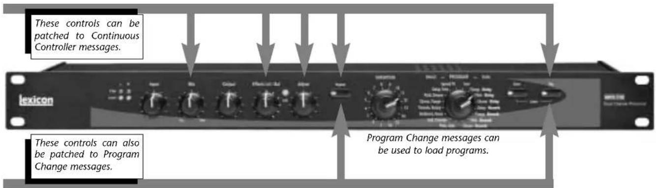
FRONT PANEL OVERVIEW
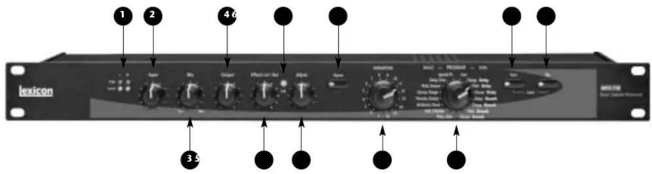
1. Clip and Level LEDs
Indicate incoming signal levels. The Level LEDs do not light when the incoming signal is more than 30dB below overload. The Clip LEDs light red when the signal approaches overload (-2.5dB). When a signal level is acceptable, the Level LEDs light green almost continuously and the Clip LEDs flash red on the loudest passages. See page 1-10 for more information about setting audio levels.
2. Input
Sets the level of the incoming signal. The Clip and Level LEDs indicate acceptable signal levels.
3. Mix
Controls the ratio of processed (Wet) to unprocessed (Dry) audio signals.
4. Output
Sets analog output levels.
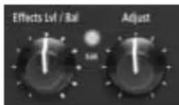
5. Effects Lvl/Bal
Sets effect level in SINGLE programs or effect balance in DUAL programs.
6. Edit LED
Lights to indicate that a program has been modified but not stored, and flashes to indicate MIDI activity. (See page 2-4 for more information about editing programs.)
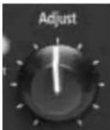
7. Adjust
Controls the most relevant parameters for the selected program variation.
8. Bypass
Mutes or bypasses the incoming signal, depending on the setting of the System Mode parameter Bypass. Press and hold for 2 seconds to access System Mode parameters.
9. VARIATION
Selects program variations when the PROGRAM knob is set to a SINGLE or DUAL program. Selects memory locations for storing User programs when the PROGRAM knob is set to User.
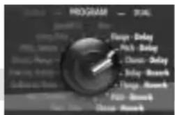
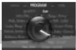
10. PROGRAM
Selects SINGLE, DUAL, or User programs.
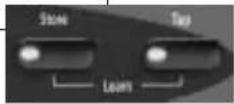
11. Store
Activates the store function for User programs. When pressed with Tap, activates MIDI Learn Mode.
12. Tap
Flashes to indicate that a tempo-based program is selected. When pressed twice, sets tempo. When pressed and held, uses input level to determine tempo. When pressed with Store, activates MIDI Learn Mode.
REAR PANEL OVERVIEW
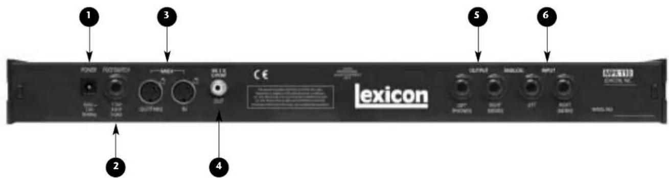
1. POWER
Supplies power to the unit. Utilizes a Lexicon 1.9A, 9VAC power pack.
2. FOOTSWITCH
Allows footswitch control of front panel Bypass and Tap functions. A 1/4 inch Tip/Ring/Sleeve connector for a momentary contact footswitch is available.
3. MIDI IN, OUT/THRU
Provide MIDI operation capabilities. Two 5-pin DIN MIDI connectors are available for MIDI IN and software-selectable MIDI OUT/THRU.
4. S/PDIF OUT
Provides digital audio output. One RCA coaxial S/PDIF connector is available.
5. ANALOG OUTPUTs
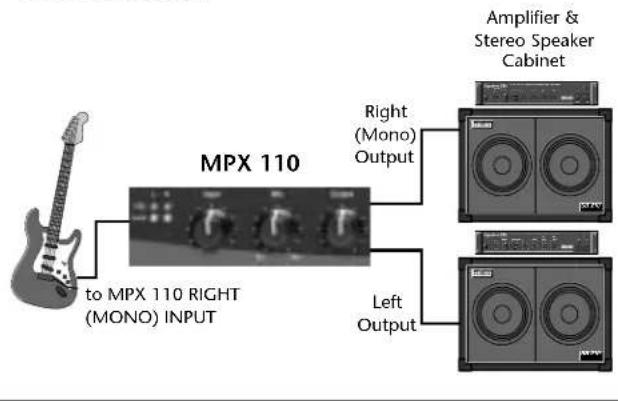
Provide analog audio output. Two unbalanced, single-ended stereo output connectors are available. Both offer typical output levels of +8dBu. Use the RIGHT (MONO) OUTPUT for mono output. If no connection is made to the RIGHT (MONO) OUTPUT, the LEFT (PHONES) OUTPUT can be used to drive headphones at a modest volume.
6. ANALOG INPUTs
Provide analog audio input. Two unbalanced, single-ended stereo input connectors are available. Both accept levels as low as -30dBu. Input impedance is 500kΩ. These can be used as direct inputs for guitars. Use the RIGHT (MONO) INPUT for mono sources.
CONNECTING THE UNIT
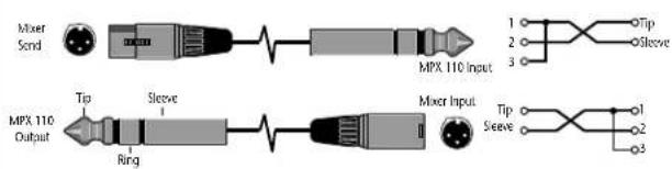
The INPUT and OUTPUT connectors on the MPX 110 are 1/4 inch unbalanced sockets. Connections should be made utilizing high-quality shielded cables with 1/4 inch Tip/Sleeve phone plugs at the end connected to the unit.
The unit produces effects from either mono or stereo sources. For mono sources, use the RIGHT (MONO) INPUT. For instruments and stereo sources, use both inputs. It is recommended to use stereo outputs whenever stereo inputs are used. Use the RIGHT (MONO) OUTPUT if mono output is required. The left and right input signals are combined internally when only the RIGHT (MONO) OUTPUT is used.
HEADPHONES
The LEFT (PHONES) OUTPUT supplies a stereo signal adequate to drive headphones, provided no connections are made at the RIGHT (MONO) OUTPUT. This feature is included for convenience and practice purposes. It is intended to provide modest volume.
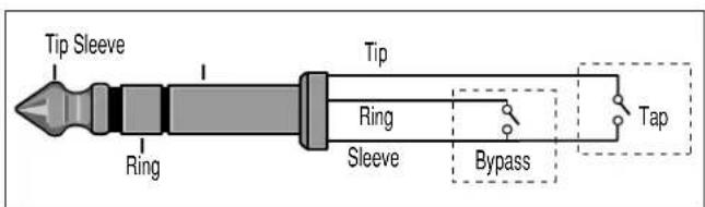
FOOTSWITCH
A footswitch connected to the rear panel FOOTSWITCH connector can be used to control front panel Tap and Bypass functions. A momentary footswitch can be wired to a Tip/Ring/Sleeve connector or a stereo Y-connector, which allows two identical switches to be used.
Note:
Power off the unit prior to connecting the footswitch. Otherwise, Bypass functions will be enabled.
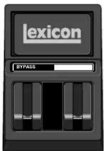
Dual-Function Footswitch
A dual-function footswitch with labels to indicate Tap and Bypass functions is available at Lexicon dealers or www.lexicon.com.
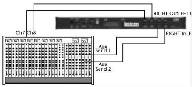
The MPX 110 can be used as two independent effects processors with DUAL program variations 11 to 16. Designate two auxiliary sends on the console. Connect these to the unit - one to the LEFT INPUT and the other to the RIGHT (MONO) INPUT. See Section 4 to take advantage of this configuration.
Connecting to a Mono Guitar Input with Mono or Stereo Amplifiers
Connecting to a Balanced Console
Connecting to a Dual Processor Setup with a Console
SETTING AUDIO LEVELS
- Begin with the Input knob set to the 9 o'clock position.
- Set the instrument or effects sends to a modest output level.
- Begin playing or sending audio to the MPX 110. The Level LEDs should light green. If the Clip LEDs light red, reduce the output level of the instrument or effects sends until the Clip LEDs do not light during the loudest passages.
- Continue to play or send audio to the MPX 110. Gradually increase the Input knob setting until the Clip LEDs light red on the loudest passages.
- Set the Mix knob to Dry.
-
Set the Output knob to the desired level.
-
If utilizing console sends and returns, set the Mix knob to Wet. If utilizing an instrument amplifier, set the Mix knob to the 12 o'clock position.
The Level LEDs do not light when the incoming signal is more than 30dB below overload. The Clip LEDs light red when the signal approaches overload (-2.5dB). When an acceptable signal is present, the Level LEDs light green almost continuously and the Clip LEDs flash red on the loudest passages.
Note:
As with all audio products, it is good practice to first power on all outboard equipment, then the mixer, then the speakers.
REINITIALIZATION
The procedure below outlines the process to reinitialize the unit. When reinitialized, the unit will restore all System Mode parameters to their factory-default settings; replace all User programs with factory-default presets; and clear all Learned Patches.
To reinitialize the unit:
- While powering the unit on, press and hold the front panel Store button until the Store and Tap LEDs flash quickly.
- To reinitialize the unit, press the Store button. To cancel reinitialization without affecting the unit, press either the Tap or Bypass button.
- After reinitialization, restart the unit - power it off, then on again.
Note:
Reinitialization will cause the unit to:
- Restore all System Mode parameters to their factory-default settings.
- Replace all User programs with factory-default presets. (See the table on page 4-38.)
- Clear all Learned Patches.
2
Basic Operation
Adjust 2-2
Selecting Programs....2-2
SINGLE Programs • DUAL Programs • User Programs
Editing Programs 2-4
Storing Programs....2-4
Tap Tempo 2-5
Varying Rhythm • Audio Tap • Global Tempo
Bypass 2-6
ADJUST
The Adjust knob has been customized for each individual program, and in most cases controls several parameters at once to handle complicated editing processes. For instance, Adjust controls the "liveness" of space in many Chamber and
Room programs by changing decay, EQ, and early reflections simultaneously.
The behavior of the Adjust knob is also customized for different functions:
- It can act as a linear control, at its minimum value when set to the 7 o'clock position and its maximum value when set to the 5 o'clock position.
- It can act as a bipolar control, at its minimum value when set to the 12 o'clock position, like a cut/boost EQ control.
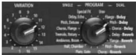
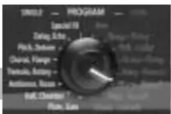
SELECTING PROGRAMS
All programs can be selected with the front panel PROGRAM and VARIATION knobs. The PROGRAM knob selects either a SINGLE, DUAL, or User program. SINGLE program selections are arranged around the left side of the knob; DUAL and User program selections are arranged around the right side of the knob. The VARIATION knob selects among 16 program variations, arranged around the knob.
SINGLE PROGRAMS
When the PROGRAM knob is set to a SINGLE program:
- VARIATION knob settings 1 to 8 will load eight variations of the first effect.
- VARIATION knob settings 9 to 16 will load eight variations of the second effect.
- See pages 4-2 to 4-17 for more information about SINGLE programs.
For example, when Plate, Gate is selected:
- VARIATION knob settings 1 to 8 will load eight different Plate program variations.
- VARIATION knob settings 9 to 16 will load eight different Gate program variations.
When Special FX is selected:
- VARIATION knob settings 1 to 16 will each load one program.
• See page 4-18 for more information.
DUAL PROGRAMS
When the PROGRAM knob is set to a DUAL program:
- VARIATION knob settings 1 to 16 load 16 different program variations. Each program contains both effects.
• See pages 4-20 to 4-35 for more information about DUAL programs.
USER PROGRAMS
When the PROGRAM knob is set to User:
- VARIATION knob settings 1 to 16 will each load one memory location available for storing User programs. When shipped, these locations will contain duplicates of presets.
• See page 4-38 for more information about User programs.
SINGLE Programs
DUAL Programs
User Programs
EDITING PROGRAMS
The front panel Adjust and Effects Lvl/Bal knobs can both be used to edit programs. The Adjust knob provides instant manipulation of critical program parameters. These parameters are arranged under the knob, meaning that just one turn is all that is required to customize a program to personal taste. The Effects Lvl/Bal knob can be used to control effect level in SINGLE programs, or effect balance in DUAL programs.
The unit recognizes changes made with either knob as edits. When edits are made, the front panel Edit LED will light to indicate that the selected program has been modified but not stored.
Use the Adjust knob to edit the selected program, and the Effects Lvl/Bal knob to control effect level in SINGLE programs or effect balance in DUAL Programs. The Edit LED will light to indicate that the selected program has been modified from its stored condition.
STORING PROGRAMS
To store a program in a User memory location:
- Press the Store button. The Store LED will flash slowly to indicate that the store function is activated.

-
To continue saving the program, set the PROGRAM knob to User. To cancel the store function without saving the program, make sure the PROGRAM knob is not set to User, then press the Store button again.
-
Set the VARIATION knob to select one of the 16 User memory locations.
-
Press the Store button to save the program to the selected location. The Store LED will flash quickly until the store process is complete. The Edit LED will no longer be lit when the saved version becomes the selected program.
CAUTION
When new programs are stored in a User memory location, programs that were previously stored at that location will be automatically replaced.
TAP TEMPO
VARYING RHYTHM
Tap Tempo can be used to match the delay times and modulation rates of tempo-based programs with those of the music. The Tap LED will flash whenever a tempo-based preset is loaded. To set tempo from the front panel, press the Tap button twice in time with the music. It is not required to enter what could be the delay time in milliseconds. Just press the Tap button twice, and the unit will calculate the appropriate delay time. To change tempo, press the Tap button twice again in the new rhythm. Changes made to tempo with the Tap button are not considered program edits, and will not cause the Edit LED to light.

AUDIO TAP
To use audio input to set tempo:
- Press and hold the Tap button for 2 seconds. (The optional dual footswitch allows the musician to remain in contact

with the instrument while pressing and holding the Tap button.)
- While holding the Tap button, play two short notes in rhythm, then release the Tap button. The unit will automatically calculate tempo based on the time lapse between the two notes.
Audio tap is a must for live performances. It offers a simple method of setting delay times and modulation rates to match the music.
... continued on page 2-6
Tap Tempo (continued from page 2-5)
GLOBAL TEMPO
Most factory presets are stored with individual tempo rates, which can be customized to suit personal taste. Tap in the new tempo, then store the modified version of the preset in a User memory location (see page 2-4).
To recall the tempo rate stored with each program, set the System Mode parameter Tempo to Program. The unit will apply the individual tempo setting of each program as it is loaded. To apply the current tempo rate to all programs, set the System Mode parameter Tempo to Global. The unit will ignore individual tempo settings and apply the current tempo setting to each program as it is loaded. (The Tap LED will flash when a tempo-controlled program is loaded.)
BYPASS
The Bypass button can be used to mute audio or to force the unit to pass only dry, unprocessed audio. Its function depends on the setting of the System Mode parameter Bypass. When set to Bypass Dry, the unit sends only dry, unprocessed audio to the outputs. When set to Mute Input, the unit mutes the inputs only. Running effects will continue their natural decay. Bypass functions can also be activated with a footswitch or MIDI control device (see pages 1-8 and 5-5).

When pressed and held for 2 seconds, the Bypass button also activates System Mode. (See Section 3 for more information about System Mode.)
3
System Mode
Overview 3-2
System Mode Parameters & Functions....3-3
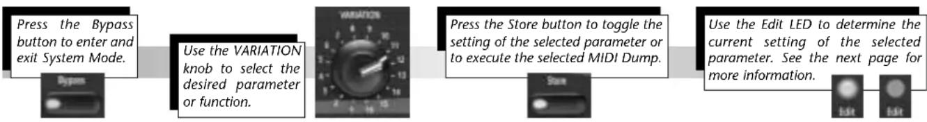
System Mode can be used to configure System Mode parameters and execute MIDI Dumps. To enter System Mode, press and hold the front panel Bypass button for approximately 2 seconds. The Bypass and Store LEDs will flash slowly to indicate that System Mode is active.
The table on the next page shows System Mode parameters and functions. The VARIATION knob selects the desired parameter or function. Settings 1 to 8 select System Mode parameters. Settings 14 to 16 select MIDI Dumps.
The Edit LED shows the current setting of the selected parameter (see the table on the next page). Press the Store button to toggle the parameter setting. When VARIATION knob settings 14, 15, or 16 are selected, press the Store button to execute the selected MIDI Dump.
When finished, reset the VARIATION knob to its original setting before System Mode was activated. Otherwise, a new program will load based on this setting when
System Mode is deactivated. Use the Tap LED to determine if the VARIATION knob has been reset; it will light when the knob is set to the last loaded program.

To exit System Mode, press the Bypass button. The Store LED will flash quickly to indicate that parameter settings have changed. (The Store LED will not flash if no changes were made.)
Descriptions of all System Mode parameters and functions are available on pages 3-3 to 3-5.
flowchart
graph LR
    A["Press the Bypass button to enter and exit System Mode."] --> B["Use the VARIATION knob to select the desired parameter or function."]
    B --> C["Press the Store button to toggle the setting of the selected parameter or to execute the selected MIDI Dump."]
    C --> D["Use the Edit LED to determine the current setting of the selected parameter. See the next page for more information."]
SYSTEM MODE PARAMETERS & FUNCTIONS
VARIATION Edit LED Edit LED
Knob Setting Parameter/Function On Off


1 Bypass Mute Input Bypass Dry *
2 MIDI Patching Disabled Enabled *
3 Program Load Mute Bypass *
4 Digital Output Dry Wet *
5 MIDI OUT/THRU Out * Thru
6 MIDI Pgm Change Disabled Enabled *
7 MIDI Clock Receive Disabled Enabled *
8 Tempo Program * Global
14 Dump User Programs
15 Dump Selected Program
16 Dump System and Learned Patches
* Indicates factory-default setting
1. Bypass Mute Input, Bypass Dry
Controls the front panel Bypass button, or the footswitch or MIDI control device assigned to Bypass. When set to Bypass Dry, the unit sends only dry, unprocessed audio to the outputs. When set to Mute Input, the unit mutes the inputs only. Running effects will continue their natural decay.
2. MIDI Patching Disable, Enable
Activates and deactivates Learned Patches. When set to Disable, the unit ignores all Learned Patches. When set to Enable, the unit recognizes all Learned Patches.
3. Program Load Mute, Bypass
Determines how the unit will process incoming audio signals when loading programs. When set to Mute, the unit mutes all audio during program load. When set to Bypass, the unit passes only dry, unprocessed audio during program load.
4. Digital Output Dry, Wet
Determines what is sent to the unit's S/PDIF output. When set to Dry, the unit bypasses processed audio, sending only dry, unprocessed audio to the S/PDIF output. When set to Wet, the unit sends the processed audio signal (according to the Mix knob setting) to the S/PDIF output.
5. MIDI OUT/THRU Out, Thru
Controls the function of the rear panel MIDI OUT/THRU connector. When set to Out, the unit only sends MIDI messages that originate from the unit, such as MIDI Dumps. When set to THRU, the unit sends - but does not modify - messages received from the input.
6. MIDI Pgm Change Disable, Enable
Determines whether or not the unit will recognize MIDI Program Change messages. When set to Disable, the unit does not recognize these messages. When set to Enable, the unit recognizes these messages.
7. MIDI Clock Receive Disable, Enable
Determines whether or not the unit will use MIDI Clock messages to set tempo. When set to Disable, the unit ignores these messages. When set to Enable, the unit recognizes these messages. (This parameter has no effect on programs that are not tempo-based.)
8. Tempo Program, Global
Controls the application of tempo to tempo-based programs. When set to Program, the unit applies the program-specific tempo of each program as it is loaded. When set to Global, the unit maintains the current tempo that was entered by any means as programs are loaded. (This parameter has no effect on programs that are not tempo-based).
14. Dump User Programs
Executes a MIDI Dump of User programs to an external MIDI device, such as a sequencer. These programs can be dumped back to the unit, which is useful for preserving User programs when default settings are restored. When VARIATION knob setting
14 is selected, press the front panel Store button to execute the dump. When dumped back, User programs will be returned to their original locations.
15. Dump Selected Program
Executes a MIDI Dump of the currently active program, allowing programs to be saved to an external MIDI device. When VARIATION knob setting 15 is selected, press the front panel Store button to execute this dump. When dumped back, the program will automatically become the currently active program.
16. Dump System and Learned Patches
Executes a MIDI Dump of all System Mode parameter settings and Learned Patches. When VARIATION knob setting 16 is selected, press the front panel Store button to execute the dump. When dumped back, the System Mode settings and Learned patches will take effect immediately.
4
Program Descriptions
SINGLE Programs 4-2
Plate • Gate • Hall • Chamber • Ambience • Room • Tremolo • Rotary • Chorus •
Flange • Pitch • Detune • Delay, Echo
Special FX....4-18
DUAL Programs 4-20
Effects Lvl/Bal • Flange-Delay • Pitch-Delay • Chorus-Delay • Delay-Reverb •
Flange-Reverb • Pitch-Reverb • Chorus-Reverb
The Pitch Programs 4-36
User Programs 4-38
SINGLE PROGRAMS
PLATE
Plate reverb began with a large, thin sheet of metal suspended upright under tension on springs. Transducers attached to the plate transmitted a signal that made the plate vibrate, causing sounds broadcast through it to appear to be occurring in a large, open space.
The Plate programs synthesize the sound of metal plates with high initial diffusion and a relatively bright-colored sound. These programs are designed to be heard as part of the music, mellowing and thickening the sound. Plate programs are a popular choice for enhancing pop music, particularly percussion.
VARIATIONS Adjust Tap
| 1 Small Plate Liveness* – | |
| 2 Medium Plate Liveness* – | |
| 3 Large Plate Liveness* PreDelay | (1/32 Note) |
| 4 Larger Plate Decay Time* PreDelay | (1/32 Note) |
| 5 Tape Slap ±Decay/ –Plate 15 or 7.5ips** | |
| 6 Rich Plate Decay Time* PreDelay | (1/32 Note) |
| 7 Large Bright Decay Time* PreDelayPlate (1/32 Note) | |
| 8 Vocal Plate Low Cut, Echo Decay Time* | |
* The Adjust knob functions as a linear control in these variations. See page 2-2 for more information.
** When the Adjust knob is set to the left of the 12 o'clock position, decay is 15ips. When the Adjust knob is set to the right of the 12 o'clock position, decay is 7.5ips.
GATE
Gated reverbs were created by feeding a reverb, such as a metal plate, through an analog gate device. Decay time was set to instant, while hold time varied duration and sound.
The Gate programs provide a fairly constant sound with no decay until the reverb is cut off abruptly. These programs work well on percussion, particularly on snare and toms. It is recommended to experiment with other sound sources as well.
VARIATIONS Adjust Tap
| 9 Straight Gate Duration** – | |
| 10 Drum Gate Duration** – | |
| 11 Slope Down Duration** – | |
| 12 140ms Gate High Cut* PreDelay | (1/32 Note) |
| 13 240ms Gate High Cut* PreDelay | (1/32 Note) |
| 14 340ms Gate High Cut* PreDelay | (1/32 Note) |
| 15 440ms Gate High Cut* PreDelay | (1/32 Note) |
| 16 540ms Gate High Cut* PreDelay | (1/32 Note) |
* The Adjust knob functions as a linear control in these variations. See page 2-2 for more information.
** Audio will be briefly muted when Duration is altered with the Adjust knob.
Program Descriptions
Lexicon
HALL
Lexicon's Hall programs recreate the acoustics of actual places - from grand, reverberant enclosures to small concert halls.
The clean reverberation of Hall programs is designed to add spaciousness without altering source material. In addition to general instrumental and vocal applications, the Hall programs give separately recorded tracks a sense of belonging to the same performance.
VARIATIONS Adjust\* Tap
1 Recital Hall Decay –
2 Small Church Decay –
3 Jazz Hall Decay –
4 Dance Hall Decay –
5 Synth Hall Decay –
6 Medium Hall Decay –
7 Large Hall Decay –
8 Large Church Decay –
CHAMBER
Historically, recording studio chambers were oddly shaped rooms with a loudspeaker and set of microphones to collect ambience in various parts of the room.
Stereo Chamber programs produce even, relatively dimensionless reverberation with little color change as sound decays. The initial diffusion is similar to Hall programs. However, the sense of size and space is much less obvious. This characteristic, coupled with the low color of the decay tail, makes these programs useful on a wide range of material - especially the spoken voice, to which Chamber programs add a noticeable increase in loudness with low color.
VARIATIONS Adjust\* Tap
9 Brick Wall Liveness –
10 Basement Liveness –
11 Live Concert Liveness Eko Delay
12 Percussion 1 Liveness –
13 Percussion 2 Liveness –
14 Live Chamber Liveness –
15 Vocal 1 Liveness Eko Delay
16 Vocal 2 Liveness Eko Delay
AMBIENCE
Ambience adds warmth, spaciousness, and depth to a performance without coloring its direct sound. It is commonly used to add a room sound to recorded music and speech. In music recording, Ambience can realistically add distance to close-mic'ed signals.
Ambience programs simulate reflections from room surfaces with random reflections, a gradual decay of overall level, and a gradual narrowing of bandwidth. In these programs, the Mix control adds depth - emulating the movement of a coincident pair of microphones away from the sound source into the room.
Variations 1 to 8 provide a series of rooms, increasing in size.
VARIATIONS Adjust* Tap
| 1 Voice Over High Cut – |
| 2 Very Small High Cut – Ambience |
| 3 Small High Cut – Ambience |
| 4 Medium High Cut – Ambience |
| 5 Studio D High Cut – |
| 6 Bright Decay Level – Ambience |
| 7 Dark Decay Level – Ambience |
| 8 Marble Foyer Liveness – |
* The Adjust knob functions as a linear control in these variations. See page 2-2 for more information.
ROOM
Room programs simulate actual rooms where there is a strong sense of being in a small, live place. These programs are useful on drums and percussion, and can also be applied to electric guitar tricks.
Variations 9 to 16 provide a series of rooms, increasing in size.
VARIATIONS Adjust\* Tap
9 Bedroom Wall Reflections –
10 Tiled Room Low-frequency - Cut
11 Studio C Liveness –
12 Small Room Liveness –
13 Studio B Decay Time –
14 Rehearsal Room High/Low Equalizer
15 Studio A Decay Time –
16 Large Room High/Low Equalizer
* The Adjust knob functions as a linear control in these variations. See page 2-2 for more information.
TREMOLO
Tremolo is a rhythmic change in loudness, commonly employed as an expressive technique by vocalists and wind instrument players. It is also one of the oldest electronic effects, frequently used with electric guitar, electric piano, and occasionally vocals. Different tremolo effects are largely determined by the rate (fast or slow) and waveform shape (smooth or sharp) of the change in loudness. If the effect is used in a stereo mix, the left and right can be synchronized to produce dramatic side-to-side motion.
The Tremolo programs offer classic tremolo shapes, such as square, sawtooth, triangle, sine, and rectified sine. The synchronization of the left and right channels can be adjusted to produce mono and stereo effects. The Tap button sets tremolo rates, making it simple to match the tempo of the music. The Adjust knob (phase) sets left and right channel waveforms out-of-phase, resulting in a panning motion.
Set the front panel Mix knob to Wet for all program variations. Mix can be used to effectively set the depth of the Tremolo program when more dry is added to the wet-to-dry mix. (Turn the knob to the right, moving its setting closer to Dry.) It is recommended to make the rate work with the tempo of the music, as Tremolo is essentially a rhythmic effect.
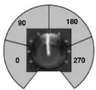
The Adjust knob can function as a four-position switch, selecting the amount of phase shift. When a setting is selected in the 0 range, no phase shift is applied. When a setting is selected in the other ranges, the indicated amount of phase shift is applied. Numbers indicate phase shift in degrees.
VARIATIONS Adjust Tap
1 Rectified Sine Wave Rate: -

0.4 to 15Hz*
2 Square Wave Rate: -

0.4 to 15Hz*
3 Sawtooth Wave Rate: -

0.4 to 15Hz*
4 Rectified Sine Wave Sweep: Rate

0, 90, 180, 270** (1/4 Note)
5 Square Wave Sweep: Rate

0, 90, 180, 270** (1/4 Note)
6 Sawtooth Wave Sweep: Rate

0, 90, 180, 270** (1/4 Note)
7 Triangle Wave Sweep: Rate

0, 90, 180, 270** (1/4 Note)
8 Sine Wave Sweep: Rate

0, 90, 180, 270** (1/4 Note)
* The Adjust knob functions as a linear control in these variations. See page 2-2 for more information.
** The Adjust knob functions as a four-position switch in these variations. See page 4-8 for more information.
ROTARY
Rotary speaker cabinets were designed to provide a majestic vibrato/choir effect for electronic theater and church organs. The most well known rotary speaker is the Leslie™ Model 122, which has two counter-rotating elements: a high-frequency horn and a low-frequency rotor with slow and fast speeds. The sound generated as the spinning elements change speed is truly magical. The swirling, spacious effect is difficult to describe - but clearly recognizable.
The Rotary programs are a detailed simulation of a Leslie-style cabinet. The input signal is split into high and low-frequency bands. The rotation effect is created by a synchronized combination of pitch shifting, tremolo, and panning. Like the physical cabinet, the high (horn) and low (rotor) frequencies are “spun” in opposite directions. Horn and rotor speeds are independent, and designed with acceleration and deceleration characteristics to simulate the inertia of the original mechanical elements.
A virtual requirement for organ music, Rotary programs also sound remarkable with guitar and electric piano rhythm parts. In fact, these programs are great alternatives to chorus and tremolo effects for any sound source.
To achieve the full effect, set the front panel Mix knob to Wet for all variations of this program (9 to 16).
VARIATIONS Adjust Tap
| 9 Rotary Slow/Fast – | |
| 10 Rotary Slow/Fast, –Width | |
| 11 Rotary Slow/Fast, –Balance | |
| 12 Slow Rotary ±Resonance* – | |
| 13 Varispeed Speed –Rotary | |
| 14 Tap Rotary Balance Rate | (1/4 Note) |
| 15 Tap Rotary Width Rate | (1/4 Note) |
| 16 Tap Rotary ±Resonance* Rate | (1/4 Note) |
* The Adjust knob functions as a bipolar control in these variations. See page 2-2 for more information.
CHORUS
Chorus effects create lush, full sounds by multiplying the original audio source. Traditionally, these effects were used to fatten up tracks and to add body to guitar without coloring the original tone. Chorus effects are also often combined with plates, echoes, and other reverb effects.
The stereo Chorus programs, inherited from Lexicon's PCM 80, create a rich, airy effect that simulates the sound of multiple sources from a single source. These programs are stunning on acoustic or clean-electric guitar.
These programs utilize six independently-randomized delay voices panned across the stereo field. Set the front panel Mix knob to Wet to achieve the full richness of the 6-voice chorus.
VARIATIONS Adjust Tap
1 Rich Chorus ± Resonance* –
2 Rich Chorus ± Depth* –
3 Rich Chorus Rate –
4 Rich Chorus High Cut –
5 Diffuse Chorus Diffusion –
6 Slap Chorus Diffusion –
7 Slap Chorus ± Resonance* –
8 Slap Chorus ± Depth* -
FLANGE
Flange effects were originally created by simultaneously recording and playing back two identical programs on two tape recorders, then using hand pressure against the flange of the tape reels to slow down first one machine, then the other. The result was a series of changing phase cancellations and reinforcements, with characteristic swishing, tunneling, and fading sounds.
The stereo Flanger has two 2-Tap delays - one per channel. The first tap is fixed, and the second sweeps past it. Mixing the two delay taps together creates the flanging effect.
Set the front panel Mix knob to Wet to achieve the full flange effect of these program variations.
VARIATIONS Adjust Tap
| 9 Light Flange: ± Resonance* –in-phase sweep |
| 10 Light Flange ± Resonance* –out-of-phase sweep |
| 11 Light Flange Rate –in-phase sweep |
| 12 Light Flange Rate –out-of-phase sweep |
| 13 Deep Flange ±Resonance* –in-phase-sweep |
| 14 Deep Flange ±Resonance* –out-of-phase sweep |
| 15 Light Flange Sweep: –0, 90, 180, 270** |
| 16 Deep Flange Sweep: –0, 90, 180, 270** |
* The Adjust knob functions as a bipolar control in these variations. See page 2-2 for more information.
** The Adjust knob functions as a four-position switch in these variations. See page 4-8 for more information.
PITCH
Altering the pitch of a sound produces a wide range of effects - from subtle detunes, to harmonies, to chords. The stereo polyphonic Pitch programs can be used to shift program material or monophonic sources within a range of one octave up to two octaves down.
For pitch correction, set the front panel Mix knob to Wet. For harmonization, set the front panel Mix knob to the desired setting.
VARIATIONS Adjust Tap
| 1 Semi-tone Shift -2 to +1 octaves* – | ||
| 2 Glide Shifter | ±1 octave* | – |
| 3 ±100 cents ±100 cents* – | ||
| 4 Minor 3rd to Flat 3rd to –4th Harmony 4th Up | ||
| 5 4th/5th 4th to 5th Up –Harmony | ||
| 6 5th/6th 5th to 6th Up –Harmony | ||
| 7 2nd Inversion Minor/Major 3rd –Triad | ||
| 8 Power Chords | Inversion | – |
* The Adjust knob functions as a bipolar control in these variations. See page 2-2 for more information.
DETUNE
Detune effects add a delayed or pitch-shifted version of the original source, thickening the sound. This creates a particularly effective simulation of double-tracking. These effects are also great alternatives to Chorus effects, adding the richness of a chorus without the audible sweep caused by the chorus rate.
The 4-voice stereo Detune programs have one pair of voices per channel. As more detune is applied with the Adjust knob, the pair become more out of tune, providing a lush sound without the need for mixing in a dry signal.
Set the front panel Mix knob to Wet to achieve the full effect of these programs.
VARIATIONS Adjust\* Tap
9 Mild Detuning –
10 Moderate Detuning –
11 Heavy Detuning –
12 FullRange Detuning –
13 Warm & Mild Detuning –
14 Warm & Detuning - Moderate
15 Warm & Heavy Detuning –
16 Slap Detuner Detuning –
DELAY, ECHO
Delays and echoes repeat a sound a short time after it first occurs. The simplest (and oldest) delay effect is tape slap - a single repeat about 100ms after the original sound. Tape slap was often used on Elvis Presley's voice and rockabilly guitar tracks.
Tape slap becomes tape echo when the output of the tape is fed back into the input (feedback). This turns a single repeat into a series of repeats, each a little softer and a little darker than the last. This darkening is characteristic of the analog tape recording process. Digital delays do not have this characteristic; each repeat has the same exact timbre. For digital delays, loudness is the only difference from repeat to repeat.
Tape echo and digital delay are both useful, but different. Tape echo is warmer, allowing the original sound to distinguish itself. Digital delay presents a "perfect" copy of the original sound.
The Delay and Echo variations include mono (5.5 seconds), stereo (2.7 seconds), and 6-voice multi-tap effects. Each program can be used for tape echo or digital delay effects.
When the Adjust knob is set to a value between 12 and 5 o'clock, tape echo effects are produced. Each repeat is darker and softer. When the Adjust knob is set to a value between 7 and 12 o'clock, digital delay effects are produced. Each repeat is the same timbre, but softer.
In variations 1 to 8, the Adjust knob sets the amount of feedback with an increasing number of repeats as the setting is increased. Delay time is set with Tap. Each program is preset with a different rhythm. In variations 9 to 16, the amount of feedback is preset and the Adjust knob determines the delay time.
With all Delay and Echo effects, note the way the repeats fall rhythmically to the beat. The most effective Delay and Echo patterns are those that lock with the tempo of the music.
VARIATIONS Adjust Tap
| 1 Mono Delay/Echo Delay TimeQuarter-Note Feedback** |
| 2 Stereo Delay/Echo Delay TimeQuarter-Note Feedback** |
| 3 Triplet Delay/Echo Delay TimeShuffle Feedback** |
| 4 Dotted Delay/Echo Delay TimeEighth-Note Feedback** |
| 5 Eighth-Note Delay/Echo Delay Timeand Triplet Feedback** |
| 6 Ping Pong Delay/Echo Delay TimeQuarter-Note Feedback** |
| 7 Triplet Delay/Echo Delay TimeRhythm 1 Feedback** |
| 8 Triplet Delay/Echo Delay TimeRhythm 2 Feedback** |
* The Adjust knob functions as a linear control in these variations. See page 2-2 for more information.
** The Adjust knob functions as a bipolar control in these variations. See page 4-16 for more information.
| VARIATIONS | Adjust | Tap |
| 9 Mono | Delay/Echo Time:0 to 5.5 sec* | - |
| 10 Stereo | Delay/Echo Time:0 to 2.7 sec* | - |
| 11 Tape Slap | Delay/Echo Time:3 3/4 to 30ips*** | - |
| 12 Multi Bounce | Delay/Echo Time:0 to 100ms* | - |
| 13 Multi Linear | Delay/Echo Time:0 to 400ms* | - |
| 14 Multi Inverse | Delay/Echo Time:0 to 400ms* | - |
| 15 Multi Repeat | Delay/Echo Time:0 to 150ms + Fbk** | - |
| 16 Multi Pong | Delay/Echo Time:0 to 200ms + Fbk** | - |
***The Adjust knob functions as a four-position switch in these variations. See page 4-8 for more information.
SPECIAL FX
Special FX VARIATIONS Adjust* Tap
| 1 Infinite Reverb High Cut Echo | ||
| 2 The Abyss ±Pitch Blend – | ||
| 3 Jet Flange Tone Rate (Whole Note) | ||
| 4 Chorus Verb High Cut – | ||
| 5 Rotary Delay Dly/Echo Time: 0 to 150ms + Feedback Rate (1/4 Note) | ||
| 6 Fader Verb Input Volume | Echo | |
| 7 PCM 60 - LgSize | Decay Time | – |
| 8 LowRumble | Decay Time | – |
Special FX VARIATIONS Adjust* Tap
| 9 Ducking Reverb Decay Time – | ||
| 10 Ducking Chorus>Delay ±Resonance Delay Time | ||
| 11 Ducking Triplets Delay/Echo Feedback Delay Time | ||
| 12 Subdividing Delay Beat Value: 1/32-Whole Note Delay Time | ||
| 13 Panning Delays Delay/Echo Feedback Delay Time | ||
| 14 Dream Sequence ±Shift Amount | – | |
| 15 Infinite Repeat | Feedback: 0 to Infinite | Dly Time (Whole Note) |
| 16 Diffusor | Diffusion | – |
* The Adjust knob function differs in each of the Special FX variations. It is recommended to experiment with each program. See page 2-2 for more information about Adjust knob functions.
DUAL PROGRAMS
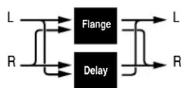
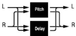
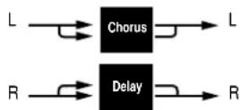
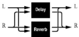
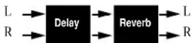
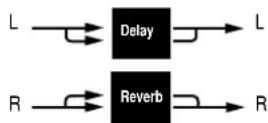
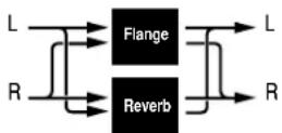
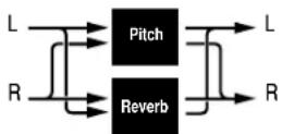
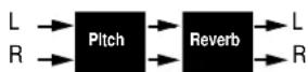
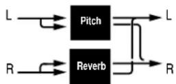
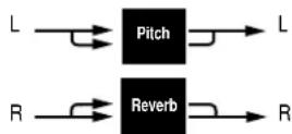
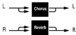
The DUAL Programs combine Delay with Reverb, or either Delay or Reverb with Chorus, Flange, or Pitch. Four routing configurations are used in the variations of each DUAL program: Dual Stereo (Parallel), Cascade, Mono Split, and Dual Mono.
Variation knob settings are configured as follows:
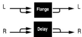
- Variations 1 to 6 are arranged in the Dual Stereo (Parallel) configuration - two stereo effects placed next to one another to receive and output stereo audio from both the left and right channels.
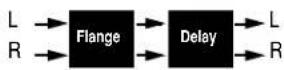
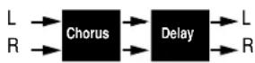
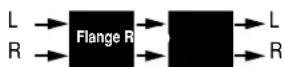
- Variations 7 to 10 are arranged in the Cascade configuration - two stereo effects, one placed after the other. For example, in Flange-Delay, Flange passes its stereo signal to Delay.
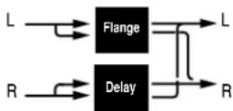
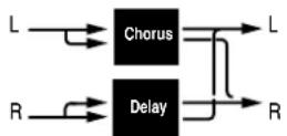
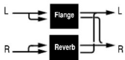
- Variations 11 to 14 are arranged in the Mono Split configuration, which is similar to the Dual Stereo (Parallel) configuration. One effect (Flange) receives audio from the left input and the other effect (Delay) receives audio from the right input. Both effects output stereo audio.
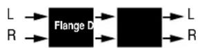
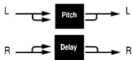
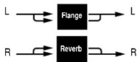
- Variations 15 and 16 are arranged in the Dual Mono configuration where one effect (Flange) appears on the left channel only, while the other effect (Delay) appears on the right channel only.
Dual Stereo (Parallel)
Cascade
Mono Split
Dual Mono
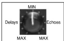
EFFECTS LVL/BAL
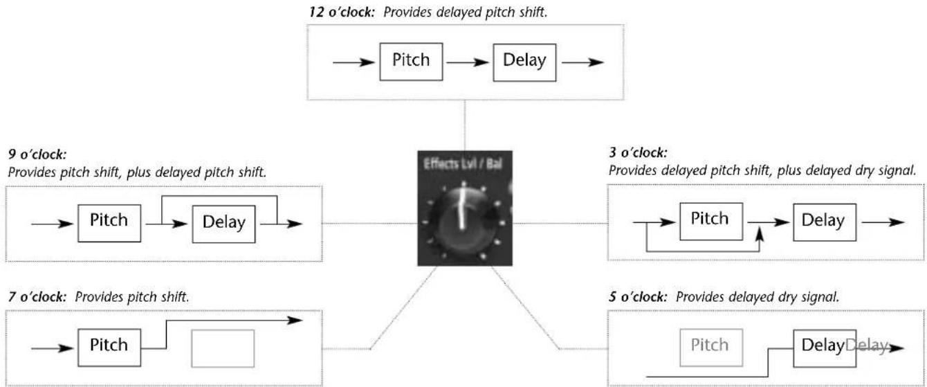
The front panel Effects Lvl/Bal knob controls the relative balance of each effect in the DUAL program. In Cascade variations, the knob also varies the amount of the first effect or dry signal fed into the second effect.
The illustration below uses the Pitch-Delay program to show the behavior of the Effects Lvl/Bal knob at certain settings when a Cascade variation is selected.
flowchart
graph TD
    A["12 o'clock: Provides delayed pitch shift."] --> B["Pitch"]
    B --> C["Delay"]
    C --> D["Effects Lvl / Bal"]
    D --> E["Pitch"]
    E --> F["Delay"]
    F --> G["Pitch"]
    G --> H["Delay"]
    H --> I["Pitch"]
    I --> J["Delay"]
    J --> K["Pitch"]
    K --> L["Delay"]
    L --> M["Pitch"]
    M --> N["Delay"]
    N --> O["Pitch"]
    O --> P["Delay"]
    P --> Q["Pitch"]
    Q --> R["Delay"]
    R --> S["Pitch"]
    S --> T["Delay"]
    T --> U["Pitch"]
    U --> V["Delay"]
    V --> W["Pitch"]
    W --> X["Delay"]
    X --> Y["Pitch"]
    Y --> Z["Delay"]
    Z --> AA["Pitch"]
    AA --> AB["Delay"]
    AB --> AC["Pitch"]
    AC --> AD["Delay"]
    AD --> AE["Pitch"]
    AE --> AF["Delay"]
    AF --> AG["Pitch"]
    AG --> AH["Delay"]
    AH --> AI["Pitch"]
    AI --> AJ["Delay"]
    AJ --> AK["Pitch"]
    AK --> AL["Delay"]
    AL --> AM["Pitch"]
    AM --> AN["Delay"]
    AN --> AO["Pitch"]
    AO --> AP["Delay"]
    AP --> AQ["Pitch"]
    AQ --> AR["Delay"]
    AR --> AS["Pitch"]
    AS --> AT["Delay"]
    AT --> AU["Pitch"]
    AU --> AV["Delay"]
    AV --> AW["Pitch"]
    AW --> AX["Delay"]
    AX --> AY["Pitch"]
    AY --> AZ["Delay"]
    AZ --> BA["Pitch"]
    BA --> BB["Delay"]
    BB --> BC["Pitch"]
    BC --> BD["Delay"]
    BD --> BE["Pitch"]
    BE --> BF["Delay"]
    BF --> BG["Pitch"]
    BG --> BH["Delay"]
    BH --> BI["Pitch"]
    BI --> BJ["Delay"]
    BJ --> BK["Pitch"]
    BK --> BL["Delay"]
    BL --> BM["Pitch"]
    BM --> BN["Delay"]
    BN --> BO["Pitch"]
    BO --> BP["Delay"]
    BP --> BQ["Pitch"]
    BQ --> BR["Delay"]
    BR --> BS["Pitch"]
    BS --> BT["Delay"]
    BT --> BU["Pitch"]
    BU --> BV["Delay"]
    BV --> BW["Pitch"]
    BW --> BX["Delay"]
    BX --> BY["Pitch"]
    BY --> BZ["Patch"]
FLANGE-DELAY
Flange-Delay VARIATIONS Adjust Tap Routing
| 1 Deep Flange - Stereo Delay Delay/Echo Feedback* Delay Time (1/4 Note) Dual Stereo (Parallel) | |
| 2 Deep Flange - Stereo Delay Delay/Echo Feedback* Dotted (1/8 Note) Dual Stereo (Parallel) | |
| 3 Deep Flange - Stereo Delay Delay/Echo Feedback* Triplet (1/8 Note) Dual Stereo (Parallel) | |
| 4 Light Flange - Ping Pong Delay/Echo Feedback* Delay Time (1/4 Note) Dual Stereo (Parallel) | |
| 5 Light Flange - Repeat D/E Time: 0 to 150ms, Fbk – Dual Stereo (Parallel) | |
| 6 Light Flange - Bounce D/E Time: 0 to 200ms, Fbk – Dual Stereo (Parallel) | |
| 7 Deep Flange>Stereo Delay | Delay/Echo Feedback* Delay Time (1/4 Note) Cascade |
| 8 Deep Flange>Repeat | D/E Time: 0 to 150ms, Fbk – Cascade |
Dual Stereo (Parallel)

Cascade
Flange-Delay VARIATIONS Adjust Tap Routing
| 9 Deep Flange>Ping Pong Delay/Echo Feedback* Delay Time (1/4 Note) Cascade | ||
| 10 Deep Flange>Bounce D/E Time: 0 to 200ms, Fbk – Cascade | ||
| 11 Light Flange+Stereo Delay Delay/Echo Feedback* Delay Time (1/4 Note) Mono Split | ||
| 12 Light Flange+Ping Pong | Delay/Echo Feedback* Delay Time (1/4 Note) Mono Split | |
| 13 Light Flange+Repeat | D/E Time: 0 to 150ms, Fbk – Mono Split | |
| 14 Light Flange+Bounce | D/E Time: 0 to 200ms, Fbk – Mono Split | |
| 15 Deep Flange/Mono Delay | Delay/Echo Feedback* Delay Time (1/4 Note) Dual Mono | |
| 16 Deep Flange/Mono Delay | Delay/Echo Feedback* Dly Time (Dotted 1/4 Note) Dual Mono | |
In these variations, the Adjust knob functions as it does in the Delay, Echo variations. See page 2-2 for more information.
Mono Split

Dual Mono

PITCH-DELAY
Pitch-Delay VARIATIONS Adjust Tap Routing
| 1 5th Up/Down - Stereo 1/4 Note ±5th* Delay Time Dual Stereo (Parallel) |
| 2 Octave Up/Down - Triplet Shuffle ±1 octave* Delay Time Dual Stereo (Parallel) |
| 3 Octave Up/Down - Eighth and Triple ±1 octave* Delay Time Dual Stereo (Parallel) |
| 4 3rd Up/4th Up - Ping Pong 1/4 Note Minor 3rd to 4th Up Delay Time Dual Stereo (Parallel) |
| 5 4th Up/5th Up - Triplet Rhythm 1 4th to 5th Up Delay Time Dual Stereo (Parallel) |
| 6 5th Up/6th Up - Triplet Rhythm 2 5th to 6th Up Delay Time Dual Stereo (Parallel) |
| 7 Octave Up/Down > Triplet Rhythm 1 ±1 octave* Delay Time Cascade |
8 5th Up/Down > Stereo 1/4 Note ±5th * Delay Time Cascade
Dual Stereo (Parallel)
Cascade

Pitch-Delay VARIATIONS Adjust Tap Routing
| 9 Major/Minor Minor/Major 3rd w/ Fbk Delay Time Cascade | |||
| 10 Intervals Up Ascending Intervals w/Fbk Delay Time Cascade | |||
| 11 5th Up/Down + Stereo 1/4 Note ±5th* Delay Time Mono Split | |||
| 12 Octave Up/Down + Triplet Shuffle ±1octave* | Delay Time Mono Split | ||
| 13 4th Up/5th Up + Triplet Rhythm 1 | 4th to 5th Up | Delay Time | Mono Split |
| 14 5th Up/6th Up + Triplet Rhythm 2 | 5th to 6th Up | Delay Time | Mono Split |
| 15 Octave Up/Down / Mono 1/4 Note | ±1 octave* | Delay Time Dual Mono | |
| 16 Octave Up/Down / Triplet Shuffle | ±1 octave* | Delay Time | Dual Mono |
* The Adjust knob functions as a bipolar control in these variations. See page 2-2 for more information.
Mono Split

Dual Mono
CHORUS-DELAY
Chorus-Delay VARIATIONS Adjust Tap Routing
| 1 Rich Chorus 1 - Stereo 1/4 Note Delay/Echo Feedback* Delay Time Dual Stereo (Parallel) | |
| 2 Rich Chorus 1 - Dotted 1/8 Note Delay/Echo Feedback* Delay Time Dual Stereo (Parallel) | |
| 3 Rich Chorus 1 - 1/8 Note and Triplet Delay/Echo Feedback* Delay Time Dual Stereo (Parallel) | |
| 4 Rich Chorus 1 - Ping Pong 1/4 Note Delay/Echo Feedback* Delay Time Dual Stereo (Parallel) | |
| 5 Rich Chorus 1 - Multi Repeat D/E Time: 0 to 150ms, Fbk – Dual Stereo (Parallel) | |
| 6 Rich Chorus 1 - Multi Pong D/E Time: 0 to 200ms, Fbk – Dual Stereo (Parallel) | |
| 7 Rich Chorus 1 > Stereo 1/4 Note | Delay/Echo Feedback* Delay Time Cascade |
| 8 Rich Chorus 2 > Multi Repeat | D/E Time: 0 to 150ms, Fbk – Cascade |
Dual Stereo (Parallel)

Cascade
Chorus-Delay VARIATIONS Adjust Tap Routing
| 9 Rich Chorus 2 > Ping Pong 1/4 Note Delay/Echo Feedback* Delay Time Cascade | |
| 10 Rich Chorus 3 > Multi Pong D/E Time: 0 to 200ms, Fbk – Cascade | |
| 11 Rich Chorus 1 + Stereo 1/4 Note Delay/Echo Feedback* Delay Time Mono Split | |
| 12 Rich Chorus 1 + Ping Pong 1/4 Note Delay/Echo Feedback* Delay Time Mono Split | |
| 13 Rich Chorus 1 + Crossfeed | D/E Time: 0 to 150ms, Fbk – Mono Split |
| 14 Rich Chorus 1 + Multi Pong | D/E Time: 0 to 200ms, Fbk – Mono Split |
| 15 Rich Chorus 4 Mono 1/4 Note | Delay/Echo Feedback* Delay Time Dual Mono |
| 16 Rich Chorus 4 Dotted 1/8 Note | Delay/Echo Feedback* Delay Time Dual Mono |
* The Adjust knob functions as a bipolar control in these variations. See page 2-2 for more information.
Mono Split
Dual Mono
DELAY-REVERB
Delay-Reverb VARIATIONS Adjust* Tap Routing
| 1 Stereo 1/4 Note - Small Space Decay Time Delay Time Dual Stereo (Parallel) |
| 2 Triplet Shuffle - Medium Space Decay Time Delay Time Dual Stereo (Parallel) |
| 3 1/8 Note and Triplet - Large Space Decay Time Delay Time Dual Stereo (Parallel) |
| 4 Ping Pong 1/4 Note - Small Space Decay Time Delay Time Dual Stereo (Parallel) |
| 5 Triplet Rhythm 1 - Medium Space Decay Time Delay Time Dual Stereo (Parallel) |
| 6 Triplet Rhythm 2 - Large Space Decay Time Delay Time Dual Stereo (Parallel) |
| 7 Stereo 1/4 Note > Room Decay Time Delay Time Cascade |
| 8 1/8 Note and Triplet > Large Space Decay Time Delay Time Cascade |
Dual Stereo (Parallel)
Cascade
Delay-Reverb VARIATIONS Adjust* Tap Routing
| 9 Triplet Rhythm 1 > Room Decay Time Delay Time Cascade | |
| 10 Triplet Rhythm 2 > Large Space Decay Time Delay Time Cascade | |
| 11 Stereo 1/4 Note + Medium Space Decay Time Delay Time Mono Split | |
| 12 Ping Pong 1/4 Note + Large Space Decay Time Delay Time Mono Split | |
| 13 Triplet Rhythm 1 + Medium Space Decay Time Delay Time Mono Split | |
| 14 Triplet Rhythm 2 + Small Space Decay Time Delay Time Mono Split | |
| 15 Mono 1/4 Note / Room | Decay Time Delay Time Dual Mono |
| 16 Triplet Rhythm 2 / Large Space | Decay Time Delay Time Dual Mono |
* The Adjust knob functions as a linear control in these variations. See page 2-2 for more information.
Mono Split

Dual Mono
FLANGE-REVERB
Flange-Reverb VARIATIONS Adjust* Tap Routing
| 1 Light Flange - Small Space Decay Time Speed Dual Stereo (Parallel) |
| 2 Light Flange - Medium Space Decay Time – Dual Stereo (Parallel) |
| 3 Light Flange - Large Space Decay Time Speed Dual Stereo (Parallel) |
| 4 Deep Flange - Small Space Decay Time – Dual Stereo (Parallel) |
| 5 Deep Flange - Medium Space Decay Time Speed Dual Stereo (Parallel) |
| 6 Deep Flange - Large Space Decay Time Speed Dual Stereo (Parallel) |
| 7 Light Flange - Large Space Decay Time – Cascade |
| 8 Deep Flange - Large Space Decay Time – Cascade |
Dual Stereo (Parallel)
Cascade
Flange-Reverb VARIATIONS Adjust* Tap Routing
| 9 Light Flange > Room Decay Time – Cascade | |
| 10 Deep Flange > Room Decay Time Speed Cascade | |
| 11 Light Flange + Medium Space Decay Time Speed Mono Split | |
| 12 Light Flange + Room Decay Time Speed Mono Split | |
| 13 Deep Flange + Medium Space Decay Time Speed Mono Split | |
| 14 Deep Flange + Room Decay Time – Mono Split | |
| 15 Light Flange / Large Space | Decay Time Speed Dual Mono |
| 16 Light Flange / Large Space | Decay Time – Dual Mono |
* The Adjust knob functions as a linear control in these variations. See page 2-2 for more information.
Mono Split
Dual Mono
PITCH-REVERB
Pitch-Reverb VARIATIONS Adjust Tap Routing
| 1 Minor 3rd to 4th - Room 3rd to 4th Up PreDelay (1/32 Note) Dual Stereo (Parallel) | ||
| 2 4th to 5th - Room 4th to 5th Up PreDelay (1/32 Note) Dual Stereo (Parallel) | ||
| 3 5th to 6th - Room 5th to 6th Up PreDelay (1/32 Note) Dual Stereo (Parallel) | ||
| 4 ±1 Octave - Medium Space ±1 Octave* PreDelay (1/32 Note) Dual Stereo (Parallel) | ||
| 5 Power Chords - Medium Space Decay Time PreDelay (1/32 Note) Dual Stereo (Parallel) | ||
| 6 Manual Detune - Room Detuning PreDelay (1/32 Note) Dual Stereo (Parallel) | ||
| 7 ±100 > Small Space | ±100 Cents* | PreDelay (1/32 Note) Cascade |
| 8 Power Chords > Large Space | Decay Time PreDelay (1/32 Note) Cascade | |
Dual Stereo (Parallel)
Cascade
Pitch-Reverb VARIATIONS Adjust Tap Routing
| 9 4ths > Medium Space Decay Time PreDelay (1/32 Note) Cascade | |
| 10 Octaves > Medium Space Decay Time PreDelay (1/32 Note) Cascade | |
| 11 4th to 5th + Room 4th to 5th Up PreDelay (1/32 Note) Mono Split | |
| 12 5th to 6th + Room 5th to 6th Up PreDelay (1/32 Note) Mono Split | |
| 13 4ths + Large Space Decay Time PreDelay (1/32 Note) Mono Split | |
| 14 Octaves + Medium Space Decay Time PreDelay (1/32 Note) Mono Split | |
| 15 Octaves / Medium Space | Decay Time PreDelay (1/32 Note) Dual Mono |
| 16 4ths / Large Space | Decay Time PreDelay (1/32 Note) Dual Mono |
* The Adjust knob functions as a bipolar control in these variations. See page 2-2 for more information.
Mono Split
Dual Mono
CHORUS-REVERB
Chorus-Reverb VARIATIONS Adjust* Tap Routing
| 1 Rich Chorus 1 - Small Space Decay Time – Dual Stereo (Parallel) |
| 2 Rich Chorus 1 - Medium Space Decay Time – Dual Stereo (Parallel) |
| 3 Rich Chorus 1 - Large Space Decay Time – Dual Stereo (Parallel) |
| 4 Rich Chorus 2 - Small Space Decay Time – Dual Stereo (Parallel) |
| 5 Rich Chorus 2 - Medium Space Decay Time – Dual Stereo (Parallel) |
| 6 Rich Chorus 2 - Large Space Decay Time – Dual Stereo (Parallel) |
| 7 Rich Chorus 1 > Room Liveness – Cascade |
| 8 Rich Chorus 2 > Room Liveness – Cascade |
Dual Stereo (Parallel)

Cascade
Chorus-Reverb VARIATIONS Adjust* Tap Routing
| 9 Rich Chorus 3 > Room Liveness – Cascade | |
| 10 Rich Chorus 1 > Small Space Decay Time – Cascade | |
| 11 Rich Chorus 1 + Small Space Decay Time – Mono Split | |
| 12 Rich Chorus 2 + Medium Space Decay Time – Mono Split | |
| 13 Rich Chorus 2 + Large Space Decay Time – Mono Split | |
| 14 Rich Chorus 1 + Large Space Decay Time – Mono Split | |
| 15 Rich Chorus 1 / Room | Liveness – Dual Mono |
| 16 Rich Chorus 4 / Room | Liveness – Dual Mono |
* The Adjust knob functions as a linear control in these variations. See page 2-2 for more information.
Mono Split

Dual Mono
THE PITCH PROGRAMS
The MPX 110 features single Pitch, Pitch-Delay, and Pitch-Reverb programs. All pitch programs are designed to input and output two channels and to respond to pitch-shifting in either Stereo or Dual Mono mode.
Note:
In this case, Dual Mono refers to signal type - not routing configuration.
In Stereo mode, the same pitch-shift is applied to both channels at the same time. This helps maintain the proper phase relationship between the channels. When pitch programs operate in Stereo mode, rotating the Adjust knob will affect both channels in the same manner.
In Dual Mono mode, pitch-shift is applied to each channel separately. When pitch programs operate in Dual Mono mode, rotating the Adjust knob will affect each channel in a different manner. Sometimes one channel may seem to experience no effect at all.
The mode in which a particular program responds to pitch-shifting cannot be selected. The tables that begin below list each pitch program along with its assigned mode of operation.
Pitch VARIATIONS
| 1 Semi-tone Shift Stereo |
| 2 Glide Shifter Stereo |
| 3 ±100 cents Stereo |
| 4 Minor 3rd to 4th Harmony Stereo |
| 5 4th/5th Harmony Stereo |
| 6 5th/6th Harmony Stereo |
| 7 2nd Inversion Triad Dual Mono |
| 8 Power Chords Dual Mono |
For more information about Pitch VARIATIONS, see page 4-14.
Pitch-Delay VARIATIONS
| 1 5th Up/Down - Stereo 1/4 Note Stereo |
| 2 Octave Up/Down - Triplet Shuffle Stereo |
| 3 Octave Up/Down - Eighth and Triple Stereo |
| 4 3rd Up/4th Up - Ping Pong 1/4 Note Stereo |
| 5 4th Up/5th Up - Triplet Rhythm 1 Stereo |
| 6 5th Up/6th Up - Triplet Rhythm 2 Stereo |
| 7 Octave Up/Down > Triplet Rhythm 1 Stereo |
| 8 5th Up/Down > Stereo 1/4 Note Stereo |
| 9 Major/Minor Dual Mono |
| 10 Intervals Up Dual Mono |
| 11 5th Up/Down + Stereo 1/4 Note Stereo |
| 12 Octave Up/Down + Triplet Shuffle Stereo |
| 13 4th Up/5th Up + Triplet Rhythm 1 Stereo |
| 14 5th Up/6th Up + Triplet Rhythm 2 Stereo |
| 15 Octave Up/Down / Mono 1/4 Note Dual Mono |
| 16 Octave Up/Down / Triplet Shuffle Dual Mono |
For more information about Pitch-Delay VARIATIONS, see page 4-24.
Pitch-Reverb VARIATIONS
| 1 Minor 3rd to 4th - Room | Stereo |
| 2 4th to 5th - Room | Stereo |
| 3 5th to 6th - Room | Stereo |
| 4 ±1 Octave - Medium Space | Stereo |
| 5 Power Chords - Medium Space | Dual Mono |
| 6 Manual Detune - Room | Dual Mono |
| 7 ±100 > Small Space | Stereo |
| 8 Power Chords > Large Space | Dual Mono |
| 9 4ths > Medium Space | Dual Mono |
| 10 Octaves > Medium Space | Dual Mono |
| 11 4th to 5th + Room | Stereo |
| 12 5th to 6th + Room | Stereo |
| 13 4ths + Large Space | Dual Mono |
| 14 Octaves + Medium Space | Dual Mono |
| 15 Octaves / Medium Space | Dual Mono |
| 16 4ths / Large Space | Dual Mono |
For more information about Pitch-Reverb VARIATIONS, see page 4-32.
USER PROGRAMS
When the PROGRAM knob is set to User, VARIATION knob settings 1 to 16 each select one memory location available for storing User programs. When shipped, these locations will contain duplicates of preset programs. The table at the right lists the factory-default preset stored in each User memory location.
VARIATION Preset
| 1 Medium Plate (Plate 2) |
| 2 Straight Gate (Gate 9) |
| 3 Synth Hall (Hall 5) |
| 4 Medium Hall (Hall 6) |
| 5 Percussion 2 (Chamber 13) |
| 6 Small Ambience (Ambience 3) |
| 7 Rehearsal Room (Room 14) |
| 8 Rectified Sine Wave (Tremolo 1) |
| 9 Rotary (Rotary 9) |
| 10 Tap Rotary (Rotary 15) |
| 11 Rich Chorus (Chorus 3) |
| 12 Light Flange: out of phase sweep(Flange 12) |
| 13 Semi-tone Shift (Pitch 1) |
| 14 FullRange (Detune 12) |
| 15 Triplet Rhythm 2 (Delay, Echo 8) |
| 16 Multi Bounce (Delay, Echo 12) |
5
MIDI Operation
Learn Mode 5-2
Program Load Channel....5-3
Program Change Messages ....5-4
Loading Programs • Activating Bypass or Tap Functions
Learning Continuous Controllers ....5-6
Clearing Learned Assignments 5-7
MIDI Clock 5-8
MIDI Dumps....5-8
MIDI Sysex Messages....5-9
Permanent Patches 5-9
MIDI Implementation Chart....5-12
LEARN MODE
Learn Mode enables the MPX 110 to "learn" MIDI Program Change and Continuous Controller messages. To activate and deactivate Learn Mode, press the Store and Tap buttons simultaneously. The Store LED will flash slowly and the Tap LED will light to indicate that Learn Mode is active.
The unit supports five learned patches for the front panel Mix, Effects Lvl/Bal, Adjust, Bypass, and Tap controls. Program Change messages 0 to 15 are reserved for executing program loads. The Program Load function can also be assigned to a separate MIDI channel (see page 5-3).
Simultaneously press the Store and Tap buttons to activate and deactivate Learn Mode.
PROGRAM LOAD CHANNEL
The MPX 110 is designed to have one MIDI channel dedicated to loading programs, called the Program Load MIDI Channel. This allows Program Change messages to load programs.
The Program Load channel can be the same channel that is used to receive other Program Change messages for Learned Patches. However, numbers 0 to 15 will always load the 16 variations of the selected program. Program Change messages 0 to 15 will be ignored on all other MIDI channels.
MIDI channel 1 is the default Program Load Channel. To assign this function to a different channel:
-
Simultaneously press the Store and Tap buttons to activate Learn Mode. The Store LED will flash slowly and the Tap LED will light to indicate that Learn Mode is active.
-
Send a Program Change message to the unit. The Edit LED will flash to indicate incoming MIDI activity.
- The unit learns the MIDI channel of the transmitting device, and reassigns the Program Load function to that channel.
- Simultaneously press the Store and Tap buttons to deactivate Learn Mode.
The unit will remember the Program Load Channel assignment until the Program Load Channel is reassigned using the same procedure.
PROGRAM CHANGE MESSAGES
LOADING PROGRAMS
Standard MIDI Program Change messages can be used to load all 240 preset and 16 User programs. The unit conforms to the use of MIDI Continuous Controller 32 to execute Bank Select messages. For purposes of this section, each PROGRAM knob setting selects a "bank" of 16 programs. These banks are numbered as shown in the table at the right.
When a standard MIDI Program Change message is sent to the unit on its Program Load channel, Program Change messages 0 to 15 will load program variations 1 to 16 from the selected program bank. When a Bank Select message is sent to the unit with Continuous Controller 32 before the Program Change message, any one of the 256 programs can be loaded.
For example, the PROGRAM knob is set to Plate, Gate:
- Sending Program Change 1 will load the first Plate program.
MPX 110 Program Banks
| 0 User | 8 Plate, Gate |
| 1 Flange-Delay | 9 Hall, Chamber |
| 2 Pitch-Delay | 10 Ambience, Room |
| 3 Chorus-Delay | 11 Tremolo, Rotary |
| 4 Delay-Reverb | 12 Chorus, Flange |
| 5 Flange-Reverb | 13 Pitch, Detune |
| 6 Pitch-Reverb | 14 Delay, Echo |
| 7 Chorus-Reverb | 15 Special FX |
- Sending Controller 32 with a value of 0 followed by Program Change 1 will load the first program in the User bank.
- Sending Controller 32 with a value of 1 followed by Program Change 2 will load the second program in the Flange-Delay bank.
- Sending Controller 32 with a value of 8 followed by Program Change 15 will load the last Gate program in the Plate, Gate bank.
Once a bank is selected with the PROGRAM knob, all subsequent Program Change messages will select
programs within that bank until a new value for Controller 32 is received, or until the PROGRAM or VARIATION knobs are adjusted.
MIDI Program Change messages can be disabled in System Mode with the MIDI Pgm Change parameter (see page 3-4 for more information).
ACTIVATING BYPASS OR TAP FUNCTIONS
The unit can recognize MIDI Program Change messages 16 to 127 (17 to 128 on some MIDI devices) on any channels.
To assign a Program Change message to the Bypass or Tap controls:
-
Simultaneously press the Store and Tap buttons to activate Learn mode. The Store LED will flash slowly and the Tap LED will light to indicate that Learn Mode is active.
-
Press the desired front panel button - Bypass or Tap.
-
Send a MIDI Program Change message to the MPX 110. The Edit LED will flash to indicate incoming MIDI activity.
- Press the Store button to commit the assignment. The Store LED will flash repeatedly.
- Simultaneously press the Store and Tap buttons to deactivate Learn Mode.
Some MIDI controllers do not allow repeated Program Change messages to be sent with a single button. To assist these controllers, the unit also recognizes the next highest Program Change message with each Program Change message it learns for Bypass and Tap. For instance, if Program Change 20 is learned as the source for Bypass, Program Change 21 will also control Bypass functions. To avoid conflicting Bypass and Tap assignments, leave a space between the assignments of these two buttons. For instance, if Program Change 20 is learned for Bypass, remember that 21 will also be learned. Skip to Program Change 22 (and consequently 23) for Tap.
LEARNING CONTINUOUS CONTROLLERS
The unit recognizes Pitch Bend, AfterTouch, and MIDI Continuous Controllers 1 to 31 and 33 to 119.
To learn a Continuous Controller:
- Simultaneously press the Store and Tap buttons to activate Learn mode. The Store LED will flash slowly and the Tap LED will light to indicate that Learn Mode is active.
- Adjust the desired front panel control - Mix, Effects Lvl/Bal, Adjust, Bypass, or Tap - to assign it to the controller.
- Move the MIDI controller through its full range. To utilize a portion of the controller range, limit this movement to the desired range. The Edit LED will flash to indicate incoming MIDI activity.
-
Press the Store button to commit to the assignment. The Store LED will flash quickly.
-
To assign another front panel control, repeat steps 2 to 4.
- Simultaneously press the Store and Tap buttons to deactivate Learn Mode.
Note:
When a MIDI controller has been assigned to the Bypass control, moving the controller above the mid-point of its learned range engages Bypass. Moving the controller below the mid-point range disengages Bypass. When a MIDI controller has been assigned to the Tap control, moving the controller above the mid-point of its learned range will "tap" the control as if the Tap button had been pressed.
CLEARING LEARNED ASSIGNMENTS
To clear a learned assignment:
- Simultaneously press the Store and Tap buttons to activate Learn mode. The Store LED will flash slowly and the Tap LED will light to indicate that Learn Mode is active.
- Adjust the desired front panel control - Mix, Effects Lvl/Bal, Adjust, Bypass, or Tap.
Note:
Be careful that any attached MIDI device (such as a footpedal) does not accidentally send any learnable message. If it does, that will be learned as a new patch.
-
Press Store to clear the assignment. The Store LED will flash quickly.
-
To clear another front panel assignment, repeat steps 2 and 3.
- Simultaneously press the Store and Tap buttons to deactivate Learn Mode.
Learnable Front Panel Controls and Assignable MIDI Sources
Front Panel Controllers Pgm Change Control 1 to 31, 33 to 119 100 to 127 \*
Mix Yes No
* Program Change numbers 0 to 15 will be ignored, except on the MIDI channel assigned the Program Load function.
MIDI CLOCK
The unit can use MIDI Clock messages to apply tempo (40 to 400bpm) to programs that use the Tap Tempo feature. Connect a MIDI device that outputs MIDI Clock, such as the MPX R1 foot controller or a MIDI sequencer, to the MPX 110 MIDI IN connector. The unit will automatically recognize and begin to process MIDI Clock messages. When the tempo of the connected device changes, the unit will automatically adjust its delay times and modulation rates to match the new tempo.
This feature can be disabled with the MIDI Clock Receive parameter in System Mode (see page 3-5).
MIDI DUMPS
MIDI Dumps can be used to save the 16 User programs, the currently active program, or the System Mode settings and Learned Patch assignments to a storage device (typically a MIDI sequencer). MIDI Dumps are performed in System Mode.
To perform a MIDI Dump:
-
Press and hold the Bypass button for 2 seconds. The Bypass and Store LEDs will blink to indicate that System Mode is active.
-
Set the VARIATION knob to 14 to dump the User programs; 15 to dump the currently active (or loaded) program; or 16 to dump the System Mode settings and Learned Patch assignments.
-
Press Store to execute the dump.
-
Press Bypass to deactivate System Mode.
MIDI SYSEX MESSAGES
MIDI Sysex messages can be used to access all algorithm parameters. More information about using this advanced feature with the MPX 110 and other Lexicon products is available at www.lexicon.com. The website offers instructions, sample messages, and a complete table of parameter Sysex addresses.
Note:
Executing MIDI Sysex messages is a complicated process. Please observe the cautionary notes included on the website.
PERMANENT PATCHES
The MPX 110 recognizes permanent, non-learnable MIDI patches to provide additional MIDI control. Permanent patches connect designated Continuous Controllers to specific audio parameters that are not accessible on the front panel. Permanent Patches for each algorithm are shown on pages 5-10 and 5-11.
The unit recognizes Permanent Patches on the current Program Load Channel only. To use a permanently patched controller for a Learned Patch, make the unit learn that patch on a different channel. If a controller is used for both a Permanent and Learned Patch on the same channel, the result will be unpredictable.
Some patched parameters are also controlled with the Adjust knob. In these cases, either control will function and will override adjustments made by the other.
Note:
Permanent Patches will be disabled when the System Mode parameter MIDI Patching is set to Disabled.
Permanent Patches (continued)
| CC No. | Plate Gate Hall | Chamber Ambience Room | Tremolo Rotary Chorus Flange | |||||||
| 1 | Decay | Duration | Decay | Decay | DecayTime | Decay | Rate | MstrRate | KorRate1 | FlgRate |
| 2 | PreDelay | PreDelay | PreDelay | PreDelay | PreDelay | PreDelay | Depth | MstrDepth | KorRate2 | FlgDepth |
| 3 | RTHiCut | LowSlope | RTHiCut | RTHiCut | RTHiCut | RTHiCut | Phase | Resnce1 | KorDepth1 | FlgResnce |
| 4 | Bassmult | HighSlope | Bassmult | Bassmult | DecayLvl | Bassmult | Waveform | Resnce2 | KorDepth2 | FlgBlend |
| 5 | Bassxover | Crossover | Bassxover | Bassxover | - | Bassxover | - | Width | KorResnce1 | - |
| 6 | - | RTHiCut | - | - | - | - | - | - | KorResnce2 | - |
| 7 | Rolloff | Rolloff | Rolloff | Rolloff | Rolloff | Rolloff | Rolloff | Rolloff | KorSpread | Rolloff |
| 8 | - | - | - | - | - | - | - | - | Rolloff | - |
| CC No. | Special FX VARIATION 5: Rotary Delay |
| 1 | MstrRate |
| 2 | MstrDepth |
| 3 | Resnce1 |
| 4 | Resnce2 |
| 5 | Width |
| 6 | MstrDly |
| 7 | RTHiCut |
| 8 | DlyHiCut |
| CC Delay, Flange- No. | Pitch Detune | Pitch- Chorus- Echo Delay | Delay- Flange- Delay Delay | Pitch- Chorus- Reverb | Reverb | Reverb | |||||
| 1 | Interval2 | Detune1 | MstrDly | FlgRate | Decay | KorRate1 | Decay | Decay | Decay | Decay | Decay |
| 2 | Pitch2 | Detune2 | MstrFbk | FlgDepth | PreDelay | KorRate2 | PreDelay | PreDelay | PreDelay | PreDelay | PreDelay |
| 3 | Interval1 | - | MstrXFbk | FlgResnce | RTHiCut | KorDepth1 | RTHiCut | RTHiCut | RTHiCut | RTHiCut | RTHiCut |
| 4 | Pitch1 | - | RTHiCut | FlgBlend | Bassmult | KorDepth2 | Bassmult | Bassmult | Bassmult | Bassmult | Bassmult |
| 5 | Feedback2 | - | DlyLeft1 | DMstrDly | Bassxover | KorResnce1 | Bassxover | Bassxover | Bassxover | Bassxover | Bassxover |
| 6 | Feedback1 | - | DlyLeft2 | DMstrFbk | - | KorResnce2 | - | - | - | - | - |
| 7 | Rolloff | Rolloff | DlyLeft3 | FlgHiCut | RvbHiCut | KorSpread | RvbHiCut | RvbHiCut | RvbHiCut | RvbHiCut | RvbHiCut |
| 8 | - | - | Rolloff | DlyHiCut | PchHiCut | KorHiCut | DlyHiCut | FlgHiCut | PchHiCut | KorHiCut | |
| 9 | - | - | LvlLeft1 | - | - | MstrDly | - | - | - | - | - |
| 10 | - | - | LvlLeft2 | - | - | MstrFbk | - | - | - | - | - |
| 11 | - | - | LvlLeft3 | - | - | DlyHiCut | - | - | - | - | - |
| 12 | - | - | DlyRight1 | - | - | - | - | - | - | - | - |
| 13 | - | - | DlyRight2 | - | - | - | - | - | - | - | - |
| 14 | - | - | DlyRight3 | - | - | - | - | - | - | - | - |
| 15 | - | - | LvlRight1 | - | - | - | - | - | - | - | - |
| 16 | - | - | LvlRight2 | - | - | - | - | - | - | - | - |
| 17 | - | - | LvlRight3 | - | - | - | - | - | - | - | - |
MIDI IMPLEMENTATION CHART
Function Transmitted Recognized Remarks
| Basic Default X 1 Learned Channel Channel X 1-16 | ||||
| Mode Default Mode 2 Messages X X Altered X | ||||
| Note Number True Voice | X X | |||
| Velocity | Note ON | X | X (Off=9, v=0) | |
| Note OFF | X X | |||
| After Touch | Keys | X X | Used as controller | |
| Channels | X | OX | Learned | |
| Pitch Blender | X | OX | Used as controller Learned | |
| Control Change | X | OX | 1 to 119 (0 to 32 used as Bank Select) Learned | |
Function Transmitted Recognized Remarks
| Program X 0 to 15 = 1 to 16 16 to 127 ignored; Program ChangeChange True # messages 1 to 15 = Program Change | messages 1 to 16 for selected | |||
| Bank Select X X program bank | ||||
| System Lexicon Exclusive | O O Product ID = 14 (decimal) | Device ID = MIDI Channel 0 to15 = | ||
| Real Time non-Real Time | X X X 1 to 16 | X | ||
| System :Song Pos | X X | |||
| :Song Sel | X X | |||
| Common | :Tune | X X | ||
| System :Clock | X | O | ||
| Real Time | :Commands | X X | ||
| Aux Messages | :Local ON/OFF X X | |||
| :All Notes OFF | X X | |||
| :Active Sense | ||||
| :Reset | X X | |||
| Mode 1: OMNI ON, POLY | Mode 2: OMNI ON, MONO | O: Yes | ||
| Mode 3: OMNI OFF, POLY | Mode 4: OMNI OFF, MONO | X: NoOX: Selectable | ||
A
Appendix
Specifications....A-2
Declaration of Conformity ......A-3
SPECIFICATIONS
Audio Inputs (2)
Level -30dBu to +4dBu
Impedance 500K unbalanced
1/4-inch connectors for direct instrument input (unit detects a mono input on the right input)
Audio Outputs (2)
Level +8dBu typical
Impedance 75Ω1/4-inch
connectors for
headphone output (right used for mono output; left used for stereo headphones)
Digital Audio Output
Connector 24-bit digital S/PDIF
output (always active) Coaxial RCA
Sample Rate 44.1kHz
Footswitch
Tip/Ring/Sleeve phone jack for Bypass and Tap (optional)
Frequency Response
Wet/Dry 20Hz-20kHz, ±1dB
THD+N
<0.05%, 20Hz-20kHz
Dynamic Range
A/A >95dB typical, 20Hz-20kHz, unweighted
A/D >100dB typical, 20Hz-20kHz, unweighted
Conversion 24-bits analog-to-digital, 24-bits digital-to-analog, 44.1kHz sample rate
Crosstalk >45dB
Internal Audio Data Path
DSP 24-bit
Power Requirements
9VAC wall transformer provided in North America and Europe No-transformer option available
Dimensions
Width 19 inches (483mm)
Height 1.75 inches (45mm)
Depth 4 inches (102mm)
Weight
2 pounds, 2 ounces (0.959kg)
Environment
Operating 32 to 104°F (0 to 40°C)
Temperature
Relative 95% Non-condensing
Humidity
Specifications are subject to change without notice.
DECLARATION OF CONFORMITY
Application of Council Directive(s): 89/336/EEC and 93/68/EEC
Standard(s) to which Conformity is Declared: EN 55103-1 and EN 55103-2
Manufacturer: Lexicon, Inc., 3 Oak Park, Bedford, MA 01730-1441 USA
The equipment identified here conforms to the Directive(s) and Standard(s) specified above.
Type of Equipment: Dual Channel Processor
Model: Lexicon MPX 110
Date: February 2002
Lexicon, Inc.
Vice President of Engineering
3 Oak Park
Bedford, MA 01730-1441 USA
Tel: 781-280-0300
Fax: 781-280-0490
Index
Adjust Knob .....1-5, 2-2, 2-4, 5-2, 5-7
Ambience Programs .....4-6, 5-10
ANALOG INPUTs 1-7
ANALOG OUTPUTs .....1-7
Appendix .....A-1 to A-3
Audio Tap 2-5
Bank Select Messages .....5-4
Basic Operation .....2-1 to 2-6
Bypass Button . . . 1-5, 2-6, 3-2, 5-2, 5-5, 5-7
Bypass Functions .....2-6
Bypass Parameter* 3-4
Cascade Configuration .....4-20, 4-21
CD-ROM, About the .....iv to ix
CD-ROM Dry Tracks ....Back Cover
Chamber Programs .....4-5, 5-10
Chorus Programs .....4-12, 5-10
Chorus-Delay Programs ..4-26 to 4-27, 5-11
Chorus-Reverb Programs . .4-34 to 4-35, 5-11
Clearing Learned Assignments .....5-7
Clip LEDs....1-4
Configuration, Routing .....4-20
Connecting the Unit .....1-8 to 1-9
Connectors 1-6 to 1-7
Continuous Controllers .....5-6
Declaration of Conformity .....A-3
Delay, Echo Programs .....4-16 to 4-17
Delay-Reverb Programs . .4-28 to 4-29, 5-11
Detune Programs .....4-15, 5-11
Digital Output Parameter* .....3-4
Dry Tracks, CD-ROM ....Back Cover
Dual-Function Footswitch .....1-8
Dual Mono Configuration .....4-20
Dual Mono Pitch Programs . . . .4-36 to 4-37
DUAL Programs .....2-3, 4-20 to 4-35
Dump Selected Program* .....3-5
Dual Stereo (Parallel) Configuration . . . .4-20
Dump System and Learned Patches* . . . 3-5
Dump User Programs* 3-5
Edit LED 1-5, 3-2, 3-3
Editing Programs 2-4
Effects Lvl/Bal Knob ..1-5, 2-4, 4-21, 5-2, 5-7
Factory-Default Settings, Restoring ....1-11
Flange Programs .....4-13, 5-10
Flange-Delay Programs . .4-22 to 4-23, 5-11
Flange-Reverb Programs . .4-30 to 4-31, 5-11
Footswitch Connector .....1-6
Footswitch, Connecting a .....1-8
Front Panel 1-4 to 1-5, 5-2
Gate Programs 4-3, 5-10
Getting Started .....1-1 to 1-11
Global Tempo 2-6
Hall Programs 4-4, 5-10
Headphones, Connecting .....1-8
Input Knob .....1-4
Index
Lexicon
Inputs .....1-6 to 1-7
Inspection .iv to ix
Introduction .....i to ix
Learn Mode .....5-2
Learned Assignments, Clearing .....5-7
LEFT INPUT 1-7
LEFT (PHONES) OUTPUT .....1-7
Level LEDs....1-4
Limited Warranty .....Inside Back Cover
Loading Programs .....2-2 to 2-3, 5-4
MIDI Bank Select Messages .....5-4
MIDI Clock 5-8
MIDI Clock Receive Parameter* .....3-5
MIDI Continuous Controllers .....5-2, 5-6
MIDI Dumps .....3-2, 3-3, 3-5, 5-8
MIDI Implementation Chart ..5-12 to 5-13
MIDI IN Connector .....1-7
MIDI Learn Mode .....5-2
MIDI Learned Assignments, Clearing ..5-7
MIDI Operation .....5-1 to 5-11
MIDI OUT/THRU Connector .....1-7
MIDI OUT/THRU Parameter* .....3-4
MIDI Patching Parameter* .....3-4
MIDI Permanent Patches .....5-9 to 5-11
MIDI Pgm Change Parameter* .....3-4
MIDI Program Bank Numbers .....5-4
MIDI Program Change Messages .....5-2, 5-4 to 5-5
MIDI Program Load Channel .....5-3
MIDI Sysex Messages .....5-9
Mix Knob .....1-4, 5-2, 5-7
Mono Input .....1-7, 1-8
Mono Output .....1-7, 1-8
Mono Split Configuration .....4-20
MPX 110, About the .....1-2 to 1-3
Output Knob 1-5
Outputs 1-6 to 1-7
Parallel Configuration .....4-20
Permanent Patches .....5-9 to 5-11
Pitch Programs . .4-14, 4-36 to 4-37, 5-11
Pitch-Delay Programs . .4-21, 4-24 to 4-25, 4-36 to 4-37, 5-11
Pitch-Reverb Programs .....4-32 to 4-33, 4-36 to 4-37, 5-11
Pitch Shifting .....4-36 to 4-37
Plate Programs .....4-2, 5-10
POWER Switch 1-6
Product Registration ....Back Cover
Program Bank Numbers .....5-4
Program Change Messages ..5-2, 5-4 to 5-5
PROGRAM Knob .....1-5, 2-2 to 2-3
Program Load Channel .....5-3
Program Load Parameter* .....3-4
Rear Panel 1-6 to 1-7
Registration ....Back Cover
Reinitialization 1-11
Restoring Factory-Default Settings . . .1-11
Rhythm, Varying .....2-5
RIGHT (MONO) INPUT .....1-7
RIGHT (MONO) OUTPUT .....1-7
Room Programs 4-7, 5-10
Rotary Programs .....4-10 to 4-11, 5-10
Routing Configuration .....4-20
Safety Instructions .....Inside Front Cover
Selecting Programs .....2-2 to 2-3
Setting Audio Levels .....1-10
SINGLE Programs . .2-2 to 2-3, 4-2 to 4-17
Special FX Programs . . . .2-3, 4-18 to 4-19
Specifications .....A-2
S/PDIF OUT Connector .....1-7
Stereo Pitch Programs .....4-36 to 4-37
Store Button .....1-5, 2-4, 3-2, 5-2
Storing Programs .....2-4
Sysex Messages 5-9
System Mode ....3-1 to 3-5
System Mode Functions .....3-3, 3-5
MPX 110
Index
System Mode Parameters .....3-3 to 3-5
Table of Contents .....ii to iii
Tap Button ....1-5, 2-5, 3-2, 5-2, 5-5, 5-7
Tap Tempo 2-5 to 2-6
Tempo Parameter* 3-5
Tremolo Programs .....4-8 to 4-9, 5-10
Unpacking Instructions .....iv to ix
User Information .....iv to ix
User Programs .....2-3, 4-38
VARIATION Knob .....1-5, 2-2 to 2-3, 3-2
Varying Rhythm 2-5
Warranty .....Inside Back Cover
* Indicates System Mode Parameters and Functions.
MPX 110
Notes
Notes
Lexicon
LIMITED WARRANTY
Lexicon, Inc. offers the following warranty on this product:
What is the Duration of this Warranty?
This warranty will remain in effect for one (1) year from the original date of purchase.
Who is Covered?
This warranty may be enforced by the original purchaser and subsequent owners during the warranty period, provided the original dated sales receipt or other proof of warranty coverage is presented at time of service.
What is Covered?
This warranty covers all defects in material and workmanship on this product, except as specified below. The following are not covered:
- Damage resulting from
A. Accident, misuse, abuse, or neglect.
B. Failure to follow instructions contained in the User Guide.
C. Repair or attempted repair unauthorized by Lexicon, Inc.
D. Failure to perform recommended periodic maintenance.
E. Causes other than product defects, including lack of skill, competence, or experience on the part of the owner.
-
Damage occurring during any shipment of this product. Claims for shipping damages must be made with the carrier.
-
Damage to a unit that has been altered, or on which the serial number has been defaced, modified, or removed.
What Expenses will Lexicon, Inc. Assume?
Lexicon, Inc. will pay all labor and material expenses for covered items. Payment of shipping charges is discussed in the next section of the warranty.
How is Service Obtained?
When this product needs service, write, telephone, or fax Lexicon, Inc. to request information about where the unit should be taken or sent. When making a written request, please include your name, complete address, and daytime telephone number; the product model and serial numbers; and a description of the problem. Do not return the unit to Lexicon, Inc. without prior authorization.
When Shipping a Product for Service . . .
- Pay any initial shipping charges, which are the responsibility of the owner. If necessary repairs are covered by this warranty, Lexicon, Inc. will pay return shipping charges to any destination in the United States using the carrier of our choice.
- Pack the unit securely. Package insurance is strongly recommended.
- Include a copy of the original dated sales receipt. (A copy of the original dated sales receipt must be presented when warranty service is required.)
- Do not include accessories such as power cords or user guides unless instructed to do so.
What are the Limitations of Implied Warranties?
Any implied warranties, including warranties of merchantability and fitness for a particular purpose, are limited in duration to the length of this warranty.
What Certain Damages are Excluded?
Lexicon's liability for a defective product is limited to repair or replacement of that product, at our option. Lexicon, Inc. shall not be liable for damages based on inconvenience; loss of use of the product; loss of time; interrupted operation; commercial loss; or any other damages, whether incidental, consequential, or otherwise.
How do State Laws Relate to this Warranty?
Some states do not allow limitations on the duration of implied warranties and/or the exclusion or limitation of incidental or consequential damages. As such, the above limitations may not apply. This warranty is not enforceable outside of North America. This warranty provides specific legal rights. Additional rights may be provided by some states.

Lexicon, Inc 3 Oak Park Bedford, MA 01730-1441 USA
Tel 781-280-0300 Fax..781-280-0490 www.lexicon.com
Customer Support Tel 781-280-0300 Fax..781-280-0495 (Sales) Fax..781-280-0499 (Service)

lexicon
HA Harman International Company
Lexicon Part No. 070-14956 | Rev 1 | 02/02
Lexicon, Inc.
3 Oak Park
Bedford, MA 01730-1441
USA
Tel 781-280-0300
Fax 781-280-0490
www.lexicon.com
Customer Support
Tel 781-280-0300
Fax 781-280-0495 (Sales)
Fax 781-280-0499 (Service)

HA Harman International Company
Dry Tracks
This card lists the dry tracks included on the CD-ROM enclosed with this user guide.
Percussion
2 Bass Drum .....(0:30)
3 Snare Drum 1 .....(0:46)
4 Snare Drum 2 .....(0:38)
5 Stick (0:38)
6 Shaker .....(0:39)
7 Claps .....(0:41)
8 Conga .....(0:48)
9 Table & Udo .....(0:54)
10 Percussion 1 .....(1:00)
11 Percussion 2 .....(1:23)
12 Open Drum Kit .....(1:16)
13 Funk Drum Kit .....(1:08)
14 Fusion Drums & Bass .....(0:33)
15 Funk Drums & Bass .....(0:33)
16 Fusion Drums & Bass .....(1:18)
17 Broadband Click .....(0:38)
18 Narrowband Click .....(0:38)
Guitar
19 Acoustic Chords 1 .....(0:59)
20 Acoustic Chords 2 .....(2:13)
21 Acoustic Chords 3 .....(1:12)
22 Acoustic Leads .....(0:41)
23 Acoustic Stops .....(0:36)
24 Electric Solo .....(0:44)
25 Electric Clean & Fast .....(0:32)
26 Electric Dirty .....(1:24)
27 Electric Crunch .....(0:38)
Bass
28 Slap (120 bpm) .....(1:29)
29 Fingered (120 bpm) .....(0:49)
WARNING
Do not play Track 1 on an audio CD player. It contains the computer portion of the disc and will emit full-scale digital noise.
Voice
30 Female Vocal 1 .....(0:43)
31 Female Vocal 2 .....(0:56)
32 Female Vocal 3 .....(0:20)
33 Male Vocal 1 .....(1:20)
34 Male Vocal 2 .....(0:21)
35 Vocal Group 1 .....(0:26)
36 Vocal Group 2 .....(0:28)
Keyboard
37 Hammond 1 .....(0:12)
38 Hammond 2 (0:07)
39 Rhodes .....(0:59)
Horns
40 Horn Section 1 .....(1:23)
41 Horn Section 2 .....(1:36)
42 Sax Solo .....(0:30)
43 Tenor Sax Solo .....(2:21)
Miscellaneous
44 Flute Solo .....(0:24)
45 Accordian Solo .....(0:35)
Dual Mono (Left/Right)
46 Kick/Snare .....(0:30)
47 Kick/Bass .....(0:37)
48 African Bell/Slit Drum .....(0:43)
49 Acoustic Guitar/Vocal .....(0:23)
50 Electric Guitar/Vocal .....(1:31)
51 Church Guitars .....(0:36)
52 Ms. Pride/Xavier .....(1:04)
Post
53 Ambulance .....(0:19)
54 Motorcycle .....(1:08)
55 Street Noise .....(1:00)
56 Propeller Place .....(0:58)
57 Jet Airplane .....(1:02)
58 Pipe Band .....(1:20)
59 TV Music .....(0:18)
60 Monologue .....(1:06)
TOTAL TIME .....(54:31)