
OR-VID-VP-1069 - Doorbell VIBELL - Free user manual and instructions
Find the device manual for free OR-VID-VP-1069 VIBELL in PDF.


| Product Type | Wireless Doorbell |
| Brand | Vibell |
| Model | OR-VID-VP-1069 |
| Dimensions (Receiver) | 10.5 x 7.0 x 3.2 cm |
| Dimensions (Transmitter) | 5.0 x 3.5 x 1.8 cm |
| Weight (Receiver) | 95 g |
| Weight (Transmitter) | 45 g |
| Power Supply Receiver | 2 x AAA batteries (not included) |
| Power Supply Transmitter | 1 x CR2032 battery (included) |
| Operating Frequency | 433 MHz |
| Range (Open Field) | 100 m |
| Number of Chimes | 50 selectable melodies |
| Volume Levels | 4 adjustable levels |
| Waterproof Rating (Transmitter) | IP44 |
| Material | ABS plastic |
| Color | White |
| Maintenance | Wipe with a soft, dry cloth. Do not use solvents. |
| Safety | Low voltage device. Keep out of reach of children under 3 years due to small parts. |
| Spare Parts | Batteries (AAA and CR2032) |
| Repairability | Batteries are user-replaceable. No other serviceable parts. |
| Included Accessories | Doorbell transmitter, receiver, CR2032 battery, mounting screws, user manual |
| Compliance | CE, RoHS |
Frequently Asked Questions - OR-VID-VP-1069 VIBELL
User questions about OR-VID-VP-1069 VIBELL
0 question about this device. Answer the ones you know or ask your own.
Ask a new question about this device
Download the instructions for your Doorbell in PDF format for free! Find your manual OR-VID-VP-1069 - VIBELL and take your electronic device back in hand. On this page are published all the documents necessary for the use of your device. OR-VID-VP-1069 by VIBELL.
USER MANUAL OR-VID-VP-1069 VIBELL
natural_image
Exterior view of a modern office building (no signage)CE

SPIS TREŚCI
natural_image
Front view of a blank rectangular device with control buttons at the bottom (no text or symbols on screen)

natural_image
Pure technical line drawing of a U-shaped bracket with mounting holes (no text or symbols)


BUDOWA ZESTAWU

- Kaseta zewnętrzna

natural_image
Line drawing of a portable electronic device with buttons and a cable (no text or symbols)
natural_image
Technical line drawing of a device housing and panel assembly (no text or symbols)5

6
natural_image
Illustration of hands holding a tablet device with a control panel and download arrow (no text or symbols)2

natural_image
Illustration of a device with a wall-mounted plug and a separate plug, no text or symbols present.SCHEMAT PODŁACZENIA
natural_image
Silhouette of a person with no visible text, numbers, or symbols
natural_image
Illustration of a hand pressing a button on a screen displaying a silhouette of a person (no text or symbols)natural_image
Illustration of a hand interacting with a touchscreen displaying a silhouette of a person (no text or symbols on the screen)natural_image
Illustration of a hand pressing a button on a digital screen displaying a silhouette of a person (no text or symbols)natural_image
Illustration of a hand interacting with a touchscreen displaying a silhouette of a person (no text or symbols present)natural_image
Illustration of a hand interacting with a screen displaying a silhouette of a person (no text or symbols present)natural_image
Simple line drawing of a door with a handle and vertical post (no text or symbols)| OUTDOOR PANEL WITH CAMERA | |
| POWER SUPPLY: | 12V DC (from monitor) |
| CAMERA TYPE: | CMOS |
| VIEW ANGLE: | vertically 65°, horizontally 90° |
| RESOLUTION: | 600 TV lines |
| NIGHTLIGHTING: | bright LEDs |
| WORKING TEMPERATURE: | -25°C+50°C |
| DIMENSIONS: | 110 x 158 x 57mm |
| NET WEIGHT: | 0.48kg |
| MONITOR | |
| POWER SUPPLY: | 15V DC 1200mA |
| MONITOR TYPE: | ultra-slim, colorful, hands-free |
| DISPLAY: | 7" TFT-LCD |
| POWER CONSUMPTION: | standby <1W; working <6W |
| RESOLUTION: | 480x800 |
| CONVERSATION TIME: | 120 sec. |
| MONITORING TIME: | 40 sec. |
| WORKING TEMPERATURE: | -5°C → 50°C |
| DIMENSIONS: | 200 x 138 x 23mm |
| NET WEIGHT: | 0.45kg |
PRODUCER
ORNO-LOGISTIC Sp. z o.o.
natural_image
Exterior view of a modern office building (no signage)CE
TABLE OF CONTENTS
Elements of the set....19
Set construction 20
Installation 21
Monitor installation 23
Wiring scheme 24
Operation 26
Cleaning and maintenance ....31
Troubleshooting 31
Technical data 32

INTRODUCTION
Please read this manual carefully before installing and using the device. In case of any problems with understanding its contents, please contact the seller.
The device can be installed and started up on its own, provided that the assembler has basic knowledge of electronics and uses appropriate tools. However, it is recommended that the device be installed by qualified personnel.
The manufacturer is not responsible for any damage that can result from improper device installation or operation. Any repair or modification carried out by yourselves results in loss of guarantee.
In view of the fact that the technical data are subject to continuous modifications, the manufacturer reserves a right to make changes to the product characteristics and to introduce different constructional solutions without deterioration of the product parameters or functional quality. Additional information about ORNO products are available at www.orno.pl
Orno-Logistic Sp. z o.o. holds no responsibility for the results of non-compliance with the provisions of the present Manual. Orno Logistic Sp. z o.o. reserves the right to make changes to the Manual - the latest version of the Manual can be downloaded from www.orno.pl. Any translation/interpretation rights and copyright in relation to this Manual are reserved.
Each household is a user of electrical and electronic equipment, and hence a potential producer of hazardous waste for humans and the environment, due to the presence of hazardous substances, mixtures and components in the equipment. On the other hand, used equipment is valuable material from which we can recover raw materials such as copper, tin, glass, iron and others.
The wee sign placed on the equipment, packaging or documents attached to it indicates the need for selective collection of waste electrical and electronic equipment. Products so marked, under penalty of fine, cannot be thrown into ordinary garbage along with other waste. The marking means at the same time that the equipment was placed on the market after August 13, 2005. It is the responsibility of the user to hand the used equipment to a designated collection point for proper processing. Used equipment can also be handed over in order to handle the equipment. The use of the equipment is not intended to be taken on the available collection system of waste electrical equipment can be found in the information desk of the store and in the municipal office or district office. Proper handling of used equipment prevents negative consequences for the environment and human health.

ELEMENTS OF THE SET
1x Monitor
- 1x Monitor mounting frame
- 7x Screws
- 1x Diode
- 5x Proximity tags (3 user tags, 1 add tag, 1 delete tag)
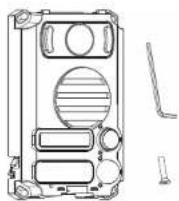
- 1x Outdoor station
- 1x Rain cover
- 7x Plastic plug
- 1x Installation and operation manual
- 1x Power supply
- 1x Allen key
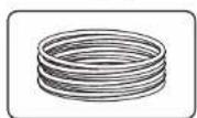
- 1x 5m cable

natural_image
Front view of a blank rectangular device with control buttons at the bottom (no text or symbols on screen)
natural_image
Pure technical line drawing of a U-shaped bracket with mounting holes (no text or symbols)





SET CONSTRUCTION
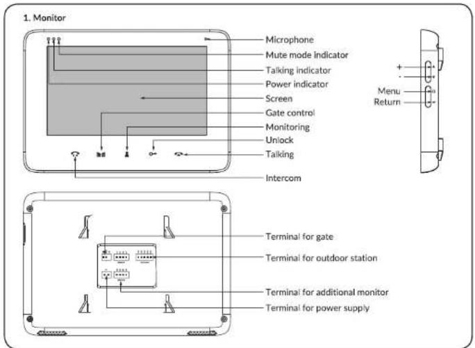
- Outdoor station

INSTALLATION
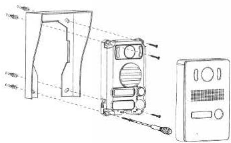
1. Outdoor panel installation.
- Use the supplied Allen key to loosen the screw in the base of the outer cassette.
- Take off the cassette housing.
1

natural_image
Line drawing of a rectangular electronic device with ports and a cable (no text or symbols)2


3. Connect the wires according to the wiring diagram (see point 5) and set the volume level for the outdoor cassette.
3

- Take out the name plate and write the correct name or room number on it.
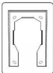
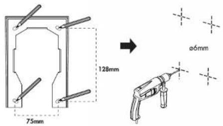
- Use the supplied screws to fix the rain cover (use the dimensions shown in the drawing).
- Replace the cassette body and its housing and tighten them with screws.
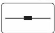
Suggested height of the camera is 1.4 - 1.7 m.
4

5
6

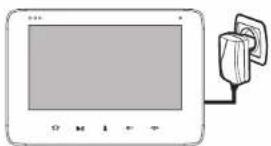
2. Monitor installation.
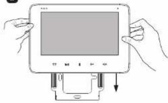
- Use the screws to fix the supplied mounting frame to the wall.

- Hang the monitor on the mounting frame, connect the wires, and then plug the power supply into an socket.
1
natural_image
Illustration of hands holding a tablet device with a control panel and download arrow (no text or symbols)2

natural_image
Illustration of a device with a screen and a plug, no visible text or symbolsWIRING SCHEME
- Wiring diagram for one monitor and outdoor panel
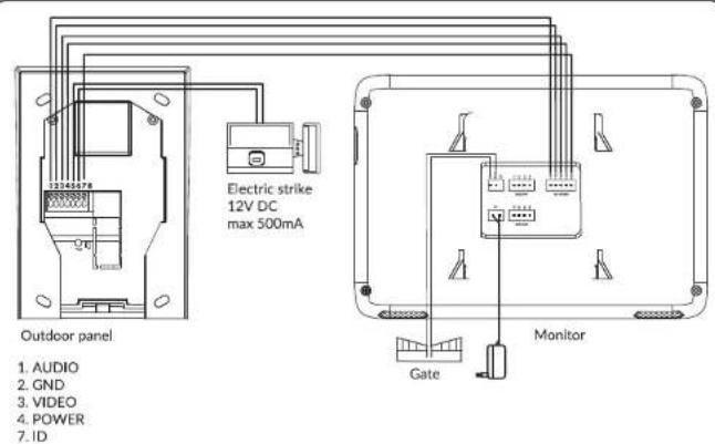
Description:
-
Terminals 1,2,3,4,7 of the external panel are connected to terminals O11, O12, O13, O14, O15 of the internal monitor.
-
Terminals 5, 6 of the external panel are connected to the electric door strike.
-
The NO COM terminal of the internal monitor connects to the gateway accordingly.
-
The + - terminal of the internal monitor connects to the power supply.
IMPORTANT
It is forbidden to make connections to live devices!
Failure to comply with the above recommendations may result in permanent damage to the device.
When designing an electrical installation, the proper section of the wires should be taken into account:
up to 30m - recommended wire XzTKMXpw 3 x 2 x 0,5 mm ^2
from 30m to 100m - recommended wire XzTKMXpw 3 × 2 × 0.8 ~mm^2
Electric door strike should be connected with 2 x 1 mm ^3 .
The set is compatible with any type of 12VDC electric door strike with max. 500mA power consumption.
The total length of the installation cannot exceed 100m.
The manufacturer does not recommend to use stranded wires for this installation.
The set does not include an additional monitor, electric door strike and automatic gate control unit!
- Wiring diagram for outdoor panel and three monitors
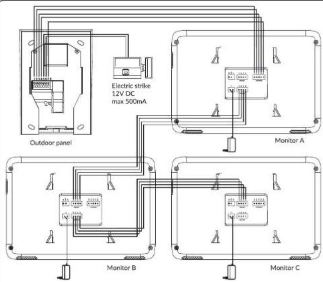
- Terminals 1,2,3,4,7 of external cassette A are connected to terminals O11, O12, O13, O14, O15 of internal monitor A.
- Terminals 121, 122, 123, 124 of the indoor monitor A are connected to terminals 111, 112, 113, 114 of the indoor monitor B.
- Terminals 121, 122, 123, 124 of the indoor monitor B are connected to terminals 111, 112, 113, 114 of the indoor monitor C.
- Terminals 5, 6 of the outer cassette connect to the electric door strike.
- The NO COM terminal of the internal monitor connects to the gate.
- The + - terminal of the internal monitor connects to the power supply.
OPERATION
- Operation of the internal monitor
- Call up/conversation/open door/gate control
1

))
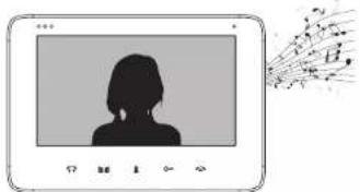
To start a call, press the call button on the external panel
natural_image
Illustration of a person silhouette inside a video player interface with abstract fan-like graphics on the right (no text or symbols)The internal monitor will activate the ringing tone and the external camera image will be displayed on its screen
2
natural_image
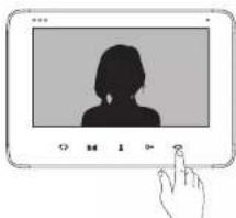
Illustration of a hand interacting with a screen displaying a silhouette of a person (no text or symbols present)Press the TALK button to start a conversation with the person standing outside. Press the same button again to turn off the monitor panel.
3
natural_image
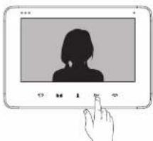
Illustration of a hand interacting with a touchscreen display showing a silhouette of a person (no text or symbols present)To open the door, press the open button.
Important:
The monitor will automatically return to standby mode after 120 seconds.
You can adjust the volume, screen brightness and color saturation parameters while talking.
- Monitoring
1
natural_image
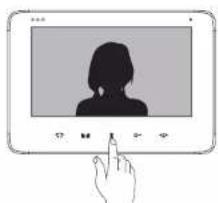
Illustration of a hand pressing a button on a digital screen displaying a silhouette of a person (no text or symbols)To preview the camera image, press the MONITORING button. Press the same button again to return to standby mode.
2

natural_image
Illustration of a hand interacting with a touchscreen display showing a silhouette of a person (no text or symbols present)To open the outside gate, press the GATE CONTROL button.
3

natural_image
Illustration of a hand interacting with a screen displaying a silhouette of a person (no text or symbols present)Monitoring time: approx. 40 seconds.
After 40 seconds, the monitor will automatically return to standby mode.
Important:
When the device is in preview mode, you can start a conversation with a person standing outside by pressing the TALK button. To open the door, press the open button. In this mode you can adjust the volume, brightness and color saturation.
- Intercom
1


- Press the INTERCOM button to start communication between the monitors.

To start a conversation, press the TALK button on the monitor. To end the call between monitors and return to the standby mode, press the TALK button again.
- Adjusting the brightness, colour and volume of the conversation
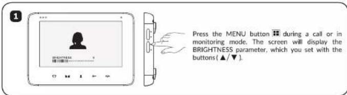
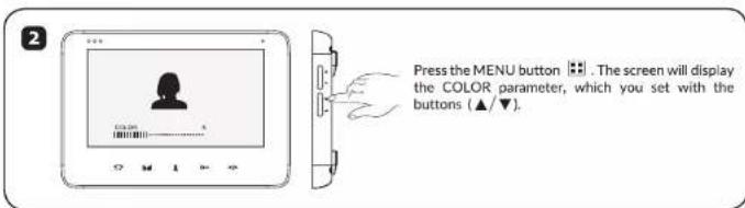

- Ring tone selection and volume control
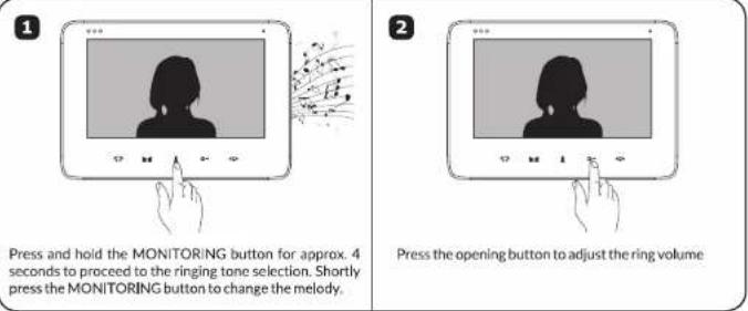


OPERATION
2. External cassette operation
- Opening the door opener (applies to door/wicket door opener) using proximity tags
The set includes 5 tags (3x user tags, 1x add tag, 1x delete tag):
User's tag: no marking
Delete tag: with the symbol (·) used for deletion.
Add tag: with the symbol (+) used for adding new users.
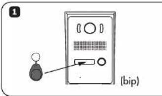
2

- Adding / deleting tags
Adding a new user tag: remember to buy new user tags first
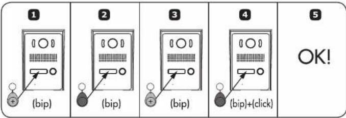
Deleting tag
After deleting the tag, the user will no longer be able to access

CLEANING AND MAINTENANCE
- Do not install the indoor monitor in a place with high temperatures, high humidity or near the TV.
· Do not touch the monitor screen with wet fingers.
· The outdoor cassette is weatherproof (IP44), but do not spray high-pressure water directly onto it, as excessive
moisture may cause improper operation.
- For a clear picture, only clean the monitor panel and the outdoor camera with a soft cloth.
Do not use dishwashing liquid, solvents or other corrosive cleaning agents.
· Do not throw or hit the device.
- If there is a strong light on the external panel, the resulting image may be illegible.
- Do not disassemble the device to avoid a short circuit.
TROUBLESHOOTING
- No sound or vision, no light is on
a) no supply voltage,
b) damaged or poorly connected connection cable, check your installation for technical requirements,
c) check that the installation is not exposed to water, moisture ect.
- Unclear or pale image
a) check the settings and adjust
- In the picture, numerous interferences, no synchronization (picture blinks)
a) the connection cable has a cross-section not adapted to the length
b) connection too long - use shielded cable
c) poor cable quality
d) strong source of electromagnetic interference - use shielded cable
- The sound on the monitor interrupts or couples
a) check your installation for technical requirements
b) check that the installation is not exposed to water, moisture etc.
c) check that the protective film is removed from the screen
- The electric strike does not open every time
a) check the independent operation of the door strike by connecting it to the required voltage, etc.
b) check the current consumption at 12V DC (max. 500mA)
- The monitor screen is scratched
a) check that the protective film is removed from the screen
natural_image
Exterior view of a modern office building (no signage)CE
INHALTSVERZEICHNIS
natural_image
Front view of a blank rectangular device with control buttons at the bottom (no text or symbols on screen)

natural_image
Pure technical line drawing of a U-shaped bracket with mounting holes (no text or symbols)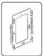



SET-KONSTRUKTION
- Monitor

natural_image
Line drawing of a portable electronic device with buttons and a cable (no text or symbols)2

6

2. Montage des internen Monitors
natural_image
Illustration of hands holding a tablet device with a scroll and download button (no text or symbols)2
natural_image
Illustration of a device with a wall-mounted plug and a separate plug, no text or symbols present.SCHALTPLAN
natural_image
Illustration of a person silhouette inside a video player interface with abstract background elements (no text or symbols)natural_image
Illustration of a hand pressing a button on a screen displaying a silhouette of a person (no text or symbols present)natural_image
Illustration of a hand interacting with a screen displaying a silhouette of a person (no text or symbols present)natural_image
Illustration of a hand pressing a button on a digital screen displaying a silhouette of a person (no text or symbols)natural_image
Illustration of a hand interacting with a screen displaying a silhouette of a person (no text or symbols present)natural_image
Illustration of a hand interacting with a screen displaying a silhouette of a person (no text or symbols present)natural_image
Simple line drawing of a door with a handle and vertical post (no text or symbols)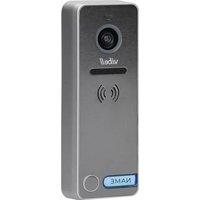


- SPIS TREŚCI
- SCHEMAT PODŁACZENIA
- TABLE OF CONTENTS
- INTRODUCTION
- ELEMENTS OF THE SET
- INSTALLATION
- Outdoor panel installation.
- Monitor installation.
- WIRING SCHEME
- Description:
- IMPORTANT
- OPERATION
- - Monitoring
- - Intercom
- External cassette operation
- - Adding / deleting tags
- Deleting tag
- CLEANING AND MAINTENANCE
- TROUBLESHOOTING
- INHALTSVERZEICHNIS
- SET-KONSTRUKTION
- Montage des internen Monitors
- SCHALTPLAN
Brand : VIBELL
Model : OR-VID-VP-1069
Category : Doorbell