
OR-VID-WI-1068KV - Doorbell VIBELL - Free user manual and instructions
Find the device manual for free OR-VID-WI-1068KV VIBELL in PDF.


| Product Type | Video door phone with 7-inch LCD touch screen |
| Display | 7" color TFT LCD, 1024x600 resolution |
| Camera | 1/4" CMOS, 115° horizontal, 60° vertical viewing angle |
| Night Vision | Infrared LEDs, range 0.5 - 1 m |
| Power Supply (Monitor) | DC 15V, 1A |
| Power Supply (External Panel) | Powered from monitor, consumption 200-250 mA |
| Wi-Fi | 2.4 GHz, 802.11 b/g/n |
| Mobile App | aivisi (iOS/Android) |
| Card Reader | Supports main and user proximity tags/cards |
| Storage | Micro SD card (TF) for photos (JPEG) and videos (AVI) |
| Intercom | Up to 2 monitors, internal call function |
| Electric Strike Control | 12V DC, max 500 mA (not included) |
| Gate Control | Via monitor and app |
| Protection Rating (Panel) | IP44 |
| Working Temperature | -10°C to +50°C |
| Working Humidity | ≤ 85% |
| Installation | 2-wire connection up to 100 m, twisted-pair not recommended |
Frequently Asked Questions - OR-VID-WI-1068KV VIBELL
User questions about OR-VID-WI-1068KV VIBELL
0 question about this device. Answer the ones you know or ask your own.
Ask a new question about this device
Download the instructions for your Doorbell in PDF format for free! Find your manual OR-VID-WI-1068KV - VIBELL and take your electronic device back in hand. On this page are published all the documents necessary for the use of your device. OR-VID-WI-1068KV by VIBELL.
USER MANUAL OR-VID-WI-1068KV VIBELL
- Table of contents 2
- Introduction 3
- Characteristics 3
- Set construction 4
- Installation 5
a) External panel installation 6
b) Monitor installation 8 - Installation of applications 9
WiFi network connection 11 - Adding device 12
- Application settings 14
- Operation 15
- Use of card and proximity tag reader 18
- Operation 20
- Technical data 25
Each household is a user of electrical and electronic equipment, and hence a potential producer of hazardous waste for humans and the environment, due to the presence of hazardous substances, mixtures and components in the equipment. On the other hand, used equipment is valuable material from which we can recover raw materials such as copper, tin, glass, iron and others.

The wee sign placed on the equipment, packaging or documents attached to it indicates the need for selective collection of waste electrical and electronic equipment. Products so marked, under penalty of fine, cannot be thrown into ordinary garbage along with other waste. The marking means at the same time that the equipment was placed on the market after August 13, 2005. It is the responsibility of the user to hand the used equipment to a designated collection point for proper processing. Used equipment can also be handed over to the seller, if one buys a new product in an amount not greater than the new purchased equipment of the same type. Information on the available collection system of waste electrical equipment can be found in the information desk of the store and in the municipal office or district office. Proper handling of used equipment prevents negative consequences for the environment and human health!
INTRODUCTION
Before using the device, read this Service Manual and keep it for future use. In case something written herein is unclear, please contact the seller. Installation and commissioning of the equipment by the customer are possible if the installer has basic knowledge of electrical systems and the use of proper tools. Nevertheless, the device installation by qualified personnel is recommended.
The manufacturer is not responsible for any damage that can result from improper device installation or operation. Any repair or modification carried out by yourselves results in loss of guarantee.
In view of the fact that the technical data are subject to continuous modifications, the manufacturer reserves a right to make changes to the product characteristics and to introduce different constructional solutions without deterioration of the product parameters or functional quality.
Additional information about ORNO products are available at www.support.orno.pl. Orno-Logistic Sp. z o.o. holds no responsibility for the results of non-compliance with the provisions of the present Manual. Orno Logistic Sp. z o.o. reserves the right to make changes to the Manual - the latest version of the Manual can be downloaded from www.orno.pl. Any translation/interpretation rights and copyright in relation to this Manual are reserved.
- Disconnect the power supply before performing any activities.
- Do not immerse the product in water or other liquids.
- Do not operate the device with damaged housing.
- Do not open or repair the device yourself.
- Do not use the device contrary to its dedication.
- Do not install the monitor near devices that emit strong magnetic fields such as TV sets or speakers.
- Do not install the monitor in a location subject to high humidity, vibration, shock or strong sunlight.
- After installation and mounting, remove the protective foil from the monitor screen.
CHARACTERISTICS
The video doorphone is designed for installation in 1 family buildings.
Functions:
- the possibility to talk to the person at the entrance and observe at the same time on the monitor screen,
- directly control the electric strike;
-gate control; - infrared LED lighting enables night vision;
- stepless adjustment of monitor parameters (brightness, colour and ring volume);
- intercom function when using an additional monitor.
Main features:
- touch screen 7" LCD display;
- 2-wire installation and an electric door strike which does not require additional power supply.
SET CONSTRUCTION
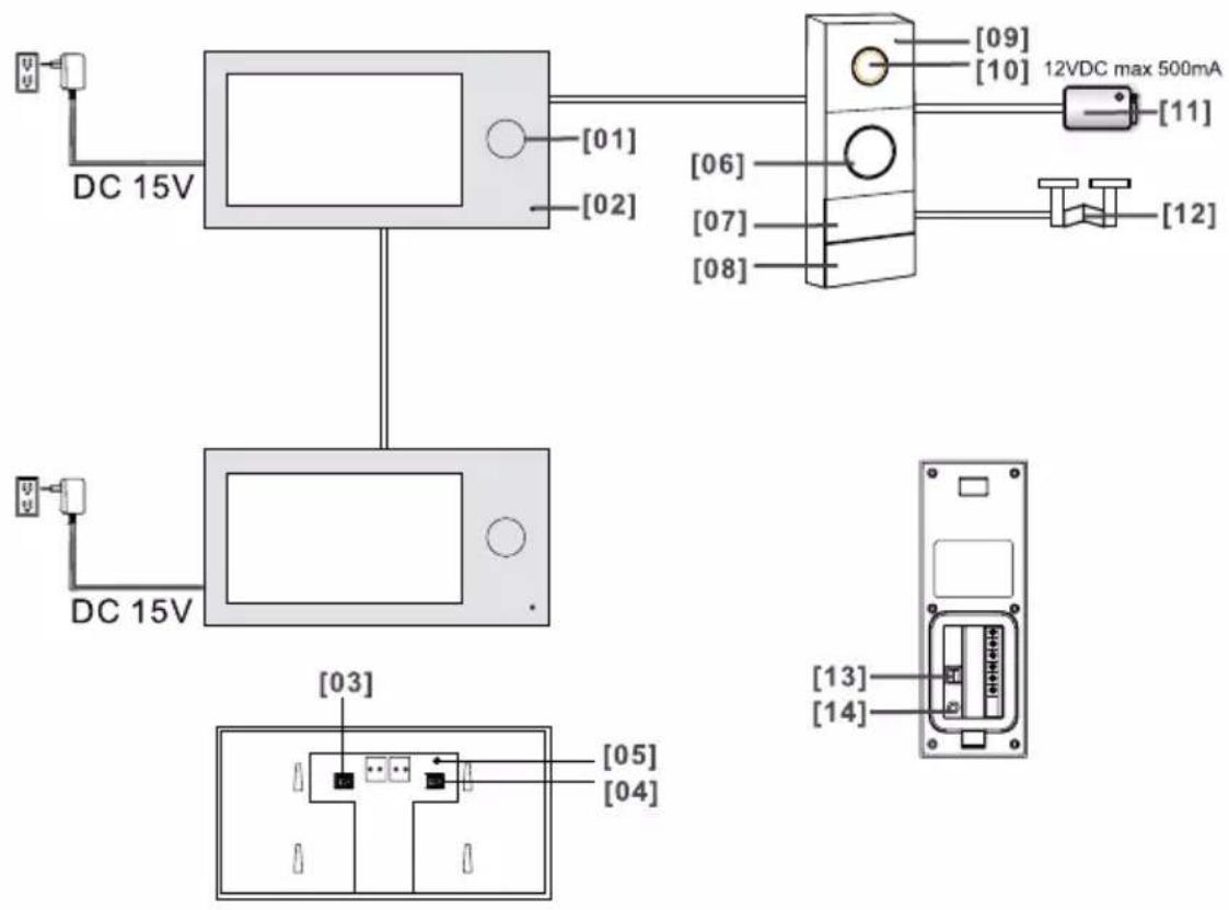
- Indicator light
- Microphone
- TF card slot (for storing photo and video files)
- TF card slot (expansion of the list of available ringtones)
- Reset button (used to restore factory settings; password:admin)
- Loudspeaker
- Card and tag reader
- Call button
- Microphone
- Camera lens
- Electric strike
- Gate automation
- Door strike release time adjustment/address of external panel
- Main card login button
INSTALLATION
Before installing the device on a permanent basis, connect its cables to check that it is working properly.

External panel
The video doorphone cables should not be routed in one cable with the cables of other installations such as bell, alarm, etc. Any power and telecommunication cables emitting strong magnetic fields (e.g. loudspeaker columns, TV set) in direct contact with the cables connecting the external panel to the monitor may adversely affect the operation of the set.
If the user has other connection cables than the recommended ones, it is allowed to use them, however, it is necessary to make a test connection of the set in order to check its correct functioning.
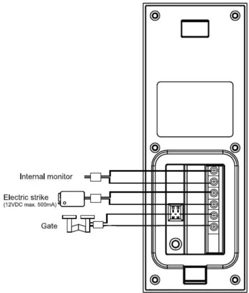
The set does not include an electric door strike and automatic gate control unit!
While designing the wiring system, take into account the suitable cross-section of cables: up to 30 m - recommended cable XzTKMXpw 2 x 2 x 0.5 mm 4
from 30 m to 100 m - recommended cable XzTKMXpw 2 x 2 x 0.8 mm 2
The connection to the electromagnetic lock should be made with 2 x 1mm 2 . Any 12 VDC electric striker with a max current draw of 500 mA can be connected to the set.
The total length of the installation must not exceed 100 meters.
The use of twisted-pair cables is absolutely not recommended.
Connection diagram for multiple components of the set
![graph TD A["Device 1"] --> B["Motor 1"] C["Device 2"] --> D["Motor 2"] E["Device 3"] --> F["Motor 3"] G["Device 4"] --> H["Motor 4"] I["Device 5"] --> J["Motor 5"] K["Device 6"] --> L["Motor 6"] M["Device 7"] --> N["Motor 7"] O["Device 8"] --> P["Motor 8"] Q["Device 9"] --> R["Motor 9"] S["Device 10…](/content/2026/05/851365/images/5d44af0a909d8e33461150eb23591994019926ad6ce2df609ad94b8a92b03d8b.jpg)
a) External panel installation
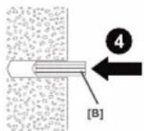
![01 [03] x 1 [B] x 4 1 X X X [03] 2 3 4 [B]](/content/2026/05/851365/images/cd81a956d771db2ebd82b48624b446260f0ad3dee5278d78993874f44474e37c.jpg)
![02 [03]](/content/2026/05/851365/images/1d61ffb74e64fa36966e8ae1e807463d871f2a740917e60ee1f157d238756054.jpg)

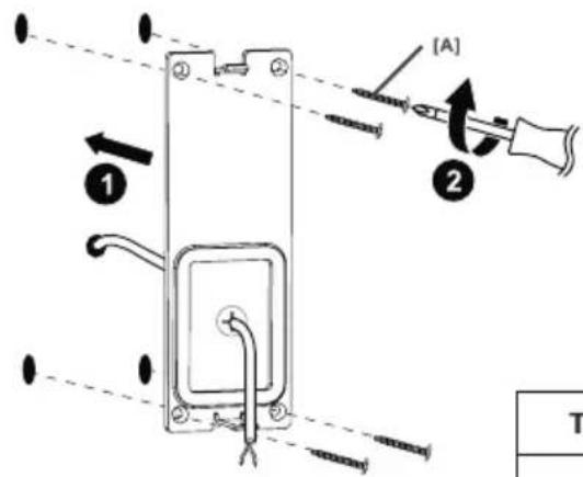
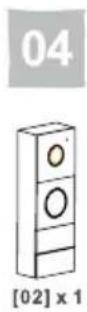
![[02] ON 1 2](/content/2026/05/851365/images/ee2e21f697ff062dfe6b1204878b0c8d46416ade88bccd3bb0eb7036cf1694ac.jpg)
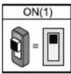

| Type of adjustment | Description | |
| 1Door release time | ID = (00) 1 sec. | |
| ID = (01) 4-7 sec. | ||
| 2ID selectionof external panel | ID = 1(00),setting for the first external panel | |
| ID = 2(01),setting for the second external panel |
05
06
![07 [C] x 1](/content/2026/05/851365/images/16e203bd21dd30b3ede8c27c0a63f4802af229f11c5b2be740b514771693be84.jpg)

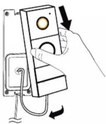
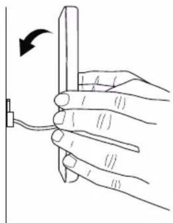
![[C]](/content/2026/05/851365/images/584809bf64c155877eb5887d67a2eb32e02abf48bdc2292648f3433f818224b6.jpg)
b) Monitor installation
01

[04] × 1

[B]×2
![Technical diagram showing a device component with labeled parts and directional arrows, including section marker [04] and tool.](/content/2026/05/851365/images/6541c9be00dfa5bfe31fdb0e7dffb1c690e04bfbdbbb1bb3edee59e9de333e98.jpg)

02


03

[01] × 1
![External panel Power adaptor Black Red [01]](/content/2026/05/851365/images/60182857d8e0cc4e8e2c8924547e678f2009f1add3257631ebbe9cab0a127736.jpg)
04
05
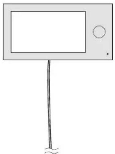

INSTALLATION OF APPLICATIONS
- Open the App Store (iOS) or Google Play (Android) on your phone. Search for the "aivisi" app and install it or
- Scan one of the QR codes below, depending on your operating system.
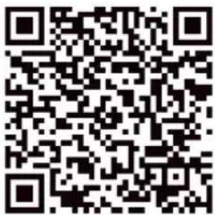
Android

IOS
After the installation is complete, the system will ask for application permissions. Granting permission is necessary for the proper operation of this application.
After installing the application, an icon will appear on your phone

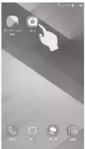
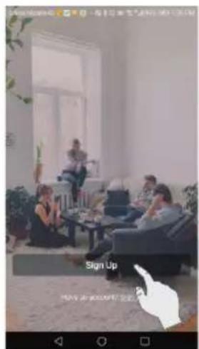
- Press „Sign Up“

- Select your country and press "Next"

- Create an account: set up a username and password. Press "Sign Up".
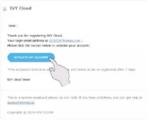
- A message will appear on the screen, click "Activate my account"

- An activation e-mail has been sent to the address you provided. Activate your account by confirming your e-mail address and log in again.
WiFi network connection

- Exit sleep mode, press the SETTINGS icon

- Select the WIFI icon

- Select the WIFI network to which you want to connect the monitor
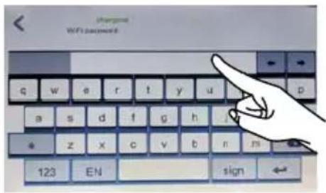
- Enter the WIFI password and press the icon to confirm.

- Configuration complete.
ADDING DEVICE
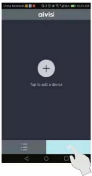
- Press in the aivisi application, the icon „+”

- Choose WIFI VIDEO DOOR PHONE

- Press "Next"
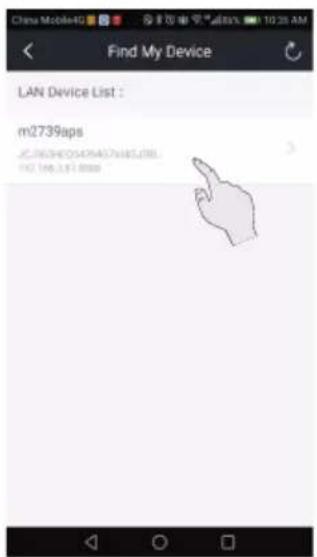
- Select the device found.

- Select the device name and press "Save"
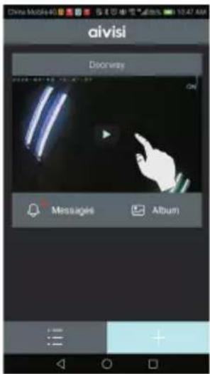
- Press to view the monitoring area

- Device login: For security purposes, set a new name and a new password for the camera.

- The device has been successfully added.
APPLICATION SETTINGS


- Press in the aivisi application, the icon
Application settings
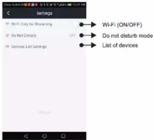
OPERATION
1. Calling
When the visitor presses the call button on the external panel, the LEDs will start flashing and you will hear an alarm indicating the call. The following message will appear on the mobile device:

2. Conversation
Press 📞 to answer the call and talk to your visitor.

3. Monitoring function
The monitoring function is only possible when the device is online. The preview time is 60 seconds.

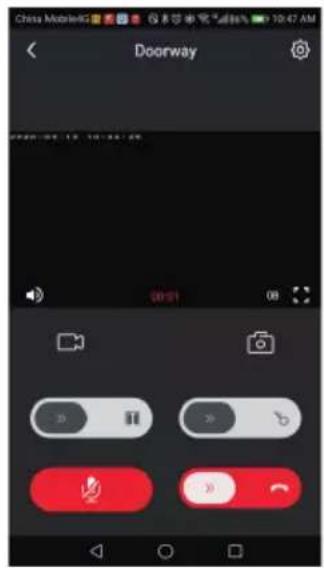
4. Browsing the album

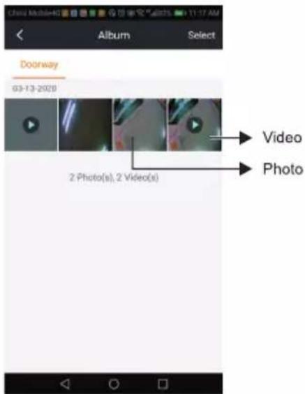
5. Reading the message

6. Device settings

7. Resetting

USE OF CARD AND PROXIMITY TAG READER
01 Main tag registration
(Note: as a rule, there is no need for the user to register the proximity tags separately, as they are already registered at the production stage)
Blue: main tag (2pcs.)

- Press the registration button after turning on the power.
Black: user tag (4pcs.)
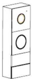
- The LED lights up white and the red LED flashes.
![3D diagram of a vertical rectangular object with three circular holes and a labeled component [08] (no text or symbols beyond label)](/content/2026/05/851365/images/8ba5ecca3ad8e2ffe6002b33d7a0a59b5ffe1d424cd7e2ea6af3b64d766f0673.jpg)
- Read the tag, you will hear a sound DI—DI DI, indicating that the tag has been successfully logged in. Press the call button.
A maximum of 2 main key tags can be registered simultaneously. After registering a third, the first key tag will automatically be deleted from the memory.
02 User tag registration
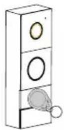
1. In standby mode, apply the main tag. The LED will light up white.

- Press and hold the call button for approx. 3s, you will hear the "DI" tone and the red LED will flash.
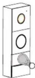
3. Read the tag which you want to register, you will hear a DI----DI DI sound, indicating that the tag has been successfully logged in. Read the main tag twice.
A maximum of 50 user tags can be registered.
03
Deleting user tag

- In standby mode, read the main tag. The LED will light up white.

- Press and hold the call button for approx. 3s, you will hear the "DI" tone and the red LED will flash

- Read the main tag again. The white LED will light off, you will hear the sound "DI DI DI"
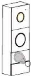
- Read the user tag which you want to delete, you will hear a "DI" sound, which indicates that the user tag has been successfully deleted.
04
Deleting all user cards and proximity tags

- In standby mode, press the call button for approximately 3 seconds, you will hear the "DI" tone and the LED will light up red

- Insert the main card into the reader, you will hear the following sound "DIDIDI"

- Hold down the call button until you hear "DI—", which means that all user cards and proximity tags have been successfully deleted.
05
Unlocking
In standby mode, move the card/tag in front of the reader, the device will open the electric door and you will hear a "DI-DI" sound. Gate control is only possible from the monitor and the app!
IMPORTANT: Simultaneous calling of two actions "press call button" and "unlock with card/proximity tag" is not permitted. There must be at least 3 seconds between the actions.
OPERATION
![[01] 09:58 2018/10/12 [02] [03] [04] [05] [06]](/content/2026/05/851365/images/e246bdd58a43e3b9678955528c7da88057919fb7e74d293416a4f66e0723785d.jpg)
- System date and time
- Preview
- Intercom
- Gallery
- Settings
- Off button
01 Receiving a call
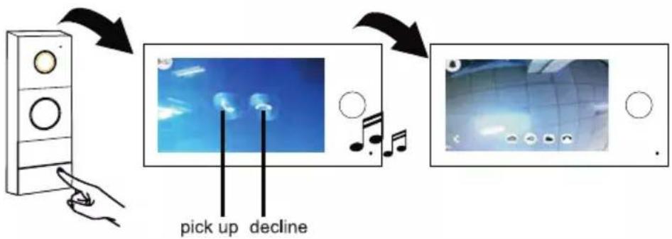
When the call button on the external panel is pressed, the call is signalled by a ringing tone and the monitor displays information about the incoming call.
Press the icon 📋 on the monitor screen to start a conversation with the visitor.
Press the icon 📞 on the monitor screen to disconnect the call.
Press the icon ↻ on the monitor screen to return.
If no one answers the call, the monitor automatically goes out after about 30 seconds.
02 Monitoring function

You can monitor the entrance at any time via the monitor and external camera.
- In standby mode, touch the screen anywhere
- Press the icon 📄 on the main menu
Entrance monitoring
If more than one external panel is connected:
Press the 1 or 2 icon on the monitor screen to select the desired external panel.
Press the icon ↩ on the monitor screen to return.
03
Internal (intercom) call
![graph TD A["Left Frame 09:58"] --> B["Home Screen Icon"] C["Right Frame 09:58"] --> B B --> D["Arrow Up"] style A fill:#f9f,stroke:#333 style C fill:#f9f,stroke:#333](/content/2026/05/851365/images/a09dc4e6cf8416d9043fb579d60578faf03187b9b922601b3ae90692ad937689.jpg)
Press the icon 📁 on one of the monitors, then the other monitor will start ringing. Once the call is answered, the conversation will begin.
04
Door/gate opening
It is possible to open the door/gate during a conversation or while monitoring the entrance.
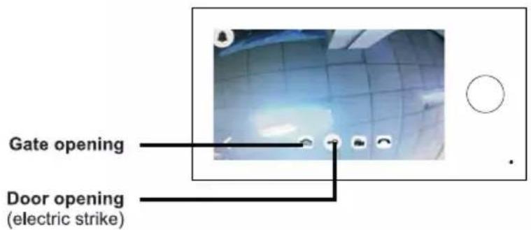
Electric strike is not included. Use only 12 V DC electric strike, max. 500mA.
05
Picture taking / Recording (Micro SD card required)
![graph TD A["Input"] --> B["Process Step 1"] B --> C["Process Step 2"] C --> D["Process Step 3"] D --> E["Output"]](/content/2026/05/851365/images/9f460ae0507be97d02c6883ad4559d05358d9b0cfd634bea3ebc62b99661446f.jpg)
When a visitor presses the call button, the device will automatically take a picture or record a movie. On the monitor screen, press the 📷 or 📖 button to take a photo or record a movie. The files will be saved on the SD card.

06
Browse files (stored on SD card)

Saved pictures/recordings can be played back on the monitor screen. In the main menu, press the icon 📄 on the monitor screen.
| 2016 JAN > | ||||||
| SUN | MON | TUE | WED | THU | FRI | SAT |
| 1 | ||||||
| 2 | 3 | 4 | 5 | 6 | 7 | 8 |
| 9 | 10 | 11 | 12 | 13 | 14 | 15 |
| 16 | 17 | 18 | 19 | 20 | 21 | 22 |
| 23 | 24 | 25 | 26 | 27 | 28 | 29 |
| 30 | ||||||
Press "<" or ">", to select a date,
Press the icon 📄, to select a photo file,
Press the icon ▶, to select a video file.
Press the icon ⬆, to return to the main menu,
Press the icon ↩, to return to the previous page.

Press "<" or ">", to select suitable recordings, press the icon 📁, to delete the displayed photo/video.
07
Settings
Press the icon ⚫, to enter system settings
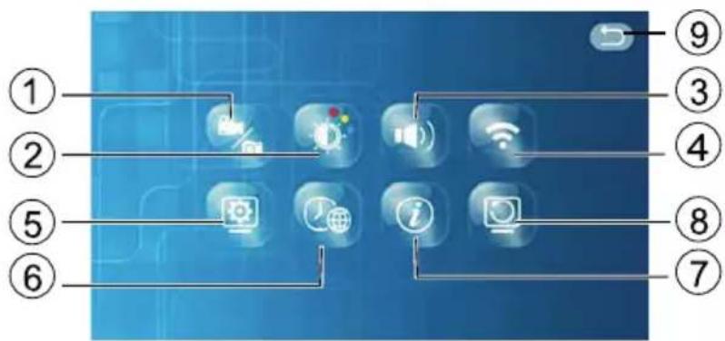
- Capture mode
- Setting image parameters
- Setting ringtone and volume
-
Wi-fi connection
-
Monitor settings (main or additional monitor)
- Date /time /language setting
- Information about the software version and QR code
- Settings reset
- Back to previous page
1. Capture mode


Select the desired setting. When the field ○ is marked with √, the respective function is activated.
Press the icon ⬆, to return to the main menu
Press the icon ↻, to return to the previous page
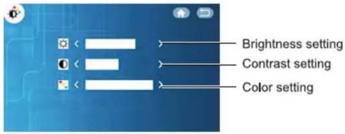
2. Setting image parameters

Press "<" or ">", to change settings.
Press the icon ⬆, to return to the main menu
Press the icon ↩, to return to the previous page.
3. Setting ringtone and volume

Press "<" or ">", to change settings.
Press the icon ↑, to return to the main menu.
Press the icon ↻, to return to the previous page.
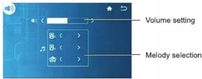
Your own ringtones
Load MP3 files onto the formatted SD card.
4. Wi-fi connection


- After turning on the monitor, press the Settings icon
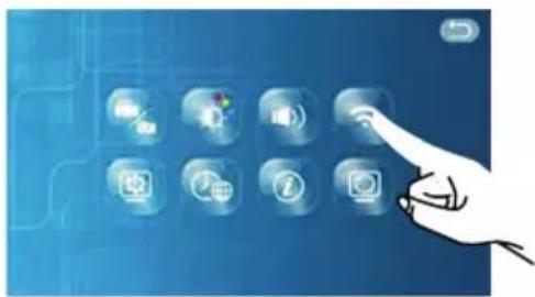
- Press the WIFI icon

- Select the appropriate wi-fi network.

- Enter your network password and press to confirm

- Network setting successful
5. Monitor settings

A maximum of 2 monitors (main monitor and additional monitor) can be connected. Important: One monitor required as the main monitor.
Press the icon 🔓, to rename a device
Press the icon ⬆, to return to the main menu
Press the icon ↻, to return to the previous page.


6. Date /time /language setting


7. Information about the software version

Date/time setting
Press ▲ or ▼, to change setting
Important: The time and date will be set automatically if the device is connected to a wi-fi network and paired with an application.
Language selection
Press the icon SAVE, to save the current settings
Press the icon ↗, to return to the main menu
Press the icon ↩, to return to the previous page

Press the icon ⬆, to return to the main menu
Press the icon ↩, to return to the previous page
8. Settings reset


Press "OK" to restore the factory settings Press "Cancel" to cancel the restoration of the factory settings Press the icon ↩, to return to the previous page
TECHNICAL DATA
Monitor
| Wi-fi frequency | 2.4GHz |
| Standard | 802.11b/g/n, 802.3, 802.3u |
| Power output | <13dBm@11n, <18dBm@11b, <18dBm@11g |
| Power supply | DC 15V 1A |
| Screen size | 7" |
| Video system | PAL/NTSC |
| Resolution | 1024x600 |
| Power consumption | 500 +/-200mA |
| Working temperature | -10°C ~ +50°C |
| Working humidity | 85%(Max) |
| Card type | Micro SD TF |
| Photos file type | JPEG |
| Video file type | AVI |
External panel
| Camera type | 1/4"CMOS |
| Viewing angle | 115°(horizontal), 60°(vertical) |
| Power supply | from monitor |
| Power consumption | 200~250mA |
| Night vision range | 0.5 - 1m |
| Working temperature | -10°C ~ +50°C |
| Storage temperature | -20°C ~ +60°C |
| Working humidity | ≤85%RH |
| Protection level | IP44 |
PRODUCER
ORNO-LOGISTIC Sp. z o.o.


- INTRODUCTION
- CHARACTERISTICS
- FUNCTIONS
- MAIN FEATURES
- SET CONSTRUCTION
- INSTALLATION
- INSTALLATION OF APPLICATIONS
- WIFI NETWORK CONNECTION
- ADDING DEVICE
- APPLICATION SETTINGS
- OPERATION
- CALLING
- CONVERSATION
- MONITORING FUNCTION
- BROWSING THE ALBUM
- READING THE MESSAGE
- DEVICE SETTINGS
- RESETTING
- USE OF CARD AND PROXIMITY TAG READER
- 01 MAIN TAG REGISTRATION
- 02 USER TAG REGISTRATION
- 03
- DELETING USER TAG
- 04
- DELETING ALL USER CARDS AND PROXIMITY TAGS
- 05
- UNLOCKING
- 01 RECEIVING A CALL
- 02 MONITORING FUNCTION
- ENTRANCE MONITORING
- INTERNAL (INTERCOM) CALL
- DOOR/GATE OPENING
- PICTURE TAKING / RECORDING (MICRO SD CARD REQUIRED)
- 06
- BROWSE FILES (STORED ON SD CARD)
- 07
- SETTINGS
- CAPTURE MODE
- SETTING IMAGE PARAMETERS
- SETTING RINGTONE AND VOLUME
- YOUR OWN RINGTONES
- WI-FI CONNECTION
- MONITOR SETTINGS
- DATE /TIME /LANGUAGE SETTING
- INFORMATION ABOUT THE SOFTWARE VERSION
- DATE/TIME SETTING
- LANGUAGE SELECTION
- SETTINGS RESET
- TECHNICAL DATA
Brand : VIBELL
Model : OR-VID-WI-1068KV
Category : Doorbell