
HMC-211 - Remote control DANFOSS - Free user manual and instructions
Find the device manual for free HMC-211 DANFOSS in PDF.


| Product Type | PLUS+1® Controller Module (HMC-211) |
| Model Number | HMC-211-010/112 |
| Supply Voltage (Nominal) | 9 to 36 Vdc |
| Maximum Supply Voltage | 36 Vdc |
| Digital Inputs | Multifunction: DIN/AIN/FreqIN/Rheo |
| Analog Input Resolution | 12-bit (4096 counts) |
| Analog Input Ranges | 0-5.25 V (low), 0-36 V (high) |
| Input Impedance (Analog) | 206–236 kΩ (low range, no pull-up) |
| Digital Output Types | DOUT (3 A), HDOUT (6 A), PWMOUT/DOUT/PVGOUT (3 A), HPWMOUT/DOUT (6/10 A) |
| PWM Frequency Range | 33 to 4000 Hz |
| CAN Bus | CAN 2.0B, one port |
| Protection Rating | IP67 (with mating connector) |
| Operating Temperature | -40 to 70 °C |
| Storage Temperature | -40 to 85 °C |
| Connector Type | DEUTSCH (bag assembly) |
| Mounting | Panel mounting only |
| Dimensions (approximate) | 160 x 80 x 35 mm |
| Weight (approximate) | 200 g |
| Programming Software | PLUS+1® GUIDE |
| Sleep Mode Current | 0.14 mA at 12 Vdc, 0.28 mA at 24 Vdc |
| Safety Feature | Emergency stop required (OEM responsibility) |
| Spare Parts | Mating connector kits, crimp tools (e.g., HDT48-00) |
Frequently Asked Questions - HMC-211 DANFOSS
User questions about HMC-211 DANFOSS
0 question about this device. Answer the ones you know or ask your own.
Ask a new question about this device
Download the instructions for your Remote control in PDF format for free! Find your manual HMC-211 - DANFOSS and take your electronic device back in hand. On this page are published all the documents necessary for the use of your device. HMC-211 by DANFOSS.
USER MANUAL HMC-211 DANFOSS
Technical Information
PLUS+1® Controllers
MC0XX-0XX Controller Family
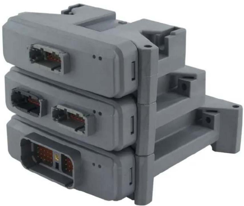
natural_image
Stacked gray plastic electronic device modules with visible internal connectors (no text or symbols)Revision history Table of revisions
| Date Changed Rev | ||
| May 2021 Added torque information 1908 | ||
| Changed document number from 'BC00000034' and '520L0719' to 'BC152886484710' | XX | |
| October 2019 Resolved link under General ratings, table MC controllers general ratings. 1804 | ||
| October 2019 Corrected table Danfoss crimp extraction tool part information, last row, Description: Extraction tool DEUTSCH 0411-240-2005; 16 to 20, 20 to 24 AW. | 1803 | |
| March 2017 Changed module name, HMC-211-010/112; Changed name of manual, from PLUS+1 Controller Family to PLUS+1 MC0XX-0XX Controller Family. | 1802 | |
| December 2016 Added input impedance for analog inputs 1801 | ||
| July 2016 Updated DIN/AIN/FreqIN; Din/AIN/FreqIN/Rheo Specifications table; Din/AIN/FreqIN Specifications table; added link to MC038-010 sleep mode in first bullet under MC038-010 power supply; updated to Engineering Tomorrow design | 1701 | |
| May 2015 Revised note regarding pin C1p26 QA | ||
| February 2014 MC050-055/05B input voltage maximum is limited to 16 Vdc PB | ||
| January 2014 Converted to Danfoss layout PA | ||
| June 2005 to September 2013 | Various updates | BA through OA |
| March 2004 First edition | AA | |
Contents
MC0XX-0XX Controller Family literature references
Technical Information (TI)....4
Module product Data Sheet (DS)....4
API specifications (API)....4
PLUS+1 ^® GUIDE User Manual....4
User liability and safety statements
OEM responsibility....5
Overview
MC0XX-0XX Controller Family....6
CAN
Input types....7
DIN....7
AIN....8
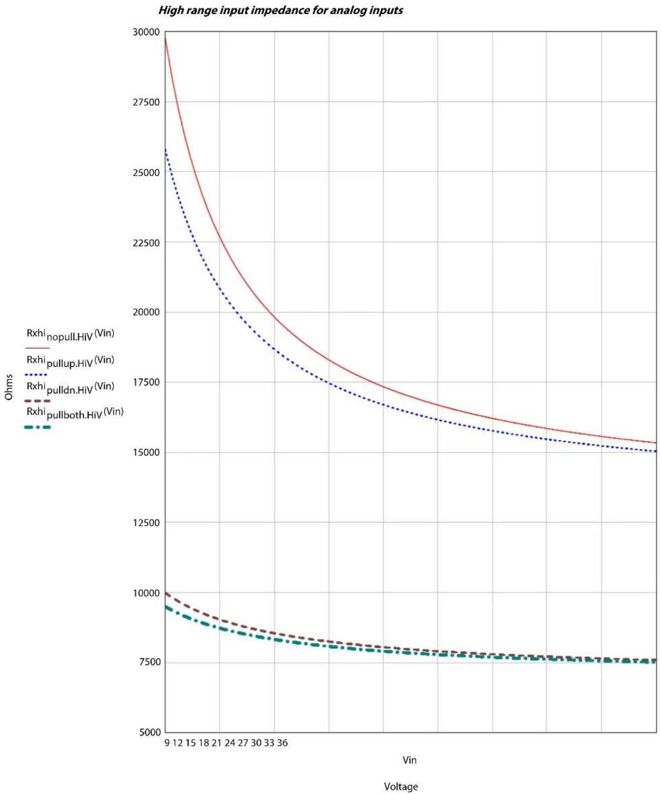
High range input impedance for analog inputs....9
AIN offset....10
A/D refresh rate....10
AIN/Temp/Rheo; DIN/AIN/FreqIN/Rheo....10
DIN/AIN/FreqIN; DIN/AIN/FreqIN/Rheo....11
DIN/AIN/FreqIN....13
DIN/AIN/4-20 mA IN....14
Output types....15
DOUT and DOUT/PVEpwr....16
HDOUT....17
PWMOUT/DOUT/PVGOUT....17
HPWMOUT/DOUT....19
MC038-010, MC088-XXX output pin power supply....19
Controller Area Network (CAN)
CAN system design....20
Specifications for terminating resistor....20
Notes on CAN Bus installation....20
Expansion module CAN Bus loading....20
Product ratings
Module supply voltage/maximum current ratings.... 22
MC038-010 power supply....22
MC038-010 sleep mode....22
Sensor power supply ratings....23
PVG valve power supply ratings....24
EEPROM write/erase ratings....24
Vault memory....24
FRAM memory....24
Environmental testing criteria....25
General ratings....26
Modules housing....26
Product installation and start-up
Connectors....27
Mounting....28
Machine diagnostic connector....29
Grounding....29
Hot plugging....29
Machine wiring guidelines....29
Machine welding guidelines....30
PLUS+1 ^° USB/CAN Gateway....30
MC0XX-0XX Controller Family literature references
| Literature title Document type Literature ID | ||
| MC0XX-0XX Controller Family Technical Information | User Guide | BC152886484710 |
| MC0XX-0XX Controllers Data Sheets Data Sheet | * | |
| PLUS+1*GUIDE Software User Manual Operation Guide AQ152886483724 | ||
* Data Sheets for 12, 18, 24, 38, 50, and 88 pin models, go to https://www.danfoss.com/en/products/electronic-controls/?sort=default_sort.
Comprehensive technical literature is online at www.danfoss.com
Technical Information (TI)
A TI is comprehensive information for engineering and service personnel to reference.
Module product Data Sheet (DS)
A module product DS contains summarized information and parameters that are unique to an individual PLUS+1 ^* module, including:
• Numbers and types of inputs and outputs
• Module connector pin assignments
• Module maximum current capacity
• Module sensor power supply (if present) current capacity
• Module installation drawing
- Module weights
• Product ordering information
API specifications (API)
Module API specifications contain detailed information about the module BIOS. PLUS+1 ^® BIOS functionality is pin dependent. Pins are defined in module data sheets as C (connector number) p (pin number).
API specifications include:
- Variable name
- Variable data type
• Variable direction (read/write)
• Variable function and scaling
Module API specifications are the definitive source of information regarding PLUS+1 ^® module pin characteristics.
PLUS+1\* GUIDE User Manual
The Operation Manual (OM) details information regarding the PLUS+1 ^ GUIDE tool used in building PLUS +1 ^ applications. This OM covers the following broad topics:
- How to use the PLUS+1* GUIDE graphical application development tool to create machine applications
• How to configure module input and output parameters
• How to download PLUS+1 ^® GUIDE applications to target PLUS+1 ^® hardware modules
• How to upload and download tuning parameters
• How to use the PLUS+1 ^® Service Tool
User liability and safety statements
OEM responsibility
The OEM of a machine or vehicle in which Danfoss products are installed has the full responsibility for all consequences that might occur. Danfoss has no responsibility for any consequences, direct or indirect, caused by failures or malfunctions.
- Danfoss has no responsibility for any accidents caused by incorrectly mounted or maintained equipment.
- Danfoss does not assume any responsibility for Danfoss products being incorrectly applied or the system being programmed in a manner that jeopardizes safety.
- All safety critical systems shall include an emergency stop to switch off the main supply voltage for the outputs of the electronic control system. All safety critical components shall be installed in such a way that the main supply voltage can be switched off at any time. The emergency stop must be easily accessible to the operator.
Overview
MCOXX-0XX Controller Family
PLUS+1 ^* Mobile Machine Modules are designed to provide flexible, expandable, powerful and cost effective total machine management systems for a wide variety of vehicle applications.
These modules communicate with one another and other intelligent systems over a machine Controller Area Network (CAN) data bus.
PLUS+1 ^® controller products utilize modular designs wherever possible. This modularity extends to product housings, connectors and control circuitry.
PLUS+1 ^® hardware products are designed to be equally effective in a distributed CAN system, with intelligence in every node, or as stand-alone control for smaller machine systems.
PLUS+1* Compliant systems are incrementally expandable: additional modules can be easily added to the machine CAN bus to increase system capabilities or computational power.
Six standard housings, 12, 18, 24, 38, 50, and 88 pin, cover this product line.
CAN
Input types
- Digital (DIN)
• Digital or Analog (DIN/AIN)
• Analog or Temperature or Rheostat (AIN/Temp/Rheo)
• Multifunction: Digital or Analog or Frequency (DIN/AIN/FreqIN)
• Multifunction: Digital or Analog or Frequency or Rheostat (DIN/AIN/FreqIN/Rheo)
• Fixed Range Analog or CAN shield (AIN/CAN shield)
• Digital or Analog or Current (DIN/AIN/4-20 mA IN)
Each PLUS+1 ^9 module input pin supports one of the above functional types. For pins with multiple functions, input configurations are user programmable using PLUS+1 ^6 GUIDE templates.
DIN
Digital inputs (DIN) connected to PLUS+1 ^® dedicated digital input pins are debounced in software. Digital input debounce is defined as an input being in a given state for three samples before a state change is reported. The sample time is a function of application loop time.
Multifunction pins that are configured to be Digital input (DIN) are subject to the same update rates as the Analog input (AIN) function for that pin. Debounce is not used, as hysteresis is built into the function. The time to recognize a transition is dependent on the timing of the switch activation and the sample rate.
General response to input time
| Description Comment | |
| Response to input below minimum voltage | Non-damaging, non-latching; reading saturates to the low limit. |
| Response to input above maximum voltage | Non-damaging, non-latching; reading saturates to the high limit. |
| Response to input open | Pin configuration dependent: No pull up/ no pull down = floating Pull up to 5 Vdc = 5 Vdc Pull down = 0 Vdc Pull up/ pull down = 2.5 Vdc |
| Voltage working ranges | Programmable (see specific data sheets for ranges). |
DIN characteristics
| Description Units Minimum | Maximum | Comment | ||
| Allowed voltage at pin Vdc 0 | 36 | * | Modules will survive with full functionality if input voltage does not exceed 36 Vdc. | |
| Rising voltage threshold Vdc | 2.80 4.15 | A digital input is guaranteed to be | read as high if the voltage is greater than 4.15 Vdc. | |
| Falling voltage threshold Vdc | 1.01 2.77 | A digital input is guaranteed to be | read as low if the voltage is less than 1.01 Vdc. | |
| Time to change state in response to step input | ms 1.5 | Input change from maximum to | minimum—add to debounce time. | |
| Input impedance | ||||
| Input voltage < 5.7 Vdc kΩ 233 nominal—no pull up or pull down pin configuration. | ||||
| Input impedance | ||||
| Input voltage < 5.7 Vdc kΩ 14.1 nominal—pull up or pull down pin configuration. | ||||
CAN
DIN characteristics (continued)
| Description Units Minimum | Maximum | Comment | ||
| Input impedance | ||||
| Input voltage ≥ 5.7 Vdc kΩ | 14.1 nominal—all pin configurations. | |||
MC050-055/05B input voltage maximum is limited to 16 Vdc.
AIN
Analog inputs (AIN) specifications
| Description Units Minimum | Maximum | Comment | ||
| Allowed voltage at pin* | Vdc 0 36 | ** | ||
| 0 to 5 Vdc range maximum discernible voltage | Vdc 5.21 | 5.30 5.26 is typical. | ||
| 0 to 36 Vdc range maximum discernible voltage | Vdc 31.70 | |||
| Precision mV 1.28 | ||||
| Input impedance kΩ 206 236 | Depends | on pin configuration. |
* Maximum allowed voltage on fixed range analog input pins (CAN shield) is 25 Vdc.
** MC050-055/05B input voltage maximum is limited to 16 Vdc.
For voltages > 5.7 V, see High range input impedance for analog inputs on page 9.
In high range the input impedance decreases as the input voltage increases.
CAN
CAN
AIN offset
Module analog input offset error can be 80 counts out of 4096 (12 bit resolution). Therefore, the minimum voltage that a module will read at the 0 to 5.25 V DC range is 105 mV. The minimum voltage that a module will read at the 0 to 36 V DC range is 703 mV.
The input offset error is a function of component tolerances and can vary from one module to the next. When an input value is used in an algorithm where the offset error could impact the control strategy, the way the signal is acquired and the need to calibrate should be considered.
A/D refresh rate
Analog to Digital (A/D) refresh rates for individual PLUS+1* MC0XX-0XX family modules and expansion modules are listed in the following table.
A/D channels are sampled at 25 kHz and 64 samples are taken to build an average value. This results in a refresh rate of 2.56 ms for channels directly measured. All internal current feedback channels are refreshed at the 2.56 ms rate.
Some PLUS+1* MC0XX-0XX family modules A/D channels are shared. Each of the shared channels have eight multiplexed analog inputs. Each multiplexed input is serviced every 20.48 ms. Update rates for specific analog input pins are found in the following table. Update rates for input expander modules are dependent on the CAN message frequency selected in the application program.
A/D refresh rates for PLUS+1 ^® MC0XX-0XX family modules
| PLUS+1* module A/D refresh rate | |
| MC012-010/012 All: 2.56 ms | |
| MC012-026/029 All: 2.56 ms | |
| HMC-211-010/012 All: 2.56 ms | |
| MC024-010/011/012/014 All: 2.56 ms | |
| MC024-020/021/022/024 C1p10 to C1p12: 7.68 msRemaining pins: 2.56 ms | |
| MC024-500 All: 2.56 ms | |
| MC038-010 C1p08, C1p14, C1p17 to C1p20, C1p24 to C1p27, C1p36 to C1p38: 20.48 msC1p05, C1p10 to C1p12: 2.56 ms | |
| MC050-010/012 C1p05, C1p08, C1p14 to C1p19, C1p22 to C1p30, C1p34 to C1p36: 20.48 msC1p02: 2.56 ms | |
| MC050-020/022 C1p05, C1p22, C1p25 to C1p32, C1p39, C1p40: 20.48 msC1p02, C1p08, C1p18, C1p19, C1p23, C1p24: 2.56 ms | |
| MC050-055/05B C1p05, C1p13 to C1p29, C1p31 to C1p39, C1p41 to C1p45: 20.48 msC1p46 to C1p49: 2.56 ms | |
| MC088-015/01B/315 C1p05, C1p08, C1p14 to C1p19, C1p22 to C1p30, C1p34 to C1p36, C1p47 to C1p50 , C2p09 to C2p11, C2p35 to C2p38: 20.48 ms | |
| IOX012-010 Refresh rate is a function of CAN message frequency | |
| IOX024-020 Refresh rate is a function of CAN message frequency | |
| IX012-010 Refresh rate is a function of CAN message frequency | |
| IX024-010 Refresh rate is a function of CAN message frequency | |
AIN/Temp/Rheo; DIN/AIN/FreqIN/Rheo
Analog/Temperature/Rheostat (AIN/Temp/Rheo); Digital/Analog/Frequency/Rheostat (DIN/AIN/FreqIN/Rheo).
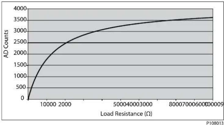
When a PLUS+1 ^ module input pin is configured in the temperature/rheostat mode, the input has a 1.33 kΩ pull up resistor to +5 Vdc. It will source up to 3.75 mA current to an external load (RL) which then can be measured. The equation for relating AD counts to a given load is: AD counts = (4096*RL) / (RL + 1330).
CAN
This calculation is solved internally and the ohms value is available for the programmer. The following chart shows the relationship between AD counts and load resistance in ohms.
Rheostat inputs
line
| Load Resistance (Ω) | AD Counts | | ------------------- | --------- | | 0 | 0 | | 10000 | 1500 | | 2000 | 2500 | | 5000 | 3000 | | 8000 | 3500 | | 10000 | 3600 |Specifications
| Description Units Minimum | Maximum | Comment | ||
| Allowed voltage at pin Vdc 0 | 36 | |||
| Measured resistance Ω 0 100 | 00 |
DIN/AIN/FreqIN; DIN/AIN/FreqIN/Rheo
All modules except IX012-010, IX024-010.
The characteristics of Digital/Analog/Frequency (DIN/AIN/FreqIN) pins are PLUS+1* GUIDE software controlled. The input can be digital, analog or frequency.
Inputs can be pulled to 5 Vdc, pulled to ground, pulled to 2.5 Vdc, or no pull-up/pull-down.
DIN/AIN/FreqIN general information
| Description Comment | |
| Response to input below minimum voltage | Non-damaging, non-latching; reading saturates to the low limit. |
| Response to input above maximum voltage | Non-damaging, non-latching; reading saturates to the high limit. |
| Expected measurement Frequency (Hz) | |
| Period (0.1 μsec) | |
| Channel to channel phase shift (paired inputs . . . ) (0.1 ms). | |
| PWM duty cycle (0.01%)—Duty cycle measurement only valid up to 5 kHz (FreqIN). | |
| Edge count. | |
| Quadrature count (paired inputs driven from a quadrature encoder). | |
| Pull up/pull down configuration | No pull down/ pull up is standard with pull up or pull down programmable; failure modes are detectable. |
As with analog input pins, values in the following table assume software compensation for AD converter offset errors.
Specifications
| Description Units Minimum | Maximum | Comment | ||
| Allowed voltage at pin Vdc 0 | 36 | |||
| Frequency range Hz 0 10000 | In steps of 1 Hz. |
CAN
Specifications (continued)
| Description Units Minimum | Maximum Comment | ||
| Maximum discernible voltage (high range) | Vdc 34.62 35.91 35.3 Vdc is typical. | ||
| Maximum discernible voltage (middle range) | Vdc 5.18 5.33 5.26 Vdc is typical. | ||
| Maximum discernible voltage (low range) | Vdc 0.360 0.375 0.368 Vdc is typical. | ||
| Precision (high range) mV – - 8.62 | |||
| Worst case error (high range) | mV – - 614 | ||
| Precision (middle range) mV – - 1.28 | |||
| Worst case error (middle range) | mV – - 75 | ||
| Precision (low range) μV – - 89.7 | |||
| Worst case error (low range) | mV – - 7.39 | ||
| Input impedance (pulled to 5 Vdc or ground, middle and low range) | kΩ 13.9 14.3 | ||
| Input impedance (pulled to 2.5 Vdc middle and low range) | kΩ 7.17 7.37 | ||
| Input impedance (no pull ups, middle and low range) | kΩ 230 236 | ||
| Input impedance (pulled to 5 Vdc or ground, high range) | kΩ 13.0 13.4 | ||
| Input impedance (pulled to 2.5 Vdc high range) | kΩ 6.92 7.12 | ||
| Input impedance (no pull ups, high range) | kΩ 108 112 | ||
| Rising voltage threshold (high range) | Vdc 27.6 It is inadvisable to use the high range | option when configuring the input as a digital or frequency input. | |
| Falling voltage threshold (high range) | Vdc 6.8 | It is inadvisable to use the high range option when configuring the input as a digital or frequency input. | |
| Rising voltage threshold (middle range) | Vdc 4.27 Voltage required for frequency input | to read high. | |
| Falling voltage threshold (middle range) | Vdc 0.96 | Voltage required for frequency input to read low. | |
| Rising voltage threshold (low range) | Vdc 0.298 Voltage required for frequency input | to read high. | |
| Falling voltage threshold (low range) | Vdc 0.07 | Voltage required for frequency input to read low. | |
MC050-010 and MC050-018 pin C1p26 should not be configured as a FreqIN.
Recommendation is to not use pin C1p26 as a frequency input. If used, recommendation is to disable internal filtering and use filter inside the application instead.
CAN
DIN/AIN/FreqIN
The characteristics of Digital/Analog/Frequency (DIN/AIN/FreqIN) pins are PLUS+1* GUIDE software controlled. The input can be digital, analog or frequency.
Inputs can be pulled to 5 Vdc, pulled to ground, pulled to 2.5 Vdc, or no pull-up/pull-down.
Analog to digital resolution is 10 bits.
As with analog input pins, values in the following table assume software compensation for the errors in the AD converter.
Specifications
| Description Units Minimum | Maximum | Comment | ||
| Allowed voltage at pin Vdc 0 | 36 | |||
| Frequency range Hz 0 10000 | In steps of 1 Hz. | |||
| Maximum discernible voltage (high range) | Vdc 35.3 | 36 36 Vdc is typical. | ||
| Maximum discernible voltage (middle range) | Vdc 5.67 | 5.83 5.75 Vdc is typical. | ||
| Maximum discernible voltage (low range) | Vdc 0.440 | 0.456 0.448 Vdc is typical. | ||
| Minimum discernible voltage | Vdc 0 0.08 | |||
| Precision (high range) mV - - | 36.5 | |||
| Worst case error (high range) | mV - - 614 | |||
| Precision (middle range) | mV - - 5.62 | |||
| Worst case error (middle range) | mV - - 75 | |||
| Precision (low range) | μV | - - 438 | ||
| Worst case error (low range) | mV - - 7.39 | |||
| Input impedance (pulled to 5 Vdc or ground, middle and low range) | kΩ 13.9 | 4.3 | ||
| Input impedance (pulled to 2.5 Vdc middle and low range) | kΩ 7.17 | 7.37 | ||
| Input impedance (no pull ups, middle and low range) | kΩ 230 | 236 | ||
| Input impedance (pulled to 5 Vdc or ground, high range) | kΩ 10.3 | 10.7 | ||
| Input impedance (pulled to 2.5 Vdc high range) | kΩ 6.07 | 6.27 | ||
| Input impedance (no pull ups, high range) | kΩ 36.4 | 38.4 | ||
| Rising voltage threshold (high range) | Vdc - - 27 | 7.6 It is inadvisable to use the high range | option when configuring the input as a digital or frequency input. | |
| Falling voltage threshold (high range) | Vdc 6.8 | - - It is inadvisable to use the high range | option when configuring the input as a digital or frequency input. | |
CAN
Specifications (continued)
| Description Units Minimum | Maximum | Comment | ||
| Rising voltage threshold (middle range) | Vdc 4.27 | Voltage required for frequency input | to read high. | |
| Falling voltage threshold (middle range) | Vdc 0.96 | Voltage required for frequency input | to read low. | |
| Rising voltage threshold (low range) | Vdc 0.298 | Voltage required for frequency input | to read high. | |
| Falling voltage threshold (low range) | Vdc 0.071 | Voltage required for frequency input | to read low. | |
Potential for IX modules to not go online. If voltage is applied to an IX module input pin prior to the module being powered on, there is a possibility that the module CPU will not power up. The module is not damaged and will power up and operate normally once power is removed from the input pins. It is recommended that either the IX module's 5 Vdc sensor power be used to power sensors or that power is removed from the input pins until the module is powered up.
If the frequency goes to zero, the data will not decay over time, it will be updated once a new pulse is seen, or times out. It is possible to monitor the count of pulses to know when the frequency reading is updated.
DIN/AIN/4-20 mA IN
Digital/Analog/4-20 mA (DIN/AIN/4-20 mA IN).
Refer to DIN/AIN/FreqIN on page 13, for input properties when pins are configured as digital, analog or frequency. If the pin is configured to read current, the table below applies. When interfacing with sensors that transmit a 4 to 20 mA current signal, the positive lead of the transmitter is connected to battery voltage and the negative lead is connected to the PLUS+1* module pin. The current measuring configuration relies on the application program to provide over current protection.
The current measuring configuration is only available on MC088-XXX modules.
Specifications
| Description Units Minimum | Maximum | Comment | ||
| Allowed voltage at pin Vdc 0 | 36 | |||
| Minimum input current mA | 34 | |||
| Maximum input current mA | 2024 | |||
| Precision | μA | 5.86 |
CAN
Output types
- Digital (DOUT)
• Digital/PVG valve reference power (DOUT/PVGpwr)
• High current digital (HDOUT)
• Pulse width modulated (PWM/DOUT/PVGOUT)
• High current (6 A) pulse width modulated (HPWMOUT/DOUT) - High current (10 A) pulse width modulated (HPWMOUT/DOUT)
Output pins available on PLUS+1° Controller Family
| PLUS+1* module | DOUT (2A) | DOUT (3 A) | HDOUT (6 A) | DOUT/PVGpwr (3 A) | PWMOUT/ DOUT/PVGOUT (3 A) | HPWMOUT/ DOUT (6 A) | HPWMOUT/ DOUT (10 A) |
| MC012-010/012 2 | |||||||
| MC012-026/029 2 | |||||||
| HMC-211-010/01 2 | 4 | 2 | |||||
| MC024-010/011/ 012/014 | 4 | ||||||
| MC024-020/021/ 022/024 | 8 | ||||||
| MC038-010 2 3 3 5 | |||||||
| MC050-010/012 | 3 3 10 | ||||||
| MC050-020/022 6 | 2 6 | ||||||
| MC050-055/05B 1 | 2 | ||||||
| MC088-015/01B 13 | 6 3 10 | ||||||
| IOX012-010 2 | |||||||
| IOX024-020 8 | |||||||
| OX012-010 6 | |||||||
| OX024-010 4 2 10 |
PLUS+1 ^® modules feature user-configurable output pin parameters. Output pin parameters are configured using PLUS+1 ^® GUIDE templates.
Refer to module data sheets for maximum output current ratings of individual modules and MC038-010 and MC088-015/01B power planes. The total output current for any PLUS+1* module must not exceed the maximum allowable current specified in the module data sheet. In the case of MC038-010 and MC088-015/01B modules, both the total output current for an individual power plane and the total output for the module must not exceed the limits specified on the module data sheets.

Warning
Unintended movement of the machine or mechanism may cause injury to the technician or bystanders. The module will be powered up if battery voltage is applied to the module's output pin. To protect against unintended movement, secure the machine.

Caution
Warranty will be voided if module is damaged. Avoid significant current driven back through an output pin.
CAN
DOUT and DOUT/PVEpwr
Digital (DOUT) and Digital/PVG Reference Power (DOUT/PVEpwr).
Digital outputs can source up to 3 A. The exception is MC038-010 controller, DOUT pins are limited to 2 A.
• Current outputs for MC050-010, MC050-020, MC088-015, and OX024-010 module
• DOUT and DOUT/PVG Pwr pins are pair limited and a function of temperature.
Output per pair is: 6 A maximum at 25 C [77 F]. Output per pair is 4 A maximum at 70°C [158°F]
• MC050-010 pairs are: C1p31 and C1p32, C1p33 and C1p34, C1p35 and C1p36
• MC050-020 pairs are: C1p33 and C1p34, C1p35 and C1p36, C1p37 and C1p38, C1p39 and C1p40
• MC088-015 pairs are:
Power plane C2p35: C1p31 and C1p32, C1p33 and C1p34
Power plane C2p36: C1p35 and C1p36
Power plane C2p37: C2p1 and C2p7, C2p2 and C2p3, C2p4 and C2p5, C2p30 and C2p33
Power plane C2p38: C2p6 and C2p12
- OX024-010 pairs are: C1p6 and C1p7, C1p8 and C1p9, C1p10 and C1p11
• Example: at a module temperature of 70^ C [158°F], if C1p31 is sourcing 2.5 A, the most current that can be sourced on its paired pin C1p32 is 1.5 A
General
| Description Comment | |
| Configuration Sourcing only. | |
| Type Linear switching. | |
| Short circuit to ground protection Non-damage, current/thermal limit with status indication; automatic latch off /resume. | |
| Open circuit detection Fault indication provided. The GUIDE Pin Status requires a load of 500 mA to be connected or an open fault will be declared. | |
| Parallel operation Digital outputs from the same module are capable of being connected together such that the net current rating is the sum of the individual ratings; timing is resolved by the operating system; diagnostic capability is maintained. | |
| Shut off Processor control with hardware WatchDog override. | |
Specifications
| Description Units Minimum Maximum Comment | ||||
| Allowed voltage at pin Vdc 0 36 Reference warning | statement in topicHDOUTon page 17. | |||
| Output voltage, energized state Vdc Vbatt-1.0 Vbatt | Over all load conditions. | |||
| Output voltage, off state | Vdc 0 0.1 | At | Rload=200 Ω | |
| Output current range for a status bit to read OK | A | 0.5 | 3 Refer to the note | aboveregarding pair. |
Do not connect a digital output to battery+ (back drive) without a series diode.
CAN
HDOUT
High Current Digital (HDOUT)
High current digital outputs can source up to 6 A.
General
| Description Comment | |
| Configuration Sourcing only. | |
| Type Linear switching. | |
| Short circuit to ground protection Non- | damage, current/thermal limit with status indication; automatic latch off/resume. |
| Open circuit detection Status indication | provided. The GUIDE pin status requires a load of 1000 mA to be connected or an open status will be declared. |
| Parallel operation Digital outputs from | the same module are capable of being connected together such that the net current rating is the sum of the individual ratings: timing is resolved by the operating system and diagnostic capability is maintained. |
| Shut off Processor control with hardware | Watchdog override. |
Specifications
| Description Units Minimum | Maximum | Comment | ||
| Allowed voltage at pin Vdc 0 | 36 See caution statement below. | |||
| Output voltage, energized state | Vdc Vbatt-1.0 Vbatt | Over all load conditions. | ||
| Output voltage, off state | Vdc 0 0.1 | At | Rload=200 Ω | |
| Output current range for status bit to read OK | A | 1 6 See pair comment above. | ||

Warning
Unintended movement of the machine or mechanism may cause injury to the technician or bystanders. DOUT and HDOUT digital outputs do not have an internal feedback to the PLUS+1* module kernel. To protect against unintended movement, if the application requires fault detection, an external feedback using an AIN configured pin must be used.
External feedback is required if the actual output is to be read by the PLUS+1 ^® Service Tool.
All other output types have internal feedback to the PLUS+1 ^® module kernel that provide pin fault and status information that can be read directly by the application and the PLUS+1 ^® Service Tool.
PWMOUT/DOUT/PVGOUT
All PLUS+1 ^® module proportional outputs are Pulse Width Modulated (PWM). PWM frequency is software adjustable using PLUS+1 ^® GUIDE. A low frequency dither may also be added with software to some outputs (see individual module API specifications for PWM outputs that support dither). There are two modes of PWM operation: open loop and closed loop (current control).
In open loop mode, current can be sourced or sunk (all modules are limited to 8 amps sinking), but the output is a PWM duty cycle. Current feedback may be monitored in open loop mode, but the output is a constant voltage, not a constant current. PVG valves may be driven with open loop PWM.
In closed loop mode, current is sourced and a constant current is maintained by the module's operating system using internal current feedback. Load impedance must not exceed 65 ohms.
CAN
In closed loop mode, the maximum current is limited by measuring the feedback current. There is no thermal protection. If the maximum current is exceeded, the controller kernel will shut down the output and latch it. The kernel also limits how quickly the output can be repowered (250 ms). The output cannot be reset until the command goes to 0 or False (if configured as a digital output).
Proportional outputs that are used as a digital sinking output have a potential for a leakage current of up to 5 mA when off.
Refer to individual module data sheets for the maximum allowable output current for each PLUS+1 ^® module.
General
| Description Comment | |
| Configuration Sourcing or sinking | |
| Type (Linear vs. PWM) PWM | |
| Operating modes Programmable: closed loop current or open loop voltage (duty cycle) | |
| Dual coil PCPs Compensated for induced currents in a non-driven coil (closed loop mode) | |
| Short circuit to ground Output fully protected against damage and fault detected | |
| Mode selection (current or voltage) and full scale current ranges | Programmable |
Do not connect a digital output to battery+ (back drive) without a series diode.
PLUS+1 ^® PWM output circuits are not designed to be used as inputs. Output current feedback readings should be used for fault checking only.

Warning
Unintended movement of the machine or mechanism may cause injury to the technician or bystanders. The module will be powered up if battery voltage is applied to the module's output pin. To protect against unintended movement, secure the machine.

Caution
Warranty will be voided if module is damaged.
Avoid significant current driven back through an output pin.
Specifications
| Description Units Minimum Maximum | Comment | |||
| Full scale proportional current output | mA 10 3000 | The current may accidentally be exceeded in | open loop mode. If the current exceeds the trip point, the output will be latched off. | |
| Output voltage, 100% duty cycle Vdc | 0 Vbatt-1 | |||
| Output resolution of 3 A | mA | 0.25 | ||
| Repeatability of full range | % of full scale | 0.5 | ||
| Absolute accuracy of full range | % of full scale | 3.0 | ||
| Output settling time | ms | 100 | Depends on load characteristics. | |
| PWM frequency | Hz | 33 4000 Some pins have a fixed frequency, consult | module application program interface (API). | |
| Dither frequency | Hz | 33 | 250 | Increased in steps, see module API. |
CAN
Specifications (continued)
| Description Units Minimum Maximum Comment | |||
| Dither amplitude A 0 0.5 Increased in steps, see module API. | |||
| Over-current trip point A 5 5.25 There is over-current protection built into each | output driver. If the instantaneous current exceeds the trip point, the driver is latched off. GUIDE application software can reset the latch and attempt to drive current again. | ||
HPWMOUT/DOUT
High Current Pulse Width Modulated (HPWMOUT/DOUT).
High current proportional outputs are unique to the MCO38-010 controller. These outputs are PWM, with PWM frequency user-configurable using PLUS+1 ^® GUIDE.
The MC038-010 has two types of high current PWM outputs:
• Paired bi-directional PWMs (10 A) that can be configured as either H bridges or independent outputs.
• Sourcing only PWMs (one 10 A and six 6 A).
See the product data sheet and API documents for pair assignments.
All high current proportional outputs are operated as open loop. The controller kernel does, however, monitor current for circuit protection, but there is no current feedback to the application. The output is a constant voltage and not a constant current. PWM outputs are hardware protected from short or over current.
Specifications
| Description Units Minimum | Maximum | Comment | ||
| Over-current trip point, 6 A A | 12 | Temperature dependent. | ||
| Over-current trip point, 10 A | A 18 | Temperature dependent. | ||
| PWM frequency | Hz | 33 | 4000 |
MC038-010, MC088-XXX output pin power supply
The output pin power supply design of the MC038-010 and MC088-XXX controllers is different from that of other PLUS+1 ^® modules. MC038-010 and MC088-XXX controllers have discrete power supply planes for output pins and a separate dedicated power supply for the DSP. Each output pin is associated with a specific power supply plane. Refer to the controller data sheets for a map of outputs and their associated power plane.
The controller DSP will be powered if power is supplied to any one of the controller's power planes.
Controller Area Network (CAN)
CAN system design
All PLUS+1 ^® modules have CAN ports that conform to CAN 2.0B specifications, including CAN shield. CAN1 port and CAN2 port on MC050-155/15B controllers cannot be used to download PLUS+1 ^® GUIDE application programs.
Specifications for terminating resistor
Each end of the main backbone of the CAN bus must be terminated with an appropriate resistance to provide correct termination of the CAN_H and CAN_L conductors. This termination resistance should be connected between the CAN_H and CAN_L conductors.
Specifications
| Description Units Minimum Maximum | Nominal Comment | |||
| Resistance Ω 110 130 120 Minimum power dissipation | 400 mW | (assumes a short of 16 Vdc to CAN_H). | ||
| Inductance μH 1 |
Notes on CAN Bus installation
Total bus impedance should be 60 Ω.
The CAN transceiver will be damaged by any voltage outside of allowable range, (-7 to +36 Vdc), even with a very short pulse.
If using shielded cable, the shield must be grounded to the machine ground at one point only; preferably at the mid-point of the CAN bus. Each PLUS+1° module CAN shield pin must be connected to the cable shield.
Expansion module CAN Bus loading
System designers incorporating PLUS+1 ^ expansion modules in their applications should be aware of PLUS+1 ^ CAN bus loading and controller memory usage during system design. Each expansion module is associated with a PLUS+1 ^* controller and uses part of the controller's memory resources for inter-module communications. The following table can be used to estimate system CAN bus loading and the memory impact of I/O modules on their associated controller.
Estimated usage of memory and communication resources
| Description IX0 | 12-010 IX024-010 | OX012-010 O | OX024-010 IOX01 | 12-010 IOX024-20 | |
| Estimated module bus load (using default update and 250K bus speed) | 4% 10% 11% 27% | 11% 27% | |||
| Estimated module bus load (using 70 ms updates and 250K bus speed) | 2% 5% 3% 8% 4% | 8% | |||
| RAM usage on MC012-XXX | 9% 12% 9% 14% | 9% 17% | |||
| RAM usage on MC024-010 | 9% 12% 9% 14% | 9% 17% |
Controller Area Network (CAN)
Estimated usage of memory and communication resources (continued)
| Description IX0 | 12-010 IX024-01 | 10 OX012-010 O | X024-010 IOX01 | 12-010 IOX024-20 | ||
| RAM usage on MC050-010, MC050-020 | 1% 1% 1% 2% 1% 2% | |||||
| RAM usage on MC050-055 | 1% 1% 1% 2% 1% 0% | |||||
| ROM usage on MC012-XXX | 8% 11% 12% 18% 10% 19% | |||||
| ROM usage on MC024-010 | 8% 11% 12% 18% 10% 20% | |||||
| ROM usage on MC050-010, MC050-020 | 3% 4% 4% 6% 3% 8% | |||||
| ROM usage on MC050-055 | 3% 4% 4% 6% 3% 8% | |||||
Product ratings
Module supply voltage/maximum current ratings
PLUS+1 ^* modules are designed to operate with a nominal 9 to 36 Vdc power supply.
The modules will survive with full functionality if the supply voltage remains below 36 Vdc.
Specifications
| Description Units Minimum Maximum | Comment | |||
| Allowed voltage at pin V 0 36 | ||||
| Allowed module current A 0 120 |

Caution
PCB damage may occur.
To prevent damage to the module all module power supply + pins must be connected to the vehicle power supply to support advertised module maximum output current capacity. DO NOT use module power supply + pins to supply power to other modules on a machine.
MC038-010 power supply
The MC038-010 controller's power supply design recommendations must be followed:
- Power supply to MC038-010 controller's output power planes (C1-p36 to C1-p38) must be wired directly to the vehicle battery (see MC038-010 sleep mode on page 22) and the wiring runs must be kept as short as possible.
- Power supply to the controller's DSP (C1-p2) must be wired separately from the power supply to the controller's output power planes.
- Do not connect any other PLUS+1 ^* controllers to the power supply to MC038-010 controller's output power planes.
MC038-010 sleep mode
Sleep mode is unique to the MC038-010 controller. This feature gives OEM designers the ability to implement automotive-like features in their machine control system design. If the sleep mode feature is not implemented, this controller has the same operating characteristics as any other PLUS+1 ^® controller.
When used as a sleep mode controller, supply power to the MC038-010 is connected directly to the battery. Sleep mode initiation is defined by the controller's application software: PLUS+1 ^® GUIDE programmers define the conditions under which the controller is to put to sleep. When in sleep mode, controller outputs are set to zero, sensor power supply is off and the controller consumes a small amount of current.
Controller sleep mode current consumption
| Supply voltage Sleep mode current consumption | |
| 12 Vdc 0.14 mA | |
| 24 Vdc 0.28 mA |
Battery power must be supplied to designated wake-up digital inputs, since the controller's 5 Vdc regulated power supply is not available when the controller is in sleep mode.
Either of two conditions will wake up the controller:
- Switching any of the designated wake-up digital inputs (DIN) in the PLUS+1 ^9 GUIDE application, to high
• Cycling all input power to the controller
The following input pins may be designated as wake-up digital inputs:
Product ratings
• DIN (C1p06, C1p07)
• DIN/AIN (C1p14, C1p17 to C1p20, C1p24 to C1p27
Specifications
| Description Units Minimum | Maximum | Comment | ||
| Wake-up pin threshold Vdc 2 | 36 To wake up by cycling input power. | |||
| Wake-up pin threshold Vdc 4 | 5 36 To wake up by digital input. | |||
| Wake-up time delay ms 250 | 500 | |||
Sensor power supply ratings
PLUS+1 ^® modules that support sensor inputs are provided with dedicated, software adjustable, regulated sensor power supply and ground pins. Refer to individual product data sheets for sensor power supply current ratings.
The sensor power is nominally 5 Vdc, unless otherwise noted on the product data sheet.
General
| Description Comment | |
| Short circuit to ground | Output is not damaged and fault is detected. |
| Short circuit to battery + | Output is not damaged and fault is detected. |
Specifications (all modules except MC050-055/05B)
| Description Units Minimum Maximum | Comment | |||
| Output short circuit voltage | V | 36 | ||
| Output voltage (actual) | V | 4.88 | 5.12 | |
| Output voltage (internally measured) | V | 4.64 5.32 | ||
| Output current | mA | Refer to individual data sheets for sensor power supply ratings. | ||
| Output Load Capacitance | μF | 10 | ||
| Hold up time after power loss | ms | 5 | 15 | |
MC050-055/05B controllers feature two additional levels of regulated power: 1.6 Vdc and 3.3 Vdc. The PLUS+1 ^® GUIDE application developer can detect open and short digital inputs, when these power supplies are used in conjunction with DIN/AIN inputs.
Specifications (MC050-055/05B)
| Description Units Minimum | Maximum | Comment | ||
| Output short circuit voltage | Vdc | 36 | ||
| Output voltage, sensors | Vdc | 4.88 | 5.12 | Sensor power supply drops below minimum if controller power supply is less than 9 Vdc. |
| Output voltage, DIN diagnostics | Vdc 1.54 | 1.66 | Nominal 1.6 | |
| Output voltage, DIN diagnostics | Vdc 3.00 | 3.60 | Nominal 3.3 | |
Product ratings
PVG valve power supply ratings
DOUT/PVGpwr pins can provide the battery supply voltage required by Danfoss PVG valve electronics for those control strategies requiring application software control of the valve power source.
When enabled, the DOUT/PVGpwr pin passes battery (reference) voltage to the PVG valve electronics. One DOUT/PVGpwr pin can power up to 3 PVG valves. Refer to individual module API documents for PVG power pin characteristics.
EEPROM write/erase ratings
To prevent unexpected memory writes, care must be taken to ensure memory with a high number of read/write cycles is either U32 or S32 data types.
Write/erase cycles
| Description Minimum Maximum Comment | |||
| EEPROM write/erase cycles 1 million | Minimum valid over entire operating temperature range. |
EEPROM used in MC050-055/05B controllers is rated for 1 million read/write cycles per sector. Sector size is 32 bits. When a value is written to EEPROM, all 32 bits in a particular sector are always written, regardless of the size of the size of the saved value. If the value being saved in a sector is less than 32 bits (such as U8, S16, BOOL) adjacent bits in the same EEPROM sector are rewritten with their previous value. The implication of this memory property is that if two values are being written to the same memory sector, the useful life of the sector is determined by the value being written most frequently. If that value exceeds 1 million read/write cycles, all values in the sector may be compromised if the useful life is exceeded.
Vault memory
Some variants of PLUS+1 ^* modules have 2 Mbyte of serial flash vault memory (also referred to as application logging memory).
Application developers can use this memory to log machine event data and use the PLUS+1° Service Tool to extract the logged data. As there is no real time clock on PLUS+1° modules, vault memory is not time stamped.
Accessing non-volatile or application log memory can delay the service tool scan.
FRAM memory
Write/erase cycles
| Description Minimum Maximum Comment | |||
| FRAM write/erase cycles 100 trillion | Minimum valid over entire operating temperature range. |
FRAM used in the MC050-055/05B controller, is rated for 100 trillion read/write cycles per sector. Sector size is 32 bits. When a value is written to FRAM, all 32 bits in a particular sector are always written, regardless of the size of the saved value. If the value being saved in a sector is less than 32 bits (such as U8, S16, BOOL, etc) adjacent bits in the same FRAM sector are rewritten with their previous value. The implication of this memory property is that if two values are being written to the same memory sector, the useful life of the sector is determined by the value being written most frequently. If that value exceeds 100 trillion read/write cycles, all values in the sector may be compromised if the useful life is exceeded.
Product ratings
Environmental testing criteria
Climate environment
| Description Applicable standard | Comment | |
| Storage temperature IEC 60068-2-1 | test Ab, IEC60068-2-2 test Bb | |
| Operating temperature IEC 60068-2 | -1, test Ab, IEC60068-2-2 test Bd | |
| Thermal cycle IEC 60068-2-2, test Na | IEC60068-2-38 (partial) | |
| Humidity IEC 60068-2-78, IEC | 60068-2-30 test Db | Damp heat steady state and cyclic. |
| Degree of protection IEC 60529 |
Chemical environment
| Description Applicable standard | Comment | |
| Salt mist IEC 60068-2-58 test Kb | ||
| Chemical resistance ISO 16750-5 |
Mechanical environment
| Description Applicable standard | Comment | |
| Vibration IEC 60068-2-6 test Fc, IEC | 6008-2-64 test Fh | |
| Bump IEC 60068-2-29 test Eb | ||
| Shock IEC 60068-2-27 test Ea | ||
| Free fall IEC 60068-2-32 test Ed |
Electrical/electromagnetic
| Description Applicable | standard | Comment |
| EMC emission ISO 13766, SAE | J1113-13 | Electromagnetic compatibility for earth moving machinery. |
| EMC immunity ISO 13766 Electromagnetic compatibility for earth moving machinery. | ||
| Electrostatic discharge EN 60-1 000-4-2 | ||
| Auto electrical transients | ISO 7637-2, ISO 7637-3 | |
| Short circuit protection | Danfoss test | Inputs and outputs survive continuous short circuit.Normal function resumes when short is removed. |
| Reversed polarity protection | Danfoss test | Survives reverse polarity at supply voltage for at least five minutes. |
Product ratings
General ratings
MC controllers general ratings
| Description Units Minimum | Maximum | Comment | ||
| Operating temperature °C [°F] | -40 [-40] | 70 [158] Maximum | operating temperature | ure for MC012-026/029 modules is 105°C (221°F). |
| Storage temperature °C [°F] | -40 [-40] | 85 [185] Maximum storage temperature for | MC012-026/029 modules is 105°C (221°F). | |
| Allowable module supply voltage | Vdc 9 36 | * | Minimum allowable supply voltage for the MC038-010 module CPU power pin is 6 Vdc. | |
| Module sensor supply voltage | Vdc 4.8 5 | 2 Sensor voltage drops below the | minimum value if module supply voltage < 9 Vdc. Exception for MC050-055/05B and MC024-01A, see Sensor power supply ratings on page 23. | |
| Analog input voltage levels | Vdc 36 | * | ||
| Allowable output load current (per pin) | A See individual module data sheets. | |||
| Module allowable total output current | A See individual module data sheets. | |||
| All modules Ingress Protection (IP) rating** | IP 67 | |||
| All modules CE rating CE compliant. | ||||
* MC050-055/05B input voltage maximum is limited to 16 Vdc.
** The PLUS+1* modules IP 67 rating is only valid when the module mating connector is in place and unused connector pin positions have sealing plugs installed.
Modules housing
MC050-055/05B module housing features are ultrasonically welded together with an assembly that is tamper-proof. Once assembled at the factory, the housing cannot be opened for service.

Caution
Warranty will be voided if device is opened.
Device is not field serviceable. Do not open the device.
Product installation and start-up
Connectors
PLUS+1 ^9 modules use DEUTSCH connectors. Danfoss assembles mating connector kits, referred to as a bag assembly.
Mating connector bag assembly ordering information is found in module product data sheets.
DEUTSCH mating connector part information
| Description 12 | pin module | 18 pin module | 24 pin module | 38 pin module | 50 pin module | 88 pin module |
| Crimp tool HDT4 | 48-00(solid contacts)(20 to 24 AWG) | HDT48-00(solid contacts)(16 to 20 AWG) | HDT48-00(solid contacts)(20 to 24 AWG) | — — HDT48-00 | solid contacts)(20 to 24 AWG) | HDT48-00(solid contacts)(20 to 24 AWG, 12 to 14 AWG) |
| DTT20-00(stamped contacts)(16 to 20 AWG) | DTT20-00(stamped contacts)(16 to 20 AWG) | DTT20-00(stamped contacts)(16 to 20 AWG) | DTT20-00(stamped contacts)(16 to 20 AWG) | |||
| Contacts Solid: | 0462-201-2031(20 to 24 AWG) | Solid:0462-201-1631(16 to 20 AWG) | Solid:0462-201-2031(20 to 24 AWG) | Stamped:0462-203-12141(10 to 14 AWG)1062-20-0144(16 to 20 AWG) | Solid:0462-201-2031(20 to 24 AWG) | Solid:0462-201-2031(20 to 24 AWG) |
| Stamped:1062-20-0144(16 to 20 AWG) | Stamped:1062-20-0144(16 to 20 AWG) | Stamped:1062-20-0144(16 to 20 AWG) | Solid:0462-201-12141(12 to 14 AWG) | |||
| Stamped:1062-20-0144(16 to 20 AWG) | ||||||
| Connector plug | Gray A-Key DTM 06-12SA | DT16-185B-K004 | Gray A-KeyDTM06-12SA Black B-Key DTM06-12SB | DRC26-38S01-P017 | DRC26-50S01 DRC26-50S01DRC26-38S01-P017 | |
| Wedge WM-12S | Not required WM-12S Not required | Not required Not required | ||||
| Strip length 3.96 | to 5.54mm[0.156 to 0.218 in] | 6.35 to 0.792mm[0.250 to 0.312 in] | 3.96 to 5.54mm[0.156 to 0.218 in] | 6.43 to 0.79mm[0.253 to 0.031 in] | 3.96 to 5.54mm[0.156 to 0.218 in] | 20 to 24 AWG:3.96 to 5.54mm[0.156 to 0.218 in] |
| 12 to 14 AWG:6.43 to 0.79mm[0.253 to 0.031 in] | ||||||
| Rear seal maximum insulation OD | 3.05 mm[0.120 in] | 3.05 mm[0.120 in] | 3.05 mm[0.120 in] | 4.32 mm [0.17 in] | 2.41 mm[0.095 in] | 20 to 24 AWG:2.41 mm[0.095 in] |
| 12 to 14 AWG:4.32 mm [0.17 in] | ||||||
| Sealing plugs 04 | 13-204-2005 114 | 017 0413-204-20 | 05 114017 0413- | 204-2005 0413-20 | 04-2005 | , 114017 |
Product installation and start-up
Danfoss mating connector part information
| Description 12 | pin module | 18 pin module | 24 pin module | 38 pin module | 50 pin module | 88 pin module |
| Mating connector bag assembly (20 to 24 AWG) | 10100944 — — | 10100945 — — | 10100946 101056 | 49 | ||
| Mating connector bag assembly (16 to 20 AWG) | 10102025 10102025 | 10102023 1027919 | 10102024 | 11071844 |
Danfoss crimp extraction tool part information
| Description Part number | |
| Crimp tool for 20 to 24 AWG 10100745 | |
| Crimp tool for 16 to 20 AWG 10102028 | |
| Extraction tool DEUTSCH 114010; 12 AWG 11068808 | |
| Extraction tool DEUTSCH 0411-240-2005; 16 to 20, 20 to 24 AWG 10100744 | |
Controller mounting
| Recommended outer diameter (OD) Recommended torque | |
| 6.0 mm (0.25 in) 2.26 N•m (20 in•lbs) |
Mounting
PLUS+1*MC0XX-0XX 12, 24, 38, and 50 pin modules can be mounted in one of three ways:
• End (bulkhead) installation
• Up to 3 units stacked on one another
• Individually side mounted
HMC-211-0XX modules are designed for panel mounting only.
MC088-XXX modules are designed for bulkhead mounting only.
Care must be taken to insure that the module connector is positioned so that moisture drains away from the connector.
If the module is side or stack mounted, provide a drip loop in the harness. If the module is mounted vertically, the connector should be on the bottom of the module.
Provide strain relief for mating connector wires.

Caution
Module damage may occur.
Use caution when installing modules. Due to the size of the mating connector wire bundle, it is possible to twist off the end cap of the module if excessive pressure is applied during the installation of harness strain relief.
Fasteners
| Recommended outer diameter (OD) Recommended torque | |
| 6.0 mm (0.25 in) 2.26 N·m (20 in·lbs) | |
Product installation and start-up
Machine diagnostic connector
It is recommended that a diagnostic connector be installed on machines that are controlled by PLUS+1 ^9 modules. The connector should be located in the operator's cabin or in the area where machine operations are controlled and should be easily accessible.
Communication (software uploads and downloads and service and diagnostic tool interaction) between PLUS+1 ^® modules and personal computers is accomplished over the vehicle CAN network. The diagnostic connector should tee into the vehicle CAN bus and have the following elements:
• CAN +
CAN-
• CAN shield
Grounding
Proper operation of any electronic control system requires that all control modules including displays, microcontrollers and expansion modules be connected to a common ground. A dedicated ground wire of appropriate size connected to the machine battery is recommended.
Hot plugging
Machine power should be off when connecting MC050-055/05B modules to mating connectors.
Machine wiring guidelines
W Warning
Unintended movement of the machine or mechanism may cause injury to the technician or bystanders. Improperly protected power input lines against over current conditions may cause damage to the hardware. Properly protect all power input lines against over-current conditions. To protect against unintended movement, secure the machine.
C Caution
Unused pins on mating connectors may cause intermittent product performance or premature failure. Plug all pins on mating connectors.
- Protect wires from mechanical abuse, run wires in flexible metal or plastic conduits.
- Use 85^ (185°F) wire with abrasion resistant insulation and 105^ (221°F) wire should be considered near hot surfaces.
- Use a wire size that is appropriate for the module connector.
- Separate high current wires such as solenoids, lights, alternators or fuel pumps from sensor and other noise-sensitive input wires.
- Run wires along the inside of, or close to, metal machine surfaces where possible, this simulates a shield which will minimize the effects of EMI/RFI radiation.
- Do not run wires near sharp metal corners, consider running wires through a grommet when rounding a corner.
• Do not run wires near hot machine members. - Provide strain relief for all wires.
- Avoid running wires near moving or vibrating components.
- Avoid long, unsupported wire spans.
- Ground electronic modules to a dedicated conductor of sufficient size that is connected to the battery (-).
Product installation and start-up
• Power the sensors and valve drive circuits by their dedicated wired power sources and ground returns.
• Twist sensor lines about one turn every 10 cm (4 in).
- Use wire harness anchors that will allow wires to float with respect to the machine rather than rigid anchors.
Machine welding guidelines

Warning
High voltage from power and signal cables may cause fire or electrical shock, and cause an explosion if flammable gasses or chemicals are present.
Disconnect all power and signal cables connected to the electronic component before performing any electrical welding on a machine.
The following is recommended when welding on a machine equipped with electronic components:
- Turn the engine off.
- Remove electronic components from the machine before any arc welding.
• Disconnect the negative battery cable from the battery.
• Do not use electrical components to ground the welder. - Clamp the ground cable for the welder to the component that will be welded as close as possible to the weld.
PLUS+1" USB/CAN Gateway
Communication (software uploads and downloads and service and diagnostic tool interaction) between PLUS+1 ^® modules and a personal computer (PC) is accomplished using the vehicle's PLUS+1 ^® CAN network.
The PLUS+1 ^® CG150-2 USB/CAN gateway provides the communication interface between a PC USB port and the vehicle CAN bus. When connected to a PC, the gateway acts as a USB slave. In this configuration, all required electrical power is supplied by the upstream PC host. No other power source is required.
Refer to the PLUS+1 ^® GUIDE Software User Manual, AQ152886483724, for gateway set-up information. Refer to the CG150-2 USB/CAN Gateway Data Sheet, AI152986480800, for electrical specifications and connector pin details.
Products we offer:
- Cartridge valves
• DCV directional control valves
• Electric converters
Electric machines
Electric motors - Gear motors
- Gear pumps
• Hydraulic integrated circuits (HICs)
• Hydrostatic motors
• Hydrostatic pumps - Orbital motors
- PLUS+1 ^® controllers
- PLUS+1 ^ displays
• PLUS+1° joysticks and pedals
• PLUS+1 ^® operator interfaces - PLUS+1 ^ sensors
- PLUS+1* software
• PLUS+1 ^® software services, support and training
• Position controls and sensors
• PVG proportional valves
• Steering components and systems - Telematics
Danfoss Power Solutions is a global manufacturer and supplier of high-quality hydraulic and electric components. We specialize in providing state-of-the-art technology and solutions that excel in the harsh operating conditions of the mobile off-highway market as well as the marine sector. Building on our extensive applications expertise, we work closely with you to ensure exceptional performance for a broad range of applications. We help you and other customers around the world speed up system development, reduce costs and bring vehicles and vessels to market faster.
Danfoss Power Solutions – your strongest partner in mobile hydraulics and mobile electrification.
Go to www.danfoss.com for further product information.
We offer you expert worldwide support for ensuring the best possible solutions for outstanding performance. And with an extensive network of Global Service Partners, we also provide you with comprehensive global service for all of our components.
Local address:
Hydro-Gear
www.hydro-gear.com
Daikin-Sauer-Danfoss
www.daikin-sauer-danfoss.com
Danfoss
Power Solutions (US) Company
2800 East 13th Street
Ames, IA 50010, USA
D-24539 Neumünster, Germany
Phone: +49 4321 871 0
Danfoss
Power Solutions ApS
Nordborgvej 81
DK-6430 Nordborg, Denmark
Phone: +45 7488 2222
Danfoss
Power Solutions Trading
(Shanghai) Co., Ltd.
Building #22, No. 1000 Jin Hai Rd
Jin Qiao, Pudong New District
Shanghai, China 201206
Phone: +86 21 2080 6201
Danfoss can accept no responsibility for possible errors in catalogues, brochures and other printed material. Danfoss reserves the right to alter its products without notice. This also applies to products already on order provided that such alterations can be made without subsequent changes being necessary in specifications already agreed.
All trademarks in this material are property of the respective companies. Danfoss and the Danfoss logotype are trademarks of Danfoss A/5. All rights reserved.
- PLUS+1® Controllers
- MC0XX-0XX Controller Family
- Contents
- MC0XX-0XX Controller Family literature references
- User liability and safety statements
- Overview
- CAN
- Controller Area Network (CAN)
- Product ratings
- Product installation and start-up
- Technical Information (TI)
- Module product Data Sheet (DS)
- API specifications (API)
- PLUS+1\* GUIDE User Manual
- OEM responsibility
- MCOXX-0XX Controller Family
- Input types
- DIN
- AIN
- AIN offset
- A/D refresh rate
- AIN/Temp/Rheo; DIN/AIN/FreqIN/Rheo
- DIN/AIN/FreqIN; DIN/AIN/FreqIN/Rheo
- DIN/AIN/FreqIN
- DIN/AIN/4-20 mA IN
- Output types
- Warning
- Caution
- DOUT and DOUT/PVEpwr
- HDOUT
- PWMOUT/DOUT/PVGOUT
- HPWMOUT/DOUT
- MC038-010, MC088-XXX output pin power supply
- CAN system design
- Specifications for terminating resistor
- Notes on CAN Bus installation
- Expansion module CAN Bus loading
- Module supply voltage/maximum current ratings
- MC038-010 power supply
- MC038-010 sleep mode
- Sensor power supply ratings
- PVG valve power supply ratings
- EEPROM write/erase ratings
- Vault memory
- FRAM memory
- Environmental testing criteria
- General ratings
- Modules housing
- Connectors
- Mounting
- W Warning
- C Caution
- Machine welding guidelines
- PLUS+1" USB/CAN Gateway
- Products we offer:
- Go to www.danfoss.com for further product information.
- Hydro-Gear
- Daikin-Sauer-Danfoss
- Danfoss
Brand : DANFOSS
Model : HMC-211
Category : Remote control