
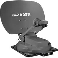
D1 Profi-Line II - Satellite antenna MEGASAT - Free user manual and instructions
Find the device manual for free D1 Profi-Line II MEGASAT in PDF.


| Product Type | Satellite Antenna |
| Brand | Megasat |
| Model | D1 Profi-Line II |
| Dish Diameter | 55 cm |
| Weight | 2.5 kg |
| Material | Aluminum |
| Polarization | Linear |
| Frequency Range | 10.7 - 12.75 GHz |
| Gain | 34 dBi |
| LNB Type | Universal |
| LNB Output | 1 output |
| Power Consumption | < 1 W (passive) |
| Mounting | Wall or tripod |
| Operating Temperature | -20°C to +50°C |
| Waterproof Rating | IP54 |
| Cable Length (included) | 1.5 m |
| Connector | F-type |
| Features | Easy alignment, pre-assembled |
| Maintenance & Cleaning | Clean with damp cloth, avoid solvents |
| Safety | Keep away from power lines, use stable mount |
| Spare Parts & Accessories | LNB, cable, mount available separately |
| Repairability | Modular design, LNB replaceable |
| General Information | Designed for satellite TV reception; compatible with most receivers |
Frequently Asked Questions - D1 Profi-Line II MEGASAT
User questions about D1 Profi-Line II MEGASAT
0 question about this device. Answer the ones you know or ask your own.
Ask a new question about this device
Download the instructions for your Satellite antenna in PDF format for free! Find your manual D1 Profi-Line II - MEGASAT and take your electronic device back in hand. On this page are published all the documents necessary for the use of your device. D1 Profi-Line II by MEGASAT.
USER MANUAL D1 Profi-Line II MEGASAT
natural_image
Diagram showing a satellite projecting to buildings and a small house, with no text or symbols present.Schlechter Empfang:
natural_image
Simple line drawing of a satellite projecting buildings to a small house, with no text or symbols present.natural_image
Simple line drawing of a cloud with raindrops falling (no text or symbols)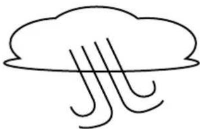
natural_image
Simple line drawing of a cloud with three vertical lines below it, no text or symbols present.
natural_image
Simple line drawing of a cloud with snowflakes falling below (no text or symbols)Regen:
natural_image
Exterior view of a modern office building (no signage)natural_image
Exterior view of a brick wall with a metallic bracket and a white rectangular label featuring the brand name 'HEGAGAT' (no other text or symbols visible)natural_image
Exterior view of a brick wall with a window and a hanging metal bracket labeled 'MEGA CAT' (no other text or symbols visible)natural_image
Exterior view of a rectangular electronic device with a metal bracket and mounting bracket (no text or symbols visible)natural_image
Exterior view of a rectangular electronic device with a metal bracket and mounting holes (no text or symbols visible)natural_image
Exterior view of a rectangular electronic device with mounting bracket and handle (no text or symbols visible)natural_image
Close-up of a metal bracket with labeled part B6, mounted on a brick wall (no text or symbols beyond label)natural_image
Top-down view of a mechanical component with two handles and a central square housing (no visible text or symbols)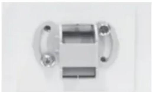
natural_image
Metal mechanical component with flanges and central shaft (no visible text or symbols)
natural_image
Abstract geometric pattern with intersecting gray lines and a central black line (no text or symbols)schlechter Empfang
natural_image
Abstract geometric shape resembling a cross with a horizontal line (no text or symbols)guter Empfang

natural_image
Simple cross-shaped diagram with no text or symbolsbester Empfang

LNB Position

Satellitensignal
| Land | Stadt | Astra 2 | Astra 3 | Astra 1 | Hotbird | Astra 4 | Thor | Hispasat | Eutelsat 5 |
| Bulgarien | Sofia | +1.7 | +6.8 | +11.4 | +11.0 | +19.0 | +24.0 | +41.0 | +27.2 |
| Dänemark | Kopenhagen | -3.4 | -0.4 | +2.5 | -0.3 | +5.3 | +9.1 | +24.8 | +11.6 |
| Finnland | Helsinki | +5.2 | +7.9 | +10.3 | +6.8 | +11.2 | +14.2 | +25.2 | +16.0 |
| Frankreich | Paris | -13.9 | -10.5 | -7.2 | -9.2 | -2.2 | +2.9 | +25.0 | +6.3 |
| Deutschland | Berlin | -4.1 | -0.7 | +2.6 | +0.3 | +6.6 | +10.8 | +27.8 | +13.5 |
| England | London | -13.7 | -10.7 | -7.8 | -10.3 | -4.0 | +0.6 | +21.6 | +3.9 |
| Griechenland | Athen | +1.3 | +7.3 | +12.7 | +13.4 | +22.5 | +28.1 | +45.9 | +31.6 |
| Ungarn | Budapest | -1.3 | +3.0 | +6.9 | +5.6 | +12.8 | +17.5 | +34.7 | +20.5 |
| Italien | Rom | -9.8 | -5.0 | -0.4 | -0.6 | +8.5 | +14.6 | +37.0 | +18.5 |
| Polen | Warschau | +1.5 | +5.1 | +8.4 | +6.1 | +12.2 | +16.2 | +31.0 | +18.8 |
| Portugal | Lissabon | -30.2 | -27.0 | -23.7 | -25.3 | -16.8 | -10.1 | +23.9 | -5.1 |
| Spanien | Madrid | -24.8 | -21.2 | -17.6 | -18.7 | -9.9 | -3.2 | +27.5 | +1.5 |
| Belgien | Brüssel | -11.2 | -7.9 | -4.8 | -7.0 | -0.3 | +4.4 | +24.7 | +9.3 |
| Schweden | Stockholm | +1.1 | +3.8 | +6.4 | +3.0 | +7.8 | +11.0 | +23.8 | +13.0 |
| Schweiz | Bern | -11.3 | -7.5 | -3.8 | -5.2 | +2.4 | +7.8 | +29.5 | +11.4 |
| Österreich | Wien | -3.4 | +0.7 | +4.5 | +3.0 | +10.2 | +15.0 | +32.9 | +18.0 |
7. Fehlerbehebungen
www.megasat.tv/support/downloads
Safety instructions....03
- Scope of delivery and designations 04 - 05
- Selecting a location....06
- Mounting options....08
3.1 Basic mounting of the antenna 09
3.2 Mounting on a mast....10
3.3 Mounting on a wall....11
3.4 Mounting on a window....12
- Prepare and lay coaxial cable....13
- Align the antenna .... 14
- Skew setting....15
- Troubleshooting 16
- Specifications....17
Please read this manual carefully before using this product and follow carefully the installation, mounting and alignment instructions!
- Any electrical or magnetic field near the flat antenna may cause poor reception or even cause the unit to completely lose the signal.
- Do not damage the plastic housing of the antenna. The housing protects the antenna from moisture and weather.
- Make sure that the antenna does not fall to the ground or be subjected to any other impact, as otherwise the electronics inside may be damaged.
- Do not open the housing of the antenna, as this will invalidate the warranty. Leave repairs only to qualified personnel.
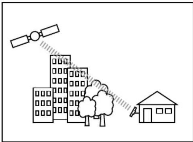
- Obstacles such as buildings, trees, etc. can affect the signal of the satellite and lead to the loss of the signal.
- The antenna cover should always be free of dirt or other substances as this will block the reception of the signal from the satellite.
- The cable between the antenna and the satellite receiver must not be longer than 30m , as this will reduce the quality of the signal.
• Using uninsulated jacks will result in loss of signal level. - Tighten all mounting screws when making adjustments to align the antenna.
- This product contains a universal LNB, it is prohibited to add, replace or modify an LNB.
- Antennas can be easily damaged or misaligned by wind and weather if they are poorly installed or placed in an unsuitable location. The damage can be severe, even life-threatening.
- The owner or installer is responsible to consider all aspects of the installation (weight, wind and ice) and also to make sure that the installation is stable enough and that there are no leaks or leakage.
- The manufacturer is not responsible for any damage that may result from the installation, use or otherwise of this satellite antenna.
1. Scope of delivery and designations
Please check before installation, if all parts are present!
| No. | Part name Symbol Figure Q'ty | |||
| 1 | Antenna A1 | 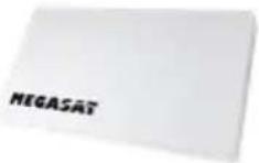 | 1 | |
| 2 | Angle bracket 1 B0 | 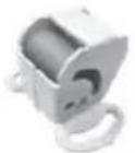 | 1 | |
| 3 | Angle bracket 2 B1 | 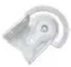 | 1 | |
| 4 | Mounting arm B2 | 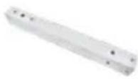 | 1 | |
| 5 | Support B3-1 | 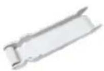 | 1 | |
| 6 | Mounting bracket B3-2 | 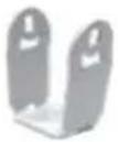 | 1 | |
| 7 | Pole clamp B4 | 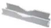 | 2 | |
| 8 | Mounting bracket B5 | 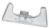 | 1 | |
| 9 | Mounting bracket B6 | 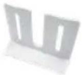 | 1 |
1. Scope of delivery and designations
| No. | Part name Symbol Figure Q'ty | |||
| 10 | Wrench B7 | 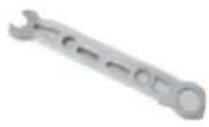 | 1 | |
| 11 | M5 x 12Fixing screw | M1 |  | 4 |
| 12 | M6 x 20Fixing screw | M2 |  | 1 |
| 13 | M8 x 40Fixing screw | M3 |  | 1 |
| 14 | M6 x 45Fixing screw | M4 | 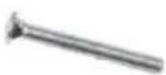 | 5 |
| 15 | M6 x 75Fixing screw | M5 | 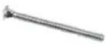 | 4 |
| 16 | Screw nut (M6) M6 |  | 8 | |
| 17 | M6 x 10Fixing screw | M7 |  | 2 |
| 18 | Compass B4 | 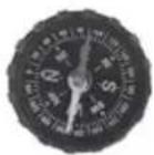 | 1 |
2. Selecting a location
To receive a signal from the satellite, the antenna must be installed outdoors. An installation in the apartment, or through the window is not possible!
Make sure the antenna is facing south at the selected location. Use a compass for rough orientation.
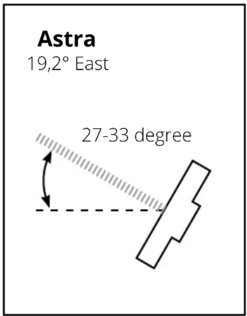
See this example if you want to receive the Astra 1 (19.2° East) satellite in Germany:
Azimuth (horizontal angle) Elevation (ertical angle)
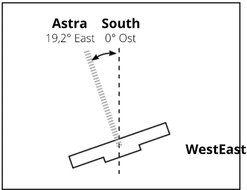
Important note:
Before mounting the antenna, make sure that the appropriate coaxial cable can also be routed to the receiver. The antenna should not be too far from the receiver. The length of the coaxial cable should be max. 30 meters. Longer cables could degrade the signal quality.
2. Selecting a location
Attention:
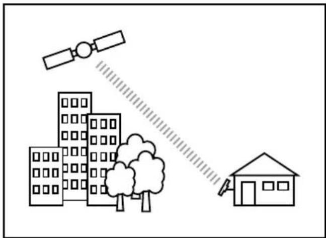
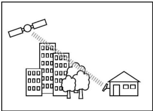
Houses, trees and other tall objects can reduce reception or completely block the signal from the satellite. Also keep in mind that trees can grow and affect reception in some time.
Good reception:
natural_image
Simple line drawing of a satellite projecting to buildings and a house, with no text or symbols present.Bad reception:
natural_image
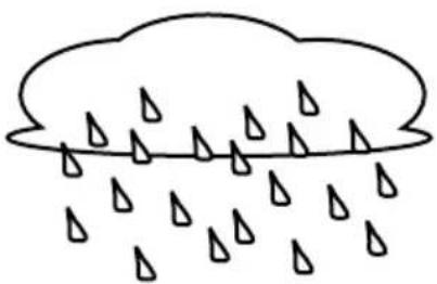
Simple line drawing of a satellite projecting buildings to a small house, with no text or symbols present.Also weather influences can lead to the signal reduction! Heavy rain, wind or snow can cause the signal to be weakened. But this is usually short-lived.
natural_image
Simple line drawing of a cloud with raindrops falling (no text or symbols)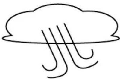
natural_image
Simple line drawing of a cloud with three vertical lines below it, no text or symbols present.
natural_image
Simple line drawing of a cloud with snowflakes falling below (no text or symbols)Rain:
In heavy rain, the satellite signal may temporarily stop. An optimally oriented antenna as well as the shortest possible cable run minimize the risk of such „rain fading“.
Wind:
Make sure that the antenna is securely and securely mounted so that it does not lose its orientation in strong wind or the screws loosen by constantly moving back and forth.
Snow:
Heavy snow accumulation on the antenna can lead to a weaker satellite signal. The snow should be removed from the antenna as soon as possible.
3. Mounting options
There are several ways you can attach the antenna:
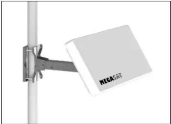
- Mounting on a mast
natural_image
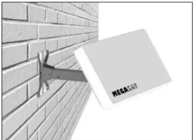
Exterior view of a modern office building (no signage)- Mounting on a wall
natural_image
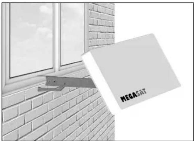
Exterior view of a brick wall with a metal bracket and a white MEGA CAT logo (no other text or symbols visible)- Mounting on a window
natural_image
Exterior view of a brick wall with a window and a hanging object labeled 'MEGA' (no other text or symbols visible)3. Mounting options
3.1 Basic mounting of the antenna
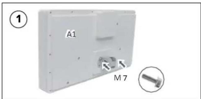
On the back of the antenna (A1), insert the bracket (B0). Fasten it with two M6 x 10 fastening screws (M7).
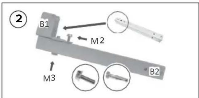
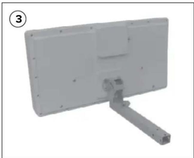
Place the holder (B1) on the mounting arm (B2). Fasten it with an M6 x 20 fastening screw (M2) and an M8 x 40 fastening screw (M3). Do not overtighten the screws so that you can still adjust the antenna alignment angle.
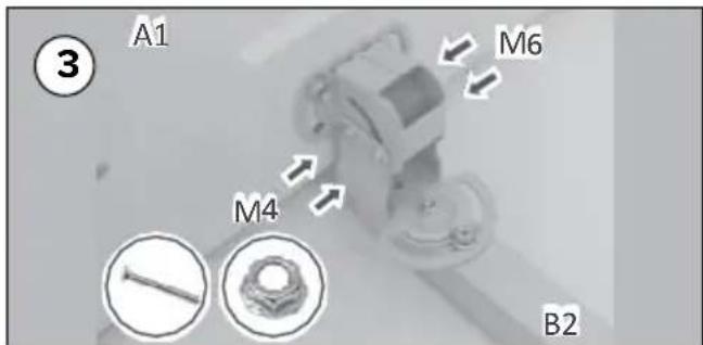
Assemble the holder with the antenna. Fasten them with two M6 x 45 fastening screws (M4) and fix them with one screw nut (M5) each.
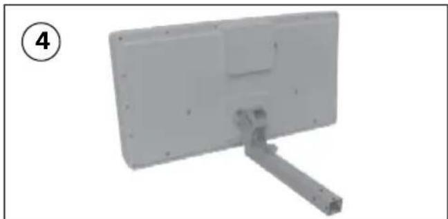
natural_image
Exterior view of a rectangular electronic device with a metal bracket and mounting bracket (no text or symbols visible)The basic assembly of the antenna is now completed.
3. Mounting options
3.2 Mounting on a mast
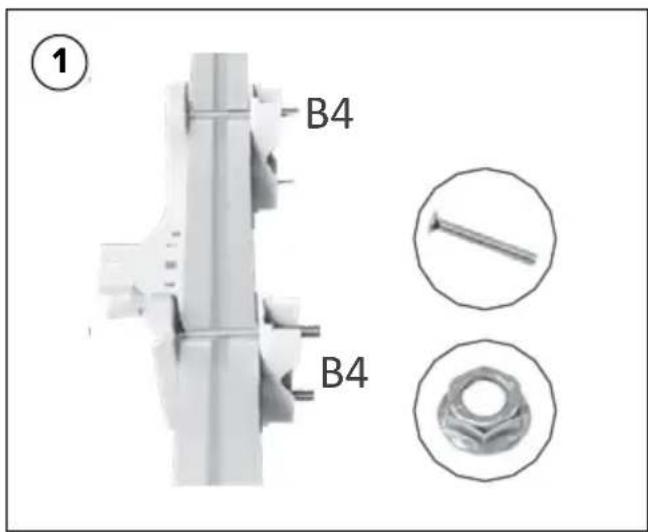
Attach the mast clamps (B4) and the bracket (B5) between the balcony lattice struts. Fasten them with M6 x 75 fastening screws (M5) and fix them with a screw nut (M5) each.
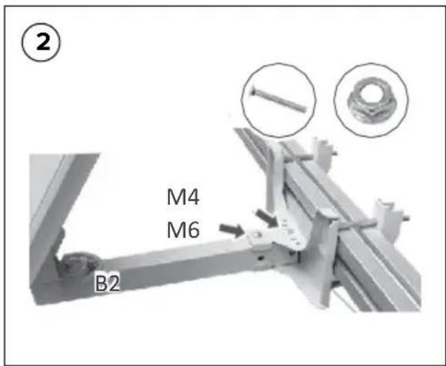
Place the preassembled antenna unit in the holder. Fasten it with two M6 x 45 fastening screws (M4) and the corresponding nuts (M6). Use the wrench (B7) for this purpose.
natural_image
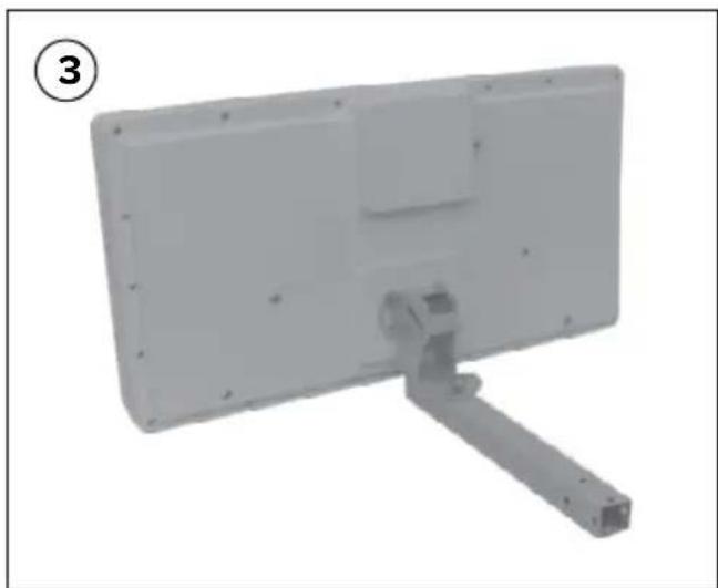
Exterior view of a rectangular electronic device with a metal bracket and mounting holes (no text or symbols visible)After the final position to the satellite is found, you can tighten all screws.
3. Mounting options
3.3 Mounting on a wall
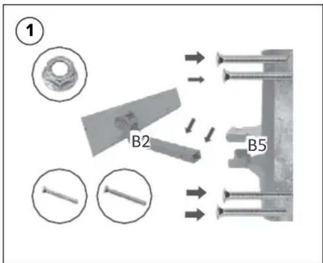
Mount the mounting plate (B5) on a suitable wall. To do this, use suitable screws or dowels to match the wall structure. Place the preassembled antenna unit in the holder. Fasten it with two M6 x 45 fastening screws (M4) and the corresponding nuts (M6).
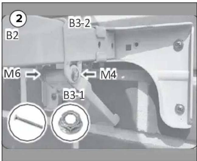
Mount the mounting bracket (B3-2) to the mounting arm (B2). Now attach the support (B3-1). Fasten it with the M6 x 45 fastening screw (M4) and a screw nut (M6).
natural_image
Exterior view of a rectangular electronic device with mounting bracket and handle (no text or symbols visible)After the final position to the satellite is found, you can tighten all screws.
3. Mounting options
3.4 Mounting on a window
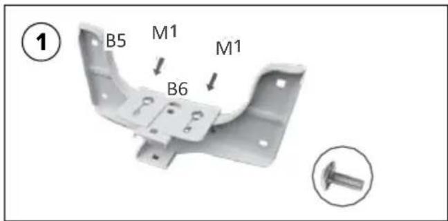
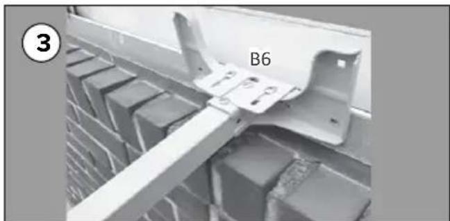
Mount the holder (B6) with the holder (B5). Use two M5 x 12 fastening screws (M1) for this purpose. Do not over-tighten them when screwing them together!
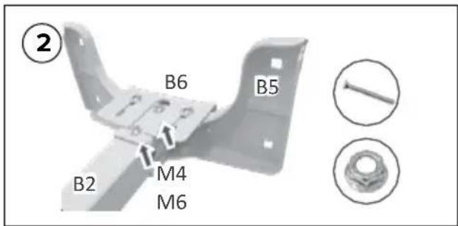
Place the preassembled antenna unit in the holder. Fasten it with two M6 x 45 fastening screws (M4) and the corresponding nuts (M6). Use the wrench (B7) for this purpose.
natural_image
Close-up of a metal bracket with labeled component B6, mounted on a brick wall (no text or symbols beyond label)The bracket (B6) can be adjusted in depth to the window. Hang the complete holder in the window frame and adjust the holder (B6) according to the depth of the frame. Now tighten the fixing screws (M1) firmly.
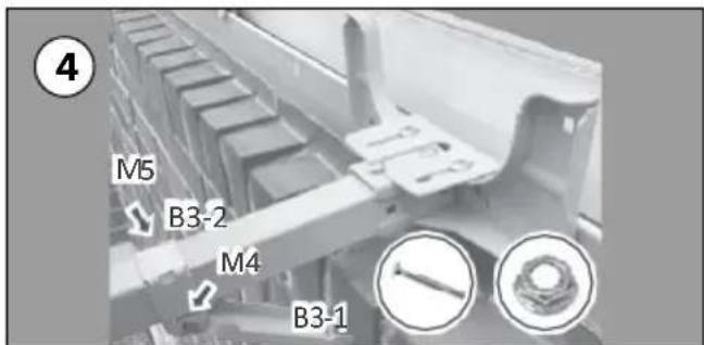
Mount the mounting bracket (B3-2) to the mounting arm (B2). Now attach the support (B3-1). Fasten it with the M6 x 45 fastening screw (M4) and a screw nut (M6).
4. Prepare and lay coaxial cable
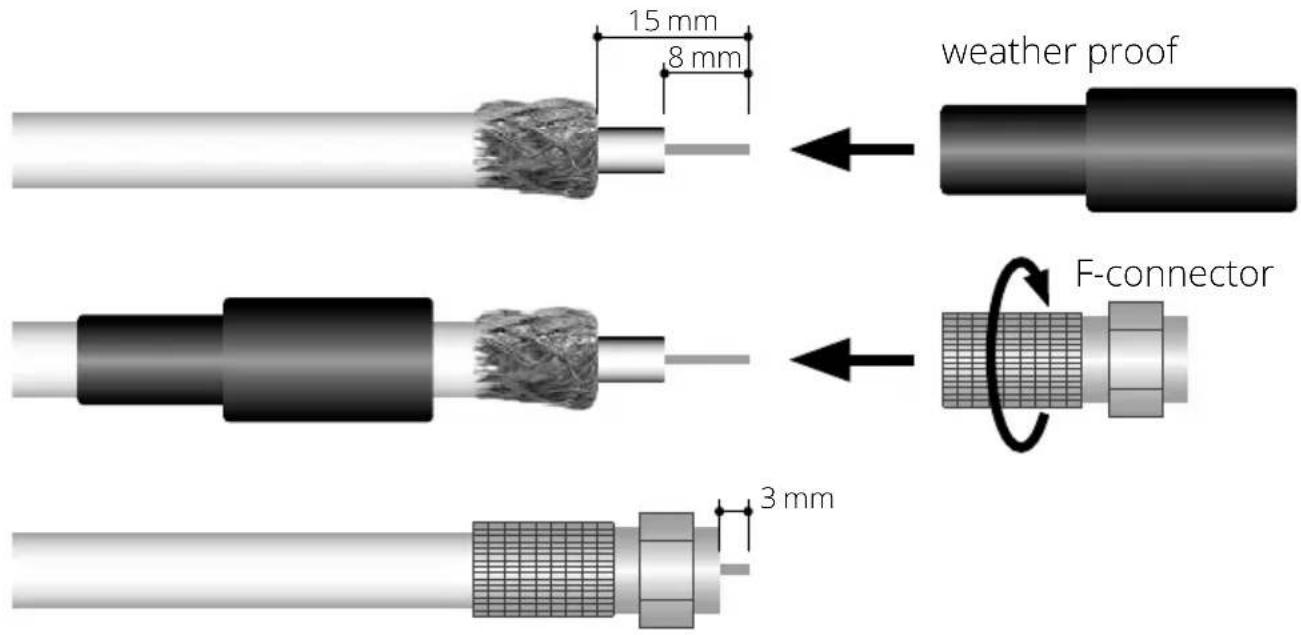
When installing the F-connectors, make sure that they are installed correctly. Failure to correctly install the F connectors may result in signal loss or short circuit. The weather protection is only necessary for the exterior of the antenna.
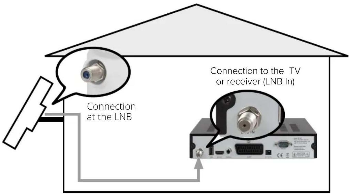
Route the coaxial cable from the antenna to the satellite receiver. Make sure that you do not damage the cable during installation or that there are no kinks. Do not exceed the length of 30 meters, otherwise there may be signal loss. If you would like to lay the cable through a window, please use a suitable window feedthrough.
5. Align the antenna
Satfinder
For orientation via a Sat-Finder, you must connect the Sat-Finder between the antenna and the receiver. Pay attention to the instructions of the Sat Finder for the correct connection and operation.
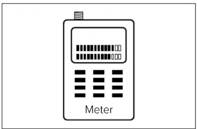
Meter
Via a satellite measuring device, you can set the signal level even more precisely and, if necessary, perform an error analysis. To align the antenna no receiver is needed here. The power supply is provided by the meter alone.
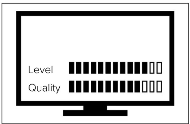
TV-Menu
If you do not have a satellite finder or meter at hand, you can read the signal level and quality from the on-screen menu. Turn and tilt the antenna until the best signal values are achieved.
Note:
After aligning the antenna, tighten all mounting screws.
6. Skew setting
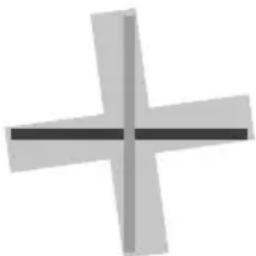
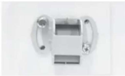
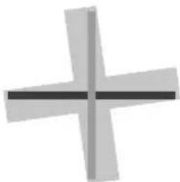
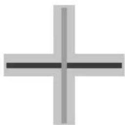
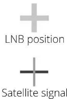
Signals in vertical (red) and horizontal (blue) line have an offset of exactly 90° to each other. Due to the different position of the satellites, depending on your location, it is possible that the signals do not hit the LNB exactly vertically and horizontally. To adjust this, you need to bring the LNB in the correct position to the emitted signal. This adjustment on the LNB is called „skew adjustment“. The following figure shows you the optimal setting of the LNB. The closer the match, the better the reception. Slightly loosen the screws on the back of the antenna. Set the required skew angle and then tighten the screws again.
natural_image
Metal mechanical component with two handles and a central rectangular body (no visible text or symbols)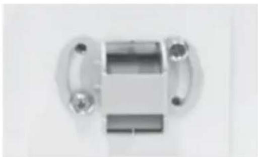
natural_image
Metal mechanical component with cylindrical body and flanges (no visible text or symbols)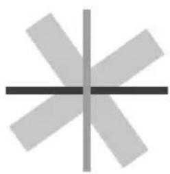
natural_image
Abstract geometric pattern with intersecting lines and shaded segments (no text or symbols)bad reception
natural_image
Abstract geometric shape resembling a cross or plus sign with a horizontal line (no text or symbols)good reception
natural_image
Simple cross-shaped diagram with no text or symbolsbest reception
| Country | City | Astra 2 | Astra 3 | Astra 1 | Hotbird | Astra 4 | Thor | Hispasat | Eutelsat 5 |
| Bulgaria Sofia + | 1.7 +6.8 +11.4 + | 11.0 +19.0 +2 | 4.0 +41.0 +27.2 | ||||||
| Denmark Copenhagen | -3.4 -0.4 | +2.5 -0.3 +5.3 | +9.1 +24.8 +11.6 | ||||||
| Finland Helsinki | +5.2 | +7.9 +10.3 + | 6.8 +11.2 +14.2 +25.2 | +16.0 | |||||
| France Paris | -13.9 | -10.5 -7.2 -9.2 | -2.2 +2.9 +25.0 +6.3 | ||||||
| Germany | Berlin | -4.1 | -0.7 | +2.6 | +0.3 | +6.6 | +10.8 | +27.8 | +13.5 |
| England London | -13.7 | -10.7 -7.8 -1 | 0.3 -4.0 +0.6 | +21.6 +3.9 | |||||
| Greece | Athens | +1.3 | +7.3 | +12.7 | +13.4 | +22.5 | +28.1 | +45.9 | +31.6 |
| Hungary Budapest | -1.3 | +3.0 | +6.9 +5.6 + | 12.8 +17.5 +3 | 4.7 +20.5 | ||||
| Italy | Rome | -9.8 | -5.0 | -0.4 | -0.6 | +8.5 | +14.6 | +37.0 | +18.5 |
| Poland | Warsaw | +1.5 | +5.1 | +8.4 | +6.1 | +12.2 | +16.2 | +31.0 | +18.8 |
| Portugal | Lisbon | -30.2 | -27.0 | -23.7 | -25.3 | -16.8 | -10.1 | +23.9 | -5.1 |
| Spain | Madrid | -24.8 | -21.2 | -17.6 | -18.7 | -9.9 | -3.2 | +27.5 | +1.5 |
| Belgium | Brussels | -11.2 -7.9 | -4.8 -7.0 -0.3 | +4.4 +24.7 +9.3 | |||||
| Sweden Stockholm | holm +1.1 +3.8 | +6.4 +3.0 | +7.8 +11.0 +23.8 | +13.0 | |||||
| Switzerland | Bern | -11.3 -7.5 | -3.8 -5.2 +2.4 | +7.8 +29.5 +11.4 | |||||
| Austria Vienna | -3.4 | +0.7 | +4.5 +3.0 +10.2 | +15.0 +32.9 | +18.0 |
7. Troubleshooting
If you receive a bad or no signal, it may have the following reasons:
- Make sure all cable connections are intact and each connection is properly tightened.
- Check the inside of each F connector for dirt or a possible connector shell.
- Check again the setup of the antenna (horizontal and vertical angle). Possibly, the antenna points you to another satellite.
- Make sure that there are no obstacles such as trees, buildings, windows, corners or overhangs of the roof that can affect the signal.
- An RG 6 cable with a solid copper core conductor is strongly recommended because it has a much lower DC voltage drop compared to an RG 6 cable with a copper-plated steel core conductor.
- Make sure the TV is set to the correct input (eg HDMI 1), depending on which input the receiver is plugged in to.
- Make sure the receiver is turned on and a corresponding station list is loaded for the selected satellite.
8. Specifications
FEATURES
- Input frequency: 10.7 - 12.75 GHz
- Polarization: Linear (vertical / horizontal)
- Antenna gain: 33.7 dBi @ 12.75 GHz
• LNB DVB-S/S2 outputs: 1, 2 or 4
• LNB output frequency: 950 - 1.950 MHz / 1.100 - 2.150 MHz
• L.O. Frequency: 9.75 GHz / 10.6 GHz - LNB Gain: 60 dB
• Gain Flatness: ±0.5 dB / 26 MHz
• Power supply: 12 - 14 V DC (V) / 16 - 19 V DC (H)
• Power consumption: max. 130 mA - Operating temperature: -20^ C to +60^ C
• Storage temperature: -40^ C to +80^ C
OTHER
• Dimensions: 530 x 295 x 90 mm
- Weight: 5.1 kg
Conformity information
Hereby, Megasat Werke GmbH declares that the following product is in compliance with the essential requirements and other relevant provisions of directives 2014/30/EU (EMC), 2014/35/EU (LVD) and 2014/53/EU (RED):
Flat antenna D1 Profi-Line II (Art-No. 200213)
Flat antenna D2 Profi-Line II (Art-No. 200214)
Flat antenna D4 Profi-Line II (Art-No. 200215)
The declaration of conformity for this product is located at the company: Megasat Werke GmbH, Industriestraße 4a, D-97618 Niederlauer
The declaration of conformity can be downloaded from our homepage: www.megasat.tv/support/downloads
Version 1.1 (July 2021) // Technical changes, printing errors and errors reserved.
- Regen:
- Fehlerbehebungen
- Scope of delivery and designations
- Selecting a location
- Azimuth (horizontal angle) Elevation (ertical angle)
- Important note:
- Attention:
- Rain:
- Wind:
- Snow:
- Mounting options
- Basic mounting of the antenna
- Mounting on a mast
- Mounting on a wall
- Mounting on a window
- Prepare and lay coaxial cable
- Align the antenna
- Satfinder
- Meter
- TV-Menu
- Note:
- Skew setting
- Troubleshooting
- Specifications
- FEATURES
- OTHER
- Conformity information
Brand : MEGASAT
Model : D1 Profi-Line II
Category : Satellite antenna