
i-MiEV (2016) - Automotive MITSUBISHI - Free user manual and instructions
Find the device manual for free i-MiEV (2016) MITSUBISHI in PDF.


| Product Type | Electric Vehicle |
| Brand | Mitsubishi |
| Model | i-MiEV (2016) |
| Category | Automotive |
| Length | 3395 mm |
| Width | 1475 mm |
| Height | 1600 mm |
| Wheelbase | 2550 mm |
| Curb Weight | 1080 kg |
| Battery Capacity | 16 kWh (lithium-ion) |
| Driving Range (NEDC) | 150 km |
| Motor Power | 49 kW (67 hp) |
| Motor Torque | 196 Nm |
| Charging Time (240V) | 6 hours (full charge) |
| Charging Port | Type 1 (SAE J1772) |
| Top Speed | 130 km/h |
| Number of Seats | 4 |
| Safety Features | Airbags (front, side), ABS, ESC, Traction Control |
| Maintenance | Regular tire pressure checks, battery health monitoring, brake fluid replacement every 2 years |
| Cleaning | Use mild soap and water; avoid pressure washers on electrical components |
Frequently Asked Questions - i-MiEV (2016) MITSUBISHI
User questions about i-MiEV (2016) MITSUBISHI
0 question about this device. Answer the ones you know or ask your own.
Ask a new question about this device
Download the instructions for your Automotive in PDF format for free! Find your manual i-MiEV (2016) - MITSUBISHI and take your electronic device back in hand. On this page are published all the documents necessary for the use of your device. i-MiEV (2016) by MITSUBISHI.
USER MANUAL i-MiEV (2016) MITSUBISHI
| Overview | 1 |
| Quick index | 2 |
| General information/Charging | 3 |
| Seat and restraint systems | 4 |
| Features and controls | 5 |
| Driving safety | 6 |
| Comfort controls | 7 |
| For emergencies | 8 |
| Vehicle care and maintenance | 9 |
| Customer assistance/Reporting Safety Defects | 10 |
| Specifications | 11 |
| Alphabetical index | 12 |
Instruments and controls (Driver's area)
Instruments and controls (Driver's area)
NDD100202632
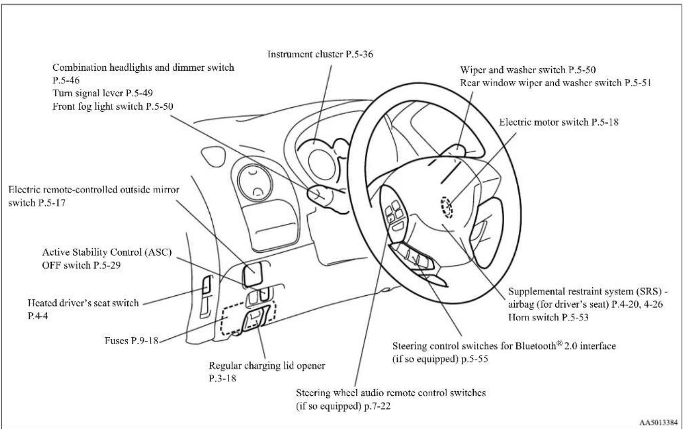
1-1 Overview
Instruments and controls (Instrument panel)
N00113202645
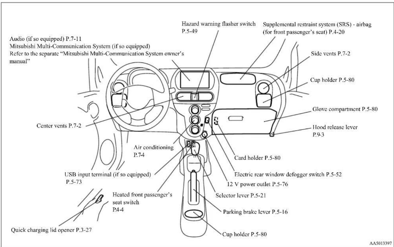
Overview 1-2
Interior
Interior
NDD100302569
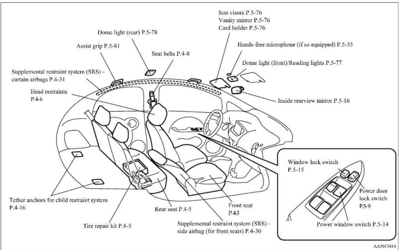
1-3 Overview
Under the hood/Electric motor unit room
N0013800041
Under the hood Electric motor unit room
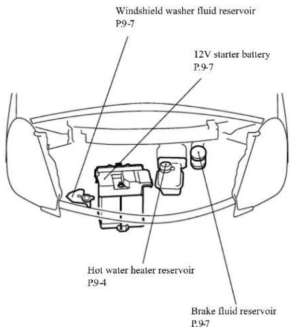
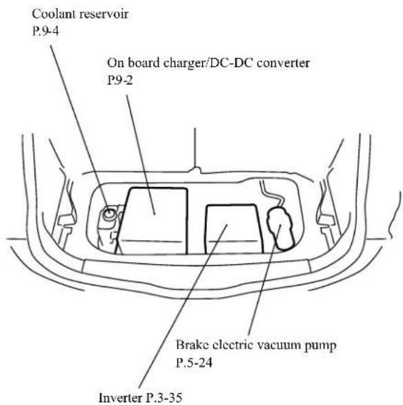
AA5013427
Overview 1-4
Outside (Front)
Outside (Front)
N00100602450
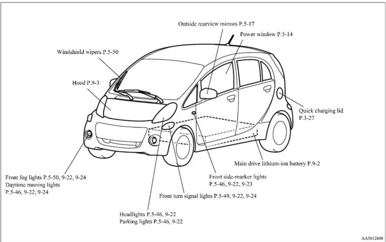
1-5 Overview
Outside (Rear)
N00130601352
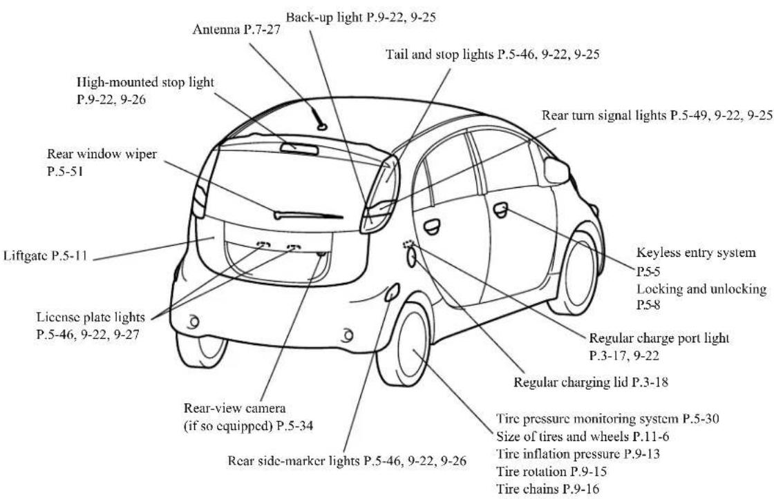
AA5013401
Overview 1-6
| 100% | |
| 100% | 100% |
| 100% | 100% |
| 100% | 100% |
| 100% | 100% |
| 100% | 100% |
| 100% | 100% |
| 100% | 100% |
| 100% | 100% |
| 100% | 10 |
If this warning light comes on or flashes while you're driving...
If this warning light comes on or flashes while you're driving...
N(021)702221

NOTE
- These warning lights will come on for a few seconds for a bulb check when the electric motor switch is first turned to "ON".
| Warning light Do this Ref. page | ||
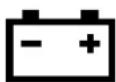 12V starter battery charging system warning light 12V starter battery charging system warning light | ● Park your vehicle in a safe place and turn off the electric motor unit. Contact a certified i-MiEV dealer for assistance. | P.5-45 |
 Brake warning light Brake warning light | ● If this light comes on while driving, check to see that the parking brake is fully released.● If this light stays on after releasing the parking brake, stop and check the brake fluid level.● If the brake fluid level is correct, there may be a system malfunction. Avoid hard braking and high speeds, and contact a certified i-MiEV dealer for assistance. | P.5-44 |
 Electric motor unit warning light Electric motor unit warning light | ● Park your vehicle in a safe place and contact a certified i-MiEV dealer for assistance. | P.5-45 |
If this warning light comes on or flashes while you're driving...
| Warning light Do this Ref. page | ||
 Electric power steering system (EPS) warning light Electric power steering system (EPS) warning light | ● If this light comes on while the electric motor unit is running, it may become harder to turn the steering wheel. Have your vehicle inspected at a certified i-MiEV dealer as soon as possible. | P5-28 |
 Anti-lock braking system warning light Anti-lock braking system warning light | ● When this light comes on, the anti-lock braking system is not functioning and only the ordinary braking system is functioning.● Park your vehicle in a safe place and stop the electric motor unit. Test the system as described on page 5-27.● If the light does not go out after the test, or if it comes on again, we recommend that you have the system checked at a certified i-MiEV dealer as soon as possible. | P.5-26, 5-27 |
 SRS warning light SRS warning light | ● Immediately have the airbag and the seat belt pre-tensioner system checked at a certified i-MiEV dealer. | P.4-13, 4-26 |
 Power down warning light Power down warning light | ● If this light comes on while driving, avoid sudden acceleration and sudden starting.● When the remaining power in the main drive lithium-ion battery is low, recharge the main drive lithium-ion battery as soon as possible. | P5-46 |
2-2 Quick index
If this warning light comes on or flashes while you're driving...
| Warning light Do this Ref. page | ||
 Selector lever position indicator in the instrument cluster flashes slowly Selector lever position indicator in the instrument cluster flashes slowly | Have the transmission checked at a certified i-MiEV dealer as soon as possible. | P.5-21 |
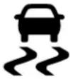 and and  ASC indicator and ASC OFF indicator ASC indicator and ASC OFF indicator | Park your vehicle in a safe place and turn off the electric motor unit.Restart the electric motor unit and check to see if the indicator comes on again.If the indicator does not go out, or if it comes on again, have your vehicle inspected at a certified i-MiEV dealer as soon as possible.When this indicator comes on, the active stability control is not functioning and normal operation of the vehicle will not be affected. | P.5-30 |
 Tire pressure monitoring system warning light Tire pressure monitoring system warning light | If the warning light comes on, you should stop and adjust the tires to the proper inflation pressure as soon as possible.(See “Tire inflation pressures” on page 9-13.)Once adjustments have been made, the warning light will go off after a few minutes of driving.If the warning light blinks for approximately 1 minute and then remains continuously illuminated, the system is not operating properly. If the system returns to normal, the warning light will go off. If the warning light does not go off, have the vehicle inspected at a certified i-MiEV dealer. | P.5-31, 5-32 |
If this problem occurs...
If this problem occurs...
ND02(09)1923
| Problem Do this Ref. | Page | |
Cannot turn the key. From “LOCK” 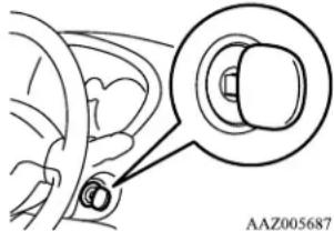 | to “ACC”.Turn the key while turning the steering wheel in either direction.From “ACC” to “LOCK”.Check the position of the selector lever.The key cannot be removed unless the selector lever is set to the “P” (PARK) position. | P.5-19, 5-20 |
| Cannot shift the selector lever from the “P” (PARK) position. | Shift the selector lever while pressing the brake pedal.Check that the electric motor switch is in the “ON” position. | P.5-21 |
The windows are fogged up.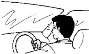 | 1. Set the mode selection dial to the “or ” position.2. Turn on the blower. | P.7-9 |
| The electric motor unit does not start.The lights do not come on.The lights are dim.The horn does not honk.The horn sound is weakCannot charge the main drive lithium-ion battery. | Have the 12V starter battery checked. Recharge or replace as needed. | P.8-2, 9-7 |
2-4 Quick index
If this problem occurs...
| Problem Do this Ref. Page | ||
| The vehicle is stuck in sand, mud, or snow. | Rock your vehicle back and forth to free it. P.8-13 | |

WARNING
- When attempting to rock your vehicle out of a stuck position, be sure that no one is near the vehicle. The rocking motion may cause the vehicle to suddenly lurch forward or backward, possibly injuring bystanders.
- Avoid spinning the wheels. Prolonged efforts to free a stuck vehicle may result in transmission failure.
If the vehicle remains stuck after several rocking attempts, have a towing service pull the vehicle out.
| Problem Do this Ref. page | ||
| The brakes are not functioning properly after driving through water. | Dry out the brakes by driving slowly while lightly pressing the brake pedal. P.6-5 | |
A tire is punctured.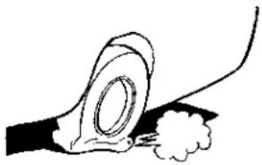 | 1. Park the vehicle in a safe place where the surface is flat and level.2. Repair the flat tire with tire repair kit. | P.8-5 |
| 100% | |
| 100% | 100% |
| 100% | 100% |
| 100% | 100% |
| 100% | 100% |
| 100% | 100% |
| 100% | 100% |
| 100% | 100% |
| 100% | 100% |
| 100% | 10 |
General information/Charging
Familiarizing yourself with i-MiEV 3-2
Modifications to and racing of your vehicle 3-6
Mitsubishi Motors genuine parts 3-8
California Perchlorate Materials Requirements 3-8
Cautions and actions to deal with intense heat 3-8
Cautions and actions to deal with intense cold 3-10
Charging 3-13
Precautions during Charging the
Main Drive Lithium-ion Battery 3-15
Regular charging
(charging method with rated AC 120 V outlet) ....3-16
EV charging cable 3-23
Regular charging
(using 240 V Electric Vehicle Supply Equipment) ....3-26
Quick charging
(charging method with quick charger) 3-27
Charging troubleshooting guide 3-31
High-Voltage components 3-34
MiEV Remote System 3-36
Familiarizing yourself with i-MiEV
N01200100013
i-MiEV is a pure electric vehicle. Some of the vehicle systems operate differently from and have different characteristics than ordinary vehicles equipped with an internal combustion engine. For this reason, it is very important to read carefully this entire owner's manual.
Main features
No1200200027
- i-MiEV is powered only by electricity. This vehicle does not emit exhaust gases, such as carbon dioxide and nitrogen oxide.
- The i-MiEV uses electricity stored in the lithium ion battery. The lithium-ion battery is called the main drive lithium-ion battery. This vehicle does not have an internal combustion engine and does not require gasoline or diesel fuel.
- The main drive lithium-ion battery must be charged with electricity to drive the vehicle. As the vehicle operates, the main drive lithium-ion battery gradually discharges. If the main drive lithium-ion battery becomes completely discharged, the vehicle will not operate until it is recharged. The charging process can take up to 23 hours as described more precisely in this manual.
● This vehicle uses two types of batteries.
One is 12V starter battery that is the same type of the battery used in ordinary vehicles. It is called the 12V starter battery. The other battery which propels the vehicle is called the main drive lithium-ion battery.
● The 12V starter battery provides power to the vehicle systems and features such as the audio system, supplemental restraint systems, headlights and windshield wiper.
- The main drive lithium-ion battery provides power to the electric motor that propels the vehicle and charges the 12V starter battery.
- Through a process called regenerative braking, the main drive lithium-ion battery is automatically charged, while the vehicle is decelerating or being driven downhill.

NOTE
- If the 12V starter battery is discharge, the electric motor unit cannot be started. And also the main drive lithium-ion battery cannot be charged.

WARNING
- Pay special attention to pedestrians. Because there is no engine noise, pedestrians may not know the vehicle is approaching and may step into the path of vehicle travel. Refer to "Acoustic vehicle alerting system (AVAS)" on page 5-23.
- When leaving the vehicle, always turn off the electric motor switch. Refer to "Electric motor switch" on page 5-18.
- When parking, to avoid unintended vehicle movement, always move the selector lever to "P" (PARK) position and apply the parking brake because the vehicle can move when the ready indicator light is ON. When the ready indicator light is ON, do not leave the selector lever in a position other than the "P" (PARK) position. For the ready indicator, refer to "Indicator and warning light package" on page 5-43.

WARNING
- Keep the brake pedal depressed until you are ready to drive. When the vehicle is in the "D" (DRIVE), "ECO" (ECO MODE), "B" (REGENERATIVE BRAKE MODE) or "R" (REVERSE) position, if you release the brake pedal and even if you do not depress accelerator, the vehicle will creep and may move slowly.
Regenerative braking
N01205601036
Motion energy is converted into electric energy using the motor as a power generator. While decelerating, electric energy will be created and used to charge to the main drive lithium-ion battery.
- If you lift your foot off the accelerator pedal while driving, a braking force that equivalent to the engine braking of a gasoline or diesel powered vehicle engine vehicle will be generate.
For increased regenerative braking, set the selector lever to "B" (REGENERATIVE BRAKE MODE) or "ECO" (ECO MODE) as follows: - "B": Strong regenerative braking (For downhill driving)
-
“ECO”: Moderate regenerative braking (For economical driving or gentle downhill driving)
-
As greater brake force is applied by depressing the brake pedal, increased regenerative braking occurs.
- When regenerative braking produces strong brake force, the stop lights will illuminate, even if the brake pedal is not depressed.

NOTE
- When the main drive lithium-ion battery level is full or nearly full, or the main drive lithium-ion battery temperature is too high or too low, the regenerative braking force may be reduced and stronger service brake effort may be required to operate the brakes. When the main drive lithium-ion battery level is no longer full or near full, or the main drive lithium-ion battery temperature has returned to a normal range, the regenerative brake force will resume.
- If a problem occurs in the electric motor unit or if the ABS and/or the ASC have been activated, the regenerative braking will be restricted. The service brakes will still operate.
Main drive lithium-ion battery
N01200300015

WARNING
- The main drive lithium-ion battery is sealed high voltage battery and has no user serviceable parts.
- To avoid severe burns and/or electrical shock that may result in serious injury or death, never attempt to detach the main drive lithium-ion battery from the vehicle or try to disassemble it.
- Never attempt to dispose or recycle the main drive lithium-ion battery by yourself. Consult with a certified i-MiEV dealer, when the main drive lithium-ion battery is disposed or recycled.
- Never attempt to use the main drive lithium-ion battery for any other purpose.

CAUTION
- To help prevent damage to the main drive lithium-ion battery, follow the instructions described below. Failure to do so can result in damage to the main drive lithium-ion battery that will not be covered by the main drive lithium-ion battery warranty.
- Do not leave your vehicle with the energy level gauge (Refer to "Energy level gauge" on page 5-41) showing 0 bars.
Familiarizing yourself with i-MiEV
CAUTION
• Repeatedly performing quick charging can reduce battery capacity. Regular charging is recommended unless quick charging is necessary.
- Do not store your vehicle at ambient temperatures above 131 °F (55 °C) for over 24 hours, or below
-13 °F (-25 °C) for over 7 days. The temperatures may damage the main drive lithium-ion battery.
NOTE
- It is recommended that your vehicle be stored at temperatures below 77 °F (25 °C) to help maximize the life of the main drive lithium-ion battery.
Decrease of battery capacity
N01205500012
- The capacity of the lithium-ion battery used as the main drive lithium-ion battery on your i-MiEV, like other commonly used lithium ion batteries, will decrease according to time and usage. This type of decrease in battery capacity is normal, and is not indicative of any defect or failure in your main drive lithium-ion battery. As the main drive lithium-ion battery capacity decreases, the initial cruising range of the vehicle will similarly decrease.
- Mitsubishi Motors estimates that after 5 years, the capacity of the main drive lithium-ion battery provided with your vehicle will be approximately 80% of the original capacity. After 10 years, the capacity should be approximately 70% of the original capacity. These are only estimates, and the actual capacity of your vehicle battery over time will depend on a variety of factors including how your vehicle is used, stored and charged. Factors that can adversely affect battery capacity over time include frequent driving using aggressive acceleration/deceleration, repeated frequent use of the quick charger, and operation/storage in extreme temperature environments.
- The main drive lithium-ion battery has a limited service life, and when its charging capacity falls, owners should bring their vehicle to a certified i-MiEV dealer for inspection and possible battery replacement.
- For details regarding the warranty coverage for the main drive lithium-ion battery, refer to the Warranty and Maintenance Manual.
NOTE
- To help maintain the capacity of the main drive lithium-ion battery, the following are recommended:
NOTE
- Fully charge the vehicle by regular charging every 2 weeks.
- Do not repeat charging when the main drive lithium-ion battery is at or near full charge.
Cruising range
N01200400016
The distance you can drive the vehicle (cruising range) depends on a number of factors including available charge, weather, temperature, usage, battery age, topography, and driving style. When the main drive lithium-ion battery is new, the estimated cruising range with a fully charged main drive lithium-ion battery is 62 miles (100 km) based on the EPA laboratory test commonly called the combined range. Your actual range can vary, either initially or as the battery ages and with use over time.
As the main drive lithium-ion battery capacity decreases, the cruising range of the vehicle will similarly decrease. Refer to "Decrease of battery capacity" on page 3-4.
NOTE
- Since cooling or heating consumes power from the main drive lithium-ion battery, operation of these functions will reduce the cruising range.
3-4 General information/Charging

NOTE
- Put the selector lever in the "B" (REGENERATIVE BRAKE MODE) or "Eco" (ECO MODE) position according to the road condition. Using appropriate regenerative braking can help increase the cruising range. Refer to "Regenerative braking" on page 3-3.
Range-Driving conditions
NO1205900016
| Shorten driving range |  | Lengthen driving range | |
| Range Reducing Condition Range Extending | |||
| High acceleration, speed Driving style Low acceleration, speed | |||
| Heater on Heater usage | Heater off (or use seat heater) | ||
| A/C on A/C usage A/C off | |||
| Highway City/Highway City | |||
| Heavy payload Payload Light payload | |||
| Windy, wet | Weather | Calm, dry | |
| Uphill, rough | Road conditions | Flat/Downhill, smooth | |
| D-mode | Drive mode | (Eco or B mode) | |
Operating sound under charging or Remote Climate Control
N01206300020
While charging, even if the electric motor switch is in the "LOCK" position, you may hear operating sounds such as sounds from the cooling fan and air conditioning compressor when operating the main drive lithium-ion battery cooling system or Remote Climate Control.
This is normal.
Refer to "Remote Climate Control" on page 3-36, 3-47.
For persons with electro-medical apparatus such as implantable cardiac pacemaker or implantable cardiovascular defibrillator
N01206400021
WARNING
- Before charging, read the instructions described below carefully and follow them. Also read and follow the instructions for "Regular charging (charging method with rated AC 120 V outlet)" on page 3-16, "Regular charging (using 240 V Electric Vehicle Supply Equipment)" on page 3-26, and "Quick charging (charging method with quick charger)" on page 3-27.
- Before charging, individuals using an electro-medical apparatus such as implantable pacemakers and implantable cardiovascular-defibrillators should check with the manufacturer of the apparatus to confirm the effect of the electromagnetic waves from charging. The electromagnetic waves may affect the operations of the electro-medical apparatus.
WARNING
- When performing regular charging, keep your electro-medical apparatus, such as implantable cardiac pacemaker or implantable cardiovascular defibrillator, away from the charge connector, EV charging cable, control box or regular charging station.
- Do not perform quick charging and keep away from a quick charger. Electromagnetic waves produced by a quick charger may affect the operation of your electric-medical apparatus. If you have accidentally approached a quick charger, walk away from the quick charger immediately. If quick charging is necessary, ask someone for help.
● While charging;
- Do not stay inside the vehicle.
- Do not go inside the vehicle, for example to remove or place an item in the passenger compartment.
- Do not open the liftgate, for example to remove or place an item in the cargo area.
Modifications to and racing of your vehicle
N01200500017
This vehicle should not be modified with non-Mitsubishi Motors genuine parts. Mitsubishi Motors designs and manufactures
high quality vehicles with an emphasis on safety and durability. Modifications using non-Mitsubishi Motors genuine parts may affect the performance, safety and/or durability of your vehicle, and may violate applicable state and/or federal regulations.
DAMAGE OR PERFORMANCE PROBLEMS RESULTING FROM MODIFICATIONS TO OR RACING OF YOUR VEHICLE ARE NOT COVERED UNDER WARRANTY.
Examples of modifications to your vehicle that can cause damage or performance problems include the following:
● Failure to use Mitsubishi Motors genuine parts
- Failure to use required fluids (refer to "Refill capacities" on page 11-7)
● Failure to use proper size tires and wheels
- Modification of the suspension, electric motor, drive train, batteries (main drive lithium-ion battery and 12V starter battery), charging systems or electrical wiring systems
- Modification of any onboard computer/control module, including reprogramming, or replacing/adding chips to any onboard computer/control module
Review the Warranty and Maintenance Manual for further details regarding warranty coverage.
Installation of accessories
N01200600018
CAUTION
- Before any electrical or electronic accessories are installed, consult a certified i-MiEV dealer.
- The installation of accessories, optional parts, etc., should only be carried out within the limits prescribed by law in the driving area and in accordance with the guidelines and warnings contained within the documents accompanying this vehicle. Only Mitsubishi Motors approved accessories should be fitted to your vehicle.
- Improper installation of electrical parts could cause fire. Refer to the “Modification/alterations to the electrical systems” section within this owner’s manual.
- Tires and wheels which do not meet specifications must not be used.
Refer to the “Specifications” section for information regarding wheel and tire sizes.
WARNING
- If you choose to use a cellular phone while driving, you must not allow that usage to distract you in the safe operation of your vehicle. Anything, including cellular phone usage, that distracts you from the safe operation of your vehicle increases your risk of an accident. Refer to and follow all local laws in your area regarding cellular phone usage while driving.
Important point!
Due to the large number of accessory and replacement parts provided by different manufacturers in the market, it is not always possible for a certified i-MiEV dealer to check whether the attachment or installation of non-Mitsubishi Motors genuine parts will affect the driving safety of your Mitsubishi-vehicle.
Modification/alterations to the electrical systems
N01200700019
Mitsubishi Motors manufactures high quality vehicles with an emphasis on safety. It is important to consult a certified i-MiEV dealer before installation of any accessory which
may involve modification of the electrical systems.
CAUTION
- Please consult a certified i-MiEV dealer concerning any such accessory fitment or modification.
If the wires interfere with the vehicle body or improper installation methods are used (protective fuses not included, etc.), electronic devices may be adversely affected, resulting in a fire, vehicle damage, or other accident.
Mitsubishi Motors genuine parts
N01200800010
Mitsubishi Motors Genuine Parts are designed and manufactured to meet high standards of performance, and are recommended for all of your maintenance needs. Also available from a certified i-MiEV dealer are a wide variety of accessories to personalize your new vehicle. Each Mitsubishi vehicle has a selection of Mitsubishi Motors authorized accessories to choose from to tailor your new vehicle to your own personal preference. A certified i-MiEV dealer's Parts Manager has information on various audio systems, protection items, as well as interior and exterior accessories available for your specific model.
California Perchlorate Materials Requirements
N01200900011
Certain components of this vehicle, such as airbag modules, seat belt pretensioners, and button cell batteries, may contain perchlorate materials.
Special handling may apply. For additional information, see www.dtsc.ca.gov/hazardous-waste/perchlorate.
Cautions and actions to deal with intense heat
N01201001045
- When the vehicle is driven in a high ambient temperature, its air-conditioner performance can be insufficient. Also, using the air conditioner will reduce the vehicle's cruising range.
- When the ambient temperature is approximately 104^ (40 °C) or higher, the phenomena described below may occur. Please take the described actions.
- Even if the ambient temperature is approximately 104^ (40 °C) or lower, when performing quick charging, driving at high-speed and uphill repeatedly, the phenomena described below may occur. Please take the described actions.
Cautions and actions to deal with intense heat
| Approx. ambient temperature | Phenomena Corrective action | ||
| Approx. 104 °F (40 °C) or higher | Startup and driving • | During quick charging, repeated high-speed driving, or repeated uphill driving, the power down warning light* comes on and the motor output is restricted to protect the main drive lithium-ion battery or motor (electric motor unit).• Regenerative braking performance may decrease. When braking, depress the brake pedal more strongly. | • Stop the vehicle in a safe place for a while, avoid quick charging, and wait for the power down warning light* to go off. |
| • If you continue driving after the power down warning light* comes on, the vehicle may stop after you have driven a few miles/kilometres. | |||
| Charging and battery | • During quick charging, charging times get longer. | ||
| Approx.113 °F (45 °C) or higher | Startup and driving • | During quick charging, repeated high-speed driving, or repeated uphill driving, the power down warning light* comes on and the motor output is restricted to protect the main drive lithium-ion battery and/or motor (electric motor unit).• Regenerative braking performance may decrease. When braking, depress the brake pedal more strongly. | • Stop the vehicle in a safe place for a while, avoid quick charging, and wait for the power down warning light* to go off. |
| • If you continue driving after the power down warning light* comes on, the vehicle may stop after you have driven a few miles/kilometres. | |||
| Charging and battery • | The EV charging cable (regular charging cable) cannot be used.• During quick charging, charging times get longer. | • Park in a safe, well-ventilated and shady place. | |
| • The main drive lithium-ion battery capacity is decreased more quickly, and the cruising range is decreased. | |||
General information/Charging 3-9
Cautions and actions to deal with intense cold
| Approx. ambient temperature | Phenomena Corrective action | ||
| Approx. 140 °F (60 °C) or higher | Startup and driving | The power down warning light* comes on, and the vehicle may stop. | Park in a safe, well-ventilated and shady place, avoid quick charging, and wait for the power down warning light* to go off. |
| Charging and battery | The EV charging cable (regular charging cable) cannot be used.Quick charging may become impossible. | Park in a safe, well-ventilated and shady place. | |

NOTE
●*: Refer to "Power down warning light" on page 5-46. Illumination of the power down warning light does not indicate a malfunction.
Cautions and actions to deal with intense cold
N01201101033
- When the vehicle is driven in a low ambient temperatures, its heater performance can be insufficient. Also, using the heater can reduce the vehicle's cruising range.
- When the ambient temperature is approximately 5^ (-15 °C) or lower, the phenomena described below may occur. Please take the corrective actions described below.
3-10 General information/Charging
Cautions and actions to deal with intense cold
| Approx. ambient temperature | Phenomena Corrective action | ||
| Approx.5 °F (-15 °C) or lower | Startup and driving | • Motor output is restricted, and the power down warning light*1 may come on.<Reference: When the main drive lithium-ion battery temperature is 5 °F (-15 °C) or lower and the main drive lithium-ion battery's remaining power is 50 %, the driving performance may decrease by approximately 30 %> | • Keep driving if you can drive at a safe speed.If you cannot drive at a safe speed, stop the vehicle in a safe place and charge the main drive lithium-ion battery. |
| • Regenerative braking performance may decrease. • When braking, depress the brake pedal more strongly. | |||
| Charging and battery | • Charging times get longer.• Complete charging may not be possible. | • When you have finished driving, charge the main drive lithium-ion battery before battery temperature falls. | |
| Approx.-13 °F (-25 °C) or lower | Startup and driving | • Motor output is restricted, and the power down warning light*1 may come on.<Reference: When the main drive lithium-ion battery temperature is -13 °F (-25 °C) or lower and the main drive lithium-ion battery's remaining power is 50 %, the driving performance may decrease by approximately 50 %> | • Keep driving if you can drive at the same speed as surrounding vehicles. If you cannot drive the same speed as surrounding vehicles, stop the vehicle in a safe place and charge the main drive lithium-ion battery. |
| • Regenerative braking performance may decrease or be eliminated. | • When braking, depress the brake pedal more strongly. | ||
| Charging and battery | • Charging may become impossible. • When you have finished driving, charge the main drive lithium-ion battery before battery temperature falls. | ||
General information/Charging 3-11
Cautions and actions to deal with intense cold
| Approx. ambient temperature | Phenomena Corrective action | ||
| Approx. -22 °F (-30 °C) or lower | Startup and driving | The ready indicator*2 does not come on, and startup may not be possible.In the worst-case scenario, the vehicle may become undrivable (with the energy level gauge and cruising range indications still shown). | In the daytime, wait for the temperature to rise. When the temperature in the vicinity of the main drive lithium-ion battery has risen, start up. |
| Regenerative braking performance may decrease or be eliminated. | When braking, depress the brake pedal more strongly | ||
| Charging and battery | Charging may become impossible • In the daytime, wait for the temperature to rise. When the temperature in the vicinity of the main drive lithium-ion battery has risen, begin charging. | ||

NOTE
-
- Refer to "Power down warning light" on page 5-46. Illumination of the power down warning light does not indicate a malfunction.
- ^2* : Refer to "Ready indicator" on page 5-44.
Charging
N012012011047
Your vehicle comes standard with a charge port and charging cable (EV charging cable) that uses a household outlet (AC 110-120V) as a charging source. You may also charge your vehicle using an i-MiEV compatible 220-240V charging device (EVSE ^1 - available separately). Your vehicle comes equipped with an additional quick charge port to be used with a CHAdeMO ^2 quick charger.
| Category | Charge port | Charge connector | Charging Source | Charging time | Reference |
| Level 1Regular charging 110-120V (Attached EV charging cable) | 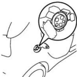 passenger side of vehicle passenger side of vehicle | 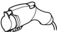 | 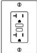 110-120V household outlet (15 amp dedicated circuit required) 110-120V household outlet (15 amp dedicated circuit required) | 120V/8A: Approximately 22-25 hours120V/12A: Approximately 14-16 hours | P3-16 |
| Level 2Regular charging 220-240V (Primary Home EVSE*1 Dock-Available separately) | 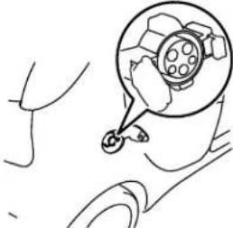 passenger side of vehicle passenger side of vehicle | 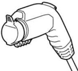 | 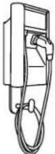 Home or public charging device Home or public charging device | Approximately 6-7 hours | P.3-16, 3-26 |
Charging
| Category | Charge port | Charge connector | Charging Source | Charging time | Reference |
| Quick charging (charging method with quick charger) | 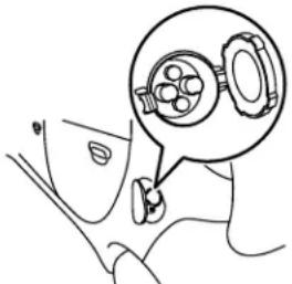 driver side of vehicle driver side of vehicle | 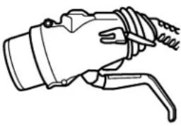 |  Public charging stations where available Public charging stations where available | Approximately 30 minutes for 80 % charge | P.3-27 |
*1. EVSE = Electric Vehicle Supply Equipment
^*2 : CHAdeMO is a standard for quick charging of electric vehicle originally started in Japan, and the contents have also become international standard.
Charging time will vary depending on battery condition, air temperature and condition of power source (such as specification of the quick charger).
A vehicle equipped with a quick charge port is compatible with most CHAdeMO connectors on charging stations. Charging stations using the CHAdeMO standard are UL certified and safe to use in the US.

NOTE
- The 12V starter battery will be automatically charged during charging and also while the ready indicator is illuminated. Refer to “Ready indicator” on page 5-44.
● Repeatedly performing only quick charging can reduce battery capacity. Regular charging is recommended unless quick charging is necessary. - If the 12V starter battery is discharged, the main drive lithium-ion battery cannot be charged. Refer to "Jump-starting" on page 8-2.
3-14 General information/Charging
Precautions during Charging the Main Drive Lithium-ion Battery
N01202601051

WARNING
- Improper charging can result in a fire, property damage, and serious injury or death.
Read the instructions described below carefully and follow them. Also read and follow the instructions for “Regular charging (charging method with rated AC 120V outlet)” on page 3-16, Regular charging (using 240V Electric Vehicle Supply Equipment) on page 3-26 and “Quick charging (charging method with quick charger)” on page 3-27 before using the charging device. - Do not touch regular charge port, regular charge connector, plug and outlet with wet hands.
- Keep away from water when connecting the regular charge port, regular charge connector, plug and outlet.
- Do not perform charging outdoors in adverse weather, such as heavy rain, heavy snow or strong winds, or when adverse weather is expected.
WARNING
- Never charge or touch the vehicle when lightning or thunder is observed or expected. A lightning strike may back feed into the regular charger causing damage and possible personal injury or death. If lightning or thunder begins during regular charging, do not touch the vehicle or the EV charging cable and turn off the breaker.
- Make sure there is no water or foreign materials in the charge port, charge connector or plug, and that they are not damaged or affected by rust or corrosion. If any of these conditions are noticeable, do not charge the main drive lithium-ion battery.
- Never touch the metal contacts of the charge port, charge connector or plug.
- Never disassemble or modify the charge port or charging cable.
- If you notice unusual odor or smoke coming from the vehicle, charging cable or plug, or if the charging cable or plug becomes hot to the touch, stop charging immediately.
- Keep away from the cooling fan under the hood during charging. During charging, the cooling fan may automatically be operated even if the electric motor switch is in the “LOCK” position.
WARNING
- Some public regular chargers may not be compatible with your vehicle. If necessary, consult an administrator or the maker of the regular charger to determine whether the charger is compatible with your vehicle before using it. Also be sure to use the regular charger according to operating procedures indicated on the body of the regular charger.
CAUTION
- Do not place the selector lever in any position other than the "P" (PARK) position while the regular charger is connected. If the selector lever is placed in a position other than the "P" position, the vehicle could accidentally move resulting in damage to the regular charge connector. If the selector lever is placed in any position other than "P" position while the regular charge connector is still connected and the electric motor switch is the "ON" position, a warning buzzer will sound.
- To prevent damage to the charging equipment:
- Do not close the charge port lid without closing the cap.
- Do not subject the charging equipment to impact.
- Do not pull or twist the charge cable.
- Do not drag the charge cable.
Regular charging (charging method with rated AC 120 V outlet)
CAUTION
- Do not store charging equipment in locations where the temperature is above 185^ (85^) or below -40^ (-40^) .
- Do not place the charging equipment close to a heater or other heat source.
● Make sure the inner cap is closed on the charge port when charging is finished. If the charge port lid is closed when the cap is opened, water or foreign materials may enter the charge port.
- Do not charge when a vehicle body cover is in use.
This may cause damage to the charge connector.
- Do not attempt to perform a jump start on the 12V starter battery at the same time that the main drive lithium-ion battery is being charged. Doing so may damage the vehicle or charging cable and could cause an injury. See “Jump-starting” in the “6. For emergency” section.
- Forcing the charge connector to connect may cause damage to the charging equipment and vehicle.

NOTE
● Repeatedly performing only quick charging can reduce the battery capacity. Regular charging is recommended unless quick charging is necessary.
NOTE
● To help maintain the capacity of the main drive lithium-ion battery, the following is recommended:
- If you repeatedly perform only the quick charging, fully charge the vehicle by regular charging every 2 weeks.
- Do not repeat charging when the main drive lithium-ion battery is at or near the full charge.
- Both of the regular charging and quick charge cannot be performed at the same time. The quick charging is given priority.
- While charging, even if the electric motor switch is in the "LOCK" position, you may hear operating sounds such as sounds from the cooling fan and air conditioning compressor when operating the main drive lithium-ion battery cooling system or Remote Climate Control. This is normal.
Refer to "Remote Climate Control" on page 3-36, 3-47.
- It is recommended that you perform regular charging from 2 bars or less on the energy level gauge to full at least once every three months. This allows the energy level gauge to adjust to decreased battery capacity and correctly display the remaining energy in the main drive lithium-ion battery.
A certified i-MiEV dealer can also adjust the energy level gauge for you when requested.
Regular charging (charging method with rated AC 120 V outlet)
N01203101040
Carefully read instructions regarding “Precautions during charging the main drive lithium-ion battery” on page 3-15 and described in this section and also instructions on “EV charging cable” on page 3-23 or instructions for a charging device you use, and follow them.
WARNING
- Improper charging can result in a fire, property damage, and serious injury or death.
● Always use a grounded outlet protected by a ground-fault circuit interrupter, rated AC 120V and rated for 15A or more connected to a dedicated branch circuit. If the outlet is not grounded, the risk of electrical shock will increase in the event of an insulation failure in the EV charging cable.
If the circuit is shared, and another electrical device is being used at the same time the vehicle is charging, the circuit may heat abnormally, the breaker may trip and the circuit may cause adverse interference on household electrical appliances such as televisions and audio systems.

WARNING
- Individuals using an electro-medical apparatus such as implantable pacemakers and implantable cardiovascular-defibrillators should check with the manufacturer of the apparatus to confirm the effect of the electromagnetic waves from charging. The electromagnetic waves may affect the operations of the electro-medical apparatus.
- If you use an electro-medical apparatus, such as an implantable cardiac pacemaker or an implantable cardiovascular defibrillator, observe the following precautions before charging:
- Keep your electro-medical apparatus away from the charge connector, EV charging cable, control box and regular charging station.
- While regular charging;
·Do not stay inside the vehicle.
- Do not go inside the vehicle, for example to remove or place an item in the passenger compartment.
- Do not open the liftgate, for example to remove or place an item in the cargo area.
● To reduce the risk of electric shock, connect only to a properly grounded and waterproofed outlet.
- Never use an extension cable, multi-plug adapter or conversion adapter.
Using them may cause overheating resulting in fire.

WARNING
- Never force the connection if the charging cable or plug shows damage or is not easily connected due to foreign material entering the plug or the outlet.
● Never use an outlet that is worn, damaged, or will not hold the plug firmly.
● Make sure that the plug is inserted all the way into the outlet before use. - While it is normal for the plug and charging cable to become warm during charging, discontinue use immediately if the plug or charging cable becomes too hot to touch.
● Never pull the cable to remove the plug. - Never connect or disconnect the plug with a wet hand.

NOTE
- Your vehicle is equipped with an EV charging cable for regular charging. Refer to “EV charging cable” on page 3-23.
- When connecting or disconnecting the regular charge connector, insert/pull out the connector straight.
Also, do not incline or twist the connector.
Doing so could cause a bad connection or malfunction.
● Make sure to lock the doors to prevent theft, etc. during charging.
Regular charge port light
N01216200019
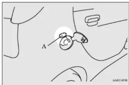
Regular charge port light (A) comes on when the UNLOCK button on the remote control transmitter is pressed, or when any door or the liftgate is opened. The regular charge port light and the dome lights (with the dome light switch in the "DOOR" position) will come on simultaneously. However, the regular charge port light will not come on when you press the dome light (front) lens or slide the dome light (rear) switch to the "ON" position.
For details, refer to "Keyless entry system" on page 5-5, "Dome light (Front)/Reading lights" on page 5-77 and "Dome light (Rear)" on page 5-78.
To turn on the charge port light again, press the UNLOCK button on the remote control transmitter, or open any door or the liftgate.
Regular charging (charging method with rated AC 120 V outlet)

NOTE
- The time until the light goes off can be adjusted. See a certified i-MiEV dealer for details.
Charging from rated AC 120 V outlet
N01203201041
- Fully apply the parking brake and place the selector lever to the "P" (PARK) position.
- Stop the electric devices such as lamps and turn the electric motor switch to the "LOCK" position.
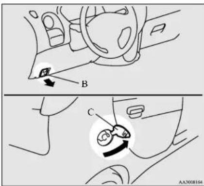
- Pull the regular charging opener (B) at the bottom left of the instrument panel to open the regular charging lid (C) at the right rear side of the vehicle.
- Remove key and lock the vehicle.
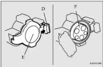
- Press the tab (D) to open the inner lid (E).

WARNING
- Do not touch the metal terminal of the charge port (F) and the regular charge connector. Doing so could cause an electric shock and/or malfunction.

CAUTION
- To help keeping foreign material out of the charge port, do not leave the inner lid open without connecting the charge connector.

NOTE
- There is a hole on the charge port for water drainage. If this hole is blocked and water gets trapped in the charge port, do not charge. Contact a certified i-MiEV dealer. - If the charge port becomes frozen, use a hair dryer to defrost and dry the regular charge port before charging. Forcing the charging connector to connect with the regular charge port while it is frozen can damage the regular charge port and/or prevent charging.
- Insert the charging cable plug into an outlet.
3-18 General information/Charging
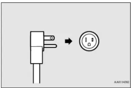
WARNING
● Make sure that the plug is inserted all the way into the outlet before use.
- To reduce the risk of electric shock or fire due to electric leak, always use a grounded outlet protected by a ground-fault circuit interrupter, rated AC 120V and rated for 15A or more, that is connected to a dedicated branch circuit. If the outlet is not grounded, the risk of electrical shock will increase in the event of an insulation failure in the EV charging cable.
If the circuit is shared, and another electrical device is being used at the same time the vehicle is charging, the circuit may heat abnormally, the breaker may trip and the circuit may cause adverse interference on the household electrical appliances such as televisions and audio systems.
WARNING
-
Never use an extension cable, multi-plug adapter or conversion adapter. Using them may cause overheating resulting in fire.
● To prevent an electrical shock or fire, do not use a multi type outlet. The grounded line may not work properly and it is not a dedicated type outlet.
● To reduce the risk of electric shock, connect only to a properly grounded and waterproofed outlet.
● Always use an AC 120V outlet rated for 15A or more. -
Press the 8A/12A manual selection button (G) on the control box to charge quickly when needed. If selected, the 12A indicator (H) will illuminated.
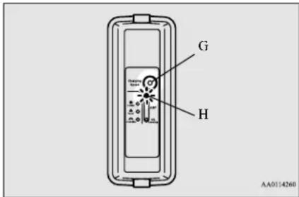
WARNING
-
If the selected electrical current level exceeds the electrical current capacity of the electrical circuit or outlet being used for charging, the circuit and outlet can overheat resulting in fire.
If the capacity of an outlet and its electrical circuit are unknown, do not use the outlet for charging the vehicle. -
Open the cap (I) on the regular charge connector (J) and make sure that there is no foreign matter such as dust at the end of the regular charge connector and the regular charge port.
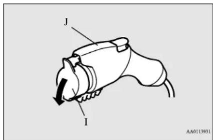
- Connect the regular charge connector until a click is heard without pressing the button (K).
Regular charging (charging method with rated AC 120 V outlet)
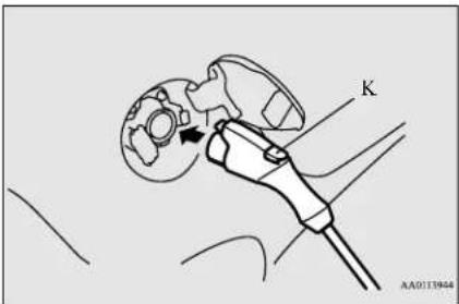
CAUTION
- Do not clasp the top of regular charge connector. It could cause injury to from the protrusion on the lid.
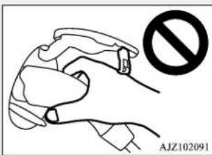

NOTE
- If the electric motor switch is turned to the "START" position with the regular charge connector connected to the regular charge port, the electric motor unit cannot be started.

NOTE
- Do not connect or disconnect the regular charge connector repeatedly in a short time period. You may experience difficulty charging your vehicle.
- Make sure that the charging indicator on the instrument cluster is illuminated.
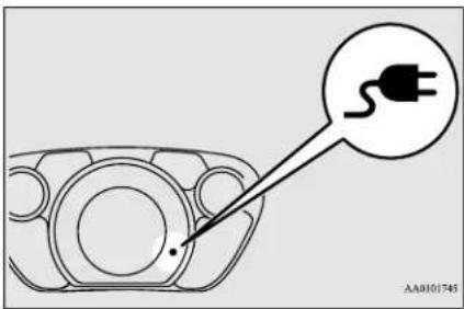
If the charging indicator is not illuminated, charging will not start. Make sure that the regular charge port, the plug and the connector are correctly connected, and perform charging from Step 5 again.

NOTE
- When the regular charge connector is connected to the regular charge port, the charging indicator is blinking. When charging is started, the charging indicator is illuminated.

NOTE
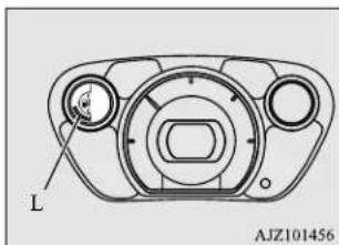
- The charge level for main drive lithium-ion battery can be checked with the energy level gauge (L) on the instrument cluster. Refer to "Energy level gauge" on page 5-41.
natural_image
Technical diagram of a mechanical component with labeled part 'L' and reference number 'AJZ101456' (no text or symbols beyond label)- You may hear operating sounds from the main drive lithium-ion battery cooling system, such as sounds from the cooling fan and air conditioning compressor, during regular charging. This is normal.
- Charging is complete when the charging indicator turns off. Pull out the regular charge connector while pressing the button (M).
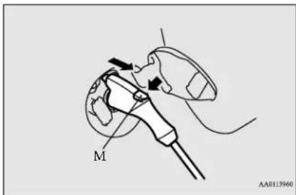
3-20 General information/Charging

WARNING
- After charging, disconnect the charge connector completely from the regular charge port. If the charge connector remains partially engaged with the latch unlocked, the electric motor switch can be turned to the "START" position and the vehicle can be moved.

NOTE
● Charging can be stopped half way. In this case, pull out the regular charge connector while pressing the button.
- Close the inner lid and close the regular charging lid.

WARNING
- After charging, be sure to close the inner lid and the regular charging lid completely. Be careful that water or dust does not enter in the regular charge port inner lid and regular charge connector. Entry of water or dust could cause electric leakage, resulting in a fire or electric shock.

NOTE
- Make sure that the inner lid is completely closed before closing the regular charging lid. If the regular charging lid is forcibly closed without completely closing the inner lid, the hinge on the inner lid may be broken.
- Remove the charging cable plug from the outlet.
- Install the cap on the regular charge connector.
Main drive lithium-ion battery warming system
N01202501047
You cannot charge the main drive lithium-ion battery when the main drive lithium-ion battery temperature is -13 °F (-25 °C) or lower. The air conditioning will automatically operate and the main drive lithium-ion battery will be heated when all the following conditions are met.
- The main drive lithium-ion battery temperature is between -22 °F (-30 °C) and -13 °F (-25 °C).
- The energy level gauge shows 4 bars or more of full charge.
- The electric motor switch is in the "LOCK" position.
- The regular charge connector is connected to the regular charge port.
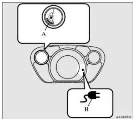
The energy level gauge (A) in the instrument cluster and charging indicator (B) illuminate while the main drive lithium-ion battery warming system is operating.
The main drive lithium-ion battery warming system will automatically stop when the main drive lithium-ion battery temperature is -4^ ( -20^ ) or higher.
Regular charging (charging method with rated AC 120 V outlet)

NOTE
- When the main drive lithium-ion battery warming system operates while the remote climate control is operating, the remote climate control stops. When the main drive lithium-ion battery warming system stops, the remote climate control operates again.
3-22 General information/Charging
EV charging cable
N01202801053
Your vehicle is equipped with an EV charging cable that consists of a cable (A), control box (B), plug (C), and regular charge connector (D).
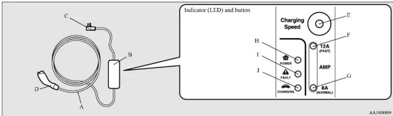
E-8A/12A manual selection button
F-12A indicator
G-8A indicator J ()- CHARGING indicator
H(▲) POWER indicator
I (▲ FAULT indicator

For a quicker charge, press the 8A/12A manual selection button (E) and confirm that the 12A indicator (F) is illuminated. Each time you press the button, either the 12A indicator or the 8A indicator (G) will illuminate.
POWER (II), FAULT (I) and CHARGING (J) indicators located on the control box will illuminate/blink in response to the following conditions:
○: Illuminates ⓄBlinking : Not illuminated
| POWER | FAULT | CHARGING | Operating condition |
| ○ | ○ | ○ | Every time the charging cable plug (C) is connected to an outlet, all indicator lights illuminate for 1/2 second, then go out. |
| ○ | ● | ● | After initial processing is completed, when the regular charge connector is not connected to the regular charge port, or the regular charge connector is connected to the regular charge port but charging is not being performed. |
| ○ | ● | ○ | While the main drive lithium-ion battery is being charged |
| ◎ | ◎ | ● | When the ground cable is disconnectedCheck the grounding of the outlet being used. If the outlet is properly grounded, contact a certified i-MiEV dealer. |
| ○ | ● | ◎ | When charging is completed. |
| POWER | FAULT | CHARGING | Abnormal operating condition and corrective action |
| ○ | ◎ | ● | When an electric leakage occurs or the EV charging cable malfunctions. Stop use immediately and contact a certified i-MiEV dealer. |
| ○ | ○ | ● | When the EV charging cable malfunctions. Stop use immediately and contact a certified i-MiEV dealer. |
| ● | ● | ● | If the control box indicator light does not illuminate after connecting the charging cable plug to the outlet, check the circuit breaker for the outlet. If the breaker has tripped, the circuit may not be suitable for use with EV charging cable. You should have a licensed electrician inspect and repair the electrical circuit. If the breaker is not tripped, stop using the EV charging cable and contact a certified i-MiEV dealer. |

WARNING
- Improper use of the EV charging cable can result in a fire, property damage, and serious injury or death.
Carefully read instructions regarding "Precautions during charging the main drive lithium-ion battery" on page 3-15 and on "Regular charging (charging method with rated AC 120 V outlet)" on page 3-16 and described in this section and follow them.
● Always use an outlet protected by a ground-fault circuit interrupter, rated for 15A or more, and that is connected to a dedicated branch circuit. - Never use an extension cable or conversion adapter.
- When using a non-waterproof outlet, take care to avoid contact with rainwater during charging.
● Never connect or disconnect the plug with a wet hand. - Make sure that the plug is inserted all the way into the socket before use. Continued charging with a plug not completely inserted or pulled halfway out of the socket may result in a risk of overheating or fire.
- If the indicators show the EV charging cable malfunctions as described below, stop using the EV charging cable and contact a certified i-MiEV dealer.
- Never disassemble the EV charging cable or attempt to open the control box.

NOTE
- All indicators are illuminated momentarily for confirming operation when the charging cable plug is inserted into an outlet. After that, the POWER indicator is continuously illuminated and the CHARGING indicator is continuously blinking.
- The CHARGING indicator will start to blink when charging is completed. The POWER indicator is continuously illuminated while charging cable plug is inserted into an outlet.
Handling and storing the control box
N01202901041

CAUTION
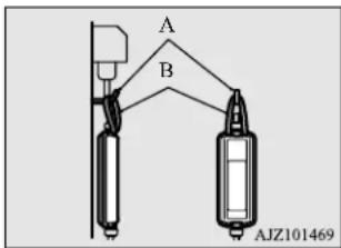
- Use the method shown below to help secure the control box and to prevent the plug from being pulled halfway out of the socket during charging.

NOTE
- Use hook (A) and a rope (B) that can support the weight of the EV charging cable, 8.8 lbs (4 kg) as shown in the figure below.

NOTE
● Make sure that the rope has no damage before use.
FCC Notice: This equipment has been tested and found to comply with the limits for a Class B digital device, pursuant to part 15 of the FCC Rules. These limits are designed to provide reasonable protection against harmful interference in a residential installation.
This equipment generates, uses and can radiate radio frequency energy and, if not installed and used in accordance with the instructions, may cause harmful interference to radio communications.
However, there is no guarantee that interference will not occur in a particular installation. If this equipment does cause harmful interference to radio or television reception, which can be determined by turning the equipment off and on, the user is encouraged to try to correct the interference by one or more of the following measures:
Regular charging (using 240 V Electric Vehicle Supply Equipment)
● Reorient or relocate the receiving antenna.
- Increase the separation between the equipment and receiver.
- Connect the equipment into an outlet on a circuit different from that to which the receiver is connected.
- Consult the dealer or an experienced radio/TV technician for help.
ICES Notice: This Class B digital apparatus complies with Canadian ICES-003.
Cleaning the EV charging cable
N01203000013
- Gently wipe outside surface of the EV charging cable with gauze or a similar soft cloth soaked with a mild soap and water solution.
- Wipe off all detergent with a soft cloth dipped in fresh water and thoroughly wrung out.
- Wipe all moisture off and dry in a shaded, well-ventilated area.
WARNING
- Before cleaning, be sure to remove the charging cable plug from the socket and the regular charging plug from the vehicle. Do not connect or disconnect the plug with a wet hand. Doing so can cause an electric shock.
WARNING
- Never expose the metal terminal of the regular charge connector or the charging cable plug to water or neutral detergent. Water or detergent entering into the plugs can cause a fire or an electric shock.
CAUTION
- Never use benzine, petrol, organic solvents, acid, or alkaline solvents to clean the charging cable. Doing so could cause deformation, discolour, or malfunction. Also, these substances may be present in various cleaners, so check carefully before use.
Regular charging (using 240 V Electric Vehicle Supply Equipment)
N01216101028
You can charge your vehicle through the regular charge port using 240V Electric Vehicle Supply Equipment (EVSE) compatible with i-MiEV.
Carefully read instructions on “Precautions during charging the main drive lithium-ion battery” on page 3-15, described in this section.
For connecting/disconnecting the charging connector to/from the vehicle, follow instruc-
tions for the regular charging (charging method with rated AC 120V outlet) on page 3-16. Also follow instructions provided with the 240V EVSE.
WARNING
- Individuals using an electro-medical apparatus such as implantable pacemakers and implantable cardiovascular-defibrillators should check with the manufacturer of the apparatus to confirm the effect of the electromagnetic waves from charging. The electromagnetic waves may affect the operations of the electro-medical apparatus.
-
If you use an electro-medical apparatus, such as an implantable cardiac pacemaker or an implantable cardiovascular defibrillator, observe the following precautions before charging;
-
Keep your electro-medical apparatus away from the charge connector, EV charging cable, control box and regular charging station.
• While regular charging;
- Do not stay inside the vehicle.
- Do not go inside the vehicle, for example to remove or place an item in the passenger compartment.
- Do not open the liftgate, for example to remove or place an item in the cargo area.

CAUTION
- Be sure to use a 240V EVSE compatible with i-MiEV. Use of a non-compatible 240V EVSE may not charge the main drive lithium-ion battery correctly or may damage the main drive lithium-ion battery.

NOTE
- The 240V EVSE compatible with i-MiEV is available separately. Contact a certified i-MiEV dealer.
Quick charging (charging method with quick charger)
N01203301039
Your vehicle is equipped with a quick charge port. The quick charge port is compatible with most CHAdeMO* connectors on charging stations.
*: CHAdeMO is a standard for quick charging of electric vehicle originally started in Japan, and the contents have become an international standard. Charging stations using this standard are UL certified and safe to use in the US.
Improper charging can result in a fire, property damage, and serious injury or death.
Carefully read and follow instructions on "Precautions during charging the main drive
lithium-ion battery" on page 3-15, instructions described in this section and also instructions for the quick charger you use.
WARNING
- Be sure to use a quick charger compatible with i-MiEV. Use of a non-compatible quick charger may cause a fire or malfunction.
For the quick charger compatible with i-MiEV, consult an certified i-MiEV dealer. - For operation of a quick charger, follow instructions for each quick charger.
- If you use an electro-medical apparatus, such as implantable cardiac pacemaker or an implantable cardiovascular defibrillator, follow the precautions described below. Quick charging may affect the operation of electric medical devices.
- Do not perform quick charging and keep away from a quick charger. Electromagnetic waves produced by a quick charger may affect the operation of your electric-medical apparatus.
- If you have accidentally approached a quick charger, walk away from the quick charger immediately.
- If quick charging is necessary, ask someone for help.
- While quick charging;

WARNING
Do not stay inside the vehicle.
Do not go inside the vehicle, for example to remove or place an item in the passenger compartment.
Do not open the liftgate, for example to remove or place an item in the cargo area.
● Never connect or disconnect the charger with a wet hand.
- Never pull the cable to disconnect the charger.
- During charging, the cooling fans under the hood may automatically be operated even if the electric motor switch is in the "LOCK" position. Keep your hands away from the cooling fan during charging.
- As the quick charge connector is heavier in comparison to the regular charge connector, allowing it to drop could cause damage to the vehicle or charge connector or personal injury.

CAUTION
- If the charge connector cannot easily be connected to the quick charge port, do not force the connection. Foreign material may be in the charge connector or quick charge port, or the charging device may not be compatible with your vehicle. Contact a certified i-MiEV dealer.
Quick charging (charging method with quick charger)

NOTE
● Repeatedly performing only quick charging can reduce the battery capacity. Regular charging is recommended unless quick charging is necessary.
- Before using a publicly available quick charger, confirm that the charger is suitable for your vehicle.
● Make sure to lock the doors to prevent theft, etc. during charging.
- Do not turn the electric motor switch to the "ON" position during quick charging; doing so will stop quick charging.
- When using a quick charger, make sure that the time available is enough so that the quick charging can be finished in the time available.
If the power supply of the quick charger is shut off during quick charging, it could lead to a vehicle failure.
- Fully apply the parking brake and move the selector lever to the "P" (PARK) position.
- Stop the electric devices such as lamps, air conditioning, etc. and turn the electric motor switch to the "LOCK" position.
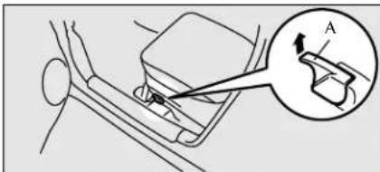
- Pull the quick charging lid opener (A) at the bottom left of the driver's seat to open the quick charging lid (B) at the left rear side of the vehicle.
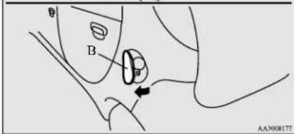
- Remove key and lock the vehicle.
- Press the tab (C) to open the inner lid (D).
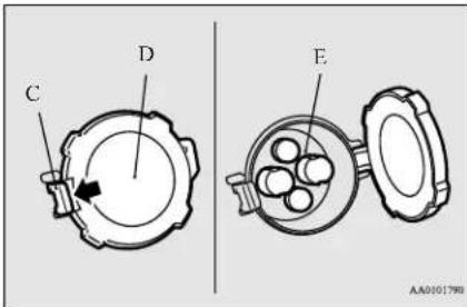

WARNING
- Do not touch the metal terminal of the quick charge port (E) and the quick charge connector.
Doing so could cause an electric shock and/or malfunction.

CAUTION
- Be sure to insert the quick charge connector straight into the quick charge port all the way to the base.
Failure to do so may result in the main drive lithium-ion battery not charging or cause damage to the charging equipment. - Do not leave the inner lid open for any significant period of time without the charge connector inserted. Foreign material, if allowed to enter the quick charge port, can damage the quick charge port and/or prevent charging.

NOTE
- There is a hole on the quick charge port for water drainage. If this hole is blocked and water gets trapped in the quick charge port, do not charge. Contact a certified i-MiEV dealer.
3-28 General information/Charging
Quick charging (charging method with quick charger)

NOTE
- If the quick charge port becomes frozen, use a hair dryer to defrost and dry it before charging. Forcing the charging connector into the quick charge port while it is frozen can damage the quick charge port, and it may prevent charging.
- Insert the quick charge connector completely into the quick charge port to begin charging.
For connecting and disconnecting, follow the instruction manual for each quick charger.

WARNING
- Be sure to insert the charge connector completely into the quick charge port. If the charge connector is only partially inserted and the connector latch is not locked, the electric motor switch could be turned to the "START" position and the vehicle could start moving
- Make sure that the charging indicator on the instrument cluster is illuminated.
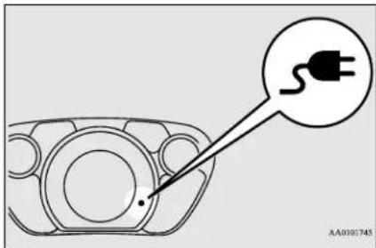
If the charging indicator is not illuminated, charging has not started. Refer to the quick charger user manual.

NOTE
- When the quick charging plug is connected to the charging connection, the charging indicator will blink. Once charging has started, the charging indicator will illuminate.

NOTE
- The charge level for the main drive lithium ion battery can be checked with the energy level gauge (F) on the instrument cluster. Refer to "Energy level gauge" on page 5-41.
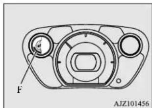
- You may hear operating sounds from the main drive lithium-ion battery cooling system, such as sounds from the cooling fan and air conditioning compressor, during quick charging. This is normal.
- Since the main drive lithium-ion battery cooling system uses cool air from the air conditioning system, the air conditioning will automatically be operated. After quick charging, you may find dehumidified water from the air conditioning system under the vehicle. This is normal.
- Charging is complete when the charging indicator turns off.
Disconnect the quick charge connector according to the manual of the quick charger.
Quick charging (charging method with quick charger)
CAUTION
- Do not leave the quick charge connected to the quick charge port after charging. Someone might stumble on the charger or the quick charge port might get damaged.
NOTE
- Although it is possible to start the electric motor unit if quick charging has not finished normally, the charging indicator is continuously blinking. In such a situation, perform quick charging again and finish it normally or contact a certified i-MiEV dealer.
- Close the inner lid and close the quick charging lid.
WARNING
- After charging, be sure to close the inner lid and the quick charging lid completely. Be careful that water or dust does not enter in the quick charge port, inner lid and quick charge connector. Entry of water or dust could cause a fire, electric shock or short circuit.
NOTE
- If the electric motor switch is turned to the "START" position with the quick charge connector connected to the quick charge port, the electric motor unit cannot be started.
Be sure to disconnect the quick charge connector before starting the electric motor unit. - Charging may stop before full charge. This is a control for efficient charge and not a malfunction.
To achieve full charge, repeat charging from Step 5 again. - Make sure that the inner lid is completely closed before closing the quick charging lid. If the quick charging lid is forcibly closed without first completely closing inner lid, the hinge on the inner lid may be broken.
Charging troubleshooting guide
N(120)2301032
| Symptom Possible | cause Possible solution | |
| Charging cannot be started. | The electric motor switch is in the ON position. | Before charging, place the electric motor switch in the “LOCK” position. |
| The main drive lithium-ion battery is already fully charged. | Charging cannot be performed if the main drive lithium-ion battery is already fully charged. Charging automatically turns off if the main drive lithium-ion battery is fully charged. | |
| The temperature of the main drive lithium-ion battery is too high or too low to charge. | Confirm the main drive lithium-ion battery temperature.Refer to “Cautions and actions to deal with intense heat” on page 3-8 and “Cautions and actions to deal with intense cold” on page 3-10. | |
| The 12V starter battery is discharged. | The main drive lithium-ion battery can be charged if the vehicle electrical systems cannot be turned on. If the battery is discharged, charge or jump start the 12V starter battery. Refer to “Jump-starting” on page 8-2. | |
| The vehicle or the charging cable has a malfunction. | The vehicle or the charging cable may have a malfunction. Confirm if the warning light on the meter is illuminated. Confirm if the indicator on the charger is indicating a malfunction. If a warning is displayed, stop charging and contact a certified i-MiEV dealer. | |
| The fuse has blown. Confirm if the fuse of the interior lights (dome lights) in the fuse block in the passenger compartment located in front of the driver’s seat has blown. Refer to “Fuses” on page 9-18. | ||
Charging troubleshooting guide
| Symptom Possible | cause Possible solution | |
| Regular charging cannot be started. | There is no electrical power coming from the outlet. | Confirm that there has not been a power failure. Make sure the breaker is on. If an outlet with a timer device installed is used, power will only be available at the time set by the timer. Confirm if the POWER indicator on the control box is illuminated. |
| The charge connector is not connected correctly. | Confirm the charge connector is connected correctly. | |
| The charge connector was connected and disconnected repeatedly in a short time. | Disconnect the charge connector, wait for a while, then start charging procedure again from the beginning. | |
| A charging cable for other vehicle is used. | Use the EV charging cable only for your vehicle. | |
| The regular charger may not be compatible with your vehicle. | Ask an administrator or the manufacturer of the regular charger whether the charger is compatible with your vehicle. Always follow the instructions shown on the regular charger. | |
| Charging Timer by MiEV remote cannot be started. | Refer to “Action to be taken when the MiEV Remote system does not operate correctly” on page 3-52. | |
3-32 General information/Charging
Charging troubleshooting guide
| Symptom Possible | cause Possible solution | |
| Regular charging is discontinued. | There is no power coming from the outlet. | There may have been a electrical power failure, or the breaker may have failed.Charging will resume when the power source is reset. |
| The EV charging cable has been disconnected. | Check that the EV charging cable has not been disconnected. | |
| The button on the regular charge connector has been pressed. | If the charge connector button is pressed for a long period of time, charging will be stopped. Start the charging procedure again. | |
| The temperature of the main drive lithium-ion battery is too hot or too cold to charge. | Confirm the main drive lithium-ion battery temperature.Refer to “Cautions and actions to deal with intense heat” on page 3-8 and “Cautions and actions to deal with intense cold” on page 3-10. | |
| Charging is stopped by the regular charge timer. | Charging will stop depending on the timer function setting of the regular charge device. If you need to charge the main drive lithium-ion battery more, start the charging procedure again. | |
| Quick charging cannot be started. | The charge connector is not connected correctly and/or not locked. | Check that the charge connector is connected correctly and that it is locked. |
| The self-diagnostic function of the quick charge device returns a negative result. | There is a possibility that the vehicle has a malfunction. Stop charging and contact a certified i-MiEV dealer. | |
| The power switch of the quick charger is off. | Check the power switch of the quick charger.Consult an administrator or a maker of the quick charger. | |
| Quick charge is discontinued. | Charging is stopped by the quick charge timer. | Charging will stop depending on the timer function setting of the quick charge device.If you need to charge the main drive lithium-ion battery more, start the charging procedure again. |
| Charging stops at 80% capacity. | Charging is designed to stop when the main drive lithium-ion battery capacity reaches 80%. If you need to charge the main drive lithium-ion battery more than 80%, start the charging procedure again. | |
| The power supply for the quick charger is off. | Check whether the power supply for the quick charger is off.Consult an administrator or a maker of the quick charger. |
General information/Charging 3-33
High-Voltage components
| Symptom Possible | cause Possible solution | |
| The charging indicator is continuously blinking even if the quick charge connector is not connected into the quick charge port when you start the electric motor unit after quick charging. | Quick charging has not finished normally. | Perform quick charging again and finish it normally or contact a certified i-MiEV dealer. |
| EV (Electric Vehicle) system does not start after quick charging. | The vehicle has a malfunction. Contact | a certified i-MiEV dealer.If you need to push the vehicle, turn the electric motor switch to the “ON” position and move the selector lever to the “N”(NEUTRAL) position. |
High-Voltage components
N01205700027

WARNING
- The EV (Electric Vehicle) system uses high voltage up to DC 330 volt. The system can be hot during and after starting and when the vehicle is shut off. Be careful of both the high voltage and the high temperature. Follow the warning labels that are attached to the vehicle.
WARNING
- Never touch, disassemble, remove or replace high-voltage parts, exposed electrical components, cables or connectors. Failure to follow this instruction can result in severe burns or electric shock causing serious injury or death. High-voltage cables are colored orange. The vehicle high voltage system has no user serviceable parts. Take your vehicle to a Certified i-MiEV dealer for any necessary maintenance.
● Always assume the high voltage battery and associated components are energized and fully charged.
High voltage components and wiring cables are located as shown in the figure below.
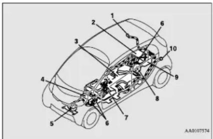
1- Regular charge port
2-MCU
3- Main drive lithium-ion battery
4- Heater
5- Air conditioner compressor
6- High voltage connector
7- Service plug
8- Electric motor (Electric motor unit)
9- On board charger/DC-DC converter
10- Quick charge port
In case of a collision
N01205800031
A crash or impact significant enough to require an emergency response for conventional vehicles would also require the same response for electric vehicles.
Also follow the instructions described below to avoid severe burns and electrical shock that may result in serious injury or death.

WARNING
- If your vehicle is drivable, pull your vehicle off the road to a safe, nearby location and remain on the scene.
Also, if possible, do the following operations and stay out of the way of any oncoming traffic while awaiting the arrival of emergency responders. - Apply chocks to the wheels.
- Move the selector lever to the "P" (PARK) position.
- Apply the parking brake.
- Open the windows, doors and liftgate.
- Turn the electric motor switch to the "LOCK" position.
- Turn on the hazard warning flashers.
- Move the key away from the vehicle to prevent unintended start-up of the system by inadvertent contact with a switch or impact from the crash.
WARNING
- Never touch high-voltage wiring, connectors, and other high-voltage parts, such as the inverter unit and main drive lithium-ion battery. An electric shock may occur if exposed electric wires are visible when viewed from inside or outside of your vehicle. For their locations, see “High-voltage components” on page 3-34.
- If the vehicle receives a strong impact to the floor while driving, stop the vehicle in a safe place and check the floor.
● Leaks or damage to the main drive lithium-ion battery may result in a fire. If you discover them, contact emergency services immediately. Since the fluid leak may be lithium manganite from the Lithium-ion battery, never touch any fluid leaking from the inside or outside of the vehicle. If the fluid contacts your skin or eyes, wash it off immediately with a large amount of water and receive immediate medical attention to help avoid serious injury. - If you are unable to safely assess the vehicle due to vehicle damage, do not touch the vehicle. Leave the vehicle and contact emergency services. Advise emergency responders that this is an electric vehicle.
WARNING
- If a fire occurs in this vehicle, leave the vehicle as soon as possible and contact emergency services. Do not attempt to extinguish a fire by yourself. If the fire involves a lithium-ion battery, it will require large, sustained volumes of water for extinguishment. Using a small amount of water or the incorrect fire extinguisher can result in serious injury or death from electrical shock.
- When you leave the vehicle, if possible, open the windows, doors and liftgate to prevent accumulation of poisonous/combustible gasses. This will also assist in the rescue and fire fighting process.
- As with any vehicle fire, the byproducts of combustion can be toxic. Do not inhale smoke, vapors, or gas from the vehicle. Move to a safe distance upwind and uphill from the vehicle fire and out of the way of any oncoming traffic while awaiting the arrival of emergency responders.
- If you detect leaking fluids, sparks, smoke, flames, gurgling, popping or hissing noises originating from the high voltage battery compartment, contact emergency services immediately. This may result in a fire.
● Physical damage to the vehicle or high voltage battery may result in immediate or delayed release of toxic and/or flammable gases and fire.
WARNING
- If your vehicle needs to be towed, transport the vehicle on a flatbed truck or tow the vehicle either with all wheels or the rear wheels (drive wheels) off the ground. If the rear wheels are on the ground when towing, this may cause damage to the electric motors. This may also cause a fire, if wiring in the electric motor unit room becomes damaged. Refer to "Towing" on page 8-11.
- Do not attempt to repair a damaged electric vehicle yourself. Please contact a certified i-MiEV dealer for service.
- In the event of an accident that requires body repair and painting, the vehicle should be delivered to a Certified i-MiEV dealer to have the main drive lithium-ion battery and high voltage parts such as the inverter, including the attached wiring harness, removed prior to painting. If exposed to heat in the paint booth, the main drive lithium-ion battery will experience battery capacity loss. A damaged main drive lithium-ion battery can also pose safety risks to untrained mechanics and repair personnel.

NOTE
- The emergency shut-off system will be activated and the high-voltage system will automatically turn off under the following conditions:

NOTE
- Certain front, side or rear collisions.
- Certain EV (Electric Vehicle) system malfunctions.
- When the emergency shut-off system is activated, the ready indicator is turned off. Refer to "Indicator and warning light package" on page 5-43.
- If the emergency shut-off system activates, contact a Certified i-MiEV dealer.
MiEV Remote System
N01203401056
The MiEV Remote System has the following three functions.
● Charging Timer→P.3-41
When the EV charging cable (regular charger) (Level 1 or Level 2) is connected, the batteries will only charge during the pre-set time period selected using the MiEV Remote.
● Remote Climate Control → P.3-47
When the EV charging cable (regular charger) (Level 1 or Level 2) is connected, the air-conditioner or heater can be activated for up to 30 minutes prior to vehicle usage. This feature can be used to cool or heat the car and to activate the front and rear window defroster.
COOL: Operates in cooling mode intended for exclusive use with Remote Climate Control (Pre-Cooling Mode).
HEAT: Operates in heating mode intended for exclusive use with Remote Climate Control (Pre-Heating Mode). The heated seats can be used while the Remote Climate Control is activated.
Operates in defroster mode intended for exclusive use with Remote Climate Control (Pre-Defroster Mode). The electric rear window defogger is activated automatically when the Remote Climate Control is activated in Pre-Defroster Mode.
● Main Drive Lithium-ion Battery Level Indicator → P.3-50
The charge remaining in the Main Drive Lithium-ion Battery can be confirmed through the MiEV Remote.
For your quick reference, refer to "Basic operation of the MiEV Remote" on page 3-40.
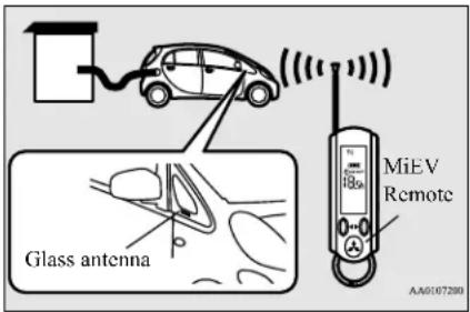
WARNING
- Individuals who use implantable pacemakers or implantable cardiovascular-defibrillators should keep away from the external and internal transmitters. The electromagnetic waves used in the MiEV Remote System may affect the operation of implantable pacemakers and implantable cardiovascular-defibrillators.
- Individuals using other electro-medical apparatus besides implantable pacemakers and implantable cardiovascular-defibrillators should check with the manufacturer of the apparatus to confirm the effect of the electromagnetic waves used by the MiEV Remote System. The electromagnetic waves may affect the operations of the electro-medical apparatus.
- Never use the MiEV Remote near medical equipment. Electromagnetic waves could adversely affect the medical equipment.
WARNING
- Keep the MiEV Remote in the place where children will not touch or play with the remote.
- When bringing the MiEV Remote on flights, do not press any switches on the MiEV Remote while on the plane. If a switch is pressed on the plane, the MiEV Remote emits electromagnetic waves which like cell phones and other wireless devices, could interfere with systems on the airplane.
When carrying the MiEV bag, be careful that no switches on the MiEV Remote can be pressed by mistake.
CAUTION
- Never disassemble or modify the MiEV Remote. No user serviceable parts are inside except batteries.
● Disassembling or modifying the MiEV Remote or removing a label from the MiEV Remote may violate regulations.
NOTE
- The MiEV Remote system uses radio waves. The MiEV Remote can operate within approximately 328 feet (100 m) from the vehicle.
In the following environments or situations, the MiEV Remote may not transmit and receive radio waves correctly. As a result, the remote may not operate properly.
- When the vehicle and the MiEV Remote are separated by a concrete wall.
-
When there is a metal wall between the t vehicle and the MiEV Remote.
-
When the vehicle is surrounded by other tall vehicles.
- When the vehicle and/or the MiEV Remote is near a facility emitting strong radio waves, such as a television tower, a transformer substation, a broadcasting station or an airport.
- When other electrical equipment such as computers or cell-phones are placed near the MiEV Remote.
- When the MiEV Remote touches something metallic, or is covered by a metal object.
- When batteries for the MiEV Remote are weak.
- Melody and buzzer from the MiEV Remote can be turned on or off. Refer to "To turn on/off melody and buzzer" on page 3-49.

NOTE
● The transmitter signal will reach further when the antenna of the MiEV Remote is fully extended and held upright.
● The onboard antenna is printed on the right side delta glass of the vehicle.
- When the MiEV Remote is not used for more than 30 seconds, the MiEV Remote will automatically turn off.
- Some charge facilities have a timer function which turns the power supply on and off automatically. When using a charge facility with this timer function, please adjust the charging time set by the MiEV Remote to be consistent with the timer used by the charging facility.
- When you need additional MiEV Remotes, please contact a certified i-MiEV dealer. Up to four MiEV Remotes can be used per vehicle.
- You may hear operating sounds such as sounds from the cooling fan and air conditioning compressor when the Remote Climate Control is activated even if the electric motor switch is in "LOCK" position during timer charging. This is normal.
Refer to "Remote Climate Control" on page 3-47.
MiEV Remote
N01203501044
Switches
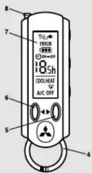
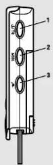
1- Power/communication switch - Press and hold to turn remote on. Press quickly to transmit command to vehicle.
2- MODE switch - The display of the MiEV Remote is changed in order of "ON timer", "OFF timer" and "Remote Climate Control" by pressing this switch.
3- Manual charge switch (this can also cancel the timers and Remote Climate Control).
4- Ring
5- UP switch - scrolls up the display items
6- DOWN switch - scrolls down the display items
7- Display
8- Antenna
Display (LCD monitor)
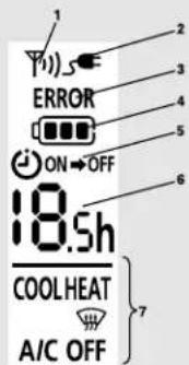
AA3008207
1- Blinks when communicating with vehicle, and when error occurs.
2- The indicator lights up during charging. The indicator blinks when the manual charging button is pressed. The indicator will rapidly blink, if EV charging cable (regular charger) is not connected when the timer charging or Remote Climate Control is set.
3- Blinks if there is an operation or communication error.
4- Shows remaining charge of the Main Drive Lithium-ion Battery. Blinks if battery has less than 20% charge.
5- ON: Indicates ON timer is set
ON→OFF: Indicates OFF timer is set
6- Indicates amount of time until Charging Timer is complete.
7- When Remote Climate Control is set, displays mode set to operate:
COOL: Pre-Cooling Mode
HEAT: Pre-Heating Mode
: Pre-Defroster Mode
A/C OFF: Remote Climate Control OFF
CAUTION
- Never leave the MiEV Remote in a place where it will be subject to high temperatures, such as in direct sunlight, or subject to extreme low temperatures. The MiEV Remote can be damaged and may not properly operate.
● Never drop or hit the MiEV Remote. Do not apply force to bend the antenna. These can cause damage to or failure of the remote.
- If the MiEV Remote gets wet, please wipe water off immediately. Water entering the MiEV Remote can cause a failure.
Basic operation of the MiEV Remote
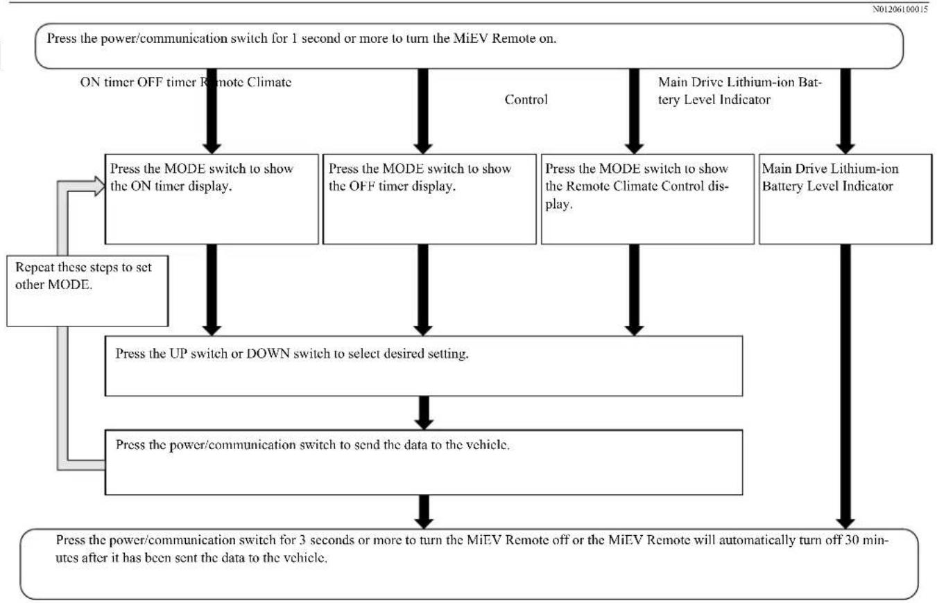
flowchart
graph TD
    A["Press the power/communication switch for 1 second or more to turn the MiEV Remote on."] --> B["ON timer OFF timer Remote Climate"]
    B --> C["Press the MODE switch to show the ON timer display."]
    C --> D["Press the UP switch or DOWN switch to select desired setting."]
    D --> E["Press the power/communication switch to send the data to the vehicle."]
    E --> F["Press the power/communication switch for 3 seconds or more to turn the MiEV Remote off or the MiEV Remote will automatically turn off 30 minutes after it has been sent the data to the vehicle."]
    F --> G["Repeat these steps to set other MODE."]
    G --> C
    H["Main Drive Lithium-ion Battery Level Indicator"] --> I["Press the MODE switch to show the OFF timer display."]
    I --> J["Press the MODE switch to show the Remote Climate Control display."]
    J --> K["Main Drive Lithium-ion Battery Level Indicator"]
    K --> F
    style A fill:#f9f,stroke:#333
    style F fill:#ccf,stroke:#333
3-40 General information/Charging
Charging Timer
N01203701020
The Charging Timer can be set as follows.
● ON timer: Time from the present to when charging will begin.
- OFF timer: Time from the start of charging to the end of charging
To set the timer, the following conditions must be met.
- Selector lever: "P" (PARK) position
● Electric motor switch: "LOCK"position - EV charging cable (regular charger): Connected
WARNING
- Improper charging can result in a fire, property damage, and serious injury or death.
Before Charging Timer, carefully read and follow the instructions in "Precaution on Charging the Main Drive Lithium-ion Battery" on page 3-15 and "Regular charging (charging method with rated AC 120 V outlet)" on page 3-16.
NOTE
- Charging Timer cannot be used with a quick charging system.
Example of Charging Timer
N01205001030
- In case you set the timer at 9:00 PM so that charging starts at 11:00 PM and stops at 7:00 AM of the following day (for 8 hours).
- In case you set the timer at 7:00 PM so that charging starts and stops at the same time the last time.
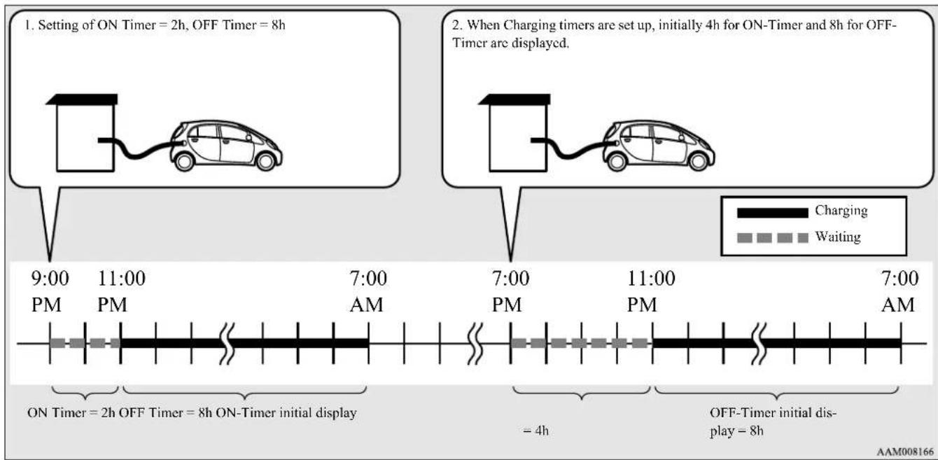
flowchart
graph TD
    A["Setting of ON Timer = 2h, OFF Timer = 8h"] --> B["Charging Time: 9:00 PM to 11:00 AM"]
    C["Setting of ON Timer = 2h, OFF Timer = 8h, ON-Timer initial display"] --> D["Charging Time: 7:00 PM to 11:00 AM"]
    E["Setting of ON Timer = 2h, OFF Timer = 8h, ON-Timer final display"] --> F["Charging Time: 7:00 PM to 11:00 AM"]
    G["Setting of ON Timer = 2h, OFF Timer = 8h, ON-Timer final display"] --> H["Charging Time: 7:00 PM to 11:00 AM"]
    I["Setting of ON Timer = 2h, OFF Timer = 8h, ON-Timer final display"] --> J["Charging Time: 7:00 PM to 11:00 AM"]
    K["Setting of ON Timer = 2h, OFF Timer = 8h, ON-Timer final display"] --> L["Charging Time: 7:00 PM to 11:00 AM"]
    M["Setting of ON Timer = 2h, OFF Timer = 8h, ON-Timer final display"] --> N["Charging Time: 7:00 PM to 11:00 AM"]
    O["Setting of ON Timer = 2h, OFF Timer = 8h, ON-Timer final display"] --> P["Charging Time: 7:00 PM to 11:00 AM"]
    Q["Setting of ON Timer = 2h, OFF Timer = 8h, ON-Timer final display"] --> R["Charging Time: 7:00 PM to 11:00 AM"]
    S["Setting of ON Timer = 2h, OFF Timer = 8h, ON-Timer final display"] --> T["Charging Time: 7:00 PM to 11:00 AM"]
    U["Setting of ON Timer = 2h, OFF Timer = 8h, ON-Timer final display"] --> V["Charging Time: 7:00 PM to 11:00 AM"]
    W["Setting of ON Timer = 2h, OFF Timer = 8h, ON-Timer final display"] --> X["Charging Time: 7:00 PM to 11:00 AM"]
    Y["Setting of ON Timer = 2h, OFF Timer = 8h, ON-Timer final display"] --> Z["Charging Time: 7:00 PM to 11:00 AM"]
    AA["Setting of ON Timer = 2h, OFF Timer = 8h, ON-Timer final display"] --> AB["Charging Time: 7:00 PM to 11:00 AM"]
    AC["Setting of ON Timer = 2h, OFF Timer = 8h, ON-Timer final display"] --> AD["Charging Time: 7:00 PM to 11:00 AM"]
    AE["Setting of ON Timer = 2h, OFF Timer = 8h, ON-Timer final display"] --> AF["Charging Time: 7:00 PM to 11:00 AM"]
    AG["Setting of ON Timer = 2h, OFF Timer = 8h, ON-Timer final display"] --> AH["Charging Time: 7:00 PM to 11:00 AM"]
    AI["Setting of ON Timer = 2h, OFF Timer = 8h, ON-Timer final display"] --> AJ["Charging Time: 7:00 PM to 11:00 AM"]
    AK["Setting of ON Timer = 2h, OFF Timer = 8h, ON-Timer final display"] --> AL["Charging Time: 7:00 PM to 11:00 AM"]
    AM["Setting of ON Timer = 2h, OFF Timer = 8h, ON-Timer final display"] --> AN["Charging Time: 7:00 PM to 11:00 AM"]
    AO["Setting of ON Timer = 2h, OFF Timer = 8h, ON-Timer final display"] --> AP["Charging Time: 7:00 PM to 11:00 AM"]
    AQ["Setting of ON Timer = 2h, OFF Timer = 8h, ON-Timer final display"] --> AR["Charging Time: 7:00 PM to 11:00 AM"]
    AS["Setting of ON Timer = 2h, OFF Timer = 8h, ON-Timer final display"] --> AT["Charging Time: 7:00 PM to 11:00 AM"]
    AU["Setting of ON Timer = 2h, OFF Timer = 8h, ON-Timer final display"] --> AV["Charging Time: 7:00 PM to 11:00 AM"]
    AW["Setting of ON Timer = 2h, OFF Timer = 8h, ON-Timer final display"] --> AX["Charging Time: 7:00 PM to 11:00 AM"]
    AY["Setting of ON Timer = 2h, OFF Timer = 8h, ON-Timer final display"] --> AZ["Charging Time: 7:00 PM to 11:00 AM"]
    BA["Setting of ON Timer = 2h, OFF Timer = 8h, ON-Timer final display"] --> BB["Charging Time: 7:00 PM to 11:00 AM"]
    BC["Setting of ON Timer = 2h, OFF Timer = 8h, ON-Timer final display"] --> BD["Charging Time: 7:00 PM to 11:00 AM"]
    BE["Setting of ON Timer = 2h, OFF Timer = 8h, ON-Timer final display"] --> BF["Charging Time: 7:00 PM to 11:00 AM"]
    BG["Setting of ON Timer = 2h, OFF Timer = 8h, ON-Timer final display"] --> BH["Charging Time: 7:00 PM to 11:00 AM"]
    BI["Setting of ON Timer = 2h, OFF Timer = 8h, ON-Timer final display"] --> BJ["Charging Time: 7:00 PM to 11:00 AM"]
    BK["Setting of ON Timer = 2h, OFF Timer = 8h, ON-Timer final display"] --> BL["Charging Time: 7:00 PM to 11:00 AM"]
    BM["Setting of ON Timer = 2h, OFF Timer = 8h, ON-Timer final display"] --> BN["Charging Time: 7:00 PM to 11:00 AM"]
    BO["Setting of ON Timer = 2h, OFF Timer = 8h, ON-Timer final display"] --> BP["Charging Time: 7:00 PM to 11:00 AM"]
    BQ["Setting of ON Timer = 2h, Off Timer = 8h"] --> BR["Charging Time: -4h"]
    BS["Setting of ON Timer = 2h, Off Timer = 8h"] --> BT["Charging Time -4h"]
    BU["Setting of ON Timer = 2h, Off Timer = 8h"] --> BV["Charging Time -4h"]
    BW["Setting of ON Timer = 2h, Off Timer = 8h"] --> BX["Charging Time -4h"]
    BY["Setting of ON Timer = 2h, Off Timer = 8h"] --> BZ["Charging Time -4h"]
3-42 General information/Charging
To turn the MiEV Remote ON/OFF
N01205100018
- Extend the antenna (A) and press the power/communication switch (B) for 1 second or more to turn the MiEV Remote on. When it communicates with the vehicle properly, the vehicle information will be displayed on the screen.
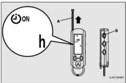
- To turn the MiEV Remote off, press the power/communication switch (B) for 3 seconds or more and store the antenna (A).
To set the ON timer
N01205201029
-
Start the regular charging. Refer to "Regular charging (charging method with rated AC 120 V outlet)" on page 3-16.
-
Turn on the MiEV Remote. Refer to "To turn the MiEV Remote ON/OFF" on page 3-43.
- Press the UP switch (C) or the DOWN switch (D) once. The time remaining from the present to the time that was previously set for the ON timer will be displayed and blink.
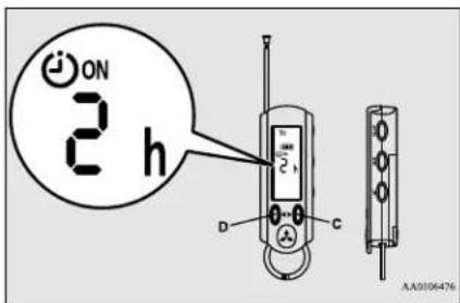

NOTE
- The remaining time for the last charging is displayed with blinking as follows. Example: If you set the charging starting time to 11:00 PM of the day before:
| Present time | Remaining time | Display |
| 9:00 PM 2:00 2h | ||
| 9:10 PM 1:50 2h | ||
| 9:40 PM 1:20 1.5h |

NOTE
- If the MiEV Remote cannot communicate with the vehicle, the remaining time will not be displayed.
- If you need to change the remaining time for the ON timer, press the UP switch (C) or the DOWN switch (D) to change the remaining time. The remaining time can be changed within the range from 0 to 19.5 hours in half hour increments.
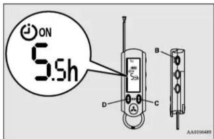

NOTE
- When you want to start the charging at the same time as the last time, changing the remaining time is unnecessary. - When the remaining time is set to 0h, the charging starts immediately after step 5.
General information/Charging 3-43
MiEV Remote System
- Press the power/communication switch (B) for less than 1 second to send the setting data to the vehicle. The MiEV Remote will sound melodies on transmission and reception.

NOTE
- The melodies can be turned off. Refer to "To turn on/off melody and buzzer" on page 3-49.
- If a communication error occurs or the MiEV Remote System is not functioning properly, the buzzer will sound. Refer to "Display of MiEV Remote during communicating with vehicle" on page 3-46.
- If the OFF Timer is unset when setting the ON timer, the OFF timer will be automatically set with "fully charged".
-
To set OFF Timer, refer to "To set OFF Timer" on page 3-45.
-
To turn off the MiEV Remote, refer to "To turn the MiEV Remote ON/OFF" on page 3-43.

NOTE
- The energy level gauge (E) in the instrument panel on the vehicle will illuminate and the charging indicator (F) will blink approximately 30 seconds after the vehicle has received the setting for the ON timer. After approximately 30 seconds, the energy level gauge and the charging indicator will go off, and the vehicle will be prepared for the Charging Timer.
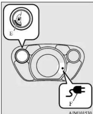
- Turning the electric motor switch to the "ON" position or the "ACC" position will cancel the Charging Timer.
- If the MODE switch is pressed while changing the ON timer setting, the change will be canceled.
- The symbol on the MiEV Remote will be illuminated while the vehicle is charging.

NOTE
- If the charge connector is disconnected before the time set by the ON timer, the Charging Timer is not canceled. If the charge connector is re-connected again before starting the charge or setting the charge timers, the Charging Timer will resume.
To start the charging immediately after the ON timer has been set
N01206000014
- Turn on the MiEV Remote. Refer to "To turn the MiEV Remote ON/OFF" on page 3-43.
- Press the UP switch (C) or the DOWN switch (D) once, and the remaining time from the present to the time set for the ON timer will be displayed and blink.
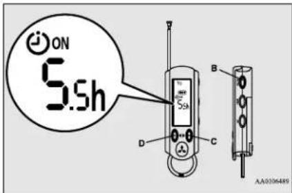
- Change the remaining time to 0h by pressing the UP switch (C) or the DOWN switch (D).
3-44 General information/Charging
- Press the power/communication switch (B) for less than 1 second to send the setting data to the vehicle. The MiEV Remote will sound melodies on transmission and reception. The charging will start.
Refer to “Regular charging (charging method with rated AC 120 V outlet)” on page 3-16.
- Turn off the MiEV Remote. Refer to "To turn the MiEV Remote ON/OFF" on page 3-43.
To set OFF Timer
N01205301093
The OFF timer can be set during the regular charging or after setting the ON timer.
- When the power of MiEV Remote is off, turn the power on. Refer to "To turn the MiEV Remote ON/OFF" on page 3-43.
- Press the MODE switch (G) to change the display to the OFF timer (2).
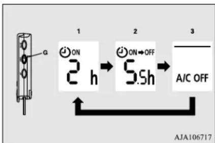
1 Shown the ON timer
2 Shown the OFF timer
3 Shown the Remote Climate Control
- Press the UP switch (C) or the DOWN switch (D) once. The time set last time for the OFF timer will be displayed and blink.
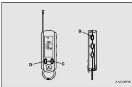
-
If you need to change the time for the OFF timer, press the UP switch (C) or the DOWN switch (D) to change the time.
-
The time can be changed within the range from 0.5h to 19.5h by half hour and can be changed to “-h”.
- When “-h” is displayed, the charging will end when Main Drive Lithium-ion Battery is fully charged.

NOTE
- To display “-h”, press the UP switch (C) when 19.5h is displayed or press DOWN switch (D) when 0.5h is displayed.
- Press the power/communication switch (B) for less than 1 second to send the setting data to the vehicle.
The MiEV Remote will sound melodies on transmission and reception.

NOTE
- The melodies can be turned off. Refer to "To turn on/off melody and buzzer" on page 3-49.
- If a communication error occurs or the MiEV Remote System is not functioning properly, the buzzer will sound. Refer to "Display of MiEV Remote during communicating with vehicle" on page 3-46.
-
If the ON timer is unset when setting the OFF timer, the ON timer will be automatically set with "0h".
-
Turn off the MiEV Remote. Refer to "To turn the MiEV Remote ON/OFF" on page 3-43.

NOTE
- The energy level gauge (E) in the instrument panel will illuminate and the charging indicator (F) will blink approximately 30 seconds after the vehicle has received the setting for the OFF timer.
After approximately 30 seconds, the energy level gauge and the charging indicator will then go off, and the vehicle will be prepared for Charging Timer in accordance with the ON/OFF setting.
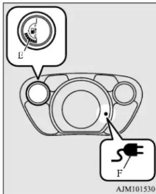
- The symbol on the MiEV Remote illuminates while the Main Drive Lithium-ion Battery is charging.

NOTE
- The Charging Timer will be cancelled if the electric motor switch is turned to the "ON" or "ACC" position.
- Once the Main Drive Lithium-ion Battery is fully charged, the charging will end even if before the time set by the OFF timer.
- If the charge connector is disconnected during charging, the OFF charging timer will be canceled.
Display of MiEV Remote during communicating with vehicle
N01203801021
It communicates with the vehicle when the power of the MiEV Remote is turned on with pressing the power supply/communication switch (B) for 1 second or more and if the power supply/communication switch (B) is pressed for less than 1 second while the power of the MiEV Remote is on.
If the normal reception melody sounds after the transmitting melody, it is set completion.
Communication symbol (H) blinks while communicating with the vehicle.
If the buzzer sounds with ERROR symbol (I) blinks, a problem is detected. Refer to "Actions to be taken when the MiEV Remote system does not operate correctly" on page 3-52.
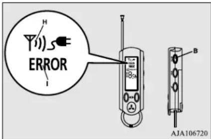
To cancel Charging Timer
N01203901022
There are two methods to cancel Charging Timer.
● By using the MiEV Remote
- By operating the electric motor switch on the vehicle

NOTE
- If the Charging Timer is canceled during charging, the charging will continue until the Main Drive Lithium-ion Battery is fully charged.
- If the Charging Timer is canceled before charging starts, charging will start immediately and continue until the Main Drive Lithium-ion Battery is fully charged.

NOTE
● Charging Timer cannot be canceled by disconnecting the charge connector before the time set by the ON timer. The Charging Timer will resume when the charging connector is again connected to the vehicle.
A. By using the MiEV Remote
- When the power of MiEV Remote is off, turn the power ON. Refer to "To turn the MiEV Remote ON/OFF" on page 3-43.
- Press the manual charging switch (J), then press the power/communication switch (B) for less than 1 second.
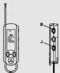
AJA106733

NOTE
- If the manual charging switch (J) is pressed, the symbol of MiEV Remote will blink. Remote Climate Control is also stopped.
- Canceling Charging Timer is complete, and the MiEV Remote will sound two different melodies.
- Turn off the MiEV Remote. Refer to "To turn the MiEV Remote ON/OFF" on page 3-43.
B. By operating the electric motor switch on the vehicle
Turn the electric motor switch to the "ACC" or "ON" position, then turn back to the "LOCK" position.
Canceling the Charging Timer is now complete.
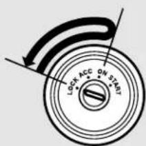
AA0106564
Remote Climate Control
N01204201035

WARNING
- The Remote Climate Control, even when set, cannot be relied upon to maintain safe vehicle cabin temperatures while the vehicle is stopped or parked. Never leave children or persons requiring supervision/nursing unattended inside the vehicle. Temperature inside the vehicle could become extremely high or low resulting in a risk of heat stroke or hyperthermia that could result in death.
In addition, children can activate switches and controls, resulting in an injury or fatal accident. - While the Remote Climate Control is activated, keep away from the cooling fan under the front hood, since the cooling fan may automatically operate even if the electric motor switch is in the "LOCK" position.

NOTE
- The Remote Climate Control works regard less the position of the air conditioning switch or dial on the vehicle. While the Remote Climate Control is activated, the air conditioning switch or dial on the vehicle will not affect operation of the cooler, heater or defroster.

NOTE
- The Remote Climate Control will automatically stop 30 minutes after the Remote Climate Control has been set.
- The Remote Climate Control is operated by electric power supplied through the EV charging cable (regular charger).
● Under the following conditions, the effect of the Remote Climate Control can be decreased.
- When the outside temperature is very high.
- When the sunlight is strong.
- When the outside temperature is very low.
- When Remote Climate Control is activated while charging the Main Drive Lithium-ion Battery, the time required to fully charge the Main Drive Lithium-ion Battery will become longer or the amount of charge may decrease if the OFF timer has been set.
- If the Main Drive Lithium-ion Battery Warming System is operated while the Remote Climate Control is activated, the Remote Climate Control will stop. When the Main Drive Lithium-ion Battery Warming System stops, the Remote Climate Control will resume. Refer to "Main Drive Lithium-ion Battery Warming System" on page 3-21.
● While the Remote Climate Control is activated, if a heated seat switch is ON, the heated seat will operate.
To operate the Remote Climate Control
N01204301036
The following conditions must be met to operate the Remote Climate Control.
- Selector lever: P (PARK) position.
● Electric motor switch: LOCK position. - EV charging cable (regular charger): Connected.
● Quick charging: Not used. - Main Drive Lithium-ion Battery Level Indicator: Shows one bar or more. Refer to “Main Drive Lithium-ion Battery Level Indicator” on page 3-50.
● All doors and the liftgate: Closed.
WARNING
-
Improper charging can result in a fire, property damage, and serious injury or death.
Carefully read and follow instructions in "Precaution during Charging the Main Drive Lithium-ion Battery" on page 3-15 and "Regular charging (charging method with rated AC 120 V outlet)" on page 3-16. -
Start charging. Refer to "Regular charging (charging method with rated AC 120 V outlet)" on page 3-16.
-
Turn on the MiEV Remote. Refer to "To turn the MiEV Remote ON/OFF" on page 3-43.
- Press the MODE switch (G) to change the mode to Remote Climate Control (3).
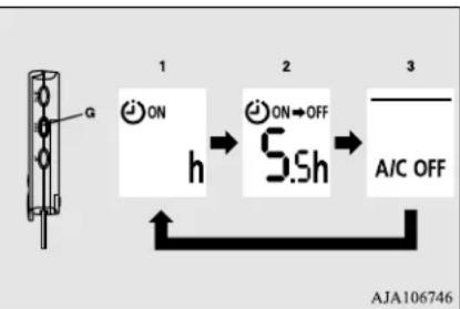
flowchart
graph LR
    A["Device Icon"] -->|1 ON h| B["State Transition"]
    B -->|2 ON→OFF S.Sh| C["State Transition"]
    C -->|3 A/C OFF| D["Output"]
    style A fill:#f9f,stroke:#333
    style B fill:#ccf,stroke:#333
    style C fill:#cfc,stroke:#333
    style D fill:#fcc,stroke:#333
1 Shown the ON timer
2 Shown the OFF timer
3_ Shown the Remote Climate Control
- Select a desired mode by pressing UP switch (C) or DOWN switch (D).
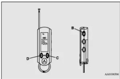
The modes will be changed in the order from 1 to 4 by pushing the UP switch.
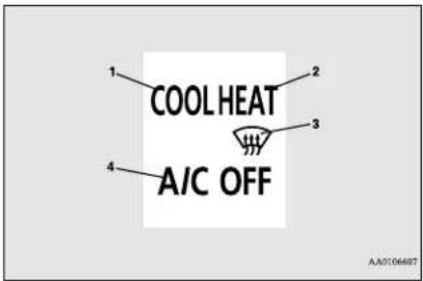
1 COOL: Pre-Cooling Mode
2 HEAT: Pre-Heating Mode
3. Pre-Defroster Mode
4_ A/C OFF: Remote Climate Control
OFF
- Press the power/communication switch (B) for less than 1 second to send the setting to the vehicle. The MiEV Remote will sound melodies on transmission and reception.

NOTE
- The melodies can be turned off. Refer to "To turn on/off melody and buzzer" on page 3-49.

NOTE
- If a communication error occurs or the MiEV Remote System is not functioning properly, the buzzer will sound. Refer to "Display of MiEV Remote during communicating with vehicle" on page 3-46.
- Turn off the MiEV Remote. Refer to "To turn the MiEV Remote ON/OFF" on page 3-43.
To stop the Remote Climate Control
NO1204401024
The Remote Climate Control can be stopped by either of the following methods.
A. By using the MiEV Remote, after pressing the manual charging switch (J), press the power/communication switch (B) for less than 1 second.
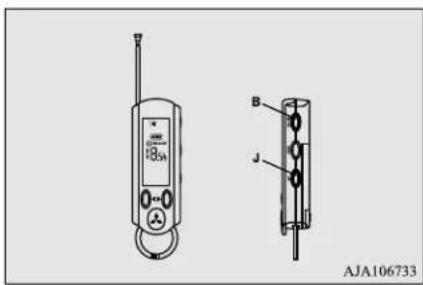
B. By using the MiEV Remote, select the A/C OFF mode and send the setting. Refer to "To operate the Remote Climate Control" on page 3-48.
C. Turn the electric motor switch to the "ACC" or the "ON" position.
D. Disconnect the regular charge connector from the vehicle.

NOTE
● The Remote Climate Control will not stop if the doors or liftgate are opened after the Remote Climate Control has started.
To turn on/off melody and buzzer
N01204100024
- Turn on the MiEV Remote. Refer to "To turn the MiEV Remote ON/OFF" on page 3-43.
• To turn off the sounds, press the UP switch (C) while pressing MODE switch (G).
- To turn on the sounds, press the DOWN switch (D) while pressing MODE switch (G).
MiEV Remote System
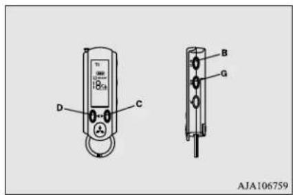
- Turn off the MiEV Remote. Refer to "To turn the MiEV Remote ON/OFF" on page 3-43.
Main Drive Lithium-ion Battery Level Indicator
NO1204500015
The remaining energy in the Main Drive Lithium-ion Battery can be checked using the MiEV Remote.
- If the MiEV Remote has been turned off, turn on the MiEV Remote. Refer to "To turn the MiEV Remote ON/OFF" on page 3-43.
- Current remaining energy in the Main Drive Lithium-ion Battery is shown on the display while the MiEV Remote is ON.
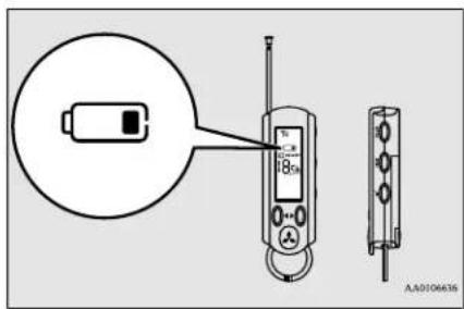
The remening energy is shown by the number of segments displayed.
3 segments: Full or near full
: 2 segments: Moderate
: 1 segment: Low
☐: 0 segments: Empty or near empty

NOTE
- More than re-ained quantity in the Main Drive Lithium-ion Battery is necessary to operate the Remote Climate Control.
- Turn off the MiEV Remote. Refer to "To turn the MiEV Remote ON/OFF" on page 3-43.
General information
N01205400011
Your MiEV Remote System operates on a radio frequency subject to Federal Communications Commission (FCC) Rules (For vehicles sold in U.S.A.) and Industry Canada Rules (For vehicles sold in Canada). This device complies with Part 15 of the FCC Rules and RSS-Gen of the Industry Canada Rules.
Operation is subject to the following two conditions.
● This device may not cause harmful interference.
● This device must accept any interference received, including interference that may cause undesired operation.

CAUTION
- Changes or modifications not expressly approved by the manufacturer for compliance could void the user's authority to operate the equipment.
3-50 General information/Charging
Replacement of batteries for the MiEV Remote
N01204600016
CAUTION
- MiEV Remote is a precision electronic device with a built-in signal transmitter. Do not disassemble or touch an internal parts. Keep away from water or dust.
- Be careful not to break the tab on the battery cover when removing or installing the battery cover.
About battery
N01204700017
Two coin type batteries are used. Replace as necessary to assure proper operation.

NOTE
- Standard battery life on the MiFV Remote is about 1 year. Battery life can vary depending on environmental and usage conditions.
To replace the batteries
N01204800021
- Before replacing the batteries, remove static electricity from your body by touching a metal grounded object.
- Battery cover (B) lifts when the slide portion (A) is moved to the arrow direction.
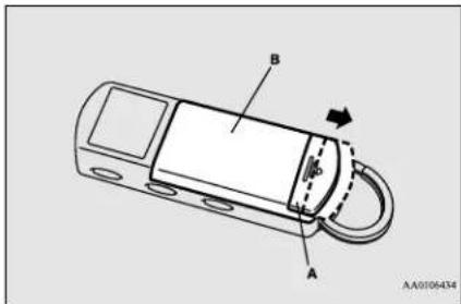
- By moving the battery cover (B) in the arrow direction, tabs (C) on the battery cover will come out and the battery cover can be removed.
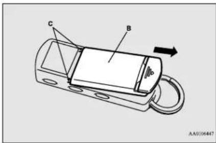
- Remove the old batteries.
- Install two new coin type CR2032 batteries (D) with the "+" side up.
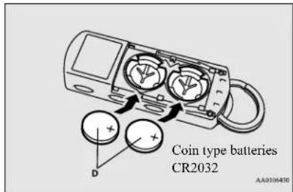
- Attach the battery cover (A) in the reverse order from the way you have detached it.
- Confirm the MiEV Remote can be turned ON. Refer to "To turn the MiEV Remote ON/OFF" on page 3-43.

NOTE
- Replace both batteries with new ones at the same time.
● A certified i-MiEV dealer can replace the batteries for you if you prefer.
Actions to be taken when the MiEV Remote system does not operate correctly
N01204901032
Take the following actions when the system does not operate correctly. If the system still does not operate correctly after the action(s) have been taken, a system component may not be working properly. Please consult with a certified i-MiEV dealer to check it.
| Phenomena Cause Remedy | |||
| Charging does not start when regular charge connector is inserted. | “ON” timer has been set. Cancel the “ON” | timer. | |
| The regular charge connector is not locked completely. | Lock the regular charge connector securely. | ||
| A household electrical outlet, which the EV charging cable is connected to, is shut down.(e.g. disconnected plug) | Turn on the household electrical outlet and make sure the plug is securely connected. | ||
| MiEV Remote does not operate normally. | MiEV Remote is not powered on. | Batteries in the MiEV Remote are defective or the batteries are discharged. | Replace the batteries in the MiEV Remote.Refer to “Replacement of batteries for the MiEV Remote” on page 3-51. |
| No indicator lights come on when the remote is turned on. | |||
| Melody or buzzer does not sound. | Melody or buzzer has been disabled. Enable | the melody or buzzer.Refer to “To turn on/off melody and buzzer” on page 3-49. | |
MiEV Remote System
| Phenomena Cause Remedy | |||
| The following symbol blinks when the power supply/communication switch on the MiEV Remote is pressed.● ERROR symbol● Symbol | Blinks after about 1 second. | ● Electrical noise source is present in the vicinity of the MiEV Remote. (e.g. personal computer)● Electrical noise source is present between the vehicle and the MiEV Remote. | Move away from the noise source. |
| Blinks after about 10 seconds. | The MiEV Remote antenna is not extended. | Extend the MiEV Remote antenna to communicate. | |
| Out of effective communication range. (e.g. too far away from the vehicle, or radio signal is interfered) | Move to the location where the system reaches the effective communication range. | ||
| The electric motor switch is at the position other than “LOCK” position. | Turn the electric motor switch to the “LOCK” position. | ||
| ● Electrical noise source is present in the vicinity of the vehicle.● Electrical noise source is present between the vehicle and the MiEV Remote. | Move away from the noise source. | ||
| 12V starter battery is discharged. Charge or | replace the 12V starter battery.Refer to “Jump-starting” on page 8-2, “12V starter battery” on page 11-6. | ||
| The below symbol blinks about 10 seconds after the power/communication switch on the MiEV Remote is pressed.● ERROR symbol | Some errors occur while the system is in processing. | Press the power/communication switch again. | |
MiEV Remote System
| Phenomena Cause Remedy | |||
| Charging Timer is not possible. | After the power/commu-nication switch is pressed, the following symbol blinks in several seconds.● ERROR symbol● Symbol | Regular charge connector is not inserted or not locked completely. | Lock the regular charge connector securely. |
| A household electrical outlet, which the EV charging cable (regular charger) is connected to, is shut down.(e.g. disconnected plug) | Turn on the household electrical outlet which the EV charging cable (regular charger) is connected to. | ||
| Ground fault at the household electrical outlet. Otherwise, the power supply at the household electrical outlet is cut off. | Check the ground fault and confirm the plug is con- nected. | ||
| If the charging unit is equipped with the timer function, the power supply to the unit has been cut off. | Preset the Charging Timer while the charging unit with timer function is powered on. | ||
| After the power/commu-nication switch is pressed, the following symbol blinks in several seconds.● ERROR symbol | The selector lever is at a position other than P (PARK). | Place the selector lever to P (PARK) position. | |
| Quick charging is in progress. (The symbol illuminates.) | Terminate the quick charging, or wait until the quick charging completes. | ||
| The temperature of the Main Drive Lithium-ion Battery has exceeded about 140 °F (60 °C). | Allow the temperature of the Main Drive Lithium-ion Battery to reach normal operating temperature. Refer to “Cautions and action to deal with intense heat” on page 3-8. | ||
MiEV Remote System
| Phenomena Cause Remedy | |||
| Charging Timer is not possible. | The system is charged although the ON timer is being set. | Backup charging for the Main Drive Lithium-ion Battery Warming System has been operated. | This is not a malfunction. Charging will be terminated when the system has been charged enough for the Main Drive Lithium-ion Battery Warming System. |
| Charging is preset, but the specified charging level is not satisfied.The charging level is not expected amount.Is not charged.Is not charged at the preset time. | The timer is cancelled or the preset time is changed by using another MiEV Remote. | Check whether another person has operated his or her MiEV Remote. | |
| The electric motor switch has been operated before the system is charged. | Check whether the electric motor switch has been operated before the system is charged. | ||
| The temperature of the Main Drive Lithium-ion Battery has exceeded about 140 °F (60 °C). | Allow the temperature of the Main Drive Lithium-ion Battery to reach normal operating temperature. Refer to “Cautions and action to deal with intense heat” on page 3-8. | ||
| Charging Timer is not preset correctly. Preset the timed charging again. | |||
| Although the charging is preset, too much time is needed to charge the system fully. | The Remote Climate Control has been activated. | Check whether the Remote Climate Control has been activated. | |
| The Main Drive Lithium-ion Battery Warming System has been operated. | Move the vehicle to a warmer location. | ||
| Temperature of the Main Drive Lithium-ion Battery is low. | Refer to “Cautions and action to deal with intense cold” on page 3-10. | ||
| Charging Timer is not possible. | It is not fully charged. If the | the charging unit is equipped with the timer function, the power supply to the unit has been cut off. | Preset the Charging Timer while the charging unit with timer function is powered on. |
MiEV Remote System
| Phenomena Cause Remedy | |||
| The Remote Climate Control can-not be activated. | After the power/commu-nication switch is pressed, the following symbol blinks in several seconds. ● ERROR symbol ● Symbol | The regular charge connector is not inserted or it is not locked completely. | Lock the regular charge connector securely. |
| A household electrical outlet, which the EV charging cable (regular charge) is con- nected to, is shut down.(e.g. disconnected plug) | Turn on the household electrical outlet which the EV charging cable (regular charge) is connected to. | ||
| Ground fault at the household electrical outlet. Otherwise, the power supply at the household electrical outlet is cut off. | Check the ground fault and confirm the plug is con- nected. | ||
| If the charging unit is equipped with the timer function, the power supply to the unit has been cut off. | Preset the Charging Timer while the charging unit with timer function is powered on. | ||
| After the power/commu-nication switch is pressed, the following symbol blinks in several seconds. ● ERROR symbol ● Symbol | The Main Drive Lithium-ion Battery charging level is low. | Charge the Main Drive Lithium-ion Battery until the MiEV Remote illuminates the battery charging level by at least 1 segment. | |
MiEV Remote System
| Phenomena Cause Remedy | |||
| The Remote Climate Control cannot be activated. | After the power/communication switch is pressed, the following symbol blinks in several seconds.● ERROR symbol | Any of the door or liftgate is open. | Close all the doors and liftgate. |
| The selector lever is at the position other than P (PARK). | Place the selector lever to P (PARK) position. | ||
| Quick charging is in progress.(The symbol will illuminate.) | Terminate the quick charging, or wait until the quick charging completes. | ||
| The temperature of the Main Drive Lithium-ion Battery has exceeded about 140 °F (60 °C). | Allow the temperature of the Main Drive Lithium-ion Battery to reach normal operating temperature. Refer to “Cautions and action to deal with intense heat” on page 3-8. | ||
| The Remote Climate Control is not activated. | The electric motor switch has been operated before the system is charged. | Check whether the electric motor switch has been operated before the system is charged. | |
| The temperature of the Main Drive Lithium-ion Battery has exceeded about 140 °F (60 °C). | Allow the temperature of the Main Drive Lithium-ion Battery to reach normal operating temperature. Refer to “Cautions and action to deal with intense heat” on page 3-8. | ||
| The Remote Climate Control cannot be activated. | The heated seat is not powered on. | The heated seat switch is turned off. Turn on the heated seat switch. | |
| The heated seat becomes hot while the air conditioning (cooling) is activated. | The heated seat switch is turned on. Turn off the heated seat switch. | ||
Cleaning the MiEV Remote
N01203600019
- Gently wipe with gauze or another soft cloth soaked with a mild soap and water solution.
- Wipe off all the detergent with a soft cloth dipped in fresh water and thoroughly wrung out.
- Wipe all moisture off and dry in a shaded, well-ventilated area.
General information/Charging 3-57
MiEV Remote System
CAUTION
- Never use benzine, petrol, or other organic solvents, or acid or alkaline solvents. Doing so could cause deformation, discolor, or malfunction. Also, these substances may be present in various cleaners, so check carefully before use.
3-58 General information/Charging
Seat and restraint systems
Seats 4-2
Seats and restraint systems 4-2
Front seats 4-3
Rear seats 4-5
Head restraints 4-6
Seat belts 4-8
Seat belt use during pregnancy 4-12
Seat belt pre-tensioner and force limiter systems 4-12
Child restraint systems ....4-13
Maintenance and inspection of seat belts 4-20
Supplemental Restraint System (SRS) - airbag ....4-20
Seats
Seats
ND04(84)0495
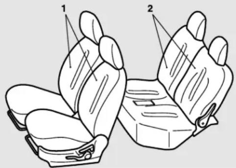
1 - Front seats
● To adjust the seat forward or backward → P.4-3
● To adjust the seatback → P.4-3
- To adjust the seat height (Driver's side only) P.4-4
● Heated seats → P.4-4
2 - Rear seats
● To adjust the seatback → P.4-5
● Folding the seatbacks forward → P.4-6
Seats and restraint systems
N00401600209
Your vehicle has seat belts and other features that help protect you and your passengers in an accident.
Seat belts are the most important safety device. When worn properly, seat belts can reduce the chance of serious injury or death in various types of crashes. For added protection during a severe frontal collision, your vehicle has a Supplemental Restraint System (SRS) with airbags for the driver and passengers. The seats, head restraints, and door
locks are also safety equipment, which must be used correctly.
Always check the following before you drive:
- That everyone in your vehicle is properly wearing their seat belt.
- That infants and small children are properly secured in appropriate child restraint systems in the rear seat.
● That all doors are fully closed and locked. - That seatbacks are upright, with head restraints properly adjusted.
4-2 Seat and restraint systems
Safety equipment cannot prevent injury or death in all motor vehicle accidents. You can help reduce the risk of injury or death, however, by following the instructions in this manual.
Front seats
NO401800386
Position the driver's seat as far back as possible while maintaining a position that still enables you to fully apply the pedals, easily control the steering wheel and safely operate the vehicle.
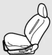
AA0105105
WARNING
- Do not attempt to adjust the seat while driving. This can cause loss of vehicle control and result in an accident.
● After adjusting the seat, make sure that the seat is securely locked into position.
WARNING
- To reduce the risk to the driver of serious injury or death during deployment of the driver's airbag, always properly wear the seat belt and adjust the driver's seat as far back as possible while maintaining a position that still enables you to fully apply the pedals, easily control the steering wheel, and safely operate the vehicle.
- To reduce the risk to the front passenger of serious injury or death during deployment of the passenger's airbag, always properly wear the seat belt and adjust the front passenger's seat as far back as possible.
● Always place children 12 years old and under in the rear seat and use appropriate child restraint systems.
CAUTION
● Make sure that the seat is adjusted by an adult. If it is adjusted by a child, an unexpected accident might occur.
- Do not place a cushion or the like between your back and the seatback while driving. The effectiveness of the head restraints will be reduced in the event of an accident.
- When sliding the seats, be careful not to catch your hand or leg.
- When sliding or reclining the seat rearward, pay careful attention to the rear seat passengers.
To adjust the seat forward or backward
N(04)1900303
Pull the seat adjusting lever up and slide the seat forward or backward to the desired position. Release the adjusting lever to lock the seat in place.
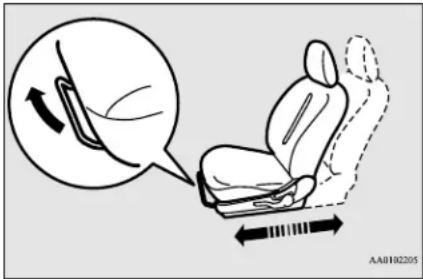
WARNING
- To make sure that the seat is locked, try to move it forward or backward without using the adjusting lever.
To adjust the seatback
N00402000356
To adjust the seatback, lean forward slightly, gently pull the seatback lock lever up, then lean backward to a comfortable position and
Front seats
release the lever. The seatback will lock in place.
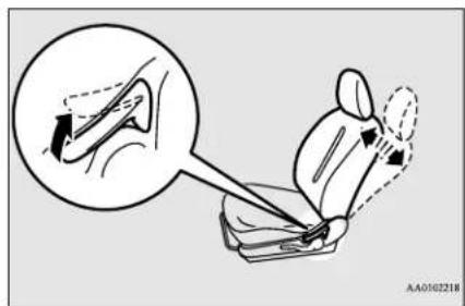
CAUTION
- The reclining mechanism used in the seatback is spring loaded, and will cause the seatback to return quickly to the vertical position when the lock lever is operated. When pulling the lever, sit close to the seatback or hold the seatback with your hand to control its return motion.
WARNING
- To reduce the risk of serious injury or death in the event of an accident or sudden stop, all seatbacks should be kept in the upright position while the vehicle is in motion.
Seat belt performance during an accident can be adversely affected if the seatbacks are reclined. The more a seatback is reclined, the more likely seat belt performance will be adversely affected. If the seat belt is not properly positioned against the body during an accident, there is increased risk you will slide under the belt and receive serious injury or death.
To adjust the seat height (Driver's side only)
N00402100230
Operate the lever repeatedly to raise or lower the seat.
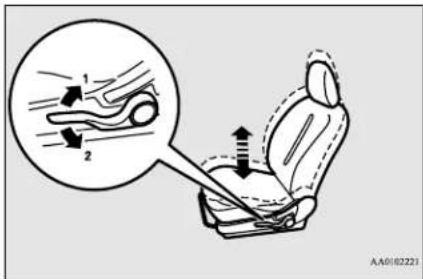
1- Raise
2-Lower
Heated seats
N00435601434
The heated seats can be operated when the electric motor switch is in the "ON" position.
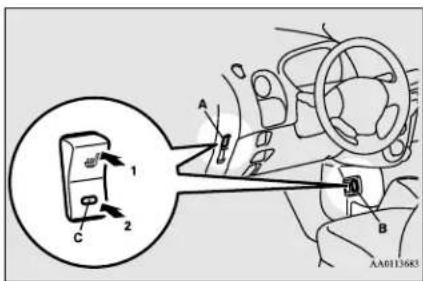
A- For the driver's seat
B- For the front passenger's seat
4-4 Seat and restraint systems
1- Heater on.
2- Heater off
The indicator light (C) will illuminate while the heater is on.

WARNING
- Persons who are unable to feel temperature change or skin pain due to age, illness, injury, medication, alcohol use, fatigue or other physical conditions or who have sensitive skin may suffer burns when using the heated seat even at low temperatures. To reduce the risk of burns, people with such conditions must use care when using the heated seat.

CAUTION
- Switch off the seat heater when not in use.
- Do not place heavy objects on the seat or stick pins, needles, or other pointed objects into the seat.
- Do not place a blanket, cushion, or other insulating material on the seat while using the heater; doing so can cause the heater element to overheat.
- When cleaning the seat, do not use benzine, kerosene, gasoline, alcohol, or other organic solvents; doing so can cause damage not only to the surface of the seat, but also to the heater.

CAUTION
- If water or any other liquid is spilled on the seat, allow it to dry thoroughly before attempting to use the heater.
● Turn the heater off immediately if it appears to be malfunctioning during use.

NOTE
- Do not turn the electric motor switch to the "ON" position; doing so will stop quick charging.
- You can use the heated seats while the Remote Climate Control is activated.
Refer to "Remote Climate Control" on page 3-36, 3-47 and "For persons with electro-medical apparatus such as implantable cardiac pacemaker or implantable cardiovascular defibrillator" on page 3-6.
Rear seats
N00402500218
CAUTION
● Child restraint lower anchorages (A) are provided between the seat cushion and the seat-back.
Be careful that the lower anchorages may be hot due to heat of the electric motor unit room.
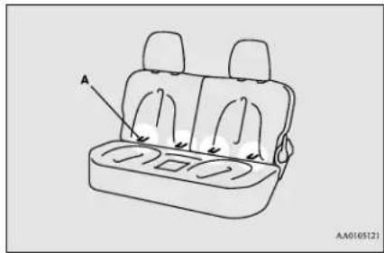
natural_image
Line drawing of a car backseat with seat covers and side seats, labeled A (no text or symbols on the diagram itself)To adjust the seatback
N00402800022
To adjust the seatback, lean forward slightly, gently pull the seatback lock lever, then lean backward to a comfortable position and release the lever. The seatback will lock in place.
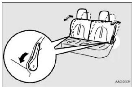
Head restraints

NOTE
- It is possible to adjust the seatback angle independently on each side.
4 Folding the seatbacks forward
N00402901219
The rear seatbacks can be folded forward to provide additional luggage compartment space.
Pull the lever, and fold the rear seatbacks forward. Confirm that the seatback locks securely when it is returned.
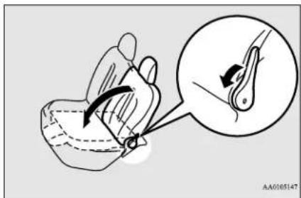

WARNING
- Do not allow anyone to ride in the center of rear seat or in the luggage compartment vehicle is in motion. People who are not properly seated and restrained can be seriously injured or killed in an accident.

WARNING
● To avoid reducing rearward vision, do not load cargo or luggage higher than the top of the seatback.
- Firmly secure cargo and luggage. Unsecured cargo and luggage can move during braking or in an accident, causing serious injury or death.

NOTE
- Do not push the lever toward the rear of the vehicle. Doing so could damage the lever and make it impossible to operate the seat-back.
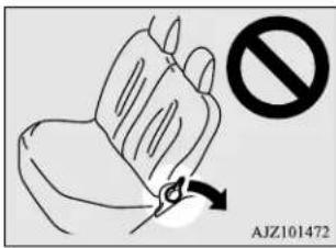
Head restraints
N00404300571
Padded head restraints for the seats can reduce the risk of a whiplash injury if your vehicle is hit from the rear.
The head restraints are equipped in the illustrated position.
To maximize the effectiveness of your head restraint, seatback to the upright position, and the head restraint to the proper position. Sit back against the seatback with your head close to the head restraint.
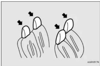
natural_image
Illustration of two finger joints with arrows indicating movement or force direction (no text or symbols)
WARNING
- In order to minimize the risk of a neck injury due to a rear impact, the head restraint must be adjusted to the proper position before vehicle operation. For the driver and front passenger, the seatbacks must be adjusted to the upright position before adjusting the head restraints. The driver should never adjust the seat while the vehicle is in motion.
4-6 Seat and restraint systems

WARNING
- Driving without the head restraints in place can cause you and your passengers serious injury or death in an accident. To reduce the risk of injury in an accident, always make sure the head restraints are installed and properly positioned when the seat is occupied.
- Never place a cushion or similar device on the seatback. This can adversely affect head restraint performance by increasing the distance between your head and the restraint.
Adjustment of the head restraint height
To reduce the risk of injury in an accident, adjust the head restraint height so that the center of the restraint is at your eye level when seated. Any person too tall for the restraint to reach their eye level when seated should raise the restraint to the highest locked position.
● To raise the restraint, pull it straight up.
● To lower the restraint, push down on it while pressing the lock knob (A) in the direction shown by the arrow.
● After adjusting the height, push down on the restraint to make sure it is locked in position.
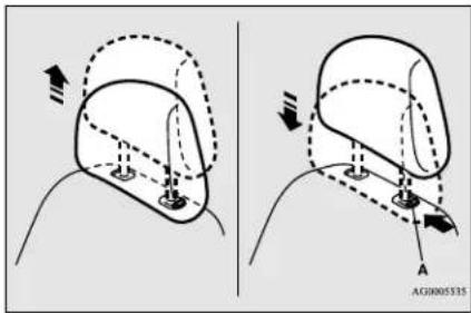
To remove
Press the lock knob (A) in the direction shown by the arrows. Then pull the head restraint up and out of the seatback.
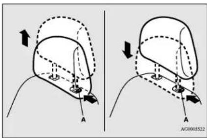

WARNING
- To help minimize the risk of neck injury in the event of an accident, the head restraints must be properly installed and positioned to proper height before vehicle operation.
To install
First check that the head restraint is facing in the right direction as shown in the previous illustration, and then insert it into the seat-back. Push the head restraint down while pressing the lock knob (A) until the restraint locks into place.

CAUTION
- Check that the lock knob (A) is extended out as shown in the illustration. Then pull the head restraint up to make sure that it is locked in place and will not come out of the seatback.
Seat belts
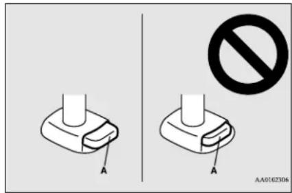
CAUTION
- The shape and size of the head restraint differs according to the seat. Always use the correct head restraint provided for the seat and do not install the head restraint in the wrong direction.
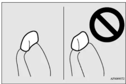
Seat belts
N00406001494
Seat belts are installed in your vehicle to help reduce the risk of injury to the driver and passenger in the event of an accident. Always use the provided seat belts.
Carefully review the following information for proper seat belt usage.
WARNING
- To help reduce the risk of injury or death in an accident, seat belts and child restraint systems must always be used. Refer to “Child restraint systems” on page 4-13 for additional information.
- Never use one seat belt for more than one person.
● Never carry more people in your vehicle than there are seat belts.
● Always adjust the seat belt for a snug fit.
● Always place the shoulder belt over your shoulder and across your chest. Never put it behind you or under your arm.
● Always wear the lap belt as low as possible across your hips, not around your waist. - Never modify or alter the seat belts in your vehicle.
WARNING
- To reduce the risk to the driver of serious injury or death during deployment of the driver's airbag, always properly wear the seat belt and adjust the driver's seat as far back as possible while maintaining a position that still enables you to fully apply the pedals, easily control the steering wheel, and safely operate the vehicle.
- To reduce the risk to a front seat passenger of serious injury or death from a deploying airbag, make sure the passenger always wears the seat belt properly, remains seated all the way back and upright in their seat, and moves the seat as far back as possible. Refer to “Supplemental Restraint System (SRS) - airbag” on page 4-20 for additional information.
- Never hold an infant or child in your arms or on your lap when riding in this vehicle even when you are wearing your seat belt. Never place any part of the seat belt you are wearing around an infant or child. Failure to follow these simple instructions creates a risk of serious injury or death to your child in the event of an accident or sudden stop.

WARNING
- Children 12 years old and under should always ride in the rear seat and be properly restrained. This reduces their risk of serious injury or death in an accident, especially due to a deploying front passenger's airbag. Refer to "Child restraint systems" on page 4-13 for additional information.
- Any child who is too small to properly wear a seat belt must be properly restrained in an appropriate child restraint system.
- Infants MUST be placed in a rear-facing child safety seat and positioned in the rear seat.
- In the event of an accident, all seat belt assemblies, including retractors and attachment hardware, should be inspected by a certified i-MiEV dealer to determine whether replacement is necessary.
Seat belt instructions
N10406200457
All seats are equipped with a seat belt which uses one combined lap-and-shoulder belt with an emergency locking retractor.
This system is designed to provide both comfort and safety. It permits full extension and automatic retraction of the belts during normal vehicle operation. A sensing device inside the belt retractor is designed to lock the
retractor in the event of a sudden change in the vehicle's motion.

NOTE
- For instructions on installing a child restraint system using a seat belt, refer to "Installing a child restraint system using the seat belt" on page 4-18.
- Occupants should always sit back in their seats with their backs against the upright seatback. To reduce the risk of serious injury or death during deployment of the airbag, adjust the driver's seat as far back as possible while maintaining a position that still enables you to fully apply the pedals, easily control the steering wheel, and safely operate the vehicle. The front passenger seat should also be moved as far back as possible. Refer to "Supplemental Restraint System (SRS) - airbag" on page 4-20. Also refer to "To adjust the seat forward or backward" on page 4-3.

natural_image
Line drawing of a person wearing a short-sleeve dress and holding a belt (no text or symbols)TAOOOIO8

WARNING
- To reduce the risk of serious injury or death in the event of an accident or sudden stop, all seatbacks should be kept in the upright position while the vehicle is in motion. Seat belt performance during an accident can be adversely affected if the seatbacks are reclined. The more a seatback is reclined, the more likely seat belt performance will be adversely affected. If the seat belt is not properly positioned against the body during an accident, there is increased risk you will slide under the belt and receive serious injury or death.
- Grasp the latch plate and slide it up the webbing so that it easily pulls across your body.
Seat belts
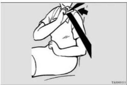
natural_image
Illustration of a person receiving a medical or therapeutic procedure, no text or symbols present- Pull the seat belt out slowly while holding the latch plate. Push the latch plate into the buckle until you hear a "click". Pull up on the belt to be sure the latch plate is locked securely in the buckle.
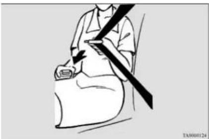
natural_image
Line drawing of a person sitting on a bed with a belt and diagonal stripe (no text or symbols)
NOTE
- If the seat belt locks up and cannot be pulled out, pull it once with force and let it retract all the way. Then, pull the belt out slowly once again.
4-10 Seat and restraint systems
- The lap part of the belt must always be worn low and snug across the hips. Pull up on the shoulder portion of the belt to take up any slack in the lap belt.
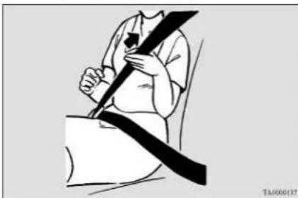
natural_image
Illustration of a person sitting on a seatbelt with a belt buckle (no text or symbols)
NOTE
- With the exception of the seat belt for the driver, the seat belts in all other seating positions are equipped with an Automatic Locking Retractor (ALR) function. If you pull the seat belt fully out of the retractor, the retractor will switch to its ALR child restraint installation function (see page 4-18). When the ALR function has been activated, the seat belt will only retract. If this happens, let the belt fully retract, then pull the seat belt back out, repeating steps 1 through 4.

WARNING
- Be sure the lap belt portion fits snugly and is worn as low as possible across the hips, not around the waist. Failure to follow this instruction will increase the risk of serious injury or death in the event of an accident.
-
Be sure the seat belt webbing is not twisted when worn. Twisted webbing may adversely affect seat belt performance.
-
To release the belt, press the button on the buckle and allow the belt to retract. If the belt does not retract smoothly, pull it out and check for kinks or twists in the webbing. Then make sure it remains untwisted as it retracts.
Driver's seat belt reminder/warning light
N00418400371
A tone and warning light are used to remind the driver to fasten the seat belt.
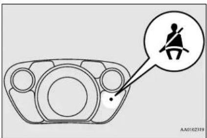
If the electric motor switch is turned to the "ON" position without the driver's seat belt being fastened, a warning light will come on, and a tone will sound for approximately 6 seconds to remind you to fasten your seat belt.
If the seat belt remains unfastened approximately 1 minute later, the warning light will flash and the tone will sound intermittently for approximately 90 seconds when the vehicle is driven.
If the seat belt subsequently remains unfastened, the warning light and tone will issue further warnings each time the vehicle starts moving from a stop. And if the driver unfastens the seat belt while driving, the warning will operate in the same way. When the seat belt is fastened, the warnings will stop.
WARNING
- In order to reduce the risk of serious injury or death in an accident, always wear your own seat belt. Do not allow anyone to ride in your vehicle unless he or she is also seated and wearing a seat belt. Children should additionally be restrained in a secure child restraint system.
Front passenger seat belt warning light
N00418300224
The front passenger seat belt warning light is located in the instrument panel.
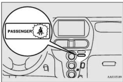
When the electric motor switch is turned to the "ON" position, this indicator normally comes on and goes off a few seconds later.
The light comes on when a person sits on the front passenger seat but does not fasten the seat belt.
It goes off when the seat belt is subsequently fastened.
WARNING
- When a child booster seat is used on the front passenger seat, the front passenger seat belt warning light will not come on, if the seat belt is not fastened when the booster seat is used. Confirm that the child is wearing the seat belt properly.
- Do not install any accessory or sticker that makes the light difficult to see.
Adjustable seat belt shoulder anchor (front seats)
N00406300328
The seat belt anchor height can be adjusted. To move the anchor, pull the lock knob (A) and slide the anchor to the desired position. Release the lock knob to lock the anchor into position.
Seat belt use during pregnancy
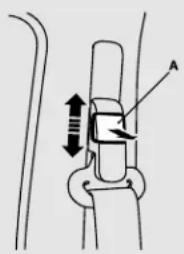
natural_image
Diagram of a mechanical joint or connector with directional arrows indicating movement (no text or symbols)AA0165192
WARNING
● Always adjust the shoulder belt anchor so that the shoulder belt is positioned across the center of your shoulder without touching your neck. The shoulder belt should not be able to fall off your shoulder. Failure to follow this instruction can adversely affect seat belt performance and increase the risk of serious injury or death in the event of an accident.
- Adjust the shoulder belt anchor only when the vehicle is not in motion.
● Make sure the anchor is securely locked in position after adjusting it.
Seat belt extender
N00406700087
When your seat belt, even fully extended, is not long enough, a seat belt extender must be
obtained. The extender may be used for either of the front seats.
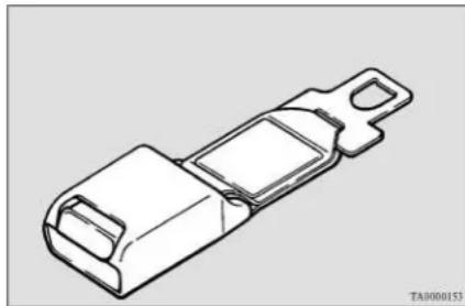
natural_image
Technical line drawing of a mechanical component (no text or symbols)WARNING
- The extender should only be used if the existing belt is not long enough. Anyone who can use the standard seat belt should not use an extender. Unnecessary use of an extender can adversely affect seat belt performance in an accident.
- When not required, the extender must be removed and stowed.
Seat belt use during pregnancy
N00406800121
Seat belts work for everyone, including pregnant women. Like all occupants, pregnant women are more likely to be seriously injured or killed in an accident if they do not wear seat belts.
WARNING
- To reduce the risk of serious injury or death to pregnant women and unborn children in an accident, pregnant women should always wear a seat belt. The lap portion of the seat belt should be worn snug and low across the hips and below the rounding. Consult your doctor if you have any additional questions or concerns.
Seat belt pre-tensioner and force limiter systems
N00417701736
The driver's and front passenger's seats each have a seat belt equipped with a pre-tensioner system and force limiter system.
Pre-tensioner system
The driver and front passenger seat belts are equipped with a seat belt pre-tensioner system. In moderate-to-severe front or side collisions, this system operates simultaneously with the deployment of the front airbags, side airbags or curtain airbags.
The seat belt pre-tensioners are located within the seat belt retractors (A). When activated,
4-12 Seat and restraint systems
the pre-tensioners quickly draw back seat belt webbing and increase seat belt performance.
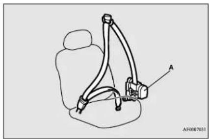
natural_image
Line drawing of a car seatbelt with labeled component A (no text or symbols beyond label)The seat belt pre-tensioner system includes the following components:
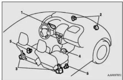
1- SRS warning light
2- Front impact sensors
3- Seat belt pre-tensioners
4- Airbag control unit
5- Side impact sensors
The airbag control unit monitors the readiness of the electronic parts of the system whenever the electric motor switch is in the "ON" or "START" position. These include all of the items listed above and all related wiring.
The pre-tensioner seat belt system will operate only when the electric motor switch is in the "ON" or "START" position.
When the seat belt pre-tensioners activate, some smoke is released and a loud noise will be heard. The smoke is not harmful, but care should be taken not to intentionally inhale it, as it may cause some temporary irritation to people with respiratory problems.
The pre-tensioners activate in the event of a moderate-to-severe front or side impact, even if the seat belt is not being worn. The seat belt pre-tensioners may not activate in certain frontal collisions, even though the vehicle may appear to be severely damaged. Such non-activation does not mean something is wrong with the seat belt pre-tensioner system, but rather that the collision forces were not severe enough or not of the type to activate the system.
WARNING
- The seat belt pre-tensioner system designed to work only once. After the seat belt pre-tensioners have been activated, they will not work again. They must promptly be replaced and the entire seat belt pre-tensioner system inspected by a certified i-MiEV dealer.
SRS warning light
N00408700124
This warning light tells you if there is a problem involving the SRS airbags and/or the pretensioner seat belts. Refer to "SRS warning light" on page 4-26.
Force limiter system
N00408900113
In the event of an accident, the seat belt force limiter system will help reduce the force applied to the driver and front seat passenger.
Child restraint systems
N00407101795
When transporting infants or small children in your vehicle, an appropriate child restraint system must always be used. This is required by law in the U.S. and Canada.
Child restraint systems
Child restraint systems specifically designed for infants and small children are offered by several manufacturers. Choose only a child restraint system with a label certifying that it complies with Federal Motor Vehicle Safety Standard 213 (FMVSS 213) or Motor Vehicle Restraint Systems and Booster Seats Safety Regulations (RSSR). Look for the manufacturer's statement of compliance on the box and child restraint system itself.
The child restraint system should be appropriate for your child's weight and height, and should properly fit your vehicle's seat.
For detail information, refer to the instruction manual accompanying the child restraint system.
Guidelines for child restraint system selection
All children should be properly restrained in a restraint device that offers the maximum protection for their size and age.
Be sure to check local, state, or provincial requirements for child size and age that may vary from the recommendations listed below.
● Children less than 1 year old and who weigh 22 pounds (10 kg) or less MUST ride in a rear-facing child safety seat that MUST ONLY be used in the rear seat.
4-14 Seat and restraint systems
● Children older than 1 year of age and who weigh less than 40 pounds (18 kg) or who are less than 40 inches (100 cm) tall must be in a forward-facing restraint used only in the rear seat.
- Children who weigh more than 40 pounds (18 kg) or who are more than 40 inches (100 cm) tall, regardless of age, should use a suitable child seat or a booster seat in the rear seat until the vehicle's lap/shoulder belt fits them properly.
WARNING
- All children must be seated in the rear seat, and properly restrained. Accident statistics show that children of all sizes and ages are safer when properly restrained in the rear seat, rather than in the front seat.
WARNING
- Any child who is too large to use a child restraint system should ride in the rear seat and wear the lap and shoulder belt properly. The shoulder belt must be positioned over the shoulder and across the chest, not across their neck, and with the lap belt positioned low on the child's hips, not across their stomach. If necessary, a booster seat should be used to help achieve a proper seat belt fit. Follow the booster seat manufacturer's instructions. Only use a booster seat that is certified as complying with Federal Motor Vehicle Safety Standards or Motor Vehicle Restraint Systems and Booster Seats Safety Regulations.
- Never hold an infant or child in your arms or on your lap when riding in this vehicle, even when you are wearing your seat belt. Never place any part of the seat belt you are wearing around an infant or child. Failure to follow these simple instructions creates a risk of serious injury or death to your child in the event of an accident or sudden stop.
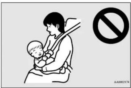
WARNING
- Your vehicle is also equipped with a front passenger's airbag.
Never put REAR-FACING CHILD RESTRAINT SYSTEMS or INFANT RESTRAINT SYSTEMS in the front passenger seat. This places the infant too close to the passenger's airbag. During deployment of the airbag, the infant can be seriously injured or killed. Rear-facing child restraint systems or infant restraint systems must only be used in the rear seat.
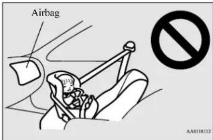
WARNING
- FRONT-FACING CHILD RESTRAINT SYSTEMS should be used in the rear seat whenever possible. If they must be used in the front passenger seat, move the seat to the most rearward position and make sure the child stays in the child restraint system, properly restrained. Failure to follow these instructions could result in serious injury or death to the child.
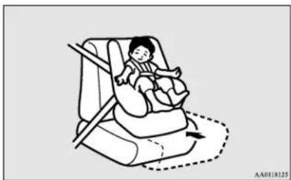
natural_image
Illustration of a child seated in a car seat using a seatbelt, with no text or symbols present.WARNING
- It is important to use an approved rear-facing infant restraint until the infant is one year old (unless the infant outgrows the seat sooner). This allows the infant's neck and spine to develop enough to support the weight of their head in the event of an accident.
- When installing a child restraint system, follow the instructions provided by the manufacturer and follow the directions in this manual. Failure to do so can result in serious injury or death to your child in an accident or sudden stop.
- After installation, push and pull the child restraint system back and forth, and side to side, to see that it is firmly secured. If the child restraint system is not installed securely, it may cause injury to the child or other occupants in the event of an accident or sudden stop.
- When not in use, keep your child restraint system secured with the seat belt, or remove it from the vehicle, in order to prevent it from being thrown around inside the vehicle during an accident.
Child restraint systems

NOTE
Before purchasing a child restraint system try installing it in the rear seat to make sure there is a good fit. Because of the location of the seat belt buckles and the shape of the seat cushion, it may be difficult to securely install some manufacturer's child restraint systems. If the child restraint system can be pulled forward or to either side easily on the seat cushion after the seat belt has been tightened, choose another manufacturer's child restraint system.
Depending on the seating position in the vehicle and the child restraint system that you have, the child restraint system can be attached using one of the following two methods:
• To the lower anchorage in the rear seat ONLY if the child restraint system is compatible with the LATCH system (See page 4-16).
• To the seat belt (See page 4-18).
Installing a child restraint system using the LATCH (Lower Anchors and Tethers for children) system
N00418800144
Lower anchor locations
The seating positions in the rear seat of your vehicle are equipped with lower anchors for attaching child restraint systems compatible with the LATCH system.
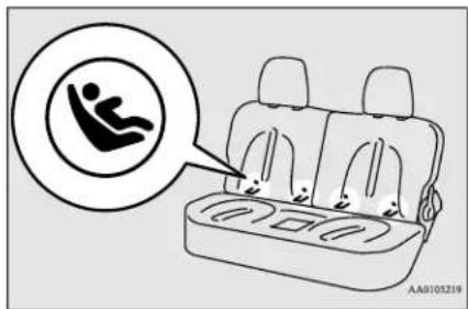
Tether anchor locations
N00418900187
Your vehicle has 2 attachment points on the floor of the luggage compartment. These are for securing a child restraint system tether strap to each of the 2 rear seating positions in your vehicle.
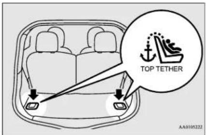

NOTE
● The symbols on the seatback show the location of the lower anchor points.
Examples of child restraint systems compatible with the LATCH system
N00419000185
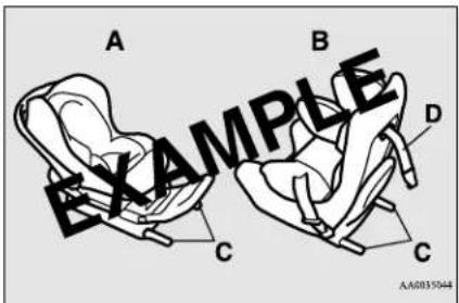
A- Rear-facing child restraint system
B- Front-facing child restraint system
C- Child restraint system lower anchor connectors
D- Tether strap (These are only examples.)
Using the LATCH system
N00419100229
- In order to securely fasten the tether strap, remove the head restraint from the location where you wish to install the child restraint system.
-
Open the gap a little between the seat cushion (A) and the seatback (B) with your hand to locate the lower anchorages (C).
-
Push the anchor connectors (D) on the child restraint system into the lower anchors (C) in accordance with the instructions provided by the child restraint system manufacturer. Remember, the lower anchors provided with your vehicle are designed to secure suitable child restraint systems compatible with the LATCH system in the outboard positions of the rear seat only.
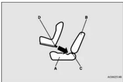
A- Vehicle seat cushion
B- Vehicle seatback
C- Lower anchor
D- Connector

NOTE
- In order to secure a child restraint system compatible with the LATCH system, use the lower anchor points in the rear seat. It is not necessary to use the vehicle's seat belt.
WARNING
- If there is any foreign material in or around the lower anchors, remove it before installing the child restraint system. Also, make sure the seat belt is away from, not looped through or otherwise interfering with, the child restraint system. If foreign matter is not removed and/or the seat belt interferes with the child restraint system, the child restraint system will not be secured properly, could detach and move forward in the event of sudden braking or an accident, and could result in injury to the child or other vehicle occupants.
-
When the vehicle is moving, do not adjust the seat where the child restraint system is installed.
-
Open the cover (E) for the tether anchor by pulling it back with your hand as illustrated below (4).
- Latch the tether strap hook (F) of the child restraint system to the anchor (G) as illustrated below (5) and tighten the top tether strap so it is securely fastened.
Child restraint systems
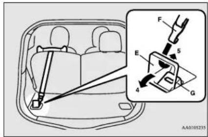
- Push and pull the child restraint system in all directions to be sure it is firmly secured.
WARNING
- Child restraint system tether anchors are designed only to withstand loads from correctly fitted child restraint systems. Under no circumstances are they to be used for adult seat belts, harnesses, for attaching other items, or equipment to the vehicle.
Installing a child restraint system using the seat belt (with emergency/automatic locking mechanism)
N00407301481
With the exception of the driver, the seat belt in all other seating positions can be converted
4-18 Seat and restraint systems
from normal Emergency Locking Retractor (ELR) mode to Automatic Locking Retractor (ALR) mode. This means that when you pull the seat belt fully out of the retractor, the retractor will switch to its ALR child restraint installation function. Always use the ALR child restraint installation function when you install a child restraint system using the seat belt.
Children 12 years old and under should always be restrained in the rear seat, whenever possible, although the front passenger seat belt can also be converted to ALR mode.
WARNING
- When you install a child restraint system using the seat belt, always make sure the retractor has been switched to the ALR child restraint installation function. The ALR function will keep the child restraint system tightly secured to the seat. Failure to convert the retractor to the ALR function may allow the child restraint system to move forward during sudden braking or an accident, resulting in serious injury or death to the child or other occupants.
Installation
- Place the child restraint system on the seat where you wish to install it. To help assure proper fitting of the child restraint system, always remove the head restraint.
- Route the seat belt through the child restraint system according to the instructions provided by the child restraint system manufacturer. Then insert the seat belt latch plate into the buckle. Make sure you hear a "click" when you insert the latch plate into the buckle.
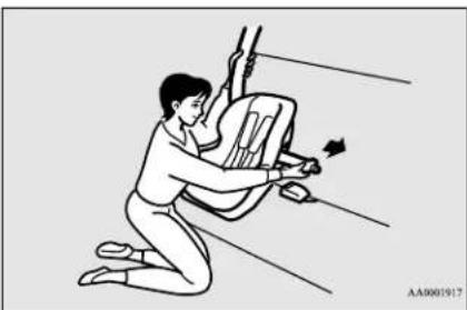
natural_image
Illustration of a person kneeling with tools, no text or symbols present- To activate the ALR child restraint installation function, slowly pull the shoulder part of the belt all the way out of the retractor until it stops. Then let the belt feed back into the retractor.
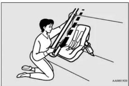
natural_image
Illustration of a person kneeling and working on a large mechanical device (no text or symbols visible)-
After the belt has retracted, tug on it. If the belt is in the ALR function, you will not be able to pull it out. If the webbing can be pulled out from retractor, the ALR function has not been activated and you will need to repeat steps 3 and 4.
-
After confirming that the belt is locked, grab the shoulder part of the belt near the buckle and pull up to remove any slack from the lap part of the belt allowing the slack to feed into the retractor. Remember, if the lap belt portion is not tight, the child restraint system will not be secure. It may help to put your weight on the child restraint system and/or push on its seat-back while pulling up on the belt (see illustration).
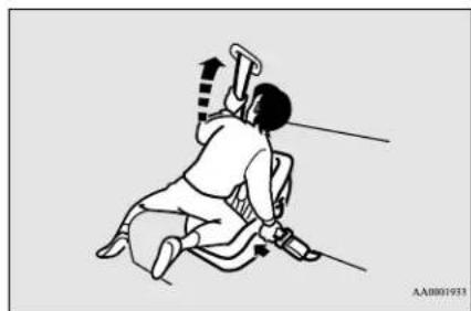
natural_image
Illustration of a person in motion, possibly performing a martial arts or exercise pose with a sword and rope (no text or symbols)If your child restraint system requires the use of a tether strap, fasten the tether strap in accordance with the following procedures.
- Open the cover from the tether anchor installation point by pulling it back with your hand as illustrated below (6).
- Latch the tether strap hook (A) of the child restraint system to the tether anchor (B) as illustrated below (7) and tighten the top tether strap so it is securely fastened.
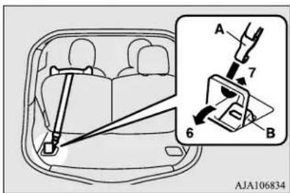
WARNING
- Child restraint system tether anchors are designed only to withstand loads from correctly fitted child restraint systems. Under no circumstances are they to be used for adult seat belts, harnesses, for attaching other items, or equipment to the vehicle.
-
Before putting your child in the restraint, push and pull the restraint in all directions to be sure it is firmly secured. Do this before each use. If the child restraint system is not firmly secure, repeat steps 1 through 7.
-
To remove a child restraint system from the vehicle and deactivate the ALR mode, remove the child from the restraint. Unlatch the buckle. Then remove the belt from the restraint and let the belt fully retract.
-
Reinstall the head restraint. Refer to "Head restraints" on page 4-6.
Children who have outgrown child restraint systems
N00407601615
Children who have outgrown a child restraint system should be seated in the rear seat and wear the seat belt. If the shoulder belt crosses their face or neck, and/or the lap belt crosses their stomach, a commercially available
Seat and restraint systems 4-19
Maintenance and inspection of seat belts
booster seat must be used, to raise the child so that the shoulder belt crosses their shoulder and the lap belt remains positioned low across their hips. The booster seat should fit the vehicle seat and have a label certifying compliance with Federal Motor Vehicle Safety Standards or Motor Vehicle Restraint Systems and Booster Seats Safety Regulations.
WARNING
- Any child who is too small to properly wear a seat belt must be properly restrained in an appropriate child restraint system, to reduce their risk of serious injury or death in an accident.
- A child should never be left unattended in, or unsupervised, around your vehicle. When you leave the vehicle always take the child out as well.
● Children can die from heat stroke if left or trapped inside the vehicle, especially on hot days. - Keep your vehicle locked when not in use. Keep your vehicle keys away from children.
Maintenance and inspection of seat belts
N00407000351
The seat belt webbing may be cleaned with mild soap or detergent solution. Do not use an organic solvent. Allow the belts to dry in the shade. Do not allow them to retract until completely dry. Do not attempt to bleach or redye the belts. The color may rub off and the webbing strength may be affected.
Regularly check your seat belt buckles and their release mechanisms for positive engagement and release of the latch plate. Check the retractors for automatic locking when in the Automatic Locking Retractor function.
The entire seat belt assembly should be replaced if the webbing shows any obvious cuts, tears, increase in thickness in any section of the webbing from broken fibers, or severe fading from sunlight. All of these conditions indicate a weakening of the belt, which may adversely affect seat belt performance in an accident.
WARNING
- Do not attempt to repair or replace any part of the seat belt assemblies. This work should be done by a certified i-MiEV dealer. Failure to have a certified i-MiEV dealer perform the work could reduce the effectiveness of the belts and could result in a serious injury or death in an accident.
Supplemental Restraint System (SRS) - airbag
N00407701834
This vehicle is equipped with a Supplemental Restraint System (SRS), which includes airbags for the driver and passengers.
The SRS front airbags are designed to supplement the primary protection of the driver and front passenger seat belt systems by providing those occupants with protection against head and chest injuries in certain moderate to severe frontal collisions.
The SRS front airbags, together with sensors at the front of the vehicle and sensors attached to the front seats, form an advanced airbag system.
The SRS side airbags and the curtain airbags are also designed to supplement the seat belts. The SRS side airbags provide the driver and front passenger with protection against chest,
abdomen and hip injuries by deploying the bag on the side impacted in moderate to severe side impact collisions. The SRS curtain airbags provide the driver and passengers on the front seat and rear seat with protection against head injuries by deploying a bag on the side impacted in moderate to severe side impact collisions.
The SRS airbags are NOT a substitute for use of the seat belts. For maximum protection in all types of accidents, seat belts must ALWAYS be worn by everyone who drives or rides in this vehicle (with infants and small children in an appropriate child restraint system in the rear seat, and older children buckled in the rear seat). Refer to “Child restraint systems” on page 4-13.
WARNING
- IT IS VERY IMPORTANT TO ALWAYS WEAR YOUR SEAT BELT PROPERLY EVEN WITH AN AIRBAG.
WARNING
- Seat belts help keep the driver and passengers properly positioned. This reduces the risk of injury in all collisions, and reduces the risk of serious injuries or death when the airbags inflate.
During sudden braking just before a collision, an unrestrained or improperly restrained driver or passengers can move forward into direct contact with, or within close proximity to, the airbag when it begins to inflate.
The beginning stage of airbag inflation is the most forceful and can cause serious injuries or death if the occupant comes in contact with the airbag at this time.
- Seat belts reduce the risk of injury in rollovers, rear impact collisions, and in lower-speed frontal collisions, because the airbags are not designed to inflate in those situations.
- Seat belts reduce the risk of being thrown from your vehicle in a collision or rollover.
- IT IS VERY IMPORTANT TO BE PROPERLY SEATED.
- A driver or front passenger sitting too close to the steering wheel or instrument panel during airbag deployment can be seriously injured or killed.
WARNING
- Airbags inflate very quickly and with great force. If the driver and front passenger are not properly seated and restrained, the airbag may not provide the proper protection and can cause serious injuries or death when it inflates.
- To reduce the risk to the driver of serious injury or death due to a deploying driver's airbag, always properly wear your seat belt and adjust the driver's seat as far back as possible, maintaining a position that still allows the driver to have good control of the steering wheel, brake, accelerator, and other vehicle controls.
- To reduce the risk to the front passenger of serious injury or death from a deploying passenger's airbag, make sure the passenger always wears the seat belt properly, remains seated upright and all the way back in the seat, and positions the seat as far back as possible.
- Seat all infants and children in the rear seat, properly restrained in an appropriate child restraint system.
- Airbags inflate very quickly and with great force. Do not sit on the edge of the seat or lean your head or chest close to the steering wheel or the instrument panel.
- Do not put your feet or legs on or against the instrument panel.
Supplemental Restraint System (SRS) - airbag
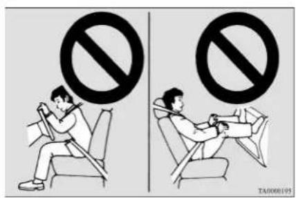
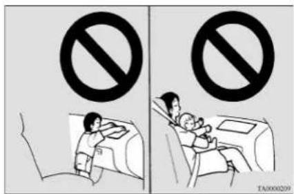
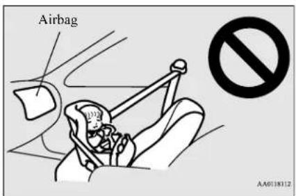
WARNING
- Infants and small children should never ride unrestrained, or lean against the instrument panel. They should never ride held in your arms or on your lap. They can be seriously injured or killed in an accident, especially when the airbags inflate. Infants and children should be properly seated in the rear seat in an appropriate child restraint system. Refer to "Child restraint systems" on page 4-13.
WARNING
- NEVER put REAR-FACING CHILD RESTRAINT SYSTEMS or INFANT RESTRAINT SYSTEMS in the front passenger seat. This places the infant too close to the passenger's airbag. During deployment of the airbag, the infant can be seriously injured or killed. Rear-facing child restraint systems or infant restraint systems must only be used in the rear seat.
WARNING
- FRONT-FACING CHILD RESTRAINT SYSTEMS should be used in the rear seat whenever possible. If they must be used in the front passenger seat, move the seat to the most rearward position and make sure the child stays in the child restraint system, properly restrained. Failure to follow these instructions could result in serious injury or death to the child.
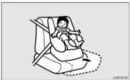
natural_image
Illustration of a baby sitting inside a car seat, with no text or symbols present.4-22 Seat and restraint systems

WARNING
- Older children should be seated in the rear seat with their seat belt properly worn, and with an appropriate booster seat if needed. Refer to "Children who have outgrown child restraint systems" on page 4-19.
How the Supplemental Restraint System works
N00407800489
The SRS includes the following components:
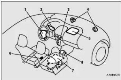
1- Driver's airbag
2- SRS warning light
3- Passenger's airbag off indicator
4- Front impact sensors
5- Passenger's front airbag
6- Driver's seat position sensor
7- Passenger's seat occupant classification sensor system
8- Airbag control unit
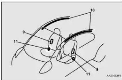
9- Side airbag modules
10- Curtain airbag modules
11- Side impact sensors
The airbag control unit monitors the readiness of the electronic parts of the system whenever the electric motor switch is in the "ON" or "START" position. These include all of the items listed above and all related wiring.
The airbags will operate only when the electric motor switch is in the "ON" or "START" position.
When the impact sensors detect a sufficient front or side impact to deploy the airbag(s), the appropriate airbag(s) will be deployed.
When airbags deploy, some smoke is released accompanied by a loud noise. The smoke is not harmful, but do not intentionally inhale the smoke as it may cause temporary irritation to people with respiratory problems.
After deployment, the airbags will quickly deflate, so quickly that some people may not even realize the airbags inflated.
Airbag inflation does not prevent the driver from seeing or being able to steer the vehicle, and does not prevent people from leaving the vehicle.

CAUTION
- Airbags inflate very quickly and with great force. In certain situations, contact with an inflating airbag may cause small cuts, abrasions, and bruises.
Event Data Recording
N00418600227
This vehicle is equipped with an event data recorder (EDR).
The main purpose of an EDR is to record, in certain crash or near crash-like situations, such as an airbag deployment or hitting a road obstacle, data that will assist in understanding how a vehicle's systems performed. The EDR is designed to record data related to vehicle dynamics and safety systems for a
Seat and restraint systems 4-23
Supplemental Restraint System (SRS) - airbag
short period of time, typically 30 seconds or less.
The EDR in this vehicle is designed to record such data as:
- How various systems in your vehicle were operating;
- Whether or not the driver safety belt was buckled/fastened;
- How far (if at all) the driver was depressing the accelerator and/or brake pedal; and,
● How fast the vehicle was traveling.
These data can help provide a better understanding of the circumstances in which crashes and injuries occur.

NOTE
- EDR data are recorded by your vehicle only if a non-trivial crash situation occurs; no data are recorded by the EDR under normal driving conditions and no personal data (e.g., name, gender, age, and crash location) are recorded. However, other parties, such as law enforcement, could combine the EDR data with the type of personally identifying data routinely acquired during a crash investigation.
To read data recorded by an EDR, special equipment is required, and access to the vehicle or the EDR is needed. In addition to the vehicle manufacturer, other parties, such as law enforcement, that have the special equipment, can read the information if they have access to the vehicle or the EDR.
Driver's seat position sensor
N00417900210
The driver's seat position sensor is attached to the seat rail and provides the airbag control unit with information on the seat's fore-aft position. The airbag control unit controls deployment of the driver's front airbag in accordance with the information it receives from this sensor.
If there is a problem involving the driver's seat position sensor, the SRS warning light in the instrument panel will come on. Refer to "SRS warning light" on page 4-26.
WARNING
- If the SRS warning light comes on, have the vehicle inspected by a certified i-MiEV dealer as soon as possible.
- Please observe the following instructions to ensure that the driver's seat position sensor can operate correctly.
- Adjust the seat to the correct position, and sit well back against the seatback. Refer to "Front seats" on page 4-3.
- Do not recline the seatback more than necessary when driving.

WARNING
- Do not place metallic objects or luggage under the front seat.
- If the vehicle is involved in a severe impact, have the SRS sensor inspected by a certified i-MiEV dealer as soon as possible.
Passenger's seat occupant classification sensor system
N00418000351
The passenger's seat occupant classification sensor system is attached to the front passenger seat cushion and provides the airbag control unit with information regarding the occupant on the front passenger seat. The airbag control unit controls deployment of the passenger's front airbag in accordance with the information it receives from this system. The passenger's front airbag will not deploy in an impact when the system senses no occupant on the front passenger's seat or a child in a child restraint system. In this case, the passenger's airbag off indicator will come on.
Refer to "Passenger's airbag off indicator" on page 4-25.
If there is a problem involving the passenger's seat occupant classification sensor system, the SRS warning light in the instrument panel will come on. Refer to "SRS warning light" page 4-26.

WARNING
- If any of the following conditions occur, you should immediately have your vehicle inspected by a certified i-MiEV dealer as soon as possible:
- The SRS warning light does not initially come on when the electric motor switch is turned to the "ON" or "START" position.
- The SRS warning light does not go out after several seconds.
- The SRS warning light comes on while you are driving.
- To ensure that the passenger's seat occupant classification sensor system can sense correctly, observe the following instructions. Failure to follow these instructions can adversely affect the performance of the passenger's airbag system.
- Adjust the seat to the correct position, and sit well back against the seatback. Refer to "Front seats" on page 4-3.
- Do not recline the seatback more than necessary.
- Never have more than one person (adult or child) sitting on the seat.
- Do not place anything between the seat and the floor console.
- When attaching a child restraint system, secure it firmly.
- Do not place luggage or other objects on the seat.
- Do not use a seat cover or a cushion.

WARNING
- Do not modify or replace the seat and seat belt.
- Do not place luggage or other objects under the seat.
- Do not place and use an electronic device such as a computer on the seat.
- Do not place heavy objects on the seat or stick pins, needles, or other objects into it.
- Do not remove the seat cushion skin.
- If any liquid is spilled on the seat, wipe it and dry the seat immediately.
- If the vehicle is involved in a severe impact, have the SRS sensors inspected by a certified i-MiEV dealer as soon as possible.
Passenger's airbag off indicator
N00418100310
The passenger's airbag off indicator is located in the instrument panel.
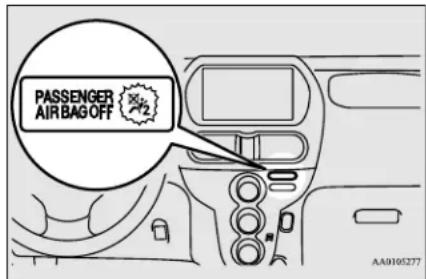
The indicator normally comes on when the electric motor switch is turned to the "ON" position and goes out a few seconds later.
In the following situations, the indicator will stay on to show that the passenger's front airbag is not operational.
- The front passenger's seat is not occupied.
- The system senses that a child is in the child restraint system on the front passenger's seat.
When the passenger's seat occupant classification sensor system senses there is a person seated in the front passenger's seat, the indicator goes out to show that the passenger's front airbag is operational.
Supplemental Restraint System (SRS) - airbag
WARNING
- If any of the following conditions occur, you should immediately have the airbag system in your vehicle inspected by a certified i-MiEV dealer as soon as possible:
- The passenger's airbag off indicator comes on when an adult is sitting on the front passenger seat.
- The passenger's airbag off indicator does not come on when the front passenger's seat is not occupied.
- The passenger's airbag off indicator does not come on when the electric motor switch is turned to the "ON" position.
- The passenger's airbag off indicator comes on and goes out repeatedly.
- Do not attach any accessory to your vehicle that makes the passenger's airbag off indicator difficult or impossible to see.
You must be able to see the passenger's airbag off indicator and verify the status of the passenger's airbag system.
SRS warning light
N00418301606
There is a Supplemental Restraint System (SRS) warning light on the instrument panel. The system checks itself every time the electric motor switch is turned on. The SRS warning light will come on for several seconds and then go out. This is normal and means the system is working properly. If there is a prob-
4-26 Seat and restraint systems
lem involving one or more of the SRS components, the warning light will come on and stay on. The SRS warning light is shared by the SRS airbag and the seat belt pre-tensioner system.
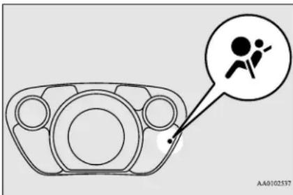
natural_image
Diagram of a mechanical component with a circular annotation and a stick figure icon (no text or symbols)WARNING
- If any of the following conditions occur there may be a problem with the SRS airbags and/or seat belt pre-tensioners, and they may not function properly in a collision or may suddenly activate without a collision:
- Even when the electric motor switch is in "ON" position, the SRS warning light does not come on or it remains on.
- The SRS warning light comes on while driving.
WARNING
The SRS airbags and seat belt pre-tensioners are designed to help reduce the risk of serious injury or death in certain collisions. If either of the above conditions occurs, immediately have your vehicle checked by a certified i-MiEV dealer.
Driver's and passenger's front airbag system
N00407900321
The driver's airbag is located under the pad-ded cover in the middle of the steering wheel. The front passenger's airbag is contained in the instrument panel above the glove compartment. The driver's airbag and the front passenger's airbag are designed to deploy at the same time. However, the front passenger's airbag does not deploy when the front passenger seat is not occupied or when the system senses that a child is in the child restraint system.
Supplemental Restraint System (SRS) - airbag
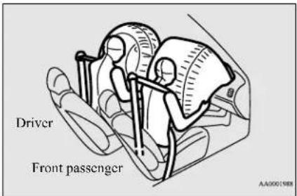
Deployment of front airbags
N00418000589
The front airbags ARE DESIGNED TO DEPLOY when...
Head-on collision with a solid wall at speeds of approx. 15 mph (25 km/h) or higher
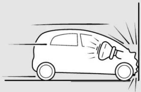
natural_image
Line drawing of a car with a megaphone emitting exhaust smoke, no text or symbols presentModerate to severe frontal impact within the shaded area between the arrows
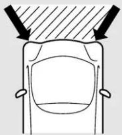
natural_image
Top-down diagram of a car's front view showing dashboard and seat (no text or symbols)AA1008421
Seat and restraint systems 4-27
Supplemental Restraint System (SRS) - airbag
The front airbags are designed to deploy when the vehicle suffers a moderate to severe frontal impact. A typical condition is shown in the illustration to the left.
The front airbags are designed to deploy only in certain moderate to severe frontal collisions within the shaded area between the arrows in the illustration to the right.
The front airbags will deploy if the impact to the vehicle's main structure is above a specific threshold level. The threshold level is approximately 15 mph (25 km/h) for a frontal collision straight into a solid flat wall that does not bend or deform. If the impact to the vehicle's main structure is below this threshold level, the front airbags may not deploy. This threshold level may also be higher if the vehicle hits something that absorbs the impact, either by bending or moving (for example, another stationary vehicle, a pole or a guard rail).
The beginning stage of airbag inflation is the most forceful, and can cause serious injuries or death if you are too close to the deploying airbag. Accordingly, it is important that you always wear the available seat belt.
The front airbags MAY NOT DEPLOY when ...
In certain types of front collisions, the front airbags may not deploy, even if the deformation of the body seems to be large, because the vehicle's body structure is designed to absorb the impact and deform in order to help protect the occupants. Some typical situations where the front airbags may not deploy are shown in the illustrations.
Because the front airbags do not protect the occupant in all types of frontal collisions, be sure to always wear your seat belts properly.
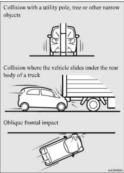
The front airbags ARE NOT DESIGNED TO DEPLOY when
The front airbags are not designed to deploy in situations where they cannot provide protection to the occupants.
Some typical situations are shown in the illustrations.
Because the front airbags do not protect the occupants in all types of collisions, be sure to always wear your seat belts properly.
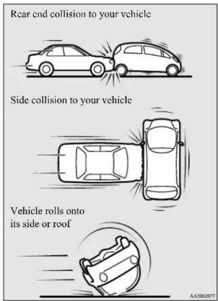
The front airbags MAY DEPLOY when ...
The front airbags may deploy if the underside of the vehicle suffers a moderate to severe impact (undercarriage impact). Some typical situations are shown in the illustrations.
Because the front airbags may deploy in certain types of unexpected impacts, as shown in the illustrations, and these unexpected impacts can move you out of position, it is important to always wear your seat belts properly. When worn properly, seat belts can help maintain your distance from the airbags when they begin to inflate. The beginning stage of airbag inflation is the most forceful and can cause serious injury or death if you are close to the deploying airbag.
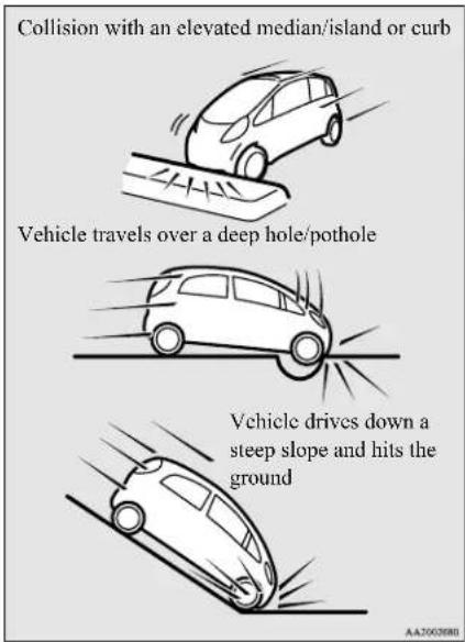
Supplemental Restraint System (SRS) - airbag
WARNING
- Do not attach anything to the steering wheel's padded cover, such as trim material, badges, etc. These could strike and injure an occupant if the airbag inflates.
- Do not set anything on, or attach anything to, the instrument panel above the glove compartment. Such items could strike and injure an occupant if the airbag inflates.
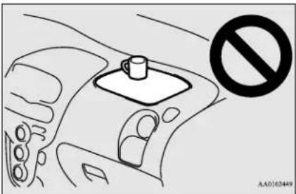
natural_image
Diagram of a car interior showing a hand holding a cup and a switch, with no visible text or symbols.WARNING
- Do not place objects, such as packages or pets, between the airbags and the driver or the front passenger. Such objects can adversely affect airbag performance, or cause serious injury or death when the airbag deploys.
- Immediately after airbag inflation, some parts of the airbag system will be hot. Do not touch them. You could be burned.
- The airbag system is designed to work only once. After the airbags deploy, they will not work again. They must promptly be replaced and the entire airbag system must be inspected by a certified i-MiEV dealer.
Side airbag system
N00408[004]8
The side airbags (A) are contained in the driver and front passenger seatbacks.
The side airbag is designed to inflate only on the side of the vehicle that is impacted, even with no passenger in the front seat.
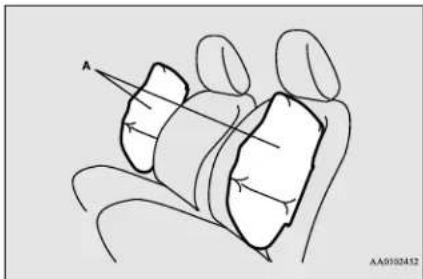
natural_image
Line drawing of a hand holding a car with a labeled point A (no text or symbols beyond label)A label is attached to the seatbacks in vehicles with side airbags.
WARNING
- Do not attach accessories to, or put them in front of, the windshield. They could restrict the airbag inflation, or strike and injure an occupant, when the airbag inflates.
- Do not attempt to remove, install, disassemble or repair the SRS airbags.
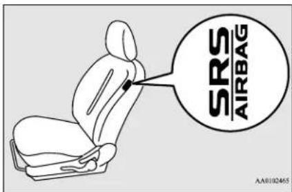
4-30 Seat and restraint systems
Curtain airbag system
N00419200204
The curtain airbags are contained in the front pillars and roof side rail. The curtain airbag is designed to inflate only on the side of the vehicle that is impacted, even with no passenger in the front seat.
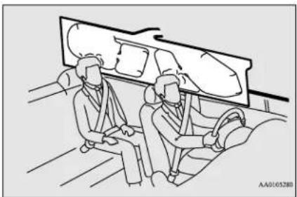
natural_image
Line drawing of two people seated in a car, facing each other with a vehicle in the background (no text or symbols)WARNING
- The side airbag and curtain airbag can cause serious injury or death to anyone too close to the airbag when it deploys. To reduce the risk of injury from a deploying side airbag and curtain airbags, all occupants must be properly restrained and seated well back, upright, and in the middle of the seat. Do not lean against the door.
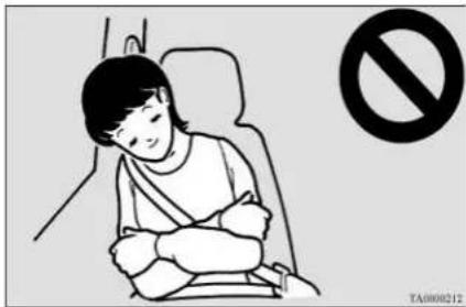
WARNING
- In order to reduce the risk of injury from a deploying side airbag, do not allow any rear seat passengers to hold onto the back of either front seat. Special care should be taken with children.
- Do not place any objects near or around the front of either front seatback. Such objects can interfere with proper side airbag deployment and cause injury during deployment of the side airbag.
- Do not place stickers, labels or additional trim on the back of either front seat. They can interfere with proper side airbag deployment.
- Do not install seat covers or re-cover seats that have side airbags. Covers can interfere with proper side airbag deployment and adversely affect side airbag performance.
WARNING
- Do not attach a microphone (A) or any other object around the part where the curtain airbag (B) deploys, such as on the windshield, side door glass or front and rear pillars and roof side rail. When the curtain airbag inflate, the microphone or other object may be hurled with great force or the curtain airbag may not inflate correctly, resulting in death or serious injury.
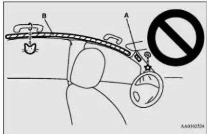
WARNING
● Never install a rear-facing child restraint system in the front passenger seat. Rear-facing child restraint systems MUST ONLY be used in the rear seat.
WARNING
- Front-facing child restraint systems should also be used ONLY in the rear seat. If a front-facing child restraint system must be used in the front passenger seat, move the seat as far back as possible, and make sure that the child stays in the child restraint system, properly restrained and away from the door.
- Do not allow a child to lean against or sit close to the passenger door, even if the child is seated in a child restraint system. The child's head should also not lean against or be close to the section of the seatback where the side airbag and curtain airbag are located. It is dangerous if the side airbag and curtain airbag deploys. Failure to follow all of these instructions could lead to serious injury or death to the child.
- Work done on or in the vicinity of the side airbag and curtain airbag system components should be done only by a certified i-MiEV dealer. Improper work methods can cause accidental side airbag and curtain airbag deployment, or render a side airbag and curtain airbag inoperable. Either of these situations can result in serious injury or death.
Deployment of side airbag and curtain airbag
N00408200523
The side airbag and curtain airbag ARE DESIGNED TO DEPLOY when ...
A side airbag and curtain airbag are designed to deploy when the vehicle suffers a moderate to severe side impact to the middle of the passenger compartment.
The typical situation is shown in the illustration.
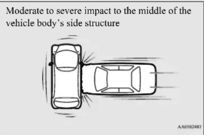
The seat belts in your vehicle are your primary means of protection in an accident. The SRS side airbags and curtain airbags are designed to provide additional protection. Therefore, for your safety and the safety of all
occupants, be sure to always wear your seat belts properly.
The side airbag and curtain airbag MAY NOT DEPLOY when ...
In certain types of side collisions, the side airbag and curtain airbag may not deploy, even if the deformation of the body seems to be large, because the vehicle's body structure is designed to absorb the impact and to deform in order to help protect the occupants. Some typical situations where the side airbag and curtain airbag may not deploy are shown in the illustrations.
Because the side airbags and curtain airbags do not protect the occupant in all types of side collisions, be sure to always wear your seat belts properly.
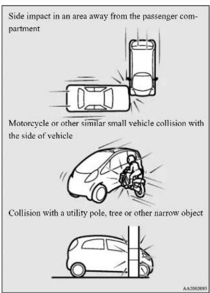
AA2002093
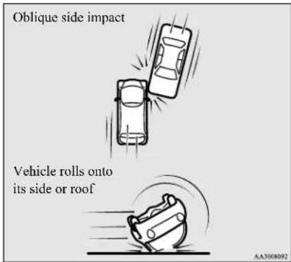
m = 311
The side airbag and curtain airbag ARE NOT DESIGNED TO DEPLOY when ...
The side airbag and curtain airbag are not designed to deploy in situations where they cannot provide protection to the occupants. Some typical situations are shown in the illustrations.
Because the side airbags and curtain airbags do not protect the occupants in all types of collisions, be sure to always wear your seat belts properly.
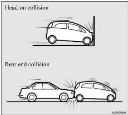
AA3008106
Supplemental Restraint System (SRS) - airbag
SRS servicing
N00408500715
WARNING
- Any maintenance performed on or near the components of the SRS should be performed only by a certified i-MiEV dealer.
Do not permit anyone else to do any service, inspection, maintenance or repair on any SRS components or wiring. Similarly, no part of the SRS should ever be handled, removed or disposed by anyone except a certified i-MiEV dealer.
Improper work methods on the SRS components or wiring could result in an accidental airbag deployment or could make the SRS inoperable. Either of these situations could result in serious injury or death. - Do not modify your steering wheel or any other SRS component or related vehicle part. For example, replacement of the steering wheel, or modifications to the front bumper or body structure can adversely affect SRS performance and may lead to injury.
- If your vehicle has received any damage, you should have the SRS inspected by a certified i-MiEV dealer to make sure it is in proper working order.
WARNING
- Do not modify your front seats, center pillar or center console. Such modifications can adversely affect SRS performance and may lead to injury.
Also, if you discover any tear or open seam in the seat fabric near the side airbag, have the seat inspected by a certified i-MiEV dealer. - If you find a crack in or damage to the front pillar, rear pillar, or roof side rail where the curtain airbag is located, have the SRS inspected by a certified i-MiEV dealer.
NOTE
- When you transfer ownership of the vehicle to another person, we urge you to alert the new owner that it is equipped with the SRS and refer that owner to the applicable sections in this owner's manual.
- If you decide to junk or scrap your vehicle, we urge you to first take it to a certified i-MiEV dealer so that the SRS can be made safe for disposal.
- If any of the following parts needs to be modified for use by a handicapped person, the advanced airbag system will be greatly affected. Please consult a certified i-MiEV dealer for assistance.
- Driver's seat
- Front passenger seat
- Front seat belt
NOTE
- Steering wheel
- Instrument panel
[For vehicles sold in U.S.A.]
To contact Mitsubishi Motors North America, Inc.
call 1-888-648-7820 or write to:
Mitsubishi Motors North America, Inc.
Customer Relations Department
P. O. Box 6400
Cypress, CA 90630-0064
[For vehicles sold in Canada]
To contact Mitsubishi Motor Sales of Canada, Inc.
call 1-888-576-4878 or write to:
Mitsubishi Motor Sales of Canada, Inc.
Customer Relations Department
P.O. Box 41009
4141 Dixie Road
Mississauga, ON L4W 5C9
Warning labels
N00408600370
Occupant restraint warning labels for the SRS are located in the vehicle as shown in the illustration.
Supplemental Restraint System (SRS) - airbag
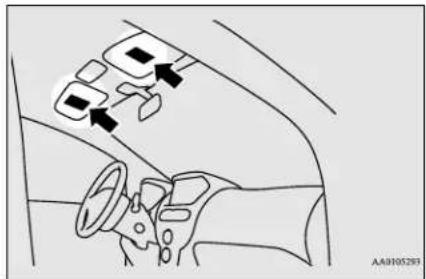
natural_image
Interior view of a car showing dashboard, steering wheel, and three directional arrows indicating movement or navigation (no text or symbols present)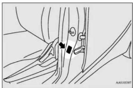
natural_image
Medical illustration showing surgical hardware and surgical instruments (no text or labels)Located in the passenger's side as well.
Seat and restraint systems 4-35
| 100% | |
| 100% | 100% |
| 100% | 100% |
| 100% | 100% |
| 100% | 100% |
| 100% | 100% |
| 100% | 100% |
| 100% | 100% |
| 100% | 100% |
| 100% | 10 |
Features and controls
Break-in recommendations 5-2
Keys 5-2
Electronic immobilizer (Anti-theft starting system) 5-2
Keyless entry system 5-5
Door locks 5-8
Child safety locks for rear door 5-10
Liftgate 5-11
Theft-alarm system 5-12
Power window control 5-14
Parking brake 5-16
Inside rearview mirror 5-16
Outside rearview mirrors 5-17
Electric motor switch 5-18
Steering wheel lock 5-20
Starting the electric motor unit 5-20
Selector lever 5-21
Acoustic vehicle alerting system (AVAS) 5-23
Service brake 5-24
Brake assist system 5-25
Anti-lock braking system 5-25
Electric power steering system (EPS) 5-27
Active stability control (ASC) 5-28
Tire pressure monitoring system 5-30
Rear-view camera (if so equipped)....5-34
Instrument cluster 5-36
Indicator and warning light package ....5-43
Indicators 5-44
Warning lights 5-44
Combination headlights and dimmer switch 5-46
Turn signal lever 5-49
Hazard warning flasher switch 5-49
Front fog light switch 5-50
Wiper and washer switch 5-50
Electric rear window defogger switch 5-52
Horn switch 5-53
Link System (if so equipped) 5-53
Bluetooth ^® 2.0 interface (if so equipped)....5-53
USB input terminal (if so equipped) 5-73
Sun visors 5-76
12 V power outlet 5-76
Interior lights 5-77
Storage spaces 5-79
Cup holder 5-80
Assist grip 5-81
Break-in recommendations
Break-in recommendations
N00518700343
Advanced automobile manufacturing techniques permit you to operate your new vehicle without requiring a long break-in period of low-speed driving.
However, you can add to the future performance and economy of your vehicle by observing the following precautions during the first 300 miles (500 km).
Drive your vehicle at moderate speeds during the break-in period.
- Do not overload the vehicle. Observe the seating capacity (See “Cargo load precautions” on page 6-10).
- Do not use this vehicle for trailer towing.
Keys
N00508800618
Two keys are provided.
The keys fit all locks. Keep one in a safe place as a spare key.
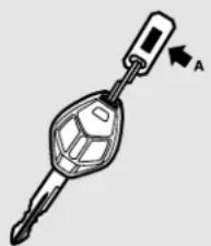
natural_image
Illustration of a key inserted into a car key (no text or symbols)
NOTE
- The key number (A) is stamped on the key number plate as shown in the illustration.
Make a record of the key number and store the key and key number plate in separate places, so that you can order a key from a certified i-MiEV dealer if the original keys are lost.
● The key is a precision electronic device with a built-in signal transmitter. Please observe the following in order to prevent damage. - Do not leave where it may be exposed to heat caused by direct sunlight, such as on top of the dashboard.
- Do not take the remote control transmitter apart.
- Do not excessively bend the key or subject it to strong impacts.
- Keep the remote control transmitter dry.
- Keep away from magnetic objects such as key holders.

NOTE
- Keep away from devices that produce magnetism, such as audio systems, computers and televisions.
- Do not clean with ultrasonic cleaners.
- Do not leave the key where it may be exposed to high temperature or high humidity.
- As your vehicle is equipped with an electronic immobilizer, the electric motor unit is designed so that it will not start if the ID code registered in the immobilizer computer and the key's ID code do not match. Refer to the section entitled "Electronic immobilizer" for details and key usage.
Electronic immobilizer (Anti-theft starting system)
N00509101846
The electronic immobilizer is designed to significantly reduce the possibility of vehicle theft. The purpose of the system is to immobilize the vehicle if an invalid start is attempted. A valid start attempt can only be achieved (subject to certain conditions), using a key “registered” to the immobilizer system. All of the keys provided with your new vehicle have been programmed to the vehicle’s electronics.
5-2 Features and controls

NOTE
- In the following cases, the vehicle may not be able to recognize the registered ID code from the key. This means the electric motor unit will not start even when the registered key is turned to the "START" position.
- When the key contacts a key ring or other metallic or magnetic object
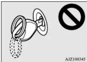
- When the key grip contacts metal of another key
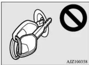

NOTE
- When the key contacts or is close to other immobilizing keys (including keys of other vehicles)
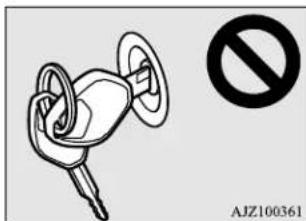
- In cases like the above, move the offending object(s) away from the key and turn the key back to the "ACC" or "LOCK" position. Then try to start the electric motor unit again. If the electric motor unit does not start, contact a certified i-MiEV dealer.
- Electronic immobilizer is not compatible with commercially available remote starting systems. Use of commercially available remote starting systems may result in vehicle starting problems and a loss of security protection.
- A system failure is suspected when the electric motor switch is turned to the "START" position, and the electric motor unit does not start. In such a case, contact a certified i-MiEV dealer.

CAUTION
- Do not make any alterations or additions to the immobilizer system. Alterations or additions could cause failure of the immobilizer.
Replacement keys
Only keys that have been programmed to the vehicle electronics can be used to start the vehicle.
If you lose a key, you can order a key from a certified i-MiEV dealer by referring to the key number.
To prevent vehicle theft, the ID code for the vehicle keys must be changed.
Take your vehicle and all remaining keys to a certified i-MiEV dealer to have your ID code changed.
Additional keys
To add a key, you need to register the ID code to the vehicle.
Registering the ID code can be done by a certified i-MiEV dealer. Or it can be done by yourself (except for vehicles sold in Canada). To register the ID code yourself, follow the "Customer key programming" procedure below.
Electronic immobilizer (Anti-theft starting system)
If you choose to have a certified i-MiEV dealer register the ID code, take your vehicle and any remaining keys to a certified i-MiEV dealer.

NOTE
- You are provided with 2 keys, but you may add up to 6 more keys.
Customer key programming (Except for vehicles sold in Canada)
N00562200113
You can program new keys to the system if you have two valid (already registered) keys and blank (not registered) immobilizer key (specially cut for your vehicle at a certified i-MiEV dealer) by doing the following:
- Insert the first valid key into the ignition and turn the ignition to the "ON" position for 5 seconds.
- Turn the ignition to the "LOCK" position and remove the first key.
-
Within 30 seconds of turning the first key to the "LOCK" position, insert the second valid key into the ignition and turn it to the "ON" position. About 10 seconds later, the immobilizer indicator will start blinking.
-
When the immobilizer indicator starts blinking, turn the second valid key to the "LOCK" position and remove it. Within 30 seconds after doing so, insert a blank immobilizer key into the ignition and turn it to the "ON" position. Perform this operation no more than 30 seconds after the immobilizer indicator starts blinking. When registration of the ID code is complete, the immobilizer indicator will come on for 3 seconds then go off. If an error occurs, the immobilizer indicator will go off during the procedure.
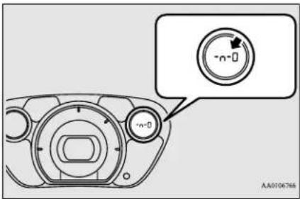
- If you wish to register another key, perform the process again from step 1.

NOTE
- It is not possible to register a key if:
• the immobilizer indicator goes off during the procedure

NOTE
- the immobilizer indicator does not come on for 3 seconds after turning the ignition to the "ON" position with a blank immobilizer key
- The procedure will be terminated automatically if:
- a period of 30 seconds or longer elapses from the moment when the first key is turned to the "LOCK" position to the moment when the second key is turned to the "ON" position
- a period of 30 seconds or longer elapses from the moment when the second key is turned to the "LOCK" position to the moment when the blank immobilizer key (specially cut for your vehicle at a certified i-MiEV dealer) is turned to the "ON" position
- more than 20 seconds elapse after the immobilizer indicator starts blinking
General information
NO0562319084
Your electronic immobilizer operates on a radio frequency subject to Federal Communications Commission (FCC) Rules (For vehicles sold in U.S.A.) and Industry Canada Rules (For vehicles sold in Canada). This device complies with Part 15 of the FCC Rules and RSS-Gen of the Industry Canada
5-4 Features and controls
Rules. Operation is subject to the following two conditions.
- This device may not cause harmful interference.
- This device must accept any interference received, including interference that may cause undesired operation.
This digital apparatus does not exceed the Class A limits for radio noise emissions from digital apparatus set out in the Radio Interference Regulations of the Canadian Department of Communications.

CAUTION
- Changes or modifications not expressly approved by the manufacturer for compliance could void the user's authority to operate the equipment.
Keyless entry system
N00509000910
Press the remote control transmitter buttons to lock or unlock the doors and to open the liftgate.
It can also help you signal for attention by setting off the panic alarm.
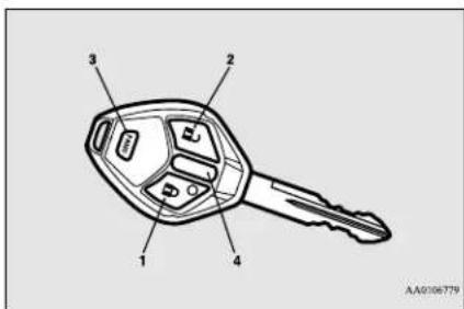
1- LOCK (button
2- UNLOCK (button
3- PANIC button
4- Indicator light
To loc k
Press the LOCK button (1) to lock all the doors and the liftgate.
If the dome light switch is in the door position, the dome light will blink once. The turn signal lights will also blink once.

NOTE
- If you press the LOCK button (1) after locking the doors and the liftgate, the horn will sound once to confirm that they are locked.
To unlock
Press the UNLOCK button (2) to unlock the driver's door only.
Within about 2 seconds, press the UNLOCK button one more time to unlock all the doors and the liftgate.
If the dome light switch is in the door position, the dome light will turn on for about 30 seconds. The turn signal lights will also blink twice.

NOTE
- If the UNLOCK button (2) is pressed and no door or liftgate is opened within approximately 30 seconds, relocking will automatically occur (automatic relocking function). The time for automatic relocking can be changed. For details, please contact a certified i-MiEV dealer.
- The door and liftgate unlock function can be set so that all doors and liftgate unlock when the UNLOCK button (2) is pressed once. For details, please contact a certified i-MiEV dealer.
Answerback function
The keyless entry system answerback functions from the horn can each be turned on or off as desired.
Features and controls 5-5
Horn deactivation/reactivation
The horn answerback function can be set to the following three conditions.
Each time the horn answerback function is set, a chime will sound to tell you the condition of the answerback function.
| Number of chimes | Condition |
| One chime The | horn will not sound. |
| Two chimes The | the horn will sound. |
| Three chimes | The horn will sound if the auto light switch is ON (if so equipped). |
| Four chimes | The horn will sound if the LOCK button is pressed twice quickly. |
- Remove the key from the electric motor switch.
- Open the driver's door and turn the combination headlights and dimmer switch to the "OFF" position.
- Press the LOCK button (1) for 4 to 10 seconds and press the UNLOCK button (2) during this time.
- Release in sequence the UNLOCK and LOCK buttons within 10 seconds of pressing the UNLOCK button in step 3.
Changing the setting of the turn signal lights answerback function
The turn signal lights answerback function can be changed.
If you want to change the answerback function, please contact a certified i-MiEV dealer for details.
Setting of door unlock function
N00543600105
The door and liftgate unlock function can be set so that all doors and liftgate unlock when the UNLOCK button (2) is pressed once. For details, please contact a certified i-MiEV dealer.
Using the panic alarm
N00543700050
If you are near your vehicle and feel threatened, you may activate the alarm to call attention as follows:
- Press the PANIC button (3) for more than 1 second.
- The headlights will blink on and off and the horn will sound intermittently for about 3 minutes.
- To turn off the alarm, press any button on the remote control transmitter.
Replacement remote control transmitters
N005438190177
Only remote control transmitters programmed with the vehicle's electronics can lock or unlock all doors.
If you lose the remote control transmitter, you can order a remote control transmitter from a certified i-MiEV dealer by referring to the key number.
To prevent vehicle theft, the ID codes for all the remote control transmitters except the one for the lost key must be programmed again.
Take your vehicle and all the remaining remote control transmitters to a certified i-MiEV dealer to have your ID codes programmed again.
Additional remote control transmitters
ND0543910165
To add a remote control transmitter, you must already have one registered remote control transmitter.
Registering the ID code can be done by yourself or by a certified i-MiEV dealer. For you to register the ID code yourself, follow the "Customer remote control transmitter programming" procedure below.
5-6 Features and controls
If you choose to have a certified i-MiEV dealer register the ID code, take your vehicle and all remaining keys to a certified i-MiEV dealer.

NOTE
- You are provided with 2 remote control transmitters, but you may register up to 4 remote control transmitters.
General information
N00546100101
Your keyless entry system operates on a radio frequency subject to Federal Communications Commission (FCC) Rules (For vehicles sold in U.S.A.) and Industry Canada Rules (For vehicles sold in Canada). This device complies with Part 15 of the FCC Rules and RSS-Gen of the Industry Canada Rules. Operation is subject to the following two conditions.
● This device may not cause harmful interference.
● This device must accept any interference received, including interference that may cause undesired operation.
CAUTION
- Changes or modifications not expressly approved by the manufacturer for compliance could void the user's authority to operate the equipment.
Procedure for replacing the remote control transmitter battery
N00544101133
- Before replacing the battery, remove static electricity from your body by touching a metal grounded object.
- With the Mitsubishi mark facing up, insert the cloth-covered tip of a flat blade screw-driver into the notch in the remote control transmitter case and use it to open the case.
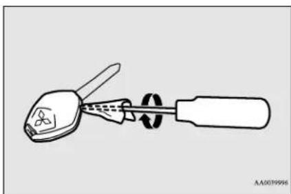
natural_image
Diagram of a screwdriver tool connecting a connector to a flat screwdriver (no text or symbols)
NOTE
- Be sure to perform the procedure with the Mitsubishi mark facing up. If the Mitsubishi mark is not facing up when you open the remote control transmitter case, the buttons may come out.
- Remove the remote control transmitter from the remote control transmitter case. Then, open the remote control transmitter using the method described in step 2.
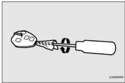
natural_image
Diagram of a tool with a handle and screwdriver, no text or symbols present- Remove the old battery.
- Install a new battery with the + side (A) down.
Door locks
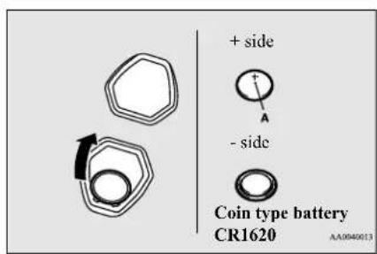
- Close the remote control transmitter firmly.
- Place the remote control transmitter in the remote control transmitter case, then securely close the remote control transmitter case.
- Check the keyless entry system to see that it works.

NOTE
- A certified i-MiEV dealer can replace the battery for you if you prefer.

CAUTION
- When the remote control transmitter case is opened, be careful to keep water, dust, etc. out. Also, do not touch internal components.
Door locks
N005(920)534
WARNING
● Make sure all doors are tightly closed and locked while driving.
- Locked doors, in combination with the use of seat belts, can help reduce the risk of ejection in an accident.
- Locked doors can help keep passengers, especially small children, from opening doors and falling out of moving vehicles.
- Locked doors can help prevent outsiders from gaining access to your vehicle when you slow down or come to a stop.
- Lock your vehicle whenever you leave it. Children who get into unlocked vehicles may not be able to get out. Children trapped inside vehicles can quickly be overcome by heat and suffer serious injury or death due to heat stroke.
- Never leave children unattended inside a vehicle. In addition to the risk of heat stroke, children can activate switches and controls, resulting in an injury or fatal accident.
To lock or unlock the door with the key
Turn the key toward the front of the vehicle to lock the door. After checking that the door is locked, turn the key back to the center and remove it.

1- Insert or remove the key
2-Lock
3- Unlock
5-8 Features and controls
To lock or unlock the door from the inside
Move the lock knob to the lock position to lock the door.
All doors should be kept locked while driving.
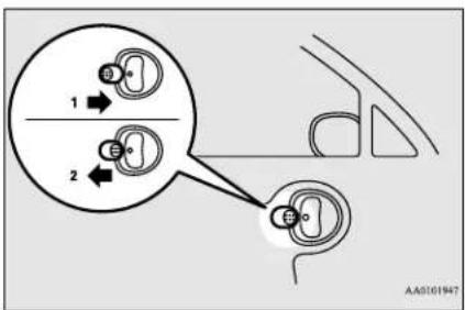
1-Lock
2- Unlock
The driver's door can be unlocked without using the lock knob by pulling on the inside door handle.
To lock the door without using the key
-
Move the inside lock knob to the locked position.
-
Be sure the keys are not inside the vehicle. Close the door.
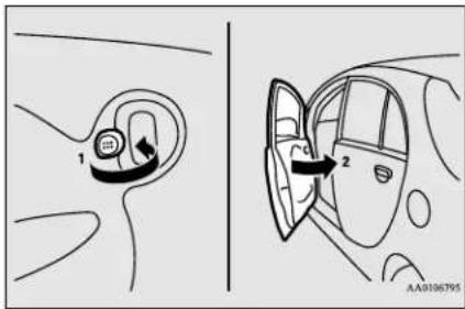
Key reminder buzzer
N00549600240
If you open the driver's door while the key is in the "LOCK" or "ACC" position, a tone will sound, reminding you to remove the key.
Lock out protection
N00549700179
If the key is in the electric motor switch when you push the lock knob forward with the driver's door or passenger's door open, the lock knob will automatically return to the unlocked position.
Power door locks
N00509300607
NOTE
- When locking or unlocking with the key on the driver's door, only the driver's door will lock or unlock.
- Repeated continuous operation between lock and unlock could activate the power door locking systems built-in protection circuit and prevent the system's from operating. If this occurs, wait about 1 minute before operating the power door lock switch.
Child safety locks for rear door
To lock and unlock by the power door lock switch
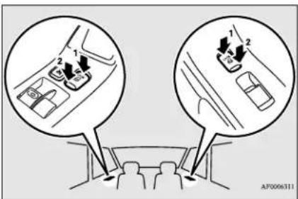
1-Lock
2- Unlock
All of the doors and the liftgate can be locked or unlocked by operating the power door lock switch on the driver's or the passenger's door.
To unlock the doors and liftgate
N00563400095
You can select the functions to unlock the doors and liftgate either using the electric motor switch position or using the selector lever position.
These functions are not activated when the vehicle is shipped from the factory. To activate or deactivate these functions, please contact a certified i-MiEV dealer.
5-10 Features and controls
Using the selector lever position
All doors and the liftgate will unlock when the selector lever is moved to the "P" (PARK) position with the electric motor switch in the "ON" position.
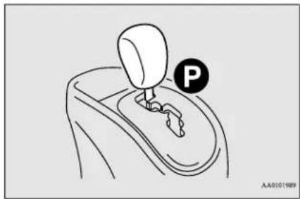
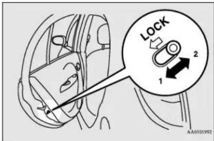
1- To lock
2- To release
Child safety locks help prevent rear passengers, especially children, from opening the rear door using the inside door handle.
A lock lever for the child safety lock is provided on each rear door.
When the lever is in the lock position (1), the rear door cannot be opened using the inside door handle.
To open the rear door when the child safety lock lever is in the lock position, pull the outside door handle.
When the lever is in the release position (2), the child safety lock is released and the rear
door can be opened using the inside door handle.
WARNING
● Always keep the doors tightly closed and locked when driving. An unlocked door may be accidentally opened by a passenger, especially by a child who could fall out. Also, if the doors are not locked, there is a greater risk of someone being thrown from the vehicle in an accident.
Liftgate
N01510101266
WARNING
- When opening and closing the liftgate, make sure that there are no people nearby and be careful not to hit your head or pinch your hands, neck, etc.
- If snow or ice has accumulated on the liftgate, remove it before opening the liftgate. Otherwise the liftgate may abruptly close due to the weight of the snow or ice.
- When opening the liftgate, always fully open it. A partially opened liftgate can unexpectedly close due to its own weight.
- When the vehicle is parked on a slope, the effort required to open or close the liftgate may be greater or less than expected. The liftgate may also open or close more quickly.
CAUTION
● To avoid damage to the liftgate, make sure the area above and behind the liftgate is clear before opening it.
To open
After unlocking the liftgate, push the switch (A) and pull up the liftgate.
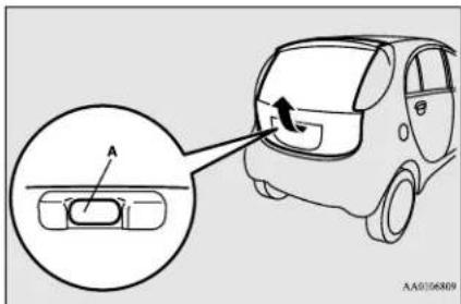
NOTE
- If you do not open the liftgate immediately after pulling the handle, the liftgate can not be lifted. If this happens, pull the handle again and lift the liftgate.
● The liftgate cannot be opened when the battery is flat or disconnected.
To close
Pull the liftgate grip (A) downward as illustrated. Gently push the upper gate from the outside with enough force so that it is completely closed. Always ensure the liftgate is securely closed.
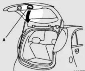
CAUTION
● To avoid injuring your hand or arm, do not attempt to close the liftgate the gate grip (A).
- Before starting the vehicle, be sure to confirm that the liftgate is locked. If the liftgate opens while driving the vehicle, objects stored in the luggage compartment could fall out into the road.
- When closing the liftgate, always ensure that everybody removes their hands and fingers from the liftgate opening.
Theft-alarm system

NOTE
● Gas struts (B) are installed to support the lif-gate.
To prevent damage or faulty operation.
- Do not hold the gas struts when closing the liftgate.
- Also, do not push or pull on the gas struts.
- Do not attach any plastic material, tape, etc., to the gas struts.
- Do not tie anything, etc., around the gas struts.
- Do not hang any objects on the gas struts.
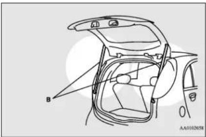
Theft-alarm system
N00510200244
The theft-alarm system is designed to provide protection from unauthorized entry into the vehicle. This system is operated in three stages: the first is the "armed" stage, the sec-
ond is the "alarm" stage, and third is the "disarmed" stage. If triggered, the system provides both audible and visual alarm signals.
CAUTION
- Do not modify or add parts to the theft-alarm system. Doing so could cause the theft-alarm to malfunction.
Armed stage
Park the vehicle and stop the electric motor unit. Arm the system as described below.
- Remove the key from the electric motor switch.
- Lock all doors and the liftgate by using the keyless entry system.
Arm the system and leave
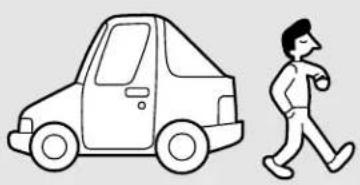
natural_image
Simple line drawing of a car and a walking person (no text or symbols)AA0056858
At this time, the theft-alarm indicator (A) in the meter cluster flashes for confirmation.
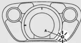
natural_image
Technical line drawing of a mechanical component with circular features and a central axis (no text or symbols)AA0106812
- The system has entered the armed stage after about 20 seconds, when the theft-alarm indicator flashing becomes slower. The theft-alarm indicator continues to flash while the system is in the armed stage.

NOTE
- The system will be disarmed if, while the theft-alarm indicator is illuminated, all doors and the liftgate are unlocked by using the keyless entry system.
- The system will be disarmed if, while the theft-alarm indicator is illuminated, the electric motor switch is turned to the "ON".
- The system will not be armed if a door or the liftgate is not completely closed. If this happens, rearm the system as described above.
5-12 Features and controls

NOTE
- The theft-alarm system can be activated when people are riding inside the vehicle or when the windows are open. To prevent accidental activation of the alarm, do not set the system to the system armed mode while people are riding in the vehicle.
- If the answerback function (flashing of the turn signal lights by locking and unlocking the doors and the liftgate) is deactivated, the turn signal lights do not flash after the locking and unlocking operation. For information on the answerback function, refer to "Keyless entry system" on pages 5-5.
Alarm stage
The alarm will be activated if the following occurs while the vehicle is parked and the system is armed.
● One of the doors and the liftgate is opened without using the keyless entry system.
Type of alarm
When the alarm is activated:
- The headlights blink on and off for 3 minutes.
After 3 minutes the headlights automatically shut off.
- The horn will sound intermittently for 3 minutes.
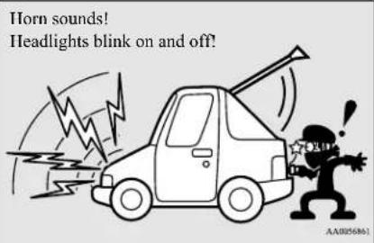

NOTE
- The alarm will continue to operate for 3 minutes. At the end of that period, the alarm will automatically shut off to save battery power. The system will then be rearmed until the proper disarming step is taken.
- The alarm will resume if unauthorized actions are taken again, even if the alarm has stopped.
Alarm deactivation
The alarm can be deactivated in the following ways.
- By using the keyless entry system to lock or unlock the doors and liftgate.
- Turn the electric motor switch to the "ON" position.
Disarmed stage
The system will be disarmed if the following operation is performed.
- The electric motor switch is turned to the "ON" position.
- All doors and the liftgate are unlocked by using the keyless entry system.
Disarm...by using the keyless entry system
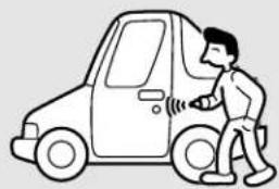
natural_image
Line drawing of a person standing beside a car door, no text or symbols presentAAD070940

NOTE
- If the UNLOCK button on the remote control transmitter is operated when all doors and the liftgate are closed and no door is opened within approximately 30 seconds, re-arming will automatically occur.
Power window control

NOTE
- The amount of time after unlocking until the vehicle relocks automatically can be adjusted. See a certified i-MiEV dealer for details.
- Once the system has been disarmed, it cannot be rearmed except by repeating the arming procedure.
Testing the theft-alarm system
Use the following procedure to test the system:
- Lower the driver's window.
- Arm the system as explained in "Armed stage".
- Make sure that the theft-alarm indicator comes on and flashes for approximately 20 seconds.
- Wait a few seconds and then unlock the driver's side door by using the inside door lock knob. Open the door.
- Make sure that the horn sounds intermittently and the headlights blink when a door is opened.
- Disarm the system by unlocking all doors and the liftgate by using the keyless entry system.
Power window control
N00510801410
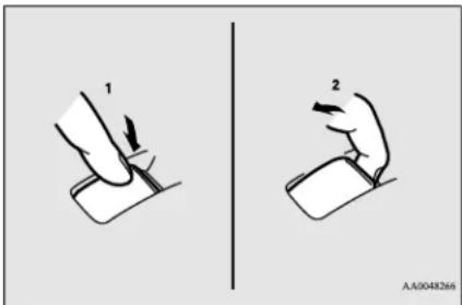
1- Open (down)
2- Close (up)

NOTE
- Never try to operate the main switch and sub-switch in different directions at the same time. This will freeze the window in position.
- Operating the power windows repeatedly with the electric motor unit stopped will run down the 12V starter battery. Use the window switches only while the electric motor unit is operating.
- Do not turn the electric motor switch to the "ON" position during quick charging. Doing so will stop quick charging.

WARNING
- Before operating the power windows, make sure that nothing can be trapped (head, hands, fingers, etc.) in the window.
- Never leave the vehicle without carrying the key.
● Never leave children or unreliable adults unattended inside the vehicle.
5-14 Features and controls
Main switch
N00548700127
The main switch located on the driver's door can be used to operate all the windows.
A window can be opened or closed by operating the corresponding switch.
Press the switch down to open the window, and pull up the switch to close it.
If the driver's door window switch is fully pressed down, the driver's door window automatically opens completely.
If you want to stop the window movement, operate the switch lightly in the reverse direction.
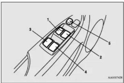
1- Driver's door window switch
2- Front passenger door window switch
3- Left rear door window switch
4- Right rear door window switch
5- Lock switch
Sub switch
N00548800115
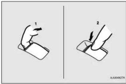
1-Close
2-Open
Each sub-switch can be used for it's own passenger door window, unless the driver's window lock switch is activated.
Power window timer function
N00548900145
The power windows can be run up or down when the electric motor switch is in the "ON" position.
The door windows can be opened or closed for a 30-second period after the electric motor switch is turned to the "ACC" or "LOCK" position. However, once the driver's door or the front passenger's door is opened, the power windows cannot be operated.
Lock switch
N00549000156
When this switch is in the lock mode, the passenger door switches cannot be used to open or close the door windows, and the main switch will open or close only the driver's door window. To unlock the switch, press it again.
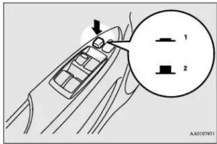
1-Lock
2- Unlock
WARNING
- Before driving with a child in the vehicle, be sure to lock the window switch to make it inoperative. Children tampering with the switch could easily trap their hands or heads in the window.
Parking brake
Parking brake
N00511400386
To park the vehicle, first bring it to a complete stop, fully engage the parking brake, and set the selector lever to "P" (PARK) position.
5
To apply
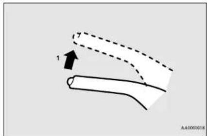
natural_image
Diagram of a curved pipe or tube with dashed lines indicating flow direction, no text or symbols present1- Pull the lever up without pushing the button at the end of hand grip.
When the parking brake is set and the electric motor switch is in the "ON" position, the brake warning light in the instrument cluster will come on.
Before driving, be sure to release the parking brake.
To release
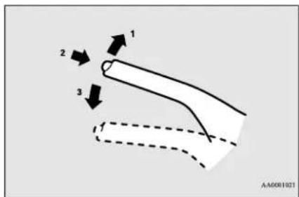
1- Pull the lever up slightly.
2- Press and hold the button at the end of the hand grip.
3- Push the lever downward.
When parking on a hill, apply the parking brake and turn the front wheels toward the curb on a downhill grade, away from the curb on an uphill grade.
CAUTION
- Before driving, be sure that the parking brake is fully released and brake warning light is off.
If a vehicle is driven without releasing the parking brake, the brakes will be overheated, resulting in ineffective braking and possible brake failure.
Inside rearview mirror
N00511600287
Adjust the inside rearview mirror only after making any seat adjustments so as to have a clear view to the rear of the vehicle.

WARNING
- Do not attempt to adjust the inside rearview mirror while driving. This can be dangerous.
Be sure to adjust the mirror before driving.
Adjust the inside mirror to maximize the view through the rear window.
To adjust the vertical mirror position
It is possible to move the mirror up and down to adjust its position.
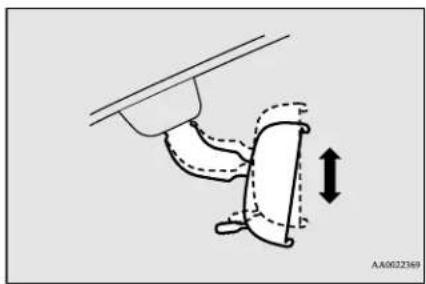
natural_image
Diagram of a hand holding a curved object with dashed lines indicating motion, no text or symbols presentTo adjust the mirror position
It is possible to move the mirror up/down and left/right to adjust its position.
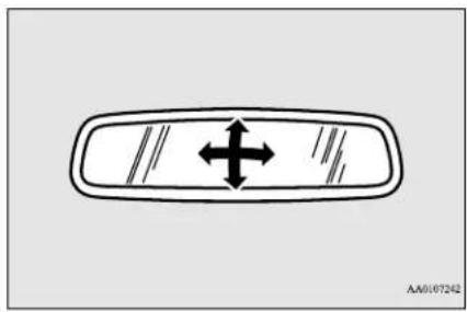
natural_image
Simple diagram of a vehicle rearview with bidirectional arrows indicating left and right directions (no text or symbols)To reduce the glare
The day/night knob (A) at the bottom of the mirror can be used to adjust the mirror to reduce the glare from the headlights of vehicles behind you during night driving.
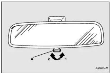
1-Daytime position
2- Night position
Outside rearview mirrors
N00512200222
Adjust the outside rearview mirrors only after making any seat adjustments so you have a clear view to the rear of the vehicle.
WARNING
- Do not attempt to adjust the outside rearview mirrors while driving. This can be dangerous.
Be sure to adjust the mirrors before driving. - Your front passenger's side mirror is convex. The objects you see in the mirror will look smaller and farther away than they appear in a regular flat mirror.
Do not use this mirror to estimate the distance of vehicles following you when changing lanes.
Electric motor switch
To adjust the mirror position
The outside rearview mirrors can be adjusted when the electric motor switch is in the "ON" or "ACC" position.
Move the lever (A) to the same side as the mirror you wish to adjust.
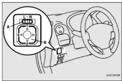
L- Left outside mirror adjustment
R- Right outside mirror adjustment
Press the switch (B) to adjust the mirror position.
1-Up
2-Down
3- Right
4- Left

NOTE
- After adjusting, return the lever to the “(off) position.
To fold the mirror
The outside mirror can be folded in toward the side window to prevent damage when parking in tight locations.
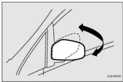
natural_image
Diagram of a car side mirror with curved arrows indicating rotation (no text or symbols)Heated mirror
N00549301231
When the rear window defogger switch is pressed, the outside rearview mirrors are defogged or defrosted. Current will flow through the heater element inside the mirrors, thus clearing away frost or condensation.
The indicator light (C) will illuminate while the defogger is on.
The heater will be turned off automatically in about 20 minutes.
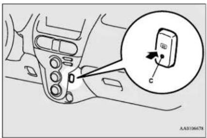
Electric motor switch
N00571500011
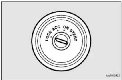
5-18 Features and controls
LOCK
The steering wheel is locked. The key can be inserted and removed only when the switch is in this position.
ACC
The ready indicator is not illuminated, but the audio system and other electric devices can be operated.
ON
The electric motor unit is running, and all the vehicle's electrical devices can be operated.
START
The electric motor unit operates. After the electric motor unit has started, release the key and it will automatically return to the "ON" position.

NOTE
- Your vehicle is equipped with an electronic immobilizer. To start the electric motor unit, the ID code which the transponder inside the key sends must match the one registered to the immobilizer computer. (Refer to "Electronic immobilizer" on page 5-2.)
ACC power auto-cutout function
N00573800021
After about 30 minutes has elapsed with the electric motor switch in the "ACC" position, the function automatically cuts out the power for the audio system and other electric devices that can be operated with that position.
When the electric motor switch is turned from the "ACC" position, the power is supplied again to those devices.

NOTE
- It is possible to modify functions as follows - The ACC power auto-cutout function can be deactivated by a certified i-MiEV dealer.
To remove the key
N00571600025
When removing the key, first set the selector lever to the "P" (PARK) position, and then turn the key to the "LOCK" position and remove it.
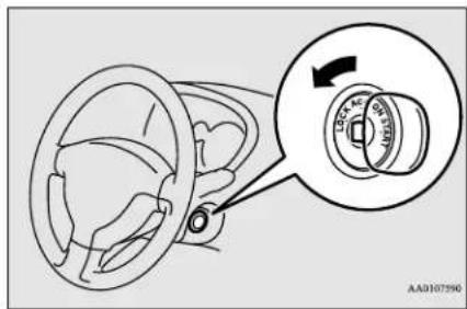
CAUTION
- Do not remove the key from the electric motor switch while driving. The steering wheel will lock, causing loss of control.
- If the ready indicator is turned off while driving, the power brake booster will stop functioning and braking efficiency will be reduced. Also, the power steering system will not function and it will require greater effort to manually steer the vehicle.
- Do not leave the key in the "ON" position for a long time when the electric motor unit is not running. This will cause the 12V starter battery to run down.
Features and controls 5-19
Steering wheel lock
Key reminder buzzer
N00571700013
If the driver's door is opened while the electric motor switch is in the "LOCK" or "ACC" position, a tone will sound.
5
Steering wheel lock
NO0512500209
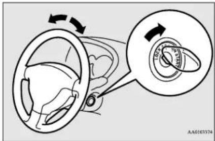
To loc k
Remove the key at the "LOCK" position. Turn the steering wheel until it is locked.
To u n l o c k
Turn the key to the "ACC" position while moving the steering wheel slightly.
5-20 Features and controls
CAUTION
- Remove the key when leaving the vehicle.
- If your vehicle needs to be towed, turn the key to the "ACC" position to unlock the steering wheel.
NOTE
- If the front wheels are turned, the anti-theft lock may sometimes make it difficult to turn the key from "LOCK" position to "ACC" position. Firmly turn the steering wheel to the left or to the right as you turn the key.
Starting the electric motor unit
N00571800014
CAUTION
● Never attempt to start the electric motor unit by pushing or pulling the vehicle.
- Make sure all occupants are properly seated with seat belts fastened.
- Insert the key.
- Make sure the parking brake is applied.
- Press and hold the brake pedal down with your right foot.
-
Make sure the selector lever is in the "P" (PARK) position.
-
Turn the key to the "ON" position and make certain that all warning lights are functioning properly before starting the electric motor unit.
- Turn the key to the "START" position for one to two seconds, and slowly return it to its original position. When you hear the startup sound and the ready indicator comes on, startup of the electric motor unit is complete.
Electric motor reminder
If the driver's door is opened while the key is in the "ON" position, the electric motor reminder buzzer sounds intermittently to remind the key is in the electric motor switch.
Selector lever
Selector lever
N01583600022
Selector lever operation
N00583700023
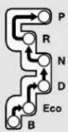
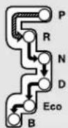
AN0107040
| a== | While depressing the brake pedal, move the selector lever through the gate. |
| b== | Move the selector lever through the gate. |
WARNING
● Always depress the brake pedal when shifting the selector lever into another position from the "P" (PARK) or "N" (NEUTRAL) position.
Never put your foot on the accelerator pedal while shifting the selector lever from the "P" (PARK) or "N" (NEUTRAL) position.
NOTE
- To avoid erroneous operation, move the selector lever firmly into each position and briefly hold it there. Always check the position shown by the selector lever position display after moving the selector lever.
- If the brake pedal is not depressed and held, the shift-lock device activates to prevent the selector lever from being moved from the "P" (PARK) position.
Selector lever position indicator
N00583800024
When the electric motor switch is turned to the "ON" position, the current position of the selector lever is indicated on the instrument cluster.
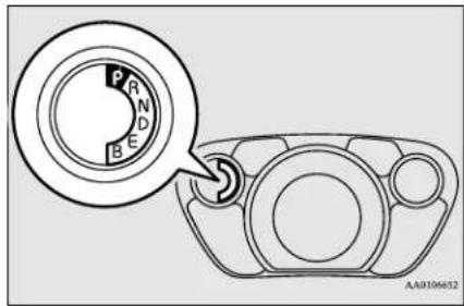
When the selector lever position indicator flashes while you are driving, there could be a malfunction in the transmission.
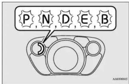
Selector lever
CAUTION
- If the selector lever position indicator blinks while you are driving, it is likely that a safety device is operating because of a malfunction in the transmission system. We recommend you to have your vehicle inspected as soon as possible.
- The selector lever position indicator warning function does not operate with the selector lever in the "R" (REVERSE) position.
Selector lever positions
N010583900025
"P" PARK
This position locks the transmission to prevent the vehicle from moving. The electric motor unit can be started from the "PARK" position.
WARNING
- Do not leave the vehicle with the electric motor switch in the "ON" position. The vehicle can move suddenly. To be sure the vehicle will not move, even when you are on level ground, always set the parking brake and move the selector lever to the "P" (PARK) position.
“R” REVERSE
This position is to back up.
CAUTION
- Never move the selector lever to the "P" (PARK) or "R" (REVERSE) position while the vehicle is in motion. If the lever is moved to the "P" (PARK) or "R" (REVERSE) position while the vehicle is in motion, the transmission could be damaged.
“N” NEUTRAL
Use this position only when the vehicle is stationary for an extended length of time while driving, such as in a traffic jam.
WARNING
- Never move the selector lever to the "N" (NEUTRAL) position while the vehicle is in motion. You will lose regenerative braking. In addition, a serious accident could occur if the selector lever were inadvertently moved into the "P" (PARK) position or "R" (REVERSE) position.
“D” DRIVE
Use this position for normal driving.
CAUTION
- To avoid transmission damage, never shift into the “D” (DRIVE) position from the “R” (REVERSE) position while the vehicle is in motion.
"ECO" ECO MODE
Use this position when you desire to limit power consumption and/or when moderate regenerative braking is required.
"B" REGENERATIVE BRAKE MODE
Use this position when strong regenerative braking is required, such as on a steep downhill.
Refer to “Regenerative braking” on page 3-3. Refer to “When driving downhill” on page 6-5.

WARNING
- While driving on a slippery road, do not use the "B" position. Abruptly releasing the accelerator pedal can apply strong regenerative braking causing the vehicle to skid which could result in an accident.

NOTE
- When the main drive lithium-ion battery level is full or nearly full, or the main drive lithium-ion battery temperature is too high or too low, the regenerative braking force may be reduced and stronger effort may be required to operate the brakes.
Operation of the transmission
N00584000023

CAUTION
- Before selecting a position with the electric motor unit running and the vehicle stationary, fully depress the brake pedal to prevent the vehicle from creeping.
The vehicle will begin to move as soon as the transmission is engaged, the brakes should only be released when you are ready to drive away. - Depress the brake pedal with the right foot at all times.
Using the left foot could cause driver movement delay in case of an emergency.

CAUTION
- Operating the accelerator pedal while the other foot is resting on the brake pedal will affect braking efficiency and may cause premature wear of brake pads.
Waiting
N00584100024
For short waiting periods, such as at traffic signals the vehicle can be left in selector lever position and held stationary with the service brake.
For longer waiting periods with the electric motor unit running, place the selector lever in the "N" (NEUTRAL) position and apply the parking brake, while holding the vehicle stationary with the service brake.
CAUTION
● Never hold the vehicle stationary on a hill with the accelerator. Always apply the parking brake and/or service brake.
Parking
N00584200025
To park the vehicle, first bring it to a complete stop, fully engage the parking brake, and then move the selector lever to the "P" (PARK) position.
If you are going to leave the vehicle unattended, always switch off the electric motor unit and carry the key.

NOTE
- On a slope, be sure to apply the parking brake before moving the selector lever to the "P" (PARK) position. If you move the selector lever to the "P" (PARK) position before applying the parking brake, it may be difficult to disengage the selector lever from the "P" (PARK) position when next you drive the vehicle, requiring application of a strong force to the selector lever to move from the "P" (PARK) position.
Acoustic vehicle alerting system (AVAS)
N00571900028
While driving at low speeds, such as in parking lots, the acoustic vehicle alerting system (AVAS) alerts people who may not hear your vehicle approaching.
The system sounds when the vehicle speed is approximately 22 mph (35 km/h) or less.
The acoustic vehicle alerting system (AVAS) will operate under the following conditions:
- When the vehicle speed is approximately 2 mph (3 km/h) or less and the brake pedal is not depressed.
Features and controls 5-23
Service brake
- When the vehicle speed is approximately 2-22 mph (3-35 km/h).
The system will not operate under the following conditions:
- When the vehicle speed is approximately 2 mph (3 km/h) or less and the brake pedal is depressed.
- When the vehicle speed is approximately 22 mph (35 km/h) or more.
- When the selector lever is in the “P” (PARK) position.
WARNING
● Always pay special attention to pedestrians. Even if the acoustic vehicle alerting system (AVAS) sounds, pedestrians may not notice your vehicle.
Under normal conditions, the indicator light in the instrument cluster illuminates when the electric motor switch is turned to the "ON" position and goes off a few seconds later. Always confirm the indicator light goes off before driving.
NOTE
- If the indicator light blinks, turn the electric motor switch back to the "LOCK" position and again turn the switch to the "ON" position. It is not a malfunction if the indicator light goes off. If the indicator light blinks again, however, have the vehicle inspected at a certified i-MiEV dealer as soon as possible.
Service brake
N00517500305
Brake pedal
Overuse of the brake can cause poor brake response and premature wear of the brake pads.
WARNING
- Do not leave any objects near the brake pedal or let a floor mat slide under it; doing so could prevent the full pedal stroke that would be necessary in an emergency. Make sure that the pedal can be operated freely at all times. Make sure the floor mat is securely held in place.
CAUTION
- It is important not to drive the vehicle with your foot resting on the brake pedal when braking is not required. This practice can result in very high brake temperatures, premature pad wear, and possible damage to the brakes.
Power brakes
ND05176DN423
Your vehicle is equipped with power brakes for more braking force with reduced brake pedal effort.
Your brakes are designed to operate at full capacity, even if the power assist is lost.
If the power assist is lost, the effort needed to press the brake pedal is greater.
If you should lose the power assist for some reason, the brakes will still work.
If the power brake unit or either of the two brake hydraulic systems stop working prop-
erly, the rest of the brake system will still work, but the vehicle will not slow down as quickly.
You will know this has happened if you find you need to depress the brake pedal down further, or harder when slowing down or stopping, or if the brake warning light comes on.

WARNING
- Never turn off the electric motor switch while driving. Doing so will result in a loss of power assist for the brakes and steering, increasing the effort required to steer and brake the vehicle.

NOTE
- At times, you may hear the brake electric vacuum pump for the power brakes operating when the ready indicator illuminates or the brake pedal is depressed. This sound is normal and does not indicate a problem.
Brake pad wear alarm
N101532500162
The disc brakes have an alarm that makes a metallic squeal when the brake pads have worn down enough to need service. If you hear this sound, have the brake pads replaced at a certified i-MiEV dealer.

WARNING
● Driving with worn brake pads will make it harder to stop, and can cause an accident.
Brake assist system
N00567300063
The brake assist system is a device assisting drivers who cannot depress the brake pedal firmly such as in emergency stop situations and provides greater braking force.
If the brake pedal is depressed suddenly, the brakes will be applied with more force than usual.

CAUTION
- The brake assist system is not a device designed to exercise braking force greater than its capacity. Make sure to always keep a sufficient distance between vehicles in front of you without relying too much on the brake assist system.

NOTE
- Once the brake assist system is operational, it maintains great braking force even if the brake pedal is lightly released. To stop its operation, completely remove your foot from the brake pedal.

NOTE
- The brake assist system may become operational when the brake pedal is fully depressed even if it has not been depressed suddenly.
- When the brake assist system is in use while driving, you may feel as if the depressed brake pedal is soft, the pedal moves in small motions in conjunction with the operation noise, or the vehicle body and the steering wheel vibrate. This occurs when the brake assist system is operating normally and does not indicate faulty operation. Continue to depress the brake pedal.
- You may hear an operation noise when the brake pedal is depressed suddenly while stationary. This does not indicate a malfunction and the brake assist system is operating normally.
Anti-lock braking system
N00517900325
The anti-lock braking system helps prevent the wheels from locking up when braking. This helps you keep control of your vehicle and its direction.
Driving hints
- When using the anti-lock brakes (sudden braking), steering is slightly different from normal driving conditions. Use the steering wheel carefully.
● Always keep a safe distance from the vehicle in front of you. Even if your vehicle is equipped with the anti-lock braking system, leave a greater braking distance when:
- Driving on gravel or snow-covered roads.
- Driving on uneven road surfaces.
- Operation of anti-lock braking system is not restricted to situations where brakes are applied suddenly. This system may also prevent the wheels from locking when you drive over manholes, steel roadwork plates, road markings, or any uneven road surface.
- When the anti-lock braking system is in use, you may feel the brake pedal vibrating and hear a unique sound. You may also feel as if the pedal resists being pressed.
In this situation, simply hold the brake pedal down firmly. Do not pump the brake, which will result in reduced braking performance.
- An operation noise may be emitted from under the hood in the following situations. The sound is associated with checking the operations of the anti-lock braking system.
At this time, you may feel a shock from the brake pedal if you depress it. These do not indicate a malfunction.
- When the electric motor switch is set to the "ON" position.
- When the vehicle is driven for a while after the electric motor is turned on.
- The ABS can be used after the vehicle has reached a speed over approximately 6 mph (10 km/h). It stops working when the vehicle slows below approximately 3 mph (5 km/h).
CAUTION
- The anti-lock braking system cannot prevent accidents. It is your responsibility to take safety precautions and to drive carefully.
- Be sure to use the specified type and size of tire on all four wheels. Otherwise, the ABS may not work properly.
- Do not install any aftermarket limited slip differential (LSD) on your vehicle. The ABS may stop functioning properly.
Anti-lock braking system warning light
N005316IXI661
This light comes on in the event of a malfunction in the anti-lock braking system. It will also come on as a self-check for a few seconds when the electric motor switch is turned to the "ON" position. Always make sure that the light goes out before beginning to drive.
CAUTION
- If the anti-lock braking system warning light comes on and stays on after starting the electric motor unit or while driving, it means that the anti-lock braking system is not working and that only the standard brake system is available. (The standard brake system will still work properly.) If this happens, take your vehicle to a certified i-MiEV dealer as soon as possible.
If the warning light illuminates while driving
N01531700590
If only the ABS warning light illu- minate
Avoid hard braking and high-speed driving. Stop the vehicle in a safe place, put the selector lever to the "P" (PARK) position and turn off the electric motor unit.
Restart the electric motor unit and check to see whether the light goes out after a few minutes driving; if it then remains off during driving, there is no problem.
However, if the warning light does not disappear, or if it comes on again when the vehicle is driven, we recommend you to have the vehicle checked.
If the ABS warning light and brake warning light illuminate at the same time
The ABS and brake force distribution function may not work, so hard braking could make the vehicle unstable.
Avoid hard braking and high-speed driving. Stop the vehicle in a safe place and we recommend you to have the vehicle checked.

NOTE
- The warning light may be illuminated when the electric motor unit is started while the 12V starter battery voltage is low, but this is not an ABS malfunction.
When the main drive lithium-ion battery is charged, the 12V starter battery is charged at the same time, and the warning light will go out.
If the warning light does not go out or illuminates from time to time even after the battery is charged, take your vehicle to a certified i-MiEV dealer and have the system checked as soon as possible.
- After driving on snow or icy roads, remove any snow and ice which may have been left around the wheels. On vehicles that have an anti-lock braking system, be careful not to damage the wheel speed sensors (A) or the cables located at each wheel.
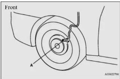

Electric power steering system (EPS)
N00568400058
The power steering system operates while the electric motor unit is running. It helps reduce the effort needed to turn the steering wheel.
The power steering system has mechanical steering capability in case the power assist is lost. If the power assist is lost for some reason, you will still be able to steer your vehicle, but you will notice it takes much more effort to steer. If this happens, have your vehicle inspected at a certified i-MiEV dealer.
Active stability control (ASC)
WARNING
- Do not turn the key from the ON position while the vehicle is moving. Stopping the electric motor unit would make the steering wheel extremely hard to turn, possibly resulting in an accident.

NOTE
- During repeated full-lock turning of the steering wheel (for example, while you are maneuvering the vehicle into a parking space), a protection function may be activated to prevent overheating of the power steering system. This function will make the steering wheel gradually harder to turn. In this event, limit your turning of the steering wheel for a while. When the system has cooled down, the steering effort will return to normal.
- If you turn the steering wheel while the vehicle is stationary with the headlights on, the headlights may become dim. This behavior is not abnormal. The headlights will return to their original brightness after a short while.
Electric power steering system warning light
N00574400024
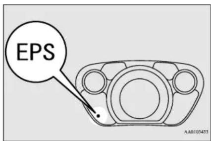
If there is a malfunction in the system, the warning light will come on.
Under normal conditions, the warning light comes on when the electric motor switch is turned to the "ON" position and goes off a few seconds later.
CAUTION
- If the warning light appears while the electric motor unit is running, have the vehicle inspected at a certified i-MiEV dealer as soon as possible. It may become harder to turn the steering wheel.
Active stability control (ASC)
N00559100163
The active stability control (ASC) takes overall control of the anti-lock braking system, traction control function and skid control function to help maintain the vehicle's control. Also refer to the following pages on the anti-lock braking system, traction control function and skid control function.
Anti-lock braking system (ABS) → P.5-25
Traction control function → P.5-29
Skid control function → P.5-29
CAUTION
- Do not over-rely on the ASC. Even the ASC cannot prevent the natural laws of physics from acting on the vehicle. This system, like any other system, has limits and cannot help you to maintain traction and control of the vehicle in all circumstances. Reckless driving can lead to accidents. It is the driver's responsibility to drive carefully. This means taking into account the traffic, road and environmental conditions.
- Be sure to use the specified type and size of tire on all four wheels. Otherwise, the ASC may not work properly.
- Do not install any aftermarket limited slip differential (LSD) on your vehicle. The ASC may stop functioning properly.

NOTE
- An operation noise may be emitted from under the hood in the following situations. The sound is associated with checking the operations of the ASC. At this time, you may feel a shock from the brake pedal if you depress it. These do not indicate a malfunction.
- When the electric motor switch is set to the "ON" position.
- When the vehicle is driven for a while after the electric motor unit is turned on.
- When the ASC is activated, you may feel a vibration in the vehicle body or hear a whining sound from under the hood. This indicates that the system is operating normally. It does not indicate a malfunction.
- When the anti-lock braking system warning light is illuminated, the ASC is not active.
Traction control function
MK1559200089
On slippery surfaces, the traction control function prevents the drive wheels from spinning excessively, thus helping the vehicle to start moving from a stopped condition. It also provides sufficient driving force and steering performance as the vehicle turns while pressing the acceleration pedal.

CAUTION
- When driving a vehicle on a snowy or icy road, be sure to install snow tires and drive the vehicle at moderate speeds.
Skid control function
N00546800049
The skid control function is designed to help the driver maintain control of the vehicle on slippery roads or during rapid steering maneuvers. It works by controlling the electric motor unit output and the brake on each wheel.

NOTE
● The skid control function operates at speeds of about 9 mph (15 km/h) or higher.
ASC OFF switch
N00559401280
The ASC is automatically activated when the electric motor switch is turned to the "ON" position. You can deactivate the system by pressing down the ASC OFF switch for 3 seconds or longer.
When the ASC is deactivated, the indicator will be illuminated. To reactivate the
ASC, momentarily press the ASC OFF switch; the indicator is turned off.
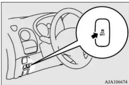

CAUTION
- For safety reasons, the ASC OFF switch should be operated when your vehicle is stopped.
- Be sure to keep the ASC on while driving in normal circumstances.
- If you deactivate the ASC to move out of mud, sand or fresh snow, be sure to reactivate the ASC immediately when done. Do not deactivate the ASC except when necessary.
- If you depress the accelerator pedal excessively and the wheels continue spinning while the ASC is deactivated, the transmission or other parts may become damaged and could cause an accident.
Tire pressure monitoring system

NOTE
- Using the ASC OFF switch turns off both the skid control function and the traction control function.
- When trying to move out of mud, sand or fresh snow, even if the accelerator pedal is depressed, the ASC may not allow the electric motor speed to increase enough to move the vehicle out.
In such situations, deactivating the ASC may make it easier to move your vehicle out. Refer to “If your vehicle becomes stuck in sand, mud or snow” on page 8-13.
- If you continue to press the ASC OFF switch after the ASC has been turned off, the ASC will automatically be reactivated to prevent misoperation of the ASC OFF switch.
ASC indicator, ASC OFF indicator
N00546901063
The indicators should illuminate when the electric motor switch is turned to the "ON" position, and should turn off after a few seconds.
If the indicator stays on or does not illuminate when the electric motor switch is turned to the "ON" position, have the vehicle inspected by a certified i-MiEV dealer as soon as possible.
§ indicator blinks when the ASC is operating.
indicator is illuminated when the ASC is deactivated.
CAUTION
- When indicator blinks, the ASC is operating, which means that the road is slippery or that your vehicle's wheels are beginning to slip. If this happens, drive slower.
- If an abnormal condition occurs in the system while driving, the and indicators will illuminate.
In these cases, follow these procedures:
- Park your vehicle in a safe place and stop the electric motor unit. Restart the electric motor unit again and check whether the
and indicators go out. If these indicators go out, there is no abnormal condition.
If the find indicators remain on even after your vehicle is driven a short distance after re-starting the electric motor unit, have the vehicle inspected by a certified i-MiEV dealer as soon as possible.
- When towing the vehicle with only the rear wheels raised off the ground, do not place the electric motor switch in the "ON" position. Placing the electric motor switch in the "ON" position could cause the ASC to operate, resulting in an accident. For details, refer to "Towing" on page 8-11.
Tire pressure monitoring system
N00530201537
The tire pressure monitoring system uses tire inflation pressure sensors (A) on the wheels to monitor the tire inflation pressures. The system only indicates when a tire is significantly under-inflated.
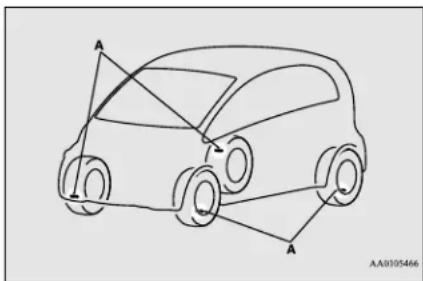
natural_image
Line drawing of a car with three labeled points A and directional arrows indicating motion (no text or symbols beyond labels)
NOTE
- The tire pressure monitoring system is not a substitute for regularly checking tire inflation pressures. Be sure to check the tire inflation pressures as described in “Tires” on page 9-10.
5-30 Features and controls

NOTE
- The tire inflation pressure sensor (A) is installed in the illustrated location. Replace grommet (B) with a new one when the tire is replaced. For details, please contact a certified i-MiEV dealer.
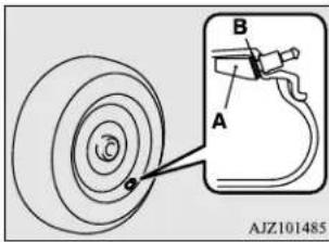
Tire pressure monitoring sys- tem warning light
N00554800136
When the electric motor switch is turned to the "ON" position, this light normally illuminates and goes off a few seconds later.
If one or more of the vehicle tires is significantly under-inflated, however, this light will remain illuminated while the electric motor switch is in the "ON" position.
Refer to "If the warning light illuminates while driving" on page 5-32 and take the necessary measures.
CAUTION
- If the tire pressure monitoring system warning light does not illuminate when the electric motor switch is turned to the "ON" position, it means that the tire pressure monitoring system is not working properly. Have the system inspected by a certified i-MiEV dealer.
In such situations, a malfunctioning of the system may be preventing the monitoring of the tire pressure. Avoid sudden braking, sharp turning and high-speed driving.
- If a malfunction is detected in the tire pressure monitoring system, the tire pressure monitoring system warning light will blink for approximately 1 minute and then remain continuously illuminated. The warning light will issue further warnings each time the electric motor unit is restarted as long as the malfunction exists.
Check to see whether the warning light goes off after few minutes of driving.
If it then goes off during driving, there is no problem.
However, if the warning light does not go off, or if it blinks again when the electric motor unit is restarted, have the vehicle inspected by a certified i-MiEV dealer.
In such situations, a malfunctioning of the system may be preventing the monitoring of the tire pressure. For safety reasons, when the warning light appears while driving, avoid sudden braking, sharp turning and high-speed driving.
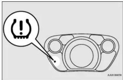
Each tire, including the spare (if provided), should be checked monthly when cold and inflated to the inflation pressure recommended by the vehicle manufacturer on the vehicle placard or tire inflation pressure label. (If your vehicle has tires of a different size than the size indicated on the vehicle placard or tire inflation pressure label, you should determine the proper tire inflation pressure for those tires.)
As an added safety feature, your vehicle has been equipped with a tire pressure monitoring system (TPMS) that illuminates a low tire pressure telltale when one or more of your tires is significantly under-inflated.
Accordingly, when the low tire pressure tell-tale illuminates, you should stop and check your tires as soon as possible, and inflate them to the proper pressure.
Tire pressure monitoring system
Driving on a significantly under-inflated tire causes the tire to overheat and can lead to tire failure.
Under-inflation also reduces alternative fuel efficiency and tire tread life, and may affect the vehicle's handling and stopping ability.
Please note that the TPMS is not a substitute for proper tire maintenance, and it is the driver's responsibility to maintain correct tire pressure, even if under-inflation has not reached the level to trigger illumination of the TPMS low tire pressure telltale.
Your vehicle has also been equipped with a TPMS malfunction indicator to indicate when the system is not operating properly. The TPMS malfunction indicator is combined with the low tire pressure telltale.
When the system detects a malfunction, the telltale will flash for approximately one minute and then remain continuously illuminated. This sequence will continue upon subsequent vehicle start-ups as long as the malfunction exists.
When the malfunction indicator is illuminated, the system may not be able to detect or signal low tire pressure as intended.
TPMS malfunctions may occur for a variety of reasons, including the installation of replacement or alternate tires or wheels on the vehicle that prevent the TPMS from functioning properly. Always check the TPMS malfunction telltale after replacing one or more tires or wheels on your vehicle to ensure that the replacement or alternate tires and wheels allow the TPMS to continue to function properly.
If the warning light illuminates while driving
N00532800484
- If the low tire pressure monitoring system warning light illuminates, avoid hard braking, sharp steering maneuvers and high speeds. You should stop and adjust the tires to the proper inflation pressure as soon as possible. Refer to "Tires" on page 9-10.

NOTE
- When inspecting or adjusting the tire pressure, to avoid breakage, do not apply excessive force to the valve stem.
- After inspecting or adjusting the tire pressure, always reinstall the valve cap on the valve stem.
Without the valve cap, dirt or moisture could get into the valve, resulting in damage to the tire inflation pressure sensor. - Do not use metal valve caps, which may cause a metal reaction, resulting in corrosion and damage of the tire inflation pressure sensors.
-
Once adjustments have been made, the warning light will go off after a few minutes of driving.
-
If the tire pressure monitoring system warning light remains illuminated after you have been driving for about 20 minutes after you adjust the tire inflation pressure, one or more of the tires may have a puncture. Inspect the tire and if it has a puncture, have it repaired by a certified i-MiEV dealer as soon as possible.

WARNING
- If the tire pressure monitoring system warning light illuminates while you are driving, avoid hard braking, sharp steering maneuvers and high speeds. Driving with an under-inflated tire adversely affects vehicle performance and can result in an accident.

CAUTION
● The tire pressure monitoring system warning light may not illuminate immediately in the event of a tire blowout or rapid leak.

NOTE
- To avoid the risk of damage to the tire inflation pressure sensors, have any punctured tire repaired by a certified i-MiEV dealer. If the tire repair is not done by a certified i-MiEV dealer, it is not covered by your warranty.
5-32 Features and controls

NOTE
- Do not use an aerosol puncture-repair spray on any tire. Such a spray could damage the tire inflation pressure sensors.
- Using the tire repair kit may damage the tire inflation pressure sensor. The vehicle must promptly be inspected and repaired by a certified i-MiEV dealer after using the tire repair kit.
The tire pressure monitoring system may not work normally in the following circumstances:
● A wireless facility or device using the same frequency is near the vehicle.
- Snow or ice is stuck inside the fenders and/or on the wheels.
- The tire inflation pressure sensors' battery is exhausted.
- Wheels other than Mitsubishi Motors genuine wheels are being used.
- Wheels that are not fitted with tire inflation pressure sensors are being used.
- Wheels whose ID codes are not memorized by the vehicle are used.
● A window tint that affects the radio wave signals is installed.

NOTE
- Tire inflation pressures vary with the ambient temperature. If the vehicle is subjected to large variations in ambient temperature, the tire inflation pressures may be under-inflated (causing the warning light to come on) when the ambient temperature is relatively low. If the warning light comes on, adjust the tire inflation pressure.
Whenever the tires and wheels are replaced with new ones
If you use new wheels with new tire inflation pressure sensors, their ID codes must be programmed into the tire pressure monitoring system. Have tire and wheel replacement performed by a certified i-MiEV dealer to avoid the risk of damaging the tire inflation pressure sensors.

CAUTION
- The use of non-genuine wheels will prevent the proper fit of the tire inflation pressure sensors, resulting air leakage or damage of the sensors.
General information
N00533000207
Your tire pressure monitoring system operates on a radio frequency subject to Federal Communications Commission (FCC) Rules (For vehicles sold in U.S.A.) and Industry Canada Rules (For vehicles sold in Canada). This device complies with Part 15 of the FCC Rules and RSS- Gen of the Industry Canada Rules.
Operation is subject to the following two conditions.
- This device may not cause harmful interference.
- This device must accept any interference received, including interference that may cause undesired operation.

CAUTION
- Changes or modifications not expressly approved by the manufacturer for compliance could void the user's authority to operate the equipment.
Rear-view camera (if so equipped)
Rear-view camera (if so equipped)
N00546201200
When the selector lever is in the "R" (REVERSE) position with the electric motor switch is in the "ON" position, the rear-view image will be displayed on the screen of the Mitsubishi Multi Communication System. When the selector lever is shifted out of the "R" position, the rear-view image will turn off.
WARNING
- Never rely solely on the rear-view camera to clear the area behind your vehicle. Always check visually behind and all around your vehicle for persons, animals, obstructions or other vehicles. Failure to do so can result in vehicle damage, serious injury or death.
● The rear-view camera is an aid system for backing up, but it is not a substitute for your visual confirmation. - The view on the screen is limited, and objects outside the view, such as under the bumper or around either corner of the bumper end, cannot be seen on the screen.
Location of rear-view camera
Reference lines on the screen
The rear-view camera is in the liftgate. Reference lines and upper surface of the rear bumper (A) are displayed on the screen.
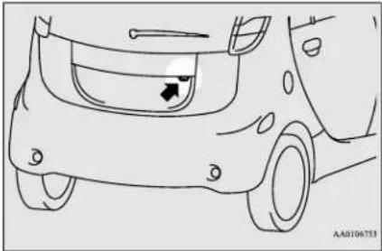
natural_image
Line drawing of a car's front wheel and side rear wheel, showing no text or symbolsCAUTION
- If the camera lens gets dirty, a clear image cannot be obtained. As necessary, rinse the lens with clean water and gently wipe with a clean, soft cloth.
● To avoid damaging the camera; - Do not rub the cover excessively or polish it by using an abrasive compound.
- Do not disassemble the camera.
- Do not splash hot water directly on the lens.
- Do not spray the camera and its surroundings with high-pressure water.
• Make sure that the liftgate is securely closed when backing up.
● Red line (B) indicates approximately 20 inches (50 cm) behind the rear bumper.
● Two Green lines (C) indicate approximately 8 inches (20 cm) outside of the vehicle body.
- Short transverse lines (1 to 3) indicate distance from the rear bumper.
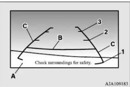
1: Approximately at the rear edge of the rear bumper
2: Approximately 39 inches (100 cm)
3: Approximately 79 inches (200 cm)

CAUTION
● The rear-view camera uses a wide-angle lens. As a result, images and distances shown on the screen are not exact.
- Actual distance may be different from distance indicated by the lines on the screen, depending on the loading condition of the vehicle and road surface condition.
The reference lines for distance and vehicle width are based on a level, flat road surface. In the following cases, objects shown on the screen will appear to be farther off than they actually are.
- When the rear of the vehicle is weighed down with the weight of passengers and luggage in the vehicle. (Case 1)
- When there is an upward slope at the back. (Case2)
Case 1
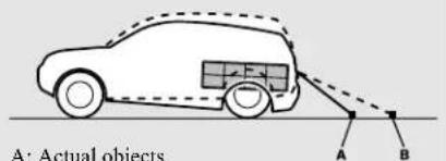
B: Objects shown on the screen
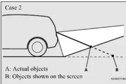
CAUTION
- The reference lines for distance and vehicle width are intended to indicate the distance to a flat object such as a level, flat road surface. They may not indicate correct distance depending on the shape of an obstacle. For example, when there is an object behind the vehicle that has upper sections projecting in the direction of the vehicle, the reference lines on the screen will indicate that point A is the farthest point and point B is the closest point to the vehicle. In reality, point A and B are actually the same distance from the vehicle, and point C is farther off than point A and B.
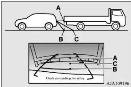

NOTE
● Mirror image is displayed on the screen.
● Monitor brightness is adjusted automatically by sensors.
- It is possible to change the display language of the screen.
For details, please refer to the separate owner's manual for "Mitsubishi Multi-Communication System".
● Under certain circumstances, it may become difficult to see an image on the screen, even when the system is functioning correctly.
• In a dark area, such as at night.
- When water drops or condensation are on the lens.
- When sunlight or headlights shine directly into the lens.
Instrument cluster
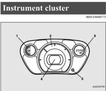
1- Energy level gauge
2- Energy usage indicator
3- Odometer/Trip odometer/Dash lights brightness indicator/Service reminder/Cruising range indicator/Outside temperature display
4- Speedometer
5- Reset button/Dash lights illumination button/Selector button
Speedometer
N00519100246
When the electric motor switch is in the "ON" position, the speedometer indicates the vehicle's speed in miles per hour (mph) or kilometers per hour (km/h).
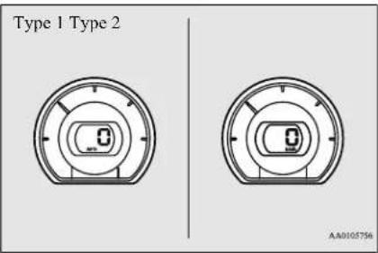
NOTE
- The display setting can be changed to the preferred units (miles or km). Refer to “Changing the display unit” on page 5-36.
Changing the display unit
N00572000013
It is possible to select the speedometer's display unit.
- Press the reset button (A) to display the odometer (B).
(Refer to "To change the display" on page 5-37.) - Keep the reset button pressed for 2 seconds or longer to change the display unit from MPH to km/h or from km/h to MPH.
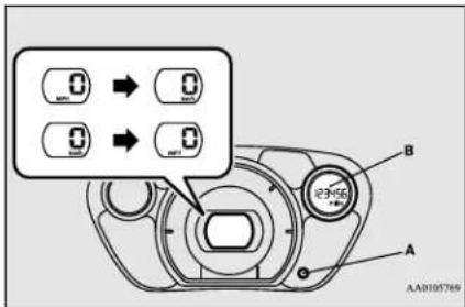
NOTE
- Once the display unit has changed, keeping the reset button pressed will not cause the display unit to change again.
The display unit for the cruising range will change to match the selected speedometer's display unit.
| Speedometer Cruising range | |
| MPH miles | |
| km/h km | |
NOTE
- Even if speedometer's display unit is changed, the display units for the odometer, trip odometer, and service reminder do not change.
5-36 Features and controls
Energy usage indicator
N00572101037
The power consumption of the electric motor, the air conditioning, and power generation by the regenerative brake are indicated.
When the ready indicator comes on, the red needle will move to the neutral point (A) and then move to the right or left according to the amount of power consumption or power generation.
[When the red needle moves to the right of the neutral point]
This indicates that the electric motor unit and/or the air conditioning are consuming electric energy from the main drive lithium-ion battery.
The more the needle moves to the right, the more electrical energy is being consumed.
[When the red needle moves to the left of the neutral point]
This indicates that electric energy is being generated by the regenerative brake and charged to the main drive lithium-ion battery.
The more the needle moves to the left, the more electric energy is being generated.

NOTE
- When the main drive lithium-ion battery is at or near full charge, or the main drive lithium-ion battery temperature is too high or too low, the needle in the energy usage indicator may not move to the left of the neutral point, since the main drive lithium-ion battery cannot receive charge.
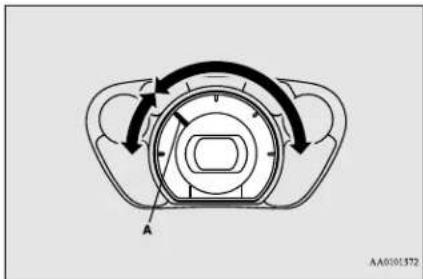
Odometer/Trip odometer/Dash lights brightness indicator/Service reminder/Cruising range indicator/Outside temperature display
N00519501449
Odometer, trip odometer, dash lights brightness indicator, service reminder, cruising
range indicator, and outside temperature are displayed.
To change the display
N00572201025
The display is changed every time the reset button (A) is briefly pressed.
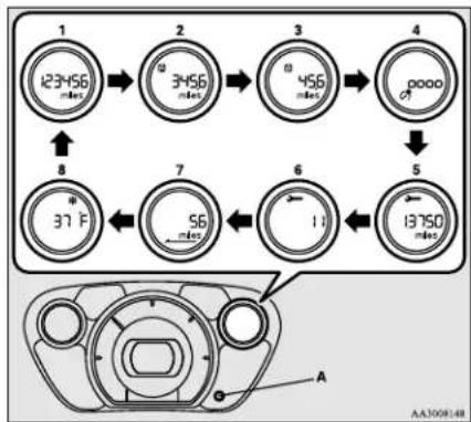
flowchart
graph TD
    A["123°56 msec"] --> B["3°56 msec"]
    B --> C["456 msec"]
    C --> D["13°50 msec"]
    D --> E["37°F"]
    E --> F["56 msec"]
    F --> G["11"]
    G --> H["13°50 msec"]
    H --> I["8"]
    I --> J["123°56 msec"]
1-Odometer
2- Trip odometer A
3- Trip odometer B
4- Dash lights brightness indicator
5- Service reminder (Drive distance remaining until next inspection)
6- Service reminder (Number of months remaining until next inspection)
7- Cruising range indicator
Instrument cluster
8- Outside temperature display

NOTE
- The cruising range indicator and outside temperature display are not indicated when the electric motor switch is in the "ACC" or "LOCK" position.
- If there is no operation for about 10 seconds when the meter illumination control or service reminder is shown, the display returns to the odometer.
Odometer
N00572300016
The odometer indicates the total distance the vehicle has traveled.

NOTE
- Even if the electric motor switch is turned to "ACC" or "LOCK", the odometer will be displayed for about 30 seconds after the reset button is pressed.
Trip odometer
N00572400020
The trip odometer shows the distance traveled since the last time it was reset.
There are two trip odometer displays: ▶ and
B.
5-38 Features and controls
Trip odometer A can be used to measure the distance traveled since the current trip began. At the same time, Trip odometer B can be used to measure the distance from a second location.

NOTE
- Even if the electric motor switch is turned to "ACC" or "LOCK" position, the trip odometer will be displayed for about 30 seconds after the reset button is pressed.
To reset the trip odometer
To zero the counter, press and hold the reset button for more than 1 second. Only the currently displayed value will be reset.
If trip odometer As displayed, for example, only trip odometer A will be reset.

NOTE
- Both trip odometer A and trip odometer B can measure trips up to 9999.9 miles/kilometers.
- If the 12V starter battery is disconnected for a long time, both of these displays will be reset to "0".
Service reminder
N00572500021
The service reminder shows the driving distance or number of months remaining until the next recommended periodic maintenance inspection is required.
When the next inspection is nearly due, the display shows “----”.

NOTE
- The service reminder time can be modified by a certified i-MiEV dealer, to adjust for severe usage, etc. Refer to "Severe maintenance schedule" in your vehicle's Warranty and Maintenance Manual. For further information, please contact a certified i-MiEV dealer.
- Even if the electric motor switch is turned to "ACC" or "LOCK" position, the service reminder will be displayed for about 30 seconds after reset button is pressed.
Driving distance
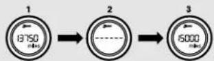
Number of months
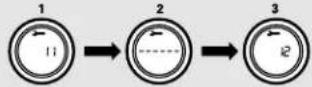
AA0105785
- The display shows the driving distance or number of months remaining until the next periodic inspection.
- This informs you that a periodic inspection is due. Contact a certified i-MiEV dealer to have the system checked.
At this time, a spanner mark is shown for a few seconds whenever the electric motor switch is turned from the "LOCK" position or the "ACC" position to the "ON" position.
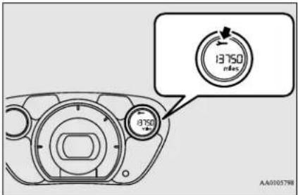
- After your vehicle is inspected at a certified i-MiEV dealer, it displays the time and miles (km) until the next periodic inspection.

NOTE
● The indicated distance decreases in steps of 100miles (100 km). The indicated number of months decreases in steps of one month.

NOTE
- It is possible to change the settings for the service reminder. For further information, we recommend you to consult a certified i-MiEV dealer.
Resetting the service reminder
With the electric motor switch in the "LOCK" position or the "ACC" position, it is possible to reset the spanner mark (A) and "--" indication (B).
When they have been reset, the driving distance or number of months remaining until the next periodic inspection are shown and the spanner mark (A) is no longer shown every time the electric motor switch is turned from the "LOCK" position or the "ACC" position to the "ON" position.
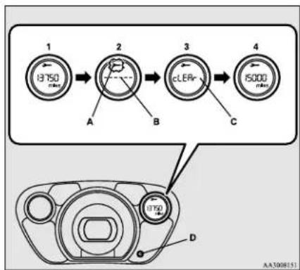
flowchart
graph LR
    A["13750 RPM"] --> B["2"]
    B --> C["cLER"]
    C --> D["15000 RPM"]
    style A fill:#f9f,stroke:#333
    style B fill:#ccf,stroke:#333
    style C fill:#cfc,stroke:#333
    style D fill:#fcc,stroke:#333
- Push the reset button (D) to view the driving distance or number of months remaining until the next periodic inspection.
- Give the reset button (D) a long push (at least 2 seconds) to make the spanner mark (A) start flashing. (If you do not touch the reset button for about 10 seconds while the spanner mark is flashing, the display will revert to its original indication.)
- Give the reset button (D) a gentle push while the spanner mark is flashing. The “----” indication (B) will change to “cLEAr” (C).
- The driving distance or number of months remaining until the next periodic inspection will be shown.
Instrument cluster
CAUTION
- The customer is responsible for making sure that regular inspections and maintenance are performed. Inspections and maintenance must be performed to prevent accidents and malfunctions.
NOTE
- It is not possible to reset the “----” indication (B) with the electric motor switch in the “ON” position.
- When a certain distance has been driven and a certain period has elapsed after appearance of the “----” indication (B), the indication is automatically reset and the number of months until the next periodic inspection is shown.
- If you accidentally reset the display, consult a certified i-MiEV dealer for assistance.
Dash lights brightness indicator
N(0572600)19
Each time you press the dash lights illumination button (B), the brightness of the instruments changes.
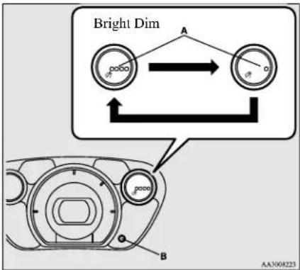
A- Brightness display
B- Dash lights illumination button
NOTE
- You can adjust to 4 different levels for when the parking lights or headlights are illuminated and 4 for when they are not.
- If you press and hold the button for longer than about 1 second, the brightness automatically scrolls through its different levels, and stops scrolling when you release the button. Select your desired level of brightness.
- When the combination headlights and dimmer switch is in the "AUTO" position, the meter illumination switches automatically to the adjusted brightness, depending on the brightness outside the vehicle.
NOTE
● The brightness level of the instruments is stored when the electric motor switch is turned off.
- If the 12V starter battery is disconnected for a long time, these level of brightness will be reset.
Cruising range indicator
N00572700036
This displays the approximate cruising range (how many more miles or kilometres you can drive). When the cruising range becomes short, the indication changes to “---”.
NOTE
- The cruising range is displayed based on the past drive data. It may vary depending on the driving condition (road condition, driving situation, etc.) and air conditioning operation status.
For example, the cruising range can be shortened by driving on congested roads, by driving uphill, by repeated hard acceleration, and by use of the air conditioner and heater.
When the 12V starter battery terminal is disconnected, the power consumption data of the main drive lithium-ion battery in the past is deleted. A different value from before may be displayed. Be sure to use the display only for reference.

NOTE
- When the main drive lithium-ion battery is charged, the approximate cruising range is updated.
Outside temperature display
N00573000010
This value (A) shows the outside temperature of the vehicle.
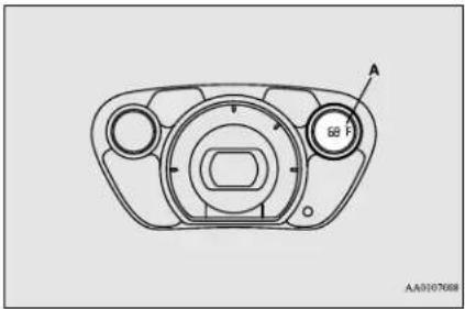
natural_image
Technical line drawing of a mechanical component with circular features and a central hub (no text or symbols)
NOTE
● The outside temperature can be displayed from -40 °F (-40 °C) to 122 °F (50 °C).
- When the outside temperature is over 122 °F (50 °C) or below -40 °F (-40 °C) will remain 122 °F (50 °C) or -40 (-40 °C).

NOTE
- The outside temperature displayed may differ from the actual temperature on account of surrounding conditions, driving conditions, etc.
If the outside temperature drops below approximately 37 °F (3 °C), the alarm sounds and the outside air temperature warning indicator (B) flash for approximately 10 seconds to show there is a danger the road might be icy.
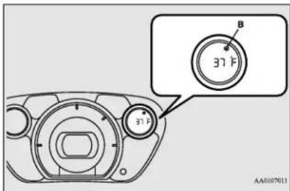

CAUTION
- Even when the outside air temperature warning indicator (B) indications do not flash, the road may be icy, so please take care when driving.
Change of the outside temperature unit
N00573100011
When the electric motor switch is in the "ACC" or "ON" position, pressing the selector button (A) for more than 2 seconds will switch the outside temperature unit between ^ and ^ .
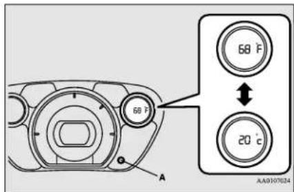

NOTE
- Disconnecting the battery cable causes the outside temperature unit memory to be erased. If it has been disconnected, readjust the unit with the above procedure.
Energy level gauge
N(0572800)24
The energy level gauge indicates the remaining power in the main drive lithium-ion bat-
Features and controls 5-41
Instrument cluster
tery during charging or when the electric motor switch is in the "ON" position.
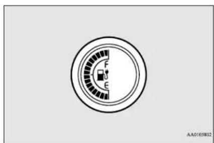
F-Battery is fully charged.
E- Charge the battery.

NOTE
● The charging indicator is also illuminated during charging.
Refer to "Charging indicator" on page 5-44.
Low energy warning indicator
N00572900025
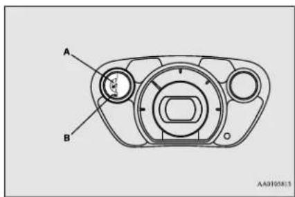
When the electric motor switch is in the "ON" position and the remaining bar of the energy level gauge shows 2 bars or less, the warning indicator (A) and the charging bars (B) flash as follows:
When the energy level gauge shows 2 bars: The warning indicator flashes.
When the energy level gauge shows 1 bar: The warning indicator and the charging bars flash alternately.
Recharge the main drive lithium-ion battery as soon as possible.

NOTE
- If the energy level gauge shows 0 bars during use of the air conditioning, the cooling or heating may stop operation and the mode is changed to fan only.
- If the energy level gauge shows 0 bars, the power down warning light is illuminated to control the output.
- If the energy level gauge shows 2 bars while the main drive lithium-ion battery is being charged, the warning indicator flashes. If the energy level gauge shows 1 bar while the main drive lithium-ion battery is being charged, the warning indicator and the charging bars flash alternately.
Indicator and warning light package
N00519801888
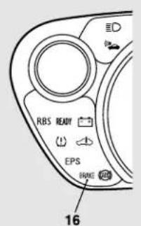
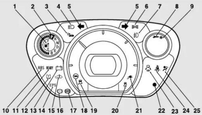
AA1008450
1- Low energy warning indicator
→ P.5-42
2- Selector lever position indicator
→ P.5-21
3- Acoustic Vehicle Alerting System (AVAS) indicator→P.5-23
4-High-beam indicator P.5-44
5- Turn-signal indicators/Hazard warning lights → P.5-44
6- Position indicator → P.5-44
7- Front fog light indicator → P.5-44
8- Service reminder → P5-3 8
9- Outside air temperature warning indicator → P541
10- Regenerative brake system indicator
→ P.5-44
11- Ready indicator → P.5-44
12- Tire pressure monitoring system warning light → P.5-31
13- 12V starter battery charging system warning light → P.5-45
14- Electric power steering system warning light → P.5-28
15- Electric motor unit warning light
→ P.5-45
16- Brake warning light → P5 - 44
17- Anti-lock braking system warning light
→ P.5-26
18- Power down warning light → P.5-46
19- Active stability control (ASC) indicator
→ P.5-30
20- Active stability control (ASC) OFF indicator → P5-30
21- Charging indicator → P.5-44
22- Theft-alarm indicator → P.5-12
23- Door-ajar warning light → P.5-45
24- Driver's seat belt reminder/warning light → P4-10
25- Supplemental Restraint System (SRS) warning light → P.4-13
Indicators
Indicators
N00519900127
Turn signal indicators/Hazard warning lights
N00520000232
The arrows will flash in time with the corresponding exterior turn signals when the turn signal lever is used.
Both arrows will flash when the hazard warning flasher switch is pressed.

NOTE
- If the indicator flashes faster than usual or if the indicator stays on without flashing, check for a malfunctioning turn signal light bulb or turn signal connection.
High beam indicator
N00520100086
A blue light comes on when the headlights are on high beam.
Front fog light indicator
N00520201244
This indicator comes on while the front fog lights are on.
Position indicator
N00551300039
This indicator turns on while the position lights are on.
Ready indicator
N00573200012
This indicator comes on when the electric motor switch is turned to "START" and driving becomes possible.
Charging indicator
N00573301023
This indicator flashes when the EV charging cable (regular charger or quick charger) is connected.
After that, the light switches to being illuminated when charging starts and goes out when charging is completed.

NOTE
- Although it is possible to start the electric motor unit if quick charging has not finished normally, the charging indicator is continuously blinking. Refer to “Charging troubleshooting guide” on page 3-31.
Regenerative brake system indicator
N0057340014
The indicator comes on when the regenerative brake performance may be weakened. In this case, drive the vehicle at a lower speed.
Warning lights
N00520300147
Brake warning light
N00520400513
This light comes on when the electric motor switch is turned to the "ON" position, and goes off after a few seconds when the parking brake is released. Before driving your vehicle, release the parking brake and make certain that the brake warning light has gone off. If the light stays on when the parking brake is fully released, the service brake system is not working properly or the brake fluid level is low.

WARNING
- If any of the following conditions occur, the brake effort may significantly increase. Stop the vehicle in a safe location, avoiding where possible any sudden brake application, and contact a certified i-MiEV dealer.

WARNING
- The brake warning light does not come on when the electric motor switch is turned to the "ON" position.
- The brake warning light does not illuminate while the parking brake is applied and the electric motor switch is in the "ON" position.
• The brake warning light stays on when the parking brake is not applied.

NOTE
- When the brake warning light illuminates, the warning buzzer may also sound.
- When the brake pedal has been repeatedly depressed over a short period of time, the brake warning light may come on and the brake warning buzzer may sound. The service brake system is working normally, if the warning light goes out and the buzzer stops sounding in a few seconds.
12V starter battery charging system warning light
N00573500028
This light will illuminate when there is a problem with the charging system for the 12V starter battery.
Normally, when the electric motor switch is turned to the "ON" position, this light will
illuminate. Then, when the electric motor unit is started and the ready indicator illuminates, the light will go out.
CAUTION
- If the warning light stays on after the ready indicator illuminates, there may be a problem with the charging system for the 12V starter battery.
- Immediately park your vehicle in a safe place and contact a certified i-MiEV dealer.
- Do not charge the 12V starter battery.
Door-ajar warning light and buzzer
N00520900316
This light comes on when any door or liftgate is open or not completely closed.
When the vehicle is moving at more than 5 mph (8 km/h) and any door or liftgate is open or ajar, a tone will sound 16 times and the warning light will flash 16 times to inform the driver that a door or liftgate is not properly shut.
CAUTION
- Before driving, make sure that the door-ajar warning light is off.

NOTE
● The flashing of the warning light and the buzzer can be disabled.
For further details, please contact a certified i-MiEV dealer.
- When the driver's door is open, the door-ajar warning buzzer does not sound because the electric motor reminder sounds instead.
Electric motor unit warning light
N00573600029
This warning light will illuminate when there is a problem with a high voltage component. Refer to "Service precautions" on page 9-2.

CAUTION
- If this light illuminates while driving, immediately park your vehicle in a safe place and contact a certified i-MiEV dealer.
Power down warning light
N00573700020

If this warning light illuminates, the power provided by the electric motor will be reduced and the vehicle will be only able to move at low speeds.
This warning light will illu- minate;
- When the energy level in the main drive lithium-ion battery is near empty.
- When temperature of the electric motor unit or the main drive lithium-ion battery is too high or too low.
- When voltage of the main drive lithium-ion battery becomes low.
If the energy level gauge shows 0 bar, the main drive lithium-ion battery is near empty and must be charged as soon as possible. Refer to "Charging" on page 3-13.
If the warning light illuminates after the vehicle has been driven continuously uphill or when the outside air temperature is very high, stop the vehicle in a safe place so the electric motor unit and/or the main drive lithium-ion battery can cool down. When they have cooled down, the warning light will go off. If the warning light does not turn off, contact a certified i-MiEV dealer.

NOTE
- When the power down warning light illuminates, avoid rapid starts and aggressive acceleration.
- Illumination of the power down warning light does not indicate a malfunction.
- If the power down warning light illuminates while the air conditioning is used, the cooling or heating may stop operating and only the fan will operate.
Combination headlights and dimmer switch
N00522501805
Headlights

NOTE
- Do not leave the headlights and other lights on for a long period of time while the ready indicator is not illuminated. A run down 12V starter battery could result.
- When it rains, or when the vehicle has been washed, the inside of the lens sometimes becomes foggy. This is the same as when window glass mists up on a humid day, and does not indicate a problem. When the light is switched on, the heat will dry out the fog. However, if water collects inside the light, have it checked by a certified i-MiEV dealer.
Rotate the switch to operate the lights.
If the warning light illuminates when the outside air temperature is very low, move the vehicle to a warmer location.
5-46 Features and controls
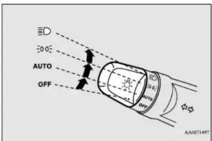
The combinations of switch operations and illuminated lights differ in accordance with the following conditions.
[When the ready indicator is illuminated, and the parking brake is released]
The daytime running lights will be illuminated:
| OFF | The daytime running lights illuminated |
| AUTO | The daytime running lights illuminatedHeadlights and other lights turn on and off automatically in accordance with outside light level. |
| EDGE | The daytime running lights illuminatedParking, tail, front and rear side-marker lights, license plate and instrument panel lights on |
| ED | Headlights and other lights on |

NOTE
- Once the daytime running light come on they do not go out until the electric motor switch is turned to the "LOCK" or "ACC" position.
[When the ready indicator is not illuminated, or when the ready indicator is illuminated but the parking brake is not released]
The electric motor unit starts when the lights are off.
| OFF All lights off | |
| AUTO | Headlights and other lights turn on and off automatically in accordance with outside light level. |
| EDGE | Parking, tail, front and rear side-marker lights, license plate and instrument panel lights on |
| ED | Headlights and other lights on |

NOTE
- The sensitivity of the automatic on/off control can be adjusted. For further information, please contact a certified i-MiEV dealer.
- Do not place anything on the sensor (A), and do not clean with a glass cleaner. Clean only with clear water.
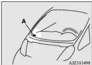
natural_image
Line drawing of a car's front panel with labeled point A and model number AJZ101498 (no text or symbols on the diagram itself)- If the lights do not turn on or off with the switch in the "AUTO" position, manually operate the switch. Have the system checked by a certified i-MiEV dealer.
Light auto-cutout function (headlights and other lights)
N00532600554
- If the key is turned to "LOCK" or "ACC" position or removed from the electric motor switch and the driver's door is opened with the combination headlights and dimmer switch in the "☐Gr " " ☐D position, the lights automatically turn off.
Combination headlights and dimmer switch
- If the driver's door is opened after the key is removed from the electric motor switch, a buzzer will sound to remind you to turn off the lights.
- If the driver's door is opened with the key in the electric motor switch, a buzzer will sound intermittently to remind you to remove the key.
- If the key is turned to "LOCK" or "ACC" position with the driver's door closed and the combination headlights and dimmer switch in the "30Gtr" position, the lights will stay on for about 3 minutes and then turn off automatically.

NOTE
- The light auto-cutout function can be deactivated. See a certified i-MiEV dealer for details.
When you want to keep the lights on:
If the combination headlights and dimmer switch is turned to the “∅” or “” position again after the electric motor switch is turned to “LOCK” or “ACC” position, the auto-cutout function described above will not work. The lights (the parking lights, tail lights and license plate lights) will stay on and will not turn off automatically.

NOTE
- If the driver's door is opened and the key is removed, the headlight reminder buzzer will sound. If the key is still in the electric motor switch the key reminder buzzer will sound intermittently. The buzzer stops when the driver's door is closed.
Headlight reminder buzzer
If the driver's door is opened with the key removed from the electric motor switch while the lights are on, the buzzer will sound to remind you to turn off the lights.
The lights and buzzer will turn off automatically.
Or you can turn the combination headlights and dimmer switch to the "OFF" position to stop the buzzer.
Dimmer (high/low beam change)
N00549900155
To change the headlights from high beam to low beam and vice versa, pull the turn signal lever to fully toward you (1). Switch the headlights to low beam as a courtesy whenever there are oncoming vehicles, or when there is traffic moving ahead of you. An illuminated blue light in the instrument cluster indicates when the headlights are on high beam.
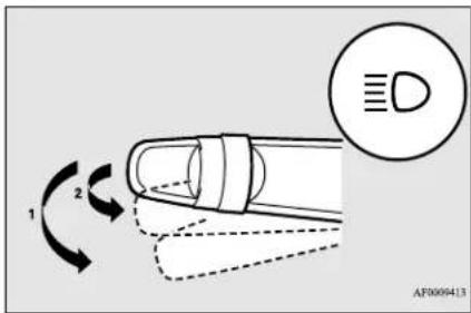
Headlight flasher
N00550000198
You can flash the high beams by pulling the lever gently toward you (2). The lights will go back to normal when you let go. While the high beam is on, you will see a blue light on the instrument panel.

NOTE
- You can flash the high beams by pulling the lever toward you, even if the combination headlights and dimmer switch is off.

NOTE
- If you turn the lights off with the headlights set to high-beam illumination, the headlights are automatically returned to their low-beam setting when the combination headlights and dimmer switch is next turned to the “ID” position.
Turn signal lever
N00522600506
When changing lanes, or to making a gradual turn, hold the lever in the "lane change" position (1). It will return to the neutral position when you let go. Use the full position (2) when making a normal turn. The lever will return to the neutral position when the turn is complete. There may be times when the lever does not return to the neutral position. This usually happens when the steering wheel is turned only slightly. You can easily return the lever by hand.
Also, when you move the lever to (1) slightly then release it, the turn signal lights and indicator in the instrument cluster will flash three times.
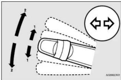

NOTE
- A light in the instrument panel flashes to show when the front and rear turn signal lights are working properly. If this light flashes faster than usual, check for a burned out light bulb or malfunctioning connection. If the panel light does not come on when the lever is moved, check for a blown fuse or a burned out bulb in the panel. Have the vehicle inspected by a certified i-MiEV dealer.
- It is possible to modify functions as follows: - Deactivate the turn signal light 3-flash function for lane changes. - Adjust the time required to operate the lever for the 3-flash function. See a certified i-MiEV dealer for details.
Hazard warning flasher switch
N00522700305
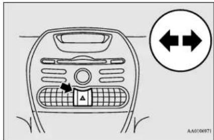
If you press the flasher switch, the front and rear turn signals will flash intermittently, and so will the hazard warning lights. This is an emergency warning system and should not be used when the vehicle is in motion, except for emergencies.
If you need to leave your vehicle, the flashers will keep working after the key is removed from the electric motor switch.

NOTE
- If you keep the flashers on for a long period of time while the ready indicator is not illuminated, the 12V starter battery could go flat and the electric motor unit could be impossible to start.
Front fog light switch
Front fog light switch
N00522801433
The front fog lights illuminate only when the headlights are on low beam.
Turning the knob in the direction of the "ON" position turns on the front fog lights as well as the indicator in the instrument cluster. To turn them off, turn the knob in the direction of the "OFF" position.
The knob will return to the neutral position when it is released.
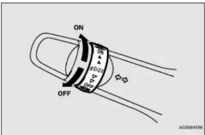

NOTE
- If the headlights are switched to high beam, the front fog lights will go out; they will illuminate again when the headlights are switched back to low beam.

NOTE
- If the combination headlights and dimmer switch is rotated to the "OFF" or "Position" while the front fog lights are illuminated, they will automatically turn off. They can be turned back on again by rotating the combination headlights and dimmer switch back to "Position", and turning the knob in the direction of the "ON" position.
- Do not use fog lights except in conditions of fog, otherwise excessive light glare may temporarily blind oncoming vehicle drivers.
Wiper and washer switch
N00523000640
CAUTION
- If the washer is used in cold weather, the washer fluid sprayed against the glass may freeze, which may hinder visibility. Warm the glass with the defroster before using the washer.
Windshield wipers
The windshield wiper and washer can be operated with the electric motor switch in the "ON" or "ACC" position.
If the blades are frozen to the windshield, do not operate the wipers until the ice has melted
and the blades are freed, otherwise the wiper motor may be damaged.
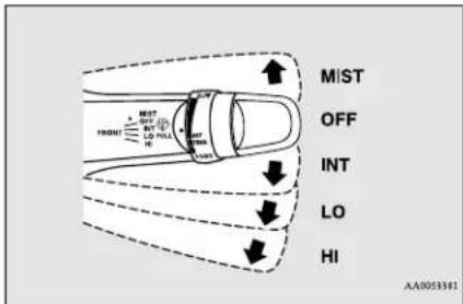
MIST- Misting function
The wipers will operate once.
OFF-Off
INT- Intermittent (Speed sensitive)
LO-Slow
HI- Fast
To adjust intermittent intervals
With the lever in the "INT" (speed sensitive intermittent operation) position, the intermittent intervals can be adjusted by turning the knob (A).
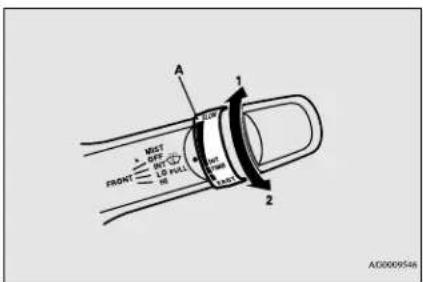
1 - Fast
2- Slow

NOTE
- The speed-sensitive-operation function of the windshield wipers can be deactivated. For further information, please contact a certified i-MiEV dealer.
Misting function
The wipers will operate once if the wiper lever is raised to the "MIST" position and released. This operation is useful when it is drizzling, etc. The wipers will continue to operate while the lever is held in the "MIST" position.
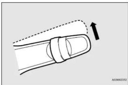
natural_image
Diagram of a finger with a dashed outline and an arrow indicating direction (no text or symbols)Windshield washer
N00504600272
To turn on the windshield washer, pull the lever toward you with the electric motor switch in either the "ON" or "ACC" position. The washer fluid will be sprayed onto the windshield by pulling the lever toward you.
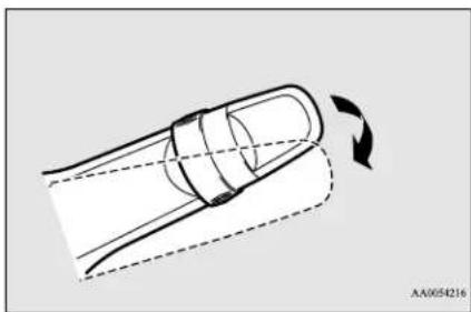
natural_image
Diagram of a mechanical component with dashed lines indicating motion, showing a curved arrow and dashed line (no text or symbols)Rear window wiper and washer
N00523200394
The rear window wiper and washer can be operated when the electric motor switch in either the "ON" or "ACC" position.
Turn the knob to operate the rear window wiper.
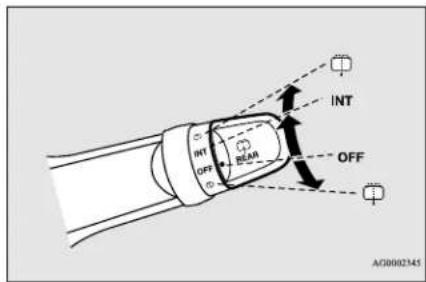
OFF-Off
INT- The wiper operates continuously for several seconds then operates intermittently at intervals of about 8 seconds.
Washer fluid will be sprayed onto the rear window glass while the knob is turned fully in either direction.
When the washer fluid is sprayed, the wiper will automatically operate 2 or 3 times.
Features and controls 5-51
Electric rear window defogger switch

NOTE
- To ensure a clear rearward view, the wiper performs several continuous operations when the reverse gear is engaged and the switch is in the "INT" position.
Following this continuous operation, the wiper will automatically switch to intermittent operation. - It is possible to modify functions as follows:
- Adjustment of the interval for intermittent operation
- Changing intermittent wiper operation to continuous wiper operation
For details, consult a certified i-MiEV dealer.
● The washer fluid reservoir is located underneath the hood.
Check the fluid level regularly and refill if necessary. (Refer to "Washer fluid" on page 9-7.)
Precautions to observe when using wipers and washers
N00523500241

CAUTION
- If the washer is used in cold weather, the washer fluid sprayed onto the glass might freeze, blocking your view. In cold weather, heat the glass with the defroster before using the washer.

NOTE
- Do not use the wipers when the windshield is dry. This could scratch the glass and wear the wiper blades prematurely.
- Before using the wipers in cold weather, check to be sure that the wiper blades are not frozen to the windshield. Using the wipers while the blades are frozen could cause the wiper motor to burn out.
- If the wipers are left on the glass out of the parked position and they become blocked by ice or other deposits on the glass, the motor may still burn out even if the wiper switch is OFF. If deposits form on the windshield, park your vehicle in a safe place, turn off the electric motor switch, and clean the glass so that the wipers can operate smoothly.
- Avoid using the washer for more than 20 seconds at a time. Do not operate the washer when the fluid reservoir is empty or the pump may fail.
- During cold weather, add a recommended washer solution that will not freeze in the washer reservoir. Otherwise the washer may not work or may be damaged.
- Replace the wiper blades when they are worn. Use the proper size replacement blades. If you have questions, ask a certified i-MiEV dealer.
Electric rear window defog- ger switch
N00523701455
The electric rear window defogger can be used when the ready indicator is illuminated.
The indicator light (A) will come on when you press the electric rear window defogger switch. Electric current will flow through the heating wires on the rear window to help clear away moisture or frost.
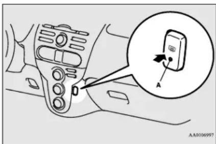
After about 20 minutes of operation, the system will shut off automatically.
To switch the defogger OFF before 20 minutes have passed, press the switch again. The indicator light will go out and the defogger will turn off.
If you need the defogger for more than 20 minutes, press the switch again. This will add 20 more minutes.
5-52 Features and controls

CAUTION
- The rear window defogger is not designed to melt snow. Remove any snow manually before using the rear window defogger.
- Use the rear window defogger only after the ready indicator is illuminated. Be sure to turn the defogger switch off immediately after the window is clear to save on 12V starter battery power.
- Do not place stickers, tape, or other items that are attached with adhesive over the grid wires on the rear window.
- When cleaning the inside rear window, use a soft cloth and wipe lightly over the grid wires.

NOTE
- If your vehicle is equipped with heated mirrors, mist can also be removed from the outside rearview mirrors when the rear window defogger switch is pressed. (Refer to "Heated mirror" on page 5-18.)
- The electric rear window defogger is activated automatically when the Remote Climate Control is activated in Pre-Defroster Mode.
Refer to “Remote Climate Control” on page 3-36, 3-47 and “For persons with electro-medical apparatus such as implantable cardiac pacemaker or implantable cardiovascular defibrillator” on page 3-6.
Horn switch
N00523800172
To honk the horn, press around the “” mark on the steering wheel.
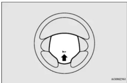
natural_image
Diagram of a circular anatomical structure with internal segments and a central arrow labeled 'kv' (no text or symbols beyond label)Link System (if so equipped)
N00563700030
The Link System takes overall control of the devices connected via the USB input terminal or the Bluetooth ^® 2.0 interface allowing the connected devices to be operated by using the switches in the vehicle or voice commands. See the following section for details on how to operate.
Refer to “Bluetooth ^® 2.0 interface” on page 5-53. Refer to “USB input terminal” on page 5-73.
Refer to "To play iPod/USB memory device tracks via voice operation" on page 7-20.
Bluetooth ^® is a registered trademark of BLUETOOTH SIG, INC.
Link System End User License Agreement
N00563800015
You have acquired a device that includes software licensed by Mitsubishi Motors Corporation from JOHNSON CONTROLS Inc (the automotive experience business unit), and their subsequent 3rd party suppliers. For a complete list of these 3rd party products and their end user license agreements, please go to the following website. http://www.jeiblueconnect.com/faq/fulldisclosure.pdf
Bluetooth ^® 2.0 interface (if so equipped)
N00563901286
The Bluetooth ^® 2.0 interface allows for making/receiving hands-free calls in the vehicle using a Bluetooth ^® compatible cellular phone based on the wireless communication technology commonly known as Bluetooth ^® . It also allows the user to play music, saved in a
Features and controls 5-53
Bluetooth® music player, from the vehicle's speakers.
The system is equipped with a voice recognition function, which allows you to make hands-free calls by simple switch operations and voice command operations using a defined voice tree.
The Bluetooth ^® 2.0 interface can be used when the electric motor switch is in the "ON" or "ACC" position.
Before you can use the Bluetooth ^® 2.0 interface, you must pair the Bluetooth ^® device and Bluetooth ^® 2.0 interface. Refer to “Connecting the Bluetooth ^® 2.0 interface and Bluetooth ^® device” on page 5-59.
Bluetooth ^® is a registered trademark of BLUETOOTH SIG, INC.
WARNING
- Although the Bluetooth 2.0 interface allows you to make hands-free calls, if you choose to use the cellular phone while driving, you must not allow yourself to be distracted from the safe operation of your vehicle. Anything, including cellular phone usage, that distracts you from the safe operation of your vehicle increases your risk of an accident.
WARNING
- Refer to and comply with all state and local laws in your area regarding cellular phone usage while driving.
NOTE
- If the electric motor switch is left in the “ACC” position, the accessory power will automatically turn off after a certain period of time and you will no longer be able to use the Bluetooth® 2.0 interface. The accessory power comes on again if the electric motor switch is turned from the “ACC” position. Refer to “ACC power auto-cutout function” on page 5-19.
- The Bluetooth ^ 2.0 interface cannot be used if the Bluetooth ^ device has a dead battery or the device power is turned off.
- Hands-free calls will not be possible if your phone does not have service available.
- If you place the Bluetooth® device in the luggage compartment, you may not be able to use the Bluetooth® 2.0 interface.
- Some Bluetooth devices are not compatible with the Bluetooth ^® 2.0 interface.
- You can confirm the Link System software version by pressing the HANG-UP button 3 times (press and hold 2 times and then press briefly) within 10 seconds.
NOTE
- For detail of the Bluetooth 2.0 interface, refer to the following web site:
[For vehicles sold in U.S.A.]
You can access the Mitsubishi Motors North America website.
[For vehicles sold in Canada]
You can access the Mitsubishi Motors website.
Please read and agree to the "Warning about Links to the Web Sites of Other Companies", the websites mentioned above may connect you to websites other than the Mitsubishi Motors website.
http://www.mitsubishi-motors.com/en/products/index.html
- Software updates by cellular phone/digital audio device manufacturers may change/alter device connectivity.
Steering control switch and microphone → P.5-55
Voice recognition function → P.5-56
Useful voice commands → P.5-56
Speaker enrollment function → P. 5 - 58
Connecting the Bluetooth ^® 2.0 interface and the Bluetooth ^® device → P.5-59
Operating a music player connected via Bluetooth ^® → P.5-63
How to make or receive hands-free calls → P.5-63
Phonebook function → P.5-66
Bluetooth® 2.0 interface (if so equipped)
Steering control switch and microphone
N01564001170
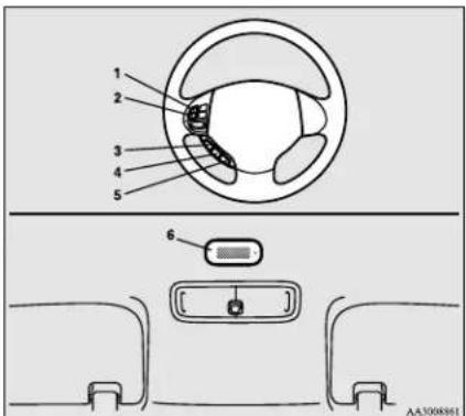
1- Volume up button
2- Volume down button
3- SPEECH button
4- PICK-UP button
5- HANG-UP button
6- Microphone
Volume up button
Press this button to increase the volume.
Volume down button
Press this button to decrease the volume.
SPEECH button
- Pressing this button will activate the voice recognition mode of Mitsubishi Multi-Communication System (a beep will sound when successfully activated). To use the voice recognition of the Bluetooth® 2.0 interface, press the PICK-UP button.
- Pressing the SPEECH button longer will deactivate the voice recognition mode.
PICK-UP button
- Press this button when an incoming call is received to answer the telephone.
- When not receiving incoming calls, pressing the PICK-UP button will activate the voice recognition of the Bluetooth® 2.0 interface.
- When another call is received during a call, press this button to put the first caller on hold and talk to the new caller.
• In such circumstances, you can press the button briefly to switch between callers. You will switch to the first caller and the other caller will be put on hold.
- To establish a three-way call in such situations, press the SPEECH button to enter voice recognition mode and then say "Join calls."
HANG-UP button
- Press this button when an incoming call is received to refuse the call.
- Press this button during a call to end the current call.
When another call is on hold, you will switch to that call. - If this button is pressed in the voice recognition mode, the voice recognition mode will be deactivated.
NOTE
- When you press the PICK-UP button to enter voice recognition mode with a cellular phone paired to the system, current information on the cellular phone, such as "remaining battery life," "signal strength" or "roaming," will be displayed on the audio display.*
*: Some cellular phones will not send this information to the Bluetooth ^® 2.0 interface. - Call waiting and three-way calls can be used by the Bluetooth® 2.0 interface, only if it is possible to use those services with your cellular phone.
Microphone
Your voice will be recognized by a microphone in the overhead console, allowing you to make hands-free calls with voice commands.

NOTE
- If a cellular phone is within close proximity of the microphone, it may distort the sound quality. In this case, place the cellular phone as far as possible from the microphone.
Voice recognition function
N00564101168
The Bluetooth ^® 2.0 interface is equipped with a voice recognition function.
Simply say voice commands and you can perform various operations and make or receive hands-free calls.
With the Bluetooth ^® 2.0 interface, voice recognition is possible for US English, North American Spanish, Canadian French and Japanese. The factory setting is “English.”

NOTE
- If the voice command that you say differs from the predefined command or cannot be recognised due to ambient noise or some other reason, the Bluetooth® 2.0 interface will ask you for the voice command again up to 3 times.
- For best performance and further reduction of ambient noise, the vehicle windows should be closed, lower the blower speed and refrain from conversation with your passengers while engaging the voice recognition function.
- Depending on the selected language, some functions may not be available.
Selecting the language
- Press the PICK-UP button.
- Say "Setup."
- Say "Language."
- The voice guide will say "Select a language: English, Spanish, French or Japanese." Say the desired language. (Example: "English")
- The voice guide will say "English (Spanish, French or Japanese) selected. Is this correct?" Say "Yes." If you say "No," the system will return to Step 4.

NOTE
- The voice guide will repeat the same message twice. The first message is in the current language, and the second message is in the selected language.
- If many entries are registered in the vehicle phonebook, changing the language will take a longer time.
-
Changing the language deletes the mobile phonebook imported to the Bluetooth® 2.0 interface. If you wish to use it, you will have to import it again.
-
When the voice guide says "English (Spanish, French or Japanese) selected," the language change process will be completed and the system will return to the main menu.
Useful voice commands
N0156421X0116
Help function
N00564300017
The Bluetooth ^® 2.0 interface is equipped with a help function.
If you say "Help" when the system is waiting for a voice command input, the system will tell you a list of the commands that can be used under the circumstances.
Canceling
N00564400018
There are 2 cancel functions.
If you are at the main menu, say “Cancel” to exit from the Bluetooth ^® 2.0 interface.
If you are anywhere else within the system, say "Cancel" to return to the main menu.
Confirmation function setting
N00564501061
The Bluetooth ^® 2.0 interface is equipped with a confirmation function.
With the confirmation function activated, you are given more opportunities than normal to confirm a command when making various settings to the Bluetooth ^® 2.0 interface. This allows you to decrease the possibility that a setting is accidentally changed.
The confirmation function can be turned on or off by following the steps below.
- Press the PICK-UP button.
- Say "Setup."
- Say "Confirmation prompts."
- The voice guide will say “Confirmation prompts are
. Would you like to turn confirmation prompts .”
Answer "Yes" to change the setting or answer "No" to keep the current setting.
- The voice guide will say “Confirmation prompts are
” and then the system will return to the main menu.
Security function
N00564601163
It is possible to use a passcode as a security function by setting a passcode of your choice for the Bluetooth ^® 2.0 interface.
When the security function is turned on, it is necessary to make a voice input of a 4-digit passcode in order to use all functions of the Bluetooth ^® 2.0 interface, except for reception.
Setting the passcode
Use the following procedure to turn on the security function by setting a passcode.
- Press the PICK-UP button.
- Say "Setup."
- Say "Passcode."
- The voice guide will say "Passcode is disabled. Would you like to enable it?" Answer "Yes."
Answer "No" to cancel the setting of the passcode and return to the main menu. - The voice guide will say "Please say a 4-digit passcode. Remember this passcode. It will be required to use this system."
Say a 4-digit number which you want to set as a passcode.
- For confirmation purposes, the voice guide will say "Passcode <4-digit pass-code>. Is this correct?" Answer "Yes."
Answer "No" to return to the passcode input in Step 5. - When the registration of the passcode is completed, the voice guide will say "Passcode is enabled" and the system will return to the main menu.
NOTE
- Passcode will be required to access the system after restarting the electric motor unit.
- It is required for a little time after the ready indicator has turned off that the entered passcode is actually recorded in the system. If the electric motor switch is made to "ACC" or "ON" or the electric motor is started immediately after the ready indicator has turned off, there is a case when the entered passcode is not recorded in the system. At this time, please try to enter the passcode again.
Entering the passcode
If a passcode has been set and the security function is enabled, the voice guide will say "Hands-free system is locked. State the passcode to continue" when the PICK-UP button is pressed to enter voice recognition mode.
Bluetooth® 2.0 interface (if so equipped)
Say the 4-digit passcode number to enter the passcode.
If the entered passcode is wrong, the voice guide will say "<4-digit passcode>, Incorrect passcode. Please try again." Enter the correct passcode.

NOTE
- You can reenter the passcode as many times as you want.
- If you have forgotten your passcode, say "Cancel" to quit the voice input mode and then check with a certified i-MiEV dealer.
Disabling the passcode
Use the following procedure to turn off the security function by disabling the passcode.

NOTE
-
System must be unlocked to disable the pass code.
-
Press the PICK-UP button.
- Say "Setup."
- Say "Passcode."
-
The voice guide will say "Passcode is enabled. Would you like to disable it?" Answer "Yes."
Answer "No" to cancel the disabling of the passcode and return to the main menu. -
When the disabling of the passcode is completed, the voice guide will say "Passcode is disabled" and the system will return to the main menu.
Speaker enrollment function
N0D564700011
The Bluetooth ^® 2.0 interface can use the speaker enrollment function to create a voice model for one person per language.
This makes it easier for the Bluetooth ^® 2.0 interface to recognise voice commands said by you.
You can turn a voice model registered with the speaker enrollment function on and off whenever you want.
Speaker enrollment
N00564801149
It takes about 2 to 3 minutes to complete the speaker enrollment process.
To ensure the best results, run through the process while in the driver's seat, in an environment that is as quiet as possible (when there is no rain or strong winds and the vehicle windows are closed). Please turn off your phone while in speaker enrollment to prevent interruption of the process.
Use the following procedure for speaker enrollment.
- Stop your vehicle in a safe area, put the selector lever in the "P" (PARK) position, and then pull the parking brake lever.

NOTE
-
Speaker enrollment is not possible unless the vehicle is parked. Make sure you park the vehicle in a safe area before attempting speaker enrollment.
-
Press the PICK-UP button.
-
Say "Voice training."
-
The voice guide will say "This operation must be performed in a quiet environment while the vehicle is stopped. See the owner's manual for the list of required training phrases. Press and release the SPEECH button when you are ready to begin. Press the HANG-UP button to cancel at any time."
Press the SPEECH button to start the speaker enrollment process.

NOTE
-
If you do not start the speaker enrollment process within 3 minutes after pressing the SPEECH button, the speaker enrollment function will time out.
The voice guide will say “Speaker enrollment has timed out.” The system will then beep and the voice recognition mode will be deactivated. -
The voice guide will prompt for phrase 1. Repeat the corresponding phrase listed in table "Enrollment commands" on page 5-73.
The system will register your voice and then move on to the registration of the next command. Continue the process until all phrases have been registered.

NOTE
- To repeat the most recent voice training command, press and release the SPEECH button.
-
If you press the HANG-UP button anytime during the process, the system will beep and stop the speaker enrollment process.
-
When all enrollment commands have been read out, the voice guide will say "Speaker enrollment is complete." The system will then end the speaker enrollment process and return to the main menu.

NOTE
- Completing the speaker enrollment process will turn on the voice model automatically.
- The commands "Help" and "Cancel" will not work in this mode.
Enabling and disabling the voice model and retraining
N00564901108
You can turn a voice model registered with the speaker enrollment function on and off whenever you want.
You can also retrain the system. Use the following procedure to perform these actions.
- Press the PICK-UP button.
- Say "Voice training."
- If you have completed a speaker enrollment process once already, the voice guide will say either "Enrollment is enabled. Would you like to disable or retrain?" or "Enrollment is disabled. Would you like to enable or retrain?"
- When enrollment is "enabled," the voice model is on; when enrollment is "disabled," the voice model is off. Say the command that fits your needs.
Say "Retrain" to start the speaker enrollment process and recreate a new voice model. (Refer to "Speaker enrollment" on page 5-58.)
Connecting the Bluetooth ^® 2.0 interface and Bluetooth ^® device
N00565001278
Before you can make or receive hands-free calls or play music using the Bluetooth ^® 2.0 interface function, you must pair the Bluetooth ^® device and Bluetooth ^® 2.0 interface.

NOTE
- Pairing is required only when the device is used for the first time. Once the device has been paired with the Bluetooth ^ 2.0 interface, all you need is to bring the device into the vehicle next time and the device will connect to the Bluetooth ^ 2.0 interface automatically (if supported by the device).
Up to 7 Bluetooth ^® devices can be paired with the Bluetooth ^® 2.0 interface.
If multiple paired Bluetooth ^® devices are available in the vehicle, the cellular phone or music player most recently connected is automatically connected to the Bluetooth ^® 2.0 interface.
You can also change a Bluetooth ^® device to be connected.
To pair
To pair a Bluetooth ^® device with the Bluetooth ^® 2.0 interface, follow the steps below.
- Stop your vehicle in a safe area, put the selector lever in the "P" (PARK) position, and then pull the parking brake lever.

NOTE
- You cannot pair any Bluetooth® device with the Bluetooth® 2.0 interface unless the vehicle is parked. Before paring a Bluetooth® device with the Bluetooth® 2.0 interface, confirm that the vehicle is parked in a safe location.
- Press the PICK-UP button.
- Say "Setup."
- Say "Pairing Options."
- The voice guide will say "Select one of the following: pair, edit, delete, or list." Say "Pair."

NOTE
- If 7 devices have already been paired, the voice guide will say "Maximum devices paired" and then the system will end the pairing process. To register a new device, delete one device and then repeat the pairing process. (Refer to "Deleting a device" on page 5-61.)
- The voice guide will say "Please say a 4-digit pairing code." Say a 4-digit number. When the confirmation function is on, the system will confirm whether the number said is acceptable. Answer "Yes." Answer "No" to return to pairing code selection.

NOTE
- Some Bluetooth devices require a specific pairing code. Please refer to the device manual for pairing code requirements.

NOTE
- The pairing code entered here is only used for the Bluetooth® connection certification. It is any 4-digit number the user would like to select. Remember the pairing code as it needs to be keyed into the Bluetooth® device later in the pairing process. Depending on the connection settings of the Bluetooth® device, this code may have to be entered each time you connect the Bluetooth® device to the Bluetooth® 2.0 interface. For the default connection settings, refer to the instructions for the device.
- The voice guide will say "Start pairing procedure on the device. See the device manual for instructions." Enter in the Bluetooth® device the 4-digit number you have registered in Step 6.

NOTE
- Depending on the device, it might take a few minutes to pair the Bluetooth® device with the Bluetooth® 2.0 interface. - If the Bluetooth® 2.0 interface cannot recognize the Bluetooth® device, the voice guide will say "Pairing has timed out" and the pairing process will be cancelled. Confirm that the device you are pairing supports Bluetooth®, and try pairing it again.
Bluetooth® 2.0 interface (if so equipped)

NOTE
- If you enter the wrong number, the voice guide will say "Pairing failed" and the pairing process will be cancelled. Confirm the number is right, and try pairing it again.
- The voice guide will say "Please say the name of the device after the beep." You can assign a desired name for the Bluetooth® device and register it as a device tag. Say the name you want to register after the beep.

NOTE
- When the confirmation function is on, after repeating the device tag you have said, the voice guide will ask "Is this correct?" Answer "Yes." To change the device tag, answer "No" and then say the device tag again.
- The voice guide will say "Pairing complete," and the pairing process will end.
Selecting a device
MX1565101123
If multiple paired Bluetooth ^® devices are available in the vehicle, the cellular phone or music player most recently connected is auto-
matically connected to the Bluetooth ^® 2.0 interface.
You can connect to the other cellular phone or music player by following setting change procedures.
To select a cellular phone
- Press the PICK-UP button.
- Say "Setup."
- Say "Select phone."
- After the voice guide says "Please say," the numbers of the cellular phones and device tags of corresponding cellular phones will be read out in order, starting with the cellular phone that has been most recently connected.
Say the number of the cellular phone that you want to connect to.
When the confirmation function is on, the system will ask you again whether the phone that you want to connect to is correct. Answer "Yes" to continue and connect to the cellular phone.
Answer "No," and the voice guide will say "Please say." Say the number of the phone that you want to connect to.

NOTE
- You can connect to a phone at any time by pressing the SPEECH button and saying the number, even before all of the paired numbers and device tags of corresponding cellular phones are read out by the system.
- The selected phone will be connected to the Bluetooth® 2.0 interface. The voice guide will say "
selected" and then the system will return to the main menu.
To select a music player
- Press the PICK-UP button.
- Say "Setup."
- Say "Select music player."
- After the voice guide says "Please say," the numbers of the music players and device tags of corresponding music players will be read out in order, starting with the music player that has been most recently connected.
Say the number of the music player that you want to connect to.
When the confirmation function is on, the system will ask you again whether the music player that you want to connect to is correct. Answer "Yes" to continue and connect to the music player.
Features and controls 5-61
Answer “No,” and the voice guide will say “Please say.” Say the number of the music player that you want to connect to.

NOTE
- You can connect to a music player at any time by pressing the SPEECH button and saying the number, even before all of the paired numbers and device tags of corresponding music players are read out by the system.
- The selected music player will be connected to the Bluetooth ^® 2.0 interface. The voice guide will say “
selected” and then the system will return to the main menu.
Deleting a device
Use the following procedure to delete a paired Bluetooth ^® device from the Bluetooth ^® 2.0 interface.
- Press the PICK-UP button.
- Say "Setup."
- Say "Pairing Options."
-
The voice guide will say "Select one of the following: pair, edit, delete, or list." Say "Delete."
-
After the voice guide says "Please say," the numbers of the devices and device tags of corresponding devices will be read out in order, starting with the device that has been most recently connected. After it completes reading all pairs, the voice guide will say "or all."
Say the number of the device that you want to delete from the system.
If you want to delete all paired phones from the system, say "All."
- For confirmation purposes, the voice guide will say "Deleting
. Is this correct?" or "Deleting all devices. Is this correct?"
Answer "Yes" to delete the phone(s).
Answer "No," the system will return to Step 4.
- The voice guide will say "Deleted," and then the system will end the device deletion process.

NOTE
- If the device deletion process fails for some reason, the voice guide will say “Delete failed” and then the system will cancel deleting the device.
To check a paired Bluetooth ^® device
N00565201065
You can check a paired Bluetooth ^® device by following the steps below.
- Press the PICK-UP button.
- Say "Setup."
- Say "Pairing Options."
- The voice guide will say "Select one of the following: pair, edit, delete, or list." Say "List."
- The voice guide will read out device tags of corresponding devices in order, starting with the Bluetooth ^® device that has been most recently connected.
- After the device tags of all paired Bluetooth ^® devices have been read, the system will say “End of list, would you like to start from the beginning?”
To hear the list again from the beginning, answer "Yes."
When you are done, answer "No" to return to the main menu.

NOTE
- If you press and release the SPEECH button and say "Continue" or "Previous" while the list is being read, the system will advance or rewind the list.
Say "Continue" to proceed to the device with the next highest number or "Previous" to return to the phone with the previous number. - You can change the device tag by pressing and releasing the SPEECH button and then saying "Edit" while the list is being read.
- You can change the phone to be connected by pressing and releasing the SPEECH button and then saying "Select phone" while the list is being read.
- You can change the music player to be connected by pressing and releasing the SPEECH button and then saying "Select music player" while the list is being read.
Changing a device tag
N00565301066
You can change the device tag of a paired cellular phone or music player.
Follow the steps below to change a device tag.
- Press the PICK-UP button.
- Say "Setup."
-
Say "Pairing Options."
-
The voice guide will say "Select one of the following: pair, edit, delete, or list." Say "Edit."
- The voice guide will say "Please say," and read out the numbers of the Bluetooth ^ devices and device tags of corresponding devices in order, starting with the Bluetooth ^ that has been most recently connected.
After all paired device tags have been read, the voice guide will say “Which device, please?” Say the number of the device tag you want to change.

NOTE
- You can press and release the SPEECII button while the list is being read, and immediately say the number of the device tag you want to change.
- The voice guide will say "New name, please." Say the name you want to register as a new device tag.
When the confirmation function is on, the voice guide will say "
Answer "No," you can say the new device tag you want to register again.
- The device tag is changed.
When the change is complete, the voice guide will say "New name saved" and then the system will return to the main menu.
Operating a music player connected via Bluetooth®
N00565400028
For the operation of a music player connected via Bluetooth ^® , refer to “To play iPod/USB memory device tracks via voice operation” on page 7-20.
How to make or receive hands-free calls
N00565500061
You can make or receive hands-free calls using a Bluetooth ^® compatible cellular phone connected to the Bluetooth ^® 2.0 interface.
You can also use the phonebooks in the Bluetooth ^® 2.0 interface to make calls without dialling telephone numbers.
To make a call P.5-64
Send function P.5-65
Receiving calls P.5-65
Mute function P.5-65
Switching between hands-free mode and private mode P.5-66

NOTE
● The hands-free calls might not be operated correctly when it makes calling or receiving by operating the cellular phone directly.
To make a call
N00565601131
You can make a call in the following 3 ways using the Bluetooth® 2.0 interface: Making a call by saying a telephone number, making a call using the Bluetooth® 2.0 interface's phonebook, and making a call by redialing.
Making a call by using the telephone number
You can make a call by saying the telephone number.
- Press the PICK-UP button.
- Say "Dial."
- After the voice guide says "Number please," say the telephone number.
- The voice guide will say "Dialing
."
The Bluetooth ^® 2.0 interface will then make the call.
When the confirmation function is on, the system will confirm the telephone number again. To continue with that number, answer "Yes."
To change the telephone number, answer "No." The system will say "Number please" then say the telephone number again.

NOTE
- In the case of English, the system will recognise both “zero” and “oh” (Letter “o”) for the number “0.”
- The Bluetooth 2.0 interface supports numbers (0 to 9) and characters (+, # and *).
- The maximum supported telephone number length is as follows:
• International telephone number: + and telephone numbers (to 18 digits). - Except for international telephone number: telephone numbers (to 19 digits).
Making a call using a phonebook
You can make calls using the vehicle phonebook or mobile phonebook of the Bluetooth ^® 2.0 interface.
For details on the phonebooks, refer to "Phonebook function" on page 5-66.
- Press the PICK-UP button.
- Say "Call."

NOTE
-
If you say "Call" when the vehicle phonebook and the mobile phonebook are empty, the voice guide will say "The vehicle phonebook is empty. Would you like to add a new entry now?"
Answer "Yes," and the voice guide will say "Entering the phonebook - new entry menu." You can now create data in the vehicle phonebook.
Answer "No," the system will return to the main menu. -
After the voice guide says "Name please," say the name you want to call, from those registered in the phonebook.
- If there is only 1 match, the system will proceed to Step 5.
If there are 2 or more matches, the voice guide will say “More than one match was found, would you like to call
Answer “No,” the name of the next matching person will be uttered by the voice guide.

NOTE
- If you say “No” to all names read by the system, the voice guide will say “Name not found, returning to main menu” and the system will return to the main menu.
- If only 1 telephone number is registered under the name you just said, the voice guide will proceed to Step 6.
If 2 or more telephone numbers are registered that match the name you just said, the voice guide will say “Would you like to call

NOTE
- If the name you selected has matching data in the vehicle phonebook but no telephone number is registered under the selected location, the voice guide will say “{home/work/mobile/other} not found for
Say "Try again," and the system will return to Step 3.
Say "Add location" and you can register an additional telephone number under the selected location.
- If the name you selected has matching data in the mobile phonebook but no telephone number is registered under the selected location, the voice guide will say “{home/work/mobile/other} not found for
Answer "Yes," and the system will return to Step 3.
Answer “No,” and the call making will be cancelled. Start over again from Step 1.
- The voice guide will say "Calling
" and then the system will dial the telephone number.

NOTE
- When the confirmation function is on, the system will check if the name and location of the receiver are correct. If the name is correct, answer "Yes."
To change the name or location to call, answer "No." The system will return to Step 3.
Redialing
You can redial the last number called, based on the history of dialed calls in the paired cellular phone.
Use the following procedure to redial.
- Press the PICK-UP button.
- Say "Redial."
Send function
N00565700018
During a call, press the SPEECH button to enter voice recognition mode, then say "
For example, if during a call you need to simulate the pressing of a phone button as a response to an automated system, press the
SPEECH button and speak "1 2 3 4 pound send" and the 1234# will be sent via your cellular phone.
Receiving calls
N00565800022
If an incoming phone call is received while the electric motor switch is in the "ACC" or "ON" position, the audio system will be automatically turned on and switched to the incoming call, even when the audio system was originally off.
The voice guide announcement for the incoming call will be output from the front passenger's seat speaker.
If the CD player or radio was playing when the incoming call was received, the audio system will mute the sound from the CD player or radio and output only the incoming call.
To receive the call, press the PICK-UP button on the steering wheel control switch.
When the call is over, the audio system will return to its previous state.
Mute function
N00565900010
At any time during a call, you can mute the vehicle microphone.
Pressing the SPEECH button and then saying "Mute" during a call will turn ON the mute function and mute the microphone.
Bluetooth® 2.0 interface (if so equipped)
Saying "Mute off" in the same way will turn off the mute function and cancel the mute on the microphone.
Switching between hands-free mode and private mode
N00566600014
The Bluetooth® 2.0 interface can switch between hands-free mode (hands-free calls) and private mode (calls using cellular phone). If you press the SPEECH button and say "Transfer call" during a hands-free call, you can stop the hands-free mode and talk in private mode.
To return to hands-free mode, press the SPEECH button again and say "Transfer call."
Phonebook function
N00566000018
The Bluetooth ^® 2.0 interface has 2 types of unique phonebooks that are different from the phonebook stored in the cellular phone. They are the vehicle phonebook and the mobile phonebook.
These phonebooks are used to register telephone numbers and make calls to desired numbers via voice recognition function.

NOTE
- Disconnecting the battery cable will not delete information registered in the phone-book.
Vehicle phonebook
N00566101120
This phonebook is used when making calls with the voice recognition function.
Up to 32 names can be registered in the vehicle phonebook per language.
Also, each entry has 4 locations associated with: home, work, mobile and other. You can register one telephone number for each location.
You can register a desired name as a name for any phonebook entry registered in the vehicle phonebook.
Names and telephone numbers can be changed later on.
The vehicle phonebook can be used with all paired cellular phones.
■ To register a telephone number in the vehicle phonebook
NOD58015DIX159
You can register a telephone number in the vehicle phonebook in the following 2 ways: Reading out a telephone number, and selecting and transferring 1 phonebook entry from the phonebook of the cellular phone.
■ To register by reading out a telephone number
N00580600106
- Press the PICK-UP button.
- Say "Phonebook."
- The voice guide will say "Select one of the following: new entry, edit number, edit name, list names, delete, erase all, or import contact." Say "New entry."
- The voice guide will say "Name please." Say your preferred name to register it.

NOTE
- If the maximum number of entries are already registered, the voice guide will say "The phonebook is full. Would you like to delete a name?" Say "Yes" if you want to delete a registered name. If you say "No," the system will return to the main menu.
- When the name has been registered, the voice guide will say "home, work, mobile, or other?" Say the location for which you want to register a telephone number.

NOTE
- When the confirmation function is on, the voice guide will say "
Answer "No" to return to location selection in Step 5.
If a telephone number has been registered for the selected location, the voice guide will say "The current number is
If you do not want to change the telephone number, say "cancel" or the original number to keep it registered.
- The voice guide will say "Number please." Say the telephone number to register it.

NOTE
- In the case of English, the system will recognise both “zero” and “oh” (Letter “o”) for the number “0.”
- The voice guide will repeat the telephone number you have just read, and then register the number.
When the telephone number has been registered, the voice guide will say "Number saved. Would you like to add another number for this entry?"
To add another telephone number for a new location for the current entry, answer "Yes." The system will return to location selection in Step 5.
Answer "No" to end the registration process and return to the main menu.

NOTE
- When the confirmation function is on, after repeating the telephone number you have read, the voice guide will ask "Is this correct?" Answer "Yes."
Answer "No" to return to telephone number registration in step 6.
■ To select and transfer one phonebook entry from the phonebook of the cellular phone
N00580700080
You can select 1 phonebook entry from the phonebook of the cellular phone and register it in the vehicle phonebook.

NOTE
● Transfer is not permitted unless the vehicle is parked. Before transferring, make sure that the vehicle is parked in a safe location.
- All or part of data may not be transferred, even when the cellular phone supports Bluetooth ^ , depending on the compatibility of the device.

NOTE
- The maximum supported telephone number length is 19 digits. Any telephone number of 20 digits or more will be truncated to the first 19 digits.
- If telephone numbers contain characters other than 0 to 9, *, # or +, these characters are deleted before the transfer.
- For the connection settings on the cellular phone side, refer to the instructions for the cellular phone.
- Press the PICK-UP button.
- Say "Phonebook."
- The voice guide will say "Select one of the following: new entry, edit number, edit name, list names, delete, erase all, or import contact." Say "Import contact."
- The voice guide will say "Would you like to import a single entry or all contacts?" Say "Single entry."
The Bluetooth ^® 2.0 interface will become ready to receive transferred phonebook data.

NOTE
- If the maximum number of entries are already registered, the voice guide will say "The phonebook is full. Would you like to delete a name?" Say "Yes" if you want to delete a registered name. If you say "No," the system will return to the main menu.
Bluetooth® 2.0 interface (if so equipped)
- After the voice guide says "Ready to receive a contact from the phone. Only a home, a work, and a mobile number can be imported," the Bluetooth® 2.0 interface will receive the phonebook data from the Bluetooth® compatible cellular phone.
- Operate the Bluetooth ^® compatible cellular phone to set it up so that the phonebook entry you want to register in the vehicle phonebook can be transferred to the Bluetooth ^® 2.0 interface.

NOTE
- If the Bluetooth®2.0 interface cannot recognise the Bluetooth® compatible cellular phone or the connection takes too much time, the voice guide will say "Import contact has timed out" and then the system will cancel the registration. In such case, start over again from Step 1.
-
Pressing the HANG-UP button or pressing and holding the SPEECH button will cancel the registration.
-
When the reception is complete, the voice guide will say "
numbers have been imported. What name would you like to use for these numbers?"
Say the name you want to register for this phonebook entry.

NOTE
- If the entered name is already used for other phonebook entry or similar to a name used for other phonebook entry, that name cannot be registered.
- The voice guide will say "Adding
"
When the confirmation function is on, the system will ask if the name is correct. Answer "Yes."
Answer "No," the voice guide will say "Name please." Register a different name. - The voice guide will say "Numbers saved."
- The voice guide will say "Would you like to import another contact?"
Answer "Yes" if you want to continue with the registration. You can continue to register a new phonebook entry from Step 5.
Answer "No," the system will return to the main menu.
■ To change the content registered in the vehicle phonebook
N0057980049
You can change or delete a name or telephone number registered in the vehicle phonebook.
You can also listen to the list of names registered in the vehicle phonebook.

NOTE
● The system must have at least one entry.
◆ Editing a telephone number
N00579900082
- Press the PICK-UP button.
- Say "Phonebook."
- The voice guide will say "Select one of the following: new entry, edit number, edit name, list names, delete, erase all, or import contact". Say "Edit number."
- The voice guide will say "Please say the name of the entry you would like to edit, or say list names." Say the name of the phonebook entry you want to edit.

NOTE
- Say "List names," and the names registered in the phonebook will be read out in order. Refer to "Listening to the list of registered names" on page 5-69.
- The voice guide will say "Home, work, mobile or other?" Select and say the location where the telephone number you want to change or add is registered.
When the confirmation function is on, the system will check the target name and location again. Answer "Yes" if you want to continue with the editing.
Answer "No," the system will return to Step 3.
- The voice guide will say "Number, please." Say the telephone number you want to register.

NOTE
- If the telephone number is already registered in the selected location, the voice guide will say "The current number is
- The voice guide will repeat the telephone number.
When the confirmation function is on, the system will ask if the number is correct. Answer "Yes."
Answer "No," the system will return to the Step 3.
- Once the telephone number is registered, the voice guide will say "Number saved" and then the system will return to the main menu.

NOTE
- If the location where a telephone number was already registered has been overwritten with a new number, the voice guide will say "Number changed" and then the system will return to the main menu.
Editing a name
N00580100084
-
Press the PICK-UP button.
-
Say "Phonebook."
-
The voice guide will say "Select one of the following: new entry, edit number, edit name, list names, delete, erase all, or import contact." Say "Edit name."
-
The voice guide will say "Please say the name of the entry you would like to edit, or say list names." Say the name you want to edit.

NOTE
- Say "List names," and the names registered in the phonebook are read out in order. Refer to "Listening to the list of registered names" on page 5-69.
- The voice guide will say "Changing
."
When the confirmation function is on, the system will check if the name is correct. Answer "Yes" if you want to continue with the editing based on this information. Answer "No," the system will return to Step 4.
-
The voice guide will say "Name please." Say the new name you want to register.
-
The registered name will be changed. When the change is complete, the system will return to the main menu.
◆ Listening to the list of registered names
N00580200072
- Press the PICK-UP button.
- Say "Phonebook."
- The voice guide will say "Select one of the following: new entry, edit number, edit name, list names, delete, erase all, or import contact." Say "List names."
- Bluetooth ^® 2.0 interface will read out the entries in the phonebook in order.
- When the voice guide is done reading the list, it will say "End of list, would you like to start from the beginning?" When you want to check the list again from the beginning, answer "Yes."
When you are done, answer "No" to return to the previous or main menu.

NOTE
- You can call, edit or delete a name that is being read out.
Press the SPEECH button and say "Call" to call the name, "Edit name" to edit it, or "Delete" to delete it.
The system will beep and then execute your command.
- If you press the SPEECH button and say "Continue" or "Previous" while the list is being read, the system will advance or rewind the list. Say "Continue" to proceed to the next entry or "Previous" to return to the previous entry.
◆ Deleting a telephone number
N00580300099
- Press the PICK-UP button.
- Say "Phonebook."
- The voice guide will say "Select one of the following: new entry, edit number, edit name, list names, delete, erase all, or import contact." Say "Delete."
- The voice guide will say "Please say the name of the entry you would like to delete, or say list names." Say the name of the phonebook entry in which the telephone number you want to delete is registered.

NOTE
- Say “List names,” and the names registered in the phonebook are read out in order. Refer to “Listening to the list of registered names” on page 5-69.
- If only one telephone number is registered in the selected phonebook entry, the voice guide will say "Deleting
.”
If multiple telephone numbers are registered in the selected phonebook entry, the voice guide will say “Would you like to delete [home], [work], [mobile], [other], or all?”
Select the location to delete, and the voice guide will say “Deleting

NOTE
- To delete the telephone numbers from all locations, say "All."
- The system will ask if you really want to delete the selected telephone number(s) to go ahead with the deletion, answer "Yes."
Answer “No,” the system will cancel deleting the telephone number(s) and then return to Step 4.
- When the telephone number deletion is complete, the voice guide will say "
deleted" and then the system will return to the main menu. If all locations are deleted, the system will say " and all locations deleted" and the name will be removed from the phonebook. If numbers still remain under the entry, the name will retain the other associated numbers.
■ Erasing the phonebook
N00580400074
You can delete all registered information from the vehicle phonebook.
- Press the PICK-UP button.
- Say "Phonebook."
- The voice guide will say "Select one of the following: new entry, edit number, edit name, list names, delete, erase all, or import contact." Say "Erase all."
- For confirmation purposes, the voice guide will ask "Are you sure you want to erase everything from your hands-free system phonebook?" Answer "Yes."
Answer “No” to cancel the deletion of all registered information in the phonebook and return to the main menu.
- The voice guide will say "You are about to delete everything from your hands-free system phonebook. Do you want to continue?" Answer "Yes" to continue.
Answer "No" to cancel the deletion of all registered information in the phonebook and return to the main menu.
- The voice guide will say "Please wait, erasing the hands-free system phonebook" and then the system will delete all data in the phonebook.
When the deletion is complete, the voice guide will say "Hands-free system phonebook erased" and then the system will return to the main menu.
Mobile phonebook
N00566201105
All entries in the phonebook stored in the cellular phone can be transferred in a batch and registered in the mobile phonebook.
Up to 7 mobile phonebooks, each containing up to 1,000 names, can be registered.
The Bluetooth ^® 2.0 interface automatically converts from text to voice the names registered in the transferred phonebook entries, and creates names.

NOTE
- Only the mobile phonebook transferred from the connected cellular phone can be used with that cellular phone.
- You cannot change the names and telephone numbers in the phonebook entries registered in the mobile phonebook. You cannot select and delete specific phonebook entries, either. To change or delete any of the above, change the applicable information in the source phonebook of the cellular phone and then transfer the phonebook again.
To import a devices phonebook
Follow the steps below to transfer to the mobile phonebook the phonebook stored in the cellular phone.

NOTE
- Transfer should be completed while the vehicle is parked. Before transferring, make sure that the vehicle is parked in a safe location.
- The already stored phonebook in the mobile phonebook is overwritten by the stored phonebook in the cellular phone.
- All or part of data may not be transferred, even when the cellular phone supports Bluetooth ^ , depending on the compatibility of the device.
- Only a home, a work, and a mobile number can be imported.

NOTE
- The maximum supported telephone number length is 19 digits. Any telephone number of 20 digits or more will be truncated to the first 19 digits.
- If telephone numbers contain characters other than 0 to 9, *, # or +, these characters are deleted before the transfer.
-
For the connection settings on the cellular phone side, refer to the instructions for the cellular phone.
-
Press the PICK-UP button.
- Say "Phonebook."
- The voice guide will say "Select one of the following: new entry, edit number, edit name, list names, delete, erase all, or import contact." Say "Import contact."
- The voice guide will say "Would you like to import a single entry or all contacts?" Say "All contacts."
- The voice guide will say "Importing the contact list from the mobile phonebook. This may take several minutes to complete. Would you like to continue?" Answer "Yes," transferring to the mobile phonebook the phonebook stored in the cellular phone will start.
Answer "No," the system will return to the main menu.

NOTE
● The transfer may take some time to complete depending on the number of contacts.
- If the Bluetooth 2.0 interface could not be connected to the Bluetooth® compatible cellular phone, the voice guide will say “Unable to transfer contact list from phone” and then the system will return to the main menu.
- If you press the HANG-UP button or press and hold the SPEECH button during the data transfer, the transfer will be cancelled and the system will return to the main menu.
- If an error occurs during the data transfer, all transfer will be cancelled and the voice guide will say “Unable to complete the phonebook import” and then the system will return to the main menu.
- If there are no contacts in the phonebook, the voice guide will say “There are no contacts on the connected phone.”
- When the transfer is complete, the voice guide will say "Import complete" and then the system will return to the main menu.
General information
N005663011092
MODEL: MMC FCC ID: CB2MDGMY10 IC: 279B-MDGMY10
Your Bluetooth ^® 2.0 interface operates on a radio frequency subject to Federal Communications Commission (FCC) Rules (For vehicles sold in U.S.A.) and Industry Canada Rules (For vehicles sold in Canada). This device complies with Part 15 of the FCC Rules and RSS-210 of the Industry Canada Rules. Operation is subject to the following two conditions:
● This device may not cause harmful interference.
- This device must accept any interference received, including interference that may cause undesired operation.
CAUTION
- Changes or modifications made to this equipment not expressly approved by the manufacturer may void the FCC authorization to operate this equipment.
The term "IC:" before the radio certification number only signifies that Industry Canada technical specifications were met.
The antenna used for this transmitter must not be co-located or operating in conjunction with any other antenna or transmitter. End-users and installers must be provided with installation instructions and transmitter operating conditions for satisfying RF exposure compliance.
FCC Notice: This equipment has been tested and found to comply with the limits for a Class B digital device, pursuant to part 15 of the FCC Rules. These limits are designed to provide reasonable protection against harmful interference in a residential installation.
This equipment generates, use and can radiate radio frequency energy and, if not installed and used in accordance with the instructions, may cause harmful interference to radio communications.
However, there is no guarantee that interference will not occur in a particular installation. If this equipment does cause harmful interference to radio or television reception, which can be determined by turning the equipment off and on, the user is encouraged to try to correct the interference by one or more of the following measures:
● Reorient or relocate the receiving antenna.
- Increase the separation between the equipment and receiver.
- Connect the equipment into an outlet on a circuit different from that to which the receiver is connected.
- Consult the dealer or an experienced radio/TV technician for help.
ICES Notice: This Class B digital apparatus complies with Canadian ICES-003.
USB input terminal (if so equipped)
Enrollment commands
N00566401080
| Phrase | English | Spanish | French | Japanese |
| 1 | 123456789 | 123456789 | 123456789 | 123456789 |
| 2 | 888 555 1212 | 888 555 1212 | 888 555 1212 | 888 555 1212 |
| 3 | Call | Llamar | Appeler | 呼び出し |
| 4 | Dial | Marcar | Composer | ダイヤル |
| 5 | Setup | Configurar | Configurer | 設定 |
| 6 | Cancel | Cancelar | Annuler | キャンセル |
| 7 | Continue | Continuar | Continuer | つぎ |
| 8 | Help | Ayuda | Aide | ヘルプ |
USB input terminal (if so equipped)
N00566701041
You can connect your USB memory device or iPod* to play music files stored in the USB memory device or iPod.
The following explains how to connect and remove a USB memory device or iPod.
*: "iPod" is a registered trademark of Apple Inc. in the United States and other countries.
How to connect a USB memory device
N00566800087
- Park your vehicle in a safe place and turn the electric motor switch to the "LOCK" position.
- Open the USB input terminal cover (A) in the floor console.
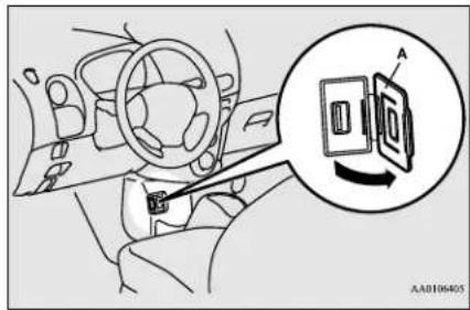
- Connect a commercially available USB connector cable (C) to the USB memory device (B).
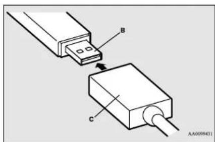
- Connect the USB connector cable (C) to the USB input terminal (D).
USB input terminal (if so equipped)
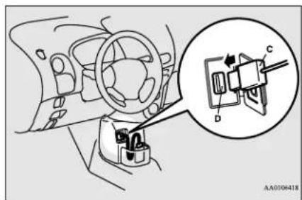
WARNING
- Place the USB memory device and the USB connector cable so as not to interfere with driving.
NOTE
- Do not connect the USB memory device to the USB input terminal directly. The USB memory device may be damaged.
- To remove the USB connector cable, turn the electric motor switch to the "LOCK" position first and perform the installation steps in reverse.
How to connect an iPod
N00566900075
- Park your vehicle in a safe place and turn the electric motor switch to the "LOCK" position.
- Open the USB input terminal cover (A) in the floor console.
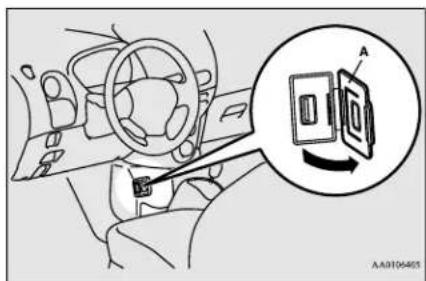
- Connect the Dock connector (C) to the iPod (B).
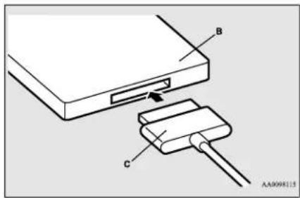
NOTE
- Use a genuine Dock connector from Apple Inc.
- Connect the Dock connector (C) to the USB input terminal (D).
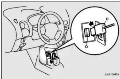
WARNING
- Place the iPod and the USB connector cable so as not to interfere with driving.
- To remove the Dock connector, turn the electric motor switch to the "LOCK" position first and perform the installation steps in reverse.
5-74 Features and controls
Types of connectable devices and supported file specifications
N00567000031
Device types
N00567101169
Devices of the following types can be connected.
| Model name Condition | |
| USB memory device | Storage capacity of 256 Mbytes or more |
| Models other than USB memory devices and iPods | Digital audio player supporting mass storage class |
For these connectable device types, “iPod*,” “iPod classic*,” “iPod nano*,” “iPod touch*” and “iPhone*,” refer to the following website:
[For vehicles sold in U.S.A.]
You can access the Mitsubishi Motors North America website.
[For vehicles sold in Canada]
You can access the Mitsubishi Motors website. Please read and agree to the “Warning about Links to the Web Sites of Other Companies”. The websites mentioned above may
connect you to websites other than the Mitsubishi Motors website. http://www.mitsubishi-motors.com/en/products/index.html
*: "iPod," "iPod classic," "iPod nano," "iPodtouch," and "iPhone" are registered trademarks of Apple Inc. in the United States and other countries.

NOTE
- Depending on the type of the USB memory device or other device connected, the connected device may not function properly or the available functions may be limited.
- It is recommended to use an iPod with firmware updated to the latest version.
- You can charge your iPod by connecting it to the USB input terminal when the electric motor switch is in the “ACC” or “ON” position.
- Do not keep your USB memory device or iPod in your vehicle.
- It is recommended that you back up the files in case of data damage.
- Do not connect to the USB input terminal any device (hard disk, card reader, memory reader, etc.) other than the connectable devices specified in the previous section. The device and/or data may be damaged. If any of these devices was connected by mistake, remove it after turning the electric motor switch to the "LOCK" position.
File specifications
N00567201069
You can play music files of the following specifications that are saved in a USB memory device or other device supporting mass storage class. When you connect your iPod, playable file specifications depend on the connected iPod.
| Item Condition | |
| File format | MP3, WMA, AAC, WAV |
| Maximum number of levels(including the root) | Level 8 |
| Number of folders 700 | |
| Number of files 65,535 |
Sun visors
Sun visors
N00524600340
Fold the sun visor downward (1) to reduce front glare while driving. To reduce side glare, turn the visor to the side (2).
5
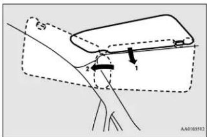
Vanity mirror
A vanity mirror is fitted to the back of the sun visor.
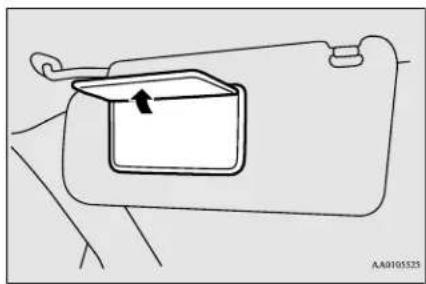
natural_image
Diagram of a car interior showing a rectangular box with an arrow pointing to it, no text or symbols present.Card holder
Cards can be slipped into the front (A) of the lid of the vanity mirror.
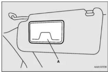
12 V power outlet
N00525018602
CAUTION
- Be sure to use a "plug-in" type accessory operating at 12 V and 120 W or less.
- Be aware that using electronic equipment with the ready indicator off may run the 12 V starter battery down.
- When the 12 V power outlet is not in use, be sure to close the 12 V power outlet cover. This will prevent the 12 V power outlet from becoming dirty and possibly short-circuiting.
The accessory can be operated when the electric motor switch is in the "ON" or "ACC" position.
To use a "plug-in" type accessory, open the cover, then insert the plug in the socket.
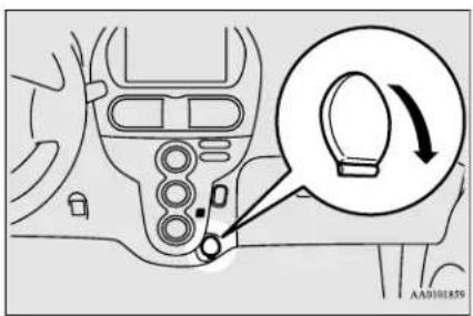
5-76 Features and controls
Interior lights

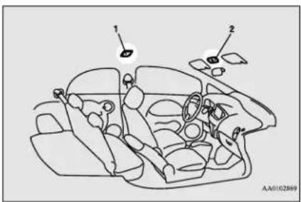
1- Dome light (Rear) → P.5-78
2- Dome light (Front)/Reading lights
→P.5-77
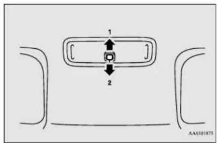
1-Door
2-Off
1-(DOOR)
Dome light (Front)/Reading lights (if so equipped)
N00525800222
Dome light (Front)
The dome light can be turned on by sliding the dome light switch.
- The dome light comes on when any door or the liftgate is opened. It goes off approximately 30 seconds after the door or liftgate is closed (delayed off function). However, the light goes off immediately if:
- The door and the liftgate are closed and the electric motor switch is turned to the "ON" position.
- The driver's door is closed after all the other doors are closed while the lock knob of the driver's door is in the lock position.
• The door and the liftgate are closed and the power door lock switch is used to lock the doors. - The keyless entry system remote control transmitter is used to lock the doors.
Interior lights
- If the dome light is left switched on with the electric motor switch in the "LOCK" or "ACC" position and a door or the liftgate is opened, it goes off automatically after approximately 30 minutes.
The light will illuminate again after it automatically goes off in the following cases:
- When the electric motor switch is turned to the "ON" position.
- When the keyless entry system remote control transmitter is operated.
- When any of the doors or the liftgate is opened after all doors and the liftgate are closed.

NOTE
- When the key is removed while the doors and liftgate are closed, the dome light will illuminate for approximately 30 seconds before going off.
- The time until the light goes off (delayed off) can be adjusted. See a certified i-MiEV dealer for details.
However, the dome light will shut off in sync with the automatic relocking function, even if the dome light delayed off function has been extended. For the automatic relocking function, refer to "Keyless entry system" on page 5-5.

NOTE
● The auto cut-out function can be deactivated. See a certified i-MiEV dealer for details.
2-
The dome light goes off.
Reading lights
N0055380096
Regardless of the dome light switch position, when you press the lens, the light on the side that is pressed illuminates; when you press the lens again, the light goes off.
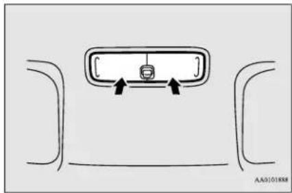
natural_image
Diagram of a vehicle rearview mirror with two arrows indicating direction (no text or symbols)Dome light (Rear)
N00525400459
The rear dome light can be turned on by sliding the dome light switch.
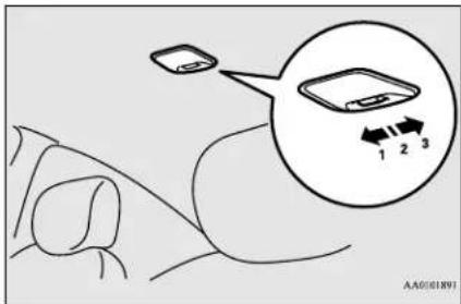
1- On
2- Door
3-Off
1-(ON)
The dome light comes on.
2-(●)
5-78 Features and controls
- The dome light comes on when any door or the liftgate is opened. It goes off approximately 30 seconds after the door or liftgate is closed (delayed off function). However, the light goes off immediately if:
- The door and the liftgate are closed and the electric motor switch is turned to the "ON" position.
- The driver's door is closed after all the other doors are closed while the lock knob of the driver's door is in the lock position.
- The door and the liftgate are closed and the power door lock switch is used to lock the doors.
- The keyless entry system remote control transmitter is used to lock the doors.
- If the dome light is left switched on with the electric motor switch in the "LOCK" or "ACC" position and a door or the liftgate is opened, it goes off automatically after approximately 30 minutes.
The light will illuminate again after it automatically goes off in the following cases:
- When the electric motor switch is turned to the "ON" position.
- When the keyless entry system remote control transmitter is operated.
- When any of the doors or the liftgate is opened after all doors and the liftgate are closed.

NOTE
- When the key is removed while the doors and liftgate are closed, the dome light will illuminate for approximately 30 seconds before going off.
- The time until the light goes off (delayed off) can be adjusted. See a certified i-MiEV dealer for details.
However, the dome light will shut off in sync with the automatic relocking function, even if the dome light delayed off function has been extended. For the automatic relocking function, refer to "Keyless entry system" on page 5-5.

NOTE
- The auto cut-out function cannot be operated when the dome light switch is in the "ON" position.
Also, this function can be deactivated. See a certified i-MiEV dealer for details.
3-(OFF)
The dome light goes off.
Storage spaces
N00526400502

CAUTION
- Never leave lighters, carbonated drink cans, or spectacles in the cabin when parking the vehicle in hot sunshine. The cabin will become extremely hot, so lighters and other flammable items may catch fire and unopened drink cans (including beer cans) may rupture. The heat may also deform or crack plastic spectacle parts.
- Keep the lids of storage spaces closed while driving the vehicle. A lid or the contents of a storage space could otherwise cause injuries during a sudden stop.

NOTE
- Do not leave valuables in any storage space when leaving the vehicle.
Cup holder
Glove compartment
N00551500259
To open the glove compartment, pull the lever (A).
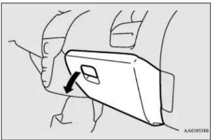
natural_image
Diagram of a car interior showing a door handle and seat, with no visible text or symbolsWARNING
- An open glove compartment door can cause a serious injury or death to the front passenger in an accident, even if the passenger is wearing his/her seat belt. Always keep the glove compartment door closed when driving.
Card holder
N00571400010
There is a card holder on the inside of the glove compartment.
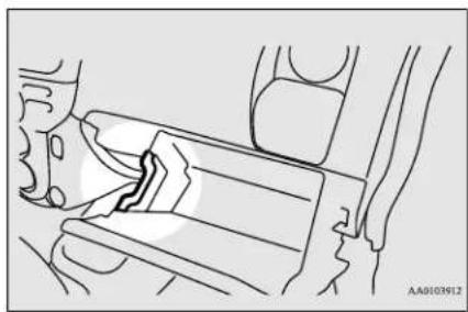
natural_image
Technical line drawing of a mechanical assembly or valve mechanism (no text or symbols)Cup holder
N00527300364
For the front seat
The cup holder is located in front of the side vent.
The cup holder is designed for holding cups or drink-cans securely in its holes.
Tip the cup holder toward you to use it.
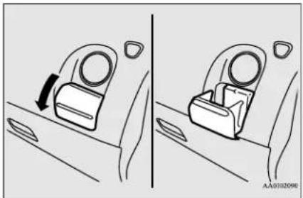
natural_image
Diagram showing two car seatbelt configurations with a directional arrow indicating movement (no text or symbols)CAUTION
- Do not drink beverages while driving your vehicle. This is distracting and could cause an accident.
NOTE
- When not using the holder, push the holder in to stow it away.
- Do not put your hand on the cup holder while getting in or out of the vehicle. The cup holder could break.
● Never place anything other than cup or drink can in the cup holder.
For the rear seat
N00537019146
This cup holder is located behind the parking brake lever.
5-80 Features and controls
Assist grip
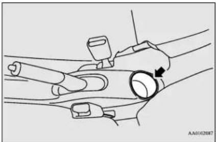
natural_image
Illustration of a hand holding a wrist with a circular object and a tool, no text or symbols presentCAUTION
- Do not use the assist grips when getting into or out of the vehicle. The assist grips could detach and cause an accident.
Assist grip
N00559000058
These grips are to support the body by hand while seated in the vehicle.
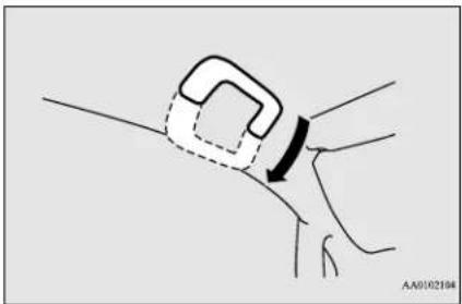
natural_image
Diagram showing a hand holding a small object with an arrow indicating motion (no text or symbols)Features and controls 5-81
| 100% | |
| 100% | 100% |
| 100% | 100% |
| 100% | 100% |
| 100% | 100% |
| 100% | 100% |
| 100% | 100% |
| 100% | 100% |
| 100% | 100% |
| 100% | 10 |
Driving safety
Economical driving 6-2
Driving, alcohol and drugs 6-2
Floor mat 6-2
Vehicle preparation before driving 6-3
Safe driving techniques 6-4
Driving during cold weather 6-4
Braking 6-5
Parking 6-6
Loading information 6-6
Cargo loads 6-10
Trailer towing 6-10
Dinghy towing 6-10
Economical driving
Economical driving
N00628500029
For economical driving, there are some technical requirements that have to be met. In order to achieve longer life of the vehicle and the most economical operation, we recommend you to have the vehicle checked at regular intervals according to the “WARRANTY AND MAINTENANCE MANUAL”.
Starting and acceleration
Avoid driving with the accelerator pedal fully depressed, such as for unnecessarily sudden starts, acceleration and deceleration. Smoothly depress the accelerator pedal. Observe the speed limit and keep the speed as constant as possible while driving.
Idling
Parking for a long period with the ready indicator illuminated will shorten the cruising range.
Speed
At higher the vehicle speed the more main drive lithium-ion battery is consumed. Avoid
driving at full speed. Even a slight release of the accelerator pedal will save a significant amount of main drive lithium-ion battery charge.
Tire inflation pressure
Check the tire inflation pressures at regular intervals Low tire inflation pressure increases road resistance. In addition, low tire pressures adversely affect tire wear and driving stability.
Cargo loads
Do not drive with unnecessary articles in the luggage compartment.
Air conditioning
Too much cooling/heating can affect the cruising range, so maintain an appropriate temperature to extend the cruising range.
Driving, alcohol and drugs
N00628900010
Drunk driving is one of the most frequent causes of accidents.
Your driving ability can be seriously impaired even with blood alcohol levels far below the legal minimum. If you have been drinking, don't drive. Ride with a designated non-drinking driver, call a cab or a friend, or use public transportation. Drinking coffee or taking a cold shower will not make you sober.
Similarly, prescription and nonprescription drugs affect your alertness, perception and reaction time. Consult with your doctor or pharmacist before driving while under the influence of any of these medications.
WARNING
● NEVER DRINK AND DRIVE.
Your perceptions are less accurate, your reflexes are slower and your judgment is impaired.
Floor mat
N00628600017
The original equipment floor mat provided with your vehicle was specifically designed for your vehicle. Always properly position the floor mat and assure it does not interfere with operation of the pedals. Always use the retaining clip on the driver's floorboard to secure the floor mat. When used, this clip will help prevent the floor mat from moving forward and possibly interfering with the operation of the pedals. To prevent the floor mat
6-2 Driving safety
from moving forward and possibly interfering with the operation of the pedals, Mitsubishi genuine floor mats are recommended.
To install the floor mat
N00628700063
- Place the floor mat to fit the shape of the floorboard.
- Align the floor mat with the installation holes over the retaining clips.
- Secure the floor mat with retaining clips.
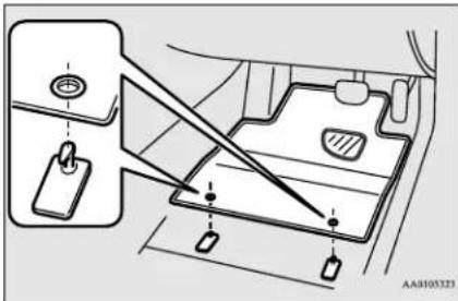
natural_image
Diagram of a vehicle interior showing dashboard, steering wheel, and keyway (no text or labels)
NOTE
● The shape of the mat and the number of retaining clips may vary depending on the vehicle model.
WARNING
- If a floor mat is the wrong size or is not properly installed, it can interfere with the operation of the pedals. Interference with the pedals can cause unintended acceleration and/or increased stopping distances resulting in a crash and injury. Always make sure the floor mat does not interfere with the accelerator or brake pedal.
- Always use the retaining clip on the driver's floorboard to secure the floor mat.
● Always install the mat with the correct side facing down.
● Never install a second mat over or under an existing floor mat. - Do not use a floor mat designed for another model vehicle even if it is a Mitsubishi genuine floor mat.
● Before driving, be sure to check the following: - Periodically check that the floor mat is properly secured with the retaining clips. If you remove the floor mat while cleaning the inside of your vehicle or for any other reason, always check the condition of the floor mat after it has been reinstalled.
- While the vehicle is stopped with the electric motor unit off, check that the floor mat is not interfering with the pedals by depressing the pedals fully.
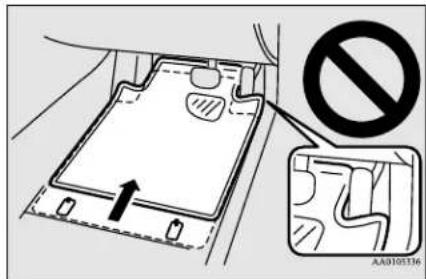
Vehicle preparation before driving
N00629000698
For a safer and more enjoyable trip, always observe the following:
Seat belts and seats
- Before starting the vehicle, make certain that you and all passengers are seated and wearing their seat belts properly (with children in the rear seat, in appropriate restraints), and that all the doors and the rear hatch are locked.
Safe driving techniques
- Move the driver's seat as far backward as possible, while still keeping good visibility, and good control of the steering wheel, brakes, accelerator, and controls. Check the instrument panel indicators for any possible problem.
- Move the front passenger seat as far back as possible.
● Make sure that infants and small children are properly restrained in accordance with all laws and regulations.
Defrosters
Check these by selecting the defroster mode, and set the blower switch on high. You should be able to feel the air blowing against the windshield.
(Refer to “Defrosting or defogging the windshield and door windows” on page 7-9.)
Tires
Check all the tires for heavy tread wear or uneven wear patterns. Look for stones, nails, glass, or other objects stuck in the tread. Look for any tread cuts or sidewall cracks. Check the wheel nuts for tightness, and the tires for proper pressures. Replace your tires before they are heavily worn out.
As your vehicle is equipped with a tire pressure monitoring system, there is a risk of damage to the tire inflation pressure sensors when the tire is replaced on the rim. Tire replacement should, therefore, be performed only by a certified i-MiEV dealer.
Lights
Have someone watch while you turn all the exterior lights on and off. Also check the turn signal indicators and high-beam indicators on the instrument panel.
Fluid leaks
Check the ground under the vehicle after parking overnight, for water, oil, or other leaks. Make sure all the fluid levels are correct.
Safe driving techniques
N00629200124
Even this vehicle's safety equipment, and your safest driving, cannot guarantee that you can avoid an accident or injury. However, if you give extra attention to the following areas, you can better protect yourself and your passengers:
- Drive defensively. Be aware of traffic, road and weather conditions. Leave plenty of stopping distance between your vehicle and the vehicle ahead.
● Before changing lanes, check your mirrors and use your turn signal light.
● While driving, watch the behavior of other drivers, bicyclists, and pedestrians.
● Always obey applicable laws and regulations. Be a polite and alert driver. Always leave room for unexpected events, such as sudden braking.
Driving during cold weather
N00629400416
- Check the 12V starter battery, including terminals and cables. During extremely cold weather, the 12V starter battery will not be as strong and its power level may drop. Before driving the vehicle, check to see if the headlights are as bright as normal. Charge or replace the 12V starter battery if necessary. During extreme cold weather, it is possible that a very low 12V starter battery could freeze.

WARNING
- The 12V starter battery gives off explosive hydrogen gas. Any spark or flame can cause the 12V starter battery to explode, which could cause serious injury or death. Always wear protective clothes and a face mask when working with your 12V starter battery, or let a skilled mechanic do it.
- Check the antifreeze.
If there is not enough coolant because of a leak, add high-quality ethylene glycol antifreeze and water. Use Mitsubishi Motors Genuine Super Long Life Coolant Premium or an equivalent. The recommended blend is about 50 % water and 50 % anti-freeze. Use a higher concentration (not over 60 %) when the outside temperature is -31 °F (-35 °C) or lower. When the electric motor unit is working very hard (for example, during mountain driving and/or when the outside temperature is high), use a 50 % concentration. This blend will provide adequate protection from corrosion and boiling.

WARNING
- Never open the coolant reservoir cap while it is hot. You could be seriously burned.
Braking
N00629501531
All the parts of the brake system are critical to safety. Have the vehicle serviced by a certified i-MiEV dealer at regular intervals according to the “WARRANTY AND MAINTENANCE MANUAL”.
When brakes are wet
Check the brake system while driving at a low speed immediately after starting, especially when the brakes are wet, to confirm they work normally.
A film of water can be formed on the brake discs and prevent normal braking after driving in heavy rain or through large puddles, or after the vehicle is washed. If this occurs, dry the brakes out by driving slowly while lightly depressing the brake pedal.
When driving in cold weather
On snowy roads, ice can form on the braking system, making the brakes less effective. While driving in such conditions, pay close attention to preceding and following vehicles and to the condition of the road surface. From time to time, lightly depress the brake pedal and check how effective the brakes are.
When driving downhill
Put the selector lever to "B" (REGENERATIVE BRAKE MODE) or "ECO" (ECO MODE) position according to the grade of the slope and vehicle speed. This will allow effective use of the regenerative brake and prevent the service brake from overheating. If the brake pedal is continuously or frequently depressed on downhill roads, the service brake could overheat and the brake performance will be reduced.

NOTE
- When the main drive lithium-ion battery level is full or nearly full, or the main drive lithium-ion battery temperature is too high or too low, the regenerative braking force may be reduced. Refer to "Regenerative braking" on page 3-3.
- If the red needle in the energy usage indicator does not move to the left of the neutral point (A) while the accelerator pedal is released, the regenerative brake will not work. Refer to "Energy usage indicator" on page 5-37. In the such case, before approaching a long downhill road, reduce speed to prevent the service brake from overheating.
Parking
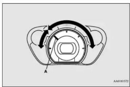
natural_image
Diagram of a mechanical component with curved arrows indicating rotational motion, labeled 'A' at the base (no text or symbols beyond label)Parking
N00629600317
Parking on a hill
When parking on a hill, set the parking brake, and turn the front wheels toward the curb on a downhill, or away from the curb on an uphill. If necessary, apply chocks to wheels.
NOTE
- On a slope, be sure to apply the parking brake before moving the selector lever to the "P" (PARK) position. If you move the selector lever to the "P" (PARK) position before applying the parking brake, it may be difficult to disengage the selector lever from the "P" (PARK) position when next you drive the vehicle, requiring application of a strong force to the selector lever to move from the "P" (PARK) position.
Parking with the electric motor unit running
Never leave the electric motor unit running while you take a short sleep/rest.
WARNING
● Leaving the electric motor unit running when you are not alert risks injury or death from accidentally moving the selector lever.
Where you park
Your front bumper can be damaged if you scrape it over curbs or parking stop blocks. Be careful when traveling up or down steep slopes where your bumper can scrape the road.
When leaving the vehicle
Always remove the key from the electric motor switch and lock all doors and the lift-gate when leaving the vehicle unattended. Always try to park your vehicle in a well lit area.
Do not keep the steering wheel fully turned for a long time
More effort could be required to turn the steering wheel. Refer to "Electric power steering system (EPS)" on page 5-27.
Loading information
N00629900411
It is very important to know how much weight your vehicle can carry. This weight is called the vehicle capacity weight and includes the weight of all occupants, cargo and non-factory-installed options. The tire and loading information placard located on the driver's door sill of your vehicle will show how much weight it may properly carry.

WARNING
- Never overload your vehicle. Overloading can damage your vehicle, adversely affect vehicle performance, including handling and braking, cause tire failure, and result in an accident.
It is important to familiarize yourself with the following terms before loading your vehicle:
● Vehicle maximum load on the tire: load on an individual tire that is determined by distributing to each axle its share of the maximum loaded vehicle weight and dividing by two.
● Vehicle normal load on the tire: load on an individual tire that is determined by distributing to each axle its share of the curb weight, accessory weight, and normal occupant weight and dividing by two.
● Maximum loaded vehicle weight: the sum of -
(a) Curb weight;
(b) Accessory weight;
(c) Vehicle capacity weight; and
(d) Production options weight.
- Curb weight: the weight of a motor vehicle with standard equipment including the maximum capacity of oil, and coolant.
- Accessory weight: the combined weight (in excess of those standard items which may be replaced) of automatic transmission, power steering, power brakes, power windows, power seats, radio, and heater, to the extent that these items are available as factory- installed equipment (whether installed or not).
- Vehicle capacity weight: the rated cargo and luggage load plus 150 lbs (68 kg)* times the vehicle's designated seating capacity.
● Production options weight: the combined weight of those installed regular production options weighing over 5 lbs (2.3 kg) in excess of those standard items which they replace, not previously considered in curb weight or accessory weight, including heavy duty brakes, ride levelers, roof rack, heavy duty battery, and special trim.
● Normal occupant weight: 150 lbs (68 kg)* times the number of specified occupants. (In your vehicle the number is 2) - Occupant distribution: distribution of occupants in a vehicle as specified. (In your vehicle the distribution is 2 in front seat)
*: 150 lbs (68 kg) is the weight of one person as defined by U.S.A. and Canadian regulations.
Tire and loading information placard
N00630100370
The tire and loading information placard is located on the driver's door sill.
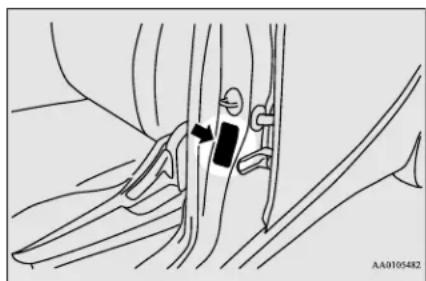
natural_image
Medical illustration showing anatomical structures with no visible text or symbolsThis placard shows the maximum number of occupants permitted to ride in your vehicle as well as “the combined weight of occupants and cargo” (C), which is called the vehicle capacity weight. This placard also tells you the size and recommended inflation pressure for the original equipment tires on your vehicle. For more information, refer to “Tires” on page 9-10.
Loading information
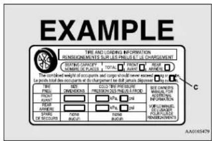
Steps for Determining Correct Load Limit
N00630201264
- Locate the statement "The combined weight of occupants and cargo should never exceed XXX kg or XXX lbs." on your vehicle's placard.
- Determine the combined weight of the driver and passengers that will be riding in your vehicle.
-
Subtract the combined weight of the driver and passengers from XXX kg or XXX lbs.
-
The resulting figure equals the available amount of cargo and luggage load capacity. For example, if the "XXX" amount equals 1400 lbs. and there will be five 150 lbs. passengers in your vehicle, the amount of available cargo and luggage load capacity is 650 lbs. (1400 - 750 (5 x 150) = 650 lbs.)
- Determine the combined weight of luggage and cargo being loaded on the vehicle. That weight may not safely exceed the available cargo and luggage load capacity calculated in Step 4.
- If your vehicle will be towing a trailer, load from your trailer will be transferred to your vehicle. Consult this manual to determine how this reduces the available cargo and luggage load capacity of your vehicle.

NOTE
- The above steps for determining correct load limit were written in accordance with U.S.A. regulations.
For your vehicle, please determine correct load limit bearing in mind the following differences: - Your vehicle's seating capacity is 4 people.
- Your vehicle cannot tow a trailer, so step 6 is irrelevant.

NOTE
- The following table shows examples on how to calculate total cargo/load capacity of your vehicle with varying seating configurations and number and size of occupants. This table is for illustration purposes only and may not be accurate for the seating and load capacity of your vehicle.
- For the following example the combined weight of occupants and cargo should never exceed 865 lbs (392 kg).
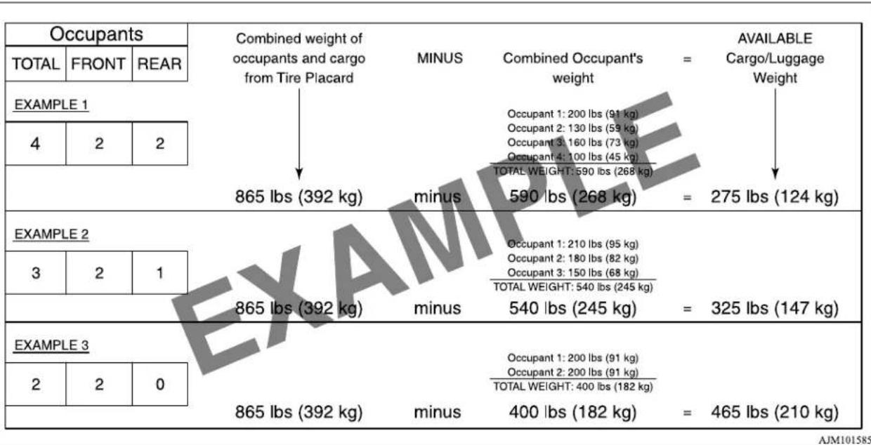
other
| Occupation | Total Weight (lbs) | Occupant Weight (lbs) | |---|---|---| | Occupants | 865 | 400 | | TOTAL | 392 | 465 | The table shows the total weight of 275 lbs (124 kg) and the total weight of 325 lbs (147 kg). The table also includes a table for the number of employees in each occupation. The values are expressed as percentages relative to the total weight. The table also includes a minimum value of 590 lbs (268 kg) and a minus value of 400 lbs (182 kg). The table also includes a minimum value of 540 lbs (245 kg) and an equals sign indicating the difference between the two groups. The table also includes a separate label 'MAXIM' at the bottom.- Under a maximum loaded vehicle condition, gross axle weight ratings (GAWR's) for the front and rear axles must not be exceeded. For further information on GAWR's, vehicle loading, see the "Specifications" section of this manual.
Cargo loads
Cargo loads
N00629700510
Cargo load precautions
To determine the cargo load capacity for your vehicle, subtract the weight of all vehicle occupants from the vehicle capacity weight. For added information, if needed, refer to "Steps for Determining Correct Load Limit" on page 6-8.
DO NOT USE the Gross Vehicle Weight Rating and Gross Axle Weight Rating numbers listed on the safety certification label located on the driver's side door pillar as the guide for passengers and/or cargo weight.
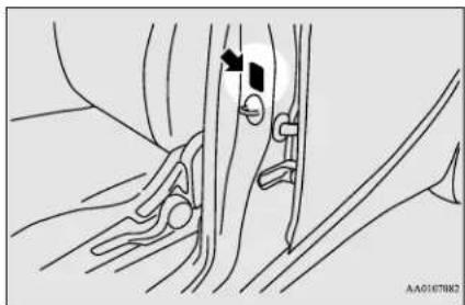
natural_image
Medical illustration showing anatomical structures with arrows indicating specific regions (no text or labels)WARNING
- To reduce the risk of serious injury or death, the combined weights of the driver, passengers and cargo and must never exceed the vehicle capacity weight.
- Exceeding the vehicle capacity weight will adversely affect vehicle performance, including handling and braking, and may cause an accident.
- Do not load cargo or luggage higher than the top of the seatback. Be sure that your cargo or luggage cannot move when your vehicle is in motion.
Having either the rear view blocked, or your cargo being thrown inside the cabin if you suddenly have to brake can cause a serious accident or injury or death. - Put cargo or luggage in the cargo area of your vehicle. Try to spread the weight evenly.
Trailer towing
N00629810188
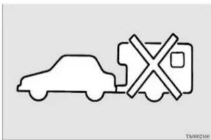
WARNING
- Do not use this vehicle for trailer towing. It may not be possible to maintain control or adequate braking.
Dinghy towing
N00630700015
Dinghy towing is towing the vehicle with all four wheels on the ground.
Dinghy towing
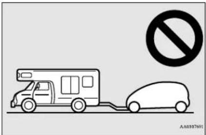
CAUTION
- Your vehicle is not designed to be dinghy towed behind a motor home.
- Dinghy towing can cause damage to the electric motor unit. Damage caused by dinghy towing will not be covered by the vehicle warranty.
Driving safety 6-11
| 100% | |
| 100% | 100% |
| 100% | 100% |
| 100% | 100% |
| 100% | 100% |
| 100% | 100% |
| 100% | 100% |
| 100% | 100% |
| 100% | 100% |
| 100% | 10 |
Comfort controls
Vents 7-2
Air conditioning 7-4
Important air conditioning operating tips 7-10
Air purifier 7-11
Remote Climate Control 7-11
AM/FM electronically tuned radio with CD player (if so equipped) 7-11
To play iPod/USB memory device tracks via voice operation (vehicles with Bluetooth® 2.0 interface) ....7-20
Steering wheel audio remote control switch (if so equipped) .....7-22
Error codes 7-24
Handling of compact discs 7-25
Antenna 7-27
Clock (if so equipped) 7-27
General information about your radio 7-28
Vents
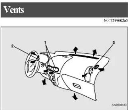
1- Center vents
2- Side vents

NOTE
- Do not place beverages on top of the instrument panel. If they splash into the air conditioning vents, they could damage the system.
Air flow and direction adjustments
N00730200314
Center vents
Adjust the direction of the air flow by moving the knob (A) and vent.
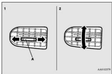
1- Left-right adjustment
2- Up-down adjustment
Side vents
When the dimple (A) is pressed, the vent opens.
To close the vent, press the dimple (B) on the opposite side.
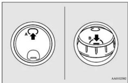

NOTE
- On rare occasions, air from the vents of an air-conditioned vehicle may be foggy. This is only moist air cooling suddenly and does not indicate a problem.
- Do not let drinks or other liquids get into the vents as they could prevent the air conditioning from operating normally.
Changing the mode selection
N007364181581
To change the position and amount of air flowing from the vents, turn the mode selection dial. Refer to "Mode selection dial" on page 7-5.
These symbols are used in the next several illustrations to demonstrate the quantity of air coming from the vents.
→: Small amount of air from the vents
◆: Large amount of air from the vents
7-2 Comfort controls
Face position
Air flows only to the upper part of the passenger compartment.
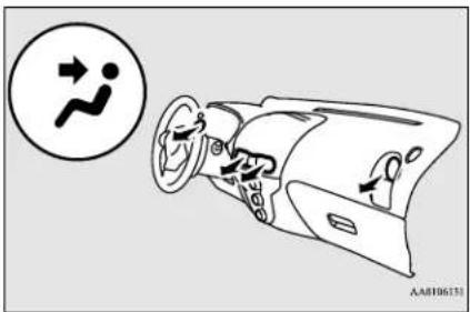
Foot/Face position
Air flows to the upper part of the passenger compartment, and flows to the leg area.
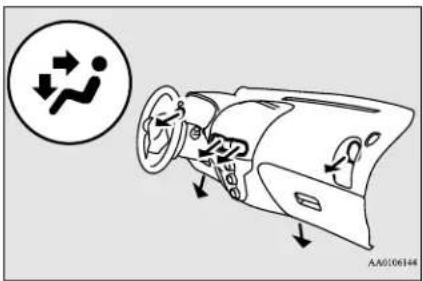

NOTE
- With the mode selection dial between the “and” positions, air flows mainly to the upper part of the passenger compartment. With the mode selection dial between the “and” positions, air flows mainly to the leg area.
Foot position
Air flows mainly to the leg area.
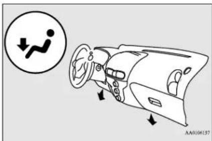
Foot/Defroster position
Air flows to the leg area, the windshield and the door windows.
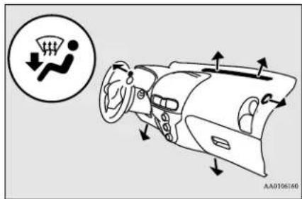

NOTE
- With the mode selection dial between the “” and “” positions, air flows mainly to the leg area. With the mode selection dial between the “” and “” positions, air flows mainly to the windshield and door windows.
Air conditioning
Defroster position
Air flows mainly to the windshield and the door windows.
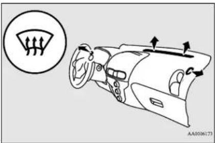
Air conditioning
N00730300328
The air conditioning can only be used when the ready indicator is illuminated.

NOTE
- If the energy level gauge is at 0 bars or the power down warning light illuminates, the vehicle interior may not be cooled/heated even though the dial or switch is operated. Furthermore, the defog performance may be also reduced.
Refer to "Energy level gauge" on page 5-41. Refer to "Power down warning light" on page 5-46.
Control panel
N00730501314
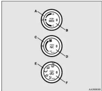
A- Temperature control dial
B-MAX switch
C- Blower speed selection dial
D- Air conditioning switch
E- Mode selection dial
F- Air selection switch

NOTE
- There is an interior air temperature sensor (G) in the illustrated position.
Never place anything over the sensor, since doing so will prevent it from functioning properly.
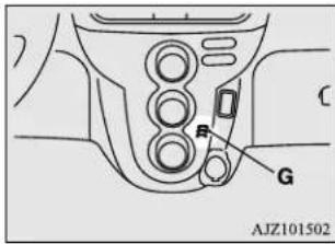
7-4 Comfort controls
Blower speed selection dial Temperature control dial
N00736500191
When the electric motor switch is in the "ON" position, select the blower speed by turning the blower speed selection dial. Turning the dial clockwise will increase the blower speed;
turning the dial counterclockwise will decrease it. When the dial is set to the "OFF" position, all fan-driven airflow will stop.
When the dial is set to the "AUTO" position, the air flow is adjusted automatically according to the temperature of the interior and the position of the temperature control dial.
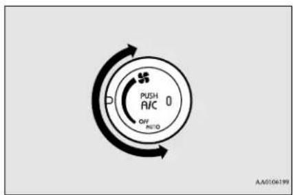
N00736600235
Use this dial to adjust the temperature of the air flow from the vents.
Turn the temperature control dial clockwise to make the air warmer. Turn it counterclockwise to make the air cooler.
When the dial is set to middle (●) position, only uncooled and unheated air will flow.
When the dial is moved to middle (●) position when using cooling or heating, cooling or heating stops.
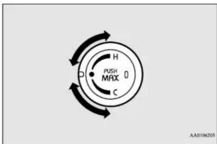

NOTE
- When the dial is moved from middle (● position to the left while the air conditioning is not operating, the air temperature will not change.

NOTE
- When the dial is moved to middle (●) position and then to the left while the air conditioning is operating, the air conditioning system is operating again.
- When the temperature control dial is set to "C" position, the air selection will be automatically set to the recirculation position and the air conditioning will operate.
When the dial is moved thereafter, the air conditioning continues to operate and the air selection setting returns to the setting before the dial was set to "C" position.
Mode selection dial
N00736700210
To change the position and amount of air flowing from the vents, turn the mode selection dial. Refer to "Changing the mode selection" on page 7-2.
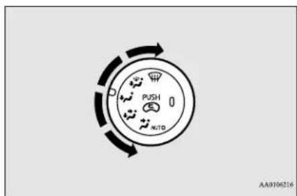
Comfort controls 7-5
Air conditioning
"AUTO" position
The vents change to the following positions according to the position of the temperature control dial.
Refer to "Temperature control dial" on page 7-5.
| Temperature control dial position | Vents | |
| Between “C” and mid-dle(●) | : Upper part of front passen-ger compa-rt-ment | |
| Mid-dle(●) | Set the dial to middle (●) from the “C” side | : Upper part of front passen-ger compa-rt-ment |
| Set the dial to middle (●) from the “H” side | : Leg area | |
| Between middle (●) and “H” | Near middle (●) | : Leg area |
| Near “H” | : Leg area, windshield, and door windows | |
CAUTION
- When using the mode selection dial between the “and” positions, prevent fogging by pressing the air selection switch to select outside air. (Refer to “Air selection switch” on page 7-6.)
Air selection switch
N00736800400
Normally, use the outside air position to keep the windshield and side windows clear and to quickly remove fog or frost from the windshield.
To change the air selection, simply press the air selection switch.
● Outside air {Indicator light (A) OFF}
Outside air is introduced into the passenger compartment.
● Recirculated air {Indicator light (A) ON} Air is recirculated inside the passenger compartment.
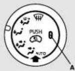
AA0106229
If high cooling performance is desired, or, if the outside air is dusty or contaminated in some way, use the recirculation position. Switch to the outside air position every now and then to keep the windows from fogging up.
CAUTION
- Using recirculated air for a long time may cause the windows to fog up.
NOTE
- When the mode selection dial is set to the "in" position, the air conditioning compressor runs automatically. Outside air introduction will also be selected automatically.
- When the temperature control dial is set to the "C" position, the air selection will be automatically set to the recirculation position.
Air conditioning switch
N00731000465
Push the switch, and the air conditioning compressor will turn on. The air conditioning indicator light (A) will come on.
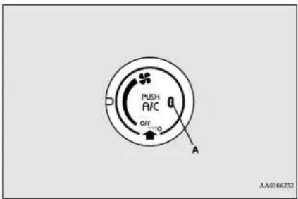
Push the switch again and the air conditioning compressor will stop and the indicator light (A) goes off.
MAX switch
N00766500015
When the blower speed selection dial is not OFF and the MAX switch is pressed, the indicator light (A) illuminates and cooling/heating performance and the air conditioning setting is changed according to the temperature control dial position.
When the switch is pressed again, the operation returns to the mode before pressing the switch.
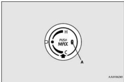
When the temperature control dial is set between middle (●) and "H" position
The heating capability is at maximum.
When the temperature control dial is in middle (●) position
The air flow is at maximum.
When the temperature control dial is set between "C" and middle (●) position
The air conditioning automatically operates and the cooling capability is at maximum.
NOTE
- Do not use the cooling/heating function with the MAX switch for a long time. Because the power consumption is greatly increased, the cruising range is shortened.
NOTE
- When the blower speed selection dial or temperature control dial is operated with the indicator light illuminated, the indicator light goes out and the selected function overrides others.
Other functions return to the mode before pressing the MAX switch. - When the air conditioning is operated with the MAX switch, the air conditioning does not stop if the function is cancelled.
Operating the air conditioning system
N00731101290
Heating
- Set the mode selection dial to the "” position.
- Set the air selection switch (A) to the outside position.
- Turn the temperature control dial clockwise or counterclockwise to the desired temperature between middle (●) and "H" position.
- Select the desired blower speed.
Air conditioning
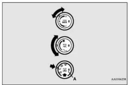

NOTE
- When the blower speed selection dial is set to the "AUTO" position, the air flow is adjusted automatically according to the temperature of the interior and the position of the temperature control dial.
- Set the air selection switch (A) to the outside position.
- Turn the temperature control dial clockwise or counterclockwise to between middle (●) position and "H" position.
- Turn the blower speed selection dial to any position other than "OFF" position.
- Press the MAX switch (B).
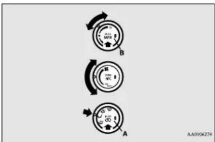

NOTE
- Do not use the heating function with the MAX switch for a long time. Because the power consumption is greatly increased, the cruising range is shortened.
Cooling
N00731201363
For ordinary cooling
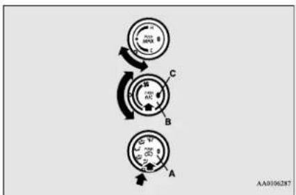
- Set the mode selection dial to the “” position.
- Set the air selection switch (A) to the outside position.
- Turn the temperature control dial clockwise or counterclockwise to the desired temperature between middle (●) and "C" position.
- Select the desired blower speed.
- Push the air conditioning switch (B).
- When the air conditioning is operating, the switch indicator light (C) illuminates.
Quick heating
- Set the mode selection dial to the "” position.
7-8 Comfort controls

NOTE
- If the outside air is dusty or contaminated in some way, set the air selection switch (A) to the recirculation position. Let in some outside air from time to time for good ventilation.
- To cool the leg areas, set the mode selection dial to the "position.
- When the blower speed selection dial is set to the "AUTO" position, the air flow is adjusted automatically according to the temperature of the interior and the position of the temperature control dial.
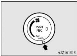
For quick cooling
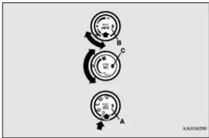
- Set the mode selection dial to the “” position.
- Set the air selection switch (A) to the recirculation position.
- Turn the temperature control dial clockwise or counterclockwise to between middle (●) and "C" position.
- Turn the blower speed selection dial to any position other than "OFF" position.
- Press the MAX switch (B). The air conditioning automatically operates and the indicator light (C) illuminates.

NOTE
- Do not use the cooling function with the MAX switch for a long time. Because the power consumption is greatly increased, the cruising range is shortened.
Defrosting or defogging (wind-shield, door windows)
N00731400557

CAUTION
- For safety, make sure you have a clear view through all the windows.
To remove frost or fog from the windshield and door windows, use the mode selection dial ("or")
For ordinary defrosting
Use this setting to keep the windshield and door windows clear of mist, and to keep the leg area heated (when driving in rain or snow).
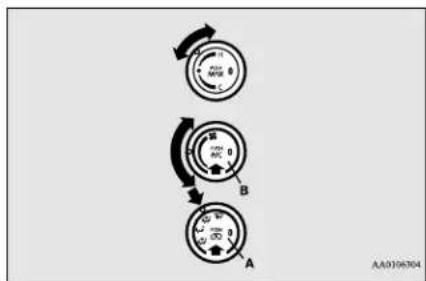
- Set the air selection switch (A) to the outside position.
Comfort controls 7-9
Important air conditioning operating tips
- Set the mode selection dial to the position.
- Turn the temperature control dial clockwise or counterclockwise to the desired temperature between middle (●) and "H" position.
- Select the desired blower speed.
- Push the air conditioning switch (B).
For quick defrosting
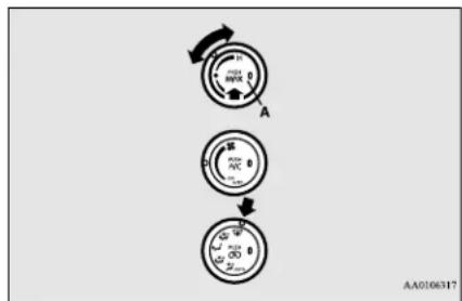
flowchart
graph TD
    A["Circle 1: 0.5V, 2.5V"] --> B["Circle 2: 0.5V, 2.5V"]
    B --> C["Circle 3: 0.5V, 2.5V"]
- Set the mode selection dial to the “” position.
- Turn the temperature control dial clockwise or counterclockwise to the desired temperature between middle (●) and "H" position.
- Press the MAX switch (A).
NOTE
- When the mode selection dial is set to the “W” position, the air conditioning compressor runs automatically. Outside air introduction will also be selected automatically.
- When defrosting, do not set the temperature control dial to the maximum cool position. This would blow cool air on the window glass and fog it up.
- Since defogging or defrosting with the MAX switch consumes a large amount of power, stop the switch after defogging or defrosting. Use the MAX setting for a long time decreases the cruising range.
Important air conditioning operating tips
N00733700323
- Park the vehicle in the shade whenever possible. Parking in the hot sun makes the vehicle interior extremely hot which then requires more time to cool. If it is necessary to park in the sun, open the windows for the first few minutes of air conditioning to expel the hot air.
-
Afterwards, keep the windows closed when the air conditioning is in use. The entry of outside air through open windows will reduce cooling efficiency.
-
When running the air conditioning, make sure the air intake, which is located in front of the windshield, is free of obstructions such as leaves. Leaves collected in the air-intake chamber may reduce air flow and plug the water drains.
Air conditioning system refrigerant and lubricant recommendations
If the air conditioning seems less effective than usual, the cause might be a refrigerant leak.
Have the system inspected by a certified i-MiEV dealer.

CAUTION
- The air conditioning system in your vehicle must be charged with the refrigerant HFC-134a and the lubricant POE MA68EV.
Use of any other refrigerant or lubricant will cause severe damage and may require replacing your vehicle's entire air conditioning system.
The release of refrigerant into the atmosphere is not recommended.
The new refrigerant HFC-134a in your vehicle is designed not to harm the earth's ozone layer. However, it may contribute slightly to global warming.
It is recommended that the old refrigerant be saved and recycled for future use.
During a long period of disuse
The air conditioning should be operated for at least five minutes each week, even in cold weather. This includes the quick defrosting mode. Operating the air condition system weekly maintains lubrication of the compressor internal parts and maintains the air conditioning in the best operating condition.
Air purifier
N00733800177
The air conditioning system is equipped with an air filter to reduce pollen and dust entering the cabin.
The air filter's ability to collect pollen and dust will be reduced as it becomes dirty, so replace it periodically. For the maintenance interval, refer to the “WARRANTY AND MAINTENANCE MANUAL”.

NOTE
- Operation in certain conditions such as driving on a dusty road or frequent use of the air conditioning can reduce the service life of the filter. When you feel that the air flow is lower than normal or when the windshield or windows start to fog up easily, replace the air filter. Contact a certified i-MiEV dealer for assistance.
Remote Climate Control
N00766601026
You can run the air conditioning in advance of using the vehicle. For details, refer to "Remote Climate Control" on page 3-36, 3-47.
AM/FM electronically tuned radio with CD player (if so equipped)
N00734301062
The audio system can only be used when the electric motor switch is in the "ON" or "ACC" position.

NOTE
- To listen to the audio system while the electric motor unit is not running, turn the electric motor switch to the "ACC" position. If the electric motor switch is in the "ACC" position, the accessory power will automatically turn off after a certain period of time and you will no longer be able to use the audio system. The accessory power comes on again if the electric motor switch is turned from the "ACC" position. Refer to "ACC power auto-cutout function" on page 5-19.
- If a cellular phone is used inside the vehicle, it may create noise in the audio equipment. This does not mean that anything is wrong with your audio equipment. In such a case, use the cellular phone at a place as far away as possible from the audio equipment.
AM/FM electronically tuned radio with CD player (if so equipped)

NOTE
- If foreign objects or water get into the audio equipment, or if smoke or a strange odor comes from it, immediately turn off the audio system and have it checked at a certified i-MiFV dealer. Never try to repair it yourself. Avoid using the audio system until it is inspected by a qualified person.
- If the audio system is damaged by foreign objects, water, or fire, have the system checked at a certified i-MiEV dealer.
Volume and tone control panel
N00711900716
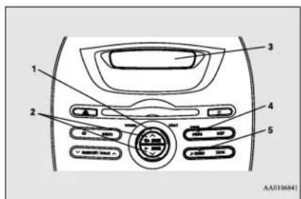
1- VOLUME (Volume control) knob
2-SEEK (Audio adjust) button
3- Display
4- POWER (On-Off) button
5- (Mode change) button
To adjust the volume
N00712000408
Turn the VOLUME knob clockwise to increase the volume; counterelocwise to decrease the volume.
The status will be displayed in the display.
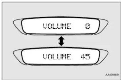

NOTE
- The volume control mode will shut off automatically if the another mode is selected, or if no adjustment is made within about 2 seconds.
To adjust the tone
N00712100672
- Press the ▶button repeatedly to select the tone, balance and SCV (Speed Compensated Volume) function control to change. The order is: BASS → TREBLE → FADER → BALANCE → SCV → Audio adjust mode OFF
- Press the SEEK button to change the tone, balance and SCV function setting. The status will be displayed in the display.
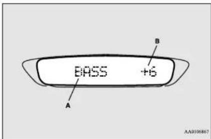
A- Adjust mode
B- Adjust level
7-12 Comfort controls
| Adjust Mode | Adjust Level | SEEK button operation | |
| BASS | -6 to 6 | Stronger | Weaker |
| TRE-BLE | Stronger | Weaker | |
| FADER | F11 to R11 | F (Front) increases | R (Rcar) increases |
| BAL-ANCE | L11 to R11 | R (Right) increases | L (Left) increases |
| SCV | HIGH, MID, LOW, OFF | HIGH↑MID↑LOW↑OFF | HIGH↓MID↓LOW↓OFF |
BASS (Bass tone control)
To select the desired bass level.
TREBLE (Treble tone control)
To select the desired treble level.
FADER (Front/Rear balance control)
To balance the volume from the F (front) and the R (rear) speakers.
BALANCE (Left/Right balance control)
To balance the volume from the L (left) and the R (right) speakers.
SCV (Speed Compensated Volume) function
Speed Compensated Volume function is a feature that automatically adjusts the VOLUME, BASS and TREBLE settings in accordance with the vehicle speed.
The effects of the SCV function can be selected either of three levels (LOW, MID and HIGH). Select the degree of your choice by pressing the SEEK button.
If you want to stop the SCV function, select the OFF.

NOTE
- The audio adjust mode will automatically shut off when another mode is selected, or if no adjustment is made within about 10 seconds.
Radio control panel and display
N00734900902
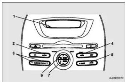
1-FM (FM1/FM2) indicator
2- RADIO (AM/FM selection) button
3- MEMORY (Memory selection) button
4- POWER (On-Off) button
5- SCAN button
6- SEEK (Up-seek) button
7- SEEK (Down-seek) button
AM/FM electronically tuned radio with CD player (if so equipped)
To listen to the radio
N00735000913
- Press the POWER button until it beeps to turn the audio system ON and OFF. The system turns on in the last mode used. Press the RADIO button to turn ON the radio.
- Press the RADIO button to select the desired band (AM/FM1/FM2).
- Press the SEEK button to tune to a station, or press the MEMORY button either ∧ or ∨ to tune in to a station memorized. Refer to "Automatic tuning", "Manual tuning" or "To enter frequencies into the memory".
Automatic tuning
After pressing the SEEK button, a receivable station will be automatically selected and reception of the station will begin.
SCAN function
Press the SCAN button. The radio will tune consecutively to each available station for about 5 seconds per station. If you want to stop scanning, press the SCAN button again. The frequency display of the current station flashes once per second during SCAN.
Manual tuning
The frequency changes every time the SEEK button is pressed. Press the button to select the desired station.
To enter frequencies into the memory
As many as 6 AM and 12 FM stations can be entered into the memory.
To store a frequency in the memory, follow these steps:
- Press the SEEK button to tune to the frequency you wish to keep in the memory.
- Press the MEMORY button either or V until it beeps.
The sound will be momentarily interrupted while the frequency is being entered into the memory.
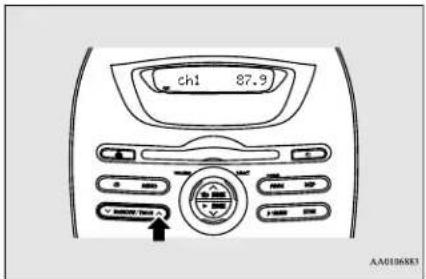
- To recall a frequency that has been saved in memory, press the MEMORY button briefly for no longer than about 1 second.

NOTE
- Disconnecting the 12V starter battery cables erases all the radio station settings stored in the memory.
7-14 Comfort controls
CD control panel and display
N00735300743
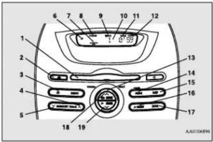
1- Disc loading slot
2- Eject button
3- CD (CD mode changeover) button
4- TRACK ∧ (Fast-forward/Track up) button
5- TRACK (Fast-reverse/Track down) button
6- CD indicator
7- SEL (Select mode) indicator
8- FOLDER indicator
9- TRACK indicator
10- Display
11-RDM/F-RDM indicator
12-RPT/F-RPT indicator
13- SELECT knob
14- POWER (On-Off) button/PAGE (Title scroll) button
15- DISP (Title display) button
16- MENU button
17- SCAN button
18- SEEK ∧ (Up-seek) button (Return) button
19- SEEK V (Down-seek) button/▶ (Select) button
To listen to a CD
N00735502097
To set a disc
-
Press the POWER button until it beeps to turn the audio system ON and OFF. The system turns on in the last mode used.
-
Insert the disc with the label facing up. When a disc is inserted, the CD indicator will come on and the CD player will begin playing even if the radio is being used. The CD player will also begin playing when the CD button is pressed with a disc set in the CD player or in the disc loading slot, even if the radio is being used.

NOTE
- For information concerning the adjustment of volume and tone, refer to "To adjust the volume" on page 7-12 and "To adjust the tone" on page 7-12.
● 3 inches (8 cm) compact disc cannot be played on this CD player.

NOTE
- For information concerning the handing of the compact discs, refer to "Handling of compact discs" on page 7-25.
To eject a disc
When the eject button is pressed, the disc automatically stops and is ejected. The system automatically switches to radio mode.

NOTE
- If you do not remove an ejected disc before 15 seconds have elapsed, the disc will be reloaded.
To listen to a music CD
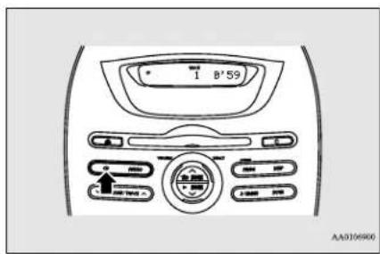
AM/FM electronically tuned radio with CD player (if so equipped)
Push the CD button if a disc is already in the CD player. The audio system will enter CD mode and start playback. The track number and the playing time will appear on the display. The tracks in the disc will be played consecutively and continuously.
To listen to an MP3 CD
This CD player allows you to play MP3 (MPEG Audio Layer-3) files recorded on CD-ROMs, CD-Rs (recordable CDs), and CD-RWs (rewritable CDs) in ISO9660 Level 1/Level 2, Joliet, and Romeo formats. Each disc may have a maximum of 16 trees, 100 folders and 255 files. During MP3 playback, the unit can display ID3 tag information. For information concerning ID3 tag, refer to "CD text and MP3 title display" on page 7-19.
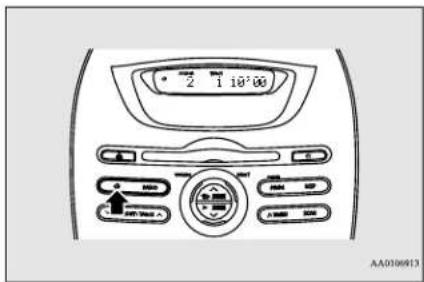
7-16 Comfort controls
Push the CD button if a disc is already in the CD player.
The display shows "READING", then play-back begins. The folder number, the track number and the playing time will appear on the display.

NOTE
- While listening to a disc on which CD-DA (CD-Digital Audio) and MP3 files have both been recorded, you can switch between reading of the CD-DA, reading of the MP3 files, and the external audio input mode by pressing the CD button for 2 seconds or longer (until you hear a beep).
- With a disc that contains both CD-DA and MP3 files, the CD-DA files are automatically played first.
- The playback sound quality differs depending on the encoding software and the bit rate. For details, refer to the user manual of your encoding software.
- Depending on file/folder configurations on a disc, it may take some time before playback starts.
● MP3 encode software and writing software are not supplied with this unit. - You may encounter trouble in playing an MP3 or displaying the information of MP3 files recorded with certain writing software or CD recorders (CD-R/RW drivers).
- If you record too many folders or files other than MP3 onto a disc, it may take some time before playback starts.

NOTE
● This unit does not record MP3 files.
- For information concerning CD-Rs/RWs, refer to "Notes on CD-Rs/RWs" on page 7-26.

CAUTION
- Attempting to play a file not in the MP3 format which has the “.mp3” file name may produce noise from the speakers and speaker damage, and can damage your hearing.
Folder selection order/MP3 file playback order (Example)
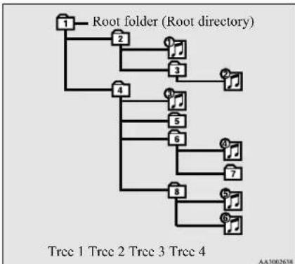
flowchart
graph TD
    A["Root folder (Root directory)"] --> B["Tree 1"]
    A --> C["Tree 2"]
    A --> D["Tree 3"]
    A --> E["Tree 4"]
    A --> F["Tree 5"]
    A --> G["Tree 6"]
    A --> H["Tree 7"]
    A --> I["Tree 8"]
    A --> J["Tree 9"]
    style A fill:#f9f,stroke:#333
    style B fill:#ccf,stroke:#333
    style C fill:#ccf,stroke:#333
    style D fill:#ccf,stroke:#333
    style E fill:#ccf,stroke:#333
    style F fill:#ccf,stroke:#333
    style G fill:#ccf,stroke:#333
    style H fill:#ccf,stroke:#333
    style I fill:#ccf,stroke:#333
    style J fill:#ccf,stroke:#333
Folder selection
In the order

File selection
In the order

To fast forward/reverse the disc
To fast forward or fast reverse the disc, press the TRACK button or the TRACK button.
Fast forward
You can fast-forward the disc by pressing the TRACK /button. While the button is kept pressed, the disc will be fast-forwarded.
Fast reverse
You can fast reverse the disc by pressing the TRACK V button. While the button is kept pressed, the disc will be fast-reversed.
To select a desired track
You can select your desired track by using the TRACK button.
Track up
Press the TRACK 🐨 button repeatedly until the desired track number appears on the display.
When listening to a MP3 CD, keep pressing the button to continue to move up tracks.
Track down
Press the TRACK Vutton repeatedly until the desired track number appears on the display.
When listening to a MP3 CD, keep pressing the button to continue to move down tracks.

NOTE
- Pressing the TRACKV button once during the song will cause the CD player to restart playback from the beginning of the song.
To find a file (MP3 CDs only)
Operate the following buttons or the SELECT knob to select desired file.
When this mode is activated by pressing the
button, the SEL indicator will be displayed in the display.
button
:Press the button to start this mode or cancel the selection.
SELECT knob :Turn the knob to show the folder or file.
▶ button
:Press the button to select the folder or file.

NOTE
- If no operation is performed for 10 seconds or more or other button is operated after the SELECT knob has been turned, searching of the desired file is canceled.
- If no operation is performed for 5 seconds or more after the file is displayed, playback starts.
AM/FM electronically tuned radio with CD player (if so equipped)

NOTE
- When the SEL indicator is not shown on the display and the SELECT knob is operated, the volume adjustment is effective.
To select the playing mode
N00771500013
- Press the MENU button until beeps.
- Press the SEEK ∧ Button repeatedly to select the mode.
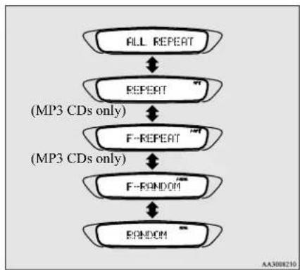
flowchart
graph TD
    A["ALL REPEAT"] --> B["REPEAT"]
    B --> C["F-REPEAT"]
    C --> D["F-FONDOM"]
    D --> E["F-ONDOM"]
    style A fill:#f9f,stroke:#333
    style B fill:#ccf,stroke:#333
    style C fill:#cfc,stroke:#333
    style D fill:#fcc,stroke:#333
    style E fill:#cff,stroke:#333
- Press the MENU button until you hear a beep. The selected mode will operate.
To play tracks in repeat
N00771600014
Repeat an all track (normal playback)
Select the ALL REPEAT mode. Refer to "To select the playing mode" on page 7-18. The all tracks on the disc will be played repeatedly.
Repeat a track
Select the REPEAT mode. Refer to "To select the playing mode" on page 7-18. The RPT indicator will come on and repeat the same track.
Repeat tracks in the same folder (MP3 CDs only)
Select the F-REPEAT mode. Refer to "To select the playing mode" on page 7-18. The F-RPT indicator will come on and the all track on the currently selected folder will be played repeatedly.

NOTE
- With a disc that contains both CD-DA and MP3 files, the repeat mode causes only files of the same format (CD-DA only or MP3 files only) to be repeated.
To play tracks in random order
N00771800016
Random playback for a disc (music CDs only)
Select the RANDOM mode. Refer to "To select the playing mode" on page 7-18. The RDM indicator will come on and the tracks on the disc will be played in a random sequence.
Random playback for a folder (MP3 CDs only)
Select the F-RANDOM mode. Refer to "To select the playing mode" on page 7-18. The F-RDM indicator will come on and the tracks on the currently selected folder will be played in a random sequence.
Random playback for all folders on a disc (MP3 CDs only)
Select the RANDOM mode. Refer to "To select the playing mode" on page 7-18. The RDM indicator will come on and the files from all the folders on the disc will be playback in a random sequence.

NOTE
- With a disc that contains both CD-DA and MP3 files, the random mode causes only files of the same format (CD-DA only or MP3 files only) to be repeated.
To find the start of each track on a disc for playback
N00771900017
Press the SCAN button. "SCAN" will appear on the display and the CD player will play back the first 10 seconds of each track on the selected disc (music CDs only) or the currently selected folder (MP3 CDs only).
The track number will blink while the scan mode is selected. To stop the scan mode, press the SCAN button again.

NOTE
- Once all tracks on the disc (music CDs only) or the currently selected folder (MP3 CDs only) have been scanned, playback of the disc will restart from the beginning of the track that was playing when scanning started.
- With a disc that contains both CD-DA and MP3 files, the scan mode causes only files of the same format (CD-DA only or MP3 files only) to be played.
CD text and MP3 title display
N00752100166
This audio system can display CD text and MP3 titles including ID3 tag information.
CD text
The audio system can display disc and track titles for discs with converted disc and track title information. Press the DISP button repeatedly to make selections in the following sequence: disc name → track name → normal display mode.

NOTE
- The display can show up to 11 characters. If a disc name or track name has more than 11 characters, press the PAGE button to view the next 11 characters.
- When there is no title information to be displayed, the display shows "NO TITLE".
- Characters that the audio system cannot display are shown as “”.
MP3 title
The audio system can display folder and track titles for discs with converted folder and track information. Press the DISP button repeatedly to make selections in the following sequence: folder name → track name → normal display mode.
ID3 tag information
The audio system can display ID3 tag information for files that have been recorded with ID3 tag information.
- Press the DISP button for 2 seconds or longer to switch to the ID3 tag information. "TAG" will appear on the display.
- Press the DISP button repeatedly to make selections in the following sequence: album name → track name → artist name → normal display mode.

NOTE
- To return from ID3 tag information to the folder name, press the DISP button again for 2 seconds or longer.
- When there is no title information to be displayed, the display shows "NO TITLE".
- The display can show up to 11 characters. If a folder name, track name, or item of ID3 tag information has more than 11 characters, press the PAGE button to view the next 11 characters.
- Folder names, track names and ID3 tag information can each be displayed up to a length of 32 characters.
- Characters that the audio system cannot display are shown as “”.
To play iPod/USB memory device tracks via voice operation (vehicles with Bluetooth® 2.0 interface)
To play iPod/USB memory device tracks via voice operation (vehicles with Bluetooth® 2.0 interface)
N00772001025
Desired tracks can be selected and played from your iPod or USB memory device by "Artist", "Album", "Playlist" and "Genre" using voice commands.
For information concerning the voice recognition function or speaker registration function, refer to “Bluetooth® 2.0 interface” on page 5-53.
The following explains how to prepare for voice operation and play the tracks.
Preparation for voice operation
N00772101026
To use the voice operation, press the PICK-UP button (1) first.
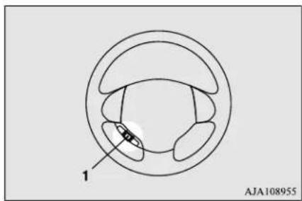
natural_image
Diagram of a biological structure with labeled parts, no readable text or symbols presentTo search by artist name
N00772200017
- Say "Play" on the main menu.

NOTE
- The Bluetooth® 2.0 interface starts recognizing the connected device. If the connected device cannot be recognized or a connection error occurs, the Bluetooth® 2.0 interface starts an appropriate voice guide. Follow the voice guide.
- After the voice guide says "Would you like to play by Artist, Album, Playlist or Genre?," say "Artist".

NOTE
- If you say "Artist
-
After the voice guide says "What Artist would you like to play?," say the artist name.
-
If there is only one match, the system proceeds to step 6.
-
If there are two or more matches, the voice guide will say "More than one match was found, would you like to play
?" If you say "Yes," the system proceeds to step 6.
If you say "No," the next matching artist is uttered by the system.

NOTE
- If you say "No" to three or all artist names uttered by the system, the voice guide will say "Artist not found, please try again" and the system returns to step 2.
- Search time depends on the number of songs on your connected device. Devices containing a large number of songs may take longer to return search results.
- After the voice guide says "Playing
," the system creates a playlist index for the artist.
To play iPod/USB memory device tracks via voice operation (vehicles with Bluetooth® 2.0 interface)

NOTE
- If the confirmation function is active, the voice guide confirms if the artist name is correct. If the artist name is correct, say "Yes". If not, say "No". After the voice guide says "Artist not found, please try again," the system returns to step 2.
- The system exits the voice recognition mode and starts playback.
To search by album title
N0172300018
- Say "Play" on the main menu.

NOTE
- The Bluetooth ^® 2.0 interface starts recognizing the connected device. If the connected device cannot be recognized or a connection error occurs, the Bluetooth ^® 2.0 interface starts an appropriate voice guide. Follow the voice guide.
- After the voice guide says "Would you like to play by Artist, Album, Playlist or Genre?," say "Album".

NOTE
- If you say "Album

- Instruments and controls (Driver's area)
- Instruments and controls (Instrument panel)
- Interior
- Under the hood/Electric motor unit room
- Outside (Front)
- Outside (Rear)
- If this warning light comes on or flashes while you're driving...
- NOTE
- If this problem occurs...
- WARNING
- General information/Charging
- Familiarizing yourself with i-MiEV
- Main features
- Regenerative braking
- Main drive lithium-ion battery
- CAUTION
- Decrease of battery capacity
- Cruising range
- Range-Driving conditions
- Operating sound under charging or Remote Climate Control
- For persons with electro-medical apparatus such as implantable cardiac pacemaker or implantable cardiovascular defibrillator
- Modifications to and racing of your vehicle
- DAMAGE OR PERFORMANCE PROBLEMS RESULTING FROM MODIFICATIONS TO OR RACING OF YOUR VEHICLE ARE NOT COVERED UNDER WARRANTY.
- Installation of accessories
- Important point!
- Modification/alterations to the electrical systems
- Mitsubishi Motors genuine parts
- California Perchlorate Materials Requirements
- Cautions and actions to deal with intense heat
- Cautions and actions to deal with intense cold
- Charging
- 3-14 General information/Charging
- Precautions during Charging the Main Drive Lithium-ion Battery
- Regular charging (charging method with rated AC 120 V outlet)
- Regular charge port light
- Charging from rated AC 120 V outlet
- Main drive lithium-ion battery warming system
- EV charging cable
- Handling and storing the control box
- Regular charging (using 240 V Electric Vehicle Supply Equipment)
- Cleaning the EV charging cable
- Quick charging (charging method with quick charger)
- High-Voltage components
- In case of a collision
- MiEV Remote System
- MiEV Remote
- Switches
- Display (LCD monitor)
- Charging Timer
- Example of Charging Timer
- To turn the MiEV Remote ON/OFF
- To set the ON timer
- To start the charging immediately after the ON timer has been set
- To set OFF Timer
- Display of MiEV Remote during communicating with vehicle
- To cancel Charging Timer
- Remote Climate Control
- To operate the Remote Climate Control
- To stop the Remote Climate Control
- To turn on/off melody and buzzer
- Main Drive Lithium-ion Battery Level Indicator
- General information
- Replacement of batteries for the MiEV Remote
- About battery
- To replace the batteries
- Actions to be taken when the MiEV Remote system does not operate correctly
- Cleaning the MiEV Remote
- Seat and restraint systems
- Seats
- - Front seats
- - Rear seats
- Seats and restraint systems
- Front seats
- To adjust the seat forward or backward
- To adjust the seatback
- To adjust the seat height (Driver's side only)
- Heated seats
- Rear seats
- Folding the seatbacks forward
- Head restraints
- Adjustment of the head restraint height
- To remove
- To install
- Seat belts
- Seat belt instructions
- Driver's seat belt reminder/warning light
- Front passenger seat belt warning light
- Adjustable seat belt shoulder anchor (front seats)
- Seat belt extender
- Seat belt use during pregnancy
- Seat belt pre-tensioner and force limiter systems
- Pre-tensioner system
- SRS warning light
- Force limiter system
- Child restraint systems
- Guidelines for child restraint system selection
- Installing a child restraint system using the LATCH (Lower Anchors and Tethers for children) system
- Lower anchor locations
- Tether anchor locations
- Examples of child restraint systems compatible with the LATCH system
- Using the LATCH system
- Installing a child restraint system using the seat belt (with emergency/automatic locking mechanism)
- Installation
- Children who have outgrown child restraint systems
- Maintenance and inspection of seat belts
- Supplemental Restraint System (SRS) - airbag
- How the Supplemental Restraint System works
- Event Data Recording
- Driver's seat position sensor
- Passenger's seat occupant classification sensor system
- Passenger's airbag off indicator
- Driver's and passenger's front airbag system
- Deployment of front airbags
- The front airbags ARE DESIGNED TO DEPLOY when...
- The front airbags MAY NOT DEPLOY when ...
- The front airbags ARE NOT DESIGNED TO DEPLOY when
- The front airbags MAY DEPLOY when ...
- Side airbag system
- Curtain airbag system
- Deployment of side airbag and curtain airbag
- The side airbag and curtain airbag ARE DESIGNED TO DEPLOY when ...
- The side airbag and curtain airbag MAY NOT DEPLOY when ...
- The side airbag and curtain airbag ARE NOT DESIGNED TO DEPLOY when ...
- SRS servicing
- Warning labels
- Features and controls
- Break-in recommendations
- Keys
- Electronic immobilizer (Anti-theft starting system)
- Replacement keys
- Additional keys
- Customer key programming (Except for vehicles sold in Canada)
- Keyless entry system
- To loc k
- To unlock
- Answerback function
- Horn deactivation/reactivation
- Changing the setting of the turn signal lights answerback function
- Setting of door unlock function
- Using the panic alarm
- Replacement remote control transmitters
- Additional remote control transmitters
- Procedure for replacing the remote control transmitter battery
- Door locks
- To lock or unlock the door with the key
- To lock or unlock the door from the inside
- To lock the door without using the key
- Key reminder buzzer
- Lock out protection
- Power door locks
- To unlock the doors and liftgate
- Using the selector lever position
- Liftgate
- To open
- To close
- Theft-alarm system
- Armed stage
- 5-12 Features and controls
- Alarm stage
- Type of alarm
- Alarm deactivation
- Disarmed stage
- Power window control
- Testing the theft-alarm system
- 5-14 Features and controls
- Main switch
- Sub switch
- Power window timer function
- Lock switch
- Parking brake
- Inside rearview mirror
- To adjust the vertical mirror position
- To adjust the mirror position
- To reduce the glare
- Outside rearview mirrors
- To fold the mirror
- Heated mirror
- Electric motor switch
- LOCK
- ACC
- ON
- START
- ACC power auto-cutout function
- To remove the key
- Steering wheel lock
- To u n l o c k
- Starting the electric motor unit
- Electric motor reminder
- Selector lever
- Selector lever operation
- Selector lever position indicator
- Selector lever positions
- "P" PARK
- “R” REVERSE
- “N” NEUTRAL
- “D” DRIVE
- "ECO" ECO MODE
- "B" REGENERATIVE BRAKE MODE
- Operation of the transmission
- Waiting
- Parking
- Acoustic vehicle alerting system (AVAS)
- Service brake
- Brake pedal
- Power brakes
- Brake pad wear alarm
- Brake assist system
- Anti-lock braking system
- Driving hints
- Anti-lock braking system warning light
- If the warning light illuminates while driving
- If only the ABS warning light illu- minate
- If the ABS warning light and brake warning light illuminate at the same time
- Electric power steering system (EPS)
- Electric power steering system warning light
- Active stability control (ASC)
- Traction control function
- Skid control function
- ASC OFF switch
- Tire pressure monitoring system
- ASC indicator, ASC OFF indicator
- Tire pressure monitoring sys- tem warning light
- 5-32 Features and controls
- Whenever the tires and wheels are replaced with new ones
- Rear-view camera (if so equipped)
- Location of rear-view camera
- Reference lines on the screen
- Speedometer
- Changing the display unit
- Energy usage indicator
- Odometer/Trip odometer/Dash lights brightness indicator/Service reminder/Cruising range indicator/Outside temperature display
- To change the display
- Instrument cluster
- 8- Outside temperature display
- Odometer
- Trip odometer
- To reset the trip odometer
- Service reminder
- Resetting the service reminder
- Dash lights brightness indicator
- Cruising range indicator
- Outside temperature display
- Change of the outside temperature unit
- Energy level gauge
- Low energy warning indicator
- Indicator and warning light package
- Indicators
- Turn signal indicators/Hazard warning lights
- High beam indicator
- Front fog light indicator
- Position indicator
- Ready indicator
- Charging indicator
- Regenerative brake system indicator
- Warning lights
- Brake warning light
- 12V starter battery charging system warning light
- Door-ajar warning light and buzzer
- Electric motor unit warning light
- Power down warning light
- Combination headlights and dimmer switch
- Headlights
- Light auto-cutout function (headlights and other lights)
- When you want to keep the lights on:
- Headlight reminder buzzer
- Dimmer (high/low beam change)
- Headlight flasher
- Turn signal lever
- Hazard warning flasher switch
- Front fog light switch
- Wiper and washer switch
- Windshield wipers
- To adjust intermittent intervals
- Misting function
- Windshield washer
- Rear window wiper and washer
- Precautions to observe when using wipers and washers
- Electric rear window defog- ger switch
- Horn switch
- Link System (if so equipped)
- Link System End User License Agreement
- Bluetooth ® 2.0 interface (if so equipped)
- Steering control switch and microphone
- Volume up button
- Volume down button
- SPEECH button
- PICK-UP button
- HANG-UP button
- Microphone
- Voice recognition function
- Selecting the language
- Useful voice commands
- Help function
- Canceling
- Confirmation function setting
- Security function
- Setting the passcode
- Entering the passcode
- Disabling the passcode
- Speaker enrollment function
- Speaker enrollment
- Enabling and disabling the voice model and retraining
- Connecting the Bluetooth ® 2.0 interface and Bluetooth ® device
- To pair
- Selecting a device
- To select a cellular phone
- To select a music player
- Deleting a device
- To check a paired Bluetooth ® device
- Changing a device tag
- Operating a music player connected via Bluetooth®
- How to make or receive hands-free calls
- To make a call
- Making a call by using the telephone number
- Making a call using a phonebook
- Redialing
- Send function
- Receiving calls
- Mute function
- Switching between hands-free mode and private mode
- Phonebook function
- Vehicle phonebook
- ■ To register a telephone number in the vehicle phonebook
- ■ To register by reading out a telephone number
- Bluetooth® 2.0 interface (if so equipped)
- ■ To change the content registered in the vehicle phonebook
- ◆ Editing a telephone number
- Editing a name
- ◆ Listening to the list of registered names
- ◆ Deleting a telephone number
- ■ Erasing the phonebook
- Mobile phonebook
- To import a devices phonebook
- USB input terminal (if so equipped)
- How to connect a USB memory device
- How to connect an iPod
- Types of connectable devices and supported file specifications
- Device types
- File specifications
- Sun visors
- Vanity mirror
- Card holder
- V power outlet
- Dome light (Front)/Reading lights (if so equipped)
- Dome light (Front)
- Interior lights
- Reading lights
- Dome light (Rear)
- 5-78 Features and controls
- Storage spaces
- Glove compartment
- Cup holder
- For the front seat
- For the rear seat
- Assist grip
- Driving safety
- Economical driving
- Starting and acceleration
- Idling
- Speed
- Tire inflation pressure
- Cargo loads
- Air conditioning
- Driving, alcohol and drugs
- Floor mat
- To install the floor mat
- Vehicle preparation before driving
- Seat belts and seats
- Safe driving techniques
- Defrosters
- Tires
- Lights
- Fluid leaks
- Driving during cold weather
- Braking
- When brakes are wet
- When driving in cold weather
- When driving downhill
- Parking on a hill
- Parking with the electric motor unit running
- Where you park
- When leaving the vehicle
- Do not keep the steering wheel fully turned for a long time
- Loading information
- Tire and loading information placard
- Steps for Determining Correct Load Limit
- Cargo load precautions
- Trailer towing
- Dinghy towing
- Comfort controls
- Air flow and direction adjustments
- Center vents
- Side vents
- Changing the mode selection
- Face position
- Foot/Face position
- Foot position
- Foot/Defroster position
- Defroster position
- Control panel
- Blower speed selection dial Temperature control dial
- Mode selection dial
- "AUTO" position
- Air selection switch
- Air conditioning switch
- MAX switch
- Operating the air conditioning system
- Heating
- Cooling
- For ordinary cooling
- Quick heating
- For quick cooling
- Defrosting or defogging (wind-shield, door windows)
- For ordinary defrosting
- Important air conditioning operating tips
- Air conditioning system refrigerant and lubricant recommendations
- During a long period of disuse
- Air purifier
- AM/FM electronically tuned radio with CD player (if so equipped)
- To adjust the volume
- To adjust the tone
- BASS (Bass tone control)
- TREBLE (Treble tone control)
- FADER (Front/Rear balance control)
- BALANCE (Left/Right balance control)
- SCV (Speed Compensated Volume) function
- Radio control panel and display
- To listen to the radio
- Automatic tuning
- SCAN function
- Manual tuning
- To enter frequencies into the memory
- CD control panel and display
- To listen to a CD
- To set a disc
- To eject a disc
- To listen to a music CD
- To listen to an MP3 CD
- To fast forward/reverse the disc
- Fast forward
- Fast reverse
- To select a desired track
- Track up
- Track down
- To find a file (MP3 CDs only)
- To select the playing mode
- To play tracks in repeat
- Repeat an all track (normal playback)
- Repeat a track
- Repeat tracks in the same folder (MP3 CDs only)
- To play tracks in random order
- Random playback for a disc (music CDs only)
- Random playback for a folder (MP3 CDs only)
- Random playback for all folders on a disc (MP3 CDs only)
- To find the start of each track on a disc for playback
- CD text and MP3 title display
- CD text
- MP3 title
- ID3 tag information
- To play iPod/USB memory device tracks via voice operation (vehicles with Bluetooth® 2.0 interface)
- Preparation for voice operation
- To search by artist name
- To search by album title
Brand : MITSUBISHI
Model : i-MiEV (2016)
Category : Automotive