
L200 (2011) - Automotive MITSUBISHI - Free user manual and instructions
Find the device manual for free L200 (2011) MITSUBISHI in PDF.


| Product Type | Pickup Truck |
| Brand | Mitsubishi |
| Model | L200 (2011) |
| Model Year | 2011 |
| Engine | 2.5L Inline-4 Turbo Diesel |
| Transmission | 5-Speed Manual / 4-Speed Automatic |
| Drive Type | Rear-Wheel Drive / Selectable 4WD |
| Fuel Type | Diesel |
| Fuel Tank Capacity | 75 L |
| Length | 5,050 mm |
| Width | 1,800 mm |
| Height | 1,780 mm |
| Wheelbase | 3,000 mm |
| Ground Clearance | 200 mm |
| Curb Weight | 1,800 kg |
| Payload Capacity | 1,000 kg |
| Towing Capacity | 2,700 kg |
| Seating Capacity | 5 |
| Tire Size | 245/70 R16 |
| Fuel Consumption (Combined) | 9.0 L/100km |
| Maintenance Interval | Every 15,000 km or 12 months |
Frequently Asked Questions - L200 (2011) MITSUBISHI
User questions about L200 (2011) MITSUBISHI
0 question about this device. Answer the ones you know or ask your own.
Ask a new question about this device
Download the instructions for your Automotive in PDF format for free! Find your manual L200 (2011) - MITSUBISHI and take your electronic device back in hand. On this page are published all the documents necessary for the use of your device. L200 (2011) by MITSUBISHI.
USER MANUAL L200 (2011) MITSUBISHI
1200 - ENGLISH - OCRÉT LEI
natural_image
Exterior view of a silver SUV (L 200) with a Mitsubishi Motors logo on a textured gray surface (no other text or symbols visible)OWNER'S MANUAL
L200

L200 - ENGLISH - OCRE11E1
Foreword
Thank you for selecting a MITSUDISHI L200 as your new vehicle.
This owner's manual will add to your understanding and full enjoyment of the many fine features of this vehicle.
It contains information prepared to acquire you with the proper way to operate and maintain your vehicle for the interest in driving pleasure.
MITSUBISHI MOTORS Europe B.V. reserves the right to make changes in design and specifications and/or to make additions to or improvements in this product without obligation to install them on products previously manufactured.
It is an absolute requirement for the driver to strictly observe all laws and regulations concerning vehicles.
This owner's manual has been written in compliance with such laws and regulations, but some of the contents may become contradictory with later amendment of the laws and regulations.
Please leave this owner's manual in this vehicle at time of resale. The next owner will appreciate having access to the information contained in this owner's manual.
Rapors to your vehicle:
vehicles in the warranty period: 4 ^20 warrants remains must be on
ALL Wilfully reports must be calling 0.6 by a mail: 36 BIRTH MOKOS Authocized Service Point.
Vehicles outside the warranty period:
Where the vehicle is reported is at the discretion of the owner.
Throughout this owner's manual the words WARNING and CAUTION appear. Those serve us reminders to be especially careful. Failure to follow instructions could result in personal injury or damage to your vehicle.
△ WARNING
indicates a strong possibility of severe personal injury or death if instructions are not followed.
CAUTION
means hazards or unsafe practices that could cause minor personal injury or damage to your vehicle.
NOTE: gives helpful information.
: indicates optional equipment.
It may differ according to the sales classification refer
to the sales catalogue
Abbreviations used in this owner's manual:
1.HD: Telf-Hand Drive RHD: Right Hand Drive
M.T: Manual Transmiss
A/T: Automatic Transmission
Information for station service
无法识别
| Fuel | Fuel tank capacity 75 miles | |
| Fuel requirements | Cetons number (EN500)51 or higherRefer to the "General information" section for the fuel solution. | |
| Engine oil. Refer to the "Maintenance" section for the selection of engine oil. | ||
| Twe inflation pressure Refer to the "Maintenance" section for the twe inflation pressure. | ||
Mitsubishi Motors Europe B.V.
© 2010 Mitsubishi Motors Corporation
OCRE11E1
BLC10.002829
Table of contents
| Overview | |
| General information | |
| Locking and unlocking 1 | |
| Seat and seat belts 2 | |
| Instruments and controls 3 | |
| Starting and driving 4 | |
| For pleasant driving 5 | |
| For emergencies 6 | |
| Vehicle care 7 | |
| Maintenance 8 | |
| Specifications 9 |
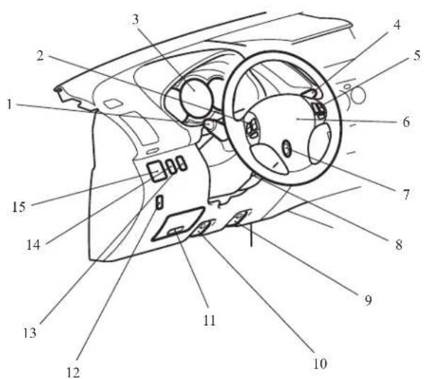
Instruments and Controls (Driver's area)
E00100105444
LIID
AA5010439
- Combination headlamps and dipper switch p. 3-30
Turn-signals lever p. 3-33
Front fog lamp switch* p. 3-34
Rear fog lamp switch p. 3-35
Headlamp washer switch* p. 3-39 - Audio remote control switches* p. 5-28
- Instruments p. 3-02
- Wiper and washer switch p. 3-36
- Cruise control switches* p. 4-49
- Supplemental restraint system (SRS) - airbag (for driver's seat) p. 2-27
Horn switch p. 3-40 - Ignition switch p. 4-11
- Steering wheel height adjustment p. 4-09
- Fuel tank filler door release lever* p. 02
- Bonnet release lever p. 8-03
- Fuses p. 8-20
- Active stability control (ASC) OFF switch Type 2* p. 4-46
- Headlamp levelling switch* p. 3-32
- Active stability control (ASC) OFF switch Type 1* p. 4-46 Rear differential lock switch* p. 4-34
- Outside rear-view mirrors switch* p. 4-10
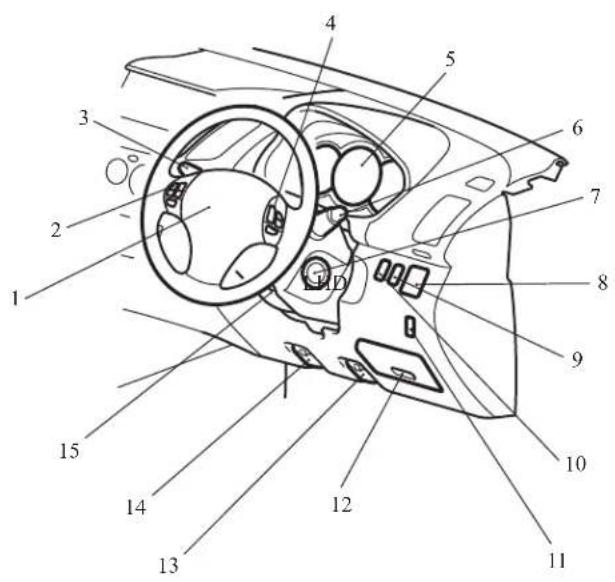
RHD
AA5010442
- Supplemental restraint system (SRS) - airbag (for driver's
scat) p. 2-27
Horn switch p. 3-40 - Audio remote control switches* p. 5-28
- Combination headlamps and dipper switch p. 3-30
Turn-signals lever p. 3-33
Front fog lamp switch* p. 3-34
Rear fog lamp switch p. 3-35
Headlamp washer switch* p. 3-39 - Cruise control switches* p. 4-49
- Instruments p. 3-02
- Wiper and washer switch p. 3-36
- Ignition switch p, 4-11
- Outside rear-view mirrors switch* p. 4-10
- Active stability control (ASC) OFF switch Type 1* p. 4-46
Rear differential lock switch* p. 4-34 - Headlamp levelling switch* p. 3-32
- Active stability control (ASC) OFF switch Type 2* p. 4-46
- Fuses p. 8-20
- Bonnet release lever p. 8-03
- Fuel tank filler door release lever* p. 02
- Steering wheel height adjustment p. 4-09
Overview
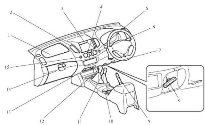
Instruments and Controls (Single cab)
E00100104577
LHD
AA5004258
- Hazard warning flasher switch p. 3-34
- Heater/Manual air conditioning* p. 5-03
- Rear window demister switch p. 3-40
- Utility box p. 5-43
- Ventilators p. 5-02
- Supplemental restraint system (SRS) - airbag (for front passenger's seat) p. 2-27
- Front passenger's airbag OFF indication lamp p. 2-31
- Glove box p. 5-42
Front passenger's airbag ON-OFF switch p. 2-30 - Cigarette lighter p. 5-37
- Gearshift lever p. 4-14
- Transfer shift lever (4WD only) p. 4-20
- Cup holder* p. 5-44
- Parking brake lever Type 1* p. 4-07
- Parking brake lever Type 2* p. 4-07
- Ashtray p. 5-36
RHD
-
Supplemental restraint system (SRS) - airbag (for front passenger's seat) p. 2-27
-
Ventilators p. 5-02
-
Utility box p. 5-43
-
Rear window demister switch p. 3-40
-
Heater/Manual air conditioning* p. 5-03
-
Hazard warning flasher switch p. 3-34
-
Cigarette lighter p. 5-37
-
Parking brake lever Type 2* p. 4-07
-
Parking brake lever Type 1* p. 4-07
-
Cup holder* p. 5-44
-
Transfer shift lever (4WD only) p. 4-20
-
Gearshift lever p. 4-14
-
Ashtray p. 5-36
-
Glove box p. 5-42
Front passenger's airbag ON-OFF switch p. 2-30
- Front passenger's airbag OFF indication lamp p. 2-31
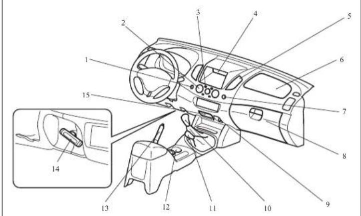
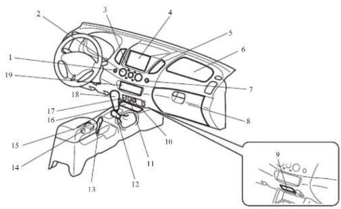
Instruments and Controls (Club, Double cab)
E00100104580
LHD
AA5010455
- Hazard warning flasher switch p. 3-34
- Heater/Manual air conditioning* p. 5-03
Automatic air conditioning* p. 5-08 - Rear window demister switch (vehicle with heater/manual air conditioning) p. 3-40
- Utility box* p. 5-43
Centre information display* p. 3-10
MITSUBISHI Multi-Communication System*
Refer to the separate "MITSUBISHI Multi-Communication Sys-
tem owner's manual" - Ventilators p. 5-02
- Supplemental restraint system (SRS) - airbag (for front passenger's seat) p. 2-27
- Front passenger's airbag OFF indication lamp p. 2-31
- Glove box p. 5-42
Front passenger's airbag ON-OFF switch p. 2-30 - Ashtray (fixed position)* p. 5-36
- Cigarette lighter p. 5-37
- Rear retractable power window switch* p. 1-08
- Transfer shift lever (4WD only) p. 4-25, 4-29
- Parking brake lever p. 4-07
- Cup holder p. 5-44
- Ashtray (movcable)* p. 5-36
- Front console box* p. 5-42
- Heated seat switch* p. 2-06
- Gearshift lever* p. 4-14
Selector lever* p. 4-16, 4-20 - Audio* p. 5-13
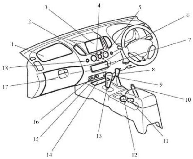
RHD
AA5010468
- Supplemental restraint system (SRS) - airbag (for front passenger's scat) p. 2-27
- Ventilators p. 5-02
- Utility box* p. 5-43
Centre information display* p. 3-10
MITSUBISHI Multi-Communication System*
Refer to the separate "MITSUBISHI Multi-Communication System owner's manual"
4. Rear window demister switch (vehicle with heater/manual air conditioning) p. 3-40
5. Heater/Manual air conditioning* p. 5-03
Automatic air conditioning* p. 5-08
6. Hazard warning flasher switch p. 3-34
7. Audio* p. 5-13
8. Transfer shift lever (4WD only) p. 4-25, 4-29
9. Heated seat switch* p. 2-06
10. Parking brake lever p. 4-07
11. Cup holder p. 5-44
12. Ashtray (moveable)* p. 5-36
13. Gearshift lever* p. 4-14
Selector lever* p. 4-16, 4-20
14. Front console box* p. 5-42
15. Cigarette lighter p. 5-37
16. Rear retractable power window switch* p. 1-08
17. Glove box p. 5-42
Front passenger's airbag ON-OFF switch p. 2-30
18. Front passenger's airbag OFF indication lamp p. 2-31
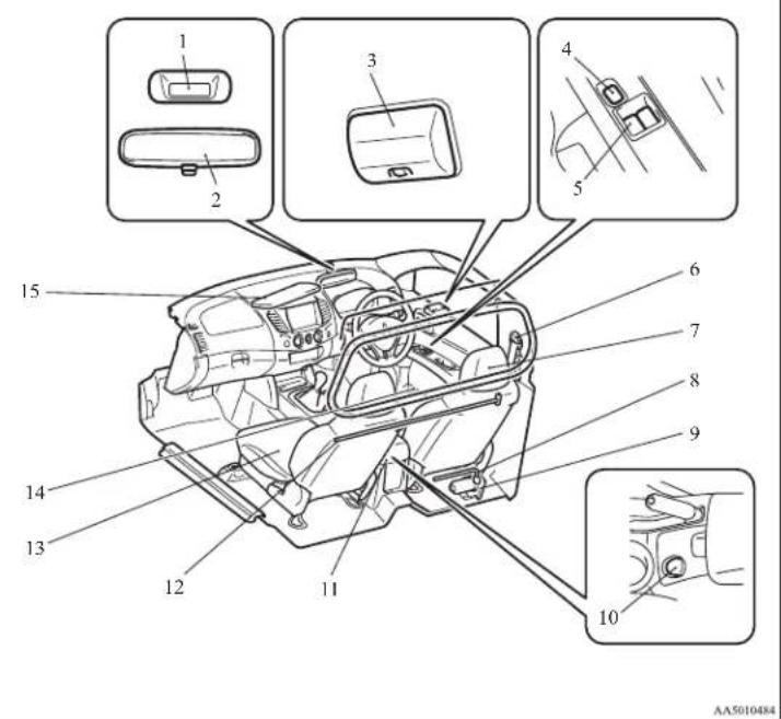
Interior (Single cab)
E00100203278
LHD
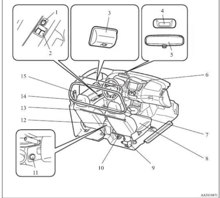
- Lock switch* p. 1-09
- Electric window control switch* p. 1-08
- Room lamp p. 5-39, 8-24, 8-32
- Digital clock p. 5-39
- Inside rear-view mirror p. 4-09
- Sun visors p. 5-35
- Bottle holder p. 5-45
- Front seats p. 2-03
- Jack p. 6-07
- Tools*1 p. 6-07
- Accessory socket* p. 5-38
- Floor console box* p. 5-42
- Jack handle p. 6-07
- Head restraints p. 2-08
- Scat belts p. 2-09
NOTE:*1- Tools differ according to the vehicle model.
RHD
-
Digital clock p. 5-39
-
Inside rear-view mirror p. 4-09
-
Room lamp p. 5-39, 8-24, 8-32
-
Lock switch* p. 1-09
-
Electric window control switch* p. 1-08
-
Seat belts p. 2-09
-
Head restraints p. 2-08
-
Tools*1 p. 6-07
-
Jack p. 6-07
-
Accessory socket* p. 5-38
-
Floor console box* p. 5-42
-
Jack handle p. 6-07
-
Front seats p. 2-03
-
Bottle holder p. 5-45
-
Sun visors p. 5-35
NOTE:*1- Tools differ according to the vehicle model.
Interior (Club cab)
E00100203890
LHD
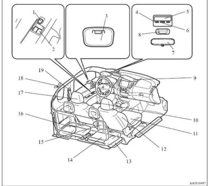
-
Lock switch* p. 1-09
-
Electric window control switch* p. 1-08
-
Room lamp (rear) p. 5-39, 8-24, 8-32
-
Personal lamps* p. 5-40, 8-24, 8-32
-
Sunglasses holder* p. 5-43
-
Room lamp (front)* p. 5-39, 8-24, 8-32
-
Inside rear-view mirror p. 4-09
-
Digital clock* p. 5-39
-
Sun visors p. 5-35
Card holder p. 5-35
Vanity mirror p. 5-36
-
Bottle holder p. 5-45
-
Front seats p. 2-03
Seat under tray* p. 5-44
-
Supplemental restraint system (SRS) - side airbag (for front seat)* p. 2-35
-
Secret box p. 5-43
-
Rear seat* p. 2-07
-
Floor console box p. 5-42
Accessory socket p. 5-38
Auxiliary Audio connector (RCA)* p. 5-27
Auxiliary Video connector (RCA)* p. 5-27
- Jack p. 6-07
Jack handle p. 6-07
Tools p. 6-07
-
Head restraints p. 2-08
-
Coat hook* p. 5-46
-
Scat belts p. 2-09
Adjustable seat belt anchor p. 2-11
RHD
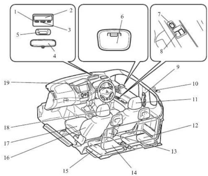
AA5010501
-
Personal lamps* p. 5-40, 8-24, 8-32
-
Sunglasses holder* p. 5-43
-
Room lamp (front)* p. 5-39, 8-24, 8-32
-
Inside rear-view mirror p. 4-09
-
Digital clock* p. 5-39
-
Room lamp (rear) p. 5-39, 8-24, 8-32
-
Lock switch* p. 1-09
-
Electric window control switch* p. 1-08
-
Seat belts p. 2-09
Adjustable seat belt anchor p. 2-11
-
Coat hook* p. 5-46
-
Head restraints p. 2-08
-
Secret box p. 5-43
-
Floor console box p. 5-42
Accessory socket p. 5-38
Auxiliary Audio connector (RCA)* p. 5-27
Auxiliary Video connector (RCA)* p. 5-27
-
Rear seat* p. 2-07
-
Jack p. 6-07
Jack handle p. 6-07
Tools p. 6-07
-
Supplemental restraint system (SRS) - side airbag (for front seat)* p. 2-35
-
Front seats p. 2-03
Scat under tray* p. 5-44
-
Bottle holder p. 5-45
-
Sun visors p. 5-35
Card holder p. 5-35
Vanity mirror p. 5-36
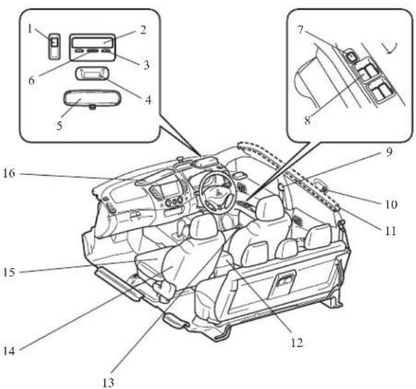
Interior - front area (Double cab)
E00100203904
LHD
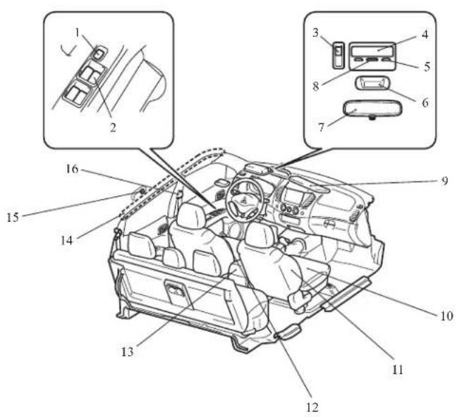
AA5010514
-
Lock switch* p. 1-09
-
Electric window control switch* p. 1-08
-
Sunroof switch* p. 1-13
-
Sunglasses holder p. 5-43
-
Personal lamps p. 5-40, 8-24, 8-32
-
Digital clock* p. 5-39
-
Inside rear-view mirror p. 4-09
-
Room lamp (front) p. 5-39, 8-24, 8-32
-
Sun visors p. 5-35
Card holder p. 5-35
Vanity mirror p. 5-36
- Front seats p. 2-03
Seat under tray* p. 5-44
-
Supplemental restraint system (SRS) - side airbag (for front seat)* p. 2-35
-
Bottle holder p. 5-45
-
Floor console box p. 5-42
Accessory socket* p. 5-38
Auxiliary Audio connector (RCA)* p. 5-27
Auxiliary Video connector (RCA)* p. 5-27
-
Supplemental restraint system (SRS) - curtain airbag* p. 2-35
-
Coat hook* p. 5-46
-
Scat belts p. 2-09
Adjustable seat belt anchor (front seats) p. 2-11
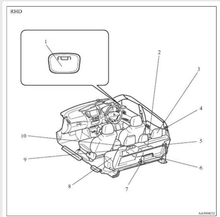
RHD
AA5010527
-
Sunroof switch* p. 1-13
-
Sunglasses holder p. 5-43
-
Personal lamps p. 5-40, 8-24, 8-32
-
Digital clock* p. 5-39
-
Inside rear-view mirror p. 4-09
-
Room lamp (front) p. 5-39, 8-24, 8-32
-
Lock switch* p. 1-09
-
Electric window control switch* p. 1-08
-
Seat belts p. 2-09
Adjustable seat belt anchor (front seats) p. 2-11
-
Coat hook* p. 5-46
-
Supplemental restraint system (SRS) - curtain airbag* p. 2-35
-
Floor console box p. 5-42
Accessory socket* p. 5-38
Auxiliary Audio connector (RCA)* p. 5-27
Auxiliary Video connector (RCA)* p. 5-27
-
Bottle holder p. 5-45
-
Supplemental restraint system (SRS) - side airbag (for front seat)* p. 2-35
-
Front seats p. 2-03
Seat under tray* p. 5-44
- Sun visors p. 5-35
Card holder p. 5-35
Vanity mirror p. 5-36
Overview
Interior - rear area (Double cab)
E00100201144
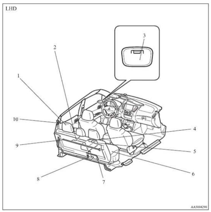
- Head restraints p. 2-08
- Bottle holder p. 5-45
- Room lamp (rcar)* p. 5-39, 8-24, 8-32
- Cup holder p. 5-45
- Armrest (for rear seat) p. 2-07
- Rear seats p. 2-07
- Tools*1 p. 6-07
- Jack p. 6-07
- Jack handle*1 p. 6-07
- Seat belts (for rear seats) p. 2-09
NOTE:*1- Tools differ according to the vehicle model.
-
Room lamp (rear)* p. 5-39, 8-24, 8-32
-
Bottle holder p. 5-45
-
Head restraints p. 2-08
-
Seat belts (for rear seats) p. 2-09
-
Jack handle*1 p. 6-07
-
Tools*1 p. 6-07
-
Jack p. 6-07
-
Rear seats p. 2-07
-
Armrest (for rear seat) p. 2-07
-
Cup holder p. 5-45
NOTE:*1- Tools differ according to the vehicle model.
Overview
Exterior - front (Single cab)
E00100503952
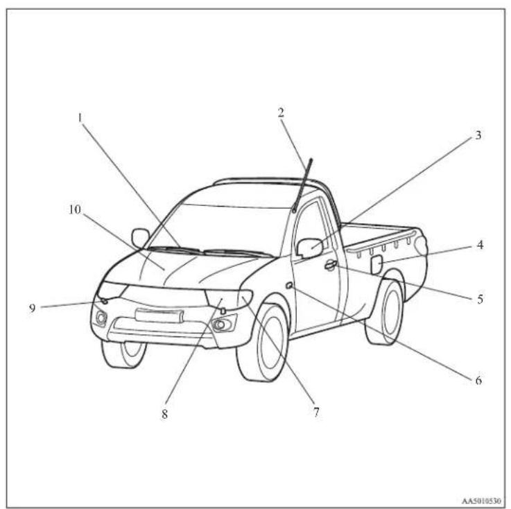
-
Wiper and washers p. 3-36
-
Antenna p. 5-34
-
Outside rear-view mirrors p. 4-10
-
Fuel tank filler door p. 02
-
Locking and unlocking p. 1-02
-
Side turn-signal lamps p. 3-33, 8-24, 8-28
-
Front turn-signal lamps p. 3-33, 8-24, 8-27
-
Headlamps p. 3-30, 8-24, 3-31
Position lamps p. 3-30, 8-24, 8-27
-
Headlamp washers* p. 3-39
-
Engine compartment p. 9-21
Bonnet p. 8-03
Exterior - rear (Single cab)
Overview
E00100503112
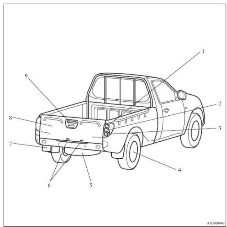
- Rear turn-signal lamps p. 3-33, 8-24, 8-30
- Stop and tail lamps p. 3-30, 8-24, 8-30
- Reversing lamps p. 8-24, 8-30
- Tyre inflation pressures p. 8-12
Changing tyres p. 6-17
Tyre rotation p. 8-13
Tyre chains p. 8-14 - Spare wheel p. 6-16
- Licence plate lamps p. 3-30, 8-24, 8-31
- Rear fog lamp (Driver's side only) p. 3-35, 8-24, 8-29
- Rear gate p. 1-11
- High-mounted stop lamp p. 8-24, 8-31
Overview
Exterior - front (Club cab)
E00100503965
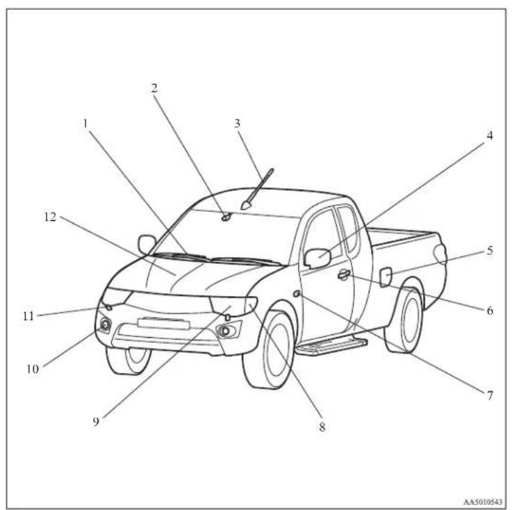
-
Wiper and washers p. 3-36
-
Rain sensor* p. 3-36
-
Antenna p. 5-34
-
Outside rear-view mirrors p. 4-10
-
Fuel tank filler door p. 02
-
Locking and unlocking p. 1-02
Keyless entry system® p. 1-04
-
Side turn-signal lamps p. 3-33, 8-24, 8-28
-
Front turn-signal lamps p. 3-33, 8-24, 8-27
-
Headlamps p. 3-30, 8-24, 3-31
Position lamps p. 3-30, 8-24, 8-27
-
Front fog lamps* p. 3-34, 8-24, 8-28
-
Headlamp washers* p. 3-39
-
Engine compartment p. 9-21
Bonnet p. 8-03
Exterior - rear (Club cab)
Overview
E00100503978
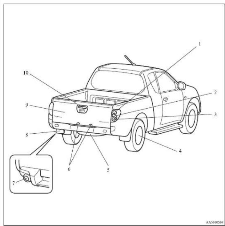
- Rear turn-signal lamps p. 3-33, 8-24, 8-30
- Stop and tail lamps p. 3-30, 8-24, 8-30
- Reversing lamps p. 8-24, 8-30
- Tyre inflation pressures p. 8-12
Changing tyres p. 6-17
Tyre rotation p. 8-13
Tyre chains p. 8-14 - Spare wheel p. 6-16
- Licence plate lamps p. 3-30, 8-24, 8-31
- Rear fog lamp (Driver's side only) Type 2* p. 3-35, 8-24, 8-29
- Rear fog lamp (Driver's side only) Type 1* p. 3-35, 8-24, 8-29
- Rear gate p. 1-11
- High-mounted stop lamp p. 8-24, 8-31
Overview
Exterior - front (Double cab)
E00100503981
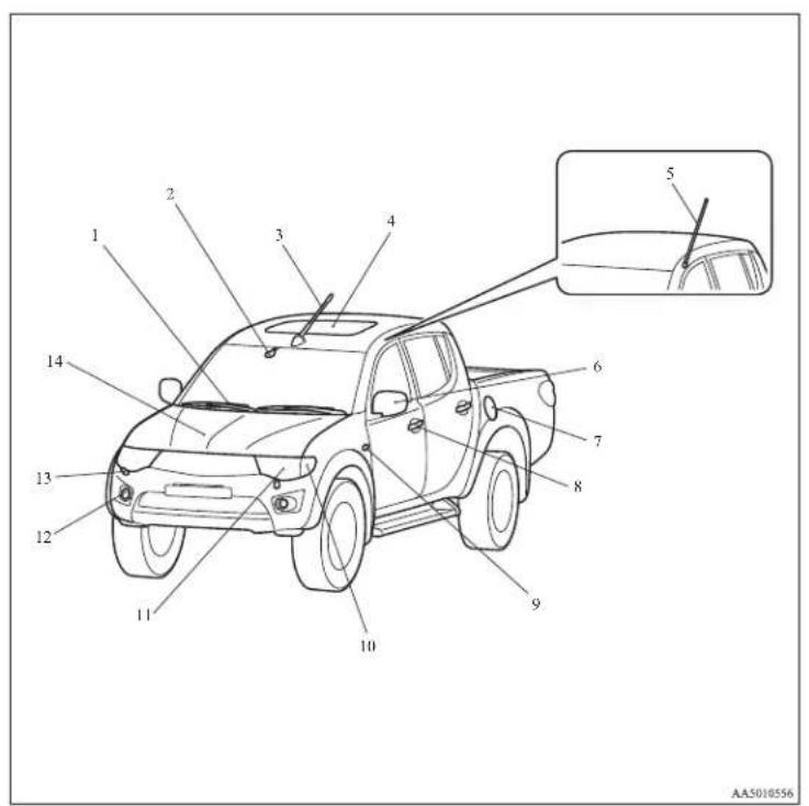
-
Wiper and washers p. 3-36
-
Rain sensor* p. 3-36
-
Antenna* p. 5-34
-
Sunroof* p. 1-13
-
Antenna* p. 5-34
-
Outside rear-view mirrors p. 4-10
-
Fuel tank filler door p. 02
-
Locking and unlocking p. 1-02
Keyless entry system* p. 1-04
-
Side turn-signal lamps p. 3-33, 8-24, 8-28
-
Front turn-signal lamps p. 3-33, 8-24, 8-27
-
Headlamps p. 3-30, 8-24, 3-31
Position lamps p. 3-30, 8-24, 8-27
-
Front fog lamps* p. 3-34, 8-24, 8-28
-
Headlamp washers* p. 3-39
-
Engine compartment p. 9-21
Bonnet p. 8-03
Exterior - rear (Double cab)
Overview
L00100503138
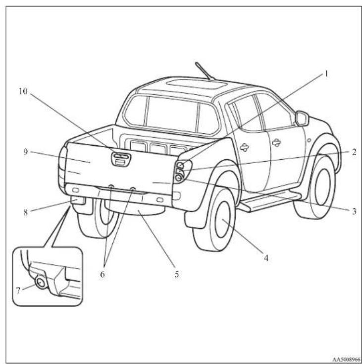
- Rear turn-signal lamps p. 3-33, 8-24, 8-30
- Stop and tail lamps p. 3-30, 8-24, 8-30
- Reversing lamps p. 8-24, 8-30
- Tyre inflation pressures p. 8-12
Changing tyres p. 6-17
Tyre rotation p. 8-13
Tyre chains p. 8-14 - Spare wheel p. 6-16
- Licence plate lamps p. 3-30, 8-24, 8-31
- Rear fog lamp (Driver's side only) Type 2* p. 3-35, 8-24, 8-29
- Rear fog lamp (Driver's side only) Type 1* p. 3-35, 8-24, 8-29
- Rear gate p. 1-11
- High-mounted stop lamp p. 8-24, 8-31
General information
Fuel selection....02
Filling the fuel tank....02
Installation of accessories....04
Modification/alterations to the electrical or fuel systems....04
Genuine parts....05
Used engine oils safety instructions and disposal information....05
Disposal information for used batteries....05
General information
Fuel selection
E00200102141
Recommended fuel
Cetane number (EN590) 51 or higher

CAUTION
- Your vehicle is designed to use only diesel fuel that meets the EN 590 standard. Use of any other type of diesel fuel would adversely affect the engine's performance and durability.
NOTE
- Due to the separation of paraffin, the fluidity of the fuel decreases considerably as the temperature falls. Because of this fact there are two kinds of fuel: "summer" and "winter". This must be considered in winter use. Select either of the two kinds of fuel in accordance with ambient temperature. Above -5 °C: "Summer" diesel Below -5 °C: "Winter" diesel When travelling abroad, find out in advance about the fuels served in local service stations.
- Poor-quality diesel fuel can cause deposits to form in the injector, resulting in black smoke and rough idling. If these problems occur, you are advised to add a cleaning additive to the diesel fuel when you refuel the vehicle. The additive will break up and remove the deposits, thereby returning the engine to a normal condition. Be sure to use a genuine MITSUBISHI DIESEL FUEL SYSTEM CLEANER. Using an unsuitable additive could make the engine malfunction. For details, please contact your MITSUBISHI MOTORS Authorized Service Point.
Filling the fuel tank
E00200202025
WARNING
- When handling fuel, comply with the safety regulations displayed by garages and filling stations.
Before removing the fuel cap, be sure to get rid of your body's static electricity by touching a metal part of the car or the fuel pump. Any static electricity on your body could create a spark that ignites fuel vapour. - Perform the whole refueling process (opening the fuel tank filler door, removing the fuel cap, etc.) by yourself. Do not let any other person come near the fuel tank filler. If you allowed a person to help you and that person was carrying static electricity, fuel vapour could be ignited.
- Do not move away from the fuel tank filler until refueling is finished. If you moved away and did something else (for example, cleaning your windscreen) part-way through the refueling process, you could pick up a fresh charge of static electricity.
- If the tank cap must be replaced, use only a MITSUBISHI MOTORS original part.
Fuel tank capacity
75 litres
Refueling
-
Before filling with fuel, stop the engine.
-
The fuel tank filler is located on the rear left side of your vehicle.
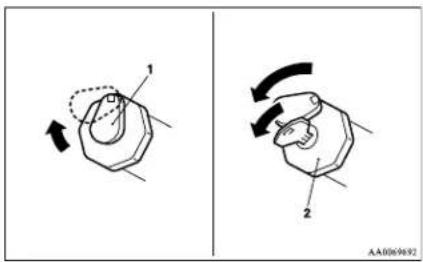
Type 1
Open the fuel tank filler door with the release lever located below the instrument panel.
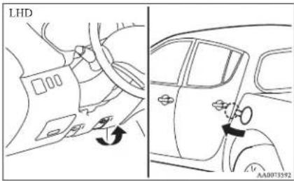
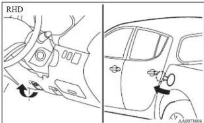
- Open the fuel tank filler tube by slowly turning the cap anticlockwise.
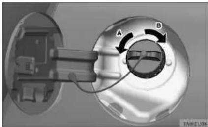
natural_image
Mechanical component diagram showing a rotating dial with labeled points A and B (no text or symbols beyond labels)A- Remove
B-Close
Type 2
Slide the cover (1). Insert the key in the cap (2) and unlock it.
Turn the cap and remove it.

CAUTION
- Since the fuel system may be under pressure, remove the fuel tank filler tube cap slowly. This relieves any pressure or vacuum that might have built up in the fuel tank. If you hear a hissing sound, wait until it stops before removing the cap. Otherwise, fuel may spray out, injuring you or others.
- Insert the gun in the tank port as far as it goes. Do not tilt the gun.
- When the gun stops automatically, do not fill with fuel any more.
- To close, turn the fuel tank filler tube cap slowly clockwise until you hear clicking sounds, then gently push the fuel tank filler door closed.
General information
Installation of accessories
E00200300875
We recommend you to consult your MITSUBISHI MOTORS Authorized Service Point.
● The installation of accessories, optional parts, should only be carried out within the limits prescribed by law in your country, and in accordance with the guidelines fitting instructions and warnings contained within the documents accompanying the parts or accessories.
- Improper installation of electrical components may cause an electrical fire if incorrectly fitted. Please refer to the Modification/alteration to the electrical or fuel systems section within this owner's manual.
● Using a cellular phone or radio set inside the vehicle without an external antenna may cause electrical system interference, which could lead to unsafe vehicle operation.
- Tyres and wheels which do not meet specifications must not be used.
Refer to the “Specifications” section for information regarding wheel and tyre sizes.
- When fitting accessories, ensure that maximum gross vehicle weight and maximum axle weight are not exceeded.
Even when such parts are officially authorized, for example by a “general operators permit” (an appraisal for the part) or through the execution of the part in an officially approved manner of construction, or when a single operation permit following the attachment or installation of such parts, it cannot be deduced from that alone, that the driving safety of your vehicle has not been affected.
Consider also that there basically exists no liability on the part of the appraiser or the official. Only in the case of parts (MITSUBISHI MOTORS original replacement or exchange parts as well as MITSUBISHI MOTORS genuine accessories) that are recommended and released by a MITSUBISHI MOTORS Authorized Service Point and that are attached or installed by a MITSUBISHI MOTORS Authorized Service Point can you assume, that optimal safety has been provided. The same also pertains to modifications of MITSUBISHI vehicle with respect to the production specifications. For your own safety, in such cases, you should only undertake modifications according to the recommendations of a MITSUBISHI MOTORS Authorized Service Point.
Modification/alterations to the electrical or fuel systems
E00200400238
MITSUBISHI MOTORS CORPORATION has always manufactured safe, high quality vehicles. In order to maintain this safety and quality, it is important that any accessory that is to be fitted, or any modifications carried out which involve the electrical or fuel systems, should be carried out in accordance with MITSUBISHI guidelines.
CAUTION
- If the wiring interferes with any part of the vehicle bodywork or improper installation methods are used, i.e. protective fuses not installed, etc.), electronic devices may be adversely affected, possibly resulting in an electrical fire or other failures that may cause an accident.
Important points!
Due to large number of accessory and replacement parts of different manufactures available in the market, it is not possible, not only for MITSUBISHI MOTORS, but also for a MITSUBISHI MOTORS Authorized Service Point, to check whether the attachment or installation of such parts affects the overall safety of your MITSUBISHI-vehicle.
Genuine parts
L00200500545
MITSUBISHI MOTORS has gone to great lengths to bring you a superbly crafted automobile offering the highest quality and dependability.
Use MITSUBISHI MOTORS Genuine Parts, designed and manufactured to maintain your MITSUBISHI MOTORS automobile at top performance. MITSUBISHI MOTORS Genuine Parts are identified by this mark and are available at all MITSUBISHI MOTORS Authorized Service Points.
Used engine oils safety instructions and disposal information
E00200600025
WARNING
● Prolonged and repeated contact may cause serious skin disorders, including dermatitis and cancer.
● Avoid contact with the skin as far as possible and wash thoroughly after any contact.
- Keep used engine oils out of reach of children.
Protect the environment
It is illegal to pollute drains, water courses and soil. Use authorized waste collection facilities, including civic amenity sites and garages providing facilities for disposal of used oil and used oil filters. If in doubt, contact your local authority for advice on disposal.
Disposal information for used batteries
E00201300029
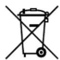
Your vehicle contains batteries and/or accumulators.
Do not mix with general household waste.
For proper treatment, recovery and recycling of used batteries, please take them to applicable collection points, in accordance with your national legislation and the Directives 2006/66/EC. By disposing of these batteries correctly, you will help to save valuable resources and prevent any potential negative effects on human health and the environment which could otherwise arise from inappropriate waste handling.
| 10.2 | 10.3 | 10.4 | 10.5 | 10.6 | 10.7 | 10.8 | 10.9 | 11.0 | 11.1 | 11.2 | 11.3 | 11.4 | 11.5 | 11.6 | 11.7 | 11.8 | 11.9 | 12.0 |
Locking and unlocking
Keys....1-02
Electronic immobilizer (Anti-theft starting system)....1-03
Keyless entry system*....1-04
Doors....1-06
Central door locks*....1-07
"Child-protection" rear doors (Double cab)....1-08
Manual window control*....1-08
Electric window control*....1-08
Quarter window (Club cab)....1-12
Rear gate....1-13
Sunroof* 1-13
Locking and unlocking
Keys
E00300101608
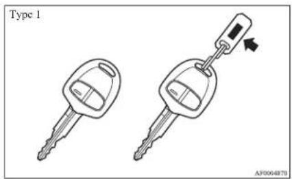
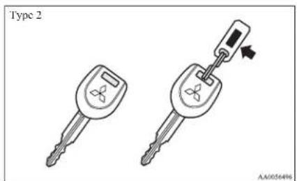
Two keys are provided. The key fits all locks. Keep one in a safe place as a spare key.
WARNING
- When taking a key on flights, do not press any switches on the key while on the plane. If a switch is pressed on the plane, the key emits electromagnetic waves, which could adversely affect the plane's flight operation. When carrying a key in a bag, be careful that no switches on the key can be easily pressed by mistake.
NOTE
● The key number is stamped on the tag as indicated in the illustration.
Make a record of the key number and store the key and key number tag in separate places, so that you can order a key in the event the original keys are lost.
● The key is a precision electronic device with a built-in signal transmitter. Please observe the following in order to prevent a malfunction.
- Do not leave in a place that is exposed to direct sunlight, for example on the dashboard.
- Do not disassemble or modify.
- Do not excessively bend the key or subject it to strong impacts.
- Do not expose to water.
- Keep away from magnetic key holders.
- Keep away from audio systems, personal computers, TVs, and other equipment that generates a magnetic field.
- Do not clean with ultrasonic cleaners or similar equipment.
- Do not leave the key where it may be exposed to high temperature or high humidity.
- The engine is designed so that it will not start if the ID code registered in the immobilizer computer and the key's ID code do not match. Refer to the "Electronic immobilizer" section for details and key usage.
Electronic immobilizer (Anti-theft starting system)
L00300200921
The electronic immobilizer is designed to significantly reduce the possibility of vehicle theft. The purpose of the system is to immobilize the vehicle if an invalid start is attempted. A valid start attempt can only be achieved (subject to certain conditions) using a keyless operation system “registered” to the immobilizer system.
NOTE
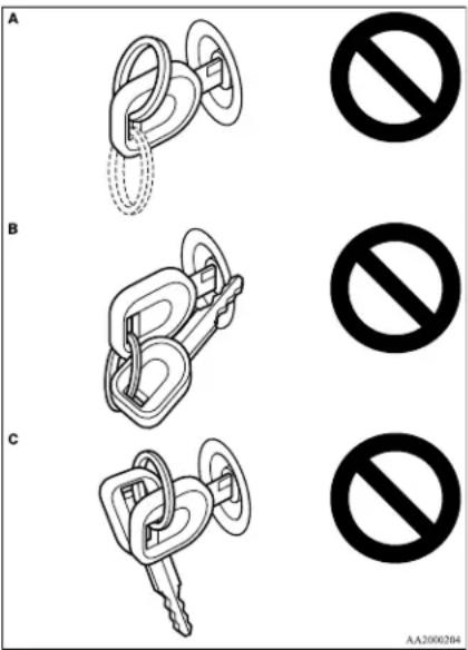
- In the following cases, the vehicle may not be able to receive the registered ID code from the key. This means the engine will not start even when the registered key is turned to the “START” position.
- When the key contacts a key ring or other metallic or magnetic object (Type A)
- When the key grip contacts metal of another key (Type B)
- When the key contacts or is close to other immobilizing keys (including keys of other vehicles) (Type C)
In cases like these, remove the object or additional key from the vehicle key and turn the key back to the "ACC" or "LOCK" position. Then try again to start the engine.
If the engine does not start, we recommend you to contact your MITSUBISHI MOTORS Authorized Service Point.
Locking and unlocking
● Two keys are provided.
If you lose one of them, order a replacement as soon as possible.
To obtain a key, take your vehicle and all remaining keys to a MITSUBISHI MOTORS Authorized Service Point.
If you need an extra spare key, take your vehicle and all the keys to a MITSUBISIII MOTORS Authorized Service Point. All the keys have to be re-registered in the immobilizer computer unit. The immobilizer allows up to 8 different ID codes to be registered; you can register a maximum of 8 keys for use.
CAUTION
- Don't make any alterations or additions to the immobilizer system; alterations or additions could cause failure of the immobilizer.
Locking and unlocking
Keyless entry system\*
E00300301860
Press the remote control switch, and all doors will be locked or unlocked as desired.
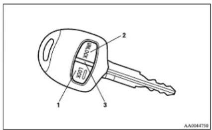
I- LOCK switch
2- UNLOCK switch
3- Indication lamp
To lock
Press the LOCK switch (1), and all doors will be locked. When they are locked with the room lamp at the [•] position, the room lamp and the turn-signal lamps blink once.
To unlock
Press the UNLOCK switch (2), and all doors will be unlocked. When unlocked with the room lamp at the [•] position, the room lamp will be turned on for approximately 15 seconds and the turn-signal lamps will blink twice.
NOTE
● The indication lamp (3) comes on each time a switch is pressed.
- If the UNLOCK switch (2) is pressed and any of the doors is not opened within approximately 30 seconds, relocking will automatically occur.
-
It is possible to modify functions as follows: For further information, please contact your MITSUBISHI MOTORS Authorized Service Point.
-
The time from pressing the UNLOCK switch (2) to the moment of automatic locking can be changed.
- The confirmation function (flashing of the turn-signal lamps) can be set to operate only when the doors are locked or only when the doors are unlocked.
- The confirmation function (this indicates locking or unlocking of the doors with the blink of the turn-signal lamps) can be deactivated.
- The number of times the turn-signal lamps are flashed by the confirmation function can be changed.
● The keyless entry system does not operate in the following conditions:
• The key is left in the key cylinder.
• The door is open.
- The remote control switch will operate within approximately 4 m from the vehicle. However, the operating range of the remote control switch may change if the vehicle is located near a power station, or radio/TV broadcasting station.
- If either of the following problems occurs, the battery may be exhausted.
- The remote control switch is operated at the correct distance from the vehicle, but the doors are not locked/unlocked in response.
- The indication lamp (3) is dim or does not come on.
For further information, please contact your MITSUBISHI MOTORS Authorized Service Point. If you replace the battery yourself, refer to "Procedure for replacing the remote control switch battery" on page 1-04.
- If your remote control switch is lost or damaged, please contact your MITSUBISHI MOTORS Authorized Service Point for a replacement remote control switch.
- If you wish to add a remote control switch, we recommend you to contact a MITSUBISHI MOTORS Authorized Service Point.
A maximum of 4 remote control switches are available for your vehicle.
Procedure for replacing the remote control switch battery
E00309500015
- Remove the screw ( ) from the remote control switch.
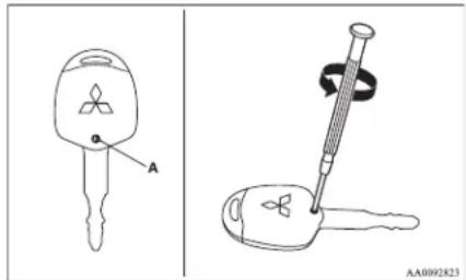
Locking and unlocking
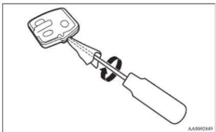
- With the MITSUBISIII mark facing you, insert the cloth covered tip of a straight blade (or minus) screwdriver into the notch in the remote control switch case and use it to open the case.
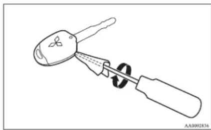
natural_image
Line drawing of a screwdriver with a handle and screwdriver tip, no text or symbols presentNOTE
- Be sure to perform the procedure with the MITSUBISHI mark facing you. If the MITSUBISHI mark is not facing you when you open the remote control switch case, the switches may come out.
- Remove the remote control transmitter from the remote control switch case. Then, open the remote control transmitter using the method described in step 2.
natural_image
Line drawing of a screwdriver holding a small component (no text or symbols)-
Remove the old battery.
-
Install a new battery with the + side (B) down.
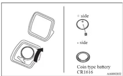
- Check the keyless entry system to see that it works.
NOTE
● You may purchase a replacement battery at an electric appliance store.
● A MITSUBISHI MOTORS Authorized Service Point can replace the battery for you if you prefer.

CAUTION
- When the remote control switch case is opened, be careful to keep water, dust, etc. out. Also, do not touch the internal components.
-
Close the remote control transmitter firmly.
-
Place the remote control transmitter in the remote control switch case, then securely close the remote control switch case.
-
Attach the screw (A) removed in step 1.
Locking and unlocking
Doors
E00300401584
CAUTION
● Make sure the doors are closed: driving with doors not completely closed is dangerous.
● Never leave children in the vehicle unattended.
● Be careful not to lock the doors while the key is inside the vehicle.
NOTE
- To prevent the key from being locked inside the vehicle, neither the lock knob on the driver's door nor the key can be used to lock the driver's door when it is open.
To lock or unlock with the key
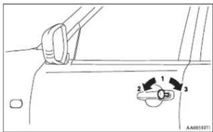
1- Insert or remove the key
2-Lock
3- Unlock
To lock or unlock from inside the vehicle
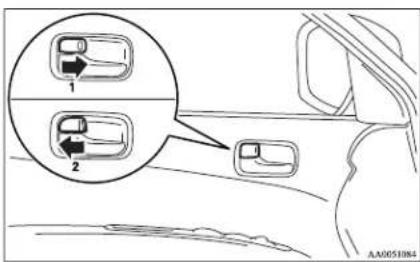
1-Lock
2- Unlock
Pull the inside door handle towards you to open the door.
NOTE
- The driver's door can be opened without using the lock knob by pulling on the inside door handle.
If your vehicle is equipped with the central door lock system, all other doors are unlocked at the same time.
To lock without using the key
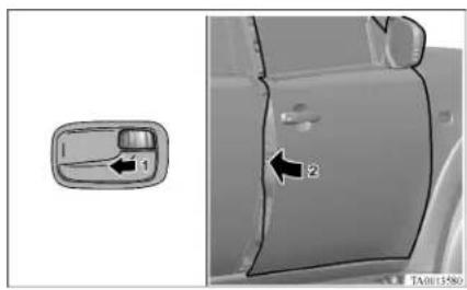
Set the inside lock knob (1) to the locked position, and close the door (2).
NOTE
- The driver's door cannot be locked using the inside lock knob while the driver's door is opened.
● Each of the doors can be locked or unlocked independently by using the inside lock knob.
- Repeated continuous operation between lock and unlock could activate the central door locking systems built-in protection circuit and prevent the system from operating. If this occurs, wait about 1 minute before operating the inside lock knob or the key.
All of the doors can be locked and unlocked as described hereafter.
Driver's door with key
Turn the key in the driver's door towards the front of the vehicle to lock the doors and towards the rear of the vehicle to unlock the doors.
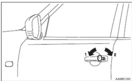
1-Lock
2- Unlock
Driver's door with inside lock knob
Set the inside lock knob on the driver's door towards the front of the vehicle to lock the doors. Set it towards the rear of the vehicle to unlock the doors.
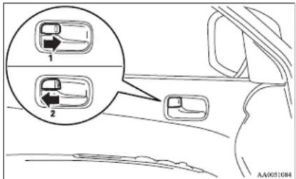
l-Lock
2- Unlock
Unlocking doors using selector lever (vehicle with keyless entry system)
It is possible to unlock all of the doors using the selector lever by placing in the "P" position while the ignition switch is in the "ON" position.
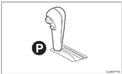
natural_image
Line drawing of a parking lift with a circular 'P' symbol and base plate (no text or labels)NOTE
- The vehicle is shipped from the factory with a setting established such that the doors are not unlocked when the selector lever is placed in the in the "P" position with the ignition switch in the "ON" position. If you wish to change the setting such that the doors are unlocked, contact your MITSUBISHI MOTORS Authorized Service Point.
Locking and unlocking
"Child-protection" rear doors (Double cab)
E00300900742
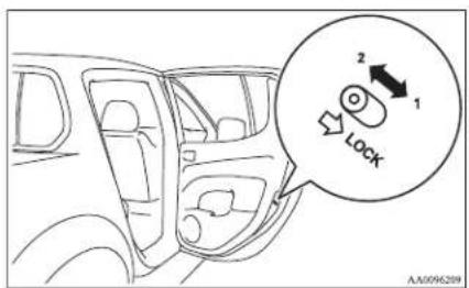
1-Lock
2- Unlock
Child protection helps prevent doors from being opened accidentally, especially when small children are in the rear seat.
A lever is provided on each rear door.
If the lever is set to the locked position, the rear door cannot be opened using the inside handle.
To open the rear door while the child protection is in use, pull the outside door handle.
If the lever is set to the "Unlock" position, the child protection mechanism does not function.
CAUTION
- When driving with a child in the rear seat, please use the child protection to prevent accidental door opening which may cause an accident.
Manual window control*
L00302100067
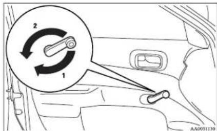
1- To open
2- To close
Electric window control\*
E00302200127
The electric windows can only be operated with the ignition switch in the "ON" position.
WARNING
● Before operating the electric window control, make sure that nothing can get trapped (head, hand, finger, etc.).
● Never leave the vehicle without removing the key.
● Never leave a child (or other person who might not be capable of safe operation of the electric window control) in the vehicle alone.
● The child may tamper with the switch at the risk of its hands or head being trapped in the window.
Electric window control switch
F00302301431
Each window opens or closes while the corresponding switch is operated.
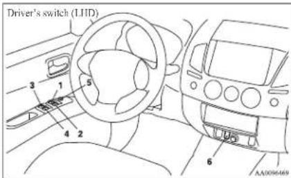

1- Driver's door window
2- Front passenger's door window
3- Rear left door window (Double cab)
4- Rear right door window (Double cab)
5- Lock switch
6- Rear retractable power window (Double cab)*
The switches can be used to operate all door windows. A window can be opened or closed by operating the corresponding switch.
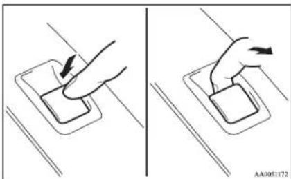
Press the switch down to open the window, and pull up the switch to close it.
natural_image
Two-step diagram showing hand pressing a button on a surface, with no text or symbols present.If the switch is fully pressed down/pulled up, the door window automatically opens/closes completely.
If you want to stop the window movement, operate the switch lightly in the reverse direction.
NOTE
● Repeated operation with the engine stopped will run down the battery. Operate the window switches only while the engine is running.
● The rear door windows only open halfway.
Rear retractable power window switch (Double cab)*
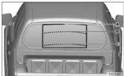
The rear retractable power window switch can be used to operate the rear retractable power window. The rear retractable power window stops in three positions: the fully closed position, a ventilation position, and the fully open position.
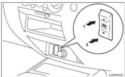
1-Close
2-Open
Locking and unlocking
NOTE
- It is not possible to stop the rear retractable power window in any position other than the fully closed position, ventilation position, and fully open position.
If the rear retractable power window is opened while the rear window demister is operating, the rear window demister automatically stops. When the rear retractable power window is subsequently fully closed, the behaviour of the rear window demister depends upon the elapsed time of the rear window demister's timer. (The timer runs for about 20 minutes in total.)
- If the rear window demister's timer is running, the rear window demister restarts for the remaining time.
- If the rear window demister's timer has finished, the rear window demister does not operate. If you wish to activate the rear window demister, press the rear window demister switch again.
natural_image
Top-down view of a car's rearview showing dashboard and front panel with no visible text or symbolsLocking and unlocking
A- Fully closed position
In this position, the rear retractable power window is fully closed.
To place the rear retractable power window in the fully closed position, firmly press the rear retractable power window switch (1).
B- Ventilation position
In this position, the rear retractable power window is slightly open.
To place the rear retractable power window in the ventilation position, lightly press the rear retractable power window switch (1) or (2).
WARNING
- In each of the following circumstances, the operating direction of the rear retractable power window switch and the operating direction of the rear retractable power window do not match each other. Exercise caution to avoid the risk of accidentally trapping a hand or your head when operating the rear retractable power window.
- Even if the rear retractable power window switch (1) is lightly pressed while the rear retractable power window is moving from the fully closed position towards the ventilation position, the rear retractable power window does not return to the fully closed position.
WARNING
- Even if the rear retractable power window switch (2) is lightly pressed while the rear retractable power window is moving from the fully open position towards the ventilation position, the rear retractable power window does not return to the fully open position.
C- Fully open position
In this position, the rear retractable power window is fully open.
To place the rear retractable power window in the fully open position, firmly press the rear retractable power window switch (2).
WARNING
- If the rear retractable power window switch (1) is lightly pressed while the rear retractable power window is moving from the fully closed position towards the fully open position, the rear retractable power window will come up to the ventilation position. To avoid the risk of accidentally trapping a hand or your head, do not operate the switch while the rear retractable power window is moving.
NOTE
● The rear retractable power window only opens halfway.
Lock switch
E00303100396
When this switch is operated, the passenger's switches and the rear retractable power window switch cannot be used to open or close the windows. To unlock, press it once again.
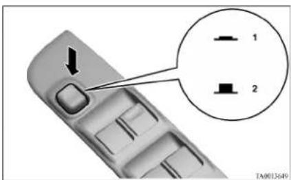
1-Lock
2- Unlock
NOTE
- The driver's switch can open or close any door windows.
WARNING
- A child may tamper with the switch at the risk of its hands or head being trapped in the window. When driving with a child in the vehicle, please press the window lock switch to disable the passenger's switches and rear retractable power window switch.
Timer function
E00302400709
Door's window
The door windows can be opened or closed for 30 seconds after the ignition switch is turned from the "ON" position to the "ACC" or "LOCK" position. If the driver's door is opened during this period, the door window can be opened or closed for another 30 seconds.
However, once the driver's door is closed, the windows cannot be operated.
Rear retractable power window
The rear retractable power window can be opened or closed for 30 seconds after the ignition switch is turned from the "ON" position to the "ACC" or "LOCK" position.
If the driver's door is opened during this period, the rear retractable power window can be opened or closed for another 30 seconds.
However, once the driver's door is closed, the rear retractable power window cannot be operated.
Safety mechanism
E00302500537
Door's window
If a hand or head is trapped in the closing power window, it will lower automatically.
Nonetheless, make sure that nobody puts their head or hand out of the power window when closing a power window.
The lowered window will become operational after a few seconds.
WARNING
- If the safety mechanism is activated three or more times successively, the safety mechanism will be temporarily cancelled. If a hand or head got trapped, a serious injury could result.
CAUTION
● The safety mechanism is cancelled just before the power window is fully closed. This allows the power window to close completely. Therefore be especially careful that no fingers are trapped in the power window.
NOTE
● The safety mechanism can be activated if the driving conditions or other circumstances cause the power window to be subjected to a physical shock similar to that caused by a trapped hand or head.
- If the safety mechanism is activated three or more times in a row, the safety mechanism will be cancelled and the power window will not close correctly. In such a case, the following procedure should be implemented to rectify this situation. Repeatedly raise the appropriate power window switch until that power window has been fully closed. Following this, release the switch, raise the switch once again and hold it in this condition for at least one second, then release it. You should now be able to operate the power window in the normal fashion.
Rear retractable power window
If a hand or head is trapped in the closing rear retractable power window, it will lower automatically. Nonetheless, make sure that nobody puts their head or hand out of the rear retractable power window when closing a rear retractable power window. The lowered window will become operational after a few seconds.
WARNING
- If the safety mechanism is activated three or more times successively, the safety mechanism will be temporarily cancelled. If a hand or head got trapped, a serious injury could result.
CAUTION
● The safety mechanism is cancelled just before the rear retractable power window is fully closed. This allows the rear retractable power window to close completely. Therefore be especially careful that no fingers are trapped in the rear retractable power window.
NOTE
● The safety mechanism can be activated if the driving conditions or other circumstances cause the rear retractable power window to be subjected to a physical shock similar to that caused by a trapped hand or head.
Locking and unlocking
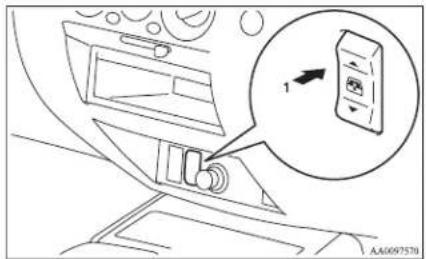
- If the safety mechanism is activated three or more times in a row, the safety mechanism will be cancelled and the rear retractable power window will not close correctly. In such a case, the following procedure should be implemented to rectify this situation. Repeatedly press the rear retractable power window switch (1) until that rear retractable power window has been fully closed. Following this, release the switch, press the switch once again and hold it in this condition for at least 1 second, then release it. You should now be able to operate the rear retractable power window in the normal fashion.
Quarter window (Club cab)
L00302600088
To open
- Pull the lever towards you.

natural_image
Illustration of a hand holding a pen with a magnified inset showing the tip of the pen (no text or symbols present)- Push the lever towards the outside of the vehicle.
- Push the lever towards the rear of the vehicle to secure it in place.
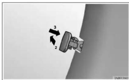
To close
Pull the lever, returning it to its original position and securing it in place.
Rear gate
L00303000050
To open
Lift up the handle and lower the rear gate.
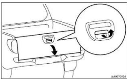
To close
Raise the rear gate and close with enough force to latch the assembly securely into position.
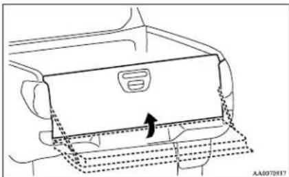
natural_image
Diagram of a car interior showing a rear intake manifold with dashed lines indicating movement or flow (no text or symbols)
CAUTION
- Do not stand behind the exhaust pipe when loading and unloading luggage. Heat from the exhaust could lead to burns.
● Pay attention not to catch your fingers in the rear gate. - Do not weight the rear gate.
● Before driving, make sure that the rear gate is securely closed. If the rear gate opens while driving the vehicle, objects stored in the cargo area could fall out on-to the road.
Locking and unlocking
Sunroof\*
L00302700887
The sunroof can only be operated with the ignition switch in the "ON" position.
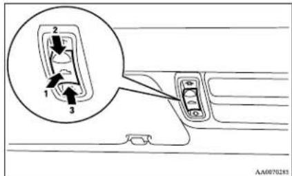
To open
The sunroof automatically opens if the switch (3) is pressed.
To stop the moving sunroof, press the switch (1) or (2).
NOTE
● The sunroof automatically stops just before reaching the fully open position. Press the switch again to fully open it.
To close
The sunroof closes while the switch (2) is pressed.
To tilt up
When the switch (1) is pressed, the rear edge of sun-roof rises for ventilation.
To tilt down
The sunroof tilt down while the switch (2) is pressed.
Locking and unlocking
Safety mechanism
E00303800029
If a hand or head is trapped in the closing sunroof, it will reopen automatically.
Nonetheless, make sure that nobody puts their head or hand out of the sunroof when opening or closing. The opened sunroof will become operational after a few seconds.
If the safety mechanism is activated 5 or more times consecutively or the switch (1) is kept pressed for 10 seconds or longer with the sunroof stationary in the fully tilted up position, normal closing of the sunroof will be aborted. In such an event, you should take the following steps:
- Press the switch (1) repeatedly until the sun-roof has been fully tilt up.
- Once the fully tilt up position has been reached, press again and hold the switch (1) for at least 3 seconds.
- After pressing the switch (3) to perform full opening, press the switch (2) to fully close the sunroof.
NOTE
● The safety mechanism can be activated if the driving conditions or other circumstances cause the sunroof to be subjected to a physical shock similar to that caused by a trapped hand or head.
● Avoid stopping the sunroof before it reaches the opening or closing end during operations. If this should accidentally happen, repeat the process from step 1.
CAUTION
● The safety mechanism is cancelled just before the sunroof is fully closed. This allows the sunroof to close completely. Therefore be especially careful that no fingers are trapped in the sunroof.
4. Following this action, it should be possible to operate the sunroof in the normal manner.
Sunshade
E00307900044
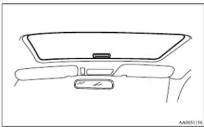
Slide the sunshade manually to open and close it.
natural_image
Line drawing of a car rearview dashboard and windshield (no text or symbols)CAUTION
● Be careful that hands are not trapped when closing the sunshade.
NOTE
● The sunshade will operate together with the sunroof when the sunroof is opened.
- Be sure to tilt down the sunroof before closing the sunshade.
● The sunshade cannot be closed with the sunroof opened. Do not attempt to close the sunshade when the sunroof is opened.
WARNING
- Do not put head, hands or anything else out of the sunroof opening while driving the vehicle.
● Never leave a child (or other person who might not be capable of safe operation of the sunroof switch) in the vehicle alone.
● Before operating the sunroof, make sure that nothing is capable of being trapped (head, hand, finger, etc.).
NOTE
● The sunroof stops just before reaching the fully open position.
If the vehicle is driven with the sunroof in this position, wind throb is lower than with the sunroof fully open.
- When leaving the vehicle unattended, make sure you close the sunroof and remove the ignition key.
- Do not try to operate the sunroof if it is frozen closed (after snow fall or during extreme cold).
- Do not sit or place heavy luggage on the sun-roof or roof opening edge.
● Release the switch as soon as the sunroof reaches the fully open or fully closed position.
- If the sunroof does not operate when the sunroof switch is operated, release the switch and check whether something is trapped by the sunroof. If nothing is trapped, we recommend you to have the sunroof checked.
- Depending on the model of ski carriers or roof carriers, the sunroof may make contact with the carrier when the sunroof is tilted up. Be careful when tilting up the sunroof if such a ski carrier or a roof carrier is installed.
- Be sure to close the sunroof completely when washing the vehicle or when leaving the vehicle.
- Be careful, not to put any wax on the weatherstrip (black rubber) around the sunroof opening. If stained with wax, the weatherstrip cannot maintain a weatherproof seal with the sunroof.
● After washing the vehicle or after it has rained, wipe off any water that is on the sun-roof before operating it.
● Operating the sunroof repeatedly with the engine stationary will run down the battery. Operate the sunroof while the engine is running.
| 10.2 | 10.3 | 10.4 | 10.5 | 10.6 | 10.7 | 10.8 | 10.9 | 11.0 | 11.1 | 11.2 | 11.3 | 11.4 | 11.5 | 11.6 | 11.7 | 11.8 | 11.9 | 12.0 |
Seat and seat belts
Seat....2-02
Seat adjustment....2-03
Front seat....2-03
Rear seat ^* 2-07
Head restraints....2-08
Seat belts....2-09
Pregnant women restraint....2-11
Seat belt pretensioner system and force limiter system*......2-12
Child restraint....2-13
Seat belt inspection....2-27
Supplemental restraint system (SRS) - airbag*......2-27
Seat and seat belts
Seat
E00400101146
AA1003468
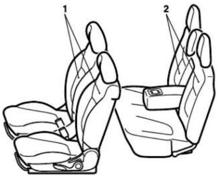
1-Front seat
● To adjust forward or backward → p. 2-03
● To recline the seatback → p. 2-04
● To adjust the seat height (Driver's seat)* → p. 2-05
● To get in and out of the cargo space (Club cab, passenger's seat) → p. 2-05
- Folding the seatback forward (Single cab, passenger's seat)* → p. 2-06
● Heated seats* → p. 2-06
2-Rear seat\*
● Folding the seatback forward (Double cab) → p. 2-07
● Folding up the seat cushion (Club cab)* → p. 2-07
● Armrest (Double cab) → p. 2-07
Seat adjustment
L00400300200
Adjust the driver's seat so that you are comfortable and that you can reach the pedals, steering wheel, switches etc. while retaining a clear field of vision.

WARNING
- Do not attempt to adjust the seat while driving. This can cause loss of vehicle control and result in an accident. After adjustments are made, ensure the seating is locked in position by attempting to move the seat forward and rearward without using the adjusting mechanism.
- It is extremely dangerous to ride in the cargo area (inside or outside) of a vehicle. Also, the cargo area and rear seats should never be used as a play area by children. In a collision, people or children riding unrestrained in these areas are more likely to be seriously injured or killed. Do not allow people or children to ride in any area of your vehicle that is not equipped with seats and seat belts, and make sure that everyone travelling in your vehicle is in a seat and wearing a seat belt, or in the case of a child is strapped in a child restraint.
Seat and seat belts

WARNING
● To minimize the risk of personal injury in the event of a collision or sudden braking, the seatbacks should always be in the almost upright position while the vehicle is in motion. The protection provided by the seat belts may be reduced significantly when the seatback is reclined. There is greater risk that the passenger will slide under the seat belt, resulting in serious injury, when the seatback is reclined.

CAUTION
● Make sure the seat is adjusted by an adult or with adult supervision for correct and safe operation.
- Do not place a cushion or the like between your back and the seatback while driving. The effectiveness of the head restraints will be reduced in the event of an accident.
- When sliding the seats, be careful not to catch your hand or foot.
- When sliding or reclining the seat rearward, pay careful attention to the rear seat passengers. (Double cab and Club cab)
Front seat
To adjust forward or backward
E0400400012
E00400500475
Manual type
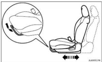
Pull the seat adjusting lever and adjust the seat forward or backward to the desired position. After adjustment, release the adjusting lever to lock the seat in position.

WARNING
● To ensure the seat is locked securely, try to move the seat forward or backward without using the adjusting lever.
Seat and seat belts
Power type
Adjust the seat by operating the switch as indicated by the arrows.
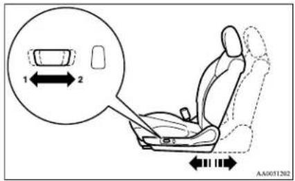
I- Adjustment forward
2- Adjustment backward
NOTE
● To prevent the battery from running down, operate the power type seat with the engine running.
To recline the seatback
E00400600593
Manual type
In order to recline the seatback, lean forward slightly, pull the seatback lock lever up, and then lean backward to the desired position and release the lever. The seatback will lock in that position.
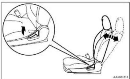

CAUTION
● The reclining mechanism of the seatback is spring loaded, causing it to return to the vertical position when the lock lever is operated. When operating the lever, sit close to the seatback or hold it with your hand to control its return motion.
Power type
Adjust the seatback angle by operating the switch as indicated by the arrows.
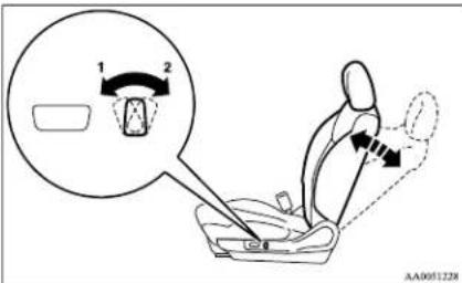
1- To move to forward direction
2- To recline rearward
NOTE
● To prevent the battery from running down, operate the power type seat with the engine running.
Seat and seat belts
To adjust the seat height (Driver's seat)\*
E00400700653
Manual type
Adjust the seat height by repeatedly operating the lever.
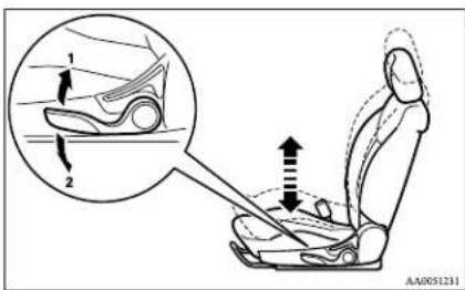
1- Raise
2-Lower
Power type
To adjust the seat height, operate the switch as indicated by arrows.
NOTE
● To prevent the battery from running down, operate the power type seat with the engine running.
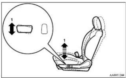
1- To move the front of the seat up and down
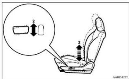
2- To move the rear of the seat up and down
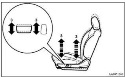
3- To move the whole seat up and down
To get in and out of the cargo space (Club cab, passenger's seat)
F00411000021
The lever can be used to make getting in and out easier.
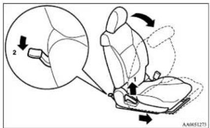
1- To get in or out
2- To get out
Seat and seat belts
When the lever or pedal is used, the seatback will tilt forward and at the same time the entire seat will move forward. To return the seat, slide the entire seat rearward and then raise the seatback rearward to lock the seat in position.
WARNING
- Do not drive the vehicle with the seatback folded forward. The seat is not retained position if it is not kept in an upright position, so serious injuries could be suffered in the event of hard braking or a collision.
CAUTION
- The reclining mechanism of the seatback is spring loaded, causing it to return to the vertical position when the lock lever is operated. When using the lever, sit close to the seatback or hold it with your hand. - Use a foot to operate the pedal (2).
Folding the seatback forward (Single cab, passenger's seat)\*
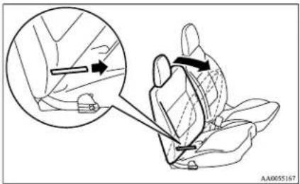
To access the onboard tool kit, fold forward the seat-back of the passenger's seat. Refer to "Tools, jack and jack handle" on page 6-07.
Pull the band and fold the seatback forward.
Heated seats\*
F00401100784
The heated seats can be operated with the ignition switch in the "ON" position.
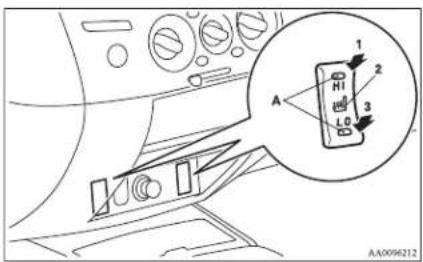
I (HI)- Heater high (for quick heating).
2- Heater off.
3 (LO)- Heater low (to keep the seat warm).
The indication lamp (A) will illuminate while the heater is on.
CAUTION
● Switch off seat heaters when not in use.
- Operate in the high position for quick heating. Once the seat is warm, set the heater to low to keep it warm. Slight variations in seat temperature may be felt while using the heated seats. This is caused by the operation of the heater's internal thermostat and does not indicate a malfunction.
- If the following types of persons use the heated seats, they might become too hot or receive minor burns (red skin, heat blisters, etc.):
• Children, elderly or ill people
• People with sensitive skin
• Excessively tired people
• People under the influence of alcohol or sleep inducing medication (cold medicine, etc.)
- Do not place heavy objects on the seat or stick pins, needles, or other pointed objects into it.
- Do not use a blanket, cushion, or other material with high heat insulation properties on the seat while using the heater; this might cause the heater element to overheat
- When cleaning the seat, do not use benzene, kerosene, petrol, alcohol, or other organic solvents; these might damage the surface of the seat and also the heater element.
- If water or any other liquid is spilled on the seat, allow it to dry thoroughly before attempting to use the heater.
● Turn the heater off immediately if it appears to be malfunctioning during use.
Rear seat\*
L00401300148
When a person is sitting in the middle seating position of the rear seat, adjust the head restraint to height at which it lock in position. Refer to "Head restraints" on page 2-08.
Folding the seatback forward (Double cab)
F00401600242
Pull up the band on the top of the seatback and fold it forward.
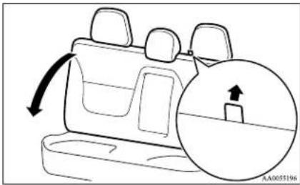
natural_image
Diagram of a car backrest with a magnified inset showing a side panel and directional arrow (no text or symbols)Confirm that the seatback locks securely when it is returned.
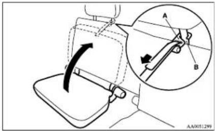
Folding up the seat cushion (Club cab)\*
E00411300024
The right and left seat cushions can be folded up separately.
To fold the seat cushions up, raise the seat cushions.
Securely retain the seat cushion by hooking the retaining band (A) onto the head restraint (B) of the rear seat.
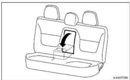
Armrest (Double cab)
E00401700605
To use the armrest, fold it down. To return to the original position, push it backward (into the seatback) until it is level with the seat.
natural_image
Line drawing of a car backseat with seat compartments and a highlighted seatbelt (no text or symbols)Seat and seat belts
NOTE
- Do not stand or sit on the armrest. It could break.
● The top surface of the armrest contains a cup holder for rear seat occupants.
Refer to "Cup holder" on page 5-44.
Seat and seat belts
Head restraints
E00403300995
WARNING
- Driving without the head restraints in place can cause you and your passengers serious injury or death in an accident. To reduce the risk of injury in an accident, always make sure the head restraints are installed and properly positioned when the scat is occupied.
● Never place a cushion or similar device on the seatback. This can adversely affect head restraint performance by increasing the distance between your head and the restraint.
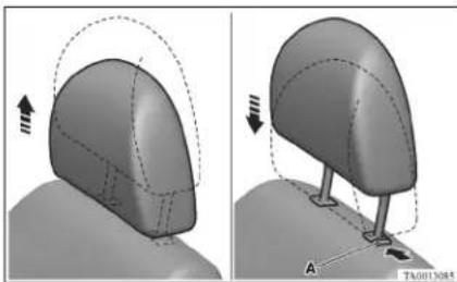
To raise the head restraint, move it upward. To lower the restraint, move it downward while pushing the height adjusting knob ( ) in the direction of the arrow. After adjustment, push the head restraint downward and make sure that it is locked.
natural_image
3D CAD model of a mechanical component with two views showing motion, no text or symbols presentTo adjust height
Adjust the head restraint height so that the centre of the restraint is as close as possible to eye level to reduce the chances of injury in the event of collision. Any person too tall for the restraint to reach their seated eye level, should adjust the restraint as high as possible.
To remove
Lift the head restraint with the height adjusting knob (A) pushed in.
To install
Confirm that the head restraint is facing the correct direction, and then insert it into the seatback while pressing the height adjusting knob (A) in the direction indicated by the arrow.
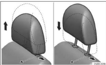
natural_image
3D model of a curved object with dashed outline and arrows indicating motion, labeled 'A' (no text or symbols on the object itself)CAUTION
- Confirm that the height adjusting knob (A) is correctly adjusted as shown in the illustration, and also lift the head restraints to ensure that they do not come out of the seatback.
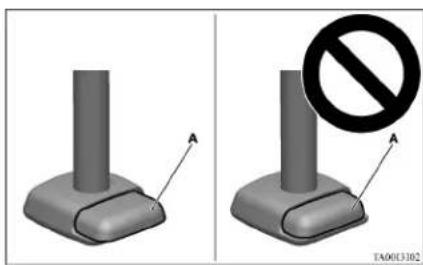
natural_image
Two identical 3D model of a mechanical component with a prohibition symbol overlay (no text or symbols on the components)CAUTION
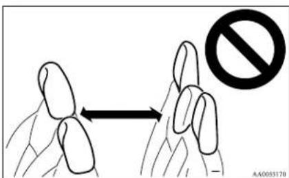
- If your vehicle is equipped with the rear seat head restraint, the head restraints for the front and rear seats differ in size. When installing head restraints, make sure the front and rear head restraints are fitted in their respective seats.
Seat belts
E00404800825
To protect you and your passengers in the event of an accident, it is most important that the seat belts are worn correctly while driving.
A seat belt for a front seat equipped with an airbag has a pretensioner system. These belts are used the same way as a conventional seat belt.
Refer to "Seat belt pretensioner system and force limiter system" on page 2-12.
WARNING
● Always place the shoulder belt over your shoulder and across your chest. Never put it behind you or under your arm.
● One seat belt should be used by only one person. Doing otherwise can be dangerous.
● The seat belt will provide its wearer with maximum protection if the recliner seatback is placed in fully upright position. When the seatback is reclined, there is greater risk that the passenger will slide under the belt, especially in a forward impact accident, and may be injured by the belt or by striking the instrument panel or seatbacks.
- Seat belts should always be worn by every adult who drives or rides in this vehicle, and by all children who are tall enough to wear seat belts properly.
- Remove any twists when using the belt.
- No modifications or additions should be made by the user which will either prevent the seat belt adjusting devices from operating to remove slack, or prevent the seat belt assembly from being adjusted to remove slack.
Seat and seat belts
WARNING
- To reduce risk of serious or fatal injury in an accident, including the deploying driver's airbag, adjust the driver's seat as far back as possible while maintaining a position that still allows good visibility and good control of the steering wheel, the brake and accelerator, and vehicle controls.
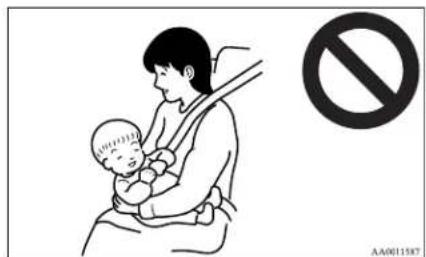
● Never hold a child in your arms or on your lap when riding in this vehicle, even if you are wearing your seat belt. To do so risks severe or fatal injury to the child in a collision or sudden stop.
● Always adjust the seat belt to a snug fit.
3-point type seat belt (with emergency locking mechanism)
E00404901126
This type of belt requires no length adjustment. Once worn, the belt adjusts itself to the movement of the wearer, but in the event of a sudden or strong shock, the belt automatically locks to hold the wearer's body.
Seat and seat belts
NOTE
- You can check if the belt locks by pulling it forward quickly.
To fasten
- Pull the seat belt out slowly while holding the latch plate.
NOTE
- When the seat belts cannot be pulled out in a locked condition, pull the belts once forcefully and then return them. After that, pull the belts out slowly once again.
- Insert the latch plate into the buckle until a "click" is heard.
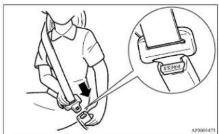
WARNING
● Never wear the lap portion of the belt across your abdomen. During accidents it can press sharply against the abdomen and increase the risk of injury.
WARNING
● The seat belts must not be twisted when worn.
- Pull the belt slightly to adjust slackness as desired.
To unfasten
Hold the latch plate and push the button on the buckle.
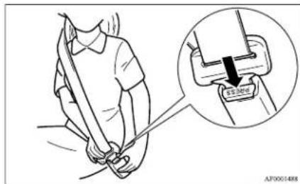
NOTE
● As the belt retracts automatically, keep holding the latch plate while retracting so that the belt stows slowly. Failure to do this could damage the vehicle.
Seat belt reminder/warning lamp
E00409800790
A tone and warning lamp are used to remind the driver and front passenger to fasten the seat belt.
NOTE
- For the front passenger seat, the warning function works only while a person is sitting on the seat.
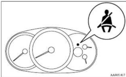
When the ignition key is turned to the "ON" position, the warning lamp will come on and a tone will sound for about 6 seconds. If the front seat belt remains unfastened approximately 1 minute later, the warning lamp will flash and the tone sound intermittently (each 12 times) when the vehicle is driven. If the passenger subsequently unfastens the seat belt while driving, the warning lamp and tone will issue further warnings. And if the seat belt remains unfastened, the warning lamp and tone will issue further warnings each time the vehicle starts moving from a stop. When the seat belt is fastened, the warnings will stop.

WARNING
- In order to reduce the risk of serious or fatal injury in an accident, always wear your own seat belt. Do not allow anyone to ride in your vehicle unless he or she is also seated and wearing a seat belt. Children should additionally be restrained in a secure child restraint system.
NOTE
- When luggage is placed on the front passenger seat, a sensor in the seat cushion may, depending on the weight and position of the luggage, cause the warning tone to sound and the warning lamp to come on (Double cab).
Adjustable seat belt anchor (front seats)\*
L00405000299
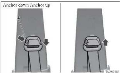
The seat belt anchor height can be adjusted. Move the seat belt anchor down with the lock knob (A) depressed. To move the anchor up, slide it without depressing the lock knob (A).

WARNING
- When adjusting the seat belt anchor, set it at a position that is sufficiently high so that the belt will make full contact with your shoulder but will not touch your neck.
Lap belts\*
EDM05100128
The lap belts should be adjusted by holding the belt and latch plate at right angles to each other, and then pulling the belt as shown in the illustration to a snug fit around the occupant.
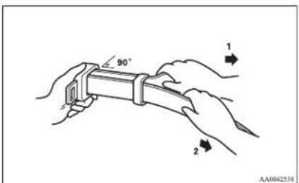
1- Tighten
2- Loosen
While holding the latch plate, insert the latch plate into the buckle until a "click" is heard.
Pregnant women restraint
E00405600064

WARNING
- Seat belts work for everyone, including pregnant women. Pregnant women should use the available seat belts. This will reduce the likelihood of injury to both the woman and the unborn child. The lap belt should be worn across the thighs and as snug against the hips as possible, but not across the waist. Consult your doctor if you have any additional questions or concerns.
Seat and seat belts
Seat belt pretensioner system and force limiter system\*
E00405700283
The driver's and front passenger's seat equipped with an airbag has a pretensioner seat belt.
Pretensioner system
E00405801089
The pretensioner system will retract their respective seat belts instantaneously, thus maximizing the seat belt's effectiveness, if there is a frontal impact severe enough to injure the driver and/or front passenger and the ignition switch is in the "ON" or "START" position.
The seat belt pretensioner includes the following components:
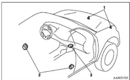
1- Front impact sensors
2- Seat belt pretensioners
3- Airbag control unit
WARNING
● To obtain the best results from your pretensioner seat belt, make sure you have adjusted your seat correctly and wear your seat belt properly.
CAUTION
● Installation of audio equipment or repairs in the vicinity of the pretensioner seat belts or floor console must be performed in line with MITSUBISHI MOTORS guidelines. It is important to do so because the work could affect the pretensioner systems.
- If you need to scrap the vehicle, please consult a MITSUBISHI MOTORS Authorized Service Point. It is important to do so because unexpected activation of the pretensioner seat belts could cause injuries.
NOTE
● The pretensioner seat belts will be activated if the vehicle suffers a severe frontal impact, even if the seat belts are not worn.
● The pretensioner seat belts are designed to work only once. After the pretensioner seat belts have been activated, we recommend you have them replaced by a MITSUBISHI MOTORS Authorized Service Point.
SRS warning lamp
ED0405900126
This warning lamp is shared by the SRS airbags and the pretensioner seat belts.
Refer to "SRS warning lamp" on page 2-38.
Force limiter system
E00406000078
In the event of a collision, each force limiter system will effectively absorb the load applied to the seat belt so as to minimize the impact to the passenger.
Child restraint
E00406401297
When transporting children in your vehicle, some type of child restraint system should always be used according to the size of the child. This is required by law in most countries.
The regulations concerning driving with children in the front seat may differ from country to country. You are advised to comply with the relevant regulations.
WARNING
- When possible, put children in the rear seat. Accident statistics indicate that children of all sizes and ages are safer when properly restrained in the rear seat rather than in the front seat. (Double cab and Club cab)
- Holding a child in your arms is no substitute for a restraint system. Failure to use a proper restraint system can result in severe or fatal injury to the child.
● Each child restraint device or fixing is to be used only by one child. - When attaching a child restraint to the rear seat, place the front seatbacks in the upright position.
Otherwise, the child could be seriously injured in the event of hard braking or a collision. (Double cab and Club cab)
Caution for installing the child restraint on vehicles with a front passenger airbag
E00406500190
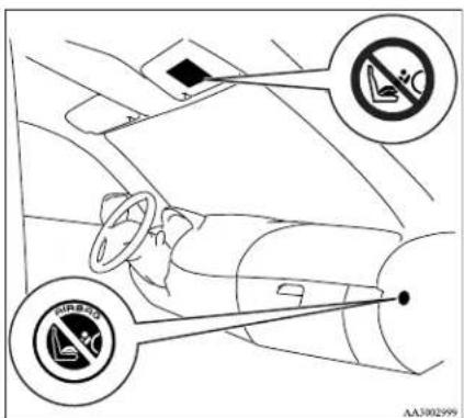
The label shown here is attached on vehicles with a front passenger airbag.
WARNING
● Extreme Hazard!
Do not use a rearward facing child restraint on a seat protected by an airbag in front of it!
● A REARWARD FACING CHILD RESTRAINT must NOT be used in the front passenger seat if the front passenger's airbag has not been deactivated. The force of an inflating airbag could kill or cause serious injuries to the child.
Seat and seat belts
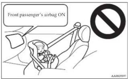
NOTE
- If you have a rearward facing child restraint system that cannot be fitted to any seat other than the front passenger seat, be sure to turn OFF the front passenger's airbag ON-OFF switch before using it. (Refer to "To turn an airbag off" on page 2-30.)
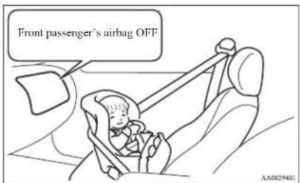
Seat and seat belts
WARNING
● A FORWARD FACING CHILD RE-STRAINT should not be used in the front passenger seat whenever possible; if used in the front passenger seat, adjust the seat to the most rearward position.
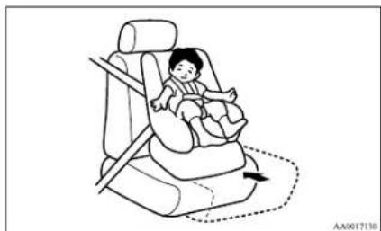
natural_image
Line drawing of a child seated in a car seat, no text or symbols presentInfants and small children
E00406600768
When transporting infants and small children in your vehicle, follow the instruction given below.
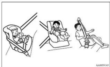
natural_image
Illustration of three children in car seat positions: one seated in a car, two standing in a seat, and one using a mobility device (no text or symbols)Instruction:
- For small infants, an infant carrier should be used. For small children whose height when seated allows the shoulder belt to lie in contact with the face or the throat, a child seat should be used.
- The child restraint system should be appropriate for the child's weight and height and properly fit in the vehicle.
- Before purchasing a child restraint system, try installing it in the seat to make sure there is a good fit. Because of the location of the seat belt buckles and the shape of the seat cushion, it may be difficult to securely install some manufacturer's child restraint systems. If the child restraint system can be pulled forward or to either side easily on the seat cushion after the seat belt has been tightened, choose another manufacturer's child restraint system.
WARNING
- When installing a child restraint system, refer to the instructions provided by the manufacturer of the restraint system. Failure to do so can result in severe or fatal injury to the child.
● After installation, push and pull the child restraint system back and forth, and side to side, to see that it is properly secured. If the child restraint system is not installed securely, it may cause injury to the child or other occupants in the case of accident or sudden stops.
WARNING
- When the child restraint system is not in use, keep your child restraint system secured with the seat belt or remove it from the vehicle in order to prevent it from being thrown around inside the vehicle during an accident.
NOTE
● Depending on the seating position in the vehicle and the child restraint system that you have, the child restraint can be attached using one of the following two locations:
• To the lower anchorage in the rear seat ONLY if the child restraint has ISOFIX mountings (Double cab, See page 2-25).
• To the seat belt (See page 2-26).
Older children
E00406700235
Children who have outgrown the child restraint system should be seated in the rear seat and wear combination lap shoulder belt.
The lap portion of the belt should be snug and positioned low on the abdomen so that it is below the top of the hip-bone. Otherwise, the belt could intrude into the child's abdomen during an accident and cause injury.
WARNING
● Children who are not buckled up can be thrown out of the vehicle in an accident.

WARNING
● Children who are not buckled up can strike other people in the vehicle in an accident.
● A child should never be left unattended in your vehicle. When you leave the vehicle, take the child with you.
Seat and seat belts
Seat and seat belts
Suitability for various ISOFIX positions
E00411400269
| Mass group Size | class Fixture | Vehicle ISOFIX positions | |||
| Front passenger Rear | outboard Rear centre | ||||
| Carrycot F ISO/L1 X | X X | ||||
| G ISO/L2 X X | X | ||||
| X X X | |||||
| 0 - Up to 10 kg E ISO/R1 X X X | |||||
| X X X | |||||
| 0+ - Up to 13 kg E ISO/R1 X | IL^*2 | X | |||
| D ISO/R2 X X | X | ||||
| C ISO/R3 X X | X | ||||
| X X X | |||||
| I -9 to 18 kg D ISO/R2 X X X | |||||
| C ISO/R3 X X | X | ||||
| B ISO/F2 X | IUF | X | |||
| B1 | ISO/F2X | X | IUF, IL^*1 | ||
| A ISO/F3 X | IUF | X | |||
| X X X | |||||
| II -15 to 25 kg | X X X | ||||
| III -22 to 36 kg | X X X | ||||
Key of letters to be inserted in the table above:
● IUF- Suitable for ISOFIX forward child restraints systems of universal category approved for use in the mass group.
- IL- Suitable for particular ISOFIX child restraint systems given in the following list (MITSUBISHI MOTORS genuine parts).
● X- ISOFIX position not suitable for ISOFIX child restraint systems in this mass group and/or this size class.
Seat and seat belts
IL (Genuine part information)
| Genuine part No. ECE No. | ||
| *1 | MZ313045 E1-04301133 | |
| *2 | MZ314393 (Child restraint system), MZ314394 (ISOFIX base) | E1-04301146 |
NOTE
● MITSUBISHI MOTORS Europe B.V. reserves the right to changes without any prior announcement.
For further information, please contact a MITSUBISHI MOTORS Authorized Service Point.
Seat and seat belts
Suitability for various seating positions
Single cab (Separate seat)
E00406S00874
| Mass group | Seating position | |
| Front passenger | ||
| Activated airbag | Deactivated airbag*1 | |
| 0 - Up to 10 kg X U | ||
| 0+ - Up to 13 kg X | U, L*2 | |
| I -9 to 18 kg | UF, L*3, L*4 | U, L*3, L*4 |
| II -15 to 25 kg | UF, L*5 | U, L*5 |
| III -22 to 36 kg | UF, L*5 | U, L*5 |
^*1 : With front passenger's airbag deactivated by means of front passenger's airbag ON-OFF switch.
Key of letters to be inserted in the table above:
● U- Suitable for “universal” category restraints approved for use in this mass group.
- UF-Suitable for forward-facing "universal" category restraints approved for use in this mass group.
● L- Suitable for particular child restraints in the following list (MITSUBISHI MOTORS genuine parts).
● X- Seat position not suitable for children in this mass group.
L (Genuine part information)
| Genuine parts No. ECE No. | ||
| *2 | MZ312807 E1-04301146 | |
| *3 | MZ314451 E1-04301203 | |
| *4 | MZ313045 E1-04301133 | |
| *5 | MZ314250 E1-04301169 |
CAUTION
- When installing a child restraint system, prevent the head restraint from touching the child restraint system by removing it or adjusting its height.
NOTE
- There is no applicable MITSUBISHI MOTORS Genuine Parts to the Mass Group "0-Up to 10 kg".
MITSUBISHI MOTORS Europe B.V. reserves the right to changes without any prior announcement. For further information, please contact a MITSUBISHI MOTORS Authorized Service Point.
Single cab (Bench seat)
| Mass group | Seating position | ||
| Front passenger | Front centre | ||
| Activated airbag | Deactivated airbag*1 | ||
| 0 - Up to 10 kg X U X | |||
| 0+ - Up to 13 kg X | U, L*2 | X | |
| I -9 to 18 kg | UF, L*3, L*4 | U, L*3, L*4 | X |
| II -15 to 25 kg | UF, L*5 | U, L*5 | X |
| III -22 to 36 kg | UF, L*5 | U, L*5 | X |
*1: With front passenger's airbag deactivated by means of front passenger's airbag ON-OFF switch.
Key of letters to be inserted in the table above:
- U- Suitable for “universal” category restraints approved for use in this mass group.
- UF-Suitable for forward-facing "universal" category restraints approved for use in this mass group.
● L- Suitable for particular child restraints in the following list (MITSUBISHI MOTORS genuine parts).
● X- Seat position not suitable for children in this mass group.
Seat and seat belts
L (Genuine part information)
| Genuine parts No. ECE No. | ||
| ≈ 2 | MZ312807 E1-04301146 | |
| *3 | MZ314451 E1-04301203 | |
| *4 | MZ313045 E1-04301133 | |
| *5 | MZ314250 E1-04301169 |
2

CAUTION
- When installing a child restraint system, prevent the head restraint from touching the child restraint system by removing it or adjusting its height.
NOTE
● There is no applicable MITSUBISHI MOTORS Genuine Parts to the Mass Group "0-Up to 10 kg".
MITSUBISHI MOTORS Europe B.V. reserves the right to changes without any prior announcement.
For further information, please contact a MITSUBISHI MOTORS Authorized Service Point.
Club cab
| Mass group | Seating position | ||
| Front passenger | Rear outboard | ||
| Activated airbag | Deactivated airbag*1 | ||
| 0 - Up to 10 kg X U X | |||
| 0+ - Up to 13 kg X | U, L*2 | L*2 | |
| I -9 to 18 kg | UF, L*3, L*4 | U, L*3, L*4 | L*3, L*4 |
| II -15 to 25 kg | UF, L*5 | U, L*5 | X |
| III -22 to 36 kg | UF, L*5 | U, L*5 | X |
^*1 : With front passenger's airbag deactivated by means of front passenger's airbag ON-OFF switch.
Key of letters to be inserted in the table above:
- U- Suitable for "universal" category restraints approved for use in this mass group.
- UF-Suitable for forward-facing "universal" category restraints approved for use in this mass group.
● L- Suitable for particular child restraints in the following list (MITSUBISHI MOTORS genuine parts).
● X- Seat position not suitable for children in this mass group.
L (Genuine part information)
| Genuine parts No. ECE No. | ||
| *2 | MZ312807 E1-04301146 | |
| *3 | MZ314451 E1-04301203 | |
| *4 | MZ313045 E1-04301133 | |
| *5 | MZ314250 E1-04301169 |

CAUTION
- When installing a child restraint system, prevent the head restraint from touching the child restraint system by removing it or adjusting its height.
NOTE
- There is no applicable MITSUBISHI MOTORS Genuine Parts to the Mass Group "0-Up to 10 kg".
MITSUBISHI MOTORS Europe B.V. reserves the right to changes without any prior announcement. For further information, please contact a MITSUBISHI MOTORS Authorized Service Point.
Seat and seat belts
Double cab
| Mass group | Seating position | |||
| Front passenger | Rear outboard Rear centre | |||
| Activated airbag | Deactivated airbag*1 | |||
| 0 - Up to 10 kg X U U X | ||||
| 0+ - Up to 13 kg X | U, L*2 | U, L*2 | X | |
| I -9 to 18 kg | UF, L*3, L*4 | U, L*3, L*4 | U, L*3, L*4 | L*4 |
| II -15 to 25 kg | UF, L*5 | U, L*5 | U, L*5 | L*5 |
| III -22 to 36 kg | UF, L*5 | U, L*5 | U, L*5 | L*5 |
*1: With front passenger's airbag deactivated by means of front passenger's airbag ON-OFF switch.
Key of letters to be inserted in the table above:
● U- Suitable for “universal” category restraints approved for use in this mass group.
- UF-Suitable for forward-facing "universal" category restraints approved for use in this mass group.
● L- Suitable for particular child restraints in the following list (MITSUBISHI MOTORS genuine parts).
● X- Seat position not suitable for children in this mass group.
L (Genuine part information)
| Genuine parts No. ECE No. | ||
| *2 | MZ312807 E1-04301146 | |
| *3 | MZ314451 E1-04301203 | |
| *4 | MZ313045 E1-04301133 | |
| *5 | MZ314250 E1-04301169 |

CAUTION
- When installing a child restraint system, prevent the head restraint from touching the child restraint system by removing it or adjusting its height.
Seat and seat belts
NOTE
- There is no applicable MITSUBISHI MOTORS Genuine Parts to the Mass Group "0-Up to 10 kg".
MITSUBISHI MOTORS Europe B.V. reserves the right to changes without any prior announcement. For further information, please contact a MITSUBISHI MOTORS Authorized Service Point.
Seat and seat belts
Child restraint anchorage points (Double cab)\*
E00406900354
Anchorage locations
There are 2 child restraint anchorage points on the floor, located behind the rear seat. These are for securing a child restraint system tether strap to each of the 2 rear seating positions in your vehicle.
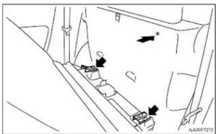
natural_image
Diagram of a vehicle's seatbelt mechanism with directional arrows and a marked component (no text or symbols)*: Rear of the vehicle

CAUTION
● The anchorages are only applicable for child restraints fitted in the rear seat.
Tether anchorage strap installation

WARNING
● Child restraint anchorages are designed to withstand only those loads imposed by correctly fitted child restraints. Under no circumstances are they to be used for adult seat belts, harnesses, or for attaching other items or equipment to the vehicle.
1. Remove the head restraint from the location in which you wish to install a child restraint.
2. Drop the child restraint's tether strap (A) down the back of the rear seatback.
1. Remove the head restraint from the location in which you wish to install a child restraint.
2. Drop the child restraint's tether strap (A) down the back of the rear seatback.
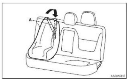
- Tip the armrest forward. Open the fastener (B) that is located in the space where the armrest was stowed.
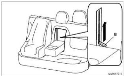
- Put your hand in the opening of the fastener, attach the tether strap's hook (C) to the tether anchorage (D), and securely tighten the tether strap.
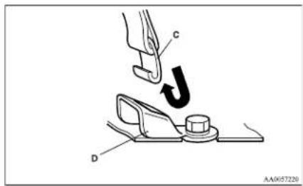
Installing a child restraint system to the lower anchorage (ISOFIX child restraint mountings)\*
E00408900114
Your vehicle's second seat is fitted with lower anchorages for attaching a child restraint system with ISOFIX mountings.
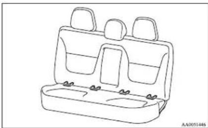
natural_image
Line drawing of a car backseat with three seats and two side seats (no text or symbols)Child restraint system with ISOFIX mountings
E00409000369
The child restraint system is designed only for seats that incorporate lower anchorages. Retain the child restraint system using the lower anchorages.
It is not necessary to retain the child restraint system using the vehicle's seat belts.
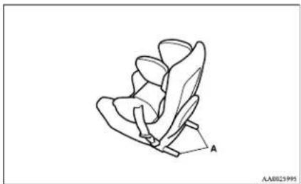
natural_image
Line drawing of a car seat with labeled point A (no text or symbols on the diagram itself)A- Child restraint system connectors
To install
WARNING
- If there is any foreign material in or around the connectors, remove it before installing the child restraint system. Also, make sure the seat belt is away from, not looped through or otherwise interfering with, the child restraint system. If foreign matter is not removed and/or the seat belt interferes with the child restraint system, the child restraint system will not be secured properly and could move forward in the event of sudden braking or a collision, seriously injuring the child and possibly other vehicle occupants.
- When the vehicle is moving do not adjust the seat where the child restraint system is installed.
Seat and seat belts
- Push the child restraint system's connectors into the lower anchorages (A) in accordance with the instructions provided by the child restraint system's manufacturer.
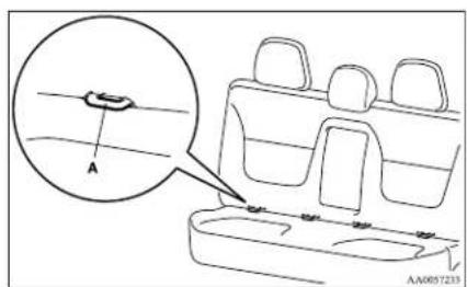
If your child restraint system requires the use of a tether strap, fasten the tether strap in accordance with the following procedures.
- Remove the head restraint from the location in which you wish to install a child restraint.
- Drop the child restraint's tether strap (B) down the back of the rear seatback.
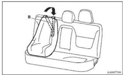
natural_image
Line drawing of a car interior showing seatbelt and belt (no text or symbols)Seat and seat belts
- Tip the armrest forward. Open the fastener (C) that's located in the space where the armrest was stowed.
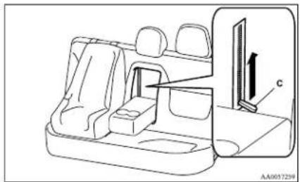
natural_image
Line drawing of a car backrest and side panel with a directional arrow indicating movement (no text or symbols)- Put your hand in the opening of the fastener, attach the tether strap's hook (D) to the tether anchorage (E), and securely tighten the tether strap.
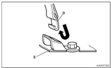
- Push and pull the child restraint system in all directions to be sure it is firmly secured.
To remove
Remove the child restraint in accordance with the instructions provided by the child restraint system's manufacturer.
Installing a child restraint system to a 3-point type seat belt (with emergency locking mechanism)
E00408700516
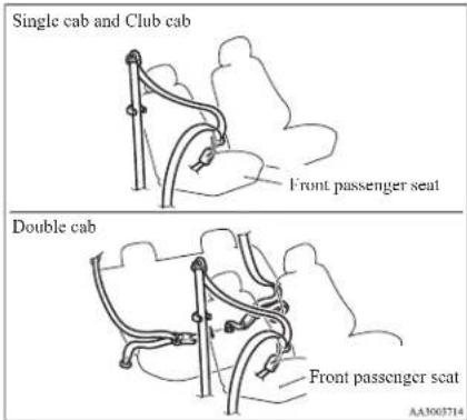
Installation:
- Fasten the seat belt to secure the child restraint system.
Make sure you hear a "click" when you insert the latch plate in the buckle. - Remove all slack by using the locking clip.
- Push and pull the child restraint in all directions to be sure it is secure.
WARNING
- For some types of child restraint, the locking clip (A) should be used to help avoid personal injury during a collision or sudden manoeuvre.
It must be fitted and used in accordance with the child restraint manufacturer's instructions.
The locking clip must be removed when the child restraint is removed.
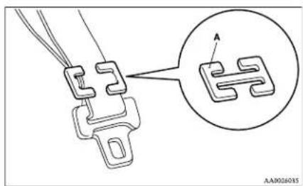
natural_image
Technical line drawing of a mechanical component with an inset showing a close-up view of a labeled section (no text or symbols present)Seat belt inspection
L00406300475
- Check the belts for cuts, worn or frayed webbing and for cracked or deformed metallic parts. Replace the belt assembly if defective.
● A dirty belt should be cleaned with neutral detergent in warm water. After rinsing in water, let it dry in the shade. Do not attempt to bleach or re-dye the belts because this affects their characteristics.
WARNING
- We recommend you have all seat belt assemblies including retractors and attaching hardware inspected after any collision. We recommend that seat belt assemblies in use during a collision be replaced unless the collision was minor and the belts show no damage and continue to operate properly.
- Do not attempt to repair or replace any part of the seat belt assemblies; we recommend you to have this work done by a MITSUBISHI MOTORS Authorized Service Point. Incorrect repair or replacement could reduce the effectiveness of the belts and could result in serious injury in the event of a collision.
- Once the pretensioner has activated, it cannot be re-used. It must be replaced together with the retractor.
Supplemental restraint system (SRS) - airbag\*
E00407201797
The information written in this Supplemental Restraint System (SRS) section contains important points concerning the driver, front passenger, side and curtain airbags.
The SRS driver and front passenger airbags are designed to supplement the primary protection of the driver and front passenger side seat belt systems by providing those occupants with protection against head and chest injuries in certain moderate-to-severe frontal collisions.
The SRS side airbag is designed to supplement the properly worn seat belts and provide the driver and front passenger with protection against chest injury in certain moderate-to-severe side impact collisions.
The SRS curtain airbags are designed to supplement the properly worn seat belts and provide the driver and passengers with protection against head injuries in certain moderate-to-severe side impact collisions.
The SRS is NOT a substitute for the seat belts; for maximum protection in all types of crashes and accidents, seat belts should ALWAYS be worn by everyone who drives or rides in this vehicle.
WARNING
● IT IS VERY IMPORTANT TO ALWAYS PROPERLY WEAR YOUR SEAT BELT, EVEN WITH AN AIRBAG:
WARNING
- Seat belts help keep the driver and passengers properly positioned, which reduces injury risk in all collisions, and reduces the risk of serious or fatal injuries when the airbags inflate. During sudden braking just before a collision, an unrestrained or improperly restrained driver or passengers can move forward into direct contact with or within close proximity to the airbag which may then deploy during the collision.
The initial stage of airbag inflation is the most forceful which could cause serious or fatal injuries if the occupant contacts it at this stage.
- Seat belts reduce the risk of injury in roll-overs, rear impact collisions, and in lower-speed frontal collisions, because driver's and passenger's airbags are not designed to inflate in those situations.
- Seat belts reduce the risk of being thrown from your vehicle in a collision or roll-over.
● IT IS VERY IMPORTANT TO BE PROPERLY SEATED.
A driver or front passenger too close to the steering wheel or instrument panel during airbag deployment can be killed or seriously injured.
Airbags inflate very fast, and with great force.
If the driver and front passenger are not properly seated and restrained, the air-
Seat and seat belts
WARNING
bags may not protect you properly, and could cause serious or fatal injuries when it inflates.
- Before driving, adjust the driver's seat as far back as possible while still maintaining complete control of the vehicle.
- Before driving, adjust the front passenger seat as far back as possible.
- Make sure all vehicle occupants are always properly restrained using the available seat belts.
- With seat belts properly fastened, the driver and passengers should sit well back and upright without leaning against the window or door.
- Do not sit on the edge of the seat, or lean head or chest close to the steering wheel or instrument panel.
Do not put feet or legs on or against the instrument panel.
WARNING
- Infants and small children should never be unrestrained, stand up against the instrument panel or be held in your arms or on your lap. They could be seriously injured or killed in a collision, including when the airbag inflates. They should be properly seated in an appropriate child restraint system. See the “Child restraint” section of this owner’s manual.
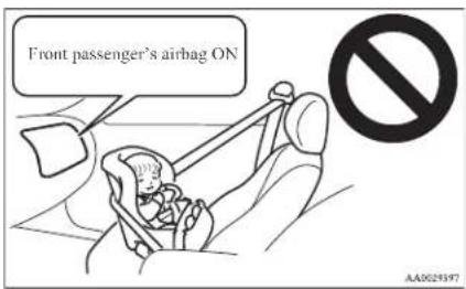
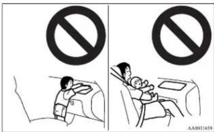
NOTE
- If you have a rearward facing child restraint system that cannot be fitted to any seat other than the front passenger seat, be sure to turn OFF the front passenger's airbag ON-OFF switch before using it. (Refer to "To turn an airbag off" on page 2-30.)
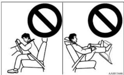
WARNING
- A REARWARD FACING CHILD RESTRAINT must NOT be used in the front passenger seat if the front passenger's airbag has not been deactivated. The force of an inflating airbag could kill or cause serious injuries to the child.
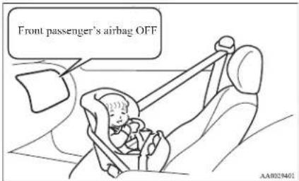

WARNING
● A FORWARD FACING CHILD RESTRAINT should not be used in the front passenger seat whenever possible; if used in the front passenger seat, adjust the seat to the most rearward position. Failure to do so could kill or cause serious injuries to the child.
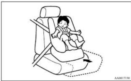
natural_image
Illustration of a baby sitting in a car seat with a diagonal guide line and arrow indicating direction (no text or symbols)
WARNING
● Older children should be seated, properly wearing the seat belt, with an appropriate booster seat if needed.
Caution for installing the child restraint on vehicles with a front passenger airbag
E00408800272
The label shown here is attached on vehicles with a front passenger airbag.
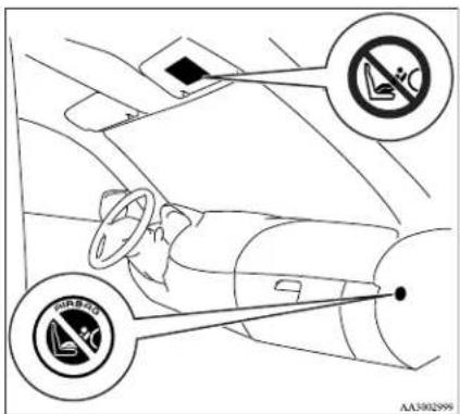
Do not use a rearward facing child restraint on a seat protected by an airbag in front of it!
How the Supplemental Restraint System works
E00407301352
The SRS includes the following components:
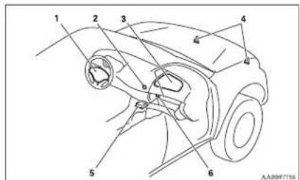
1- Airbag module (Driver)
2- Front passenger's airbag OFF indication lamp
3- Airbag module (Passenger)
4- Front impact sensors
5- Airbag control unit
6- Front passenger's airbag ON-OFF switch
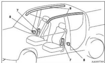
7- Side airbag modules
8- Side impact sensors
9- Curtain airbag modules
Seat and seat belts
The airbags will operate only when the ignition switch is in the "ON" or "START" position.
When the airbag control unit detect an impact of sufficient frontal or side force, it sends an ignition signal to the airbag modules to ignite materials in the inflator and generate gas and inflate the airbags.
The airbags deployment produces a sudden, loud noise, and releases some smoke and powder, but these conditions are not injurious, and do not indi-
cate a fire in the vehicle. People with respiratory problems may feel some temporary irritation from chemicals used to produce the deployment; open the windows after airbag deployment, if safe to do so.
The airbags deflate very rapidly after deployment, so there is little danger of obscured vision.
The time required from the sensors detecting an impact to deflation of the airbags after deployment is shorter than a blink of an eye.

CAUTION
● Airbags inflate at an extremely rapid speed. In certain situations, contact with inflating airbags can result in abrasions, light cuts, bruises, and the like.
Front passenger's airbag ON-OFF switch
ED0410100184
The front passenger's airbag ON-OFF switch can be used to disable the front passenger's airbag. If you have a rearward facing child restraint system that cannot be fitted to any seat other than the front passenger seat, be sure to turn OFF the front passenger's airbag ON-OFF switch before using it. (Refer to "To turn an airbag off" on page 2-30.)
The front passenger's airbag ON-OFF switch is located in the glove box.
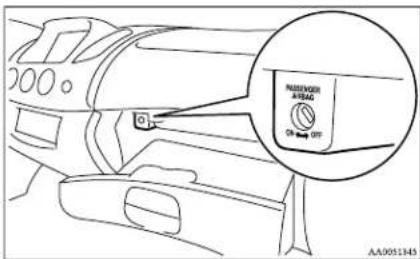

WARNING
● To reduce risk of serious or fatal injury:
- Always remove the key from the ignition switch before operating a front passenger's airbag ON-OFF switch. Failure to do so could adversely affect the airbag performance.
- Wait at least 60 seconds to operate the front passenger's airbag ON-OFF switch after turning the ignition switch from "ON" position to "LOCK" position.
The SRS airbag system is designed to retain enough voltage to deploy the airbag.

WARNING
- Always remove the key from the front passenger's airbag ON-OFF switch after operating that switch. Failure to do so could lead to improper position of the front passenger's airbag ON-OFF switch.
To turn an airbag off
E00410600219
To turn an airbag off, follow these steps:
- Insert the key into the key opening of the appropriate front passenger's airbag ON-OFF switch, and turn that airbag ON-OFF switch to the "OFF" position.
- Remove the key from the key opening of the front passenger's airbag ON-OFF switch.
- Insert the key into the ignition switch, and turn the ignition to the "ON" position.
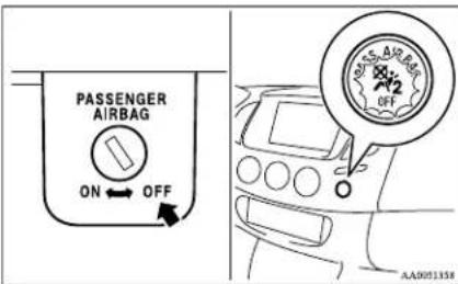
The front passenger's airbag OFF indication lamp will stay on to show that the front passenger's airbag is not operational. ("Front passenger's airbag OFF indication lamp" on page 2-31)
That airbag will remain OFF, and will NOT deploy, until it is turned ON again.
WARNING
● To reduce risk of serious or fatal injury:
- If the indication lamp does not come on when the front passenger's airbag ON-OFF switch is turned OFF, do not fit a rearward facing child restraint system to the front passenger seat.
- Do not turn OFF the front passenger's airbag ON-OFF switch except when a rearward facing child restraint system is fitted to the front passenger seat.
To turn an airbag on
E00410700106
To turn an airbag on, follow these steps:
- Insert the key into the key opening of the appropriate front passenger's airbag ON-OFF switch, and turn that airbag ON-OFF switch to "ON" position.
-
Remove the key from the key opening of that front passenger's airbag ON-OFF switch.
-
Insert the key into the ignition switch, and turn the ignition to the "ON" position.
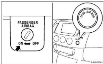
The front passenger's airbag OFF indication lamp goes off to show that the front passenger's airbag is operational.
That airbag will remain ON, and will be ready to deploy, until it is again turned OFF.
WARNING
● To reduce risk of serious or fatal injury:
- Turn ON the front passenger's airbag ON-OFF switch immediately after removing a rearward facing child restraint system from the front passenger seat.
- If the indication lamp remains on when the front passenger's airbag ON-OFF switch is turned ON, do not allow anyone to sit on the front passenger seat.
Front passenger's airbag OFF indication lamp
E00410200257
The front passenger's airbag OFF indication lamp is located in the instrument panel.
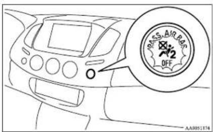
When the front passenger's airbag ON-OFF switch is turned OFF, the indication lamp will stay on to show that the front passenger's airbag is not operational.
When the front passenger's airbag ON-OFF switch is turned ON, the indication lamp goes off to show that the front passenger's airbag is operational.
WARNING
- If the indication lamp behaves in any of the following ways, there may be a fault in the airbag system.
Have the vehicle inspected at a MITSUBISHI MOTORS Authorized Service Point as soon as possible.
Seat and seat belts

WARNING
- The indication lamp does not come on when the front passenger's airbag ON-OFF switch is turned OFF.
- The indication lamp stays on when the front passenger's airbag ON-OFF switch is turned ON.

WARNING
- Do not fit any accessory that makes the indication lamp impossible to see, and do not cover the indication lamp with a sticker. You would not be able to verify the status of the passenger airbag system.
Driver's and passenger's front airbag system
F00407400330
The driver's airbag is located under the padded cover in the middle of the steering wheel. The front passenger's airbag is contained in the instrument panel above the glove box.
The driver's airbag and the front passenger's airbag are designed to inflate at the same time even if the passenger seat is not occupied.
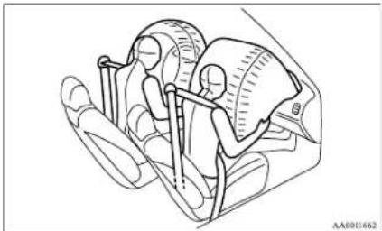
natural_image
Medical illustration of a human head with surgical instruments and measurement scales (no text or labels)Deployment of front airbags
L00407501354
The front airbags ARE DESIGNED TO DEPLOY when...
Head-on collision with a solid wall at speed of approximately 25 km/h (16 mph) or higher
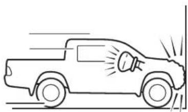
natural_image
Line drawing of a pickup truck with motion lines indicating speed (no text or symbols)Moderate to severe frontal impact within the shaded area between the arrows
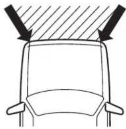
natural_image
Top-down diagram of a car's front view showing dashboard and rearview (no text or symbols)AA1002966
The front airbags are designed to deploy when the vehicle suffers a moderate to severe frontal impact. A typical condition is shown in the illustration.
The front airbags will deploy if the severity of impact is above the designed threshold level, comparable to an approximately 25 km/h (16 mph) collision when impacting straight into a solid wall that does not move or deform. If the severity of the impact is below the above threshold level, the front airbags may not deploy. However, this threshold speed will be considerably higher if the vehicle strikes an object that absorbs the impact by either deforming or moving (for example, another stationary vehicle, pole or a guard rail).
Because frontal collisions can easily move you out of position, it is important to always properly wear your seat belts. Your seat belts will help keep you in a safe distance from the steering wheel and instrument panel during the initial stages of airbag deployment. The initial stage of airbag inflation is the most forceful, and can possibly cause serious or fatal injuries. Moreover, the seat belts in your vehicle are your primary means of protection in a collision. The SRS airbags are designed to provide additional protection. Therefore, for your safety and the safety of all occupants, be sure to always properly wear your seat belts.
The front airbags MAY NOT DEPLOY when...
With certain types of frontal collisions, the vehicle's body structure is designed to absorb the shock to help protect the occupants from harm. (The vehicle body's front area may deform significantly as it absorbs the impact.) Under such circumstances, the front airbags may not deploy irrespective of the deformation and damage to the vehicle body. Examples of some typical conditions are shown in the illustration.
Examples of some typical conditions are shown in the illustration.
Because the front airbags do not protect the occupant in all types of frontal collisions, be sure to always properly wear your seat belts.
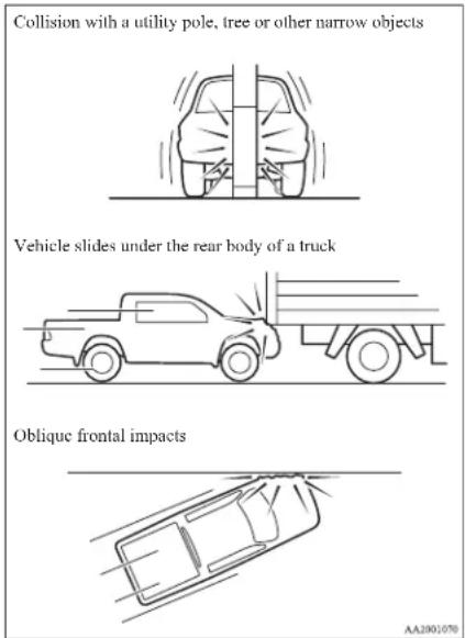
The front airbags ARE NOT DESIGNED TO DE- PLOY when...
The front airbags are not designed to deploy in conditions where they cannot typically provide protection to the occupant. Such conditions are shown in the illustration.
Seat and seat belts
Because the front airbags do not protect the occupant in all types of collisions, be sure to always properly wear your seat belts.
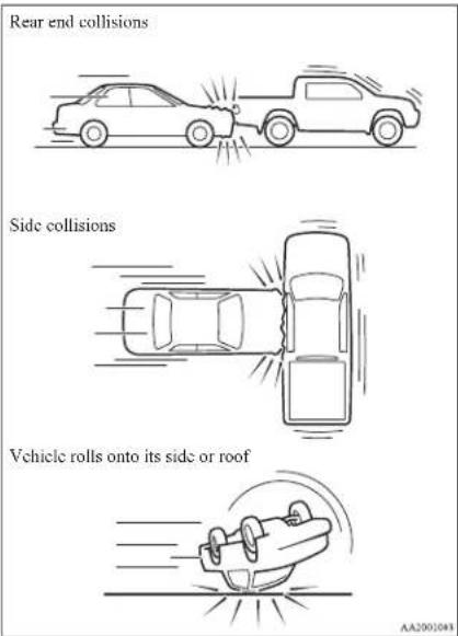
The front airbags MAY DEPLOY when...
The front airbags may deploy if the bottom of the vehicle suffers a moderate-to-severe impact (undercarriage damage).
Examples of some typical conditions are shown in the illustration.
Because the front airbags may deploy in certain types of unexpected impacts as shown in the illustration that can easily move you out of position, it is important to always properly wear your seat belts. Your seat belts will help keep you a safe distance from the steering wheel and instrument panel during the initial stages of airbag deployment. The initial stage of airbag inflation is the most forceful and can possibly cause serious or fatal injuries if you contact it at this stage.
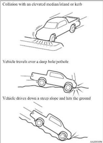
WARNING
- Do not attach anything to the steering wheel padded cover, such as trim material, badges, etc. It might strike and injure an occupant if the airbag inflates.
- Do not set anything on, or attach anything to, the instrument panel above the glove box. It might strike and injure an occupant if the airbag inflates.
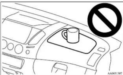
natural_image
Line drawing of a car interior showing a cup on the dashboard and a no-smoking symbol (no text or labels)WARNING
- Do not attach accessories to, or put them in front of, the windscreen. These objects could restrict the airbag inflation, or strike and injure an occupant if the airbags inflate.
- Do not put packages, pets or other objects between the airbags and the driver or front passenger. It could affect airbag performance, or could cause injury when the airbag inflates.

WARNING
● Right after the airbag inflation, several airbag system components will be hot. Do not touch them; you could be burned.
● The airbag system is designed to work only once. Once the airbags have deployed, they will not work again. They must promptly be replaced, and we recommend you to have the entire airbag system inspected by a MITSUBISHI MOTORS Authorized Service Point.
Side airbag system
E00407600374
The side airbags (A) are contained in the driver and front passenger seatbacks.
The side airbag is designed to inflate only on the side of the vehicle that is impacted, even with no passenger in the front seat.
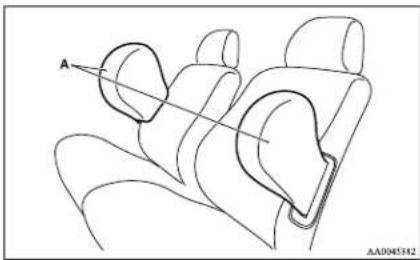
natural_image
Line drawing of a car interior showing seat, neck, and jaw (no text or symbols)The label shown here is attached to the seatbacks with a side airbag.
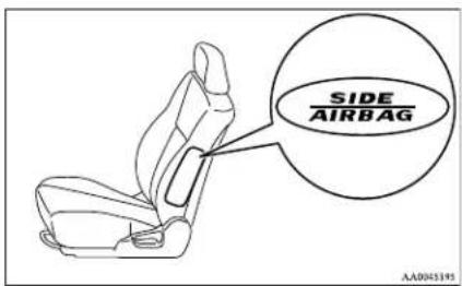
Curtain airbag system
E00409100474
The curtain airbags are contained in the front pillars and roof side rail. The curtain airbag is designed to inflate only on the side of the vehicle that is impacted, even with no passenger in the front seat or rear seat.
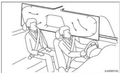
natural_image
Line drawing of two people seated in a car, viewed from the side (no text or symbols)Deployment of side airbags and cur- tain airbags
E00407701011
The side airbags and curtain airbags ARE DESIGNED TO DEPLOY when...
The side airbags and curtain airbags are designed to deploy when the vehicle suffers a moderate-to-severe side impact to the middle of the passenger compartment.
The typical condition is shown in the illustration.
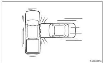
natural_image
Top-down line drawing of a car with motion lines indicating speed or flow (no text or symbols)The seat belts in your vehicle are your primary means of protection in a collision. The SRS side airbags and curtain airbags are designed to provide additional protection. Therefore, for your safety and the safety of all occupants, be sure to always properly wear your seat belts.
Seat and seat belts
The side airbags and curtain airbags MAY NOT DEPLOY when...
With certain types of side collisions, the vehicle's body structure is designed to absorb the shock to help protect the occupants from harm. (The vehicle body's side area may deform significantly as it absorbs the impact.) Under such circumstances, the side airbags and curtain airbags may not deploy irrespective of the deformation and damage to the vehicle body.
Examples of some typical conditions are shown in the illustration.
Because the side airbags and curtain airbags do not protect the occupant in all types of side collisions, be sure to always properly wear your seat belts.
Side impacts in an area away from the passenger compartment
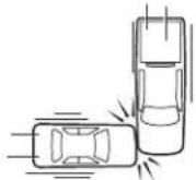
Motorcycle or other similar small vehicle collides with the side of vehicle
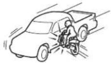
Collision with a utility pole, tree or other narrow object
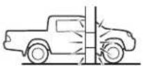
AA2001897
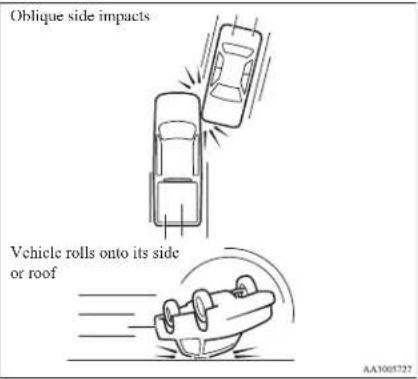
The side airbags and curtain airbags ARE NOT DESIGNED TO DEPLOY when...
The side airbags and curtain airbags are not designed to deploy in conditions where they cannot usually provide protection to the occupant. Typical conditions are shown in the illustration.
1Head-on collisions
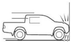
Rear end collisions
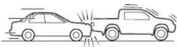
AA3065730
Because the side airbags and curtain airbags do not protect the occupant in all types of collisions, be sure to always properly wear your seat belts.

WARNING
● The side airbags and curtain airbags are designed to supplement the driver and passenger seat belts in certain side impacts. Seat belts should always be worn properly, and the driver and passenger should sit well back and upright without leaning against the window or door.
WARNING
● The side airbags and curtain airbags inflate with great force. The driver and front passenger should not put their arms out the window, and should not lean against the door, in order to reduce the risk of serious or possible fatal injury from the deploying side airbag and curtain airbag.
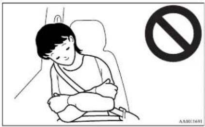
WARNING
- Do not allow a child to kneel on the passenger seat facing the passenger's side door, since the side airbags and curtain airbags inflate with great force. Otherwise, the child may be killed or seriously injured.
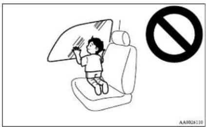
WARNING
- Do not allow any rear seat occupant to hold onto the seatback of either front seat, in order to reduce risk of injury from the deploying side airbag. Special care should be taken with children.
- Do not place any objects near or in front of the seatback of either front seat. They could interfere with proper side airbag inflation, and also could cause injury if thrown free by side airbag deployment.
- Do not place stickers, labels or additional trim on the seatback of either front seat. They could interfere with proper side air-bag inflation.
- Do not install seat covers on seats with side airbags. Do not re-cover seats that have side airbags. This could interfere with proper side airbag inflation.
Seat and seat belts
WARNING
- Do not attach a microphone (A) or any other device or object around the part where the curtain airbags (B) activate such as on the windscreen, side door glass, front and rear pillars and roof side or assist grips. When the curtain airbags inflate, the microphone or other device or object will be hurled with great force or the curtain airbags may not activate correctly, resulting in death or serious injury.
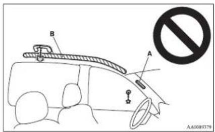
WARNING
- Do not put a hanger or any heavy or pointed object on the coat hook.
If the curtain airbag was activated, any such item could be propelled away with great force and could prevent the curtain airbag from inflating correctly. Hang clothes directly on the coat hook (without using a hanger).
Make sure there are no heavy or sharp objects in the pockets of clothes that you hang on the coat hook. - Do not allow a child to lean against or close to the front door even if the child is seated in a child restraint system.
The child's head should also not be leaned against or be close to the area of the seat where the side airbag and curtain airbag are located. It is dangerous if the side airbag and curtain airbag inflate. Failure to follow all of these instructions could lead to serious or fatal injury to the child. - We recommend work around and on the side airbags and curtain airbags system to be done by MITSUBISHI MOTORS Authorized Service Point. Improper work could result in inadvertent deployment of a side airbags and curtain airbags, or could render a side airbags and curtain airbags inoperative; either situation could result in serious injury.
SRS warning lamp
E00407801201
There is a Supplemental Restraint System ("SRS") warning lamp on the instrument panel. The system checks itself and the lamp tells you if there is a problem. When the ignition switch is turned to the "ON" or "START" position, the warning lamp should illuminate for several seconds and then should go out. This means the system is ready. If an SRS airbag or pretensioner seat belt is not operating properly, the warning lamp comes on and stays on.
The SRS warning lamp is shared by the SRS airbag and the seat belt pretensioner system.
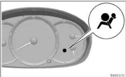
natural_image
Diagram of a mechanical device with a magnified inset showing a person in a chair (no text or symbols present)WARNING
- If any of the following conditions occur, the SRS and/or seat belt pretensioners are not working properly, and we recommend you to have it inspected by a MITSUBISHI MOTORS Authorized Service Point immediately.

WARNING
• The SRS warning lamp does not illuminate when you start the vehicle.
- The SRS warning lamp does not go out after several seconds.
• The SRS warning lamp illuminates while driving.
SRS servicing
E00407901244

WARNING
We recommend any maintenance performed on or near the components of the SRS to be performed by a MITSUBISHI MOTORS Authorized Service Point. Improper work on the SRS components or wiring could result in inadvertent deployment of the airbags, or could render the SRS inoperative; either situation could result in serious injury.
- Do not modify your steering wheel, seat belt retractor or any other SRS components. For example, replacement of the steering wheel, or modifications to the front bumper or body structure can adversely affect SRS performance and lead to possible injury.
- If your vehicle has sustained any damage, we recommend you to have the SRS inspected to ensure it is in proper working order.

WARNING
● On vehicles equipped with side airbags, do not modify your front seats, centre pillar and centre console.
It can adversely affect SRS performance and lead to possible injury.
Also, if you have found any tear or open seam in the seat fabric at the portion near the side airbag, we recommend you to have the seat inspected.
- On vehicles with the curtain airbags, if you have found any scratch, crack or damage to the portion of the front and rear pillars and roof side rail, we recommend you to have the SRS inspected by a MITSUBISHI MOTORS Authorized Service Point.
NOTE
- When you transfer ownership of the vehicle to some other person, we urge you to alert the new owner that it is equipped with the SRS and refer the new owner to the applicable section in this owner's manual.
- If you junk or scrap the vehicle, we urge you to first take the vehicle to a MITSUBISHI MOTORS Authorized Service Point so that the SRS can be rendered safe.
| 10.2 | 10.3 | 10.4 | 10.5 | 10.6 | 10.7 | 10.8 | 10.9 | 11.0 | 11.1 | 11.2 | 11.3 | 11.4 | 11.5 | 11.6 | 11.7 | 11.8 | 11.9 | 12.0 |
Instruments and controls
Instruments....3-02
Indication and warning lamps....3-06
Indication lamps....3-07
Warning lamps....3-08
Centre information display*....3-10
Combination headlamps and dipper switch....3-30
Headlamp levelling switch*....3-32
Turn-signals lever....3-33
Hazard warning flasher switch....3-34
Front fog lamp switch* 3-34
Rear fog lamp switch....3-35
Wiper and washer switch....3-36
Rear window demister switch....3-40
Horn switch....3-40
Instruments and controls
Instruments
E00500100876
Type A Type B
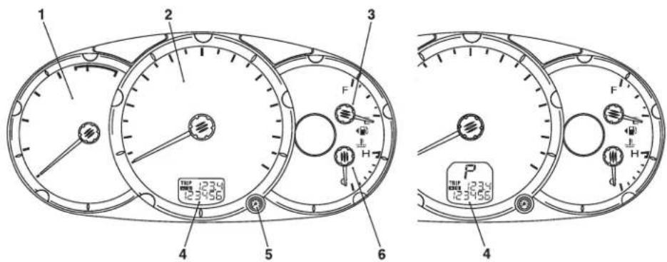
1- Tachometer
2- Speedometer
3- Fuel gauge
4- Odometer/Tripmeter
5- Tripmeter reset button/Daytime dipper button*
6- Water temperature gauge
Speedometer
E00500200880
Indication for km/h
The speedometer indicates the vehicle's speed in kilometers per hour (km/h).
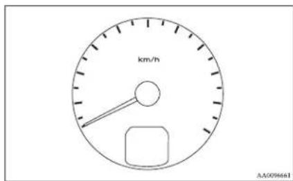
Indication for km/h and mph
The speedometer indicates the vehicle's speed in miles per hour (mph) and kilometers per hour (km/h).
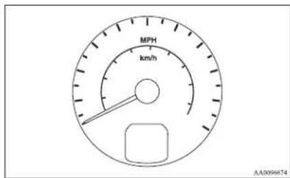
Tachometer
E00500300780
The tachometer indicates the engine speed (r/min). The tachometer can help you obtain more economical driving and also warns you of excessive engine speeds.
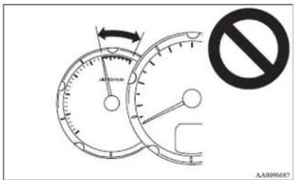
CAUTION
- When driving, watch the tachometer to make sure that the engine speed indication does not rise into the red zone (excessive engine rpm).
Odometer/Tripmeter
E00500601113
When the ignition switch is in the "ON" position, odometer and tripmeter indications are given.
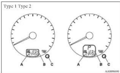
A-Odometer
B- Tripmeter
C- Reset button
Odometer
The odometer indicates the total distance the vehicle has travelled.
Tripmeter
The tripmeter indicates the distance travelled during a particular trip or period.
There are two tripmeter displays: TRIP A and B.
TRIP A can be used to measure the distance travelled since the current trip began. At the same time, TRIP B can be used to measure the distance from an intermediate location.
Instruments and controls
Every time the reset button (C) is pressed lightly (less than 1 second), the tripmeter display changes (between TRIP And ). B
To reset the tripmeter
To return the display to "0", press the reset button (C) for more than 1 second. Only the currently displayed value will be reset. If TRIP A is displayed, for example, only TRIP A will be reset.
NOTE
● Display TRIP And each have a maximum distance of 999.9 km (999.9 miles)
- When disconnecting the battery terminal for a long time, the memory of tripmeter display TRIP And are cleared, and the display returns to "0".
Fuel gauge
E00500700902
The fuel gauge indicates the fuel level in the fuel tank when the ignition switch is in the "ON" position.
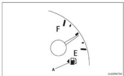
F-Full
E- Empty
NOTE
- When the engine on diesel-powered vehicles fails to operate due to running out of fuel, it may sometimes be difficult to start after refueling. This is due to air entering the fuel system. Therefore, air must be bled from the system. (Refer to “Bleeding the fuel system” on page 6-05.)
Fuel lid mark
The fuel lid mark (A) indicates that the fuel tank filler door is located on the left side of the vehicle (Refer to "Filling the fuel tank" on page 02).
Low fuel warning lamp
F00508100739
The warning lamp (A) comes on when the fuel level is getting low (approx. 11 litres) with the ignition switch in the "ON" position. Refuel as soon as possible.
natural_image
Technical line drawing of a mechanical component with no visible text or symbolsNOTE
● On inclines or curves, due to the movement of fuel in the tank, the low fuel warning lamp may indicate incorrectly.
Water temperature gauge
E00500800479
The water temperature gauge indicates the engine coolant temperature when the ignition switch is in the "ON" position.
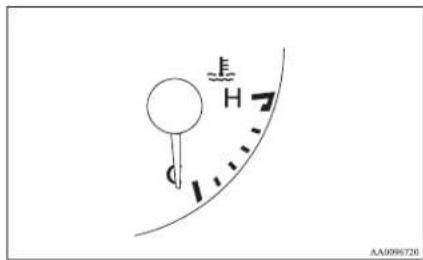
Turn the dial to adjust the illumination (meter, multi centre display, audio system's control panel, heater control panel, etc.) to the desired brightness.
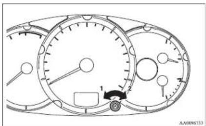
1- To reduce brightness
2- To increase brightness
CAUTION
- If the indication needle enters the H zone while the engine is running, it indicates that the engine is possibly overheating. Immediately park your vehicle in a safe place and make the necessary corrections. (Refer to "Engine overheating" on page 6-04.) While driving, care should always be taken to maintain the normal operating temperature.
Daytime dipper button (meter illumination control)\*
1-00508800273
The rheostat can be adjusted while the headlamps or tail lamps turn on.
Instruments and controls
Indication and warning lamps
E00501502002
Type 1 Type 2
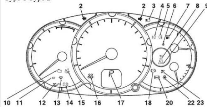
- CRUISE indication lamp* → p. 4-49
- Turn-signal indication lamps/Hazard warning indication lamps → p. 3-07
- High-beam indication lamp → p. 3-07
- Front fog lamp indication lamp* → p. 3-07
- Rear fog lamp indication lamp → p. 3-07
- Seat belt reminder/warning lamp → p. 2-10
- Low fuel warning lamp → p. 3-04
- 2WD/4WD operation indication lamp* → p. 4-27, 4-32
- Rear differential lock indication lamp* → p. 4-34
- Check engine warning lamp → p. 3-08
- Diesel preheat indication lamp → p. 3-07
-
Oil pressure warning lamp → p. 3-09
-
Fuel filter indication lamp → p. 3-07
- Charge warning lamp → p. 3-09
- A/T (automatic transmission) fluid temperature warning lamp (vehicles with A/T) → p. 4-18
- Overdrive off indication lamp (vehicles with 4A/T) → p. 4-18
- Selector lever position indicator (vehicles with A/T) → p. 4-16, 4-23
- Brake warning lamp → p. 3-08
- Active Stability & Traction Control (ASTC) OFF indication lamp* → p. 4-47
- Anti-lock brake system (ABS) warning lamp* → p. 4-44
- Active Stability & Traction Control (ASTC) indication lamp* → p. 4-47
- Door ajar warning lamp → p. 3-09
- Supplement Restraint System (SRS) warning lamp → p. 2-38
Instruments and controls
Indication lamps
L00501600012

Turn-signal indication lamps/ Hazard warning indication lamps
E00501700185
These indication lamps blink on and off when a turn-signal lamp is operating.
NOTE
- If the blinking is too fast, the cause may be a blown lamp bulb or a faulty turn-signal connection.
When the hazard warning lamp switch is pressed, all turn-signal lamps will flash on and off continuously.

High-beam indication lamp
E00501800115
This indication lamp illuminates when the high-beam is used.

Front fog lamp indication lamp\*
E00501900347
This indication lamp illuminates while the front fog lamps are on.

Rear fog lamp indication lamp
L00502000114
This indication lamp illuminates while the rear fog lamp is on.

Diesel preheat indication lamp
E00502300250
This indication lamp illuminates when the ignition switch is placed in the "ON" position. As the glow plug becomes hot, the lamp goes out and the engine can be started.

CAUTION
- If the diesel preheat indication lamp comes on after the engine is started, the engine speed may not rise above the idling speed because of fuel freezing. In this case, keep the engine idling for about ten minutes, then turn off the ignition switch and immediately turn it on again to confirm that the diesel preheat indication lamp is off.
NOTE
- If the engine is cold, the diesel preheat indication lamp is on for a longer time.
- When the engine has not been started within about 5 seconds after the diesel preheat indication lamp went out, return the ignition switch to the "LOCK" position. Then, turn the switch to the "ON" position to preheat the engine again.
- When the engine is warm, the diesel preheat indication lamp does not come on even if the ignition switch is placed in the "ON" position.

Fuel filter indication lamp
ED05(099)(017)
This indication lamp illuminates when the ignition switch is turned to the "ON" position and goes off after the engine has started. If it lights up while the engine is running, it indicates that water has accumulated inside the fuel filter; if this happens, remove the water from the fuel filter.
Refer to “Removal of water from the fuel filter” on page 6-06.
When the lamp goes out, you can resume driving. If it either does not go out or comes on from time to time, we recommend you to have the vehicle inspected.
Instruments and controls
Warning lamps
E00502400017

Brake warning lamp
100502501637
This lamp illuminates when the ignition switch is turned to the "ON" position, and goes off after a few seconds.
Always make sure that the lamp goes off before driving.
With the ignition switch in the "ON" position, the brake warning lamp illuminates under the following conditions:
● When the parking brake lever has been engaged.
● When the brake fluid level in the reservoir falls to a low level.
- When the brake force distribution function is not operating correctly. (vehicles with anti-lock brake system)

CAUTION
- In the situations listed below, brake performance may be compromised or the vehicle may become unstable if brakes are applied suddenly; consequently, avoid driving at high speeds or applying the brakes suddenly. Furthermore, immediately the vehicle should be brought to a stop in a safe location and to have it checked.

CAUTION
• The brake warning lamp does not illuminate when the parking brake is applied or does not turn off when the parking brake is released.
- The ABS warning lamp and brake warning lamp illuminate at the same time. For details, refer to “ABS warning lamp” on page 4-44. (vehicles with anti-lock brake system)
• The brake warning lamp remains illuminated during driving.
● The vehicle should be brought to a halt in the following manner when brake performance has deteriorated.
- Depress the brake pedal harder than usual. Even if the brake pedal moves down to the very end of its possible stroke, keep it pressed down hard.
- Should the brakes fail, use engine braking to reduce your speed and carefully pull the parking brake lever to park your vehicle.
Depress the brake pedal to operate the stop lamp to alert the vehicles behind you.

Check engine warning lamp
E00502600657 This lamp is a part of an onboard diagnostic system which monitors the emissions, engine and automatic transmission control systems.
If a problem is detected in one of these systems, this lamp illuminates.
Although your vehicle will usually be drivable and not need towing, we recommend you to have the system checked as soon as possible.
This lamp will also illuminate for a few seconds when the ignition switch is turned to the "ON" position. If it does not go off after a few seconds, we recommend you to have the vehicle checked.

CAUTION
● Prolonged driving with this lamp on may cause further damage to the emission control system. It could also affect fuel economy and drivability.
- If the lamp does not illuminate when the ignition switch is turned to the "ON" position, we recommend you to have the system checked.

CAUTION
- If the lamp illuminates while the engine is running, avoid driving at high speeds and we recommend you to have the system checked.
During vehicle operation with the lamp illuminated, the vehicle may not accelerate when you depress the accelerator pedal.
When the vehicle is stationary with the lamp illuminated, you must depress the brake pedal more firmly than usual since the engine idling speed is higher than usual and the vehicle with an A/T has a stronger tendency to creep forward.

Charge warning lamp
E00502700821
This lamp illuminates when the ignition switch is turned to the "ON" position, and goes off after the engine has started.

CAUTION
- If the lamp comes on while the engine is running, the probable cause is as shown below. Park the vehicle immediately at a safe place and we recommend you to have it checked.
- Broken drive belt or abnormality in the charging system. A broken drive belt causes poor braking efficiency. Depress the brake pedal harder than usual to park the vehicle in a safe place.

CAUTION
- If this lamp illuminates when the engine oil level is not low, have it inspected.
● This warning lamp does not indicate the amount of oil in the crankcase. This must be determined by checking the oil level on the dipstick, while the engine is switched off. - If you continue driving with low engine oil level or with this warning lamp illuminated, engine seizure may occur.
NOTE
- The oil pressure warning lamp should not be treated as an indication of the engine's oil level. The oil level must be checked using the dipstick.
NOTE
● The engine electronic control module accommodating the onboard diagnostic system has various fault data (especially about the exhaust emission) stored.
This data will be erased if a battery cable is disconnected which will make a rapid diagnosis difficult. Do not disconnect a battery cable when the check engine warning lamp is ON.

Oil pressure warning lamp
This lamp illuminates when the ignition switch is turned to the "ON" position, and goes off after the engine has started. If it illuminates while the engine is running, the oil pressure is too low.
If the warning lamp illuminates while the engine is running, turn the engine off and have it inspected.

Door ajar warning lamp
100503300475 This lamp illuminates when a door is either open or not completely closed. If the vehicle speed reaches approximately 8 km/h (5 mph) with a door open or incompletely closed, the warning lamp flashes 16 times and a buzzer simultaneously sounds 16 times as a warning.
Instruments and controls

CAUTION
● Before moving your vehicle, check that the warning lamp is OFF.
NOTE
- It is possible to change the buzzer setting for either of the following types of operation. For further information, we recommend you to consult a MITSUBISHI MOTORS Authorized Service Point.
- No buzzer operation (buzzer disabled)
• Continuous buzzer operation
Centre information display\*
L00517800181

WARNING
- When operating the system for a prolonged period, make sure the vehicle is parked in a well ventilated area to avoid the accumulation of toxic fumes inside and outside of the passenger compartment.

CAUTION
- The driver should not operate the display while the vehicle is in motion. - When operating the system, stop the vehicle in a safe area.
When the ignition switch is turned to "ACC" position, the screen switches on automatically.
NOTE
- Placing a cellular phone in the monitor's small storage compartment may weaken the phone's reception. This does not indicate a fault with the system.
- Use of wireless devices such as transceivers or a cellular phone near the monitor may make the following condition on the display. This does not indicate a fault with the system.
• The screen goes dark temporarily.
- The compass may not show the correct direction.
- Depending on the angle of view, you may see reddish horizontal lines on the monitor. The lines are a characteristic of the vacuum fluorescent display (VFD) used in the monitor. They do not indicate a fault.
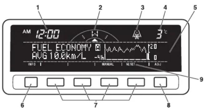
AA1006977
1- Clock → p. 3-19
Indicates the time.
2- Electronic compass
This display shows the direction of the vehicle.
3- Frozen road warning → p. 3-16
Gives an indication when the outside temperature is 3 °C or lower.
4- Outside temperature → p. 3-16
5- Centre information display indications
Indicates details of each display.
6- "INFO" button
Used to select various kinds of information for display.
7- Function buttons
Press this button to select options shown in the display.
8- "ADJ" button
Used for adjusting the clock and for selecting settings displays.
9- Display for function buttons
This display shows the options available for each function button.
Instruments and controls
Adjusting the time
E00518000063
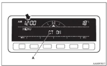
Following modes are available for clock adjustment:
● For vehicles with MITSUBISHI genuine audio:
"Automatic mode" and "Manual mode"
● Except for vehicles with MITSUBISHI genuine audio:
"Manual mode" only
Automatic mode (MITSUBISHI genuine audio)
The automatic adjustment mode can set the local time automatically by using the signal from the local RDS stations. In this mode, “CT” (A) (Clock Time: sent with the RDS signal) is shown in the audio display.
NOTE
● Automatic clock adjustment does not take place while a settings display is shown.
Manual mode
The manual mode is also available in case the automatic mode shows the incorrect time when the adjacent local RDS stations are located in a different time zone. Refer to “Radio data system (RDS)” on page 5-18.
It is possible to manually adjust the time. Refer to “Changing the clock settings” on page 3-19.
Changing the information display
E00517900124 Every time the "INFO" button is pressed lightly, the display can be changed to the following:
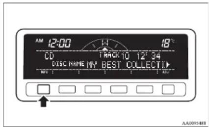
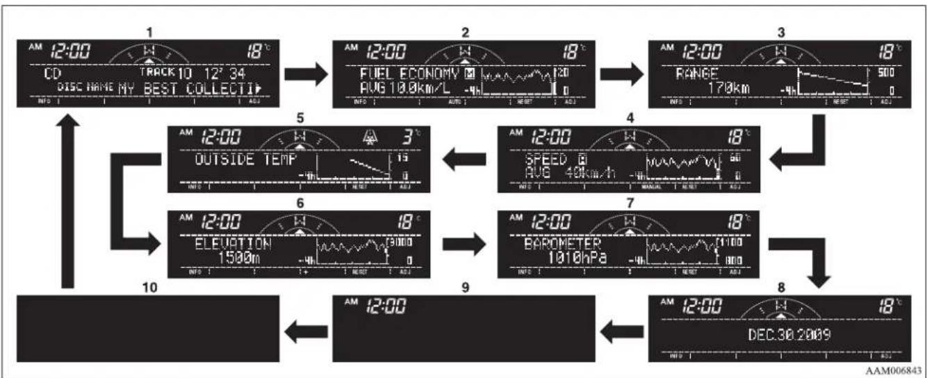
flowchart
graph TD
    A["1 AM 12:00"] --> B["2 AM 12:00"]
    B --> C["3 AM 12:00"]
    C --> D["4 AM 12:00"]
    D --> E["5 AM 12:00"]
    E --> F["6 AM 12:00"]
    F --> G["7 AM 12:00"]
    G --> H["8 AM 12:00"]
    H --> I["9 AM 12:00"]
    I --> J["10 AM 12:00"]

    subgraph Time_Steps
        K["CD TRACK 10 12° 34 DISCH NAME MY BEST COLLECTIP"] --> L["FUEL ECONOMY AVG 10.9km/L -4h"]
        M["RANGE 170km"] --> N["SPEED AVG 40km/h"]
        O["DEC 30 2009"] --> P["BAROMETER 1010hPa"]
    end

    subgraph Mode_Steps
        Q["OUTSIDE TEMP"] --> R["15"]
        S["ELEVATION 1500m"] --> T["3000"]
        U["TIME"] --> V["TIME"]
    end

    style A fill:#f9f,stroke:#333
    style B fill:#f9f,stroke:#333
    style C fill:#f9f,stroke:#333
    style D fill:#f9f,stroke:#333
    style E fill:#f9f,stroke:#333
    style F fill:#f9f,stroke:#333
    style G fill:#f9f,stroke:#333
    style H fill:#f9f,stroke:#333
    style I fill:#f9f,stroke:#333
    style J fill:#f9f,stroke:#333
    style K fill:#ccf,stroke:#333
    style L fill:#ccf,stroke:#333
    style M fill:#ccf,stroke:#333
    style N fill:#ccf,stroke:#333
    style O fill:#ccf,stroke:#333
    style P fill:#ccf,stroke:#333
    style Q fill:#cfc,stroke:#333
    style R fill:#cfc,stroke:#333
    style S fill:#cfc,stroke:#333
    style T fill:#cfc,stroke:#333
    style U fill:#cfc,stroke:#333
    style V fill:#cfc,stroke:#333
    style W fill:#cfc,stroke:#333
    style X fill:#cfc,stroke:#333
    style Y fill:#cfc,stroke:#333
    style Z fill:#cfc,stroke:#333
1- Audio information → p. 5-13
2- Average fuel consumption → p. 3-14
3- Driving range → p. 3-14
4- Average speed → p. 3-15
5- Outside temperature → p. 3-16
6- Altimeter → p. 3-16
7- Barometer → p. 3-17
8- Calendar → p. 3-18
9- Clock-only → p. 3-18
10- Blank → p. 3-18
Instruments and controls
Average fuel consumption
E00518200166
The average fuel consumption during the period since the last reset is shown in (A) and the momentary fuel consumption in (C). The average value of the fuel consumption is graphed every 5 minutes and the data for up to 4 hours are shown in (B). When you press the "MANUAL" function button in the auto reset mode, the mode will be changed to the manual reset mode. When you press the "AUTO" function button in the manual reset mode, the mode will be changed to the auto reset mode.
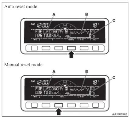
NOTE
- When you turn the ignition switch to the "ON" position after turning it from the "ON" position to the "ACC" or "LOCK" position in the manual reset mode, the auto reset mode will automatically be selected.
- When the average fuel consumption cannot be calculated, “--.-” will be shown.
● The average and momentary fuel consumption change depending on the driving condition (road condition, driving behavior, etc.). The indications may differ from the actual fuel consumption. Therefore, it is recommended to use the indications as reference. - The unit indication can be changed to your desired setting {km/L, L/100 km, mpg (UK GALLON), or mpg (US GALLON)}. Refer to “User customization” on page 3-24.
Resetting the average fuel consumption
Press the "RESET" function button to reset the average fuel consumption indication.
NOTE
● The average fuel consumption can be reset separately for the auto reset mode and for the manual reset mode.
- When you turn the ignition switch to the "ON" position about 4 hours (or more) after turning it from the "ON" position to the "ACC" or "LOCK" position in the auto reset mode, the average fuel consumption indication will automatically be reset.
Driving range
E00518300095
This value (A) shows the distance (in km or miles) that can be driven on the fuel remaining in the fuel tank. The driving range is graphed every 5 minutes and the data for up to 4 hours are shown in (B).
NOTE
- When the driving range is 50 km (30 miles) or less, the display shows “----”.
When it is 3,000 km (2,000 miles) or more, "3,000 km" or "2,000 miles" will be shown. - When the driving range cannot be measured, the display shows “----”.
● The driving range is shown based on the accumulated fuel consumption data, however, may be changed depending on the driving condition (road condition, driving behavior, etc.). If the battery terminals are disconnected, the accumulated fuel consumption data will be erased. It is recommended to use the indication as reference.
- When the vehicle is fueled, the driving range will be updated. However, if the amount of fueling is small, the indication may not be correct. Therefore, fill up the tank as much as possible in case of fueling.
- When the vehicle is stopped on a steep slope, the value of the driving range may increase. This is caused by the fuel movement inside the tank on the slope and is not deemed as a failure.
Resetting the driving range
Press the “RESET” function button to reset the driving range plotted in graph.
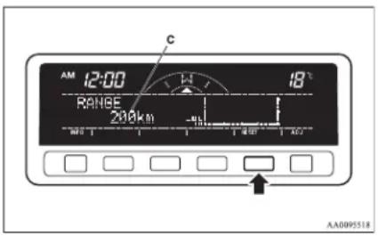
NOTE
- Pressing the "RESET" function button will not reset the indication (C).
- It is possible to set the display unit to km or miles.
Refer to "User customization" on page 3-24.
Average speed
E00518400126
The average speed during the period since the last reset is shown in (A) and the momentary speed in (C). The average value of the vehicle speed is graphed every 5 minutes and the data for up to 4 hours are shown in (B).
When you press the "MANUAL" function button in the auto reset mode, the mode will be changed to the manual reset mode. When you press the "AUTO" function button in the manual reset mode, the mode will be changed to the auto reset mode.
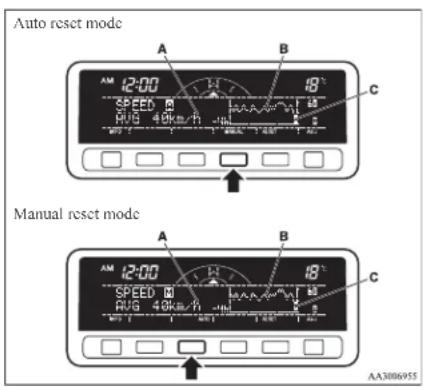
- When you turn the ignition switch to the "ON" position after turning it from the "ON" position to the "ACC" or "LOCK" position in the manual reset mode, the auto reset mode will automatically be selected.
- When the average speed cannot be calculated, “---” will be shown.
● The average and momentary speed change depending on the driving condition (road condition, driving behavior, etc.). The indications may differ from the actual speed. Therefore, it is recommended to use the indications as reference. - The unit indication can be changed to your desired setting (km/h or mph). Refer to “User customization” on page 3-24.
Resetting the average speed
Press the "RESET" function button to reset the average vehicle speed.
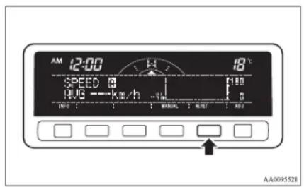
Instruments and controls
NOTE
● The average speed can be reset separately for the auto reset mode and for the manual reset mode.
- When you turn the ignition switch to the "ON" position about 4 hours (or more) after turning it from the "ON" position to the "ACC" or "LOCK" position in the auto reset mode, the average speed indication will automatically be reset.
Outside temperature
ED0518500097
The outside temperature is graphed every 5 minutes and the data for up to 4 hours are shown in (A). The current outside temperature is shown in (B).
Resetting the outside temperatur
Press the "RESET" function button to reset the graph of the outside temperature.
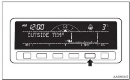
When the outside air temperature drops below about 3 ^ ( 37 ^ ), the alarm sounds and the outside air temperature warning symbol (A) flashes for about 10 seconds.
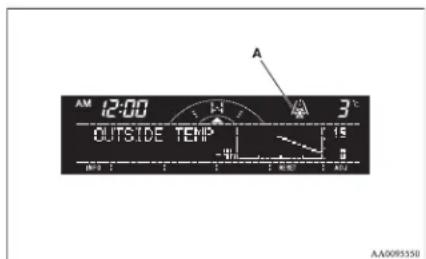
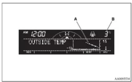
NOTE
● Depending on factors such as the driving conditions, the displayed temperature may vary from the actual outside temperature.
- It is possible to set the display unit to °C or °F. Refer to “User customization” on page 3-24.
Frozen road warning
This shows the temperature outside the vehicle.

CAUTION
● There is a danger the road might be icy, even when this symbol is not flashing, so please take care when driving.
Altimeter
F00518600069
The current elevation in units of 100 m (400 ft) is shown in (A). The elevation is graphed every 5 minutes and the data for up to 4 hours are shown in (B).
To adjust the elevation
It is possible to adjust the currently indicated elevation using the following function buttons:
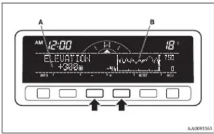
“+”- Adjustment of elevation
The elevation increases by 100 m (400 ft) every time you lightly push the “+” button.
If you continue pressing the button for about 2 seconds or more, the elevation indication is fast-forwarded. Then the setting is changed to the elevation selected.
“-”- Adjustment of elevation
The elevation decreases by 100 m (400 ft) every time you lightly push the “-” button.
If you continue pressing the button for about 2 seconds or more, the elevation indication is fast-forwarded. Then the setting is changed to the elevation selected.
NOTE
● The elevation is determined from changes in atmospheric pressure. Depending on weather conditions, the indicated elevation may differ from the actual elevation. Variations in atmospheric pressure can cause different elevations to be shown even in the same location. This behavior does not indicate a fault. Use the indication as a guide only.
Resetting the elevation
Press the “RESET” function button to reset the elevation plotted in graph.
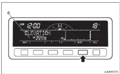
NOTE
- Pressing the "RESET" function button will not reset the indication (C).
- It is possible to set the display unit to m or ft. Refer to "User customization" on page 3-24.
Barometer
E00518700044
This display shows the atmospheric pressure at the present location in (A). The atmospheric pressure values are graphed every 5 minutes and the data for up to 4 hours are shown in (B).
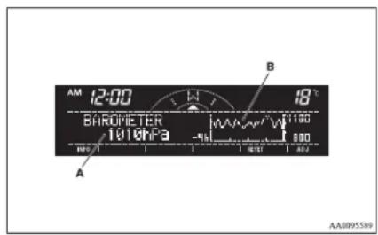
Resetting the atmospheric pressure
Press the "RESET" function button to reset the atmospheric pressure plotted in graph.
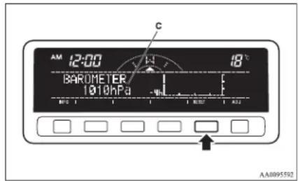
Instruments and controls
NOTE
- Pressing the "RESET" function button will not reset the indication (C).
- It is possible to set the display unit to hPa, mb, kPa, or inHg.
Refer to "User customization" on page 3-24.
Calendar
E00518800032
The date is shown. The calendar pattern can be changed to your desired setting.
Refer to “Changing the calendar setting” on page 3-23.
Clock-only
ED0518900033
Only the clock is shown. The time notation can be changed to your desired setting. (12 hour/24 hour)
Refer to "User customization" on page 3-24.
Blank
L00519000015
The whole display can be turned into blank. In this case, buttons remain illuminated.

natural_image
Solid black rectangle on white background with no text or symbolsNOTE
- If you operate the audio system, the audio display pops up.
Selecting settings displays
E00519100090
Every time the “ADJ” button is pressed lightly, the display can be changed to the following:

CAUTION
● The driver should not operate the display while the vehicle is in motion.
- When operating the system, stop the vehicle in a safe area.
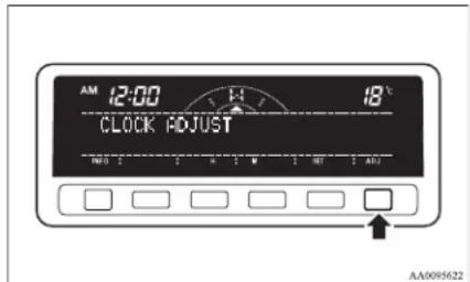
1- Changing the clock settings p. 3-19
2- Adjusting the display brightness → p. 3-20
3- Correcting the compass p. 3-21
4- Changing the calendar setting → p. 3-23
5- User customization → p. 3-24
6- Adjusting the barometer → p. 3-28
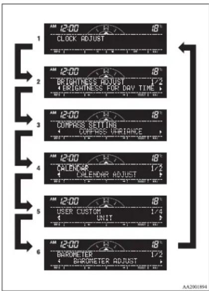
Changing the clock settings
E00519200121
- Press the "ADJ" button to select the clock setting display.
- It is possible to adjust the clock using the function buttons.
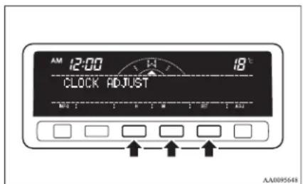
Instruments and controls
“H”- Adjust “hour”.
The indication increases by one hour, every time you lightly press the "IT" function button. If you continue pressing the button for about 2 seconds or more, the indication is fast-forwarded, and then the setting is changed to the hour selected.
“M”- Adjust “minute”.
The indication increases by one minute, every time you lightly press the "M" function button. If you continue pressing the button for about 2 seconds or more, the indication is fast-forwarded, and then the setting is changed to the minute selected.
"SET"- To reset the minutes to zero.
The time is adjusted as described below by pressing the function button "SET".
In this occasion, the display flashes twice and then the setting is changed.
- After making the adjustment, press the "INFO" button to select the information display.
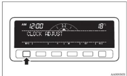
Instruments and controls
Adjusting the display brightness
E00519300034
The display brightness can be adjusted at 13 levels for both daytime and nighttime.
● BRIGHTNESS FOR DAY TIME
The display brightness is adjusted when the light switch is in the "OFF" position.
● BRIGHTNESS FOR NIGHT TIME
The display brightness is adjusted when the light switch is in the “☐ or “” position.
- Press the "ADJ" button to show the brightness adjusting display.
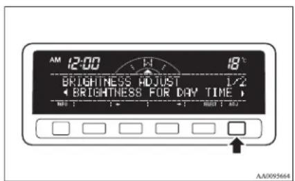
- Press the “←” or “→” function button to select the setting you wish to adjust (daytime or nighttime). Then press the “SELECT” function button.
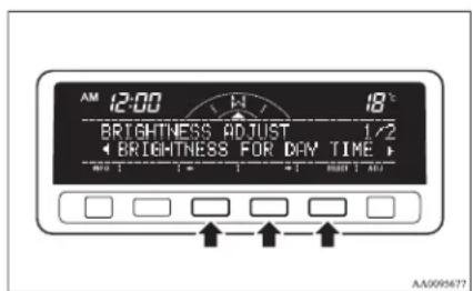
- Use the function buttons to adjust the brightness.
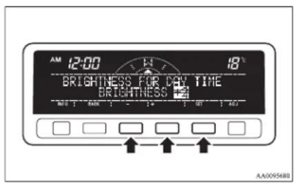
“+”- To make the display brighter The display becomes brighter by one step, every time you lightly press the “+” function button. If you continue pressing the button for about 2 seconds or more, the indication is fast-forwarded.
“-”- To make the display darker The display becomes darker by one step, every time you lightly press the “-” function button. If you continue press- ing the button for about 2 seconds or more, the indication is fast-forwarded.
“SET”- To set the brightness Press function button “SET” to set the new brightness. The display will flash twice.
NOTE
- If you next wish to adjust the other adjustment setting (daytime or nighttime), press the "ADJ" button or "BACK" function button.
- After adjustment, press the "INFO" button to select the information display.
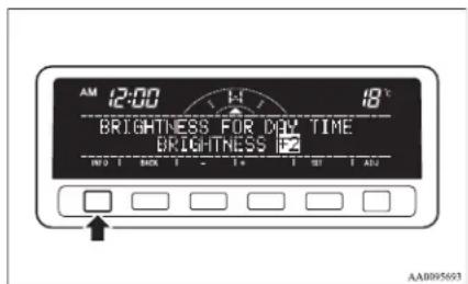
Instruments and controls
NOTE
● As the display brightness can be adjusted in the center information display only, the brightness inside the meter cannot be changed.
Correcting the compass
L00519400178
This compass shows the direction of the vehicle by the 8 azimuth system.
natural_image
Abstract black-and-white diagram with curved dotted lines and scattered white shapes, no text or symbols present.NOTE
- This system uses the earth's magnetic field, and so may not show the correct direction depending on the traffic condition or in the following places where the earth's magnetic field is disrupted.
• Car parks located in buildings and tunnels
- Expressways and underground cables
• Area over the subway
- Transforming station
- Areas along the railroad
In these cases, the correct direction will be displayed once the vehicle returns to a place where the earth's magnetic field is stable.
- Do not install ski racks, antennas, etc. which are attached to the vehicle by means of a magnet. They affect the operation of the compass.
Setting the declination
The declination is the difference between true north (the direction of the geographic north pole) and where a compass needle points to. Since the declination varies from place to place, it needs to be set for each region. Otherwise the compass will not show the correct direction.
Set the declination by the following steps:

NOTE
● The default declination setting is 0 degrees. In accordance with the illustration, set the declination setting to the declination contour nearest to a region where you drive the vehicle.
● The declination can be set at intervals of 1 degrees, from 28 degrees west (W28) to 28 degrees east (E28).
With a settings display showing, press the "ADJ" button and select "COMPASS VARIANCE".
- Press the function button for "SELECT".
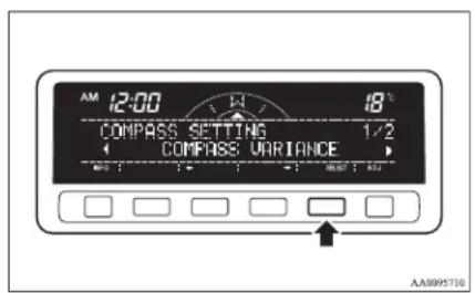
- Press the function button for “←” or “→” to set the desired declination.
Pressing “←” or “→” for more than 1 second makes the value change rapidly.
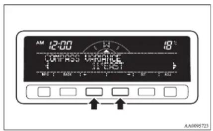
Instruments and controls
- When the declination adjustment has been completed, press the "SET" function button.
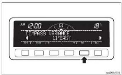
3
Setting the compass
The compass is usually calibrated automatically when the vehicle is moving. At times when complete calibration is not possible, no compass indications are given. Manually set the compass using the following procedure.
natural_image
Abstract geometric diagram with curved dotted lines and a triangle, no text or symbols presentNOTE
- If your vehicle has a sunroof, keep the sunroof closed when calibrating the compass. Having the sunroof open when calibrating the compass could render the compass unable to correctly show directions.
With a settings display showing, press the "ADJ" button and select "COMPASS CALIBRATION".
- Press the function button for "SELECT".
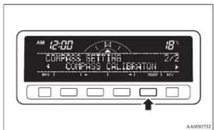
- Press the function button for "SELECT".
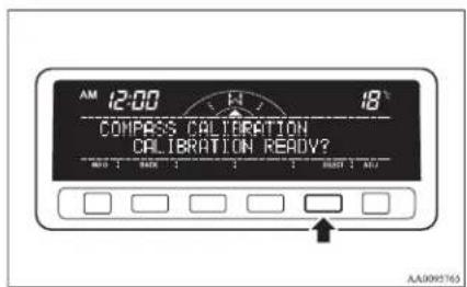
- Turn the vehicle slowly through 360 degrees in a safe, open area with no buildings and other vehicles.
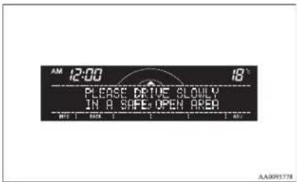
NOTE
- If you wish to stop calibrating the compass part-way through the procedure, press the "INFO" button or "ADI" button.
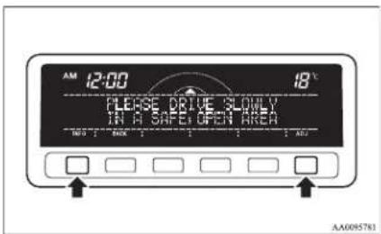
NOTE
- The “Completed the calibration”. message may be displayed even if you terminate the turn before it is complete and return to the vehicle’s original direction. The compass may not be properly calibrated in this case, so you must turn the vehicle through at least 360 degrees.
- The compass setting will finish automatically and the words "COMPASS CALIBRATION COMPLETE" will appear on the screen.
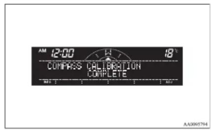
Changing the calendar setting
F0051950036
The date and the calendar indication patterns can be changed.
Date setting
- Press the "ADJ" button to select the calendar setting display.
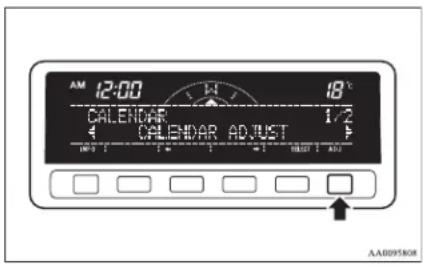
- Press the “←” or “→” function button to select “CALENDAR ADJUST”. Then press the “SELECT” function button.
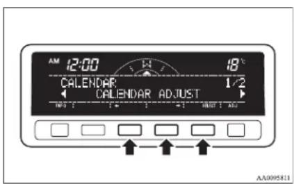
- Use the function buttons to set the calendar.
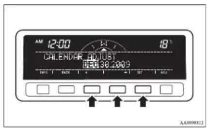
“→”- Select “YEAR”, “MONTH”, “DAY” you wish to change.
“YEAR”, “MONTH”, and “DAY” are changed over by turns every time you lightly press the “→” function button.
“+”- Change “YEAR”, “MONTH”, “DAY” you have selected.
The indication is changed to your desired date every time you lightly press the "+" function button.
If you continue pressing the button for about 2 seconds or more, the indication is forwarded.
"SET"- Determine the date.
Press the “SET” function button. Then the display flashes twice and the setting is changed.
NOTE
● The year changes in the following sequence: 2009 → 2010 → ... 2099 → 2009.
- You can return to the previous display by pressing the "BACK" function button.
Instruments and controls
- After setting the date, press the "INFO" button to return to the information display.
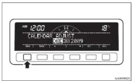
Changing the calendar pattern
- Press the "ADJ" button to select the calendar setting display. Press the "←" or "→" function button to select "CALENDAR PATTERN SELECT". Then press the "SELECT" function button.
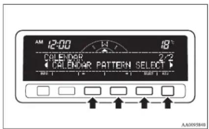
- Press function button “←” or “→” to select your desired indication pattern.
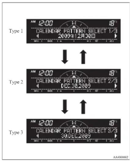
- Press the function button "SET". The display will flash twice, and the indication pattern will be updated.
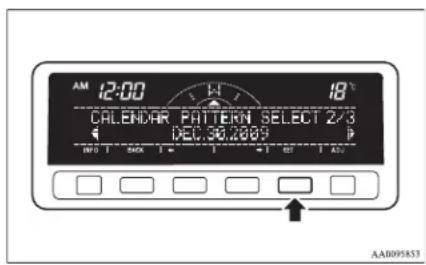
NOTE
- You can return to the previous display by pressing the "BACK" function button.
- After setting the calendar pattern, press the "INFO" button to return to the information display.
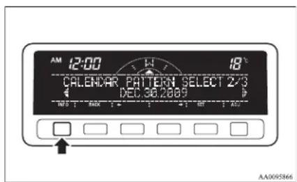
User customization
E00519600154
You can set the indication of unit, language, and the time notation.
In addition, you can return these settings to the factory default settings.
Instruments and controls
Selecting the item to set
- Press the "ADJ" button to select the user customization display.
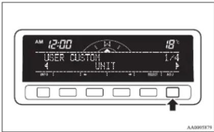
- Press the function button “←” or “→” to select the item you wish to set.
● "UNIT": Changing the unit
● "LANGUAGE": Changing the language
● “12h ↔ 24h”: Changing the time format
- “DEFAULT”: Resetting to factory settings
Push the function button “SELECT”. The setting display for your selected item will appear.
Changing display units
It is possible to change the display units for the fuel consumption, driving range, average speed, outside temperature, elevation, and atmospheric pressure as shown below.
| FUEL ECONOMY | km/L → L/100 km → mpg(UK GALLON) → mpg(US GALLON) |
| RANGE km → miles | |
| SPEED km/h → mph | |
| OUTSIDE TEM-PERATURE | °C → °F |
| ELEVATION m → ft | |
| BAROMETER hPa | → mb → kPa → inHg |
● Changing the display unit for fuel consumption
1. Press the “←” or “→” function button to select “FUEL ECONOMY”. Then press the “SELECT” function button.
- Press the “←” or “→” function button to select “km/L”. Then press the “SET” function button. The display will flash twice, and the display unit will be updated to the selected one.
NOTE
- You can return to the previous display by pressing the "BACK" function button.
- After setting, press the "INFO" button to return to the information display.
Instruments and controls
Changing the language
It is possible to set the display language of the centre information display to English, Spanish, French, German, Portuguese or Italian.
● To change the display language to English
- Press the “←” or “→” function button to select “ENGLISH”. Then press the “SET” function button. The display will flash twice, and then the setting is completed to the language selected.
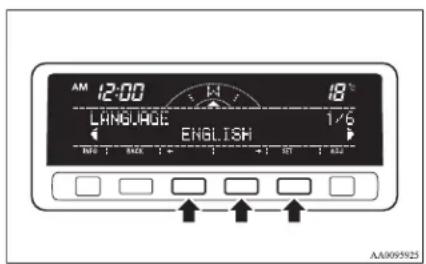
NOTE
- You can return to the previous display by pressing the "BACK" function button.
- After setting the language, press the "INFO" button to return to the information display.
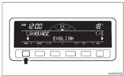
Changing the time notation
It is possible set the time notation to 12-hour or 24-hour.
- Press the “←” or “→” function button to select “12h TIME NOTATION” or “24h TIME NOTATION”. Then press the “SET” function button. The display will flash twice, and the display time notation will be updated to the selected one.
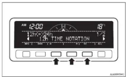
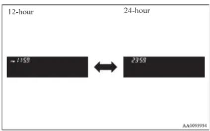
NOTE
- You can return to the previous display by pressing the "BACK" function button.
- After setting the time notation, press the "INFO" button to return to the information display.
Returning display items to their factory settings
You can return to the setting of each item to the factory default settings.
Instruments and controls
NOTE
● The factory settings are as follows:
• Fuel consumption: L/100 km (62 mph)
- Driving range: km
• Average speed: km/h
- Outside temperature: °C
- Elevation: m
• Atmospheric pressure: hPa
• Display language: English
• Time notation: 12-hour
- Push the "SELECT" function button.
- Press the “←” function button to select “YES”.
- Press the "SELECT" function button.
- Once more press the “←” function button to select “YES”.
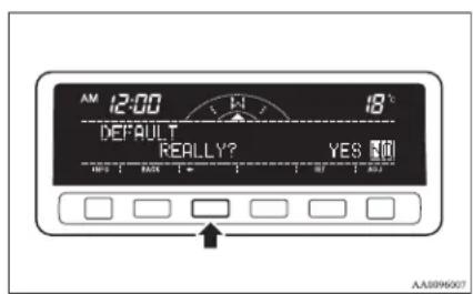
- Press the "SET" function button.
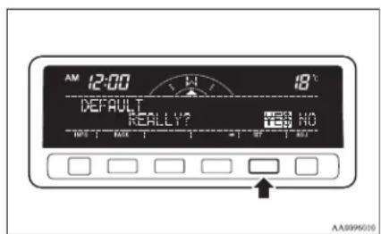
- The display shown below will appear, and the display items will return to their factory settings.
Instruments and controls
NOTE
- If the battery terminals are disconnected, the settings for the date and time may be erased. If this happens, please set the date and time again.
Adjusting the barometer
ED0524400033
It is possible to adjust the barometer indication and return it to the factory setting.
NOTE
- It is not necessary to adjust the barometer because it has been adjusted at the factory. However, if you wish, adjust it using an accurate barometer.
To adjust the barometer
- Press the "ADJ" button to select the barometer adjustment display.
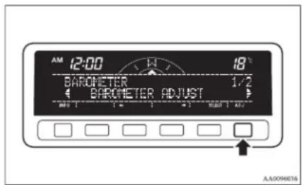
- Press the “←” or “→” function button to select the “BAROMETER ADJUST” display. Then press the “SELECT” function button.
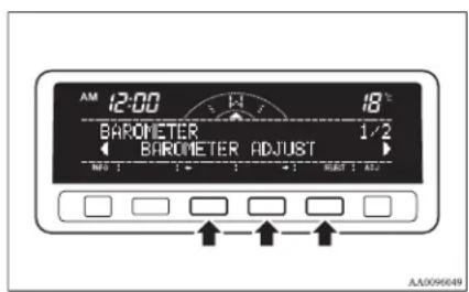
- Adjust the barometer by pressing the function buttons.
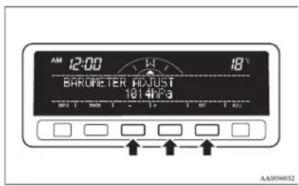
“+”- To adjust the barometer
Each gentle press of the “+” function button will increase the indicated barometer by 2 hPa. If you continue pressing the button for about 2 seconds or longer, the indication is fast-forwarded.
“-”- To adjust the barometer
Each gentle press of the “-” function button will decrease the indicated barometer by 2 hPa. If you continue pressing the button for about 2 seconds or longer, the indication is fast-forwarded.
"SET"- To set the barometer
Press the "SET" function button. The display will flash twice, and the new setting will be established.
NOTE
- You can return to the previous display by pressing the "BACK" function button.
Instruments and controls
- After setting the barometer adjust, press the "INFO" button to return to the information display.
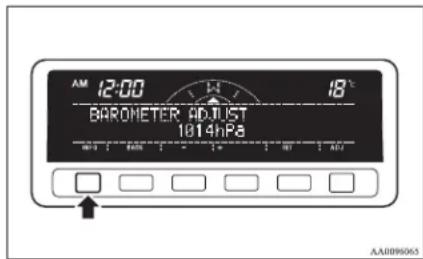
Resetting to the factory setting
- Press the "ADJ" button to select the barometer adjustment display.
Press the “←” or “→” function button to select the “BAROMETER DEFAULT” display. Then press the “SELECT” function button.
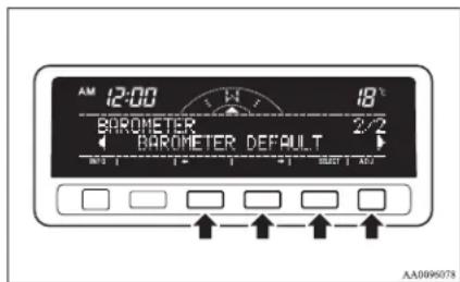
- Press the "SET" function button. The display will flash twice and the barometer indication will return to the factory settings.
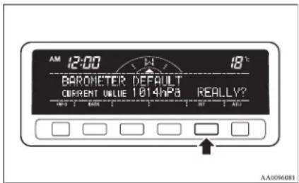
NOTE
- Although the barometer value is changed to the factory setting, a barometer unit you have selected is unchanged.
-
You can return to the previous display by pressing the "BACK" function button.
-
After setting the barometer default, press the "INFO" button to return to the information display.
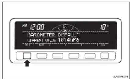
Care of the monitor
E00519700012
If the monitor becomes covered in fingerprints or otherwise dirty, clean it with a soft and dry cloth.
NOTE
- Don't use a wet cloth or abrasive cleaner as this may cause damage.
Instruments and controls
Combination headlamps and dipper switch
E00506001728
Headlamps
NOTE
- Do not leave the headlamps and other lamps on for a long time while the engine is stationary (not running). A run-down battery could result.
- When it rains or when the vehicle has been washed, the inside of the lens sometimes becomes foggy. This is the same phenomenon as when window glass mists up on a humid day, and does not indicate a functional problem. When the lamp is switched on, the heat will remove the fog. However, if water gathers inside the lamp, we recommend you to have it checked.
Type 1
Rotate the switch to turn on the lamps.
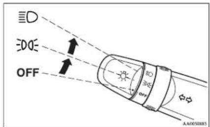
| OFF | All lamps off |
| Position, tail, licence plate and instrument panel lamps on | |
| Headlamps and other lamps go on |
Type 2
Rotate the switch to turn on the lamps.
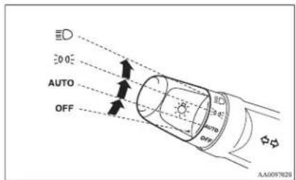
| OFF All lamps off | |
| AUTO | With the ignition switch in the “ON” position, headlamps, position, tail, licence plate, and instrument panel lamps turn on and off automatically in accordance with outside light level. All lamps turn off automatically when the ignition switch is turned to the “OFF” position. |
| 300E | Position, tail, licence plate and instrument panel lamps on |
| 3D | Headlamps and other lamps go on |
NOTE
● The sensitivity of the automatic on/off control can be adjusted.
For further information, we recommend you to consult a MITSUBISHI MOTORS Authorized Service Point.
- When the headlamps are turned off by the automatic on/off control with the ignition switch in the "ON" position, the front fog lamps (if so equipped) and rear fog lamp also go off. When the headlamps are subsequently turned back on by the automatic on/off control, the front fog lamps also come on but the rear fog lamp stays off. If you wish to turn the rear fog lamp back on, operate the switch again.
- Do not cover the sensor (A) for the automatic on/off control by affixing a sticker or label to the windscreen.
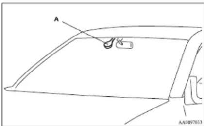
- If the lamps do not turn on or off with the switch in the "AUTO" position, manually operate the switch and we recommend you to have your vehicle checked.
[ Vehicles with Daytime Running Lamp ]
When the ignition switch is in the "ON" position and the lamp switch is set to the "OFF" position, the low beam of the headlamps, tail lamps, etc., will illuminate.
Lamps (headlamps, fog lamp, etc.) auto-cutout function
- If the key is turned to the "LOCK" or "ACC" position or removed from the ignition switch and the lamps will stay on for about 3 minutes without opening the driver's door while the lamp switch in the "≡Position, the lamps automatically turn off.
- If the key is turned to the “LOCK” or “ACC” position or removed from the ignition switch and the driver’s door is opened within 3 minutes while the lamp switch in the “ D” position, a buzzer will sound to warn the driver that the lamps have not been turned off, and these lamps will automatically turn off.
NOTE
- The lamp auto-cutout will not function when the lamp switch is in the “position.
- When the ignition key has been turned to either the “LOCK” or “ACC” position or removed from the ignition switch with the lamp switch in the “ 位置 , and the lamp switch is returned to the “OFF” position within approximately 3 minutes, the autocutout function will not be activated.
When you want to keep the lamps on
- Turn the switch in the "OFF" position to switch off all lamps while the ignition key is in the "LOCK" or "ACC" position or remove it from the ignition switch.
- Turn on the lamps with the switch in the “DOZ” or “≡Q position again, then the lamps will remain on.
NOTE
- It is possible to alter the auto-cutout function such that:
- Auto-cutout function is never activated. For details, we recommend you to consult a MITSUBISHI MOTORS Authorized Service Point.
Lamp monitor buzzer
E00506100184
If the driver's door is opened when the ignition key is in the "LOCK" or "ACC" position or removed from the ignition switch while the lamps are on, a buzzer will sound to remind the driver to turn off the lamps. When the lamp auto-cutout function acts, the buzzer will stop automatically. When this function does not act, turn off the lamp switch to stop the buzzer.
Dipper (High/Low beam change)
0506200286
When the lamp switch is in the “≡” position, the beam changes from high to low (or low to high) each time the lever is pulled to (1). While the high-beam is on, the high-beam indication lamp in the instrument cluster will also illuminate.
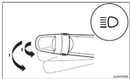
Headlamp flasher
L00506300157
The high-beams flash when the lever is pulled slightly (2), and will go off when it is released. When the high-beam is on, the high-beam indication lamp in the instrument cluster will also illuminate.
Instruments and controls
NOTE
● The high-beams can also flash when the lamp switch is in the "OFF" position.
- If you turn the lamps off with the headlamps set to high-beam illumination, the headlamps are automatically returned to their low-beam setting when the lamp switch is next turned to the “Position.
Headlamp levelling switch\*
L00506400800
The angle of the headlamp beam varies depending on the load carried by the vehicle.
The headlamp levelling switch can be used to adjust the headlamp illumination distance (when the lower beam is illuminated) so that the headlamps' glare does not distract other drivers.
Set the switch (referring to the following table) to the appropriate position according to the number of people and the load in the vehicle.
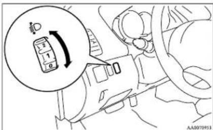
CAUTION
● Always perform adjustments before driving.
Do not attempt to adjust while driving, as it could cause an accident.
Single cab
| Vehicle condi- tion |  |  |
| Switch position | “0” “2” |
●: 1 person
: Full luggage loading
Switch position 0- Driver only
Switch position 2- Driver + Full luggage loading
Club cab
| Vehicle condition |  |  |
| Switch position“0” | “2” or “3” or “4” | |
●: 1 person
: Full luggage loading
NOTE
- When adjusting the beam position, first put the dial in the "0" position (the highest beam position).
Switch position 0- Driver only
Switch position 2- Driver + Full luggage loading {Vehicles for Russia, Kazakhstan and Ukraine with heavy duty suspension}
Switch position 3- Driver + Full luggage loading {Vehicles for Russia, Kazakhstan and Ukraine without heavy duty suspension} {Except for vehicles for Russia, Kazakhstan and Ukraine with heavy duty suspension}
Switch position 4- Driver + Full luggage loading {Except for vehicles for Russia, Kazakhstan and Ukraine without heavy duty suspension}
Double cab
| Vehicle condition |  |  |
| Switch position | “0” | “2” or “3” or “4” |
●: 1 person
: Full luggage loading
Switch position 0- Driver only
Switch position 2- Driver + Full luggage loading {Vehicles for Russia, Kazakhstan and Ukraine with heavy duty suspension}
Switch position 3- Driver + Full luggage loading {Vehicles for Russia, Kazakhstan and Ukraine without heavy duty suspension} {Except for vehicles for Russia, Kazakhstan and Ukraine with heavy duty suspension}
Switch position 4- Driver + Full luggage loading {Except for vehicles for Russia, Kazakhstan and Ukraine without heavy duty suspension}
Turn-signals lever
L00506501273
The turn-signal lamps flash when the lever is operated (with the ignition switch in the "ON" position). At the same time, the turn-signal indication lamps flash.
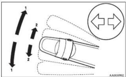
1- Turn-signals
When making a normal turn, use position (1). The lever will return automatically when cornering is completed.
There are times when the lever will not return after cornering. This occurs when the steering wheel is turned only slightly. In such cases, return the lever by hand.
2- Lane-change signals
When changing lanes, use position (2). It will return to the neutral position when released.
NOTE
- If the lamp flashes unusually quickly, the bulb in a turn-signal lamp may have burned out. We recommend you to have the vehicle inspected.
Instruments and controls
- It is possible to activate the following functions. For further information, we recommend you to consult a MITSUBISHI MOTORS Authorized Service Point.
- Flashing of the turn-signal lamps and the indication lamp in the instrument cluster when the lever is operated with the ignition switch in the "ACC" position
- Flashing of the turn-signal lamps and the indication lamp in the instrument cluster three times when you move the lever to (2) slightly then release it
- The time required to operate the lever for the 3-flash function can be adjusted.
Hazard warning flasher switch
L00506600903
Use the hazard warning flasher switch when the vehicle has to be parked on the road for any emergency. The hazard warning flashers can always be operated, regardless of the position of the ignition key.
Push the switch to turn on the hazard warning flashers; push the switch again to turn them off.
When this switch is operated, all turn-signal lamps flash continuously, as do the turn-signal indication lamps in the instrument cluster.
Front fog lamp switch\*
E00506800934
The front fog lamps can be used only when the head-lamps or tail lamps are on. Turn the knob once in the "ON" direction to turn on the front fog lamps. The indication lamp in the instrument cluster will also come on. To turn the front fog lamps off, turn the knob once in the "OFF" direction. While the rear fog lamp is on, turn the knob twice in the "OFF" direction to turn the front fog lamps off. The knob will automatically return to its original position when you release it.
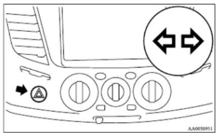
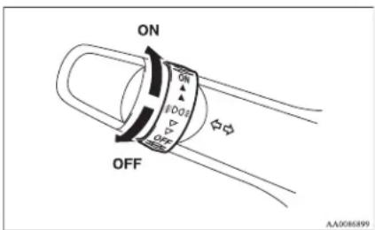
NOTE
- If the lamps are kept flashing for a long time, the battery will be discharged, resulting in hard engine starting or no start condition.
- If the lamp flashes unusually quickly, the bulb in a turn-signal lamp may have burned out.
We recommend you to have the vehicle inspected.
NOTE
- The front fog lamps are automatically turned off when the headlamps or tail lamps are turned off. To turn the front fog lamps on again, turn the knob in the "ON" direction after turning on the headlamps or tail lamps.
- Do not use fog lamps except in conditions of fog, otherwise excessive lamp glare may temporarily blind oncoming vehicle drivers.
- In case of vehicles with Daytime Running Lamp, the front fog lamp can be operated even if the lamp switch is set to the "OFF" position, because the low beam of the head-lamps, tail lamps, etc. illuminate when the ignition key is at the "ON" position.
Rear fog lamp switch
E00506900313
The rear fog lamp illuminates only when the head-lamps or front fog lamps (if so equipped) are on. An indication lamp in the instrument cluster comes on when the rear fog lamp is turned on.
[ Vehicles without front fog lamps ]
Turn the knob once in the "ON" direction to turn on the rear fog lamp. To turn the rear fog lamp off, turn the knob once in the "OFF" direction. The knob will automatically return to its original position when you release it.
[ Vehicles with front fog lamps ]
Turn the knob once in the "ON" direction to turn on the front fog lamps. Turn the knob once more in the "ON" direction to turn on the rear fog lamp. To turn the rear fog lamp off, turn the knob once in the "OFF" direction. Turn the knob once more in the "OFF" direction to turn off the front fog lamps. The knob will automatically return to its original position when you release it.
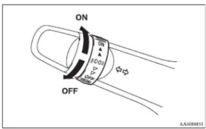
NOTE
● The rear fog lamp is automatically turned off when the headlamps and front fog lamps (if so equipped) are turned off.
- To turn the rear fog lamp on again, turn the knob once in the “ON” direction after turning on the headlamps. (Vehicles without front fog lamps)
- To turn the rear fog lamp on again, turn the knob twice in the "ON" direction after turning on the headlamps. (Vehicles with front fog lamps)
- In case of vehicles with Daytime Running Lamp, the rear fog lamp can be operated even if the lamp switch is set to the "OFF" position, because the low beam of the head-lamps, tail lamps, etc. illuminate when the ignition key is at the "ON" position.
Instruments and controls
Wiper and washer switch
E00507101191
CAUTION
- If the washer is used in cold weather, the washer fluid sprayed against the glass may freeze, which may hinder visibility. Warm the glass with the defroster or rear window demister before using the washer.
Windscreen wipers
E00516900303
Except for vehicles equipped with rain sensor The windscreen wipers can be operated with the ignition switch in the "ON" or "ACC" position. If the blades are frozen to the windscreen, do not operate the wipers until the ice has melted and the blades are freed, otherwise the wiper motor may be damaged.
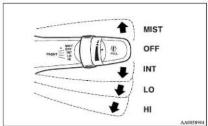
MIST- Misting function
The wipers will operate once.
OFF-Off
INT- Speed sensitive intermittent operation Interval between wipers varies in accordance with vehicle speed.
LO-Slow
HI-Fast
To adjust intermittent intervals
With the lever in the "INT" (speed-sensitive) position, the intermittent intervals can be adjusted by turning the knob (A).
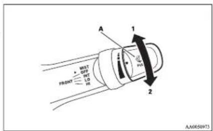
1-Fast
2-Slow
NOTE
● The speed-sensitive-operation function of the windscreen wipers can be deactivated. For further information, we recommend you to consult a MITSUBISHI MOTORS Authorized Service Point.
Misting function
Move the lever in the direction of the arrow and release, to operate the wipers once.
Use this function when you are driving in mist or drizzle.
If the lever is held in the upward position (MIST), the wipers continue operating until the lever is released.
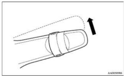
natural_image
Diagram of a car with an arrow indicating motion or force direction (no text or symbols)Vehicles with rain sensor
E00526400369
The windscreen wipers can be operated with the ignition switch in the "ON" or "ACC" position.
If the blades are frozen to the windscreen, do not operate the wipers until the ice has melted and the blades are freed, otherwise the wiper motor may be damaged.
Keep the lever in the "OFF" position if the windscreen is dirty and the weather is dry. Wiper operation under these conditions can scratch the windscreen and damage the wipers.
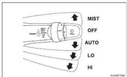
MIST- Misting function
The wipers will operate once.
OFF-Off
AUTO-Auto-wiper control
Rain sensor
The wipers will automatically operate depending on the degree of wetness on the windscreen.
LO-Slow
HI-Fast
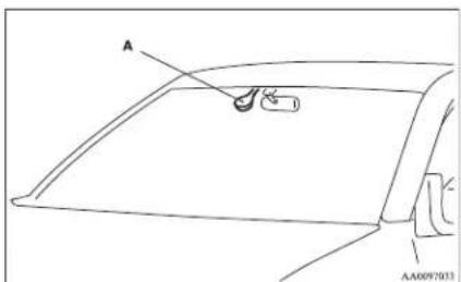
Rain sensor
Can only be used when the ignition switch is in the "ON" position.
If the lever is put in the "AUTO" position, the rain sensor (A) will detect the extent of rain (or snow, other moisture, dust, etc.) and the wipers will operate automatically.
CAUTION
- With the ignition switch in the "ON" position and the lever in the "AUTO" position, the wipers may automatically operate in the situations described below. If your hands get trapped, you could suffer injuries or the wipers could malfunction. Be sure to turn the ignition switch to the "OFF" position or move the lever to the "OFF" position to deactivate the rain sensor.
- When cleaning the outside surface of the windscreen, if you touch the rain sensor.
- When cleaning the outside surface of the windscreen, if you wipe with a cloth the rain sensor.
- When using an automatic car wash.
- A physical shock is applied to the windscreen.
• A physical shock is applied to the rain sensor.
NOTE
● To protect the rubber parts of the wipers, this operation of the wipers does not take place when the vehicle is stationary and the ambient temperature is about 0 °C or lower.
- Do not cover the sensor by affixing a sticker or label to the windscreen. Also, do not put any water-repellent coating on the windscreen. The rain sensor would not be able to detect the extent of rain, and the wipers might stop working normally.
● In the following cases, the rain sensor may be malfunctioning.
Instruments and controls
Have the vehicle inspected at a MITSUBISHI MOTORS Authorized Service Point.
- When the wipers operate at a constant interval despite changes in the extent of rain.
- When the wipers do not operate even though it is raining.
- The wipers may automatically operate when things such as insects or foreign objects are affixed to the windscreen on top of the rain sensor or when the windscreen is frozen. Objects affixed to the windscreen will stop the wipers when the wipers cannot remove them. To make the wipers operate again, place the lever in the “LO” or “HI” position.
Also, the wipers may operate automatically due to strong direct sunlight or electromagnetic wave. To stop the wipers, place the lever in the "OFF" position.
- Contact a MITSUBISHI MOTORS Authorized Service Point when replacing the windscreen or reinforcing the glass around the sensor.
To adjust the sensitivity of the rain sensor
With the lever in the "AUTO" (rain sensor) position, it is possible to adjust the sensitivity of the rain sensor by turning the knob (A).
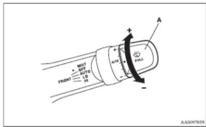
"+"- Higher sensitivity to rain
"-"- Lower sensitivity to rain
NOTE
- It is possible to activate the following functions. For further information, we recommend you to consult a MITSUBISHI MOTORS Authorized Service Point.
- Automatic operation (rain droplet sensitive) can be changed to intermittent operation (vehicle-speed sensitive).
• Automatic operation (rain droplet sensitive) can be changed to intermittent operation (except vehicle-speed sensitive).
Misting function
Move the lever in the direction of the arrow and release, to operate the wipers once.
Use this function when you are driving in mist or drizzle.
If the lever is held in the upward position (MIST), the wipers continue operating until the lever is released.
natural_image
Diagram of a car being pulled with a rope, showing motion direction (no text or symbols)The wipers will operate once if the lever is moved to the “AUTO” position and the knob (A) is turned in the “+” direction when the ignition switch is “ON” position.
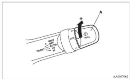
Windscreen washer
L00507200805
The windscreen washer can be operated with the ignition switch in the "ON" or "ACC" position.
The washer fluid will be sprayed onto the windscreen by pulling the lever towards you. The wipers operate automatically several times while the washer fluid is being sprayed.
On a vehicle equipped with a headlamp washer, the headlamp washer operates together with the windscreen washer the first time the windscreen washer is used if the headlamps are on.
natural_image
Diagram of a car with motion arrows indicating speed or direction (no text or symbols)CAUTION
- If the washer is used in cold weather, the washer fluid sprayed against the glass may freeze resulting in poor visibility. Heat the glass with the defroster or demister before using the washer.
NOTE
- It is possible to spray washer fluid without activating the wipers. To do so, hold the lever in the pulled position and turn the ignition switch to the "ON" or "ACC" position.
- It is possible to cause the wipers never to operate when washer fluid is sprayed. For further information, we recommend you to consult a MITSUBISHI MOTORS Authorized Service Point.
Headlamp washer switch\*
E00510100273
The headlamp washer can be operated when the ignition switch is in the "ON" or "ACC" position and the headlamps are on.
Push the button once and the washer fluid will be sprayed on to the headlamps.
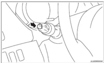
natural_image
Technical line drawing of a mechanical component with no visible text or symbolsNOTE
- If the ignition switch is in the "ON" or "ACC" position and the headlamps are on, the headlamp washer operates together with the windscreen washer the first time the windscreen washer lever is pulled.
Precautions to observe when using wipers and washers
E00507600014
- If the moving wipers become blocked by ice or other deposits on the glass, the motor may burn out even if the wiper switch is turned to OFF. If obstruction occurs, park your vehicle in a safe place, turn off the ignition, and clean the deposits from the glass so that the wipers operate smoothly.
- Do not use the wipers when the glass is dry. They may scratch the glass surface and the blades wear out prematurely.
● Before using the wipers in cold weather, check that the wiper blades are not frozen onto the glass. The motor may burn out if the wipers are used with the blades frozen onto the glass. - Avoid using the washer continuously for more than 20 seconds. Do not operate the washer when the fluid reservoir is empty. Otherwise, the motor may burn out.
- Periodically check the level of washer fluid in the reservoir and refill if required. During cold weather, add a recommended washer solution that will not freeze in the washer reservoir. Failure to do so could result in loss of washer function and frost damage to the system components.
Instruments and controls
Rear window demister switch
E00507900961
The rear window demister switch can be operated with the ignition switch in the "ON" position. Push the switch to turn on the rear window demister. It will be turned off automatically in about 20 minutes. To turn off the demister within about 20 minutes, push the switch again.
The indication lamp (A) will illuminate while the demister is on.
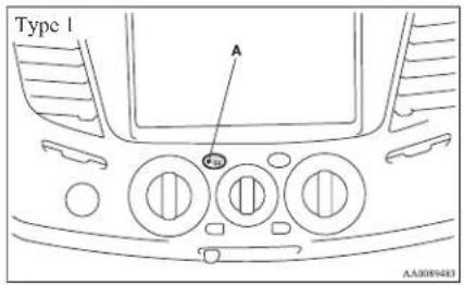
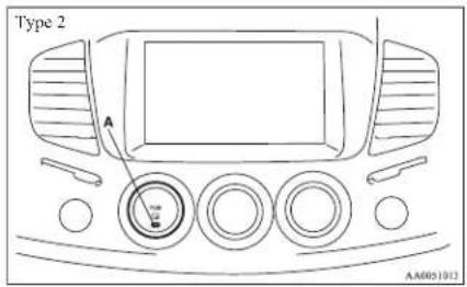
NOTE
- If your vehicle is equipped with heated mirrors, these operate in conjunction with the demister. Refer to "Heated mirror" on page 4-11.
● The demister switch is not to melt snow but to clear mist. Remove snow before use of the demister switch.
● To avoid unnecessary discharge of the battery, do not use the rear window demister during starting of the engine or when the engine is not running. Turn the demister off immediately after the window is clear. - When cleaning the inside of the rear window, use a soft cloth and wipe gently along the heater wires, being careful not to damage the wires.
- Do not allow objects to touch the inside of the rear window glass, or damaged or broken wires may result.
Horn switch
E00508000608
Press the steering wheel on or around the "B" mark.
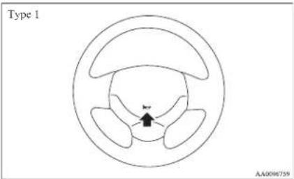
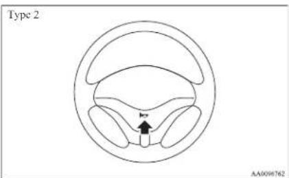
Starting and driving
Economical driving....4-02
Driving, alcohol and drugs....4-02
Safe driving techniques....4-03
Running-in recommendations....4-04
Parking brake....4-07
Parking....4-08
Steering wheel height adjustment....4-09
Inside rear-view mirror....4-09
Outside rear-view mirrors....4-10
Ignition switch....4-11
Steering wheel lock....4-12
Starting....4-13
Manual transmission....4-14
Automatic transmission 4A/T....4-16
Automatic transmission Sports Mode 5A/T....4-20
Easy select 4WD*....4-25
Super select 4WD*....4-29
Rear differential lock*....4-34
4-wheel drive operation....4-38
Inspection and maintenance following rough road operation....4-40
Cautions on handling of 4-wheel drive vehicles....4-40
Limited-slip differential* 4-42
Braking....4-42
Anti-lock brake system (ABS)*....4-43
Power steering system....4-45
Active Stability & Traction Control (ASTC)*......4-46
Cruise control* 4-48
Cargo loads....4-52
Trailer towing....4-53
Starting and driving
Economical driving
E00600100620
For economical driving, there are some technical requirements that have to be met. The prerequisite for low fuel consumption is a properly adjusted engine. In order to achieve longer life of the vehicle and the most economical operation, we recommend you to have the vehicle checked at regular intervals in accordance with the service standards.
Fuel economy and generation of exhaust gas and noise are highly influenced by personal driving habits as well as the particular operating conditions. The following points should be observed in order to minimize wear of brakes, tyres and engine as well as to reduce environmental pollution.
Starting
Avoid rapid acceleration and sudden starts; such operation will result in higher fuel consumption.
Shifting
Shift only at an appropriate speed and engine speed. Always use the highest gear possible. The transfer shift lever should be set to "2H" when driving 4WD vehicles on normal roads and express ways to obtain best possible fuel economy.
City traffic
Frequent starting and stopping increases the average fuel consumption. Use roads with smooth traffic flow whenever possible. When driving on congested roads, avoid use of a low gear at high engine speeds.
Idling
The vehicle consumes fuel even during idling. Avoid extended idling whenever possible.
Speed
The higher the vehicle speed, the more fuel consumed. Avoid driving at full speed. Even a slight release of the accelerator pedal will save a significant amount of fuel.
Tyre inflation pressure
Check the tyre inflation pressures at regular intervals. Low tyre inflation pressure increases road resistance and fuel consumption. In addition, low tyre pressures adversely affect tyre wear and driving stability.
Load
Do not drive with unnecessary articles in the cargo area. Especially during city driving where frequent starting and stopping is necessary, the increased weight of the vehicle will greatly affect fuel consumption.
Cold engine starting
Starting of a cold engine consumes more fuel. Unnecessary fuel consumption is also caused by keeping a hot engine running. After the engine is started, commence driving as soon as possible.
Air conditioning\*
The use of the air conditioning will increase the fuel consumption.
Driving, alcohol and drugs
E00600200012
Driving after drinking alcohol is one of the most frequent causes of accidents.
Your driving ability can be seriously impaired even with blood alcohol levels far below the legal minimum. If you have been drinking, don't drive. Ride with a designated non-drinking driver, call a cab or a friend, or use public transportation.
Drinking coffee or taking a cold shower will not make you sober.
Similarly, prescription and nonprescription drugs affect your alertness, perception and reaction time. Consult with your doctor or pharmacist before driving while under the influence of any of these medications.
WARNING
● NEVER DRINK AND DRIVE.
Your perceptions are less accurate, your reflexes are slower and your judgment is impaired.
Safe driving techniques
L00600300491
Driving safety and protection against injury cannot be fully ensured. However, we recommend that you pay extra attention to the following:
Seat belts
Before starting the vehicle, make sure that you and your passengers have fastened your seat belts.
Floor mats

WARNING
- Keep floor mats clear of the pedals by correctly laying floor mats that are suitable for the vehicle.
To prevent the floor mats from slipping out position, securely retain them using the hooks etc.
Note that laying a floor mat over a pedal or laying one floor mat on top of another can obstruct pedal operation and lead to a serious accident.
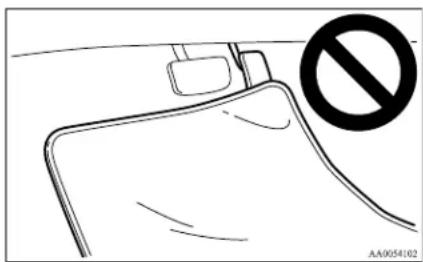
Starting and driving
Carrying children in the vehicle
● Never leave your vehicle unattended with the key in the ignition and children inside the vehicle. Children may play with the driving controls and this could lead to an accident.
● Make sure that infants and small children are properly restrained in accordance with the laws and regulations, and for maximum protection in case of an accident.
● Prevent children from playing in the cargo area. It is quite dangerous to allow them to play there while the vehicle is moving.
Starting and driving
Running-in recommendations
E00600402135
During the running-in period for the first 1,000 km (620 miles), it is advisable to drive your new vehicle using the following precautions as a guideline to aid long life as well as future economy and performance.
● Do not race the engine at high speeds.
● Avoid rapid starting, accelerating, braking and prolonged high-speed running.
- Keep to the running-in speed limit shown below.
Please note that the legal speed limits displayed must be adhered to.
● Do not exceed loading limits.
● Refrain from towing a trailer.
Vehicles with manual transmission
| Shift point | Speed limit | ||||
| 2WD | Vehicles with easy select 4WD Vehicles with super select 4WD | ||||
| 2H, 4H 4L 2H, 4H, 4HLc 4LLc | |||||
| 1^st gear | 20 km/h (12 mph) 20 km/h (12 mph) 10 km/h (6 mph) 20 km/h (12 mph) 10 km/h (6 mph) | ||||
| 2^nd gear | 40 km/h (25 mph) 40 km/h (25 mph) 20 km/h (12 mph) 40 km/h (25 mph) 20 km/h (12 mph) | ||||
| 3^rd gear | 65 km/h (40 mph) 70 km/h (43 mph) 35 km/h (22 mph) 70 km/h (43 mph) 35 km/h (22 mph) | ||||
| 4^th gear | 95 km/h (59 mph) 100 km/h (62 mph) 55 km/h (34 mph) 100 km/h (62 mph) 50 km/h (30 mph) | ||||
| 5^th gear | 120 km/h (74 mph) 130 km/h (81 mph) 65 km/h (40 mph) 130 km/h (81 mph) 65 km/h (40 mph) | ||||
Starting and driving
Vehicles with automatic transmission
Vehicles with 4A/T
| Shift point | Speed limit | ||||
| 2WD | Vehicles with easy select 4WD Vehicles with super select 4WD | ||||
| 2II, 4II 4L 2II, 4III, 4IILc 4LLc | |||||
| “L” (LOW) 25 km/h (16 mph) 25 km/h (16 mph) 15 km/h (9 mph) 25 km/h (16 mph) 15 km/h (9 mph) | |||||
| “2” (SECOND) 65 km/h (40 mph) 65 km/h (40 mph) 35 km/h (22 mph) 65 km/h (40 mph) 35 km/h (22 mph) | |||||
| “D” (DRIVE) *1 | 100 km/h (62 mph) 100 km/h (62 mph) 50 km/h (30 mph) 100 km/h (62 mph) | 50 km/h (30 mph) | |||
| “D” (DRIVE) *2 | 140 km/h (87 mph) 140 km/h (87 mph) — 135 km/h (84 mph) — | ||||
*1: With overdrive switched OFF
*2: With overdrive switched ON
Vehicles with 5A/T
| Shift point | Speed limit | |
| 2H, 4H, 4HLc 4LLc | ||
| 1^st gear | 15 km/h (9 mph) 5 km/h (3 mph) | |
| 2^nd gear | 40 km/h (25 mph) 20 km/h (12 mph) | |
| 3^rd gear | 60 km/h (37 mph) 30 km/h (19 mph) | |
| 4^th gear | 85 km/h (53 mph) 45 km/h (28 mph) | |
| 5^th gear | 120 km/h (74 mph) — | |
NOTE
- On 4WD vehicles with automatic transmission, when the transfer shift lever is in "4LLc", the transmission will not shift into the overdrive gear.
Starting and driving

CAUTION
- On 4WD vehicles, the “4LLc” range gives maximum torque for low-speed driving on steep slopes, as well as sandy, muddy, and other difficult surfaces. On vehicles with A/T, do not exceed speeds of approximately 70 km/h (43 mph) in “4LLc” range.
Parking brake
L00600501562
To park the vehicle, first bring it to a complete stop, fully engage the parking brake, and then move the gearshift lever to 1 ^st (on an uphill) or Reverse (on a downhill) position for vehicles with manual transmission or set the selector lever to "P" (PARK) position on automatic transmission vehicles.

CAUTION
● Before driving, be sure that the parking brake is fully released and brake warning lamp is off.
If a vehicle is driven without releasing the parking brake, the brake will be overheated, resulting in ineffective braking and possible brake failure.
- When you intend to apply the parking brake, firmly press the brake pedal to bring the vehicle to a complete stop before pulling the parking brake lever. Pulling the parking brake lever with the vehicle moving could make the rear wheels lock up, thereby making the vehicle unstable. It could also make the parking brake malfunction.
- If the brake warning lamp does not extinguish when the parking brake is fully released, the brake system may be an abnormal.
Have your vehicle checked immediately. For details, refer to "Brake warning lamp" on page 3-08.
Type 1
To apply
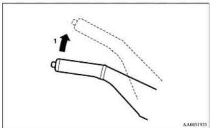
natural_image
Diagram of a mechanical component with dashed and solid lines indicating motion, no text or symbols present1- Firmly depress and hold the brake pedal, then pull the lever up without pushing the button at the end of hand grip.
To release
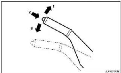
1- Firmly depress and hold the brake pedal, then pull the lever up slightly.
2- Push the button at the end of hand grip.
3- Lower the lever fully.
Type 2
To apply
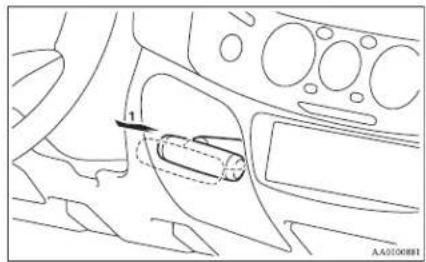
natural_image
Diagram of a car interior showing a hand valve and dashboard (no text or symbols)1- Firmly depress and hold the brake pedal, then pull the lever out.
To release
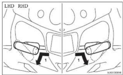
Starting and driving
1- Firmly depress and hold the brake pedal, then pull the lever out slightly and turn it clockwise (LHD) or anticlockwise (RHD).
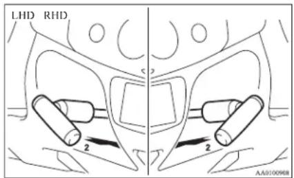
2- Push in the lever completely.
Parking
E00600601202
Parking on a hill
To prevent the vehicle from rolling, follow these procedures:
Parking on a downhill slope
Turn the front wheels towards the kerb and move the vehicle forward until the kerb side wheel gently touches the kerb.
Set the parking brake and place the gearshift lever into the “R” (Reverse) position (with M/T) or the selector lever into the “P” (PARK) position (with A/T).
If necessary, apply chocks to wheels.
Parking on an uphill slope
Turn the front wheels away from the kerb and move the vehicle back until the kerb side wheel gently touches the kerb.
Set the parking brake and place the gearshift lever into the 1 ^st position (with M/T) or the selector lever into the “P” (PARK) position (with A/T).
If necessary, apply chocks to wheels.
NOTE
- If your vehicle is equipped with A/T, be sure to apply the parking brake before moving the selector lever to the "P" (PARK) position. If you move the selector lever to the "P" (PARK) position before applying the parking brake, it may be difficult to disengage the selector lever from the "P" (PARK) position when next you drive the vehicle, requiring application of a strong force to the selector lever to move from the "P" (PARK) position.
Parking with the engine running
Never leave the engine running while you take a short sleep/rest. Also, never leave the engine running in a closed or poorly ventilated place.
WARNING
● Leaving the engine running risks injury or death from accidentally moving the gearshift lever (on M/T vehicles) or the selector lever (on A/T vehicles) or the accumulation of toxic exhaust fumes in the passenger compartment.
Where you park
Your front bumper can be damaged if you scrape it over kerbs or parking stop blocks. Be careful when travelling up or down steep slopes where your bumper can scrape the road.
WARNING
- Do not park your vehicle in areas where combustible materials such as dry grass or leaves can come in contact with a hot exhaust, since a fire could occur.
When leaving the vehicle
Always remove the key from the ignition switch and lock all doors when leaving the vehicle unattended.
Always try to park your vehicle in a well lit area.
Steering wheel height adjustment
E00600700219
To adjust the steering wheel height, release the tilt lock lever while holding the steering wheel by hand, and raise or lower the steering wheel to the desired height.
After adjustment, securely lock the lever by pulling it upward.
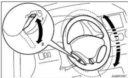
1-Locked
2-Release
WARNING
● After adjusting to the desired height, check to be sure that the lever is locked.
- Do not attempt to adjust the steering wheel while you are driving the vehicle.
- When releasing the tilt lock lever, move it to the release position (2) and hold the steering wheel by hand to prevent it falling to the lowest position.
Inside rear-view mirror
E00600800106
Adjust the rear-view mirror only after making any seat adjustments so you have a clear view to the rear of the vehicle.
WARNING
- Do not attempt to adjust the rear-view mirror while driving. This can be dangerous. Always adjust the mirror before driving.
Adjust the rear-view mirror to maximize the view through the rear window.
To adjust the vertical mirror position
It is possible to move the mirror up and down to adjust its position.
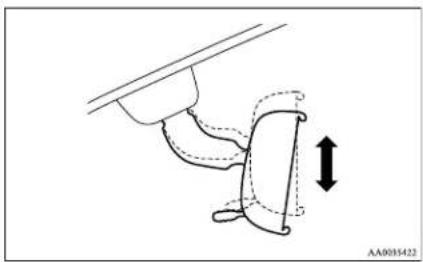
natural_image
Diagram of a mechanical component with dashed lines indicating motion, no text or symbols presentTo reduce the glare
The lever (A) at the bottom of the mirror can be used to adjust the mirror to reduce the glare from the headlamps of vehicles behind you during night driving.
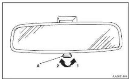
1- Normal
2- Anti-glare
Starting and driving
Outside rear-view mirrors
To adjust the mirror position
E00600900149
E00601000482
WARNING
- Do not attempt to adjust the rear-view mirrors while driving. This can be dangerous.
Always adjust the mirrors before driving. - Your vehicle is equipped with convex type mirrors.
Please take into consideration, that objects you see in the mirror will look smaller and farther away compared to a normal flat mirror.
Do not use this mirror to estimate distance of following vehicles when changing lanes.
Manual outside rear-view mirrors\*
Adjust the mirror surface by hands as indicated by the arrows.
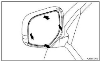
natural_image
Diagram of a car side mirror with directional arrows indicating rotation (no text or symbols)Electric remote-controlled outside rear-view mirrors*
The electric remote-controlled outside rear-view mirrors can be operated when the ignition switch is in the "ON" or "ACC" position.
Push the switch (A) on the same side as the mirror whose adjustment is desired.
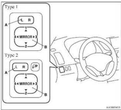
L- Left outside mirror adjustment
R- Right outside mirror adjustment
NOTE
● After adjustment, lightly push the switch on the opposite side to return it to the neutral position.
Press the switch (B) to the left, right, up or down to adjust the mirror position.
1-Up
2-Down
3-Right
4- Left
To fold the mirror
E00601100467
The outside mirror can be folded in towards the side window to prevent damage when parking in narrow areas.
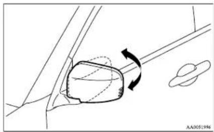
natural_image
Diagram of a car interior showing a seatbelt mechanism with rotation arrow (no text or symbols)Mirror retractor switch\*
The mirror retractor switch can be operated with the ignition switch in the "ON" or "ACC" position.
Starting and driving
Push the switch to fold the mirrors inward, and push the switch again to return them to extended position.
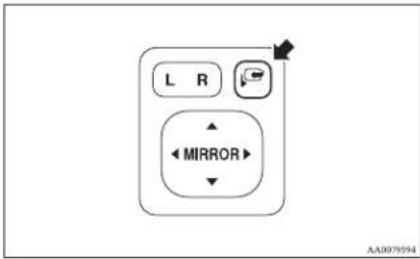
NOTE
- It is also possible to fold and return the mirrors by hand.
- When freezing has occurred and mirrors fail to operate as intended, please refrain from repeated pushing of the retractor switch as this action can result in burn-out of the mirror motor circuits.
Heated mirror\*
E00601200253
When the rear window demister switch (C) is pressed, the outside rear-view mirrors are demisted or defrosted. Current will flow through the heater element inside the mirrors, thus clearing away frost or condensation.
The indication lamp (D) will illuminate while the demister is on. The heater will be turned off automatically in about 20 minutes.
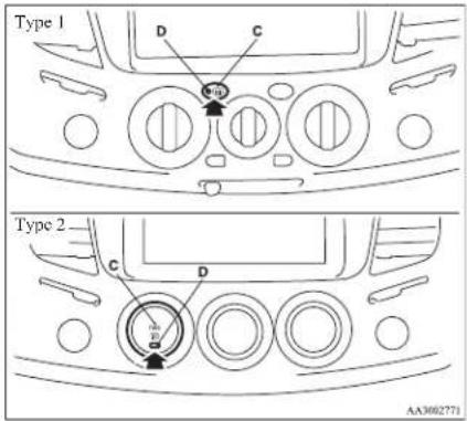
Ignition switch
E00601401874
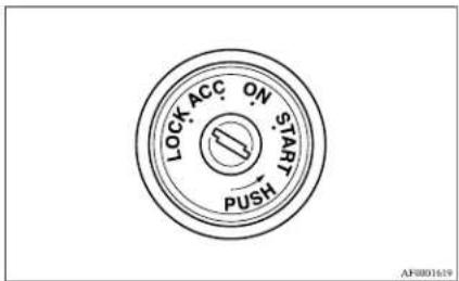
LOCK
The engine is stopped and the steering wheel locked. The key can only be inserted and removed when the switch in this position.
ACC
The engine is stopped, but the electrical devices such as the radio and cigarette lighter can be operated.
ON
The engine is running, and all the vehicle's electrical devices can be operated.
START
The starter motor operates. After the engine has started, release the key and it will automatically return to the "ON" position.
Starting and driving
NOTE
- If your vehicle is equipped with the Daytime Running Lamp, when the ignition switch is in the "ON", the headlamp low beams etc. are turned on.
Refer to "Headlamps" on page 3-30.
- Your vehicle is equipped with an electronic immobilizer.
To start the engine, the ID code which the transponder inside the key sends must match the one registered in the immobilizer computer.
Refer to "Electronic immobilizer" on page 1-03.
To remove the key
Push the key in at the "ACC" position and keep it depressed until it is turned to the "LOCK" position and remove it.
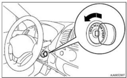
CAUTION
- Do not remove the ignition key from the ignition switch while driving. The steering wheel will be locked, causing loss of control.
- If the engine is stopped while driving, the brake servomechanism will cease to function and braking efficiency will deteriorate. Also, the power steering system will not function and it will require greater manual effort to operate the steering.
- Do not leave the key in the "ON" position for a long time when the engine is not running, doing so will cause the battery to be discharged.
- Do not turn the key to the "START" position when the engine is running, doing so could damage the starter motor.
Steering wheel lock
E00601500227
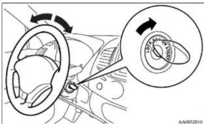
To lock
Remove the key at the "LOCK" position.
Turn the steering wheel until it is locked.
To unlock
Turn the key to the "ACC" position while moving the steering wheel slightly.
CAUTION
- Remove the key when leaving the vehicle.
NOTE
- If the front wheels are turned, the anti-theft lock may sometimes make it difficult to turn the key from "LOCK" to "ACC". Firmly turn the steering wheel to the left or to the right as you turn the key.
Starting
E00601600404
Tips for starting
- Do not operate the starter motor continuously for anything longer than 10 seconds; doing so could run down the battery. If the engine does not start, turn the ignition switch back to "LOCK" position, wait a few seconds, and then try again. Trying repeatedly with the starter motor still turning will damage the starter mechanism.
- If the engine cannot be started because the battery is weak or dead, refer to the "Emergency starting" section for instructions on starting the engine.
- The engine is well warmed up if the coolant temperature gauge needle starts to move (the engine speed decreases). Extended warming-up operation will result in excessive fuel consumption.
WARNING
● Never run the engine in a closed or poorly ventilated area any longer than is needed to move your vehicle in or out of the area. Carbon monoxide gases are odourless and can be fatal.
CAUTION
● Never attempt to start the engine by pushing or pulling the vehicle. Especially the automatic transmission, since the structure is different from a manual transmission, it is not possible to start the engine by using this technique. Never attempt this or it could damage the automatic transmission.
- Do not run the engine at high rpm or drive the vehicle at high speed until the engine has had a chance to warm up.
● Release the ignition key as soon as the engine starts to avoid damaging the starter motor.
- Do not stop the engine immediately after high-speed or uphill driving. First allow the engine to idle to give the turbocharger a chance to cool down.
Starting the engine
E00601701792
- Insert the ignition key and fasten the seat belt.
- Make sure the parking brake is applied.
- Depress and hold the brake pedal.
- On vehicles with manual transmission, place the gearshift lever in the "N" (Neutral) position and depress the clutch pedal all the way.
Starting and driving
On vehicles with automatic transmission, make sure the selector lever in the "P" (PARK) position.
Vehicles with manual transmission
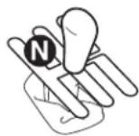
Vehicles with automatic transmission
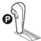
AA097134
NOTE
-
On vehicles with automatic transmission, the engine will not start if the selector lever is in any position other than "P" (PARK) or "N" (NEUTRAL) position.
For safety, start the engine with the selector lever in the "P" (PARK) position because in this position the rear wheels are locked in place. -
Turn the ignition key to the "ON" position. The diesel preheat indication lamp will first illuminate, and then after a short time go out, indicating that preheating is completed.
NOTE
- If the engine is cold, the diesel preheat indication lamp is on for a longer time.
Starting and driving
- When the engine has not been started within about 5 seconds after the diesel preheat indication lamp went out, return the ignition key to the "LOCK" position. Then, turn the key to the "ON" position to preheat the engine again.
-
When the engine is warm, the diesel preheat indication lamp does not come on even if the ignition key is placed in the "ON" position. Start the engine by turning the ignition key right to the "START" position.
-
Operate the accelerator pedal as described below in accordance with the atmospheric temperature and/or engine condition and then start the engine.
-
When the atmospheric temperature is moderate or the engine is warm, start the engine without depressing the accelerator pedal.
- When the atmospheric temperature is low and the engine is cold, start the engine while depressing the accelerator pedal.
Fuel injection amount learning process
E00616000028
To keep exhaust emissions and engine noise low, the engine very occasionally performs a learning process for the fuel injection amount.
The engine sounds slightly different from usual while the learning process is taking place. The change in the engine sound does not indicate a fault.
Manual transmission
E00602000199
The shift pattern is shown on the gearshift lever knob. Be sure to always fully depress the clutch pedal before attempting to shift the lever.
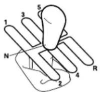
AA0052036
CAUTION
- Do not move the gearshift lever into reverse while the vehicle is moving forward; doing so will damage the transmission.
- Do not rest your foot on the clutch pedal while driving as this will cause premature clutch wear or damage.
CAUTION
- If the clutch is engaged suddenly while the engine revolution is high, an extremely large load will be applied instantaneously to the power train, possibly leading to the breakage of that component. Please ensure, therefore, that the clutch pedal is always applied in a slow yet firm manner. Your vehicle has a special feature to protect the power train from damage; the engine is controlled in such a way that excessive increase in engine revolution is prevented in situations where the accelerator pedal is depressed while the gearshift lever is in the 1^st position and the clutch pedal has been depressed.
NOTE
- If it is hard to shift into 1^st , depress the clutch pedal again; the shift will then be easier to make.
- To shift into reverse from 5^th gear, move the gearshift lever to the "N" (Neutral) position, and then shift it into reverse.
Changing gears
E00610600136
Always take care to change the gear with the vehicle speed matched to the engine speed. Proper shifting will prolong engine life.
Avoid shifting down at high speed, as this may cause excessive engine speed (the tachometer needle into the red zone) and damage the engine.
Possible driving speed
E00610801151
| Shift point | Speed limit | |||
| 2WD | Vehicles with easy select 4WD Vehicles with super select 4WD | |||
| 2H, 4H 4L 2H, 4H, 4HLc 4LLc | ||||
| 1^st gear | 30 km/h (19 mph) 35 km/h (22 mph) 15 km/h (9 mph) | 35 km/h (22 mph) 15 km/h (9 mph) | ||
| 2^nd gear | 60 km/h (37 mph) 65 km/h (40 mph) 35 km/h (22 mph) | 65 km/h (40 mph) 30 km/h (19 mph) | ||
| 3^rd gcar | 100 km/h (62 mph) 105 km/h (65 mph) 55 km/h (34 mph) | 105 km/h (65 mph) 55 km/h (34 mph) | ||
| 4^th gear | 145 km/h (90 mph) 155 km/h (96 mph) 80 km/h (50 mph) | 150 km/h (93 mph) 80 km/h (50 mph) | ||
5^th gear is an overdrive ratio and its use reduces engine speed below that of the 4^th gear. Use 5^th gear whenever vehicle speed allows, for maximum fuel economy.
Starting and driving
Automatic transmission 4A/T
E00603200619
NOTE
● During running-in period or immediately after reconnection of the battery cable, there may be a case where gear shifts are not made smoothly. This does not indicate a faulty transmission.
Gear shifts will become smooth after the transmission has been shifted several times by the electronic control system.
Selector lever operation
ED0607300968
The transmission has 4 forward gears and 1 reverse gear.
The individual gears are selected automatically, depending on the position of the gear selector lever, the speed of the vehicle and the position of the accelerator pedal.
The selector lever has 6 positions, and is equipped with a lock button (A) to avoid inadvertent selection of the wrong gear.
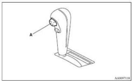
natural_image
Line drawing of a mechanical lever or support structure with labeled component 'A' (no text or symbols beyond label)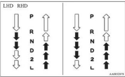
| ↓ | Lock button must be pushed to move the selector lever. |
| ↓ | Lock button need not be pushed to move the selector lever. |
WARNING
- If the lock button is always pushed to operate the selector lever, the selector lever may be accidentally shifted into the following position:
LHD: "P", "R", "2" or "L"
RHD: "P", "R" or "L"
Be sure not to push the lock button when performing the operations indicated by
↓ in the illustration.
WARNING
● Always depress the brake pedal when shifting the selector lever into a gear from the "P" (PARK) or "N" (NEUTRAL) position. When beginning to drive, do not shift the selector lever from the "P" (PARK) or "N" (NEUTRAL) position while depressing the accelerator pedal, doing so is dangerous because the vehicle will "jump" forward or backward.
Selector lever position indicator
E00603500797
When the ignition switch is turned to the "ON" position, the currently position of the selector lever is indicated by the indicator (A) shown on the instrument cluster {i.e. "P" (PARK), "R" (REVERSE), "N" (NEUTRAL), "D" (DRIVE), "2" (SECOND) or "L" (LOW)}.
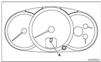
natural_image
Pure diagram of three circular components with internal symbols and a labeled point A, no text or numerical data present.Selector lever positions
E00603800615
"P" PARK
This position locks the transmission to prevent the vehicle from moving. The engine can be started in this position.
"R" REVERSE
This position is to back up.

CAUTION
- Never shift into the “P” (PARK) or “R” (REVERSE) position while the vehicle is in motion to avoid transmission damage.
"N" NEUTRAL
At this position the transmission is disengaged. It is the same as the neutral position on a manual transmission, and should be used when the vehicle is stationary for an extended length of time during driving, such as in a traffic jam.

WARNING
- Never move the selector lever to the "N" (NEUTRAL) position while driving. A serious accident could occur since you could accidentally move the selector lever into the "P" (PARK) or "R" (REVERSE) position or you will lose engine braking.
- On a gradient the engine should be started in the "P" (PARK) position, not in the "N" (NEUTRAL) position.
WARNING
● Always keep your right foot on the brake pedal when the vehicle is in "N" (NEUTRAL) position, or when shifting into or out of "N" (NEUTRAL) position, to minimize the risk of loss of control.
"D" DRIVE
This position is for normal driving. The transmission automatically selects a suitable gear for your speed and acceleration.
CAUTION
- Never shift into the “D” (DRIVE) position from the “R” (REVERSE) position while the vehicle is in motion to avoid transmission damage.
"2" SECOND
This position is for extra power when driving up moderately steep hills, and for engine braking when descending moderately steep gradients.
"L"LOW
This position is for driving up very steep hills and for engine braking at low speeds when descending steep gradients.
WARNING
● This position can be used for maximum engine braking.
Be very careful not to shift into "L" (LOW) position suddenly. Sudden engine braking may cause the tyres to skid. To avoid erroneous operation, move the selector lever firmly into each position and briefly hold it there.
Select this position according to the road conditions and vehicle speed.
NOTE
- The A/T has a control function that prevents over-revving. As a result, it may not perform a shift when the selector lever is moved from the “D” (DRIVE) position to the “2” (SECOND) position or from the “2” (SECOND) position to the “L” (LOW) position.
Overdrive control switch
E00604000089
The overdrive control switch can be used while the selector lever is in the "D" (DRIVE) position.
During normal driving
Press the overdrive control switch to turn the overdrive function on. The transmission will shift automatically among the 1^st , 2^nd , 3^rd , and 4^th gears, enabling fuel-efficient, economical driving.
Starting and driving
During hilly roads driving
Press the overdrive control switch to turn the overdrive function off. The transmission will shift automatically among the 1 ^st , 2 ^nd , and 3 ^rd gears, and light engine braking will be available on downhill roads.
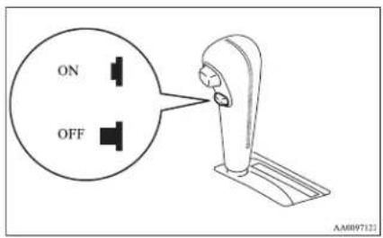
Overdrive OFF indication lamp
ED0614600017
When the overdrive control switch is in the OFF position, the overdrive OFF indication lamp in the meter cluster comes on.
When a malfunction occurs in the automatic transmission
E00615100019
When the selector lever position indicator blinks L00615280166
When the selector lever position indicator blinks while you are driving, there could be a malfunction in the automatic transmission system.
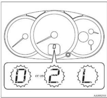
CAUTION
- If the selector lever position indicator blinks while you are driving, it is likely that a safety device is operating because of a malfunction in the automatic transmission. We recommend you to have your vehicle inspected as soon as possible.
CAUTION
● The selector lever position indicator warning function does not operate with the selector lever in the "P" (PARK), "R" (REVERSE) or "N" (NEUTRAL) position.
When the A/T (automatic transmission) fluid temperature warning lamp comes on
F00615300137
The automatic transmission fluid temperature warning lamp comes on when the automatic transmission fluid temperature becomes abnormally high with the ignition switch "ON" position.
Normally the warning lamp comes on when the ignition switch is turned to the "ON" position, and then will go out after a few seconds.
CAUTION
- If the warning lamp comes on, reduce the engine speed and stop the vehicle in a safe area.
Then set the selector lever to "P" (PARK) position and idle the engine until the warning lamp goes off.
When the warning lamp goes off, resume normal driving.
If the warning lamp does not go off, we recommend you to have your vehicle inspected.
Operation of the automatic transmission
L00604200515
CAUTION
● Before selecting a gear with the engine running and the vehicle stationary, fully depress the brake pedal to prevent the vehicle from creeping.
The vehicle will begin to move as soon as the gear is engaged, especially when the engine speed is high, at fast idle or with the air conditioning operating, the brakes should only be released when you are ready to drive away.
● Depress the brake pedal with the right foot at all times.
Using the left foot could cause driver movement delay in case of an emergency.
CAUTION
● To prevent sudden acceleration, never race the engine when shifting from the "P" (PARK) or "N" (NEUTRAL) position.
- Operating the accelerator pedal while the other foot is resting on the brake pedal will affect braking efficiency and may cause premature wear of brake pads. Do not race the engine with brake pedal pressed.
This can damage the transmission.
● Use the selector lever in the correct shift position in accordance with driving conditions.
Never coast downhill backward with the "D" (DRIVE) position or coast forward with the "R" (REVERSE) position. The engine stops and the brake pedal effort or the steering wheel handling weight increasing could lead to an accident.
Passing acceleration
E00604500127
To gain extra acceleration in "D" (DRIVE) position (when passing another vehicle), push the accelerator to the floor. The automatic transmission will automatically downshift.
Waiting
ED0604500128
For short waiting periods, such as at traffic signals, the vehicle can be left in gear and held stationary with the service brake.
For longer waiting periods with the engine running, the selector lever should be placed in the "N" (NEU-TRAL) position.
CAUTION
● Never hold the vehicle stationary on a hill using the accelerator pedal (without using the brake pedal). Always apply the parking brake and/or service brakes.
● Unexpected acceleration may occur if the selector lever is in a position other than "P" (PARK) or "N" (NEUTRAL) position. Prior to moving off after having stopped the vehicle, make sure that the selector lever is in "D" (DRIVE) position.
Parking
ED0604700246
To park the vehicle, first bring it to a complete stop, fully engage the parking brake, and then move the selector lever to the "P" (PARK) position. If you are going to leave the vehicle unattended, always switch off the engine and remove the ignition key.
NOTE
- On a slope, be sure to apply the parking brake before moving the selector lever to the "P" (PARK) position. If you move the selector lever to the "P" (PARK) position before applying the parking brake, it may be difficult to disengage the selector lever from the "P" (PARK) position when next you drive the vehicle, requiring application of a strong force to the selector lever to move from the "P" (PARK) position.
Starting and driving
When the automatic transmission makes no speed change
E00604800478
If the transmission does not change speeds while driving, or your vehicle does not pick up enough speed when starting on an uphill slope, it may be that there is something unusual happening in the transmission, causing a safety device to activate. We recommend you to have your checked as soon as possible.
NOTE
- When the selector lever position indicator in the instrument panel blinks, it means that there is an abnormal condition in the transmission. Refer to “When the selector lever position indicator blinks” on page 4-18.
Automatic transmission Sports Mode 5A/T
E00603200576
NOTE
- During running-in period or immediately after reconnection of the battery cable, there may be a case where gear shifts are not made smoothly. This does not indicate a faulty transmission. Gear shifts will become smooth after the transmission has been shifted several times by the electronic control system.
Selector lever operation
E00603300867
The transmission has 5 forward gears and 1 reverse gear.
The individual gears are selected automatically, depending on the position of the gear selector lever, the speed of the vehicle and the position of the accelerator pedal.
The selector lever has 2 gates; the main gate (1) and the manual gate (2).
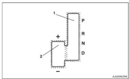
NOTE
- For information on manual gate operation, please refer to "Sports mode" on page 4-22.
In the main gate, selector lever has 4 positions, and is equipped with a lock button (A) to avoid inadvertent selection of the wrong gear.
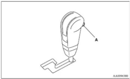
natural_image
Technical line drawing of a mechanical component with labeled point A (no text or symbols beyond label)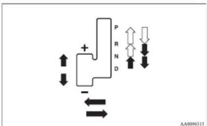
| ↓ | The lock button must be pushed to move the selector lever. |
| ↓ | The lock button need not be pushed to move the selector lever. |

WARNING
- If the lock button is always pushed to operate the selector lever, the lever may be accidentally shifted into the "P" (PARK) or "R" (REVERSE) position. Be sure not to push the lock button when performing the operations indicated by in the illustration.
● Always depress the brake pedal when shifting the selector lever into a gear from the "P" (PARK) or "N" (NEUTRAL) position.
When beginning to drive, do not shift the selector lever from the "P" (PARK) or "N" (NEUTRAL) position while depressing the accelerator pedal, doing so is dangerous because the vehicle will "jump" forward or backward.
Selector lever position indicator
E00603500726
When the ignition switch is turned to the “ON” position, the currently position of the selector lever is indicated by the indicator (A) shown on the instrument cluster {i.e. “P” (PARK), “R” (REVERSE), “N” (NEUTRAL), “D” (DRIVE)}.
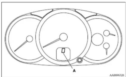
natural_image
Diagram of a multi-circular mechanical or electrical component with labeled points A and B, showing no readable text or symbols.Selector lever positions (Main gate)
ED0603800585
"P" PARK
This position locks the transmission to prevent the vehicle from moving. The engine can be started in this position.
"R" REVERSE
This position is to back up.

CAUTION
- Never shift into the "P" (PARK) or "R" (REVERSE) position while the vehicle is in motion to avoid a transmission damage.
"N" NEUTRAL
At this position the transmission is disengaged. It is the same as the neutral position on a M/T, and should only be used when the vehicle is stationary for an extended length of time during driving, such as in a traffic jam.

WARNING
- Never move the selector lever to the "N" (NEUTRAL) position while driving. A serious accident could occur since you could accidentally move the lever into the "P" (PARK) or "R" (REVERSE) position or you will lose engine braking.
- On a gradient the engine should be started in the "P" (PARK) position, not in the "N" (NEUTRAL) position.
● Always keep your right foot on the brake pedal when shifting into or out of "N" (NEUTRAL), to minimize the risk of loss of control.
"D" DRIVE
This position is for normal driving. The transmission automatically selects a suitable gear ratio for your speed and acceleration.

CAUTION
- Never shift into the “D” (DRIVE) position from the “R” (REVERSE) position while the vehicle is in motion to avoid transmission damage.
Starting and driving
Sports mode
E00603901088
Whether the vehicle is stationary or in motion, sports mode is selected by gently pushing the selector lever from the "D" (DRIVE) position into the manual gate (A). To return to "D" range operation, gently push the selector lever back into the main gate (B).
In sports mode, gear shifts can be made rapidly simply by moving the selector lever backward and forward. In contrast to a manual transmission, the sports mode allows gear shifts with the accelerator pedal depressed.
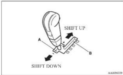
+(SHIFT UP)
Push the lever forward once to shift up one gear.
- (SHIFT DOWN)
Pull the lever backward once to shift down one gear.
CAUTION
- In sports mode, the driver must execute upward shifts in accordance with prevailing road conditions, taking care to keep the engine speed below the red zone.
- By rapidly moving the selector lever backward (SHIFT DOWN) twice, it is possible to skip one gear, i.e., 3^rd to 1^st , 4^th to 2^nd or 5^th to 3^rd . Since sudden engine braking and/or rapid acceleration can cause a loss of traction, downshifts must be made carefully in accordance with the vehicle's speed.
NOTE
- The upward shift may be made automatically in sports mode when the engine revolutions rises and approaches the tachometer's red zone (the red-coloured part of the tachometer dial).
- In sports mode, only the 5 forward gears can be selected. To reverse or park the vehicle, move the selector lever to the "R" (REVERSE) or "P" (PARK) position as required.
-
To maintain good running performance, the transmission may refuse to perform an upshift when the selector lever is moved to the “+ (SHIFT UP)” position at certain vehicle speeds. Also, to prevent over-revving of the engine, the transmission may refuse to perform a downshift when the lever is moved to the “- (SHIFT DOWN)” position at certain vehicle speeds.
-
In sports mode, downward shifts are made automatically when the vehicle slows down. When the vehicle stops, 1^st gear is automatically selected.
- When driving away on a slippery road, push the selector lever forward into the “+ (SHIFT UP)” position. This causes the transmission to shift into the 2^rd gear which is better for smooth driving away on a slippery road. Push the selector lever to the “- (SHIFT DOWN)” side to shift back to the 1^st gear.
Sports mode indicator
F00612300355
In sports mode, the currently selected position is indicated by the indicator (A) shown on the instrument panel.
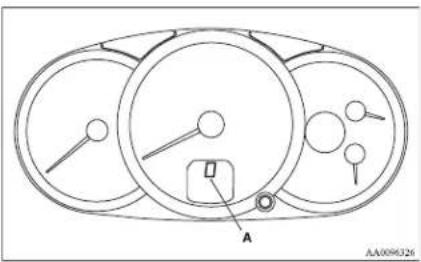
When a malfunction occurs in the automatic transmission
E00615100152
When the selector lever position indicator blinks
L00615200179
When the selector lever position indicator blinks while you are driving, there could be a malfunction in the automatic transmission system.
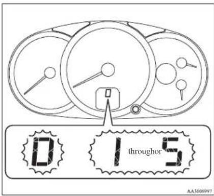
CAUTION
- If the selector lever position indicator blinks while you are driving, it is likely that a safety device is operating because of a malfunction in the automatic transmission. We recommend you to have your vehicle inspected as soon as possible.
CAUTION
● The selector lever position indicator warning function does not operate with the selector lever in the "P" (PARK), "R" (REVERSE) or "N" (NEUTRAL) position.
When the A/T (automatic transmission) fluid temperature warning lamp comes on
ED015300141
The automatic transmission fluid temperature warning lamp comes on when the automatic transmission fluid temperature becomes abnormally high. Normally the warning lamp comes on when the ignition switch is turned to the "ON" position, and then will go out after a few seconds.
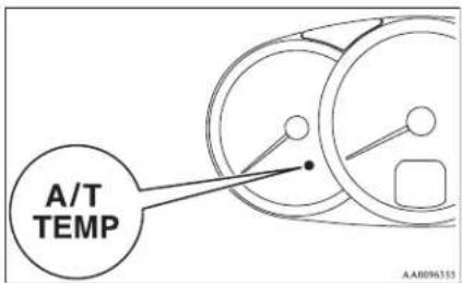
CAUTION
- If the lamp comes on, reduce the engine speed and stop the vehicle in a safe area. Then set the selector lever to the "P" (PARK) position and idle the engine until the warning lamp goes off. When the warning lamp goes off, resume normal driving. If the warning lamp does not go off, we recommend you to have your vehicle inspected.
Operation of the automatic transmission
E00604200528
CAUTION
● Before selecting a gear with the engine running and the vehicle stationary, fully depress the brake pedal to prevent the vehicle from creeping.
The vehicle will begin to move as soon as the gear is engaged, especially when the engine speed is high, at fast idle or with the air conditioning operating, the brakes should only be released when you are ready to drive away.
● Depress the brake pedal with the right foot at all times.
Using the left foot could cause driver movement delay in case of an emergency.
● To prevent sudden acceleration, never race the engine when shifting from the "P" (PARK) or "N" (NEUTRAL) position.
Starting and driving

CAUTION
- Operating the accelerator pedal while the other foot is resting on the brake pedal will affect braking efficiency and may cause premature wear of brake pads.
- Use the selector lever in the correct shift position in accordance with driving conditions.
Never coast downhill backward with the driving shift position {"D" (DRIVE) or sports mode} or coast forward with the "R" (REVERSE) position.
The engine stops and the brake pedal effort or the steering wheel handling weight increasing could lead to an accident. - Do not race the engine with brake pedal pressed when the vehicle is stationary. This can damage the automatic transmission.
Passing acceleration
E00604500329
To gain extra acceleration in "D" (DRIVE) position, push the accelerator to the floor. The automatic transmission will automatically downshift.
NOTE
- In “Sports mode”, downshifts do not take place when the accelerator is depressed all the way to the floor.
Waiting
E00604600304
For short waiting periods, such as at traffic signals, the vehicle can be left in gear and held stationary with the service brake.
For longer waiting periods with the engine running, place the selector lever in the "N" (NEUTRAL) position..

CAUTION
● Never hold the vehicle stationary on a hill using the accelerator pedal (without using the brake pedal). Always apply the parking brake and/or service brakes.
● Unexpected acceleration may occur if the selector lever is in a position other than "P" (PARK) or "N" (NEUTRAL). Prior to moving off after having stopped the vehicle, make sure that the selector lever is in the "D" (DRIVE) position.
Parking
E00604700262
To park the vehicle, first bring it to a complete stop, fully engage the parking brake, and then move the selector lever to the "P" (PARK) position. If you are going to leave the vehicle unattended, always switch off the engine and remove the ignition key.
NOTE
- On a slope, be sure to apply the parking brake before moving the selector lever to the "P" (PARK) position. If you move the selector lever to the "P" (PARK) position before applying the parking brake, it may be difficult to disengage the selector lever from the "P" (PARK) position when next you drive the vehicle, requiring application of a strong force to the selector lever to move from the "P" (PARK) position.
When the automatic transmission makes no speed change
E00604800683
If the transmission does not change speeds while driving, or your vehicle does not pick up enough speed when starting on an uphill slope, it may be that there is something unusual happening in the transmission, causing a safety device to activate. We recommend you to have your checked as soon as possible.
- If your vehicle has difficulty moving uphill, shift the selector lever into 2^d gear of the “Sports mode”.
This method might not work depending on the type of transmission malfunction.
- Once the vehicle is moving on a level road, move the selector lever back to "D" (DRIVE).
NOTE
- When the selector lever position indicator in the instrument panel blinks, it means that there is an abnormal condition in the transmission. Refer to “When the selector lever position indicator blinks” on page 4-18.
Easy select 4WD\*
E00614700119
Shifting to rear-wheel drive or 4-wheel drive can be made by operating the transfer shift lever (A). Shift the transfer shift lever to an appropriate position according to the road surface conditions. In addition, the 2WD/4WD operation indication lamp indicates the transfer shift lever shifting state. Refer to "2WD/4WD operation indication lamp" on page 4-27.
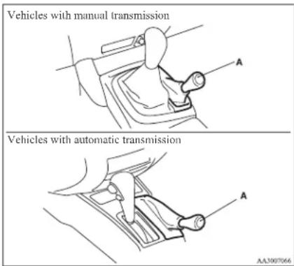
Transfer shift lever position and 2WD/4WD operation indication lamp
E00614800080
| Transfer shift lever position | 2WD/4WD operation indication lamp | Driving conditions | |
| 2II | Rear-wheel drive | 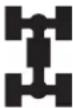 | When driving on dry paved road. |
| 4II | 4-wheel drive | 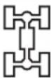 | When driving on rough, sand or snow covered roads. |
| 4L | Low range 4-wheel drive | 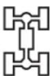 | When driving up or down steep hills, on rough or muddy roads (especially when increased torque is required). |
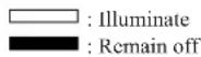
Starting and driving
NOTE
- On vehicles with automatic transmission, when the transfer shift lever is in "4L", the transmission will not shift into the overdrive gear.
CAUTION
- The “4L” range gives maximum torque for lowspeed driving on steep slopes, as well as sandy, muddy, and other difficult surfaces. On vehicles with automatic transmission, do not exceed speeds of approximately 70 km/h (43 mph) in “4L” range.
- Do not drive your vehicle in the "4H" or "4L" on dry paved roads and highways. Doing so may result in excessive tyre wear, increased fuel consumption, and possible noise generation. It may also increase the differential oil temperature, which may damage the drive system. Further, the drive train will be subjected to excessive loading, resulting in oil leakage, component seizure, or other serious problems. On dry paved roads and highways, drive the vehicle in "2H" only.
Starting and driving
Transfer shift lever operation
E00614900111
The shift pattern is shown on the transfer shift lever knob.
The transfer shift lever should be positioned in accordance with the following operating conditions:
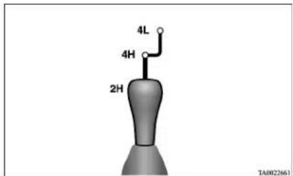
| To shift from To | Procedure | ||
| Vehicles with manual transmission Vehicles with automatic transmission | |||
| 2H 4H | The transfer shift lever can be operated while the vehicle is either moving or stationary.When the vehicle is not in motion, shift the gearshift lever to the “N” (Neutral) position before operating the transfer shift lever.When the vehicle is moving, and only while it can be steered straight ahead, release the accelerator pedal before operating the transfer shift lever. | The transfer shift lever can be operated while the vehicle is either moving or stationary.When the vehicle is not in motion, shift the selector lever to the “N” (NEUTRAL) position before operating the transfer shift lever.When the vehicle is moving, and only while it can be steered straight ahead, shift the selector lever to the “D” (DRIVE) position, and release the accelerator pedal before operating the transfer shift lever. | |
| 4H 2H | |||
| 4H 4L | Stop the vehicle, depress the clutch pedal to the floor and operate the transfer shift lever. | Stop the vehicle, shift the selector lever to the “N” (NEUTRAL) position, and operate the transfer shift lever.If operation is made with the selector lever placed in any other position than “N” (NEUTRAL) position, a gear noise may be generated, with a possible failure to shift into a proper gear. | |
| 4L 4H | |||
NOTE
- Shifting of the transfer shift lever between “2H” ↔ “4H” should only be done at speeds below 100 km/h (62 mph).
- During driving, never attempt to shift from "4H" to "4L".
- When shifting from “2II” to “4II” in cold weather while the vehicle is in motion, the transmission gear may make some noise. In cold weather, try to shift the gear while the vehicle is stopped.
- There may be a case that the transfer shift lever feels heavy when it is moved from "4H" to "2IT" with the steering wheel in turned position.
This is normal and not any indication of trouble.

CAUTION
- Do not operate the transfer shift lever while the rear wheels of the vehicle are slipping on snow or ice.
2WD/4WD operation indication lamp
E00615000092
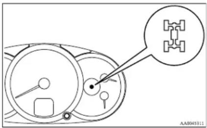
When the ignition switch is in the "ON" position, the 2WD/4WD operation indication lamp shows the shifting condition. The 2WD/4WD operation indication lamp comes on at each transfer shift lever position as follows:
Except for vehicles for Russia and Ukraine
“2H” “4H”
| Transfer shift lever position | 2WD/4WD operation indication lamp |
| 2H |  |
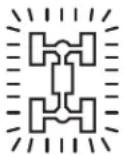 | |
| Drive mode switching in progress | |
| 4H |  |
: Blink
Starting and driving
NOTE
● The 2WD/4WD operation indication lamp blinks while the selection is in process. Take the following precautions when the indication lamp is blinking or remains off.
- Keep the steering wheel in the straight ahead position while making range selections. If you attempt to drive forward with the steering wheel turned, gear rattling may occur and the desired range may not actually be selected.
- If the 2WD/4WD operation indication lamp continues blinking after a "2H" "4H" selection has been made with the vehicle moving, hold the steering wheel in the straight ahead position and slowly depress the accelerator pedal several times.
Vehicles for Russia and Ukraine
“2H” “4H”
| Transfer shift lever position | 2WD/4WD operation indication lamp | |
| 2H |  |  |
 | ### | |
| Drive mode switching in progress |  |  |
| ### | ### | |
| 4H |  |  |
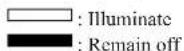
NOTE
- When the transfer shift lever is shifted between 2H 4H, the 2WD/4WD operation indication lamp does not switch to illuminate or remain off while the selection is in process. Take the following precautions when the indication lamp is remains on or off.
- Keep the steering wheel in the straight ahead position while making range selections. If you attempt to drive forward with the steering wheel turned, gear rattling may occur and the desired range may not actually be selected.
- When the transfer shift lever is shifted between “2H” “4H” while the vehicle is stopped, the 2WD/4WD operation indication lamp does not switch to illuminate or remain off while the selection is in process. Drive slowly and normally after confirming that the lamp is switched.
- Do not move the selector lever while the 2WD/4WD operation indication lamp is switched.
- If the 2WD/4WD operation indication lamp does not switch after a "2H" "4H" selection has been made with the vehicle moving, hold the steering wheel in the straight ahead position and slowly depress the accelerator pedal several times.
“4H” “4L”
| Transfer shift lever position | 2WD/4WD operation indication lamp |
| 4H | 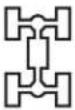 |
 | |
| Drive mode switching in progress | 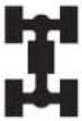 |
 | |
| 4L | 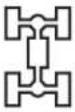 |

Starting and driving
NOTE
- The 2WD/4WD operation indication lamp will go out momentarily during shifting process from "4H" to "4L" or vice versa, as the transfer shift lever passes through the neutral position.
Be sure to operate the transfer shift lever until the 2WD/4WD operation indication lamp illuminates again.
- If, after a "4H" "4L" selection has been made, the 2WD/4WD operation indication lamp remains off and the desired range is not actually selected, return the transfer shift lever to its previous position. Place the steering wheel in the straight ahead position, drive the vehicle forward, and release the accelerator pedal. Next, hold down the clutch pedal (with manual transmission) or place the selector lever in the "N" (NEUTRAL) position (with automatic transmission) and make the range selection again.
Super select 4WD\*
L00605700197
Shifting to rear-wheel drive or 4-wheel drive can be made by operating the transfer shift lever (A). Shift the transfer shift lever to an appropriate position according to the road surface conditions. In addition, the 2WD/4WD operation indication lamp indicates the transfer shift lever shifting state. Refer to "2WD/4WD operation indication lamp" on page 4-32.
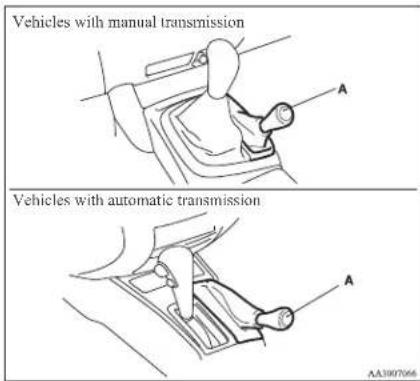
Starting and driving
Transfer shift lever position and 2WD/4WD operation indication lamp
E00605800228
| Transfer shift lever position | 2WD/4WD operation indication lamp | Driving conditions | |
| 2II | Rear-wheel drive |  | When driving on dry paved road. |
| 4II | Full-time 4-wheel drive |  | The basic position for super select 4WD.When driving on dry paved or slippery roads. |
| 4HLc | Centre differential lock engaged 4-wheel drive |  | When driving on rough, sand or snow covered roads. |
| 4LLc | Low range centre differential lock engaged 4-wheel drive |  | When driving up or down steep hills, on rough or muddy roads (especially when increased torque is required). |

Illuminate

Remain off
NOTE
- On vehicles with automatic transmission, when the transfer shift lever is in "4LLc", the transmission will not shift into the overdrive gear.

CAUTION
- The “4L.Lc” range gives maximum torque for low-speed driving on steep slopes, as well as sandy, muddy, and other difficult surfaces. On vehicles with automatic transmission, do not exceed speeds of approximately 70 km/h (43 mph) in “4L.Lc” range.
- Do not drive your vehicle in the "4HLc" or "4LLc" on dry paved roads and highways. Doing so may result in excessive tyre wear, increased fuel consumption, and possible noise generation. It may also increase the differential oil temperature, which may damage the drive system. Further, the drive train will be subjected to excessive loading, resulting in oil leakage, component seizure, or other serious problems. On dry paved roads and highways, drive the vehicle in "2H" or "4H" only.
Transfer shift lever operation
E00605900173
The shift pattern is shown on the transfer shift lever knob.
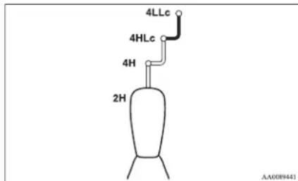
chemical
Chemical structure diagram of a 4H-2H-4Lc-4HLc reaction vessel with labeled componentsThe transfer shift lever should be positioned in accordance with the following operating conditions:
☐ : Not push down the transfer shift lever
: Push down the transfer shift lever
Starting and driving
| To shift from To | Procedure | ||
| Vehicles with manual transmission Vehicles with automatic transmission | |||
| 2H 4H | The transfer shift lever can be operated while the vehicle is either moving or stationary.When the vehicle is not in motion, shift the gearshift lever to the “N” (Neutral) position before operating the transfer shift lever.When the vehicle is moving, and only while it can be steered straight ahead, and release the accelerator pedal before operating the transfer shift lever. | The transfer shift lever can be operated while the vehicle is either moving or stationary.When the vehicle is not in motion, shift the selector lever to the “N” (NEUTRAL) position before operating the transfer shift lever.When the vehicle is moving, and only while it can be steered straight ahead, shift the selector lever to the “D” (DRIVE) position, and release the accelerator pedal before operating the transfer shift lever. | |
| 4II 2II or 4IILc | |||
| 4HLc 4H | |||
| 4HLc 4LLc | Stop the vehicle, depress the clutch pedal to the floor and operate the transfer shift lever while keeping the transfer shift lever pushed down.Keep depressing the clutch pedal while the 2WD/4WD operation indication lamp continues to blink. | Stop the vehicle, shift the selector lever to the “N” (NEUTRAL) position, and operate the transfer shift lever while keeping the transfer shift lever pushed down.If operation is made with the selector lever placed in any other position than “N” (NEUTRAL) position, a gear noise may be generated, with a possible failure to shift into a proper gear. | |
| 4LLc 4HLc | |||
NOTE
- Shifting of the transfer shift lever between “2H” “4H” should only be done at speeds below 100 km/h (62 mph).
- During driving, never attempt to shift from "4HLc" to "4LLc".
- When shifting from “2H” to “4H” in cold weather while the vehicle is in motion, the transmission gear may make some noise. In cold weather, try to shift the gear while the vehicle is stopped.
- When the transfer shift lever is shifted from "4H" to "4HLc" while the vehicle is stopped, the 2WD/4WD operation indication lamp blinks while the selection is in process. Drive slowly and normally after confirming that the lamp is illuminated. (Refer to "2WD/4WD operation indication lamp" on page 4-32.)
- Do not move the selector lever while the 2WD/4WD operation indication lamp is blinking.
- The 2WD/4WD operation indication lamp will go out momentarily during shifting process from "4HLc" to "4LLc" or vice versa, as the transfer shift lever passes through the neutral position.
Be sure to operate the transfer shift lever until the 2WD/4WD operation indication lamp illuminates again.
- There may be a case that the transfer shift lever feels heavy when it is moved from "2H" to "4H" with the steering wheel in turned position. This is normal and not any indication of trouble.

CAUTION
- Do not operate the transfer shift lever while the rear wheels of the vehicle are slipping on snow or ice.
Starting and driving
2WD/4WD operation indication lamp
E00625900036
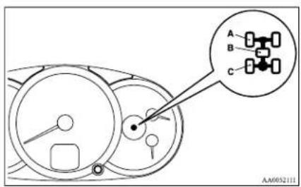
A-Front wheel lamp
B- Centre differential lock lamp
C- Rear wheel lamp
When the ignition switch is in the "ON" position, the 2WD/4WD operation indication lamp shows the shifting condition. The 2WD/4WD operation indication lamp comes on at each transfer shift lever position as follows:
“2H” “4H”
| Transfer shift lever position | 2WD/4WD operation indication lamp |
| 2H |  |
| [DAE1] | |
| Drive mode switching in progress |  |
| [DAE2] | |
| 4H |  |
| Transfer shift lever position | 2WD/4WD operation indication lamp |
| 4H |  |
| [G835] | |
| Drive mode switching in progress |  |
 | |
| 4HILc |
| Transfer shift lever position | 2WD/4WD operation indication lamp |
| 4HLc |  mvsz mvsz mvs mvs |
| Drive mode switching in progress | |
| 4LLc |


: Illum
: Rema
NOTE
● The 2WD/4WD operation indication lamp blinks while the selection is in process. Take
Starting and driving
the following precautions when the indication lamp is blinking or remains off.
- Keep the steering wheel in the straight ahead position while making range selections. If you attempt to drive forward with the steering wheel turned, gear rattling may occur and the desired range may not actually be selected.
- If you move the transfer shift lever from "4H" to "4HLc" while the vehicle is stationary, keep your speed initially very low when you subsequently make a standing start. Before driving at normal speeds, confirm that the centre differential lock lamp has changed from blinking to steady illumination.
- If you move the transfer shift lever from "4HLC" to "4H" and the centre differential lock lamp does not stop blinking, place the steering wheel in the straight ahead position and slowly depress the accelerator pedal several times.
- If you move the transfer shift lever from "4II" to "2II" and the front wheel lamp does not stop blinking, confirm safety around the vehicle then accelerate, decelerate, and reverse until the front wheel lamp goes off. When the front wheel lamp goes off, you can then proceed to drive the vehicle.
If you accelerate, decelerate, and reverse but the front wheel lamp still does not stop blinking, return the transfer shift lever to "4H" then have your vehicle inspected.
- When you move the transfer shift lever from "4H" to "4HLc", there may be a slight delay before the centre differential lock lamp illuminates.
Starting and driving
Rear differential lock\*
E00606200115
If one wheel starts to spin freely and the vehicle becomes stuck and cannot be freed even using 4-wheel drive, the rear differential lock switch (A) can be used to activate the rear differential lock for extra traction.
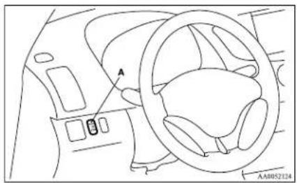
natural_image
Interior view of a car dashboard and steering wheel (no text or symbols visible)Operating the rear differential lock
- Move the transfer shift lever to "4L" or "4H" position (easy select 4WD), "4LLc" or "4HLc" position (super select 4WD).
-
To activate the rear differential lock, press the rear differential lock switch (1).
-
To deactivate the rear differential lock, press the rear differential lock switch (2).
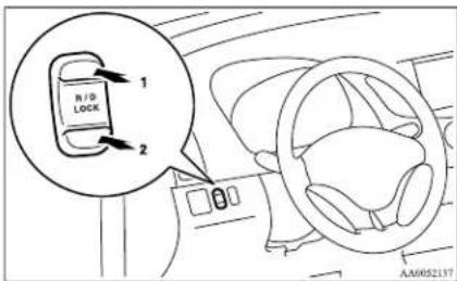
CAUTION
● Operate the rear differential lock switch after the wheels are stopped. Operating the switch with the wheels turning may cause the vehicle to dart in unexpected directions.
NOTE
● The rear differential lock does not operate when the transfer shift lever is in "2H" position (easy select 4WD), "2H" or "4H" position (super select 4WD).
- When the rear differential is locked with the transfer shift lever in "4L" or "4H" position (easy select 4WD), "4LLc" or "4HILc" position (super select 4WD) changing the shift lever to "2H" position (easy select 4WD), "2H" or "4H" position (super select 4WD) makes the rear differential unlock automatically.
The rear differential lock indication lamp
E00606300291
When the ignition switch is turned to the "ON" position, the rear differential lock indication lamp (A) in the meter cluster illuminates for a few seconds then indicates the rear differential lock's operating status (activated or deactivated).
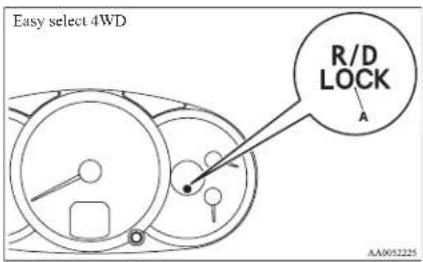
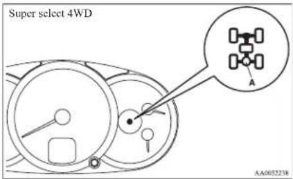
NOTE
- The 2WD/4WD operation indication lamp also illuminates for a few seconds when the ignition switch is turned to the "ON" position. Refer to "2WD/4WD operation indication lamp" on pages 4-27, 4-32.
The status of the rear differential lock (resulting from depression of the rear differential lock switch) is shown by blinking or steady illumination of the rear differential lock indication lamp.
| Transfer shift lever position | Rear differential lock indication lamp | |
| Easy select | 4WD | Super select 4WD |
| Rear differential lock deactivated |  |  |
| _out | _out | |
| Switching in progress |  |  |
| _out | _out | |
| Rear differential lock activated |  |  |
: Blink
□ : Illuminate (steady)
: Remain off
Starting and driving
NOTE
● The indication lamp blinks while the rear differential lock is being switched between its activated and deactivated conditions. When the switching operation is complete, the indication lamp is either illuminated steadily or not illuminated.
- On vehicles with the active stability & traction control (ASTC) and anti-lock brake system (ABS), the ASTC and ABS functions are suspended while the rear differential lock is activated. ASTC indication lamp, ASTC OFF indication lamp and ABS warning lamp are illuminated while these functions are suspended. It dose not indicate a problem. When the rear differential lock is disengaged, these lamps go out and function again.
Refer to “ABS warning lamp” on page 4-44, “ASTC indication lamp, ASTC OFF indication lamp” on page 4-47.
● On vehicles with the anti-lock brake system (ABS), the ABS function is suspended while the rear differential lock is activated.
ABS warning lamp is illuminated while this function is suspended.
Refer to "ABS warning lamp" on page 4-44.
- If the indication lamp continues blinking after the switch has been pressed to deactivate the rear differential lock, hold the steering wheel in the straight ahead position then slowly depress and release the accelerator pedal several times.
- If the indication lamp continues blinking after the switch has been pressed to activate the rear differential lock, bear in mind the following instructions:
Starting and driving
- If the vehicle speed is 12 km/h (7 mph) or higher, decelerate to a speed of 6 km/h (4 mph) or lower. The indication lamp will illuminate steadily and the rear differential lock will be activated.
- If the vehicle speed is 12 km/h (7 mph) or lower, turn the steering wheel from side to side until the indication lamp illuminates steadily. If the vehicle is stuck in soft ground, make sure the area around the vehicle is clear then repeatedly attempt to drive forward and backward. The indication lamp will illuminate steadily and the rear differential lock will be activated.
Examples of effective use of the rear differential lock
ED0606400058
CAUTION
- Use the rear differential lock only as an emergency measure when the vehicle is stuck and cannot be freed with the transfer shift lever in "4L" or "4H" position (easy select 4WD) or in "4LLc" or "4HLc" position (super select 4WD). Deactivate the rear differential lock immediately after using it.
When one of the wheels has fallen in a ditch
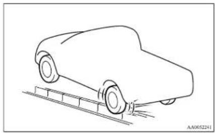
natural_image
Line drawing of a car on an inclined ramp, no text or symbols presentWhen driving on rocky roads
When the vehicle is unable to move because one of the wheels is suspended in the air.
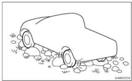
natural_image
Line drawing of a car with wheels and grass at the base (no text or symbols)When getting out of snow
When the vehicle is unable to get going because one of the wheels is on the snow and the other on a paved road.
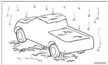
natural_image
Line drawing of a car with wheels and water spray, no text or symbols presentExamples of incorrect use of the rear differential lock
E00606500059
WARNING
- If the "4L" or "4H" position (easy select 4WD), "4L.L.c" or "4HL.c" position (super select 4WD) is selected along with the rear differential lock, the following phenomena appear and it is very dangerous. Please be sure to release the rear differential lock on normal roads.
Starting and driving

WARNING
- If the rear differential lock is used by mistake when driving on a paved road: With the rear differential lock on, the power to drive the vehicle straight ahead becomes very strong, which may make it difficult to turn the steering wheel.
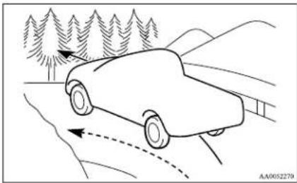
natural_image
Line drawing of a car driving on a mountain road with trees and hills in the background (no text or symbols)
WARNING
- If the rear differential lock is used by mistake when turning a curve or making a right or left turn at a crossing or the like: The vehicle is unable to make a turn and may go straight ahead.
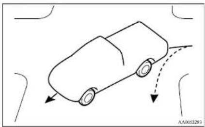
natural_image
Simple line drawing of a car on a curved road with two arrows indicating direction (no text or symbols)
WARNING
- If the rear differential lock is used by mistake except when making an emergency escape on snow or frozen road: It becomes difficult to make a steady turn.
- In the case where the condition of the road is different for the right tyre to drive from the left tyre (such as one tyre on a paved road and the other on ice), direction of the vehicle may change abruptly when engine braking or accelerating. Do not use the rear differential lock except when making an emergency escape on a snow or frozen road, but drive with 4WD.
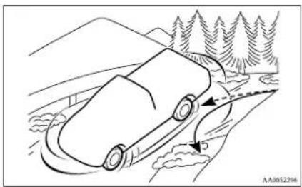
natural_image
Line drawing of a car driving on a mountain road with trees, showing motion trajectory (no text or symbols)Starting and driving
4-wheel drive operation
E00606600920
By selecting 4-wheel drive, both axles of the vehicle are rigidly connected with each other. This improves the traction characteristics. When turning sharp corners or moving forward and backward repeatedly, however, the drive line is stressed, which is felt as a braking effect. A 4-wheel drive vehicle can accelerate more quickly and smoothly. However, note that the braking distance is not shorter than that of a rear-wheel drive vehicle. When using 4-wheel drive on rough roads (snow, mud, sand, etc.), it is important to operate the vehicle correctly.
NOTE
● The driving posture should be more upright and closer to the wheel than usual; adjust the seat to a good position for easy steering and pedal operation. Be sure to wear the seat belt.
● After driving on rough roads, check each part of the vehicle and wash it thoroughly with water. Refer to the "Vehicle care" section and "Inspection and maintenance following rough road operation" on page 4-40.
Driving on dry paved road and highway
Select "2H" position (easy select 4WD), "2H" or "4H" position (super select 4WD) to drive on the dry paved road. Especially on dry highway, never select the "4H" or "4L" position (easy select 4WD), "4HLc" or "4LLc" position (super select 4WD).
CAUTION
- Selecting "4H" or "4L" position (easy select 4WD), "4HLc" or "4LLc" position (super select 4WD) to drive on dry paved road will increase the fuel consumption with possible noise generation and early tyre wear.
It may also increase the differential oil temperature, resulting in possible damage to the driving system.
Further, the drive train will be subjected to excessive loading, possibly leading to oil leakage, component seizure, or other serious faults.
Driving on snowy or icy roads
Set the transfer shift lever to "4H" or "4L" position (easy select 4WD), "4H" or "4HLc" position (super select 4WD) in accordance with the road conditions, and then gradually depress the accelerator pedal for a smooth start.
NOTE
● The use of snow tyres and/or tyre chains is recommended.
● Maintain a safe distance between vehicles, avoid sudden braking, and use engine braking (downshifting).
CAUTION
● Avoid sudden braking, sudden acceleration, and sharp turning; such operations could cause skidding and spinouts.
Driving on sandy or muddy roads
Set the transfer shift lever to "4II" or "4L" position (easy select 4WD), "4HLC" or "4LLc" position (super select 4WD) and then gradually depress the accelerator pedal for a smooth start. Keep the pressure on the accelerator pedal as constant as possible, and drive at low speed.
CAUTION
- Do not force the vehicle or drive recklessly on sandy surfaces. In comparison with normal road surfaces, the engine and other drive-system components are put under excessive strain when driving on such a surface, and this could lead to accidents.
- If any of following conditions occur while the vehicle is being driven, immediately park your vehicle in a safe place and follow these procedures:
- The needle in the temperature gauge approaches the overheating zone. Refer to "Engine overheating" on page 6-04.
- Automatic transmission fluid temperature warning lamp comes on. Refer to "When the A/T (automatic transmission) fluid temperature warning lamp comes on" on pages 4-18, 4-23.

WARNING
- When attempting to rock your vehicle out of a stuck position, be sure that the area around the vehicle is clear of people and physical objects. The rocking motion may cause the vehicle to suddenly launch forward or backward, causing injury or damage to nearby people or objects.
NOTE
- Avoid sudden braking, acceleration, and turning; such operations could result in the vehicle becoming stuck.
- If the vehicle becomes stuck in sandy or muddy roads, it can often be moved a rocking motion. Move the selector lever rhythmically between the “D” (DRIVE) and “R” (REVERSE) position (with M/T, between 1 ^st and Reverse), while applying slight pressure to the accelerator pedal.
- It is recommended to start the vehicle with parking brake partially, but not completely, applied by slightly pulling the parking brake lever. After the vehicle has become free, do not forget to release the parking brake.
- If it is necessary to drive in extremely muddy conditions, the use of tyre chains is recommended. Because the extent of muddy conditions is difficult to judge and the vehicle could become bogged down very deeply, operation should be at a low speed. If possible, get out of the vehicle and check the conditions ahead before proceeding.
- Driving over roads in coastal areas or roads on which anti-skid preparations have been spread can cause rust on the vehicle; wash the vehicle thoroughly as soon as possible after such use.
Climbing sharp grades
Set the transfer shift lever to "4L" position (easy select 4WD), "4LLc" position (super select 4WD) to maximize the engine torque.

WARNING
- Go straight up. Do not try to traverse across a steep slope.
- If you begin to lose traction, ease off the accelerator pedal and gently turn the steering wheel alternatively left and right to regain adequate traction again.
NOTE
- Choose as smooth a slope as possible with few stones or other obstacles.
● Before attempting to drive up the slope, walk up it to confirm that the vehicle can handle the grade.
Descending sharp grades
Set the transfer shift lever to "4L" position (easy select 4WD), "4LLc" position (super select 4WD), use the engine brake (downshifting) and descend slowly.

WARNING
● Avoid snaking down a sharp grade. Descend the grade as straight as possible.
NOTE
- When descending a sharp grade, if the brakes are applied suddenly because of an obstacle encountered, control of the vehicle could be lost. Before descending the slope, walk down it and confirm the path.
● Before descending a grade, it is necessary to choose the appropriate gear. Avoid changing gears or depressing the clutch while descending the grade.
● MITSUBISHI MOTORS is not responsible to the operator for any damage or injury caused or liability incurred by improper and negligent operation of a vehicle. All techniques of vehicle operation described herein depend on the skill and experience of the operator and other participating parties and any deviation from the recommended operation instructions above is at their own risk.
Turning sharp corners
When turning a sharp corner in "4H" or "4L" position (easy select 4WD), "4HLc" or "4LLc" position (super select 4WD) at low speed, a slight difference in steering may be experienced similar to as if the brakes were applied. This is called tight corner braking and results from each of the 4 tyres being at a different distance from the corner. The phenomenon is peculiar to 4-wheel drive vehicles. If this occurs, either straighten the steering wheel, or change to rear-wheel drive.
Starting and driving
Crossing a stream
4-wheel drive vehicles are not necessarily waterproof. If the electrical circuits become wet, further operation of the vehicle will be impossible; therefore, avoid crossing streams unless absolutely necessary. If crossing a stream is unavoidable, use the following procedure:
- Check depths of a stream and geographical features before attempting to cross a stream and ford the stream where the water is as shallow as practicable.
- Set the transfer shift lever to "4L" position (easy select 4WD), "4LLc" position (super select 4WD).
- Drive slowly at a speed of approximately 5 km/h (3 mph) to avoid splashing too much water.
CAUTION
● Never cross a stream where the water is deep.
Do not change gears while crossing the stream.
Frequent crossing of streams can adversely affect the life span of the vehicle; we recommend you to take the necessary measures to prepare, inspect, and repair the vehicle.
After crossing a stream, apply the brakes to be sure they are functioning properly. If the brakes are wet and not functioning properly, dry them out by driving slowly while lightly depressing the brake pedal. Inspect each part of the vehicle carefully.
Inspection and maintenance following rough road operation
L00606700048
After operating the vehicle in rough road conditions, be sure to perform the following inspection and maintenance procedures:
- Check that the vehicle has not been damaged by rocks, gravel, etc.
● Carefully wash the vehicle with water. After washing, drive the vehicle slowly while lightly depressing the brake pedal in order to dry out the brakes. If the brakes still do not function properly, we recommend you to have the brakes checked as soon as possible.
- Remove the insects, dried grass, etc. clogging the radiator core.
● After crossing a stream, be sure to have the following items inspected at a MITSUBISHI MOTORS Authorized Service Point and take the necessary measures.
- Check the brake system and, if necessary, have it serviced.
- Check the engine, transmission, transfer, and differential oil or grease level and turbidity. If the oil or grease is milky, it indicates water contamination. Replace it with new oil or grease.
- Grease the propeller shaft.
- Check the inside of the vehicle. If ingress of water is found, dry the carpet etc.
- Inspect the headlamps. If the headlamp bulb is flooded with water, we recommend you to have it drained.
Cautions on handling of 4-wheel drive vehicles
E00606800368
Tyres and wheels
Since the driving torque can be applied to the 4 wheels, the performance of the vehicle when operating in 4-wheel drive is greatly affected by the condition of the tyres.
Pay close attention to the tyres.
● Install specified tyres on all wheels. Refer to "Tyres and wheels" on page 9-17.
- Be sure to fit all 4 tyres and wheels of the same size and type.
When replacement of any of the tyres or wheels is necessary, replace all of them.
● All tyres should be rotated whenever the wear difference between the front and rear tyres is recognizable.
Good vehicle performance cannot be expected if there is a difference in wear between tyres. Refer to "Tyre rotation" on page 8-13.
- Check the tyre inflation pressure regularly.
CAUTION
● Always use tyres of the same size, same type, and same brand, and which have no wear differences. Using tyres of different size, type, brands or degree of wear, will increase the differential oil temperature, resulting in possible damage to the driving system. Further, the drive train will be subjected to excessive loading, possibly leading to oil leakage, component seizure, or other serious faults.
Towing
If towing is necessary, we recommend you to have it done by your MITSUBISHI MOTORS Authorized Service Point or a commercial tow truck service. In the following cases, transport the vehicle using a tow truck.
● The engine runs but the vehicle does not move or abnormal noise is produced.
- Inspection of the vehicle's underside reveals that oil or some other fluid is leaking.
Only when you cannot receive a towing service from a MITSUBISHI MOTORS Authorized Service Point or commercial tow truck service, tow your vehicle carefully in accordance with the instructions given in "Towing" on page 6-20.
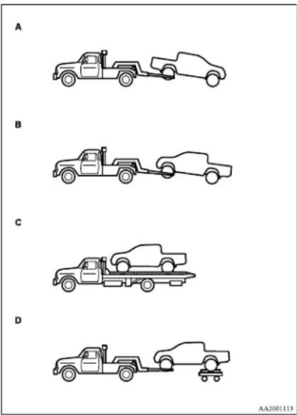
CAUTION
- Be sure to shift the transfer shift lever to "2H" position and transport the vehicle with the driving wheels on a carriage (Type A, C or D) as illustrated. Never try to tow with the transfer shift lever in "4H" or "4L" position (easy select 4WD), "4H", "4HLc" or "4LLc" position (super select 4WD) and with the front or rear wheels on the ground (Type A or B) as illustrated. This could result in damage to the drivetrain, or unstable towing. If you cannot shift the transfer shift lever to "2H" position or the transmission is malfunctioning or damaged, transport the vehicle with all the wheels on a carriage (Type C or D) as illustrated.
Jacking up a 4-wheel drive vehicle
WARNING
- Do not crank the engine while jacking up the vehicle. The tyre on the ground may turn and the vehicle may roll off the jack.
Clutch operation
Quick or slight clutch engagement made while the engine is running at high speed will cause damage to the clutch and transmission because the tractive force is very great.
Operate the pedal slowly and positively.
Starting and driving
Limited-slip differential\*
E00606900037
A limited-slip differential is applied for the rear wheel differential only. The features of this limited-slip differential are described below:
Just as with a conventional differential, the wheel on one side is allowed to turn at a different speed from the wheel on the other side when the vehicle is cornering. The difference between the limited-slip differential and a conventional differential is that if the wheel on one side of the vehicle loses traction, a greater amount of torque is applied to the wheel on the other side to improve traction.
NOTE
● Even if there is a difference in the amount of traction the wheels can get, if both of them are spinning, the limited-slip differential will not be effective.
CAUTION
● Never start the engine while one of the rear wheels is jacked up and the other in contact with the ground; doing so may cause the vehicle to jump forward.
- When attempting to extract the vehicle from snow, mud, etc., and the engine is run continuously at high speed, the limited-slip differential will be adversely affected.
Braking
E00607001494
All the parts of the brake system are critical to safety. We recommend you to have the vehicle checked at regular intervals according to the service booklet.
CAUTION
- Avoid driving habits that cause heavy braking and never "ride" the brakes by resting your foot on the brake pedal while driving. It causes brake overheating and fade.
Brake system
The service brake is divided into two brake circuits. And your vehicle is equipped with power brakes. If one brake circuit fails, the other is available to stop the vehicle. If you should lose the power assist for some reason, the brakes will still work. In these situations, even if the brake pedal moves down to the very end of its possible stroke or resists being depressed, keep depressing the brake pedal down harder and further than usual; stop driving as soon as possible and have the brake system repaired.
WARNING
- Do not turn off the engine while your vehicle is in motion. If you turn off the engine while driving, the power assistance for the braking system will stop working and your brakes will not work effectively.
WARNING
- If the power assist is lost or if either brake hydraulic system stops working properly, have your vehicle checked immediately.
Warning lamp
The brake warning lamp illuminates to indicate a fault in the braking system. Refer to “Brake warning lamp” on page 3-08.
When brakes are wet
Check the brake system while driving at a low speed immediately after starting, especially when the brakes are wet, to confirm they work normally. A film of water can be formed on the brake discs or brake drums and prevent normal braking after driving in heavy rain or through large puddles, or after the vehicle is washed. If this occurs, dry the brakes out by driving slowly while lightly depressing the brake pedal.
When driving downhill
It is important to take advantage of the engine braking by shifting to a lower shift position while driving on steep downhill roads in order to prevent the brakes from overheating.

WARNING
- Do not leave any objects near the brake pedal or let a floor mat slide under it; doing so could prevent the full pedal stroke that would be necessary in an emergency. Make sure that the pedal can be operated freely at all times. Make sure the floor mat is securely held in place.
Brake pads and linings
- Avoid hard braking situations. New brakes need to be broken-in by moderate use for the first 200 km (124 miles).
● The disc brakes are provided with a warning device which emits a shrieking metallic sound while braking if the brake pads have reached their wear limit. If you hear this sound, have the brake pads replaced immediately.

WARNING
● Driving with worn brake pads will make it harder to stop, and can cause an accident.
Starting and driving
Anti-lock brake system (ABS)\*
E00607100775
Environmental conditions can have an effect on braking. During sudden braking when there is snow, ice, oil, water etc. on the road surface, a skid may occur. In this situation, steering control and braking effectiveness is reduced and the stopping distance is increased. The vehicle may also go into an uncontrolled spin.
The ABS helps prevent the wheels from locking during braking, thus maintaining directional stability, ensuring controllability and providing optimum braking force.
Driving hints
-
With ABS fitted, steering during sudden braking (when the ABS functions) differs slightly from when the brakes are not being applied. Steer the vehicle carefully in these conditions.
● Always maintain the same distance from the vehicle in front of you as you would for a vehicle not equipped with ABS. Compared with vehicles not fitted with ABS, your vehicle may require a longer stopping distance in the following cases: -
Driving on gravel or snow-covered roads.
- Driving with tyre chains installed.
- Driving on roads where the road surface is pitted or has other differences in surface height.
- Driving on bumpy roads or other poor driving surfaces.
Operation of ABS is not restricted to situations where brakes are applied suddenly. This system may also operate to prevent wheel lock when you are driving over manholes, steel road-work plates, or the vehicle is driven over steps or level differences in the road, road markings, or other surfaces which are difficult for the wheels to grip.
- When the ABS is activated, you may feel the brake pedal pulsation and hear a characteristic noise. Also at this time, you may feel as if the pedal attempts to resist being depressed. In this situation, to let the ABS work for you, just hold the brake pedal down more firmly. Do not pump the brake. This pumping will result in reduced braking performance.

CAUTION
- Even the ABS cannot prevent the natural laws of physics from acting on the vehicle. It cannot for instance avoid accidents that may result from excessive speed on bends or following another vehicle too closely or aquaplaning. It should remain the driver's task to observe safety precautions to judge speeds and brake applications correctly in such conditions.
- Be sure to use tyres of the same type and size on 4 wheels. If tyre types or sizes are mixed, ABS may not function normally.
Starting and driving
CAUTION
● Never install a limited-slip differential, which is not a MITSUBISHI MOTORS genuine part, as the ABS may not function normally. We recommend you to consult a MITSUBISHI MOTORS Authorized Service Point.
ABS warning lamp
E00607201164
The ABS warning lamp should illuminate when the ignition switch is turned "ON", and should go off in a few seconds.
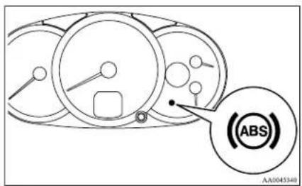
CAUTION
- If the warning lamp stays on or does not illuminate when you start the vehicle, it indicates that the ABS is not functioning and that only the standard brake system is in operation. (In this condition the standard hydraulic brake system will still function.) We recommend you to have your vehicle inspected as soon as possible.
NOTE
- On vehicles with the rear differential lock, ABS and the active stability & traction control (ASTC) functions are suspended while the rear differential lock is activated. ASTC indication lamp, Active Stability Control function OFF indication lamp, ABS warning lamp and brake warning lamp are illuminated while these functions are suspended. It does not indicate a problem. When the rear differential lock is disengaged, these lamps go out and function again. Refer to "ASTC indication lamp, ASTC OFF indication lamp" on page 4-47. - On vehicles with rear differential lock, ABS functionality is suspended while the rear differential lock is operating. The ABS warning lamp is illuminated while ABS functionality is suspended. It does not indicate a problem. When the rear differential lock is disengaged, the ABS warning lamp goes off and the ABS functions again. Refer to "Rear differential lock" on page 4-34.
If the warning lamp illuminates while driving
E00607300663
If only the ABS warning lamp illuminates
- Avoid hard braking and high-speed driving. Stop the vehicle in a safe place. Restart the engine and check to see whether the lamp goes out after a few minutes driving; if it then remains off during driving, there is no problem. However, if the lamp does not go out, or if it lights up again when the vehicle is driven, we recommend you to have the vehicle checked as soon as possible. - The ABS warning lamp can illuminate if the battery voltage is insufficient when the engine is started. In this case, it does not indicate an ABS fault. Charge the battery by allowing the engine to idle for a while. If the battery has been charged but the ABS warning lamp continues to illuminate or illuminates intermittently, have the vehicle inspected.
If the ABS warning lamp and brake warning lamp illuminate at the same time
● The ABS and brake force distribution function may not work, so hard braking could make the vehicle unstable. Avoid hard braking and high-speed driving. Stop the vehicle in a safe place and contact a MITSUBISHI MOTORS Authorized Service Point.
NOTE
- Immediately after the vehicle starts moving after engine start up, a whining sound of a motor will be heard from the engine compartment. If the brake pedal is depressed at that moment, you can feel the brake pedal pulsating.
This pulsation is due to the self-diagnosis operation of the ABS and does not indicate a malfunction.
● After driving on snowy roads, remove any snow and ice which may have become adhered to the wheel areas.
When doing this, be careful not to damage the wheel speed sensors (A) and cables located at each wheel on vehicles equipped with an ABS.
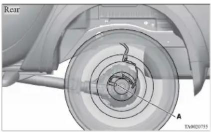
natural_image
Mechanical assembly diagram showing a wheel with labeled components and concentric circles (no readable text or symbols)● The ABS becomes operative after the vehicle has accelerated to a speed in excess of approximately 10 km/h (6 mph). It stops operating when the vehicle decelerates to a speed below approximately 7 km/h (4 mph).
Power steering system
E00607400071
When the engine is stopped, the power steering system will not function and it will require greater manual effort to operate the steering wheel. Keep this in mind in particular when towing the vehicle. Never turn off the engine while driving.
Periodically check the power steering fluid level.

CAUTION
- Do not hold the steering wheel in the fully turned position (either left or right), for longer than 10 seconds.
This can cause damage to the power steering system.
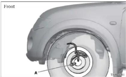
Starting and driving
Active Stability & Traction Control (ASTC)\*
E00616700344
The active stability & traction control (ASTC) takes overall control of the anti-lock brake system, traction control function and Active Stability Control function to help maintain the vehicle's control and traction. Please read this section in conjunction with the page on the anti-lock brake system, traction control function and Active Stability Control function.
Anti-lock brake system (ABS) → p. 4-43
Active Traction Control function → p. 4-47
Active Stability Control function → p. 4-46
CAUTION
- Do not over-rely on the ASTC. This system, like any other system, has limits and cannot help you to maintain traction and control of the vehicle in all circumstances. Reckless driving may lead to accidents. Always drive carefully, taking into account the traffic, road and environmental conditions.
- Be sure to use the same specified type and size of tyre on all 4 wheels. Otherwise, the ASTC may not work correctly.
NOTE
● After your vehicle is driven a short distance after starting the engine, a click is heard from the engine compartment; however, this is only the sound of ASTC being checked.
- Some vibration will be felt in the vehicle body and a whining sound of a motor will be heard from the engine compartment when the ASTC functions. This is a normal result of the ASTC operation, and does not indicate a malfunction.
● The ASTC does not operate while the ABS warning lamp is illuminated. - On vehicles with the rear differential lock, the ASTC and ABS functions are suspended while the rear differential lock is activated. ASTC indication lamp, ASTC OFF indication lamp and ABS warning lamp are illuminated while these functions are suspended. It does not indicate a problem. When the rear differential lock is disengaged, these lamps go out and function again. Refer to “ABS warning lamp” on page 4-44, “ASTC indication lamp, ASTC OFF indication lamp” on page 4-47.
Driving hints
F00616800039
When extricating the vehicle from mud, sand or fresh snow, you may find that operation of the ASTC prevents the engine speed from increasing in response to depression of the accelerator pedal. If this happens and the vehicle remains stuck as a result, deactivate the ASC function by pressing the "ASC OFF" switch. The vehicle will then be easier to extricate. (Brake control of the ATC function is still working to prevent wheel spins when the ASC function is deactivated by pressing the "ASC OFF" switch.)
Active Stability Control function
E00616900056
The Active Stability Control function is designed to improve the vehicle's stability by restraining its tendency to slip sideways (for example, when rounding a curve in slippery conditions, or when the driver takes rapid steering action to avoid an obstacle). It works by controlling the engine output and brake on each wheel.
NOTE
- On vehicles with the rear differential lock, the Active Stability Control function does not operate when the rear differential lock is activated.
"ASC OFF" switch
The Active Stability Control function is automatically activated when the ignition switch is turned to the "ON" position. You can deactivate the system by pressing the "ASC OFF" switch when the vehicle speed is below about 40 km/h (25 mph). To reactivate the Active Stability Control function, press the "ASC OFF" switch again. It is strongly recommended that the Active Stability Control function normally be kept activated.
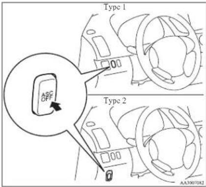
NOTE
- If the vehicle speed increases to about 120 km/h (74 mph) with the Active Stability Control function deactivated, the Active Stability Control function automatically starts operating. To subsequently stop the Active Stability Control function, stop the vehicle and press the “ASC OFF” switch again.
Active Traction Control function
E00617000025
On slippery surfaces, active traction control function prevents the drive wheels from excessive spinning, thus helping the vehicle to start moving from a stop. It also provides sufficient driving force and steering performance as the vehicle turns at accelerated speeds.

CAUTION
- When driving a vehicle on a snowy or icy road, be sure to install snow tyres and drive the vehicle at moderate speeds.
ASTC indication lamp, ASTC OFF indication lamp
ED0617100071
The Active Stability Control function and active traction control function share the same indication lamp.
The indication lamps should illuminate when the ignition switch is turned to the "ON" position and should go off after a few seconds.
If the indication lamps stay on or do not illuminate when the ignition switch is turned to the "ON" position, we recommend you to have your vehicle inspected as soon as possible.
indication lamp blinks when the Active Stability Control function or active traction control function is operating.
\$ indication lamp is illuminated when the Active Stability Control function is OFF.
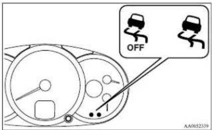

CAUTION
- When Indication lamp blinks, Active Stability Control function or active traction control function is operating, which means that the road is slippery or that your vehicle's wheels are slipping excessively. If this happens, drive slower with less accelerator input.
- If an abnormal condition occurs in the system while driving, the Indication lamp will illuminate. In these cases, follow these procedures:
Starting and driving

CAUTION
- If the temperature in the braking system continues to increase due to continuous brake control on a slippery road surface, the indication lamp will illuminate, and operation of the Active Stability Control function and active traction control function will be suspended to protect the brake system. (Normal operation of the vehicle will not be affected.) Park your vehicle in a safe place. When the temperature in the braking system has come down, the indication lamp will go off and the Active Stability Control function and active traction control function will start operating again.
- If the indication lamp does not go out even though the above procedure is followed, there could be a problem in the system.
Stop the engine and start the engine again and check whether the indication lamp goes out. If the indication lamp goes out, there is no abnormal condition.
If the Indication lamp illuminates even after your vehicle is driven a short distance after restarting the engine, we recommend you to have your vehicle checked as soon as possible.
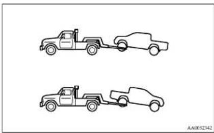
natural_image
Line drawing of two pickup trucks with attached cars, no text or symbols present
CAUTION
- If the vehicle is towed with the ignition switch in the "ON" position and only the front wheels or only the rear wheels raised off the ground, the ASTC may operate, resulting in an accident. When towing the vehicle with the front wheels raised, keep the ignition switch in the "LOCK" or "ACC" position. When towing the vehicle with the rear wheels raised, keep the ignition switch in the "ACC" position. Refer to "Towing" on page 6-20.
Cruise control\*
E00609100779
Cruise control is an automatic speed control system that keeps a set speed. It can be activated at about 40 km/h (25 mph) or more.

CAUTION
- When you do not wish to drive at a set speed, turn off the cruise control for safety.
- Do not use cruise control when driving conditions will not allow you to stay at the same speed, such as in heavy traffic or on roads that are winding, icy, snow-covered, wet, slippery, on a steep downhill slope.
- On vehicles with manual transmission, do not move the gearshift lever to the "N" (Neutral) position while driving at a set speed without depressing the clutch pedal. The engine will run too fast and might be damaged.
NOTE
● Cruise control may not be able to keep your speed on uphills or downhills.
- Your speed may decrease on a steep uphill. You may use the accelerator pedal if you want to stay at your set speed.
- Your speed may increase to more than the set speed on a steep downhill. You must use the brake to control your speed. As a result, the set speed driving is deactivated.
Cruise control switches
E00624100103
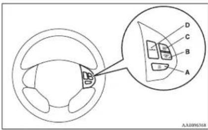
A- "ON OFF" switch
Used to turn on and off the cruise control.
B- "COAST SET" switch
Used to reduce the set speed and to set the desired speed.
C- "ACC RES" switch
Used to increase the set speed and to return to the original set speed.
D- "CANCEL" switch
Used to deactivate the set speed driving.
NOTE
- When operating the cruise control switches, press the cruise control switches correctly. The set speed driving may be deactivated automatically if two or more switches of the cruise control are pressed at the same time.
To activate
E00609300771
- With the ignition switch in the "ON" position, press the "ON OFF" switch (A) to turn on the cruise control. The "CRUISE" indication lamp in the meter cluster will come on.
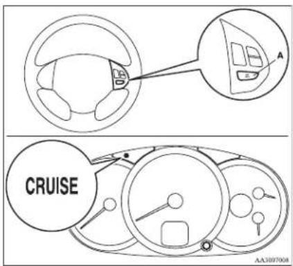
NOTE
- If the cruise control is on when the ignition switch is turned to the "LOCK" or "ACC" position, cruise control will be on automatically the next time you start the engine. The "CRUISE" indication lamp will also be on. - If the battery voltage is insufficient, the memory data for the cruise control may be erased. As a result, the "CRUISE" indication lamp may not come on when you restart the engine. If this happens, press the "ON OFF" switch once again to turn on the cruise control.
Starting and driving
- Accelerate or decelerate to your desired speed, then press and release the "COAST SET" switch (B) when the "CRUISE" indication lamp is illuminated. The vehicle will then maintain the desired speed.
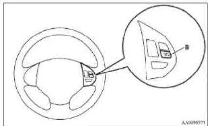
NOTE
- When you release the "COAST SET" switch, the vehicle speed will be set.
To increase the set speed
F00609400570
There are 2 ways to increase the set speed.
"ACC RES" switch
Press and hold the "ACC RES" switch (C) while driving at the set speed, and your speed will then gradually increase.
Starting and driving
When you reach your desired speed, release the switch. Your new cruising speed is now set.
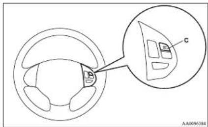
To increase your speed in small amounts, press the "ACC RES" switch for less than about 1 second and release it. Each time you press the "ACC RES" switch, your vehicle will go about 1.6km / h (1 mph) faster.
Accelerator pedal
While driving at the set speed, use the accelerator pedal to reach your desired speed and then press the "COAST SET" switch (B) and release the switch momentarily to set a new desired cruising speed.
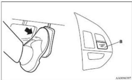
To decrease the set speed
E00609500500
There are 2 ways to decrease the set speed.
"COAST SET" switch
Press and hold the "COAST SET" switch (B) while driving at the set speed, and your speed will slow down gradually.
When you reach your desired speed, release the switch. Your new cruising speed is now set.
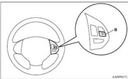
To slow down your speed in small amounts, press the "COAST SET" switch for less than about 1 second and release it.
Each time you press the “COAST SET” switch, your vehicle will slow down by about 1.6 km/h (1 mph).
Brake pedal
While driving at the set speed, use the brake pedal, which disengages the cruise control, then press the "COAST SET" switch (B) and release the switch momentarily to set a new desired cruising speed.
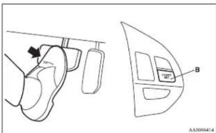
To temporarily increase or decrease the speed
E00619500154
To temporarily increase the speed
Depress the accelerator pedal as you would normally. When you release the pedal, you will return to your set speed.
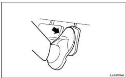
natural_image
Diagram of a mechanical component with a directional arrow indicating movement (no text or symbols present)To temporarily decrease the speed
Depress the brake pedal to decrease the speed. To return to the previously set speed, press the "ACC RES" switch (C).
Refer to "To resume the set speed" on page 4-52.
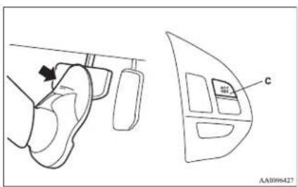
To deactivate
E00609701088
The set speed driving can be deactivated as follows:
- Press the "ON OFF" switch (A). (Cruise control will be turned off.)
- Press the "CANCEL" switch (D).
● Depress the brake pedal.
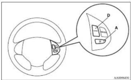
The set speed driving is deactivated automatically in any of the following ways.
- When you depress the clutch pedal (on vehicles with M/T).
- When your speed slows to about 15 km/h (9 mph) or more below the set speed because of a hill, etc.
- When your speed slows to about 40 km/h (25 mph) or less.
- When the active stability & traction control (ASTC) starts operating. (if so equipped) Refer to "Active Stability & Traction Control (ASTC)" on page 4-46.
Starting and driving
WARNING
- On vehicles with A/T, although, the set speed driving will be deactivated when shifting to the "N" (NEUTRAL) position, never move the selector lever to the "N" (NEUTRAL) position while driving. You would have no engine braking and could cause a serious accident.
Also, the set speed driving may be deactivated as follows:
- When the engine speed rises and approaches the tachometer's red zone (the red-coloured part of the tachometer dial).
CAUTION
- When the set speed driving is deactivated automatically in any situation other than those listed above, there may be a system malfunction. Press the "ON-OFF" switch to turn off the cruise control and have it inspected by a MITSUBISHI MOTORS Authorized Service Point.
To resume the set speed
E00609800561
If the set speed driving is deactivated by the condition described in "To deactivate" on page 4-51, you can resume the previously set speed by pressing the "ACC RES" switch (C) while driving at a speed of about 40 km/h (25 mph) or higher.
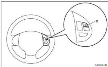
Under either of the following conditions, however, using the switch does not allow you to resume the previously set speed. In these situations, repeat the speed setting procedure:
● The "ON OFF" switch is pressed.
● The ignition switch is turned OFF.
● "CRUISE" indication lamp is turned OFF.
Cargo loads
E00609901123
Cargo loads precautions
CAUTION
- When loading luggage, be careful to the following.
- Stow cargo and luggage in the cargo area whenever possible.
- Distribute cargo or luggage evenly not to be unbalanced in weight.
- Do not place cargo or luggage on the instrument panel.
Also, do not stack up cargo or luggage on the front passenger's seat or the rear seat.
Having the driver's vision blocked, and your cargo being thrown inside the cabin if you suddenly have to brake can cause a serious accident or injury.
Trailer towing
L00610000462
In order to tow a trailer with your vehicle, when having a trailer towing device mounted that meets all relevant regulations in your area, consult a MITSUBISHI MOTORS Authorized Service Point. The regulations concerning the towing of a trailer may differ from country to country. You are advised to obey the regulations in each area.

CAUTION
● Danger of Accident!
A towing bar should be fitted according to MITSUBISHI MOTORS guidelines.
NOTE
- If you are going to tow a trailer, pay careful attention to the following points.
Maximum towable weight with brake and maximum trailer-nose weight
Never exceed the maximum towable weight with brake and the maximum trailer-nose weight as listed in the specifications.
(Refer to "Vehicle weight" on page 9-10.) If you tow a trailer at an altitude of more than 1,000 m above sea-level, reduce your weight by 10 % of the gross combination weight for every increase of 1,000 m above sea-level, as the engine output is lowered owing to decrease in atmospheric pressure.
Towing bar mounting specifications
See the following table for fixing points (A) for the towing bar.
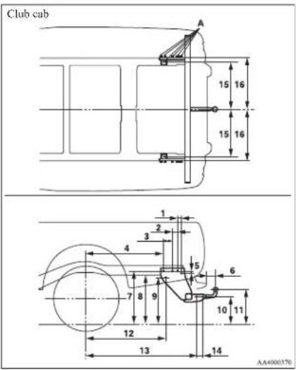
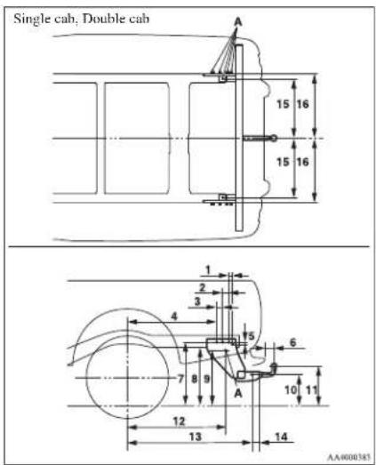
Starting and driving
| Club cab | Single cab, Double cab (Vehicles without long bed) | Double cab (Vehicles with long bed) | |
| 1 30 mm | 30 mm 30 mm | ||
| 2 55 mm | 55 mm 55 mm | ||
| 3 115 mm | 60 mm 60 mm | ||
| 4 872 mm | 812 mm 812 mm | ||
| 5 20 mm | 20 mm 20 mm | ||
| 6 85 mm | 85 mm 85 mm | ||
| 7 699 - 7 | 2 mm 678 - 701 mm, 578 - 581 mm* 679 - 716 mm, 576 mm* | ||
| 8 656 - 669 | mm 638 - 658 mm, 537 - 541 mm* 639 - 673 mm, 536 mm* | ||
| 9 626 - 639 | mm 608 - 628 mm, 507 - 511 mm* 609 - 643 mm, 506 mm* | ||
| 10 410 - 423 | mm 399 - 412 mm, 287 - 291 mm* 394 - 418 mm, 304 mm* | ||
| 11 486 - 499 | mm 479 - 488 mm, 485 - 490 mm* 474 - 494 mm, 488 mm* | ||
| 12 897 mm | 897 mm 897 mm | ||
| 13 1,251 mm | 1,136 mm | 1,316 mm | |
| 14 70 mm | 70 mm 70 mm | ||
| 15 502.5 mm | 502.5 mm | 502.5 mm | |
| 16 540.5 mm | 540.5 mm | 540.5 mm |
Item 7, 8, 9, 10, 11: at kerb weight
*: 2WD vehicles with 15 inch tyres
NOTE
● The values under item 7, 8, 9, 10, 11 are applicable to unladen vehicles. These values can also be varied depending on the tyre size, optional equipment and suspension conditions.
Operating hints
- Do not let the clutch slip (vehicles with a M/a only) and do not increase the engine speed more than necessary when starting.
- Be sure that the driving speed does not exceed the maximum speed for trailer operation.
● To prevent shocks from the overrun brake, depress the brake pedal lightly at first and then more strongly.
● To make full use of engine braking, change to a lower gear before descending a slope.
● The body, brakes, clutch, and chassis will be under additional strain when towing a trailer.
● The heavier weight and higher rolling and air resistance will increase fuel consumption.
Starting and driving
Additional precautions for vehicles equipped with an automatic transmission
It is recommended the “2” (SECOND) position (4A/T) or 2^nd gear in sports mode (5A/T) on slopes or at low speed. Use the “L” (LOW) position (4A/T) or 1^st gear in sports mode (5A/T) in mountainous areas in order to make better use of engine braking and to assist the brake system. However, be sure that the speed does not exceed the maximum speed limit for the selected gear.
| 10.2 | 10.3 | 10.4 | 10.5 | 10.6 | 10.7 | 10.8 | 10.9 | 11.0 | 11.1 | 11.2 | 11.3 | 11.4 | 11.5 | 11.6 | 11.7 | 11.8 | 11.9 | 12.0 |
For pleasant driving
Ventilators....5-02
Heater/Manual air conditioning* 5-03
Automatic air conditioning* 5-08
Important operation tips for the air conditioning....5-12
Air purifier* 5-12
LW/MW/FM electronic tuning radio with CD player*......5-13
To use the external audio input function*......5-27
Steering wheel remote control switch* 5-28
Error codes....5-30
Audio system anti-theft feature....5-32
Handling of compact discs....5-32
Antenna....5-34
Sun visors....5-35
Vanity mirror* 5-36
Ashtray....5-36
Cigarette lighter....5-37
Accessory socket ^* 5-38
Digital clock* 5-39
Interior lamps....5-39
Storage spaces....5-41
Cup holder* 5-44
Bottle holder....5-45
Convenient hook....5-46
Coat hook* 5-46
First-aid kit and warning triangle securing bands*......5-46
For pleasant driving
Ventilators
E00700100344
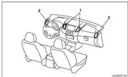
1- Centre ventilators
2- Side ventilators
Air flow and direction adjustments
E00700200749
Centre ventilators
Adjust the direction of the air flow by moving the knob (A).
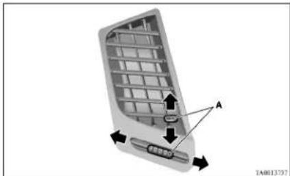
natural_image
3D diagram of a car air conditioner panel with labeled components (no text or symbols)Side ventilators
The ventilator can be opened and closed with the dial (B).

- Open

- Close
Adjust the direction of the air flow by moving the knob (C).
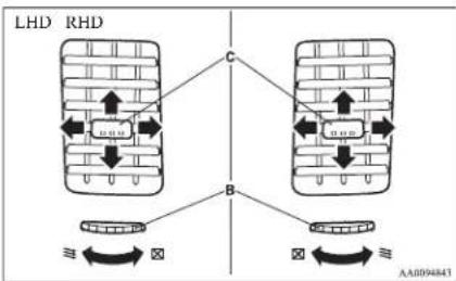
flowchart
graph TD
    A["LHD"] --> B["RHD"]
    B --> C["C"]
    C --> D["B"]
    D --> E["≡"]
    D --> F["×"]
    D --> G["≡"]
    D --> H["×"]
    D --> I["≡"]
    style A fill:#f9f,stroke:#333
    style B fill:#ccf,stroke:#333
    style C fill:#cfc,stroke:#333
    style D fill:#fcc,stroke:#333
    style E fill:#ffc,stroke:#333
    style F fill:#fcc,stroke:#333
    style G fill:#ffc,stroke:#333
    style H fill:#fcc,stroke:#333
    style I fill:#ffc,stroke:#333
NOTE
● On air conditioned vehicles, the cool air from the ventilators may appear as a mist. This is due to moist air being suddenly cooled by the air conditioning. This will clear after a few moments.
Changing the mode selection
To change the position and amount of air flowing from the ventilators, turn the mode selection dial. (Refer to "Mode selection dial" on pages 5-04, 5-09.)
These symbols are used in the next several illustrations to demonstrate the quantity of air coming from the ventilators.
→: Small amount of air from the ventilators
→: Medium amount of air from the ventilators
◆: Large amount of air from the ventilators
Face position
Air flows only to the upper part of the passenger compartment.
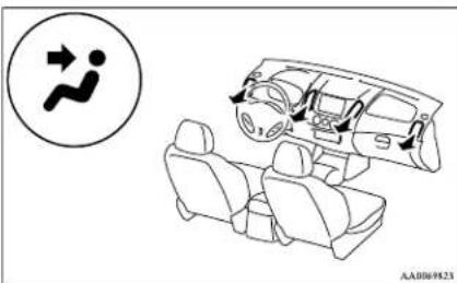
natural_image
Diagram showing a car interior with seats and a vehicle, alongside a circular icon depicting a person walking (no text or symbols)Foot/Face position
Air flows to the upper part of the passenger compartment, and flows to the leg area.
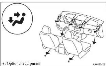
NOTE
- With the mode selection dial between the “and” positions, air flows mainly to the upper part of the passenger compartment. With the mode selection dial between the “and” positions, air flows mainly to the leg area.
Foot position
Air flows mainly to the leg area.
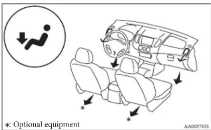
Foot/Demister position
Air flows to the leg area, the windscreen and the door windows.
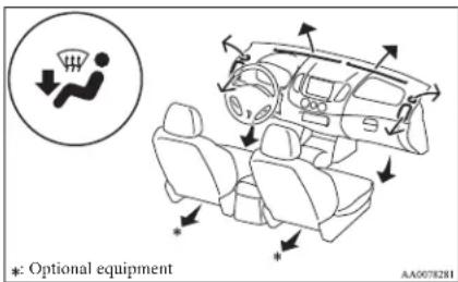
NOTE
- With the mode selection dial between the “and” positions, air flows mainly to the leg area. With the mode selection dial between the “and” positions, air flows mainly to the windscreen and door windows.
Demister position
Air flows mainly to the windscreen and the door windows.
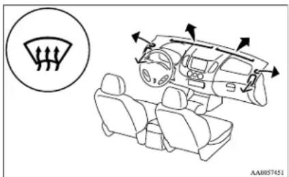
Heater/Manual air conditioning\*
The heater/air conditioning can only be used while the engine is running.
Control panel
E00700600512
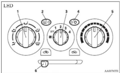
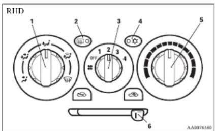
1- Mode selection dial
2- Rear window demister switch → p. 3-40
3- Blower speed selection dial
4- Air conditioning switch*
5- Temperature control dial
6- Air selection lever
For pleasant driving
Blower speed selection dial
E00700700119
Select the blower speed by turning the blower speed selection dial clockwise or anticlockwise.
The blower speed will gradually increase as the dial is turned to the right.
When the blower speed selection dial is set to the "OFF" position, all fan-driven airflow will stop.
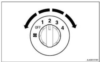
Temperature control dial
E00700900209
Turn the temperature control dial clockwise to make the air warmer. Turn it anticlockwise to make the air cooler.
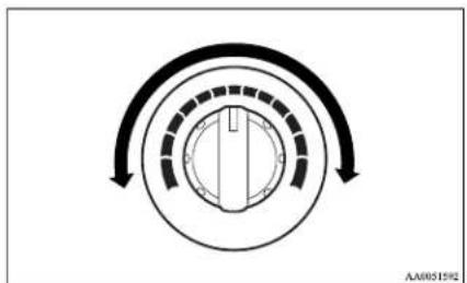
natural_image
Circular diagram with concentric arcs and a central vertical line, no text or symbols presentNOTE
● While the engine coolant temperature is low, the temperature of the air from the heater will be cool/cold until the engine warms up, even if you have selected warm air with the dial.
Mode selection dial
E00701100266
To change the position and amount of air flowing from the ventilators, turn the mode selection dial. (Refer to “Changing the mode selection” on page 5-02.)
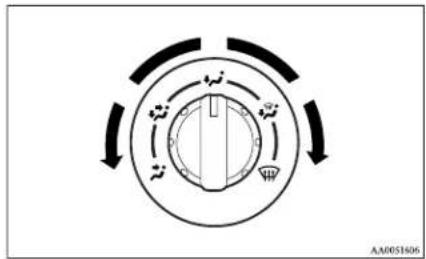
flowchart
graph TD
    A["Central Node"] --> B["Component 1"]
    A --> C["Component 2"]
    A --> D["Component 3"]
    A --> E["Component 4"]
    A --> F["Component 5"]
    A --> G["Component 6"]
    A --> H["Component 7"]
    A --> I["Component 8"]
    A --> J["Component 9"]
    A --> K["Component 10"]
    A --> L["Component 11"]
    A --> M["Component 12"]
    A --> N["Component 13"]
    A --> O["Component 14"]
    A --> P["Component 15"]
    A --> Q["Component 16"]
    A --> R["Component 17"]
    A --> S["Component 18"]
    A --> T["Component 19"]
    A --> U["Component 20"]
    A --> V["Component 21"]
    A --> W["Component 22"]
    A --> X["Component 23"]
    A --> Y["Component 24"]
    A --> Z["Component 25"]
Air selection lever
F007(13)(X460)
To change the air selection, use the air selection lever.
● Outside air
Outside air is introduced into the passenger compartment.
● Recirculated air
Air is recirculated inside the passenger compartment.
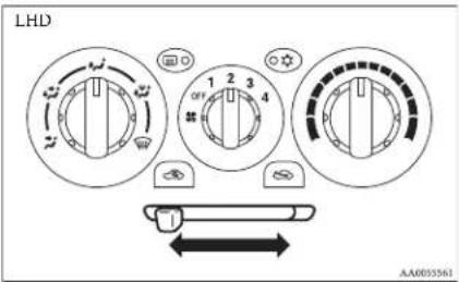
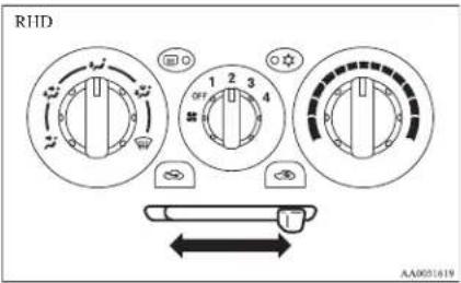

CAUTION
- Normally, use the “☐” (outside) position to keep the windscreen and side windows clear and quickly remove fog or frost from the windscreen.
If high cooling performance is desired, or if the outside air is dusty or otherwise contaminated, use the (recirculation) position. Set the air selection lever to the (outside) position periodically to increase ventilation so that the windows do not become fogged up. - Use of the (recirculation) position for extended time may cause the windows to fog up.
Air conditioning switch\*
L00701500781
Push the switch, and the air conditioning compressor will turn on. The air conditioning indication lamp (A) will come on.
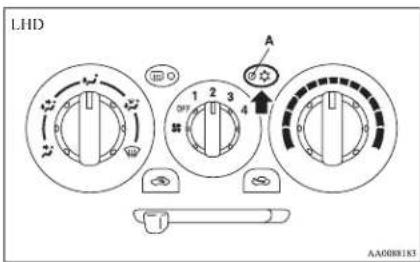
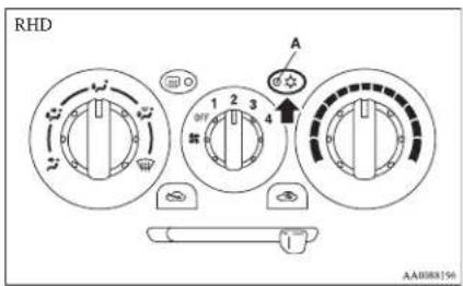
Push the switch again and the air conditioning compressor will stop and the indication lamp goes off.

CAUTION
- When using the air conditioning, the idling speed may slightly increase as the air conditioning compressor is switched on/off automatically. While the vehicle with an A/T is stationary, fully depress the brake pedal to prevent the vehicle from creeping.
Operating the air conditioning system
ED0701800247
Heating
Set the mode selection dial to the ✅ position and set the air selection lever to the “(outside) position.
For pleasant driving
Turn the temperature control dial clockwise or anticlockwise to the desired temperature. Select the desired blower speed.
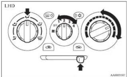
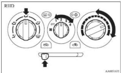
NOTE
- For maximum heat, set the blower speed at the 3^rd position.
For pleasant driving
Cooling (vehicles with air conditioning)
E00701900424
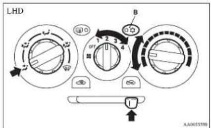
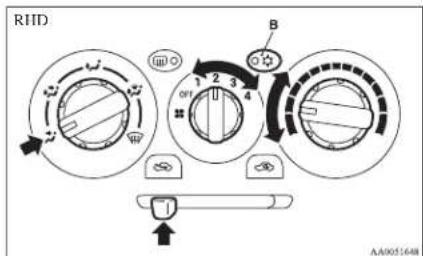
- Set the mode selection dial to the “” position.
- Set the air selection lever to the “” (outside) position.
- Push the air conditioning switch (B).
- Change the temperature by turning the control dial clockwise or anticlockwise.
- Select the desired blower speed.
CAUTION
- If the outside air is dusty or otherwise contaminated, or if high cooling performance is desired, set air selection lever to the “recirculation” position and the temperature control dial all the way to the left. Set to the “outside” position periodically to increase ventilation so that the windows do not become fogged up.
Combination of unheated air and heated air
L00702000451 Select the mode selection dial to the position shown in the illustration and set the air selection lever to the “(outside) position.
The air flow will be directed to the leg area and the upper part of the passenger compartment. Select the desired blower speed.
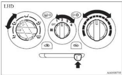
Warm air flows to the leg area and unheated or slightly warm air (depending upon temperature setting) flows to the upper part of the passenger compartment.
Demisting of the windscreen and door windows F00702100579
CAUTION
● For safety, make sure you have a clear view through all the windows.
To remove frost or mist from the windscreen and door windows, use the mode selection dial 📂 or “.”
For pleasant driving
For ordinary demisting
Use this setting to keep the windscreen and door windows clear of mist, and to keep the leg area heated (when driving in rain or snow).
- Set the air selection lever to the “”(outside) position.
- Set the mode selection dial to the “position.
- Select your desired blower speed by turning the blower speed selection dial.
- Select your desired temperature by turning the temperature control dial.
- Push the air conditioning switch (B). (vehicles with air conditioning)
For quick demisting
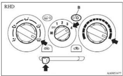
- Set the air selection lever to the “(outside) position.
- Set the mode selection dial to the “position.
- Set the blower to the maximum speed.
- Set the temperature to the maximum temperature position.
- Push the air conditioning switch (B). (vehicles with air conditioning)
NOTE
● To demist effectively, direct the air flow from the side ventilators towards the door windows.
- Do not set the temperature control dial to the max. cool position. Cool air will blow against the window glasses and form mist on them.
For pleasant driving
Introduction of outside air
E00702200235
To introduce air into the vehicle during hot weather, set the air selection lever to the “(outside) position and set the temperature control dial to the positions shown in the illustration. Be sure to set the temperature control dial all the way to the left. Select the desired blower speed.
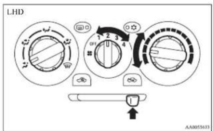
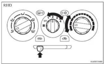
NOTE
● Turn the mode selection dial clockwise and air will flow to the leg area and the windscreen.
Automatic air conditioning\*
E00702400110
The air conditioning can only be used while the engine is running.
Control panel
E00702501192
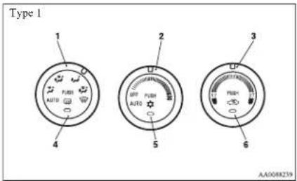
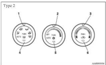
1- Mode selection dial
2- Blower speed selection dial
3- Temperature control dial
4- Rear window demister switch → p. 3-40
5- Air conditioning switch
6- Air selection switch
NOTE
- There is an interior air temperature sensor (A) in the illustrated position. Never place anything on top of the sensor, since doing so will prevent it from functioning properly.
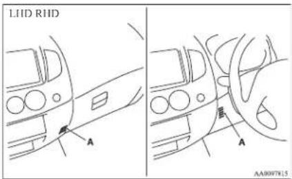
Blower speed selection dial
E00702800273
Select the blower speed by turning the blower speed selection dial clockwise or anticlockwise. The blower speed will gradually increase as the dial is turned to the right.
When the blower speed selection dial is set to the "OFF" position, all fan-driven airflow will stop.
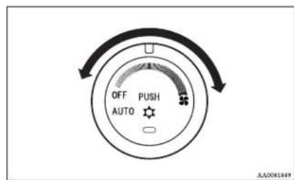
Temperature control dial
E00703000575
Turn the temperature control dial clockwise to make the air warmer. Turn it anticlockwise to make the air cooler.
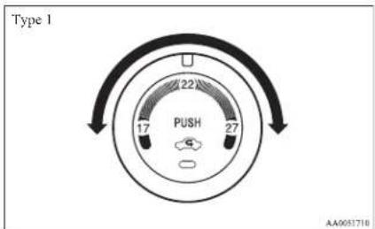
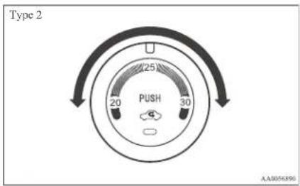
For pleasant driving
NOTE
● While the engine coolant temperature is low, the temperature of the air from the heater will be cool/cold until the engine warms up, even if you have selected warm air with the dial.
Mode selection dial
E00703200274
To change the position and amount of air flowing from the ventilators, turn the mode selection dial. (Refer to "Changing the mode selection" on page 5-02.)
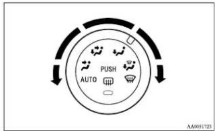
Air selection switch
E0170340638
To change the air selection, simply press the air selection switch.
● Outside air {Indication lamp (A) is OFF} Outside air is introduced into the passenger compartment.
For pleasant driving
● Recirculated air {Indication lamp (A) is ON} Air is recirculated inside the passenger compartment.
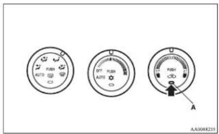
CAUTION
● Normally, use the outside position to keep the windscreen and side windows clear and quickly remove fog or frost from the windscreen.
If high cooling performance is desired, or if the outside air is dusty or otherwise contaminated use the recirculation position. Switch to the outside position periodically to increase ventilation so that the windows do not become fogged up.
● Use of the recirculation position for extended time may cause the windows to fog up.
Air conditioning switch
E00703501128
Push the switch, and the air conditioning compressor will turn on. The air conditioning indication lamp (A) will come on.
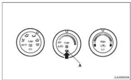
Push the switch again, and the air conditioning compressor will stop and the indication lamp goes off.
CAUTION
- When using the air conditioning, the idling speed may slightly increase as the air conditioning compressor is switched on/off automatically. While the vehicle with an A/T is stationary, fully depress the brake pedal to prevent the vehicle from creeping.
Operating the system in automatic mode
E00704100919
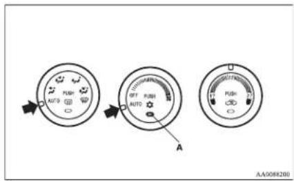
In normal conditions, use the system in the AUTO mode and follow these procedures:
- Set the blower speed selection dial to the "AU-TO" position.
- Select the temperature control dial to the desired temperature. The temperature can be set within a range of 17 to 27 (Type 1) or 20 to 30 (Type 2). The temperature will gradually increase as the dial is turned to the right.
- Set the mode selection dial to the "AUTO" position.
- Push the air conditioning switch to operate the air conditioning. When the air conditioning operates, the indication lamp (A) in the dial will come on.
The outlet port (except ☐) and blower speed, and ON/OFF of air conditioning will be controlled automatically.
NOTE
- Set the temperature at about 22 (Type 1) or 25 (Type 2) under normal conditions.
- When the temperature is set to the highest or the lowest setting under the AUTO operation, the air selection, mode selection, blower speed and the air conditioning will be automatically changed as follows.
Also, if manually operated after an automatic changeover, manual operation will be selected.
- Quick Heating (When the temperature is set to the highest setting)
Outside air will be introduced, the air flow will select foot position, and the air conditioning will stop. - Quick Cooling (When the temperature is set to the lowest setting)
Inside air will be recirculated, the air flow will select face position, and the air conditioning will operate.
Operating the system in manual mode
E00704200040
Blower speed and ventilator mode may be controlled manually by setting the blower speed selection dial and the mode selection dial to the desired positions. To return to automatic operation, set the dials to the "AUTO" position.
Demisting of the windscreen and door windows
E00704300689

CAUTION
● For safety, make sure you have a clear view through all the windows.
To remove frost or mist from the windscreen and door windows, use the mode selection dial 📄 or “.”
For ordinary demisting
Use this setting to keep the windscreen and door windows clear of mist, and to keep the leg area heated (when driving in rain or snow).
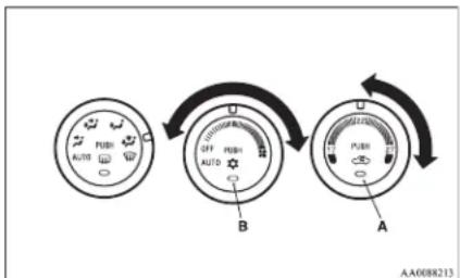
flowchart
graph TD
    A["Before"] --> B["After"]
    B --> C["After Switch"]
    style A fill:#f9f,stroke:#333
    style B fill:#ccf,stroke:#333
    style C fill:#cfc,stroke:#333
- Set the air selection switch (A) to the outside position.
- Set the mode selection dial to the “position.
- Select your desired blower speed by turning the blower speed selection dial.
- Select your desired temperature by turning the temperature control dial.
- Push the air conditioning switch (B).
For quick demisting
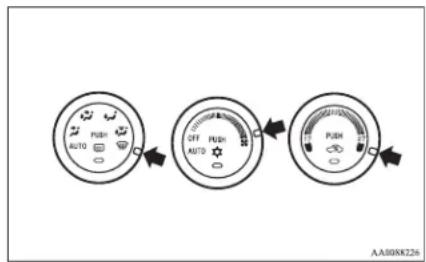
flowchart
graph LR
    A["AUTO"] --> B["OFF AUTO"]
    B --> C["PUBR"]
    C --> D["AA008K226"]
- Set the mode selection dial to the “Wposition.
- Set the blower to the maximum speed.
- Set the temperature to the highest position.
NOTE
● While the mode selection dial is set to the “m” position, the air conditioning will operate automatically and the outside air position will also be selected automatically.
● To demist effectively, direct the air flow from the side ventilators towards the door windows.
- Do not set the temperature control dial to the max. cool position. Cool air will blow against the window glasses and form mist on them.
For pleasant driving
Important operation tips for the air conditioning
E00708300951
● Park the vehicle in the shade.
Parking in the hot sun will make the vehicle inside extremely hot, and it will require more time to cool the interior.
If it is necessary to park in the sun, open the windows for the first few minutes of air conditioning operation to expel the hot air.
- Close the windows when the air conditioning is in use. The entry of outside air through open windows will reduce the cooling efficiency.
● Too much cooling is not good for the health. The inside air temperature should only be 5 to 6 °C below the outside air temperature.
- When operating the system, make sure the air intake, which is located in front of the windscreen, is free of obstructions such as leaves and snow. Leaves collected in the air-intake plenum may reduce air flow and plug the plenum water drains.
It is recommended that the refrigerant be recovered and recycled for further use.
During a long period of disuse
The air conditioning should be operated for at least five minutes each week, even in cold weather. This is to prevent poor lubrication of the compressor internal parts and to maintain the air conditioning in the best operating condition.
Air purifier\*
E00708400675
An air filter has been incorporated into this air conditioning so that dirt and dust are cleaned from the air.
Replace the air filter periodically as its ability to clean the air will be reduced as it collects pollen and dirt. For the maintenance interval, refer to the "SERVICE BOOKLET".
NOTE
● Operation in certain conditions such as driving on a dusty road and frequent use of the air conditioning can lead to reduction of service life of the filter. When you feel that the air flow is lower than normal or when the windscreen or windows start to fog up easily, replace the air filter.
We recommend you to have it checked.
Air conditioning system refrigerant and lubricant recommendations
If the air conditioning seems less effective than usual, the cause might be a refrigerant leak. We recommend you to have the system inspected.
The air conditioning system in your vehicle must be charged with the refrigerant HFC-134a and the lubricant ZXL-100PG.
Use of any other refrigerant or lubricant will cause severe damage which will result in the need to replace your vehicle's entire air conditioning system.
The release of refrigerant into the atmosphere should be prevented.
LW/MW/FM electronic tuning radio with CD player\*
The audio system can be used when the ignition switch is in the "ON" or "ACC" position.
E00708501745
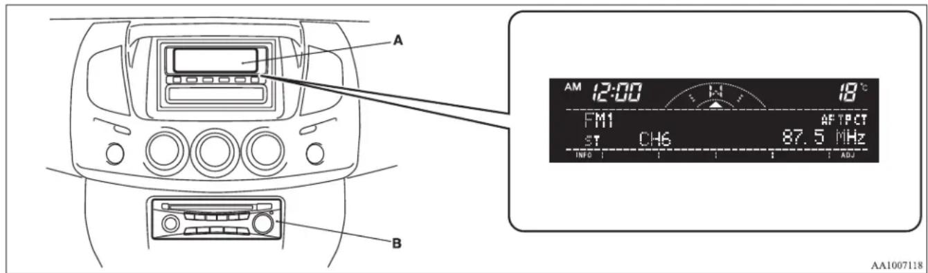
A- Display window B- Audio system
NOTE
- To listen to the audio system while the engine is stopped, turn the ignition key to the "ACC" position.
- If a cellular phone is used inside the vehicle, it may create noise from the audio equipment. This does not mean that anything is wrong with your audio equipment. In such a case, use the cellular phone at a place as far away as possible from the audio equipment.
- If foreign objects or water get into the audio equipment, or if smoke or a strange odour comes from it, immediately turn off the audio system. We recommend your to have it checked. Never try to repair it by yourself. Avoid continuous usage without inspection by a qualified person.
- The audio system's control knob can be removed to deter thieves. For details, refer to "Audio system anti-theft feature" on page 5-32.
● The audio amplifier (if so equipped) is located under the front right seat.
Do not subject the amplifier to a strong impact.
It could damage the amplifier or malfunctioning could result.
For pleasant driving
Volume and tone control panel
E00708601049
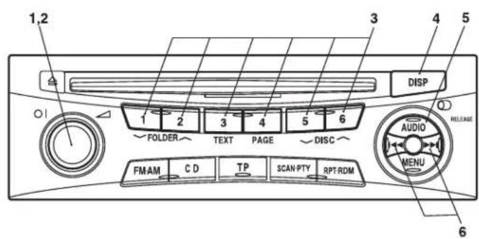
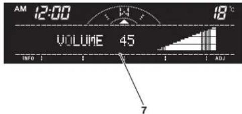
AA1007121
1- PWR (On-Off) switch
2- VOL (Volume control) knob
3- Memory select buttons
4- DISP (Display) button
5- AUDIO button
6- Audio adjust button
7- Display
For pleasant driving
To adjust the volume
E00708700548
VOL (Volume control)
Turn the VOL knob (2) clockwise to increase the volume; anticlockwise to decrease the volume. The status will be displayed in the display (7).
NOTE
● The volume control mode will shut off automatically if either the radio or CD is selected, or if no adjustment is made within about 2 seconds.
To adjust the tone
L00708801070
Press the AUDIO button (5) to select BASS→TRE-BLE→DADER BALANCE Audio adjust mode off. The status will be displayed in the display (7).
BASS (Bass tone control)
Press the audio adjust button (6) either to select the desired bass tone quality.
TREBLE (Treble tone control)
Press the audio adjust button (6) either to select the desired treble tone quality.
FADER (Front/Rear balance control)
Press the audio adjust button (6) either to balance the volume of sound from the front and the rear speakers.
BALANCE (Left/Right balance control)
Press the audio adjust button (6) either ◄◀ ▶▶1 to balance the volume of sound from the left and the right speakers.
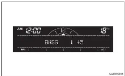
NOTE
● Audio adjust mode will be cancelled when radio or CD operation is performed or no adjustment is performed for more than 7 seconds.
To enter audio tone settings into the memory
E00733000079 It is possible to enter the audio adjustment condition (BASS, TREBLE, FADER, BALANCE) into the memory.
-
Make the desired adjustments in the audio adjust mode. Refer to "To adjust the tone" on page 5-15.
-
In the audio adjust mode, press and hold one of the memory select buttons (3) [1-6]. The display will show the button number [SOUND1-SOUND6] for which the settings were memorized.
-
In future, when you gently press the memory select button in the audio adjust mode, the audio adjustment condition memorized for that button will take effect.
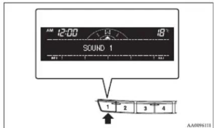
To change the information display
E0073510002 Press the DISP button (4) to change the information display. The display switches in the following sequence: Audio information → Average fuel consumption → Driving range → Average speed → Outside temperature → Altimeter → Barometer → Calendar → Clock-only → Blank. For details, refer to “Changing the information display” on page 3-12.
NOTE
● Audio information is displayed when the audio system is on.
For pleasant driving
Radio control panel and display
E00708901084
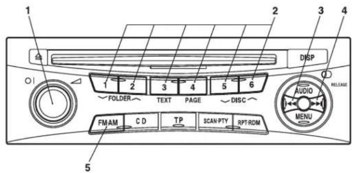
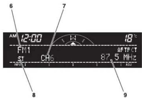
AA1007134
1- PWR (On-Off) switch
2- Memory select buttons
3- TUNE/SEEK (Down-step/Down-seek) button
4- TUNE/SEEK (Up-step/Up-seek) button
5- AM/FM (FM/MW/LW selection) button
6-FM/MW/LW indicator
7- Preset memory number display
8- ST (Stereo) indicator
9- Frequency display window
For pleasant driving
To listen to the radio
E00709000463
- Press the PWR switch (1) to turn the audio system ON and OFF. The system turns on in the last mode used.
- Press the AM/FM buttons (5) to select the desired band.
- Press the TUNE/SEEK button (3 or 4) to tune to a station, or press one of the memory select buttons (2) to recall a station memorised for that button.
To tune the radio
E00709100451
Automatic tuning
After keeping the TUNE/SEEK button (3 or 4) depressed, release the button, and the selected station reception will start.
Manual tuning
The frequency changes every time the TUNE/SEEK button (3 or 4) is pressed. Press the button to select the desired station.
To enter frequencies into the memory
E00716101102
Manual setting
You can assign to the memory select buttons (2) a maximum of 18 stations in the FM band (6 FM1, 6 FM2 and 6 FM3 stations) and 6 stations each in the MW and LW band. (Stations already assigned to the memory select buttons are replaced by any newly assigned stations.)
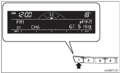
Follow the steps described below.
- Press either the TUNE/SEEK button (3 or 4) to tune the frequency to be entered in the memory.
-
Press one of the memory select buttons (2) for 2 seconds or longer.
The number of the button corresponding to the entry in the memory and the frequency are displayed. -
The preset memory setting is retrieved by pressing the button and then releasing it within 2 seconds.
Automatic setting
With the method, all manually set stations in the band currently selected for reception are replaced with stations in the same band that are automatically selected in order of signal strength. The radio automatically selects 6 stations in the FM band (FM3 station only) and 6 stations each in the MW and LW band.
Follow the steps described below.
- With the radio mode selected, hold down the AM/FM button (5) for 2 seconds or longer. The 6 stations with the best signal strength will automatically be assigned to the memory select buttons (2), with the lowest-frequency station being assigned to the lowest-number button.
- When you subsequently press a memory select button to select a channel number, the radio will begin receiving the station assigned to that number.
NOTE
- If you press the AM/FM button (5) for 2 seconds or longer while tuning in the FM1 or FM2 band, the radio will automatically switch to the FM3 band, where the automatic seeking/storing will be activated.
For pleasant driving
Radio data system (RDS)
E00709200393
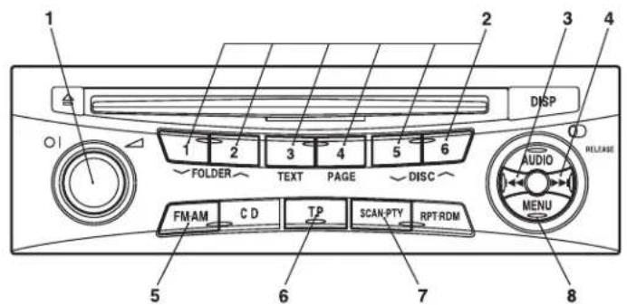
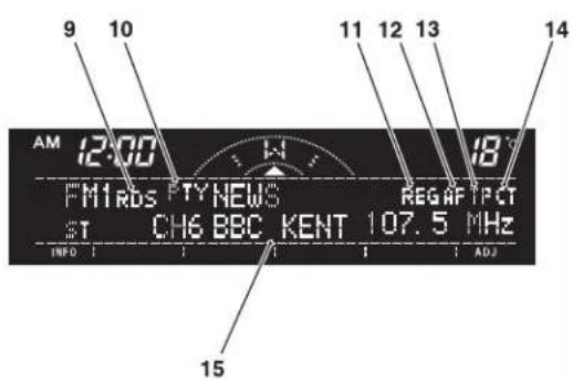
AA1007147
1- PWR (On-Off) switch
2- Memory select buttons
3- TUNE/SEEK (Down-step/Down-seck) button
4- TUNE/SEEK (Up-step/Up-seek) button
5- AM/FM (FM/MW/LW selection) button
6- TP (Traffic program) button
7- PTY (Program type) button
8- Menu button
9- RDS (Radio data system) indicator
10- PTY (Program type) indicator
11- REG (Regional program) indicator
12- AF (Alternative frequencies) indicator
13- TP (Traffic program identification) indicator
14- CT (Clock time) indicator
15- Display
RDS uses PI (program identification) signal and AF (alternative frequency) list transmitted in addition to the normal FM broadcasting programs, and picks up the FM stations that are transmitting the same program from the AF list and automatically tunes to the station with the strongest signal intensity.
Therefore, you can continue listening to one program in, for example, a long distance driving without retuning to the other station transmitting the same program when you are leaving the service area of the currently receiving station.
The RDS radio also features the limited reception of the program types, the break-in reception of the traffic announcement to the EON (enhanced other network) and emergency broadcast, and the limited/unlimited reception of the regional programs.
For pleasant driving
AF (Alternative Frequencies) function
E00720900061
The AF function finds a station broadcasting the same program and selects the station with the strongest signal of AF lists.
The AF function is turned on (with the AF indicator (12) shown on the display) at all times unless you manually switch it off.
The AF function can be turned ON and OFF. Refer to "Function setup mode" on page 5-21.
CT (Clock Time) function
L00721000131
The clock can be set automatically by using the signal from the local RDS stations. Refer to “Adjusting the time” on page 3-12.
REG function limits to receive the stations broadcasting regional programs.
Regional programming and regional networks are organized differently depending on the country or area (they may be changed according to the hour, state, or broadcast area), so if you don't want to receive the regional programs automatically, you can set up REG ON not to receive regional programs.
The REG function can be turned ON and OFF. Refer to "Function setup mode" on page 5-21.
PI (Program Identification) search function
E00721200188 When travelling long distance and the recalled preset station is weak, the radio searches another frequency broadcasting the same programming with the same PI code in AF list.
If there are no frequencies broadcasting the same programming, the radio searches a frequency broadcasting the regional programming. The radio succeeds in searching the regional programming, then the display shows the REG indicator (11).
If the radio does not succeed in searching the regional programming, the radio returns to the recalled preset station.
PTY (Program Type)
E00721300293
RDS broadcasts are classified according to program type (PTY) as follows. Use the TUNE/SEEK button (3 or 4) to select your desired PTY.
-
NEWS
-
AFFAIRS (Current affairs)
-
INFO (Information)
-
SPORT
-
EDUCATE (Education)
-
DRAMA
-
CULTURE
-
SCIENCE
-
VARIED
-
POP M (Pop music)
-
ROCK M (Rock music)
-
EASY M (Easy music)
-
LIGHT M (Light classics)
-
CLASSICS
-
OTHER M (Other music)
-
WEATHER (Weather information)
-
FINANCE
-
CHILDREN
-
SOCIAL
-
RELIGION
-
PHONE IN
-
TRAVEL
-
LEISURE
-
JAZZ
-
COUNTRY
-
NATION M (National music)
-
OLDIES
-
FOLK M (Folk music)
-
DOCUMENT
To search for a broadcast of desired program type: 1. Press the PTY button (7).
-
Press the TUNE/SEEK button (3 or 4) for less than 1 second repeatedly to select your desired PTY.
-
Two seconds after a desired PTY has been selected, the radio will begin to search for a broadcast of your selected PTY. During search, the selected PTY on the display blinks.
-
When the radio picks up a station with your desired PTY, the display will show the name of the station.
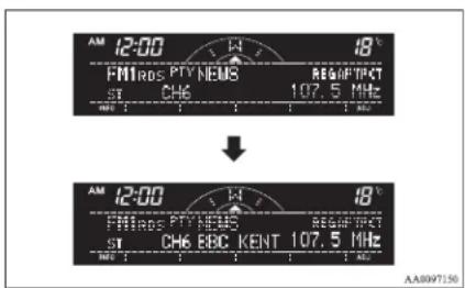
NOTE
- If the TUNE/SEEK button (3 or 4) is pressed for more than 1 second, the radio will try to find out another broadcast of the same program type as currently selected.
For pleasant driving
- If no station is found with your desired PTY, the display will show "EMPTY" for about 5 seconds and the radio will return to the previous station.
How to enter PTYs in the memory
E00721400135
As many as 6 PTYs can be entered in the memory. Follow the steps described below.
- Press either the TUNE/SEEK button (3 or 4) to tune the PTY to be entered in the memory.
- Press one of the memory select buttons (2) for 2 seconds or longer. The number of the button corresponding to the entry into the memory and the PTY are displayed.
- The preset memory setting is retrieved by pressing the button and then releasing it within about 2 seconds.
Traffic information
E00721600238
The radio will automatically tune in to traffic information broadcasts while receiving FM broadcasts or playing compact discs.
To select this function, follow the instructions below.
1. Press the TP button (6). The display will show "TP" (13). If the RDS data can be read, the display will show "RDS" (9). If not, the display will show "NO RDS" for about 5 seconds.
- If the radio detects traffic information on either the station currently selected or another station, the display will show "TRAF INF" for 5 seconds followed by a 2-second indication of the frequency. Then, it will show the name of the station broadcasting the traffic information to which you will listen. The volume level is set separately for listening to normal audio programs and for listening to traffic information. The volume level will therefore change automatically to that set when traffic information was last received. When the traffic information broadcast is over, the radio will return to the previously received program and to the corresponding volume level.
- Press the TP button (6) to return to the previous condition.
NOTE
● While "TP" is illuminated, the radio stops only at TP stations even if the TUNE/SEEK button (3 or 4) is pressed.
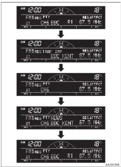
TP (Traffic information Program) search function
E00721800168
The traffic information program standby function is turned on (with the TP indicator (13) shown on the display) and after about 45 seconds since the RDS indicator (9) turns off due to weak signal or the tuning station is changed over from a TP station to a station which does not broadcast traffic information, and seeks out a TP station in all frequencies automatically.
The TP search function can be turned ON and OFF. Refer to "Function setup mode" on page 5-21.
For pleasant driving
Emergency broadcasts
E00721700213
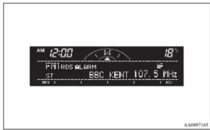
If an emergency broadcast is caught while receiving a FM broadcast or playing back a compact disc with the ignition switch in "ACC" or "ON" position, the display will show "ALARM" and the emergency broadcast will interrupt the current program. The volume level is set separately for listening to normal audio programs and for listening to emergency broadcasts. The volume level will therefore change automatically to that set when an emergency broadcast or traffic information broadcast was last received. When the emergency broadcast is over, the radio will return to the previously received program and to the corresponding volume level.
Function setup mode
E00722500364
It is possible to change the following functions:
● AF
CT
REG
TP-S
- Press the "MENU" button to select the function setup mode.
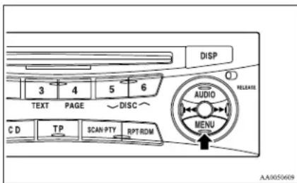
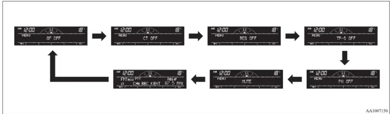
flowchart
graph TD
    A["AM 12:00"] --> B["18° AM MENU"]
    B --> C["18° AM MENU CT OFF"]
    C --> D["18° AM MENU REG OFF"]
    D --> E["18° AM 12:00 MENU TP-S OFF"]
    E --> F["18° AM 12:00 FM TROS PTY ST CHS BBC KENT 87.5 MHz"]
    F --> G["18° AM 12:00 HUTE HUTE"]
    G --> H["18° AM 12:00 MENU PH OFF"]
    H --> I["18° AM 12:00 FM TROS PM"]
- Press the "MENU" button repeatedly to select the mode you wish to change.
For pleasant driving
The order is: AF→CT REG TP=9 → PH→MUTE Function setup mode OFF.
NOTE
- Although "PH" and "MUTE" appear on the display, the PH and MUTE functions are in-operative.
- Select the desired setting for each mode to be turned ON and OFF as shown below.
The setting will be shown on the display.
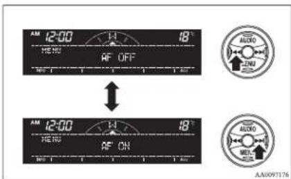
NOTE
● After selecting a mode, you can leave the function setup mode by taking either of the following steps:
- Press the "MENU" button for at least 2 seconds.
• Make no entry for 7 seconds.
CD control panel and display
F00709501117
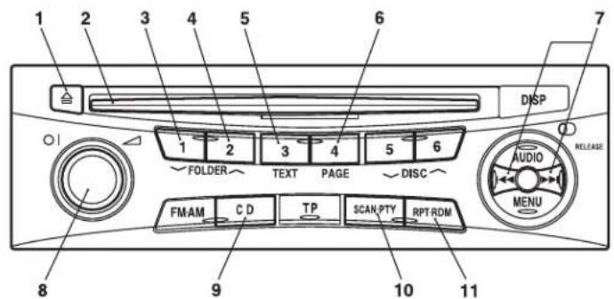
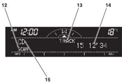
AA1007163
1- CD eject button
2- Disc-loading slot
3- FOLDER (Folder down) button
4- FOLDER (Folder up) button
9- CD (CD mode changeover) button
10- SCAN button
11- RPT/RDM (Repeat/Random) button
12- SCAN/RPT/RDM indicator
5- TEXT (Title display) button
6- PAGE (Title scroll) button
7- TRACK (Track down/up) button
8-PWR (On-Off) switch
For pleasant driving
13- TRACK indicator
14- Track play time indicator
15- CD indicator
For pleasant driving
To listen to a CD
E00709601903
- Insert a disc with the label facing up, and the CD player will begin playing even if the radio is being used. The CD indicator (15), the track number, the playing time will appear on the display. The CD player will also start playback when the CD button (9) is pressed with a disc in the player.
- To adjust the volume and tone, refer to "To adjust the volume" on page 5-15 and "To adjust the tone" on page 5-15.
- To stop the CD, turn off the power by pressing the PWR switch (8) or change over to radio mode by pressing the AM/FM buttons, or eject the disc by pressing the eject button (1).
NOTE
- When an 8 cm compact disc is used, the adapter is not needed for playback. Insert the disc in the centre of the disc-loading slot.
- For information concerning the handling of compact discs, refer to “Handling of compact discs” on page 5-32.
To fast-forward/fast-reverse the disc
To fast-forward or fast-reverse the disc, press the TRACK button (7).
Fast-forward
You can fast-forward the disc by pressing the ▶ side of the TRACK button (7). While the button is kept pressed, the disc will be fast-forwarded.
Fast-reverse
You can fast-reverse the disc by pressing the side of the TRACK button (7). While the button is kept pressed, the disc will be fast-reversed.
NOTE
- When you have fast-forwarded/fast-reversed the disc, the playing-time may be shown with deviation.
To listen to an MP3 CD
This CD player allows you to play MP3 (MPEG Audio Layer-3) files recorded on CD-ROMs, CD-Rs (recordable CDs), and CD-RWs (rewritable CDs) in ISO9660 Level 1/Level 2, Joliet, and Romeo formats. Each disc may have a maximum of 16 trees, 100 folders, and 255 files per disc. During MP3 playback, the unit can display ID3 tag information. For information concerning ID3 tag, refer to "CD text and MP3 title display" on page 5-26.
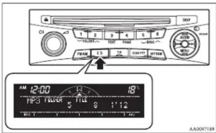
- Insert a disc containing MP3 files into the slot.
- The display shows the folder number and the file number, then playback will begin.
NOTE
● While listening to a disc on which CD-DA (CD-Digital Audio) and MP3 files have both been recorded, you can switch between reading of the CD-DA, reading of the MP3 files, and the external audio input mode (AUX) by pressing the CD button for 2 seconds or longer.
- With a disc that contains both CD-DA and MP3 files, the CD-DA files are automatically played first.
● The playback sound quality differs depending on the encoding software and the bit rate. For details, refer to the user manual of your encoding software.
- Depending on file/folder configurations on a disc, it may take some time before playback starts.
● MP3 encoding software and writing software are not supplied with this unit.
- You may encounter trouble in playing an MP3 or displaying the information of MP3 files recorded with certain writing software or CD recorders (CD-R/RW drivers).
- If you record too many folders or files other than MP3 onto a disc, it may take some time before playback starts.
● This unit does not record MP3 files.
- For information concerning CD-Rs/RWs, refer to "Notes on CD-Rs/RWs" on page 5-33.

CAUTION
- Attempting to play a file not in the MP3 format which has a “.mp3” file name may produce noise from the speakers and speaker damage, and can damage your hearing.
Folder selection order/MP3 file playback order (Example)
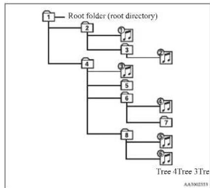
flowchart
graph TD
    A["Root folder (root directory)"] --> B["1"]
    A --> C["2"]
    A --> D["3"]
    A --> E["4"]
    A --> F["5"]
    A --> G["6"]
    A --> H["7"]
    A --> I["8"]
    A --> J["9"]
    B --> C
    C --> D
    D --> E
    E --> F
    F --> G
    G --> H
    H --> I
    I --> J
    style A fill:#f9f,stroke:#333
    style J fill:#ccf,stroke:#333
Folder selection
In the order

File selection
In the order
To select a desired folder (MP3 CDs only)
You can select your desired folder by pressing the FOLDER buttons (3 or 4).
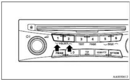
Folder up
Press the FOLDER button (4) until the desired folder number appears on the display.
Folder down
Press the FOLDER button (3) until the desired folder number appears on the display.
To select a desired track
You can select your desired track by using the TRACK button (7).
Track up
Press the ▶side of the TRACK button (7) repeatedly until the desired track number appears on the display.
Track down
Press the ◄tle of the TRACK button (7) repeatedly until the desired track number appears on the display.
For pleasant driving
NOTE
- Pressing the side of the TRACK button (7) once during the song will cause the CD player to restart playback from the beginning of the song.
To repeat the same track or change the order of tracks for playback
Press the RPT/RDM button (11) to select RPT → RDM → RPT/RDM mode off.
To repeat the same track
Select the RPT mode, and the RPT indicator (12) will come on. You can listen to the same track repeatedly.
To exit the repeat mode, press the RPT button two times.
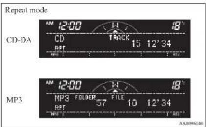
NOTE
● The repeat mode will be cancelled by pressing the track button (7), the SCAN button (10) or eject button (1).
For pleasant driving
To change the order of tracks for playback
Select the RDM mode, and the RDM indicator (18) will come on. Tracks on the currently selected disc will be played in a random sequence.
To exit the random mode, press the RPT/RDM button (11) again.
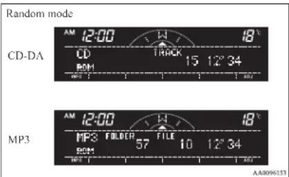
NOTE
- With a disc that contains both CD-DA and MP3 files, the random mode causes only files of the same format (CDDA only or MP3 files only) to be played in a random sequence.
To find the start of each track on a disc for playback Press the SCAN button (10). "SCAN" will appear on the display and the CD player will play back the first 10 seconds of each track on the selected disc. The track number will blink while the scan mode is selected. To exit the scan mode, press the SCAN button again.
NOTE
- Once all tracks on the disc have been scanned, playback of the disc will restart from the beginning of the track that was playing when scanning started.
● The scan mode will be cancelled when radio or CD operation is selected. - With a disc that contains both CD-DA and MP3 files, the scan mode causes only files of the same format (CD-DA only or MP3 files only) to be played.
To eject a disc
When the CD eject button (1) is pressed, the disc automatically stops and is ejected. The system automatically switches to radio mode.
CD text and MP3 title display
E00725000605
This CD player can display CD text and MP3 titles including ID3 tag information.
CD text
The CD player can display disc and track titles for discs encoded with disc and track title information. Press the TEXT button (5) repeatedly to make selections in the following sequence: disc name → track name → normal display mode.
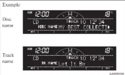
NOTE
● The display can show up to 16 characters. If a disc name or track name has more than 16 characters, press the PAGE button (6) to view the next 16 characters.
- When there is no title information to be displayed, the display shows "NO TITLE".
- Characters that the CD player cannot display are shown as “”.
MP3 title
The CD player can display folder and file titles for discs encoded with folder and file information. Press the TEXT button (5) for less than 1 second repeatedly to make selections in the following sequence: folder name → file name normal display mode.
Example
Folder name
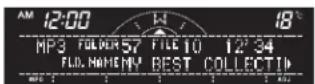
File name
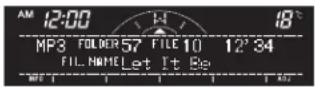
AA0096179
ID3 tag information
The CD player can display ID3 tag information for files that have been recorded with ID3 tag information.
- Press the TEXT button (5) for 2 seconds or longer to switch to the ID3 tag information.
- Then press the TEXT button for less than 1 second repeatedly to make selections in the following sequence: album name title name artist name normal display mode.
NOTE
● To return from ID3 tag information to the folder name, press the TEXT button (5) again for 2 seconds or longer.
- When there is no title information to be displayed, the display shows "NO TITLE".
For pleasant driving
● The display can show up to 16 characters. If a folder name, track name, or item of ID3 tag information has more than 16 characters, press the PAGE button (6) to view the next 16 characters.
- Folder names and track names can each be displayed up to a length of 16 characters. Items of ID3 tag information can each be displayed up to a length of 16 characters.
- Characters that the CD player cannot display are shown as “”.
To use the external audio input function\*
E00732200566
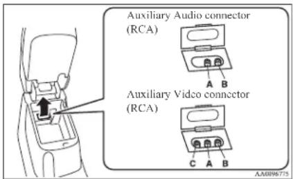
Auxiliary Audio connector (RCA)
A- Left audio input connector (white)
B- Right audio input connector (red)
Auxiliary Video connector (RCA)
A- Left audio input connector (white)
B- Right audio input connector (red)
C- Video input connector (yellow)
You can listen to commercially available audio equipment, such as a portable audio system, from your vehicle's speakers, by connecting the audio equipment to the audio input connectors, which are external input connectors (pin jacks).
For pleasant driving
NOTE
- On vehicles equipped with the MITSUBISHI Multi-Communication System (MMCS), refer to the separate owner's manual of the MITSUBISHI Multi-Communication System.
To activate the external audio input mode
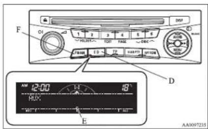
- Use a commercially available audio cable to connect the audio equipment to the external audio input connector.
- Press the CD button (D) for more than 2 seconds. The display (E) will show "AUX" and then the external audio input mode will be activated.
- To deactivate the external audio input mode, press the AM/FM button (F) or the CD button (D) to switch to another mode.
CAUTION
- Do not operate the connected audio equipment while driving. This could distract you and an accident might occur.
NOTE
- The connected audio equipment cannot be operated with the vehicle's audio system.
● Depending on the connected audio equipment, it may produce noise from the speakers. - Use the connected audio equipment's own power source, such as its battery. Noise may be produced from the speakers if the connected audio equipment is used while charging it using the accessory socket of the vehicle.
- Do not activate the external audio input mode when no audio equipment is connected. Otherwise, noise may be produced from the speakers.
- Connect audio equipment when the external audio input mode is deactivated or lower the vehicle's speaker volume before connecting it. Noise may be produced from the speakers if audio equipment is connected after the external audio input mode is activated.
- For information on how to connect and operate the audio equipment, refer to the owner's manual for the equipment.
Steering wheel remote control switch\*
E00710000694
The remote control switches are located on the left side of the steering wheel.
These switches can be used when the ignition switch is in the "ON" or "ACC" position.
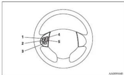
1- Volume up button
2- Volume down button
3- PWR (ON-OFF)/Mode change button
4- Seek up/Track up/Fast-forward button
5- Seek down/Track down/Fast-reverse button
NOTE
- Do not push two or more of the steering wheel remote control switches at the same time.
To turn on the power
PWR (ON-OFF) button - 3
When the power is off, press this button to turn the power on. To turn the power off, press this button for 2 seconds or longer.
To adjust the volume
Volume up button - 1
The volume will increase when this button is pressed.
Volume down button - 2
The volume will decrease when this button is pressed.
To listen to the audio system
Select the desired mode by lightly pressing the mode change button (3).
The mode switches between the radio and CD with each push of the button.
To listen to the radio
To select FM/MW/LW mode
Mode change button — 3
Select the desired band by pressing this button.
The order is: FM1 → FM2 → FM3 → MW → LW → CD → FM1.
Automatic radio tuning
Seek up button - 4/Seek down button - 5
After pressing these buttons, the reception of the selected station will begin.
To listen to a CD
To fast-forward/fast-reverse the disc
To fast-forward or fast-reverse the disc, press the fast-forward button (4) or the fast-reverse button (5).
Fast-forward button - 4
You can fast-forward the disc by pressing the fast-forward button. While the button is kept pressed, the disc will be fast-forwarded.
Fast-reverse button - 5
You can fast-reverse the disc by pressing the fast-reverse button. While the button is kept pressed, the disc will be fastreversed.
NOTE
- In the case of an MP3 CD, you can fast-forward and fastreverse tracks in the same folder.
To select a desired track
Track up button - 4
Press the button repeatedly until the desired track number appears on the display.
Track down button - 5
Press the button repeatedly until the desired track number appears on the display.
For pleasant driving
Error codes
E00710101142
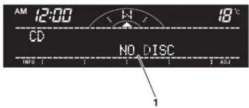
AA1007176
If an error code (1) appears in the display, take action in accordance with the table below.
For pleasant driving
| Error display Problem | Description Repair | ||
| NO DISC No disc inserted Disc is not in CD player. Insert disc. | |||
| ERROR 01 Focus error | Disc is not loaded correctly, or condensation on disc. | Insert disc with label facing up. Remove moisture from disc. | |
| ERROR 02 Disc error | Disc is dirty, scratched, or deformed; or excessive vehicle vibration. | Clean or replace disc. Retry when vibrations stop. | |
| ERROR 03 Mechanism error Loading or eject error. Pick-up is out of position. | Eject disc and reload. If disc will not eject, have the equipment inspected. | ||
| ERROR HOT High temperature Internal protection against high temperatures. | Allow CD player to cool by waiting about 30 minutes. | ||
| ERROR | Communication or power supply error | Communication error between external device and audio equipment.Power supply error of external device. | Consult a MITSUBISHI MOTORS Authorized Service Point. |
For pleasant driving
Audio system anti-theft feature
E00710200306
To prevent theft of the audio system, the control knob can be removed. Always remove the control knob when you leave the vehicle.
Removing the control knob
Slide the release button (A) to the right and remove the control knob from the audio system.
Anti-theft function operates in two ways depending on the position of the ignition key.
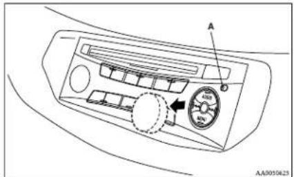
1. With the key in the "ON" or "ACC" position
"Please refit the control panel." indicator will appear on the display. Any audio system operation will be disabled while the "Please refit the control panel." indicator is displayed.
2. With the key in the "LOCK" position
The lamp (B) will start flashing to deter thieves.
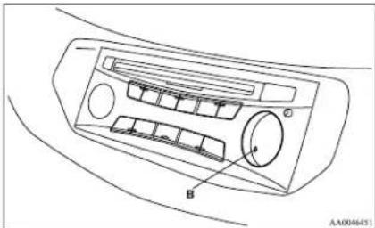
natural_image
Line drawing of a car air conditioner panel with labeled component B (no text or symbols beyond label)NOTE
- When sliding the release button, place one hand on the control knob to prevent it from falling out.
Refitting the control knob
Put the control knob back into the original position and then push it until it clicks. The "Please refit the control panel." indicator will disappear or the lamp (B) will stop flashing.
NOTE
- Do not leave the control knob in any place where it may become hot (for example, the dashboard) or in any place where it may become wet.
- If you lose the control knob, contact a MITSUBISIII MOTORS Authorized Service Point.
Handling of compact discs
E00723000034
- Use only the type of compact discs that have the mark shown in the illustration below. (Playback of CD-R or CD-RW discs may cause problems.)

AA0012063
● The use of special shaped, damaged compact discs (like cracked discs) or low-quality compact discs (like warped discs or burrs on the discs) such as those shown will damage the CD player.
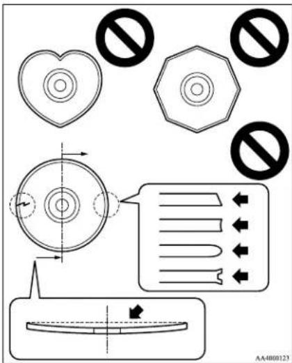
- In the following circumstances, moisture can form on discs and inside the audio system, preventing normal operation. - When there is high humidity (for example, when it is raining).
- When the temperature suddenly rises, such as right after the heater is turned on in cold weather.
In this case, wait until the moisture has had time to dry out.
- When the CD player is subjected to violent vibrations, such as during off-road driving, the tracking may not work.
- When storing compact discs, always store them in their separate cases. Never place compact discs in direct sunlight, or in any place where the temperature or humidity is high.
● Never touch the flat surface of the disc without a label. This will damage the disc surface and could affect the sound quality. When handling a compact disc, always hold it by the outer edge and the centre hole.
● To clean a disc, use a soft, clean, dry cloth. Wipe directly from the centre hole towards the outer edge. Do not wipe in a circle. Never use any chemicals such as benzine, paint thinner, a disc spray cleaner, or an anti-static agent on the disc.
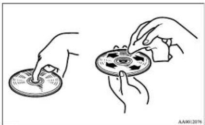
natural_image
Illustration of two hands exchanging a CD or DVD disc, showing mechanical components (no text or symbols)For pleasant driving
- Do not use a ball point pen, felt pen, pencil, etc. to write on the label surface of the disc. - Do not put additional labels (A) or stickers (B) on compact discs. Also, do not use any compact disc on which a label or sticker has started to peel off or any compact disc that has stickiness or other contamination left by a peeled-off label or sticker. If you use such a compact disc, the CD player may stop working properly and you may not be able to eject the compact disc.
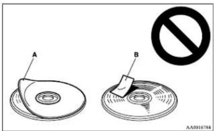
Notes on CD-Rs/RWs
- You may have trouble playing back some CD-R/RW discs recorded on CD recorders (CD-R/RW drives), either due to their recording characteristics or dirt, fingerprints, scratches, etc. on the disc surface. - CD-R/RW discs are less resistant to high temperatures and high humidity than ordinary music CDs. Leaving them inside a vehicle for extended periods may damage them and make playback impossible.
For pleasant driving
● The unit may not successfully play back a CD-R/RW that was made by the combination of writing software, a CD recorder (CD-R/RW drive) and a disc if they are incompatible with one another.
● This player cannot play the CD-R/RW discs if the session is not closed.
● This player cannot play CD-R/RW discs which contain other than CD-DA or MP3 data (Video CD, etc.).
- Be sure to observe the handling instructions for the CD-R/RW disc.
WARNING
- Operating the CD player in a manner other than specifically instructed herein may result in hazardous radiation exposure. Do not remove the cover and attempt to repair the CD player by yourself. There are no user serviceable parts inside. In case of malfunction, we recommend you to have it checked.
Antenna
E00710500022
Pillar antenna\*
E00710700109
When listening to the radio, fully extend the antenna.
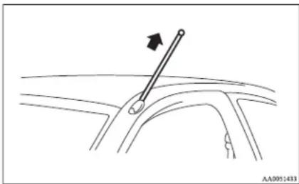
natural_image
Diagram of a car interior showing a lever and angle marker (no text or symbols)NOTE
- Be sure to retract the pillar antenna in the following cases:
- When entering a place with low clearance.
- When using an automatic car wash.
- When placing a car cover over the vehicle.
Roof antenna\*
E00710900071
When listening to the radio, raise the antenna up until you hear it click.
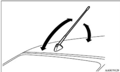
natural_image
Diagram showing a curved surface with a tool and directional arrows indicating motion (no text or symbols)To remove
Turn the pole (A) anticlockwise.
To install
Screw the pole (A) clockwise into the base (B) until it is securely retained.
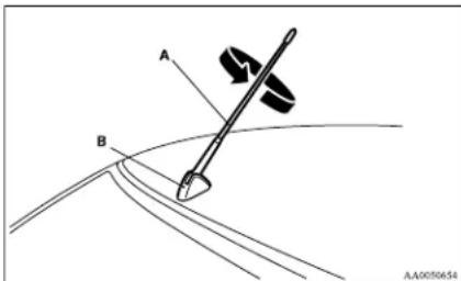
For pleasant driving
NOTE
- Be sure to remove the roof antenna in the following cases:
- When using an automatic car wash.
- When placing a car cover over the vehicle.
● Before driving into a structure that has a low ceiling, fold down the antenna to prevent it from hitting the ceiling.
Sun visors
E00711200693
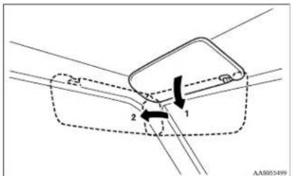
I- To eliminate front glare
2- To eliminate side glare
Ticket holder\*
The driver's sun visor is provided with a ticket holder (A) on the backside.
Card holder\*
Cards can be slipped into the front (A) of the lid of the passenger side vanity mirror.
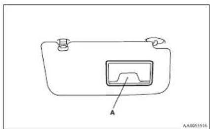
natural_image
Simple line drawing of a rectangular device with a labeled component 'A' and mounting tabs (no text or symbols beyond label)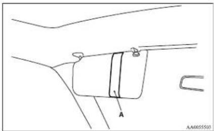
natural_image
Pure technical line drawing of a mechanical component with labeled section A (no text or symbols beyond label)For pleasant driving
Vanity mirror\*
E00711300489
A vanity mirror is fitted to the back of the sun visor on the passenger side.
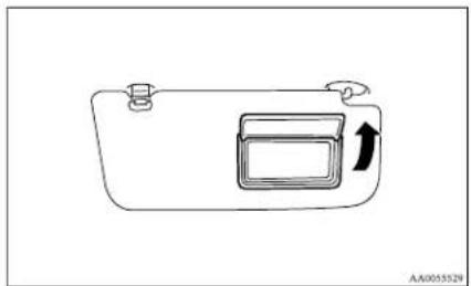
natural_image
Simple line drawing of a device casing with an arrow indicating direction (no text or symbols)Ashtray
L00711400826
CAUTION
● Put out matches and cigarettes before they are placed in the ashtray.
- Don't put papers and other things that burn into your ashtrays. If you do, cigarettes or other smoking materials could set them on fire, causing damage.
● Always close the ashtray. If left open, other cigarette butts in the ashtray may be rekindled.
Type 1 (fixed position)
To use the ashtray, pull it out.
To remove the ashtray, pull it out while pressing the stop (A).
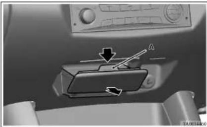
natural_image
Interior view of a car dashboard with a control panel and directional arrows (no text or symbols)Type 2 (moveable)
To use the moveable ashtray, open the lid.
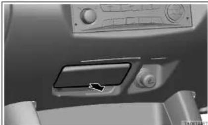
natural_image
Interior view of a vehicle dashboard with control panel and directional arrow (no text or symbols)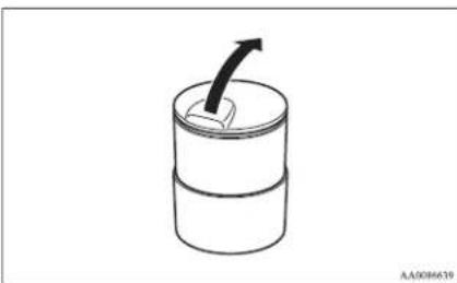
natural_image
Simple line drawing of a cylindrical container with an arrow pointing upward (no text or symbols)Mounting position for moveable ashtray
The moveable ashtray can be fitted at the indicated position.
Refer to "Cup holder" on page 5-44.
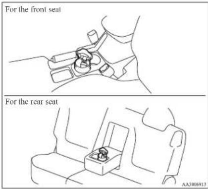
Cigarette lighter
E00711501257
The cigarette lighter can be used while the ignition switch is in the "ON" or "ACC" position.
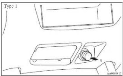
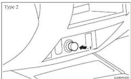
1- Push all the way in.
The lighter will automatically return to its original position with a "click" when ready. Pull it out for use.
After use, insert the lighter to its original position in the socket.
For pleasant driving
NOTE
- Do not leave the cigarette lighter removed from its socket, because the socket might become clogged by foreign material and be short-circuited.
CAUTION
- Do not touch heating element or lighter housing. Hold only the knob to prevent burns.
- Do not allow children to operate or play with the cigarette lighter as burns may occur.
● Something is wrong with the cigarette lighter if it does not pop back out within approximately 30 seconds of being pushed in.
Leaving the cigarette lighter pushed in for an extended period could cause fire. If it does not pop out by itself, we recommend you to have it checked.
- Do not leave the cigarette lighter pushed in or insert the cigarette lighter from another vehicle. Otherwise, the lighter may overheat and cause fire.
● It is recommended that only the lighter be inserted in its socket.
Use of "plug-in" type accessories may damage the socket and result in poor retention of the lighter.
For pleasant driving
CAUTION
- When the cigarette lighter socket is used as a power source for an electric appliance, be sure that the electric appliance operates at 12 V and has an electric capacity of 120 W or less. In addition, long use of the electric appliance without running the engine may run down the battery.
Accessory socket\*
L00711601160
The accessory socket can be used while the ignition switch is in the "ON" or "ACC" position. Open the cap (A) to uncover the socket. Use it to plug in an electrical device.
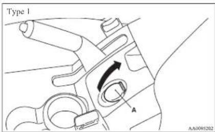
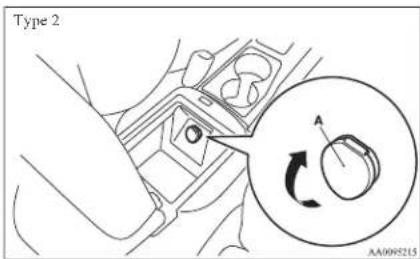
CAUTION
- When you connect an electrical device, make sure it is rated at 12 V and its electrical capacity does not exceed 120 W. Remember that prolonged use of an electrical device with the engine off could run down the battery.
- When the accessory socket is not in use, be sure to close the cap, because the socket might become clogged by foreign material and be short-circuited.
NOTE
● Long use of the electric appliance without running the engine may run down the battery. Especially avoid using it with the cigarette lighter.
For pleasant driving
Digital clock\*
E00711700193
The digital clock indicates the time with the ignition switch in either "ON" or "ACC" position.
To set the time
Set the time by pressing the various buttons as described below.
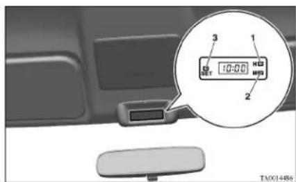
1- To adjust the hour
2- To adjust the minutes
3- To reset the minutes to zero
10:30 - 11:29..... Changes to 11:00
11:30 - 12:29..... Changes to 12:00
NOTE
- If the battery cables are disconnected during repairs or for any other reason, reset the clock to the correct time after they are reconnected.
Interior lamps
E00712000917
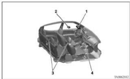
1- Room lamp (Front)*
Personal lamps*
2- Room lamp (Rear)*
3- Door courtesy lamps*
4- Centre console downlight
NOTE
- If you leave the lamps on without running the engine, you will run down the battery. Before you leave the vehicle, make sure that all the lamps are off.
Room lamps
E00712101016
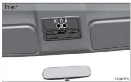
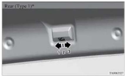
For pleasant driving
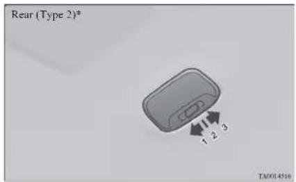
1 (ON) - The lamp illuminates.
2 (●-
[ Vehicles without central door locks system]
The room lamp goes on when a door is opened. When all doors are closed, the room lamp is illuminated and dimmed gradually for 7 seconds then goes out.
However, the lamp goes out immediately without being dimmed when the ignition switch is turned to the "ON" position.
[ Vehicles with central door locks sys- tem]
The room lamp goes on when a door is opened. When all doors are closed, the room lamp is illuminated and dimmed gradually for 15 seconds then goes out.
However, the lamp goes out immediately without being dimmed in case of the followings:
- All doors are closed and the ignition switch is turned to the "ON" position.
- All doors are locked using the key mechanism of the driver's door, the lock knob of the driver's door, or the remote control switch of the keyless entry system (if so equipped).
NOTE
● On vehicles with keyless entry system, when the ignition key is removed with the doors closed, the lamp is illuminated and after about 15 seconds it goes off.
The dimming period is also adjustable.
For further information, we recommend you to consult a MITSUBISHI MOTORS Authorized Service Point.
3 (OFF) - The lamp goes off.
Personal lamps\*
E00712500156
Push the switch (A) to turn on the lamp. Push it again to turn it off.
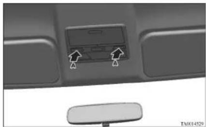
natural_image
Close-up of a car interior panel with a central touchscreen and directional arrows indicating movement (no text or symbols)Door courtesy lamps\*
E00717500034
Each door courtesy lamp comes on when the relevant door is opened and goes off when the door is closed.
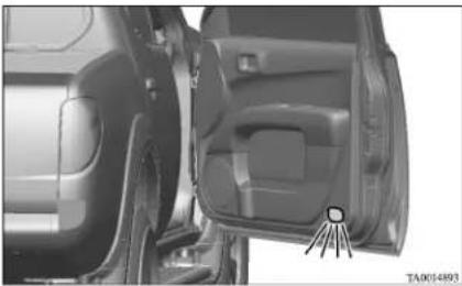
natural_image
Interior view of a car showing the door, seat, and window (no visible text or symbols)Centre console downlight
F00733300M43
The centre console downlight go on when the lamp switch is in the “” or the “” position.
Refer to "Combination headlamps and dipper switch" on page 3-30.
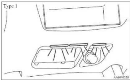
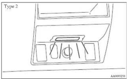
Storage spaces
E00713101404
CAUTION
● Never leave lighters, cans of carbonated drink, and spectacles in the cabin when parking the vehicle in hot sunshine. The cabin will become extremely hot, so lighters and other flammable items may catch fire and unopened drink cans (including beer cans) may rupture. The heat may also deform or crack plastic spectacle lenses and other spectacle parts that are made of plastic.
- Keep the lids of storage spaces closed while driving the vehicle. A lid or the contents of a storage space could otherwise cause injuries.
NOTE
- Do not leave valuables in any storage space when leaving the vehicle.
For pleasant driving
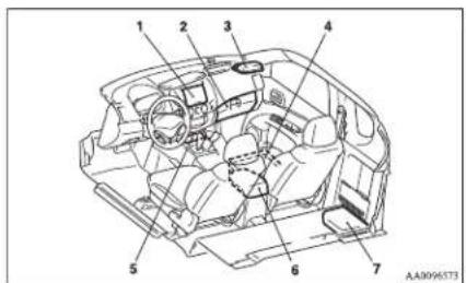
1- Utility box*
2- Glove box
3- Sunglasses holder*
4- Seat under tray*
5- Front console box*
6- Floor console box*
7- Secret box (Club cab)
Glove box
E00717601090
5
NOTE
- When the lamp switch is in the “ ^30 D” or “ ^30 D” position, the glove box lamp illuminates.
Type 1
To open, pull the lever (A).
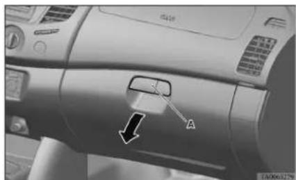
natural_image
Close-up of a car's dashboard and air vent with a directional arrow and label 'A' (no readable text or symbols beyond labels)Type 2
The glove box can be locked and unlocked using the key.
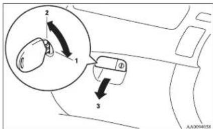
1- To lock
2- To unlock
3- To open, pull the lever
Front console box\*
To open, pull up the knob (A).
E00733400161
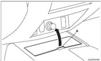
natural_image
Technical diagram of a vehicle's air intake system with labeled component A (no text or symbols beyond label)Floor console box\*
E00723300633
Type 1
To open, raise the lid.
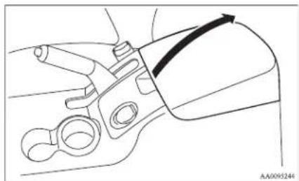
natural_image
Technical line drawing of a mechanical component with no visible text or symbolsType 2
Upper and lower boxes are located inside the floor console box.
For pleasant driving
The floor console box can also be used as an armrest.
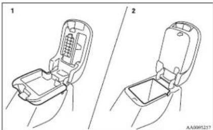
natural_image
Two technical line drawings of a car seat assembly, showing open and closed compartments (no text or symbols)1- Upper box
2-Lower box
NOTE
● The Auxiliary Audio connector (RCA) or the Auxiliary Video connector (RCA) is located in the lower box (if so equipped). For details, refer to "To use the external audio input function" on page 5-27.
Upper box
To open the upper box, lift the right release lever (A) and raise the lid.
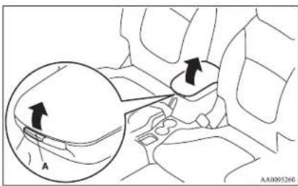
Lower box
To open the lower box, lift the left release lever (B) and raise the lid.
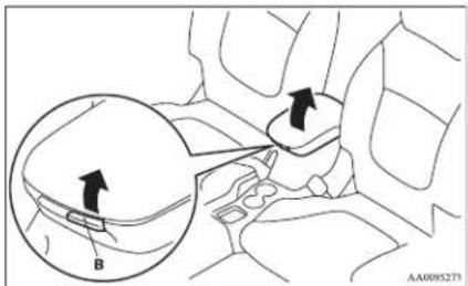
Utility box\*
To open, pull up the knob (A).
E00717900100
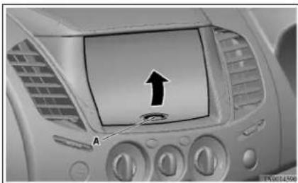
natural_image
Interior view of a car dashboard with a mounted screen and directional arrow indicator (no text or symbols)Sunglasses holder\*
Push the lid to open.
ED0718600250
Close the lid by pushing it till it clicks.
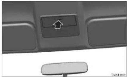
natural_image
Close-up of a car front panel with a button labeled 'C' and an arrow icon, no readable text or symbols beyond the button.CAUTION
● The holder should not be used to store anything heavier than sunglasses. These objects could drop out.
NOTE
● The holder may not be able to accommodate every possible size and shape of sunglasses; it is advisable to check compatibility before use.
Secret box (Club cab)
E00724900043
The secret box is in the floor behind the seat.
For pleasant driving
To use the box, open the lid.
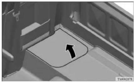
natural_image
Close-up of a mechanical component with a black arrow pointing to a specific area (no text or symbols visible)Seat under tray (under front passenger's seat)\*
E00725700035
A tray is provided underneath passenger's seat.
To use
Draw out the tray.
natural_image
Diagram of a car's side profile showing the left side of the window and rear side, with an arrow indicating direction (no text or symbols present)To store
Push in the tray positively until it is fully locked.
To remove
Pull off the tray while lifting upward.
natural_image
Diagram of a car interior showing a hand holding the seat with an arrow indicating motion (no text or symbols)Cup holder\*
E00714500802

CAUTION
- Do not drink beverages while driving the vehicle; doing so could distract you and result in an accident.
For the front seat
The cup holder is located between the front seats.
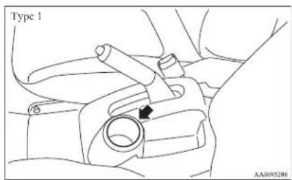

NOTE
● The cup holder adapter (A) can be removed to enable the cup holder to hold relatively large cup. Remove the cup holder adapter when necessary.
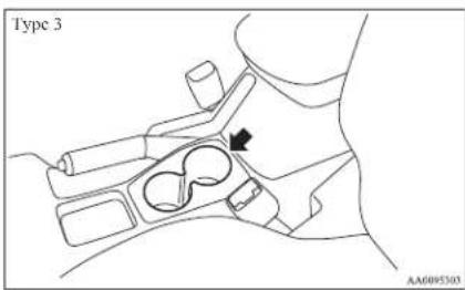
For the rear seat (Double cab)
E00716900389
In order to use the cup holder, allow the armrest to drop down.
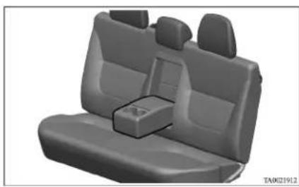
natural_image
3D rendered image of a car seat with rear seats and a central compartment (no text or symbols visible)Bottle holder
E00718200171
CAUTION
- Do not drink beverages while driving the vehicle; doing so could distract you and result in an accident.
● Beverages can spill due to vibration or other movement during vehicle operation. Be careful not to get scalded by a hot beverage if spilled
NOTE
● Make sure the cap of any plastic bottle placed in a bottle holder is tightly closed.
● The bottle holders may not accommodate bottles of certain shapes and sizes.
For the front seat
The bottle holders are provided at both sides.
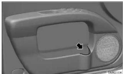
natural_image
Close-up of a car interior component with a black arrow pointing to a specific area (no text or symbols visible)For the rear seat (Double cab)
The bottle holders are provided at both sides.
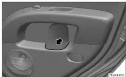
natural_image
Close-up of a car's side panel showing the handle and vent, with a black arrow pointing to a specific area (no text or symbols visible)For pleasant driving
Convenient hook
E00732900071
Light items of luggage can be hung from the hook.
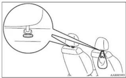
natural_image
Illustration of a person using a tool to cut a component, with magnified view of the part (no text or symbols)NOTE
● Do not hang heavy luggage (more than about 4 kg) on the hook.
Doing so could cause damage to the hook.
Coat hook\*
L00725600438
There is a coat hook on the rear seat assist grip.
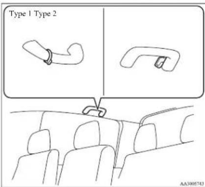
WARNING
- Do not put a hanger or any heavy or pointed object on the coat hook. If the curtain airbag was activated, any such item could be propelled away with great force and could prevent the curtain airbag from inflating correctly. Hang clothes directly on the coat hook (without using a hanger). Make sure there are no heavy or sharp objects in the pockets of clothes that you hang on the coat hook.
First-aid kit and warning triangle securing bands\*
E00717200028
A first-aid kit and a warning triangle can be secured with the band(s) installed in the illustrated position.
Single cab, Double cab
The wall behind the seat is provided with a band for securing a first-aid kit and a warning triangle.
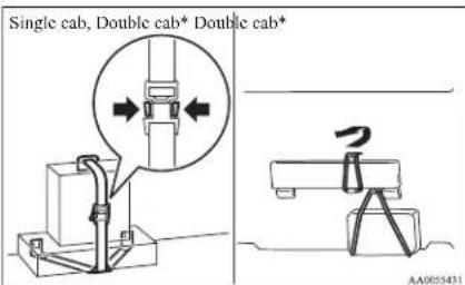
Club cab
A band for securing a first-aid kit is installed in the secret box.
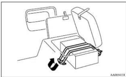
natural_image
Line drawing of a car seatbelt device with a circular arrow indicating rotation (no text or symbols)A band for securing a warning triangle is installed left under the rear seat.
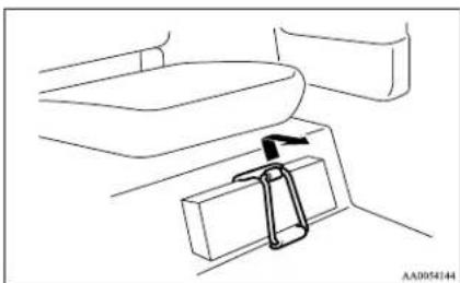
natural_image
Line drawing of a seatbelt mechanism with a directional arrow indicating motion (no text or symbols)For pleasant driving
| 10.2 | 10.3 | 10.4 | 10.5 | 10.6 | 10.7 | 10.8 | 10.9 | 11.0 | 11.1 | 11.2 | 11.3 | 11.4 | 11.5 | 11.6 | 11.7 | 11.8 | 11.9 | 12.0 |
For emergencies
If the vehicle breaks down....6-02
Emergency starting....6-02
Engine overheating....6-04
Bleeding the fuel system....6-05
Removal of water from the fuel filter....6-06
Tools, jack and jack handle....6-07
Jacking up the vehicle....6-13
Spare wheel....6-16
How to change a tyre....6-17
Towing....6-20
Operation under adverse driving conditions....6-24
For emergencies
If the vehicle breaks down
E00800101166
If the vehicle breaks down on the road, move it to the shoulder and use the hazard warning flashers and/or the warning triangle etc.
Refer to "Hazard warning flasher switch" on page 3-34.
If the engine stops/fails
Vehicle operation and control are affected if the engine stops.
Before moving the vehicle to a safe area, be aware of the following:
● The brake booster becomes inoperative and the pedal effort will increase. Press down the brake pedal harder than usual.
● Since the power steering pump is no longer operative, the steering wheel feels heavy when turning it.
Emergency starting
E00800502112
If the engine cannot be started because the battery is weak or dead, the battery from another vehicle can be used with jumper cables to start the engine.
WARNING
● To start the engine using jumper cables connected from another vehicle, perform the correct procedures according to the instruction manual. Incorrect procedures could result in a fire or explosion or damage to the vehicles.
- Get the vehicles close enough so the jumper cables can reach, but be sure the vehicles aren't touching each other. If they are, it could cause a ground connection you don't want. The vehicle will not start, and the bad grounding could damage the electrical systems.
CAUTION
- Check the other vehicle. It must have a 12-volt battery. If the other system isn't 12-volt, shorting can damage both vehicles.
- You could be injured if the vehicles move. Set the parking brake firmly on each vehicle. Put an automatic transmission in "P" (PARK) or a manual transmission in "N" (Neutral). Turn off the ignition switch.
WARNING
● Turn off the ignition on both vehicles beforehand. Make sure that the cables or your clothes cannot be caught by the fan or drive belt. Personal injury could result.
NOTE
● Turn off all lamps, heater and other electrical loads. This will avoid sparks and help save both batteries.
3. Make sure battery electrolyte is at the proper level.
Refer to “Battery” on page 8-09.
WARNING
- If electrolyte fluid is not visible, or appears to be frozen, Do Not Attempt Jump Starting! A battery might rupture or explode if the temperature is below the freezing point or if it is not filled to the proper level.
- Connect one end of one jumper cable to the positive (+) terminal of the discharged battery (A), and the other end to the positive (+) terminal of the booster battery (B).
Vehicles with 1 battery
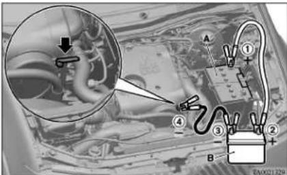
Vehicles with 2 batteries
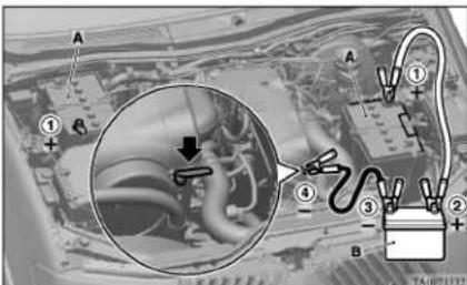
- Connect one end of the other jumper cable to the negative (-) terminal of the booster battery (B), and the other end to the engine block of the vehicle with the discharged battery at the point farthest from the battery.
NOTE
- Open the cover before connecting the jumper cable to the positive (+) terminal of the battery. (Refer to "Battery" on page 8-09.)
WARNING
- Be sure to observe the connecting sequence of ①→②→③→④
- Make sure that the connection ④s made to the appointed position (shown in the illustration). If the connection is made directly to the negative side of the battery, the inflammable gasses generated from the battery might catch fire and explode.
- When connecting the jumper cables, do not connect the positive (+) cable to the negative (-) terminal. Otherwise sparks might cause explosion of the battery.
CAUTION
● Take care not to get the jumper cable caught in the cooling fan or other rotating part in the engine compartment.
- Use the proper cables suitable for the battery size.
Otherwise heat damage to the cables could result.
- Check the jumper cables for damage and corrosion before use.
- Start the engine in the vehicle which has the booster battery, let the engine idle a few minutes, then start the engine in the vehicle with the discharged battery.
For emergencies
CAUTION
- Keep the engine of the vehicle giving assistance running.
- After the engine is started, disconnect the cables in the reverse order.
WARNING
● Charging the battery while it is installed in the vehicle might cause the battery to catch fire and explode.
Or damage to the vehicle could result. If it has to be charged in that condition for unavoidable reasons, disconnect the vehicle side negative (-) terminal connected to the battery.
- Keep sparks, cigarettes and flames away from the battery because the battery may produce an explosion.
● Use adequate ventilation when charging or using the battery in an enclosed space.
- Remove all the caps before charging the battery.
● Electrolyte is corrosive diluted sulphuric acid.
If electrolyte (battery acid) comes into contact with your hands, eyes, clothes and the painted surface of your vehicle, it should be thoroughly flushed with water. If electrolyte gets in your eyes, flush them with water immediately and thoroughly, and get prompt medical attention.
For emergencies

CAUTION
- Do not attempt to start the engine by pulling or pushing the vehicle.
It could damage your vehicle.
● Always wear protective eye goggles when working near the battery. - Keep the battery out of the reach of children.
NOTE
- On vehicles with anti-lock brake system, if the vehicle is put in motion without fully charging the battery, it might cause the loss of smooth engine operation and the antilock brake warning lamp to illuminate. Refer to "Anti-lock brake system (ABS)" on page 4-43.
Engine overheating
L00800601985
If the water temperature gauge indication remains in the overheating zone for a long time, the engine may be overheating. If this occurs, take the following corrective measures:
- Stop the vehicle in a safe place.
- Check whether steam is coming from the engine compartment.
[If steam does not come from the engine compartment]
With the engine still running, raise the bonnet to ventilate the engine compartment.
[If steam is coming from the engine compartment]
Stop the engine, and when the steam stops, raise the bonnet to ventilate the engine compartment. Restart the engine.
- Confirm that the cooling fan is turning. If the fan is not turning, stop the engine immediately and have it checked.
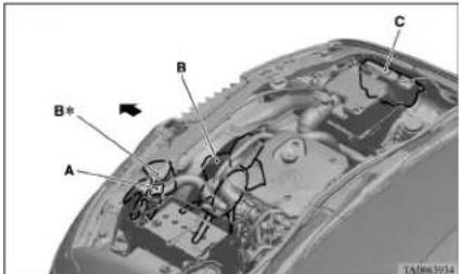
1- Radiator cap
2- Cooling fan
3- Reserve tank
*: if so equipped

WARNING
● Be careful not to get your hands or clothes caught in the cooling fan.
- After the engine coolant temperature has dropped to the normal temperature, stop the engine.
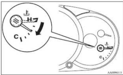
- Check the coolant level in the reserve tank.
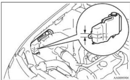
natural_image
Technical line drawing of a car engine compartment with a magnified inset showing internal components (no text or symbols)WARNING
- If there is none, make sure that the engine has cooled down before removing the radiator cap, because hot steam or boiling water otherwise will gush from the filler port and may scald you.
- Add coolant to the radiator and/or reserve tank if necessary (refer to the "Maintenance" section.)
CAUTION
- Do not add coolant while the engine is hot. Suddenly adding cold coolant could damage the engine. Wait for the engine to cool down, then add coolant a little at a time.
- Examine the radiator hoses for coolant leakage and the drive belt for looseness or damage. If there is anything wrong with the cooling system or drive belt, we recommend you to have it checked and repaired.
For emergencies
Bleeding the fuel system
E00800700178
The fuel system should be bled to remove air as described below if the fuel supply is exhausted during travel.
Type 1
- Loosen the air plug (A) at the top of the fuel filter.
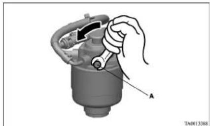
natural_image
Mechanical component diagram showing a hand holding a wrench, with no visible text or symbolsFor emergencies
- Pump the hand pump (B) until there are no more bubbles in the fuel coming out of the air plug (A). When doing this, place a cloth around the air plug (A) to prevent the escaping fuel from spraying out.
If the engine does not start, repeat the process above.
- Tighten the air plug (A) when there are no more bubbles in the fuel.
- Continue pumping until the hand pump (B) becomes stiff.
- Finally, check to be sure that there is no leakage of fuel.
If in doubt, we recommend you to consult a specialist for necessary information.
natural_image
Mechanical assembly diagram showing a hand holding a component with a bolt and arrow indicating direction (no text or symbols present)CAUTION
- Do not smoke or have any other open flame near the vehicle while bleeding the fuel system.
● Be sure to carefully clean away any spilt fuel which could ignite and cause a fire.
Removal of water from the fuel filter
E00800800267
If the fuel filter indication lamp in the instrument panel illuminates during driving, it indicates that water has accumulated in the fuel filter. If this occurs, remove the water as described below.
Type 1
- Loosen the drain plug (A) at the bottom of the fuel filter.
natural_image
Illustration of a hand holding a mechanical component with an inset close-up showing a cylindrical component labeled A (no text or symbols present)Type 2
Pump the hand pump (A) at the top of the fuel filter until the hand pump becomes stiff.
Then try again to start the engine.
- Operate the hand pump (B) slowly 6 or 7 times in order to force the water out through the drain plug (A).
natural_image
Hand holding a mechanical component with a labeled part B, no visible text or symbols- Tighten the drain plug (A) when water no longer comes out.
- Loosen the air plug and bleed the air. (Refer to "Bleeding the fuel system" on page 6-05.)
- Check to be sure that the fuel filter indication lamp illuminates when the ignition switch is turned to "ON", and that it goes off when the engine is started. If in doubt, we recommend you to consult a specialist for necessary information.
CAUTION
- Do not smoke or have any other open flame near the vehicle while bleeding the fuel system.
- Be sure to carefully clean away any water drained out because any fuel mixed with the water could ignite and cause a fire.
Type 2
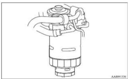
natural_image
Technical line drawing of a mechanical component with no visible text or symbolsTake your vehicle to a MITSUBISHI MOTORS Authorized Service Point to remove the water from the fuel filter.
Tools, jack and jack handle
E00800900819
Storage
The storage location of the tools, jack and jack handle should be remembered in case of an emergency.
Single cab
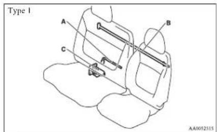
A- Tool (wheel nut wrench)
B- Jack handle
C- Jack
For emergencies
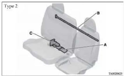
A-Tools
B- Jack handle
C- Jack
Club cab
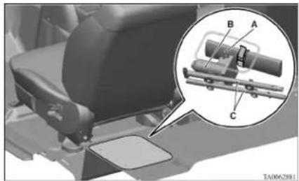
natural_image
Mechanical assembly diagram showing a car seat with labeled parts A, B, and C, plus an inset view of a mechanical component (no text or symbols present)A-Tools
B-Jack
C- Jack handle
Double cab
Except for vehicles with rear retractable power window
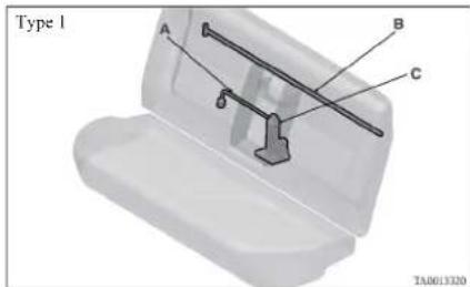
A- Tool (wheel nut wrench)
B- Jack handle
C- Jack
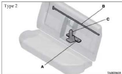
A-Tools
B- Jack handle
C- Jack
Vehicles with rear retractable power window
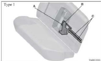
A- Tool (wheel nut wrench)
B-Jack
C- Jack handle
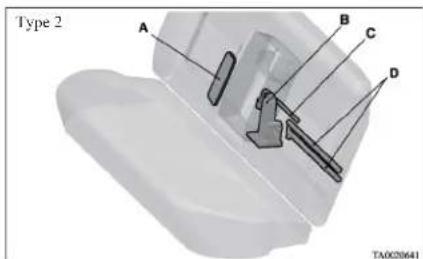
A-Tools
B-Jack
C- Wheel nut wrench
D- Jack handle
For emergencies
Tools
E00801900382
Type 1
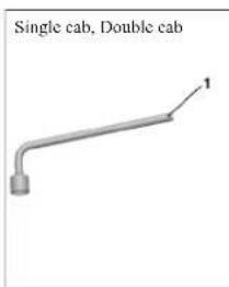
Club cab
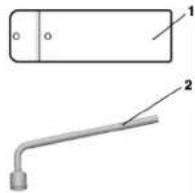
TN0015697
Single cab, Double cab
1- Wheel nut wrench
Club cab
1- Tool bag
2- Wheel nut wrench
Type 2
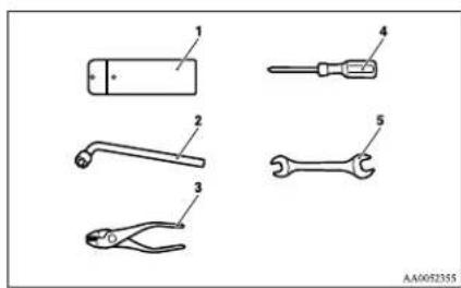
Single cab, Club cab, Double cab
1- Tool bag
2- Wheel nut wrench
3- Plier
4- Driver
5- Spanner
Removing and storing the tools, jack and jack handle
E00802300240
Single cab
The tools, jack, and jack handle are located behind the seat.
- Tip forward the seatback. (Refer to "Folding the seatback forward" on page 2-06.)
Remove the wheel nut wrench (A) from the holder (B), and take out the wrench. Remove the securing band (C), and then take out the tools (D).
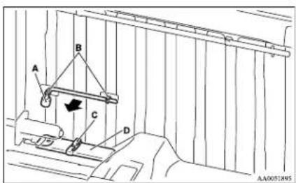
- Remove the securing nut (E), and then take out the jack (F).
- Remove the jack handle (G) from the holder (II), and take out the handle.
- Reverse the removing procedure when storing the tool, jack and jack handle.
For emergencies
NOTE
- When stowing the jack handle, align the black-marked part (I) of the jack handle with the holder (J).
Club cab
The tools, jack, and jack handle are stored under the floor on the left-hand side of the cargo space.
-
Raise the left side seat cushion. Refer to "Folding up the seat cushion (Club cab)" on page 2-07. Tip forward the seatback of the driver seat. Slide the driver seat forward.
-
Open the lid.
natural_image
Simple line drawing of a door with a curved handle and arrow indicating rotation (no text or symbols)- Remove the securing band (A), and then take out the tools (B).
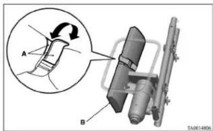
- Remove the securing nut (C), and then take out the jack (D).
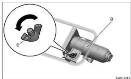
- Remove the jack handle (E) from the holder (F), and then take out the jack handle.
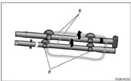
- Reverse the removing procedure when storing the tools, jack and jack handle.
NOTE
- When stowing the jack handle, align the coloured marking on the jack handle with that on the holder, and fit the jack in the holder.
Double cab
Except for vehicles with rear retractable power window
The tool (wheel nut wrench only), jack, and jack handle are located behind the rear seat.
-
Tip forward the seatback of the rear seat. (Refer to "Folding the seatback forward" on page 2-07.)
-
Remove the wheel nut wrench (A) from the holder (B), and take out the wrench.
Remove the securing band (C), and then take out the tools (D).
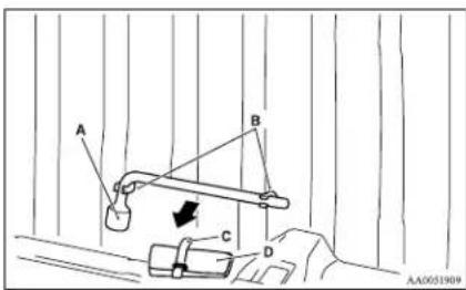
- Remove the securing nut (E), and then take out the jack (F).
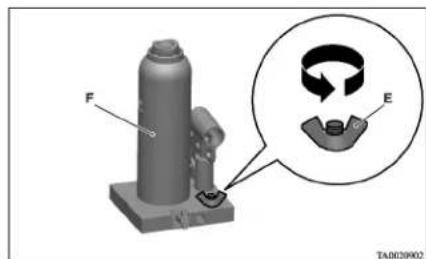
natural_image
3D mechanical assembly diagram showing a cylindrical component with labeled force F and a magnified inset showing rotational components (no text or symbols present)- Remove the jack handle (G) from the holder (H), and take out the handle.
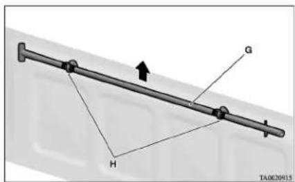
- Reverse the removing procedure when storing the tool, jack and jack handle.
NOTE
- When stowing the jack handle, align the black-marked part (I) of the jack handle with the holder (H).
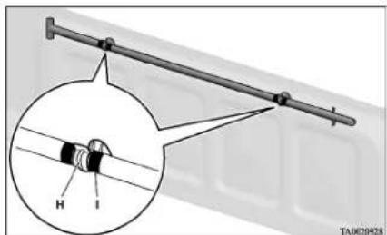
Vehicles with rear retractable power window The tools, jack, and jack handle are located behind the rear seat.
For emergencies
- Tip forward the seatback of the rear seat. (Refer to "Folding the seatback forward" on page 2-07.)
Remove the wheel nut wrench (A) from the holder of the back panel (B), and take out the wrench. Take out the tools (C) from the rear back trim (D).
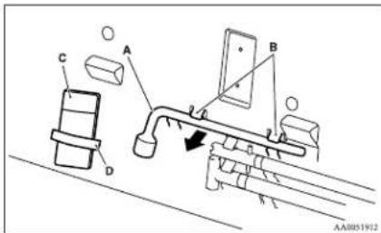
- Remove the securing nut (F), and then take out the jack (F).
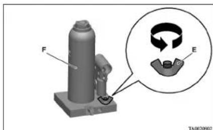
natural_image
3D mechanical component diagram with labeled parts F and E, showing a cylindrical part and a circular inset showing rotational motion (no text or symbols beyond labels)For emergencies
- Remove the jack handle (G) from the holder of the back panel (H), and take out the handle.
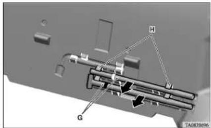
- Reverse the removing procedure when storing the tool, jack and jack handle.
NOTE
- When stowing the wheel nut wrench, insert it into the holder on the back panel as illustrated.
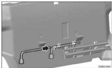
natural_image
Mechanical component diagram showing pipe connections and a labeled section (no readable text or symbols)To use the jack handle (Club cab, Double cab with rear retractable power window only)
E00802400124
- While pressing the snap pin (A) on the handle that has a black marking, withdraw and remove the inner handle (B).
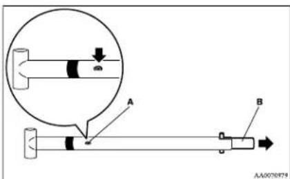
- Reverse the inner handle (B) then, while pressing the snap pin (C), insert it into the outer handle (D) until it is locked by snap pin as illustrated.
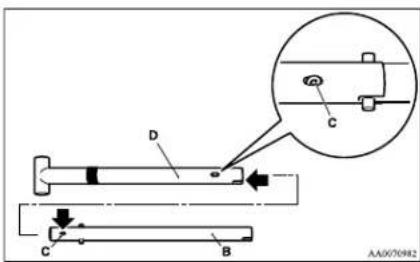
- While pressing the snap pin (F) on the assembled handle (E), insert the white-marked handle (G) until it is locked by snap pin as illustrated.
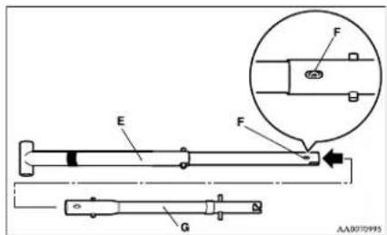
Jacking up the vehicle
L00801001436
- Park the vehicle on level and stable ground.
- Set the parking brake firmly.
- On vehicles with manual transmission, turn the ignition key to the "LOCK" position, move the gearshift lever to the "R" (Reverse) position.
On vehicles with automatic transmission, move the selector lever to the "P" (PARK) position, turn the ignition key to the "LOCK" position. - Turn on the hazard warning flashers and set up a warning triangle, flashing signal lamp, etc., at an adequate distance from the vehicle, and have all your passengers leave the vehicle.
- To prevent the vehicle from rolling when it is raised on the jack, place chocks or blocks (A) at the tyre that is diagonally opposite from the tyre (B) you are changing.
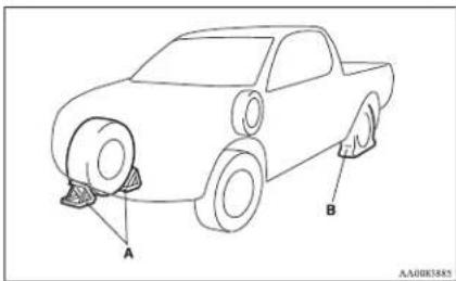
WARNING
- Be sure to apply checks or blocks to the correct tyre when jacking up the vehicle. If the vehicle moves while jacked up, the jack could slip out of position, leading to an accident.
NOTE
● The chocks shown in the illustration do not come with your vehicle. It is recommended that you keep one in the vehicle for use if needed.
- If chocks are not available, use stones or any other objects that are large enough to hold the wheel in position.
-
Get the spare wheel, jack and jack handle ready.
-
Place the jack under one of the jacking points shown in the illustration. Use the jacking point closest to the tyre you wish to change.
2WD vehicles with 15 inch wheels
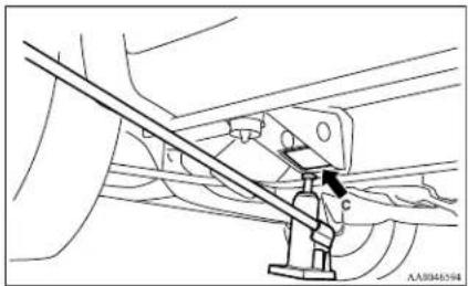
natural_image
Technical line drawing of a mechanical assembly with no visible text or symbolsC- Front jacking point (2WD vehicles with 15 inch wheels)
2WD vehicles with 16 inch wheels and 4WD vehicles
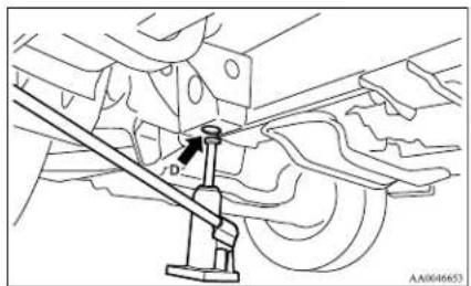
natural_image
Mechanical assembly diagram showing a lever mechanism with no visible text or symbolsD- Front jacking point (2WD vehicles 16 inch wheels and 4WD vehicles)
For emergencies
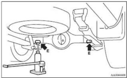
E- Rear jacking point
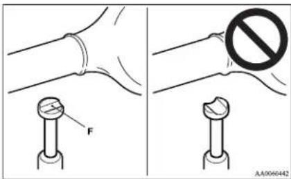
To raise the vehicle
- Using the jack handle, turn the release valve (G) clockwise until it stops.
WARNING
- Set the jack only at the positions shown here. If the jack is set at a wrong position, it could dent your vehicle or the jack might fall over and cause personal injury.
- Do not use the jack on a tilted or soft surface. Otherwise, the jack might slip and cause personal injury. Always use the jack on a flat, hard surface. Before setting the jack, make sure there are no sand or pebbles under the jack base.
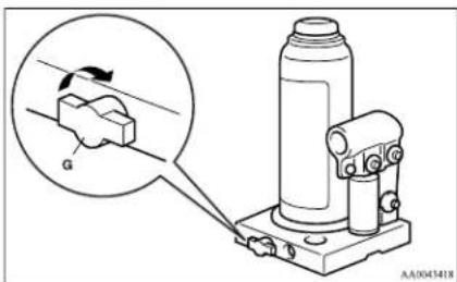
-
Insert the jack handle in the bracket of the jack and hook the notch (H) on the jack handle end to the claw (I) of the bracket.
-
Move the jack handle up and down to raise the ram until just before the jack contacts the jacking point of the vehicle. Ensure that the jack will properly contact the vehicle jacking point.
Move the jack handle up and down to raise the vehicle.
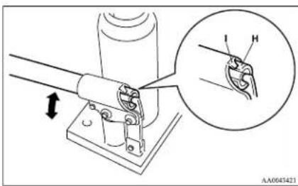
NOTE
● This jack is a 2 stage expansion type.
To lower the vehicle
- Put the notch (J) provided on the jack handle end on the valve (K) of the jack.
NOTE
- When jacking up the rear of the vehicle, turn the tip of the jack so that the grooved portion (F) properly meets the designated point.
- Using the jack handle, turn the release valve anticlockwise slowly to lower the ram and remove the jack.
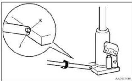
- Press the piston down all the way, and turn the release valve clockwise as far as possible.
- Store jack, jack handle and chocks.
WARNING
- Be sure to open the release valve slowly. If it is opened quickly, the vehicle will drop abruptly and the jack may come out of position, causing a serious accident.
CAUTION
- If the release valve is loosened too much (2 or more turns) in the anticlockwise direction, the jack's oil will leak and the jack cannot be used.
CAUTION
- Close the release valve slowly when lowering the vehicle, or the valve may be damaged.
NOTE
- Occasionally when the vehicle is jacked up, the grooved portion of the designated point will not come off. When this happens, rock the vehicle to lower the ram. - If the jack is difficult to remove by hand, insert the jack handle (L) into the bracket (M). Then using the handle, remove the jack.
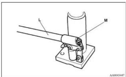
WARNING
- Stop jacking up the vehicle as soon as the tyre is raised off the ground. It is dangerous to raise the vehicle any higher. - Do not get under your vehicle while using the jack.
For emergencies
WARNING
- Do not bump the raised vehicle or leave it sitting on the jack for a long time. Both are very dangerous.
- Do not use a jack except the one that came with your vehicle.
● The jack should not be used for any purpose other than to change a tyre.
● No one should be in your vehicle when using the jack. - Do not start or run the engine while your vehicle is on the jack.
- Do not turn the raised wheel. The tyres still on the ground could turn and make your vehicle fall off the jack.
For emergencies
Spare wheel
E00801100094
The spare wheel is stored under the floor of the car-go bed.
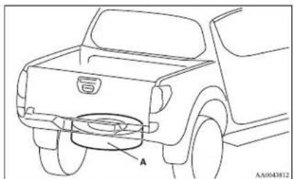
natural_image
Line drawing of a pickup truck rear bumper with labeled component A (no text or symbols beyond label)A- Spare wheel

CAUTION
- When removing the spare wheel, put on gloves. Removing the spare wheel with your bare hands may cause injury to the fingers.

CAUTION
- Check the air pressure of the spare wheel frequently and make sure it is ready for emergency use at any time. - Driving with an insufficient tyre pressure can lead to an accident. If you have no choice but to drive with an insufficient tyre pressure, keep your speed down and inflate the tyre to the correct pressure as soon as possible. (Refer to "Tyre inflation pressures" on page 8-12.) - Maintaining the spare wheel at the highest specified air pressure will ensure that it can always be used under any conditions (city/high-speed driving, varying load weight, etc.).
To remove
- Set the jack handle. (Club cab, Double cab with rear retractable power window only) (Refer to "To use the jack handle" on page 6-12.)
- Insert the jack handle (A) in the hole (B) below the rear gate.
- Securely insert the pin (C) on the jack handle into the holder (D) of the spare wheel carrier.
- Insert the wheel nut wrench (E) through the end of the jack handle hole (F), and then turn it anticlockwise to lower the spare wheel completely to the ground and to slack the chain.
- Remove the hanger disc (G) from the spare wheel.
To install
- Install the hanger disc (A) in the wheel disc hole.
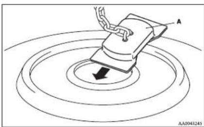
natural_image
Diagram showing a hand holding a rectangular object with a downward arrow, surrounded by concentric circular patterns (no text or symbols)- Turn the wheel nut wrench (B) clockwise to wind up the chain.
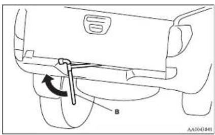
NOTE
- Confirm that the hanger disc is securely fitted in the wheel disc hole when the wheel is just lifted off the ground.
- After winding up the spare wheel sufficiently, make sure it is not loose (the tightening torque should be approximately 40 Nm) then withdraw the jack handle, taking care not to turn it in the reverse direction.
CAUTION
● The spare wheel should always be securely in position.
If a flat tyre is changed, put the flat tyre in the spare wheel mounting position with the wheel outer surface upward, and use the wheel nut wrench to secure it firmly.
For emergencies
How to change a tyre
E00801202653
Before changing a tyre, first stop your vehicle in a safe, flat location.
- Park the vehicle on level and stable ground.
- Set the parking brake firmly.
- On vehicles with manual transmission, turn the ignition key to the "LOCK" position, move the gearshift lever to the "R" (Reverse) position.
On vehicles with automatic transmission, move the selector lever to the "P" (PARK) position, turn the ignition key to the "LOCK" position. - Turn on the hazard warning flashers and set up a warning triangle, flashing signal lamp, etc., at an adequate distance from the vehicle, and have all your passengers leave the vehicle.
- To prevent the vehicle from rolling when it is raised on the jack, place chocks or blocks (A) at the tyre that is diagonally opposite from the tyre (B) you are changing.
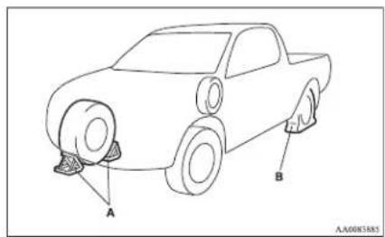
For emergencies
WARNING
- Be sure to apply checks or blocks to the correct tyre when jacking up the vehicle. If the vehicle moves while jacked up, the jack could slip out of position, leading to an accident.
NOTE
● The chocks shown in the illustration do not come with your vehicle. It is recommended that you keep one in the vehicle for use if needed.
- If chocks are not available, use stones or any other objects that are large enough to hold the wheel in position.
6. Get the spare wheel, jack, jack handle and wheel nut wrench ready.
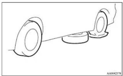
natural_image
Simple line drawing of two circular objects connected by a string, no text or symbols presentNOTE
● Put the spare wheel under the vehicle body near the flat tyre. This makes it safer if the jack slips out of position.
- Loosen the wheel nuts with the wheel nut wrench. Do not remove the wheel nuts yet.
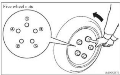
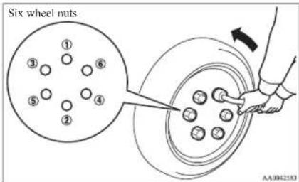
- Find the closest jacking point to the flat tyre (refer to "Jacking up the vehicle" on page 6-13). Then position the jack and raise the vehicle until the tyre is slightly off the ground.
- Remove the wheel nuts with the wheel nut wrench, then take the wheel off.
CAUTION
● Handle the wheel carefully when changing the tyre, to avoid scratching the wheel surface.
10. Clean out any mud, etc. on the hub surface (C), hub bolts (D) or in the installation holes (E) in the wheel, and then mount the spare wheel.
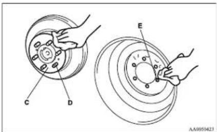
WARNING
- Mount the spare wheel with the valve stem (F) facing outboard. If you cannot see the valve stem (F), you have installed the wheel backwards. Operating the vehicle with the spare wheel installed backwards can cause vehicle damage and result in an accident.
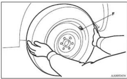
- Finger-tighten the wheel nuts. (Turn them clockwise.)
Vehicles with steel wheels
Tighten the wheel nuts (tapered nuts) until the tapered parts of the wheel nuts make light contact with the seats of the wheel holes and the wheel is not loose.
With a spare wheel, tighten the wheel nuts in the same way.
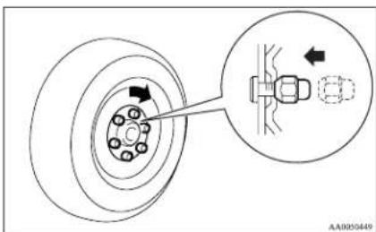
Vehicles with aluminium wheels
Tighten the wheel nuts (flange nuts) until the flanges of the wheel nuts touch the wheel and the wheel is not loose.
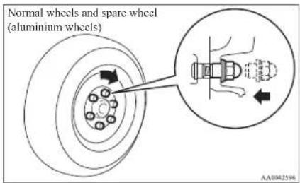
With a spare wheel, tighten the wheel nuts until the tapered parts of the wheel nuts make light contact with the seats of the wheel holes and the wheel is not loose.
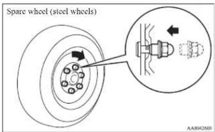
CAUTION
● Never apply oil to either the wheel bolts or the nuts, or they will tighten too much.
NOTE
● Flange nuts can be temporarily used on the spare wheel, but return to the original wheel and tyre as soon as possible.
- If all four aluminium wheels are changed to steel wheels, use tapered nuts.
- Lower the vehicle slowly and then tighten the nuts crisscross in 2 or 3 steps until each nut has been tightened securely.
Tightening torque
Steel wheel: 137 to 157 Nm
Aluminium wheel: 118 to 137 Nm
(Achieved by applying a force at the end of the wheel nut wrench supplied with the vehicle.
Steel wheel: 510 to 580 N
Aluminium wheel: 440 to 500 N)
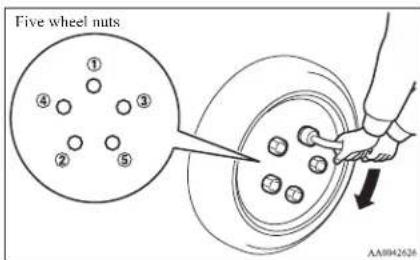
For emergencies
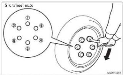
CAUTION
● Never use your foot or a pipe extension for extra force in the wheel nut wrench. If you do so, you will tighten the nut too much.
13. Lower and remove the jack, then store the jack, jack handle, wheel nut wrench, flat tyre, and chocks. Have your damaged tyre repaired as soon as possible.
14. Check your tyre inflation pressure. The correct pressures are shown on the door label. See the illustration.
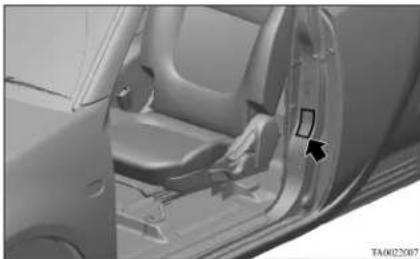
natural_image
Interior view of a car showing the dashboard and seat area with a directional arrow (no text or symbols visible)CAUTION
● The tyre pressure should be periodically checked and maintained at the specified pressure while the tyre is stowed.
● After changing the tyre and driving the vehicle about 1,000 km (620 miles), retighten the wheel nuts to make sure that they have not come loose.
- If the steering wheel vibrates when driving after changing the tyre, we recommend you to have the tyres checked for balance.
- Do not mix one type of tyre with another or use a different size from the one listed. This would cause early wear and poor handling.
Towing
E00801502816
If your vehicle needs to be towed
If towing is necessary, we recommend you to have it done by your MITSUBISHI MOTORS Authorized Service Point or a commercial tow truck service.
In the following cases, transport the vehicle using a tow truck.
● The engine runs but the vehicle does not move or abnormal noise is produced.
- Inspection of the vehicle's underside reveals that oil or some other fluid is leaking.
If a wheel gets stuck in a ditch, do not try to tow the vehicle. Please contact your MITSUBISHI MOTORS Authorized Service Point or a commercial tow truck service for assistance.
Only when you cannot receive a towing service from a MITSUBISHI MOTORS Authorized Service Point or commercial tow truck service, tow your vehicle carefully in accordance with the instructions given in "Emergency towing" in this part.
The regulations concerning towing may differ from country to country. It is recommended that you obey the regulations of the area where you are driving your vehicle.
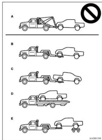
Towing the vehicle by a tow truck
CAUTION
● This vehicle must not be towed by a tow truck using sling lift type equipment (Type A) as illustrated. Using a sling lift will damage the bumper and front end.
- On 4WD vehicles, be sure to shift the transfer shift lever to "2H" position and transport the vehicle with the driving wheels on a carriage (Type C, D or E) as illustrated. Never try to tow with the transfer shift lever in "4H" or "4L" positions and with the front or rear wheels on the ground (Type B or Type C) as illustrated. This could result in driving system damage or the vehicle may jump at the carriage. If you cannot shift the transfer shift lever to "2H" position or the transmission is malfunctioning or damaged, transport the vehicle with all the wheels on a carriage (Type D or E) as illustrated.
- If vehicles equipped with the Active Stability & Traction Control system (ASTC) are towed with the ignition switch in the "ON" position and only the front wheels or only the rear wheels raised off the ground, the active Traction Control System may operate, resulting in an accident.
- On 2WD vehicles, if the transmission is malfunctioning or damaged, transport the vehicle with the driving wheels on a carriage (Type C, D or E) as illustrated.
For emergencies
CAUTION
- If you tow a vehicle with automatic transmission with the driving wheels on the ground (Type B) as illustrated, make sure that the towing speed and distance given below are never exceeded, causing damage to the transmission.
Towing speed: 50 km/h (30 mph) Towing distance: 50 km (30 miles)
For the towing speed and the towing distance, follow the local driving laws and regulations.
Towing with front wheels off the ground (Type B) Place the gearshift lever in the "N" (Neutral) position (manual transmission) or the selector lever in the "N" (NEUTRAL) position (automatic transmission).
Release the parking brake.
CAUTION
● Never tow an automatic transmission vehicle with the front wheels up (and the rear wheels on the ground) (Type B) when the automatic transmission fluid level is low. This may cause serious and expensive damage to the transmission.
For emergencies
Towing with rear wheels off the ground (Type C) Place the gearshift lever in the "N" (Neutral) position (manual transmission) or the selector lever in the "N" (NEUTRAL) position (automatic transmission). Turn the ignition key to the "ACC" position and secure the steering wheel in a straight-ahead position with a rope or tie-down strap. Never place the ignition switch in the "LOCK" position when towing.
Emergency towing
If towing service is not available in an emergency, your vehicle may be temporarily towed by a cable or chain secured to the towing hook. If your vehicle is to be towed by another vehicle, pay careful attention to the following points.
If your vehicle is to be towed by another vehicle
- The front towing hooks (A) and rear towing hook (B) are located as shown in the illustration. Secure the tow rope to the towing hook.
Front (2WD vehicles with 15 inch wheels)
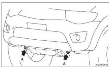
natural_image
Line drawing of a car's front bumper with labeled points A and a small arrow indicating motion (no text or symbols beyond labels)Front (2WD vehicles with 16 inch wheels and 4WD vehicles)
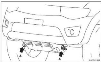
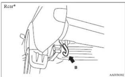
NOTE
● Using any part other than the designated towing hooks could result in damage to the vehicle body.
● Using a wire rope or metal chain can result in damage to the vehicle body. It is best to use a non-metallic rope. If you use a wire rope or metal chain, wrap it with cloth at any point where it touches the vehicle body.
● Take care that the tow rope is kept as horizontal as possible. An angled tow rope can damage the vehicle body.
- Secure the tow rope to the same side towing hook, to keep the tow rope as straight as possible.
2. Keep the engine running.
If the engine is not running, turn the ignition key to the "ACC" or "ON" position to unlock the steering wheel.

CAUTION
- When the engine is not running, the brake booster and power steering pump do not operate. This means higher brake depression force and higher steering effort are required. Therefore, vehicle operation is more difficult than usual.
-
Do not leave the key in the "LOCK" position. The steering wheel will lock, causing loss of control.
-
Place the gearshift lever in the "N" (Neutral) position (manual transmission) or the selector lever in the "N" (NEUTRAL) position (automatic transmission).
- On 4WD vehicles, the transfer shift lever to "2H" position.
- Turn on the hazard warning lamps if required by law. (Follow the local driving laws and regulations.)
- During towing make sure that close contact is maintained between the drivers of both vehicles, and that the vehicles travel at low speed.

WARNING
● To prevent entry of exhaust gas from the towing vehicle, set your air selection lever to the recirculation position.

CAUTION
- Avoid sudden braking, sudden acceleration and sharp turning; such operation could cause damage to the towing hooks or the tow rope.
People in the vicinity could be injured as a result. - When towing or being towed down a long slope, the brakes may overheat reducing the effectiveness. In this situation, have your vehicle transported by a tow truck.
- When the vehicle with automatic transmission is to be towed by another vehicle with the all wheels on the ground, make sure that the towing speed and distance given below are never exceeded, causing damage to the transmission.
Towing speed: 50 km/h (30 mph) Towing distance: 50 km (30 miles)
For the towing speed and the towing distance, follow the local driving laws and regulations.
NOTE
● Using any part other than the designated towing hook could result in damage to the vehicle body.
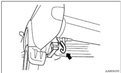
natural_image
Line drawing of a car seatbelt mechanism with a black arrow indicating the angle (no text or symbols present)
CAUTION
- On vehicles with super select 4WD, when you are going to tow another vehicle, move the transfer shift lever to "4H" position. Selecting "2H" drive may increase the differential oil temperature, resulting in possible damage to the driving system. Further, the drive train will be subjected to excessive loading possibly leading to oil leakage, component seizure, or other serious faults.
NOTE
- Your vehicle should only be used to tow another vehicle if the weight of the other vehicle is less than the weight of your vehicle.
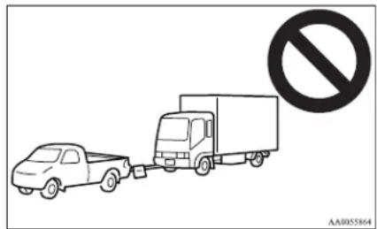
If your vehicle tows another vehicle (vehicles with rear towing hook only)
The rear towing hook is located as shown in the illustration. Secure the tow rope to the rear towing hook.
For emergencies
Operation under adverse driving conditions
E00801702140
If your vehicle becomes stuck in sand, mud or snow
If the vehicle becomes stuck in snow, sand, or mud, it can often be moved with a rocking motion. Move the selector lever alternately between the "L" (LOW) and "R" (REVERSE) position (with manual transmission, between 1^st and Reverse), while applying slight pressure to the accelerator pedal.
Avoid racing the engine or spinning the wheels. Prolonged efforts to free a stuck vehicle may result in overheating and transmission failure. Allow the engine to idle for a few minutes to let the transmission cool between rocking attempts.
If the vehicle remains stuck after several rocking attempts, seek other assistance.
WARNING
- When attempting to rock your vehicle out of a stuck position, be sure that the area around the vehicle is clear of people and physical objects. The rocking motion may cause the vehicle to suddenly launch forward or backward, causing injury or damage to nearby people or objects.
On 2WD vehicles, it is recommended to start the vehicle with parking brake partially, but not completely, applied by slightly pulling the parking brake lever.
After the vehicle has become free, do not forget to release the parking brake.
NOTE
● Depress the accelerator pedal gradually when starting the vehicle.
On a flooded road
● Avoid flooded roads. Water could enter the brake discs, resulting in temporarily ineffective brakes. In such cases, lightly depress the brake pedal to see if the brakes operate properly. If they do not, lightly depress the pedal several times while driving in order to dry the brake pads.
- When driving in rain or on a road with many puddles a layer of water may form between the tyres and the road surface.
This reduces a tyre's frictional resistance on the road, resulting in loss of steering stability and braking capability.
To cope with this, observe the following items:
(a) Drive your vehicle at slow speed.
(b) Do not drive on worn tyres. Always maintain the specified tyre inflation pressures.
On a snow-covered or frozen road
- When driving on a snow-covered or frozen road, it is recommended that you use snow tyres or tyre chains.
Refer to the "Snow tyres" and "Tyre chains" sections. - Avoid high-speed operation, sudden acceleration, abrupt brake application and sharp cornering.
● Depressing the brake pedal during travel on snowy or icy roads may cause tyre slippage and skidding. When traction between the tyres and the road is reduced the wheels may skid and the vehicle cannot readily be brought to a stop by conventional braking techniques. Braking will differ, depending upon whether you have anti-lock brake system (ABS). If you do have ABS, brake by pressing the brake system pedal hard, and keeping it pressed. If you do not have ABS, pump the brake pedal with short rapid jabs, each time fully applying and fully releasing for greatest effect.
- Allow extra distance between your vehicle and the vehicle in front of you, and avoid sudden braking.
- Accumulation of ice on the braking system can cause the wheels to lock. Pull away from a standstill slowly after confirming safety around the vehicle.
CAUTION
- Do not press the accelerator pedal rapidly. If the wheels break free of the ice, the vehicle could suddenly start moving and possibly cause an accident.
On a bumpy or rutted road
● Drive as slow as possible when driving on bumpy or rutted roads.

CAUTION
● The impact on tyres and/or wheels when driving on a bumpy or rutted road can damage the tyre and/or wheel.
For emergencies
| 10.2 | 10.3 | 10.4 | 10.5 | 10.6 | 10.7 | 10.8 | 10.9 | 11.0 | 11.1 | 11.2 | 11.3 | 11.4 | 11.5 | 11.6 | 11.7 | 11.8 | 11.9 | 12.0 |
Vehicle care
Vehicle care precautions....7-02
Cleaning the interior of your vehicle....7-02
Cleaning the exterior of your vehicle....7-03
Vehicle care
Vehicle care precautions
E00900100870
In order to maintain the value of your vehicle, it is necessary to perform regular maintenance using the proper procedures. Always maintain your vehicle in compliance with environmental pollution control regulations. Carefully select the materials used for washing, etc., to be sure that they do not contain corrosives. If in doubt, we recommend you to consult a specialist for selection of these materials.

CAUTION
- Cleaning products can be dangerous. Some are poisonous. Others can burst into flame if you strike a match or drop them on a hot part of the vehicle. Some are dangerous if you breathe their fumes in a closed space. When you use anything in a container to clean your vehicle, always follow the instructions and always open your vehicle doors or windows when you're cleaning the inside. Never use the following to clean your vehicle:
- Petrol
- Paint Thinner
• Benzine - Kerosene
- Turpentine
• Naphtha
• Lacquer Thinner
• Carbon Tetrachloride
• Nail Polish Remover - Acetone
● These are all dangerous, and can damage your vehicle.
Cleaning the interior of your vehicle
L00900200288
After cleaning the interior of your vehicle with water, cleaner or similar, wipe and dry in a shady, well-ventilated area.

CAUTION
- Do not use organic substances (solvents, benzine, kerosene, alcohol, petrol, etc.) or alkaline or acidic solutions.
These chemicals can cause discolouring, staining or cracking of the surface.
If you use cleaners or polishing agents, make sure their ingredients do not include the substances mentioned above.
NOTE
● Always read the instructions on the cleaner label.
Plastic, vinyl leather, fabric and flocked parts
E00900300045
- Gently wipe off with gauze or other soft cloth soaked with a 3 % aqueous solution of neutral detergent.
- Dip cloth in fresh water and wring it out well. Using this cloth, wipe off the detergent thoroughly.
NOTE
- Do not use cleaners, conditioners, and protectants containing silicons or wax.
Such products may cause annoying reflections and obscure vision.
Upholstery
E00900500018
- To maintain the value of your new vehicle, handle the upholstery carefully and keep the interior clean.
Use a vacuum cleaner and brush to clean the seats. If stained, vinyl and synthetic leather should be cleaned with an appropriate cleaner, and cloth fabrics can be cleaned with either upholstery cleaner or a 3 % solution of neutral detergent in lukewarm water.
- Clean the carpeting with a vacuum cleaner and remove any stains with carpet cleaner. Oil and grease can be removed by lightly dabbing with a clean colourfast cloth and stain remover.
Genuine leather\*
E00900600817
- Gently wipe off with gauze or other soft cloth soaked with a 5% aqueous solution of neutral detergent.
- Dip cloth in fresh water and wring it out well. Using this cloth, wipe off the detergent thoroughly.
- Apply leather protecting agent to the genuine leather surface.
NOTE
- If genuine leather is wet with water or is washed in water, wipe off water as quickly as possible with a dry, soft cloth. If left damp, mildew may grow.
● The genuine leather surface may be damaged if a nylon brush or synthetic fibre is rubbed hard against it.
● Organic solvents such as benzine, kerosene, alcohol and petrol, acid or alkaline solvents may discolour the genuine leather surface. Be sure to use neutral detergents. - Remove dirty patches or oil substances quickly as they can stain genuine leather.
● The genuine leather surface may harden and shrink if it is exposed to direct sun for long hours. When your vehicle is parked, place it in the shade as much as possible. - When the temperature of the vehicle interior rises in summer, vinyl products left on the genuine leather seat may deteriorate and stick to the seat.
Cleaning the exterior of your vehicle
E00900700010
If the following is left on your vehicle, it may cause corrosion, discolouration and stains, wash the vehicle as soon as possible.
● Seawater, anti-freeze for road use.
● Soot and dust, iron powder from factories, chemical substance (acids, alkalis, coal-tar, etc.).
- Droppings from birds, carcasses of insects, tree sap, etc.
Washing
E00900902016
Chemicals contained in the dirt and dust picked up from the road surface can damage the paint coat and body of your vehicle if left in prolonged contact. Frequent washing and waxing is the best way to protect your vehicle from this damage. This will also be effective in protecting it from environmental elements such as rain, snow, salt air, etc.
Do not wash the vehicle in direct sunlight. Park the vehicle in the shade and spray it with water to remove dust. Next, using an ample amount of clean water and a car washing brush or sponge, wash the vehicle from top to bottom.
Use a mild car washing soap if necessary. Rinse thoroughly and wipe dry with a soft cloth. After washing the vehicle, carefully clean the joints and flanges of the doors, bonnet, etc., where dirt is likely to remain.

CAUTION
- When washing the under side of your vehicle or wheel, be careful not to injure your hands.
- Refrain from using a car wash as its brushes may scratch the paint surface, causing it to lose its gloss.
Scratches will be especially visible on darker coloured vehicles.
● Never spray or splash water on the electrical components in the engine compartment, as this may adversely affect engine starting.
Exercise caution also when washing the underbody; be careful not to spray water into the engine compartment. - Some types of hot water washing equipment apply high pressure and heat to the vehicle. They may cause heat distortion and damage to the vehicle resin parts and may result in flooding of the vehicle interior. Therefore; observe the following.
- Maintain a distance of approx. 50 cm or more between the vehicle body and the washing nozzle.
- When washing around the door glass, hold the nozzle at a distance of more than 50 cm and at right angles to the glass surface.
Vehicle care
CAUTION
● After washing the vehicle, drive the vehicle slowly while lightly depressing the brake pedal several times in order to dry out the brakes.
Leaving the brakes wet could result in reduced braking performance. Also, there is a possibility that they could freeze up or become inoperative due to rust, rendering the vehicle unable to move.
- When using an automatic car wash, pay attention to the following items, referring to the operation manual or consulting a car wash operator. If the following procedure is not followed, it could result in damage to your vehicle.
• The outside mirrors are retracted.
- If your vehicle is equipped with the pillar antenna, it can be retracted.
- If your vehicle is equipped with the roof antenna, it can be removed.
During cold weather
Salt and other chemicals spread on the roads in some areas in winter can have a harmful effect on the vehicle body. You should therefore wash the vehicle as often as possible in accordance with our care-instructions. It is recommended to have a preservative applied and the underfloor protection checked before and after the cold weather season. After washing your vehicle, wipe off all waterdrops from the rubber parts around the doors to prevent the doors from freezing.
NOTE
● To prevent freezing of the weatherstripping on the doors, bonnet, etc., they should be treated with silicone spray.
Waxing
E0D901D00687
Waxing the vehicle will help prevent the adherence of dust and road chemicals to the paintwork. Apply a wax solution after washing the vehicle, or at least once every three months to assist displacing of water. Do not wax your vehicle in direct sunlight. You should wax after the surfaces have cooled.
CAUTION
● Waxes containing high abrasive compounds should not be used. Such waxes remove rust and stains effectively from the paintwork but they are harmful to the lustre on the painted surface and the plated surface.
Further, they are harmful to glossy surfaces such as grille, garnish, mouldings, etc.
- Do not use petrol or paint thinners to remove road tar or other contamination to the vehicle surface.
- Do not apply wax on the areas having black mat coating as it can cause uneven discolouration, patches, blurs, etc. If stained with wax, immediately wipe off with a piece of soft cloth and warm water.
CAUTION
- On vehicles with a sunroof, be careful when waxing the area around the sunroof opening, not to put any wax on the weatherstrip (black rubber). If stained with wax, the weatherstrip cannot maintain a weatherproof seal with the sunroof.
Polishing
E00901100011
The vehicle should only be polished if the paint-work has become stained or lost its lustre. Matt-finish parts and plastic bumpers must not be polished, polishing these parts will stain them or damage their finish.
Damaged paint
E00901200155
Small cracks and scratches in the paint coat should be touched up as soon as possible with MITSUBISHI touch-up paint to prevent corrosion. Check body areas facing the road or the tyres carefully for damage to the paint coat caused by flying stones, etc. The paint code number for your vehicle can be found on the vehicle information code plate. (Refer to "Vehicle labeling" on page 9-02.)
Cleaning plastic parts
E00901300446
Use a sponge or chamois leather. If a car wax adheres on a grey or black rough surface of the bumper, moulding or lamps, the surface becomes white. In such a case, wipe it off using lukewarm water and soft cloth or chamois leather.
CAUTION
- Do not use a scrubbing brush or other hard tools as they may damage the plastic part surface.
- Do not use wax containing compound (polishing powder) which may damage the plastic part surface.
- Do not bring the plastic parts into contact with petrol, light oil, brake fluids, engine oils, greases, paint thinners, and sulphuric acid (battery electrolyte) which may crack, stain or discolour the plastic parts. If they touch the plastic parts, wipe them off with soft cloth, chamois or the like and an aqueous solution of neutral detergent then immediately rinse the affected parts with water.
Chrome parts
F00901400014
In order to prevent spots and corrosion of chrome parts, wash with water, dry thoroughly, and apply a special protective coating. This should be done more frequently in winter.
Aluminium wheels\*
L00901500116
- Remove dirt using a sponge while sprinkling water on the vehicle.
- Use neutral detergent on any dirt that cannot be removed easily with water. Rinse off the neutral detergent after washing the vehicle.
- Dry the vehicle thoroughly using a chamois leather or a soft cloth.
CAUTION
- Do not use a brush or other hard implement on the wheels. Doing so could scratch the wheels.
- Do not use any cleaner that contains an abrasive substance or is acidic or alkaline. Doing so could cause the coating on the wheels to peel or become discoloured or stained.
- Do not directly apply hot water using a steam cleaner or by any other means.
- Contact with seawater and road deicer can cause corrosion. Rinse off such substances as soon as possible.
Window glass
E00901600058
The window glass can normally be cleaned using only a sponge and water.
Glass cleaner can be used to remove oil, grease, dead insects, etc. After washing the glass, wipe dry with a clean, dry, soft cloth. Never use the same cloth to wipe the window glass as would be used to wipe the paintwork; wax from the painted surfaces could adhere to the glass and reduce its transparency and visibility.
NOTE
● To clean the inside of the rear window, always use a soft cloth and wipe the window glass along the demister heater element so as not to cause damage.
Wiper blades
E00901700017
Use a soft cloth and glass cleaner to remove grease, dead insects, etc., from the wiper blades. Replace the wiper blades when they no longer wipe properly. (Refer to page "Wiper blades" on page 8-17.)
Cleaning the sunroof\*
E00901800180
Clean the inside of the sunroof with a soft cloth. Hard deposits should be wiped away with a cloth dipped in warm, neutral detergent solution. Wipe away the solution with a sponge dipped in fresh water.
NOTE
● The surface treatment on the inside of the glass may be removed if hard cloth or organic solvent (benzine, kerosene, thinner, etc.) is used.
Engine compartment
E00902100265
Clean the engine compartment at the beginning and end of winter. Pay particular attention to flanges, crevices and peripheral parts where dust containing road chemicals and other corrosive materials might collect.
If salt and other chemicals are used on the roads in your area, clean the engine compartment at least every three months.
Never spray or splash water on the electrical components in the engine compartment, as this may cause damage.
Do not bring the nearby parts, the plastic parts and so on into contact with sulphuric acid (battery electrolyte) which may crack, stain or discolour them.
Vehicle care
If they are in contact, wipe off with soft cloth, chamois or the like and an aqueous solution of neutral detergent then immediately rinse the affected parts with plenty of water.
Maintenance
Service precautions....8-02
Catalytic converter....8-02
Bonnet....8-03
Engine oil....8-04
Engine coolant....8-05
Automatic transmission fluid* 8-06
Washer fluid....8-07
Brake fluid....8-07
Clutch fluid* 8-08
Power steering fluid....8-09
Battery....8-09
Tyres....8-11
Clutch pedal free play*......8-15
Brake pedal free play....8-16
Parking brake lever stroke....8-16
Wiper blades....8-17
General maintenance....8-18
For cold and snowy weather....8-19
Fusible links....8-19
Fuses....8-20
Replacement of lamp bulbs....8-23
Maintenance
Service precautions
E01000100706
Adequate care of your vehicle at regular intervals serves to preserve the value and appearance as long as possible.
Maintenance items as described in this owner's manual can be performed by the owner.
We recommend you to have the periodic inspection and maintenance performed by a MITSUBISHI MOTORS Authorized Service Point or another specialist.
In the event a malfunction or other problem is discovered, we recommend you to have it checked and repaired. This section contains information on inspection maintenance procedures that you can do yourself. Follow the instructions and cautions for each of the various procedures.
WARNING
- When checking or servicing the inside of the engine compartment, make sure the engine is switched off and has had a chance to cool down.
- If it is necessary to do work in the engine compartment with the engine running, be especially careful that your clothing, hair, etc., does not become caught by the fans, drive belts, or other moving parts.
- For vehicle with air conditioning, the fan may turn on automatically even if the engine is not running; turn the ignition key to "LOCK" position and remove the key to ensure safety while you work in the engine compartment.
WARNING
- Do not smoke, cause sparks or allow open flames around fuel or battery. The fumes are flammable.
- Be extremely cautious when working around the battery. It contains poisonous and corrosive sulphuric acid.
- Do not get under your vehicle with just the body jack supporting it. Always use automotive jack stands.
- Improper handling of components and materials used in the vehicle can endanger your personal safety. We recommend you to consult a specialist for necessary information.
Catalytic converter
E01000200925
For ordinary use, there are no particular precautions. The exhaust gas scavenging devices used with the catalytic converter are extremely efficient for the reduction of noxious gases. The catalytic converter is installed in the exhaust system.
It is important to keep the engine properly tuned to ensure proper catalyst operation and prevent possible catalyst damage.
CAUTION
● Damage to the catalytic converter can result if your vehicle is not kept in proper operating condition. In the event of an engine malfunction particularly involving engine misfire or other apparent loss of performance, have your vehicle serviced promptly.
Continued operation of your vehicle with a severe overheated condition may result in possible damage to the converter and vehicle.
WARNING
- As with any vehicle, do not park or operate this vehicle in areas where combustible materials such as dry grass or leaves can come in contact with a hot exhaust since a fire could occur.
● Paint should not be applied to the catalytic converter.
Maintenance
The catalytic converter itself gets hot quickly, and may be damaged if overheated. The following points should be noted in order to prevent the ignition of unburned fuel within the catalytic converter.
- Do not drive with an extremely low fuel level; running out of fuel could cause damage to the catalytic converter.
- Do not switch OFF the ignition switch while driving.
- Do not attempt to start the engine by pushing the vehicle. If the battery is weak or discharged, use another battery to start the engine.
- Do not idle the engine for prolonged periods during very rough idle or malfunctioning operating conditions.
- Do not race the engine when turning off the ignition switch. This will cause the catalytic converter to be damaged due to contact with unburnt fuel.
- Stop driving the vehicle if you think the performance is noticeably low, or if the engine has a malfunction such as with the ignition, etc.
If it is impractical to stop driving immediately, reduce the speed and drive for only a short time. We recommend you to have your vehicle inspected as soon as possible.
- In unusual situations involving major engine problems, a burnt smell may indicate severe and abnormal catalyst overheating.
If this occurs, the vehicle should be stopped in a safe place, the engine switched off and the vehicle allowed to cool. Once the engine is cool, a service, including a tune-up to manufacturer's specifications, should be obtained immediately.
Bonnet
E01000302281
To open
Pull the release lever towards you to unlock the bonnet.
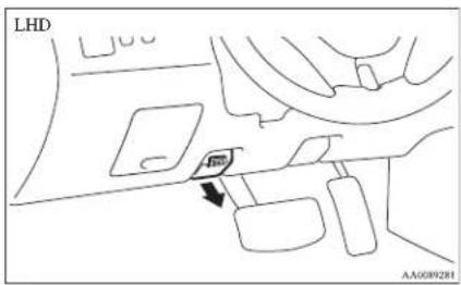
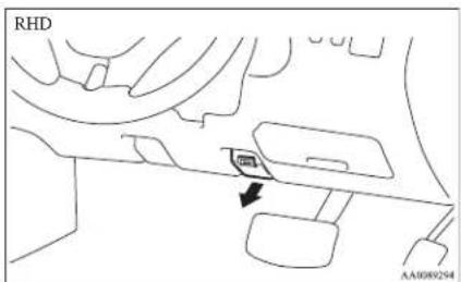
Raise the bonnet while pressing the safety lock.
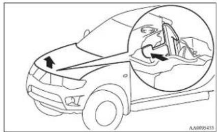
natural_image
Line drawing of a car showing front and side views with arrows indicating movement or force (no text or symbols)NOTE
- Only open the bonnet when the wipers are in the parked position. Failure to do so may cause damage to the bonnet, wiper arms or front windscreen.
Support the bonnet by inserting the support bar in its slot.
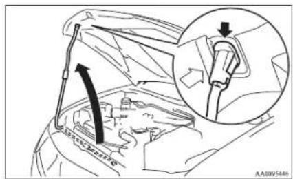
Maintenance
CAUTION
● Note that the support bar may disengage the bonnet if the open bonnet is lifted by a strong wind.
● Always insert the support bar into the hole provided specifically for this purpose. Supporting the bonnet at any other location could result in the support bar slipping out and lead to an accident.
To close
Unlatch the support bar and clip it in its holder. Slowly lower the bonnet to a position about 20 cm above the closed position, then let it drop.
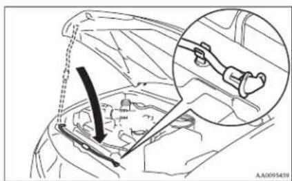
natural_image
Diagram of a car engine compartment with a hand tool inserted, showing internal components and a magnified inset of the valve mechanism (no text or symbols present)NOTE
- If this does not close the bonnet, release it from a slightly higher position.
- Do not press down the bonnet hard with a hand as it may damage the bonnet.
CAUTION
● Be careful that hands or fingers are not trapped when closing the bonnet.
● Before driving, make sure that the bonnet is securely locked. An incompletely locked bonnet can suddenly open while driving. This can be extremely dangerous.
Engine oil
E01000402455
To check and refill engine oil
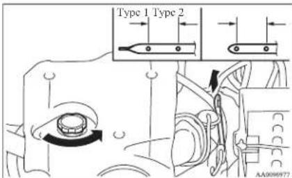
The engine oil used has a significant effect on the engine's performance, service life and startability. Be sure to use oil of the recommended quality and appropriate viscosity.
All engines consume a certain amount of oil during normal operation, and engine oil consumption is greatly influenced by payload, engine speed, etc. Therefore, it is important to check the oil level at regular intervals or before starting a long trip.
This check must be made with the engine warm but not running. Park the vehicle on a level surface, stop the engine, and then wait a few moments to allow the engine oil in circulation to return to the oil pan to ensure accurate measurement.
Remove the dipstick and wipe it with a clean cloth. Reinsert the dipstick as far as it goes. Remove the dipstick and read the oil level, which should always be within the range indicated.
Maintenance
If the oil level is below the specified limit, remove the cap located on the cylinder head cover and add enough oil to raise the level to within the specified range.
Be sure to use the specified engine oil and do not mix various types of oil. Also, avoid mixing different makes of oil together if possible.
After adding oil, close the cap securely.
Use only the recommended oils with an ACEA or API classification as specified in this manual.
NOTE
● The engine oil will deteriorate rapidly if the vehicle is subjected to severe conditions (for example, repeated operation on rough roads, in mountainous regions, on roads with many uphill and downhill gradients, or over short distances). Consequently, the oil will require earlier replacement.
● For handling of used engine oils, refer to page 05.
Selection of engine oil
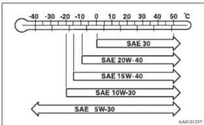
- Select engine oil of the proper SAE viscosity number according to the atmospheric temperature.
● Use engine oil conforming to the following classification:
- ACEA classification: "For service A1/ B1, A3/B3, A3/B4, A5/B5"
• API classification: "For service CF-4"
NOTE
- Use of additives is not recommended since they may reduce the effectiveness of additives already included in the engine oil. It may result in failure of the mechanical assembly.
Engine coolant
E01000501202
To check the coolant level
A translucent coolant reserve tank is located in the engine compartment. The coolant level in this tank should be kept between the "LOW" and "FULL" marks when measured while the engine is cold.
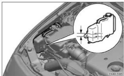
natural_image
Close-up of a car engine bay with a magnified inset showing internal components (no text or symbols visible)To add coolant
The cooling system is a closed system and normally the loss of coolant should be very slight. A noticeable drop in the coolant level could indicate leakage. If this occurs, we recommend you to have the system checked as soon as possible. If the level should drop below the "LOW" level on the reserve tank, open the lid and add coolant. Also, if the reserve tank is completely empty, remove the radiator cap and add coolant until the level reaches the filler neck.
Maintenance
WARNING
- Do not open the radiator cap while the engine is hot. The coolant system is under pressure and any hot coolant escaping could cause severe burns.
Anti-freeze
The engine coolant contains an ethylene glycol anticorrosion agent. The cylinder head and water pump housing are cast aluminium alloy, and periodic changing of the engine coolant is necessary to prevent corrosion of these parts.
Use "DIA QUEEN SUPER LONG LIFE COOLANT" or equivalent.
MITSUBISHI Genuine Coolant has excellent protection against corrosion and rust formation of all metals including aluminium and can avoid blockages in the radiator, heater, cylinder head, engine block, etc.
Because of the necessity of this anti-corrosion agent, the coolant must not be replaced with plain water even in summer. The required concentration of anti-freeze differs depending on the expected ambient temperature.
| Ambient temperature (minimum) °C | -15 | -20 | -25 | -30 | -35 | -50 | ||
| Anti-freeze concentration % | 30 | 35 | 40 | 45 | 50 | 60 |
CAUTION
- Do not use alcohol or methanol anti-freeze or any engine coolants mixed with alcohol or methanol anti-freeze. The use of an improper anti-freeze can cause corrosion of the aluminium components.
- For effective anti-corrosion and anti-freeze performance, keep the anti-freeze concentration within the range of 30 to 60% . Concentrations exceeding 60% will result in a reduction of both the anti-freeze and cooling performance thus adversely affecting the engine.
- Do not top up with water only. Water by itself reduces the rust-protective and anti-freeze qualities of the coolant and has a lower boiling point. It can also cause damage to the cooling system if it should freeze. Do not use tapwater, as it can cause corrosion and rust formation.
During cold weather
If the temperatures in your area drop below freezing, there is the danger that the coolant in the engine or radiator could freeze and cause severe damage to the engine and/or radiator. The concentration should be checked before the start of cold weather and anti-freeze added to the system if necessary. Add a sufficient amount of anti-freeze to the coolant to prevent it from freezing.
The concentration should be checked before the start of cold weather and anti-freeze added to the system if necessary.
Automatic transmission fluid\*
E01000600974
The proper amount of automatic transmission fluid is essential to the life and operation of the automatic transmission. Either insufficient fluid or excessive fluid could cause transmission trouble. The transmission fluid filler port cap is equipped with a dipstick. Use the following procedure to check the fluid level.
Procedure for checking the fluid level
- Check the fluid level after the vehicle has been driven enough to warm up the transmission fluid.
- Park the vehicle on a flat, level surface and apply the parking brake.
- With the engine idling and the brake pedal fully depressed, move the transmission selector lever through all the positions from the "P" (PARK) to "L" (LOW) (with 4A/T), the "P" (PARK) to "D" (DRIVE) (with 5A/T), stopping momentarily at each position.
- Move the selector lever to the "P" (PARK) position.
- Remove the dipstick and wipe it with a clean lint-free cloth.
-
Reinsert the dipstick as far as it goes.
-
Remove dipstick and read the automatic transmission fluid level. The fluid level should always be between the two marks on the dipstick.
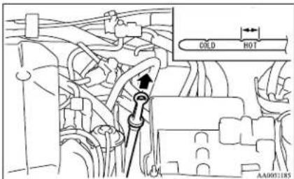
WARNING
- Do not spill the fluid onto a hot exhaust manifold during topping up or inspection, or a fire may occur.
Fluid type
Use only "DIA QUEEN ATF SP III" transmission fluid to ensure optimum transmission performance.
Washer fluid
E01000700672
The windscreen washer fluid reservoir is in the engine compartment. Check the washer fluid level at regular intervals and add washer fluid to reservoir if necessary.
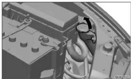
natural_image
3D mechanical component diagram showing internal parts with no visible text or symbolsNOTE
● The washer fluid container serves the wind-screen and headlamps (if so equipped).
During cold weather
To ensure proper operation of the washers at low temperatures, use a fluid containing an anti-freezing agent.
Maintenance
Brake fluid
E01000900687
To check the fluid level
Check the brake fluid level in the reservoir. The brake fluid level must be between the "MAX" and "MIN" marks on the reservoir.
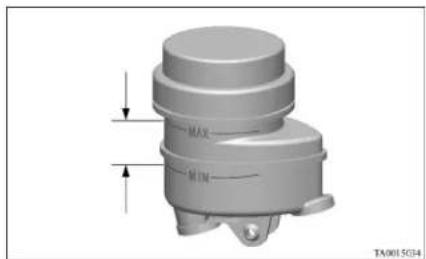
natural_image
3D mechanical component diagram with labeled parts (MAX, MIN) and directional arrows, no readable text or symbols beyond labelsThe brake fluid level is monitored by a float. When the brake fluid level falls below the "MIN" mark, the brake fluid warning lamp lights up. The fluid level falls slightly with wear of the brake pads, but this does not indicate any abnormality. If the brake fluid level falls markedly in a short length of time, it indicates leaks from the brake system. If this occurs, we recommend you to have the vehicle checked.
Fluid type
Use brake fluid conforming to DOT3 or DOT4. The brake fluid is hygroscopic. Too much moisture in the brake fluid will adversely affect the brake system, reducing the brake performance.
Maintenance
In addition, the brake fluid reservoir is equipped with a special cap to prevent the entrance of air, and this cap should not be removed.

CAUTION
● Take care in handling brake fluid as it is harmful to the eyes, may irritate your skin and also damage painted surfaces.
- Use only the specified brake fluid. Do not mix or add different brands of brake fluid to prevent chemical reactions. Do not let any petroleum-based fluid touch, mix with, or get into the brake fluid. This will damage the seals.
- Keep the reservoir tank cap closed to prevent the brake fluid from deteriorating except maintenance.
● Clean the filler cap before removing and close the cap securely after maintenance.
Clutch fluid\*
L01001000281
To check the fluid level
The clutch fluid in the master cylinder should be checked when performing other underhood service. In addition, the system should be checked for leakage at the same time.
Check to make certain that the clutch fluid level is always between the "MAX" and "MIN" level markings on the fluid reservoir.
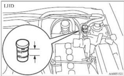
A rapid fluid loss indicates a leak in the clutch system which should be inspected by a MITSUBISHI MOTORS Authorized Service Point or another specialist and repaired immediately.
Fluid type
Brake fluid conforming to DOT 3 or DOT 4 should be used.
The reservoir cap must be fully tightened to avoid contamination from foreign matter or moisture. DO NOT ALLOW PETROLEUM-BASED FLUID TO CONTACT, MIX WITH, OR OTHERWISE CONTAMINATE THE BRAKE FLUID. SEAL DAMAGE WILL RESULT.

WARNING
● Take care in handling brake fluid as it is harmful to the eyes and may also cause damage to painted surfaces. Wipe up any spills immediately.
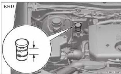
Power steering fluid
E01001100703
To check the fluid level
Check the fluid level in the reservoir while the engine is idling.
Check to make certain that the power steering fluid level is always between the “MAX” and “MIN” level markings on the fluid reservoir and refill the fluid, if necessary.
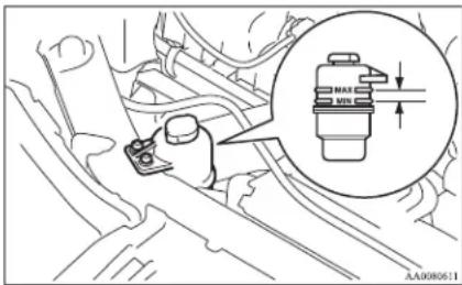
Fluid type
Use "ATF DEXRON III or DEXRON II".
Battery
E01001202144
The condition of the battery is very important for quick starting of the engine and proper functioning of the vehicle's electrical system. Regular inspection and care are especially important in cold weather.
NOTE
- On vehicles equipped with 2 batteries, when the batteries are replaced, the 2 batteries should be replaced at the same time. If only a battery is replaced, it will cause shortening the batteries life.
Checking battery electrolyte level
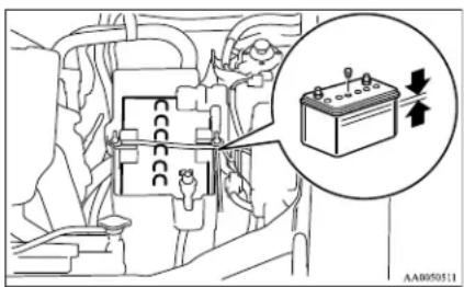
The electrolyte level must be between the specified limit on the outside of the battery. Replenish with distilled water as necessary.
The inside of the battery is divided into several compartments; remove the cap from each compartment and fill to the upper mark. Do not top up beyond the upper mark because spillage during driving could cause damage.
Maintenance
Check the electrolyte level at least once every 4 weeks, depending on the operating conditions.
If the battery is not used, it will discharge by itself with time.
Check it once every 4 weeks and charge with low current as necessary.
During cold weather
The capacity of the battery is reduced at low temperatures. This is an inevitable result of its chemical and physical properties.
This is why a very cold battery, particularly one that is not fully charged, will only deliver a fraction of the starter current which is normally available.
We recommend you to have the battery checked before the start of cold weather and, if necessary, have it charged or replaced.
This does not only ensure reliable starting, but a battery which is kept fully charged also has a longer life.
Disconnection and connection
To disconnect the battery cable, stop the engine, first disconnect the negative (-) terminal and then the positive (+) terminal.
When connecting the battery, first connect the positive (+) terminal and then the negative (-) terminal.
NOTE
- Open the terminal cover (A) before disconnecting or connecting the positive (+) terminal of the battery.
Maintenance
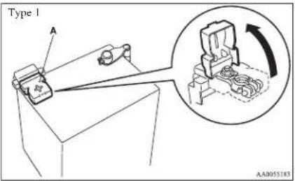
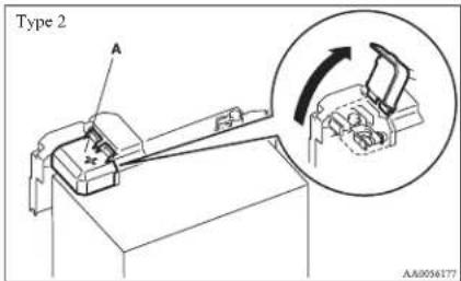
WARNING
- Keep sparks, cigarettes, and flames away from the battery because the battery could explode.
WARNING
● The battery electrolyte is extremely caustic. Do not allow it to come in contact with your eyes, skin, clothing, or the painted surfaces of the vehicle. Spilt electrolyte should be flushed immediately with ample amounts of water.
Irritation to eyes or skin from contact with electrolyte requires immediate medical attention.
● Ventilate when charging or using the battery in an enclosed space.
CAUTION
- Never disconnect the battery with the ignition switch in the "ON" position; doing so could damage the vehicle's electrical components.
● Never short-circuit the battery; doing so could cause it to overheat and be damaged.
● Always wear protective eye goggles when working near the battery. - If the battery is to be quick-charged, first disconnect the battery cables.
- In order to prevent a short circuit, be sure to disconnect the negative (-) terminal first.
- Keep it out of reach of children.
CAUTION
- Do not bring the nearby parts, the plastic parts and so on into contact with sulphuric acid (battery electrolyte) which may crack, stain or discolour them.
If they are in contact, wipe off with soft cloth, chamois or the like and an aqueous solution of neutral detergent then immediately rinse the affected parts with plenty of water.
NOTE
- Keep the terminals clean. After the battery is connected, apply terminal protection grease. To clean the terminals, use lukewarm water.
- Check to see if the battery is securely installed and cannot be moved during travel. Also check each terminal for tightness.
- When the vehicle is to be left unused for a long period of time, remove the battery and store it in a place where the battery fluid will not freeze. The battery should be stored only in a fully charged condition.
Tyres
E01001300239
WARNING
- Driving with tyres that are worn, damaged or improperly inflated can lead to a loss of control or blow out of the tyres which can result in a collision with serious or fatal injury.
Maintenance
Maintenance
Tyre inflation pressures
E01001402423
| Tyre size | UP TO 3 PASSENGERS MAX. LOAD OR TRAILER TOWING | |||
| Front Rear Front Rear | ||||
| 195R15C 106/104R 8PR | 2.2 bar(220 kPa){32 psi} | 2.2 bar(220 kPa){32 psi} | 2.2 bar(220 kPa){32 psi} | 4.5 bar(450 kPa){65 psi} |
| 205R16C 110/108R 8PR | 2.4 bar(240 kPa){35 psi} | 2.4 bar(240 kPa){35 psi} | 2.4 bar(240 kPa){35 psi} | 4.5 bar(450 kPa){65 psi} |
| 205/80R16 104S RF | 2.2 bar(220 kPa){32 psi} | 2.2 bar(220 kPa){32 psi} | 2.2 bar(220 kPa){32 psi} | 2.9 bar(290 kPa){42 psi} |
| 245/70R16 111S RF | 2.0 bar(200 kPa){29 psi} | 2.0 bar(200 kPa){29 psi} | 2.0 bar(200 kPa){29 psi} | 2.9 bar(290 kPa){42 psi} |
| 245/65R17 111S RF | 2.0 bar(200 kPa){29 psi} | 2.0 bar(200 kPa){29 psi} | 2.0 bar(200 kPa){29 psi} | 2.9 bar(290 kPa){42 psi} |
Check the tyre inflation pressure of all the tyres while they are cold; if insufficient or excessive, adjust to the specified value. After the tyre inflation pressure has been adjusted, check the tyres for damage and air leaks. Be sure to put caps on the valves,
Wheel condition
E01001800797
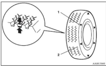
1- Location of the tread wear indicator
2- Tread wear indicator
Check the tyres for cuts, cracks and other damage. Replace the tyres if there are deep cuts or cracks. Also check each tyre for pieces of metal or pebbles. The use of worn tyres can be very dangerous because of the greater chance of skidding or hydroplaning. The tread depth of the tyres must exceed 1.6 mm in order for the tyres to meet the minimum requirement for use.
If there are tread wear indicators on the tyres, they will appear in six places on the surface of the tyre as the tyre wears, thereby indicating that the tyre no longer meets the minimum requirement for use. When these wear indicators appear, the tyres must be replaced with new ones.
Check that the wheel nuts are tightened correctly. Refer to the section entitled “For emergencies” for information concerning replacement of the tyres.
NOTE
● The mark and the location of the tyre tread wear indicators are different depending on the tyre manufacturer.
On 4-wheel drive vehicles, when replacement of any of the tyres is necessary, replace all of them.
CAUTION
● Always use tyres of the same size, same type, and same brand, and which have no wear differences. Using tyres of different size, type, brands or degree of wear, will increase the differential oil temperature, resulting in possible damage to the driving system. Further, the drive train will be subjected to excessive loading, possibly leading to oil leakage, component seizure, or other serious faults.
Replacing tyres and wheels
E01007200038
CAUTION
- Avoid using different size tyres from the one listed and the combined use of different types of tyres, as this can affect driving safety. Refer to “Tyres and wheels” on page 9-17.
CAUTION
- Even if a wheel has the same rim size and offset as the specified type of wheel, its shape may prevent it from being fitted correctly. We recommend you to consult a specialist before using wheels that you have.
Tyre rotation
E01001900990
Tyre wear varies with vehicle conditions, road surface conditions and individual driver's driving habits. To equalize the wear and help extend tyre life, it is recommended to rotate the tyres immediately after discovery of abnormal wear, or whenever the wear difference between the front and rear tyres is recognizable.
Maintenance
When rotating tyres, check for uneven wear and damage. Abnormal wear is usually caused by incorrect tyre pressure, improper wheel alignment, out of balance wheel, or severe braking. We recommend you to have it checked to determine the cause of irregular tread wear.
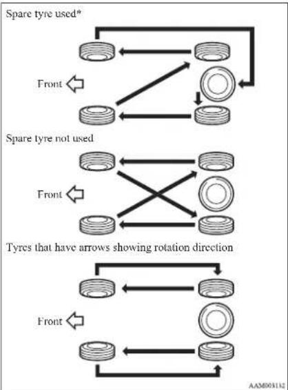
flowchart
graph TD
    A["Spare tyre used*"] --> B["Left side with rings"]
    B --> C["Right side with circles"]
    C --> D["Left side with rings"]
    D --> E["Right side with circles"]
    E --> F["Left side with rings"]
    F --> G["Right side with circles"]
    G --> H["Left side with rings"]
    H --> I["Right side with circles"]
    I --> J["Left side with rings"]
    J --> K["Right side with circles"]
    K --> L["Left side with rings"]
    L --> M["Right side with circles"]
    M --> N["Left side with rings"]
    N --> O["Right side with circles"]
    O --> P["Left side with rings"]
    P --> Q["Right side with circles"]
    Q --> R["Left side with rings"]
    R --> S["Right side with circles"]
    S --> T["Left side with rings"]
    T --> U["Right side with circles"]
    U --> V["Left side with rings"]
    V --> W["Right side with circles"]
    W --> X["Left side with rings"]
    X --> Y["Right side with circles"]
    Y --> Z["Left side with rings"]
    Z --> AA["Right side with circles"]
    AA --> AB["Left side with rings"]
    AB --> AC["Right side with circles"]
    AC --> AD["Left side with rings"]
    AD --> AE["Right side with circles"]
    AE --> AF["Left side with rings"]
    AF --> AG["Right side with circles"]
    AG --> AH["Left side with rings"]
    AH --> AI["Right side with circles"]
    AI --> AJ["Left side with rings"]
    AJ --> AK["Right side with circles"]
    AK --> AL["Left side with rings"]
    AL --> AM["Right side with circles"]
    AM --> AN["Left side with rings"]
    AN --> AO["Right side with circles"]
    AO --> AP["Left side with rings"]
    AP --> AQ["Right side with circles"]
    AQ --> AR["Left side with rings"]
    AR --> AS["Right side with circles"]
    AS --> AT["Left side with rings"]
    AT --> AU["Right side with circles"]
    AU --> AV["Left side with rings"]
    AV --> AW["Right side with circles"]
    AW --> AX["Left side with rings"]
    AX --> AY["Right side with circles"]
    AY --> AZ["Left side with rings"]
    AZ --> BA["Right side with circles"]
    BA --> BB["Left side with rings"]
    BB --> BC["Right side with circles"]
    BC --> BD["Left side with rings"]
    BD --> BE["Right side with circles"]
    BE --> BF["Left side with rings"]
    BF --> BG["Right side with circles"]
    BG --> BH["Left side with rings"]
    BH --> BI["Right side with circles"]
    BI --> BJ["Left side with rings"]
    BJ --> BK["Right side with circles"]
    BK --> BL["Left side with rings"]
    BL --> BM["Right side with circles"]
    BM --> BN["Left side with rings"]
    BN --> BO["Right side with circles"]
    BO --> BP["Left side with rings"]
    BP --> BQ["Right side with circles"]
*- If the spare tyre wheel differs from the standard tyre wheel, do not perform tyre rotation using a spare wheel.
CAUTION
- If the tyres have arrows (A) indicating the correct direction of rotation, swap the front and rear wheels on the left hand side of the vehicle and the front and rear wheels on the right hand side of the vehicle separately. Keep each tyre on its original side of the vehicle. When fitting the tyres, make sure the arrows point in the direction in which the wheels will turn when the vehicle moves forward. Any tyre whose arrow points in the wrong direction will not perform to its full potential.
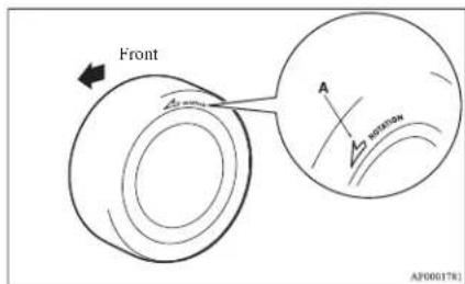
CAUTION
- Avoid the combined use of different types of tyres. Using different types of tyres can affect vehicle performance and safety.
Snow tyres
E01002000725
The use of snow tyres is recommended for driving on snow and ice. To preserve driving stability, mount snow tyres of the same size and tread pattern on all 4 wheels.
Snow tyres worn more than 50% are no longer suitable for use as snow tyres.
Snow tyres which do not meet specifications must not be used.
CAUTION
- Observe permissible maximum speed for your snow tyres and the legal speed limit.
NOTE
● The laws and regulations concerning snow tyres (driving speed, required use, type, etc.) vary. Find out and follow the laws and regulations in the area you intend to drive.
- If flange nuts are used on your vehicle, change to tapered nuts when steel wheels are used.
Tyre chains
E01002101534
It is recommended that snow chains are carried in snow regions and fitted when required to the rear wheels.
On 4WD vehicles in which the driving power is distributed preferentially to the rear wheels, ensure that the tyre chains are fitted on the rear.
Use only tyre chains which are designed for use with the tyres mounted on the vehicle: use of the incorrect size or type of chain could result in damage to the vehicle body.
Before fitting tyre chains, we recommend you to consult a MITSUBISHI MOTORS Authorized Service Point. The max. chain height is as follows.
| Tyre size Wheel size | Max. chain height [mm] |
| 195R15C 15x6.0 JJ | 22 |
| 205R16C 16x6.0 JJ | |
| 205/80R16 16x6.0 JJ | |
| 245/70R16 16x7.0 J | |
| 245/65R17 17x7.5 J |
The speed limit for tyre chain is 50 km/h (30 mph) and remove the tyre chains as soon as possible on snow free roads.
WARNING
● DO NOT use a jack when fitting the chains, as in these conditions, the tyres may slip on the icy road causing the vehicle to slip off the jack.
CAUTION
- Practice fitting the chains before you need them. Don't expect help from other people to the cold.
- Choose a clear straight stretch of road where you can pull over and still be seen while you are fitting the chains.
- Do not fit chains before you need them. This will wear out your tyres and the road surface.
CAUTION
● After driving around 100-300 metres, stop and retighten the chains.
● Drive carefully and do not exceed 50 km/h (30 mph). Remember, fitting chains is not going to stop accidents from happening.
- When tyre chains are installed, take care that they do not damage the disc wheel or body.
● An aluminium wheel can be damaged by a tyre chain while driving. When fitting a tyre chain on an aluminium wheel, take care that any part of the chain and fitting cannot be brought into contact with the wheel.
- When installing or removing the tyre chains, take care that hands and other parts of your body are not injured by the sharp edges of the vehicle body.
● Install the chains only on the rear tyres and tighten them as tightly as possible with the ends securely fastened.
NOTE
- The laws and regulations concerning the use of tyre chains vary. Find out and follow the laws and regulations of the area you're driving in.
In most countries, it is prohibited by law to use tyre chains on roads without snow.
Clutch pedal free play\*
E01002200222
Press down the clutch pedal with your fingers until initial resistance is felt.
This distance should be within the specified range.
natural_image
Illustration of a hand holding a belt with a measuring tape, showing motion direction (no text or symbols)A- Free play: 3 to 8 mm
If the clutch pedal free play is not within the standard range, we recommend you to have it checked.
Maintenance
Brake pedal free play
E01002300281
Stop the engine, depress the brake pedal several times, and press down the pedal with your fingers until initial resistance is felt. This distance should be within the specified range.
A- Free play: 3 to 8 mm
If the brake pedal free play is not within the standard range, we recommend you to have it checked.
Parking brake lever stroke
L01002400527
Pull the parking brake lever up to check the number of "clicks" that the ratchet makes. One click represents a lever movement of one notch. The lever should move the specified number of notches for normal brake application.
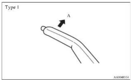
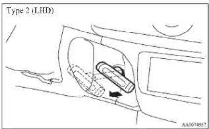
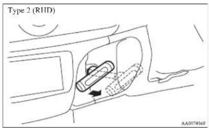
A- Parking brake lever stroke
Type 1 8 to 9 notches
Type 2 11 to 13 notches
(Parking brake adjustment when pulled with the force of 200 N)
If the parking brake lever stroke is out of the standard range, we recommend you to have it checked.
WARNING
● Continued operation of the vehicle with the parking brake lever out of adjustment may result in the vehicle moving when unattended.
Maintenance
Wiper blades
L01002600385
When lifting the wiper arms off the windscreen, first raise the driver's side wiper arm and then the passenger's side wiper arm.
When returning them to their original positions, first put the passenger's side wiper arm back in place and then the driver's side wiper arm.
If the blades are frozen to the windscreen, do not operate the wipers until the ice has melted and the blades are freed, otherwise the wiper motor may be damaged.
Wiper blade rubber replacement
Driver's side
- Lift the wiper arm off the windscreen.
- Pull the wiper blade until its stopper (A) disengages from the hook (B). Then, pull the wiper blade further to remove it.
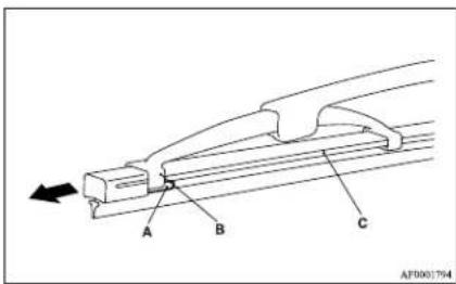
NOTE
- Do not allow the wiper arm to fall onto the windscreen; it could damage the glass.
- Attach the retainers (C) to a new wiper blade.
For LIID vehicles refer to the illustration to ensure that the retainers are correctly aligned as you attach them.
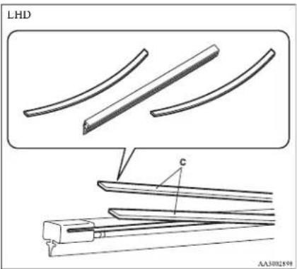
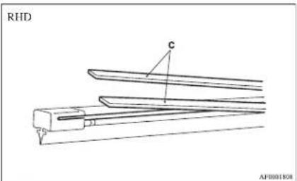
- Insert the wiper blade into the arm, starting with the opposite end of the blade from the stopper. Make sure the hook (B) is fitted correctly in the grooves in the blade.
NOTE
- If retainers are not supplied with the new wiper blade, use the retainers from the old blade.
- Push the wiper blade until the hook (B) engages securely with the stopper (A).
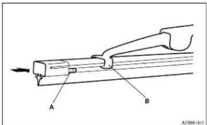
Passenger's side
- Lift the wiper arm off the windscreen.
- Pull the wiper blade until its stopper (A) disengages from the hook (B). Then, pull the wiper blade further to remove it.
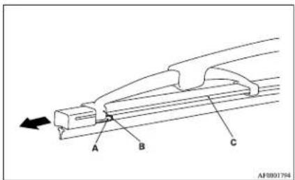
Maintenance
NOTE
- Do not allow the wiper arm to fall onto the windscreen; it could damage the glass.
- Attach the retainers (C) to a new wiper blade. Refer to the illustration to ensure that the retainers are correctly aligned as you attach them.
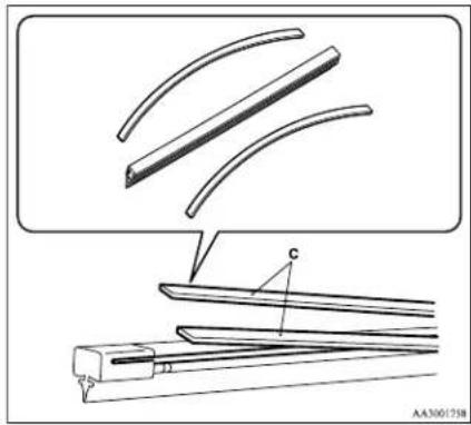
natural_image
Technical line drawing of a mechanical assembly with curved components and a base plate (no text or symbols)- Insert the wiper blade into the arm, starting with the opposite end of the blade from the stopper. Make sure the hook (B) is fitted correctly in the grooves in the blade.
NOTE
- If retainers are not supplied with the new wiper blade, use the retainers from the old blade.
- Push the wiper blade until the hook (B) engages securely with the stopper (A).
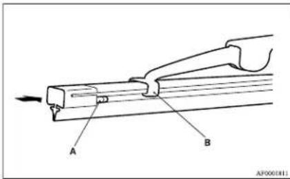
General maintenance
E01002700113
Fuel, engine coolant, oil and exhaust gas leakage
Look under the body of your vehicle to check for fuel, engine coolant, oil and exhaust gas leaks.
WARNING
- If you see a suspicious fuel leak or if you smell fuel, do not operate the vehicle; we recommend you to call for assistance.
Exterior and interior lamp operation
Operate the combination lamp switch to check that all lamps are functioning properly.
If the lamps do not illuminate, the probable cause is a blown fuse or defective lamp bulb. Check the fuses first. If there is no blown fuses, check the lamp bulbs.
For information regarding the inspection and replacement of the fuses and the lamp bulbs, refer to "Fuses" on page 8-20 and "Replacement of lamp bulbs" on page 8-23.
If the fuses and bulbs are all OK, we recommend you to have your vehicle checked and repaired.
Meter, gauge and indicator/warning lamps operation
Run the engine to check the operation of all meters, gauges, and indicator/warning lamps.
If there is anything wrong, we recommend you to have your vehicle inspected.
Maintenance
Hinges and latches lubrication
Check all latches and hinges, and lubricate if necessary by first cleaning and then applying multipurpose grease.
For cold and snowy weather
E01002800257
Ventilation slots
The ventilation slots in front of the windscreen should be kept clear of leaves or brushed clear after heavy snowfall, so that the operation of the heating and ventilation systems will not be impaired.
Weatherstripping
To prevent freezing of the weatherstripping on the doors, bonnet, etc., they should be treated with silicone grease or spray.
Additional equipment
It is a good idea to carry a shovel or a short-handled spade in the vehicle during the winter so that you can clear away snow if you get stranded. A small hand-brush for sweeping snow off the vehicle and a plastic scraper for the windscreen and rear window are also useful.
Fusible links
E01002900030
The fusible links will melt to prevent a fire if a large current attempts to flow through certain electrical systems.
In case of a melted fusible link, we recommend you to have your vehicle inspected.
Maintenance
Fuses
E01003000849
Fuse block location
E01007600032
To prevent damage to the electrical system due to shortcircuiting or overloading, each individual circuit is provided with a fuse.
There are fuse blocks in the passenger compartment and in the engine compartment.
Passenger compartment
The fuse block in the passenger compartment is located in front of the driver's seat at the position shown in the illustration.
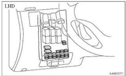
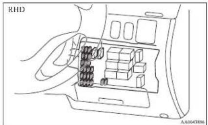
Engine compartment
In the engine compartment, the fuse block is located as shown in the illustration.

natural_image
Close-up of a mechanical component with numbered parts and an inset magnified view (no readable text or symbols)1- Push the knob.
2- Remove the cover.
Fuse load capacity
E01007700033
The fuse capacity and the name of the electrical systems protected by the fuses are indicated on the inside of the fuse lid located at the driver's leg area and on the inside of the fuse block cover for fuses located in the engine compartment.
Passenger compartment fuse location table
E01007900501
NOTE
- Spare fuses are contained in the fuse lid. Always use a fuse of the same capacity for replacement.
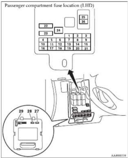
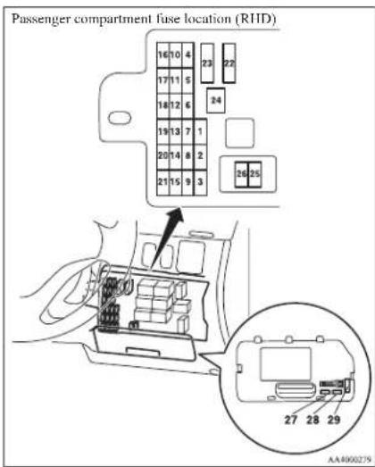
| No. | Symbol | Electrical system | Ca-pacity |
| 1 | Tail | ( left) 7.5 A | |
| 2 | Cigarette lighter 15 A | ||
| 3 | Ignition coil | 10 A | |
| 4 | Starter motor | 7.5 A | |
| 5 | Sunroof 20 A | ||
| 6 | Accessory socket | 15 A | |
| No. | Symbol | Electrical system | Capacity |
| 7 | Tail lamp (right) 7.5 A | ||
| 8 | Outside rear-view mirrors 7.5 A | ||
| 9 | Engine control unit 7.5 A | ||
| 10 | Control unit 7.5 A | ||
| 11 | Rear fog lamp | 10 A | |
| 12 | Central door lock | 15 A | |
| 13 | Room lamp | 10 A | |
| 14 | Rear window wiper | 15 A | |
| 15 | Gauge | 7.5 A | |
| 16 | Relay | 7.5 A | |
| 17 | Hcated scat | 20 A | |
| 18 | Option* | 10 A | |
| 19 | Hcated door mirror | 7.5 A | |
| 20 | Windscreen wiper | 20 A | |
| 21 | Reversing lamps | 7.5 A | |
| 22 | Demister | 30 A | |
| 23 | Heate# | 30 A | |
| 24 | Power/seat | 40 A | |
| 25 | Radio | 10 A | |
Maintenance
| No. | Symbol | Electrical system | Ca-pacity |
| 26 | Electronic controlled unit | 15 A | |
| 27 | — | Spare fuse | 7.5 A |
| 28 | — | Spare fuse | 20 A |
| 29 | — | Spare fuse | 30 A |
● Some fuses may not be installed on your vehicle, depending on the vehicle model or specifications.
● The table above shows the main equipment corresponding to each fuse.
The fuse block does not contain spare 10 A and 15 A fuses. If a fuse of one of these capacities blows, replace it temporarily by borrowing the one that matches from:
10 A: Radio
15 A: Cigarette lighter
Replace the borrowed fuse as soon as possible.
Maintenance
Engine compartment fuse location table
E01008000583
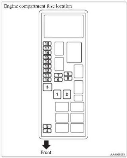
| No. | Symbol | Electrical system | Capacity |
| 1 | — — — | ||
| 2 | Electric window system | 40 A | |
| 3 | Ignition switch | 40 A | |
| 4 | Air conditioning compres-sor | 10 A | |
| 5 | Condenser fan motor | 20 A |
| No. | Symbol | Electrical system | Capacity |
| 6 | Headlamp high-beam(left) | 10 A | |
| 7 | Headlamp high-beam(right) | 10 A | |
| 8 | Headlamp low beam (left) | 10 A | |
| 9 | Headlamp low beam(right) | 10 A | |
| 10 | Engine control | 20 A | |
| 11 | Alternator | 7.5 A | |
| 12 | Stop lamps | ||
| 13 | Horn | 10 A | |
| 14 | A/T | Automatic transmission | 20 A |
| 15 | Hazard warning flasher | 10 A | |
| 16 | Fuel pump | 15 A | |
| 17 | Front fog lamps | 15 A | |
| 18 | Audio amp | 20 A | |
● Some fuses may not be installed on your vehicle, depending on the vehicle model or specifications.
● The table above shows the main equipment corresponding to each fuse.
Identification of fuse
E01008100308
| Capacity Colour | |
| 7.5 A Brown | |
| 10 A Red | |
| 15 A Blue | |
| 20 A Yellow | |
| 30 A | Green (fuse type)/Pink (fusible link type) |
| 40 A Green (fusible link type) | |
Fuse replacement
E01007800656
- Before replacing a fuse, always turn off the electrical circuit concerned and place the ignition switch in the "LOCK" position.
- Pull the fuse lid (A) to remove it.
- Remove the fuse puller (B) from the fuse lid (A).
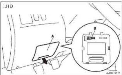
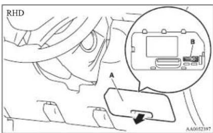
- Referring to the fuse load capacity table, check the fuse pertaining to the problem.
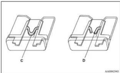
natural_image
Technical line drawing of two mechanical components labeled C and D, showing internal structure without any text or symbols.C- Fuse is OK D- Blown fuse
NOTE
- If any system does not function but the fuse corresponding to that system is normal, there may be a fault in the system elsewhere. We recommend you to have your vehicle checked.
- Insert a new fuse of the same capacity by using the fuse puller into the same place at the fuse block.
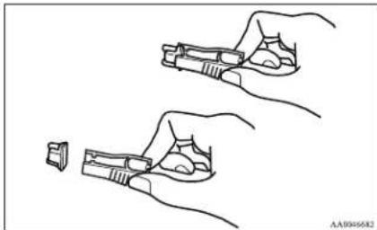
natural_image
Line drawing of two hands holding a handgun, one with a small inset showing the grip (no text or symbols)CAUTION
- If the newly inserted fuse blows again after a short time, we recommend you to have the electrical system checked to find the cause and rectify it.
● Never use a fuse with a capacity larger than that specified or any substitute, such as wire, foil, etc.; doing so will cause the circuit wiring to heat up and could cause a fire.
Maintenance
Replacement of lamp bulbs
E01003100710
Before replacing a bulb, ensure the lamp is off. Do not touch the glass part of the new bulb with your bare fingers; the skin oil left on the glass will evaporate when the bulb gets hot and the vapour will condense on the reflector and dim the surface.
CAUTION
● Bulbs are extremely hot immediately after being turned off.
When replacing a bulb, wait for it to cool sufficiently before touching it. You could otherwise be burnt.
NOTE
- If you are unsure of how to carry out the work as required, we recommend you to consult a specialist.
● Be careful not to scratch the vehicle body when removing a lamp or lens. - When it rains or when the vehicle has been washed, the inside of the lens sometimes becomes foggy. This is the same phenomenon as when window glass mists up on a humid day, and does not indicate a functional problem. When the lamp is switched on, the heat will remove the fog. However, if water gathers inside the lamp, we recommend you to have the lamp checked.
Bulb capacity
E01003200085
When replacing a bulb, use a new bulb with the same wattage and colour.
Maintenance
Outside
E01003302530
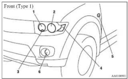
1- Headlamps, high-beam: 60 W (HB3)
2- Headlamps, low beam: 55 W (H11)
3- Position lamps: 5 W (W5W)
4- Front turn-signal lamps: 21 W (PY21W)
5- Side turn-signal lamps: 5 W (WY5W)
6- Front fog lamps*: 55 W (H11)
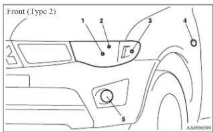
1- Headlamps, high/low beam: 60/55 W (H4)
2- Position lamps: 5 W (W5W)
3- Front turn-signal lamps: 21 W (PY21W)
4- Side turn-signal lamps: 5 W (WY5W)
5- Front fog lamps*: 55 W (H11)
Codes in parentheses indicate bulb types.
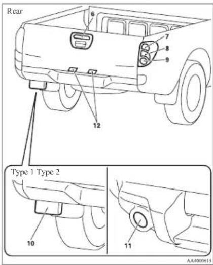
6- High-mounted stop lamp: 5 W (W5W)
7- Rear turn-signal lamps: 16 W (W16W)
8- Tail and stop lamps: 21/5 W (P21/5W)
9- Reversing lamps: 16 W (W16W)
10- Rear fog lamp (Type 1, Driver's side only): 21 W (P21W)
11- Rear fog lamp (Type 2, Driver's side only): 21 W (W21W)
12- Licence plate lamps: 5 W (W5W)
Codes in parentheses indicate bulb types.
Inside
E01003401518
Single cab
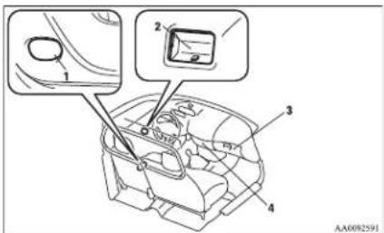
1- Door courtesy lamps*: 3.4 W
2- Room lamp: 8 W
3- Glove box lamp: 1.4 W
4- Centre console downlight: 1.4 W
Club cab
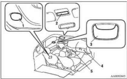
1- Door courtesy lamps*: 3.4 W
2-Front room lamp and personal lamps*: 7.5 W
3- Rear room lamp: 8 W
4- Glove box lamp: 1.4 W
5- Centre console downlight: 1.4 W
Double cab
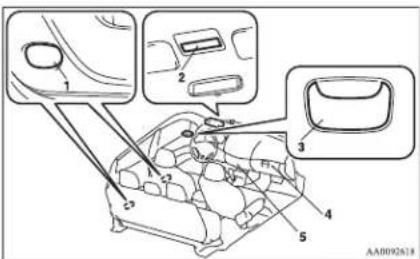
1- Door courtesy lamps*: 3.4 W
2- Front room lamp and personal lamps: 7.5 W
3- Rear room lamp*: 8 W
4- Glove box lamp: 1.4 W
5- Centre console downlight: 1.4 W
Headlamps
E01003501375
Type 1
- Remove the bulb and connector assembly (A) by turning it anticlockwise.
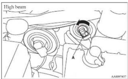
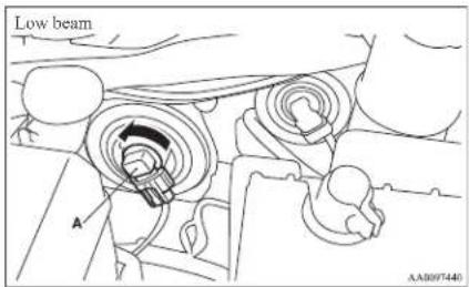
Maintenance
- Depress the tab (B) on the harness connector and pull the harness connector (C) to remove it.
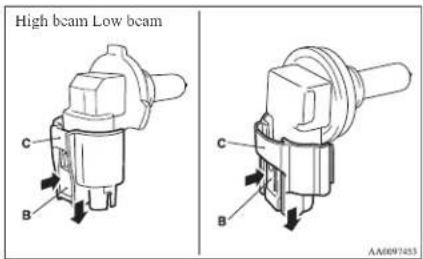
- To install the bulb, perform the removal steps in reverse.
CAUTION
● Handle halogen lamp bulbs with care. The gas inside halogen lamp bulbs is highly pressurized, so dropping, knocking, or scratching a halogen lamp bulb can cause it to shatter.
● Never hold the halogen lamp bulb with a bare hand, dirty glove, etc.
The oil from your hand could cause the bulb to break the next time the head-lamps are operated.
If the glass surface is dirty, it must be cleaned with alcohol, paint thinner, etc., and refit it after drying it thoroughly.
Maintenance
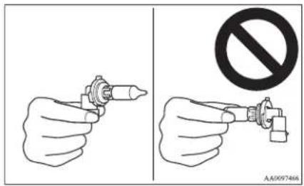
Type 2
- Disconnect the connector (A).
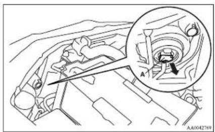
natural_image
Technical line drawing of a mechanical component with an inset magnified view showing internal components (no text or symbols)- Remove the sealing cover (B).
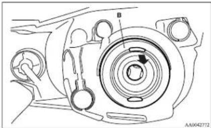
- Unhook the spring (C) which secures the bulb, and then remove the headlamp bulb.
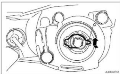
natural_image
Technical line drawing of a mechanical component with no visible text or symbols- To install the bulb, perform the removal steps in reverse.

CAUTION
● Handle halogen lamp bulbs with care. The gas inside halogen lamp bulbs is highly pressurized, so dropping, knocking, or scratching a halogen lamp bulb can cause it to shatter.
● Never hold the halogen lamp bulb with a bare hand, dirty glove, etc.
The oil from your hand could cause the bulb to break the next time the head-lamps are operated.
If the glass surface is dirty, it must be cleaned with alcohol, paint thinner, etc., and refit it after drying it thoroughly.
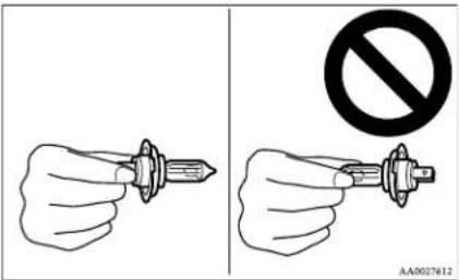
Maintenance
Position lamps
E01003700833
Type 1
- Turn the bulb socket anticlockwise to remove it. And remove the bulb from the socket by pulling out.
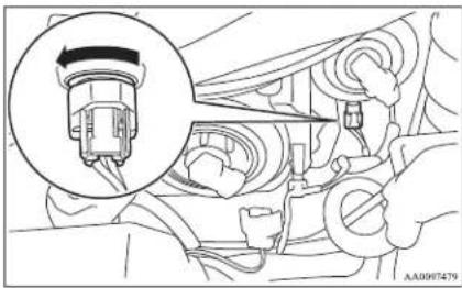
natural_image
Mechanical assembly diagram showing a component with a magnified inset (no text or symbols visible)- To install the bulb, perform the removal steps in reverse.
Type 2
- Turn the bulb socket anticlockwise to remove it. And remove the bulb from the socket by pulling out.
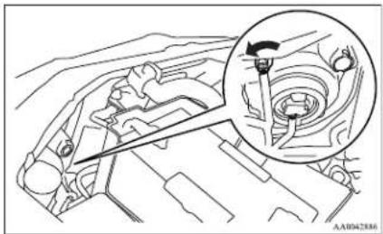
natural_image
Technical line drawing of a mechanical assembly with an inset showing a component detail (no text or symbols)- To install the bulb, perform the removal steps in reverse.
Front turn-signal lamps
E01003800818
Type 1
- Turn the bulb socket anticlockwise to remove it. And remove the bulb from the sock-
et by turning it anticlockwise while pressing in.
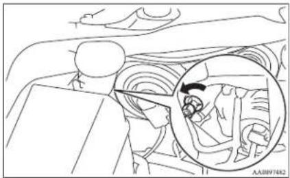
natural_image
Line drawing of a car interior with an inset showing a person inside the vehicle (no text or symbols)- To install the bulb, perform the removal steps in reverse.
Type 2
- Turn the bulb socket anticlockwise to remove it. And remove the bulb from the socket by turning it anticlockwise while pressing in.
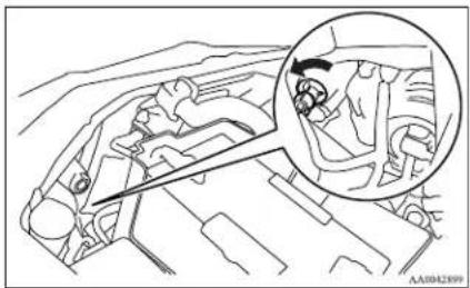
natural_image
Technical line drawing of a mechanical component with an inset magnified view (no text or symbols)Maintenance
- To install the bulb, perform the removal steps in reverse.
Side turn-signal lamps
ED1003900037
- To remove a side turn-signal lamp, insert a straight blade (or minus) screwdriver at the end of the lamp nearer the front of the body and use it to gently lever the lamp out of the body.
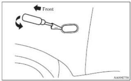
NOTE
● Wrap a piece of cloth around the tip of the screwdriver in order to avoid scratching the lens and the body.
- Remove the socket and bulb assembly together by turning it anticlockwise, and then remove the bulb by pulling out.
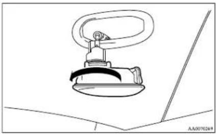
natural_image
Line drawing of a mechanical component with a curved handle and circular base (no text or symbols)- To install the bulb, perform the removal steps in reverse.
NOTE
- When replacing the lamp assembly, push in the end facing the rear of the vehicle first.
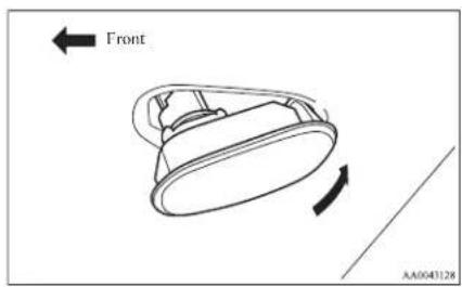
Front fog lamps\*
E01004001537
- Insert a straight blade (or minus) screwdriver with a cloth over its tip at the edge of the cover and pry gently to remove the cover.
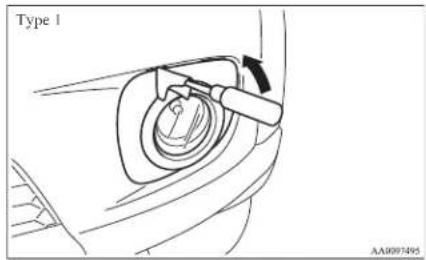
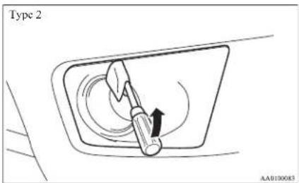
- Turn the 3 bolts (A) anticlockwise to remove them. And then remove the lamp assembly.
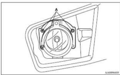
natural_image
Technical line drawing of a mechanical component with mounting holes and a central hub (no text or symbols)- Depress the tab (B) on the harness connector and pull the harness connector (C) to remove it.
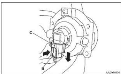
- Turn the entire socket and bulb assembly (D) anticlockwise to remove it.
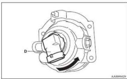
natural_image
Technical line drawing of a mechanical assembly with no visible text or symbols- To install the bulb, perform the removal steps in reverse.
CAUTION
● Handle halogen lamp bulbs with care. The gas inside halogen lamp bulbs is highly pressurized, so dropping, knocking, or scratching a halogen lamp bulb can cause it to shatter.
● Never hold the halogen lamp bulb with a bare hand, dirty glove, etc.
The oil from your hand could cause the bulb to break the next time the fog lamps are operated.
If the glass surface is dirty, it must be cleaned with alcohol, paint thinner, etc., and refit it after drying thoroughly.
Maintenance
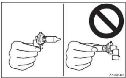
Rear fog lamp
E01004100384
Type 1 (Driver's side only)
- Remove the screws (A) from the rear fog lamp lens, and then remove the lens (B).
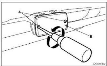
Maintenance
- Remove the bulb (C) by turning it anticlockwise while pressing it inward.
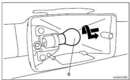
- To install the bulb, perform the removal steps in reverse.
Type 2 (Driver's side only)
- Remove the socket and bulb assemblies by turning it anticlockwise, and then remove the bulb by pulling out.
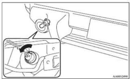
natural_image
Technical line drawing of a mechanical component with a magnified inset showing internal components (no text or symbols)- To install the bulb, perform the removal steps in reverse.
Rear combination lamps
E01004200763
- Open the rear gate.
(Refer to "Rear gate" on page 1-13.)
- Remove the screws (A) that hold the lamp unit.
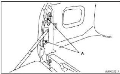
- Move the lamp unit towards the rear of the vehicle and remove the clips (B).
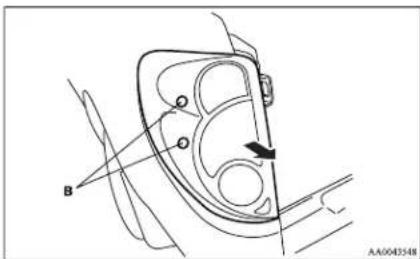
- Remove each socket and bulb assembly by turning it anticlockwise.
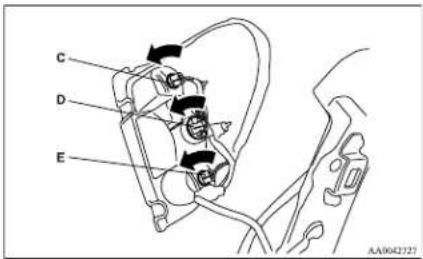
C- Rear turn-signal lamp
Remove the bulb by pulling it out.
D- Tail and stop lamp
Remove the bulb from the socket by turning it anticlockwise while pressing in.
E- Reversing lamp
Remove the bulb by pulling it out.
- To install the bulb, perform the removal steps in reverse.
NOTE
- When mounting the lamp unit, align the pins (F) and clip (G) on the lamp unit with the holes (H) in the body.
Maintenance
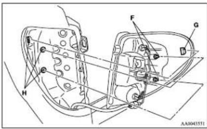
High-mounted stop lamp
L01D04500577
- Open the rear gate. (Refer to "Rear gate" on page 1-13.)
- Remove the 8 screws (A) from the inner surface of the rear gate. Remove the rear gate cover (B).
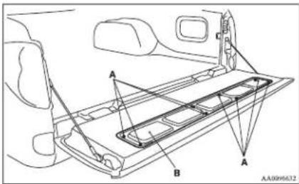
- Remove the socket and bulb assembly together by turning it anticlockwise, and then remove the bulb by pulling it out.
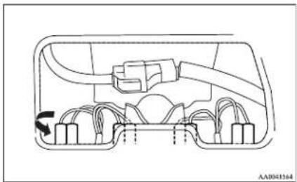
natural_image
Technical diagram of a mechanical or electrical component with no visible text, numbers, or symbols- To install the bulb, perform the removal steps in reverse.
Licence plate lamps
E01004600578
- Insert a straight blade (or minus) screwdriver into the lamp assembly and pry gently to remove it.
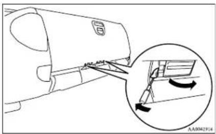
NOTE
- Wrap a piece of cloth around the tip of the screwdriver in order to avoid scratching the lens and the body.
- Remove the socket and bulb assembly together by turning it anticlockwise, and then remove the bulb by pulling out.
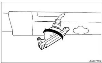
natural_image
Line drawing of a car seatbelt with a belt buckle, no text or symbols present- To install the bulb, perform the removal steps in reverse.
NOTE
- When mounting the lamp unit, put the hook (A) on the right side of the lamp unit into the body first.
Maintenance
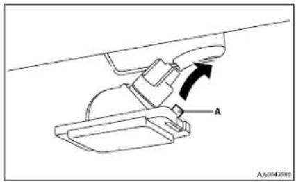
natural_image
Technical line drawing of a mechanical component with labeled section A (no text or symbols beyond label)Front room lamp and personal lamps\*
ED1004700364
- Insert a straight blade (or minus) screwdriver into the notch of the lens and pry gently to remove it.
Remove the bulb from the lamp holder.
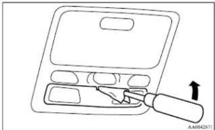
natural_image
Line drawing of a tool inside a device with an arrow indicating direction (no text or symbols)NOTE
- Wrap a piece of cloth around the tip of the screwdriver in order to avoid scratching the lens.
- To install the bulb, perform the removal steps in reverse.
NOTE
- When installing the lens, align the 2 tabs on the lens with the holes on the vehicle side.
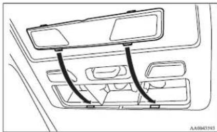
natural_image
Diagram of a car interior showing dashboard and seat compartments with curved arrows indicating flow or movement (no text or symbols)Rear room lamp\*
L01004900119
Type 1
- Insert a straight blade (or minus) screwdriver into the notch of the lens and pry gently to remove it. Remove the bulb from the lamp holder.
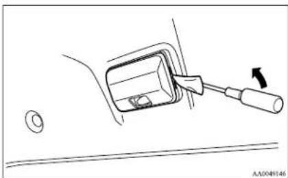
natural_image
Technical line drawing of a mechanical component with a tool and circular base (no text or symbols)NOTE
- Wrap a piece of cloth around the tip of the screwdriver in order to avoid scratching the lens.
- To install the bulb, perform the removal steps in reverse.
NOTE
- When installing the lens, fit the two tabs on one side of the lens into the holes on the vehicle side before fitting the two tabs on the opposite side of the lens into the holes on the vehicle side.
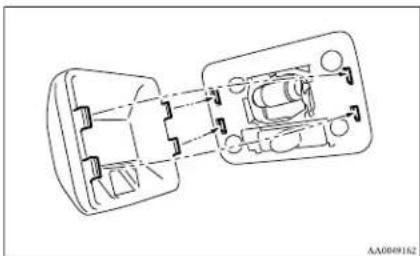
natural_image
Technical line drawing of a mechanical assembly with internal components (no text or symbols)Type 2
- Insert a straight blade (or minus) screwdriver into the notch of the lens and pry gently to remove it. Remove the bulb from the lamp holder.
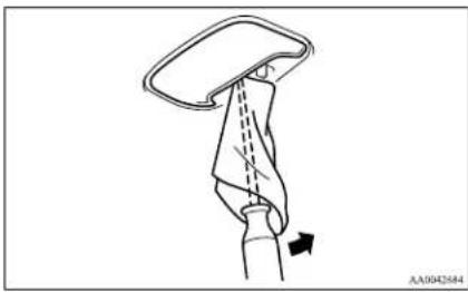
natural_image
Diagram of a hand holding a device with a dashed line indicating motion or force, and an arrow pointing to the handle (no text or symbols present)NOTE
- Wrap a piece of cloth around the tip of the screwdriver in order to avoid scratching the lens.
- To install the bulb, perform the removal steps in reverse.
NOTE
- When installing the lens, align the 2 tabs on the lens with the holes on the vehicle side.
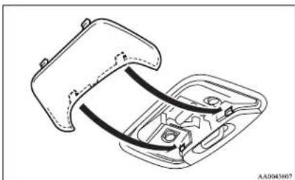
natural_image
Technical line drawing of a car interior frame with visible wiring and mounting points (no text or symbols)Door courtesy lamps\*
E01005400238
- Insert a straight blade (or minus) screwdriver into the lens and pry gently to remove it. Remove the bulb from the lamp holder.
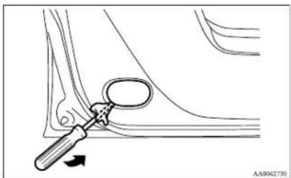
natural_image
Medical illustration showing a surgical instrument interacting with a joint, with no visible text or symbolsNOTE
● Wrap a piece of cloth around the tip of the screwdriver in order to avoid scratching the lens.
2. To install the bulb, perform the removal steps in reverse.
NOTE
- When installing the lens, align the 2 tabs on the lens with the holes on the vehicle side.
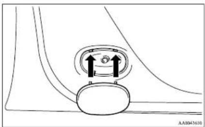
natural_image
Diagram of a mechanical component with two upward arrows indicating motion or force direction (no text or symbols)Glove box lamp
E01006100069
We recommend you to have the glove box lamp replaced by a specialist.
Centre console downlight
E01008700144
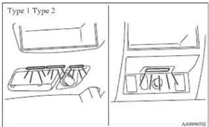
Maintenance
Type 1
We recommend you to have the centre console downlight replaced by a specialist.
Type 2
- Insert a straight blade (or minus) screwdriver with a cloth over its tip at edge of the garnish (A) and pry gently to remove it.
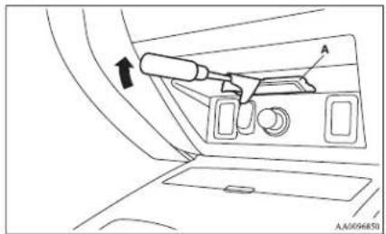
natural_image
Interior view of a car showing the dashboard and seat area with a tool (no text or symbols visible)- Turn the bulb socket (B) anticlockwise to remove it.
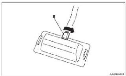
- Remove the bulb by pulling out.
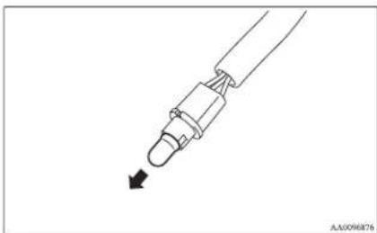
natural_image
Line drawing of a mechanical connector with an arrow indicating direction (no text or symbols)- To install the bulb, perform the removal steps in reverse.
Specifications
Vehicle labeling....9-02
Vehicle dimensions....9-03
Vehicle performance....9-09
Vehicle weight....9-10
Engine specifications....9-14
Transmission specifications....9-15
Electrical system....9-16
Tyres and wheels....9-17
Other specifications....9-18
Fuel consumption....9-19
Refill capacities....9-21
Specifications
Vehicle labeling
E01100101791
Vehicle identification number
The vehicle identification number is stamped as shown in the illustration.
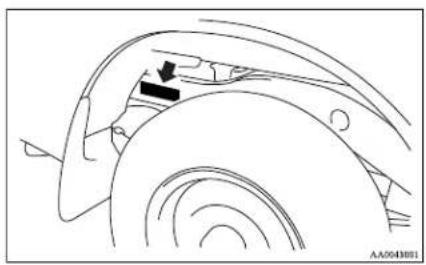
natural_image
Technical line drawing of a car wheel assembly with a black arrow indicating a component (no text or symbols present)Vehicle information code plate
The vehicle information code plate is located as shown in the illustration.
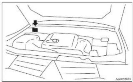
natural_image
Line drawing of a car interior with a black arrow pointing to the hood (no text or symbols)The plate shows model code and engine model, transmission model and body colour code, etc.
Please use this number when ordering replacement parts.
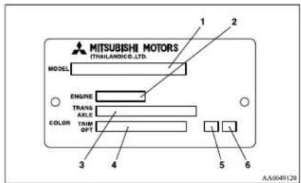
1- Model code
2- Engine model code
3- Transmission model code
4- Body colour code
5- Interior code
6- Option code
Vehicle identification number plate (RHD vehicles only)
The vehicle identification number is stamped on the plate riveted to the left front corner of the instrument panel pad. It is visible from outside of the vehicle through the windscreen.
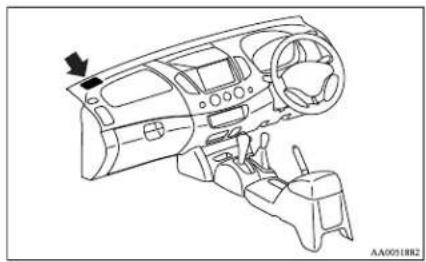
natural_image
Line drawing of a car dashboard and steering wheel (no text or symbols)Engine number
The engine number is stamped on the engine cylinder block as shown in the illustration.
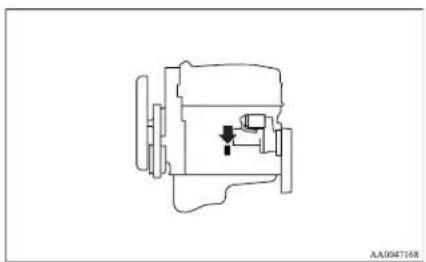
natural_image
Technical line drawing of a mechanical component (no text or symbols)Specifications
Vehicle dimensions
E01100202308
Single cab
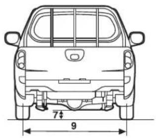
natural_image
Top-down line drawing of a car showing front and rear views with dimension annotations (7 and 9) — no text or symbols present.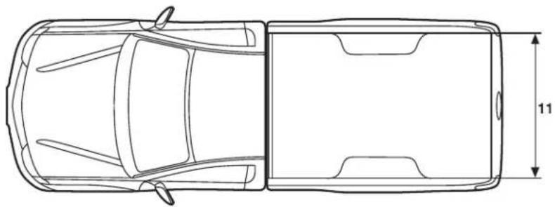
natural_image
Top-down line drawing of a car showing front and side views with dimension label (11) — no text or symbols present.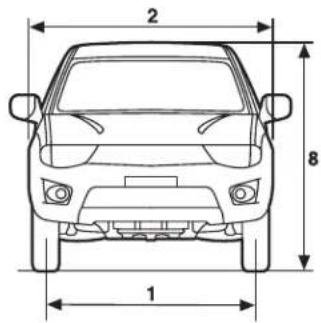
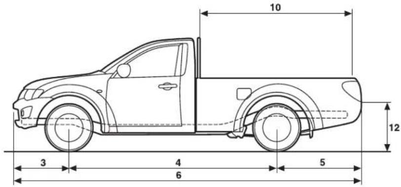
AA5009585
Specifications
Single cab
| 1 Front track 1,505 mm | |
| 2 Overall width 1,750 mm | |
| 3 Front overhang 830 mm | |
| 4 Wheel base 3,000 mm | |
| 5 Rear overhang 1,210 mm | |
| 6 Overall length 5,040 mm | |
| 7 Ground clearance (unladen) 200 mm | |
| 8 Overall height (unladen) 1,775 mm | |
| 9 Rear track 1,500 mm | |
| 10 Cargo bed length 2,220 mm | |
| 11 Cargo bed width 1,470 mm | |
| 12 Cargo bed height 845 mm |
Specifications
Club cab
Specifications
Club cab
| Item Easy select 4WD Super select 4WD | ||||
| 1 Front track 1,505 mm 1,520 mm | ||||
| 2 Overall width 1,750 mm 1,800 mm | ||||
| 3 Front overhang | 795 mm, 830 mm^*1 | |||
| 4 Wheel base 3,000 mm | ||||
| 5 Rear overhang | Without rear bumper 1,325 mm | |||
| With rear bumper 1,400 mm | ||||
| 6 Overall length | Without rear bumper | 5,120 mm, 5,155 mm^*1 | ||
| With rear bumper | 5,195 mm, 5,230 mm^*1 | |||
| 7 Ground clearance (unladen) 200 mm 205 mm | ||||
| 8 Overall height (unladen) 1,775 mm 1,780 mm | ||||
| 9 Rear track 1,500 mm 1,515 mm | ||||
| 10 Cargo bed length 1,805 mm | ||||
| 11 Cargo bed width 1,470 mm | ||||
| 12 Cargo bed height | 855 mm 860 mm | |||
*1: Vehicles for Russia and Ukraine
Specifications
Double cab
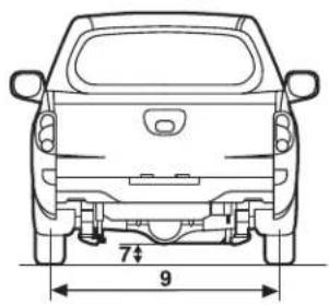
natural_image
Top-down line drawing of a car showing rear wheel, side-mounted chassis, and height dimension (no text or symbols)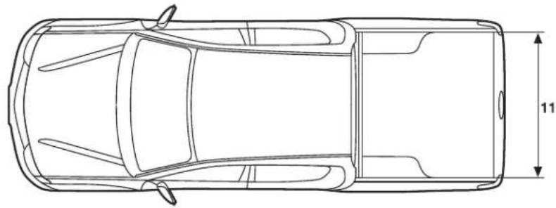
natural_image
Top-down line drawing of a car showing front and side views with dimension标注 (no text or symbols)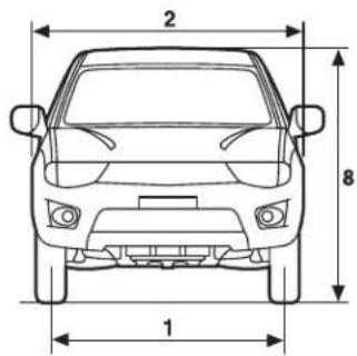
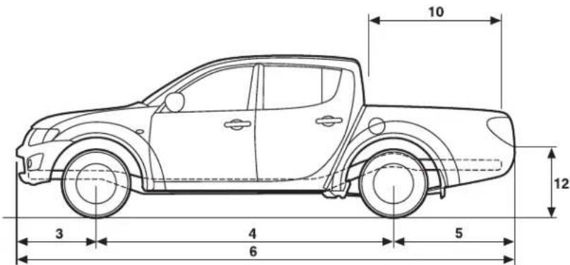
AA5010165
Specifications
Double cab
| Item 2WD and Easy select 4WD Super select | 4WD | |||
| 1 Front track 1,505 mm 1,520 mm | ||||
| 2 Overall width 1,750 mm 1,800 mm | ||||
| 3 Front overhang | 795 mm, 830 mm*1 | |||
| 4 Wheel base 3,000 mm | ||||
| 5 Rear overhang | Overall length | Without rear bumper | 1,210 mm, 1,390 mm*1 | |
| With rear bumper | 1,285 mm, 1,465 mm*1 | |||
| 6 | Without rear bumper | 5,005 mm, 5,185 mm*1, 5,040 mm*2, 5.220 mm*3 | ||
| With rear bumper | 5,080 mm, 5,260 mm*1, 5.115 mm*2, 5.295 mm*3 | |||
| 7 Ground clearance (unladen) 200 mm 205 mm | ||||
| 8 Ovcrall height (unladen) 1,775 mm 1,780 mm | ||||
| 9 Rear track 1,500 mm 1,515 mm | ||||
| 10 Cargo bed length | 1,325 mm, 1,505 mm*1 | |||
| 11 Cargo bed width 1,470 mm | ||||
| 12 Cargo bed height 845 mm 850 mm | ||||
*1: Vehicles with long bed
^*2 : Vehicles for Russia and Ukraine
*3: Vehicles for Russia and Ukraine with long bed
Specifications
Vehicle performance
E01100301966
| Item M/T A/T | |||
| Maximum speed | Vehicles with standard power engine | 167 km/h (104 mph), 165 km/h* (102 mph)* | 165 km/h (102 mph) |
| Vehicles with high power engine 179 km/h (111 mph) 175 km/h (109 mph) | |||
| Minimum turning radius | Body | 6.3 m, 6.1 m* | |
| Wheel | 5.9 m, 5.7 m* | ||
*: 2WD vehicles with 15 inch tyres
Specifications
Vehicle weight
E01100404160
Single cab
| Item 2WD | 4WD | |||
| LHD RHD | ||||
| Kerb weight | Without optional parts 1,555 kg 1,770 kg | |||
| With full optional parts 1,585 kg 1,830 kg 1,810 kg | ||||
| Maximum gross vehicle weight 2,630 kg 2,850 kg 2,890 kg | ||||
| Maximum axle weight | Front 1,030 kg 1,260 kg | |||
| Rear 1,700 kg 1,800 kg | ||||
| Maximum towable weight | With brake 1,800 kg 2,700 kg | |||
| Without brake 750 kg | ||||
| Maximum trailer-nose weight 77 kg 115 kg | ||||
| Maximum gross combination weight 4,400 kg 5,500 kg 5,540 kg | ||||
| Seating capacity (including a driver) | 2 persons, 3 persons^a | |||
*: Vehicles equipped with bench seat
NOTE
- Trailer specifications indicate the manufacturer's recommendation.
- When loading luggage and/or towing a trailer, make sure not to exceed any of the above maximum weights all the time.
Club cab
| Item | Easy select 4WD | Super select 4WD | ||
| LJID RIID | ||||
| Kerb weight | Without optional parts 1,790 kg | 1,805 kg, 1,815 kg * | ||
| With full optional parts 1,890 kg 1,870 kg | 1.900 kg, 1.910 kg * | |||
*: Vehicles with high power engine
Specifications
| Itcm | Easy select 4WD | Super select 4WD | ||
| LHD RHD | ||||
| Maximum gross vehicle weight 2,850 kg | ||||
| Maximum axle weight | Front 1,260 kg | |||
| Rear 1,800 kg | ||||
| Maximum towable weight | With brake 2,700 kg | |||
| Without brake 750 kg | ||||
| Maximum trailer-nosc weight 115 kg | ||||
| Maximum gross combination weight 5,500 kg | ||||
| Seating capacity (including a driver) 4 persons | ||||
*: Vehicles with high power engine
NOTE
- Trailer specifications indicate the manufacturer's recommendation.
- When loading luggage and/or towing a trailer, make sure not to exceed any of the above maximum weights all the time.
Double cab
| Item | 2WD | |||
| M/T | A/T | |||
| Vehicles with 15 inch tyres | Vehicles with 16 inch tyres | |||
| Kerb weight | Without optional parts 1,655 kg 1,760 kg | 1,770 kg | ||
| With full optional parts 1,725 kg 1,890 kg | 1,900 kg | |||
| Maximum gross vehicle weight 2,630 kg 2,800 kg | ||||
| Maximum axle weight | Front 1,030 kg 1,260 kg | |||
| Rear 1,700 kg 1,800 kg | ||||
Specifications
| Item | 2WD | |||
| M/T | A/T | |||
| Vehicles with 15 inch tyres | Vehicles with 16 inch tyres | |||
| Maximum towable weight | With brake 1,800 kg 2,700 kg | |||
| Without brake 750 kg | ||||
| Maximum trailer-nose weight 75 kg 112 kg | ||||
| Maximum gross combination weight 4,400 kg 5,465 kg | ||||
| Seating capacity (including a driver) 5 persons | ||||
NOTE
- Trailer specifications indicate the manufacturer's recommendation.
● When loading luggage and/or towing a trailer, make sure not to exceed any of the above maximum weights all the time.
| Item | 4WD | |||||||
| Easy select 4WD Super select 4WD | ||||||||
| M/T | A/TLHD RHD | M/T A/T | ||||||
| LHD RHD | LHD RHD | |||||||
| Kerb weight | Without optional parts 1,860 kg 1,840 kg 1,870 kg | 1,880 kg,1,890 kg *1 | 1,865 kg,1,875 kg *1 | 1,890 kg,1,905 kg *1 | 1,875 kg,1,890 kg *1 | |||
| With full optional parts | 1,990 kg,1,980 kg *2 | 1,970 kg 2 | 000 kg | 2,020 kg,2,030 kg *1,2,015 kg *2 | 2,010 kg,2,020 kg *1 | 2,020 kg,2,035 kg *1,2,025 kg *2 | 2,020 kg,2,035 kg *1 | |
| Maximum gross vehicle weight 2,850 kg 2,890 kg 2,850 kg | 2,910 kg,2,920 kg *1 | 2,850 kg | 2,920 kg,2,935 kg *1 | |||||
*1: Vehicles with high power engine
^*2 : Vehicles for Russia and Ukraine
Specifications
| Item | 4WD | |||||||
| Easy select 4WD Super select 4WD | ||||||||
| M/T | A/T LIID RIID | M/T A/T | ||||||
| LIID RIID | LIID RIID | |||||||
| Maximum axle weight | Front 1,260 kg | |||||||
| Rear 1,800 kg | ||||||||
| Maximum towable weight | With brake 2,700 kg | |||||||
| Without brake 750 kg | ||||||||
| Maximum trailer-nose weight 115 kg | ||||||||
| Maximum gross combination weight 5,500 kg 5,540 kg 5,500 kg | 5,560 kg, 5,570 kg*1 | 5,500 kg | 5,570 kg, 5,585 kg*1 | |||||
| Scating capacity (including a driver) 5 persons | ||||||||
*1: Vehicles with high power engine
^*2 : Vehicles for Russia and Ukraine
NOTE
- Trailer specifications indicate the manufacturer's recommendation.
- When loading luggage and/or towing a trailer, make sure not to exceed any of the above maximum weights all the time.
Specifications
Engine specifications
E01100602416
| Item | Standard power engine High power engine | ||||
| M/T A/T2WD with 15 inch tyres 2WD with 16 in | |||||
| Engine type | Four-cylinder, in line, water cooled four-cycle, double overhead camshaft with small-sized intercooler and turbocharger | Four-cylinder, in line, water cooled four-cycle, double overhead camshaft with intercooler and turbocharger | |||
| Engine models 4D56Total displacement 2,477 ccBore 91.1 mmStroke 95.0 mm | |||||
| Compression ratio 17.0:1 16.5:1 | |||||
| Valve clearance | Intake 0.09 mm (cold) | ||||
| Exhaust 0.14 mm (cold) | |||||
| Maximum output (EEC net) 94 kW/4,000 r/min | 100 kW/4,000 r/min,100 kW/3,500 r/min* | 131 kW/4,000 r/min | |||
| Maximum torque (EEC net) | 240 Nm/1,500 to 3,500 r/min | 314 Nm/2,000 r/min | 400 Nm/2,000 to 2.850 r/min | 350 Nm/1.800 to 3,500 r/min | |
*: Vehicles for Ukraine and Kazakhstan.
Specifications
Transmission specifications
E01100701452
| Item | M/T A/T | |||||||||
| 2WD 4WD | 2WD | 4WD | ||||||||
| Vehicles with 15 inch tyres | Vehicles with 16 inch tyres | Easy select 4WD | Super select 4WD | Easy select 4WD | Super select 4WD | |||||
| High power engine | Standard power en-ginc | 4A/T 5A/T | ||||||||
| Transmission | 1^st gear ratio | 4.313 2.842 3.789 | ||||||||
| 2^nd gear ratio | 2.330 1.495 2.057 | |||||||||
| 3^rd gear ratio | 1.436 1.000 1.421 | |||||||||
| 4^th gear ratio | 1.000 0.731 1.000 | |||||||||
| 5^th gear ratio | 0.788 — 0.731 | |||||||||
| Reverse gear ratio 4.220 2.720 3.865 | ||||||||||
| Transfcr | High gear ratio — 1.000 — 1.000 1.000 | |||||||||
| Low gear ratio — 1.900 — 1.900 1.900 | ||||||||||
| Final gear ratio 3.909 3.917 3.917 3.917 4. | 00 3.917 3.9 | 7 4.100 3.917 | ||||||||
Specifications
Electrical system
E01100801769
| Voltage 12 V | |||
| Battery | Type (JIS) 95D31L 80D26L* | ||
| Capacity (5HR) 64 Ah 55 Ah* | |||
| Alternator capacity 90 A, 120 A* | |||
*; Optional equipment
Specifications
Tyres and wheels
E01100902204
| Tyre 195R15C 106/104R 8PR | 205/80R16 104S RF,205R16C 110/108R 8PR | 245/70R16 111S RF 245/65R17 111S RF | ||
| Wheel | Size 15x6 JJ 16x6 JJ 16x7 J 17x7 1/2 J | |||
| Offset 46 mm 38 mm | ||||
NOTE
- Contact your MITSUBISHI MOTORS Authorized Service Point for details on the combination used on your vehicle.
Specifications
Other specifications
E01101000862
| Fuel system | Fuel control Direct injection common rail system | ||
| Fuel pump Electronic controlled rotary type | |||
| Clutch Dry single disc clutch with diaphragm spring, hydraulic action | |||
| Steering system Rack & pinion type, power assisted | |||
| Suspension | Front Independent type, wishbone, coil spring | ||
| Rear Rigid type, leaf spring | |||
| Service brakes | Type | Vehicles without ABS Hydraulic, front and rear split double circuit system with power assistance | |
| Vehicles with ABS Hydraulic, diagonal split double circuit system with power assistance | |||
| Front Ventilated disc brakes | |||
| Rear Drum brakes | |||
| Parking brakes Parking brake acts mechanically on rear wheels | |||
Specifications
Fuel consumption
Vehicles with standard power engine
E01101100560
| Item | Combined Urban conditions | Extra-urban conditions | |||||
| CO_2 (g/km) | Fuel consumption (L/100 km) | Fuel consumption (L/100 km) | Fuel consumption (L/100 km) | ||||
| Single cab | 2WD 190 7.2 9.3 6.0 | ||||||
| 4WD 215 8.1 10.3 6.9 | |||||||
| Club cab | Standard | 215, 221*1 | 8.1, 8.4*1 | 10.3, 10.6*1 | 6.9, 7.1*1 | ||
| Full option | 218, 224*1 | 8.3, 8.5*1 | 10.4, 10.7*1 | 7.1, 7.2*1 | |||
| Double cab | 2WD with 15 inch tyres 194 7.4 9.4 6.2 | ||||||
| 2WD with 16 inch tyres | M/T | Standard 215 8.1 | 10.3 6.9 | ||||
| Full option 218 8.3 | 10.4 7.1 | ||||||
| A/T | Standard 229 8.6 | 11.0 7.3 | |||||
| Full option 234 8.8 | 11.2 7.5 | ||||||
| 4WD | M/T | Standard | 218, 215*2, 224*1 | 8.3, 8.1*2, 8.5*1 | 10.4, 10.3*2, 10.7*1 | 7.1, 6.9*2, 7.2*1 | |
| Full option | 223, 218*2, 229*1 | 8.5, 8.3*2, 8.7*1 | 10.5, 10.4*2, 10.9*1 | 7.3, 7.1*2, 7.4*1 | |||
| A/T | Standard | 234, 240*1 | 8.8, 9.0*1 | 11.2, 11.7*1 | 7.5 | ||
| Full option | 240, 246*1 | 9.1, 9.3*1 | 11.6, 12.1*1 | 7.6, 7.7*1 | |||
*1: Vehicles for Russia and Ukraine
^*2 : RHD vehicles without wide fender
Specifications
Vehicles with high power engine
| Item | Combined Urban conditions | Extra-urban conditions | ||||
| CO2(g/km) | Fuel consumption (L/100 km) | Fuel consumption (L/100 km) | Fuel consumption (L/100 km) | |||
| Club cab | Standard 212 8.0 9.6 7.1 | |||||
| Full option 214 8.1 9.7 7.2 | ||||||
| Double cab | M/T | Standard 214 8.1 9.7 7.2 | ||||
| Full option 218 8.3 9.8 7.4 | ||||||
| A/T | Standard 240 9.1 10.9 8.1 | |||||
| Full option 248 9.4 11.3 8.3 | ||||||
NOTE
● The results given do not express or imply any guarantee of the fuel consumption of the particular vehicle.
The vehicle itself has not been tested and there are inevitably differences between individual vehicles of the same model. In addition, this vehicle may incorporate particular modifications. Furthermore, the driver's style and road and traffic conditions, as well as the extent to which the vehicle has been driven and the standard of maintenance, will all affect its fuel consumption.
Refill capacities
E01101303358
LHD
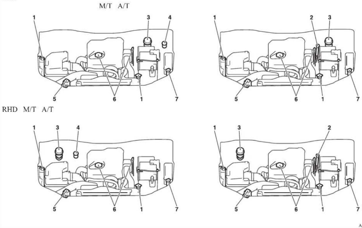
AA5004072
Specifications
| No. Item Quantity Lubricants | ||||||
| 1 Engine coolant | 8.2 litres [includes 0.65 litre in the reserve tank] | DIA QUEEN SUPER LONG LIFE COOLANT or equivalent | ||||
| 2 Automatic transmission fluid 9.7 litres DIA QUEEN ATF SP III | ||||||
| 3 Brake fluid As required Brake fluid DOT3 or DOT4 | ||||||
| 4 Clutch fluid As required Brake fluid DOT3 or DOT4 | ||||||
| 5 Power steering fluid As required ATF DEXRON III or DEXRON II | ||||||
| 6 Engine oil | Oil pan | 2WD with 15 inch tyres 6.5 litres | Refer to page 8-04. | |||
| 2WD with 16 inch tyres, 4WD 5.5 litres | ||||||
| Oil filter 0.8 litre | ||||||
| Oil cooler 0.1 litre | ||||||
| 7 Washer fluid | 4.8 litres, 4.5 litres*1 | — | ||||
| 8 | Manual transmis-sion oil | 2WD 2.3 litres | Gear oil API classification GL-3 SAE 75W-85 | |||
| 4WD 3.4 litres | ||||||
| 9 Transfer oil | 2.5 litres | Gear oil API classification GL-3 SAE 75W-85 or Gear oil API classification GL-4 SAE 75W-85 | ||||
| 10 | Differential oil | Front*2 | 1.2 litres | Gear oil API classification GL-5 or higher SAE 80W | ||
| Rear | Standard power engine | 2WD with 15 inch tyres | 1.5 litres | |||
| 2WD with 16 inch tyres, 4WD | 2.6 litres | |||||
| High power engine | A/T | |||||
| M/T | 3.2 litres | |||||
| 11 | Refrigcrant (air conditioning) | 480-520 g, 535-575 g*3 | HFC-134a | |||
*1: Vehicles with "front (Type 1)" (Refer to "Outside" on page 8-24)
*2: 4WD vehicles only
Specifications
| 10.2 | 10.3 | 10.4 | 10.5 | 10.6 | 10.7 | 10.8 | 10.9 | 11.0 | 11.1 | 11.2 | 11.3 | 11.4 | 11.5 | 11.6 | 11.7 | 11.8 | 11.9 | 12.0 |
Alphabetical index
4
4-wheel drive operation 4-38
A
Accessory (Installation) 04
Accessory socket 5-38
Active Stability & Traction Control (ASTC) 4-46
Additional equipment 8-19
Air conditioning
Automatic air conditioning 5-08
Important operation tips for the air condition-
ing 5-12
Manual air conditioning 5-03
Air purifier 5-12
Airbag 2-27
Antenna 5-34
Anti-lock brake system (ABS) 4-43
Warning lamp 4-44
Armrest (Double cab) 2-07
Ashtray 5-36
Audio
Audio system anti-theft feature 5-32
Error codes 5-30
Handling of compact discs 5-32
LW/MW/FM electronic tuning radio with CD
player 5-13
Steering wheel remote control switch 5-28
Automatic air conditioning 5-08
Automatic transmission 4A/T 4-16
Fluid 8-06,9-21
Overdrive control switch 4-17
Selector lever operation 4-16,4-20
Selector lever position 4-17
Selector lever position indicator 4-16
Automatic transmission Sports Mode 5A/T 4-20
Fluid 8-06,9-21
Selector lever operation 4-20
Selector lever position indicator 4-21
Selector lever positions 4-21
Sports mode 4-22
Sports mode indicator 4-22
B
Battery 8-09
Discharged battery (Emergency starting) 6-02
Specification 9-16
Bleeding the fuel system 6-05
Bonnet 8-03
Bottle holder 5-45
Brake
Anti-lock brake 4-43
Braking 4-42
Fluid 8-07,9-21
Parking brake 4-07
Parking brake lever stroke 8-16
Pedal free play 8-16
Warning lamp 3-08
C
Cargo loads 4-52
Catalytic converter 8-02
Cautions on handling of 4-wheel drive vehi-
clcs 4-40
Central door locks 1-07
Centre console downlight 5-41
Bulb capacity 8-24
Replacement 8-34
Centre information display 3-10
Changing a fuse 8-22
Changing gears 4-14
Check engine warning lamp 3-08
Child restraint 2-13
Child-protection rear doors 1-08
Cigarette lighter 5-37
Cleaning
Exterior of your vehicle 7-03
Genuine leather 7-02
Interior of your vehicle 7-02
Plastic, vinyl leather, etc 7-02
Sunroof 7-05
Waxing 7-04
Clock 3-19,5-39
Clutch
Fluid 8-08,9-21
Pedal free play 8-15
Coat hook 5-46
Combination headlamps and dipper switch 3-30
Convenient hook 5-46
Coolant (engine) 8-05,9-21
Cruise control 4-48
Switch 4-49
Cup holder 5-44
Curtain airbag system 2-35
D
Demister (rear window) 3-40
Differential oil 9-21
Digital clock 3-19,5-39
Dimensions 9-03
Dipper (High/Low beam change) 3-31
Door courtesy lamps 5-41
Replacement 8-33
Doors
Central door locks 1-07
Child-protection 1-08
Lock and unlock 1-06
Driving, alcohol and drugs 4-02
E
Easy select 4WD 4-25
Alphabetical index
Economical driving 4-02
Electric window control 1-08 Switch 1-08
Electrical system 9-16
Electronic immobilizer (Anti-theft starting system) 1-03
Emergency starting 6-02
Engine specifications 9-14
Engine
Coolant 8-05,9-21
Number 9-02
Oil 8-04,9-21
Overheating 6-04
Specifications 9-14
Used engine oils safety instructions and disposal
information 05
Water temperature gauge 3-05
Error codes 5-30
Exterior and interior lamp operation 8-18
F
First-aid kit and warning triangle band for securing 5-46
Floor console box 5-42
Fluid
Automatic transmission fluid 8-06,9-21
Brake fluid 8-07,9-21
Clutch fluid 8-08,9-21
Engine coolant 8-05,9-21
Power steering fluid 8-09,9-21
Washer fluid 8-07,9-21
For cold and snowy weather 8-19
Front console box 5-42
Front fog lamps
Bulb capacity 8-24
Indication lamp 3-07
Replacement 8-28
Switch 3-34
Front room lamp
Bulb capacity 8-25
Replacement 8-32
Front seat 2-03
Front turn-signal lamps
Bulb capacity 8-24
Replacement 8-27
Fuel consumption 9-19
Fuel
Filling the fuel tank 02
Fuel filter indication lamp 3-07
Fuel gauge 3-04
Fuel selection 02
Low fuel warning lamp 3-04
Modification/alterations to the electrical or fuel
systems 04
Tank capacity 02
Fuses 8-20
Fusible links 8-19
G
Gauges 3-02
General maintenance 8-18
General vehicle data 9-03
Genuine parts 05
Glove box 5-42
Glove box lamp
Bulb capacity 8-24
Replacement 8-33
H
Handling of compact discs 5-32
Hazard warning flasher switch 3-34
Hazard warning indication lamps 3-07
Head restraints 2-08
Headlamp levelling switch 3-32
Headlamps
Bulb capacity 8-24
Headlamp flasher 3-31
Replacement 8-25
Switch 3-30
Washer switch 3-39
Heated mirror 4-11
Heated seats 2-06
Heater 5-03
High-mounted stop lamp
Bulb capacity 8-24
Replacement 8-31
Hinges and latches lubrication 8-19
Hooks
Coathook 5-46
Convenient hook 5-46
Horn switch 3-40
I
If the vehicle breaks down 6-02
Ignition switch 4-11
Indication and warning lamps 3-06
Indication lamps 3-07
Inside rear-view mirror 4-09
Inspection and maintenance following rough road
operation 4-40
Installation of accessories 04
Instruments 3-02
Interior lamps 5-39
J
Jack handle 6-12
Storage 6-07
Jacking up the vehicle 6-13
Jack
Storage 6-07
Jump starting (Emergency starting) 6-02
Alphabetical index
K
Keyless entry system 1-04
Keys 1-02
L
Labeling 9-02
Lamp monitor buzzer 3-31
Lamps (headlamps, fog lamp, etc.) auto-cutout function 3-31
Leakage (Fuel, engine coolant, oil and exhaust gas) 8-18
Licence plate lamps
Bulb capacity 8-24
Replacement 8-31
Limited-slip differential (LSD) 4-42
Low fuel warning lamp 3-04
Lubricants 9-21
LW/MW/FM electronic tuning radio with CD player 5-13
M
Manual transmission 4-14
Oil 9-21
Manual window control 1-08
Mirror
Inside rear-view mirror 4-09
Outside rear-view mirrors 4-10
Vanity mirror 5-36
Modification/alterations to the electrical or fuel systems 04
0
Odometer 3-03
Oil
Differential oil 9-21
Engine oil 8-04,9-21
Manual transmission fluid 9-21
Transfer oil 9-21
Operation under adverse driving conditions 6-24
Other specifications 9-18
Outside rear-view mirrors 4-10
Overheating 6-04
P
Parking 4-08
Parking brake 4-07
Parking brake lever stroke 8-16
Personal lamps 5-40
Replacement 8-32
Position lamps
Bulb capacity 8-24
Replacement 8-27
Power steering
Fluid 8-09,9-21
System 4-45
Precautions to observe when using wipers and washers 3-39
Pregnant women restraint 2-11
Puncture (Tyre changing) 6-17
R
Radio
LW/MW/FM electronic tuning radio with CD
player 5-13
Rear combination lamps
Bulb capacity 8-24
Replacement 8-30
Rear differential lock 4-34
Rear fog lamp
Bulb capacity 8-24
Indication lamp 3-07
Replacement 8-29
Switch 3-35
Rear room lamp 5-39
Bulb capacity 8-25
Replacement 8-32
Rear seat 2-07
Rear side/quarter window 1-12
Rear turn-signal lamps
Bulb capacity 8-24
Replacement 8-30
Rear window demister switch 3-40
Rear-view mirror
Inside 4-09
Outside 4-10
Refill capacities 9-21
Removal of water from the fuel filter 6-06
Replacement of lamp bulbs 8-23
Reversing lamps
Bulb capacity 8-24
Replacement 8-30
Room lamp 5-39,5-40
Running-in recommendations 4-04
S
Safe driving techniques 4-03
Seat belt 2-09
Adjustable seat belt anchor 2-11
Child restraint 2-13
Inspection 2-27
Pregnant women restraint 2-11
Pretensioner 2-12
Seat belt reminder/warning lamp 2-10
Seat under tray 5-44
Seat
Adjustment 2-03
Armrest (Double cab) 2-07
Front seat 2-03
Head restraints 2-08
Alphabetical index
Heated seats 2-06
Rear seat 2-07
Secret box 5-43
Service precaution 8-02
Side airbag system 2-35
Side turn-signal lamps
Bulb capacity 8-24
Replacement 8-28
Snow tyres 8-14
Spare wheel 6-16
Spark plug 9-16
Specifications 9-02
Speedometer 3-03
Starting 4-13
Steering
Power steering fluid 8-09,9-21
Power steering system 4-45
Steering wheel height adjustment 4-09
Steering wheel lock 4-12
Steering wheel remote control switch 5-28
Stop lamps
Bulb capacity 8-23
Replacement 8-30
Storage spaces 5-41
Sunvisors 5-35
Sunglasses holder 5-43
Sunroof 1-13
Safety mechanism 1-14
Sunshade 1-14
Switch 1-13
Super select 4WD 4-29
Supplemental restraint system 2-27
How the Supplemental Restraint System
works 2-29
Servicing 2-39
Warning lamp 2-38
T
Tachometer 3-03
Tail lamps
Bulb capacity 8-24
Replacement 8-30
Tank capacity 02
Ticket holder 5-35
Tools 6-09
Storage 6-07
Towing 6-20
Trailer towing 4-53
Transfer oil 9-21
Transmission
Automatic transmission 4A/T 4-16
Automatic transmission Sports Mode 5A/
T 4-20
Fluid 8-06,9-21
Manual transmission 4-14
Specifications 9-15
Tripmeter 3-03
Turn-signal indication lamps 3-07
Turn-signals lever 3-33
Tyres 8-11
How to change a tyre 6-17
Inflation pressures 8-12
Rotation 8-13
Size (tyre and wheel) 9-17
Snow tyres 8-14
Tyre chains 8-14
Wheel condition 8-13
U
Used engine oils safety instructions and disposal in-
formation 05
Utility box 5-43
V
Vanity mirror 5-36
Vehicle care precautions 7-02
Vehicle dimensions 9-03
Vehicle identification number 9-02
Vehicle identification number plate 9-02
Vehicle information code plate 9-02
Vehicle labeling 9-02
Vehicle performance 9-09
Vehicle weight 9-10
Ventilators 5-02
W
Warning lamps 3-08
Washer
Fluid 8-07,9-21
Switch 3-36,3-39
Washing 7-03
Water temperature gauge 3-05
Waxing 7-04
Weatherstripping 8-19
Weight 9-10
Wheel condition 8-13
Wheel
Specification 9-17
Wiper
Switch 3-36
Wiper blade rubber replacement 8-17
Wiper blades 8-17
MITSUBISHI
MITSUBISHI ELECTRIC CORPORATION
HIMEJI WORKS
840 CHYODA-MACHI, HIMEJI HYOGO, 670-8677 JAPAN Tel: 81.792.98.8896 . Fax: 81.792.98.9262
DECLARATION of CONFORMITY
We, MITSUBISHI ELECTRIC CORPORATION, HIMEJI WORKS of the above address, hereby declare, at our sole responsibility, that the following product conforms to the Essential Requirements of the Radio and Telecommunications Terminal Equipment Directive 1999/5/EC in accordance with the tests conducted to the appropriate requirements of the relevant standards, as listed herewith.
Immobilizer System
IMB223-02
Directive and Standards used : Radio :EN 300 330-1 V1.3.2 (12-2002)
:EN 300 330-2 V1.1.1 (06-2001)
EMC : EN 301 489-1 V1.4.1 (08-2002)
: EN 301 489-3 V1. Safety: EN 60065: 1998
2005
C€0891
: K Odechu
: Kazuhiro Ikebuchi
: Manager, Chassis Control Engineering Group 6 Electronic Control Engineering Dept
: May 31, 2005
Signature
Name
Position
Date
| Czech | Společnost Mitsubishi Electric Corp., Himeji Works timto prohlašuje, že Immobilizer System (IMB213-01/IMB223-02) spíňuje základní požadavky a další příslušně ustanovení Direktivy 1999/5/EC. |
| Danish | Undertegnede Mitsubishi Electric Corp., Himeji Works erklærer herved, at følgende udstyr Immobilizer System (IMB213-01/IMB223-02) overholder de væsentlige krav og øvrige relevante krav i direktiv 1999/5/EF |
| German | Hiermit erklärt Mitsubishi Electric Corp., Himeji Works, dass sich dieser/diese/dieses Immobilizer System (IMB213-01/IMB223-02) in Übereinstimmung mit den grundlegenden Anforderungen und den anderen relevanten Vorschriften der Richtlinie 1999/5/EG befindet*. (BMW) |
| Estonian | Sellega kinnitab Mitsubishi Electric Corp., Himeji Works, et see Immobilizer System (IMB213-01/IMB223-02) vastab direktivi 1999/5/EC pôhilistele nõudmistele ja muudele asjakohastele määrustele. |
| English | Hereby. Mitsubishi Electric Corp., Himeji Works, declares that this Immobilizer System (IMB213-01/IMB223-02) is in compliance with the essential requirements and other relevant provisions of Directive 1999/5/EC |
| Spanish | Por medio de la presente Mitsubishi Electric Corp., Himeji Works declara que el Immobilizer System (IMB213-01/IMB223-02) cumple con los requisitos esenciales y cualesquiera otras disposiciones aplicables o exigibles de la Directiva 1999/5/CE |
| Greek | ME THN ΠΑΡΟΥΣΑ Mitsubishi Electric Corp., Himeji Works ΔΗΛΩΝΕΙ ΟΤΙ Immobilizer System (IMB213-01/IMB223-02) ΣΥΜΜΟΡΦΩΝΕΤΑΙ ΠΡΟΣ ΤΙΣ ΟΥΣΙΩΔΕΙΣ ΑΠΑΙΤΗΣΕΙΣ ΚΑΙ ΤΙΣ ΛΟΙΠΕΣ ΣΧΕΤΙΚΕΣ ΔΙΑΤΑΞΕΙΣ ΤΗΣ ΟΔΗΓΙΑΣ 1999/5/ΕΚ |
| French | Par la présente Mitsubishi Electric Corp., Himeji Works declare que Immobilizer System (IMB213-01/IMB223-02) est conforme aux exigences essentielles et aux autres dispositions pertinentes de la directive 1999/5/CE |
| Italian | Con la presente Mitsubishi Electric Corp., Himeji Works dichiara che questo Immobilizer System (IMB213-01/IMB223-02) è conforme ai requisiti essenziali ed alle altre disposizioni pertinenti stabilite dalla direttiva 1999/5/CE. |
| Latvian | Ar șo, Mitsubishi Electric Corp., Himeji Works, apstiprina, ka Immobilizer System (IMB213-01/IMB223-02) atbilst Direktivas 1999/5/ΕΚ galvenajám praslibăm un citiem fãs nosacijumiem. |
| Lithuanian | Šiuo, Mitsubishi Electric Corp., Himeji Works, pareiškia, kad šis Immobilizer System (IMB213-01/IMB223-02) attilinka pagrindinius Direktyvos 1999/5/EB reikalavimus ir kitas svarbias nuostatas. |
| Dutch | Hierbij verklaart Mitsubishi Electric Corp., Himeji Works dat het toestel Immobilizer System (IMB213-01/IMB223-02) in overeenstemming is met de essentiele eisen en de andere relevante bepalingen van richtlijn 1999/5/EG |
| Maltese | Hawnhekk. Mitsubishi Electric Corp., Himeji Works, tiddikjara li Immobilizer System (IMB213-01/IMB223-02) josserva l-higtijiet essenzjali u dispozizzjonijiet relevanti ohra tad-Direttiva 1995/5/KE. |
| Hungarian | Alufirott, Mitsubishi Electric Corp., Himeji Works kijelenti, hogy a jelen Immobilizer System (IMB213-01/IMB223-02) megfelel az 1999/5/EC irányelven meghatározott alapvető kovetelményeknek és egyéb vonatkozó előírásoknak. |
| Polish | Mitsubishi Electric Corp., Himeji Works niniejszym oświadcza, ze Immobilizer System (IMB213-01/IMB223-02) spełnia zasadnicze wymogi oraz inne istotne postanowienia dyrektywy 1999/5/EC. |
| Portuguese | Mitsubishi Electric Corp., Himeji Works declara que este Immobilizer System (IMB213-01/IMB223-02) está conforme com os requisitos essenciais e outras disposições da Directiva 1999/5/EC. |
| Slovenian | S tem Mitsubishi Electric Corp., Himeji Works izjavlja, da je ta Immobilizer System (IMB213-01/IMB223-02) v skladu z osnovnimi zahtevami in ostalimi ustreznimi predpisi Direktive 1999/5/EC. |
| Slovak | Spoločnost Mitsubishi Electric Corp., Himeji Works týmto vyhlasuje, że Immobilizer System (IMB213-01/IMB223-02) splňa základné požiadavky a dalsie prislušné ustanovenia Direktivy 1999/5/EC. |
| Finnish | Mitsubishi Electric Corp., Himeji Works vakuuttaa fäten että Immobilizer System (IMB213-01/IMB223-02) tyyppinen laite on direktivin 1999/5/EY oleellisten vaatimusten ja sita koskevien direktivin muiden ehtojen mukainen. |
| Swedish | Härmed intygar Mitsubishi Electric Corp., Himeji Works att denna Immobilizer System (IMB213-01/IMB223-02) står i överensstämmeise med de väsentliga egenskapskrav och övriga relevanta bestämmelser som framgår av direktiv 1999/5/EG. |
| Icelandic | Hér med lýsir Mitsubishi Electric Corp., Himeji Works yfir pvl ad Immobilizer System (IMB213-01/IMB223-02) er i samræmi við grunnikrofur og adrar ikrofur, sem gerðar eru í tiskipun 1999/5/EC. |
| Norwegian | Mitsubishi Electric Corp., Himeji Works erklærer herved at utstyret Immobilizer System (IMB213-01/IMB223-02) er i samsvar med de grunnieggende krav og øvrige relevante krav i direktiv 1999/5/EF. |
| Turkish | Išbu belge ile Mitsubishi Electric Corp., Himeji Works, bu Immobilizer System (IMB213-01/IMB223-02) in 1999/5/EC Yönetmeliği esas gereksinimlerine ve diğer şartlarına uygun olduğunu beyan eder. |
| Romanian | Prin prezenta, Mitsubishi Electric Corp., Himeji Works declară că acest Immobilizer System (IMB213-01/IMB223-02) este conform cu cerințele principale și cu celelaite prevederi relevante ale Directivei 1999/5/EC. |
| Bulgarian | С настоящия документ Mitsubishi Electric Corp., Himeji Works декларира, че Immobilizer System (IMB213-01/IMB223-02) e e съгласие с основните изисквания и съответниме постановлення на Директива 1999/5/EC. |
OMRON
OMRON Corporation
6368 NENJO-ZAKA, OKUSA, KOMAKI-CITY,
AICHI 482-0802 JAPAN PHONE: +81-568-78-6159
FAX :+81-568-78-7659
DECLARATION of CONFORMITY
We, OMRON Corporation, AUTOMOTIVE ELECTRONIC COMPONENTS COMPANY hereby declare, at our sole responsibility, that the following product conforms to the Essential Requirements of the Radio and Telecommunications Terminal Equipment Directive 1999/5/EC in accordance with the tests conducted to the appropriate requirements of the relevant standards, as listed herewith.
Product : Keyless Entry System for vehicle
Model/ Type Number : G8C-930M, G8C-931M, G8C-932M for receiver and immobilizer : G8D-571M-A for transmitter
Directive and Standards used as appropriate: Radio : EN 300 220-1 V2.1.1
EN 300 220-2 V2.1.2
EN 300 330-1 V1.3.2 ^4
EN 300 330-2 V1.3.1 ^4
: EN 301 489-1 V1.8.1 ^2
EN 301 489-1 V1.6.1 ^3
EN 301 489-3 V1.4.1
Safety : EN 60065:2002+Amd.1:2006+Amd.11:2008 ^2 EN 60065:2002+Amd.1:2006 ^3
931M *2 except G8D-571M-A *3 only G8D-571M-A
Year of affixing CE marking : 2010
Name : Fumio Hayashi
Date : March 24, 2010
CE 1731
| [Czech] | OMRON Corporation timto prohlašuje, že tento [G8D-407M-A*,G8D-410M-B*, G8D-520M-A*,G8C-500M*,G8D-581M-B*,G8D-571M-A*,G8D-518M-A*,G8C-507M*,G8C-223M-3C,G8C-541M*,G8D-621M-A*,G8C-519M*,G8C-518M*,G8C-527M*,G8C-546M*, G8C-930M*, G8C-931M*, G9C-932M*] je ve shodě se základními požadavky a dalšími příslušnými ustanoveními směrnice 1999/5/ES. |
| [Danish] | Undertegnede OMRON Corporation erklærer herved, at folgende udstyr [G8D-407M-A*,G8D-410M-B*, G8D-520M-A*,G8C-500M*,G8D-581M-B*,G8D-571M-A*,G8D-518M-A*,G8C-518M-A*,G8C-507M*,G8C-507M*,G8C-223M-3C,G8C-541M*,G8D-621M-A*,G8C-519M*,G8C-518M*,G8C-527M*,G8C-546M*, G8C-930M*, G8C-931M*, G9C-923M*] overholder de væsentlige krav og avrige relevante knv i direktiv 1999/5/EF. |
| [German] | Hiermit erklärt OMRON Corporation, dass sich das Gerät [G8D-407M-A*,G8D-410M-B*, G8D-520M-A*,G8C-500M*,G8D-581M-B*,G8D-571M-A*,G8D-518M-A*,G8C-507M*,G8C-223M-3C,G8C-541M*, G8D-621M-A*,G8C-519M*,G8C-518M*,G8C-527M*,G8C-546M*, G8C-930M*, G8C-931M*, G9C-932M*] in Übereinstimmung mit den grundlegenden Anforderungen und den übrigen einschlägigen Bestimmungen der Richtlinie 1999/5/EG befindet. |
| [Estonian] | Käesolevaga kinnitab OMRON Corporation seadme [G8D-407M-A*,G8D-410M-B*, G8D-520M-A*,G8C-500M*,G8D-581M-B*,G8D-571M-A*,G8D-518M-A*,G8C-507M*,G8C-223M-3C,G8C-541M*, 68D-621M-A*,G8C-519M*,G8C-518M*,G8C-527M*,G8C-546M*, G8C-930M*, G8C-931M*, G9C-932M*] vastavust direktivi 1999/5/EÜ põhinõutetei ja nimetatud direktüvist tulnevatele teistele asjakohastele sätetele. |
| [English] | Hereby, OMRON Corporation, declares that this [G8D-407M-A*,G8D-410M-B*, G8D-520M-A*,G8C-500M*,G8D-581M-B*,G8D-571M-A*,G8D-518M-A*,G8C-507M*,G8C-223M-3C,G8C-541M*,68D-621M-A*,G8C-519M*,G8C-518M*,G8C-527M*,G8C-546M*, G8C-930M*, G8C-931M*, G9C-932M*] is in compliance with the essential requirements and other relevant provisions of Directive 1999/5/EC. |
| [Spanish] | Por medio de la presente OMRON Corporation declara que el [G8D-407M-A*,G8D-410M-B*, G8D-520M-A*,G8C-500M*,G8D-581M-B*,G8D-571M-A*,G8D-518M-A*,G8C-507M*,G8C-223M-3C,G8C-541M*,88D-621M-A*,G8C-519M*,G8C-518M*,G8C-527M*,G8C-546M*, G8C-930M*, G8C-931M*, G9C-932M*] cumple con los requisitos esenciales y cualesquiera otras disposiciones aplicables o exigibles de la Directiva 1999/5/CE. |
| [Greek] | ME THN ΠΑΡΟΥΣΑ OMRON Corporation ΔΗΛΩΝΕΙ ΟΤΙ [G8D-407M-A*,G8D-410M-B*, G8D-520M-A*,G8C-500M*,G8D-581M-B*,G8D-571M-A*,G8D-518M-A*,G8C-507M*,G8C-223M-3C,G8C-541M*,08D-621M-A*,G8C-519M*,G8C-518M*,G8C-527M*,G8C-546M*, G8C-930M*, G8C-931M*, G9C-932M*] ΣΥΜΜΟΡΦΩΝΕΤΑΙ ΠΡΟΣ ΤΕ ΟΥΣΙΩΑΕΙΣ ΑΠΑΙΤΗΣΕΙΣ ΚΑΙ ΤΕ ΛΟΙΠΕΣ ΣΧΕΤΙΚΕΣ ΔΙΑΤΑΞΕΙΣ ΤΗΣ ΟΔΗΓΙΑΣ 1999/5/EK. |
| [French] | Par la présente OMRON Corporation déclare que l'appareil [G8D-407M-A*,G8D-410M-B*, G8D-520M-A*,G8C-500M*,G8D-581M-B*,G8D-571M-A*,G8D-518M-A*,G8C-507M*,G8C-223M-3C,G8C-541M*,18D-621M-A*,G8C-519M*,G8C-518M*,G8C-527M*,G8C-546M*, G8C-930M*, G8C-931M*, G9C-932M*] est conforme aux exigences essentielles et aux autres disposizioni pertinentes de la directive 1999/5/CE. |
| [Italian] | Con la presente OMRON Corporation dichiara che questo [G8D-407M-A*,G8D-410M-B*, G8D-520M-A*,G8C-500M*,G8D-581M-B*,G8D-571M-A*,G8D-518M-A*,G8C-507M*,G8C-223M-3C,G8C-541M*,S8D-621M-A*,G8C-519M*,G8C-518M*,G8C-527M*,G8C-546M*, G8C-930M*, G8C-931M*, G9C-932M*] è conforme ai requisiti essenziali ed alle altre disposizioni pertinenti stabilite dalla direttiva 1999/5/CE. |
| [Latvian] | Ar što OMRON Corporation deklarče, ka [G8D-407M-A*,G8D-410M-B*, G8D-520M-A*,G8C-500M*,G8D-581M-B*,G8D-571M-A*,G8D-518M-A*,G8C-507M*,G8C-223M-3C,G8C-541M*, S8D-621M-A*,G8C-519M*,G8C-518M*, G8C-527M*,G8C-546M*, G8C-930M*, G8C-931M*, G9C-932M*] albilst Direktivas 1999/5/EK bütiskajäm prasítbām un citiem ar to saitsítajiem noteikumiem. |
| [Lithuanian] | Šluo OMRON Corporation deklaruojia, kad šis [G8D-407M-A*,G8D-410M-B*, G8D-520M-A*,G8C-500M*,G8D-581M-B*,G8D-571M-A*,G8D-518M-A*,G8C-507M*,G8C-223M-3C,G8C-541M*,58D-621M-A*,G8C-519M*,G8C-518M*,G8C-527M*,G8C-546M*, G8C-930M*, G8C-931M*, G9C-932M*] atitinka esminius reikalavimus ir kitas 1999/5/EB Direktyvos nuostatas. |
| [Dutch] | Hierbij verklaart OMRON Corporation dat het toestel [G8D-407M-A*,G8D-410M-B*, G8D-520M-A*,G8C-500M*,G8D-581M-B*,G8D-571M-A*,G8D-518M-A*,G8C-507M*,G8C-223M-3C,G8C-541M*,O8D-621M-A*,G8C-519M*,G8C-518M*,G8C-527M*,G8C-546M*, G8C-930M*, G8C-931M*, G9C-932M*] in overeenstemming is met de essentielle eisen en de andere relevante bepalingen van richtlijn 1999/5/EG. |
| [Maltese] | Hawnhekk, OMRON Corporation, jiddikjara li dan [G8D-407M-A*,G8D-410M-B*, G8D-520M-A*,G8C-500M*,G8D-581M-B*,G8D-571M-A*,G8D-518M-A*,G8C-507M*,G8C-223M-3C,G8C-541M*,G8D-621M-A*,G8C-519M*,G8C-518M*,G8C-527M*,G8C-546M*, G8C-930M*, G8C-931M*, G9C-932M*], jikkonforma mal-htigijiet essenzjali u ma provvedimenti ohrajn relevanti li hemm fid-Dirrettiva 1999/5/EC. |
| [Hungarian] | Alulírott, OMRON Corporation nylatkozom, hogy a [G8D-407M-A*,G8D-410M-B*, G8D-520M-A*,G8C-500M*,G8D-581M-B*,G8D-571M-A*,G8D-518M-A*,G8C-507M*,G8C-223M-3C,G8C-541M*, G8D-621M-A*,G8C-519M*,G8C-518M*,G8C-527M*,G8C-546M*, G8C-930M*, G8C-931M*, G9C-932M*] megfelel a vonatkozó alapvető követelményeknek és az 1999/5/EC irányelv egyéb előírásainak. |
| [Polish] | [OMRON Corporation ] niniejszym oświadcza, że [G8D-407M-A*,G8D-410M-B*, G8D-520M-A*,G8C-500M*,G8D-581M-B*,G8D-571M-A*,G8D-518M-A*,G8C-507M*,G8C-223M-3C,G8C-541M*, 68D-621M-A*,G8C-519M*,G8C-518M*,G8C-527M*,G8C-546M*, G8C-930M*, G8C-931M*, G9C-932M*] spelnia zasadnicze wymogi oraz inne istotne postanowienia dyrektywy 1999/5/EC. |
| [Portuguese] | OMRON Corporation declara que este [G8D-407M-A*,G8D-410M-B*, G8D-520M-A*,G8C-500M*,G8D-581M-B*,G8D-571M-A*,G8D-518M-A*,G8C-507M*,G8C-223M-3C,G8C-541M*,68D-621M-A*,G8C-519M*,G8C-518M*,G8C-527M*,G8C-546M*, G8C-930M*, G8C-931M*, G9C-932M*] está conforme com os requisitos essenciais e outras disposições da Direktiva 1999/5/CE. |
| [Slovenian] | OMRON Corporation izjavla, da je ta [G8D-407M-A*,G8D-410M-B*, G8D-520M-A*,G8C-500M*,G8D-581M-B*,G8D-571M-A*,G8D-518M-A*,G8C-507M*,G8C-223M-3C,G8C-541M*,58D-621M-A*,G8C-519M*,G8C-518M*,G8C-527M*,G8C-546M*, G8C-930M*, G8C-931M*, G9C-932M*] v skladu z bistvenimi zahtevami in ostalimi relevantnimi določili direktive 1999/5/ES. |
| [Slovak] | OMRON Corporation týmto vyhlasuje, že [G8D-407M-A*,G8D-410M-B*, G8D-520M-A*,G8C-500M*,G8D-581M-B*,G8D-571M-A*,G8D-518M-A*,G8C-507M*,G8C-223M-3C,G8C-541M*,08D-621M-A*,G8C-519M*,G8C-518M*,G8C-527M*,G8C-546M*, G8C-930M*, G8C-931M*, G9C-932M*] splňa základné požiadavky a všetky príslušné ustanovenia Šmernice 1999/5/ES. |
| [Finnish] | OMRON Corporation vakuuttaa táten että [G8D-407M-A*,G8D-410M-B*, G8D-520M-A*,G8C-500M*,G8D-581M-B*,G8D-571M-A*,G8D-518M-A*,G8C-507M*,G8C-223M-3C,G8C-541M*,88D-621M-A*,G8C-519M*,G8C-518M*,G8C-527M*,G8C-546M*, G8C-930M*, G8C-931M*, G9C-932M*] tyyppinen laite on direktivin 1999/5/EY oleellisten vaatimusten ja sită koskevien direktiivin muiden ehtojen mukainen. |
| [Swedish] | Harmed intygar OMRON Corporation att denna [G8D-407M-A*,G8D-410M-B*, G8D-520M-A*,G8C-500M*,G8D-581M-B*,G8D-571M-A*,G8D-518M-A*,G8C-507M*,G8C-223M-3C,G8C-541M*,18D-621M-A*,G8C-519M*,G8C-518M*,G8C-527M*,G8C-546M*, G8C-930M*, G8C-931M*, G9C-932M*] stár I överensstämmelse med de väsentliga egenskapskrav och övriga relevanta bestämmelser som framgår av direktiv 1999/5/EG. |
| [Icelandic] | Hér með lysir OMRON Corporation yfír byi að [G8D-407M-A*,G8D-410M-B*, G8D-520M-A*,G8C-500M*,G8D-581M-B*,G8D-571M-A*,G8D-518M-A*,G8C-507M*,G8C-223M-3C,G8C-541M*,28D-621M-A*,G8C-519M*,G8C-518M*,G8C-527M*,G8C-546M*, G8C-930M*, G8C-931M*, G9C-932M*] er i samræmi við grunnkrófur og aðrar krófur, sem gerðar eru i tilskipun 1999/5/EC. |
| [Norwzgian] | OMRON Corporation erklærer herved at utstyret [G8D-407M-A*,G8D-410M-B*, G8D-520M-A*,G8C-500M*,G8D-581M-B*,G8D-571M-A*,G8D-518M-A*,G8C-507M*,G8C-223M-3C,G8C-541M*,38D-621M-A*,G8C-519M*,G8C-518M*,G8C-527M*,G8C-546M*, G8C-930M*, G8C-931M*, G9C-932M*] er i samsvar med de grunnleggende krav og övrige relevante krav i direktiv 1999/5/EF. |
| [Turkish] | Išbu belge ile OMRON Corporation, bu [G8D-407M-A*,G8D-410M-B*, G8D-520M-A*,G8C-500M*,G8D-581M-B*,G8D-571M-A*,G8D-518M-A*,G8C-507M*,G8C-223M-3C,G8C-541M*,48D-621M-A*,G8C-519M*,G8C-518M*,G8C-527M*,G8C-546M*, G8C-930M*, G8C-931M*, G9C-932M*] in 1995/5/EC Yönetmeliği essas gereksinimlerine ve diğer sartlarına uygun olduğunu beyan eder. |
| [Romania] | „Noi OMRON Corporation declarám că aparatul [G8D-407M-A*,G8D-410M-B*, G8D-520M-A*,G8C-500M*,G8D-581M-B*,G8D-571M-A*,G8D-518M-A*,G8C-507M*,G8C-223M-3C,G8C-541M*,B8D-621M-A*,G8C-519M*,G8C-518M*,G8C-527M*,G8C-546M*, G8C-930M*, G8C-931M*, G9C-932M*] este în conformitate cu cerințele escentiale și cu alte prevederi relevante ale Hotărării Guvernului nr 88/2003 și Directivel 1999/5/EC. |
| [Bulgarian] | С настоящия документ OMRON Corporation декларира, че [G8D-407M-A*,G8D-410M-B*, G8D-520M-A*,G8C-500M*,G8D-581M-B*,G8D-571M-A*,G8D-518M-A*,G8C-507M*,G8C-223M-3C,G8C-541M*, B8D-621M-A*,G8C-519M*,G8C-518M*, G8C-527M*,G8C-546M*, G8C-930M*, G8C-931M*, G9C-932M*] е в съгласие с основните измеквання и съответните постановлення на Дирситива 1999/5/EC. |

- Foreword
- △ WARNING
- CAUTION
- Mitsubishi Motors Europe B.V.
- Instruments and Controls (Driver's area)
- Instruments and Controls (Single cab)
- Instruments and Controls (Club, Double cab)
- Interior (Single cab)
- Interior (Club cab)
- Interior - front area (Double cab)
- Interior - rear area (Double cab)
- Exterior - front (Single cab)
- Exterior - rear (Single cab)
- Exterior - front (Club cab)
- Exterior - rear (Club cab)
- Exterior - front (Double cab)
- Exterior - rear (Double cab)
- General information
- Fuel selection
- NOTE
- Filling the fuel tank
- WARNING
- Fuel tank capacity
- Refueling
- Installation of accessories
- Modification/alterations to the electrical or fuel systems
- Important points!
- Genuine parts
- Used engine oils safety instructions and disposal information
- Protect the environment
- Disposal information for used batteries
- Locking and unlocking
- Keys
- Electronic immobilizer (Anti-theft starting system)
- Keyless entry system\*
- To lock
- To unlock
- Procedure for replacing the remote control switch battery
- Doors
- Driver's door with key
- Driver's door with inside lock knob
- Unlocking doors using selector lever (vehicle with keyless entry system)
- Electric window control\*
- Electric window control switch
- Lock switch
- Timer function
- Door's window
- Rear retractable power window
- Safety mechanism
- Quarter window (Club cab)
- To open
- To close
- Rear gate
- Sunroof\*
- To tilt up
- To tilt down
- Sunshade
- Seat and seat belts
- 1-Front seat
- 2-Rear seat\*
- Seat adjustment
- Front seat
- To adjust forward or backward
- Manual type
- Power type
- To recline the seatback
- To adjust the seat height (Driver's seat)\*
- To get in and out of the cargo space (Club cab, passenger's seat)
- Folding the seatback forward (Single cab, passenger's seat)\*
- Heated seats\*
- Rear seat\*
- Folding the seatback forward (Double cab)
- Folding up the seat cushion (Club cab)\*
- Armrest (Double cab)
- Head restraints
- To adjust height
- To remove
- To install
- Seat belts
- 3-point type seat belt (with emergency locking mechanism)
- To fasten
- To unfasten
- Seat belt reminder/warning lamp
- Adjustable seat belt anchor (front seats)\*
- Lap belts\*
- Pregnant women restraint
- Seat belt pretensioner system and force limiter system\*
- Pretensioner system
- SRS warning lamp
- Force limiter system
- Child restraint
- Caution for installing the child restraint on vehicles with a front passenger airbag
- Infants and small children
- Instruction:
- Older children
- Suitability for various seating positions
- Key of letters to be inserted in the table above:
- Child restraint anchorage points (Double cab)\*
- Anchorage locations
- Tether anchorage strap installation
- Installing a child restraint system to the lower anchorage (ISOFIX child restraint mountings)\*
- Child restraint system with ISOFIX mountings
- Installing a child restraint system to a 3-point type seat belt (with emergency locking mechanism)
- Installation:
- Seat belt inspection
- Supplemental restraint system (SRS) - airbag\*
- Front passenger's airbag ON-OFF switch
- To turn an airbag off
- To turn an airbag on
- Front passenger's airbag OFF indication lamp
- Driver's and passenger's front airbag system
- Deployment of front airbags
- The front airbags MAY NOT DEPLOY when...
- The front airbags MAY DEPLOY when...
- Side airbag system
- Curtain airbag system
- Deployment of side airbags and cur- tain airbags
- The side airbags and curtain airbags ARE DESIGNED TO DEPLOY when...
- The side airbags and curtain airbags MAY NOT DEPLOY when...
- The side airbags and curtain airbags ARE NOT DESIGNED TO DEPLOY when...
- SRS servicing
- Instruments and controls
- Speedometer
- Indication for km/h
- Indication for km/h and mph
- Tachometer
- Odometer/Tripmeter
- Odometer
- Tripmeter
- To reset the tripmeter
- Fuel gauge
- Fuel lid mark
- Low fuel warning lamp
- Water temperature gauge
- Daytime dipper button (meter illumination control)\*
- Indication and warning lamps
- Indication lamps
- Turn-signal indication lamps/ Hazard warning indication lamps
- High-beam indication lamp
- Front fog lamp indication lamp\*
- Rear fog lamp indication lamp
- Diesel preheat indication lamp
- Fuel filter indication lamp
- Warning lamps
- Brake warning lamp
- Check engine warning lamp
- Charge warning lamp
- Oil pressure warning lamp
- Door ajar warning lamp
- Centre information display\*
- Adjusting the time
- Automatic mode (MITSUBISHI genuine audio)
- Manual mode
- Changing the information display
- Average fuel consumption
- Resetting the average fuel consumption
- Driving range
- Resetting the driving range
- Average speed
- Resetting the average speed
- Outside temperature
- Resetting the outside temperatur
- Frozen road warning
- Altimeter
- To adjust the elevation
- “+”- Adjustment of elevation
- “-”- Adjustment of elevation
- Resetting the elevation
- Barometer
- Resetting the atmospheric pressure
- Calendar
- Clock-only
- Blank
- Selecting settings displays
- Changing the clock settings
- “H”- Adjust “hour”.
- “M”- Adjust “minute”.
- "SET"- To reset the minutes to zero.
- Adjusting the display brightness
- Correcting the compass
- Setting the declination
- Setting the compass
- Changing the calendar setting
- Date setting
- Changing the calendar pattern
- User customization
- Selecting the item to set
- Changing display units
- Changing the language
- Changing the time notation
- Returning display items to their factory settings
- Adjusting the barometer
- To adjust the barometer
- “+”- To adjust the barometer
- “-”- To adjust the barometer
- "SET"- To set the barometer
- Resetting to the factory setting
- Care of the monitor
- Combination headlamps and dipper switch
- Headlamps
- Type 1
- Type 2
- [ Vehicles with Daytime Running Lamp ]
- Lamps (headlamps, fog lamp, etc.) auto-cutout function
- When you want to keep the lamps on
- Lamp monitor buzzer
- Dipper (High/Low beam change)
- Headlamp flasher
- Headlamp levelling switch\*
- Single cab
- Club cab
- Turn-signals lever
- Hazard warning flasher switch
- Front fog lamp switch\*
- Rear fog lamp switch
- Wiper and washer switch
- Windscreen wipers
- To adjust intermittent intervals
- Misting function
- Vehicles with rain sensor
- Rain sensor
- To adjust the sensitivity of the rain sensor
- Windscreen washer
- Headlamp washer switch\*
- Precautions to observe when using wipers and washers
- Rear window demister switch
- Horn switch
- Starting and driving
- Economical driving
- Starting
- Shifting
- City traffic
- Idling
- Speed
- Tyre inflation pressure
- Load
- Cold engine starting
- Air conditioning\*
- Driving, alcohol and drugs
- Safe driving techniques
- Floor mats
- Carrying children in the vehicle
- Running-in recommendations
- Vehicles with automatic transmission
- Parking brake
- To apply
- To release
- Parking
- Parking on a hill
- Parking on a downhill slope
- Parking on an uphill slope
- Parking with the engine running
- Where you park
- When leaving the vehicle
- Steering wheel height adjustment
- Inside rear-view mirror
- To adjust the vertical mirror position
- To reduce the glare
- Outside rear-view mirrors
- To adjust the mirror position
- Manual outside rear-view mirrors\*
- To fold the mirror
- Mirror retractor switch\*
- Heated mirror\*
- Ignition switch
- LOCK
- ACC
- ON
- START
- To remove the key
- Steering wheel lock
- Tips for starting
- Starting the engine
- Fuel injection amount learning process
- Manual transmission
- Changing gears
- Automatic transmission 4A/T
- Selector lever operation
- Selector lever position indicator
- Selector lever positions
- "P" PARK
- "R" REVERSE
- "N" NEUTRAL
- "D" DRIVE
- "2" SECOND
- "L"LOW
- Overdrive control switch
- During normal driving
- During hilly roads driving
- Overdrive OFF indication lamp
- When a malfunction occurs in the automatic transmission
- When the A/T (automatic transmission) fluid temperature warning lamp comes on
- Operation of the automatic transmission
- Passing acceleration
- Waiting
- Automatic transmission Sports Mode 5A/T
- Selector lever positions (Main gate)
- Sports mode
- Sports mode indicator
- When the automatic transmission makes no speed change
- Easy select 4WD\*
- Transfer shift lever position and 2WD/4WD operation indication lamp
- Transfer shift lever operation
- 2WD/4WD operation indication lamp
- Except for vehicles for Russia and Ukraine
- Vehicles for Russia and Ukraine
- Super select 4WD\*
- Rear differential lock\*
- Operating the rear differential lock
- The rear differential lock indication lamp
- Examples of effective use of the rear differential lock
- When one of the wheels has fallen in a ditch
- When driving on rocky roads
- When getting out of snow
- Examples of incorrect use of the rear differential lock
- 4-wheel drive operation
- Driving on dry paved road and highway
- Driving on snowy or icy roads
- Driving on sandy or muddy roads
- Climbing sharp grades
- Descending sharp grades
- Turning sharp corners
- Crossing a stream
- Inspection and maintenance following rough road operation
- Cautions on handling of 4-wheel drive vehicles
- Tyres and wheels
- Towing
- Jacking up a 4-wheel drive vehicle
- Clutch operation
- Limited-slip differential\*
- Braking
- Brake system
- Warning lamp
- When brakes are wet
- When driving downhill
- Brake pads and linings
- Anti-lock brake system (ABS)\*
- Driving hints
- ABS warning lamp
- If the warning lamp illuminates while driving
- If only the ABS warning lamp illuminates
- If the ABS warning lamp and brake warning lamp illuminate at the same time
- Power steering system
- Active Stability & Traction Control (ASTC)\*
- Active Stability Control function
- "ASC OFF" switch
- Active Traction Control function
- ASTC indication lamp, ASTC OFF indication lamp
- Cruise control\*
- Cruise control switches
- A- "ON OFF" switch
- B- "COAST SET" switch
- C- "ACC RES" switch
- D- "CANCEL" switch
- To activate
- To increase the set speed
- "ACC RES" switch
- Accelerator pedal
- To decrease the set speed
- "COAST SET" switch
- Brake pedal
- To temporarily increase or decrease the speed
- To temporarily increase the speed
- To temporarily decrease the speed
- To deactivate
- To resume the set speed
- Cargo loads
- Cargo loads precautions
- Trailer towing
- Maximum towable weight with brake and maximum trailer-nose weight
- Towing bar mounting specifications
- Operating hints
- Additional precautions for vehicles equipped with an automatic transmission
- For pleasant driving
- Ventilators
- Air flow and direction adjustments
- Centre ventilators
- Side ventilators
- Changing the mode selection
- Face position
- Foot/Face position
- Foot position
- Foot/Demister position
- Demister position
- Heater/Manual air conditioning\*
- Control panel
- Blower speed selection dial
- Temperature control dial
- Mode selection dial
- Air selection lever
- Air conditioning switch\*
- # # # # # # # # # # # # # # # # # # # # # # # # # # # # # # # # # # # # # # # # # # # # # # # # # # # # # # # # # # # # # # # # # # # # # # # # # # # # # # # # # # # # # # # # # # # # # # # # # # # # #
- Operating the air conditioning system
- Heating
- Cooling (vehicles with air conditioning)
- Combination of unheated air and heated air
- For ordinary demisting
- Introduction of outside air
- Automatic air conditioning\*
- Air selection switch
- Air conditioning switch
- Operating the system in automatic mode
- Operating the system in manual mode
- For quick demisting
- Important operation tips for the air conditioning
- During a long period of disuse
- Air purifier\*
- Air conditioning system refrigerant and lubricant recommendations
- LW/MW/FM electronic tuning radio with CD player\*
- To adjust the volume
- VOL (Volume control)
- To adjust the tone
- BASS (Bass tone control)
- TREBLE (Treble tone control)
- FADER (Front/Rear balance control)
- BALANCE (Left/Right balance control)
- To enter audio tone settings into the memory
- To change the information display
- To listen to the radio
- To tune the radio
- Automatic tuning
- Manual tuning
- To enter frequencies into the memory
- Manual setting
- Automatic setting
- AF (Alternative Frequencies) function
- CT (Clock Time) function
- PI (Program Identification) search function
- PTY (Program Type)
- How to enter PTYs in the memory
- Traffic information
- TP (Traffic information Program) search function
- Function setup mode
- CD control panel and display
- To listen to a CD
- To fast-forward/fast-reverse the disc
- Fast-forward
- Fast-reverse
- To listen to an MP3 CD
- Folder selection
- File selection
- To select a desired folder (MP3 CDs only)
- Folder up
- Folder down
- To select a desired track
- Track up
- Track down
- To repeat the same track or change the order of tracks for playback
- To repeat the same track
- To change the order of tracks for playback
- To eject a disc
- CD text and MP3 title display
- CD text
- MP3 title
- ID3 tag information
- To use the external audio input function\*
- To activate the external audio input mode
- Steering wheel remote control switch\*
- To turn on the power
- PWR (ON-OFF) button - 3
- Volume up button - 1
- Volume down button - 2
- To listen to the audio system
- To select FM/MW/LW mode
- Automatic radio tuning
- Fast-forward button - 4
- Fast-reverse button - 5
- Track down button - 5
- Audio system anti-theft feature
- Removing the control knob
- With the key in the "ON" or "ACC" position
- With the key in the "LOCK" position
- Refitting the control knob
- Handling of compact discs
- Notes on CD-Rs/RWs
- Antenna
- Pillar antenna\*
- Roof antenna\*
- Ticket holder\*
- Card holder\*
- Vanity mirror\*
- Ashtray
- Type 1 (fixed position)
- Type 2 (moveable)
- Cigarette lighter
- Accessory socket\*
- Digital clock\*
- To set the time
- Interior lamps
- Room lamps
- (●-
- Personal lamps\*
- Door courtesy lamps\*
- Centre console downlight
- Storage spaces
- Glove box
- Front console box\*
- Floor console box\*
- Upper box
- Lower box
- Utility box\*
- Sunglasses holder\*
- Secret box (Club cab)
- Seat under tray (under front passenger's seat)\*
- To use
- To store
- Cup holder\*
- For the front seat
- For the rear seat (Double cab)
- Bottle holder
- Convenient hook
- Coat hook\*
- First-aid kit and warning triangle securing bands\*
- Single cab, Double cab
- For emergencies
- If the vehicle breaks down
- If the engine stops/fails
- Emergency starting
- Engine overheating
- Bleeding the fuel system
- Removal of water from the fuel filter
- Tools, jack and jack handle
- Storage
- Tools
- Single cab, Club cab, Double cab
- Removing and storing the tools, jack and jack handle
- Double cab
- Except for vehicles with rear retractable power window
- To use the jack handle (Club cab, Double cab with rear retractable power window only)
- Jacking up the vehicle
- To raise the vehicle
- To lower the vehicle
- Spare wheel
- How to change a tyre
- Vehicles with steel wheels
- If your vehicle needs to be towed
- Towing the vehicle by a tow truck
- Emergency towing
- If your vehicle is to be towed by another vehicle
- Operation under adverse driving conditions
- If your vehicle becomes stuck in sand, mud or snow
- On a flooded road
- On a snow-covered or frozen road
- On a bumpy or rutted road
- Vehicle care
- Vehicle care precautions
- Cleaning the interior of your vehicle
- Plastic, vinyl leather, fabric and flocked parts
- Upholstery
- Genuine leather\*
- Cleaning the exterior of your vehicle
- Washing
- During cold weather
- Waxing
- Polishing
- Damaged paint
- Cleaning plastic parts
- Chrome parts
- Aluminium wheels\*
- Window glass
- Wiper blades
- Cleaning the sunroof\*
- Engine compartment
- Maintenance
- Service precautions
- Catalytic converter
- Bonnet
- Engine oil
- Selection of engine oil
- Engine coolant
- To check the coolant level
- To add coolant
- Anti-freeze
- Automatic transmission fluid\*
- Procedure for checking the fluid level
- Fluid type
- Washer fluid
- Brake fluid
- To check the fluid level
- Clutch fluid\*
- Power steering fluid
- Battery
- Disconnection and connection
- Tyres
- Wheel condition
- Replacing tyres and wheels
- Tyre rotation
- Snow tyres
- Tyre chains
- Clutch pedal free play\*
- Brake pedal free play
- Parking brake lever stroke
- Wiper blade rubber replacement
- Driver's side
- Passenger's side
- General maintenance
- Fuel, engine coolant, oil and exhaust gas leakage
- Exterior and interior lamp operation
- Meter, gauge and indicator/warning lamps operation
- Hinges and latches lubrication
- For cold and snowy weather
- Ventilation slots
- Weatherstripping
- Additional equipment
- Fusible links
- Fuses
- Fuse block location
- Passenger compartment
- Fuse load capacity
- Passenger compartment fuse location table
- A: Radio
- A: Cigarette lighter
- Fuse replacement
- Replacement of lamp bulbs
- Bulb capacity
- Outside
- Inside
- Position lamps
- Front turn-signal lamps
- Side turn-signal lamps
- Front fog lamps\*
- Type 1 (Driver's side only)
- Type 2 (Driver's side only)
- Rear combination lamps
- Front room lamp and personal lamps\*
- Rear room lamp\*
- Glove box lamp
- Specifications
- Vehicle labeling
- Vehicle identification number
- Vehicle information code plate
- Vehicle identification number plate (RHD vehicles only)
- Engine number
- Fuel consumption
- Refill capacities
- Alphabetical index
- 4
- A
- B
- C
- D
- E
- F
- G
- H
- I
- J
- K
- L
- M
- 0
- P
- R
- S
- T
- U
- V
- W
- MITSUBISHI
- DECLARATION of CONFORMITY
- C€0891
- OMRON
- CE 1731
Brand : MITSUBISHI
Model : L200 (2011)
Category : Automotive