
Mirage (2021) - Automotive MITSUBISHI - Free user manual and instructions
Find the device manual for free Mirage (2021) MITSUBISHI in PDF.


| Product Type | Subcompact Sedan/Hatchback |
| Overall Length | 151.4 in (3,845 mm) |
| Overall Width | 65.6 in (1,665 mm) |
| Overall Height | 59.4 in (1,510 mm) |
| Wheelbase | 96.5 in (2,450 mm) |
| Curb Weight (Manual) | 2,910 lb (1,320 kg) GVWR |
| Curb Weight (CVT) | 3,020 lb (1,370 kg) GVWR |
| Seating Capacity | 5 persons |
| Engine Type | 1.2L Inline-3 (3A92) |
| Fuel Type | Unleaded gasoline (87 octane minimum) |
| Fuel Tank Capacity | 9.2 gal (35 L) |
| Transmission | 5-speed manual or CVT |
| Brake System | Power brakes with ABS, EBD, Brake Assist |
| Steering | Electric Power Steering (EPS) |
| Tire Size | 165/65R14 or 175/55R15 |
| Safety Systems | SRS airbags (front, side, curtain), FCM, LDW, AHB, ASC, TPMS |
| Air Conditioning | Automatic climate control (if equipped) |
| Lighting | Halogen or LED headlights, Daytime Running Lights |
| Engine Oil Capacity (with filter) | 3.1 qt (2.9 L) |
| Coolant Capacity (Manual) | 4.2 qt (4.0 L) |
| Coolant Capacity (CVT) | 4.8 qt (4.6 L) |
| Washer Fluid Capacity | 2.6 qt (2.5 L) |
| Refrigerant Type | HFO-1234yf |
Frequently Asked Questions - Mirage (2021) MITSUBISHI
User questions about Mirage (2021) MITSUBISHI
0 question about this device. Answer the ones you know or ask your own.
Ask a new question about this device
Download the instructions for your Automotive in PDF format for free! Find your manual Mirage (2021) - MITSUBISHI and take your electronic device back in hand. On this page are published all the documents necessary for the use of your device. Mirage (2021) by MITSUBISHI.
USER MANUAL Mirage (2021) MITSUBISHI
2021 / Owner's Manual
Introduction
N09200102475
Thank you for buying a MITSUBISHI MIRAGE.
We are confident you will enjoy your vehicle. It has been engineered for optimum performance, durability and comfort. By thoroughly reading this Owner's Manual, you will gain an understanding of the many features that are included in the MIRAGE. The Owner's Manual contains descriptions and illustrations that will assist in the operation and maintenance of your vehicle.
Your Authorized Mitsubishi Motors Dealer will be happy to assist you with any further questions you may have regarding the operation of your vehicle.
Please note that this manual applies to all MIRAGE models and explains all features including options. Some features explained in this manual may not be installed on your vehicle.
Please leave this Owner's Manual in the vehicle at the time of resa. The next owner will appreciate having access to the information contained here.
This manual includes instructions for standard and optional equipment available at the time of printing. Mitsubishi Motors Corporation reserves the right to make changes in design and specifications and to make additions or improvements in its product without assuming any obligation to install these on previously manufactured products.
Throughout this manual the words WARNING and CAUTION appear.
These are reminders to be especially careful. Failure to follow the instructions could result in personal injury or damage to your vehicle.
WARNING
Indicates a strong possibility of severe personal injury or death if instructions are not followed.
CAUTION
Points out hazards or unsafe practices that could cause minor personal injury or damage to your vehicle.
You will see another important symbol:
NOTE Gives helpful information.
This vehicle is manufactured by Mitsubishi Motors (Thailand) Co., Ltd. in Thailand under license from Mitsubishi Motors Corporation.

California Proposition 65 Warning
WARNING
- Operating, servicing and maintaining a passenger vehicle or off-highway motor vehicle can expose you to chemicals including engine exhaust, carbon monoxide, phthalates, and lead, which are known to the State of California to cause cancer and birth defects or other reproductive harm. To minimize exposure, avoid breathing exhaust, do not idle the engine except as necessary, service your vehicle in a well-ventilated area and wear gloves or wash your hands frequently when servicing your vehicle.
For more information go to www.P65Warnings.ca.gov/passenger-vehicle.
Table of contents
| Overview | 1 |
| Quick index | 2 |
| General information | 3 |
| Seat and restraint systems | 4 |
| Features and controls | 5 |
| Driving safety | 6 |
| Comfort controls | 7 |
| For emergencies | 8 |
| Vehicle care and maintenance | 9 |
| Customer assistance/Reporting Safety Defects | 10 |
| Specifications | 11 |
| Alphabetical index | 12 |
Instruments and controls
NO100202993
![Combination headlights and dimmer switch P.5-91 Automatic High Beam (AHB) switch (if so equipped) P.5-93 Turn-signal lever P.5-96 Front fog light switch (if so equipped) P.5-97 Instrument cluster P.5-77 Hazard warning flasher switch P.5-97 Wiper and washer switch P.5-97 Rear window wiper and washer switch P.5-99 Engine switch (if so equipped) P.5-14 Forward Collision Mitigation system (FCM) ON/OFF switch (if so equipped) P.5-64 Lane Departure Warning (LDW) switch (if so equipped) P.5-68 Active stability control (ASC) OFF switch P.5-54 Electric remote-controlled outside rearview mirror switch P.5-37 Fuses P.9-25 Supplemental restraint system (SRS) - knee airbag (for driver's seat) P.4-26, 4-32 Instrument cluster P.5-77 Cruise control switches (if so equipped) P.5-56 Ignition switch (if so equipped) P.5-38 Supplemental restraint system (SRS)-airbag (for driver) P.4-26, 4-32 Horn switch P.5-100 Steering wheel remote control switches [Refer to the separate owner's manual.] Steering wheel height adjustment lever P.5-35 AJ5110961](/content/2026/05/829274/images/e8e3975b8f2b98b8fcd198b3fe1c1d05a70ea7b80ec540ecd67f77ba487db4b7.jpg)
![Center vents P.7-2 Supplemental restraint system (SRS)-air- bag (for front passenger) P.4-26, 4-32 DISPLAY AUDIO (if so equipped), Smartphone-link Display Audio (SDA) (if so equipped), Clock (if so equipped) [Refer to the separate owner's manual.] Side vents P.7-2 Engine hood release lever P.9-4 Key slot (if so equipped) P.5-21 Cup holder (for the front seat) P.5-105 Fuel tank filler door release lever P.3-3 Gearshift lever (if so equipped) P.5-41 Selector lever (if so equipped) P.5-43 Cup holder (for the rear seat) P.5-106 Glove compartment P.5-105 12 V power outlets P.5-103 USB input terminal P.5-101 Heated seats switches (if so equipped) P.4-5 Parking brake lever P.5-34 Automatic air conditioning P.7-4 Electric rear window defogger switch P.5-100 AJ5109974](/content/2026/05/829274/images/bcf1b82d800c2d01da3fc02c7393475726c0cdd862427395a280a9e0401ddd47.jpg)
Interior
Interior
ND01003102662
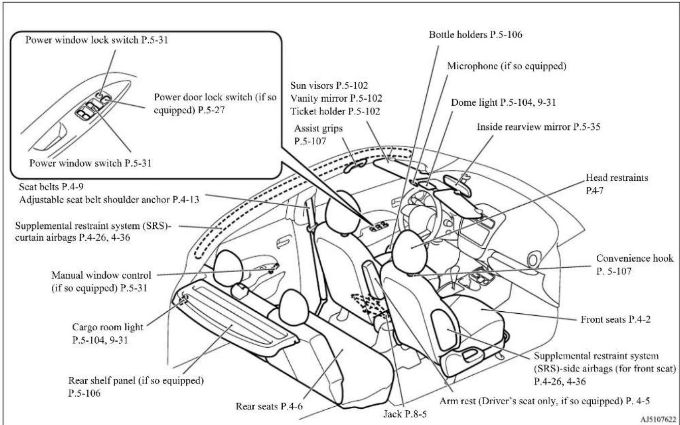
1-3 Overview
Luggage area
N(010)501638
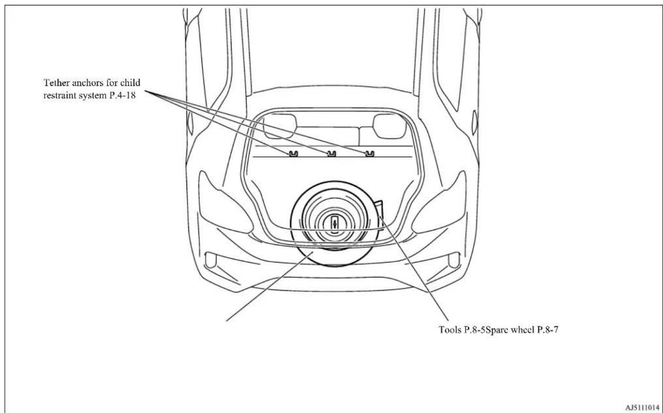
Overview 1-4
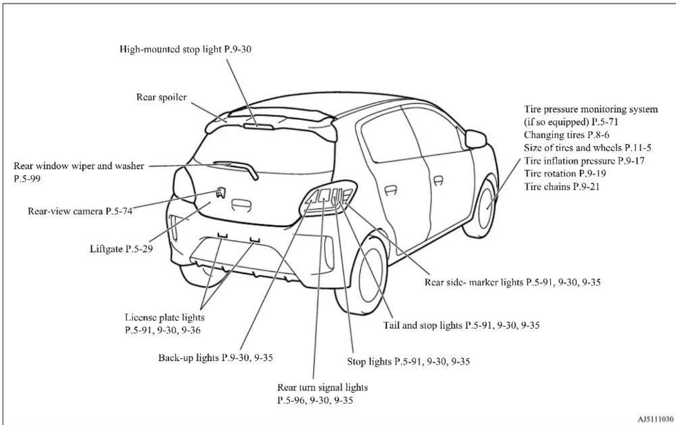
Outside
ND0100602971
![Sensor (if so equipped) [for Automatic High Beam (AHB), Forward Collision Mitigation system (FCM) and Lane Departure Warning (LDW)] P.5-93, 5-60, 5-68 Antenna P.7-11 Power window P.5-31 Outside rearview mirrors P.5-37 Side turn-signal lights (if so equipped) P.5-96, 9-30 Fuel tank filler P.3-3 Windshield wipers P.5-97 Engine hood P.9-4 F.A.S.T.-key (Free-hand Advanced Security Transmitter) (if so equipped) P.5-9 Keyless entry system (if so equipped) P.5-6 Locking and unlocking P.5-26 Front fog lights (if so equipped) P.5-97, 9-30, 9-34 Daytime running lights (if so equipped) P.5-91, 9-30, 9-34 Side turn signal lights (if so equipped) P.5-96, 9-30 Halogen headlights type LED headlights type Headlights P.5-91, 9-30, 9-31 Front turn signal lights P.5-96, 9-30, 9-33 Parking lights P.5-91, 9-30, 9-33 Front side- marker lights P.5-91, 9-30, 9-32 Headlights P.5-91, 9-30, 9-32 Front turn signal lights P.5-96, 9-30, 9-33 Parking lights/Daytime running lights P.5-91, 9-30 Front side- marker lights P.5-91, 9-30, 9-32 AJ5111027](/content/2026/05/829274/images/ec3e2819a12770eb1e14fb51ce608e7c6acf92d13f5631c7666cac504485b582.jpg)
1-5 Overview
| 100% | |
| 100% | 100% |
| 100% | 100% |
| 100% | 100% |
| 100% | 100% |
| 100% | 100% |
| 100% | 100% |
| 100% | 100% |
| 100% | 100% |
| 100% | 10 |
If this warning light comes on or flashes while you're driving...
If this warning light comes on or flashes while you're driving...
N(020)7(241)

NOTE
- These warning lights will come on for a few seconds for a bulb check when the ignition switch is first turned to "ON" or the operation mode is put in ON.
| Warning lights Do this Ref. | Page | |
 Charging system warning light Charging system warning light | Park your vehicle in a safe place and stop the engine.Contact your Mitsubishi Motors dealer or a repair facility of your choice for assistance. | P. 5-90 |
 (Illuminates and intermittent sounds)(for vehicles equipped with the F.A.S.T.-key) (Illuminates and intermittent sounds)(for vehicles equipped with the F.A.S.T.-key) | Park your vehicle in a safe place and stop the engine.Contact your Mitsubishi Motors dealer or a repair facility of your choice for assistance. | P. 5-16 |
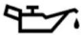 Oil pressure warning light Oil pressure warning light | Park your vehicle in a safe place and stop the engine, then check the engine oil level.If the light comes on while the engine oil level is normal, have the system checked at an authorized Mitsubishi Motors dealer or a repair facility of your choice as soon as possible. | P. 5-90 |
If this warning light comes on or flashes while you're driving...
| Warning lights Do this Ref. Page | ||
 Brake warning light Brake warning light | ● If this light comes on while driving, check to see that the parking brake is fully released.● If this light stays on after releasing the parking brake, immediately stop and check the brake fluid level.● If the brake fluid level is correct, there may be a system malfunction. Avoid hard braking and high speed, and contact an authorized Mitsubishi Motors dealer or a repair facility of your choice for assistance. | P. 5-88 |
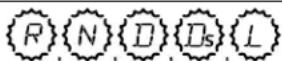 Selector lever position indicator in the instrument cluster flashes rapidly (once per second) Selector lever position indicator in the instrument cluster flashes rapidly (once per second) | ● Park your vehicle in a safe place.Idle the engine until the selector lever position indicator stops flashing.If the indicator does not go off, contact an authorized Mitsubishi Motors dealer or a repair facility of your choice immediately. | P. 5-46 |
 or or 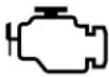 Engine malfunction indicator (“SERVICE ENGINE SOON” or “Check engine light”) Engine malfunction indicator (“SERVICE ENGINE SOON” or “Check engine light”) | ● Although your vehicle will usually be drivable and not need towing, have the engine system checked at an authorized Mitsubishi Motors dealer or a repair facility of your choice as soon as possible. If the vehicle is not drivable, contact emergency roadside assistance at 1-888-648-7820 (for vehicles sold in U.S.A.) or 1-888-576-4878 (for vehicles sold in Canada), an authorized Mitsubishi Motors dealer, or local towing company for assistance. | P. 5-89 |
 Electric power steering system (EPS) warning light Electric power steering system (EPS) warning light | ● If this light comes on while the engine is running, it may become harder to turn the steering wheel. Have your vehicle inspected at an authorized Mitsubishi Motors dealer or a repair facility of your choice as soon as possible. | P. 5-52 |
2-2 Quick index
If this warning light comes on or flashes while you're driving...
| Warning lights Do this Ref. | Page | |
 Anti-lock braking system warning light Anti-lock braking system warning light | When this light comes on, the anti-lock braking system is not functioning and only the ordinary braking system is functioning.Park your vehicle in a safe place and stop the engine.Test the system as described on page 5-52.If the light does not go out after the test, or if it comes on again, we recommend that you have the system checked at an authorized Mitsubishi Motors dealer or a repair facility of your choice as soon as possible. | P. 5-51 |
 SRS warning light SRS warning light | Immediately have the airbag and the pre-tensioner seat belt system checked at an authorized Mitsubishi Motors dealer. | P. 4-31 |
 Selector lever position indicator in the instrument cluster flashes slowly (every 2 seconds) Selector lever position indicator in the instrument cluster flashes slowly (every 2 seconds) | Have your continuously variable transmission (CVT) checked at an authorized Mitsubishi Motors dealer or a repair facility of your choice immediately. | P. 5-46 |
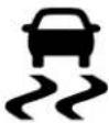 and and 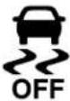 ASC indicator and ASC OFF indicator ASC indicator and ASC OFF indicator | Park your vehicle in a safe place and stop the engine.Restart the engine and check whether the indicator goes out.If the indicator does not go out, or if it comes on again, have your vehicle inspected by an authorized Mitsubishi Motors dealer or a repair facility of your choice as soon as possible.When this indicator comes on, the active stability control is not functioning. | P. 5-55 |
Quick index 2-3
If this warning light comes on or flashes while you're driving...
| Warning lights Do this Ref. Page | ||
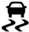 ASC indicator ASC indicator | Park your vehicle in a safe place and stop the engine.Restart the engine and check whether the indicator goes out.If the indicator does not go out, or if it comes on again, have your vehicle inspected by an authorized Mitsubishi Motors dealer or a repair facility of your choice as soon as possible.When this indicator comes on, the hill start assist is not functioning.Start off carefully on a steep uphill slope. | P. 5-50 |
 Tire pressure monitoring system warning light (if so equipped) Tire pressure monitoring system warning light (if so equipped) | If the warning light comes on, you should stop and adjust the tires to the proper inflation pressure as soon as possible.(See “Tire inflation pressures” on page 9-17.)Once adjustments have been made, the warning light will go off after a few minutes of driving.If the warning light blinks for approximately 1 minute and then remains continuously illuminated, the system is not operating properly. If the system returns to normal, the warning light will go off. If the warning light does not go off, have the vehicle inspected at an authorized Mitsubishi Motors dealer. | P. 5-71 |
If this warning light comes on or flashes while you're driving...
| Warning lights Do this Ref. | Page | |
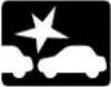 and and  Forward Collision Mitigation system (FCM) indicator and Forward Collision Mitigation system (FCM) OFF indicator (if so equipped) Forward Collision Mitigation system (FCM) indicator and Forward Collision Mitigation system (FCM) OFF indicator (if so equipped) | Park your vehicle in a safe place and restart the engine.If the indicators or warning lights remain, contact an authorized Mitsubishi Motors dealer.When this indicators come on, FCM, LDW and AHB are not functioning. | P.5-66 |
 Lane Departure Warning (LDW) light (yellow) (if so equipped) Lane Departure Warning (LDW) light (yellow) (if so equipped) | P.5-70 | |
 Automatic High Beam (AHB) warning light (yellow) (if so equipped) Automatic High Beam (AHB) warning light (yellow) (if so equipped) | P.5-96 |
Quick index 2-5
If this warning light comes on or flashes while you're driving...
| Warning lights Do this Ref. Page | ||
 and and  (blink)Forward Collision Mitigation system (FCM) indicator and Forward Collision Mitigation system (FCM) OFF indicator (if so equipped) (blink)Forward Collision Mitigation system (FCM) indicator and Forward Collision Mitigation system (FCM) OFF indicator (if so equipped) | Park your vehicle in a safe place.Clean the outside surface of the windscreen of the sensor portion, and check whether the indicators go off.If the indicators or warning lights remain, contact an authorized Mitsubishi Motors dealer for inspection of the sensor.When these indicators or warning light come on, FCM and LDW are not functioning. | P.5-65 |
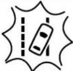 (blink slowly)Lane Departure Warning (LDW) light (yellow) (if so equipped) (blink slowly)Lane Departure Warning (LDW) light (yellow) (if so equipped) | P.5-70 | |
If this problem occurs...
If this problem occurs...
N00200902193
| Problem Do this Ref. | Page | |
Unable to turn the key.(except for vehicles equipped with the F.A.S.T.-key)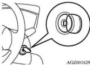 | From “ACC” to “OFF”Vehicles with continuously variable transmission (CVT):Check the position of the selector lever.The key cannot be removed unless the selector lever is set to the “P” (PARK) position. | P. 5-39 |
The engine does not start when the engine switch is pressed.(for vehicles equipped with the F.A.S.T.-key)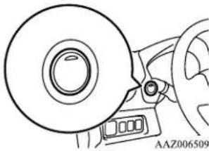 | Make sure the F.A.S.T.-key is in the vehicle.Make sure the selector lever is in the “P” (PARK) position, and then press the engine switch while depressing the brake pedal. | P. 5-14 |
Quick index 2-7
If this problem occurs...
| Problem Do this Ref. | Page | |
| The engine does not start and the operation mode cannot be changed to OFF. (for vehicles equipped with the F.A.S.T.-key) | 1. Move the selector lever to the “P” (PARK) position, and then change the operation mode to OFF. (For vehicles with continuously variable transmission (CVT))2. One of the other causes could be low battery voltage.If this occurs, the keyless entry system and the F.A.S.T.-key operation will also not operate.Contact an authorized Mitsubishi Motors dealer. | P. 5-15 |
| The F.A.S.T.-key does not operate.(for vehicles equipped with the F.A.S.T.-key) | Use the emergency key to lock and unlock the door.Insert the F.A.S.T.-key into the key slot of the floor console, and then start the engine or change the operation mode. | P. 5-19 |
| Cannot shift the selector lever from the “P” (PARK) position.(for vehicles with continuously variable transmission (CVT)) | Shift the selector lever while pressing the brake pedal.Check that the ignition switch or the operation mode is in ON. | P. 5-43 |
The windows are fogged up.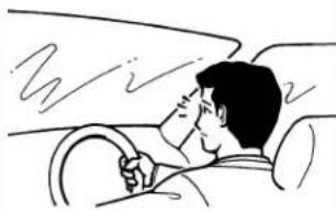 | Push the defogger switch to change the “” node. | P. 7-6 |
| The engine does not start.The lights do not come on.The lights arc dim.The horn does not honk.The horn sound is weak. | Have the battery checked. Recharge or replace as needed. | P. 8-2,P. 9-11 |
2-8 Quick index
If this problem occurs...
| Problem Do this Ref. | Page | |
The high coolant temperature warning light is illuminated.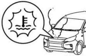 AJZ103610Steam comes out of the engine compartment. AJZ103610Steam comes out of the engine compartment. | The engine is overheated.Carefully stop the vehicle in a safe place. | P. 8-4 |
| The vehicle is stuck in sand, mud or snow | Rock your vehicle back and forth to free it. P. 8-13 |
WARNING
- When attempting to rock your vehicle out of a stuck position, be sure that no one is near the vehicle. The rocking motion may cause the vehicle to suddenly lurch forward or backward, possibly injuring bystanders.
- Avoid revving the engine or spinning the wheels. Prolonged efforts to free a stuck vehicle may result in overheating and transaxle failure. If the vehicle remains stuck after several rocking attempts, have a towing service pull the vehicle out.
| Problem Do this Ref. | Page | |
| The brakes are not functioning properly after crossing a puddle or stream. | Dry out the brakes by driving slowly while lightly pressing the brake pedal. | P. 6-5 |
Quick index 2-9
If this problem occurs...
| Problem Do this Ref. | Page | |
| The continuously variable transmission (CVT) makes no shift change when accelerating. The initial movement of the vehicle is slow when the vehicle starts moving.(for vehicles with CVT) | There may be a problem in the CVT.Have the vehicle inspected by an authorized Mitsubishi Motors dealer or a repair facility of your choice immediately. | P. 5-46 |
A tire is punctured.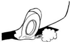 | 1. Park the vehicle in a safe place where the surface is flat and level.2. Replace the flat tire with the compact spare tire. | P. 8-6 |
2-10 Quick index
General information
Fuel selection 3-2
Filling the fuel tank 3-3
Modifications to and racing of your vehicle 3-5
Genuine Mitsubishi Motors parts 3-6
California Perchlorate Materials Requirements 3-7
Event Data Recording 3-7
Fuel selection
Fuel selection
N00301001993
Your vehicle is designed to use unleaded gasoline only. It is equipped with a fuel tank filler pipe specifically designed to accept only a small diameter unleaded gasoline dispensing nozzle.
WARNING
● Gasoline is highly flammable and explosive. You could be burned, seriously injured or killed when handling it. Whenever you refuel your vehicle, stop the engine and keep flames, sparks, and smoking materials away from the vehicle. Always handle fuel in well-ventilated outdoor areas.
CAUTION
- Using leaded gasoline in your vehicle will damage the engine, catalytic converter, and the oxygen sensors. Also, using leaded gasoline is illegal, and will void your warranty coverage of the engine, catalytic converter, and oxygen sensors.
Gasoline detergent additives
In the United States, fuel suppliers are required by law to add detergents to their gas-
3-2 General information
oline to minimize fuel-injector clogging and minimize intake-valve deposits. Detergent gasoline helps keep your engine in tune and your emission-control system working properly.
Octane requirement
Your vehicle is designed to operate on unleaded gasoline having a minimum octane number of 87 [(MON+RON)/2] or 91 RON.
Oxygenated gasoline
Gasoline sold at some service stations contains oxygenates such as ethanol, although the oxygenates may not be identified by those names. Oxygenates are required in some areas of the country. Such fuel can be used in your vehicle.
Ethanol (Gasohol)
A mixture of up to 10 % ethanol (grain alcohol) and 90 % unleaded gasoline may be used in your vehicle, provided the octane number is at least as high as that recommended for unleaded gasoline.
Methanol
Do not operate your vehicle on gasoline containing methanol (wood alcohol). Using this type of alcohol could adversely affect the vehicle's performance and damage critical parts of the vehicle's fuel system.
Reformulated gasoline
Many areas of the country require the use of cleaner burning fuel referred to as “Reformulated Gasoline”.
Reformulated gasoline contains oxygenates and is specially blended to reduce vehicle emissions and improve air quality.
Mitsubishi Motors Corporation strongly supports the use of reformulated gasoline. Properly blended reformulated gasoline has no adverse effect on vehicle performance or the durability of the engine and fuel system.
MMT (methylcyclopentadienyl manganese tricarbonyl)
MMT is a manganese-containing metallic additive that is blended into some gasolines to increase the octane number. Mitsubishi Motors Corporation recommends using gaso-lines without MMT.
Use of gasolines blended with MMT may adversely affect performance, and cause the malfunction indicator on your instrument panel to come on. If this happens, contact an authorized Mitsubishi Motors dealer or a repair facility of your choice for assistance.
Sulfur in gasoline
Your vehicle may have been designed to satisfy California's low-emission regulations based on clean-burning low-sulfur gasoline. Gasoline sold in parts of the country other than California is allowed to have a higher sulfur content. Using such gasoline could adversely affect the vehicle's catalytic converter and cause the engine malfunction indicator ("SERVICE ENGINE SOON" or "Check engine light") to come on. Illumination of this indicator while using high-sulfur gasoline does not necessarily mean the vehicle's emission-control system is malfunctioning. Your authorized Mitsubishi Motors dealer may suggest using a different, lower-sulfur brand of unleaded gasoline to determine if the problem is fuel-related.

NOTE
- Poor-quality gasoline can cause problems such as hard starting, stalling during idling, abnormal engine noise, and poor acceleration. If you experience any of these problems, try using a different brand of gasoline. If the engine malfunction indicator (“SERVICE ENGINE SOON” or “Check engine light”) flashes, have the vehicle inspected as soon as possible by the nearest authorized Mitsubishi Motors dealer or a repair facility of your choice.
● Repeatedly driving short distances at low speeds can cause deposits to form in the fuel system and engine, resulting in hard starting and poor acceleration. If these problems occur, you are advised to add a detergent additive to the gasoline when you refuel the vehicle. The additive will remove the deposits, thereby returning the engine to a normal condition. Be sure to use a Mitsubishi Motors Genuine cleaning additive. Using an unsuitable additive could make an engine malfunction. For details, please contact the nearest authorized Mitsubishi Motors dealer.
Filling the fuel tank
N00301100913
WARNING
- When handling fuel, comply with the safety regulations displayed by garages and filling stations.
WARNING
- Gasoline is highly flammable and explosive. You could be burned, seriously injured or killed when handling it. When refueling your vehicle, always turn the engine off and keep away from flames, sparks, and smoking materials. Always handle fuel in well-ventilated outdoor areas.
- Before removing the fuel tank filler cap, be sure to get rid of your body's static electricity by touching a metal part of the car or fuel pump. Any static electricity on your body could create a spark that ignites fuel vapor.
● Perform the whole refueling process (opening the fuel tank filler door, removing the fuel tank filler cap, etc.) by yourself; do not let any other person near the fuel tank filler. If you allowed a person to help you and that person was carrying static electricity, fuel vapor could be ignited. - Do not move away from the fuel tank filler until refueling is finished. If you moved away and did something else (for example, sitting on a seat) part-way through the refueling process, you could pick up a fresh charge of static electricity.
- Be careful not to inhale fuel vapor. Fuel contains toxic substances.
- Keep the doors and windows closed while refueling the vehicle. If they were open, fuel vapor could get into the cabin.
General information 3-3
Filling the fuel tank
Fuel tank capacity
9.2 gal (35 L)
Refueling
- Before filling with fuel, stop the engine.
- The fuel tank filler is located on the rear driver side of your vehicle.
The fuel tank filler door can be opened from inside the vehicle with the fuel tank filler door release lever located at the left side of the driver's seat.
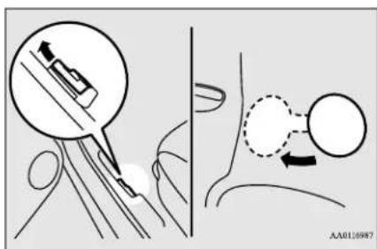
- Open the fuel tank filler pipe by slowly turning the fuel tank filler cap counterclockwise.
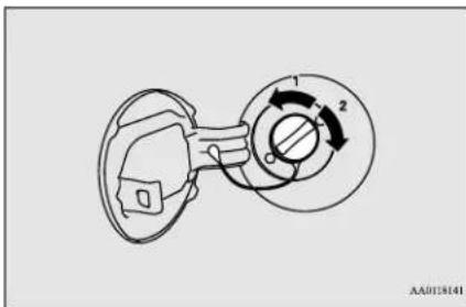
1- Remove
2- Close
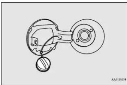
- While filling with fuel, hang the fuel tank filler cap cord on the hook located on the inside surface of the fuel tank filler door.
natural_image
Technical line drawing of a mechanical component with no visible text or symbolsWARNING
-
Since the fuel system may be under pressure, remove the fuel tank filler cap slowly. This relieves any pressure or vacuum that might have built up in the fuel tank. If the fuel tank filler cap is venting vapor or if you hear a hissing sound, wait until the sound stops before removing the fuel tank filler cap. Otherwise, fuel may spray out, injuring you or others.
-
To fill with fuel correctly depends mainly on correct handling of the fuel filler nozzle. Do not tilt the nozzle. Insert the nozzle in the fuel tank filler port as far as it goes.
CAUTION
- Your vehicle can only be operated using unleaded gasoline. Serious engine and catalytic converter damage will result if leaded gasoline is filled into these vehicles, and consequently, this must never be attempted.
- When the nozzle stops automatically, do not add more fuel.
3-4 General information

CAUTION
- To avoid fuel spillage and overfilling, do not "top-off" the fuel tank. Spilled fuel could discolor, stain, or crack the vehicle's paintwork. If fuel spills on the paintwork, wipe it off with a soft cloth.
- To close, turn the fuel tank filler cap slowly clockwise until you hear clicking sounds, then gently push the fuel tank filler door closed.

WARNING
- Make sure the fuel tank filler cap is securely closed. If the fuel tank filler cap were loose, fuel could leak, resulting in a fire.

CAUTION
- If you need to replace the fuel tank filler cap, use only the fuel tank filler cap specified for your model vehicle.

NOTE
- If the fuel tank filler cap is not tight driving, the engine malfunction indicator ("SERVICE ENGINE SOON" or "Check engine light") may come on when the onboard diagnostic (OBD) system perform a self check.
Always tighten the fuel tank filler cap until you hear at least 3 clicks.
The indicator will go off after several driving cycles. If the indicator does not go off, contact your authorized Mitsubishi Motors dealer or a repair facility of your choice as soon as possible.
Modifications to and racing of your vehicle
N0031600194
This vehicle should not be modified with non-Mitsubishi Motors genuine parts. Mitsubishi Motors designs and manufactures high quality vehicles with an emphasis on safety and durability. Modifications using non-Mitsubishi Motors genuine parts may affect the performance, safety and/or durability of your vehicle, and may violate applicable state and/or federal regulations.
DAMAGE OR PERFORMANCE PROBLEMS RESULTING FROM MODIFICATIONS TO OR RACING OF YOUR
VEHICLE ARE NOT COVERED UNDER WARRANTY.
Examples of modifications to your vehicle that can cause damage or performance problems include the following:
● Failure to use Mitsubishi Motors genuine parts
● Failure to use required fuel and fluids
● Failure to use proper size tires and wheels
- Modification of the fuel, intake, exhaust, emission, suspension, engine, drive train or electrical wiring systems
- Modification of any onboard computer/control module, including reprogramming, or replacing/adding chips to any onboard computer/control module
Review the Warranty and Maintenance Manual for further details regarding warranty coverage.
Installation of accessories
N00301701310

CAUTION
- Before any electrical or electronic accessories are installed, consult an authorized Mitsubishi Motors dealer.
CAUTION
- Your vehicle is equipped with a diagnosis connector (data link connector) for checking and servicing the electronic control system. Mitsubishi Motors does not recommend connecting a device other than the Scan Tool for inspections and service to this connector because an unexpected problem could result. In addition, malfunctions caused by connecting a device other than the Scan Tool may not be covered under warranty.
- The installation of accessories, optional parts, etc., should only be performed within the limits prescribed by law, and in accordance with the guidelines and warnings contained within the documents accompanying this vehicle.
Only Mitsubishi Motors approved accessories should be fitted to your vehicle. - Improper installation of electrical parts could cause a fire. Refer to the “Modification/alterations to the electrical or fuel systems” section within this owner’s manual.
- Using a cellular phone or radio set inside the vehicle without an external antenna may cause electrical system interference, which could lead to unsafe vehicle operation.
- Tires and wheels which do not meet specifications must not be used.
Refer to the “Specifications” section for information regarding wheel and tire sizes.
WARNING
● While driving, do not use a cellular ph in a way that hinders safe driving. Any thing, including cellular phone usage, that distracts you from the safe operation of your vehicle increases your risk of an accident.
Refer to and follow all state and local laws in your area regarding cellular phone usage while driving.
Important point!
Due to the large number of accessory and replacement parts provided by different manufacturers in the market, it is not always possible for an authorized Mitsubishi Motors dealer to check whether the attachment or installation of a non-Mitsubishi Motors genuine parts affects the driving safety of your vehicle.
Modification/alterations to the electrical or fuel systems
ND0301800183
Mitsubishi Motors manufactures high quality vehicles with an emphasis on safety. It is important to consult an authorized Mitsubishi Motors dealer before installation of any accessory which may involve modification of the electrical or fuel systems.
CAUTION
- Please consult an authorized Mitsubishi Motors dealer concerning any such accessory fitment or modification. If the wires interfere with the vehicle body or improper installation methods are used (protective fuses not included, etc.), electronic devices may be adversely affected, resulting in a fire, vehicle damage, or other accident.
Genuine Mitsubishi Motors parts
NO2301401261
Mitsubishi Motors Genuine Parts are designed and manufactured to meet high standards of performance, and are recommended for all of your maintenance needs. Also available from your Mitsubishi Motors dealer are a wide variety of accessories to personalize your new vehicle. Each Mitsubishi Motors
vehicle has a selection of Mitsubishi Motors authorized accessories to choose from to tailor your new vehicle to your own personal preference. Your Mitsubishi Motors dealer's Parts Manager has information on various audio systems, protection items, as well as interior and exterior accessories available for your specific model.
California Perchlorate Materials Requirements
N00300100017
Certain components of this vehicle, such as airbag modules, seat belt pretensioners, and button cell batteries, may contain perchlorate materials.
Special handling may apply. For additional information, see www.dtsc.ca.gov/hazardous-waste/perchlorate.
Event Data Recording
N00302700033
This vehicle is equipped with an event data recorder (EDR).
The main purpose of an EDR is to record, in certain crash or near crash-like situations, such as an airbag deployment or hitting a road obstacle, data that will assist in understanding how a vehicle's systems performed.
The EDR is designed to record data related to vehicle dynamics and safety systems for a short period of time, typically 30 seconds or less.
The EDR in this vehicle is designed to record such data as:
● How various systems in your vehicle were operating;
- Whether or not the driver and front passenger safety belts were buckled/fastened;
- How far (if at all) the driver was depressing the accelerator and/or brake pedal; and,
● How fast the vehicle was traveling.
These data can help provide a better understanding of the circumstances in which crashes and injuries occur.

NOTE
- EDR data are recorded by your vehicle only if a non-trivial crash situation occurs; no data are recorded by the EDR under normal driving conditions and no personal data (e.g., name, gender, age, and crash location) are recorded. However, other parties, such as law enforcement, could combine the EDR data with the type of personally identifying data routinely acquired during a crash investigation.
To read data recorded by an EDR, special equipment is required, and access to the vehicle or the EDR is needed. In addition to the vehicle manufacturer, other parties, such as law enforcement, that have the special equipment, can read the information if they have access to the vehicle or the EDR.
| 100% | |
| 100% | 100% |
| 100% | 100% |
| 100% | 100% |
| 100% | 100% |
| 100% | 100% |
| 100% | 100% |
| 100% | 100% |
| 100% | 100% |
| 100% | 10 |
Seat and restraint systems
Seats 4-2
Seats and restraint systems 4-2
Front seats 4-3
Rear seats 4-6
Head restraints 4-7
Seat belts 4-9
Seat belt use during pregnancy 4-14
Seat belt pre-tensioner and force limiter systems ....4-14
Child restraint systems 4-15
Maintenance and inspection of seat belts 4-25
Supplemental Restraint System (SRS) - airbag 4-26
Seats
Seats
N01408401580
natural_image
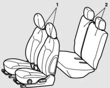
Line drawing of two car seats with labeled parts (1 and 2), no text or symbols present1 - Front seats
● To adjust the seat forward or backward → Page 4-3
● To adjust the seatbacks → Page 4-4
- To adjust the seat height (only, if so equipped) → Page 4-4
- Arm rest (Driver's equipped) → Page 4-5
● Heated seats (if so equipped) → Page 4-5
2 - Rear seats
● Folding the seatbacks forward → Page 4-6
Seats and restraint systems
seat only, if so ND401601235 Your vehicle has seat belts and other safety features that help protect you and your passengers in an accident.
Seat belts are the most important safety device. When worn properly, seat belts can reduce the chance of serious injury or death in various types of crashes. For added protec-
tion during a severe frontal collision, your vehicle has a Supplemental Restraint System (SRS) with airbags for the driver and passengers. The seats, head restraints, and door locks also are safety equipment, which must be used correctly.
Always check the following before you drive:
● That everyone in your vehicle is properly wearing their seat belt.
- That infants and small children are properly secured in an appropriate child restraint system in the rear seat.
● That all doors are fully closed and locked.
4-2 Seat and restraint systems
- That seatbacks are upright, with head restraints properly adjusted.
Safety equipment cannot prevent injury or death in all motor vehicle accidents. However, you can help reduce the risk of injury or death by following the instructions in this manual.

WARNING
- Do not place objects under the seats, could prevent the seat from locking securely, and it could lead to an accident. It may also cause damage to the seat or other parts.
Front seats
N00401800403
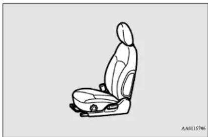
Position the driver's seat as far back as possible while maintaining a position that still enables you to fully apply the pedals, easily control the steering wheel and safely operate the vehicle.
natural_image
Line drawing of a car seat with driver seat and seatbelt (no text or symbols)This
WARNING
- Do not attempt to adjust the seat while driving. This can cause loss of vehicle control and result in an accident.
● After adjusting the seat, make sure that seat is securely locked into position. - To reduce the risk to the driver of serious injury or death during deployment of the driver's airbag, always properly wear the seat belt and adjust the driver's seat as far back as possible while maintaining a position that still enables you to fully apply the pedals, easily control the steel and safely operate the vehicle.
- To reduce the risk to the front passenger of serious injury or death during deployment of the passenger's air properly wear the seat belt and adjust the front passenger's seat as far back as possible.

WARNING
● Always place children 12 years o under in the rear seat and use appropriate child restraint systems.

CAUTION
● Make sure that the seat is adjusted by an adult. If it is adjusted by a child, an unexpected accident might occur.
- Do not place a cushion or the like between your back and the seatback while driving. The effectiveness of the head restraints will be reduced in the event of an accident.
- When sliding the seats, be careful not to catch your hand or leg.
- When sliding or reclining the seat rearward, pay careful attention to the rear seat passengers.
To adjust the seat forward or backward
ring wheel,
N00401900316
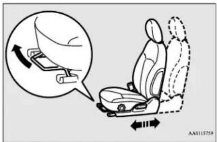
Pull the seat adjusting lever up and slide the seat forward or backward to the desired position. Release the adjusting lever to lock the bag, always seat in place.
Front seats
natural_image
Diagram of a car seatbelt with hand placement and motion arrows, no text or symbols presentWARNING
● To make sure that the seat is securely locked, try to move it forward or backward without using the adjusting lever.
To adjust the seatbacks
N01402001369
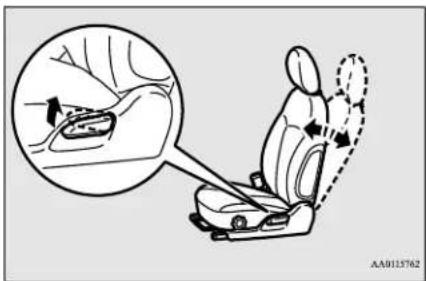
To adjust the seatback, lean forward slightly, gently pull the seatback lock lever up, then lean backward to a comfortable position and release the lever. The seatback will lock in place.
CAUTION
- The reclining mechanism used in the seatback is spring loaded, and will cause the seatback to return quickly to the vertical position when the lock lever is operated. When pulling the lever, sit close to the seatback or hold the seatback with your hand to control its return motion.
WARNING
- To reduce the risk of serious injury or death in the event of an accident or sudden stop, all seatbacks should be kept in the upright position while the vehicle is in motion. Seat belt performance during an accident can be adversely affected if the seatbacks are reclined. The more a seatback is reclined, the more likely seat belt performance will be adversely affected. If the seat belt is not properly positioned against the body during an accident, there is increased risk you will slide under the belt and receive serious injury or death.
To adjust the seat height (Driver's seat only, if so equipped)
N00402100243
To adjust the seat height, turn the dial as shown in the illustration.
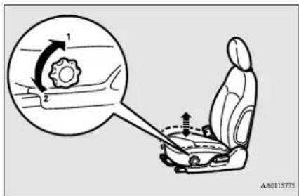
1- To move the seat cushion up
2- To move the seat cushion down
Arm rest (Driver's seat only, if so equipped)
N00402301079
To adjust the arm rest angle, tip the arm rest forward and then raise it to the desired position. To release the arm rest angle, raise it fully reward as shown.
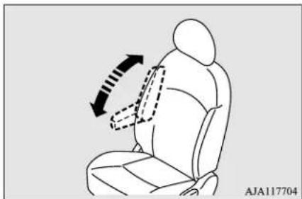
natural_image
Line drawing of a person seated in a chair with a dashed arrow indicating motion or force direction (no text or symbols)
NOTE
- Do not stand or sit on the arm rest. It could break.
Heated seats (if so equipped)
N00435601476
The heated seats can be operated by pushing the switch when the ignition switch or the operation mode is in ON. The indicator light (A) will illuminate while the heater is on.
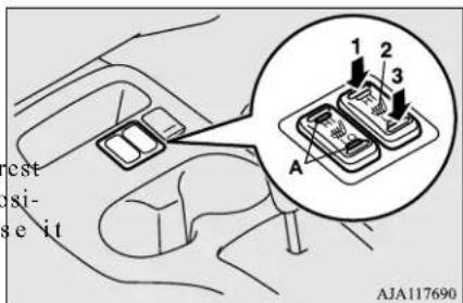
1 (HI) - Heater high
(for quick heating)
2 (neutral position) - Heater off
3 (LO) - Heater low
(to keep the seat warm)

WARNING
- Persons who are unable to feel temperature change or skin pain due to age, illness, injury, medication, alcohol use, fatigue or other physical conditions or who have sensitive skin may suffer burns when using the heated seat even at low temperatures. To reduce the risk of burns, people with such conditions must use care when using the heated seat.

CAUTION
- Switch off the heated seats when not in use. Operate the heaters at the "HI" position for quick heating. After the seat has become warm, set the heater switch to the "LO" position to keep it warm. Slight variations in the seat temperature may be felt while using the heated seats. This is caused by the operation of the heater's internal thermostat and does not indicate a malfunction.
- Do not place heavy objects on the seat or stick pins, needles, or other pointed objects into the seat.
- Do not place a blanket, cushion, or other insulating material on the seat while using the heater; doing so can cause the heater element to overheat.
- When cleaning the seat, do not use benzine, kerosene, gasoline, alcohol, or other organic solvents; doing so can cause damage not only to the surface of the seat, but also to the heater.
Seat and restraint systems 4-5
Rear seats
CAUTION
- If water or any other liquid is spilled on the seat, allow it to dry thoroughly before attempting to use the heater. Turn the heater off immediately if it appears to be malfunctioning during use.
Rear seats
N00402500221
WARNING
- Never adjust the seats to m area when the vehicle is in motion or on a slope. The seats could move more than necessary or move suddenly causing a serious accident and/or injury.
● After folding down a seat or returning a seat back to its original position, make sure the seat is firmly secured. Also check to make sure that the seat belts are in front of the seatbacks, and not caught behind the seatbacks. If the seat is not secured, it could move causing a serious accident and/or injury. - Do not allow anyone to ride in the cargo area while the vehicle is in motion. People who are not properly seated and restrained can be seriously injured or killed in an accident.
WARNING
- The cargo area in the rear of the vehicle should never be used as a play area by children. All children should be properly restrained in a restraint device that offers the maximum protection for their size and age. Refer to “Child restraint systems” on page 4-15.
CAUTION
- In the cargo area, do not load luggage or cargo higher than the top of the seats and make sure that it is firmly secured. Restricted rear vision or flying objects entering the passenger compartment during sudden braking could result in a serious accident and/or injury. - Seatbacks should always be folded and put back into their normal position by an adult. - When adjusting the seats, be careful not to catch your hand. Personal injury could result.
Folding the seatbacks forward
N00402901222
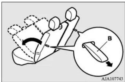
The rear seatbacks can be folded forward to provide additional luggage compartment space.
To fold
- Place each head restraint in its lowest position. (Refer to "Head restraints" on page 4-7.)
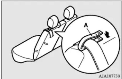
- Make sure that the seat belt for the outboard seating position is passed through the seat belt guide strap (A) and the seat belt guide is fastened as shown in the illustration.
natural_image
Technical illustration of a mechanical component with an inset showing a close-up view of a tool labeled 'A' (no text or symbols present)- Pull the left or right release straps (B), and fold the rear seatbacks forward.

NOTE
- If the seat belt interferes with luggage, unfasten the seat belt guide to release the seat belt and store the seat belt latch plate as shown in the illustration.
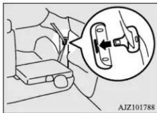
natural_image
Diagram showing a mechanical assembly with an inset close-up of a component (no text or symbols visible)To return
-
Make sure that the seat belt for the outboard seating position is passed through the seat belt guide or the seat belt latch plate for the outboard seating position is stored.
-
Raise the seatback until it locks securely into place.
After returning the seatback to its normal position, gently shake the seat and seat-back to make sure they are firmly secured.
WARNING
● After returning the seatbacks to their upright positions, make sure that the seatbacks are locked in place and firmly. Also check to be sure that the belts are in front of the seatbacks, and not caught behind the seatbacks.
CAUTION
- Do not grab the seat belt guide to raise the seatback; doing so can cause damage of the seat belt guide and the seatback.
Head restraints
N(04)4300584
Padded head restraints for the seats can reduce the risk of a whiplash injury if your vehicle is hit from the rear.
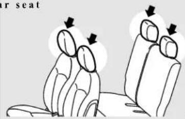
The head restraints are equipped in the illustrated position.
To maximize the effectiveness of your head restraint, adjust the front seatback to the upright position, the rear seatback to the normal seating position, and the head restraint to the proper position. Sit back against the seatback with your head close to the head restraint.
rear seat
AA0115805
Head restraints
WARNING
- Driving without the head restraints in place can cause you and your passengers serious injury or death in an accident. To reduce the risk of injury in an accident, always make sure the head restraint installed and properly positioned when the seat is occupied.
- In order to minimize the risk injury due to a rear impact, the front seat-back must be adjusted to the upright position, the rear seatback to the normal seating position, and the head restraint to the proper position before vehicle operation. The driver should never adjust the seat while the vehicle is in motion.
- Never place a cushion or similar device on the seatback. This can adversely affect head restraint performance by increasing the distance between your head and the restraint.
Adjustment of the head restraint height
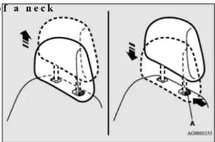
To reduce the risk of injury in an accident, adjust the head restraint height so that the center of the restraint is at your ear level when seated. Any person too tall for the restraint to reach their ear level when seated should raise the restraint to the highest locked position.
4-8 Seat and restraint systems
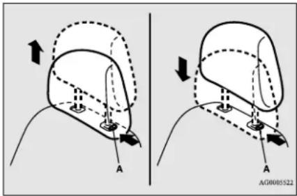
● To raise the restraint, pull it straight up.
- To lower the restraint, push down on while pressing the lock knob (A) in the direction shown by the arrow.
- After adjusting the height, push down on the restraint to make sure it is locked in position.
To remove
Press the lock knob (A) in the direction shown by the arrows. Then pull the head restraint up and out of the seatback.
WARNING
- To help minimize the risk of neck injury in the event of an accident, the head restraints must be properly installed and positioned to proper height before vehicle operation.
To install
First check that the head restraint is facing in the right direction as shown in the previous illustration, and then insert it into the seat-back. Push the head restraint down while
pressing the lock knob (A) until the restraint locks into place.
CAUTION
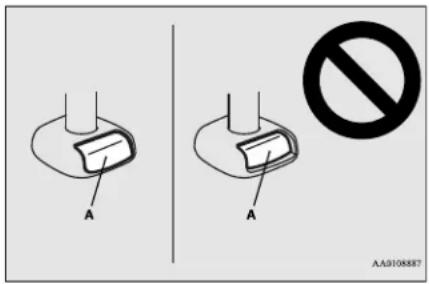
- Check that the lock knob (A) is extended out as shown in the illustration. Then pull the head restraint up to make sure that it is locked in place and will not come out of the seatback.
CAUTION
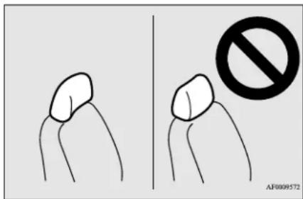
- The shape and size of the head restraint differs according to the seat. Always use the correct head restraint provided for the seat and do not install the head restraint in the wrong direction.
Seat belts
N00406001566
Seat belts are installed in your vehicle to help reduce the risk of injury to the driver and passenger in the event of an accident. / use the provided seat belts.
Carefully review the following information for proper seat belt usage.
WARNING
- To help reduce the risk of injury or death in an accident, seat restraint systems must always be used. Refer to "Child restraint systems" on page 4-15 for additional information.
- Never use one seat belt for more than one person.
● Never carry more people in your vehicle than there are seat belts.
● Always adjust the seat belt for a snug fit.
WARNING
● Always place the shoulder belt over your shoulder and across your chest. Never put it behind you or under your arm.
● Always wear the lap belt as low as possible across your hips, not around your waist.
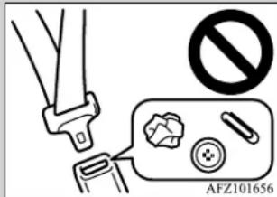
● Never insert any foreign object, such as a piece of plastic, paper clip, button or coin, into the seat belt buckle.
Alw
Never modify or alter the seat belts in your vehicle.
- To reduce the risk to the driver of serious injury or death during deployment of the driver's airbag, always properly wear the seat belt and adjust the driver's seat as far back as possible while maintaining a posi-
b e t t s a n d e n f l d
tion that still enables you to fully apply the pedals, easily control the steering wheel, and safely operate the vehicle.
Seat belts
WARNING
- To reduce the risk to a front seat passenger of serious injury or death from a deploying airbag, make sure the passenger always wears these remains seated all the way back and upright in their seat, and moves the seat as far back as possible. Refer to “Supplemental Restraint System (SRS) - airbag” on page 4-26 for additional information.
- Never hold an infant or child in your arms or on your lap when riding in this vehicle even when you are wearing your seat belt. Never place any part of the seat belt you are wearing around an infant or child. Failure to follow these simple instructions creates a risk of serious injury or death to your child in the event of an accident or sudden stop.
- Children 12 years old and under should always ride in the rear seat and be pr erly restrained. This reduces their risk of serious injury or death in an accident, especially due to a deploying front passenger's airbag. Refer to "Child restraint systems" on page 4-15 for additional information.
- Any child who is too small to properly wear a seat belt must be properly restrained in an appropriate child restraint system.
- Infants MUST be placed in a rear-facin child safety seat and positioned in the rear seat.
WARNING
- In the event of an accident, all seat belt assemblies, including retractors and attachment hardware, should be inspected by cah t authorized Mitsubishi Motors dealer to determine whether replacement is necessary.
- Do not let children play with the seat belts. If children play with the seat belts by wrapping them around their bodies, the seat belt may retract and become tight. This can result in a serious injury or death, such as suffocation. This can occur even if the vehicle is parked. If the child cannot be released from the seat belt, use an appropriate tool such as a knife or scissors to cut the seat belt.
Seat belt instructions
prop-
N00406201539
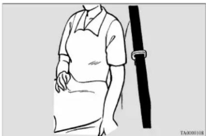
All seats are equipped with a seat belt which uses one combined lap-and-shoulder belt with an emergency locking retractor.
This system is designed to provide both comfort and safety. It permits full extension and automatic retraction of the belts during normal vehicle operation. A sensing device inside the belt retractor is designed to lock the retractor in the event of a sudden change in the vehicle's motion.
NOTE
- For instructions on installing a child restraint system using a seat belt, refer to “Installing a child restraint system using the seat belt” on page 4-22.
- Occupants should always sit back in their seats with their backs against the upright seatback. To reduce the risk of serious injury or death during deployment of the airbag, adjust the driver's seat as far back as possible while maintaining a position that still enables you to fully apply the pedals, easily control the steering wheel, and safely operate the vehicle. The front passenger seat should also be moved as far back as possible. Refer to "Supplemental Restraint System (SRS) - airbag" on page 4-26. Also refer to "To adjust the seat forward or backward" on page 4-3.
natural_image
Line drawing of a person wearing a dress and holding a belt (no text or symbols)Seat belts

WARNING
● To reduce the risk of serious injury or death in the event of an accident or sudden stop, all seatbacks should be kept in the upright position while the vehicle is in motion.
Seat belt performance during an accident can be adversely affected if the seatbacks are reclined. The more a seatback is reclined, the more likely seat belt performance will be adversely affected. If the seat belt is not properly positioned against the body during an account increased risk you will slide under the belt and receive serious injury or death.
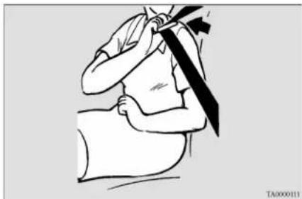
- Grasp the latch plate and slide it up the webbing so that it easily pulls across your body.
natural_image
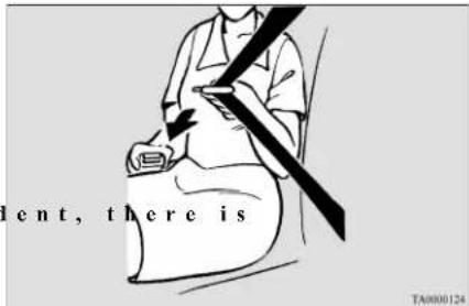
Illustration of a person performing a medical procedure with a surgical instrument (no text or symbols present)- Pull the seat belt out slowly while holding the latch plate. Push the latch plate into the buckle until you hear a "click". Pull up on the belt to be sure the latch plate is locked securely in the buckle.

NOTE
- If the seat belt locks up and cannot be pulled out, pull it once with force and let it retract all the way. Then, pull the belt out slowly once again.
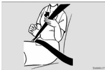
- The lap part of the belt must always be worn low and snug across the hips. Pull up on the shoulder portion of the belt to take up any slack in the lap belt.
natural_image
Illustration of a person wearing a seatbelt and holding a belt (no text or symbols)
NOTE
- With the exception of the seat belt for the driver, the seat belts in all other seating positions are equipped with an Automatic Locking Retractor (ALR) function. If you pull the seat belt fully out of the retractor, the retractor will switch to its ALR child restraint installation function (see page 4-22). When the ALR function has been activated, the seat belt will only retract. If this happens, let the belt fully retract, then pull the seat belt back out, repeating steps 1 through 4.
Seat belts
WARNING
- Be sure the lap belt portion fits snugly and is worn as low as possible across the hips, not around the waist. Failure to follow this instruction will increase the risk of serious injury or death in the event of an accident.
-
Be sure the seat belt webbing is not twisted when worn. Twisted webbing may adversely affect seat belt performance.
-
To release the belt, press the button on the buckle and allow the belt to retract.
If the belt does not retract smoothly, pull it out and check for kinks or twists in the webbing. Then make sure it remains untwisted as it retracts.
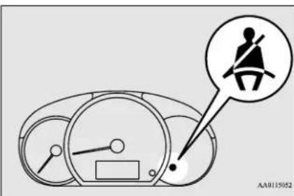
Driver's seat belt reminder/warning light
MK4184K0384
A tone and warning light are used to remind the driver to fasten the seat belt.
NOTE
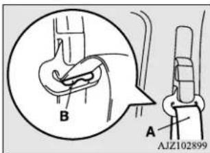
- If the seat belt (A) or ring (B) becomes dirty, the belt may not retract smoothly. If the seat belt and ring are dirty, clean them with mild soap or detergent solution.
If the ignition switch is turned to the "ON" position or the operation mode is put in ON without the driver's seat belt being fastened, a warning light will come on and a tone will sound for approximately 6 seconds to remind you to fasten your seat belt.
If the vehicle is driven with the seat belt still unfastened, the warning light will blink and the tone will sound intermittently until the seat belt is fastened.
WARNING
- In order to reduce the risk of serious injury or death in an accident, always fasten your own seat belt. Do not allow anyone to ride in your vehicle unless he or she is also seated and fastening a seat belt. Children should additionally be restrained in a secure child restraint system.
NOTE
- If the seat belt subsequently remains unfastened, the warning light and the tone will issue further warnings each time the vehicle starts moving from a stop.
Front passenger seat belt warning light
N00418300237
The front passenger seat belt warning light is located at shown in the illustration.
4-12 Seat and restraint systems
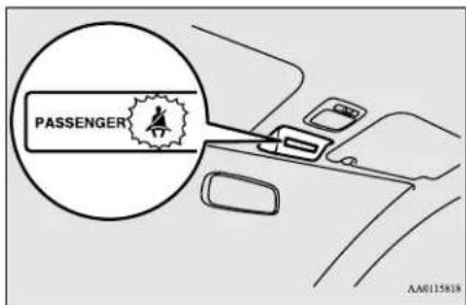
When the ignition switch is turned to the "ON" position or the operation mode is put in ON, this indicator normally comes on and goes off a few seconds later.
The light comes on when a person sits on the front passenger seat but does not fasten the seat belt. It goes off when the seat belt is subsequently fastened.

WARNING
- When a child booster seat is used front passenger seat, the front passenger seat belt warning light will not come on, if the seat belt is not fastened when the booster seat is used. Confirm that the child is wearing the seat belt properly.
- Do not install any accessory or sticker that makes the light difficult to see.
Adjustable seat belt shoulder anchor (front seats)
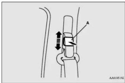
N004D6300357
The seat belt anchor height can be adjusted. To move the anchor, pull the lock knob (A) and slide the anchor to the desired position. Release the lock knob to lock the anchor into position.
WARNING
● Always adjust the shoulder belt anchor so that the shoulder belt is positioned across the center of your shoulder without touching your neck. The shoulder belt should not be able to fall off your shoulder. Failure to follow this instruction can adversely affect seat belt performance and increase the risk of serious injury or death in the event of an accident.

WARNING
- Adjust the shoulder belt anchor only when the vehicle is not in motion.
● Make sure the anchor is securely locked in position after adjusting it.
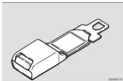
Seat belt extender
N00406700205
If your seat belt is not long enough, even when fully extended, a seat belt extender must be obtained. The extender may be used for either of the front seats.
natural_image
Technical line drawing of a mechanical buckle or buckle component (no text or symbols)
WARNING
- The extender should only be used if the existing belt is not long enough. Anyone who can use the standard seat belt should not use an extender. Unnecessary use of an extender can adversely affect performance in an accident.
Seat belt use during pregnancy
WARNING
- When not required, the extender must be removed and stowed.
Seat belt use during pregnancy
N01406801147
Seat belts work for everyone, including pregnant women. Like all occupants, pregnant women are more likely to be seriously injured or killed in an accident if they do not wear seat belts.
WARNING
● To reduce the risk of serious injury or death to pregnant women and unborn children in an accident, pregnant women should always wear a seat belt. The lap portion of the seat belt should be worn snug and low across the hips and below the rounding. Consult your doctor if you have any additional questions or concerns.
Seat belt pre-tensioner and force limiter systems
N00417701752
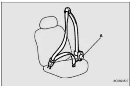
The driver's and front passenger's seats each have a seat belt equipped with a pre-tensioner system and force limiter system.
Pre-tensioner system
The driver and front passenger seat belts are equipped with a seat belt pre-tensioner system. In a moderate-to-severe frontal or side collision or when a rollover or overturning of the vehicle is detected, the pre-tensioner system operates simultaneously with the deployment of the front airbags, side airbags or curtain airbags.
The seat belt pre-tensioners are located within the seat belt retractors (A). When activated, the pre-tensioners quickly draw back seat belt webbing and increase seat belt performance.
natural_image
Line drawing of a car seatbelt buckle with no text or symbolsThe seat belt pre-tensioner system includes the following components:
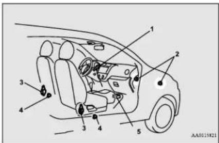
1- SRS warning light
2- Front impact sensors
3- Seat belt pre-tensioner
4- Side impact sensors
5- Airbag control unit
The airbag control unit monitors the readiness of the electronic parts of the system whenever the ignition switch or the operation mode is under the following conditions. These include all of the items listed above and all related wiring.
[Except for vehicles equipped with the F.A.S.T.-key]
The ignition switch is in the "ON" or "START" position.
[ Vehicles equipped with the F.A.S.T.-key] The operation mode is in ON.
The seat belt pre-tensioners will operate under the same conditions as the airbag control unit.
4-14 Seat and restraint systems
When the seat belt pre-tensioners activate, some smoke is released and a loud noise will be heard. The smoke is not harmful, but care should be taken not to intentionally inhale it, as it may cause some temporary irritation to people with respiratory problems.
The pre-tensioners activate in the event of a moderate-to-severe front or side impact, even if the seat belt is not being worn. The seat belt pre-tensioners may not activate in certain collisions, even though the vehicle may appear to be severely damaged. Such non-activation does not mean that something is wrong with the seat belt pre-tensioner system, but rather that the collision forces were not severe enough to activate the system.

WARNING
- The seat belt pre-tensioner system is designed to work only once. After the seat belt pre-tensioners have been activated, they will not work again. They must promptly be replaced and the ent belt pre-tensioner system inspected by an authorized Mitsubishi Motors dealer.
SRS warning light
N004D8700137
This warning light tells you if there is a problem involving the SRS airbags and/or the seat belt pre-tensioner system. Refer to "SRS warning light" on page 4-31.
Force limiter system
N00408900142
In the event of an accident, the seat belt force limiter system will help reduce the force applied to the driver and front seat passenger.
Child restraint systems
N00407101913
When transporting infants or small children in your vehicle, an appropriate child restraint system must always be used. This is required by law in the U.S. and Canada. Child restraint systems specifically designed for infants and small children are offered by several manufacturers. Choose only a child restraint system with a label certifying that it complies with Federal Motor Vehicle Safety Standard 213 (FMVSS 213) or Motor Vehicle Restraint Systems and Booster Seats Safety Regulations (RSSR). Look for the manufacturer's statement of compliance on the box and child restraint system itself.
The child restraint system should be appropriate for your child's weight and height, and should properly fit your vehicle's seat. For detailed information, refer to the instruction manual accompanying the child restraint system.
Recommendations for child restraint system selection
All children should be properly restrained in a restraint device that offers the maximum protection for their size and age as specified by local, state, or provincial laws.
Be sure to check local, state, or provincial requirements for child size and age that may vary from the recommendations listed below.
● Children less than 2 years old and weigh 40 pounds (18kg) or less MUST ride in a rear-facing child safety seat that MUST ONLY be used in the rear seat.
● Children older than 2 years of age and who weigh less than 60 pounds (27kg) or who are less than 57 inches (145cm) tall must be in an appropriate child restraint system used only in the rear seat.
- Children who weigh more than 60 pounds (27kg) or who are more than 57 inches (145cm) tall, regardless of age, should use a suitable child seat or a booster seat in the rear seat until the vehicle's lap-and-shoulder belt fits them properly.
Child restraint systems
WARNING
● All children must be seated in the rear seat, and properly restrained.
Accident statistics show that children of all sizes and ages are safer when properly restrained in the rear seat, rather than in the front seat.
- Be sure to select a child restraint system that is appropriate not only for the child's size and age but also for your vehicle. Some child restraint systems may not fit your vehicle properly.
- Any child who is too large to use restraint system should ride in the rear seat and wear the lap-and-shoulder belt properly. The shoulder belt must be positioned over the shoulder and across the chest, not across their neck, and with the lap belt positioned low on the child's hips, not across their stomach. If necessary, a booster seat should be used to help achieve a proper seat belt fit. Follow the booster seat manufacturer's instructions. Only use a booster seat that is certified as complying with Federal Motor Standards or Motor Vehicle Restraint Systems and Booster Seats Safety Regulations.
WARNING
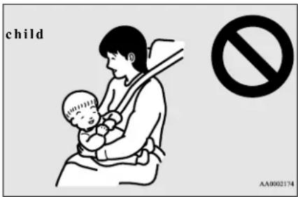
- Never hold an infant or child in your arms or on your lap when riding in this vehicle, even when you are wearing your seat belt. Never place any part of the seat belt you are wearing around an infant or child. Failure to follow these simple instructions creates a risk of serious injury or death to your child in the event of an accident or sudden stop.
Vehicle Safety
WARNING
- Your vehicle is also equipped with a front passenger's airbag.
Never put REAR-FACING CHILD RESTRAINT SYSTEMS or INFANT RESTRAINT SYSTEMS in the front passenger seat. This places the infant too close to the passenger's airbag. During deployment of that airbag, the infant can be seriously injured or killed. Rear-facing child restraint systems or infant restraint systems must only be used in the rear seat.
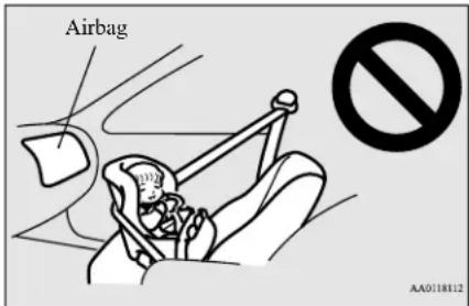

WARNING
- FRONT-FACING CHILD RESTRAINT SYSTEMS should be used in the rear seat whenever possible. If one must be used in the front passenger seat, move the seat the most rearward position and make sure the child stays in the child restraint system, properly restrained. Failure to follow these instructions could result in serious injury or death to the child.
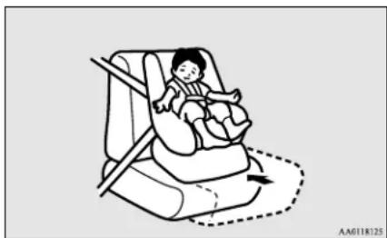
natural_image
Illustration of a child seated in a car seat using a seatbelt, with no text or symbols present.
WARNING
- When installing a child restraint system, follow the instructions provided by the manufacturer and follow the directions in this manual. Failure to do so can result in serious injury or death to your child in an accident or sudden stop.
- After installation, push and pull the child restraint system back and forth, and side to side, to see that it is firmly secured. the child restraint system is not installed securely, it may cause injury to the child or other occupants in the event of an accident or sudden stop.
- When not in use, keep your child restraint system secured with the seat belt, or remove it from the vehicle, in order to prevent it from being thrown around inside the vehicle during an accident.

NOTE
Before purchasing a child restraint system, try installing it in the rear seat to ensure proper fit. Due to the location of the seat belt buckles and the shape of the seat cushion, it may be difficult to securely install some manufacturer's child restraint systems.
If the child restraint system can be pulled forward or to either side easily on the seat cushion after the seat belt has been tightened, choose another manufacturer's child restraint system.
Depending on the seating position in the vehicle and the child restraint system that you have, the child restraint system can be attached using one of the following 2 methods:
- Attach to the lower anchorage in the rear seat ONLY if the child restraint system is compatible with the LATCH system (See page 4-18).
- Attach to the seat belt (See page 4-22).

WARNING
- It is important to use an approved rear-facing infant restraint until the infant is one year old (unless the infant outgrows the seat sooner). This allows the infant's neck and spine to develop enough to support the weight of their head in the event of an accident.
Child restraint systems
Installing a child restraint system using the LATCH (Lower Anchors and Tethers for children) system
N00418800157
Lower anchor locations
The outboard seating positions in the rear seat of your vehicle are equipped with lower anchors for attaching child restraint systems compatible with the LATCH system.
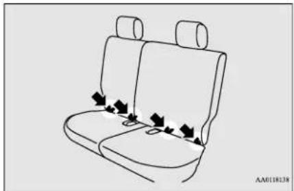
natural_image
Line drawing of a car backseat with seat covers and seatbelt, no text or symbols presentTether anchor locations
N00418900190
Your vehicle has 3 attachment points on the back of the rear seatbacks. These are for securing a child restraint system tether strap to each of the 3 rear seating positions in your vehicle.
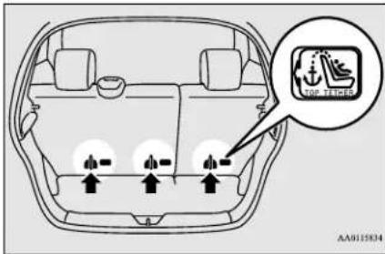

NOTE
● The attachments points are behind slits on the seatback backboard cloth.
Examples of child restraint systems compatible with the LATCH system
N00419000202
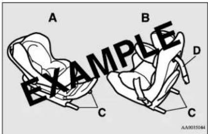
A- Rear-facing child restraint system
B- Front-facing child restraint system
C- Child restraint system lower anchor connectors
D- Tether strap
(These are only examples.)
Using the LATCH system
N00419101356
Except for booster seat
-
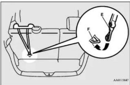
In order to securely fasten the tether strap, remove the head restraint from the location where you wish to install the child restraint system.
-
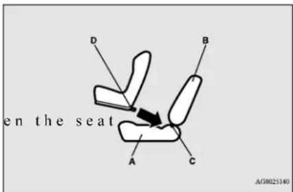
Open the gap a little between cushion (A) and the seatback (B) with your hand to locate the lower anchors (C).
- Push the anchor connectors (D) on the child restraint system into the lower anchors (C) in accordance with the instructions provided by the child restraint system manufacturer.
Remember, the lower anchors provided with your vehicle are designed to secure suitable child restraint systems compatible with the LATCH system in the outboard positions of the rear seats only. The anchor connectors are NOT designed to secure a suitable child restraint system in the center position of the rear seat.
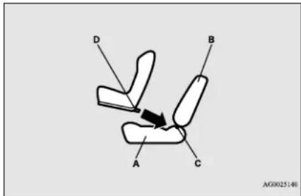
A- Vehicle seat cushion
B- Vehicle seatback
C- Lower anchor
D- Connector
en the seat NOTE
- In order to secure a child restraint system compatible with the LATCH system, you must use the lower anchor points in the outboard positions of the rear seat. To secure a child restraint system in the center position of the rear seat, you must use the vehicle's center seat belt.
WARNING
- If there is any foreign material in or around the lower anchors, remove it before installing the child restraint system. Also, make sure the seat belt is away from, not looped through or otherwise interfering with, the child restraint system. If foreign matter is not removed and/or the seat belt interfere child restraint system, the child restraint system will not be secured properly, could detach and move forward in the event of sudden braking or an accident, and could result in injury to the child or other vehicle occupants.
-
When the vehicle is moving, do not adjust the seat where the child restraint system is installed.
-
On a vehicle equipped with a rear shelf panel, remove the rear shelf panel from the vehicle. (Refer to "Rear shelf panel" on page 5-106.)
-
Open the slit on the backboard cloth of the seatback, latch the tether strap hook (E) of the child restraint system to the tether anchor bar (F) and tighten the tether strap so it is securely fastened.
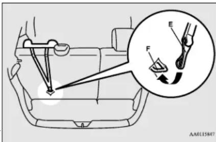
WARNING
● With the
Child restraint system tether anchors are designed only to withstand loads from correctly fitted child restraint systems.
Under no circumstances are they to be used for adult seat belts, harnesses, or for attaching other items or equipment to the vehicle.
6. Before putting your child in the restraint, push and pull the restraint in all directions to be sure it is firmly secure. Do this before each use. If the child restraint system is not firmly secure, repeat steps 3 through 5.
Child restraint systems
CAUTION
● After removing the child restraint system, install the head restraint.
Booster seat
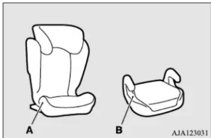
natural_image
Line drawings of two car seat compartments labeled A and B, showing front and side views (no text or symbols beyond labels)A- High back booster seat
B- Booster cushion
WARNING
- To avoid injury to child, do not use the lap/shoulder belt Automatic Locking Retractor (ALR) child restraint installation function when using a booster seat with the seat belts.
■ High back booster seat
-
In order to securely fasten the tether strap, remove the head restraint from the location where you wish to install the high back booster seat.
-
Open the gap a little between cushion (A) and the seatback (B) with your hand to locate the lower anchors (C).
-
Push the anchor connectors (D) on the high back booster seat into the lower anchors (C) in accordance with the instructions provided by the child restraint system's manufacturer.
Remember, the lower anchors (C) provided with your vehicle are designed to secure suitable high back booster seats compatible with the LATCH system in the outboard positions of the rear seats only. The anchor connectors are NOT designed to secure a suitable high back booster seat in the middle seating position of the rear seat.
A- Vehicle seat cushion
B- Vehicle seatback
C- Lower anchor
D- Connector
WARNING
- If there is any foreign material in or around the lower anchors, remove it before installing the high back booster seat. Also, make sure the seat belt is away from, not looped through or otherwise interfering with, the high back booster seat. If foreign matter is not removed and/or the seat belt interfere high back booster seat, the high back booster seat will not be secured properly, could detach and move forward in the event of sudden braking or an accident, and could result in injury to the child or other vehicle occupants.
eres with

WARNING
- When the vehicle is moving, do not adjust the seat where the high back booster seat is installed.
- On a vehicle equipped with a rear shelf panel, remove the rear shelf panel from the vehicle. (Refer to "Rear shelf panel" on page 5-106.)
- Open the slit on the backboard cloth of the seatback, latch the tether strap hook (E) of the high back booster seat to the tether anchor bar (F) and tighten the tether strap so it is securely fastened.

WARNING
- Child restraint system tether anchors are designed only to withstand loads from correctly fitted child restraint systems. Under no circumstances are they to be used for adult seat belts, having other items, or equipment to the vehicle.
-
Before putting your child in the restraint, push and pull the high back booster seat in all directions to be sure it is firmly secure. Do this before each use. If the high back booster seat is not firmly secure, steps 3 through 5.
-
Sit the child in the high back booster seat. Fit the seat belt to the high back booster seat according to the child restraint system's manufacturer.

CAUTION
● After removing the high back booster seat, install the head restraint.

Booster cushion

CAUTION
- Do not remove the head restraint when installing a booster cushion.
- Open the gap a little between t cushion (A) and the seatback (B) with your hand to locate the lower anchors (C).
- Push the anchor connectors (D) on the booster cushion into the lower anchors (C) in accordance with the instructions e, provided by the child restraint system's manufacturer.
Remember, the lower anchors (C) provided with your vehicle are designed to secure suitable booster cushions compatible with the LATCH system in the outboard positions of the rear seats only. The anchor connectors are NOT designed to secure a suitable booster cushion in the middle seating position of the rear seat.
Child restraint systems
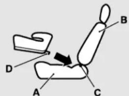
AJA123028
A- Vehicle seat cushion
B- Vehicle seatback
C- Lower anchor
D- Connector
WARNING
- If there is any foreign material in or around the lower anchors, remove it before installing the booster cushion. Also, make sure the seat belt is away from, not looped through or otherwise interfering with, the booster cushion. If foreign matter is not removed and/or the seat belt interferes with the booster cushion, the booster cushion will not be secured properly, could detach and move forward in the event of sudden braking or an accident, and could result in injury to the child or other vehicle occupants.
-
When the vehicle is moving, do not ad the seat where the booster cushion is installed.
-
Sit the child in the booster cushion.
Fit the seat belt to the booster cushion according to the child restraint system's manufacturer.
WARNING
- When using a child restraint in a rear seating position, always review the instructions provided with that restraint to make sure it is compatible with this vehicle and to understand how to properly install it. Child restraints, including booster seats, come in different sizes and configurations. Depending on where you place these child restraints, and depending on their size and configuration, you may not be able to access or properly use one or more adjacent seat belt assemblies. If this occurs, the adjacent seating position or position should not be used. Failure to use a seat belt or improper use of a seat belt can result in serious injury or death should a crash occur.
Installing a child restraint system using the seat belt (with emergency/automatic locking mechanism)
With the exception of the driver, the seat belt in all other seating positions can be converted
from normal Emergency Locking Retractor (ELR) mode, to Automatic Locking Retractor (ALR) mode. This means that when you pull the seat belt fully out of the retractor, the retractor will switch to its ALR child restraint installation function. Always use the ALR child restraint installation function when you install a child restraint system using the seat belt.
Children 12 years old and under should always be restrained in the rear seat, whenever possible, although the front passenger seat belt can also be converted to ALR mode.
WARNING
- When you install a child restraint system using the seat belt, always make sure the retractor has been switched to the ALR child restraint installation function. The ALR function will keep the child restraint system tightly secured to the seat. Failure to convert the retractor to the ALR function may allow the child restraint system to move forward during sudden braking or an accident, resulting in serious injury or death to the child or other occupants.
Installation
Except for booster seat
- Place the child restraint system on the seat where you wish to install it.
To help assure proper fitting of the child restraint system, always remove the head restraint.
- Route the seat belt through the child restraint system according to the instructions provided by the child restraint system's manufacturer. Then insert the seat belt latch plate into the buckle. Make sure you hear a "click" when you insert the latch plate into the buckle.

natural_image
Illustration of a person kneeling with hands using a computer mouse, no text or symbols present- To activate the ALR child restraint installation function, slowly pull the shoulder part of the belt all the way out of the retractor until it stops. Then let the belt feed back into the retractor.
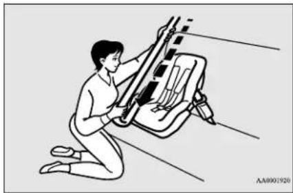
natural_image
Illustration of a person kneeling beside a mechanical device with wires, no text or symbols present-
After the belt has retracted, tug on it. If the belt is in the ALR function, you will not be able to pull it out. If the webbing can be pulled out from retractor, the ALR function has not been activated and you will need to repeat steps 3 and 4.
-
After confirming that the belt is locked, grab the shoulder part of the belt near the buckle and pull up to remove any slack from the lap part of the belt allowing the slack to feed into the retractor. Remember, if the lap belt portion is not tight, the child restraint system will not be secure. It may help to put your weight on the child restraint system and/or push on its seat-back while pulling up on the belt (See illustration).
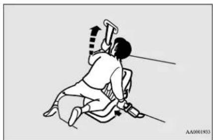
natural_image
Illustration of a person performing a physical exercise with a tool, no text or symbols presentIf your child restraint system requires the use of a tether strap, fasten the tether strap in accordance with the following procedures.
- On a vehicle equipped with a rear shelf panel, remove the rear shelf panel from the vehicle. (Refer to "Rear shelf panel" on page 5-106.)
Child restraint systems
- Latch the tether strap hook (A) of the child restraint system to the tether anchor bar (B) and tighten the tether strap so it is securely fastened.
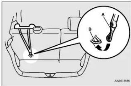
WARNING
- Child restraint system tether anchors are designed only to withstand loads from correctly fitted child restraint systems. Under no circumstances are they to be used for adult seat belts, harnesses, or for attaching other items or equipment to the vehicle.
- Before putting your child in the restraint, push and pull the restraint in all directions to be sure it is firmly secure. Do this before each use. If the child restraint system is not firmly secure, repeat steps 1 through 7.
CAUTION
● After removing the child restraint system, be sure to perform the following actions.
- Wind up the seat belt completely to deactivate the ALR mode.
• Install the head restraint.
Booster seat
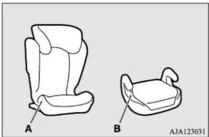
natural_image
Line drawings of two car seats labeled A and B, showing front and side views (no text or symbols beyond labels)A- High back booster seat
B- Booster cushion
WARNING
● To avoid injury to child, do not use the lap/shoulder belt Automatic Locking Retractor (ALR) child restraint installation function when using a b with the seat belts.
■ High back booster seat
- Place the high back booster seat on the seat where you wish to install it.
To help assure proper fitting of the high back booster seat, always remove the head restraint.
If your high back booster seat requires the use of a tether strap, fasten the tether strap in accordance with the following procedures. - On a vehicle equipped with a rear shelf panel, remove the rear shelf panel from the vehicle. (Refer to "Rear shelf panel" on page 5-106.)
- Latch the tether strap hook (A) of the child restraint system to the tether anchor bar (B) and tighten the tether strap so it is securely fastened.
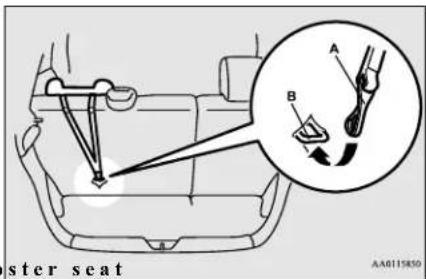
Maintenance and inspection of seat belts

WARNING
- Child restraint system tether anchors are designed only to withstand loads from correctly fitted child restraint systems. Under no circumstances are they to be used for adult seat belts, harnesses, for attaching other items, or equipment to the vehicle.
- Sit the child in the high back booster seat. Fit the seat belt to the high back booster seat according to the child restraint system's manufacturer.

CAUTION
- After removing the high back booster seat, install the head restraint.

Booster cushion

CAUTION
- Do not remove the head restraint when installing a booster cushion.
- Place the booster cushion on the seat where you wish to install it.
- Sit the child in the booster cushion. Fit the seat belt to the booster cushion according to the child restraint system's manufacturer.
Children who have outgrown child restraint systems
N004D7601631
Children who have outgrown a child restraint system should be seated in the rear seat and wear the seat belt. If the shoulder belt crosses their face or neck, and/or the lap belt crosses their stomach, a commercially available booster seat must be used to raise the child so that the shoulder belt crosses their shoulder and the lap belt remains positioned low across their hips. The booster seat should fit the vehicle seat and have a label certifying compliance with Federal Motor Vehicle Safety Standards or Motor Vehicle Restraint Systems and Booster Seats Safety Regulations.

WARNING
- Any child who is too small to properly wear a seat belt must be properly restrained in an appropriate child restraint system, to reduce their risk of serious injury or death in an accident.
- A child should never be left unattended in, or unsupervised around, your vehicle. When you leave the vehicle, always take the child out as well.
● Children can die from heat stroke if left or trapped inside the vehicle, especially on hot days.

WARNING
- Keep your vehicle locked when not in use. Keep your vehicle keys away from children.
Maintenance and inspection of seat belts
N00407001404
Regularly check your seat belt buckles and their release mechanisms for positive engagement and release of the latch plate. Check the retractors for automatic locking when in the Automatic Locking Retractor function.
The entire seat belt assembly should be replaced if the webbing shows any obvious cuts, tears, increase in thickness in any section of the webbing from broken fibers, or severe fading from sunlight. All of these conditions indicate a weakening of the belt, which may adversely affect seat belt performance in an accident.
WARNING
- Do not attempt to repair or replace any part of the seat belt assemblies. This work should be done by an authorized
Mitsubishi Motors dealer. Failure to have an authorized Mitsubishi Motors dealer perform the work could reduce the effectiveness of the belts and could result in a serious injury or death in an accident.
- Never use an organic solvent to clean the seat belt webbing. Do not attempt to bleach or re-dye the seat belt webbing. These may weaken the seat belt webbing, increasing risk of injury or death in an accident.
Clean seat belt webbing only with mild soap or detergent solution and rinse it with lukewarm water, and dry the seat belt webbing completely before retracting it.
Supplemental Restraint System (SRS) - airbag
N00407701850
This vehicle is equipped with a Supplemental Restraint System (SRS), which includes airbags for the driver and passengers.
The SRS front airbags are designed to supplement the primary protection of the driver and front passenger seat belt systems by providing those occupants with protection against
head and chest injuries in certain moderate to severe frontal collisions. The SRS front airbags, together with sensors at the front of the vehicle and sensors attached to the front seats, form an advanced airbag system.
The SRS driver's knee airbag is designed to supplement the primary protection of the driver's seat belt system. It can reduce the forward movement of the driver's lower legs and provide increased overall body protection in certain moderate to severe frontal collisions.
The SRS side airbags and the curtain airbags are also designed to supplement the seat belts. The SRS side airbags provide the driver and front passenger with protection against chest injuries by deploying the bag on the side impacted in moderate to severe side impact collisions. The SRS curtain airbags provide the driver and passengers on the front seat and rear outboard seat with protection against head injuries by deploying the curtain airbag on the side impacted in moderate to severe side impact collisions and by deploying both curtain airbags when a rollover is detected. The curtain airbags are also designed to help reduce the risk of complete and partial ejection from the vehicle through side windows in both side impact and rollover type accidents.
The SRS airbags are NOT a substitute for use of the seat belts. For maximum protection in all types of accidents, seat belts must ALWAYS be worn by everyone who drives or rides in this vehicle (with infants and small children in an appropriate child restraint system in the rear seat, and older children buckled in the rear seat). Refer to “Child restraint systems” on page 4-15.
WARNING
- IT IS VERY IMPORTANT TO ALWAYS WEAR YOUR SEAT BELT PROPERLY EVEN WITH AN AIRBAG.
- Seat belts help keep the driver and passengers properly positioned. This reduces the risk of injury in all collisions, and reduces the risk of serious injuries or death when the airbags inflate.
During sudden braking just before a collision, an unrestrained or improperly restrained driver or passengers can move forward into direct contact with, or within close proximity to, the airbag when it begins to inflate.
The beginning stage of airbag inflation is the most forceful and can cause serious injuries or death if the occupant comes in contact with the airbag at this time.
- Seat belts reduce the risk of injury in rear impact collisions, and in lower-speed frontal collisions because the air bags are not designed to inflate in those situations.

WARNING
- Seat belts reduce the risk of being thrown from your vehicle in a collision or rollover.
- IT IS VERY IMPORTANT TO BE PROPERLY SEATED.
• A driver or front passenger close to the steering wheel or instrument panel during airbag deployment can be seriously injured or killed.
• Airbags inflate very quickly and with great force. If the driver and fro senger are not pro restrained, the airbag may not provide the proper protection, and can cause serious injuries or death when it inflates. - To reduce the risk to the driver of serious injury or death due to a deploying driver's airbag, always properly wear your seat belt and adjust the driver's seat as far back as possible, maintaining a position that still allows the driver to have good control of the steering wheel, brake, accelerator, and other vehicle controls.
- To reduce the risk to the front passenger of serious injury or death from a deploying passenger's airbag, make sure the passenger always wears the seat belt properly, remains seated upright and all the way back in the seat, and positions the seat as far back as possible.

WARNING
- Seat all infants and children in the rear seat, properly restrained in an appropriate child restraint system.
Airbags inflate very quickly and with great force. Do not sit on the edge of the sitting gear or sit with your lower legs too close to the instrument panel, or lean your head or chest close to the steering wheel or the instrument panel. - Do not put your feet or legs on or against nt paste instrument panel.
erly seated and
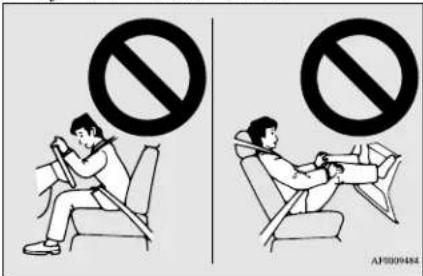

WARNING
- Infants and small children should never ride unrestrained, or lean against the instrument panel. They should never ride held in your arms or on your lap. They can be seriously injured or accident, especially when the airbags inflate. Seat all infants and children in the rear seat, properly restrained in an appropriate child restraint system. Refer to "Child restraint systems" on page 4-15.
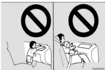
Supplemental Restraint System (SRS) - airbag
WARNING
- NEVER put REAR-FACING CHILD RESTRAINT SYSTEMS or INFANT RESTRAINT SYSTEMS in the front passenger seat. This places the infant too close to the passenger's airbag. During deployment of that airbag, the infant can be seriously injured or killed. Rear-facing child restraint systems or infant restraint systems must only be used in the rear seat.
WARNING
- FRONT-FACING CHILD RESTRAINT SYSTEMS should be used in the rear seat whenever possible. If they must be used in the front passenger seat, move the seat the most rearward position and make sure the child stays in the child restraint system, properly restrained. Failure to follow these instructions could result in serious injury or death to the child.
How the Supplemental Restraint System works
ND04078D1574
The SRS includes the following components: cat to
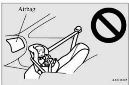
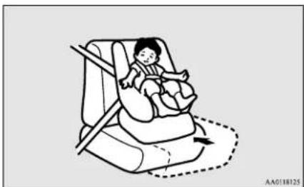
natural_image
Illustration of a baby car seatbelt with a dashed arrow indicating motion (no text or symbols)WARNING
- Older children should be seated in the rear seat with their seat belt properly worn, and with an appropriate booster seat if needed. Refer to "Children who have outgrown child restraint systems" on page 4-25.
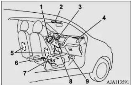
1- Airbag module (Driver)
2- Passenger's airbag off indicator
3- SRS warning light
4- Airbag module (Passenger)
5- Side airbag modules
6- Driver's seat position sensor
7- Passenger's seat occupant classification sensor system
8- Airbag module (Driver's knee)
9- Airbag control unit
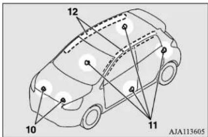
10- Front impact sensors
11- Side impact sensors
12- Curtain airbag modules
The airbag control unit monitors the readiness of the electronic parts of the system whenever the ignition switch or the operation mode is under the following conditions. These include all of the items listed above and all related wiring.
[Except for vehicles equipped with the F.A.S.T.-key]
The ignition switch is in the "ON" or "START" position.
[ Vehicles equipped with the F.A.S.T.-key]
The operation mode is in ON.
The airbags will operate under the same conditions as the airbag control unit.
When the impact sensors detect a sufficient front or side impact to deploy the airbag(s), the appropriate airbag(s) will be deployed.
When the airbag control unit detects rollover of the vehicle, curtain airbags will be deployed.
When airbags deploy, some smoke is released accompanied by a loud noise. The smoke is not harmful, but do not intentionally inhale the smoke as it may cause temporary irritation to people with respiratory problems.
An inflated airbag will deflate quickly, so you may not even notice that the airbag was inflated.
Airbag inflation does not prevent the driver from seeing or being able to steer the vehicle, and does not prevent people from leaving the vehicle.
CAUTION
- Airbags inflate very quickly and with great force. In certain situations, contact with an inflating airbag may cause small cuts, abrasions, and bruises.
Driver's seat position sensor
N00417900223
The driver's seat position sensor is attached to the seat rail and provides the airbag control
unit with information on the seat's fore-aft position. The airbag control unit controls deployment of the driver's front airbag in accordance with the information it receives from this sensor.
If there is a problem involving the driver's seat position sensor, the SRS warning light in the instrument panel will come on. Refer to "SRS warning light" on page 4-31.
WARNING
- If the SRS warning light comes on, have the vehicle inspected by an authorized Mitsubishi Motors dealer as soon as possible.
- Please observe the following instructions to ensure that the driver's seat position sensor can operate correctly.
- Adjust the seat to the correct position, and sit well back against the seatback. Refer to "Front seats" on page 4-3.
- Do not recline the seatback more than necessary when driving.
- Do not place metallic objects or luggage under the front seat.
- If the vehicle is involved in a severe impact, have the SRS sensor inspected by an authorized Mitsubishi Motors dealer as soon as possible.
Supplemental Restraint System (SRS) - airbag
Passenger's seat occupant classification sensor system
N00418000364
The passenger's seat occupant classification sensor system is attached to the front passenger seat cushion and provides the airbag control unit with information regarding the occupant on the front passenger seat. The airbag control unit controls deployment of the passenger's front airbag in accordance with the information it receives from this system. The passenger's front airbag will not deploy in an impact when the system senses no occupant on the front passenger seat or a child in a child restraint system. In this case, the passenger's airbag off indicator will illuminate. Refer to "Passenger's airbag off indicator" on page 4-30.
If there is a problem involving the passenger's seat occupant classification sensor system, the SRS warning light in the instrument panel will come on.
Refer to "SRS warning light" page 4-31.
WARNING
- If any of the following conditions occur, you should immediately have your vehicle inspected by an authorized Mitsubishi Motors dealer as soon as possible:
WARNING
- The SRS warning light does not initially come on when the ignition switch or operation mode is under the following conditions.
- [Except for vehicles equipped with the F.A.S.T.-key] The ignition switch is in the “ON” or “START” position.
[ Vehicles equipped with the F.A.S.T.-key] The operation mode is in ON.
• The SRS warning light does not go out after several seconds.
• The SRS warning light comes you are driving.
- To ensure that the passenger's seat pant classification sensor system can sense correctly, observe the following instructions. Failure to follow these instructions can adversely affect the performance of the passenger's airbag system.
- Adjust the seat to the correct position, and sit well back against the seatback. Refer to "Front seats" on page 4-3.
- Do not recline the seatback more than necessary.
- Never have more than one person (adult or child) sitting on the seat.
- Do not place anything between the seat and the floor console.
- When attaching a child restraint system, secure it firmly.
- Do not place luggage or other objects on the seat.
WARNING
- Do not use a seat cover or a cushion.
- Do not modify or replace the seat and seat belt.
- Do not place luggage or other objects under the seat.
- Do not place and use an electronic device such as a computer on the seat.
- Do not place heavy objects on the seat or stick pins, needles, or other objects into it.
- Do not remove the seat cushion skin.
- If any liquid is spilled on the seat, wipe it while and dry the seat immediately.
- If the vehicle is involved in a severe impact, have the SRS sensors inspected by an authorized Mitsubishi Motors dealer as soon as possible.
Passenger's airbag off indicator
N00418101359
The passenger's airbag off indicator is located at shown in the illustration.
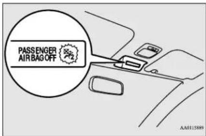
The indicator normally comes on when the ignition switch is turned to the "ON" position or the operation mode is put in ON, and goes out a few seconds later. In the following situations, the indicator will stay on to show that the passenger front airbag is not operational.
● The front passenger seat is not occupied.
● The system senses that a child is using a child restraint system on the front passenger seat.
When the passenger's seat occupant classification sensor system senses there is a person seated in the front passenger seat, the indicator goes out to show that the passenger's front airbag is operational.
WARNING
- If any of the following conditions occur, you should immediately have the airbag system in your vehicle inspected by an authorized Mitsubishi Motors dealer as soon as possible:
- The passenger's airbag off indicator comes on when an adult is sitting on the front passenger seat.
- The passenger's airbag off indicator does not come on when the front seat is not occupied.
- The passenger's airbag off indicator does not come on when the ignition switch is turned to the "ON" position or the operation mode is put in ON.
- The passenger's airbag off indicator does not come on when a child is in restraint system on the front passenger seat.
- The passenger's airbag off indicator comes on and goes out repeatedly.
- Do not attach any accessory to your uncle that makes the passenger's airbag off indicator difficult or impossible to see. You must be able to see the passenger's airbag off indicator and verify the status of the passenger's airbag system.
SRS warning light
N00408300579
There is a Supplemental Restraint System (SRS) warning light on the instrument panel.
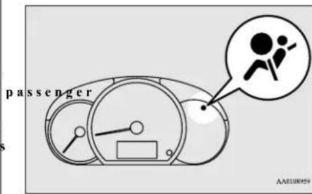
a The system checks itself every time the ignition switch is turned to the "ON" position or the operation mode is put in ON. The SRS warning light will come on for several seconds and then go out. This is normal and means the system is working properly.
If there is a problem involving one or more of the SRS components, the warning light will come on and stay on.
The SRS warning light is shared by the SRS airbag and the seat belt pre-tensioner system.
Supplemental Restraint System (SRS) - airbag
WARNING
- If any of the following conditions occur, there may be a problem with the SRS airbags and/or seat belt pre-tensioners, and they may not function properly in a collision or may suddenly activate without a collision:
• Even when the ignition switch or the operation mode is in ON, the SRS warning light does not come on or it remains on.
• The SRS warning light comes on driving.
The SRS airbags and seat belt pre-tensioners are designed to help reduce the risk of serious injury or death in certain collisions. If either of the above conditions occurs, immediately have your vehicle checked by an authorized Mitsubishi Motors dealer.
ger's airbag does not deploy when the front passenger seat is not occupied or when the system senses that a child is in the child restraint system.
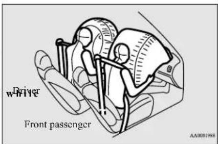
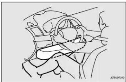
natural_image
Line drawing of a car interior showing steering wheel and dashboard (no text or symbols)Driver's and passenger's front airbag system
N00407900321
Driver's knee airbag system
N00404500036
The driver's knee airbag is located under the steering wheel. The driver's knee airbag is designed to deploy at the same time as the driver's front airbag.
The driver's airbag is located under the pad- ded cover in the middle of the steering wheel. The front passenger's airbag is contained in the instrument panel above the glove com- partment. The driver's airbag and the front passenger's airbag are designed to deploy at the same time. However, the front passen-
4-32 Seat and restraint systems
Deployment of front airbags
N00408001687
The front airbags and driver's knee airbag ARE DESIGNED TO DEPLOY when ...
Head-on collision with a solid wall at speeds of approx. 15 mph (25 km/h) or higher
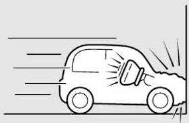
natural_image
Simple line drawing of a car speeding with motion lines indicating speed (no text or symbols)Moderate to severe frontal impact within the shaded area between the arrows
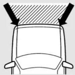
natural_image
Top-down diagram of a car head with arrows indicating airflow or movement (no text or symbols)AA1009095
The front airbags and driver's knee airbag are designed to deploy when the vehicle suffers a moderate to severe frontal impact. A typical condition is shown in the illustration to the left.
The front airbags and driver's knee airbag are designed to deploy only in certain moderate to severe frontal collisions within the shaded area between the arrows in the illustration to the right.
The front airbags and driver's knee airbag will deploy if the impact to the vehicle's main structure is above a specific threshold level. The threshold level is approximately 15 mph (25 km/h) for a frontal collision straight into a solid flat wall that does not bend or deform. If the impact to the vehicle's main structure is below this threshold level, the front airbags and driver's knee airbag may not deploy. This threshold level may also be higher if the vehicle hits something that absorbs the impact, either by bending or moving (for example,
another stationary vehicle, a pole or a guard rail).
The initial stage of airbag inflation is the most forceful, and can cause serious injury or death if you are too close to the deploying airbag. Accordingly, it is important that you always wear the available seat belt.
Supplemental Restraint System (SRS) - airbag
The front airbags and driver's knee airbag MAY NOT DEPLOY when ...
In certain types of front collisions, the front airbags and driver's knee airbag may not deploy, even if the deformation of the body seems to be large, because the vehicle's body structure is designed to absorb the impact and deform in order to help protect the occupants. Some typical situations where the front airbags and driver's knee airbag may not deploy are shown in the illustrations.
Since the front airbags and driver's knee airbag do not protect the occupant in all types of frontal collisions, be sure to always wear your seat belts properly.
Collision with a utility pole, tree or other narrow object
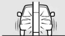
Collision where the vehicle slides under the rear body of a truck
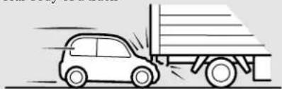
natural_image
Line drawing of a car moving on a flatbed truck (no text or symbols)Oblique frontal impact
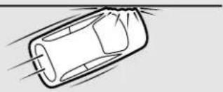
natural_image
Simple line drawing of a car with motion lines indicating speed or airflow (no text or symbols)The front airbags and driver's knee airbag ARE NOT DESIGNED TO DEPLOY when
...
The front airbags and driver's knee airbag are not designed to deploy in situations where
they cannot provide protection to the occupants.
Some typical situations are shown in the illustration.
Since the front airbags and driver's knee airbag do not protect the occupants in all types of collisions, be sure to always wear your seat belts properly.
Rear end collision to your vehicle
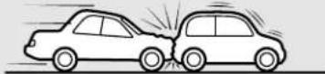
Side collision to your vehicle
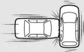
natural_image
Top-down line drawing of a car with two cars, one moving right and one on the side (no text or symbols)Vehicle rolls onto its side or roof
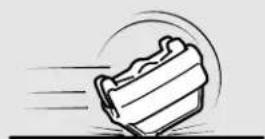
AA2002237
The front airbags and driver's knee airbag MAY DEPLOY when
...
The front airbags and driver's knee airbag may deploy if the underside of the vehicle suffers a moderate to severe impact (undercarriage impact). Some typical situations are shown in the illustration.
Since the front airbags and driver's knee airbag may deploy in certain types of unexpected impacts, as shown in the illustrations, and these unexpected impacts can move you out of position, it is important to always wear your seat belts properly. When worn properly, seat belts can help maintain your distance from the airbags when they begin to inflate. The initial stage of airbag inflation is the most forceful and can cause serious injury or death if you are close to the deploying airbag.
Collision with an elevated median/island or curb
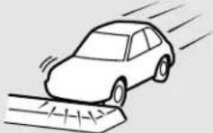
Vehicle travels over a deep hole/pothole
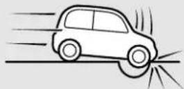
Vehicle drives down a steep slope and hits the ground
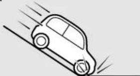
natural_image
Simple line drawing of a car on a slope with motion lines (no text or symbols)WARNING
- Do not attach anything to the steering wheel's padded cover, such as trim material, badges, etc. These could strike and injure an occupant if the airbag inflates.
- Do not set anything on, or attach anything to, the instrument panel above the glove compartment. Such items could strike and injure an occupant if the airbag inflates.
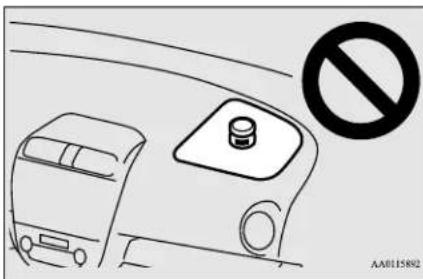
WARNING
- Do not attach accessories to, or put them in front of, the windshield. The restrict the airbag inflation, or strike and injure an occupant, when the airbag inflates.
- Do not attach additional keys or accessories (hard, pointed or heavy objects) to the ignition key. Such objects could prove the driver's knee airbag from inflating normally or could be propelled to cause serious injury if the airbag inflates.
- Do not attach accessories to the lower portion of the driver's side instrument panel. Such objects could prevent the driver's knee airbag from inflating normally or could be propelled to cause serious injury if the airbag inflates.
Supplemental Restraint System (SRS) - airbag
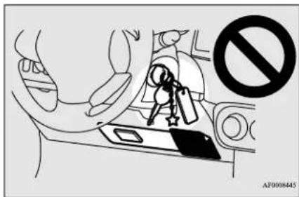
WARNING
- Do not attempt to remove, install, disassemble or repair the SRS airbags.
- Do not place objects, such as packages pets, between the airbags and the driver or the front passenger. Such objects can adversely affect airbag performance, or cause serious injury or death when the airbag deploys.
- Immediately after airbag inflation, some parts of the airbag system will be hot. Do not touch them. You could otherwise be burned.
- The airbag system is designed to work only once. After the airbags deploy, they will not work again. They must promptly be replaced and the entire airbag system must be inspected by an authorized Mitsubishi Motors dealer.
Side airbag system Curtain airbag system
N0040810042
The side airbags (A) are contained in the driver and front passenger seatbacks.
The side airbag is designed to inflate only on the side of the vehicle that is impacted, even with no passenger in the front seat.
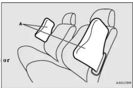
A label is attached to the seatbacks in vehicles equipped with side airbags.
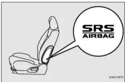
N00419201344
The curtain airbags are contained in the front pillars and roof side rail.
The curtain airbag is designed to inflate only on the side of the vehicle that is impacted, even with no passenger in the seat.
Also, when the airbag control unit detects rollover of the vehicle, the curtain airbags will deploy.
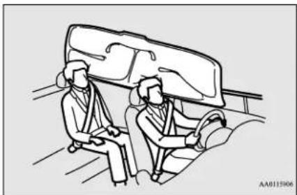
natural_image
Line drawing of two people seated in a car, one wearing headphones, with no visible text or symbolsWARNING
- The side airbags and curtain airbags can cause serious injury or death to anyone too close to the airbag when it deploys. To reduce the risk of injury from a deploying side airbag and curtain airbag, all occupants must be properly restrained and seated well back, upright, and in the middle of the seat. Do not lean against the door.
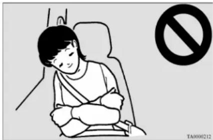
WARNING
- In order to reduce the risk of injury from a deploying side airbag, do not allow any rear seat passengers to hold onto the back of either front seat. Special care should be taken with children.
- Do not place any objects around the where the side airbags deploy. Such objects can interfere with proper side airbag deployment, and cause injury during deployment of the side airbag.
- Do not place stickers, labels or ad trim on the back of either front seat. They can interfere with proper side airbag deployment.
WARNING
- Do not attach a microphone other object around the part where the curtain airbag deploys, such as on the windshield, side door glass or rear pillars and roof side rail. A curtain airbag inflates, the microphone or other object may be hurled with great force or the curtain airbag may not inflate correctly, resulting in death or serious injury.
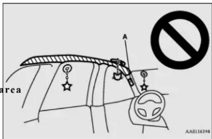
WARNING
- Do not install seat covers or re-cover seats that have side airbags. Covers can interfere with proper side airbag deployment and adversely affect side airbag performance.
- Never install a rear-facing child restraint system in the front passenger seat. Rear-facing child restraint systems MUST ONLY be used in the rear seat.
WARNING
(A) ●Front-facing child restraint systems should also be used ONLY in the rear seat. If a front-facing child restraint system front must be used in the front passenger seat,
When theve the seat as far back as possible, and make sure that the child stays in the ch restraint system, properly restrained and away from the door.
- Do not allow a child to lean against or sit close to the passenger door, even if the child is seated in a child restraint system. The child's head should also not lean against or be close to the section of the seatback where the side airbag and curtain airbag are located. It is dangerous if the side airbag or curtain airbag deploys. Failure to follow all of these instructions could lead to serious injury or death to the child.
- Work done on or in the vicinity of the side airbag or curtain airbag components should be done only by an authorized Mitsubishi Motors dealer. There is of a serious injury or death. Improper work methods can cause accidental side airbag or curtain airbag deployment, or render a side airbag or curtain airbag inoperable. Either of these situations could result in serious injury or death.
is a risl
Supplemental Restraint System (SRS) - airbag
WARNING
- Do not place luggage heavier than the specified on the roof carrier. Such luggage may cause the curtain air bags to inflate accidentally, which could result in serious injury or death.
Deployment of side airbag and curtain airbag
N00408201634
The side airbag and curtain airbag ARE DESIGNED TO DEPLOY when...
The side airbag and curtain airbag are designed to deploy when the vehicle suffers a moderate to severe side impact to the middle of the passenger compartment. Also when the vehicle detects rollover of the vehicle, the curtain airbags will deploy. Typical situations are shown in the illustration.
Moderate to severe impact to the middle of the vehicle body's side structure
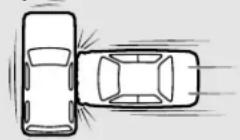
When the vehicle detects rollover of the vehicle (Curtain airbag only)
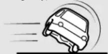
The seat belts in your vehicle are your primary means of protection in an accident. The SRS side airbags and curtain airbags are designed to provide additional protection. Therefore, for your safety and the safety of all occupants, be sure to always wear your seat belts properly.
The side airbag and curtain airbag MAY NOT DEPLOY when...
In certain types of side collisions, the side airbag and curtain airbag may not deploy, even if the deformation of the body seems to be large, because the vehicle's body structure is designed to absorb the impact and to deform in order to help protect the occupants. There
are also cases where the side airbag and curtain airbag may not deploy at the same time, depending on the location of the impact. Some typical situations where the side airbags and curtain airbags may not deploy are shown in the illustrations on the following page.
Since the side airbags and curtain airbags do not protect the occupant in all types of side collisions, be sure to always wear the seat belts properly.
Side impact in an area away from the passenger compartment
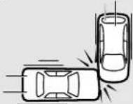
Motorcycle or other similar small vehicle collision with the side of vehicle
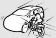
Collision with a utility pole, tree or other narrow object
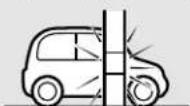
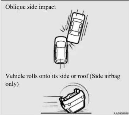
The side airbag and curtain airbag ARE NOT DESIGNED TO DEPLOY when...
The side airbag and curtain airbag are not designed to deploy in situations where they cannot provide protection to the occupants. Some typical situations are shown in the illustration.
Since the side airbags and curtain airbags do not protect the occupant in all types of collisions, be sure to always wear your seat belts properly.
Head-on collision
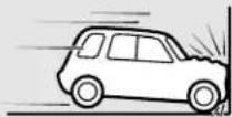
Rear end collision to your vehicle
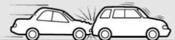
Pitch end over end
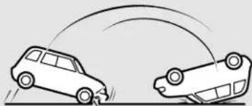
natural_image
Diagram showing two cars in motion with curved trajectory lines (no text or symbols)AG2000299
Supplemental Restraint System (SRS) - airbag
SRS servicing
N00408501800
WARNING
- Any maintenance performed on or near the components of the SRS should be performed only by an authorized Mitsubishi Motors dealer. Do not permit anyone else to do any service, inspection, maintenance or repair on any SRS components or wiring. Similarly, no part of the SRS's ever be handled, removed or disposed by anyone except an authorized Mitsubishi Motors dealer.
Improper work methods on the SRS components or wiring could result in an accidental airbag deployment or could make the SRS inoperable. Either of these situations could result in serious injury or death. - Do not modify your steering wheel or any other SRS component or related vehicle part. For example, replacement of the steering wheel, or modifications to the front bumper or body structure can adversely affect SRS performance and may lead to injury.
- If your vehicle has received any damage, you should have the SRS inspected by an authorized Mitsubishi Motors dealer to make sure it is in proper working order.
WARNING
- Do not modify your front seats, center pillar or center console. Such modifications can adversely affect SRS performance and may lead to injury.
Also, if you discover any tear or open scam in the seat fabric near the side airbag, have the seat inspected by an authorized Mitsubishi Motors dealer. - If you have found any scratch, crack or should damage to the portion of the front and rear pillars and roof side rail, you should have the SRS inspected by an author Mitsubishi Motors dealer.
NOTE
- When you transfer ownership of the vehicle to another person, we urge you to alert the new owner that it is equipped with the SRS and refer that owner to the applicable sections in this owner's manual.
- If you decide to junk or scrap your vehicle, we urge you to first take it to an authorized Mitsubishi Motors dealer so that the SRS can be made safe for disposal.
- If any of the following parts needs to be modified for use by a handicapped person, the advanced airbag system will be greatly affected. Please consult an authorized Mitsubishi Motors dealer.
- Driver's seat
- Front passenger seat
- Front seat belt
NOTE
- Steering wheel
- Instrument panel
[For vehicles sold in U.S.A.]
To contact Mitsubishi Motors North America, Inc.
call 1-888-648-7820 or write to:
Mitsubishi Motors North America, Inc.
Customer Relations Department
P.O. Box 689040
Franklin, TN 37068
[For vehicles sold in Canada]
To contact Mitsubishi Motor Sales of Canada, Inc.
call 1-888-576-4878 or write to:
Mitsubishi Motor Sales of Canada, Inc.
Customer Relations Department
P.O. Box 41009
4141 Dixie Road
Mississauga, ON L4W 5C9
[For vehicles sold in Puerto Rico]
To contact Mitsubishi Motor Sales of Caribbean, Inc.
call 1-787-251-8715 or write to:
Mitsubishi Motor Sales of Caribbean, Inc.
Customer Service Department P.O. Box 192216
SAN JUAN PR 00919-2216
[For vehicles sold in Guam]
To contact Triple J Enterprises Inc.
call (671) 649-3673 or write to:
Triple J Enterprises, Inc.
P.O. Box 6066
TAMUNING
GUAM 96931
[For vehicles sold in Saipan]
To contact Triple J Motors
call (670) 234-7133 or write to:
Triple J Motors
P.O. Box 500487
SAIPAN, MP96950-0487
[For vehicles sold in American Samoa]
To contact Pacific Marketing Inc. call 684 (699) 9140 or write to:
Pacific Marketing, Inc.
P.O. Box 698
PAGO PAGO,
AMERICAN SAMOA AS, 96799
Warning label
N00408600383
Occupant restraint warning labels for the SRS are located in the vehicle as shown in the illustration.
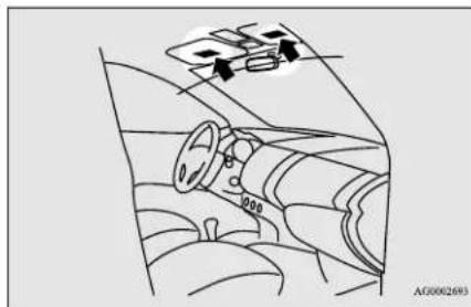
natural_image
Interior view of a car dashboard with steering wheel and steering wheel (no text or symbols visible)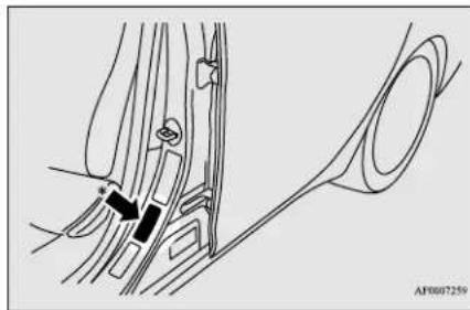
natural_image
Medical illustration showing anatomical structures with no visible text or symbols* - Located in the passenger's side as well.
| 100% | |
| 100% | 100% |
| 100% | 100% |
| 100% | 100% |
| 100% | 100% |
| 100% | 100% |
| 100% | 100% |
| 100% | 100% |
| 100% | 100% |
| 100% | 10 |
Features and controls
Break-in recommendations 5-2
Keys 5-2
Electronic immobilizer (Anti-theft starting system) 5-3
Keyless entry system (if so equipped) 5-6
Free-hand Advanced Security Transmitter (F.A.S.T.-key) (if so equipped) 5-9
Door locks 5-26
Power door locks 5-27
Child safety locks for rear door 5-29
Liftgate 5-29
Manual window control (if so equipped)....5-31
Power window control 5-31
Parking brake 5-34
Steering wheel height adjustment 5-35
Inside rearview mirror 5-35
Outside rearview mirrors 5-37
Ignition switch 5-38
Starting the engine 5-39
Manual transaxle (if so equipped) 5-41
Continuously variable transmission (CVT) (if so equipped)......5-43
Service brake 5-48
Hill start assist 5-49
Brake assist system 5-50
Anti-lock braking system 5-51
Electric power steering system (EPS) 5-52
Active stability control (ASC) 5-53
Cruise control (if so equipped) 5-56
Forward Collision Mitigation system (FCM) (if so equipped).....5-60
Lane Departure Warning (LDW) (if so equipped) 5-68
Tire pressure monitoring system (TPMS) (if so equipped)....5-71
Rear-view camera 5-74
Instrument cluster 5-77
Multi-information display 5-78
Indicator and warning light package 5-87
Indicators 5-88
Warning lights 5-88
Combination headlights and dimmer switch 5-91
Turn signal lever 5-96
Hazard warning flasher switch 5-97
Front fog light switch (if so equipped) 5-97
Wiper and washer switch 5-97
Electric rear window defogger switch 5-100
Horn switch 5-100
Link System 5-100
USB input terminal 5-101
Sun visors 5-102
12 V power outlets 5-103
Interior lights 5-103
Storage spaces 5-105
Cup holders 5-105
Bottle holders 5-106
Rear shelf panel (if so equipped) 5-106
Convenience hook 5-107
Assist grips 5-107
Break-in recommendations
Break-in recommendations
N00508701382
Advanced automobile manufacturing techniques permit you to operate your new vehicle without requiring a long break-in period of low-speed driving.
However, you can add to the future keep one in a safe place as a spare key.
mance and economy of your vehicle by observing the following precautions during the first 300 miles (500 km).
Drive your vehicle at moderate speeds during the break-in period.
- Avoid revving the engine.
- Avoid rough driving such as sudden starts, sudden acceleration, prolonged high-speed driving and sudden braking. These would have a detrimental effect on the engine and also cause increased fuel and oil consumption, which could result in malfunction of the engine components. Be particularly careful to avoid full acceleration while in low shift position (low gears).
- Do not overload the vehicle. Stay within the seating capacity. (Refer to "Cargo load precautions" on page 6-11.)
- Do not use this vehicle for trailer towing.
VS
NKG508801699
Type 1
Two keys are provided. The keys fit all locks. Keep one in a safe place as a spare key.
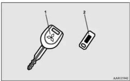
1- Key for the electronic immobilizer
2- Key number plate
Type 2
Two keys are provided. The keys fit all locks. Keep one in a safe place as a spare key.
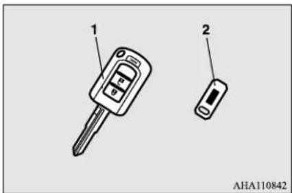
1- Key for the electronic immobilizer and keyless entry system
2- Key number plate
Type 3
Two F.A.S.T.-keys and two emergency keys are provided.
Keep one F.A.S.T.-key and one emergency key in a safe place together as a set of spare keys.
5-2 Features and controls
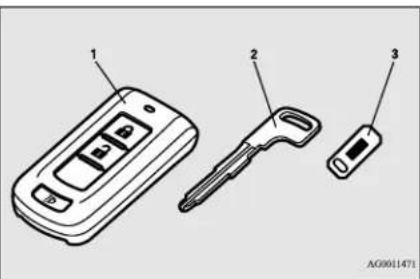
1-F.A.S.T.-key
(with electronic immobilizer and keyless entry system function)
2- Emergency key
3- Key number plate
NOTE
- The keyless entry key and F.A.S.T.-key are a precision electronic device with a built-in signal transmitter. Please observe the following in order to prevent damage.
- Do not leave where it may be exposed to heat caused by direct sunlight, such as on top of the dashboard.
- Do not take the remote control transmitter apart.
- Do not excessively bend the key or subject it to strong impacts.
- Keep the remote control transmitter dry.
- Keep away from magnetic objects such as key rings.
NOTE
- Keep away from devices that produce magnetism, such as audio systems, computers and televisions.
- Keep away from devices that emit strong electromagnetic waves, such as cellular phones, wireless devices and high frequency equipment (including medical devices).
- Do not clean with ultrasonic cleaners.
- Do not leave the key where it may be exposed to high temperature or high humidity.
- If you lose your key, to prevent the theft of the vehicle immediately contact an authorized Mitsubishi Motors dealer.
If you notify an authorized Mitsubishi Motors dealer of the key number, they can make a new key. The key number is stamped on the key number plate. Keep the key number plate in a safe place separate from the key itself.
- No keys other than those registered in advance can be used to start the engine. Refer to "Electronic immobilizer (Anti-theft starting system)" on page 5-3.
Refer to "Free-hand Advanced Security Transmitter (F.A.S.T.-key): "Electronic immobilizer (Anti-theft starting system)" on page 5-21.
NOTE
- When the theft-alarm is in the system operational status, the alarm operates if a door or liftgate is opened after using the key, the door lock knob or the power door lock switch to unlock the vehicle.
● The system does not enter the preparation status if the keyless entry system or the F.A.S.T.-key was not used to lock the vehicle.
Electronic immobilizer (Anti-theft starting system)
N00509101976
CAUTION
- Do not make any alterations or additions to the immobilizer system. Alterations or additions could cause failure of the immobilizer.
[For vehicles equipped with the Free-hand Advanced Security Transmitter (F.A.S.T.-key)]
For information on operations for vehicles equipped with the Free-hand Advanced Security Transmitter (F.A.S.T.-key), refer to "Free-hand Advanced Security Transmitter (F.A.S.T.-key): Electronic immobilizer (Anti-theft starting system)" on page 5-21.
Electronic immobilizer (Anti-theft starting system)
[Except for vehicles equipped with the Free-hand Advanced Security Transmitter (F.A.S.T.-key)]
The electronic immobilizer is designed to significantly reduce the possibility of vehicle theft. The purpose of the system is to immobilize the vehicle if an invalid start is attempted. A valid start attempt can only be achieved (subject to certain conditions) using a key "registered" to the immobilizer system. All of the keys provided with your new vehicle have been programmed to the vehicle's electronics.

NOTE
- In the following cases, the vehicle may not be able to recognize the registered ID code from the key. This means the engine will not start even when the key is turned to the "START" position.
- When the key contacts a key ring or other metallic or magnetic object
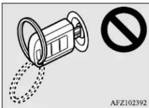

NOTE
- When the key grip contacts metal of another key
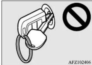
- When the key contacts or is close to other immobilizer keys (including keys of other vehicles)
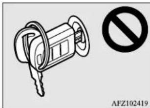
natural_image
Illustration of a key inserted into a lock with a no-smoking symbol (no text or labels)- In cases like the above, move the offending object(s) away from the key and turn the key back to the "ACC" or "OFF" position. Then try to start the engine again. If the engine does not start, contact an authorized Mitsubishi Motors dealer. - The key may not operate properly when it is near an object or facility that emits strong electromagnetic waves.

NOTE
● Electronic immobilizer is not compatible with commercially available remote starting systems. Use of commercially available remote starting systems may result in vehicle starting problems and a loss of security protection.
- A system failure is suspected when the ignition switch is turned to the "START" position, and the engine does not start. In such a case, contact an authorized Mitsubishi Motors dealer.
Replacement keys
Only keys that have been programmed to the vehicle's electronics can be used to start the vehicle.
If you lose the key, you can order a key from your authorized Mitsubishi Motors dealer by referring to the key number.
To prevent vehicle theft, the ID code for the vehicle keys must be changed.
Take your vehicle and all remaining keys to your authorized Mitsubishi Motors dealer to have your ID code changed.
Additional keys
To add a key, you must already have 2 registered keys. You need to register the ID code to the vehicle.
Registering the ID code can be done by yourself (except for vehicles sold in Canada), or by your authorized Mitsubishi Motors dealer. For you to register the ID code yourself, follow the "Customer key programming" procedure below.
If you choose to have your authorized Mitsubishi Motors dealer register the ID code, take your vehicle and all remaining keys to your authorized Mitsubishi Motors dealer.

NOTE
- You are provided with 2 keys, but you may register up to 8 keys.
Customer key programming (Except for vehicles sold in Canada)
NO0562201194
You can program new keys to the system if you have two valid (already registered) keys and blank immobilizer key (specially cut for
your vehicle at your Mitsubishi Motors dealer) by doing the following:
-
Insert the first valid key into the ignition switch and turn the key to the "ON" position for 5 seconds.
-
Turn the key to the "OFF" position and remove the first key.
-
Within 30 seconds of removing the first key, insert the second valid key into the ignition and turn it to the "ON" position. About 10 seconds later, the immobilizer indicator will start to blink.
-
When the immobilizer indicator starts blinking, turn the second valid key to the "OFF" position and remove it. Within 30 seconds after doing so, insert a blank immobilizer key into the ignition switch and turn it to the "ON" position. Perform this operation no more than 30 seconds after the immobilizer indicator starts blinking. When registration of the ID code is complete, the immobilizer indicator will come on for 3 seconds then go off. If an error occurs, the immobilizer indicator will go off during the procedure.
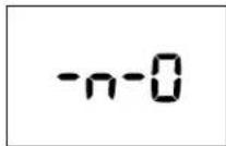

NOTE
- When the key registration is completed, the ion immobilizer indicator will come on within 3 seconds of turning the ignition switch to the "ON" position with the blank immobilizer key (specially cut for your vehicle at your Mitsubishi Motors dealer).
- If you wish to register another key, perform the process again from step 1.

NOTE
- It is not possible to register a key if: - the immobilizer indicator goes off during the procedure - the immobilizer indicator does not come on within 30 seconds after step 4.
● The procedure will be terminated automatically if:
- a period of 30 seconds or longer elapses from the moment when the turned to the "OFF" position to the moment when the second key is turned to the "ON" position
- a period of 30 seconds or longer elapses from the moment when the second key is turned to the "OFF" position to the moment when the blank immobilizer key is turned to the "ON" position
- more than 20 seconds elapses after the immobilizer indicator starts blinking
first
Keyless entry system (if so equipped)
General information
N00562300097
Your electronic immobilizer operates on a radio frequency subject to Federal Communications Commission (FCC) Rules (For vehicles sold in U.S.A.) and Industry Canada Rules (For vehicles sold in Canada). This device complies with part 15 of FCC Rules and Industry Canada licence-exempt RSS standard(s).
Operation is subject to the following two conditions.
- This device may not cause harmful interference.
● This device must accept any interference received, including interference that may cause undesired operation of this device.
WARNING
- Changes or modifications not expressly approved by the party responsible for compliance could void the user's authority to operate the equipment.
Keyless entry system (if so equipped)
N00509002103
Press the remote control transmitter buttons to lock or unlock the doors and the liftgate. It can also help you signal for attention by setting off the panic alarm.
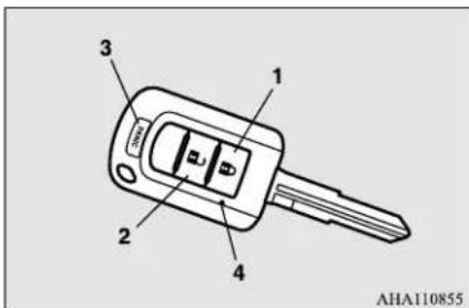
1- LOCK (button
2- UNLOCK (button
3- PANIC button
4- Indicator light
To lock
Press the LOCK button (1) to lock all the doors and the liftgate.
The turn signal lights will also blink once.

NOTE
- If you press the LOCK button (1) twice the horn will sound once.
To unlock
Press the UNLOCK button (2) to unlock the driver's door only.
Within about 2 seconds, press the UNLOCK button one more time to unlock all the doors and liftgate.
The dome light will turn on for 30 seconds. The turn signal lights will also blink twice.

NOTE
- If the UNLOCK switch (2) is pressed and no door or liftgate is opened within approximately 30 seconds, relocking will automatically occur.
- The amount of time after unlocking until the vehicle relocks automatically can be adjusted. See an authorized Mitsubishi Motors dealer for details.
Answerback function
The horn of the keyless entry system answer-back function can be changed as required.
This is done with the key removed from the ignition switch.

NOTE
- The answerback function will not operate if any of the doors are open.
Horn deactivation/reactivation
The answerback function can be set in the following three ways.
Each time the answerback function is set, a chime will sound to tell you the condition of the answerback function.
One chime: The horn will not sound.
Two chimes: The horn will sound.
Four chimes: The horn will sound if the LOCK button is pressed twice within 1 second.
- Remove the key from the ignition switch.
- Open the driver's door and turn the combination headlights and dimmer switch to the "OFF" position.
-
Press the LOCK button (1) for 4 to 10 seconds and press the UNLOCK button (2) during this time.
-
Release in sequence the UNLOCK and LOCK buttons within 10 seconds of pressing the UNLOCK button in step 3.
Turn signal lights deactivation/reactivation
The turn signal lights answerback function can be changed.
If you want to change the answerback function, please contact an authorized Mitsubishi Motors dealer.
Using the panic alarm
N00543701099
If you are near your vehicle and feel threatened, you may activate the alarm to call attention as follows:
- Press the PANIC button (3) for more than 1 second.
- The headlights will blink on and off and the horn will sound intermittently for about 3 minutes.
- To turn off the alarm, press any button on the remote control transmitter.
Replacement remote control transmitters
N010543800051
Only remote control transmitters programmed with the vehicle's electronic lock or unlock all doors and the liftgate.
If you lose the remote control transmitter, you can order a remote control transmitter from your authorized Mitsubishi Motors dealer by referring to the key number.
To prevent vehicle theft, the ID code for the remote control transmitter must be changed.
Take your vehicle and all remote control transmitters to your authorized Mitsubishi Motors dealer to have your ID code changed.
Additional remote control transmitters
N00543900078
To add a remote control transmitter, you must already have 1 registered remote control transmitter.
Registering the ID code can be done by your authorized Mitsubishi Motors dealer.
Take your vehicle and any remaining keys to your authorized Mitsubishi Motors dealer.
Keyless entry system (if so equipped)

NOTE
- You are provided with 2 remote control transmitters, but you may register up to 4 remote control transmitters.
Procedure for replacing the remote control transmitter battery
NK1544101276
General information
N00546100114
Your keyless entry system operates on a radio frequency subject to Federal Communications Commission (FCC) Rules (For vehicles sold in U.S.A.) and Industry Canada Rules (For vehicles sold in Canada). This device complices with Part 15 of FCC Rules and Industry Canada licence-exempt RSS standard(s).
Operation is subject to the following two conditions.
● This device may not cause harmful interference.
● This device must accept any interference received, including interference that may cause undesired operation of this device.

WARNING
- Changes or modifications not expressly approved by the party responsible for compliance could void the user's authority to operate the equipment.

WARNING
- Do not swallow a coin type battery.
- This product contains coin type battery. If a coin type battery is swallowed, it can cause severe internal burns and can lead to death.
There have been cases where a swallowed battery has caused severe internal burns in just 2 hours. - Keep new and used batteries away from children.
- If the remote control transmitter case does not close securely, st product and keep it away from children.
- If you think batteries might swallowed or placed inside any part of a person's body, seek immediate medical attention.
● To prevent an explosion or leakage of flammable liquid or gas: - Do not replace the battery with an incorrect type. Replace only with the same or equivalent type.
- Do not dispose of a battery into a fire or incinerator, or by mechanically crushing or cutting the battery.

WARNING
- Do not use, store, or take a battery any place where it may be exposed to extremely high temperature or extremely low air pressure.

CAUTION
- When the remote control transmitter case is opened, be careful to keep water, dust, etc. out. Also, do not touch the internal components.
-
Dispose of used battery according to regulations for the disposal of battery.
-
Before replacing the battery, remove static electricity from your body by touching a u social grounded object.
- Remove the screw (A) from the remote have control transmitter.
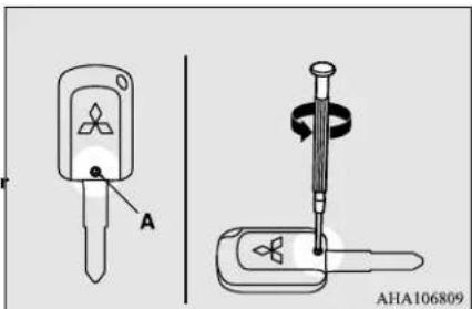
Free-hand Advanced Security Transmitter (F.A.S.T.-key) (if so equipped)
- With the Mitsubishi mark facing you, insert the cloth-cov-ered tip of a flat blade screwdriver into the notch in the remote control transmitter case and use it to open the case.
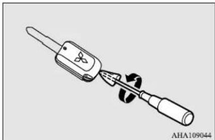
natural_image
Illustration of a screwdriver with a handle and screwdriver tip, no text or symbols present
NOTE
● The Federal Communications Commission (FCC) ID number, the Industry Canada (IC) number and the model number (radio certification) are indicated in the illustrated position.
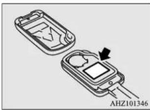
natural_image
Two electronic devices with a central display and an arrow indicating a component (no text or symbols visible)- Check the keyless entry system to see that it works.

NOTE
- You may purchase a replacement battery an electric appliance store.
● An authorized Mitsubishi Motors dealer can replace the battery for you if you prefer.
Free-hand Advanced Security Transmitter (F.A.S.T.-key) (if so equipped)
N00503101248

NOTE
- Be sure to perform the procedure with the Mitsubishi mark facing you. If the Mitsubishi mark is not facing you when you open the remote control transmitter case, the buttons may come out.
-
Remove the used battery.
-
Install a new battery with the + side (B) up.
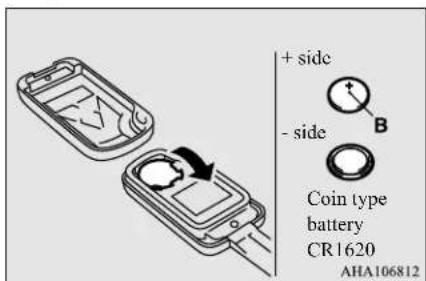
- Close the remote control transmitter firmly.
- Attach the screw (A) removed in step 2.
The Free-hand Advanced Security Transmitter (F.A.S.T.-key) enables the doors and the liftgate to be locked and unlocked, the engine to be started and the operation mode to be changed simply by carrying it.
The F.A.S.T.-key can also be us remote control transmitter of the keyless entry system.
Refer to "Free-hand Advanced Security Transmitter (F.A.S.T.-key): Keyless entry system" on page 5-22.
Free-hand Advanced Security Transmitter (F.A.S.T.-key) (if so equipped)
The F.A.S.T.-key must be carried by the driver. The F.A.S.T.-key is required for vehicle operations such as locking and unlocking the doors and the liftgate, starting the engine, and changing the operation mode. When leaving the vehicle, make sure you are carrying the F.A.S.T.-key and then lock the vehicle.
WARNING
- Individuals who use implantable pacemakers or implantable cardiovascular-defibrillators should keep away from the external and internal transmitters. The electromagnetic waves used in the F.A.S.T.-key may affect the operation of implantable pacemakers and implantable cardiovascular-defibrillators.
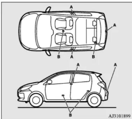
A- External transmitter
B- Internal transmitter
WARNING
- Individuals using other electro-medical apparatus besides implantable pacemakers and implantable cardiovascular-defibrillators should check with the manufacturer of the apparatus to confirm the effect of the electromagnetic waves used by the F.A.S.T.-key. The electromagnetic waves may affect the operations of the electro-medical apparatus.
The operations possible with the F.A.S.T.-key can be modified as stated below. (Keyless entry operations are possible.) For details, contact an authorized Mitsubishi Motors dealer.
- Enabling only the locking and unlocking of the doors and the liftgate
- Enabling only the starting of the engine
• Deactivating the F.A.S.T.-key
NOTE
● The F.A.S.T.-key uses weak electromagnetic waves.
In cases such as the following, operation may be improper or unstable.
• The vehicle is near a facility that emits strong electromagnetic waves, such as a TV transmitting tower, a power station, a radio station or an airport
• The key is carried together with other communication devices such as cellular phones or radios, or electrical appliances such as computers
• The F.A.S.T.-key touches or is covered by a metal object
- A keyless entry system is being used nearby
• The battery of the F.A.S.T.-key is run down
• The vehicle is in a location with strong electromagnetic waves or noise
Free-hand Advanced Security Transmitter (F.A.S.T.-key) (if so equipped)

NOTE
Use the emergency key in such circumstances.
Refer to "To operate without using the F.A.S.T.-key" on page 5-20.
- The F.A.S.T.-key is constantly performing reception operations in its communication with the vehicle. This means that the battery is always running down, regardless of how often the F.A.S.T.-key is used. The battery life is about 1 to 2 years, depending on the usage conditions.
- Since the F.A.S.T.-key is constantly performing reception operations, the reception of strong electromagnetic waves can accelerate the running down of the battery. Do not place near to electrical appliances such as televisions or computers.
Operating range of the FAST-key
N00503201294
When a person enters the operating range of the F.A.S.T.-key while carrying the F.A.S.T.-key and presses the driver's door lock/unlock switch the liflgate lock/unlock switch, verification of the ID code is performed.
The doors and the liftgate can only be locked and unlocked, the engine can only be started and the operation mode can only be changed when the I D codes of F.A.S.T.-key match.
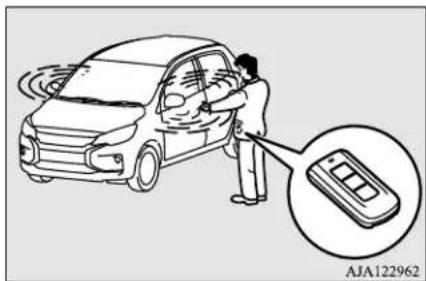

NOTE
- When the battery of the F.A.S.T.-key has run down or there are strong electromagnetic waves or noise in the area, the operating range could decrease or operate become unstable.
Operating range for locking and unlocking the doors and the lift-gate
The operating range is within about 2.3 feet (70 cm) of the driver's door lock/unlock switch and the liftgate lock/unlock switch.
the vehicle and
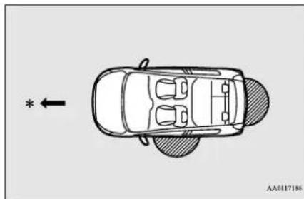
natural_image
Top-down diagram of a car with a directional arrow and an asterisk, no text or symbols present*: Front of the vehicle

Operating range

NOTE
● could Only the doors and the liftgate that detect the F.A.S.T.-key can be locked and unlocked.
- The system may not operate if the F.A.S.T. key is too close to the windshield, door windows or liftgate.
- Even if the F.A.S.T.-key is within about 2.3 feet (70 cm) of the driver's door lock/unlock switch or the liftgate lock/unlock switch, the system may not operate if the key is close to the ground or in a high position.
- If the F.A.S.T.-key is within the operating range, even a person not carrying the F.A.S.T.-key can lock and unlock the doors or the liftgate by pressing the driver's door lock/unlock switch or the liftgate lock/unlock switch.
Free-hand Advanced Security Transmitter (F.A.S.T.-key) (if so equipped)
Operating range for starting the engine and changing the operation mode
N00503300070
The operating range is the interior of the vehicle.
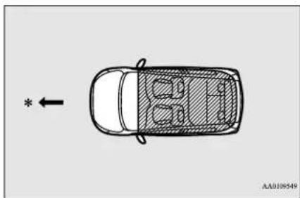
natural_image
Top-down line drawing of a car with a directional arrow and a vehicle interior (no text or symbols)*: Front of the vehicle

Operating range

NOTE
- Even if the F.A.S.T.-key is within the operating range, it may not be possible to start the engine and change the operation mode if the key is in a storage space such as the glove compartment, on top of the instrument panel, or in the door pocket or luggage compartment.

NOTE
- Even if the F.A.S.T.-key is inside the vehicle, it may not be possible to start the engine and change the operation mode if the key is too close to a door or door window.
To operate using the F.A.S.T.-key
N00503401515
To lock
While carrying the F.A.S.T.-key, press the driver's door lock/unlock switch (A), or the liftgate lock/unlock switch (B) within the operating range to lock all the doors and the liftgate.
The turn signal lights will blink once and the buzzer will sound once.
Also refer to "Doors locks", "Power door locks" and "Liftgate" on pages 5-26, 5-27 and 5-29 respectively.
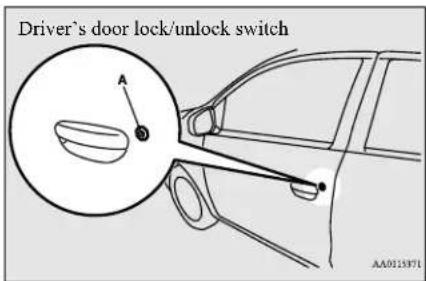
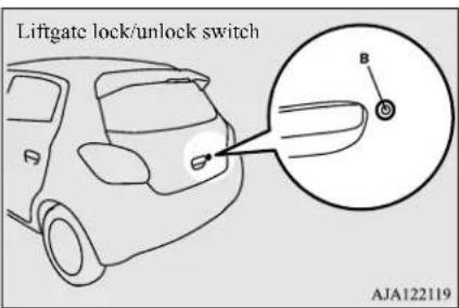

NOTE
- In cases such as the following, the F.A.S.T. key does not operate.
- There is a F.A.S.T.-key in the passenger compartment
• A door or the liftgate is open or ajar
• The operation mode is not in OFF. - The time within which locking confirmation is possible can be adjusted. See an authorized Mitsubishi Motors dealer for details.
5-12 Features and controls
To unlock
While carrying the F.A.S.T.-key within the operating range, you can unlock the doors and the liftgate by using the F.A.S.T.-key. The dome light will turn on for 30 seconds. The turn signal lights will blink twice and the buzzer will sound twice.
Also refer to "Door locks", "Power door locks" and "Liftgate" on pages 5-26, 5-27 and 5-29 respectively.
Press the driver's door lock/unlock switch (A) to unlock only the driver's door. Within about 2 seconds, press the driver's door lock/unlock switch one more time to unlock all the doors and the liftgate.
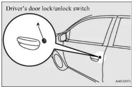

NOTE
- Settings can be changed so that all doors and the liftgate are unlocked automatically by pressing the driver's door lock/unlock switch once. See an authorized Mitsubishi Motors dealer for details.
Press the liftgate lock/unlock switch (B) to unlock all the doors and the liftgate.
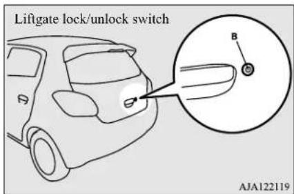

NOTE
- If the doors and the liftgate are unlocked using the driver's door lock/unlock switch when all doors and the liftgate are locked and no doors or the liftgate are opened within about 30 seconds, the doors and the liftgate will automatically re-lock.

NOTE
- The amount of time after unlocking until the vehicle relocks automatically can be adjusted. See an authorized Mitsubishi Motors dealer for details.
- In cases such as the following, the F.A.S.T. key does not operate.
• The operation mode is not in OFF.
● Functions settings can be modified as stated below.
See an authorized Mitsubishi Motors dealer for details. - Activating the operation confirmation function (blinking of the turn signal lights) only during locking, or only during unlocking.
- Deactivating the operation confirmation function (blinking of the turn signal lights) and buzzer.
- Modifying the number of blinks in the operation confirmation function (blinking of the turn signal lights).
- Making the buzzer sound when the F.A.S.T.-key is removed from the passenger compartment when all the doors and the liftgate are closed.
Free-hand Advanced Security Transmitter (F.A.S.T.-key) (if so equipped)
Engine switch
N00513501173
To prevent vehicle theft, no other than those registered in advance can be used to start the engine. (Electronic immobilizer function)
While carrying the F.A.S.T.-key, the engine switch can be used to start the engine.
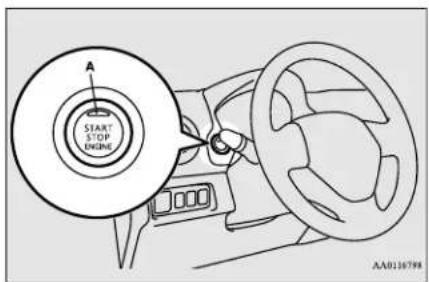
CAUTION
- The indicator light (A) will flash orange when there is a problem or malfunction in Free-hand Advanced Security Transmitter. Never drive if the indicator light on the engine switch is flashing orange. Immediately contact your authorized Mitsubishi Motors dealer.
CAUTION
- If the engine switch operation is not smooth F and feels like it is sticking, do not operate the switch. Immediately contact an authorized Mitsubishi Motors dealer.
NOTE
- When operating the engine switch, press the switch all the way in. If the switch is not fully pressed, the engine may not start or the operation mode may not change. If the engine switch is pressed correctly, there is no need to hold the engine switch down. - When the battery in the F.A.S.T.-key has worn out, or taking the F.A.S.T.-key out of the vehicle, a warning lamp will blink for 5 seconds.
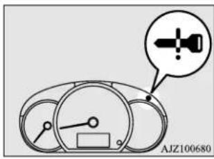
Operation mode of the engine switch and its function
OFF
The indicator light on the engine switch turns off.
The operation mode cannot be put in OFF when the selector lever is in any position other than the "P" (PARK) position.
ACC
Allows operation of some electrical accessories.
The indicator light on the engine switch illuminates orange.
ON
All electrical accessories can be used.
The indicator light on the engine switch illuminates green.
The indicator light turns off when the engine is running.
Free-hand Advanced Security Transmitter (F.A.S.T.-key) (if so equipped)

NOTE
- Your vehicle is equipped with an electronic immobilizer. To start the engine, the ID code which the F.A.S.T.-key sends must match the one registered to the immobilizer computer. (Refer to "Electronic immobilizer (Anti-theft starting system)" on page 5-21)
Changing the operation mode
N00568001178
If you press the engine switch without pressing the brake pedal while the vehicle is stationary, you can change the operation mode in the order of OFF, ACC, ON, OFF.
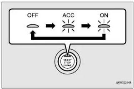
flowchart
graph TD
    A["OFF"] --> B["ACC"]
    B --> C["ON"]
    D["START STOP ONLINE"] --> B
CAUTION
- When the engine is not running, put the operation mode in OFF. Leaving the operation mode in ON or ACC for a long time when the engine is not running may cause the battery to be discharged, making it impossible to start the engine.
- When the battery is disconnected, the current operation mode is memorized. After reconnecting the battery, the memorized mode is selected automatically. Before disconnecting the battery for repair or replacement, make sure to put the operation mode in OFF. Be careful if you are not sure which operation mode the vehicle is in when the battery is run down.
- The operation mode cannot be changed from OFF to ACC or ON if the F.A.S.T.-key is not detected to be in the vehicle. Refer to "Operating range for starting the engine and changing the operation mode" on page 5-12.

NOTE
- If the operation mode cannot be changed to OFF, perform the following procedure.
- Move the selector lever to the "P" (PARK) position, and then change the operation mode to OFF. (For vehicles with continuously variable transmission (CVT))

NOTE
- One of the other causes could be low battery voltage. If this occurs, the keyless entry system and the F.A.S.T.-key operation will also not operate. Contact an authorized Mitsubishi Motors dealer.
ACC power auto-cutout function
N00568101049
When the vehicle is in ACC operation mode for approximately 30 minutes, the ACC power auto-cutout function automatically cuts power to the audio system and other electronic devices that can be used during ACC operation mode.
To enable power after ACC power auto-cut-out function, press the engine switch while in ACC.

NOTE
- It is possible to modify the functions as follows:
• The time until the power cuts out can be changed to approximately 60 minutes. - The ACC power auto-cutout function can be deactivated.
For details, we recommend you to consult an authorized Mitsubishi Motors dealer.
Free-hand Advanced Security Transmitter (F.A.S.T.-key) (if so equipped)
Warning activation
N00503501271
With the F.A.S.T.-key, warnings are given through buzzers and displayed symbols in order to prevent mistaken operations or vehicle theft.
When a warning operates, be sure to check the vehicle and the F.A.S.T.-key. A warning is also shown if there is a problem in the F.A.S.T.-key.
If the following warning shows, contact an authorized Mitsubishi Motors dealer.
| There is a problem in the F.A.S.T.key | |
| Put the operation mode in OFF and then start the engine again.If the warning is not cancelled, there is a fault in the electronic immobilizer (Anti-theft starting system).Please contact an authorized Mitsubishi Motors dealer. |
If the following warnings show, the light goes off if the correct action is taken.
- The ID codes of the F.A.S.T.-key and the vehicle cannot be verified
 | Someone may be carrying a F.A.S.T.-key with a different ID code, or the F.A.S.T.-key may not be within the operating range |
| Refer to “F.A.S.T.-key take-out monitoring system” on page 5-16. | |
 | The battery of the F.A.S.T.-key is run down |
- A door or the liftgate cannot be locked even when the driver's door lock/unlock switch or the liftgate lock/unlock switch is pressed.
Refer to "Key lock-in prevention system" on page 5-17.
Refer to "Door ajar prevention system" on page 5-17.
Refer to "Operation mode OFF reminder system" on page 5-17.
F.A.S.T.-key take-out monitoring system
N00559801196
When the operation mode is in any mode other than OFF, and a door is opened and the F.A.S.T.-key is removed from the passenger compartment the ID codes of the F.A.S.T.-key and the vehicle can no longer be verified. When the door is closed, the warning light blinks and the buzzer sounds 4 times as a warning. If the vehicle starts, the inner buzzer sounds once.

NOTE
- The F.A.S.T.-key take-out monitoring system does not function if the F.A.S.T.-key is removed through a window without opening a door.
This setting can be changed.
See an authorized Mitsubishi Motors dealer for details. - The warning may display even if the F.A.S.T.-key is in the operating range for starting the engine and changing the operation mode. The surrounding environment or electromagnetic waves may make it impossible to verify the ID codes of the F.A.S.T.-key and vehicle.
5-16 Features and controls
Key lock-in prevention system
N00559901171
When the operation mode is in OFF, the F.A.S.T.-key is left in the passenger compartment, all the doors and the liftgate are closed, and someone tries to lock t pressing the driver's door lock/unlock switch or the liftgate lock/unlock switch, the warning light blinks and the buzzer sounds for about 3 seconds as a warning, and the doors and the liftgate cannot be locked.
Door ajar prevention system
N00560001172
When the operation mode is in OFF, and someone tries to lock the vehicle by pressing the driver's door lock/unlock switch or the liftgate lock/unlock switch while one of doors or the liftgate is not fully closed, the warning light blinks and the buzzer sounds for about 3 seconds as a warning, and the doors and the liftgate cannot be locked.
Operation mode OFF reminder system
N00560101186
When the operation mode is in any mode other than OFF, and someone tries to lock the vehicle by pressing the driver's door lock/unlock switch or the liftgate lock/unlock switch, the warning light blinks and the buzzer sounds for about 3 seconds as a warning, and the doors and the liftgate cannot be locked.
Starting and stopping the engine
N00514601403
Tips for starting
- The operation mode can be in any mode to start the engine.
th● The starter motor will be turning for up to approximately 15 seconds if the engine switch is released at once. Pressing the engine switch again while the starter motor is still turning will stop the starter motor. The starter motor will be turning for up to approximately 30 seconds while the engine switch is pressed.
If the engine does not start, wait for a while and then attempt to start the engine again. Trying repeatedly with the starter motor still turning will damage the starter mechanism.
- If the engine will not start because the battery is weak or discharged, refer to "Jump-starting the engine" on page 8-2 for instructions.
- A longer warm up period will only consume extra fuel.
The engine is warmed up enough for driving when the low coolant temperature indicator goes out.
Refer to "Low coolant temperature indicator" on page 5-88.

WARNING
- Never run the engine in a closed or poorly ventilated area any longer than is needed to move your vehicle out of the area. Carbon monoxide gas, which is odorless and extremely poisonous, could build up and cause serious injury or death.

CAUTION
- Do not push-start the vehicle.
- Do not run the engine at high rpms or drive at high speeds until the engine has had a chance to warm up.
Free-hand Advanced Security Transmitter (F.A.S.T.-key) (if so equipped)
Starting the engine
Your vehicle is equipped with an electronically controlled fuel injection system. This is a system that automatically controls fuel injection. There is usually no need to depress the accelerator pedal when starting the engine.
To prevent battery drain, wait a few seconds between attempts to restart the engine. 5.1
- Make sure all occupants are properly seated with seat belts fastened.
- Make sure the parking brake is applied.
- Press and hold the brake pedal down firmly with your right foot.

NOTE
- After the engine has not started for a wh the brake pedal effort needed to start the engine may become greater. If this occurs depress the brake pedal more firmly than usual.
- Make sure the selector lever is in the "P" (PARK) position.

NOTE
-
The engine can only be started when the selector lever is in the “P” (PARK) (NEUTRAL) position.
For safety reasons, the engine should be started when the selector lever is in the "P" (PARK) position in which the driving wheels lock. -
Press the engine switch.
- Confirm that all warning lights and warning displays are functioning properly.

NOTE
● Minor noises may be heard on engine start-up. These will disappear as the engine warms up.
When the engine is hard to start
After several attempts, you may experience that the engine still does not start.
- Make sure that all electric devices, such as lights, air conditioning blower and rear window defogger, are turned off.
-
While depressing the brake pedal, press the accelerator pedal halfway and hold it there, then crank the engine. Release the accelerator pedal, immediately after the engine starts.
-
If the engine still will not start, the engine could be flooded with too much gasoline. While depressing the brake pedal, push or "N" the accelerator pedal all the way down and hold it there, then press the engine switch to crank the engine. If the engine does not start after 5 to 6 seconds, push the engine switch to stop cranking the engine, and release the accelerator pedal. Put the operation mode in OFF. Wait a few seconds, and then press the engine switch to crank the engine again while depressing the brake pedal, but do not push the accelerator pedal. If the engine fails to start, repeat these procedures. If the engine still will not start, contact your local Mitsubishi Motors dealer or a repair facility of your choice for assistance.
Startability of continuously variable transmission (CVT) vehicles with an ambient temperature of -4 °F (-20 °C) or lower
When the ambient temperature is -4 °F (-20 °C) or lower, it may not be possible to start from a standstill even with the selector lever in the “D” (DRIVE) or “R” (REVERSE) position.
This phenomenon occurs because the transaxle has not warmed up sufficiently; it does not indicate a problem. If this occurs, place the selector lever in the "P" (PARK) position and let the engine idle for at least 10 minutes.
Free-hand Advanced Security Transmitter (F.A.S.T.-key) (if so equipped)
The transaxle will warm up, and you will be able to start normally. Do not leave the vehicle during warm-up operation.
Stopping the engine
N00568201037

WARNING
- Do not operate the engine driving except in an emergency. If the engine is stopped while driving, the brake servomechanism will cease to function and braking efficiency will deteriorate. Also, the power steering system will not function and it will require gr effort to operate the steering. This could result in a serious accident.

NOTE
- If you have to bring the engine to an emergency stop while driving, press and hold the engine switch for 3 seconds or more, or press it quickly 3 times or more. The engine will stop and the operation mode will go to ACC.

NOTE
- Do not stop the engine with the selector lever in any position other than the "P" (PARK) position. If the engine is stopped with the selector lever in any position other than the "P" (PARK) position, the operation mode will go to ACC rather than OFF. Put the operation mode in OFF after placing the selector lever in the "P" (PARK) posi
switch while
- Stop the vehicle.
- Fully engage the parking brake while depressing the brake pedal.
- Move the selector lever to the "P" er (RanRak) position, and engine switch to stop the engine.
If the F.A.S.T.-key is not operating properly
N010568301126
Insert the F.A.S.T.-key into the key slot of the floor console. Starting the engine and changing the operation mode should be now possible.
Remove the F.A.S.T.-key from the key slot after starting the engine or changing the operation mode.
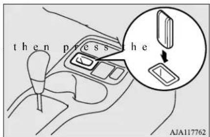

NOTE
- Do not insert into the key slot anything other than the F.A.S.T.-key. This could cause damage or a malfunction.
Free-hand Advanced Security Transmitter (F.A.S.T.-key) (if so equipped)

NOTE
- Remove the object or additional key from the F.A.S.T.-key before inserting the key into the key slot. The vehicle may not be able to receive the registered ID code from the registered key. Therefore, the engine may not start and the operation mode may not change.
● The F.A.S.T.-key is fixed in the key slot when inserted in the illustrated direction. Simply pull out the key to remove it from the key slot.
F.A.S.T.-key reminder
If the operation mode is in OFF and the driver's door is opened with the F.A.S.T.-key in the key slot, a warning is issued with warning light and the buzzer buzzing for approximately 3 seconds to remind you to remove the key.
To operate without using the F.A.S.T.-key
NK1514800017
Emergency key
N00515201174
The emergency key is built into the F.A.S.T.-key.
When the F.A.S.T.-key cannot be used, such as when the battery of the F.A.S.T.-key or the vehicle has run down, the emergency key can be used to lock and unlock the passenger's door.
To use the emergency key (A), lock knob (B) and remove it from the FAST Key (C).
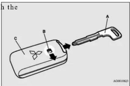

NOTE
- Only use the emergency key in an emergency. When the battery of the F.A.S.T.-key has run down, replace the battery as soon as possible and use it as a F.A.S.T.-key again.
● After using the emergency key, be sure to reinsert it into the F.A.S.T.-key.
Locking and unlocking the passenger's door
Turn the emergency key toward the front of the vehicle to lock the door. After checking that the door is locked, turn the emergency key back to the center and remove it.
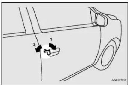
1-Lock
2- Unlock
Electronic immobilizer (Anti-theft starting system)
N00529600055
The electronic immobilizer is designed to significantly reduce the possibility of vehicle theft. The purpose of the system is to immobilize the vehicle if an invalid start is attempted. A valid start attempt can only be achieved (subject to certain conditions) using a F.A.S.T.-Key “registered” to the immobilizer system.
All of the keys provided with your new vehicle have been programmed to the vehicle's electronics.
Replacement F.A.S.T.-keys
N00561000042
Only the F.A.S.T.-keys that have been programmed to the vehicle's electronics can be used to start the vehicle.
If you lose the F.A.S.T.-key, you can order a F.A.S.T.-key from your authorized Mitsubishi Motors dealer by referring to the key number. To prevent vehicle theft, take your vehicle and the remaining F.A.S.T.-keys to an authorized Mitsubishi Motors dealer to have the ID codes reprogrammed.
Additional F.A.S.T.-keys
N00561100056
To add a F.A.S.T.-key, you must already have 2 registered F.A.S.T.-keys. You need to register the ID code to the vehicle.
Registering the ID code can be done by your authorized Mitsubishi Motors dealer. Or it can be done by yourself (except for vehicles sold in Canada).
For you to register the ID code yourself, follow the “Customer F.A.S.T.-key programming” procedure below.
If you choose to have your authorized Mitsubishi Motors dealer register the ID code, take your vehicle and all remaining F.A.S.T.-keys to your authorized Mitsubishi Motors dealer.

NOTE
- You are provided with 2 F.A.S.T.-keys, you may register up to 4 F.A.S.T.-keys. You can obtain blank F.A.S.T.-keys for your vehicle from your Mitsubishi Motors dealer.
Customer F.A.S.T.-key programming (Except for vehicles sold in Canada)
N00561201272
You can program new F.A.S.T.-keys to the system if you have two valid (already regis-
tered) F.A.S.T.-keys and blank (not registered) F.A.S.T.-key.
For F.A.S.T.-key programming, follow the procedures below.
- Open the driver's door.

NOTE
- Keep the driver's door open until F.A.S.T. key programming is finished. Do not open or close other doors.
- While carrying the first valid F.A.S.T.-key, put the operation mode in ON. (Perform the following procedure within 30 seconds.)
- Insert the new F.A.S.T.-key into the key slot.
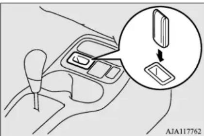
- With the first valid F.A.S.T.-key, press the UNLOCK button for 4 to 10 seconds and press the LOCK button during this time.
Features and controls 5-21
Free-hand Advanced Security Transmitter (F.A.S.T.-key) (if so equipped)
- Release in sequence the LOCK and UNLOCK buttons within 10 seconds of pressing the LOCK button in step 4. (Perform the following procedure seconds.)
- With the second valid F.A.S.T.-key, press the UNLOCK button for 4 to 10 seconds and press the LOCK button during this time.
- Release in sequence the LOCK and UNLOCK buttons within 10 seconds of pressing the LOCK button in step 6. The immobilizer warning light will blink.
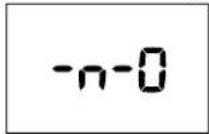
When registration of ID code is complete, the buzzer will sound 3 times and the immobilizer indicator will come on for 30 seconds.
If an error occurs, F.A.S.T.-key programming will be terminated and the buzzer will sound for 3 seconds.

NOTE
F.A.S.T.-key programming will be terminated if the operation mode is put in OFF before the immobilizer warning light starts blinking.
- If you wish to register another F.A.S.T.-key, repeat the process from step 1 after the operation mode is put in OFF.
w 0t When3 all F.A.S.T.-keys are registered, remove the F.A.S.T.-key from the key slot.

NOTE
● The immobilizer display will go off immediately if the operation mode is put in OFF.
- It is not possible to register a F.A.S.T.-key the immobilizer warning light goes off during the procedure.
Keyless entry system
N00515501353
Press the remote control transmitter buttons to lock or unlock the doors and the liftgate.
It can also help you signal for attention by setting off the panic alarm.
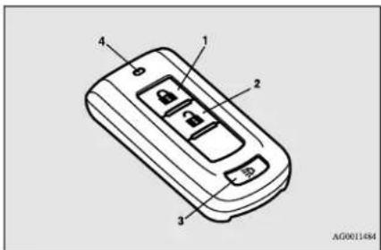
1- LOCK (🔒) button
2- UNLOCK (3) button
3- PANIC button
4- Operation indicator light
To lock
Press the LOCK button (1) to lock all the doors and the liftgate.
The turn signal lights will also blink once.

NOTE
- If you press the LOCK button (1) twice, the horn will sound once.
To unlock
Press the UNLOCK button (2) to unlock the driver's door only.
5-22 Features and controls
Within about 2 seconds, press the UNL button one more time to unlock all the doors and liftgate.
The dome light will turn on for 30 seconds. The turn signal lights will also blink twice.

NOTE
- The door and liftgate unlock function can be set so that all doors and liftgate unlock when the UNLOCK button (2) is pressed once. Refer to "Setting of door and liftgate unlock function" on page 5-23.
Answerback function
The horn of the keyless entry system answer-back function can be changed as required. This is done with the operation mode in OFF.
Horn deactivation/reactivation
The answerback function can be set in the following three ways.
One chime: The horn will not sound.
Two chimes: The horn will sound.
Four chimes: The horn will sound if the LOCK button is pressed twice within 1 second.
- Put the operation mode in OFF.
CR. Open the driver's door and turn the combination headlights and dimmer switch to the "OFF" position.
- Press the LOCK button (1) for 4 to 10 seconds and press the UNLOCK button (2) during this time.
- Release in sequence the UNLOCK and LOCK buttons within 10 seconds of pressing the UNLOCK button in step 3.
Turn signal light deactivation/reactivation
The turn signal lights answerback function can be changes.
If you want to change the answerback function, please contact an authorized Mitsubishi Motors dealer.
Buzzer deactivation/reactivation
The buzzer answerback function can be turned ON or OFF as required.
Setting of door and liftgate unlock function
N00544600098
The door and liftgate unlock function can be set to the following two conditions.
Each time the door and liftgate unlock function is set, a chime will sound to tell you the
condition of the door and liftgate unlock function.
| Number of chimes | Condition |
| One chime | All doors and the liftgate unlock |
| Two chimes | Driver's door unlock only |
- Put the operation mode in OFF.
- Open the driver's door and turn the combination headlights and dimmer switch to the "OFF" position.
- Press the LOCK button (1) for 4 to 10 seconds and press the UNLOCK button (2) during this time.
- Release in sequence the LOCK and UNLOCK buttons within 10 seconds of pressing the LOCK button in step 3.
Using the panic alarm
N00544701168
If you are near your vehicle and feel threatened, you can activate the alarm to call attention as follows:
- Press the PANIC button (3) for more than 1 second.
- The headlights will blink on and off and the horn will sound intermittently for about 3 minutes.
Features and controls 5-23
Free-hand Advanced Security Transmitter (F.A.S.T.-key) (if so equipped)
- To turn off the alarm, press any button on the remote control transmitter.

NOTE
● The indicator light (4) comes on each time a button is pressed.
- The F.A.S.T.-key can be used from about 40 feet (12 m) away. However, this distance may change if your vehicle is near a TV transmitting tower, a power station, or a radio station.
- If the following conditions are observed after pressing the LOCK (1) or UNLOCK (2) button on the remote control transmitter, the buttery in the F.A.S.T.-key may ne replaced.
- The doors and the liftgate cannot be locked or unlocked.
• The panic alarm cannot be operated.
- The indicator light (4) is dim or does not come on.
- If you lose your F.A.S.T.-key, please contact an authorized Mitsubishi Motors dealer for a replacement.
- If you wish to obtain an additional F.A.S.T. key, please contact an authorized Mitsubishi Motors dealer. A maximum of four F.A.S.T. key can be programmed for your vehicle.
- To use the new remote control transmitters, it is necessary to register the key with the electronic immobilizer and keyless entry system. Refer to “Electronic immobilizer (Anti-theft starting system): Customer F.A.S.T.-key programming” on page 5-21.
General information
N00562000065
Your F.A.S.T.-key operates on a radio frequency subject to Federal Communications Commission (FCC) Rules (For vehicles sold in U.S.A.) and Industry Canada Rules (For vehicles sold in Canada). This device complies with Part 15 of FCC Rules and Industry Canada licence-exempt RSS standard(s). Operation is subject to the following two conditions.
- This device may not cause harmful interference.
- This device must accept any interference received, including interference that may cause undesired operation of this device.
WARNING
- Changes or modifications not expressly approved by the party responsible for compliance could void the user's authority to operate the equipment.
Procedure for replacing the remote control transmitter battery
NO0562101177

WARNING
- Do not swallow a coin type battery.
- This product contains coin type battery. If a coin type battery is swallowed, it can cause severe internal burns and can lead to death.
There have been cases where a swallowed battery has caused severe internal burns in just 2 hours. - Keep new and used batteries away from children.
- If the remote control transmitter case does not close securely, stop using product and keep it away from children.
- If you think batteries might have been swallowed or placed inside any part of a person's body, seek immediate medical attention.
● To prevent an explosion or leakage of flammable liquid or gas: - Do not replace the battery with an incorrect type. Replace only with the same or equivalent type.
- Do not dispose of a battery into a fire or incinerator, or by mechanically crushing or cutting the battery.
Free-hand Advanced Security Transmitter (F.A.S.T.-key) (if so equipped)

WARNING
- Do not use, store, or take a battery any place where it may be exposed to extremely high temperature or extremely low air pressure.

CAUTION
- When the remote control transmitter case is opened, be careful to keep water, dust, etc. out. Also, do not touch the internal components.
-
Dispose of used battery according to regulations for the disposal of battery.
-
With the Mitsubishi mark facing you, insert the cloth-covered tip of a flat blade screwdriver into the notch in the case and use it to open the case.
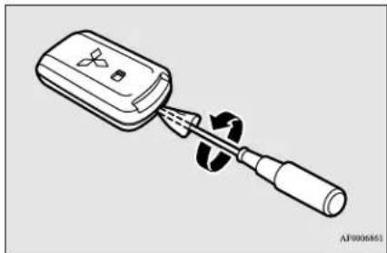
natural_image
Line drawing of a handheld electronic device with a screwdriver inserted (no text or symbols)- Install a new battery with the + side (A) up.
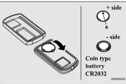
- Before replacing the battery, remove static electricity from your body by touching a metal grounded object.
- Remove the emergency F.A.S.T-key.
Refer to "Emergency key" on page 5-20.

NOTE
-
Be sure to perform the procedure with the
Mitsubishi mark facing you. If the Mitsubishi mark is not facing you when you open the case, the transmitter may come out. -
Remove the used battery.
-
Close the case firmly.
- Install the emergency key removed in step 2.
- Check the keyless entry system to see that it works.

NOTE
- You may purchase a replacement battery an electric appliance store.
● An authorized Mitsubishi Motors dealer can replace the battery for you if you prefer.
Door locks
Door locks
N101509201603
WARNING
● Make sure all doors are tightly closed and locked while driving.
- Locked doors, in combination with the use of seat belts, can help reduce the risk of ejection in an accident.
- Locked doors can help keep passengers, especially small children, from opening doors and falling out of moving vehicles.
- Locked doors can help prevent outsiders from gaining access to your vehicle when you slow or come to a stop.
- Lock your vehicle whenever you leave it. Children who get into unlocked vehicles may not be able to get out. Children trapped inside vehicles can quickly be overcome by heat and suffer serious injury or death due to heat stroke.
- Never leave a child alone in the vehicle. In addition to the risk of heat stroke, children can activate switches and controls, resulting in an injury or fatal accident.
- When closing a door, make sure door is fully closed and the door-ajar warning display goes out on the information screen on the multi-information display. If the door is ajar it could open while driving and cause an accident.
To lock and unlock with the key (driver's door)
Turn the key toward the front of the vehicle to lock the door. After checking that the door is locked, turn the key back to the cen remove it.
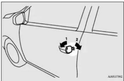
1-Lock
2- Unlock
that the

NOTE
- When locking or unlocking with the key, only the driver's door will be locked or unlocked.
To lock or unlock all doors and the liftgate, use the power door lock switches, the key- and entry system or the F.A.S.T-key operation. (if so equipped)
Refer to "Power door locks" on page 5-27, "Keyless entry system" on pages 5-6 and 5-22, and "To operate using the F.A.S.T.-key" on page 5-12. - In vehicles equipped with the F.A.S.T.-key, the passenger's door can be locked and unlocked using the emergency key. Refer to "Emergency key" on page 5-20.
To lock or unlock the door from the inside
Move the lock knob to the lock position to lock the door.
All doors should be kept locked while driving.
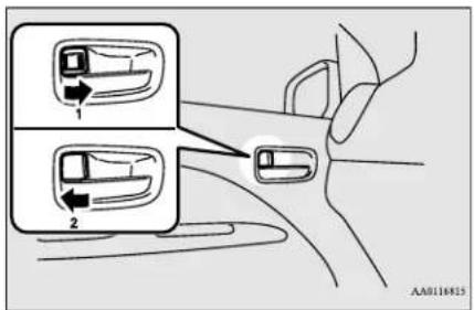
1-Lock
2- Unlock
The driver's door can be unlocked without using the lock knob by pulling on the inside door handle.
To lock the door without using the key
- Move the inside lock knob to the locked position.
- Be sure the keys are not inside the vehicle. Close the door.
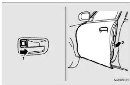
Key reminder system (except for vehicles equipped with the F.A.S.T.-key)
N00549600253
If the ignition switch is turned off and the driver's door is opened with the key in the ignition switch, the key reminder buzzer will sound intermittently to remind you to remove the key.
Lock out protection
N00517300042
If the key is in the ignition switch or the operation mode is in any mode other than OFF when you push the lock knob forward with the driver's door or passenger's door open, the lock knob will automatically return to the unlocked position.
Operation mode ON reminder system (vehicles equipped with the F.A.S.T.-key)
N015D3800150
If the driver's door is opened while the engine is stopped and the operation mode is in any position other than OFF, the operation mode ON buzzer will sound intermittently to remind you to put the operation mode in OFF.
Power door locks
N00509300610

NOTE
- When locking or unlocking with the key on the driver's door, only the driver's door will lock or unlock.
- Repeated continuous operation between lock and unlock could activate the power door locking system's built-in protection circuit, and prevent the system from operating. If this occurs, wait about 1 minute before operating the power door lock switch.
Power door locks
To lock and unlock the doors and liftgate
Using the power door lock switch (if so equipped)
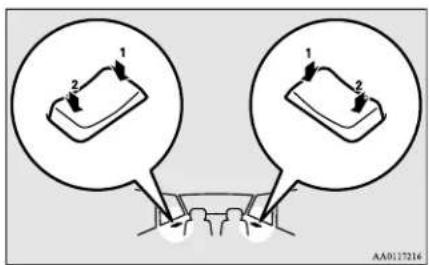
1- Lock
2- Unlock
All of the doors and the liftgate can be locked or unlocked by pressing the power door lock switch on the driver's or the front passenger door.
To unlock the doors and liftgate
N00563401193
You can select the functions to unlock the doors and liftgate either using the ignition switch or the engine switch, or using the selector lever position {continuously variable transmission (CVT)}.
These functions are not activated when the vehicle is shipped from the factory. To activate or deactivate these functions, please contact your authorized Mitsubishi Motors dealer.
Using the selector lever position {continuously variable transmission (CVT)}
All doors and the liftgate will unlock when the selector lever is moved to the "P" (PARK) position with the ignition switch or the operation mode in ON.
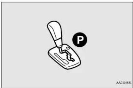
natural_image
Diagram of a hand crank with a parking tag and circular symbol (no text or labels)5-28 Features and controls
Child safety locks for rear door
N00509400291
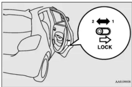
1- To lock
2- To release
Child safety locks help prevent rear passengers, especially children, from opening the rear door using the inside door handle.
A lock lever for the child safety lock is vided on each rear door.
When the lever is in the lock position (1), the rear door cannot be opened using the inside door handle.
To open the rear door when the child safety lock lever is in the lock position, pull the outside door handle.
When the lever is in the release position the child safety lock is released and the rear
door can be opened using the inside door handle.
WARNING
● Always keep the doors tightly closed and locked when driving. An unlocked door may be accidentally opened by a passenger, especially by a child who out. Also, if the doors are not locked, there is a greater risk of someone being thrown from the vehicle in an accident.
Liftgate
N00510101383
WARNING
- It is dangerous to drive with the liftgate open since carbon monoxide (CO) gas can contained in engine exhaust gases can enter the passenger compartment.
CO is an invisible, odorless gas that cause unconsciousness and even death. - When opening and closing the liftgate, make sure that there are no people nearby and be careful not to hit your head or pinch your hands, neck, etc.
- If snow or ice has accumulated on the liftgate, remove it before opening the liftgate. Otherwise the liftgate may abruptly close), due to the weight of the snow or ice.
WARNING
- When opening the liftgate, always fully open it. A partially opened liftgate can unexpectedly close due to its own weight.
- When the vehicle is parked on a slope, the effort required to open or close the liftgate may be greater or less than expected. The
could mitigate may also open or close more quickly.
CAUTION
- Do not stand behind the exhaust pipe when loading and unloading luggage. Heat from the exhaust could lead to burns.
- To avoid damage to the liftgate, make sure that area above and behind the liftgate is clear before opening it.
NOTE
Locking and unlocking the doors by using the power door lock switch, the keyless entry system or the F.A.S.T.-key operation also locks and unlocks the liftgate. (if so equipped)
Liftgate
To open
After unlocking the liftgate, pull the liftgate handle upward to open.
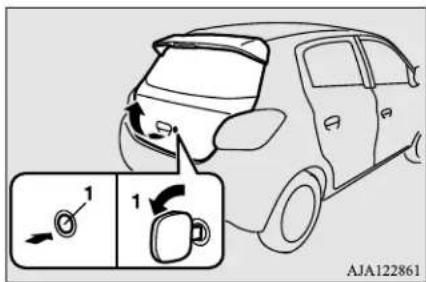
1- Unlock
To close
Pull the liftgate grip (A) downward as illustrated and release it before the liftgate closes completely. Gently slam the liftgate from the outside so that it is completely closed.
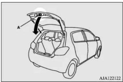
CAUTION
● Make sure there is no one standing nearby when opening the liftgate.
CAUTION
● To avoid injuring your hand or arm, do not attempt to close the liftgate without releasing the liftgate grip (A).
- Before starting the vehicle, be sure to confirm that the liftgate is locked. If the liftgate opens while driving the vehicle, objects stored in the luggage compartment could fall out into the road.
NOTE
● Gas struts (B) are installed in the locations illustrated in order to support the liftgate.
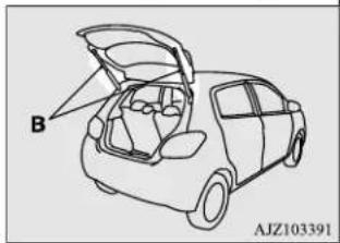
natural_image
Line drawing of a car interior with open lid and labeled component 'B' (no text or symbols beyond labels)Please observe the following in order to prevent damage or faulty operation:
- Do not touch, push or pull the gas struts when closing the liftgate.
- Do not attach any plastic material, tape, etc., to the gas struts.
- Do not tie string, etc., around the gas struts.
- Do not hang objects on the gas struts.
Manual window control (if so equipped)
Manual window control (if so equipped)
N00510700021
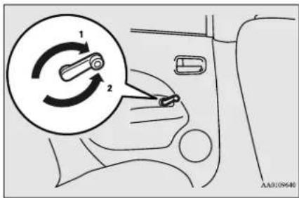
1- To open
2- To close
Power window control
N00510800370
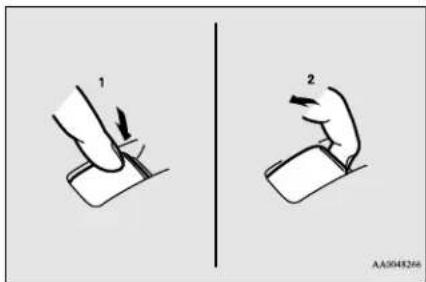
1- Open (down)
2- Close (up)

NOTE
● Never try to operate the main switch and sub-switch in different directions at the same time. This will freeze the window in position.
- Operating the power windows repeatedly with the engine stopped will run down the battery. Use the window switches only while the engine is running.
WARNING
● Before operating the power windows, make sure that nothing can be trapped (head, hands, fingers, etc.) in the window.
● Never leave the vehicle without the key.
● Never leave children or unreliable adults unattended inside the vehicle.
Main switch
N00548700130
The main switch located on the driver's door can be used to operate all the windows.
A window can be opened or closed by operating the corresponding switch.
Press the switch down to open the window, and pull up the switch to close it.
If the driver's door window switch is fully pressed down/pulled up, the driver's door window automatically opens/closes completely. (Type 1)
If the driver's door window switch is fully pressed down, the driver's door window automatically opens completely. (Type 2)
If you want to stop the window movement operate the switch lightly in the reverse direction.
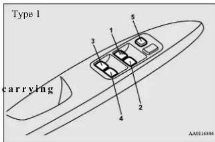
Power window control
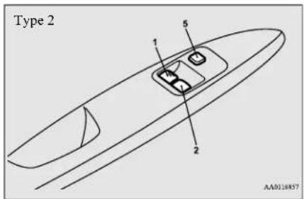
I- Driver's door window switch
2- Front passenger door window switch
3- Left rear door window switch
4- Right rear door window switch
5- Lock switch
Sub switch
N00548800098
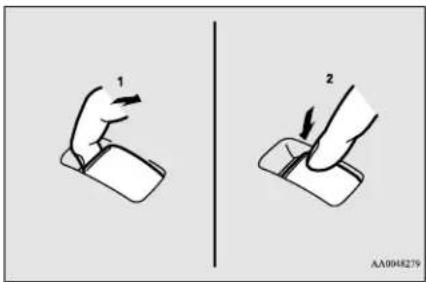
1-Close
2- Open
Each sub-switch can be used for it's own passenger door window, unless the driver's window lock switch is activated.

NOTE
● The rear door windows open only half-way
Power window timer function
N00548900132
The power windows can be run up or down when the ignition switch or the operation mode is in ON.
The door windows can be opened or closed for a 30-second period after the engine is
stopped. However, once the driver's door or the front passenger's door is opened, the power windows cannot be operated.
Lock switch
N00549000169
When this switch is in the lock mode, the passenger door switches cannot be used to open or close the door windows, and the main switch will open or close only the driver's door window. To unlock the switch, press it again.
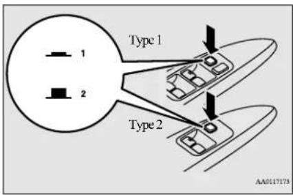
1-Lock
2- Unlock

WARNING
- Before driving with a child in the v be sure to lock the window switch to make it inoperative. Children tampering with the switch could easily trap their hands or heads in the window.
Safety mechanism (Driver's door window of Type 1 only)
N00528801158
If a hand or head is trapped, for safety the door window is automatically lowered a little. After the door window is lowered, clear the obstruction, then pull up the switch again to close the door window.

WARNING
- If the battery terminals are disconnected or the fuse for electric window is replaced, the safety mechanism will be cancelled. If a hand or head got trapped, a serious injury could result.

CAUTION
- The safety mechanism is deactivated just before the door window closes. This allows the door window to close completely. Therefore be especially careful that fingers are not trapped in the door window opening.

CAUTION
The safety mechanism is deactivated while the switch is pulled up. Therefore be especially careful that fingers are not trapped in the door window opening.
- Do not deliberately trap your hands or head in order to activate the safety mechanism. Your hand or head could be trapped and personal injury could result.

NOTE
- The safety mechanism can be activated if the driving conditions or other circumstances cause the door window to be subjected to a physical shock similar to that caused by trapped hand or head.
- If the safety mechanism is activated 5 or more times in a row, the safety mec will be cancelled and the door window will not close correctly. In such a case, the following procedure should be implemented to rectify this situation. If the window is open, repeatedly raise the driver's door window switch until that window has been fully closed.
Following this, release the switch, raise the switch once again and hold it in this condition for at least 1 second, then release it. You should now be able to operate in the normal fashion.

NOTE
- If the battery terminals are disconnected or the fuse for electric window is replaced, the safety mechanism will be cancelled and the door window will not automatically open/close completely. If the window is open, repeatedly raise the driver's door window switch until the window has been fully closed. Following this, release the switch, raise the switch once again and hold it in this condition for at least 1 second, then release it. You should now be able to operate the driver's door window in the normal fashion.
What to do if you hear wind buffeting when driving
chanism
N00551400043
Wind buffeting can be described as the perception of pressure on the ears or a booming or rumbling sound. Your vehicle may exhibit wind buffeting when driving with one or both rear door windows down or partially opened. This is a normal occurrence that can be minimized. If the buffeting occurs with the rear door windows open, open the front door windows as well as the rear door windows to minimize the condition.
Parking brake
Parking brake
N00511400399
To park the vehicle, first bring it to a complete stop, fully engage the parking brake, and then move the gearshift lever to 1st (on a uphill) or "R" (Reverse) (on a downhill) position for vehicles equipped with a manual transaxle, set the self (PARK) position for vehicles equipped with a continuously variable transmission (CVT).
To apply
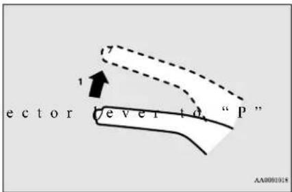
1- Pull the lever up without pushing the button at the end of hand grip. When the parking brake is set and the ignition switch or the operation mode is in the "ON" position, the brake warning light in the instrument cluster will come on.
Before driving, be sure to release the parking brake.
To deactivate
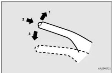
1- Pull the lever up slightly.
2- Press and hold the button at the end of the hand grip.
3- Push the lever downward.
When parking on a hill, set the parking brake, and turn the front wheels toward the curb on a downhill, or away from the curb on an uphill.

CAUTION
● Before driving, be sure that the parking brake is fully released and brake warning light is off.
If you drive without the parking brake fully released, the warning lamp will illuminate and a buzzer sounds when the vehicle speed exceeds 5 mph (8 km/h).
If a vehicle is driven without releasing the parking brake, the brakes will be overheated, resulting in ineffective braking and possible brake failure.
Steering wheel height adjustment
N00511500231
To adjust the steering wheel to the desired position, move the lever upward or downward while moving the steering wheel to the desired level.
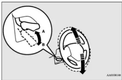
A- Wheel lock
B- Release
WARNING
● After adjusting, make sure the lever is secured in the locked (A) position.
- Do not attempt to adj wheel while driving. This can be dangerous.
- When releasing the lever (moving it to position (B)), be sure to hold the steering wheel firmly. Otherwise, the steering wheel may slip down too suddenly.
Inside rearview mirror
N010511601499
Adjust the inside rearview mirror only after making any seat adjustments so as to have a clear view to the rear of the vehicle.
Type 1
natural_image
Simple line drawing of a rear view mirror (no text or symbols)Type 2
the
WARNING
- Do not attempt to adjust the inside rearview mirror while driving. This can be dangerous.
Be sure to adjust the mirror before driving.
Adjust the inside mirror to maximize the view through the rear window.
Inside rearview mirror
To adjust the vertical mirror position
It is possible to move the mirror up and down to adjust its position.
5
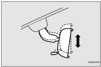
natural_image
Diagram of a hand holding a curved object with dashed lines indicating motion, no text or symbols presentTo adjust the mirror position To reduce the glare
It is possible to move the mirror up/down and left/right to adjust its position.
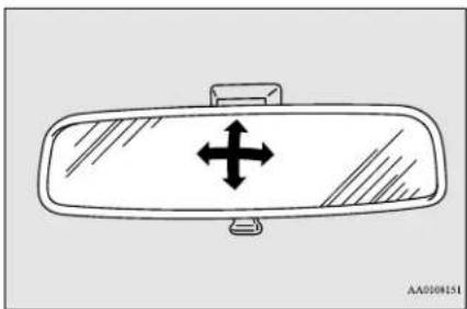
natural_image
Diagram of a car rearview mirror with bidirectional arrow indicator (no text or symbols)Type 1
The day/night knob (A) at the bottom of the mirror can be used to adjust the mirror to reduce the glare from the headlights of vehicles behind you during night driving.
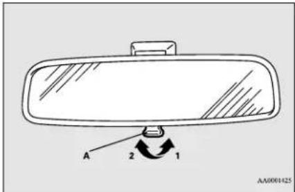
1-Daytime position
2- Night position
Type 2
When the headlights of the vehicles behind you are very bright, the reflection factor of the rearview mirror is automatically changed to reduce the glare.
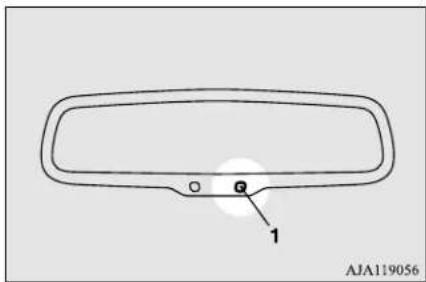
When the ignition switch is turned to the "ON" position or the operation mode is put in ON, the reflection factor of the mirror is automatically changed.

NOTE
- Do not hang items on, or spray glass cleaner on the sensor (1), as reduced sensitivity could result.
Outside rearview mirrors
N00512200206
Adjust the outside rearview mirrors only after making any seat adjustments so as to have a clear view to the rear of the vehicle.
WARNING
- Do not attempt to adjust the outside rearview mirrors while driving. This dangerous.
Be sure to adjust the mirrors before driving.
- Your passenger's side mirr The objects you see in the mirror will look smaller and farther away than they appear in a regular flat mirror.
Do not use this mirror to estimate the distance of vehicles following you when changing lanes.
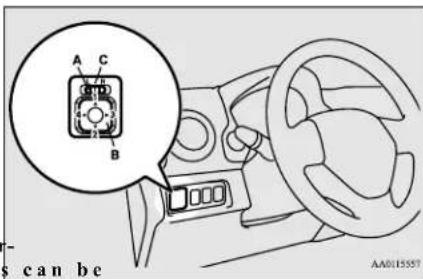
L- Left outside mirror adjustment
R- Right outside mirror adjustment
ror is convex.
Press the switch (B) to adjust the mirror position.
1-Up
2-Down
3- Right
4- Left
To adjust the mirror position
N00549100144
The outside rearview mirrors can be adjusted when the ignition switch or the operation mode is in ON or ACC.
Move the lever (A) to the same side as the mirror you wish to adjust.

NOTE
● After adjusting, return the lever to the “•” (OFF) position (C).
Ignition switch
To fold the mirror
N00549200099
The outside mirror can be manually folded in towards the side window to prevent damage when parking in tight locations.
5
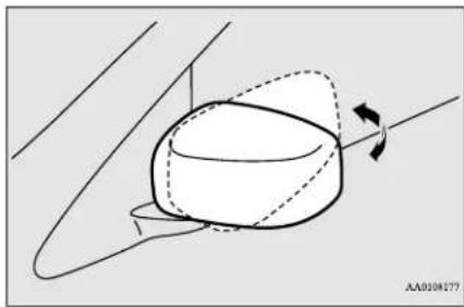
natural_image
Diagram of a 3D object with dashed and solid lines indicating orientation, no text or symbols presentDoor mirror heater (if so equipped)
N00549301286
When the rear window defogger switch is pressed with the engine running, the outside rearview mirrors are defogged or defrosted. Current will flow through the heater element inside the mirrors, thus clearing away frost or condensation.
The indicator light (A) will illuminate while the defogger is on. The heater will be turned off automatically in about 20 minutes.
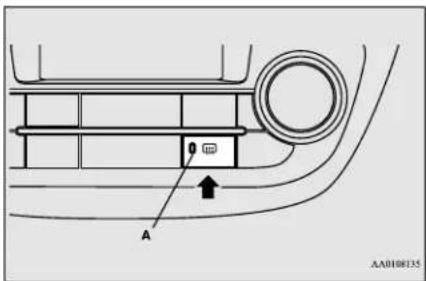
N00512401726
Ignition switch
[For vehicles equipped with the Free-hand Advanced Security Transmitter (F.A.S.T.-key)]
For information on operations for vehicles equipped with the Free-hand Advanced Security Transmitter (F.A.S.T.-key), refer to "Free-hand Advanced Security Transmitter (F.A.S.T.-key): Engine switch" on page 5-14.
[Except for vehicles equipped with the Free-hand Advanced Security Transmitter (F.A.S.T.-key)]
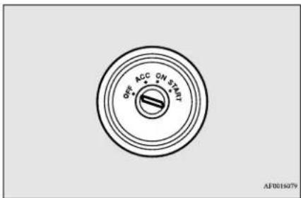
OFF
The engine is off. The key can be inserted and removed only when the switch is in this position.
ACC
Allows operation of some electrical accessories with the engine off.
ON
The engine runs and all accessories can be used.
5-38 Features and controls
START
Engages the starter. Release the key when the engine starts. It will automatically return to the "ON" position.

NOTE
- Your vehicle is equipped with an electronic immobilizer. To start the engine, the ID code which the transponder inside the key sends must match the one registered to the immobilizer computer. (Refer to "Electronic immobilizer" on page 5-3.)
To remove the key
N00551900201
- Set the selector lever to the "P" (PARK) position {continuously variable transmission (CVT)}.
- Turn the key to the "OFF" position and remove it.
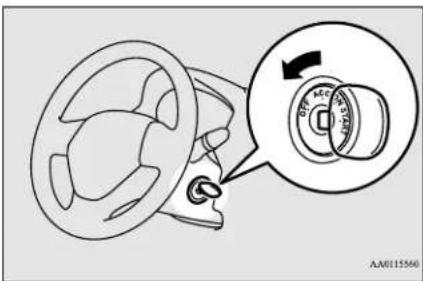
CAUTION
- If the engine is stopped while driving, the brake servomechanism will cease to function and braking efficiency will deteriorate. Also, the power steering system will not function and it will require greater manual effort to operate the steering.
- Do not leave the key in the "ON" position for a long time when the engine is not running, doing so will cause the battery to be discharged.
- Do not turn the key to the "START" position when the engine is running, doing so could damage the starter motor.
Starting the engine
N00512601861
[For vehicles equipped with the Free-hand Advanced Security Transmitter (F.A.S.T.-key)]
For information on operation for vehicles equipped with the Free-hand Advanced Security Transmitter (F.A.S.T.-key), refer to "Free-hand Advanced Security Transmitter (F.A.S.T.-key): Starting and stopping the engine" on page 5-17.
[Except for vehicles equipped with the Free-hand Advanced Security Transmitter (F.A.S.T.-key)]
Tips for starting
- Do not operate the starter motor continuously for longer than 15 seconds as this could run the battery down or damage the starter motor. If the engine does not start, turn the ignition switch back to the "OFF" position, wait a few seconds, and then try again. Trying repeatedly with the engine or starter motor still turning will damage the starter mechanism.
- If the engine will not start because the battery is weak or discharged, refer to "Jump-starting the engine" (on page 8-2) for instructions.
- A longer warm up period will only consume extra fuel. The engine is warmed up enough for driving when the low coolant temperature indicator goes out. Refer to “Low coolant temperature indicator” on page 5-88.
Features and controls 5-39
Starting the engine
WARNING
- Never run the engine in a closed or poorly ventilated area any longer than is needed to move your vehicle out of the area. Carbon monoxide gas, which is odorless and extremely poisonous, could build up a cause serious injury or death.
and
- Insert the ignition key.
- Make sure the parking brake is applied.
- Press and hold the brake pedal down firmly with your right foot.
- Press and hold the clutch pedal all the way down (manual transaxle).
CAUTION
- Do not push-start the vehicle.
- Do not run the engine at high rpms or drive at high speeds until the engine has had a chance to warm up.
- Release the ignition switch as soon as the engine starts. Otherwise, the starter motor will be damaged.
NOTE
-
On vehicles equipped with manual transaxle, the starter will not operate unless the clutch pedal is fully depressed (Clutch interlock).
-
On vehicles equipped with manual transaxle, place the gearshift lever in the "N" (Neutral) position.
On vehicles equipped with continuously variable transmission (CVT), make sure the selector lever is in the "P" (PARK) position.
Starting the engine
This model is equipped with an electronically controlled fuel injection system. This is a system that automatically controls fuel injection. There is usually no need to depress the accelerator pedal when starting the engine. The starter should not be run for more than 15 seconds at a time.
To prevent battery drain, wait a few seconds between attempts to restart the engine.
NOTE
-
On vehicles equipped with CVT, the starter will not operate unless the selector lever is in the "P" (PARK) or "N" (NEUTRAL) position.
For safety reasons, start the engine in the "P" (PARK) position so that the wheels are locked. -
Make sure all occupants are properly seated with seat belts fastened.
5-40 Features and controls
-
Turn the ignition switch to the "ON" position and make certain that all warning lights are functioning properly before starting the engine.
-
Turn the ignition switch to the "START" position without pressing the accelerator pedal. Release the key when the engine starts.
NOTE
● Minor noises may be heard on engine start-up. These will disappear as the engine warms up.
When the engine is hard to start
After several attempts, you may experience that the engine still does not start.
- Make sure that all electric devices, such as lights, air conditioning blower and rear window defogger, are turned off.
-
While depressing the brake pedal {continuously variable transmission (CVT)} or the clutch pedal (manual transaxle), press the accelerator pedal halfway and hold it there, then crank the engine. Release the accelerator pedal, immediately after the engine starts.
-
If the engine still will not start, the engine could be flooded with too much gasoline. While depressing the brake pedal (CV or the clutch pedal (manual transaxle), push the accelerator pedal all the way down and hold it there, then crank the engine for 5 to 6 seconds. Return the ignition switch to the "OFF" position and release the accelerator pedal. Wait a few seconds, and then crank the engine again for 5 to 6 seconds while depressing the brake pedal (CVT) or the clutch pedal (manual transaxle), but do not push the accelerator pedal. Release the ignition switch if the engine starts. If the engine fails to start, repeat these procedures. If the engine still will not start, contact your local Mitsubishi Motors dealer or a repair facility of your choice for assistance.
Startability of CVT vehicle with ambient temperature of -4 °F (-20 °C) or lower
When the ambient temperature is -4 °C) or lower, it may not be possible to start from a standstill even with the selector lever in the “D” (DRIVE) or “R” position.
This phenomenon occurs because the transaxle has not warmed up sufficiently; it does
not indicate a problem. If this occurs, place the selector lever in the "P" (PARK) position and let the engine idle for at least 10 minutes. The transaxle will warm up, and you will be able to start normally.
Do not leave the vehicle during warm-up operation.
Manual transaxle (if so equipped)
N00512701224
The shift pattern below is shown on the gear-shift lever. Press the clutch pedal all the way down while shifting gears.
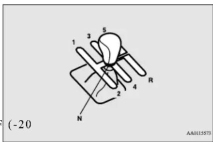
(REVERSE)

NOTE
- During cold weather, shifting may be difficult until the transaxle lubricant has warmed up. This is normal and not harmful to the transaxle.
To start
Press the clutch pedal all the way down and shift into 1st or "R" (Reverse) position, operating the gearshift lever slowly. Then gradually release the clutch pedal while depressing the accelerator pedal.

CAUTION
- Do not move the gearshift lever into reverse while the vehicle is moving forward; doing so will damage the transaxle.
- Do not rest your foot on the clutch pedal because this will cause premature clutch wear or damage.
- Do not coast in the “N” (Neutral) position (illegal in many states).
- Do not use the gearshift lever as a handrest, because this can result in premature wear of the transaxle shift forks.
Manual transaxle (if so equipped)

NOTE
- If it is hard to shift into 1st, depress the clutch pedal a second time; the shift will then be easier.
- To shift into reverse from 5th gear, move the gearshift lever to the "N" (Neutral) position, and then shift it into reverse.
- To avoid grinding noises when shifting into reverse, wait approximately 3 seconds with the clutch pedal depressed when the vehicle is stationary.
Proper shift points
N00537400065
Always use care to change the gear with the vehicle speed matched to the engine speed. Proper shifting will improve fuel economy and prolong engine life.

CAUTION
- Avoid downshifting that may cause the tachometer pointer to enter the red zone. This puts the engine at risk of being damaged.
Upshifting
N00512900131
For the best fuel economy and performance in using your manual transaxle, upshift as listed below.
At low altitude locations, shift at the vehicle speeds listed. Upshifting earlier during cruise conditions (relatively steady speeds) will improve your fuel economy.
| Shift point | Upshift speeds | |
| Acceleration | Cruise | |
| 1st gear to 2nd gear | 15 mph (24 km/h) | 15 mph (24 km/h) |
| 2nd gear to 3rd gear | 28 mph (45 km/h) | 19 mph (31 km/h) |
| 3rd gear to 4th gear | 36 mph (58 km/h) | 33 mph (53 km/h) |
| 4th gear to 5th gear | 45 mph (72 km/h) | 45 mph (72 km/h) |
At high altitude locations, upshift as listed below.
| Shift point Upshift speeds |
| 1st gear to 2nd gear 15 mph (24 km/h) |
| 2nd gear to 3rd gear 25 mph (40 km/h) |
| 3rd gear to 4th gear 40 mph (64 km/h) |
Shift point Upshift speeds
4th gear to 5th gear 45 mph (72 km/h)
Downshifting
ND051300X096
It is recommended that you downshift to a lower gear when needed to maintain the desired speed, according to the table.
Avoid downshifting at too high a speed. The engine may suffer damage.
To maintain a safe speed and prolong brake life, shift down to 2nd or 1st when descending a steep hill.
Downshifting is also important to avoid "lugging" the engine at too low a speed, such as when turning a corner or when driving up a steep hill.
Recommended downshifting speed
| Downshifting speed | Shift point |
| Under 20 mph (32 km/h) | Shift down from current gear to 2nd gear. |
| 20 to 30 mph (32 to 48 km/h) | Shift down from current gear to 3rd gear. |
Driving precautions
N00513100244
- Do not use the gearshift lever as a handrest. This can result in premature wear of the transaxle shift forks.
Maximum possible driving speed
| Shift points | Maximum possible driving speed |
| 1st gear 2 | 8 mph (45 km/h) |
| 2nd gear | 53 mph (85 km/h) |
| 3rd gear | 78 mph (125 km/h) |
| 4th gear | 105 mph (170 km/h) |
- The table above shows the maximum recommended driving speed for in each gear. Do not drive near or at these speeds for prolonged periods of time.
Continuously variable transmission (CVT) (if so equipped)
N00560200050
The CVT will automatically and continuously change its gear ratio depending on road and
driving conditions. This helps achieve smooth driving and excellent fuel efficiency.
DRIVING UPHILL
The transmission prevents unnecessary upshifts even when the accelerator pedal is released and ensures smooth driving.
DRIVING DOWNHILL
According to the conditions, the transmission will automatically shift to a lower gear ratio to achieve stronger engine braking. This may help reduce your need to use the service brake.
Selector lever operation
N00560301087
As an additional safety precaution, models equipped with a continuously variable transmission have a shift-lock device that holds the selector lever in the "P" (PARK) position. To move the selector lever from the "P" (PARK) position to another position, follow the steps below.
- Press and hold the brake pedal down.
- Move the selector lever to the desired position.

NOTE
- The selector lever cannot be moved from "P" (PARK) to another position if the ignition switch is set to the "OFF" or "ACC" position, or if the key has been removed, or operation mode is in "OFF" or "ACC", or if the brake pedal is not pressed and held down.
The CVT selects an optimum ratio automatically when the selector lever is in the “D” (DRIVE) position, depending on the speed of the vehicle and the position of the accelerator pedal.
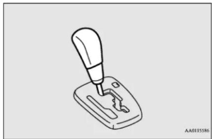
natural_image
Line drawing of a manual lever mechanism (no text or symbols)Continuously variable transmission (CVT) (if so equipped)
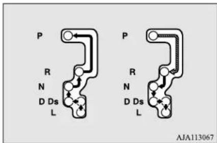
| Set the selector lever in the gate to operate while the bit depressed. | |
| Set the selector lever in the gate to operate. |
WARNING
● Always press the brake pedal when ing the selector lever into a selector position from the "N" (NEUTRAL) position. When beginning to drive, do not shift the selector lever from the "N" (NEUTRAL) position while pressing the accelerator pedal. This will cause the vehicle to "jump" forward or backward.
NOTE
- To prevent mistakes in operating the lever, make sure you stop briefly at each position. After operating, check the position in the multi-information display.
- If the brake pedal is not depressed and held the shift-lock device activates to prevent the selector lever from being moved from the "P" (PARK) position.
- For a shift indicated by in the illustration, depress the brake pedal before moving the selector lever. If you attempt to move the selector lever before depressing the brake pedal, the selector lever may not move.
When the selector lever cannot be shifted from the "P" (PARK) position
shift- N00563300049
When the selector lever cannot be shifted from the "P" (PARK) position to another position while the brake pedal is pressed and held down with the ignition switch or the operation mode in ON, the battery may be flat or the shift-lock mechanism may be malfunctioning.
Immediately have your vehicle checked by an authorized Mitsubishi Motors dealer or a repair facility of your choice.
If you need to move the vehicle, shift the selector lever as follows.
- Make sure the parking brake is fully applied.
- Stop the engine if it is running.
- Insert a screwdriver with a cloth over its tip into the notch (A) of the cover. Pry gently as shown to remove the cover.
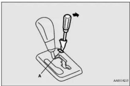
natural_image
Diagram of a tool interacting with a mechanical component, showing a tool tip and base (no text or symbols)- Depress the brake pedal with the right foot.
- Insert a screwdriver in the shift-lock release hole (B). Shift the selector lever to the "N" (NEUTRAL) position while pressing the screwdriver down.
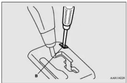
natural_image
Illustration of a medical procedure with surgical tool and labeled component 'B' (no text or symbols beyond label)Selector lever position display
N00560400078
When the ignition switch is turned to the "ON" position or the operation mode is put in ON, the selector lever position is shown on the multi-information display.

natural_image
Diagram of a car dashboard with steering wheel and speedometer (no text or symbols)Selector lever positions
N00560601093
"P" PARK
This position locks the transmission to prevent the vehicle from moving. The engine can be started from the "P" (PARK) position.
"R" REVERSE
Move the lever to this position only after the vehicle has come to a complete stop.
CAUTION
- Never shift into the "P" (REVERSE) position while the vehicle is in motion. If the lever is shifted into the "P" (PARK) or "R" (REVERSE) position while the vehicle is in motion, the transmission may be damaged.
"N" NEUTRAL
At this position, the transmission is disengaged. It is the same as the neutral position on a manual transaxle and should be used when the vehicle is not moving for an extended length of time during driving, such as in a traffic jam.
WARNING
- Never move the selector lever to the "N" (NEUTRAL) position while driving since you could accidentally slip it into the "P" (PARK) or "R" (REVERSE) position, damaging the transmission.
- To prevent the vehicle from rolling when stopped on a slope, the engine should be started in the "P" (PARK) position, not in "N" (NEUTRAL) position.
- To prevent rolling, always keep your foot on the brake pedal when the vehicle is in "N" (NEUTRAL) position, or when shifting into or out of "N" (NEUTRAL) position.
(PARK)DRIVE _R
This position is used for most city and highway driving. The transmission will automatically and continuously change its gear ratio depending on road and driving conditions.
CAUTION
- To prevent transmission damage, never shift into the "D" (DRIVE) position from the "R" (REVERSE) position while the vehicle is in motion.
Continuously variable transmission (CVT) (if so equipped)
"Ds" DOWNSHIFT & SPORTY DRIVING
Use when engine braking is needed, or for high-power sport drive.
“L” LOW
This position is for driving up very steep hills and for engine braking at low speeds when driving down steep hills.
WARNING
● This position can be used for maximum engine braking.
Be very careful not to shift into "L" (LOW) suddenly.
Sudden engine braking may cause the tires to skid.
Select this position according to the road conditions and vehicle speed.
When a malfunction occurs in the automatic transaxle
NX54950018
When the selector lever position indicator blinks
N00574601049
When the selector lever position indicator blinks while you are driving, there could be a malfunction in the automatic transaxle system or CVT fluid temperature becomes abnormally high.
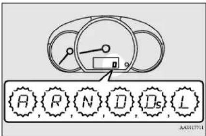
NOTE
- The “A” indicator blinks only if the CVT selector lever switch is broken. It is not seen during normal driving.
CAUTION
- If a malfunction occurs in the CVT while driving, the indicator will blink. In this case, immediately park your vehicle in a safe place and follow these procedures: [If the indicator blinks rapidly (once per second), the CVT fluid is overheating.] Park your vehicle in a safe place but do not turn off the engine. Move the selector lever to the "P" (PARK) position and open the engine hood. Keep the engine, idling. After a while, move the selector lever into any position other than "P" (PARK) position and confirm that the indicator stops blinking. It is safe to continue driving if the indicator no longer blinks. If the indicator continues blinking, contact an authorized Mitsubishi Motors dealer or repair facility of your choice immediately. [If the indicator blinks slowly (once per 2 seconds), the CVT may be operating in fail-safe mode due to a malfunction.] Have the vehicle inspected at an authorized Mitsubishi Motors dealer or repair facility of your choice immediately.
Operation of the CVT
N00560801095
CAUTION
- Before selecting a position with the engine running and the vehicle stationary, firmly depress the brake pedal to prevent the vehicle from creeping.
The vehicle will begin to move as soon as the CVT is engaged, especially when the engine speed or idle speed is high, or with the air conditioning operating.
Do not release the brake pedal until you are ready to drive away. - Depress the brake pedal with the right foot at all times.
Using the left foot could cause driver movement delay in case of an emergency. - To prevent sudden acceleration, never run the engine at high rpms when shifting from the "P" (PARK) or "N" (NEUTRAL).
- Operating the accelerator pedal while the other foot is resting on the brake pedal will affect braking efficiency and may cause premature wear of brake pads.
CAUTION
- Use the selector lever in the correct shift position in accordance with driving conditions.
Never coast downhill backward in the driving shift position “D” (DRIVE), “Ds” (DOWNSHIFT & SPORTY DRIVING), “L” (LOW) or coast forward in the “R” (REVERSE) position.
Engine stopping and increased brake pedal and steering effort could lead to an accident. - Do not rev the engine with the brake pedal pressed when the vehicle is stationary.
This can damage the CVT.
Also, when you depress the accelerator pedal while holding down the brake pedal with the selector lever in the "D" (DRIVE) position, the engine revolutions may not rise as h as when performing the same operation with the selector lever in the "N" (NEUTRAL) position.
Passing acceleration
To gain extra acceleration in "D" (DRIVE) position (when passing another vehicle) push the accelerator to the floor. The CVT will automatically downshift.
Waiting
For short waiting periods, such as at traffic lights, the vehicle can be left in selector lever position and held stationary with the service brake.
For longer waiting periods with the engine running, place the selector lever in the "N" (NEUTRAL) position and apply the parking brake, while holding the vehicle stationary with the service brake.
Prior to moving off after having stopped the vehicle, make sure that the selector lever is in "D" (DRIVE) position.
CAUTION
- To avoid transmission overheating, never try to keep your vehicle stationary on a hill by using the accelerator pedal. Always apply the parking brake and/or service brake.
- Do not rev the engine unnecessarily while the vehicle is stationary. Unexpected acceleration may occur if the selector lever is in a position other than "P" (PARK) or "N" (NEUTRAL).
Parking
To park the vehicle, first bring it to a complete stop, fully engage the parking brake,
Service brake
and then move the selector lever to the "P" (PARK) position.
When the CVT makes no speed change
If the CVT does not shift while driving, or your vehicle does not pick up enough speed when starting on an uphill slope, it may be that there is something unusual happening in the transmission. Have your vehicle checked at an authorized Mitsubishi Motors dealer or a repair facility of your choice immediately.
Service brake
N00517501328
Brake pedal
Overuse of the brake can cause weakening, resulting in poor brake response and premature wear of the brake pads.
When driving down a long or steep hill, use engine braking by moving the selector lever to "Ds" (DOWNSHIFT & SPORTY DRIVING) or "L" (LOW) position.
WARNING
- Do not leave any objects near the pedal or let a floor mat slide doing so could prevent the full pedal stroke that would be necessary in an emergency. Make sure that the pedal can be operated freely at all times. Make sure the floor mat is securely held in place.
CAUTION
- It is important not to drive the vehicle with your foot resting on the brake pedal when braking is not required. This practice can result in very high brake temperatures, premature lining wear, and possible damage to the brakes.
Power brakes
N00517601462
Your vehicle is equipped with power brakes for more braking force with less brake pedal effort.
Your brakes are designed to operate at full capacity, even if the power assist is not being used.
If the power assist is not being used, the effort needed to press the brake pedal is greater.
If you should lose the power assist for some reason, the brakes will still work.
If the power brake unit or either of the two brake hydraulic systems stops working properly, the rest of the brake system will still work, but the vehicle will not slow down as quickly.
You will know this has happened if you find you need to press the brake down farther, or harder when slowing down or stopping, or if the brake warning light and the warning display in the multi-information display comes on. Have the brake system repaired at an authorized Mitsubishi Motors dealer or a repair facility of your choice immediately.
WARNING
- Never coast downhill with the engine OFF. Keep the engine running whenever your vehicle is in motion. If you turn off the engine while driving, the power brake booster will stop working and your brakes will not work as well.
- If the power assist is lost or if either brake hydraulic system stops working properly, take your vehicle to an authorized Mitsubishi Motors dealer or a repair facility of your choice immediately.
Brake pad wear alarm
N00550700124
The disc brakes have an alarm that makes a metallic squeal when the brake pads have worn down enough to need service.
If you hear this sound, have the brake pads replaced at an authorized Mitsubishi Motors dealer or a repair facility of your choice.
WARNING
- Driving with worn brake pads will make it harder to stop, and can cause an accident.
Hill start assist
N00562601127
The hill start assist makes it easy to start off on a steep uphill slope by preventing the vehicle from moving backwards. It keeps the brakes applied for approximately 2 seconds when you move your foot from the brake pedal to the accelerator pedal.
CAUTION
- Do not overly rely on the hill start assist to prevent backwards movement of the vehicle. Under certain circumstances, even when hill start assist is activated, the vehicle may move backwards if the brake pedal is not sufficiently depressed, if the vehicle is heavily loaded, or if the road is very steep or slippery.
- The hill start assist is not designed to keep the vehicle stopped in place on uphill slopes for more than 2 seconds.
- When facing uphill, do not rely on using the hill start assist to maintain a stopped position as an alternative to depressing the brake pedal.
Doing so could cause an accident.
- Do not perform the following operation while the hill start assist is operating.
[Except for vehicles equipped with the F.A.S.T.-key]
Turn the ignition switch to the "OFF" or "ACC" position.
[ Vehicles equipped with the F.A.S.T.-key] Put the operation mode in OFF or ACC. The hill start assist could stop operating, which could result in an accident.
- On vehicles with manual transaxle, place the gearshift lever into the 1st position. On vehicles with CVT, place the selector lever into the "D" (DRIVE) position.
NOTE
- When reversing on an uphill slope, place the gearshift lever or selector lever into the "R" position.
-
Release the brake pedal and the hill start assist will maintain the braking force applied while stopped for approximately 2 seconds.
-
Depress the accelerator pedal and the hill start assist will gradually decrease the braking force as the vehicle starts moving.
NOTE
- The hill start assist is activated when all the following conditions are met.
• The engine is running.
(The hill start assist will not be activated while the engine is starting or immediately after the engine is started.)
To operate
N00562701131
- Stop the vehicle completely using the brake pedal.
Brake assist system

NOTE
- On vehicles with manual transaxle, the gearshift lever is in the following position. [When starting an uphill slope forwards.]
The gearshift lever is in any position other than "R" (Reverse).
(The hill start assist will operate, even if the gearshift lever is in the "N" (Neutral) position.)
[When starting an uphill slope backwards.] The gearshift lever is in the "R" (Reverse) position.
(The hill start assist will not operate the gearshift lever is in the "N" (Neutral) position.)
- On vehicles with CVT, the selector lever is in any position other than "P" (PARK) or "N" (NEUTRAL).
• The vehicle is completely stationary, with the brake pedal depressed.
• The parking brake is released.
- The hill start assist will not operate if the accelerator pedal is depressed before the brake pedal is released.
● The hill start assist also operates when reversing on an uphill slope.
- When the hill start assist is activated, you may feel the operating sound or vibration from under the body.
This is a normal result of the hill start assist operation, and does not indicate a problem.
Warning indicator
N00562800092
If an abnormal condition occurs in the system, the following indicator will turn on.

ASC indicator
CAUTION
- If the warning is displayed, the hill start can assist will not operate. Start off carefully.
- Park your vehicle in a safe place and stop the engine.
Restart the engine and check whether the indicator goes out, in which case the hill start assist is again working normally.
If they remain displayed or reappear frequently, it is not necessary to stop the vehicle immediately, but the vehicle should be inspected by an authorized Mitsubishi
Motors dealer or a repair facility of your choice as soon as possible.
Brake assist system
N00567301116
The brake assist system is a device assisting drivers who cannot depress the brake pedal firmly such as in emergency stop situations and provides greater braking force.
If the brake pedal is depressed suddenly, the brakes will be applied with more force than usual.

CAUTION
- The brake assist system is not a device designed to exercise braking force greater than its capacity. Make sure to always keep a sufficient distance between your vehicle and a vehicle in front of you without relying too much on the brake assist system.

NOTE
- Once the brake assist system is operational, it maintains great braking force even if the brake pedal is lightly released.
To stop its operation, completely remove your foot from the brake pedal.
- When the brake assist system is in use while driving, you may feel as if the depressed brake pedal is soft, the pedal moves in small motions in conjunction with the operation noise, or the vehicle body and the steering wheel vibrate. This occurs when the brake assist system is operating normally and does not indicate faulty operation. Continue to depress the brake pedal.
- When the anti-lock brake system warning light is illuminated, the brake assist system is not functioning.
Anti-lock braking system
N00517900338
The anti-lock braking system helps prevent the wheels from locking up when braking. This helps maintain vehicle drivability and steering wheel handling.
Driving hints
-
When using the anti-lock brakes (sudden braking), steering is slightly different from normal driving conditions. Use the steering wheel carefully.
● Always keep a safe distance from the vehicle in front of you. Even if your vehicle is equipped with the anti-lock braking system, leave a greater braking distance when: -
Driving on gravel or snow-covered roads.
- Driving on uneven road surfaces.
- Operation of anti-lock braking system is not restricted situations where brakes are applied suddenly. This system may also prevent the wheels from locking when you drive over manholes, steel roadwork plates, road markings, or any uneven road surface.
- When the anti-lock braking system is in use, you may feel the brake pedal vibrating and hear a unique sound. It may also feel as if the pedal resists being pressed. In this situation, simply hold the brake pedal down firmly. Do not pump the brake, which will result in reduced braking performance.
CAUTION
● The anti-lock braking system cannot prevent accidents. It is your responsibility to take safety precautions and to drive carefully.
● To prevent failure of the anti-lock braking system, be sure all 4 wheels and tires are the same size and the same type.
NOTE
- You may feel the operating sound or v tion from under the body when driving immediately after starting the engine. This is a normal result the anti-lock braking system makes when performing a self-check. It does not indicate a problem.
● The anti-lock braking system can be used after the vehicle has reached a speed over approximately 6 mph (10 km/h). It stops working when the vehicle slows below 3 mph (5 km/h).
Anti-lock braking system warning light
N00531600674
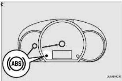
If there is a malfunction in the system, the anti-lock braking system warning light will come on.
Under normal conditions, the ABS warning light comes on when the ignition switch is turned to the "ON" position or the operation mode is put in ON and goes off a few seconds later.
CAUTION
- Any of the following indicates that the anti-lock braking system is not functioning and only the standard brake system is working. (The standard brake system is functioning normally.) If this happens, take your vehicle to an authorized Mitsubishi Motors dealer or a repair facility of your choice.
Features and controls 5-51
Electric power steering system (EPS)
CAUTION
- When the ignition switch is turned to the "ON" position or the operation mode is put in ON, the warning light does not come on or it remains on and does not go off.
• The warning light comes on while driving
5 If the warning light illuminate while driving
N00531700604
If only the anti-lock braking system warning light illuminate
- Avoid hard braking and high-speed driving. Stop the vehicle in a safe place.
Test the system by restarting the engine and driving at a speed of about 12 mph (20 km/h) or higher.
If the warning light then remains off during driving, there is no abnormal condition.
However, if the warning light does not disappear, or if they come on again when the vehicle is driven, have the vehicle checked by an authorized MITSUBISHI MOTORS dealer or repair facility of your choice as soon as possible.
If the anti-lock braking system warning light and brake warning light illuminate at the same time
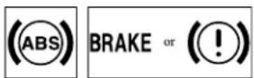
The anti-lock braking system and brake force distribution function may not work, so hard braking could make the vehicle unstable.
Avoid hard braking and high-speed driving. Stop the vehicle in a safe place and contact an authorized MITSUBISHI MOTORS dealer or repair facility of your choice.
After driving on icy roads
N00529200080
After driving on snow or icy roads, remove any snow and ice which may have be left around the wheels. On vehicles that have an anti-lock braking system, be careful not to damage the wheel speed sensors (A) or the cables located at each wheel.
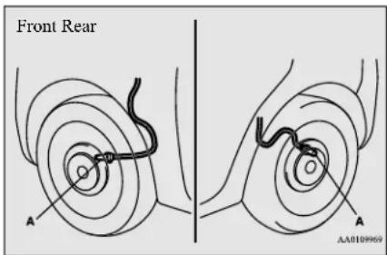
Electric power steering system (EPS)
N00568400074
The power steering system operates while the engine is running. It helps reduce the effort needed to turn the steering wheel.
The power steering system has mechanical steering capability in case the power assist is lost. If the power assist is lost for some reason, you will still be able to steer your vehicle, but you will notice it takes much more effort to steer. If this happens, have your vehicle inspected at an authorized Mitsubishi Motors dealer or a repair facility of your choice.

WARNING
- Do not stop the engine while the vehicle moving. Stopping the engine would make the steering wheel extremely hard to turn, possibly resulting in an accident.
Electric power steering system is warning light

NOTE
- During repeated full-lock turning of the steering wheel (for example, while you are manoeuvring the vehicle into a parking space), a protection function may be activated to prevent overheating of the power steering system. This function will make the steering wheel gradually harder to turn. In this event, limit your turning of the steering wheel for a while. When the system has cooled down, the steering effort will return to normal. - If you turn the steering wheel while the vehicle is stationary with the headlights on, the headlights may become dim. This behavior is not abnormal. The headlights will return to their original brightness after a short while.
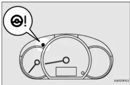
If there is a malfunction in the system, the warning light will come on. Under normal conditions, the warning lamp comes on when the ignition switch is turned to the "ON" position or the operation mode is put in ON, and goes off after the engine has started.
CAUTION
- If the warning light appears while the engine is running, have the vehicle inspected by an authorized Mitsubishi Motors dealer or a repair facility of your choice as soon as possible. It may become harder to turn the steering wheel.
Active stability control (ASC)
N00559100176
The Active stability control (ASC) takes overall control of the anti-lock braking system, traction control function and skid control function to help maintain the vehicle's control and traction. Please read this section in conjunction with the page on the anti-lock braking system, traction control function and skid control function.
Anti-lock braking system → P.5-51
Traction control function P.5-54
Skid control function → P.5-54

CAUTION
- Do not over-rely on the ASC. Even the ASC cannot prevent the natural laws of physics from acting on the vehicle. This system, like any other system, has limits and cannot help you to maintain traction and control of the vehicle in all circumstances. Reckless driving can lead to accidents. It is the driver's responsibility to drive carefully. This means taking into account the traffic, road and environmental conditions.
- Be sure to use the same specified type and size of tire on all four wheels. Otherwise, the ASC may not work properly.
Active stability control (ASC)
CAUTION
- Do not install any aftermarket limited slip differential (LSD) on your vehicle. The ASC may stop functioning properly.
ning excessive, thus helping the vehicle to start moving from a stopped condition. It also provides sufficient driving force and steering performance as the vehicle turns while pressing the acceleration pedal.
deactivate the system by pressing down the "ASC OFF" switch for 3 seconds or longer. When the ASC is deactivated, the indicator will turn on. To reactivate the ASC, momentarily press the "ASC OFF" switch; the indicator is turned off.
NOTE
- An operating sound or vibration may be emitted from under the body in the following situations. The sound or vibration is associated with checking the operations of the ASC. At this time, you may feel a shock from under the body and the brake pedal if you depress it. These do not indicate a malfunction.
- When the ignition switch is turned to the "ON" position or the operation mode is put in ON.
- When the vehicle is driven for a while after the engine is turned on.
- When the ASC is activated, you may feel a vibration in the vehicle body or hear a whining sound from the engine compartment. This indicates that the system is operating normally. It does not indicate a malfunction.
- When the anti-lock braking system warning light is illuminated, the ASC is not active.
CAUTION
- When driving a vehicle on a snowy or icy road, be sure to install snow tires and drive the vehicle at moderate speeds.
Skid control function
N00559300051
The skid control function is designed to help the driver maintain control of the vehicle on slippery roads or during rapid steering maneuvers. It works by controlling the engine output and the brake on each wheel.
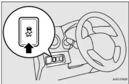
NOTE
● The skid control function operates at speeds of about 9 mph (15 km/h) or higher.
CAUTION
- For safety reasons, the "ASC OFF" switch should be operated when your vehicle is stopped.
- Be sure to keep the ASC on while driving in normal circumstances.
Traction control function
N00559200076
On slippery surfaces, the traction control function prevents the drive wheels from spin-
ASC OFF switch
N00559400254
The ASC is automatically activated when the ignition switch is turned to the "ON" position or the operation mode is put in ON. You can
NOTE
- Using the "ASC OFF" switch turns off both the stability control function and the traction control function.
5-54 Features and controls

NOTE
- When moving out of mud, sand or fresh snow, pressing the accelerator pedal may not allow the engine speed to increase. In such situations, temporarily turning off ASC with the "ASC OFF" switch will make it easier to move out your vehicle.
- If you continue to press the "ASC OFF" switch after the ASC is turned off, the "mistaken operation protection function" will activate and the ASC will turn back on.
ASC operation indicator or ASC OFF indicator
N00546500118

ASC operation indicator
The indicator will blink when the ASC is operating.

ASC OFF indicator
This indicator will turn on when the ASC is turned off with the "ASC OFF" switch.

CAUTION
- When indicator blinks, ASC is operating, which means that the road is slippery or that your vehicle's wheels are beginning to slip. If this happens, drive slower with less accelerator input.

NOTE
- The indicator may turn on when you start the engine. This means that the battery voltage momentarily dropped when the engine was started. It does not indicate a malfunction, provided that the display goes out immediately.
- When a compact spare tire has been put on your vehicle, the gripping ability of the tire will be lower, making it more likely that the
indicator will blink.
ASC warning indicator
N00546600119
If an abnormal condition occurs in the system, the following indicator will turn on.
ASC indicator
ASC OFF indicator

CAUTION
● The system may be malfunctioning.
Park your vehicle in a safe place and stop the engine.
Restart the engine and check whether the indicator goes out. If they go out, there is no abnormal condition. If they do not go out or appear frequently, it is not necessary to stop the vehicle immediately, but you should have your vehicle inspected by an authorized Mitsubishi Motors dealer or a repair facility of your choice as soon as possible.
Towing
N00546300031

CAUTION
- When towing the vehicle with only the front wheels or only the rear wheels raised off the ground, do not place the ignition switch in the "ON" position or do not put the operation mode in ON. Placing the ignition switch in the "ON" position or putting the operation mode in ON could cause the ASC to operate, resulting in an accident. Note that the correct towing method depends on the transmission type and the vehicle's drive configuration. For details, refer to "Towing" on page 8-12.
Cruise control (if so equipped)
Cruise control (if so equipped)
N00518301655
Cruise control is an automatic speed control system that keeps a set speed. It can be activated at speeds from about 25 mph (40 km/h). Cruise control does not work at speeds below about 25 mph (40 km/h).
CAUTION
- When you do not wish to drive at a set speed, turn off the cruise control for safety.
- Do not use cruise control when driving conditions will not allow you to stay at the same speed, such as in heavy traffic or on roads that are winding, icy, snow-covered, wet, slippery, on a steep downhill slope.
NOTE
- Cruise control may not be able to keep your speed on uphills or downhills.
- Your speed may decrease on a steep uphill. You may use the accelerator pedal if you want to stay at your set speed.
- Your speed may increase to more than the set speed on a steep downhill. You have to use the brake to control your speed. As a result, the set speed driving is deactivated.
Cruise control switches
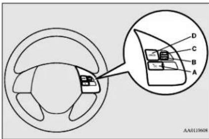
A- CRUISE CONTROL ON/OFF switch
Used to turn on and off the cruise control.
B- SET - switch
Used to reduce the set speed and to set the desired speed.
C-RES + switch
Used to increase the set speed and to return to the original set speed.
D-CANCEL switch
Used to deactivate the set speed driving.
NOTE
- When operating the cruise control switches, press the cruise control switches correctly. The set speed driving may be deactivated automatically if two or more switches of the cruise control are pressed at the same time.
To activate
NO518400385
- With the ignition switch is in "ON" position or the operation mode is in ON, press the CRUISE CONTROL ON/OFF switch (A) to turn on the cruise control. The indicator in the meter cluster will come on.
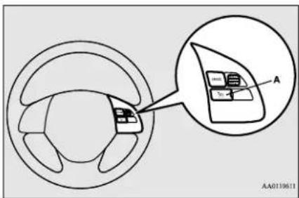
Indicator

- Accelerate or decelerate to your desired speed, then press and release the SET-switch (B) when the indicator is illuminated. The vehicle will then maintain the desired speed.
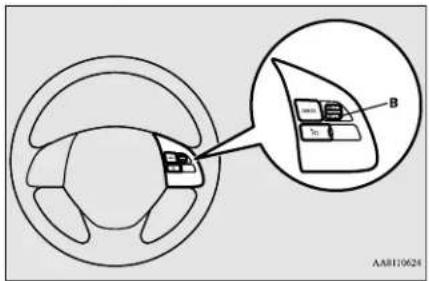

NOTE
- When you release the SET - switch, the vehicle speed will be set.
To increase the set speed
N00518500344
There are 2 ways to increase the set speed.
RES + switch
Press and hold the RES + switch (C) while driving at the set speed, and your speed will then gradually increase.
When you reach your desired speed, release the switch. Your new cruising speed is now set.
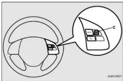
To increase your speed in small amounts, press the RES + switch for less than about 1 second and release it.
Each time you press the RES + switch, your vehicle will go about 1 mph (1.6 km/h) faster.
Accelerator pedal
While driving at the set speed, use the accelerator pedal to reach your desired speed and then press the SET - switch (B) and release the switch momentarily to set a new desired cruising speed.
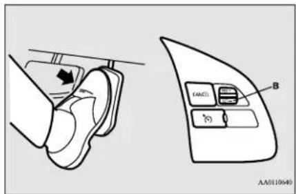
To decrease the set speed
N00518600273
There are 2 ways to decrease the set speed.
SET - switch
Press and hold the SET - switch (B) while driving at the set speed, and your speed will slow down gradually.
When you reach your desired speed, release the switch. Your new cruising speed is now set.
Cruise control (if so equipped)
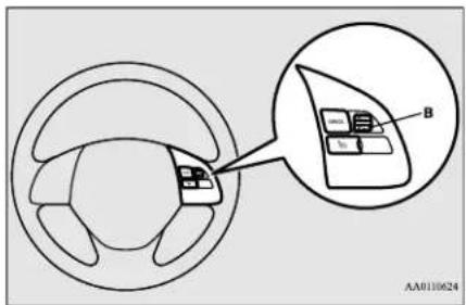
To slow down your speed in small amounts, press the SET - switch for less than about 1 second and release it. Each time you press the SET - switch, your vehicle will slow down by about 1 mph (1.6 km/h).
Brake pedal
While driving at the set speed, use the brake pedal, which disengages the cruise control, then press the SET - switch (B) and release the switch momentarily to set a new desired cruising speed.
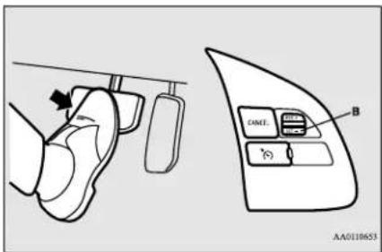
To temporarily increase or decrease the speed
N00541700056
To temporarily increase the speed
Depress the accelerator pedal as you would normally. When you release the pedal, you will return to your set speed.
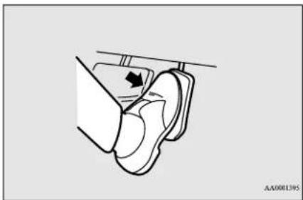
natural_image
Diagram of a mechanical component with a curved arrow indicating direction (no text or symbols)To temporarily decrease the speed
Depress the brake pedal to decrease the speed. To return to the previously set speed, press the RES + switch (C). Refer to "To resume the set speed" on page 5-59.
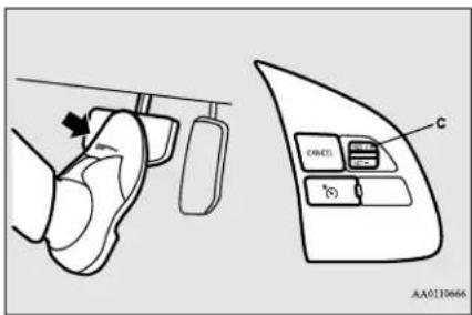
To deactivate
N00518801647
The set speed driving can be deactivated as follows:
- Press the CRUISE CONTROL ON/OFF switch (A). (Cruise control will be turned off.)
- Press the CANCEL switch (D).
- Depress the brake pedal.
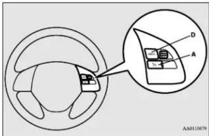
The set speed driving is deactivated automatically in any of the following ways.
- When your speed slows to about 10 mph (15 km/h) or more below the set speed because of a hill, etc.
- When your speed slows to about 25 mph (40 km/h) or less.
- When the active stability control (ASC) starts operating.
Refer to "Active stability control (ASC)" on page 5-53.
WARNING
- Although the set speed driving will be deactivated when shifting to the "N" (NEUTRAL) position, never move the selector lever to the "N" (NEUTRAL) position while driving.
You would have no engine braking and could cause a serious accident.
Also, the set speed driving may be deactivated as follow:
- When the engine speed rises and approaches the tachometer's red zone (the red-colored part of the tachometer dial).
CAUTION
- When the set speed driving is deactivated automatically in any situation other than those listed above, there may be a system malfunction.
Press the CRUISE CONTROL ON/OFF switch to turn off the cruise control and have your vehicle inspected by an authorized Mitsubishi Motors dealer or a repair facility of your choice.
To resume the set speed
N00518900306
If the set speed driving is deactivated by the condition described in "To deactivate" on page 5-59, you can resume the previously set speed by pressing the RES + switch (C) while driving at a speed of about 25 mph (40 km/h) or higher.
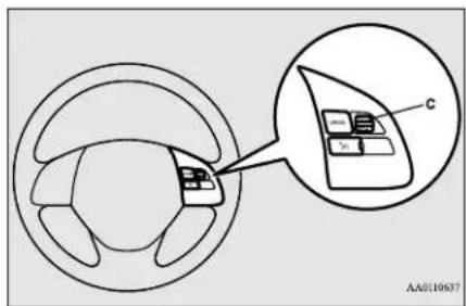
Under either of the following conditions, however, using the switch does not allow you to resume the previously set speed. In these situations, repeat the speed setting procedure:
● The CRUISE CONTROL ON/OFF switch is pressed.
● [Except for vehicles equipped with the F.A.S.T.-key]
Turn the ignition switch to the "OFF" or "ACC" position.
[ Vehicles equipped with the F.A.S.T.-key]
Features and controls 5-59
Forward Collision Mitigation system (FCM) (if so equipped)
Put the operation mode in OFF or ACC. - Indicator is turned OFF.
Forward Collision Mitigation system (FCM) (if so equipped)
N00577300138
The Forward Collision Mitigation system (FCM) is designed to help reduce the risk of a collision with a vehicle or a pedestrian straight ahead of your vehicle. The FCM uses a sensor (A) to determine the distance and relative speed to a vehicle and a pedestrian in front. The FCM is not designed as an automatic driving system or as a collision avoidance system.
When your vehicle is approaching a vehicle or a pedestrian straight-ahead in your path and the FCM judges that there is the risk of a collision, the system will give audible and visual warnings.
When the FCM judges that a collision with the vehicle or the pedestrian straight-ahead is imminent, the system will automatically apply moderate braking to warn you to apply the brakes immediately.
When the FCM judges that a collision with the vehicle or the pedestrian straight-ahead is highly unavoidable, the system will apply emergency braking to reduce the severity of
the collision and, if possible, to avoid the collision. Stop lights are illuminated during automatic braking.
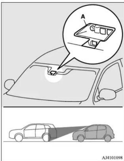
WARNING
- Before using the FCM, read this entire section to fully understand the limitations of this system. Failure to follow instructions could result in an accident.
WARNING
- The FCM is designed to help avoid certain frontal collisions or reduce the crash speed in such collisions. It is not a substitute for your safe and careful driving. Under certain circumstances, the system may not operate or may not detect correctly a vehicle or a pedestrian in front. When your vehicle is approaching a vehicle or a pedestrian too closely, take all necessary actions to avoid a collision, such as braking and steering, regardless of whether the FCM is activated or not. Never rely on the FCM to prevent a collision.
● Never attempt to test the operation of the FCM. Doing so could cause an accident, resulting in serious injury or death.
Forward collision warning function
N00577400D96
If the system judges that there is your vehicle colliding with a vehicle or the pedestrian in front, this function warns you of the potential hazard with the indicator blinks and audible alarms.
When this function is triggered, a buzzer sounds and, at the same time, the following indicator blinks.
The FCM will also prepare to provide quick brake response and greater brake force when you apply the brakes.
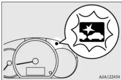
natural_image
Diagram of a car dashboard with a thought bubble showing a vehicle icon and label 'AJA122454' (no readable text or symbols on the diagram itself)The forward collision warning function operates when the following vehicle speed:
- Against a vehicle: Approximately 10 mph a (15km/h) to 87mph (140 km/h).
● Against a pedestrian: Approximately 5 mph (7 km/h) to 40 mph (65 km/h).
FCM braking function
N00572700161
When the FCM judges that a collision with the vehicle or the pedestrian straight-ahead is imminent, the FCM will automatically apply moderate braking to warn the driver to apply the brakes immediately.
If the FCM judges that the collision is highly unavoidable, it will automatically apply emergency braking to reduce the severity of the collision and, if possible, to avoid the collision.
When the FCM applies emergency braking, a buzzer sounds and the indicator blinks in the meter cluster.
The FCM braking function operates when the following vehicle speed:
- Against a vehicle: Approximately 3 mph (5 km/h) to 50 mph (80 km/h).
- Against a pedestrian: Approximately 3 mph (5 km/h) to 40 mph (65 km/h).
WARNING
- If the Active stability control (ASC) is turned off, the FCM braking function will not operate. Refer to "Active stability control (ASC)" on page 5-53.
- If the brake pedal is not depressed within 2 seconds after your vehicle has been stopped by the FCM, a warning buzzer will sound and the brakes activated by the FCM will automatically be released. Apply the brakes as necessary to keep your vehicle stationary.
● The FCM will not activate and will not provide either warning or braking in certain situations. Some of these include: - When the selector lever is in the "P" (PARK) or "R" (REVERSE) position.
- When an object other than a vehicle or a pedestrian is in front.
- When the FCM has detected a problem in the system.
- When a vehicle or a pedestrian suddenly cuts in front of your vehicle.
- The FCM may or may not detect a motorcycle, bicycle or wall depending on the situation. The FCM is not designed to detect these objects.
- The forward collision warning function and/or the FCM braking function may not activate in certain situations. Some of these include:
- When a vehicle suddenly appears just in front of your vehicle.
WARNING
- When a vehicle cuts into your path at a close distance.
- When a vehicle ahead is not completely in your path.
- When your vehicle changed lanes, and your vehicle approached immediately behind the vehicle ahead.
- When a vehicle ahead is towing a trailer.
- When a vehicle ahead is a truck loaded with freight that protrudes rearward from the cargo bed.
- When the height of a vehicle ahead is extremely low or its road clearance is extremely high.
- When a vehicle ahead is extremely dirty.
- When a vehicle ahead is covered with snow.
- When a vehicle ahead has a large glass surface.
- When a vehicle ahead does not have reflectors (light reflector) or the position of the reflector is low.
- When a vehicle ahead is a car carrier or a similar shaped vehicle.
- When accelerating and decelerating quickly.
- When driving on a slippery road covered by rain water, snow, ice, etc.
- When driving on a road with alternating up and down steep slopes.
- When driving on a curve.
- When driving on a bumpy or rough road.
WARNING
- When driving in dark areas, such as in a tunnel or at night.
- When the system recognizes driver's steering, accelerating, braking or gear shifting actions as evasive actions to avoid collision.
- When the rear of your vehicle is weighed down with the weight of passengers and luggage.
- Up to several seconds after starting driving.
- In adverse weather conditions, such as rain, snow, fog or sand-storm.
- When the windshield of the sensor portion is covered with dirt, water droplets, snow and ice, etc.
- When a vehicle ahead or an oncoming vehicle is splashing water, snow or dirt.
- When using a windshield washer.
- If windshield wipers are not Mitsubishi Motors Genuine parts or equivalent.
- When the sensor becomes extremely hot or cold.
- If the battery becomes weak or runs down.
- When the sensor is affected by strong light, such as direct sunlight or the headlights of an oncoming vehicle.
● The FCM may not detect a pedestrian in certain situations. Some of these include:
WARNING
- If the pedestrian is shorter than approximately 3.2 feet (1 m) approximately 6.5 feet (2 m).
- If the pedestrian is wearing loose-fitting clothes.
- If part of a pedestrian's body is hidden, such as when holding an umbrella, large bag, etc.
- If a pedestrian bends forward, sits or lies on the road.
- When a pedestrian is pushing/pulling something, such as a stroller, bicycle or wheelchair.
- When pedestrians gather in a group.
- When a pedestrian clothing appears to be nearly the same color or brightness as its surroundings.
- When a pedestrian is very close to an object, such as a vehicle.
- When a pedestrian is in a dark area, such as at night or in a tunnel.
- When a pedestrian is walking fast or running.
- When a pedestrian suddenly rushes in front of the vehicle.
- When the position of a pedestrian is close to the edge of the vehicle.
- When the system recognizes driver's steering or accelerating actions as evasive actions to avoid a collision, FCM control and alarm functions may be canceled.

WARNING
- In certain situations, though there is little or no risk of a collision, the activate. Examples include:
- When overtaking a vehicle.
- When driving on a curve.
- When there is a road side object (B) that reflects the radar sensor signal, such as a road sign.
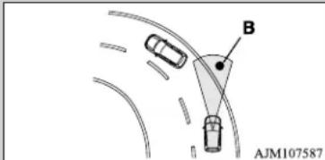
- When approaching a gate, a railroad crossing, an underpass, a narrow bridge, manhole lid or a speed bump.
- When driving under an overpass or pedestrian bridge.
- When driving in a narrow tunnel.
- When driving in a parking structure.
- When approaching a slope where the incline changes significantly.
- When trying to stop your vehicle very close to a vehicle or an object in front.

WARNING
- When passing a vehicle, a pedestrian or F C M anabject closely.
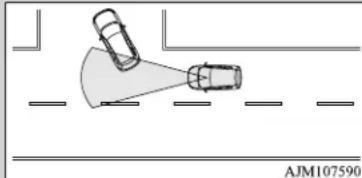
natural_image
Diagram showing two cars approaching a road with a shaded triangular area, no text or symbols present- When a vehicle in the next lane becomes positioned directly in front of your vehicle due to winding road conditions.
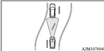
natural_image
Pure diagram of a mechanical or electrical component with no visible text, numbers, or symbols- When passing through an area that objects may contact the vehicle, such as thick grass, tree branches, or a banner.
- When there are patterns on the road that may be mistaken for a vehicle or a pedestrian.
- When a vehicle cuts into your path in the detecting range of the sensor.
- When an oncoming vehicle is positioned straight ahead of y o curved road.

WARNING
- When the FCM detects a long object carried on your vehicle, such as skis or a roof carrier.
- When driving through fog, steam, smoke or dust.
● The FCM should be tuned off if any of following situations occur: - When using an automatic car wash.
- When the tires are not properly inflated.
- When the emergency spare tire is used.
- When your vehicle is towed by another vehicle.
- When your vehicle is carried on a truck.
- When your vehicle is on a chassis dynamometer or free rollers.
- If the windshield on or surrounding the sensor is cracked or scratched.

NOTE
- When depressing the brake pedal while automatic braking is applied, the brake pedal will feel firm. This is normal. Depress the brake pedal harder to apply greater braking force.
- During the automatic braking, operating sounds may be heard. This is normal.
ur vehicle on a
Forward Collision Mitigation system (FCM) (if so equipped)
FCM ON/OFF switch
N00577800146
This switch is used to turn on or off the FCM, and also to select the distance which will trigger the forward collision warning function.
5
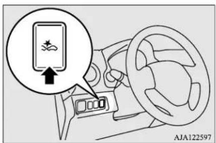
To turn on/off the FCM
Every time the ignition switch is turned to the "ON" position or the operation mode is put in "ON", the FCM will automatically be turned on.
To turn off the FCM, press and hold the FCM ON/OFF switch. The following message will appear in the multi-information display and the indicator will come on in the instrument cluster.
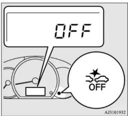
To turn on the FCM again, press and hold the FCM ON/OFF switch. The indicator on the instrument cluster will go off, and a current distance mode for the forward collision warning will be shown in the multi-information display.
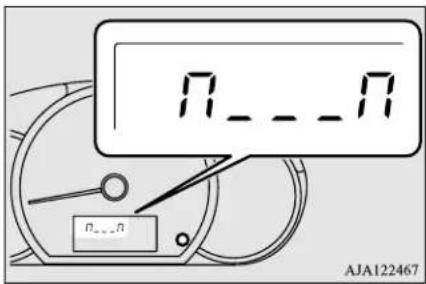
To change forward collision warning distance
The distance to the vehicle ahead which triggers the forward collision warnings can be selected from three levels, "FAR", "MIDDLE" or "NEAR".
To change the distance mode, press the FCM ON/OFF switch. Every time the switch is pressed, the distance mode will be switched.
The selected distance mode is shown on the multi-information display.
Forward Collision Mitigation system (FCM) (if so equipped)
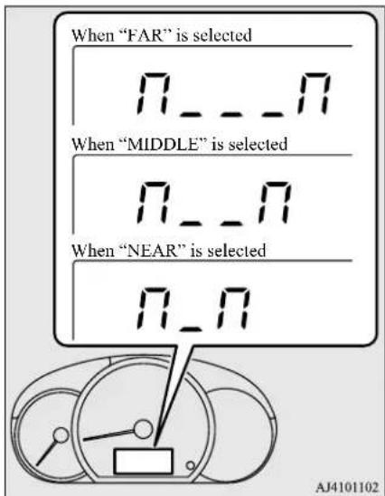

NOTE
- Actual distance which triggers the forward collision warnings will vary depending on your vehicle speed and the front vehicle speed. The distance will become longer when the vehicle speeds are higher.
● The distance which will trigger the FCM braking function cannot be adjusted.
System problem warning
N00594800066
If there is a malfunction in the system, the following indicators will illuminate or blink depending on the situation.
When the sensor cannot detect accurately
N00594900067
When the FCM system determines that its performance has been degraded, the FCM will become inoperative.
This can occur when
● Foreign objects, such as dirt, snow, ice, mist or dew condensation adhere to the windshield of the sensor portion.
● In adverse weather conditions, such as rain, snow, sand storms, etc.
● A front vehicle or an oncoming vehicle is splashing water, snow or dirt.
The FCM indicator will blink and the FCM OFF indicator will illuminate.
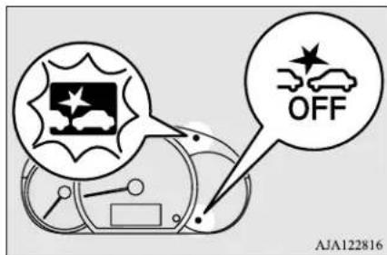
When the sensor performance returns, the FCM functions will resume operation. If the indicators remain, there is a possibility that the sensor has a malfunction. Contact an authorized Mitsubishi Motors dealer for inspection of the sensor.

NOTE
● The indicators may temporarily blink and illuminate when the sensor cannot detect a vehicle, a pedestrian or an object within range. This is not a malfunction. When a vehicle or an object comes within range, the FCM function will resume and the indicators will go off.
● The indicators may blink and illuminate when driving on a nonbusy road with a few vehicles and obstacles in front.
Forward Collision Mitigation system (FCM) (if so equipped)

NOTE
- On vehicles with Lane Departure Warning (LDW), if the LDW is ON, the Lane Departure Warning light (yellow) will blink at the same time.
FCM deactivation due to fault
N00595300084
If the FCM detects a malfunction in the system, the following indicators will illuminate, and the FCM will automatically be turned off.

NOTE
- If the sensor or its surrounding area becomes extremely high temperature when parking the vehicle under a blazing sun, the indicators may illuminate. If the indicators remain even after the temperature of the sensor or its surrounding area is within normal range, please contact an authorized Mitsubishi Motors dealer.
Handling of the sensor
N00593400140
The sensor (A) is located inside the wind-shield as shown in the illustration.
The sensor is shared in the following systems:
FCM
● Lane Departure Warning (LDW) (if so equipped)
● Automatic High Beam (AHB) (if so equipped)
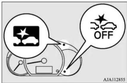
If the indicators remain even after the ignition switch is turned to the "OFF" position and then turned back to the "ON" position or the operation mode is put in OFF and then turned back to ON, please contact your authorized Mitsubishi Motors dealer.
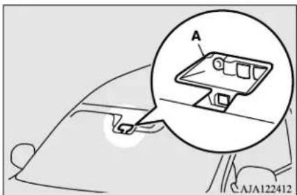
natural_image
Diagram of a car interior showing a component with a magnified inset labeled 'A', no readable text or symbols present.
CAUTION
● To maintain proper performance of the FCM, LDW and AHB;
• Always keep clean the windshield.
If the inside of the windshield where the sensor is installed becomes dirty or fogged, contact an authorized Mitsubishi Motors dealer.
CAUTION
- Do not apply an impact or load on the sensor or its surrounding area.
- Do not put anything including a sticker or film to the outer side of the windshield in front of or surrounding area of the sensor. Also, do not put anything including a sticker or film to the inner side of the windshield under the sensor.
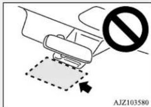
- Do not attempt to detach or disassemble the sensor.
- If the windshield is misted, remove the mist from the windshield by using the defogger switch.
- Maintain the wiper blades in good condition. Refer to "Wiper blades" on page 9-41. When replacing the wiper blades, use only Mitsubishi Motors Genuine parts or equivalent.
- Do not dirty or damage the sensor.
- Do not spray glass cleaner on the sensor. Also, do not spill liquid, such as a beverage, to the sensor.
CAUTION
- Do not install an electronic device, such as antenna, or a device that emits strong electric waves, near the sensor.
• Always use tires of the same size, same type and same brand, and which have no significant wear differences. - Do not modify the vehicle's suspensions.
- If the windshield on the sensor or in the surrounding area of the sensor is cracked or scratched, the sensor may not detect an object properly. This could cause a serious accident. Turn off the FCM and have your vehicle inspected as soon as possible at an authorized Mitsubishi Motors dealer. If you need to replace the windshield, contact an authorized Mitsubishi Motors dealer.
- The sensor emits infrared rays when the ignition switch is turned to the "ON" position or the operation mode is put in ON. Do not look into the sensor by using optical goods such as a magnifying glass. The infrared ray might injure your eyes.
Laser radar specifications
FDA Assertion number: 1520863-000
Laser classification
| Max average power 45 mW | |
| Pulse duration 33 ns | |
| Wavelength 905 nm | |
| Divergent angle (horizon x vertical) | 28° x 12° |
Laser classification label
For vehicles sold in U.S.A.
Laser explanatory label
 Lane Departure Warning (LDW) (if so equipped)Lane Departure Warning (LDW) (if so equipped)
N00577900147 The Lane Departure Warning (LDW) is a driving aid system to help prevent unintentional lane departure. The LDW is designed to read lane markers by using a sensor (A) under certain conditions. The LDW will give you both visual and audible warnings when your vehicle is leaving or has left the lane. natural_image
Diagram of a car interior with a magnified inset showing a device labeled 'A' (no text or symbols present)natural_image
Top-down line drawing of a car on a road with lane markings (no text or symbols)WARNING
- Never rely solely on the LDW. The LDW is not a collision avoidance system and is not a substitute for your safe and careful driving. - Before using the LDW, read this entire section to understand the limitations of this system. Failure to follow instructions could result in an accident.To turn on/off the LDW
NOTE
● The LDW is turned on when the vehicle is shipped from the factory. - The currently selected LDW setting (on off) is stored even when the ignition switch is turned to the "OFF" position or the operation mode is put in OFF. To turn on the LDW, press the LDW switch. The LDW indicator (green) in the meter cluster will illuminate.  To turn off the LDW, press the LDW switch. The LDW indicator (green) in the meter cluster will then go out. To return the LDW to "ON", press the LDW switch again. Operation of the LDW
N00581100108 The LDW, when turned ON, is capable of recognizing the lane in which your vehicle is travelling and issuing an audible warning when your vehicle begins to leave that travel lane. The LDW will not operate, however, if any of following conditions have occurred: ● The vehicle speed is less than approximately 38 mph (60 km/h). ● The turn signal lever is being operated or has been operated in the past 7 seconds. ● The hazard warning light is being operated or has been operated in the past 7 seconds.Lane departure warning
N00581200095 While the Lane Departure Warning indicator (green) in the meter cluster is lit, if your vehicle is leaving or has left the lane, a buzzer will sound intermittently and the Lane Departure Warning light (yellow) will blink rapidly.  NOTE
- The warnings will not continue for more than 3 seconds, even if your vehicle continues leaving the lane. - If the lane markers are only on one side of the road, the LDW will operate only for the appropriate side where the lane marker is drawn. WARNING
- The LDW will not function when no lane marker exists, such as at an intersection or near a toll booth. ● The LDW may not operate correctly in the following situations and the LDW may not give warnings or may give false warnings: - When lane markers are not clearly visible due to rain, snow, fog, dark area, etc. - When the road surface is shiny. - When old lane markers remain on the road surface. - When the lane markers are double lines or the shape of the lane complicated. - When driving in an extremely narrow lane. - When the distance between your vehicle and a vehicle in front is short. - When driving into the sun light. - When driving on curves. - When driving on bumpy roads. - When driving in construction zones. - When passing through a place where the brightness suddenly changes, such as at the entrance to or exit of a tunnel. - When the headlights of an oncoming vehicle are very bright. - When the rear of your vehicle is weighed down with the weight of passengers and luggage. - When the headlights of your vehicle are not clean or are not properly aimed.WARNING
- When the front windshield is not clean. - When the front windshield wipers do not clean the windshield properly.CAUTION
- To maintain proper function of the LDW: • Always keep the windshield and the headlights clean. - Do not put anything, such as a sticker, on the front windshield in front of the sensor. - Avoid applying a shock or load to the sensor. - Do not attempt to detach or disassemble the sensor. - Use only Mitsubishi Motors Genuine parts when replacing the windshield wipers.NOTE
\- When driving conditions are not suitable use the LDW, turn off the LDW.When the sensor cannot detect accurately
N0059860020 If the LDW system determines that its performance has been degraded, the Lane Departure Warning light (yellow) will blink slowly. This can occur when
to ● Foreign objects, such as dirt, snow, ice, mist or dew condensation adhere to the windshield of the sensor portion. - In adverse weather conditions, such as rain, snow, sand storms, etc. ● A front vehicle or an oncoming vehicle is splashing water, snow or dirt.System problem warning
N00578100074 If there is a malfunction in the system, the warning light will illuminate or blink depending on the situation. When the sensor performance returns, the LDW functions will resume operation. If the warning light remains, there is a possibility that the sensor has a malfunction. Con- tact an authorized Mitsubishi Motors dealer for inspection of the sensor.NOTE
\- If the Forward Collision Mitigation system (FCM) is ON, the FCM indicator will blink and the FCM OFF indicator will illuminate at the same time.LDW deactivation due to fault
If the LDW detects a malfunction in the system, the Lane Departure Warning light (yellow) will illuminate, and the LDW will automatically be turned off.  If the warning light remains even after the ignition switch is turned to the "OFF" position and then turned back to the "ON" position or the operation mode is put in OFF and then turned back to ON, contact your autho- Tire pressure monitoring system (TPMS) (if so equipped) rized Mitsubishi Motors dealer for inspection of the system. NOTE
\- If the sensor or its surrounding area becomes extremely high temperature when parking the vehicle under a blazing sun, the warning light may illuminate. If the warning light remains even after the temperature of the sensor or its surrounding area is within normal range, please contact an authorized Mitsubishi Motors dealer.Tire pressure monitoring system (TPMS) (if so equipped)
N00530201683 The tire pressure monitoring system (TPMS) uses tire inflation pressure sensors (A) on the wheels to monitor the tire inflation pressures. The system only indicates when a tire is significantly under-inflated. natural_image
Line drawing of a car with three wheels and connected points, no text or symbols presentNOTE
- The TPMS is not a substitute for regularly checking tire inflation pressures. Be sure to check the tire inflation pressures as described in "Tires" on page 9-13. - The tire inflation pressure sensor (A) is installed in the illustrated location. Replace rubber air valve (B) with a new one when the tire is replaced. For details, please contact your authorized Mitsubishi Motors dealer.  WARNING
\- The compact spare wheel does not have a tire inflation pressure sensor. When the spare tire is used, the TPMS will not work properly. See an authorized Mitsubishi Motors dealer as soon as possible to replace or repair the original tire. Tire pressure monitoring system (TPMS) (if so equipped)Tire pressure monitoring sys- tem warning light
N00532701435  When the ignition switch is "ON" position or the operation mode is put in ON, the tire pressure monitoring system warning light normally illuminates and goes off a few seconds later. If one or more of the vehicle tires (except for the spare tire) is significantly under-inflated, the warning light will remain illuminated while the ignition switch or the operation mode is in ON. Refer to “If the warning light illuminates while driving” on page 5-73 and take the necessary measures.CAUTION
\- If the tire pressure monitoring system warning light does not illuminate when the ignition switch is turned to the "ON" position or the operation mode is put in ON, it means that the tire pressure monitoring system is not working properly. Have the system inspected by an authorized Mitsubishi Motors dealer. In such situations, a malfunctioning of the system may be preventing the monitoring of the tire pressure. Avoid sudden braking, sharp turning and high-speed driving. \- If a malfunction is detected in the tire pressure monitoring system, the tire pressure monitoring system warning light will blink them to the for approximately 1 minute and then remain continuously illuminated. The warning light will issue further warnings each time the engine is restarted as long as the malfunction exists. Check to see whether the warning light goes off after few minutes driving. If it then goes off during driving, there is no problem. However, if the warning light does not go off, or if it blinks again when the engine is restarted, have the vehicle inspected by an authorized Mitsubishi Motors dealer. In such situations, a malfunctioning of the system may be preventing the monitoring of the tire pressure. For safety reasons, when the warning light appears while driving, avoid sudden braking, sharp turning and high-speed driving. Each tire, including the spare, should be checked monthly when cold and inflated to the inflation pressure recommended by the vehicle manufacturer on the vehicle placard or tire inflation pressure label. (If your vehicle has tires of a different size than the size indicated on the vehicle placard or tire inflation pressure label, you should determine the proper tire inflation pressure for those tires.) As an added safety feature, your vehicle has been equipped with a tire pressure monitoring system (TPMS) that illuminates a low tire pressure telltale when one or more of your tires is significantly under-inflated. Accordingly, when the low tire pressure tell-tale illuminates, you should stop and check your tires as soon as possible, and inflate them to the proper pressure. Driving on a significantly under-inflated tire causes the tire to overheat and can lead to tire failure. Under-inflation also reduces fuel efficiency and tire tread life, and may affect the vehicle's handling and stopping ability. Please note that the TPMS is not a substitute for proper tire maintenance, and it is the driver's responsibility to maintain correct tire pressure, even if under-inflation has not reached the level to trigger illumination of the TPMS low tire pressure telltale. Your vehicle has also been equipped with a TPMS malfunction indicator to indicate when the system is not operating properly. The TPMS malfunction indicator is combined with the low tire pressure telltale. When the system detects a malfunction, the telltale will flash for approximately one minute and then remain continuously illuminated. This sequence will continue upon subsequent vehicle start-ups as long as the malfunction exists. When the malfunction indicator is illuminated, the system may not be able to detect or signal low tire pressure as intended. TPMS malfunctions may occur for a va of reasons, including the installation of replacement or alternate tires or wheels on the vehicle that prevent the TPMS from functioning properly. Always check the TPMS malfunction telltale after replacing one or more tires or wheels on your vehicle to ensure that the replacement or alternate tires and wheels allow the TPMS to continue to function properly.If the warning light illuminates while driving
N00532801566 1. If the tire pressure monitoring system warning light illuminates, avoid hard braking, sharp steering maneuvers and high speeds. You should stop and adjust the tires to the proper inflation pressure as soon as possible. Adjust the spare tire at the same time. Refer to "Tires" on page 9-13. NOTE
- When inspecting or adjusting the tire pressure, do not apply excessive force to the valve stem to avoid breakage. ● After inspecting or adjusting the tire pressure, always reinstall the valve cap on the valve stem. Without the valve cap, dirt or moisture could get into the valve, resulting in damage to the tire inflation pressure sensor. - Do not use metal valve caps, which may cause a metal reaction, resulting in corrosion and damage of the tire inflation pressure sensors. - Once adjustments have been made, the warning light will go off after a few minutes of driving. 2. If the tire pressure monitoring system warning light remains illuminated after you have been driving for approximately 20 minutes after you adjust the tire inflation pressure, one or more of the tires may have a puncture. Inspect the tire and if it has a puncture, have it repaired by an authorized Mitsubishi Motors dealer as soon as possible. WARNING
- If the warning light illuminates while you are driving, avoid hard braking, sharp steering maneuvers and high speeds. Driving with an under-inflated tire adversely affects vehicle performance and can result in an accident. CAUTION
● The warning light may not illuminate immediately in the event of a tire blowout or rapid leak. NOTE
\- To avoid the risk of damage to the tire inflation pressure sensors, have any punctured tire repaired by an authorized Mitsubishi Motors dealer. If the tire repair is not done by an authorized Mitsubishi Motors dealer, damage to the tire inflation pressure sensor is not covered by your warranty. Features and controls 5-73Rear-view camera
NOTE
\- Do not use an aerosol puncture-repair spray on any tire. Such a spray could damage the tire inflation pressure sensors. Have any puncture repaired by an authorized Mitsubishi Motors dealer. The tire pressure monitoring system may not work normally in the following circumstances: ● A wireless facility or device using the same frequency is near the vehicle. ● Snow or ice is stuck inside the fenders and/or on the wheels. - The tire inflation pressure sensor's battery is dead. - Wheels other than Mitsubishi Motors Genuine wheels are being used. - Wheels that are not fitted with tire inflation pressure sensors are being used. - Wheels whose ID codes are not memorized by the vehicle are used. - Compact spare tire is fitted on a road wheel. ● A window tint that affects the radio wave signals is installed. NOTE
\- Tire inflation pressures vary with the ambient temperature. If the vehicle is subjected to large variations in ambient temperature, the tire inflation pressures may be under-inflated (causing the warning light come on) when the ambient temperature is relatively low. If the warning light comes on, adjust the tire inflation pressure.Whenever the tires and wheels are replaced with new ones
NIXI5329IXI153 If new wheels with new tire inflation pressure sensors are installed, their ID codes must be programmed into the tire pressure monitoring system. Have tire and wheel replacement performed by an authorized Mitsubishi Motors dealer to avoid the risk of damaging the tire inflation pressure sensors. If the wheel replacement is not done by an authorized Mitsubishi Motors dealer, it is not covered by your warranty. CAUTION
\- The use of non-genuine wheels will prevent the proper fit of the tire inflation pressure sensors, resulting air leakage or damage of the sensors.General information
N00533001288 Your tire pressure monitoring system operates on a radio frequency subject to Federal Communications Commission (FCC) Rules (For vehicles sold in U.S.A.) and Industry Canada Rules (For vehicles sold in Canada). This device complies with part 15 of FCC Rules and Industry Canada licence-exempt RSS standard(s). Operation is subject to the following two conditions. ● This device may not cause harmful interference. ● This device must accept any interference received, including interference that may cause undesired operation. WARNING
\- Changes or modifications not expressly approved by the manufacturer for compliance could void the user's authority to operate the equipment.Rear-view camera
N00546201431 When the gearshift lever or the selector lever is in the "R" position with the ignition switch or the operation mode is in ON, the rear-view image will be displayed on the screen of the DISPLAY AUDIO or the Smartphone-link Display Audio (SDA). When the gearshift lever or the selector lever is shifted out of the "R" position, the rear-view image will go off. WARNING
\- Never rely solely on the rear-view camera to clear the area behind y Always check visually behind and all around your vehicle for persons, animals, obstructions or other vehicles. Failure to do so can result in vehicle damage, serious injury or death. ● The rear-view camera is an aid system for backing up, but it is not a substitute for your visual confirmation. \- The view on the screen is objects outside the view, such as under the bumper or around either corner of the bumper end, cannot be seen on the screen.Location of rear-view camera
The rear-view camera (A) is in the liftgate, at the left side of the liftgate handle. CAUTION
limit the camera lens gets dirty, a clear image cannot be obtained. As necessary, rinse the lens with clean water and gently wipe with a clean, soft cloth. ● To avoid damaging the camera; - Do not rub the cover excessively or polish it by using an abrasive compound. - Do not disassemble the camera. - Do not splash hot water directly on the lens. - Do not spray the camera and its surroundings with high-pressure water. - Make sure that the liftgate is securely closed when backing up.Reference lines on the screen
Reference lines and upper surface of the rear bumper (A) are displayed on the screen. ● The red line (B) indicates approximately 20 inches (50 cm) behind the rear bumper. ● The Green lines (C) indicate approximately 8 inches (20 cm) outside of the vehicle body. - Short transverse lines (1 to 3) indicate distance from the rear bumper.  1: Approximately at the rear edge of the rear bumper 2: Approximately 39 inches (100 cm) 3: Approximately 79 inches (200 cm)Rear-view camera
CAUTION
● The rear-view camera uses a wide-angle lens. As a result, images and distances shown on the screen are not exact. - Actual distance may be different from distance indicated by the lines on the screen, depending on the loading condition of the vehicle and road surface condition. The reference lines for distance and vehicle width are based on a level, flat road surface. In the following cases, objects shown on the screen will appear to be farther off than they actually are. - When the rear of the vehicle is weighed down with the weight of passengers and luggage in the vehicle. (Case 1) - When there is an upward slope at the back. (Case 2) Case 1  A- Actual objects B- Objects shown on the screen Case 2 CAUTION
\- The reference lines for distance and vehicle width are intended to indicate the distance to a flat object such as a level, flat road surface. They may not indicate correct d depending on the shape of an obstacle. For example, when there is an object behind the vehicle that has upper sections projecting in the direction of the vehicle, the reference lines on the screen will indicate that point A is the farthest point and point B is the closest point to the vehicle. In reality, point A and B are actually the same distance from the vehicle, and point C is farther off than point and B. NOTE
● Mirror image is displayed on the screen. ● Monitor brightness is adjusted automatically by sensors. \- In order certain circumstances, it may become difficult to see an image on the screen, even when the system is functioning correctly. • In a dark area, such as at night. - When water drops or condensation are on the lens. - When sun light or headlights shine directly into the lens. Instrument cluster  1- Tachometer → P.5-77 2- Multi-information display → P.5-78 3- Speedometer → P.5-77 4- Multi-information display switchSpeedometer
N00519101331 The speedometer shows the vehicle speed in miles per hour (mph) or kilometers per hour (km/h).     Tachometer
N00519201332 The tachometer shows engine revolutions per minute. This allows the driver to determine the most efficient selector position and engine speed combinations. This gauge also assists in evaluating engine performance. Features and controls 5-77Multi-information display
CAUTION
\- The red zone indicates an engine speed beyond the range of safe operation. Select the correct shift transaxle) or selector position (CVT) to control the engine speed so that the tachometer indicator does not enter the red zone.  position (man  1- Information display → P.5-79 2- Frozen road warning → P.5-82 3- Fuel remaining display → P.5-82 4- Selector lever position display (if so equipped) → P.5-45Multi-information display
N00555001536 The multi-information display includes the odometer, trip odometer, service reminder, fuel remaining, selector lever position, average fuel consumption, driving range, etc.NOTE
\- When the ignition switch or the operation mode is in OFF, the selector lever position display, fuel remaining display and frozen road warning are not displayed. 5-78 Features and controlsInformation display
N00574801083 Each time you lightly press the multi-information display switch (A), the display switches in the following order. flowchart
graph TD
    A["1: 00/1234 miles"] --> B["2: 376.5 miles"]
    B --> C["3: 290.1 miles"]
    C --> D["4: -00/1 miles"]
    D --> E["5: 100 miles"]
    E --> F["6: AVG@mpg 10.4"]
    F --> G["7: 37 F"]
    G --> H["8: 4800 miles"]
    H --> I["9: 5/1"]
    I --> A
NOTE
- When the ignition switch or the operation mode is in OFF, the driving range display, average fuel consumption display and outside temperature display are not displayed. ● While driving, the service reminder is not displayed even if you operate the multi-information display switch. Multi-information display NOTE
\- When the parking lights are not illuminated, the instrument panel light dimmer control is not displayed even if you operate the multi-information display switch.Odometer
N015749X016 The odometer indicates the total distance the vehicle has traveled.Trip odometer
N0157500014 The trip odometer indicates the distance traveled between two points. Usage examples for trip odometer A, trip odometer B It is possible to measure two currently traveled distances, from home using trip odometer And from a particular point on the way using trip odometer BTo reset the trip odometer
To return the display to 0, hold down the multi-information display switch for about 1 second or more. Only the currently displayed value will be reset. Example 5-80 Features and controls If trip odometer ▶s displayed, only trip odometer ▶will be reset. NOTE
- Both trip odometers A and B count up to 9999.9 miles/kilometers. When a trip odometer goes past 9999.9 miles/kilometers, it returns to 0.0 miles/kilometers. - When disconnecting the battery terminal, the memories of trip odometer displays are cleared, and their displays return to "0.0 miles/kilometers".Instrument panel light dimmer control
N00575101025 Turn the parking lights on and press the multi-information display switch (2), there is a sound and the brightness changes.  1- Brightness level 2- Multi-information display switch NOTE
- When the parking lights are illuminated, you can adjust to 8 levels. ● Each time you reduce two brightness levels, the segment display of the brightness level decreases by one segment. - If you press and hold the switch for longer than about 1 second, the brightness automatically scrolls through its different levels, and stops scrolling when you release the switch. Select your desired level of brightness. NOTE
\- The brightness level of the instruments is stored when the ignition switch is turned to the "OFF" position or the operation mode is put in OFF.Driving range display
N00575201042 This displays the approximate driving range (how many more miles or kilometers you can drive). When the driving range falls below approximately 30 miles (50 km), “---” is displayed. NOTE
● The driving range is determined based on the fuel consumption data. This may vary depending on the driving conditions and habits. Treat the distance displayed as just a rough guideline. - When you refuel, the driving range display is updated. However, if you only add a small amount of fuel, the correct value will not be displayed. Fill to a full tank whenever possible. - When your vehicle is stopped on an extremely steep hill, the driving range value may change. This is due to the movement of fuel in the tank and does not indicate any breakdown. NOTE
\- The display setting can be changed to the preferred units (miles or km). Refer to “Changing the function settings” on page 5-84.Average fuel consumption display
N00575300017 This displays the average fuel consumption from the last reset to the present. The reset mode conditions for the average fuel consumption display can be switched between “Auto reset” and “Manual reset”. For information on how to change the average fuel consumption display setting, refer to “Changing the function settings” on page 5-84. NOTE
- The average fuel consumption display can be reset separately in both auto reset mode and manual reset mode. - “---” is displayed when the average fuel consumption cannot be measured. - The initial (default) setting is “Auto reset mode”. NOTE
● Average fuel consumption may vary depend on the driving conditions (road conditions, how you drive, etc.). The actual fuel consumption may differ from the fuel consumption displayed, so treat the fuel consumption displayed as just a rough guideline. - Disconnecting the battery cable will erase from memory the manual reset mode or auto reset mode setting for the average fuel consumption display. - The display setting can be changed to the preferred units {mpg, km/L, L/100 km}. Refer to “Changing the function settings” on page 5-84.Outside temperature display
N00556501147 Shows the temperature outside the vehicle. NOTE
- The display setting can be changed to the preferred units (°F or °C). Refer to “Changing the function settings” on page 5-84. - Depending on factors such as the driving conditions, the displayed temperature may vary from the actual outside temperature.Multi-information display
Frozen road warning
N00579000070 If the outside air temperature drops below approx. 37 °F (3 °C), the alarm sounds and the outside air temperature warning symbol (A) flashes for about 10 seconds. CAUTION
\- There is a danger the road might be icy, even when this symbol is not flashing, so please take care when driving.Fuel remaining display
N00575401031 The fuel remaining display indicates the fuel level in the fuel tank when the ignition switch or the operation mode in ON.  1 - Full 0- Empty NOTE
- It may take several seconds to stabilize the display after refilling the tank. - If fuel is added with the ignition switch the operation mode in ON, the remaining fuel display may incorrectly indicate the fuel level. - The fuel lid mark (A) indicates that the fuel tank filler door is located on the left side of the vehicle. (Refer to "Filling the fuel tank" on page 3-3.)Fuel remaining warning display
When the remaining fuel level runs low (one segment is displayed), the last segment of the fuel gauge flashes when the ignition switch is turned to the "ON" position or the operation mode is changed to ON. When the remaining fuel level runs very low (no segments displayed), the bar graph flashes. If the warning display appears, refuel as soon as possible.  NOTE
\- On hills or curves, the display may be incorrect due to the movement of fuel in the tank. CAUTION
\- Running out of gas could damage the catalytic converter. If the warning display appears, refuel as soon as possible.Service reminder
N00556701309 Displays the approximate time until the next recommended periodic inspection. “---” is displayed when the inspection time has arrived. NOTE
\- The service reminder time can be modified by an authorized Mitsubishi Motors dealer to adjust for severe usage, etc. Refer to "Severe maintenance schedule" in your vehicle's Warranty and Maintenance Manual. For further information, please contact your authorized Mitsubishi Motors dealer. Distance flowchart
graph LR
    A["1: 800P"] --> B["2: -P"]
    B --> C["3: 4800P"]
    D["1: -P"] --> E["2: -P"]
    E --> F["3: 5P"]
NOTE
● Shows the distance in units of 100 miles (100 km) and the time in units of 1 month. 2. This informs you that a periodic inspection is due. Contact an authorized Mitsubishi Motors dealer or a repair facility of your choice to have the system checked. 3. After your vehicle is inspected at an authorized Mitsubishi Motors dealer, it displays the time until the next periodic inspection. NOTE
\- When the next periodic inspection is approaching, the wrench symbol will be displayed whenever the ignition switch is turned from the "OFF" position to the "ON" position or when the operation mode is changed from OFF to ON. The wrench symbol will continuously be displayed, even on non-service reminder displays (odometer, trip meter, etc.), until the service reminder is reset. When the service reminder resets, the wrench symbol will not be displayed until the next periodic inspection.To reset
The “---” display can be reset while the ignition switch or the operation mode is in OFF. 1. When you lightly press the multi-information display switch a few times, the information display switches to the service reminder display. flowchart
graph LR
    A["3765 Units"] --> B["290 Units"]
    B --> C["Output Box"]
    style A fill:#f9f,stroke:#333
    style B fill:#ccf,stroke:#333
    style C fill:#cfc,stroke:#333
Multi-information display
3. With this indicator flashing, if you lightly press the multi-information meter switch, the display switches from “---” to “cLEAr”. After that, the time until the next periodic inspection is shown. flowchart
graph LR
    A["Input Signal"] --> B["Clear-"]
    B --> C["730G"]
CAUTION
\- The customer is responsible for making sure that regular inspections and maintenance and periodic inspections and maintenance are performed. Inspections and maintenance must be performed to prevent accidents and malfunctions.NOTE
\- The “---” display cannot be reset while the ignition switch or the operation mode is in ON.NOTE
- When “---” is displayed, after a ce tance and a certain period of time, the dis- play is reset and the time until the next periodic inspection is displayed. - If you accidentally reset the display, consul an authorized Mitsubishi Motors dealer for assistance.Changing the function settings
N00556801267 The "Average fuel consumption reset mode", "Fuel consumption unit" and "Temperature unit" setting can be modified as desired, when the ignition switch or the operation mode is ON.CAUTION
● The driver should not operate the display while the vehicle is in motion. - When operating the system, stop the vehicle in a safe area.Changing the reset mode for average fuel consumption
N00575501032 You can change the mode condition for the average fuel consumption display to "Auto reset" or "Manual reset". 1. When you lightly press the multi-information display switch a few times, the information display switches to the driving range display. Refer to "Information display" on page 5-79. 2. Each time you press the multi-information display switch for 1 second or more on driving range display, you can switch reset mode for average fuel consumption. (A: Auto reset mode, B: Manual reset mode) Manual reset mode
- When the average fuel consumption is being displayed, if you hold down the multi-information display switch, these calculations will be reset to zero. - When the following operation is performed, the mode setting changes automatically from manual to auto. [Except for vehicles equipped with the F.A.S.T.-key] Turn the ignition switch to the "ON" position from the "ACC" or "OFF" position. [For vehicles equipped with the F.A.S.T.-key] Change the operation mode to ON from ACC or OFF.Auto reset mode
- When the average fuel consumption is being displayed, if you hold down the multi-information display switch, these calculations will be reset to zero. - When the engine switch or the operation mode is in the following conditions, the average fuel consumption display will automatically reset. [Except for vehicles equipped with the F.A.S.T.-key] The ignition switch has been set to the “ACC” or “OFF” position for about 4 hours or more. [For vehicles equipped with the F.A.S.T.-key] The operation mode has been set to ACC or OFF for about 4 hours or more. NOTE
- The average fuel consumption display can be reset separately for the auto reset mode and for the manual reset mode. - Disconnecting the battery cable will erase from memory the manual reset mode or auto reset mode setting for the average fuel consumption display. - The initial (default) setting is “Auto reset mode”.Changing the fuel consumption display unit
N00557100156 The fuel consumption display unit can be changed. The distance and amount units are also switched to match the selected fuel consumption unit. 1. When you lightly press the multi-information display switch a few times, the information display switches to the average fuel consumption display. Refer to “Information display” on page 5-79. 2. Press and hold the multi-information display switch for about 5 seconds or more until buzzer sound is heard twice. 3. Press and hold the multi-information display switch to switch in sequence from “km/L” → “L/100 km” → “mpg” → “km/L”. flowchart
graph TD
    A["85%"] --> B["5.3%"]
    B --> C["0.0V"]
    C --> D["1.0V"]
    D --> E["2.0V"]
    E --> F["3.0V"]
    F --> G["4.0V"]
    G --> H["5.0V"]
    H --> I["6.0V"]
    I --> J["7.0V"]
    J --> K["8.0V"]
    K --> L["9.0V"]
    L --> M["10.0V"]
    M --> N["11.0V"]
    N --> O["12.0V"]
    O --> P["13.0V"]
    P --> Q["14.0V"]
    Q --> R["15.0V"]
    R --> S["16.0V"]
    S --> T["17.0V"]
    T --> U["18.0V"]
    U --> V["19.0V"]
    V --> W["20.0V"]
    W --> X["21.0V"]
    X --> Y["22.0V"]
    Y --> Z["23.0V"]
    Z --> AA["24.0V"]
    AA --> AB["25.0V"]
    AB --> AC["26.0V"]
    AC --> AD["27.0V"]
    AD --> AE["28.0V"]
    AE --> AF["29.0V"]
    AF --> AG["30.0V"]
    AG --> AH["31.0V"]
    AH --> AI["32.0V"]
    AI --> AJ["33.0V"]
    AJ --> AK["34.0V"]
    AK --> AL["35.0V"]
    AL --> AM["36.0V"]
    AM --> AN["37.0V"]
    AN --> AO["38.0V"]
    AO --> AP["39.0V"]
    AP --> AQ["40.0V"]
    AQ --> AR["41.0V"]
    AR --> AS["42.0V"]
    AS --> AT["43.0V"]
    AT --> AU["44.0V"]
    AU --> AV["45.0V"]
    AV --> AW["46.0V"]
    AW --> AX["47.0V"]
    AX --> AY["48.0V"]
    AY --> AZ["49.0V"]
    AZ --> BA["50.0V"]
    BA --> BB["51.0V"]
    BB --> BC["52.0V"]
    BC --> BD["53.0V"]
    BD --> BE["54.0V"]
    BE --> BF["55.0V"]
    BF --> BG["56.0V"]
    BG --> BH["57.0V"]
    BH --> BI["58.0V"]
    BI --> BJ["59.0V"]
    BJ --> BK["60.0V"]
    BK --> BL["61.0V"]
    BL --> BM["62.0V"]
    BM --> BN["63.0V"]
    BN --> BO["64.0V"]
    BO --> BP["65.0V"]
    BP --> BQ["66.0V"]
    BQ --> BR["67.0V"]
    BR --> BS["68.0V"]
    BS --> BT["69.0V"]
    BT --> BU["70.0V"]
    BU --> BV["71.0V"]
    BV --> BW["72.0V"]
    BW --> BX["73.0V"]
    BX --> BY["74.0V"]
    BY --> BZ["75.0V"]
    BZ --> CA["76.0V"]
    CA --> CB["77.0V"]
    CB --> CC["78.0V"]
    CC --> CD["79.0V"]
    CD --> CE["80.0V"]
    CE --> CF["81.0V"]
    CF --> CG["82.0V"]
    CG --> CH["83.0V"]
    CH --> CI["84.0V"]
    CI --> CJ["85.0V"]
    CJ --> CK["86.0V"]
    CK --> CL["87.0V"]
    CL --> CM["88.0V"]
    CM --> CN["89.0V"]
    CN --> CO["90.0V"]
    CO --> CP["91.0V"]
    CP --> CQ["92.0V"]
    CQ --> CR["93.0V"]
    CR --> CS["94.0V"]
    CS --> CT["95.0V"]
    CT --> CU["96.0V"]
    CU --> CV["97.0V"]
    CV --> CW["98.0V"]
    CW --> CX["99.0V"]
NOTE
- The display units for the driving range, the average fuel consumption are changed, but the units for the indicating needle (speedometer), the odometer, the trip odometer and the service reminder will remain unchanged. - If the battery is disconnected, the memory of the unit setting is erased and it returns automatically to factory setting. The distance units is also changed in the following combinations to match the selected fuel consumption unit. Multi-information display| Fuel consumption | Distance (driving range) |
| km/L km | |
| L/100 km km | |
| mpg mile (s) |
Changing the temperature unit (if so equipped)
N00557201183 The temperature display unit can be switched. 1. When you lightly press the multi-information display switch a few times, the information display switches to the outside temperature display. Refer to "Information display" on page 5-79. 2. Each time you press the multi-information display switch for 5 seconds or more on outside temperature display, you can switch from °F to °C or from °C to °F unit of outside temperature display. NOTE
- The temperature value on air conditioning panel is switched in conjunction with outside temperature display unit of the multi-information display. However, “°F” or “°C” are not shown to temperature display of an air conditioning. 5-86 Features and controlsIndicator and warning light package
N00519801963  1- High beam indicator → P.5-88 2- Electric power steering system warning light → P.5-52 3- Tire pressure monitoring system warning light (if so equipped) → P.5-72 4- Turn signal indicators/Hazard warning lights → P.5-88 5- Forward Collision Mitigation system (FCM) indicator (if so equipped) → P.5-66 6- Front fog light indicator (if so equipped) → P.5-88 7- Washer fluid level warning light (if s15-Charging system warning light equipped) → P.5-91 → P.5-90 8- Door-ajar warning light → P.5-90 9- Supplemental Restraint System (SRS) warning light → P.4-31 10- High coolant temperature warning light (red) → P.5-90 11- Low coolant temperature indicator (green) → P.5-88 12- ECO indicator → P.5-88 13- Oil pressure warning light → P.5-90 14- Engine malfunction indicator ("SERVICE ENGINE SOON" or "Check engine light") → P.5-89 16- Brake warning light → P.5-88 17- Anti-lock braking system warning light → P.5-51 18- Multi-information display → P.5-78 19- Cruise control indicator (if so equipped) → P.5-56 20- Driver's seat belt reminder/warning light → P.4-12 21- Forward Collision Mitigation system (FCM) OFF indicator (if so equipped) → P.5-64 22- Active stability control (ASC) indicator/warning light → P.5-55Indicators
23- Lane Departure Warning (LDW) light (yellow) (if so equipped) → P.5-70 24- Automatic High Beam (AHB) warning light (yellow) (if so equipped) → P.5-96 25- Active stability control (ASC) OFF indicator/warning light → P.5-55 26- Position indicator (if so equipped) →P.5-88 27- Lane Departure Warning (LDW) indicator (green) (if so equipped) → P.5-68 28- Automatic High Beam (AHB) indicator (green) (if so equipped) → P.5-94 29- For details, refer to “Warning activation” on page 5-16 (if so equipped) 30- For details, refer to "Warning activation" on page 5-16 (if so equipped)Indicators
N00519900127Turn signal indicators/Hazard warning lights
N00520001242 The arrows will flash in time with the corresponding exterior turn signals when the turn signal lever is used. Both arrows will flash when the hazard warning flasher switch is pressed. NOTE
\- If the indicator flashes faster than usual or if the indicator stays on without flashing, check for a malfunctioning turn signal light bulb or turn signal connection. NOTE
\- When the indicator goes out, this should be used as a rough indication of when the heating starts working.High beam indicator
N00520100086 A blue light comes on when the headlights are on high beam.Front fog light indicator (if so equipped)
N00520200175 This indicator comes on while the front fog lights are on.Position indicator (if so equipped)
N00551301049 This indicator light illuminates while the parking lights are on.Low coolant temperature indicator - green
N00575600010 This indicator comes on in green while the coolant temperature is low.ECO indicator
N00568800036 This indicator comes on while fuel-efficient driving is achieved.Warning lights
N00520300147Brake warning light and buzzer
N00520400526 This light comes on when the ignition switch is turned to the "ON" position (engine off) or the operation mode is put in ON. When the engine is started, the light should go off a few seconds later. The warning light also illuminates after starting the engine under the following conditions. - When the parking brake is still applied. ● When the brake fluid level is low. - When the brake system circuit is not working properly. When the vehicle is moving at more than 5 mph (8 km/h) and the parking brake applied, a buzzer will sound to inform the driver that the parking brake is not properly release. Before driving, be sure that the parking brake is fully released and the brake warning light is off.CAUTION
\- If the brake warning light and the Anti-lock braking system warning light are illuminated at the same time, the braking force distribution function will not operate, the vehicle may be destabilized during sudden braking under the following conditions. - When the brake warning light does not go out even when the parking brake is released. - When the brake warning light stays on while driving. If the above occurs, avoid sudden braking and high-speed driving. Park the vehicle in a safe place, and contact an authorized Mitsubishi Motors dealer or a repair facility of your choice as soon as possible. - The vehicle should be brought to a halt in the following manner when brake performance is deteriorated. - Confirm that the vehicle slows down when you press down on the brake pedal harder than usual. In some cases, the brake pedal may go all the way to the floor.CAUTION
\- Should the brakes fail, use engine braking to reduce your speed and slowly apply the parking brake. Depress the brake pedal to illuminate the stop lights and to alert the vehicles behind you.Engine malfunction indicator ("SERVICE ENGINE SOON" or "Check engine light")
N00520501869 This indicator is a part of the onboard diagnostic (OBD) system which monitors the emissions, engine control system or continuously variable transmission (CVT) control system. If a problem is detected in one of these systems, this indicator illuminates or flashes. When the ignition switch is turned to the "ON" position or the operation mode is put in ON, this indicator normally comes on and goes off after the engine has started. This indicator will come on if the fuel tank filler cap is not properly tightened. If this indicator comes on and stays on after refueling, stop the engine and check that the cap is properly tightened. (Turn the cap clockwise until you hear clicking sounds.) If this indicator does not go off after several seconds or lights up while driving, have the system checked immediately at an authorized Mitsubishi Motors dealer or a repair facility of your choice.CAUTION
- Driving for a long time with the engine malfunction indicator on may cause more damage to the emission control system. This could also affect fuel economy and drivability. - If this indicator does not come on when the ignition switch is turned to the "ON" position or the operation mode is put in ON, have the system checked at an authorized Mitsubishi Motors dealer or a repair facility of your choice. - If the engine malfunction indicator comes on while the engine is running, avoid driving at high speeds. During vehicle operation with the indicator on, the vehicle may not accelerate when you depress the accelerator pedal. When the vehicle is stationary with the indicator on, you must depress the brake pedal more firmly than usual since the engine idling speed is higher than usual and a vehicle with a CVT has a stronger tendency to creep forward.Warning lights
NOTE
\- Do not disconnect the battery cable when the engine malfunction indicator ("SERVICE ENGINE SOON" or "Check engine light") is on. The engine electronic control module stores critical OBD information (especially exhaust emission data), which may be lost if the battery cable is disconnected while the engine malfunction indicator is on. This will make it difficult to diagnose the cause of future problems.Charging system warning light
N00520601352 This light comes on in the event of a malfunction in the charging system or when the ignition switch is turned to the "ON" position (engine off) or the operation mode is put in ON. When the engine is started, the light should go out. Check to make sure that the light has gone out before driving. CAUTION
\- If the warning light stays on while the engine is running, park your vehicle in a safe place immediately and contact an authorized Mitsubishi Motors dealer or a repair facility of your choice to have the system checked.Oil pressure warning light
N00520700170 This light comes on when the engine oil pressure is below normal. If the light stays on while driving, stop the engine as soon as possible. Do not run the engine until the cause of the low oil pressure is corrected. CAUTION
- If this light comes on when the engine oil level is not low, have your vehicle checked at an authorized Mitsubishi Motors dealer or a repair facility of your choice. - This warning light does not show the amount of oil in the crankcase. This can only be determined by checking the oil level with the dipstick with the engine turned off.High coolant temperature warning light - red
N0057570001 This light comes on in red if the coolant temperature becomes excessively high. CAUTION
\- If the light comes on during vehicle operation, it indicates that the engine is possibly overheating. Continued driving could make the engine fail. Immediately stop the vehicle in a safe place and take appropriate action. (Refer to "Engine overheating" on page 8-4.) NOTE
\- The high coolant temperature warning light may illuminate when the vehicle has been driven at high speeds or on hilly roads. This illuminating does not necessarily indicate a problem. It should stop if you keep the engine running for a while or continue driving the vehicle.Door-ajar warning light and buzzer
NO0520900329 This light comes on when any door or the lift-gate is open or not completely closed. When the vehicle is moving at more than 5 mph (8 km/h) and any door or the liftgate is open or ajar, a tone will sound 4 times to inform the driver that any door or the liftgate is not properly shut. CAUTION
● Before driving, make sure that the door-ajar warning light is off. NOTE
\- When the auto cut-out function of the doom light is been activated, the light goes out automatically after about 30 minutes. Refer to "Dome light" on page 5-104.Washer fluid level warning light (if so equipped)
N00590300021 This light comes on when the washer fluid is running low. If the light comes on, replenish the container with washer fluid. Refer to "Washer fluid" on page 9-10.Combination headlights and dimmer switch
N00522502017Headlights
Rotate the switch to operate the lights.  The combinations of switch operations and illuminated lights differ in accordance with the following conditions.| Except for vehicles equipped with daytime running lights |
| OFF | All lights off |
| Parking, tail, front and rear side-marker lights, license plate and instrument panel lights on | |
| Headlights and other lights on |
Vehicles equipped with daytime running lights
[When the engine is started, and the parking brake is released] The daytime running lights will be illuminated:| OFF | The daytime running lights illuminated |
| EDGE | The daytime running lights illuminatedParking, tail, front and rear side-marker lights, license plate and instrument panel lights on |
| ED | Headlights and other lights on |
NOTE
\- Once the daytime running light come on, they do not go out until the ignition switch is turned to the "OFF" or "ACC" position or the operation mode is changed to OFF or ACC. [When the engine is not running, or when the engine is running but the parking brake is not released]Combination headlights and dimmer switch
The engine starts when the lights are off.| OFF | All lights off |
| Parking, tail, front and rear side-marker lights, license plate and instrument panel lights on | |
| Headlights and other lights on |
NOTE
- Do not leave the headlights and other lights on for a long period of time when the engine is not running. The battery will run down. - When it rains, or when the vehicle has washed, the inside of the lens sometimes becomes foggy. This is the same as when window glass mists up on a humid day, and does not indicate a problem. When the light is switched on, the heat will dry out the fog. However, if water collects inside the light have it checked by an authorized Mitsubishi Motors dealer or a repair facility of your choice.Light auto-cutout function (headlights and other lights)
N00532600570 \- If the following operation is performed with the combination headlights and dimmer switch in the “30 or ” position, the lights automatically turn off. [Except for vehicles equipped with the F.A.S.T.-key] The ignition switch is turned to the "OFF" or "ACC" position or the key is removed from the ignition switch and the driver's door is opened. [For vehicles equipped with the F.A.S.T.-key] The operation mode is changed to OFF or ACC and the driver's door is opened. \- If the following operation is performed with the combination headlights and dimbeen mer switch in the “###” position, the lights automatically turn off after about 3 minutes. [Except for vehicles equipped with the F.A.S.T.-key] The ignition switch is turned to the "OFF" or "ACC" position or the key is removed from the ignition switch and the driver's door is not opened. [For vehicles equipped with the F.A.S.T.-key] The operation mode is changed to OFF or ACC and the driver's door is not opened. NOTE
\- The light auto-cutout function can be deactivated. See your authorized Mitsubishi Motors dealer for details.When you want to keep the lights on:
If the combination headlights and dimmer switch is turned to EHE " " ED" " position again after the engine is turned off, the about 3-minute auto-cutout function described above will not work. The lights (the parking lights, tail lights and license plate lights) will stay on and will not turn off automatically.Headlight reminder buzzer
ND0549800226 [When using a key to start the engine] If the driver's door is opened with the key in the "OFF" or "ACC" position or removed from the ignition switch while the lights are on, the tone will sound to remind you to turn off the lights. [When using the F.A.S.T.-key to start the engine] Combination headlights and dimmer switch If the driver's door is opened with the operation mode is put in OFF or ACC, or if the operation mode is changed to OFF while the lights are on, the tone will sound to remind you to turn off the lights. In either case, the lights will turn off automatically and so will the tone. Or you can turn the light switch to the "OFF" position to stop the tone. Automatic High Beam (AHB) (if so equipped)
N0105913001103 The Automatic High Beam (AHB) turns the high beam light on or off automatically according to surrounding light conditions. The sensor (A) detects lights, such as the lights of an oncoming vehicle, a vehicle ahead or street lights.Dimmer (high/low beam change)
N00549900142 To change the headlights from high beam to low beam and vice versa, pull the turn signal lever to (1). Switch the headlights to low beam as a courtesy whenever there are oncoming vehicles, or when there is traffic moving ahead of you. An illuminated blue light in the instrument cluster indicates when the headlights are on high beam.Headlight flasher
N00550000185 You can flash the high beams by pulling the lever gently toward you (2). The lights will go back to normal when you let go. While the high beam is on, you will see a blue light on the instrument panel. NOTE
- You can flash the high beams by pulling the lever toward you, even if the light switch is off. - If you turn the lights off with the head lights set to high-beam illumination, the headlights are automatically returned to their low-beam setting when the light switch is next turned to the “≡” position. natural_image
Diagram of a car interior with a magnified inset showing a device labeled 'A' (no text or symbols present)WARNING
- Do not rely solely on the AHB. Always observe surrounding traffic and light conditions. If necessary, manually turn the high beams on or off. Refer to "Dimmer (high/low beam change)" on page 5-93.Combination headlights and dimmer switch
How to use the AHB
N00593600126 1. Rotate the light switch to ☑ position when the engine is running. 2. Press the AHB switch. The AHB is activated and the AHB indicator (green) is illuminated. If the AHB switch is pressed again, the AHB will be deactivated and AHB indicator (green) will go off.   NOTE
\- You can switch the headlight beams (high/low) manually by operating the lever even if the AHB is working. Refer to "Dimmer (high/low beam change)" on page 5-93. If the lever is operated manually, the AHB indicator (green) will go off and the AHB will be deactivated. Refer to "Manual switching" on page 5-94. - The AHB is not deactivated when you or the lever slightly (operation of the headlight flasher). Manual switching
Switching to low beam
1. Pull the turn signal lever toward you. 2. The AHB indicator (green) will go off. 3. The AHB switch is pressed again, the AHB will be activated.Switching to high beam
1. Pull the turn signal lever toward you. 2. The AHB indicator (green) will go off and the high beam indicator illuminates. 3. The AHB switch is pressed again, the AHB will be activated.Automatic switching conditions
N00593700101 The high beam headlights illuminate when all of the following conditions are met: - Your vehicle speed exceeds approximately 33 mph (53 km/h). - It is dark ahead of your vehicle. - There are no vehicles in front or oncoming vehicles, or none of their exterior lights are illuminating. The low beam headlights illuminate when any of the following conditions occur: - Your vehicle speed does not exceed approximately 28 mph (45 km/h). ● It is bright ahead of your vehicle. - An exterior light of a vehicle in front or oncoming vehicle is illuminating. NOTE
● The headlights may not be switched from high beam to low beam under the following circumstances. • A vehicle in front or oncoming vehicle is hindered by any object such as continuous bends, elevated median/island, traffic signs, roadside trees. - Your vehicle passes an oncoming vehicle suddenly on a bend with poor visibility. NOTE
- Another vehicle crosses ahead of your vehicle. ● The headlights may remain at low beam (or be switched from high beam to low beam) when a reflective object (e.g. street light, traffic signal, noticeboard and signboard) reflects light. - Any of the following factors may influence the headlight beam switching timing: - How brightly the exterior lights of a vehicle in front or oncoming vehicle illuminate. - Movement or direction of a vehicle in front or oncoming vehicle. - Only right or left exterior light of a vehicle in front or oncoming vehicle is illuminating. - A vehicle in front or oncoming vehicle is a motorcycle. - Road conditions (gradient, bends and road surface). • The number of occupants and luggage load. - The AHB recognises environmental conditions by sensing a light source ahead of your vehicle. Therefore, you may feel like something is not quite right when the headlight beams are switched automatically. ● The system may not detect a light vehicle such as a bicycle. - The system may not detect an ambient brightness precisely. This causes the traffic to be dazzled by high beam or the low beam to be maintained. In such cases, you should switch the headlight beams manually. NOTE
- In bad weather (heavy rain, fog, snow or sandstorm). • The windshield is dirty or fogged up. • The windshield is cracked or broken. • The sensor is deformed or dirty. - A light, which is similar to the headlights or tail lights, is shining around your vehicle. • A vehicle in front or oncoming vehicle driven without lights, the exterior lights are dirty or discoloured, or the direction of the headlight beams is adjusted improperly. - It becomes dark and bright suddenly and continuously around your vehicle. - Your vehicle is driven on uneven surfaces. - Your vehicle is driven on a winding road. - A reflective object such as a noticeboard or a mirror reflects a light ahead of your vehicle. - When lights of the vehicle in front or headlights of an oncoming vehicle blend into the other lights. - The rear end of a vehicle in front (such as a container truck) reflect a strong light. - Your vehicle's headlight is broken or dirty. - Your vehicle is inclined due to a flat tire or towing. • The AHB warning light (yellow) illuminates. (Refer to "System problem warning" on page 5-96.) - Observe the precautions below to maintain good usage conditions: NOTE
- Do not attempt to disassemble the sensor. - Do not affix a sticker or label on the wind-shield near the sensor. - Avoid overload. - Do not modify your vehicle. - When the windshield is replaced, use the Mitsubishi Motors genuine parts.To adjust the sensitivity of the sensor
The sensitivity of the sensor can be temporarily lowering in the following ways. 1. Park your vehicle in a safe place and the ignition switch is turned to the "OFF" position or the operation mode is put in OFF. 2. Press the AHB switch more than 15 times within 5 seconds after the ignition switch is turned back to the "ON" position or the operation mode is turned back to ON.Turn signal lever
System problem warning
N00593800098 If a failure is detected in the system, the AHB warning light (yellow) will illuminate and the AHB will automatically be turned off. If the warning light remains even after the ignition switch is turned to the "OFF" position and then turned back to the "ON" position or the operation mode is put in OFF and then turned back to ON, please contact an authorized Mitsubishi Motors dealer.  complete. There may be times when the lever does not return to the neutral position. This usually happens when the steering wheel is turned only slightly. You can easily return the lever by hand. Also, when you move the lever to (1) slightly then release it, the turn signal lights and the indicator light in the instrument cluster will flash three times.  NOTE
● A light in the instrument panel flashes to show when the turn signal lights are working properly. If this light flashes faster than usual, check for a burned out turn signal light bulb or malfunctioning connection in the signal. If the panel light does not come on when the lever is moved, check for a blown fuse or a burned out bulb in the panel. Have the system inspected by your authorized Mitsubishi Motors dealer or a repair facility of your choice. \- It is possible to modify functions as follows: - Deactivate the turn signal light 3-flash function for lane changes. - Adjust the time required to operate the lever for the 3-flash function. - Changing of the tone of a sounding buzzer as the turn signal lights flash. See your authorized Mitsubishi Motors dealer for details.Turn signal lever
N00522601587 When changing lanes, or to making a gradual turn, hold the lever in the "lane change" position (1). It will return to the neutral position when you let go. Use the full position (2) when making a normal turn. The lever will return to the neutral position when the turn is 5-96 Features and controlsHazard warning flasher switch
N00522700318  If you press the flasher switch, the turn signals will flash intermittently, and so will the hazard warning lights. This is an emergency warning system and should not be used when the vehicle is in motion, except for emergencies. If you need to leave your vehicle, the flashers will keep working after the ignition switch is removed or the operation mode is put in OFF. NOTE
\- If the flashers are used for several hours, the battery will run down. This could make it difficult or impossible to restart your vehicle.Front fog light switch (if so equipped)
N00522800393 The front fog lights illuminate only when the headlights are on low beam. Turning the knob in the direction of the "ON" position turns on the front fog lights as well as the indicator in the instrument cluster. To turn them off, turn the knob in the direction of the "OFF" position. The knob will return to the neutral position when it is released.  NOTE
\- If the headlights are switched to high beam the front fog lights will go out; they will illuminate again when the headlights are switched back to low beam. NOTE
- If the light switch is rotated to the "OFF" or “Position while the front fog lights are illuminated, they will automatically turn off. They can be turned back on again by rotating the combination headlights and dimmer switch back to Position, and turning the knob in the direction of the “ON” position. - Do not use fog lights except in conditions of fog, otherwise excessive light glare temporarily blind oncoming vehicle drivers.Wiper and washer switch
NO0523000666 CAUTION
\- If the washer is used in cold weather, the washer fluid sprayed against the glass may freeze, which may hinder visibility. Warm the glass with the defroster before using the washer.Windshield wipers
The windshield wiper and washer can be operated with the ignition switch or the operation mode is in ON or ACC. If the blades are frozen to the windshield, do not operate the wipers until the ice has melted Wiper and washer switch and the blades are freed, otherwise the wiper motor may be damaged.  MIST- Misting function The wipers will operate once. OFF-Off INT- Intermittent (Speed sensitive) LO-Slow HI-FastTo adjust intermittent intervals
With the lever in the "INT" (speed sensitive intermittent operation) position, the intermittent intervals can be adjusted by turning the knob (A).  1- Fast 2- Slow NOTE
\- The speed-sensitive-operation function of the windshield wipers can be deactivated. For further information, please contact your authorized Mitsubishi Motors dealer or a repair facility of your choice.Misting function
The misting function can be used when the ignition switch or the operation mode is in ON or ACC. The wipers will operate once if the wiper lever is raised to the "MIST" position and released. This operation is useful when it is drizzling, etc. The wipers will continue to operate while the lever is held in the "MIST" position. natural_image
Diagram of a finger pressing a curved edge with an arrow indicating direction (no text or symbols)Windshield washer
N00504600298 To turn on the windshield washer, pull the lever toward you with the ignition switch or the operation mode is in ON or ACC. The wipers will wipe automatically several times when the washer fluid is sprayed. To turn off the spray, release the lever.  5-98 Features and controlsRear window wiper and washer
N00523200408 The rear window wiper and washer can be operated when the ignition switch or the operation mode is in ON or ACC. Turn the knob to operate the rear window wiper.  OFF-Off INT- The wiper operates continuously for several seconds then operates intermittently at intervals of about 8 seconds.  Washer fluid will be sprayed onto the rear window glass while the knob is turned fully in either direction. When the washer fluid is sprayed, the wiper will automatically operate 2 or 3 times. NOTE
- On vehicles with CVT, to ensure a clear rearward view, the wiper perform several continuous operations when the reverse gear is engaged and the switch is in the "INT" position. Following this continuous operation, the wiper will automatically switch to intermittent operation. - It is possible to modify functions as follows: - Adjustment of the interval for intermittent operation. - Changing intermittent wiper operation to continuous wiper operation. See your authorized Mitsubishi Motors dealer for details. ● The washer fluid reservoir is located in the engine compartment. Check the fluid level regularly and refill if necessary. (Refer to "Washer fluid" on page 9-10.)Precautions to observe when using wipers and washers
N00523501336CAUTION
\- If the washer is used in cold weather, washer fluid sprayed onto the glass might freeze, blocking your view. Heat the glass with the defroster before using the washer. NOTE
- Do not use the wipers when the windshield is dry. This could scratch the glass and wear the wiper blades prematurely. ● Before using the wipers in cold weather, check to be sure that the wiper blades are not frozen to the windshield or rear window. Using the wipers while the blades are frozen could cause the wiper motor to burn out. - If the moving wipers become blocked p way through a sweep by ice or other deposits on the glass, the wipers may temporarily stop operating to prevent the motor from overheating. In this case, park the vehicle in safe place, turn the ignition switch to the "OFF" position or put the operation mode in OFF, and then remove the ice or other deposits. Because the wipers will start operating again after the wiper motor cools down, check that the wipers operate before using them. - Avoid using the washer for more than 20 seconds at a time. Do not operate the washer when the washer fluid reservoir is empty or the pump may fail. ● During cold weather, add a recommended washer solution that will not freeze in the washer fluid reservoir. Otherwise the washer may not work or may be damaged. - Replace the wiper blades when they are worn. Use the proper size replacement blades. For further information, please contact your authorized Mitsubishi Motors dealer. Electric rear window defogger switchElectric rear window defog- ger switch
N00523701569 The rear window defogger can be used when the engine is running. The indicator light (A) will come on when you press the electric rear window defogger switch. Electric current will flow through the heating wires on the rear window to help clear away moisture or frost.  After about 20 minutes of operation, the system will shut off automatically. To switch the defogger OFF before 20 minutes have passed, press the switch again. The indicator light will go out and the defogger will turn off. If you need the defogger for more than 20 minutes, press the switch again. This will add 20 more minutes.CAUTION
- The rear window defogger is not designed to melt snow. Remove any snow manually before using the rear window defogger. - Use the rear window defogger only after the engine has started and is running. Be sure to turn the defogger switch off immediately after the window is clear to save on battery power. - Do not place stickers, tape, or other items that are attached with adhesive over the grid wires on the rear window. - When cleaning the inside rear window, use a soft cloth and wipe lightly over the grid wires.NOTE
\- If your vehicle is equipped with heated mirrors, mist can also be removed from the outside rearview mirrors when the rear window defogger switch is pressed. (Refer to "Door mirror heater" on page 5-38.)Horn switch
NIXI5238X0185 To honk the horn, press around the "mark on the steering wheel. natural_image
Diagram of a vehicle steering wheel with a circular head and arrow indicating clockwise motion (no text or symbols)Link System
K00563701226 The Link System takes control of the devices connected via the USB input terminal or the Bluetooth ^® ; the system allows the connected devices to be operated by using the switches in the vehicle or voice commands (if so equipped). For details on how to operate, refer to "USB input terminal" on page 5-101 and the separate owner's manual. Bluetooth ^® is a registered trademark of BLUETOOTH SIG, INC. 5-100 Features and controlsUSB input terminal
N00566701302 You can connect your USB memory device, iPod\* or smartphone to play music files stored in the connected device. \*: "iPod" is a registered trademark of Apple Inc. in the United States and other countries. This section explains how to connect and remove a USB memory device, iPod or smartphone. Refer to the separate owner's manual for details on the types of connectable devices and supported files, and how to play music files.WARNING
\- Do not connect/disconnect the USB ory device or iPod while driving. This can be dangerous. Be sure to do this before driving.How to connect a USB memory device
N00566801172To connect
1. Connect a commercially available USB connector cable (A) to the USB memory device (B).  2. Open the cover (C) and connect the opposite end of the USB connector cable. NOTE
\- Do not connect the USB memory device to the USB input terminal directly. The USB memory device may be damaged. 3. To disconnect the USB connector cable, perform the installation steps in reverse.How to connect an iPod or smartphone
N00566901287To connect
1. Connect the connector cable to the iPod or the USB connector cable to the smartphone.NOTE
\- When you connect the iPod, use a genuine connector cable from Apple Inc.Sun visors
2. Open the cover (A) and connect the opposite end of the connector cable or the USB connector cable.  3. To disconnect the connector cable or the USB connector cable, perform the installation steps in reverse.Sun visors
NIK15246H1435 Pull the sun visor downward (1) to reduce front glare while driving. To reduce side glare, turn the visor to the side (2). Vanity mirror
A vanity mirror is fitted to the back of the sun visor. natural_image
Diagram of a car interior showing a rectangular box with an arrow pointing to it, no text or symbols present.Ticket holder
The holder (A) is located on the back of the sun visor. CAUTION
\- Do not leave plastic cards in the ticket holder. Because the inside of the vehicle will become hot if the vehicle is parked in strong sunlight, the cards could deform or crack.CAUTION
\- When the power outlet is not in use, be sure to close the power outlet cover. This will prevent the power outlet from becoming clogged and short circuiting. Accessories can be operated while the ignition switch or the operation mode is in ON or ACC. To use a "plug-in" type accessory, open the cover, and insert the plug in the power outlet. Interior lights
N010525300575NOTE
\- Be aware that leaving the light illuminated with the engine off may run the battery down. Never leave the vehicle without checking that the light is off.  1- Cargo room light → P.5-104 2- Dome light → P.5-10412 V power outlets
N00525001670CAUTION
- Be sure to use a "plug-in" type accessory operating at 12 V and at 120 W or less. - Also be aware that using electronic equipment with the engine off may run the battery down.Interior lights
Dome light
N00525801388  1-( ) The light illuminates regardless of whether a door or the liftgate is open or closed. 2-(•)Delayed off function
The light illuminates when a door or the liftgate is opened. It goes off approximately 30 seconds after the door or liftgate is closed. However, the light goes off immediately with all doors and the liftgate closed in the following cases: - When the ignition switch is turned to the "ON" position or the operation mode is put in ON. - When the power door lock function is used to lock the vehicle. - When the remote control transmitter of the keyless entry system or the F.A.S.T.-key is used to lock the vehicle. - When the door lock/unlock switch or liftgate lock/unlock switch is pressed to lock the vehicle while carrying the F.A.S.T.-key.Auto cut-out function
If the light is left switched on with the ignition switch in the "OFF" or "ACC" position or the operation mode in OFF or ACC, and a door or the liftgate is opened, it goes off automatically after approximately 30 minutes. The light will illuminate again after it automatically goes off in the following cases: - When the ignition switch is turned to the "ON" position or the operation mode is put in ON. - When the keyless entry system or the F.A.S.T.-key is operated. - When all doors and the liftgate are closed. NOTE
\- When the key was used to start the engine: if the key is removed while the doors and lift-gate are closed, the light is illuminated and after approximately 30 seconds it goes off. NOTE
- When the F.A.S.T.-key was used to start the engine: if the operation mode is put in OFF while the doors and liftgate are closed, the light illuminates and after approximately 30 seconds it goes off. - The time until the light goes off (delayed off) can be adjusted. See your authorized Mitsubishi Motors dealer for details. - The auto cut-out function cannot be operated when the dome light switch is in the \*” position. Also, this function can be deactivated. See your authorized Mitsubishi Motors dealer for details. 3-(① The light goes off regardless of whether a door or the liftgate is open or closed.Cargo room light
N00526100176 natural_image
Line drawing of a car interior showing the dashboard and seat area (no text or symbols)5-104 Features and controls
The light illuminates when the liftgate is opened, and goes out when the liftgate is closed.Storage spaces
N00526400528 CAUTION
- Never leave lighters, carbonated drink cans, or spectacles in the cabin when parking the vehicle in hot sunshine. The cabin will become extremely hot, so lighters and other flammable items may catch fire and unopened drink cans (including beer cans) may rupture. The heat may also deform or crack plastic spectacle lenses and other spectacle parts that are made of plastic. - Keep the lids of storage spaces closed while driving the vehicle. A lid or the contents of a storage space could otherwise cause injuries during a sudden stop. NOTE
\- Do not leave valuables in any storage space when leaving the vehicle.Glove compartment
N00551501331WARNING
\- An open glove compartment door can cause a serious injury or death to the front passenger in an accident, even if the senger is wearing his/her seat belt. Always keep the glove compartment door closed when driving. To open, pull the lever (A). Cup holders
NO0527301518 The cup holder is designed for holding cups or drink-cans securely in its holes. WARNING
\- Do not spray water or spill beverages inside the vehicle. If switches, wi electrical components become wet, they could malfunction or cause a vehicle fire. If you accidentally spill a beverage, wipe up as much liquid as possible. NOTE
\- Plastic bottles may sometimes not fit securely depending on the shape of the bottle. Plastic bottles could fall if driving is done while a plastic bottle is not securely placed, so check that plastic bottles are placed securely or use the bottle holder.For the front seat
The cup holder is located in front of the floor console. natural_image
Line drawing of a car gear shift lever (no text or symbols)Bottle holders
CAUTION
\- Do not drink beverages while driving your vehicle. This is distracting and could cause an accident.5
For the rear seat N00537000175 natural_image
Line drawing of a car interior showing steering wheel and dashboard (no text or symbols)Bottle holders
N01502N01091WARNING
\- Do not spray water or spill beverages inside the vehicle. If switch electrical components become wet, they could malfunction or cause a vehicle fire. If you accidentally spill a beverage, wipe up as much liquid as possible.CAUTION
\- Drinking beverages while driving your vehicle is distracting and can cause an accident. - Vibration and shaking while driving may cause beverages to spill. Be very careful, as spilling hot beverages could cause burns. There are bottle holders located on the front doors. NOTE
\- Do not store cup or drink can in the bottle holder. - Make sure all lids are tightly closed when storing beverages that are in plastic bottles, etc. - i Some beverages may not be stored, depending on the size and shape of the plastic bottles, etc.Rear shelf panel (if so equipped)
NO0528201093CAUTION
\- Do not place luggage or other items on the rear shelf panel. Any items on the rear shelf panel would obstruct your rearward view, and they could fly forward and cause injuries or other mishap in the event of hard braking.To install
1. Insert the concave portion (A) on the underside of the rear shelf panel into the inside protruding portion (B) of the rear pillar.  CAUTION
● Lightly push the rear shelf panel to make sure that the concave portion (A) is set firmly in the protruding portion (B) of the liftgate. If the rear shelf panel is not securely locked in place, it could unhook while driving and cause injuries. 2. Hang the strap (C) of the rear shelf panel on the hook (D). To remove
Follow this procedure in reverse to remove.Convenience hook
N00574700014 Convenience hook is located on the seatback of the passenger's seat.  NOTE
\- To avoid damage to the convenience hook, do not hang objects that weight more than 9 pounds (4 kg).Assist grips
N00559001101 These grips are to support the body by hand while seated in the vehicle. natural_image
Diagram of a car seatbelt buckle being adjusted, showing no text or symbolsCAUTION
\- Do not use the assist grips when getting into or out of the vehicle. The assist grips could detach causing you to fall.| 100% | |
| 100% | 100% |
| 100% | 100% |
| 100% | 100% |
| 100% | 100% |
| 100% | 100% |
| 100% | 100% |
| 100% | 100% |
| 100% | 100% |
| 100% | 10 |
Driving safety
Fuel economy 6-2 Driving, alcohol and drugs 6-2 Floor mat 6-2 Vehicle preparation before driving 6-3 Safe driving techniques 6-4 Driving during cold weather 6-4 Braking 6-5 Parking 6-5 Loading information 6-6 Cargo loads 6-11 Trailer towing 6-12Fuel economy
Fuel economy
N00628800178 Fuel economy is dependent on many factors. Your personal driving habits can have a significant effect on your fuel consumption. Several recommendations for achieving the greatest fuel economy are listed below. - Whenever accelerating from a stop, always accelerate slowly and smoothly. - When parked for even a short period, do not idle the engine. Shut it off. - Plan your trips to avoid unnecessary stops. - Keep your tires inflated to the recommended pressures. - For freeway driving, maintain a speed of approximately 50 mph (80 km/h) when traffic, roadway and weather conditions safely permit. - Keep your air filter clean and your vehicle lubricated according to the recommendations in this manual. ● Always keep your vehicle well maintained. A poorly maintained engine wastes fuel and costs money. ● Never overload your vehicle.Driving, alcohol and drugs
N00628900049 Drunk driving is one of the most frequent causes of accidents. Your driving ability can be seriously impaired even with blood alcohol levels far below the legal minimum. If you have been drinking, don't drive. Ride with a designated non-drinking driver, call a cab or a friend, or use public transportation. Drinking coffee or taking a cold shower will not make you sober. Similarly, prescription and nonprescription drugs affect your alertness, perception and reaction time. Consult with your doctor or pharmacist before driving while under the influence of any of these medications.WARNING
\- NEVER DRINK AND DRIVE. Your perceptions are less accurate, your reflexes are slower and your judgment is impaired.Floor mat
N00628601069 The original equipment floor mat provided with your vehicle was specifically designed for your vehicle. Always properly position the floor mat and assure it does not interfere with operation of the pedals. Always use the retaining clip on the driver's floorboard to secure the floor mat. When used, this clip will help prevent the floor mat from moving forward and possibly interfering with the operation of the pedals. To prevent the floor mat from moving forward and possibly interfering with the operation of the pedals, Mitsubishi Motors Genuine floor mats are recommended.To install the floor mat
N00628701099 1. Place the floor mat to fit the shape of the floorboard. 2. Align the floor mat with the installation holes over the retaining clips. 3. Secure the floor mat with retaining clips. 6-2 Driving safety
NOTE
● The shape of the mat and the number of retaining clips may vary depending on the vehicle model. WARNING
- If a floor mat is the wrong size or is properly installed, it can interfere with the operation of the pedals. Interference with the pedals can cause unintended acceleration and/or increased stopping distances resulting in a crash and injury. Always make sure the floor mat does not interfere with the accelerator or brake pedal. ● Always use the reta driver's floorboard to secure the floor mat. ● Always install the mat with the correct side facing down. ● Never install a second mat over or under an existing floor mat. - Do not use a floor mat designed for another model vehicle even if it is a Mitsubishi Motors Genuine floor mat. ● Before driving, be sure to check the following: \- Periodically check that the floor mat is properly secured with the retaining clips. If you remove the floor mat while cleaning the inside of your vehicle or for any other reason, always check the condition of the floor mat after it has been reinstalled. WARNING
\- While the vehicle is stopped with the engine off, check that the floor mat is not interfering with the pedals by depressing the pedals fully. Vehicle preparation before driving
N00629001871 For a safer and more enjoyable trip, always check for the following:Seat belts and seats
- Before starting the vehicle, make certain that you and all passengers are seated and wearing their seat belts properly (with children in the rear seat, in appropriate restraints), and that all the doors and the liftgate are locked. - Move the driver's seat as far backward as possible, while keeping good visibility, and good control of the steering wheel, brakes, accelerator, and controls. Check the instrument panel indicators and multi-information display for any possible problem. ● Similarly, the front passenger seat should also be moved as far back as possible. ● Make sure that infants and small children are properly restrained in accordance with all laws and regulations.Defrosters
Check these by selecting the defroster mode, and set the blower switch on high. You should be able to feel the air blowing against the windshield. Refer to "Defrosting or defogging (wind-shield, door windows)" on page 7-9.Tires
Check all the tires for heavy tread wear or uneven wear patterns. Look for stones, nails, glass, or other objects stuck in the tread. Look for any tread cuts or sidewall cracks. Check the wheel nuts for tightness, and the tires (including spare tire) for proper pressure. Replace your tires before they are heavily worn out. On vehicles equipped with a tire pressure monitoring system, there is a risk of damage to the tire inflation pressure sensors when the tire is replaced on the rim. Tire replacement should, only be performed by an authorized Mitsubishi Motors dealer.Lights
Have someone watch while you turn all the exterior lights on and off. Also check the turn signal indicators and high-beam indicators on the instrument panel.Fluid leaks
Check the ground under the vehicle after parking overnight, for fuel, water, oil, or other leaks. Make sure all the fluid levels are correct. Also, if you can smell fuel, you need to find out why immediately and have it fixed.Safe driving techniques
N00629200137 Even this vehicle's safety equipment, and your safest driving, cannot guarantee that you can avoid an accident or injury. However, if you give extra attention to the following areas, you can better protect yourself and your passengers: - Drive defensively. Be aware of traffic, road and weather conditions. Leave plenty of stopping distance between your vehicle and the vehicle ahead. - Before changing lanes, check your mirrors, your blind spots, and use your turn-signal light. - While driving, watch the behavior of other drivers, bicyclists, and pedestrians. ● Always obey applicable laws and regulations. Be a polite and alert driver. Always leave room for unexpected events, such as sudden braking. - If you plan to drive in another country, obey their vehicle registration laws and make sure you will be able to get the right fuel.Driving during cold weather
N00629400474 - Check the battery. At the same time, check the terminals and wiring. During extremely cold weather, the battery will not be as strong. Also, the battery power level may drop because more power is used for cold starting and driving. Before driving the vehicle, check to see if the engine runs at the proper speed and if the headlights are as bright as normally. Charge or replace the battery if necessary. During extreme cold weather, it is possible that a very low battery could freeze.WARNING
- The battery gives off explosive hydrogen gas. Any spark or flame can cause the battery to explode, which could cause serious injury or death. Always wear protective clothes and a face mask when working with your battery, or let a skilled mechanic do it. ● Warm the engine sufficiently. After starting the engine, allow a short warm-up time to distribute oil to all cylinders. Then drive your vehicle slowly. - Stay at low speeds at first so that the manual transaxle oil or the automatic transaxle fluid has time to spread to all the lubrication points. - Manual transaxle can be harder to shift in cold weather conditions. This is normal and shifting will get easier as the transaxle warms up. - Check the engine antifreeze. If there is not enough coolant because of a leak or from engine overheating, add Mitsubishi Motors Genuine Super Long Life Coolant Premium or equivalent. Please read this section in conjunction with the "Engine coolant" on page 9-7.WARNING
● Never open the radiator cap when the radiator is hot. You could be seriously burned.Braking
N00629500521 All parts of the brake system are critical to safety. Have the vehicle serviced by an authorized Mitsubishi Motors dealer or a repair facility of your choice at regular intervals according to the “WARRANTY AND MAINTENANCE MANUAL”.When brakes are wet
Check the brake system while driving at a low speed immediately after starting, espe- cially when the brakes are wet, to confirm they work normally. A film of water can be formed on the brake discs or brake drums, and prevent normal braking after driving in heavy rain or through large puddles, or after the vehicle is washed. If this occurs, dry the brakes out by driving slowly while lightly depressing the brake pedal.When driving in cold weather
On snowy roads, ice can form on the braking system, making the brakes less effective. While driving in such conditions, pay close attention to surrounding vehicles and to the condition of the road surface. From time to time, lightly depress the brake pedal and check how effective the brakes are.When driving downhill
It is important to take advantage of the engine braking by downshifting while driving on steep downhill roads in order to prevent the brakes from overheating.Parking
N010629600333Parking on a hill
When parking on a hill, set the parking brake, and turn the front wheels toward the curb on a downhill, or away from the curb on an uphill. If necessary, apply chocks to the wheels.For vehicles equipped with manual transaxle
Place the gearshift lever into the “R” (Reverse) position when parking on a downhill slope, into the 1st position when parking on an uphill slope.For vehicles equipped with continuously variable transmission (CVT)
Be sure that the parking brake is firmly set when parked and that the selector lever is in the "P" (PARK) position. When parking on a hill, it is important to set the parking brake before moving the selector lever to the "P" (PARK) position. This prevents loading the parking brake against the Driving safety 6-5Loading information
transaxle. When this happens, it is difficult to move the selector lever out of the "P" (PARK) position.Parking with the engine run- ning
Never leave the engine running while you take a short nap or rest. Also, never leave the engine running in a closed or poorly ventilated place.WARNING
\- Leaving the engine running risks injury or death from accidentally moving the gear-shift lever (manual transaxle) or the selector lever (CVT) or from the accumulation of toxic exhaust fumes in the passenger compartment.Where you park
Your front bumper can be damaged if you scrape it over curbs or parking stop blocks. Be careful when traveling up or down steep slopes where your bumper can scrape the road.WARNING
\- Do not park your vehicle in areas where combustible materials such as dry grass or leaves can come in contact with a hot exhaust, since a fire could occur.Do not keep the steering wheel fully turned for a long time
More effort could be required to turn the steering wheel. Refer to "Electric power (EPS)" on page 5-52.When leaving the vehicle
Always carry the key and lock all doors and the liftgate when leaving the vehicle unattended. Always try to park your vehicle in a well lit area.Loading information
N00629901476 It is very important to know how much weight your vehicle can carry. This weight is called the vehicle capacity weight and includes the weight of all occupants, cargo, non-factory-installed options, if any, being towed. The tire and loading information placard located on the driver's door sill of your vehicle will show how much weight it may properly carry.WARNING
\- Never overload your vehicle. Overloading can damage your vehicle, adversely affect vehicle performance, including handling and braking, cause tire failure, and result in an accident. It is important to familiarize yourself with the following terms before loading your vehicle: \- Vehicle maximum load on the tire: load on an individual tire that is determined by distributing to each axle its share of the maximum loaded vehicle weight and dividing by two. - Vehicle normal load on the tire: load on an individual tire that is determined by distributing to each axle its share of the curb weight, accessory weight, and normal occupant weight and dividing by two. - Maximum loaded vehicle weight: the sum of - (a) Curb weight; (b) Accessory weight; (c) Vehicle capacity weight; and (d) Production options weight. - Curb weight: the weight of a motor vehicle with standard equipment including the maximum capacity of fuel, oil, and coolant. - Accessory weight: the combined weight (in excess of those standard items replaced) of automatic transmission, power steering, power brakes, power windows, power seats, radio, and heater, to the extent that these items are available as factory- installed equipment (whether installed or not). - Vehicle capacity weight: the rated cargo and luggage load plus 150 lbs (68 kg)\* times the vehicle's designated seating capacity. ● Production options weight: the combined weight of those installed regular production options weighing over 5 lbs (2.3 kg) in excess of those standard items which they replace, not previously considered in curb weight or accessory weight, including heavy duty brakes, ride levelers, roof rack, heavy duty battery, and special trim. - Normal occupant weight: 150 lbs (68 kg)\* times the number of w specified hoccupantsa (In your vehicle the number is 3) - Occupant distribution: Occupant distribution within the passenger compartment (In your vehicle the distribution is 2 in front, 1 in second row seat) \*: 150 lbs (68 kg) is the weight of one person as defined by U.S.A. and Canadian regulations. Loading informationTire and loading information placard
N00630101436 The tire and loading information placard is located on the inside sill of the driver's door. 6 natural_image
Medical illustration showing a surgical procedure with an arrow pointing to a specific anatomical structure (no text or labels present)Steps for Determining Correct Load Limit
N00630/201280 1. Locate the statement “The combined weight of occupants and cargo should never exceed XXX kg or XXX lbs.” on your vehicle’s placard. 2. Determine the combined weight of the driver and passengers that will be riding in your vehicle. 3. Subtract the combined weight of the driver and passengers from XXX kg or XXX lbs. 4. The resulting figure equals the available amount of cargo and luggage load capacity. For example, if the "XXX" amount equals 1400 lbs. and there will be five 150 lbs. passengers in your vehicle, the amount of available cargo and luggage load capacity is 650 lbs. (1400 - 750 (5 x 150) = 650 lbs.) 5. Determine the combined weight of luggage and cargo being loaded on the vehicle. That weight may not safely exceed the available cargo and luggage load capacity calculated in Step 4. 6. If your vehicle will be towing a trailer, load from your trailer will be transferred to your vehicle. Consult this manual to determine how this reduces the available cargo and luggage load capacity of your vehicle. NOTE
- The above steps for determining correct load limit were written in accordance with U.S.A. regulations. Your vehicle cannot tow a trailer, so step 6 is irrelevant. Loading information NOTE
- The following table shows examples on how to calculate total cargo/load capacity of your vehicle with varying seating configurations and number and size of occupants. This table is for illustration purposes only and may not be accurate for the seating and load capacity of your vehicle. - For the following example the combined weight of occupants and cargo should never exceed 865 lbs (392 kg).| Occupants | Combined weight of occupants and cargo from Tire Placard | MINUS | Combined Occupant's weight | = | AVAILABLE Cargo/Luggage and Trailer Tongue Weight | ||
| TOTAL | FRONT | REAR | |||||
| EXAMPLE 1 | 865 lbs (392 kg) | minus | Occupant 1: 200 lbs (91 kg) Occupant 2: 130 lbs (59 kg) Occupant 3: 160 lbs (73 kg) Occupant 4: 100 lbs (45 kg) Occupant 5: 80 lbs (36 kg) TOTAL WEIGHT: 670 lbs (304 kg) | = | 195 lbs (88 kg) | ||
| 5 | 2 | 3 | |||||
| EXAMPLE 2 | 865 lbs (392 kg) | minus | Occupant 1: 210 lbs (95 kg) Occupant 2: 180 lbs (82 kg) Occupant 3: 150 lbs (68 kg) TOTAL WEIGHT: 540 lbs (245 kg) | = | 325 lbs (147 kg) | ||
| EXAMPLE 3 | 865 lbs (392 kg) | minus | Occupant 1: 200 lbs (91 kg) Occupant 2: 200 lbs (91 kg) TOTAL WEIGHT: 400 lbs (182 kg) | = | 465 lbs (210 kg) | ||
| 2 | 2 | 0 | |||||
NOTE
\- Under a maximum loaded vehicle condition, gross axle weight ratings (GAWR's) for the front and rear axles must not be exceeded. For further information on GAWR's, vehicle loading, see the "Specifications" section of this manual.Cargo loads
N00629700435Cargo load precautions
N00630300082 To determine the cargo load capacity for your vehicle, subtract the weight of all vehicle occupants from the vehicle capacity weight. For additional information, if needed, refer to "Steps for Determining Correct Load Limit" on page 6-9. DO NOT USE the Gross Vehicle Weight Rating and Gross Axle Weight Rating numbers listed on the safety certification label (A) located on the inside sill of the driver's door as the guide for passengers and/or cargo weight. natural_image
Line drawing of a car seat and dashboard with labeled component A (no text or symbols beyond label)WARNING
● To reduce the risk of serious injury or death, the combined weights of the driver, passengers and cargo and must never exceed the vehicle capacity weight. - Exceeding the vehicle capacity weight will adversely affect vehicle performance, including handling and braking, and may cause an accident. WARNING
- Do not load cargo or luggage higher than the top of the seatback. Be sure that your cargo or luggage cannot move when your vehicle is in motion. Having either the rear view blocked, or your cargo being thrown inside the cabin if you suddenly have to brake can cause a serious accident or injury or death. - Put cargo or luggage in the cargo area of your vehicle. Try to spread the v evenly.Loading cargo on the roof
N00630401136 WARNING
\- Weight placed on the roof of the vehicle will raise the vehicle's center of gravity and adversely affect its handling characteristics. As a result, driving errors or emergency maneuvers could lead to a loss of control and result in an accident. Drive slowly and avoid excessive maneuvers such as sudden braking or quick turning. eightTrailer towing
WARNING
- Make sure that the weight of luggage and the roof carrier do not exceed the maximum roof load, 110 lb (50 kg). If the maximum roof load is exceeded, this could cause damage to the vehicle or result in an accident. - The total weight of all occupants and luggage, including your roof load, must not exceed the vehicle capacity weight. For more information, refer to "Tire and loading information placard" on page 11-3. ● Roof load is determined by adding the weight of the roof carrier and the weight of the luggage placed on the roof carrier.CAUTION
- Do not load luggage directly onto the roof. Use a roof carrier that properly fits your vehicle. For installation, refer to the instruction manual provided with the roof carrier. - Place the luggage on the carrier so that its weight is distributed evenly with the heaviest items on the bottom. Do not load items that are wider than the roof carrier.CAUTION
\- Before driving and after traveling a short distance, always check the load to make sure it is securely fastened to the roof carrier. Stop the vehicle periodically and check that the load remains secure. If the load is not secure, it could fall from the vehicle and damage your vehicle, another vehicle or create a road hazard.NOTE
- To prevent wind noise or reduction in gas mileage, remove the roof carrier when not in use. - Before using an automatic car wash, with the attendant to determine if the root carrier should be removed. - Be sure that adequate clearance is maintained for raising the liftgate during loading luggage on the roof carrier.Trailer towing
NO0629801417 natural_image
Simple line drawing of a car with a crossed-out parking sign (no text or symbols)WARNING
\- Do not use this vehicle for trailer towing. It may not be possible to maintain control or adequate braking.Comfort controls
Vents 7-2 Automatic air conditioning 7-4 Important air conditioning operating tips 7-10 Air purifier 7-11 Antenna 7-11 General information about your radio 7-12 Vents  \*: Optional equipment I- Center vents 2- Side ventsAir flow and direction adjustments
N00730200330Center vents
Move the knob (A) to make adjustments. Side vents
When the dimple (A) is pressed, the open. To close the vents, press the dimple on the opposite side. Change the direction of the air flow by turning the vent itself.  1- Open 2- CloseNOTE
- On rare occasions, air from the vents of an air-conditioned vehicle may be foggy. This is only moist air cooling suddenly and does not indicate a problem. - Do not let drinks or other liquids get into the vents as they could prevent the air conditioning from operating normally.Changing the mode selection
N00736401793 To change the position and amount of air flowing from the vents, press the MODE switch or defogger switch. (Refer to "MODE switch" on page 7-6, "Defogger switch" on page 7-6.) 7-2 Comfort controls These symbols are used in the next several illustrations to demonstrate the quantity of air coming from the vents. → : Small amount of air from the vents → : Medium amount of air from the vents ◆ : Large amount of air from the ventsFace position
Air flows only to the upper part of the passenger compartment. Foot/Face position
Air flows to the upper part of the passenger compartment, and flows to the leg area. Foot position
Air flows mainly to the leg area. Foot/Defroster position
Air flows to the leg area, the windshield and the door windows. Defroster position
Air flows mainly to the windshield and the door windows.  Automatic air conditioningAutomatic air conditioning
N00731501496 The air conditioning can only be used while the engine is running.CAUTION
● The engine speed may increase when the air conditioning is operating. With an increased engine speed, a CVT vehicle will creep to a greater degree than with a lower engine speed. Fully depress the brake pedal to prevent the vehicle from creeping. 7Control panel
ND0711801624  I- Temperature control switch 2- Air conditioning switch 3- MODE switch 4- Air selection switch 5- Blower speed selection switch 6- Defogger switch 7- AUTO switch 8- Electric rear window defogger switch → P.5-100 9-OFF switch 10- Temperature display 7-4 Comfort controls 11- Mode selection display 12- Air selection indicator 13- Air conditioning indicator 14-AUTO indicator 15- Blower speed display NOTE
\- There is an interior air temperature sensor (A) in the illustrated position. Never place anything over the sensor, since doing so will prevent it from functioning properly.  ● A sound will be made every time you push any of the switches.Blower speed selection switch
N00736901293 Press of the blower speed selection switch to increase the blower speed. Press of the blower speed selection switch to decrease the blower speed. The selected blower speed will be shown in the display (A).  1- Increase 2- Decrease NOTE
\- Due to a drop in the battery voltage or some other problem, the blower speed may temporarily become less than the selected blower speed display setting or the fan may stop. If the fan stops, turn the ignition switch to the "OFF" position or put the operation mode in OFF, wait a few minutes, and then turn the ignition switch back to the "ON" position or put the operation mode back in ON. In the following cases, have the system inspected by your authorized Mitsubishi Motors dealer or a repair facility of your choice. \- The blower speed remains lower than the blower speed set using the blower speed display or the blower speed decreases frequently. NOTE
• The fan does not operate even after stopping and restarting the engine or the fan stops frequently.Temperature control switch
N00737001406 Press or of the temperature control switch to the desired temperature. The selected temperature will be shown in the display (A).  NOTE
● The temperature value of air conditioning is switched in conjunction with outside temperature display unit of the multi information display. Refer to "Changing the temperature unit" on page 5-86.Automatic air conditioning
NOTE
\- While the engine coolant temperature is low, the temperature of the air from the heater will be cool/cold until the engine warms up, even if you have selected warm air with the switch. To prevent the windshield and windows from fogging up, the vent mode will be changed to "” and the blower speed will be reduced. \- When the temperature is set to the highest or the lowest setting under the AUTO operation, the air selection and the air conditioning will be automatically changed as follows. \- Quick Heating (When the temperature is set to the highest setting) Outside air will be introduced and the air conditioning will stop. If the air selection and the air conditioning are operated manually after an automatic changeover, manual operation will be selected. \- Quick Cooling (When the temperature is set to the lowest setting) Inside air will be recirculated and the air conditioning will operate. The above indicates the factory settings. You can personalize the air selection switch and air conditioning switch to match your personal preferences. Contact your Mitsubishi Motors dealer or a repair facility of your choice for assistance. Refer to "Personalizing the air conditioning switch (Changing the function setting)" on page7-8. Refer to "Personalizing the air selection (Changing the function setting)" on page7-7.MODE switch
N00737100208 To change the amount of air flowing from the vents, press the MODE switch. Each time the MODE switch is pressed, the mode changes to the next one in the following sequence: “ ”→“ ”→“ ”→“ ”→“ ”. The selected mode is shown in the display (A). Refer to “Changing the mode selection” on page 7-2. Defogger switch
N00703400015 When this switch is pressed, the mode changes to the “” mode. The indicator light (A) will come on. The selected mode is shown in the display (B). Refer to “Changing the mode selection” on page 7-2.  NOTE
\- When the defogger switch is pressed, the air conditioning system automatically operates and outside air (as opposed to recirculated air) is selected. Refer to "Defrosting or defogging (wind-shield, door windows)" on page 7-9.Air selection switch
N00737200368 Normally, use the outside air position to keep the windshield and side windows clear and to quickly remove fog or frost from the windshield. To change the air selection, simply press the air selection switch. The selected position will be shown in the display (A). - Outside air: indicator is ON Outside air is introduced into the passenger compartment. - Recirculated air: 📋 indicator is ON Air is recirculated inside the passenger compartment.  When the air conditioning turns on, the air selection is controlled automatically. When the air conditioning turns off, the air selection automatically goes back to the outside air position. If high cooling performance is desired, or if the outside air is dusty or contaminated in some way, use the recirculation position. Switch to the outside air position every now and then to keep the windows from fogging up.CAUTION
\- Using recirculated air for a long time may cause the windows to fog up. NOTE
\- If you press the AUTO switch to select automatic control after manual operation, the air selection switch will also be automatically controlled.Personalizing the air selection (Changing the function setting)
N0076000089 You can change the following functions to match your preference. ● Enable automatic air control: When the AUTO switch is pressed, the air selection switch will also be automatically controlled. ● Disable automatic air control: Even when the AUTO switch is pressed, the air selection switch will not be automatically controlled. - Changing the settings Press the air selection switch for about 10 seconds or longer. When the setting has changed, the system will beep and the “” indicator will flash. - When the setting has changed from enabled to disabled, the system will beep three times and the indicator will flash three times. - When the setting has changed from disabled to enabled, the system will beep two times and indicator will flash three times. NOTE
- The factory setting is “Enable automatic air control”. - When the defogger switch is pressed, the air selection will automatically change to the outside air position, even if the system is set to "Disable automatic air control", in order to prevent windows from fogging up.Automatic air conditioning
Air conditioning switch
N00737301409 Push the switch, and the air conditioning compressor will turn on. The “Indicator” will be shown in the display (A).  Push the switch again and the air conditioning compressor will stop and the indicator goes off.Personalizing the air conditioning switch (Changing the function setting)
N00759800090 You can change the following functions to match your preference. \- Enable automatic air conditioning control: When the AUTO switch is pressed, or when the temperature control switc been set to the minimum temperature, the air conditioning switch is automatically controlled. ● Disable automatic air conditioning control: The air conditioning switch is not automatically controlled, unless the air conditioning switch is used. \- Changing the settings Press the air conditioning switch for about 10 seconds or longer. When the setting has changed, the system will beep and the “”Indicator will flash. \- When the setting has changed from enabled to disabled, the system will beep three times and the indicator will flash three times. \- When the setting has changed from disabled to enabled, the system will beep two times and the indicator will flash three times. NOTE
\- The factory setting is "Enable automatic air conditioning control". NOTE
\- When the defogger switch is pressed, the air conditioning will run automatically, even if the system is set to "Disable automatic air conditioning control", in order to prevent windows from fogging up.AUTO switch
N00703500016 When the AUTO switch is pressed, the mode selection, blower speed adjustment, recirculated/outside air selection, temperature adjustment, and air conditioner ON/OFF status are all controlled automatically. The "AUTO" indicator will be shown in the display (A). 7-8 Comfort controls
OFF switch
N00703600017 Push the switch to turn off the air conditioning system. Operating the air conditioning system (automatic mode)
N00731701531  In normal conditions, use the system in the AUTO mode and follow these procedures: 1. Push the AUTO switch. 2. Set the temperature control switch to the desired temperature. The temperature can be set within a range of around 61 to 89 (Type 1) or 17 to 31 (Type 2). The vents, recirculation/outside air, blower speed, temperature adjustment and ON/OFF of air conditioning will be controlled automatically. NOTE
\- Set the temperature at about 75 (Type 1) or 24 (Type 2) under normal conditions.Operating the air conditioning system (manual mode)
N00731801154 Blower speed and vent mode may be controlled manually by setting the blower speed selection switch and the MODE switch to the desired positions. To return to automatic operation, press the AUTO switch.Defrosting or defogging (wind-shield, door windows)
N00732401522 CAUTION
\- For safety, make sure you have a clear view through all the windows. To remove frost or mist from the windshield and door windows, use the MODE switch or defogger switch ("", or "").For ordinary defrosting
Use this setting to keep the windshield and door windows clear of mist, and to keep the leg area heated (when driving in rain or snow).  1. Set the MODE switch to the “\*”position.Important air conditioning operating tips
2. Set the air selection switch to the outside air position. 3. Select your desired blower speed by pressing the blower speed selection switch. 4. Select your desired temperature by pressing the temperature control switch. 5. Push the air conditioning switch. For quick defrosting   1. Push the defogger switch to change to the "” position. 2. Set your blower to the maximum speed. 3. Set the temperature to the highest position. NOTE
\- While the mode selection is set “” position, the air conditioning compressor will run automatically. The outside air position will also be selected automatically. NOTE
- If the mode selection is set "” position, you cannot turn the air conditioning off or select the recirculation position vents the windows from fogging up. ● To defog quickly, direct the air flow from the side vents toward the door windows. - When defrosting, do not set the temperature to the maximum cool position. This will blow cool air on the window glass and fog it up.Important air conditioning operating tips
N00733701421 1. Park the vehicle in the shade whenever possible. Parking in the hot sun makes the vehicle interior extremely hot which then requires more time to cool. If it is necessary to park in the sun, open the windows for the first few minutes of air conditioning to expel the hot air. 2. Afterwards, keep the windows closed when the air conditioning is in use. The entry of outside air through open windows will reduce cooling efficiency. 3. When running the air conditioning, make sure the air intake, which is located front of the windshield, is free of obstructions such as leaves. Leaves collected in this air-intake chamber may reduce air flow and plug the water drains.Air conditioning system refrigerant and lubricant recommendations
If the air conditioning seems less effective than usual, the cause might be a refrigerant leak. Have the system inspected by your authorized Mitsubishi Motors dealer or a repair facility of your choice.7-10 Comfort controls
CAUTION
● The air conditioning system in your vehicle must be charged with the refrigerant HFO-1234yf and the lubricant YR20. Use of any other refrigerant or lubricant will cause severe damage and may require replacing your vehicle's entire air conditioning system. The release of refrigerant into the atmosphere is not recommended. The new refrigerant HFO-1234yf in your vehicle is designed not to harm the earth's ozone layer. Additionally, it has a significantly reduced global warming impact on the environment, compared to the refrigerant HFC-134a. The air filter's ability to collect pollen and dirt is reduced as it becomes dirty, so replace it periodically. For the maintenance interval, refer to the "WARRANTY AND MAINTENANCE MANUAL". NOTE
Operation in certain conditions such as driving on a dusty road and frequent use of the air conditioning can lead to reduction of service life of the filter. When you feel that the air flow is lower than normal or when the windshield or windows start to fog up easily, replace the air filter. Contact your Mitsubishi Motors dealer or a repair facility of your choice for assistance.Antenna
N(073420154)To remove
Turn the pole (A) counterclockwise. During a long period of disuse
The air conditioning should be operated for at least five minutes each week, even in cold weather. This includes the quick defrosting mode. Operating the air condition system weekly maintains lubrication of the compressor internal parts to keep the air conditioning in the best operating condition.Air purifier
N00733801233 The air conditioning system is equipped with an air filter to remove pollen and dust.To install
Screw the pole (A) clockwise into the base (B) until it is securely retained. NOTE
\- Be sure to remove the roof antenna in the following cases: - When using an automatic car wash - When covering your vehicle with a car cover General information about your radio NOTE
\- When driving into a structure that has a low ceilingGeneral information about your radio
N00733901566 Your vehicle's radio receives both AM and FM stations. The quality of your reception is affected by distance, obstacles, and signal interference. This radio complies with Part 15 of Federal Communications Commission (FCC) Rules (for vehicles sold in U.S.A.). Operation is subject to the following conditions: ● The device may not cause harmful interference. - This device must accept any interference received, including interference that may cause undesirable operation.CAUTION
\- Changes or modifications not expressly approved by the party meeting the above conditions could void the user's authority to operate the equipment.Signal transmission
FM signals do not follow the earth surface nor are they reflected by the upper atmosphere. For this reason, FM broadcasts cannot be received over long distances. AM signals follow the earth's surface and are reflected by the upper atmosphere. For this reason, AM broadcasts can be received over longer distances. Weak reception (fading)
Because of the limited range of FM signals and the way FM waves transmit, you may experience weak or fading FM reception. When the broadcast is blocked by mountains or similar obstructions, reception can be disturbed.Reflection
The reason why one can hear FM but not AM in parking garages, under bridges etc., is that FM signals, unlike AM signals, are reflected by solid objects such as buildings, etc. Because FM signals are easily reflected buildings, this can also cause reception disturbances. The direct signal from the broadcast station reaches the antenna slightly before the reflected signal. This time difference may cause some reception disturbance or flutter. This problem occurs primarily in urban areas. natural_image
Illustration of a car driving on a curved road with sensor waves projecting outward, buildings in background (no text or symbols)Cross modulation
If one listens to a weak station and is in the vicinity of another strong station, both stations might be received simultaneously. natural_image
Illustration of a car driving on a curved road with sensor waves, no text or symbols presentFM stereo reception
Stereo reception requires a high quality broadcast signal. This means that types of disturbances mentioned previously become more marked and the reception range is somewhat diminished during stereo reception.Causes of disturbances
FM reception is affected by the electrical systems of vehicles in the vicinity, especially those without an electronic noise suppression device. The disturbance is even greater if the station is weak or poorly tuned. FM reception is not as sensitive to electrical disturbances as AM. AM reception is sensitive to electrical disturbances such as power lines, lightning and other types of similar electrical phenomena. natural_image
Cartoon illustration of a person riding a motorcycle while driving a damaged car (no text or symbols)| 100% | |
| 100% | 100% |
| 100% | 100% |
| 100% | 100% |
| 100% | 100% |
| 100% | 100% |
| 100% | 100% |
| 100% | 100% |
| 100% | 100% |
| 100% | 10 |
For emergencies
If the vehicle breaks down 8-2 If the operation mode cannot be changed to OFF (vehicles equipped with the F.A.S.T.-key) 8-2 Jump-starting the engine 8-2 Engine overheating 8-4 Jack and tools 8-5 How to change a tire 8-6 Towing 8-12 Operation under adverse driving conditions 8-13 Fuel Pump Shut-off System 8-15 If the vehicle breaks downIf the vehicle breaks down
N00836300233 If your vehicle breaks down on the road, move to the shoulder and turn on the hazard warning flashers. If there is no shoulder, or the shoulder is not safe, drive in the right lane slowly with the hazard lights flashing until you come to a safe stopping place. Keep the flashers flashing.If the engine stops/fails
If the engine stops, there will be no power assist to the steering and brakes, making these difficult to use. ● The brake booster will not work, so the brakes will not grip well. The brake pedal will be harder to press than usual. - Since there is no power steering assist, the steering wheel will be hard to turn.When the engine fails at the intersection
Get help from your passengers, bystanders, etc. to push the vehicle and move it to a safe area.If the operation mode cannot be changed to OFF (vehicles equipped with the F.A.S.T.-key)
N00860700117 If the operation mode cannot be changed to OFF, perform the following procedure. 1. Move the selector lever to the "P" (PARK) position, and then change the operation mode to OFF. (For vehicles with continuously variable transmission (CVT)) 2. One of the other causes could be low battery voltage. If this occurs, the k entry system and the F.A.S.T.-key operation will also not operate. Contact an authorized Mitsubishi Motors dealer.Jump-starting the engine
N00836401837 If the engine cannot be started because the battery is weak or dead, you can start it with the battery from another vehicle using jumper cables.WARNING
- To reduce the risk of igniting flammable gas that may be emitted from the battery, carefully read this section before jump-starting the vehicle. - Do not try to start your vehicle by pushing or towing. This can cause an accident resulting in serious injury or death and can damage the vehicle.NOTE
\- Do not use jumper cables if they have damage or corrosion. 1. Take off any metal jewelry such as watch less bands or bracelets that might create an accidental electrical contact. 2. Position the vehicles close enough together so that the jumper cables can reach, but be sure the vehicles aren't touching each other.CAUTION
\- Check the other vehicle. It must have a 12-volt battery. If the other system isn't 12-volt, both systems can be damaged. 8-2 For emergencies 3. You could be injured if the vehicles move. Set the parking brake firmly on each vehicle. Put an automatic transaxle or CVT in "P" (PARK) or a manual transaxle in "N" (Neutral). 4. Turn the ignition switch to the "OFF" position or put the operation mode in OFF. NOTE
- Turn off all lights, heater, and other electrical loads. This will avoid sparks and help save both batteries. 5. Make sure your battery electrolyte is at the proper level. (Refer to "Battery" on page 9-11.) WARNING
\- If the electrolyte fluid is not visible, or looks frozen, DO NOT ATTEMPT JUMP STARTING!! The battery might split open or explode if the temperature is below the freezing point or if it is not filled to the proper level. 6. Connect one end of one jumper cable ① to the positive (+) terminal of the discharged battery (A), and then connect the other end @ the positive (+) terminal of the booster battery (B).  WARNING
● Make sure that the jumper cables and your clothing are clear of the cooling fans and drive belts. Entanglement with the fans or belts can cause serious personal injury. NOTE
- Open the terminal cover before connecting the jumper cable to the positive terminal of the battery. (Refer to "Battery: Disconnection and connection" on page 9-12.) - Use the proper cables suitable for the battery size. Otherwise heat damage to the cables could result. 7. Connect one end of the other jumper cable ③ to the negative (-) terminal of the booster battery (B), and then connect the other end ④ to the designated ground location of the vehicle with the discharged battery (A) at the point farthest from the battery. WARNING
- Be sure to follow the proper order when connecting the batteries, of: ①→②→③→④ - Make sure that the connection is made to the correct designated location (as shown in the illustration) properly. If connection is directly made to the negative (-) terminal of the battery, the flammable gases from inside the battery might catch fire and explode, causing personal injury. - When connecting the jumper cable, do not connect the positive (+) cable to the negative (-) terminal. Sparks can make the battery explode. 8. Start the engine in the vehicle providing the boost. Let the engine idle a few minutes, then start the engine in the vehicle with the discharged battery. 9. After the engine is started, disconnect the cables in the reverse order from the way you connected them.Charging the battery by using an external battery charger
WARNING
● Always remove the battery from your vehicle when the battery is charged by an external battery charger. - Keep sparks, cigarettes, and flames away from the battery because the battery could explode. - Keep your work area well vented when charging or using the battery in an enclosed space. - Remove all the caps before charging the battery. - Electrolyte (battery acid) is made of corrosive diluted sulfuric acid. If electrolyte comes in contact with your hands, eyes, clothes, or the painted surface of your vehicle, thoroughly flush with water. If electrolyte gets in your eyes, flush them immediately and thoroughly with water, and get prompt medical attention. ● Always wear protective clothing and goggles when working near the battery. - Keep the battery out of the reach dren.As your vehicle has anti-lock brakes
If you drive your vehicle with a low battery charge after the engine has been started by using jumper cables, the engine may misfire. This can cause the anti-lock braking system warning light to blink on and off. This is only due to the low battery voltage. It is not a problem with the brake system. If this happens, fully charge the battery and ensure the charging system is operating properly.Engine overheating
N00836501405 If the high coolant temperature warning light illuminates during the engine is running, the engine may be overheating. If this happens: 1. Stop the vehicle in a safe place. Turn the hazard warning flashers. 2. With the engine still running, carefully raise the engine hood to vent the engine compartment. of chil. Check that the cooling fan is running. If the fan is not turning, stop the engine immediately and contact an authorized Mitsubishi Motors dealer or a repair facility of your choice for assistance.WARNING
● To avoid personal injury, keep hands, hair, jewelry and clothes away from the cooling fan. The cooling fan can start at any time. 4. If you see steam or spray coming from under the hood, turn off the engine. 5. If you do not see steam or spray coming from under the hood, leave the engine on until the high coolant temperature warning light goes off. After the high coolant temperature warning light has gone off, you can start driving again. If the high coolant temperature warning light stays on, turn off the engine.WARNING
\- Before raising the engine hood, check to see if there is steam or spray coming from under the hood. Steam or spray coming from an overheated engine could seriously scald you. Do not open the hood until there is no steam or spray. 6. When you do not see any more steam or spray, open the hood. Look for obvious leaks, such as a split radiator hose. Be careful as components will be hot. Any leak source must be repaired. 7. If there is no obvious leak source, check the coolant level in the engine coolant reservoir. If there is none, or if it is too low, slowly add coolant. 8. If the engine coolant reservoir needs coolant, you will probably also need to add coolant to the radiator. Do not loosen or remove the radiator cap until the engine has cooled down.WARNING
\- Removing the radiator cap could scald you with escaping hot water or steam. When checking the radiator level, cover the cap with a cloth be remove it. Turn it slowly counterclockwise, without pressing down, to the first notch. The pressure in the system will then be let out. When the pressure is COMPLETELY LET OUT, press down and keep turning the cap counterclockwise until it comes off. 9. Start the engine, and slowly add coolant, up to the bottom of the filler neck. Use plain water if you have to (and replace it with the right coolant as soon as possible). 10. Replace the radiator cap and tighten it fully. Check the coolant temperature warning light. You can start driving again when the high coolant temperature warning light does not come on. 11. Have the system inspected by your authorized Mitsubishi Motors dealer or a repair facility of your choice.Jack and tools
N00836601451Storage
The tools are stored beneath the floor board of the cargo area. The jack is stored under the driver's seat.  1- Tools 2- JackTools
 1- Tools bag 2- Wheel nut wrench 3- Jack bar 4- Towing hookJack
Before removing or storing the jack, move the driver's seat fully forward to access the jack from the rear seat area. (Refer to "Front seats" on page 4-3.)CAUTION
\- Never access, remove or store the jack from the front of the driver's seat. Doing so could damage electrical wires under the driver's seat. How to change a tireTo remove
Turn the shaft end of the jack in the direction (1) until the jack fully retracts and remove the jack from the holder (A).Tostore
Put the jack in the holder (A) and turn the shaft end of the jack in the direction (2) by hand until the jack is firmly secured. WARNING
\- After storing the jack in place, make sure the jack is securely fixed in the holder. If the jack is not fixed secure move and hit an occupant in an accident resulting in serious injury or death. Also the jack may move forward during driving and could interfere with driver's pedal operation causing an accident.How to change a tire
N00836901890WARNING
\- The jack should not be used for any purpose other than to change a tire. - Never get under the vehicle or put any portion of your body under the vehicle while it is supported by the jack. Before changing a tire, first stop your vehicle in a safe, flat location. 1. Park the vehicle on level and stable ground. 2. Set the parking brake firmly. 3. On vehicles equipped with manual transaxle, stop the engine and move the gear-shift lever to the "R" (Reverse) position. On vehicles equipped with continuously variable transmission (CVT), move the selector lever to the "P" (PARK) position, and stop the engine. 4. Turn on the hazard flashers and set up a warning triangle, flashing signal light, etc., at an adequate distance from the vehicle, and have all your passengers exit the vehicle. 5. To prevent the vehicle from rolling when it is raised on the jack, place chocks or blocks (A) at the tire that is diagonally opposite from the tire (B) you are changing. WARNING
\- Be sure to apply checks or blocks to the correct tire when jacking up the vehicle. If the vehicle moves while jacked up, the jack could slip out of position, leading to an accident. NOTE
- The chocks shown in the illustration do not come with your vehicle. It is recommended that you purchase chocks or blocks and keep them in the vehicle for use if needed. - If chocks or blocks are not available, use stones or any other objects that are large enough to hold the wheel in position. 6. Get the jack, bar and wheel nut wrench ready. (Refer to "Jack and tools" on page 8-5.)Spare tire information
N00849600344Compact spare tire
The compact spare tire is stowed beneath the floor board of the cargo area. It is designed to save space in the cargo area. Its lighter weight makes it easier to use if a flat tire occurs. WARNING
\- Tires, including spare tire, d time with age even when they are not being used. It is recommended that tires over 6 years generally be replaced even if damage is not obvious. CAUTION
- While the compact spare tire is stowed, the inflation pressure should be checked at least once a month to assure that it remains at the recommended inflation pressure. See the tire and loading information placard attached to the driver's door sill. Refer to "Tire and loading information placard" on page 11-3. - Driving with an improperly inflated tire can cause an accident. If you have no choice but to drive with an under-inflated tire, keep your speed down and avoid sudden steering or braking, if possible. Inflate the tire to the correct pressure as soon as possible. Refer to "Tire inflation pressures" on page 9-17. - The compact spare tire should be used only temporarily. While the compact spare tire is being used, the tire pressure monitoring system will not function properly. Have the tire replaced or repaired at an authorized Mitsubishi Motors dealer or a repair facility of your choice as soon as possible. - Do not go over 50 mph (80 km/h) when driving with the compact spare tire. - Avoid sudden starting and braking when driving with the compact spare tire. - Do not drive through automatic car washes a dead or over-obstacles that could possibly damage the underside of your vehicle. Because the compact spare tire is smaller than the original tire, there is less clearance between the ground and your vehicle. CAUTION
● Because the compact spare tire is designed only for your vehicle, do not use it on any other vehicle. - Do not put the compact spare tire on a different wheel, and do not put standard tires, snow tires, wheel covers or trim rings on the compact spare wheel. Otherwise, you could damage these parts or other parts on your vehicle. - Do not use tire chains with your compact spare tire. Using a chain could cause damage to your vehicle and loss of the chains.To remove compact spare tire
N00849701368 1. Lift up the floor board of the cargo area. 2. To remove the compact spare tire, remove the installation clamp (A) by turning it counterclockwise.  How to change a tire NOTE
\- The flat tire with a normal size wheel cannot be stored beneath the floor board. Store the flat tire in the cargo area.To change a tire
N00849801587 1. On vehicles with wheel covers, first remove the covers (refer to "Wheel covers" on page 8-11). Then, loosen the wheel nuts with the wheel nut wrench. Do not remove the wheel nuts yet.  2. Place the jack under one of the jacking points (A) shown in the illustration. Use the jacking point closest to the tire you wish to change. WARNING
- Set the jack only at the positions shown here. If the jack is set at a wrong position, it could dent your vehicle or the jack might fall over and cause personal injury. - Do not use the jack on a tilted or soft surface. Otherwise, the jack might slip and cause personal injury. Always use the jack on a flat, hard surface. Before setting the jack, make sure there are no sand or pebbles under the jack base. NOTE
\- Put the spare wheel under the vehicle body near the jack. This makes it safer if the jack slips out of position. natural_image
Simple line drawing of a pulley system with two wheels and a handle (no text or symbols)WARNING
- Stop jacking up the vehicle as soon as the tire is raised off the ground. It is da ous to raise the vehicle any higher. - Do not get under your vehicle while using the jack. - Do not bump the raised vehicle or leave it sitting on the jack for a long time. Both are very dangerous. - Do not use a jack except the one that came with your vehicle. ● The jack should not be used for any purpose other than to change a tire.WARNING
● No one should be in your vehicle when using the jack. - Do not start or run the engine while your vehicle is on the jack. - Do not turn the raised wheel, that are still on the ground could turn and make your vehicle fall off the jack. 5. Remove the wheel nuts with the wheel nut wrench, then take the wheel off.CAUTION
- Handle the wheel carefully when changing the tire, to avoid scratching the wheel surface. 6. Clean out any mud, etc. on the hub surface (F), hub bolts (G) or in the installation holes (H) in the wheel, and then mount the spare tire. WARNING
- Mount the spare wheel with the valve stem (I) facing outward. If you cannot see the valve stem (I), you have installed the wheel backwards. The Operating the vehicle with the spare wheel installed backwards can cause vehicle damage and result in an accident. natural_image
Technical line drawing of a car tire being held, showing hands and tire alignment (no text or symbols)How to change a tire
7. Install the wheel nuts with their tapered ends facing inward, then tighten by hand until the wheel is no longer loose. CAUTION
● Never apply oil to either the wheel bolts or the nuts or they will tighten too much. 8. Lower the vehicle slowly until the tire touches the ground, by rotating the wheel nut wrench counterclockwise. natural_image
Illustration of a hand using a tool to lift a car tire (no text or symbols present)CAUTION
\- Never use your foot or a pipe extension to apply added force to the wheel nut wrench when tightening the wheel nuts. If you do so, you can over-tighten the wheel nuts and damage the wheel, wheel nuts and hub bolts. 10. Lower the jack all the way and remove it. 11. Check the tire inflation pressure. The recommended tire pressure for your vehicle is listed on the tire and loading information placard attached to the driver's door sill as shown in the illustration. Refer to "Tire inflation pressures" on page 9-17. natural_image
Technical line drawing of a mechanical component with no visible text or symbolsCAUTION
\- Driving with an improperly inflated tire can cause an accident. If you have no choice but to drive with an under-inflated tire, keep your speed down and avoid sudden steering or braking, if possible. Inflate the tire to the correct pressure as soon as possible. Refer to "Tire inflation pressures" on page 9-17. - After changing the tire and driving the vehicle about 620 miles (1,000 km), retighten the wheel nuts to make sure that they have no come loose.8-10 For emergencies
CAUTION
- If the steering wheel vibrates when driving after changing the tire, have the tire checked for balance at an authorized Mitsubishi Motors dealer or a repair facility of your choice. - Do not mix one type of tire with another or use a different size from the one listed. This would cause early wear and poor handling.To store the flat tire or spare tire, jack, bar and wheel nut wrench
N00850001215 Store the flat tire in the cargo area. Reverse the removing procedure when storing the spare tire, jack, bar and wheel nut wrench. Refer to "To remove compact spare tire" on page 8-7 and "Jack and tools" on page 8-5.Wheel covers (if so equipped)
N00849401251To remove
Wrap the tip of the bar with a cloth, insert it into the notch provided in the wheel cover, and pry the cover away from the wheel. Using the same procedure at the other wheel cover notches, work the wheel cover away from the wheel to remove it completely.  NOTE
● The wheel cover is made of plastic. Be careful when prying it off. CAUTION
\- Trying to remove the wheel cover with only your bare hands can seriously injure your fingers.To install
CAUTION
\- Before installing the wheel cover to the wheel, make sure that the tabs back of the wheel cover correctly engage the ring (B) to prevent the wheel cover from coming off. Do not install a wheel cover that has broken tabs. Towing
1. Align the tire air valve (C) and the wheel cover notch (D).  4. Gently tap around the circumference of the wheel cover at the top (H), then push the wheel cover into place.  NOTE
Full wheel covers have a symbol mark (I provided on the reverse side to show the air valve location. Before installing the wheel cover to the wheel, make sure that the opening with the symbol mark is correctly aligned with the air valve.Towing
N00837002000If your vehicle needs to be towed
2. Push the bottom (F) of the wheel cover into the wheel. 3. Gently push in both sides (G) of the wheel cover and hold them in place with both knees. If towing is necessary, we recommend you to have it done by a commercial tow truck service. When towing is required, transport the vehicle using a tow truck. Incorrect towing equipment could damage your vehicle. CAUTION
\- Do not attempt to be towed by another vehicle with a rope. NOTE
\- Do not use the tie-down hooks for towing. These hooks are provided only for the purpose of transporting the vehicle itself. - Your vehicle cannot tow any other vehicle. There may be local regulations concerning towing in your area. Obey the regulations of the area where you are driving your vehicle. Towing the vehicle by a tow truck
CAUTION
● This vehicle must not be towed by a tow truck using sling lift type equipment (Type A) as illustrated. Using a sling lift will damage the bumper and front end.CAUTION
\- Do not tow continuously variable transmission (CVT) vehicles with the driving wheels on the ground (Type B) as illustrated. If the vehicle is towed like this, the continuously variable transmission (CVT) fluid reach all parts of the transmission, thus damaging it. If you tow CVT vehicles, use Type C, D or E equipment. \- If the manual transaxle is malfunctioning or damaged, transport the vehicle with the driving wheels on a carriage (Type C, D or E) as illustrated. \- If the vehicle is towed with the ignition switch in the "ON" position or the operation mode in ON and only the front wheels or only the rear wheels raised off the ground (Type B or C), the Active Stability Control (ASC) may operate, resulting in an accident. When towing the vehicle with the rear wheels raised, turn the ignition switch to the "ACC" position or put the operation mode in ACC. When towing the vehicle with the front wheels raised, keep the ignition switch or the operation mode as follows. [Except for vehicles equipped with the F.A.S.T.-key] The ignition switch is in "OFF" or "ACC" position. [Vehicles equipped with the F.A.S.T.-key] The operation mode is in OFF or ACC.Towing with rear wheels off the ground (Type B - manual transaxle vehicles only)
Set the gearshift lever to the "N" (Neutral) may not position. Secure the steering wheel in a straight-ahead position with a rope or tie-down strap.Towing with front wheels off the ground (Type C)
Release the parking brake. Place the gearshift lever in the "N" (Neutral) position (manual transaxle) or the selector lever in the "N" (NEUTRAL) position (CVT).Operation under adverse driving conditions
N00837201799If your vehicle becomes stuck in sand, mud or snow
If your vehicle becomes stuck in snow, sand, or mud, it can often be moved by a rocking motion. Rock your vehicle back and forth to free it. For emergencies 8-13Operation under adverse driving conditions
Do not rev the engine or spin Constant efforts to free a stuck vehicle can cause overheating and transaxle failure. Let the engine idle for a few minutes to cool the transaxle before trying again. If your vehicle is still stuck after several rocking attempts, call for a commercial tow truck service.WARNING
\- When trying to rock your vehicle out of a stuck position, make sure that there are no people nearby. The rocking make your vehicle suddenly lurch forward or backward, and injure any bystanders.On wet roads
CAUTION
- Avoid flooded roads. Water is often deeper than it looks, and you could be seriously hurt by driving into flood water. - When driving in rain, on water-covered roads, or through a car wash, water could get into the brake discs and make them fail temporarily. In such cases, lightly press the brake pedal to see if they are working properly. If they are not, press the pedal lightly several times while driving to dry the brake pads or linings, then check them again.new wheels CAUTION
- When driving in rain, a layer of water may form between the tires and the road surface (hydroplaning). This loosens your tires' grip on the road, making it difficult to steer or brake properly. When driving on a wet road: - Drive your vehicle at a safe speed. - Do not drive on worn tires. • Always keep the tires at the correct inflation pressures.On snowy or icy roads
- When driving on a road covered with snow or ice, use snow tires. Tire cannot be used on your vehicle. There may be state or local regulations about using snow tires. Always check the regulations in your local area before using them. Refer to “Snow tires” on page 9-20 and “Tire chains” on page 9-21. - Drive slowly. Do not make sudden starts or stops, sharp turns, or slam on the brakes. - Allow extra distance between your vehicle and the vehicle in front of you, and avoid sudden braking. - If a skid occurs when the accelerator pedal is depressed, take your foot off the pedal. Steer gently in the direction of the skid. - Your vehicle is equipped with an anti-lock braking system (ABS). Hold the 1 pedal down firmly and keep it depressed. Do not pump the brake pedal which will result in reduced braking performance. ● After parking on snowy or icy roads, it may be difficult to move your vehicle due to the brake being frozen. Depress the accelerator pedal little by little to move the vehicle when safe to do so.CAUTION
- Do not depress the accelerator pedal rapidly. The vehicle could start moving when it breaks free from the ice, possibly resulting in chains an accident.On a bumpy or rutted road
● Drive as slow as possible when driving on bumpy, rutted roads or over potholes etc.CAUTION
- Driving on bumpy, rutted roads or over potholes can damage the tires and wheels. Wheels with low-profile tires or underinflated tires are especially at risk for damage. - The vehicle's body, bumper, muffler and other parts may be damaged if the vehicle is: CAUTION
- driven over a step (for example, at the entrance or exit of a parking lot); - parked too closely against a curb or parking block, or by the side of a road with curb-stones; - driven on a steep slope.Fuel Pump Shut-off System
N00860600031 WARNING
- Before attempting to restart the engine after a collision, always inspect the ground under the vehicle for leaking fuel. If a fuel leak is found or a fuel odor is detected, do not restart the engine. ● Mitsubishi Motors recommends that your vehicle be inspected by an authorized Mitsubishi Motors dealer after any collision. In the event of a collision causing frontal airbag deployment, the fuel pump shut-off system will activate to stop fuel supply to the engine.| 100% | |
| 100% | 100% |
| 100% | 100% |
| 100% | 100% |
| 100% | 100% |
| 100% | 100% |
| 100% | 100% |
| 100% | 100% |
| 100% | 100% |
| 100% | 10 |
Vehicle care and maintenance
Service precautions 9-2 Catalytic converter 9-3 Engine hood 9-4 View of the engine compartment 9-5 Engine oil and oil filter 9-5 Engine coolant 9-7 Air cleaner filter 9-9 Manual transaxle oil (if so equipped) 9-9 Continuously variable transmission (CVT) fluid (if so equipped) 9-9 Washer fluid 9-10 Brake fluid 9-10 Battery 9-11 Tires 9-13 Clutch pedal free play (if so equipped)....9-21 Brake pedal free play 9-21 Parking brake 9-21 Wiper blades 9-22 Emission-control system maintenance 9-22 General maintenance 9-23 For cold and snowy weather 9-24 Fusible links 9-25 Fuses 9-25 Replacement of light bulbs 9-29 Vehicle care precautions 9-37 Cleaning the inside of your vehicle 9-37 Cleaning the outside of your vehicle 9-38Service precautions
N00937301599 Taking regular care of your vehicle will preserve its value and appearance as long as possible. You can do some of the maintenance work yourself, and the rest should only be performed by an authorized Mitsubishi Motors dealer or a repair facility of your choice. If you discover a malfunction or other problem, have it corrected by an authorized Mitsubishi Motors dealer or a repair facility of your choice. This section describes the maintenance inspections that you can do yourself, if you so desire. Follow the instructions and precautions for each procedure.WARNING
- When checking or servicing the the engine compartment, be sure the engine is stopped and has had a chance to cool down. - If you need to work in the engine compartment with the engine running, be especially careful that your clothing, hair, etc. does not get caught in the fan, drive belts, or other moving parts.WARNING
● After performing the maintenance work, make sure that no tools or cloths are left behind in the engine compartment. If they are left behind, a fire or damage to the vehicle may occur. - The fan can turn on automatically even if the engine is not running. Turn the ignition switch to the "OFF" position or put the operation mode in OFF to be safe while you work in the engine compartment. - Do not smoke or allow open flames around fuel or the battery. The fumes are flammable. - Be extremely careful when working around the battery. It contains poisonous and corrosive sulfuric acid. - Do not get under your vehicle while it is on a jack. Always use properly rated automotive jack stands. insid● Handling your vehicle's parts and materials in the wrong way can injure you. Ask an authorized Mitsubishi Motors dealer or a repair facility of your choice if you have questions.  MITSUBISHI MOTORSDIAMOND CARE PROTECTION PLAN
Have you purchased the Mitsubishi Motors Diamond Care Protection Plan? The Plan supplements your new vehicle warranties. See your authorized Mitsubishi Motors dealer for details.If your vehicle is raised with a garage jack
Only use the designated positions shown the illustration.  \*- Front of the vehicleWARNING
\- Set a garage jack only at the position shown here. If the garage jack is set a wrong position, it could damage your vehicle and/or your vehicle might fall from the jack causing injury or death.WARNING
\- Do not use the jack on a tilted or soft surface. in Otherwise, the jack might slip and cause personal injury. Always use the jack on a flat, hard surface. Before setting the jack, make sure there are no sand or pebbles under the jack base.Catalytic converter
N00937400450 The catalytic converter requires you to use unleaded fuel only. Leaded gasoline will destroy the emission-control effectiveness of the converter. Normally, the catalytic converter does not require maintenance. However, it is important to keep the engine properly tuned for the converter to continue to work properly.CAUTION
\- Damage to the catalytic converter can result if your vehicle is not kept in proper operating condition. If the engine malfunctions or misfires, or if your vehicle performance suffers, have it serviced promptly. Running your vehicle when it is overheated may result in damage to the converter and vehicle.WARNING
- Do not park or run your vehicle in areas where combustible materials such as dry grass or leaves can come in contact with a hot exhaust, since a fire could occur. - Do not put undercoat paint on the catalytic converter. To reduce the possibility of catalytic converter damage: - Use UNLEADED GASOLINE ONLY of the type of recommended in the “Fuel selection”. - Do not drive with an extremely low fuel level. Running out of gas could damage the catalytic converter. - Do not try to start the engine by pushing or towing the vehicle. If the battery is weak or run down, use jumper cables to properly start the engine. - Do not idle the engine with any spark plug wires disconnected or removed, such as when performing diagnostic tests. - Do not idle the engine for a long time if it is idling roughly or otherwise obviously malfunctioning. - To prevent the catalytic conver being damaged from unburned gas, do not race the engine when stopping the engine.Engine hood
- Stop driving the vehicle if you think the Pull the lever toward you to release the performance is noticeably low, or the engine hood latch. ignition, etc. If you are not able to stop driving immediately, slow down and drive for only a short time. Have your vehicle checked at an authorized Mitsubishi Motors dealer or a repair facility of your choice as soon as possible. - In unusual situations involving major engine problems, a burning odor may indicate severe and abnormal catalytic converter overheating. If this occurs, stop in a safe place, shut the engine off and let the vehicle cool. Once the engine is cool, immediately take your vehicle to a dealer or a repair facility of your choice for service. ● Never use the release lever to unlatch the engine hood while the vehicle is in motion.Engine hood
N00937501719To open
Use the engine hood release lever (located under the instrument panel near the driver's door) to unlock the engine hood. natural_image
Diagram of a medical or anatomical structure with a highlighted region and arrow, no visible text or symbolsWARNING
- Do not drive your vehicle unless the engine hood is locked. Release the lever and lift the engine hood.  NOTE
\- To prevent damage to the engine hood and wipers, make sure the wipers are at resting position when you open the engine hood. Support the engine hood with the hood prop. Insert the hood prop securely in the opening under the hood marked with an arrow.  CAUTION
● Always insert the support prop into the hole specially made for it. Propping the engine hood at any other place could cause the prop to slip out and lead to an accident. ● The hood prop can fall out if the hood is lifted by a strong wind.9-4 Vehicle care and maintenance
To close
Unlatch the prop from the engine hood and put it back in its retainer. natural_image
Diagram of a car interior showing a hand holding a tool and a magnified inset of a mechanical component (no text or symbols)CAUTION
- Be careful not to trap your hands or fingers when closing the engine hood. ● Make sure the engine hood is firmly closed before driving. If you drive without the engine hood completely closed, it could open up while driving. NOTE
- If this does not close the engine hood properly, drop it again from a slightly higher position. - Do not push down strongly on the engine hood. Depending on how strongly or where you push down, you could create a dent in the vehicle body.  N00937601794  1- Engine oil level dipstick 2-Air cleaner filter 3- Battery 4- Brake fluid 5- Windshield and rear window washer fluid reservoir 6- Engine oil filler cap 7- Radiator cap 8- Engine coolant reservoirEngine oil and oil filter
N00937702125To check and refill engine oil
It is normal for an engine to use oil. You may need to add oil between the recommended oil change intervals. Before starting the engine, check the engine oil level. Refill if necessary. To check the oil level, remove the dipsti wipe it off, and gently reinsert it all the way. Slowly pull the dipstick straight out and check the oil level by checking the upper surface of the dipstick. The oil level must not go above the line on the dipstick. NOTE
\- If it is difficult to verify the oil level, wipe off the dipstick and reinsert it. Wait a moment and then recheck the oil level checking the upper surface of the dipstick.Engine oil and oil filter
If the level does not reach the line which shows the minimum amount of oil required, remove the oil filler cap on the engine valve cover, and fill to within the "Good" range. CAUTION
● Overfilling will cause oil aeration and loss of oil pressure, which could damage the engine.WARNING
- Used engine oil is poisonous, and can damage your skin. Prolonged and repeated contact may cause serious skin disorders, including dermatitis and cancer. Do not let used oil touch your skin and wash thoroughly after working with it. - Keep used oil out of the reach of children.NOTE
● Engine oil consumption is greatly influenced by payload, engine speed, etc. - The engine oil will deteriorate rapidly if the vehicle is subjected to severe conditions (for example, repeated operation on rough roads, in mountainous regions, on roads with many uphill and downhill gradients, or over short distances). Consequently, the oil will require earlier replacement in accordance with the schedule in the "WARRANTY AND MAINTENANCE MANUAL".Engine oil identification mark
Mitsubishi Motors recommends using only engine oils with the ILSAC certification symbol on the front of the container. ILSAC certification symbol  TA000313 If you cannot find oils with the ILSAC certification symbol, use an API classification SN or higher oil with the following label. This mark appears on the top of the oil container and tells you two important things about the oil. API service symbol  AH005849 1- The upper part indicates the quality of the oil. 2- The center part indicates the SAE grade of the oil viscosity.Recommended engine oil vis- cosity
Use engine oil with the proper thickness for the outdoor temperatures where you will be driving.  Mitsubishi Motors Genuine 0W-20 Synthetic Engine Oil is recommended for optimum fuel economy and cold weather starting. If Mitsubishi Motors Genuine 0W-20 Synthetic Engine Oil is not available, 5W-20 grade oils displaying the ILSAC certification can be used. However, Mitsubishi Motors Genuine 0W-20 Synthetic Engine Oil should be used at the next oil change to maintain optimum fuel economy and cold weather starting.To replace the oil filter
The oil filter should be replaced at the time or mileage specified in the "WARRANTY AND MAINTENANCE MANUAL". Only use high quality replacement filters on this vehicle. The manufacturer's specifications for Mitsubishi Motors Genuine oil filters require that the filter can withstand a pressure of 256 psi (1.8 MPa). A Genuine Mitsubishi oil filter is the best replacement filter. Follow the installation instructions printed on the filter.Engine coolant
N00937801679To check the coolant level
The engine coolant reservoir (A) lets you quickly see when you need to add coolant. When the engine is cold, the level of the coolant in the reservoir should be between the "F" (FULL) and "L" (LOW) marks. The radiator usually stays full so there is no reason to remove the radiator cap (B) except when you check the coolant freeze point or replace the antifreeze coolant. To add coolant
Use "Mitsubishi Motors Genuine Super Long Life Coolant Premium" or equivalent\*. Vehicle care and maintenance 9-7Engine coolant
\*: similar high quality ethylene glycol based non-silicate, non-amine, non-nitrate and non-borate coolant with long life hybrid organic acid technology Mitsubishi Motors Genuine Coolant provides excellent protection against corrosion and rust formation on all metals, including aluminum, and prevents clogs in some parts of the engine. If you need to add coolant often, or if the level in the reservoir does not drop when the engine cools, the cooling system should be pressure-tested for leaks. Take your vehicle to an authorized Mitsubishi Motors dealer or a repair facility of your choice for testing.CAUTION
- Do not use alcohol or methanol antifreeze or any engine coolants that contain them. Using the wrong antifreeze can corrode aluminum parts. - The required concentration of anti-freeze differs depending on the expected ambient temperature. Above -31 °F (-35 °C) : 50 % concentration of anti-freeze Below -31 °F (-35 °C) : 60 % concentration of anti-freeze You can check the concentration level with a gauge from an automotive supply store, or your authorized Mitsubishi Motors dealer or service station can check it for you.CAUTION
- Do not use water to adjust the concentration of coolant. - Do not top off the reservoir with plain water only. Water by itself boils at a lower temperature and does not stop rust or freezing. If the water freezes, it will damage your cooling system. Do not use tapwater. It can cause corrosion and rust.Radiator cap
The radiator cap must be sealed tight to prevent losing coolant, which may result in engine damage. Only use a Mitsubishi Motors Genuine Parts radiator cap, or an approved equivalent.WARNING
\- Wait for the engine to cool down before opening the radiator cap. Otherwise hot steam or boiling coolant could spray up from the filler port and scald you. Points to remember
- Do not overfill the reservoir. - Your vehicle uses a special radiator cap that stays sealed and lets the coolant flow from the reservoir back to the radiator when the engine cools down. If you need to change the cap, use the exact same kind.9-8 Vehicle care and maintenance
- Check the coolant freeze point in the radiator with the proper gauge, and only when it is safe. If you add antifreeze, the contents of the reservoir must be protected against freezing. - Keep the front of the radiator and condenser clean. - If the engine coolant temperature does not rise after the engine is warmed-up, take your vehicle to an authorized Mitsubishi Motors dealer or a repair facility of your choice to have the thermostat checked, and replaced if necessary.Air cleaner filter
N00937901540 The air cleaner filter will get dirty and dusty from use and not filter properly. Replace it with a new filter using the schedule in the "WARRANTY AND MAINTENANCE MANUAL". 1. Unclamp the cover. Open up the top of the cover and take out the air cleaner filter. natural_image
Technical line drawing of a mechanical assembly with no visible text or symbolsCAUTION
● Take care not to scratch the engine air flow sensor when removing the air cleaner cover. 2. Replacing the air cleaner filter and put the cover back on in its original position.NOTE
● Genuine Mitsubishi Motors Parts are recommended when replacing the air cleaner filter. ● After replacing the air cleaner filter, make sure that the hinges at the bottom of cover are firmly set.Manual transaxle oil (if so equipped)
N00938201205 Whenever the manual transaxle oil level is checked, add oil to maintain the proper level, if necessary. Refill or change with the oil according to the table below.Oil type
| Lubricant | Mitsubishi Motors Genuine NEW MULTI GEAR OIL ECO API GL-4 |
| Viscosity range SAE 75W-80 | |
Continuously variable transmission (CVT) fluid (if so equipped)
N00938101129 The continuously variable transmission (CVT) should be maintained and serviced by an authorized Mitsubishi Motors dealer or a repair facility of your choice to obtain the best performance and longest life. It is impor- Vehicle care and maintenance 9-9Washer fluid
tant that the transmission fluid is kept at the correct level.Fluid type
Use only "Mitsubishi Motors Genuine CVTF-J4" transmission fluid to ensure optimum transmission performance.CAUTION
\- Using the improper transaxle fluid may damage the transaxle.Special additives
Do not use any fluid additives to the transmission.Washer fluid
N00938601368 The windshield and rear window washer fluid reservoir is in the engine compartment. Check the washer fluid level at regular intervals and add washer fluid to reservoir if necessary. Open the reservoir cap and check the level of washer fluid. Full level is approximately 2 incl below from the upper surface of the reservoir.  When freezing weather is anticipated, flush out the water in the reservoir by operating the pump. Fill the reservoir with windshield anti-freeze (not radiator antifreeze), and operate the system for a few seconds to flush out the residual water.Brake fluid
N00938701314To check the fluid level
(5 cm) The fluid level must be between the "MAX" and "MIN" marks on the reservoir.  The fluid level falls slightly with wear of the brake pads, but this does not indicate any abnormality. The fluid in the master cylinder should be checked when doing other work under the engine hood. The brake system should also be checked for leaks at the same time. If the fluid level falls noticeably in a short length of time, it indicates leaks from the brake system. If this occurs, have the vehicle checked by an authorized Mitsubishi Motors dealer or a repair facility of your choice.Fluid type
Use the brake fluid conforming to DOT 3 or DOT 4. The reservoir cap must be tightly sealed to keep dirt and water out.WARNING
Take care in handling brake fluid as it is harmful to the eyes, may irritates your skin and will damage paint. Wipe up spills immediately. If brake fluid gets on your ha your eyes, flush immediately with clean water. Follow up with a doctor as necessary.CAUTION
- Do not let any petroleum-based fluid touch, mix with, or get into the brake fluid. This will damage the seals. - Be careful when handling brake fluid. It can damage painted surfaces. - Use only the listed brake fluid. Different brands of brake fluid have different additives, and these can cause a chemical reaction. Do not mix brands of brake fluid.CAUTION
\- Keep the reservoir cap closed to keep the brake fluid from evaporating.Battery
N00939100943 The condition of the battery is very important for quick starting and to keep the vehicle's electrical system working properly. Check the battery regularly.Checking battery electrolyte
televr faces. N00901500072 ds or in The electrolyte level must be between the limits shown on the outside of the battery. Fill it with distilled water as needed. The inside of the battery is divided into several compartments. Take the cap off of each compartment and fill to the mark. Do not fill above the top line because a spill during driving could cause damage. natural_image
Technical line drawing of a battery with cooling pipes and wiring (no text or symbols)WARNING
- If the battery goes flat, be sure to check the battery electrolyte level before connecting booster cables. ● After checking the battery electrolyte level, make sure the caps are fitted securely. - If any of the caps has a loose fit, replace the battery.During cold weather
N(09016006) The battery is weaker in cold temperatures. This has to do with its chemical and physical properties and is why a very cold battery, especially one with a low charge, will have a hard time starting your vehicle. It is recommended that you have your battery and charging system checked by an authorized Mitsubishi Motors dealer or a repair Vehicle care and maintenance 9-11Battery
facility of your choice before the start of cold weather. If necessary, have it charged. This will provide more reliable starting, and longer battery life.Disconnection and connection
N00901701172 To disconnect the battery engine. Disconnect the negative (-) terminal first, then the positive (+) terminal. To reconnect the battery, first connect the positive (+) terminal and then the negative (-) terminal, before starting the vehicle.9
NOTE
\- Open the terminal cover (A) before disconnecting or connecting the positive (+) terminal of the battery. NOTE
\- Loosen the nut (B) and then disconnect the battery cable from the positive (+) terminal.  c a b l e,  WARNING
- Never disconnect the ba engine is running, or you could damage the vehicle's electrical parts. ● Never short-circuit the battery. This could cause it to overheat and be damaged. - Keep sparks, cigarettes, and flames away from the battery because the battery could explode. WARNING
Electrolyte (battery acid) is made of corrosive diluted sulfuric acid. If it spills nearby parts, it can crack, stain, or discolor them. And if it gets on your skin or in your eyes, it can cause burns or blindness. Please observe the following handling instructions: - If electrolyte gets on plastic parts or other nearby parts, wipe it off with a soft cloth or chamois soaked in a solution of water and neutral detergent then immediately rinse the affected parts with plenty of water. - If electrolyte gets on your hands or clothes, rinse thoroughly with water. If electrolyte gets in your eyes, flush them with water immediately and get immediate medical attention. - Open doors and windows in any closed space where you may be charging or working with the battery. ● Always wear protective clothing and goggles when working with the battery, or have a skilled automobile technician do it. - If you are quick-charging your battery, first disconnect the battery cables. - In order to prevent a short-circuit, be sure to disconnect the negative (-) terminal first, and reconnect it last. ● Battery posts, terminals and related accessories contain lead and lead compounds. Wash hands after handling. Tires NOTE
- Check each battery terminal for corrosion. You can stop more corrosion by washing with a solution of baking soda and water. Grease the posts and clamps after cleaning or tightening them. - Check to see that the battery is securely installed and cannot be moved. Also check each terminal for tightness. - If you will not be driving your vehicle for a long period of time, remove the battery and store it in a place where the battery fluid will not freeze. The battery only should be stored with a full charge. - Before cleaning the battery, tighten filler port caps to keep dirt and moisture out.Tires
N00939201693WARNING
- Driving with tires that are worn, damaged or improperly inflated is dangerous. These type tire conditions will adversely affect vehicle performance. These type tire conditions can also cause a tread separation or blowout which may result in an accident causing serious injury or death. all the blowout which may result - Tires, including spare tire, degrade over time with age even when they are not being used. It is recommended that tires over 6 years generally be replaced even if damage is not obvious. It is important to familiarize yourself with the following terms: \- Cold tire pressure: • The measured pressure after the vehicle has been parked for at least three hours, or • The measured pressure when the vehicle is driven less than 1 mile (1.6 km) after h parked for three hours. ● Maximum pressure: the maximum permissible cold tire inflation pressure for this tire. \- Recommended inflation pressure: the inflation pressure for optimum tire performance. \- Intended outboard sidewall: • The sidewall that contains a whitewall, bears white lettering or bears manufacturer, brand, and/or model name molding that is higher or deeper than the same molding on the other sidewall of the tire, or Vehicle care and maintenance 9-13Tires
- The outward facing sidewall of an asymmetrical tire that has a particular side that must always face outward when mounted on a vehicle. - Passenger car tire: a tire intended for use on passenger cars, multi-purpose passenger vehicles, and trucks that have a gross vehicle weight rating (GVWR) of 10,000 pounds or less. ● Light truck (LT) tire: a tire designated by its manufacturer as primarily intended for use on lightweight trucks or multipurpose passenger vehicles. - Tread: portion of a tire that comes into contact with the road. - Tread rib: a tread section running circumferentially around a tire. - Tread separation: pulling away of the tread from the tire carcass. - Carcass: the tire structure, except tread and sidewall rubber which, when inflated, bears the load. - Sidewall: portion of a tire between the tread and bead. - Section width: the linear distance between the exteriors of the sidewalls of an inflated tire, excluding elevations due to labeling, decoration, or protective bands. - Bead: the part of the tire that is made of steel wires, wrapped or reinforced by ply cords and that is shaped to fit the rim. - Ply: a layer of rubber-coated parallel cords. - Cord: the strands forming the plies in the tire. - Rim: a metal support for a tire or a tire and tube assembly upon which the tire beads are seated. - Rim diameter: nominal diameter of the bead seat. - Groove: the space between feature grades adjacent tread ribs. 1- Size Designation 2- Service Description 3- Maximum Load 4- Maximum PressureTire Markings
 5- U.S. DOT Safety Standards Code (TIN) 6- Treadwear, Traction and Tem-Size Designation
EXAMPLE: P215/65R15| P | Passenger car tire size based on U.S.A. design standards |
| 215 | Section width in millimeters (mm) |
| 65 | Aspect ratio in percent (%)Ratio of section height to section width of tire. |
| R | Construction code• “R” means radial construction.• “D” means diagonal or bias construction. |
| 15 Rim diameter in inches (in) | |
NOTE
\- European/Japanese metric tire sizing is based on European/Japanese design standards. Tires designed to these standards have the tire size molded into the sidewall beginning with the section width. The letter “P” is absent from this tire size designation. Example: 215/65R15 96H. NOTE
\- LT (Light Truck) -metric tire sizing is based on U.S.A. design standards. The size designation for LT-metric tires is the same as for P-metric tires except for the letters “LT” that are molded into the sidewall preceding the size designation. Example: LT235/85R16. \- Temporary spare tires are high pressure compact spares designed for temporary emergency use only. Tires designed to this standard have the letter "T" molded into the sidewall preceding the size designation. Example: T145/80D18 103M.Service Description
EXAMPLE: 95H| 95 | Load indexA numerical code associated with the maximum load a tire can carry. |
| H | Speed symbolA symbol indicating the range of speeds at which a tire can carry a load corresponding to its load index under certain operating conditions.The maximum speed corresponding to the speed symbol should only be achieved under specified operating conditions. (i.e. tire pressure, vehicle loading, road conditions and posted speed limits) |
Maximum Load
Maximum load indicates the maximum load this tire is designed to carry. TiresWARNING
\- Overloading of your tire is dangerous. Overloading can cause tire failure, affect vehicle handling, and increase your stopping distance. Use tires of the recommended load capacity for your vehicle. Never overload them.Maximum Pressure
Maximum Pressure indicates the maximum permissible cold tire inflation pressure for this tire.Tire Identification Number (TIN)
The TIN may be found on one or both sides of the tire but the date code may only be on one side. Look for the TIN on the outboard side of tires as mounted on the vehicle. If the TIN is not found on the outboard side then you will find it on the inboard side of the tire. EXAMPLE: DOT MA L9 ABCD 1504| DOT | Department of TransportationThis symbol certifies that the tire is in compliance with the U.S. Department of Transportation tire safety standards, and is approved for highway use. |
| MA | Code representing the tire manufacturing location.(2 digits) |
| L9ABCD | Code representing the tire size. (2 digits)Code used by tire manufacturer. (1 to 4 digits) |
| 15 | Number representing the week in which the tire was manufactured. (2 digits) |
| 04 | Number representing the year in which the tire was manufactured. (2 digits) |
Treadwear, Traction and Temperature Grades
Treadwear
The treadwear grade is a comparative rating based on the wear rate of the tire when tested under controlled conditions on a specified government test course. For exam graded 150 would wear one and one-half ( 1^1/2 ) times as well on the government course as a tire graded 100. The relative performance of tires depends upon the actual conditions of their use, however, and may depart significantly from the norm due to variations in driving habits, service practices and different characteristics and climate.Traction
The traction grades, from highest to lowest, are AA, A, B and C. Those grades represent the tire's ability to stop on wet pavement as measured under controlled conditions on speci- fied government test surfaces of asphalt and concrete. A tire marked C may have poor traction perfor- mance.Temperature
The temperature grades are A (the highest), B and C, representing the tire's resistance to the generation of heat and its ability to dissipate heat when tested under controlled conditions on a specified indoor laboratory test wheel. Sustained high temperature can cause the material of the tire to degenerate and reduce tire life, and excessive temperature can lead to sudden tire failure. The grade C corresponds to a level of performance which all passenger car tires must meet under the Federal Motorcle Safety Standard No. 109. Grades B and A represent higher levels of performance on the laboratory test wheel than the minimum required by law.Tire inflation pressures
N00939302079 Proper tire inflation pressure is essential for the safe and satisfactory operation of your vehicle. The wrong tire pressure will cause problems in three major areas: \- Safety Too little pressure increases flexing in the tire and can cause tire failure. Too much pressure can cause a tire to lose its ability to cushion shock. Objects on the road and potholes could then cause tire damage that may result in tire failure. \- Economy The wrong tire pressure can cause uneven wear patterns in the tire tread. These abnormal wear patterns will reduce the tread life, and the tire will have to be replaced sooner. Too little pressure also makes it harder for the tire to roll, and this uses up more fuel. \- Ride comfort and vehicle stability The superior riding experience built into your vehicle partly depends on the correct tire pressure. Too much pressure gives an uncomfortable and jarring ride. Too little pressure feels as if your vehicle is slow to respond. Unequal tire pressures can make steering your vehicle uneven and unpredictable. The tire pressure for your vehicle under normal driving conditions is listed on the placard attached to the driver's door sill. (Refer to “Tire and loading information placard” on page 11-3.)Tires
The recommended inflation pressures under normal driving conditions should be used for the tires listed below.| Item | Tire size | Front | Rear |
| Normal tire | 165/65R 14 | 270 kPa, 39 psi | 270 kPa, 39 psi |
| 175/55R 15 | 240 kPa, 35 psi | 240 kPa, 35 psi | |
| Compact spare wheel | T115/70 D14 | 420 kPa, 60 psi | |
Replacing tires and wheels
N00939601482CAUTION
- Avoid using different size tires from the one listed and the combined use of different types of tires, as this can affect driving safety. Refer to "Tires and wheels" on page 11-5. - If your vehicle is equipped with a tire pressure monitoring system, only Mitsubishi Motors Genuine wheels should be used. Use of another type of wheel risks air leaks and sensor damage, as it will not be possible to install the tire pressure sensor properly. TiresTire maintenance
N00939701207 The following maintenance steps are recommended: - Check tire pressures regularly. - Have regular maintenance done on the wheel balance and rear suspension alignment. - Rotate your tires regularly as described in the "Tire rotation" section on page 9-19.Tread wear indicator
N00939801237  1- Location of the tread wear indicator 2- Tread wear indicator Tread wear indicators are built into the original equipment tires on your vehicle to help you know when your tires should be replaced. Many states have laws requiring that you replace your tires at this point. These indicators are molded into the bottom of the tread grooves and will appear when the tire tread is worn down to 1/16 inch (1.6 a ^m d, front When the bands appear next to one another in two or more places, replace your tires. NOTE
\- Tire wear indicators can have different marks and locations depending on the tire manufacturer.Tire rotation
N00939901586 To even out the wear on your tires and make them last longer, Mitsubishi Motors Corporation recommends that you rotate your tires at the mileage listed in the "WARRANTY AND MAINTENANCE MANUAL". However, the timing for tire rotation may vary according to your vehicle condition, road surface conditions, and your own personal driving hab- its. Any time you notice unusual wear, rotate your tires as soon as possible. When rotating tires, check for uneven wear, damage, and wheel alignment. Abnormal wear is usually caused by a wrong tire pressure, wheels that are not aligned properly, wheels that are out-of-balance, or severe braking. Check with an authorized Mitsubishi Motors dealer or a repair facility of your choice to find out the reason for uneven tread wear. The first tire rotation is the most important one. It will allow all your tires to wear evenly.Tires
Tires that do not have arrows showing rotation direction   Tires that have arrows showing rotation direc- tion  flowchart
graph TD
    A["Coil"] --> B["Coil"]
    B --> C["Coil"]
    C --> D["Coil"]
    D --> E["Coil"]
    E --> F["Coil"]
    F --> A
    style A fill:#f9f,stroke:#333
    style B fill:#f9f,stroke:#333
    style C fill:#f9f,stroke:#333
    style D fill:#f9f,stroke:#333
    style E fill:#f9f,stroke:#333
    style F fill:#f9f,stroke:#333
CAUTION
\- A compact spare tire can be installed temporarily in place of a tire that has been removed during the tire rotation. However, it must not be included in the regular tire rotation sequence.CAUTION
\- If the tires have arrows (A) indicating the correct direction of rotation, swap the front and rear tires on the left-hand side of the vehicle and the front and rear tires on the right-hand side of the vehicle separately. Keep each tire on its original side of the vehicle. When installing the tires, make sure the arrows point in the direction in wheels will turn when the vehicle moves forward. Any tire whose arrow points in the wrong direction will not perform to its full potential. CAUTION
\- Avoid the combined use of different types of tires. Using different types of tires can affect vehicle performance and safety.Snow tires
N00940001444 In some areas of the country, snow tires are required for winter driving. If snow tires are required in your area, you must choose snow tires of the same size and type as the original tires provided with your vehicle. Snow tires should also be installed on all four wheels. Otherwise your safety and vehicle handling can be reduced. Even where laws may permit it, snow tires should not be operated at sustained speeds over 75 mph (120 km/h).CAUTION
\- If your vehicle is equipped with a tire pressure monitoring system, only Mitsubishi Motors Genuine wheels should be used. Use of another type of wheel risks air leaks and sensor damage, as it will not be possible to install the tire pressure sensor properly. Clutch pedal free play (if so equipped)Tire chains
N00940100116CAUTION
\- Tire chains cannot be used on your vehicle. The clearance between the chains and the body is not sufficient to allow proper clearance, and the vehicle body might be damaged.Clutch pedal free play (if so equipped)
N00940200090 To check the clutch pedal free play (A), turn off the engine and press the pedal until you feel resistance. Clutch pedal free play: .4 to .6 inch (11 to 16 mm)  If the free play is not within these limits, take your vehicle to an authorized Mitsubishi Motors dealer or a repair facility of your choice for adjustment.Brake pedal free play
N00940300336 To check the brake pedal free play (A) off the engine and press the brake pedal several times with your foot. Then press the pedal down with your fingers until you first feel resistance. Brake pedal free play: .1 to .3 inch (3 to 8 mm)  If the free play is not within these limits, take your vehicle to an authorized Mitsubishi Motors dealer or a repair facility of your choice for adjustment.Parking brake
N010940400252Parking brake lever stroke
Check the parking brake lever travel occasionally. To check this, pull the lever up slowly and count the number of clicks of the ratchet. Parking brake lever stroke: 7 to 9 notches (clicks) (Parking brake adjustment when pulled with the force of 200 N) Also check to see if the lever stays gripped by the ratchet after pulling. natural_image
Diagram showing a curved pipe with an arrow indicating upward motion, no text or symbols presentWiper blades
WARNING
\- Continued operation of the vehicle with the parking brake lever out of adjustment may result in the vehicle moving when unattended.Wiper blades
N00940700138 Check the wiper blades occasionally. Clean them regularly to remove deposits of salt and road film. Use a sponge or cloth and a mild detergent or non-abrasive cleaner to clean the blades and glass areas. Replace the blades if they continue to streak or smear. NOTE
\- Do not run the wipers on dry glass for a long time. This wears out the rubber and can scratch the glass.During cold weather
If the blades are frozen to the windshield or rear window, do not operate the wipers until the ice has melted and the blades are freed, otherwise the wiper motor may be damaged.Emission-control system maintenance
N00940800328 Your vehicle is equipped with an emission-control system that meets all the requirements of the U.S. Environmental Protection Agency and Environment Canada. The emission-control system is made of: ● a positive crankcase ventilation system ● an evaporative emission-control system ● an exhaust emission-control system To be sure the emission-control system works properly, have your vehicle inspected and maintained by an authorized Mitsubishi Motors dealer or a repair facility of your choice. This should be done at the time or mileage specified in the "WARRANTY AND MAINTENANCE MANUAL". These, and all the other “general” maintenance services listed in this manual, need to be performed to keep your vehicle running properly and reliably. You should also have an inspection and service any time you suspect a malfunction. NOTE
\- To meet government regulations and promote cleaner air, your vehicle is equipped with an onboard diagnostic system (OBD). The engine electronic control module that controls OBD functions stores various data (especially about the exhaust emissions). This data will be erased if the battery cable is disconnected, which could make a rapid diagnosis difficult. Do not disconnect the battery cable when the engine malfunction indicator ("SERVICE ENGINE SOON" or "Check engine light") is ON.Spark plugs
NO0940900228 Spark plugs must fire properly for good engine performance and emission-control. Do not reuse them by cleaning or regapping. Change them at the mileage listed "WARRANTY AND MAINTENANCE MANUAL". NOTE
\- Use the spark plugs listed under “Engine specifications” on page 11-5 or plugs that are exactly the same. Other plugs could cause engine damage, performance problems or radio noise.Fuel hoses
N00941000040 Check the hose surfaces for any heat and mechanical damage, hard and brittle rubber, cracking, tears, cuts and abrasions. Pay special attention to the hoses closest to high heat sources such as the exhaust manifold. Check all the hose connections, such as clamps and couplings, to make sure they are secure and that there are no leaks. If you see any wear or damage, replace the hoses immediately.Intake valve clearance
N00950100050 Have the valve clearance checked at an authorized Mitsubishi Motors dealer at the mileage specified in the "WARRANTY AND MAINTENANCE MANUAL". If the engine sounds abnormally loud, have adjustments made by an authorized Mitsubishi Motors dealer.Fuel system (tank, pipe line and connection, and fuel tank filler cap)
N00941300173 Check these regularly for damage or leaks in the fuel lines and connections. Check the fuel tank filler cap for damage or looseness. Pay special attention to the fuel lines closest to high heat sources such as the exhaust manifold.WARNING
\- If you see a fuel leak or if you smell do not run the engine. Any spark (including from the ignition), flame or smoking material could cause an explosion or fire. Call an authorized Mitsubishi Motors dealer or a repair facility of your choice for assistance.Evaporative emission control system (except evaporative emission canister)
N00941400187 If the fuel-vapor vent line is clogged or damaged, the fuel-vapor mixture will escape, polluting the air. Have the system checked at an authorized Mitsubishi Motors dealer at the mileage specified in the "WARRANTY AND MAINTENANCE MANUAL".General maintenance
N00941500292 The next pages list the maintenance service recommended by Mitsubishi Motors Corporation. In addition to the general maintenance that needs to be performed at the times listed, there are other parts which do not usually need regular maintenance. But, if any of these parts stops working properly, your vehicle performance could suffer. Have these items checked if you notice a problem with them. If you have any questions, see your authorized Mitsubishi Motors dealer for assistance.Disc brake pads
N00941600059 Good brakes are essential for safe driving. Check the brake pads for wear. For good braking performance, replace the brake pads with the same type pads as the originals.Brake hoses
N00941700076 Brake hoses and tubing should be checked for: - Severe surface cracking, scuffing or worn spots. If the fabric casing of the hose is showing through any cracks or worn spots in the rubber hose cover, the hose should be replaced. The brakes can fail if the hose wears through. - Improper installation may cause twisting, or wheel, tire or chassis interference. Vehicle care and maintenance 9-23 For cold and snowy weatherBall joint, steering linkage seals and drive shaft boots
N1094180077 Check the following parts for damage and grease leaks: ● Ball joint boots of the front suspension and steering linkage ● Bellows on both ends of the drive shaftExhaust system
N00942200111WARNING
\- Carbon monoxide gas from your vehicle's exhaust is poisonous. Breathing these fumes can cause unconsciousness or death. The best way to keep carbon monoxide gas from entering inside your vehicle is to have the engine exhaust system properly serviced. Have a competent mechanic inspect the complete exhaust system and nearby body areas for broken, damaged, deteriorated, or mispositioned parts if you notice any of the following: ● A change in the sound of the exhaust system ● The smell of exhaust fumes inside the vehicle ● The underside or rear of the vehicle is damaged Also check the exhaust system each time the vehicle is raised for lubrication, oil changes, or required service. Any open seams or loose connections could let dangerous exhaust fumes seep into the luggage and passenger compartments.Check for any of the following conditions:
- Check for holes or exhaust gas leaks caused by corrosion or damage. - Check the joints and connections for looseness or exhaust gas leaks. - Check the rubber hangers and brackets for damage.Hood lock release mechanism and safety catch
N00942500127 The hood lock release mechanism and hood safety catch should be checked, cleaned, and oiled when needed for easy movement and to prevent rust and wear. Use Multipurpose Grease NLGI Grade 2 sparingly for all sliding parts of the hood latch and release lever. Work the grease into the hood lock mechanism until all the movable surfaces are covered. Also, put a light coat of the same grease on the safety catch wherever moving parts touch.For cold and snowy weather
N00942600102Ventilation slots
The ventilation slots in front of the wind-shield should be brushed clear after a heavy snowfall so that the operation of the heating and ventilation systems will not be impaired.Weatherstripping
To prevent freezing of the weatherstripping on the doors, engine hood, etc., they should be treated with silicone grease.Additional equipment (For regions where snow is encountered)
It is a good idea to carry a shovel or a short-handled spade in the vehicle during the winter so that you can clear away snow if you get stranded. A small hand-brush for sweeping snow off the vehicle and a plastic scraper for the windshield, side and rear window are also useful.Fusible links
N00942700305 The fusible links will melt to prevent a fire if a large current attempts to flow through certain electrical systems. In case of a melted fusible link, see your authorized Mitsubishi Motors dealer or a repair facility of your choice for inspection and replacement. For the fusible links, please refer to "Fuse load capacities" on page 9-25. WARNING
\- Fusible links must not be replaced by any other device. Failing to fit the correct fusible link may result in fire in the vehicle, property destruction and serious or fatal injuries at any time.Fuses
N00942800902Fuse block location
To prevent damage to the electrical system from short-circuiting or overloading, each individual circuit is equipped with a fuse. The fuse blocks are located in the passenger compartment and in the engine compartment.Passenger compartment
The fuse block in the passenger compartment is located in front of the driver's seat at the position shown in the illustration. natural_image
Line drawing of a car interior showing steering wheel, dashboard, and internal components (no text or symbols)Engine compartment
In the engine compartment, the fuse block is located as shown in the illustration. While pressing the tab (A or B), pull up the cover. Fuse load capacities
N00954801498 This fuse list shows the names of the electrical systems and their fuse capacities. There are spare fuses in the fuse block in the engine compartment. Always replace a blown fuse with one of the same capacity as the original. Fuses Passenger compartment fuse location table | No. | Symbol | Electrical system | Capacity |
| 1 | Taitlight (left) 7.5 A | ||
| 2 | Cigarette lighter 15 A | ||
| 3 | Ignition coil 10 A | ||
| 4 | Starter-motor 7.5 A | ||
| 5 | — | — | — |
| 6 | — | — | — |
| 7 | Taitlight (right) 7.5 A | ||
| 8 | Outside rearview mirrors | 7.5 A | |
| 9 | Engine control unit 7.5 A | ||
| 10 | Control unit | 7.5 A |
| No. | Symbol | Electrical system | Capacity |
| 11 | Rear fog light | 10 A | |
| 12 | Door lock | 15 A | |
| 13 | Interior light (Dome light) | 15 A | |
| 14 | Rear window wiper | 15 A | |
| 15 | Gauggs | 7.5 A | |
| 16 | Relay | 7.5 A | |
| 17 | Heated seats | 20 A | |
| 18 | Option | 10 A | |
| 19 | Heated outside rear-view mirrors | 7.5 A | |
| 20 | Windshield wiper | 20 A | |
| 21 | Back-up light | 7.5 A | |
| 22 | Defogger | 30 A | |
| 23 | Heater | 30 A | |
| 24 | — | — | — |
| 25 | Radio | 10 A | |
| 26 | Electronic controlled unit | 15 A |
| No. | Symbol | Electrical system | Capacity |
| SBF1 | Radiator fan motor | 40 A* | |
| SBF2 | Anti-lock braking system | 30 A* | |
| SBF3 | Ignition switch | 40 A* | |
| SBF4 | Power window control | 40 A* |
| No. | Symbol | Electrical system | Capacity |
| BF1 | DCADC | (P/T) 30 A | |
| BF2 | DCADC | (AUDIO) 30 A | |
| F1 | Headlight (low beam) (left) | 10 A | |
| F2 | Headlight (low beam) (right) | 10 A | |
| F3 | Headlight (high beam) (left) | 10 A | |
| F4 | Headlight (high beam) (right) | 10 A | |
| F5 | Hormo-10 | A | |
| F6 | Front Fog | lights 15 A | |
| F7 | Daytime running lights | 10 A | |
| F8 | |||
| F9 | |||
| F10 | Battery current sensor | 7.5 A | |
| F11 | |||
| F12 | STOP | Stop lights (Brake lights) | 15 A |
| F13 | Ignition coil | 7.5 A | |
| F14 | Engine control | 7.5 A |
| No. | Symbol | Electrical system | Capacity |
| F15 | Alternator | 7.5 A | |
| F16 | Hazard warning flasher | 10 A | |
| F17 | A/T | Automatic trans-axle | 15 A |
| F18 | Air conditioning | 10 A | |
| F19 | ETV | 15 A | |
| F20 | Starter | 7.5 A | |
| F21 | A/T | CVT oil/pump | 15 A |
| F22 | Fuel pump | 15 A | |
| F23 | Engine | 20 A | |
| F24 | A/T | Automatic trans-axle | 7.5 A |
| #1 — | Spare fuse 20 | A | |
| #2 — | Spare fuse 30 | A |
| No. | Symbol | Electrical system | Capacity |
| SBF1 | PTC heater | 40 A* | |
| SBF2 | PTC heater | 40 A* | |
| SBF3 | PTC heater | 40 A* |
Fuses
15 A: Cigarette lighter
When using a substitute fuse, replace with a fuse of the correct capacity as soon as possible. Identification of fuse| Capacity | Color |
| 7.5 A Brown | |
| 10 A Red | |
| 15 A Blue | |
| 20 A | Yellow |
| 30 A | Green (fuse type) /Pink (fusible link type) |
| 40 A | Green (fusible link type) |
Fuse replacement
N00954900131 1. Before replacing a fuse, always turn off the electrical item concerned to the fuse and turn the ignition switch to the "OFF" position or put the operation mode in OFF. 2. There is a fuse remover (A) in the engine compartment fuse block. natural_image
Diagram of a vehicle battery pack with labeled components and wiring (no text or symbols beyond label)natural_image
Illustration of two hands holding a small object, no text or symbols presentnatural_image
Technical line drawing of two mechanical components labeled A and B, showing internal structure without any text or symbols.CAUTION
- Never use a fuse with a capacity greater than the one listed or any substitute, such as wire, foil etc. This would cause the circuit wiring to heat up and could cause a fire. - If the replacement fuse blows again after a short time, have the electrical system checked by an authorized Mitsubishi Motors dealer or a repair facility of your choice to find and correct the cause.Replacement of light bulbs
N00942901362 Before replacing the bulb, be sure the light is off. Do not touch the glass part of the new bulb with your bare fingers; the oil from your skin will stay on the glass and dim or destroy the bulb when it gets hot. CAUTION
- Bulbs are extremely hot immediately after being turned off. When replacing the bulb, wait for it to cool sufficiently before touching it. You could otherwise be burned. - Handle halogen light bulb with care. The gas inside halogen light bulb is highly pressurized, so dropping, knocking, or scratching a halogen light bulb can cause it to shatter. ● Never hold the halogen light bulb with a bare hand, dirty glove, etc. The oil from your hand could cause the bulb to break the next time the headlights are used. If the glass surface is dirty, alcohol and let it dry completely before installing the bulb. natural_image
Hand holding a button component (no text or symbols visible)CAUTION
\- Do not install commercially available LED-type bulbs. Commercially available LED-type bulbs could adversely affect the operation of the vehicle, such as by preventing the lights and other vehicle equipment from operating properly. NOTE
- If you are unsure of how to carry out the a work as required, it is recommended that these procedures be carried out by an authorized Mitsubishi Motors dealer or a r facility of your choice. - Be careful not to scratch the vehicle body when removing a light and lens. NOTE
\- When it rains, or when the vehicle has been washed, the inside of the lens sometimes becomes temporarily foggy. This is the same phenomenon as when window glass mists up on a humid day, and does not indicate a functional problem. When the light is switched on, the heat will remove the fog. However, if water gathers inside the light, please have it checked by an authorized Mitsubishi Motors dealer or a repair facility of your choice.Bulb location and capacity
N00943001230 CAUTION
\- When replacing a bulb, be sure to use a new bulb of the same type, wattage, and color. If you install a different bulb, the bulb could malfunction or fail to come on and could lead to a vehicle fire. Replacement of light bulbs Outside N00950302229  Type A: Halogen headlights type Type B: LED headlights type| Description | Watt-age | ANSI Trade No. or Bulb type | ||
| 1 | Front turn signal light | 27 W # | 1156NA | |
| 2 | Parking light | Type A | 5 W W | 5W |
| Parking light/Day-time run-ning light | Type B | — | — | |
| 3 | Headlight | Type A | 60/55 W | HB2 |
| Type B | — | — | ||
| 4 | Front side-marker light | 5 W W | 5W | |
| 5 | Front fog light (if so equipped) | 19 W H | 16 | |
| Daytime running light (if so equipped) | 13 W P | 13W | ||
| 6 | Side turn signal light (on fender, if so equipped) | 5 W — | ||
| Description | Watt-age | ANSI Trade No. or Bulb type | |
| 7 | Side turn signal light (on outside rearview mirror, if so equipped) | — | — |
NOTE
- It is not possible to repair or replace only the bulb for the side turn signal light (on fender). Check with an authorized Mitsubishi Motors dealer or a repair facility of your choice when the light needs to be repaired or replaced. - The following lights use an LED instead of the bulb. Check with an authorized Mitsubishi Motors dealer or a repair facility of your choice when either light needs to be repaired or replaced. - Parking light/Daytime running light (Type B) - Headlight (Type B) - Side turn signal light (on outside rearview mirror) | Item Wattage | ANSI trade No. or bulb type | ||
| 1 | High-mounted stop light | — | — |
| 2 | License plate light | 5 W W5W | |
| 3 | Back-up light 16 W | W16W | |
| 4 | Rear turn signal light | 21 W PY21W | |
| 5 | Tail and stop light | — | — |
| 6 | Stop light — — | ||
| 7 | Rear side-marker light | — | — |
| Item | Wattage | |
| 1 | Cargo room light | 5 W |
| 2 | Dome light | 8 W |
Headlights (Halogen headlights type)
N0109D1801304 1. Pull out the connector (A), and then remove the scaling cover (B).  \*- Front of the vehicle 2. Unhook the spring (C), which secures the bulb, and then remove the bulb (D).  Vehicle care and maintenance 9-31Replacement of light bulbs
3. To install the bulb, perform the removal steps in reverse.Headlights (LED headlights type)
N00901901204 NOTE
● The headlights use an LED-type bulb. Check with an authorized Mitsubishi Motors dealer or a repair facility of your choice when the light needs to be repaired or replaced. 9Headlight aim adjustment
N00943200352 The alignment of the headlights should be checked by an authorized Mitsubishi Motors dealer or a repair facility of your choice.Front side-marker lights
N00917301809 1. Turn the socket (A) counterclockwise to remove it.  2. Pull the bulb out of the socket. natural_image
Diagram of a connector with a cable and arrow indicating direction (no text or symbols)Front turn signal lights
N00943401524 1. Turn the socket (A) counterclockwise to remove it.  \*- Front of the vehicle 2. Remove the bulb from the socket by turning it counterclockwise while pressing in. natural_image
Diagram of a bulb connector with a cable, showing internal wiring and a directional arrow (no text or symbols)Parking lights (Halogen headlights type)
N00917301812 1. Turn the socket (A) counterclockwise to remove it.  \*- Front of the vehicle 2. Pull the bulb out of the socket. natural_image
Diagram of a connector with a cable and arrow indicating direction (no text or symbols)Replacement of light bulbs
Front fog lights (if so equipped)/Daytime running lights (if so equipped)
N00943602044 1. To create enough work space, turn the steering wheel all the way in the direction opposite to the side you wish to replace. 2. Remove the clips/bolts (A) to turn up the cover (B).  3. While pressing the tab, pull out the connector.  4. Turn the bulb counterclockwise to remove it.  Type 1- Fog light type Type 2- Daytime running light type C- Fog light bulb D- Daytime running light bulb 9-34 Vehicle care and maintenance 5. To install the bulb, perform the removal steps in reverse. NOTE
\- When refitting each of the clips, first insert part (E) of the clip into the hole and then press part (F) into it. Rear combination lights
N00943701660 1. Open the liftgate. (Refer to "Liftgate" on page 5-29.) 2. Remove the screws (A) that hold the light unit.  3. Move the light unit toward the rear of the vehicle to unfix the notch (B) and pin (C).  4. Turn the socket counterclockwise to remove it.  D- Back-up light E- Rear turn signal light F- Do not touch the socket because replacing this light is carried out by an authorized Mitsubishi Motors dealer or a repair facility of your choice. NOTE
\- The following lights use an LED-type bulb. Check with an authorized Mitsubishi Motors dealer or a repair facility of your choice when either light needs to be repaired or replaced. • High-mounted stop light • Tail and stop light - Stop light - Rear side-marker lightReplacement of light bulbs
5. Remove the bulb from the socket as follows. - Back-up light bulb Pull the bulb out. - Rear turn signal light bulb Turn the bulb counterclockwise while pressing in. Back-up light bulb Rear turn signal light bulb   AJA112695 6. To install the bulb, perform the removal steps in reverse. NOTE
\- When mounting the lamp unit, align the notch (G) and pin (H) on the lamp unit with the clip (I) and hole (J) in the body. License plate lights
N00944001426 1. Push the light unit (A) toward the left side of the vehicle to remove it.  2. Turn the socket (B) counterclockwise to remove it, and then pull the bulb out from the socket.  3. To install the bulb, perform the removal steps in reverse. NOTE
\- When installing the light unit, first insert the tab (C) into the hole on the body, and then push on the light unit to fit it into place. natural_image
Technical line drawing of a mechanical assembly with labeled component C (no text or symbols beyond label)Vehicle care precautions
N00945100166 In order to maintain the value of your vehicle, perform regular maintenance using the proper materials and procedures. Be sure to use only those materials and procedures that meet your local environmental pollution control regulations. Choose the materials you will use carefully, to be sure that they do not contain corrosives. If you are not sure, contact an authorized Mitsubishi Motors dealer for help in choosing these materials.CAUTION
\- Cleaning products can be dangerous. Some are poisonous and others are highly flammable. Some are dangerous if you breathe their fumes in a closed space. When you use anything in a container to clean your vehicle, be sure to follow the instructions. Always open your vehicle doors or windows when you're cleaning the inside. Never use the following chemicals to clean your vehicle: - Gasoline • Carbon Tetrachloride - Benzine - Kerosene - Naphtha - Acetone - Turpentine - Paint Thinner - Lacquer ThinnerCAUTION
\- Nail Polish Remover These can all be dangerous, and they all can damage your vehicle.Cleaning the inside of your vehicle
N00945200095 After washing the inside of your vehicle with any cleaner, wipe it dry in a shady, well ventilated area.CAUTION
\- Do not use organic substances (solvents, benzine, kerosene, alcohol, gasoline, etc.) or alkaline or acidic solutions. These chemicals can cause discoloring, staining or cracking of the surface. If you use cleaners or polishing agents, make sure their ingredients do not include the substances mentioned above.NOTE
● Always read the instructions on the cleaner label.Plastic, vinyl leather, fabric and flocked parts
N00945300142 1. Lightly wipe these off with a soft cloth soaked in a 3% solution of gentle soap and water. 2. To rinse, dip the cloth in fresh water, wring it out well, and wipe off all the soap.NOTE
\- Do not use cleaners, conditioners, and protectants containing silicones or wax. Such products, when applied to the instrument panels or other parts, may cause reflections on the windshield and obscure vision. Also, if such products get on the switches of the electrical accessories, it may lead to failure of these accessories.Upholstery
N00945500128 1. To maintain the value of your new vehicle, maintain the upholstery carefully and keep the interior clean.Cleaning the outside of your vehicle
Use a vacuum cleaner and brush to clean the seats. If stained, vinyl and synthetic leather should be cleaned with an appropriate cleaner. Cloth fabrics can be cleaned with either upholstery cleaner or a 3% solution of gentle soap in lukewarm water. 2. Clean the carpeting with a vacuum cleaner and remove any stains with carpet cleaner. Oil and grease can be removed by lightly dabbing with a clean white cloth and spot remover. NOTE
\- If fuzzing is difficult to remove from the seat upholstery, draw a suitable defuzzing brush over the surface in one direction.Genuine leather (if so equipped)
N00945600187 1. To clean, lightly wipe the leather with a soft cloth soaked in a 5% solution of gentle soap and water. 2. To rinse, dip the cloth in fresh water, wring it out well, and wipe off all the soap. 3. To preserve and protect, use a leather protecting agent on the genuine leather surface. NOTE
- If genuine leather is wet with water, wipe it with a dry, soft cloth. If left damp, mildew may grow. - The genuine leather surface can be damaged if brushed with a nylon or synthetic fiber brush. - Organic solvents such as benzine, kerosene, alcohol, gasoline, or acid or alkaline solvents can discolor the genuine leather surface and should not be used. ● Genuine leather can mildew if not kept clean. Clean up any oil stains immediately. - The genuine leather surface may harden and shrink if it is exposed to the direct sunlight for long hours. When your vehicle is parked, place it in the shade as much as possible. - When the temperature of the vehicle interior rises in summer, vinyl products left on the genuine leather seat may deteriorate and stick to the seat.Cleaning the outside of your vehicle
N00945700058 To protect your vehicle's finish, wash it often and thoroughly. If desired, you may wax your vehicle using a nonabrasive automobile wax.Foreign material
N00945800033 Industrial pollution, road tar, bird droppings, tree sap, insect remains, sea water and other foreign matters can damage the finish on your vehicle. Generally, the longer any foreign material stays on the finish, the worse the damage. Wash your vehicle as soon as possible whenever the finish gets soiled.Washing
N00945901754 Chemicals contained in the dirt and dust picked up from air, rain, snow, or road surfaces can damage the paint and body of your vehicle if left on. Frequent washing and waxing is the best way to protect your vehicle from this damage. Do not wash the vehicle in direct sunlight. Park the vehicle in the shade and spray it with water to remove dust. Next, using plenty of clean water and a car washing mitt or sponge, wash the vehicle from top to bottom. Use a mild car washing soap if necessary. Rinse thoroughly and wipe dry with a cham- ois or soft cloth. After washing the vehicle, carefully clean the joints and flanges of the doors, hood, etc., where dirt is likely to remain.CAUTION
- When washing the underside of your vehicle or the wheels, wear a pair of gloves to protect your hands. - Never spray or splash water on the electrical parts in the engine compartment. This may damage them. Be careful also when washing the underbody to ensure that water does not enter the engine compartment. - Avoid automatic car washers that use rotating brushes. These brushes may scratch the paint surface and make it dull. Scratches are more noticeable on darker colored vehicles. - Some hot water washing equipment uses high pressure and heat to clean your vehicle. Because hot water can damage plastics parts and seep inside your vehicle, make sure you do the following when using such equipment: - Keep the washing nozzle at least 28 inches (70 cm) away from the vehicle body. - When washing around the door glass, hold the nozzle at a distance of more than 28 inches (70 cm) and at a right angle to the glass surface. ● Make sure to do the following when using an automatic car wash, with help from either this manual or the car wash operator, to avoid damaging your vehicle: - Fold the outside rearview mirrors. - Remove the antenna. - Tape the wiper arm assembly.CAUTION
- As your vehicle is equipped with a rear spoiler, check with the car wash operator before using the car wash. - If your vehicle is equipped with the Forward Collision Mitigation system turn off the system. Refer to "FCM ON/OFF switch" on page 5-64.During cold weather
Salt and other chemicals spre roads in some geographical areas can have a detrimental effect on the vehicle underbody. You should flush the underbody with a high pressure hose every time you wash the outside of your vehicle. Take special care to remove mud or other debris which could trap and hold salt and moisture. After washing your vehicle, wipe off all waterdrops from the rubber parts around the doors to prevent the doors from freezing.NOTE
- When the door is frozen, opening it by force may tear off or crack the rubber gasket installed around the door. Pour warm water to melt the ice. Be sure to thoroughly wipe (Off the) water after opening the door. To prevent freezing of the weatherstripping on the doors, hood, etc., treat with silicone lubricant.Waxing
N00946000234 d on winter Wax your vehicle once or twice a year, or when water does not bead up on the paint. Use a soft cloth to put a small amount of wax on the painted surfaces. After the w dried, polish with a dry soft cloth. Do not wax your vehicle in direct sunlight. You should wax when the painted surfaces are cool.CAUTION
- Waxes containing high abrasive compounds should not be used. These waxes remove rust and stain effectively from the paintwork, but are harmful to the finish of the paint, because they also remove paint/clearcoat. They are also harmful to other glossy surfaces such as the grille, trim, moldings, etc.Cleaning the outside of your vehicle
CAUTION
- Do not use gasoline, benzine, kerosene or paint thinners to remove road tar or other dirt from the vehicle surface. - Do not put wax on the areas having black matte coating because it can cause uneven discoloration, patches, blurs, etc. If these get wax on them, wipe the wax off right away with a soft cloth and warm water.Polishing
N00946100046 If painted surfaces have been severely da- aged and lost their original luster and color tone, polish the surface lightly with a fine polishing compound. Avoid limiting your polishing to the damaged surface only; polish a somewhat wider area, moving the polishing cloth in one direction. After polishing, flush the compound from the surface and apply a coat of wax to regain a beautiful luster.Damaged paint
N00946200092 Small cracks and scratches in the paint coat should be touched up as soon as possible with touch-up paint to prevent corrosion. Check body areas facing the road or the tires carefully for damage to the paint caused by flying stones, etc. The paint code number for your vehicle can be found on the vehicle information code plate on the front passenger door sill.Cleaning plastic parts
N00946300194 Use a sponge or chamois to clean these parts. If a vehicle wax sticks to a gray or black rough surface of the bumper, molding or lights, the surface may appear white in color. In this case, wipe it off using lukewarm water and a soft cloth or chamois.CAUTION
- Do not use a scrubbing brush or other rough scrubber as these may damage the plastic surface. - Do not use wax containing compounds (polishing powder) which may damage the plastic surface. - Do not let plastic parts get soiled with g line, oil, brake fluids, engine oils, greases, paint thinner, and sulfuric acid (battery electrolyte), as such substances will cause stains, cracks, or discoloration. If any of these get on a plastic part, wipe them up with a soft cloth or chamois and a mild solution of soap and water. Then rinse them immediately with water.Chrome parts
N00946400052 To prevent spots and corrosion of chrome parts, wash with water, dry thoroughly, and apply a nonabrasive automotive wax. If the chrome is severely damaged or pitted, use a commercially available chrome polish.Aluminum wheels (if so equipped)
N00946501236 1. Remove dirt using a wet sponge. 2. Use a mild detergent on any dirt that cannot be removed easily with water. Rinse off the detergent after washing the wheels. 3. Dry the wheels thoroughly using a cham- ois leather or a soft cloth.CAUTION
- Do not use a brush or other hard implement on the wheels. - Do not use any cleaner that contains an abrasive substance or is acidic or alkaline. Doing so could cause the coating on the wheels to peel or become discolored or stained. - Do not directly apply hot water using a steam cleaner or by any other means. - Contact with seawater or road salt used for de-icing can cause corrosion. Rinse off such substances as soon as possible.Window glass
N00946600054 The window glass can usually be cleaned using only a sponge and water. Glass cleaner can be used to remove wax, oil, grease, dead insects, etc. After washing the glass, wipe it dry with a clean, dry, soft cloth.Wiper blades
N00946700068 Use a soft cloth and glass cleaner to remove grease, dead insects, etc., from the wiper blades. Replace the wiper blades when they no longer clean the windshield and rear window properly.Engine compartment
N00947000071 Never spray or splash water on the electrical accessories in the engine compartment. This puts the engine at risk of being damaged. Do not bring the circumferential parts, the plastic parts and so on into contact with sulfuric acid (battery electrolyte) which may crack, stain or discolor them. If they are in contact, wipe off with soft cloth, chamois or the like and an aqueous solution of neutral detergent then immediately rinse the affected parts with plenty of water.| 100% | |
| 100% | 100% |
| 100% | 100% |
| 100% | 100% |
| 100% | 100% |
| 100% | 100% |
| 100% | 100% |
| 100% | 100% |
| 100% | 100% |
| 100% | 10 |
Customer assistance/Reporting Safety Defects
Consumer information (For vehicles sold in U.S.A.) 10-2 Reporting Safety Defects 10-2 Important facts to know in case of an accident ....10-4 Consumer information (For vehicles sold in U.S.A.)Consumer information (For vehicles sold in U.S.A.)
N01047101194 This information is provided in compliance with the requirements of the National Highway Traffic Safety Administration, Department of Transportation. It provides the purchasers and/or prospective purchasers with information on reporting safety defects.Uniform tire quality grading
DOT quality grades - All passenger vehicle tires must conform to Federal Safety Requirements in addition to these grades. The specific grade rating in each grade category is shown on the side wall of the tires on your vehicle.Treadwear
The treadwear grade is a comparative rating based on the wear rate of the tire when tested under controlled conditions on a specified government test course. For example, a tire graded 150 would wear one and one-half (1^1/2) times as well on the government course as a tire graded 100. The relative performance of tires depends upon the actual conditions of their use, however, and may depart significantly from the norm due to variations in driving habits, service practices and differences in road characteristics and climate.Traction AA, A, B, C
The traction grades, from highest to lowest, are AA, A, B and C. Those grades represent the tire's ability to stop on wet pavement as measured under controlled conditions on specified government test surfaces of asphalt and concrete. A tire marked C may have poor traction performance.WARNING
\- The traction grade assigned to this tire is based on straight-ahead braking traction tests, and does not include acceleration, cornering, hydroplaning, or peak traction characteristics.Temperature A, B, C
The temperature grades are A (the highest), B and C, representing the tire's resistance to the generation of heat and its ability to dissipate heat when tested under controlled conditions on a specified indoor laboratory test wheel. Sustained high temperature can cause the material of the tire to degenerate and reduce tire life, and excessive temperature can lead to sudden tire failure. The grade C corresponds to a level of performance which all passenger car tires must meet under the Federal Motor Vehicle Safety Standard No. 109. Grades B and A represent higher levels of performance on the laboratory test wheel than the minimum required by law.WARNING
\- The temperature grade for this tire is established for a tire that is properly inflated and not overloaded. Excessive speed, underinflation, or excessive loading, either separately or in combination, can cause heat buildup and possible tire failure.Reporting Safety Defects
N01047201629 If you believe that your vehicle has a defect which could cause a crash or could cause injury or death, you should immediately inform the National Highway Traffic Safety Administration (NHTSA) in addition to notifying Mitsubishi Motors Corporation. 10-2 Customer assistance/Reporting Safety Defects If NHTSA receives similar complaints, it may open an investigation, and if it finds that a safety defect exists in a group of vehicles, it may order a recall and remedy campaign. However, NHTSA cannot become involved in individual problems between you, your dealer, or Mitsubishi Motors Corporation. To contact NHTSA, you may call the Vehicle Safety Hotline toll-free at 1-888-327-4236 (TTY: 1-800-424-9153); go to http://www.safercar.gov; or write to: NHTSA Headquarters 1200 New Jersey Avenue, SE West Building Washington, DC 20590 You can also obtain other information about motor vehicle safety from http://www.safercar.gov.For vehicles sold in U.S.A.
To contact Mitsubishi Motors North America, Inc. call 1-888-648-7820 or write to: Mitsubishi Motors North America, Inc. Customer Relations Department P.O. Box 689040 Franklin, TN 37068For vehicles sold in Canada
If you live in Canada, and you believe that your vehicle has a safety defect, you should immediately notify Transport Canada. To contact Transport Canada's Defect Investigations and Recalls Division, you may call the toll-free number: 1-800-333-0510. You may write to: Transport Canada-ASFAD 330 Sparks Street Ottawa, ON K1A 0N5 You can also obtain additional information concerning motor vehicle safety from http://www.tc.gc.ca/recalls (English) or http://www.tc.gc.ca/rappels (French). In addition to notifying Mitsubishi Motor Sales of Canada, Inc. To contact Mitsubishi Motor Sales of Canada, Inc. call 1-888-576-4878 or write to: Mitsubishi Motor Sales of Canada, Inc. Customer Relations Department P.O. Box 41009 4141 Dixie Road Mississauga, ON L4W 5C9 Important facts to know in case of an accidentFor vehicles sold in Puerto Rico
To contact Mitsubishi Motor Sales of Caribbean, Inc. call 1-787-251-8715 or write to: Mitsubishi Motor Sales of Caribbean, Inc. Customer Service Department P.O. Box 192216 SAN JUAN PR 00919-2216 10For vehicles sold in Guam
To contact Triple J Enterprises Inc. call (671)649-3673 or write to: Triple J Enterprises, Inc. P.O. Box 6066 TAMUNING GUAM 96931For vehicles sold in Saipan
call (670)234-7133 or write to: Triple J Motors P.O. Box 500487 SAIPAN, MP96950-0487For vehicles sold in American Samoa
To contact Pacific Marketing Inc. call 684(699)9140 or write to: Pacific Marketing, Inc. P.O. Box 698 PAGOPAGO, AMERICAN SAMOA AS, 96799Important facts to know in case of an accident
N01047301271 We hope you will never be involved in an accident, but there is always that potential danger. So, please be sure to buckle up and drive safely.In the event of an accident
- Remain calm. - Check for injuries. Report all injuries to the police, and, if necessary, call for an ambulance. - Record all the details of the accident. This will provide you with accurate records of the accident for discussions with your insurance company and other persons who may be acting on your behalf.Key information to discuss with your insurance company
- Understand your repair estimate before approving repairs. - Choosing the repair shop and the brands of parts that they use on your vehicle is your decision. - Ask for genuine Mitsubishi Motors parts. Many times, to save money, your insurance company will recommend imitation parts that do not meet the original specifications of fit, finish, corrosion resistance or workmanship. To contact Triple J Motors 10-4 Customer assistance/Reporting Safety DefectsMitsubishi Motors built-in protection
The strength and integrity built into your vehicle is the result of a specific design referred to as “Energy Management”. Individual body parts are designed to act as one unit in the event of an accident. Shock waves are absorbed by protective panels or are channeled around the passenger compartment. This important feature is possible because high tensile steel is used in panels and structural parts, something that cannot be guaranteed by the manufacturers of imitation parts. All Genuine Mitsubishi Motors body panels and support brackets are designed and constructed as important protection features in the event of an accident. By replacing body parts with non-Genuine Mitsubishi Motors parts, your vehicle may no longer meet original equipment specifications.Consumer rights (For vehicles sold in U.S.A.)
As a consumer requesting repair on your vehicle, you have consumer rights. Across the country, State Insurance Commissioners have begun considering rules on the use of non-OEM parts. This could mean that repair shops will have to disclose to the consumer when they intend to use non-OEM parts. Since regulations are not consistent on this point, remember you have a choice. So, if you want genuine Mitsubishi Motors parts, you may have to specifically request them. Make certain your insurance company understands imitations are not to be used in the repair of your vehicle. You deserve the best genuine Mitsubishi Motors parts.Genuine Mitsubishi Motors parts
Genuine Mitsubishi Motors parts are built with the high quality and durability standards you expect. Genuine Mitsubishi Motors replacements parts are your guarantee that your vehicle will have all the technological advantages and maintain the style and protection of a brand new Mitsubishi Motors. Remember to ask for genuine Mitsubishi Motors parts.| 100% | |
| 100% | 100% |
| 100% | 100% |
| 100% | 100% |
| 100% | 100% |
| 100% | 100% |
| 100% | 100% |
| 100% | 100% |
| 100% | 100% |
| 100% | 10 |
Specifications
Vehicle labeling 11-2 Vehicle dimensions 11-3 Vehicle weights 11-4 Engine specifications 11-5 Battery 11-5 Tires and wheels 11-5 Capacity 11-6Vehicle labeling
Vehicle labeling
N01147401954 Keep a record of the chassis number and vehicle identification number. Such information will assist police if your vehicle is stolen.  1 - Vehicle emission control information label
The vehicle emission control information label is affixed on the underside of the engine hood.2 - Vehicle identification number plate
The vehicle identification number is stamped on the plate riveted to the left front corner of the vehicle body. It is visible from outside of the vehicle through the windshield.3 - Air conditioning label
The air conditioning label is affixed on the inside panel of the engine hood.4 - Vehicle information code plate
The vehicle information code plate is located on the front passenger door sill.Chassis number
The chassis number is stamped on the bulk-head as shown in the illustration. natural_image
Technical line drawing of a car engine compartment with no visible text or symbols11-2 Specifications
Engine model/serial number
The engine model and serial number are stamped on the cylinder block as shown in the illustration. natural_image
Technical line drawing of a mechanical component with directional arrows and a small asterisk mark (no text or symbols)Tire and loading information placard
N01148101655 The tire and loading information placard is located on the driver's door sill. natural_image
Medical illustration showing anatomical structures with no visible text or symbolsCertification label
N01148200242 The certification label is located on the driver's door sill. natural_image
Medical illustration showing anatomical structures with no visible text or symbolsVehicle dimensions
N01147501711| Overall length 151.4 in (3,845 mm) |
| Overall width 65.6 in (1,665 mm) |
| Overall height 59.4 in (1,510 mm) |
| Wheel base 96.5 in (2,450 mm) |
| Item Manual transaxle | Continuously variable transmission (CVT) | |
| Gross vehicle weight rating (GVWR) 2,910 lb (1,320 kg) 3,020 lb (1,370 kg) | ||
| Gross axle weight rating (GAWR) | Front 1,609 lb (730 kg) | |
| Rear 1,477 lb (670 kg) | ||
| Vehicle capacity weight 827 lb (375 kg) | ||
| Seating capacity 5 persons | ||
| Maximum roof load 110 lb (50 kg) | ||
NOTE
\- Roof load is important because it affects the vehicle capacity weight. Refer to “Loading cargo on the roof” on page 6-11. GVWR: maximum total weight (load) limit specified for the vehicle GAWR: maximum weight (load) limit specified for the front or rear axle Seating capacity: the maximum number of occupants 11-4 Specifications Engine specifications N01147701654| Engine model 3A92 | ||
| Engine displacement | 72.8 CID (1,193 cm ^3 ) | |
| No. of cylinders and cylinder arrangement Inline-3 | ||
| Bore 2.95 in (75.0 mm) | ||
| Stroke 3.54 in (90.0 mm) | ||
| Compression ratio 10.5:1 | ||
| Thermostat valve opening temperature 189 °F (87 °C) | ||
| Spark plugs NGK LZFR5DI-11 | ||
| Spark plug gap .040 to .043 in (1.0 to 1.1 mm) | ||
| Firing order 1-3-2 | ||
| 55D23L (356CCA/99RC) |
| Tire | 165/65R1479S | 175/55R1577V | |
| Wheel | Size | 14 x 41/2J | 15 x 5 J |
| PCD 3.93 in (100 mm) | |||
| Offset(Inset) | 1.81 in (46 mm) | ||
NOTE
- Contact an authorized Mitsubishi Motors dealer for details on the combination used on your vehicle. - These tires satisfy vehicle loading conditions described in this owner's manual. Capacity| Item Capacity Lubricants | |||
| Fuel (approximate) | 9.2 gal (35 L) Refer to “Fuel selection” on page 3-2 | ||
| Engine oil | Oil pan | 2.9 qt (2.8 L) | Engine oils displaying the ILSAC certification mark (“star-burst” symbol) on the container.If these oils are not available, an API classification SN or higher can be used. |
| Oil filter .21 qt | (0.2 L) | ||
| Manual transaxle 1.7 qt (1.6 L) | Mitsubishi Motors Genuine NEW MULTI GEAR OIL ECO API GL-4 SAE 75W-80 | ||
| Continuously variable transmission (CVT) 7.4 qt (7.0 L) | Refer to “Continuously variable transmission (CVT) fluid” on page 9-9. | ||
| Brake As required Conforming to Brake fluid DOT3 or DOT4 | |||
| Hood lock release mechanism and safety catch | As required | Multipurpose type grease NLGI Grade 2 | |
| Engine coolant {Includes .53 qt (0.5 L) in reserve tank} | Manual trans-axle | 4.2 qt (4.0 L) | Mitsubishi Motors Genuine Super Long Life Coolant Premium or equivalent* |
| CVT 4.8 qt (4.6 L) | |||
| Washer fluid | 2.6 qt (2.5 L) | — | |
| Refrigerant (air conditioning) | Refer to the “Air con-ditioning label” on page 11-2. | HFO-1234yf | |
11-6 Specifications
A
Accessory (installation) 3-5 Active stability control (ASC).... 5-53 Air cleaner filter 9-9 Air conditioning Automatic air conditioning 7-4 Important air conditioning operating tips.. 7-10 Air purifier.... 7-11 Airbag 4-26 Aluminum wheels.... 9-40 Antenna 7-11 Anti-lock braking system.... 5-51 Assist grips 5-107 Automatic air conditioning 7-4 Automatic High Beam (AHB)...... 5-93B
Back-up lights Bulb capacity 9-30 Replacement 9-35 Ball joint, steering linkage seals and drive shaft boots.... 9-24 Battery....9-11 Charging system warning light..... 5-90 Checking battery electrolyte level..... 9-11 Disconnection and connection.... 9-12 During cold weather 9-11 Specification.... 11-5 Bottle holders.... 5-106 Brake Fluid 11-6 Brake assist system.... 5-50 Braking 6-5 Anti-lock braking system 5-51 Hose 9-23 Pad wear alarm 5-49 Parking brake.... 5-34 Pedal.... 5-48 Pedal free play 9-21 Power brakes 5-48 Service brake 5-48 Warning lights 5-88 Break-in recommendations.... 5-2 Bulb capacity.... 9-29 Bulb location 9-29C
California Perchlorate Materials Requirements.... 3-7 Capacity 11-6 Cargo loads.... 6-11 Cargo room light Bulb capacity 9-31 Catalytic converter 9-3 Certification label 11-3 Charging system warning light.... 5-90 Child restraint systems 4-15 Child safety locks for rear door 5-29 Cleaning Inside of your vehicle.... 9-37 Outside of your vehicle 9-38 Clutch Pedal free play.... 9-21 Consumer information.... 10-2 Continuously variable transmission (CVT) ... 5-43 Fluid.... 9-9, 11-6 Selector lever operation 5-43 Selector lever positions.... 5-45 Convenience hook.... 5-107 Coolant (engine) 9-7, 11-6 Cruise control.... 5-56 Cup holders.... 5-105D
Daytime running lights Bulb capacity 9-30 Replacement.... 9-34 Defogger (rear window) 5-100 Defrosting or defogging (windshield, door windows).... Dimensions 11-3Alphabetical index
Dimmer (high/low beam change) ..... 5-93 Disc brake pads 9-23 Dome light Bulb capacity 9-31 Door-ajar warning buzzer 5-90 Door-ajar warning light 5-90 Doors Lock....5-26 Power door locks....5-27 Driving during cold weather 6-4 Driving, alcohol and drugs.... 6-2E
Electric power steering system (EPS) ... 5-52 Electric rear window defogger switch. 5-100 Electronic immobilizer (Anti-theft starting system).... 5-3, 5-21 Emission-control system maintenance .. 9-22 Engine Compartment 9-5 Coolant.... 9-7, 11-6 Engine model 11-3 High coolant temperature warning light .... 5-90 Hood 9-4 Oil and oil filter.... 9-5, 11-6 Overheating 8-4 Serial number.... 11-3 Specification 11-5 Engine hood 9-4 Engine switch 5-14 Event Data Recording.... 3-7 Exhaust system 9-24F
Floor mat.... 6-2 Fluid Brake fluid .... 11-6 Continuously variable transmission (CVT) fluid.... 9-9, 11-6 Engine coolant.... 9-7, 11-6 Manual transaxle.... 9-9, 11-6 Washer fluid 9-10, 11-6 Fluid capacities and lubricants.... 11-6 Forward Collision Mitigation system (FCM). 5-60 Free-hand advanced security transmitter (F.A.S.T.-key) 5-9 Front fog lights Bulb capacity.... 9-30 Indicators 5-88 Replacement.... 9-34 Switch.... 5-97 Front seat adjustment.... 4-3 Front side-marker lights Bulb capacity.... 9-30 Replacement.... 9-32 Front turn signal lights Bulb capacity 9-30 Replacement 9-33 Fuel Filling the fuel tank.... 3-3 Fuel economy.... 6-2 Fuel hoses.... 9-23 Fuel remaining warning display ..... 5-82 Fuel selection 3-2 Tank capacity.... 11-6 Fuel Pump Shut-off System 8-15 Fuel remaining display 5-82 Fuses 9-25 Fusible links....9-25G
General maintenance Maintenance.... 9-23 General vehicle data.... 11-3 Genuine Mitsubishi Motors parts.... 3-6 Glove compartment.... 5-105H
Hazard warning flasher switch 5-97 Hazard warning lights 5-88 Head restraints.... 4-7 Headlights Bulb capacity .... 9-30 Dimmer .... 5-93Alphabetical index
Headlight flasher 5-93 Replacement 9-31 Switch 5-91 High beam indicator.... 5-88 High coolant temperature warning light 5-90 High-mounted stop light Bulb capacity 9-30 Hill start assist.... 5-49 Hood lock release mechanism and safety catch....9-24 Hook Convenience hook 5-107 Horn switch.... 5-100I
If the vehicle breaks down 8-2 Ignition switch.... 5-38 Important facts to know in case of an accident 10-4 Indicator and warning light package ..... 5-87 Indicators 5-88 Information display.... 5-79 Inside rearview mirror 5-35 Instrument panel light dimmer control .. 5-80 Interior lights.... 5-103J
Jack Garage jack up position.... 9-3 Storage.... 8-5 Jump-starting the engine 8-2K
Key slot.... 5-19 Keyless entry system 5-6, 5-22 Keys 5-2L
Labeling 11-2 Lane Departure Warning (LDW) ..... 5-68 License plate lights Bulb capacity 9-30 Replacement.... 9-36 Liftgate 5-29 Link System.... 5-100 Loading information 6-6 Lubricants 11-6M
Malfunction indicator light.... 5-89 Manual transaxle 5-41 Oil 9-9, 11-6 Shift points.... 5-42 Manual window control.... 5-31 Modifications to and racing of your vehicle.. 3-5 Multi-information display.... 5-77, 5-780
Octane number 3-2 Oil Engine oil 9-5, 11-6 Manual transaxle oil.... 9-9, 11-6 Oil pressure warning light.... 5-90 Operation mode 5-14 Operation under adverse driving conditions.. 8-13 Outside rearview mirrors 5-37 Overheating.... 8-4P
Parking 6-5 Parking brake lever stroke 9-21 Parking brake 5-34, 9-21 Parking lights Bulb capacity 9-30 Replacement.... 9-33 Polishing....9-40 Power brakes 5-48Alphabetical index
Power outlet.... 5-103 Power windows 5-31 Puncture (Tire changing) 8-6R
Radio General information about your radio 7-12 Rear combination lights Bulb capacity 9-30 Replacement 9-35 Rear seats 4-6 Rear shelf panel.... 5-106 Rear side-marker lights Bulb capacity 9-30 Replacement 9-35 Rear turn signal lights Bulb capacity 9-30 Replacement 9-35 Rear-view camera.... 5-74 Rearview mirror Inside rearview mirror.... 5-35 Outside rearview mirrors.... 5-37 Replacement of light bulbs 9-29 Replacing tires and wheels 9-18 Reporting Safety Defects.... 10-2S
Safe driving techniques.... 6-4 Seat belts.... 4-9 Adjustable seat belt shoulder anchor. 4-13 Child restraint systems.... 4-15 Front passenger seat belt warning light.....4-12 Maintenance and inspection 4-25 Seat belt extender.... 4-13 Seat belt force limitter system 4-15 Seat belt instructions 4-10 Seat belt pre-tensioners.... 4-14 Seat belt use during pregnancy 4-14 Seats 4-2 Front seats.... 4-3 Head restraints.... 4-7 Heated seats.... 4-5 Seats and restraint systems 4-2 Service brake.... 5-48 Service precautions 9-2 Side turn signal lights Bulb capacity.... 9-30 Snow tires 9-20 Spark plugs.... 9-22 Starting the engine.... 5-39 Steering Electric power steering system (EPS) 5-52 Steering wheel height adjustment..... 5-35 Stop lights Bulb capacity 9-30 Replacement 9-35 Storage spaces.... 5-105 Sunvisors 5-102 Supplemental Restraint System 4-26 How the Supplemental Restraint System works 4-28 Maintenance service 4-40T
Tail lights Bulb capacity 9-30 Replacement 9-35 Tank capacity.... 11-6 Ticket holder 5-103 Tire pressure monitoring system (TPMS)...... 5-71 Tires.... 9-13 Inflation pressures 9-17 Maintenance.... 9-19 Quality grading 10-2 Replacing tires and wheels 9-18 Rotation.... 9-19 Size (tire and wheel) 11-5 Snow tires.... 9-20 Tire and loading information placard 11-3 Tire chains 9-21 To change a tire.... 8-6 Tread wear indicator 9-19Alphabetical index
Tools 8-5 Storage 8-5 Towing 8-12 Trailer towing.... 6-12 Turn signal lights Indicators.... 5-88 Lever.... 5-96U
USB input terminal .... 5-101 How to connect a USB memory device.... 5-101 How to connect an iPod or smartphone ... 5-101V
Vanity mirror 5-102 Vehicle care precautions.... 9-37 Vehicle dimensions.... 11-3 Vehicle labeling.... 11-2 Vehicle preparation before driving...... 6-3 Vehicle weights 11-4 Vents 7-2W
Warning lights.... 5-88 Washer Fluid 9-10, 11-6 Rear window washer 5-99 Switch.... 5-97, 5-98 Washing 9-38 Waxing 9-39 Weights.... 11-4 Wheel Covers....8-11 Specification....11-5 Wiper Rear window wiper .... 5-99 Switch.... 5-97, 5-99 Wiper blades.... 9-22How to calculate your gasoline mileage
You can calculate your miles-per-gallon or kilometers-per-litre by using the following process: 1. Fill your vehicle's fuel tank and record the odometer mileage. 2. Drive your vehicle as you normally do. Gas mileage record| Date | Odometer | Gallons /Litres This Fill | Cost Per Gallon /Litre | Cost This Fill | Miles Per Gallon/Kilometers Per Litre (Miles/Gals.)/(Kilometers/Litres) |
| Date | Odometer | Gallons /Litres This Fill | Cost Per Gallon /Litre | Cost This Fill | Miles Per Gallon/Kilometers Per Litre (Miles/Gals.)/(Kilometers/Litres) |
| Name of Owner Date of Purchase | |
| Address of Owner Model of Vehicle | |
| Name and Address of Dealer Vehicle Identification Number |
| Service Performed Date | Kilometers Miles | Inspection and Maintenance Item | |
| 100% | |
| 100% | 100% |
| 100% | 100% |
| 100% | 100% |
| 100% | 100% |
| 100% | 100% |
| 100% | 100% |
| 100% | 100% |
| 100% | 100% |
| 100% | 10 |

- Introduction
- WARNING
- CAUTION
- California Proposition 65 Warning
- Instruments and controls
- Interior
- Luggage area
- Outside
- If this warning light comes on or flashes while you're driving...
- NOTE
- If this problem occurs...
- General information
- Fuel selection
- Gasoline detergent additives
- Octane requirement
- Oxygenated gasoline
- Ethanol (Gasohol)
- Methanol
- Reformulated gasoline
- MMT (methylcyclopentadienyl manganese tricarbonyl)
- Sulfur in gasoline
- Filling the fuel tank
- Fuel tank capacity
- Refueling
- Modifications to and racing of your vehicle
- VEHICLE ARE NOT COVERED UNDER WARRANTY.
- Installation of accessories
- Important point!
- Modification/alterations to the electrical or fuel systems
- Genuine Mitsubishi Motors parts
- California Perchlorate Materials Requirements
- Event Data Recording
- Seat and restraint systems
- Seats
- - Front seats
- - Rear seats
- Seats and restraint systems
- Front seats
- This
- To adjust the seat forward or backward
- To adjust the seatbacks
- To adjust the seat height (Driver's seat only, if so equipped)
- Arm rest (Driver's seat only, if so equipped)
- Heated seats (if so equipped)
- Rear seats
- Folding the seatbacks forward
- To fold
- To return
- Head restraints
- Adjustment of the head restraint height
- To remove
- To install
- Seat belts
- Seat belt instructions
- Driver's seat belt reminder/warning light
- Front passenger seat belt warning light
- Adjustable seat belt shoulder anchor (front seats)
- Seat belt extender
- Seat belt use during pregnancy
- Seat belt pre-tensioner and force limiter systems
- Pre-tensioner system
- SRS warning light
- Force limiter system
- Child restraint systems
- Recommendations for child restraint system selection
- Lower anchor locations
- Tether anchor locations
- Examples of child restraint systems compatible with the LATCH system
- Using the LATCH system
- Except for booster seat
- en the seat NOTE
- Booster seat
- ■ High back booster seat
- Booster cushion
- Installing a child restraint system using the seat belt (with emergency/automatic locking mechanism)
- Installation
- Children who have outgrown child restraint systems
- Maintenance and inspection of seat belts
- Supplemental Restraint System (SRS) - airbag
- How the Supplemental Restraint System works
- Driver's seat position sensor
- Passenger's seat occupant classification sensor system
- Passenger's airbag off indicator
- Driver's and passenger's front airbag system
- Driver's knee airbag system
- Deployment of front airbags
- The front airbags and driver's knee airbag ARE DESIGNED TO DEPLOY when ...
- The front airbags and driver's knee airbag MAY NOT DEPLOY when ...
- The front airbags and driver's knee airbag ARE NOT DESIGNED TO DEPLOY when
- The front airbags and driver's knee airbag MAY DEPLOY when
- Side airbag system Curtain airbag system
- Deployment of side airbag and curtain airbag
- The side airbag and curtain airbag ARE DESIGNED TO DEPLOY when...
- The side airbag and curtain airbag MAY NOT DEPLOY when...
- The side airbag and curtain airbag ARE NOT DESIGNED TO DEPLOY when...
- SRS servicing
- Warning label
- Features and controls
- Break-in recommendations
- Type 1
- Type 2
- Type 3
- 5-2 Features and controls
- Electronic immobilizer (Anti-theft starting system)
- Replacement keys
- Additional keys
- Customer key programming (Except for vehicles sold in Canada)
- Keyless entry system (if so equipped)
- To lock
- To unlock
- Answerback function
- Horn deactivation/reactivation
- Turn signal lights deactivation/reactivation
- Using the panic alarm
- Replacement remote control transmitters
- Additional remote control transmitters
- Procedure for replacing the remote control transmitter battery
- Free-hand Advanced Security Transmitter (F.A.S.T.-key) (if so equipped)
- Operating range of the FAST-key
- Operating range for locking and unlocking the doors and the lift-gate
- Operating range for starting the engine and changing the operation mode
- To operate using the F.A.S.T.-key
- Engine switch
- Operation mode of the engine switch and its function
- OFF
- ACC
- ON
- Changing the operation mode
- ACC power auto-cutout function
- Warning activation
- F.A.S.T.-key take-out monitoring system
- Key lock-in prevention system
- Door ajar prevention system
- Operation mode OFF reminder system
- Starting and stopping the engine
- Tips for starting
- Starting the engine
- When the engine is hard to start
- Stopping the engine
- switch while
- If the F.A.S.T.-key is not operating properly
- F.A.S.T.-key reminder
- To operate without using the F.A.S.T.-key
- Emergency key
- Locking and unlocking the passenger's door
- Replacement F.A.S.T.-keys
- Additional F.A.S.T.-keys
- Customer F.A.S.T.-key programming (Except for vehicles sold in Canada)
- Keyless entry system
- Turn signal light deactivation/reactivation
- Buzzer deactivation/reactivation
- Setting of door and liftgate unlock function
- Door locks
- To lock and unlock with the key (driver's door)
- To lock or unlock the door from the inside
- To lock the door without using the key
- Key reminder system (except for vehicles equipped with the F.A.S.T.-key)
- Lock out protection
- Operation mode ON reminder system (vehicles equipped with the F.A.S.T.-key)
- Power door locks
- To lock and unlock the doors and liftgate
- To unlock the doors and liftgate
- Using the selector lever position {continuously variable transmission (CVT)}
- Child safety locks for rear door
- Liftgate
- To open
- To close
- Manual window control (if so equipped)
- Power window control
- Main switch
- Power window timer function
- Lock switch
- Safety mechanism (Driver's door window of Type 1 only)
- What to do if you hear wind buffeting when driving
- Parking brake
- To apply
- To deactivate
- Steering wheel height adjustment
- Inside rearview mirror
- To adjust the vertical mirror position
- To adjust the mirror position To reduce the glare
- Outside rearview mirrors
- To adjust the mirror position
- To fold the mirror
- Door mirror heater (if so equipped)
- Ignition switch
- START
- To remove the key
- Startability of CVT vehicle with ambient temperature of -4 °F (-20 °C) or lower
- Manual transaxle (if so equipped)
- To start
- Proper shift points
- Upshifting
- Shift point Upshift speeds
- Downshifting
- Driving precautions
- Maximum possible driving speed
- Continuously variable transmission (CVT) (if so equipped)
- DRIVING UPHILL
- DRIVING DOWNHILL
- Selector lever operation
- When the selector lever cannot be shifted from the "P" (PARK) position
- Selector lever position display
- Selector lever positions
- "P" PARK
- "R" REVERSE
- "N" NEUTRAL
- (PARK)DRIVE _R
- "Ds" DOWNSHIFT & SPORTY DRIVING
- “L” LOW
- When a malfunction occurs in the automatic transaxle
- When the selector lever position indicator blinks
- Operation of the CVT
- Passing acceleration
- Waiting
- Parking
- Service brake
- When the CVT makes no speed change
- Brake pedal
- Power brakes
- Brake pad wear alarm
- Hill start assist
- To operate
- Brake assist system
- Warning indicator
- Anti-lock braking system
- Driving hints
- Anti-lock braking system warning light
- If the warning light illuminate while driving
- If only the anti-lock braking system warning light illuminate
- If the anti-lock braking system warning light and brake warning light illuminate at the same time
- After driving on icy roads
- Electric power steering system (EPS)
- Electric power steering system is warning light
- Active stability control (ASC)
- Skid control function
- Traction control function
- ASC OFF switch
- ASC operation indicator or ASC OFF indicator
- ASC warning indicator
- Towing
- Cruise control (if so equipped)
- Cruise control switches
- A- CRUISE CONTROL ON/OFF switch
- B- SET - switch
- C-RES + switch
- D-CANCEL switch
- To activate
- To increase the set speed
- RES + switch
- Accelerator pedal
- To decrease the set speed
- SET - switch
- To temporarily increase or decrease the speed
- To temporarily increase the speed
- To temporarily decrease the speed
- To resume the set speed
- Forward Collision Mitigation system (FCM) (if so equipped)
- Forward collision warning function
- FCM braking function
- FCM ON/OFF switch
- To turn on/off the FCM
- To change forward collision warning distance
- System problem warning
- When the sensor cannot detect accurately
- FCM deactivation due to fault
- Handling of the sensor
- Laser radar specifications
- Laser classification label
- Laser explanatory label
- Lane Departure Warning (LDW) (if so equipped)
- To turn on/off the LDW
- Operation of the LDW
- Lane departure warning
- This can occur when
- LDW deactivation due to fault
- Tire pressure monitoring system (TPMS) (if so equipped)
- Tire pressure monitoring sys- tem warning light
- If the warning light illuminates while driving
- Rear-view camera
- Whenever the tires and wheels are replaced with new ones
- Location of rear-view camera
- Reference lines on the screen
- Speedometer
- Tachometer
- Multi-information display
- Information display
- Odometer
- Trip odometer
- To reset the trip odometer
- Instrument panel light dimmer control
- Driving range display
- Average fuel consumption display
- Outside temperature display
- Frozen road warning
- Fuel remaining display
- Fuel remaining warning display
- Service reminder
- To reset
- Changing the function settings
- Changing the reset mode for average fuel consumption
- Manual reset mode
- Auto reset mode
- Changing the fuel consumption display unit
- Changing the temperature unit (if so equipped)
- Indicator and warning light package
- Indicators
- Turn signal indicators/Hazard warning lights
- High beam indicator
- Front fog light indicator (if so equipped)
- Position indicator (if so equipped)
- Low coolant temperature indicator - green
- ECO indicator
- Warning lights
- Brake warning light and buzzer
- Engine malfunction indicator ("SERVICE ENGINE SOON" or "Check engine light")
- Charging system warning light
- Oil pressure warning light
- High coolant temperature warning light - red
- Door-ajar warning light and buzzer
- Washer fluid level warning light (if so equipped)
- Combination headlights and dimmer switch
- Headlights
- Vehicles equipped with daytime running lights
- Light auto-cutout function (headlights and other lights)
- When you want to keep the lights on:
- Headlight reminder buzzer
- Automatic High Beam (AHB) (if so equipped)
- Dimmer (high/low beam change)
- Headlight flasher
- How to use the AHB
- Manual switching
- Switching to low beam
- Switching to high beam
- Automatic switching conditions
- To adjust the sensitivity of the sensor
- Turn signal lever
- Hazard warning flasher switch
- Front fog light switch (if so equipped)
- Wiper and washer switch
- Windshield wipers
- To adjust intermittent intervals
- Misting function
- Windshield washer
- Rear window wiper and washer
- Precautions to observe when using wipers and washers
- Electric rear window defog- ger switch
- Horn switch
- Link System
- USB input terminal
- How to connect a USB memory device
- To connect
- How to connect an iPod or smartphone
- Sun visors
- Vanity mirror
- Ticket holder
- Interior lights
- V power outlets
- Dome light
- Delayed off function
- Auto cut-out function
- Cargo room light
- 5-104 Features and controls
- Storage spaces
- Glove compartment
- Cup holders
- For the front seat
- Bottle holders
- 5
- Rear shelf panel (if so equipped)
- Convenience hook
- Assist grips
- Driving safety
- Fuel economy
- Driving, alcohol and drugs
- Floor mat
- To install the floor mat
- 6-2 Driving safety
- Vehicle preparation before driving
- Seat belts and seats
- Defrosters
- Tires
- Lights
- Fluid leaks
- Safe driving techniques
- Driving during cold weather
- Braking
- When brakes are wet
- When driving in cold weather
- When driving downhill
- Parking on a hill
- For vehicles equipped with manual transaxle
- For vehicles equipped with continuously variable transmission (CVT)
- Loading information
- Parking with the engine run- ning
- Where you park
- Do not keep the steering wheel fully turned for a long time
- When leaving the vehicle
- Tire and loading information placard
- Steps for Determining Correct Load Limit
- Cargo loads
- Cargo load precautions
- Loading cargo on the roof
- Trailer towing
- Comfort controls
- Air flow and direction adjustments
- Center vents
- Side vents
- Changing the mode selection
- Face position
- Foot/Face position
- Foot position
- Foot/Defroster position
- Defroster position
- Automatic air conditioning
- Control panel
- Blower speed selection switch
- Temperature control switch
- MODE switch
- Defogger switch
- Air selection switch
- Personalizing the air selection (Changing the function setting)
- Air conditioning switch
- Personalizing the air conditioning switch (Changing the function setting)
- AUTO switch
- 7-8 Comfort controls
- OFF switch
- Operating the air conditioning system (automatic mode)
- Operating the air conditioning system (manual mode)
- Defrosting or defogging (wind-shield, door windows)
- For ordinary defrosting
- Important air conditioning operating tips
- Air conditioning system refrigerant and lubricant recommendations
- 7-10 Comfort controls
- Antenna
- During a long period of disuse
- Air purifier
- General information about your radio
- Signal transmission
- Weak reception (fading)
- Reflection
- Cross modulation
- FM stereo reception
- Causes of disturbances
- For emergencies
- If the vehicle breaks down
- If the engine stops/fails
- When the engine fails at the intersection
- If the operation mode cannot be changed to OFF (vehicles equipped with the F.A.S.T.-key)
- Jump-starting the engine
- Charging the battery by using an external battery charger
- As your vehicle has anti-lock brakes
- Engine overheating
- Jack and tools
- Storage
- Tools
- Jack
- Tostore
- How to change a tire
- Spare tire information
- Compact spare tire
- To remove compact spare tire
- To change a tire
- 8-10 For emergencies
- To store the flat tire or spare tire, jack, bar and wheel nut wrench
- Wheel covers (if so equipped)
- If your vehicle needs to be towed
- Towing the vehicle by a tow truck
- Towing with rear wheels off the ground (Type B - manual transaxle vehicles only)
- Towing with front wheels off the ground (Type C)
- Operation under adverse driving conditions
- If your vehicle becomes stuck in sand, mud or snow
- On wet roads
- new wheels CAUTION
- On snowy or icy roads
- On a bumpy or rutted road
- Fuel Pump Shut-off System
- Vehicle care and maintenance
- Service precautions
- DIAMOND CARE PROTECTION PLAN
- If your vehicle is raised with a garage jack
- Catalytic converter
- Engine hood
- 9-4 Vehicle care and maintenance
- Engine oil and oil filter
- To check and refill engine oil
- Engine oil identification mark
- Recommended engine oil vis- cosity
- To replace the oil filter
- Engine coolant
- To check the coolant level
- To add coolant
- Radiator cap
- Points to remember
- 9-8 Vehicle care and maintenance
- Air cleaner filter
- Manual transaxle oil (if so equipped)
- Oil type
- Continuously variable transmission (CVT) fluid (if so equipped)
- Washer fluid
- Fluid type
- Special additives
- Brake fluid
- To check the fluid level
- Battery
- Checking battery electrolyte
- During cold weather
- Disconnection and connection
- 9
- Tire Markings
- Size Designation
- Service Description
- Maximum Load
- Maximum Pressure
- Tire Identification Number (TIN)
- Treadwear, Traction and Temperature Grades
- Treadwear
- Traction
- Temperature
- Tire inflation pressures
- Replacing tires and wheels
- Tire maintenance
- Tread wear indicator
- Tire rotation
- Snow tires
- Tire chains
- Clutch pedal free play (if so equipped)
- Brake pedal free play
- Parking brake lever stroke
- Wiper blades
- Emission-control system maintenance
- Spark plugs
- Fuel hoses
- Intake valve clearance
- Fuel system (tank, pipe line and connection, and fuel tank filler cap)
- Evaporative emission control system (except evaporative emission canister)
- General maintenance
- Disc brake pads
- Brake hoses
- Ball joint, steering linkage seals and drive shaft boots
- Exhaust system
- Check for any of the following conditions:
- Hood lock release mechanism and safety catch
- For cold and snowy weather
- Ventilation slots
- Weatherstripping
- Additional equipment (For regions where snow is encountered)
- Fusible links
- Fuses
- Fuse block location
- Passenger compartment
- Engine compartment
- Fuse load capacities
- A: Cigarette lighter
- Fuse replacement
- Replacement of light bulbs
- Bulb location and capacity
- Headlights (Halogen headlights type)
- Headlights (LED headlights type)
- Headlight aim adjustment
- Front side-marker lights
- Front turn signal lights
- Parking lights (Halogen headlights type)
- Front fog lights (if so equipped)/Daytime running lights (if so equipped)
- Rear combination lights
- License plate lights
- Vehicle care precautions
- Cleaning the inside of your vehicle
- Plastic, vinyl leather, fabric and flocked parts
- Upholstery
- Cleaning the outside of your vehicle
- Genuine leather (if so equipped)
- Foreign material
- Washing
- Waxing
- Polishing
- Damaged paint
- Cleaning plastic parts
- Chrome parts
- Aluminum wheels (if so equipped)
- Window glass
- Customer assistance/Reporting Safety Defects
- Consumer information (For vehicles sold in U.S.A.)
- Uniform tire quality grading
- Traction AA, A, B, C
- Temperature A, B, C
- Reporting Safety Defects
- For vehicles sold in U.S.A.
- For vehicles sold in Canada
- For vehicles sold in Puerto Rico
- For vehicles sold in Guam
- For vehicles sold in Saipan
- For vehicles sold in American Samoa
- Important facts to know in case of an accident
- In the event of an accident
- Key information to discuss with your insurance company
- Mitsubishi Motors built-in protection
- Consumer rights (For vehicles sold in U.S.A.)
- Specifications
- Vehicle labeling
- - Vehicle emission control information label
- - Vehicle identification number plate
- - Air conditioning label
- - Vehicle information code plate
- Chassis number
- 11-2 Specifications
- Engine model/serial number
- Certification label
- Vehicle dimensions
- 11-6 Specifications
- A
- B
- C
- D
- Alphabetical index
- E
- F
- G
- H
- I
- J
- K
- L
- M
- 0
- P
- R
- S
- T
- U
- V
- W
- How to calculate your gasoline mileage
Brand : MITSUBISHI
Model : Mirage (2021)
Category : Automotive