
SA-XR58 - Receiver PANASONIC - Free user manual and instructions
Find the device manual for free SA-XR58 PANASONIC in PDF.

| Product Type | AV Control Receiver |
| Brand | Panasonic |
| Model | SA-XR58 |
| Dimensions (W x H x D) | 430 mm x 107.5 mm x 390 mm |
| Weight | 4.7 kg |
| Power Supply | AC 230-240 V, 50 Hz |
| Power Consumption | 140 W (standby 0.9 W, HDMI off 0.35 W) |
| Power Output (6 Ω) | Front L/R: 100 W per channel (DIN 1 kHz, 1% THD); 80 W continuous (20 Hz-20 kHz, both channels driven); Center, Surround, Surround Back: 100 W per channel |
| Surround Sound Formats | Dolby Digital, Dolby Digital Surround EX, DTS, DTS-ES, DTS 96/24, Dolby Pro Logic IIx, DTS Neo:6, SFC (Sound Field Control) |
| HDMI | Version 1.2a, 1 input, 1 output (supports up to 1080i) |
| Digital Audio Inputs | 2 optical, 2 coaxial |
| Video Inputs | Composite, S-Video, Component Video |
| Tuner | FM/AM with RDS (Radio Data System) |
| Speaker Impedance | 6 Ω to 16 Ω (Front A/B, Center, Surround, Surround Back) |
| Auto Speaker Setup | With supplied calibration microphone, detects speaker presence, distance, polarity, size, frequency, and level |
| HDAVI Control | Compatible with Panasonic VIERA TV and DIGA DVD recorder via HDMI |
| Supplied Accessories | Remote control, calibration microphone, FM indoor antenna, AM loop antenna, 2 batteries, AC mains lead |
| Safety Precautions | Place on even surface, avoid direct sunlight, high humidity, vibration; do not block ventilation; do not expose to rain/moisture; use only specified voltage |
| Cleaning | Wipe with soft dry cloth; never use alcohol, paint thinner, or benzine |
| Service/Repair | Do not attempt repairs; contact dealer or authorized service center for any issues |
Frequently Asked Questions - SA-XR58 PANASONIC
User questions about SA-XR58 PANASONIC
0 question about this device. Answer the ones you know or ask your own.
Ask a new question about this device
Download the instructions for your Receiver in PDF format for free! Find your manual SA-XR58 - PANASONIC and take your electronic device back in hand. On this page are published all the documents necessary for the use of your device. SA-XR58 by PANASONIC.
USER MANUAL SA-XR58 PANASONIC
Operating Instructions
AV Control Receiver
Model No. SA-XR58
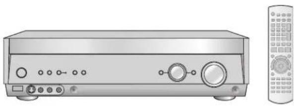
natural_image
Illustration of a silver audio equipment unit with control knobs and a remote control (no text or symbols)
natural_image
Illustration of a family watching TV, with no visible text or symbolsDear customer
Thank you for purchasing this product.
Before connecting, operating or adjusting this product, please read the instructions completely.
Please keep this manual for future reference.
HDMI ^TM
HIGH-DEFINITION MULTIMEDIA INTERFACE
Safety precautions
Placement
Set the unit up on an even surface away from direct sunlight, high temperatures, high humidity, and excessive vibration. These conditions can damage the cabinet and other components, thereby shortening the unit's service life.
Do not place heavy items on the unit.
Voltage
Do not use high voltage power sources. This can overload the unit and cause a fire.
Do not use a DC power source. Check the source carefully when setting the unit up on a ship or other place where DC is used.
AC mains lead protection
Ensure the AC mains lead is connected correctly and not damaged.
Poor connection and lead damage can cause fire or electric shock. Do not pull, bend, or place heavy items on the lead.
Grasp the plug firmly when unplugging the lead. Pulling the AC mains lead can cause electric shock.
Do not handle the plug with wet hands. This can cause electric shock.
Foreign matter
Do not let metal objects fall inside the unit. This can cause electric shock or malfunction.
Do not let liquids get into the unit. This can cause electric shock or malfunction. If this occurs, immediately disconnect the unit from the power supply and contact your dealer.
Do not spray insecticides onto or into the unit. They contain flammable gases which can ignite if sprayed into the unit.
Service
Do not attempt to repair this unit by yourself. If sound is interrupted, indicators fail to light, smoke appears, or any other problem that is not covered in these operating instructions occurs, disconnect the AC mains lead and contact your dealer or an authorized service center.
Electric shock or damage to the unit can occur if the unit is repaired, disassembled or reconstructed by unqualified persons.
Extend operating life by disconnecting the unit from the power source if it is not to be used for a long time.
CAUTION!
- DO NOT INSTALL OR PLACE THIS UNIT IN A BOOKCASE, BUILT-IN CABINET OR IN ANOTHER CONFINED SPACE. ENSURE THE UNIT IS WELL VENTILATED. TO PREVENT RISK OF ELECTRIC SHOCK OR FIRE HAZARD DUE TO OVERHEATING, ENSURE THAT CURTAINS AND ANY OTHER MATERIALS DO NOT OBSTRUCT THE VENTILATION VENTS.
- DO NOT OBSTRUCT THE UNIT'S VENTILATION OPENINGS WITH NEWSPAPERS, TABLECLOTHS, CURTAINS, AND SIMILAR ITEMS.
- DO NOT PLACE SOURCES OF NAKED FLAMES, SUCH AS LIGHTED CANDLES, ON THE UNIT.
- DISPOSE OF BATTERIES IN AN ENVIRONMENTALLY FRIENDLY MANNER.
WARNING:
TO REDUCE THE RISK OF FIRE, ELECTRIC SHOCK OR PRODUCT DAMAGE, DO NOT EXPOSE THIS APPARATUS TO RAIN, MOISTURE, DRIPPING OR SPLASHING AND THAT NO OBJECTS FILLED WITH LIQUIDS, SUCH AS VASES, SHALL BE PLACED ON THE APPARATUS.
THIS UNIT IS INTENDED FOR USE IN MODERATE CLIMATES.
This product may receive radio interference caused by mobile telephones during use. If such interference is apparent, please increase separation between the product and the mobile telephone.
The socket outlet shall be installed near the equipment and easily accessible or the mains plug or an appliance coupler shall remain readily operable.
CAUTION!
Do not place anything on top of this unit or block the heat radiation vents in any way. In particular, do not place DVD recorder or CD/DVD players on this unit as heat radiated from it can damage your software.
HDMI, the HDMI logo and High-Definition Multimedia Interface are trademarks or registered trademarks of HDMI Licensing LLC.
HDAVI Control™ is a trademark of Matsushita Electric Industrial Co., Ltd.
Manufactured under license from Dolby Laboratories. "Dolby", "Pro Logic" and the double-D symbol are trademarks of Dolby Laboratories.
"DTS", "DTS-ES", "Neo:6" and "DTS 96/24" are trademarks of Digital Theater Systems, Inc.
Refer to the back cover for "Supplied accessories".
Table of contents
Before use
Safety precautions 2
The remote control 3
Control guide .... 4
Remote control/The main unit and display 4
Connections
Home Theater connections .... 5
Connecting your television and DVD equipment .... 5
High-quality audio and video simply with HDMI connection .. 5
Connections for high-resolution video (components without an HDMI) 6
Connections for standard-resolution video (components without an HDMI) 7
Connection with 21-pin scart cable 7
6-channel discrete connection (for high-quality DVD-Audio sound) 8
Analogue audio connections 8
Playing audio from your television through speakers connected to this unit 9
Connecting a combination DVD recorder/VCR 9
Connecting other equipment 10
Connecting a set top box (cable or satellite)/Connecting a
VCR/Connecting a CD player/Connecting a video camera or other portable device 10
Connecting the antennas and AC mains lead .... 11
Using headphones 11
Speaker connections 12
Connecting speakers 12
Connections and placement to suit the number of speakers you have 12
Connecting biwireable speakers/Connecting a second pair of front speakers 13
Before playback 14
Auto speaker setup 14
Process for auto speaker setup 14
Troubleshooting for auto speaker setup 16
Automatic speaker detection 17
Speaker output and level 17
Basic operations
Enjoying Home Theater features 18
Basic play 18
Digital signals this unit can play/Signal indicators 19
Playback options 20
Using SPEAKERS B/ADVANCED DUAL AMP/BI-AMP/
Playing DVD-Audio 20
Using HDAVI Control™ 21
One-touch Home Theater 21
Operations
Surround sound 22
Dolby Pro LogicIIx 22
Adjusting the Dolby Pro LogicIIx "MUSIC" mode ..... 22
NEO:6 23
Adjusting the NEO:6 "MUSIC" mode 23
SFC (Sound Field Control) 24
Adjusting SFC (Sound Field Control) 25
Receiver settings 26
Basic operations 26
Speaker and size settings/Distance/LR BI-WIRE setting/ Low-pass filter/Auto Setup 27
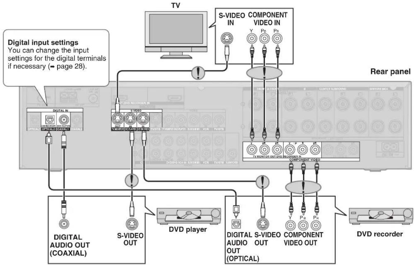
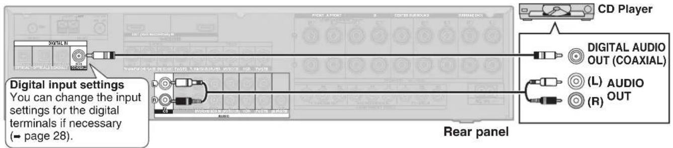
Digital input settings/Input signal/Bi-amp settings 28
HDMI settings/Turning the ADVANCED DUAL AMP off/Clear audio at low volume/Attenuating analogue input/Delaying audio/Resetting factory settings 29
Sound effects/Other functions 30
Basic operations 30
Sound effects-Adjusting the bass/Adjusting the treble/Adjusting front speaker balance/Adjusting the subwoofer level 31
Other functions-Selecting audio channels/Adjusting the dimness of the display/Sleep timer/Muting 31
The radio 32
Manual tuning 32
Preset tuning 33
Presetting stations/Selecting channels 33
RDS broadcasts 34
Changing the display 34
Using the remote control with other equipment ..... 34
Television 34
DVD recorder/DVD player 35
VCR/CD player 36
Changing the remote control code/Enter a code to operate some equipment 37
Reference
Specifications (DIN 45 500) 38
Help messages 38
Troubleshooting guide 39
Supplied accessories .... Back cover
Maintenance ...... Back cover
The remote control
Batteries
Press on the tab to open.
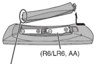
Insert this side first when closing.
Note
- Insert so the poles (+ and −) match those in the remote control.
- Do not use rechargeable type batteries.
Use
Sensor
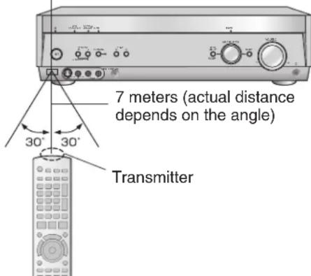
Caution
- Ensure there are no obstacles between the remote control and the main unit.
- Strong light sources (direct sunlight or strong fluorescent light) can interfere with operation.
- Keep the transmitter and sensor free from dust.
When you set the unit in a cabinet
Thick or coloured glass can reduce the operating distance.
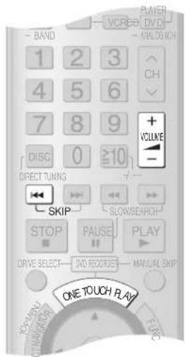
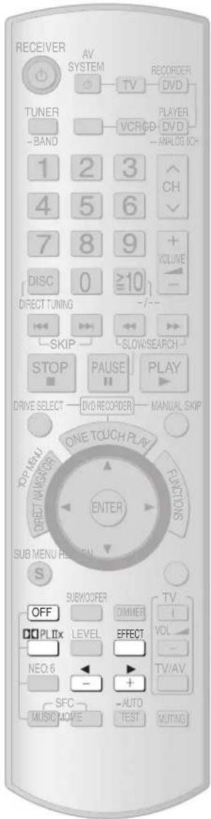
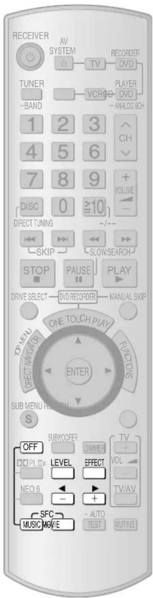
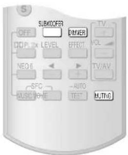
Remote control
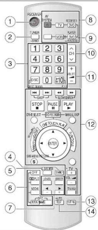
① Power button
② For selecting tuner/ For switching FM or AM (→ page 32)
③ For selecting stations directly TUNER (→ page 32)
For selecting channels TUNER (→ page 33)
TV (→ page 34)
DVD recorder (→ page 35)
VCR (→ page 36)
For selecting tracks and chapters DVD recorder/DVD player (→ page 35)
For selecting tracks CD player (→ page 36)
④ To dim the display (→ page 31)
⑤ To adjust the subwoofer level ( page 31)
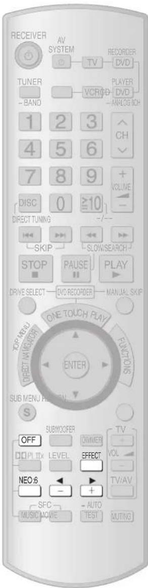
⑥ For selecting sound modes (→ pages 22, 23, and 24)
⑦ For speaker adjustments (→ page 17) For changing sound quality and sound field (→ pages 22, 23, and 25)
⑧ Switches on or off other equipment/ switches the source/ switches the remote control mode ( pages 34 to 37)
⑨ For switching on the DVD-Audio 6-channel mode (→ page 20)
⑩ To change channels TUNER (→ page 33) TV (→ page 34) DVD recorder (→ page 35) VCR (→ page 36)
⑪ Adjusts volume (→ page 17)
⑫ For operating other equipment (→ pages 21 and 34 to 37)
⑬ To mute the volume (→ page 31)
14 For auto speaker setup (→ pages 14 to 16) For testing speaker output (→ page 17)
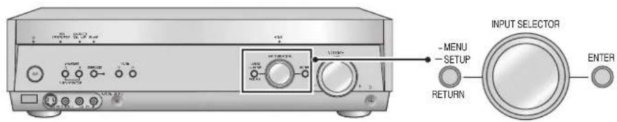
The main unit and display
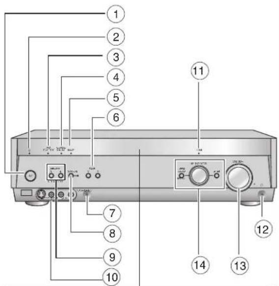
1 Standby/on switch [∅/l]
Press to switch the unit from on to standby mode or vice versa. In standby mode, the unit is still consuming a small amount of power.
② Standby indicator [☐]
When the unit is connected to the AC mains supply, this indicator lights up in standby mode and goes out when the unit is turned on.
③ Flashes during auto speaker setup. Lights when the setup finishes (→ pages 14 to 16)
④ Lights when you are using the Advanced Dual Amp (→ page 20)
⑤ Lights when you are using the bi-amp (→ page 20)
⑥ For tuning the radio and selecting preset stations (→ pages 32 to 33)
⑦ Setup microphone jack (→ page 14)
⑧ For switching surround (The indicator lights when you are using this feature) (→ page 18)
⑨ For selecting front speakers (→ pages 11, 17, 18, and 20)
⑩ For connecting other equipment (→ pages 10)
11 Lights when you are using the HDMI connections (→ page 5)
12 Headphone jack (→ page 11)
⑬ Adjusts volume (→ pages 11 and 18)
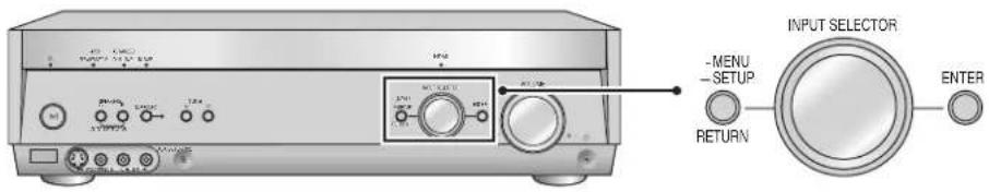
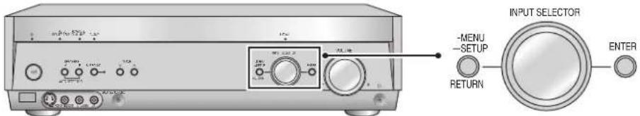
14 For switching input (→ page 18)
Also used during menu and setup operation
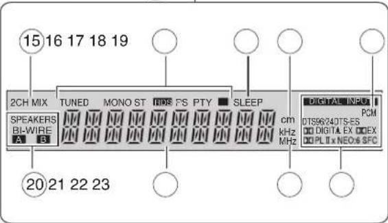
15 Lights when multi-channel sources are being down-mixed to 2 channels
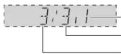
16 Radio indicators
⑰ Sleep timer indicator
⑱ Units for speaker distance and Bi-amp delay time
⑲ Lights when you have set the PCM FIX mode
20 Shows the front speaker mode you have selected
21 General display
22 Frequency unit indicators
23 Digital signal format (→ page 19)
Home Theater connections
- Turn off all components before making any connections.
- Peripheral equipment and cables sold separately unless otherwise indicated.
- To connect equipment, refer to the appropriate operating instructions.
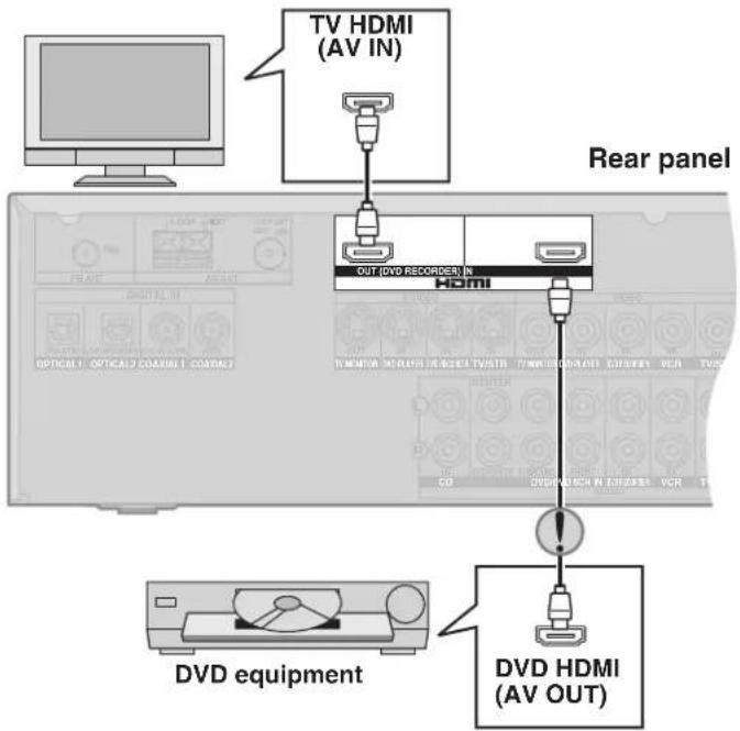
Connecting your television and DVD equipment
High-quality audio and video simply with HDMI connection
![[HDMI]](/content/2026/05/846938/images/8007114349ab97f90291ba5ec342e2b23c941b60e4a83daa7f42fd4e0394ec9b.jpg)
- The HDMI (High Definition Multimedia Interface) connection means you only need one cable to transmit digital audio and video between two pieces of equipment. It also carries a command signal that allows you to control your Panasonic TV (VIERA) or DVD recorder (DIGA) with one touch of a button (→ page 21).
- DVD-Audio multi-channel audio is carried as a digital signal. Some DVD equipment (e.g. with HDMI Ver.1.0) cannot output multi-channel audio as a digital signal. Use the 6-channel discrete connection (→ pages 8 and 20) if this is the case.
- The HDMI indicator lights when you are using this connection.
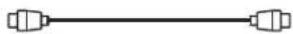
Connection cable
Video and Audio cable
HDMI Cable
(Use a Panasonic HDMI cable for best results.)
[Recommended part number: RP-CDHG15 (1.5 m), RP-CDHG30 (3.0 m), RP-CDHG50 (5.0 m) etc.]
Use only HDMI cables that have the HDMI logo (as shown on the cover).
To play audio from the television through speakers connected to this unit, - page 9.

If you decide to connect a DVD player through the HDMI, change the "HDMI settings" (→ page 29).
Note
Connect only DVD equipment to the HDMI input terminal of the unit. Connecting other equipment may prevent the output of sounds or show distorted pictures.
In such cases, see "Connecting other equipment", page 10, for connections other than HDMI.
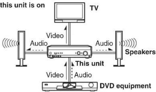
Audio and video signal flow when you have used HDMI connections
The audio and video signals from DVD equipment pass through to the television even if this unit is set to standby.
When this unit is on
flowchart
graph TD
    TV["TV"] -->|Audio| Device["Device"]
    Audio["Audio"] --> Device
    Video["Video"] --> Device
    Audio --> Speaker1["Speakers"]
    Video --> Audio2["Audio"]
    Audio2 --> Audio3["Video"]
    Video --> Audio4["Audio"]
    Audio4 --> Audio5["Video"]
    Video --> Audio6["Audio"]
    Audio6 --> Audio7["Video"]
    Video --> Audio8["Audio"]
    Audio8 --> Audio9["Video"]
    Video --> Audio10["Audio"]
    Audio10 --> Audio11["Video"]
    Audio11 --> Audio12["Audio"]
    Audio12 --> Audio13["Video"]
    Audio13 --> Audio14["Audio"]
    Audio14 --> Audio15["Video"]
    Audio15 --> Audio16["Audio"]
    Audio16 --> Audio17["Video"]
    Audio17 --> Audio18["Audio"]
    Audio18 --> Audio19["Video"]
    Audio19 --> Audio20["Audio"]
    Audio20 --> Audio21["Video"]
    Audio21 --> Audio22["Audio"]
    Audio22 --> Audio23["Video"]
    Audio23 --> Audio24["Audio"]
    Audio24 --> Audio25["Video"]
    Audio25 --> Audio26["Audio"]
    Audio26 --> Audio27["Video"]
    Audio27 --> Audio28["Audio"]
    Audio28 --> Audio29["Video"]
    Audio29 --> Audio30["Audio"]
    Audio30 --> Audio31["Video"]
    Audio31 --> Audio32["Audio"]
    Audio32 --> Audio33["Video"]
    Audio33 --> Audio34["Audio"]
    Audio34 --> Audio35["Video"]
    Audio35 --> Audio36["Audio"]
    Audio36 --> Audio37["Video"]
    Audio37 --> Audio38["Audio"]
    Audio38 --> Audio39["Video"]
    Audio39 --> Audio40["Audio"]
    Audio40 --> Audio41["Video"]
    Audio41 --> Audio42["Audio"]
    Audio42 --> Audio43["Video"]
    Audio43 --> Audio44["Audio"]
    Audio44 --> Audio45["Video"]
    Audio45 --> Audio46["Audio"]
    Audio46 --> Audio47["Video"]
    Audio47 --> Audio48["Audio"]
    Audio48 --> Audio49["Video"]
    Audio49 --> Audio50["Audio"]
    Audio50 --> Audio51["Video"]
    Audio51 --> Audio52["Audio"]
    Audio52 --> Audio53["Video"]
    Audio53 --> Audio54["Audio"]
    Audio54 --> Audio55["Video"]
    Audio55 --> Audio56["Audio"]
    Audio56 --> Audio57["Video"]
    Audio57 --> Audio58["Audio"]
    Audio58 --> Audio59["Video"]
    Audio59 --> Audio60["Audio"]
    Audio60 --> Audio61["Video"]
    Audio61 --> Audio62["Audio"]
    Audio62 --> Audio63["Video"]
    Audio63 --> Audio64["Audio"]
    Audio64 --> Audio65["Video"]
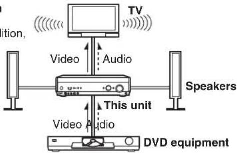
When this unit is in standby mode
(in standby ON condition, page 29)
flowchart
graph TD
    TV["TV"] --> Audio["Audio"]
    Audio --> Video["Video"]
    Video --> Speaker1["Speakers"]
    Video --> Audio2["Video"]
    Audio2 --> Video3["Video"]
    Video3 --> DVD["DVD equipment"]
For your reference
- Audio signals from HDMI connection takes priority to digital terminal connections (→ page 6 and 7).
- This unit's HDMI can carry video signals up to 1125i (1080i) (even when this unit is in standby mode).
1125i: an interlace (jump scanning) system that divides 1,125 scan lines in two and sends each half alternately every 1/60 second.
Home Theater connections
Connecting your television and DVD equipment (cont.)
Connections for high-resolution video (components without an HDMI)
Connection cable
- Check the connections on your equipment and prepare the necessary cables.
- Your equipment will have more than one way of connecting video, so decide which best suits your needs.
| Video cable Audio cable | ||
S-VIDEO connection cable Optical fibre cable | 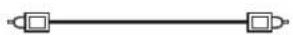 | Connecting the optical fibre cableNote the shape and fit it 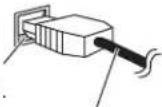 correctly into the terminalDo not bend! correctly into the terminalDo not bend! |
| Video connection cable Coaxial cable | ||
To play audio from the television through speakers connected to this unit, → page 9.
flowchart
graph TD
    TV["TV"] --> SVIDEQS["COMPONENT VIDEO IN"]
    SVIDEQS --> TVDAVOUT1["OCTICAL AUDIO OUT (COAXIAL)"]
    SVIDEQS --> TVDAVOUT2["OPTICAL AUDIO OUT (COAXIAL)"]
    SVIDEQS --> TVDAVOUT3["OPTICAL AUDIO OUT (COAXIAL)"]
    SVIDEQS --> TVDAVOUT4["OPTICAL AUDIO OUT (COAXIAL)"]
    SVIDEQS --> TVDAVOUT5["OPTICAL AUDIO OUT (COAXIAL)"]
    SVIDEQS --> TVDAVOUT6["OPTICAL AUDIO OUT (COAXIAL)"]
    SVIDEQS --> TVDAVOUT7["OPTICAL AUDIO OUT (COAXIAL)"]
    SVIDEQS --> TVDAVOUT8["OPTICAL AUDIO OUT (COAXIAL)"]
    SVIDEQS --> TVDAVOUT9["OPTICAL AUDIO OUT (COAXIAL)"]
    SVIDEQS --> TVDAVOUT10["OPTICAL AUDIO OUT (COAXIAL)"]
    SVIDEQS --> TVDAVOUT11["OPTICAL AUDIO OUT (COAXIAL)"]
    SVIDEQS --> TVDAVOUT12["OPTICAL AUDIO OUT (COAXIAL)"]
    SVIDEQS --> TVDAVOUT13["OPTICAL AUDIO OUT (COAXIAL)"]
    SVIDEQS --> TVDAVOUT14["OPTICAL AUDIO OUT (COAXIAL)"]
    SVIDEQS --> TVDAVOUT15["OPTICAL AUDIO OUT (COAXIAL)"]
    SVIDEQS --> TVDAVOUT16["OPTICAL AUDIO OUT (COAXIAL)"]
    SVIDEQS --> TVDAVOUT17["OPTICAL AUDIO OUT (COAXIAL)"]
    SVIDEQS --> TVDAVOUT18["OPTICAL AUDIO OUT (COAXIAL)"]
    SVIDEQS --> TVDAVOUT19["OPTICAL AUDIO OUT (COAXIAL)"]
    SVIDEQS --> TVDAVOUT20["OPTICAL AUDIO OUT (COAXIAL)"]
    SVIDEQS --> TVDAVOUT21["OPTICAL AUDIO OUT (COAXIAL)"]
    SVIDEQS --> TVDAVOUT22["OPTICAL AUDIO OUT (COAXIAL)"]
    SVIDEQS --> TVDAVOUT23["OPTICAL AUDIO OUT (COAXIAL)"]
    SVIDEQS --> TVDAVOUT24["OPTICAL AUDIO OUT (COAXIAL)"]
    SVIDEQS --> TVDAVOUT25["OPTICAL AUDIO OUT (COAXIAL)"]
    SVIDEQS --> TVDAVOUT26["OPTICAL AUDIO OUT (COAXIAL)"]
    SVIDEQS --> TVDAVOUT27["OPTICAL AUDIO OUT (COAXIAL)"]
    SVIDEQS --> TVDAVOUT28["OPTICAL AUDIO OUT (COAXIAL)"]
    SVIDEQS --> TVDAVOUT29["OPTICAL AUDIO OUT (COAXIAL)"]
    SVIDEQS --> TVDAVOUT30["OPTICAL AUDIO OUT (COAXIAL)"]
    SVIDEQS --> TVDAVOUT31["OPTICAL AUDIO OUT (COAXIAL)"]
    SVIDEQS --> TVDAVOUT32["OPTICAL AUDIO OUT (COAXIAL)"]
    SVIDEQS --> TVDAVOUT33["OPTICAL AUDIO OUT (COAXIAL)"]
    SVIDEQS --> TVDAVOUT34["OPTICAL AUDIO OUT (COAXIAL)"]
    SVIDEQS --> TVDAVOUT35["OPTICAL AUDIO OUT (COAXIAL)"]
    SVIDEQS --> TVDAVOUT36["OPTICAL AUDIO OUT (COAXIAL)"]
    SVIDEQS --> TVDAVOUT37["OPTICAL AUDIO OUT (COAXIAL)"]
    SVIDEQS --> TVDAVOUT38["OPTICAL AUDIO OUT (COAXIAL)"]
    SVIDEQS --> TVDAVOUT39["OPTICAL AUDIO OUT (COAXIAL)"]
    SVIDEQS --> TVDAVOUT40["OPTICAL AUDIO OUT (COAXIAL)"]
    SVIDEQS --> TVDAVOUT41["OPTICAL AUDIO OUT (COAXIAL)"]
    SVIDEQS --> TVDAVOUT42["OPTICAL AUDIO OUT (COAXIAL)"]
    SVIDEQS --> TVDAVOUT43["OPTICAL AUDIO OUT (COAXIAL)"]
    SVIDEQS --> TVDAVOUT44["OPTICAL AUDIO OUT (COAXIAL)"]
    SVIDEQS --> TVDAVOUT45["OPTICAL AUDIO OUT (COAXIAL)"]
    SVIDEQS --> TVDAVOUT46["OPTICAL AUDIO OUT (COAXIAL)"]
    SVIDEQS --> TVDAVOUT47["OPTICAL AUDIO OUT (COAXIAL)"]
    SVIDEQS --> TVDAVOUT48["OPTICAL AUDIO OUT (COAXIAL)"]
    SVIDEQS --> TVDAVOUT49["OPTICAL AUDIO OUT (COAXIAL)"]
    SVIDEQS --> TVDAVOUT50["OPTICAL AUDIO OUT (COAXIAL)"]
    SVIDEQS --> TVDAVOUT51["OPTICAL AUDIO OUT (COAXIAL)"]
    SVIDEQS --> TVDAVOUT52["OPTICAL AUDIO OUT (COAXIAL)"]
    SVIDEQS --> TVDAVOUT53["OPTICAL AUDIO OUT (COAXIAL)"]
    SVIDEQS --> TVDAVOUT54["OPTICAL AUDIO OUT (COAXIAL)"]
    SVIDEQS --> TVDAVOUT55["OPTICAL AUDIO OUT (COAXIAL)"]
    SVIDEQS --> TVDAVOUT56["OPTICAL AUDIO OUT (COAXIAL)"]
    SVIDEQS --> TVDAVOUT57["OPTICAL AUDIO OUT (COAXIAL)"]
    SVIDEQS --> TVDAVOUT58["OPTICAL AUDIO OUT (COAXIAL)"]
    SVIDEQS --> TVDAVOUT59["OPTICAL AUDIO OUT (COAXIAL)"]
    SVIDEQS --> TVDAVOUT60["OPTICAL AUDIO OUT (COAXIAL)"]

The video terminals
- Connect the video cables in sets so that you have the same type for input and output.
- The component video connection provides the best colour reproduction by separating the luminance (Y) and colour (red: P_B or C_n , and blue: P_B or C_B ) signals.
Note
To connect a set top box (cable or satellite), → page 10.
- Turn off all components before making any connections.
- Peripheral equipment and cables sold separately unless otherwise indicated.
- To connect equipment, refer to the appropriate operating instructions.
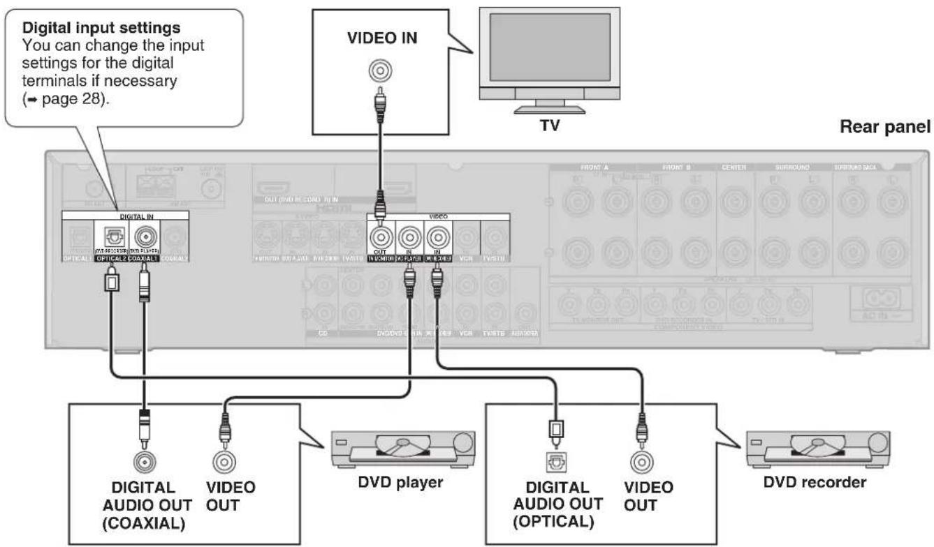
Connections for standard-resolution video (components without an HDMI)
Connection cable
| Video cable Audio cable | ||
Video connection cable Optical fibre cable |  | Connecting the optical fibre cableNote the shape and fit it correctly into the terminal.  Do not bend! Do not bend! |
| Scart cable | ||
21-pin scart cable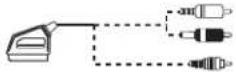 You will need an adaptor to connect equipment with a 21-pin scart terminal. You will need an adaptor to connect equipment with a 21-pin scart terminal. | 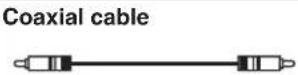 | |
To play audio from the television through speakers connected to this unit, → page 9.
flowchart
graph TD
    A["Digital input settings\nYou can change the input settings for the digital terminals if necessary\n(→ page 28)."] --> B["TV"]
    B --> C["Video IN"]
    C --> D["Central Panel with Digital Audio Out (COAXIAL)"]
    C --> E["Central Panel with Video Player"]
    C --> F["Central Panel with OUT (DVD RECORD) IN"]
    C --> G["Central Panel with OUT (DVD RECORD) OUT"]
    C --> H["Central Panel with OUT (DVD RECORD) OUT"]
    C --> I["Central Panel with OUT (DVD RECORD) OUT"]
    C --> J["Central Panel with OUT (DVD RECORD) OUT"]
    C --> K["Central Panel with OUT (DVD RECORD) OUT"]
    C --> L["Central Panel with OUT (DVD RECORD) OUT"]
    C --> M["Central Panel with OUT (DVD RECORD) OUT"]
    C --> N["Central Panel with OUT (DVD RECORD) OUT"]
    C --> O["Central Panel with OUT (DVD RECORD) OUT"]
    C --> P["Central Panel with OUT (DVD RECORD) OUT"]
    C --> Q["Central Panel with OUT (DVD RECORD) OUT"]
    C --> R["Central Panel with OUT (DVD RECORD) OUT"]
    C --> S["Central Panel with OUT (DVD RECORD) OUT"]
    C --> T["Central Panel with OUT (DVD RECORD) OUT"]
    C --> U["Central Panel with OUT (DVD RECORD) OUT"]
    C --> V["Central Panel with OUT (DVD RECORD) OUT"]
    C --> W["Central Panel with OUT (DVD RECORD) OUT"]
    C --> X["Central Panel with OUT (DVD RECORD) OUT"]
    C --> Y["Central Panel with OUT (DVD RECORD) OUT"]
    C --> Z["Central Panel with OUT (DVD RECORD) OUT"]
    C --> AA["Central Panel with OUT (DVD RECORD) OUT"]
    C --> AB["Central Panel with OUT (DVD RECORD) OUT"]
    C --> AC["Central Panel with OUT (DVD RECORD) OUT"]
    C --> AD["Central Panel with OUT (DVD RECORD) OUT"]
    C --> AE["Central Panel with OUT (DVD RECORD) OUT"]
    C --> AF["Central Panel with OUT (DVD RECORD) OUT"]
    C --> AG["Central Panel with OUT (DVD RECORD) OUT"]
    C --> AH["Central Panel with OUT (DVD RECORD) OUT"]
    C --> AI["Central Panel with OUT (DVD RECORD) OUT"]
    C --> AJ["Central Panel with OUT (DVD RECORD) OUT"]
    C --> AK["Central Panel with OUT (DVD RECORD) OUT"]
    C --> AL["Central Panel with OUT (DVD RECORD) OUT"]
    C --> AM["Central Panel with OUT (DVD RECORD) OUT"]
    C --> AN["Central Panel with OUT (DVD RECORD) OUT"]
    C --> AO["Central Panel with OUT (DVD RECORD) OUT"]
    C --> AP["Central Panel with OUT (DVD RECORD) OUT"]
    C --> AQ["Central Panel with OUT (DVD RECORD) OUT"]
    C --> AR["Central Panel with OUT (DVD RECORD) OUT"]
    C --> AS["Central Panel with OUT (DVD RECORD) OUT"]
    C --> AT["Central Panel with OUT (DVD RECORD) OUT"]
    C --> AU["Central Panel with OUT (DVD RECORD) OUT"]
    C --> AV["Central Panel with OUT (DVD RECORD) OUT"]
    C --> AW["Central Panel with OUT (DVD RECORD) OUT"]
    C --> AX["Central Panel with OUT (DVD RECORD) OUT"]
    C --> AY["Central Panel with OUT (DVD RECORD) OUT"]
    C --> AZ["Central Panel with OUT (DVD RECORD) OUT"]
    C --> BA["Central Panel with OUT (DVD RECORD) OUT"]
    C --> BB["Central Panel with OUT (DVD RECORD) OUT"]
    C --> BC["Central Panel with OUT (DVD RECORD) OUT"]
    C --> BD["Central Panel with OUT (DVD RECORD) OUT"]
    C --> BE["Central Panel with OUT (DVD RECORD) OUT"]
    C --> BF["Central Panel with OUT (DVD RECORD) OUT"]
    C --> BG["Central Panel with OUT (DVD RECORD) OUT"]
    C --> BH["Central Panel with OUT (DVD RECORD) OUT"]
    C --> BI["Central Panel with OUT (DVD RECORD) OUT"]
    C --> BJ["Central Panel with OUT (DVD RECORD) OUT"]
    C --> BK["Central Panel with OUT (DVD RECORD) OUT"]
    C --> BL["Central Panel with OUT (DVD RECORD) OUT"]
    C --> BM["Central Panel with OUT (DVD RECORD) OUT"]
    C --> BN["Central Panel with OUT (DVD RECORD) OUT"]
    C --> BO["DVD player"]
    B --> BP["DVD recorder"]
    B --> BQ["DVD recorder"]
Note
To connect a set top box (cable or satellite), → page 10.
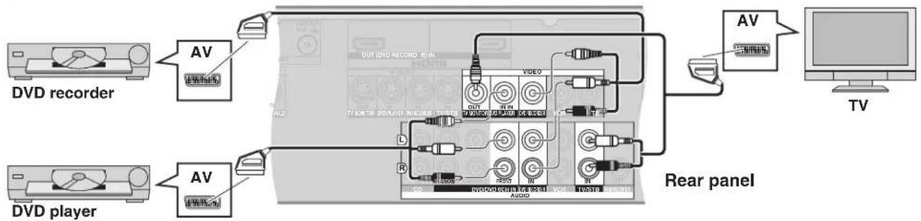
Connection with 21-pin scart cable
flowchart
graph TD
    A["DVd recorder"] --> B["AV"]
    C["DVD player"] --> D["AV"]
    B --> E["TV OUT RVD RECORD BY IN"]
    D --> F["TV OUT RVD Player INPUT/REDACT"]
    E --> G["Video"]
    F --> H["Audio"]
    G --> I["AV"]
    H --> J["TV OUT RVD REDACT BY IN"]
    I --> K["TV OUT RVD Player INPUT/REDACT"]
    J --> L["TV OUT RVD Player INPUT/REDACT"]
    K --> M["TV OUT RVD Player INPUT/REDACT"]
    L --> N["TV OUT RVD Player INPUT/REDACT"]
    M --> O["TV OUT RVD Player INPUT/REDACT"]
    N --> P["TV OUT RVD Player INPUT/REDACT"]
    O --> Q["TV OUT RVD Player INPUT/REDACT"]
    P --> R["TV OUT RVD Player INPUT/REDACT"]
Home Theater connections
Connecting your television and DVD equipment (cont.)
Connection cable
| Video cable Audio cable | |
| Video connection cable Stereo phono cable | |
| Optical fibre cableConnecting the optical digital cableNote the shape and fit it correctly into the terminal.Do not bend! |
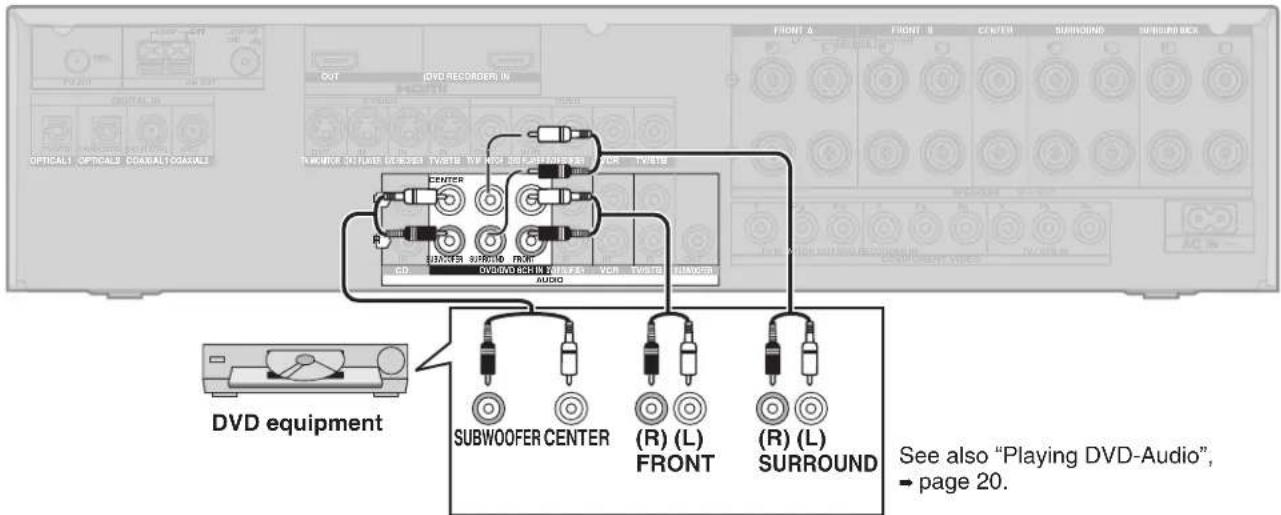
6-channel discrete connection (for high-quality DVD-Audio sound)
Rear panel
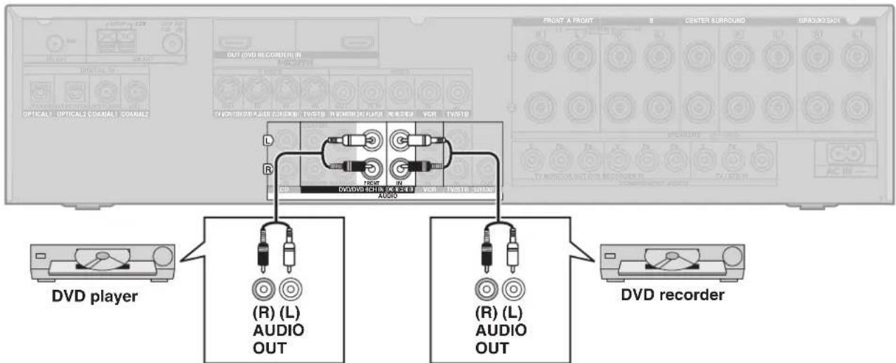
Analogue audio connections
There are some limitations on digital output from DVD equipment, so you may need to make this connection. For video connections, → pages 6 and 7. Rear panel
Rear panel
- Turn off all components before making any connections.
- Peripheral equipment and cables sold separately unless otherwise indicated.
- To connect equipment, refer to the appropriate operating instructions.
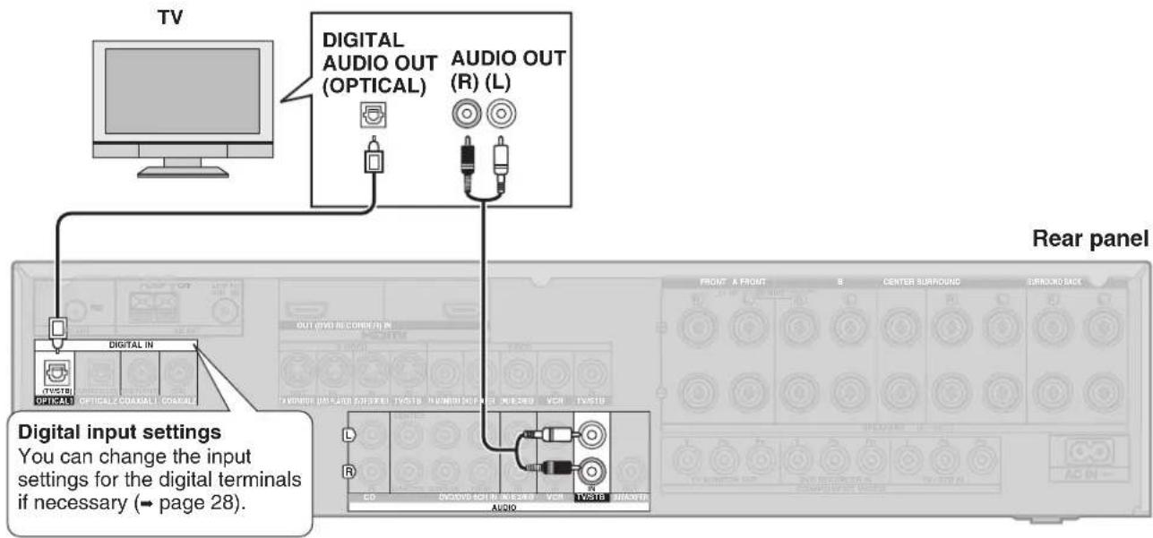
Playing audio from your television through speakers connected to this unit
Your equipment may be able to output both digital and analogue audio, so decide which best suits your needs.
To take advantage of the multi-channel sounds now available with digital television, use a digital connection. Read your television's operating instructions for details.
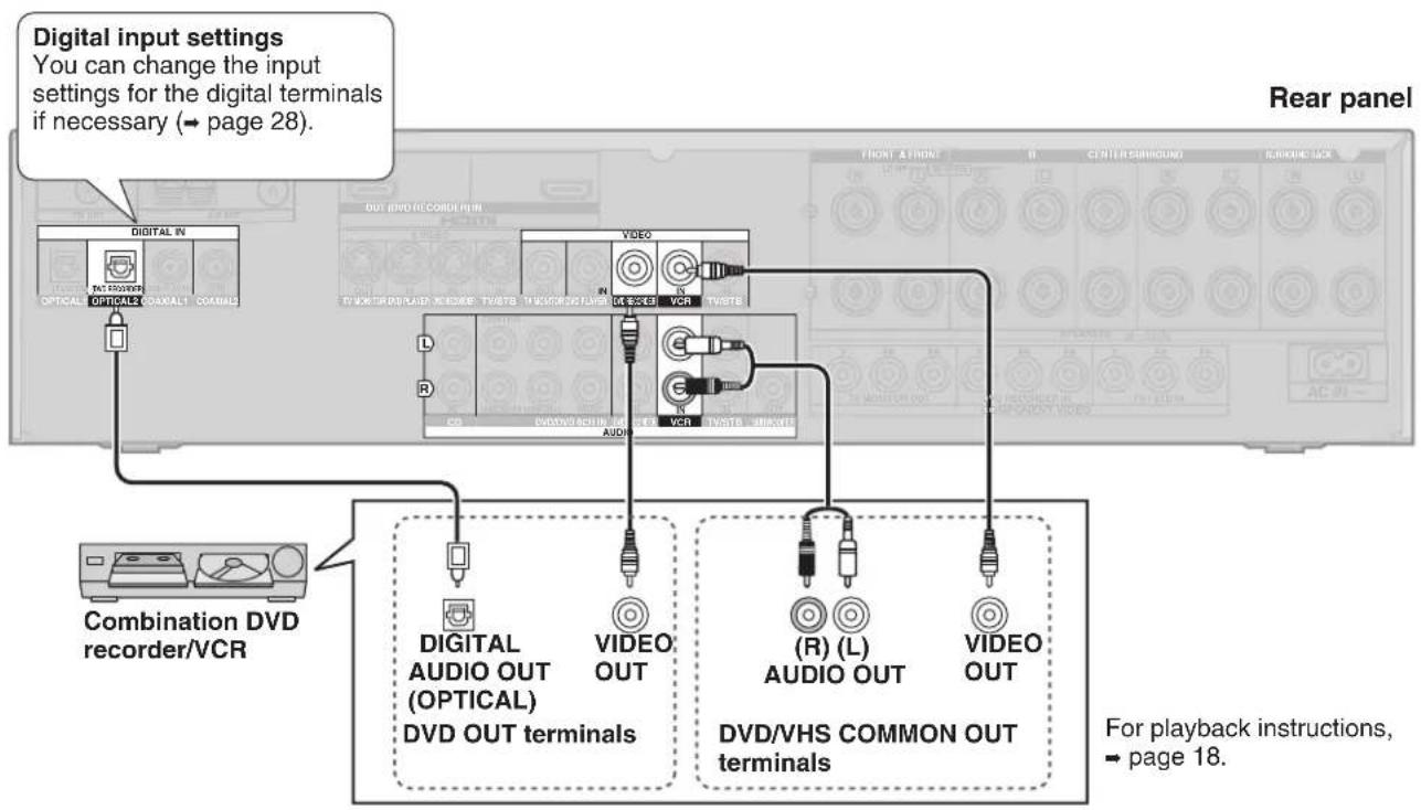
Connecting a combination DVD recorder/VCR
flowchart
graph TD
    A["Digital input settings\nYou can change the input settings for the digital terminals if necessary (→ page 28)."] --> B["Combination DVD recorder/VCR"]
    B --> C["DIGITAL IN\nOPTICAL OPTICAL COARALT COARALS"]
    B --> D["VIDEO OUT\nAUDIO OUT"]
    B --> E["(R) (L) AUDIO OUT\nDVD/VHS COMMON OUT terminals"]
    B --> F["VIDEO OUT\nVBR"]
    G["Rear panel"] --> H["Front A front\nCenter Rescound\nSubridge lock"]
    G --> I["CD/AC/11"]
Connecting other equipment
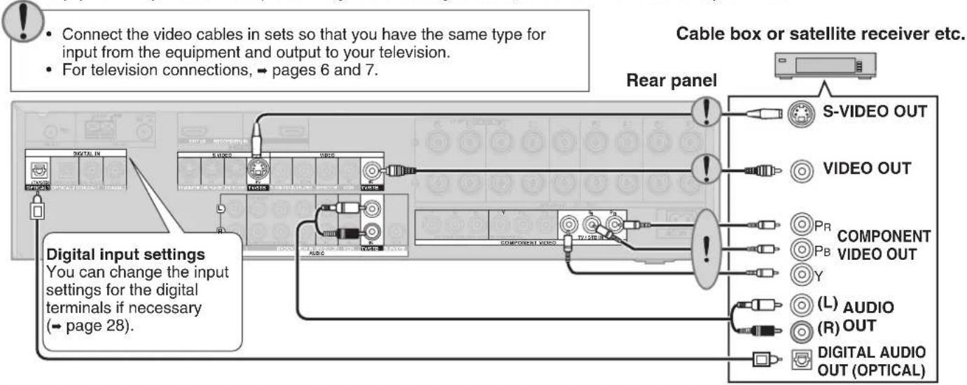
Connecting a set top box (cable or satellite)
Your equipment may be able to output both digital and analogue audio, so decide which best suits your needs.
flowchart
graph TD
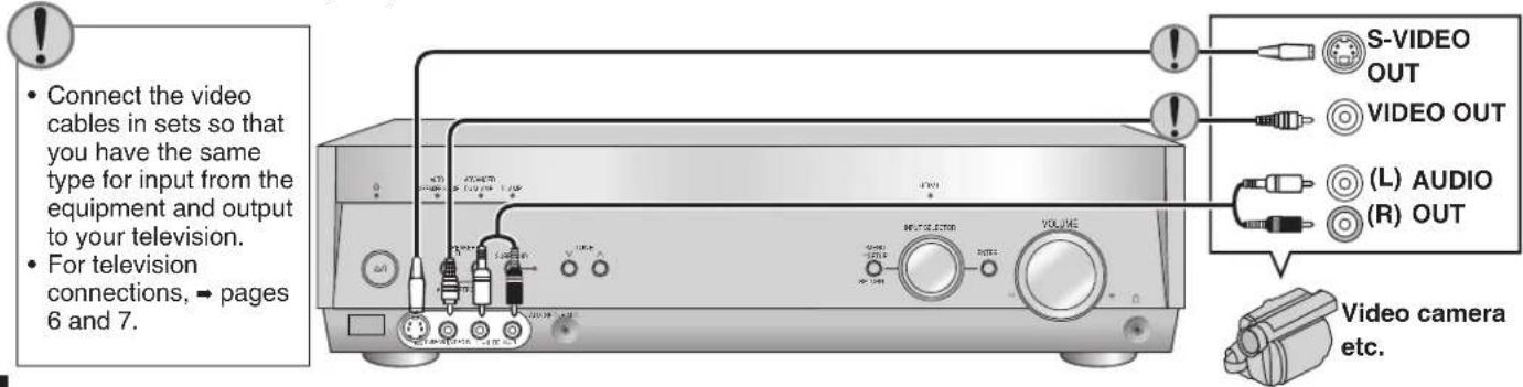
A["Digital input settings"] --> B["Connect the video cables in sets so that you have the same type for input from the equipment and output to your television."]
A --> C["For television connections, → pages 6 and 7."]
D["Cable box or satellite receiver etc."] --> E["Rear panel"]
E --> F["S-VIDEO OUT"]
E --> G["VIDEO OUT"]
E --> H["PR COMPONENT VIDEO OUT"]
E --> I["Y"]
E --> J["(L) AUDIO (R) OUT"]
E --> K["DIGITAL AUDIO OUT (OPTICAL)"]
Connecting a VCR
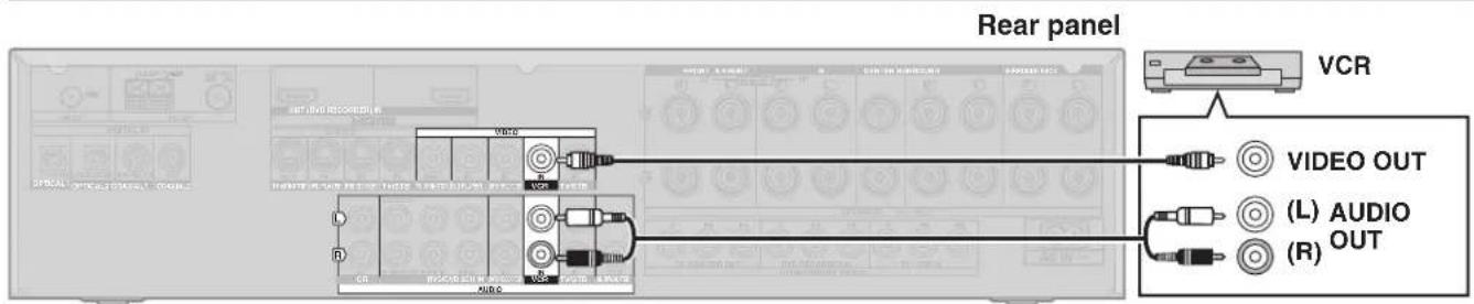
Note that you must also use matching connections for your television and DVD recorder, "Connections for standard-resolution video", - page 7, to view or record the images played on the VCR.
Connecting a CD player
Your equipment may be able to output both digital and analogue audio, so decide which best suits your needs.
Connecting a video camera or other portable device
Use these terminals for temporary connections.
- Turn off all components before making any connections.
- Peripheral equipment and cables sold separately unless otherwise indicated.
- To connect equipment, refer to the appropriate operating instructions.
Connecting the antennas and AC mains lead
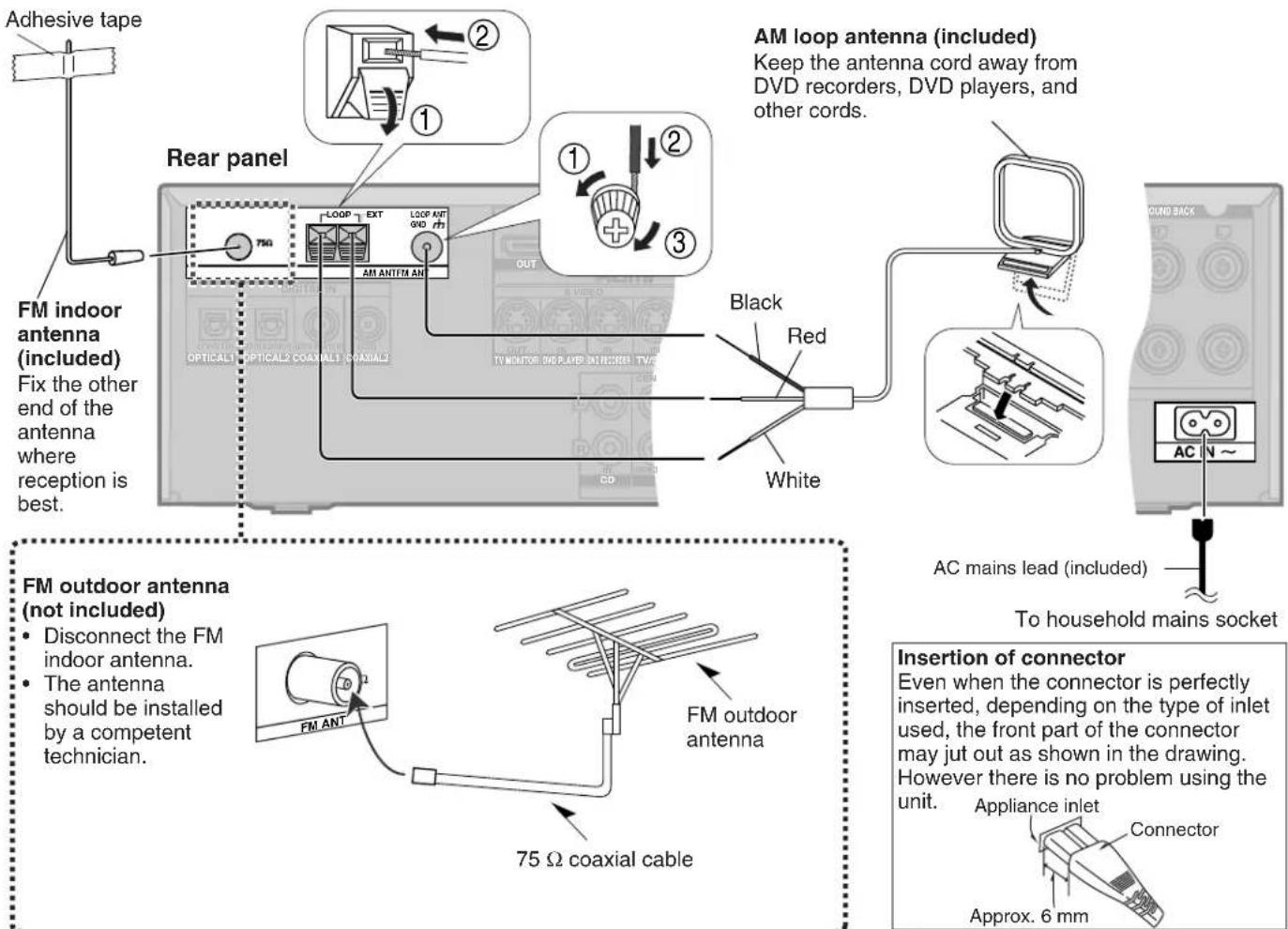
Connect AC mains lead after all other cables and cords are connected.
- The included AC mains lead is for use with this unit only. Do not use it with other equipment.
- Do not use an AC mains lead from other equipment.
- If the unit is left unplugged for longer than two weeks, all settings will revert to the factory settings. Perform the settings again if this occurs.
Using headphones
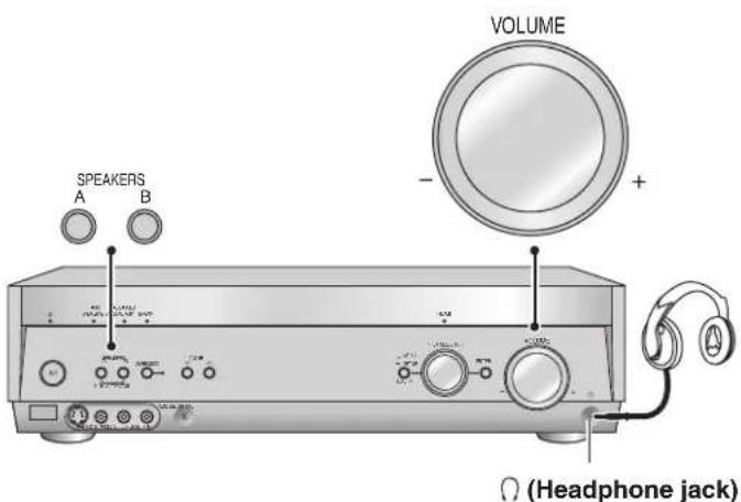
- Press [SPEAKERS A] and [SPEAKERS B] to turn off the speakers.
- Reduce the volume and connect the headphones.
Plug type: 6.3 mm stereo (in diameter)
- Adjust the volume.
Note
- Avoid listening for prolonged periods of time to prevent hearing damage.
- Turning the speakers off automatically engages stereo play, and when you play multi-channel sources they are down-mixed (2CH MIX). (Some DVD-Audio prohibit down-mixing.)
- Note that if you are using DVD 6CH input (→ page 20), the input source switches to "DVD" (2 channel) and only the sound for the front speakers is output.
Speaker connections
Connecting speakers
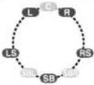
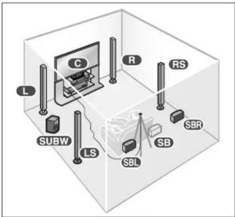
Connections and placement to suit the number of speakers you have
The ideal is to have all the speakers (except the subwoofer) at equal distances from the seating area. Auto speaker setup compensates for any differences (= pages 14 to 16).
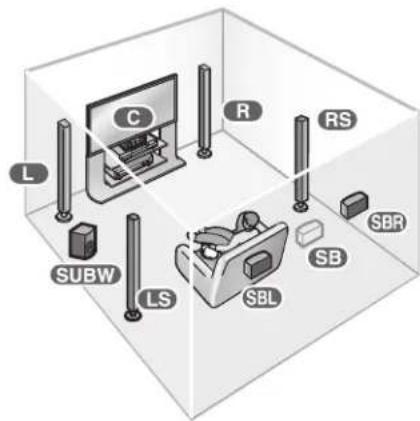
Front speakers (left, right)
R
Place either side of the television, then adjust their position and angle towards the seating position until you are satisfied with the relationship between the images and sound.
Center speaker () C
Place directly above or below the center of the television, aiming at the seating position.
Surround speakers (left, right)
RS
Place on either side of or slightly behind the seating area, about one meter higher than ear level.
Surround back speakers (left, right / when you connect only one speaker) SB
Place behind the seating area, about one meter higher than ear level.
Subwoofer ( ) SUBW
Place anywhere near the television (but not so close as to cause excessive vibration).
| Number of speakers | Placement | |
| 7 | 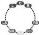 | This setup is suitable for playing 6.1-channel sources (DTS-ES and Dolby Digital Surround EX).Use Dolby Pro LogicIIx, DTS NEO:6, or SFC to enhance 2-channel or 5.1-channel sources. |
| 6 | 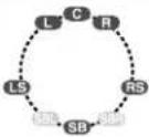 | This is the best setup for playing 6.1-channel sources (DTS-ES and Dolby Digital Surround EX).Use Dolby Pro LogicIIx, DTS NEO:6, or SFC to enhance 2-channel or 5.1-channel sources. |
 | Use this setup when you do not have a center speaker.The center channel is split between the front speakers. | |
| 5 | 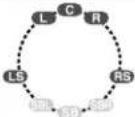 | This is the best setup for playing 5.1-channel sources (Dolby Digital and DTS materials).Use Dolby Pro LogicIIx, DTS NEO:6, or SFC to enhance 2-channel sources. |
 | Use this setup when you do not have a center speaker.The center channel is split between the front speakers. | |
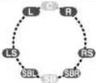
| 4 | 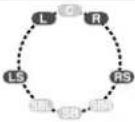 | Any center-channel sound (from 2-channel, 5.1-channel or 6.1-channel sources or allocated by Dolby Pro LogicIIx, DTS NEO:6, or SFC) is split between the front speakers. Surround back speakers are split between the surround speakers. |
| 3 |  | Any surround or surround back-channel sound (from multi-channel sources or allocated by Dolby Pro LogicIIx, DTS NEO:6, or SFC) is split between the front speakers. |
| 2 |  | This is the best setup for stereo sources.All other channels are “down-mixed” and played through the front speakers. |
- Turn off all components before making any connections.
- Peripheral equipment and cables sold separately unless otherwise indicated.
- To connect equipment, refer to the appropriate operating instructions.
Speaker impedance
Front A: 6 to 16 Ω
Center: 6 to 16 Ω
Surround: 6 to 16 Ω
Surround back: 6 to 16 Ω
If you have a single surround back speaker, connect it to the SURROUND BACK (L) terminal.
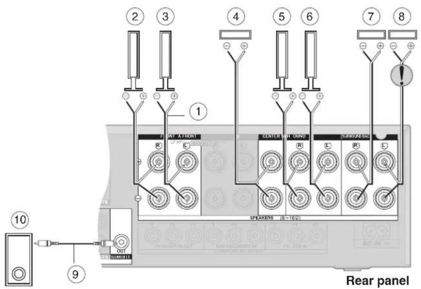
① Speaker cable
② Front speaker (R)
③ Front speaker (L)
④ Center speaker
⑤ Surround speaker (R)
6 Surround speaker (L)
⑦ Surround back speaker (R)
⑧ Surround back speaker (L)
⑨ Monaural connection cable
10 Active subwoofer
Note
After changing your speaker set up: Perform auto speaker setup
(→ pages 14 to 16) or automatic speaker detection (→ page 17); or for manual settings (→ page 27).
Connecting biwireable speakers
Biwireable speakers have separate terminals for the high frequency and low frequency signals.
- Use this connection to reduce interference between the high frequency and low frequency signals for high-fidelity sound.
- When you are playing analogue or 2-channel PCM sources, the unit can allocate an amplifier each to the high frequency and low frequency signals, thereby giving you a much clearer bi-amp stereo sound (→ page 20).
• HF stands for high frequency and LF for low frequency.
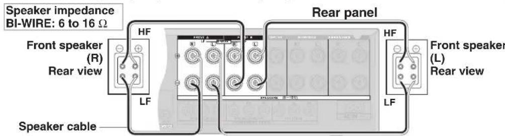
For your reference
- Be sure to connect the HF cables to the FRONT B terminals, and the LF cables to the FRONT A terminals, so that you can correct any delay that may occur (→ page 28).
- To take advantage of this connection and ensure the best possible sound, be sure to change the setting in "LR BI-WIRE setting" to "YES" (→ page 27).
Connecting a second pair of front speakers
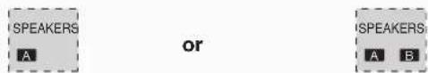
This second set of terminals allows you to connect a second pair of speakers to place in another room, for example. To use the speakers connected to the FRONT B terminals, press [SPEAKERS B] ( page 20).
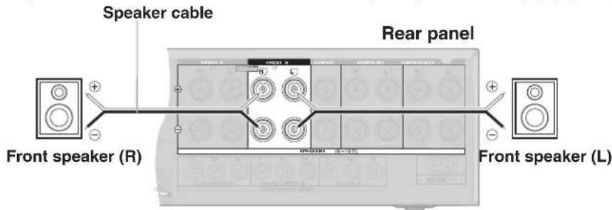
Speaker impedance
Front A and B: 6 to 16 Ω
Front B: 6 to 16 Ω
Note
When only SPEAKERS B is on, output will be 2-channel only. Signals from multi-channel sources are "down-mixed" and output through the two front speakers you have connected.
Before playback
Auto speaker setup
Auto speaker setup allows you to achieve a satisfactory listening environment easily with the use of the supplied calibration microphone as a detector of sound signals. The unit will first perform automatic speaker detection, then checks and adjusts the following settings.
| Automatic speaker detection (This can also be performed in “Automatic speaker detection”, ➔ page 17. However, for a more optimized listening environment, carry out the setup here.) | Checks which speakers you have connected.The factory setting is 7 speakers and a subwoofer.Some types of speakers and cables may cause disruptions to the setup. In this case, conduct manual setting, “Speaker and size settings”, ➔ page 27. |
| DISTANCE | Checks the distance of each speaker from the listening position and adjusts the timing of each channel. For manual setup, “Distance”, ➔ page 27. |
| POLARITY | Checks the polarity of each speaker. You can choose not to have polarity checked, “Auto setup”, ➔ page 27. |
| SIZE | Checks the speaker’s frequency response. For manual setup, “Speaker and size settings”, ➔ page 27.The front speakers are set to SMALL if the unit determines that they are different sizes. |
| FREQUENCY | Sets the appropriate low frequency crossover for each channel according to the speaker size. For manual setup, “Low-pass filter”, ➔ page 27.The setting is based on the speaker with the lowest bass reproduction range.Also checks on “Level” setting to adjust the sound level (volume) for each speaker. |
| LEVEL | Makes any further corrections to the volume of each speaker (for manual setup, “Speaker output and level” ➔ page 17) and also to the frequency response. |
Before setup
- Conduct the auto speaker setup in a quiet environment. A noisy background will give unsatisfactory results.
- Put the subwoofer in position, switch it on, and sets its volume to the level you would normally use. If you do auto speaker setup without the subwoofer, the front speakers will be set as large, possibly resulting in an unsatisfactory bass.
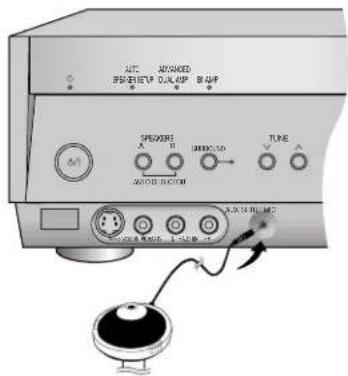
Process for auto speaker setup
1 Placing of calibration microphone.
Place on a flat surface at the seating area. Use a tripod for best results.
2 Connect the calibration microphone to the [SETUP MIC] jack on the front panel.
Note
The calibration microphone is sensitive to heat. Keep it away from direct sunlight and do not place it on top of the unit.
- Turn off all components before making any connections.
- Peripheral equipment and cables sold separately unless otherwise indicated.
- To connect equipment, refer to the appropriate operating instructions.
3 Start performing auto speaker setup.
Turn on the unit.

The standby indicator goes off when you turn on the unit.


a) Press and hold for about 2 seconds.
• [AUTO SPEAKER SETUP] indicator starts flashing.

- "AUTO SETUP" appears on the display.
b) The unit checks that you have correctly connected the calibration microphone.
c) The automatic setup starts the automatic speaker detection, STEP 1, STEP 2, and STEP 3 calibration as follows.
![[A]O SPEAKER SETUP [Φ] M AUTO AUTO AUTO AUTO AUTO AUTO AUTO AUTO AUTO AUTO AUTO AUTO AUTO AUTO AUTO AUTO AUTO AUTO AUTO AUTO AUTO AUTO AUTO AUTO AUTO AUTO AUTO AUTO AUTO AUTO AUTO AUTO AUTO AUTO AUTO AUTO AUTO AUTO AUTO AUTO AUTO AUTO AUTO AUTO AUTO AUTO AUTO AUTO AUTO AUTO AUTG AUTO AUTO AUTO AUTO AUTO AUTO AUTO AUTO AUTO AUTO AUTO AUTO AUTO AUTO AUTO AUTO AUTO AUTO AUTO AUTO AUTO AUTO AUTO AUTO AUTO AUTO AUTO AUTO AUTO AUTO AUTO AUTO AUTO AUTO AUTO AUTO AUTO AUTO AUTO AUTO AUTO AUTO AUTO AUTO](/content/2026/05/846938/images/9e12ce5cc6a05eb137244bd7d1ea9ee13e4ccde87bd778d9a5d3ab83bc4d7719.jpg)
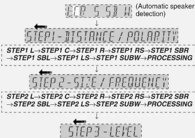
flowchart
graph TD
    A["STEP 5 SB W"] --> B["STEP1 - DISTANCE / POLARITY"]
    B --> C["STEP1 L→STEP1 C→STEP1 R→STEP1 RS→STEP1 SBR → STEP1 SBL→STEP1 LS→STEP1 SUBW→PROCESSING"]
    C --> D["STEP2 - SIZE / FREQUENCY"]
    D --> E["STEP2 L→STEP2 C→STEP2 R→STEP2 RS→STEP2 SBR → STEP2 SBL→STEP2 LS→STEP2 SUBW→PROCESSING"]
    E --> F["STEP3 - LEVEL"]
STEP3 L→STEP3 C→STEP3 R→STEP3 RS→STEP3 SBR →STEP3 SBL→STEP3 LS→STEP3 SUBW→PROCESSING
During setup, operations may stop when there is an error message on the display. Refer to page 16 for troubleshooting.
Speaker abbreviations
L: Front left C: Center R: Front right
S: Surround
RS: Surround right
LS: Surround left
SB: Surround
SBR: Surround back
SBL: Surround back
back
right
left
W/SUBW: Subwoofer
For your reference
- Loud test tones are output from each speaker during the configuration.
- The checked settings display for a minimum of 3 seconds each.
4 Auto speaker setup finishes.
- "COMPLETE" appears on the display and all calibrations are saved.
• [AUTO SPEAKER SETUP] indicator lights.
-AUTO
• To exit, press .TEST
- Disconnect the calibration microphone.
To cancel during setup
Press any button on the main unit or remote control. "CANCELED" appears on the display.
Note
Perform auto speaker setup again if you have changed the speakers, speaker positions, or the layout of your listening environment.
Before playback
Auto speaker setup
While performing auto speaker setup, errors may occur and the messages will blink or scroll on the display, depending on the conditions. Press any button on the main unit or remote control to stop the setup.
After troubleshooting, press and hold -AUTO TEST for 2 seconds to start the setup process again.
Troubleshooting for auto speaker setup
| Message Solutions | Pages | |
| “INSERT MIC” Calibration | microphone is not detected. Insert the microphone correctly.• 14 | |
| “NO SIGNAL” Check that | the calibration microphone is connected correctly.• 14 | |
| “DISTANCE ERROR” | • Bring the speakers nearer to the calibration microphone. | - |
| “NOISY” | • Setup in a quiet environment or do auto speaker setup at a quieter time of day.• Turn off equipment that may produce noise, such as air conditioners. | - - |
| “MEASURING ERROR” | • Change the positions of the speakers and perform the setup again. | - |
| “CHECK CONNECTION TO SBL SPEAKER” | • Left surround back speaker not detected. If you have decided to use only one surround back speaker, connect it to the SURROUND BACK (L) terminal.• Check connection to left surround back speaker. | 13 13 |
| “NEED TO CONNECT LS/RS SPEAKERS” | • Surround speakers not detected. You must have surround speakers connected before you can connect and use surround back speakers effectively. | 13 |
| “CHECK CONNECTIONS TO LS/RS SPEAKERS” | • 13ne or both surround speakers not detected. Check the connections. | |
| “CHECK CONNECTIONS TO L/R SPEAKERS” | • 13check the front (L) and (R) connections. | |
| “LOW SIGNAL” | • Change the position (height and direction) of the microphone.• Make sure there is nothing around the microphone that could interfere with the test tones.• Make sure the volume of the subwoofer is set to the level you would normally use. | - - 17 |
Note
- Auto speaker setup may produce an unsatisfactory result with some speaker setups and configurations.
- You can perform auto speaker setup even if SPEAKERS A are off.
- For subwoofer, only level is adjusted in auto speaker setup.
- All settings in auto speaker setup return to the factory setting if you do automatic speaker detection (− page 17) separately, or, change the speaker size (except for front speakers) from “NO” or “NONE” to other size settings (“Speaker and size settings”, − page 27).
- Auto speaker setup will not start if you have muted the speakers. Turn the muting off (− page 31).
- HDAVI Control™ (= page 21) is disabled during auto speaker setup.
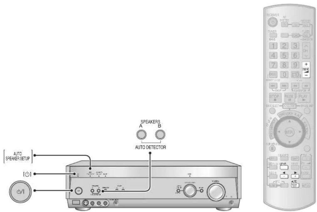
Automatic speaker detection
Automatic speaker detection is performed during auto speaker setup. Do the following only if you want to check speakers' status, and not other settings.
1 Turn on the unit.

The standby indicator goes off when you turn on the unit.

2 Start automatic speaker detection.

• These settings are saved even if you turn the unit off.
- Refer to page 14 for further notes and page 16 for error message explanations. ("WARNING" may appears on the display during the detection here.)
Speaker output and level
Adjust the level of the speakers so they are the same apparent level as the front speakers from the seating area.
Speaker level is adjusted during auto speaker setup. Do the following only if you find the level unsatisfactory.
1 To turn on SPEAKERS A.
SPEAKERS A are on SPEAKERS A and B are on
- The unit does not output the test signal if only SPEAKERS B is on.
2 Press -AUTO to output the test signal.
- The signal is output from each speaker in order for about two seconds each:
L C R RS SBR SBL LS SUBW or L C R RS SB' LS SUBW
^1 If you connect one surround back speaker only (the left surround back speaker)
Make sure your speaker settings match your connections (→ pages 13, and 14 to 16). There will be no output from a speaker if it is set as NO or NONE (→ page 27).
Speaker abbreviations
L: Front left C: Center
R: Front right RS: Surround right
LS: Surround left SBR: Surround back right
SBL: Surround back left SB: Surround back (If you connect
SUBW: Subwoofer one surround back speaker)
3 Set speakers volume to the level you would normally use.

Volume range:
-- dB (minimum), -79 dB to 0 dB (maximum)
4 Press LEVEL to select the speaker channel to adjust.
5 Press to adjust the level to the same apparent level as the front speakers.
Repeat steps 4 and 5 for each speaker channel.
Adjustment range:
-20 dB to +10 dB (Factory setting: 0 dB)
For the subwoofer (SUBW)
MIN (minimum) ↔ 1 to 29 ↔ MAX (maximum)
(Factory setting: 20)
The test signal is output only from the speaker you are adjusting in steps 4 and 5. Test signal for connected speakers resumes after 2 seconds.
6 Press -AUTO to stop the test signal.
Enjoying Home Theater features
Basic play
1 Turn on the unit.
Press

The standby indicator goes off when you turn on the unit.

The [SURROUND] indicator lights to show that the surround mode is on (factory setting).

Note
Before using the unit for the first time or after changing your speaker set up, make sure that you perform auto speaker setup (→ pages 14 to 16) or automatic speaker detection (→ page 17), or for manual settings (→ page 27).
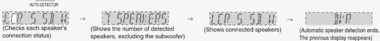
2 Turn on SPEAKERS A.
Press


If you have bi-wired your front speakers (→ page 13), make sure you have selected "YES" for the "LR BI-WIRE setting" (→ page 27).


If you also want to use SPEAKERS B, press [SPEAKERS B] to turn them on. (Remember that sound will only be stereo if you use just SPEAKERS B.)
INPUT SELECTOR
Turn

If you have a combination DVD recorder/VCR (→ page 9)
- Select "DVR" to watch DVDs.
- Select "VCR" to watch video tapes.
4 Start playing the source
If you would prefer to listen in stereo, press [SURROUND] to turn the indicator off.
To return to surround sound, press [SURROUND] to turn the indicator on.
Input sources:
TUNER FM, TUNER AM, CD, TV/STB, DVD, DVR (DVD
recorder), VCR (video recorder), AUX (front terminals)
- "DVD RECORDER" scrolls once across the display if you select "DVR".
-
You can also select the input source with the buttons on the remote control (→ pages 34 to 36).
-
The unit stores whether you have selected SURROUND or not for each input source, but the mode automatically activates if you play a multi-channel source.
- You can "down mix" multi-channel sources to 2 channels by pressing [SURROUND] to turn the indicator off during play. (Some DVD-Audio prohibit down-mixing.)
2-channel down-mix cancels when you turn the unit off or change the input source.
5 Adjust the volume.
Turn
Volume range:
-- dB (minimum), -79 dB to 0 dB (maximum)
When you finish listening
Be sure to reduce the volume and press [∅/l] to switch the unit to standby.
Digital signals this unit can play
| Dolby Digital (including Dolby Digital Surround EX) | These digital surround systems were developed by Dolby Laboratories. Dolby Digital Surround EX, with its additional surround back channels, produces an increased sense of realism. |  | DVD etc. |
| DTS (including DTS-ES and DTS 96/24) | These digital surround systems were developed by DTS (Digital Theater Systems, Inc.). DTS-ES, with its additional surround back channel, immerses you in sound. DTS 96/24 delivers multi-channel sound with superior fidelity (96 kHz/24 bit). |  | DVD etc. |
| PCM | You can input PCM signals with sampling frequencies up to 192 kHz with the DIGITAL IN COAXIAL 1 terminal. The other digital terminals allow input of up to 96 kHz. The display shows the sampling frequency when you input 88.2-kHz, 96-kHz, 176.4-kHz, or 192-kHz signals. |  | CD, DVD-Audio etc. |
Note
This unit cannot process Dolby Digital RF or MPEG audio signal.
Signal indicators
| 2CH MIX | TUNED | MONO ST | RDS | PS | PTY | M | SLEEP | DIGITAL INPUT |
| SPEAKERS BI-WIRE A | B | PCM | ||||||
| cm DTS96/24DTS-ES | ||||||||
| kHz DIGITAL EX | ||||||||
| MHz PL II x NEO:6 SFC |
DIGITAL: Dolby Digital sources DTS: DTS sources
☐ DIGITAL EX: Dolby Digital Surround EX decoder (while in Dolby Pro LogicIIx mode) when the input signal is Dolby Digital 5.1-channel or Dolby Digital Surround EX and you are using one surround back speaker.
EX: Dolby Digital Surround EX decoder (while in Dolby Pro LogicI1x mode) when the input signal is DTS 5.1-channel and you are using one surround back speaker.
PLIIx: Dolby Pro LogicIIx decoder
☐ PLII: Dolby Pro LogicII with stereo sources when you are not using a surround back speaker.
DTS 96/24: DTS 96/24 sources
DTS-ES: DTS-ES Discrete 6.1 sources or when using the DTS-ES matrix
NEO:6: DTS NEO:6 matrix
SFC: Sound field control
For your reference
- Dolby Pro LogicIIx, NEO:6, and SFC add surround effects by "adding" channels, so if they are off, the unit plays the number of channels recorded in the original source.
For example, if it is a 5.1-channel source, there will be no output from the surround back speakers. - The SURROUND mode turns off when input is 192-kHz PCM.
- Whenever you switch to a different source, the following display appears to show you the number of channels. (It may not appear with some sources.)
Subwoofer
Surround and surround back channels
Front and center channels
Playback options
![[ADVANCED] [DUAL AMP] [BI-AMP] SPEAKERS A B 100kV 200kV 300kV 400kV 1.2A 100kV 200kV 300kV 400kV 100kV 200kV 300kV 400kV 100kV 200kV 300kV 400kV](/content/2026/05/846938/images/050ad61f4d2f4e3da9686f48c266b68ac75de95a93480ad21e291594dc4c73cb.jpg)
| Using SPEAKERS B | To use the speakers connected to the FRONT B terminals.Press | Sound will be stereo from SPEAKERS B.If you have only SPEAKERS B on and the input signal is multi-channel, the signal is down-mixed and “2CH MIX” appears on the display.To turn off sound from SPEAKERS A, press [SPEAKERS A] so “A goes off.Note that if you are using DVD 6CH input (below), only the sound for the front speakers is output.Speaker settings (→ page 27) are fixed as follows when you have only SPEAKERS B on.Speaker size:LARGESubwoofer:NO(bass is output from the front speakers.) | |
| ADVANCED DUAL AMP | The Advanced Dual Amp activates automatically. In stereo sources or in 5.1 channel, the unused surround back speakers amplifiers drive the front speakers for a clearer, purer sound. | [ADVANCED DUAL AMP] lights when the function is on.You can turn this function off (→ page 29). | |
| BI-AMP | The bi-amp activates if you have bi-wired your front speakers and play analogue or stereo PCM sources.The amplifiers for the front and surround speakers separately run the low frequency and high frequency. You can use this feature in combination with the Advanced Dual Amp (→ above) for an even clearer and purer stereo sound. | PreparationBi-wire your front speakers (→ page 13).Make sure you have selected “YES” for the “LR BI-WIRE setting” (→ page 27).Turn the SURROUND mode off (→ page 18). | [BI-AMP] lights when the function is on.To make bi-amp settings (→ page 28).NoteYou cannot use the bi-amp if you are using DVD 6CH input (→ below). |
| Playing DVD-Audio | Digital | Connect your DVD equipment with an HDMI cable (→ page 5) or with a coaxial cable through the DIGITAL IN COAXIAL 1 terminal (→ pages 6 and 7). | |
| DVD analogue 6CH | PreparationConnect through the DVD 6CH IN terminals (→ page 8).Switch on SPEAKERS A or BI-WIRE.Select “DVD” as input (→ page 18).Press and hold until “DVD 6CH” appears on the display.DVD 6CHTo cancel, press and hold until “DVD” appears on the display. | If you are using a DVD recorderYou cannot switch to DVD 6CH input if “DVR” is the input source, so connect your recorder through the DVD 6CH IN terminals and select “DVD” as the input source if you want to listen to DVD-Audio.Note“Level” settings (→ pages 14 and 17) made on this unit, except for subwoofer level, are ineffective. | |
| 2-channel analogue | This mode lets you enjoy the high-quality stereo sound available with DVD-Audio recorded with a sampling frequency of 192 kHz. | 1. Cancel “DVD 6CH” if necessary (→ above).2. In INPUT MODE, fix input to analogue (→ page 28). | |
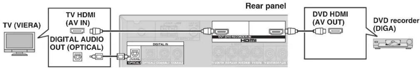
Using HDAVI Control™
HDAVI Control
This convenient feature links control of your receiver and your other Panasonic home theater equipment. VIERA televisions and DIGA DVD recorders connected with an HDMI cable can be controlled in this way. For details, refer to the operating instructions of your other equipment.
Preparation
- Connect your other Panasonic home theater equipment (HDAVI Control compatible VIERA television or DIGA DVD recorder) with an HDMI cable (→ page 5).
(Cables that do not meet the HDMI specifications are not compatible with this feature. Use a Panasonic HDMI cable for best results.)
-
Read your television's operating instructions and make the settings necessary to activate the HDAVI Control.
-
Switch on all your equipment, then switch your television off then on again and check that images from DIGA appear correctly.
(Do this whenever you change connections or settings.)
flowchart
graph LR
    A["TV (VIERA)"] --> B["TV HDMI (AV IN)"]
    B --> C["DIGITAL AUDIO OUT (OPTICAL)"]
    C --> D["Digital In"]
    D --> E["OUT DVD RECORDER IN"]
    E --> F["DVD HDMI (AV OUT)"]
    F --> G["DVD recorder (DIGA)"]
    G --> H["Computer"]
    style A fill:#f9f,stroke:#333
    style B fill:#ccf,stroke:#333
    style C fill:#cfc,stroke:#333
    style D fill:#fcc,stroke:#333
    style E fill:#cff,stroke:#333
    style F fill:#ffc,stroke:#333
    style G fill:#cfc,stroke:#333
    style H fill:#fcc,stroke:#333
• To take advantage of the multi-channel sounds now available with digital television, use a digital connection if your TV has a digital output terminal.
One-touch Home Theater

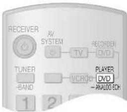
Point the remote control at your DIGA DVD recorder and press [ONE TOUCH PLAY].
-
Your DIGA switches on. Play starts if there is a disc in the tray. If a disc is not in the tray, DIGA plays the television program last recorded to the hard disk.
-
Your VIERA switches on and input switches.
-
This unit switches on, input switches to "DVR", and multi-channel play starts.
Press [+ VOLUME -] to adjust the volume.
You can also adjust the volume with VIERA's remote control.
(An indicator appears on the television showing that you are adjusting this unit's volume.)
If the beginning of the program is cut off, press [◀◀ SKIP] to skip back to the beginning.
For your reference
- If you switch your VIERA off, this unit also switches off (unless you have changed the input source to "TUNER" or "CD").
- VIERA's speakers start to output the audio instead if you switch this unit off. If you then switch this unit on again, audio output switches back to this unit.
- If this unit is off and you switch the setting on your VIERA so that audio is output from a connected receiver, this unit switches on and starts to output the audio.
Multi-channel audio for your VIERA
- Connect your VIERA's digital output terminal to the DIGITAL IN OPTICAL 1 terminal on this unit (→ page 9).
- Refer to your VIERA's operating instructions and make the settings necessary to switch audio output from VIERA's speakers to speakers connected to this unit.
- The input source on this unit switches to "TV" if you select a channel or otherwise operate the television (→ page 34).
To turn off HDAVI Control, "HDMI settings", - page 29.
Surround sound
There are various modes you can use to add surround effects or play stereo through more than just the normal two speakers.
Note
• You may be unable to use some of these surround
effects with some sources.
• These settings are saved even if you turn the unit off.
Dolby Pro LogicIIx
• This feature adds surround effects to stereo sources.
- It can also expand 5.1-channel Dolby Digital and DTS so that you can hear them through 7.1 channels (when you have connected 2 surround back speakers) or 6.1 channels (when you have connected 1 surround back speaker).
- Use this mode when playing Dolby Digital Surround EX to make effective use of the surround back channel.
DOPLIX
Press to select one of the following modes.

(Movie)
Use this mode when playing movie software, especially if it is recorded in Dolby Surround. If you have connected two surround back speakers, their output will be in stereo. This is the factory setting.

(Music)
This mode is effective on music sources.

(Dolby Digital EX)
Use this mode when playing movie software, especially if it is recorded in Dolby Digital EX format. It is effective on multi-channel sources. If you have connected two surround back speakers, output from them will be monaural.
- If you have connected one surround back speaker, the "FIXIIx" indicator goes out and either "DIGITAL EX" or "EXOUGHTs instead.

(Game)
Enjoy gaming with more impact. This mode is effective on stereo sources. You cannot use this mode unless you have connected both surround speakers and surround back speakers ( pages 13 and 14 to 17). Make sure you have also set these speakers as present in “Speaker and size settings” ( page 27).
To cancel, press OFF
Adjusting the Dolby Pro LogicIIx "MUSIC" mode
You can make the following adjustments in stereo sources.
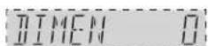
(Dimension Control)
You can make up for differences in the output level of the front and surround speakers.
EFFECT
Press to select "DIMEN", then press to adjust the level.

Adjustment range: -3 (emphasis on the surround speakers) to +3 (emphasis on the front speakers) Factory setting: 0

(Center Width Control)
This is an overall adjustment for the front and center speakers to achieve a more natural sound.
EFFECT
Press to select "C-WIDTH", then press to adjust the level.

Adjustment range: 0 (for a distinct center) to 7 (for a broad center) Factory setting: 3

(Panorama)
This mode spreads sound out to envelope you in music.
EFFECT
Press to select "PANORAMA", then press to select "ON" or "OFF".

Factory setting: OFF
Note
- There will be no output from the subwoofer when using NEO:6 on stereo sources and you have set all of your speakers to "LARGE" in "Speaker and size settings" (→ page 27).
- You may be unable to use some of these surround effects with some sources.
• These settings are saved even if you turn the unit off.
NEO:6
• This feature adds surround effects to stereo sources.
- It can also expand 5.1-channel Dolby Digital and DTS so that you can hear them through 6.1 channels.
NEO:6
Press to select one of the following modes.

Use this mode when playing movies.
(Cinema)
This mode is effective on music sources.
(Music)
For 2-channel Dolby Digital and DTS sources with matrix-encoded multi-channel audio, use "CINEMA". For simple stereo sources, use "MUSIC".
To cancel, press OFF
Adjusting the NEO:6 "MUSIC" mode

This is an overall adjustment for the front and center speakers to achieve a more natural sound.
(Center Image Control)
EFFECT
Press to select "C-IMAGE", then press to adjust the level.

Adjustment range: 0 (for a distinct center) to 5 (for a broad center) Factory setting: 2
Surround sound
There are various modes you can use to add surround effects or play stereo through more than just the normal two speakers.
| SFC (Sound Field Control) | |
| Use SFC modes to add realism and depth to Dolby Digital, DTS, PCM, and analogue stereo sources. | |
 (Music)Pressto select one of the following modes (Music)Pressto select one of the following modes | This mode is effective on music sources. |
You can also press  | |
 (Live) (Live) | Adds reverberation and depth that makes you feel like you were in a concert hall. |
 (Pop/rock) (Pop/rock) | Suitable for pop and rock. |
 (Vocal) (Vocal) | For adding gloss to vocals. |
 (Jazz) (Jazz) | Adds the reverberations you would experience in an intimate jazz club. |
 (Dance) (Dance) | Adds the echoes and feeling of space you would experience in a dance hall. |
 (Party) (Party) | This mode uses all available speakers so that sound is in stereo regardless of the direction you are facing, and is useful at parties where listeners are spread out. |
| To cancel, press OFF | |
 (Movie)Pressto select one of the following modesor (Movie)Pressto select one of the following modesor | |
 (Drama) (Drama) | For dramas and other material where dialogue is important. |
 (Action) (Action) | For action movies and other material where impact is important. |
 (Sports) (Sports) | To make you feel like you were in the stadium. |
 (Musical) (Musical) | Makes you feel like you are in a theater. |
 (Game) (Game) | Enjoy gaming with more impact. |
| To cancel, press OFF | |
SFC (Sound Field Control)
Adjusting SFC (Sound Field Control)
Adjusting the output level
LEVEL
Press to select the speaker you want to adjust, then press to adjust the level.
C (center), RS (surround right), SBR (surround back right), SBL (surround back left), (SB when you have connected only one surround back speaker), LS (surround left)
Adjustment range: -20 dB to +10 dB
Factory setting: 0 dB
SUBW (Subwoofer)
Adjustment range: --- (off), MIN (minimum), 1 to 29, MAX (maximum)
Factory setting: 20
Adjusting the effect level
EFFECT
Press, then press to adjust the level.
Adjustment range: EFFECT 1 (minimum) to EFFECT 10 (maximum)
Factory setting: EFFECT 5
You cannot adjust the effect level in the "PARTY" mode (→ page 24).
Note
- In "PARTY" mode, you can only adjust the subwoofer output level (→ page 17).
- You can only adjust speakers if you have connected them (→ pages 13, and 14 to 17) and set them as present (“Speaker and size settings”, → page 27).
- You may be unable to use some of these surround effects with some sources.
• These settings are saved even if you turn the unit off. - You cannot use SFC modes unless you have connected center or surround speakers.
- When in “PARTY” mode and you have connected a single surround back speaker (the left surround back speaker), there will be no sound from that speaker unless you have also connected a center speaker. Similarly, there will be no sound from your center speaker unless you have also connected a surround back speaker (the left surround back speaker).
- There may be some distortion with some input sources and modes. Reduce the effect level (→ above), or choose another mode.
Receiver settings
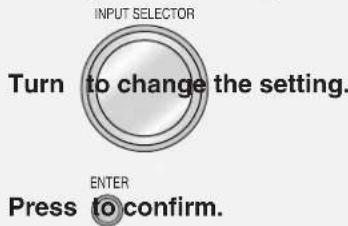
Basic operations
1 Enter the setup menu.

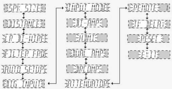
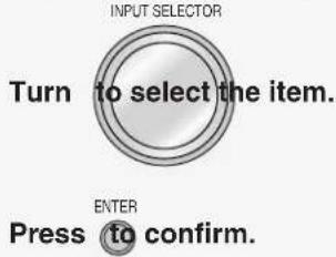
2 Select the item you want to change.
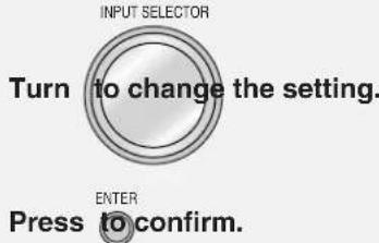
2a Turn (to select the item.
• Refer to pages 27, 28, and 29 for each item settings.
- For "REMOTE 1", refer to page 37 to change the remote control code.
ENTER
Press to confirm.
flowchart
graph TD
    A["SPIK SIZE"] --> B["DISTANCE"]
    B --> C["DI-WIRE"]
    C --> D["FILTER FREQ"]
    D --> E["AUTO SETUP"]
    E --> F["ATTENUATORS"]
    F --> G["OUTPUT MODE"]
    G --> H["DI-AMPS"]
    H --> I["CHOWI"]
    I --> J["ORAL AMPS"]
    J --> K["OPCOMPS"]
    K --> L["SATTENUATORS"]
    L --> M["REMOTE"]
    M --> N["ETF DELAY"]
    N --> O["RESET"]
    O --> P["EXIT"]
2b Turn to select a sub-item.

ENTER Press to confirm.
3 Change the setting.
Repeat 26nd f3 other sub-item settings.
4 Exit the menu.

ENTER Press to confirm.
• The previous display reappears.
- You can also turn [INPUT SELECTOR] to select "EXIT".
To return to the previous display/To cancel
Press
-MENU -SETUP

RETURN
Speaker and size settings
- Set the speakers and their sizes.
- Different speakers play different ranges. Change the size setting to achieve a satisfactory bass.
- Only change this setting if auto speaker setup has not produced a satisfactory result.
2a Select and confirm.

26 Select the speaker you want to set and confirm.

3 Change the setting and confirm.

When you have set the front speakers (LR) as "LARGE"
- The subwoofer outputs bass even when you are playing analogue or PCM stereo sources.
- The sound recorded for the LFE (low frequency effect) channel is played through the subwoofer.
For your reference
- The "SMALL" setting allows you to set the low pass filter to suit the frequency range of your speakers. (→ below)
- The following settings are automatic: "SUBW" (subwoofer) is set to "YES" if you set "LR" (front) to "SMALL". "LR" is set to "LARGE" if you set "SUBW" to "NO".
- “SB” (surround back) have the same size setting as “S” (surround).
SUBW: Subwoofer
LR: Front speakers
C: Center speaker
S: Surround speakers
SB: Surround back speakers
SUBW (Subwoofer)
NO: Unconnected YES : Connected (factory setting)
LR (Front), C (Center), S (Surround)
NONE: Speakers not connected (center or surround)
SMALL : Speakers that cannot adequately reproduce the bass range (sufficient for most speakers when using a subwoofer) (factory setting).
LARGE: Speakers that can reproduce a full sound range, down to 20 Hz.
SB (Surround back)
NONE: Not connected
1-SPK: 1 connected
2-SPK : 2 connected (factory setting)
RETURN (Returns to the main menu)
Distance
Enter the distance of the speakers from the seating position so that the sound from all the speakers (except for the subwoofer) reaches you at the same time.
2a Select and confirm.

2b Select the speaker you want to set and confirm.

3 Select the distance and confirm.

L, R: Front speakers C: Center speaker
LS, RS: Surround speakers SBL, SBR: Surround back speakers
Adjustment range: 0.5 m to 15.0 m
Factory settings:
L, R (Front), C (Center) 3.0 m
LS, RS (Surround), SBL, SBR (Surround back) 1.5 m
Note
"OVER" appears if a speaker was detected as being more than 15.0m away during auto speaker setup.
LR BI-WIRE setting
Change this setting if you have bi-wired your front speakers (→ page 13).
2a Select and confirm.

3 Select and confirm.

YES: You have bi-wired your front speakers
NO: You have not bi-wired your front speakers
Factory setting: NO
Low-pass filter
- Only necessary if you have set speaker size to "SMALL" (→ above).
- Small speakers are unable to reproduce the bass range adequately, so set the filter to match the range of your speakers so that more bass is output from the subwoofer.
- Only change this setting if auto speaker setup has not produced a satisfactory result.
2a Select and confirm.

3 Select the cut-off frequency and confirm.

The settings are 80 Hz, 100 Hz, 120 Hz, 140 Hz, 160 Hz, 180 Hz, and 200 Hz.
Factory setting: 100
For your reference
The filter applies to any speakers you have set as "SMALL".
Auto Setup
- Reset the settings done in auto speaker setup.
- Choose whether to check speaker polarity during auto speaker setup. (If polarity is reversed, a minus sign (-) appears besides the distance reading, for example, "L 3.0 -" to show that polarity has been corrected.)
Reset
2a Select and confirm. AUTO SETUP
2b Select and confirm.

3 Select and confirm.

YES: Reset all auto speaker setup settings NO: To cancel
Factory setting: NO
Polarity
2a Select and confirm.

2b Select and confirm.

3 Select and confirm.

Receiver settings
→ page 26 for basic operations
Digital input settings
- Change these settings to suit the connections you have made to the digital input terminals (→ pages 6, 7, 9, and 10).
- You cannot allocate more than one terminal per input. Therefore, if you change the setting for "DVD" to "OPT 1", digital input for DVD input will be only through the OPTICAL 1 terminal.
2a Select and confirm.

26 Select the equipment and confirm.

3 Change the digital input setting and confirm.

Repeat 2bnd to3 hange other settings.
TV: Television
DVR: DVD recorder
DVD: DVD player
CD: CD player
Factory setting:
TV: OPT1 (OPTICAL 1)
DVR: OPT2 (OPTICAL 2)
DVD: COAX1 (COAXIAL 1)
CD: COAX2 (COAXIAL 2)
Input signal
- This unit automatically detects whether input is digital or analogue, but you can fix the input mode.
- Select "AUTO" if it isn't necessary to fix a certain signal.
2a Select and confirm.

2b Select the equipment and confirm.

3 Select the setting and confirm.

Repeat 2nd to3 hange other settings.
PCM FIX mode
- In rare cases, the unit may have trouble recognizing the digital signals on discs. Use this mode if the beginnings of tracks are cut off when playing CDs.
- Do not use this mode if the unit can handle audio from CDs normally.
- When PCM FIX mode is on, the unit cannot process other signals. Choose another mode if PCM FIX causes noise.
TV: Television
DVR: DVD recorder
DVD: DVD player
CD: CD player
AUTO: The unit automatically detects whether input is digital or analogue. (HDMI takes priority when input is digital.)
ANALOG: Analogue input fixed
DIG: Digital input fixed
PCMFIX: PCM (from CDs) digital input fixed
Factory setting:
- "DIGITAL INPUT" lights after fixing digital input.
- "PCM" lights if you select the PCM FIX mode.
- "PCM FIX" flashes on the display if you input any signal other than PCM after you have set the PCM FIX mode.
Bi-amp settings
- This option appears after you have set "LR BI-WIRE setting" to "YES" (→ page 27).
- Adjust high frequency (HF) and low frequency (LF) balance.
- Correct HF and LF delay time.
Balance
2 Select and confirm.

2a Select and confirm.

3 Adjust and confirm.

Use the bar as a guide.
LF: low frequency HF: high frequency
Delay time
Speaker
(cross section of a speaker)
Difference
2 Select and confirm.

2a Select and confirm.

3 Adjust and confirm.

Adjustment range: 0 to 30 cm
Adjust in 1-cm increments.
Factory setting: 0 cm
| Selecting Input | Standby selection | HDAVI Control | |
| HDMI settingsSpecify the DVD equipment you have connected to the HDMI terminal.To reduce standby power consumption.Choice for turning off the HDAVI Control (→ page 21). | Select and confirm.Select and confirm INPUT: DVRSelect the equipment and confirm INPUT: DVR: You have connected a DVD recorder (factory setting)DVD: You have connected a DVD player | Select and confirm.Select and confirm.STNBY OFFSelect and confirm.STNBY OFFOFF: Standby power consumption reduced (approximately 0.35 W).Signals from DVD equipment cannot pass through HDMI connection to the television when the unit is in standby (→ page 5).HDAVI Control (→ page 21) does not work when the unit is in standby.ON: Normal standby power consumption (factory setting) | Select and confirm.HDMISelect and confirm.CTRL OFFSelect and confirm.CTRL OFFOFF: HDAVI Control is OFFON: HDAVI Control is ON (factory setting) |
| Turning the ADVANCED DUAL AMP off | Select and confirm.DUAL AMPSelect and confirm. | OFF: The Advance Dual Amp is offAUTO: The Advanced Dual Amp works when possibleFactory setting: AUTO | |
| Clear audio at low volumeSet the dynamic range (the difference between the loudest and softest sounds) compression for Dolby Digital. Use this function when you have to turn the volume down, such as late at night. It compresses the dynamic range so that you can still hear dialogue and leave the sound field unaffected. | Select and confirm.TRCOMPSelect a level and confirm. | OFF: OffSTANDARD: The level recommended by the producer of the software for household viewing.MAX: The maximum allowable compression (recommended for night viewing)Factory setting: OFF | |
| Attenuating analogue inputAnalogue input can cause distortion and the “OVERFLOW” warning to appear on the display. Turn the attenuator on if this occurs. | Select and confirm.ATTENUATORSSelect and confirm. | OFF: OffON: OnFactory setting: OFF | |
| Delaying audioDelay audio if there appears to be a difference in timing between audio and pictures. | Select and confirm.TV DELAYSelect and confirm. | OFF: No delayON: Audio delayedFactory setting: OFF | |
| Resetting factory settingsDo the necessary settings again after this. | Select and confirm.RESETSelect and confirm. RESET NO Select “NO” to cancel. | YES: Reset all settings to those made in the factoryNO: CancelFactory setting: YES | |
| NoteInput switches to TUNER after you select “YES”. (Preset channels remain intact.) | |||
Sound effects/Other functions
Basic operations
1 Enter the menu.

2 Select the item you want to change.
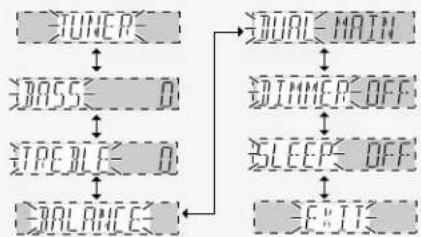
flowchart
graph TD
    A["TUNER"] --> B["O"]
    B --> C["STE BLCE"]
    C --> D["BALANCE"]
    D --> E["EBIT"]
    F["ORIAL MAIN"] --> G["ORIMMER OFF"]
    G --> H["SLEEP OFF"]
    H --> I["EXIT"]
3 Change the setting.
4 Exit the menu.

• The previous display reappears.
- You can also turn [INPUT SELECTOR] to select "EXIT".
To return to the previous display/To cancel

Sound effects
Adjusting the bass
Adjusting the treble
Adjusting front speaker balance
Adjusting the subwoofer level
Adjust the subwoofer level while listening to a source for a more or lesser bass.
2 Select and confirm.

3 Adjust and confirm.

Adjustment range: -10 dB to +10 dB
Factory setting: 0 dB
2 Select and confirm.

3 Adjust and confirm.

Adjustment range: -10 dB to +10 dB
Factory setting: 0 dB
2 Select and confirm.

3 Adjust and confirm.

Use the bar as a guide.
L: Front left
R: Front right
Note
You cannot adjust the balance when the
"PARTY" SFC mode is on (→ page 24).
SUBWOOFER
Press to select a level.
• Factory setting: SUBW 20
- There is no output from the subwoofer if you select “---”.

Adjustment range: --- (off), MIN (minimum), 5, 10, 15, 20, 25, MAX (maximum)
Note
- Sound can be distorted if you raise the volume while subwoofer level is high. Reduce subwoofer level if this occurs.
- You can also make fine adjustments to subwoofer level ("Speaker output and level", page 17).
Other functions
Selecting audio channels
You can switch between the main and secondary audio soundtracks of Dolby Digital or DTS sources.
"DUAL PRG" appears on the display when the unit is receiving a signal with dual audio channels.
2 Select and confirm.

3 Select the audio track and confirm.

MAIN: Main audio channel (factory setting)
SAP: Second audio program
M+S: Main and second channel
Adjusting the dimness of the display
Dim the display for better viewing in a darkened room.
2 Select and confirm.

Adjustment range:
Factory setting: OFF
3 Select a level and confirm.
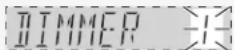
To return to the normal brightness, select "DIMMER OFF".
Press DIMMER
- The display dims to the level you have selected.
- Press again to cancel.
Sleep timer
- The sleep timer turns the unit off after a set time.
- It does not control any other components.
Muting
2 Select and confirm.

3 Select the time and confirm.

Times available: 30, 60, 90, 120 (minutes) Factory setting: OFF
- "SLEEP" lights when the timer is set.
- To check the setting:
Select "SLEEP" again in Step 2.
• To change a setting: Repeat the procedure from the beginning.
Press MUTING
"MUTING IS ON" scrolls across the display while output is muted.
Press again to cancel.
Muting also cancels when you adjust the volume or switch the unit to standby.

The radio
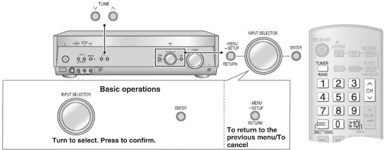
Manual tuning
On the remote control (Direct tuning)
Input the frequency of the station.
1
Select "TUNER".

2
Select "FM" or "AM".
TUNER Press and hold for 2 seconds. -BAND
3

4
Press the numbered buttons to enter the frequency.
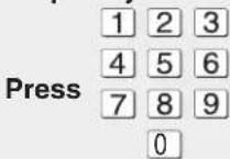
e.g. to select 107.90 MHz, press [1] → [0] → [7] → [9] → [0]
- If you do not press a button while the cursor is flashing, the display returns to the frequency being received.
- If the frequency has not been input correctly, "ERROR" will be displayed.
- "TUNED" lights when a station is tuned.
- "ST" lights when a stereo FM broadcast is tuned.
Improving reception
DVD recorders and DVD players can interfere with radio reception.
Turn the DVD recorder and the DVD player off or move it further away from the AM loop antenna if this occurs.
On the main unit
1
Select "TUNER FM" or "TUNER AM".
INPUT SELECTOR
Turn

2
Tune to the station.
Press

Automatic tuning
Press and hold [TUNE ∨ or ∧] until the frequency starts scrolling to start automatic tuning. (Tuning stops when a station is found or when there is interference.)
To change the AM frequency step
If the correct AM frequency cannot be tuned in, change the frequency step to suit your area.
Preparation: Press [-MENU, -SETUP, RETURN] to enter the menu.
- Select "TUNER" and confirm.
- Select "AM STEP" and confirm.
- Select "AM STEP 9 kHz" or "AM STEP 10 kHz" and confirm.
- Press [-MENU, -SETUP, RETURN] twice to select "EXIT" and press [ENTER].
Preset tuning
Preset channels to make selection simpler.
Even if the AC mains lead is disconnected from the household mains socket, the stations remain in the memory for approximately two weeks.
Presetting stations
■ Auto presetting
The FM stations the unit can receive are preset in channels 1 to 30. The AM stations the unit can receive are preset in channels 21 to 30 (FM stations are replaced if any were preset in these channels).
-
Tune to the frequency where you want to begin (→ page 32). Tune to FM 87.50 MHz or AM 522 kHz (9 kHz steps), AM 530 kHz (10 kHz steps) to start from the lowest frequency.
-
Enter the menu
Press

- Select "TUNER" and confirm.
- Select "AUTO MEMO" and confirm.
-
Select "START" and press [ENTER]. Select "CANCEL" to cancel.
-
During automatic presetting, the memory indicator (M) flashes and the frequency scrolls. The memory indicator and channel numbers are displayed for a second when a station is preset.
- The last station to be preset is played when presetting finishes.
- Stations may not preset correctly if broadcasts are too strong or weak. Preset manually if this is the case.
■ Manual presetting
Preset the stations one at a time.
- Tune to the station (→ page 32).
- Enter the menu.
Press

- Select "TUNER" and confirm.
- Select "MEMORY" and confirm.
- Select a channel number and press [ENTER]. "STORED" is displayed. To preset other channels, repeat from step 1.
- Press [-MENU, -SETUP, RETURN] twice to select "EXIT" and press [ENTER].
You can also preset FM stations in the MONO mode ( below).
Selecting channels
■ On the remote control
- Select the channel.
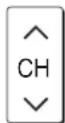
- Press the numbered buttons to select the channel.
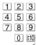
To select a two digit number e.g. 21: [≥10, -/--] → [2] → [1]
■ On the main unit
- Enter the menu.
Press

- Select "TUNER" and confirm.
- Select "TUNE MODE" and confirm.
- Select "PRESET" and confirm.
- Press [-MENU, -SETUP, RETURN] twice to select "EXIT" and press [ENTER].
- Select the channel.
Press
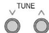
Press and hold to change channels faster.
Select "MANUAL" in step 4 to tune manually again (→ page 32).
Reducing excessive noise (on the main unit)
Preparation: Press [-MENU, -SETUP, RETURN] to enter the menu.
■ During FM stereo reception
You can improve FM reception by switching reception to monaural.
- Select "TUNER" and confirm.
- Select "FM MODE" and confirm.
- Select "MONO" and confirm.
- "MONO" lights.
• To return to normal reception, select "AUTO".
- Press [-MENU, -SETUP, RETURN] twice to select "EXIT" and press [ENTER].
During AM reception
When there is a lot of noise interference with an AM broadcast, try switching to this mode.
- Select "TUNER" and confirm.
- Select "BEAT PROOF" and confirm.
- Select "MODE 1" or "MODE 2" and confirm.
- Press [-MENU, -SETUP, RETURN] twice to select "EXIT" and press [ENTER].
RDS broadcasts
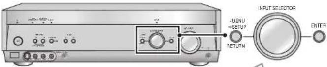
Basic operations
INPUT SELECTOR

ENTER
Turn to select. Press to confirm.

To return to the previous menu/To cancel
| PTY displays | |
| NEWS News | |
| AFFAIRS Current affairs | |
| INFO Information | |
| SPORT Sport | |
| EDUCATE Education | |
| DRAMA Drama | |
| CULTURE Culture | |
| SCIENCE Science | |
| VARIED Varied | |
| POP M Pop music | |
| ROCK M Rock music | |
| M. O. R. M Middle-of-the-road Music | |
| LIGHT M Light classical | |
| CLASSICS Serious classical | |
| OTHER M | Other music |
| WEATHER | Weather information |
| FINANCE | Finance |
| CHILDREN Children | |
| SOCIAL A | Social affairs |
| RELIGION Religion | |
| PHONE IN | Phone in |
| TRAVEL | Travel |
| LEISURE | Leisure |
| JAZZ Jazz music | |
| COUNTRY Country music | |
| NATIONAL | National music |
| OLDIES | Oldies |
| FOLK M Folk music | |
| DOCUMENT | Documentary |
| TEST | Test broadcast |
| ALARM Emergency announcement | |
Changing the display
This unit can display the text data transmitted by the radio data system (RDS) available in some areas.
"RDS" lights while RDS signals are being received.
RDS displays may not be available if reception is poor.
- Press [-MENU, -SETUP, RETURN] to enter the menu.
- Select "TUNER" and confirm.
- Select "RDS DISP" and confirm.
- Select the display mode and confirm.
FREQUENCY: Frequency display
PS DISP: Program service, the station name
PTY DISP: Program type
- Press [-MENU, -SETUP, RETURN] twice to select "EXIT" and press [ENTER].
Using the remote control with other equipment
This remote control can operate Panasonic televisions, DVD recorders, DVD players, VCRs, and CD players. Note that this remote control cannot operate some equipment. For details about the operations, refer to your equipment's operating instructions.
You may need to enter a code to operate some equipment (→ page 37).
Point the remote control at the equipment you want to operate.
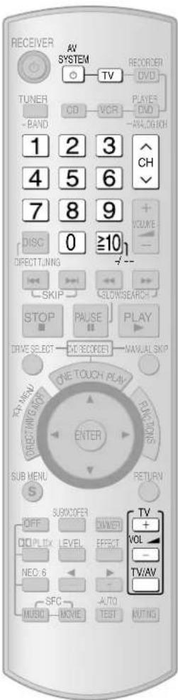
Television
| To switch the unit's input to "TV"/To switch the remote control to the TV operation mode |  Do this before trying to operate the television. Do this before trying to operate the television. |
| To switch the television on or off |  |
| To switch the television's input mode |  |
| To adjust the television's volume | 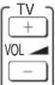 |
| Select the channel | To change channels sequentially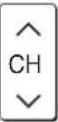 To select a channel directly To select a channel directly [WWDS] [WWDS]  |
To select a channel directly
Using the remote control with other equipment
Point the remote control at the equipment you want to operate.
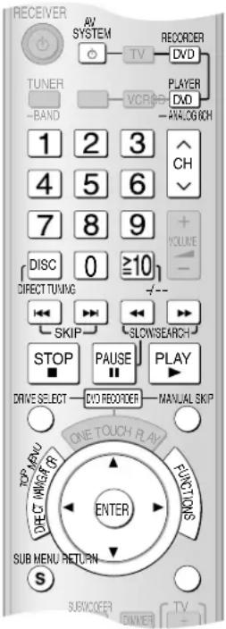
Before using this remote control with a Panasonic DVD recorder
You may need to change the code in the remote control to match the remote control mode of the DVD recorder.
Preparation: Check the remote control mode of your DVD recorder. Read its operating instructions for details.
-
Press [DVD RECORDER].
-
While pressing [ENTER], press and hold [1], [2], or [3] for about 2 seconds.
-
The remote control code switches to 1, 2, or 3, depending on which numbered button you pressed.
- The factory setting is "1".
If you are unable to switch the drives on the DVD recorder
The DVD recorder is not responding to the signal from the remote control.
Do the following to change the signal, then try switching drives again.
-
Press [DVD RECORDER].
-
While pressing [ENTER], press and hold [8] for about 2 seconds.
To restore the original signal:
In step 2, while pressing [ENTER], press and hold [9] for about 2 seconds.
DVD recorder/DVD player
| To switch the unit's input to “DVR” or “DVD”/To switch the remote control to the DVD recorder or DVD player operation mode |  Do this before trying to operate the DVD recorder. Do this before trying to operate the DVD recorder. |  Do this before trying to operate the DVD player. Do this before trying to operate the DVD player. | ||
| To switch the DVD recorder/DVD player on or off | AV SYSTEM[IMAGE] | To confirm selection of an item |  | |
| To skip a track or chapter |  | For selecting tracks and chapters directly | 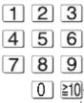 You may have to then press [ENTER] on some models. You may have to then press [ENTER] on some models. | |
| To search through the disc |  | |||
| Slow-motion | 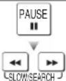 | To pause |  | |
| To start play |  | Frame-by-frame | 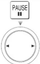 | |
| To show the direct navigator or top menu |  | |||
| To show sub menus | SUB MENU | To skip ahead 30 seconds (For DVD recorder only) |  | |
| To show the FUNCTIONS window (while stopped) |  | To switch the DVD recorder's drive (HDD, disc, and SD) (For DVD recorder only) | DRI | |
| To return to the previous screen |  | Select the channel (For DVD recorder only) | To change channels sequentially[6x35] | |
| To navigate through menus |  Use these buttons to select items after pressing [DIRECT NAVIGATOR, TOP MENU], [S, SUB MENU], or [FUNCTIONS]. Use these buttons to select items after pressing [DIRECT NAVIGATOR, TOP MENU], [S, SUB MENU], or [FUNCTIONS]. | To select a channel directly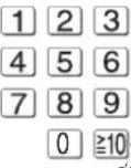 | ||
| To specify a disc (5-disc changer only) (For DVD player only) | 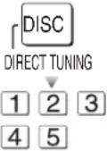 | To stop play |  | |
Note
[FUNCTIONS] activates display functions on some of the Panasonic DVD players.
Using the remote control with other equipment
Point the remote control at the equipment you want to operate.
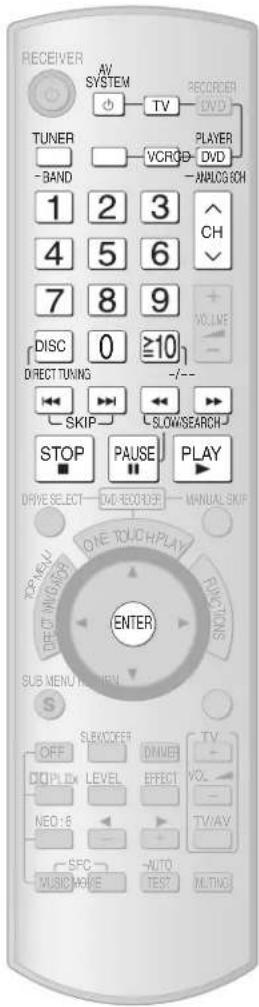
VCR CD player
| To switch the unit's input to “VCR”/To switch the remote control to the VCR operation mode |  Do this before trying to operate the VCR. Do this before trying to operate the VCR. |
| To switch the VCR on or off |  [IMAGE] [IMAGE] |
| To start play |  |
| Fast-forward/rewind |  |
| To pause |  |
| Select the channel | To change channels sequentially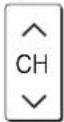 To select a channel directly1 2 34 5 67 8 90 ≥10... To select a channel directly1 2 34 5 67 8 90 ≥10... |
| To stop play |  |
| To switch the unit's input to “CD”/To switch the remote control to the CD player operation mode |  Do this before trying to operate the CD player. Do this before trying to operate the CD player. |
| To switch the CD player on or off |  |
| To start play |  |
| To skip a track |  |
| To search through the disc |  |
| To pause |  |
| To specify a disc (3- or 5-disc changer) | 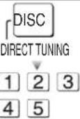 |
| To start play from a specified disc [MEGA CD changer](holds more than 50 discs) |  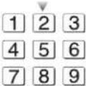  |
| To select a track directly | 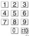 |
| To stop play |  |
Changing the remote control code
Change the code if you find the remote control unintentionally also controls other Panasonic equipment.
Do the following to set the remote control code and this unit's remote control mode to the same one.
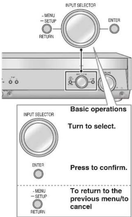
Change the main unit's mode
- Enter the SETUP menu.

- Select and press [ENTER].

- Select and press [ENTER].

- Press [-MENU, -SETUP, RETURN] twice to select "EXIT" and press [ENTER].
Change the remote control's code
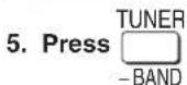
- While pressing ENTER, press and hold for about 2 seconds.
:To restore the code to "1"
- On the main unit: In step 3, select "1".
- On the remote control: In step 6, while pressing [ENTER], press and hold [1] for about 2 seconds.
Enter a code to operate some equipment
This remote control can operate Panasonic and Technics audio-visual equipment that have remote control sensors. You may need to change the remote control code. It can also operate some other brands of televisions, video cassette recorders, and DVD players. Check the table for the brand and enter the code as follows.
Changing the codes
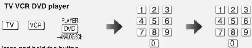
Enter the first digit. Enter the second digit.
The remote control outputs the on/off signal. If the code is correct, the equipment turns on or off. If it doesn't, try entering another code.
- Note that this remote control cannot operate some equipment and that it may not be able to perform some operations.
• Re-enter the codes after you change the batteries.
Code table
| TV | VCR | DVD player | |
| PANASONIC | 01/29/30/31 | 01/29/30 | 01 |
| AKAI | 07/11/28/36/37 | 06/08/16/17/19/37 | - |
| ALBA | 05/11/12 | 02/06/23 | - |
| BAIRD | - | 08/10/37 | - |
| BAUR | 32 | - | - |
| BLAUPUNKT | 28/36 | 01/26/29/30/33 | - |
| BRANDT | 26/41 | - | - |
| BUSH | 02/05/10/11/12/32/38 | 02/09/23 | - |
| DAEWOO | 11/12/32 | 15 | - |
| DENON | - | - | 01/17 |
| DUAL | 32 | - | - |
| FERGUSON | 11/12 | 31 | 02 |
| FINLUX | 11/12/22/23/24/25/40 | - | - |
| FISHER | 37 | 05/07/10/11/12 | - |
| FUNAI | 02/38 | - | - |
| GOLDSTAR | 11/12 | - | - |
| GOLDSTAR/LG | - | 03/04/36/37 | - |
| GOODMANS | 11/12/25/32 | 02/03/18/23/27/33 | - |
| GO-VIDEO | - | - | 12 |
| GRUNDIG | 28/36 | 02/23/26/28/32/33 | - |
| HCM | - | 02/23 | - |
| HITACHI | 01/09/26/41 | 13/14 | 11 |
| ICE | 21/39 | - | - |
| INNO HIT | 34 | - | - |
| ITT | - | 08/10/11/37 | - |
| ITT/NOKIA | 05/07/37 | 18/27/37 | - |
| JVC | 18 | 20/21 | 09 |
| KENDO | 40 | 08/09/37 | - |
| KENWOOD | - | - | 15 |
| LOEWE | 14/33 | 03/32 | - |
| LOEWE OPTA | 32 | - | - |
| LUXOR | 37 | 08/10/11/17/19/37 | - |
| MATSUI | 02/05/06/07/10/11/12/25/37/38 | 03/05/09 | - |
| METZ | - | 01 | - |
| MITSUBISHI | 14/19/28/36 | 17/19/21/32 | 06 |
| TV | VCR | DVD player | |
| NEC | - | 04/21/36/37 | - |
| NOKIA | 05/07/37 | 08/10/11/18/22/27/37 | - |
| NORDMENDE | 26/41 | 20/21 | 02 |
| OCEANIC | 27/35 | - | - |
| OKANO | - | 06 | - |
| ORION | 02/03/05/10/11/12/38 | 05/09 | - |
| PHILIPS | 11/12/13/15 | 22/32/33/34/35 | 04/16 |
| PHONOLA | 11/12 | 32 | - |
| PIONEER | - | - | 03 |
| POLKAUDIO | - | - | 16 |
| RADIOLA | 11/12 | - | - |
| RAITE | - | - | 13 |
| RCA | - | - | 02 |
| RFT | - | 33 | - |
| ROADSTAR | 39 | 02/03/18/23/27 | - |
| SABA | 26/41 | 21 | 02 |
| SALORA | 07/37 | 08/11/17/19/37 | - |
| SAMPO | - | - | 14 |
| SAMSUNG | 11/12/15/21/25/34/39 | 15/16/18/27 | 10 |
| SANYO | 07/17/25/37 | 07/10/11 | - |
| SCHAUB LORENZ | - | 10 | - |
| SCHNEIDER | 11/12 | 02/03/18/23/27/32 | - |
| SEG | 39/40 | 02/18/23/27 | - |
| SELECO | 11/24 | - | - |
| SHARP | 17/20 | 22 | 08 |
| SIEMENS | 11/12/17/28/36 | 03/10/11/32 | - |
| SINUDYNE | 02/05/11/12/22/24/38/40 | - | - |
| SONY | 16 | 24/25/26 | 05 |
| TECHNICS | - | - | 01 |
| THOMSON | 05/26/41 | 21 | 02 |
| THORN | 06/08/11/12/14/16/25/32 | 10 | - |
| TOSHIBA | 03/04/06/08 | 15/17/19/32 | 04 |
| UNIVERSUM | 39 | 03/08/32/37 | - |
| WHITE WESTIN HOUSE | 11/12/22/40 | - | - |
| YAMAHA | - | - | 01 |
| ZENITH | - | - | 07/12 |
Specifications (DIN 45 500)
■ AMPLIFIER SECTION
Power output (at AC 230 to 240 V)
DIN 1 kHz (T.H.D. 1 %) 2 x 100 W (6 Ω)
20 Hz to 20 kHz continuous power output
both channel driven 2 x 80 W (6 Ω)
Total harmonic distortion
rated power at 20 Hz to 20 kHz 0.09 % (6 Ω)
Power bandwidth
both channel driven, -3 dB 4 Hz to 88 kHz (6 Ω, 0.9 %)
Power output each channel driven (at AC 230 to 240 V)
Front (L/R) 100 W (6 Ω)
Center 100 W (6 Ω)
Surround (L/R) 100 W (6 Ω)
Surround Back (L/R) 100 W (6 Ω)
Load impedance
Front (L/R)
A or B 6 Ω to 16 Ω
A and B 6 Ω to 16 Ω
BI-WIRE 6 Ω to 16 Ω
Center 6 Ω to 16 Ω
Surround (L/R) 6 Ω to 16 Ω
Surround Back (L/R) 6 Ω to 16 Ω
Frequency response
CD, DVD, DVD Recorder, VCR, TV/STB, AUX 4 Hz to 88 kHz, ±3 dB
DVD 6CH 4 Hz to 44 kHz, ±3 dB
Input sensitivity and impedance
CD, DVD/DVD 6CH, DVD Recorder, VCR, TV/STB, AUX 200 mV/22 kΩ
S/N at rated power (6 Ω)
CD, TV/STB, DVD, DVD Recorder (Digital input) 90 dB (IHF, A: 103 dB)
Tone controls
BASS 50 Hz, +10 dB to -10 dB
TREBLE 20 kHz, +10 dB to -10 dB
Channel balance (250 Hz to 6.3 kHz)
Channel separation 55 dB
Subwoofer frequency response (-6 dB) 7 Hz to 200 Hz
| Digital input | (OPTICAL) 2(COAXIAL) | 2 |
| HDMI (Version 1.2a) | Input | 1 |
| Output | 1 |
■ FM TUNER SECTION
| Frequency range | 87.50 MHz to 108.00 MHz |
| Sensitivity | |
| S/N 30 dB | 1.5 μV/75 Ω |
| S/N 26 dB | 1.3 μV/75 Ω |
| S/N 20 dB | 1.2 μV/75 Ω |
| IHF usable sensitivity (IHF '58) | 1.5 μV/75 Ω |
| IHF 46 dB stereo quieting sensitivity | 22 μV/75 Ω |
Total harmonic distortion
MONO 0.2%
STEREO 0.3%
S/N
MONO 60 dB
STEREO 58 dB
Frequency response 20 Hz to 15 kHz, +1 dB, -2 dB
Alternate channel selectivity ±400 kHz, 65 dB
Capture ratio 1.5 dB
Image rejection at 98 MHz 40 dB
IF rejection at 98 MHz 70 dB
Spurious response rejection at 98 MHz 70 dB
AM suppression 50 dB
Stereo separation 40 dB
Carrier leak 19 kHz, -30 dB
Channel balance (250 Hz to 6.3 kHz) ±1.5 dB
Limiting point 1.2 μV
Bandwidth
IF amplifier 180 kHz
FM demodulator 1000 kHz
Antenna terminal
■AM TUNER SECTION
Frequency range 522 kHz to 1611 kHz (9 kHz steps)
530 kHz to 1620 kHz (10 kHz steps)
Sensitivity 20 μV, 330 μV/m
Selectivity (at 999 kHz) 55 dB
IF rejection (at 999 kHz) 50 dB
■VIDEO SECTION
Output voltage at 1 V input (unbalanced) 1±0.1 Vp-p
Maximum input voltage 1.5 Vp-p
Input/output impedance 75 Ω (unbalanced)
S-Video
Input DVD, DVD Recorder, TV/STB
Output TV MONITOR
Component Video
Input DVD Recorder, TV/STB
Output TV MONITOR
GENERAL
Power supply AC 230 to 240 V, 50 Hz
Power consumption 140 W
Dimensions (W x H x D) 430 mm x 107.5 mm x 390 mm
Mass 4.7 kg
Power consumption in standby mode: 0.9 W
Power consumption in HDMI off mode: 0.35 W
Notes:
-
Specifications are subject to change without notice.
-
Mass and dimensions are approximate
-
Total harmonic distortion is measured by the digital spectrum analyzer.
Help messages
| Message | Causes and solutions |
| CANCEL MUTING FUNCTION | Muting is on.Press [MUTING] on the remote control to cancel (→ page 31). |
| MUSIC MODE ONLY | You are trying to use a feature that is available only in “MUSIC” mode.Change the mode to “MUSIC” (→ pages 22 to 23). |
| NO CENTER AND SURPOUND SPEAKERS | Center and surround speakers are not connected, or they are set as absent.Connect the speakers (→ page 13) or change their setting to present (→ page 27). |
| NO SURPOUND AND SURPOUND BACK SPEAKERS | Surround and surround back speakers are not connected, or they are set as absent. Connect the speakers (→ page 13) or change their setting to present (→ page 27). |
| NO SURPOUND BACK SPEAKER | Surround back speakers are not connected, or they are set as absent. Connect the speakers (→ page 13) or change their setting to present (→ page 27). |
| NOT POSSIBLE FOR DTS-ES SOURCE | You are trying to use an effect unavailable with DTS-ES sources. |
| NOT POSSIBLE FOR DVD AUDIO SOURCE | You are trying to use an effect unavailable with DVD-Audio sources. |
| NOT POSSIBLE FOR DVD GCH INPUT | You are trying to use an effect unavailable with DVD analogue 6-channel input. |
| NOT POSSIBLE FOR THIS INPUT SOURCE | You are trying to use an effect unavailable with the current input source. |
| PCM FIX(flashing) | You have set the “PCM FIX” mode. Cancel this mode (→ page 28). |
| SELECT SPEAKER A | SPEAKERS A is off. Press [SPEAKERS A] to turn on “SPEAKERS A” (→ page 18). |
| SPEAKERS ARE OFF | SPEAKERS A and SPEAKERS B are off. Select one of the speakers (→ page 18). |
Troubleshooting guide
Before requesting service, make the following checks. If you are in doubt about some of the check points, or if the remedies indicated in the chart do not solve the problem, consult your dealer for instructions.
■ Common problems
Pages
| No power. Ensure the AC mains lead is connected.• 11 | ||
| No sound.Sound is distorted. | Turn the volume up.Check connections to speakers and other equipment.Turn on the speakers.Select the correct source.Change DIG INPUT setting to suit the type of connection you have made.Check that the digital signals can be decoded by this unit.Turn the muting off.Turn PCM FIX off.Recording of some DVD-Audio may not be possible due to copyright protection. | 185 to 13181828193128- |
| Sound stops. “OVERLOAD” appears on the display for about a second, and the unit turns off. | Determine and correct the cause, then turn the unit on.Causes include:- Shorting (bare wires touching) of positive and negative speaker wires.- Using speakers with an impedance lower than that rated for this unit.- Straining of the speakers through excessive volume or power.- Using the unit in a hot environment without proper ventilation.Consult your dealer if the problem occurs again after switching the unit on. | -13-- |
| Analogue input becomes distorted and the message “OVERFLOW” appears on the display during playback. | Switch the attenuator on.• 29 | |
| “F76” appears on the display and the unit turns off. | Turn the unit off, disconnect the AC mains lead, and consult your dealer.• - | |
| “F70” appears on the display. | Turn the unit off, disconnect the AC mains lead, and consult your dealer. | - |
| “REMOTE 2” or “REMOTE 1” appears on the display. | Match the codes on the main unit and the remote control.• 37 | |
| Display is dim. Cancel “DIMMER”.• 31 | ||
| Clicking sound is heard during play. | -Depending on the input signal when playing DVD etc., the ADVANCED DUAL AMP function changes automatically. A clicking sound is heard when it changes. This does not mean a problem with the unit.→You can also set the unit against automatic advanced dual amp operations. | 29 |
■ Surround effects Pages
| Sound is not heard from the center, surround or subwoofer speakers. | · Ensure the speaker settings for your speakers are correct.· Confirm Dolby Pro Logic11x, NEO:6, or SFC settings, and select an adequate mode.· Switch SURROUND on when you play 2-channel stereo sources. | 14 to 17, 2722 to 2518 |
| Sound is not heard from the surround back speaker. | · Ensure the speaker settings for your speakers are correct.· Switch SURROUND on. | 14 to 17, 2718 |
| Cannot switch SURROUND on.(Dolby Pro Logic11x, NEO:6, and SFC are unavailable.) | · Check if the center speaker, surround speakers, and surround back speakers are connected properly.· Switch SPEAKERS A on.· You cannot use the SURROUND effect when the input source contains PCM signals with sampling frequencies of 192 kHz.· Cancel DVD analogue 6-channel playback.· You cannot use the effect when the input source contains dual audio signals in Dolby Digital or DTS formats. | 1318-20- |
| There is no DTS audio output.There is audio output, but the DTS decoder indicator is not lit. | Set the DTS Digital Audio Output setting on the DVD player or DVD recorder to “Bitstream”.• - | |
| Sound is distorted when using the Sound Field Control (SFC). | · 25pending on the input source, sound may be distorted if you increase the SFC effect level. If this happens, decrease the SFC effect level. |
Radio
Pages
| The radio cannot be tuned in or there is a lot of noise and interference. | Connect the appropriate antenna. (You may need an outdoor antenna or one with more elements.)Adjust the position of the FM or AM antenna.Reduce the treble.Turn off nearby televisions, video decks, DVD recorder, DVD player, and satellite receivers.Separate the antenna from other cables, cords, and appliances. | 111131-- |
| There is a lot of noise when listening to AM. | Try changing the BEAT PROOF mode. • 33 | |
| The correct AM frequency cannot be tuned in. | Change the frequency step to suit your area when AM is selected. • 32 |
HDMI
Pages
| When using an HDMI connection, the first few seconds of sound is cut off. | Should you be playing a chapter on a DVD:- Change the audio output setting on the DVD player or DVD recorder from “Bitstream” to “PCM”. (6.1-channel sources will however be played as 5.1-channel.)- Select “PCMFIX” as instructed in “Input signals” when you play 2-channel sources. | -28 |
| “U 70-1-1” appears on the display. | The equipment connected by the HDMI cable is not compatible with the unit’s copyright protection technology. | - |
| “U 70-1-2” appears on the display. | -The unit has received a signal for a picture format that is incompatible with the HDMI connection. Check the settings of the connected equipment. | |
| “U 70-3” appears on the display. | Should anything unusual happen using an HDMI connection:Consult your dealer if the sign remains on the display after these steps.- Turn the connected equipment off and on again.- Pull out the HDMI cable then reinsert it.- Reduce the amount of equipment connected in series to the HDMI terminal if exceeding 2 units. | -5, 21- |
| The unit does not work properly. | The unit does not work properly when wrong cords are in HDMI input and output terminals. Turn the unit off, unplug the AC mains lead, and make connections again. | 5, 21 |
| HDAVI Control does not function properly. | Connect the unit to your TV (VIERA) using the HDMI cable, switch the TV on, unplug the unit’s AC mains lead, and insert it into a household mains socket again. |
■ Remote control
Pages
| The remote control does not work. | Replace the batteries if they are worn. | 3 |
| Other products respond to the remote control. | Change this unit's remote control code to “REMOTE 2”. | 37 |
Supplied accessories

Please check and identify the supplied accessories.

1 AC mains lead 1 FM indoor antenna 1 AM loop antenna 2 Batteries
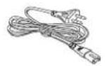
1 Remote control

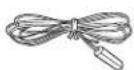

Calibration microphone
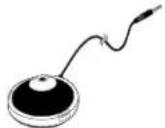
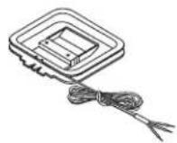
Use numbers indicated in parentheses when asking for replacement parts.

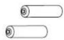
-If you see this symbol-
Information on Disposal for Users of Waste Electrical & Electronic Equipment (private households)

This symbol on the products and/or accompanying documents means that used electrical and electronic products should not be mixed with general household waste.
For proper treatment, recovery and recycling, please take these products to designated collection points, where they will be accepted on a free of charge basis. Alternatively, in some countries you may be able to return your products to your local retailer upon the purchase of an equivalent new product.
Disposing of this product correctly will help to save valuable resources and prevent any potential negative effects on human health and the environment which could otherwise arise from inappropriate waste handling. Please contact your local authority for further details of your nearest designated collection point.
Penalties may be applicable for incorrect disposal of this waste, in accordance with national legislation.
For business users in the European Union
If you wish to discard electrical and electronic equipment, please contact your dealer or supplier for further information.
Information on Disposal in other Countries outside the European Union
This symbol is only valid in the European Union.
If you wish to discard this product, please contact your local authorities or dealer and ask for the correct method of disposal.
NORSK
ADVARSEL!
- APPARATET MÅ IKKE PLASSERES I EN BOKHYLLE, ET INNEBYGGET KABINETT ELLER ET ANNET LUKKET STED HVOR VENTILASJONSFORHOLDENE ER UTILSTREKKELIGE. S∅RG FOR AT GARDINER ELLER LIGNENDE IKKE FORVERRER VENTILASJONSFORHOLDENE, SÅ RISIKO FOR ELEKTRISK SJOKK ELLER BRANN FORÅRSAKET AV OVERHETING UNNGÅS.
- APPARATETS VENTILASJONSÅPNINGER MÅ IKKE DEKKES TIL MED AVISER, BORDDUKER, GARDINER OG LIGNENDE.
- PLASSER IKKE ÅPEN ILD, SLIK SOM LEVENDE LYS, OPPÅ APPARATET.
- BRUKTE BATTERIER MÅ KASSERES UTEN FARE FOR MILJ∅ET.
ADVARSEL:
FOR Å REDUSERE FAREN FOR BRANN, ELEKTRISK STÖT ELLER SKADER PÅ PRODUKTET, MÅ DETTE APPARATET IKKE UTSETTES FOR REGN, FUKTIGHET, VANNDRÅPER ELLER VANNSPRUT. DET MÅ HELLER IKKE PLASSERES GJENSTANDER FYLT MED VANN, SLIK SOM BLOMSTERVASER, OPPÅ APPARATET.
DETTE APPARATET ER BEREGNET TIL BRUK UNDER MODERATE KLIMAFORHOLD.
If the surfaces are dirty
To clean this unit, wipe with a soft, dry cloth.
- Never use alcohol, paint thinner or benzine to clean this unit.
- Before using chemically treated cloth, carefully read the instructions that came with it.
Matsushita Electric Industrial Co., Ltd.
Web Site: http://panasonic.net

- AV Control Receiver
- Dear customer
- Safety precautions
- Placement
- Voltage
- AC mains lead protection
- Foreign matter
- Service
- CAUTION!
- WARNING:
- Table of contents
- Before use
- Connections
- Basic operations
- Operations
- Reference
- The remote control
- Batteries
- Note
- Caution
- When you set the unit in a cabinet
- Home Theater connections
- Connecting your television and DVD equipment
- High-quality audio and video simply with HDMI connection
- Connection cable
- Video and Audio cable
- Audio and video signal flow when you have used HDMI connections
- For your reference
- Connecting your television and DVD equipment (cont.)
- Connections for high-resolution video (components without an HDMI)
- The video terminals
- Connections for standard-resolution video (components without an HDMI)
- 6-channel discrete connection (for high-quality DVD-Audio sound)
- Analogue audio connections
- Playing audio from your television through speakers connected to this unit
- Connecting a combination DVD recorder/VCR
- Connecting other equipment
- Connecting a set top box (cable or satellite)
- Connecting a CD player
- Connecting a video camera or other portable device
- Connecting the antennas and AC mains lead
- Connect AC mains lead after all other cables and cords are connected.
- Using headphones
- Speaker connections
- Connecting speakers
- Connections and placement to suit the number of speakers you have
- Front speakers (left, right)
- Center speaker () C
- Surround speakers (left, right)
- Surround back speakers (left, right / when you connect only one speaker) SB
- Subwoofer ( ) SUBW
- Connecting biwireable speakers
- Connecting a second pair of front speakers
- Before playback
- Auto speaker setup
- Before setup
- Process for auto speaker setup
- Placing of calibration microphone.
- Connect the calibration microphone to the [SETUP MIC] jack on the front panel.
- Start performing auto speaker setup.
- Turn on the unit.
- a) Press and hold for about 2 seconds.
- b) The unit checks that you have correctly connected the calibration microphone.
- c) The automatic setup starts the automatic speaker detection, STEP 1, STEP 2, and STEP 3 calibration as follows.
- Speaker abbreviations
- Auto speaker setup finishes.
- To cancel during setup
- Troubleshooting for auto speaker setup
- Automatic speaker detection
- Turn on the unit.
- Start automatic speaker detection.
- Speaker output and level
- To turn on SPEAKERS A.
- Press -AUTO to output the test signal.
- Set speakers volume to the level you would normally use.
- Press LEVEL to select the speaker channel to adjust.
- Press to adjust the level to the same apparent level as the front speakers.
- Press -AUTO to stop the test signal.
- Enjoying Home Theater features
- Basic play
- Press
- Turn on SPEAKERS A.
- INPUT SELECTOR
- Turn
- Start playing the source
- Input sources:
- Adjust the volume.
- Volume range:
- When you finish listening
- Playback options
- Using HDAVI Control™
- HDAVI Control
- Preparation
- One-touch Home Theater
- Point the remote control at your DIGA DVD recorder and press [ONE TOUCH PLAY].
- Multi-channel audio for your VIERA
- Surround sound
- Dolby Pro LogicIIx
- Adjusting the Dolby Pro LogicIIx "MUSIC" mode
- NEO:6
- Adjusting the NEO:6 "MUSIC" mode
- SFC (Sound Field Control)
- Adjusting SFC (Sound Field Control)
- Adjusting the output level
- Adjusting the effect level
- Receiver settings
- Enter the setup menu.
- Select the item you want to change.
- 2a Turn (to select the item.
- 2b Turn to select a sub-item.
- Change the setting.
- Exit the menu.
- Speaker and size settings
- Distance
- LR BI-WIRE setting
- Low-pass filter
- Auto Setup
- Reset
- Polarity
- Digital input settings
- Input signal
- PCM FIX mode
- Bi-amp settings
- Balance
- Delay time
- Sound effects/Other functions
- Enter the menu.
- Sound effects
- Adjusting the bass
- Adjusting the treble
- Adjusting front speaker balance
- Adjusting the subwoofer level
- SUBWOOFER
- Press to select a level.
- Other functions
- Selecting audio channels
- Adjusting the dimness of the display
- Press DIMMER
- Sleep timer
- Muting
- The radio
- Manual tuning
- On the remote control (Direct tuning)
- Improving reception
- On the main unit
- To change the AM frequency step
- Preset tuning
- Presetting stations
- ■ Auto presetting
- ■ Manual presetting
- Selecting channels
- ■ On the remote control
- ■ On the main unit
- Reducing excessive noise (on the main unit)
- ■ During FM stereo reception
- During AM reception
- RDS broadcasts
- Changing the display
- Using the remote control with other equipment
- Changing the remote control code
- Change the main unit's mode
- Change the remote control's code
- Enter a code to operate some equipment
- Changing the codes
- Specifications (DIN 45 500)
- ■ AMPLIFIER SECTION
- Help messages
- Troubleshooting guide
- Supplied accessories
- NORSK
- ADVARSEL!
- ADVARSEL:
Brand : PANASONIC
Model : SA-XR58
Category : Receiver