
OWS 451 P - Range hood AMICA - Free user manual and instructions
Find the device manual for free OWS 451 P AMICA in PDF.


| Product Type | Island Range Hood |
| Brand | Amica |
| Model | OWS 451 P |
| Installation Type | Ceiling-mounted over hob |
| Minimum Distance from Hob | 84 cm (for electric hob; check gas hob instructions) |
| Number of Fan Speeds | 5 speeds |
| Control Type | Touch sensors and remote control |
| Lighting | LED lights, switchable independently |
| Timer | 15-minute countdown auto shut-off |
| Extraction Modes | Ducted (external) or recirculation (with charcoal filter) |
| Duct Diameter | 120 mm |
| Grease Filter Type | Aluminium (washable) or acrylic (replaceable) |
| Charcoal Filter | Required for recirculation; replace every 2 months |
| Remote Control | Includes battery-operated remote for fan and light |
| Power Supply | 220-240 V, 50/60 Hz (check rating plate) |
| Cleaning | Wipe with damp cloth and mild detergent; do not use abrasives |
| Safety Features | Auto shut-off timer, grease filter maintenance for fire safety |
| Warranty | As per warranty card |
Frequently Asked Questions - OWS 451 P AMICA
User questions about OWS 451 P AMICA
0 question about this device. Answer the ones you know or ask your own.
Ask a new question about this device
Download the instructions for your Range hood in PDF format for free! Find your manual OWS 451 P - AMICA and take your electronic device back in hand. On this page are published all the documents necessary for the use of your device. OWS 451 P by AMICA.
USER MANUAL OWS 451 P AMICA
Before using the appliance, please carefully read this manual!
natural_image
3D diagram of a cabinet with an open lid and internal components, no text or symbols present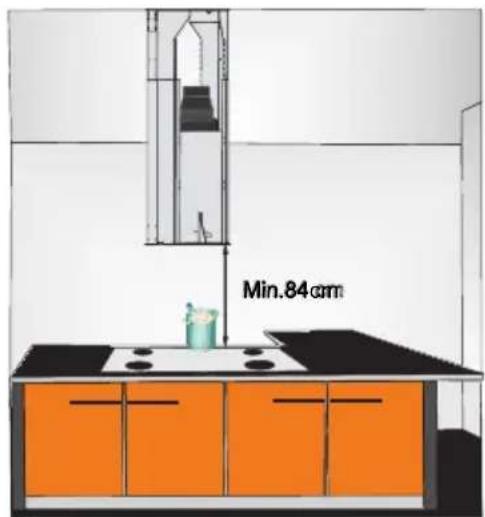
3a3b

natural_image
Technical diagram of a mechanical assembly with an inset showing a close-up view of a component (no text or symbols present)
3c
3d

natural_image
Technical line drawing of a mechanical device with a cylindrical component and mounting base (no text or symbols)
natural_image
Close-up of a metallic, ribbed pipe with fine bracing (no text or symbols visible)
natural_image
Close-up of a coiled, segmented worm-like structure with red X-shaped lines (no text or symbols)3f

natural_image
Close-up of a dark blue plastic component with a circular top and side slot, placed on a red background (no text or symbols visible)3e
3g
natural_image
Technical line drawing of a cylindrical industrial vessel with mounting flanges and a directional arrow indicating upward motion (no text or symbols)
natural_image
Diagram of a cylindrical device with internal components and an upward arrow, no text or symbols present3i
natural_image
Diagram of a cylindrical device with internal components and directional arrows indicating rotation or movement (no text or symbols)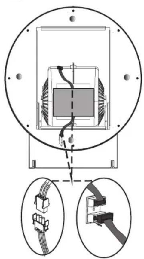
natural_image
Technical diagram of an electrical connector assembly with circular components and two close-up views of internal wiring (no text or labels)3j
3k


4b

natural_image
Diagram of a hand placing a component into a square chamber with arrows indicating direction (no text or symbols)5

natural_image
Two black circular filter fans with radial blades, placed on an orange surface (no text or symbols visible)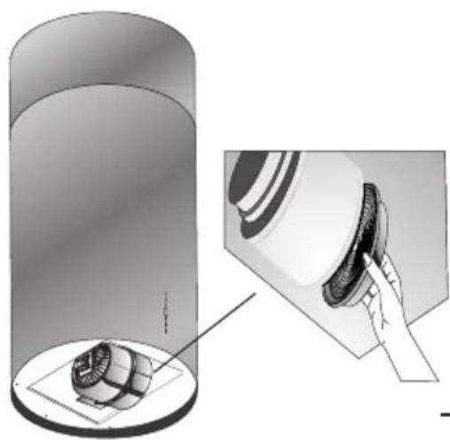
natural_image
Diagram showing a cylindrical device with a base and a magnified view of its internal components, no text or symbols present.6
GRATULUJEMY WYBORU SPRZĘTU MARKI AMICA
Szanowni Państwo,
natural_image
Simple line drawing of a recycling symbol (three chasing arrows) with no text or labelsnatural_image
Simple line drawing of a three chasing recycling symbol (no text or labels)natural_image
Simple line drawing of a three chasing recycling symbol (no text or labels)THANK YOU FOR PURCHASING AN AMICA APPLIANCE
DEAR CUSTOMER!
You are now a user of a kitchen extractor hood. This hood has been designed and manufactured specially with a view to satisfying your expectations and it will certainly constitute a fitting element of a modern kitchen. The modern structural solutions and the newest technologies used in production of this hood guarantee its high effectiveness and good appearance.
Please read these instructions carefully before installing the hood. They will help you avoid mistakes during installation and operation of the hood.
We wish you a lot of satisfaction from choosing our kitchen extractor hood.
Symbols appearing in these instructions have the following meaning:

Important information concerning proper operation of the appliance and your personal safety.

Risks resulting from improper operation of the appliance. Activities that must be performed by a qualified technician.

Tips on how to use the appliance.

Information on how to protect the environment.

This indicates actions than must not be performed by the user.
TABLE OF CONTENTS
GUIDELINES CONCERNING THE SAFETY OF USE 39
INSTALLATION 43
The appliance is intended for household use only.
The manufacturer reserves the right to introduce changes which do not affect the operation of the appliance.

●The manufacturer will accept no responsibility for any damage due to installation or operation not conforming to these instructionsi
- Cooker hood is designed to remove cooking odours. Do not use co-oker hood for other purposes.
- Connect the cooker hood operating in extraction mode to a suitable ventilation duct (do NOT connect the cooker to smoke or flue gas ducts, which are in use). It requires installation of the air extraction duct to the outside. The duct length (typically 120 or 150mm in diameter) should not exceed 4-5 m. The air exhaust duct is also required for telescopic and under furniture cooker hoods operating in air recirculation mode.
- Cooker hood operating in air recirculation mode requires the installation of an activated charcoal filter. In this case, installing an extractor duct is not required, however it is recommended to install an air guide vane. (chimney cooker hoods only).

● The cooker hood features independent lighting and exhaust fan that can be operated at one of several speeds.

- Depending on the type, the hood is designed to be permanently attached to a vertical wall over a gas or electric stove (chimney and universal hoods); on the ceiling over a gas or electric stove (island hoods); on the vertical built in furniture over a gas or electric stove (telescopic and built-in hoods). Before installing, make sure that the wall/ceiling structure is strong enough to suspend the hood. Some hoods are very heavy.

- For details of the installation distance above an electric hob please refer to product technical sheet If the installation instructions of the gas cooker specify a greater distance, this must be taken into account (Fig. 1a/b/c).

- Do not leave an open flame under the hood. When the pots are removed from the burner, set the minimum flame. Always make sure that the flame does not extend outside the pot, because it causes unwanted loss of energy and a dangerous concentration of heat.

- Any food cooked in fat shall be constantly monitored, since over-heated fat can ignite very easily.
- Pull the plug of the power cord from a wall socket before any filter cleaning or repair operation.

- The textile grease filter should be replaced, and the aluminium filter should be cleaned at least every one month in connection with the existing fire danger (saturated fat is very flammable).
- If any other non-electric devices are used in the same room as the hood (e.g. liquid fuel ovens, flow-through or volumetric water heaters), it is necessary to provide appropriate ventilation (air supply). Safe operation is possible when during simultaneous operation of the hood and combustion devices dependent on air supply the negative pressure of not more than 0.004 milibar is maintained at the location of these devices inside the room (this point does not apply when the hood is used as an odour absorber).
- Do not abut against the hood


- The hood should be frequently cleaned inside and on the outside surfaces (at least once a month). See “Cleaning section” in this manual.

- If the power wire gets broken, it should be replaced with a new one in a specialist repair shop.

- Make sure the appliance can be easily disconnected from the mains, either by pulling the plug out of the mains socket, or by switching the two-pole switch off.

- This appliance is not intended for use by persons (including children) with reduced physical, sensory or mental capabilities, or lack of experience and knowledge, unless they have been given supervision or instruction concerning use of the appliance by a person responsible for their safety.
● Children should be supervised to ensure that they do not play with the appliance.

- Check if the voltage indicated on the rating plate corresponds to the local power supply parameters.
● Before installing unwind and straighten the power cord.
- Warning! The packaging materials (polyethylene bags, small pieces of foamed polystyrene etc.) should be kept away from children while unpacking.
NOTE: Before connecting the hood to the mains power supply always check that the power cord is properly installed and is not trapped by the appliance. It is recommended to make sure the hood operates correctly before installation.
- Never use the hood without effectively mounted grating!
● The flaming of foods beneath the hood itself is severely prohibited.
- With regards to the technical and safety measures to be adopted for fume discharging it is important to closely follow the regulations provided by the local authorities.
● WARNING! Failure to install the screws or fixing device in accordance with these instructions may result in electrical hazardsii
Elements
kitchen hood consists of the following elements (Fig. 2):
- Upper masking frame
- Body
- Control Panel
- Aluminium grease filter
- Lighting
5a. Filter cover
Installation
Step-by-step appliance installation is shown on Fig. 3...
- Open the aluminium filter cover (on selected models-Figure 3a) and remove the aluminium grease filter (for filter removal description please refer to other section of this manual).
- The distance between the hob and the motor body must should be at least 84 cm (Fig. 3b).
- Remove the mounting screws (Fig. 3c) and set the unit at the correct height and then tighten both parts of the hood.
- Place mounting template on the ceiling where the hood is to be mounted. Drill holes A, B, C, D with a 10 mm drill and insert the wall plugs in them. Insert the screws 5.5 x45YSB leaving a 5mm gap between the screw head and the ceiling. Place the hood body on the ceiling so that the heads of the screws go through the mounting holes. Now turn the hood body clockwise so that it is locked and permanently fixed to the ceiling. Tighten the mounting screws (Figure 3d).
The wall plugs provided are not universal. If the ceiling structure requires a different type of anchors, purchase them at a DIY store.
- If the cooker hood will operate in extraction mode, connect the duct (Fig. 3e, 3f) to the outlet installed earlier on (Fig. 3g). Make sure that the duct is properly fitted and that operating the hood at the highest speed will cause the duct to detach from the nozzle.
- Insert the upper masking frame and secure it with the screws (Fig. 3h).
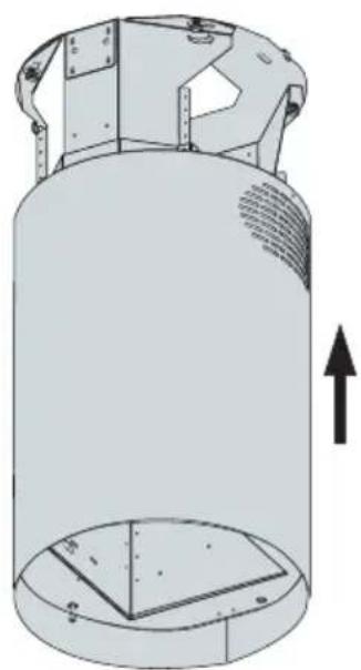
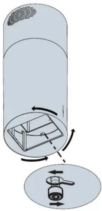
- Slide the cover body (Figure 3i) in and turn it clockwise until it locks in place (Fig. 3j).
- Connect the wiring harnesses for lighting and the control panel (Figure 3k). In addition, connect the lighting wiring harnesses.
Setting the air extractor mode of operation of the hood
In the extractor mode air is discharged to the outside by a special conduit. In that setting any carbon filters shall be removed. The hood should be connected to the opening discharging air to the outside by means of a rigid or flexible conduit of 120 mm diameter, which should be purchased in a shop selling installation materials.
A qualified installer should be commissioned to make the connection.
Setting the odour absorber mode of operation of the hood
In this option filtered air returns to the room through openings in the front of the hood. In this setting it is necessary to install the carbon filter. It is recommended to install the air guide (availability depending on model).
In some universal hoods you need to switch lever inside the hood (Fig. 8) to switch between the extraction and air recirculation modes. The cleaned air is returned to the room through the holes in the top of the unit.
Furniture and telescopic cooker hoods operating in air recirculation mode require installation of the exhaust duct. The other end of the duct should be directed to the room as it will discharge filtered air.
Fan speeds
The lowest and medium speeds should be used under normal conditions and with low concentration of fumes. The maximum speed should be used in case of high concentration of kitchen fumes, e.g. during frying or grilling.
Use control panel to control your cooker hood (Fig. 4a)
The cook hood fan can operate at 5 speeds. Select the fan speed appropriate for cooking intensity. To run the fan press the „ button on the control panel (Figure 1, item 3). Touch the „ v ”. sensor each time you want to increase the fan speed or touch the ” sensor to reduce the fan speed. When you turn on the cooker hood the fan always runs at speed 2. Touch the ”, sensor to activate the countdown timer. Touch the „ sensor to activate the timer. The appliance will turn off after 15 minutes. When the timer is counting down the digit will blink on the display and the appliance will turn off after 15 minutes.
To remove any residual odours and vapour from the kitchen it is recommended to use the hood for several minutes after cooking.
Lighting
Your cooker hood features LED lighting. Touching the "💡" sensor on the control panel (Figure 1, item 3) to turn on or off the lighting.
Remote control (Fig. 4b)
Your cooker hood can be controlled by a remote control.
Remote control functions are described below:
D. Turn the lights on/off
Touch the POWER sensor to turn on the appliance. The fan will run at speed 2.
Hood lighting can be switched on independently of the „POWER” sensor.
To use the remote control:
- Gently bend the tab and pull out the battery compartment cover.
- Place the new batteries in the remote control according to the markings inside battery compartment.
- Close the battery cover.
- Point the remote control toward the front of the cooker hood.
Ensure there are no obstacle between the remote control transmitter and the sensor on the cooker hood. Fluorescent light can interfere with the remote control operation.

Regular maintenance and cleaning of the device will ensure faultless operation, and help extend the life of the unit. Attention should be paid to replacing grease and carbon filters according to instructions.
Aluminium grease filter
Cleaning
For normal hood operation, aluminium grease filter should be cleaned every month in the dishwasher or by hand using a mild detergent or liquid soap.
To replace:
Dismantling of aluminium grease filter is shown on Figure 5.
Acrylic filter is used in some models. This filter should be replaced at least once every two months or more frequently if the appliance is used intensively.
Charcoal filter (only the recirculation version)
Operation - Carbon filters can be used only when the hood is not connected to any ventilation duct. Filters with active carbon can absorb odours until they are saturated. They cannot be washed or regenerated and should be replaced at least every 2 months or more frequently in case of very intensive use.
Replace:
Dismantling of charcoal filter is shown on Figure 6.
Lighting
See Figure 7 for details how to replace lights. Use incandescent / halogen / LED modules of the same specification as those factory-installed in the appliance.
Cleaning
Normal hood cleaning:
- Do not use a soaked cloth, sponge, or water jet.
- Do not use solvents or alcohol, as they may tarnish lacquered surfaces.
- Do not use caustic substances, especially for cleaning stainless steel.
- Do not use a rough or abrasive cloth.
It is recommend to use a damp cloth and a neutral detergent.
Aluminium filters may be washed in the dishwasher. The colour of aluminium filters may change after several washings. This is normal and it is not necessary to renew the filters.
ENVIRONMENTAL PROTECTION

Recycling of the packaging
natural_image
Simple line drawing of a recycling symbol (three chasing arrows), no text or labels present.Our packaging is made of environmentally friendly materials, which can be reused:
● The external packaging is made of cardboard/foil
● The FCKW free shape of foamed polystyrene (PS)
● Polyethylene (PE) foils and bags

ELIMINATION / DISPOSAL OF THE EQUIPMENT

If the appliance is no longer in use, cut the connecting cable off the used equipment before scrapping. We also recommend that the appliance is locked or render it useless so that the appliance presents no danger to children while being stored for disposal. This appliance is marked with a symbol of the crossed out waste container in conformance with the European Directive 2002/96/EC. Such marking informs that the equipment may not be kept together with other waste coming from the household after the period of its use. The user is obliged to dispose of the appliance at the waste collection point authorised by the local authority. The local waste collection points, shops and communal units form an appropriate system enabling the disposal of the equipment.
Handling the used electrical and electronic equipment and any hazardous substances contained therein in a correct manner is vital to avoid damage the local natural environment. Therefore care and responsibility should always be taken in the disposal of these products
WARRANTY AND AFTER-SALE SERVICES
Warranty
Warranty service as stated on the warranty card
The manufacturer shall not be held liable for any damage caused by improper use of the product.
Manufacturer's Declaration
The manufacturer hereby declares that this product meets the requirements of the following European directives:
● Low Voltage Directive 2006/95/EC,
Electromagnetic Compatibility (EMC) Directive 2004/108/EC,
• ErP Directive 2009/125/EC
and has thus been marked with the symbol and been issued with a declaration of compliance made available to market regulators.
natural_image
Simple line drawing of a recycling symbol (three chasing arrows) with no text or labelsINSTALLATIE VAN HET APPARAAT 63
BEDIENING EN ONDERHOUD 65
MILIEUBESCHERMING 67
GARANTIE, SERVICE 67

natural_image
Simple line drawing of a recycling symbol (three chasing arrows) with no text or labels
- GRATULUJEMY WYBORU SPRZĘTU MARKI AMICA
- Szanowni Państwo,
- THANK YOU FOR PURCHASING AN AMICA APPLIANCE
- DEAR CUSTOMER!
- TABLE OF CONTENTS
- Elements
- Installation
- Setting the odour absorber mode of operation of the hood
- Fan speeds
- Lighting
- Remote control (Fig. 4b)
- Aluminium grease filter
- Charcoal filter (only the recirculation version)
- Cleaning
- ENVIRONMENTAL PROTECTION
- Recycling of the packaging
- ELIMINATION / DISPOSAL OF THE EQUIPMENT
- WARRANTY AND AFTER-SALE SERVICES
- Warranty
- Manufacturer's Declaration
Brand : AMICA
Model : OWS 451 P
Category : Range hood