
576 - Receiver DBX - Free user manual and instructions
Find the device manual for free 576 DBX in PDF.


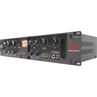
| Product Type | Vacuum Tube Preamplifier & Compressor (Receiver category) |
| Dimensions | 3.5" H x 19" W x 8" D (89 x 483 x 203 mm) |
| Weight | 12 lbs (5.5 kg) |
| Power Supply | 30W max, switchable 100/120/230/240 VAC, 50/60 Hz |
| Fuse Rating | 100/120V: 500 mA 250V Slow Blow; 230/240V: T250 mA 250V |
| Vacuum Tube | Premium-grade 12AU7, hand-tested and graded |
| Microphone Input | XLR female, balanced, 1.70 kΩ impedance, phantom power +48V |
| Line Inputs | XLR and 1/4" TRS, balanced/unbalanced, >40 kΩ balanced |
| Instrument Input | Line input with rear-panel INST switch, 470 kΩ unbalanced |
| Outputs | XLR and 1/4" TRS, servo-balanced, max +21 dBu |
| Insert Loop | Send and Return TRS, post-tube, pre-EQ |
| Sidechain Loop | Send and Return TRS, for external compressor detector processing |
| Equalizer | Low shelf 80 Hz, Mid sweep 100 Hz-8 kHz (wide/narrow Q), High shelf 12 kHz; ±15 dB gain each band |
| Compressor | OverEasy® or hard knee, threshold -40 to +20 dBu, ratio 1:1 to ∞:1, attack 3 dB/msec to .04 dB/msec, release 250 dB/sec to 5 dB/sec, Auto mode |
| Limiter | PeakPlus™ Intelligent Predictive Limiting, threshold 0 dBu to +22 dBu (off), infinity:1 ratio |
| Frequency Response | <10 Hz to >200 kHz +0/-3.0 dB |
| THD + Noise | 0.04% typical at 0 dBu out, 1 kHz, 33 dB gain |
| CMRR (Mic) | >115 dB at 60 Hz, >110 dB at 1 kHz |
| Warranty | 2 years parts and labor (original purchaser, USA) |
| Safety | Complies with EN 60065, IEC65; ground connection required; do not expose to rain/moisture |
Frequently Asked Questions - 576 DBX
User questions about 576 DBX
0 question about this device. Answer the ones you know or ask your own.
Ask a new question about this device
Download the instructions for your Receiver in PDF format for free! Find your manual 576 - DBX and take your electronic device back in hand. On this page are published all the documents necessary for the use of your device. 576 by DBX.
USER MANUAL 576 DBX
PROFESSIONAL PRODUCTS
576
Vacuum Tube Preamplifier & Compressor
Owner's Manual
Version 1.0

ATTENTION: RISQUE DE CHOC ELECTRIQUE - NE PAS OUVRIR
WARNING: TO REDUCE THE RISK OF FIRE OR ELECTRIC SHOCK DO NOT EXPOSE THIS EQUIPMENT TO RAIN OR MOISTURE
The symbols shown above are internationally accepted symbols that warn of potential hazards with electrical products. The lightning flash with arrow-point in an equilateral triangle means that there are dangerous voltages present within the unit. The exclamation point in an equilateral triangle indicates that it is necessary for the user to refer to the owner's manual.
These symbols warn that there are no user serviceable parts inside the unit. Do not open the unit. Do not attempt to service the unit yourself. Refer all servicing to qualified personnel. Opening the chassis for any reason will void the manufacturer's warranty. Do not get the unit wet. If liquid is spilled on the unit, shut it off immediately and take it to a dealer for service. Disconnect the unit during storms to prevent damage.
WARNING
FOR YOUR PROTECTION, PLEASE READ THE FOLLOWING:
WATER AND MOISTURE: Appliance should not be used near water (e.g. near a bathtub, wash-bowl, kitchen sink, laundry tub, in a wet basement, or near a swimming pool, etc). Care should be taken so that objects do not fall and liquids are not spilled into the enclosure through openings.
POWER SOURCES: The appliance should be connected to a power supply only of the type described in the operating instructions or as marked on the appliance.
GROUNDING OR POLARIZATION: Precautions should be taken so that the grounding or polarization means of an appliance is not defeated.
POWER CORD PROTECTION: Power supply cords should be routed so that they are not likely to be walked on or pinched by items placed upon or against them, paying particular attention to cords at plugs, convenience receptacles, and the point where they exit from the appliance.
SERVICING: To reduce the risk of fire or electric shock, the user should not attempt to service the appliance beyond that described in the operating instructions. All other servicing should be referred to qualified service personnel.
FOR UNITS EQUIPPED WITH EXTERNALLY ACCESSIBLE FUSE RECEPTACLE: Replace fuse with same type and rating only.
MULTIPLE-INPUT VOLTAGE: This equipment may require the use of a different line cord, attachment plug, or both, depending on the available power source at installation. Connect this equipment only to the power source indicated on the equipment rear panel. To reduce the risk of fire or electric shock, refer servicing to qualified service personnel or equivalent.
U.K. MAINS PLUG WARNING
A moulded mains plug that has been cut off from the cord is unsafe. Discard the mains plug at a suitable disposal facility. NEVER UNDER ANY CIRCUMSTANCES SHOULD YOU INSERT A DAMAGED OR CUT MAINS PLUG INTO A 13 AMP POWER SOCKET. Do not use the mains plug without the fuse cover in place. Replacement fuse covers can be obtained from your local retailer. Replacement fuses are 13 amps and MUST be ASTA approved to BS1362.
ELECTROMAGNETIC COMPATIBILITY
This unit conforms to the Product Specifications noted on the Declaration of Conformity. Operation is subject to the following two conditions:
- this device may not cause harmful interference, and
- this device must accept any interference received, including interference that may cause undesired operation.
Operation of this unit within significant electromagnetic fields should be avoided.
- use only shielded interconnecting cables.
SAFETY INSTRUCTIONS
NOTICE FOR CUSTOMERS IF YOUR UNIT IS EQUIPPED WITH A POWER CORD.
WARNING: THIS APPLIANCE MUST BE EARTHED.
The cores in the mains lead are coloured in accordance with the following code:
GREEN and YELLOW - Earth
BLUE - Neutral
BROWN - Live
As colours of the cores in the mains lead of this appliance may not correspond with the coloured markings identifying the terminals in your plug, proceed as follows:
- The core which is coloured green and yellow must be connected to the terminal in the plug marked with the letter E, or with the earth symbol, or coloured green, or green and yellow.
- The core which is coloured blue must be connected to the terminal marked N or coloured black.
- The core which is coloured brown must be connected to the terminal marked L or coloured red.

This equipment may require the use of a different line cord, attachment plug, or both, depending on the available power source at installation. If the attachment plug needs to be changed, refer servicing to qualified service personnel who should refer to the table above. The green/yellow wire shall be connected directly to the unit's chassis.
WARNING: If the ground is defeated, certain fault conditions in the unit or in the system to which it is connected can result in full line voltage between chassis and earth ground. Severe injury or death can then result if the chassis and earth ground are touched simultaneously.
DECLARATION OF CONFORMITY
Manufacturer's Name: dbx Professional Products
Manufacturer's Address: 8760 S. Sandy Parkway Sandy, Utah 84070, USA
declares that the product:
dbx 576
conforms to the following Product Specifications:
Safety: EN 60065 (1993)
IEC65 (1985) with Amendments 1, 2, 3
EMC: EN 55013 (1990)
EN 55020 (1991)
Supplementary Information:
The product herewith complies with the requirements of the Low Voltage Directive 73/23/EEC and the EMC Directive 89/336/EEC as amended by Directive 93/68/EEC.
dbx Professional Products
Vice-President of Engineering
8760 S. Sandy Parkway
Sandy, Utah 84070, USA
July 1, 1998
European Contact: Your Local dbx Sales and Service Office or
International Sales Office
68 Sheila Lane
Valparaiso, Indiana
46383, USA
Tel: (219) 462-0938
Fax: (219) 462-4596
Table of Contents
Introduction....2
Features....2
Inspection....3
Warranty....3
Connections....4
Preamp Controls ....5
Compressor Controls....10
Rear Panel: Prcamp....14
Rear Panel: Compressor 16
Specifications 17
Settings Page....20
Introduction
Thank you for purchasing the dbx 576 vacuum tube preamplifier and compressor. The 576 combines high quality microphone and instrument preamplification with world-renowned dbx compression in a single chassis to offer you a flexible input path to your audio devices.
The dbx 576's preamplifier circuit is a hybrid design consisting of a high-voltage class A vacuum tube amplification stage, coupled with an ultra low noise, low distortion solid-state driver stage. The vacuum tube amplification stage is a classic, high plate-voltage design utilizing a pure class A topology. A parallel-triode arrangement is employed, in addition to a fully-regulated plate supply to maximize noise performance and transient response. The premium-grade 12AU7 vacuum tubes used in the dbx 576 are hand tested and graded specifically for gain, noise, and microphonics.
The compression section incorporates the features that have made dbx the standard for high quality audio compression: Over Easy ^TM compression curve, PeakPlus ^TM limiting and the advanced dbx V1 ^TM VCA module that ensures high system performance. Precision 1% resistors are used throughout the audio path to ensure performance stability and low noise. To ensure years of trouble-free operation, each dbx 576 must pass a rigorous set of performance tests and a 24-hour burn-in period before it is shipped from the factory.
We recommend that you take a moment to read through this operation manual. It provides valuable information that will assist you in setting up and operating your dbx 576.
Features
- Flexible configuration; useful as a single comprehensive input section or dual discrete channels
- Low noise, pure Class A vacuum tube preamplifier stage with adjustable Drive and Level controls
- Flexible semi-parametric EQ stage with low cut, midband Q select and hardwire bypass
- PeakPlus™ Limiter available on both channels
- Mic, Line and Hi-Z instrument inputs to preamplifier
• Class A Vacuum tube stage in compressor section with Drive control - Selectable dbx OverEasy® compression curve
- Pre-EQ insert loop in preamp section, Sidechain loop in Compressor section
- Multi-source VU metering and Peak indication
- Ready for optional dbx TYPE IV™ Conversion System digital output module
Inspection
Verify that the 576's package contains the following:
- 576 Unit (according to Model number marked on package)
- AC Power Cord
• Operation Manual - Registration Card
- Rack screws & washers
If any of these items are missing, contact dbx customer service at (801) 568-7660.
Warranty
This warranty is valid only for the original purchaser and only in the United States. We warrant dbx products against defects in materials or workmanship for a period of two years from the date of original purchase for use, and agree to repair or, at our option, replace any defective item, except external power transformers, without charge for either parts or labor.
IMPORTANT: This warranty does not cover damage resulting from accident, misuse or abuse, lack of reasonable care, the affixing of an attachment not provided with the product, loss of parts, or connecting the product to any but the specified receptacles. This warranty is void unless service or repairs are performed by an authorized service center. No responsibility is assumed for any special, incidental or consequential damages. However, the limitation of any right or remedy shall not be effective where such is prohibited or restricted by law.
Simply take or ship your dbx product prepaid to our service department. Be sure to include your sales slip as proof of purchase date. (We will not repair transit damage under the no-charge terms of this warranty.) dbx will pay return shipping.
NOTE: No other warranty, written or oral is authorized for dbx products.
This warranty gives you specific legal rights, and you may also have other rights which vary from state to state. Some states do not allow the exclusion of limitations of incidental or consequential damages or limitations on how long an implied warranty lasts, so the above exclusion and limitations may not apply to you.
To connect the 576 to your system, refer to the following steps:
- Turn off all equipment before making any connections.
- Mount the 576 in a rack with the rack screws provided. The 576 can be mounted above or below anything that does not generate excessive heat. Ambient temperatures should not exceed 95^ (35^) when equipment is in use. Although the unit is shielded against radio frequency and electromagnetic interference, extremely high fields of RF and EMI should be avoided where possible.
- Make audio connections via XLR, 1/4" TRS, or 1/4" TS plugs. Refer to Fig.1 for a typical studio connection layout. The XLR and 1/4" TRS connectors on the inputs and outputs can be used for balanced or unbalanced connections. However, the use of more than one connector at a time on the input pair could unbalance balanced lines, cause phase cancellations, short a conductor to ground, or cause damage to other equipment connected to the 576.
- Verify that the fuse installed in the pull-out fuse holder of the fuse receptacle matches the type and rating corresponding to the voltage in use as indicated on the rear panel of the 576.
- Apply power. Connect the AC power cord to the AC power receptacle on the back of the unit. Route the AC power cord to a convenient power outlet away from audio lines. The unit may be turned on and off from the rear panel power switch or from a master equipment power switch.

flowchart
graph TD
    A["Input Signal"] --> B["Database Database"]
    B --> C["Audio Equipment"]
    C --> D["Audio Receiver"]
    D --> E["Audio Mixer"]
    E --> F["Output Audio System"]
    G["Audio Player"] --> B
    H["Audio Generator"] --> D
    I["Audio Record Input Channel"] --> B
    J["Audio Mixer for Monitoring"] --> E
Figure 1: A typical 576 connection scheme
Preamp Controls

Figure 1: Preamp Section of the front panel
INSERT switch
This switch enables the rear panel insert loop by inserting any device connected to the Send and Return jacks into the signal path. The insertion point is post-tube, pre-EQ. See page 15 for more details on the Insert feature.
LOW control
This control varies the gain of the low frequency equalization; the gain range is -15 to +15 dB. The low frequency filter is a shelving lowpass configuration with a knee frequency of 80 Hz.
MID control
This control varies the gain of the mid frequency equalization; the gain range is -15 to +15 dB. The mid frequency filter is a bandpass configuration with variable frequency and switchable bandwidth.
NARROW switch
This switch selects the bandwidth for the mid frequency filter. The default bandwidth is 1.5 octaves; with the Narrow switch depressed, the bandwidth is 0.5 octaves.
FREQUENCY control
This control selects the center frequency for the mid frequency filter. The frequency range is 100 Hz to 8 kHz.
HIGH control
This control varies the gain of the high frequency equalization; the gain range is -15 to +15 dB. The high frequency filter is a shelving highpass configuration with a knee frequency of 12 kHz.
Preamp Controls (cont.)
EQ switch
This switch enables the equalizer. When the equalizer is disabled, the EQ circuit is hardwire bypassed. This switch allows you to instantly assess the effect of your EQ settings.
PEAK led
This red led illuminates when the 576's internal signal level is within 3 dB of clipping. The signal level is monitored at all critical stages of the circuit.
LINE switch
When activated, this switch selects the rear-panel line inputs as the source signal to the preamp. When this switch is de-activated, the mic input is the source to the preamp.
DRIVE control
This control sets the amount of gain that will be applied at the input of the vacuum tube stage. The range of gain available is +10 to +60 dB. The Drive control works in conjunction with the Level control to determine the degree of tube saturation to be applied to the signal. For minimal tube saturation (cleanest possible sound), use relatively low settings of the Drive control and higher settings of the Level control. Moderate amounts of tube character can be achieved with moderate settings of the Drive and Level controls; if a high degree of tube saturation is desired, this result can be obtained by using higher settings of the Drive control in conjunction with lower settings of the Level control. Experiment with different settings of the Drive and Level controls to find the amount of tube saturation that is right for you.
+48V switch
This switch activates phantom power for condenser microphones on pins 2 and 3 of the XLR mic input. You should connect your microphone before turning on the phantom power to prevent high voltage arcing that may damage your mic.
20dB PAD switch
This switch inserts a 20 dB attenuator circuit into the signal path from the microphone input. The pad is inserted before the signal is routed through the mic preamp gain stage. Use the 20 dB Pad to attenuate signals from “hot” sources such as high-output microphones.
INVERT switch
This switch inverts the phase of the incoming signal at the Mic input by swapping pins 2 and 3 on the XLR connector. Phase inversion is typically used to overcome “notchy-sounding” comb filtering effects when using multiple mics on a single source. It can also be used when the audio cable from the source device has been wired to another pin arrangement.
Preamp Controls (cont.)
LOW CUT switch
This switch places a 12 dB per octave shelving high pass filter in the signal path. The knee frequency of the Low Cut filter is 75 Hz. This filter is very useful for removing low frequency rumble or handling noise from a microphone input signal. It is also good for reducing the very low frequency components of signals that can damage speakers or use up amplifier power unnecessarily.
LEVEL control
This control determines the output level of the preamp section of the 576. It is used to moderate signal levels produced by the tube drive and EQ circuits. There is +/- 15 dB of gain control available.
LIMIT led
This led illuminates when the output signal exceeds the level set by the Threshold control and it indicates that PeakPlus ^™ limiting is occurring.
PeakPlus™ Limiter THRESHOLD control
This control sets the threshold level at which the PeakPlus ^™ Limiter circuit becomes active. The threshold range is from 0 dBu to +22 dBu (off). The PeakPlus ^™ Limiter stage is a unique program Limiter featuring Intelligent Predictive Limiting ^™ . Its function is to monitor the input signal and intelligently predict the amount of gain reduction needed to keep the output signal below the ceiling set by the PeakPlus ^™ control.
Note that since the PeakPlus ^™ Limiter is a fail-safe Limiter it must come after the Output Gain control. If the Output Gain is set too high as compared to the PeakPlus ^™ Level control, continuous limiting can occur. While PeakPlus ^™ is typically used as a protective function, creative effects can be achieved by intentionally driving the signal into heavy PeakPlus ^™ limiting.
Great care has gone into the design of the PeakPlus™ Limiter to keep it acoustically transparent. Appropriate use of it can protect your gear while keeping the signal free of artifacts. Peak Plus™ also serves to prevent digital overload when used in conjunction with the dbx Type IV™ Conversion System option.
DRIVE LEVEL switch
This configures the meter to show the signal level at the input to the vacuum tube. Note that high gain settings can result in excessive movement of the meter as the needle contacts the endpin. In this situation it's best to briefly check the drive level and then switch to one of the other meter modes.
INSERT LEVEL switch
This allows you to monitor the signal level sent post-tube to an external processor unit (switch out) or the signal level returning to the 576 from an external unit (switch in).
OUTPUT LEVEL switch
This configures the meter to show the output signal level. This works in conjunction with the output level assignment switch on the back of the 576. When the rear switch is set to +4 dBu, a meter reading of 0 VU corresponds to +4 dBu output. When the rear switch is set to -10 dBV, a meter reading of 0 VU corresponds to -10 dBV output.
DITHER switch
This switch becomes active only when the optional dbx TYPE IV ^™ Conversion System digital output module is installed. Refer to the manual for the TYPE IV ^™ Conversion System for a description of the function of this switch.
SHAPE switch
This switch becomes active only when the optional dbx TYPE IV ^TM Conversion System output module is installed. Refer to the manual for the TYPE IV ^TM Conversion System module for a description of the function of this switch.
Compressor Controls

Figure 2: Compressor Section of the front panel
+ 0 - THRESHOLD leds:
The “+” led illuminates when the signal is above the OverEasy® portion of the compression curve and that the full compression ratio is in effect. If OverEasy® is disabled, this led indicates that the signal is above the level set by the Compressor Threshold control and that compression is occurring.
The “0” led illuminates when the signal is in the OverEasy® portion of the compression curve. In this region the ratio varies as a function of signal level between 1:1 and the ratio set by the Ratio control. This led will not light when the OverEasy® function is off.
The “-” led illuminates when the signal is below the level set by the Compressor Threshold control. This indicates that the Compressor is not compressing and is operating in its linear region.
THRESHOLD control:
This control sets the level above which compression occurs, and has a 60 dB range.
OverEasy® switch:
OverEasy® is a feature that provides a softer compression sound than hard knee does. OverEasy® smooths the transition from un-compressed to compressed. This smooth transition greatly reduces compression artifacts and allows faster attack times and higher compression ratios while still maintaining the natural characteristics of the signal. The switch lights to indicate OverEasy® processing is enabled. When conventional hard knee processing is desired, disable the OverEasy® function. See Figure 3 for a comparison of OverEasy® and hard knee compression curves.
Compressor Controls (cont.)

line
| INPUT LEVEL (dB) | OUTPUT LEVEL (dB) | | ---------------- | ----------------- | | -15 | -15 | | -10 | -10 | | -5 | -5 | | 0 | 0 | | 5 | 5 | | 10 | 10 | | 15 | 15 | | 20 | 20 |
line
| INPUT LEVEL (dB) | OUTPUT LEVEL (dB) | | ---------------- | ----------------- | | -15 | -15 | | -10 | -10 | | -5 | -5 | | 0 | 0 | | 5 | 5 | | 10 | 10 | | 15 | 15 | | 20 | 20 |Figure 3: Hard Knee and OverEasy® Compression Curves
RATIO control:
This control selects the ratio between input and the output levels for signals above the level set by the Threshold control. It is adjustable between 1:1 (no compression) and infinity:1 (full compression). Note that when OverEasy® processing is selected, the ratio slopes gradually from the linear to the compressed region. As the signal exceeds the threshold, the ratio approaches the ratio set by the Ratio control.
ATTACK control:
This control sets the amount of time it takes the 576 to begin compressing a signal once the detector has sensed a signal above the threshold. The attack range is from 3 dB/msec for a tighter and more noticeable compression effect with very little overshoot to .04 dB/msec for a more gradual compression that preserves attack transients. A very fast attack setting will cause the 576 to act like a peak Limiter even though RMS (average level) detection circuitry is used. Slower attack settings cause the 576 to act like an RMS or averaging detecting Compressor/Limiter.
AUTO switch:
This switch overrides both the Attack and Release controls and enables preset program-dependent attack and release times. These times are derived from the characteristics of the input signal and continuously change to match its dynamics. The switch lights indicating the attack and release times are being automatically adjusted in a program-dependent fashion. Enabling the Auto function duplicates the “classic dbx sound” of the 576’s forerunners which have become standards in the industry.
Compressor Controls (cont.)
RELEASE control:
The Release control sets how fast the compression circuit returns the input to its original level. The release rate is from 250 dB/sec where compression follows the envelope of the program material very tightly to 5 dB/sec for very smooth compression.
UNLINK Switch:
This switch determines whether the input to the Compressor section comes from the Compressor's line input jack or from the output of the 576's Preamp. This is a convenience feature to allow you to use the Preamp and Compressor as two independent processors if desired. When activated, this switch unlinks the normal connection between the output of the Preamp and the input of the Compressor. When de-activated, the Preamp and Compressor are placed in series for processing a single signal source.
DRIVE control
This control sets the amount of gain that will be applied at the input of the vacuum tube stage present in the Compressor section. When the 576's Compressor section is used independently of the Preamp section, this control offers tube drive control (with its sonic stamp) to any signal routed through the Compressor. When the Preamp and Compressor sections are connected in series a high Drive control setting can be used in conjunction with a high drive setting on the Preamp section to offer “over-the-top” distortion effects.
SC (SIDECHAIN) ENABLE switch
This switch enables the Sidechain processing loop. The Sidechain in and out connectors on the 576 rear panel allow external processing of the Compressor's detector signal. This switch has no effect if there is nothing plugged into the Sidechain loop even though the switch will light when pressed. For more discussion of the Sidechain see page 16.
SC (SIDECHAIN) MON switch
This switch allows you to monitor the sound of the Sidechain processing. The switch will light when pressed to indicate that you are listening to the Sidechain; not the main signal path.
CONTOUR switch
This switch adds a gentle low frequency de-emphasis into the detector path (this is identical to having an equalizer in the Sidechain loop, only we’ve done it for you). This is extremely useful in keeping low frequency program material from “muffling” or “punching holes in” the compressed signal. This feature allows faster attack times and higher compression ratios with less artifacts. The switch will light indicating contouring is activated.
Compressor Controls (cont.)
BYPASS switch
This switch bypasses the compression section completely. The input is “hardwired” to the output bypassing the tube amplification and VCA circuitry. This feature is very useful for setting optimum compression and gain settings because it gives you an instant reference to the amount of effect you’ve introduced to your signal.
LEVEL control
This is the output gain control (also known as a “gain compensation” or “makeup gain” control). It is used to compensate for signal level lost due to compression and for excess gain contributed by the tube drive section. There is +/- 15 dB of gain control available with this knob.
PeakPlus™ LIMITER THRESHOLD control
This control sets the threshold level at which the PeakPlus ^™ Limiter circuit becomes active. The threshold range is from 0 dBu to +22 dBu (off). See page 7 for more information on the PeakPlus ^™ limiting circuit.
DRIVE LEVEL switch
This configures the meter to show the signal level at the input to the vacuum tube. Note that high gain settings can result in excessive movement of the meter as the needle contacts the endpin. In this situation it's best to briefly check the drive level and then switch to one of the other meter modes.
GAIN REDUCTION switch
This configures the meter to show the amount of gain reduction due to compression. The lower markings on the meter show increasing gain reduction from right (0 dB) to left (-30dB). Note that when configured to the Gain Reduction setting, the meter swings from the fully right position and not the 0 dB position indicated on the top line of the meter.
OUTPUT LEVEL switch
This configures the meter to show the output signal level. This works in conjunction with the output level assignment switch on the back of the 576. When the rear switch is set to +4 dBu, a meter reading of 0 VU corresponds to +4 dBu output. When the rear switch is set to -10 dBV, a meter reading of 0 VU corresponds to -10 dBV output.
Rear Panel: Preamp

WIRING SCHEME
All of the input and output connectors are “pin 2 hot” meaning that pin number 2 on the XLR connecting cables carries the positive side of the balanced signal. Pin number 3 is “cold”, carrying the negative polarity and pin 1 is the shield. The 1/4” TRS jacks are wired so that when you use 3 conductor cables and balanced signals, the tip is hot, the ring is cold and the sleeve is the shield. The 1/4” jacks can also be used with 2 conductor unbalanced cables. In this case, the tip is hot and the ring and sleeve are grounded.
MIC INPUT
Connect the cable from your microphone here. If your mic requires phantom power, ensure that the phantom power switch on the front panel is turned off before connecting your mic.
LINE INPUTS
Both XLR and 1/4" TRS connectors are provided to allow balanced or unbalanced +4 dBu line-level devices to be connected to the 576. These inputs can also be used for instrument-level devices, depending on the status of the Line/Inst. switch.
LINE/INST switch
To connect instrument-level devices to the 576, use either the 1/4" or XLR Line Input connector and depress the Line/Inst. switch. Doing so will increase the input impedance and the gain applied to these inputs to make them suitable for devices using passive or piezoelectric pickups (guitars etc.). The INST. setting also reconfigures the Line Inputs as strictly unbalanced, pin 2 (tip) hot, pins 1 and 3 (sleeve and ring) grounded.
INSERT SEND and RETURN
These connectors allow you to place another processor such as a de-esser or Graphic EQ into the pre-amp signal path. This would generally be used to take advantage of the 576's digital output option. A signal from your microphone or instrument could be preamplified by the 576, processed externally through the INSERT I/O and returned to the 576 to be passed along to the high-resolution dbx TYPE IV™ digital output. The Send may also be used as a direct post-preamp output that bypasses the EQ and main output stages of the 576.
The Send is post-preamp and the Return is pre-EQ. Both the Send and Return are balanced TRS jacks with +4 dBu nominal sensitivity. The Return can also be used as an alternate input that makes use of the equalizer, Limiter, and digital output option without passing through the tube in the Preamp section. This input source would be selected by pressing the INSERT switch on the front panel.
LINE OUTPUTS
Both XLR and TRS 1/4" connectors are provided for connecting either balanced or unbalanced line-level devices to the 576. The nominal output level can be set to either +4 dBu or -10 dBV with the +4 dBu/-10 dBV switch.
Rear Panel: Compressor

LINE INPUTS
Both XLR and TRS 1/4" connectors allow balanced or unbalanced line-level devices to be connected to the input of the 576's Compressor section. The nominal input level can be set to either +4 dBu or -10 dBV with the +4 dBu/-10 dBV switch.
LINE OUTPUTS
Both XLR and TRS 1/4" connectors are provided for connecting either balanced or unbalanced line-level devices to the 576. The nominal output level can be set to either +4 dBu or -10 dBV with the +4 dBu/-10 dBV switch.
SIDECHAIN SEND
The Sidechain Send and Return allow external processing of the Compressor's detector signal. The Sidechain Send is typically used to feed an external equalizer to produce compression that is triggered mostly by a specific frequency band. The Sidechain Send jack taps the signal before the tube section without interrupting the main output from the Compressor. This also allows the Sidechain Send to be used as an additional pre-tube line level output. The nominal output level is +4 dBu.
SIDECHAIN RETURN
The output of an external device used for Sidechain processing of the detector circuit is connected here. The nominal return level is +4 dBu.
Specifications
PREAMP
Microphone Input:
Connector: Female XLR Pin 2 hot
Type: Electronically balanced/unbalanced
Impedance: 1.70 kΩ
Optimum Microphone Impedance: 150 - 200
Maximum Input Level: >+13 dBu, or +33 dBu with 20 dB pad engaged
CMRR: > 115 dB at 60 Hz, > 110 dB at 1 kHz, > 75 dB at 10
kHz
Line Inputs:
Connectors: Female XLR Pin 2 hot and TRS 1/4"
Type: Electronically balanced/unbalanced
Impedance: >40kΩ balanced, >20kΩ unbalanced, or 470kΩ
unbalanced with rear-panel INST switch engaged
Maximum Input Level: >+30 dBu, or +22 dBu with rear-panel INST switch
engaged
Outputs:
Connectors: Male XLR Pin 2 hot and TRS 1/4"
Type: Servo-balanced/unbalanced, RF filtered
Impedance: Balanced 120, unbalanced 60
Maximum Output Level: >+21 dBu, balanced or unbalanced
Insert Send and Return:
Connectors: TRS 1/4"
Type: Impedance balanced/unbalanced
(Send),
Electronically balanced/unbalanced
(Return)
Impedance: Send: 100 balanced/50 unbalanced
Return: 40kΩ balanced, 20kΩ unbalanced
Nominal Send Level: +4 dBu
Nominal Return Level: +4 dBu
EQUALIZER
LOW Frequency: 80 Hz, shelving filter
Specifications (cont.)
HIGH Frequency: 12 kHz, shelving filter
MID Frequency: Sweepable from 100 Hz to 8 kHz, bandwidth 1.5
octaves (WIDE) or 0.5 octaves (Narrow)
Gain (all bands): Sweepable from -15 to +15 dB.
COMPRESSOR
Threshold Range: -40 dBu to +20 dBu
Ratio: 1:1 to inf. to 1
Threshold Characteristic: Selectable OverEasy ^® or hard knee curves
Attack/Release Characteristic: AutoDynamic
TM
Attack/Release Modes: Selectable Manual or Auto
Manual Attack Time: Scalable program-dependent. Typically 3 dB/msec to
.04 dB/msec
Manual Release Time: Scalable program-dependent. Typically 250 dB/sec to 5
dB/sec
Auto Attack Time: Program-dependent. Typically 15ms for 10 dB, 5ms for
20 dB, and 3ms for 30 dB.
Auto Release Time: Program-dependent. Typically 125 dB/sec rate.
Output Gain: -15 to +15 dB
LIMITER
Type: PeakPlus™ Limiter
Threshold Range: +4 dBu to > +22 dBu (off)
Ratio: Infinity : 1
Stage 1 Attack and Release Time: Zero
Stage 2 Attack Time Program-dependent, typically < 5 msec
Stage 2 Release Time Program-dependent, typically 22 dB/sec
SYSTEM PERFORMANCE
DRIVE Control Range: +10 dB to +60 dB
LEVEL Control Range: -15 dB to +15 dB
0.5 dB Bandwidth: 15 Hz to >90 kHz +0/-0.5 dB
Frequency Response: <10 Hz to >200 kHz +0/-3.0 dB
EIN: Typically -126 dBu, 150 source impedance, unweighted, 22 kHz measurement bandwidth
Specifications (cont.)
THD + Noise: 0.04% typical at 0 dBu out, 1kHz, 33 dB gain
(Drive control at minimum, Level control at maximum)
3.5% typical at +21 dBu out, 1kHz, 35 dB gain
(tube saturation with Drive and Level controls at 50%)
Deviation From Linear Phase: < 20 degrees, 20 Hz to 20 kHz.
Interchannel Crosstalk: Typically -98 dB, 20 Hz to 20 kHz.
POWER SUPPLY:
Operating Voltage: Switchable between 100, 120, 230, and
240VAC, 50/60 Hz
Power Consumption: 30 Watts max.
Fuse: 100/120V: 500mA 250V Slow Blow 5mm X 20mm
230/240V: T250 mA 250V 5mm X 20mm
Mains Connection: IEC 320 Receptacle
PHYSICAL:
Dimensions: 3.5"H X 19"W X 8"D
Weight: 12 lbs (5.5 kg)
Shipping Weight: 13 lbs (5.9 kg)
Note: 0 dBu = 0.775V RMS. Specifications subject to change without notice.
dbx 576 Settings Page
Photocopy this page and mark the settings you use for your sessions.

Session: Date:
Comments:

Session: Date:
Comments:

PROFESSIONAL PRODUCTS
8760 South Sandy Pkwy.
Sandy, Utah 84070
Phone: (801) 568-7660
Fax: (801) 568-7662
Int'l Fax: (603) 672-4246
Questions or comments?
E-mail us at: customer@dbxpro.com
or visit our World Wide Web home page at:
www.dbxpro.com

- PROFESSIONAL PRODUCTS
- 576
- Vacuum Tube Preamplifier & Compressor
- WARNING
- FOR YOUR PROTECTION, PLEASE READ THE FOLLOWING:
- U.K. MAINS PLUG WARNING
- ELECTROMAGNETIC COMPATIBILITY
- SAFETY INSTRUCTIONS
- NOTICE FOR CUSTOMERS IF YOUR UNIT IS EQUIPPED WITH A POWER CORD.
- DECLARATION OF CONFORMITY
- Table of Contents
- Introduction
- Features
- Inspection
- Warranty
- Preamp Controls
- INSERT switch
- LOW control
- MID control
- NARROW switch
- FREQUENCY control
- HIGH control
- Preamp Controls (cont.)
- EQ switch
- PEAK led
- LINE switch
- DRIVE control
- +48V switch
- 20dB PAD switch
- INVERT switch
- LOW CUT switch
- LEVEL control
- LIMIT led
- PeakPlus™ Limiter THRESHOLD control
- DRIVE LEVEL switch
- INSERT LEVEL switch
- OUTPUT LEVEL switch
- DITHER switch
- SHAPE switch
- Compressor Controls
- + 0 - THRESHOLD leds:
- THRESHOLD control:
- OverEasy® switch:
- Compressor Controls (cont.)
- RATIO control:
- ATTACK control:
- AUTO switch:
- RELEASE control:
- UNLINK Switch:
- SC (SIDECHAIN) ENABLE switch
- SC (SIDECHAIN) MON switch
- CONTOUR switch
- BYPASS switch
- GAIN REDUCTION switch
- Rear Panel: Preamp
- WIRING SCHEME
- MIC INPUT
- LINE INPUTS
- LINE/INST switch
- INSERT SEND and RETURN
- LINE OUTPUTS
- Rear Panel: Compressor
- SIDECHAIN SEND
- SIDECHAIN RETURN
- Specifications
- PREAMP
- EQUALIZER
- Specifications (cont.)
- COMPRESSOR
- LIMITER
- SYSTEM PERFORMANCE
- POWER SUPPLY:
- PHYSICAL:
- dbx 576 Settings Page
Brand : DBX
Model : 576
Category : Receiver