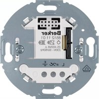
85121101 - Electrical switch HAGER - Free user manual and instructions
Find the device manual for free 85121101 HAGER in PDF.


| Product Type | Universal switch insert (1-gang and 2-gang versions) |
| Model | 85121101 (1-gang) / 8512220x (2-gang) |
| Installation Depth | 32 mm |
| Rated Voltage | 230 V~, +10%/-15% |
| Mains Frequency | 50/60 Hz |
| Standby Power Consumption | < 0.3 W (1-gang) / 0.3 W (channel 1) and 0.7 W (channel 2) for 2-gang |
| Degree of Protection | IP20 |
| Operating Temperature | -5°C to +45°C |
| MCB (Circuit Breaker) | max. 16 A |
| Number of Extension Units | Unlimited (push-button, motion detector) |
| Maximum Cable Length (Extension) | 50 m |
| Maximum Load Cable Length | 100 m |
| Connecting Terminals | 1 x 2.5 mm² or 2 x 1.5 mm² |
| Supported Loads (1-gang) | Incandescent: 25–400 W; HV halogen: 25–400 W; LV halogen (electronic transformer): 25–400 VA; LV halogen (conventional transformer): 25–400 VA; Dimmable 230 V LED: 5–70 W; Dimmable CFL: 13–80 W |
| Supported Loads (2-gang per output) | Incandescent: 35–300 W; HV halogen: 35–300 W; LV halogen (electronic transformer): 35–300 VA; LV halogen (conventional transformer): 35–300 VA; Dimmable 230 V LED: 12–40 W; Dimmable CFL: 15–54 W |
| Functions | Automatic load detection, soft start, electronic short circuit protection, overload and overheating protection, interference signal suppression |
| Safety Notes | Do not operate without application module; not suitable for safe disconnection; use only dimmable loads; observe load derating above 25°C |
| Accessories | Application modules, push-buttons (1-gang, 2-gang), KNX radio buttons, motion detectors (1.1 m, 2.2 m) |
| Maintenance | Clean with dry cloth; no special maintenance required |
Frequently Asked Questions - 85121101 HAGER
User questions about 85121101 HAGER
0 question about this device. Answer the ones you know or ask your own.
Ask a new question about this device
Download the instructions for your Electrical switch in PDF format for free! Find your manual 85121101 - HAGER and take your electronic device back in hand. On this page are published all the documents necessary for the use of your device. 85121101 by HAGER.
USER MANUAL 85121101 HAGER
Universal switch insert 1gang/
Universal switch insert 2gang
Order no.: 8512 11 0x, 8512 22 0x
Operating instructions
1. Safety instructions
Electrical equipment may only be installed and assembled by a qualified electrician in accordance with the relevant installation standards, guidelines, regulations, directives, safety and accident prevention regulations of the country.
Failure to comply with these instructions may result in damage to the device, fire or other hazards.
Hazard due to electric shock. Do not operate device without application module.
Hazard due to electric shock. The device is not suited for safe disconnection of the mains supply. Even when the device is switched off, the load is not galvanically separated from the mains supply.
Do not connect any non-dimmable lamps, their transformers or operating devices.
Observe manufacturer's data.
Hazard of fire. During operation with conventional transformers, fuse each transformer on the primary side according to manufacturer's data. Use safety transformers that comply with EN 61558-2-6 (VDE 0570 Part 2-6) only.
These instructions are an integral component of the product and must be retained by the end user.
2. Design and layout of the device

Figure 1: Universal switch insert 1gang

Figure 2: Universal switch insert 2gang
(1) Universal switch insert
(2) Universal switch insert 2gang
(3) Frames
(4) Application module
(5) Application module 2gang
(6) Screw for dismantling protection (not R.1/R.3)
(7) Button design cover
(8) Connecting terminals
3. Function
Correct use
- Only suitable for use in indoor areas with no drip and no spray water.
- Switching of incandescent lamps, HV halogen lamps, dimmable energy-saving and 230 V retrofit LED lamps; electronic and dual-mode transformers or conventional transformers with low voltage halogen lamps
- Suitable for mixed loads up to the specified total capacity (see "Technical Data")
- Installation into wall box according to DIN 49073 (recommended for touch switch insert 2gang, deep box)
- Operate with suitable application module (see "Accessories")
No mixed load operation of capacitive and inductive loads possible at the output.
Product characteristics
– Power extension via universal power boosters (except for switch insert 2gang, see catalogue)
- automatic setting of load-dependent switching principle and additional, optional settings via the application module e.g. for energy-saving lamps and 230 V retrofit LED lamps
- Soft start for bulb protection
– Electronic short circuit protection
- Electronic overload and overheating protection
- Electronic interference signal suppression e.g. for ripple control impulses (tariff signals)
- Connection of extension unit push-button (NO contact)
Additional product characteristics, switch insert 2gang
– Different load types at each output possible
– Output wattage ratings independent from each other
– Possible to operate output 1 only
– Connection of extension unit push-button (NO contact) per each output possible
Switching process (table 1)
Do only use dimmable loads.
Flickering of connected lamps possible due to falling below of the indicated minimum load, ripple control impulses (tariff signals) of power station or illuminant exchange of energy-savings lamps or 230 V retrofit LED lamps.
i Short term flickering during load detection of ohmic loads possible. No operation is possible during load detection. These are not defects of the device.
If the switching performance of energy-saving lamps and 230 V LED lamps is unsatisfactory in factory setting, a load setting must be carried out. The load setting is described in the instructions of the respective application module.
When circuiting several loads to one output (parallel circuiting) optimise switching performance via load setting if necessary.
4. Operation
These instructions describe the installation of the switch inserts. The operation is to be taken from the instructions of the respective application module.
The operation of extension units is only possible if a cover is attached to the main unit.
5. Information for electricians
5.1 Installation and electrical connection
DANGER!
Touching live parts can result in an electric shock.
An electric shock can be lethal.
Disconnect the connecting cables before working on the device and cover all live parts in the area!
CAUTION!
Do not interconnect the outputs of universal switch insert 2gang.
Operating both outputs on a joint load will destroy the device.
For capacity extension, use universal power boosters (except for universal switch insert 2gang, see catalogue).
Circuiting and mounting the switch insert
A MCB max. 16 A has been installed as device protection.
■ Circuit switch insert and optional extension units according to the connection diagram (Figure 3 to 6).
■ Mount the switch insert into a wall box. The connecting terminals must be at the bottom.
■ Attach frame and application module (see instructions for application module).
A deep wall box is recommended for switch insert 2gang.
i Illuminated mechanical push-buttons must be equipped with a separate N-terminal.
i Motion detector extension units can only be used when the switch insert is operated with a motion detector application module.
i Motion detector extension units are not suitable for the switch insert 2gang.
For power supply, a load must be connected to output 1 of the switch insert 2gang.
6. Appendix
6.1 Technical data
Rated voltage 230 V\~, + 10%/- -15%
Mains frequency 50/60 Hz
MCB
max. 16 A
Standby power consumption < 0.3 W
Degree of protection IP 20
Relative humidity 0 ... 65 % (no condensation)
Operating temperature -5^ +45^
Storage/transport temperature -20°C ... +60°C
Number of extension units unlimited
Extension unit cable length max. 50 m
Number of motion detector extension units unlimited
Cable length motion detector extension units max. 50 m
Load cable length max. 100 m
Connecting terminals 1 x 2.5 mm ^4 or 2 x 1.5 mm ^4
Mounting orientation connecting terminals downwards
Installation depth
32 mm
Performance reduction per 5°C above 25°C:
- Incandescent lamps, HV halogen lamps, LV halogen lamps with electronic transformers or dual-mode transformers, NV halogen lamps with conventional transformers -25 %
Dimmable 230 V retrofit LED lamps, dimmable energy-savings lamps -30 %
Installation in wood or drywallas well as in multiple combinations -25 %
Performance data including transformer power dissipation
- Conventional transformers 20%
– Electronic transformers, dual-mode transformers 10 %
Universal switch insert 1gang
Standby power consumption < 0.3 W
Incandescent lamps 25 ... 400 W
HV halogen lamps 25 ... 400 W
LV halogen lamps with electronic transformers or dual-mode transformers 25 ... 400 VA
LV halogen lamps with conventional transformers 25 ... 400 VA
Dimmable 230 V retrofit LED lamps 5 ... 70 W
Dimmable energy-savings lamps 13 ... 80 W
Mixed loads possible to lowest maximum load
Universal switch insert 2gang per output
Standby power consumption
0.3 W channel 1 / 0.7 W channel 2
Incandescent lamps 35 ... 300 W
HV halogen lamps 35 ... 300 W
LV halogen lamps with electronic transformers or dual-mode transformers 35 ... 300 VA
LV halogen lamps with conventional transformers 35 ... 300 VA
Dimmable 230 V retrofit LED lamps 12 ... 40 W
Dimmable energy-savings lamps 15 ... 54 W
Mixed loads possible to lowest maximum load
Conventional transformers should be operated with at least 25 % nominal load. Nonetheless, 75 % is recommended because in individual cases, depending on the transformer, unstable switching performance may occur.
Carry out loading of conventional, electronic and dual-mode transformers according to manufacturer's instructions.
Do not use non-dimmable energy-saving lamps or 230 V retrofit LED lamps.
For 230 V retrofit LED lamps, the power supply of the switch insert via the lamp, even when switched off, may cause weakened illumination of the lamp.
6.2 Troubleshooting
Device switches off and can no longer be switched on after a certain time.
Electronic overheating protection has triggered.
Reduce connected load.
Check the installation situation.
Device briefly switches off and on again.
Short circuit protection has triggered, but in the meantime there is no longer a fault.
Switch insert 2gang switches both outputs off.
Load at output 1 is defective and interrupts the power supply of the joint switch insert.
Repair load at output 1.
6.3 Accessories
Universal switch insert 1gang
Push-button 1gang 8514 51 xx
KNX radio button 1gang quicklink 8514 51 xx
KNX radio button 4gang quicklink 8564 81 xx
Motion detector 1.1 m 8534 11 xx
Motion detector 2.2 m 8534 21 xx
IR Motion detector comfort 1.1 m 8534 12 xx
IR Motion detector comfort 2.2 m 8534 22 xx
KNX radio motion detector comfort 1.1 m quicklink 8534 21 xx
KNX radio motion detector comfort 2.2 m quicklink 8534 21 xx
Universal switch insert 2gang
Push-button 2gang 8514 21 xx
KNX radio button 2gang quicklink 8514 61 xx
KNX radio button 4gang quicklink 8564 81 xx
6.4 Warranty
We reserve the right to realise technical and formal changes to the product in the interest of technical progress.
Our products are under guarantee within the scope of the statutory provisions.
If you have a warranty claim, please contact the point of sale.



- Universal switch insert 1gang/
- Universal switch insert 2gang
- Operating instructions
- Safety instructions
- Design and layout of the device
- Function
- Correct use
- Product characteristics
- Additional product characteristics, switch insert 2gang
- Switching process (table 1)
- Operation
- Information for electricians
- Installation and electrical connection
- DANGER!
- CAUTION!
- Circuiting and mounting the switch insert
- Appendix
- Technical data
- Universal switch insert 1gang
- Universal switch insert 2gang per output
- Troubleshooting
- Device switches off and can no longer be switched on after a certain time.
- Device briefly switches off and on again.
- Switch insert 2gang switches both outputs off.
- Accessories
- Warranty
Brand : HAGER
Model : 85121101
Category : Electrical switch