
Aether RM1 - Microphone Eikon - Free user manual and instructions
Find the device manual for free Aether RM1 Eikon in PDF.


| Product Type | Microphone |
| Brand | Eikon |
| Model | Aether RM1 |
| Dimensions (approx.) | 6.3 x 1.5 x 1.5 inches (160 x 38 x 38 mm) |
| Weight | 11.6 oz (330 g) |
| Power Source | USB bus power (5V/500mA) |
| Polar Pattern | Cardioid |
| Frequency Response | 20 Hz - 20 kHz |
| Sample Rate | Up to 48 kHz |
| Bit Depth | 24-bit |
| Connectivity | USB-C |
| Mounting | Built-in table stand, 5/8" thread for mic stand |
| Main Functions | Recording, podcasting, streaming, voice calls |
| Controls | Mute button, volume knob, gain adjustment |
| LED Indicator | Red when muted, blue when live |
| Included Accessories | USB cable, table stand, user manual |
| Maintenance & Cleaning | Wipe with a soft, dry cloth. Avoid liquids. |
| Safety | Do not expose to moisture or extreme temperatures. |
| Spare Parts & Repairability | Not user-serviceable. Contact Eikon support. |
| General Information | Compatible with Windows, macOS, and Linux. |
Frequently Asked Questions - Aether RM1 Eikon
User questions about Aether RM1 Eikon
0 question about this device. Answer the ones you know or ask your own.
Ask a new question about this device
Download the instructions for your Microphone in PDF format for free! Find your manual Aether RM1 - Eikon and take your electronic device back in hand. On this page are published all the documents necessary for the use of your device. Aether RM1 by Eikon.
USER MANUAL Aether RM1 Eikon
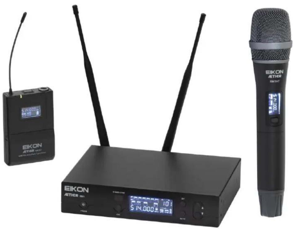
Wireless Microphone System
natural_image
Three black EIKON AETHER audio devices with visible microphone, earbuds, and digital display (no text or symbols on main components)USER'S MANUAL
ENGLISH
ITALIANO
INDEX
DISPOSAL OF OLD ELECTRICAL & ELECTRONIC EQUIPMENT 3
SAFETY INSTRUCTIONS .... 3
IN CASE OF FAULT 3
PACKAGING, SHIPPING AND COMPLAINT 3
WARRANTY AND PRODUCTS RETURN....3
MAINTENANCE AND DISCLAIMER 4
POWER SUPPLY 4
USER'S WARNINGS AND CE CONFORMITY 4
LICENSING INFORMATION: 4
INTRODUCTION 6
DESCRIPTION 6
RM1 RECEIVER....6
RM1 MENU 8
SET UP RECEIVER 8
RM1HT HANDHELD MICROPHONE TRANSMITTER....9
RM1BT BODYPACK TRANSMITTER....11
BATTERY REPLACEMENT....12
TECHNICAL SPECIFICATION....13
TROUBLESHOOTING 14
AVVERTENZE PER LA SICUREZZA....15
IN CASO DI GUASTO....15
IMBALLAGGIO, TRASPORTO E RECLAMI....15
GARANZIE E RESI....16
AVVERTENZE PER L'UTILIZZO E CONFORMITÀ EU 17
INFORMATIVA SULLA LICENZA:....17
INTRODUZIONE 18
DESCRIZIONE 18
RICEVITORE RM1 18
RM1 MENU 20
SET UP RICEVITORE....20
TRASMETTITORE A MANO RM1HT 21
TRASMETTITORE BODYPACK WM1B....22
This marking shown on the product or its literature, indicates that it should not be disposed with other household wastes at the end of its working life. To prevent possible harm to the environment or human health from uncontrolled waste disposal, please separate this from other types of wastes and recycle it responsibly to promote the sustainable reuse of material resources. Household users should contact either the retailer where they purchased this product, or their local government
office, for details of where and how they can take this item for environmentally safe recycling. Business users should contact their supplier and check the terms and conditions of the purchase contract. This product should not be mixed with other commercial wastes for disposal.
SAFETY INSTRUCTIONS
- CAUTION - Before using this product carefully read the following safety instructions. Look of this manual entirely and preserve it for future reference. When using any electric product, basic precautions should always be taken, including the following:
• To reduce the risk, close supervision is necessary when the product is used near children. - Protect the apparatus from atmospheric agents and keep it away from water, rain and high humidity places.
- This product should be site away from heat sources such as radiators, lamps and any other device that generate heat.
- Care should be taken so that objects and liquids do not go inside the product.
- The product should be connected to a power supply only of the type described on the operating instructions or as marked on the product.
IN CASE OF FAULT
- In case of fault or maintenance this product should be inspected only by qualified service personnel when:
■ Liquids have spilled inside the product.
■ The product has fallen and been damaged.
The product does not appear to operate normally or exhibits a marked change in performance.
- Do not operate on the product, it has no user-serviceable parts inside.
- Refer servicing to an authorized maintenance center.
PACKAGING, SHIPPING AND COMPLAINT
- This unit package has been submitted to ISTA 1A integrity tests. We suggest you control the unit conditions immediately after unpacking it.
- If any damage is found, immediately advise the dealer. Keep all unit packaging parts to allow inspection.
• Proel is not responsible for any damage that occurs during shipment. - Products are sold "delivered ex warehouse" and shipment is at charge and risk of the buyer.
- Possible damages to unit should be immediately notified to forwarder. Each complaint for manumitted package should be done within eight days from product receipt.
WARRANTY AND PRODUCTS RETURN
• Proel products have operating warranty and comply their specifications, as stated by manufacturer.
- Proel warrants all materials, workmanship, and proper operation of this product for a period of two years from the original date of purchase. If any defects are found in the materials or workmanship or if the product fails to function properly during the applicable warranty period, the owner should inform about these defects the dealer or the distributor, providing receipt or invoice of date of purchase and defect detailed description. This warranty does not extend to damage resulting from improper installation,
misuse, neglect, or abuse. Proel S.p.A. will verify damage on returned units, and when the unit has been properly used and warranty is still valid, then the unit will be replaced or repaired. Proel S.p.A. is not responsible for any "direct damage" or "indirect damage" caused by product defectiveness.
MAINTENANCE AND DISCLAIMER
- Clean only with dry cloth.
- Proel products have been expressly designed for audio application, with signals in audio range (20Hz to 20kHz). Proel has no liability for damages caused in case of lack of maintenance, modifications, improper use, or improper installation non-applying safety instructions.
• Proel S.p.A. reserves the right to change these specifications at any time without notice. - Proel S.p.A. declines any liability for damages to objects or persons caused by lacks maintenance, improper use, installation not performed with safety precautions and at the state of the art.
POWER SUPPLY
- This apparatus should only be connected to power source type specified in this owner's manual or on the unit.
- If the supplied AC power cable plug is different from the wall socket, please contact an electrician to change the AC power plug.
- Hold the plug and the wall outlet while disconnecting the unit from AC power.
- If the unit will not be used for a long period of time, please unplug the power cord from AC power outlet.
- To avoid unit power cord damage, please do not strain the AC power cable and do not bundle it.
- In order to avoid unit power cord damage, please ensure that the power cord is not stepped on or pinched by heavy objects.
USER'S WARNINGS AND CE CONFORMITY
- Changes or modifications not expressly approved by PROEL S.p.A. could void your authority to operate the equipment.
LICENSING INFORMATION:
• Frequency Range of RM1: 514 - 542; 606 - 614; 655 - 679; 823 - 832; 863 - 865 MHz.
- A ministerial license may be required to operate this equipment in certain areas. The use of this professional wireless microphone equipment in some countries could be intended for professional use, so the licensability depends on the country it operates. Proel suggests the user to contact the appropriate telecommunications authority concerning proper licensing.
- This equipment may be capable of operating on some frequencies not authorized in your country. Please contact your national authority to obtain information on authorized frequencies for wireless microphone products in your region.
- Licensing of professional wireless microphone equipment is the user's responsibility, and licensability depends on the user's classification and application, and on the selected frequency.
• The product is in compliance with 2014 / 30/ EU EMC Directive & 2014 /35 / EU LVD Directive.
- PROEL S.p.A hereby, declares that this wireless microphone system complies with the essential requirements of Radio Equipment Directive (RED) 2014 / 53 / EU.
- The full and detailed declaration of conformity can be downloaded from the web site:
www.eikon-audio.com
| TABLE OF THE AUTHORIZED FREQUENCIES FOR THE RM1 WIRELESS MICROPHONE SYSTEM IN EUROPE UPDATED WITH REFERENCE TO ERC-REC 70-03E DOCUMENT DATED FEBRUARY 7 2014 | ||
| COUNTRY CODE | RM1HT / RM1BT TRANSMITTING FREQUENCIES (MHz) | |
| 514-542; 606-614; 655-679; 823-832 | 863.000 - 865.000 | |
| BE CZ DK FI DE IS IE LI LU CH ES SI AL MD TR | Individual license required | no personal license required |
| AT EE FR IT LT PL SE GB | Individual license required and/or Limited implementation | |
| BG CY HR GR HU LV MT NL NO PT RO SK BA MK ME RU RS UA | NOT IMPLEMENTED | |
| GE | NOT IMPLEMENTED | |
| IN ALL COUNTRIES THE USE OF WIRELESS MICROPHONES SYSTEMS IS SUBJECT TO ANY TELEVISION AND BROADCAST TRANSMISSION | ||
| CONSULT LOCAL OR NATIONAL RADIO SPECTRUM AUTHORITIES FOR INFORMATION ON POSSIBLE RESTRICTIONS OR NECESSARY AUTHORIZATIONS BEFORE USING THIS SHORT-RANGE DEVICE. | ||
INTRODUCTION
Thank you for choosing this EIKON product and for your trust in our brand, synonymous of professionalism, accuracy, high quality and reliability. All our products are CE approved and designed for continuous use in professional systems.
DESCRIPTION
The RM1 Wireless Microphone is a UHF, PLL controlled, true diversity system providing a reliable and high-quality signal transmission and equipped with automatic channel scan and IR sync.
RM1 Wireless Microphone system features 3 units: RM1 receiver, RM1HT handheld transmitter and RM1BT body pack transmitter. The system is available in two different configurations:
Aether RM1M: RM1 + RM1HT
Aether RM1H: RM1 + RM1BT + headset microphone
388 total channel frequencies are available allowing the simultaneous use of 12 devices without interference between them.
RM1 RECEIVER
See FIG. 1 at page 24:
- POWER
On/off switch: press and hold for two seconds to switch on or off the receiver.
- ASC
Press this key to start the infrared frequency transmitter.
- IR DATA SYNC
This is the infrared port to send the channel setting to the transmitter.
- DISPLAY LCD
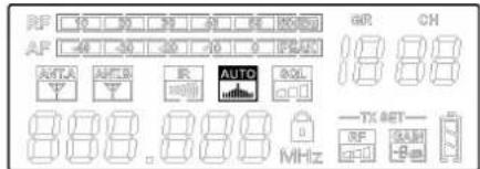
The LCD display shows various information. Some of them are described here, for in-depth instructions see further in this manual.
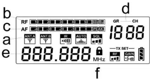
a. This is the currently used antenna, A and B.
b. RF: this meter shows the radio frequency signal level. If the transmitter is ON, the meter must be close to the top. If the transmitter is OFF the meter is completely down. In this condition, if some signal is shown on the meter, it means that there is a RF disturbance: to avoid it you must select a different RF channel.
c. AF: this meter shows the audio frequency signal send to the outputs. If no AF signal is present when the user speaks into the microphone, check the RF and MUTE indicators in the transmitter. If the RF signal is null, check if the transmitter is operative and if it is set on the same RF channel as the receiver.
d. GR – CH: this is the number of the selected group and the channel stored in the receiver memory.
e. This is the number of the selected frequency stored in the receiver memory.
f. when this symbol is on the receiver is locked, it is not possible to change the setting parameters.
5. AUTO
Press this button for the automatic search of the free frequency.
6. SET
Press this button during the normal operation to scroll between the menu options.
7. UP
Pressing this button you can increase the value of the correspondent menu option.
8. DOWN
Pressing this button you can decrease the value of the correspondent menu option.
9. 12VDC
Socket for the AC/DC adaptor: use only the adaptor supplied with the system.
10. OUTPUT (BAL)
Balanced output with mic level: connect it through a XLR cable to a mixer MIC input. This output is used preferably for long runs.
11. OUTPUT (UNBAL)
Unbalanced output with line level: connect it through a mono 6.3mm jack cable to a mixer or instrument amplifier input. This output is used preferably for short runs.
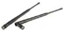
12. ANT A ANT B
These are the receiving antennas. Screw them in and raise them up during the use. In order to obtain a good transmission angle, them at 90^ and place the receiver away from other metal objects and far away no more than 40 m from the transmitter. The internal diversity receiving circuit chooses the best signal from one of the two antennas.
RM1 MENU
SET UP RECEIVER
Menu setting: press the "SET" button for two seconds, the icon "☐" disappears, the receiver enters EDIT mode. Now it is possible to move, by pressing the SET button in sequence within the 7 functions.
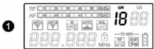
GROUP: press the "SET" button once, the GR icon will start flashing, press the button
▲ to select the desired group.
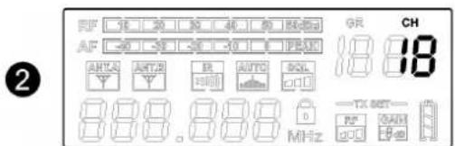
CHANNEL: press the "SET" button once, the CH icon will start flashing, press the button
▲ ▼ to select the desired group.
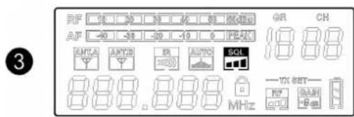
SQUELCH: press the "SET" button once, the SQL icon will start flashing, press the button
▲ ▼ to select the level desired.
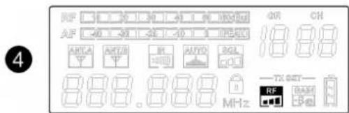
RF POWER Transmitter: press the "SET" button once, the RF icon will start flashing, press the button
▲ ▼ to select the level desired.
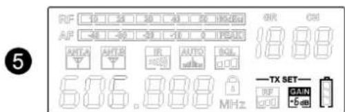
TX SET GAIN: press the "SET" button once, the GAIN icon will start flashing, press the button
▲ ▼ to select the level desired.
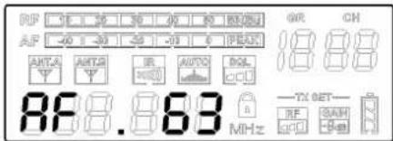
VOLUME AUDIO RECEIVER: press the "SET" button for two seconds, the icon "☐" disappears press the button to select the output level desired.
6
AUTO SCAN: press the "SET" button for two seconds, the icon "💡" disappears press the button AUTO, icon AUTO flashing, the receiver scrolls all the channels in select group to find a free one and selects the best. Please note that when you have more than one RM1 systems to set up, you must leave ON any transmitter you have already set up and synced with its receiver, except the transmitter that you want to set up, which must be off.
7
SYNC IR DATA
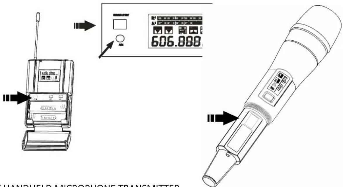
To synchronize the receiver with the transmitter, expose the IR sensor by bringing it closer to the receiver's IR DATA SYNC window. Press the ASC button, the IR icon will start flashing together with the receiver's IR sensor. After synchronization, the LED will stop flashing. Check that the transmitter shows the same frequency on the receiver display.
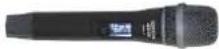
RM1HT HANDHELD MICROPHONE TRANSMITTER
See FIG. 2 at page 25
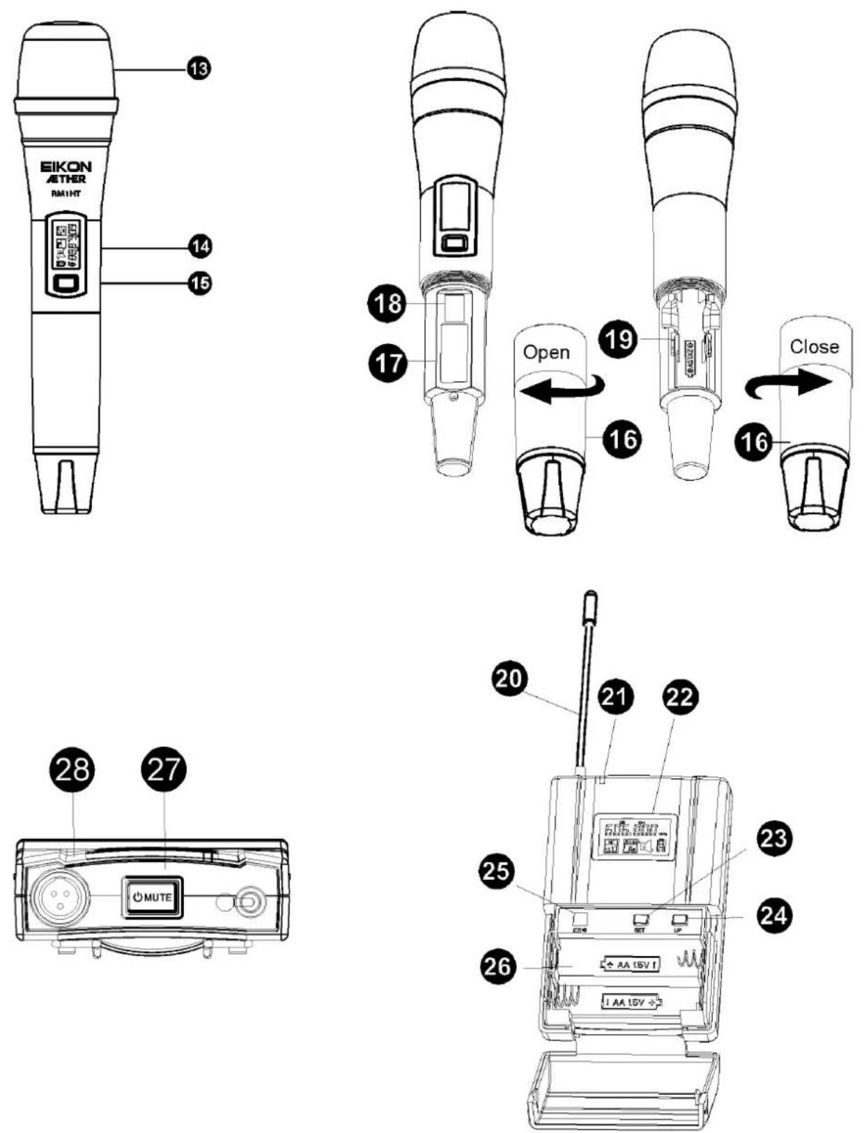
13. MICROPHONE GRILLE
The grille protects the microphone capsule and includes a pop filter. The microphone capsule is dynamic with a cardioid polar pattern.
14. DISPLAY LCD
The LCD display shows various information:
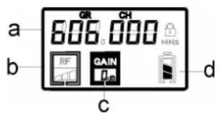
a) Frequency
b) RF level of the transmitter
c) Audio Gain of the transmitter
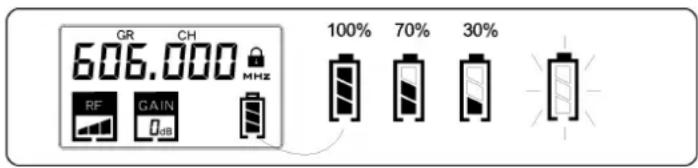
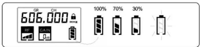
d) Charge level of the battery. Three segments show the state of charge as a percentage. When the voltage drops below 1.8 Volts the segments are not visible, and the icon starts flashing indicating that the transmitter is shutting down.
15. ON-OFF MUTE BUTTON
Press this button for 1 second and the transmitter starts working. To disable the sound of the transmitter, press the ON-OFF button once the symbol 📋 appears on the display of the transmitter and receiver, a subsequent press re-enables the sound, and the symbol disappears.
To turn off the transmitter, press the ON-OFF key for one second and the message "OFF" appears on the display.
16. BATTERY COMPARTMENT COVER
17. FREQUENCY TRANSMITTER
This label shows the operating frequency of the transmitter.
18. IR
This is the IR infrared sensor port to receive channel settings from the RM1 receiver. Bring the transmitter close to the IR port to the receiver's and expose the sensor during the frequency sync procedure and to transmit settings parameters.
19. BATTERY INLET
Open the handheld microphone as show in figure to access at the battery compartment. Respect always the polarity marked inside the battery compartment.
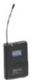
RM1BT BODYPACK TRANSMITTER
See FIG. 2 at page 25
20. ANTENNA
This is the transmitting antenna: do not force it, disconnect it or try to replace it with a different one.
21. LED POWER
when the power button is pressed, the LED lights up indicating that the transmitter is in operation.
22. DISPLAY LCD
The LCD display shows various information:
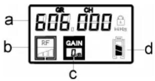
a) Frequency
b) RF level of the transmitter.
c) Audio Gain of the transmitter.
d) Charge level of the battery. Three segments show the state of charge as a percentage. When the voltage drops below 1.8 Volts the segments are not visible, and the icon starts flashing indicating that the transmitter is shutting down.
23. SET BUTTON
Press and hold this button for 1 seconds and you can access the BODYPACK SET UP. Using the set button, you can scroll the available options.
24. UP BUTTON
Pressing this button after the SET button you can change the value of the option selected.
25. IR
This is the IR infrared sensor port to receive channel settings from the RM1 receiver. Bring the Bodypack close to the IR port to the receiver's and expose the sensor during the frequency sync procedure and to transmit settings parameters.
26. BATTERIES INLETS
To access the battery compartment and the IR sensor, lightly press the side flaps indicated by a raised dash on the cover and slide down the battery cover. When replacing the batteries respect always the polarity marked inside the battery inlet.
27. ON-OFF BUTTON
Press this button for 1 second and the bodypack starts working. To disable the sound of the transmitter, press the ON-OFF button once and the symbol 📄 appears on the display of the bodypack and receiver, a subsequent press re-enables the sound, and the symbol disappears.
To turn off the transmitter, press the ON-OFF key for one second and the message "OFF" appears on the display.
28. AUDIO INPUT
Mini XLR 3P input socket to connect the supplied microphone or other microphones.
BATTERY REPLACEMENT
For the Battery replacement use always 2x 1.5V AA size LITHIUM or ALKALINE type for the best performances. You can use also rechargeable batteries but, in this case, the operating time is shorter. Good quality ALKALINE batteries guarantee an operating time of about 10 hours.
Be careful to respect always the polarity marked inside the battery inlet.
Always remember to remove the batteries if you do not use the microphone for a long period of time: this will avoid the corrosion of the battery contacts.
ACCESSORIES
The following table shows all the accessories available for the RM1 system (for more information visit the web site www.eikon-audio.com):
| Code | Description |
| AETHERSPLIT | Antenna Splitter with booster for 4 RM1 units, 1 rack unit (BNC connector) |
| AETHERANT | 4 dB GAIN Yagi directional Antenna for mic stand (BNC connector) |
| AETHERBOOST | Antenna boost |
| HCM14EK | High performance Cardioid Headset Microphone for singers (body colour) |
| HCM12EK | High performance Omni-directional Headset Microphone for actors (body colour) |
| HCM10V2 | High performance Cardioid Headset Microphone for singers (body colour) |
| HCM08PRO | High performance Omnidirectional Headset Microphone for actors (body colour) |
| HCM23AK | Premium Omnidirectional Headset Microphone (body colour) |
| HCM25AK | Premium Cardioid Headset Microphone for singers (black colour) |
| LCH370 | High-quality Cardioid miniature Broadcast Lavalier Microphone (black colour) |
| LCH100AK | Omnidirectional miniature Lavalier Microphone (black colour) |
TECHNICAL SPECIFICATION
| RM1 – UHF PLL Receiver | |
| RF Channels | 388 total preset frequencies |
| RF Frequency Band | UHF A: 514 - 542 MHz (144 Ch) |
| UHF B: 606 - 614 MHz (40 Ch) | |
| UHF C: 655 - 679 MHz (120 Ch) | |
| UHF D: 823 - 832; 863 - 865 MHz (84 Ch ) | |
| RF Receiver Type | PLL UHF Synthesized |
| RF Modulation type | FM (F3E) |
| RF Sensitivity | -105 dBm / 12 dB SINAD |
| RF Image/Spurious Rejection | >70 dB |
| RF Interference Rejection | >70 dB |
| RF Frequency Stability | ± 0.005% (-10 ÷ +50 °C) |
| THD Distortion | < 1 % |
| S/N Ratio | >90 dB |
| Dynamic Ratio | >100 dB |
| Frequency Response | 60 Hz – 18000 Hz (±3 dB) |
| XLR balanced nominal audio output | -10 dBu (245 mVrms) |
| JACK unbalanced nominal audio output | 0 dBu (775 mVrms) |
| Power Supply | 12 V DC 500 mA |
| Dimensions | H 43 x L 213 x W 173 mm |
| Weight | 880 g |
| RM1HT – Handheld Microphone UHF PLL Transmitter | |
| RF Channels | 388 total preset frequencies |
| RF Frequency Band | UHF A: 514 - 542 MHz (144 Ch) |
| UHF B: 606 - 614 MHz (40 Ch) | |
| UHF C: 655 - 679 MHz (120 Ch) | |
| UHF D: 823-832; 863 - 865 MHz (84 Ch) | |
| RF Power | max 10 mW |
| Modulation method | FM (F3E) |
| RF Max deviation | ± 50 KHz compressor-expander system |
| RF Frequency Stability | ± 0.005% (-10 ÷ +50 °C) |
| Spurious Emission | under limits EN 300422 |
| Frequency Response | 50 Hz – 15000 Hz (±3 dB) |
| Microphone type | Dynamic lper-Cardioid |
| Power Supply | 2x1.5V AA alkaline battery |
| Dimensions (DxH) | 51 x 257 mm |
| Weight | 360 g |
| RM1BT – Bodypack UHF PLL Transmitter | |
| RF Channels | 388 total preset frequencies |
| RF Frequency Band | UHF A: 514 - 542 MHz (144 Ch) |
| UHF B: 606 - 614 MHz (40 Ch) | |
| UHF C: 655 - 679 MHz (120 Ch) | |
| UHF D : 823 - 832; 863 - 865 MHz (84 Ch) | |
| RF Power | max 10 mW |
| Modulation method | FM (F3E) |
| RF Max deviation | ± 50 KHz compressor-expander system |
| RF Frequency Stability | ± 0.005% (-10 ÷ +50 °C) |
| Spurious Emission | under limits EN 300422 |
| Frequency Response | 50 Hz – 15000 Hz (±3 dB) |
| Microphone included | Headset condenser |
| Input connector | Mini Xlr 3P |
| Power Supply | 2x1.5V AA alkaline battery |
| Dimensions (HxWxD) | 98 x 63 x 24 mm |
| Weight | 130 g |
TROUBLESHOOTING
| Issue | Indicator Status | Solution |
| No sound or faint sound | Receiver LCD off | Make sure AC adapteris securely plugged into electrical outlet and into DC input connector on rear panel of receiver.Make sure AC electrical outlet works and is supplying proper voltage. |
| Transmitter power light off | Turn transmitter onMake sure the +/- indicator on battery match the transmitter terminals.Insert a fresh battery. | |
| Receiver display indicates antenna activity. | Press mute switch on transmitterTurnup reveir volume control.Increase transmitter ain switch setting.Check the cable connection between receiver and mixer. | |
| Receiver: Reception is not displayed on antenna A or B; Transmitter and receiver power ligths glowing. | Extend receiver antennas vertically.Move receiver away from metal objects.Check for line of sight between transmitter and receiver.Move receiver closer to transmitter.Check that receiver are using the same frequency. | |
| Transmitter Display indicates "LO BAT". | Insert a fresh battery. | |
| Distortion or unwanted noise bursts | Receiver display indicates antenna activity. | Remove nearby sources of RF interferences (CD players, computer, digital effects, in-ear monitor).Change receiver and transmitter to a different frequency.Reduce transmitter Gain.Replace transmitter battery.Increase the frequency spread between systems. |
| Distortion suond | Reduce transmitter Gain.Replace transmitter battery. |

TRATTAMENTO DEL DISPOSITIVO ELETTRICO OD ELETTRONICO A FINE VITA
Aether RM1M: RM1 + RM1HT
Aether RM1H: RM1 + RM1BT
natural_image
Pure technical line drawing of a mechanical component with arrows indicating direction (no text or symbols)27. ON-OFF, MUTE BUTTON
natural_image
Pure electrical circuit lines without any symbolsFIG.2
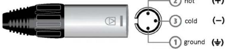
Connections and cables
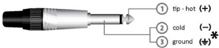
Jack (unbalanced)
*note: connect both cold and ground to make cable from balanced to unbalanced
*nota: connettere insieme cold e ground per cavi da bilanciato a sbilanciato
Jack (sbilanciato)
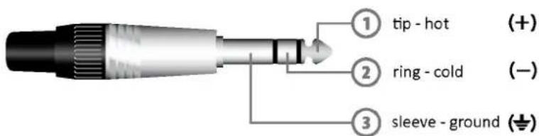
Jack (balanced)
Jack (bilanciato)
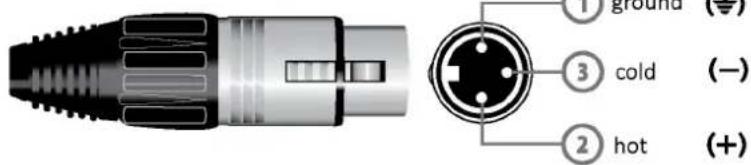
Balanced female XLR
XLR bilanciato femmina
natural_image
Open black hard-shell case containing a handheld electronic device and a small component (no visible text or symbols)| RM1 System | RM1M Handheld Transmitter | RM1B Bodypack Transmitter |
 | ● | ● |
 | X | ● |
 | ● | X |
 | ● | ● |
 | ● | ● |
 | ● | ● |
 | ● | ● |
EIKON
is a brand of
PROEL S.p.A.
(World Headquarters - Factory)
- Wireless Microphone System
- INDEX
- SAFETY INSTRUCTIONS
- IN CASE OF FAULT
- PACKAGING, SHIPPING AND COMPLAINT
- WARRANTY AND PRODUCTS RETURN
- MAINTENANCE AND DISCLAIMER
- POWER SUPPLY
- USER'S WARNINGS AND CE CONFORMITY
- LICENSING INFORMATION:
- INTRODUCTION
- DESCRIPTION
- RM1 RECEIVER
- See FIG. 1 at page 24:
- AUTO
- SET
- UP
- DOWN
- 12VDC
- OUTPUT (BAL)
- OUTPUT (UNBAL)
- ANT A ANT B
- RM1 MENU
- SET UP RECEIVER
- SYNC IR DATA
- MICROPHONE GRILLE
- DISPLAY LCD
- ON-OFF MUTE BUTTON
- BATTERY COMPARTMENT COVER
- FREQUENCY TRANSMITTER
- IR
- BATTERY INLET
- RM1BT BODYPACK TRANSMITTER
- See FIG. 2 at page 25
- ANTENNA
- LED POWER
- DISPLAY LCD
- SET BUTTON
- UP BUTTON
- IR
- BATTERIES INLETS
- ON-OFF BUTTON
- AUDIO INPUT
- BATTERY REPLACEMENT
- ACCESSORIES
- TROUBLESHOOTING
- TRATTAMENTO DEL DISPOSITIVO ELETTRICO OD ELETTRONICO A FINE VITA
- ON-OFF, MUTE BUTTON
- Connections and cables
- EIKON
Brand : Eikon
Model : Aether RM1
Category : Microphone