
ACC-W-EH5C - Uncategorized LG - Free user manual and instructions
Find the device manual for free ACC-W-EH5C LG in PDF.

| Product Type | Wall Mount Kit |
| Compatible Brands | LG |
| Model Number | ACC-W-EH5C |
| Application | Signage display mounting |
| Material | Steel (estimated) |
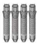
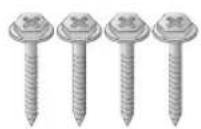
| Screws Included | M4 x L16, M4 x L8, M3 x L4.5, Φ4 x L10, 3 x L6, 3 x L10, M3 x L4.5, M4 x L8, anchor bolts |
| Required Tools | 8 mm concrete drill bit, hammer drill, torque wrench |
| Installation Personnel | Two or more people required |
| Wall Type Supported | Concrete, lightweight concrete, hard/soft fieldstone, brick, cellular block (not plaster board or MDF) |
| Maximum Load Capacity | 70 kgf (686 N) uplifting, 100 kgf (980 N) shearing per fixing point |
| Drilling Depth | 80 mm – 100 mm |
| Torque for Screws | 45 kgf·cm – 60 kgf·cm |
| Included Components | Brackets, T-con box covers, cables (16/22 pin, HDMI), cable holders, jack cover, mounting brackets |
| Cable Management | Supports embedding cables into wall or external routing |
| Safety Features | Caution against single-person installation, anchor and screw fixing instructions |
| Manual Languages | English, Korean (and others via email request) |
| Pages | 32 |
Frequently Asked Questions - ACC-W-EH5C LG
User questions about ACC-W-EH5C LG
0 question about this device. Answer the ones you know or ask your own.
Ask a new question about this device
Download the instructions for your Uncategorized in PDF format for free! Find your manual ACC-W-EH5C - LG and take your electronic device back in hand. On this page are published all the documents necessary for the use of your device. ACC-W-EH5C by LG.
USER MANUAL ACC-W-EH5C LG
natural_image
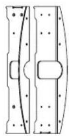
Technical line drawing of two curved mechanical components with mounting holes, one shown in profile and the other a separate detail (no text or symbols)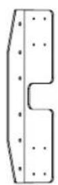
natural_image
Technical line drawing of two mechanical components with bolt holes and a central rectangular feature (no text or symbols)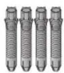

(M4 × L16)
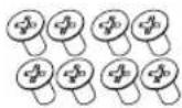
(M4 × L8)

(Φ4 × L10)

주의
natural_image
Diagram of a vehicle under load with motion arrows indicating movement, showing internal components and motion direction (no text or symbols)natural_image
Diagram of a device with a curved cable and multiple pins, mounted on a flat surface (no text or symbols)natural_image
Technical diagram of a mechanical assembly with labeled component A, showing two parallel rods and a central bracket (no text or symbols present)! 맹커 및 나사의 고정 방법
natural_image
Technical diagram of a mechanical assembly with a magnified inset showing internal components (no text or labels)natural_image
Simple line drawing of a mechanical component with a curved section and a vertical bar (no text or symbols)natural_image
Technical line drawing of a cable connector mounted on a panel (no text or symbols)대구
<였면>

natural_image
Simple line drawing of a door with a cable and a wall-mounted panel (no text or symbols)natural_image
Technical line drawing of a computer drive chassis with ports and connectors (no text or symbols)
| |
The Ground Truth image displays a single, solid horizontal line. According to Rule 2 (UNDERSCORE & LINE RULES), if the GT contains lines used for stylistic emphasis or as background (like this), the OCR result must ignore them. The provided OCR content is "____", which consists of four underscores. This is incorrect because underscores are not equivalent to a solid line and are not permitted under the “Stylistic/Background Lines (Ignore)” rule. Outputting underscores for a stylistic line violates the rule and constitutes an error. Therefore, the OCR result is inconsistent with the Ground Truth.
[Non-Text]
[Non-Text]
[Non-Text]
[Non-Text]
[Non-Text]
[Non-Text]
[Non-Text]
[Non-Text]
[Non-Text]
[Non-Text]
[Non-Text]
[Non-Text]
[Non-Text]
[Non-Text]
[Non-Text]
[Non-Text]
[Non-Text]
[Non-Text]
[Non-Text]
[Non-Text]
[Non-Text]
[Non-Text]
(No text to output)
(No text)
| |
[Non-Text]

OWNER'S MANUAL
Wall mount kit
Please read this manual carefully before operating your set and retain it for future reference.
ACC-W-EH5C

natural_image
Technical line drawing of two curved mechanical components with mounting holes, one shown in profile and the other a separate detail (no text or symbols)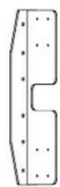
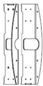
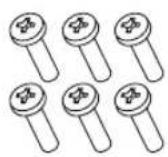
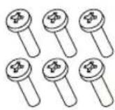
(M4 x L16)
(M4 × L8)

(Φ4 × L10)

CAUTION
- When installing or adjusting the height of this product, two or more people are required. If you try to install or adjust the product alone, it may fall, causing personal injury or product damage.


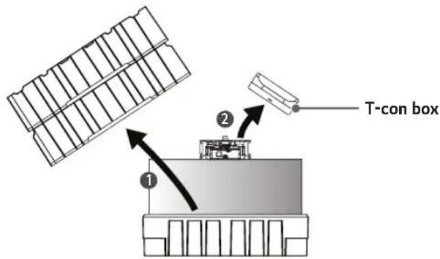
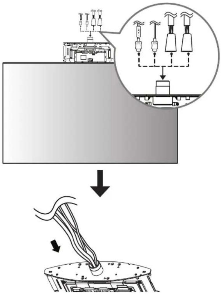
1 Open the product box and remove the packaging materials and T-con box in the order they appear.
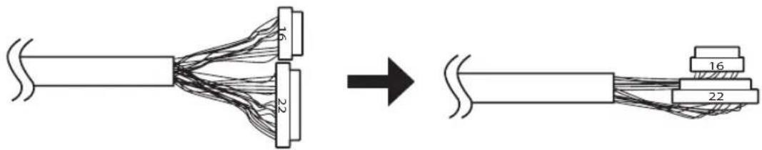
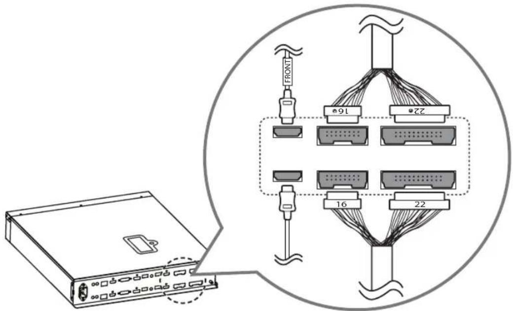
2 Fold the connectors on the opposite side of the 16/22 pin cables to make them parallel to the cable.
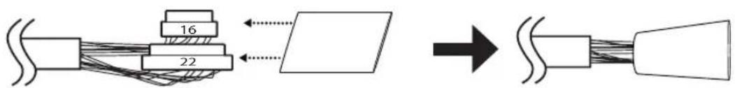
3 Insert the connectors of the 16/22 pin cables into the tubes.
4 Pass the cables through the hole in the middle of the SET.
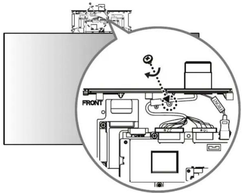
5 Connect the HDMI cable with the label marked 'FRONT' to the FRONT side. Insert the 16/22 pin cable with the red mark into the cable holder and attach it using a screw (M3 x L4.5).

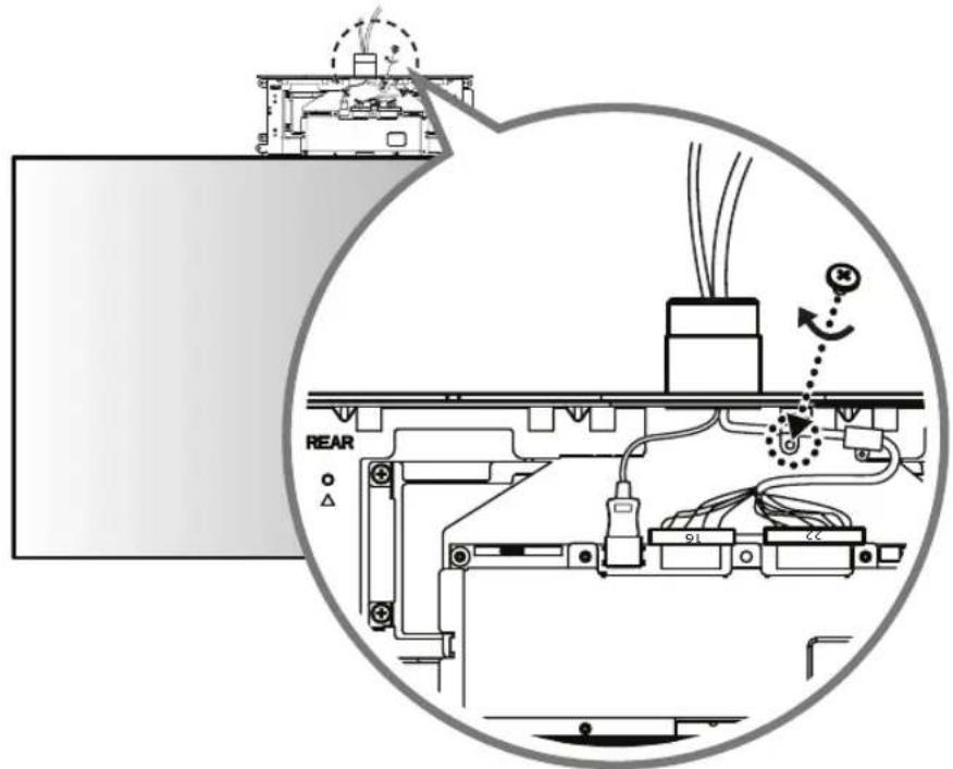
6 Connect the HDMI cable without the label marked 'FRONT' to the REAR side. Insert the 16/22 pin cable without the red mark into the cable holder and attach it using a screw (M3 x L4.5).
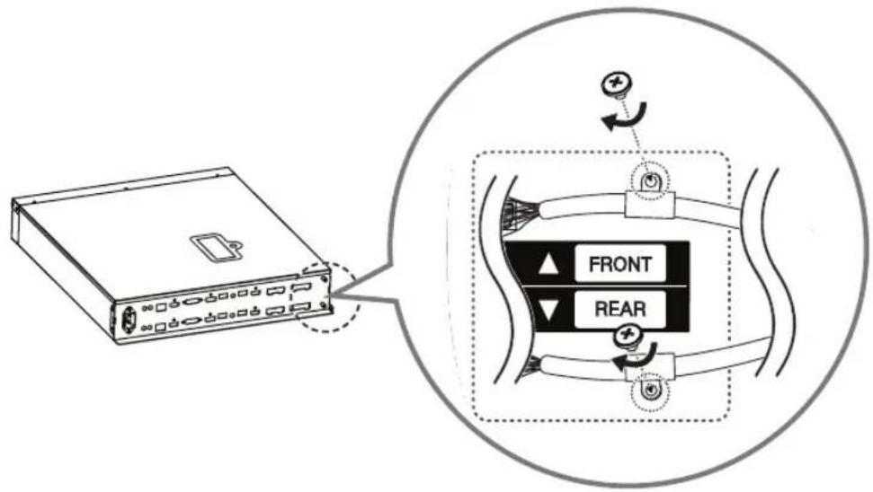
7 Cover the FRONT side with the side of the T-con box cover that has the IR receiver and attach it using 4 screws ( 3 × L6 ) on the opposite side (REAR side).
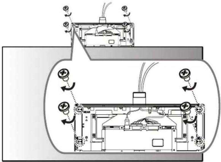
8 Cover the REAR side with the other T-con box cover and attach it using 2 screws ( 3 × L10 ).
natural_image
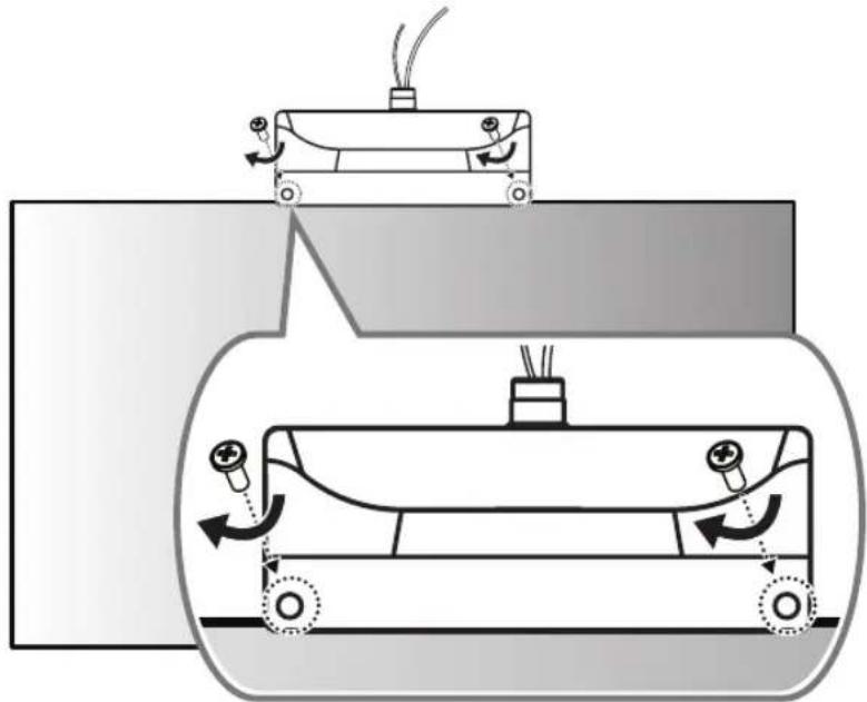
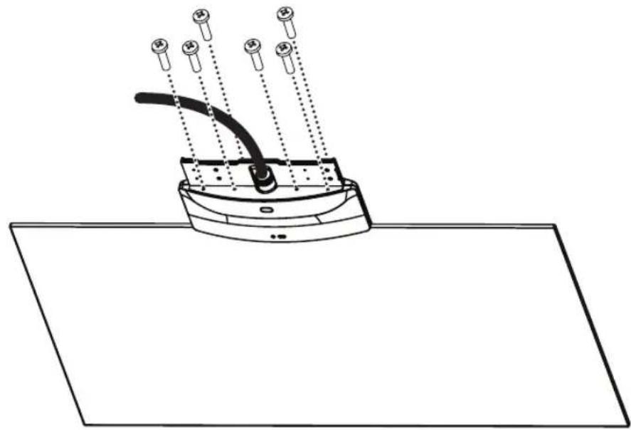
Diagram of a mechanical device with rotating components and motion arrows, no text or symbols present9 Using 6 screws (M4 x L16), assemble 2 brackets to the set.
natural_image
Diagram of a device with a curved cable and multiple pins, mounted on a flat surface (no text or symbols)
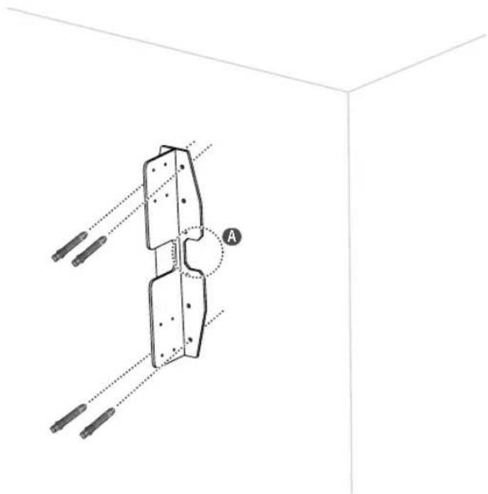
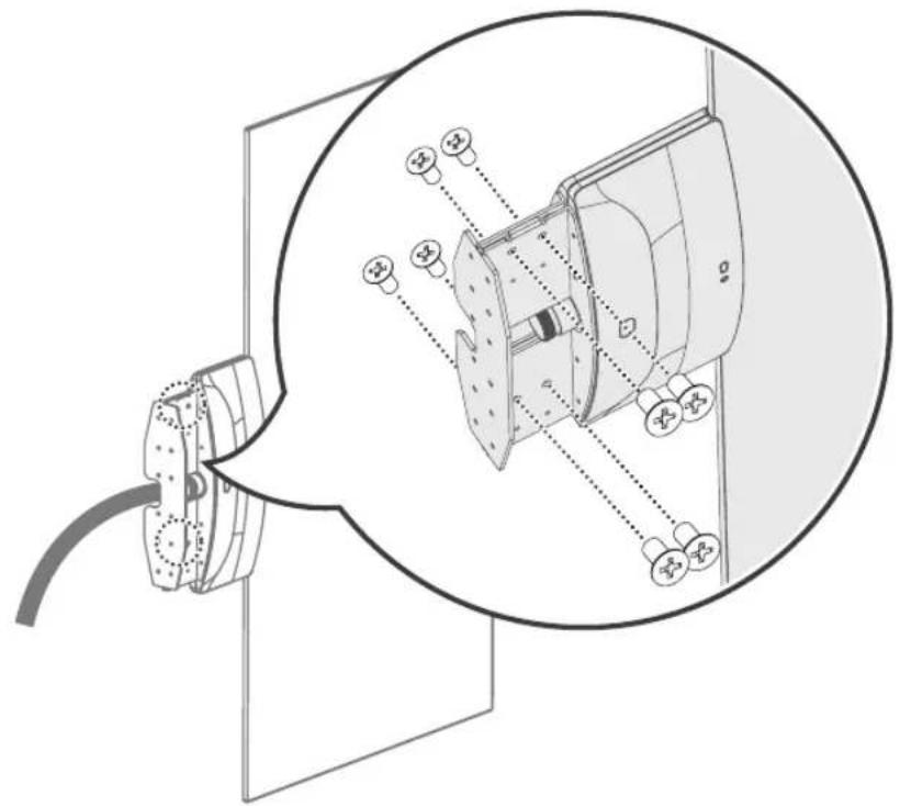
10 Using 4 anchor bolts, install the wall mount on the wall surface. (Refer to "Fixing the anchors and screws".) When embedding cables into the wall, drill holes into the wall according to the markings (A).
natural_image
Technical diagram of a mechanical assembly with labeled component A, showing alignment lines and support elements (no text or symbols beyond labels)FIXING THE ANCHORS AND SCREWS
- Check the wall material and thickness of the finish material.
- You can use the provided Anchor bolts and screws on walls made with concrete, lightweight concrete, hard fieldstone, soft fieldstone, brick, cellular block, etc., or other materials that do not crack.
- Do not mount the device on walls made with plaster board or medium-density fiberboard (MDF). In this case, the anchor and screws must be inserted into the concrete behind the finish. If there is no concrete on the other side, then install first a separate hanger where the anchors and screws can be fixed.
- When installing it on a wall other than that specified in this manual, make sure that each fixing point withstands uplifting load of 70 kgf (686 N) and shearing load of 100 kgf (980 N) or more.
1
The image is too blurry to recognize any text content.
●
4
●
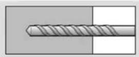
-Use 8 mm concrete drill bit and hammer (impact) drill.
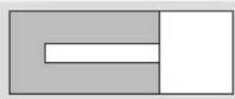
1 Drill a hole with depth of 80 mm – 100 mm where the anchor will be attached using ∅ 8 mm drill bit.
② Clean out the drilled hole.
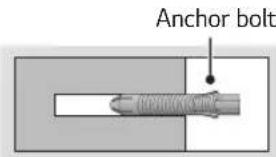
3 Insert the anchor bolt provided into the hole. (Use a hammer when inserting the anchor bolt.)
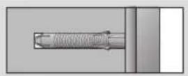
4 Place the wall mount up close to the wall. The angle adjusting attachment should be facing upward.
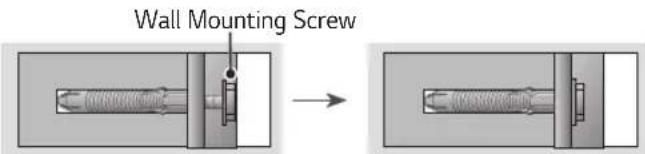
5 Insert the wall mounting screw into the hole and tighten it. Tighten the screw using a torque of at least 45 kgf/cm - 60 kgf/cm.
11 Assemble the wall mount and bracket, and then fix in place using 8 screws (M4 x L8).
natural_image
Technical diagram of a mechanical assembly with a magnified inset showing internal components (no text or labels)
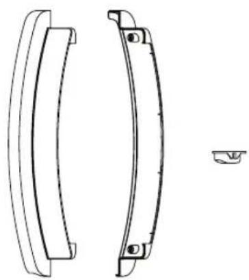
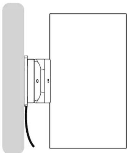
12 Assemble the front/rear/side covers appropriately with the set and fix in place using 2 screws ( 4 × L10 ). If the cables do not pass through the wall, do not assemble the side cover; remove the cables through the gap. -When cables are embedded in the wall
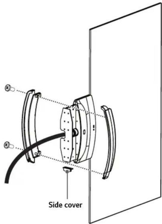
natural_image
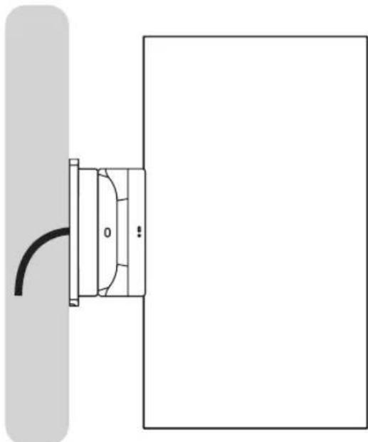
Simple line drawing of a door with a curved handle and a vertical bar on the left (no text or symbols)-When cables are not embedded in the wall
natural_image
Technical line drawing of a cable connector mounted on a panel (no text or symbols)
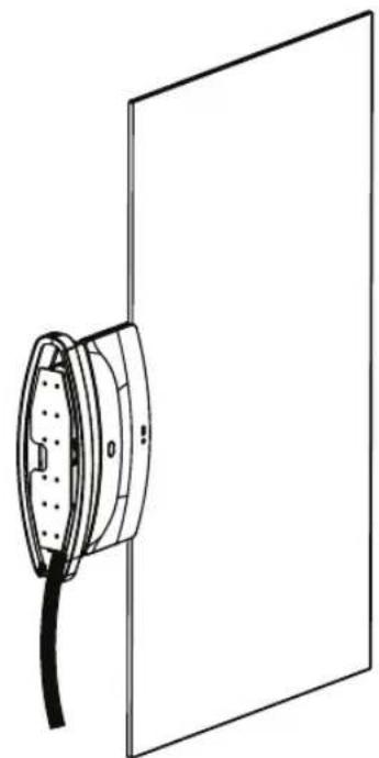
natural_image
Simple line drawing of a door with a cable and a wall-mounted panel (no text or symbols)13 Connect the cables to the Signage box. Here, the HDMI cable with the FRONT label is attached to the top, and the HDMI cable without the FRONT label is attached to the bottom. The 16/22 pin cable with red mark must be connected to the lower part.
14 Attach the 16/22 pin cables using 2 screws (M3 x L4.5).
15 Position the jack cover so that the cables fit into the cut spaces and attach it using 2 screws (M3 x L4.5).
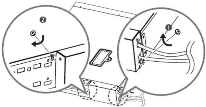
16 Attach the mounting brackets to the Signage box using 4 screws (M4 x L8). If necessary, fix in place using the holes on the bracket.
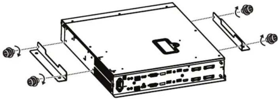
natural_image
Technical line drawing of a computer drive chassis with ports and connectors (no text or symbols)
HS179NE
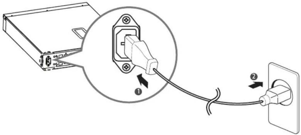
Connect the power cable to the Signage box.
| |
The Ground Truth image displays a single, solid horizontal line. According to Rule 2 (UNDERSCORE & LINE RULES), if the GT contains lines used for stylistic emphasis or as background (like ruled paper), the OCR result must ignore them. The provided OCR content is "____", which consists of four underscores. This is incorrect because underscores are not equivalent to a solid line and are not permitted under the “Stylistic/Background Lines (Ignore)” rule. Outputting underscores for a stylistic line violates the rule and constitutes an error. Therefore, the OCR result is inconsistent with the Ground Truth.
[Non-Text]
[Non-Text]
[Non-Text]
[Non-Text]
[Non-Text]
[Non-Text]
[Non-Text]
[Non-Text]
[Non-Text]
[Non-Text]
[Non-Text]
[Non-Text]
[Non-Text]
[Non-Text]
[Non-Text]
[Non-Text]
[Non-Text]
[Non-Text]
[Non-Text]
[Non-Text]
[Non-Text]
[Non-Text]
(No text to output)
(No text)
| |
[Non-Text]

Brand : LG
Model : ACC-W-EH5C
Category : Uncategorized