
MRS-1002USB - Blender Omnitronic - Free user manual and instructions
Find the device manual for free MRS-1002USB Omnitronic in PDF.


| Product Type | Compact audio mixer / recording mixer |
| Model | MRS-1002USB |
| Brand | Omnitronic |
| Channels | 2 mono + 4 stereo (6 inputs total) |
| USB Interface | Full duplex USB 2.0 (type B), recording & playback |
| Mic Inputs | 2 x XLR balanced (phantom power +48 V selectable) |
| Line Inputs (mono) | 2 x 6.3 mm jack balanced |
| Line Inputs (stereo) | 4 x 6.3 mm jack L/R balanced |
| Main Output | 6.3 mm jack L/R unbalanced (650 mV) |
| Control Room Output | 6.3 mm jack L/R unbalanced (2 V) |
| Aux Send Output | 6.3 mm jack unbalanced (2 V) |
| Headphones Output | 6.3 mm jack stereo (max 6 V, min impedance 8 Ω) |
| Tape Input/Output | RCA L/R (input 100 mV, output 2 V) |
| Stereo Aux Return | 6.3 mm jack L/R balanced (100 mV) |
| Tone Controls per Channel | High: ±15 dB at 12 kHz, Mid: ±15 dB at 2.5 kHz, Low: ±15 dB at 80 Hz |
| Phantom Power | +48 V switchable for all mic inputs |
| LED Level Display | 4-digit stereo, master or tape/USB source |
| Frequency Range | 20 – 20,000 Hz |
| Distortion (THD) | < 0.05% |
| Signal-to-Noise Ratio | > 74 dB |
| Power Supply | 230 V AC, 50 Hz via included power unit (17 V DC 27 W) |
| Dimensions (W x D x H) | 260 x 189 x 72 mm |
| Weight | 1.7 kg |
| Housing | Rugged metal |
| Operating Temperature | -5°C to +45°C |
| Cleaning | Use moist lint-free cloth; no alcohol or solvents. Disconnect before cleaning. |
| Safety Class | Protection class III (operate only with supplied power unit) |
Frequently Asked Questions - MRS-1002USB Omnitronic
User questions about MRS-1002USB Omnitronic
0 question about this device. Answer the ones you know or ask your own.
Ask a new question about this device
Download the instructions for your Blender in PDF format for free! Find your manual MRS-1002USB - Omnitronic and take your electronic device back in hand. On this page are published all the documents necessary for the use of your device. MRS-1002USB by Omnitronic.
USER MANUAL MRS-1002USB Omnitronic
natural_image
Abstract 3D rendering of a white circular ring with black center and blue/colored wave lines at bottom (no text or symbols)USER MANUAL
BEDIENUNGSANLEITUNG
MRS-1002USB
RECORDING MIXER
MRS-1002USB
RECORDING MIXER
Compact Audio Mixer
- Compact audio mixer with 6 inputs and USB interface
• Built-in USB audio interface allows recordings and playback of digital audio files with a computer (PC and Mac)
• Full duplex USB port: simultaneous recording and playback possible
• 2 mono input channels with gain control, 3-way EQ and pan control
• 4 stereo input channels with 3-way EQ and balance control - Adjustable stereo aux send output; aux return input
- Tape input and output
- Separate main mix and control room outputs
- Adjustable headphones output
• +48 V phantom power, can be switched centrally - Precise 4-digit stereo LED level display
• Operation via supplied power unit
• Rugged, compact metal housing

Inhaltsverzeichnis
Thank you for having chosen an OMNITRONIC product. If you follow the instructions given in this manual, we are sure that you will enjoy this device for a long period of time. Please keep this manual for future needs.

CAUTION!
Keep this device away from rain and moisture!

For your own safety, please read this user manual carefully before you initially start-up.

This user manual is valid for the article number 10040271. You can find the latest update at: www.omnitronic.de.
Every person involved with the installation, operation and maintenance of this device has to
- be qualified
- follow the instructions of this manual
- consider this manual to be part of the total product
- keep this manual for the entire service life of the product
- pass this manual on to every further owner or user of the product
- download the latest version of the user manual from the Internet
2
SAFETY INSTRUCTIONS

CAUTION!
Be careful with your operations. With a dangerous voltage you can suffer a dangerous electric shock when touching the wires!
This device has left our premises in absolutely perfect condition. In order to maintain this condition and to ensure a safe operation, it is absolutely necessary for the user to follow the safety instructions and warning notes written in this user manual.
Damages caused by the disregard of this user manual are not subject to warranty. The dealer will not accept liability for any resulting defects or problems.
Please make sure that there are no obvious transport damages. Should you notice any damages on the power unit or on the casing, do not take the device into operation and immediately consult your local dealer.
The device falls under protection class III. The device always has to be operated with an appropriate power unit. Always plug in the power unit last. The power plug must always be inserted without force. Make sure that the plug is tightly connected with the outlet.
We recommend a frequent cleaning of the device. Please use a moist, lint-free cloth. Never use alcohol or solvents. Disconnect from mains before starting maintenance operation! There are no serviceable parts inside the device. Should you have further questions, please contact your dealer.
3
OPERATING DETERMINATIONS
The MRS-1002USB is a compact audio mixer with USB interface for recordings and playback of digital audio files with a computer (PC and Mac). The mixer is equipped with two mono input channels with mic/line input and four stereo input channels with line input. In addition, connections for a recorder, separate outputs for a PA system and a monitor system and an effect way are available.
The mixer requires an operating voltage of 17 V direct current supplied via the included power unit.
The unit was designed for indoor use only. The ambient temperature must always be between -5^ C and +45^ C. Keep away from direct insulation (particularly in cars) and heaters.
The relative humidity must not exceed 100 % with an ambient temperature of 25^ C. This device must only be operated in an altitude between -20 and 2000 m over NN.
If the device has been exposed to drastic temperature fluctuation (e.g. after transportation), do not switch it on immediately. The arising condensation water might damage your device. Leave the device switched off until it has reached room temperature.
Please consider that unauthorized modifications on the device are forbidden due to safety reasons! If this device will be operated in any way different to the one described in this manual, the product may suffer damages and the guarantee becomes void. Furthermore, any other operation may lead to dangers like short-circuit, burns, electric shock etc.
4
OPERATING ELEMENTS & CONNECTIONS
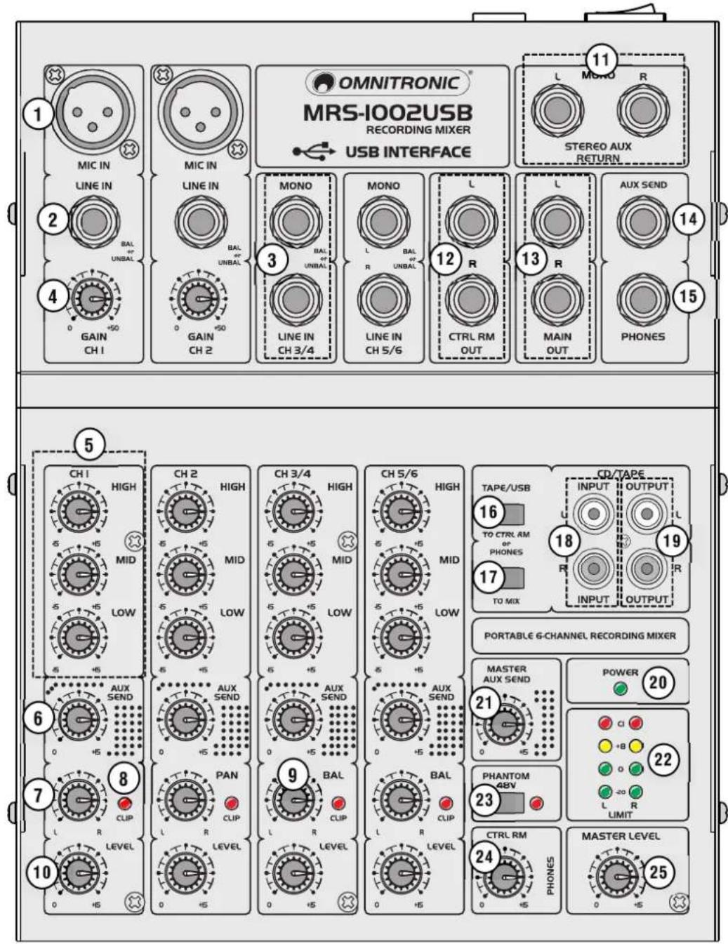
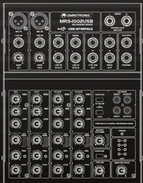
| 1 Microphone input MIC INBalanced XLR connector for the mono channels to connect a microphone. For condenser microphones, a 48 V phantom power can be activated with the PHANTOM 48V switch. |
| 2 Input LINE INBalanced 6.3 mm jack for the mono channels to connect audio units with line level (e.g. musical instrument). |
| 3 Input LINE INBalanced 6.3 mm jacks L/R for the stereo channels to connect audio units with line level (e.g. musical instrument). When connecting a mono device, only use the upper jack L/MONO. |
| 4 Control GAINFor adjusting the input amplification of the microphone and line input of the mono channels. |
| 5 Tone controlsFor adjusting the high frequencies (HIGH), mid-frequencies (MID) and bass frequencies (LOW). |
| 6 Control AUX SENDTo add the channel signal to the effect send way which is available at the output AUX SEND. |
| 7 Panorama controlTo place the mono signal in the stereo sound for the mono channels. |
| 8 CLIP indicator |
| 9 Balance controlFor adjusting the balance left/right for the stereo signal for the stereo channels. |
| 10 Level controlTo add the channel signal to the master signal. |
| 11 Input STEREO AUX RETURNInput (6.3 mm jacks L/R, unbal.) for connecting an effect unit or an additional line audio source.When connecting a mono device, only use the left jack L/MONO. |
| 12 Output CTRL RM OUTOutput (6.3 mm jacks L/R, unbal.) for connecting an amplifier of a monitor system. |
| 13 Output MAIN OUTMain output (6.3 mm jacks L/R, unbal.) for the master signal for connecting an amplifier or a second mixer. |
| 14 Output AUX SENDMono output (6.3 mm jacks, unbal.) for connecting the input of an effector. |
| 15 Headphones output6.3 mm jack for connecting stereo headphones (min. impedance 8 Ω). |
| 16 Button TAPE TO CTRL RM/PHONESWith the button pressed, the signal at the input CD/TAPE INPUT and the USB port is sent to the monitoring outputs CTRL RM OUT and PHONES and indicated by the LED level indicators. |
| 17 Button TAPE/USB TO MIXWith the button pressed, the signal at the input CD/TAPE INPUT and the USB port is sent to the master channel |
| 18 Input CD/TAPE INPUTStereo input (RCA L/R) for connecting the output of a recorder or another playback unit (e.g. CD player). |
| 19 Output CD/TAPE OUTStereo output (RCA L/R) of the master signal for connecting the input of a recorder or an amplifier. |
| 20 Power indicator |
| 21 Level control MASTER AUX SENDLevel control for the total signal of the effect way at the output AUX SEND. |
22 LED level indicators
4-digit LED level indicators for the level of the master signal or the signal at the input CD/TAPE INPUT and the USB port with the button TAPE/USB TO CTRL RM/PHONES pressed.
23 Button PHANTOM 48V with LED
When engaged, a 48 V phantom power is switched on for all microphone inputs MIC which most condenser microphones require. Caution! If the phantom power is switched on, no unbalanced microphones must be connected. Otherwise, these microphones may be damaged.
24 Level control CTRL RM/PHONES
For adjusting the monitoring level at the monitor outputs CTRL RM OUT and PHONES.
25 Master level control
Level control for the master signal which is sent to the outputs MAIN OUT, CD/TAPE OUTPUT and the USB port and can be monitored via the outputs CTRL RM OUT and PHONES.
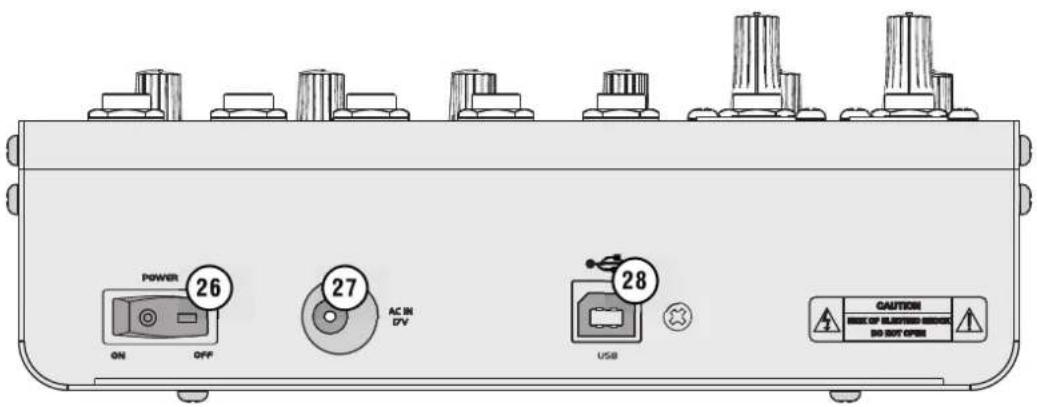
26 Power switch
27 Power input
Connect the included power supply unit here.
28 USB port
For connection to a computer. The USB port allows transmission of digital audio signals in both directions between the mixer and the computer.
Use as input: Press the button TAPE/USB TO MIX to switch the audio signal coming from the computer to the master channel; with the button TAPE/USB TO CTRL RM/PHONES pressed, the audio signal can be monitored via the monitor outputs CTRL RM OUT and PHONES.
Use as output: The USB port sends the digital master signal.
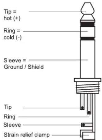
Balanced use of 6.3 mm jack plugs
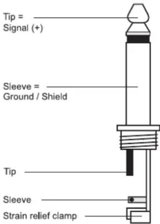
Unbalanced use of 6.3 mm jack plugs
Balanced use of XLR connectors
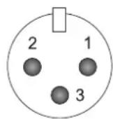
1 = Ground / Shield
2 = Hot (+)
3 = Cold (-)
For unbalanced use pin 1 and pin 3 have to be bridged.
5
SETTING INTO OPERATION
Switching on and off
1 Prior to switching on, turn the output controls MASTER LEVEL und CTRL RM to minimum to avoid damage to the hearing by a volume which is too high when switching on.
2 If condenser microphones are connected, press the button PHANTOM 48V to switch on a 48 V phantom power for all XLR jacks. The indicator next to the button lights up.

CAUTION!
- If the phantom power is switched on, no microphones with unbalanced output must be connected. Otherwise these microphones may be damaged. During the stabilization phase (approx. 1 minute), you must not change any connection.
vent switching noise, only actuate the button PHANTOM POWER when the mixer is switched off or when the output level controls are set to minimum.
3 Switch on the mixer with the power switch. The power indicator lights up. Switch on the connected units. After operation, switch off the unit with the power switch.
Basic control
For even sound, every input channel should be adjusted to the same level. Follow this procedure for every input channel:
1 Set the gain control, the level control, the tone controls and the pan/balance control to mid-position.
2 Feed an audio signal (test signal or music) to the input channel.
3 Adjust the MASTER LEVEL control for the overall volume to a level that the subsequent adjustments can be heard well via a connected PA system.
4 For a mono channel, adjust the gain control so that the level indication lights up at 0 dB. For a stereo channel, turn up the level control so that the level indication lights up at 0 dB.
5 Adjust the desired sound with the tone controls. By adjusting the tone controls, the high frequencies (control HIGH), the mid frequencies (control MID) and the low frequencies (control LO) can be boosted or attenuated. With the controls in mid-position, the frequency response is not affected.
6 For the mono channels, place the mono signals in the stereo sound with the panorama control PAN, and for the stereo channels, adjust the balance of the stereo signals with the control BAL.
7 The LED CLIP serves as an overload indication by which the level of the channel can coarsely be controlled. If it lights up permanently, attenuate the input amplification and/or turn back the tone controls or reduce the output level of the audio source.
8 Repeat the steps for other channels as described above.
9 When all adjustments for level matching and all sound adjustments have been made, mix the signals of all audio sources used in the desired volume ratio with the level controls.
10 Via the output meter, adjust the desired level available at the master outputs with the master level control. Usually an optimum level control is obtained if the output meter shows values in the 0 dB range at average volume. However, if the output level at the master outputs is too high for the following unit, the master signal must be controlled to a corresponding lower level. In case of overload the red LEDs CLIP light up.
Operation with a Computer
The USB port allows transmission of digital audio signals in both directions between the mixer and the computer. As soon as the mixer is connected to a computer, it will be recognized as a standard USB audio device and the required drivers are installed.
1 You can control the mixer using the standard audio interface controls in the Mac and Windows operating system. For data transmission from the mixer to the computer the USB interface of the mixer must be selected as the recording device. For data transmission from the computer to the mixer the USB interface of the mixer must be selected as the playback device.
2 Open your playback/recording software to make the required adjustments for audio playback via the mixer or for audio recording from the mixer.
3 With the selector switch TAPE/USB TO MIX, the audio signal coming from the computer can be switched to the master channels. With the selector switch TAPE/USB TO CTRL RM/PHONES it can be monitored via headphones and a monitor system.
4 For recordings with the computer, the USB port sends the digital master signal.
Note: If the mixer is connected to both a computer and to a unit grounded via the mains cable (e.g. amplifier), noise interference may occur due to ground loops. To eliminate this interference, a ground isolator (e.g. OMNITRONIC LH-082) may be used to connect the mixer to the unit.
Adjusting the Effect Send Way
Connect the effect unit to the output AUX SEND and to the input STEREO AUX RETURN of an input.
1 To make sure that the subsequent effect adjustments are audible, first set the control MASTER AUX SEND to mid-position.
2 Use the controls AUX SEND to add the signals of the input channels to the effect way. The signal will be picked up after the level control LEVEL, i. e. the effect part of a channel is always proportional to the channel level adjusted.
3 Use the control AUX SEND MASTER to adjust the total level for the output signal of the effect way which is sent to the input of the effect unit. The signal received from the effect unit is added to the master signal via the jacks STEREO AUX RETURN.
Monitoring via Headphones and Monitor System
1 When the button TAPE/USB TO CTRL RM/PHONES is not pressed, the master signal adjusted with the master level control is indicated by the LED level indicators and can be monitored via the outputs CTRL RM OUT and PHONES. The monitoring volume can be adjusted with the control CTRL RM/PHONES.
2 Press the button TAPE/USB TO CTRL RM/PHONES to indicate and monitor the signal at the input CD/TAPE INPUT and the USB port.
6
CLEANING AND MAINTENANCE

DANGER TO LIFE!
Disconnect from mains before starting maintenance operation!
We recommend a frequent cleaning of the product. Please use a soft lint-free and moistened cloth. Never use alcohol or solvents!
There are no serviceable parts inside the device. Maintenance and service operations are only to be carried out by authorized dealers.
Should you need any spare parts, please use genuine parts. Should you have further questions, please contact your dealer.
7
TECHNICAL SPECIFICATIONS
Power supply: 230 V AC, 50 Hz \~ via supplied power unit
Power consumption: 27 W
Inputs/sensitivity:
2 x Mic, mono 0.5 mV, XLR bal.
2 x Line In, mono 1 mV, 6.3 mm jack bal.
2 x Line In, stereo 10 mV, 150 mV, RCA L/R
1 x Stereo Aux Return 100 mV, 6.3 mm jack L/R bal.
1 x Tape In 100 mV, RCA L/R
Outputs/level:
1 x Main Out 650 mV, 6.3 mm jack L/R unbal.
1 x Control Room Out 2 V. 6.3 mm jack L/R unbal.
1 x Aux Send 2 V, 6.3 mm jack unbal.
1 x Tape Out 2 V, RCA L/R
1 x Headphones 6 V max., 6.3 mm jack unbal.
USB port: 2.0, type B
Frequency range: 20-20 000 kHz
Distortion: 0.05 %
S/N ratio: >74 dB
Tone control/channel:
Treble: ±15 dB at 12 kHz
Middle: ±15 dB at 2.5 kHz
Bass: ±15 dB at 80 Hz
Phantom power: +48 V
Dimensions (LxWxH): 260 x 189 x 72 mm
Weight: 1.7 kg
© OMNITRONIC 2014
- MRS-1002USB
- RECORDING MIXER
- Compact Audio Mixer
- Inhaltsverzeichnis
- CAUTION!
- 2
- SAFETY INSTRUCTIONS
- 3
- OPERATING DETERMINATIONS
- 4
- OPERATING ELEMENTS & CONNECTIONS
- LED level indicators
- Button PHANTOM 48V with LED
- Level control CTRL RM/PHONES
- Master level control
- Power switch
- Power input
- USB port
- 5
- SETTING INTO OPERATION
- Switching on and off
- Basic control
- Operation with a Computer
- Adjusting the Effect Send Way
- Monitoring via Headphones and Monitor System
- 6
- CLEANING AND MAINTENANCE
- DANGER TO LIFE!
- 7
- TECHNICAL SPECIFICATIONS
Brand : Omnitronic
Model : MRS-1002USB
Category : Blender