PM-3010 Pro - Blender Omnitronic - Free user manual and instructions
Find the device manual for free PM-3010 Pro Omnitronic in PDF.


| Product Type | Commercial Blender |
| Brand | Omnitronic |
| Model | PM-3010 Pro |
| Power Rating | 1200 W |
| Voltage | 220-240 V, 50/60 Hz |
| Capacity | 1.5 L (pitcher) |
| Speed Settings | Variable speed with pulse function |
| Material | Stainless steel blades, BPA-free plastic pitcher |
| Dimensions (H x W x D) | 40 cm x 20 cm x 20 cm |
| Weight | 4.5 kg |
| Noise Level | < 85 dB |
| Safety Features | Overload protection, non-slip feet, interlock switch |
| Cleaning | Removable pitcher and lid; dishwasher-safe parts |
| Maintenance | Regular blade cleaning, check gasket seal |
| Warranty | 2 years |
| Certifications | CE, RoHS |
Frequently Asked Questions - PM-3010 Pro Omnitronic
User questions about PM-3010 Pro Omnitronic
0 question about this device. Answer the ones you know or ask your own.
Ask a new question about this device
Download the instructions for your Blender in PDF format for free! Find your manual PM-3010 Pro - Omnitronic and take your electronic device back in hand. On this page are published all the documents necessary for the use of your device. PM-3010 Pro by Omnitronic.
USER MANUAL PM-3010 Pro Omnitronic
- INTRODUCTION....18
- SAFETY INSTRUCTIONS .... 18
- OPERATING DETERMINATIONS....19
- DESCRIPTION....20
4.1 Features 20
4.2 Operating elements and connections 21
-
INSTALLATION 25
-
OPERATION....27
6.1 Basic adjustment of the input channels 27
6.2 Basic adjustment of the output channels 27
6.3 Crossfading between two channels/mixing the signal sources 27
6.4 Announcements via the DJ microphone 28
6.5 Prefader listening to the channels.... 28
6.6 Level adjustment of a further mixer.... 28
- CLEANING AND MAINTENANCE 29
7.1 Replacing the crossfader 29 - PROBLEM ChART 30
- TECHNICAL SPECIFICATIONS....31
This user manual is valid for the article numbers: 10006851
Keep this device away from rain and moisture! Unplug mains lead before opening the housing!
For your own safety, please read this user manual carefully before you initially start-up.
Every person involved with the installation, operation and maintenance of this device has to
- be qualified
- follow the instructions of this manual
- consider this manual to be part of the total product
- keep this manual for the entire service life of the product
- pass this manual on to every further owner or user of the product
- download the latest version of the user manual from the Internet
1 INTRODUCTION
Thank you for having chosen the OMNITRONIC mixer PM-3010. You have acquired a reliable and powerful device. If you follow the instructions given in this manual, we can assure you that you will enjoy this device for many years.
Unpack your mixer.
2 SAFETY INSTRUCTIONS
This device has left our premises in absolutely perfect condition. In order to maintain this condition and to ensure a safe operation, it is absolutely necessary for the user to follow the safety instructions and warning notes written in this user manual.

Important:
Damages caused by the disregard of this user manual are not subject to warranty. The dealer will not accept liability for any resulting defects or problems.
Please make sure that there are no obvious transport damages. Should you notice any damages on the power unit or on the casing, do not take the device into operation and immediately consult your local dealer.
This device falls under protection-class III. The device always has to be operated with an appropriate transformer.
English
Always plug in the power unit least. Make sure that the device is switched off before it is connected to the mains.
Keep away from heaters and other heating sources!
If the device has been exposed to drastic temperature fluctuation (e.g. after transportation), do not switch it on immediately. The arising condensation water might damage your device. Leave the device switched off until it has reached room temperature.
Never put any liquids on the device or close to it. Should any liquid enter the device nevertheless, disconnect from mains immediately. Please let the device be checked by a qualified service technician before you operate it again. Any damages caused by liquids having entered the device are not subject to warranty!
Always disconnect from the mains, when the device is not in use or before cleaning it.
Please note that damages caused by manual modifications on the device or unauthorized operation by unqualified persons are not subject to warranty.
CAUTION: Turn the amplifier on last and off first!
Keep away children and amateurs!

HEALTH HAZARD!
By operating an amplifying system, you can produce excessive sound pressure levels that may lead to permanent hearing loss.
There are no serviceable parts inside the device. Maintenance and service operations are only to be carried out by authorized dealers.
3 OPERATING DETERMINATIONS
The DJ mixer PM-3010 features three stereo input channels with matrix input assignment, one DJ microphone channel, and a replaceable crossfader and has been designed for general professional PA applications.
This product is allowed to be operated with an alternating current of 2 x 15 V, 50 Hz and was designed for indoor use only.
The device must only be operated with the included power unit. The power unit falls under protection-class 2 and the mixer under protection-class 3.
Do not shake the device. Avoid brute force when installing or operating the device.
When choosing the installation-spot, please make sure that the device is not exposed to extreme heat, moisture or dust. There should not be any cables lying around. You endanger your own and the safety of others!
The ambient temperature must always be between -5^ C and +45^ C. Keep away from direct insulation (particularly in cars) and heaters.
The relative humidity must not exceed 50 % with an ambient temperature of 45^ C.
This device must only be operated in an altitude between -20 and 2000 m over NN.
Operate the device only after having familiarized with its functions. Do not permit operation by persons not qualified for operating the device. Most damages are the result of unprofessional operation!
Never use spray cleaners in order to clean the faders!
English
Never use solvents or aggressive detergents in order to clean the device! Rather use a soft and damp cloth.
Please use the original packaging if the device is to be transported.
Please consider that unauthorized modifications on the device are forbidden due to safety reasons!
Never remove the serial barcode from the device as this would make the guarantee void.
If this device will be operated in any way different to the one described in this manual, the product may suffer damages and the guarantee becomes void. Furthermore, any other operation may lead to dangers like short-circuit, burns, electric shock, etc.
4 DESCRIPTION
4.1 Features
Professional 3+1-channel DJ mixer with matrix
- Matrix input assignment: each channel with routing facility of all input sources as desired
- 3 input channels with gain control, 3-band equalizer, cue button, smooth and durable fader and 10-digit LED level meter
• 1 DJ microphone channel with 3-band equalizer, level control, on air and talkover selector
• Color illuminated rotary controls and rubber buttons - Prefader listening to all input channels and the master output via adjustable headphones output, with cue mix/split function
- Replaceable crossfader for crossfading between input channels, with assignment switches, adjustable curve and reverse function
- Master control and stereo LED level meter
- Master level switchable 0.75 V or 1.5 V
- Separately controllable monitor and zone outputs
- Separately controllable session input to connect a further mixer
- 2 recording outputs, independent of the master and with on/off switch for DJ microphone signals
- Inputs: 4x line (stereo RCA); 3x phono/line (stereo RCA), switchable; 1x DJ microphone (XLR/6.3 mm jack), 2x microphone (6.3 mm jack) and 1x headphones (6.3 mm jack)
- Outputs: 1x master (stereo XLR/stereo RCA), 1x zone (6.3 mm stereo jack, bal.), 1x booth (stereo RCA), 2x record (stereo RCA) and 1x session (stereo RCA)
• Operation via supplied power unit
4.2 Operating elements and connections
FRONT PANEL [1]
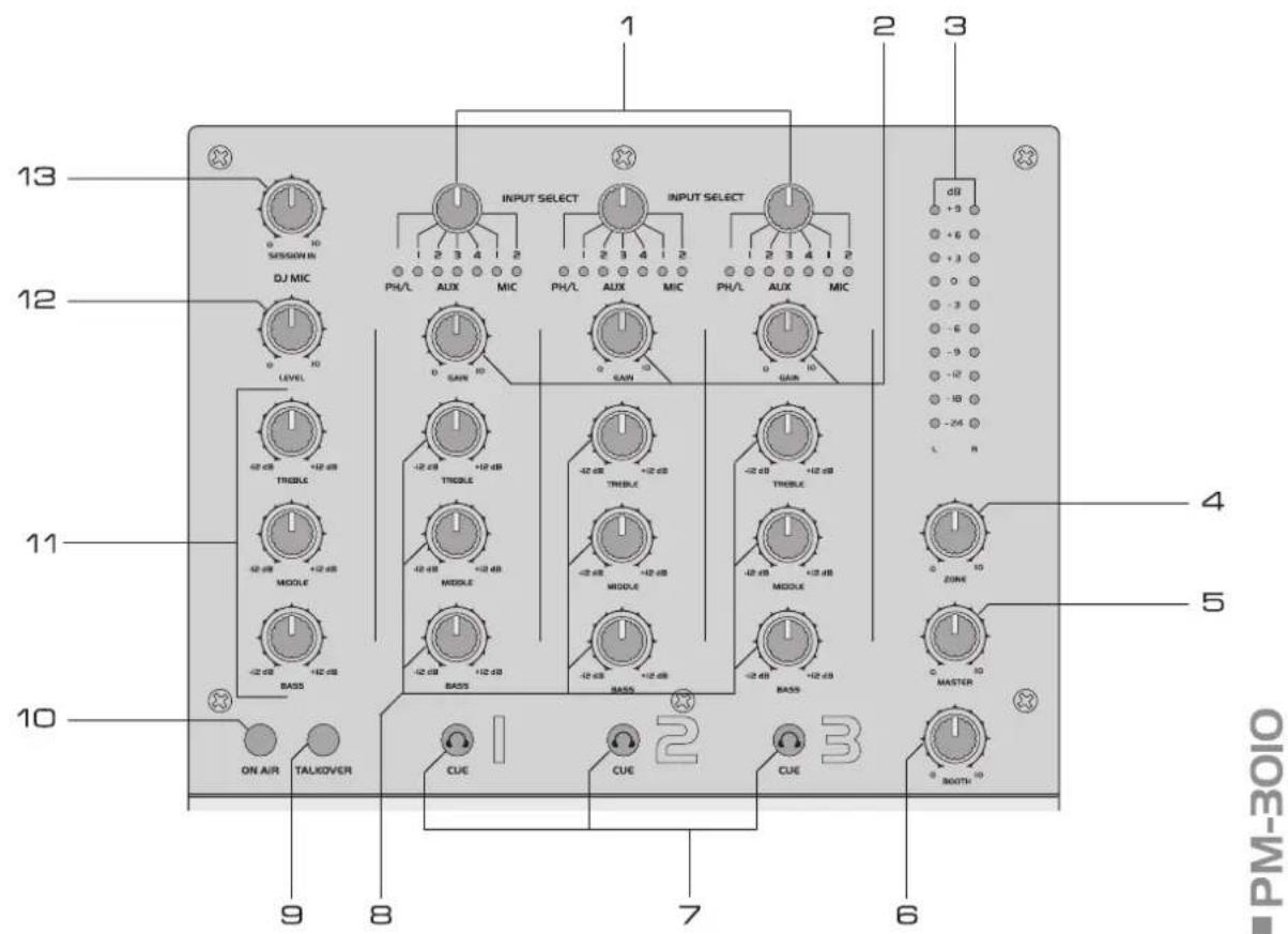
1 Matrix input selector switches
For selecting the input source for the channels 1-3. The LEDs indicate which input is active. Aux and mic input sources are freely assignable to each channel. For creative mixing, the same source may be assigned to several channels.
2 Gain controls
Adjust the input amplification for the channels 1-3.
3 Output level LED meter L/R
10-digit LED meter for the stereo master signal within the range of -24 dB to +9 dB.
4 Control ZONE
Level control for the output ZONE.
5 Master control
Level control for the master output.
6 Control BOOTH
Level control for the output BOOTH.
7 Buttons CUE
Buttons for monitoring the input channels 1-3 ahead of the respective channel fader via headphones connected to the jacks HEADPHONES. With the button pressed, the blue LED lights to immediately indicate that a channel is monitored.
8 Tone controls
3-band equalizer for the channels 1-3: TREBLE, MIDDLE, BASS.
9 Talkover on/off
On/off switch for the talkover function. With the button pressed (blue LED lights), the levels of the channels 1-3 are automatically attenuated by 15 dB when announcements are made with the DJ microphone.
10 Microphone channel on/off
On/off switch for the DJ microphone channel. With the button pressed (red LED lights), the DJ microphone is switched on.
11 Tone controls
3-band equalizer for the DJ microphone: TREBLE, MIDDLE, BASS.
12 Level control
Level control for the DJ microphone.
13 Control SESSION IN
Level control for a mixer connected to the jacks SESSION. Please note that the signal is directly routed to the mix and not to the crossfader.
FRONT PANEL [2]
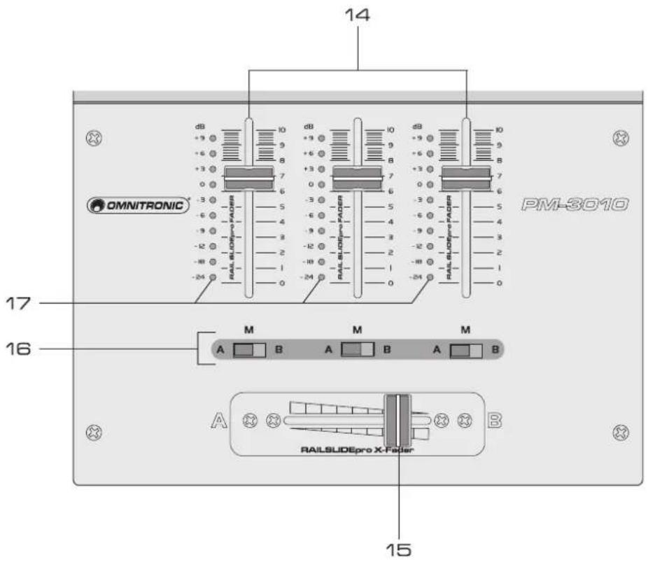
■ PM-3010
14 Channel faders
Level controls for the channels 1-3.
15 Crossfader
For crossfading between two of the channels 1-3, which can be selected with the assignment switches. In mid-position, both channels can be heard at the same volume.
- The crossfader curve can be adjusted with the control X-FADER CURVE.
- The switch X-FADER REVERSE reverses the assigned channels for the crossfader.
16 Assignment switches
Select the channel for crossfading with the crossfader. I crossfading is not required, the channel can be switched directly to the master signal.
• left position A: channel switched to side A
• center position M: channel switched to master signal
• right position B: channel switched to side B
17 Level LED meter
10-digit LED meter for the channels 1-3; the level is indicated ahead of the corresponding channel fader (prefader).
FRONT PANEL [3]
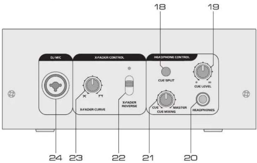
■ PM-3010
18 Selector switch CUE SPLIT
For selecting the monitoring mode for the headphones output:
- SPLIT (button pressed, red LED lights): The prefader level (mono) is on one side and the output signal (mono) is on the other side of the headphones.
- MIX (button released, blue LED lights): A mixed signal of prefader level and master signal is on both sides of the headphones.
19 Level control CUE LEVEL
Level control for the headphones output.
20 Headphones input
Input (6.3 mm jack) for connecting stereo headphones (impedance ≥8 Ω).
21 Control CUE MIXING
For selecting and crossfading the monitoring signal for the headphones output:
- left stop position CUE: The prefader level of the input channel of which the button CUE is pressed is monitored.
- right stop position MASTER: The music program currently playing is monitored ahead of the master fader and the output controls ZONE and BOOTH.
22 Selector switch X-FADER REVERSE
Reverses the assigned channels for the crossfader.
• upper position: the assigned channels are on their usual sides (control indicator off)
- lower position: the assigned channels are reversed (red LED lights)
23 X-FADER CURVE control
For continuously adjusting the characteristic of the crossfader.
- left stop position: smooth crossfading (gradual transition) e.g. for long mixes
- right stop position: sharp crossfading (abrupt transition) e.g. for scratching and cutting
24 Microphone input DJ MIC
Input for connecting a DJ microphone via an XLR plug of 6.3 mm plug.
REAR PANEL
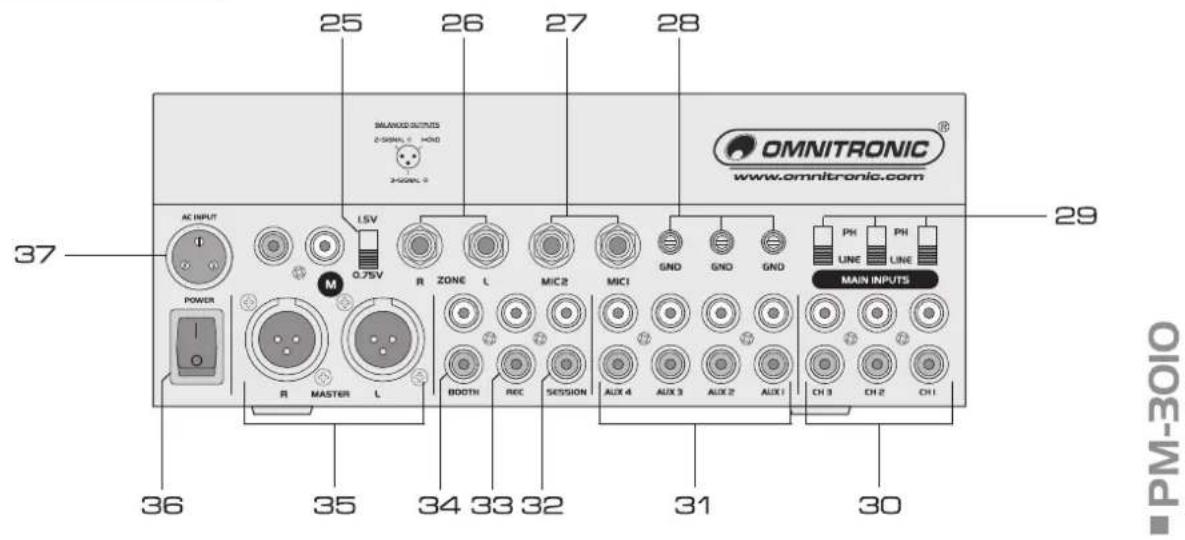
25 Level selector switch
Switches the level at the master output between 0.75 V and 1.5 V.
26 Output ZONE
Stereo output (RCA) for connecting a further amplifier, e.g. for PA application in a secondary room.
27 Microphone inputs
6.3 mm jacks with free routing facility for connecting microphones.
28 GND (ground terminals)
Ground clamping screws for turntables connected to the channels 1-3.
29 Input selector switches
Switches the main inputs between phono and line level.
30 Main inputs
- Stereo inputs (RCA) assigned to the channels 1-3 for connecting units with line level output e.g. CD players or turntables.
- With the corresponding input selector switches the inputs can be switched between phono and line level.
31 Aux inputs
Stereo inputs (RCA) with free routing facility for connecting units with line level output e.g. CD players or tape decks.
32 Input SESSION
Stereo input (RCA) for connecting a further DJ mixer for team routines.
33 Output REC(ORD)
Stereo output (RCA) for connecting a recording unit. The recording level is independent of the position of the master control and the output controls ZONE and BOOTH.
34 Output BOOTH
Stereo output (RCA) for connecting a further amplifier, e.g. for the monitoring system or PA application in a secondary room.
35 Master output
Stereo output (optionally XLR, bal. or RCA) for connecting amplifiers or other units with line level inputs.
36 Power on/off
Press this button to turn the unit on and off.
37 AC connection
Plug in the mains cable of the supplied power unit here and fix it with the union nut.
English
5 INSTALLATION
The PM-3010 can be used as a table top unit or it can be installed into a console. Please make sure that there is enough space around the unit for ventilation to improve heat dissipation. Steady overheating will damage the unit.
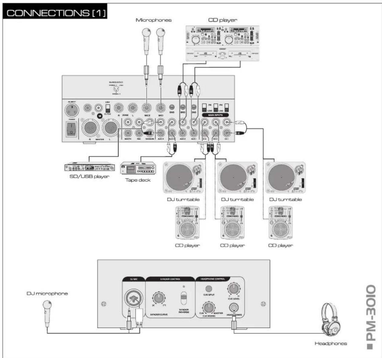
Switch off the mixer prior to connecting any units or to changing any existing connections.
flowchart
graph TD
    A["Microphones"] --> B["CD player"]
    B --> C["SD/USB player"]
    B --> D["Tape deck"]
    D --> E["DJ turntable"]
    D --> F["DJ turntable"]
    D --> G["DJ turntable"]
    D --> H["DJ turntable"]
    D --> I["DJ turntable"]
    D --> J["DJ turntable"]
    D --> K["DJ turntable"]
    D --> L["DJ turntable"]
    D --> M["DJ turntable"]
    D --> N["DJ turntable"]
    D --> O["DJ turntable"]
    D --> P["DJ turntable"]
    D --> Q["DJ turntable"]
    D --> R["DJ turntable"]
    D --> S["DJ turntable"]
    D --> T["DJ turntable"]
    D --> U["DJ turntable"]
    D --> V["DJ turntable"]
    D --> W["DJ turntable"]
    D --> X["DJ turntable"]
    D --> Y["DJ turntable"]
    D --> Z["DJ turntable"]
    D --> AA["DJ turntable"]
    D --> AB["DJ turntable"]
    D --> AC["DJ turntable"]
    D --> AD["DJ turntable"]
    D --> AE["DJ turntable"]
    D --> AF["DJ turntable"]
    D --> AG["DJ turntable"]
    D --> AH["DJ turntable"]
    D --> AI["DJ turntable"]
    D --> AJ["DJ turntable"]
    D --> AK["DJ turntable"]
    D --> AL["DJ turntable"]
    D --> AM["DJ turntable"]
    D --> AN["DJ turntable"]
    D --> AO["DJ turntable"]
    D --> AP["DJ turntable"]
    D --> AQ["DJ turntable"]
    D --> AR["DJ turntable"]
    D --> AS["DJ turntable"]
    D --> AT["DJ turntable"]
    D --> AU["DJ turntable"]
    D --> AV["DJ turntable"]
    D --> AW["DJ turntable"]
    D --> AX["DJ turntable"]
    D --> AY["DJ turntable"]
    D --> AZ["DJ turntable"]
    D --> BA["DJ turntable"]
    D --> BB["DJ turntable"]
    D --> BC["DJ turntable"]
    D --> BD["DJ turntable"]
    D --> BE["DJ turntable"]
    D --> BF["DJ turntable"]
    D --> BG["DJ turntable"]
    D --> BH["DJ turntable"]
    D --> BI["DJ turntable"]
    D --> BJ["DJ turntable"]
    D --> BK["DJ turntable"]
    D --> BL["DJ turntable"]
    D --> BM["DJ turntable"]
    D --> BN["DJ turntable"]
    D --> BO["DJ turntable"]
    D --> BP["DJ turntable"]
    D --> BQ["DJ turntable"]
    D --> BR["DJ turntable"]
    D --> BS["DJ turntable"]
    D --> BT["DJ turntable"]
    D --> BU["DJ turntable"]
    D --> BV["DJ turntable"]
    D --> BW["DJ turntable"]
    D --> BX["DJ turntable"]
    D --> BY["DJ turntable"]
1 Connect the stereo audio sources to the corresponding RCA jacks (white jack = left; red jack = right):
- The jacks MAIN INPUTS CH-1 to CH3 are assigned to the channels 1-3 and allow for connecting units with line level output e.g. CD players or turntables. If your turntable is equipped with a separate ground lead, connect it to the corresponding clamping screw GND.
- The jacks AUX 1 to 4 can be freely assigned to each channel and allow for connecting units with line level output e.g. CD players or tape decks.
- Aux and mic input sources are freely assignable to each channel. For creative mixing, the same source may be assigned to several channels.
2 You can connect three microphones: a DJ microphone to the DJ microphone channel DJ MIC and two further microphones to the microphone channels MIC 1 and MIC 2.
- Connect a DJ microphone via an XLR plug or a 6.3 mm plug to the front input DJ MIC
- Two further microphones can be connected via 6.3 mm plugs to the rear inputs MIC 1 and MIC 2 and can be freely assigned to each channel.
English
3 For prefader listening to the input channels or for monitoring the current music program ahead of the master control and the output controls ZONE and BOOTH, it is possible to connect stereo headphones to the front input HEADPHONES via a 6.3 mm plug.
CONNECTIONS [2]
![Omnitronic PM-3010 Pro - CONNECTIONS [2] - 1](/content/2026/05/1023946/images/fc474c28534dbcb54609410f3ac552d13dfaf9d0d489ab9457e7cf94dabefa41.jpg)
flowchart
graph TD
    A["PA system"] --> B["DAI"]
    C["PA system"] --> D["DAI"]
    E["Interface"] --> F["Laptop/computer"]
    G["Recording unit"] --> H["Mixer"]
    I["DJ monitor system"] --> J["Mixer"]
    K["Radio"] --> L["Radio"]
    M["Radio"] --> N["Radio"]
    O["Radio"] --> P["Radio"]
    Q["Radio"] --> R["Radio"]
    S["Radio"] --> T["Radio"]
    U["Radio"] --> V["Radio"]
    W["Radio"] --> X["Radio"]
    Y["Radio"] --> Z["Radio"]
    AA["Radio"] --> AB["Radio"]
    AC["Radio"] --> AD["Radio"]
    AE["Radio"] --> AF["Radio"]
    AG["Radio"] --> AH["Radio"]
    AI["Radio"] --> AJ["Radio"]
    AK["Radio"] --> AL["Radio"]
    AM["Radio"] --> AN["Radio"]
    AO["Radio"] --> AP["Radio"]
■ PM-3010
4 For connecting amplifiers, several stereo outputs with individual level controls are available:
- Connect the main amplifier to the master output, optionally to the balanced XLR or unbalanced RCA output.
- For PA application in a secondary room, connect the amplifier to the stereo output ZONE.
- If a monitoring system is available, connect the amplifier of the monitoring system to the stereo output BOOTH.
5 For analog sound recordings, connect the recording unit to the output REC(ORD). The recording level is independent of the position of the master control and the output controls ZONE and BOOTH. With an audio interface such as the OMNITRONIC DDI 4x4 you can also digitize the analog output signal of the PM-3010 and transfer it to a computer with USB 1.1 or 2.0 connection.
6 A further mixer for team routines may be connected to the input SESSION.
7 Connect the power supply unit to the AC input of the PM-3010 and the mains plug to a mains socket. Use the unit only with the supplied power unit. Always disconnect the mains connector when you wish to change connections, move the unit to a different place or if it is not used for a longer period.
6 OPERATION
Prior to switching on, set the master control and the output controls ZONE and BOOTH to zero to avoid damage to the hearing by a volume which is too high when switching on. Switch on the mixer with the power switch. Switch on the connected units. After operation, switch off the mixer with the power switch.
6.1 Basic adjustment of the input channels
1 First set all gain controls, equalizer controls and the crossfader to mid-position. Set the crossfader assignment selectors to the position "M".
2 Use the input selector buttons to select the signal sources connected to the channels 1-3.
3 To control a channel, feed an audio signal (test signal or music piece) to the respective input channel and advance the channel fader to approx. 2/3 of its maximum. Set all other channel faders to zero.
4 To monitor the signal via the speaker of a PA system connected, advance the corresponding output control. The signal can also be monitored via headphones (please refer to section 6.5).
5 The level indication of the channel displays the signal level ahead of the channel fader (prefader level). Via the level indication, control the level of the input with the gain control of the channel. An optimum level control is obtained if level values in the 0 dB range are shown at average volume. If the red LEDs of the meter light up, there is an overload of the channel.
6 Adjust the desired sound with the tone controls of the channel. By adjusting the three tone controls, the high frequencies (control TREBLE), the midrange frequencies (control MIDDLE), and the low frequencies (control BASS) can be boosted (12 dB max.) or substantially attenuated (26 dB max.). With the controls in mid-position, the frequency response is not affected. Sound adjustments affect the level. Readjust the channel level with the gain control, if necessary.
7 Repeat the steps for the other connected input channels as described above.
6.2 Basic adjustment of the output channels
The output signal is fed to the adjustable outputs MASTER, ZONE and BOOTH and to the recording output REC(ORD) without individual level control.
1 Via the output meter, adjust the master signal to an optimum level with the master control. Usually an optimum level control is obtained if the output meter shows values in the 0 dB range at average volume. However, if the output level at the master output is too high for the following unit, the master signal must be controlled to a corresponding lower level. If the output level is too low, it can be increased to 1.5 V with the rear level selector switch.
2 Adjust the desired signal level for the output ZONE with the control ZONE.
3 Adjust the desired signal level for the output BOOTH with the control BOOTH.
4 The recording signal at the output REC(ORD) is taken off ahead of the output controls, i.e. it is not affected by the master control and the output controls ZONE and BOOTH.
6.3 Crossfading between two channels/mixing the signal sources
1 Select the two signal sources for crossfading with the crossfader assignment selectors:
- position A: the channel is switched to side A
- position B: the channel is switched to side B
2 Set the faders of the channel not used to zero and control the two channels selected to an optimum level with their faders.
3 Now crossfading between the two channels selected is possible:
• crossfader moved to the left: fade-in of side A and fade-out of side B
• crossfader moved to the right: fade-in of side B and fade-out of side A
- For hearing the signals of the two channels at the same level, set the crossfader to mid-position.
4 For mixing the signal of the other input channel to the music program, advance the fader accordingly.
5 If crossfading is not required, the connected audio sources can be switched directly to the master signal: Set the corresponding assignment selectors to position "M" and adjust the desired volume ratio of the audio sources with the channel faders.
6 The control X-FADER CURVE allows for continuous adjustment of the crossfading characteristic: Use the left stop position for smooth crossfading e.g. for long mixes. The further the control is turned to the right, the more abrupt the crossfading e.g. for scratching and cutting.
7 The switch X-FADER REVERSE allows reversing the assigned channels for the crossfader:
• upper position: the assigned channels are on their usual sides (control indicator off)
- lower position: the assigned channels are reversed (control indicator lights up)
6.4 Announcements via the DJ microphone
1 To switch on the DJ microphone at the jack DJ MIC press the button ON AIR (control LED lights red).
2 Adjust the volume of the microphone announcement with the control LEVEL.
3 Adjust the desired sound with the 3-band equalizer. By adjusting the tone controls, the high frequencies (control TREBLE), the middle frequencies (control MIDDLE) and the low frequencies (control BASS) can be boosted or attenuated ( ± 12 dB).
4 To improve the audibility of an announcement during the current music program, press the button TALKOVER (control LED lights blue) to activate the talkover function. Then during a microphone announcement, the levels of channels 1-3 are automatically attenuated by 15 dB.
5 To switch off the DJ microphone press the button ON AIR again (control LED off).
6.5 Prefader listening to the channels
The cue function allows monitoring each of the channels 1-3 via headphones even if the corresponding channel is faded out. Thus, it is possible, e. g. to time the moment for fading in an audio source. Alternatively it is possible to monitor the current music program ahead of the master control or the output controls ZONE and BOOTH.
1 For prefader listening to a channel, press the corresponding switch CUE (control indicator lights) and turn the control CUE MIXING to the left stop position "CUE". To monitor the current music program ahead of the master control and the output controls ZONE and BOOTH, turn the control CUE MIXING to the right stop position "MASTER".
2 Select the monitoring mode with the selector switch CUE MODE:
- SPLIT (button pressed, red LED lights): The prefader level (mono) is on one side and the output signal (mono) is on the other side of the headphones.
- MIX (button released, blue LED lights): A mixed signal of prefader level and master signal is on both sides of the headphones.
3 Adjust the desired headphones volume with the control CUE LEVEL.
6.6 Level adjustment of a further mixer
When a further mixer is connected to the jacks SESSION, the input level can be adjusted with the control SESSION IN. Please note that the signal is directly routed to the mix and not to the crossfader.
7 CLEANING AND MAINTENANCE

DANGER TO LIFE!
Disconnect from mains before starting maintenance operation!
We recommend a frequent cleaning of the device. Please use a soft lint-free and moistened cloth. Never use alcohol or solvents!
There are no serviceable parts inside the device. Maintenance and service operations are only to be carried out by authorized dealers.
Should you need any spare parts, please use genuine parts.
Should you have further questions, please contact your dealer.
7.1 Replacing the crossfader
Procedure:
Step 1: Remove the fader knob.
Step 2: Remove the two outer screws on the fader panel.
Step 3: Take the fader out and unplug the connection cable.
Step 4: Connect the new fader and fix it in the unit.
8 PROBLEM CHART
| PROBLEM CAUSE REMEDY | ||
| The power does not turn on. | · The power cable is not connected. | · Connect the cable to a power outlet. |
| There is little or no sound. | ·The input selector switch is in the wrong position.· The rear input selector switch PH/LINE is set to LINE although a turntable is connected.· The connection cable was not connected properly or not connected at all.·The terminal or plug is dirty.·The master level is too low. | ·Set the selector switch to the correct signal source.· Set the input selector switch PH/LINE to PH.·Connect the cable properly.·Clean and reconnect.·Increase the level with the master control or control. |
| There is noise or distortion. | ·The master level is too high.·The input level is too high.·The rear input selector switch PH/LINE is set to PH although a unit with line level output is connected. | ·Via the output meter, adjust the master level to an optimum level with the master control.·Via the level indication, adjust the channel to an optimum level with the gain control.·Set the input selector switch PH/LINE to LINE. |
| Crossfading does not work. | ·The assignment of the assignment switches overlaps. | ·Select the correct signal sources for crossfading with the assignment switches. |
9 TECHNICAL SPECIFICATIONS
| Power supply: | 230 V AC, 50 Hz ~, via supplied power unit |
| Power consumption: 35 W | |
| Inputs: | |
| DJ MIC: combined XLR/6.3 mm jack (bal.) | |
| MIC 1, 2: 6.3 mm jack (bal.) | |
| Minimum input voltage: 1 mV | RMS |
| LINE/PHONO 1-3: stereo RCA | |
| Minimum input voltage: 150 mV RMS (line), 3 mV RMS (phono) | |
| AUX 1-4: stereo RCA | |
| Minimum input voltage: 150 mV RMS | |
| Outputs: | |
| MASTER: stereo XLR/stereo | RCA |
| Output voltage: 0.75 V/1.5 V | RMS (switchable) |
| ZONE: 6.3 mm stereo jack | |
| Output voltage: 0.75 V RMS | |
| BOOTH: stereo RCA | |
| Output voltage: 0.75 V RMS | |
| REC: stereo RCA | |
| Output voltage: 0.75 V RMS | |
| Headphones: | 6.3 mm jack (≥8 Ω) |
| Tone control (DJ MIC): | |
| 1x high: -12 dB to +12 dB/ 10 | kHz, ±1 dB |
| 1x middle: -12 dB to +12 dB/ | 1 kHz, ±1 dB |
| 1x low: -12 dB to +12 dB/ 100 | Hz, ±1 dB |
| Talkover attenuation: | -15 dB |
| Tone control (channel 1-3): | |
| 3x high: -26 dB to +12 dB/ 10 | kHz, ±1 dB |
| 3x middle: -26 dB to +12 dB/ | 1 kHz, ±1 dB |
| 3x low: -26 dB to +12 dB/ 100 | Hz, ±1 dB |
| S/N ratio: | >75 dB |
| Frequency range: | 20-20,000 Hz |
| Distortion: | 0.03% |
| Dimensions (WxHxD): | 340 x 220 x 110 mm |
| Weight: | 4.5 kg |
Please note: Every information is subject to change without prior notice. 25.06.2009 ©

- INTRODUCTION
- SAFETY INSTRUCTIONS
- Important:
- English
- HEALTH HAZARD!
- OPERATING DETERMINATIONS
- DESCRIPTION
- Features
- Professional 3+1-channel DJ mixer with matrix
- Operating elements and connections
- FRONT PANEL [1]
- Matrix input selector switches
- Gain controls
- Output level LED meter L/R
- Control ZONE
- Master control
- Control BOOTH
- Buttons CUE
- Tone controls
- Talkover on/off
- Microphone channel on/off
- Tone controls
- Level control
- Control SESSION IN
- FRONT PANEL [2]
- Channel faders
- Crossfader
- Assignment switches
- Level LED meter
- FRONT PANEL [3]
- Selector switch CUE SPLIT
- Level control CUE LEVEL
- Headphones input
- Control CUE MIXING
- Selector switch X-FADER REVERSE
- X-FADER CURVE control
- Microphone input DJ MIC
- REAR PANEL
- Level selector switch
- Output ZONE
- Microphone inputs
- GND (ground terminals)
- Input selector switches
- Main inputs
- Aux inputs
- Input SESSION
- Output REC(ORD)
- Output BOOTH
- Master output
- Power on/off
- AC connection
- INSTALLATION
- CONNECTIONS [2]
- OPERATION
- Basic adjustment of the input channels
- Basic adjustment of the output channels
- Crossfading between two channels/mixing the signal sources
- Announcements via the DJ microphone
- Prefader listening to the channels
- Level adjustment of a further mixer
- CLEANING AND MAINTENANCE
- DANGER TO LIFE!
- Replacing the crossfader
- Procedure:
- PROBLEM CHART
- TECHNICAL SPECIFICATIONS
Brand : Omnitronic
Model : PM-3010 Pro
Category : Blender