
PMK360 - Motion detector JUNG - Free user manual and instructions
Find the device manual for free PMK360 JUNG in PDF.


| Product Type | Ceiling-Mounted Motion Detector |
| Model | PMK360 |
| Brand | JUNG |
| Detection Angle | 360° |
| Maximum Range | 8 m (tangential), 5 m (radial) |
| Mounting Height | 2.2 - 4 m |
| Power Supply | 230 V AC, 50/60 Hz |
| Switching Capacity | 2300 W (incandescent), 1150 VA (fluorescent) |
| Time Setting | 10 s - 15 min (adjustable) |
| Light Sensitivity | 3 - 2000 lux (adjustable) |
| Protection Rating | IP44 (indoor/outdoor use) |
| Operating Temperature | -25°C to +55°C |
| Dimensions (Diameter x Height) | 105 mm x 55 mm |
| Weight | 0.12 kg |
| Material | Polycarbonate, UV-resistant |
| Connection Type | Screw terminals |
| Functions | Automatic on/off, twilight control, walk-through detection |
| Maintenance | Wipe with dry cloth; avoid solvents |
| Security Features | Overload protection, short-circuit proof |
| Spare Parts | None specified; full unit replacement |
| General Information | Suitable for wall or ceiling mounting; use with JUNG mounting brackets |
Frequently Asked Questions - PMK360 JUNG
User questions about PMK360 JUNG
0 question about this device. Answer the ones you know or ask your own.
Ask a new question about this device
Download the instructions for your Motion detector in PDF format for free! Find your manual PMK360 - JUNG and take your electronic device back in hand. On this page are published all the documents necessary for the use of your device. PMK360 by JUNG.
USER MANUAL PMK360 JUNG
Presence detector compact
Art. No.: PMK 360 WW
Presence detector compact
Art. No.: PMK 360 AL
Operating instructions
1 Safety instructions
Electrical equipment may only be installed and fitted by electrically skilled persons.
Failure to observe the instructions may cause damage to the device and result in fire and other hazards.
Danger of electric shock. Device is not suitable for disconnection from supply voltage.
Danger of electric shock. Always disconnect before carrying out work on the devise or load. At the same time, take into account all circuit breakers that supply dangerous voltage to the device or load.
Do not press on the lens. Device can be damaged.
The device is not suitable for use as a burglar alarm or other alarm.
These instructions are an integral part of the product, and must remain with the end customer.
2 Device components
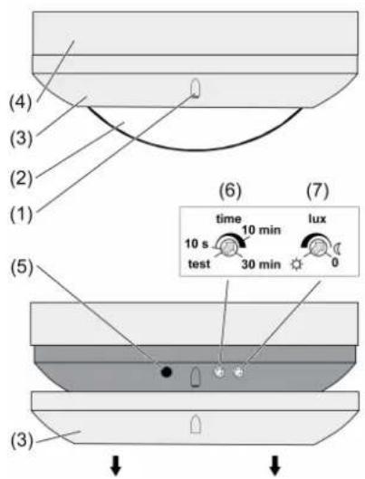
Figure 1: Device components
(1) Brightness sensor
(2) Sensor window
(3) Decor ring
(4) Connection box
(5) LED
(6) Adjuster time, run-on time
(7) Adjuster lux, Brightness
3 Function
Intended use
- Automatic switching of lighting depending on the heat motion and ambient brightness.
- Ceiling installation, surface-mounted
Product characteristics
- 2-point light control
- Run-on time and brightness value settable
- Test operation for checking the detection area
- Push-on cover for limiting the detection area
- Parallel connection of multiple presence detectors possible
- Manual switch-on and switch-off possible with installation button
Automatic operation
The presence detector detects heat motions of people, animals and objects.
- The light is switched on if someone or something enters the monitored detection area and the brightness is below the set level.
- The light remains switched on as long as there are motions present in the detection area and the brightness is not below the set level.
- The light is switched off if no more movement is detected in the detection area and the run-on time has elapsed.
- The light is switched off if the brightness exceeds twice the set value for longer than 10 minutes.
i The minimum switch-off brightness is 400 lux, even if a lower value is set.
Function of presence detectors that are connected in parallel
Presence detectors that are connected in parallel operate largely independently of each other.
Run-on time and brightness are set separately on each presence detector. A soon as a presence detector switches on, this is detected by the other presence detectors. They switch on when there is motion in their detection area, unless the brightness in their detection area is double the set value.
As a general rule, the following applies: the light is switched on when the first presence detector switches on, and is switched off when the last presence detector switches off.
Behaviour in case of a mains failure
- Less than 0.2 seconds: the old switching position is restored after mains return.
- Longer than 0.2 seconds: a self-test is performed after mains return. This takes approx. 30 seconds. The light is switched on during the self-test; operation via extensions is not possible.
4 Operation
Switching on the light
An installation button is connected.
■ Press the installation button.
The light is switched on for at least 2 minutes.
If motions are detected, the light remains on after the 2 minutes have elapsed. The run-on time is set to the time specified on the adjuster.
If the time adjuster is set to test, then the light remains switched on as long as the installation button is pressed. The light remains switched off for approx. 1 second after release.
Switching the light off
It is possible to switch the automatic function off in a targeted fashion, e.g. in order to darken a room.
An installation button is connected.
Light is switched on
■ Press the installation button.
The light is switched off for 3 minutes. Each detected motion extends the time by 3 minutes. After the 3 minutes have elapsed the presence detector is in automatic mode again. During these 3 minutes the light can only be switched on using the installation button.
In the case of presence detectors connected in parallel the time in each device elapses independently of each other. The result may be unwanted switching-on of the light, if the time has already elapsed in a presence detector and if it detects motions.
Switching off the brightness evaluation
The brightness evaluation can be switched off if the brightness is perceived as too dark after the light is switched off.
An installation button is connected.
The presence detector has switched the light off due to adequate extraneous light, e.g. daylight.
■ Press the installation button within 3 minutes after switch-off.
The light is switched on. The light remains switched on as long as the presence detector detects motions. The brightness is not evaluated.
i After the run-on time has elapsed, the presence detector switches off and is in automatic mode once again.
5 Information for electrically skilled persons
5.1 Fitting and electrical connection

DANGER!
Electrical shock when live parts are touched.
Electrical shocks can be fatal.
Before carrying out work on the device or load, disengage all the corresponding circuit breakers. Cover up live parts in the working environment.
Selecting the installation location
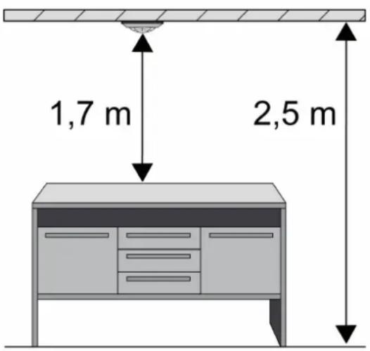
Figure 2
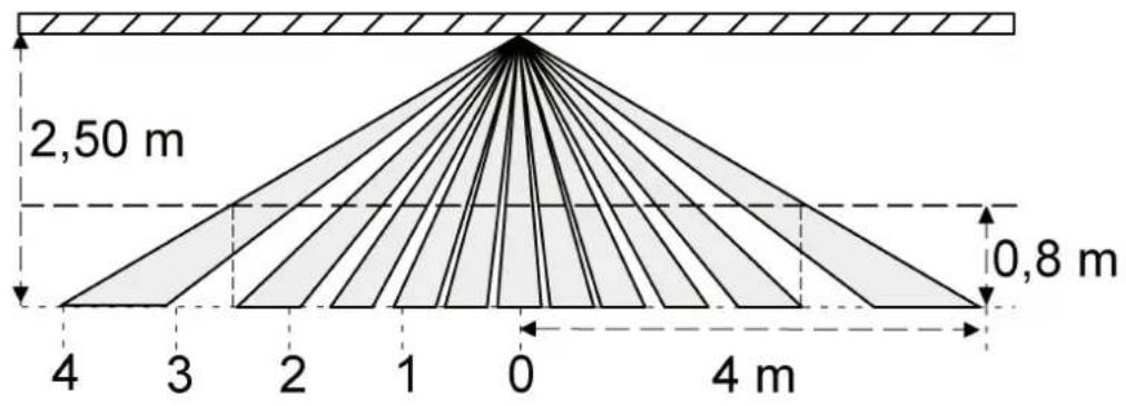
The presence detector is installed on the ceiling, and monitors the surface under it (figure 2). The presence detector has a detection area of 360^ . Die PIR sensor system operates with 6 detection levels and 80 lenses.
geo
| Segment | Width (m) | |---------|-----------| | Top Left | 2.50 | | Bottom Right | 0.8 |Figure 3: Detection field
The range is approx. 5 m in diameter at table height, e.g. approx. 80 cm. At floor level the range diameter is approx. 8 m (figure 3).
These data are applicable for installation on the ceiling at an installation height of 2.5 m.
At installation heights greater than 2.5 m the detection area becomes larger, while at the same time the detection density and sensitivity are reduced.
If necessary, the detection area can be limited using the push-on cover (see Limiting the detection area).
■ Select a vibration-free installation location; vibrations can lead to unwanted switching.
■ Avoid interference sources in the detection area. Interference sources, e.g. heaters, ventilation, air conditioners, and cooling light bulbs can lead to unwanted switching.
Preparations for installation
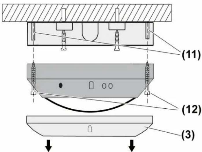
Figure 4: Fitting
(3) Decor ring
(11) Fastening pins
(12) Screws
■ Pull off decor ring (3) (figure 4).
■ Loosen screws (12).
Installing the connection box
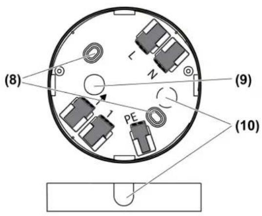
Figure 5: Connection box
(8) Fastening holes
(9) Cable entry, surface-mounted
(10) Thin points for optional cable entries
■ For an additional flush-mounted cable entry or surface-mounted cable entry, break out the appropriate thin point (10) (figure 5).
■ Align the presence detector so that the brightness sensor is on the side away from the windows. This reduces the effects of scattered light.
■ Fasten connection both (4) with enclosed anchor/screw set through holes (8) (figure 5).
Alternatively, the presence detector can also be mounted on a 60 mm appliance box. The screws are not included in the scope of delivery.
Connecting the presence detector
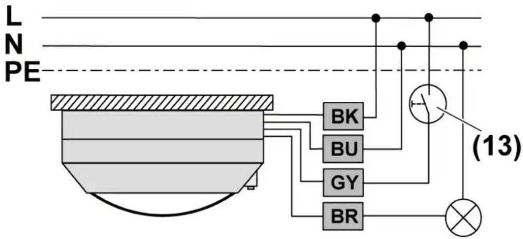
Figure 6: Connection diagram
Max. power cable length 100 m. This takes into account all connecting cables between the presence detector and lamps.
■ Connect presence detector according to connection diagram (figure 6).
■ If multiple miniature circuit breakers supply dangerous voltages to the device or load, couple the miniature circuit breakers or label them with a warning, to ensure release is guaranteed.
Connection assignment
| black, BK, L External conductor | |
| brown, BR, ↓ Switched external conductor | |
| blue, BU, N Neutral conductor | |
| grey, GY, 1 Installation button connection | |
| PE Earth conductor |
■ Connect optional installation button (13) (figure 6). This is only necessary if manual operation is also desired.
i Lit installation buttons may only be connected if they have an N terminal.
■ Screw presence detector to connection box (4) with screws (12) and mounting pins (11) (figure 4).
Connecting presence detectors in parallel
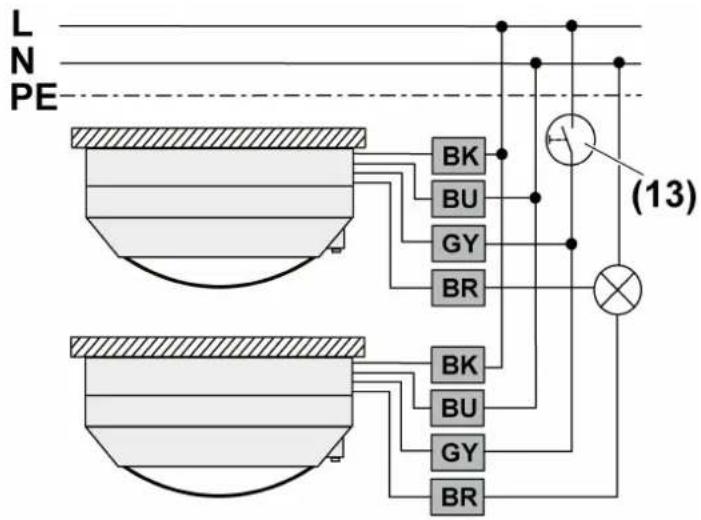
Figure 7: Connection diagram for connection in parallel
Several presence detectors can be connected in parallel to expand the detection area.
Connect all presence detectors to the same external conductor.
Do not connect more than five presence detectors in parallel.
Max. power cable length 100 m. This takes into account all connecting cables between the presence detectors and lamps.
i The connection in parallel does not increase maximum connected load.
■ Connect presence detector according to connection diagram (figure 7).
Connection assignment
| black, BK, L External conductor | |
| brown, BR, ↓ Switched external conductor | |
| blue, BU, N Neutral conductor | |
| grey, GY, 1 Installation button connection | |
| PE Earth conductor |
■ Connect optional installation button (13) to all presence detectors (figure 7). This is only necessary if manual operation is also desired.
i Lit installation buttons may only be connected if they have an N terminal.
■ Screw presence detector to connection box (4) with screws (12) and mounting pins (11) (figure 4).
5.2 Commissioning
Testing the detection area
The presence detector is mounted and connected properly.
■ Pull off decor ring (3).
■ Set lux adjuster to ✝ (figure 1).
The presence detector operates independently of the brightness.
■ Turn time adjuster to test (figure 1).
The presence detector switches on for approx. 1 second when there is motion.
- Pace off the detection area, paying attention to reliable detection and interference sources. Limit detection area if necessary using the push-on cover.
In the case of presence detectors connected in parallel, check the detection areas one after the other. Turn lux adjuster to 0 on the presence detectors whose detection areas are not being tested (figure 1).
■ Attach decor ring (3).
Limiting the detection area
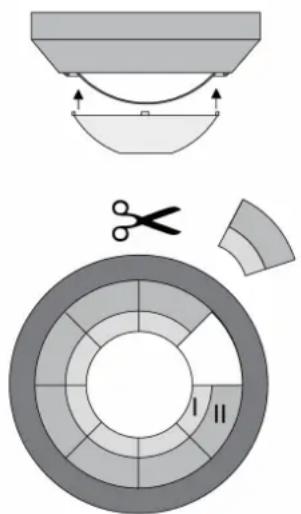
Figure 8: Push-on cover
The push-on cover can be used to limit the detection area, e.g. in order to mask out interference sources.
| Cover size Detection area on the floor | |
| Complete cover ∅ approx 2.2 m | |
| Area I cut out ∅ approx. 4 m | |
| Areas I + II cut out ∅ approx. 6 m |
Without cover ∅ approx. 8 m
All data are applicable for an installation height of 2.5 m
■ Pull off push-on cover.
■ Using scissors, cut out push-on cover along the marked lines as required.
■ Push on push-on cover.
Calibrating the brightness value
Brightness calibration is necessary to prevent light oscillations from occurring. A light oscillation occurs when the presence detector switches off again due to the lighting that has been switched on (brightness value exceeded). The brightness calibration is performed in the lighting situation that is required as workplace brightness. The lighting controlled by the presence detector is switched on. Avoid extraneous light, e.g. from daylight and other lighting. Various lamps, e.g. fluorescent lamps, require some time to reach full brightness. Therefore note the run-in phase of the lamp. The LED (5) can be used as an adjustment aid.
Meaning of the LED with the load switched off
| LED off Monitored surface is too dark, load switches on when motion detected. |
| LED on or LED flashes Monitored surface is bright enough, load remains off when motion detected. |
Meaning of the LED with the load switched on
| LED off Monitored surface is too dark, load remains switched on when motion detected. When no motion is detected, it is switched off after the run-on time elapses. |
| LED on Monitored surface is bright enough due to lighting that is switched on, load remains switched on when motion detected. When no motion is detected, it is switched off after the run-on time elapses. |
| LED flashes Monitored surface is very bright due to lighting that is switched on or extraneous light, load switches off after approx. 10 minutes, even if the run-on time is set longer or if motion is detected. |
■ Pull off decor ring (3).
■ Turn adjuster (7) time to 30 min.
■ Turn lux adjuster to ✝. LED (5) is off.
Do not place brightness sensor (1) in shadow, because otherwise correct brightness measurement will not be possible. The measured brightness value consists of the reflected artificial light and daylight, and depends on the reflective characteristics of the surface under the presence detector.
■ Switch on presence detector via motion in the detection area.
■ Turn lux adjuster (7) in ℃ direction until LED (5) lights up. Presence detector is set to the current brightness.
i If lux adjuster is on 0, the presence detector only switches on through operation of an extension. In this case the switch-off brightness is 400 lux.
■ Attach decor ring (3).
Setting the switch-off delay
The fewer the motions expected in the monitored area, the longer the run-on time setting should be. This reduces the probability that the presence detector will switch off even though people are present. Use 10 minutes as the default setting value.
■ Pull off decor ring (3).
■ Turn time adjuster (6) in the appropriate direction. The presence detector is ready for operation
■ Attach decor ring (3).
6 Appendix
6.1 Technical data
PMK 360 WW
Rated voltage AC 230 / 240 V \~
Mains frequency 50 / 60 Hz
Ambient temperature +5 ... +35 °C
Degree of protection IP 20
Circuit breaker max. 10 A
Detection angle 360°
Detection area
Desk height ∅ approx. 5 m
Floor ∅ approx. 8 m
Switch-off delay approx. 10 s ... 30 min
Run-on time, test approx. 1 s
Brightness setting approx. 10 ... 1000 lx
Connected load at 25 °C
Incandescent lamps 1000 W
HV halogen lamps 1000 W
Tronic transformers 750 W
Inductive transformers 750 VA
Fluorescent lamps, uncompensated 500 VA
Fluorescent lamps, parallel compensated
Electronic ballast
Switching current at 25 °C
Ohmic
Switch-on current max. 4 s at 10% switch-on time
Minimum switching current AC 100 mA
Contact type
Connection
single stranded
finely stranded with tin-plated conductor ends
Number of extension units
Non-illuminated installation buttons
Total length of extension unit cable
Total length power cable
PMK 360 AL
Rated voltage AC 230 / 240 V \~
Mains frequency 50 / 60 Hz
Ambient temperature +5 ... +35 °C
Degree of protection IP 20
Circuit breaker max. 10 A
Detection angle 360°
Detection area
Desk height ∅ approx. 5 m
Floor ∅ approx. 8 m
400 VA Type-dependent
10 A 35 A
μ
1.0 ... 2.5 mm ^2 0.75 ... 1.5 mm ^2
unlimited
max. 100 m
max. 100 m
Switch-off delay approx. 10 s ... 30 min
Run-on time, test approx. 1 s
Brightness setting approx. 10 ... 1000 lx
Connected load at 25 °C
Incandescent lamps 1000 W
HV halogen lamps 1000 W
Tronic transformers 750 W
Inductive transformers 750 VA
Fluorescent lamps, uncompensated 500 VA
Fluorescent lamps, parallel compensated 400 VA
Electronic ballast Type-dependent
Switching current at 25 °C
Ohmic 10 A
Switch-on current max. 4 s at 10% switch-on
time
Minimum switching current AC 100 mA
Contact type μ
Connection
single stranded 1.0 ... 2.5 mm²
finely stranded with tin-plated conductor ends 0.75 ... 1.5 mm ^2
Number of extension units
Non-illuminated installation buttons unlimited
Total length of extension unit cable max. 100 m
Total length power cable
35 A
max. 100 m
6.2 Troubleshooting
Presence detector switches does not switch on when there is motion, even though the brightness is too low
Brightness value setting too low.
Turn lux adjuster in ⚙ direction.
lux adjuster is set to 0. Initial detection is switched off.
Switch on via extension.
Turn lux adjuster in ✝ direction (see Calibrating the brightness).
Switched off via extension.
Switch on via extension.
Presence detector switches on without any detectable motion
Interference sources in the detection area.
Pay attention to interference sources, e.g. heating, ventilation, air conditioners, cooling light bulbs in the detection area.
Possibly limit detection area with the push-on cover (see Limiting the detection area).
Presence detector does not switch off even when there is a great deal of extraneous light.
The brightness value setting is too high.
Turn lux adjuster in ℂ direction (see Calibrating the brightness value).
Presence detector switches off, even though people are present and the brightness is too low
Detection problem, the surface to be monitored is not in the detection area, or furniture or pillars are in the way.
Use an additional presence detector (see Connecting presence detectors in parallel).
Run-on time too short. Motion of persons is not detected.
Extend run-on time using time adjuster (see Setting the run-on time).
Presence detector switches on and of constantly
time adjuster is set to test.
Set run-on time using time adjuster (see Setting the run-on time).
Presence detector switches off briefly and then on again immediately
Brightness drops below the brightness value setting after switch-off.
Turn lux adjuster in ✉ direction (see Commissioning section)
6.3 Accessories
Not combinable with devices from the light management system.
6.4 Warranty
The warranty is provided in accordance with statutory requirements via the specialist trade.
ALBRECHT JUNG GMBH & CO. KG
Volmestraße 1
58579 Schalksmühle
GERMANY
Telefon: +49 2355 806-0
Telefax: +49 2355 806-204
kundencenter@jung.de
www.jung.de
- Operating instructions
- Safety instructions
- Device components
- Function
- Intended use
- Product characteristics
- Automatic operation
- Function of presence detectors that are connected in parallel
- Behaviour in case of a mains failure
- Operation
- Switching on the light
- Switching the light off
- Switching off the brightness evaluation
- Information for electrically skilled persons
- Fitting and electrical connection
- DANGER!
- Selecting the installation location
- Preparations for installation
- Installing the connection box
- Connecting the presence detector
- Connecting presence detectors in parallel
- Connection assignment
- Commissioning
- Testing the detection area
- Limiting the detection area
- Calibrating the brightness value
- Meaning of the LED with the load switched off
- Meaning of the LED with the load switched on
- Setting the switch-off delay
- Appendix
- Technical data
- PMK 360 WW
- PMK 360 AL
- Troubleshooting
- Presence detector switches does not switch on when there is motion, even though the brightness is too low
- Presence detector switches on without any detectable motion
- Presence detector does not switch off even when there is a great deal of extraneous light.
- Presence detector switches off, even though people are present and the brightness is too low
- Presence detector switches on and of constantly
- Presence detector switches off briefly and then on again immediately
- Accessories
- Warranty
- ALBRECHT JUNG GMBH & CO. KG
Brand : JUNG
Model : PMK360
Category : Motion detector