
DWPMK360 - Motion detector JUNG - Free user manual and instructions
Find the device manual for free DWPMK360 JUNG in PDF.


| Product Type | Motion and presence detector (ceiling-mounted) |
| Dimensions (Diameter × Height) | 103 × 66 mm |
| Power Supply | AC 110-230 V~, 50/60 Hz |
| Standby Power | Max. 0.3 W |
| Detection Angle | 360° |
| Detection Field Diameter (at 3 m height) | Approx. 20 m |
| Brightness Setting Range | Approx. 5–2000 lx (including day operation) |
| Run-on Time | Approx. 10 s to 30 min (fixed, individual, or dynamic) |
| Sensor Type | 3 independent PIR sensors |
| Remote Control Battery | 1× Lithium CR2025 (button cell) |
| Operating Temperature | -5 to +45 °C |
| Switching Current (Ohmic at 35°C) | 16 A (AC1) |
| Connection Type | Screw terminals for 1.0–2.5 mm² solid or stranded wire |
| Protection Class | IP20 (indoor use) |
| Housing Material | Plastic (polycarbonate) |
| Color Variants | White (WW) and Aluminium (AL) |
| Installation | Ceiling surface-mounted or on 60 mm appliance box |
| Accessories | IR remote control for electrician (Art. no. DWPMFBIRI) |
| Maintenance | Clean with a dry cloth; do not use solvents |
| Safety Warning | Installation only by skilled persons; not suitable for burglar alarm |
Frequently Asked Questions - DWPMK360 JUNG
User questions about DWPMK360 JUNG
0 question about this device. Answer the ones you know or ask your own.
Ask a new question about this device
Download the instructions for your Motion detector in PDF format for free! Find your manual DWPMK360 - JUNG and take your electronic device back in hand. On this page are published all the documents necessary for the use of your device. DWPMK360 by JUNG.
USER MANUAL DWPMK360 JUNG
Operating instructions
Motion and presence detector
Art. no. DWPMK360WW
Motion and presence detector
Art. no. DWPMK360AL
natural_image
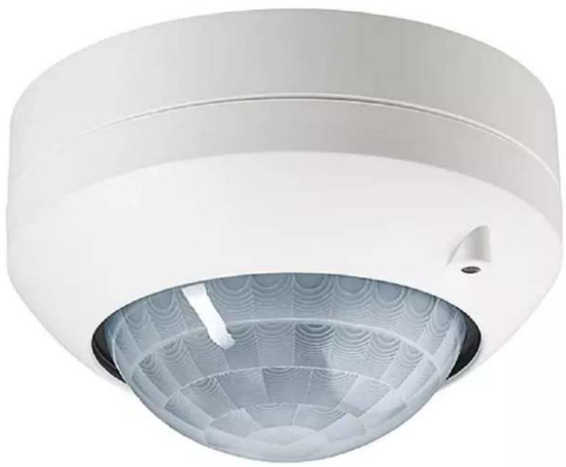
Exterior view of a white ceiling-mounted security camera with a spherical dome and patterned glass cover (no text or symbols visible)ALBRECHT JUNG GMBH & CO. KG
Vollmestraße 1
58579 Schalksmühle
GERMANY
Telefon: +49 2355 806-0
Telefax: +49 2355 806-204
kundencenter@jung.de
www.jung.de
Product image non-binding
25.09.2023
82593233 J0082593233
Table of contents
1 Safety instructions .... 3
2 Battery safety instructions .... 3
3 Device components 4
4 Intended use.... 4
5 Operation....7
6 Information for electrically skilled persons.... 10
6.1 Mounting and electrical connection.... 11
6.2 Commissioning 17
7 Technical data 22
8 Troubleshooting.... 23
9 Accessories 25
10 Warranty 25
1 Safety instructions

Electrical devices may be mounted and connected only by electrically skilled persons.
Serious injuries, fire or property damage are possible. Please read and follow the manual fully.
Danger of electric shock. Device is not suitable for disconnection from supply voltage because mains potential even is applied on the load when the device is switched off. Before carrying out work on the device or load, switch off all corresponding circuit breakers.
Do not press on the sensor window. Device can be damaged.
The device is not suitable for use as a burglar alarm or other alarm.
This manual is an integral part of the product, and must remain with the customer.
2 Battery safety instructions
This device or its accessories are supplied with batteries in the form of button cells.
DANGER! Batteries can be swallowed. This can lead directly to death by suffocation. Dangerous substances may cause severe internal burns leading to death within 2 hours.
Keep new and used batteries away from children.
Do not use devices if the battery compartment does not close securely and keep away from children.
If you suspect that a battery has been swallowed or is in any orifice of the body, seek immediate medical attention.
WARNING! Improper handling of batteries can result in explosion, fire or chemical burn due to leakage.
Do not heat or throw batteries into fire.
Do not reverse polarity, short-circuit or recharge batteries.
Do not deform or disassemble batteries.
Replace batteries only with an identical or equivalent type.
Remove empty batteries immediately and dispose of in an environmentally friendly manner.

Remove empty batteries immediately, cover the poles with adhesive tape and dispose of in an environmentally friendly manner. Do not throw batteries into a hold waste. Consult your local authorities about environmentally friendly sal. According to statutory provisions, the customers are obligated to return batteries.
3 Device components
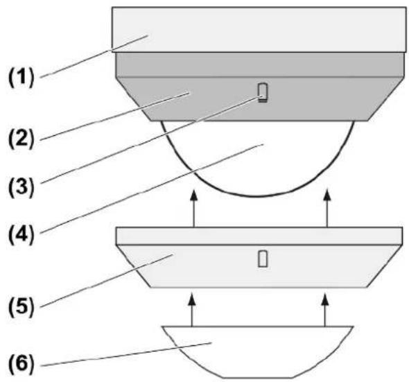
Figure 1
(1) Connection box
(2) Sensor cover
(3) Brightness sensor
(4) Sensor window with red and blue display LED
(5) Decor ring
(6) Push-on cover
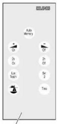
(7)
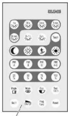
(8)
Figure 2
(7) IR end customer remote control, included in the scope of delivery
(8) IR installation engineer remote control (see Accessories)
4 Intended use
- Automatic switching of lighting depending on the heat motion and ambient brightness
- Indoor ceiling mounting, surface-mounted
Product characteristics
- 2-point light control
– Functions settable with IR remote controls - Restriction of the detection field by switching off individual sensors or push-on cover
- Operation with IR remote control, 2-wire extension or push-button
- Teach function for adjustment of the brightness threshold, in combination with IR remote controls
- Switch-off warning
– Short time operation, e.g. to activate acoustic signal encoders - Display LEDs
– Presence simulation - Function as twilight switch
- Dynamic run-on time
- Extension of the detection field through parallel switching of multiple devices
The extension of the detection field with 3-wire extensions is not possible.
Automatic operation
The device detects heat motions of people, animals and objects.
- The light is switched on if a person enters the detection field and the brightness threshold is below the set brightness threshold.
The run-on time restarts with each detected motion. - The light is switched off when it is no longer required because:
no more movement is detected in the detection field and the run-on time has elapsed or the ambient light is bright enough.
The switch-off brightness is calculated from the set brightness threshold and the connected light.
To avoid brief shading from causing switch-off, switch-off only takes place when the set run-on time has elapsed. The run-on time does not restart on movement detection for as long as the switch-off brightness is exceeded.
The minimum switch-off brightness is 100 lux, even if a lower value is set.
To avoid any switch-on caused by a cooling lamp, no movement signals are evaluated for a brief lockout time after switching off. The motion detector adjusts itself to the ambient conditions to keep the time as short as possible.
Short-time operation
If motion occurs, then a short pulse of approx. 0.5 seconds is triggered depending on the brightness. The pulse is cyclically repeated as long as motions are detected.
Switch-off warning
If the switch-off warning is active, the light is not switched off immediately after the run-on time has elapsed. Triple flashing at an interval of 10 seconds shows that the light will be switched off soon. The run-on time is thereby prolonged by approx. 30 seconds. If movement is detected during the switch-off prewarning, then the run-on time is restarted and the light remains on.
Dynamic run-on time
The function determines a run-on time within specified limits automatically and dynamically from detected movements. In so doing, the run-on time is increased if presence continues or decreased if absence is detected.
Presence simulation
In automatic operation, the motion detector continuously saves times for which the lighting was switched on. A maximum of 60 switching operations are saved over a period of 24 hours. If more switching operations take place, the oldest ones are overwritten respectively. If the presence simulation is activated, the motion detector switches the lighting at the saved times depending on brightness. Switch-off takes place after the run-on time has elapsed. Detected motions prolong the run-on time or the light is switched on depending on brightness. Times are not saved.
Function as twilight switch
The function is active as soon as all the PIR sensors have been switched off (see Commissioning).
The light is switched according to the brightness. Motions are not evaluated.
- The light is switched on if the brightness is below the set brightness threshold for 4 minutes.
- The light is switched off when the switch-off brightness (see Automatic mode) is exceeded for 4 minutes.

Switch-on and switch-off of the light via 2-wire extensions or push-buttons is not possible. The Continuous on/off and on/off for 2 hours functions cannot be used.
Behaviour after mains voltage return
After mains voltage return, the device performs a self-test for a maximum of 20 seconds. After the self-test has been completed, the device is ready for operation. The device switches the light according to the settings made.
The following applies during the self-test:
- The red and blue display LEDs (4) light up.
- The device cannot be operated or set using an IR remote control.
- Movements are not detected.
- The device can be switched via 2-wire extensions or installation push-buttons.
5 Operation
Special functions can be switched and settings adjusted using the end user IR remote control.
i Special functions can restrict operation via the 2-wire extensions or push-buttons.
If multiple devices are within the range of the IR remote control, then align it so that only the device to be operated can receive the signals.
Inserting the battery
i Obey the battery safety instructions.
- Keep contacts of batteries and device free of grease.
■ Insert the supplied battery with correct polarity (see IR remote control imprint).
LED display
Behind the sensor window (4) are a red and a blue LED (see figure 1) for indicating different states of operation.
| Red LED Blue LED Signalling | ||
| Off On Light switched on continu- | ously | |
| On Off Light switched off continu- | ously or twilight button function activated | |
| Flashing slowly Off Presence simulation | switched on | |
| Flashing Off Receipt of IR signals | ||
| Off Flashing IR signal detected | ||
Button assignment of the end user IR remote control
| Taste Funktion | |
| Auto MemoryPressing for less than 0.4 seconds | Switching on automatic mode |
| Auto MemoryActuation of between 1 and 4 seconds | In automatic mode: Switch-on for the duration of the run-on time |
| + OnPressing for less than 0.4 seconds | Continuous on |
| - OffPressing for less than 0.4 seconds | Continuous off |
| 2 h onPressing for less than 0.4 seconds | On for 2 hours |
| 2 h offPressing for less than 0.4 seconds | Off for 2 hours |
| Lux TeachPressing for less than 10 seconds | In the next 10 seconds, the brightness threshold can be changed incrementally using the + On or ▲- Off buttons. |
| Lux TeachPressing for longer than 10 seconds | Saving the current ambient brightness as the brightness threshold |
| Set 2Pressing for longer than 10 seconds | Activate settings that have been saved during commissioning |
| Pressing for longer than 10 seconds | Switching the presence simulation on or off |
| TimePressing for less than 10 seconds | In the next 10 seconds, the run-on time can be changed incrementally using the + On or ▲- Off buttons. |
Switching on light for the duration of the run-on time
A 2-wire extension or a push-button is connected.
In short time operation, cyclic pulses take place whilst the 2-wire extension at top or bottom or the push-button is pressed.
Alternatively, press the Auto Memory button of the IR remote control for between 1 and 4 seconds. In short time operation, there is a single pulse after releasing the button.
Light is switched off.
Motion detector operation
■ Press the 2-wire extension or push-button for less than 0.4 seconds.
If the 2-wire extension or the push-button is pressed again after switch-on, then the run-on time is restarted.
Presence detector operation
- Press the top or full-surface of the 2-wire extension or push-button for less than 0.4 seconds.
Light is switched on depending on brightness and motion. Movements are evaluated depending on brightness and prolong the run-on time.
Switching the light off for a period of 3 minutes
i This function can only be used in presence detector operation.
A 2-wire extension or a push-button is connected.
Light is switched on.
■ Press the bottom 2-wire extension or push-button.
The light is switched off for the period of 3 minutes. When movements are detected, the time is restarted.
Switch on the light for 2 hours
Motions are not evaluated during this time. It is not possible to switch off via a 2-wire extension or push-button.
■ Press 2 h On button of the IR remote control.
Light is switched on for 2 hours. The motion detector is in automatic operation again after the 2 hours have elapsed.
i The time is restarted if actuation is repeated.
i Automatic operation is switched on again using the Auto Memory button.
Switch on the light continuously
Motions are not evaluated during this time. It is not possible to switch off via a 2-wire extension or push-button.
■ Press the + On button for shorter than 0.4 seconds.
Light is switched on continuously. The blue LED lights up.
i Automatic operation is switched on again using the Auto Memory button.
Switch off the light for 2 hours
Motions are not evaluated during this time. It is not possible to switch on via a 2-wire extension or push-button.
■ Press the 2 h Off button.
Light is switched off for 2 hours. The device is in automatic operation again after the time has elapsed.
i The time is restarted if actuation is repeated.
i Automatic operation is switched on again using the Auto Memory button.
Switch off the light continuously
Motions are not evaluated. It is not possible to switch on via a 2-wire extension or push-button.
- Press the ▲- Off button for shorter than 0.4 seconds.
Light is switched off continuously. The red LED lights up.
i Automatic operation is switched on again using the Auto Memory button.
Adjusting the switch-on brightness
The switch-on brightness is set during commissioning. The switch-on brightness can be adjusted at a later time using the end user IR remote control.
■ Press Lux Teach button briefly.
■ Within 10 seconds, press the + On or ▲ Off button briefly.
Each button press extends or shortens the brightness threshold by 10% of the set value, but by at least 1 lux.
Saving the current brightness as the switch-on brightness
■ Press the Lux Teach button for longer than 10 seconds.
The current brightness is saved as the switch-on brightness.
Adjusting the run-on time
The run-on time is set during commissioning. The run-on time can be adjusted at a later time using the end user IR remote control.
■ Press Time button briefly.
■ Within 10 seconds, press the + On or ▲ Off button briefly.
Each button press extends or shortens the run-on time by 10% of the set value, but by at least 1 second.
Recalling saved settings
During commissioning, the settings made can be saved (see Saving settings). These can be recalled if, for example, changes made later are no longer required.
■ Press the Set 2 button for longer than 10 seconds.
The saved settings are active again.
Switching the presence simulation on or off
■ Press the 🔊 button for longer than 10 seconds.
The presence simulation is switched on or off alternately. If the function is switched on, the red LED flashes slowly.
The function cannot be activated until 24 hours after first commissioning.
6 Information for electrically skilled persons

DANGER!
Electric shock when live parts are touched.
Electric shocks can be fatal.
Always disconnect before carrying out work on the device or load. For this, switch off all corresponding circuit breakers, secure against being switched on again and check that there is no voltage. Cover up adjacent live parts.
6.1 Mounting and electrical connection
Detection field and range
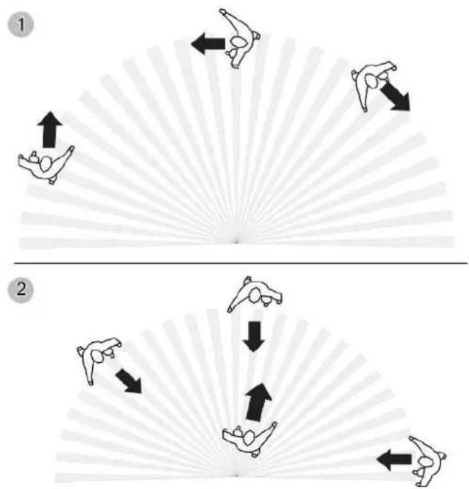
Figure 3: Tangential and radial direction of motion
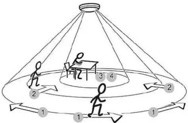
The device has a detection field of 360^ . The diameter of the detection field depends on the installation height and the direction of motion of persons in the detection field (see figure 4).
The detection field becomes larger the greater the installation height, while the detection density and sensitivity are reduced at the same time.
flowchart
graph TD
    A["Step 1: Table with person at center"] --> B["Step 2: Person at table"]
    B --> C["Step 3: Table with person at table"]
    C --> D["Step 4: Person at table"]
    D --> A
Figure 4: Detection range depending on the direction of movement
Diameter of detection field for direction of movement
| Installation height | 1: 2: 3: 4: | |||
| 2.20 m 14.50 m | 11.50 m 8.00 m 6.00 m | |||
| 2.50 m 16.50 m | 13.00 m 10.00 m | 7.00 m | ||
| 3.00 m 20.00 m | 16.00 m 12.00 m | 8.00 m | ||
| 3.50 m 23.00 m | 18.50 m 14.00 m | 9.00 m | ||
| 4.00 m 26.00 m | 17.00 m 14.50 m (*) - *) | |||
| 5.00 m 28.00 m | 18.00 m 15.00 m (*) - *) | |||
| 6.00 m 29.00 m | 19.00 m - *) - *) |
1: Range for tangential movement on the ground
2: Range for radial movement on the ground
3: Range for typical movements at desks, e.g. torso movement
4: Range of fine detection at desks, e.g. mouse movements
*) When used as a presence detector: Installation height should not be more than 3.5 m, otherwise fine detection is not possible.
Selecting installation location
For use as a presence detector, the device is installed, for example, above a workplace and monitors the surface below it. For use as a motion detector, the device is installed, for example, in the hallway.
■ Select a vibration-free installation location. Vibrations can lead to unwanted switching.
■ Avoid interference sources in the detection field. Interference sources, e.g. heaters, ventilation, air conditioners, and cooling luminaires can lead to unwanted detections.
The detection field can be limited in order to minimise the influence of interference sources. For this, use the push-on cover (see Limiting the detection field with the push-on cover) or switch off individual sensors (see Limiting the detection field).
Aligning the device
The device has three independent PIR sensors for motion detection (see figure 5).
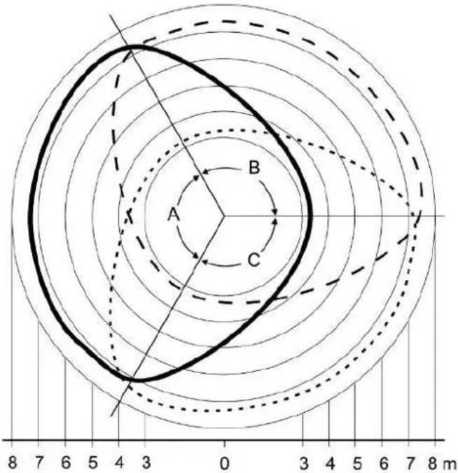
Figure 5: Detection field areas A, B and C, installation height 2.50 ~m
flowchart
graph TD
    A["Outer Ring"] -->|A/B| B["Inner Ring"]
    B -->|B/C| C["Outer Ring"]
    C -->|C/A| A
    A -->|A/B| B
    B -->|B/C| C
    C -->|C/A| A
    A -->|A/B| B
    B -->|B/C| C
    C -->|C/A| A
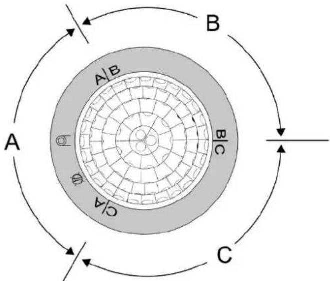
Figure 6: Arrangement of the areas A, B and C
■ Align the connection box (1) in such a way that the areas A, B and C match the structural conditions. The arrangement is clearly evident under the decor ring (see figure 6).
Preparations for mounting
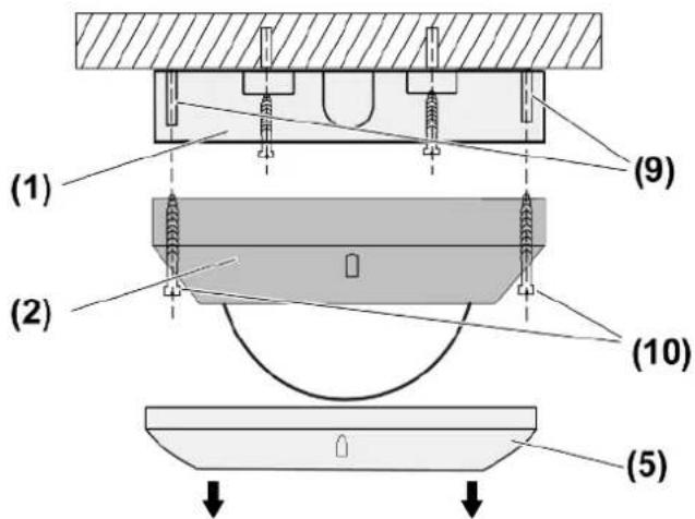
Figure 7: Mounting
(1) Connection box
(2) Sensor cover
(5) Decor ring
(9) Fastening pins
(10) Screws
■ Pull off decor ring (5) (see figure 7).
■ Loosen screws (10) (see figure 7).
Installing the connection box
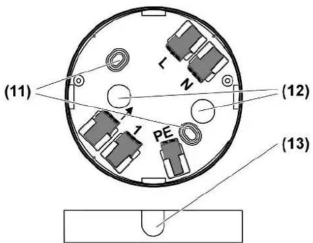
Figure 8: Connection box
(11) Fastening holes
(12) Cable entry, surface-mounted
(13) Thin points for optional cable entries
- Align the device (for the position of areas A, B, C, see Aligning the device) – the brightness sensor should, if possible, be located on the side away from the window. This reduces the effects of scattered light.
■ For an additional flush-mounted cable entry or surface-mounted cable entry, break out the appropriate thin point (13) (see figure 8).
■ Fastening the connection box (1) through holes (11) (see figure 8).
Alternatively, the device can also be mounted on a 60 mm appliance box. The screws are not included in the scope of delivery.
Connect device
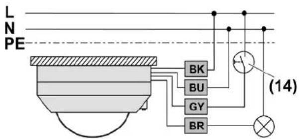
Figure 9: Connection diagram, single device
flowchart
graph TD
    A["LE PENE"] --> B["BK"]
    A --> C["BU"]
    A --> D["GY"]
    A --> E["BR"]
    F["LE PE"] --> G["BK"]
    F --> H["BU"]
    F --> I["GY"]
    F --> J["BR"]
    K["Switch 14"] --> L["Light Bulb"]
    M["Switch 14"] --> N["Light Bulb"]
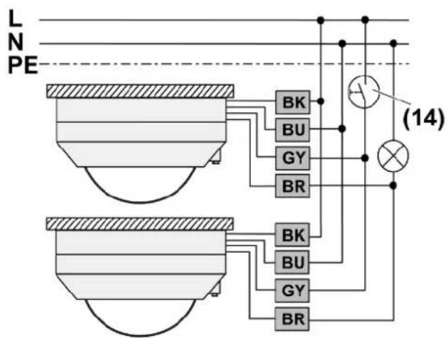
Figure 10: Connection diagram, parallel circuit for expanding the detection field
Max. power cable length 100 m. This takes into account all the connecting cables between the devices and lamps.
Do not connect more than five devices in parallel.
Connect all devices to the same phase conductor.
Set all the devices to the same device function (motion detector or presence detector).
i The connection in parallel does not increase maximum connected load.
■ Connect the sensor cover according to the connection diagram (see figure 9) or switch the sensor covers according to the circuit diagram (see figure 10).
■ If multiple circuit breakers supply dangerous voltages to the device or load, couple the circuit breakers or label them with a warning to ensure tripping.
Connection assignment
| black, BK, L | Phase conductor |
| brown, BR, ↓ Switched phase conductor | |
| blue, BU, N | Neutral conductor |
| grey, GY, 1 | Connection push-button |
| PE | Protective conductor |
■ Connect optional push-button (14) (see figure 9) or (see figure 10). This is only necessary if manual operation is also desired.
i Lit push-buttons may only be connected if they have an N connection terminal.
In the case of single devices, a 2-wire extension can be used as an alternative to the push-button (14).
■ Screw the sensor cover (2) to connection box (1) with screws (10) and mounting pins (9) (see figure 7).
Limiting the detection field using the push-on cover
The push-on cover can be used to limit the detection field, e.g. in order to mask out interference sources.
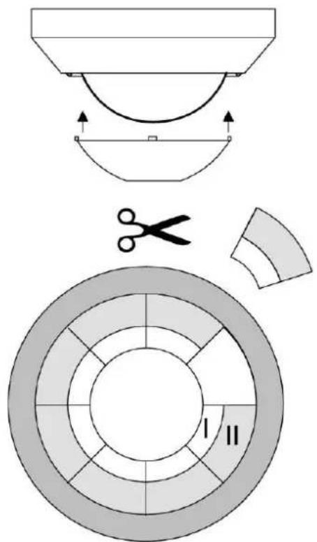
Figure 11: Push-on cover
| Cover size Range on the ground (mounting height 3 m) |
| Complete push-on cover ∅ approx. 4.5 m |
| Area I cut out ∅ approx. 7.5 m | |
| Areas I + II cut out ∅ approx. 12 m | |
| without push-on cover ∅ approx. 20 m |
■ Pull off push-on cover.
■ Using scissors, cut out push-on cover along the marked lines as required.
■ Push on push-on cover.
Alternatively, the detection field can also be limited by switching off individual sensors (see Commissioning).
6.2 Commissioning
Insert battery into IR remote control
The necessary settings are carried out using the "installation engineer" IR remote control (see Accessories).
If multiple devices are within the range of the IR remote control, then align it so that only the device to be operated can receive the signals.
Inserting the battery
i Obey the battery safety instructions.
- Keep contacts of batteries and device free of grease.
■ Insert the supplied battery with correct polarity (see IR remote control imprint).
Button assignment of the "installation engineer" IR remote control
| Taste Funktion | |
| 1 s ✘ Short-time operation | |
| 30 s ✘, 2 min ✘, 5 min ✘, 30 min ✘ | Set run-on time |
| Lux TeachPressing for longer than 10 seconds | Saving ambient brightness as brightness threshold |
| (, ⚙, ⏻, ⚙ | Setting the brightness threshold |
| 0-1 h ✘ Setting individual run-on time | |
| Dyn. ✘ Pressing for longer than 10 seconds | Switching on the dynamic run-on time |
| PIR A, PIR B, PIR C, PIR A-CPressing for longer than 10 seconds | Switching off the PIR sensors |
| PIR A, PIR B, PIR C, PIR A-CPressing for less than 10 seconds | In the next 5 seconds, use the 25%, 50%, 75% and 100% buttons to set the sensitivity of the appropriate PIR sensor |
| 25%, 50%, 75%, 100% | Setting the sensitivity |
| Mode ⚠Pressing for longer than 10 seconds | Switching on the Presence detector device function |
| Mode ⚙Pressing for longer than 10 seconds | Switching on the Motion detector device function |
| Eco ⚑ No function is saved for this device | |
| Test 100 hPressing for less than 10 seconds | Switch on test operation |
| Test 100 hPressing for longer than 10 seconds | On for 100 hours |
| Set 1Pressing for longer than 10 seconds | Save any changes made for later recall using the Set 2 button of the supplied IR remote control |
| On/OffPressing for longer than 10 seconds | Switch on/off switch-off warning |
| Prog Func | No function is saved for this device |
| ResetPressing for between 4 seconds and 10 seconds | Switching off the functions: dynamic run-on time, switch-off prewarning, on for 100 hours, test operation |
| ResetPressing for longer than 10 seconds | Restoring to factory settings |
Switching on a device function
The device can work either as a motion detector or presence detector.
■ Press the Mode ◯ or Mode 🔒 button.
The device works either as a motion detector or presence detector.
When changing the device function, the settings of the previous device function are saved and reactivated on changing again.
Setting the sensitivity
The sensitivity can be set individually for each PIR sensor.
■ Press PIR A, PIR B, PIR C or PIR A-C button for less than 10 seconds.
■ Within 5 seconds, press the 25%, 50%, 75% or 100% button. Sensitivity is set.
i If no touch-sensitive button is pressed within 5 seconds, the old setting is kept.
Limiting the detection field
The detection field of the motion detector can be limited by switching off one or two PIR sensors. Since the detection areas of the PIR sensors overlap, there is no distinct demarcation of the blocked out detection area. If all the PIR sensors have been switched off, then the device works as a twilight switch.
■ Press the PIR A, PIR B or PIR C button for longer than 10 seconds.
The appropriate PIR sensor is switched off and the detection field is limited.
■ Press the PIR A-C button for longer than 10 seconds.
If all the PIR sensors are switched off, then the device functions as a twilight switch.
i Individual PIR sensors or all of them can be switched on by setting a sensitivity for the PIR sensors (see Setting sensitivity).
Setting the switch-on brightness
One of four predefined brightness thresholds (see table) or one individual brightness threshold can be set (see Saving current brightness as the switch-on brightness). If the device is set as a motion detector, then the brightness is measured on the device. If the device is set as a presence detector, then the brightness is measured on the work surface.
■ Press the appropriate button (see table).
Brightness thresholds
| Icon Device function, motion | detector | Device function, presence detector |
| 5 lux 200 lux | ||
| 10 lux 500 lux | ||
| 150 lux * 1000 lux | ||
| Brightness-independent-day operation | Brightness-independent-day operation | |
* Setting for stairways according to DIN EN12464-1, 2003-03
Saving the current brightness as the switch-on brightness
The Teach function can be used to save the current brightness as a switch-on brightness.
Do not shade the device during the measuring process.
■ Create the desired lighting situation, e.g. switch light on or off.
■ Press the Lux Teach button for longer than 10 seconds.
The Teach function is activated, the current brightness is saved as the switch-on brightness and is used after a maximum of 3 minutes.
If a value greater than 2000 lux is saved, the motion detector switches to day operation independent of the brightness.
Setting fixed run-on time
■ Press the 30 s 🎨, 2 min 🎨, 5 min 🎨 or 30 min 🎨 button.
If the run-on time is shortened, then it only becomes active after the device has switched off once. To cancel a running run-on time, set the special function Continuous on, for example, and then switch back to Automatic operation (see Operation).
Setting individual run-on time
The individual run-on time can be set within a range of 10 seconds to 60 minutes. One of the fixed run-on times can be set again at any time.
■ Press the 0-1 h 🎨 button.
Run-on time starts.
■ When the required run-on time is reached, press the 0-1 h button.
The device saves the run-on time.
If the run-on time is shortened, then it only becomes active after the device has switched off once. To cancel a running run-on time, set the special function Continuous on for example and then switch back to Automatic operation (see Operation).
Setting the dynamic run-on time
The device adapts the run-on time to the motion situation.
■ Press the Dyn. 🎨 button for longer than 10 seconds.
The dynamic run-on time is activated.
To switch off the function, press the Reset button for between 4 and 10 seconds
Switching on short time operation
■ Press the 1 s 🎨 button.
i No individual or dynamic run-on time can be set in short time operation.
To switch off short time operation, set a fixed or individual run-on time.
Switching on switch-off warning
Switch-off warning is switched off.
■ Press the ▶ On/Off button for longer than 10 seconds.
Switch-off warning is switched on. If pressed again, the switch-off warning is switched off again.
The function is also switched off if the Reset button is pressed for between 4 and 10 seconds.
Switching on the function as a twilight switch
All the PIR sensors must have been switched off for the device to work as a twilight switch.
■ Press the PIR A-C button for longer than 10 seconds.
The red LED lights up. The device functions as a twilight switch.
If day operation is set as the switch-on brightness, the light remains off continuously.
i Switching via a 2-wire extension or push-button is not possible.
Switch on test operation
The test operation is used for testing the detection area. In test operation, the device operates independently of the brightness. All the other settings remain unchanged. Detected motions are signalled by the blue status LED.
■ Press the Test 100 h button for between 4 and 10 seconds.
Test operation is switched on for 5 minutes.
By pressing the Auto Memory button of the supplied IR remote control, you can switch to automatic operation at any time (see Operation).
The function is also switched off if the Reset button is pressed for between 4 and 10 seconds.
Switch on "On" for 100 h
This function is used to burn in fluorescent lamps.
■ Press the Test 100 h button for longer than 10 seconds.
The lamps are switched on for 100 hours. The device is switched back to automatic operation again after the time has elapsed.
During the 100 hours, no switching is possible via 2-wire extension, push-button or IR remote control, movement signals are not evaluated.
To switch off the function, press the Reset button for between 4 and 10 seconds.
Saving settings
Save the settings so that, if necessary, the end customer can recall them using the Set 2 button of the supplied IR remote control. No values are saved in the as-delivered state.
■ Press the Set 1 button for longer than 10 seconds.
The following settings are saved: device function, sensitivity of PIR A-C, detection angle, switch-on brightness, run-on time, dynamic run-on time, short time operation, switch-off pre-warning. Previously saved values are overwritten.
Restoring the device to factory settings
■ Press the Reset button for longer than 10 seconds.
| Function Value | |
| Device function Motion detector | |
| Operating mode Automatic operation | |
| Sensitivity of PIR A-C 75% | |
| Detection angle 360°, PIR A-C switched on | |
| Switch-on brightness 10 lux | |
| Run-on time 2 minutes | |
| Dynamic run-on time switched-off | |
| Short-time operation switched-off | |
| Switch-off warning switched-off | |
| Presence simulation switched-off | |
| Test operation switched-off |
If the Reset button is pressed for between 4 and 10 seconds, only a few functions are terminated (see Button assignment of "installation engineer" IR remote control).
7 Technical data
Rated voltage AC 110 ... 230 V \~
Mains frequency 50 / 60 Hz
Ambient temperature -5 ... +45°C
Standby power max. 0.3 W
Circuit breaker max. 16 A
Contact type ε
Detection angle 360°
Dimensions × H 103 × 66 mm
Installation height 3 m
Detection field ∅ approx. 20 m
Sensitivity 25 ... 100%
Brightness setting Approx. 5 ... 2000 lx (and day operation)
Run-on time approx. 10 s ... 30 min
Short-time operation
Pulse duration approx. 0.5 s
Pulse stop approx. 3 s
Switching current at 35^
Ohmic 16 A (AC1)
Fluorescent lamps 4 AX
Minimum switching current AC 100 mA
Connected load at AC 230 V\~ and 35 °C
Incandescent lamps 2300 W
HV halogen lamps 2000 W
Electronic transformers 1500 W
Inductive transformers 1000 VA
HV-LED lamps typ. 400 W
Compact fluorescent lamps typ. 400 W
Fluorescent lamps, uncompensated 920 VA
Capacitive load 690 VA (560 μF)
Connected load at AC 110 V\~ and 35 °C
Incandescent lamps 1150 W
HV halogen lamps 1000 W
Electronic transformers 750 W
Inductive transformers 500 VA
HV-LED lamps typ. 200 W
Compact fluorescent lamps typ. 200 W
Fluorescent lamps, uncompensated 460 VA
Capacitive load 345 VA (560 μF)
Connection
Single stranded 1.0 ... 2.5 mm ^4
finely stranded with tin-plated conductor ends 0.75 ... 1.5 mm ^2
Number of extension units
Push-button unlimited
2-wire unlimited
Total length of extension device cable Max. 100 m
Total length power cable Max. 100 m
IR remote control
Battery type 1×lithium CR 2025
8 Troubleshooting
Device does not switch on
Cause 1: The ambient brightness is greater than the set brightness value.
Set brightness value.
Cause 2: Device does not detect any motions.
Increase sensitivity.
Switch on all sensors.
Cause 3: Off for 2 hours or Continuous off is activated
Switch on automatic mode.
Device switches on without motions
Cause 1: Presence simulation is activated. Device switches at saved times.
Switch the presence simulation off.
Cause 2: Interference sources in the detection field.
Remove interference sources if possible.
Reduce sensitivity.
Limit the detection field.
Device constantly switches on and off during motion
Cause 1: Short time operation is switched on.
Set a longer run-on time.
Device switches off despite motion
Cause 1: The device does not detect any motion.
Increase sensitivity.
Cause 2: Detection field is limited because a sensor was switched off.
Switch on all sensors.
Cause 3: Detection field is limited by push-on cover.
Check the push-on cover.
Device does not switch off
Cause 1: Interference sources in the detection field, device detects motions constantly.
Remove interference sources if possible.
Reduce sensitivity.
Limit the detection field.
Cause 2: On for 2 hours, Continuous on or On for 100 hours is activated.
Switch on automatic mode.
The device does not respond to IR remote control, red LED does not flash.
Cause 1: IR remote control out of range.
Go closer to the motion detector.
Cause 2: Battery in IR remote control is empty.
Change battery (see back of the IR remote control).
The device does not respond to IR remote control, red LED flashes, blue LED does not
Cause: Device is receiving an IR signal. Function or setting cannot be executed.
9 Accessories
IR remote control for electrician Art. no.: DWPMFBIRI
10 Warranty
The warranty is provided by the specialist trade in accordance with statutory requirements.
ALBRECHT JUNG GMBH & CO. KG
Volmestraße 1
58579 Schalksmühle
GERMANY
Telefon: +49 2355 806-0
Telefax: +49 2355 806-204
kundencenter@jung.de
www.jung.de
- Operating instructions
- Table of contents
- Safety instructions
- Battery safety instructions
- Device components
- Intended use
- Product characteristics
- Automatic operation
- Short-time operation
- Switch-off warning
- Dynamic run-on time
- Presence simulation
- Function as twilight switch
- Behaviour after mains voltage return
- Operation
- Inserting the battery
- LED display
- Switch on the light for 2 hours
- Switch on the light continuously
- Switch off the light for 2 hours
- Switch off the light continuously
- Adjusting the switch-on brightness
- Information for electrically skilled persons
- DANGER!
- Mounting and electrical connection
- Selecting installation location
- Aligning the device
- Preparations for mounting
- Commissioning
- Setting the switch-on brightness
- Saving the current brightness as the switch-on brightness
- Setting fixed run-on time
- Setting individual run-on time
- Setting the dynamic run-on time
- Switching on short time operation
- Switching on switch-off warning
- Switch on test operation
- Switch on "On" for 100 h
- Saving settings
- Restoring the device to factory settings
- Technical data
- Troubleshooting
- Accessories
- Warranty
Brand : JUNG
Model : DWPMK360
Category : Motion detector