
Gaming 980B - Computer Case LC-Power - Free user manual and instructions
Find the device manual for free Gaming 980B LC-Power in PDF.


| Product Type | Computer Case |
| Brand | LC-Power |
| Model | Gaming 980B |
| Form Factor | Mid Tower |
| Supported Motherboard | ATX, Micro-ATX, Mini-ITX |
| Dimensions (W x D x H) | 200 x 440 x 460 mm (approx.) |
| Weight | 5.8 kg (approx.) |
| Material | Steel, Tempered Glass |
| Side Panel | Tempered Glass |
| PSU Support | ATX (bottom mount) |
| Max GPU Length | 330 mm |
| Max CPU Cooler Height | 160 mm |
| Expansion Slots | 7 |
| Storage Bays | 2 x 3.5"/2.5" (internal), 2 x 2.5" (internal) |
| Front I/O Ports | 2 x USB 3.0, 2 x USB 2.0, HD Audio (Mic & Headphone) |
| Fan Support Front | 3 x 120mm / 2 x 140mm |
| Fan Support Top | 2 x 120mm / 2 x 140mm |
| Fan Support Rear | 1 x 120mm |
| Pre-installed Fans | Rear: 1 x 120mm (optional) |
| Radiator Support | Front: 360mm/280mm; Top: 240mm; Rear: 120mm |
| Dust Filters | Top, Bottom, Front |
| Cleaning Instructions | Use a soft, dry cloth. Avoid harsh chemicals. |
| Safety Features | Edge protection, tempered glass panel safety film |
| Warranty | 2 years (refer to manufacturer) |
Frequently Asked Questions - Gaming 980B LC-Power
User questions about Gaming 980B LC-Power
0 question about this device. Answer the ones you know or ask your own.
Ask a new question about this device
Download the instructions for your Computer Case in PDF format for free! Find your manual Gaming 980B - LC-Power and take your electronic device back in hand. On this page are published all the documents necessary for the use of your device. Gaming 980B by LC-Power.
USER MANUAL Gaming 980B LC-Power
natural_image
Exterior view of a black computer tower case (no signage or text visible)Content
Chapter 1 Product introduction
1.1 Specification....03
1.2 Accessory....04
Chapter 2 Installation guide
2.1 Side panel assembly....05
2.2 Motherboard installation....06
2.3 5,25" device installation....07
2.4 3,5" device installation....08-09
2.5 2,5" device installation....10
2.6 PSU installation.... 11
2.7 Fan installation.... 12-13
2.8 Water cooling installation....13-14
2.9 Front panel control & I/O installation....14-16
Thank you for purchasing the "Gaming 980B - SKYTOWER" case
from LC-Power. Please read this manual before usage.
Specifications may be subject to change without prior notice.
Chapter 1 Product introduction
1.1 Specification
| Dimension 238 | (w) x 545 (h) x 573 (d) mm |
| Material Steel (SECC) | |
| Front & top panel: ABS + meshed designed | |
| 5,25" drive bay 4 external | |
| 3,5" drive bay 6 internal - HDD cage with hot swap feature | |
| 2,5" drive bay 3 internal | |
| PCI slot 9 | |
| I/O Panel 2x USB 3.0, 4x USB 2.0, 1x Audio, 1x Mic | |
| Control Panel Power switch, Reset switch, Power LED, HDD LED | |
| Cans fans mounting options | Front: 2x 120 mm (included in delivery) |
| Back: 1x 120 mm (included in delivery) or 1x 140 mm | |
| Top: 3x 120 mm | |
| Bottom: 2x 120 mm | |
| Water cooling: support up to 360 mm radiator on top and up to 240 mm radiator on bottom | |
| Motherboard E-ATX / ATX / Micro-ATX / Mini-ITX | |
| Power Supply ATX standard | |
| Compatibility Graphic card up to 340 mm | |
| CPU cooler up to 190 mm | |
1.2 Accessory
Accessory box contents: 1x user manual, 1x screw bag
| Standoff Screw | Screw Screw | ||
| 5H-6#*4- 6#*6.5HCu M3*5 6*5KM 3*8*8PWA | |||
 |  |  |  |
| 10PCS 20PCS 24PCS 4PCS | |||
| Plastic hand screws Screw Cable tie Cable tie | |||
| 6#-32 6#6HW-TC L=120mm L=150mm | |||
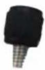 | 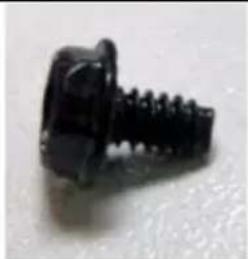 |  |  |
| 10PCS 4PCS | 3PCS | 3PCS | |
| Plastic standoff | |||
 | |||
| 3PCS | |||
3PCS
Chapter 2 Installation guide
2.1 Side panel assembly
1. Remove the side panel:
Remove the screws on the back of the chassis and open the side panel.

natural_image
Close-up of a mechanical component with a diagonal tool inserted, no visible text or symbols
natural_image
Close-up of a hand holding a black electronic device with a red arrow pointing to the left side (no visible text or symbols)2. Reattach the side panel:
Align the side panel with hook holes to close the side panel.
Fix it with screws.

natural_image
Close-up of a hand holding a dark object, possibly a device or tool, with no visible text or symbols.
natural_image
Close-up of a computer monitor with a red curved arrow indicating a change or action (no text or symbols visible)2.2 Motherboard installation
- Screw the standoffs on the holes for the motherboard installation bracket.
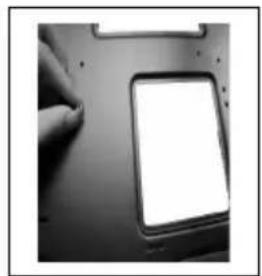
natural_image
Close-up of a hand holding a blank white rectangular device on a dark surface (no visible text or symbols)- Install the motherboard in a proper location and fix it with the provided screws.

natural_image
Close-up of a hand inserting a component into a computer motherboard (no visible text or symbols)Note: CPU, RAM and any peripheral installation steps are not included in this manual. Please refer to your motherboard manual for related mounting instructions.
2.3 5,25" device installation
- Remove the 5,25" drive cover from the chassis by pushing it inside out. Now put the 5,25" ODD into the drive bay.

natural_image
Close-up of a computer monitor with a hand operating it, showing a screen and control buttons (no visible text or symbols)- Fix the 5,25" ODD with the quick release screws on the side.

natural_image
Close-up of a hand inserting a red circular arrow into a black electronic device panel (no text or symbols visible)2.4 3,5" device installation
- Open the side panel with the help of the latch.
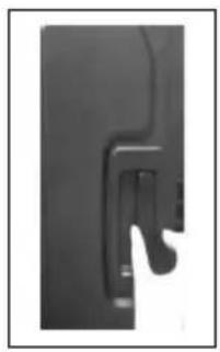
natural_image
Close-up of a black mechanical component with a curved handle and a small looped end (no visible text or symbols)
natural_image
Black office chair with open door and side panel (no visible text or symbols)- Push the latch of the drive bay and take out the 3,5" drive bay tray.

natural_image
Close-up of a server rack with multiple drive bays and a hand holding a hard drive, showing a red arrow indicating compression (no text or symbols visible)
natural_image
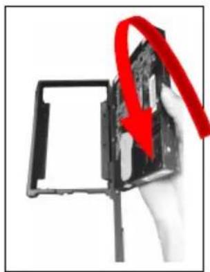
Interior view of a computer tower case showing internal storage racks and a highlighted component (no text or symbols visible)- Place an HDD into the drive bay tray and secure it on the bottom of the tray with the provided screws. Reverse the above mentioned steps to place the HDD tray in the device cage.
natural_image
Hand holding a black rectangular device with a red arrow indicating rotation or change (no text or symbols visible)
natural_image
Black-and-white photo of a computer hard drive casing with four red-circled mounting points (no visible text or symbols)- Connect the backplane with a 4 pin Molex/PATA connector of the power supply.
Connect the backplane to the motherboard with the help of SATA cables.

natural_image
Black-and-white photo of an electronic device panel with various ports and connectors (no visible text or labels)Note: The user may choose the direction of the 3,5" drive cage. This will help the user to arrange the chassis placement flexibly. Please refer to the pictures below for the further information.
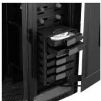
natural_image
Interior view of a server rack with stacked drive bays and open door (no visible text or labels)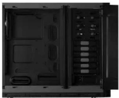
natural_image
Interior view of a black server rack unit with visible internal compartments and ventilation slots (no text or labels)
natural_image
Interior view of a black desktop computer case showing front panel, rear panel, and internal hardware (no visible text or labels)2.5 2,5" device installation
Gaming 980B provides three positions for the 2,5" HDD/SSD installation.
Two HDDs/SSDs on the side of the 5,25" drive cage and one HDD/SSD under the 3,5" HDD cage location.
- Open the side panel with the help of the latch.

natural_image
Close-up of a mechanical component or bracket with no visible text or symbols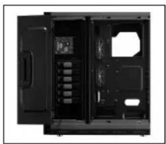
natural_image
Black office computer case with open door and internal compartments (no visible text or labels)- Place the 2,5" HDD/SSD in a proper location as shown below and fix it with the provided screws.

natural_image
Close-up of a computer motherboard showing a CD drive with a red arrow pointing to its component (no visible text or symbols)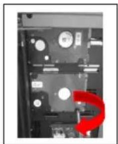
natural_image
Close-up of a computer motherboard showing discoloration and mounting holes (no text or symbols visible)- For the third position, release the screw on top of the 3,5" HDD cage and remove it. Put the 2,5" HDD/SSD on the bottom side of the bracket as shown below and secure the HDD/SSD with the provided screws.


natural_image
Close-up of a computer hard drive with four red-circled mounting holes (no visible text or symbols)2.6 PSU installation
- Place the PSU in a proper location and fix it with the provided screws.

natural_image
Back view of a computer monitor with an attached power strip and ventilation grille (no visible text or symbols)
natural_image
Back view of a computer tower with an attached power strip and ventilation unit (no visible text or symbols)(Screw holes enable a PSU mounting from both sides; fan up or down)
- Place the power supply cables behind the mainboard tray.

natural_image
Close-up of a metallic component with internal curved and straight lines, possibly part of a mechanical or electronic assembly (no visible text or symbols)- To clean the dust filter, pull out the washable dust filter which is placed under the power supply location.

natural_image
Close-up of a mechanical component with a red downward arrow indicating a decrease or drop (no visible text or symbols)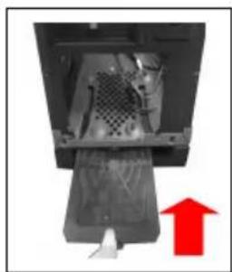
natural_image
Close-up of a mechanical device with a red upward arrow indicating motion or force (no visible text or symbols)2.7 Fan installation
- Remove 6 screws as shown below and then remove the bottom bracket.
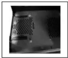
natural_image
Close-up of a computer ventilation grille with no visible text or symbols- Install the fan inside the chassis and secure the screws from the bottom side.
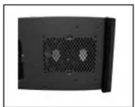
natural_image
Black rectangular device with two ventilation grilles and a side panel (no visible text or symbols)You can install maximum two 120 mm fans on the bottom panel.
Top panel fan installation
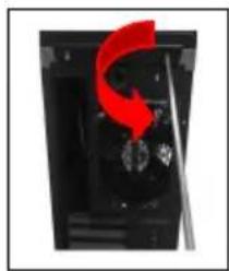
- Remove the screws on the back side of chassis and open the top panel.
natural_image
Close-up of a mechanical component with a red arrow indicating rotation or movement, no visible text or symbols
natural_image
Close-up of a black plastic container with a red downward arrow indicating a drop or reduction (no text or symbols visible)- Install the fans on the top of the case and use screws to fix them to the matching holes.

natural_image
Close-up of a computer tower case with three fans and a central fan (no visible text or symbols)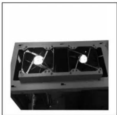
natural_image
Interior view of a mechanical fan or enclosure with two blades and mounting holes (no visible text or symbols)You can install maximum three 120 mm or two 140 mm fans on the top of the chassis.
2.8 Water cooling installation
On the back side of the case you will find pre-drilled water cooling holes.

natural_image
Black electronic device casing with internal panel and indicator lights (no visible text or symbols)Screw holes are drilled on the top of the chassis to fix a 360 mm radiator.

natural_image
Metallic heat exchanger or radiator component with ribbed internal structure (no text or symbols visible)On the bottom panel, you can fix a 240 mm radiator.

natural_image
Back view of a black electronic device with a perforated grille and a screwdriver inserted (no text or symbols visible)2.9 Front panel control & I/O installation
- Please refer to the following table for front panel control & I/O ports.
| Item Description Item Description | ||
| 1 Power on/off 2 Reset | ||
| 3 USB 3.0 port 4 USB 2.0 port | ||
| 5 Audio & mic |
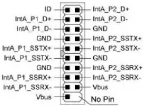
- Please refer to the following illustration of the front I/O connectors and your motherboard user manual.
Front I/O Connector
| Motherboard Case cable connector | |
| USB 3.0 | |
 |  |
| USB 2.0 | |
 |  |
| AC'97 | |
 |  |
| HD Audio | |
 |  |
The product has a two year warranty period from the date of purchase, service issues will be handled by your dealer.
If the case is damaged due to improper operation, the warranty period expires immediately.
Check www.lc-power.com or contact us by e-mail at support@lc-power.com.
Silent Power Electronics GmbH
Formerweg 8
47877 Willich
Germany

POWER



Brand : LC-Power
Model : Gaming 980B
Category : Computer Case