
R-1 - Tachometer Electronics International - Free user manual and instructions
Find the device manual for free R-1 Electronics International in PDF.


| Product Type | Tachometer |
| Brand | Electronics International |
| Model | R-1 |
| Display Type | Analog (pointer) or Digital (varies) |
| Measurement Range | 0-8000 RPM (typical) |
| Accuracy | ±1% of full scale |
| Power Supply | 12V DC (aircraft or automotive electrical system) |
| Dimensions | 3.0 x 2.5 x 1.5 inches (approx.) |
| Weight | 0.2 lbs (approx.) |
| Mounting | Panel mount, 2-1/8 inch diameter hole |
| Operating Temperature | -20°C to +70°C |
| Input Signal | Magnetic pickup, ignition coil, or tach generator |
| Functions | RPM display, hour meter, overspeed warning (varies) |
| Backlight | Optional (depends on model variant) |
| Maintenance | Clean with dry cloth; no internal user serviceable parts |
| Safety | Use only specified voltage; avoid shock and moisture |
| Repairability | Replace entire unit; no field repairs |
| Certifications | FAA TSO (if for aircraft use) or equivalent |
| Warranty | 1 year limited warranty |
| Manual Format | PDF, 15 pages (available online) |
Frequently Asked Questions - R-1 Electronics International
User questions about R-1 Electronics International
0 question about this device. Answer the ones you know or ask your own.
Ask a new question about this device
Download the instructions for your Tachometer in PDF format for free! Find your manual R-1 - Electronics International and take your electronic device back in hand. On this page are published all the documents necessary for the use of your device. R-1 by Electronics International.
USER MANUAL R-1 Electronics International
Operating and Installation Instructions Operating
OI 0517911
5/17/91
Rev. C 9/24/97 *
You must read this manual before installing or operating the instrument. This manual contains warranty and other information that may affect your decision to install this product and/or the safety of your aircraft.

Model: Model:
S/N:S/N:
Important Notice Important
***** MUST READ *****
Notic
MUST R
If you think it is not important to read this manual, you're wrong! This manual contains important installation information that may affect the safety of your aircraft, delay your installation or affect the operation of your instrument. You Must Musish this monthua prior to installing your read this m instrument. Any reduction from these installation instructions is the sole responsibility of the installer/pilot and may render the STC invalid.
Check that the instrument make and model marked on the side of the instrument and on the invoice are correct before starting the installation. A R-1-6 is used on a 6-cylinder engine and a R-1-4 is used on a 4-cylinder engine. Also, check the invoice for proper tach time.
Check that the limit information on this instrument matches the published limits in your aircraft's P.O.H. or Flight Manual. Also, this information may be listed in the T.C. Data Sheet for your aircraft. Any AD's and/or STC's may set forth additional limitations on the operation of your engine. The limit information listed in the AML is for unmodified aircraft and is intended for reference only. It is it is the aircraft owner's and/or installer's responsibility to determine proper instrument calibration and range markings using the aircraft's P.O.H.
On the front of this instrument you will find a red light marked with the maximum RPM information. If there are any additional red or yellow lights on this instrument, the operating range of these lights can be found on a sticker located on the side of the instrument (see the AML at the back of this manual to decode this information). This instrument designates any "Caution Range" with yellow LEDs, any "Maximum and Minimum Limits" with Red LEDs and the "Safe Operating Range" with green LEDs. The "Safe Operating Range" on this instrument is equivalent to the green "Normal Operating Range" and any unmarked areas on a analog gauge.
Read the Warranty / Agreement Read the iWarranty Agreement Warranty / Agreement that may alter your decision to install this product. If you do not accept the terms of the Warranty /If you Agreement, do not install this product. This product may be returned for a refund. Contact Electronics International inc. for details.
It is possible for any instrument to fail thereby displaying inaccurate high, low or jumpy RPM readings. Therefore, you must be able to recognize an instrument failure and you must be proficient in operating your aircraft safely in spite of an RPM instrument failure. If you do not have this knowledge, contact the FAA or a local flight instructor for training.
The pilot must understand the operation of this product before flying the aircraft. Do not allow anyone to operate the aircraft that does not know the operation of this product. Keep the Operating Manual in the aircraft at all times.
ContentsContents
Warranty 2
Operating Instructions 3
Instrument 3
Analog Display 3
Digital Display 3
Mag Drop 4
Tach Time 4
Flight Timer and Peak RPM 5
Installation Instructions 5
Important Information and Initial Check Out 5
Route The Circular Connector 6
Install the Isolators 6
Route the Pickup Wires 7
Route the Power and Ground Wires 7
Route the Backlight Wires: 7
Route the External Warning Control Line 8
Install the Instrument in the Panel 8
Connect the Circular Connector to the Instrument 8
Check Instrument Operation 8
Wiring Diagram 10
R-1 Circular Connector 11
Specifications and Operating Features 12
STC Information 13
Warranty / Agreement warranty / Agreement
Electronics International Inc. warrants this instrument and system components to be free from defects in materials and workmanship for a period of one year from the user invoice date. Electronics International Inc. will repair or replace any item under the terms of this Warranty provided the item is returned to the factory prepaid.
- This Warranty shall not apply to any product that has been repaired or altered by any person other than Electronics International Inc., or that has been subjected to misuse, accident, incorrect wiring, negligence, improper or unprofessional assembly or improper installation by any person. This warranty does notThis warranty cover any reimbursement for any person's time for installation, removal, assembly or repair. Electronics International retains the right to determine the reason or cause for warranty repair.
- This warranty does not extend to any machine, vehicle, boat, aircraft or any other device to which the Electronics International Inc. product may be connected, attached, interconnected or used in conjunction with in any way.
- The obligation assumed by Electronics International Inc. under this warranty is limited to repair, replacement or refund of the product, at the sole discretion of Electronics International Inc.
- Electronics International Inc. is not liable for expenses incurred by the customer or installer due to factory updates, modifications, improvements, upgrades, changes, or any other alterations to the product that may affect the form, fit, function or operation of the product.
- Personal injury or property damage do to misinterpretation or lack of understanding this product is solely the pilots responsibility. The pilot must understand the operation of this product before flying the aircraft. Do not allow anyone to operate the aircraft that does not know the operation of this product. Keep the Operating Manual in the aircraft at all times.
- E. I. Inc. is not responsible for shipping charges or damages incurred under this Warranty.
- No representative is authorized to assume any other liability for Electronics International Inc. in connection with the sale of Electronics International Inc. products.
- If you do not agree to and accept the terms of this warranty, you may return the product for a refund. For a refund.
This Warranty is made only to the original user. THIS WARRANTY IS IN LIEU OF ALLTHIS WARRANTY OTHER WARRANTIES OR OBLIGATIONS: EXPRESS OR IMPLIED. MANUFACTURER EXPRESSLY DISCLAIMS ALL IMPLIED WARRANTIES OF MERCHANTABILITY OR FITNESS FOR A PARTICULAR PURPOSE. PURCHASER AGREES THAT IN NO EVENT SHALL MANUFACTURER BE LIABLE FOR SPECIAL, INCIDENTAL OR CONSEQUENTIAL DAMAGES, INCLUDING LOST PROFITS OR LOSS OF USE OR OTHER ECONOMIC LOSS. EXCEPT AS EXPRESSLY PROVIDEDOF USE OR OTHER HEREIN, MANUFACTURER DISCLAIMS ALL OTHER LIABILITY TO PURCHASER OR ANY OTHER PERSON IN CONNECTION WITH THE USE OR PERFORMANCE OF MANUFACTURER'S PRODUCTS, INCLUDING SPECIFICALLY LIABILITY IN TORT.
Operating Instructions Operating Instruct R-1R-1
Instrument:Instrument:
The R-1 is a precision RPM instrument featuring a 210 degree analog display and a full four-digit digital display. These two displays have many advantages over conventional analog gauges as described below.
Also, the R-1 features long-term accuracy and reliability. Since the R-1 does not incorporate any moving parts (needles, bearings, springs, etc.) there is little to go wrong or wear out. The internal microprocessor assures accuracy and repeatability.
Analog Display: Analog Display:
The 210 degree analog display provides a quick reference of the engine's RPM with respect to its operating range. With a glance you can get a relative idea of how close to the maximum RPM limit the engine is being operated and approximately how far the RPM has to increase to reach its limit. Precise information is provided in the digital display.
An advantage of the analog display is its ability to emit a green, yellow or red light. With a quick glance you can determine if you're operating in a normal, caution or restricted range. Also, when you exceed a maximum limit the red light will blink 20 times at full intensity to catch your attention and warn you that a maximum limit has been violated. After 20 blinks the red light will stop blinking and display continuous red so it does not distract you. The digital display will continue to display accurate RPM readings well beyond the red line limit of the analog display.
During night operation the analog lights may be too bright. If so, turn the panel light rheostat up and the analog lights will dim. The red (maximum limit) light will always be displayed at full intensity.
Digital Display: Digital Display:
The digital display provides RPM information in 10 RPM increments. This allows for precise setting and monitoring of the engine RPM. Also, the digital display is excellent for monitoring trends or changes in the engine's performance.
For aircraft fitted with a fixed pitch prop a relative indication of an engine's ability to produce power can be measured by accurately monitoring the engine's RPM during the first 5 seconds of a full power take-off. A normal reduction in power will occur from high outside air temperatures, high altitudes and excessively rich mixtures. Getting to know your engine's normal take-off RPM can go a long way in detecting engine problems early.
The 10 RPM resolution of the R-1 can also help in setting the mixture control for maximum horsepower for aircraft fitted with either a fixed or variable pitch prop. This is most helpful during high altitude climbs or take-offs. As your engine is leaned at high altitudes it may exhibit an increase in RPM. This increase in RPM indicates an increase in power. For a variable pitch prop this will be a small change. It is not recommended to lean an engine when operated above 75% power. Consult your engine manufacturer's operating procedures for proper operation.
If the digital display backlight has been permanently powered up (as recommended), the digital display will be easier to see during low ambient light conditions and at night.
Mag Drop:Mag Drop:
The mag drop feature allows you to view a change in RPM from a base line. Start by setting the throttle to achieve normal run-up RPM. Then push both buttons on the R-1. This establishes your base line RPM and the display will show "000". Any change in RPM (up or down from the base line) will be displayed. RPM drops will be displayed as negative numbers (i.e.: a "- 200" display means a 200 RPM drop from the base line). Now switch the mag to "Left" or "Right" and the RPM drop will be displayed. Switch your mag back to "Both" and the display will return to "000" or near "000". Most mags will not totally recover back to "000". A problem (fouled plug, bad mag wire, mag problems, etc.) will show up as excessive drop in one mag and the recover RPM (how close it returns to "000") will be excessive. The mag drop feature can be used to check prop governors, horsepower gain or loss during leaning and may other engine operations.
During mag drop operation the analog display will continue to show proper engine RPM. The Mag drop operation will automatically be canceled in 60 seconds or it may be canceled at any time by pushing any button on the R-1.
Tach Time:ach Time:
The tach timer keeps a running total of time the engine is above 1300 RPM. The time is stored in memory for life. There are no internal batteries and bus power is not required to keep the memory alive. The maximum reading is 99,999.9 hours.
To display the time on the tach in thousands of hours, press the right push button marked "Tach Time" and hold the button in. The digital display will show two digits which represent thousands of hours on the tach.
To display the hundreds, tens, units and 1/10 hours on the tach, release the "Tach Time" button for no more than two seconds and press it again and hold it in. The display will show four digits with a decimal point. The digits represent hundreds, tens, units and 1/10 hours on the tach. Each time the "Tach Time" button is pushed and held in the display will toggle between the two displays. If the "Tach Time" button is released for more than three seconds the digital and analog displays will revert back to RPM.
Flight Timer and Peak RPM: Flight Timer and Peak RPM:
This instrument includes an automatic flight timer. When the RPM meets or exceeds 2000 RPM for 10 seconds (as would occur on takeoff), the flight timer will reset to "00.00" and start timing in one-minute increments. The peak RPM register will also be reset to "0000". The flight timer will continue to count until the RPM drops below 1200 RPM for 10 seconds (as would occur on the landing roll-out). At this point the flight time and peak RPM will be stored in memory. There are no internal batteries and bus power is not required to keep the memory alive. Your last flight time and peak RPM will always be available even if the power is turned off.
As the flight timer is counting, the maximum RPM is also being recorded. For an RPM to be recorded as "peak" it must exceed the last recorded RPM for three seconds or longer.
To display flight time, press the push button marked "Flt Time" and hold it in. The digital display will show your flight time in hours and minutes.
To display the highest RPM your engine reached during the flight release the "Flt Time" button for no more than two seconds and press it again and hold it in. The digital display will show the peak RPM reached during the flight. Each time the "Flt Time" button is pushed and held in the display will toggle between flight time and peak RPM. If the "Flt Time" button is released for more than three seconds the digital and analog display will revert back to RPM.
Installation Instructions Installation Instru R-1R-1
Important Information and Initial Check Out: Important Information and Initial
- The installer and aircraft owner must read the Warranty before starting the installation. There is information in the Warranty that may alter your decision to install this instrument. If you do not accept the terms of the Warranty, do not install this instrument.
- If you are not an FAA Certified Aircraft Mechanic familiar with the issues of installing aircraft RPM instruments, Dig NotcrafterRPMtininstalls this instrument.DoT Notinstalls hept (Ghinstalls) should use current aircraft standards and practices to install this instrument (refer to AC 43.13).AC 43.13).
- Check that any necessary FAA Approvals (STC's, etc.) are available for your aircraft before starting the installation. The FAA Approved Model List (AML) is located at the back of this manual. Resolve any issues you may have before starting the installation.
-
Before starting installation, read the entire Installation Instructions and resolve any installation, operating and performance issues you may have. This may eliminate any delays once the installation is started. If the tach cable is removed, a RPM cap is available to cover the port (see price sheet).
-
Check that the instrument make and model marked on the side of the instrument and on the invoice are correct before starting the installation. A R-1-6 is used on a 6-cylinder engine and a R-1-4 is used on a 4-cylinder engine. The R-1-?S1 or R-1-?S2 is to be used on a Lasar ignition system (or any system with a tach out). Also, check the invoice for proper tach time.
-
Check that the limit information on this instrument matches the published limits in your aircraft's P.O.H. or Flight Manual. Also, this information may be listed in the T.C. Data Sheet for your aircraft. Any AD's and/or STC's may set forth additional limitations on the operation of your engine. The limit information listed in the AML is for unmodified aircraft and is intended for reference only. It is the aircraft owner's and/or installer's responsibility to determine proper instrument calibration and range markings for your aircraft.
On the front of this instrument you will find a red light marked with the maximum RPM information. If there are any additional red or yellow lights on this instrument, the operating range of these lights can be found on a sticker located on the side of the instrument (see the AML at the back of this manual to decode this information). This instrument designates any "Caution Range" with yellow LEDs, any "Maximum and Minimum Limits" with Red LEDs and the "Safe Operating Range" with green LEDs. The "Safe Operating Range" on this instrument is equivalent to the green "Normal Operating Range" and any unmarked areas on a analog gauge.
Do not attempt to remove or replace the limit stickers on this instrument. If the RPM limits for your engine do not match those which are marked on this instrument send this unit back to Electronics International Inc. for re-calibration. DO NOT install or use a primary engine instrument DO NOT insta that is not properly calibrated for your aircraft, that is not properly calibrated for your aircraft.
-
Before starting the installation make sure the unit will fit in the location you intend to install it without obstructing the operation of any controls.
-
If this instrument is to replace an existing unit in the aircraft, it is the installer's responsibility to move or replace any existing instruments or components in accordance with FAA approved methods and procedures. The following Installation Instructions do not cover moving or the removal of any existing instruments or components.
Route The Circular Connector: Route The Circular Connector:
Starting from under the instrument panel, route the circular connector end of the wire harness up to the instrument mounting location. (See the wiring diagram at the back of this manual). Place the circular connector about 8 inches back from the panel. Tie wrap the harness in place approximately 1 foot back from the circular connector. This will allow the harness to be flexible and accommodate varying lengths in instrument wires. Be sure these wires do not obstruct the freedom of travel of any controls.
Install the Isolators: Install the Isolators:
On the back of the mag switch will be a number of lugs. Locate the two lugs connected to the left and right mag leads (P leads). Connect the two isolators supplied with the kit to these lugs (see wiring diagram). When installing these isolators do not remove the existing mag leads (P leads). These isola-These isola-
tors should not be changed, lengthened or altered in any way. There is another set of isolators in the instrument. These isolators insure safe operation while providing an easy and simple installation free of mechanical cables and pickups. Make sure the mag lead screws are tight and the connectors are not interfering or shorting to any other terminals on the mag switch.
Route the Pickup Wires: Route the Pickup Wires:
Route the orange wire and the brown wire from the wire harness to the isolators. Cut to length and install a male slip-on connector on each wire. Double over the stripped wire before inserting it into the male connector. Double crimp the connector making sure the crimping tool closes completely. Now mate the orange wire and the brown wire to the female connectors on the isolators. Either wire may connect to either isolator. Be sure the connectors mate properly. If the tab in the male connector gets bent, it can wedge itself between the red nylon and the female metal receptacle. This can result in an intermittent connection after about a month or more. If the connectors are removed several times, the female connector can become loose. If this happens, use a pair of needle nose pliers and tighten the metal receptacle inside the female connector. Tie wrap these wires so they do not obstruct the freedom of travel of any controls. controls.
Route the Power and Ground Wires: Route the Power and Ground Wires:
Route the red wire in the wire harness to the aircraft's 12 or 24 volt main or emergency bus as applicable via an independent circuit breaker (five amps or less). An alternate method would be to route the red lead to the bus via a one amp in-line fuse. With this method a spare fuse should be kept in the aircraft.
Route the black wire in the wire harness to a good ground. Tie wrap these wires so they do not Tie wrap the obstruct the freedom of travel of any controls. Obstruct the freedom of travel of any controls.
Route the Backlight Wires: Route the Backlight Wires:
Connect the backlight wires as follows:
- It is recommended to permanently power up the digital display backlight.
a) For a 12-volt system connect the white/brown wire to the instrument red power lead. Connect the white/red wire to ground (see Wiring Diagram).
b) For a 24-volt system leave the white/brown open and connect the white/red wire to the instrument red power lead (see Wiring Diagram).
- Connect the white/orange wire to the panel light rheostat. This wire will dim the analog LED's for night operation when the panel lights are turned on. If this line is left open, the analog LED's will remain at full intensity at all times. Also, if the voltage on this line drops below 11.5 volts, the analog LED's will be displayed at full intensity. Tie wrap all wires so they do not ob-Tie wrap all w struct the freedom of travel of any controls. Struct the Thirdline of a travel company controls. CP-1 Intensity Control Pot (see price sheet.
Route the External WaRouge t0enExteriale:Wrning Control Line:
The white/yellow wire can be connected to an external light (AL-1), buzzer (ATG-1), voice annunciator (AV-17), a relay, etc. This wire grounds when the red warning light is on. The current in this line must be limited to 1/10 of an amp maximum. Exceeding this limit will damage the unit. If this feature is not used leave this line open. Tie wrap this wire so it does not obstruct the freedom of travel of any controls.controls.
Install the Instrument in the Parstaline Instrument in the P
Install the instrument from behind the instrument panel using 6 x 32 screws. These screws should not be any longer than 1/2".
Connect the Circular Connector to the Instrument: Connect the Circular Con
- Push the two mating connectors together and twist them until they snap into position.
- Turn the locking ring on the instrument connector clockwise (1 1/2 turns) until it locks into position.
Check Instrument Operation: Check Instrument Operation:
To check instrument operation perform the follows:
- Turn the master switch on and verify that the instrument sequences through all the analog lights and reads "8888" on the digital display for 3 seconds or less and then switches to "0000." A problem at this step could be caused by poor connections on the red and/or black leads.
- Check the digital display backlight. With high or medium ambient light it is hard to see the digital display backlight (it is only required during low ambient light conditions but should be on all the time).
- Start the aircraft engine and allow it to idle with the mag switch on "Both." The digital and analog display should be reading properly. An engine's RPM will fluctuate 10 to 20 RPM at low idle. A problem at this step could be caused by a poor or improper connection on the brown or orange mag wires. To troubleshoot, connect the brown mag wire to the mag (through an isolator), leave the orange mag wire disconnected and look for proper operation with the engine at a stable idle RPM. Then connect the orange mag wire to the mag (through an isolator) and leave the brown mag wire disconnected. Look for proper operation with the engine at a stable idle RPM.
-
With all wires connected and the engine at idle select "Left" on the mag switch. Check the analog and digital display for proper operation. A large drop in the RPM for one second is normal. The microprocessor is switching to the other mag. Do this same test for the right mag. A problem at this step could be caused by a poor or improper connection on the brown or orange pickup cables. To troubleshoot see step 3 above.
-
Bring the engine RPM up to 1500 and look for proper operation. A jumpy high RPM reading at this step may be cause by a higher than normal voltage output from a Bendix Mag. If this is the case, install the Bendix Isolators supplied in your R-1 package.
- Check that the screws on the mag switch have been properly tightened and the connectors are not interfering or shorting to any other terminals on the mag switch.
RPM (R-1)RPM (R-1)
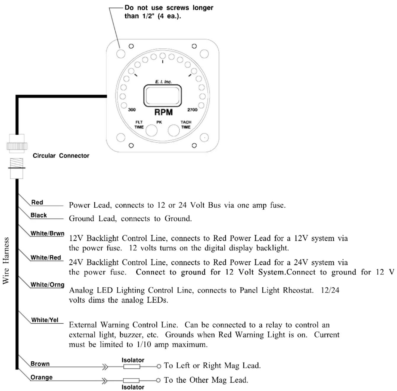
Wiring Diagram Wiring Diagram
WD 0311911
R-1 Circular ConnectorR-1 Circular Con:
Connecting Cable Harness, Back View (wire side)

Note: See Wiring Diagram for hook up information.
Specifications and Operating FeaturesSpecification
S0520911
Model:
R-1 (RPM Instrument)
Case Dimensions:
2.5" x 2.5" x 3.65" depth, 2 1/4" Bezel.
Weight:
10 Oz.
Environmental:
Meets TSO C49a.
Power Requirements:
7.5 to 30 Volts, 1/10 Amp.
Analog Display:
17 High Intensity Light Emitting Diodes (LEDs) in a 210 degree arc with Intensity Control Line available for dimming. Sequential flash test on power up. Microprocessor eliminates LED hunting (flicker).
Red LEDs:
If the Analog Display goes from a Green LED or Yellow LED to a Red LED, the Red LED will blink 20 times then go solid red. The Red Max Limit LED is always displayed at full intensity.
Digital Display:
LCD (viewable in direct sunlight), with 12 and 24 volt backlight control wires for night operation. Readings below 300 RPM will be displayed as "0000". Display will read "8888" on power up.
Accuracy:
1% in accordance with TSO C49a.
Resolution:
10 RPM.
Max Digital Range:
4300 RPM.
Update Time:
3 times per second.
Signal Pickup:
Connects to Left and Right Mag Leads through isolators. Safety insured by additional in-line isolators located in the unit. Instrument will operate on Mags, CDIs and automotive ignition systems. No cables or mechanical connections required.
Tach Time:
Keeps a running total time for RPM readings at or above 1300 RPM. Time is stored in memory for life. There are no internal batteries and power is not required to keep memory alive. Maximum reading is 99,999.9 hours. Displayed in .1 hour increments.
Automatic Flight Time:
Resets to "00.00" and starts timing when RPM reading reaches or exceeds 2000 for 10 seconds. Stops Flight Timer and holds reading in memory when RPM drops below 1200 RPM for 10 seconds. Maximum reading is 99.59 (99 hours and 59 minutes). Displayed in 1 minute increments.
Peak RPM:
Operates in conjunction with the Automatic Flight Timer. Stores the highest RPM for the flight. For an RPM to be recorded as "peak" it must exceed the last recorded peak RPM for 3 seconds or longer.
External Warning Control Line:
Grounds when any Red Warning Light is on or blinking. Current should be limited to 2/10 amp.
STC InformationSTC Information
The R-1 is TSO'd, STC'd and PMA'd as a primary instrument. If you have any question on which aircraft are included on our Approved Model List (AML), please call our factory.
- OPERATING AND INSTALLATION INSTRUCTIONS OPERATING
- IMPORTANT NOTICE IMPORTANT
- MUST READ
- NOTIC
- MUST R
- CONTENTSCONTENTS
- WARRANTY 2
- OPERATING INSTRUCTIONS 3
- INSTALLATION INSTRUCTIONS 5
- WIRING DIAGRAM 10
- R-1 CIRCULAR CONNECTOR 11
- SPECIFICATIONS AND OPERATING FEATURES 12
- STC INFORMATION 13
- WARRANTY / AGREEMENT WARRANTY / AGREEMENT
- OPERATING INSTRUCTIONS OPERATING INSTRUCT R-1R-1
- INSTRUMENT:INSTRUMENT
- ANALOG DISPLAY: ANALOG DISPLAY
- DIGITAL DISPLAY: DIGITAL DISPLAY
- MAG DROP:MAG DROP
- TACH TIME:ACH TIME
- FLIGHT TIMER AND PEAK RPM: FLIGHT TIMER AND PEAK RPM
- INSTALLATION INSTRUCTIONS INSTALLATION INSTRU R-1R-1
- IMPORTANT INFORMATION AND INITIAL CHECK OUT: IMPORTANT INFORMATION AND INITIAL
- ROUTE THE CIRCULAR CONNECTOR: ROUTE THE CIRCULAR CONNECTOR
- INSTALL THE ISOLATORS: INSTALL THE ISOLATORS
- ROUTE THE PICKUP WIRES: ROUTE THE PICKUP WIRES
- ROUTE THE POWER AND GROUND WIRES: ROUTE THE POWER AND GROUND WIRES
- ROUTE THE BACKLIGHT WIRES: ROUTE THE BACKLIGHT WIRES
- ROUTE THE EXTERNAL WAROUGE T0ENEXTERIALE:WRNING CONTROL LINE
- INSTALL THE INSTRUMENT IN THE PARSTALINE INSTRUMENT IN THE P
- CONNECT THE CIRCULAR CONNECTOR TO THE INSTRUMENT: CONNECT THE CIRCULAR CON
- CHECK INSTRUMENT OPERATION: CHECK INSTRUMENT OPERATION
- RPM (R-1)RPM (R-1)
- WIRING DIAGRAM WIRING DIAGRAM
- R-1 CIRCULAR CONNECTORR-1 CIRCULAR CON
- SPECIFICATIONS AND OPERATING FEATURESSPECIFICATION
- SIGNAL PICKUP
- TACH TIME
- AUTOMATIC FLIGHT TIME
- PEAK RPM
- EXTERNAL WARNING CONTROL LINE
- STC INFORMATIONSTC INFORMATION
Brand : Electronics International
Model : R-1
Category : Tachometer