
FL-2RA-12 - Measuring instrument Electronics International - Free user manual and instructions
Find the device manual for free FL-2RA-12 Electronics International in PDF.


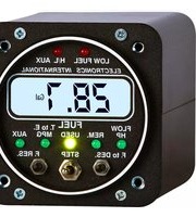
| Product Type | Dual Fuel Level Instrument |
| Model | FL-2RA-12 |
| Compatible Systems | 12 Volt Systems with Resistive Fuel Sensors |
| Analog Display | Two 90° analog LED arcs (7 LEDs each) with green, yellow, red zones |
| Digital Display | LCD, viewable in direct sunlight, with 12/24V backlight control |
| Fuel Level Range per Tank | 4 to 999 gallons |
| Resolution | Programmable to 1 gallon or 0.5 gallon (when calibrated in gallons) |
| Power Requirements | 7.5–35 VDC, 0.1 A |
| Dimensions (Unit) | 2.5" x 2.5" x 3.65" depth; bezel 2.25" |
| Weight | 10 oz (unit only) |
| Filter Response Time | Programmable: 8, 16, 32, 64, or 128 seconds |
| Calibration Points per Tank | 2 to 9 points (empty, partial, full) |
| Operating Modes | FL r (resistive decreasing), FLrH (resistive increasing), FL C (capacitive) |
| Warning Features | 1/4 tank yellow blink, low fuel red blink, open sensor “OPEN” display |
| External Warning Control | Grounds on red warning; max 0.1 A |
| Backlight | Digital backlight always on; analog LEDs dimmable via panel light rheostat |
| Warranty | 1 year from invoice date (repair/replacement at manufacturer’s discretion) |
| Installation Requirements | Must be installed by FAA certified mechanic; for experimental or certified aircraft with TC/STC |
| Included Accessories | Circular connector harness (6 ft leads), mounting screws, placard |
Frequently Asked Questions - FL-2RA-12 Electronics International
User questions about FL-2RA-12 Electronics International
0 question about this device. Answer the ones you know or ask your own.
Ask a new question about this device
Download the instructions for your Measuring instrument in PDF format for free! Find your manual FL-2RA-12 - Electronics International and take your electronic device back in hand. On this page are published all the documents necessary for the use of your device. FL-2RA-12 by Electronics International.
USER MANUAL FL-2RA-12 Electronics International
Dual Fuel Level Dual Fuel L
(FL-2RA-12, FL-2RA-24 and FL-2CA) (FL-2RA-1
(2nd Generation Instruments)(2nd Generation
Operating and Installation Instructions Operating
OI 0131941A
10/15/01
You must read this manual before installing or operating the instrument. This manual contains warranty and other information that may affect your decision to install this product and/or the safety of your aircraft.
Model: Model:
S/N:S/N:
FL-2FL-2
Important Notice Important Notice
\* \* \* \* \* Must Read \* \* \* \* \* \* \* \* Must Read \*
"DO NOT SOLELY RELY ON THE FL-2 TO DETERMINE THE FUEL LEVELS IN THE FUEL TANKSTANKUse of the FL-2 does not eliminate or reduce the necessity for the pilot to use good flight planning, preflight and in-flight techniques for managing fuel.
The following requirements must be met with before operating the aircraft with the FL-2:
- The FL-2 should only be installed in experimental aircraft or a certified aircraft by a T.C. or S.T.C. holder. holder.
- All of the Operating Instructions must be read. There is important information in this manual which the pilot must understand before flying the aircraft. The pilot must understand before flying the aircraft.
- A copy of this operating manual must be in the aircraft at all times.
- The placard reading "DOTNOT PLACARFLYDRREL'Y ON THE FUEL LEVEL INSTRUMENT TO DETER-DO NOT SO MINE THE FUEL LEVELS IN THE AIRCRAFT MINUST BE MOULD ON THE AIRCAFF INSTAIRR PANEL near the FL-2.
- The FL-2 must be calibrated to the aircraft fuel system and its accuracy must be verified before flying the aircraft.
If you ever find an inaccuracy issue or any other problem with the FL-2, cover the face of the instrument with a note saying "DEFECTIVE". This will alert anyone flying the aircraft to the condition of the FL-2.
Warranty 2
Operating Instructions 3
Instrument: 3
Analog Display: 3
Digital Display: 4
Accuracy Limitations: (MUST READ) (MUST.READ)...... 4
Important Considerations: (MUST READ) (MUST.READ).... 5
Installation Instructions 6
Important Information and Initial Check Out: 6
Route The Circular Connector: 7
Route the Power and Ground Wires: 7
Route the Backlight Wires: 7
Route the (Optional) External Warning Control Line: 8
Route the Left and Right Fuel Tank Sensor Wires (FL-2RA-12 and -24 Only): 8
Route the Fuel Tank Ground Sensor Wire (FL-2R and FL-2RH Only): 8
Install the Instrument in the Panel: 8
Connect the Circular Connector to the Instrument: 8
Mount the Placard on the Instrument Panel: 8
Selecting the Proper Filter: 9
Selecting the Proper Operating Mode: 9
Selecting the Resolution: 9
Programming the Filter, Operating Mode and Resolution: 10
Calibration Issues: 11
Calibrate the Left Fuel Tank: 12
Calibrate the Right Fuel Tank: 15
FL-2RA-12 and FL-2RA-24 Wiring Diagram 16
FL-2RA-12 and FL-2RA-24 Circular Connector 17
FL-2CA Wiring Diagram 18
FL-2CA Circular Connector 19
Specifications and Operating Features 20
Technical Notes 21
Warranty
1209921
Electronics International Inc. warrants this instrument and system components to be free from defects in materials and workmanship for a period of one year from the user invoice date. Electronics International Inc. will repair or replace any item under the terms of this Warranty provided the item is returned to the factory prepaid.
- This Warranty shall not apply to any product that has been repaired or altered by any person other than Electronics International Inc., or that has been subjected to misuse, accident, incorrect wiring, negligence, improper or unprofessional assembly or improper installation by any person. This warranty does not cover any reimburse-This warranty for any person's time for installation, removal, assembly or repair. Electronics International retains the right to determine the reason or cause for warranty repair.
- This warranty does not extend to any machine, vehicle, boat, aircraft or any other device to which the Electronics International Inc. product may be connected, attached, interconnected or used in conjunction with in any way.
- The obligation assumed by Electronics International Inc. under this warranty is limited to repair, replacement or refund of the product, at the sole discretion of Electronics International Inc.
- Electronics International Inc. is not responsible for shipping charges or damages incurred under this Warranty.
- No representative is authorized to assume any other liability for Electronics International Inc. in connection with the sale of Electronics International Inc. products.
- If you do not agree to and accept the terms of this warranty, you may return the product in new condition, with receipt, within thirty (30) days for a refund. With receipt, within thirty (30) days for a refund.
This Warranty is made only to the original user. THIS WARRANTY IS IN LIEU OF ALL OTHER WARRAN-THIS WAR TIES OR OBLIGATIONS: EXPRESS OR IMPLIED. MANUFACTURER EXPRESSLY DISCLAIMS ALL IMPLIED WARRANTIES OF MERCHANTABILITY OR FITNESS FOR A PARTICULAR PURPOSE. PURCHASER AGREES THAT IN NO EVENT SHALL MANUFACTURER BE LIABLE FOR SPECIAL, INCIDENTAL OR CONSEQUENTIAL DAMAGES, INCLUDING LOST PROFITS OR LOSS OF USE OR OTHER ECONOMIC LOSS. EXCEPT AS EXPRESSLY PROVIDED HEREIN, MANUFACTURER DISCLAIMS ALL OTHER LIABILITY TO PURCHASER OR ANY OTHER PERSON IN CONNECTION WITH THE USE OR PERFORMANCE OF MANUFACTURER'S PRODUCTS, INCLUDING SPECIFICALLY LIABILITY IN TORT.CALLY LIABILITY IN TORT.
Operating Instructions Operating Instruction FL-2RA & FL-2CAFL-2RA & FL-2CA
Instrument: Instrument:
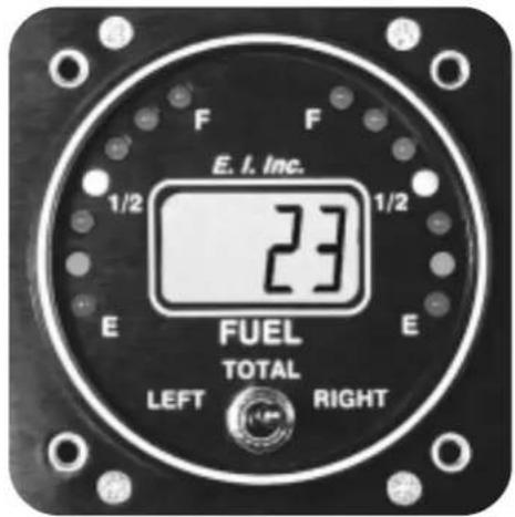
The FL-2 is a fuel level instrument featuring dual 90 degree analog displays and a digital display. These two displays provide the primary indication of the fuel level for the left and right wing tanks and offer many advantages over conventional analog gauges, as described below. The instrument may be calibrated to display in gallons, pounds or liters. If the FL-2 is calibrated for gallons, the instrument may be programmed to display in one or 1/2 gallon increments. For fuel levels above 99 gallons the FL-2 will display in one gallon increments only. Since the FL-2 does not incorporate any moving parts (needles, bearings, springs, etc.) there is little to go wrong or wear out.
The FL-2 has a programmed filter that effects how the instrument responds to changes in fuel level. The filter may be set to 8, 16, 32, 64 or 128 seconds response. In the installation section of this manual is a discussion of the advantages and disadvantages of the different filter settings.
The FL-2 connects to two fuel level sensors mounted in the left and right wing tanks. The FL-2RA-12 and FL-2RA-24 was designed to be used with resistive fuel level sensors that decrease or increases in resistance as fuel is added to the tank. The -12 is for a 12 volt system and the -24 is for a 24 volt system. The FL-2CA was designed to be used with E.I.'s capacitive fuel level sensors and it will operate on a 12 or 24 volt system.
Once the FL-2 is installed in the aircraft it must be calibrated to the aircraft fuel tanks and sensors by filling the tanks to predetermined fuel levels. You may use as few as two calibration points or as many as 9 points. This mapping of the tanks removes any non-linearity in the tanks and sensors.
Analog Display: Analog Display:
The dual 90 degree analog displays provide a quick reference of the left and right fuel levels. More precise information is provided in the digital display. An advantage of the analog display is its ability to emit a green, yellow or red light. With a quick glance you can determine if your fuel level is in the green, yellow, or red operating range. In addition the FL-2 provides the following warnings:
- 1/4 Tank Warning -1/4 (BankfWarrigh) tank level reaches 1/4 of a tank, the appropriate yellow LED will blink. This is intended to alert you that the fuel level is getting low.
- Low Fuel -LowFuel-or right tank reaches 1/8 of a tank or 2 gallons (whichever is greater), the appropriate red LED will blink. This is intended to alert you that the fuel level is getting very low.
- "OPEN" - "OPENWire to the left or right fuel tank sensor becomes open, the analog display for the tank with the problem will show an empty and the digital display will show "OPEN." This warning is intended to alert you when the FL-2 has lost the signal from one or both of the fuel sensors.
Note: Note acknowledge a blinking LED (i.e., to stop the blinking), change the position of the Tank Selector Switch. Once a blinking warning is acknowledged it will not occur again until the FL-2's power has been turned off and back on. Although these blinking warnings are valuable, they can be annoying. For this reason we provide a way of shutting them off.
During night operation the analog LED's may be too bright. If so, turn the panel light rheostat up and the analog lights (LED's) will dim. If you wish to control the intensity of the LED's independent of the panel light rheostat, a LED Intensity Control Pot is available from Electronics International. The red LED's will always be displayed at full intensity.
Digital Display: Digital Display:
With the Tank Selector Switch in the left or right position the digital display will show the fuel level in the appropriate tank. With the Tank Selector in the center position the total fuel (left + right) will be displayed. Fuel levels below 2 gallons will be displayed as "0" in the left, right and total position.
If the digital display backlight has been permanently powered up (as recommended), the digital display will be easier to see during low ambient light conditions and at night.
On power-up the FL-2 performs the following tests in sequence:
- The left tank's calibration data is check for errors. A table of error codes is provided in the calibration section of this manual. If an error is found, the appropriate error code is displayed and the FL-2 operation is stopped.
- The right tank's calibration data is check for errors. If an error is found, the appropriate error code is displayed and the FL-2 operation is stopped.
- A self test is performed, all the LED's are sequenced and "8888" is shown on the digital display.
***** MUST READ ***** MUST READ *****
Accuracy Limitations: Accuracy Limitations:
The accuracy limitations of the FL-2 are listed below. It is the pilot/owner's obligation to make anyoneIt is the pilot/own flying the aircraft aware of these limitations.flying the aircraft aware of these limitations.
- Angle of Attack -1. The angle of attack calibrated with the aircraft in a cruise angle of attack. If the aircraft is in a condition other than cruise, depending on the mounting location and type of sensor used, the FL-2 may display inaccurate fuel levels. If your aircraft does not sit at a cruise angle of attack when on the ground, it may not display accurate fuel levels. Test your aircraft at different angles of attack and seeTest your aircraft what the effects are on the fuel level readings for the FL-2.
- Full Fuel Readings - Full Fuel Readings the fuel sensor may not be able to detect the fuel entering the upper corners of the fuel tank. If this is the case with your sensor, the FL-2 will display lower fuel levels
than the actual fuel in the tanks when the tanks are full. When the fuel level drops to a point where the fuel sensors start to detect a change, the displayed fuel level should be accurate. Check your system by Check your s comparing the displayed fuel levels on the FL-2 to the fuel levels listed in the flight manual at each fill up.up.
-
Low Fuel Readings -3Do not Fely Breakings-2 to determine the fuel in the tank for indicated tank levels below 1/8 levels should always fly the aircraft in such a manner as to at least maintain the FAA minimum fuel requirements in the aircraft at all times. Depending on the mounting location and type of Depending on sensor used, the FL-2 may not be able to accurately measure the last few gallons of fuel in the tanks.
-
Improper Calibration -4 If the Fiper Calibration properly calibrated it will not display accurate fuel levels in the tanks. It is important you verify the accuracy of the FL-2. Always cross check your measured Always cross ch fuel levels in the tanks with the readings on the FL-2 before each flight.
-
Poor Connections -5P or connection is the wires leading from the FL-2 to the fuel sensors can become intermittent with age. An intermittent connection will most likely show up as wandering or inaccurate readings on the FL-2. Always cross check your measured fuel levels in the tanks with the readings on the FL-2 before each flight, the FL-2 before each flight.
-
Defective Fuel Level Sensors -6FDefectivesFuel BeachSensorsittent or change resistance with age. It is not uncommon to find intermittent problems even in new sensors. We recommend Stewart Warner F-385-CP05 resistive sensors be used with the FL-2RA. An intermittent problem with a fuel sensor will most likely show up as wandering or inaccurate readings on the FL-2. Always cross check the measuredAlways cross fuel levels in the tanks with the readings on the FL-2 at each fill up.
If you ever find an inaccuracy issue or any other problem with the FL-2, cover the face of the instrument with a note saying "DEFECTIVE". This will alert anyone flying the aircraft to the condition of the FL-2.
\*\*\*\*\* MUST READ \*\*\*\*\*
Important Considerations:
"DO NOT SOLELY RELY ON THE FUEL LEVEL INSTRUMENT (FL-2) TO DETERMINE THE FUEL LEVELS IN THE AIRCRAFT". The use of the FL-2 does not eliminate or reduce the necessity for the pilot to use good flight planning, preflight and in-flight techniques for managing fuel. It is important the pilot adopt the practices listed below. If you are not familiar with these techniques, contact the FAA to acquire proper training.
-
A copy of this operating manual must be in the aircraft at all times.
-
Flight Planning - Always calculate the fuel requirement for each leg of the flight including any alternate plans for bad weather. Keep this information available in the aircraft during the flight. Keep a chart of the published fuel flows for various flight/engine conditions in the aircraft. Keep a chart of the measured fuel flows for various flights in the aircraft. Measured fuel flows can be considerably different from published figures. This is usually due to old inaccurate engine instruments.
-
Preflight - Do not rely on the FL-2 to determine the fuel level in the fuel tanks. The pilot must visually check/measure the fuel levels in the tanks before every takeoff. Cross-check the measured fuel levels with the displayed levels on the FL-2. Also, crosscheck these levels with the fuel requirements for the flight listed in your flight plan.
-
In Flight -4Mark FlightFL-2 part of your normal instrument scan. Cross-check the fuel levels displayedCross-check the on FL-2 with your flight plan at each leg of the flight or every 30 minutes (if a leg is longer than 30 minutes). Calculate the fuel flows from the FL-2 displayed fuel levels and compare them with your charts of measured and published fuel flows for the aircraft. If there is a discrepancy, land the aircraft at the nearest airport and verify the fuel levels. Discrepancies should be taken seriously.
-
New Pilot or Owner of the Aircraft -5 If Newell is at new pilot or owner of the aircraft, it is the previous aircraft pilot/owner's responsibility to insure the new pilot has read this manual and is aware of the accuracy limitations and other important considerations. All limitations and operating characteristics learned from operating the FL-2 must be passed on to the new pilot/owner.
Installation Instructions Installation Instruct FL-2FL-2
Important Information and Initial Check Out: Important Information and Initial Chec
-
The installer and aircraft owner must read the Warranty before starting the installation. There is information in the Warranty that may alter your decision to install this instrument. If you do not acceptIf you do not at the terms of the Warranty, do not install this instrument.the terms of the Warranty, do not install this instrument.
-
If you are not an FAA Certified Aircraft Mechanic familiar with the issues of installing aircraft fuel level instruments, Do Not attempt to install this instrument.
-
Read the entire Installation Instructions and resolve any issues you may have before starting the installation. This may eliminate any delays once the installation is started.
-
THIS INSTALLATION MAY REQUIRE SOME PARTS UNIQUE TO YOUR AIRCRAFT THAT ARE NOT SUPPLIED IN THE KIT. Acquire all the parts necessary to install this instrument before starting the installation.
-
Check that the instrument make and model are correct before starting the installation. The FL-2RA-12 is for a 12 volt system and a resistive probe, the FL-2RA-24 is for a 24 volt system and a resistive probe and the FL-2CA is for E.I.'s capacitive probe.
-
Before starting the installation make sure the unit will fit in the location you intend to install it without obstructing the operation of any controls.
-
The FL-2 must be calibrated to the aircraft fuel system and its accuracy must be verified before flying the aircraft.the aircraft.
-
The FL-2 should only be installed in experimental aircraft or a certified aircraft by a T.C. or S.T.C. holder. holder.
-
A copy of this manual must be presented to the pilot/owner. At copy of this manual info that is presented to the pilot/ow must read.
Route The Circular Connector: Route The Circular Connector:
Starting from under the instrument panel, route the circular connector wire harness up to the instrument mounting location. (See the wiring diagram at the back of this manual). Place the circular connector about 2 inches back from the panel. Tie wrap the harness in place approximately 1 foot back from the circular connector. This will allow the FL-2 to be connected outside the instrument for calibration. Be sure these wires do not be sure these wires obstruct the freedom of travel of any controls. obstruct the freedom of travel of any controls.
Route the PBweteath Ground Wires:ower and Ground Wires:
In the wire harness are 3 foot red and black wires used for instrument power and ground. Route the 3 foot red wire in the harness to the aircraft's 12 or 24 volt main or emergency bus as applicable via an independent circuit breaker (five amps or less). An alternate method would be to route the red lead to the bus via a one amp in-line fuse. With this method a spare fuse should be kept in the aircraft.
Route the 3 foot black wire in the harness to a good ground. Tie wrap these wires so they do not obstruct Tie wrap these the freedom of travel of any controls, the freedom of travel of any controls.
Route the Backlight Wires: Route the Backlight Wires:
Connect the backlight wires as follows:
- It is recommended to permanently power up the digital display backlight.
a) For a 12-volt system connect the white/brown wire to the bus (via the same fuse used to power the unit) and connect the white/red wire to ground (see Wiring Diagram).
b) For a 24-volt system leave the white/brown open and connect the white/red wire to the bus (via the same fuse used to power the unit) (see Wiring Diagram).
- Connect the white/orange wire to the panel light rheostat. This wire will dim the analog LED's for night operation when the panel lights are turned on. If this line is left open, the analog LED's will remain at full intensity at all times. Tie wrap all wires so they do not obstruct the freedom of travel of any controls.any controls.
Route the External Waring to Enterprise Warning Control Line:
The white/yellow wire can be connected to a relay to control an external light, buzzer, etc. This wire grounds when the red warning light is on. The current in this line must be limited to 2/10 of an amp maximum. Exceeding this limit will damage the unit. If this feature is not used leave this line open. Tie wrap this wire so it does not Tie wrap this w obstruct the freedom of travel of any controls, obstruct the freedom of travel of any controls.
Route the Left and Right FDelute@SensiorWiRigh(FE2RASt2sndW24e8RAL12 and -2 Only):Only):
In the wire harness are 6 foot brown and orange wires. Route and connect the brown wire to the left fuel tank resistive sensor and route and connect the orange wire to the right fuel tank resistive sensor. These wires may be spliced for extra wire length. Tie wrap these wires so they do not obstruct the freedom of travel of any controls, controls. The maximum resistance of you sensor must be between 90 and 300 ohms.
Route the Left and Right FLReLU@SeaStarWiRigh(FE20CASnspr-20AesO(Fly):
Route and connect the group of wires marked "LEFT" to the left fuel tank sensor and the group of wires marked "RIGHT" to the right fuel tank sensor. These wires maybe spliced for extra wire length. Tie wrap these Tie wrap these wires so they do not obstruct the freedom of travel of any controls.
Install the Instrument in the Planabartle Instrument in the P
Install the instrument from behind the instrument panel using 6 x 32 screws. These screws should not be any longer than 1/2".
Note: If you cannot get to the Enter Button on the back of the unit for calibration, you may want to mount the instrument in the panel after you have calibrated the tanks.
Connect the Circular Connector to the Instrument:
1) Push the two mating connectors together and twist them until they snap into position.
2) Turn the locking ring on the instrument connector clockwise (1 1/2 turns) until it locks into position.
3) Tie wrap any loose wires as needed.
Mount the Placard on the Instrument Panel:anel:
Mount the placard reading "DO NOT SOLELY RELY ON THE FUEL LEVEL INSTRUMENT TO DETERMINE THE FUEL LEVELS IN THE AIRCRAFT" on the aircraft instrument panel near the FL-2.
Selecting the Proper Filter: Selecting the Proper Filter:
The filter may be programmed for a response time of 8, 16, 32, 64 or 128 seconds (time to 100% respond to a change in the fuel level). The advantage and disadvantage of a fast and slow filter setting is discussed below.
Advantages of a faster filter setting (8 to 16 seconds) - A fast response time may show some fluctuations in the fuel level during sloshing or turns. This can give you a good feeling the instrument is working, and there is fuel in the tank. If you ever fly with low fuel levels, this can be very comforting. Once you reach level flight and the fuel has leveled out, accurate fuel levels will be displayed in 8 to 16 seconds depending on the filter setting.
Disadvantages of a faster filter setting (8 to 16 seconds) - A fast response time could show excessive fluctuation in the fuel level that could be annoying. This is especially true for thin wet long wing tanks with little dihedral. Fluctuation can cause the FL-2 to read from near empty to near full.
Advantages of a slower filter setting (32 to 128 seconds): - A slower filter can stabilize the display and remove all short term fluctuations.
Disadvantages of a slower filter setting (32 to 128 seconds): - If you stay in a turn for a long period of time, aircraft with thin wet long wings tanks and little dihedral can have a significant shift in fuel. Eventually this will effect the fuel level readings. Once you establish level flight and the fuel has leveled out, it will take 32 to 128 seconds for an accurate fuel level reading to be displayed on the FL-2, depending on the filter setting.
How your aircraft will react to different filter settings depends on your tanks shape, size, baffles, baffle hole sizes, and probe placement. You may need to experiment with the filter setting to get the results you like best. The filter setting has no effect on calibration or the response time during calibration.
Selecting the Proper Operating Mode: Selecting the Proper Operating Mode:
If you have an FL-2CA Instrument (used with and Electronics International capacitive probe) set the operating mode to “FL C” the “FLrH” mode will cause the instrument to read improperly.
If you have an FL-2RA-12 or -24 and a resistive fuel probe that decreased resistance as you add fuel, set the operation mode to "FL r".
If you have an FL-2RA-12 or -24 and a resistive fuel probe that increase resistance as you add fuel, set the operation mode to "FLrH".
Selecting the Resolution: Selecting the Resolution:
The units of measure (gallons, liters, lbs.) the FL-2 is calibrated in, will be the units of measure the FL-2 will display fuel levels in during operation. If the FL-2 is to be calibrated in gallons, the resolution of the digital display may be set for one gallon (shown as “GAL1”) or 12 gallon (shown as “GAL.5”). If you calibrate the FL-2 in liters, pounds or any other units, the resolution should be set to “GAL1”.
Programming the Filter Operating Mode Filter Resolution:, Operating Mode and Res
To program the Filter, Operating Mode and Resolution perform the following steps:
Note: You will need access to the back of the FL-2 to program the instrument. This may be difficult with the instrument mounted in the panel. You may want to remove the FL-2 from the panel and reconnect it on the outside of the instrument panel with the wires routed through the instrument mounting hole. Tape a clean rag around the FL-2 case to protect it.
- Turn the power to the FL-2 off.
- Set the tank Selector Switch to the center position ("Total").
-
Push and hold the Enter Button on the back of the unit. Turn on the power, wait 3 seconds and release the Enter Button. The FL-2 will display the current filter setting (F 08, 16, 32, 64 or 128). The programmable numbers will be blinking.
-
Toggling the Selector Switch from the center position (total) to the left or right will change the filter setting (F 08, 16, 32, 64 or 128).
-
Once you have selected the filter setting, tap the Enter Button on the back of the FL-2 to display the current operating mode. The programmable letters will be blinking.
-
Toggling the Selector Switch from the center position to the left or right will change the operating mode (“FL r”, “FLrH” and “FL C”).
-
Once you have selected the operation mode, tap the Enter Button on the back of the FL-2 to display the current resolution. The programmable numbers will be blinking.
-
Toggling the Selector Switch from the center position to the left or right will change the resolution ("GAL1" or GAL.5").
-
To exit this program mode, push and hold the Enter Button on the back of the FL-2 for 3 seconds, then release the button. All programmed data is stored in memory for 100 years with or without aircraft power connected to the instrument.


Calibration Issues: Calibration Issues:
The FL-2 must be calibrated to the left and right fuel tanks separately. You may calibrate the FL-2 in gallon, pounds, liters or any other unit you choose. Whatever units you calibrate the FL-2 in, is the units it will display in. For this procedure we will use gallons.
The FL-2 can be calibrated for 4 gallon tanks or as large as 999 gallon tanks. The left and right tanks do not have to be the same size or shape.
The FL-2 can be calibrated with as few as two points (full and empty) or as many as 9 points. The calibration points provide the FL-2 with a fuel sensor output for a specific fuel level. The output of a fuel sensor will be resistance for a resistive fuel probe or a frequency for the Electronics International capacitive probe. In either case, the output of the fuel probe is converted to an arbitrary count we call “Sensor Counts”.
As the fuel level in the fuel tanks increase, the Sensor Counts displayed on the FL-2 will increase (provided you have programmed the FL-2 with the proper operating mode). Some common problems with fuel tanks are listed below:
- As you add fuel to an empty tank, it will take a certain amount of fuel before the resistive float starts to move off the bottom of the tank or off the bottom end stop. For a capacitive system, it takes a certain amount of fuel to reach the center electrode. Fuel levels below this point cannot be measured.
- As you add fuel and the fuel level nears the top of the tank, the float on a resistive sensor will hit the top of the tank or the top end stop. For a capacitive system, the fuel level will exceed the center electrode. The fuel above this point cannot be measured. Therefore the FL-2 may not read a full tank.
These problems can cause accuracy issues for any system. To improve the accuracy of the FL-2, we recommend you set 5 calibration points, empty, 14 , 12 , 34 , and full. By doing this, any issues at the full or empty fuel levels will not effect the accuracy between the 14 and 34 fuel levels.
Another common problem with fuel gauges is they may not display a full tank after calibration. If the FL-2 has this problem, slightly reduce the Sensor Counts for the full fuel level calibration point. To calculate how much to reduce the counts, divide the change in the Sensor Counts between two cal points (near 1/2 tank) by the change in the fuel level between the same two cal points. The FL-2 allows you to change the fuel level or the Sensor Counts for any calibration point without having to add or remove fuel from the tank. You can also recalibrate any calibration point at any time.
On power-up the FL-2 checks the left tank's calibration data and then the right tank's calibration data. If there is any errors in the left tank's calibration, the FL-2 will report the error and stop operation. Therefore, if you need to recalibrate both tanks, start with the left tank and resolve all reported errors before calibrating the right tank.
Calibrate the Left FCellPlateTable: Left F
- Use the chart at the back of this section and select the fuel levels for each calibration point. You can use any number of cal points between 2 and 9. If you are not sure what the full fuel level will be for your tank, you can record this level at the last step of this procedure when you have an accurate measurement of the fuel required to fill the tank.
- Drain the Left Tank with a normal aircraft angle of attack (nose up or down) such that the most amount of fuel is left in the tank. This fuel in the tank is considered unusable and the FL-2 should read "0" (Empty) for this fuel level.
Note: Gasoline is explosive and can be very dangerous. It should be handled in a well ventilated hangar or outdoors. Keep it away from any flames, heat sources or electrical equipment. Always store gasoline in a closed container. If you are not familiar with all of the issues of working with gasoline, contact your local fire department for important safety advice.
-
Set the aircraft angle of attack for cruise flight.
-
Turn the power to the FL-2 off. Set the Tank Selector Switch to the left position.
-
Push and hold the Enter Button on the back of the unit. Turn on the power. Wait 3 seconds and release the Enter Button. Only the Left Empty LED should be lit and the digital display should read "Cal 1". This is your first calibration point.
Note: If you are recalibrating the FL-2 and wanted to advance to a specific calibration point, push and hold the Enter Button on the back of the FL-2 until you get to the calibration point of interest. The calibration points will advance every 3 seconds. If you accidentally advance past the full fuel calibration point, the FL-2 will check for errors, go through the power-up sequence and then into the normal operating mode. You will have to start over.
-
Place the Selector Switch into the center position. The FL-2 will display "E000". The "E" indicates you are calibrating the Empty Fuel Level. The "000" indicates the fuel level for this calibration point is 0 gallons.
-
Place the Selector Switch into the right position. The FL-2 will display the last programmed Sensor Counts for this cal point.
Tap the Enter Button on the back of the FL-2, the display will start blinking and the Sensor Counts for the current fuel level in the tank will be displayed. Wait for the display to stabilize and tap the Enter Button to lock the current Sensor Counts into the display and stop the blinking.
- Record the Sensor Counts for calibration point 1 in the calibration chart at the back of this section.


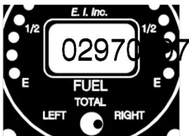
Note: If you want to manually program the Sensor Counts, push and hold the Enter Button at the back of the FL-2 (with the Sensor Counts displayed and not blinking) until the thousands digits starts to blink.
To increase the count of the blinking digit, move the Selector Switch from the center position to the right.
To decrease the count of the blinking digit, move the Selector Switch from the center position to the left.
To blink the next digit to the right, tap the Enter Button on the back of the FL-2.
To exit the manual programming of the Sensor Counts, lock the Sensor Counts into the display and stop the blinking of a digit, push and hold the Enter Button for 3 seconds.
- To advance to the next calibration point, move the selector switch to the left position, push and hold the Enter Button on the back of the unit until you see "CAL2" in the display. All of the calibration data for calibration point 1 has been stored to permanent memory.
- Fill the tank to the fuel level indicated on your calibration chart for the next calibration point.
- Place the Selector Switch to the center position. The FL-2 will display the last programmed fuel level for
this calibration point. The display will show something like "P015" or maybe "F015". A "P" would indicate this is a partial fuel level (not the full fuel level). An "F" would indicate this is the full fuel level for the tank and the last cal point. The "015" is the fuel level for this cal point.
- To program (change) the fuel level for this calibration point, push and hold the Enter Button on the back of the FL-2 for 3 seconds. The far left letter (“P” or “F”) will be blinking. To change this letter, move the selector switch to the left or right.


If this calibration point is for a partial fuel level (not the full fuel level), select “P”. If this calibration point if for the full fuel level (the last cal point) select “F”.
Note: The programmed fuel level must increase for each calibration point.
To increase the count of the blinking digit, move the Selector Switch from the center position to the right.
To decrease the count of the blinking digit, move the Selector Switch from the center position to the left.
To blink the next digit to the right, tap the Enter Button on the back of the FL-2.
To exit the programming of the fuel level for this calibration point and stop the blinking of a digit, push and hold the Enter Button on the back of the FL-2 for 3 seconds.
- Place the Selector Switch into the right position. The FL-2 will display the last programmed Sensor Counts for this cal point.
Tap the Enter Button on the back of the FL-2, the display will start blinking and the Sensor Counts for the current fuel level in the tank will be displayed. Wait for the display to stabilize and tap the Enter Button to lock the current sensor counts into the display, and stop the blinking.
- Record the Sensor Counts for this cal point on the calibration chart at the back of this section.

- Perform steps 10 trough 14 for each call point. Once you have calibrated the full fuel level, the FL-2 will evaluate the calibration data for any errors. The error codes are listed on the following table.
| sedoCrorrE | ||
| knaTtfeL | k | natthgiR |
| 1L | 1 | The SensorCounts forCalPoint 1 (Empty) is too high (>r3072). |
| 2L | 2 | The FullFuelCalibration point is missing. A 19 CalPoints are for partial fuel levels. |
| L3 | r3 | The FullFuelLevel is less than 4 gallons. |
| 4L | 4 | The SensorCounts between full and empty is less than 200 counts. |
| 5L | 5 | The fuel level for each successive CalPoint must be higher than the last. One or more is .to |
| 1030011 | ||
Note: On every power-up, the FL-2 checks the left tank calibration data for errors and if there are no errors, it checks the right tank calibration data for errors. If an error is found, the FL-2 displays the first error it finds and locks the FL-2 into a nonoperating mode with the first error code found shown in the digital display.
Calibrating the Right FCellKing the Right F
The right fuel tank is calibrated in the same manner as the left tank. The right tank does not have to be the same size nor does it have to have the same calibration points as the left tank.
Calibrate the right tank using the left tank calibration procedure (steps 1 through 15) with the following change: When the procedure calls for the Selector Switch to be placed in the left position, place it in the right position. When the procedure calls for the Selector Switch to be placed in the right position, place it in the left position.
Provide the Operating and Installation Manual to the Pilot: Provide the Operating ar
A copy of this manual must be presented to the pilot/owner. At copy of this manual must be presented to the pilot/owner be read. A copy of this manual must be kept in the aircraft at all times.
| FL-2 Calibration Chart | ||||
| Cal Point | Fuel Level | Left Tank Sensor Count | Right Tank Sensor Count | Comments |
| 1 | The Sensor Counts for Cal Point 1 (empty) must not be >3072 (Error Code 1). | |||
| 2 | ||||
| 3 | The fuel level must increase for each successive Cal Point (Error Code 5). | |||
| 4 | The Sensor Counts between Full and Empty must be 200 Sensor Counts or more (Error Code 4). | |||
| 5 | ||||
| 6 | ||||
| 7 | ||||
| 8 | ||||
| 9 | The full fuel level must be 4 gallons or more (Error Code 3). | |||
| 103002 | ||||
FL-2RA-12 and FL-2RA-22-2RA-24
Wiring Diagram Wiring Diagram
Do not use screwsDo not use screws
longer than 1/2" (4 ea.).longer than 1/2"

Circular Connector
Wire Harness
Red
Black
White/Brwn
White/Red
White/Orng
White/Yel
Brown Wire
Orng Wire
3' Power Lead, connects to 12 or 24 Volt Bus via 1 amp fuse or circuit breaker.
3' Ground Lead, connects to Ground.
3' Backlight Control Line, connects to 12 Volt Bus via 1 amp fuse (may use the power fuse). 12 volts turns on the digital display backlight.
3' Backlight Control Line, connects to 24 Volt Bus via 1 amp fuse (may use the power fuse). Connect to ground for 12 Volt System.
3' Analog LED Lighting Control Line, connects to Panel Light Rheostat. 12/24 volts dims the analog LEDs.
3' External Warning Control Line. Can be connected to a relay to control an external light, buzzer, etc. Grounds when Red Warning Light is on. Current must be limited to 1/10 amp maximum.
6' Left Tank Input, connects to Left Tank Resistive Sensor.
6' Right Tank Input, connects to Right Tank Resistive Sensor.

natural_image
Pure electrical circuit lines without any symbolsAirframe Ground
FL-2RA-12 and FL-2RA-24FL-2RA-12 and I
Circular Connector Circular Connector
Connecting Cable Harness, Back View (wire side)

Note: See Wiring Diagram for hook up information.
FL-2CA-2CA
Wiring Diagram Wiring Diagram
Do not use screwsDo not use screws longer than 1/2" (4 ea.).longer than 1/2"


Circular Connector
Red
3' Power Lead, connects to 12 or 24 Volt Bus via 1 amp fuse or circuit breaker.
Black
3' Ground Lead, connects to Ground.
White/Brwn
3' Backlight Control Line, connects to 12 Volt Bus via 1 amp fuse (may use the power fuse). 12 volts turns on the digital display backlight.
White/Red
3' Backlight Control Line, connects to 24 Volt Bus via 1 amp fuse (may use the power fuse). Connect to ground for 12 Volt System.
White/Orng
3' Analog LED Lighting Control Line, connects to Panel Light Rheostat. 12/24 volts dims the analog LEDs.
Wire Harness
White/Yel
3' (Optional) External Warning Control Line. Can be connected to a relay to control an external light, buzzer, etc. Grounds when Red Warning Light is on. Current must be limited to 1/10 amp maximum.
Red Wire
Black Wire
6' Grouped wires marked "Left", connects to Left Tank Capacitive Sensor.
White Wire
Red Wire
Black Wire
6' Grouped wires marked "Right", connects to Right Tank Capacitive Sensor.
White Wire
FL-2CAFL-2CA
Circular Connector Circular Connector
Connecting Cable Harness, Back View (wire side)

Specifications and Operating FeaturesSpecification
Model:
FL-2RA-12FD42RAut2Level Instrument to be used in a 12 Volt System and with resistive sensors.)
FL-2RA-24FDu2RAu24Level Instrument to be used in a 24 Volt System and with resistive sensors.)
FL-2CAFD-2CAuel Level Instrument for use with E.I.'s capacitive sensors from 125Hz to 5KHz.)
Case Size and Weight:
2.5" x 2.5" x 3.65" depth, 2 1/4" Bezel.
10 Oz. Unit Only.
Power Requirements:
7.5 to 35 Volts, 1/10 Amp.
Analog Display:
Two sets of 7 High Intensity Light Emitting Diodes (LEDs) in 90 degree arcs with Intensity Control Line available for dimming. Sequential flash test on power up.
LED Warnings:
- 1/4 Tank Warning -1/4 (thank Warright tank level reaches 1/4 of a tank, the appropriate yellow LED will blink.
- Low Fuel -LifthEleft-or right tank reaches 1/8 of a tank, the appropriate red LED will blink.
- "OPEN" - "OTHERWire to the left or right fuel tank sensor becomes open, the analog display for the tank with the problem will show an empty and the digital display will show "OPEN."
Note: Note acknowledge a blinking LED (i.e., to stop the blinking), change the position of the Tank Selector Switch.
Digital Display:
On every power-up, the FL-2 checks the left tank calibration data for errors and if there are no errors, it checks the right tank calibration data for errors. If an error is found, the FL-2 displays the first error it finds and locks the FL-2 into a non-operating mode. If no errors are found, the FL-2 will perform a power-up test, sequence the leds and display "8888" on the digital display. The FL-2 uses an LCD display (viewable in direct sunlight), with 12 and 24 volt backlight control wires for night operation.
Max, Min and Resolution:
Minimum fuel level for each tank: 4 gallons.
Maximum fuel level for each tank: 999 gallons.
Resolution: Programmable to 1 or 1/2 Gallon (Fuel levels below 2 gallons will be displayed as "0").
External Warning Control Line:
Grounds when any Red Warning LED is on or yellow LED blinking. Current should be limited to 1/10 amp.
By: Ron RobertsBy: Ron Roberts
0718971A
Rev. A: 10/15/01
FL-2 Fe@FLevel Instrumentuel Level Instrument andand
Fuel Level System Issuesuel Level System Issue
Getting a fuel level system to operate accurately is not always an easy task. The FL-2 solves many of the problems found in standard gauges, but there are still many issues that must be addressed. These notes will cover some of those issues.
Resistive F-Resistive Sensor Issuesuel Level Sensor Issues
It's a good idea to test the resistance of the fuel sensors before installing the FL-2RA Instrument in the aircraft.
A. For Resistive Fuel Sensors which decrease resistance when fuel is added perform the following tests:
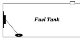
- With the float at the bottom of the tank (as it would be if the tank was empty), measure the resistance of the fuel sensor. The resistance should be between 270 ohms and 90 ohms. If the readings are below 90 ohms or greater than 270 ohms, you may be using the wrong type of sensor. Use a sensor which decreases resistance when fuel is added and which has a maximum resistance of between 90 and 270 ohms.
- With the float at the top of the tank (as it would be if the tank was full), measure the resistance of the fuel sensor. The resistance should be near 0 ohms.
- As you raise the sensor float slightly slightly bottom of the tank, the resistance should start to decrease. If it does not, the sensor resistance is probably topped out. The FL-2 will read lower than actual fuel levels until the sensor wiper drops onto the resistive element.
With the sensor float held to the bottom of the tank, adjust the sensor float arm so the wiper is on the resistive element and not on the termination (end stop). You will need an ohmmeter to determine this. As you slightly move the float arm, the resistance should change.

Technical Notesechnical Notes
Page Two
- As you lower the sensor float slightly slightly the top of the tank, the resistance should start to increase. If it does not, the sensor resistance is probably bottomed out. The FL-2 will read lower than actual fuel levels until the sensor wiper drops onto the resistive element.
With the sensor float held to the top of the tank, adjust the sensor float arm so the wiper is on the resistive element and not on the termination (end stop). You will need an ohmmeter to determine this. As you slightly move the float arm, the resistance should change.
B. For resistive fuel sensors that increase resistance when fuel is added perform the following tests:
- With the float at the bottom of the tank (as it would be if the tank was empty), measure the resistance of the fuel sensor. The resistance should measure 1/4 or less of the total sensor resistance. If the readings are higher, you may need to adjust the sensor float arm. Prior to doing this, read tests 3 and 4 below.
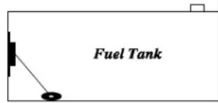
- With the float at the top of the tank (as it would be if the tank was full), measure the resistance of the fuel sensor. The resistance should be between 270 ohms and 90 ohms. If the readings are below 90 ohms or greater than 270 ohms, you may be using the wrong type of sensor. Use a sensor that increases resistance when fuel is added and has a maximum resistance of between 90 and 270 ohms.
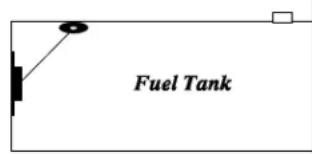
- As you raise the sensor float slightly slightly bottom of the tank, the resistance should start to increase. If it does not, the sensor resistance is probably bottomed out. The FL-2 will read lower than actual fuel levels until the sensor wiper drops onto the resistive element.
With the sensor float held to the bottom of the tank, adjust the sensor float arm so the wiper is on the resistive element and not on the termination (end stop). You will need an ohmmeter to determine this. As you slightly move the float arm, the resistance should change.
- As you lower the sensor float slightly slightly the top of the tank, the resistance should start to decrease. If it does not, the sensor resistance is probably topped out. The FL-2 will read lower than actual fuel levels until the sensor wiper drops onto the resistive element.
With the sensor float held to the top of the tank, adjust the sensor float arm so the wiper is on the resistive element and not on the termination (end stop). You will need an ohmmeter to determine this. As you slightly move the float arm, the resistance should change.
Technical Notesechnical Notes
Page Three
As a general rule, resistive sensors can be unreliable. We tested a number of NEW resistive fuel sensors and only found two that passed our tests. That was the Stewart Warner F-385-CP05 and the Rochester 7740-304. We do not know the long-term reliability of these sensor.
Some problems with resistive fuel sensors are listed below:
A. Linearity - This is NOT a problem when used with the FL-2. The FL-2 compensates for sensor and tank non-linearity.
C. Repeatability - If a sensor cannot repeat its resistive output for a given fuel level, your fuel level readings on the FL-2 will be inaccurate. Some factors that affect repeatability are:
- Side loading of the float arm - Most resistive fuel sensors fail this test. This problem is usually caused by poor design of the float arm linkage and/or wiper.
- Temperature Changes - Most resistive fuel sensors pass this test.
- Moisture Changes - Most resistive fuel sensors pass this test.
- Intermittent opens in the wiper - Many resistive fuel sensors fail this test. This problem can be caused by low wiper force, poor wiper design, height variation of the resistive element or poor linkage design. Also, as the wiper bumps onto the terminator (end stops) the wiper can go open (high resistance).
- Long term reliability - As the wiper, wire wound resistor and linkage wear, intermittent “opens” and side loading effects can become a problem. Also, varnish and other products in the fuel can deposit on the wiper and wire wound resistor. In addition, if the fuel level in the tank leaves the wiper and wire wound resistor exposed to air for long periods of time, they can corrode.
The P3000 Capacitive Fu600G@CaprobienceF Level Probe
The P-300C is a capacitive fuel level probe. It does not have any moving parts and, therefore, does not have any of the failure mechanisms of a resistive fuel level sensor. The electronics that convert the probe capacitance to a pulse is external from the probe (P-300C Interface Module) and, there-
fore, can be changed without removing the probe. The minimum probe length for the P-300C probe is 2 feet.
Not all capacitive probes are the same. There are several subtle manufacturing design issues that must be addressed to produce a reliable and repeatable capacitive probe. These design issues will not be covered here.

Technical Notesechnical Notes
Page Four
Capacitive and Resistive F0capacitive Sensib resistance Level Sensor Iss
The dihedral of the wing can affect full fuel level readings. Once the fuel level in the tank goes above the sensor, the fuel level reading on the FL-2 will not read any higher. (For example: if a tank holds 20
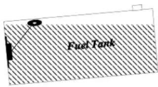
gallons of fuel but at 18 gallons the fuel is at the top of the sensor, the maximum the FL-2 will read is 18 gallons.) The FL-2 reading will only be accurate for tank levels of 18 gallons and lower. This is a common problem for most resistive fuel sensor installations. By programming the FL-2 with a slightly lower Sensor Count for the full fuel level calibration point, the FL-2 can be made to read the Full Fuel Level.
To minimize this problem with a resistive sensor some aircraft manufacturers will install two fuel sensors in a single tank; one at the in-board and one at the out-board
portion of the tank. The sensors are wired in series (one sensor must be insulated from ground). They must not have a combined series resistance of over 270 ohms to work with the FL-2RA instrument (a paralleling resistor can be used to fix this problem). Since there are two resistive fuel sensors in a single tank, there is twice as much to go wrong. It is very important to use very reliable and repeatable resistive fuel sensors (if there is such a thing) in this design.

Fuel slosh to the in-board or out-board portion of the tank can also cause inaccurate readings. For example: depending on the fuel sensor placement in the tank, as the fuel sloshes to the out-board portion of the tank during a turn, the fuel level reading on an in-board mounted sensor will lower,
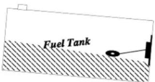

indicating an inaccurate low-fuel level reading on the FL-2. It might not seem that this would be a problem in a coordinated turn but it happens (try it for yourself). This is a common problem in most resistive fuel sensor installations or for long wet wing tanks with little dihedral. A compensating factor is that when one wing s fuel level reads low the other reads high. Therefore, the FL-2 will read correctly when displaying Total. For the most accurate readings, read your fuel level only in straight and level flight.
If the fuel sensor cannot measure the lowest portion of the tank, the FL-2 will display inaccurate low fuel level readings. For example: if a tank level of 4 gallons or less does not produce a change in the output of the fuel level sensor, the FL-2 will display a fuel level of 0 gallons for tank levels of 4 gallons and below. Be sure the fuel sensors are mounted and/or adjusted to measure fuel at the lowest point in the tank as possible.


- Dual Fuel Level Dual Fuel L
- (FL-2RA-12, FL-2RA-24 and FL-2CA) (FL-2RA-1
- (2nd Generation Instruments)(2nd Generation
- Operating and Installation Instructions Operating
- FL-2FL-2
- Important Notice Important Notice
- \* \* \* \* \* Must Read \* \* \* \* \* \* \* \* Must Read \*
- Warranty 2
- Operating Instructions 3
- Installation Instructions 6
- FL-2RA-12 and FL-2RA-24 Wiring Diagram 16
- FL-2RA-12 and FL-2RA-24 Circular Connector 17
- FL-2CA Wiring Diagram 18
- FL-2CA Circular Connector 19
- Specifications and Operating Features 20
- Technical Notes 21
- Warranty
- Operating Instructions Operating Instruction FL-2RA & FL-2CAFL-2RA & FL-2CA
- Instrument: Instrument:
- Analog Display: Analog Display:
- Digital Display: Digital Display:
- Accuracy Limitations: Accuracy Limitations:
- \*\*\*\*\* MUST READ \*\*\*\*\*
- Important Considerations:
- Installation Instructions Installation Instruct FL-2FL-2
- Important Information and Initial Check Out: Important Information and Initial Chec
- Route The Circular Connector: Route The Circular Connector:
- Route the PBweteath Ground Wires:ower and Ground Wires:
- Route the Backlight Wires: Route the Backlight Wires:
- Route the External Waring to Enterprise Warning Control Line:
- Route the Left and Right FDelute@SensiorWiRigh(FE2RASt2sndW24e8RAL12 and -2 Only):Only):
- Route the Left and Right FLReLU@SeaStarWiRigh(FE20CASnspr-20AesO(Fly):
- Install the Instrument in the Planabartle Instrument in the P
- Connect the Circular Connector to the Instrument:
- Mount the Placard on the Instrument Panel:anel:
- Selecting the Proper Filter: Selecting the Proper Filter:
- Selecting the Proper Operating Mode: Selecting the Proper Operating Mode:
- Selecting the Resolution: Selecting the Resolution:
- Programming the Filter Operating Mode Filter Resolution:, Operating Mode and Res
- Calibration Issues: Calibration Issues:
- Calibrate the Left FCellPlateTable: Left F
- Note: The programmed fuel level must increase for each calibration point.
- Calibrating the Right FCellKing the Right F
- Provide the Operating and Installation Manual to the Pilot: Provide the Operating ar
- FL-2RA-12 and FL-2RA-22-2RA-24
- Wiring Diagram Wiring Diagram
- FL-2RA-12 and FL-2RA-24FL-2RA-12 and I
- Circular Connector Circular Connector
- FL-2CA-2CA
- Red
- Black
- White/Brwn
- White/Red
- White/Orng
- Wire Harness
- White/Yel
- Red Wire
- Black Wire
- White Wire
- FL-2CAFL-2CA
- Specifications and Operating FeaturesSpecification
- Model:
- Case Size and Weight:
- Power Requirements:
- Analog Display:
- LED Warnings:
- Digital Display:
- Max, Min and Resolution:
- External Warning Control Line:
- FL-2 Fe@FLevel Instrumentuel Level Instrument andand
- Fuel Level System Issuesuel Level System Issue
- Resistive F-Resistive Sensor Issuesuel Level Sensor Issues
- Technical Notesechnical Notes
- Page Two
- Page Three
- The P3000 Capacitive Fu600G@CaprobienceF Level Probe
- Page Four
- Capacitive and Resistive F0capacitive Sensib resistance Level Sensor Iss
Brand : Electronics International
Model : FL-2RA-12
Category : Measuring instrument