
FOBQ 803 G X - Grill Fulgor Milano - Free user manual and instructions
Find the device manual for free FOBQ 803 G X Fulgor Milano in PDF.


| Product Type | Built-in barbecue for outdoor use |
| Brand | Fulgor Milano |
| Model | FOBQ 803 G X |
| Category | Grill |
| Width | 80 cm (approximate, based on model number) |
| Depth | 60 cm minimum counter depth required |
| Cut-out Dimensions | Approximately 808 x 502 mm (based on 80 cm model) |
| Burner Quantity | 3 burners |
| Fuel Type | Gas (LPG or natural gas, convertible) |
| Gas Connection | Rigid or flexible hose, rear connection |
| Cooking Surface | Stainless steel grill groups (3 sets), optional cooking plate |
| Cover Types Available | Low cover (FOBQ LL 800 MBK) or high cover (FOBQ HL 800 MBK) |
| Ignition System | Automatic with battery (D cell); manual lighting with long match |
| Safety Features | Gas leak testing, thermocouple, ventilation requirements, anti-tip |
| Cleaning | Removable oil drip pans, washable grill parts |
| Maintenance | Annual burner inspection, battery replacement, ventilation checks |
| Installation Requirements | Outdoor use only, non-combustible surface, adequate ventilation |
| Weight | Approximately 30-40 kg (estimated) |
| Warranty | Refer to manufacturer's declaration |
| Spare Parts Available | Injectors, flame diffusers, grill groups, ignition electrode |
Frequently Asked Questions - FOBQ 803 G X Fulgor Milano
User questions about FOBQ 803 G X Fulgor Milano
0 question about this device. Answer the ones you know or ask your own.
Ask a new question about this device
Download the instructions for your Grill in PDF format for free! Find your manual FOBQ 803 G X - Fulgor Milano and take your electronic device back in hand. On this page are published all the documents necessary for the use of your device. FOBQ 803 G X by Fulgor Milano.
USER MANUAL FOBQ 803 G X Fulgor Milano
natural_image
Simple black-and-white diagram showing a surface with smoke or vapor rising above a dotted line (no text or symbols)FOBQ 1000 G X
FOBQ 1000 G MBK
FOBQ 803 G X / MBK
FOBQ 602 G X
FOBQ 601 TY G X
BARBECUE DA INCASSO PER USO DOMESTICO DA ESTERNO
BUILT-IN BARBECUE FOR HOME OUTDOOR USE
EINBAU-GRILLKOFFER FÜR DEN HAUSGEBRAUCH IM OUTDOOR-BEREICH
BARBECUE DE EMPOTRADO PARA USO DOMÉSTICO EN EXTERIORES
natural_image
Simple circular diagram with five curved arrows forming a cycle (no text or symbols)BARBECUE MOD. FOBQ 1000 G X
COPERCHIO BASSO MOD. FOBQ LL 1000 X
BARBECUE MOD. FOBQ 1000 G X
COPERCHIO ALTO MOD. FOBQ HL 1000 X
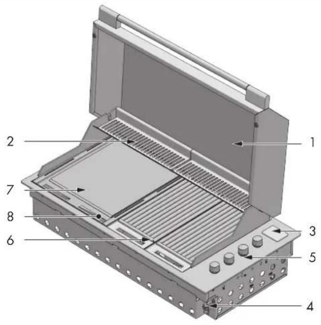
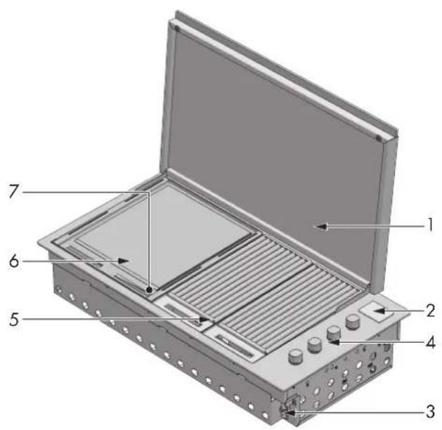
BARBECUE MOD. FOBQ 803 G X
COPERCHIO ALTO MOD. FOBQ HL 800 MBK
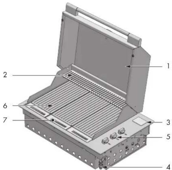
BARBECUE MOD. FOBQ 803 G MBK
COPERCHIO BASSO MOD. FOBQ LL 800 MBK
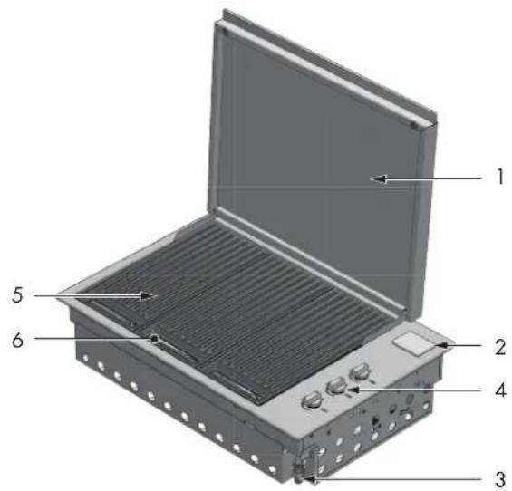
BARBECUE MOD. FOBQ 803 G MBK
COPERCHIO ALTO MOD. FOBQ HL 800 MBK
BARBECUE MOD. FOBQ 601 TY G X
COPERCHIO BASSO MOD. FOBQ HL 600 X
BARBECUE MOD. FOBQ 602 G X
COPERCHIO BASSO MOD. FOBQ HL 600 X
natural_image
Three gray rectangular electronic components with ventilation slots, labeled 'GRUPPI GRIGLIE IN GHISA' (no other text or symbols visible)GRUPPI GRIGLIE IN ACCIAIO INOX
natural_image
3D rendering of three rectangular metal grates with internal slots, shown from different angles (no text or symbols)natural_image
3D rendering of a metal plate with ribbed structure and mounting bracket (no text or symbols)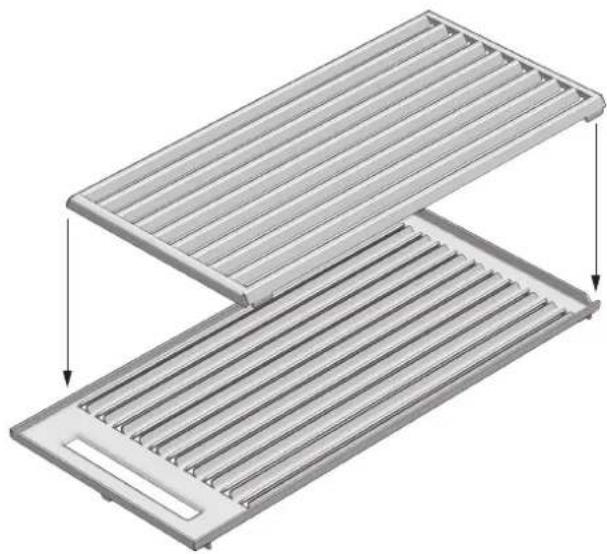
natural_image
3D diagram of a two-tiered storage tray with horizontal slats and a cutout, showing internal structure and directional arrows (no text or symbols)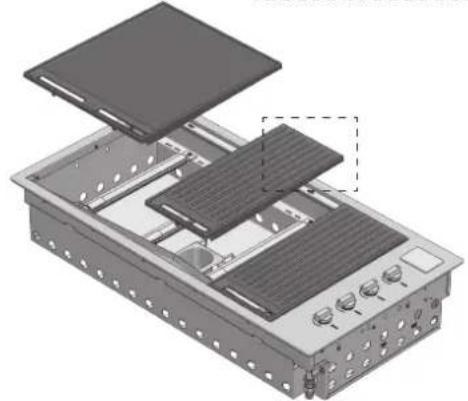
natural_image
Exploded view diagram of an electronic device showing internal components and mounting holes (no text or labels)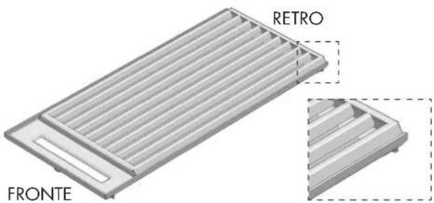
natural_image
3D diagram of a rectangular device with labeled front and retro views (no text or symbols beyond labels)natural_image
Technical illustration of a mechanical assembly with exploded and assembled views (no text or symbols)NOTE
natural_image
Mechanical assembly diagrams showing two views of a mechanical component with bolted parts and a separate view of a bolted nut (no text or symbols present)natural_image
Mechanical assembly diagram showing a bolt inserted into a housing with a separate bolt inserted into a housing (no text or symbols present)natural_image
Technical illustration of a mechanical assembly with three views: top view, front view, and side view (no text or symbols)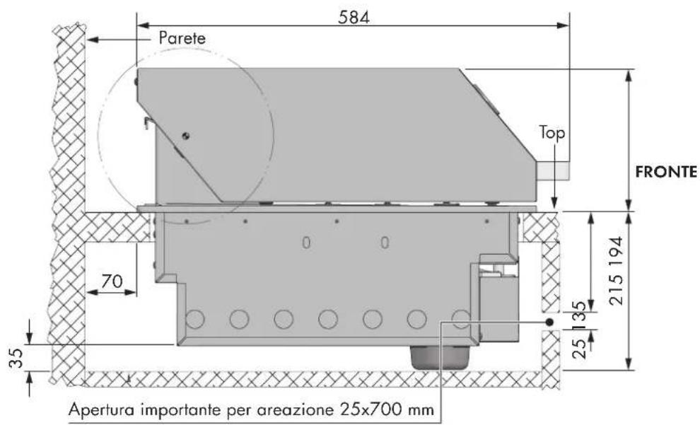

ATTENZIONE
natural_image
Technical diagram of a gas cylinder connected to a control panel with a side-mounted valve, against a hatched wall (no text or symbols)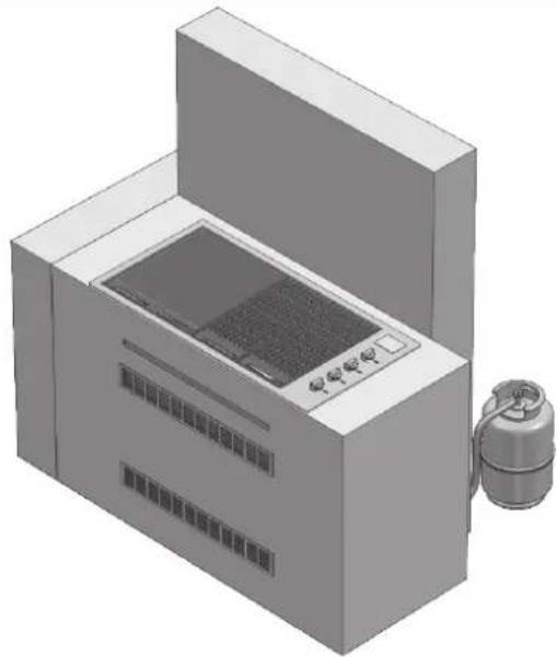
natural_image
3D rendering of a laboratory or industrial machine with control panel and external tank (no visible text or symbols)natural_image
Line drawing of a cylindrical container with cutouts and a lid (no text or symbols)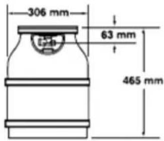
natural_image
Line drawing of a rectangular container with a small cylindrical object on top (no text or symbols)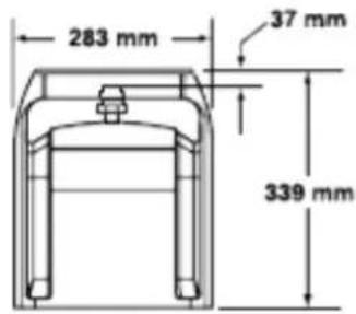
CALOR 5 kg PRIMAGAZ 5.2 kg
natural_image
Line drawing of a mechanical component with no visible text or symbols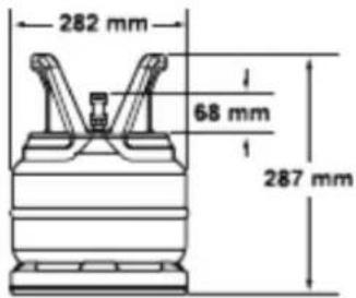
natural_image
Technical line drawing of a mechanical component with a central hub and concentric rings (no text or symbols)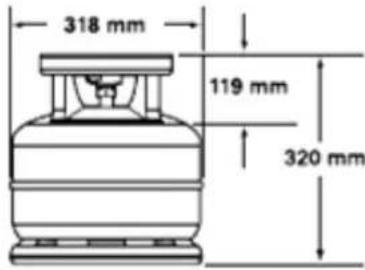
natural_image
Mechanical assembly diagram showing a valve and pump connected to a tank (no text or symbols visible)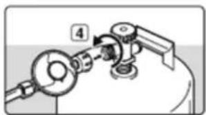
natural_image
Mechanical assembly diagram showing a lever and pump mechanism (no text or symbols)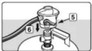
natural_image
Diagram of a showerhead emitting water, showing no text or symbols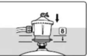
natural_image
3D technical illustration of a mechanical housing component with mounting holes and internal compartments (no text or symbols)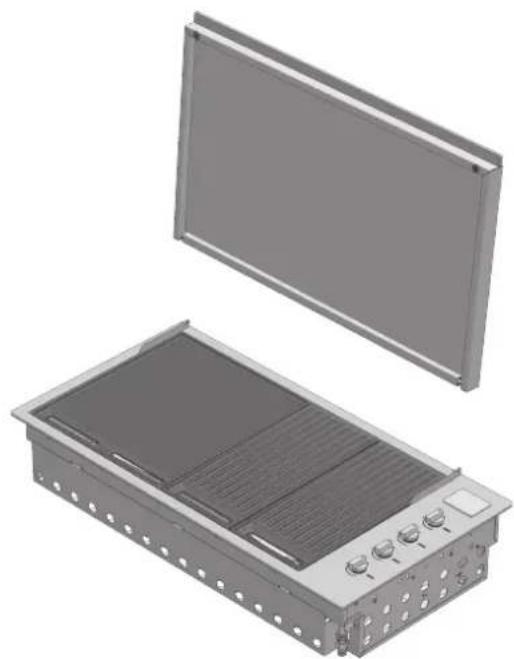
natural_image
3D rendering of an electronic device housing with a flat panel and internal cooling unit (no text or symbols visible)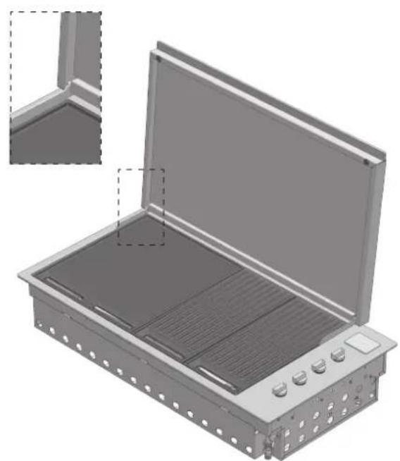
natural_image
3D rendering of an open industrial enclosure with internal compartments and control knobs (no text or symbols visible)natural_image
3D technical illustration of a mechanical housing component with internal compartments and mounting holes (no text or symbols)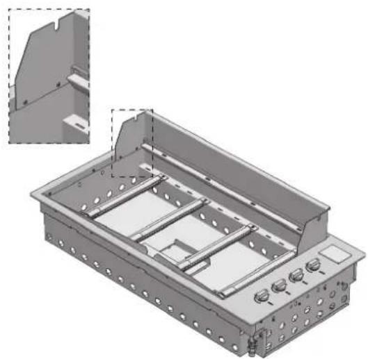
natural_image
3D technical illustration of a mechanical housing or enclosure with internal components and mounting holes (no text or symbols)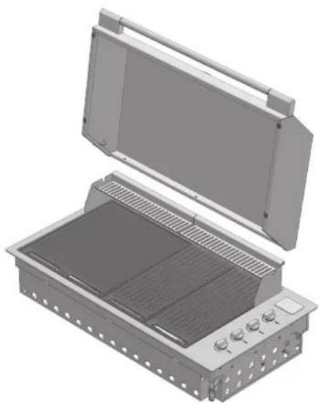
natural_image
3D rendering of an open industrial enclosure with internal grating and ventilation slots (no text or symbols visible)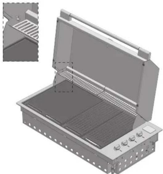
natural_image
3D technical illustration of an open fire extinguisher with internal grating and ventilation slots (no text or symbols)
IMPORTANTE
natural_image
3D rendering of a rectangular electronic device with heat exchangers and ventilation grilles (no text or symbols visible)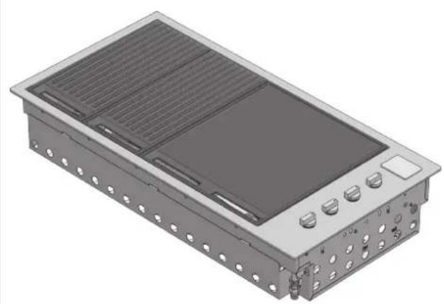
natural_image
3D rendering of a rectangular electronic device with heat sinks and mounting holes (no text or symbols visible)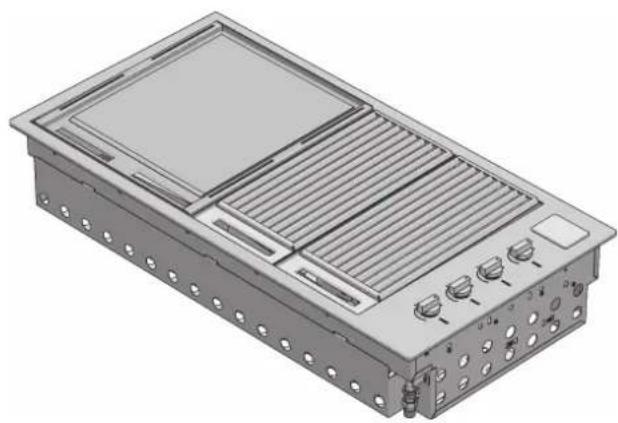
natural_image
3D rendering of a modular electronic device with ventilation grilles and control knobs (no text or symbols visible)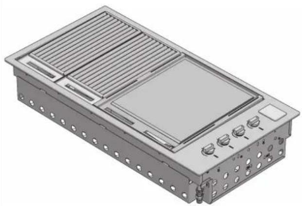
natural_image
3D rendering of a modular electronic device with ventilation grilles and control knobs (no text or symbols visible)natural_image
3D rendering of a rectangular electronic device with heat sinks and mounting holes (no text or symbols visible)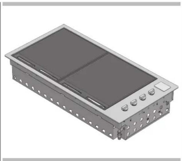
natural_image
3D rendering of a rectangular electronic device with two internal compartments and mounting holes (no text or symbols visible)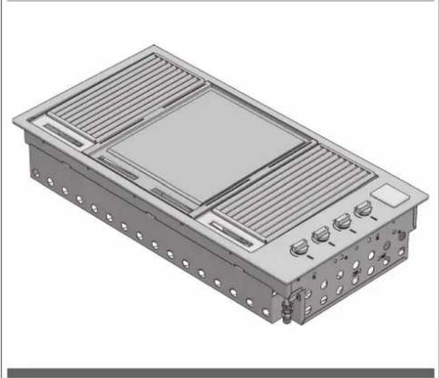
natural_image
3D rendering of a rectangular electronic device with ventilation grilles and control knobs (no text or symbols visible)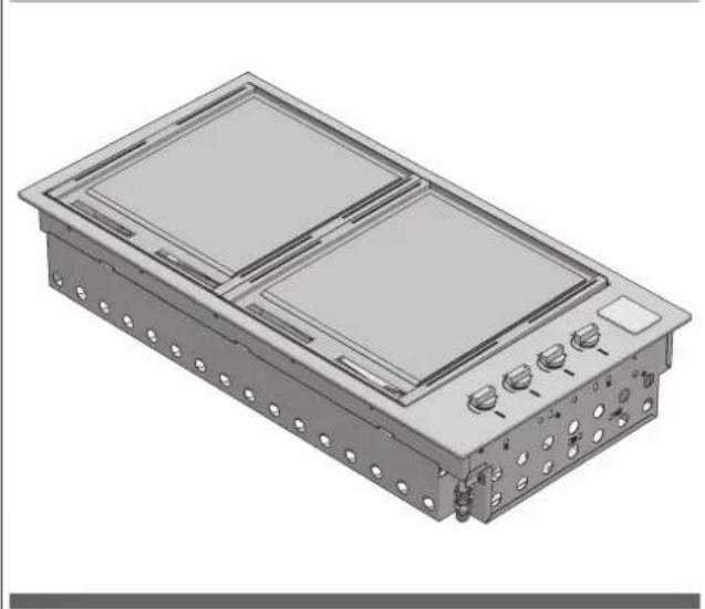
natural_image
3D rendering of a rectangular electronic device with two internal compartments and mounting holes (no text or symbols visible)Mod. BBQ 80 cm
natural_image
3D rendering of an industrial air conditioning unit with heat exchangers and cooling fins (no text or symbols visible)Mod. BBQ 60 cm
natural_image
3D rendering of a rectangular industrial or electrical enclosure with slatted top and side panels, no visible text or symbols.natural_image
3D rendering of a rectangular electronic device with mounting holes and a central screen (no text or symbols visible)Accensione manuale
natural_image
3D rendering of an open industrial electrical enclosure with internal compartments and mounting holes (no text or symbols visible)
ATTENZIONE
IL COPERCHIO SOTTILE NON DEVE ESSERE CHIUSO QUANDO I BRUCIATORI SONO IN FUNZIONE.
natural_image
3D diagram of a rectangular electronic device with internal components and a close-up inset showing a component being inserted (no text or symbols present)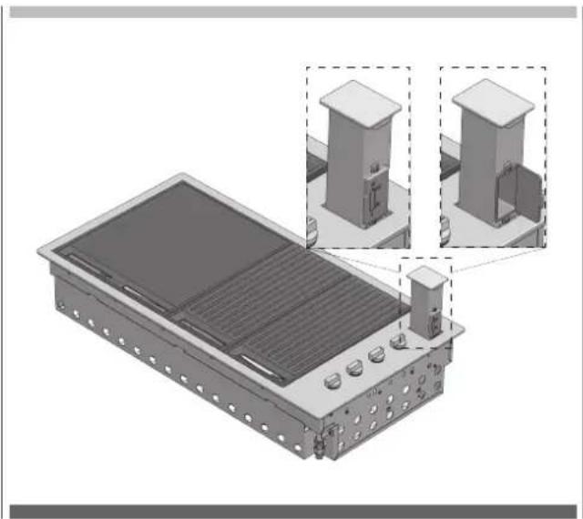
natural_image
3D technical illustration of a solar panel installation with two zoomed-in views showing internal components (no text or symbols)Congratulations and thanks for choosing our integrated barbecue. We are confident that it will be a pleasure for you to use our new barbecue. Before using the barbecue, we recommend reading the entire user guide, which provides a description of the barbecue and its functions. To avoid those risks that are always present when using a gas appliance, it is important to install it correctly and carefully read the safety instructions in order to avoid misuse and hazards. We recommend you keep this instruction booklet for future reference and pass it to any subsequent owners. After removing the barbecue from its packaging, check to see that it is not damaged. If in doubt, do not use the appliance and contact your nearest customer service centre.
Suggestion for the environment Disposal information for users

natural_image
Simple circular diagram with five curved arrows forming a cycle (no text or symbols)- Most of the packaging material is recyclable. These materials should be disposed of through a local recycling centre or by putting them in appropriate collection containers.
- If you want to discard the product, contact your local authorities and ask about the correct method of disposal
TABLE OF CONTENTS PAGE
1 - Product description 2
2 - Components 7
3 - Important safety instructions 8
Use 8
The manufacturer's liability: 10
4 - Assembling the barbecue 11
5 - Characteristics of gas in different countries 13
Adapting to different types of gas 14
Gas connection 15
Rigid and semi-rigid metal and rubber hose connection 15
6 - Gas cylinder safety information 17
Leak testing procedure 17
7 - Installation instructions and warnings 18
Selection of the point of installation 19
Installation compartment 19
Island-mounted 19
Installation in a counter in a special context 19
8 - Connection of the LPG cylinder 28
TABLE OF CONTENTS PAGE
9 - Application of the cover 29
Application of the low cover 29
Application of the high cover 30
10 - Usage instructions 31
Control functions 34
Ignition instructions 34
Manual lighting 34
Pre-heating cooking areas 34
To turn off the burner 35
11 - Cleaning and care 36
Care and cleaning of the appliance 36
Cleaning of cooking parts 36
Other stainless steel surfaces 36
Cleaning the cooking grills made of cast iron 36
Cleaning the stainless steel grills 36
Cleaning the grease drip pan 37
Burners 37
12 - Maintenance 38
Ignition system 38
Ventilation openings 38
13 - Troubleshooting 39
BARBECUE MOD. FOBQ 1000 G MBK
LOW LID MOD. FOBQ LL 1000 MBK
BARBECUE MOD. FOBQ 1000 G X
LOW LID MOD. FOBQ LL 1000 X
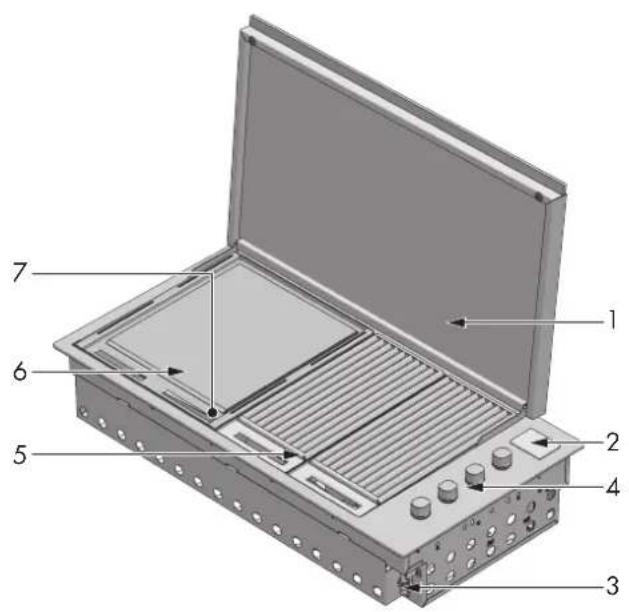
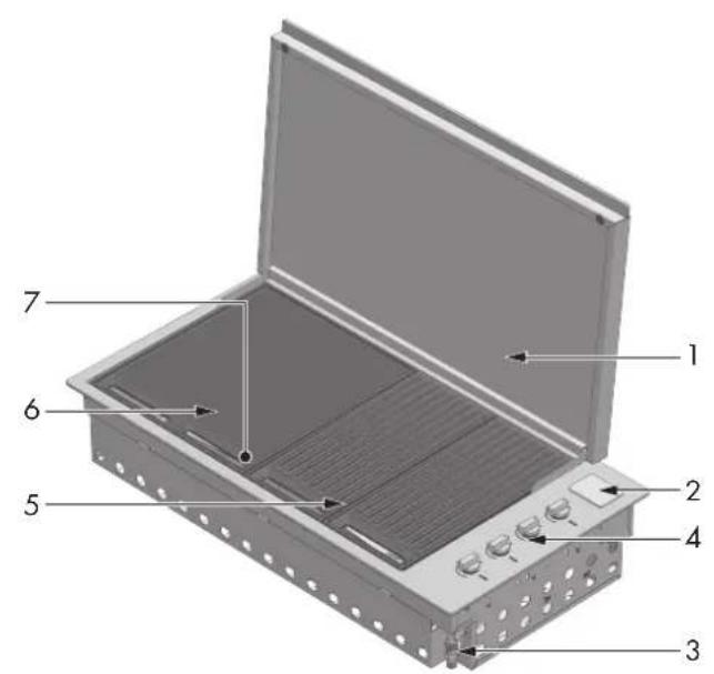
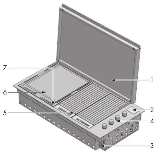
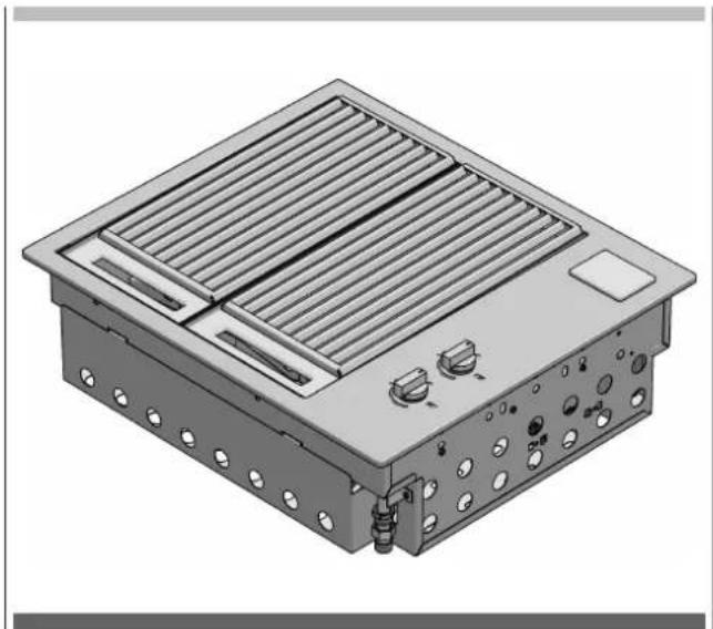
Integrated barbecue with thin cover
| 1. Thin cover 1. Thin cover | ||
| 2. Battery compartment cover 2. Battery compartment cover | ||
| 3. Gas connection point 3. Gas connection point | ||
| 4. Burner controls 4. Burner controls | ||
| 5. Cast iron grills group (2 set) 5. Stainless steel grill group (2 set) | ||
| 6. Cooking plate 6. Cooking plate | ||
| 7. Removable oil collection drip plan located in front of the cooking surface (not shown) | 7. Removable oil collection drip plan located in front of the cooking surface (not shown) | |
| 8. Flame diffusers (2 pcs.) located under the grills (not shown) | ||
BARBECUE MOD. FOBQ 1000 G MBK
HIGH LID MOD. FOBQ LL 1000 MBK
BARBECUE MOD. FOBQ 1000 G X
HIGH LID MOD. FOBQ HL 1000 X
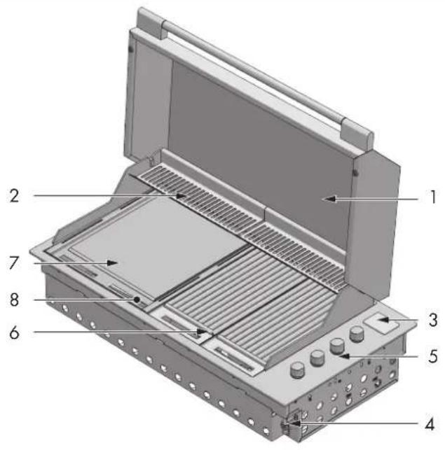
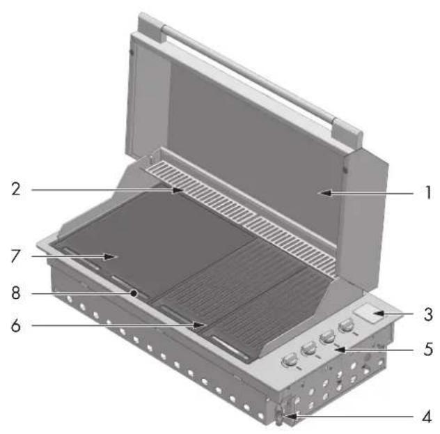
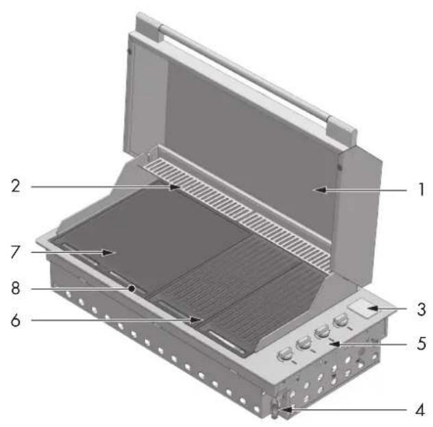
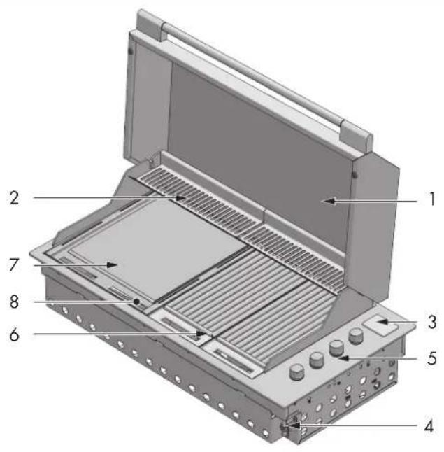
Integrated barbecue with high cover
| 1. High cover 1. High cover | ||
| 2. Heating racks 2. Heating racks | ||
| 3. Battery compartment cover 3. Battery compartment cover | ||
| 4. Gas connection point 4. Gas connection point | ||
| 5. Burner controls 5. Burner controls | ||
| 6. Cast iron grill group (2 set) 6. Stainless steel grill group (2 set) | ||
| 7. Cooking plate 7. Cooking plate | ||
| 8. Removable oil collection drip plan located in front of the cooking surface (not shown) | 8. Removable oil collection drip plan located in front of the cooking surface (not shown) | |
| 9. Flame diffusers (2 pcs.) located under the grills (not shown) | ||
BARBECUE MOD. FOBQ 803 G X
LOW LID MOD. FOBQ LL 800 MBK
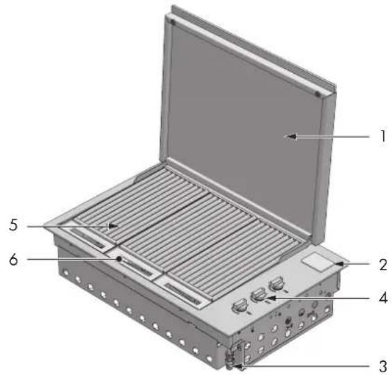
BARBECUE MOD. FOBQ 803 G X
HIGH LID MOD. FOBQ HL 800 MBK
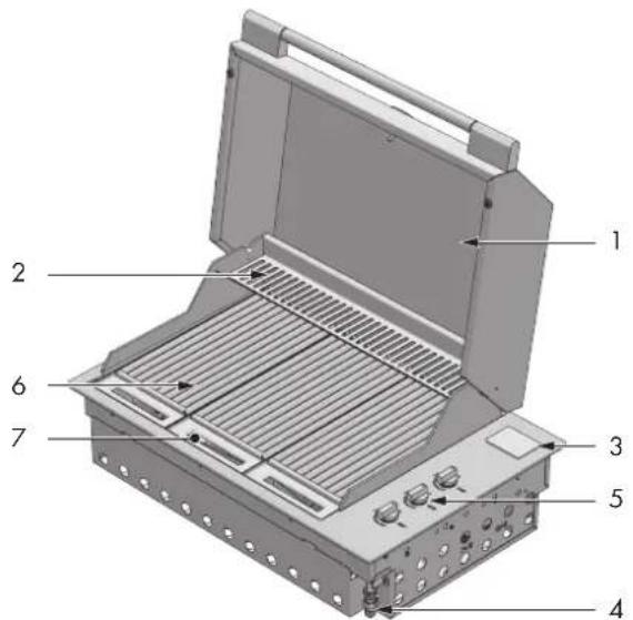
BARBECUE MOD. FOBQ 803 G MBK
LOW LID MOD. FOBQ LL 800 MBK
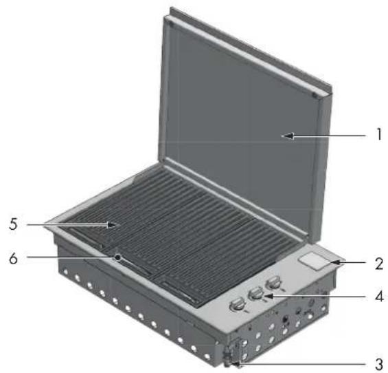
BARBECUE MOD. FOBQ 803 G MBK
HIGH LID MOD. FOBQ HL 800 MBK
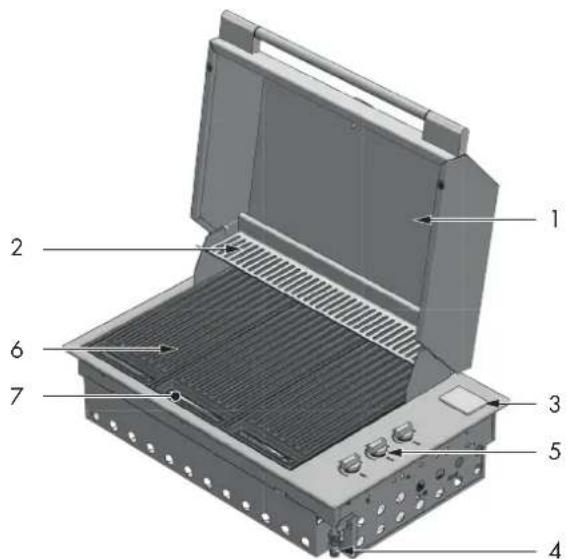
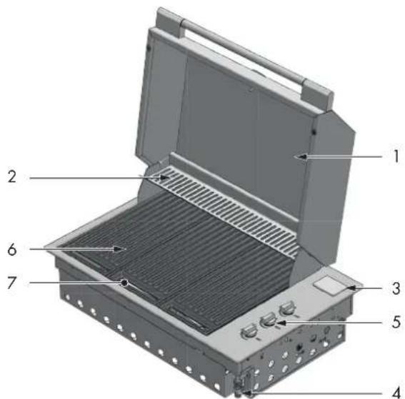
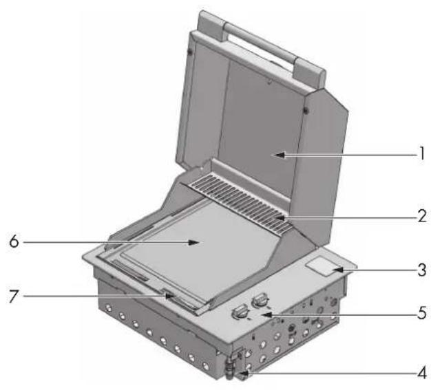
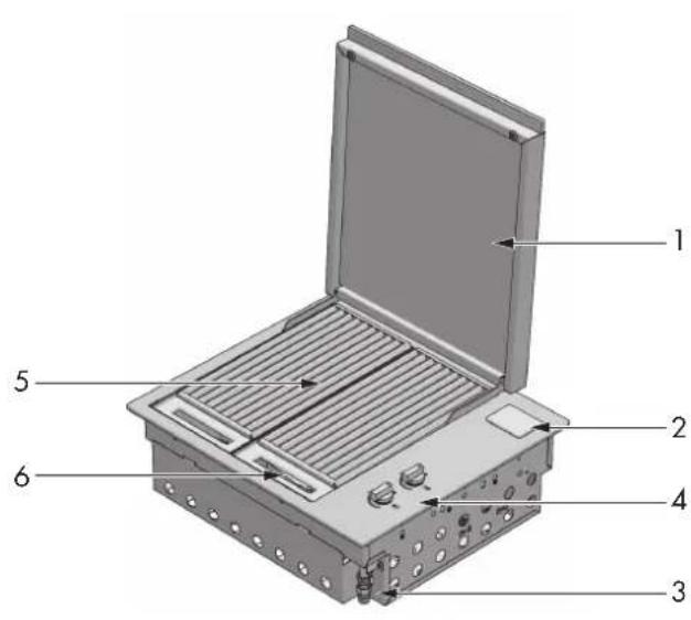
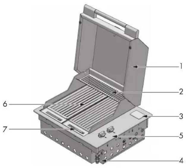
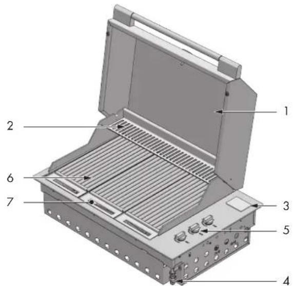
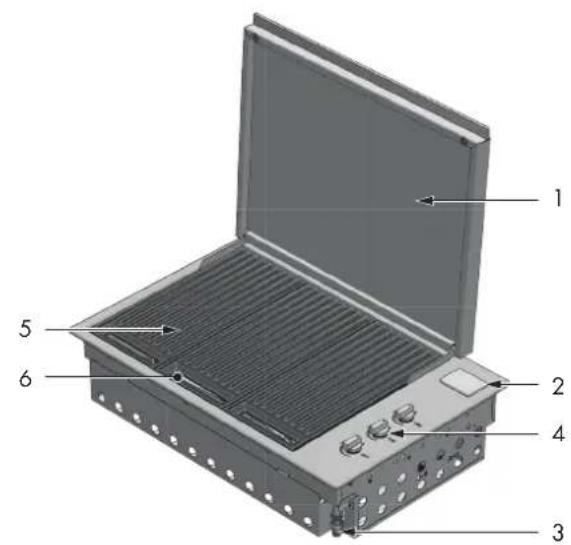
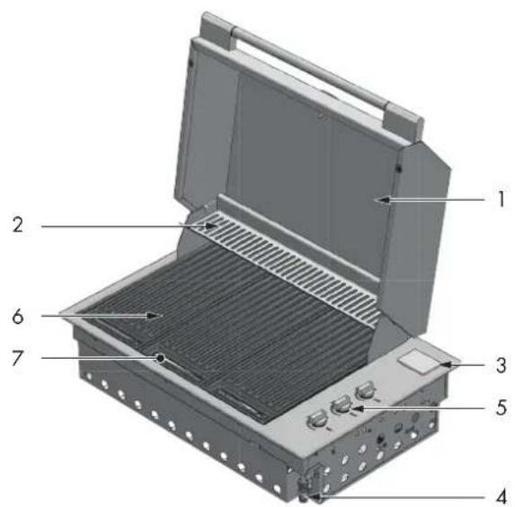
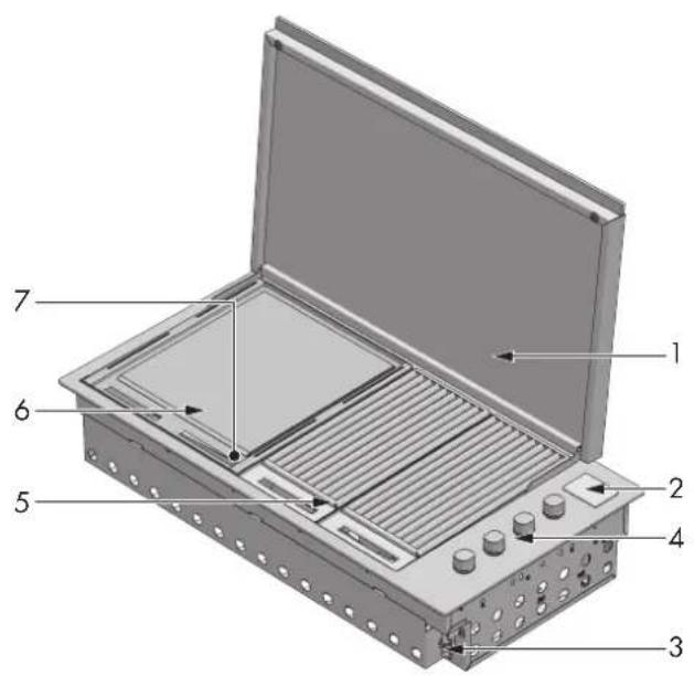
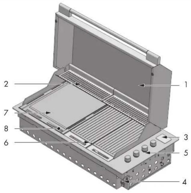
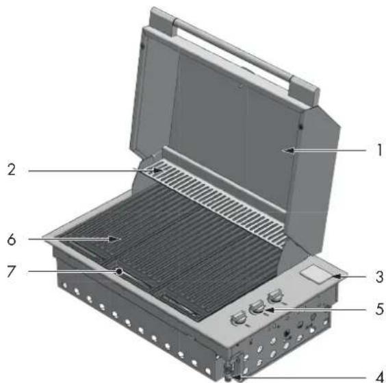
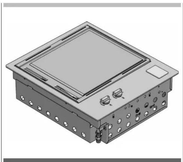
Integrated barbecue with cover
- Low cover 1. High cover
- Battery compartment cover 2. Heating racks
- Gas connection point 3. Battery compartment cover
- Burner controls 4. Gas connection point
- Stainless steel grill group (3 set) 5. Burner controls
- Removable oil collection drip plan located in front of the cooking surface (not shown)
-
Flame diffusers (3 pcs.) located under the grills (not shown)
-
Stainless steel grill group (3 set)
-
Removable oil collection drip plan located in front of the cooking surface (not shown)
-
Flame diffusers (3 pcs.) located under the grills (not shown)
BARBECUE MOD. FOBQ 601 TY G X
LOW LID MOD. FOBQ LL 600 X

BARBECUE MOD. FOBQ 601 TY G X
HIGH LID MOD. FOBQ HL 600 X
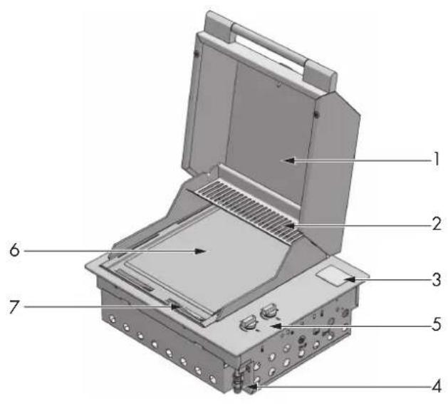
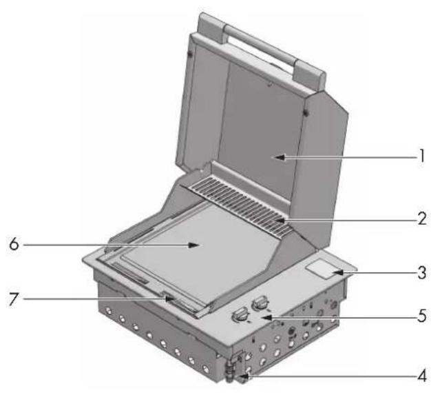
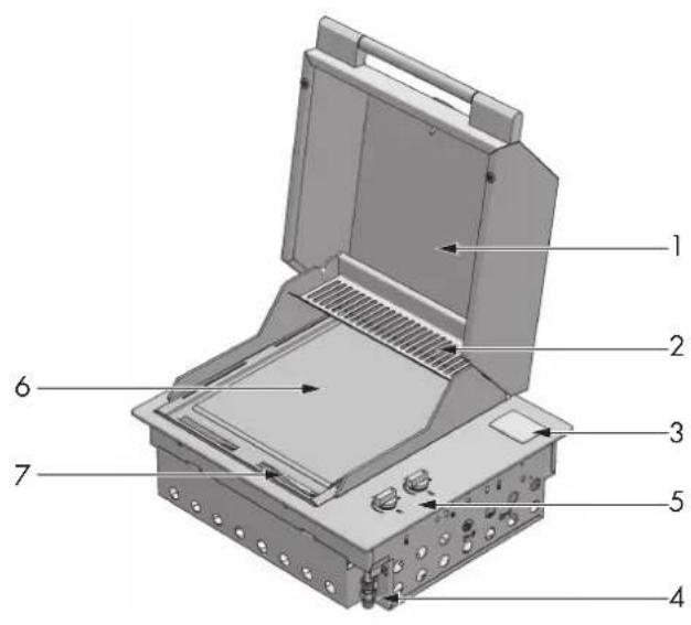
Integrated barbecue with cover
- Low cover 1. High cover
- Battery compartment cover 2. Heating racks
- Gas connection point 3. Battery compartment cover
- Burner controls 4. Gas connection point
- Cooking plate 5. Burner controls
-
Removable oil collection drip plan located in front of the cooking surface (not shown)
-
Cooking plate
-
Removable oil collection drip plan located in front of the cooking surface (not shown)
BARBECUE MOD. FOBQ 602 G X
LOW LID MOD. FOBQ LL 600 X
BARBECUE MOD. FOBQ 602 G X
HIGH LID MOD. FOBQ HL 600 X
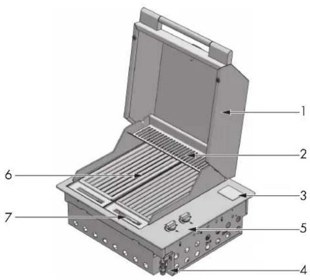
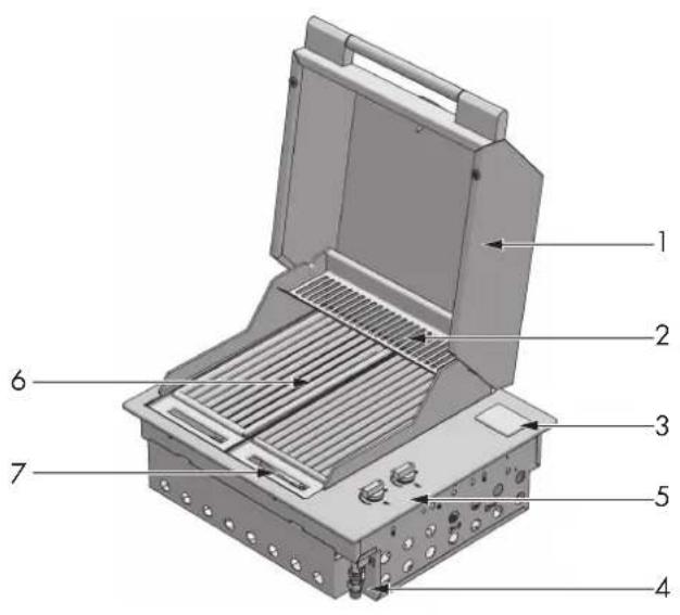
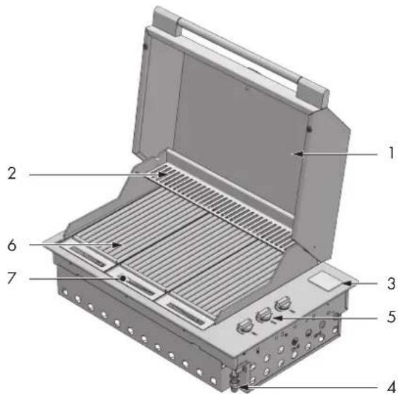
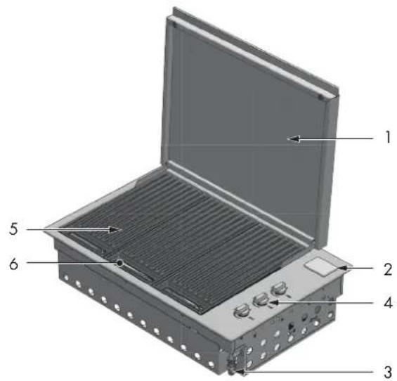
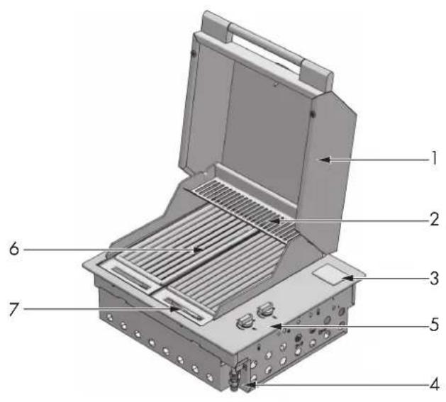
Integrated barbecue with cover
| 1. Low cover 1. High cover | ||
| 2. Battery compartment cover 2. Heating racks | ||
| 3. Gas connection point 3. Battery compartment cover | ||
| 4. Burner controls 4. Gas connection point | ||
| 5. Stainless steel grill group (2 set) 5. Burner controls | ||
| 6. Removable oil collection drip plan located in front of the cooking surface (not shown) | 6. Stainless steel grill group (2 set) | |
| 7 Flame diffusers (2 pcs.) located under the grills (not shown) | 7. Removable oil collection drip plan located in front of the cooking surface (not shown) | |
| 8 Flame diffusers (2 pcs.) located under the grills (not shown) | ||

IMPORTANT
The quantity of each component may vary depending on the model.
| QTY DESCRIPTION QTY DESCRIPTION | |||||
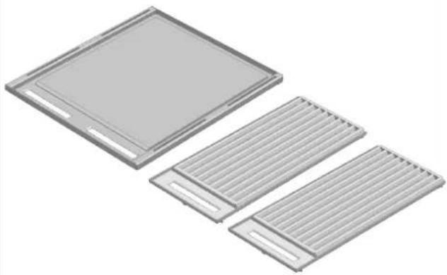
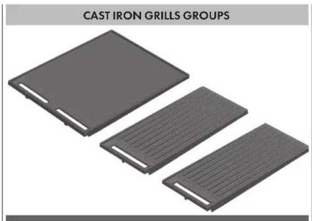
 | 1 | Burner box and external profile | 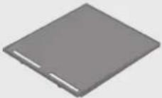 | 1 | Large cast iron cooking plate. Only for 100cm models. |
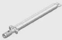 | 2 | Burners for 60cm model | 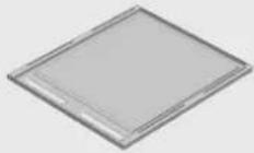 | Stainless steel cooking plate. | |
| 3 | Burners for 80cm model | ||||
| 4 | Burners for 100cm model | ||||
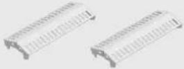 | 2 | Flame diffusers for 60cm model* | 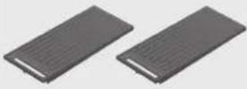 | 2 | Large cast grill groups for 100cm model |
| 3 | Flame diffusers for 80cm model* | ||||
| 2 | Flame diffusers for 100cm model* | ||||
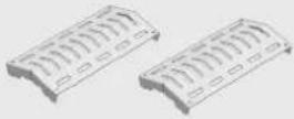 | 2 | Flame diffusers for 60cm model (optional)* | 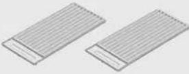 | 2 | Stainless steel grill groups for 60cm model |
| 3 | Flame diffusers for 80cm model (optional)* | 3 | Stainless steel grill groups for 80cm model | ||
| 2 | Flame diffusers for 100cm model (optional)* | 4 | Stainless steel grill groups for 100cm model | ||
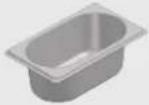 | 1 | Oil tray | |||
*Presence depending on the model, see pp. 2-6
| CONFIGURATION 1 | ||
| QTY DESCRIPTION | ||
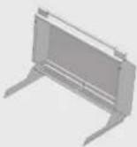 | 1 High cover for cooking | |
CONFIGURATION 2
| CONFIGURATION 2 | ||
| QTY DESCRIPTION | ||
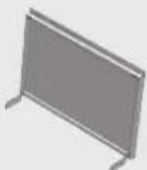 | 1 Low cover | |

For your own safety, you should read this manual before operating the barbecue.

Use
Carefully read the user manual and keep it in a handy place for future reference. Below, we explain the meaning of the symbols used in this manual:

ATTENTION
This symbol indicates information relating to the user's personal safety

WARNING
This symbol indicates information on how to prevent damage to the appliance

TIPS AND INFORMATION
This symbol indicates tips and information about the use of the appliance

SUGGESTION FOR THE ENVIRONMENT
This symbol indicates information for the economical and ecological use of the appliance

PROHIBITION
This symbol indicates a prohibited action

ATTENTION
The appliance MUST only be installed and serviced by qualified and authorized personnel. Improper installation, modification, adjustment or maintenance can cause personal injury or property damage. Contact your nearest Service Centre for further information.
NOTE FOR THE INSTALLER: THIS MANUAL MUST BE LEFT WITH THE OWNER FOR FUTURE REFERENCE

ATTENTION
IF YOU SMELL GAS, do not try to light the barbecue. Perform the leak test procedure described in this manual. Locate the leak and tighten the leaking fitting; if it is the cylinder fitting, also replace the gasket seal.
If the leak persists, turn off the gas supply and call for technical assistance.

PROHIBITION
- Do not lean over barbecue while lighting.
- Do not leave the barbecue unattended when it is on.
- Do not delay ignition once the gas is opened.
- Do not store or use aerosol sprays near the barbecue.
- Do not store inflammable liquids near the barbecue.
- Do not use abrasive or caustic detergents on the barbecue.
- Do not operate the barbecue with the cover closed.
- Do not attempt to disassemble or adjust the control valves.
- Do not attempt to disassemble or adjust the cylinder regulator (not supplied) but, if necessary, replace with a new one.
- Do not use an open flame to check for leaks.
- Do not modify the structure of the appliance and do not modify the dimensions of the injector orifice.

PROHIBITION
- Do not obstruct the ventilation openings of the barbecue.
- Do not allow children to operate the barbecue or play near it.
- Do not use the barbecue if inflammable materials are within a radius of about 60 cm from the top, bottom, rear or sides of the appliance.
- Keep any electrical wires and fuel hoses away from hot surfaces.
- Never store a spare gas cylinder near the barbecue.
- This appliance reaches high temperatures. Be especially careful when children and elderly persons are present
- Do not move the barbecue when it is on.
- Wear protective gloves when using the barbecue.
- Keep children under the age of eight years away, if not constantly supervised.
- Never attempt to extinguish a flame/fire with water: turn off the appliance and cover the flame with a cover or a fire blanket.

PROHIBITION
- Be careful when handling gas cylinders even if they appear empty, in compliance with current safety rules.
- Do not use dented or rusty gas cylinders
- Do not disconnect the gas cylinder from the appliance when it is on. Perform any service on the gas cylinder far away from the appliance.
- Only turn the burners on with the cover lifted
- If the knob becomes difficult to rotate, have the taps checked by an authorized service centre.
- Lower the cover, accompanying it with your hand and make sure that nothing is obstructing its proper closure.
- When cooking with the cover closed keep an eye on the thermometer: if the temperature exceeds 350 °C, lift the cover to prevent dangerous overheating.
- Do not leave objects on the cooking surfaces.
- Never use the appliance to heat the area.
- Always close the valve of the gas cylinder after use.
The manufacturer's liability:
The manufacturer will not be liable for personal injury or property damage caused by:
- any use of the appliance other than anticipated;
- failure to follow the instructions of the user manual;
• tampering with any part of the appliance; - use of other than original parts.
Tools needed for assembly:
- Phillips screwdriver
- Remove all components from the box.
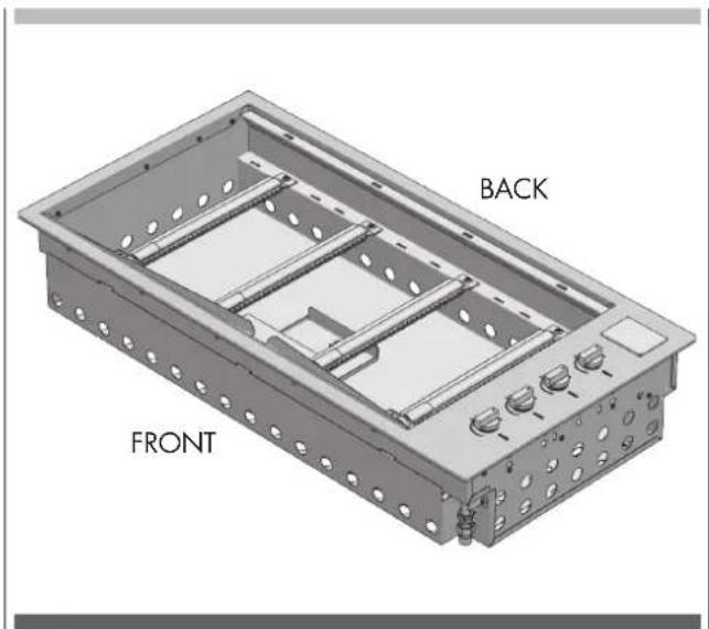
- Place the flame diffusers in the desired positions (under the points (A) in which the grill sections will be placed) and attach the rear edge of the flame diffuser to the rear of the body of the barbecue.
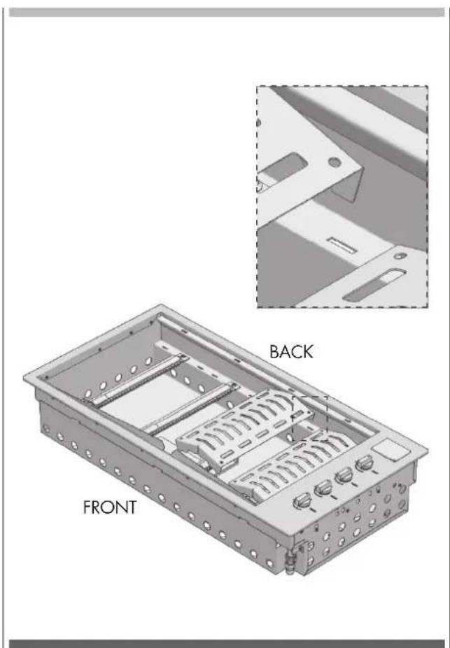
- Apply the oil drip pans to the front of the barbecue.
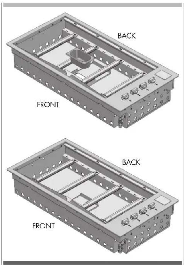
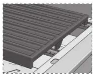
- Place the cooking plate and grill sections in the desired positions, making sure that the flame diffusers are under the grill sections.
NOTE: Make sure that the grill groups are correctly oriented so that the surface of the grill is tilted forward to allow the oil to drain into the drip pans.
natural_image
Three gray rectangular grills arranged diagonally (no text or symbols visible)STAINLESS STEEL GRILLS GROUPS

natural_image
3D rendering of three rectangular metal grates with internal slots, shown from different angles (no text or symbols)- After installation in the counter, connect the thin cover or cooking hood area as described in the chapter "Application of the thin cover or cooking hood" in this manual.
natural_image
3D rendering of a wooden deck structure with slatted metal panels and mounting brackets (no text or symbols visible)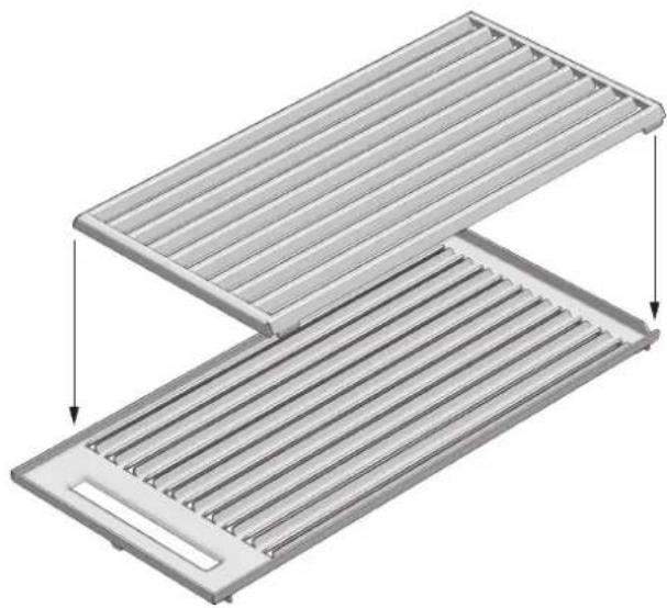
natural_image
3D diagram of a two-tiered storage tray with horizontal slats and a cutout, showing internal structure and directional arrows (no text or symbols)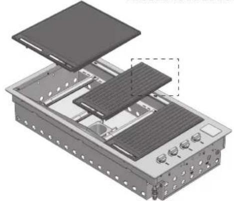
natural_image
Exploded view diagram of an electronic device showing internal components and mounting holes (no text or labels)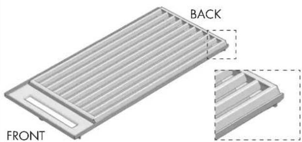
natural_image
3D diagram of a rectangular electronic component with labeled front and back views (no text or symbols beyond labels)COUNTRIES OF DESTINATION
| AT | BE | CY | HR | DK | EE | FI | FR | DE | GR | IE | IS | IT | LV | LT | LU | MT | NO | NL | PT | PL | GB | CZ | RO | SK | SI | ES | SE | CH | TR | HU | ||||
| I3+ | G30 | /G31 = 28-30/37 mbar | ● | ● | ● | ● | ● | ● | ● | ● | ● | ● | ● | ● | ● | ● | ● | |||||||||||||||||
| I3B/P(30) | G30 | /G31 = 30 mbar | ● | ● | ● | ● | ● | ● | ● | ● | ● | ● | ● | ● | ● | ● | ● | ● | ● | ● | ● | |||||||||||||
| I3B/P(37) | G30 | /G31 = 37 mbar | ● | |||||||||||||||||||||||||||||||
| I3B/P(50) | G30 | /G31 = 50 mbar | ● | ● | ● | ● | ● | |||||||||||||||||||||||||||
| 2H | G20 | = 20 mbar | ● | ● | ● | ● | ● | ● | ● | ● | ● | ● | ● | ● | ● | ● | ● | ● | ● | ● | ● | ● | ● | ● | ||||||||||
| 2E | G20 | = 20 mbar | ● | ● | ● | ● | ● | |||||||||||||||||||||||||||
| 2E+ | G20 | = 20 mbar | ● | ● | ||||||||||||||||||||||||||||||
| 2L | G25 | = 25 mbar | ● | |||||||||||||||||||||||||||||||
| 2LL | G25 | /20 mbar | ● | ● | ||||||||||||||||||||||||||||||
| 2H(25) | G20 /25 mbar | ● | ||||||||||||||||||||||||||||||||
| 2S | G25.3 /25 mbar | ● | ● | |||||||||||||||||||||||||||||||
| 2Lw | G27 /20 mbar | ● | ||||||||||||||||||||||||||||||||
| 2Ls | G2.350/13 mbar | ● | ||||||||||||||||||||||||||||||||
| G20-20 cat. 2H, 2E, 2E+ | G20-25 cat. 2H(25) | G25-20 at. 2LL | G25-25 cat.2L | G25.3 cat.2S | G27 cat.2Lw | G2.350 cat.2Ls | G30 /G31 cat. 13+ | G30 /G31 cat. 13B/P (30) | G30 /G31 cat. 13B/P (37) | G30 /G31 cat. 13B/P (50) | |
| Nominal heat input (kW) | 15,2 | 15,2 | 15,2 | 15,2 | 15,2 | 15,2 | 15,2 | 15,2 | 15,2 | 15,2 | 15,2 |
| Injector diameter (1/100mm) | 135 | 130 | 155 | 145 | 145 | 155 | 194 | 94 | 94 | 89 | 83 |
| Number of injectors | 4 | 4 | 4 | 4 | 4 | 4 | 4 | 4 | 4 | 4 | 4 |
| Pressure (mbar) | 20 | 25 | 20 | 25 | 25 | 20 | 13 | 28..30/30..37 | 30 | 37 | 50 |
| Maximum consumption (l/h) | 1448 | 1448 | 1684 | 1684 | 1683 | 1766 | 2011 | 1106 | 1106 | 1106 | 1106 |
| Primary air regulation (mm) (X) see fig. page 15 | 1 | 1 | 1 | 1 | 1 | 1 | 1 | All open | All open | All open | All open |
Adapting to different types of gas
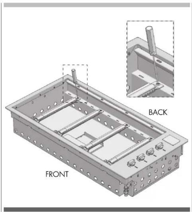
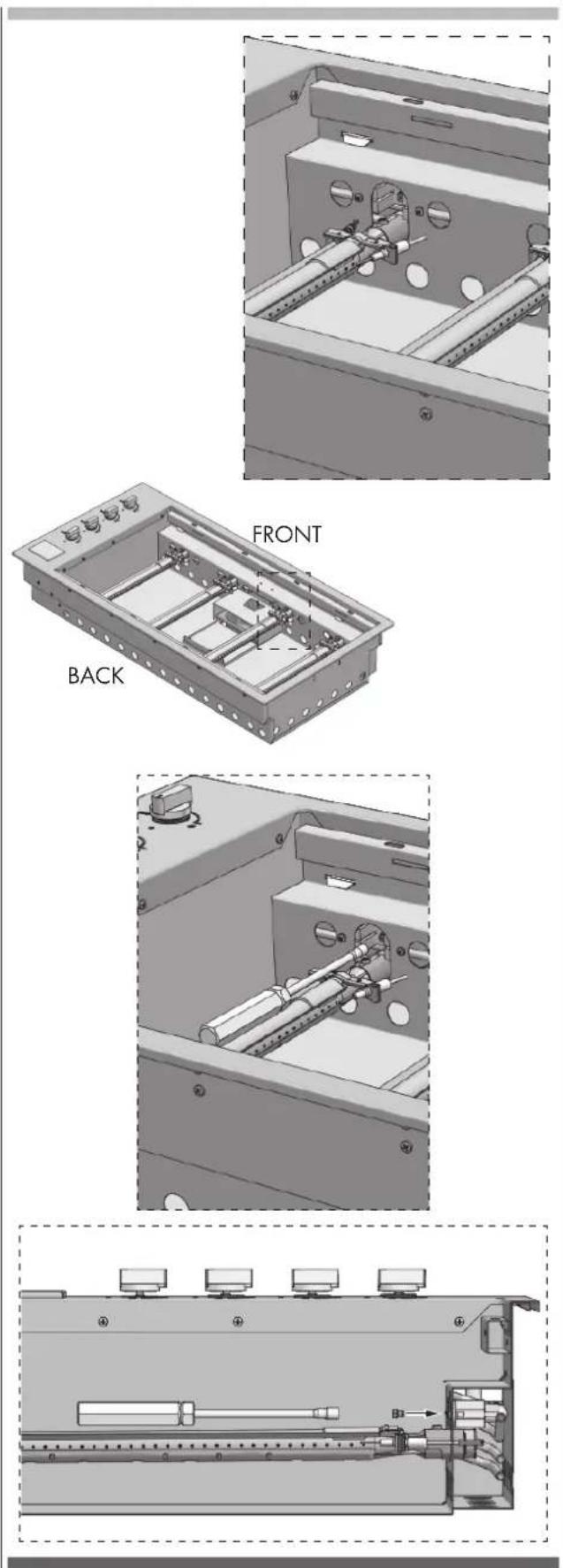
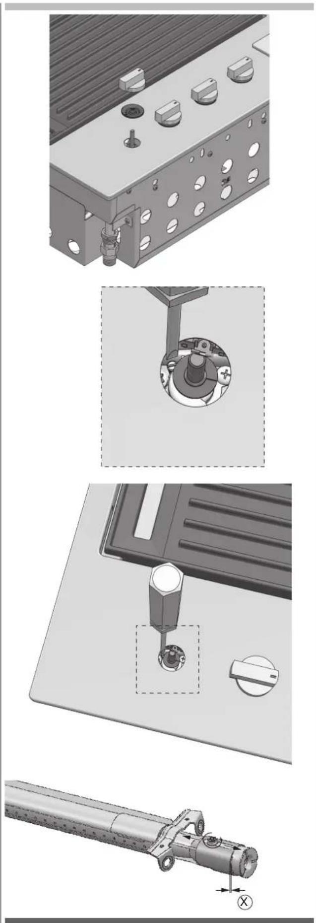
If the appliance is configured for a different type of gas than that available, you have to replace the injectors with ones corresponding to the type of gas to be used (see tables on the preceding pages). The replacement will be made using an adequate 7 mm key after having lowered the burners as in the following images. After replacing the injector, regulate the air to 1 mm for natural gas and to the maximum if LPG. To adjust the minimum, after lighting the burner, remove the knob and the gasket below and rotate the screw of the tap (B - see page 15), which should be totally closed for LPG and opened about 3/4 turn for natural gas, keeping in mind that a flame lower than 3 mm may not even be "perceived" by the thermocouple of the tap. After regulating the minimums, replace the gaskets and knobs.
1 - Unscrew the fixing screws of the burner.
2 - Lower the burner and replace the injector.
natural_image
Technical illustration of a mechanical assembly with exploded and assembled views (no text or symbols)NOTES
- The appliance MUST only be installed and serviced by qualified and authorized personnel.
• The product is exclusively intended for outdoor use. - The product must be installed according to the instructions, which require ventilation openings to allow the grill to work properly. The lack of adequate ventilation to supply air to the appliance can lead to poor operation of the burners or excessive heat build-up in the installation compartment.
- The unit's ventilation openings must not be covered during installation.
Gas connection
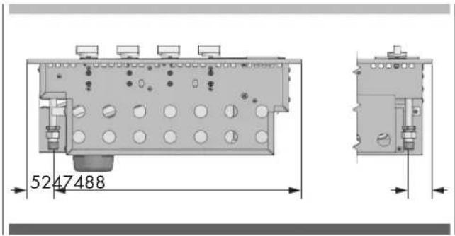
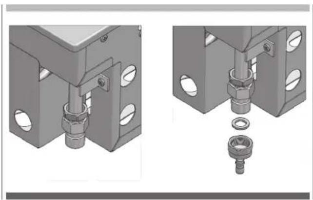
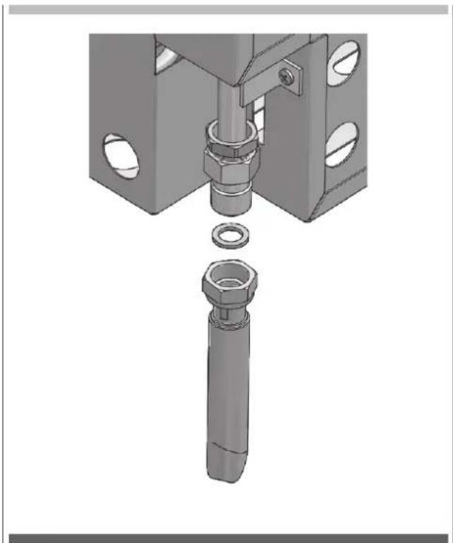
Connect the appliance to the cylinder or system according to the requirements of current law, making sure that the appliance is configured for the type of gas available. If not, see: "Adapting to different types of gas". Also check that the feed pressure falls within the values shown in the table: "Gas specifications".
Rigid and semi-rigid metal and rubber hose connection
Make the hook-up with metal fittings and pipes (even flexible hoses) so as not to stress the components inside the appliance. A rubber hose connection complies with current law only if the hose can be inspected along its entire length and easily replaced near the expiration indicated on the hose.
NOTE: - After installation, use soapy water to check the perfect seal of the entire connection system. DO NOT USE AN OPEN FLAME TO CHECK THE GAS SEAL.
Detail of the gas connection
natural_image
Mechanical assembly diagram showing two views of a mechanical component with bolted parts and a separate view of a bolted nut (no text or symbols present)With note: natural gas connection NG.
natural_image
Mechanical assembly diagram showing a bolt inserted into a housing with a separate bolt inserted into a housing (no text or symbols present)- When converted for the use of universal LPG, the appliance is designed to use different types of cylinders depending on the installation made. See the chapters on Installation Preparation and Connection of the cylinder.
- The gas cylinder must be manufactured and marked in accordance with the specifications for LPG cylinders.
- The shut-off valve must be closed when the appliance is not in use.
- The gas cylinders must be kept in an approved housing out of the reach of children.
- When you disconnect the gas cylinder, make sure all the control valves are in the "OFF" (O) position.
- Before disconnecting, remove the cylinder from any housing in which it may be located.
- When you reconnect the hose to the cylinder, make sure all the connections are tight before placing it back in its compartment.
- After each connection of a cylinder, perform a leak test as described below.
Leak testing procedure
- Make sure that all the gas taps are in the "OFF" (O) position.
- Mix a solution of water and detergent or soap in a small container.
- After connecting the hose, open the valve on the gas cylinder or gas system tap.
- Using a brush, paint the solution on the gas connection points and check for bubbles.
- Bubbles indicate a leak.
- Close the valve and tighten the fitting, possibly inserting a new gasket. Repeat the leak test.
- If the leak persists, turn off the gas and contact an authorized gas system maintenance technician to repair the leak.
EN 7 - Installation instructions and warnings

ATTENTION
- The appliance must only be used above ground level, in open air and natural ventilation without stagnant areas where leaking gas and combustion products are rapidly dispersed by the wind or natural convection. This barbecue is designed exclusively for outdoor use. Refer to the drawings below.
- Never install the barbecue inside buildings, garages, sheds or covered walkways, or in a boat, camper or caravan. This prevents the creation of fires or carbon monoxide with toxic effects or asphyxiation.
- The compartment in which the appliance is installed must conform to one of the following requirements:

ATTENTION
- A compartment with walls on all sides, but with at least one permanent opening at ground level and without upper cover.
- In a partial compartment that has a top cover and not more than two walls.
- In a partial compartment that has a top cover and not more than two walls; in this case, the following principle applies:
- At least 25% of the total area of the walls is completely open and at least 30% of the remaining area of the walls is open and free.
- In the case of balconies, at least 20% of the total area of the side, front and rear walls must be and remain open and free.
| External surface area example 1 | 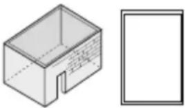 |
| External surface area example 2 | 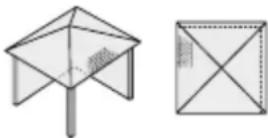 |
| External surface area example 3 | 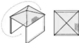 both ends open both ends open |
| External surface area example 4 | 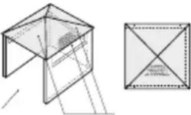 open side for at least 25% of the total area of the walls in total 30% or more of the remaining surface of the walls is open and free open side for at least 25% of the total area of the walls in total 30% or more of the remaining surface of the walls is open and free |
| External surface area example 5 | 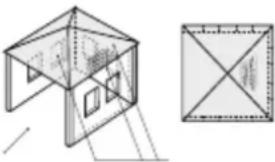 open side for at least 25% of the total area of the walls in total 30% or more of the remaining surface of the walls is open and free open side for at least 25% of the total area of the walls in total 30% or more of the remaining surface of the walls is open and free |
Selection of the point of installation
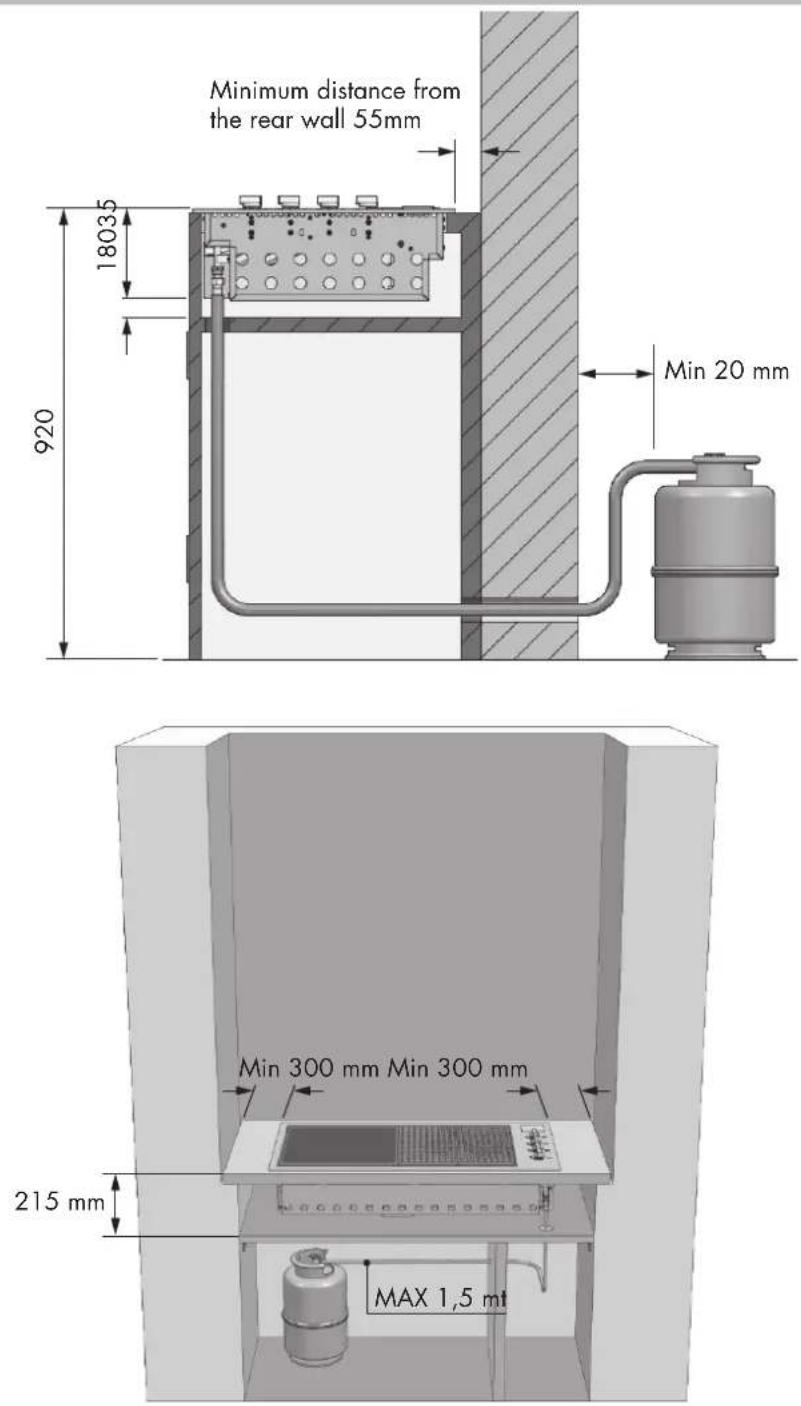
- The appliance must not be installed on combustible materials. The minimum distance from combustible materials is 600 mm.
- The free space above the cooking surface with respect to combustible materials must be at least 600 mm.
• The appliance must be installed in accordance with standards and local deviations. - When using LPG, ventilation must be ensured in the compartment. The gas is highly explosive and can cause serious personal injury and property damage if it is left to accumulate and then ignited.
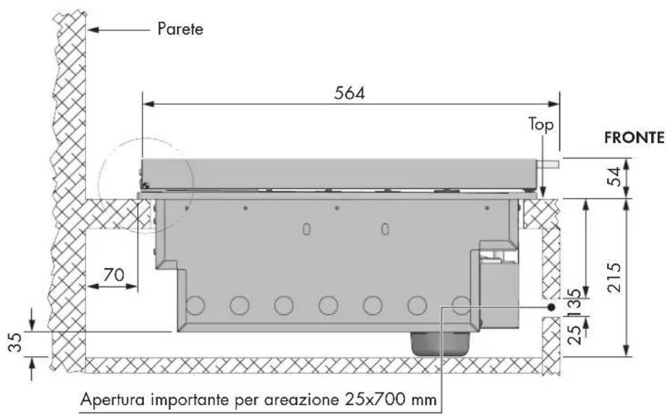
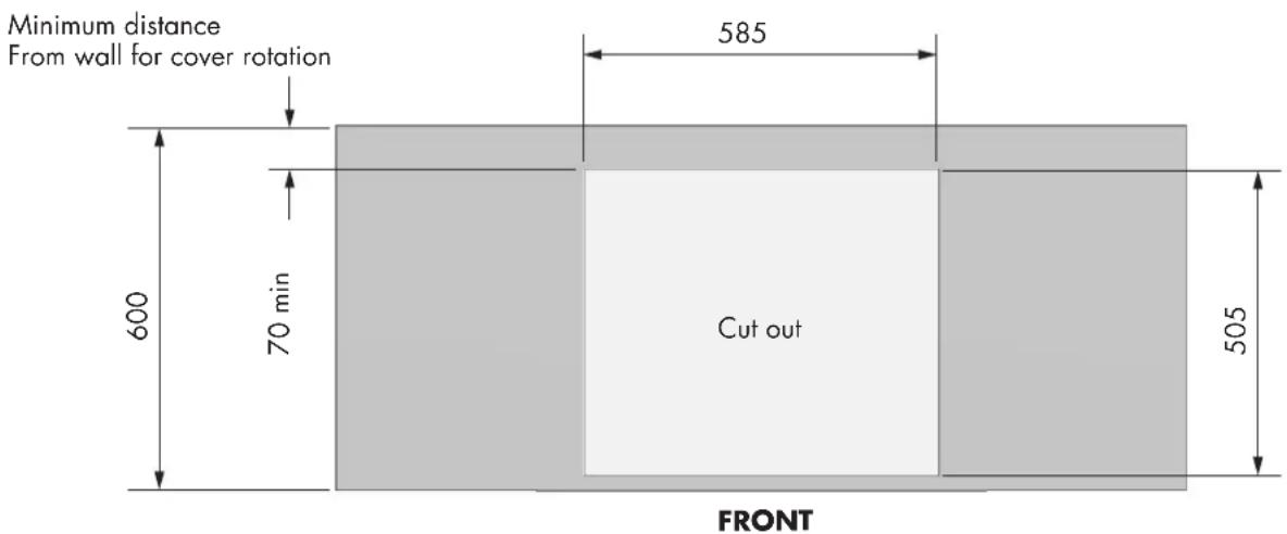
- The barbecue is designed to be mounted in a counter with a minimum depth of 600 mm.
- Avoid locations exposed to the wind as this may affect cooking and the efficiency of the burners. If you cannot avoid such a location, screens may be necessary.
Installation compartment
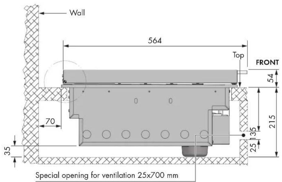
- The barbecue requires a non-combustible barrier beneath it to prevent reaching an excessive temperature in compliance with the current UNI EN 498 standard. The panel that acts as a barrier must be positioned 30/35 mm below the base of the unit.
- The installation compartment must be made of non-combustible materials. Materials suitable for its construction include brick, granite, marble, Hardiplank® and Villaboard® on a metal or brick structure.
- The appliance requires ventilation openings in the front wall of the compartment. See the drawing page "RIMANDO 2" a paging 25.
- The appliance unit can be mounted in an island counter or a counter with splash guard. Read the specific requirements for each type of mounting.
Island-mounted
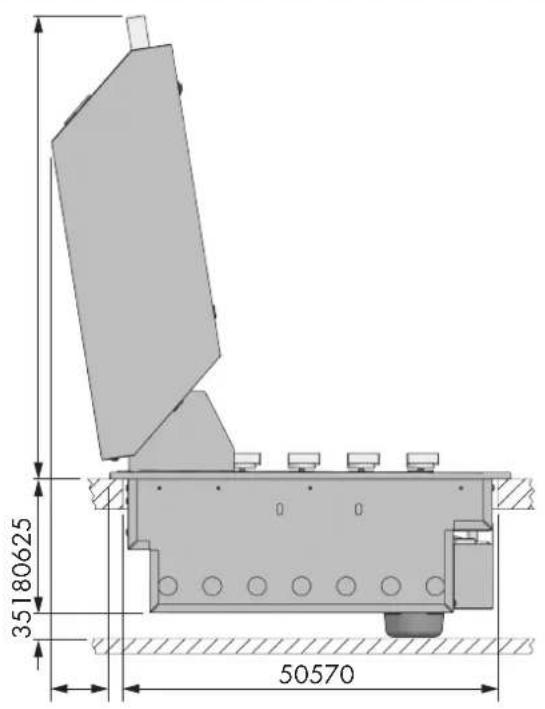
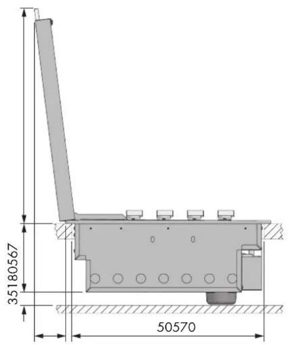
- If the appliance is installed in an island, it can be placed in the centre. Pay particular attention to the overall dimensions of the top of the island, taking into account the open cooking hood and its projection. See page 20.
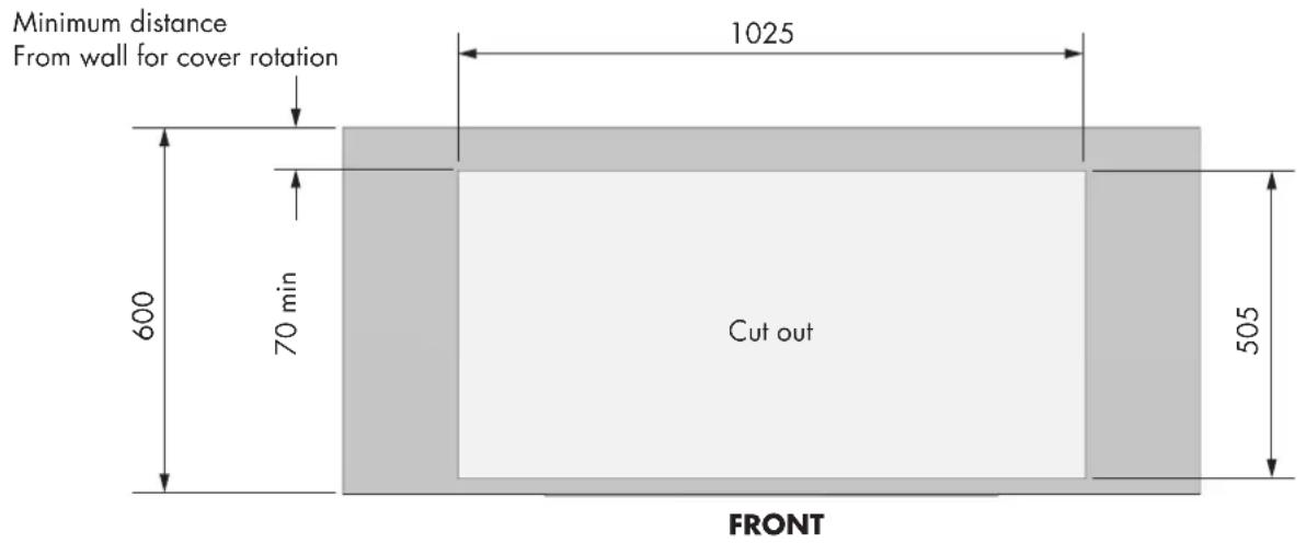
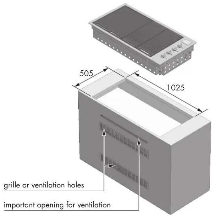
- The required dimensions of the cut-out are 1025 mm x 502 mm (see drawing).
Installation in a counter in a special context
• The context must be made of non-combustible material.
- When mounting the appliance against a wall or a fence, it is essential to insulate combustible materials. All combustible materials must be kept at least 600 mm away from the barbecue.
• The minimum depth of the mounting surface (counter) is 600 mm
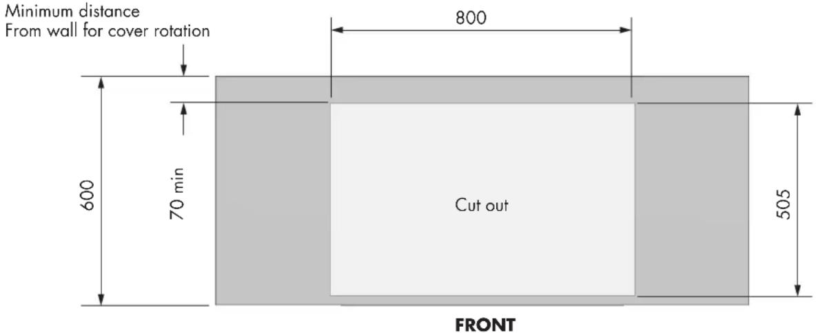
- The required dimensions of the cut-out are 1025 mm x 505 mm (see drawing).
- Models with high cooking cover require a specific free space on the back of the barbecue between the splash guard and the cut-out of the counter of at least 70 mm. This, so that the hood has the free space needed to open.
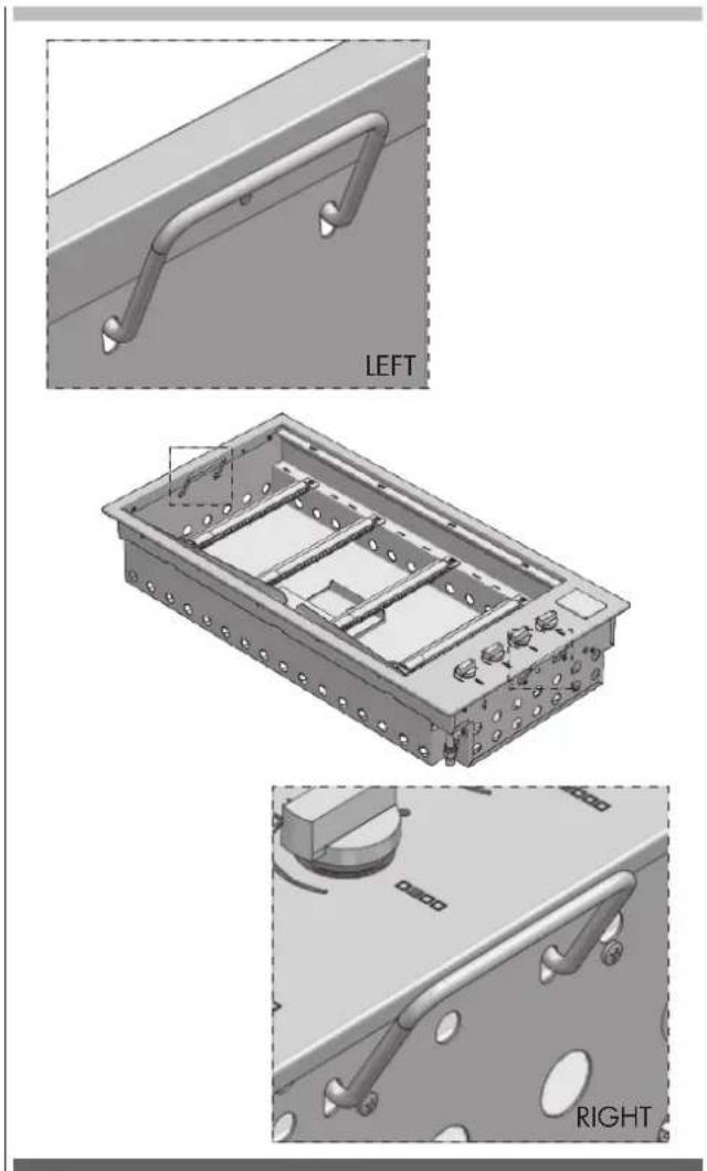
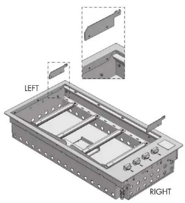
To facilitate insertion in the cabinet, the product has specific lifting handles (see figure below)
natural_image
Technical illustration of a mechanical assembly with three views: left, right, and bottom (no text or symbols present)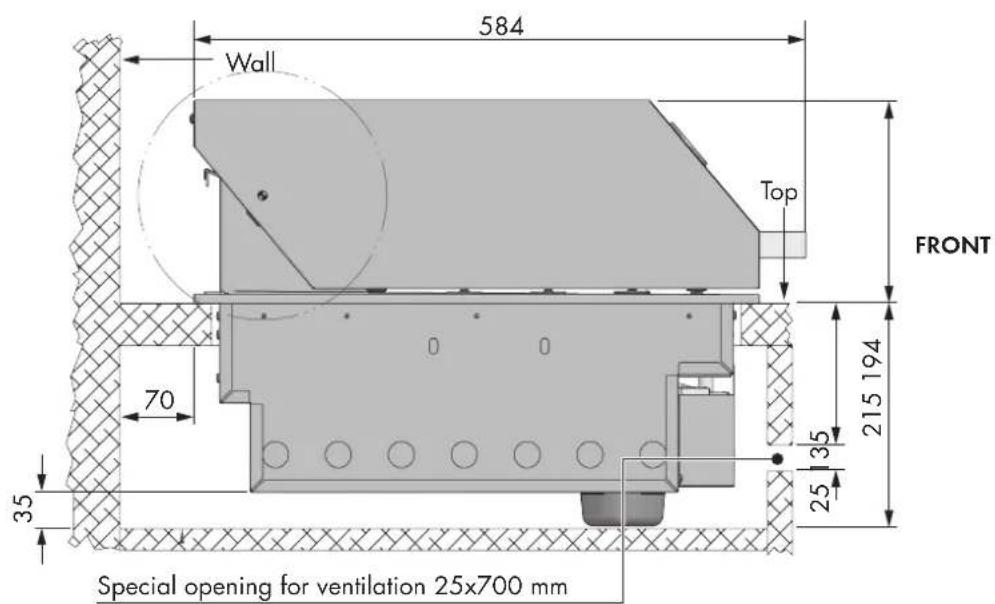
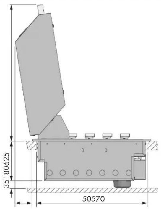
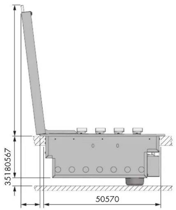

ATTENTION
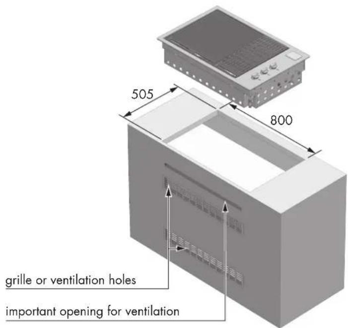
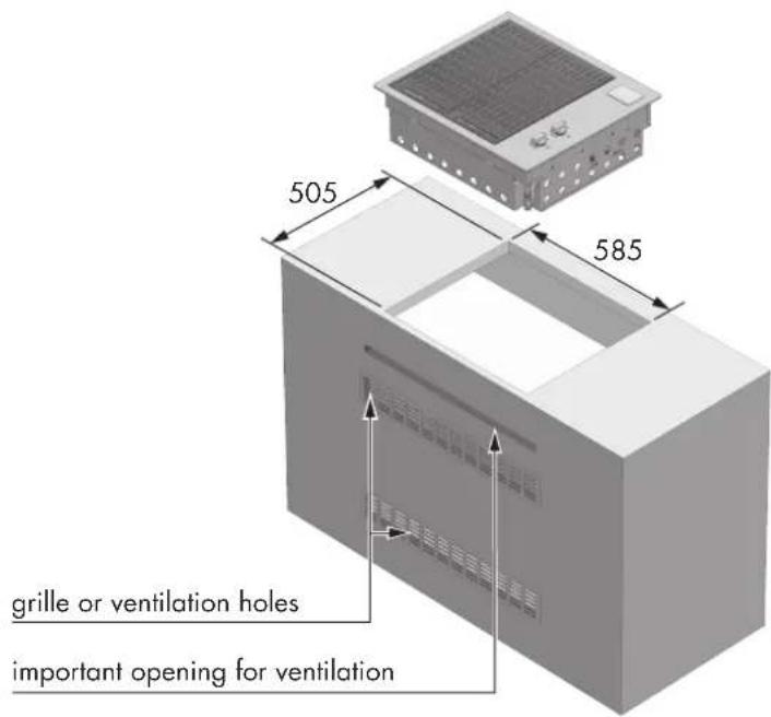
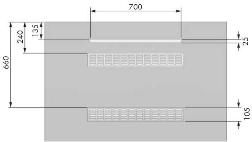
- The appliance requires adequate ventilation. An open area must be provided as shown below. A ventilation grate can be applied, if desired. This ventilation surface allows air to enter the compartment for the proper combustion of the gas and aspiration of the combustion products. In the case of LPG, the gas is heavier than air; in the event of a leak the vent allows the gas to leave the compartment. The air vent must be at least 700 mm x 25 mm and placed in a central position 135 mm below the mounting surface. (See drawing).
Mod. BBQ 100 cm
Mod. BBQ 80 cm
Mod. BBQ 60 cm
Mod. BBQ 100 cm
Mod. BBQ 80 cm
Mod. BBQ 60 cm
Mod. BBQ 100-80-60 cm

ATTENTION
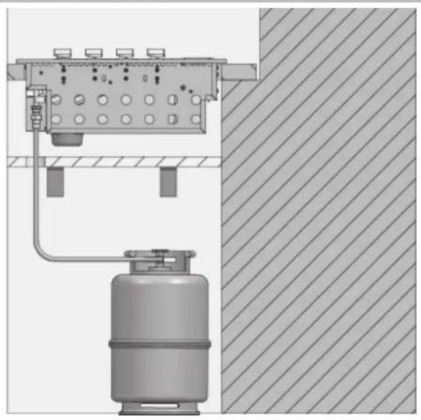
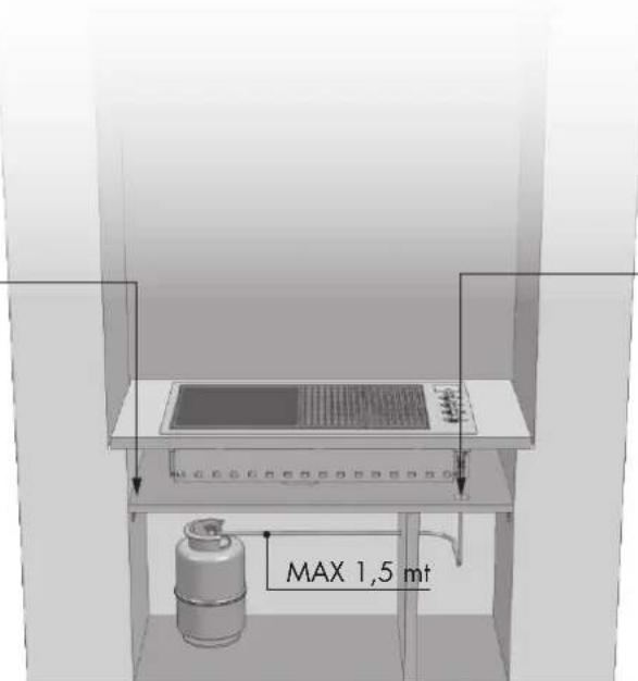
- The LPG cylinder in the compartment below the barbecue unit, must be isolated from it by a non-combustible panel. The compartment must comply with the requirements of EN 498.
• The ventilation requirements of EN 498 for the cylinder compartment are: - In case of a sheet metal, or similar impenetrable, structure, ventilation openings must be made on the top and bottom the compartment or cavity, each of which must provide a free surface of at least 200 cm2 per cylinder housed; the openings also serve as inspection points if a rubber hose is used.
natural_image
Technical diagram of a gas cylinder connected to a control panel with a side-mounted valve, against a hatched wall (no text or symbols)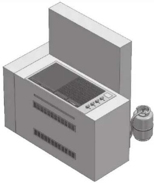
natural_image
3D rendering of a mechanical device with control panel and external housing (no visible text or symbols)non-combustible barrier necessary under the barbecue
cut a hole in the non-combustible barrier only for the hose
front of the compartment emoved for clarity
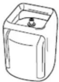
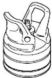
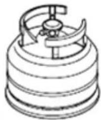
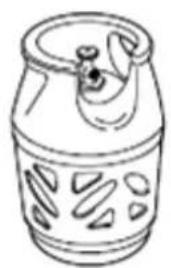
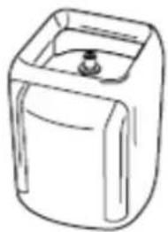
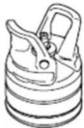
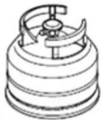
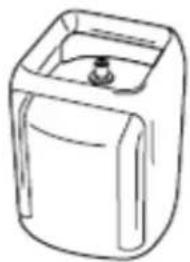
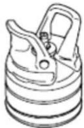
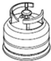
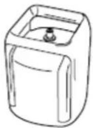
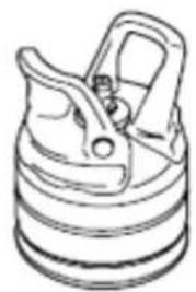
The LPG cylinder may be connected inside the object-holder compartment of barbecue only if it has the dimensions shown in the guidelines. The safe use of a cylinder inside the object-holder compartment of the barbecue depends on several factors:
A) The base of the cylinder must be properly inserted between the plates and be horizontal on the base panel.
Dimensions of the cylinder
Max height 465 mm
Width 289 mm - (rectangular section) or 318 mm (circular section) maximum B) Capacity of the cylinder max 6 kg There are several models of cylinders with approved dimensions (2).

WARNING
If the LPG cylinder purchased does not have the required dimensions, do not attempt to connect it inside the object-holder compartment. Fix the cylinder to the bracket or rest it on the floor. Failure to follow these instructions could damage the hose and cause fire or explosion, with serious injury or death and property damage.
BP 5 kg BUTAGAZ 6 kg
natural_image
Line drawing of a cylindrical container with cutouts and a lid (no text or symbols)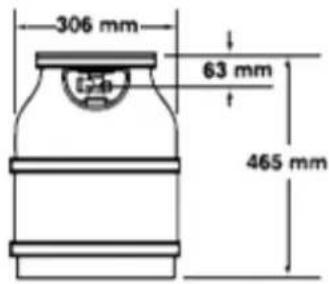
natural_image
Line drawing of a rectangular container with a small outlet (no text or symbols)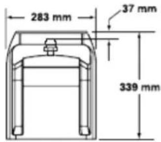
CALOR 5 kg PRIMAGAZ 5.2 kg
natural_image
Line drawing of a mechanical component with no visible text or symbols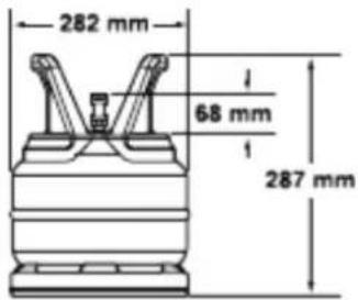
natural_image
Technical line drawing of a mechanical component with a central hub and concentric rings (no text or symbols)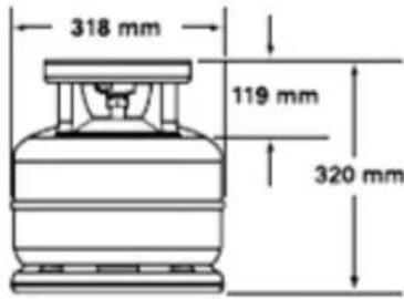
EN 8 - Connection of the LPG cylinder

WARNING
Make sure the LPG cylinder valve or regulator is closed.
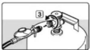
Connect the LPG cylinder.
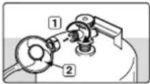
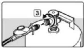
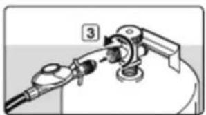
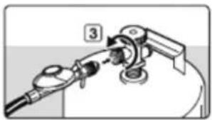
Some regulators are connected by pushing ON and are disconnected by pulling OFF, while other types of regulators have a nut with left hand thread for connecting to the cylinder valve. Follow the illustrations in the instructions for the specific connection of the regulator.
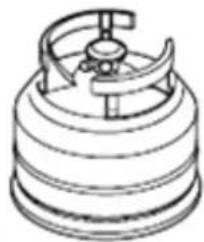
a) Screw the regulator to the cylinder by turning it counterclockwise (1). Install the regulator so that the vent hole (2) is facing downward.
b) Screw the regulator to the cylinder by turning it counterclockwise (3).
c) Make sure that the regulator lever (5) is in the lowered or off position.
Press the regulator on the cylinder valve until you hear a click indicating that it is in position (6).
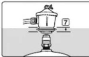
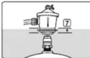
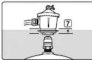
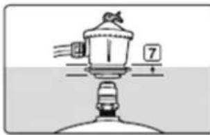
d) Make sure that the regulator lever is in the OFF position. Lift the bezel of the regulator (7). Press the regulator onto the cylinder valve and hold it pressed. Lower the bezel (8). If the regulator does not lock, repeat the procedure.
natural_image
Diagram of a gas station with a valve and pipe fitting (no text or symbols)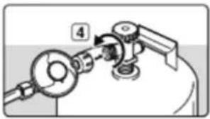
natural_image
Mechanical assembly diagram showing a valve and pump mechanism (no text or labels)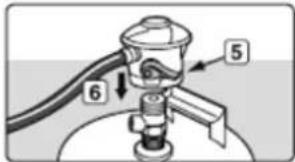
natural_image
Simple line drawing of a showerhead with water spray and a scale indicator (no text or symbols)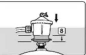
natural_image
Diagram of a mechanical device with arrows indicating motion or force direction (no text or symbols)Application of the low cover
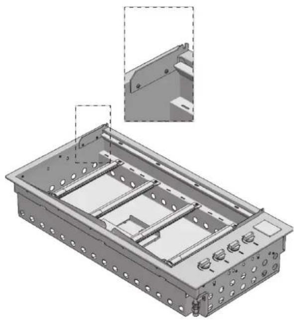
- Remove the thin cover from the packaging.
- Attach the hinges to the outer frame and secure it with the special screw provided.
natural_image
3D technical illustration of a mechanical housing component with mounting holes and internal compartments (no text or symbols)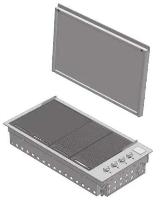
natural_image
3D rendering of an open industrial enclosure with internal heat exchanger and cooling unit (no text or symbols visible)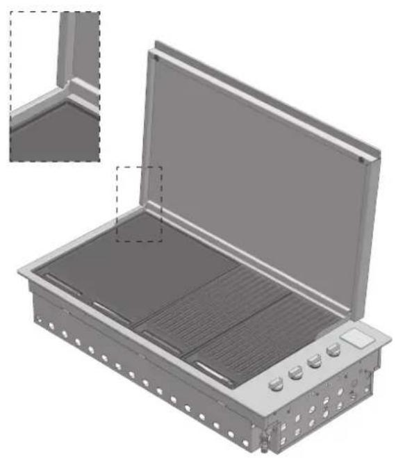
natural_image
3D rendering of an open industrial enclosure with internal grating and control panel (no text or symbols visible)Application of the high cover
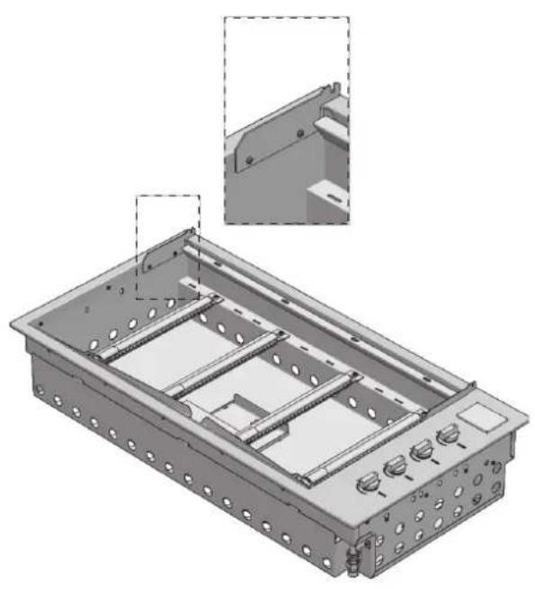
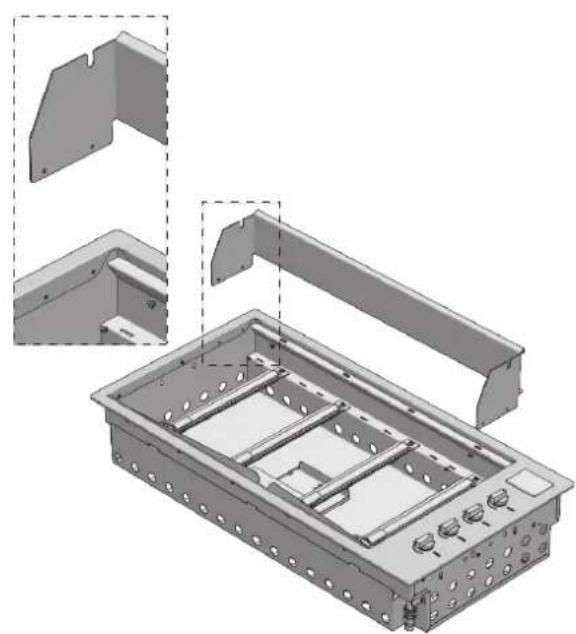
- Remove the High cover from the packaging.
- Remove the hinge from the cover and apply it to the outer frame. Fix it with the special screws provided.
- Insert the cover into the seats of the hinge

IMPORTANT
Given the dimensions of the cooking hood, we recommend that two people position it. During positioning the high cover group, take special care to avoid scratching the external profile.
natural_image
3D technical illustration of a mechanical housing assembly with cutouts and mounting brackets (no text or symbols)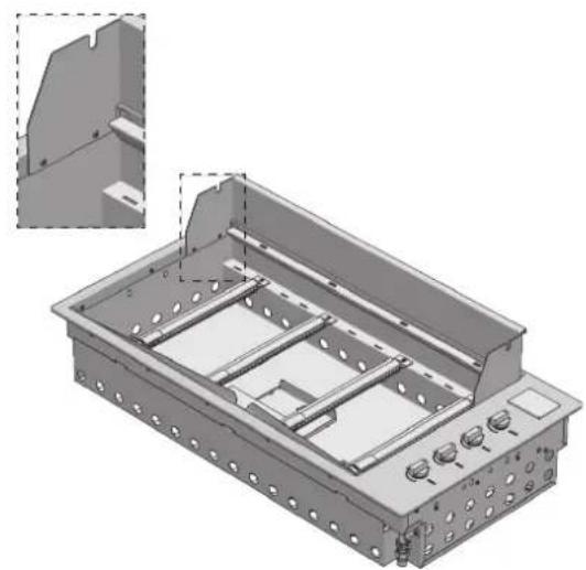
natural_image
3D technical illustration of a mechanical housing or enclosure with internal compartments and mounting holes (no text or symbols)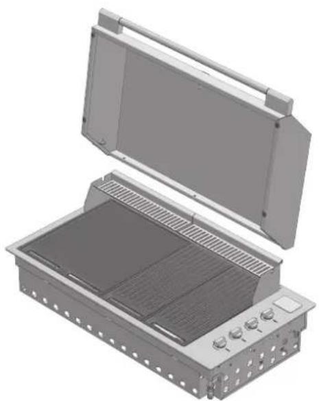
natural_image
3D rendering of an open industrial enclosure with internal grating and ventilation slots (no text or symbols visible)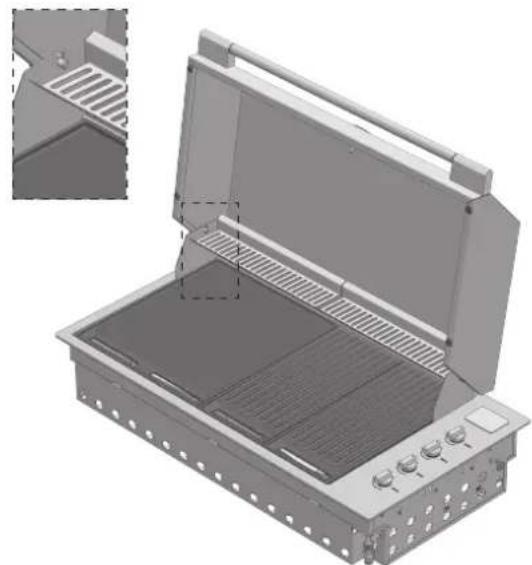
natural_image
3D technical illustration of an open fire extinguisher with internal grating and ventilation slots (no text or symbols)
IMPORTANT
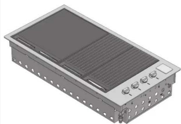
Make sure that the flame diffusers are positioned flame under the panels of the grills.
Mod. BBQ 100 cm
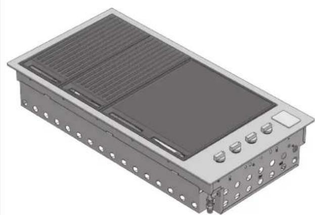
BBQ 100 Solid cooking plate on the left, double grill on the right - best orientation for grilling
natural_image
3D rendering of a rectangular electronic device with heat sinks and ventilation grilles (no text or symbols visible)BBQ 100 Solid cooking plate on the right, double grill on the left - alternative best orientation for grilling
natural_image
3D rendering of a rectangular electronic device with ventilation grilles and mounting holes (no text or symbols visible)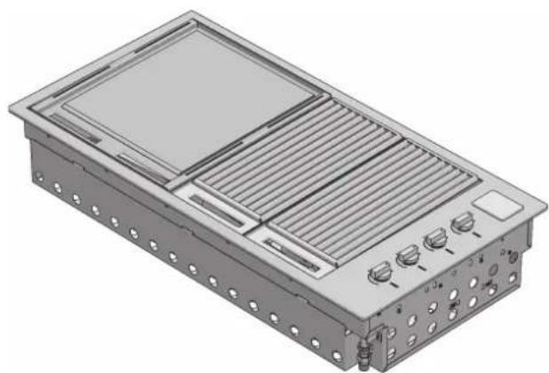
natural_image
3D technical illustration of a modular electronic device with ventilation grilles and control knobs (no text or symbols)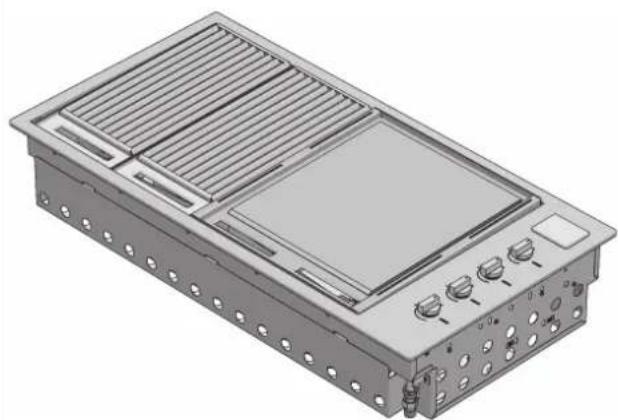
natural_image
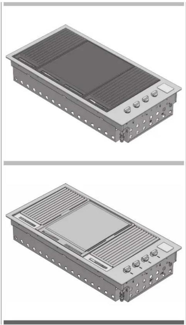
3D rendering of a rectangular electronic device with heat exchangers and a central display (no text or symbols visible)BBQ 100 half grill on the left, central solid cooking plate, hal grill on the right - best orientation for roasting
BBQ 100 Two solid cooking plates side by side - optional arrangement
natural_image
Technical illustration of two industrial electronic components with heat sinks and ventilation grilles (no text or symbols)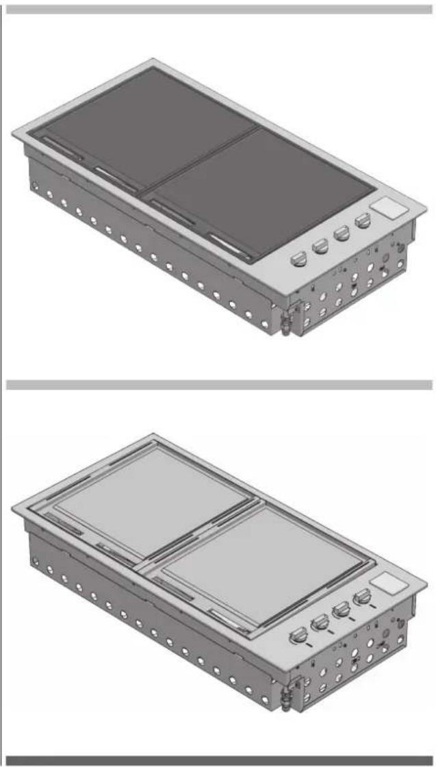
natural_image
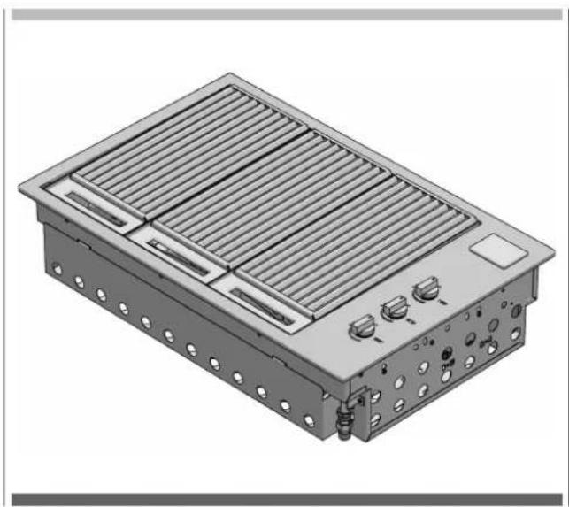
Technical illustration of a dual-chamber electronic device with mounting holes and control buttons (no text or symbols)Mod. BBQ 80 cm
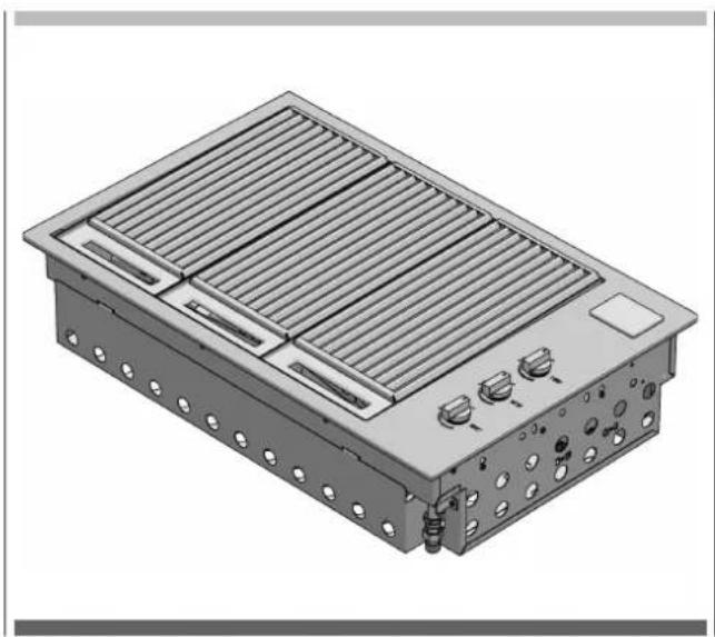
BBQ 80 total grill
natural_image
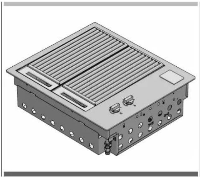
3D rendering of a modular electronic device with heat exchangers and cooling fins (no text or symbols visible)Mod. BBQ 60 cm
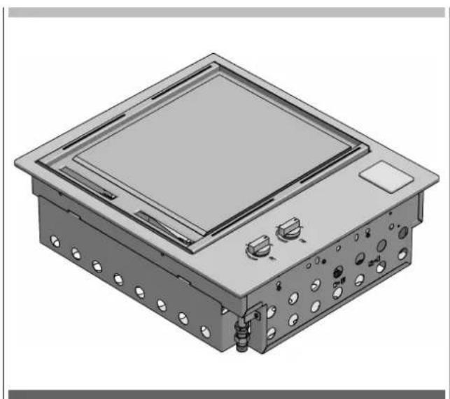
BBQ 60 total grill
natural_image
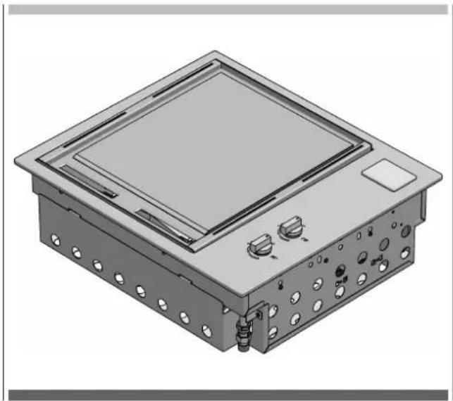
3D rendering of a rectangular industrial or electrical enclosure with heat sinks and mounting holes (no text or symbols visible)BBQ 60 total solid cooking plate
natural_image
3D rendering of a rectangular electronic device with mounting holes and control knobs (no text or symbols visible)Control functions
Before lighting the barbecue:
- Check that all the gas hoses and fittings are tight.
- Open the thin or high cover.
NOTE: The thin cover is intended to protect against the weather. The cover is not intended to be used as a cooking hood. - Make sure that all the control knobs are in the closed (O) position.
• Make sure that the cooking surfaces are clean.

WARNING
Before use, check that there is no accumulated grease in the lower tray. Remove excessive grease to prevent it from catching fire in the tray.x
- Open the main gas valve.
Ignition instructions
- Do not light the burners with the cooking surfaces covered.
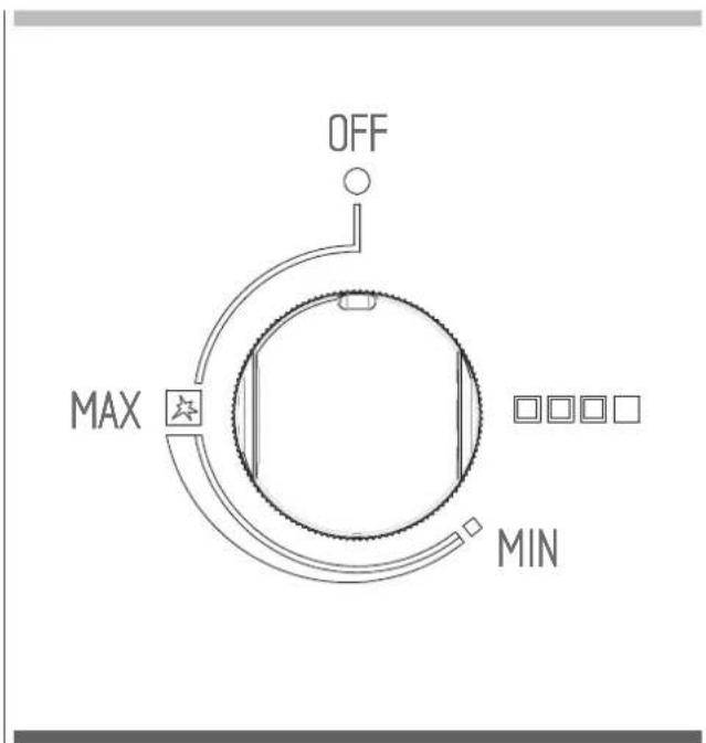
- To light a burner, press the knob and turn it to the "MAX" (fast pre-heating) position.
- Hold it for 5 seconds (count to 10), release it and check the flame from the slots in the front.
- If the burner is not lit, turn the knob to the closed (O) position. Allow the gas to disperse, and then repeat the ignition procedure.
Manual lighting
- If the automatic ignition system is not working, the barbecue can be lit manually.
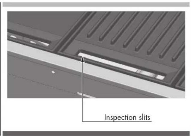
- To turn it on manually, use a long match (28cm). Pass the lit match between the inspection slots under the front part of the hob, approaching it to the burner, then turn the knob and hold it pressed on MAX (quick preheating) in order to perform the ignition. If it does not light, close the control valve and wait a few minutes for the gas to disperse before trying to light the barbecue again.
- Once one burner is lit, repeat the procedure for the others, if necessary.
Pre-heating cooking areas
- The barbecue is equipped with high-power burners. Under most conditions, it will only be necessary to preheat the barbecue for just 5 minutes before starting to cook.
- As with most things, experience will teach the user the effectiveness and interval necessary for reaching the best pre-heating time for obtaining the ideal cooking temperature. Don't forget that this also depends on the type of food, its thickness and how you want to cook it.
- Tests have shown that you can reduce the heat of the burners for satisfactory cooking.
- If the barbecue has a thin cover, you should remove it in the presence of wind.
- If the appliance is not working properly, refer to the chapter "Troubleshooting".
- If you let the cooking areas overheat, there will be excessive smoke during cooking and the food will burn.
- While cooking, avoid leaning over the open grill or placing the hands or fingers on the edge of the oven.
- In case of uncontrolled sudden flames, remove the food from the fire until the flame is damped.
- To roast with the high cover closed, it is sufficient to adjust the 4 burners to the minimum power (MIN) for satisfactory cooking
To turn off the burner
- When done cooking, turn the knob fully clockwise so that the mark on the knob is in the closed (O) position.

WARNING
Remember to always close the valve of the gas cylinder after use.

WARNING
Remember to shut-off the gas before closing the cover.
natural_image
3D rendering of an open industrial electrical enclosure with internal compartments and mounting points (no text or symbols visible)
ATTENTION
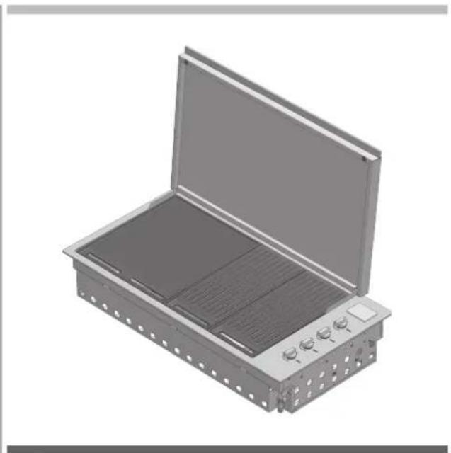
THE COVER MUST NOT BE CLOSED WHEN THE BURNERS ARE LIT.
If the cover is closed while the burners are lit, the cover and barbecue can be discoloured and damaged.
EN 11 - Cleaning and care
Care and cleaning of the appliance
To preserve its original appearance, we recommend cleaning the cooking surfaces after each use.

ATTENTION
Make sure the barbecue is turned off and has cooled down before executing the instructions shown below.
Cleaning of cooking parts
- Remove from the grill and from the cooking burners all the solid materials and the excess grease using a scraper or a metal brush with brass bristles
- Use a clean, dry cloth to make sure all surfaces are dry.
Other stainless steel surfaces

WARNING
Do not use caustic or abrasive detergents, steel wool or metal scrapers on these stainless steel surfaces because they can scratch and permanently damage the barbecue.
- Wash all stainless steel parts, including the thin cover, high cover and control knobs, with a soft cloth and warm soapy water
- Clean the surfaces, making sure to rub/dry in the direction of the grain in order not to damage the stainless steel.
- The inside of the barbecue can be cleaned with a soft cloth soaked in warm soapy water. The front panel/tray placed inside can be removed for an easy cleaning.
- Use a clean, dry cloth to make sure all surfaces are dry.
Cleaning the cooking grills made of cast iron
- Clean with an adequate brass bristle brush. If necessary, remove from barbecue, wash with warm soapy water, rinse with water and dry carefully.

IMPORTANT
After cooking and cleaning, the cast-iron grids should be oiled. Apply a thin layer of vegetable oil using a cloth or brush. Afterwards, use a cloth to rub the cookware as if you want clean the oil you just placed on it.
Cleaning the stainless steel grills
- Remove all solid materials and excess grease from the grill and cooking plate using a scraper or wire brush.
- To facilitate cleaning, the two halves of the grill can be removed with the cooking plate. For stubborn stains, simply immerse the parts of the grill and the plate in hot soapy water before carefully rinsing them.
• Make sure all surfaces are dried with a clean, dry cloth.

WARNING
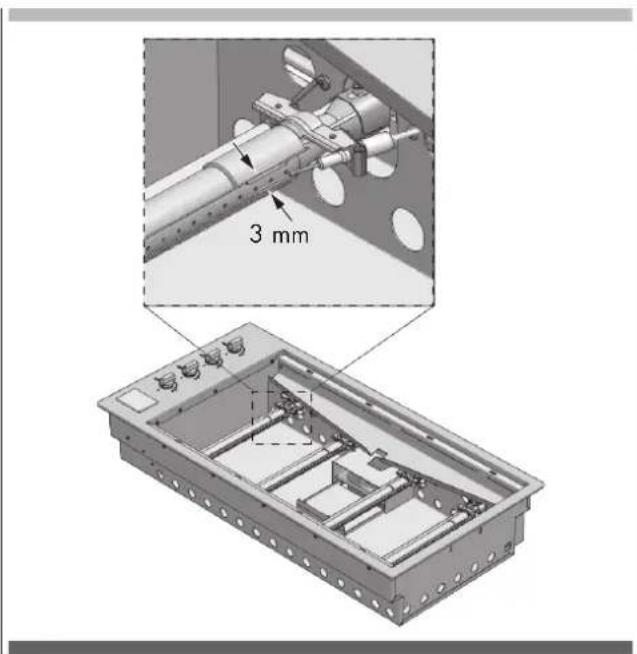
Pay particular attention (especially when cleaning the knobs and around them) to avoid water and soap residue from entering the control panel containing the valves or in the burners. Also, be careful not to touch the ignition electrode and thermocouple. There must be 3 mm of space between the electrode and the burners (see drawing on the next page).
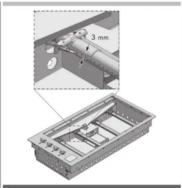
Cleaning the grease drip pan
The integrated barbecue has a unique oil management system that uses overlapping channels to convey all the oil towards the front to easily removable drip pans, which must be cleaned after each use.
- To remove the drip pan, pull them upwards from the front of the barbecue; dispose of their contents in a responsible way. Wash the collection pans in hot soapy water or, if you want, you can put them in the dishwasher.
Burners
The burners should be checked at least once a year and cleaned if necessary. Inspect the burners to make sure that no residue deposits and that the gas connections are free.

SUGGESTIONS AND INFORMATION
Special note on "tea staining"
Sometimes stainless steel surfaces are affected by a colour change called "tea staining". This usually occurs in areas high heat is used and can be easily removed using specific detergents for stainless steel. For best results, we recommend that you regularly use specific detergents on all stainless steel parts. These detergents are available in almost all hardware stores and even supermarkets.
Special note on stainless steel
Stainless steel panels can be deformed during use but return to their normal shape when cooled.
EN 12 - Maintenance
Ignition system
To change the battery, remove the battery cover by lifting the battery holder flap on the left side and pull out the battery. Replace it with a new D battery and replace the cover. Perform a test by pressing the knob; you should hear a click.
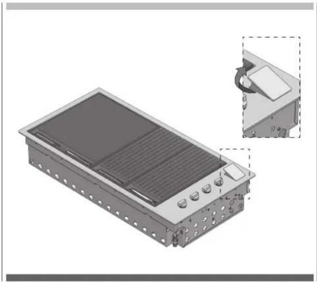
natural_image
3D rendering of a rectangular electronic device with internal components and a close-up inset showing a component being inserted (no text or symbols visible)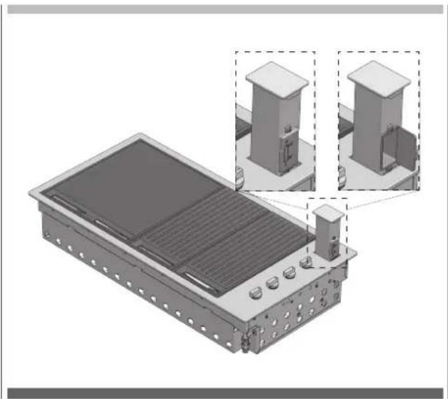
natural_image
3D technical illustration of a solar panel installation with two zoomed-in views showing internal components (no text or symbols)Ventilation openings
The ventilation openings of the installation compartment must be inspected before each use of the appliance to make sure that there are no obstructions that could impede the free flow of air.
| PROBLEM | POSSIBLE CAUSE | SOLUTION |
| The barbecue doesn’t light No gas | Check that the shut-off valve is open (ON) | |
| Gas cylinder empty - refill or change the cylinder | ||
| The ignition system is not working | Check the battery - you should hear a clicking sound when you press the knob | |
| Replace the battery | ||
| Light the barbecue manually | ||
| Gas tap regulated too high Clean | and delicately dry the electrode making sure that its position is correct | |
| Excessive smoke from the cooking surface | Gas valve set too high Lower the gas or turn off some of the burners | |
| Odour of gasDON NOT TRY TO LIGHT THE APPLIANCE | Gas leak Close the gas with the shut-off valves | |

MANUFACTURER'S DECLARATION
The manufacturer declares that, depending on their type, the products in this catalogue conform to the fundamental requirements of European Directives and, for this reason, the product bears the CE mark, for which this declaration of conformity was issued and made available to market supervisory bodies.
DISPOSAL OF USED APPLIANCES
At the end of their useful life, these appliances may not be disposed of with normal urban waste but must be given to an electronic and electrical equipment collection and recycling point. This is indicated by the symbol shown on the product, in the instruction manual or on the packing materials.
The materials used in this appliance can be reused in conformity with their intended use. Thanks to the reuse, recycling or other forms of recovery of unusable appliances, you will make a contribution to protecting our natural environment. You can obtain information about the disposal points for unusable appliances from your local authorities.
The manufacturer will not be liable for inaccuracies in this manual due to typographic errors. We reserve the right to make improvements or indispensable modifications to products without altering their essential specifications. Products can be modified following requests for improvements and CE standards.
natural_image
Abstract circular arrow diagram with no text or symbolsBBQ MOD. FOBQ 1000 G X
FLACHE ABDECKHAUBE MOD. FOBQ LL 1000 X
BBQ MOD. FOBQ 1000 G MBK
HOHE ABDECKHAUBE MOD. FOBQ HL 1000 MBK
BBQ MOD. FOBQ 1000 G X
HOHE ABDECKHAUBE MOD. FOBQ HL 1000 X
BBQ MOD. FOBQ 803 G X
HOHE ABDECKHAUBE MOD. FOBQ HL 800 MBK
BBQ MOD.FOBQ 803 G MBK
FLACHE ABDECKHAUBE MOD.FOBQ LL 800 MBK
BBQ MOD.FOBQ 803 G MBK
HOHE ABDECKHAUBE MOD.FOBQ HL 800 MBK
BBQ MOD. FOBQ 601 TY G X
HOHE ABDECKHAUBE MOD. FOBQ HL 600 X
BARBECUE MOD. FOBQ 602 G X
HIGH LID MOD. FOBQ HL 600 X
Integrated barbecue with cover
| 1. Low cover 1. High cover | ||
| 2. Battery compartment cover 2. Heating racks | ||
| 3. Gas connection point 3. Battery compartment cover | ||
| 4. Burner controls 4. Gas connection point | ||
| 5. Stainless steel grill group (2 set) 5. Burner controls | ||
| 6. Removable oil collection drip plan located in front of the cooking surface (not shown) | 6. Stainless steel grill group (2 set) | |
| 7 Flammabstrahler (2 Stück) unter den Gittern (nicht abgebildet) | 7. Removable oil collection drip plan located in front of the cooking surface (not shown) | |
| 8 Flammabstrahler (2 Stück) unter den Gittern (nicht abgebildet) | ||

WARNUNG
natural_image
3D rendering of three rectangular metal grates with internal slots, shown from different angles (no text or symbols)natural_image
3D rendering of a wooden deck or shelf structure with slats and a small inset detail (no text or symbols visible)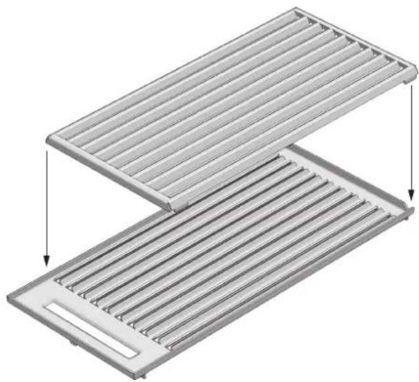
natural_image
3D diagram of a two-tiered storage tray with horizontal slats and a slot, showing internal structure and flow arrows (no text or symbols)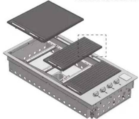
natural_image
Exploded view diagram of an electronic device showing internal components and mounting holes (no text or labels)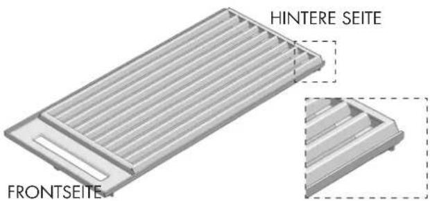
natural_image
Technical illustration of a mechanical assembly with exploded and assembled views (no text or symbols)ANMERKUNGEN
natural_image
Mechanical assembly diagram showing two views of a mechanical component with bolted parts and a separate view of a bolted nut (no text or symbols present)natural_image
Mechanical assembly diagram showing a bolt inserted into a housing with a separate bolt inserted into a housing (no text or symbols present)natural_image
Technical illustration of a mechanical assembly with three orthographic views (LEFT, RIGHT, and an unlabeled right view) showing internal components and mounting holes (no text or symbols present)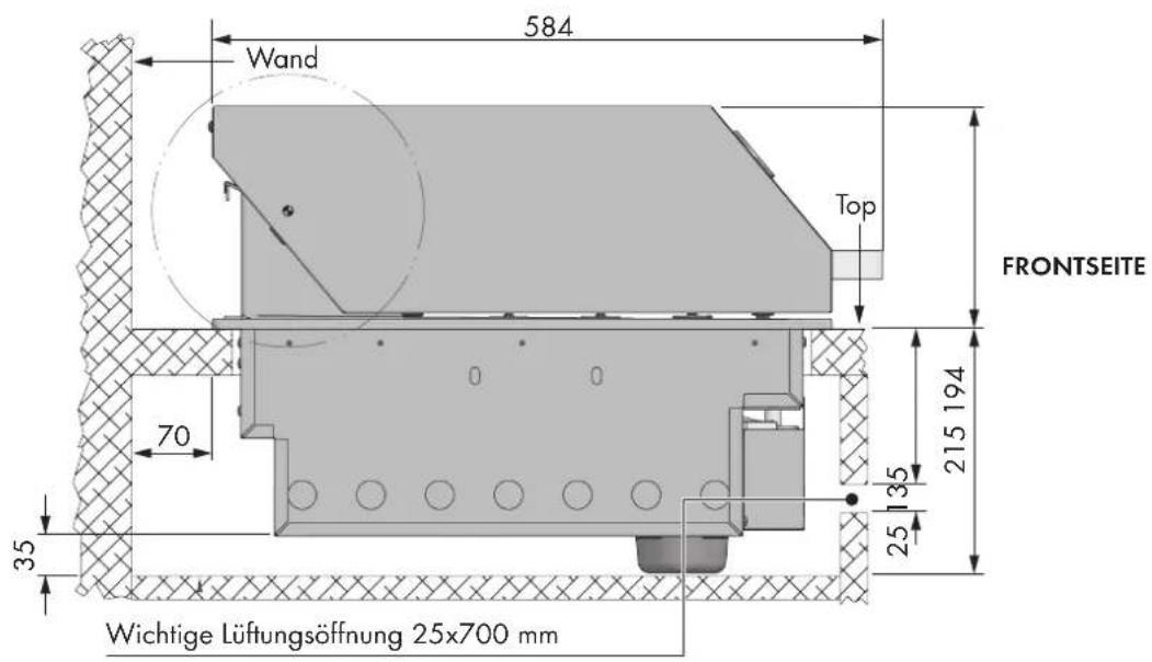
natural_image
Technical diagram of a gas cylinder connected to a control panel with a side-mounted valve, against a hatched wall (no text or symbols)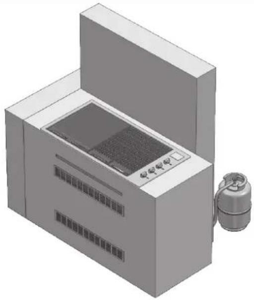
natural_image
3D rendering of a laboratory or industrial machine with control panel and cylindrical device (no visible text or symbols)natural_image
Line drawing of a cylindrical container with cutouts and a lid (no text or symbols)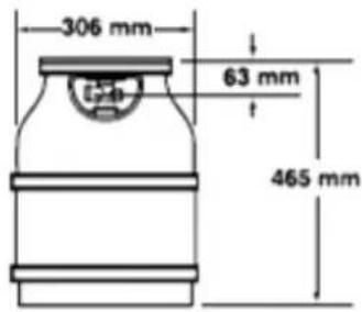
natural_image
Line drawing of a rectangular container with a small cylindrical object on top (no text or symbols)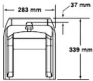
CALOR 5 kg PRIMAGAZ 5.2 kg
natural_image
Line drawing of a mechanical component with no visible text or symbols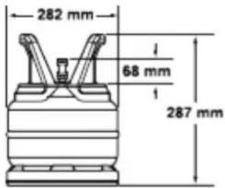
natural_image
Technical line drawing of a mechanical component with a central hub and concentric rings (no text or symbols)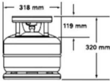
natural_image
Mechanical assembly diagram showing a valve and pump connected to a tank (no text or symbols visible)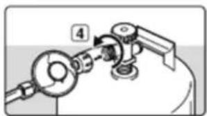
natural_image
Mechanical assembly diagram showing a lever and pump mechanism (no text or symbols)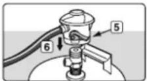
natural_image
Diagram of a showerhead emitting water, showing no text or symbols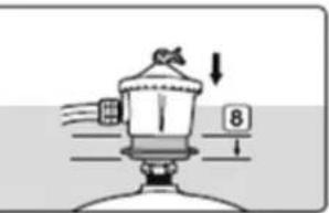
natural_image
Diagram of a mechanical device with a downward arrow and numbered label (no readable text or symbols)Montage der flachen Abdeckhaube
natural_image
3D technical illustration of a mechanical housing component with mounting holes and internal compartments (no text or symbols)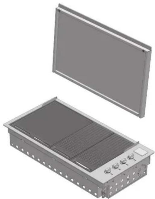
natural_image
3D rendering of an electronic device housing with a flat panel and internal cooling unit (no text or symbols visible)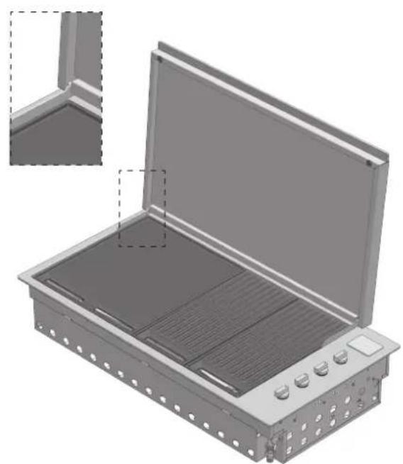
natural_image
3D rendering of an open industrial enclosure with internal compartments and control knobs (no text or symbols visible)natural_image
3D technical illustration of a mechanical housing component with internal compartments and mounting holes (no text or symbols)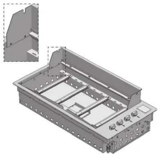
natural_image
3D technical illustration of a mechanical housing or enclosure with internal components and mounting holes (no text or symbols)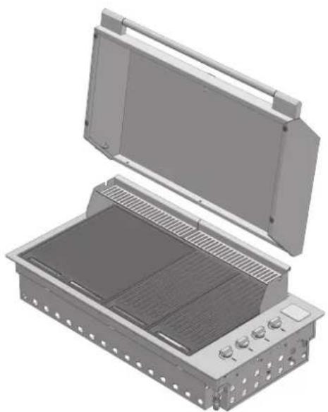
natural_image
3D rendering of an open industrial enclosure with internal grating and ventilation slots (no text or symbols visible)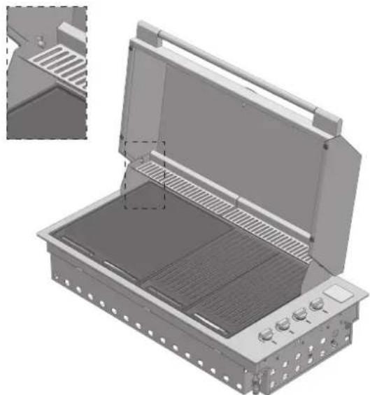
natural_image
3D technical illustration of an open fire extinguisher with internal grating and ventilation slots (no text or symbols)
WICHTIG
natural_image
3D rendering of a rectangular electronic device with ventilation grilles and control knobs (no text or symbols visible)natural_image
3D rendering of a rectangular electronic device with ventilation grilles and control knobs (no text or symbols visible)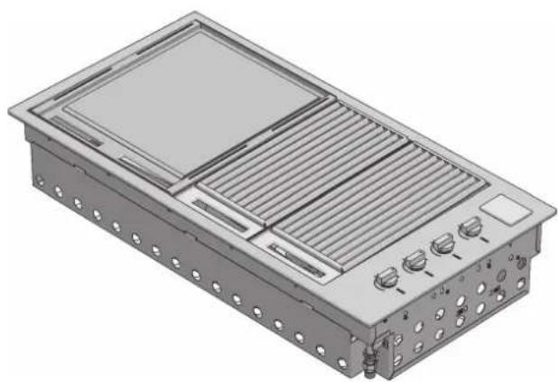
natural_image
3D rendering of a rectangular electronic device with ventilation grilles and control knobs (no text or symbols visible)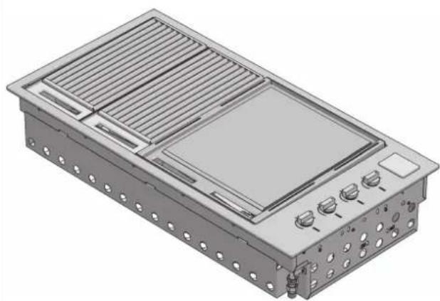
natural_image
3D rendering of a modular electronic device with ventilation grilles and control knobs (no text or symbols visible)natural_image
Technical illustration of two industrial electronic equipment modules with heat sinks and ventilation grilles (no text or symbols)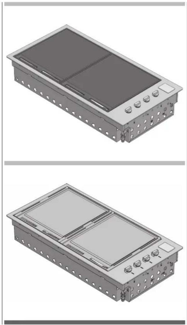
natural_image
Technical illustration of a dual-chamber electronic device with mounting holes and control buttons (no text or symbols)Mod. BBQ 80 cm
natural_image
3D rendering of an industrial air conditioning unit with heat exchangers and cooling fins (no text or symbols visible)Mod. BBQ 60 cm
natural_image
3D rendering of a rectangular industrial or electrical enclosure with slatted top and side panels, no visible text or symbols.BBQ 60 Gesamtplatte
natural_image
3D rendering of a rectangular electronic device with mounting holes and a central screen (no text or symbols visible)natural_image
3D rendering of an open industrial enclosure with internal compartments and control knobs (no text or symbols visible)
ACHTUNG
natural_image
3D rendering of a rectangular electronic device with internal components and a close-up inset showing a paper clip (no text or symbols)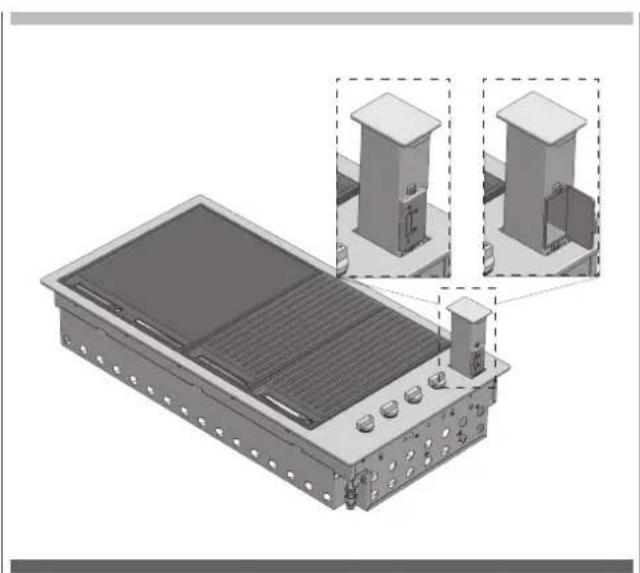
natural_image
3D technical illustration of a solar panel installation with two inset views showing structural components (no text or symbols)Lüftungsöffnungen
natural_image
Recycling symbol composed of five arrows forming a cycle (no text or labels)BARBECUE MOD. FOBQ 1000 G X
TAPA BAJA MOD. FOBQ LL 1000 X
BARBECUE MOD. FOBQ 1000 G X
TAPA ALTA MOD. FOBQ HL 1000 X
Barbecue integrado tapa alta
BARBECUE MOD. FOBQ 803 G X
TAPA ALTA MOD. FOBQ HL 800 MBK
BARBECUE MOD. FOBQ 803 G MBK
TAPA BAJA MOD. FOBQ LL 800 MBK
BARBECUE MOD. FOBQ 803 G MBK
TAPA ALTA MOD. FOBQ HL 800 MBK
Barbecue integrado tapa
BARBECUE MOD. FOBQ 601 TY G X
TAPA ALTA MOD. FOBQ HL 600 X
Barbecue integrado tapa
BARBECUE MOD. FOBQ 602 G X
TAPA ALTA MOD. FOBQ HL 600 X
Barbecue integrado tapa
natural_image
3D rendering of three rectangular metal grates with internal slots, shown from different angles (no text or symbols)natural_image
3D rendering of a wooden deck or shelf structure with slats and a small inset detail (no text or symbols visible)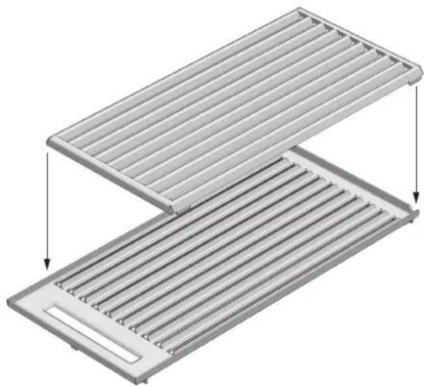
natural_image
3D diagram of a two-tiered storage tray with horizontal slats and a cutout, showing internal structure (no text or symbols)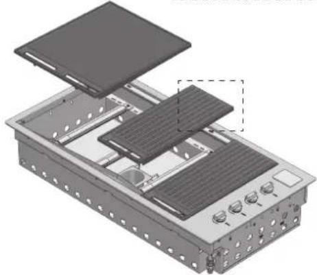
natural_image
Exploded view diagram of an electronic device showing internal components and mounting holes (no text or symbols)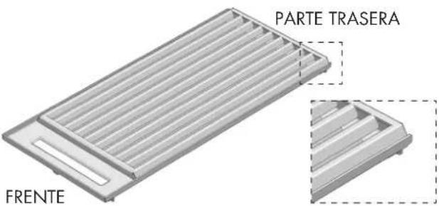
natural_image
Technical illustration of a mechanical assembly with exploded and assembled views (no text or symbols)NOTAS
natural_image
Mechanical assembly diagram showing two views of a mechanical component with bolted parts and a separate view of a bolted nut (no text or symbols present)natural_image
Mechanical assembly diagram showing a bolt inserted into a housing with a separate bolt inserted into a housing (no text or symbols present)natural_image
Technical diagram of a gas cylinder connected to a control panel with a side-mounted valve, against a hatched wall (no text or symbols)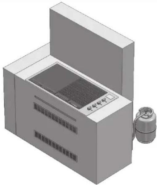
natural_image
3D rendering of a laboratory or industrial machine with control panel and external tank (no visible text or symbols)natural_image
Line drawing of a cylindrical container with cutouts and a lid (no text or symbols)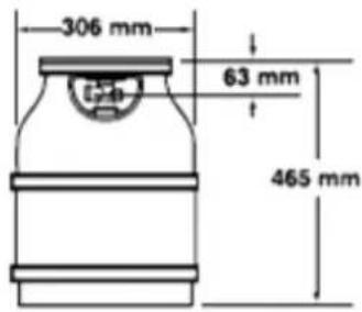
natural_image
Line drawing of a rectangular container with a small cylindrical object on top (no text or symbols)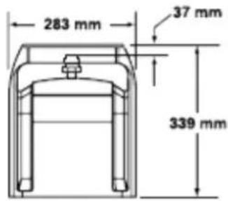
CALOR 5 kg PRIMAGAZ 5.2 kg
natural_image
Line drawing of a mechanical component resembling a container or pump (no text or symbols)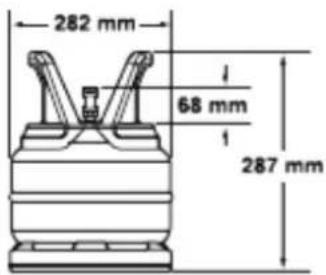
natural_image
Technical line drawing of a mechanical component with a central hub and concentric rings (no text or symbols)

ADVERTENCIA
natural_image
Mechanical assembly diagram showing a lever and pump mechanism (no text or symbols)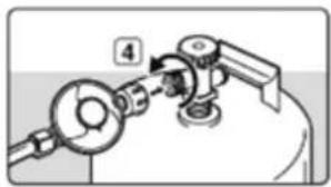
natural_image
Mechanical assembly diagram showing a rotating component with a numbered label (4), no readable text or symbols present.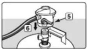
natural_image
Simple line drawing of a lamp with a base and top, no text or symbols present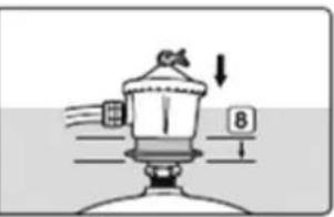
natural_image
3D technical illustration of a mechanical housing component with mounting holes and internal compartments (no text or symbols)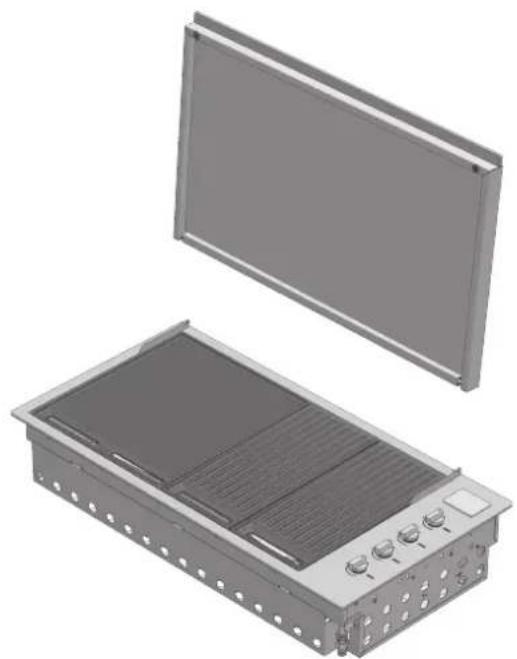
natural_image
3D rendering of an electronic device housing with a flat panel and internal cooling unit (no text or symbols visible)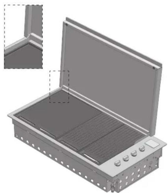
natural_image
3D rendering of an open industrial enclosure with internal compartments and control knobs (no text or symbols visible)natural_image
3D CAD model of a mechanical housing assembly with internal compartments and mounting holes (no text or symbols)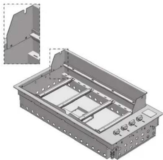
natural_image
3D technical illustration of a mechanical housing or enclosure with internal components and mounting holes (no text or symbols)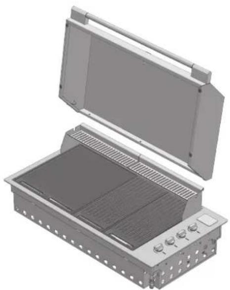
natural_image
3D rendering of an open industrial enclosure with internal grating and ventilation slots (no text or symbols visible)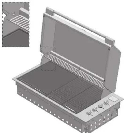
natural_image
3D technical illustration of an open fire extinguisher with internal grating and ventilation slots (no text or symbols)
IMPORTANTE
natural_image
3D rendering of a rectangular electronic device with heat exchangers and a central panel (no text or symbols visible)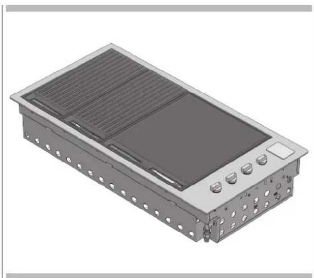
natural_image
3D rendering of a rectangular electronic device with ventilation grilles and mounting holes (no text or symbols visible)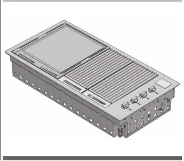
natural_image
3D rendering of a modular electronic device with ventilation grilles and mounting holes (no text or symbols visible)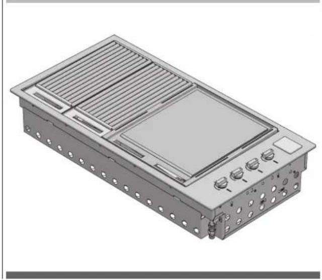
natural_image
3D rendering of a rectangular electronic device with heat exchangers and a central display (no text or symbols visible)natural_image
Technical illustration of two industrial electronic equipment modules with heat sinks and ventilation grilles (no text or symbols)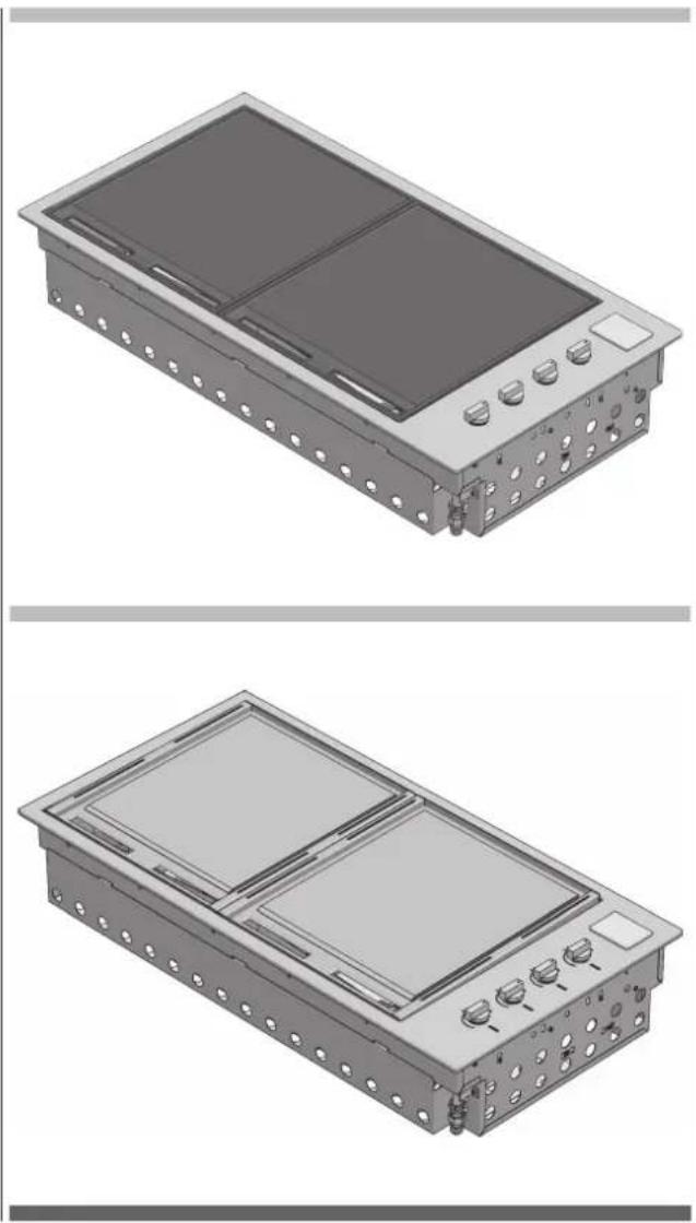
natural_image
Technical illustration of a dual-chamber electronic device with mounting holes and control buttons (no text or symbols)Mod. BBQ 80 cm
BBQ 80 rejillas totales
natural_image
3D rendering of an industrial air conditioning unit with heat exchangers and cooling fins (no text or symbols visible)Mod. BBQ 60 cm
BBQ 60 rejillas totales
natural_image
3D rendering of a rectangular industrial or electrical enclosure with slatted top and side panels, no visible text or symbols.BBQ 60 placa total
natural_image
3D rendering of a rectangular electronic device with mounting holes and a central screen (no text or symbols visible)natural_image
3D rendering of an open industrial electrical enclosure with internal compartments and control buttons (no text or symbols visible)
ATENCIÓN
natural_image
3D rendering of a rectangular electronic device with internal components and a close-up inset showing a component being inserted (no text or symbols visible)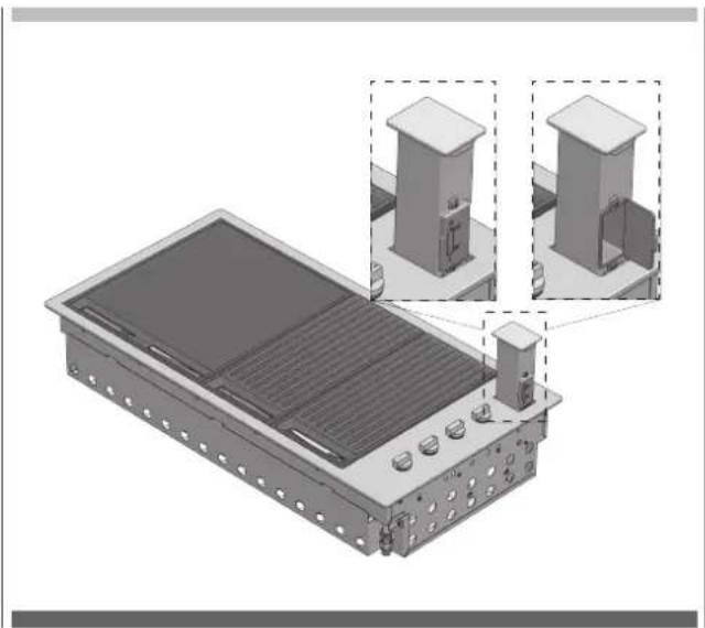
natural_image
3D technical illustration of a solar panel installation with two zoomed-in views showing internal components (no text or symbols)

- NOTE
- ATTENZIONE
- IMPORTANTE
- Mod. BBQ 80 cm
- Mod. BBQ 60 cm
- Accensione manuale
- Suggestion for the environment Disposal information for users
- TABLE OF CONTENTS PAGE
- Integrated barbecue with cover
- IMPORTANT
- Use
- ATTENTION
- WARNING
- TIPS AND INFORMATION
- SUGGESTION FOR THE ENVIRONMENT
- PROHIBITION
- The manufacturer's liability:
- Tools needed for assembly:
- Adapting to different types of gas
- NOTES
- Gas connection
- Rigid and semi-rigid metal and rubber hose connection
- Leak testing procedure
- EN 7 - Installation instructions and warnings
- Selection of the point of installation
- Installation compartment
- Island-mounted
- Installation in a counter in a special context
- Dimensions of the cylinder
- EN 8 - Connection of the LPG cylinder
- Application of the low cover
- Application of the high cover
- Mod. BBQ 100 cm
- Control functions
- Ignition instructions
- Manual lighting
- Pre-heating cooking areas
- To turn off the burner
- EN 11 - Cleaning and care
- Care and cleaning of the appliance
- Cleaning of cooking parts
- Other stainless steel surfaces
- Cleaning the cooking grills made of cast iron
- Cleaning the stainless steel grills
- Cleaning the grease drip pan
- Burners
- SUGGESTIONS AND INFORMATION
- Special note on "tea staining"
- Special note on stainless steel
- EN 12 - Maintenance
- Ignition system
- Ventilation openings
- MANUFACTURER'S DECLARATION
- DISPOSAL OF USED APPLIANCES
- WARNUNG
- ANMERKUNGEN
- Montage der flachen Abdeckhaube
- WICHTIG
- ACHTUNG
- Lüftungsöffnungen
- Barbecue integrado tapa
- NOTAS
- ADVERTENCIA
- ATENCIÓN
Brand : Fulgor Milano
Model : FOBQ 803 G X
Category : Grill