
CR0301 - Regulator IFM - Free user manual and instructions
Find the device manual for free CR0301 IFM in PDF.


| Product Type | Mobile Controller (CabinetController R 360) |
| Dimensions (L x W x H) | 223 x 134 x 33 mm |
| Weight | 0.55 kg |
| Operating Voltage | 10...32 V DC |
| Inputs | 24 total (8 analogue / 16 digital) |
| Outputs | 18 total (8 digital semiconductor / 10 relay) |
| Programming | IEC 61131-3 via CODESYS |
| Protection Rating | IP20 |
| Operating Temperature | -40 to 85 °C |
| Storage Temperature | -40 to 85 °C |
| CAN Interface | CANopen 2.0 B, up to 1 Mbit/s |
| Serial Interface | RS-232 C |
| Mounting | 4 screws M4 in dry enclosed area |
| Maintenance | No user maintenance; manufacturer only |
| Safety | SELV supply required; not for safety of persons |
| Repairability | Manufacturer service only |
| Disposal | Per national environmental regulations |
| Accessories | Connector set EC2075, programming adapter EC2076 |
Frequently Asked Questions - CR0301 IFM
User questions about CR0301 IFM
0 question about this device. Answer the ones you know or ask your own.
Ask a new question about this device
Download the instructions for your Regulator in PDF format for free! Find your manual CR0301 - IFM and take your electronic device back in hand. On this page are published all the documents necessary for the use of your device. CR0301 by IFM.
USER MANUAL CR0301 IFM
Mounting and installation instructions
ecomot100®
natural_image
Front view of a computer interface panel with ports, connectors, and a central circle (no text or symbols)Sicherheitshinweise

This description is part of the unit. It contains texts and drawings concerning the correct handling of the controller and must be read before installation or use.
Observe the information of the description. Non-observance of the notes, operation which is not in accordance with use as prescribed below, wrong installation or handling can result in serious harm concerning the safety of persons and plant.
The instructions are for authorised persons according to the EMC and low voltage guidelines. The controllers must be installed and commissioned by a skilled electrician (programmer or service technician).
If the unit is not supplied by the mobile on-board system (12/24 V battery operation) it must be ensured that the external voltage is generated and supplied according to the criteria for safety extra-low voltage (SELV) as this is supplied without further measures to the connected controller, the sensors, and the actuators.
The wiring of all signals in connection with the SELV circuit of the unit must also comply with the SELV criteria (safe extra-low voltage, safe electrical separation from other electric circuits).
If the supplied SELV voltage has an external connection to ground (SELV becomes PELV) the responsibility lies with the user and the respective national regulations for installation must be complied with. All statements in these operating instructions refer to the unit the SELV voltage of which is not grounded.
The terminals may only be supplied with the signals indicated in the technical data or on the unit label and only the approved accessories of ifm electronic gmbh may be connected.
The unit can be operated within a wide temperature range according to the technical specification indicated below. Due to the additional self-heating the housing walls can have high perceptible temperatures when touched in hot environments.
In case of malfunctions or uncertainties please contact the manufacturer. Tampering with the unit can lead to considerable risks for the safety of persons and plant. It is not permitted and leads to the exclusion of any liability and warranty claims.
Contents
- Function and features page 11
- Programming page 11
- Mounting page 12
- Electrical connection page 12
- Maintenance, repair and disposal page 12
- Approvals/standards page 12
Technical data (data sheets 1...5)
Dimensions, mechanics, electronics page 13 Operating status (status LED) page 14 Test standards and regulations page 14 Characteristics of the inputs/outputs page 15 Wiring page 17
1. Function and features
The freely programmable controllers of the "CabinetController R 360" series are rated for use under difficult conditions (e.g. extended temperature range, strong vibration, intensive EMC interference).
They are thus suited for direct mounting into machines in mobile and rugged applications. Due to their specification the inputs and outputs are especially rated for this use. Integrated hardware and software functions (operating system) offer high protection of the machine.
The controllers can be used as CANopen master.

The controllers "CabinetController R 360" are not approved for safety-relevant tasks in the field of safety of persons.
2. Programming
The application software can be easily created by the user with the programming system CODESYS according to IEC 61131-3.
In addition to the programming system the complete system manual is required to program the controller.
If this manual is not available, please contact one of the ifm branch offices over-leaf for your free copy. The system manual (pdf format) can also be downloaded from the web (www.ifm.com)..
| Request | → System manual R360; English (order no. EC2041) |
| Internet | → Data sheet direct → CR0301 → Additional data |
The user is responsible for the safe functioning of the application programs which he creates himself. If necessary, he must additionally obtain an approval according to the corresponding national regulations by the corresponding testing and supervisory organisations.
3. Mounting
The controller is to be mounted in a dry and enclosed environment (e.g. control panel of the driver's cab, separate control boxes etc.).
It is mounted with 4 screws M4 x L.
4. Electrical connection
To protect the whole system (wiring and controller) the individual electric circuits must be protected.
| Designation Potential Connector : Pin no. Fuse | |||
| supply voltage U | B | X1:01 max. 2 A | |
| supply voltage digital outputs U | COM01/02 | X3:05/10 max. 16 A | |
| supply voltage relay outputs U (relay 0...2) | COM03...05 | X5.1:02/06/10 max. 10 A | |
| supply voltage relay outputs U (relay 3...9) | COM06...12 | X5.1:14/16X5.2:02/06/10/14/16 | max. 2 A |
5. Maintenance, repair and disposal
As the Controller does not contain any components which must be maintained by the user, the housing must not be opened. The maintenance of the controller may only be carried out by the manufacturer. The disposal must be carried out according to the corresponding national environmental regulations.
6. Approvals/standards
Test standards and provisions Technical data.
The CE Declaration of Conformity and the E1 approval are available at:
www.ifm.com → Data sheet direct → CR0301 → Approvals
CR0301
Mobile controller
CabinetController
24 inputs
18 outputs
Programming
to IEC 61131-3
Operating voltage
10...32 V DC
CE
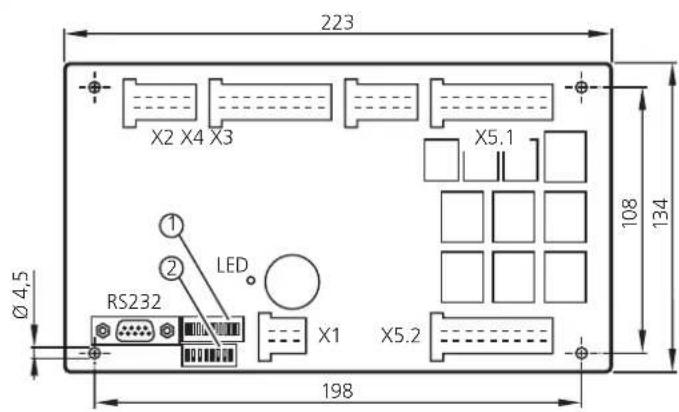
1.) row of LEDs (10 segments) 2.) DIP switch (8 segments)

Technical data usable as CANopen m
| Design PCB without housing |
| Dimensions (l x w x h) 223 x 134 x 33 m |
| Mounting fixing via 4 bore holes (∅ 4.5 |
| Connections AMP crimp connector to be |
| Inputs / outputs 2 x 10 pins, 3 x 18 p |
| Operating voltage and CAN bus 1 x 6 |
| Programming, TEST D-Sub socket, 9 p |
| Weight 0.55 kg |
| Operating temperature |
| Storage temperature |
| Protection |
| Inputs |
| possible configurations |
ster or intelligent I/O module
24 inputs (8 analogue / 16 digital) and 18 outputs (8 digital / 10 relay)
| (for mechanical protection potted in a potting tub) |
| n |
| (um) |
| clipped into place and thus vibration-resistant,protected against reverse polarity (AMP Junior Timer contacts) |
| s |
| pins |
| ns |
| -40...85 °C (depending on the load) |
| -40...85 °C |
| IP 20 |
| 24 |
Outputs
| possible configurations | |
| Abbreviations | |
| A | = analogue |
| B1 | = binary high side |
| BL | = binary low side |
| I1 | = pulse low side |
| PWM | = pulse width modulation |
| Amount | Signal | Type | |
| 8or | analoguedigital | 0...10/32 V DC, 0...20 mA or ratiometricas binary voltage input | A B_L |
| 8 | digital | for positive sensor signals, with diagnostic capability | B_L |
| 4or | digitalfrequency | for positive sensor signals, with diagnostic capabilitypulse inputs, max. 30 kHz | B_L I_L |
| 4 | digital | for positive / negative sensor signals | B_L/H |
18
| Amount | Signal | Type | |
| 4 or | digital PWM | positive switching (high side)PWM frequency max. 250 Hz | B_H PWM |
| 4 | digital | positive switching (high side) | B_H |
| 3 | relay 1 changeover contact each, potential-free, max. 10 A | ||
| 7 | relay 1 changeover contact each, potential-free, max. 2 A | ||
Accessories
| (to be ordered separately) |
order no. EC2075
connector set for CabinetController, consisting of:
| AMP crimp housing, 1 x 6 pins, 2 x 10 pins, 3 x 18 pins incl. crimp contacts (Junior Power Timer) |
order no. EC2076
| RS 232 programming adapter for the connection of U_B to the TEST input |
We reserve the right to make technical alterations without prior notice. CR0301 / page 1
05.11.2014
CR0301 Technical data
| Operating voltage UB | 10...32 V DC |
| Overvoltage 36 V for t ≤ 10 sUndervoltage detection for UAuto save for U | _B ≤9,5 VB≤9,0 V |
| Current consumption | ≤100 mA (without external load at 24 V DC)external fuse with max. 10 A |
| CAN interface CAN interface 2.0 B, ISO Baud rate 50 Kbits/s...1 Mbit/s (default setting 125 Kbits/s)Communication profile CANopen, CiA DS 301 version 3.0, CiA DS 401 version 1.4 | |
| Node ID (CANopen) hex 20 (= dec 32) | |
| Serial interfaceBaud rateTopologyProtocol predefined ifm protocol (INTELHEX) | RS-232 C9.6 / 19.2 / 28.8 / 38.4 / 57.6 kBit/s (default setting 57.6 Kbits/s)point-to-point (max. 2 participants); master-slave connection |
| Processor | CMOS microcontroller 16 bits C167Cpulse frequency 20 MHz |
| MemoryProgram memory 192 Kbytes FlashData memoryData memory (auto save memory) | 48 Kbytes SRAM, 32 Kbytes Flash, 4 Kbytes EEPROM256 bytes (protected in case of power failure) |
| Indicators / input elements(freely configurable) | 10-segment row of LEDs8-segment DIP switch |
| Status LED | two-colour LED (red / green) |
| LED colour | Status | Description |
| - | off | no operating voltage |
| orange | 1 x on | initialisation or reset checks |
| green | 5 Hz | no operating system loaded |
| green | 2.0 Hzon | RunStop |
| red | 2.0 Hzon | Run with errorfatal error or stop with error |
| Climatic test |
| Mechanical resistance |
| Immunity to conducted interference |
| Immunity to interfering fields |
| Interference emission |
We reserve the right to make technical alterations without prior notice.
CR0301 / page 2 05.11.2014
CR0301 Characteristics of the inputs
| Analogue inputs■Voltage inputsX2:01...10, A_IN 00...A_IN 07 input voltage can be configured as ... resolution 10 bits | accuracy ± 1% FSinput resistance 78.4 kΩ (0...10 V), 46.6 kΩ (0...32 V)input frequency 50 Hz |
| ■Current inputs, with diagnostic capabilityinput current 0...20 mAresolution 10 bitsaccuracy ± 1% FSinput resistance 400 Ωinput frequency 50 HzAt a current of >23 mA the pair of channels is switched to the voltage input! | |
| ■Voltage inputs, 0...32 V, ratiometricfunction ( U_N ÷ U_B ) x 1000 ‰value range 0...1000 ‰ | |
| ■Binary voltage inputs for positive sensor signalsThe analogue inputs A_IN 00...07 are configured / switched in pairs!The following inputs are combined in pairs: 0+4, 1+5, 2+6, 3+7 | |
| Digital inputsX4:01...08, IN 00...IN 07can be configured as ... switch-off level | ■ Digital inputs for positive sensor signals, with diagnostic capabilityswitch-on level >0.6 U<0.3 Input resistance 3.21 kΩinput frequency 50 Hz |
| Digital inputsX4:11...14, IN 08...IN 11can be configured as ... switch-off level | ■ Digital inputs for positive sensor signals, with diagnostic capabilityswitch-on level >0.6 U<0.3 Input resistance 3.16 kΩinput frequency 50 Hz |
| ■Frequency inputs for positive sensor signals, with diagnostic capabilityswitch-on level 0.4...0.7 Ubswitch-off level 0.2...0.24 Ubinput resistance 3.16 kΩmeasuring range 0...2 kHz oder 1...30 kHz | |
| Digital inputsX4:15...18, IN 12...IN 15can be configured as ... switch-off level | ■ Digital inputs for positive sensor signalsswitch-on level >0.6 U<0.3 Input resistance 3.21 kΩinput frequency 50 Hz |
| ■Digital inputs for negative sensor signalsswitch-on level <0.2 Ubswitch-off level >0.5 Ubinput resistance 3.21 kΩinput frequency 50 Hz | |
| The digital inputs IN 12...15 are configured / switched in pairs!The following inputs are combined in pairs: 12+13, 14+15 | |
| Test inputRS 232, D-Sub plug, pin 09 | During the test mode (e.g. programming) the TEST input must be connected to U_B (10...32 V DC).For the "RUN" mode the TEST input must not be connected. |
| also see wiring, page 5 | |
ifm electronic gmbh • Friedrichstraße 1 • 45128 Essen
We reserve the right to make technical alterations without prior notice.
CR0301 / page 3 05.11.2014
| CR0301 Characteristics of the output | |
| Digital outputsX3:01...04, OUT 00...OUT 03 short-circuit can be configured as ... switching voltage | ■ Semi conductor outputs, positive switching (high side), with diagnostic capability and overload protected10...32 V DCSwitching current max. 2 A |
| ■PWM outputsPWM frequency max. 250 Hzsetting resolution 0,1 %load current max. 2 A | |
| The outputs 0...3 are combined and have a common U_COM connection. | |
| Digital outputsX3:06...09, OUT 04...OUT 07 short-circuit | ■ Semi conductor outputs, positive switching (high side),and overload protectedswitching voltage 10...32 V DCSwitching current max. 2 A |
| The outputs 4...7 are combined and have a common U_COM connection. | |
| Relay outputsX5.1:01...11, OUT 08...OUT 10 | ■ Changeover contacts, potential-free (R0...R2)switching current 0,5...10 A (NO), 0,5...5 A (NC)switching voltage 10...32 V DCnumber of operating cycles (without load) ≥ 10^6 switching - time constant ≤ 3 ms |
| Relay outputsX5.1:13...18, OUT 11...OUT 12X5.2:01...18, OUT 13...OUT 17 | ■ Changeover contacts, potential-free (R3...R9)switching current 0,01...2,0 Aswitching voltage 10...32 V DCnumber of operating cycles (without load) ≥ 10^6 switching - time constant ≤ 5 ms |
| External free-wheeling diode | To protect the outputs free-wheeling diodes must be connected in parallel with the load in the case of high switch-off energies (inductive or capacitive loads). |
| also see wiring, page 5 | |
ifm electronic gmbh • Friedrichstraße 1 • 45128 Essen
We reserve the right to make technical alterations without prior notice.
CR0301 / page 4 05.11.2014
CR0301 Wiring
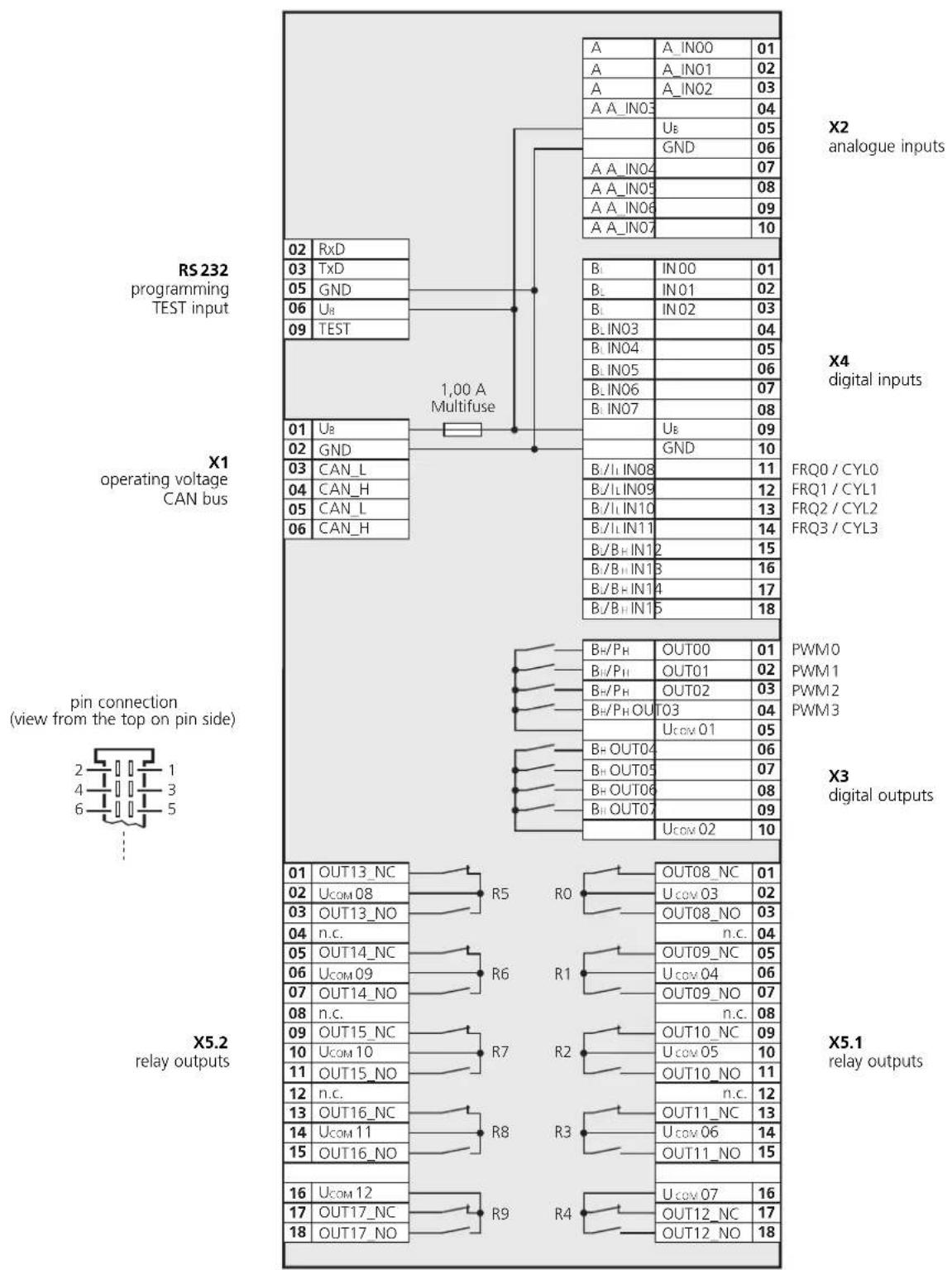
Explanation of the abbreviations:
A = analogue
BH = binary (high side)
BL = binary (low side)
FRQ/CYL = frequency inputs
IL = pulse (low side)
PH = PWM (high side)
PWM = pulse width modulated signals
RxD = serial interface (data received)
TxD = serial interface (data transmitted)


- Sicherheitshinweise
- This description is part of the unit. It contains texts and drawings concerning the correct handling of the controller and must be read before installation or use.
- Contents
- Function and features
- Programming
- Mounting
- Electrical connection
- Maintenance, repair and disposal
- Approvals/standards
- CR0301
- CR0301 Wiring
Brand : IFM
Model : CR0301
Category : Regulator