
A320 - Blender Aviom - Free user manual and instructions
Find the device manual for free A320 Aviom in PDF.


| Product Type | Blender |
| Model | A320 by Aviom |
| Power | 600 W |
| Capacity | 1.5 L (6 cups) |
| Jar Material | Tritan plastic, BPA-free |
| Blade Material | Stainless steel, 4-point |
| Speed Settings | 2 speeds + pulse |
| Ice Crush Function | Yes |
| Dishwasher Safe Parts | Jar, lid, and blade assembly (top rack) |
| Non-Slip Base | Yes, with suction feet |
| Safety Lock | Motor shuts off if jar is not properly locked |
| Overload Protection | Automatic shut-off to prevent overheating |
| Dimensions (H x W x D) | 40 cm x 18 cm x 18 cm (15.7 x 7.1 x 7.1 in) |
| Weight | 2.3 kg (5.1 lbs) |
| Cord Length | 1.0 m (39.4 in) |
| Voltage / Frequency | 120 V, 60 Hz (US model) |
| Warranty | 1 year limited |
| Certifications | ETL, FDA approved materials |
Frequently Asked Questions - A320 Aviom
User questions about A320 Aviom
0 question about this device. Answer the ones you know or ask your own.
Ask a new question about this device
Download the instructions for your Blender in PDF format for free! Find your manual A320 - Aviom and take your electronic device back in hand. On this page are published all the documents necessary for the use of your device. A320 by Aviom.
USER MANUAL A320 Aviom
Important Safety Instructions
- Read these instructions.
- Keep these instructions.
- Heed all warnings.
- Follow all instructions.
- Do not use this apparatus near water.
- Clean only with a dry cloth.
- Do not block any ventilation openings. Install in accordance with the manufacturer's instructions.
- Do not install near any heat sources such as radiators, heat registers, stoves, or other apparatus (including amplifiers) that produce heat.
- Do not defeat the safety purpose of the polarized or grounding-type plug. A polarized plug has two blades with one wider than the other. A grounding type plug has two blades and a third grounding prong. The wide blade or third prong is provided for your safety. If the provided plug does not fit your outlet, consult an electrician for replacement of the obsolete outlet.
- Protect the power cord from being walked on or pinched, particularly at plugs, convenience receptacles, and the point where they exit the apparatus.
- Only use attachments/accessories specified by the manufacturer.
- Use only with the cart, stand, tripod, bracket, or table specified by the manufacturer, or sold with the apparatus. When a cart is used, use caution when moving the cart/apparatus combination to avoid injury from tip-over.
- Unplug this apparatus during lightning storms or when unused for long periods of time.
- Refer all servicing to qualified personnel. Servicing is required when the apparatus has been damaged in any way, such as when the power-supply cord or plug is damaged, liquid has been spilled or objects have fallen into the apparatus, the apparatus has been exposed to rain or moisture, does not operate normally, or has been dropped.
- No on/off power switches are included in the system. The external power supply should be used to control power to an Aviom device. This power supply should remain readily operable.
- The solid line over dashed line symbol (____) indicates that the input voltage must be a DC voltage.
- The box within a box symbol (☐) indicates that the external power supply is double insulated.

WARNING!

TO REDUCE THE DANGER OF ELECTRICAL SHOCK DO NOT REMOVE COVERS.
NO USER SERVICEABLE PARTS INSIDE.
REFER SERVICING TO QUALIFIED SERVICE PERSONNEL ONLY.
To reduce the risk of fire or electrical shock, do not expose this product to rain or other types of moisture.
To avoid the hazard of electrical shock, do not handle the power cord with wet hands.
Replace fuse with same type and rating.
Operating Temperature: 0^ C to 50^ C ( 32^ F to 122^ F)
This equipment has been tested and found to comply with the limits for a Class B digital device, pursuant to part 15 of the FCC Rules. These limits are designed to provide reasonable protection against harmful interference in a residential installation. This equipment generates, uses and can radiate radio frequency energy and, if not installed and used in accordance with the instructions, may cause harmful interference to radio communications. However, there is no guarantee that interference will not occur in a particular installation. If this equipment does cause harmful interference to radio or television reception, which can be determined by turning the equipment off and on, the user is encouraged to try to correct the interference by one or more of the following measures:
- Reorient or relocate the receiving antenna.
- Increase the separation between the equipment and receiver.
- Connect the equipment into an outlet on a circuit different from that to which the receiver is connected.
- Consult the dealer or an experienced radio/TV technician for help.
Changes or modifications to the product not expressly approved by Aviom, Inc. could void the user's FCC authority to operate the equipment.
CAUTION:
- Using any audio system at high volume levels can cause permanent damage to your hearing.
- Set your system volume as low as possible.
- Avoid prolonged exposure to excessive sound pressure levels.
Certifications
EMC: EN55103-1:2009
EN 55103-2: 2009
EN 55022:2006 / CISPR 22:1997
CAN/CSA-CEI/IEC CISPR 22:02
FCC 47 CFR, Part 15
Safety: UL 62368-1 Ed 2.0; Proposal Number 500542870;
Testing done to UL 62368-1 first edition
Can/CSA C22.2 62368-1
ETL/cETL Listed and RoHS Compliant


Notice of Rights
All rights reserved. No part of this document may be reproduced or transmitted in any form or by any means—electronic, mechanical, photocopy, recording, or otherwise—without written permission of Aviom, Inc.
Trademarks
Aviom, A-Net, the A-Net icon, Pro16, Pro16e, Pro64, Virtual Data Cables, m-control, One-Touch Ambience, Dual Profile Channel, Network MixBack, and AllFrame are trademarks of Aviom, Inc. All other trademarks are the property of their respective owners.
©2014 Aviom, Inc. All rights reserved.
Information is subject to change without notice.
Aviom, Inc. Limited Warranty
Aviom, Inc. warrants this product against defects in materials and workmanship for a period of one year from the date of the original retail purchase.
This warranty does not apply if the equipment has been damaged due to misuse, abuse, accident, or problems with electrical power. The warranty also does not apply if the product has been opened or modified in any way; if the product serial number has been damaged, modified, or removed; or if the original Quality Assurance label has been damaged, modified, or removed.
If a defect is discovered, first write or call Aviom, Inc. to obtain a Return Authorization number. No service will be performed on any product returned without prior authorization. Aviom, Inc. will, at its option, repair or replace the product at no charge to you. The product must be returned during the warranty period, with transportation charges prepaid to Aviom, Inc., 1157 Phoenixville Pike, Suite 201, West Chester, PA 19380. You must use the product's original packing materials for shipment. Shipments should be insured for the value of the product. Include your name, address, phone number, description of the problem, and copy of the original bill of sale with the shipment. The Return Authorization number should be written on the outside of the box.
THIS LIMITED WARRANTY GIVES YOU SPECIFIC LEGAL RIGHTS. YOU MAY HAVE OTHER RIGHTS, WHICH VARY FROM STATE TO STATE (OR JURISDICTION TO JURISDICTION). AVIOM'S RESPONSIBILITY FOR MALFUNCTIONS AND DEFECTS IN HARDWARE IS LIMITED TO REPAIR AND REPLACEMENT AS SET FORTH IN THIS LIMITED WARRANTY STATEMENT. ALL EXPRESS AND IMPLIED WARRANTIES FOR THE PRODUCT, INCLUDING BUT NOT LIMITED TO ANY IMPLIED WARRANTIES OF MERCHANTABILITY AND FITNESS FOR A PARTICULAR PURPOSE, ARE LIMITED IN DURATION TO THE WARRANTY PERIOD SET FORTH ABOVE. NO WARRANTIES, WHETHER EXPRESS OR IMPLIED, WILL APPLY AFTER SUCH PERIOD.
AVIOM, INC. DOES NOT ACCEPT LIABILITY BEYOND THE REMEDIES SET FORTH IN THIS LIMITED WARRANTY DOCUMENT. AVIOM, INC.'S LIABILITY IS LIMITED TO THE REPAIR OR REPLACEMENT, AT OUR OPTION, OF ANY DEFECTIVE PRODUCT, AND SHALL IN NO EVENT INCLUDE INCIDENTAL OR CONSEQUENTIAL DAMAGES OF ANY KIND.
SOME STATES DO NOT ALLOW EXCLUSIONS OR LIMITATION OF IMPLIED WARRANTIES OR LIABILITY FOR INCIDENTAL OR CONSEQUENTIAL DAMAGES, SO THE ABOVE LIMITATIONS MAY NOT APPLY TO YOU.
Warranty Information
Please record the following information for future reference:
Your Authorized Aviom Dealer:
Name: ____
Address: ____
Phone: ____
Serial Numbers of Your Aviom Products: ____
Date of Purchase: ____
Your Authorized Aviom Dealer is your primary source for service and support. The information recorded above will be helpful in communicating with your Authorized Aviom Dealer should you need to contact Aviom Customer Service. If you have any questions concerning the use of this unit, please contact your Authorized Aviom Dealer first. For additional technical support, or to find the name of the nearest Authorized Aviom Repair Station, check the Aviom web site at www.aviom.com.
To fulfill warranty requirements, your Aviom product should be serviced only at an authorized Aviom service center. The Aviom serial number label must appear on the outside of the unit, or the Aviom warranty is void.
This manual and its contents are copyrighted by Aviom, Inc. All rights are reserved by Aviom, Inc. This document may not, in whole or in part, be copied, photocopied, reproduced, translated, or reduced to any electronic medium or machine-readable form without prior written consent from Aviom, Inc.
The software and/or firmware contained within Aviom products is copyrighted and all rights are reserved by Aviom, Inc.
Although every effort has been made to ensure the accuracy of the text and illustrations in this manual, no guarantee is made or implied as to the accuracy of the information contained within.
Table of Contents
Important Safety Instructions . . . . . . . . . . . . . . . . . . . . . . . . . . . . . . . . . . . . . . . . . . . . ii
Certifications. iv
Aviom, Inc. Limited Warranty.
Warranty Information . . . . . . . . . . . . . . . . . . . . . . . . . . . . . . . . . vi
A320 Personal Mixer 1
Feature Overview 1
Conventions Used in this Document 2
Using Personal Mixers 2
Cat-5 Cables 2
A-Net Distributors 2
Channels and Slots 2
Button Presses 2
Package Contents 3
About A-Net 3
Compatibility 4
Pro16 Products 4
Pro64 Products 4
About Category 5 5
Cat-5e Cables 5
Cable Lengths 6
AC Line Conditioning. 7
Supplying Power to Your A320. 7
Cleaning and Maintenance Information 7
Quick Start Tutorial 8
Choose a Mixer Mode 8
16-Channel Mode 8
32-Channel Mode 8
Basic A320 Features 9
Connect the A320 to an A-Net Distributor 10
Make Your First Mix 11
Set Channel Volumes 11
Set Stereo Placement 12
Adjust the Master Tone Settings 12
Save a Mix Preset 13
A320 Front Panel 14
Mix Channels 14
Channel Label Strip 15
Mix Channel Buttons 15
Mix Presets. 15
16-Channel Vs. 32-Channel Mode ..... 16
Channel Controls Section 17
Channel Controls. 18
Central Control Knob 18
Channel Volume 18
Stereo Placement 19
Mono Channels 19
Stereo Channels 20
Using the A320 in 16-Channel Mode ..... 20
Using the A320 in 32-Channel Mode 20
Compatibility 20
Understanding Stereo Placement on the A320 ..... 21
Channel Mute 22
Channel Solo 23
Trim All Function 24
Master Section 25
A-Net and the A320 26
A-Net LED 26
Setting the Mixer Mode 26
Troubleshooting Mixer Modes ..... 27
Master Volume. 28
Master Tone Button 28
Enhance Tone Control 28
Treble Tone Control 29
Bass Tone Control 29
Mix Presets 30
Saving Mix Presets 31
What Gets Saved in a Mix Preset 32
Settings Not Saved in a Preset 32
Recall Mix Button 33
To Recall a Mix Preset 33
Clear a Mix 33
A320 Personal Mixer Rear Panel 34
Rear Panel Features 35
Stereo Mix Out 35
A-Net In 35
Personal Mixing System Setup 36
Pro16e Personal Mixing Systems 36
16-Channel Systems 37
How Stereo Links Work in a 16-Channel System ..... 37
Parallel Connections 38
Adding the A320 to an Existing System 38
32-Channel Systems 39
How Stereo Links Work in 32-Channel Systems ..... 40
Using Multiple Input Devices 41
Slot Range Setup. 42
64-Channel Systems 43
Legacy Products 43
Using Legacy Input Devices 44
Connecting Monitoring Devices 45
Connecting to the Stereo Mix Output 45
Headphones and Earbuds 45
Stereo Wireless In-Ear Systems. 46
Stereo Speakers 47
Specifications 48
Dimensions 49
Mixer Label 50
Cat-5 Cable Pinout 51
T568A 51
T568B 51
Index 52
Warranty Registration 56
A320 Personal Mixer
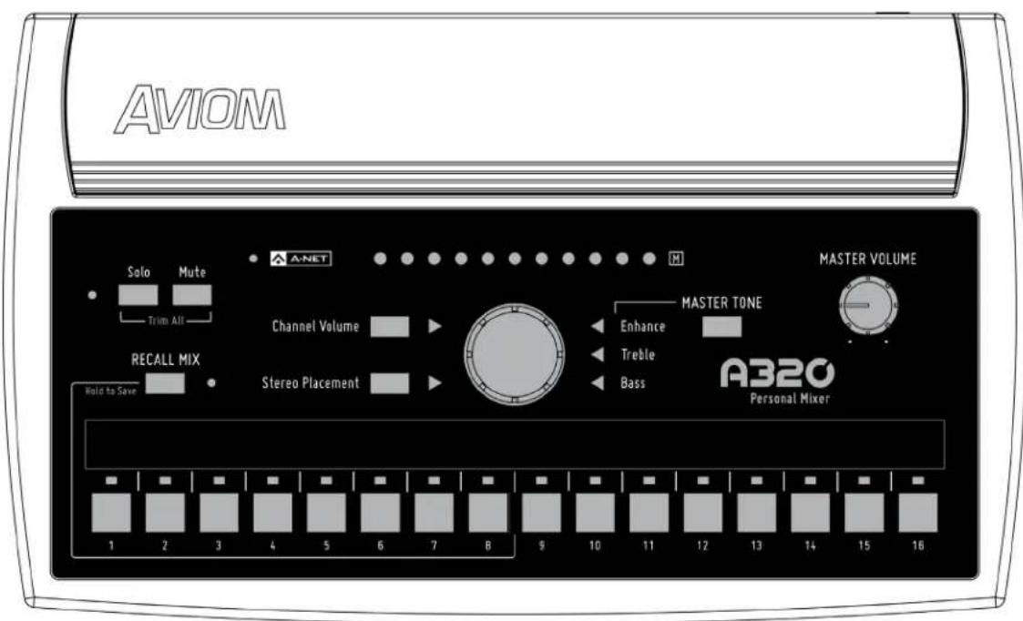
Thank you for purchasing the Aviom A320 Personal Mixer. This User Guide is designed to familiarize you with your new product's features and to have your personal mixing system up and running as quickly as possible.
Feature Overview
The A320 Personal Mixer is part of Aviom's Pro16 ^ Series of products; it can be combined with Pro16 ^ and Pro16e ^TM analog input devices, console cards, and/or the Pro64 ^ ASI A-Net ^ Systems Interface to create personal mixing systems for applications in live performance, recording, and broadcast.
The A320 Personal Mixer features:
• 16 mono or stereo mix channels
• 32-channel mix engine
- Advanced Stereo Placement positioning controls for improved sonic clarity
- Three-band master tone controls with Enhance™, optimized for in-ear monitors
- 8 Mix Presets
- Powered over the Cat-5 cable
- Seamless integration with existing Aviom personal mixing systems
Conventions Used in this Document
Using Personal Mixers
When referring to the use of the Personal Mixers in a personal mixing system in general, the term Personal Mixer is used to describe a case where an A320 Personal Mixer or A360 Personal Mixer can be used. Legacy personal mixers such as the A-16II and A-16R may also be used.
Cat-5 Cables
In most cases Cat-5e, Cat-6, and Cat-6e cables can be interchanged. When speaking about interconnections between components in a system, the term Cat-5 is used generically to indicate the use of any of the applicable cable types.
A-Net Distributors
The Aviom D800, D800-Dante, D400, D400-Dante, A-16D and A-16D Pro A-Net Distributors are referred to generically as A-Net Distributors. These are used to supply power to the A320 and to copy an A-Net digital signal and split it into multiple copies so that personal mixers may be connected in parallel.
Channels and Slots
Analog input devices and digital console cards used with Aviom personal mixing systems typically provide 16 input channels each to the Pro16 network. Once a part of the network, we refer to these resources as Slots rather than channels.
Button Presses
When instructed to press a specific button on the A320 Personal Mixer, a special font style is used. For example, "Press the Solo button."
Package Contents
The A320 Personal Mixer box includes:
• One A320 Personal Mixer
- Quick Start Documentation
Options for your personal mixing system include:
• Cat-5e/Cat-6 interconnect cables
• MT-1a Mic Stand Mount
• D800, D800-Dante, D400, D400-Dante, A-16D or A-16D Pro A-Net Distributors
Also included is a Warranty Registration, found within this User Guide. Be sure to fill out the form and return it to Aviom, Inc. via mail or fax as soon as possible.
About A-Net
A-Net ^® is a proprietary high-speed data transmission protocol developed by Aviom, capable of sending and receiving high-quality digital audio using readily available Cat-5 cables.

A-Net is based on the physical layer of Ethernet, a Local Area Network (or LAN) technology. This provides A-Net with a mature and robust base on which to build. However, it is important to note that A-Net devices are not compatible with Ethernet devices.
Some of the benefits of using A-Net to transmit digital audio are:
- Virtually no latency; analog in to analog out is always less than one millisecond
- No ground loops
- Easy cabling using readily available components
- An unlimited number of A-Net devices can be used in a system
- Ease in spanning long distances between system components
There are two versions of Pro16 A-Net: the original Pro16 A-Net signal carries sixteen channels of digital data while the enhanced Pro16e version of A-Net is capable of carrying up to 64 channels of digital audio data. Like standard Pro16 A-Net, Pro16e is a point-to-point digital audio protocol.
Pro16e A-Net data is intended for use with the A320 and A360 Personal Mixers which can take advantage of the higher network channel count that Pro16e provides.
Compatibility
The A320 Personal Mixer is compatible with current and legacy Pro16, Pro16e, and Pro64 A-Net devices as detailed below.
Pro16 Products
The A320 Personal Mixer must be connected to a powered port on an A-Net Distributor to be used in a personal mixing system. Compatible A-Net Distributors include:
• D800 A-Net Distributor
• D800-Dante A-Net Distributor
• D400 A-Net Distributor
• D400-Dante A-Net Distributor
• A-16D A-Net Distributor (requires optional PS-120 Power Supplies)
• A-16D Pro A-Net Distributor
The A-NET OUT from the following devices may be connected to the A-Net distributors listed above to provide inputs and A-Net data to the A320 Personal Mixer:
• AN-16/i v.2 Input Module
• AN-16/i-M Mic Input Module
• AV-M8 Mic Input Module
• Aviom16/o-Y1 A-Net Card for Yamaha® devices
• Third-Party Pro16 A-Net digital console cards
• AN-16/i Input Module
Pro64 Products
Adding the ASI A-Net Systems Interface to a Pro64 ^® digital snake or audio network allows Pro64 channels to be translated into Pro16 data. The ASI separates the 64-channel Pro64 stream into up to four 16-channel Pro16 outputs, depending on the Pro64 sample rate being used. Any of the four Pro16 A-Net outputs from the ASI may be connected to the A-Net In on an A-Net distributor to supply A-Net data and DC power to the A360 Personal Mixer.
The ASI's Pro16 A-Net outputs can also be connected to the A-Net In on the AN-16/i v.2 Input Module when creating a personal mixing system that uses the enhanced Pro16e version of A-Net for increased channel count.
About Category 5
The term Category 5 (also referred to as Cat-5) is broadly used to describe a type of high performance network cabling used for data transmission purposes to connect computer networks and other devices. A standard patch cable consists of four twisted pairs of copper wire terminated by RJ45 male connectors. The cable assembly is used to provide connectivity between any two Cat-5 female RJ45 jacks.
A variation of the cable, called Category 5e (or Cat-5e), has largely replaced Cat-5 in the field; it uses additional twists in the cable's wire pairs to reduce interference in high-speed network applications. Additional wire pair variations are found in Cat-6 and Cat-6e cables, typically used with gigabit networking devices.
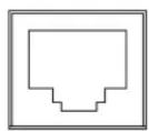
RJ45 Jack
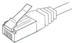
Cat-5e Cable
√ Note: While the Cat-5e cables and connectors used on your Aviom products look like typical computer Ethernet network connections, do not connect computers, routers, or other home and business networking equipment to your Aviom products.
Cat-5e Cables
Although the A320 Personal Mixer will operate properly with unshielded Cat-5e cable, shielded Cat-5e (or better) cable must be used to stay below the CISPR 22 Class B, ICES-003, and FCC 47 CFR Part 15 Class B emissions limits.
For fixed or permanent installations, you have the option of running Cat-5 cables inside walls and terminating them with readily available wall panel connectors that include the RJ45 jack. (Solid wire is recommended for permanent installations.) A Cat-5 cable wiring pinout table is included at the end of this document. See "Cat-5 Cable Pinout" on page 51.
In addition to standard Category 5e cables, Cat-6 and Cat-6e cables may also be used.
√ Note: When purchasing Category 5e cables, be sure to buy only standard Cat-5e cables, not those sold as crossover cables. A crossover cable is used for file transfer between two computers and is not compatible with your Aviom equipment.
Cable Lengths
For Pro16 applications—connecting one Pro16 device to another—the Cat-5e cables used with your Aviom products may be up to 500 feet (approximately 150 meters) in length between devices. For example, connecting a Y1 console card from a Yamaha digital console to the A-NET IN on a D800 A-Net Distributor is such a connection.
Total Pro16 A-Net cable length: 500 feet (150 meters)

flowchart
graph TD
    A["Pro16 A-Net Out"] --> B["Passive Coupler"]
    C["Pro16 A-Net In"] --> B
    D["Passive Coupler"] --> B
When using Pro16e—such as the A-NET OUT from an AN-16/i v.2 to any other Pro16 or Pro16e device—Cat-5e cables may be up to 400 feet (approximately 122 meters) in length between compatible devices due to the larger amount of data being transmitted to accommodate Pro16e's higher channel count.
Total Pro16e A-Net cable length: 400 feet (122 meters)

flowchart
graph TD
    A["Pro16e A-Net Out"] --> B["Passive Coupler"]
    C["Passive Coupler"] --> B
    D["Pro16 or Pro16e A-Net In"] --> B
The maximum cable length specification applies to the total cable length between an A-NET OUT port on one device and the A-NET IN port on the next A-Net capable device in your system.
Your cable length performance will be affected by a number of factors including the quality of the cables used, and the number of passive devices such as cable couplers or passive wall panel interconnections in use.
Stranded or solid Cat-5e cable may be used; stranded cable is easier to deploy on a stage while solid core cable provides slightly better maximum distance performance. Solid core wire is typically used in permanent installations in walls and across ceilings.
When using the optional SB4 System Bridge with Pro16 and Pro16e devices, the cable length specification applies to the total cable length between the two active A-Net devices being connected with the passive System Bridge, plus all cables. This is also true when using a passive inline coupler to extend cable lengths.
Pre-made cables in a variety of lengths and colors are available at most computer outlets. Cables may be extended by using a simple passive device called an inline coupler to add length to existing cables (as long as you do not exceed the specified maximum cable length). If you need a longer cable on occasion, this is a simple solution. Note that the maximum cable length performance can be compromised by using inline couplers or other passive connection devices.
AC Line Conditioning
Aviom products are digital devices and as such are sensitive to sudden spikes and drops in the AC line voltage. Changes in the line voltage from lightning, power outages, etc. can sometimes damage electronic equipment.
To minimize the chance of damage to your equipment from sudden changes in the AC line voltage, you may want to plug your equipment into a power source that has surge and spike protection. Power outlet strips are available with built-in surge protection circuits that may help protect your equipment.
Other options for protection of your equipment include the use of an AC line conditioner or a battery backup system (sometimes referred to as an uninterruptible power supply, or UPS).
Supplying Power to Your A320
The A320 Personal Mixer is intended to be connected to an Aviom A-Net Distributor such as the D800, D800-Dante, D400, or D400-Dante when creating a personal mixing system. A-Net Distributors provide both parallel A-Net connections for up to eight devices as well as the DC power required to run them.
Cleaning and Maintenance Information
The exterior of your Aviom products should be cleaned with a dry, soft, lint-free cloth. For tougher dirt, you can use a cloth slightly dampened with water or with a mild detergent.
When cleaning your Aviom products, never spray cleaners directly onto the product surfaces. Instead, spray a small amount of the cleaning solution onto a clean cloth first. Then use the dampened cloth to clean the product.
√ Note: Never use solvents or abrasive cleaners on the finished surfaces of your Aviom products.
Quick Start Tutorial
Can't wait to get started with your A320 Personal Mixer? Don't have time to read the entire manual? Here's a quick guide to setting up your A320.
Choose a Mixer Mode
The A320 can operate in one of two modes, 16-channel or 32-channel, which accommodate the two versions of the A-Net protocol, Pro16 and Pro16e. Which mixer mode you should use is based on the number of input channels your personal mixing system has.
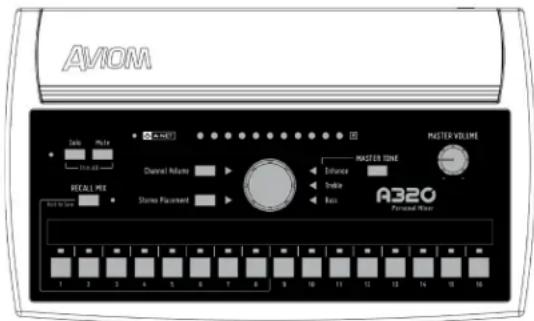
16-Channel Mode
If your system has only one input device (analog or digital console card), use the 16-channel mode. Mono inputs are mapped to a single A320 mix channel button and stereo inputs are mapped to an adjacent pair of channels.
By default, the A320 ships in 16-channel mode, so there is nothing to change if you want to plug your A320 into a 16-channel system. To set the A320 back to 16-channel mode after using the 32-channel mode, hold the MUTE and CHANNEL 1 buttons while powering up the unit. (The A320 powers up when its rear-panel Cat-5 jack is connected to an A-Net Distributor port.)
32-Channel Mode
When a system includes multiple input devices or a Dante network, the 32-channel mode can be used. In 32-channel mode, stereo inputs are mapped to a single A320 mix channel button, allowing up to 16 stereo inputs to be used.
To set the A320 to use 32-channel mode, hold the MUTE and CHANNEL 2 buttons while powering up the unit.
Basic A320 Features
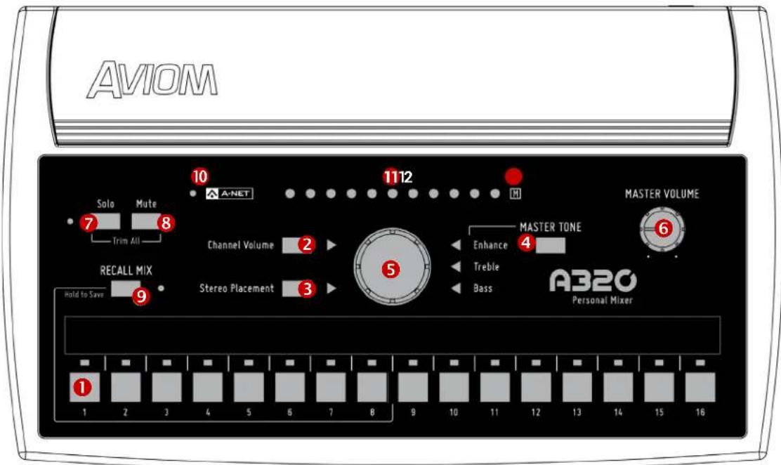
| Function | ||
| 1 Mix | Channel Buttons, with LED | Press to select a channel and make it active for editing. |
| 2 Channel | Volume Button | When pressed, the green LED lights. Sets the central control knob to change volume. |
| 3 Stereo | Placement Button | Sets the central control knob to change stereo placement. The green LED lights when active. |
| 4 Master | Tone Button | Toggle to select Enhance, Treble, Bass, then turn the central control knob. The LED lights when active. |
| 5 Central | Control Knob | Changes the value for the selected function—Volume, Stereo Placement, Treble, Bass, or Enhance. |
| 6 Master | Volume Knob | Sets the level of the stereo mix in the headphones or earbuds. |
| 7 Solo | Button and LED | Press to activate Solo mode; isolates the selected channel from the mix; Solo LED blinks when active. |
| 8 Mute | Button | Press to mute the selected channel in the mix. The M icon flashes. |
| 9 Recall | Mix Button | Press and release to recall a mix preset; press and hold to save a mix preset. |
| 10 A-Net | LED | Lights green for Pro16 A-Net and red for Pro16e A-Net. |
| 11 | Volume, Stereo Placement, and Tone LEDs | Shows the value for the selected function being edited. |
| 12 Mute | LED Flashes when the selected channel is muted. | |
Connect the A320 to an A-Net Distributor
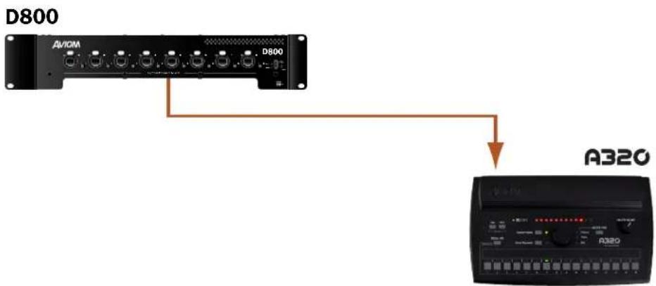
The A320 Personal Mixer needs to be connected with a Cat-5 cable to a powered port on an A-Net Distributor such as the D800 or D400. The A-Net Distributor supplies the multi-channel digital audio data as well as the DC power required to run the A320.
flowchart
graph TD
    A["D800"] --> B["A10M"]
    B --> C["D800"]
    C --> D["A320"]
Connect A320 Personal Mixer to an A-Net Distributor.
The Cat-5 cable connecting the A-Net Distributor and the A320 can be up to 400 feet (122 m) in length.
√ Note: When connecting the A320 Personal Mixer to a D800 or D800-Dante A-Net Distributor, the D800's front panel switches must be set to the "I" position. The "II" position is for use only with the A360 Personal Mixer.
Make Your First Mix
After plugging headphones or earbuds into the rear-panel STEREO MIX OUT jack, you're ready to make your first mix on the A320.
Set Channel Volumes
Start by turning up the volume level of the most important channels, those that supply the essential elements you need most in a monitor system while performing, singing and/or playing an instrument—channels that provide critical timing and pitch reference cues.
- Press a channel button to select a mix channel for editing; the green LED above the channel button lights.
- The green triangle LED next to the CHANNEL VOLUME button should be lit. If it's not, press the CHANNEL VOLUME button to light it.
- Turn the central control knob to raise the level of the selected channel. The channel's volume is shown in the row of red LEDs across the top of the A320.
- Select another channel and follow the same procedure to set its volume level.
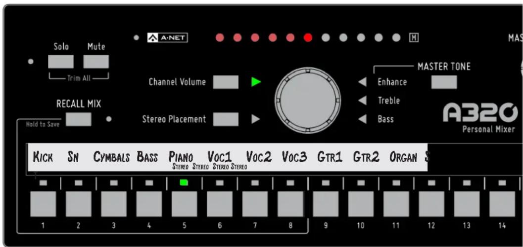
Channel 5 is selected for editing.
The volume setting for each channel in your mix will be saved when you store a mix preset or power down the system.
Set Stereo Placement
Monitoring in stereo provides a more natural monitoring experience, especially if you are wearing in-ear monitors.
- Select the mono or stereo channel that you want to change.
- Press the STEREO PLACEMENT button; the green triangle LED next to the button should be lit.
- Turn the central control knob to pan the channel in the stereo mix.
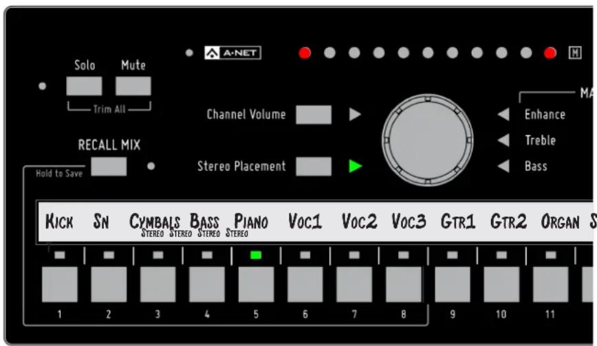
Stereo Placement is being edited on Channel 5.
Mono channels will use a single LED to display panning, while a stereo channel will use a pair of LEDs that indicate the left and right sides of the channel. Stereo Placement settings for each channel in your mix are saved as part of a mix preset.
Adjust the Master Tone Settings
The Master Tone section's Treble, Bass, and Enhance can be used to adjust to overall EQ of your headphones or earbuds. Once you have a basic mix set up, adjust the Treble and Bass tone controls first, leaving the Enhance control set to the minimum. Once you have the treble and Bass tone controls set to your liking, slowly raise the amount of Enhance until you find a pleasing amount. Enhance is a combination bass/treble circuit that boosts the extreme low end and extreme high end of a mix. Press the MASTER TONE button to cycle through the three tone options.
The Master Tone section affects the stereo mix output as a whole and its settings are not saved as part of a mix preset.
Save a Mix Preset
Once you have a basic mix set up, it can be saved as a preset for easy recall later. The A320 can store eight mix presets using the first eight channel buttons as storage locations. To save a mix as a preset:
- Press and hold the RECALL MIX button.
- Press a channel button 1-8.
• The mix is saved; the A-Net and Recall Mix LEDs flash as a confirmation.
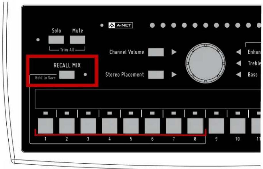
Hold the RECALL MIX button and then press a channel button 1-8 to save a mix preset.
A320 Front Panel
The following sections cover the basic functions of the A320's user interface. See "Personal Mixing System Setup" on page 36 for information about adding your A320 Personal Mixer to a new or existing system
Mix Channels
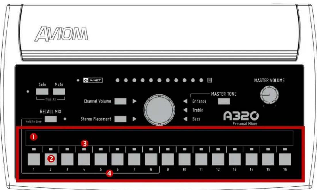
| Function | |
| 1 Channel Label Strip | |
| 2 Mix Channel Buttons | |
| 3 Channel LEDs – green | |
| 4 Mix Preset Locations - Channel Buttons 1-8 |
Channel Label Strip
The channel label strip is designed to accept 1/2-inch (13 mm) wide artist's tape or custom-made labels. A spreadsheet style channel label template is available on the Aviom website. Do not use permanent adhesives or tapes with your Aviom product. See "Mixer Label" on page 50.
Mix Channel Buttons
The 16 mix channel buttons can be assigned either a mono or stereo source, allowing up to 32 input sources to be mixed on the A320 (if each of the 16 mix channels is assigned a stereo source). Stereo links are assigned at the Pro16 or Pro16e input device with the stereo link switches on that device.
To select a channel and make it active for editing, press one of the 16 mix channel buttons; its green LED will light and the green CHANNEL VOLUME LED will light. The current volume level for the selected channel will be shown in the horizontal row of red LEDs across the top of the mixer.
Make channel-level changes as needed using the Channel Volume, Stereo Placement, and Mute controls. While editing, the Solo function is also available to isolate the selected mono or stereo channel from the mix. See "Channel Solo" on page 23 for addition information on the Solo function.
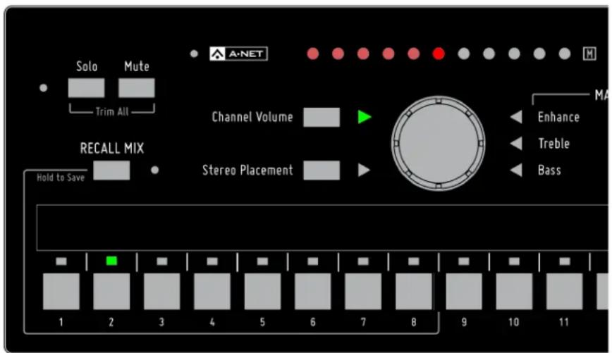
Channel 2 is selected for editing.
Mix Presets
The first eight mix channel buttons also double as Mix Preset storage locations. See "Saving Mix Presets" on page 31 for information on saving and recalling Mix Presets.
16-Channel Vs. 32-Channel Mode
When the A320 is in 32-channel mode, stereo pairs of input channels are mapped to a single channel button on the A320. When a stereo channel is selected, the Stereo Placement feature uses two LEDs to indicate the relative positions of the left and right sides of the stereo signal in your mix.
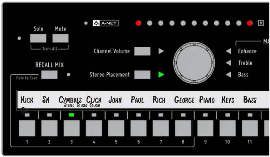
Channel 3 is a stereo input when in 32-channel mode.
When the A320 is in 16-channel mode, a stereo source will be mapped to two adjacent channel buttons (in odd-even pairs). Pressing either channel button will light both buttons, and the stereo channel pair may be edited using the Channel Volume, Stereo Placement, and Mute controls. Pressing the Solo button will place both channels into solo, isolating them from the rest of the current mix. See "32-Channel Systems" on page 39 for information about using stereo inputs with the A320.
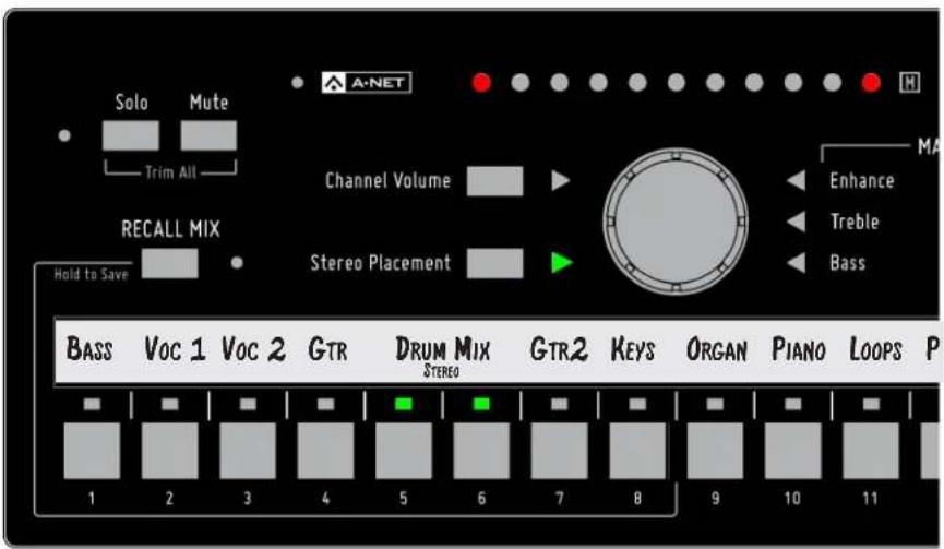
Channel 5-6 are stereo linked at a Pro16 input device when in 16-channel mode.
Channel Controls Section
Each mix channel has Volume, Solo, Mute, and Stereo Placement settings available.
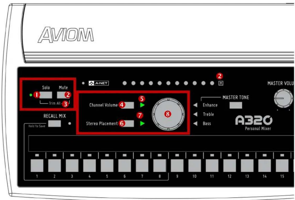
| Function | |
| 1 Solo Button with Solo LED - green | |
| 2 Mute Button and Mute LED | |
| 3 Trim All Function - Solo + Mute | |
| 4 Channel Volume Button | |
| 5 Channel Volume LED - green | |
| 6 Stereo Placement Button | |
| 7 Stereo Placement LED - green | |
| 8 Central Control Knob |
Channel Controls
The individual channel control functions are available whenever one of the 16 mix channel buttons is selected. Volume, Stereo Placement, and Mute settings are saved with a Mix Preset.
Central Control Knob
The large knob in the center of the A320 Personal Mixer is a multi-function rotary encoder that is used for channel-level editing as well as for making changes to the Master Tone settings—Enhance, Treble, and Bass. The function currently assigned to the central control knob is controlled by pressing the Channel Volume, Stereo Placement, and Master Tone buttons. (The green triangle LED next to the currently assigned function will be lit.)
Channel Volume
Each channel's level in the current mix is set with the control knob; the 11 LEDs that run horizontally across the top of the A320 indicate the current volume of the channel and will update in real time as you make changes.
To set a mix channel's level, press its numbered button to select it; the green triangle LED next to the CHANNEL VOLUME button will light indicating that the Central Control knob is affecting volume. Turn the central control knob to set the desired level. The red LEDs indicate the current volume for the channel. Two LED brightness levels are used —low and high. Each LED turns on first at its low level and then at its high level. (Only one LED will ever be at its maximum brightness.)
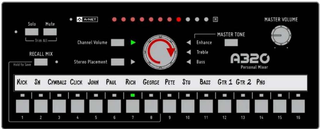
Volume is being edited for channel 7.
To turn a channel off, turn the central control knob fully left until no LEDs are lit. To silence a channel temporarily, use the Mute function.
Stereo Placement
Each channel button on the A320 Personal Mixer can host either a mono or stereo channel when the A320 is set to 32-channel mode. The advantage to this approach is in the simplicity afforded the user. A stereo source such as a piano, drum submix, or the left/right outputs of a stereo guitar processor are easily accessible with a single button press. This powerful feature makes it easy to keep stereo sources intact in a monitor mix rather than forcing the performer to listen in mono to inputs that have valuable stereo spatial information. See "Setting the Mixer Mode" on page 26 for more information.
The Stereo Placement feature controls the selected channel's position within the current mix's stereo image. The A320 Personal Mixer offers a unique treatment of the stereo positioning controls for each channel in a mix. Stereo placement on the A320 Personal Mixer uses carefully selected position locations that are musically useful and have been optimized for use with in-ear monitors.
Every audio source can be heard in full stereo fidelity without taking up additional space on the mixer, creating a more realistic monitor mix environment for performers wearing stereo earbuds and headphones. Using stereo sources allows every channel to be positioned precisely in the left-right stereo image and provides a clearer, more accurate mix at a lower volume with no loss of fidelity.
When positioning a mono or stereo channel in your mix, the central control knob uses two encoder clicks per location as it steps through the various options as described below.
Mono Channels
A mono channel's position in the stereo field is indicated with a single LED that is green when centered, or red when panned left or right.
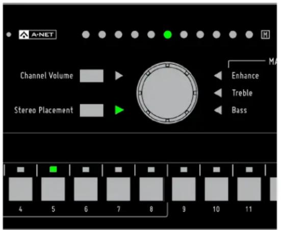
The default centered pan position for a mono channel A mono channel shown panned
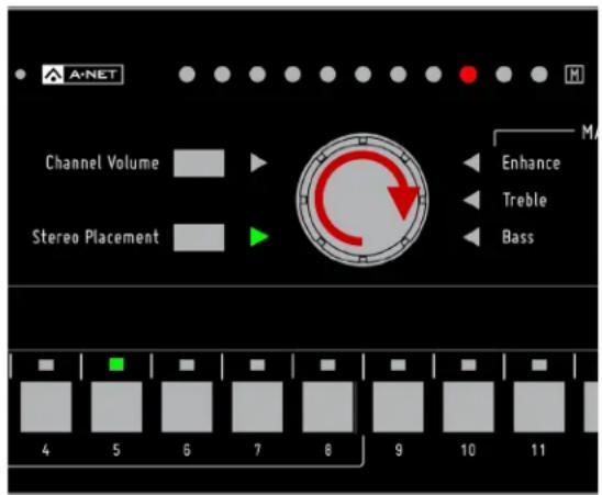
To position a mono channel, first press the STEREO PLACEMENT button; its green triangle LED will light. Turn the central control knob left or right. To return the selected channel to its default center position, make sure that the green Stereo Placement LED is lit, and then turn the central control knob until the green LED is shown in the center of the LED display.
Stereo Channels
Stereo sources are set up at the Pro16 or Pro16e input device feeding the A320 Personal Mixers by simply setting the stereo/mono Link switch for a pair of channels. On the A320, the stereo channel behavior is determined by the mixer mode. See "Setting the Mixer Mode" on page 26.
The Pro16 version of A-Net has a fixed 16-channel maximum, while the Pro16e version offers a pool of up to 64 source channels, connected to up to four input devices. The A320 Personal Mixer can make use of inputs 1-32 in a monitor system that uses more than 32 input channels. Channels 33 and above are only accessible to the A360 Personal Mixer.
Using the A320 in 16-Channel Mode
When a system is configured with a single 16-channel input device (including the original AN-16/i Input Module, AN-16/i-M Mic Input Module, Y1 A-Net Card for Yamaha ^® , or the console cards built by Aviom partners that use the Pro16 A-Net technology), the A320 should be set to 16-channel mode so that stereo channels are mapped to adjacent channel pairs. Odd-even adjacent mixer channels behave as one. For example, linking inputs 3-4 on a Y1 A-Net Card installed in a Yamaha digital console will cause an A320 mixer's channels 3 and 4 to light together when either channel button is pressed.
The A320 should always be used in 16-channel mode when a single input module (16 inputs or less) is used to create a personal mixing system.
Using the A320 in 32-Channel Mode
When at least one Pro16e input device (such as the AN-16/i v.2 Input Module) is used to provide 32 inputs to the network, the A320 should be set to 32-channel mode so that stereo sources will be mapped to a single A320 channel button when the input device's mono/stereo link switches are set to stereo.
When two or more Pro16e input modules or a Dante network are used as the system's input section, the A320 should be set for 32-channel mode. Each stereo pair will be mapped to a single A320 mix channel button. Up to 16 stereo channels are possible when all input pairs are set to stereo.
Compatibility
When at least one AN-16/i v.2 is used to create a system with multiple input devices, the first 16 input channels of the network may come from any device that outputs the Pro16 version of A-Net including: the original AN-16/i, AN-16/i-M, AV-M8, Y1 A-Net Card, partner console cards, or the Pro64 ASI A-Net Systems Interface. Connecting the A-Net Out from one of these Pro16 devices to the A-Net In on the AN-16/i v2 causes the data to be merged inside the AN-16/i v.2 and output as a Pro16e packet.
When a D800 or D800-Dante A-Net Distributor is used, multiple digital console cards from the same clock source may be connected to an SB4 System Bridge. The System Bridge's output may be connected to the A-Net In on the D800; the data streams will be merged by the D800 and transmitted from its A-Net outputs. The D800 always outputs the Pro16e version of A-Net.
Understanding Stereo Placement on the A320
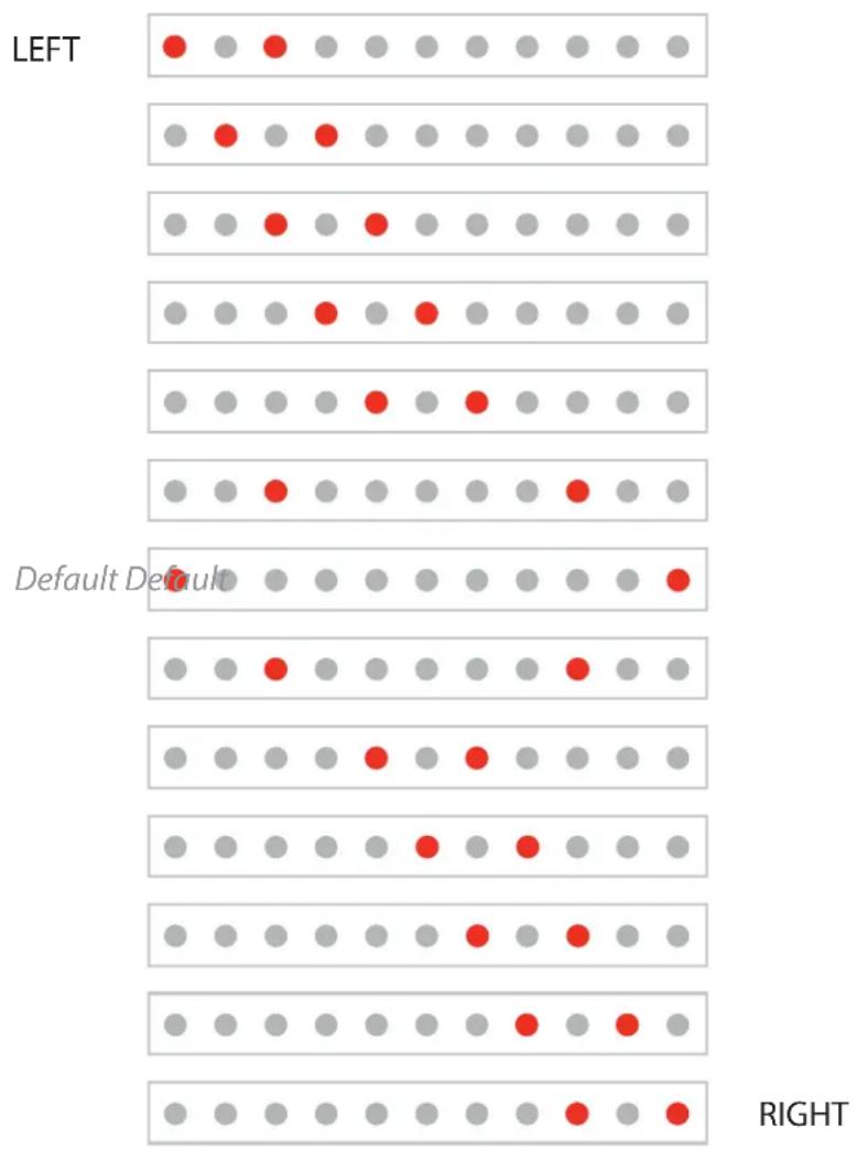
When Stereo Placement is selected for editing, two red LEDs are used to indicate the location of the sources within the stereo image. The default spread for a stereo source is full left and full right.
The following example shows the eleven relative Stereo Placement positions available for a stereo channel. As you change the Stereo Placement setting for a channel, you'll notice that the center-panned options appear twice—as you move from the left side of the stereo image to the right and again as you move from the right back to the left.
other
| Direction | Red | Grey | | --------------- | ----- | ----- | | LEFT | ● | ● | | LEFT | ● | ● | | LEFT | ● | ● | | LEFT | ● | ● | | LEFT | ● | ● | | LEFT | ● | ● | | LEFT | ● | ● | | LEFT | ● | ● | | LEFT | ● | ● | | LEFT | ● | ● | | LEFT | ● | ● | | LEFT | ● | ● | | LEFT | ● | ● | | LEFT | ● | ● | | LEFT | ● | ● | | LEFT | ● | ● | | LEFT | ● | ● | | LEFT | ● | ● | | LEFT | ● | ● | | LEFT | ● | ● | | LEFT | ● | ● | | LEFT | ● | ● | | LEFT | ● | ● | | LEFT | ● | ● | | LEFT | ● | ● | | LEFT | ● | ● | | LEFT | ● | ● | | LEFT | ● | ● | | LEFT | ● | ● | | LEFT | ● | ● | | LEFT | ● | ● | | LEFT | ● | ● | | LEFT | ● | ● | | LEFT | ● | ● | | LEFT | ● | ● | | LEFT | ● | ● | | LEFT | ● | ● | | LEFT | ● | ● | | LEFT | ● | ● | | LEFT | ● | ● | | LEFT | ● | ● | | LEFT | ● | ● | | LEFT | ● | ● | | LEFT | ● | ● | | LEFT | ● | ● | | LEFT | ● | ● | | LEFT | ● | ● | | LEFT | ● | ● | | LEFT | ● | ● | | LEFT | ● | ● | | Left | ● | ● | | Left | ● | ● | | Left | ● | ● | | Left | ● | ● | | Left | ● | ● | | Left | ● | ● | | Left | ● | ● | | Left | ● | ● | | Left | ● | ● | | Left | ● | ● | | ← Default Default| ■ | ○ | | ← Default Default| ■ | ○ | | ← Default Default| ■ | ○ | | ← Default Default| ■ | ○ | | ← Default Default| ■ | ○ | | ← Default Default| ■ | ○ | | ← Default Default| ■ | ○ | | ← Default Default| ■ | ○ | | ← Default Default| ■ | ○ | | ← Default Default| ■ | ○ | | ← Default Default| ■ [Oval] | ○ | | ← Default Default| ■ [Oval] | ○ | | ← Default Default| ■ [Oval] | ○ | | ← Default Default| ■ [Oval] | ○ | | ← Default Default| ■ [Oval] | ○ | | ← Default Default| ■ [Oval] | ○ | | ← Default Default| ■ [Oval] | ○ (Right) | | ← Default Default| ■ [Oval] | ○ | | ← Default Default| ■ [Oval] | ○ | | ← Default Default| ■ [Oval] | ○ | | ← Default Default| ■ [Oval] | ○ | | ← Default Default| ■ [Oval] | ○ | | ← Default Default| ■ [Oval] | ○ (Right) | | ← Default Default| ■ [Oval] | ○ | | ← Default Default| ■ [Oval] | ○ | | ← Default Default| ■ [Oval] | ○ | | ← Default Default| ■ [Oval] | ○ | | ← Default Default| ■ [Oval] | ○ (Right) | | ← Default Default| ■ [Oval] | ○ | | ← Default Default| ■ [Oval] | ○ | | ← Default Default| ■ [Oval] | ○ | | ← Default Default| ■ [Oval] | ○ | | ← Default Default| ■ [Oval] | ○ | | ← Default Default| ■ [Oval] | ○ (Right) | | ← Default Default| ■ [Oval] | ○ | | ← Default Default| ■ [Oval] | ○ | | ← Default Default| ■ [Oval] | ○ | | ← Default Default| ■ [Oval] | ○ | | ← Default Default| ■ [Oval] | ○ (Right) | | ← Default Default| ■ [Ocal] | ○ | | ← Default Default| ■ [Ocal] | ○ | | ← Default Default| ■ [Ocal] | ○ | | ← Default Default| ■ [Ocal] | ○ | | ← Default Default| ■ [Ocal] | ○ (Right) | | ← Default Default(Right)| ■ [Ocal] 100% 0% 0% 0% 0% 0% 0% 0% 0% 0% 0% 0% 0% 0% 0% 0% 0% 0% 0% 0% 0% 0% 0% 0% 0% 0% 0% 0% 0% 0% 0% 0% 0% 0% 50% 50% 50% 50% 50% 50% 50% 50% 50% 50% 50% 50% 50% 50% 50% 50% 50% 50% 50% 50% 50% 50% 50% 50% 50% 0% 50% 50% 50% 50% 50% 50% 50% 50% 50% 50% 50% 50% 50% 50% 50% 50% 50% 50% 50% 50% 50% 50% 50% 51.737872486666666666666666666666666666666666666666666666666666666666666666666666666666666666666666666666666666712343333333333333333333333333333333333333333333333333333333333333333333333333333333333333333333333333333 (Right) (Right) (Right) (Right) (Right) (Right) (Right) (Right) (Right) (Right) (Right) (Right) (Right) (Right) (Right) (Right) (Right) (Right) (Right) (Right) (Right) (Right) (Right) (Right) (Right) (Right) (Right) (Right) (Right) (Right) (Right) (Right) (Right) (Right) (Right) (Right) (Right) (Right) (Right) (Right) (Right) (Right) (Right) (Right) (Right) (Right) (Right) (Right) (Right) (Right) (Right) (Right)The A320 Stereo Placement LED positions
The stereo positions have been carefully selected to be both easy to use and musically useful while performing live on stage or in the studio.
Channel Mute
Any mix channel on the A320 can be muted. To mute the selected channel, press the MUTE button. The yellow Mute icon blinks to indicate that the channel is muted in the current mix as long as the channel is selected (or whenever the channel is re-selected). The Mute setting for each channel will be saved when you store a mix preset.
Any number of mix channels may be muted while making a mix. To mute additional channels in the current mix, simply select a channel's mix button and then press the MUTE button.
To unmute a channel, select the channel first (its green LED above the channel button will light and the Mute icon will be flashing) and then press the MUTE button. The channel can be heard again in the mix. While muted, a channel's Volume and Stereo Placement settings can still be edited, but these changes will not be heard until the channel is unmuted.
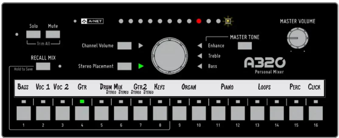
Channel 4 is muted; the Mute LED is flashing as long as Channel 4 is selected.
√ TIP: To clear a mix, press the RECALL Mix button and then press the MUTE button. Refer to "Clear a Mix" on page 33 for more information.
Channel Solo
Pressing the Solo button on the A320 allows the selected mono or stereo channel to be heard alone without affecting the rest of your mix. If the A320 Personal Mixer is used in 16-channel mode, two adjacent channels are used to create a stereo pair. Pressing the Solo button when a stereo linked pair is selected on the A320 will cause both channels to enter Solo Mode.
The green Solo LED next to the Solo button will flash while a channel is in solo. Edit channel volume or Stereo Placement settings as needed. To exit Solo Mode and return to the full stereo mix, press the Solo button again. The green Solo LED will stop flashing.
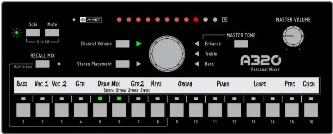
A stereo channel, 5-6, is in Solo Mode; the Solo LED is flashing.
To isolate a different channel, press its channel button at any time while the Solo LED is flashing. The new channel enters Solo, replacing the previous channel. Only one mono or stereo channel may be in Solo at a time. Muted channels in the mix will be temporarily unmuted when placed in Solo; the channel's MUTE LED will go out while the channel is in Solo. Note that you cannot mute a channel while it is in Solo mode; the Solo LED will flicker briefly as a reminder.
To exit Solo mode, press the Solo button; the Solo LED stops flashing and you are returned to the full mix.
Trim All Function
The Trim All function is an easy way to turn down the volume of all channels in a mix by a uniform amount with a single command. Use Trim All if a channel being edited is already at its maximum level and you want to continue to raise its volume relative to the other elements in the current mix.
To use Trim All, simultaneously press the SoLo and MUTE buttons. Each press of this button combination lowers all channel volumes by 3dB.
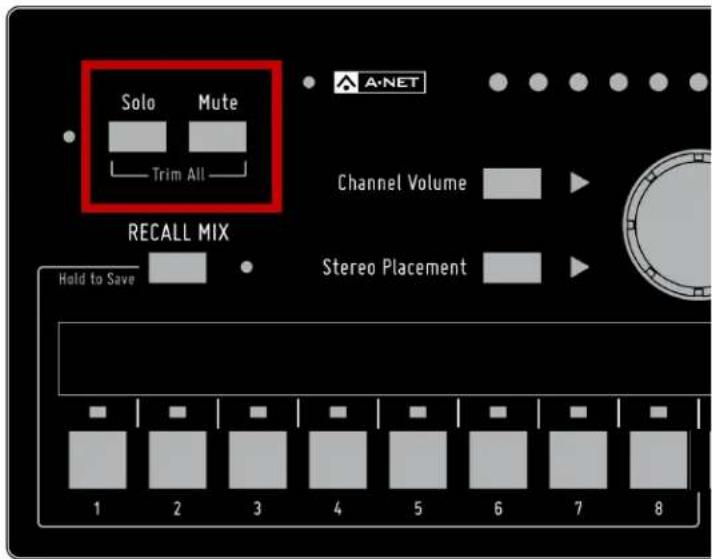
All channel volumes are lowered by 3dB when you use the Trim All command.
Once the mix has been trimmed by the desired amount, you can continue making mix adjustments as needed. After using the Trim All function as described above, you may need to raise the Master Volume level to compensate for the lower overall mix level.
The master section of the A320 Personal Mixer's interface includes the A-Net LED and the global controls for master volume and tone.
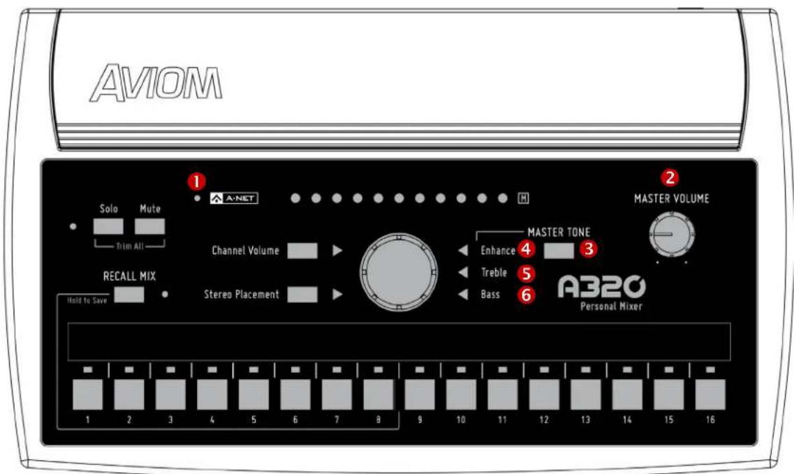
| Function | |
| 1 A-Net LED, bi-color green/red | |
| 2 Master Volume Control | |
| 3 Master Tone Button | |
| 4 Enhance Tone Control LED, green | |
| 5 Treble Tone Control LED, green | |
| 6 Bass Tone Control LED, green |
A-Net and the A320
The A320 Personal Mixer can operate in one of two modes—the 16-channel maximum Pro16 version where each channel is assigned to one mix channel button (and stereo channels, therefore, occupy a pair of adjacent channels), or the 32-channel Pro16e mode where stereo channel pairs occupy a single mix button on the A320 interface. Which mixer mode you will use will depend upon the type and number of input devices that make up your personal mixing system.
If your personal mixing system has only 16 input sources and uses a single analog input module or digital console card, use the 16-channel mode. If you use a Dante network, use the 32-channel mode. If your system has two or more input devices and at least one of them is a Pro16e device such as the AN-16/i v.2 Input Module, then you can make use of the 32-channel (Pro16e) version of the protocol. (Remember that the A320 can only use slots 1-32 of a larger Pro16e network; slots 33-64 can be accessed only by the A360 Personal Mixer.)
A-Net LED
The A-Net LED on the A320 Personal Mixer will light green when it is receiving the Pro16 version of A-Net; it will light red when the Pro16e version is being received.
Setting the Mixer Mode
To choose a mixer mode, a special power-up button combination is used. Start with the power off (disconnect the Cat-5 cable from the back of the mixer). To set the A320 to use the 16-channel mode, hold the MUTE button and the CHANNEL 1 mix button and then power up the unit. To use the 32-channel mode, start with the power off, hold the MUTE button and the CHANNEL 2 mix button and then power up the unit.
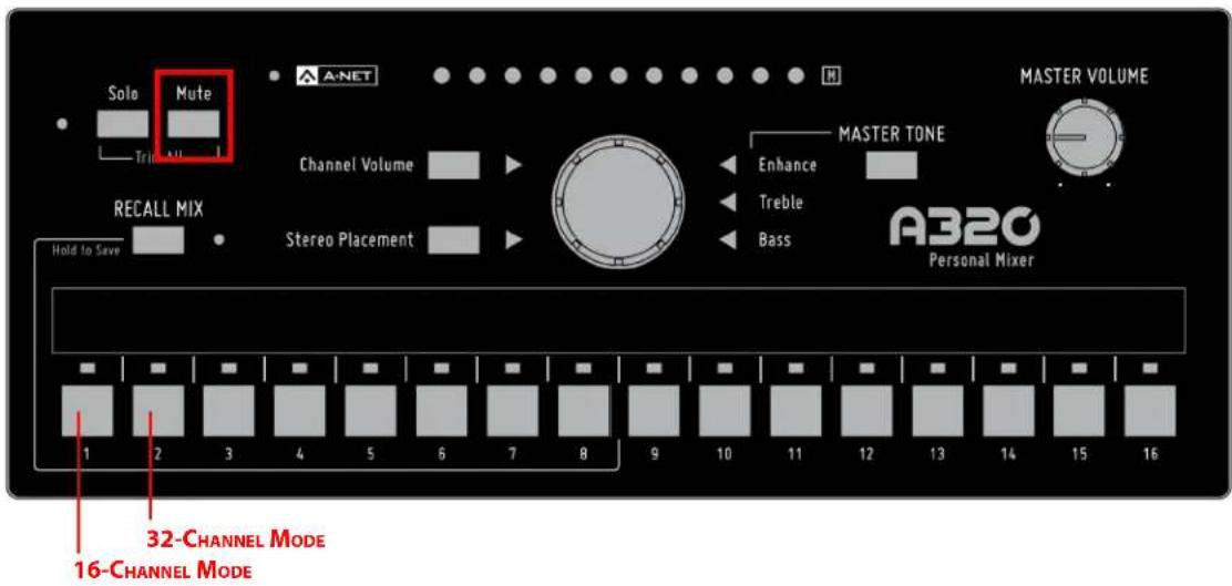
On power up, holding MUTE and CHANNEL 1 sets the A320 to 16-channel mode; holding MUTE and CHANNEL 2 sets the A320 to 32-channel mode.
√ Note: When the mixer mode is changed, the A320 is completely reset. This clears all volume, stereo placement, and mute settings from the current mix and also resets the eight mix presets to default values.
Troubleshooting Mixer Modes
The A320 cannot be damaged by choosing the wrong mixer mode, but the channel mapping may not be what you expect. Here is how the A320 will react:
- If Pro16 A-Net packets are received while the A320 is in 32-channel mode, only the first 8 mix channel buttons are usable. Pressing mix channel buttons 9-16 will flicker the red A-Net LED to indicate that you are trying to access network slots that are not available in the 16-channel Pro16 packet.
- If Pro16e A-Net packets are received in 16-channel mode, only the first 16 slots from the packet are available. The upper slots (17-32) and any associated stereo links will be ignored.
- When Pro16e A-Net packets are received while the A320 is in 32-channel mode, and those packets include slots from 33-64 (which can be used by the A360 Personal Mixer), slots 1-32 are used and slots 33-64 are ignored.
√ Note: The A360 will briefly display the mixer mode during power up. A green A-Net LED indicates 16-channel mode (the factory default), and a red A-Net LED indicates 32-channel mode.
Master Volume
The Master Volume control sets the level for the 1/4-inch Stereo Mix Out jack on the rear panel. The Master Volume level is an analog control and is not saved as part of a Mix Preset.
Master Tone Button
The Master Tone button is used to select one of the three tone settings—ENHANCE, TREBLE, or BASS—for editing. Pressing the button will cycle through the three options, lighting the green triangle LED next to the current selection.
Enhance Tone Control
Enhance is a specially developed bass and treble EQ curve designed to increase low-end punch and high-end brilliance in a mix. It is especially useful for performers listening through in-ear monitors.
The default position for the Enhance control is fully left with no LEDs lit—off. To use the Enhance control, start by creating a mix with the control in the full off (counterclockwise) position. Set the Master Tone Treble and Bass as desired. Press the MASTER TONE button to light the green LED next to ENHANCE and select it for editing. Then start raising the Enhance amount slowly while listening to the mix until you find an amount that's pleasing.
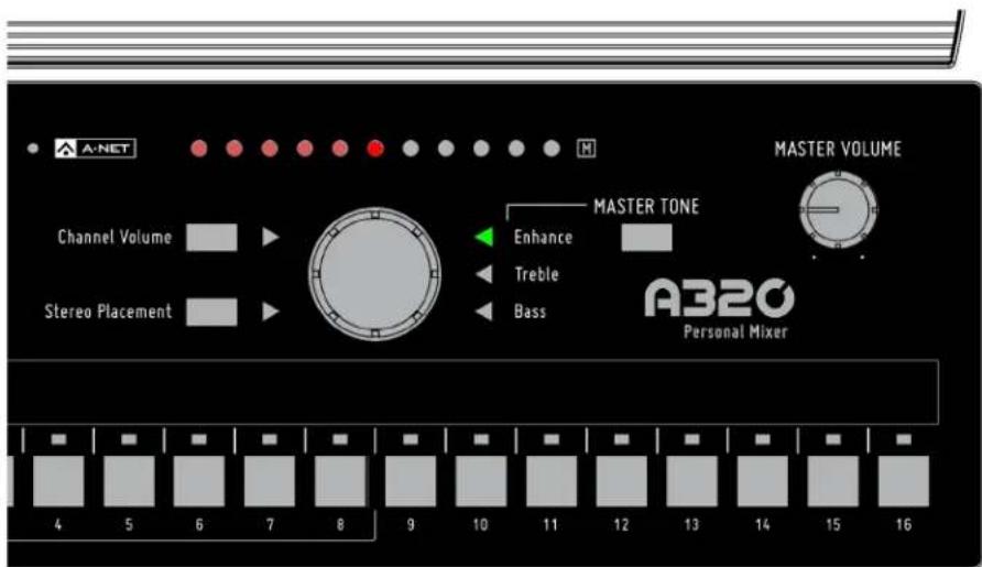
When the Enhance LED is lit, turn the central control knob to change the amount of Enhance applied to the mix.
The Enhance tone control amount is not saved with a Mix Preset.
Treble Tone Control
Use the Treble tone control to add or subtract high frequencies from the stereo mix output. The default (flat) setting for the Treble tone control is at the center of the LED display; a green LED is shown.
To change the amount of treble frequencies in your mix, press the MASTER TONE button until the TREBLE LED is lit and then turn the central control knob left to remove treble or right to add it. The amount of treble adjustment is shown with a red LED.
The Treble tone control's amount is not saved with a Mix Preset.
Bass Tone Control
The master section's Bass tone control adds or subtracts low frequencies from the stereo mix output. It is designed as overall tone compensation for the headphones, earbuds, or speaker systems connected to the A320 Personal Mixer.
The default setting for the Bass tone control is at 12 o'clock (flat). To change the amount of bass frequencies in your mix, press the MASTER TONE button until the BASS LED is lit and then turn the central control knob left to remove bass or right to add it. The amount of adjustment is shown with a red LED.
The Bass tone control's setting is not saved as part of a Mix Preset.
The A320 can save up to eight separate mixes as presets. These presets are accessed using the first eight mix channel buttons, which double as preset location buttons. The A320 will also preserve the last mix settings when the mixer is powered down.
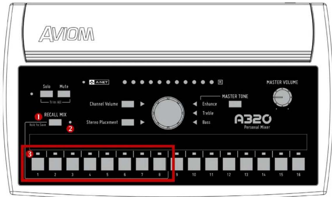
| Function | |
| 1 Recall Mix Button (Hold to Save) | |
| 2 Recall Mix LED | |
| 3 Mix Preset Memory Locations 1-8 |
Saving Mix Presets
The A320 Personal Mixer can save up to eight Mix Presets using the channel select buttons numbered 1-8 as storage locations. Mixes are retained in the A320 even when the mixer is powered down.
To save a mix to one of the channel buttons numbered 1-8:
- Hold down the RECALL MIX button to activate the Save function
- Note that the LED next to the RECALL MIX button does not blink.
- While still holding the RECALL MIX button, press one of the first eight channel buttons.
- As a confirmation, the RECALL MIX and A-NET LEDs will blink briefly.
While holding the RECALL Mix button, you can store a mix to multiple locations if desired. Each save action will display the confirmation message (the RECALL Mix and A-NET LEDs will blink). While saving a mix reset, buttons 9-16 are ignored; they are not valid mix preset locations.
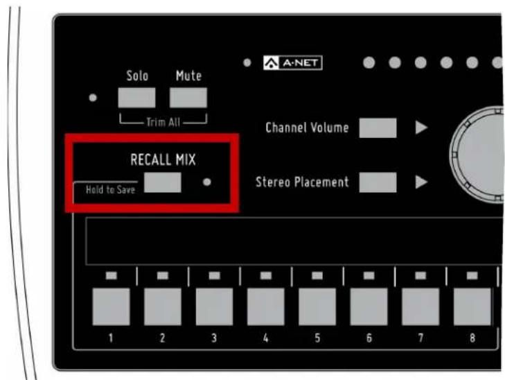
Hold the Recall Mix button and press a mix channel 1-8 to save a mix preset.
√ Note: Using the Save function will cancel Solo mode.
What Gets Saved in a Mix Preset
The following settings are saved when a Mix Preset is created:
• Channel Volume for all channels
• Channel Stereo Placement for mono channels
• Channel Stereo Placement for stereo channels
• Channel Mute on/off
- Last selected mix channel
Settings Not Saved in a Preset
The following are not saved when a Mix Preset is created:
• Master Volume level
• Master Bass tone control amount
• Master Treble tone control amount
• Enhance tone control amount
- Solo mode
Recall Mix Button
The RECALL Mix button has two functions on the A320. When pressed and released, it activates the Recall Mix function. When held, the Save function is activated.
To Recall a Mix Preset
To recall a Mix Preset that has been stored in one of the A320 Personal Mixer's mix locations (the channel buttons 1-8):
- Press and then release the RECALL MIX button; its yellow LED will blink.
- Press the channel button 1-8 that corresponds to the mix you wish to recall (buttons 9-16 are ignored).
- The mix is recalled and the yellow LED next to the RECALL MIX button goes out.
- To cancel a mix recall, press the RECALL MIX button again instead of a channel button 1-8.
Clear a Mix
The current mix can be cleared and reset by pressing and releasing the RECALL MIX button and then pressing the MUTE button, returning all channel settings to their default values. Resetting a mix does not erase the mix parameters stored in memory for any of the eight Mix Preset locations. To overwrite a Mix Preset after performing a reset, use the Save procedures described previously.
This command resets the following:
• Channel volumes are set to zero
• All channels are unmuted
- Stereo Placement (Pan) for all mono channels is set to center
- Stereo Placement for all stereo channels is set to full left/right
• Channel Button 1 is selected
The Master Volume and Master Tone settings are not affected by this command.
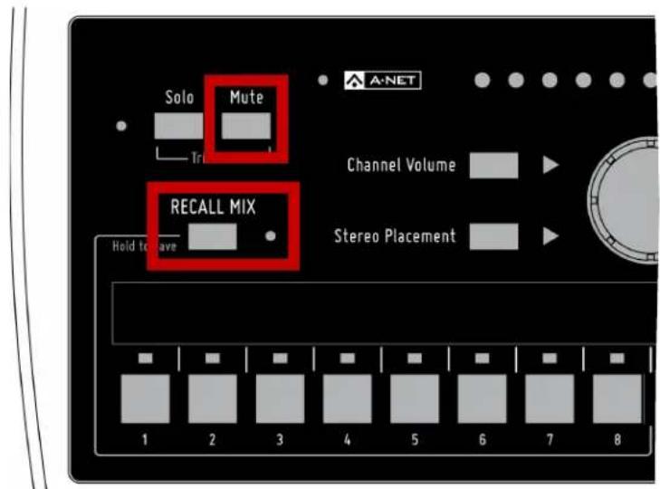
Press RECALL MIX and then press MUTE to clear the current mix.
A320 Personal Mixer Rear Panel

| Function | |
| 1 Stereo Mix Out – 1/4-inch TRS | |
| 2 A-Net In – RJ45 |
1 Stereo Mix Out - 1/4-inch TRS
2 A-Net In - RJ45
This section details the function of each of the rear panel features on the A320 Personal Mixer.
Stereo Mix Out
A 1/4-inch TRS Stereo Mix Out jack is provided for direct connections to earbuds and headphones. The TRS output may also be used as a line-level output when connecting the Stereo Mix Out to a wireless in-ear transmitter or a set of powered stereo speakers. A TRS to dual TS splitter cable is required for this application (sometimes referred to as an insert cable or Y-cable). A splitter cable provides separate unbalanced left and right signals to the inputs of the receiving device.
√ Note: Do not connect the TRS output from the Stereo Mix Out jack to a balanced mono input. A balanced audio input is differential—it subtracts the positive signal from the negative signal to remove any noise and interference picked up in the cable. The TRS Stereo Mix Out is not a balanced signal.
A-Net In
The Cat-5 A-Net In port is fitted with a standard RJ45 jack, and accepts either Pro16 or Pro16e A-Net data. The A320 also receives DC power over the same Cat-5e data cable. An external DC power supply is not required.
√ Note: When the A320 is connected to an A-Net Distributor, the type of A-Net received (Pro16 or Pro16e) is dependent on the input device that is supplying A-Net to the distributor. Both data types are compatible with the A-Net Distributors.
See "Setting the Mixer Mode" on page 26 for information on setting the A320 to 16-channel or 32-channel operation.
Personal Mixing System Setup
This section explains how the A320 Personal Mixer integrates with other Pro16 devices (from Aviom or third-party partners) to create a personal mixing system. See the detailed User Guides that came with the Aviom products mentioned in this section for complete information about their use, features, and setup.
Pro16e Personal Mixing Systems
The A320 Personal Mixer uses the enhanced version of A-Net, Pro16e, which allows up to 64 audio sources to be included in the network pool by using up to four 16-channel input devices. Each A320 in a personal mixing system can use the first 32 Slots of the network; Slots 33-64 can only be utilized by the A360 Personal Mixer and are ignored by the A320.
A basic monitor system that includes the A320 consists of three elements—an input device (analog or console card), an A-Net Distributor, and one or more personal mixers.
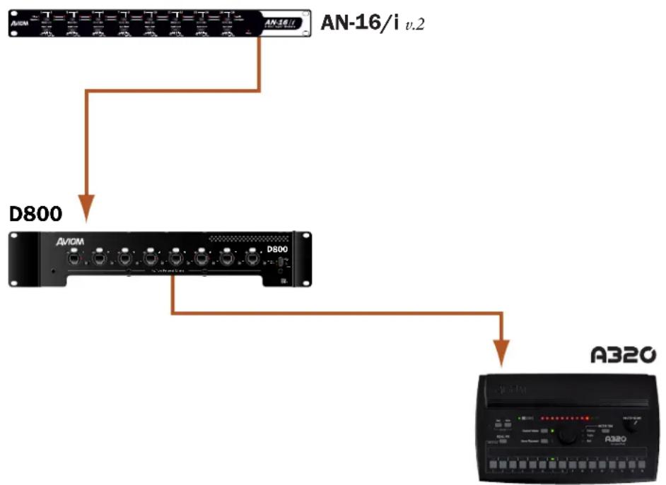
flowchart
graph TD
    A["AN-16/i v.2"] --> B["D800"]
    B --> C["AVIOM"]
    C --> D["A320"]
A basic monitor system with one A320 Personal Mixer
16-Channel Systems
When a single analog input module or console card is used with A320 Personal Mixers, the A320 should be set to 16-channel mode (hold MUTE and CHANNEL 1 on power up). Each input channel on the input device is mapped to one mix channel button in sequential order. For example, if the input source connected to channel 1 of an AN-16/i v.2 Input Module is a bass, that bass signal will appear on button 1 of the A320.
How Stereo Links Work in a 16-Channel System
The Pro16 version of A-Net allows a total of 16 channels to be sent from an input device to personal mixers. Stereo links are treated as channel pairs, using two adjacent buttons on the A320.
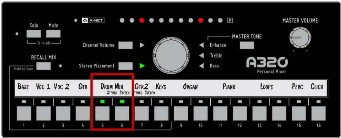
Channels 5-6 are a stereo linked pair in a system with only one input module.
See additional information about the Pro16 and Pro16e versions of A-Net on page 27.
√ Note: When connecting the A320 Personal Mixer to a D800 or D800-Dante A-Net Distributor, the D800's front panel switches must be set to the "I" position. The "II" position is for use only with the A360 Personal Mixer.
Parallel Connections
Using one or more A-Net Distributors allows any number of Personal Mixers to be integrated into a personal mixing system.
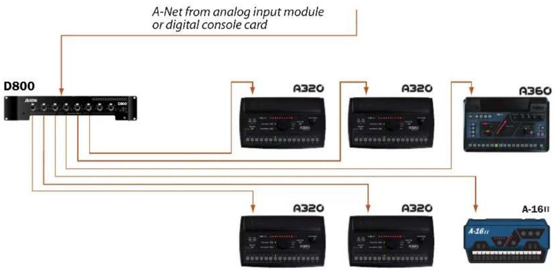
flowchart
graph TD
    D800["DA800"] --> A320["A320"]
    A320 --> A360["A360"]
    A320 --> A3201["A320"]
    A320 --> A3202["A320"]
    A320 --> A-16II["A-16II"]
    A-16II --> A3201
    A-16II --> A3202
    A-16II --> A-16II1["A-16II"]
    A-16II1 --> A3201
    A-16II1 --> A3202
    A-16II1 --> A360
    A-16II --> A-NetA["A-Net from analog input module or digital console card"]
An A-Net Distributor allows Personal Mixers to be connected in parallel.
In addition to Pro16 analog devices and console cards, the Pro64 ASI A-Net Systems Interface may be substituted for the input devices seen in the diagrams that follow. Any of the ASI's four Pro16 A-Net outputs may be used.
Adding the A320 to an Existing System
The A320 Personal Mixer can be added to existing 16-channel personal mixing systems that use the A360 and/or A-16II Personal Mixers and contain at least one A-Net Distributor. (The A320 gets its power from an A-Net Distributor and cannot be used in a system without an A-Net Distributor.)
Most 16-channel personal mixing systems use the same basic setup—an input device (analog or a digital console card) is used to generate an A-Net digital signal which is connected to an A-Net Distributor. Personal Mixers are connected to the ports on A-Net Distributor. Remember that when using a D800 or D800-Dante, the front panel switches need to be in the "I" position when connecting an A320.
32-Channel Systems
When multiple input devices are combined to create a network with more than 16 input sources, the A320 can use the first 32 network slots and will ignore any slots above 33. The A320 must be placed into 32-channel mode to allow the 32 inputs to be recognized. This is also true when using the A320 with Dante devices. See "Setting the Mixer Mode" on page 26 for additional information.
Each 16-channel input module or digital console card can provide 8 stereo pairs if all Stereo Link switches are set for stereo.
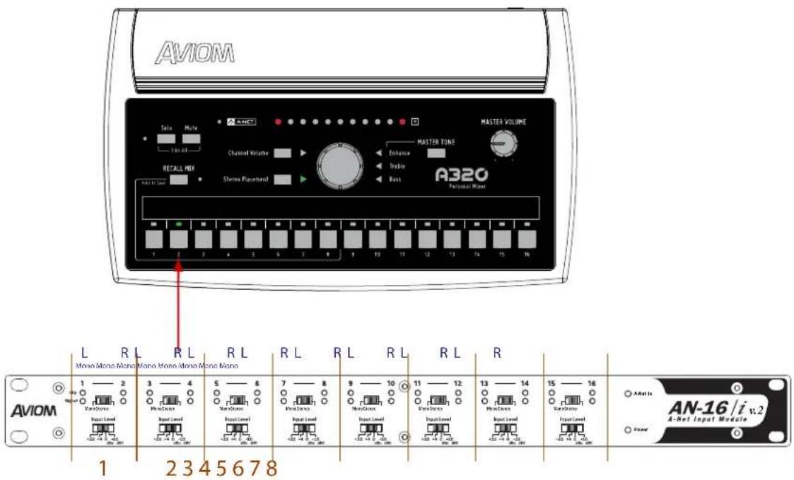
Each channel pair of an input module provides either a mono or stereo source for an A320 mix button, as determined by the Mono/Stereo link switch. When set to mono, the right side input is ignored when the A320 is in 32-channel mode.
How Stereo Links Work in 32-Channel Systems
When channels are stereo linked on an input module, both channels appear as a stereo pair, on one mix channel button on the A320. The table shows the mapping of 32 input sources to A320 buttons.
| AN-16/i v.2 Default A320 Channel | |||
| Bank Channel If Stereo If Mono | |||
| 1-16 | 1 | 1 (left) 1 | |
| 2 | 1 (right) | Ignored | |
| 3 | 2 (left) 2 | ||
| 4 | 2 (right) | Ignored | |
| 5 | 3 (left) 3 | ||
| 6 | 3 (right) | Ignored | |
| 7 | 4 (left) 4 | ||
| 8 | 4 (right) | Ignored | |
| 9 | 5 (left) 5 | ||
| 10 | 5 (right) | Ignored | |
| 11 | 6 (left) 6 | ||
| 12 | 6 (right) | Ignored | |
| 13 | 7 (left) 7 | ||
| 14 | 7 (right) | Ignored | |
| 15 | 8 (left) 8 | ||
| 16 | 8 (right) | Ignored | |
| 17-32 | 1 | 9 (left) 9 | |
| 2 | 9 (right) | Ignored | |
| 3 | 10 (left) 10 | ||
| 4 | 10 (right) | Ignored | |
| 5 | 11 (left) 11 | ||
| 6 | 11 (right) | Ignored | |
| 7 | 12 (left) 12 | ||
| 8 | 12 (right) | Ignored | |
| 9 | 13 (left) 13 | ||
| 10 | 13 (right) | Ignored | |
| 11 | 14 (left) 14 | ||
| 12 | 14 (right) | Ignored | |
| 13 | 15 (left) 15 | ||
| 14 | 15 (right) | Ignored | |
| 15 | 16 (left) 16 | ||
| 16 | 16 (right) | Ignored | |
If the channels are not stereo linked, then only the odd (left) input channel is utilized by the A320, and the even (right) input channel is ignored.
Using Multiple Input Devices
When using multiple input devices in a personal mixing system, each input device provides one 16-channel bank of slots to the network. The Slot Range switches on the rear panel of the AN-16/i v.2 control the bank assignment. Up to four input devices may be used to create a pool of 64 slots, but remember that the A320 cannot access slots 33-64.
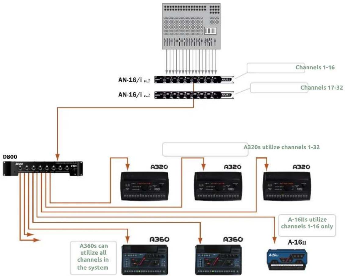
The system shown below shows 32 input sources being used by a variety of personal mixers.
flowchart
graph TD
    A["An-16/I v.2"] --> B["D800"]
    C["AN-16/I v.2"] --> B
    B --> D["A320"]
    B --> E["A320"]
    B --> F["A320"]
    B --> G["A360"]
    B --> H["A360"]
    B --> I["A-16IIs"]
    B --> J["A-16II"]
    D --> K["A320s utilize channels 1-32"]
    E --> L["A320s utilize channels 1-32"]
    F --> M["A-16IIs utilize channels 1-16 only"]
    G --> N["A-16IIs utilize channels 1-16 only"]
    H --> O["A-16IIs utilize channels 1-16 only"]
    I --> P["A-16IIs utilize channels 1-16 only"]
    Q["A360s can utilize all channels in the system"] --> B
A 32-input personal mixing system with A320 Personal Mixers along with the A360 and A-16ll Personal Mixers
√ Note: The A320 Personal Mixer can use Slots 1-32 of a network with multiple input devices. Only the A360 Personal Mixer can use network Slots 33-64.
When using a Dante network, stereo links must be set on the A-Net Distributor.
Slot Range Setup
Each input device in a Pro16e-based personal mixing system supplies one bank of 16 channels to the network. The SLOT RANGE switches on the AN-16/i v.2 are used to set the assignment for each; the physical location of the device within the daisy chain does not matter as long as the Slot Range switch settings are correct. Each input module is daisy chained, connecting a Cat-5 cable from its A-NET OUT to the A-NET IN of the next input device in the chain.
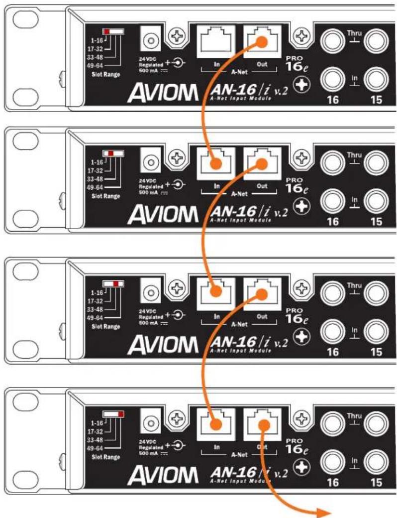
Slot Range switches for each input device in a 64-input system are shown. A legacy Pro16 device may be substituted for the first bank of 16 channels.
Connect the A-NET OUT of the last input device in the chain to the A-NET IN of the A-Net Distributor. The A320 Personal Mixers are then connected to the distributor's A-NET OUT ports. Remember that an A320 Personal Mixer can only use the first 32 slots of an expanded network.
A legacy Pro16 device may be substituted for the first bank of 16 slots in a daisy chain of input devices. It will automatically default to supplying the first 16 slots to the network pool.
64-Channel Systems
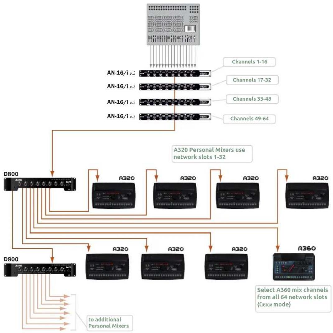
The diagram below shows a 64-input system. The A320 Personal Mixers use inputs 1-32 only; the A360 Personal Mixer can use any slot in the network when configured in its Custom mode.
flowchart
graph TD
    A["ADAM"] --> B["D800 Microcontroller"]
    B --> C["AN-16/i v.2"]
    B --> D["AN-16/i v.2"]
    B --> E["AN-16/i v.2"]
    B --> F["AN-16/i v.2"]
    C --> G["A320 Personal Mixers"]
    D --> G
    E --> G
    F --> G
    G --> H["A320 Channel 1-16"]
    G --> I["A320 Channel 17-32"]
    G --> J["A320 Channel 33-48"]
    G --> K["A320 Channel 49-64"]
    H --> L["A360 Channel"]
    I --> L
    J --> L
    K --> L
    L --> M["Select A360 mix channels from all 64 network slots (CUSTOM mode)"]
    B --> N["to additional Personal Mixers"]
A 64-input system using two A-Net Distributors is shown.
Legacy Products
A-16II or A-16R Personal Mixers may be used in a Pro16e-based system, but note that they can only access the first 16 network slots.
Using Legacy Input Devices
One legacy input device or Pro16 console card may be used in a multiple input device configuration—it will default to supplying the first 16 slots to the network and must be connected to the A-NET IN of the first Pro16e device in the system. The Pro16e input devices (such as the AN-16/i v.2) should be set to Slot Range 17 and above for this application.
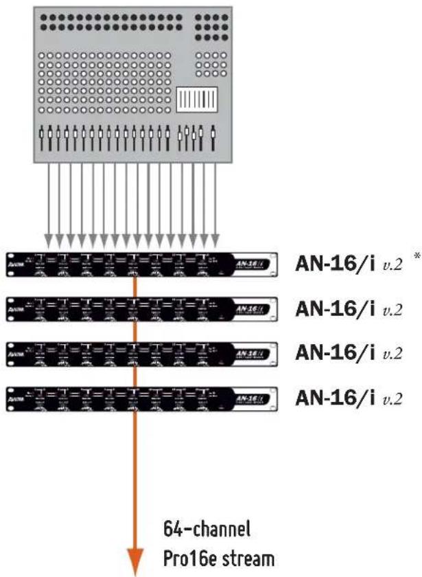
flowchart
graph TD
    A["Analog Block"] --> B["64-channel Pro16e stream"]
    B --> C["AN-16/i v.2 *"]
    B --> D["AN-16/i v.2"]
    B --> E["AN-16/i v.2"]
    B --> F["AN-16/i v.2"]
A legacy Pro16 input module or digital console card can be combined with up to three AN-16/i v.2 Input Modules.
* A Pro16 device—original AN-16/i, AN-16/i-M, Y1 A-Net card, ASI, or a third-party console card—may be substituted for the first AN-16/i v.2 in a daisy chain of input devices; a legacy device automatically defaults to Slot Range 1-16.
Connecting Monitoring Devices
Headphones, wired in-ear monitors, wireless in-ear transmitter systems, and powered speakers can be connected to the A320 Personal Mixer separately or in combination. This section details the connection of these devices to the A320's stereo mix output.

The A320 has a 1/4-inch stereo mix out that can be used as a headphone or line-level output.
Connecting to the Stereo Mix Output
The A320 has a 1/4-inch TRS output dedicated to the stereo mix coming from the Personal Mixer. The output can be connected to headphones, earbuds, or the line-level input of a wireless transmitter system.
Headphones and Earbuds
Connect headphones or wired earbuds to the A320. For best performance, choose low impedance headphones or earbuds whenever possible. High impedance devices will not harm the A320, but note that the mix output level may be lower with these devices. For devices with an 1/8-inch TRS jack an optional 1/4-to-1/8-inch adapter is required.
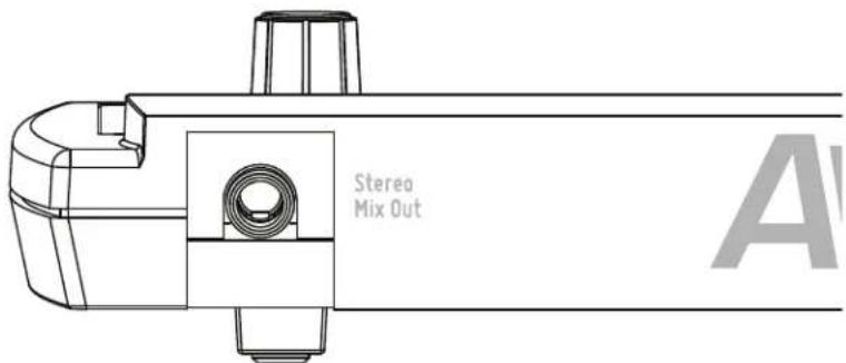
Connect headphones or earbuds to the Stereo Mix Out jack.
Stereo Wireless In-Ear Systems
The A320's Stereo Mix Out may be connected to the left/right inputs of a wireless transmitter used for in-ear monitoring. A Y-cable that splits the TRS (tip-ring-sleeve) stereo output of the A320 to a pair of TS (tip-sleeve) mono left and right outputs is required. Note that the connection from the left and right TS cables is unbalanced. If the inputs to the wireless transmitter are XLR only, a special cable may need to be made. Consult the transmitter's documentation for information about properly connecting unbalanced signals to its balanced XLR inputs.
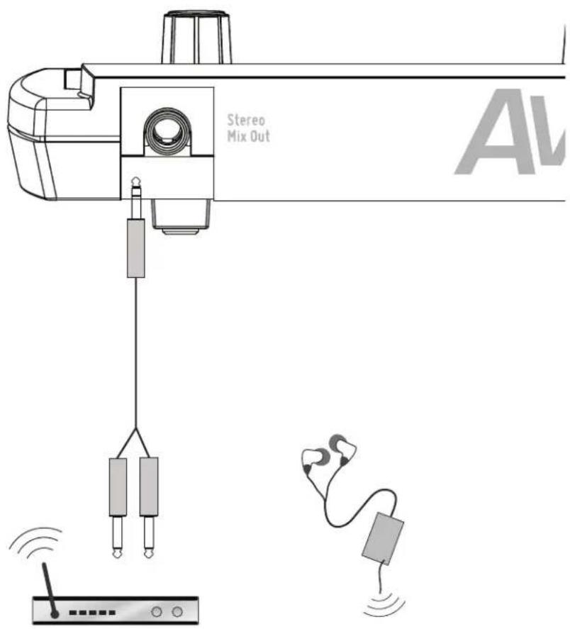
The Stereo Mix Out can be connected to a wireless in-ear transmitter with a Y-cable.
If you need to create a custom adapter cable, note that the TRS tip connector carries the left audio signal, the ring carries the right signal, and the sleeve provides ground for both. The left and right signals are unbalanced in this case.
Stereo Speakers
The Stereo Mix Out may be connected to a set of powered stereo monitor speakers using a Y-cable that splits the TRS stereo output to a pair of TS mono left and right outputs.
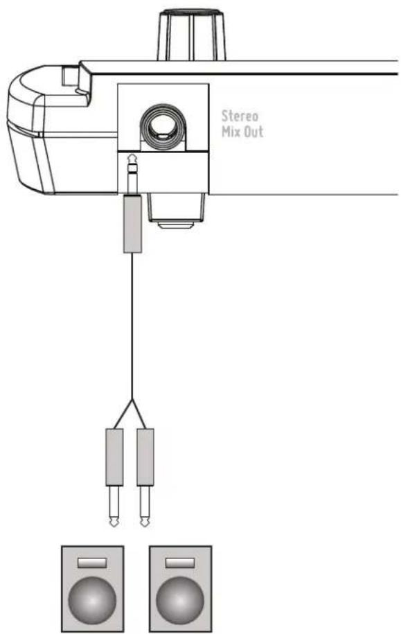
A Y-cable is required to connect the A320 to stereo powered speakers.
If the powered speakers have XLR inputs, a custom cable may be required. Check the powered speaker's documentation for information about properly connecting the unbalanced left and right signals from the A320 Stereo Mix Out to the balanced inputs of the powered speakers.
| Audio Output | 1/4" TRS stereo, headphone or line level; |
| Stereo Mix Output, Headphone/Line | Tip: Audio Left; Ring: Audio Right; Sleeve: Ground |
| A-Net I/O | 1 A-Net In, RJ45 connector; Supports Pro16 and Pro16e |
| D/A Conversion | 44.1/48kHz, 24-bit |
| Stereo Operation | Stereo Link, per channel pair; Set at the input module; Variable pan per mono channel or pan/spread per stereo channel pair |
| Headphone Output | 275 mW per side into 50 Ohms (both sides driven) |
| Headphone Output Impedance | 5 Ohms |
| Freq. Response | 3Hz-22kHz +0.2dB/-3dB at 50 Ohms |
| THD +N | < 0.003% |
| Signal to Noise (unweighted) | -106dB (measured with zero data into all channels) |
| Latency | 0.880 msec (measured from analog input to analog output) |
| A-Net Cables | Use shielded Cat-5e (or better) to stay below the CISPR 22 Class B, ICES-003, and FCC 47 CFR Part 15 Class B emissions limits. |
| A-Net Cable Length 400 feet | (122 m) |
| A-Net Pro16e Protocol | Supports original Pro16 16-channel data; Supports Power Over A-Net |
| Power | 24 VDC, 0.5 amp; Power is supplied over the Cat-5 cable when connected to an Aviom A-Net Distributor |
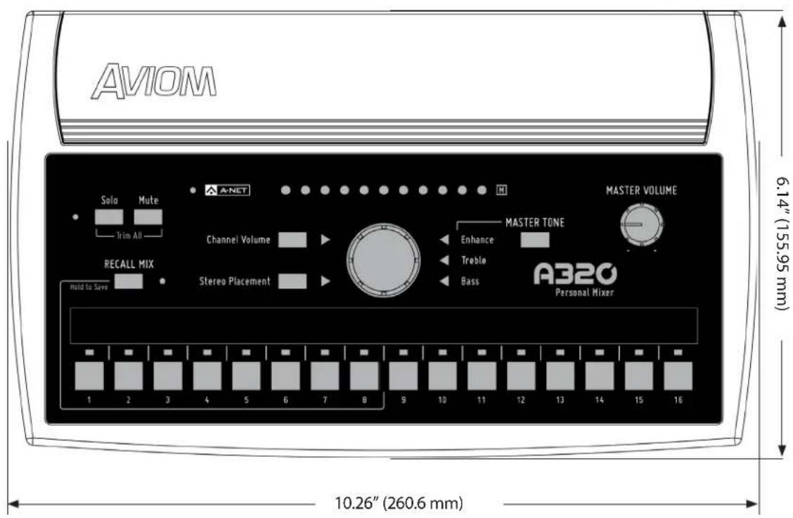
| Dimensions | 10.26" (260.6 mm) wide x 6.14" (155.95 mm) deep; 1.91" (48.51 mm) high |
| Weight 1.3 lb. (0.59 kg) | |
| Options | MT-1a Mic Stand Mount (uses 6-32 1/4-inch screws); EB-1 Extension Bracket; |

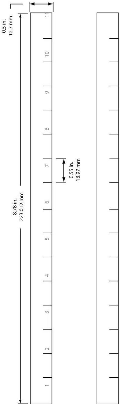
Mixer Label
Use this template as a starting point for creating custom Personal Mixer labels for the A320. It is shown actual size.
other
| Segment | Width (mm) | | ------- | ---------- | | Top Left | 8.78 | | Top Right | 12.7 | | Bottom Left | 0.55 | | Bottom Right | 13.97 |Cat-5 Cable Pinout
The tables below detail the two wiring pinout variations for Cat-5 cables. When making custom cables, either pinout can be used, but both ends of a cable must use the same wiring pattern.
T568A
| RJ45 Pin Wire Color | ||
| 1 White/Green |  | |
| 2 Green |  | |
| 3 White/Orange |  | |
| 4 Blue |  | |
| 5 White/Blue |  | |
| 6 Orange |  | |
| 7 White/Brown |  | |
| 8 Brown |  | |
T568B
| RJ45 Pin Wire Color | ||
| 1 White/Orange |  | |
| 2 Orange |  | |
| 3 White/Green |  | |
| 4 Blue |  | |
| 5 White/Blue |  | |
| 6 Green |  | |
| 7 White/Brown |  | |
| 8 Brown |  | |
Index
Symbols
1/4" TRS stereo 48
1-16 Slot Range 44
3dB
Trim All 24
16-channel bank 41
16-channel Mode 37
16-Channel Mode 8, 16, 20, 27
16-Channel System 37
17-32 Slot Range 40
32-channel mode 39
32-channel Mode 19
32-Channel Mode 8, 16, 20, 27
32-Channel System 39,40
64-Channel System 43
A
A-16D A-Net Distributor 2,3
A-16D Pro A-Net Distributor 2,3
A-16ll Personal Mixer 38,43
A-16R Personal Mixer 43
A360 Personal Mixer 2, 3, 10, 20, 26, 27, 36, 38, 41, 43
AC Line Conditioning 7
AN-16/i Input Module 4, 20
AN-16/i-M Mic Input Module 4, 20, 44
AN-16/i v.2 Input Module 4, 6, 20, 26, 42, 44
AN-16/o Output Module 4
A-Net 3, 26, 48
Pro16, Pro16e 20
A-Net Cable 48
A-Net Distributor 2, 4, 7, 8, 10, 20, 37, 42
D800-Dante, D800 20
A-Net In 6, 34, 35, 42
A-Net I/O 48
A-Net LED 9, 25, 27
green, red 26
A-Net Out 4, 6, 42
ASI A-Net Systems Interface 1, 4, 20, 38, 44
Aviom16/o-Y1 A-Net Card 4
AV-M8 Mic Input Module 4, 20
B
balanced 46
balanced mono input 35
Bank
channel 40, 41, 42
Bass 12
Bass Tone Control 25, 29
Big Knob 18
C
Cable Length 6,48
Pro16e 6
Cables 5
Cat-5 2,5
Cat-5 A-Net In 35
Cat-5 cable length 10
Cat-5 Cable Pinout 51
Cat-5e
5
shielded 5
UTP 5
Cat-5e cable
solid v. stranded 6
Cat-5 Pinout 5
Cat-6, Cat-6e 2, 5
Central Control Knob 9, 11, 17, 18
Certifications iv
Channel Button 9, 14, 15
Channel Controls 17, 18
channel count 20
Channel Label Strip 9, 14, 15
Channel Map 40
Channel Mapping 27, 32, 40
Channel Mute LED 14
channel pairs 16, 20
Channels 15
channels 1-32 20
channels 33-64 20
Channel Volume 11, 15, 18, 32
Channel Volume button 11
Channel Volume Button 9, 11, 17
Channel Volume Control 18
Channel Volume LED 15, 17
Cleaning and Maintenance 7
Clear a Mix 22, 27, 33
clock source 20
Compatibility 4, 6, 20, 35, 42, 43, 44
with Pro64 5
computer network 5
Connecting Listening Devices 45
console card 4, 8, 20, 26, 37, 44
Control Knob 17, 18
crossover cables 5
Custom Mode 35
A360 43
D
D400 A-Net Distributor 2, 4, 10
D400-Dante A-Net Distributor 2, 3, 4, 7, 10
D800 A-Net Distributor 2, 3, 4, 7, 10, 37, 38
D800-Dante A-Net Distributor 3, 4, 7, 10, 20, 37, 38
D/A Conversion 48
Dante 2, 4, 8, 10
A-Net Distributor 20
DC power 10,35
default 8
Default A320 Channel 40
default settings
Enhance control 28
Mix 33
tone control 29
default Slot Range
Pro16 44
default value 27
digital console card 37, 38, 39
Dimensions 49
mixer label 50
E
earbuds 45
EB-1 Extension Bracket 48
Enhance 12, 18
Enhance Tone Control 25, 28, 32
default setting 28
EQ 12, 28
Ethernet 3
expanding a system 38
F
flat
tone control 29
Frequency Response 48
Front Panel 14
G
green triangle LED 28
H
Headphone/Line 48
Headphone Output 48
headphones 45
Hold to Save 30
I
I, II switches 38
D800 10,37
Impedance 45
headphone 48
in-ear monitors 2,46
wired 45
In-Ear System 46
in-ear transmitter 35
inline coupler 6
certified 6
input device 20
Input Module 4
inputs 20
insert cable 35
L
Label Strip 14, 15
LAN
Local Area Network 3
Last selected mix channel 32
Latency 48
LED 17
Channel Mute 14
LEDs 9
legacy device 42, 44
Legacy Input Hardware 44
Level Trim 24
line-level output 35
Line Out 48
Link
Stereo 37,40
linked channel 16
link switch 20
low impedance 45
M
mapped
stereo channels 16
Mapping
channel 40
Master Bass tone control 32
Master Section 25
Tone Control 32
Master Tone 18
Master Tone Button 9, 25, 28
Master Tone Settings 12
Master Treble tone control 32
Master Volume 24, 28, 32
Master Volume Control 25
Master Volume Knob 9
maximum cable length 6
M icon 22
Mic Stand Mount 3
Mix
default settings 33
Mix Channel 14, 15, 40
Mixer Label 50
template 50
Mixer Mode 8, 26, 27
Mix Output 28, 35, 48
Mix Preset 2, 13, 15, 18, 29, 30, 31, 32
not saved in a mix 32
reset 27
What Gets Saved 32
Monitoring Device 45
Mono Channel 19
mono input 35
MT-1a Mic Stand Mount 3,48
Multiple Input Devices 41
Mute 15, 16, 32
Mute a channel 18
Mute All 22
Mute Button 9, 17, 22
Muted channel
Solo 23
Mute LED 9,22
Mute + Solo
Trim All 24
N
network 5
network slots 41
0
odd-even channel pairs 20
Operating Temperature iii
Options 48
original AN-16/i 44
Output Impedance 48
P
Package Contents 3
packet 27
Pan 19, 21
Parallel Connections 38
permanent installation 5
Pinout 5,51
pool 41
powered speaker 35,45
Power Over A-Net 48
power over Cat-5 35
Preset 18,30
storage locations 15
What Gets Saved 19, 32
Preset Locations 14
Pro16 1
default Slot Range 44
Pro16 A-Net 3, 4, 8, 20, 26, 27, 37
Pro16e 1,36
Pro16e A-Net 3, 8, 15, 20, 26, 27, 37
cable length 6
Pro16 vs. Pro16e 35
Pro64 1,38
Pro64 A-Net 4
R
Range switch 41, 42
Rear Panel 34
Recall a Mix Preset 33
Recall Mix Button 9, 13, 22, 30, 31, 33
Recall Mix LED 33
Reset a Mix 27, 33
RJ45 5,34,35
router 5
S
Sample Rate 48
Save a Mix Preset 13, 31, 33
SB4 System Bridge 20
Setting the A-Net Mode 26
Setup 36
Shielded Cat-5 5
Signal to Noise 48
slot 26
Slot Range 41,44
Slot Range Setup 42
Slot Range switch 41, 42
solid v. stranded Cat-5e 6
Solo 15, 23, 31
Muted channel 23
Solo Button 9, 16, 17, 24
Solo LED 17,23
splitter cable 35
Stereo Channels 16, 20
in Pro16 mode 16
Panning 22, 23
Stereo Link 15, 20, 37, 39, 40
Stereo Mix Out 28, 34, 35, 45, 47
stereo/mono Link switch 20
Stereo Placement 2, 12, 15, 16, 18, 19, 32
Stereo Placement Button 9, 12, 17
Stereo Placement LED 17
Stereo Speakers 47
storage locations
Preset 15
submix 19
surge protection 7
System Bridge 6
T
T568A 51
T568B 51
template
Mixer Label 50
Tone 25, 28
Tone Button 25
Tone Control 29
default setting 29
flat 29
master section 32
To Recall a Mix 33
transmitter 46
Treble 12
Treble Tone Control 25, 29
Trim All 17, 24
Troubleshooting Mixer Modes 27
TRS 35, 45, 48
TRS Stereo 35
TRS to TS 35
Y-cable 46,47
TRS wiring 46
TS mono 47
U
unbalanced 35, 46, 47
unmute 22,33
Unshielded Cat-5 5
UPS 7
V
Volume 18,28
W
Warranty Registration 3
What Gets Saved
mix preset 32
wired in-ear monitors 45
Wireless In-Ear System 35, 45, 46
wiring pinout 5, 51
X
XLR input 46
Y
Y1 A-Net Card 4, 20, 44
Yamaha 4,20
Y-cable 35, 46, 47
Warranty Registration
Please take a moment to fill in this warranty registration form.
Return it to Aviom via mail or fax. All information will be kept confidential.
Model Product Serial Number
Model ____ Product Serial Number
Model Product Serial Number
Model Product Serial Number
Date Purchased
Dealer Name
Dealer Location
Your Name
Address
Address
City
State/Province
Zip/Postal Code
Country
Email Address
Fax this form to Aviom at +1 610-738-9950
AVIOM
1157 Phoenixville Pike, Suite 201 • West Chester, PA 19380 USA
Voice: +1 610.738.9005 • Fax: +1 610.738.9950 • www.Aviom.com
- Important Safety Instructions
- WARNING!
- CAUTION:
- Certifications
- Notice of Rights
- Trademarks
- Aviom, Inc. Limited Warranty
- Warranty Information
- Table of Contents
- A320 Personal Mixer
- Feature Overview
- Conventions Used in this Document
- Using Personal Mixers
- Cat-5 Cables
- A-Net Distributors
- Channels and Slots
- Button Presses
- Package Contents
- About A-Net
- Compatibility
- Pro16 Products
- Pro64 Products
- About Category 5
- Cat-5e Cables
- Cable Lengths
- AC Line Conditioning
- Supplying Power to Your A320
- Cleaning and Maintenance Information
- Quick Start Tutorial
- Choose a Mixer Mode
- 16-Channel Mode
- 32-Channel Mode
- Basic A320 Features
- Connect the A320 to an A-Net Distributor
- Make Your First Mix
- Set Channel Volumes
- Set Stereo Placement
- Adjust the Master Tone Settings
- Save a Mix Preset
- A320 Front Panel
- Mix Channels
- Channel Label Strip
- Mix Channel Buttons
- Mix Presets
- 16-Channel Vs. 32-Channel Mode
- Channel Controls Section
- Channel Controls
- Central Control Knob
- Channel Volume
- Stereo Placement
- Mono Channels
- Stereo Channels
- Using the A320 in 16-Channel Mode
- Using the A320 in 32-Channel Mode
- Understanding Stereo Placement on the A320
- Channel Mute
- Channel Solo
- Trim All Function
- A-Net and the A320
- A-Net LED
- Setting the Mixer Mode
- Troubleshooting Mixer Modes
- Master Volume
- Master Tone Button
- Enhance Tone Control
- Treble Tone Control
- Bass Tone Control
- Saving Mix Presets
- What Gets Saved in a Mix Preset
- Settings Not Saved in a Preset
- Recall Mix Button
- To Recall a Mix Preset
- Clear a Mix
- A320 Personal Mixer Rear Panel
- Stereo Mix Out
- A-Net In
- Personal Mixing System Setup
- Pro16e Personal Mixing Systems
- 16-Channel Systems
- How Stereo Links Work in a 16-Channel System
- Parallel Connections
- Adding the A320 to an Existing System
- 32-Channel Systems
- How Stereo Links Work in 32-Channel Systems
- Using Multiple Input Devices
- Slot Range Setup
- 64-Channel Systems
- Legacy Products
- Using Legacy Input Devices
- Connecting Monitoring Devices
- Connecting to the Stereo Mix Output
- Headphones and Earbuds
- Stereo Wireless In-Ear Systems
- Stereo Speakers
- Mixer Label
- Cat-5 Cable Pinout
- Index
- Symbols
- A
- B
- C
- D
- E
- F
- G
- H
- I
- L
- M
- N
- 0
- P
- R
- S
- T
- U
- V
- W
- X
- Y
- Warranty Registration
- AVIOM
Brand : Aviom
Model : A320
Category : Blender