A640 - Blender Aviom - Free user manual and instructions
Find the device manual for free A640 Aviom in PDF.


| Product Type | Blender |
| Brand | Aviom |
| Model | A640 |
| Dimensions (H x W x D) | 400 x 200 x 180 mm |
| Weight | 1.5 kg |
| Power Supply | 220-240V, 50/60Hz |
| Power Consumption | 700 W |
| Jug Capacity | 1.5 L |
| Blade Material | Stainless steel |
| Jug Material | Plastic (Tritan) |
| Number of Speed Settings | 2 + Pulse |
| Main Functions | Blending, crushing ice, smoothies, purees, milkshakes |
| Safety Features | Overload protection, non-slip feet, locking lid |
| Cleaning | Detachable parts dishwasher safe; wipe motor base with damp cloth |
| Spare Parts Available | Jug, lid, sealing ring, blade assembly |
| Repairability Index | 8/10 (easy to replace consumables) |
| Warranty | 2 years |
| Included Accessories | Blending jug, lid, user manual |
Frequently Asked Questions - A640 Aviom
User questions about A640 Aviom
0 question about this device. Answer the ones you know or ask your own.
Ask a new question about this device
Download the instructions for your Blender in PDF format for free! Find your manual A640 - Aviom and take your electronic device back in hand. On this page are published all the documents necessary for the use of your device. A640 by Aviom.
USER MANUAL A640 Aviom
Important Safety Instructions
- Read these instructions.
- Keep these instructions.
- Heed all warnings.
- Follow all instructions.
- Do not use this apparatus near water.
- Clean only with a dry cloth.
- Do not block any ventilation openings. Install in accordance with the manufacturer's instructions.
- Do not install near any heat sources such as radiators, heat registers, stoves, or other apparatus (including amplifiers) that produce heat.
- Do not defeat the safety purpose of the polarized or grounding-type plug. A polarized plug has two blades with one wider than the other. A grounding type plug has two blades and a third grounding prong. The wide blade or third prong are provided for your safety. If the provided plug does not fit your outlet, consult an electrician for replacement of the obsolete outlet.
- Protect the power cord from being walked on or pinched, particularly at plugs, convenience receptacles, and the point where they exit the apparatus.
- Only use attachments/accessories specified by the manufacturer.
- Use only with the cart, stand, tripod, bracket, or table specified by the manufacturer, or sold with the apparatus. When a cart is used, use caution when moving the cart/apparatus combination to avoid injury from tip-over.
- Unplug this apparatus during lightning storms or when unused for long periods of time.
- Refer all servicing to qualified personnel. Servicing is required when the apparatus has been damaged in any way, such as when the power-supply cord or plug is damaged, liquid has been spilled or objects have fallen into the apparatus, the apparatus has been exposed to rain or moisture, does not operate normally, or has been dropped.
- No on/off power switches are included in the system. The external power supply should be used to control power to an Aviom device. This power supply should remain readily operable.
- The solid line over dashed line symbol (____) indicates that the input voltage must be a DC voltage.
- The box within a box symbol (☐) indicates that the external power supply is double insulated.

WARNING!

TO REDUCE THE DANGER OF ELECTRICAL SHOCK DO NOT REMOVE COVERS.
NO USER SERVICEABLE PARTS INSIDE.
REFER SERVICING TO QUALIFIED SERVICE PERSONNEL ONLY.
To reduce the risk of fire or electrical shock, do not expose this product to rain or other types of moisture.
To avoid the hazard of electrical shock, do not handle the power cord with wet hands.
Replace fuse with same type and rating.
Operating Temperature: 0°C to 50°C (32°F to 122°F)
This equipment has been tested and found to comply with the limits for a Class A digital device, pursuant to part 15 of the FCC Rules. These limits are designed to provide reasonable protection against harmful interference in a residential installation. This equipment generates, uses and can radiate radio frequency energy and, if not installed and used in accordance with the instructions, may cause harmful interference to radio communications. However, there is no guarantee that interference will not occur in a particular installation. If this equipment does cause harmful interference to radio or television reception, which can be determined by turning the equipment off and on, the user is encouraged to try to correct the interference by one or more of the following measures:
- Reorient or relocate the receiving antenna.
- Increase the separation between the equipment and receiver.
- Connect the equipment into an outlet on a circuit different from that to which the receiver is connected.
- Consult the dealer or an experienced radio/TV technician for help.
Changes or modifications to the product not expressly approved by Aviom, Inc. could void the user's FCC authority to operate the equipment.
CAUTION:
- Using any audio system at high volume levels can cause permanent damage to your hearing.
- Set your system volume as low as possible.
- Avoid prolonged exposure to excessive sound pressure levels.
Certifications
EMC:
EN 55032:2015/AMD1:2019
CISPR 32:2015/ AMD1:2019
ICES-003, Issue 7, October 2020
FCC 47 CFR Part 15: 2021
CISPR 35 Edition 1.0 2016-08
Safety:
UL 62368-1:2019 Ed.3
CSA C22.2#62368-1:2019 Ed.3
ETL/cETL Listed and RoHS Compliant


Notice of Rights
All rights reserved. No part of this document may be reproduced or transmitted in any form or by any means—electronic, mechanical, photocopy, recording, or otherwise—without written permission of Aviom, Inc.
Trademarks
Aviom, A-Net, the A-Net icon, Pro16, Pro16e, Enhance, and Network Mix Back are trademarks of Aviom, Inc. All other trademarks are the property of their respective owners.
© Aviom, Inc. All rights reserved.
Information is subject to change without notice.
Aviom products are designed and manufactured in the USA.

III
Aviom, Inc. Limited Warranty
Aviom, Inc. warrants this product against defects in materials and workmanship for a period of one year from the date of the original retail purchase.
This warranty does not apply if the equipment has been damaged due to misuse, abuse, accident, or problems with electrical power. The warranty also does not apply if the product has been opened or modified in any way; if the product serial number has been damaged, modified, or removed; or if the original Quality Assurance label has been damaged, modified, or removed.
If a defect is discovered, first write or call Aviom, Inc. to obtain a Return Authorization number. No service will be performed on any product returned without prior authorization. Aviom, Inc. will, at its option, repair or replace the product at no charge to you. The product must be returned during the warranty period, with transportation charges prepaid to Aviom, Inc., 1157 Phoenixville Pike, Suite 201, West Chester, PA 19380. You must use the product's original packing materials for shipment. Shipments should be insured for the value of the product. Include your name, address, phone number, description of the problem, and copy of the original bill of sale with the shipment. The Return Authorization number should be written on the outside of the box.
THIS LIMITED WARRANTY GIVES YOU SPECIFIC LEGAL RIGHTS. YOU MAY HAVE OTHER RIGHTS, WHICH VARY FROM STATE TO STATE (OR JURISDICTION TO JURISDICTION). AVIOM'S RESPONSIBILITY FOR MALFUNCTIONS AND DEFECTS IN HARDWARE IS LIMITED TO REPAIR AND REPLACEMENT AS SET FORTH IN THIS LIMITED WARRANTY STATEMENT. ALL EXPRESS AND IMPLIED WARRANTIES FOR THE PRODUCT, INCLUDING BUT NOT LIMITED TO ANY IMPLIED WARRANTIES OF MERCHANTABILITY AND FITNESS FOR A PARTICULAR PURPOSE, ARE LIMITED IN DURATION TO THE WARRANTY PERIOD SET FORTH ABOVE. NO WARRANTIES, WHETHER EXPRESS OR IMPLIED, WILL APPLY AFTER SUCH PERIOD.
AVIOM, INC. DOES NOT ACCEPT LIABILITY BEYOND THE REMEDIES SET FORTH IN THIS LIMITED WARRANTY DOCUMENT. AVIOM, INC.'S LIABILITY IS LIMITED TO THE REPAIR OR REPLACEMENT, AT OUR OPTION, OF ANY DEFECTIVE PRODUCT, AND SHALL IN NO EVENT INCLUDE INCIDENTAL OR CONSEQUENTIAL DAMAGES OF ANY KIND.
SOME STATES DO NOT ALLOW EXCLUSIONS OR LIMITATION OF IMPLIED WARRANTIES OR LIABILITY FOR INCIDENTAL OR CONSEQUENTIAL DAMAGES, SO THE ABOVE LIMITATIONS MAY NOT APPLY TO YOU.
Warranty Information
Please record the following information for future reference:
Your Authorized Aviom Dealer:
Name: ____
Address: ____
Phone: ____
Serial Numbers of Your Aviom Products: ____
Date of Purchase: ____
Your Authorized Aviom Dealer is your primary source for service and support. The information recorded above will be helpful in communicating with your Authorized Aviom Dealer should you need to contact Aviom Customer Service. If you have any questions concerning the use of this unit, please contact your Authorized Aviom Dealer first. For additional technical support, or to find the name of the nearest Authorized Aviom Repair Station, check the Aviom web site at www.aviom.com.
To fulfill warranty requirements, your Aviom product should be serviced only at an authorized Aviom service center. The Aviom serial number label must appear on the outside of the unit, or the Aviom warranty is void.
This manual and its contents are copyrighted by Aviom, Inc. All rights are reserved by Aviom, Inc. This document may not, in whole or in part, be copied, photocopied, reproduced, translated, or reduced to any electronic medium or machine-readable form without prior written consent from Aviom, Inc.
The software and/or firmware contained within Aviom products is copyrighted and all rights are reserved by Aviom, Inc.
Although every effort has been made to ensure the accuracy of the text and illustrations in this manual, no guarantee is made or implied as to the accuracy of the information contained within.
Table of Contents
Important Safety Instructions . . . . . . . . . . . . . . . . . . i
Certifications .... iii
Aviom, Inc. Limited Warranty iv
A640 Personal Mixer 5
Features 5
Compatibility 6
About A-Net 7
Conventions Used in this Document 8
Using Personal Mixers 8
Cat-5 Cables. 8
A-Net Distributors....8
Button Presses. 8
Network Channels and Slots 8
A640 Front Panel Interface 9
A-Net LED 10
Save Button 10
Recall Button. 11
View Button 11
Mixer Setup Button. 12
Aux Volume 12
Master Volume 13
Master EQ Button 13
Color LCD 14
Left/Right Rotary Encoders....14
Intercom Button 15
Ambience Button 15
Built-in Ambience Mic 15
Assignable Soft Buttons 16
Trim All Function . . . . . . . . . . . . . . . . . . . . . . . . . . . . . . . . 16
Channel Label Strip. 17
Channel Buttons 17
Channel Active LEDs 18
Channel Mute LEDs 18
Favorite Button. 18
A640 Rear Panel 20
Stereo Audio Outputs 20
XLR Mono Output 20
USB Port 21
A-Net In Port. 21
DC Power Connector. 22
Creating a Monitor Mix 23
A640 Mix Views 23
D800 Sync Indicator 23
Common Editing Functions 24
Solo. 24
Additive Solo 25
Mute 26
Group. 27
Editing a Group 28
Editing in Channel View 31
Pan 31
Stereo Pan. 31
Tone Controls 32
EFX 33
Editing in Mix View 34
Editing in Names View 36
Intercom Setup 38
Transmitting and Receiving Intercom Audio. 39
Transmitting Intercom Audio. 39
Receiving Intercom Audio 40
Intercom Modes 42
Momentary 42
Latched 42
How The Intercom Works. 43
Using the Local Mic 43
Using an External Mic 47
Using Multiple External Mics. 48
Intercom Audio and Legacy Devices 48
A-16ll Personal Mixer 49
A320 Personal Mixer 49
A360 Personal Mixer. 49
Mixer Setup Menu. 50
File Transfer 51
USB Data Port 52
Save a Configuration 52
File Name Rules 54
Disk Full Warning 54
Updating Configurations 55
Recall a Configuration 55
Import an A360 Configuration ..... 56
Check for A640 Firmware Updates 58
Firmware Files. 58
Updating the A640 Firmware 59
Edit Channel Names 60
Manual Edit 60
Channel Names Using Dante....61
Loading Channel Names One Time from a D800-Dante ..... 62
Loading Dante Channel Names In Sync. 63
Dante Channel Names and Stereo Links 64
Channel Mapping Errors....68
Disable an A640 Mix Channel Button. 69
Aux Mix Audio Source ..... 71
Aux Mix Channel Settings 71
Intercom Audio Source 73
Intercom Broadcast Slot 74
Legacy Devices 77
Getting Help 78
Pro16 Mode - 16 mono channels ..... 78
Default Mode - 16 stereo channels ..... 79
Mono vs. Stereo Channels 80
Favorite Button 82
Custom Mode....82
Input List 83
Clear Current Mix. 83
LCD Backlight Level 85
Help 86
Restore Defaults 87
About This Mixer. 87
Personal Mixing System Setup 89
Adding the A640 to a 16-Channel System 89
Daisy chaining an A640 92
Pro16e Personal Mixing Systems 92
Analog Inputs 92
Slot Range Setup 93
Console Card Inputs 94
Connecting Monitoring Devices 95
Connecting to the Stereo Mix Output. 95
Headphones and Earbuds 95
Stereo Wireless In-Ear Systems ..... 96
Stereo Speakers 97
Mono Speakers 98
Subwoofers 99
Tactile Shaker Devices 100
Analog Cabling 102
Dante Patching 102
Network Channels (Slots) 105
Input 105
Stereo 105
Source 105
Network Channels (Slots) 105
Input 105
Stereo 105
Source 105
Network Channels (Slots) 105
Input 105
Stereo 105
Source 105
Network Channels (Slots) 105
Input 105
Stereo 105
Source 105
Specifications 106
Dimensions....107
Cat-5 Cable Pinout 109
A640 Personal Mixer
Thank you for purchasing the Aviom A640 Personal Mixer. This User Guide is designed to familiarize you with your new product's features and to have your personal mixing system up and running as quickly as possible.
Features
The A640 Personal Mixer is part of Aviom's Pro16 ^ Series of products, powered by the high speed, low latency A-Net ^ digital audio transport protocol. It can be combined with Pro16 and Pro16e ^TM analog input devices, digital console cards, and/or Dante-based systems to create personal mixing systems for applications in live performance, recording, broadcast, etc.
A640 Personal Mixer features:
• Advanced 36-channel mix engine
• 16 mono or stereo standard mix channels
- Programmable channel selection from up to 64 sources in an Aviom network
- Three mixer modes allow the A640 to adapt to any size Aviom monitoring system
- Favorite Channel
- Ambience channel with onboard mic
- Color LCD
• Per-channel Volume, Treble, Bass, Effects, and Pan
- Three-band Master EQ with Enhance™, optimized for in-ear monitors
- Intercom function to communicate with other A640 users (requires a D800)
• 1/4-inch and 1/8-inch stereo outputs
- XLR mono Aux Mix output with custom channel selection
- 16 Mix Presets
- USB storage for saving and loading mixer presets and configurations
- Seamless integration with current and legacy Aviom personal mixing systems
Options for your personal mixing system include:
• MT-1a Mic Stand Mount
• Cat-5e/Cat-6 UTP interconnect cables
• PS-120/PS-240 Power Supply
Compatibility
The A640 Personal Mixer is compatible with Pro16 A-Net devices (maximum 16 source channels) and Pro16e A-Net devices (up to 64 source channels) as detailed below.
The A-Net Out from the following devices may be connected to the A640 Personal Mixer's A-Net In port:
• AN-16/i v.2 Input Module
- Aviom16/o-Y1 A-Net Card for Yamaha® devices
• Third-Party Pro16 A-Net digital console cards
• D800 and D800-Dante A-Net Distributors
• D400 and D400-Dante A-Net Distributors
• AN-16/o v.4 Output Module
Legacy Products:
• AN-16/i Input Module
• AN-16/i-M Mic Input Module
• A-16D and A-16D Pro A-Net Distributors
• A-16II Personal Mixer
• A-16R Rack-mount Personal Mixer
• AN-16/o Output Module
Power Supplies
The A640 Personal Mixer is designed to be connected to an Aviom A-Net Distributor such as the D800 or D400 when creating a personal mixing system. A-Net Distributors provide parallel A-Net digital audio data connections for up to eight Personal Mixers as well as the DC power required to operate them.
The A640 can also be powered with an optional DC power supply, the PS-120, which is a universal switching type supply capable of working with voltages from 90 to 240 volts AC. The external power supply is also available in international versions, sold as the PS-240.
Should you need to add or replace a power supply, we recommend using only a power supply that meets the following specifications.
| Type Switching | ||
| Input Voltage 90-24 | 40 volts 50/60Hz 30VA | |
| Output 24Vdc 0.5A | ||
| Polarity Outer = negative; Inner = positive | ||
| Plug Size 2 mm | ||
Note that the polarity of the plug found on the DC power supply needs to match that of the power supply specified to work with your Aviom equipment. Aviom products use a center positive power supply. The outer contact of the 2mm plug is negative, the inner contact is positive.
About A-Net

A-Net ^® is a proprietary high-speed data transmission protocol developed by Aviom, capable of sending and receiving high-quality digital audio using readily available Cat-5 cables.
A-Net is based on the physical layer of Ethernet, a Local Area Network (or LAN) technology. This provides A-Net with a mature and robust base on which to build. However, it is important to note that A-Net devices are not compatible with Ethernet devices.
Some of the benefits of using A-Net to transmit digital audio are:
- Virtually no latency; analog in to analog out is always less than one millisecond
- No ground loops
- Easy cabling using readily available components
- An unlimited number of A-Net devices can be used in a system
- Ease in spanning long distances between system components
There are two versions of Pro16 A-Net: the original Pro16 A-Net signal carries sixteen channels of digital data while the enhanced Pro16e ^® version of A-Net is capable of carrying up to 64 channels of digital audio data. Like standard Pro16 A-Net, Pro16e is a point-to-point digital audio protocol.
Conventions Used in this Document
Using Personal Mixers
When referring to the use of Aviom Personal Mixers in a personal mixing system in general, the term Personal Mixer is used to describe a case where an A640 Personal Mixer, A360 Personal Mixer, A320 Personal Mixer, or A-16ll Personal Mixer can be used.
Cat-5 Cables
In most cases unshielded Cat-5e, Cat-6, and Cat-6e UTP (Unshielded Twisted Pair) cables can be interchanged. When speaking about interconnections between components in a system, the term Cat-5 is used generically to indicate the use of any of the applicable cable types.
A-Net Distributors
The D800, D800-Dante, D400, D400-Dante, A-16D and A-16D Pro A-Net Distributors are referred to generically as A-Net Distributors. A-Net Distributors are used to copy an A-Net digital signal and split it into multiple copies so that Personal Mixers may be connected in parallel.
Button Presses
When instructed to press a specific button on the A640 Personal Mixer, a special font style is used. For example, "Press the VIEW button."
Network Channels and Slots
An Aviom A-Net digital audio network can transport up to 64 audio sources to be used by the Personal Mixers connected to it. Each of the 64 network channels in the A-Net network is referred to as a Slot. Each of the 64 Slots in an A-Net network is always available whether audio has been assigned to it or not. The terms network channel and Slot are used interchangeably in this document.
A640 Front Panel Interface
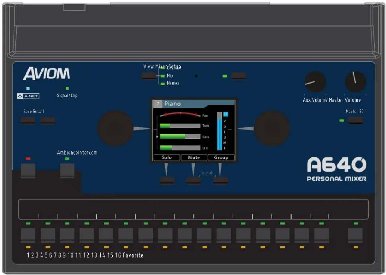
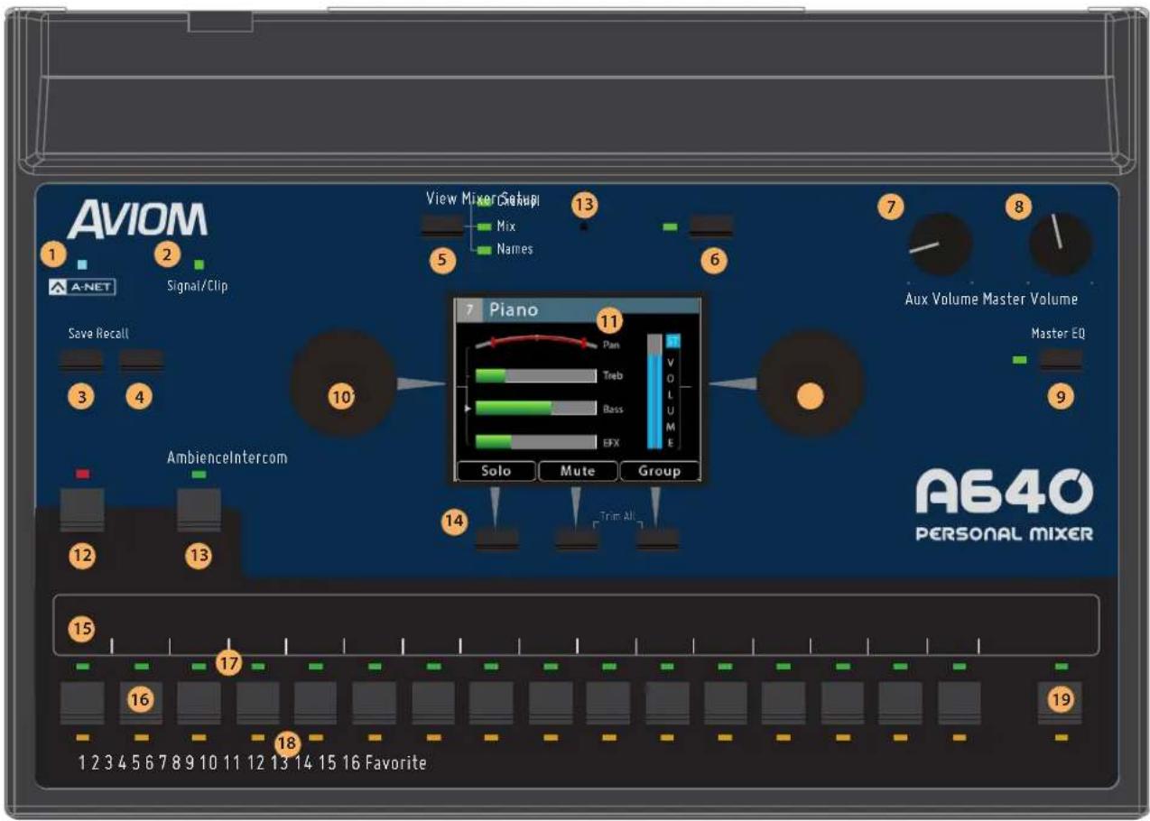
The A640 Personal Mixer's front panel controls and features are described below.
| Function | Function | |||
| 1 | A-Net LED | 11 | Color Liquid Crystal Display (LCD) | |
| 2 | Signal/Clip LED | 12 | Intercom Button | |
| 3 | Save Button | 13 | Ambience Button & Built-in Ambience Mic | |
| 4 | Recall Button | 14 | Assignable Soft Buttons & Trim All function | |
| 5 | View Button | 15 | Channel Label Strip | |
| 6 | Mixer Setup Button | 16 | Channel Buttons | |
| 7 | Aux Volume | 17 | Channel Active LEDs | |
| 8 | Master Volume | 18 | Channel Mute LEDs | |
| 9 | Master EQ Button | 19 | Favorite Button | |
| 10 | Left/Right Rotary Encoders | |||
A-Net LED
The A-Net LED lights whenever a valid digital Pro16 or Pro16e A-Net signal is connected to the A640. When the legacy 16-channel Pro16 version of A-Net is connected, the A-Net LED lights green; when the enhanced (up to) 64-channel Pro16e version of A-Net is connected, the A-Net LED lights blue.
Signal/Clip LED
The A640 includes custom circuitry to maximize mix headroom and minimize clipping in the digital domain. A bi-color Signal/Clip LED is provided to help maintain a high fidelity, distortion-free mix. The LED lights green under normal circumstances. As channel mix levels begin to increase, peaks (especially those from percussive sources) will begin to light the red LED to indicate that some clipping has started to occur.
When the red LED is on frequently, this is an indication that your mix headroom is being compromised. Turning down the Master Volume knob will not reduce clipping or eliminate distortion in this case; the Master Volume changes the output level after the digital mix has already been created. The solution is to use the Trim All function which lowers all channel mix volumes uniformly.
Save Button
The A640 Personal Mixer can save and recall sixteen mix presets in its onboard memory. The A640's sixteen mix channel buttons are used as the preset memory locations. Press the SAVE button followed by one of the mix channel buttons 1-16 to save the current settings as a mix preset to that location.
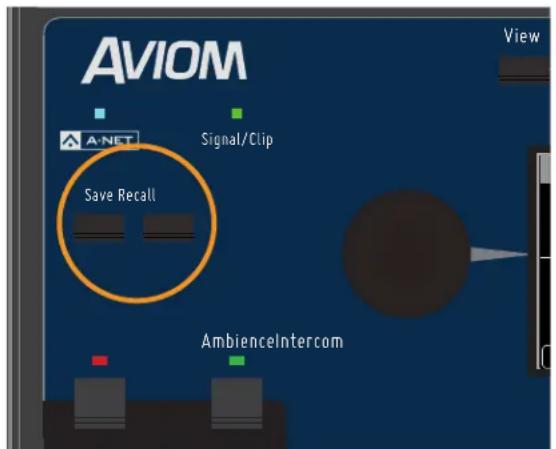
Save and Recall buttons
Mix Presets 1-16 store the following information:
- Mixer Mode (Pro16, Default, or Custom)
- Settings for each channel:
Volume
□ Mute status
□ Pan for mono and stereo channels
□ Treble boost amount
□ Bass boost amount
□ EFX level
- Last selected channel 1-16, or 1-17 in Custom mode
- Which channel is mapped to the Favorite button (Pro16 and Default modes only)
• Master EQ Bass, Treble, and Enhance amounts - Ambience On/Off status
- Ambience volume
• Intercom Volume and audio source - Aux Out source (Main Mix or Aux Mix)
• Aux Mix channel On/Off selections - Group 1-4 settings
• The last View screen displayed - Current Stereo Link values for all 64 Slots from the A-Net network
Recall Button
The RECALL button is used to load one of the sixteen saved mix presets into memory. Press the RECALL button followed by the channel button that corresponds to the mix preset you wish to load.
The Mixer Mode (Pro16, Default, or Custom) saved within the preset must match the current Mixer Mode in order to load the mix preset.
An error message is displayed if you attempt to load a mix preset whose settings do not match the current Mixer Mode.
View Button
The A640's built-in display can show your mix settings in one of three views—Channel View, Mix View, or Names View.
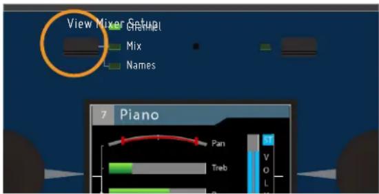
Cycle through the three views at any time while mixing by pressing the dedicated VIEW button found above the display.
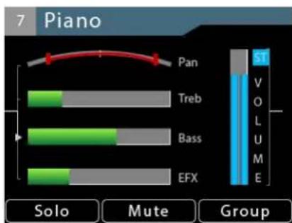
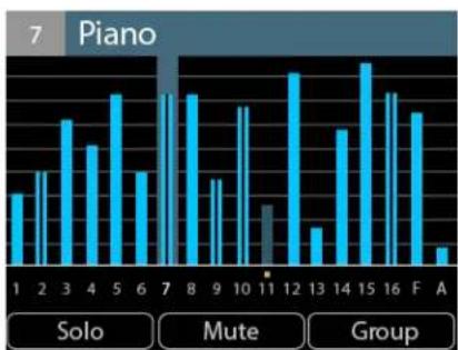
bar
7 Piano | Category | Count | |---|---| | 1 | 3 | | 2 | 4 | | 3 | 5 | | 4 | 4 | | 5 | 6 | | 6 | 3 | | 7 | 6 | | 8 | 6 | | 9 | 3 | | 10 | 5 | | 11 | 2 | | 12 | 7 | | 13 | 2 | | 14 | 5 | | 15 | 7 | | 16 | 6 | | F | 5 | | A | 1 |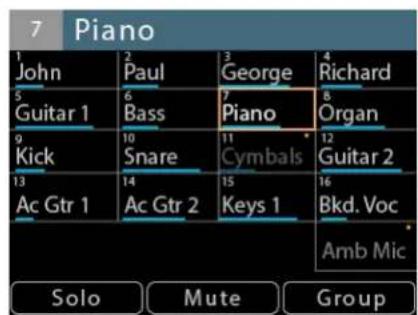
(L/R) Channel, Mix, and Names views
See "A640 Mix Views" on page 23 for a detailed explanation of the Views and their features.
Mixer Setup Button
Pressing the dedicated MIXER SETUP button at the top of the A640 interface opens the Mixer Setup menu which provides access to the A640 Personal Mixer's customizable settings and storage options. Each function in the list contains a Help page that provides a brief overview of the selected function's operation.
See "Mixer Setup Menu" on page 50 for complete information on all the functions and settings available in the Mixer Setup menu.
Aux Volume
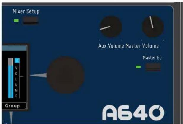
In addition to the stereo mix output, the A640 automatically generates a balanced line-level mono mix that makes connecting a subwoofer, bass shaker, or powered speaker easy. The AUX VOLUME knob controls the level of the mono mix being sent to the Aux Out XLR jack on the rear panel.
The Aux Volume level is not saved in a mix preset or configuration.
Aux Volume, Master Volume, and Master EQ
You can choose between using the mono version of the main mix or a customized set of channels. See page 71 to learn more about setting up and using the Aux Mix.
Master Volume
The MASTER VOLUME knob controls the stereo mix level heard when using headphones or earbuds connected to the A640's rear-panel 1/4- or 1/8-inch output jacks. The Master Volume is independent of the Aux Volume. Its volume level is not saved in a mix preset or configuration.
Master EQ Button
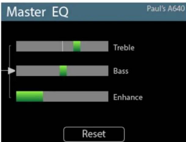
The A640 Personal Mixer includes a global Master EQ section that is applied to the stereo mix being sent to the 1/4-inch and 1/8-inch stereo headphone outputs as well as the XLR mono Aux Mix output on the rear panel of the A640. Press the MASTER EQ button to access its settings.
bar
| Category | Segment 1 | Segment 2 | | --------- | --------- | --------- | | Treble | 10 | 5 | | Bass | 10 | 5 | | Enhance | 10 | 5 |The A640 Master EQ section
Press either encoder button to scroll to the Treble, Bass, or Enhance settings. Then turn the encoder to change the amount. The Treble and Bass controls offer boost or cut. Scroll to the left of the center indicator (the default setting) for a Treble or Bass cut; scroll to the right for a boost.
The Enhance circuit is a specially designed boost-only feature that adds a simultaneous bass and treble boost at varying amounts as you increase its level. Its specially designed EQ curve is ideal for in-ear monitoring. The default setting for Enhance is fully left (off). The settings for the Master EQ will save with each mix preset created on the A640.
To return the Treble, Bass, and Enhance controls to their default values, press the RESET button.
Color LCD
The central LCD (Liquid Crystal Display) shows the current mix in one of three Views. The LCD is also used with the Master EQ and when setting up the A640 Personal Mixer using the options in the Mixer Setup window.
Color LCD as seen in Channel View
Left/Right Rotary Encoders
Two rotary encoders with push button switches are found on either side of the display. The encoders are used for creating and editing a monitor mix, setting up an Aux Mix, creating a custom channel map, setting up preferences in the Mixer Setup window, etc.
Intercom Button
The A640 Personal Mixer's built-in intercom function allows you to communicate with other performers without removing headphone or earbuds. It has two modes—momentary (push-to-talk) and latched (hands-free). The Intercom can use either the built-in mic or an external mic assigned to one of the 64 A-Net channels (Slots) on the Aviom network.
See page 38 for additional information on setting up and using the A640 Intercom.
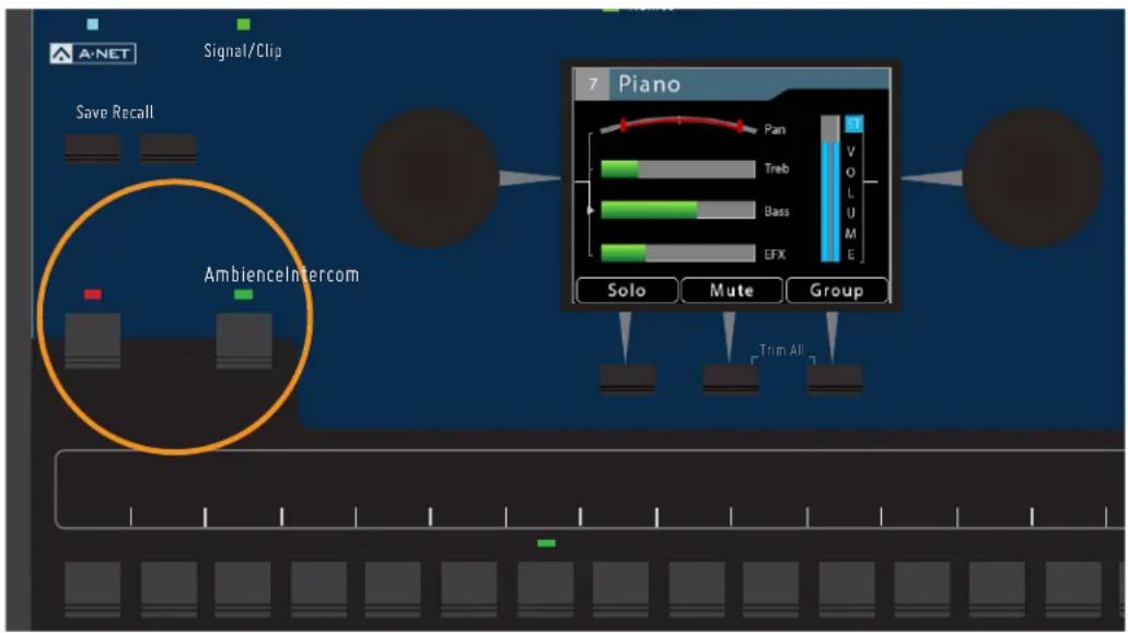
Intercom and Ambience buttons
Ambience Button
The Ambience button acts as an on/off switch for the built-in mic on the A640 Personal Mixer located above the LCD. The Ambience mic can be used to add acoustic stage sound into your monitor mix for a more realistic monitoring experience. Hold the AMBIENCE button to set the level of the built-in mic.
The Ambience channel can also be used as a standard mono/stereo audio channel when configuring an A640 in Custom mode. See "Channel Mapping" on page 65.
Built-in Ambience Mic
The Ambience mic itself is located at the top of the A640 Personal Mixer interface between the View and Mixer Setup buttons. The internal mic can also be used with the Intercom feature.
Assignable Soft Buttons
Below the A640's LCD are three assignable buttons that are used while mixing and for navigating in the Mixer Setup window while setting up your A640 Personal Mixer. Whenever a function such as Solo, Mute, or Group is available, the LCD will display the name of the function above the assignable button. Press the associated soft button to use that feature.
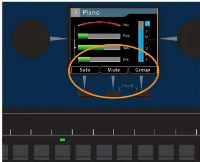
In the Channel View the soft buttons are assigned to Solo, Mute, and Group.
Trim All Function
The Trim All function is an easy way to turn down the volume of all channels in a mix (including the Ambience mic channel) by a uniform amount with a single command. Use Trim All to clean up a mix if the Signal/Clip LED is lit solid red, or if a channel being edited is already at its maximum level and you need to continue to raise its volume relative to the other elements in the current mix.
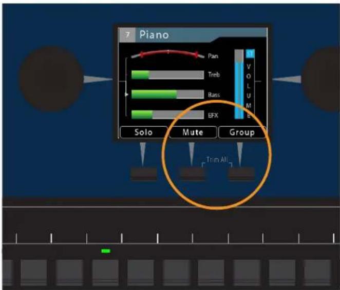
Press both buttons to activate Trim All.
The Trim All function is activated by simultaneously pressing the two rightmost soft buttons beneath the display. Each press of this button combination lowers the level of each channel in the mix by 3dB.
Trim All is available only when one of the three Views (Channel, Mix, or Names) is active in the LCD.
Channel Label Strip
The channel label strip is designed to accept 1/2-inch (13 mm) wide artist's tape or custom-made printed labels. A channel label template is available at the end of this document and on the Aviom website. Do not use permanent adhesives or tapes with your Aviom product.
Channel Buttons
The A640 Personal Mixer has 16 standard mix channel buttons that can host either a mono or stereo network source (global stereo links are assigned at the network's input device with the stereo link switches).
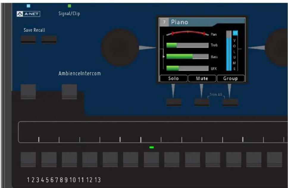
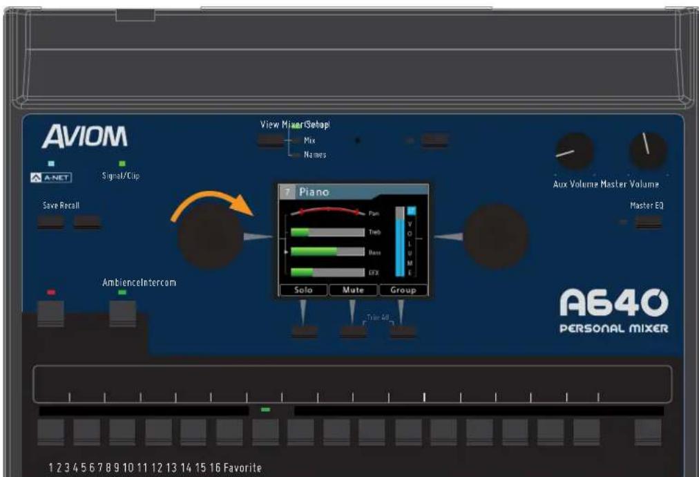
To select a channel and make it active for editing, press one of the 16 mix channel buttons; its green LED will light. Make channel-level changes as needed using the Channel Volume, Pan, Treble, Bass, Effects (EFX), and Mute controls. Use the Channel View for the most detailed editing.
While editing, the Solo function is also available to isolate the selected channel from the mix.
flowchart
graph TD
    A["Signal/Clip"] --> B["Save Recall"]
    B --> C["AmbienceIntercom"]
    C --> D["Piano Mode Selection"]
    D --> E["Solo"]
    D --> F["Mute"]
    D --> G["Group"]
    H["1 2 3 4 5 6 7 8 9 10 11 12 13"] --> I["Track Bar"]
    J["Pan"] --> K["Treb"]
    L["Bass"] --> M["BFX"]
    N["VOLUME"] --> O["Zoomer"]
    P["Trim All"] --> Q["Track Bar"]
Channel 7 is selected for editing, as seen in Channel View.
Channel Active LEDs
When a mix channel is selected for editing, the LED above its button will light in green. When a Group is created, all channels that are members of the Group will have their Channel Active LEDs lit when the Group is selected.
Channel Mute LEDs
Any number of mix channels can be muted within a mix. When a mix channel is muted, the LED below its button will light in gold.
Favorite Button
When operating the A640 Personal Mixer in Pro16 or Default mode, any one of the 16 standard mixer channel buttons may be assigned to the A640's Favorite channel button, allowing easy access to a frequently-used channel. Hold the FAVORITE button and then press a channel button to assign it.
Whenever your Favorite channel is selected on the A640—either by pressing the numbered channel button or the FAVORITE button itself—it will be indicated in each View with the addition of FAV in the top bar of the View next to the channel name.
The Favorite channel's assignment is saved as part of a preset and in a configuration.
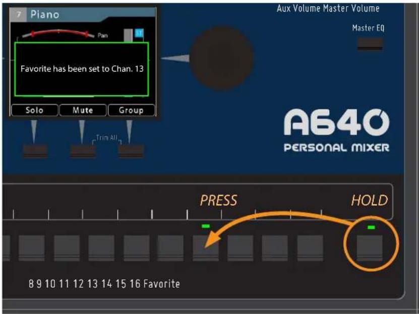
Setting channel 13 as the Favorite in Pro16 or Default modes
In Custom mode, the Favorite channel becomes a fully-assignable mono/stereo audio channel. Assign any network audio source to the Favorite button (which is displayed as channel 17) by using the Channel Mapping function found in the Mixer Setup window.
See "Mixer Mode" on page 77 for additional information about the A640 modes. See page 65 for additional information about Channel Mapping.
A640 Rear Panel
The A640 Personal Mixer's rear panel components are described below.
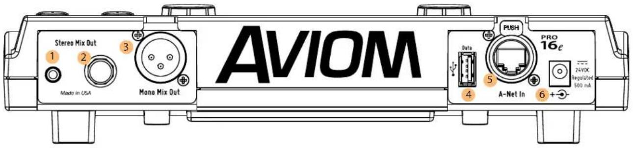
| Function | |
| 1 1/8-Inch Stereo Output | |
| 2 1/4-Inch Stereo Output | |
| 3 XLR Mono Mix Output | |
| 4 USB Port | |
| 5 Pro16e A-Net In Port | |
| 6 DC Power Connector | |
Stereo Audio Outputs
The A640 Personal Mixer's current stereo mix is available at the 1/8-inch and 1/4-inch TRS (tip, ring, sleeve) outputs on the rear panel. Plug standard stereo headphones or earbuds into the jacks, adjusting the listening level with the MASTER VOLUME knob on the front panel.
Both stereo outputs may be used at the same time. Use headphones/earbuds with similar output impedances to avoid volume level differences between users.
XLR Mono Output
In addition to the stereo mix, the A640 outputs a mono version of the current mix which is available at the XLR output on the rear panel. The mono output may be connected to a wireless in-ear transmitter, audio recording device, bass shaker, powered speaker, etc. Adjust the mono aux mix's output level with the independent AUX VOLUME knob on the front panel.
Channels in the aux mix ignore any left/right panning set up in the stereo version of the monitor mix.
By default, the mono mix contains the same channels as the stereo mix. The mono mix channels are always at the same volume level as those in the stereo mix. The Aux Mix can also output a custom set of channels selected from your monitor mix by using the Aux Mix Setup function found in the Mixer Setup window.
See page 71 to learn how to set up a custom Aux Mix.
USB Port
Save and recall your A640 mix settings and configurations with a standard USB storage device connected to the A640's USB port. If new A640 firmware is available, the A640 can be updated by using the Check for Updates function, found in the File Transfer section of the Mixer Setup menu.
The USB data port is designed to use a PC-formatted USB storage device and is not designed to work with external hard drives or any other types of peripherals that connect via USB. It cannot be used to charge another USB device.
To learn more about the File Transfer function and saving and recalling A640 configurations, see page 51.
A-Net In Port
Aviom's high speed, low latency A-Net audio data transport protocol can connect a virtually unlimited number of A-Net devices. The A-Net port on the A640 Personal Mixer can supply up to 64 sources for the A640 to choose from when creating custom channel mappings for a performer's monitor mix.
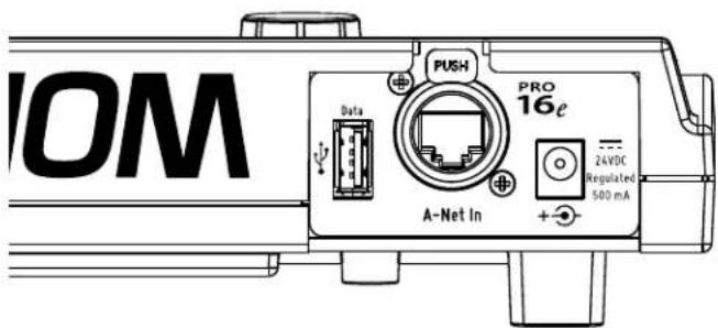
The A640's A-Net In port can be connected to current or legacy A-Net devices including analog input
modules, digital console cards, and A-Net Distributors.
The A-Net In port can accept standard Cat-5e (or higher) network cables or those fitting with the locking EtherCon ^® jack.
See page 6 for product compatibility info.
DC Power Connector
The A640 Personal Mixer is designed to be connected to an Aviom A-Net Distributor to receive its digital audio data and 24V DC power over the same Cat-5e cable. When using the A640 with an A-Net device that does not supply DC power over the Cat-5e cable, you can use the optional PS-120 Power Supply (or PS-240 international version) connected to the DC jack on the A640.
See page 7 for additional information on DC power supplies for the A640.
Creating a Monitor Mix
The A640 Personal Mixer simplifies the task of creating and using a monitor mixer while performing by offering a variety of ways to access and manage the individual components of your personalized mix.
A640 Mix Views
bar
7 Piano | Category | Value | |---|---| | 1 | 2 | | 2 | 3 | | 3 | 4 | | 4 | 3 | | 5 | 5 | | 6 | 2 | | 7 | 5 | | 8 | 4 | | 9 | 2 | | 10 | 4 | | 11 | 1 | | 12 | 5 | | 13 | 1 | | 14 | 3 | | 15 | 5 | | 16 | 4 | | F | 3 | | A | 1 |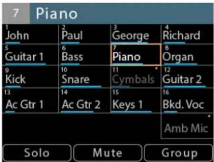
(L/R) Channel View, Mix View, and Names View
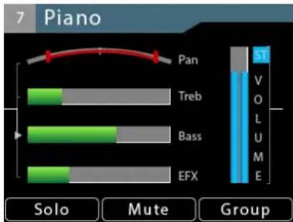
The A640's built-in liquid crystal display (LCD) can show your mix settings in one of three views—Channel View, Mix View, or Names View. Cycle through the three views at any time while mixing by pressing the dedicated VIEW button found above the display.
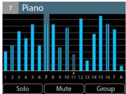
Channel View displays the most detail for the selected channel—volume, mono/stereo pan, treble and bass tone controls, and the effects (EFX) level. Use Channel View to fine tune the settings for each channel when setting up a monitor mix.
Mix View shows an overview of the volume levels of all channels in the current mix, including the Favorite and Ambience mic channels. The currently selected channel's volume and mute may be edited.
The Names View provides an easy way to see the text labels for all channels without needing to add a printed label strip or tape to the A640 surface. The currently selected channel's volume and mute may be edited while in Names View. Custom channel names can be entered by using the Edit Channel Names function found in the Mixer Setup window.
D800 Sync Indicator
Two-way communication between the A640 and D800 is required to use the Intercom and other features such as receiving channel names via Dante. Whenever the A640 Personal Mixer is used with the D800 or D800-Dante A-Net Distributor the A640 will indicate its sync status with the D800 by displaying a green bar in the upper left corner of the LCD. The sync status will be shown in each View
as long as the D800's I/II switch is in the "II" position.
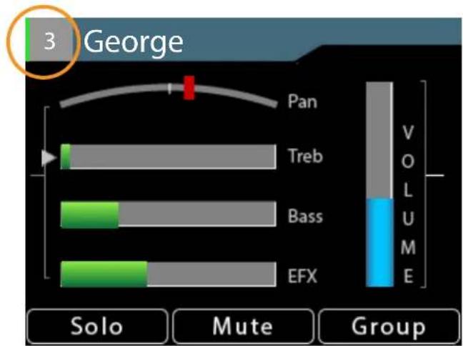
A green indicator shows two-way communication with a D800.
The sync process takes a few seconds to complete when an A640 Personal Mixer is first connected to the D800 or when the system is first powered on. In a Dante-based system, channel names entered in Audinate's Dante Controller software can be shared with the A640 from the D800-Dante.
Bidirectional communication with the D800 or D800-Dante requires that the D800's front-panel I/II switches be set to the "II" position for each port where an A640 Personal Mixer will be used.
Common Editing Functions
While making a monitor mix there are three mix functions that are always available for the selected channel regardless of the currently selected View—Solo, Mute, and Group. Press the assignable button beneath the display on the A640 to activate the function.
Solo
To listen to the currently selected channel in Solo mode, press the Solo button; it will light green in the display. The selected channel is heard in isolation while all other channels are temporarily muted. To hear a different channel in solo, press its channel button. To exit Solo mode and return to normal mixing, press the Solo button again.
When using Solo in the Mix view or Names view, any channels in Solo will have a green highlight.
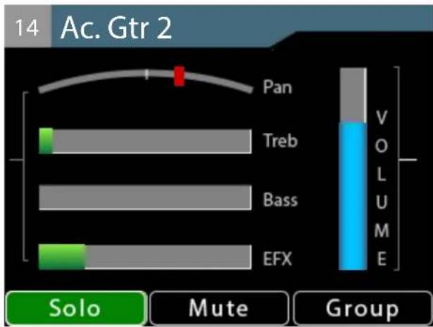
The Solo button lights green when any channel is placed into Solo mode.
Additive Solo
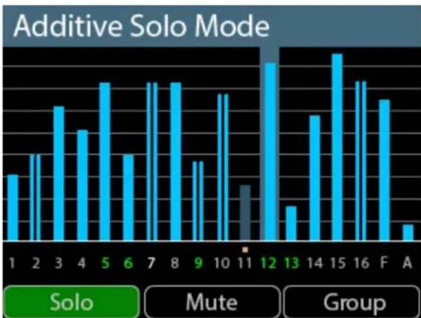
To hear multiple channels while in Solo mode, double-click channel buttons to add them to the Solo mix. The info bar at the top of the current View's window will indicate Additive Solo Mode whenever more than one channel is in solo. To remove a channel that has been added to the Additive Solo group, double-click its channel button again. To exit Additive Solo mode press the Solo button to return to normal mixing.
When using Additive Solo in the Mix view or Names view, all channels added to the Solo group will have a green highlight.
bar
Additive Solo Mode | Category | Additive Solo Mode | |---|---| | 1 | 2 | | 2 | 3 | | 3 | 4 | | 4 | 3 | | 5 | 5 | | 6 | 3 | | 7 | 5 | | 8 | 5 | | 9 | 3 | | 10 | 4 | | 11 | 2 | | 12 | 6 | | 13 | 2 | | 14 | 4 | | 15 | 6 | | 16 | 5 | | F | 4 | | A | 1 |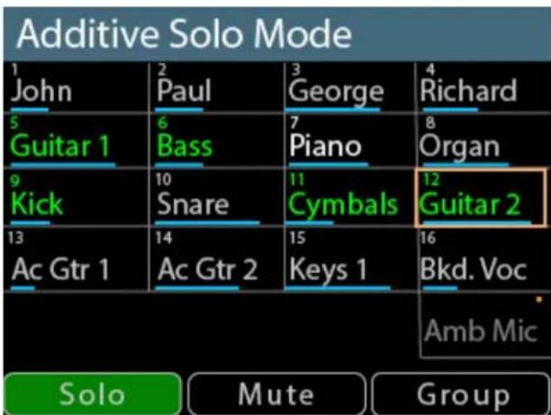
Channels 5, 6, 9, 12, and 13 are shown in Additive Solo Mode in the Mix View (L) and Names View (R).
The Solo mode on/off state is temporary and is not saved as part of a mix preset or configuration.
Mute
Silence the currently selected channel or Group by pressing the MUTE button. The channel is removed from the mix; its settings for volume, pan, tone control, and effects remain in view and can be edited if needed.
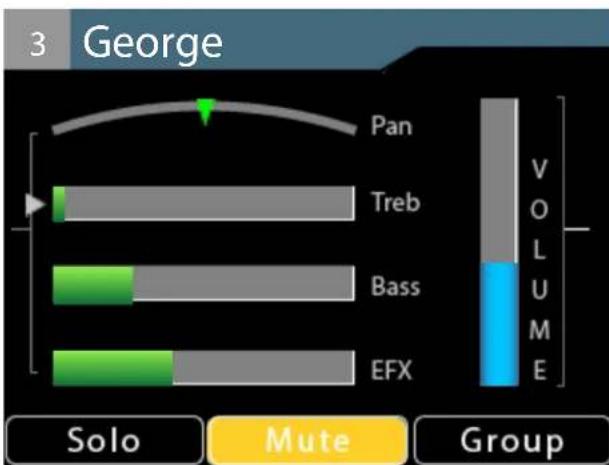
Any number of channels can be muted in a monitor mix. Any time a muted channel is selected in the Channel View, the on-screen Mute indicator will light. A dedicated gold LED beneath the channel button also lights for each muted channel on the A640.
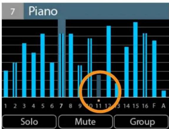
In Mix View, a muted channel displays a gold Mute indicator above its channel number and its volume level blue bar is also dimmed. Muted channels in Names View also display with dimmed volume bars and channel names. The on-screen Mute button lights only when a muted channel is selected.
bar
7 Piano | Note | Count | | :--- | :--- | | 1 | 20 | | 2 | 30 | | 3 | 45 | | 4 | 35 | | 5 | 55 | | 6 | 25 | | 7 | 50 | | 8 | 48 | | 9 | 20 | | 10 | 45 | | 11 | 30 | | 12 | 60 | | 13 | 0 | | 14 | 40 | | 15 | 65 | | 16 | 50 | | F | 45 | | A | 5 |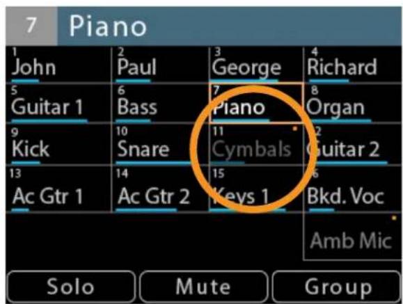
A muted channel (with dimmed volume level or text) as seen in Mix View and Names View
Press the MUTE button again to return the selected channel to the mix.
Each channel's Mute state is saved as part of a mix preset and as part of a configuration when saved to a USB storage device.
Mute All - The A640 Personal Mixer contains a special feature that will mute all channels at once. Double-click the MUTE button to activate the Mute All function. Press the MUTE button again to exit and return to mixing.
Group
The A640 can create up to four channel Groups which make it easy to change the volume of a set of related channels (all vocals or all drums, for example). A Group can contain any number of channels, but each mixer channel may only be part of one Group at a time. The Ambience channel cannot be added to a Group.
To create a Group:
- Select the first mix channel that will be part of the Group.
- Press the GROUP button; it lights in purple.
- Double-click other channels to add them to the Group.
- The green Select LEDs blink as channels are added to the Group.
- Press the GROUP button again to complete the process.
• The Group indicator goes out. - The Select LEDs for all channels in the Group are now lit solid green.
- With any member channel of the Group selected, turn the right encoder to adjust the volume of the Group.
Note that the status bar at the top of the A640 display reads Group 1 (or 2,3,4) when the Group is selected while mixing. While creating or editing a Group the status bar will display the name of the last selected channel within the Group.
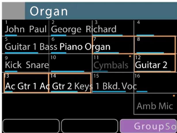
bar
Organ | Instrument | Count | | :--- | :--- | | John Paul | 1 | | George Richard | 2 | | Guitar 1 Bass Piano Organ | 6 | | Kick Snare | 9 | | Guitar 2 | 12 | | Ac Gtr 1 Ac Gtr 2 Keys | 14 | | Amb Mic | 15 | | GroupSo | 16 |A Group of five channels being created in Names view
When any member channel of the Group is selected while mixing, you can edit the overall volume of the Group with the A640's right rotary encoder. All channels in the Group change volume at the same time and will maintain their volume levels relative to each other within the Group. A Group may also be muted; pressing the MUTE button will silence all member channels in the Group. When muted, the
gold Mute LED will be on for all members of the Group.
To create additional Groups:
- Select any channel that is not currently part of an established Group.
- Press the GROUP button; it lights in purple.
- Double-click other channels to add them to the Group. (Adding a channel that is already part of an existing Group to a new Group will remove its assignment as a member of the original Group.)
- Press the GROUP button again to complete the process.
• The Group indicator goes out.
While mixing, each Group will be identified (Group 1, Group 2, Group 3, etc.) whenever any channel belonging to a Group is selected.
All Groups and their settings are saved as part of a mix preset and are also saved when an A640 configuration is saved to a USB storage device using the File Transfer function found in the Mixer Setup menu.
Editing a Group
Any channel that is part of a Group may be edited or removed from a Group completely. This allows each channel's volume, pan, tone and effects (EFX) level to changed while it remains an active member of a Group.
To edit a channel's mix settings while it is part of a Group:
- Switch to the desired View (Channel View offers the most detailed editing).
- Select the Group that contains the mix channel that you need to edit.
- Press the GROUP button; it lights purple.
- The channels that are part of the Group have blinking green Channel Select LEDs and one of those channels is lit with a solid LED. This is the channel that is active for editing.
• To choose a different channel to edit, press its channel button to select it. - Its green Select LED will light solid while all others blink.
- Make edits to volume, pan, tone, or effects as needed.
• To remove a channel from the Group, double-click its channel button. - Continue the process to select other Group channels for editing.
- When the edits are complete, press the GROUP button again to exit and return to mixing.
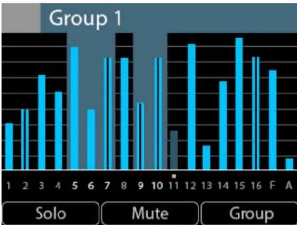
The example below shows a Group of five channels (5, 6, 7, 9, and 10), a blend of mono and stereo audio. When selected, all members of the Group are highlighted (as seen here in Mix View in the left image).
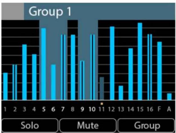
bar
Group 1 | Category | Value | |---|---| | 1 | 2 | | 2 | 3 | | 3 | 4 | | 4 | 3 | | 5 | 5 | | 6 | 2 | | 7 | 4 | | 8 | 4 | | 9 | 2 | | 10 | 4 | | 11 | 1 | | 12 | 4 | | 13 | 1 | | 14 | 3 | | 15 | 5 | | 16 | 4 | | F | 3 | | A | 1 |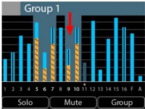
bar
Group 1 | Category | Blue Bar | Orange Striped Bar | |---|---|---| | 1 | 3 | 0 | | 2 | 4 | 0 | | 3 | 5 | 0 | | 4 | 4 | 0 | | 5 | 6 | 4 | | 6 | 3 | 2 | | 7 | 5 | 4 | | 8 | 5 | 0 | | 9 | 3 | 2 | | 10 | 4 | 4 | | 11 | 0 | 0 | | 12 | 6 | 0 | | 13 | 2 | 0 | | 14 | 4 | 0 | | 15 | 6 | 0 | | 16 | 5 | 0 | | F | 5 | 0 | | A | 1 | 0 | Solo; Mute; GroupA Group is selected (left) and its volume is changed (right). All channels change by the same amount.
When the A640's right side rotary encoder is turned, the volume level for each channel in the Group is changed by the same amount. In the example, all channels have been lowered in volume by rotating the right encoder to the left. For reference, the level difference is illustrated with orange bars in the right-side image above.
Channel View
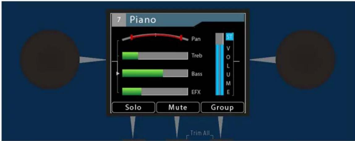
The A640 Personal Mixer's Channel View displays a complete channel strip for the currently selected mixer channel. It displays the channel's number and name, volume level, mono/stereo pan information, Treble and Bass tone control amounts, and its Effects (EFX) level. In addition, Channel View will display the Solo, Mute on/off, Group, and Favorite channel status as needed.
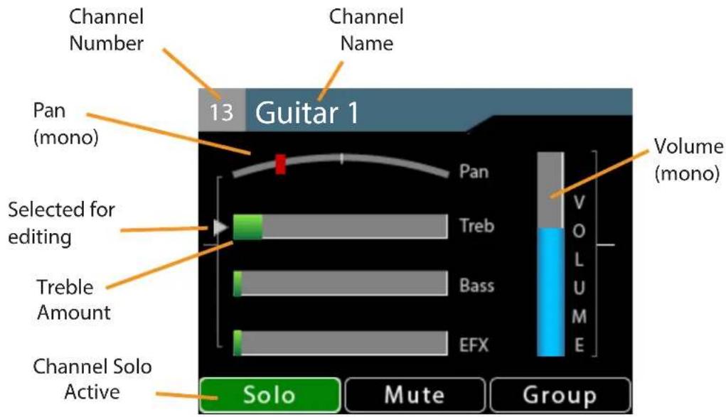
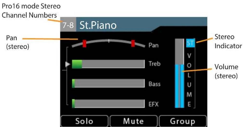
Stereo indicators for volume, pan and Pro16
In Pro16 mode, stereo channels use a pair of adjacent mix channel buttons on the A640. Stereo channels are indicated with two numbers (1-2, 7-8, 13-14, etc.) in the gray box next to the channel name at the top of the display.
In the A640's Default and Custom modes, stereo channels will display the mix channel's button number only. Stereo is indicated on the Pan control with two icons and by the special ST icon in the Volume bar.
Editing in Channel View
The A640's central rotary encoders each have dedicated functions in Channel View. The left encoder is used to select Pan, Treble, Bass, or Effects (EFX) for editing. Press the encoder's button to cycle through the four options. Turn the left encoder left/right to change the value for the currently selected option.
The right encoder is used to change the selected channel's volume level. The right rotary encoder's button is not active in Channel View.
At the bottom of the Channel View are selections for Solo, Mute, and Group. Use the assignable buttons beneath the display to access these features.
Pan
Channel View should be used to set up the basic stereo image for your monitor mix. For mono channels, Pan is shown with a single indicator. When a channel is fully centered in the mix, the Pan indicator is a green triangle. As the channel is moved through the stereo field, its position is shown with a red indicator. As the signal reaches the extreme left or right side, the position indicator turns to green.
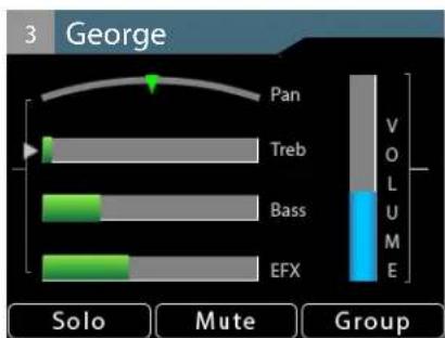
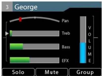
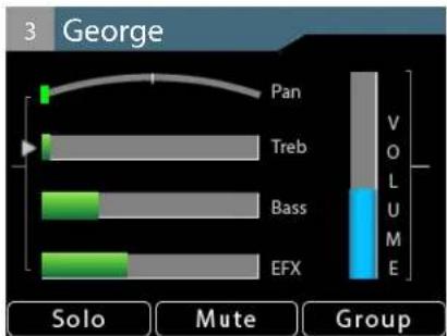
Channel 3 is shown with its Pan set at center, partially left, and fully left.
Stereo Pan
For stereo channels, Pan position is shown with a pair of indicators. As with mono channels, when the left/right channels are at the boundary of the stereo field, a pair of green indicators is used. As the Pan knob (left rotary encoder) is turned the stereo position is shown with a pair of red indicators. The A640 offers a number of creative pan position options as you turn the encoder that vary the left/right
positioning as well as the stereo width of the audio source.
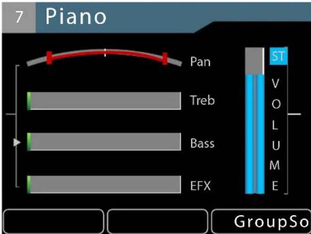
Channel 7 is panned in the stereo field.
When a stereo channel's left/right sides reach the center as the Pan encoder is turned, the signal is mono and displayed with a single green triangle.
Pan settings are saved as part of a mix preset saved to any of the A640's 16 mix preset locations.
Tone Controls
Each mix channel on the A640 has a pair of tone controls, Treble and Bass. Use these to fine-tune the audio of the individual channels in your monitor mix. Use the left encoder's push button to cycle through the channel-level options in Channel View—Pan, Treble, Bass, and Effects (EFX).
The Treble and Bass tone controls are positive-only (boost); they add treble or bass to the sound of the channel but cannot subtract it. Turn the left encoder left/right to adjust the amount of Treble or Bass boost. The default amount is fully left.
With the Bass tone control selected, turning the encoder to the right adds a bass boost.
The per-channel Treble and Bass amounts are saved when a mix preset is stored into one of the A640's 16 preset memory locations and will also be restored with any configurations saved to a USB storage device using the File Transfer options found in the Mixer Setup window.
EFX
Each mix channel on the A640 Personal Mixer can make use of the built-in Effects (EFX) engine. Adding a little reverb to a channel can make a singer or horn player using earbuds more comfortable, putting a little space around them in the monitor mix.
Use the left encoder's push button to cycle through the channel-level options in Channel View. When EFX is selected, turn the left encoder to add reverb to the selected channel. The default amount is fully left (off).
The EFX amounts for each channel are saved when a mix preset is stored.
Mix View
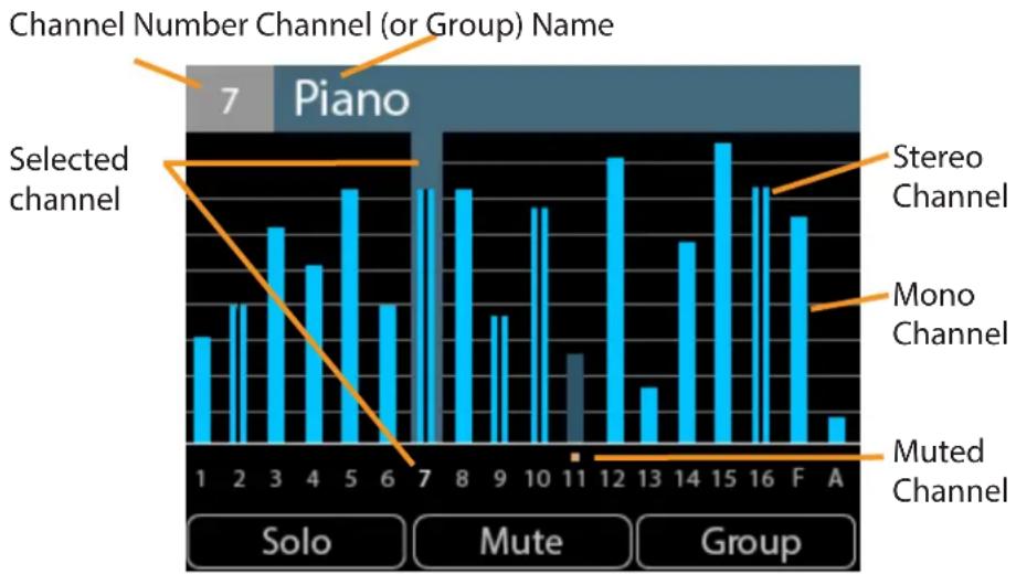
To see the volume level of every channel in a mix, use the Mix View. Mono channels are displayed with a single blue volume level bar; stereo audio has a double blue bar. A selected channel (or Group) is highlighted and its channel number is shown in white. Muted channels have gold Mute indicators above the channel number, and their blue volume level bars are dimmed.
bar
| Channel | Label | Frequency | | :--- | :--- | :--- | | Selected | 1 | 3 | | Selected | 2 | 4 | | Selected | 3 | 5 | | Selected | 4 | 4 | | Selected | 5 | 6 | | Selected | 6 | 3 | | Selected | 7 | 6 | | Selected | 8 | 6 | | Selected | 9 | 4 | | Selected | 10 | 5 | | Selected | 11 | 2 | | Stereo Channel | 12 | 6 | | Stereo Channel | 13 | 2 | | Stereo Channel | 14 | 4 | | Stereo Channel | 15 | 6 | | Stereo Channel | 16 | 5 | | Stereo Channel | F | 4 | | Stereo Channel | A | 1 | | Mono Channel | 1 | 0 | | Mono Channel | 2 | 0 | | Mono Channel | 3 | 0 | | Mono Channel | 4 | 0 | | Muted Channel | 5 | 0 | | Muted Channel | 6 | 0 | | Muted Channel | 7 | 0 | | Muted Channel | 8 | 0 | | Muted Channel | 9 | 0 | | Muted Channel | 10 | 0 | | Muted Channel | 11 | 0 | | Muted Channel | 12 | 0 | | Muted Channel | 13 | 0 | | Muted Channel | 14 | 0 | | Muted Channel | 15 | 0 | | Muted Channel | A | 0 | The chart is a single bar chart showing the frequency of selected channels in the piano. The legend indicates that 'Selected channel' and 'Muted channel' are used to denote different channels. The chart includes labels for the x-axis (labeled 'Solo') and y-axis (labeled 'Piano').The Favorite and Ambience channels are also displayed in Mix View, indicated on screen with an F for the Favorite channel and an A for the Ambience mic channel. When using the A640 Personal Mixer in Custom mode, the Favorite channel is replaced with a fully-assignable channel 17.
Editing in Mix View
Each channel's volume and mute on/off can be changed while in Mix View. The left encoder will scroll left or right through the mix channels. Use the right encoder to change the volume level for the selected channel (or Group). The left and right encoder push buttons are inactive in Mix View.
bar
Group 1 | Category | Value | |---|---| | 1 | 2 | | 2 | 3 | | 3 | 4 | | 4 | 3 | | 5 | 6 | | 6 | 2 | | 7 | 5 | | 8 | 5 | | 9 | 3 | | 10 | 5 | | 11 | 1 | | 12 | 6 | | 13 | 2 | | 14 | 4 | | 15 | 6 | | 16 | 5 | | F | 4 | | A | 1 |Channels 5, 6, 7, 9, and 10 belong to Group 1, as seen in Mix View
As with the Channel and Names Views, you can solo or mute channels in the mix by using the Solo or MUTE buttons on the A640. Groups can be created or edited from Mix View as well.
When using the A640's Custom mode, any mix channels that are set to be disabled (no network Slot assignment) will be skipped as you scroll through the channels with the left encoder. See page 65 for more info on channel mapping.
The Solo, Mute, and Group functions are not available when the Ambience channel is selected.
To edit the Pan, Treble, Bass, or Effects (EFX) settings for a channel, switch to Channel View.
Names View
The Names View allows you to see all default or custom channel names at a glance. The currently selected channel is displayed with a gold outline. Volume levels for all channels (mono and stereo) are shown with a single blue horizontal bar. A muted channel's name and volume bar are dimmed.
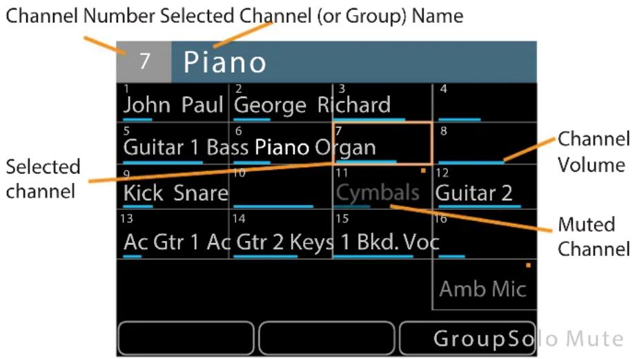
When using the A640's Custom mode, a fully assignable channel 17 will appear in the on-screen names list. The Ambience channel does not appear in Names View.
Editing in Names View
The selected channel's (or Group's) volume and mute on/off can be changed while in Names View. The left encoder will scroll left or right through the mix channels. Use the right encoder to change the volume level for the selected channel. The left and right encoder buttons are inactive in Names View.
When using the Custom mode, any mix channels that are set to be disabled (no network Slot assignment) will be skipped as you scroll through the channels with the left encoder. See page 65 for more info on channel mapping.
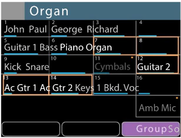
Solo or mute channels or Groups in the mix by pressing the SOLO or MUTE buttons on the A640 below the display. In Solo (or Additive Solo) mode, channel names are shown in green. Any Groups created or edited from Names View will show all member channels highlighted in gold whenever any mix channel that is part of a Group is selected.
bar
Organ | Organ | 1 | 2 | 3 | 4 | | :--- | :--- | :--- | :--- | :--- | | John Paul | 5 | 6 | 7 | 8 | | Guitar 1 Bass Piano Organ | 9 | 10 | 11 | 12 | | Kick Snare | 13 | 14 | Cymbals | 16 | | Ac Gtr 1 Ac Gtr 2 Keys 1 Bkd. Voc | 16 | 15 | 16 | 16 | Amb Mic GroupSoo Mute
Creating a Group with five channel members
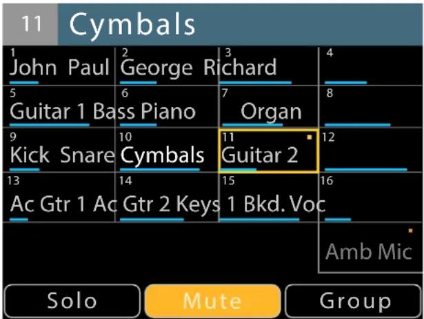
When a muted channel is selected in Names View, the channel name changes from gray to white. Press the MUTE button to return the channel to the mix.
other
11 Cymbals | Instrument | Value | | :--- | :--- | | John Paul | 1 | | George Richard | 2 | | Guitar 1 Bass Piano | 6 | | Organ | 7 | | Kick Snare | 9 | | Cymbals | 10 | | Guitar 2 | 11 | | Ac Gtr 1 Ac Gtr 2 Keys | 14 | | 1 Bkd. Voc | 15 | | Amb Mic | 16 | Solo | Mute GroupChannel 11 is muted and selected for editing.
To fine tune other channel settings (pan, bass, treble, etc.) for a single channel or for any members of a Group, switch to the Channel View.
Intercom Setup
The A640 Personal Mixer's intercom is a convenient way for A640 users to communicate with each other while wearing headphones or earbuds during a live stage or theater performance, recording session, TV broadcast, etc.
The Intercom feature requires that the personal mixing system include a D800 or D800-Dante A-Net Distributor (with v4.00 or higher firmware installed). The D800 can support up to eight A640 Personal Mixers.
Using the Intercom also requires that each port of the D800 or D800-Dante that will make use of the Intercom feature has its I/II switch set to the 'II' position to enable bidirectional communication between the A640 Personal Mixers and the host D800.
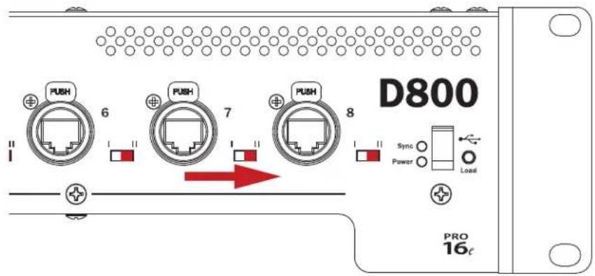
D800 I/II switches must be set to the "II" position.
The basic steps required to set up the Intercom include:
- Connect A640 Personal Mixers to a D800 or D800-Dante A-Net Distributor.
- Set the D800 front panel I/II switches to "II."
- Choose a global Broadcast Slot for the Intercom audio being sent through the network.
- Set the desired audio source (internal mic, external mic connected to the Aviom A-Net network, or none) for each A640 Personal Mixer that will transmit over the Intercom.
Attempting to use the Intercom without a connection to a D800 or D800-Dante A-Net Distributor will result in an error message being displayed on the A640.
ERROR: Must be connected to D800 or
D800-Dante v4.00 or newer
Press any button to continue.
The Intercom feature requires a connection to a D800 or D800-Dante.
Transmitting and Receiving Intercom Audio
The Intercom feature needs at least one A640 Personal Mixer set up to transmit Intercom audio to other A640 users, and one dedicated network Slot assigned to broadcast and route that audio throughout the network to the other A640 users.
For ultimate flexibility the Intercom transmit audio source can be set independently for each A640 Personal Mixer in the monitor mixing system. This allows multiple A640 users to have the option to transmit audio over the network to other A640 users. Users also have the option to choose the built-in A640 mic or an external mic connected to the network as the source of their audio transmitted to other users.
Transmitting Intercom Audio
The Intercom Audio Source setting tells each A640 Personal Mixer how they will send Intercom audio from their A640 to the other A640 users listening to the Intercom audio. The choices are:
- Listen Only (no transmitting allowed),
• the Internal Mic built into the A640, or - an external microphone connected to the Aviom network and active on one of its 64 Slots.
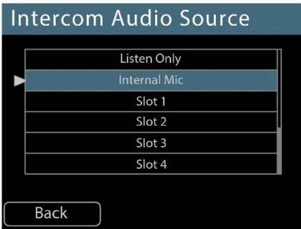
Selecting a transmit source for the Intercom
To choose the Intercom's audio transmit source:
- Choose Intercom in the Mixer Setup menu; press either encoder button to open the options.
- Select the Audio Source option by pressing either encoder button.
- Scroll to select Internal Mic or any one of the 64 network Slots where an external mic is connected.
• To prevent an A640 from broadcasting over the Intercom, choose Listen Only. - Press either encoder button to confirm the selection.
- The display returns to the main Intercom window and the selected source is shown within the Audio Source text.
See page 73 for additional information about setting up the Intercom.
When using a D800-Dante A-Net Distributor, note that the Audio Source setting for transmitting audio while using an external microphone must be set to a Dante channel that is both active in the Dante network and available at the current Dante sample rate.
Receiving Intercom Audio
The Broadcast Slot is a global setting that tells the A-Net network which network channel (referred to as a Slot) will be used by all A640 Personal Mixers when they listen to incoming Intercom audio from another A640 user.
You can choose any one of the 64 available network Slots to be the Broadcast Slot, regardless of the sample rate that might be selected when using a D800-Dante A-Net Distributor (the Dante network's sample rate does not affect the number of Slots available in an Aviom A-Net network). The A-Net Pro16e network always has 64 available Slots. Choose a Broadcast Slot that will not be used for monitor mixing audio, for example, Slot 64.
The A640 must be connected to a D800/D800-Dante to access the Broadcast Slot settings. To set the intercom Broadcast Slot source from the Intercom window:
- Press the MIXER SETUP button
- Open the Intercom settings from the list of options.
- Scroll to select the Broadcast Slot option in the Intercom settings.
- Press either encoder button to open the channel list.
- Scroll with the encoders to select None (Intercom disabled) or any one of the 64 A-Net network Slots.
- Press either encoder button to confirm the selection.
- Press YES to set the Broadcast Slot or No to return to the Slot list.
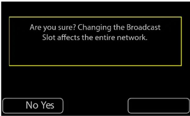
Press Yes to confirm the selection.
After confirming, the display returns to the main Intercom window and the current Broadcast Slot source is shown within the Broadcast Slot text.
Only one A640 needs to set up the Broadcast Slot. The Broadcast Slot selection will be transmitted to the D800 from the A640 and then broadcast from the D800 to all other A640 Personal Mixers connected to it.
When an A640's Intercom Audio Source is set to Listen Only, you cannot change the Broadcast Slot from that A640. An error message will be displayed.
Cannot change the Broadcast Slot while in Listen Only mode.
Press any button to continue.
You can temporarily set the Audio Source to Local Mic or a network Slot to make the change or opt to edit the Broadcast Slot from a different A640 in the network.
Additional information about setting up the options for the Intercom are found in the Mixer Setup window. See page 73.
Intercom Modes
The A640 Personal Mixer's Intercom function can operate in one of two modes—momentary (push-to-talk) or latched (hands-free).
Momentary
The momentary (push-to-talk) Intercom function is useful when you need to transmit a brief message to the other A640 users in the network. Holding the INTERCOM button down activates the Intercom and transmits audio from your location while you speak until the button is released. The Intercom LED will light solid on the speaker's A640 for as long as the button is held down. On other users' A640 Personal Mixers the Intercom LED blinks to notify them that Intercom audio is available. Each user can choose an Intercom Receive Volume level for Intercom audio that best suits their needs.
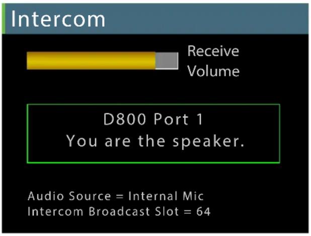
Each A640 can set its own Intercom Receive Volume.
Hold the Intercom button down and turn either encoder to set the Intercom Receive Volume.
Latched
For longer hands-free communications, press the INTERCOM button once to latch it on. The Intercom will remain active without requiring that the button be held down. When done speaking, press the INTERCOM button a second time to turn it off. The speaker's Intercom LED remains lit solid until the INTERCOM button is pressed a second time to exit the latched mode. As with the momentary Intercom mode, the other A640 users' Intercom LEDs blink to notify them that Intercom audio is available.
Only one A640 Personal Mixer can be the Intercom's Speaker on the network at a time for both momentary and latched modes.
Attempting to activate the latched mode on a second A640 while the Intercom is already active on another A640 results in an error message.
ERROR: Cannot latch Intercom on. Another mixer is already the speaker.
Press any button to continue.
The Intercom supports one speaker at a time.
How The Intercom Works
To transmit audio via the Intercom, an A640 Personal Mixer can use either its internal Ambience mic or an external mic connected to one of the network Slots.
Using the Local Mic
The following diagram illustrates how the Intercom works when using the A640's built-in Ambience mic as the source for the Intercom audio.
In each Cat-5 cable in an Aviom Pro16e A-Net network, all 64 available network Slots are always present (whether they have audio assigned to them or not). This is indicated with the orange arrow in the diagram below. The A-Net data stream is being sent from a D800 A-Net Distributor to the A640's A-Net In jack.
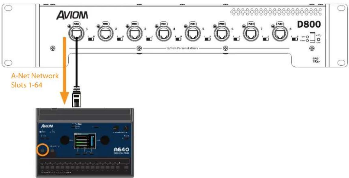
64 network channels are sent to an A640 from a D800.
The A640 Personal Mixer receives the multi-channel A-Net digital audio sources and then maps those audio sources to its mix channel buttons according to the currently selected mode that the A640 is set to—Pro16, Default, or Custom. Network channels (Slots) that are not assigned to a mix channel button are simply ignored. See page 77 for more info on using and selecting the A640 modes.
One of the 64 A-Net network Slots is assigned the duty of carrying the Intercom audio, known as the Broadcast Slot, on one of those 64 Slots. This global network Slot will contain the Intercom audio for all users and the D800 will distribute it to all A640 Personal Mixers connected to its front panel A-Net ports. (Slot #64 is chosen for broadcasting Intercom audio in this example.)
When the INTERCOM button is held down, the A640 display shows the current Intercom Receive Volume level and other information about the current Intercom setup.
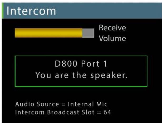
Intercom info is displayed when you hold the Intercom button down.
While the Intercom is active, the local mic on the A640 picks up the user's voice and transmits it as digital audio back to the D800 (shown in the illustration below with a purple arrow).
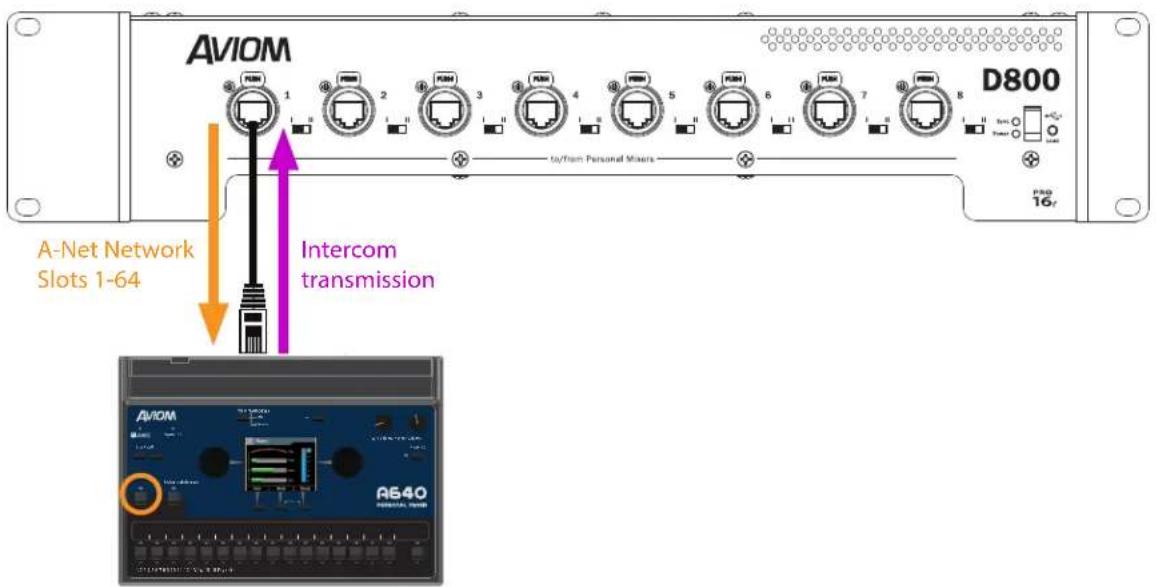
The local Ambience mic transmits Intercom audio to the D800 A-Net Distributor
The D800 seamlessly merges the Intercom audio from the user's local mic into the A-Net digital data stream (on the designated Broadcast Slot) and then distributes it to all connected A640 Personal Mixers along with the other audio sources making up the monitor mix (illustrated with green arrows below).
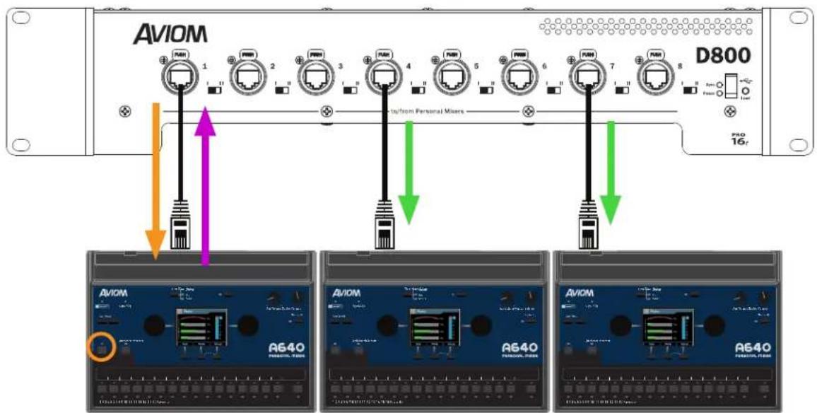
All users hear intercom audio sent from A640 #1 when its Intercom button is pressed.
The D800 notifies all A640 users that there is Intercom audio available by blinking their Intercom LEDs. All A640 Personal Mixer users can hear the Intercom audio and control its local volume.
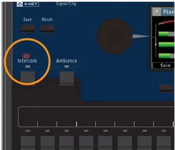
The Intercom LED flashes to notify users that Intercom audio is being transmitted.
The other A640 Personal Mixer users connected to the D800/D800-Dante will see Intercom info in their display when their local INTERCOM button is held down.
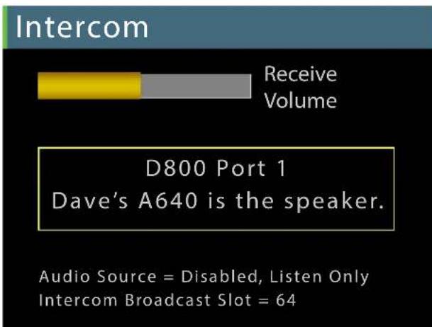
Intercom info is displayed when you hold the Intercom button down.
Users listening to the Intercom are shown the name and location of the A640 Personal Mixer that is currently transmitting the Intercom audio when their INTERCOM button is held down. (In this example, the user connected to D800 port #1 has named this A640 "Dave's A640" by using the Edit Mixer Name function found in the Mixer Setup window.)
Adjust the Intercom Receive Volume at any time while the INTERCOM button is held down by turning either encoder.
Using an External Mic
In some applications, it may be beneficial to use an external microphone as the input source for transmitting audio over the Intercom. For example, this might include a head-worn or lavalier mic used by a musical director, a wireless mic that is being shared by multiple performers, or an off-stage mic being used by a member of the tech staff for communication purposes.
Using an external microphone to transmit Intercom audio requires that the mic be connected to the Aviom network and assigned to one of its 64 available audio Slots. In most cases this microphone—intended to be heard by only the performers using A640 Personal Mixers—would not be routed to any front-of-house (FOH) mix that the audience would hear. The mic can be connected directly to an AN-16/i Input Module (with the use of an optional mic preamp), to a line-level input on an AN-16/i from an analog output on a mixing console, to one of the 16 Slots available on a digital console card, or from a Dante network.
When using a D800-Dante A-Net Distributor, note that the Audio Source setting for transmitting audio while using an external microphone must be set to a Dante channel that is both active in the Dante network and available at the current Dante sample rate.
To choose an external microphone as the Intercom's transmit audio source:
- Connect the external mic to the audio system's mixing console as you would any other microphone.
- Route the external mic's audio to an available A-Net network Slot.
- On the A640, press the MIXER SETUP button.
- Choose Intercom from the menu.
- Press the encoder button to open the Intercom options.
- Select the Audio Source option by pressing either encoder button.
- Scroll to select the network Slot where the external mic is connected.
- Press either encoder button to confirm the selection.
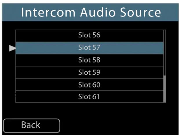
Selecting an external mic on Slot 57 as the transmit source for the Intercom
- The display returns to the main Intercom window and the selected source is shown within the Audio Source text.
- You are now ready to use the external mic to transmit Intercom audio whenever the INTERCOM button is pressed.
The Intercom's Audio Source and Broadcast Slot must be set to different Slot numbers within the network when using an external mic.
Information about the external mic and its Slot assignment is shown in the A640 display when the INTERCOM button is held down.
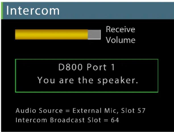
Info about the external mic is displayed when you hold the Intercom button down.
Using Multiple External Mics
In some settings it may be convenient to have multiple A640 users capable of speaking over the Intercom, each using an external mic at their location. To do this, follow the instructions above for setting up an external mic as the audio source for transmitting Intercom audio. Choose a different network Slot to transmit the second user's Intercom audio, being careful not to select a network Slot that is already in use for monitor mix audio.
Only one A640 user may be the speaker at a time while using the Intercom.
Intercom Audio and Legacy Devices
When using the A640 Personal Mixer in a system that also includes other Aviom Personal Mixers such as the A360, A320, and A-16II, Intercom audio can be heard on these devices as long as the system is set up the allow the legacy Personal Mixers to access the Intercom audio's network Slot.
There are some limitations:
- The A360, A320, and A-16ll cannot indicate to the user that someone is speaking on the Intercom.
- Legacy Personal Mixers cannot distinguish between A-Net Slots. The audio from the Intercom broadcast throughout the network is treated the same as any other mono audio source.
- The legacy Personal Mixers cannot become a speaker on the Intercom, or interact with the Intercom in any way.
- A320 and A-16II Personal Mixers do not have any channel mapping capabilities.
A-16II Personal Mixer
To make use of Intercom audio on an A-16II Personal Mixer, the Intercom audio must be mapped to an A-Net Slot (using the Broadcast Slot setting) that is within the range of Slots 1-16. All A-Net Slot numbers above 16 are invisible to an A-16II.
A320 Personal Mixer
To hear Intercom audio on an A320 Personal Mixer, the Intercom audio must be mapped to an A-Net Slot that is available to the A320 —in the range of Slots 1-32. Network Slot numbers 33 and above are invisible to an A320.
Note that the A320 has two operating modes—16-channel and 32-channel—so choosing which Slot to broadcast Intercom audio on will depend on which mode the A320 Personal Mixers will be set to. When using the 16-channel mode, no network Slots above 16 are available to an A320 Personal Mixer.
A360 Personal Mixer
The A360 is the most flexible Personal Mixer when used with the A640 and its Intercom feature. The A360's Custom mode allows any incoming network Slot to be mapped to any A360 mix channel. This makes the entire 64-channel network range of channels available to the A360 Personal Mixer. Create a custom channel map using the A360 Channel Manager software and then load a saved configuration into the A360 from a USB storage device.
Mixer Setup Menu
Pressing the dedicated MIXER SETUP button at the top of the A640 interface opens the Mixer Setup menu which provides access to the A640 Personal Mixer's customizable settings and storage options. Each function in the list contains a Help page that provides a brief overview of the selected function's operation.
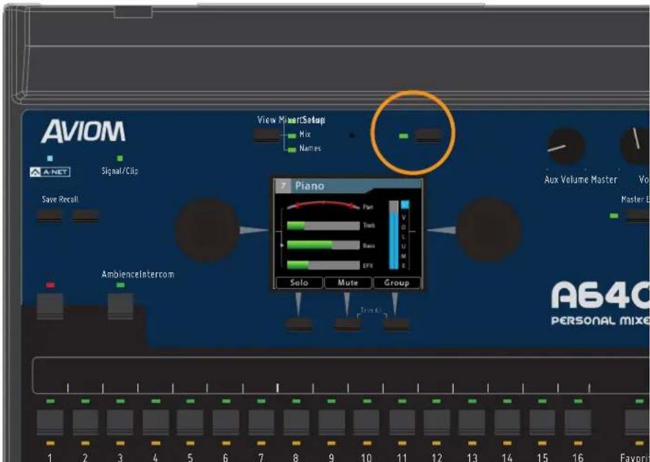
Press the Mixer Setup button to access the Setup menu.
Scroll to select an option from the Mixer Setup menu. Press either encoder button on the A640 to access its settings and options.
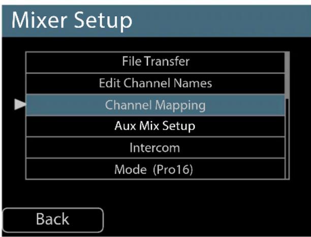
The available options are:
- File Transfer
- Edit Channel Names
- Channel Mapping
- Aux Mix Setup
- Intercom
- Mode
- Clear Current Mix
- Edit Mixer Name
- LCD Backlight Level
- Help
- Restore Defaults
- About This Mixer
Some functions make use of the A640's assignable buttons beneath the display to confirm edits, navigate the windows and menus, choose options, or cancel an operation. (Press BACK to exit, for example.) Press the corresponding button beneath the display to activate the function.
The following section explains each option in the Mixer Setup menu in detail.
File Transfer
The A640 can save and load mix presets, custom configurations, and access firmware updates using a USB storage device connected to its USB port.
By using the File Transfer functions, it's easy to back up settings from the A640 Personal Mixer or create a configuration in one A640 that will be loaded into multiple A640 Personal Mixers via a USB storage device.
Three options are available in the File Transfer menu. A properly formatted USB storage device must be connected to the A640's USB port to access the three options.
Scroll with either encoder knob to select the option you want. Press the encoder to activate it.
While using the File Transfer functions, audio is temporarily disabled. The A-Net LED will blink while the File Transfer window is open.
USB Data Port
The A640's USB data port is designed to use a PC-formatted USB storage device (also referred to as a memory stick or thumb drive) to update its firmware and save/recall mixer configurations and Mix Presets. It is not designed to work with external hard drives, computers, or any other type of peripherals that connect via USB.
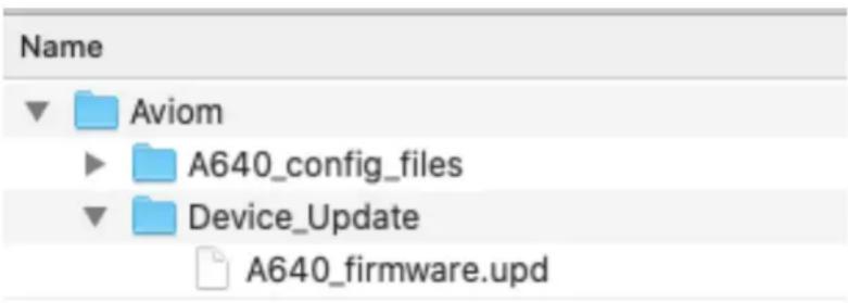
The Aviom file and folder structure on a USB storage device
All A640 configurations are stored in a folder named A640_config_files found within a folder named Aviom created at the root level of the USB device which will be created automatically when a configuration is saved from the A640's File Transfer function.
The USB storage device can contain other types of data, folders, pictures, etc., but the Aviom folder must reside at the root level of the device in order to be recognized by the A640 Personal Mixer.
Save a Configuration
The A640 can save all settings for its 16 mix presets as well as custom channel mappings and custom channel names that you have created. Each USB storage device can hold 32 unique configurations.
A configuration saves:
- Mixer Mode (Pro16, Default, or Custom)
- 16 mix presets
- Channel volume for each channel (including Favorite and Ambience channels)
- Pan for each channel
- Treble and Bass tone settings for each channel
• Effects (EFX) settings for each channel - Mutes
- Groups
- Master EQ settings
- Custom channel names
-
Custom channel mappings
-
Aux Mix settings
- Ambience on/off
- Intercom volume
• Intercom audio source Slot - LCD Backlight Level
- Mixer Name
- Dante channel names auto-sync on/off setting
- Startup Help on/off at power up setting
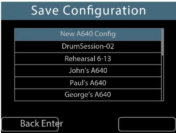
Saving a new configuration
To save a configuration:
- Select the Save Configuration option by scrolling with either encoder knob.
- Press the encoder button to activate it.
- When the Save Configuration window opens, a default file name New MixerName Config (based on the A640's current Mixer Name setting) is selected. Any other configurations previously saved to the USB device are shown in the list.
- Press the ENTER soft button on the A640 to start the process.
- Accept the default name or edit the name as needed (scroll with the left encoder; choose a character with the right encoder).
- Use the CLEAR command to reset the current file name. File names can use up to 32 characters and must contain at least one character *.
- Press the SAVE soft button on the A640 to start the file saving process.
- An on-screen progress bar is displayed and a confirmation message follows once the save process is complete.
- Press any button to exit the Save function and return to the File Transfer menu.
While editing the file name, a second set of 16 characters will become available once a character has been added to position #16 in the name, indicated by a right triangle. Turn the encoder to access additional characters for the name.
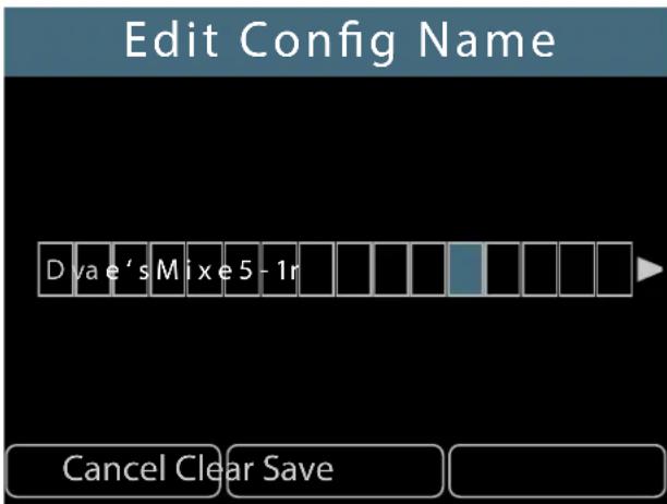
Configuration names can be up to 32 characters long.
To cancel and exit to the File Transfer menu without saving a configuration, press the CANCEL soft button.
File Name Rules
* Certain file name conventions must be observed in order to retain file compatibility with Mac and PC computers. The following files name types will not be allowed when saving an A640 configuration:
- Blank configuration names
- Configuration names that start with a period
- Configuration names that end with a period
- Configuration names that are exactly one of the following (case-insensitive) letter/number combinations: com1, com2, com3, com4, com5, com6, com7, com8, com9, lpt1, lpt2, lpt3, lpt4, lpt5, lpt6, lpt7, lpt8, lpt9, con, nul, prn, aux
An error message will be displayed if you attempt to save a configuration using one of the unsupported files names.
Disk Full Warning
When the USB storage device contains the maximum 32 configuration files (either A640 or A360 in any combination), an error message will be displayed if you attempt to save additional configuration files. Choose a different USB storage device or back up and then delete unwanted configurations files from the USB device using a Mac/PC computer.
ERROR: A maximum of 32 configurations are allowed.
Press any button to continue.
Each USB device can hold 32 configurations.
Updating Configurations
Once a configuration has been saved, you can update it if changes have been made to any of the settings. This overwrites and replaces the existing file on the USB storage device.
To update an existing configuration:
- Select the Save Configuration option by scrolling with either encoder knob.
- Press the encoder button to activate it.
- When the Save Configuration window opens, scroll to select the previously saved configuration to be updated from the list.
- Press the SAVE soft button on the A640 to start the process.
- Confirm the overwrite warning by pressing YES (or press the No soft button to exit the file saving process).
- An on-screen progress bar is displayed and a confirmation message follows once the update process is complete.
- Press any button to exit the Save function and return to the File Transfer menu.
Recall a Configuration
Any one of the 32 possible A640 configurations saved to a USB storage device may be recalled by using the Recall Configuration function.
As with the Save Configuration function, recalling a configuration from a USB device loads:
- Mixer Mode (Pro16, Default, or Custom)
- 16 mix presets
- Channel volume for each channel (including Favorite and Ambience channels)
- Pan for each channel
- Treble and Bass tone settings for each channel
• Effects (EFX) settings for each channel - Mutes
- Groups
- Master EQ settings
- Custom channel names
- Custom channel mappings
- Aux Mix settings
-
Ambience on/off
-
Intercom volume
• Intercom audio source Slot - LCD Backlight Level
- Mixer Name
• Dante channel names auto-sync on/off setting - Startup Help on/off at power up setting
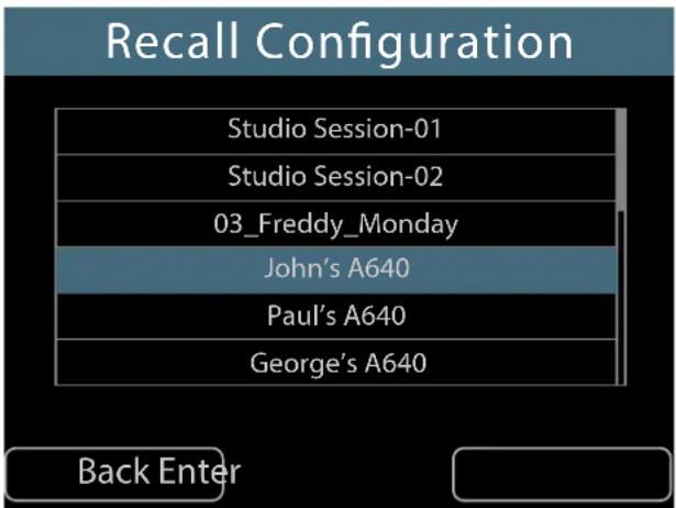
Scroll to select a configuration to recall.
To recall a saved A640 configuration:
- Select the Recall Configuration option by scrolling with either encoder knob.
- Press the encoder button to activate it.
- When the Recall Configuration window opens, scroll to select one of the saved configurations.
- Press the soft button below ENTER to start the loading process.
- An on-screen progress bar is displayed and a confirmation message follows once the recall process is complete.
- Press any button to exit the save routine and return to the File Transfer menu.
To cancel and return to the File Transfer menu without recalling a configuration, press the BACK button.
Import an A360 Configuration
The A640 Personal Mixer can import configurations created for the A360 Personal Mixer. A360 configurations save custom channel maps created with the A360 Channel Manager software plus mix presets 1-16 created on the A360 itself. A360 mix presets saved to its four Instant Mix recall locations A-D are ignored. Because the feature sets of the A360 and A640 are different, importing an A360 configuration will map the A360 settings to the A640 parameters as closely as possible. The Master EQ settings on the A640 are set to their defaults when importing an A360 configuration.
Imported A360 configurations will appear in the list of available configurations whenever the Recall
Configuration function is accessed. A360 configuration file names are formatted as (A360)config01 through (A360)config16.
An A640 configuration cannot be loaded into an A360 Personal Mixer.
To import an A360 Personal Mixer configuration:
- Select the Recall Configuration option by scrolling with either encoder knob.
- Press the encoder button to activate it.
- When the Recall Configuration window opens, scroll to select one of the saved configurations.
- Press the soft button below ENTER to start the loading process.
- An on-screen progress bar is displayed and a confirmation message follows once the recall is complete.
- Press any button to exit the save routine and return to the File Transfer menu.
Tip: The A640 data created by using the Save Configuration function can be backed up on a Mac/PC computer. Simply copy the entire Aviom folder and its contents from the USB storage device to the computer.
Do not alter the Aviom folder's file structure.
Mix presets created on the A360 Personal Mixer store information about the mixer mode (Pro16, Default, or Custom) that was used when the mix presets were created. Be sure to set the A640 to the same mode after importing an A360 configuration.
Information about the network's stereo links are also saved as part of a configuration. Attempting to recall a mix preset from an imported A360 configuration into a network with different stereo link settings causes a warning message to appear.
NOTE: Stereo links in this preset do not match the current network settings.
Press any button to continue.
Stereo links are a global network-wide property and must match to make the imported mix presets fully compatible.
Check for A640 Firmware Updates
An A640 Personal Mixer can be updated to install new features by installing new firmware. The Check for A640 Updates function in the File Transfer menu searches the USB storage device for compatible firmware update files and can install them if they are found.
Firmware Files
New firmware files for the A640 Personal Mixer have the file extension .upd and must be stored on the USB device in a specific location in order to be located by the Check For Updates function.
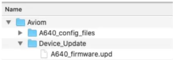
The Aviom folder structure on a USB device
When using a blank USB device for a firmware update for the first time, create the Aviom folder at the root level of the USB storage device. Create a second folder named Device_Update within the Aviom folder to hold the firmware update file(s). Note that A640 configurations are stored in a separate folder named A640_config_files which will be created automatically when a configuration is saved from the A640.
The Aviom folder's structure and its folder names must be set up exactly as shown and must be saved at the root level of the USB storage device. Any files stored outside of the Aviom folder structure are ignored by the A640.
Aviom firmware files for the A640 are built to match the specific circuit board hardware used during the manufacturing process. There may be multiple firmware files provided for a firmware release, appended with letters A, B, C, etc. (for example, A640_firmwareA.upd and A640_firmwareB.upd). Place all firmware files into the Device_Update folder. The A640 will load the appropriate firmware file that matches its circuit board hardware configuration automatically.
Firmware files can be copied to a computer for backup purposes. If you need to save different firmware versions in the same directory, rename the files to make each name unique (for example, A640_firmwareA-01.upd, A640_firmwareA-02.upd, etc.). Files names in the Device_Update folder must match the original formatting to be recognized By the A640.
Updating the A640 Firmware
The firmware update process resets the A640 and clears all user settings and preset data. It is a good idea to back up the current state of the A640 as a configuration as part of the update process to preserve your current mixes and user preferences. The firmware update process includes an opportunity to save all current settings.
Updating the A640 firmware disables all audio and mixing functions until the process is complete.
To update the A640 firmware:
- Select the Check for A640 Updates option from the File Transfer window by scrolling with either encoder knob.
- Press either encoder button to activate it.
- The A640 searches the USB storage device for a valid firmware file that is newer than what is currently installed.
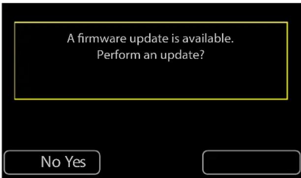
Choose Yes to continue the firmware update.
- If new firmware is found, choose YES to continue and install the update or choose No to exit without updating the A640's firmware.
- If you answer Yes to continue the firmware update process you are given the opportunity to save the current user settings and mix presets in the A640 as a configuration.
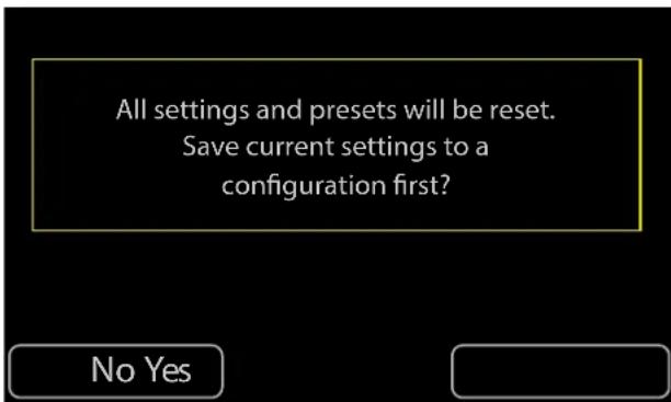
Choose Yes to save a configuration file.
- Click YES to continue the process of saving the A640 settings.
- The Save Configuration dialog opens.
- Press ENTER to name and save the current configuration.
- When the firmware update message reappears, press YES to continue the firmware update.
- Progress bars are displayed during the firmware update process; expect about five minutes for the firmware update to complete.
Do not remove the USB storage device while a firmware update is in progress.
Once the update is complete, the A640 Personal Mixer will restart and is ready to begin mixing. If you saved a configuration file as part of the update process, reload it by using the Recall Configuration function. See "Recall a Configuration" on page 55.
Edit Channel Names
The A640's mix channels support multiple forms of channel naming. Channels names can be edited manually from the Mixer Setup menu or they can be loaded from a Dante network that has a D800-Dante A-Net Distributor connected.
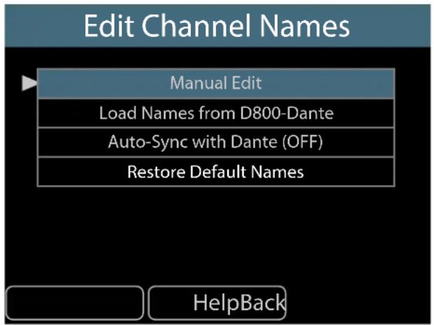
Each A640 mix channel name can be up to eight characters long.
Manual Edit
To create (or edit) names for each A640 mix channel manually:
- Select Edit Channel Names from the Mixer Setup menu.
- Scroll with the encoder to select the Manual Edit option.
- Press either encoder button to access the channel name list.
- The channel list will open and display the first six mixer channel names.
Edit Channel Names
| 1 | Kick |
| 2 | Snare |
| 3 | Cymbals |
| 4 | Piano |
| 5 | Bass |
| 6 | Vocal 1 |
Back
- Scroll to select a channel name to edit.
- Press either encoder button to begin editing its name.
Edit Channel 4 Name
ElecPno
Cancel Clear Save
- The text editing window opens.
- Turn the left encoder to scroll through the eight text cells.
- Turn the right encoder to select a letter, number, or special character from the list.
- To finalize the name, press the SAVE button.
To clear all characters from the current channel name, press the CLEAR button.
To exit the name editing fields without changing the current channel name, press the CANCEL button. At this point you may select a different channel name for editing or use the BACK button to return to the main Edit Channel Names window.
Channel Names Using Dante
The A640, when used with the D800-Dante A-Net Distributor (with Aviom v4.00 firmware or newer and Dante firmware 4.2.3.13 or newer), can load channel names from a D800-Dante that is part of a Dante network. Channel names can be loaded as a one-time command or they can be synced over the Dante network so that any changes made to the D800-Dante A-Net Distributor's channel names
from within the Dante Controller software (available from the Audinate website) can be instantly updated on the A640 Personal Mixer.
Loading Channel Names One Time from a D800-Dante
To load channel names for each A640 mix channel while connected to a D800-Dante A-Net Distributor:
- First, enter channel names for the D800-Dante in Dante Controller from its Device View.
- From the Edit Channel Names window on the A640, select Load Names from D800-Dante from the menu.
- When the confirmation message appears, select YES to load the channel names.
- Names are loaded from Dante into the A640's mixer channels.
- To cancel the process without loading names, press the No button to return to the Edit Channel Names window.
The I/II switch on the front panel of the D800-Dante must be in the II position to use this feature for each port where an A640 is connected.
Once names are loaded from Dante, press any channel button to exit the menu and begin mixing.
| Receive Channels | |||
| Channel | Signal | Connected to | Status |
| Drums L | 01@Mac-mini | ||
| Drums R | 02@Mac-mini | ||
| Cymbals | 03@Mac-mini | ||
| Bass | 04@Mac-mini | ||
| Gtr 1 | 05@Mac-mini | ||
| Gtr 2 | 06@Mac-mini | ||
| Kbd 1 | 07@Mac-mini | ||
| Kbd 2 | 08@Mac-mini | ||
| 09' | 09@Mac-mini | ||
| 10 | 10@Mac-mini | ||
| 11 | 11@Mac-mini | ||
| 12 | 12@Mac-mini | ||
Editing channel names in Device View for a D800-Dante as seen in the Dante Controller software
If you need to alter any of the channel names after loading them from the D800-Dante with the one-time command, use the Manual Edit option, described above. If you change the channel mapping after loading names from Dante using the one-time command the channel names will not update. Use the Load Names from D800-Dante again or set the A640 to load channel names in sync.
The D800-Dante's Disable switch found in the first set of DIP switches on the rear panel) must be in the down position (Dante enabled) to load channel names from a Dante network.
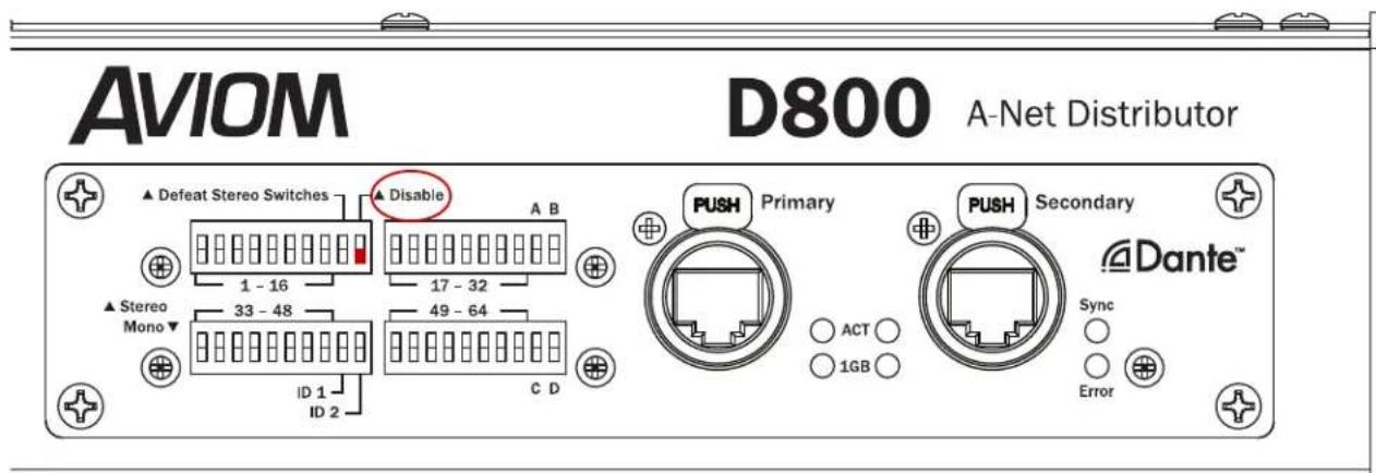
The Dante interface on a D800-Dante A-Net Distributor must be enabled to get channel names via Dante.
Loading Dante Channel Names In Sync
Channel names loaded into the A640 while in sync with a D800-Dante will update any time the D800-Dante's channel names are changed in the Dante Controller software. To sync and load channel names for each A640 mix channel while connected to a D800-Dante A-Net Distributor:
- First, enter channel names for the D800-Dante in Dante Controller from its Device View.
- From the Edit Channel Names window on the A640, select Auto-Sync with Dante from the menu.
- Select YES to load the channel names and activate sync via Dante.
- Names are loaded from the D800-Dante over the Dante network and will update as needed if any changes are made from within Dante Controller.
- To cancel the process without loading names, press the No button to return to the Edit Channel Names window.
Once channel names are loaded from Dante, press any channel button to exit the Edit Channel Names menu and begin mixing. If any changes to channel names are made in the D800-Dante's Device View in Dante Controller, the A640's channel names will update immediately.
When the Channel Mapping function is used to create a custom configuration for the A640, the A640's channel button names seen in the Channel Mapping editor will update whenever mapping assignment changes occur.
The I/II switch on the front panel of the D800-Dante must be in the II position to use this feature for each port where an A640 is connected.
When setting up an A640 Personal Mixer for use with a Dante network you can set the Auto-Sync with Dante option to ON without an actual connection to a Dante network. Once the A640 is connected to a D800-Dante A-Net Distributor that is part of a Dante network, the channel names will update.
Dante Channel Names and Stereo Links
Dante networking does not support stereo links. When stereo links are set up on the D800-Dante using its rear-panel DIP switches, the stereo link information is embedded in the Aviom A-Net data that each Personal Mixer receives. The channel names for stereo pairs will adopt the odd-numbered channel's text (as seen in Dante Controller) and display that on the A640 mix channels.
For example, if you name Dante channels 1 and 2 as "Drums-L" and "Drums-R" in Dante Controller, the A640 will display the channel name as "Drums-L" when channels 1-2 are stereo linked on the D800-Dante.
To reset all channel names and return them to their default settings use the Restore Default Names command.
• From the Edit Channel Names window, select Restore Default Names from the menu.
- Press either encoder to activate the function.
- Answer YES to reset the names or No to return to the Edit Channel Names window without changing the channel names.
When finished with changes in the Edit Channel Names window, press the MIXER SETUP button to return to the main Mixer Setup menu or press any mix channel button to begin mixing.
Channel Mapping
You can assign any of the 64 available A-Net network sources to the A640's mixer channel buttons (including the Favorite and Ambience channels) for use with the A640's Custom mode. User-created channel maps can be saved to a USB storage device as part of a configuration for backup or for loading into other A640 Personal Mixers.
To create a custom channel map:
- From the Mixer Setup menu, select the Channel Mapping option by scrolling with either encoder knob.
- Press the encoder button to activate it.
- A warning message is displayed (a reminder that custom channel mapping only works with Custom mode) if the A640 is currently set to Pro16 or Default modes.
- The channel list is displayed along with the current channel assignments.
- Scroll with the left encoder to select a mixer channel to edit.
- The selected channel's current network Slot assignment is highlighted in green.
| Channel Mapping | ||||
| Ch | Name | Stereo | Slot | Err |
| 1 | Drums | Yes | 1-2 | |
| 2 | Bass | No | 3 | |
| 3 | Gtr 1 | No | 7 | |
| 4 | Paul Voc | No | 16 | |
| 5 | John Voc | No | 9 | |
| 6 | Ac Gtr | No | 26 | |
- Turn the right encoder to scroll through a list of the currently available mono and stereo network Slots (all network Slots already in use will be skipped in the list).
- The edited channel's highlight changes to orange.
| Channel Mapping | ||||
| Ch | Name | Stereo | Slot | Err |
| 1 | Drums | Yes | 1-2 | |
| 2 | Bass | No | 3 | |
| 3 | Gtr 1 | No | 7 | |
| 4 | Paul Voc | No | 15 | |
| 5 | John Voc | No | 9 | |
| 6 | Ac Gtr | No | 26 | |
- Press the right encoder to confirm the change and assign the network Slot to that A640 channel button.
- Continue selecting and editing A640 channel assignments as needed.
- Press the BACK button to exit.
If a mistake is made while editing a channel, right-scroll until the channel assignment highlights in green; this is the original assignment.
If the Edit Channel Names function is set to sync with names coming from a D800-Dante on a Dante network, the Name field in the channel mapping editor will update when the encoder is pressed to confirm a new network Slot assignment.
Default Slot Assignments
The default network Slot assignments for the A640 channel buttons are shown below for both mono and stereo channels.
| Channel Button Mono Stereo | ||
| 1 1 1-2 | ||
| 2 3 3-4 | ||
| 3 5 5-6 | ||
| 4 7 7-8 | ||
| 5 9 9-110 | ||
| 6 11 11-12 | ||
| 7 13 13-14 | ||
| 8 15 15-16 | ||
| 9 17 17-18 | ||
| 10 19 19-20 | ||
| 11 21 21-22 | ||
| 12 23 23-24 | ||
| 13 25 25-26 | ||
| 14 27 27-28 | ||
| 15 29 29-30 | ||
| 16 31 31-32 | ||
| Favorite (F) 33 33-34 | ||
| Ambience (A) Mic Mic | ||
Mono vs. Stereo
In the channel mapping Slot list, available mono sources appear as single digits; network channels that are stereo linked appear as pairs (1-2, 17-18, 63-64, etc.). It is important to remember that stereo links are a global network setting controlled at the network's input source and are common to all Personal Mixers in the system. You cannot stereo link channels on the A640 itself.
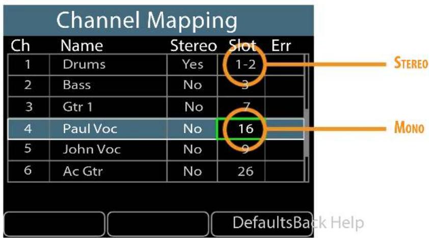
To return all channels to their default Slot assignments, press the DEFAULTS soft button and then choose YES to confirm and continue or No to cancel. The default Slot assignments will always reflect the network's current mono/stereo settings when using this command.
To use the new custom channel map, the A640's mode must be set to Custom.
Use the File Transfer function to save an A640 configuration to a USB storage device which will back up a custom channel map. It can also be used to copy a custom channel map from one A640 to another.
When you save a configuration that contains a custom channel map, it is important to remember that the mono/stereo status of each channel pair is dependent upon the global link settings that are currently in use. Loading a saved configuration into an A640 connected to an Aviom A-Net network with different stereo link settings may affect what you hear on each mixer channel.
Channel Mapping Errors
Any channel mapping errors are indicated with a red "!” in the Err column of the channel table. As an example, a channel mapping error could occur if a channel map has network Slot 1 assigned to A640 mixer button #1 and network Slot 2 assigned to A640 mixer button #2. If network Slots 1-2 are then stereo linked, that channel mapping will cause the Error warning to appear. Both channel buttons are not permitted to use the same 1-2 stereo channel pair simultaneously.
Mix presets and configurations cannot be saved until the channel mapping error is corrected.
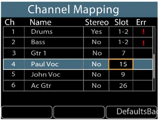
Adding a stereo link creates a channel conflict
ck Help
In systems using the Intercom feature, the Intercom's Broadcast Slot should not be assigned to an A640 mix channel button in a Custom Mode channel map. The channel list will indicate the current Broadcast Slot in red text; no monitor mix audio will be heard on the Broadcast Slot.
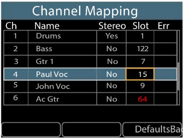
Assigning the Broadcast Slot (64) to a mix channel button will cause that channel to have no audio output.
ck Help
Disable an A640 Mix Channel Button
It is possible to disable an A640 mix channel button by setting it to have no network Slot assignment. To do this:
- Follow the previous steps to begin editing a channel map.
- Select the A640 mix channel to be disabled.
- Scroll the Slot assignment list to the left using the right encoder until the double dash “--” character appears.
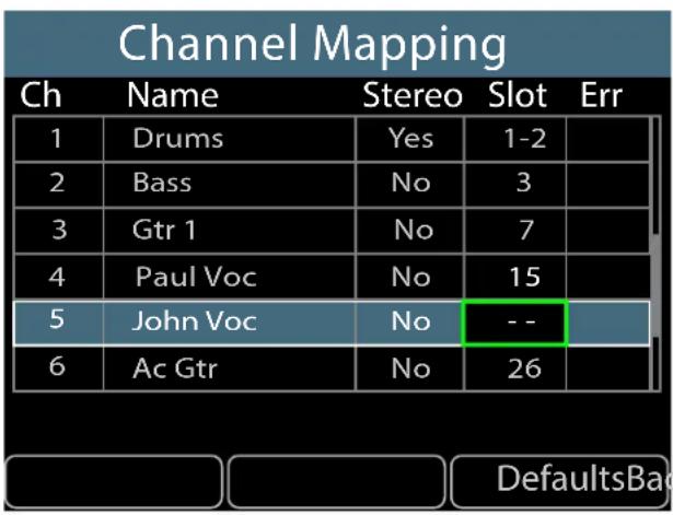
- Press the right encoder button to complete the assignment.
- Press the BACK soft button to exit.
The channel's-Volume, Pan, Treble, Bass, and EFX settings are reset whenever a channel is disabled.
Any mix channels set to have no network Slot assignment cannot be selected or edited while mixing on the A640 in Custom mode. An error message will be displayed whenever an unassigned mix channel button is selected on the A640. The channel button's green LED will also flash as a reminder.
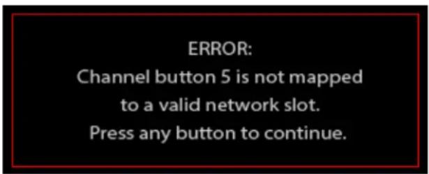
Channel Map settings are saved and recalled as part of a configuration. See "Save a Configuration" on page 52.
Aux Mix Setup
The A640 has a dedicated mono XLR Aux Mix output with its own volume control that can be used to send a separate line-level mono mix to a wireless transmitter, bass shaker such as Aviom's BOOM-1, recording device, etc. The Aux Mix can be set to output the same audio channels as the main stereo mix (automatically converted to mono) or it can use a custom user-defined set of channels.
The Aux Mix always uses the same individual channel volume, and Treble/Bass tone settings as set in the main stereo mix. The Master EQ settings are the same in the main and aux mixes.
Panning is ignored in the Aux Mix. The effects (EFX) levels are also ignored.
Select Aux Mix Setup from the Mixer Setup window and press either encoder button to access the Aux Mix settings.
Aux Mix Audio Source
Two options are available for selecting the audio that is output from the Aux Mix jack on the rear of the A640—the mono version of the main stereo mix or a custom subset of those channels selected by the user.
To choose the source for the Aux Mix output from the Aux Mix Setup options:
- Select the Audio Source option by scrolling with either encoder knob.
- Press either encoder button to activate it.
- The audio source options are displayed.
- Scroll to choose Main (Mono) Mix or Aux Mix.
- Press the encoder button to activate your choice.
To exit without making a change, press the BACK button.
Aux Mix Channel Settings
When Aux Mix is selected as the audio source for the Aux Mix output, you can choose to activate any combination of A640 mixer channels to be assigned to the XLR Aux Mix output.
The Ambience Mic channel is available to be used as a component of the Aux Mix. This can be especially useful in Custom mode where the Ambience Channel can be assigned to any available network Slot.
Intercom audio is not available as a source to be included in the Aux Mix.
In Pro16 and Default modes, mix channels 1-16 are available. The Favorite channel is a copy of an
existing mix channel and will not appear as a separate entry in the channel list when creating a custom Aux Mix.
When using Custom mode, the Favorite channel is replaced with a fully-assignable channel #17 which will be available for inclusion in the Aux Mix.
To create a custom set of channels for the Aux Mix output:
- Select the Aux Mix option as the source (see the steps above).
- From the Aux Mix Setup menu choose Aux Mix Channel Settings.
- Press either encoder button to activate it.
- A list of all available mix channels is displayed
- Scroll with either encoder to select a channel
- Press either encoder to activate a channel and make it part of the Aux Mix
- The text in the on-screen table is set to On in green for each active channel.
- Repeat the process for any other channels you want to add to the custom Aux Mix.
- Press BACK to exit when done assigning channels to the Aux Mix.
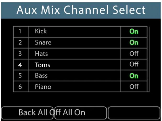
Any combination of channels may be sent to the Aux Mix
When using stereo channels in Pro16 mode, note that each side of the stereo signal may be added to or removed from the Aux Mix individually. For example, if channels 1 and 2 are stereo linked, you can decide to include channel 1 but not channel 2 in the Aux Mix output.
Two handy utility functions are also available while editing. Press the ALL OFF soft button to set all mix channels to Off, removing them from the Aux Mix. Press the ALL ON soft button to add all channels to the Aux Mix.
Press the BACK soft button to return to the Aux Mix Setup menu when done editing.
Muting a channel in the main stereo mix also mutes the channel in the Aux Mix.
The Aux Mix settings are saved and recalled as part of a configuration.
Intercom
The Intercom feature on the A640 allows you to transmit audio from one user's mixer (such as a musical director) to all other A640 users. It simplifies the process of communicating with a group of performers wearing headphones or in-ear monitors. Use it for rehearsal, song count-offs, performance cues, musical instructions, etc.
The Intercom feature requires the use of a D800 or D800-Dante A-Net Distributor (with Aviom firmware version 4.00 or newer installed).
Using the Intercom feature along with a D800 requires that the I/II switches on the D800's front panel be set to the "II" position for bi-directional communication.

D800 I/II switches must be set to the "II" position.
There are settings that are specific to each A640 user who will make use of the Intercom as well as network-wide settings that affect all users.
Intercom Audio Source
The transmit audio source for the Intercom feature can use either the A640's internal mic or one of the A-Net network Slots to which an external microphone has been connected. When the Intercom is engaged, this is the source that the speaker will be using to transmit audio over the network to other performers listening on their A640 Personal Mixers.
To choose the Intercom's audio transmit source:
- Choose Intercom in the Mixer Setup menu; press the encoder button to open the options.
- Select the Audio Source option by pressing either encoder button.
- Scroll to select Internal Mic or any one of the 64 network Slots (a warning message will be displayed if you select a Slot that is already in use for monitor mixing).
• To prevent an A640 from broadcasting over the Intercom, choose Listen Only. - Press either encoder button to confirm the selection.
- The display returns to the main Intercom window and the selected source is shown within the Audio Source text.
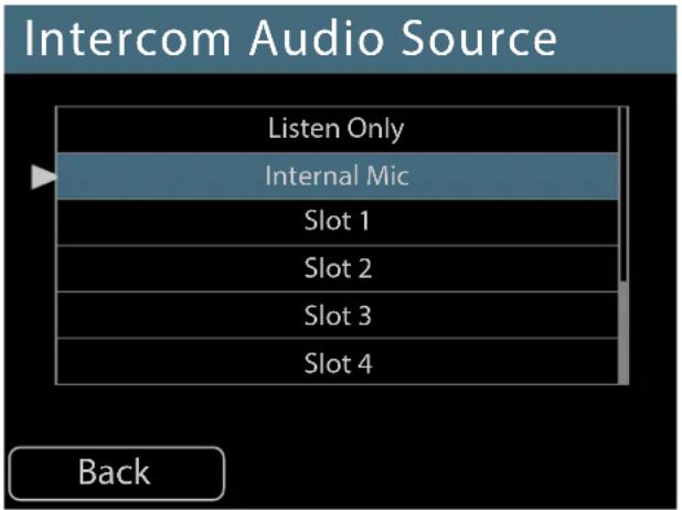
Selecting a transmit source for the Intercom
The network's current Broadcast Slot will be shown in red text in the Intercom Audio Source list. The Broadcast Slot cannot be assigned as an audio source for the Intercom.
The Intercom transmit source can be set independently for each A640 Personal Mixer in the system. The current setting for the Intercom Audio Source is displayed whenever you hold down the INTERCOM button.
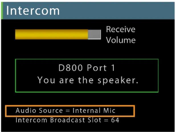
The current Audio Source setting is displayed whenever the Intercom button is held. If no source is selected, the source reads Disabled, Listen Only.
Intercom Broadcast Slot
The A-Net network always uses one of its 64 available network Slots as the global Intercom communication channel to send intercom audio to all A640s connected to the D800. Choosing a
Broadcast Slot from the A640 sends a command to the D800 A-Net Distributor which then broadcasts this information throughout the network to all connected A640 Personal Mixers. When the INTERCOM is engaged on an A640, all A640 Personal Mixers will hear intercom audio from that user via the selected Broadcast Slot.
The Broadcast Slot can be set to off (None) or to any one of the 64 network Slots.
The A640 must be connected to a D800 or D800-Dante A-Net Distributor to access the Intercom Broadcast Slot settings.
To set the global Intercom Broadcast Slot source from the Intercom window:
- Scroll to select the Broadcast Slot option in the Intercom settings.
- Press either encoder button to open the channel list.
- Scroll with the encoders to select None or any one of the 64 network Slots.
- Press either encoder button to confirm the selection.
- The display returns to the main Intercom window and the selected Broadcast Slot source is shown within the Broadcast Slot text.
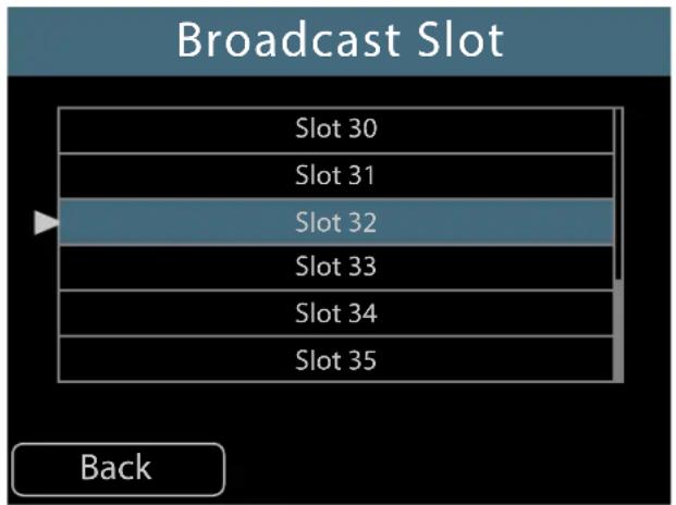
Selecting Slot 32 as the Intercom Broadcast Slot for all A640 users
When choosing None as the Broadcast Slot option, Intercom communication is disabled and none of the A640 Personal Mixers will be allowed to broadcast Intercom audio to the other A640 users in the network.
Choosing a network Slot to be used for the Intercom broadcast function disables all standard audio traffic for that Slot (or stereo pair if a stereo link is set).
Always be sure to choose a Broadcast Slot that will not interfere with audio sources already being used for monitor mixing.
Only one A640 Personal Mixer needs to set the global Broadcast Slot. The selected Slot number assignment is stored in the D800/D800-Dante and the Broadcast Slot information is shared by all A640 Personal Mixers until such time that it is changed. All A640 users will see the current Broadcast Slot number in the A640 display when their INTERCOM button is held down.
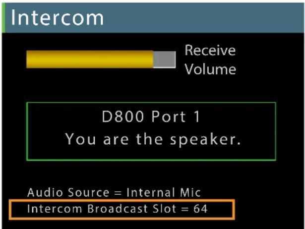
The global Broadcast Slot has been set to Slot 64.
Mixer Mode
The A640 Personal Mixer can operate in one of three modes —Pro16, Default, or Custom. Each mode affects how the A640 uses the A-Net network's incoming multi-channel digital audio data. All A-Net network channels (also referred to as network Slots) are always present in the A-Net data stream and are available to all Personal Mixers in the system. The three mixer modes simply tell each A640 Personal Mixer how to use them and map them onto the A640's mix channel buttons.
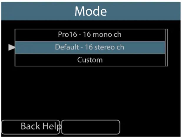
The currently selected mode is shown in the Mode field when you open the Mode options from the Mixer Setup menu. If it is not already selected, scroll to the Mode option. Press either encoder button to access the Mixer Mode settings.
To change the A640's current operating mode, scroll with either knob to select the desired option. Press the encoder to activate it. All mix settings will be cleared. Answer Yes to continue or No to return to the Mode settings options. Pressing the encoder activates the selected mode and exits to the main Mixer Setup menu.
Changing the A640's operating mode will clear the current mix settings (Volume, Pan, Bass, Treble, and EFX) for all channels as well as the current Master EQ settings.
Legacy Devices
When the A640 is connected to a legacy device or system that outputs the original 16-channel Pro16 version of A-Net, you cannot access Default or Custom modes. Using the Default and Custom modes requires that the A640 is connected to a system that is using the Pro16e (64-channel) version of A-Net.
Legacy devices include:
• AN-16/i Input Module (version 1)
• AN-16/i-M Mic Input Module
• Y1 A-Net card for Yamaha devices
• A-Net console cards manufactured by Aviom partners
• A-16D and A-16D Pro A-Net Distributors
• A-16II Personal Mixer
If the system includes a mix of Pro16 and Pro16e devices, the higher channel count Pro16e version of A-Net is used. Examples include:
• AN-16/i Input Module (version 1) connected to a D400 or D800 A-Net Distributor
- Y1 A-Net card connected to a D400 or D800 A-Net Distributor
• AN-16/i v.2 Input Module connected to an A-16D or A-16D Pro A-Net Distributor
Getting Help
Press the HELP button while the Mode options are displayed to open an overview of the three available modes.
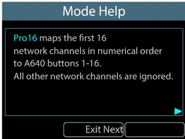
Move through the Help screens with the Next button; a Back button will appear as needed when multiple Help windows are available. Close the Help window and return to the main Mode settings by pressing the Exit button.
The Mode Help screens are not available when connected to a legacy Pro16 A-Net device.
Pro16 Mode - 16 mono channels
When the A640 is in Pro16 mode, the first 16 incoming network Slots are assigned in sequential order to the 16 mix channel buttons. This mode is ideal for systems that use a single 16-channel analog input module or digital console card.
Each A640 mixer channel button (shown in blue in the graphic below) can host one mono audio source. All other network channels (Slots) from 17-64 are ignored (shown in gray in the table below).
| Incoming A-Net Network Slots | |||||||||||||||
| 4950 | 5152539 | 4555657 | 585960 | 61626364 | |||||||||||
| 3334 | 3536373 | 3839404 | 424344 | 45464748 | |||||||||||
| 1718 | 1920212 | 2232425 | 262728 | 29303132 | |||||||||||
| 1234 | 5678910 | 111213 | 141516 | ||||||||||||
| ↓ | ↓ | ↓ | ↓ | ↓ | ↓ | ↓ | ↓ | ↓ | ↓ | ↓ | ↓ | ↓ | ↓ | CopyMic | ↓ |
| 123 | 4567 | 8910 | 1112 | 1314 | 1516 | FA | |||||||||
| A640 Personal Mixer Channel Buttons | |||||||||||||||
Mapping incoming A-Net network channels to the A640 mixer buttons in Pro16 mode.
(Note: F is the Favorite channel; A is the Ambience Mic channel.)
Any one of the standard mixer channel buttons may be assigned to the A640's Favorite channel button, allowing easy access to a frequently-used channel. Hold the FAVORITE button and press a mixer channel button to assign it. The Favorite channel's assignment is saved as part of a configuration. The Ambience channel always uses the A640's built-in mic in Pro16 mode.
The maximum number of audio sources you can hear in Pro16 mode is 16 (plus the internal mic and Intercom audio).
Default Mode - 16 stereo channels
Default mode sets the 16 mix channel buttons on the A640 to stereo. Incoming network channels are assigned as stereo pairs in sequential order. Network Slots 1-2 are assigned to mixer button #1, Slots 3-4 are assigned to button #2 and so on, up to button #16 which gets network Slots 31-32. Incoming A-Net network Slots 33-64 are ignored (shown in gray in the table below).
| Incoming A-Net Network Slots | ||||||||||||||||
| 33-343 | 5-3637 | 3839-40 | 41-4243 | 4445-46 | 647-484 | 9-5051 | 5253-54 | 55-5657 | 5859-60 | 61-6163 | 64 | |||||
| 1-23 | 45-67-89 | 10 | 11-1213 | 1415-16 | 17-1819 | 2021-2 | 223-242 | 25-2627 | 2829-30 | 31-32 | ||||||
| ↓ | ↓ | ↓ | ↓ | ↓ | ↓ | ↓ | ↓ | ↓ | ↓ | ↓ | ↓ | ↓ | ↓ | ↓ | CopyMic | ↓ |
| 123 | 4567 | 8910 | 1112 | 1314 | 1516 | FA | ||||||||||
| A640 Personal Mixer Channel Buttons | ||||||||||||||||
Mapping incoming A-Net network channels to the A640 mixer buttons in Default mode.
(Note: F is the Favorite channel; A is the Ambient Mic channel.)
As with Pro16 mode, any one of the standard mixer channel buttons may be assigned to the A640's Favorite channel button, allowing easy access to a frequently-used channel. Hold the FAVORITE button and press a mixer channel button to assign it.
Mono vs. Stereo Channels
It is important to understand that the A-Net network controls which incoming channels are mono or stereo, not the A640 Personal Mixer. A stereo link is a global setting available to all Personal Mixers in an Aviom personal mixing system.
Stereo Links are set up by moving the Stereo Link switches on an analog input device such as an AN-16/i to the right.
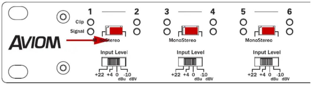
Stereo Links on the AN-16/i Input Module
For a digital console card, such as Aviom's Y1 card for Yamaha MY devices, a set of eight DIP switches is used. Console cards built by Aviom partners using Aviom's A-Net technology also provide stereo link capabilities.
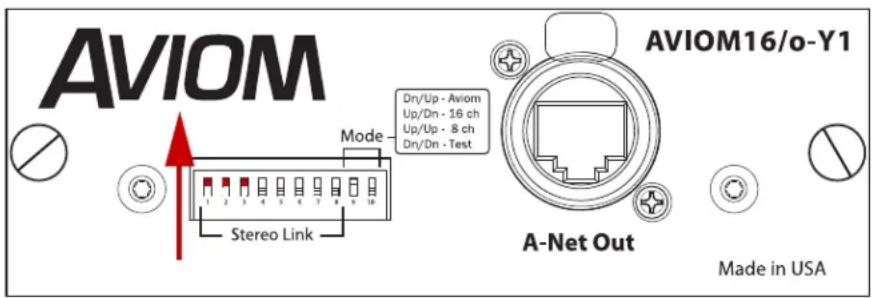
Stereo Links on the Y1 Yamaha console card
For a system based on a Dante network, the stereo links are set up at the Dante A-Net Distributor using DIP switches. Stereo Links activated on a Dante A-Net Distributor are made available to all Personal Mixers connected to its A-Net Out ports.
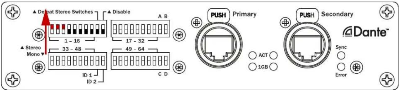
DIP switches set Stereo Links on the D800-Dante A-Net Distributor
When the global stereo link for any network channel pair is off, the A640 mixer channel is mono. Default mode uses the left channel of the pair (the odd number) as the mono source, and ignores the right side audio (the even number).
For example, when the stereo link for channel pair 1-2 is set to off (mono), A640 mixer button #1 will receive network channel 1 and will ignore network channel 2. The Pan indicator (in Channel View) shows one Pan position marker. Any audio assigned to channel 2 is not heard.
The following graphic shows the differences between a mono and stereo channel, as seen in Channel View.
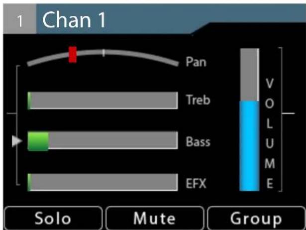
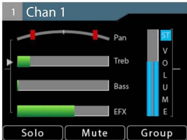
A mono channel (left) has a single Pan indicator and a mono volume level indicator. A stereo channel (right) has two Pan indicators, a dual level bar, and a Stereo ST con.
If a stereo link is set on (stereo) for network channel pair 1-2, two network digital audio signals are assigned to the first mixer channel button on the A640 in Default mode. The Pan indicator (in Channel View) shows two stereo position markers. Stereo channels have dual volume bars and a stereo indicator [ST] next to the volume bars.
If each A640 mixer channel button is assigned a stereo source, you can hear a maximum of 32 channels (16 stereo pairs) in Default mode.
The Ambience mic channel always uses the built-in mic in Default mode.
Favorite Button
As with Pro16 mode, any one of the standard mix channel buttons may be assigned to the A640's Favorite channel for easy access. Hold the FAVORITE button and press any mixer channel button to assign it. The display will show a confirmation message when the Favorite channel assignment is changed. The Favorite button always follows the mono/stereo setting of the channel assigned to it. The Favorite channel's assignment is saved as part of a mix preset and a configuration.
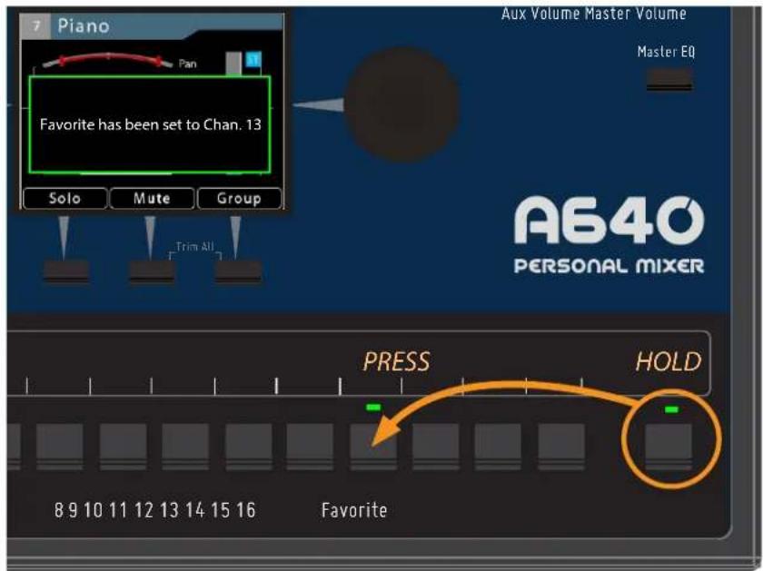
Any mix channel may be assigned as the Favorite.
Custom Mode
The A640's Custom mode allows any of the (up to 64) incoming A-Net network Slots to be assigned to any A640 mixer channel button. This feature allows each performer in an ensemble to get a set of channels for their monitor mix that best suits their needs. The rules for stereo and mono channels still apply—all stereo links are controlled globally at the network's input source.
Custom mode also allows the Favorite channel and the Ambience mic channel to be used for network audio, increasing the total number of available mono/stereo mix sources for a monitor mix from 16 to 18.
If each A640 mixer channel button is assigned a stereo source, you can hear a maximum of 36 channels (18 stereo pairs) in Custom mode.
Input List
To simplify system setup, create an input list. Print out the channel worksheet and note each source channel's network input slot, mono/stereo status, and its name making it easier to create and manage Custom mode configurations for multiple performers.
| Network Channels(Slots) Input Stereo Source | |||
| 1-16 | 1 | Kick | |
| 2 | Snare | ||
| 3 | √ | Cym & Toms L | |
| 4 | Cym & Toms R | ||
| 5 | Bass | ||
| 6 | Paul Vocal | ||
| 7 | √ | Piano L | |
| 8 | Piano R | ||
| 9 | John Vocal | ||
| 10 | George Vocal | ||
| 11 | E Gtr | L | ||
| 12 | E Gtr | R | ||
| 13 | Ac Gtr | ||
| 14 | E Gtr 2 | ||
| 15 | √ | Organ Top | |
| 16 | Organ Bottom |
The first 16 channels of an input list
A blank, full-size version of the input list appears at the end of this document. The input list is also available on the Aviom website (www.Aviom.com).
Clear Current Mix
The A640 Personal Mixer offers a simple shortcut function to quickly reset the current mix to its default settings—Clear Current Mix. The function clears the currently active mix but does not affect any mixes saved as presets in the A640. It also has no affect on any mix presets saved as part of a configuration on a USB storage device.
Using this command:
- Sets all mix channel volumes to zero.
- Centers the Pan for mono channels.
- Sets the Pan to fully Left/Right for stereo channels.
- Sets the Treble and Bass tone controls to minimum for all channels.
- Sets the Effects (EFX) amount to minimum for all channels.
- Clears all channel mutes.
- Sets the Ambience Mic to off.
- Sets the Ambience Mic channel volume to zero.
- Sets the Intercom receive volume to zero.
- Turns off the Intercom.
- Resets the Master EQ Treble, Bass, and Enhance to their defaults.
- Resets the Aux Mix to its default, the Main Mix and sets any individual channels On/Off settings to 'Off.'
To clear and reset the currently active mix:
• From the main Mixer Setup window, scroll to choose Clear Current Mix.
- Press the encoder button to activate the function.
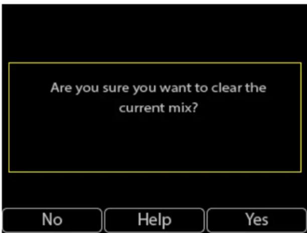
- A warning message appears in the window.
• To clear the mix press the Yes button.
To exit without clearing the current mix, press the No button to return to the main Mixer Setup menu.
Edit Mixer Name
Each A640 Personal Mixer in a system can be given a unique 12-character name. The mixer name will be displayed on the Master EQ screen, in the About This Mixer window, and to other A640 users when using the Intercom feature. Use the Edit Mixer Name function to define a name for each A640.
- From the main Mixer Setup window, scroll to choose Edit Mixer Name.
- Press either encoder button to begin editing the text.
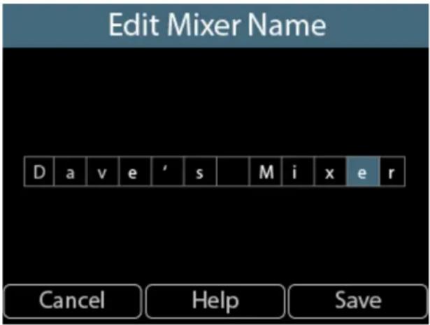
• The editing window opens.
- Scroll through the twelve text cells with the left encoder.
- Turn the right encoder to select a letter, number, or special character from the list.
- To finalize the name and exit, press the SAVE button.
To exit the name editing fields without changing the current mixer name, press the CANCEL button to return to the main Mixer Setup menu.
The mixer name is saved as part of a configuration when using the Save Configuration function.
LCD Backlight Level
The LCD on the A640 Personal Mixer can be set to one of 12 available brightness levels to allow it to adapt to any performance situation.
To change the display's brightness:
• From the main Mixer Setup window, scroll to choose LCD Backlight Level.
- Press either encoder button.
- With the LCD Backlight Level window open, turn either encoder to scroll through the 12 brightness levels.
- To exit press the BACK button to return to the main Mixer Setup menu or press any mixer interface button to exit directly to mixing.
The LCD's brightness level is remembered across power cycles and is saved as part of a configuration.
Help
The Startup Help gives a brief overview of the main features and functions of the A640 Personal Mixer. Designed for new users, the A640 will start up with its Help pages displayed each time the A640 Personal Mixer is power cycled.
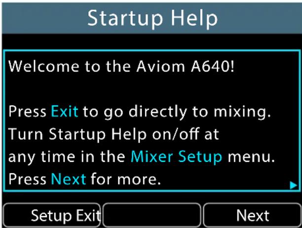
Once you are comfortable with the A640 user interface you can turn off the Startup Help.
To turn off Startup Help when the A640 is powered on:
- With the Startup Help displayed on the A640, press the SETUP button.
- The Mixer Setup menu's Help Option page opens.
- Select Startup Help Enabled.
- Press either encoder button.
- The Startup Help will toggle ON/OFF with each press of the encoder button.
- To exit press the BACK button to return to the main Mixer Setup menu or press any mixer interface button to exit directly to mixing.
To turn Startup Help on/off from the Mixer Setup menu:
- From the main Mixer Setup window, scroll to choose the Help option.
- Press either encoder button.
- In the Help options, select Startup Help Enabled.
- Press either encoder button.
- The Startup Help will toggle ON/OFF with each press of the encoder button.
- To exit press the BACK button to return to the main Mixer Setup menu or press any mixer interface button to exit directly to mixing.
To jump directly to the Help pages:
• In the Help Options, select Open Startup Help.
- Press either encoder button.
• The Startup Help pages open.
- Press Next to continue reading.
- Navigate the Help pages with the BACK and NEXT buttons, or press EXIT to start mixing.
The Startup Help on/off state is remembered across power cycles.
Restore Defaults
To reset the A640 Personal Mixer to the factory default settings, use the Restore Defaults function.
To reset an A640:
- Choose Restore Defaults from the Mixer Setup menu.
- Press either encoder button.
- At the warning message prompt choose Yes to continue or No to cancel.
• After choosing Yes, the default settings are restored. - Press any button on the A640 to begin mixing again.
Using the Restore Defaults function resets the following:
- Mode: Pro16
- Channel selected: 1
- Last used preset: 1
• Master Treble: centered - Master Bass: centered
- Master Enhance: 0
- Favorite channel: 1
-
Channel settings:
Volume: 0
□ Mute: Off
☐ Pan: centered for mono channels, fully spread for stereo channels
□ Treble: 0
□ Bass: 0
□ EFX: 0 -
Ambience: Off
- Ambience On Volume: 0
- Group settings: no groups
• Intercom Source: Listen Only
• Aux Out: Main (Mono) Mix
• Aux Mix channels: all Off
• Intercom Volume: 0
• Dante Label Auto-sync: Off
• Channel Names: Chan 1, Chan 2, etc. - Mixer Name: A640
- Startup Help screen: Enabled
- Last view screen: Channel View
• LCD Backlight Level: Maximum - All presets are overwritten with default data
- Channel Mapping: identical to Default Mode, plus channel 17 is mapped to Slots 33&34
About This Mixer
To check the current firmware version of an A640 Personal Mixer:
- From the main Mixer Setup window, scroll to choose About This Mixer.
- Press either encoder button.
- The A640's Mixer Name and firmware info is displayed.
- To exit, press any interface button to return to the main Mixer Setup menu or press any mixer interface button to exit directly to mixing.
Information about the system's A-Net Distributor is also provided:
• D400 and legacy A-16D Pro models are shown generically as Aviom A-Net Distributor.
- D800 and D800-Dante A-Net Distributors updated to v4.00 firmware or above will include the version number of the Aviom firmware that is currently installed.
- D800 and D800-Dante A-Net Distributors with non-updated firmware are shown as Aviom A-Net Distributor.
- If a legacy Pro16 A-Net input device is connected via a legacy A-Net Distributor such as the A-16D Pro, an Aviom Legacy Device will be reported.
Personal Mixing System Setup
This section explains how the A640 Personal Mixer integrates with other Pro16 and/or Pro16e A-Net devices (sold by Aviom or third-party partners) to create a personal mixing system. See the detailed User Guides that came with the Aviom products mentioned in this section for complete information about their use, features, and setup.
The Pro16 version of the Aviom A-Net protocol supports 16 total input sources while the enhanced Pro16e version of the protocol supports up to 64 input sources. The Pro16e version of A-Net is always output by the AN-16/i v.2, and the D400, D400-Dante, D800, and D800-Dante A-Net Distributors.
Adding the A640 to a 16-Channel System
The A640 Personal Mixer can be added to existing 16-channel personal mixing systems that use the A360 Personal Mixer, A320 Personal Mixer, and/or A-16II Personal Mixer. These systems use the same basic layout. One input device with sixteen input sources (an analog AN-16/i Input Module or a digital console card) is used to generate a Pro16 A-Net digital signal which is connected to the Personal Mixers by using an A-Net Distributor such as the D400, D800, or A-16D Pro for parallel connections and power over A-Net.
An A-Net Distributor simplifies the setup or expansion of an existing personal mixing system with A640 Personal Mixers. Using one or more A-Net Distributors allows any number of A640 Personal Mixers to be integrated into a personal mixing system along with A360, A320, and A-16II Personal Mixers. The A640 Personal Mixer is powered over the Cat-5 cable when connected to an A-Net Distributor.
The A640 should be set to Pro16 mode when it is used in a Pro16 personal mixing system with only 16 input channels. This maps each of the 16 incoming sources to the A640's channel buttons in numerical order. See "Mixer Mode" on page 77 for more information about the A640's mode settings.
The following diagram shows a typical 16-channel system with one A-Net Distributor and multiple Personal Mixers connected.
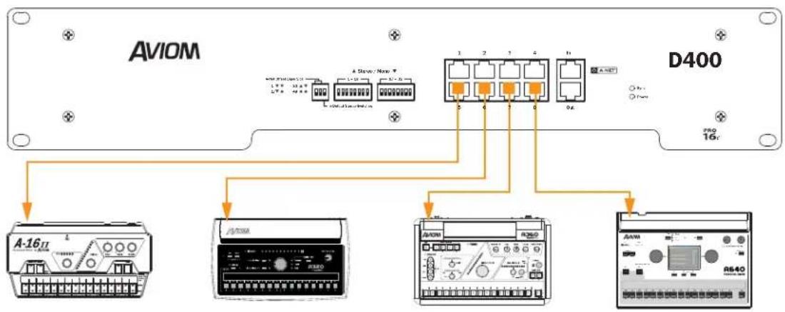
flowchart
graph TD
    A["AVIOM"] --> B["A-16II"]
    A --> C["A-200"]
    A --> D["A-250"]
    A --> E["A-640"]
    B --> F["1 2 3 4 5 6"]
    C --> G["1 2 3 4 5 6"]
    D --> H["1 2 3 4 5 6"]
    E --> I["1 2 3 4 5 6"]
    F --> J["D400"]
    G --> J
    H --> J
    I --> J
    style A fill:#f9f,stroke:#333
    style J fill:#ccf,stroke:#333
A D400 A-Net Distributor with A-16II, A320, A360, and A640 Personal Mixers connected
Expanded Systems
There is no limit to the number of Personal Mixers that can be used in an Aviom personal mixing system. Using two or more A-Net Distributors allows any number of A640 Personal Mixers to be integrated into a system along with A360, A320, and/or A-16ll Personal Mixers.
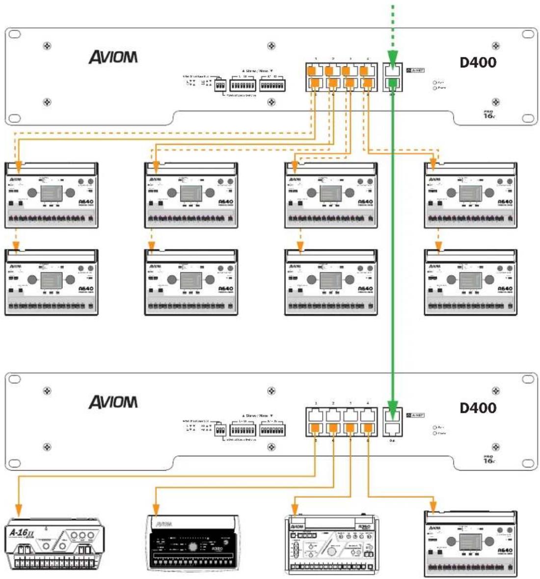
flowchart
graph TD
    subgraph AVIOM
        A["AVIOM R640"] --> B["AVIOM"]
        C["AVIOM"] --> D["AVIOM"]
        E["AVIOM"] --> F["AVIOM"]
        G["AVIOM"] --> H["AVIOM"]
    end

    subgraph D400
        I["D400"] --> J["AVIOM"]
        K["D400"] --> L["AVIOM"]
        M["D400"] --> N["AVIOM"]
    end

    A --> O["A-16"]
    C --> P["A-16"]
    E --> Q["A-16"]
    G --> R["A-16"]
    I --> S["A-16"]
    K --> T["A-16"]
    M --> U["A-16"]
    N --> V["A-16"]
    O --> W["A-16"]
    P --> X["A-16"]
    Q --> Y["A-16"]
    R --> Z["A-16"]
    S --> AA["A-16"]
    T --> AB["A-16"]
    U --> AC["A-16"]
    V --> AD["A-16"]
    W --> AE["A-16"]
    X --> AF["A-16"]
    Y --> AG["A-16"]
    Z --> AH["A-16"]
    AA --> AI["A-16"]
    AB --> AJ["A-16"]
    AC --> AK["A-16"]
    AD --> AL["A-16"]
    AE --> AM["A-16"]
    AF --> AN["A-16"]
    AG --> AO["A-16"]
    AH --> AP["A-16"]
    AI --> AQ["A-16"]
    AJ --> AR["A-16"]
    AK --> AS["A-16"]
    AL --> AT["A-16"]
    AM --> AU["A-16"]
    AN --> AV["A-16"]
    AO --> AW["A-16"]
    AP --> AX["A-16"]
    AQ --> AY["A-16"]
    AR --> AZ["A-16"]
    AS --> BA["A-16"]
    AT --> BB["A-16"]
    AU --> BC["A-16"]
    AV --> BD["A-16"]
    AW --> BE["A-16"]
    AX --> BF["A-16"]
    AY --> BG["A-16"]
    AZ --> BH["A-16"]
Multiple A-Net Distributors allow more than eight Personal Mixers to be connected simultaneously. Here, the system has been expanded to accommodate 12 performers and multiple types of Personal Mixers.
Any compatible A-Net Distributor—including the D800, D800-Dante, D400, D400-Dante or A-16D Pro—may be substituted for the A-Net Distributors shown in the example.
Daisy chaining an A640
One A640 Personal Mixer may be added to a daisy chained personal mixing system, but only at the end of the daisy chain—the A640 has only an A-Net In port and must be the last device in a daisy chain. Adding more than one A640 Personal Mixer to such a system requires the addition of an A-Net Distributor.
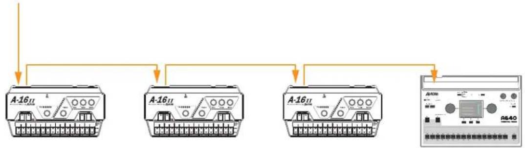
flowchart
graph TD
    A["A-16II"] --> B["信号输入"]
    C["A-16II"] --> D["信号输入"]
    E["A-16II"] --> F["信号输入"]
    G["A-16II"] --> H["信号输入"]
    I["A-16II"] --> J["信号输出"]
    style A fill:#f9f,stroke:#333
    style C fill:#f9f,stroke:#333
    style E fill:#f9f,stroke:#333
    style G fill:#ccf,stroke:#333
    style I fill:#ccf,stroke:#333
The A640 must be the last device in a daisy chain.
If an A640 Personal Mixer is connected in a daisy chain, an external DC power supply such as the PS-120 (or international version PS-240) Power Supply is required.
Pro16e Personal Mixing Systems
The A640 Personal Mixer can make use of the enhanced version of Aviom's A-Net protocol, called Pro16e, which allows up to 64 audio Slots to be included in the pool of network input sources by using up to four analog input devices, multiple digital console cards from the same clock domain, or a Dante network.
Each A640 in a personal mixing system may be programmed to use any combination of these network Slots. The A640 uses its Custom mode to access channel mappings other than the Pro16 or Default channel layouts. See page 49 for information about the Channel Mapping feature.
Analog Inputs
When using multiple analog input devices for input sources for a personal mixing system, each device provides one 16-channel bank of Slots to the network (1-16, 17-32, 33-48, and 49-64). The Slot Range switches on the rear panel of the AN-16/i v.2 control the bank assignment. Up to four analog input devices may be used to create a pool of 64 input sources. The physical location of the device within the daisy chain does not matter as long as the Slot Range switch settings are correct.
Slot Range Setup
Each analog input module is daisy chained, connecting a Cat-5 cable from its A-Net Out port to the A-Net In of the next input device in the chain.
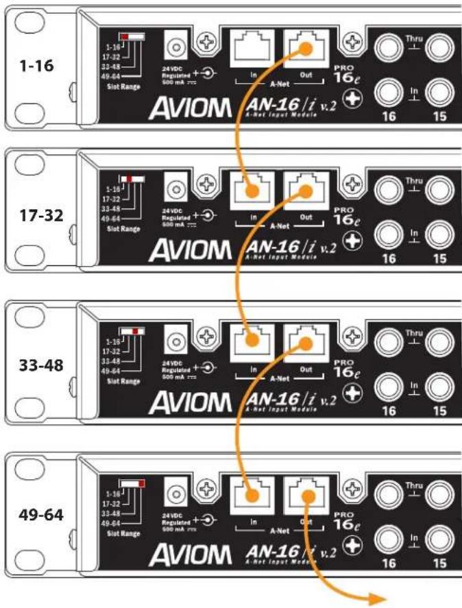
Slot Range switches for each input device in at system are shown. A legacy Pro16 device may be substituted for the first bank of 16 channels.
Connect the A-Net Out of the last input device in the chain to the A-Net In of the A-Net Distributor to send the combined set of 64 network Slots to all connected devices. The Personal Mixers are then connected to the A-Net Distributor's A-Net Out ports.
One legacy Pro16 device (analog or digital console card) may be substituted for the first bank of 16 channels in a daisy chain of input devices. It will automatically default to supplying the first 16 Slots to the network pool.
Legacy products such as the A-16II Personal Mixer may be used in a Pro16e-based system with up to 64 input sources, but note that they can only access the first 16 network Slots. All network Slots from 17 to 64 are ignored.
Console Card Inputs
Up to four 16-channel digital console cards may be combined to create a Pro16e A-Net network. The D800 or D800-Dante A-Net Distributor and the SB4 System Bridge are required to merge the four separate A-Net data streams into one.
All console cards used in this manner must be connected to the same clock source, either in the same mixing console or in multiple mixing consoles that are synced via word clock. Failure to sync the clocks for all console cards will result in digital audio clocking artifacts in the audio.
The A-Net Out from each console card connects to one of the four ports labeled 1-16, 17-32, 33-48, and 49-64 on the SB4 System Bridge. The SB4 rear-panel ports route the data in groups of sixteen channels to the SB4's front-panel A-Net Bridge port which allows a single Cat-5 cable to send all input sources to the D800.
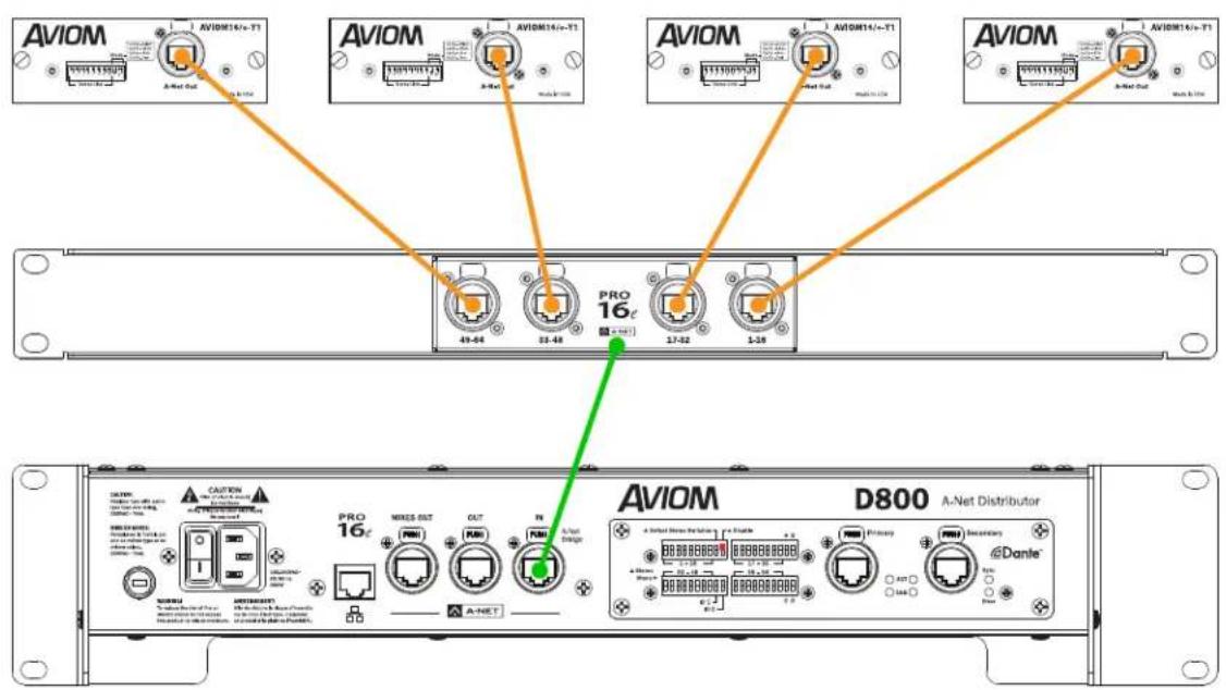
A-Net data from four console cards create a 64-channel Pro16e network.
The A-Net Bridge port of the SB4 is then connected to the A-Net In port of a D800 A-Net Distributor. The D800 merges the four data streams into one and outputs one combined set of 64 A-Net Slots from its front-panel A-Net Out ports.
When using a D800-Dante A-Net Distributor, its Dante Disable switch must be in the up position to enable the A-Net input of the D800-Dante (only one interface may be used at a time).
Connecting Monitoring Devices
Headphones, wired in-ear monitors, wireless in-ear transmitter systems, powered speakers, subwoofers, and tactile bass shakers such as Aviom's BOOM System can be connected to the A640 Personal Mixer separately or in combination. This section details the connection of these devices to the A640's audio outputs.
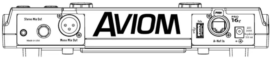
The A640 has 1/4-inch and 1/8-inch stereo and XLR mono mix outputs available.
Connecting to the Stereo Mix Output
The A640 has a pair of TRS (tip-ring-sleeve) output jacks—1/4-inch and 1/8-inch—dedicated to the stereo mix coming from the A640 Personal Mixer. The volume level for both jacks is controlled by the Master Volume knob; both jacks are always active.
Headphones and Earbuds
Connect stereo headphones or wired earbuds to the A640. For best performance, choose low impedance headphones or earbuds whenever possible. High impedance devices will not harm the A640, but note that the mix output level may be lower with these devices.
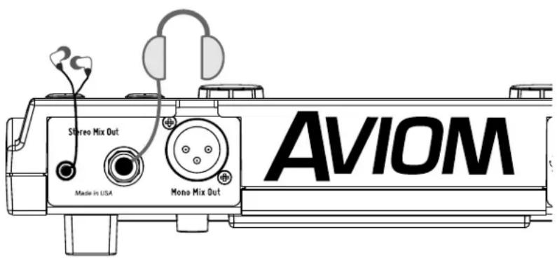
Headphones or earbuds are connected to the Stereo Mix Out jack.
The 1/4-inch and 1/8-inch stereo outputs may be used simultaneously.
Stereo Wireless In-Ear Systems
The A640's Stereo Mix Out may be connected to the left/right inputs of a wireless transmitter system used for in-ear monitoring. A Y-cable that splits the A640's TRS (tip-ring-sleeve) stereo output to a pair of TS (tip-sleeve) mono left and right outputs is required. Note that the connection from the left and right TS cables is unbalanced. If the inputs to the wireless transmitter are XLR only, a special cable may need to be made. Consult the transmitter's documentation for information about properly connecting unbalanced signals to its XLR inputs.
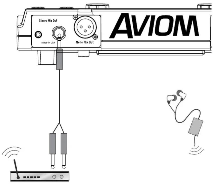
The Stereo Mix Out can be connected to a wireless in-ear transmitter with a Y-cable.
If you need to create a custom adapter cable, note that the TRS tip connector carries the left audio signal, the ring carries the right signal, and the sleeve provides ground for both. The left and right signals are unbalanced in this case.
Stereo Speakers
The Stereo Mix Out of the A640 Personal Mixer may be connected to a set of powered stereo monitor speakers using a Y-cable that splits the TRS stereo output to a pair of TS mono left and right outputs.
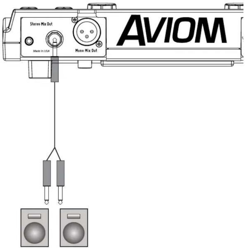
A Y-cable is required to connect the A640 to stereo powered speakers.
If the powered speakers have XLR inputs, a custom cable may be required. Check the speaker's documentation for information about properly connecting the unbalanced left and right signals from the A640 Stereo Mix Out to the balanced inputs of the powered speakers.
Connecting to the Mono Mix Out
In addition to the 1/4-inch and 1/8-inch Stereo Mix Outs, the A640 has a dedicated Mono Mix Out that is always available. The Mono Mix Out can be used alone—connected to a powered speaker, for example—or in conjunction with a stereo monitoring device such as headphones where the mono output is connected to a subwoofer or tactile bass shaker device such as Aviom's BOOM System.
The Aux Volume knob controls the level of the mono output.
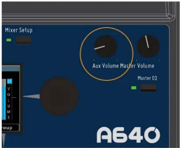
Set the output level of the mono mix with the Aux Volume knob.
The volume level of the Aux Volume knob is not stored as part of a mix preset.
Mono Speakers
The A640 Personal Mixer's Mono Mix Out is ideal when you need to connect the A640 to a mono device such as a powered speaker or wedge. The balanced line-level XLR output supplies a mono version of the mix being created on the A640, even when the stereo outputs are also being used.
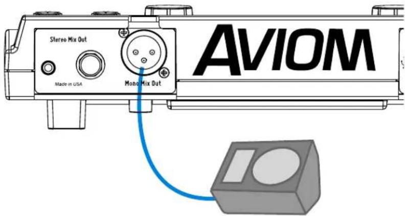
The mono out is connected to a powered wedge's input with an XLR cable.
No editing is required to create the mono output. The A640 automatically sums stereo channel and pan information to mono, even if the inputs have been stereo linked at the input modules.
Subwoofers
When a subwoofer is used to supplement a performer's monitor mix, the Stereo Mix Out and Mono Mix Out are used simultaneously. Connect wired earbuds, headphones, or a wireless in-ear transmitter system to the Stereo Mix Out jack, and then connect the Mono Mix Out jack to the line-level input of the subwoofer with an XLR cable.
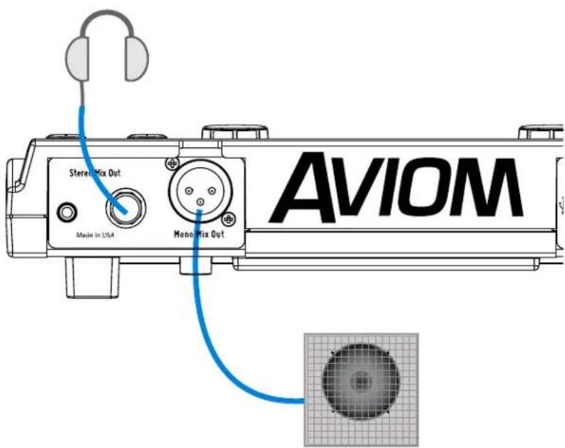
Headphones and a subwoofer are connected to the A640.
Tactile Shaker Devices
In addition to subwoofers, which are speakers designed to output primarily low frequencies, there is another category of low frequency devices designed to supplement a mix and enhance the listening and mixing experience of the user. These tactile devices are known as bass shakers, butt kickers, or throne shakers depending on how they are implemented. The Aviom BOOM System simplifies the connection of tactile devices to personal mixers.
Typically, the frequency range of these devices is restricted to 500Hz and below, so it is most likely they will be used in conjunction with headphones or earbuds. The Stereo Mix Out and the Mono Mix Out jacks of the A640 will be used simultaneously in this case.
Connect earbuds or headphones to the Stereo Mix Out; connect an XLR cable from the Mono Mix Out of the A640 to the input of the bass shaker device. An adapter cable may be required if the shaker device cannot accept a line-level balanced XLR signal.
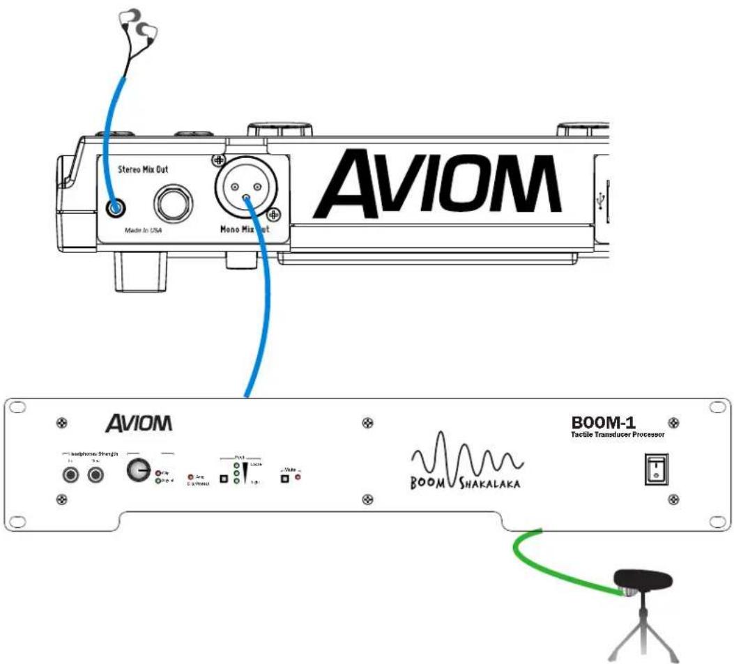
The A640 is shown connected to earbuds plus a drum throne shaker device.
Network Mix Back
The A640 Personal Mixer offers a special feature—Network Mix Back—that allows its stereo mix to be sent back through the Cat-5 cable to a D800 or D800-Dante A-Net Distributor. The D800 products have a special port labeled Mixes Out that can be used with an AN-16/o v.4 Output Module to simplify the connection to wireless in-ear transmitter systems. The A640 can then be used as a remote controller for the performer's mix without connecting earbuds or headphones to the A640.
One D800 and one AN-16/o v.4 Output Module can provide stereo mixes for up to eight users' in-ear transmitters. The stereo mixes can also be patched directly into a Dante network when using the D800-Dante A-Net Distributor, eliminating the need for the AN-16/o v.4 and the analog cabling. See the example below.
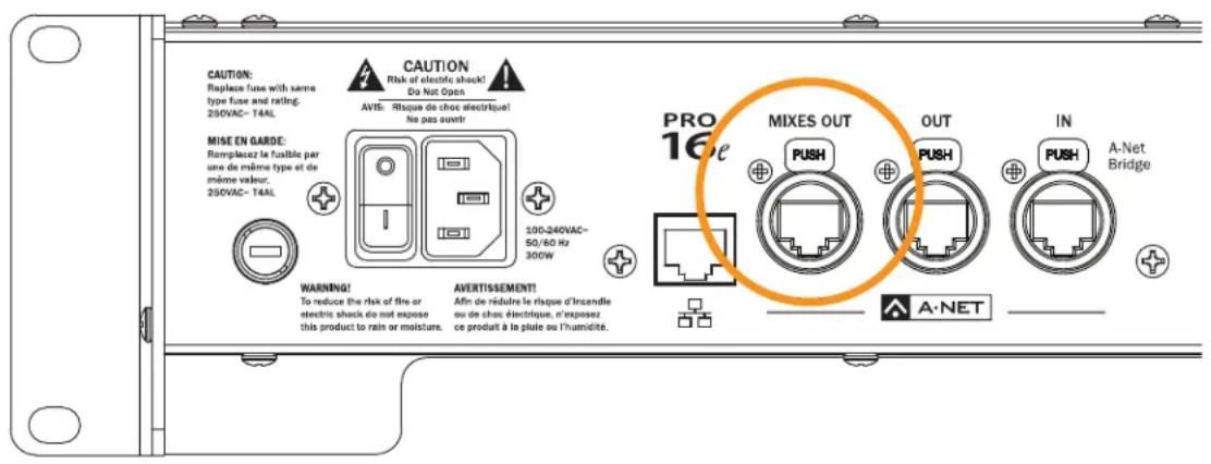
Mixes Out on the D800
To use Network Mix Back the front panel mode switches on the D800 must be set to the bidirectional position (II) for each A640 that will use the feature. Each of the eight A-Net ports on the D800 or D800-Dante can provide one stereo mix from an A640 Personal Mixer to the Mixes Out port.
The stereo mix from an A640 is automatically assigned to a pair of network channels that appear at the Mixes Out port; channels are mapped to the connected output device as seen in the table below.
| D800 Port Mixes Out Channels | |
| 1 1-2 | |
| 2 3-4 | |
| 3 5-6 | |
| 4 7-8 | |
| 5 9-10 | |
| 6 11-12 | |
| 7 13-14 | |
| 8 15-16 | |
Analog Cabling
Connect the Mixes Out port from the D800 to A-Net In on the AN-16/o v.4 Output Module with a Cat-5 cable. Analog connections for the inputs to the wireless transmitter units are available on two DB25 multipin connectors on the AN-16/o v.4 (wired to the Tascam analog standard).
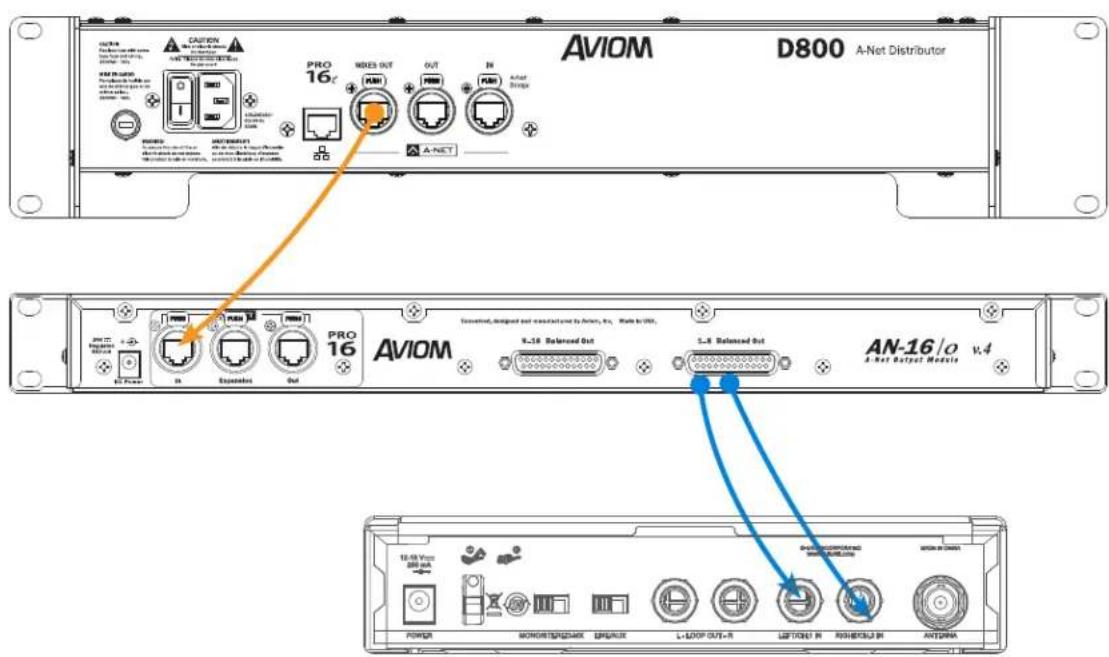
The Mixes Out port on a D800 connects to A-Net In on the AN-16/o v.4. Two of the analog outputs from a multi-pin DB25 cable connect to the left/right audio inputs of a wireless in-ear system.
Dante Patching
The eight Network Mix Back stereo mixes from the A640 Personal Mixers connected to the D800-Dante are also available in the Dante stream as D800 transmit channels 1-16. This allows you to route the signals into Dante-enabled mixing consoles, processors, wireless in-ear transmitter systems, etc., using the Dante Controller software.

D800-Dante A-Net Distributor rear panel
The D800-Dante should be connected to the Dante network with Dante Controller software running on a Mac/PC computer. Use the Routing tab of Dante Controller to assign the outputs from the D800-Dante to your other Dante devices. Use the Device View for the D800-Dante to name the Network Mix Back output channels if needed.
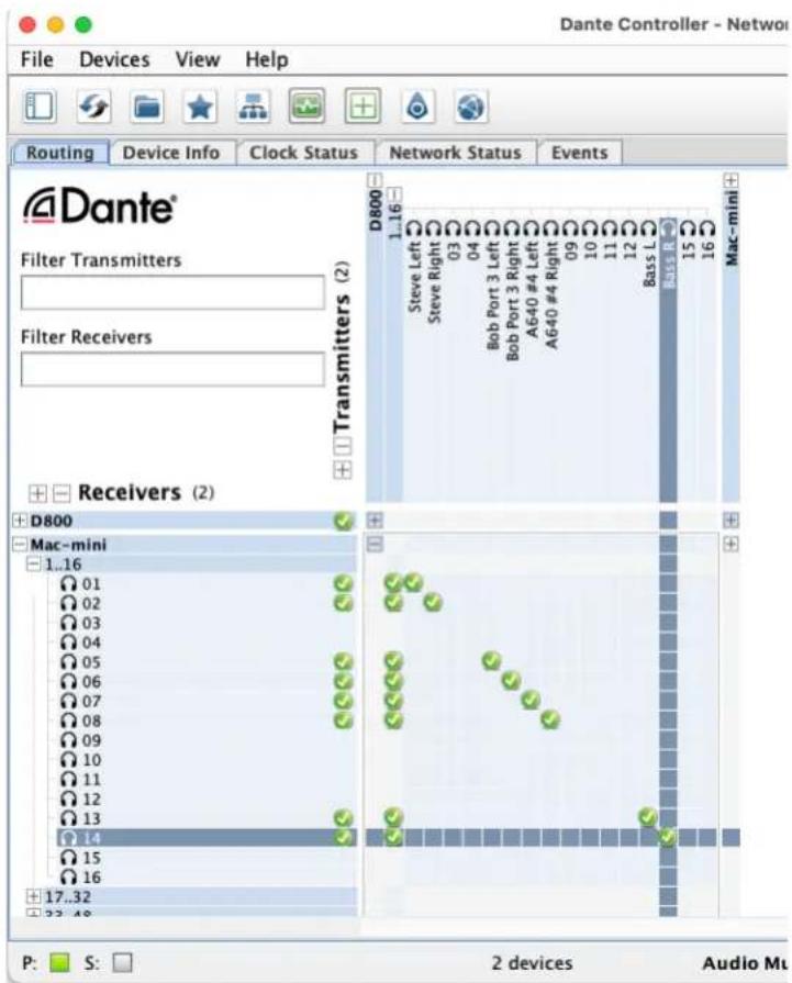
Dante Controller allows the Mixes Out channels to be routed to any device in the Dante network.
As with the patching of Network Mix Back channels using an analog output module, each of the eight A-Net ports on a D800-Dante provides a pair of channels that can be patched in the Dante network to other devices by using the Transmit and Receive patching area of the Dante Controller software.
The D800-Dante sends the following outputs into a Dante network from Personal Mixers connected to its eight front-panel A-Net ports:
| D800 Port Mixes Out Dante Channels | |
| 1 1-2 | |
| 2 3-4 | |
| 3 5-6 | |
| 4 7-8 | |
| 5 9-10 | |
| 6 11-12 | |
| 7 13-14 | |
| 8 15-16 | |
The front-panel I/II switches on the D800-Dante must be in the "II" position to use the Network Mix Back feature.
Aviom Personal Mixing System Input List
| Network Channels (Slots) Input Stereo Source | Network Channels (Slots) Input Stereo Source | |||||||
| 1-16 | 1 | 33-48 | 33 | |||||
| 2 | 34 | |||||||
| 3 | 35 | |||||||
| 4 | 36 | |||||||
| 5 | 37 | |||||||
| 6 | 38 | |||||||
| 7 | 39 | |||||||
| 8 | 40 | |||||||
| 9 | 41 | |||||||
| 10 42 | ||||||||
| 11 43 | ||||||||
| 12 44 | ||||||||
| 13 45 | ||||||||
| 14 46 | ||||||||
| 15 47 | ||||||||
| 16 48 | ||||||||
| Network Channels (Slots) Input Stereo Source | Network Channels (Slots) Input Stereo Source | |||||||
| 17-32 | 17 | 49-64 | 49 | |||||
| 18 50 | ||||||||
| 19 51 | ||||||||
| 20 52 | ||||||||
| 21 53 | ||||||||
| 22 54 | ||||||||
| 23 55 | ||||||||
| 24 56 | ||||||||
| 25 57 | ||||||||
| 26 58 | ||||||||
| 27 59 | ||||||||
| 28 60 | ||||||||
| 29 61 | ||||||||
| 30 62 | ||||||||
| 31 63 | ||||||||
| 32 64 | ||||||||
| Audio Outputs 1/4" TRS stereo | headphone or line level;1/8" TRS stereo, headphone or line level;XLR balanced mono, line level |
| Stereo Mix Outputs,Headphone/Line | Tip: Audio Left; Ring: Audio Right;Sleeve: Ground |
| Mono Mix Output Pin 2: Hot, | Pin 3: Cold; Pin 1: Ground; impedance balanced |
| A-Net I/O 1 A-Net In, locking RJ45 connector;Supports power over A-Net | |
| D/A Conversion 44.1/48kHz, 24-bit | |
| Stereo Operation Stereo Link, per channel pair;Set at the input module;Variable pan per mono channel or pan/spread per stereo channel pair | |
| USB Storage | Save/load mixer configurations, mix presets,firmware updates |
| Headphone Output 1.0 watt maximum at 100 ohmsdivided between both channels | |
| Headphone Output Impedance | 32 ohms |
| Line Output Impedance 226 ohms | |
| Freq. Response 2-22kHz +0.2 dB/-3dB | |
| THD +N < 0.003% | |
| Signal to Noise(unweighted) | -106dB (measured with zero data into all channels) |
| Latency 0.680 msec (measured from analog input to analog output) | |
| A-Net Cables | Use unshielded Cat-5e UTP (or better) cable |
| A-Net Cable Length | 400 feet (122 m) |
| A-Net Pro16e Protocol | Up to 64 audio channels;Supports Power Over A-Net |
| Optional Power SupplyInput VoltageOutput VoltagePlug Size | External, DC, universal switching type100-240 volts, 50/60Hz24 VDC, 0.5 amp2 mm |
| Dimensions | 10.76 in. (273.3mm) wide x 7.6 in. (193.04mm) deep2.212 in. (56.18mm) high |
| Weight | 2 lb. (0.907 kg); packaged weight 3 lb. (1.36 kg) |
| Options | MT-1a Mic Stand Mount (uses 6-32 1/4-inch screws);EB-1 Extension Bracket;PS-120/PS-240 Power Supply |
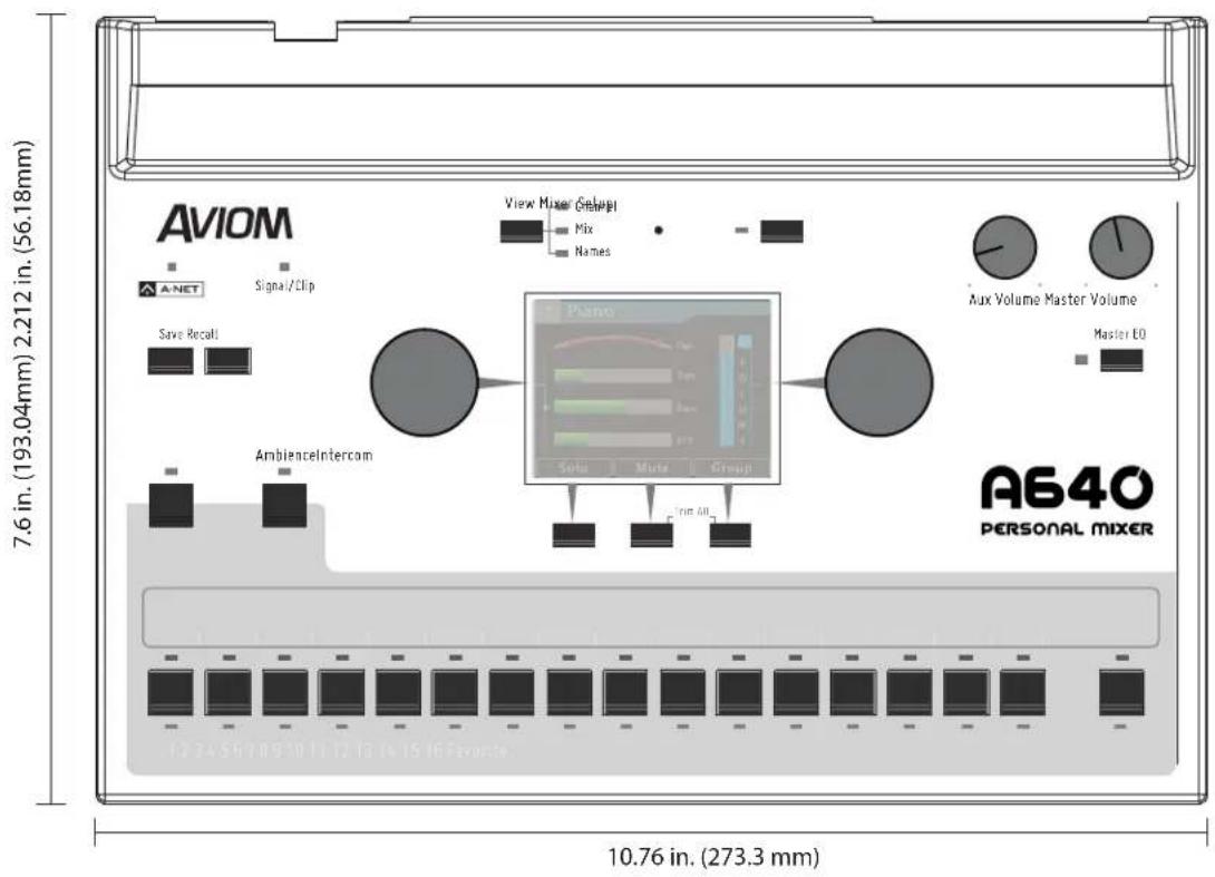
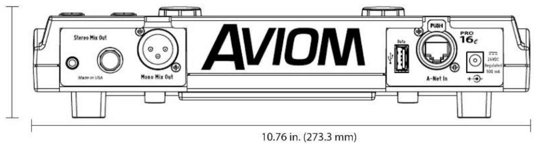
Mixer Label
Use this template as a starting point for creating custom Personal Mixer labels for the A640. It is shown actual size.

other
| Dimension | Value | | ----------------- | ----------- | | Total Length | 9.8349 in | | Height (mm) | 59.331 mm | | Total Width (mm) | 0.5417 in | | Height (mm) | 13.758 mm |Cat-5 Cable Pinout
The tables below detail the two wiring pinout variations for Cat-5 cables. When making custom cables, either pinout can be used, but both ends of a cable must use the same wiring pattern.
T568A
| RJ45 Pin Wire Color | ||
| 1 White/Green |  | |
| 2 Green |  | |
| 3 White/Orange |  | |
| 4 Blue |  | |
| 5 White/Blue |  | |
| 6 Orange |  | |
| 7 White/Brown |  | |
| 8 Brown |  | |
T568B
| RJ45 Pin Wire Color | ||
| 1 White/Orange |  | |
| 2 Orange |  | |
| 3 White/Green |  | |
| 4 Blue |  | |
| 5 White/Blue |  | |
| 6 Green |  | |
| 7 White/Brown |  | |
| 8 Brown |  | |
Index
Symbols
1/4-Inch Stereo Output 20, 95, 106
1/8-Inch Stereo Output 20, 95, 106
16-channel bank 92
16 mono channels Pro16 mode 78
16 stereo channels Default Mode 79
24V DC power 22
A
A-16D Pro A-Net Distributor 78, 89, 91
A-16II Personal Mixer 48, 49, 89, 91, 93
A320 Personal Mixer 48, 49, 89
A360 Channel Manager 49, 56
A360 Configuration import 56
A360 Personal Mixer 48, 49, 54, 56, 89, 91, 92 Stereo Link 57
A640_config_files folder 52, 58
A640 firmware 59
A640 Mix Views 23
A640 Rear Panel 20
About This Mixer 87
Active LEDs 18
Additive Solo Mode 25
All Off 72
All On 72
Ambience 27, 34, 79
Ambience Button 9, 15
Ambience channel 35
Ambience Mic 9, 15, 43, 84
Ambience Mic channel 71, 82
AN-16/i Input Module 47, 77
AN-16/i-M Mic Input Module 77
AN-16/i v.2 Input Module 78, 89, 92
AN-16/o v.4 Output Module 101
Analog Input 92
A-Net 5,7,92,106
Pro16, Pro16e 5
Pro16 vs. Pro16e 77
A-Net Bridge SB4 94
A-Net Cable 106
A-Net Distributor 6, 23, 38, 60, 61, 73, 75, 80, 81, 88, 89, 92, 93, 101
A-Net In 6
A-Net In Port 21, 92
A-Net I/O 106
A-Net LED 9, 10, 52
A-Net Out 6
A-Net Out Port 93
AN-16/i v.2 93
Assignable Soft Buttons 16
Audinate 24,62
Audio Outputs 106
Audio Source 40,48
Aux Mix 71
Intercom 39,73
Auto-Sync with Dante 63
Aux Mix 21,71
clear 84
EFX levels 71
muted channel 72
Aux Mix Channel Settings 71, 72
Aux Mix Setup 71
Aux Out 11
Aux Out XLR 12
Aux Volume 9, 12, 20
Aux Volume knob 98
Aviom folder 52, 57, 58
B
Backlight Level 85
Back up
Configuration 57
balanced 98,100
Bank
channel 92
Bass 14, 17, 32
bass shaker 12, 71, 95, 98, 100
bi-color Signal/Clip LED 10
bidirectional 101
BOOM System 71, 95, 98, 100
Bridge port
SB4, D800 94
Broadcast Slot 38, 40, 41, 45, 48, 49, 69, 74, 76
D800/D800-Dante 76
Intercom 74
None 75
C
Cable Length 106
Cat-5 Cable Pinout 109
Cat-5 Cables 8
Cat-5e 22
Certifications iii
Channel 17 19, 36, 72
Channel Active LEDs 9, 18
Channel Button
disable 69
LED 70
Channel Buttons 9, 17
Channel Label Strip 9, 17
Channel Map
Mixes Out 101, 104
Channel Mapping 19, 63, 65, 92
Defaults 68
errors 68
Slots 65
Channel Mapping Errors 68
Channel Mute LEDs 9, 18
Channel Names 30,60
Dante 61, 64
default 64
Sync 63
Channel Number 30
Channel Settings
Aux Mix 71
Channel Solo Active 30
Channel View 23, 30, 31, 81
Channel Volume 17
Check for A640 Firmware Updates 58, 59
Clear channel name 61
Clear Current Mix 83, 84
Color LCD 14
Compatibility 6, 93
Configuration 51, 52, 53, 68
Back up 57
Clear 53
import A360 56
Recall 56
stereo links 68
update 55
Connecting Listening Devices 95
Console card 47, 78, 80, 93
Create a Group 27
Creating a Monitor Mix 23
Custom 10
custom channel map 65
Custom Mode 19, 65, 68, 70, 82, 92
channel 17 36
D
D400 A-Net Distributor 78, 90, 91
D400-Dante A-Net Distributor 91
D800 38
front-panel I/II switch 24
D800 A-Net Distributor 73, 75, 78, 94, 101
Mixes Out 101
D800/D800-Dante
Broadcast Slot 76
I/II switches 73
D800-Dante A-Net Distributor 23, 38, 40, 47, 60, 62,
64, 73, 75, 94, 101
Disable switch 63
D800 Mixes Out Channels 101, 104
D800 Sync 23
D/A Conversion 106
Daisy Chain 92
Dante 23,61,80,101,103
Auto-Sync 63
Network Mix Back 102, 104
Dante Channel Names 62, 63, 66
Dante Controller 24, 62, 63, 102, 103
Dante Disable switch
D800-Dante 94
Dante firmware 61
Dante Patching
Network Mix Back 102
Data Port 21
USB 52
DB25 102
DC Power 7,92
Plug Size 7,106
DC Power Connector 20, 22
Default 10
Default Mode 18, 71, 79, 81
Default Names
restore 64
Defaults 87
Channel Mapping 68
reset an A640 87
Default Slot Assignments 67
Device_Update
Aviom folder 58
Device View
Dante Controller 62
Dimensions 107
mixer label 108
DIP switches 80
D800-Dante 63
Disable an A640 Mix Channel Button 69
Disabled channel
Broadcast Slot 75
Disabled, Listen Only 73, 74
Disable Startup Help 86
Disable switch
D800-Dante 63
Disk Full Warning 54
drum throne shaker 100
E
Earbuds 95, 100
EB-1 Extension Bracket 106
Edit Channel Names 60, 62, 63, 64, 66
Editing in Mix View 34
Editing in Names View 36
Edit Mixer Name 46, 85
Effects (EFX) 17, 32, 33
EFX 11,84
EFX levels
Aux Mix 71
Encoders 14
Enhance 14
Err column 68
Errors
Channel Mapping 68
Intercom 69
Ethernet 7
Expanded Systems 91
External Mic 47
Intercom 39,48
external power supply 92
F
Fab4 83
factory default settings 87
FAV 18
Favorite 34,82
Favorite Button 9, 11, 18, 71, 79, 80, 82
file extension .upd 58
File Name Rules 53, 54
File Transfer 21, 51, 57, 68
Firmware
Aviom 61
D800 38,73
Firmware files
Back up 58
Firmware Update 58, 59
folder
Aviom 58
format
USB storage device 52
Frequency Response 106
Front Panel Interface 9
G
Group 11, 27, 36
Editing 28
H
Headphone/Line 106
Headphone Output 13, 106
headphones 95,100
Help 78, 86
High impedance 95
|
I/II switches
D800 24, 38, 62, 63, 73
Impedance 95
headphone 106
line out 106
Import an A360 Configuration 56
In-Ear System 96
wired 95
Input List 83
Input Voltage 7,106
Intercom 73
Audio Source 39
Aux Mix 71
Errors 69
external microphone 39
Latched 42
Local Mic 43
Momentary 42
Speaker 43
Using an External Mic 47
Intercom Audio 39,48
Intercom Audio Source 41,73
Intercom Broadcast Slot 74, 75
Intercom Button 9, 15, 74, 76
Intercom info 46
Intercom LED 42, 46
Intercom Modes 42
Intercom Receive Volume 42, 46
Intercom Setup 38
Intercom Volume 11
Internal Mic 39, 41, 43, 71
Intercom 43
L
Label Strip 17
Last selected channel 11
Latched
Intercom 15,42
Latency 106
LCD Backlight Level 85
LED
Channel Button 70
LEDs 10, 18
Legacy Devices 48, 77, 93
line-level 98
Line Out 106
Liquid Crystal Display (LCD) 9
Listen Only 39, 40, 41, 73 Intercom 87
Loading Channel Names 62
Load Names from D800-Dante 62
low impedance 95
M
Main (Mono) Mix
Aux Mix 71
Manual Edit 62
Channel Names 60
Master EQ 9, 11, 13, 84 reset 77
Master Volume 9, 13, 95
maximum files per USB configuration 54
Mic 39, 41, 43, 47, 48, 71, 79 Intercom 73
Microphone external 39,47
Mix reset 83
Mix Channel Button 69 Disable 69
Mixer Label 108 template 10
Mixer Mode 10, 11, 77
Mixer Name 46,85
Mixer Setup 23
Mixer Setup Button 9, 12, 50
Mixer Setup Menu 50
Mixes Out D800 101, 102
Mix Output 106
mix presets 10, 52
Mix View 23, 34
Mode 77
Mode Switch D800 101
Momentary Intercom 15,42
Monitoring Device 95
Mono Mix Out 98, 99, 100, 106
Mono Output 20
Mono Speaker 98
Mono vs. Stereo 67
Mono vs. Stereo Channels 80, 81
channel mapping 69
MT-1a Mic Stand Mount 6, 106
multipin connector AN-16/o v.4 102
Mute 17, 26, 35
Mute All 27
Mute button 27
Muted Channel 34
Mute indicator 26
Mute LEDs 18
N
Names
Channel 60
Mixer 85
Names View 23, 36
Network Channels and Slots 8
Network Mix Back 101
Dante Patching 102
Network Mix Back to Dante 102, 103, 104
network slots 92
None 75
Broadcast Slot 75
0
Open Startup Help 86
Operating Temperature ii
Options 106
Output Impedance 106
Output Module 6
Output Voltage 106
Overwrite Configuration 55
P
Pan 17, 31
reset 84
Pan indicator 81
panning 21
Pinout
Cat-5 109
TRS 96
Plug Size
DC Power 106
Polarity
DC 7
powered speaker 95, 98
Power Over A-Net 106
power over Cat-5 89
Power Supply 7, 92, 106
Presets 10
A360 57
Pro16 10
Pro16 and Pro16e A-Net 77
Pro16e 92
Pro16e A-Net Port 20
Pro16 Mode 18, 71, 78, 89 Stereo Channels 72
Pro16, Pro16e
A-Net 5,7
PS-120 Power Supply 7, 22, 92, 106
PS-240 Power Supply 7,92 international 22
push-to-talk 15
R
recall a mix 11
Recall a saved A640 configuration 56
Recall Button 9, 11
Recall Configuration 55, 57, 60
Receive Volume Intercom 46
Receiving Intercom Audio 40
remote control 101
Rename
Firmware Update 58
Reset an A640 87
Reset Current Mix 83, 84
Rotary Encoders 9, 14
S
Sample Rate 106
save a mix 10
Save Button 9, 10, 55
Save Configuration 52, 53, 55, 60
SB4 System Bridge 94
Selected channel 34
Setup 89
Setup Menu 50
Shaker 95, 98, 100
Signal/Clip LED 9, 10, 16
Signal to Noise 106
Slot assignment 65, 70 default 68
Slot Range Setup 93
Slot Range switch 93
AN-16/i v.2 92
Slots 40, 43, 68, 77
Channel Mapping 65
Network Channels 8
Soft Buttons 9, 16
Solo 24,35
Solo mode
Additive Solo 25
Speaker
Intercom 43, 44, 48
Specifications 106
Startup Help 86
Stereo Audio Outputs 20
Stereo Channels 80
Pro16 Mode 72
Stereo Indicator ST 30, 81
Stereo Link 11, 64, 67, 80, 81 imported A360 57
stereo mix 101
Stereo Mix Out 95, 97, 100
Stereo Pan 31
stereo position markers 81
Stereo Speakers 96
Storage
USB 106
subwoofer 12, 95, 99
sum to mono 99
Sync 24
Channel Names 63
T
T568A, T568B
Cat-5 pinout 109
Tactile Shaker 100
drum 100
Template
Mixer Label 108
Tone Controls 32
transmitter
wireless in-ear 96
Transmitting Intercom Audio 39
Treble 11, 14, 17, 32
Trim All 9, 16
TRS 20,95
TRS to TS
Y-cable 96, 97
TRS wiring 96
Turn Startup Help on/off 86
U
unbalanced 96
unshielded Cat-5e 106
Updating Configurations 55
Updating the A640 Firmware 58, 59
UPD file type 58
USB 51,106
Disk Full Warning 54
PC-formatted 21
USB Data Port 20, 21, 52
USB storage device format 52
Using an External Mic Intercom 47
UTP Cat-5e 106
V
View 11
View Button 9, 11, 23
Views 23
Voltage 7
Volume reset 84 stereo 30
W
wired in-ear monitors 95
Wireless In-Ear System 95, 96, 101
X
XLR
Aux Out 12
XLR balanced 106
XLR cable 99, 100
XLR input 96
XLR Mono Output 20,98 Aux Mix 71
Y
Y1 A-Net Card 6, 78, 80
Y-cable 96, 97
AVIOM®
A640
PERSONAL MIXER

- Important Safety Instructions
- WARNING!
- CAUTION:
- Certifications
- Notice of Rights
- Trademarks
- Aviom, Inc. Limited Warranty
- Warranty Information
- Table of Contents
- Creating a Monitor Mix 23
- Intercom Setup 38
- Mixer Setup Menu. 50
- A640 Personal Mixer
- Features
- A640 Personal Mixer features:
- Compatibility
- Legacy Products:
- Power Supplies
- About A-Net
- Conventions Used in this Document
- Using Personal Mixers
- Cat-5 Cables
- A-Net Distributors
- Button Presses
- Network Channels and Slots
- A640 Front Panel Interface
- A-Net LED
- Signal/Clip LED
- Save Button
- Recall Button
- View Button
- Mixer Setup Button
- Aux Volume
- Master Volume
- Master EQ Button
- Color LCD
- Left/Right Rotary Encoders
- Intercom Button
- Ambience Button
- Built-in Ambience Mic
- Assignable Soft Buttons
- Trim All Function
- Channel Label Strip
- Channel Buttons
- Channel Active LEDs
- Channel Mute LEDs
- Favorite Button
- A640 Rear Panel
- Stereo Audio Outputs
- XLR Mono Output
- USB Port
- A-Net In Port
- DC Power Connector
- Creating a Monitor Mix
- A640 Mix Views
- D800 Sync Indicator
- Common Editing Functions
- Solo
- Additive Solo
- Mute
- Group
- To create a Group:
- Editing a Group
- Channel View
- Editing in Channel View
- Pan
- Stereo Pan
- Tone Controls
- EFX
- Mix View
- Editing in Mix View
- Names View
- Editing in Names View
- Intercom Setup
- Transmitting and Receiving Intercom Audio
- Transmitting Intercom Audio
- Receiving Intercom Audio
- Intercom Modes
- Momentary
- Latched
- How The Intercom Works
- Using the Local Mic
- Using an External Mic
- Using Multiple External Mics
- Intercom Audio and Legacy Devices
- A-16II Personal Mixer
- A320 Personal Mixer
- A360 Personal Mixer
- Mixer Setup Menu
- File Transfer
- USB Data Port
- Save a Configuration
- A configuration saves:
- To save a configuration:
- File Name Rules
- Disk Full Warning
- Updating Configurations
- Recall a Configuration
- Import an A360 Configuration
- Check for A640 Firmware Updates
- Firmware Files
- Updating the A640 Firmware
- Edit Channel Names
- Manual Edit
- Back
- Edit Channel 4 Name
- Cancel Clear Save
- Channel Names Using Dante
- Loading Channel Names One Time from a D800-Dante
- Loading Dante Channel Names In Sync
- Dante Channel Names and Stereo Links
- Channel Mapping
- Default Slot Assignments
- Mono vs. Stereo
- Channel Mapping Errors
- Disable an A640 Mix Channel Button
- Aux Mix Setup
- Aux Mix Audio Source
- Aux Mix Channel Settings
- Intercom
- Intercom Audio Source
- Intercom Broadcast Slot
- Mixer Mode
- Legacy Devices
- Getting Help
- Pro16 Mode - 16 mono channels
- Default Mode - 16 stereo channels
- Mono vs. Stereo Channels
- Custom Mode
- Input List
- Clear Current Mix
- Edit Mixer Name
- LCD Backlight Level
- Help
- Restore Defaults
- To reset an A640:
- About This Mixer
- Personal Mixing System Setup
- Adding the A640 to a 16-Channel System
- Expanded Systems
- Daisy chaining an A640
- Pro16e Personal Mixing Systems
- Analog Inputs
- Slot Range Setup
- Console Card Inputs
- Connecting Monitoring Devices
- Connecting to the Stereo Mix Output
- Headphones and Earbuds
- Stereo Wireless In-Ear Systems
- Stereo Speakers
- Connecting to the Mono Mix Out
- Mono Speakers
- Subwoofers
- Tactile Shaker Devices
- Network Mix Back
- Analog Cabling
- Dante Patching
- Mixer Label
- Cat-5 Cable Pinout
- Index
- Symbols
- A
- B
- C
- D
- E
- F
- G
- H
- |
- L
- M
- N
- 0
- P
- R
- S
- T
- U
- V
- W
- X
- Y
- AVIOM®
- A640
- PERSONAL MIXER
Brand : Aviom
Model : A640
Category : Blender