
QB250 P206 - Subwoofer MB QUART - Free user manual and instructions
Find the device manual for free QB250 P206 MB QUART in PDF.


| Brand | MB Quart |
| Model | QB250 P206 |
| Product Type | Subwoofer |
| Woofer Size | 10 inches |
| Impedance | 4 ohms |
| Power Handling (RMS) | 250 watts |
| Power Handling (Peak) | 500 watts |
| Sensitivity | 87 dB |
| Frequency Response | 30 Hz - 500 Hz |
| Enclosure Type | Sealed or ported (recommended) |
| Mounting Depth | 5.5 inches |
| Mounting Diameter | 9.25 inches |
| Cone Material | Polypropylene with rubber surround |
| Voice Coil | 2-layer copper |
| Magnet Weight | 40 oz |
| Dimensions (W x H x D) | 12 x 12 x 6 inches |
| Weight | 11 lbs |
| Operating Voltage | 12V DC (automotive use) |
| Recommended Enclosure Volume (Sealed) | 0.8 cubic feet |
| Recommended Enclosure Volume (Ported) | 1.2 cubic feet |
| Maintenance | Clean with a soft, dry cloth. Avoid moisture and direct sunlight. |
| Safety | Ensure proper ventilation. Do not exceed rated power. Secure mounting to prevent movement. |
| Spare Parts and Repairability | Replacement cones and surrounds available from authorized dealers. Repairs should be performed by qualified technicians. |
Frequently Asked Questions - QB250 P206 MB QUART
User questions about QB250 P206 MB QUART
0 question about this device. Answer the ones you know or ask your own.
Ask a new question about this device
Download the instructions for your Subwoofer in PDF format for free! Find your manual QB250 P206 - MB QUART and take your electronic device back in hand. On this page are published all the documents necessary for the use of your device. QB250 P206 by MB QUART.
USER MANUAL QB250 P206 MB QUART
natural_image
Exterior view of a speaker with mesh head and speaker grille, accompanied by automotive wiring (no text or symbols visible)QB250 P206
ENG USER'S MANUAL....2
IMPORTANT INFORMATIONS
Before you start with the installation, disconnect the ground connection from the vehicle's battery in order to prevent short circuits.
SPECIFICATIONS
Subwoofer 25 cm (10")
Output Power RMS 250 Watts
Output Power Max. 500 Watts
Lowpassfilter 50 - 200 Hz @ 12 dB/Octave
Bass Boost 0 - 12 dB @ 45 Hz
Phase Shift 0° / 180°
Input Sensitivity 6 V - 0.2 V
Auto-Turn-On ......Audio / DC-Offset / Off
Operating Voltage ....+12 V (11 - 15 V), negative ground
Fuse rating 2 x 10 A
All Specifications are subject to change.
COMPATIBILITY
Peugeot 206 / 206+ (except SW/CC, 1998 - 2012)
LEGAL NOTE
- MB Quart or Audio Design GmbH is in no way affiliated with the PSA Peugeot Citroën or any of its subsidiaries or affiliated companies connected to, or is acting on its behalf or with its authorization.
- All registered product names, trade marks and brands are the property of their respective owners.
- The compatibility with the specified types of vehicles reflects the information available on December 2012.
• Technical changes and errors reserved.
WARRANTY
This MB Quart product has a 3-year warranty from date of purchase.
To maintain your warranty coverage upright, keep your original purchase receipt to prove the date of purchase. Any damage of the product, based on incorrect or improper use, accident, incorrect and improper installation, modification of the barcode, natural disaster or any non-appropriate interventions, repairing or alteration outside our factory or authorized service centers, and caused by other acts, which are unauthorized, because have been made in an incompetent manner, is excluded from the warranty. This warranty is limited only to defective parts and especially excludes all incidental or consequential damages and those who are associated with. Please return the defective product along with a copy of your purchase receipt and a detailed malfunction description to the dealer from whom you purchased the product.
CUSTOMER SERVICE
In general, the assembly and installation of the sound system should be made by a trained and technically skilled specialists. If you nonetheless choose the self-assembly and you have any problems, contact your specialist dealer or the Audio Design Service Department under Tel. +49 (0) 7253 - 94 65 93 or by E-Mail to speakers@audiodesign.de
INTERCONNECTION
POWER SUPPLY AND TURN-ON-CONNECTION
First connect the GND terminal (2) of the power plug to an appropriate ground connection at the chassis. To ensure a good connection, remove dirt and dust from the connection point. A loose connection may cause malfunctions or interferences noise and distortion.
Use at least a 10 mm^2 cross-section for the power and ground connection cable. Suitable cable sets are available at the specialist shop.
Then connect the +12 V terminal (1) of the power plug with the battery by using an appropriate cable including an in-line fuse. This fuse should be located very close to the battery; for safety reasons not more than 30 cm away. Only insert the fuse when the installation, including the connection of the loudspeakers, has been accomplished.
Then connect the remote turn-on-wire (Remote) from the headunit with the power plug's middle connector (3). A cable with a cross-section of 0.5mm^2 is adequate.
AUTO TURN ON-FUNCTION
With this function the amplifier detects a voltage rise over the connected input signal on the AUDIO INPUT (4) when the headunit will be switched on. Hence, the amplifier will also be turned on. As soon as the headunit will be turned off, the amplifier turns also automatically off. In this case the turn-on connection (3) is not needed, if the switch (5) is in position DC OFFSET or AUDIO.
The DC OFFSET mode is the best choice for the Auto Turn On-function and usually works with 90% of all headunits, because they are equipped with "High Power"-outputs. Only with a few older and still existing headunits are working only with the AUDIO mode.
FUSE
Fuse with a rating of 2 x 10A (6). If the fuse is defective, please replace with an equivalent fuse.
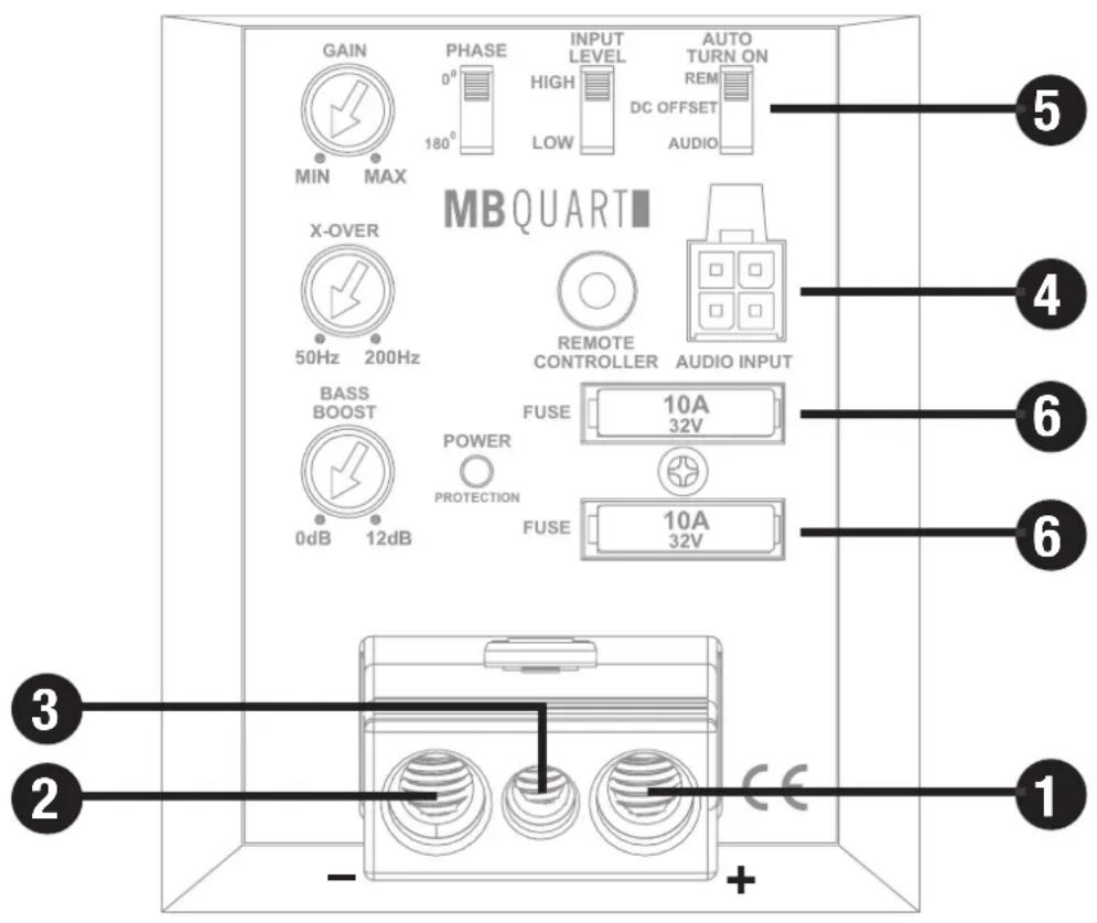
INTERCONNECTION
PROTECTION CIRCUIT
If the LED (7) lits up blue, the device is in normal operation and lits up red, when the device is overheated. If this events, the internal built-in protection circuit shuts down the device automatically. The device should work again properly after cooling down.
AUDIO SIgNAL CAbLES
Connect the audio signal cables from the RCA outputs coming from the headunit with the RCA inputs of the included plug connector. Then plug the connector into the AUDIO INPUT socket (4). If you use LOW level pre-amplifier RCA outputs from your headunit, set the switch INPUT LEVEL on position LOW (8).
The AUDIO INPUT (4) is also suitable to connect the device input with speaker wires, if your headunit is not equipped with LOW level pre-amplifier RCA outputs. Extend therefore every regarding speaker cable from your headunit with appropriate speaker cables from your car audio retailer to the mounting location of the amplifier. Then cut off the RCA jacks from the included cable connector plug and connect each matching loudspeaker cable like described below (4). Ensure to detach the cable connector plug from the device before the cutting off.
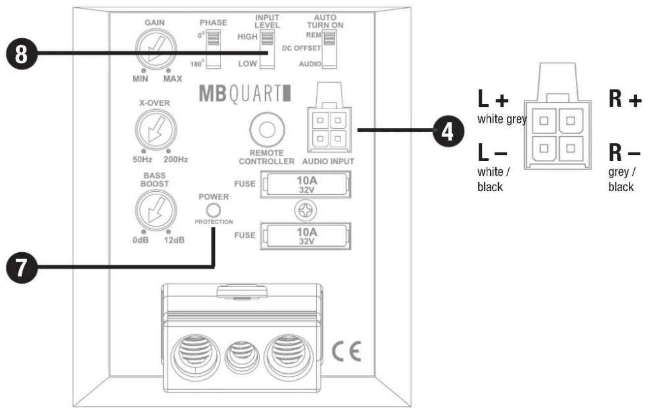
OPERATING ELEMENTS
INPUT SENSITIVITY
The input sensitivity can be adjusted to any headunit. Turn the volume control of your headunit to the center medium position and then adjust the input level controls (9) until you have an average medium level. This setting usually provides sufficient power reserves at optimum weighted signal-to-noise ratio.
VARIABLE LOWPASS FILTER
Set the desired crossover frequency of the low pass filter by using the controller (10). Hence, only the frequencies below the chosen crossover frequency will be amplified and the subwoofer plays more precised and efficient.
VARIABLE bASS b00ST
By using the boost controller (11) you are able to increase the bass boost level from 0 dB to 12 dB.
Caution: Please use the bass boost with care.
PHASE SWITCH
With the phase switch (12) you are able to turn the phase ( 0^ or 180^ ) of the subwoofer audio signal to match it with the satellite speakers of the sound systems if necessary.
bASS REMOTE CONTROLLER
Remote jack (13) for the included bass remote controller. If the bass remote controller is connected it replaces the GAIN controller (9), which is then without function.
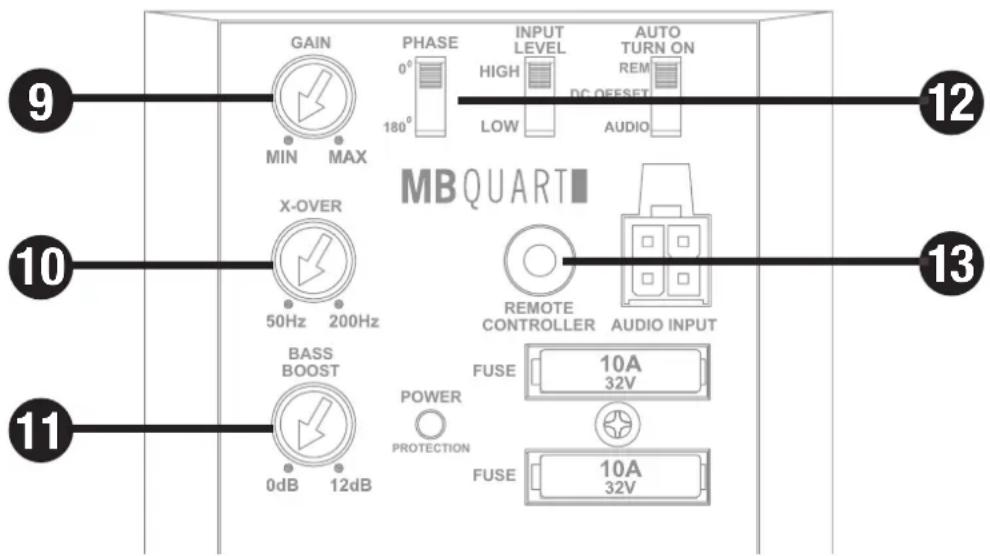
INSTALLATION
This guide is an installation aid for a proper installation of the sound system. Please read the following instructions:
- The reliability and performance of the device depends on the quality of installation.
- Please treat all parts of the sound system and the components of your vehicle with caution.
- Follow under all circumstance the regulations of the vehicle manufacturer and do not make any modifications on the vehicle, which could interfere the driving safety.
- Please observe that you don't damage any serial components of your vehicle (airbags, wires, gastank etc.) during the installation of your soundsystem by drilling or any other operations.
- Never screw or mount any other devices (amps, caps etc.) onto the subwoofer enclosure, this may cause damage to the electricity.
- Please ensure the correct polarity of all connections. Faulty installed and connected devices may damage the vehicle and the device permanently.
STEP 1:
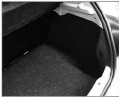
natural_image
Interior view of a car trunk showing dark material and structural details (no text or symbols visible)Clear the trunk area on the right.
STEP 2:

natural_image
Close-up of a white plastic mechanical component with a white arrow pointing to a specific area (no text or symbols visible)Stick one part of the included hook and loop tape to this position in the trunk.
STEP 3:
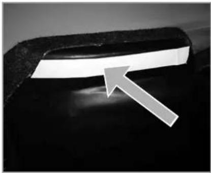
natural_image
Close-up of a dark, curved object with a white arrow pointing to a bright horizontal band (no text or symbols visible)Stick the other part of the included hook and loop tape to this position on the enclosure.
STEP 4:

natural_image
Close-up of a dark, textured surface with a white arrow pointing to a bright spot (no text or symbols visible)Remove the strip of the hook and loop tape.
STEP 5:

natural_image
Close-up of a car interior showing a dark circular object and a white arrow pointing to it (no text or symbols visible)Set in the enclosure to its final position and press it tightly against the vehicle interior wall, that both hook and loop stripes are firmly connected.
TROUBLE SHOOTING
If you are having problems after installation follow the trouble shooting procedures below.
Procedure 1:
Check the device for proper connections.
Verify that the LED (7) lits up blue. If the LED lits up blue skip to Step 3, if not continue.
- Check the fuses of the device or the external fuse on battery positive cable. Replace if necessary.
- Verify that Ground connection is connected to clean metal on the vehicle's chassis. Repair/replace if necessary.
Please ensure that you have reconnected the GND connection at the battery after the installation. - Verify that there are 11 to 15 Volts present at the positive battery and remote turn-on cable. Verify quality connections for both cables at device, headunit and battery/fuseholder. Repair/replace if necessary. Check that the vehicle charging system is maintaining proper voltage.
Procedure 2:
The LED (7) lits up red.
- If the LED lits up red, this is a sign of overheating and driving the device at very high power levels without adequate airflow around the device.
Shut off the system and allow device to cool down. If the previous items do not solve the problem, a fault may be in the device.
Check that the vehicle charging system is maintaining proper voltage.
Procedure 3:
Check the device for a proper audio signal.
- Verify good RCA input connections at headunit and device. Check entire length of cables for kinks, splices, etc.
Test RCA inputs for AC volts with stereo on. Repair/replace if necessary. - Use another audio source for testing to provide an audio signal to the Line Input.
- If you use high level speaker inputs, check the polarity.
Procedure 4:
Check the device for a popping noise while turning on.
- Disconnect input signal to device and turn device on and off.
- If the noise is eliminated, connect the REMOTE lead of device to source unit with a delay turn-on module.
OR
- Use a different 12 Volt source for REMOTE lead of the device (e.g. battery direct just for testing).
- If the noise is eliminated, use a relay to isolate the device from noisy turn-on output.
- Don't connect REMOTE directly to the battery after testing to avoid a discharge of the battery.
Procedure 5:
Check the device if you experience excess Engine Noise.
- Route all signal carrying wires (RCA, Speaker cables) away from power and ground wires.
OR
- Bypass any and all electrical components between the headunit and the device. Connect the headunit directly to input of the device. If noise goes away the unit being bypassed is the cause of the noise.
OR
- Use another audio source for testing to provide an audio signal to the Line Input.
OR
- Remove existing ground wires for all electrical components. Reground wires to different locations. Verify that grounding location is clean, shiny metal free of paint, rust etc.
OR
- Add secondary ground cable from negative battery terminal to the chassis metal or engine block of vehicle.
OR
- Have alternator and battery load tested by your mechanic. Verify good working order of vehicle electrical system including distributor, spark plugs, spark plug wires, voltage regulator etc.
WICHTIGE INFORMATIONEN
Bass Boost 0 - 12 dB @ 45 Hz
natural_image
Interior view of a car trunk showing dark interior space and visible structural lines (no text or symbols)natural_image
Close-up of a white plastic mechanical component with a black arrow pointing to a feature (no text or symbols visible)natural_image
Close-up of a dark, curved object with a bright horizontal stripe and an arrow pointing to it (no text or symbols visible)natural_image
Close-up of a dark, textured surface with a white arrow pointing to a bright spot (no text or symbols visible)natural_image
Close-up of a car interior showing a textured surface with an arrow pointing to a circular feature (no text or symbols visible)

- QB250 P206
- IMPORTANT INFORMATIONS
- Before you start with the installation, disconnect the ground connection from the vehicle's battery in order to prevent short circuits.
- SPECIFICATIONS
- COMPATIBILITY
- LEGAL NOTE
- WARRANTY
- CUSTOMER SERVICE
- INTERCONNECTION
- POWER SUPPLY AND TURN-ON-CONNECTION
- AUTO TURN ON-FUNCTION
- FUSE
- PROTECTION CIRCUIT
- AUDIO SIgNAL CAbLES
- OPERATING ELEMENTS
- INPUT SENSITIVITY
- VARIABLE LOWPASS FILTER
- VARIABLE bASS b00ST
- PHASE SWITCH
- bASS REMOTE CONTROLLER
- INSTALLATION
- TROUBLE SHOOTING
- Procedure 1:
- Procedure 2:
- Procedure 3:
- Procedure 4:
- Procedure 5:
- WICHTIGE INFORMATIONEN
Brand : MB QUART
Model : QB250 P206
Category : Subwoofer