
D-01 - Microphone NEUMANN - Free user manual and instructions
Find the device manual for free D-01 NEUMANN in PDF.


| Product Type | Condenser Microphone |
| Model | D-01 |
| Brand | Neumann |
| Polar Pattern | Cardioid |
| Frequency Response | 20 Hz - 20 kHz |
| Impedance | 50 ohms |
| Sensitivity | 20 mV/Pa at 1 kHz into 1 kohm |
| Maximum SPL | 140 dB SPL at 0.5% THD |
| Signal-to-Noise Ratio | 87 dB (CCIR 468-3) / 97 dB (A-weighted) |
| Dynamic Range | 127 dB (A-weighted) |
| Phantom Power Requirement | 48 V ± 4 V |
| Current Consumption | 3 mA |
| Dimensions (L x Diameter) | 160 mm x 56 mm |
| Weight | 500 g (without cable) |
| Connector | XLR 3-pin |
| Output | Transformer-balanced, electronically balanced |
| Accessories Included | Mounting clip, windscreen, storage case |
| Cleaning Instructions | Wipe grille with soft dry cloth; avoid moisture on diaphragm |
| Safety Note | Use only with 48V phantom power; avoid dropping |
| Repairability | Service by authorized Neumann centers only |
Frequently Asked Questions - D-01 NEUMANN
User questions about D-01 NEUMANN
0 question about this device. Answer the ones you know or ask your own.
Ask a new question about this device
Download the instructions for your Microphone in PDF format for free! Find your manual D-01 - NEUMANN and take your electronic device back in hand. On this page are published all the documents necessary for the use of your device. D-01 by NEUMANN.
USER MANUAL D-01 NEUMANN
REMOTE CONTROL SOFTWARE – RCS
GÜLTIG AB VERSION 2.0.4 VALID FROM VERSION 2.0.4
Please register your system on the website www.my-Solution-D.com, to be informed whenever updates are available!
flowchart
graph TD
    A["Load DMI Preset"] --> B["Select a preset..."]
    B --> C["Load From Device"]
    C --> D["Cancel"]
    D --> E["1: Outdoor Interv. 48k"]
    E --> F["2: Loud Env. 44k 1"]
    F --> G["3: Silent Env. 96k"]
    G --> H["4: Comp 2:1 -10dB 1k"]
    H --> I["5: Omni, LC 80Hz, 20dB"]
    I --> J["6: empty -"]
    J --> K["7: empty -"]
    K --> L["8: Testsig 1kHz"]
    L --> M["Load DMI Preset"]
    M --> N["5: Omni, LC 80Hz, 20dB"]
    N --> O["Load from Device"]
    O --> P["Cancel"]
    P --> Q["Save DMI Preset"]
    Q --> R["Select a preset..."]
    R --> S["Save to Device"]
    S --> T["Cancel"]
    T --> U["1: Outdoor Interv. 48k"]
    U --> V["2: Loud Env. 44k 1"]
    V --> W["3: Silent Env. 96k"]
    W --> X["4: Comp 2:1 -10dB 1k"]
    X --> Y["5: Omni, LC 80Hz, 20dB"]
    Y --> Z["6: empty -"]
    Z --> AA["7: empty -"]
    AA --> AB["8: Testsig 1kHz"]
    AB --> AC["Save DMI Preset"]
    AC --> AD["5: Omni, LC 90Hz, 20dB"]
    AD --> AE["Save to Device"]
    AE --> AF["Cancel"]
flowchart
graph TD
    A["B1"] --> B["Channel Navigation"]
    B --> C["USB"]
    C --> D["EtherSound"]
    D --> E["PCIe to High Speed Serial Port COM2"]
    E --> F["PCIe to High Speed Serial Port COM1"]

    G["B2"] --> H["DMI"]
    H --> I["Device Address(D): 1"]
    H --> J["Number of Channels: 3"]
    H --> K["Serial Number: 00000159"]
    H --> L["SoftwareRevision: 1.41"]
    H --> M["HardwareRevision: 002"]
    H --> N["AES42 to AES / EBU"]
    N --> O["Select Device Address(D) < 1 >"]
    O --> P["SW Update"]
    O --> Q["Close"]

    R["B3"] --> S["EtherSound Communication"]
    S --> T["AVS-ES Service"]
    T --> U["Local: 127.0.0.1"]
    T --> V["IP Address"]
    T --> W["Version: 3.17.0.1090"]
    T --> X["Details"]
    T --> Y["Close"]

    Z["B4"] --> AA["MCA Wordclock Setup"]
    AA --> AB["MAC Address: 55.03.AF 50"]
    AA --> AC["sync: 48 k"]
    AA --> AD["sync: 48 k"]
    AA --> AE["Sync: 48 k"]
    AA --> AF["Sync: 48 k"]
    AA --> AG["Sync: 48 k"]
    AA --> AH["Sync: 48 k"]
    AA --> AI["Sync: 48 k"]
    AA --> AJ["Sync: 48 k"]
    AA --> AK["Sync: 48 k"]
    AA --> AL["Sync: 48 k"]
    AA --> AM["Sync: 48 k"]
    AA --> AN["Sync: 48 k"]
    AA --> AO["Sync: 48 k"]
    AA --> AP["Sync: 48 k"]
    AA --> AQ["Sync: 48 k"]
    AA --> AR["Sync: 48 k"]
    AA --> AS["Sync: 48 k"]
    AA --> AT["Sync: 48 k"]
    AA --> AU["Sync: 48 k"]
    AA --> AV["Sync: 48 k"]
    AA --> AW["Sync: 48 k"]
    AA --> AX["Sync: 48 k"]

    A2["B2"] --> Y2["DMI SW Update"]
    Y2 --> Z2["DMI Software Update"]
    Z2 --> AA2["Downloading Time Approximately 5 min. Do not interrupt!"]
    Z2 --> AA3["Choose File: DMI2_HW002"]
    Z2 --> Z4["Start Update"]
    Z2 --> Z5["Close"]

    Y2 --> AA3
    Z2 --> AA3
    AA2 --> AB["Neumann ES Device"]
    AB --> AC["Network (MAC Add): 00.0E 55.03.AF 50"]
    AB --> AD["Device: DMI.G ES"]
    AB --> AE["Device Address (ID): 1"]
    AB --> AF["MAC Address: 00.0E 55.03.EC.39"]
    AB --> AG["Serial Number: 00000159"]
    AB --> AH["Hardware Revision: 002"]
    AB --> AI["Software Revision: 1.41"]
    AB --> AJ["Select Neumann ES device < >"]
    AB --> AK["SW Update"]
    AB --> AL["Close"]
1. Grundlagen
Allgemeines
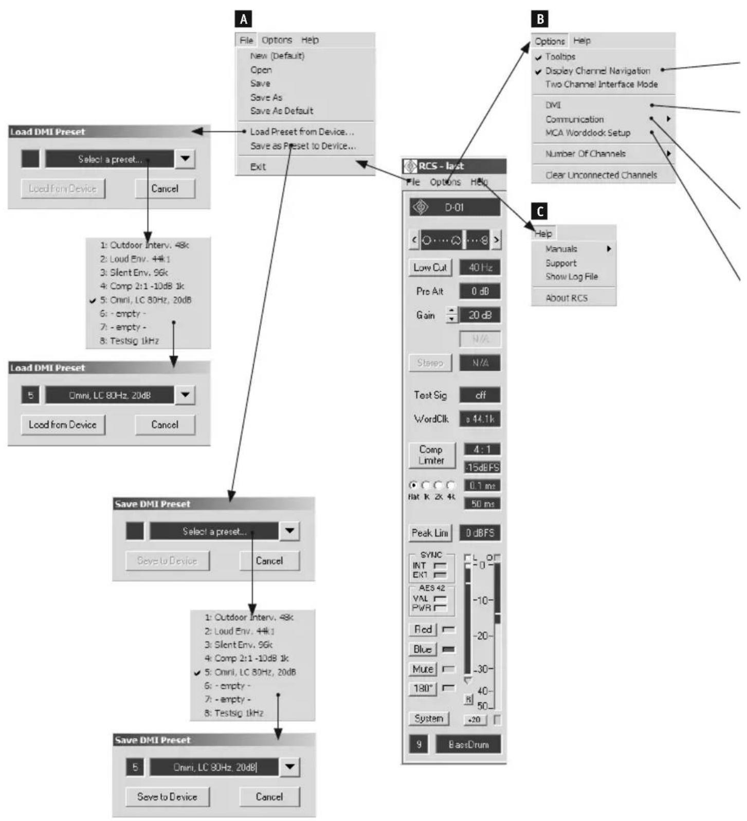
Load Preset from Device... (nur DMI-2 portable)
Save as Preset to Device... (nur DMI-2 portable)
(B1) Display Channel Navigation
Two-Channel Interface Mode
AES/EBU Output Routing:
(B4) MCA Wordclock Setup
Select Device Address (ID)
Clear Unconnected Channels
(D) Microphone Properties
(E) Polar Pattern Select
sync. to external Word Clock
The Remote Control Soft ware (RCS) for a PC/Mac controls digital AES42 compatible microphones connected to Digital Microphone Interfaces (DMI). The display of controllable functions and status indicators on the screen is clearly arranged in channel strips, similar to the layout of a mixing console. The number of channels displayed on the screen is selectable, from 2 to 8, independently of the number of microphones controlled.
All channel settings can be saved in configuration fi les for later retrieval. The current settings are automatically saved each time the soft ware is closed, and are reloaded the next time the soft-ware is started.
To change the microphone parameters, left click on the buttons or on the parameter window.
Digital Microphone Interface – DMI
The RCS communicates with the digital microphones via a Neumann Digital Microphone Interface (DMI).
The DMI supplies the connected microphones with power, and outputs the audio signals received in the familiar AES/EBU (AES3) data format. In addition, the DMI processes and transmits the control data and status information.
AES42
This standard is based upon the use of a 2-line balanced cable (AES/EBU cable; for short connections conventional analog cable can also be used). The power supply for the digital microphones is defined as Digital Phantom Power (DPP) with +10 V and max. 250 mA. Modulation of the phantom voltage generates a remote control data stream which is transmitted to the microphone (as pulses of +2 V).
The data format of the digital audio signal transmitted from the microphone complies with the AES/EBU standard. The user bits included in this standard are intended for the transmission of various types of information. The AES42 standard defines the meaning of these user bits with regard to digital microphones. In the DMI, these data are separated from the audio signal and are transmitted to the control bus, which serves as an interface for a computer or control device.
Fig. 1 shows a simple functional diagram of a microphone interface (e.g. the Neumann DMI-2), with an AES42 input and an AES/EBU output.
Use as VST plug-in
The RCS can be used as a VST plug-in. All RCS settings will then be stored in the VST host project and recalled when a project is opened. The plug-in RCS_VST.dll (Win) or RCS_VST.vst (Mac) must be copied into the plug-ins folder. The RCS_VST effect can then be inserted in one channel.
2. Connection between DMI Interfaces and Computer
DMI-2 portable
Direct connection with USB cable.
DMI-2
With RJ45 patch cable from control bus to USB 485 Converter and from there with USB cable to computer. Up to 16 DMIs can be cascaded with RJ45 patch cables on the control bus. The DMIs must be set to different addresses (ID).
DMI-8
Can be controlled via USB or EtherSound connection
• Control of DMI-8 via USB: As DMI-2.
- Control of DMI-8 via EtherSound: DMI-8 can be controlled via the same EtherSound network connection that is used to trans dio data. To do this, an EtherSound module „ES100 (DMI-8)“ must be built-in and the Windows service „ES-Server“ from Version 3.17.0 installed (part of the „ES-Monitor“ soft ware bundle). This can be downloaded free of charge from www.auvitran.com. In the RCS, choose „EtherSound“ from the „Options/Communication“ menu. At present, communication via EtherSound is only available on PCs running MS Windows.
MCA-ES
Connection of the DMI-8s with RJ45 patch cables on control bus and GN bus to MCA-ES. The MCA-ES is controlled via the built-in EtherSound module.
3. Installation
Minimum computer requirements
The minimum requirements for operation of the control soft ware on the computer are:
- Windows 98 SE, ME, 2000 or XP, Windows 7, Windows 8 operating system, or Mac OS (version 8.6 or higher, and CarbonLib version 1.6 or higher)
- Adobe® Acrobat Reader®, for the online manual
Software
Administrator rights are required for installation with Windows 2000/XP/7/8 or Mac OS X.
Start the setup program on the accompanying CD-ROM (Windows: "Setup"; Mac OS: "Install RCS"), and follow the instructions displayed on the screen.
Starting the RCS
In order for the RCS to control the microphones correctly, it is necessary to ensure that the connected DMIs have valid, unique addresses (IDs). (See the DMI operating manual for information regarding connection of the DMI and setting of the address.)

Attention: A change of ID or a newly connected DMI will be detected by the RCS only during startup or as a result of the menu command "Options/DMI".
4. Functionality
Channel display
The RCS can currently display and control up to 8 microphone channels simultaneously. The channels displayed are assigned to the inputs and outputs of the connected DMIs in a fixed sequence, in order of the addresses (IDs) which have been set for the DMIs. To simplify navigation, the Channel Navigation window can be used to scroll between the channels.. The number of channels displayed can be set in the Options/Number of Channels menu.
Channel status
If no AES42 data stream is being received for a channel, the channel has an initial status that is indicated by a gray Microphone Properties field. Channels for which an AES42 data stream is being received are indicated by the green color of the microphone model in the Microphone Properties field, and by the VAL indicator, which appears green and shines continuously.
If a valid AES42 data stream from a digital microphone is detected for a channel, the microphone model with its characteristics will be assigned to this channel, and the presence of a microphone of this model will become the target status of the channel. If an AES42 data stream is no longer being received, for instance after the microphone is disconnected, the microphone model and VAL indicator will blink and appear orange.
The Clear Channel button (see "Channel functions/Microphone Properties/Clear Channel" section) can be used to reset the channel to the initial status.
The menu function Clear Unconnected Channels (see "Menu functions/Options/Clear Unconnected Channels" section) can be used to reset all channels which do not have connected microphones to the initial status.
Configurations
All of the settings for every channel, in addition to the microphone models assigned to the channels, can be saved in configuration files for later retrieval.
Each time the RCS is closed, all of the most recently valid settings are automatically saved (in the fi le last.nkd).
When the RCS is restarted, the configuration of the most recent RCS session of the user who is logged in is reloaded (from file last.nkd) and is compared channel by-channel with the settings saved in the connected DMIs.
If there is disagreement with regard to one more channels, this is indicated by a selection dialog, where it must be decided whether the con-fi guration saved in the DMI or that saved by the RCS is to be used.
Non-agreement between confi gurations can occur, for instance, if the previous session was executed with a dif erent user account, if dif erent DMIs are connected, or if the RCS was previously closed incorrectly.
5. Menu functions
(A) File
New (Default)
Loads the default configuration file of the user who is logged in.
Open
Loads a configuration file.
Save
Saves the settings in the current configuration file.
Save As
Saves the settings in a new configuration file.
Save As Default
Saves the settings as a new default configuration file of the user who is logged in.
Load Preset from Device... (only DMI-2 portable)
Loads saved presets from device
Save as Preset to Device... (only DMI-2 portable)
Saves current settings as preset into device
Exit/Quit
Exits the RCS (Mac OS X: "RCS" menu).
(B) Options
Tooltips
Switches tooltips on and off.
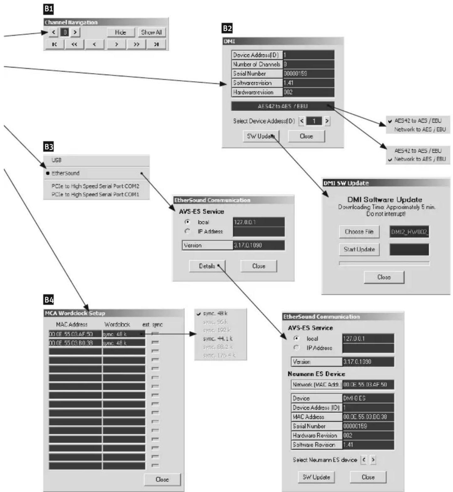
(B1) Display Channel Navigation
Enabling and disabling the navigation window.
The Channel Navigation window simplifies navigation between the channels. Up to 128 microphone channels may be connected addressing max. 16 DMI-8 and/or DMI-2. The following display and control functions are available:
< 2 .. 8 >
To set the number of displayed channels
Hide
Push-button hides unused channels
Show All
Push-button shows all available channels – used or unused
$$ | < > | $$
Navigation to the first or last channel
$$ \ll \gg $$
Shifts to previous or next screen of displayed channels
$$ < > $$
Shift s one channel back or forth
Two-Channel Interface Mode
When activated, DMI addressing and channel assignment is performed via continuous 2-channel scanning. This mode is only possible if DMI-2 devices are used exclusively, and corresponds to the previously used addressing mode. If this option is not activated, DMI addressing and channel assignment relates to the 8 channels of DMI-8 devices.
(B2) DMI
Opens a window for identifying all (new) DMIs connected to the control bus.
After a DMI has been selected by means of the device address (ID), the following data are displayed:
• Device Address (ID)
• Number of Channels
- Serial Number
- Soft ware Version
- Hardware Version
AES/EBU Output Routing
AES42 to AES/EBU or Network to AES42 (only for DMI-8 interfaces)
AES42 to AES/EBU
The digital AES42 microphone input is routed to the AES3 Output.
Network to AES42
Any EtherSound network channels can be routed to AES3 Out-
puts using EtherSound routing soft ware.
Select Device Address (ID)
Selection of a DMI address (ID) from 0 to 15
SW Update
Opens a window for updating the soft - ware of the selected DMI.
Choose File
Selects the update file (*.dfw).
Start Update
Starts the update process.
Close
Closes the window following the download. The Close function cannot be used during the transfer process.
(C) Help
Manuals
Opens a menu for the selection of installed operating manuals.
Support
Displays the e-mail address of Solution-D support. Clicking on the display opens the standard e-mail program.
Show Log File
Displays the Log File rcs.log.
About RCS
Displays the version number of the installed RCS.
For Mac OS Classic, see the "Apple" menu.
For Mac OS X, see the "RCS" menu.
(B3) Communication
USB Converter
Click on USB to display the serial number of the USB 485 converter. The display also serves as an indication that the USB connection is functioning. If no serial number is displayed, this means that there is no connection to the USB 485 converter.
EtherSound
Control via EtherSound network
Available serial interfaces are listed as additional menu items. These are currently not used by the system.
(B4) MCA Wordclock Setup
Opens a window to setup the word clock of a MCA-ES running as word clock master.
Number of Channels
Opens a menu for the selection of the number of channel strips to be displayed (from 2 to 8).
Clear Unconnected Channels
Cancels the assignment of microphone models to the respective channels. The channels are restored to their initial status.
6. Channel functions
A digital microphone which complies with the AES42 standard can transmit information about supported functions with the audio data stream. This is generally the case with Neumann microphones.
Functions that are not supported by the microphone are not controllable, and are displayed in gray in the operating interface for the corresponding channel. In accordance with the standard, the active settings for Polar Pattern Select, Low Cut and Pre Att are sent from the microphone to the RCS soft ware. This permits the correct display of the settings for mechanically switchable microphones.
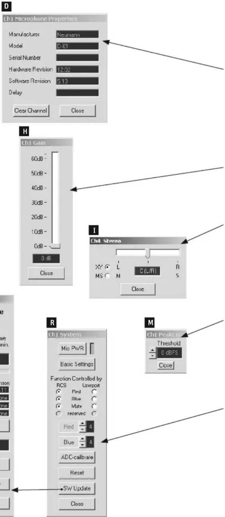
(D) Microphone Properties
Displays the saved microphone model or the model of the connected microphone. The fi eld blinks and appears orange if a microphone model is assigned to the channel but no valid data stream is received. Clicking on the display fi eld opens a window with the following information:
- Manufacturer
- Model
- Serial Number
- Soft ware Version
- Hardware Version
- Delay (Microphone latency time, dependent upon the sampling rate)
Clear Channel
Cancels the assignment of a microphone model to the channel. The channel is restored to its initial status. The function cannot be used while a microphone is connected to the channel.
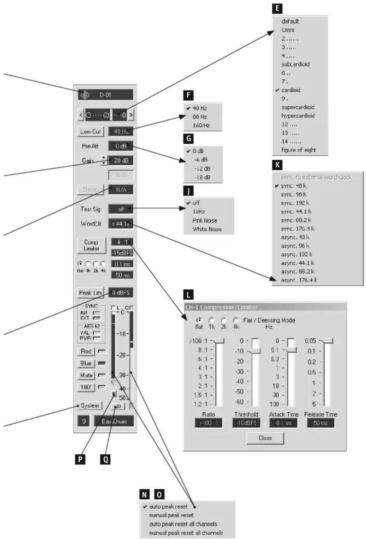
(E) Polar Pattern Select
Displays and controls the directional characteristic. Adjustable with 15 settings, from rectangular, to cardioid, to figure-eight. The setting can be changed either step-by-step, by clicking on one of the arrows at the ends of the scale; or by clicking on the display field, which opens a selection menu. The "default" O position can have different meanings for different microphones, and is normally not used. In the case of the Neumann small-diaphragm microphones, the active directional characteristic depends upon which capsule is used. For this reason, the directional characteristic of these microphones cannot be displayed, and clicking on the window will result display of the message: Polar pattern is capsule-dependent.
(F) Low Cut
Lowcut filter. Adjustable to 40 Hz, 80 Hz or 160 Hz, by clicking on the display fi eld. Clicking on the button switches the fi lter on and off. The filter setting "Off" (= fl at) is indicated by the gray color of the text in the display fi eld.
(G) Pre Att
Analog pre-attenuation. Adjustable to 0 dB, -6 dB, -12 dB or -18 dB, by clicking on the display field. This causes the analog dynamic range (i.e. maximum signal level and equivalent SPL) of the microphone to be shifted to the corresponding higher sound pressure levels.
(H) Gain
Digital gain. Adjustable from 0 dB to 63 dB in steps of 1 dB (clickless), by clicking on the display field. The setting can be changed:
- Directly, by clicking on the appropriate value on the scale
- In steps of 1 dB, by clicking on the scale above or below the slide indicator
• Continuously, by holding down the left mouse button and moving the slide indicator - Up/Down pushbuttons next to the corresponding display of the RCS, used to vary the signal gain in-side the microphone in 1dB steps without having to open the submenu.
(I) Stereo
Control of stereo microphones
The RCS can control balance and stereo width as well as switching between X/Y and M/S. The peak levels of both microphone channels are displayed omnidiin a stereo level meter.
(J) Test Sig
Generates test signals which can be used to test the signal path. The type of test signal is not defined in the AES42 standard. "Off" or one of three signals can be selected by clicking on the display field. In the case of Neumann microphones, usually 1 kHz sine, pink noise or white noise signals can be selected.
(K) Word Clk
Selects the sampling rate for the microphone and the DMI. Clicking on the display fi eld opens a selection menu where the synchronization and the sampling rates supported by the connected microphone can be set:
sync. to external Word Clock
This operating mode can be selected if an external word clock or AES11 synchronization signal is connected to the appropriate BNC port of the DMI. The type and frequency of the external word clock or AES11 signal are automatically detected by the DMI and are used for the synchronization of the DMI itself and all connected microphones.
sync. Word Clock (e.g. sync. 48 kHz)
If no valid external word clock present, the microphone operates synchronously with the selected internal word clock generated in the DMI. The signal is transmitted via the Master Clock Out port of the DMI.
All of the synchronous channels of a DMI are set to the same selected sampling rate.
Word clock rates of 48 kHz, 96 kHz and 192 kHz, as well as 44.1 kHz, 88.2 kHz and 176.4 kHz are supported. Following the activation of synchronization or a change in the word clock rate, the system requires a few seconds for the phase-locked loop (PLL) to synchronize. Successful synchronization is indicated by the indicators in the Sync field.
async. Word Clock (e.g. async. 48 kHz)
The microphone operates at the selected sampling rate without being synchronized with the DMI word clock or with an external word clock.
Sampling rates that are not supported by a microphone or DMI cannot be selected.
(L) Comp Limiter
Compressor and limiter. Clicking on the "Comp Limiter" button activates and deactivates the function. The setting "Off" is indicated by the gray color of the text in the associated display fields.
The selection fi elds below the button can be used to set the lower cutoff frequency of the working range (see "Mode"). There are also display fi elds for the compression Ratio, Threshold, Attack Time and Release Time.
Clicking on one of the display fi elds opens a window for the parameters of the limiter.
Mode
Lower cutoff frequency of the working range: Broadband (flat), 1 kHz, 2 kHz or 4 kHz. Only frequencies above the selected cutoff frequency are affected by the compressor. This also permits the compressor to be used as a de-esser.
Ratio
Compression ratio. Adjustable by clicking is on the display, with 8 levels from >100:1 to 1.2:1.
When set to >100:1, the function operates as a limiter.
The setting can be changed:
- By clicking on a value on the scale
- By clicking on the scale above or below the slide indicator
- By holding down the left mouse button and moving the slide indicator
Threshold
Threshold. Adjustable from 0 dBFS to -63 dBFS in steps of 1 dB, by clicking on the display. The setting can be changed:
- By clicking on a value on the scale
- In steps of 1 dB, by clicking on the scale above or below the slide indicator
- By holding down the left mouse button and moving the slide indicator
Attack Time
Attack time. Adjustable by clicking on the display, with 8 levels from 0 ms to 100 ms. The setting can be changed:
• By clicking on a value on the scale
- By clicking on the scale above or below the slide indicator
- By holding down the left mouse button and moving the slide indicator
Release Time
Release time. Adjustable by clicking on the display, with 7 levels from 50 ms to 5 s. The setting can be changed:
- By clicking on the appropriate value on the scale
- By clicking on the scale above or below the slide indicator
- By holding down the left mouse button and moving the slide indicator
(M) Peak Lim
Fast peak limiter for the suppression of transients and the prevention of overload. This function can be activated independently of the compressor/limiter. The setting "Off" is indicated by the gray color of the text in the associated display fi eld. The peak limiter has a negative attack time, i.e. the signal voltage to be limited is delayed relative to the control voltage generated. There is a fi xed release time.
If supported by the connected microphone, clicking on the display fi eld opens another window in which the threshold of the peak limiter can be set to a value from -15 dBFS to 0 dBFS, in steps of 1 dB.
Sync
Indicates the synchronization between the microphone and the DMI.
INT
Blinks while the microphone is being synchronized with the internal word clock of the DMI, and shines continuously when the microphone has been successfully synchronized.
EXT
Blinks while the microphone is being synchronized with an external word clock, and shines continuously when the microphone has been successfully synchronized.
AES 42
VAL
Appears green and shines continuously when a valid AES42 data stream from the microphone is detected. Blinks and appears orange when a microphone model has been assigned to the channel, but no microphone
has been detected (i.e. there is no valid AES 42 data stream). See "Channel status" section.
PWR
Shines when the phantom power (Digital Phantom Power, DPP) for the microphone is switched on.
Red
If present, controls the red LED on the microphone (Light 2 in the AES42 standard), e.g. as an "On Air" indicator. Alternatively, the LED can also be controlled via the DMI user port.
Blue
If present, controls the blue LED on the microphone (Light 1 in the AES42 standard). Alternatively, the LED can also be controlled via the DMI user port.
Mute
Mutes the audio signal. Alternatively, this function can also be controlled via the DMI user port.
180^
Reverses the polarity (phase) of the audio signal.
(N) L (Limiter) and Gain Reduction
Indicates the activation and gain reduction in dB of the peak limiter and the compressor/limiter with a peak hold function. The arrow below indicates a gain reduction of more than 30 dB.
Clicking on the gain reduction meter opens a selection menu which permits switching back and forth between automatic and manual peak reset for the selected channel or for all channels.
(0) O (Overload) Indicator and Level Meter
The level meter displays the level of the audio signal in -dBFS with a peak hold function. If an overload condition occurs in the microphone, this is indicated by the overload indicator.
Clicking on the level meter opens a selection menu which permits switching back and forth between automatic and manual peak reset for the current channel or for all channels.
(P) Peak Reset
The peak hold function of the level meter, the gain reduction meter and the overload indicator can be manually reset via the "R" button below the gain reduction meter.
(Q) +20
Increases the sensitivity of the level meter by 20 dB.

Attention: The scale of the level meter is not adjusted to reflect this change in sensitivity.
(R) System
Opens a window where the following functions can be controlled:
Mic PWR
Switches the microphone phantom power (Digital Phantom Power, DPP) on and off.
Basic Settings
Saves the current settings as startup settings in the microphone. This makes these settings available even when the microphone is operated with a power supply device complying with the AES42 standard, without remote control. If the microphone is connected to a DMI, each time after it is switched on the startup settings are overwritten by the settings saved in the DMI.
User Port Mode
Selection fi eld. Radio buttons indicate which functions are controlled by the RCS and which are controlled by the DMI user port.
Red
Sets the brightness of the red LED on the microphone (Light 2 in the AES42 standard).
Blue
Sets the brightness of the blue LED on the microphone (Light 1 in the AES42 standard).
ADC-calibrate
Calibrates the A/D converter; not required for Neumann microphones.
Reset
Resets the microphone software and restores the most recent settings.
(S) SW Update
Updates the soft ware and selects the boot sector for the microphone soft ware. A new
window is opened, where the boot sectors of the microphone are displayed as several lines, one below the other. One soft ware version can be saved in each boot sector. The user can select which boot sector will be used to start the microphone, and thus which soft ware version will then be used to operate the microphone (see Apply). Following an interrupted soft ware update, the previous soft ware version is automatically reactivated. When the window is opened, all boot sectors where soft ware versions are saved are displayed.
During soft ware update, microphones which are not updated operate normally but cannot be controlled or monitored by the RCS.
Boot Partition
Save to
The line indicated by the radio button shows which soft ware version is to be overwritten when the update is performed. As a safety precaution, the soft -ware version currently being used by the microphone cannot be overwritten.
Apply
A radio button indicates which boot sector contains the most recently selected soft ware version. By clicking on another field (line), it is possible to select a different soft ware version to be used for booting. Immediately after the window is closed, the microphone is reset and the selected soft ware version is loaded.
After software is downloaded, the sector selected for the download is automatically selected as the sector to be used for booting.
Version
Displays the software version in the corresponding boot sector.
Choose File
Opens a window where the mi- crophone fi rmware fi le (*.mfw) can be selected for the soft ware download.
Start Update
Starts the update process. The new soft ware is transmitted to the microphone via the remote control data stream specified in the AES42 standard.
Since this data stream is de- fined as having a very low bit rate, a soft ware download takes approximately 30 minutes. Following a successful software download, the microphone is automatically started with the new soft ware version, after the window is closed.
Cancel Update
Cancels the update process. The microphone continues to operate with the previously valid soft ware version.
Close
Closes the "System" window. If a soft ware download has been successfully executed, the microphone is automatically started with the new soft ware version.
Channel number
Displays the channel number. (The display cannot be edited.)
Channel name
Text field where any desired names or text may be entered. If the text is longer than the text field, the complete text will be displayed as a tooltip.
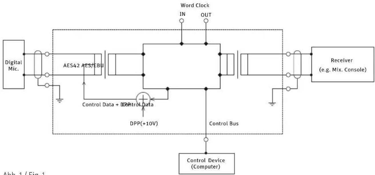
flowchart
graph TD
    A["Digital Mic."] --> B["AES42 AES7EBU"]
    B --> C["DPP(+10V)"]
    C --> D["Control Bus"]
    D --> E["Receiver (e.g. Mix. Console)"]
    E --> F["Control Device (Computer)"]
    G["Word Clock IN OUT"] --> C
    H["Control Data + DPP"] --> C
    I["Control Data"] --> C
Abb. 1 / Fig. 1
Haftungsausschluss
Limitation of Liability
Georg Neumann GmbH shall not be liable for consequences of an inappropriate use of the product not being in compliance with the technical allowance in the user manual such as handling errors, mechanical spoiling, false voltage and using other than the recommended correspondence devices. Any liability of Georg Neumann GmbH for any damages including indirect, consequential, special, incidental and punitive damages based on the user's non-compliance with the user manual or unreasonable utilization of the product is hereby excluded as to the extent permitted by law. This limitation of liability on damages is not applicable for the liability under European product liability codes or for users in a state or country where such damages cannot be limited.
CE Declaration of Conformity
Georg Neumann GmbH hereby declares that this device conforms to the applicable CE standards and regulations.
® Neumann is a registered trademark of the Georg Neumann GmbH in certain countries.

- REMOTE CONTROL SOFTWARE – RCS
- Grundlagen
- Allgemeines
- Load Preset from Device... (nur DMI-2 portable)
- Save as Preset to Device... (nur DMI-2 portable)
- (B1) Display Channel Navigation
- Two-Channel Interface Mode
- AES/EBU Output Routing:
- (B4) MCA Wordclock Setup
- Select Device Address (ID)
- Clear Unconnected Channels
- Microphone Properties
- Polar Pattern Select
- sync. to external Word Clock
- Digital Microphone Interface – DMI
- AES42
- Use as VST plug-in
- Connection between DMI Interfaces and Computer
- DMI-2 portable
- DMI-2
- DMI-8
- MCA-ES
- Installation
- Minimum computer requirements
- Software
- Starting the RCS
- Functionality
- Channel display
- Channel status
- Configurations
- Menu functions
- File
- New (Default)
- Open
- Save
- Save As
- Save As Default
- Load Preset from Device... (only DMI-2 portable)
- Save as Preset to Device... (only DMI-2 portable)
- Exit/Quit
- Options
- Tooltips
- < 2 .. 8 >
- Hide
- Show All
- (B2) DMI
- AES/EBU Output Routing
- AES42 to AES/EBU
- Network to AES42
- SW Update
- Choose File
- Start Update
- Close
- Help
- Manuals
- Support
- Show Log File
- About RCS
- (B3) Communication
- USB Converter
- EtherSound
- Number of Channels
- Channel functions
- Clear Channel
- Low Cut
- Pre Att
- Gain
- Stereo
- Test Sig
- Word Clk
- sync. Word Clock (e.g. sync. 48 kHz)
- async. Word Clock (e.g. async. 48 kHz)
- Comp Limiter
- Mode
- Ratio
- Threshold
- Attack Time
- Release Time
- Peak Lim
- Sync
- INT
- EXT
- AES 42
- VAL
- PWR
- Red
- Blue
- Mute
- 180°
- L (Limiter) and Gain Reduction
- O (Overload) Indicator and Level Meter
- Peak Reset
- Boot Partition
- Save to
- Apply
- Version
- Cancel Update
- Channel number
- Channel name
- Haftungsausschluss
- Limitation of Liability
- CE Declaration of Conformity
Brand : NEUMANN
Model : D-01
Category : Microphone