852-1322 - Switch Wago - Free user manual and instructions
Find the device manual for free 852-1322 Wago in PDF.


| Product Type | Industrial Managed Switch |
| Model Number | 852-1322 |
| Brand | WAGO |
| Dimensions (W x H x D) | 45.3 mm x 110 mm x 92 mm |
| Weight | 441 g |
| Degree of Protection | IP30 |
| Supply Voltage | 9 … 48 VDC |
| Power Consumption (max) | 5.8 W |
| Number of Ports (Copper RJ-45) | 6 x 10/100/1000BASE-T(X) |
| Number of Ports (Copper RJ-45 with MACsec) | 2 x 10/100/1000BASE-T (MAC Security) |
| Supported Standards | IEEE 802.3, 802.3u, 802.3ab, 802.3x, 802.1Q, 802.1p, 802.1AE |
| MAC Table Size | 16384 entries |
| Jumbo Frame Size | 10 kB |
| Operating Temperature | -20 … +70 °C |
| Storage Temperature | -40 … +85 °C |
| Relative Humidity | 5 … 95 % at 55 °C |
| Vibration Resistance | IEC 60068-2-6 |
| Shock Resistance | IEC 60068-2-27 |
| EMC Immunity | EN 55024, EN 61000-6-2, EN 61000-6-1 |
| EMC Emission | FCC Part 15 Class A & B, EN 55032 Class A & B, EN 61000-6-4, EN 61000-6-3 |
| Approvals | EN/IEC/CB/UL 62368-1 |
| Configuration Interface | Web-based Management (WBM) via HTTPS |
| Default IP Address | 192.168.1.254 |
| Default Username / Password | admin / wago |
| Mounting | DIN rail (35 mm) |
| Grounding | Via grounding screw on top panel |
Frequently Asked Questions - 852-1322 Wago
User questions about 852-1322 Wago
0 question about this device. Answer the ones you know or ask your own.
Ask a new question about this device
Download the instructions for your Switch in PDF format for free! Find your manual 852-1322 - Wago and take your electronic device back in hand. On this page are published all the documents necessary for the use of your device. 852-1322 by Wago.
USER MANUAL 852-1322 Wago
Industrial Managed Switch
8 Ports 1000BASE-T; MAC Security
852-1322
All rights reserved.
Every conceivable measure has been taken to ensure the accuracy and completeness of this documentation. However, as errors can never be fully excluded, we always appreciate any information or suggestions for improving the documentation.
E-Mail: ✉ documentation@wago.com
We wish to point out that the software and hardware terms as well as the trademarks of companies used and/or mentioned in the present manual are generally protected by trademark or patent.
WAGO is a registered trademark of WAGO Verwaltungsgesellschaft mbH.
Table of Contents
Provisions....6
1.1 Proper Use 6
1.2 Typographical Conventions.... 7
1.3 Legal Information 8
Safety 10
2.1 General Safety Regulations 10
2.2 Electrical Safety.... 10
2.3 Mechanical Safety 11
2.4 Indirect Safety 12
Overview 13
Properties 14
4.1 Views.... 14
4.1.1 Front View 14
4.1.2 Top View 15
4.2 Label.... 16
4.3 Connectors.... 16
4.3.1 Grounding screw 16
4.3.2 Power Supply 16
4.3.3 Network Connections ...... 17
4.3.3.1 10/100/1000BASE-T(X) ports.... 18
4.3.3.2 10/100/1000BASE-T(X) (MACsec) ports.... 18
4.4 Display Elements.... 18
4.4.1 Unit LEDs 18
4.4.2 Port LEDs 19
4.5 Technical data.... 19
4.5.1 Product 19
4.5.2 System Data.... 19
4.5.3 Power Supply 19
4.5.4 Communication 19
4.5.5 Environment requirements ...... 20
4.6 Guidelines, approvals and standards.... 20
4.6.1 Approvals 20
4.6.2 Regulations and Standards ...... 20
Functions.... 22
5.1 Security 22
5.1.1 IEEE 802.1X....22
5.1.2 RADIUS.... 22
5.1.3 MAC Security (MACSec).... 23
Planning.... 24
6.1 Structure Guidelines.... 24
6.1.1 Installation Site 24
Transport and Storage.... 25
Installation and Removal.... 26
8.1 Installation 26
8.1.1 Installation on a Carrier Rail 26
8.2 Removal 26
8.2.1 Removal from Carrier Rail.... 26
Connection 27
9.1 Grounding.... 27
9.2 Connecting the Supply Voltage.... 27
9.3 Connect 10/100/1000BASE-T ports.... 27
Configuration in the WBM 29
10.1 Login.... 29
10.2 Login Failure.... 32
10.3 Information 35
10.3.1 System Information 35
10.3.2 Legal Information.... 36
10.4 Configuration.... 36
10.4.1 System Settings 36
10.4.2 Device Discovery – LLDP 37
10.4.3 System Management – SNTP.... 38
10.4.3.1 General Information.... 38
10.4.3.2 SNTP Setup.... 39
10.4.4 Network Settings 41
10.4.5 Port Settings.... 42
10.4.5.1 Setting 42
10.4.6 Interface – Port Mirroring.... 43
10.4.6.1 General Information.... 43
10.4.6.2 Port Mirroring Setup 44
10.4.7 Password.... 44
10.5 Diagnostics.... 45
10.5.1 SNMP 45
This documentation applies to the following product:
852-1322
1.1 Proper Use
The device is designed for the IP30 protection class. It is protected against the insertion of solid items and solid impurities up to 2.5 mm in diameter, but not against water penetration. Unless otherwise specified, the device must not be operated in wet and dusty environments.
Warranty and Liability
The terms set forth in the General Business & Contract Conditions for Delivery and Service of WAGO Kontakttechnik GmbH & Co. KG and the terms for software products and products with integrated software stated in the WAGO Software License Contract – both available at www.wago.com – shall apply. In particular, the warranty is void if:
• The product is improperly used.
- The deficiency (hardware and software configurations) is due to special instructions.
- Modifications to the hardware or software have been made by the user or third parties that are not described in this documentation and that has contributed to the fault.
Individual agreements always have priority.
Obligations of Installers/Operators
The installers and operators bear responsibility for the safety of an installation or a system assembled with the products. The installer/operator is responsible for proper installation and safety of the system. All laws, standards, guidelines, local regulations and accepted technology standards and practices applicable at the time of installation, and the instructions in the the products' Instructions for Use, must be complied with. In addition, the Installation regulations specified by Approvals must be observed. In the event of non-compliance, the products may not be operated within the scope of the approval.
Improper Use
Improper use of the product is not permitted. Improper use occurs especially in the following cases:
• Non-observance of the intended use.
- Use without protective measures in an environment in which moisture, salt water, salt spray mist, dust, corrosive fumes, gases, direct sunlight or ionizing radiation can occur.
- Use of the product in areas with special risk that require continuous fault-free operation and in which failure of or operation of the product can result in an imminent risk to life, limb or health or cause serious damage to property or the environment (such as the operation of nuclear power plants, weapons systems, aircraft and motor vehicles).
1.2 Typographical Conventions
Number Notation
| 100 Decimals: Normal notation | |
| 0x64 Hexadecimals: C-notation | |
| ‘100’ | Binary: In single quotation marks |
| ‘0110.0100’ | Nibbles separated by a period |
Text Formatting
| italic Names of paths or files | |
| bold Menu items, entry or selection fields, emphasis | |
| Code Sections of program code | |
| >Selection of a menu point from a menu | |
| “Value” Value entries | |
| [F5] Identification of buttons or keys |
Cross References / Links
| Cross references/links to a topic in a document | |
| Cross references / links to a separate document | |
| Cross references / links to a website | |
| Cross references / links to an email address |
Action Instructions
√ This symbol identifies a precondition.
- Action step
- Action step
⇒ This symbol identifies an intermediate result.
⇒ This symbol identifies the result of an action.
Lists
- Lists, first level
- Lists, second level
Figures
Figures in this documentation are for better understanding and may differ from the actual product design.
Notes
DANGER
Type and source of hazard
Possible consequences of hazard that also include death or irreversible injury
• Action step to reduce risk

WARNING
Type and source of hazard
Possible consequences of hazard that also include severe injury
• Action step to reduce risk

CAUTION
Type and source of hazard
Possible consequences of hazard that include at least slight injury
• Action step to reduce risk

NOTICE
Type and source of malfunction (property damage only)
Possible malfunctions that may restrict the product's scope of functions or ergonomics, but do not lead to foreseeable risks to persons
• Action step to reduce risk

Note
Notes and information
Indicates information, clarifications, recommendations, referrals, etc.
1.3 Legal Information
Intellectual Property
Unless barred by applicable legal provisions, unauthorized copying and distribution of this document, as well as the use and communication of its content are strictly prohibited unless expressly authorized by prior agreement. Third-party products are always mentioned without any reference to patent rights. WAGO Kontakttechnik GmbH & Co. KG, or for third-party products, their manufacturer, retain all rights regarding patent, utility model or design registration.
Third-party trademarks are referred to in the product documentation. The “®” and “TM” symbols are omitted hereinafter. The trademarks are listed in the Appendix (Protected Rights).
Subject to Change
The instructions, guidelines, standards, etc., in this manual correspond to state of the art at the time the documentation was created and are not subject to updating service. The installer and operator bear sole responsibility to ensure they are complied with in their currently applicable form. WAGO Kontakttechnik GmbH & Co. KG retains the right to carry out technical changes and improvements of the products and the data, specifica-
tions and illustrations of this manual. All claims for change or improvement of products that have already been delivered – excepting change or improvement performed under guarantee agreement – are excluded.
Licenses
The products may contain open-source software. The requisite license information is saved in the products. This information is also available under www.wago.com.
Safety
This section contains safety rules that must be followed for hazard-free use of the product.
This section is aimed at the following target groups:
- Planners and installers
- Operators
• Qualified assembly personnel
- Qualified installation personnel (electrical installation, technician network installation etc.)
• Qualified operating personnel
• Qualified service and maintenance personnel
Obey the following safety rules:
2.1 General Safety Regulations
- This documentation is part of the product. Therefore, retain the documentation during the entire service life of the product. Pass on the documentation to any subsequent user of the product. In addition, ensure that any supplement to this documentation is included, if necessary.
- Any actions related to the use of WAGO software may only be performed by qualified staff with sufficient knowledge to use the respective PC system.
Steps in which files are created or changed on a PC system may only be performed by qualified employees with sufficient knowledge in the administration of the PC system used in addition to file creation or modification.
Steps that change the PC system's behavior within a network may only be performed by qualified employees with sufficient knowledge of administration of the responsible network.
- Changes to switch configurations in the network must always be performed by qualified personnel with sufficient skills.
- Comply with the laws, standards, guidelines, local regulations and accepted technology standards and practices applicable at the time of installation.
- If remote access to control components and control networks is required, use a Virtual Private Network (VPN).
2.2 Electrical Safety
- High voltage can cause electric shock or burns! Disconnect all power sources from the product before performing any installation, repair or maintenance.
Power Supply
- Connecting impermissible current or frequency values may destroy the product.
- Switch off power supply to the device immediately if the product malfunctions or is damaged.
Ground/Protection/Fuses
- Protect the product with an appropriate overcurrent protection device.
- Using the overvoltage and lightning protection designs intended for the building.
- When handling the product, please ensure that environmental factors (personnel, work space and packaging) are properly equalized. Do not touch any conducting parts.
Lines
- Maintain spacing between control, signal and data lines and the power supply lines.
- Observe permissible temperature range of connecting cables.
- Use appropriate strain relief.
- Make sure the pin assignment is correct.
- Avoid reverse polarity of data and power supply lines, as this may damage the devices involved.
Protect
- Observe the applicable standards for EMC-compatible installations.
Radio, etc.
- This is a Class A product. The product can cause radio interference in residential areas; in this case, the operator can be required to take appropriate measures to prevent such interference.
- For industrial use: WAGO's 852 Series ETHERNET Switches are certified to be used in residential and in industrial environments. If the latter, they should be considered as exposed operating components. Therefore, in industrial applications, only install these switches in lockable housings, cabinets or electrical operation rooms. Access must be limited to authorized, qualified staff having the appropriate key or tool.
- Only use devices equipped with ETHERNET or RJ-45 connectors in LANs. Never connect these devices with telecommunication networks.
Components
- Replace defective or damaged device/module (e.g., in the event of deformed contacts).
2.3 Mechanical Safety
- As the installer of the system, you are responsible for ensuring the necessary touch-proof protection. Follow the installation guidelines for the specific application.
- The surrounding air temperature for operation indicated in the technical data applies to the nominal mounting position. Different mounting positions may affect the permissible surrounding air temperature for operation.
- Cooling of the product must not be impaired. Ensure air can flow freely and that the minimum clearances from adjacent products/areas are maintained.
- Do not install the product on or in the vicinity of easily flammable materials.
- When selecting the location for installation, note that the control cabinet must remain accessible for maintenance purposes.
- Before startup, please check the product for any damage that may have occurred during shipping. Do not put the product into operation in the event of mechanical damage.
- Only use this product in a controlled environment.
- Do not open the product housing.
- Avoid conductive contamination.
2.4 Indirect Safety
- Do not use hard objects that could cause scratches for cleaning.
- Do not use any contact spray for cleaning.
- Clean tools and materials are imperative for handling the product.
- The products are not resistant to materials having seeping and insulating properties such as aerosols, silicones and triglycerides (found in some hand creams). If these substances occur in the environment of the products, install the products in an additional housing that is also resistant to these substances.
- Before installation and operation, please read the product documentation thoroughly and carefully. In addition, note the information on the product housing and further information, e.g. at www.wago.com/
- Change the password. The factory default setting is widely known and does not provide adequate protection.
- Give all products in a network different IP addresses.
- Use only the current firmware.
- Regularly perform threat analyses. You can check whether the measures taken meet your security requirements.
- Use “defense-in-depth” mechanisms in your system's security configuration to restrict the access to and control of individual products and networks.
Overview
WAGO's 852-1322 industrial managed switch is a switch with 8 Gigabit-Ports 10/100/1000 BASE-T(X) RJ-45, of which two ports support MAC Security encryption.
This industrial managed switch is easy to configure and install; thus, it can be used in numerous applications including residential applications. It is ideal for plug-and-play local area network protection with embedded MACsec key agreement that offers security protection.
MACsec uses GCM-AES to implement point-to-point security for ETHERNET links between switches. In other words, it can secure a network from a whole host of security threats, including intrusion, man-in-the-middle, masquerading, passive wiretapping, and playback attacks. And because MACsec encryption is hardware-based, there is no nameable added latency.
WAGO's 852-1322 is ideal for adding an extra layer of security in residential and industrial applications that require compact solutions while delivering high network performance up to 97% of throughput guaranteed with no nameable additional latency.
It also supports a wide operating temperature range of -20 °C to 70 °C and is EN/IEC(CB)/UL62368-1, and IEC 60068-2-6, IEC 60068-2-27, IEC 60068-2-32. WAGO's 852-1322 switches is a powerful compact device that can perform under a variety of environmental conditions, such as power input voltage, shock, drop and vibration.
Properties
4.1 Views
4.1.1 Front View
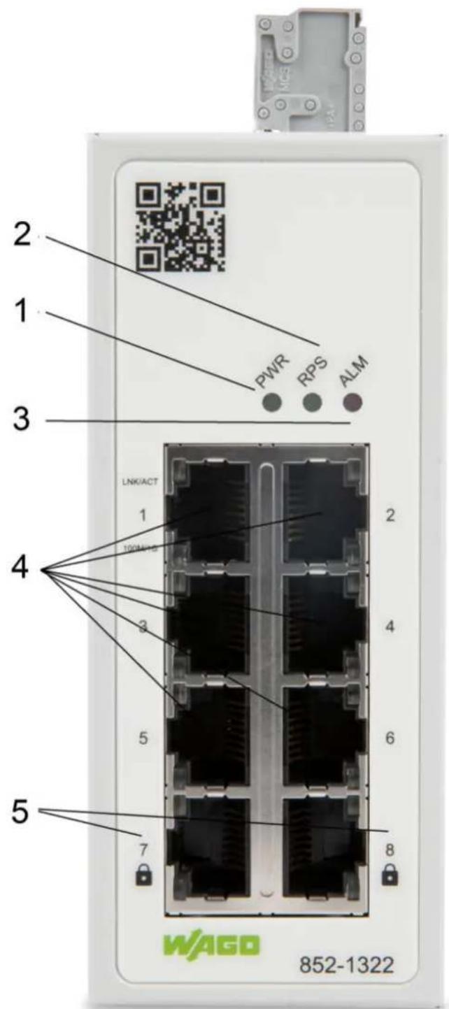
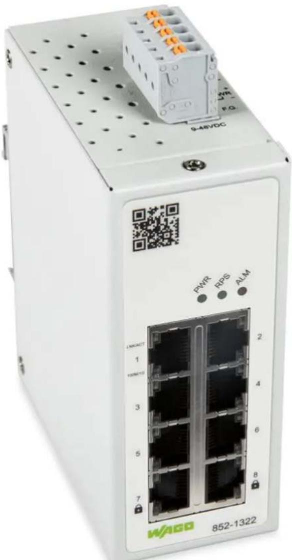
Figure 1: Front View of the Industrial Managed Switch
Table 1: Legend for the Figure "Front View of the Industrial Managed Switch"
| Pos. | Custom Name Explanation | ||
| 1 PWR | Status LED Power input | Display Elements [▶ 18] | |
| 2 RPS | Status LED redundant input | Display Elements [▶ 18] | |
| 3 ALM | Status LED alarm | Display Elements [▶ 18] | |
| 4 RJ-45 | ports (10/100/1000BASE-T(X))(6) | Port LEDs [▶ 19] | |
| 5 RJ-45 | ports (10/100/1000BASE-T(X)(MACsec) (2) | Port LEDs [▶ 19] |
4.1.2 Top View
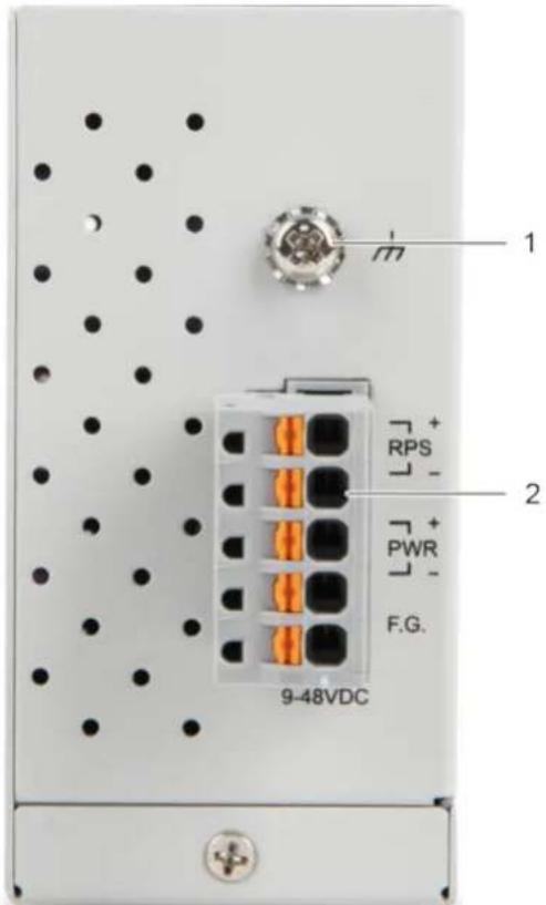
Figure 2: Top View of the Industrial Managed Switch
Table 2: Legend for the Figure "Top View of the Industrial Managed Switch"
| Pos. | Custom Name Explanation Details | |
| 1 - Grounding screw | Grounding screw [▶ 16] | |
| 2 - Connector (male) for power consumption (RPS/PWR/F.G.) (RPS/PWR/F.G.) (Item number 2231-105/026-000) | Power Supply [▶ 16] | |
4.2 Label
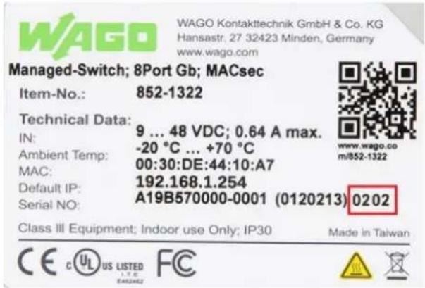
Figure 3: Label
Table 3: Legend for Figure „Label“
| Custom Name Description | |
| Item-No Item number | |
| IN Device input and maximum current and voltage | |
| Ambient Temp Device input and maximum current and voltage | |
| MAC Device MAC information | |
| Default IP Device default IP address | |
| Serial NO Device serial number | |
| QR code Connect to product information by scanning this QR code | |
4.3 Connectors
4.3.1 Grounding screw
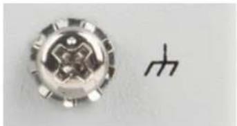
The switch must be grounded. Connect the grounding screw to the ground potential. Do not operate the switch without an appropriately installed protective earth conductor.
natural_image
Close-up of a metallic circular component with internal features and a small symbol on the right (no readable text or labels)Figure 4: Grounding screw
4.3.2 Power Supply
The female connector (Item No. 2231-105/026-000) can easily be connected to the 5-pole male connector (Item No. 231-435/001-000) located on the top of the switch.
Both PWR and RPS support input voltage between 9 and 48 VDC.
The male connector shows the following pin assignment:
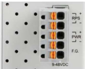
Figure 5: Power Supply Connector
Table 4: Legend for Figure "Power Supply"
| Connection | Custom Name Description | |
| + RPS | Secondary DC input | |
| - RPS | Secondary DC input | |
| + PWR | Primary DC input | |
| - PWR | Primary DC input | |
| F.G. Functional Ground | ||
NOTICE
Damage to Property Caused by Electrostatic Discharge (ESD)!
DC Powered Switch: Power is supplied through an external DC power source. Since the switch does not include a power switch, plugging its power adapter into a power outlet will immediately power it on.
4.3.3 Network Connections
The industrial managed Switch uses ports with copper connectors and supports ETHERNET, Fast ETHERNET and Gigabit ETHERNET
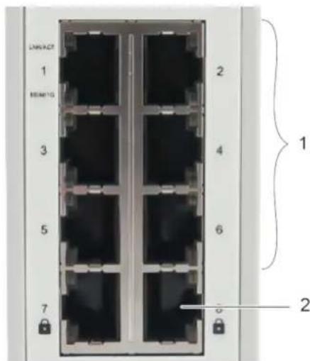
Figure 6: Network Connections
Table 5: Legend for Figure "Network Connections"
| Pos. | Description For Details, see Section: | |
| 1 6 x RJ-45 connections(10/100/1000BASE-T(X)) | - 10/100/1000BASE-T(X) ports [ > 18] | |
| 2 2 x SFP connections(10/100/1000BASE-T(X) (MACsec) | 1 10/100/1000BASE-T(X) (MACsec) ports[▶ 18] | |
4.3.3.1 10/100/1000BASE-T(X) ports
10/100/1000BASE-T(X) ports support networks speeds of 10 Mbit/s, 100 Mbit/s und 1000 Mbit/s and can be operated in half- and full-duplex transmission modes. These ports also provide automatic crossover detection (Auto-MDI/MDI-X), with plug-and-play capabilities. Simply plug the network cables into the ports; they then adapt to the end node devices.
We recommend the following cable for the RJ-45 ports:
- Cat 5e or better with a max. cable length 100 m.
4.3.3.2 10/100/1000BASE-T(X) (MACsec) ports
The 10/100/1000BASE-T(X) (MACsec) connections offer not only the network speeds of 10 Mbit/s, 100 Mbit/s and 1000 Mbit/s, but also encrypted data traffic using the MAC Security security standard.
4.4 Display Elements
The is equipped with device LEDs and port LEDs. You can see the status quickly with the device LEDs, while the port LEDs provide information about connection actions.
4.4.1 Unit LEDs
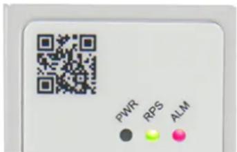
Figure 7: Unit LEDs
Table 6: Legend for "Unit LEDs" Figure
| LED Name Status Description | |||
| PWR Primary-Power-LED Green Use the primary power supply. | |||
| Off Primary power off or failure. | |||
| RPS Redundant-Power-System-LED | Green Use the redundant power supply. | ||
| Off Redundant power off or failure. | |||
| ALM Alarm-LED Red | No power supply at the primary or secondary (PWR or RPS) power supply. | ||
| Off No alarm reported | |||
4.4.2 Port LEDs
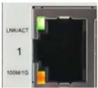
Figure 8: Port LEDs
Table 7: Legend for „Port LEDs“ Figure
| LED Connection Status Description | ||
| LINK/ACT 10/100/1000 BASE T Ports LED(1 LED for each port) | Green Port in operation | |
| Flashes Data traffic routed via the port | ||
| Off No proper link established | ||
| 100M/1G 10/100/1000 BASE T Ports LED(1 LED for each port) | Amber Port in operation at 100/1000 Mbit/s | |
| Off Port in operation at 10 Mbit/s or not linked | ||
4.5 Technical data
4.5.1 Product
Table 8: Technical Data – Device Data
| Property Value | |
| Width 45.3 mm | |
| Height 110 mm | |
| Depth 92 mm (from the top edge of the carrier rail) | |
| Weight | 441 g |
| Degree of protection | IP30 |
4.5.2 System Data
Table 9: Technical Data – System Data
| Property Value | |
| MAC table | 16384 entries |
| Jumbo Frame Size | 10 kB |
| Maximum lengths 10/100/1000BASE-T(X): 100 m | |
4.5.3 Power Supply
Table 10: Technical Data – Power Supply
| Property Value | |
| Supply voltage | 9 ... 48 VDC |
| Power consumption, max. | 5.8 W |
4.5.4 Communication
Table 11: Technical Data – Communication
| Property Value | |
| Ports (copper, RJ-45) | 6 x 10/100/1000BASE-T(X) |
| Ports (copper, RJ-45, MAC Security) | 2 x 10/100/1000BASE-T (MAC Security) |
| Standards IEEE 802.3 10BASE-T | IEEE 802.3u 100BASE-TXIEEE 802.3ab 1000BASE-TIEEE 802.3x Flow Control, back pressure Flow ControlIEEE 802.1Q for VLAN Tagging (Prioritization of Profinet Packets)IEEE 802.1p for CoS (Prioritization of Profinet Packets)IEEE 802.1AE for MAC Security |
4.5.5 Environment requirements
Table 12: Technical Data – Environmental Conditions
| Property Value | ||
| Surrounding air temperature, operation -20 ... +70 °C | ||
| Surrounding air temperature, storage -40 ... +85 °C | ||
| UL 62368-1 Use Indoor | ||
| Relative humidity 5 ... 95 %, 55 °C | ||
| Vibration resistance IEC 60068-2-6 | ||
| Shock resistance IEC 60068-2-27 | ||
| EMC immunity to interference EN 55024 | EN 61000-6-2EN 61000-6-1 | |
| EMC Emission of interference FCC Part 15, | Subpart B, Class A,Class BEN 55032 Class A and Class BEN 61000-6-4EN 61000-6-3EN 55011 | |
4.6 Guidelines, approvals and standards
4.6.1 Approvals
The following approvals have been granted for the product:


i Note
More information on approvals
You can find detailed information on the approvals online at: www.wago.com/
4.6.2 Regulations and Standards
Please observe the standards and regulations that are relevant to installation:
- The data and power lines must be connected and installed in compliance with the standards to avoid failures on your installation and eliminate any danger to personnel.
- For installation, startup, maintenance and repair, please observe the accident prevention regulations of your machine (e.g., DGUV Regulation “Electrical Installations and Equipment”).
- Emergency stop functions and equipment must not be deactivated or otherwise made ineffective. See relevant standards (e.g., EN 418).
- Your installation must be equipped in accordance to the EMC guidelines so electromagnetic interferences can be eliminated.
- Please observe the safety measures against electrostatic discharge according to EN 61340-5-1/-3. When handling the modules, ensure that environmental factors (persons, workplace and packing) are well grounded.
- The relevant valid and applicable standards and guidelines regarding the installation of switch cabinets must be observed.
Functions
5.1 Security
5.1.1 IEEE 802.1X
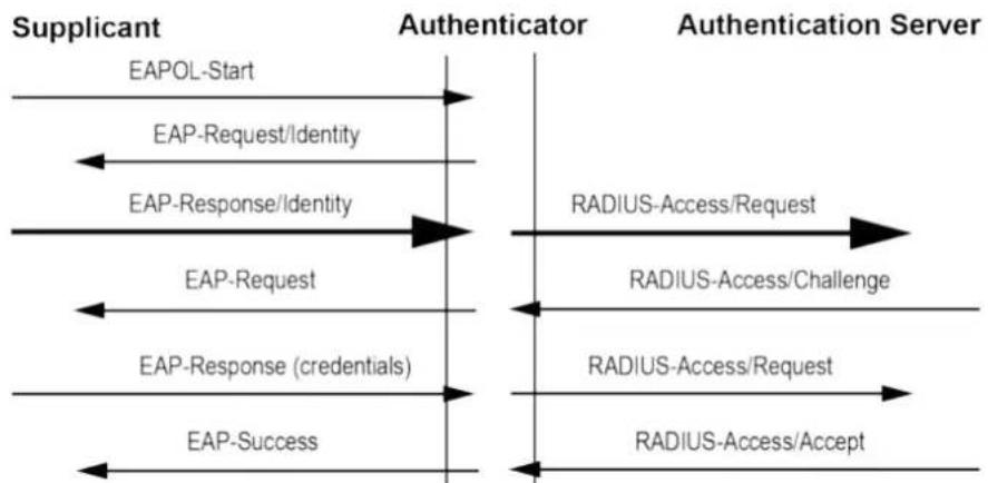
IEEE 802.1X is an IEEE standard for port-based Network-Access Control protocol. It provides an authentication mechanism to devices that need to attach to a LAN. This protocol restricts unauthorized clients from connecting to a LAN through ports that are opened to the Internet. The authentication generally involves three parties (see Figure "RADIUS Authentication Sequence" in Section RADIUS [▶ 22]): a supplicant, an authenticator, and an authentication server.
- Supplicant: A client device that requests access to the LAN
- Authentication Server: This server performs the actual authentication. We utilize RADIUS ("Remote Authentication Dial-In User Service" as the authentication server.
- Authenticator: The Authenticator is a network device (i.e. the WAGO Industrial managed switch) that acts as a proxy between the supplicant and the authentication server. It passes around information, verifies information with the server, and relays responses to the supplicant.
The authenticator acts like a security guard to a protected network. The supplicant is not allowed accessing to the protected side of the network through the authenticator until the supplicant's identity has been validated and authorized. With IEEE802.1X authentication, a supplicant and an authenticator exchange EAP ("Extensible Authentication Protocol", an authentication framework widely used by IEEE) aus. Then the authenticator forwards this information to the authentication server for verification. If the authentication server confirms the request, the supplicant (client device) will be allowed to access resources located on the protected side of the network.
5.1.2 RADIUS
The RADIUS is a networking protocol that provides authentication, authorization and accounting (AAA) management for devices to connect and use a network services. Figure "RADIUS Authentication Sequence" shows a diagram of RADIUS authentication sequence.
flowchart
graph LR
    A["Supplicant"] --> B["EAPOL-Start"]
    B --> C["EAP-Request/Identity"]
    C --> D["EAP-Response/Identity"]
    D --> E["EAP-Request"]
    E --> F["EAP-Response (credentials)"]
    F --> G["EAP-Success"]

    H["Authentication Server"] --> I["RADIUS-Access/Request"]
    I --> J["RADIUS-Access/Challenge"]
    J --> K["RADIUS-Access/Request"]
    K --> L["RADIUS-Access/Accept"]

    style H fill:#f9f,stroke:#333
    style I fill:#ccf,stroke:#333
    style J fill:#ccf,stroke:#333
    style K fill:#ccf,stroke:#333
    style L fill:#ccf,stroke:#333
Figure 9: RADIUS Authentication Sequence
5.1.3 MAC Security (MACSec)
WAGO industrial managed switches support advanced security features that allow traffic encryption and high throughput. MACsec or Media Access Control Security is a security standard specified by IEEE also called IEEE 802.1AE. This IEEE MAC security standard provides connectionless user data confidentiality, frame data integrity, and data origin authenticity. MACsec can establish point-to-point security on ETHERNET links between directly connected nodes. WAGO industrial managed switches support this security feature and can be used to transparently secure an IEEE 802 LAN connection to a peer device (such as another switch) that also supports the MACsec.
MACsec defines two terms called secure channel and connectivity association when setting up a secure communication between two switches. A secure channel in MACsec is unidirectional and used for transmitting (outbound traffic) or receiving (inbound traffic) data. A connectivity association when MACsec is enabled consists of two secure channels: one for inbound traffic and one for outbound traffic.
The point-to-point links can be secured by MACsec after matching security keys are exchanged and verified between the ports on two different secure switches.
The static secure association key (SAK) security mode is when the user manually configured the same static secure association key (SAK) on both sides of a connection. There is no key server in this mode and the keys must be matched on the ports of both switches. This can be viewed as setting up two secure channels within a connectivity association. It is suggested to have a periodic manual key update in order to prevent the key to be broken by brute-force attack.
Planning
6.1 Structure Guidelines
6.1.1 Installation Site
The location selected to install the may greatly affect its performance. When selecting a site, we recommend considering the following rules:
- Install the at an appropriate place. See Section 🚗 Environment requirements [▶ 20] , for the acceptable temperature and humidity operating ranges.
- Make sure that the heat output from the and ventilation around it is adequate.
- Do not place any heavy objects on the .
Transport and Storage
The original packaging offers optimal protection during transport and storage.
- Store the product in suitable packaging, preferably the original packaging.
- Only transport the product in suitable containers/packaging.
- Make sure the product contacts are not contaminated or damaged during packing or unpacking.
- Observe the specified ambient climatic conditions for transport and storage ( Environ- rionment requirements [▶ 20]).
Installation and Removal
8.1 Installation
8.1.1 Installation on a Carrier Rail
The carrier rail must optimally support the EMC measures integrated into the system and the shielding of the internal data bus connections.
Place the onto the DIN rail from the top and snap it into position.
8.2 Removal
8.2.1 Removal from Carrier Rail
To remove the industrial managed switch from the carrier rail, insert a suitable tool into the metal tab under the switch and deflect the metal tab downward.
You can then release the switch down from the carrier rail and remove it upwards.
Connection
9.1 Grounding
Grounding is through the grounding screw on the top of the product.
The switch must be grounded. Connect the grounding screw to the ground potential. Do not operate the switch without an appropriately installed protective earth conductor.
9.2 Connecting the Supply Voltage
The switch uses direct-current power supply of 9 ... 48 VDC.
The primary and secondary power supply pins are connected via a 5-pin plug-in connection located on the top of the industrial managed switch.
The female connector (Item No. 2231-105/026-000) is composed of five connecting terminals and can be inserted and removed easily by hand to connect to the 5-pin plug connector located on the top of the switch.
- Connect a suitable grounding conductor to the grounding lug on the top of the switch.
(i) Note Ground for the switch
The ground for the switch prevents electromagnetic interference from electromagnetic radiation.
Observe the corresponding standards for EMC-compatible installations as well.
-
Plug the female connector into the male connector of the switch if it has not already been plugged in. Check the tight fit of the multipoint connector by gently shaking it.
-
PWR +/-:
To connect or disconnect the conductors, actuate the spring directly in the female connector using a screwdriver or an operating tool and insert or remove the conductor.
-
Check whether the power LED "PWR" on the top of the device lights up when power is supplied to the device. If not, check to ensure that the power cable is plugged in correctly and fits securely.
-
RPS +/-:
To connect or disconnect the conductors, actuate the spring in the female connector directly using a screwdriver or an operating tool and insert or remove the conductor.
- Check whether the power LED "RPS" on the top of the device lights up when power is supplied to the device. If not, check to ensure that the power cable is plugged in correctly and fits securely.
9.3 Connect 10/100/1000BASE-T ports
The 10/100/1000BASE-T ports (RJ-45 ETHERNET ports) of the support both autosensing and auto-negotiation.
- Connect one end of the twisted pair cable of the type Category 3/4/5/5e to an available RJ-45 port on the and the other end to the port of the selected network node.
- Check the respective port LED on the that the connection is established (see Section ☑ Port LEDs [▶ 19]).
Configuration in the WBM
An internal file system and integrated Webserver can be used for configuration and administration of the system. Together, they are referred to as the Web-Based Management (WBM) system.
The HTML pages saved internally provide you with information about the configuration and status of the industrial managed switch. In addition, you can also change the configuration of the device here.
(i) Note
Always restart after making changes to the configuration!
The system must always be restarted for the changed configuration settings to take effect.
10.1 Login
- To open the WBM, launch a Web browser (e.g., Microsoft Edge, Mozilla Firefox or Google Chrome).
- Enter the IP address of the device.
- While the device is booting up, it would send the GARP packets to the network. Therefore, if you use the DHCP protocol to assign the device's IP address or you forget the static IP address of the device, you could capture the GARP packets by using Wireshark (a network sniffer software) as shown in Figure "Example of Wireshark software sniffing on IP address of a switch" to find the IP address that is assigned to the device.
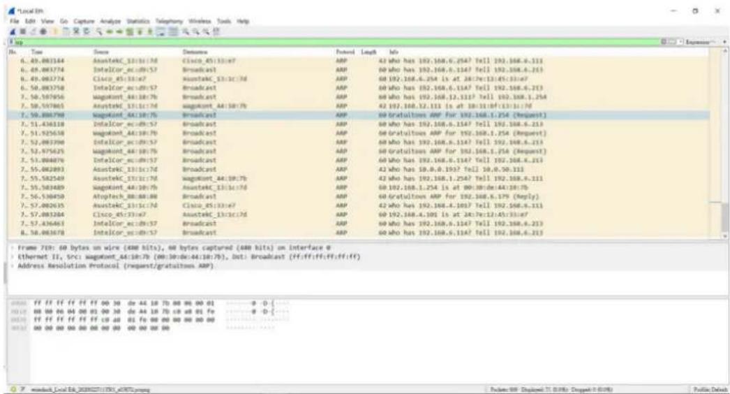
Figure 10: Example of Wireshark software sniffing on IP address of a switch
-
Click [Enter] to confirm.
-
If this is the first time that your Web browser access the device, you may see a security warning page.
- Please, click on the red box [Advanced] button and click on [Accept the Risk and Continue] button.
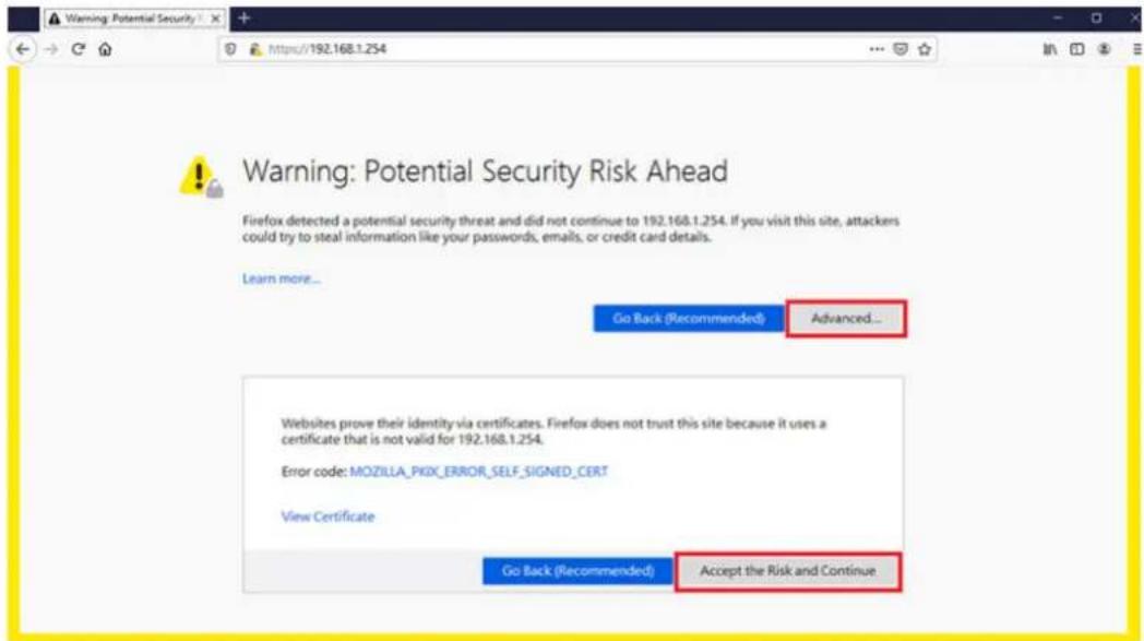
Figure 11: Security Warning Page
- After pressing the [Enter] key.
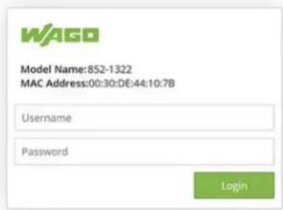
Figure 12: WAGO Login Page
- Enter your user name and password in the query dialog:
Username = „admin“
Password = „wago“
- The start page of WBM loads.
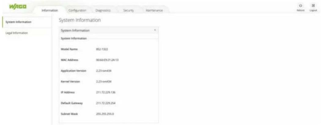
Figure 13: Start Page of WBM
-
Select your desired page on the navigation bar at the top of the screen and clicking on corresponding tab on the left hand side of the screen.
-
Make the desired settings on the desired web page.
-
Click [Submit] or [Change] or [Add] to confirm or update your changes to apply the settings.
-
It is highly recommended to avoid using the factory default password during the actual operation of your device. Therefore, if you logged in with the default password successfully, the device will remind the user to change the password with a warning pop-up dialog and redirect the user to the change password page as shown in Figure "Default Password Warning Pop-up Dialog on Password Web Page". Please click the [OK] button to accept the warning.
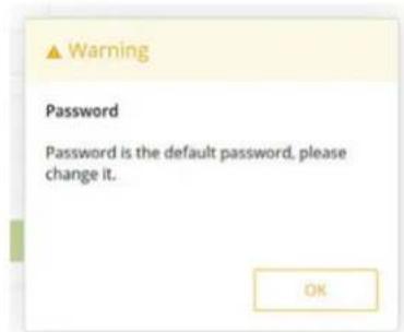
Figure 14: Default Password Warning Pop-up Dialog on Password Web Page
You can access the corresponding WBM pages via the links in the navigation bar.
Table 13: Overview – Navigation Links and WBM Pages
| Navigation Links and WBM Pages |
| [Information] |
| • System Information• Legal Information |
| [Configuration] |
| • System Settings• Device Discovery - LLDP• System Management - SNTP• Network Settings• Port Settings• Interface - Mirror• Password |
| [Diagnostics] |
| • SNMP• Modbus ® TCP• System-Log• Port Monitor |
| [Security] |
| • Static SAK• Secure Code• 802.1X (IEEE 802.1X)• Port Security• VLAN |
| [Redundancy] |
| • RSTP |
| [Maintenance] |
| • Firmware-Upgrade• Reset to Default• Backup/Restore• Reboot• Logout |
The settings/configuration of the industrial managed switch can be made on these WBM pages.
The default values are displayed in bold.
10.2 Login Failure
If you failed to login, you will encounter an Error dialog as shown in Figure "Login Failure Dialog". You will have two options or buttons to choose from which are [Forget it] or [Try again] buttons. If you click the [Try again] button, you will be re-directed to the Login page with some waiting time, which is determined by the number of times that the user failed to login. The first and the second tries will have 0 second waiting time. The third try will have a waiting time of 10 seconds. The fourth try will have a waiting time of 100 seconds. The fifth up to tenth tries will have a waiting time of 1000 seconds. If the user tried more than ten times, the user will only be able to click the [Forget it] button to log in with the a secure code generated by the security card as shown in Figure "Example of Security Card".
(i) Note
Functions of the "Secure code" tab
The use of the security card and the [Forget it] option is enabled by default on the device. You can disable this feature in the "Security" – "Secure code" tab page, after logging in for the first time.
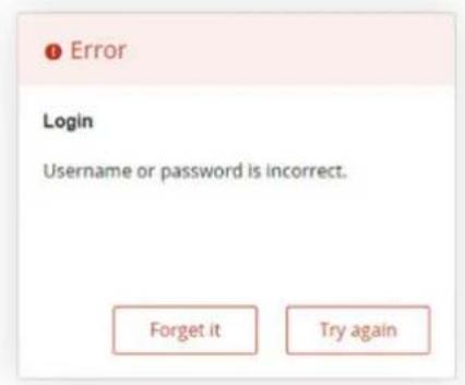
Figure 15: Login Failure Dialog
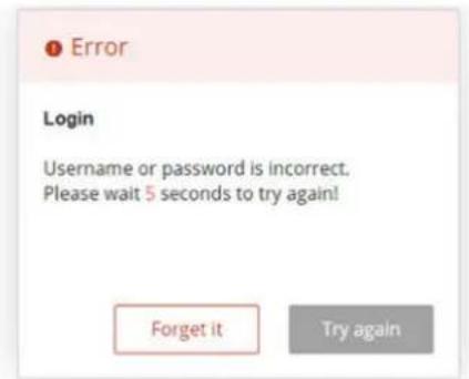
Figure 16: Login Failure Dialog with only [Forget it] button
If you click on the [Forget it] button, the device will randomly ask for a secure code of three characters. The three characters are randomly chosen from the security card. You will need to look up the characters in the security card and use them to enter them in the Secure code textbox as shown in Figure "Example of Dialog after Clicking [Forget it] Button". The secure code dialog in Figure "Example of Dialog after Clicking [Forget it] Button" provides the hints on the newly composed secure code. Based on the security card given in Figure "Example of Security Card", the secure code is "NLS". The dialog has two buttons to choose from: [OK] and [Cancel].
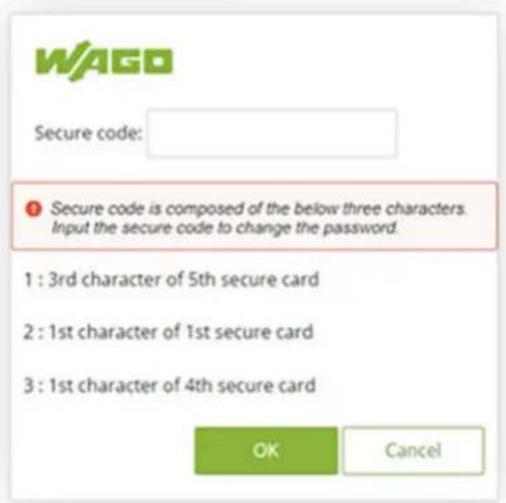
Figure 17: Example of Dialog after Clicking [Forget it] Button
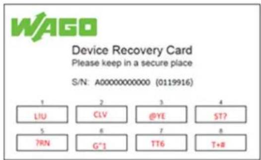
Figure 18: Example of Security Card
After clicking [OK] button with a correct secure code from the security card, you will be re-directed to the change password tab page to immediately update the password as shown in Figure "Re-direction to Change Password Tab Page". When you finished changing the new password, click on the [Submit] button. The system will prompt you with the WAGO login page to enter the new password as shown in Figure "WAGO Login Dialog after Resetting Password".
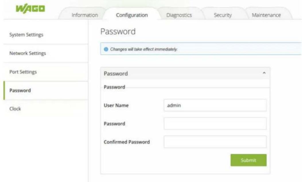
Figure 19: Re-direction to Change Password Tab Page
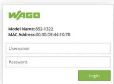
Figure 20: WAGO Login Dialog after Resetting Password
10.3 Information
10.3.1 System Information
To help users become familiar with the device, the System Information tab page provides important details of the WAGO's industrial managed switch. This is also the main welcome screen once the user has logged in. The details make it easier to identify different switches connected to the network. The user can check various information such as the Model Name, MAC Address, Application Version, Kernel Version, IP Address, Default Gateway and Subnet Mask. Figure "WBM "Information" Page – "System Information" Tab" depicts an example of System Information of WAGO 852-1322 switch. Table "WBM "Information" Page – "System Information" Tab" summarizes the description of each field of system information.
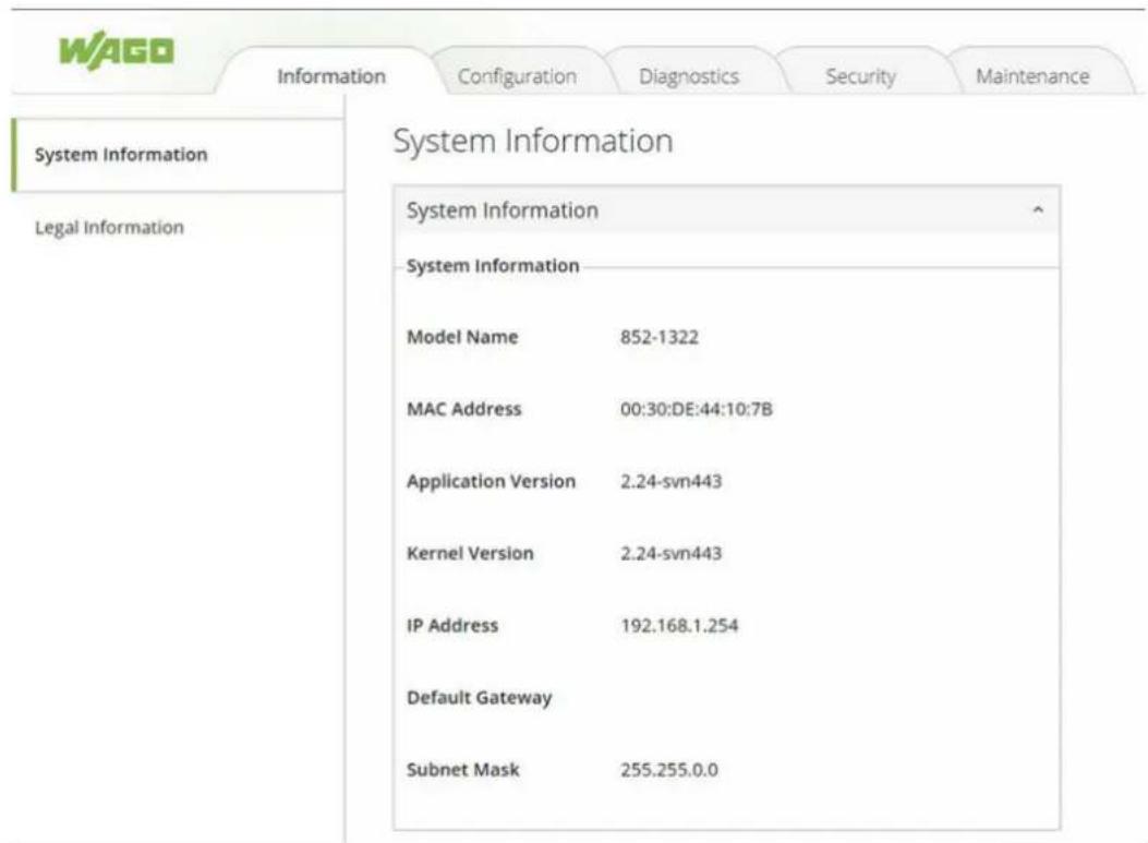
Figure 21: WBM "Information" Page – "System Information" Tab
Table 14: WBM "Information" Page – "System Information" Tab
| Parameter Description | |
| Model Name This display field shows the model name of the switch. | |
| MAC Address This display field shows the MAC (Media | Access Control) address of the switch. |
| Application Version This display field shows the application version of the firmware inside the switch. | |
| Kernel Version This display filed shows the kernel version of the firmware inside the switch. | |
| IP Address This display field shows the IP address of the switch. It is also the IP address for logging in to the device. | |
| Default Gateway This display field shows the default gateway of the switch. | |
| Subnet Mask This display filed shows the subnet mask of the switch. | |
10.3.2 Legal Information
This page has two tabs that are WAGO Licenses and Open Source Licenses. They list all information and terms about software license agreement.
Wago Licenses
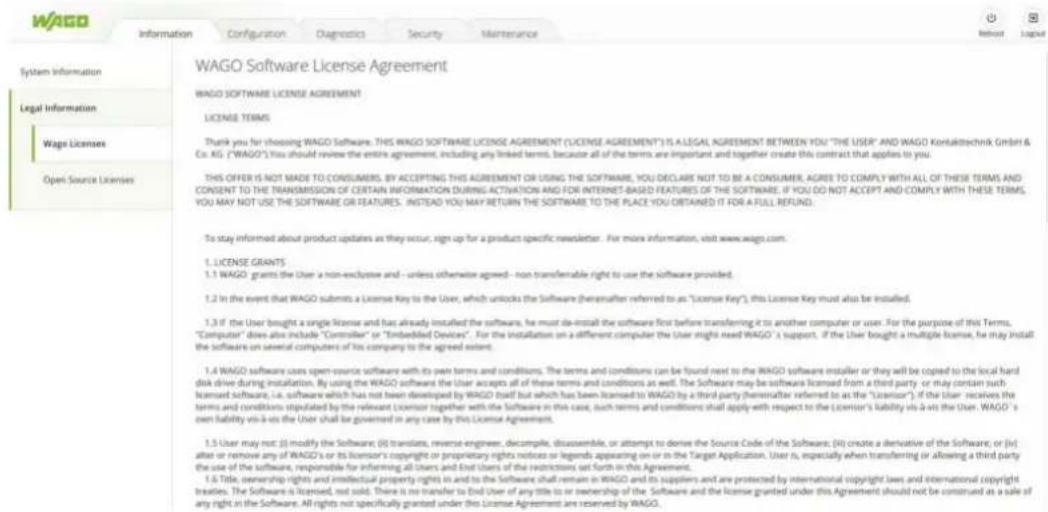
Figure 22: WBM "Information" Page – "Legal Information" – "WAGO Licenses" Tab
Open Source Licenses
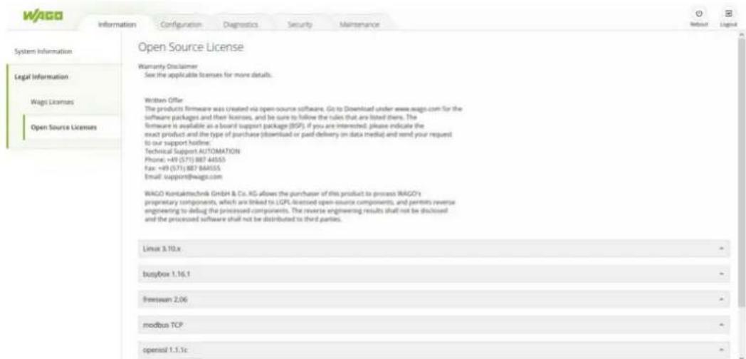
Figure 23: WBM "Information" Page – "Legal Information" – "Open Source License" Tab
10.4 Configuration
10.4.1 System Settings
Users can assign device's details to WAGO's industrial managed switch on this System Settings tab page. By entering unique and relevant system information such as device name, this information can help identifying one specific switch among all other devices in the network. Please click on the [Submit] button to update the information on the switch. Figure "WBM "Configuration" Page – "System Settings" Tab shows System Settings
page of the product. Table "WBM "Configuration" Page – "System Settings" Tab" summarizes the device information setting descriptions and corresponding default factory settings.
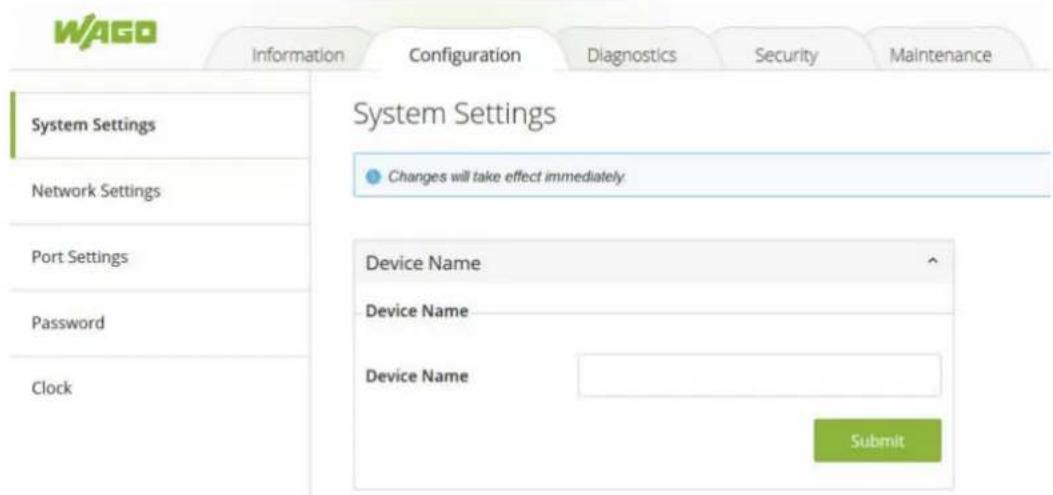
Figure 24: WBM "Configuration" Page – "System Settings" Tab
Table 15: WBM "Configuration" Page – "System Settings" Tab
| Parameters Factory | Default Description | |
| Device Name (None) | This text field can specify a particular role or application of different switches. This text field can support a maximum of 63 characters. | |
10.4.2 Device Discovery - LLDP
The LLDP (Link Layer Discovery Protocol) allows stations connected to a LAN according to IEEE 802.1ab to send information to other stations connected to the same LAN. The information includes essential system functions, including the management address or addresses of an entity or entities that provide management of these functions, as well as identification of the station's access point to the IEEE802 LAN required by the management entity or entities.
LLDP information can only be sent to and received from devices; no information is requested, and no state changes are made between nodes. The device can turn the send and receive functions on and off independently.
LLDP is designed to be managed using SNMP. Applications that use this protocol include topology discovery, inventory management, emergency services, VLAN assignment, and inline power.
(i) Note
If enabled, LLDP device information will appear on the topology map of Lean Managed Switches. The switch information will be shared with other devices connected within the same network.
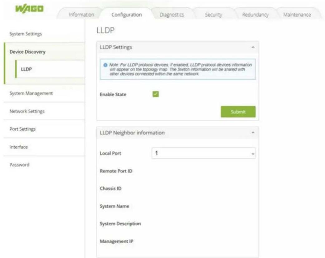
Figure 25: WBM "Configuration" tab – "LLDP Settings" page
Table 16: WBM "Configuration" tab – "LLDP Settings" page
| Parameter Description | |
| Enable State Select Enable | State to enable LLDP on the switch. Deselect Enable State to disable LLDP on the switch. Remember to click on the [Submit] button to confirm your choice. |
| LLDP Neighbor Information | A status overview of the detected LLDP neighbors is displayed here. |
| Local Port Specify the port | on the local switch for which LLDP neighbor information will be displayed. Information about LLDP-enabled devices that has been received on this port will then be shown. |
10.4.3 System Management – SNTP
10.4.3.1 General Information
The SNTP ("Simple Network Time Protocol") is a protocol for synchronizing clocks in computer systems. It is a less complex implementation of NTP ("Network Time Protocol").
SNTP uses Coordinated Universal Time. No information on time zones or daylight savings time is transmitted. This information falls outside the protocol range and must be obtained separately. The SNTP port is 123.
In addition:
- The SNTP server always replies with the current UTC time.
- If the switch receives the SNTP reply time, it adjusts the time to the time zone configuration and configures the time for the switch accordingly.
-
If the time server's IP address is not specified, the switch does not send an SNTP request packet.
-
If the switch does not receive an SNTP reply packet, it repeats the challenge every ten seconds.
- If the switch receives an SNTP reply, it repeats the time request from the NTP server every hour.
- If the time zone and NTP server changes, the switch repeats the request process.
• There is no default SNTP server.
10.4.3.2 SNTP Setup
A mode must first be selected from the Mode pull-down list. Manual mode disables SNTP. The time must then be set manually. The Network Time Protocol mode enables SNTP. Both of these modes are described below.
Mode: Manual
Select Manual mode to disable SNTP. The time must then be set manually.

Figure 26: WBM "Configuration" page – "SNTP" tab
Table 17: WBM "Configuration" page – "SNTP" tab
| Parameter Description | |
| Current Time and Date | |
| Current Time This field | displays the current time when you open or refresh the WBM. |
| Current Date This field | displays the current date when you open or refresh the WBM. |
| Time and Date Settings | |
| Date Select the date in the format day/month/year that you are manually setting for the system. | |
| Time Select the time in the format hour/minute/second that you are manually setting for the system. | |
| Daylight Saving Settings | |
| Enable State Select Enable to enable Daylight Saving Settings or Disable to disable Daylight Saving Settings. | |
| Start Day Enter the date and time for the start of daylight saving time if you have activated this option. The time is displayed in 24-hour format. | |
| End Day Enter the date and time for the end of daylight saving time if you have activated this option. The time is displayed in 24-hour format. | |
Mode: Network Time Protocol
Select Network Time Protocol mode to enable SNTP. An NTP server must then be specified.
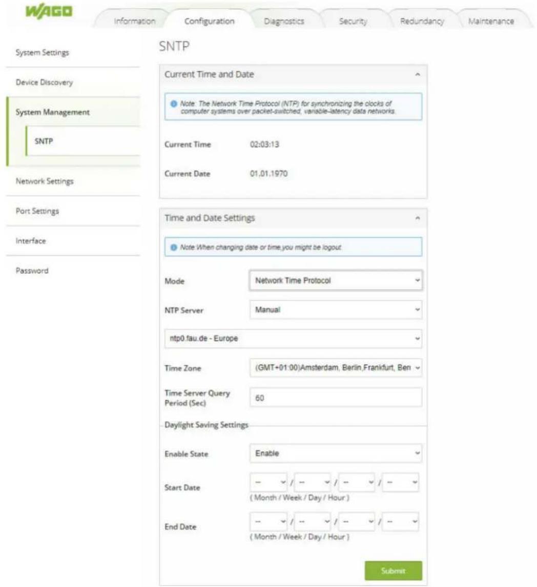
Figure 27: WBM "Configuration" tab – "SNTP" page
Table 18: WBM "Configuration" tab – "SNTP" page
| Parameter Description | |
| Current Time and Date | |
| Current Time This field displays the current time when you open or refresh the WBM. | |
| Current Date This field displays the current date when you open or refresh the WBM. | |
| Time and Date Settings | |
| NTP Server Choose a predefined time server (public) or enter the IP address of a time server manually (manual). | |
| Public Select one of the predefined time servers | |
| Manual IP/Domain Select whether you will specify the IP address or fully qualified domain name for the time server | |
| Manual In the text field below, enter the IP address or fully qualified domain name for the time server | |
| Time Zone Select the time zone you are located in. | |
| Daylight Saving Settings | |
| Enable State Select Enable to enable Daylight Saving Settings or Disable to disable Daylight Saving Settings. | |
| Start Day Enter the date and time for the start of daylight saving time if you have activated this option. The time is displayed in 24-hour format. | |
| End Day Enter the date and time for the end of daylight saving time if you have activated this option. The time is displayed in 24-hour format. |
10.4.4 Network Settings
In this tab page, users may modify network settings of Internet Protocol version 4 (IPv4) for the WAGO industrial managed switch.
The Network Settings tab page is depicted in Figure "WBM "Configuration" Page – "Network Settings" Tab". Inside the Network Settings box, the user can enable Dynamic Host Configuration Protocol (DHCP) client inside the switch by checking the DHCP box so that the switch can obtain IP address' setting automatically from a DHCP server available on the user's local network. If the DHCP is enabled, the rest of the fields will be disabled. Note that the user should consult your local network administrator for information about the availability of DHCP server. If the user prefers a static IP setting, then the user can proceed to enter the IP Address, Subnet Mask, Gateway, and the Primary DNS. If the user set gateway or DNS on this page, the industrial managed switch will not use the gateway or the DNS from DHCP server. After entering the desired information, please click [Submit] button to change the IP Setting.
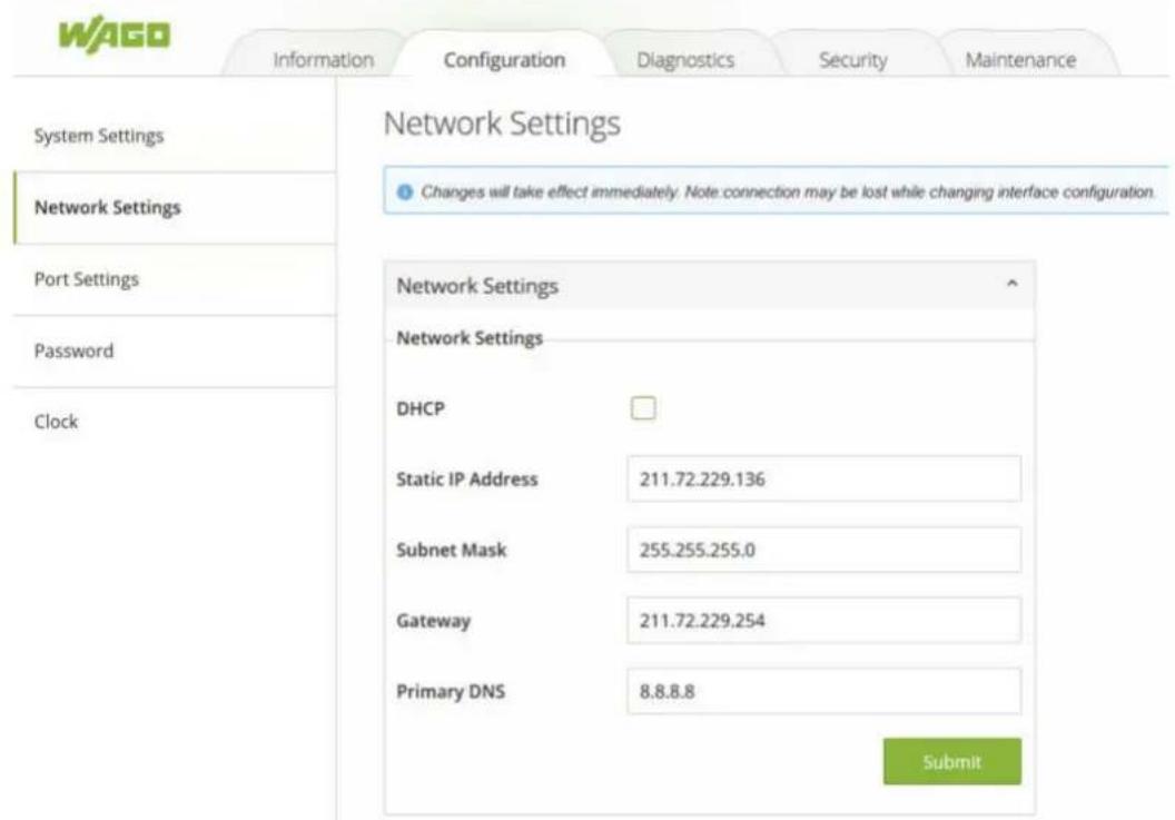
Figure 28: WBM "Configuration" Page – "Network Settings" Tab
The description of each parameter and its default value in Network Settings tab page are summarized in Table "WBM "Configuration" Page – "Network Settings" Tab".
Table 19: WBM "Configuration" Page – "System Settings" Tab
| Parameters Factory | Default Description | |
| DHCP Unchecked By | checking this box, an | IP address and related parameters will be automatically assigned. Otherwise, user can set up the static IP address and related fields manually. |
| Static IP Address 192 | 168.1.254 This field displays current IP address. The user can also set a new static IP address for the device. | |
| Subnet Mask 255.255 | 255.0 This field displays current subnet mask. The user can set a new subnet mask in this field. | |
| Gateway 0.0.0.0 This field shows current Gateway's IP address. The user can set a new IP address for the Gateway in this field. | ||
| Primary DNS Null The user can set the primary DNS' IP address used by your network in this field. | ||
10.4.5 Port Settings
10.4.5.1 Setting
The user can control the state of each port by either selecting Enable or Disable from the dropdown list as shown in Figure "WBM "Configuration" Page – "Port Settings" Tab". After finishing any change on the port setting, please click on the [Submit] button.
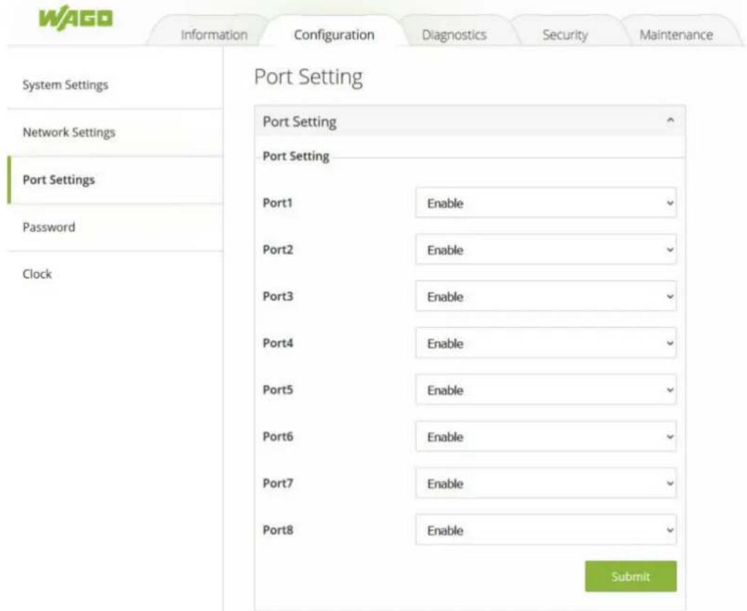
Figure 29: WBM "Configuration" Page – "Port Settings" Tab
The description of each parameter and its default value in Port Settings tab page are summarized in Table "WBM "Configuration" Page – "Port Settings" Tab".
Table 20: WBM "Configuration" Page – "Port Settings" Tab"
| Parameters Factory | Default Description | |
| Port n Enable Port number on the industrial | managed switch. The user can clickon the dropdown list to select either Enable or Disable to changethe status of the port. When enabling a port, data will be allowedto transmit and receive through that particular port. | |
10.4.6 Interface – Port Mirroring
10.4.6.1 General Information
Port-based mirroring is used on a network switch to send a copy of the network packets sent or received by one or a range of ports to a network monitoring system connected to another port (monitor port).
This is often used for network devices that require monitoring of network traffic, such as an intrusion detection system (IDS).
Port mirroring, together with a network traffic analyzer, assists in monitoring network traffic. Users can monitor the selected ports (source ports) for egress and ingress packets.
Source Mode
- Ingress: The incoming data packets are copied and forwarded to the monitor port.
- Egress: The outgoing data packets are copied and forwarded to the monitor port.
i Note
The monitor port cannot be a trunk member port.
Firmware version 2.53 for the switch does not permit you to mirror a range of ports to a monitor port.
Firmware version 2.53 for the switch does not permit you to choose between the different source modes. By default, both incoming and outgoing data packets are copied and forwarded to the monitor port.
10.4.6.2 Port Mirroring Setup
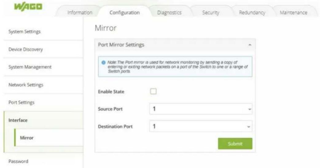
Figure 30: WBM "Configuration" tab – "Mirror" page
Table 21: WBM "Configuration" tab - "Mirror" page
| Parameter Description |
| Enable State Select Enable State to enable port mirroring. Deselect Enable State to disable port mirroring. Port mirroring must be enabled before the selected Source Port or Destination Port can be changed |
| Source Port Select a port to copy its ingress (incoming) and egress (outgoing) traffic to the Destination Port. |
| Destination Port Select the port to which the network traffic of the source port should be copied |
10.4.7 Password
User name "admin" and password "wago" are set for the device when it is manufactured. The user can modify the device's user name and password to ensure overall system security. The user name and password can be updated in this tab as shown in Figure "WBM "Configuration" Page – "Password" Tab". The password must be entered twice in Password and Confirmed Password textboxes before a change to confirm its correctness. Please click on the [Submit] button to update the user name and password information on the switch.
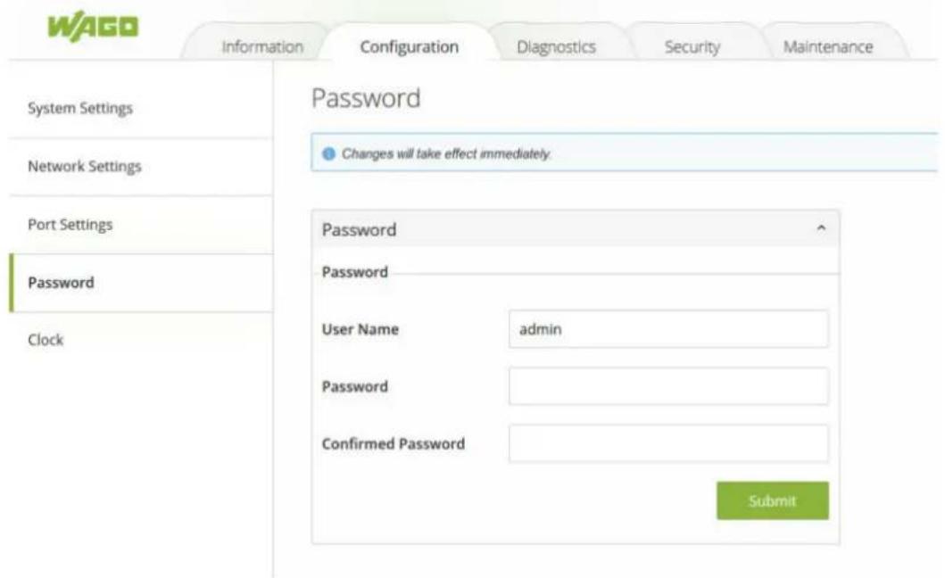
Figure 31: WBM "Configuration" Page – "Password" Tab
The description of each parameter and its default value in Password tab page are summarized in Table "WBM "Configuration" Page – "Password" Tab".
Table 22: WBM "Configuration" Page – "Password" Tab
| Parameters Factory | Default Description | |
| User Name admin User name to log-in with maximum length of 15 characters. | ||
| Password wago Password to log-in with maximum length of 15 characters. | ||
| Confirmed Password | wago Re-type the password. This has to be exactly the same as the password entered in the above field with maximum length of 15 characters. | |
10.5 Diagnostics
10.5.1 SNMP
The SNMP („Simple Network Management Protocol“) is used in network management systems to monitor the state of attached devices that require the attention of an administrator. SNMP is a component of the “internet protocol suite” defined by the IETF (“Internet Engineering Task Force”). It consists of a set of standards for network management, including an application layer protocol, a database schema and a set of data objects.
SNMP provides management data in the form of variables on the managed systems, which describe the system configuration. These variables can be queried (and sometimes changed) by managing applications.
An "SNMP community string" is a text string that acts as a password. It is used to authenticate messages that are sent between the management station (the SNMP manager) and the device (the SNMP agent). The string is included in every packet transmitted between the SNMP manager and the SNMP agent.
The “SNMP community” acts like a password and is used to define the security parameters of SNMP clients in an SNMP v1 and SNMP v2c environments. The default “SNMP community” is “public” for both SNMPv1 and SNMPv2c before SNMPv3 is enabled. Once SNMPv3 is enabled, the “Communities” of SNMPv1 and v2c have to be unique and cannot be shared.
WAGO's industrial managed switch support SNMP and can be configured in this tab page as shown in Figure "WBM "Diagnostics" Page – "SNMP" Tab". The SNMP setting has four parts, which are:
- SNMP Agent
• SNMPv1/v2c Community - SNMP-Trap
• SNMPv3 Authentication (Auth.)
Note that SNMP V1/V2c Community setting was not shown in Figure "WBM "Diagnostics" Page – "SNMP" Tab" but it will be shown when SNMP V1/V2c version option was selected.
(i) Note
Using SNMPv3
For security reasons, the user cannot use SNMP v1/v2c to reboot the device, change security related settings, and change the device's password. These changes are possible only by using SNMPv3.
SNMP Setting
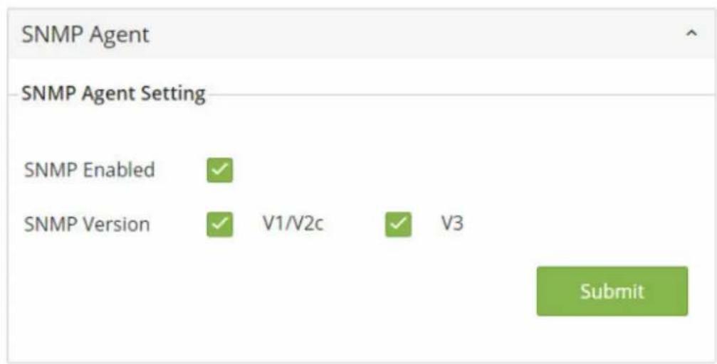
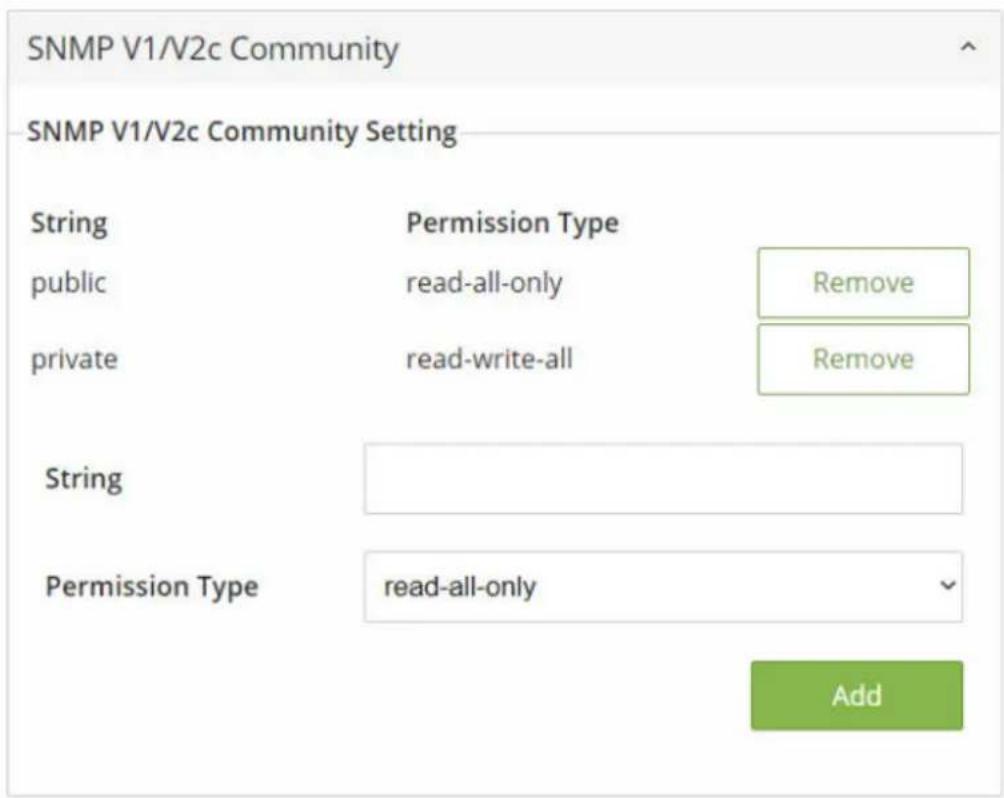
Figure 32: WBM "Diagnostics" Page – "SNMP Setting Part 1" Tab
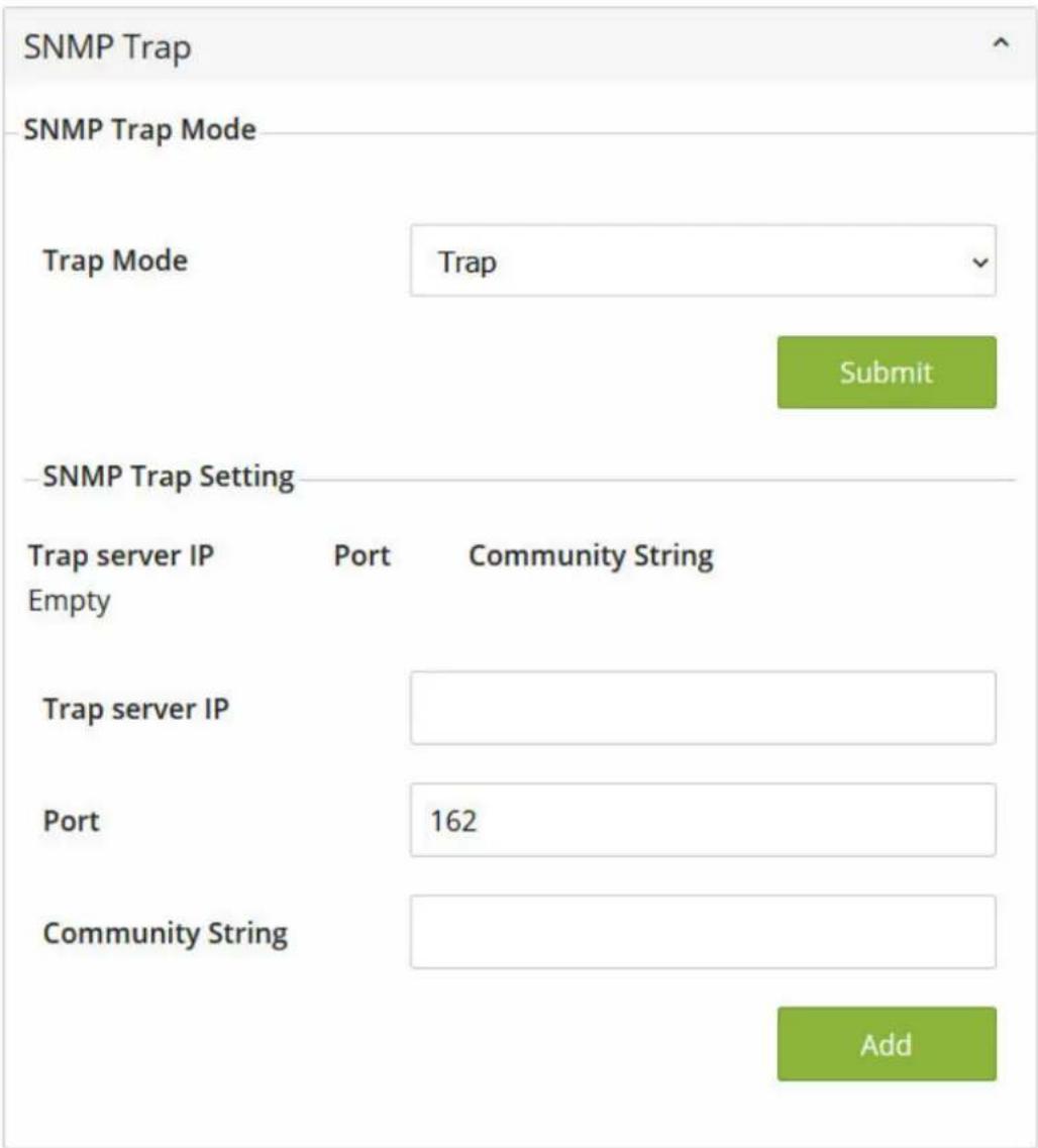
Figure 33: WBM "Diagnostics" Page – "SNMP Setting Part 2" Tab
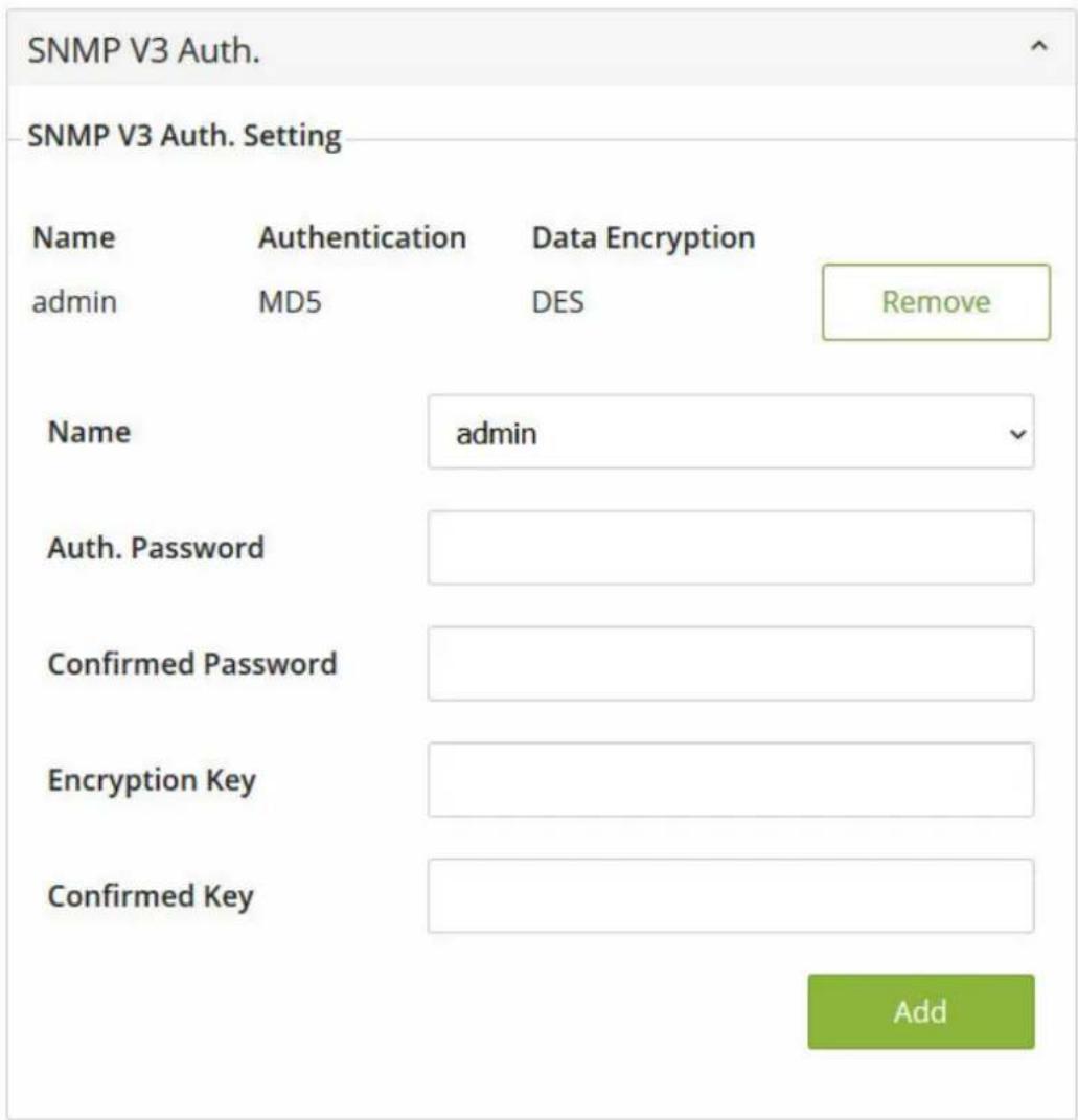
Figure 34: WBM "Diagnostics" Page – "SNMP Setting Part 3" Tab
10.5.1.1 SNMP Agent
To enable SNMP agent on the managed switch, please check the SNMP Enabled box and click [Submit] button as shown in Figure "SNMP Agent Setting". The SNMP version 1 (V1), version 2c (V2c) and version 3 are supported by WAGO's managed switches as summarized in "WBM Page, "Diagnostics" – "SNMP" Tab, SNMP Agent Setting"Fehler! Verweisquelle konnte nicht gefunden werden.. Basically, SNMP V1 and SNMP V2c have simple community string based authentication protocol for their security mechanism, while SNMP V3 is improved with cryptographic security. The default setting of SNMP Version is V3. The user can select SNMP Version by checking either the V1/V2c box and/or the V3 box.
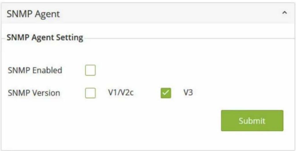
Figure 35: SNMP Agent Setting
Table 23: WBM Page, "Diagnostics" – "SNMP" Tab, SNMP Agent Setting
| Parameters Factory | Default Description | |
| SNMP Enabled Disable | Check the box to enable SNMP agent. | |
| SNMP Version V3 Check the desired SNMP | Version as either V1/V2c and/or V3. |
10.5.1.2 SNMPv1/v2c-Community
SNMP V1 and SNMP V2c use a community string matching for authentication. This authentication will allow network management software to access the information or data objects defined by Management Information Bases (MIBs) on the industrial managed switch. Note that this simple authentication is considered a weak security mechanism. It is recommended to use SNMP V3, if possible. There are two levels of authentications or permission type in WAGO 852-1322, which are read-all-only or read-write-all. For example, in our default setting as shown in Figure “SNMP V1/V2c Community Setting”, an SNMP agent, which is a network management software module residing on the industrial managed switch, can access all objects with read-all-only permissions using the string “public”. Another setting example is that the string “private” has permission of read-write-all.
The SNMP V1/V2c Community Setting as shown in Figure "SNMP V1/V2c Community Setting" allows the user to set a community string with a type of permission for authentication or remove existing community string from the list by clicking on the [Remove] button at the end of each community string item. The users can specify a new string names by entering a text in the String field and choose a type of permissions from the dropdown list of Permission Type. Then, click on the [Add] button.
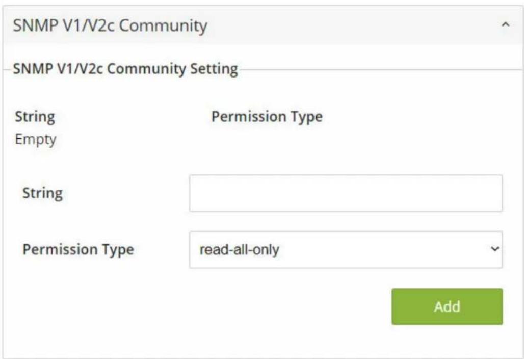
Figure 36: SNMP V1/V2c Community Setting
Table "WBM "Diagnostics" Page – "SNMP" Tab, SNMP V1/V2c Community Setting "briefly provides descriptions of SNMP V1/V2c community string setting.
Table 24: WBM "Diagnostics" Page – "SNMP" Tab, SNMP V1/V2c Community Setting
| Parameters Factory | Default Description | |
| (Community) String P | Public (read-all-only) | Define name of strings for authentication. The maximum length of the string is 15 characters. |
| Private (read-write-all) | ||
| Permission Type - Choose a type from the dropdown list: read-all-only and read-write-all. See notes below for a briefed explanation.Choose a type from the dropdown list: read-all-only and read-write-all. See notes below for a briefed explanation• Read write-all: permission to read/write OID 1 Sub Tree. | ||
10.5.1.3 SNMP Trap
The industrial managed switch provides a trap function that allows the switch to send notification to agents with SNMP traps or inform. The notifications are based on the status changes of the switch such as link up, link down, warm start, and cold start. For inform mode, after sending SNMP inform requests, the switch will resends inform request if it does not receive response within 10 seconds. The switch will try re-send three times. Figure "WBM "Diagnostics" Page – "SNMP" Tab, SNMP Trap" shows the SNMP Trap section.
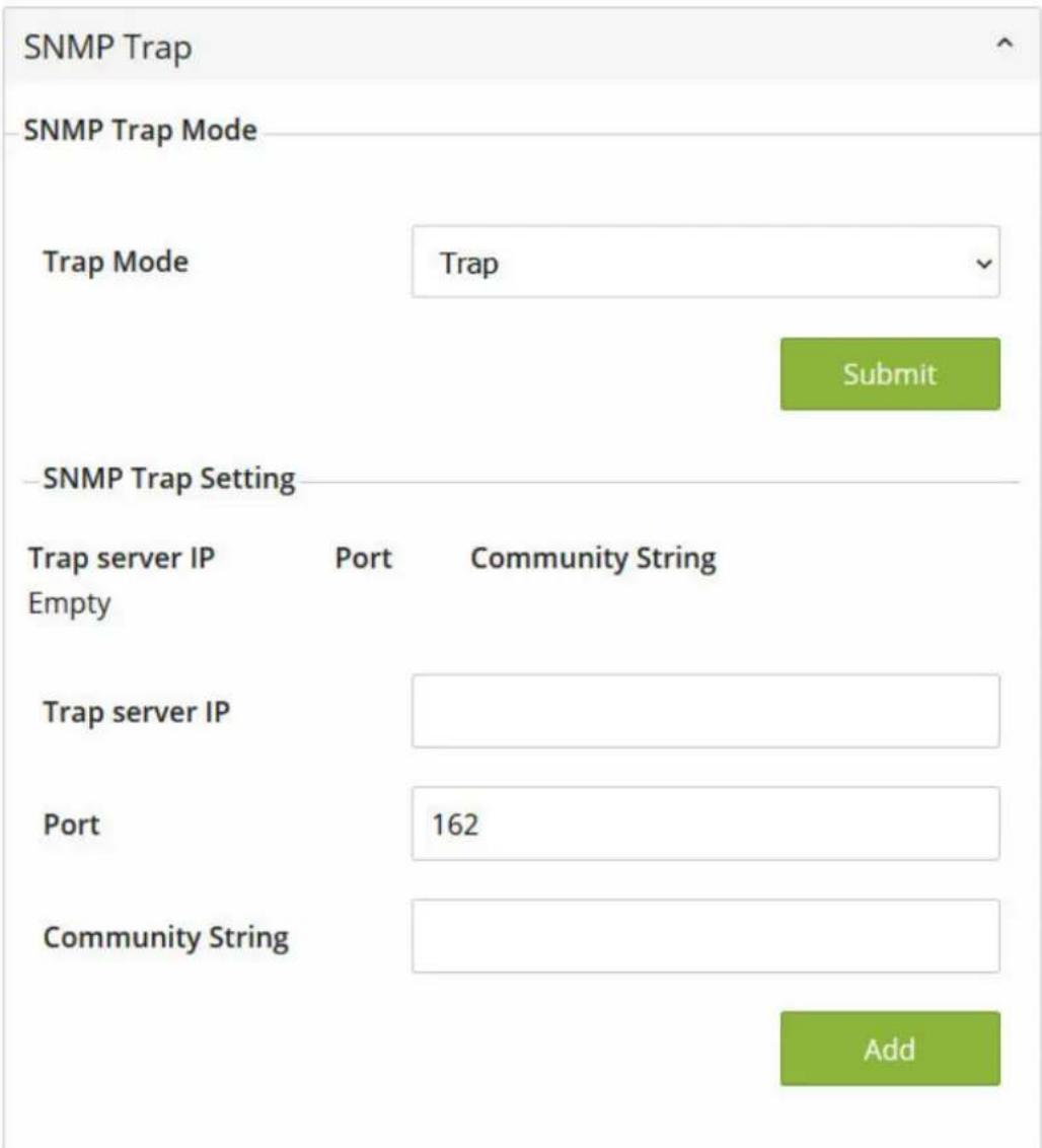
Figure 37: WBM "Diagnostics" Page – "SNMP" Tab, SNMP Trap
The SNMP Trap Mode allows users to configure SNMP Trap mode or Inform mode by selecting the desired mode from the dropdown list as shown in Figure WBM "Diagnostics" Page – "SNMP" Tab, SNMP Trap". Then, click [Submit] button to change the mode. The SNMP Trap Setting shows a list of configured SNMP Trap Server. Example in Figure "WBM "Diagnostics" Page – "SNMP" Tab, SNMP Trap" shows an Empty list. The user can enter an IP address in the Trap server IP field, port number of Trap server in the Port field, and a string used as Community String for an authentication. After filled in all required field for SNMP Trap Setting, please click on the [Add]. button. Table "WBM "Diagnostics" Page – "SNMP" Tab, SNMP Trap" summarizes the descriptions of the SNMP Trap parameters.
Table 25: WBM "Diagnostics" Page – "SNMP" Tab, SNMP Trap
| Parameters Factory | Default Description | |
| Trap Mode Trap Choose between Trap mode or Inform mode. | ||
| Trap server IP Null Enter the IP address of your Trap Server. | ||
| Port 162 Enter the Trap server's service port. | ||
| Community String Null | Enter the community | string for authentication. The maximum length of the string is 15 characters. |
10.5.1.4 SNMP-V3-Auth.
As mentioned earlier, SNMP V3 is a more secure SNMP protocol. In this part, the user will be able to set a password and an encryption key to enhance the data security. When SNMP V3 is chosen, the users can configure SNMP V3's authentication and encryption parameters. MD5 (Message-Digest algorithm 5) is used for authentication password and DES (Data Encryption Standard) is used for data encryption algorithm. Figure "WBM "Diagnostics" Page – "SNMP Tab", SNMP V3 Auth." shows the SNMP V3 Authentication (Auth.) Setting options.
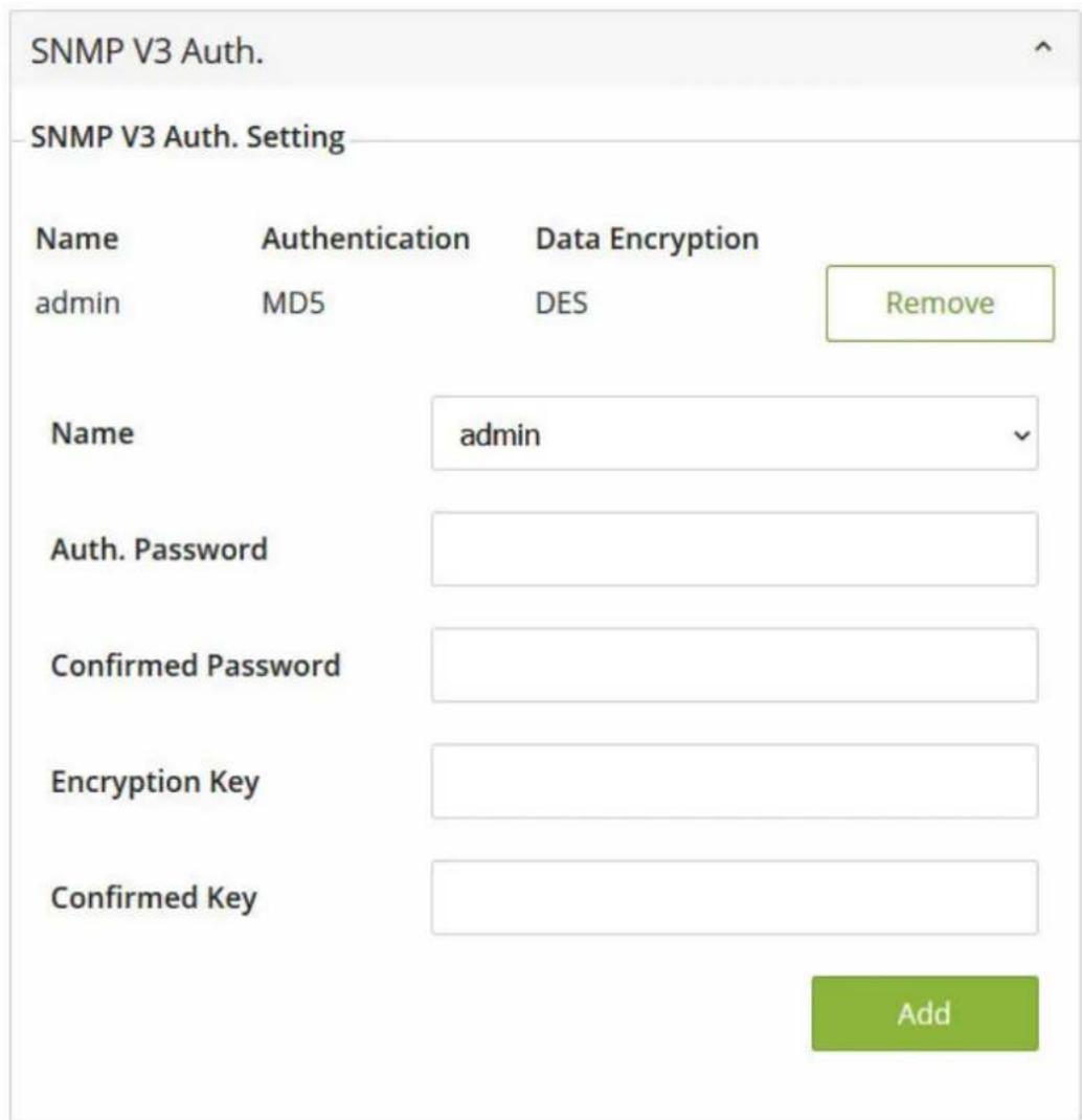
Figure 38: WBM "Diagnostics" Page – "SNMP Tab", SNMP V3 Auth.
The users can view existing SNMP V3 users' setting on the list at the upper part of SNMP V3 Auth. Setting as shown in Figure "WBM "Diagnostics" Page – "SNMP Tab", SNMP V3 Auth.". The list provides information about user Name, Authentication type, and Data Encryption. The user have an option to remove existing SNMP V3 user by clicking on the [Remove] button in the last column of each entry.
To add a new SNMP V3 user, the user have to select the user Name from the dropdown list which can be either Admin or User. Then, the authentication password with a maximum length of 31 characters must be entered in the Auth. Password field and re-entered again in the Confirmed Password field. Note that if no password is provided, there will be no authentication for SNMP V3. Finally, the encryption key with a maximum length of 31 characters can be entered in the Encryption Key field and re-entered again in Confirmed Key field. After filling all the required fields, please click on [Add] button to update the information on the industrial managed switch. Table "WBM "Diagnostics" Page – "SNMP" Tab, SNMP V3 Auth." lists the descriptions of SNMP V3 settings.
Table 26: WBM "Diagnostics" Page – "SNMP" Tab, SNMP V3 Auth.
| Parameters Factory | Default Description | |
| Name admin Choose | from one of the following options: | |
| Auth. (Authentication) Password | wago0852 Set an auth | entication password for the user name specified above. If the field is left blank, there will be no authentication. Note that the authentication password is based on MD5 and the maximum length of the password is 31 characters. |
| Confirmed Password | wago0852 Re-entering | the Authentication Password to confirm. |
| Encryption Key wago | 852 Set an encryption | key for more secure protection of SNMP communication. Note that the encryption algorithm is based on DES and the maximum length of the key is 31 characters. |
| Confirmed Key wago | 852 Re-entering the En | encryption Key to confirm. |
10.5.2 Modbus TCP
WAGO's industrial managed switch can be connected to a Modbus network using Modbus TCP/IP protocol which is an industrial network protocol for controlling automation equipment. The switch's status and settings can be read through Modbus TCP/IP protocol which operates similar to the Management Information Base (MIB) browser. The switch will be a Modbus slave which can be remotely configured by a Modbus master. The Modbus slave address must be set to match the setting inside the Modbus master. In order to access the switch, a Modbus Address must be assigned as described in this subsection. A Modbus memory mapping table, which lists all the register's addresses inside the switch and their descriptions, is provide in "Modbus Memory Map" table in the "Appendix". Figure "WBM "Diagnostics" Page – "Modbus TCP" Tab shows the Modbus TCP tab page ".
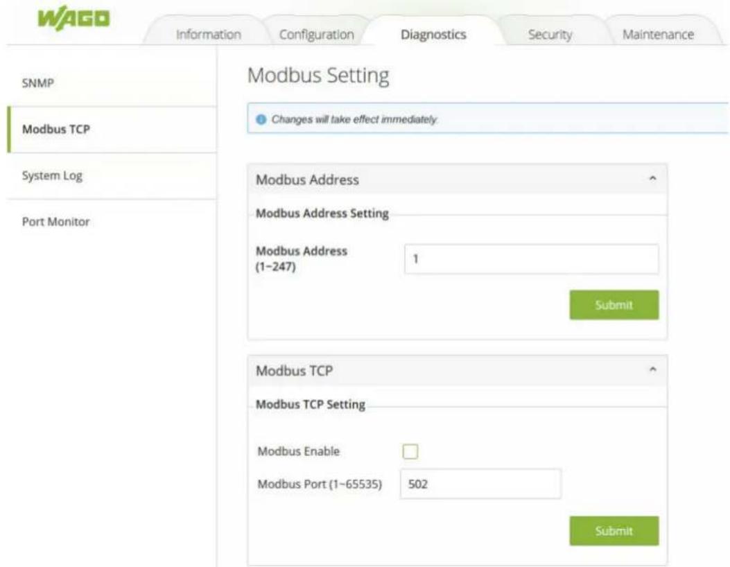
Figure 39: WBM "Diagnostics" Page – "Modbus TCP" Tab
To set a Modbus Address for the industrial managed switch, choose a number from 1 to 247 and enter it in the Modbus Address field. Click [Submit] button to configure it. To enable the Modbus protocol on the industrial managed switch, check the box behind the Modbus Enable and set a Modbus Port number by choosing a number from 1 to 65535 and enter that number in the Modbus Port field. Click [Submit] button to set the Modbus TCP. Table "WBM "Diagnostics" Page – "Modbus TCP" Tab" summarizes the descriptions of the Modbus TCP's parameters.
Please refer to Appendix for the Modbus Memory mapping (see chapter ⚙ Modbus-Register [▶ 85]).
Table 27: WBM "Diagnostics" Page – "Modbus TCP" Tab
| Parameters Factory | Default Description | |
| Modbus Address 1 Enter a number from 1 to | 247 to set the Modbus Address of the industrial managed switch. | |
| Modbus Enable Uncheck Enable the Modbus protocol on the industrial managed switch by checking the Modbus Enable box. | ||
| Modbus Port 502 Enter a number from 1 to | 65535 to set the Modbus service port number for the industrial managed switch. | |
10.5.3 System-Log
10.5.3.1 Setting
The user can enable how the system log (syslog) will be saved and/or delivered to other system in the System Log Setting tab page as show in Figure" WBM "Diagnostics" Page – "System Log" – "Setting" Tab". The syslog can be saved to flash memory inside the in-
dustrial managed switch and/or it can be sent to a remote log server. The user needs to select the log level and provides the IP address of a remote log server and the service port of the log server. Please click on the [Submit] button after finishing the setup. Table "WBM "Diagnostics" Page – "System Log" – "Setting" Tab" summarizes the descriptions of the Syslog Settings' parameters.
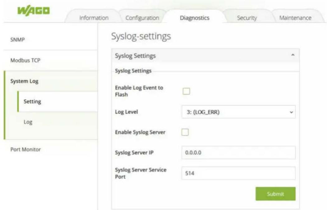
Figure 40: WBM "Diagnostics" Page – "System Log" – "Setting" Tab
Table 28: WBM "Diagnostics" Page – "System Log" – "Setting" Tab
| Parameters Factory | Default Description | |
| Enable Log Event to Flash | UncheckChecked: | Saving log event into flash memory. The flash memory can keep the log event files even if the switch is rebooted.Unchecked:Saving log event into RAM memory. The RAM memory cannot keep the log event files after each reboot. |
| Log Level (Protokollebene) | 3: (LOG_ERR) Set the | log level to determine what events to be displayed on the next webpage (Log). The level selection is inclusive. For example, if 3: (Log_ERR) is selected, all 0, 1, 2 and 3 log levels will be implied.Range from Log 0 to Log 7. |
| Enable Syslog Server | UncheckChecked: | Enable Syslog Server.Uncheck:Disable Syslog Server.If enabled, all recorded log events will be sent to the remote System Log server. |
| Syslog Server IP 0.0.0.0 Set the IP address of Syslog server. | ||
| Syslog Server Service Port | 514 Set the service port number of Syslog server.Range from Port 1 to Port 65535. | |
10.5.3.2 Log
The Log tab page under the System Log as shown in Figure "System Log Page" can display the log information based on the log level configured in the System Log Setting tab page (previous subsection). The user has options to either Read all notifications or Read only the last n records of the log. This can be selected by clicking on the corresponding radio button.
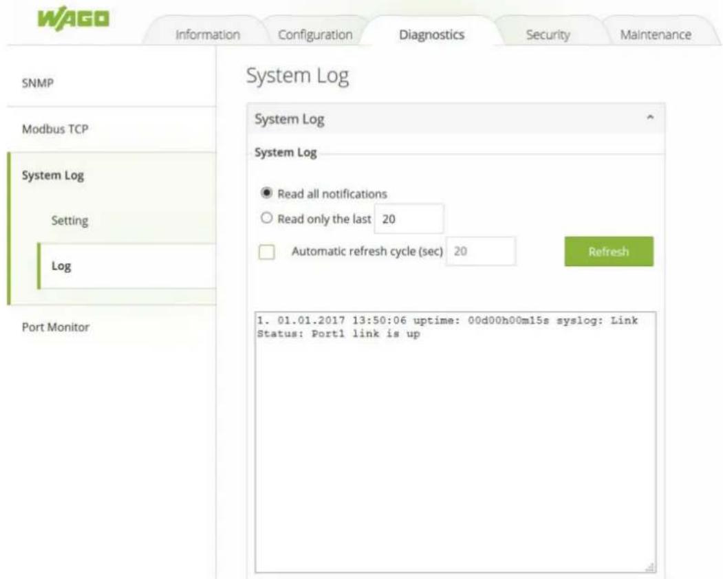
Figure 41: WBM Page, "Diagnostics" – "System Log" Tab – "Log" Section
To refresh the display or to enable cyclic refresh, click the [Refresh] button. This [Refresh] button is only visible if the Automatic refresh cycle option is not enabled or stopped. To enable cyclic refresh, click the [Start] button. The [Start] button is only visible if Automatic refresh cycle option is enabled and has not yet started as shown in Figure “[[Start] button is visible when Automatic refresh cycle is enabled”. To stop cyclic refresh again, click the [Stop]. button. The [Stop] button is only visible if cyclic refresh is enabled. The user can set the duration of automatic refresh cycle in seconds by entering the number in the corresponding field. Note that the log records are sorted by date and time. Table “WBM Page, “Diagnostics” – “System Log” – “Log” Tab” summarizes the descriptions of the parameters in the Log page. Table “Log Event Description” provides descriptions of a log event.
System Log
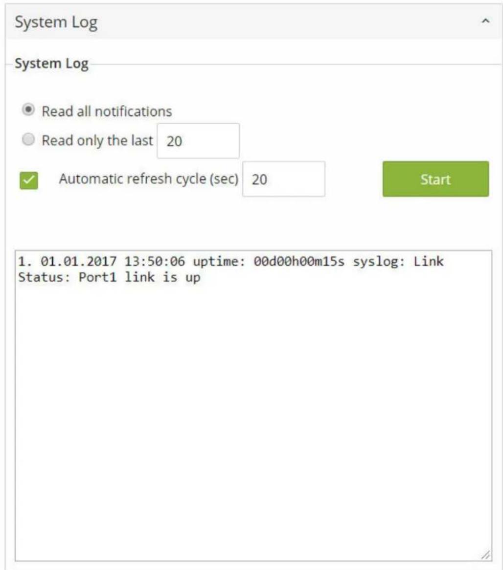
Figure 42: [Start] Button is visible when Automatic refresh cycle is enabled.
Table 29: WBM Page, "Diagnostics" – "System Log" – "Log" Tab
| Parameters Factory | Default Description | |
| Read all notifications | Selected Activate the display of all log messages. | |
| Read only the last n 20 | Activate the display of only the last n messages. The user can also specify the number of messages to be displayed. | |
| Automatic refresh cycle (sec) | Disable, 20 Select the check box to enable cyclic refresh. Enter the cycle time in seconds in which a cyclic refresh is performed. The label of the button ("Refresh"/"Start"/"Stop") changes depending on the selected mode. | |
Table 30: Log Event Description
| Parameters Description |
| Index Indicate the index of a particular log event |
| Date Indicate the system date of the occurred log event. |
| Parameters Description | |
| Time Indicate the time | stamp that this log event occurred. |
| Startup Time Indicate | how long the system (industrial managed switch) has been up since this log event occurred. |
| Event Details description of this log event. | |
10.5.4 Port Monitor
Port monitor tab page is shown in Figure "WBM "Diagnostics" Page – "Port Monitor" Tab". It depicts the actual connecting status for all available ports of the WAGO industrial managed switch in this page. The user can see that status whether a port is connected (Link Up/ Green color) or disconnected (Link Down/ Yellow color) or disabled (Black color). Table "WBM "Diagnostics" Page – "Port Monitor" Tab" summarizes the descriptions of each legend on the port status.
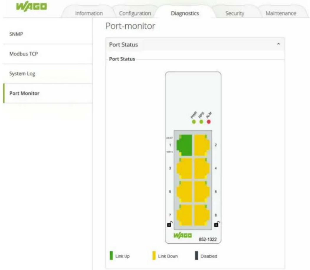
Figure[43]: WBM "Diagnostics" Page – "Port Monitor" Tab
Table131: WBM "Diagnostics" Page – "Port Monitor" Tab
| Parameters Description | |
| Port The port name: Port 1 to Port 8. | |
| Connected Status Green: indicates copper link upYellow: indicates link downBlack: indicates disable. | |
| lock Port is encrypted if the lock is closed. |
10.6 Security
10.6.1 Static SAK
Figure WBM Page, “Security” – “Static SAK” Tab shows the “Static Secure Association Key” (SAK) settings tab. Please note that WAGO 852-1322 supports the MACsec protocol on ports 7 and 8. To enable secure association mode on industrial managed switch’s port(s), first select one of the two ports from the dropdown list under the Ports. Then, enter the Secure Channel Identifier (SCI) with a 16-digit hexadecimal number (i.e., 0,1,2, ...,a,b,c,d,e,f) and enter the Secure Association Key (SAK) with a 32-digit hexadecimal number. Finally, click on the [Submit] button to update the setting to one of the ports in the Static SAK Status table in the lower part.
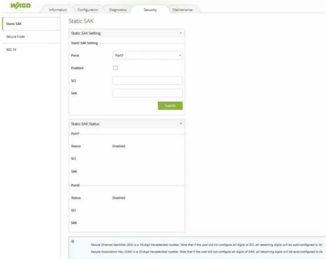
Figure 44: WBM Page, "Security" – "Static SAK" Tab
The selected port(s) will use the given static SAK as the secure key to secure all the traffic. If any two switches have the same SCI and SAK, they can securely communicate. If there is any non-secured traffic that uses incorrect SCI and SAK, the traffic will be dropped by the ingress port of the switch. The description of the static SAK setting fields are summarized in Table "WBM Page, "Security" – "Static SAK" Tab".
To disable the Static SAK setting for any of the port(s), simply select the desired port(s) from the dropdown list and uncheck the Enabled box. Then click on the [Submit] button. This will update the status of the setting in the Static SAK Status table in the lower part of the Figure "WBM Page, "Security" – "Static SAK" Tab".
Table 32: WBM Page, "Security" – "Static SAK" Tab
| Parameters Factory | Default Description | |
| Ports Option Select | specific port form the dropdown list to be configured. | |
| Enabled Uncheck Check the box to enable static secure association key (SAK) mode of MACSec for the selected port(s) on the switch. | ||
| SCI 0 Secure Channel Identifier (SCI) is a 16-digit hexadecimal number. Note that if the user did not configure all digits of SCI, all remaining digits will be auto-configured to 0s. | ||
| SAK 0 Secure Association Key (SAK) is a 32-digit hexadecimal number. Note that if the user did not configure all digits of SAK, all remaining digits will be auto-configured to 0s. | ||
10.6.2 Secure Code
Every WAGO industrial managed switch will have eight secure codes. Every code has three characters. The security codes of every switch are unique. An example of secure code is illustrated in Figure "Example of Secure Codes". They can be used to log in to the industrial managed switch when the user forgot the password and selected the [Forget it] button at the login dialog.
The use of the device recovery card is enabled by default.
To disable this secure code mechanism, uncheck the Enable box and click [Submit] button as shown in Figure "WBM "Security" Page – "Secure Code" Tab". Please refer the WAGO login in Section „Login Failure“ for more detail.
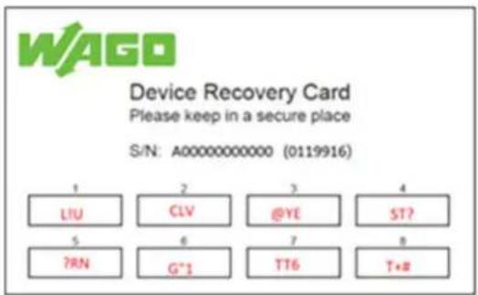
Figure 45: Example of Secure Codes
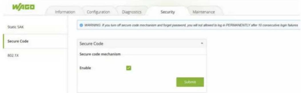
Figure 46: WBM "Security" Page – "Secure Code" Tab
10.6.3 802.1X (IEEE 802.1X)
The 802.1X tab under the Security page is subdivided into three sub-tabs which are: Setting, Parameters Setting, and Port Setting as shown below.
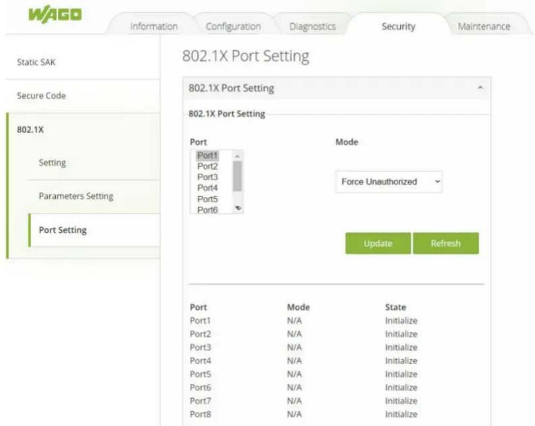
Figure 47: WBM "Security" Page – "802.1X" Tab
10.6.3.1 Setting (IEEE 802.1X - Setting)
The 802.1X security mechanism can be enabled in this tab page as shown in Figure "WBM "Security" Page – "802.1X" – "Setting" Tab. When the user checks the Enabled box, the rest of the option fields will become active. The user then have to enter all the required fields to configure the 802.1X Setting which are the IP address of RADIUS server, the RADIUS server's port number, the RADIUS server's accounting port number, the NAS identifier, and a shared key. Summary of 802.1X Setting options are given in Table "WBM "Security" Page – "802.1X" – "Setting" Tab". After inputting all the required fields, click the [Update]] button to keep the change.
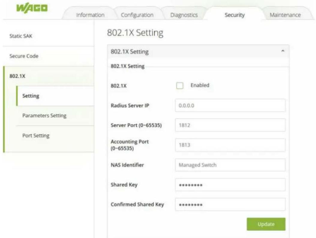
Figure 48: WBM "Security" Page – "802.1X" – "Setting" Tab
Table 33: WBM "Security" Page – "802.1X" – "Setting" Tab
| Parameters Factory | Default Description | |
| 802.1x Disabled Choose to Enable/Disable 802.1X for all ports. | ||
| Radius Server IP 0.0.0.0 Set an IP address of the RADIUS server. | ||
| Server Port 1812 Set the port number of the RADIUS server. The range is from 0 to 65535. | ||
| Accounting Port 1813 Set the accounting port number of the RADIUS server. The range is from 0 to 65535. | ||
| NAS Identifier Managed-Switch Specify the identifier string for the 802.1X Network Access Server (NAS). The maximum length is 30 characters. | ||
| Shared Key NULL A shared key between the managed switch and the RADIUS Server. Both devices must be configured to use the same key where the maximum length is 30 characters. | ||
| Confirmed Shared Key | Dependent Re-type the shared key string. | |
10.6.3.2 Parameters Setting (IEEE 802.1X - Parameter Setting)
A setting tab page of the 802.1X parameters is shown in Figure "WBM "Security" Page – "802.1X" – "802.1X Parameter Setting" Tab". These parameters are related to the authentication periods, the timeout durations, and the maximum number of authentication requests. Table "WBM "Security" Page – "802.1X" – "802.1X Parameter Setting" Tab" summarizes the descriptions of these parameters and their default settings. To keep the change of any input parameters, a user should click on the [Update] button afterwards.
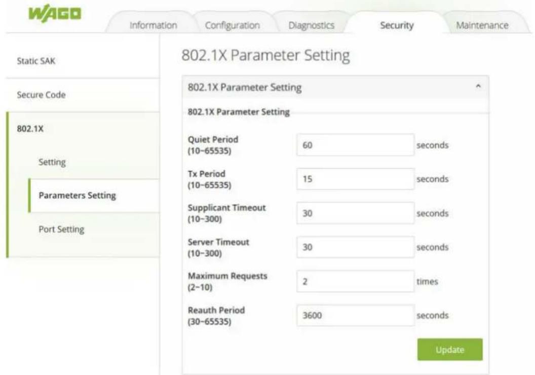
Figure 49: WBM "Security" Page – "802.1X" – "802.1X Parameter Setting" Tab
Table 34: WBM "Security" Page – "802.1X" – "802.1X Parameter Setting" Tab – Parameters Settings
| Parameters Factory | Default Description | |
| Quiet Period 60 Waiting time before a new request can be submitted after the authorization failed. The range is from 10 to 65535 seconds. | ||
| Tx Period 15 Waiting time for the supplicant's EAP response before retransmitting another EAP request. The range is from 10 to 65535 seconds. | ||
| Supplicant Timeout 30 Waiting time for the supplicant to respond to the authentication server's EAP packet. The range is from 10 to 300 seconds. | ||
| Server Timeout 30 Waiting time for the authentication server to respond to the supplicant's EAP packet. The range is from 10 to 300 seconds. | ||
| Maximum Requests 2 The maximum number of the retransmissions that the authentication server can send the EAP request to the supplicant before the authentication session times out. The range is from 2 to 10 times. | ||
| Reauth Period 3600 Time between the periodic re-authentication of the supplicant. The range is from 30 to 65535 seconds. | ||
10.6.3.3 Port Setting (IEEE 802.1X - Port Setting)
The user can configure the 802.1x security mechanism on each port of the WAGO secure switch as shown in Figure "WBM "Security" Page – "802.1X" – "802.1X Port Setting" Tab". Each port can be set for any of the four authorization modes which are Force Authorization (FA), Force Unauthorization (FU), IEEE 802.1X Standard Authorization (AU), and no authorization (NO), as described in Table "WBM "Security" Page – "802.1X" – "802.1X Port Setting" Tab".
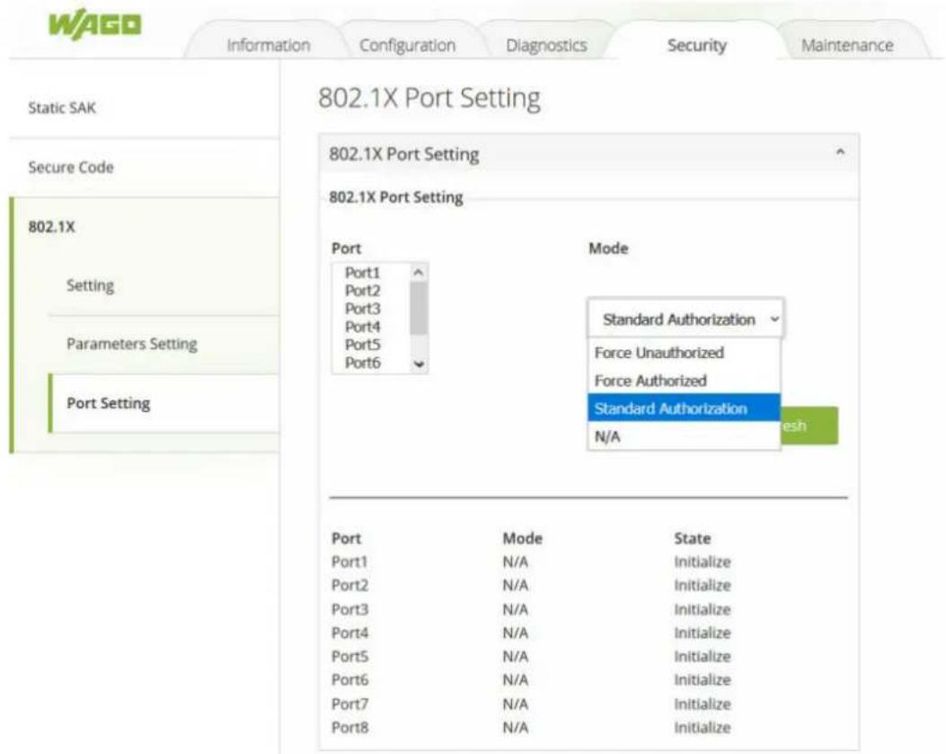
Figure 50: WBM "Security" Page – "802.1X" – "802.1X Port Setting" Tab
The webpage's representation is divided into two parts. The upper part of the webpage allows the setting of port(s) to be changed, while the lower part of the webpage is a table displaying the current status of the authorization mode and the state of each port on the managed switch. To enable the 802.1X security on any of the port(s), click one of the port or press Ctrl key and click multiple ports on the list and choose the Authorization Mode from the dropdown list and click the [Update] button. To check the latest status of the 802.1X port setting, user can click on the [Refresh] button.
Table 35: WBM "Security" Page – "802.1X" – "802.1X Port Setting" Tab
| Parameters Factory | Default Description | |
| Port Option Set specific port(s) to be configured. | ||
| Mode NO Choices: | FU (Force Unauthorized): Specify forced unauthorizedFA (Force Authorized): Specify forced authorizedAU (Standard Authorization): Specify authorization based on IEEE 802.1X.NO: Specify disable authorization | |
10.6.4 Port Security
Port security is a security feature that makes it possible to link each port of a switch with a specific number of MAC addresses so that communication is permitted only with authorized MAC addresses. For this, the switch checks the sender MAC address each time a link is established before any user data is transmitted.
The Port Security functions can specify the maximum number of MAC addresses per interface. If this number is exceeded, incoming packets with new MAC addresses are dropped. The allowed MAC addresses are defined automatically after the activation of the respective port. Once enabled, the switch stores the MAC addresses of the sender in a table each time a link is established at the port until the permitted number defined by the user is reached.
When the state of a port on the switch is changed from disabled to enabled, all MAC addresses captured by that port are deleted.
(i) Note
Configuration of the Port Security
Port security configuration will allow the user to configure MAC limitations to permit the interface. This product supports up to 1,000 MAC address for one port.
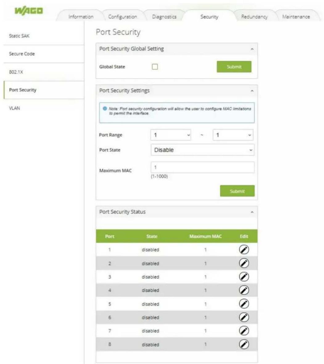
Figure 51: WBM "Security" tab – "Port Security" page
Table 36: WBM "Security" tab – "Port Security Settings" tab
| Parameter Description | |
| Port Security Global Setting | |
| Global State Select Global State to enable port security on the switch. Deselect Global State to disable port security on the switch. | |
| Port Security Settings | |
| Port Range Select the range of ports for which you want to enable/disable port security. | |
| Port State Enable or disable port security on the selected range of ports. | |
| Maximum MAC Select the maximum number of MAC addresses for the selected range of ports |
10.6.5 VLAN
10.6.5.1 Port Isolation
Port Isolation is a port-based virtual LAN function. It partitions the switching ports into virtual private domains designated on a per port basis. Data switching outside of the switch's private domain is not allowed. VLAN tag information of the packets is ignored.
This function can be used to configure one or more egress ports that allow the data received by the specific port to forward it.
If you want to allow communications between two subscriber ports, you must define the egress port for both ports. By default, it forms a VLAN with all ETHERNET ports.
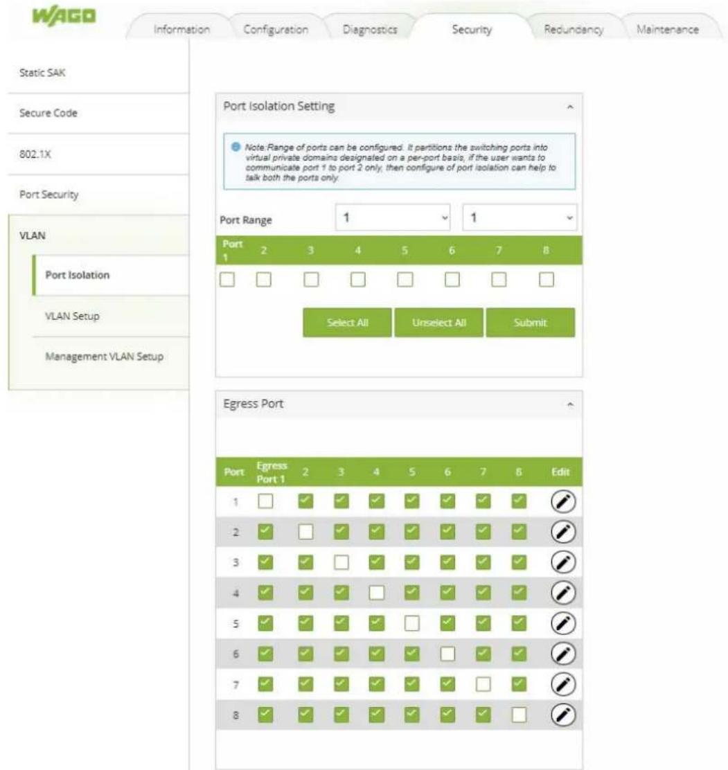
Figure 52: WBM "Security" tab – "Port Isolation Setting" page
Table 37: WBM "Security" tab – "Port Isolation Settings" page
| Parameter Description |
| Port Range Select the range of ports for which you want to submit the Port Isolation Settings. |
| Port (1-8) Select the egress ports for the selected range of ports. |
10.6.5.2 VLAN Setup
A VLAN (Virtual LAN) is a group of hosts with a common set of requirements that communicate as if they were attached to a broadcast domain, regardless of their physical location. A VLAN has the same attributes as a physical LAN, but it allows end stations to be grouped together even if they are not located on the same network switch. Networks can be reconfigured through software instead of spatially offset devices.
VID (VLAN-ID) is the identification of a VLAN that is generally used by the 802.1Q standard. It has 12 bits and allows the identification of 4096 ( 2^12 ) VLANs. Of the 4096 possible VIDs, VID 0 is used to identify Priority Frames and value 4095 (FFF) is reserved, so the maximum possible VLAN configurations are 4094.
A Tagged VLAN uses an explicit tag (VLAN ID) in the MAC header to identify the VLAN membership of a frame across Bridges; they are not confined to the switch on which they were created. VLANs can be created statically (manually by users) or dynamically via the GVRP (GARP VLAN Registration Protocol). The VLAN ID associates a frame with a specific VLAN and provides the information that switches need to process the frame across the network. A tagged frame is four bytes longer than an untagged frame and contains two bytes of TPID (Tag Protocol Identifier, residing within the type/length field of the ETHERNET Frame) and two bytes of TCI (Tag Control Information, starting after the source address field of the ETHERNET Frame).
Forwarded Tagged and Untagged Frames
Each port on the switch is capable of forwarding tagged or untagged frames. To forward a frame from an 802.1Q VLAN-aware switch to an 802.1Q VLAN-unaware switch, the switch first decides where to forward the frame and then strips off the VLAN tag. To forward a frame from an 802.1Q VLAN-unaware switch to an 802.1Q VLAN-aware switch, the switch first decides where to forward the frame and then inserts a VLAN tag reflecting the ingress port's default VID. The default PVID is VLAN 1 for all ports, but this can be changed.
A broadcast frame (or a multicast frame for a multicast group that is known by the system) is duplicated only on ports that are subscribers of the VID (except the ingress port itself), thus confining the broadcast to a specific domain.
Port-Based 802.1Q VLAN
As a subscriber of a port-based VLAN, the port is assigned to a specific VLAN independent of the user or system attached to the port. This means all users attached to the port should be subscribers of the same VLAN. The network administrator typically performs the VLAN assignment. The port configuration is static and cannot be automatically changed to another VLAN without manual reconfiguration.
Two roles can be assigned to a port in a Port-Based VLAN:
- Access port: A port that carries only traffic to and from the specific VLAN to which it is assigned.
- Trunk port: A port that can carry traffic for one or all VLANs that a specific switch can access.
As with other VLAN approaches, the packets forwarded using this method are not transmitted to other VLAN domains or networks. After a port has been assigned to a VLAN, the port cannot send to or receive from devices in another VLAN without the intervention of a Layer 3 device.
The device that is attached to the port likely has no understanding that a VLAN exists. The device simply knows that it is part of a subnet and that the device should be able to talk to all other network subscribers by simply sending information via the cable connection. The switch is responsible for identifying that the information came from a specific VLAN and for ensuring that the information gets to all other subscribers of the VLAN. The switch is also responsible for ensuring that ports in a different VLAN do not receive the information.
This approach is quite simple, fast and easy to manage in that there are no complex lookup tables required for VLAN segmentation. If the Port-to-VLAN connection is designed with an application-specific integrated circuit (ASIC), performance is very good. An ASIC allows Port-to-VLAN mapping at the hardware level.
(i) Note
Creating VLANs
Up to 128 VLANs can be set up. It is recommended to configure a trunk port with tag and have all ports join the VLAN.
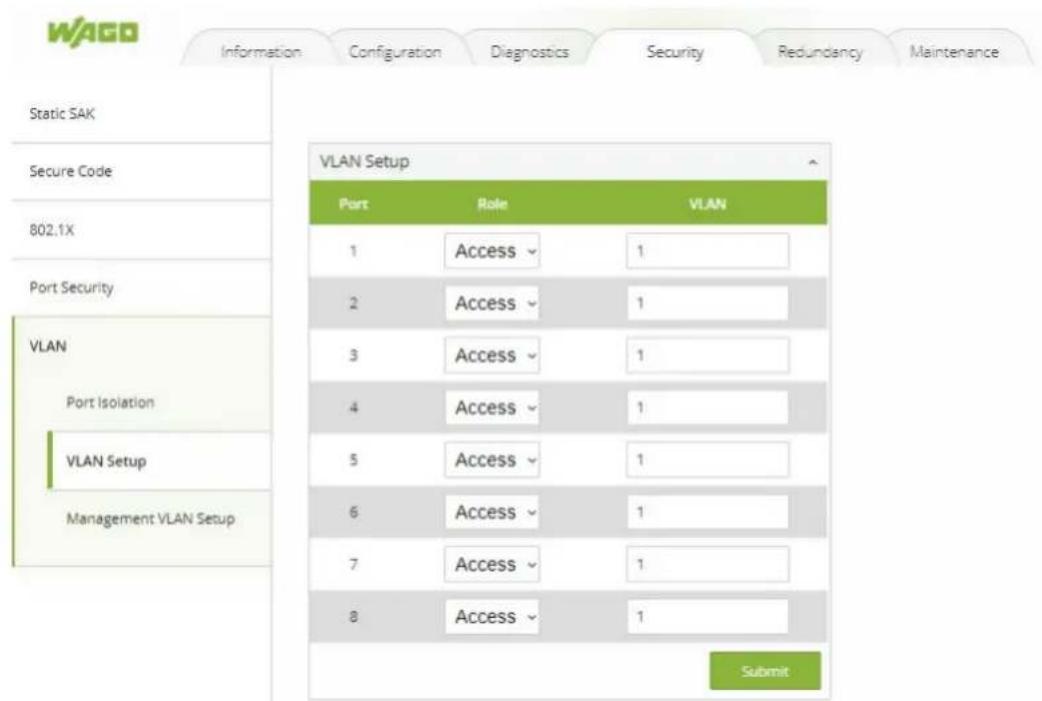
Figure 53: WBM "Security" tab – "VLAN Setup" page
Table 38: WBM "Security" tab - "VLAN Setup" page
| Parameter Description |
| Role Select whether that port should be assigned the Access or Trunk role. |
| VLAN Select the VLAN to be assigned to the port (for trunk e.g. 1,3,6,19) |
10.6.5.3 Management VLAN
There must always be a port in the Management VLAN. Otherwise, the switch cannot be configured.
(i) Note
Obtaining the management VLAN information
If the information for the Management VLAN is missing, you can obtain this information via LLDP.
- Step 1: Connect Port1 to your laptop or PC.
- Step 2: Port1 will send the information of management VLAN configuration three times via LLDP DA when the system is booting up (Interval time of 5 seconds).
- Step 3: Use the network monitoring tool to monitor LLDP packets and find the management VLAN. In the example below, the management VLAN has the ID 1. Ports 1, 3, 5, and 7 have been set up for VLAN 1.
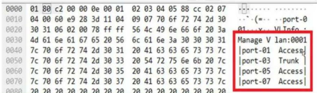
Figure 54: Management VLAN – Example
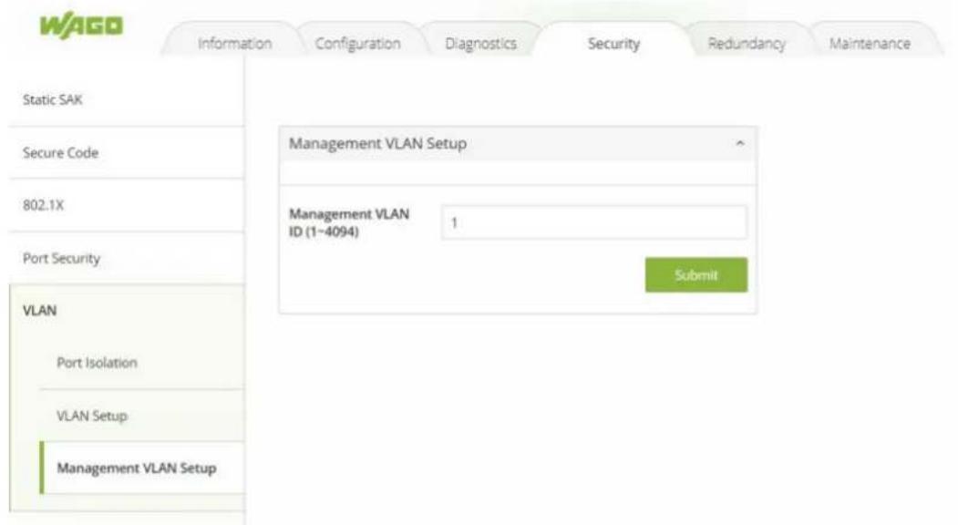
Figure 55: WBM "Security" tab – "Management VLAN Setup" page
Table 39: WBM "Security" tab – "Management VLAN Setup" page
| Parameter Description | |
| Management VLAN Select the VLAN ID for the Management VLAN |
(i) Note
If the management VLAN is not configured as an access port on the switch, the configuration must be accessed via the trunk port. In this case, the configuration must be performed via an access port of a second switch that is located in the same management VLAN.
10.7 Redundancy
10.7.1 RSTP
10.7.1.1 General Information
The Rapid Spanning Tree Protocol (RSTP) is a development of the Spanning Tree Protocol (STP). Both protocols are defined by the IEEE in the following standards:
- IEEE 802.1D: Spanning Tree Protocol
- IEEE 802.1w: Rapid Spanning Tree Protocol
RSTP can detect and break network loops and provide backup links (spare connections) between switches, bridges or routers. By regularly exchanging Bridge Protocol Data Units (BDPU), a switch can interact with other RSTP-capable switches in the network to ensure that only one connection exists between any two stations in the network at any given time.
Compared to STP, RSTP allows faster adaptation of the spanning tree. It is also backward compatible with STP-only bridges. With RSTP, information about changes in topology is broadcasted throughout the network directly from the device generating the change. With STP, a longer delay is required because the device causing a topology change first notifies the root bridge, which in turn notifies the rest of the network. Both RSTP and STP remove unwanted learned addresses from the filter database.
To create the spanning tree, a root bridge must be selected first. This is the starting point of a spanning tree. Starting from the root bridge, , all paths are defined via which the other bridges in the
network can be reached. The root bridge is selected according to a defined procedure. For this purpose, the switches exchange their Bridge-ID (BID - consisting of priority, system ID and MAC address) via multicast messages and select the switch with the lowest priority as the root bridge of the spanning tree. If the lowest priority is assigned to more than one switch, other criteria such as the MAC address are decisive.
After the root bridge has been selected, the paths through which the other bridges in the network can be reached are defined. For this purpose, all paths on which other switches can be reached are first determined. If several paths are recognized over which a switch can be reached, the paths with the least favorable path costs are blocked. The path costs are the costs for transmitting a frame through the port in the LAN. The IEEE standard defines the path costs, but also allows them to be set manually. This value should be adjusted to the transmission speed. The valid range is 1 to 200000000. A path with higher costs is more likely to be blocked by STP if a network loop is detected.
If the topology changes in a LAN coupled via bridge, a new tree is spanned. Once a stable network topology has been established, all bridges listen for Hello BPDUs transmitted from the Root Bridge. If a bridge does not get a Hello BPDU after a predefined interval (Max Age), the bridge assumes that the link to the Root Bridge is down. This bridge then initiates negotiations with other bridges to reconfigure the network to re-establish a valid network topology.
RSTP Switch Port States:
- Discarding
If a port causes a Switching Loop (looping connection between two ports), user data can no longer be sent or received. However, the port can go into the Forwarding state if the other active connections fail and the Spanning Tree algorithm determines that the port may transition to that state. BPDU data (Bridge Protocol Data Unit, configuration message) continues to be received and sent in the "Discarding" state.
- Learning
Even before the port has forwarded any frames (packets), it can learn source addresses from frames received and add them to the filter database (Switching Database).
- Forwarding
The port is in normal operating mode; it receives and sends data. RSTP still monitors incoming BPDUs, which would indicate that the port should return to the Blocking state to prevent a loop.
RSTP Bridge Port Roles
- Root
The Root Port is a forwarding port that can best transmit data from the Non-Root Bridge to the Root Bridge.
- Designated
This is a forwarding port for every LAN segment.
- Alternate
This port represents an alternate path to the Root Bridge. However, this path differs from the Root Port.
- Backup
This port is used as a backup/redundant path to a segment to which another Bridge Port is already connected.
- Disabled
This is not actually part of RSTP because a network administrator can manually disable a port.
Other important terms:
Table 40: Other important terms
| Term Description | |
| Forward Time The For | ward Time or Forward Delay is the maximum time (in seconds) that the switch waits before it changes states. This delay is required because every switch must first receive information on topology changes before it forwards frames. In addition, each port needs time to receive information on conflicts that would make it return to the blocking state. Otherwise, temporary data loops might result. The valid range is 4 to 30 seconds. |
| Max Age The Max Age | is the maximum time (in seconds) that the switch can wait without receiving a BPDU (Bridge Protocol Data Unit, configuration message) before attempting to reconfigure. All switch ports (except for Designated Ports) receive BPDUs at regular inter-vals. Each port that ages out RSTP information (from the last BPDU) becomes the Designated Port for the attached LAN. If it is a Root Port, a new Root Port is selected from among the switch ports attached to the network. |
| Hello Time The Hello | Time is the time interval in seconds between configuration messages (BDPU Bridge Protocol Data Unit) sent from the root switch. |
| Edge Port Edge Ports | are attached to a LAN that has no other bridges attached. These ports can transition directly to the Forwarding state. RSTP continues to monitor the port for BPDUs in case a bridge is connected. RSTP can also be configured to automatically detect Edge Ports. As soon as the bridge detects a BPDU coming to an Edge Port, the port loses its status as an Edge Port. |
| Transmission Limit The | Transmission Limit is used to configure the minimum interval between the transmission of consecutive RSTP BPDUs. This function can only be enabled in RSTP mode. The valid range is from 1 to 10 seconds. |
| Priority The priority is | used in determining the root switch, root port, and designated port. The switch with the highest priority (lowest numeric value) becomes the RSTP root switch. If all switches have the same priority, the switch with the lowest MAC address becomes the root switch.Enter a value from 0~61440.The lower the numeric value you assign, the higher the priority for this bridge.The priority determines the root bridge, which in turn determines the root hello time, maximum root age, and root forwarding delay. |
| Convergence Time Time | required to recalculate the spanning tree in the event of a link failure. |
| BPDU Guard This setting is configured individual for each port. If the port is enabled in BDU Guard and receives a BPDU, the port is switched to the Disabled state to prevent a faulty environment. The user must then manually enable the port. | |
| BPDU Filter This function is used to set up a filter for sending or receiving BPDUs on a switch port. If the port receives BPDUs, the BPDUs are dropped. If both of the BPDU Filter and BPDU Guard are enabled, the BPDU Filter has the higher priority. | |
| Root Guard The Root | Guard function forces an interface to become a Designated Port to prevent neighboring switches from becoming a root switch. This function provides a way to specify the selection of a Root Bridge in a network. It prevents a Designated Port from becoming the Root Port. If a port with the Root Guard function receives a superior BPDU, the port moves to a root-inconsistent state (effectively equal to the Listening state) to maintain the status of the current Root Bridge. The port can be moved to the Forwarding state if no superior BPDU received over the period of three Hello Times. |
10.7.1.2 RSTP Setup
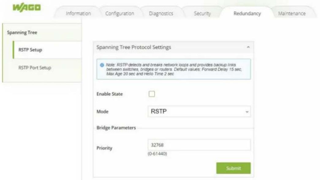
Figure 56: WBM "Redundancy" tab – "RSTP Setup" page
Table 41: WBM "Redundancy" tab - "RSTP Setup" page
| Parameter Description | |
| Enable State Select Enable State to enable RSTP on the switch. Deselect Enable State to disable RSTP on the switch. | |
| Mode Only one mode (RSTP) is supported. | |
| Bridge Parameters | |
| Priority Define the priority of the switch, which is used to determine the root switch, the root port, and the designated ports. |
i Note
Maximum switches in RSTP ring
A maximum of 20 switches can be connected in one RSTP ring (Default values: "Max Age" = 20 seconds).
10.7.1.3 RSTP Port Setup
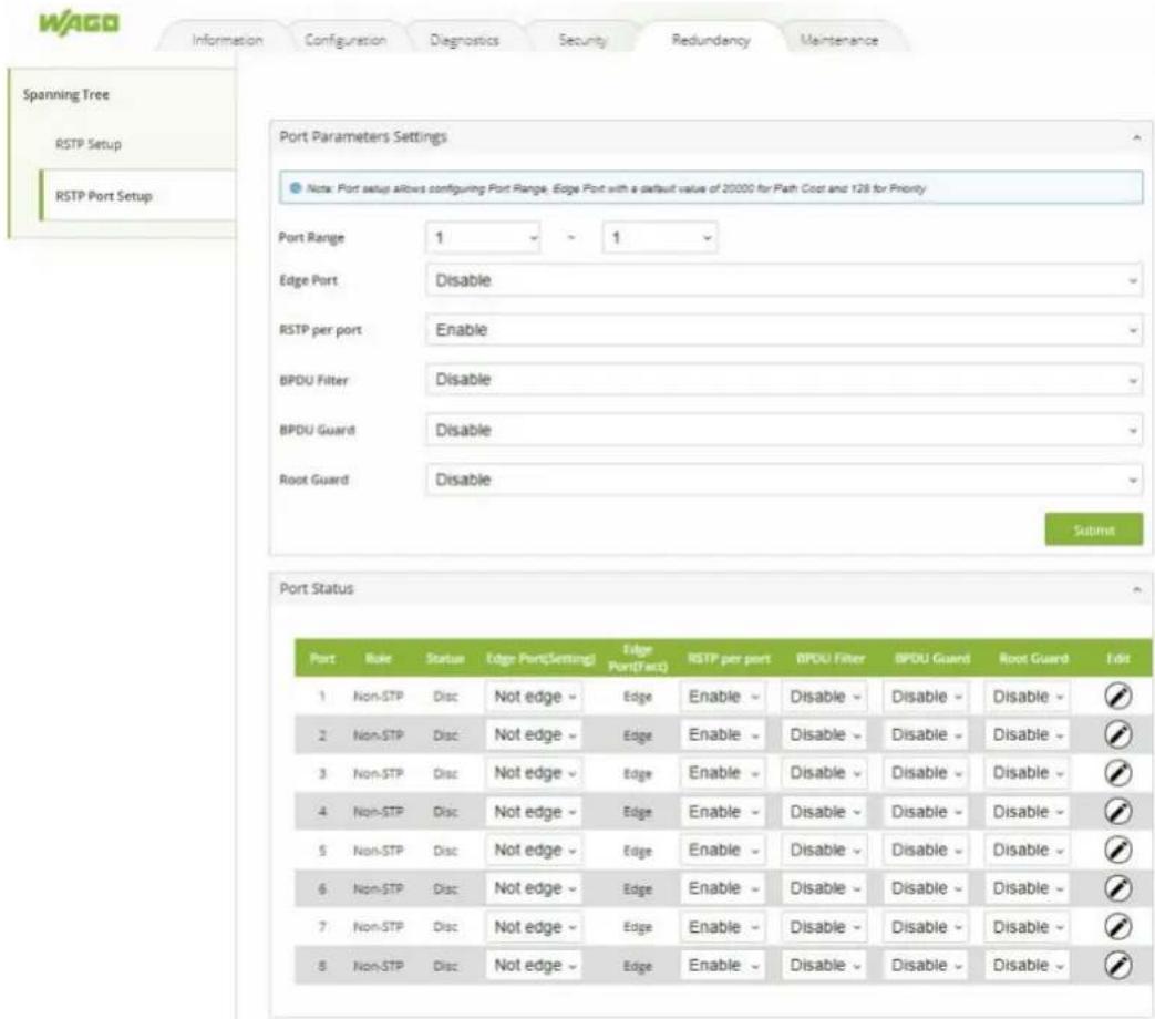
Figure 57: WBM "Redundancy" tab – "RSTP Port Setup" page
Table 42: WBM "Redundancy" tab – "RSTP Port Setup" page
| Parameter Description | |
| Port Range Select the range of ports for which you want to apply the Port Parameters Settings. | |
| Edge Port Select if the Edge Port setting should be enabled or disabled on the selected port range. | |
| RSTP per port Select if RSTP should be enabled or disabled on the selected port range. | |
| BDPU Filter Select if the BDPU Filter setting should be enabled or disabled on the selected port range. | |
| BDPU Guard Select if the BDPU Guard setting should be enabled or disabled on the selected port range. | |
| Root Guard Select if the Root Guard setting should be enabled or disabled on the selected port range. |
10.7.1.4 RSTP Failover & Recovery Times
Industrial automation applications require robust communication networks that ensure high availability. The availability of an Ethernet network is largely determined by how quickly a network can recover from a cable or device failure.
There are several approaches to ensuring availability. The ring-based network topology is the simplest and most widely used. However, not all solutions achieve the same system availability and are directly dependent on the network topology. In order to make conclu-
sions about the performance for a specific industrial network application, the results of the measurements of the failover and recovery time of the network are presented below. The tested topologies correspond to an RSTP ring with 10 and 20 switches.
Cable Break (Failover) & New Uplink (Recovery)
| Bidirectional traffic (TCP) Bidirectional traffic (UDP) | ||||
| Number of devices in the ring (852-1322) | Average failover time (ms) | Average recovery time (ms) | Average failover time (ms) | Average recovery time (ms) |
| 10 1210.7 127.0 1213.3 127.8 | ||||
| 20 1238.8 528.7 1239.0 530.0 | ||||
Power-off Root (Failover)
| Bidirectional traffic (TCP) Bidirectional traffic (UDP) | ||||
| Number of devices in the ring (852-1322) | Average failover time (ms) | Average recovery time (ms) | Average failover time (ms) | Average recovery time (ms) |
| 10 1064.9 N/A 1064.5 N/A | ||||
| 20 1233.6 N/A 1232.6 N/A | ||||
10.8 Maintenance
10.8.1 Firmware Upgrade
The user can update the device firmware via web interface as shown in Figure "WBM "Maintenance" Page – "Firmware Upgrade" Tab".
To update the firmware, the user can download a new firmware from WAGO's website and save it in a local computer. Then, the users can click [Browse...] button and choose the firmware file that is already downloaded. The switch's firmware typically has a “.dld” extension such as 0852-132x-V223.dld. After that, the users can click [Update] button and wait for the update process to be finished.
(i) Note
Firmware-Upgrade
Please make sure that the switch is plug-in with power supply all the time during the firmware upgrade.
![WAGO Information Configuration Diagnostics Security Maintenance Firmware Upgrade Reset to Default Backup/Restore Reboot Logout Firmware Upgrade Firmware Upgrade Please select the firmware file, then click the [Update] button to upgrade the system. Browse... No file selected. Update](/content/2026/05/830552/images/5d388a63202c32038f21657be26c39f7646bb2899d70d23d6701c01f10509994.jpg)
Figure 58: WBM "Maintenance" Page – "Firmware Upgrade" Tab
10.8.2 Reset to Default
When the switch is not working properly, the user can reset it back to the original factory default setting by clicking on the [Reset] button as shown in Figure "WBM "Maintenance" Page – "Reset to Default" Tab". When the switch is restarted, the web browser will be redirected to the login web page as depicted in Figure "Login Web Page". Note that there is no physical reset button on the front panel of the box; therefore, the user will have to either using the [Reset] button on this page.
![WAGO Information Configuration Diagnostics Security Maintenance Firmware Upgrade Reset Reset to Default Reset Reset Backup/Restore Please click [Reset] button to reset the switch to the factory default setting. Reboot Reset Logout](/content/2026/05/830552/images/1aa31dee94f352d10bfc55ae6cb821130cb7a407893a8d7a98cd716193902020.jpg)
Figure 59: WBM "Maintenance" Page – "Reset to Default" Tab
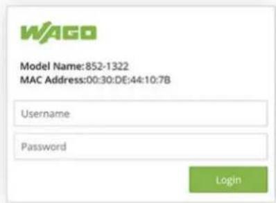
Figure 60: Login Web Page (Example)
10.8.3 Backup/Restore
The Backup/Restore tab page allow the user to back up the current configuration of the switch to a file, save the configuration file on the local PC, or upload a new configuration from a previously saved configuration file. Figure "WBM "Maintenance" Page – "Backup/Restore" Tab" shows the Backup/Restore tab page where it can be divided into two parts: Backup the Configuration and Restore the Configuration.
When clicking on the [Download] button on the upper part of the page (Backup the Configuration box), the user will be prompted to save or keep the file name 852-1322_XXX.XXX.XXX.XXX.ini by the Web browser. Choosing to Save File will back up the switch's current configuration to your local drive on the local PC.
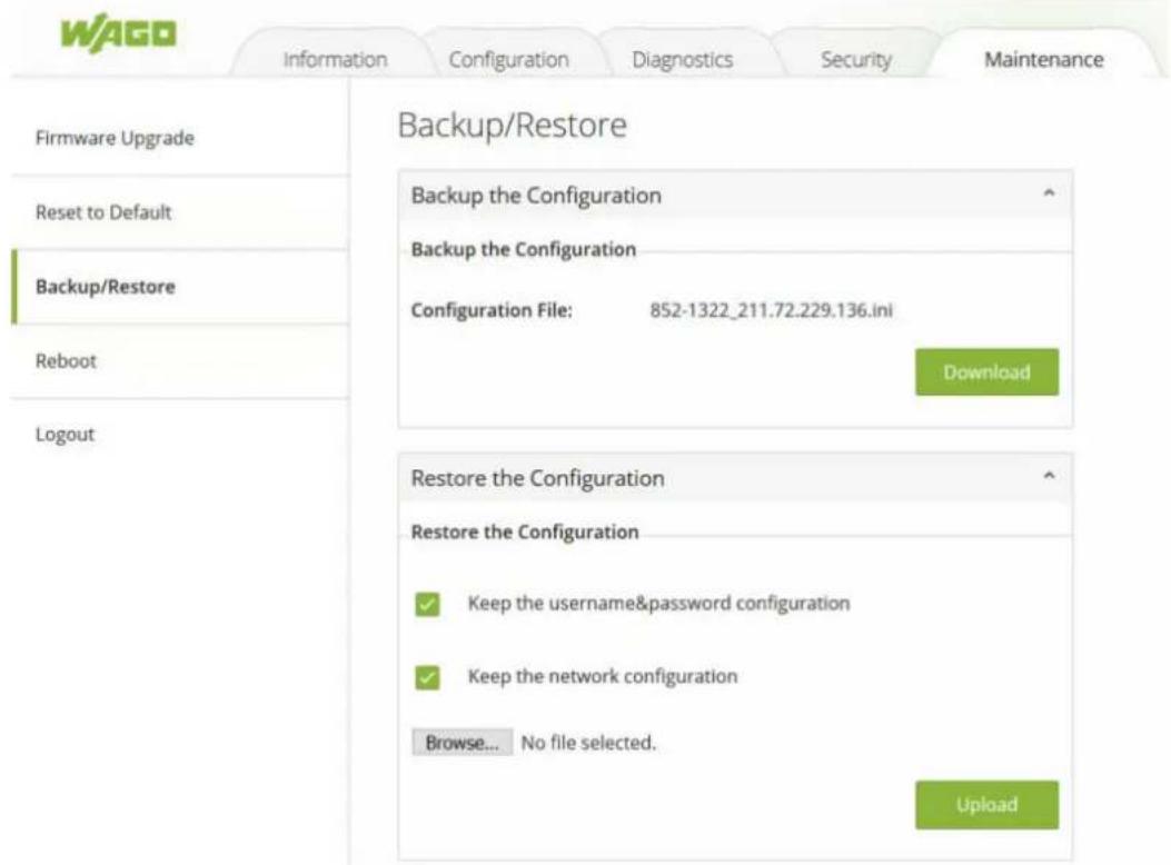
Figure 61: WBM "Maintenance" Page – "Backup/Restore" Tab
To restore a configuration file to the switch, click on [Browse...] button to open a file chooser to select a configuration file from the local drive of your PC. Before clicking the [Upload] button, the user can check any of the options above the file name, which are "Keep the username & password configuration" and "Keep the network configuration". These two options will help to prevent the users from un-necessary logging-in to the switch using previously stored username, password, and/or network configuration after settings are restored.
10.8.4 Reboot
A simple reboot function is provided in this tab page requiring only one single click on the [Reboot] button as shown in Figure "WBM "Maintenance" Page – "Reboot" Tab".
![WAGO Information Configuration Diagnostics Security Maintenance Firmware Upgrade Reboot Reset to Default Reboot Backup/Restore Please click [Reboot] button to restart the switch device. Reboot Logout Reboot](/content/2026/05/830552/images/6da8c7e45abc370f8de090d506b5497430169a280de4862b180079db974bc124.jpg)
Figure 62: WBM "Maintenance" Page – "Reboot" Tab
10.8.5 Logout
For security best practice, the users should logout of the device if they no longer need to modify the system configuration. The logout process is highly recommended to ensure that the correct user settings will not be changed easily by unauthorized access or user. The user can logout of the device by either browsing to the Logout page and click [Logout] button or using the logout quick button which is located on the upper right corner of the web page as shown in Figure "WBM "Maintenance" Page – "Logout" Tab" and Figure Logout Quick Button on the Upper Right Conner", respectively.
![WAGO Information Configuration Diagnostics Security Maintenance Firmware Upgrade Reset to Default Backup/Restore Reboot Logout Logout Logout Please click [Logout] button to logout the switch device. Logout](/content/2026/05/830552/images/118dd542f3fe580ca2aafaf9ae41913c01bd2a3170d23989e6626f2bd9504b54.jpg)
Figure 63: WBM "Maintenance" Page – "Logout" Tab
Figure 64: Logout Quick Button on the Upper Right Conner
Commissioning
(i) Note
For important and useful information on commissioning, see sections:
- System Settings: 📋 System Settings [▶ 36]
- Network Settings: 📋 Network Settings [▶ 41]
- Port Settings: ⚙️ Setting [▶ 42]
- Password: ⚙️ Password [▶ 44]
- Clock Settings: 📋 SNTP Setup [▶ 39]
Diagnostics
(i) Note
For diagnostics and troubleshooting, see sections:
Diagnostics via LED Indicators:
- Diagnostics using product LEDs: Unit LEDs [▶ 18]
- Diagnostics using connection LEDs: 📋 Port LEDs [▶ 19]
Diagnostics via WBM:
- Diagnostics using SNMP network management: 📋 SNMP [▶ 45]
- Diagnostics in the System Log: 📋 System-Log [▶ 55]
- Monitoring ports: 📋 Port Monitor [▶ 59]
Service
(i) Note
The following topics are useful for maintenance, for which the sections in the WBM description are given:
- Update the firmware: 📋 Firmware Upgrade [▶ 77]
- Reset to factory settings: 📋 Reset to Default [▶ 78]
- Backup and restore: 📋 Backup/Restore [▶ 79]
- Reboot: 📋 Reboot [▶ 79]
- Logout: ⚙️ Logout [▶ 80]
Decommissioning
14.1 Disposal and Recycling
- Observe national and local regulations for the disposal of batteries, packaging and electrical and electronic equipment.
- Clear any data stored on electrical and electronic equipment.
- Remove any batteries or memory cards installed in electrical and electronic equipment.
- Dispose of all types of packaging to ensure a high level of recovery, reuse and recycling.
- Have electrical and electronic equipment sent to a local collection point.
- The guidelines 2006/66/EG, PPWD 2018/852/EU and WEEE 2012/19/EU apply throughout Europe. National directives and laws may vary.
Table 43: WEEE Mark
| Logo Description | |
| Electrical and electronic equipment may not be disposed of with household waste. This also applies to products without this mark. |
Electrical and electronic equipment contain materials and substances that can be harmful to the environment and health. Electrical and electronic equipment must be disposed of properly after use. Environmentally friendly disposal benefits health, protects the environment from harmful substances in electrical and electronic equipment and enables sustainable and efficient use of resources.
Appendix
15.1 MODBUS/TCP Map
15.1.1 Modbus-Register
Table 44: Modbus-Register
| Address Data Type Read/Write Description | |||
| Systeminformation | |||
| 0x0020 (32) 1 word R Firmware Version = | |||
| Ex: Version = 1.02 | |||
| Word 0 Hi byte = 0x01 | |||
| Word 0 Lo byte = 0x02 | |||
| 0x0021 (33) 3 words R ETHERNET MAC Address | |||
| Ex: MAC = 00-01-02-03-04-05 | |||
| Word 0 Hi byte = 0x00 | |||
| Word 0 Lo byte = 0x01 | |||
| Word 1 Hi byte = 0x02 | |||
| Word 1 Lo byte = 0x03 | |||
| Word 2 Hi byte = 0x04 | |||
| Word 2 Lo byte = 0x05 | |||
| 0x0024 (36) 1 word R Kernel Version | |||
| Ex: Version = 1.03 | |||
| Word 0 Hi byte = 0x01 | |||
| Word 0 Lo byte = 0x03 | |||
| IP-Information | |||
| 0x0050 (80) 1 word R DHCP Status | |||
| 0x0000: Disabled | |||
| 0x0001: Enabled | |||
| 0x0051 (81) 2 words R IP Address of switch | |||
| Ex: IP = 192.168.1.1 | |||
| Word 0 Hi byte = 0xC0 | |||
| Word 0 Lo byte = 0xA8 | |||
| Word 1 Hi byte = 0x01 | |||
| Word 1 Lo byte = 0x01 | |||
| 0x0053 (83) 2 words R Subnet Maske of switch | |||
| Ex: IP = 255.255.255.0 | |||
| Word 0 Hi byte = 0xFF | |||
| Word 0 Lo byte = 0xFF | |||
| Word 1 Hi byte = 0xFF | |||
| Word 1 Lo byte = 0x00 | |||
| 0x0055 (85) 2 words R Gateway Address of switch | |||
| Ex: IP = 192.168.1.254 | |||
| Word 0 Hi byte = 0xC0 | |||
| Word 0 Lo byte = 0xA8 | |||
| Word 1 Hi byte = 0x01 | |||
| Word 1 Lo byte = 0xFE | |||
| Port Status | |||
| 0x1000 (4096) 5 words | R Port Status | ||
| 0x0000: Disabled | |||
| 0x0001: Enabled | |||
| Word 0 Hi byte = Port 1 Status | |||
| Word 0 Lo byte = Port 2 Status | |||
| Word 1 Hi byte = Port 3 Status | |||
| Word 1 Lo byte = Port 4 Status | |||
| Word 2 Hi byte = Port 5 Status | |||
| Word 2 Lo byte = Port 6 Status | |||
| Word 3 Hi byte = Port 7 Status | |||
| Word 3 Lo byte = Port 8 Status | |||
| Word 4 Hi byte = Port 9 Status | |||
| Word 4 Lo byte = Port 10 Status | |||
| 0x1040 (4160) 5 words | R Port Speed | ||
| Status, 10M = 0x01 | |||
| Status, 100M = 0x02 | |||
| Status, 1000M = 0x03 | |||
| Word 0 Hi byte = Port 1 Status | |||
| Word 0 Lo byte = Port 2 Status | |||
| Word 1 Hi byte = Port 3 Status | |||
| Word 1 Lo byte = Port 4 Status | |||
| Word 2 Hi byte = Port 5 Status | |||
| Word 2 Lo byte = Port 6 Status | |||
| Word 3 Hi byte = Port 7 Status | |||
| Word 3 Lo byte = Port 8 Status | |||
| Word 4 Hi byte = Port 9 Status | |||
| Word 4 Lo byte = Port 10 Status | |||
| 0x10A0 (4256) 5 words | R Port Link Status | ||
| Status, down = 0x00 | |||
| Status, up = 0x01 | |||
| Word 0 Hi byte = Port 1 Status | |||
| Word 0 Lo byte = Port 2 Status | |||
| Word 1 Hi byte = Port 3 Status | |||
| Word 1 Lo byte = Port 4 Status | |||
| Word 2 Hi byte = Port 5 Status | |||
| Word 2 Lo byte = Port 6 Status | |||
| Word 3 Hi byte = Port 7 Status | |||
| Word 3 Lo byte = Port 8 Status | |||
| Word 4 Hi byte = Port 9 Status | |||
| Word 4 Lo byte = Port 10 Status | |||
List of Tables
Table 1 Legend for the Figure "Front View of the Industrial Managed Switch".... 15
Table 2 Legend for the Figure "Top View of the Industrial Managed Switch" 15
Table 3 Legend for Figure „Label“ 16
Table 4 Legend for Figure "Power Supply" 17
Table 5 Legend for Figure "Network Connections".... 17
Table 6 Legend for "Unit LEDs" Figure 18
Table 7 Legend for „Port LEDs“ Figure.... 19
Table 8 Technical Data – Device Data 19
Table 9 Technical Data – System Data 19
Table 10 Technical Data – Power Supply 19
Table 11 Technical Data – Communication.... 19
Table 12 Technical Data – Environmental Conditions.... 20
Table 13 Overview – Navigation Links and WBM Pages.... 31
Table 14 WBM "Information" Page – "System Information" Tab.... 35
Table 15 WBM "Configuration" Page – "System Settings" Tab 37
Table 16 WBM "Configuration" tab – "LLDP Settings" page.... 38
Table 17 WBM "Configuration" page – "SNTP" tab 39
Table 18 WBM "Configuration" tab – "SNTP" page 41
Table 19 WBM "Configuration" Page – "System Settings" Tab 42
Table 20 WBM "Configuration" Page – "Port Settings" Tab...... 43
Table 21 WBM "Configuration" tab – "Mirror" page 44
Table 22 WBM "Configuration" Page – "Password" Tab.... 45
Table 23 WBM Page, “Diagnostics” – “SNMP” Tab, SNMP Agent Setting.... 50
Table 24 WBM "Diagnostics" Page – "SNMP" Tab, SNMP V1/V2c Community Setting .... 51
Table 25 WBM "Diagnostics" Page – "SNMP" Tab, SNMP Trap 52
Table 26 WBM "Diagnostics" Page – "SNMP" Tab, SNMP V3 Auth.... 54
Table 27 WBM "Diagnostics" Page – "Modbus TCP" Tab 55
Table 28 WBM "Diagnostics" Page – "System Log" – "Setting" Tab.... 56
Table 29 WBM Page, "Diagnostics" – "System Log" – "Log" Tab.... 58
Table 30 Log Event Description.... 58
Table 31 WBM "Diagnostics" Page – "Port Monitor" Tab.... 59
Table 32 WBM Page, "Security" – "Static SAK" Tab.... 60
Table 33 WBM "Security" Page – "802.1X" – "Setting" Tab....63
Table 34 WBM "Security" Page – "802.1X" – "802.1X Parameter Setting" Tab – Parameters Settings" 64
Table 35 WBM "Security" Page – "802.1X" – „802.1X Port Setting" Tab....65
Table 36 WBM "Security" tab – "Port Security Settings" tab 67
Table 37 WBM "Security" tab – "Port Isolation Settings" page 68
Table 38 WBM "Security" tab – "VLAN Setup" page 70
Table 39 WBM "Security" tab – "Management VLAN Setup" page 71
Table 40 Other important terms.... 73
Table 41 WBM "Redundancy" tab – "RSTP Setup" page.... 75
Table 42 WBM "Redundancy" tab – "RSTP Port Setup" page 76
Table 43 WEEE Mark 84
Table 44 Modbus-Register.... 85
List of Figures
Figure 1 Front View of the Industrial Managed Switch.... 14
Figure 2 Top View of the Industrial Managed Switch.... 15
Figure 3 Label 16
Figure 4 Grounding screw 16
Figure 5 Power Supply Connector 17
Figure 6 Network Connections.... 17
Figure 7 Unit LEDs 18
Figure 8 Port LEDs.... 19
Figure 9 RADIUS Authentication Sequence 22
Figure 10 Example of Wireshark software sniffing on IP address of a switch.... 29
Figure 11 Security Warning Page 30
Figure 12 WAGO Login Page 30
Figure 13 Start Page of WBM 31
Figure 14 Default Password Warning Pop-up Dialog on Password Web Page 31
Figure 15 Login Failure Dialog 33
Figure 16 Login Failure Dialog with only [Forget it] button.... 33
Figure 17 Example of Dialog after Clicking [Forget it] Button 33
Figure 18 Example of Security Card 34
Figure 19 Re-direction to Change Password Tab Page.... 34
Figure 20 WAGO Login Dialog after Resetting Password 34
Figure 21 WBM "Information" Page – "System Information" Tab.... 35
Figure 22 WBM "Information" Page – "Legal Information" – "WAGO Licenses" Tab ...... 36
Figure 23 WBM "Information" Page – "Legal Information" – "Open Source License" Tab ...... 36
Figure 24 WBM "Configuration" Page – "System Settings" Tab 37
Figure 25 WBM "Configuration" tab – "LLDP Settings" page.... 38
Figure 26 WBM "Configuration" page – "SNTP" tab 39
Figure 27 WBM "Configuration" tab – "SNTP" page 40
Figure 28 WBM "Configuration" Page – "Network Settings" Tab 42
Figure 29 WBM "Configuration" Page – "Port Settings" Tab.... 43
Figure 30 WBM "Configuration" tab – "Mirror" page 44
Figure 31 WBM "Configuration" Page – "Password" Tab.... 45
Figure 32 WBM "Diagnostics" Page – "SNMP Setting Part 1" Tab 47
Figure 33 WBM "Diagnostics" Page – "SNMP Setting Part 2" Tab 48
Figure 34 WBM "Diagnostics" Page – "SNMP Setting Part 3" Tab 49
Figure 35 SNMP Agent Setting 50
Figure 36 SNMP V1/V2c Community Setting.... 51
Figure 37 WBM "Diagnostics" Page – "SNMP" Tab, SNMP Trap 52
Figure 38 WBM "Diagnostics" Page – "SNMP Tab", SNMP V3 Auth.... 53
Figure 39 WBM "Diagnostics" Page – "Modbus TCP" Tab 55
Figure 40 WBM "Diagnostics" Page – "System Log" – "Setting" Tab.... 56
Figure 41 WBM Page, "Diagnostics" – "System Log" Tab – "Log" Section.... 57
Figure 42 [Start] Button is visible when Automatic refresh cycle is enabled. 58
Figure 43 WBM "Diagnostics" Page – "Port Monitor" Tab.... 59
Figure 44 WBM Page, "Security" – "Static SAK" Tab....60
Figure 45 Example of Secure Codes 61
Figure 46 WBM "Security" Page – "Secure Code" Tab.... 61
Figure 47 WBM "Security" Page – "802.1X" Tab 62
Figure 48 WBM "Security" Page – "802.1X" – "Setting" Tab....63
Figure 49 WBM "Security" Page – "802.1X" – "802.1X Parameter Setting" Tab....64
Figure 50 WBM "Security" Page – "802.1X" – "802.1X Port Setting" Tab....65
Figure 51 WBM "Security" tab – "Port Security" page.... 66
Figure 52 WBM "Security" tab – "Port Isolation Setting" page.... 68
Figure 53 WBM "Security" tab – "VLAN Setup" page 70
Figure 54 Management VLAN – Example.... 71
Figure 55 WBM "Security" tab – "Management VLAN Setup" page 71
Figure 56 WBM "Redundancy" tab – "RSTP Setup" page 75
Figure 57 WBM "Redundancy" tab – "RSTP Port Setup" page 76
Figure 58 WBM "Maintenance" Page – "Firmware Upgrade" Tab 78
Figure 59 WBM "Maintenance" Page – "Reset to Default" Tab 78
Figure 60 Login Web Page (Example)....78
Figure 61 WBM "Maintenance" Page – "Backup/Restore" Tab....79
Figure 62 WBM "Maintenance" Page – "Reboot" Tab....80
Figure 63 WBM "Maintenance" Page – "Logout" Tab 80
Figure 64 Logout Quick Button on the Upper Right Conner 80
Headquaters +49 571/887 - 0
Sales +49 (0) 571/887 - 44 222
Order Service +49 (0) 571/887 - 44 333
Fax +49 571/887 - 844169
WAGO is a registered trademark of WAGO Verwaltungsgesellschaft mbH.
Copyright – WAGO Kontakttechnik GmbH & Co. KG – All rights reserved. The content and structure of the WAGO websites, catalogs, videos and other WAGO media are subject to copyright. Distribution or modification of the contents of these pages and videos is prohibited. Furthermore, the content may neither be copied nor made available to third parties for commercial purposes. Also subject to copyright are the images and videos that were made available to WAGO Kontakttechnik GmbH & Co. KG by third parties.
- Industrial Managed Switch
- Table of Contents
- Provisions....6
- Safety 10
- Overview 13
- Properties 14
- Functions.... 22
- Planning.... 24
- Transport and Storage.... 25
- Installation and Removal.... 26
- Connection 27
- Configuration in the WBM 29
- Proper Use
- Warranty and Liability
- Obligations of Installers/Operators
- Improper Use
- Typographical Conventions
- Action Instructions
- Lists
- Figures
- Notes
- DANGER
- Type and source of hazard
- WARNING
- CAUTION
- NOTICE
- Type and source of malfunction (property damage only)
- Note
- Notes and information
- Legal Information
- Intellectual Property
- Subject to Change
- Licenses
- Safety
- General Safety Regulations
- Electrical Safety
- Power Supply
- Ground/Protection/Fuses
- Lines
- Protect
- Radio, etc.
- Components
- Mechanical Safety
- Indirect Safety
- Overview
- Properties
- Views
- Front View
- Top View
- Label
- Connectors
- Grounding screw
- Power Supply
- Damage to Property Caused by Electrostatic Discharge (ESD)!
- Network Connections
- 10/100/1000BASE-T(X) ports
- 10/100/1000BASE-T(X) (MACsec) ports
- Display Elements
- Unit LEDs
- Port LEDs
- Technical data
- Product
- System Data
- Power Supply
- Communication
- Environment requirements
- Guidelines, approvals and standards
- Approvals
- i Note
- Regulations and Standards
- Functions
- Security
- IEEE 802.1X
- RADIUS
- MAC Security (MACSec)
- Planning
- Structure Guidelines
- Installation Site
- Transport and Storage
- Installation and Removal
- Installation
- Installation on a Carrier Rail
- Removal
- Removal from Carrier Rail
- Connection
- Grounding
- Connecting the Supply Voltage
- Connect 10/100/1000BASE-T ports
- Configuration in the WBM
- Note
- Login
- Login Failure
- Functions of the "Secure code" tab
- Information
- System Information
- Legal Information
- Configuration
- System Settings
- Device Discovery - LLDP
- System Management – SNTP
- General Information
- In addition:
- SNTP Setup
- Mode: Manual
- Mode: Network Time Protocol
- Network Settings
- Port Settings
- Setting
- Interface – Port Mirroring
- General Information
- Source Mode
- Port Mirroring Setup
- Password
- Diagnostics
- SNMP
- Using SNMPv3
- SNMP Setting
- SNMP Agent
- SNMPv1/v2c-Community
- SNMP Trap
- SNMP-V3-Auth.
- Modbus TCP
- System-Log
- Setting
- Log
- System Log
- Port Monitor
- Security
- Static SAK
- Secure Code
- 802.1X (IEEE 802.1X)
- Setting (IEEE 802.1X - Setting)
- Parameters Setting (IEEE 802.1X - Parameter Setting)
- Port Setting (IEEE 802.1X - Port Setting)
- Port Security
- Configuration of the Port Security
- VLAN
- Port Isolation
- VLAN Setup
- Forwarded Tagged and Untagged Frames
- Port-Based 802.1Q VLAN
- Creating VLANs
- Management VLAN
- Obtaining the management VLAN information
- Redundancy
- RSTP
- General Information
- RSTP Switch Port States:
- - Discarding
- - Learning
- - Forwarding
- RSTP Bridge Port Roles
- - Root
- - Designated
- - Alternate
- - Backup
- - Disabled
- RSTP Setup
- Maximum switches in RSTP ring
- RSTP Port Setup
- RSTP Failover & Recovery Times
- Maintenance
- Firmware Upgrade
- Firmware-Upgrade
- Reset to Default
- Backup/Restore
- Reboot
- Logout
- Commissioning
- Diagnostics
- Diagnostics via LED Indicators:
- Diagnostics via WBM:
- Service
- Decommissioning
- Disposal and Recycling
- Appendix
- MODBUS/TCP Map
- Modbus-Register
- List of Tables
- List of Figures
Brand : Wago
Model : 852-1322
Category : Switch