852-1505/000-001 - Switch Wago - Free user manual and instructions
Find the device manual for free 852-1505/000-001 Wago in PDF.


| Product Type | Industrial Managed Switch |
| Model | 852-1505/000-001 |
| Dimensions (W x H x D) | 50 mm x 120 mm x 162 mm |
| Weight | 955 g |
| Degree of Protection | IP30 |
| Supply Voltage | 24 ... 57 VDC |
| Power Consumption (max.) | 18 W (without PoE), 258 W (with 8 PoE+ at 48 VDC) |
| Copper Ports | 8 x 10/100/1000BASE-T with PoE+ |
| Fiber Optic Ports | 4 x SFP (1000BASE-SX/LX) |
| Console Port | 1 x RJ-45 (RS-232) |
| USB Interface | 1 x USB Host 2.0 |
| PoE Standard | IEEE 802.3af/at (PoE+) |
| PoE Power Budget | 240 W (48 VDC), 120 W (24 VDC) |
| PoE Power per Port (max.) | 30 W |
| MAC Table Size | Up to 16000 addresses |
| VLAN Support | Port-based and tag-based (4094 VIDs) |
| Jumbo Frame Size | 10 kB |
| Operating Temperature | -40 ... +70 °C (CE), -10 ... +60 °C (UL) |
| Storage Temperature | -40 ... +85 °C |
| Relative Humidity | 10 ... 95% (non-condensing) |
| Mounting | DIN rail (35 mm) |
| Configuration Options | Web-based Manager (WBM), CLI (Telnet/Console), SNMP |
| Redundant Power Supply | Yes (RPS input) |
| Alarm Contact | Potential-free, configurable via DIP switches |
Frequently Asked Questions - 852-1505/000-001 Wago
User questions about 852-1505/000-001 Wago
0 question about this device. Answer the ones you know or ask your own.
Ask a new question about this device
Download the instructions for your Switch in PDF format for free! Find your manual 852-1505/000-001 - Wago and take your electronic device back in hand. On this page are published all the documents necessary for the use of your device. 852-1505/000-001 by Wago.
USER MANUAL 852-1505/000-001 Wago
WAGO Industrial Switches

852-1505/000-001
Industrial Managed Switch
8 Ports 1000BASE-T; 4 Slots 1000BASE-SX/LX; EXT;
8 x PoE; USB
All rights reserved.
Every conceivable measure has been taken to ensure the accuracy and completeness of this documentation. However, as errors can never be fully excluded, we always appreciate any information or suggestions for improving the documentation.
E-Mail: documentation@wago.com
We wish to point out that the software and hardware terms as well as the trademarks of companies used and/or mentioned in the present manual are generally protected by trademark or patent.
WAGO is a registered trademark of WAGO Verwaltungsgesellschaft mbH.
Table of Contents
1 Notes about this Documentation....11
1.1 Validity of this Documentation....11
1.2 Copyright....11
1.3 Symbols 12
1.4 Number Notation 14
1.5 Font Conventions 14
2 Important Notes ....15
2.1 Legal Bases....15
2.1.1 Subject to Changes....15
2.1.2 Personnel Qualification 15
2.1.3 Proper Use of the Industrial Switches 15
2.1.4 Technical Condition of Specified Devices....16
2.1.5 Standards and Regulations for Operating the Industrial Switches .... 16
2.2 Safety Advice (Precautions) 17
2.3 Special Use Conditions for ETHERNET Devices....20
3 General 21
3.1 Scope of Supply 21
3.2 Industrial ETHERNET-Technology 21
3.3 Switching Technology....22
3.4 PoE (Power over Ethernet)....22
3.5 Autonegotiation 22
3.6 Autocrossing....23
3.7 Store-and-forward switching mode 23
3.8 Transmission Methods....23
4 Device Description....24
4.1 View 25
4.1.1 Front View....25
4.1.2 Top View....27
4.2 Connectors....28
4.2.1 Grounding screw....28
4.2.2 Power Supply (PWR/RPS) 29
4.2.3 Network Connections....30
4.2.3.1 RJ45 Connection....31
4.2.3.2 USB Connection....31
4.2.3.3 10/100/1000BASE-T-Ports 31
4.2.3.4 10/100/1000BASE-T-Ports with PoE+ 31
4.2.3.5 1000BASE-SX/-LX-Ports 32
4.3 Display Elements....33
4.3.1 Unit-LEDs 33
4.3.2 Port-LEDs 34
4.4 Operating elements 35
4.4.1 DIP Switches 35
4.4.2 Reset Button 36
4.5 Label 37
4.5.1 Hardware and Software Version 37
4.6 Technical Data 38
4.6.1 Device Data 38
4.6.2 System Data 38
4.6.3 Power Supply....38
4.6.4 Power over Ethernet (PoE) 38
4.6.5 Communication....39
4.6.6 Environmental Conditions 40
4.7 Standards and Guidelines ....41
4.8 Approvals 42
5 Mounting....43
5.1 Installation Site 43
5.2 Installation on a Carrier Rail 43
5.3 Removal from Carrier ail....43
6 Connect Devices....44
6.1 Power Supply 44
6.2 External Alarm Contact Port 46
6.3 Console Port Cable Connection....46
6.4 1000Base-SX/LX Port, Fiber Optic 47
6.5 10/100/1000BASE-T Ports ....48
7 Function Description ....49
7.1 Basic Settings....49
7.1.1 Jumbo Frame....49
7.1.2 SNTP 49
7.1.3 Management Host....50
7.1.4 MAC Management....50
7.1.4.1 Static MAC 51
7.1.4.2 MAC Blacklist (Blacklisting) 51
7.1.5 Port Mirroring....52
7.1.6 Port Settings 52
7.2 Advanced Settings....56
7.2.1 Bandwidth Control....56
7.2.1.1 QoS....56
7.2.1.2 Rate Limitation 63
7.2.1.2.1 Storm Control....63
7.2.1.2.2 Rate Limitation....63
7.2.2 IGMP Snooping....64
7.2.3 MVR....67
7.2.3.1 Multicast Address....70
7.2.3.2 VLAN....73
7.2.3.3 Port Isolation 75
7.2.4 GARP/GVRP 76
7.2.4.1 Q-in-Q 78
7.2.4.2 Port-Based Q-in-Q....81
7.2.4.3 Selective Q-in-Q 82
7.2.4.3.1 DHCP Relay 83
7.2.4.3.2 DHCP Relay Option 82....85
7.2.5 DHCP Server 87
7.2.6 Dual Homing 88
7.2.7 Dual Ring 89
7.2.8 ERPS....90
7.2.9 Link Aggregation....93
7.2.9.1 Static Trunk 93
7.2.9.2 LACP 93
7.2.10 LLDP 95
7.2.11 Loop Detection....96
7.2.12 Jet Ring....97
7.2.13 PoE (Power over Ethernet) 98
7.2.14 Static Route 99
7.2.15 STP....100
7.2.16 Xpress Ring 105
7.3 Security 106
7.3.1 IP Source Guard 106
7.3.1.1 DHCP Snooping....107
7.3.1.1.1 Server Screening 109
7.3.1.2 Binding Table 109
7.3.1.3 ARP Inspection....110
7.3.1.3.1 Filter Table....111
7.3.2 Access Control List (ACL)....112
7.3.3 IEEE 802.1X Communication Standard....113
7.3.4 Port Security 117
7.3.4.1 Sticky MAC Settings....117
7.4 Monitor 118
7.4.1 Alarm 118
7.4.2 Monitor Information....118
7.4.3 Port Statistics....118
7.4.4 Port Utilization....118
7.4.5 RMON Statistics....118
7.4.6 SFP 119
7.4.6.1 DDMI 119
7.4.7 Traffic Monitor....119
7.5 Management 120
7.5.1 SNMP 120
7.5.1.1 SNMP Trap 121
7.5.1.2 SNMPv3 121
7.5.2 Auto Provision....121
7.5.3 Mail Alarm....123
7.5.4 Ping 123
7.5.5 USB Functions....124
7.5.5.1 Uploading the Firmware 124
7.5.5.2 Saving the Configuration File....125
7.5.5.3 Saving the Syslog File 125
7.5.5.4 Uploading the Configuration File....125
8 Configuration ....127
8.1 Overview of Configuration Options 127
8.1.1 Telnet Port 128
8.2 Console Port....129
9 Configuration in the WBM 130
9.1 System Status....134
9.1.1 System Information....134
9.2 Basic Settings....136
9.2.1 General Settings 136
9.2.1.1 System 136
9.2.1.2 Jumbo Frame 138
9.2.1.3 SNTP....139
9.2.1.4 Management Host....142
9.2.2 MAC Management....143
9.2.2.1 Static MAC Settings....143
9.2.2.2 MAC Table 145
9.2.2.3 Age Time Setting....146
9.2.2.4 Blacklisting 147
9.2.3 Port Mirroring....148
9.2.4 Port Settings 150
9.2.4.1 General Settings....150
9.2.4.2 Information 152
9.3 Advanced Settings....153
9.3.1 Bandwidth Settings 153
9.3.1.1 QoS....153
9.3.2.3.2 Group Settings....172
9.3.2.4 Static Multicast 173
9.3.2.5 Multicast Statistics....174
9.3.3 VLAN 175
9.3.3.1 Port Isolation 175
9.3.3.2 VLAN....177
9.3.3.2.1 VLAN Settings 177
9.3.3.2.2 Tag Settings....179
9.3.3.2.3 Port Settings 180
9.3.3.3 GARP VLAN Registration Protocol....182
9.3.3.3.1 GVRP 182
9.3.3.3.2 GARP Timer 184
| 9.3.3.4 | IP Subnet VLAN | 186 |
| 9.3.3.5 | MAC VLAN | 187 |
| 9.3.3.6 | Protocol VLAN | 188 |
| 9.3.3.7 | Q-in-Q | 189 |
| 9.3.3.7.1 | VLAN Stacking | 189 |
| 9.3.3.7.2 | Port-Based Q-in-Q | 191 |
| 9.3.3.7.3 | Selective Q-in-Q | 192 |
| 9.3.4 | DHCP Relay | 194 |
| 9.3.5 | DHCP Options | 195 |
| 9.3.6 | DHCP Server | 197 |
| 9.3.6.1 | General Settings | 197 |
| 9.3.6.2 | Pool Settings | 199 |
| 9.3.6.3 | Binding Information | 203 |
| 9.3.6.4 | Statistics | 204 |
| 9.3.7 | Dual Homing | 205 |
| 9.3.8 | Dual Ring | 207 |
| 9.3.9 | ERPS | 209 |
| 9.3.9.1 | Ring Settings | 209 |
| 9.3.9.2 | Instance Settings | 213 |
| 9.3.10 | Link Aggregation | 214 |
| 9.3.10.1 | Static Trunk | 214 |
| 9.3.10.2 | LACP | 216 |
| 9.3.10.3 | LACP Info | 218 |
| 9.3.11 | LLDP | 220 |
| 9.3.11.1 | Settings | 220 |
| 9.3.11.2 | Neighboring Detection | 222 |
| 9.3.12 | Loop Detection | 223 |
| 9.3.13 | Jet Ring | 225 |
| 9.3.14 | Modbus | 227 |
| 9.3.15 | PoE | 228 |
| 9.3.15.1 | Configuration | 228 |
| 9.3.15.2 | Schedule | 230 |
| 9.3.15.3 | PD Alive Check | 233 |
| 9.3.15.4 | Power Delay (Switch-on Delay) | 236 |
| 9.3.16 | Static Route | 238 |
| 9.3.17 | Spanning Tree Protocol | 240 |
| 9.3.17.1 | General Settings | 240 |
| 9.3.17.2 | Port Parameters | 242 |
| 9.3.17.3 | STP Status | 245 |
| 9.3.18 | Xpress Ring | 246 |
| 9.4 | Security | 248 |
| 9.4.1 | IP Source Guard | 248 |
| 9.4.1.1 | DHCP Snooping | 248 |
| 9.4.1.1.1 | DHCP Snooping | 248 |
| 9.4.1.1.2 | Port Settings | 250 |
| 9.4.1.1.3 | Server Screening | 251 |
| 9.4.1.2 | DHCP Snooping Binding Table | 252 |
| 9.4.1.2.1 | Static Entry Settings | 252 |
| 9.4.1.2.2 | Binding Table | 254 |
| 9.4.1.3 | ARP Inspection | 255 |
9.4.1.3.1 ARP Inspection....255
9.4.1.3.2 Filter Table....257
9.4.2 Access Control List (ACL) 258
9.4.3 IEEE 802.1X 262
9.4.3.1 Global Settings 262
9.4.3.2 Port Settings....265
9.4.4 Port Security 268
9.4.4.1 Port Security....268
9.4.4.2 Sticky MAC Settings 270
9.5 Monitor 271
9.5.1 Alarm Information....271
9.5.2 System Information....272
9.5.3 Port Statistics....274
9.5.4 Port Utilization....275
9.5.5 RMON Statistics....276
9.5.6 SFP Information....279
9.5.7 Traffic Monitor....282
9.6 Management 285
9.6.1 SNMP 285
9.6.1.1 SNMP 285
9.6.1.1.1 SNMP Settings 285
9.6.1.1.2 Community Name 286
9.6.1.2 SNMP Trap 288
9.6.1.2.1 Trap Receiver Settings....288
9.6.1.2.2 Trap Event Status 290
9.6.1.2.3 Port Trap Settings....291
9.6.1.3 SNMPv3 Configuration 292
9.6.1.3.1 SNMPv3 User 292
9.6.1.3.2 SNMPv3 Groups 294
9.6.1.3.3 SNMPv3 View....295
9.6.2 Auto Provision....296
9.6.3 Mail Alarm....297
9.6.4 Maintenance 299
9.6.4.1 Configuration....299
9.6.4.2 Firmware 301
9.6.4.3 Reboot....302
9.6.4.4 Protocols 303
9.6.5 System Log....305
9.6.6 Ping 307
9.6.7 USB Functions....308
9.6.8 User Account 309
10 Appendix ....311
10.1 Console Port (RJ-45 to DB9)....311
10.2 RJ-45 Cable 312
10.3 Configuring in the Command Line Interface (CLI)....313
10.3.1 System Status....313
10.3.1.1 System Information....313
10.3.2 Basic Settings 314
10.3.2.1 System 314
| 10.3.2.1.1 | Jumbo Frame | 315 |
| 10.3.2.1.2 | SNTP | 316 |
| 10.3.2.1.3 | Management Host | 317 |
| 10.3.2.2 | MAC Management | 318 |
| 10.3.2.2.1 | Blackhole MAC | 318 |
| 10.3.2.3 | Port Mirroring | 319 |
| 10.3.2.4 | Port Settings: | 320 |
| 10.3.3 | Advanced Settings | 321 |
| 10.3.3.1 | Bandwidth Control | 321 |
| 10.3.3.1.1 | QoS | 321 |
| 10.3.3.1.2 | Rate Limitation | 322 |
| 10.3.3.1.2.1 | Storm Control | 322 |
| 10.3.3.2 | IGMP Snooping | 323 |
| 10.3.3.2.1 | IGMP Snooping Querier | 325 |
| 10.3.3.2.2 | IGMP Snooping Filtering | 325 |
| 10.3.3.2.3 | MVR | 326 |
| 10.3.3.2.4 | Multicast Address | 327 |
| 10.3.3.3 | VLAN | 327 |
| 10.3.3.3.1 | Port Isolation | 327 |
| 10.3.3.3.2 | VLAN Settings | 328 |
| 10.3.3.3.3 | GARP/GVRP | 329 |
| 10.3.3.3.4 | IP Subnet VLAN | 330 |
| 10.3.3.3.5 | MAC VLAN | 330 |
| 10.3.3.3.6 | Protocol VLAN | 331 |
| 10.3.3.3.7 | Q-in-Q | 332 |
| 10.3.3.3.7.1 | VLAN Stacking | 332 |
| 10.3.3.4 | DHCP Relay | 333 |
| 10.3.3.5 | DHCP Options | 334 |
| 10.3.3.6 | Dual Homing | 334 |
| 10.3.3.7 | ERPS | 335 |
| 10.3.3.8 | Link Aggregation | 336 |
| 10.3.3.8.1 | LACP | 337 |
| 10.3.3.9 | LLDP | 338 |
| 10.3.3.10 | Loop Detection | 339 |
| 10.3.3.11 | Modbus | 340 |
| 10.3.3.12 | PoE | 340 |
| 10.3.3.12.1 | PoE Schedule | 340 |
| 10.3.3.12.2 | PD Alive Check | 341 |
| 10.3.3.12.3 | Power Delay | 341 |
| 10.3.3.13 | Static Route | 342 |
| 10.3.3.14 | STP | 344 |
| 10.3.3.14.1 | MSTP | 346 |
| 10.3.3.15 | Xpress Ring | 347 |
| 10.3.4 | Security | 348 |
| 10.3.4.1 | IP Source Guard | 348 |
| 10.3.4.1.1 | DHCP Snooping | 348 |
| 10.3.4.1.1.1 | Server Screening | 349 |
| 10.3.4.1.2 | Binding Table | 349 |
| 10.3.4.1.3 | ARP Inspection | 350 |
| 10.3.4.1.3.1 | Filter Table | 350 |
10.3.4.2 Access Control List....351
10.3.4.3 802.1X....353
10.3.4.4 Port Security....354
10.3.5 Monitor....355
10.3.5.1 Alarm....355
10.3.5.2 Monitor Information....355
10.3.5.3 Port Statistics 355
10.3.5.4 Port Utilization 355
10.3.5.5 RMON Statistics 355
10.3.5.6 SFP Information 355
10.3.5.7 Traffic Monitor 356
10.3.6 Management....357
10.3.6.1 SNMP 357
10.3.6.1.1 SNMP 357
10.3.6.1.2 SNMP Trap 358
10.3.6.1.2.1 Port Trap Settings 358
10.3.6.1.3 SNMPv3 359
10.3.6.2 Auto Provision 360
10.3.6.3 Mail Alarm 360
10.3.6.4 Maintenance....361
10.3.6.4.1 Reboot 362
10.3.6.5 System Log 362
10.3.6.6 USB Flash 363
10.3.6.7 User Account....364
10.4 MODBUS/TCP Tables 365
10.4.1 Data Format and Function Code 365
10.4.2 MODBUS Register....365
List of Figures 401
List of Tables....404
1 Notes about this Documentation

Note
Always retain this documentation!
This documentation is part of the product. Therefore, retain the documentation during the entire service life of the product. Pass on the documentation to any subsequent user. In addition, ensure that any supplement to this documentation is included, if necessary.
1.1 Validity of this Documentation
This documentation is only applicable to WAGO ETHERNET accessory products "Industrial Managed Switch" (852-1505/000-001).
1.2 Copyright
This Manual, including all figures and illustrations, is copyright-protected. Any further use of this Manual by third parties that violate pertinent copyright provisions is prohibited. Reproduction, translation, electronic and phototechnical filing/archiving (e.g., photocopying) as well as any amendments require the written consent of WAGO Kontakttechnik GmbH & Co. KG, Minden, Germany. Non-observance will involve the right to assert damage claims.
1.3 Symbols

DANGER
Personal Injury!
Indicates a high-risk, imminently hazardous situation which, if not avoided, will result in death or serious injury.


DANGER
Personal Injury Caused by Electric Current!
Indicates a high-risk, imminently hazardous situation which, if not avoided, will result in death or serious injury.

WARNING
Personal Injury!
Indicates a moderate-risk, potentially hazardous situation which, if not avoided, could result in death or serious injury.

CAUTION
Personal Injury!
Indicates a low-risk, potentially hazardous situation which, if not avoided, may result in minor or moderate injury.
NOTICE
Damage to Property!
Indicates a potentially hazardous situation which, if not avoided, may result in damage to property.

NOTICE
Damage to Property Caused by Electrostatic Discharge (ESD)!
Indicates a potentially hazardous situation which, if not avoided, may result in damage to property.

Note
Important Note!
Indicates a potential malfunction which, if not avoided, however, will not result in damage to property.

Information
Additional Information:
Refers to additional information which is not an integral part of this documentation (e.g., the Internet).
1.4 Number Notation
Table 1: Number Notation
| Number Code | Example | Note |
| Decimal | 100 | Normal notation |
| Hexadecimal | 0x64 | C notation |
| Binary | '100' '0110.0100' | In quotation marks, nibble separated with dots (.) |
1.5 Font Conventions
Table 2: Font Conventions
| Font Type | Indicates |
| italic | Names of paths and data files are marked in italic-type.e.g.: C:\Program Files\WAGO Software |
| Menu | Menu items are marked in bold letters.e.g.: Save |
| > | A greater-than sign between two names means the selection of a menu item from a menu.e.g.: File > New |
| Input | Designation of input or optional fields are marked in bold letters,e.g.: Start of measurement range |
| “Value” | Input or selective values are marked in inverted commas.e.g.: Enter the value “4 mA” under Start of measurement range. |
| [Button] | Pushbuttons in dialog boxes are marked with bold letters in square brackets.e.g.: [Input] |
| [Key] | Keys are marked with bold letters in square brackets.e.g.: [F5] |
2 Important Notes
This section includes an overall summary of the most important safety requirements and notes that are mentioned in each individual section. To protect your health and prevent damage to devices as well, it is imperative to read and carefully follow the safety guidelines.
2.1 Legal Bases
2.1.1 Subject to Changes
WAGO Kontakttechnik GmbH & Co. KG reserves the right to provide for any alterations or modifications. WAGO Kontakttechnik GmbH & Co. KG owns all rights arising from the granting of patents or from the legal protection of utility patents. Third-party products are always mentioned without any reference to patent rights. Thus, the existence of such rights cannot be excluded.
2.1.2 Personnel Qualification
All sequences implemented on Series 852 devices may only be carried out by electrical specialists with sufficient knowledge in automation. The specialists must be familiar with the current norms and guidelines for the devices and automated environments.
All changes to the controller should always be carried out by qualified personnel with sufficient sufficient skills in PLC programming.
2.1.3 Proper Use of the Industrial Switches
The device is designed for the IP30 protection class. It is protected against the insertion of solid items and solid impurities up to 2.5 mm in diameter, but not against water penetration. Unless otherwise specified, the device must not be operated in wet and dusty environments.
2.1.4 Technical Condition of Specified Devices
The devices to be supplied ex works are equipped with hardware and software configurations, which meet the individual application requirements. These modules contain no parts that can be serviced or repaired by the user. The following actions will result in the exclusion of liability on the part of WAGO Kontakttechnik GmbH & Co. KG:
- Repairs,
- Changes to the hardware or software that are not described in the operating instructions,
- Improper use of the components.
Further details are given in the contractual agreements. Please send your request for modified and new hardware or software configurations directly to WAGO Kontakttechnik GmbH & Co. KG.
2.1.5 Standards and Regulations for Operating the Industrial Switches
Please observe the standards and regulations that are relevant to installation:
- The data and power lines must be connected and installed in compliance with the standards to avoid failures on your installation and eliminate any danger to personnel.
- For installation, startup, maintenance and repair, please observe the accident prevention regulations of your machine (e.g., DGUV Regulation "Electrical Installations and Equipment").
- Emergency stop functions and equipment must not be deactivated or otherwise made ineffective. See relevant standards (e.g., EN 418).
- Your installation must be equipped in accordance to the EMC guidelines so electromagnetic interferences can be eliminated.
- Please observe the safety measures against electrostatic discharge according to EN 61340-5-1/-3. When handling the modules, ensure that environmental factors (persons, workplace and packing) are well grounded.
- The relevant valid and applicable standards and guidelines regarding the installation of switch cabinets must be observed.
2.2 Safety Advice (Precautions)
For installing and operating purposes of the relevant device to your system the following safety precautions shall be observed:

! DANGER
Do not work on devices while energized!
All power sources to the device shall be switched off prior to performing any installation, repair or maintenance work.
DANGER
Only install in appropriate housings, cabinets or electrical operation rooms!
WAGO's 852 Series ETHERNET Switches are considered exposed operating components. Therefore, only install these switches in lockable housings, cabinets or electrical operation rooms. Access must be limited to authorized, qualified staff having the appropriate key or tool.
DANGER
Ensure a standard connection!
To minimize any hazardous situations resulting in personal injury or to avoid failures in your system, the data and power supply lines shall be installed according to standards, with careful attention given to ensuring the correct terminal assignment. Always adhere to the EMC directives applicable to your application.
NOTICE
Do not use in telecommunication circuits!
Only use devices equipped with ETHERNET or RJ-45 connectors in LANs. Never connect these devices with telecommunication networks.
NOTICE
Replace defective or damaged devices!
Replace defective or damaged device/module (e.g., in the event of deformed contacts).
NOTICE
Protect the components against materials having seeping and insulating properties!
The components are not resistant to materials having seeping and insulating properties such as: aerosols, silicones and triglycerides (found in some hand creams). If you cannot exclude that such materials will appear in the component environment, then install the components in an enclosure being resistant to the above-mentioned materials. Clean tools and materials are imperative for handling devices/modules.
NOTICE
Clean only with permitted materials!
Clean housing and soiled contacts with propanol.
NOTICE
Do not use any contact spray!
Do not use any contact spray. The spray may impair contact area functionality in connection with contamination.
NOTICE
Do not reverse the polarity of connection lines!
Avoid reverse polarity of data and power supply lines, as this may damage the devices involved.
NOTICE
Avoid electrostatic discharge!
The devices are equipped with electronic components that may be destroyed by electrostatic discharge when touched. Please observe the safety precautions against electrostatic discharge per DIN EN 61340-5-1/-3. When handling the devices, please ensure that environmental factors (personnel, work space and packaging) are properly grounded.

CAUTION
Laser radiation warning!
Do not stare into openings of the connections when no cable is connected, so as not to expose the radiation.
It can emit invisible radiation.
It concerns here a laser class 1 according EN 60825-1.

Note
Radio interference in residential areas
This is a Class A device. This device can cause radio interference in residential areas; in this case, the operator can be required to take appropriate measures to prevent such interference.
2.3 Special Use Conditions for ETHERNET Devices
If not otherwise specified, ETHERNET devices are intended for use on local networks. Please note the following when using ETHERNET devices in your system:
- Do not connect control components and control networks directly to an open network such as the Internet or an office network. WAGO recommends putting control components and control networks behind a firewall.
- In the control components (e.g., for WAGO I/-CHECK and CODESYS) close all ports and services not required by your application to minimize the risk of cyber attacks and to enhance cyber security. Only open ports and services during commissioning and/or configuration.
- Limit physical and electronic access to all automation components to authorized personnel only.
- Change the default passwords before first use! This will reduce the risk of unauthorized access to your system.
- Regularly change the passwords used! This will reduce the risk of unauthorized access to your system.
- If remote access to control components and control networks is required, use a Virtual Private Network (VPN).
- Regularly perform threat analyses. You can check whether the measures taken meet your security requirements.
- Use “defense-in-depth” mechanisms in your system's security configuration to restrict the access to and control of individual products and networks.
3 General
3.1 Scope of Supply
• 1 Industrial managed switch with multipoint connector
- Protective covers for unused ports
• Data cable RS-232 for CLI
3.2 Industrial ETHERNET-Technology
WAGO's rugged switches are designed for industrial use in compliance with the following standards:
- IEEE 802.3
- IEEE 802.3u
- IEEE 802.3ab
- IEEE 802.3z
- IEEE 802.3ad
- IEEE 802.3x
- IEEE 802.1D
- IEEE 802.1w
- IEEE 802.1s
- IEEE 802.1Q
- IEEE 802.1p
- IEEE 802.1X
- IEEE 802.1AB
- IEEE 1588v2
- IEEE 802.3af
- IEEE 802.3at
- ITU-T G8032v1/v2
The switches have a power supply with a supply voltage range of 24 ... 57 V. "Power over Ethernet" (PoE+) is supported on eight ports. Features such as autonegotiation and auto MDI/MDIX (crossover) on all 10/100/1000 BASE-T ports are also implemented.
3.3 Switching Technology
Industrial ETHERNET primarily uses switching technology. This technology allows any network subscriber to send at any time because the subscriber always has an open peer-to-peer connection to the next switch. The connection is bidirectional, i.e., the subscriber can send and receive at the same time (full duplex).
The targeted use of switching technology can increase real-time capability because the peer-to-peer connection prevents collisions in network communication.
3.4 PoE (Power over Ethernet)
"Power over Ethernet" (PoE) supplies power and transmits data simultaneously and safely over the same ETHERNET cable, eliminating the need for a separate power supply.
"Power over Ethernet" (PoE) is an ETHERNET network technology defined in the IEEE 802.3af (PoE) und 802.3at (PoE+) standards.
If the IEEE 802.3at standard is supported, a higher current can be transmitted via the ETHERNET cable.
3.5 Autonegotiation
Autonegotiation allows the switch to detect the transmission rate and operating mode for each port and the connected subscriber or subscribers, and to set them automatically. The highest possible mode (transmission speed and operating mode) is set.
Autonegotiation is available to ETHERNET subscribers connected to the switch via copper cable.
This make the switch a plug-and-play device.
3.6 Autocrossing
Autocrossing (MDI/MDI-X, "Medium Dependent Interface") automatically reconfigures the receive and transmit signals for twisted-pair interfaces as needed. This allows users to use wired and crossover cables in the same manner 1:1.
3.7 Store-and-forward switching mode
In “Store and Forward” mode, the ETHERNET switch caches the entire data telegram, checks it for errors (CRC checksum) and if there are no errors, puts it in a queue. Subsequently, the data telegram (MAC table) is selectively forwarded to the port that has access to the addressed node.
The time delay required by the data telegram to pass the store-and-forward switch depends on the telegram length.
Advantage of "Store and Forward":
The data telegrams are checked for correctness and validity. This prevents faulty or damaged data telegrams from being distributed via the network.
3.8 Transmission Methods
2 modes are available for data transmission in ETHERNET networks:
- Half duplex
- An ETHERNET device can only send or receive data at one time.
- Collision detection (CSMA/CD) is enabled.
- The length of the network is limited by the propagation delays of the devices and transmission media.
- Full duplex
- An ETHERNET device can send and receive data at the same time.
- Collision detection (CSMA/CD) is disabled.
- The length of the network only depends on the performance limits of the send and receive components used.
4 Device Description
The 852-1505/000-001 is a configurable industrial ETHERNET switch with 8 10/100/1000BASE-T ports, all of which support Power over Ethernet (PoE+) at 30 W. These 8 PoE+ ports can be used simultaneously for power supply and data transfer.
In addition to the reduced wiring effort, it is possible to do without a separate power supply for sensors.
The industrial managed switch is easy to configure and install, so it can be used in numerous applications.
Its 4 SFP slots make it possible to integrate the industrial managed switch into extensive networks.
The integrated USB interface allows firmware updates and the configuration of the switch via a USB storage medium.
4.1 View
4.1.1 Front View

Figure 1: Front View of the Industrial Managed Switch
Table 3: Legend for the Figure "Front View of the Industrial Managed Switch"
| Pos. | Description | Meaning For Details, see Section | |
| 1 | PWR Status LED, supply voltage | “Device Description” > “Display Elements” | |
| 2 | RPS Status LED, redundant, supply voltage | “Device Description” > “Display Elements” | |
| 3 | ALM Status LED, alarm | “Device Description” > “Display Elements” | |
| 4 | POST Status LED, POST | “Device Description” > “Display Elements” | |
Table 3: Legend for the Figure "Front View of the Industrial Managed Switch"
| Pos. | Description | Meaning For Details, see Section | |
| 5 - | Status LED TX port 1000 Mbit/s(1 LED for each port) | “Device Description” >“Display Elements” | |
| 6 - | Status LED TX port 10/100 Mbit/s(1 LED for each port) | “Device Description” >“Display Elements” | |
| 7 | - | Port 4 x SFP (1000BASE-SX/LX, fiber optic) | “Device Description” >“Connections” |
| 8 | - | Port 8 x RJ-45 (10/100/1000BASE-T ports) | “Device Description” >“Connections” |
| 9 - | USB Host 2.0 | “Device Description” >“Network Connections” | |
| 10 | - | Port 1 x RJ-45 (RS-232 port switch) | “Device Description” >“Connections” |
| 11 PoE Status LED SFP port LNK/ACT (4) | “Device Description” >“Display Elements” | ||
| 12 SFP | Status LED TX port 1000 Mbit/s(1 LED for each port) | “Device Description” >“Display Elements” | |
4.1.2 Top View

Figure 2: Top View of the Industrial Managed Switch
Table 4: Legend for the Figure "Top View of the Industrial Managed Switch"
| No. | Descrip-tion | Meaning For Details see Section | |
| 1 | - | Grounding screw | - |
| 2 - | Connector (male) for power consumption (PWR/RPS/ALM) and potential-free alarm contact | "Device Description" > "Connections" | |
| 3 - | DIP Switches | "Device Description" > "Operating Elements" | |
| 4 | Reset Reset button | "Device Description" > "Operating Elements" |
4.2 Connectors
4.2.1 Grounding screw
The switch must be grounded.
Connect the grounding screw to the ground potential.
Do not operate the switch without an appropriately installed protective earth conductor.

Figure 3: Grounding screw
NOTICE
Grounding instruction!
Connect PWR - or PWR + not conductive to the earth potential.
4.2.2 Power Supply (PWR/RPS)
The female connector (Item No. 2231-106/026-000) can easily be connected to the 6-pole male connector located on the top of the switch.
The male connector shows the following pin assignment:

Figure 4: Power Supply (PWR/RPS)
Table 5: Legend for Figure "Power Supply (PWR/RPS)"
| Connection | Description | Description |
| + | PWR | Primary DC input |
| - | PWR | Primary DC input |
| + | RPS | Secondary DC input |
| - | RPS | Secondary DC input |
| ALM | Contact for external alarm | |
| ALM | Contact for external alarm |

NOTICE
Warning: Damage to property caused by electrostatic discharge (ESD)!
DC Powered Switch: Power is supplied through an external DC power source. Since the switch does not include a power switch, plugging its power adapter into a power outlet will immediately power it on.
4.2.3 Network Connections
The industrial managed switch uses ports with fiber optic or copper connectors and supports ETHERNET, Fast ETHERNET and Gigabit Ethernet.

Figure 5: Network Connections
Table 6: Legend for Figure "Network Connections"
| No. | Designation | Meaning For Details, see Section: | |
| 1 | - | 1 RJ-45 connection (RS-232 port) | "Device Description" > ... "RJ-45 Connection" |
| 2 - | USB Host | „Device Description“ > ... > „USB Host“ | |
| 3 - | 8 RJ-45 connections (10/100/1000BASE-T) with PoE+ | "Device Description" > ... "10/100/1000BASE-T Ports with PoE+" | |
| 4 - | 4 x SFP connections (1000BASE-SX/-LX, glass fibre) | „Device Description“ > ... „1000BASE-SX/-LX- Ports“ | |
4.2.3.1 RJ45 Connection
The connection to ETHERNET-based fieldbuses is made via the RJ-45 connector. The pin assignment for ETHERNET RJ-45 plugs is specified in the EIA/TIA 568 standard. The conductor colors also correspond to this standard. The pin assignment and conductor color differ depending on the number of assigned conductors (4- or 8-core).
4.2.3.2 USB Connection
The following functions can be performed through the switch's USB interface:
- Uploading the firmware
- Saving the configuration file
- Saving the Syslog file
- Uploading the configuration file
4.2.3.3 10/100/1000BASE-T-Ports
The 10/100/1000BASE-T ports support networks speeds of 10 Mbit/s, 100 Mbit/s and 1000 Mbit/s and can be operated in half- and full-duplex transmission modes. These ports also provide automatic crossover detection (Auto-MDI/MDI-X), with plug-and-play capabilities. Simply plug the network cables into the ports; they then adapt to the end node devices. We recommend the following cable for the RJ-45 ports:
- Cat. 5e or better with a max. cable length 100 m
4.2.3.4 10/100/1000BASE-T-Ports with PoE+
10/100/1000BASE-T ports support Power over Ethernet + (PoE+) up to 30 W per port.
Advantages:
• No separate power supply required for PoE+-capable terminal devices
- No separate data and power lines required

Note
Observe the PoE budget
The PoE budget for 24 VDC is 120 W.
If all eight ports are connected, the power delivered by the PSE (Power Sourcing Equipment) is a maximum 15 W.
If only four ports are connected, the power delivered by the PSE is 30 W.
4.2.3.5 1000BASE-SX/-LX-Ports
1000BASE-SX/-LX ports are designed to connect Gigabit SFP modules that support network speeds of 100/1000 Mbit/s.
4.3 Display Elements
The industrial managed switch is equipped with device LEDs and port LEDs. You can see the status quickly with the device LEDs, while the port LEDs provide information about connection actions.
4.3.1 Unit-LEDs

Figure 6: Device-LEDs
Table 7: Legend for "Device LEDs" Figure
| LED | Name | Status | Description | |
| PWR | Primary-Power-LED | Green | The industrial managed switch uses the primary power supply. | |
| Off | The primary power supply has been switched off, or a fault has occurred. | |||
| RPS | Redundant-Power-System-LED | Green | The industrial managed switch uses the redundant power supply. | |
| Off | The redundant power supply has been switched off, or a fault has occurred. | |||
| ALM | Alarm-LED | Red | Failure of a port connection; miscellaneous alarm. | |
| Off | No alarm to report. | |||
| POST | Power-On-Self-Test-LED | Flashes | The POST function is executed. | |
| Green | The POST is completed. | |||
| Off | No power supply, or error detected in the POST function. | |||
| SFP | 9 ... 12 | SFP-Port-LED | Green | Lights up when the port is linked. |
| Flashes | Data traffic being routed via the port. | |||
| Off | No proper link established at the port. | |||
| PoE | 1 ... 8 | PoE-Port-LED | Green | PoE power is present. |
| Off | No PoE power is present. | |||
4.3.2 Port-LEDs

Figure 7: Port-LEDs
Table 8: Legend for "Port LEDs" Figure
| LED | Name | Status | Description |
| 1000M | 1000BASE T-Ports LED(1 LED for each port) | Green | Port in operation at 1000 Mbit/s. |
| Flashes | Data traffic being routed via the port. | ||
| Off | No proper link established at the port. | ||
| 10/100 M | 10/100BASE T-Ports LED(1 LED for each port) | Green | Port in operation at 10/100 Mbps. |
| Flashes | Data traffic being routed via the port. | ||
| Off | No proper link established at the port. |
4.4 Operating elements
4.4.1 DIP Switches
There are two DIP switches for alarm configuration on the top of the industrial managed switch. When the alarm reporting function is active, the alarm contact is switched when an alarm event occurs.
The meaning of the DIP switch settings are described below:
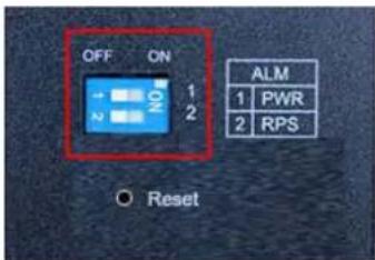
Figure 8: DIP Switches
Table 9: Legend for Figure "DIP Switches
| No. | Name | Status | Description |
| 1 | PWR | ON | The alarm reporting function for the primary power supply is activated. |
| OFF | The alarm reporting function for the primary power supply is deactivated. | ||
| 2 | RPS | ON | The alarm reporting function for the secondary power supply is activated. |
| OFF | The alarm reporting function for the secondary power supply is deactivated. |
The user can manually switch the alarm function for the primary or redundant power supply on and off through the DIP switches.
The DIP switch must be "ON" to activate the port alarm function. The default setting is "OFF".
The following is the recommended procedure for configuring and setting DIP switches during initial installation:
1 Turn all DIP switches to "OFF".
2 Install the industrial managed switch in your network.
3 Select the port(s) to be monitored or the alarm to be activated.
4 Set the DIP switch of the corresponding port to "ON".
5 Turn the industrial managed switch ON.
4.4.2 Reset Button

Figure 9: Reset Button
Table 10: Legend for Figure "Reset Button"
| Name | Status | Description |
| Reset | Press the Reset button for 2 seconds and release. | The system is restarted. |

Note
Important Note!
Use a suitable object, e.g., ballpoint pen or straightened paper clip, to press the Reset button.
4.5 Label
4.5.1 Hardware and Software Version
There is a label with the "MAC Address" and "Serial NO" on the back of the industrial managed switch.

Figure 10: Label
Table 11: Legend for Figure "Label"
| No. | “Serial NO” Description |
| 02 | Firmware version (left number sequence) |
| 02 | Hardware version (right number sequence) |
4.6 Technical Data
4.6.1 Device Data
Table 12: Technical Data – Device Data
| Width | 50 mm |
| Height | 120 mm (from the top edge of the carrier rail) |
| Depth | 162 mm |
| Weight | 955 g |
| Degree of protection | IP30 |
4.6.2 System Data
Table 13: Technical Data – System Data
| MAC table | Up to 16000 addresses |
| VLAN | Port based and tag based (4094 VIDs) |
| Jumbo Frame Size | 10 kB |
| Wavelength optical fibers | Depends on SFP module |
| Maximum lengths | 10/100/1000BASE-TX: 100 m;Fiber optic: 2 ... 80 kmRS-232: 15 m |
4.6.3 Power Supply
Table 14: Technical Data – Power Supply
| Supply voltage | 24 ... 57 VDC (CE, UL)24 VDC (DNV GL)24/48 VDC (LR) |
| Power consumption, max. | 18 W, 258 W with 8 PoE+ (DC 48 V) |
4.6.4 Power over Ethernet (PoE)
Table 15: Technical Data – Power over Ethernet (PoE)
| Power available at PD | 25.50 W |
| Max. Power delivered by PSE | 30 W |
| Voltage Range (at PSE) | 24 ... 57 V |
| Voltage Range (at PD) | 50 ... 57 V |
| Max. Current | 600 mA |
| Max. Cable resistance | 12.5 Ω (Category 5) |
| PoE Power -Budget | 240 W (48 VDC), 120 W (24 VDC) |
| PoE supported mode | Mode A |
1) PD = „Powered Device“
2) PSE = „Power Sourcing Equipment“
4.6.5 Communication
Table 16: Technical Data – Communication
| Configuration and Update | 1 x USB-Host 2.0 |
| Ports (copper; RJ-45) | 8 x 10/100/1000BASE-T with PoE+;1 x RS-232 |
| Ports (LWL) | 4 x 1000BASE-SX/-LX |
| Standards | IEEE 802.3 10BASE-TIEEE 802.3u 100BASE-TXIEEE 802.3ab 1000BASE-TIEEE 802.3z 1000BASE-SX/LXIEEE 802.3x Flow ControlIEEE 802.1d Spanning Tree Protocol (STP)IEEE 802.1w Rapid Spanning Tree Protocol (RSTP)IEEE 802.1s Multiple Spanning Tree Protocol (MSTP)IEEE 802.1Q VLAN TaggingIEEE 802.1p PrioritizationIEEE 802.1x Port AuthenticationIEEE 802.1ab Link Layer Discovery Protocol (LLDP)IEEE 802.3ad Link AggregationIEEE 1588v2 Precision Time Protocol (PTP)IEEE 802.3af Power over Ethernet (PoE)IEEE 802.3at High Power over Ethernet (PoE+)ITU-T G8032v1/v2 Ethernet Ring Protection Switching (ERPS) |
4.6.6 Environmental Conditions
Table 17: Technical Data – Environmental Conditions
| Surrounding air temperature, operation | -40 ... +70 °C (CE)-10 ... +60 °C (UL)-25 ... +70 °C (DNV GL)+5 ... +70 °C (LR) |
| Surrounding air temperature, storage | -40 °C ... +85 °C |
| UL 61010 Use Pollution degree | Indoor2 |
| Relative humidity (without condensation) | 10 ... 95 % |
| Vibration resistance | Acc. IEC 60068-2-6 |
| Shock resistance | Acc. IEC 60068-2-27 |
| EMC-1 immunity to interference | EN 55024EN 61000-6-2IEC 61000-4-2IEC 61000-4-3IEC 61000-4-4IEC 61000-4-5IEC 61000-4-6IEC 61000-4-8 |
| EMC-1 Emission of interference | FCC Part 15EN 55011: Class AEN 55032: Class AEN 61000-6-4 |
| Compass safe distance | >40 cm |
4.7 Standards and Guidelines
Energy Power Supply
acc. IEC 61850-3:2013
4.8 Approvals
The following approvals have been granted for the WAGO ETHERNET accessory product "Industrial Managed Switch" (852-1505/000-001):

Conformity Marking
The following approvals have been granted for the WAGO ETHERNET accessory product "Industrial Managed Switch" (852-1505/000-001):

Ordinary Locations
UL61010-2-201 (E175199)
The following ship approvals have been granted for the WAGO ETHERNET accessory product “Industrial Managed Switch” (852-1505/000-001):

DNV GL [Temperature: D, Humidity: B, Vibration: B, EMC: B, Enclosure: A]

LR (Lloyd's Register) Env. 1, 2, 3

Note
Applicable from HW 02!
This ship approvals are only applicable from HW 02. Switches with hardware version 01 do not have ship approvals!
The hardware versions 01 and 02 are technically identical. For hardware version 02, the label and the operating and assembly instructions have been adapted to the requirements of the ship approvals.
5 Mounting
5.1 Installation Site
The location selected to install the industrial managed switch may greatly affect its performance. When selecting a site, we recommend considering the following rules:
- Install the industrial managed switch at an appropriate place. See section "Device Description" > ... > "Technical Data" for the acceptable temperature and humidity operating ranges.
Make sure that the heat output from the industrial managed switch and ventilation around it is adequate. Do not place any heavy objects on the industrial managed switch.
5.2 Installation on a Carrier Rail
The carrier rail must optimally support the EMC measures integrated into the system and the shielding of the internal data bus connections.
Place the industrial managed switch onto the DIN rail from the top and snap it into position.
5.3 Removal from Carrier ail
To remove the industrial managed switch from the carrier rail, insert a suitable tool into the metal tab under the switch and deflect the metal tab downward.
You can then release the switch down from the carrier rail and remove it upwards.
6 Connect Devices
6.1 Power Supply
The switch uses direct current power supply for 24 ... 57 V.
The primary and secondary network link is established via a 6-pin plug-in connection located on the top of the industrial managed switch.
The female connector (Item No. 2231-106/026-000) is composed of six connecting terminals and can be inserted and removed easily by hand to connect to the 6-pin plug connector located on the top of the switch.
The power supply for the switch automatically adjusts to the local power source and can also be switched. On if no or not all patch cables are connected.
- Connect a suitable grounding conductor to the grounding lug on the top of the switch.

Note
Ground for the switch
The ground for the switch prevents electromagnetic interference from electromagnetic radiation.
Observe the corresponding standards for EMC-compatible installations as well.
NOTICE
Grounding instruction!
Connect PWR - or PWR + not conductive to the earth potential.
- Plug the female connector into the male connector of the switch if it has not already been plugged in. Check the tight fit of the multipoint connector by gently shaking it.
- PWR +/-:
To connect or disconnect the conductors, actuate the spring directly in the female connector using a screwdriver or an operating tool and insert or remove the conductor. - Check whether the power LED "PWR" on the top of the device lights up when power is supplied to the device. If not, check to ensure that the power cable is plugged in correctly and fits securely.
-
RPS +/-:
To connect or disconnect the conductors, actuate the spring in the female connector directly using a screwdriver or an operating tool and insert or remove the conductor. -
Check whether the power LED "RPS" on the top of the device lights up when power is supplied to the device. If not, check to ensure that the power cable is plugged in correctly and fits securely.
6.2 External Alarm Contact Port
The industrial managed switch has an alarm contact connection on the top panel. For detailed instructions on how to connect the alarm contact power wires to the two ALM contacts of the 6-pin female connector, please refer to section "Power Supply (PWR/RPS)" (it is the same procedure).
You can connect the alarm circuit to any warning device already installed in the user's control room or factory floor. When a fault occurs, the industrial switch sends a signal through the alarm contact to activate the external alarm. The alarm contact has two ports that form a fault circuit for connecting to alarm systems.
An alarm is signaled in the following cases:
1 PWR/RPS:
a Power failure (power cord is disconnected, power supply malfunction, etc.)
b Input power falls outside specification (24 ... 57 V)
2 Error in the Jet-Ring or ERPS-Ring
6.3 Console Port Cable Connection
The console port (RJ-45) provides the local management facility.
- Insert the RJ-45 side of the (8 pin RJ-45 to DB9) cable into the RJ-45 console port on the Industrial Managed Switch and the other end into the COM port of the computer.
- Configure the Hyper Terminal settings as mentioned in chapter "Configuration" > ... > "Console Port".
For console port (8 pin RJ-45) pin assignment, please see in the chapter "Appendix" > ...> "Console Port (RJ-45 to DB9)".
6.4 1000Base-SX/LX Port, Fiber Optic
When connecting a fiber optic cable to a 1000Base-SX/LX port on the industrial managed switch, make sure to use the right connector type (LC) and SFP module.
There are various types of multi-mode, single mode or WDM SFP modules. Follow the steps below to connect the fiber optic cable properly:

Note
Rubber covers
Remove and safely store the rubber covers of the fiber optic port (LC). If no fiber optic cable is connected, the rubber cover should be installed to protect the fiber optics.
1 Insert the respective SFP modules.
2 Ensure that the fiber optic ports are clean. You can clean the cable connectors by wiping them with a clean cloth or a cotton ball soaked with a little ethanol. Dirty fiber optic cables affect the quality of the light transmitted via the cable and leads to reduced performance at the port.
3 Connect one end of the fiber optic cable to the LC port of the industrial managed switch and the other end to the fiber optic port of the other device.

Note
Proper connection of the fiber optic cable to the SFP module
For a proper connection, snap the connector of the fiber optic cable into the SFP module audibly.
4 Check the respective port LED on the industrial managed switch that the connection is established (see section "Device Description" > ... > "Display Elements").
6.5 10/100/1000BASE-T Ports
The 10/100/1000BASE-T ports (RJ-45 ETHERNET ports) of the industrial switch support both autosensing and autonegotiation.
1 Connect one end of the twisted pair cable of the type Category 3/4/5/5e to an available RJ-45 port on the industrial switch and the other end to the port of the selected network node.
2 Check the respective port LED on the industrial switch that the connection is established.
(see section "Display Elements" > ... > "Port LEDs").
7 Function Description
7.1 Basic Settings
7.1.1 Jumbo Frame
“Jumbo Frames” are ETHERNET frames with a size of more than 1518 bytes. Jumbo frames can increase data transmission efficiency in a network. The bigger the “Jumbo Frame,” the better the network performance is.

Note
"Jumbo Frame" settings
The size setting for the “Jumbo Frames” applies to each port of the switch.
All connected network subscribers must support the same "Jumbo Frame" size. Data packets that are larger than the "Jumbo Frame" setting are rejected by the corresponding network subscribers..
7.1.2 SNTP
SNTP ("Simple Network Time Protocol") is a protocol for synchronizing clocks in computer systems. It is a less complex implementation of an NTP ("Network Time Protocol").
SNTP uses UTC – “Coordinated Universal Time” (French: “Temps Universel Coordonné”). No information on time zones or daylight savings time is transmitted. This information falls outside the protocol range and must be obtained separately.
The SNTP port is 123.

Note
Note!
- The SNTP server always replies the current UTC time.
- If the switch receives the SNTP reply time, it adjusts the time to the time zone configuration and configures the time for the switch accordingly.
- If the time server's IP address is not configured, the switch does not send an SNTP request packet.
- If the switch does not receive an SNTP reply packet, it repeats the challenge indefinitely every ten seconds.
- If the switch receives an SNTP reply, it repeats the time request from the NTP server every hour.
- If the time zone and NTP server changes, the switch repeats the request process.
- No default SNTP server.
7.1.3 Management Host
The management host limits the number of hosts that the switch can manage. There is no “Management Host” in the default settings. Any host can manage the switch via Telnet or Web browser. If a user has configured one or more hosts, only those hosts can manage the switch. The function allows users to configure up to three entries for the management IPs..
7.1.4 MAC Management
The MAC address ("Media Access Control address") is the unique hardware number in a network.
Dynamic Address
When receiving frames, the switch received the source MAC address, receiving port, VLAN and an "Age Time" in the address table. When the "Age Time" is expired, the address entry is deleted from the address table.
Static Address
A static address set by the user does not include the "Age Time" and is not deleted by the switch. The static address can only be deleted by a user. The switch supports an address table of size up to 16 K.
Static and dynamic addresses share the same address table.
MAC Table
The “MAC Table” (MAC address table, also known as a filter database) shows which frames are forwarded to the switch’s ports or filtered out.
If a device that belongs to a VLAN group sends a data packet that is forwarded to a port on the switch, the MAC address of the device is read from the switch's MAC address table.
It also shows whether the MAC address is dynamic (assigned by the switch) or static (set manually).
MAC Address Table
The switch uses the MAC address table to determine how to forward frames (see figure below).
- The switch checks a received frame and detects the port from which the source MAC address originates.
- The switch checks whether the frame's destination MAC address matches a source MAC address already detected in the MAC address table.
- If the switch already knows the port for this MAC address, it forwards the frame to that port.
- If the switch does not already know the port for this MAC address, it forwards the frame to all ports. "Port Flooding" (forwarding too often to all ports) can lead to network congestion.
- If the switch already knows the port for this MAC address and the destination port is the same as the input port, the frame is filtered.
![graph TD A["Is destination MAC address in the MAC Table?"] -->|No| B["Foward to all ports."] A -->|Yes| C{Is the outgoing port different frome the incoming port?} C -->|No| D["Filter this frame."] C -->|Yes| E["Foward to outgoing port."]](/content/2026/05/1008228/images/0c90dc40fcd58cf518b1cee1580dd220ed7219db0af5e4808afbb7bebacdfe2c.jpg)
Figure 11: MAC Address Table Flowchart
7.1.4.1 Static MAC
Static MAC Addresses
A static MAC address is an address that has been manually entered in the MAC address table. Static MAC addresses have no "Age Time." When you set up rules for static MAC addresses, you set static MAC addresses for a port. This may reduce data transmission needs.
7.1.4.2 MAC Blacklist (Blacklisting)
This type of MAC address entry is configured manually. The switch ignores packets that have MAC addresses contained in "Blackhole" MAC address entries as their source or destination. "Blackhole" entries are configured to filter out frames with specific source or destination MAC addresses.
7.1.5 Port Mirroring
Port mirroring is used on switches to send a copy of network packets sent/received on one switch port or a range of switch ports to a network monitoring connection on another switch port (Monitor Port).
Port mirroring is used in network systems that require monitoring of network traffic, such as an IDS ("Intrusion Detection System").
Port mirroring, together with an NTA ("Network Traffic Analyzer"), can help to monitor network traffic. Users can monitor the selected ports ("Source Ports") for egress and/or ingress packets.
Source Mode
- "Ingress": The incoming data packets are copied and forwarded to the monitor port.
- "Egress": The outgoing data packets are copied and forwarded to the monitor port.
• Both: Both the incoming and the outgoing data packets are copied and forwarded to the to the monitor port.

Note
Important Note!
- The monitor port cannot be a trunk member port.
- The monitor port cannot be an ingress or egress port.
- If a port has been configured as a source port and the user configures the port as a destination port, the port will be removed from the source ports automatically.
7.1.6 Port Settings
Duplex Mode
A duplex communication system is a system composed of two connected devices that can communicate with each other in both directions.
Half-Duplex
A half-duplex system provides for communication in both directions, but only one direction at a time (not simultaneously).
One device receives a signal and must wait for the other device to stop transmitting before replying.

Figure 12: Half-Duplex Mode
Full-Duplex
A full-duplex system (also known as a double-duplex system) can communicate simultaneously in both directions.
Fixed-line telephone networks, for example, are full-duplex, since both callers can talk and listen at the same time.
![graph LR A["Walkie 1"] --> B["Walkie 2"] style A fill:#f9f,stroke:#333 style B fill:#bbf,stroke:#333](/content/2026/05/1008228/images/1dadeb8c1055ca31222a5c19b8995ec1e98538f611c0966fa64f164f2cc2c572.jpg)
Figure 13: Full-Duplex Mode
Loopback Test
In a “Loopback” test, a signal is sent from and then returned to a communication device (“looped back”).
The test checks the proper functioning of the device and looks for faulty nodes in the network.
For one type of “Loopback” test, a special plug (a so-called “wrap plug”) is plugged into a communications device. The plug causes transmitted (output) data to be returned as received (input) data, simulating a closed communication circuit using a single computer.
Auto MDI/MDIX
MDI ("Medium-Dependent Interface") is part of the transmitter/receiver unit (transceiver) of a network device.
Auto-MDIX ("Automatic Medium-Dependent Interface Crossover") is a network technology integrated in the port that automatically detects the required network cable type ("Straight-through" or "Crossover" cable) and configures the connection accordingly.
"Crossover" cables are then unnecessary for connecting devices.
The interface corrects incorrect cabling automatically.
For Auto-MDIX to work properly, the speed must be set to "Auto" for the interface and in the duplex settings.
Auto-Negotiation
Auto-negotiation is a method in which two interconnected ETHERNET network ports (e.g., the network port of a PC and a port of a router, hub or switch that is connected to it) independently negotiate and configure the maximum transmission speed and the duplex process.
Auto-negotiation only applies to twisted-pair cables – not to WLAN, fiber optic or coaxial cable connections.
If the port does not support auto-negotiation or turns off this feature, the switch determines the connection speed by detecting the signal on the cable and using half duplex mode.
If auto-negotiation is enabled on the switch, a port uses its pre-configured settings for speed and duplex mode when establishing the connection.
This should ensure that the same settings have been made on the port, allowing the connection to be established.
Flow Control
"Flow Control" regulates the transmission of signals by adjusting them to the bandwidth on the input port.
Higher data traffic on the port decreases the bandwidth and can overflow the buffer memory, which can lead to packet and frame loss.
According to IEEE 802.3x, the switch uses "Flow Control" in full-duplex mode and "Backpressure Flow Control" in half-duplex mode.
With flow control, the switch is used in full-duplex mode to send a pause signal to the sending port, causing it to temporarily stop sending signals when the receiving port memory buffers fill.
For "Backpressure Flow Control", the switch sends a collision signal to the sending port in half-duplex mode (mimicking a state of packet collision), causing the sending port to temporarily stop sending signals and to resend the signals later.

Note
Support for "Force Mode"
1000 BASE-T does not support "Force Mode".
7.2 Advanced Settings
7.2.1 Bandwidth Control
7.2.1.1 QoS
Each egress port can support up to eight "transmit queues". Each transmit queue contains a list specifying the packet transmission order. Every incoming frame is forwarded to one of the eight egress transmit queues of the assigned egress port, based on its priority. The egress port transmits packets from each of the eight transmit queues according to a configurable sequence algorithm, which can be a combination of SP ("Strict Priority") and/or WRR ("Weighted Round Robin").
Normally, networks operate on a best-effort delivery basis, i.e., all data traffic has equal priority and an equal chance of being transmitted in a timely manner. If congestion occurs, all data traffic has an equal chance of being dropped.
When configuring the QoS (“Quality of Service”) function, you can select a specific data traffic, prioritize it according to its relative importance and use congestion management and congestion avoidance techniques to give preferential treatment.
Implementing QoS in a network improves network predictability and increases bandwidth utilization.
The industrial managed switch supports "802.1p Priority Queuing".
The switch has eight "Priority Queues". These priority queues are numbered, where Class 7 has the highest priority and Class 0 the lowest. The eight priority classes specified in IEEE 802.1p (p0 to p7) are mapped to the switch's priority queues as follows:
| Priority | 0 | 1 | 2 | 3 | 4 | 5 | 6 | 7 |
| Queue | 2 | 0 | 1 | 3 | 4 | 5 | 6 | 7 |
The “Priority Scheduling” is implemented in “Priority Queues”. The switch operates the four “Hardware Priority Queues” sequentially, where it starts with the highest “Priority Queue” (3) and ends with the lowest (0). Each “Hardware Queue” transmits all the packets in its buffer before the next lower priority is allowed to transmit its packets. If the lowest “Hardware Priority Queue” has transmitted all its packets, the highest starts again to transmit the packets that it received in the meantime.
QoS Enhancement
You can configure the switch to prioritize data traffic even if the incoming packets are not marked with "IEEE 802.1p Priority Tags" or change the existing "Priority Tags" based on criteria you select. The switch allows you to choose one of the following methods for assigning priority to incoming packets:
• 802.1p Tag Priority
- Assign priority to packets based on the packet's "802.1p Tag Priority".
- Port-based QoS
- Assign priority to packets based on the incoming port on the switch.
- DSCP-based QoS
- Assign priority to packets based on their DSCP ("Differentiated Services Code Points").

Note
Advanced QoS Methods
Advanced QoS methods only affect the internal "Priority Queue" mapping for the switch. The switch does not modify the IEEE 802.1p value for the egress frames.
You can choose one of these options above to alter the way incoming packets are prioritized, or you can choose not to use any QoS extension setting on the switch.
802.1p Priority
When the 802.1p priority mechanism is used, the packet is examined for the presence of a valid "802.1p Priority Tag". If it has a tag, the packet is assigned to a configurable "Egress Queue" based on its priority value. The "Tag Priority" can be assigned to any of the available "Queues".
ETHERNET Packet
| 6 | 6 | 2 | 42-1496 | 4 |
| DA | SA | Type/length | Data | FCS |
| 6 | 6 | 4 | 2 | 42-1496 | 4 |
| DA | SA | 802.1Q Tag | Type/length | Data | FCS |
802.1Q Tag:
| 2 bytes | 2 bytes | ||
| Tag Protocol Identifier (TPID) | Tag Control Information (TCI) | ||
| 16 bits | 3 bit | 1 bit | 12 bits |
| TPID (0x8100) | Priority | CFI | VID |
- TPID ("Tag Protocol Identifier") A 16-bit field is set to the value of 0x8100 to identify the frame as an "IEEE 802.1Q Tag Frame".
• TCI ("Tag Control Information")
- PCP ("Priority Code Point")
A 3-bit field that refers to the IEEE 802.1p priority. This indicates the frame priority level from 0 (lowest) to 7 (highest), which can be used to prioritize different classes of traffic (voice, video, data etc.).
- CFI ("Canonical Format Indicator")
A 1-bit field. If the value of this field is 1, the MAC address is in non-canonical format. If the value is 0, the MAC address is in canonical format. It is always set to 0 for ETHERNET switches. CFI is used for compatibility between ETHERNET and "Token Ring" networks. If a frame received at an ETHERNET port has a CFI of 1, the frame should not be output to an untagged port.
- VID ("VLAN Identifier")
A 12-bit field specifying the VLAN to which the frame belongs. A value of 0 means that the frame does not belong to any VLAN; in this case, the "802.1Q Tag" specifies only a priority and is referred to as a "Priority Tag". A hexadecimal value of 0xFFFF is reserved for implementation purposes. All other values may be used as "VLAN Identifiers", allowing support for up to 4094 VLANs. On "Bridges", VLAN 1 is often reserved for management.
Priority Levels
PCP ("Priority Code Point"):
Table 18: Priority Levels
| PCP | Network Priority | Traffic Characteristics |
| 1 | 0 (lowest) | “Background” |
| 0 | 1 | “Best Effort” |
| 2 | 2 | “Excellent Effort” |
| 3 | 3 | “Critical Applications” |
| 4 | 4 | Video, < 100 ms latency |
| 5 | 5 | Video, < 10 ms latency |
| 6 | 6 | Internetwork Control |
| 7 | 7 (highest) | Network Control |
DiffServ (DSCP)
DiffServ ("Differentiated Services") is a computer networking architecture that specifies a simple, scalable and coarse-grained mechanism for managing network traffic and providing QoS ("Quality of Service") guarantees in modern IP networks. DiffServ can, for example, be used to provide low-latency GS ("Guaranteed Service") to critical network traffic such as voice or video data while providing simple "Best Effort" traffic guarantees to non-critical services such as Web traffic or file transfers.
DSCP ("Differentiated Services Code Point") is a 6-bit field in the header of IP packets for packet classification purposes. DSCP replaces the outdated IP precedence, a 3-bit field in the "Type of Service" byte of the IP header originally used to classify and prioritize types of traffic.
When using the DiffServ priority mechanism, a packet is classified based on the DSCP field in the IP header. If the tag is present, the packet is assigned to a programmable "Egress Queue" based on the value of its "Tagged Priority." The "Tagged Priority" can be assigned to any available "Queue."
| Version | IHL | Type of Service | Total Length | |
| Marking | Flags | Fragment Offset | ||
| Time to Live | Protocol | Header Checksum | ||
| Source Address | ||||
| Destination Address | ||||
| Options | Padding | |||
Example Internet Data Packet Header
"Type of Service" in the IP header: 8-bit
The “Type of Service” field provides an indication of the abstract parameters of the “Quality of Service” desired. These parameters are used to guide the manual
selection of the actual service parameters when a data packet is to be transmitted through a particular network. Several networks offer service precedence, which treats high precedence traffic as more important than other traffic (generally by accepting only traffic above certain precedence level at high load times). The most favorable choice is a compromise between low delay, high reliability and high throughput.
| Bits 0 ... 2 | Precedence. | |
| Bit 3 | 0 = Normal delay, | 1 = Low delay. |
| Bit 4 | 0 = Normal throughput, | 1 = High throughput. |
| Bit 5 | 0 = Normal reliability, | 1 = High reliability. |
| Bits 6 ... 7 | Reserved for future use. |
| 0 | 1 | 2 | 3 | 4 | 5 | 6 | 7 | 0 | 1 | 2 | 3 |
| 4 | 5 | 6 | 7 |



Precedence
111 – Network Control
110 – Internetwork Control
101 - CRITIC/ECP
100 – Flash Override
011 - Flash
010 - Immediate
001 – Priority
000 – Routine
Specifying the Delay, Throughput and Reliability parameters can increase the service cost. In many networks, giving preference to one parameter entails a disadvantage for another. Except for very unusual cases, at most two of these three parameters should be specified.
“Type of Service” is used to specify the type of processing of the data packet while it is transmitted through a network. Example mappings of the “Internet Type of Service” to the actual service provided in networks, such as AUTODIN II, ARPANET, SATNET and PRNET, are specified in “Service Mappings.”
The Network Control precedence designation should only be used within a network. The actual use and control of that designation depends on the respective network. The Internetwork Control designation should only be changed by the initiators of the gateway control.
If these precedence designations apply to a specific network, it is the responsibility of that network to control the access to and use of those designations.
| DSCP | Priority | DSCP | Priority | DSCP | Priority |
| 0 | 0 | 1 | 0 | 2 | 0 |
| ... | |||||
| 60 | 0 | 61 | 0 | 62 | 0 |
| 62 | 0 |
Example:
IP Header
DSCP=50 -> 45 C8 ...
Queuing Algorithms
"Queuing Algorithms" can be used to maintain separate "queues" for packets, which can originate from any single source or any data flow, thus preventing one source from monopolizing the bandwidth.
SPQ
With SPQ ("Strict Priority Queuing"), the four "Hardware Priority Queues" are processed sequentially – the highest priority (3) first and the lowest (0) last. Each "Hardware Queue" transmits all the packets in its buffer before the next lower priority queue is allowed to transmit its packets. If the lowest "Hardware Priority Queue" has transmitted all its packets, the highest starts again to transmit the packets that it received in the meantime.
WRR
RR (“Round Robin”) is a scheduling service that queues packets on a rotating basis and is only activated when a port has more traffic than it can handle. A limited amount of bandwidth is provided to a queue, irrespective of the incoming traffic on that port. This “queue” then moves to the back of the list. The next “queue” is given an equal amount of bandwidth and then moves to the end of the list and so on until all “queues” have been processed. The entire process works in a looping fashion until a “queue” is empty.
WRR ("Weighted Round Robin") scheduling uses the same algorithm as "Round Robin" scheduling, but services "queues" based on their priority and queue weight (the number you configure in the "Weight Value" field) rather than a fixed amount of bandwidth. WRR is activated only when a port has more traffic than it can handle. Processing "queues" with higher weights takes precedence over processing lower weight ones. This queuing mechanism is highly efficient in that it divides the entire available bandwidth among the various "Traffic Queues" and allocates it to the ones that have not yet been emptied.

Note
DiffServ Function
DiffServ is disabled on the industrial managed switch. If the DiffServ is disabled, the "802.1p Tag Priority" is used.
7.2.1.2 Rate Limitation
7.2.1.2.1 Storm Control
A broadcast storm occurs when the network is overwhelmed with constant broadcast or multicast traffic. Broadcast storms can eventually lead to a complete loss of network connectivity as the packets proliferate.
"Storm Control" protects the switch bandwidth from packet flooding, including broadcast packets, multicast packets and DLF ("Destination Lookup Failure"). The Rate is a threshold that limits the total number of specific packet types. For example, if the broadcast and multicast options are selected, the total number of packets transmitted per second for these two types is not exceeded.
“Broadcast Storm Control” limits the number of broadcast, multicast and unknown unicast (also referred to as “Destination Lookup Failure” or DLF) packets the switch receives per second on the ports. If the maximum number of packets per second is reached, all subsequent packets are discarded. Enable this function to reduce the number of these packets in the network.
The "Storm Control" unit is 625 pps (packets per second).
7.2.1.2.2 Rate Limitation
The "Rate Limitation" is used to control the rate of traffic sent or received on a network interface.
7.2.2 IGMP Snooping
"IGMP Snooping" ("Internet Group Management Protocol Snooping") is used for multicast data traffic. The switch can passively "snoop" on IGMP packets transmitted between IP multicast routers/switches and IP multicast hosts to learn the IP multicast group membership. "IGMP Snooping" allows a switch to detect multicast groups without a user having to manually configure them.
It checks IGMP packets passing through it, reads the group registration information and configures multicasting accordingly.
The switch forwards multicast traffic to its multicast destination groups (which it has detected through "IGMP Snooping", or which you have manually configured) to ports that are members of those groups. "IGMP Snooping" generates no additional network traffic, allowing you to significantly reduce multicast traffic passing through the switch.
The switch can perform “IGMP Snooping” on up to 4094 VLANs. You can configure the switch to automatically detect multicast group membership in all VLANs. The switch then performs “IGMP Snooping” on the first VLANs that send IGMP packets.
This is referred to as "Auto Mode." Alternatively, you can specify the VLANs that "IGMP Snooping" should be performed on. This is referred to as "Fixed Mode." In "Fixed Mode", the switch does not detect multicast group membership of any VLANs other than those explicitly added as an "IGMP Snooping" VLAN.
Immediate Leave
If you enable the “IGMP Immediate Leave” function, the switch immediately deletes a port when it receives a “Leave Message” with IGMP Version 2 on that port. You should use the “Immediate Leave” function only when there is a single receiver present on every port in the VLAN (“Immediate Leave” is only supported on IGMP Version 2 hosts).
The switch uses the “Immediate Leave” function with “IGMP Snooping” to remove from the forwarding table an interface that sends a “Leave Message”, without the switch having to send group-specific queries to the interface. The VLAN interface is deleted from the multicast tree for the multicast group specified in the original “Leave Message.” “Immediate Leave” ensures optimal bandwidth management for all hosts in a switched network, even when multiple multicast groups are simultaneously in use.
Fast Leave
The switch allows you to configure a delay time. When the delay time has expired, the switch deletes the interface from the multicast group.
Last Member Query Interval
The “Last Member Query Interval” is the maximum response time in group-specific queries sent in response to “Leave Group” messages, and also indicates the time between group-specific query messages.
Without Immediate Leave, when the switch receives an IGMP leave message from a subscriber on a receiver port, it sends out an IGMP-specific query on that port and waits for IGMP group membership reports. If no reports are received in a configured time period, the receiver port is removed from multicast group membership.
IGMP Querier
There is normally only one “Querier” per physical network. All multicast routers start up as a “Querier” on each connected network. If a multicast router receives a “Query Message” from a router with a lower IP address, it MUST become a non-“Querier” in that network. If a router does not receive any “Query Messages” from another router over a certain period of time (“Other Querier Present Interval”), it assumes the role of “Querier.” Routers periodically (“Query Interval”) send a “General Query” in all attached networks for which the router is the “Querier” in order to solicit membership information. At startup, a router SHOULD send “General Queries” (“Startup Query Count”) spaced closely together (“Startup Query Interval”) to quickly and reliably determine membership information. A “General Query” is addressed to an all-systems multicast group (224.0.0.1), has a group address field value of 0 and has a maximum response time of (“Query Response Interval”).
Port IGMP Querier Mode
- Auto
- The switch uses the port as an "IGMP Query Port" if the port receives "IGMP Query" packets.
- Fixed
- The switch always uses the port(s) as "IGMP Query Port(s)." This mode is used when connecting an IGMP multicast server to the port(s). - The switch always forwards the client's "Report/Leave" packets to the port. Normally, the port is connected to an IGMP server.
- Edge
- The switch does not use the port as an "IGMP Query Port." - The "IGMP Query" packets received on this port are dropped. Normally, the port is connected to an IGMP client.

Note
Forwarding "IGMP Join/Leave" packets
The industrial managed switch will forward the “IGMP Join/Leave” packets to the query port.
IGMP Proxy Snooping
The “IGMP Proxy Snooping” can reduce the number of “Reports” and “Leaves” sent through an IGMP router.
Configurations
Users can enable/disable "IGMP Snooping" on the switch. This also applies to specific VLANs. If "IGMP Snooping" on the switch is disabled, it is disabled on all VLANs, even when enabled on some VLANs.

Note
VLAN States
There are a global state and individual VLAN states. If the global state is disabled, "IGMP Snooping" on the switch is disabled even if individual VLAN states have been enabled. If the global state is enabled for "IGMP Snooping", the function must be individually enabled by the user for specific VLANs.
7.2.3 MVR
MVR (“Multicast VLAN Registration”), through which a media server can transmit a multicast stream in an individual multicast VLAN and in which the clients receiving the VLAN stream can be located in different VLANs. Clients in different VLANs can join or leave the multicast group simply by sending an “IGMP Join Message” or “IGMP Leave Message” to a receiver port. The receiver port belonging to a multicast group can receive the multicast stream from the media server. Without MVR support, the multicast stream from the media server and subscriber would have to be in the same VLAN.
- Source ports: The stream's source ports.
- Receiver ports: The client's ports.
- Tagged ports: Configure the tagged ports with tags to designate them as source ports or receiver ports.
MVR Mode
- Dynamic Mode
If we select the dynamic mode in the MVR settings, the IGMP report message transmitted from the receiver port will be forwarded to a multicast router through its source port. The multicast router can detect dynamically which multicast groups are on which interface.
- Compatibility Mode
If we select the dynamic mode in the MVR settings, the IGMP report message transmitted from the receiver port will not be transmitted to the source ports of the multicast router. The multicast router must be statically configured.
- Operating Mode
Join Operation
A subscriber sends an “IGMP Report Message” to the switch to join the respective multicast. The next step depends on whether the “IGMP Report Message” matches the multicast MAC address configured on the switch. If it matches, the switch CPU modifies the hardware address table to include this receiver port and VLAN as a forwarding destination of MVLAN.
- Leave Operation
A subscriber sends an “IGMP Leave Message” to the switch to leave the multicast. The switch CPU sends an IGMP group-specific query to the receiver port VLAN. If there is another subscriber in the VLAN, the subscriber must respond within the maximum response time. If there is no subscriber, the switch will remove this receiver port.
- Immediate Leave Operation
A subscriber sends an "IGMP Leave Message" to the switch to leave the multicast. The subscribers do not need to wait for the switch CPU to send a group-specific "IGMP Query" to the receiver port of the VLAN. The switch will immediately remove this receiver port.
![graph TD A["MOD server"] --> B["Switch"] C["MOD with MVR"] --> B D["VLAN1"] --> B E["VLAN2"] --> B F["VLAN3"] --> B G["VLAN4"] --> B H["VLAN5"] --> B I["VLAN6"] --> B B --> J["Receiver Ports"]](/content/2026/05/1008228/images/71be6296201929b958f20325e7ba7dc0a0859cd32041c828295189154949b04c.jpg)
Figure 14: MOD without MVR
![graph TD A["MOD server"] --> B["Switch supports MVR"] B --> C["VLAN1"] B --> D["VLAN2"] B --> E["VLAN3"] B --> F["VLAN4"] B --> G["VLAN5"] B --> H["VLAN6"] C --> I["Receiver Ports"] D --> I E --> I F --> I G --> I H --> I](/content/2026/05/1008228/images/4402f416029c8f16fcdf2ee1a5e48d3bcd8b661e62ab3d9b89720ab76455bf82.jpg)
Figure 15: MOD Supports MVR
Default Configuration for a New MVR:
MVR VLAN information
VLAN ID: 2
Name: MVR2
Active: Enabled
Mode: Dynamic
Source port(s): None
Receiver port(s): None
Port(s) with tag: None
The switch allows the user to create up to 250 groups.
The switch allows the user to create up to 16 MVRs.

Note
- "IGMP Snooping" and MVR can be enabled independently.
- "IGMP Snooping" and MVR use the same IGMP timer.
• MVR can recognize IGMPv3 reports. - Both the switch and the following group record types do not treat group entries such as an IGMPv3 report as membership reports. The group record types are "MODE_IS_INCLUDE", "CHANGE_TO_INCLUDE_MODE", "ALLOW_NEW_SOURCES" and "BLOCK_OLD_SOURCES."
- Do not use group address X.0.0.1 for your multicast stream. The system detects and logs the address 224.0.0.1 for the dynamic "Querier Port." The group address X.0.0.1 could cause a conflict with 224.0.0.1.
- The lower 23 bits of the 28-bit multicast IP address are mapped to the 23 bits of the available ETHERNET address space.
- When configuring the group address, the switch only compares the lower 23 bits.
- The CLI command "group 1 start-address 224.1.1.1 6" creates six groups. That means that one IP corresponds to one group.
• The MVR name should be a combination of numbers and letters.
• The group name should be a combination of numbers and letters.
7.2.3.1 Multicast Address
A multicast address is associated with a group of interested receivers. According to RFC 3171, addresses 224.0.0.0 to 239.255.255.255 (formerly Class D addresses) are reserved as multicast addresses in IPv4.
The first octet (01) includes the broadcast/multicast bit. The lower 23 bits of the 28-bit multicast IP address are mapped to the 23 bits of the available ETHERNET address space. This means that there is an ambiguity in delivering packets. If two hosts on the same subnet each subscribe to different multicast groups whose addresses differ only in the first five bits, ETHERNET packets for both multicast groups are sent to both hosts, requiring the network software in the hosts to discard the unnecessary packets.
Table 19: Multicast Classes and Address Ranges
| Class | Address Range | Support |
| Class A | 1.0.0.1 to 126.255.255.254 | Supports 16 million hosts on each of 127 networks. |
| Class B | 128.1.0.1 to 191.255.255.254 | Supports 65,000 hosts on each of 16,000 networks. |
| Class C | 192.0.1.1 to 223.255.254.254 | Supports 254 hosts on each of 2 million networks. |
| Class D | 224.0.0.0 to 239.255.255.255 | Reserved for multicast groups. |
| Class E | 240.0.0.0 to 254.255.255.254 | Reserved for future use or research and development purposes. |

Figure 16: Multicast Address
Table 20: IP Multicast Addresses
| IP Multicast Address | Description |
| 224.0.0.0 | Base address (reserved) |
| 224.0.0.1 | “All Hosts Multicast” group that contains all systems on the same network segment. |
| 224.0.0.2 | “All Routers Multicast” group that contains all routers on the same network segment. |
| 224.0.0.5 | The “Open Shortest Path First” (OSPF protocol), the “AllSPFRouters” address. Used to send “Hello Packets” to all OSPF routers on a network segment |
| 224.0.0.6 | The “OSPF AllDRouters” address. Used to send OSPF routing information to “OSPF Designated Routers” on a network segment |
| 224.0.0.9 | The RIP (“Routing Information Protocol”) Version 2 of the group address. Used to send routing information to all RIPv2-compatible routers on a network segment. |
| 224.0.0.10 | The EIGRP group address. Used to send EIGRP routing information to all EIGRP routers on a network segment. |
| 224.0.0.13 | PIM Version 2 (“Protocol Independent Multicast”) |
Table 20: IP Multicast Addresses
| IP Multicast Address | Description |
| 224.0.0.18 | Virtual Router Redundancy Protocol |
| 224.0.0.19 - 21 | IS-IS over IP |
| 224.0.0.22 | IGMP Version 3 (“Internet Group Management Protocol”) |
| 224.0.0.102 | Hot Standby Router Protocol Version 2 |
| 224.0.0.251 | Multicast DNS address |
| 224.0.0.252 | “Link-local Multicast Name Resolution” address |
| 224.0.1.1 | “Network Time Protocol” address |
| 224.0.1.39 | “Cisco Auto-RP-Announce” address |
| 224.0.1.40 | “Cisco Auto-RP-Discovery” address |
| 224.0.1.41 | “H.323 Gatekeeper Discovery” address |
7.2.3.2 VLAN
A VLAN (“Virtual LAN”) is a group of hosts with a common set of requirements that communicate as if they were attached to a broadcast domain, regardless of their physical location. A VLAN has the same attributes as a physical LAN, but it allows for end stations to be grouped together even if they are not located on the same network switch. Networks can be reconfigured through software instead of spatially separated devices.
VID ("VLAN-ID") is the identification of a VLAN that is generally used by the IEEE 802.1Q standard. It has 12 bits and allows the identification of 4096 ( 212 ) VLANs. Of the 4096 possible VIDs, VID 0 is used to identify "Priority Frames", and value 4095 (FFF) is reserved, so the maximum possible number of VLAN configurations is 4094.
A “Tagged VLAN” uses an explicit tag (VLAN ID) in the MAC header to identify the VLAN membership of a frame across “Bridges” – they are not confined to the switch on which they were created. VLANs can be created statically (manually by users) or dynamically via the GVRP (“GARP VLAN Registration Protocol”). The VLAN ID associates a frame with a specific VLAN and provides the information that switches need in order to process the frame across the network. A tagged frame is four bytes longer than an untagged frame and contains two bytes of TPID (“Tag Protocol Identifier”, residing within the type/length field of the “ETHERNET Frame”) and two bytes of TCI (“Tag Control Information”, which starts after the source address field of the “ETHERNET Frame”).
The CFI (“Canonical Format Indicator”) is a single-bit flag, always set to zero for ETHERNET switches. If a frame received at an ETHERNET port has a CFI of 1, the frame should not be output to an untagged port. The remaining 12 bits define the VLAN ID, giving a possible maximum number of 4096 VLANs. Note that the user priority and VLAN ID are independent of each other. A frame with VID (VLAN Identifier) of null (0) is called a priority frame, meaning that only the priority level is significant, and the default VID of the ingress port is used as the VID of the frame. Of the 4096 possible VIDs, a VID of 0 is used to identify “Priority Frames”, and value 4095 (FFF) is reserved, so the maximum possible number of VLAN configurations is 4094.
| TPID | User Priority | CFI | VLAN ID |
| 2 bytes | 3 bits | 1 bit | 12 bits |
- Forwarded Tagged and Untagged Frames
Each port on the switch is capable of forwarding tagged and untagged frames. When a frame is forwarded from an 802.1Q VLAN-aware switch to an 802.1Q VLAN-unaware switch, the switch first decides where to forward the frame and then strips off the VLAN tag. When a frame is forwarded from an 802.1Q VLAN-unaware switch to an 802.1Q VLAN-aware switch, the switch first decides where to forward the frame and then inserts a VLAN tag reflecting the ingress port's default VID. The default PVID is "VLAN 1" for all ports, but this can be changed.
A broadcast frame (or a multicast frame for a multicast group that is known by the system) is duplicated only on ports that are members of the VID (except the ingress port itself), thus confining the broadcast to a specific domain.
• 802.1Q Port-Based VLAN
With port-based VLAN membership, the port is assigned to a specific VLAN independent of the user or system attached to the port. This means all users attached to the port should be subscribers of the same VLAN. The network administrator typically performs the VLAN assignment. The port configuration is static and cannot be automatically changed to another VLAN without manual reconfiguration.
As with other VLAN approaches, the packets forwarded using this method are not transmitted to other VLAN domains or networks. After a port has been assigned to a VLAN, the port cannot send to or receive from devices in another VLAN without the intervention of a Layer 3 device.
The device that is attached to the port likely has no understanding that a VLAN exists. The device simply knows that it is part of a subnet and should be able to talk to all other network subscribers by simply sending information via the cable connection. The switch is responsible for identifying information that came from a specific VLAN and for ensuring that the information gets to all other subscribers of the VLAN. The switch is also responsible for ensuring that ports in a different VLAN do not receive the information.
This approach is quite simple, fast and easy to manage, because there are no complex lookup tables required for VLAN segmentation. If the “Port-to-VLAN” connection is designed with an application-specific integrated circuit (ASIC), performance is very good. An ASIC allows “Port-to-VLAN” mapping at the hardware level.
7.2.3.3 Port Isolation
Port isolation is a port-based virtual LAN feature. It partitions the switching ports into virtual private domains designated on a per port basis. Data switching outside of the switch's private domain is not allowed. The VLAN tag information of the packets is ignored.
This feature is a per-port setting to configure the egress port(s) for the specific port to forward its received packets. If the CPU port (port 0) is not an egress port for a specific port, the host connected to the specific port cannot manage the switch.
If you wish to allow two subscriber ports to talk to each other, you must define the egress port for both ports. CPU refers to the switch's management port. By default, it forms a VLAN with all ETHERNET ports. If it does not form a VLAN with a specific port, then the switch cannot be managed from that port.
7.2.4 GARP/GVRP
GARP ("Generic Attribute Registration Protocol") and GVRP ("GARP VLAN Registration Protocol" or "Generic VLAN Registration Protocol") are industry-standard protocols described in IEEE 802.1p. GVRP is a GARP application that provides 802.1Q-compliant "VLAN Pruning" and dynamic VLAN creation on "802.1Q Trunk Ports."
With GVRP, the switch can exchange VLAN configuration information with other GVRP switches, prune unnecessary broadcast and unknown unicast traffic and dynamically create and manage VLANs on switches that are connected through "802.1Q Trunk Ports."
GVRP makes use of GID ("Group Identification") and GIP, which provide the common "State Machine Descriptions" and the common information propagation mechanisms defined for use in GARP-based applications. GVRP runs only on "802.1Q Trunk Links." GVRP prunes "Trunk Links" so that only active VLANs are transmitted across trunk connections. GVRP waits to hear join messages from the switches before adding a VLAN to the trunk. GVRP updates and hold timers can be altered. GVRP ports run in various modes to control how they prune VLANs. GVRP can be configured to dynamically add and manage VLANS in the VLAN database for "Trunking" purposes.
In other words, GVRP allows the propagation of VLAN information from device to device. With GVRP, a single switch is manually configured for all VLANs required for the network, and all other switches on the network detect these VLANs dynamically. End nodes can be plugged into any switch and connected to the required VLAN. For end nodes to make use of GVRP, they need GVRP-aware network interface cards (NICs). The GVRP-aware NIC is configured with the desired VLAN or VLANs and then connected to a GVRP-enabled switch. The NIC communicates with the switch once connectivity is established between the NIC and switch.
Registration Mode:
- Normal
The “normal” registration mode allows dynamic creation (if dynamic VLAN creation is enabled), registration and deregistration of VLANs on the trunk port. “Normal” mode is the default setting.
- Forbidden
The “forbidden” registration mode deregisters all VLANs (except VLAN 1) and prevents further creation or registration of VLANs on the trunk port.
- Fixed
The “fixed” registration mode allows manual creation and registration of VLANs, prevents VLAN deregistration and registers all known VLANs on other ports on the trunk port. (The same applies to the static VLAN.)
GVRP Timer:
- Join Timer
The “Join Timer” specifies the maximum time in milliseconds that interface waits before sending VLAN messages.
- Leave Timer
The “Leave Timer” specifies the maximum time in milliseconds an interface waits after receiving a “Leave Message” before the interface leaves the VLAN specified in the message.
- Leaveall Timer
The “Leaveall Timer” specifies the interval in milliseconds at which “Leaveall Messages” are sent on interfaces. “Leaveall Messages” help to update GVRP VLAN subscriber information in the network.
7.2.4.1 Q-in-Q
"Q-in-Q Tunneling" is also known as "VLAN Stacking." This uses 802.1Q double tagging technology. Q-in-Q is used by ISPs (Internet Service Providers) that need TLSs ("Transparent LAN Services") and that have their own VLANs, independent of customer VLANs. Normally, each service provider VLAN interconnects a group of sites belonging to a customer. However, a service provider VLAN could also be shared by a set of customers sharing the same end points and QoS requirements of the VLAN. "Double Tagging" is considered to be a relatively simple way of implementing a transparent LAN. This is accomplished by encapsulating "ETHERNET Frames." A second or outer VLAN tag is inserted into the "ETHERNET Frames" sent over the ingress PE ("Provider Edge"). This VLAN tag corresponds to the VLAN of the service provider. If the frame reaches the destination PE, the service provider VLAN opens. The destination address of the encapsulated frame and VLAN ID are used for other L2 decisions, similar to an "ETHERNET Frame" that arrives from a physical ETHERNET port. The service provider VLAN tag determines the membership in the VPLS ("Virtual Private LAN Service"). Double tagging aggregates multiple VLANs within another VLAN and allows a private dedicated ETHERNET connection between customers who want to reach their subnet transparently across multiple networks. Service providers can create their own VLANs without coming in contact with customer VLANs via "Double Tagging." This allows customers to connect to ISPs and ASPs ("Application Service Providers").
The ports that are connected to the service provider VLANs are called tunnel ports, and the ports that are connected to the customer VLANs are called access (subscriber/customer) ports. If a port is configured as tunnel port, all outgoing packets on this port are transmitted with an SPVLAN tag (SPVID and 1p priority). The incoming packet can have two tags (SPVLAN + CVLAN), one tag (SPVLAN or CVLAN) or no tag. In all cases, the packet is sent out with a SPVLAN tag. If a port is configured as an access port, the incoming traffic can only have a CVLAN tag (CVID and 1p priority) or no tag. Hence, all the packets sent from access ports are untagged or single tagged (CVLAN). If a port is configured as a normal port, it ignores “Double Tagging Frames.”
Double Tagging Format
A VLAN tag (service provider "VLAN Stacking" or customer IEEE 802.1Q) consists of the following three fields:
| TPID | Priority | VID |
TPID
TPID ("Tag Protocol Identifier") is a standard ETHERNET code identifying the frame and indicating whether the frame contains IEEE 802.1Q tag information. The value of this field is 0x8100 as described in IEEE 802.1Q. Other providers may use a different value, such as 0x9100.
“Tunnel TPID” is the “VLAN Stacking” tag type that the switch adds to the outgoing frames sent through a tunnel port of the service provider's PE devices.
Priority
The priority relates to the IEEE 802.1p standard that allows the service provider to prioritize traffic based on the class of service (CoS) the customer has paid for. "0" is the lowest priority level and "7" is the highest.
VID
VID ("VLAN ID"). SP VID is the VID for the second or outer VLAN tag (of the service provider). CVID is the VID for the first or inner VLAN tag (of the customer).
The frame formats for an untagged "ETHERNET Frame", a single-tagged 802.1Q frame (customer) and a double-tagged 802.1Q frame (service provider) are shown as follows.
| Untagged frame | DA | Len or Etype | Data | FCS | |||||||
| Single-tagged frame | DA | SA | TPID | P | VID | Len or Etype | Data | FCS | |||
| Double-tagged frame | DA | SA | Tunnel TPID | P | VID | TPID | P | VID | Len or Etype | Data | FCS |
| DA Destination Address | |||||||||||
| SA Source Address | |||||||||||
| Tunnel TPID “Tag Protocol Identifier” added to a “Tunnel Port” | |||||||||||
| VID VLAN ID | |||||||||||
| Len or Etype Length or ETHERNET frame type | |||||||||||
| Data Frame data | |||||||||||
| FCS Frame Check Sequence (checksum field) | |||||||||||
VLAN Stacking Port Roles
For "VLAN Stacking", each port can have one of three "roles": Normal, "Access Port" or "Tunnel Port."
- Select "normal" for normal (no "VLAN Stacking") IEEE 802.1Q frame switching.
- Select “Access Port” for ingress ports on PE devices of the service provider. The incoming frame is treated as “untagged,” so a second VLAN tag (outer VLAN tag) can be added.
- Select “Tunnel Port” for egress ports at the edge of the service provider’s network. All VLANs belonging to a customer can be aggregated into a single service provider’s VLAN (using the outer VLAN tag defined by SP VID).

Note
Q-in-Q Configuration
For the double-tagged frames to switch correctly, users have to configure a service provider's VLAN (SPVLAN) on the Q-in-Q switch. The double-tagged frames can then be switched according to the SP VID. The SPVLAN should include all related "Tunnels" and "Access Ports." Also, the tunnel ports have to be configured as tagged ports and the access ports as untagged ports.
7.2.4.2 Port-Based Q-in-Q
Q-in-Q encapsulation can be used to convert a single-tagged 802.1Q packet into a double-tagged Q-in-Q packet. The Q-in-Q encapsulation can be based on port or traffic. Port-based Q-in-Q can be used to encapsulate all incoming packets in a port with the same SPVID outer tag. This mode is less flexible.
In the following example figure, both X and Y are Service Provider's Network (SPN) customers with VPN tunnels between their respective head offices and branch offices. Both have an identical VLAN tag for their VLAN group. The service provider can separate these two VLANs within its network by adding tag 100 to distinguish customer X and tag 200 to distinguish customer Y at PE device A and then stripping those tags at PE device B as the data frames leave the network.
![graph TD A["Router 1"] -->|X: VLAN 20| B["Router 2"] C["Router 2"] -->|X: VLAN 20| D["Router 3"] E["Router 3"] -->|X: VLAN 20| F["Router 4"] G["Router 4"] -->|Y: VLAN 10| H["Router 5"] I["Router 5"] -->|Y: VLAN 10| J["Router 6"]](/content/2026/05/1008228/images/118a10f3a0aed63a7ba6718ca5ea8cfd277001da64c2d399704f49a9c452e157.jpg)
Figure 17: Port-Based Q-in-Q
This example shows how to configure switch A with port 1 on the switch in order to tag incoming frames with the service provider's VID of 200 (ports connected to customer X network) and configure port 7 to the service provider's VID of 100 (ports connected to customer Y network). This example also shows how to set the priority for port 1 to 3 and port 7 to 4.
7.2.4.3 Selective Q-in-Q
Traffic-based Q-in-Q is also called selective Q-in-Q. Selective Q-in-Q allows the switch to add different outer VLAN tags to the incoming frames received on one port according to their inner VLAN tags. In selective Q-in-Q mode, the switch classifies the incoming traffic on a port based on the VLAN ID. When a user uses different VLAN IDs for different services, traffic can be classified according to the VLAN ID. Example: VLAN ID 100 for surfing the Internet on a PC, VLAN ID 200 for IPTV and VLAN ID 300 for VIP customers. After receiving user data, the switch labels the traffic for surfing the Internet on a PC with 500 as a SPVID outer tag, IPTV with 600 and VIP customers with 700.
This following example shows how to configure port 3 on the switch to tag incoming frames with the different VIDs and priorities of the service provider.
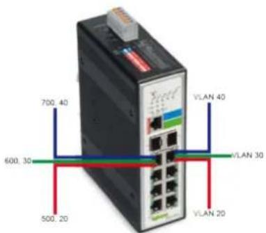
Figure 18: Configuration Example
7.2.4.3.1 DHCP Relay
Because the “DHCPDISCOVER” message is a broadcast message, and broadcasts only cross other segments when they are explicitly routed, you might have to configure a “DHCP Relay Agent” on the router interface so that all “DHCPDISCOVER” messages can be forwarded to your DHCP server.
Alternatively, you can configure the router to forward DHCP messages and BOOTP message. In a routed network, you would need "DHCP Relay Agents" if you plan to implement only one DHCP server.
The “DHCP Relay,” which is either a host or an IP router, waits for DHCP client messages to be broadcast on a subnet and then forwards those DHCP messages directly to a configured DHCP server. The DHCP server sends DHCP response messages directly back to the “DHCP Relay Agent,” which then forwards them to the DHCP client. The DHCP administrator uses “DHCP Relay Agents” to centralize DHCP servers, avoiding the need for a DHCP server on each subnet.
Most of the time in small networks, DHCP uses broadcasts, but there are some circumstances where unicast addresses are used. This can be the case when networks have a single DHCP server that provides IP addresses for multiple subnets. A router for such a subnet receives the DHCP broadcasts, converts them to unicast (with a MAC/IP destination address of the configured DHCP server, MAC/IP source address of the router itself). The GIADDR field on the main DHCP page contains the IP address of the interface on the router on which it received the DHCP request. The DHCP server uses the GIADDR field to identify the subnet for the device and selects an IP address from the correct pool. After that, the DHCP server sends the “DHCP OFFER” back to the router via unicast, which then converts it back to a broadcast and sends it out to the correct subnet containing the device that requested an address.
Configurations
A user can enable/disable the “DHCP Relay” on the switch. It can also be enabled/disabled on a specific VLAN. If “DHCP Relay” is disabled on the switch, it is disabled on all VLANs, even if enabled for individual VLANs.
Applications
• Application 1 (via a router)
DHCP client 1 and DHCP client 2 are in different IP segments. However, they receive the IP address from the same DHCP server.
Figure 19: Application 1 (via a Router)
Application 2 (local in different VLANs)
DHCP client 1 and DHCP client 2 are in different VLANs. However, they receive the IP address from the same DHCP server.
Figure 20: Application 2 (Local in Different VLANs)
VLAN 1: Port 1, 2 (Management VLAN)
VLAN 2: Port 3, 4
VLAN 3: Port 5, 6
VLAN 4: Port 7, 8
DHCP Server -> Port 1.
DHCP Client -> Port 2, 3, 4, 5, 6, 7, 8.
Result: Hosts connected to port 2, 3, 4, 5, 6, 7 and 8 receive an IP from the DHCP server.
DHCP Server Connection
The DHCP server must connect to the management VLAN member ports.
The "DHCP Relay" in the management VLAN must be enabled.
7.2.4.3.2 DHCP Relay Option 82
“DHCP Option 82” (“DHCP Relay Agent Information Option”). Option 82 was designed to allow a “DHCP Relay Agent” to insert circuit-specific information into a request that is being forwarded to a DHCP server. Specifically, the option works by setting two sub-options: “Circuit ID” and “Remote ID.”
“DHCP Option 82” operates on the basis of “DHCP Snooping” or/and “DHCP Relay.”
The switch monitors the DHCP packets and appends some information under "DHCPDISCOVER" and "DHCPREQUEST" packets. The switch deletes "DHCP Option 82" from the "DHCPOFFER" and "DHCPACK" packets. The DHCP server then assigns an IP domain to the client based on this information.
The maximum length for this information is 32 characters.
In residential, metropolitan ETHERNET-access environments, DHCP can centrally manage the IP address assignments for a large number of subscribers. If the “DHCP Option 82” function is enabled on the switch, a subscriber device is identified by the switch port through which it connects to the network (in addition to its MAC address). Multiple hosts on the subscriber LAN can be connected to the same port on the switch and are uniquely identified.
If you enable "DHCP Snooping Information Option 82" on the switch, the sequence of events is:
- The host (DHCP client) generates a DCHP request and broadcasts it on the network.
- If the switch receives the DHCP request, it adds the "Option 82" information to the packet. The information contains the switch MAC address (the "Remote ID" sub-option), the "Port Identifier" and the "VLAN-Mod-PORT" from which the packet is received (the "Circuit ID" sub-option).
- If the IP address of the “Relay Agent” has been configured, the switch adds the IP address to the DHCP packet.
- The switch forwards the DHCP request that includes the Option 82 field to the DHCP server.
- The DHCP server receives the packet. If the server is Option 82 capable, it can use the “Remote ID,” “Circuit ID” or both to assign IP addresses and implement policies, such as restricting the number of IP addresses that can be assigned to a single “Remote ID” or “Circuit ID.” The DHCP server then echoes the Option 82 field in the DHCP reply.
- The DHCP server forwards the reply to the switch as a unicast if the request was relayed to the server by the switch. If the client and server are on the same subnet, the server broadcasts the reply. The switch verifies the Option 82 data originally entered by checking the “Remote ID” and “Circuit ID” fields. The switch deletes the Option 82 field and forwards the packet to the switch port that connects to the DHCP client that sent the DHCP request.
Option Frame Format
Table 21: Option Frame Format
| Code | Len | Agent Information Field | |||||
| 82 | N | i1 | i2 | i3 | i4 | ... | iN |
The “Agent Information Field” consists of a sequence of SubOpt/Length/Value tuples for each sub-option, encoded in the following manner:
Table 22: Option Frame Format
| Sub-Option | Len | Sub-Option Value | |||||
| 1 | N | s1 | s2 | s3 | s4 | ... | sN |
DHCP Agent Sub-Option Description
Sub-Option Code
1 "Agent Circuit ID" sub-option
2 "Agent Remote ID" sub-option
Table 23: Frame Format of the "Circuit ID" Sub-Option
| Sub-Option Type | Length | “Circuit ID” Type | Length | VLAN | Module | Port |
| 1 | 6 | 0 | 4 | 2 | 1 | 1 |
Table 24: Frame Format of the "Remote ID" Sub-Option
| Sub-Option Type | Length | “Circuit ID” Type | Length | MAC Address |
| 2 | 8 | 0 | 6 | 6 |
Table 25: Format of the "Circuit ID" Sub-Option
| Code | Len | Sub-Option Type | Length | Slot ID | Port ID | VLAN ID | Information |
| 0x52 | 0x0c | 0x01 | 0x0a | 0x01 | 0x01 | 0x0002 | justin |
7.2.5 DHCP Server
For configuration of the network parameters via the DHCP (Dynamic Host Configuration Protocol), the ETHERNET device independently sends a client request to the DHCP server after initialization. This request is a broadcast telegram that contains the hardware address (MAC ID, MAC address) of the ETHERNET device.
The DHCP server then receives this request. This server manages a pool of IP addresses and saves the corresponding MAC address and other parameters for each IP address. If the MAC address from which the request is sent is already in the pool, the server responds with the IP address that has already been stored. However, the DHCP server also responds to responses from previously unknown MAC addresses: If the server still has free IP addresses in its area, it assigns one of them to the new MAC address and then sends the response.
The ETHERNET device waits for the response from the DHCP server. Incoming data packets contain information such as the IP address and the MAC address of the ETHERNET device. An ETHERNET device recognizes that a message is intended for it by the MAC address and then accepts the transmitted IP address in its network interface.
If there is no response, the request is repeated after four seconds, then eight seconds and finally, sixteen seconds.
If there is no response to any of the requests, an error message is issued.

Note
The DHCP configuration is not saved!
Note that unlike configuration via BOOTP, the network configuration when DHCP is used is not saved. The device receives a new IP address the next time the system is started.
The difference between BOOTP and DHCP is that both use different assignment methods.
7.2.6 Dual Homing
"Dual Homing" is a network topology in which a device is connected to the network by way of two independent access points ("Points of Attachment"). One access point establishes the primary connection, and the other is a reserve in case the primary connection fails.
![graph TD A["Main Campus Backbone Network"] --> B["IDP"] A --> C["IDP"] B --> D["GE Switch"] C --> E["GE Switch"] D --> F["Server 1"] D --> G["Server 2"] E --> H["Server N"] style A fill:#f9f,stroke:#333 style B fill:#ccf,stroke:#333 style C fill:#ccf,stroke:#333 style D fill:#cfc,stroke:#333 style E…](/content/2026/05/1008228/images/926aff21e299f2da89e1895e45ed1e8e81f32fee81ca72560612f5866b53ee6f.jpg)
Figure 21: Dual Homing
Primary and secondary connections, for example, can be connected to the Internet in different ways. The primary connection could be connected to a physical network and the secondary to a wireless network. If the “Dual Homing” function is enabled, a device connects via the primary connection by default, while the secondary connection remains suspended. If the port or all ports of the primary connection fail, the device switches to the secondary connection. If the secondary connection also fails, the device remains inactive. The secondary connection only works if the primary connection is interrupted.
7.2.7 Dual Ring
The "Dual Ring" function can be used to connect two neighboring rings to each other on a switch without the need for additional ports or cables. This configuration reduces the total number of required ports and the wiring costs, because no additional wiring is required.
![graph TD A["Sub Ring"] --> B["Xpress Ring"] B --> C["Jet Ring"] C --> D["Sub Ring"] D --> A A -->|6 5 6 5 6 5 6 5 6 5 6 5 6 5 6 5 6 5 6 5 6 5 6 5 6 5 6 5 6 5 6 5 6 5 6 5 6 5 6 5 6 5 6 5 6 5 6 5 6 5 6 5 B -->|9 8 8 8 8 8 8 8 8 8 8 8 8 8 8 8 8 8 8 8 8 8 8 8 8 8 8 8 8 8 8 8 8 8 8 8 8 8 8 8 8 8 8 8 8 8…](/content/2026/05/1008228/images/3307f8197cf84df2a6c549d1bdd19350bd5bf295be102670dc38204e06863bfa.jpg)
Figure 22: Dual Ring Switch ABC
![graph TD A["Sub Ring"] -->|6| B["A2"] A -->|5| C["A3"] A -->|6| D["B1"] A -->|5| E["B2"] A -->|6| F["Xpress Ring"] F -->|8| G["C"] F -->|9| H["D"] F -->|8| I["B"] F -->|9| J["B"] style A fill:#f9f,stroke:#333 style F fill:#ccf,stroke:#333 style B fill:#ccf,stroke:#333 style C fill:#ccf,stroke:#333 s…](/content/2026/05/1008228/images/0b4d8de7275dfc1dc0837ddc129ab894c1e0902c9d952ad37e69fa065ee74126.jpg)
Figure 23: Dual Ring Switch AB
Furthermore, additional WAGO ETHERNET end devices can be integrated into the Jet Ring. The fast-aging mechanism must be enabled on the devices for this.

Note
Additional information
More information is available in the manuals for the WAGO ETHERNET end devices.
These manuals are available for download under www.wago.com.
7.2.8 ERPS
The ERPS ("ETHERNET Ring Protection Switching") function implements a protection switching mechanism for ETHERNET layer ring topologies according to ITU-T standard G.8032. The ERP ("ETHERNET Ring Protection") protects ETHERNET traffic in a ring topology and ensures that no loops can arise within the ring in the ETHERNET layer. Looping is prevented by blocking traffic on either a predetermined link or a failed link.
The ETHERNET ring protection functionality includes the following:
- Loop avoidance
• Use of learning, forwarding and filter database (FDB) mechanisms
Loop avoidance in an Ethernet ring is achieved by guaranteeing that, at any time, traffic may flow on all but one of the ring links. This particular ring link serves as a reserve connection and is called an RPL ("Ring Protection Link"). In normal operation, it is blocked and not used for service traffic. A specific ETHERNET ring node, the "RPL Owner" node, is responsible for blocking traffic at one end of the RPL. Under an ETHERNET ring failure condition, the "RPL Owner" node is responsible for unblocking its end of the RPL, unless the RPL has failed, allowing the RPL to be used for traffic. The ETHERNET ring node adjacent to the RPL, the "RPL Neighbor" node, may also participate in blocking or unblocking its end of the RPL.
The ETHERNET rings can support a multi-ring/ladder network that consists of ETHERNET rings linked through one or more interconnection points. The protection switching mechanisms and protocol defined in this recommendation can be used for a multi-ring/ladder network under the following conditions:
• R-APS channels are not shared across ETHERNET ring connections;
- On each ring port, all traffic channels and all R-APS channels are controlled (e.g., for blocking or flushing) by the ETHERNET ring protection control process (ERP control process) of only one ETHERNET ring;
• Each main ring or subring has its own RPL.
In an ETHERNET ring without congestion, with all ETHERNET ring nodes in the idle state (i.e., no detected failure, no active automatic or external command and receiving only R-APS (NR, RB) messages) and with less than 1,200 km of ring fiber circumference and fewer than 16 ETHERNET ring nodes, the switch completion time (transfer time as defined in [ITU-T G.808.1]) for a failure on a ring link should be less than 50 ms.
The ring protection architecture relies on the existence of an APS protocol to coordinate ring protection actions in an ETHERNET ring.
The switch supports up to six rings.
Guard Timer
All ring subscribers use a “Guard Timer.” It prevents a closed loop from forming and prevents ring subscribers from using outdated R-APS messages. The “Guard Timer” is enabled if a ring subscriber received information on a local switching request, such as after SF (“Switch Fail”), MS (“Manual Switch”) or FS (“Forced Switch”) commands. When the timer expires, the ring subscriber begins executing the actions it received from the R-APS. This timer cannot be stopped manually.
WTR Timer
The “WTR Timer” (“Wait To Restore Timer”) is used by the “RPL Owner.” The WTR timer applies to the revertive mode to prevent frequent triggering of the protection switching due to port flapping or intermittent signal failure defects. When the timer expires, the “RPL Owner” sends an R-APS (NR, RB) message through the ring.
WTB Timer
The “WTB Timer” (“Wait To Block Timer”) is enabled on the “RPL Owner.” The “RPL Owner” uses “WTB Timers” before initiating an RPL block and then reverting to the idle state after operator-initiated commands, such as for FS or MS conditions, are entered. Because multiple FS commands are allowed to co-exist in a ring, the “WTB Timer” ensures that clearing a single FS command does not trigger the re-blocking of the RPL. The “WTB Timer” should run five seconds longer than the “Guard Timer” – enough time to allow a reporting ring subscriber to receive two R-APS messages and to allow the ring to identify the latent state. When clearing a MS command, the “WTB Timer” prevents the formation of a closed loop, because the “RPL Owner” node does not respond to an outdated remote MS request during the recovery process.
Hold-off Timer
Each ring subscriber uses a “Hold-off Timer” to delay reporting a port failure. When the timer expires, the ring subscriber checks the port status. If the problem persists, a failure is reported. If the issue does not persist, nothing is reported.
ERPS Revertive and Non-Revertive Switching
ERPS uses revertive and non-revertive operation. In revertive operation, after the conditions causing a switch have cleared, the traffic channel is restored to the working transport entity, i.e., blocked on the RPL. After an error condition is cleared, the traffic channel is switched back only after expiration of a "WTR Timer" to prevent protecting states from toggling due to intermittent errors. Without revertive operation, the traffic channel continues to use RPL after a switch condition is cleared if the RPL has not failed.
Control VLAN
The “Control VLAN” is a domain in which only ERPS control packets are transmitted. Because no other packets are transmitted in the VLAN, there are no delays for the ERPS. Therefore, when configuring a control VLAN for a ring, make sure it is a new VLAN. The ERPS creates this control VLAN and its member ports automatically. The member port should have a left right port only.
In ERPS, control packets and data packets are separated in different VLANs. The control packets are transmitted in a control VLAN.
Instance
For ERPS Version 2, an instance is a profile that specifies a control VLAN and one or more data VLANS for the ERPS. The control and data packets in ERPS are separated in different VLANs. The control packets are transmitted in the control VLAN and the data packets in one or more data VLANs. In this way, a user can easily assign an instance to an ERPS ring.
If a port is blocked by the ERPS in ERPS Version 1, all packets are blocked.
If a port is blocked by an ERPS ring in ERPS Version 2, only the packets belonging to the VLANs in this instance are blocked.

Note
Control VLAN and Instance
In CLI or Web configurations, there are settings for the control VLAN and the instance. If the control VLAN is configured for a ring and an instance is to be configured for the ring, the control VLAN must be the same for the instance as that of the ring. Otherwise, an error is displayed. If you still want to use this instance, you can first change the control VLAN so that it is the same as that of the instance. You can the configure the instance.
7.2.9 Link Aggregation
7.2.9.1 Static Trunk
“Ling Aggregation” (also called “Trunking” – parallel link bundling) is the grouping of physical ports into one logical link with higher capacity. When bundling ports, it can be more cost effective to use multiple lower-speed links than to underutilize a high-speed but expensive “Port Link.”
However, the more ports you aggregate, the fewer available ports you have. A “Trunk Group” is one logical link containing multiple ports. The switch supports both static and dynamic “Link Aggregation.”

Note
"Link Aggregation"
In a well-planned network, only static “Link Aggregation” is recommended. This ensures increased network stability and control over “Trunk Groups” on your switch.
7.2.9.2 LACP
The switch supports static and dynamic (LACP) "Port Trunking" according to IEEE 802.3ad. The IEEE 802.3ad standard describes LACP ("Link Aggregation Control Protocol") for dynamic creation and management of "Trunk Groups."
When you enable “LACP Link Aggregation” on a port, the port can automatically negotiate with the ports at the remote end of a link to establish “Trunk Groups.” LACP also allows port redundancy – that is, if an operational port fails, then one of the “standby” ports become operational without user intervention.
The following should be noted:
- All ports must be connected peer-to-peer to the same ETHERNET switch and configured for "LACP Trunking."
• LACP only works on full-duplex links. - All ports in the same “Trunk Group” must have the same media type, speed, duplex mode and settings for “Flow Control.”
- Configure the "Trunk Groups" or LACPs before you connect to the ETHERNET switch to prevent looping in the network topology.
System Priority
LACP system priority is used to determine membership in an LAG (“Link Aggregation Group”) and identifies the device for other switches during LAG negotiations.
The switch with the lowest system priority (and lowest port number, if system priority is the same) becomes the LACP “server.” The server controls the operation of the LACP settings. The smaller the number, the higher the priority level.
System ID
The “LACP System ID” is a combination of the LACP system priority value and the MAC address of the router.
Administrative Key
The “Administrative Key” defines the ability of a port to aggregate with other ports. This ability is determined by the following factors:
- The physical properties of the port, e.g., data rate, duplex capability and peer-to-peer or shared transmission medium.
- The configuration restrictions that you establish.
Port Priority
The port priority determines which ports should be put in standby mode when there is a hardware limitation that prevents all compatible ports from aggregating.
7.2.10 LLDP
The LLDP (“Link Layer Discovery Protocol”) described in this standard allows stations connected to a LAN according to IEEE 802® to send information to other stations connected to the same LAN. The information includes essential system functions, including the management address or addresses of an entity or entities that provide management of these functions, as well as identification of the station’s access point to the IEEE802 LAN required by the management entity or entities.
The information distributed via this protocol is stored by the recipients in a normal MIB (“Management Information Base”). This allows an NMS (“Network Management System”) to access the information using a management protocol such as SNTP (“Simple Network Management Protocol”).
7.2.11 Loop Detection
“Loop Detection” handles problems with loops in the network periphery. These problems can occur if a port is connected to a switch that is in a loop state. A loop state occurs as a result of user error. It happens when two ports on a switch are connected with the same cable. When a switch in loop state sends out broadcast messages, the messages loop back to the switch and are re-broadcast again and again, causing a “Broadcast Storm.”
The “Loop Detection” function sends probe packets periodically to detect whether the port is connected to a network in loop state. The switch shuts down a port if the switch detects probe packets looping back to the same port.
Loop Recovery
When “Loop Detection” is enabled, the switch sends a probe packet every two seconds and waits to receive the packet. If it receives the packet at the same port, the switch disables the port. After a defined time period (“Recovery Time”), the switch reenables the port and executes “Loop Detection” again.
The switch generates a “Syslog” (system log), internal log messages and “SNMP Traps” if it disables a port after “Loop Detection.”
7.2.12 Jet Ring
Setting up the Jet Ring function (redundant connection) in a network better protects critical connections against errors and network loops. In addition, network downtime is reduced to less than 300 ms.
The Jet Ring function can be used to set up a secondary path to the network. A data transmission safety route is then provided in case there is an abrupt interruption in a connection. This function is extremely important for industrial applications because connection errors without safeguards for network downtime can last several minutes and result in heavy losses.
The Jet Ring protocol is used to optimize secondary communication links and to ensure very short connection recovery time. The Jet Ring function is used to automatically identify a switch as the network “Master” and to automatically block connections. This prevents packets from being broadcast to all secondary loop segments of a network. If a ring segment is separated from the rest of the network due to a connection error, the Jet Ring protocol automatically adjust the ring again to restore the connection between the part of the network that was separated and the rest of the network.
Step 1
The Jet Ring function in the graphic below is applicable to connecting industrial managed switches.
![graph TD A["Master"] -->|BPDU Packets| B["4 Ethernet"] B -->|BPDU Packets| C["3 Ethernet"] C -->|BPDU Packets| D["2 Ethernet"] D -->|BPDU Packets| E["1 Ethernet"] E -->|BPDU Packets| A style A fill:#f9f,stroke:#333 style B fill:#ccf,stroke:#333 style C fill:#cfc,stroke:#333 style D fill:#fcc,stroke:…](/content/2026/05/1008228/images/767e23d65673b07a87c4854cae250342b69cc83b2ce7f21d5cf077820d56c852.jpg)
Figure 24: Jet Ring
Step 2
The Jet Ring function is used to automatically select the Arbiter switch. The network then ready for operation.
7.2.13 PoE (Power over Ethernet)
"Power over Ethernet" (PoE) supplies power and transmits data simultaneously and safely over the same ETHERNET cable, eliminating the need for a separate power supply.
"Power over Ethernet" (POE) is an ETHERNET network technology defined in the IEEE 802.3af (PoE) und 802.3at (PoE+) standards.
If the IEEE 802.3at standard is supported, a higher current can be transmitted via the ETHERNET cable.
Table 26: Comparison of PoE and PoE+
| Feature | PoE | PoE+ |
| Standard | IEEE 802.3af | IEEE 802.3at |
| PSE power | 15.4 W | 25.4 W |
| Max. power PD | 12.95 W | 21.90 W |
| Max. current per core pair | 350 mA | 600 mA |
| Transmission standard | 10Base-T100Base-TX | 10Base-T100Base-TX1000-BASE-T |
Calculation example for PoE+:
Table 27: Calculation Example for PoE+
| Power consumption | Value |
| 4 ports at 30 W | 120 W |
| Device requirement | 13 W |
| Total | 133 W |
Special equipment is required for PoE (PSE = "Power Sourcing Equipment") and subscribers (PD = "Powered Device").
The PoE description and performance classes are available in the appendix (see Section "Appendix" > "PoE Performance Classes").
PoE can be realized for this product using the following operating mode.
Operating Mode A
In this operating mode, the supply voltage is modulated on the data lines (“phantom power”).
Operating Mode A can be used with the following transmission standards:
- 10BASE-T
- 100BASE-TX
- 1000BASE-T
In this operating mode, core pairs 1 and 2 (+), as well as 3 and 6 (-) are used for the power supply. A 4-core or 8-core ETHERNET cable of at least category 5 or 5e can be used (see section "Appendix" > "RJ-45 Cable").
7.2.14 Static Route
Static routes define explicit paths between two end systems. These paths are defined when a network is installed and normally, are saved in the router. Each end device is assigned to a router through which it can be reached and can reach other destinations from. Static routes are not updated automatically. Thus, static routes must be manually reconfigured every time a change is made to the network. Static routes use less bandwidth than dynamic routes. No CPU cycles are used to calculate and analyze routing updates.
IP Forwarding
The IP forwarding enables IP packet transfer between hosts beyond the limits of a network. If two hosts are located in different networks, the data must be forwarded through a router that connects the two networks to each other. For large networks like the Internet, several routers may be involved. When routes are created, only the nearest host on the route to the destination host is indicated, not the entire route. If the data is transported via multiple routes, routes to the next router must also be created on the intermediary routers.
IP forwarding works as a router as well as an inter-VLAN routing with a trunk stick.
The routing database plays an important role in forwarding the packets. Routers populate the routing database either by manual configurations or by using dynamic routing protocols.
Manual routing configurations are called as Static routes. Whenever a router receives an IP packet, it retrieves the destination IP address and searches the routing table to find the longest prefix match route. The packet is forwarded to the assigned next assigned host in the route.
7.2.15 STP
The (R)STP (“(Rapid) Spanning Tree Protocol”) can detect and stop network loops, as well as provide “Backup Links” between switches, bridges or routers. It allows a switch to interact with other (R)STP-compliant switches in the network to ensure that only one path exists between any two stations on the network.
The switch supports both STP and RSTP as defined in the following standards:
- IEEE 802.1D Spanning Tree Protocol
- IEEE 802.1w Rapid Spanning Tree Protocol
The switch uses IEEE 802.1w RSTP, which allows faster convergence of the "Spanning Tree" than STP (the switch is also backwards-compatible with STP-only aware bridges). In RSTP, topology change information is directly propagated throughout the network from the device that generates the topology change. In STP, there are longer delays because the device that causes a topology change first notifies the "Root Bridge" and then the network. Both RSTP and STP remove unwanted learned addresses from the filtering database.
• In STP, the port states are Blocking, Listening, Learning and Forwarding.
• In RSTP, the port states are Discarding, Learning and Forwarding.
STP Switch Port States
- "Blocking"
If a port causes a “Switching Loop” (looping connection between two ports), user data can no longer be sent or received. However, the port can go into the “Forwarding” state if the other active connections fail and the “Spanning Tree” algorithm determines that the port may transition to that state. BPDU data is still received and sent in the “Blocking” state.
- "Listening"
The switch processes BPDUs and waits for possible new information that would cause it to return to the “Blocking” state.
- "Learning"
Even if the port does not yet forward any frames (packets), it can learn source addresses from frames received and add them to the filter database ("Switching Database").
- "Forwarding"
The port is in normal operating mode and receives and sends data. STP still monitors incoming BPDUs that would indicate that the port should return to the “Blocking” state to prevent a loop.
- "Disabled"
It is not strictly part of the STP because a network administrator can manually disable a port.
RSTP Bridge Port Roles
- "Root"
The “Root Port” is a forwarding port that can best transmit data from the “Non-Root Bridge” to the “Root Bridge.”
- "Designated"
This is a forwarding port for every LAN segment.
- "Alternate"
This port represents an alternate path to the “Root Bridge.” However, the path is different than for the “Root Port.”
- "Backup"
This port is used as a backup/redundant path to a segment to which another “Bridge Port” is already connected.
- "Disabled"
This is not actually part of STP because a network administrator can manually disable a port.

Note
STP/RSTP
In this document, "STP" refers to both STP and RSTP.
STP Terminology
Root Bridge
The “Root Bridge” is the “base” (root) of the spanning tree.
Path Cost
The path costs are the costs for transmitting a frame through the port in the LAN. This value should be adjusted to the transmission speed.
The valid range is 1 to 200000000. A path with higher costs is more likely to be blocked by STP if a network look is detected.
- "Path Cost Short" is the original size with a 16-bit value.
Only speeds up to 10 Gbit can be considered.
- "Path Cost Long" stands for a 32-bit value.
Speeds up to 10 Tbit are supported.
Table 28: STP Path Costs
| Transmission Speed | Recommended Value | Recommended Range | Permissible Range |
| 4 Mbit/s | 250 | 100 ... 1000 | 1 ... 65535 |
| 10 Mbit/s | 100 | 50 ... 600 | 1 ... 65535 |
| 16 Mbit/s | 62 | 40 ... 400 | 1 ... 65535 |
| 100 Mbit/s | 19 | 10 ... 60 | 1 ... 65535 |
| 1 Gbit/s | 4 | 3 ... 10 | 1 ... 65535 |
| 10 Gbit/s | 2 | 1 ... 5 | 1 ... 65535 |
- Each “Bridge” communicates with the “Root Bridge” via the “Root Port.” The “Root Port” is the port on the switch with the lowest path costs to the “Root Bridge” (the “Root Path Cost”). If there is no “Root Port,” then the switch becomes the “Root Bridge” for the “Spanning Tree” network.
- A “Designated Bridge” is selected for each LAN segment. This bridge has the lowest cost to the “Root Bridge” among the bridges connected to the LAN.
Forward Time (Forward Delay)
The “Forward Time” is the maximum time (in seconds) that the switch waits before it changes states. This delay is required because every switch must first receive information on topology changes before it forwards frames. In addition, each port needs time to receive information on conflicts that would make it return to the blocking state. Otherwise, temporary data loops might result. The valid range is 4 to 30 seconds.
Max Age
The “Max Age” is the maximum time (in seconds) that the switch can wait without receiving a BPDU (“Bridge Protocol Data Unit,” configuration message) before attempting to reconfigure. All switch ports (except for “Designated Ports”) receive BPDUs at regular intervals. Each port that ages out STP information (from the last BPDU) becomes the “Designated Port” for the attached LAN. If it is a “Root Port,” a new “Root Port” is selected from among the switch ports attached to the network.
Hello Time
The “Hello Time” is the time interval in seconds between configuration messages (BDPU “Bridge Protocol Data Unit”) sent from the root switch.
STP
After a bridge determines the lowest cost “Spanning Tree” with STP, it enables the “Root Port” and “Designated Ports” for connected LANs and disables all other ports that participate in STP. Network packets are therefore only forwarded between enabled ports, eliminating any possible network loops.
STP-aware switches exchange BPDUs periodically. If the topology changes in a LAN coupled via bridge, a new tree is spanned. Once a stable network topology has been established, all bridges listen for “Hello BPDUs” transmitted from the “Root Bridge.” If a bridge does not get a “Hello BPDU” after a predefined interval (“Max Age”), the bridge assumes that the link to the “Root Bridge” is down. This bridge then initiates negotiations with other bridges to reconfigure the network to re-establish a valid network topology.
Edge Port
"Edge Ports" are attached to a LAN that has no other bridges attached. These ports can transition directly to the "Forwarding" state. RSTP still continues to monitor the port for BPDUs in case a bridge is connected. RSTP can also be configured to automatically detect "Edge Ports." As soon as the bridge detects a BPDU coming to an "Edge Port," the port loses its status as an "Edge Port."
Forward Delay
The “Forward Delay” is the maximum time (in seconds) that the root device waits before changing states (e.g., from “Listening” to “Learning” to “Forwarding”). The valid range is from 4 to 30 seconds.
Transmission Limit
The “Transmission Limit” is used to configure the minimum interval between the transmissions of consecutive RSTP BPDUs. This function can only be enabled in RSTP mode. The valid range is from 1 to 10 seconds.
Bridge Priority
“Bridge Priority” is used in selecting the root switch, root port and “Designated Port.” The switch with the highest priority becomes the STA root switch. If all switches have the same priority, however, the switch with the lowest MAC address becomes the root switch.
Port Priority
The port priority is configured in the switch. A low numeric value indicates a high priority. A port with lower priority is more likely to be blocked by STP if a network loop is detected. The valid range is from 0 to 240.
BPDU Guard
This setting is configured separately for each port. If the port is enabled in "BDU Guard" and receives a BPDU, the port is switched to the "Disabled" state to prevent a faulty environment. The user must enable the port manually.
BPDU Filter
This function is used to set up a filter for sending or receiving BPDUs on a switch port. If the port receives BPDUs, the BPDUs are dropped. If both the "BPDU Filter" and the "BPDU Guard" are enabled, the "BPDU Filter" has the higher priority.

Note
BPDU Filter and BPDU Guard
If both the "BPDU Filter" and the "BPDU Guard" are enabled, the "BPDU Filter" has the higher priority.
Root Guard
The “Root Guard” function forces an interface to become a “Designated Port” to prevent neighboring switches from becoming a root switch. This function provides a way to specify the selection of a “Root Bridge” in a network. It prevents a “Designated Port” from becoming the “Root Port.” If a port with the “Root Guard” function receives a superior BPDU, the port moves to a root-inconsistent state (effectively equivalent to the “Listening” state) to maintain the status of the current “Root Bridge.” The port can be moved to the “Forwarding” state if it receives no superior BPDU for the time period of “Hello Times.”
MSTP
The MSTP ("Multiple Spanning Tree Protocol") is an RSTP extension. It allows different spanning tree instances in conjunction with VLANs ("Virtual Local Area Networks").
For a VLAN or group of VLANs, STP instances can be created independently that user their own different spanning trees within a LAN.
With the MSTP approach, a root bridge and the lowest path costs between the root bridge and the root ports offered of the individual bridges are determined.
The root bridge sends Bridge Protocol Data Units (BPDU) to all bridges and determines the network configuration from the configuration data contained in the BPDU data packets.
7.2.16 Xpress Ring
Xpress Ring is a fast-acting, self-healing ring recovery technology that enables networks to recover from link failure within 50 ms.
Fast Link Recovery and Ring Redundancy are important functions for increasing the reliability of nonstop systems.
If the network is planned correctly with an arbiter switch and ring ports, the network can recover from any segment failure within a very short time.
A switch in the Xpress Ring has only two roles: either "Forwarder" or "Arbiter." There can be only one Arbiter switch, while all other switches are "Forwarders."
One of the ring ports of the Arbiter Switch will be set to the blocking state. If one of the ring connections fails, the blocked port is set to the forwarding state.
7.3 Security
7.3.1 IP Source Guard
“IP Source Guard” is a security function that restricts IP traffic on untrusted Layer2 ports by filtering traffic based on a “DHCP Snooping” database connection or a manually configured IP source connection. This function helps prevent access such as “IP Spoofing” (sending IP packets with a spoofed sender IP address) if a host attempts to spoof the IP address of another host. Any IP traffic coming into the interface with a source IP address other than that assigned (via DHCP or static configuration) is filtered out on untrusted Layer2 ports.
This function is used on untrusted Layer2 interfaces in combination with “DHCP Snooping.” An IP source binding table is manually configured (static IP source binding) or created from information from the “DHCP Snooping” function and used. Each entry in this table contains the IP address and associated MAC and VLAN addresses. The “IP Source Guard” only supports Layer2 ports, including “Access Ports” and “Trunk Ports.”
The "IP Source Guard" includes the following functions:
- DHCP Snooping
- DHCP Binding Table
- ARP Inspection
- Blacklist Filter (ARP inspection with MAC address filter table)
“DHCP Snooping” is a DHCP security function that increases network security by filtering untrusted DHCP messages and creating and using a “DHCP Snooping” database connection (also called “DHCP Snooping” binding table).
“DHCP Snooping” acts like a firewall between untrusted hosts and DHCP servers. It can be used to differentiate between untrusted interfaces connected to end users and trusted interfaces connected to a DHCP server or another switch.
The “DHCP Snooping” binding table contains the MAC address, IP address, “Lease Time,” mount type, VLAN number and information on the local untrusted interfaces of a switch.
If a switch receives a packet from an untrusted interface and the interface belongs to a VLAN in which “DHCP Snooping” is enabled, the switch compares the MAC source address to the hardware address of the DHCP client. If the addresses match (as is normal), the switch forwards the packet. If the addresses do not match, the switch drops the packet.
The switch drops a DHCP packet when one of the following situations occur:
- A packet from a DHCP server, such as a DHCPOFFER, DHCPACK, DHCPNAK or DHCPLEASEQUERY packet, is received from the untrusted port.
- A packet is received on an untrusted interface, and the source MAC address and the DHCP client hardware address do not match any of the current bindings.
“DHCP Snooping” can be used to filter unauthorized DHCP packets on the network and to dynamically create a binding table. This can prevent clients from getting IP addresses from unauthorized DHCP servers.
Trusted vs. Untrusted Ports
Every port is either a “Trusted Port” or an “Untrusted Port” for “DHCP Snooping.” This setting is independent of the “Trusted/Untrusted” setting for ARP inspection. You can also specify the maximum number for DHCP packets that each port (“trusted” or “untrusted”) can receive each second.
"Trusted Ports" are connected to DHCP servers or switches. The switch only drops DHCP packets from "Trusted Ports" if the transmission rate of the DHCP packets received is too high. The switch learns the dynamic bindings from the "Trusted Ports."

Note
DHCP Requests
The switch drops all DHCP requests when “DHCP Snooping” is enabled and there are no “Trusted Ports.”
"Untrusted Ports" are connected to subscribers. The switch discards DHCP packets from untrusted ports in the following situations:
• The packet is a DHCP server packet (e.g., "OFFER," "ACK" or "NACK").
- The source MAC address and source IP address in a packet do not match any of the current bindings.
- The packet is a RELEASE or DECLINE packet, and the source MAC address and source port do not match any of the current bindings.
• The transmission rate of the DHCP packets received is too high.
DHCP Snooping Database
The switch stores the binding table in volatile memory. If the switch restarts, it loads the static bindings from non-volatile memory but loses the dynamic bindings, so the devices in the network have to send DHCP requests again.
Configuring DHCP Snooping
Follow the steps below to configure "DHCP Snooping" on the switch:
- Enable "DHCP Snooping" on the switch.
- Enable "DHCP Snooping" for each VLAN.
- Configure "Trusted Ports" and "Untrusted Ports."
- Configure the static bindings.

Note
DHCP Snooping
The switch drops all DHCP requests when “DHCP Snooping” is enabled and there are no “Trusted Ports.”
If the port link fails, the entries from this port are deleted from the "DHCP Snooping" binding table.
You must first enable global "DHCP Snooping" and "DHCP Snooping" for VLANs.
The main purposes of the "DHCP Snooping" are:
1 To create and maintain a binding table for the ARP Inspection function.
2 To filter packets from DHCP servers that are connected to an "Untrusted Port."
![graph LR subgraph "DHCP Snooping" A["1"] --> B["2"] C["3"] --> D["4"] E["5"] --> F["6"] G["7"] --> H["8"] I["9"] --> J["10"] K["11"] --> L["12"] M["13"] --> N["14"] O["15"] --> P["16"] Q["17"] --> R["18"] S["19"] --> T["20"] U["21"] --> V["22"] W["23"] --> X["24"] Y["trust"] --> Z["25"] AA["Untrust"…](/content/2026/05/1008228/images/85c8c04cd5619c7b5c1d41cadbab17a5019a4f221df40518a6138372b5a3ca8e.jpg)
Figure 25: DHCP Snooping
The packets from DHCP servers connected to an "Untrusted Port" are filtered.
7.3.1.1.1 Server Screening
The switch supports "Server Screening," a function that denies access to "Rogue DHCP Servers" (unauthorized, invalid DHCP servers). That is, when one or more DHCP servers are present on the network and both provide DHCP services to different distinct groups of clients, the valid DHCP server's packets are passed to the client.
If this function is enabled, the "DHCP Snooping" function must also be enabled beforehand. The switch allows users to configure up to three valid DHCP servers.
If no DHCP servers are configured, it means all DHCP servers are valid.
7.3.1.2 Binding Table
The “DHCP Snooping” binding table records the host information learned from “DHCP Snooping” (dynamic) or set by user (static). The ARP inspection uses this table to decide whether to forward or drop ARP packets. ARP packets sent from invalid hosts are dropped. After the “Lease Time” expires, the entry is deleted from the table.
Static bindings are uniquely identified by the MAC address and VLAN ID. Each MAC address and VLAN ID can only be in one static binding. If you create a static binding with the MAC address and VLAN ID of an existing binding, the new static binding replaces the original one.
Bindings are used by "DHCP Snooping" and ARP inspection to distinguish between authorized and unauthorized packets in the network. The switch detects the dynamic bindings by "snooping" DHCP packets and through static information from the manual entries in the "Static Entry Settings" menu.
Dynamic “ARP Inspection” (“Address Resolution Protocol Inspection”) is a security function in which ARP packets are inspected in a network. Dynamic ARP inspection validates the packet by comparing IP-to-MAC address bindings to entries stored in a trusted database (the “DHCP Snooping” database) before forwarding the packet. Dynamic ARP intercepts, logs and discards ARP packets with invalid IP-to-MAC address bindings. This function protects the network from certain “man-in-the-middle” attacks.
Dynamic ARP inspection ensures that only valid ARP requests and responses are relayed.
The switch executes the following processes:
• Interception of all ARP requests and responses on untrusted ports.
- Inspection of all intercepted packets for valid IP-to-MAC address binding before updating the local ARP cache or forwarding a packet to the respective destination.
Trusted Port and Untrusted Port
- This setting is independent of the “Trusted/Untrusted” setting for “DHCP Snooping.”
• The switch does not drop ARP packets from "Trusted Ports" for any reason. - The switch drops ARP packets from “Untrusted Ports” if the information from the sender in the ARP packets does not match any current bindings.
- Normally, the “Trusted Ports” are the “Uplink Ports,” and the “Untrusted Ports” are connected to subscribers.
Configurations
Users can enable/disable ARP Inspection on the switch. It can also be enabled/disabled on a specific VLAN. If ARP Inspection is disabled on the switch, ARP Inspection is disabled on all VLANs, even if enabled for individual VLANs.

Note
Global State/VLAN State
There are a global state and individual VLAN states.
If the global state is disabled, ARP Inspection is disabled on the switch, even if individual VLAN states are enabled.
If the global state for ARP Inspection is enabled, this function must be enabled by the user for specific VLANs
Dynamic ARP inspection validates the packet by comparing IP-to-MAC address bindings to entries stored in a trusted database (the "DHCP Snooping" database) before forwarding the packet. If the switch detects an unauthorized ARP packet, it automatically creates a MAC address filter to block traffic from the source MAC address and the source VLAN ID of the packet. In addition, the switch regularly deletes entries whose "Age Time" has expired.
- If ARP Inspection is enabled and the system detects invalid hosts, the system creates a filter entry in the MAC address table.
- If a port link fails when ARP Inspection is disabled, the switch will remove the MAC filter entries for this this port.
- If a port link fails when ARP Inspection is enabled, the switch will remove the MAC filter entries for this this port.
• The maximum number of entries in the MAC address filter table is 256. - If the MAC address filter table for ARP inspection is full and the switch receives an unauthorized ARP packet, it automatically creates a "SYSLOG" and the ARP packet is dropped. The SYSLOG is created only once.
7.3.2 Access Control List (ACL)
The ACL (“Access Control List”) is a list of permissions attached to an object. The list specifies who or what is allowed to access an object and what operations are allowed to be performed on the object.
The ACL function allows users to configure a few rules to reject packets from the specific ingress ports or all ports. These rules check the source and destination MAC addresses of packets. If packets match these rules, the system executes the “deny” action, meaning it rejects these packets.
The “Action Resolution Engine” collects the information (action and metering results) from the hit entries: If more than one rule matches, the actions and measurements/counters are taken from the policy associated with the matched rule with highest priority.
7.3.3 IEEE 802.1X Communication Standard
IEEE 802.1X is an IEEE standard for port-based Network Access Control (“port” meaning a single point of attachment to the LAN infrastructure). It is part of the IEEE 802.1 group of networking protocols. It provides an authentication mechanism for devices wishing to attach to a LAN, either establishing a point-to-point connection or preventing it if authentication fails. It is used for most wireless 802.11 access points and is based on EAP (“Extensible Authentication Protocol”).
IEEE 802.1X provides port-based authentication, which involves communications between a so-called supplicant, authenticator and authentication server. The supplicant is often software on a client device, such as a laptop, the authenticator is a wired ETHERNET switch or wireless access point, and the authentication server is generally a RADIUS ("Remote Authentication Dial-In User Service") database.
The authenticator acts like a security guard for the protected network. The supplicant (e.g., client device) is not allowed access the protected side of the network through the authenticator until the supplicant's identity is authenticated. With 802.1X port-based authentication, the supplicant provides credentials, such as a user name/password or digital certificate, to the authenticator, and the authenticator forwards the credentials to the authentication server for verification. If the credentials are valid (in the authentication server database), the supplicant (client device) is allowed to access resources located on the protected side of the network.
Upon detection of a new client (“supplicant”), the port on the switch (“authenticator”) is enabled and set to the “unauthorized” state. In this state, only 802.1X traffic is allowed; other traffic, such as DHCP and HTTP, is blocked on the network layer (Layer 3). The authenticator sends out the EAP identity request to the supplicant, the supplicant responds with the EAP response packet, which the authenticator forwards to the authenticating server. If the authenticating server accepts the request, the authenticator sets the port to the “authorized” mode, and normal traffic is allowed. If the supplicant logs off, it sends an EAP logoff message to the authenticator. The authenticator then sets the port to the “unauthorized” state, once again blocking all non-EAP traffic.
RADIUS Server
The RADIUS server ("Remote Authentication Dial-In User Service") is a client/server-based security protocol for authentication and control of network access permissions.
The RADIUS server operates using the Challenge/Response process and supports central administration of user data, such as user ID, passwords, phone numbers, access rights and account data, and consists of an accounting and authentication protocol.
In combination with DHCP and PPP, configuration of dial-in systems can occur automatically with RADIUS.
![graph TD A["Wireless Network"] --> B["Authentication Server (RADIUS)"] B --> C["AS"] C --> D["AP"] D --> E["Authenticator"] E --> F["Supplicant"] F --> G["Internet or other LAN resources"] style A fill:#f9f,stroke:#333 style B fill:#bbf,stroke:#333 style C fill:#bfb,stroke:#333 style D fill:#ffb,str…](/content/2026/05/1008228/images/ec0fe3ad43cd52b1c17f442ac4583d7c5eacacbce07bd9206d6d7ee5e154606e.jpg)
Figure 26: IEEE 802.1X
The following figure illustrates how a client connecting to an IEEE 802.1X-authentication-enabled port goes through the validation process. The switch prompts the client for login information in the form of a user name and password.
Once the client provides the login credentials, the switch sends an authentication request to the RADIUS server. The RADIUS server checks whether this client is allowed access to the port.
![graph TD A["Computer"] --> B["Server"] B --> C["Server"] B --> D["Login Credentials"] D --> E["Login Info Request"] E --> F["New Connection"] F --> G["Authentication Request"] G --> H["Authentication Reply"] H --> I["Session Granted/Denied"]](/content/2026/05/1008228/images/cd3a56cc506844c7fc0cf49215f0549521a8eb8be1e711574d9ddd4294af2e6e.jpg)
Figure 27: RADIUS Server
Local User Accounts
By storing user profiles locally on the switch, the switch can authenticate users without interacting with the network authentication server. However, there is a limit to six users that can be authenticated in this way.
Guest VLAN
The Guest VLAN function in IEEE 802.1X port-based authentication on the switch provides limited services to clients, such as downloading the IEEE 802.1X client. These clients can update their system for IEEE 802.1X authentication.
If you enable a guest VLAN on an IEEE 802.1X port, the switch assigns clients to a guest VLAN when the switch does not receive a response to its EAP request/identity frame or when EAPOL ("EAP over LAN") packets are not sent by the client.
Port Parameters
- Admin Control Direction
Both - If 802.1X port authentication for a user has failed, incoming and outgoing packets on the port are dropped.
Incoming - If 802.1X port authentication for a user has failed, only incoming packets on the port are dropped.
- Re-Authentication
This function specifies whether a subscriber must periodically re-enter his or her user name and password to stay connected to the port.
- Reauth Period
The “Reauth Period” function is used to specify how often a client has to re-enter his or her username and password to stay connected to the port. The permissible range for this field is 0 to 65535 seconds.
- Port Control Mode
| “Auto” authentication. | Users can access the network after |
| “Force-authorized” authentication. | Users can access the network without |
| “force-unauthorized” | Users cannot access the network. |
- Quiet Period
The “Quiet Period” function is used to specify the time a client has to wait before the next authentication attempt. This prevents the switch from becoming overloaded with continuous authentication attempts from the client. The permissible range for this field is 0 to 65535 seconds.
- Server Timeout
The “Server Timeout” value is used for timing out the authentication server.
- Supp Timeout
The "Supp Timeout" value is the initialization value used for timing out a supplicant.
- Max Req Time
The “Max Req Time” specifies how often the switch attempts to connect to the authentication server before determining that the server is down. The permissible range for this field is 1 to 10 attempts.
7.3.4 Port Security
The switch receives the MAC address of a device that is connected to a specific port direction and allows data forwarding. The functions of the switch allow control over which and how many devices may be connected to a switch port.
The “Port Security” functions can specify the maximum number of MAC addresses per interface. If this number is exceeded, incoming packets with new MAC addresses are dropped. A MAC address table can be used to check this. The static MAC addresses are included for this limit.

Note
State Change of a Port on the Switch
If the state of a port on the switch is changed from disabled to enabled, all MAC addresses captured by this port are dropped.
7.3.4.1 Sticky MAC Settings
Port security with sticky MAC addresses offers many of the benefits of port security with static MAC addresses; however, sticky MAC addresses can be dynamically taught. Port security with sticky MAC addresses contains MAC addresses that are dynamically taught during a link-down condition.
7.4 Monitor
7.4.1 Alarm
This function alerts the network administrator to any abnormal network situations.

Note
Alarm DIP Switches
The alarm DIP switches allow users to configure whether an alarm message should be sent when a corresponding event occurs.
Example
P1: ON (AN) – The switch sends an alarm message if the connection on Port 1 fails.
PWR: ON – The switch sends an alarm message if the primary power supply is interrupted.
RPS: ON – The switch sends an alarm message if the redundant power supply is interrupted.
7.4.2 Monitor Information
This function displays some hardware information for purposes of monitoring the system and guaranteeing proper network operation.
7.4.3 Port Statistics
With this function, the port statistics are monitored and, e.g., the number of received and sent packages is displayed.
7.4.4 Port Utilization
With this function, the port utilization is displayed.
7.4.5 RMON Statistics
This function is used to monitor or delete RMON statistics.
Jabber
Subscribers whose data packets are longer than the allowable MTU ("Maximum Transmission Unit") on a network (e.g., ETHERNET) are referred to as Jabbers.
7.4.6 SFP
SFPs ("Small Form-factor Pluggables") are small standardized modules for network connections.
SFP refers to a modular interface to support various transmission media and is used in network technology for interface flexibility.
7.4.6.1 DDMI
DDMI ("Digital Diagnostics Monitoring Interface") is technology that allows users to monitor the following real-time parameters in SFP modules:
- Voltage
- Bias current
- Input power
- Output power
- Temperature)
7.4.7 Traffic Monitor
The “Traffic Monitor” function can be used to enable or disable a specific port or the switch globally. This function can monitor the data rate of broadcast, multicast or broadcast and multicast packets. If the packet rate exceeds the specification for a user, the port is blocked. If the “Recovery” function is enabled, the port is re-enabled after the “Recovery Time” has expired.
7.5 Management
7.5.1 SNMP
SNMP (“Simple Network Management Protocol”) is used in network management systems to monitor the state of attached devices that require the attention of an administrator. SNMP is a component of the “Internet Protocol Suite” defined by the IETF (“Internet Engineering Task Force”). It consists of a set of standards for network management, including an application layer protocol, a database schema and a set of data objects.
SNMP provides management data in the form of variables of the managed systems, which describe the system configuration. These variables can then be queried (and sometimes changed) by managing applications.
Support for MIBs
- RFC 1157 A Simple Network Management Protocol
- RFC 1213 MIB-II
- RFC 1493 Bridge MIB
- RFC 1643 ETHERNET Interface MIB
- RFC 1757 RMON Group 1,2,3,9
An “SNMP Community String” is a text string that acts as a password. It is used to authenticate messages that are sent between the management station (the SNMP manager) and the device (the SNMP agent). The string is included in every packet transmitted between the SNMP manager and the SNMP agent.
The “SNMP Community” acts like a password and is used to define the security parameters of SNMP clients in SNMP v1 and SNMP v2c environments. The default “SNMP Community” is “public” for both SNMPv1 and SNMPv2c before SNMPv3 is enabled. Once SNMPv3 is enabled, the “Communities” of SNMPv1 and v2c have to be unique and cannot be shared.
Network ID of "Trusted Host":
The IP address is a combination of the network ID and host ID.
• Network ID = (host IP and mask).
- A user must enter the network ID only and leave the host ID at "0." If a user enters a host ID, such as 192.168.1.102, the system resets the host ID to 192.168.1.0.

Note
Community String
It should allow users to configure the "Community String" and rights only.
If a user configures the “Community String” and the rights and the network ID of the “Trusted Host” = 0.0.0.0, subnet mask = 0.0.0.0, this means that all hosts with this “Community String” can access the switch.
7.5.1.1 SNMP Trap
A trap is an unsolicited message from an agent to the manager that an event has occurred. The SNMP Manager that receives the trap can ask for more information.
7.5.1.2 SNMPv3
In SNMP Version 3, message exchange is tied to user accounts. Each device that recognizes the set passwords can read values from or write them on the ETHERNET device. With SNMPv3, the SNMP message user data can also be encrypted for transfer. This way, the requested values and those to be written cannot be easily decoded and eavesdropped on the ETHERNET, which is why SNMPv3 is often used in security-relevant systems.
7.5.2 Auto Provision
The “Auto Provision” is a service that service providers can use to quickly, easily and automatically configure remote devices or update firmware from a remote location.
- If the function is enabled, the switch first downloads an information file from the server of the service provider.
The file name is formed according to the following naming convention:
Series_Model_Autoprovision.txt
Example: 852_1505_Autoprovision.txt
The contents of the file are:
Firmware_Upgrade_State=1
Firmware Version=5228-000-1.0.0.b1
Firmware_Image_File=5228-000-1.0.0.b1.fw
Firmware_Reboot=1
Global_Configuration_State=0
Global_Configuration_File=5228-000-1.0.0.b1.save
Global_Configuration_Reboot=0
Specific_Configuration_State=0
Specific_Configuration_Reboot=0
-
If the "AUTO_PROVISION_VER" value is higher than the current version of the "Auto Provision," continue to Step 3. If not, please wait 24 hours and start again with Step 1.
-
If "Firmware_Upgrade_State = 1," continue to Step 4. If not, continue to Step 6.
-
If the "Firmware_Version" differs from the current firmware version, please download the "Firmware_Image_File" and update the firmware.
-
If the firmware is updated successfully and "Firmware_Reboot=1," "reboot_flag=1" is executed.
- If "Global_Configuration_State = 1," please download the "Global_Configuration_File" and update the configuration. If not, continue to Step 8.
- If the configuration is updated successfully and "Global_Configuration_Reboot = 1," "reboot_flag=1" is executed.
- If "Global_Configuration_State =1," please download the specific configuration file and update the configuration. If not, continue to Step 10. The name is: "Series_Model_" with 12-bit MAC digits, e.g., "852_1505_00e04c8196b9.txt."
- If the configuration is updated successfully and "Specific_Configuration_Reboot = 1," "reboot_flag = 1" is executed.
- If "reboot_flag=1," save the executed configuration and reboot the switch. If not, please wait 24 hours and start again at Step 1.
7.5.3 Mail Alarm
The “Mail Alarm” function sends an e-mail trap to a previously defined administrator when certain events occur. The events are listed below:
System Reboot: The system performs a warm or cold start.
Port Link Change: A port link is established or fails.
Configuration Change: The system configurations in the NV-RAM have been updated.
Firmware Upgrade: The system firmware has been updated.
User Login: A user has logged into the system.
Port Blocked: A port is blocked by "Loop Detection" or "BPDU Guard."
7.5.4 Ping
The accessibility of an ETHERNET participant is checked with the Ping command.
The basis for Ping is, a programming device sends an ICMP echo request and waits for an ICMP echo response from the addressed ETHERNET participant.
7.5.5 USB Functions
The following functions can be performed through the switch's USB interface:
- Uploading the firmware
- Saving the configuration file
- Saving the Syslog file
- Uploading the configuration file
In delivery state, these functions are disabled. They can be enabled through Web-Based Management or CLI commands. The first time a USB stick is inserted, the required folder structure is created on it.
7.5.5.1 Uploading the Firmware
Load the firmware file to the stick as follows:
- Create a folder on the USB stick (file system FAT32) with the switch article number (e.g., 852-1505_000-001).
Figure 28: USB Functions, Creating Folder

Note
Folder name
The folder name must never include special characters! When creating folders, always replace forward slashes in article numbers with underscores.
- Copy the new firmware file to this folder.
Figure 29: USB Functions, Firmware File in Folder

Note
Folder contents
This folder must contain one firmware file and nothing else. The upload will be canceled if the file contains more than one firmware file.
-
Insert the USB stick in the switch's USB port.
-
The new firmware version is automatically loaded to the switch.
During the upload, the POST LED flashes green.
After the upload, the POST LED displays a steady green.

Note
Do not remove the USB stick!
The USB stick must not be removed during the firmware update.

Note
Do not interrupt the power supply during the update!
The power supply must not be interrupted during a firmware update.
7.5.5.2 Saving the Configuration File
-
Insert the USB stick (file system FAT32) in the switch's USB port.
-
The configuration file is automatically loaded to the stick. During the save process, the POST status LED flashes green. After the save process, the POST status LED displays a steady green.
Configuration File Name Format: config_YYYYMMDDhhmmss.cfg
7.5.5.3 Saving the Syslog File
-
Insert the USB stick (file system FAT32) in the switch's USB port.
-
The Syslog file is automatically loaded to the status.
SYSLOG File Name Format: flash_YYYYMMDDhhmmss.log
During the save process, the POST status LED flashes green.
After the save process, the POST status LED displays a steady green.
7.5.5.4 Uploading the Configuration File
Load the configuration file to the stick as follows:
- Create a folder on the USB stick (file system FAT32) with the switch article number (e.g., 852-1505_000-001).
Figure 30: USB Functions, Creating Folder
Note

Folder name
The folder name must never include special characters! When creating folders, always replace forward slashes in article numbers with underscores.
- Copy the configuration file to this folder.

Figure 31: USB Functions, Configuration File in Folder
- Insert the USB stick in the switch's USB port.
- The new version of the configuration file is automatically loaded to the switch.
During the upload, the POST status LED flashes green.
After the upload, the POST status LED displays a steady green.
8 Configuration
8.1 Overview of Configuration Options
The industrial managed switch provides two options for advanced management features:
Telnet/SSH Port
A menu-driven user interface can be called up from the WBM ("Web Based Management") via the Telnet port.

Note
Additional Information
Please refer to the section "Configuring in the Web-Based Management System (WBM)" for a detailed description.
Console Port
The CLI ("Command Line Interface") can be called up from the Console port on the front of the industrial managed switch (local) via an integrated management agent.
The management agent is based on SNMP (Simple Network Management Protocol). Using this SNMP agent, management software can be used to manage the industrial managed switch from any PC in the network.
The management agent includes an embedded HTTP Web agent. A standard Web browser can be used on any PC connected to the network to access the Web agent.

Note
Additional Information
Please refer to the section "Appendix" > ... > "Configuring in the Command Line Interface (CLI)" for a detailed description.
8.1.1 Telnet Port
- Connect the computer to one of the ETHERNET ports.
- Open a Telnet session to the switch's IP address. If this is your first login, use the default values.
Table 29: Default Settings for the Telnet Port
| Setting | Default Value |
| IP Address | 192.168.1.254 |
| Subnet Mask | 255.255.255.0 |
| Default Gateway | 0.0.0.0 |
| Management VLAN | 1 |
| Default Username | admin |
| Default Password | wago |
- Make sure your computer IP address is in the same subnet, unless you are accessing the switch through one or more routers.
8.2 Console Port
Before accessing the integrated management agent of the industrial managed switch via a network connection, you first have to configure it via a local connection or the BOOTP protocol with the default IP address, a subnet mask and a standard gateway.
After configuring the IP parameters of the industrial managed switch, you can access the integrated configuration utility from any point in the connected network or via the Internet. The integrated configuration utility can be called up via Telnet from any computer connected to the network. In addition, it can be managed from any computer via a Web browser.

Note
Requirement to establish the connection
Make sure that the terminal or PC is configured for the connection with the above settings. Otherwise, no connection can be established.
- Connect the computer to the console port on the switch using the appropriate cable.
Please refer to the section "Appendix" > ... > "RJ-45 Cable" for details on the cable terminal assignment.
- Use Telnet with the following settings:
Table 30: Default Settings for the Console Port
| Setting | Default Value | |
| Baud Rate | 38400 | |
| Parity | None | |
| Number of Data Bits | 8 | |
| Number of Stop Bits | 1 | |
| Flow Control | None | |
- Press [ENTER] to open the login screen.
Table 31: Login Screen
| Setting | Default Value |
| Default Username | admin |
| Default Password | wago |
9 Configuration in the WBM
An internal file system and integrated Webserver can be used for configuration and administration of the system. Together, they are referred to as the Web-Based Management (WBM) system.
The HTML pages saved internally provide you with information about the configuration and status of the fieldbus node. In addition, you can also change the configuration of the device here.
You can also save HTML pages you created yourself via the implemented file system.

Note
Always restart after making changes to the configuration!
The system must always be restarted for the changed configuration settings to take effect.
- To open the WBM, launch a Web browser (e.g., Microsoft Internet Explorer or Mozilla Firefox).
- Enter the IP address of the fieldbus coupler/controller.
- Click [Enter] to confirm.
- Enter your user name and password in the query dialog:
User = "admin" Password = "wago"
- The start page of WBM loads.
- Make the desired settings.
- Click [Apply] or [Update] to confirm your changes, or click [Delete] or [Discard] to discard your changes.
- To apply the settings, confirm your changes with the [Save configuration] button.
You can access the corresponding WBM pages via the links in the navigation bar:
Table 32: Overview – Navigation Links and WBM Pages
| Navigation Links and WBM Pages |
| [System Status] |
| • System Information |
| [Basic Settings] |
| • General Settings• MAC Management• Port Mirroring• Port Settings |
[Advanced Settings]
[Bandwidth Control]
• QoS
- Rate Limitation
[IMGP Snooping]
- IGMP Snooping
- IGMP Filtering
- MVR
- Static Multicast
- Multicast Statistics
[VLAN]
- Port Isolation
- VLAN
• GVRP
- IP Subnet VLAN
- MAC VLAN
- Protocol VLAN
• Q-in-Q
- DHCP Relay
- DHCP Options
- DHCP-Server
- Dual Homing
- Dual Ring
- ERPS
- Link Aggregation
- LLDP
- Loop Detection
- Jet Ring
- Modbus
- PoE
- Static Route
• STP - Xpress Ring
[Security]
[IP-Source-Guard]
- DHCP Snooping
- Binding Table
-
ARP Inspection
-
Access Control List
- IEEE 802.1X
- Port Security
[Monitor]
- Alarm
- System Information
- Port Statistics
- Port Utilization
- RMON Statistics
- SFP Information
- Traffic Monitor
[Management]
[SNMP] ▶
- SNMP
- SNMP Trap
-
SNMPv3
-
Auto Provision
- Mail Alarm
- Maintenance
- System Log
- Ping
- USB Functions
- User Account
- Open Source License
- Wago Licenses
The settings/configuration of the industrial managed switch can be made on these WBM pages.
There are tab pages on some WBM pages for the settings/configurations.
The default values are displayed in bold.
9.1 System Status
9.1.1 System Information
System Information
System Information
| Model Name | 852-1505/000-001 |
| Host Name | L2SWITCH |
| Boot Code Version | V1.3.9.S0 |
| Current Running Firmware | Primary Firmware |
| Primary Firmware: | |
| Firmware Version | V1.0.2.S0 |
| Built Date | Wed May 8 09:22:16 CST 2019 |
| Checksum | 68be9437 |
| Secondary Firmware: | |
| Firmware Version | V1.0.2.S0 |
| Built Date | Wed May 8 09:22:16 CST 2019 |
| Checksum | 68be9437 |
| DHCP Client | Disabled |
| IP Address | 192.168.1.254 |
| Subnet Mask | 255.255.255.0 |
| Default Gateway | 0.0.0.0 |
| MAC Address | 00:30:de:ff.f1:9b |
| Serial Number | 00018A004209 |
| Management VLAN | 1 |
| CPU Loading | 1 % |
| Memory Information | Total: 514236 KB, Free: 467996 KB, Usage: 8.99 % |
| Current Time | 2019-8-15, 11:38:27 |
| System Uptime | 45 days, 1 hours, 8 minutes, 52 seconds |
| DHCPv6 Client | Disabled |
| IPv6 Local Address | fe80::230:deff:feff.f19b/64 |
| IPv6 Default Gateway | |
| IPv6 Global Address | |
Refresh
Figure 32: WBM "System Information" Page
Table 33: WBM "System Information" Page
| Parameter | Description |
| Model Name | This display field shows the model name of the switch. |
| Host Name | This display field shows the host name of the switch. |
| Boot Code Version | This display field shows the boot code version. |
| Current Running Firmware | Currently used firmware. |
| Primary Firmware | |
| Firmware Version | This display field shows the version number of the primary firmware currently installed. |
| Built Date | This display field shows the create date of the primary firmware currently installed. |
| Checksum | This field displays the checksum of the currently installed primary firmware. |
| Secondary Firmware | |
| Firmware Version | This display field shows the version number of the secondary firmware currently installed. |
| Built Date | This display field shows the create date of the secondary firmware currently installed. |
| Checksum | This field displays the checksum of the currently installed secondary firmware. |
| DHCP Client | This display field indicates whether the DHCP client function is enabled. |
| IP Address | This display field shows the IP address of the switch. |
| Subnet Mask | This display field shows the subnet mask of the switch. |
| Default Gateway | This display field shows the default gateway of the switch. |
| MAC Address | This display field shows the MAC (Media Access Control) address of the switch. |
| Serial Number | This display field shows the serial number. |
| Management VLAN | This display field shows the VLAN ID required for the switch management process. |
| CPU Load | This display field shows the system load of the switch as a percentage. |
| Memory Usage | This display field shows the switch's total memory ("Total"), memory available at the moment ("Free") and used memory ("Usage"). |
| Current Time | This display field shows the current date (yyyy-mm-dd) and current time (hh:mm:ss). |
| System Uptime | This field displays how long the switch remains in operation after being switched on (days, hours, minutes, seconds). |
| DHCPv6 Client | This display field indicates whether the DHCPv6 client is on or off. |
| Local IPv6 Address | This field displays the local IPv6 address. |
| IPv6 Default Gateway | This display field shows the default gateway of the switch. |
| Global IPv6 Address | This display field indicates whether the global IPv6 address has also been entered. |
| Refresh | Click this button to update the information on this page. |
9.2 Basic Settings
9.2.1 General Settings
9.2.1.1 System

Figure 33: WBM Page, "General Settings" – "System" Tab
Table 34: WBM Page, "General Settings" – "System" Tab
| System Settings | |||
| Parameters | Default | Description | |
| Hostname | L2SWITCH | Enter up to 64 alphanumeric characters for the name of your switch.The hostname should be a combination of numbers, letters, hyphens (-) or underscores (_). | |
| Management VLAN | 1 | Specify a VLAN group to have access to the switch. Valid VLAN range: 1 ... 4094. | |
 | NoteConfiguring a Management VLANBefore configuring a management VLAN, you must first create a management VLAN and assign it at least one subscriber port. | ||
| IPv6 Settings | |||
| Parameters | Default | Description | |
| DHCP Client | Disable | Select "Disable" in the selection box if you want to manually configure the IP address of the switch. | |
| Enable | Select "Enable" in the selection box to allow the switch to get its IP address from a DHCP server automatically.Click [Renew] to allow the switch to get an IP address from the DHCP server. | ||
| IP Address | 192.168.1.254 | Enter the IP address of the switch in decimal-point notation. | |
| Subnet Mask | 255.255.255.0 | Enter the IP subnet mask of the switch in decimal-point notation. | |
| Default Gateway | 0.0.0.0 | Enter the IP address of the default outgoing gateway in decimal-point notation. | |
| IPv6 Settings | |||
| Parameters | Default | Description | |
| DHCPv6 Client | Disable | Select "Disable" in the selection box if you want to manually configure the IP address of the switch. | |
| Enable | Select "Enable" in the selection box to allow the switch to get its IP address by DHCP automatically.Click [Renew] for the switch to update the values. | ||
| Static IPv6 Address | This field displays the static IPv6 address. | ||
| Default Gateway | Set | Select "Set" in the selection box to enter the IP address.Enter the IP address of the default outgoing gateway in decimal-point notation. | |
| Unset | Select "Unset" in the selection box if no IP address should be entered. | ||
9.2.1.2 Jumbo Frame

Note
Additional Information
Please refer to the section "Function Description" for more information on "Jumbo Frame".

Figure 34: WBM Page, "General" – "Jumbo Frame" Tab
Table 35: WBM Page, "General" – "Jumbo Frame" Tab
| Jumbo Frame Settings | |||
| Parameters | Default | Description | |
| Port | From: | 1 | Select a port or port range in the selection box to configure the jumbo frame. |
| to: | 1 | Select a port or port range in the selection box to configure the jumbo frame. | |
| Jumbo Frame | 10240 | Select the maximum number of bytes of a jumbo frame for all ports. The bigger the frame size, the better the network performance. | |
| 1522 | |||
| 1536 | |||
| 1552 | |||
| 9010 | |||
| 9216 | |||
| Port | 1 ... 10 (12) | This column displays the port numbers. | |
| Jumbo Frame | 1522 | This column displays the maximum number of bytes for a jumbo frame. | |
| 1536 | |||
| 1552 | |||
| 9010 | |||
| 9216 | |||
| 10240 | |||
9.2.1.3 SNTP

Note
Additional Information
Please refer to the section "Function Description" for more information on "SNTP" (Simple Network Time Protocol).

Figure 35: WBM Page, "General" – "SNTP" Tab
Table 36: WBM Page, "General" – "SNTP" Tab
| Current Time and Date | |||
| Parameters | Default | Description | |
| Current Time | This field displays the current time if you open or refresh the menu. | ||
| Current Date | The field displays the current date if you open or refresh the menu. | ||
| Time and Date Settings | |||
| Parameters | Default | Description | |
| Manual | New Time ○ | Select this option if you want to manually set the time and date for the system.Enter the new date in the format year/month/day format and time in the format hour/minute/second.Click [Apply] to display the “Current Time” and “Current Date”. | |
| Enable Network Time Protocol | Select this option to use NTP (“Network Time Protocol”) for the time service. | ||
| NTP Server ⊙0.0.0.0 | ◎ | Select this option if you want to use a predefined time server.The switch searches for a time server for 60 seconds. | |
| ○ | Select this option if you enter the IP address of a time server.The switch searches for a time server for 60 seconds. | ||
| ◎ | IP Enter the IP address of the NTP server in decimal-point notation. | ||
| ○ | Domain Name Enter the domain address of the switch. | ||
| Time Zone+0000 | Enter the time difference between UTC (“Universal Time Coordinated”, formally GMT “Greenwich Mean Time”) and the time zone in hh.mm. | ||
Table 36: WBM Page, "General" – "SNTP" Tab
| Daylight Saving Settings | |||
| Parameters | Default | Description | |
| State | Disable | Select “Disable” if you do not want to use daylight savings time. | |
| Enable | Select “Enable” if you want to use daylight savings time. | ||
| Start Date 1) | Enter the date and time for the start of daylight savings if you have enabled this option. The time is displayed in 24-hour format. | ||
| End Date 2) | Enter the date and time for the end of daylight savings if you have enabled this option. The time is displayed in 24-hour format. | ||
| 1) | Daylight savings starts on the second Sunday of March in most places in the USA.Daylight savings starts at 2 A.M local time in each time zone in the USA.Correspondingly, you would select “Second, Sunday, March” and “2:00”.In the EU, daylight savings starts on the last Sunday in March.It starts at the same time (1:00 A.M GMT or UTC) in all EU time zones. Correspondingly, you would select “Last, Sunday, March”) and in the last field, enter the time based on your time zone.In Germany, for instance, you would select “2:00” because Germany's time zone is one hour ahead of GMT or UTC (GMT+1). | ||
| 2) | In the USA, daylight savings ends on the last Sunday in October.It ends at 2:00 A.M. local time in each time zone in the USA.Correspondingly, you would select “First, Sunday, November” and “2:00”.In the EU, daylight savings ends on the last Sunday in October.Daylight savings ends at the same time (1:00 AM GMT or UTC) in all EU times zones.Correspondingly, you would select “Last, Sunday, October”) and in the last field, enter the time based on your time zone. In Germany, for instance, you would select “2:00” because Germany's time zone is one hour ahead of GMT or UTC (GMT+1). | ||
9.2.1.4 Management Host

Note
Additional Information
Please refer to the section "Function Description" for more information on "Management Host".

Figure 36: WBM Page, "General" – "Management Host" Tab
Table 37: WBM Page, "General" – "Management Host" Tab
| Management Host Settings | ||
| Parameters | Default | Description |
| Management Host | Enter the IP address of the “Management Host” in decimal-point notation. | |
| Subnet Mask | In this input field, enter the subnet mask address number of the management host in decimal-point notation. | |
| Management Host List | ||
| Parameters | Default | Description |
| No. | 1 ... 3 | This column displays the sequential numbers of each “Management Host”. |
| Management Host (IP/Mask) | This column displays the “Management Hosts”. | |
| Action | Click [Delete] to delete a specific entry. | |
9.2.2 MAC Management

Note
Additional Information
Please refer to the section "Function Description" for more information on "MAC Management".
9.2.2.1 Static MAC Settings

Note
Additional Information
Please refer to the section "Function Description" for more information on "Static MAC Settings" (static MAC address).
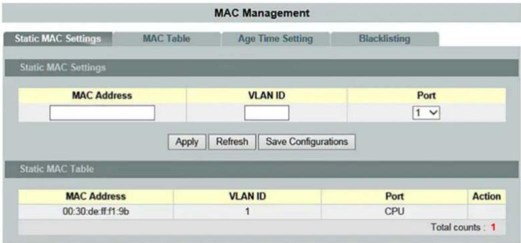
Figure 37: WBM Page, "MAC Management" – "Static MAC Settings" Tab
Table 38: WBM Page, "MAC Management" – "Static MAC Settings" Tab
| Static MAC Settings | ||
| Parameters | Default | Description |
| MAC Address | In this input field, enter the MAC address of a computer or device that you want to add to the MAC address table.The valid format is: hh:hh:hh:hh:hh:hh. | |
| VLAN ID | In this input field, enter the VLAN ID to apply to the computer or device. | |
| Port | 1 | In this selection box, select the port number to which the computer or device is connected. |
| Static MAC Table | ||
| Parameters | Default | Description |
| MAC Address | This column displays the manually entered MAC address entries. | |
| VLAN ID | This column displays the VLAN ID of the manually entered MAC address entries. | |
| Port | 1 ... 10 (12) | This column displays the port numbers of the manually entered MAC address entries.The MAC address “CPU” is the MAC address of the switch. |
| Action | Click [Delete] to delete the manually entered MAC address from the MAC address table.You cannot delete the MAC address of the switch from the static MAC address table. | |
| Total counts | This display field displays the total number of entries in the static MAC address table. | |
9.2.2.2 MAC Table
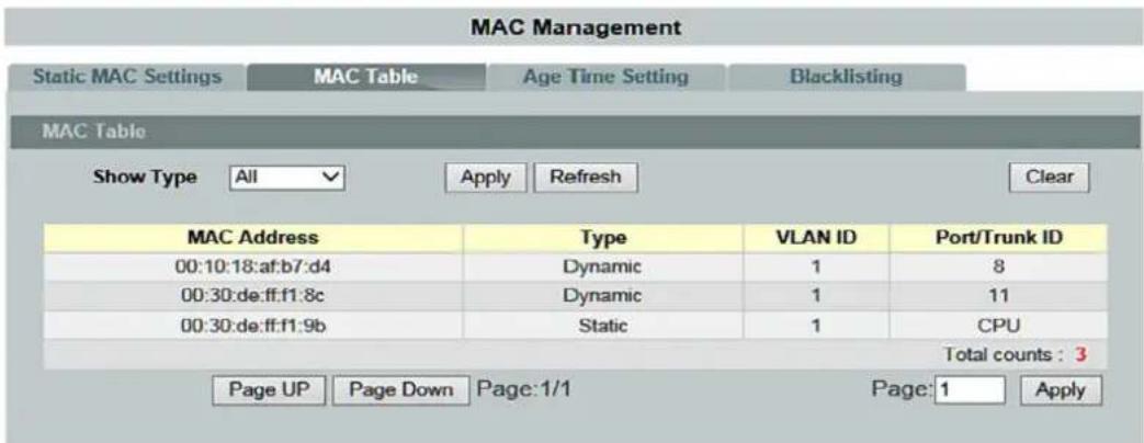
Figure 38: WBM Page, "MAC Management" – "MAC Table" Tab
Table 39: WBM Page, "MAC Management" – "MAC Table" Tab
| MAC Table | ||
| Parameters | Default | Description |
| Show Type | [All] | Select “All” to display all MAC address entries. |
| Static | Select “Static” to display the static MAC address entries. | |
| Dynamic | Select “Dynamic” to display the dynamic MAC address entries. | |
| Port | Select “Port” to display the corresponding MAC address entries. | |
| MAC | Select “MAC” to display the corresponding MAC address entries. | |
| MAC Address | This column displays the MAC addresses. | |
| Type | This column displays whether the entry was entered manually (static) or pulled by the switch (dynamic). | |
| VLAN ID | This column displays the VLAN ID of the MAC address entry. | |
| Port/Trunk ID | This column displays the port numbers to which the MAC address entry is connected. “CPU” is the MAC address entry of the switch. | |
| Total counts | This display field displays the total number of entries in the MAC address table. | |
| Page UP | This button can be used to scroll up for many MAC address entries. | |
| Page Down | This button can be used to scroll down for many MAC address entries. | |
| Page | This field displays the current page of the MAC address. | |
9.2.2.3 Age Time Setting

Figure 39: WBM Page, "MAC Management" – "Age Time Setting" Tab
Table 40: WBM Page, "MAC Management" – "Age Time Setting" Tab
| Age Time Setting | ||
| Parameters | Default | Description |
| Age Time (sec) (Range:20-400 or 0:disable) | 300 | Enter the “Age Time” in this input field. Valid range: 0 or 20 ... 400 s. |
9.2.2.4 Blacklisting

Note
Additional Information
Please refer to the section "Function Description" for more information on "Refusal MAC Settings".

Note
Maximum number of MAC blacklist entries
Up to 20 entries can be configured.

Figure 40: WBM Page, "MAC Management" – "Refusal MAC Settings" Tab
Table 41: WBM Page, "MAC Management" – "Refusal MAC Settings" Tab
| Refusal MAC Settings | ||
| Parameters | Default | Description |
| MAC Address | Enter the MAC address of a computer or device that you want to reject.The valid format is: hh:hh:hh:hh:hh:hh. | |
| VLAN ID | Any | The switch receives any VLAN ID. |
| Vlan | Enter the VLAN ID that you want to assign to the computer or device. | |
| Refusal MAC Settings | ||
| Parameters | Default | Description |
| MAC Address | This column displays the MAC addresses. | |
| VLAN ID | This field displays the VLAN ID of the MAC address entry. | |
| Action | Click [Delete], to delete a MAC address entry manually entered from the blacklist table. | |
| Total counts | This field displays the total number of entries in the blacklist table. | |
9.2.3 Port Mirroring

Note
Additional Information
Please refer to the section "Function Description" for more information on "Port Mirroring".

Note
Monitor Port
The monitor port cannot be a member of any "Truck Port" group.
The monitor port cannot be an ingress or egress port.
If a port has been configured as a source port and a user then configures it as a destination port, the port is automatically deleted from the source ports.
Port Mirroring

Figure 41: WBM "Port Mirroring" Page
Table 42: WBM "Port Mirroring" Page
| Port Mirroring Settings | ||
| Parameters | Default | Description |
| State | Disable | Select “Disable” to disable the “Port Mirroring”. |
| Enable | Select “Enable” to enable the “Port Mirroring”. | |
| Monitor to Port | 1 ... 10 (12) | Select a port to be connected to a “Network Traffic Analyzer”. |
| All Ports | - | Settings in this select box apply to all ports.Make settings here to be applied to all ports.Start here with general settings and then change the settings for individual ports. |
| Disable | ||
| Ingress | ||
| Egress | ||
| Both | ||
| Source Port | 1 ... 10 (12) | This column displays the number of individual source ports. |
| Mirror Mode | Disable | Select “Disable” to prevent traffic being copied from the specified source port to the monitor port. |
| Ingress | Select “Ingress” to only copy the input data (incoming) from the specified source ports to the monitor port. | |
| Egress | Select “Egress” to only copy the output data (outgoing) from the specified source ports to the monitor port. | |
| Both | Select “Both” to copy both incoming and outgoing data from the specified source ports to the monitor port. | |
9.2.4 Port Settings
9.2.4.1 General Settings

Figure 42: WBM Page, "Port Settings" – "General Settings" Tab
Table 43: WBM Page, "Port Settings" – "General Settings" Tab
| Port Settings | |||
| Parameters | Default | Description | |
| Port | From: | 1 | Select a port or port range that you want to configure. |
| to: | 1 | Select a port or port range that you want to configure. | |
| State | Disable | Select “Disable” to disable the port. | |
| Enable | Select “Enable” to enable the port. | ||
| Speed/Duplex | Auto | Select the speed and duplex mode of the port. | |
| 10 Mbit/s / Full Duplex | |||
| 10 Mbit/s / Half Duplex | |||
| 100 Mbit/s / Full Duplex | |||
| 100 Mbit/s / Half Duplex | |||
| 1000 Mbit/s / Full Duplex | |||
| Flow Control | Off | Select “Off” to disable access to the port's buffer resources and to interrupt operation of the switches in the network. | |
| On | Select “On” to maintain access to the port's buffer resources and to ensure lossless operation of the switches in the network. | ||
| Port State | |||
| Parameters | Default | Description | |
| Port | 1 ... 10 (12) | This column displays the port numbers. | |
| State | This column displays if the port is enabled or disabled. | ||
| Speed/Duplex | This column displays the configured speed (10 Mbit/s, 100 Mbit/s or 1000 Mbit/s) and duplex mode (full or half-duplex) for a port. | ||
| Flow Control | This column displays whether the port's “Flow Control” is set to “On” or “Off”. | ||
| Link State | This column displays the link status of a port. If the port is up, the speed, duplex mode and “Flow Control” settings are displayed. “Link Up” displays that the port is either disabled or no device is connected. | ||
9.2.4.2 Information

Figure 43: WBM Page, "Port Settings" – "Information" Tab
Table 44: WBM Page, "Port Settings" – "Information" Tab
| Port Settings | |||
| Parameters | Default | Description | |
| Port | From: | 1 | Select a port or port range that you want to display. |
| To: | 1 | Select a port or port range that you want to display. | |
| Description | Enter the name for the port in the input field. | ||
| Port Status | |||
| Parameters | Default | Description | |
| Port | 1 ... 10 (12) | This column displays the port numbers. | |
| Description | This column displays the name of the port. | ||
| Status | This column displays the status of the port. | ||
| Uptime | This column displays the operating mode of the port. | ||
| Medium Mode | CopperFiber | This column displays the connection type.Copper wireFiber optic cable | |
9.3 Advanced Settings
9.3.1 Bandwidth Settings
9.3.1.1 QoS

Note
Additional information
More information about "QoS" (Quality of Service) is available in the section "Function Description."
Figure 44: WBM "QoS" Page – "Port Priority" Tab
Table 45: WBM "QoS" Page – "Port Priority" Tab
| Port Priority Settings | ||
| Parameter | Default | Description |
| All ports have IEEE 802.1p priority. | - | In the selection box, enter the priority value for all ports.The value indicates the packet priority and is added to the “Priority Tag” field of the incoming packets. |
| 0 ... 7 | 0 = Lowest priority7 = Highest priority | |
| Port | 1 ... 10 (12) | This column shows the port numbers. |
| IEEE 802.1p Priority | 0 ... 7 | In the selection box, select a priority for packets received on this port. Only packets without “IEEE 802.1p Tag Priority” are assigned the priority specified here. |
9.3.1.1.2 IP DiffServ (DSCP)

Figure 45: WBM "QoS" Page – "IP DiffServ (DSCP)" Tab
Table 46: WBM "QoS" Page – "IP DiffServ (DSCP)" Tab
| DSCP Settings | ||
| Parameter | Default | Description |
| Mode | Tag over DSCP | In the selection box, select “Tag over DSCP” if the 802.1p tag has a higher priority than DSCP. |
| DSCP over Tag | In the selection box, select “DSCP over Tag” if the 802.1p tag has a lower priority than DSCP. | |
| DSCP | DSCP 0 ... DSCP 63 | This column displays the DSCP fields. |
| Priority | 0 ... 7 | Select the respective priority level in the selection box.0 = Lowest priority7 = Highest priority |
9.3.1.1.3 Priority/Queue Mapping

Figure 46: WBM "QoS" Page – "Priority/Queue Mapping" Tab
Table 47: WBM "QoS" Page – "Priority/Queue Mapping" Tab
| Priority/Queue Mapping Settings | ||
| Parameter | Default | Description |
| Reset to default | Click this button to reset the priority of the queue to the default values. | |
| Priority | 0 ... 7 | This column displays the respective priority level.0 = Lowest priority7 = Highest priority |
| Queue ID | 0 ... 7 | In the selection box, select the number of a queue for packets with the priority level. |
Table 48: Default Settings
| Priority | Queue ID |
| 0 | 2 |
| 1 | 0 |
| 2 | 1 |
| 3 | 3 |
| 4 | 4 |
| 5 | 5 |
| 6 | 6 |
| 7 | 7 |
9.3.1.1.4 Schedule Mode

Figure 47: WBM "QoS" Page – "Schedule Mode" Tab
Table 49: WBM "QoS" Page – "Schedule Mode" Tab
| Schedule Mode Settings | |||
| Parameter | Default | Description | |
| Schedule Mode | Strict Priority Queuing (SPQ) | In the selection box, select “Strict Priority Queuing (SPQ)” if you want to process the hardware priority queues sequentially. | |
| Weighted Round Robin (WRR) | In the selection box, select “Weighted Round Robin (WRR)” if you want to use the algorithm based on the queue weighting (the value entered in the “Weight Value (range: 1–127)” field).Processing queues with higher weighting is given precedence over processing those with lower weighting. | ||
| Queue ID | 0 ... 7 | This column indicates which queue is being configured.0 = Lowest priority7 = Highest priority | |
| Weight Value(range: 1~127) | 1 ... 127 | The “Weight Value” can only be configured if “Weighted Round Robin (WRR)” is selected.The bandwidth is divided among the different “Traffic Queues” according to their weighting.0 = Lowest priority127 = Highest priority | |
| [γx5K] | NoteChanging the “Weight Value (range: 1–127)”If you have selected “Strict Priority Queuing (SPQ),” you cannot change the “Weight Value.”You must first select “Weighted Round Robin (WRR).” You can then change “Strict Priority Queuing (SPQ).” | ||
9.3.1.2 Rate Limitation
9.3.1.2.1 Storm Control

Note
Additional information
Please refer to the section "Function Description" for more information on "Storm Control."
Rate Limitation
Storm Control
Bandwidth Limitation
Storm Control Settings
Rate Limit Mode


Storm Control Status
| Port | Rate(units) | Multicast | Broadcast | DLF | Port | Rate(units) | Multicast | Broadcast | DLF |
| 1 | 1 | Disable | Enable | Enable | 2 | 1 | Disable | Enable | Enable |
| 3 | 1 | Disable | Enable | Enable | 4 | 1 | Disable | Enable | Enable |
| 5 | 1 | Disable | Enable | Enable | 6 | 1 | Disable | Enable | Enable |
| 7 | 1 | Disable | Enable | Enable | 8 | 1 | Disable | Enable | Enable |
| 9 | 1 | Disable | Enable | Enable | 10 | 1 | Disable | Enable | Enable |
| 11 | 1 | Disable | Enable | Enable | 12 | 1 | Disable | Enable | Enable |
Figure 48: WBM "Rate Limitation" Page – "Storm Control" Tab
Table 50: WBM "Rate Limitation" Page – "Storm Control" Tab
| Storm Control Settings | |||
| Parameter | Default | Description | |
| Rate Limit Mode | ppsbps | Select the unit for band width restriction in the selection box.pps = Packets per secondbps = Bits per second | |
| Port | from: | 1 | Select a port or port range in the selection box to configure the “Storm Control Settings.” |
| to: | 1 | Select a port or port range in the selection box to configure the “Storm Control Settings.” | |
| Rate | 0 | In the selection box, choose the number of packets (of the type specified in the “Type” field) that the switch can receive per second. | |
| Type | Bcast(Broadcast) | Choose “Bcast (Broadcast)” in the selection box to specify a limiting value for the number of broadcast packets received per second. | |
| Mcast(Multicast) | Choose “Mcast (Multicast)” in the selection box to specify a limiting value for the number of multicast packets received per second. | ||
| DLF | Choose “DLF” in the selection box to specify a limiting value for the number of DLF packets received per second. | ||
| Mcast+Bcast | Choose “Mcast+Bcast” in the selection box to specify a limiting value for the number of multicast and broadcast packets received per second. | ||
| Mcast+DLF | Choose “Mcast+DLF” in the selection box to specify a limiting value for the number of multicast and DLF packets received per second. | ||
| Bcast+DLF | Choose “Bcast+DLF” in the selection box to specify a limiting value for the number of broadcast and DLF packets received per second. | ||
| Mcast+Bcast+DLF | Choose “Mcast+Bcast+DLF” in the selection box to specify a limiting value for the number of multicast, broadcast and DLF packets received per second. | ||
| Storm Control Status | |||
| Parameter | Default | Description | |
| Port | 1 ... 10 (12) | This column shows the port numbers. | |
| Rate(units) | This column displays the number of packets the switch can receive per second. | ||
| Multicast | EnableDisable | This column indicates whether the rate setting applies to multicast. | |
| Broadcast | EnableDisable | This column indicates whether the rate setting applies to broadcast. | |
| DLF | EnableDisable | This column indicates whether the rate setting applies to DLF. | |
9.3.1.2.2 Bandwidth Limitation

Note
Additional information
Please refer to the section "Function Description" for more information on "Bandwidth Limitation."
Rate Limitation
Storm Control
Bandwidth Limitation
Bandwidth Limitation Settings
| Port | Ingress | Egress | ||||
| From: | 1▼ | To: | 1▼ | 0 (Mbps) | 0 (Mbps) | |
(Disable: 0)
Apply Refresh Save Configurations
Bandwidth Limitation Status
| Port | Ingress (Mbps) | Egress (Mbps) | Port | Ingress (Mbps) | Egress (Mbps) |
| 1 | 0 | 0 | 2 | 0 | 0 |
| 3 | 0 | 0 | 4 | 0 | 0 |
| 5 | 0 | 0 | 6 | 0 | 0 |
| 7 | 0 | 0 | 8 | 0 | 0 |
| 9 | 0 | 0 | 10 | 0 | 0 |
| 11 | 0 | 0 | 12 | 0 | 0 |
Figure 49: WBM "Rate Limitation" Page – "Bandwidth Limitation" Tab
Table 51: WBM "Rate Limitation" Page – "Rate Limitation" Tab
| Bandwidth Limitation Settings | |||
| Parameter | Default | Description | |
| Port | from: | 1 | Select a port or port range in the selection box to configure the “Bandwidth Limitation Settings.” |
| to: | 1 | Select a port or port range in the selection box to configure the “Bandwidth Limitation Settings.” | |
| Ingress (Mbps) | 0 | Enter the “Bandwidth Limitation” for incoming packets in the input field. Port 1 ... 8 0 ... 100 Port 9 ... 10(12) 0 ... 1000 | |
| Egress (Mbps) | 0 | Enter the “Bandwidth Limitation” for outgoing packets in the input field. | |
| Bandwidth Limitation Status | |||
| Parameter | Default | Description | |
| Port | 1 ... 10 (12) | This column shows the port numbers. | |
| Ingress (Mbps) | This column displays the bandwidth set for Ingress. | ||
| Egress (Mbps) | This column displays the bandwidth set for Egress. | ||
9.3.2 IGMP Snooping

Note
Additional information
Please refer to the section "Function Description" for more information on "IGMP Snooping" (Internet Group Management Protocol Snooping).
9.3.2.1 IGMP Snooping
9.3.2.1.1 General Settings

Figure 50: WBM "IGMP Snooping" Page – "General Settings" Tab
Table 52: WBM "IGMP Snooping" Page – "General Settings" Tab
| IGMP Snooping Settings | ||
| Parameter | Default | Description |
| IGMP Snooping State | Disable | Select “Disable” in the selection box to disable this function. |
| Enable | Select “Enable” in the selection box to enable “IGMP Snooping” and to forward multicast group data only to ports that are members of this group. | |
| Report Suppression State | Disable | Select “Disable” to disable the “Report Suppression” function for “IGMP Snooping.” |
| Enable | Select “Enable” to enable the “Report Suppression” function for “IGMP Snooping.” | |
| IGMP Snooping VLAN State | Add | Select “Add” in the selection box and enter the VLANs on which the switch should run “IGMP Snooping.”Valid range of VLAN IDs: 1 ... 4094.Use a comma (,) or hyphen (-) to specify individual VLANs or VLAN ranges. |
| Delete | Select “Delete” in the selection box and enter the VLANs on which the switch should not run “IGMP Snooping.” | |
| Unknown Multicast Packets | In this selection box, specify the action to perform when the switch receives unknown multicast frames. | |
| Drop | Select “Drop” in the selection box to drop the frames. | |
| Flooding | Select “Flooding” in the selection box to flooding the frames to all ports. | |
| IGMP Snooping State | ||
| Parameter | Default | Description |
| IGMP Snooping State | Disable Enable | This display field indicates whether “IGMP Snooping” is enabled or disabled globally. |
| Report Suppression State | Disable Enable | This display field indicates whether the “Reporting Suppression Function” is enabled or disabled for “IGMP Snooping.” |
| IGMP Snooping VLAN State | None1 ... 4094 | This display field indicates the VLANs on which the switch runs “IGMP Snooping.”“None” is displayed if “IGMP Snooping” is not enabled for any port. |
| Unknown Multicast Packets | Drop Flooding | This display field indicates whether the switch drops unknown multicast packets or flooding them to all ports. |
9.3.2.1.2 Port Settings

Figure 51: WBM "IGMP Snooping" Page – "Port Settings" Tab
Table 53: WBM "IGMP Snooping" Page – "Port Settings" Tab
| Port Settings | |||
| Parameter | Default | Description | |
| Port | from: | 1 | Select a port or port range in the selection box to configure the “Port Settings.” |
| to: | 1 | Select a port or port range in the selection box to configure the “Port Settings.” | |
| Querier Mode | Auto | In the selection box, select the “Auto” setting if the switch should use the port as an “IGMP Query Port” if it receives “IGMP Query” packets. | |
| Fix | In this selection box, select the “Fix” setting if the switch should always use the port or ports as “IGMP Query Ports.”This setting is used if an IGMP multicast server is connected to the port(s). | ||
| Edge | In this selection box, select the “Edge” setting if the switch should not use the port as an “IGMP Query Port.” In this case, the switch does not log the information that an IGMP router is connected to this port and does not forward the “IGMP Join/Leave” packets to this port. | ||
| Immediate Leave | Disable | In this selection box, select “Disable” to disable the “Immediate Leave” function on individual ports. | |
| Enable | In this selection box, select “Enable” to enable the “Immediate Leave” function on individual ports. | ||
| Port Status | |||
| Parameter | Default | Description | |
| Port | 1 ... 10 (12) | This column shows the port numbers. | |
| Querier Mode | AutoFixEdge | This column displays the “Querier” mode for the specific port. | |
| Immediate Leave | DisableEnable | This column displays the “Immediate Leave” setting for the specific port. | |
9.3.2.1.3 Querier Settings

Figure 52: WBM "IGMP Snooping" Page – "Querier Settings" Tab
Table 54: WBM "IGMP Snooping" Page – "Querier Settings" Tab
| Querier Settings | ||
| Parameter | Default | Description |
| Querier State | Disable | Select “Disable” in the selection box to disable this function. |
| Enable | Select “Enable” in the selection box to enable this function. | |
| Querier VLAN State | Add | Select “Add” in the selection box to enter the VLAN ID. |
| Delete | Select “Delete” in the selection box to delete the VLAN ID. | |
| Querier Status | ||
| Parameter | Default | Description |
| Querier State | Disable Enable | This field displays the querier status. |
| Querier VLAN State | None 0 ... 4094 | This field displays the VLAN ID. |
9.3.2.2 IGMP Filtering
9.3.2.2.1 General Settings

Figure 53: WBM "IGMP Filtering" Page – "General Settings" Tab
Table 55: WBM "IGMP Filtering" Page – "General Settings" Tab
| IGMP Filtering Settings | ||
| Parameter | Default | Description |
| IGMP Filtering State | Disable | Select “Disable” in the selection box to disable this function. |
| Enable | Select “Enable” in the selection box to enable this function. | |
| Profile | Enter the name for the IGMP filter in the input field. | |
| Type | Deny | In the selection box, select “Deny” to deny access to the group. |
| Permit | In the selection box, select “Permit” to grant access to the group. | |
| IGMP Filtering Status | ||
| Parameter | Default | Description |
| Profile | This column displays the name of the profile.Click the name to modify the profile. | |
| Type | DenyPermit | This column displays the type of action. |
| Ports | 1 ... 10 (12) | This column displays the ports on which the profile of the IGMP filter is enabled. |
| Action | Delete | Click [Delete] to delete the multicast addresses. |
9.3.2.2.2 Multicast Groups
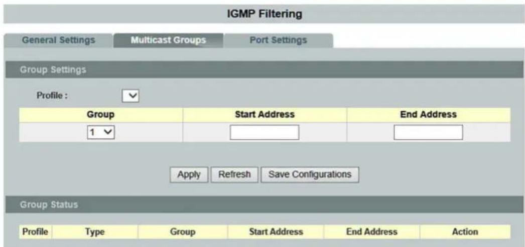
Figure 54: WBM "IGMP Filter" Page – "Multicast Groups" Tab
Table 56: WBM "IGMP Filter" Page – "Multicast Groups" Tab
| Group Settings | ||
| Parameter | Default | Description |
| Profile | Select the profile in the selection box that you want to configure for a group. | |
| Group | 1 ... 10 | Select a multicast group in the selection box. |
| Start Address | In the input field, enter the first multicast address of the group that you want to configure. | |
| End Address | In the input field, enter the last multicast address of the group that you want to configure. | |
| Group Status | ||
| Parameter | Default | Description |
| Profile | This column displays the name of the profile. | |
| Type | Deny Permit | This column displays the type of action. |
| Group | 1 ... 10 | This column displays the group. |
| Start Address | This column displays the first multicast address. | |
| End Address | This column displays the last multicast address. | |
| Action | Delete | Click [Delete] to delete the multicast addresses. |
9.3.2.2.3 Port Settings

Figure 55: WBM "IGMP Filter" Page – "Port Settings" Tab
Table 57: WBM "IGMP Filter" Page – "Port Settings" Tab
| Port Settings | ||||
| Parameter | Default | Description | ||
| Profile | Select the profile in the selection box that you want to configure for a group. | |||
| Port | Select All | ○ | ○ | No port is selected. |
| ◎ | All ports are selected. | |||
| Disable All | ○ | ○ | No port is disabled. | |
| ◎ | All ports are disabled. | |||
| □ 1 ...□ 10 (12) | □ | □ | The port is not enabled. | |
| ☑ | The port is enabled. | |||
| Port Status | ||||
| Parameter | Default | Description | ||
| Profile | This column displays the name of the profile. | |||
| Type | Deny Permit | This column displays the type of action. | ||
| Ports | 1 ... 10 (12) | This column displays the ports on which the profile of the IGMP filter is enabled. | ||
9.3.2.3 Multicast VLAN Registration

Note
Additional information
Please refer to the section "Function Description" for more information on "Multicast VLAN Registration" (MVR).
9.3.2.3.1 MVR Settings

Figure 56: WBM "Multicast VLAN" Page – "MVR Settings" Tab
Table 58: WBM "Multicast VLAN" Page – "MVR Settings" Tab
| MVR Settings | ||
| Parameter | Default | Description |
| VLAN ID | Enter the VLAN ID in the input field. | |
| Name | Enter the name for the MVR in the input field. | |
| Priority Override | Disable | Select "Disable" in the selection box to disable this function. |
| Enable | Select "Enable" in the selection box to enable this function. | |
| State | Enable | Select "Enable" in the selection box to enable the MVR. |
| Disable | Select "Disable" in the selection box to disable MVR. | |
| Mode | Dynamic | Select "Dynamic" in the selection box to configure the dynamic mode for the MVR. |
| Compatible | Select "Compatible" in the selection box to configure the compatible mode for the MVR. | |
| IEEE 802.1p Priority | 0 ... 7 | In the selection box, select a priority for packets received on this port. Only packets without an "802.1p Tag Priority" are assigned the priority specified here. |
| Source Ports | 1 ... 8 | Enter the source port or source port range for the MVR in the input field.Normally, the source ports are connected to the streaming server. |
| Receiver Ports | 1 ... 8 | Enter the receiver port or receiver port range for the MVR in the input field. Normally, the receiver ports are connected to the streaming client |
| Tagged Ports | 1 ... 8 | Enter the tagged port or port range for the MVR in the input field. The same applies to VLAN tagged ports. |
| MVR Status | ||
| Parameter | Default | Description |
| VLAN ID | This field displays the VLAN ID. | |
| Name | This field displays the name you chose. | |
| Priority Override | Disable Enable | This field displays the status. |
| State | Disable Enable | This field displays the status of the MVR. |
| Mode | Dynamic Compatible | This field displays the mode of the MVR. |
| IEEE 802.1p Priority | 0 ... 7 | This field displays the packet priority you chose. |
| Source Ports | 1 ... 8 | This field displays the source port or source port range for the MVR. |
| Receiver Ports | 1 ... 8 | This field displays the receiver port or receiver port range for the MVR. |
| Tagged Ports | 1 ... 8 | This field displays the tagged port or port range for the MVR. |
9.3.2.3.2 Group Settings

Figure 57: WBM "Multicast VLAN" Page – "Group Settings" Tab
Table 59: WBM "Multicast VLAN" Page – "Group Settings" Tab
| Group Settings | ||
| Parameter | Default | Description |
| MRV VLAN | Select the number of MVR VLANs in the selection box. | |
| Group Name | Enter the group name for the MVR in the input field. | |
| Start Address | Enter the multicast start address in the input field. | |
| Quantity | Enter the number of multicast addresses in the input field. | |
| Group Status | ||
| Parameter | Default | Description |
| MRV VLAN | This field displays the number of MVR VLANs. | |
| Group Name | This field displays the group name you chose. | |
| Address Range | This display fields shows the multicast start address. | |
| Delete | Click [Delete] to delete this setting. | |
| Delete all group | Click [Delete Entire Group] to delete the settings for the entire group. | |
9.3.2.4 Static Multicast

Note
Additional information
Please refer to the section "Function Description" for more information on "Static Multicast".
Static Multicast
Static Multicast Address Settings
| VLAN ID | MAC Address | Port |
| 1 √ |
Multicast Address Table
| VLAN ID | MAC Address | Status | Port | Action |
| 1 | 01:00:5e:22:33:44 | Static | 1-12 | Delete |
| Total counts : 1 | ||||
Figure 58: WBM "Static Multicast" Page
Table 60: WBM "Static Multicast" Page
| Static Multicast Address Settings | ||
| Parameter | Default | Description |
| VLAN ID | 1 | Select the VLAN ID in the selection box that you want to configure. |
| MAC Address | Enter the multicast MAC address of the respective ring in the input field.Configure a multicast MAC that should not receive an “Age Time.”The valid format is 0x:0x:0x:0x:0x:0x. | |
| Port | Enter the subscriber port for the multicast address in the input field. | |
| Multicast Address Table | ||
| Parameter | Default | Description |
| VLAN ID | 0 ... 4094 | This column displays the selected VLAN IDs. |
| MAC Address | This column displays the multicast addresses. | |
| Status | This column displays the status of the multicast addresses. | |
| Port | 1 ... 10 (12) | This column shows the port numbers. |
| Action | Click [Delete] to delete the multicast addresses. | |
| Number of Entries | This field displays the total number of entries in the multicast address table. | |
9.3.2.5 Multicast Statistics
Multicast Statistics
| Index | Port | Multicast Group | VID | Timeout | Explicit Tracking | Host IP |
| 1 | 1 | 0.0.0.0 | 1 | 260 | Disabled | |
| 2 | 2 | 0.0.0.0 | 1 | 260 | Disabled | |
| 3 | 3 | 0.0.0.0 | 1 | 260 | Disabled | |
| 4 | 4 | 0.0.0.0 | 1 | 260 | Disabled | |
| 5 | 5 | 0.0.0.0 | 1 | 260 | Disabled | |
| 6 | 6 | 0.0.0.0 | 1 | 260 | Disabled | |
| 7 | 7 | 0.0.0.0 | 1 | 260 | Disabled | |
| 8 | 8 | 0.0.0.0 | 1 | 260 | Disabled | |
| 9 | 9 | 0.0.0.0 | 1 | 260 | Disabled | |
| 10 | 10 | 0.0.0.0 | 1 | 260 | Disabled | |
| 11 | 11 | 0.0.0.0 | 1 | 260 | Disabled | |
| 12 | 12 | 0.0.0.0 | 1 | 260 | Disabled |
Figure 59: WBM "Multicast Statistics" Page
Table 61: WBM "Multicast Statistics" Page
| Multicast IP Table | ||
| Parameter | Default | Description |
| Index | 1 ... 10 (12) | This column displays the number of entries. |
| Port | 1 ... 10 (12) | This column displays the port number. |
| Multicast Group | This column displays the IP address of the multicast group. | |
| VLAN ID | This column displays the VLAN ID. | |
| Timeout | This column displays the timeout time. | |
| Explicit Tracking | This column indicates whether “Explicit Tracking” is set. | |
| Host IP | This column displays the host IP. | |
9.3.3 VLAN

Note
Additional information
Please refer to the section "Function Description" for more information on "VLAN" (Virtual Local Area Network).
9.3.3.1 Port Isolation

Note
Additional information
Please refer to the section "Function Description" for more information on "Port Isolation."
Port Isolation
Port Isolation Settings
Port


Egress Port :

Port Isolation Status
| Egress Port | |||||||||||||
| Port | 0 | 1 | 2 | 3 | 4 | 5 | 6 | 7 | 8 | 9 | 10 | 11 | 12 |
| 1 | V | V | V | V | V | V | V | V | V | V | V | V | V |
| 2 | V | V | V | V | V | V | V | V | V | V | V | V | V |
| 3 | V | V | V | V | V | V | V | V | V | V | V | V | V |
| 4 | V | V | V | V | V | V | V | V | V | V | V | V | V |
| 5 | V | V | V | V | V | V | V | V | V | V | V | V | V |
| 6 | V | V | V | V | V | V | V | V | V | V | V | V | V |
| 7 | V | V | V | V | V | V | V | V | V | V | V | V | V |
| 8 | V | V | V | V | V | V | V | V | V | V | V | V | V |
| 9 | V | V | V | V | V | V | V | V | V | V | V | V | V |
| 10 | V | V | V | V | V | V | V | V | V | V | V | V | V |
| 11 | V | V | V | V | V | V | V | V | V | V | V | V | V |
| 12 | V | V | V | V | V | V | V | V | V | V | V | V | V |
Figure 60: WBM "Port Isolation" Page
Table 62: WBM "Port Isolation" Page
| Port Isolation Settings | ||||
| Parameter | Default | Description | ||
| Port | from: | 1 | Select a port or port range in the selection box for which you want to configure the “Port Isolation” setting. | |
| to: | 1 | Select a port or port range in the selection box for which you want to configure the “Port Isolation” setting. | ||
| Egress Port | An egress port is an outgoing port through which a data packet leaves.Selecting a port as an egress port means it will communicate with the port currently being configured. | |||
| Select All | ○ | ○ | No egress port is selected. | |
| ◎ | All egress ports are selected. | |||
| Disable All | ○ | ○ | No egress port is disabled. | |
| ◎ | All egress ports are disabled. | |||
| □ 0(CPU) ...□ 10 (12) | □ | □ | The egress port is not enabled. | |
| ☑ | The egress port is enabled. | |||
| Port Isolation Status | ||||
| Parameter | Default | Description | ||
| Port | V | V | “V” indicates that the port’s packets can be sent to this port. | |
| Egress Port | - | “-” indicates the port’s packets cannot be sent to this port. | ||
9.3.3.2 VLAN
9.3.3.2.1 VLAN Settings

Figure 61: WBM "VLAN" Page – "VLAN Settings" Tab
Table 63: WBM "VLAN" Page – "VLAN Settings" Tab
| VLAN Settings | |||
| Parameter | Default | Description | |
| VLAN ID | from: | Enter the VLAN ID for this entry in the input field. Valid range: 1 ... 4094 | |
| to: | Enter the VLAN ID for this entry in the input field. Valid range: 1 ... 4094 | ||
| VLAN Name | Enter a descriptive name for the VLAN in the input field for unique identification.The VLAN name should be a combination of numbers, letters, hyphens (-) and underscores (_). | ||
| Member Port | In the input field, enter the port numbers you want the switch to assign to the VLAN as members. You can designate multiple individual port numbers separating individual ports with a comma (,) or specifying port ranges with a hyphen (-). | ||
| VLAN List | |||
| Parameter | Default | Description | |
| VLAN ID | 1 ... 4094 | This column displays the index number of the VLAN entry.Click the number to modify the VLAN entry. | |
| VLAN Name | This column displays the name of the VLAN. | ||
| VLAN Status | StaticDynamic802.1Q VLAN | This column displays the status of the VLAN. | |
| Member Port | 1-10 (12) | This column indicates which ports are assigned to the VLAN as subscribers. | |
| Action | Click [Delete] to delete the VLAN. | ||
 NoteDeleting VLAN1VLAN1 cannot be deleted. NoteDeleting VLAN1VLAN1 cannot be deleted. | |||
9.3.3.2.2 Tag Settings
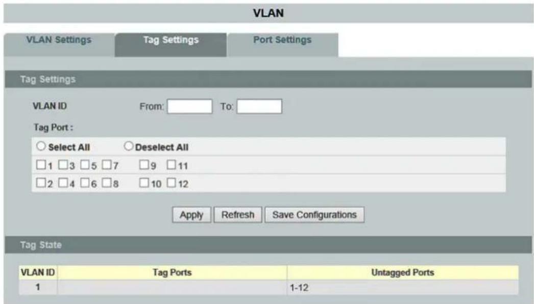
Figure 62: WBM "VLAN" Page – "Tag Settings" Tab
Table 64: WBM "VLAN" Page – "TAG Settings" Tab
| Tag Settings | ||||
| Parameter | Default | Description | ||
| VLAN ID | from: | Enter the VLAN ID for this entry in the input field. Valid range: 1 ... 4094 | ||
| to: | Enter the VLAN ID for this entry in the input field. Valid range: 1 ... 4094 | |||
| Tag Port | Select All | ○ | ○ | No port is selected as a tagged port. |
| ◎ | All ports are selected as tagged ports. | |||
| Disable All | ○ | ○ | No tagged port is disabled. | |
| ◎ | All tagged ports are disabled. | |||
| □ 1 ... □ 10 (12) | □ | □ | The port is not enabled. | |
| ☑ | The port is enabled. | |||
| Tag Status | ||||
| Parameter | Default | Description | ||
| VLAN ID | 1 ... 4094 | This column displays the VLAN ID. | ||
| Tag Ports | 1 ... 7 | This field displays the ports that have been assigned as tag ports. | ||
| Untagged Ports | 1 ... 7 | This field displays the ports that have been assigned as untagged ports. | ||
9.3.3.2.3 Port Settings

Figure 63: WBM "VLAN" Page – "Port Settings" Tab
Table 65: WBM "VLAN" Page – "Port Settings" Tab
| Port Settings | |||
| Parameter | Default | Description | |
| Port | from: | 1 | Select a port or port range in the selection box to configure the “Port Settings.” |
| to: | 1 | Select a port or port range in the selection box to configure the “Port Settings.” | |
| PVID | 1 | Select the PVID (Port VLAN ID) in the selection box. | |
| Acceptable Frame | You can specify the frame types allowed for a port in this selection box. | ||
| All | Select “All” in the selection box if all frames (tagged and untagged) should be accepted on this port. | ||
| Only Untagged VLANs | Select “Only Untagged VLANs” in the selection box if only untagged frames should be accepted on this port.All tagged frames are dropped. | ||
| Only Tagged VLANs | Select “Only Tagged VLANs” in the selection box if only tagged frames should be accepted on this port.All untagged frames are dropped. | ||
| Port Status | |||
| Parameter | Default | Description | |
| Port | 1 ... 10 (12) | This column shows the port numbers. | |
| PVID | This column displays the VLAN ID numbers. | ||
| Acceptable Frame | AllOnly Untagged VLANsOnly Tagged VLANs | This field displays the type of frames allowed on the port. | |
9.3.3.3 GARP VLAN Registration Protocol

Note
Additional information
Please refer to the section "Function Description" for more information on "GARP/GVRP" (Generic Attribute Registration Protocol/GARP VLAN Registration Protocol or Generic VLAN Registration Protocol).
9.3.3.3.1 GVRP

Figure 64: WBM "GARP VLAN Registration Protocol" Page – "GVRP" Tab
Table 66: WBM "GARP VLAN Registration Protocol" Page – "GVRP" Tab
| GVRP Settings | |||
| Parameter | Default | Description | |
| GVRP State | Disable | Select “Disable” in the selection box to disable the “GVRP” function. | |
| Enable | Select “Enable” in the selection box to enable the “GVRP” function and to exchange the VLAN configuration information with other GVRP switches. | ||
| Port | from: | 1 | Select a port or port range in the selection box to configure the GVRP settings. |
| to: | 1 | Select a port or port range in the selection box to configure the GVRP settings. | |
| State | Disable | Select “Disable” in the selection box to disable the “GVRP” function for the port. | |
| Enable | Select “Enable” in the selection box to enable the “GVRP” function for the port. | ||
| Registration Mode | Normal | Select “Normal” in the selection box to allow dynamic creation (if dynamic VLAN creation is enabled), registration and deregistration of VLANs on the trunk port. | |
| Forbidden | Select “Forbidden” in the selection box to deregister all VLANs (except VLAN 1) and to prevent any further creation or deregistration of VLANs on the “Trunk Port.” | ||
| GVRP Status | |||
| Parameter | Default | Description | |
| Port | 1 ... 10 (12) | This column shows the port numbers. | |
| State | Disable Enable | This column displays the status setting. | |
| Registration Mode | Normal Forbidden | This column displays the selected registration mode. | |
9.3.3.3.2 GARP Timer

Note
Size of the "leave," "join," "leave" and "leave all" values
The value for "leave" must be greater than three times the value for "join" (leave >= join x 3).
The value for "leave all" must be greater than the value for "leave" (leave all > leave).

Figure 65: WBM "GARP VLAN Registration Protocol" Page – "GARP Timer" Tab
Table 67: WBM "GARP VLAN Registration Protocol" Page – "GARP Timer" Tab
| GARP Timer | |||
| Parameter | Default | Description | |
| Port | from: | 1 | Select a port or port range in the selection box to configure the GARP timer. |
| to: | 1 | Select a port or port range in the selection box to configure the GARP timer. | |
| Join Time | 20 | Enter the maximum time in milliseconds that the interface waits before sending VLAN messages. | |
| Leave Time | 60 | Enter the maximum time in milliseconds that the interface waits after receiving a “Leave Message” before the interface leaves the VLAN specified in the message. | |
| Leave All Time | 1000 | Enter the time interval in milliseconds after which the Leave All messages are sent to interfaces. Leave All messages can help to update information about current GVRP VLAN subscriber information in the network. | |
| GARP Timer Status | |||
| Parameter | Default | Description | |
| Port | 1 ... 10 (12) | This column shows the port numbers. | |
| Join Time | This column displays the Join Time. | ||
| Hold Time | This column displays the Hold Time. | ||
| Leave Time | This column displays the Leave Time. | ||
| Leave All Time | This column displays the Leave All Time. | ||
9.3.3.4 IP Subnet VLAN

Note
Additional information
Please refer to the section "Function Description" for more information on "IP Subnet VLAN."
IP Subnet VLAN

Figure 66: WBM "IP Subnet VLAN" Page
Table 68: WBM "IP Subnet VLAN" Page
| IP Subnet VLAN Settings | ||
| Parameter | Default | Description |
| IP Address | Enter the IP address of the IP subnet VLAN in the input field. | |
| Subnet Mask | Enter the subnet mask of the switch in the input field in decimal-point notation. | |
| VLAN(1-4094) | Enter the value for the IP subnet VLAN for the instance in the input field.Valid range: 1 ... 4094One or more data VLANs can be configured. | |
| Priority | 0 ... 7 | Select the respective priority for the specific port in the selection box.0 = Lowest priority7 = Highest priority |
| IP Subnet VLAN Table | ||
| Parameter | Default | Description |
| Index | 1 ... 10 | This column displays the number of entries. |
| IP Address | This column displays the IP address of the IP subnet VLAN. | |
| Subnet Mask | This column shows the subnet mask of the switch. | |
| VLAN | This column displays the IP subnet VLAN ID for the specific port. | |
| Priority | 0 ... 7 | This column displays the priority for the specific port. |
| Action | Click [Delete] to delete the IP subnet VLAN addresses. | |
| Number of Entries | This field displays the total number of entries in the IP subnet VLAN table. | |
9.3.3.5 MAC VLAN

Note
Additional information
Please refer to the section "Function Description" for more information on "MAC VLAN" (Media Access Control-Virtual Local Area Network).

Figure 67: WBM "MAC VLAN" Page
Table 69: WBM "MAC VLAN" Page
| MAC VLAN Settings | ||
| Parameter | Default | Description |
| MAC Address | Enter the first three or more bytes of the MAC address in the input field. | |
| VLAN | Enter the value for the MAC VLAN for the instance in the input field. Valid range: 1 ... 4094 One or more data VLANs can be configured. | |
| Priority | 0 ... 7 | Select the respective priority for the specific port in the selection box. 0 = Lowest priority 7 = Highest priority |
| MAC VLAN Table | ||
| Parameter | Default | Description |
| Index | 1 ... 10 | This column displays the number of entries. |
| MAC Address | This column displays the MAC address. | |
| VLAN | This column displays the VLAN ID for the specific port. | |
| Priority | 0 ... 7 | This column displays the priority for the specific port. |
| Action | Click [Delete] to delete the multicast addresses. | |
9.3.3.6 Protocol VLAN
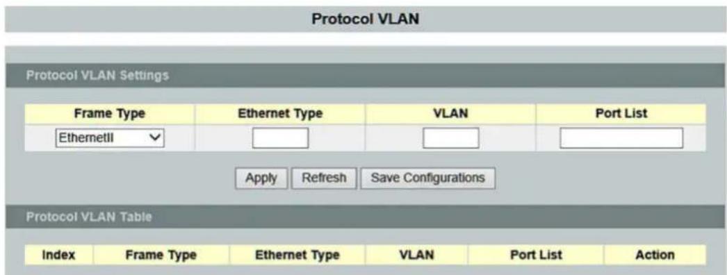
Figure 68: WBM "Protocol VLAN" Page
Table 70: WBM "Protocol VLAN" Page
| Protocol VLAN Settings | ||
| Parameter | Default | Description |
| Frame Type | ETHERNETII | Select “ETHERNETII” in the selection box if you want to configure this frame type. |
| Non-LLC SNAP | Select “Non-LLC SNAP” in the selection box if you want to configure this frame type. | |
| LLC SNAP | Select “LLC SNAP” in the selection box if you want to configure this frame type. | |
| ETHERNET Type | Enter the ETHERNET type in the input field. (e.g., 0800) | |
| VLAN(1–4094) | 1 ... 4094 | Enter the VLAN ID in the input field. Valid range: 1 ... 4094 |
| Port List | 1 ... 10 (12) | Enter the port or port group (e.g., 1–3) for the protocol VLAN in the input field. |
| Protocol VLAN Table | ||
| Parameter | Default | Description |
| Index | This column displays the number of entries. | |
| Frame Type | This column displays the frame type. | |
| ETHERNET Type | This column displays the ETHERNET type. | |
| VLAN | This column displays the VLAN ID. | |
| Port List | This column displays the port list. | |
| Action | Click [Delete] to delete the multicast addresses. | |
9.3.3.7 Q-in-Q

Note
Additional information
Please refer to the section "Function Description" for more information on "Q-in-Q."
9.3.3.7.1 VLAN Stacking

Figure 69: WBM "Q-in-Q" Page – "VLAN Stacking" Tab
Table 71: WBM "Q-in-Q" Page – "VLAN Stacking" Tab
| VLAN Stacking Settings | |||
| Parameter | Default | Description | |
| Action | Disable | Select “Disable” in the selection box to disable the “VLAN Stacking” function. | |
| Port-Based | Select “Port-Based” in the selection box for port-based execution of the “VLAN Stacking” function. | ||
| Selective | Select “Selective” in the selection box to execute the “VLAN Stacking” function selectively. | ||
| Tunnel TPID Index | 1 (Default) ... 6 | Select a table index number in the selection box. | |
| TPID(0000~ffff) | Enter a value for the TPID in the input field. Valid range: 0000 ... ffff | ||
| Port | from: | 1 | Select a port or port range in the selection box to configure the “VLAN Stacking.” |
| to: | 1 | Select a port or port range in the selection box to configure the “VLAN Stacking.” | |
| Tunnel TPID Index | 1 (Default) ... 6 | Select a “Tunnel TPID Index” in the selection box. | |
| VLAN Stacking Status | |||
| Parameter | Default | Description | |
| Tunnel TPID Index | 1 ... 6 | This column displays the table index number. | |
| TPID | 0000 ... ffff | This column displays the TPID. | |
| Port | 1 ... 10 (12) | This column displays the port number. | |
| Tunnel TPID Index(TPID) | This column displays the index number for the specific port. | ||
9.3.3.7.2 Port-Based Q-in-Q

Figure 70: WBM "Q-in-Q" Page – "Port-Based Q-in-Q" Tab
Table 72: WBM "Q-in-Q" Page – "Port-Based Q-in-Q" Tab
| Port-Based Q-in-Q | |||
| Parameter | Default | Description | |
| Port | from: | 1 | Select a port or port range in the selection box to configure the “Q-in-Q.” |
| to: | 1 | Select a port or port range in the selection box to configure the “Q-in-Q.” | |
| Role | Normal | Select “Normal” in the selection box to select this role for the specific port. | |
| Access | Select “Access” in the selection box to select this role for the specific port. | ||
| Tunnel | Select “Tunnel” in the selection box to select this role for the specific port. | ||
| SPVID(1-4094) | 1 | Enter the service provider VLAN “SPVID” in the input field. Valid range: 1 ... 4094 | |
| Priority | 0 ... 7 | Select the respective priority for the specific port in the selection box. 0 = Lowest priority 7 = Highest priority | |
| Port-Based Q-in-Q Status | |||
| Parameter | Default | Description | |
| Port | 1 ... 10 (12) | This column displays the port number. | |
| Role | This column displays the role of the specific port. | ||
| SPVID | This column displays the SPVID. | ||
| Priority | This column displays the priority for the specific port. | ||
9.3.3.7.3 Selective Q-in-Q
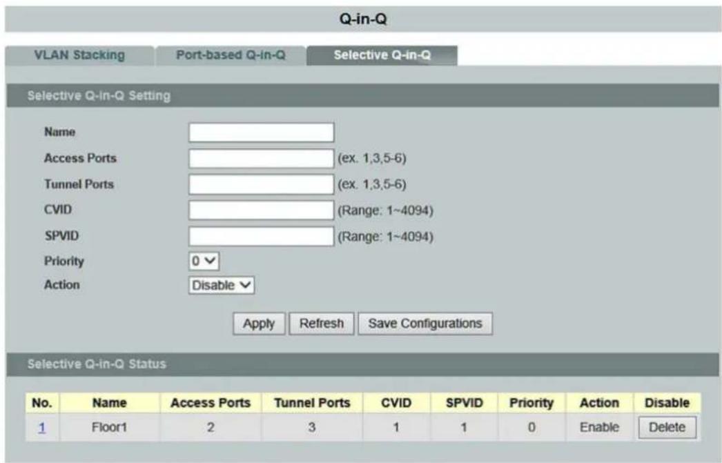
Figure 71: WBM "Q-in-Q" Page – "Selective Q-in-Q" Tab
Table 73: WBM "Q-in-Q" Page – "Selective Q-in-Q" Tab
| Selective Q-in-Q Settings | ||
| Parameter | Default | Description |
| Name | Enter the name for the selective Q-in-Q profile in the input field. | |
| Access Ports (ex. 1, 3, 5-6) | Enter the access port or access port range in the input field. | |
| Tunnel Ports (ex. 1, 3, 5-6) | Enter the tunnel port or tunnel port range in the input field. | |
| CVID (Range: 1~4094) | Enter a customer VLAN “CVID” in the input field. Valid range: 1 ... 4094 | |
| SPVID (Range: 1~4094) | Enter a service provider VLAN “SPVID” in the input field. Valid range: 1 ... 4094 | |
| Priority | 0 ... 7 | Select the respective priority level in the selection box.0 = Lowest priority7 = Highest priority |
| Action | Disable | Select “Disable” in the selection box to disable this function. |
| Enable | Select “Enable” in the selection box to enable this function. | |
| Selective Q-in-Q Status | ||
| Parameter | Default | Description |
| No. | This column displays the index number. | |
| Name | This column displays the name of the selective Q-in-Q profile. | |
| Access Ports | This column displays the access port. | |
| Tunnel Ports | This column displays the tunnel port. | |
| CVID | This column displays the customer VLAN “CVID.” | |
| SPVID | This column displays the service provider VLAN “SPVID.” | |
| Priority | 0 ... 7 | This column displays the respective priority level.0 = Lowest priority7 = Highest priority |
| Action | Disable Enable | This column displays the selected action. |
| Delete | Click [Delete] to delete the selective Q-in-Q settings. | |
9.3.4 DHCP Relay

Note
Additional information
Please refer to the section "Function Description" for more information on "DHCP Relay" (Dynamic Host Configuration Protocol Relay).

Figure 72: WBM "DHCP Relay" Page
Table 74: WBM "DHCP Relay" Page
| DHCP Relay Settings | ||
| Parameter | Default | Description |
| State | Disable | Select “Disable” in the selection box to disable “DHCP Relay.” |
| Enable | Select “Enable” in the selection box to enable “DHCP Relay.” | |
| VLAN State | Add | Select “Add” in the selection box and enter the VLANs on which the switch should run “DHCP Relay.”Valid range of VLAN IDs: 1 ... 4094.Use a comma (,) or hyphen (-) to specify individual VLANs or VLAN ranges. |
| Delete | Select “Delete” in the selection box and enter the VLANs on which the switch should not run “DHCP Relay.” | |
| DHCP Server IP | 0.0.0.0 | Enter the IP address of the DHCP server in the input field. |
| DHCP Relay Status | ||
| Parameter | Default | Description |
| DHCP Relay State | Disable Enable | This display field indicates whether “DHCP Relay” is enabled or disabled. |
| Enabled on VLAN | None0 ... 4094 | This field indicates whether a VLAN is used. |
| DHCP Server IP | This field displays the IP address of the DHCP server. | |
9.3.5 DHCP Options

Note
Additional information
Please refer to the section "Function Description" for more information on "DHCP Options".
DHCP Options
DHCP Option 82 Settings
Option 82 State
Enable
Option 82 Frame
1
Option 82 Shelf
0
Option 82 Slot
0
Circuit-ID Form
%HOSTNAME+%SPACE+eth/+%FRAME+/+%SHELF+/+%SLOT+:+%PORT+
Remote-ID Form
%HOSTNAME+%SPACE+eth/+%FRAME+/+%SHELF+/+%SLOT++%PORT+
Option 82 Command State
Port
1
Option 82 State
Enable ▼
Circuit-ID String
Remote-ID String
Apply
Refresh
Save Configurations
Option 82 Command State

Figure 73: WBM "DHCP Options" Page
Table 75: WBM "DHCP Options" Page
| DHCP Option 82 Settings | ||
| Parameter | Default | Description |
| Option 82 State | Disable | Select “Disable” in the selection box to disable “DHCP Option 82” on the switch. |
| Enable | Select “Enable” in the selection box to enable “DHCP Option 82” on the switch. | |
| Option 82 Frame | 1 | Enter the desired frame number in the input field. |
| Option 82 Shelf | 0 | Enter the desired shelf number in the input field to uniquely identify the switch. |
| Option 82 Slot | 0 | Enter the desired slot number in the input field to uniquely identify the switch. |
| Circuit ID Form | %HOSTNAME+%SPACE+eth/+%FRAME+/+%SHELF+/+%SLOT+:+%PORT+_%SVLAN+:+%CVLAN | This input field gives you the option of adapting the appended string. |
| Remote ID Form | %HOSTNAME+%SPACE+eth/+%FRAME+/+%SHELF+/+%SLOT+:+%PORT+_%SVLAN+:+%CVLAN | This input field gives you the option of adapting the appended string. |
| Option 82 Command State | ||
| Parameter | Default | Description |
| Port | 1 ... 10 (12) | Select a port in the selection box. |
| Option 82 State | Disable | Select “Disable” in the selection box to disable “Option 82 Command State” on the switch. |
| Enable | Select “Enable” in the selection box to enable “Option 82 Command State” on the switch. | |
| Circuit ID String | Enter “Circuit ID String” in the input field. | |
| Remote ID String | Enter “Remote ID String” in the input field. | |
| Option 82 Command State | ||
| Parameter | Default | Description |
| Port | 1 ... 10 (12) | This field displays the port numbers. |
| Option 82 Status | This field displays the “Option 82 Status.” | |
| Circuit ID String | This field displays the “Circuit ID String.” | |
| Remote ID String | This field displays the “Remote ID String.” | |
9.3.6 DHCP Server

Note
Additional information
Please refer to the section "Function Description" for more information on "DHCP Server".
9.3.6.1 General Settings

Figure 74: WBM "DHCP Server" Page – "General Settings" Tab
Table 76: WBM "DHCP Server" Page – "General Settings" Tab
| General Settings | ||
| Parameter | Default | Description |
| State | Enable | Select “Enable” in the selection box to enable “DHCP Server” on the switch. |
| Disable | Select “Disable” in the selection box to disable “DHCP Server” on the switch. | |
| Offer Reuse Timeout (Range: 1~120) | In this input field, enter the maximum time period after which the offered IP address can be returned to the pool of free IP addresses. Valid range: 1 ... 120 | |
| Next Server Address | 0.0.0.0 | In this input field, enter the IP address of the next server. |
| Boot File Name | In this input field, enter the name of the boot file used to identify the boot image. | |
| Echo ICMP Mode | Enable | Select “Enable” in the selection box to enable the “Echo IP Mode” function.Before the server can offer a specific IP address to a client, an ICMP request is generated to ensure that the address that should be offered is not used by any of the network hosts. |
| Disable | Select “Disable” in the selection box to disable the “Echo ICMP Mode” function. | |
| Globale Option | In this selection box, the global options and their format are configured.Global options are only available to DHCP clients when no host-specific or pool-specific options are available. | |
| None | Select “None” in the selection box if no global option should be selected. | |
| Add | Select “Add” in the selection box to add a global option. | |
| Remove | Select “Remove” in the selection box to to delete a global option. | |
| Ascii | When “Add” or “Remove” are selected, the global options can be entered in ASCII code or deleted in this input field. | |
| IP | When “Add” or “Remove” are selected, the IP addresses of the global options can be entered or deleted in this input field. | |
| Global Option-Status | ||
| Parameter | Default | Description |
| Option | This column displays the table index number. | |
| Option Value | This column displays the TPID. | |
9.3.6.2 Pool Settings

Figure 75: WBM "DHCP Server" Page – "Pool Settings" Tab
Table 77: WBM "DHCP Server" Page – "Pool Settings" Tab
| Pool Settings | ||
| Parameter | Default | Description |
| Pool ID(1~8) | In this input field, enter the pool ID(valid range: 1 ... 8). | |
| State | Disable | Select “Disable” in the selection box to disable the pool settings. |
| Enable | Select “Enable” in the selection box to enable the pool settings. | |
| Host IP Address | In this input field, enter the host ID address that is sent as source IP address when packets are sent. | |
| Network | In this input field, enter the network address. | |
| VLAN | This selection box is used to select the VLAN. | |
| None | Select “None” in the selection box if no VLAN should be entered. | |
| Add | Select “Add” in the selection box to add a VLAN. | |
| Remove | Select “Remove” in the selection box to to delete a VLAN. | |
| Lease Time(minutes) | Time | Select “Time” in the selection box to enter a time period in which the client can use the IP address assigned by the server. |
| Infinite | Select “Infinite” in the selection box to select an unlimited time period. | |
| Default Router | This selection box is used to select the default router. | |
| None | Select “None” in the selection box if no default router should be selected. | |
| Add | Select “Add” in the selection box to add a default router. | |
| Remove | Select “Remove” in the selection box to to delete a default router. | |
| Excluded IP Address | This selection box is used to the excluded IP addresses. | |
| None | Select “None” in the selection box if no default router should be selected. | |
| Add | Select “Add” in the selection box to add a default router. | |
| Remove | Select “Remove” in the selection box to to delete a default router. | |
| Domain Name | In this input field, enter the domain name. | |
| DNS-Server | This selection box is used to select the DNS server. | |
| None | This selection box is used to select the DNS server. | |
| Add | Select “None” in the selection box if no DNS server should be selected. | |
| Remove | Select “Add” in the selection box to add a DNS server. | |
Table 77: WBM "DHCP Server" Page – "Pool Settings" Tab
| NetBIOS Node Typ | None | Select “None” in the selection box if no NetBIOS node type should be selected. |
| B-Node | Select “B-Node” in the selection box to select this NetBIOS node type. | |
| H-Node | Select “H-Node” in the selection box to select this NetBIOS node type. | |
| M-Node | Select “M-Node” in the selection box to select this NetBIOS node type. | |
| P-Node | Select “P-Node” in the selection box to select this NetBIOS node type. | |
| Remove Node | Select “Remove Node” in the selection box to select the NetBIOS node type. | |
| NetBIOS Server | This selection box is used to select the NetBIOS server. | |
| None | Select “None” in the selection box if no NetBIOS server should be selected. | |
| Add | Select “Add” in the selection box to add a NetBIOS server. | |
| Remove | Select “Remove” in the selection box to to delete a NetBIOS server. | |
| Option(0~255) | In this selection box, the options and their format are configured(valid range: 0 ... 255). | |
| Keine | Select “None” in the selection box if no option should be selected. | |
| Hinzufügen | Select “Add” in the selection box to add an option. | |
| Entfernen | Select “Remove” in the selection box to to delete an option. | |
| Ascii | When “Add” or “Remove” are selected, the options can be entered in ASCII code or deleted in this input field. | |
| IP | When “Add” or “Remove” are selected, the IP addresses of the options can be entered or deleted in this input field. | |
| Host Optionxx:xx:xx:xx:xx(0~255) | In this selection box, the host options and their format are configured(valid range: 0 ... 255). | |
| None | Select “None” in the selection box if no option should be selected. | |
| Add | Select “Add” in the selection box to add an option. | |
| Remove | Select “Remove” in the selection box to to delete an option. | |
| Ascii | When “Add” or “Remove” are selected, the options can be entered in ASCII code or deleted in this input field. | |
| IP | When “Add” or “Remove” are selected, the IP addresses of the options can be entered or deleted in this input field. |
Table 77: WBM "DHCP Server" Page – "Pool Settings" Tab
| Pool Status | ||
| Parameter | Default | Description |
| Show Pool | All1 ... 8 | Select the corresponding pool in the selection box. |
| Pool ID | This field displays the pool ID. | |
| Pool Status | This field displays whether the pool is enabled or disabled. | |
| Subnet | This field displays the subnet. | |
| Subnet Mask | This field displays the subnet mask. | |
| Start IP Address | This field displays the start IP address. | |
| End IP Address | This field displays the end IP address. | |
| Host IP Address | This field displays the host IP address. | |
| Lease Time(minutes) | This field displays the lease duration in minutes. | |
| VLAN | This field displays the VLAN. | |
| Excluded IP Address | This field displays the accepted IP address. | |
9.3.6.3 Binding Information
![graph TD A["DHCP Server"] --> B["General Settings"] A --> C["Pool Settings"] A --> D["Binding Information"] A --> E["Statistics"] F["Binding Information"] --> G["IP Address"] F --> H["MAC Address"] F --> I["State"] F --> J["Lease Expire Timer"] K["Refresh"] --> L["End"]](/content/2026/05/1008228/images/f8a9ed7874b84ed6623516b244b11b667b3d8825acd0f9f8db8bcb799e605801.jpg)
Figure 76: WBM "DHCP Server" Page – "Binding Information" Tab
Table 78: WBM "DHCP Server" Page – "Binding Information" Tab
| Binding Information | ||
| Parameter | Default | Description |
| IP Address | This column displays the IP address. | |
| MAC –Address | This column displays the MAC address. | |
| State | This column displays the status. | |
| Lease Expire Timer | This column displays the lease expiration timer. | |
9.3.6.4 Statistics

Figure 77: WBM "DHCP Server" Page – "Statistics" Tab
Table 79: WBM "DHCP Server" Page – "Statistics" Tab
| Received Message Packets | ||
| Parameter | Default | Description |
| DHCP Discover | This column displays the “DHCP Discover.” | |
| DHCP Request | This column displays the “DHCP Request.” | |
| DHCP Decline | This column displays the “DHCP Decline.” | |
| DHCP Release | This column displays the “DHCP Inform.” | |
| Sent Message Packets | ||
| Parameter | Default | Description |
| DHCP Offer | This column displays the “DHCP Offer.” | |
| DHCP Ack | This column displays the “DHCP Ack.” | |
| DHCP Nack | This column displays the “DHCP Nack.” | |
9.3.7 Dual Homing

Note
Additional information
Please refer to the section "Function Description" for more information on "Dual Homing."
Dual Homing
Dual Homing Settings
State
Enable ▼
Group ID
1
Group State
Disable ▼
Primary Channel
Add
Port
1
Secondary Channel
Add
Port
2
Apply
Refresh
Save Configurations
Dual Homing Status
| Group ID | 1 |
| Group State | Disable |
| Primary Channel | Port 1 |
| Secondary Channel | Port 2 |
| Group ID | 2 |
| Group State | Disable |
| Primary Channel | None |
| Secondary Channel | None |
| Group ID | 3 |
| Group State | Disable |
| Primary Channel | None |
| Secondary Channel | None |
| Group ID | 4 |
| Group State | Disable |
| Primary Channel | None |
| Secondary Channel | None |
Figure 78: WBM "Dual Homing" Page
Table 80: WBM "Dual Homing" Page
| Dual Homing Settings | ||
| Parameter | Default | Description |
| State | Disable | Select “Disable” in the selection box to disable “Dual Homing”. |
| Enable | Select “Enable” in the selection box to enable “Dual Homing”. | |
| Group ID | 1 ... 4 | Select a Dual Homing group that you want to view. |
| Group State | Disable | Select “Disable” in the selection box to disable this function. |
| Enable | Select “Enable” in the selection box to enable this function. | |
| Primary Channel | Add | Select “Add” in the selection box to add a primary channel. |
| Reset | Select “Reset” in the selection box to reset the primary channel. | |
| Port | The primary channel is configured in this field. Select “Port” in the selection box to configure only a single port. | |
| Trunk | The secondary channel is configured in this field. Select “Trunk” in the selection box to configure only a single “Trunk Group.” | |
| Enter the number of the primary channel in the input field. | ||
| Secondary Channel | Add | Select “Add” in the selection box to add a secondary channel. |
| Reset | Select “Reset” in the selection box to reset the secondary channel. | |
| Port | The secondary channel is configured in this field. Select “Port” in the selection box to configure only a single port. | |
| Trunk | The secondary channel is configured in this field. Select “Trunk” in the selection box to configure only a single “Trunk Group.” | |
| Enter the number of the secondary channel in the input field. | ||
Dual Homing Status
| Parameter | Default | Description |
| Group ID | 1 ... 4 | This field displays the Dual Homing group ID. |
| Group Status | Disable Enable | This field indicates what status “Dual Homing” has. |
| Primary Channel | None Port 1 ... 10 (12) | This field displays the selected primary channel. |
| Secondary Channel | None Port 1 ... 10 (12) | This field displays the selected secondary channel. |
9.3.8 Dual Ring

Note
Additional information
Please refer to the section "Function Description" for more information on "Dual Ring."
Dual Ring
Dual Ring Settings
State
Disable

Xpress Ring Role
Forward

Xpress Ring PORT-1
None

Xpress Ring PORT-2
None

Xpress Ring Destination MAC (Last byte)
10

Subring PORT-1
None

Subring PORT-2
None

Apply
Refresh
Save Configurations
Dual Ring Status
Xpress Ring PORT-1 State
No connection
Xpress Ring PORT-2 State
No connection
Subring PORT-1 State
No connection
Subring PORT-2 State
No connection
Subring Bridge Role
Disabled
Subring Master Bridge MAC
00:00:00:00:00:00
Figure 79: WBM "Dual Ring" Page
Table 81: WBM "Dual Ring" Page
| Dual Ring Settings | ||
| Parameter | Default | Description |
| State | Disable | Select “Disable” in the selection box to disable “Dual Ring.” |
| Enable | Select “Enable” to enable “Dual Ring.” | |
| Xpress Ring Role | Forwarding | Select “Forwarding” in the selection box if the switch should operate in the Xpress Ring as a forwarder. |
| Arbiter | Select “Arbiter” in the selection box if the switch should operate in the Xpress Ring as an arbiter. | |
| Xpress Ring PORT 1 | None | Select “None” in the selection box if you do not want to select a port. |
| 1 ... 10 (12) | Select Port 1 in the Xpress ring in the selection box. | |
| Xpress Ring PORT 2 | None | Select “None” in the selection box if you do not want to select a port. |
| 1 ... 10 (12) | Select Port 2 in the Xpress ring in the selection box. | |
| Xpress Ring Destination MAC Address (Last Byte) | f0 | Enter the Xpress ring ID in the input field. |
| Subring PORT 1 | None | Select “None” in the selection box if you do not want to select a port. |
| 1 ... 10 (12) | Select Port 1 in the jet ring in the selection box. | |
| Subring PORT 2 | None | Select “None” in the selection box if you do not want to select a port. |
| 1 ... 10 (12) | Select Port 2 in the jet ring in the selection box. | |
| Dual Ring Status | ||
| Parameter | Default | Description |
| Xpress Ring PORT 1 Status | Forwarding Blocking | This field indicates what status Xpress ring port 1 has. |
| Xpress Ring PORT 2 Status | Forwarding Blocking | This field indicates what status Xpress ring port 2 has. |
| Subring PORT 1 Status | Forwarding Blocking | This field indicates what status Jet Ring Port 1 has. |
| Subring PORT 2 Status | Forwarding Blocking | This field indicates what status jet ring port 2 has. |
| Subring Bridge Role | Forwarder Master | This field displays the role of the switch in the Xpress ring. |
| Subring Master Bridge MAC | This field displays the MAC ID of the jet ring. | |
9.3.9 ERPS

Note
Additional information
Please refer to the section "Function Description" for more information on "ERPS" (ETHERNET Ring Protection Switching).
9.3.9.1 Ring Settings

Figure 80: WBM "ERPS" Page – "Ring Settings" Tab
Table 82: WBM "ERPS" Page – "Ring Settings" Tab
| ERPS Global Settings | ||
| Parameter | Default | Description |
| Global State | Disable | Select “Disable” in the selection box to disable the “ERPS” function. |
| Enable | Select “Enable” in the selection box to enable the “ERPS” function. | |
| ERPS Ring Settings | ||
| Parameter | Default | Description |
| Ring ID(1~255) | Enter the ring ID in the input field. Valid range: 1 ... 255 | |
| State | Disable | Select “Disable” in the selection box to disable the state of the ring. |
| Enable | Select “Enable” in the selection box to enable the state of the ring. | |
| Ring Name | Enter the name of the ring (max. 32 characters) in the input field.(e.g., Major Ring ID255) | |
| Revertive | Enable | Select “Enable” to enable revertive mode. |
| Disable | Select “Disable” in the selection box to disable revertive mode. | |
| Instance(0:Disable, 0~30) | Enter the instance for the ring in the input field. Valid range: 0 ... 300 (“Disable”) means that the ERPS is running in version 1. The control VLAN of the instance should be the same as the control VLAN below it. | |
| Ring Type | Major Ring | Select “Major Ring” in the selection box if the switch should operate in the major ring. |
| Subring | Select “Subring” in the selection box if the switch should operate in the subring. | |
| Control VLAN(1~4094) | 1 ... 4094 | Enter the VLAN ID in the input field that should serve as the domain for the ERPS control packets. Valid range: 1 ... 4094 |
| Version | v2 | Select “v2” in the selection box if you want to use Version 2 of the “ERPS” function. |
| v1 | Select “v1” in the selection box if you want to use Version 1 of the “ERPS” function. | |
| Holdoff Timer (ms)(0~10000) | 0 | Enter the value for the “Holdoff Timer” for the ring in the input field.Time: 0 ... 10000 ms. |
| WTR Timer (min)(5~720) | 300 | Enter the value for the “WTR Timer” for the ring in the input field.Time: 5 ... 720 min |
| MEL(0~7) | 7 | Enter the value for the “Control MEL” (Maintenance Entity Group Level) for the ring in the input field.The MEL specifies the priority.0 = Lowest priority7 = Highest priority |
Table 82: WBM "ERPS" Page – "Ring Settings" Tab
| Guard Timer (ms)(10~2000) | 500 | Enter the value for the “Guard Timer” for the ring in this input field.Time: 10 ... 2000 ms. |
| Left Port | The selection box is used to configure the left port and its type for the ring. | |
| None | Select “None” in the selection box if you do not want to select a port. | |
| 1 ... 10 (12) | Select the corresponding port in the selection box. | |
| Normal | Select “Normal” in the selection box if the port is not assigned any specific function in the ERPS ring. | |
| Neighbor | Select “Neighbor” in the selection box if the neighboring port has the “Neighbor” function. | |
| Owner | Select “Owner” in the selection box if the port should take on the “Owner” function in the ERPS ring. | |
| Right Port | This selection box is used to configure the right port and its type for the ring. | |
| None | Select “None” in the selection box if you do not want to select a port. | |
| 1 ... 10 (12) | Select the corresponding port in the selection box. | |
| Normal | Select “Normal” in the selection box if the port is not assigned any specific function in the ERPS ring. | |
| Neighbor | Select “Neighbor” in the selection box if he neighboring port has the “Neighbor” function. | |
| Owner | Select “Owner” in the selection box if the port should take on the “Owner” function in the ERPS ring. | |
| Left Port Enhance Mode | Disable | Select “Disable” in the selection box if a device that supports ERPS is connected to this port. |
| Enable | Select “Enable” in the selection box if a device that does not support ERPS is connected to this port.Please note the Aging Time of the connected device. | |
| Right Port Enhance Mode | Disable | Select “Disable” in the selection box if a device that supports ERPS is connected to this port. |
| Enable | Select “Enable” in the selection box if a device that does not support ERPS is connected to this port.Please note the Aging Time of the connected device. | |
| Alarm Relay | Disable | Select “Disable” in the selection box to disable the alarm relay. |
| Enable | Select “Enable” in the selection box to enable the alarm relay. |
Table 82: WBM "ERPS" Page – "Ring Settings" Tab
| ERPS Ring Status | ||
| Parameter | Default | Description |
| Ring ID | 1 ... 255 | This field displays the ring ID. |
| State | Disable Enable | This field displays the ring status. |
| Ring Name | This field displays the ring name. | |
| Revertive | Enable Disable | This field displays the status of the revertive mode. |
| Instance | This field displays the instance for the ring. | |
| Ring Type | Major Ring Subring | This field displays the ring type. |
| Control VLAN | 1 ... 4084 | This field displays the VLAN of the controller. |
| Version | v2 v1 | This field displays the version of the “ERPS” function. |
| Holdoff Timer (ms) | 0 ... 10000 | This field displays the time for the “Holdoff Timer.” |
| WTR Timer (min) | 5 ... 12 | This field displays the time for the “WTR Timer.” |
| MEL | 0 ... 7 | This field displays the value for the “Control MEL.” |
| Guard Timer (ms) | 10 ...2000 | This field displays the time for the “Guard Timer.” |
| Left Port | None 1 ... 10 (12) | This field displays the port number of the left port. |
| Right Port | None 1 ... 10 (12) | This field displays the port number of the right port. |
| Left Port Type | Normal Neighbor Owner | This field displays the type of the left port. |
| Right Port Type | Normal Neighbor Owner | This field displays the type of the right port. |
| Left Port Enhance Mode | Enable Disable | This field displays the status of the left port. |
| Right Port Enhance Mode | Enable Disable | This field displays the status of the right port. |
| Left Port Status | Forwarding Blocking | This field displays the current status of the left port. |
| Right Port Status | Forwarding Blocking | This field displays the current status of the right port. |
| Ring Status | Protection Idle | This field displays the ring status. |
| Alarm Relay | Enable Disable | This field displays the status of the alarm relay. |
| Delete | Click [Delete] to delete this setting. | |
9.3.9.2 Instance Settings
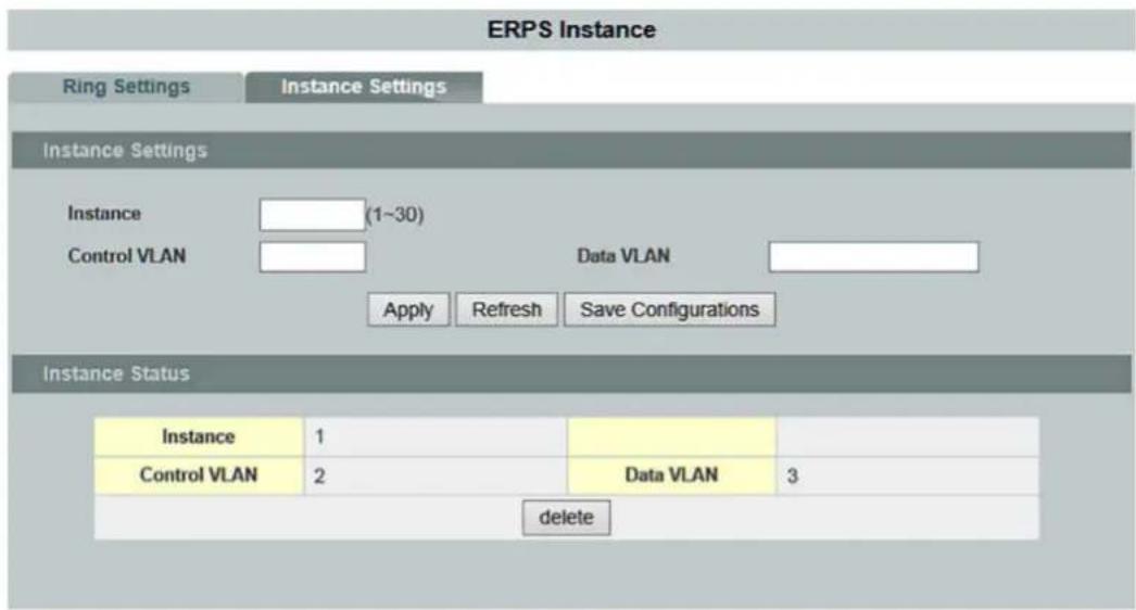
Figure 81: WBM "ERPS" Page – "Instance Settings" Tab
Table 83: WBM "ERPS" Page – "Instance Settings" Tab
| Instance Settings | ||
| Parameter | Default | Description |
| Instance(1~30) | Enter the instance ID in the input field. Valid range: 1 ... 30 | |
| Control VLAN | Enter the VLAN of the controller for the instance in the input field. Valid range: 1 ... 4094 | |
| Data VLAN | Enter the value for the data VLAN for the instance in the input field. Valid range: 1 ... 4094 One or more data VLANs can be configured. | |
| Instance Status | ||
| Parameter | Default | Description |
| Instance | 1 ... 31 | This field displays the instance ID. |
| Control VLAN | 1 ... 4094 | This field displays the controller VLAN of the instance. |
| Data VLAN | 1 ... 4094 | This field displays the data VLAN of the instance. |
| Delete | Click [Delete] to delete this setting. | |
9.3.10 Link Aggregation

Note
Additional information
Please refer to the section "Function Description" for more information on "Link Aggregation".
9.3.10.1 Static Trunk

Figure 82: WBM "Link Aggregation" Page – "Static Trunk" Tab
Table 84: WBM "Link Aggregation" Page – "Static Trunk" Tab
| Static Trunk Settings | ||||
| Parameter | Default | Description | ||
| Group State | Group 1 ... Group 6 | Select a group ID for the “Trunk Group” (a logical link containing multiple ports) in the selection box. | ||
| Disable | Select “Disable” in the selection box to disable a static “Trunk Group.” | |||
| Enable | Select “Enable” in the selection box to use a static “Trunk Group.” | |||
| Load Balance | MAC | Select “MAC” in the selection box to configure the algorithm for load balancing of a specific “Trunk Group.” | ||
| IP | Select “IP” in the selection box to configure the algorithm for load balancing of a specific “Trunk Group.” | |||
| Member Ports | Select All | ○ | ○ | No port is selected to be added to the static “Trunk Group.” |
| ◎ | All ports are selected to be added to the status “Trunk Group.” | |||
| Disable All | ○ | ○ | No port is disabled. | |
| ◎ | All ports are disabled. | |||
| □ 1 ... □ 10 | □ | □ | The port is not enabled. | |
| ☑ | The port is enabled. | |||
| Trunk Group Status | ||||
| Parameter | Default | Description | ||
| Group ID | 1 ... 6 | This column displays the group ID for a “Trunk Group” (a logical link containing multiple ports). | ||
| State | Disable Enable | This column indicates whether a “Trunk Group” is enabled or disabled. | ||
| Load Balance | 1 ... 6 | This column displays the policy for load balancing of the “Trunk Group.” | ||
| Member Ports | This column displays the ports assigned to the “Trunk Group.” | |||
9.3.10.2 LACP

Note
Additional information
Please refer to the section "Function Description" for more information on "LACP" (Link Aggregation Control Protocol).

Figure 83: WBM "Link Aggregation" Page – "LACP" Tab
Table 85: WBM "Link Aggregation" Page – "LACP" Tab
| LACP Settings | |||
| Parameter | Default | Description | |
| State | Disable | Select “Disable” in the selection box if you do not want to use the “Link Aggregation Control Protocol” (LACP). | |
| Enable | Select “Enable” in the selection box to enable the “Link Aggregation Control Protocol” (LACP). | ||
| System Priority | 1 ... 65535 | Select the LACP system priority in the selection box. Enter a number to set the priority of an active port with “Link Aggregation Control Protocol” (LACP). The smaller the number, the higher the priority level. | |
| Group LACP | Group 1 ... Group 6 | Select a “Trunk Group ID” in the selection box. | |
| Disable | Select “Disable” in the selection box to disable LACP for this “Trunk Group ID.” | ||
| Enable | Select “Enable” in the selection box to enable LACP for this “Trunk Group.” | ||
| Port Priority | from: | - | Select a port or a range of ports in the selection box for which you want to configure the LACP priority. |
| to: | - | Select a port or a range of ports in the selection box for which you want to configure the LACP priority. | |
| 32768 | The default system priority is 32768. | ||
| LACP Group Status | |||
| Parameter | Default | Description | |
| Group ID | 1 ... 6 | This column displays the LACP group ID. | |
| LACP State | Enable Disable | This column indicates whether LACP is enabled or disabled for a group. | |
| LACP Port Priority Status | |||
| Parameter | Default | Description | |
| Port | 1 ... 10 (12) | This column displays the port ID. | |
| Priority | 1 ... 65535 | This column displays the LACP priority of the port. | |
9.3.10.3 LACP Info.

Figure 84: WBM "Link Aggregation" Page – "LACP Info." Tab
Table 86: WBM "Link Aggregation" Page – "LACP Info." Tab
| LACP Information | ||
| Parameter | Default | Description |
| Group ID | - | Select an LACP group that you want to view. |
| Neighbor Information | ||
| Parameter | Default | Description |
| Port | 1 ... 10 (12) | This column displays the LACP ID of the subscriber port. |
| System Priority | 0 ... 65535 | This column displays the LACP system priority. |
| System ID | This column displays the system ID of the neighboring switch. | |
| Port | 1 ... 10 (12) | This column displays the ID of the directly connected port of the neighboring switch. |
| Age | This column displays the available time period for the LACP information of the neighboring switch. | |
| Port State | This column displays the status of the directly connected port on the neighboring switch. | |
| Port Priority | This column displays the priority of the directly connected port on the neighboring switch. | |
| Oper Key | This column displays the “Oper Key” of the neighboring switch. | |
| Internal Information | ||
| Parameter | Default | Description |
| Port | This column displays the LACP ID of the subscriber port. | |
| Port Priority | The port priority of the LACP member port. | |
| Admin Key | This column displays the “Admin Key” of the LACP member port. | |
| Oper Key | This column displays the “Oper Key” of the LACP member port. | |
| Port Status | This column displays the port status of the LACP member port. | |
9.3.11 LLDP

Note
Additional information
Please refer to the section "Function Description" for more information on "LLDP" (Link Layer Discovery Protocol).
9.3.11.1 Settings

Figure 85: WBM "LLDP" Page – "LLDP Settings" Tab
Table 87: WBM "LLDP" Page – "LLDP Settings" Tab
| LLDP Settings | |||
| Parameter | Default | Description | |
| State | Disable | Select “Disable” in the selection box to disable the LLDP function for the switch globally. | |
| Enable | Select “Enable” in the selection box to enable the LLDP function for the switch globally. | ||
| TX Interval | 30 | Enter the value for the “TX Interval” (transmission interval) for the LLDP packets in the input field. | |
| TX Hold | 4 | Enter the value for the “TX Hold Time” in the input field that determines the TTL of the switch’s message.(TTL = tx-hold * tx-interval) | |
| Time to Live | 120 | This field displays the lifetime for the switch’s information. | |
| Port | from: | 1 | Select a port or port range in the selection box for which you want to configure the “LLDP” setting. |
| to: | 1 | Select a port or port range in the selection box for which you want to configure the “LLDP” setting. | |
| Status | Enable | In this selection box, select “Enable” to enable the LLDP function on individual ports. | |
| Rx Only | Select the “Rx Only” setting in the selection box if “Rx Interval” is always used as the transmission interval for the switch or ports. | ||
| Tx Only | Select the “Tx Only” setting in the selection box if “Tx Interval” is always used as the transmission interval for the switch or ports. | ||
| Disable | In this selection box, select “Disable” to disable the “LLDP” function on individual ports. | ||
| LLDP Status | |||
| Parameter | Default | Description | |
| Port | 1 ... 10 | This column shows the port numbers. | |
| Status | Disable Enable | This column indicates whether “LLDP” is enabled or disabled. | |
9.3.11.2 Neighboring Detection

Figure 86: WBM "LLDP" Page – "Neighboring Detection" Tab
Table 88: WBM "LLDP" Page – "Neighboring Detection" Tab
| LLDP Neighbor Information | ||
| Parameter | Default | Description |
| Port | All | Select “All” in the selection box if you want to display information from all neighboring ports. |
| 1 ... 10 (12) | Select the port in the selection box for whose neighbor port you want to display information. | |
| Local Port | 1 ... 10 (12) | This field displays the port numbers. |
| Remote Port ID | This field displays the ID of the connected port. | |
| Chassis ID | This field displays the neighbor port's chassis ID. | |
| System Name | This field displays the neighbor port's system name. | |
| System Description | This field displays the neighbor port's system description. | |
| System Capabilities | This field displays the system capabilities of the neighbor port. | |
| Management IP | This field displays the neighbor port's management address. | |
| Time to Live | This field displays the validity period of the information of the neighbor port. | |
9.3.12 Loop Detection

Note
Additional information
Please refer to the section "Function Description" for more information on "Loop Detection."
Loop Detection
Loop Detection Settings
State
Disable
MAC Address
00:0b:04:aa:aa:ab

Loop Detection Status
| Port | State | Status | Recovery State | Recovery Time (min) |
| 1 | Disabled | Normal | Enabled | 1 |
| 2 | Disabled | Normal | Enabled | 1 |
| 3 | Disabled | Normal | Enabled | 1 |
| 4 | Disabled | Normal | Enabled | 1 |
| 5 | Disabled | Normal | Enabled | 1 |
| 6 | Disabled | Normal | Enabled | 1 |
| 7 | Disabled | Normal | Enabled | 1 |
| 8 | Disabled | Normal | Enabled | 1 |
| 9 | Disabled | Normal | Enabled | 1 |
| 10 | Disabled | Normal | Enabled | 1 |
| 11 | Disabled | Normal | Enabled | 1 |
| 12 | Disabled | Normal | Enabled | 1 |
Figure 87: WBM "Loop Detection" Page
Table 89: WBM "Loop Detection" Page
| Loop Detection Settings | |||
| Parameter | Default | Description | |
| State | Disable | Select “Disable” in the selection box to disable this function. | |
| Enable | Select “Enable” in the selection box to enable this function. | ||
| MAC Address | Enter the destination MAC address in the input field to which the probe packets should be sent. If the port receives the same packets, it is shut down. | ||
| Port | from: | 1 | Select a port or port range in the selection box for which you want to configure the “Loop Guard Protection” settings. |
| to: | 1 | Select a port or port range in the selection box for which you want to configure the “Loop Guard Protection” settings. | |
| State | Disable | Select “Disable” in the selection box to disable the “Loop Guard” function for the switch. | |
| Enable | Select “Enable” in the selection box to enable the “Loop Guard” function for the switch. | ||
| Action | None | Select “None” in the selection box if you want to disable loop detection on the port. | |
| Activate | Select “Activate” in the selection box if you do not want to change the “Status” and “Loop Correction” functions. | ||
| Loop Recovery | Enable | Select “Enable” in the selection box to automatically re-enable the port after the designated “Recovery Time” has elapsed. | |
| Disable | Select “Disable” in the selection box to disable this function. | ||
| Recovery Time (min) (Range: 1~60) | 1 | In the input field, enter the value for the “Recovery Time” (in minutes) that the switch waits before re-enabling the port.Time: 1 ... 60 min | |
| Loop Detection Status | |||
| Parameter | Default | Description | |
| Port | 1 ... 10 (12) | This column shows the port numbers. | |
| State | Enable Disable | This column indicates whether the “Loop Guard” function is enabled or disabled. | |
| Status | None Normal | This column indicates whether a port is blocked. | |
| Loop Recovery | Enable Disable | This column indicates whether the “Loop Recovery” function is enabled or disabled. | |
| Recovery Time (min) | 1 ... 50 | This column displays the “Recovery Time” for the “Loop Recovery” function. | |
9.3.13 Jet Ring

Note
Additional information
Please refer to the section "Function Description" for more information on "Jet Ring".
Jet Ring
Jet Ring Setting
State
Enable
Master Bridge MAC
00:30 DE FF DD 16
Jet Ring Total Nodes
1
Bridge Role
Learning
Apply
Refresh
Jet Ring Status
| Port | Port Status | Ring Port |
| 1 | Forwarding | |
| 2 | No connection | |
| 3 | No connection | |
| 4 | No connection | |
| 5 | No connection | |
| 6 | No connection | |
| 7 | Forwarding | |
| 8 | No connection | |
| 9 | No connection | |
| 10 | No connection |
Figure 88: WBM "Jet Ring" Page
Table 90: WBM "Jet Ring" Page
| Jet Ring Settings | ||
| Parameter | Default | Description |
| State | Disable | In this selection box, select “Disable” to disable the “Jet Ring” function on individual ports. |
| Enable | In this selection box, select “Enable” to enable the “Jet Ring” function on individual ports. | |
| Alarm Relay | Disable | Select “Disable” in the selection box to disable the alarm relay. |
| Enable | Select “Enable” in the selection box to enable the alarm relay. | |
| Master Bridge MAC | This field displays the IP address of the jet ring master. | |
| Jet Ring Total Nodes | This field displays the number of nodes in the jet ring. | |
| Bridge Role | This field displays the function of the switch in the jet ring. | |
| Jet Ring Status | ||
| Parameter | Default | Description |
| Port | 1 ... 10 (12) | This column shows the port numbers. |
| Port Status | No Connection Forwarding Blocking | This column displays the port status. |
| Ring Port | Yes | This column indicates whether the port operates in a ring. |
9.3.14 Modbus

Figure 89: WBM "Modbus" Page
Table 91: WBM "Modbus" Page
| Modbus Settings | ||
| Parameter | Default | Description |
| State | Disable | In this selection box, select “Disable” to disable the “Modbus” function on individual ports. |
| Enable | In this selection box, select “Enable” to enable the “Modbus” function on individual ports. | |

Note
Modbus Tables
The table „Modbus Tables“ can be found in section „Appendix > „Modbus Tables“.
9.3.15 PoE

Note
Additional information
Please refer to the section "Function Description" for more information on "Power over Ethernet" (PoE).
9.3.15.1 Configuration
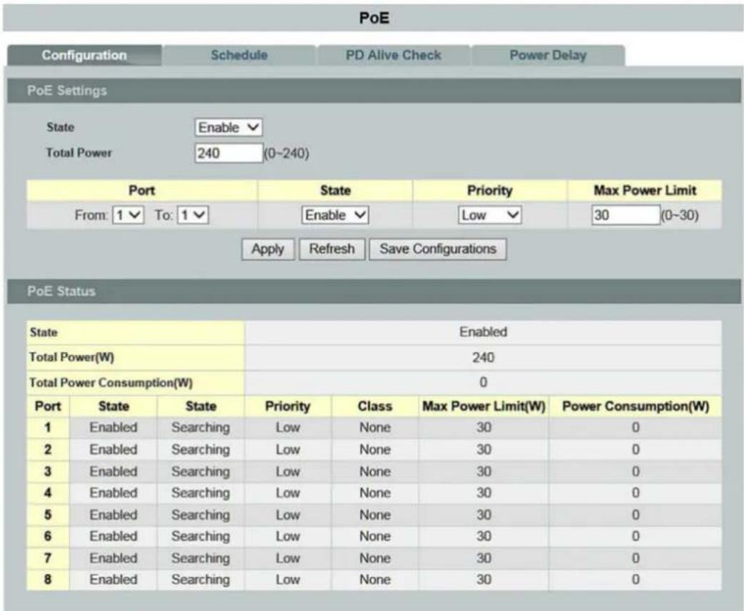
Figure 90: WBM "PoE" Page – "Configuration" Tab
Table 92: WBM "PoE" Page – "Configuration" Tab
| PoE Settings | |||
| Parameter | Default | Description | |
| State | Enable | Select “Enable” in the selection box to enable the “PoE” function. | |
| Disable | Select “Disable” in the selection box to disable the “PoE” function. | ||
| Total Power (0-240)) | 240 | Enter the total power of the switch in the input field. | |
| Port | from: | 1 | Select a port or port range in the selection box for which you want to configure the “PoE” setting. |
| to: | 1 | Select a port or port range in the selection box for which you want to configure the “PoE” setting. | |
| State | Enable | In this selection box, select “Enable” to enable the “PoE” function on individual ports. | |
| Disable | In this selection box, select “Disable” to disable the “PoE” function on individual ports. | ||
| Priority | LowHighCritical | Select the PoE priority for the selected port or range of ports in the selection box. | |
| Max. Power Limit (0-30) | 30 | Enter the power limit for the selected port in the input field. | |
| PoE Status | |||
| Parameter | Default | Description | |
| State | EnableDisable | This field displays the status of the “PoE” function. | |
| Total Power (W) | 0 ... 240 | This field displays the total power that the switch supports. | |
| Total Power Consumption (W) | 0 ... 240 | This field displays the total power consumption of all PD (“Powered Device”) subscribers. | |
| Port | 1 ... 8 | This field displays the port number. | |
| State | EnableDisable | This field displays the “PoE” state for the specific port. | |
| Status | This field displays the status of the “PoE” function. | ||
| Priority | LowHighCritical | This field displays the “PoE” priority for the specific port. | |
| Class | The field displays the class mode for the specific port which the PSE (“Power Sourcing Equipment”) device has negotiated with the “PD” (“Powered Device”) subscriber. | ||
| Max. Power Limit (W) | 0 ... 30 | This field displays the power limit for the specific port. | |
| Power Consumption (W) | 0 ... 240 | This field displays the power consumption for the specific port. | |
9.3.15.2 Schedule

Figure 91: WBM "PoE" Page – "Schedule" Tab
Table 93: WBM "PoE" Page – "Schedule" Tab
| Schedule Settings | |||
| Parameter | Default | Description | |
| Port | 1 ... 8 | In this selection box, select a port for which you want to configure the “PoE” schedule function. | |
| All | Select “All” in the selection box if you want to configure the “PoE” schedule function for all ports. | ||
| State | Disable | Select “Disable” in the selection box to disable the “PoE” schedule function. | |
| Enable | Select “Disable” in the selection box to enable the “PoE” schedule function. | ||
| Week | MondayTuesdayWednesdayThursdayFridaySaturdaySunday | In this selection box, select the day of the week for which you want to configure the schedule. | |
| All | Select “All” in the selection box if you want to configure the schedule for all days of the week. | ||
| Check | Yes | Select “Yes” in the selection box to check the “PoE” schedule on the specific port for a defined time period. | |
| No | Select “Yes” in the selection box in order not to check the “PoE” schedule on the specific port for a defined time period. | ||
| Action | Enable | Select “Enable” in the selection box to enable the “PoE” schedule on the specific port for a defined time period. | |
| Disable | Select “Yes” in the selection box to disable the “PoE” schedule on the specific port for a defined time period. | ||
| Time (Hour) | from: | 0 ... 24 | In the selection box, select a start time (hour) of the “PoE” schedule on a specific day of the week for the specific port. |
| to: | 0 ... 24 | In the selection box, select an end time (hour) of the “PoE” schedule on a specific day of the week for the specific port. | |
Table 93: WBM "PoE" Page – "Schedule" Tab
| PoE Status | ||
| Parameter | Default | Description |
| Port | 1 ... 8All | This field displays the port number. |
| State | EnableDisable | This field displays the status of the “PoE” schedule function. |
| Current Time | This field displays the current time. | |
| Week | MondayTuesdayWednesdayThursdayFridaySaturdaySunday | This column displays the specific day of the week. |
| Check | YesNo | This column displays the status of the check of the “PoE” schedule. |
| Action | EnableDisable | This column displays the status of the “PoE” schedule for the defined time period and the specific port. |
| Start Time (Hour) | 0 ... 24 | This column displays the start time of the “PoE” schedule on a specific day of the week for the specific port. |
| End Time (hour) | This column displays the end time of the “PoE” schedule on a specific day of the week for the specific port. | |
9.3.15.3 PD Alive Check
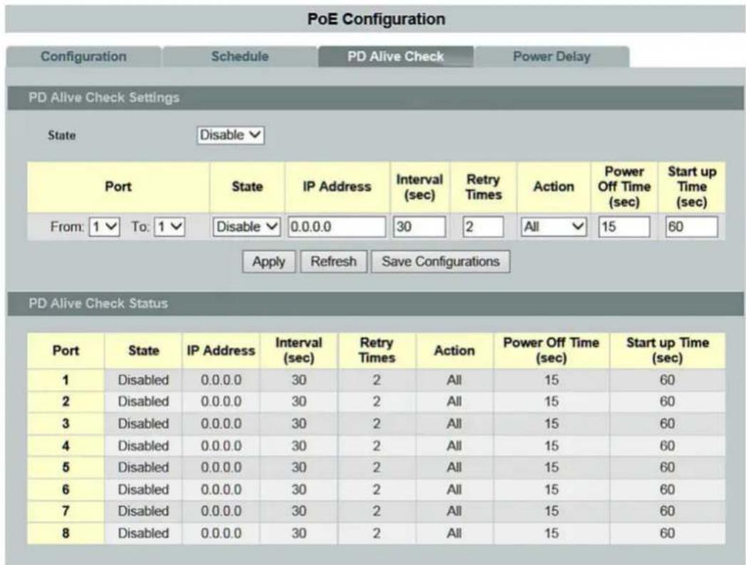
Figure 92: WBM "PoE" Page – "PD Alive Check" Tab
Table 94: WBM "PoE" Page – "PD Alive Check" Tab
| PD Alive Check Settings | |||
| Parameter | Default | Description | |
| State | Disable | Select “Disable” in the selection box to disable the “PD Alive Check” function. | |
| Enable | Select “Enable” in the selection box to enable the “PD Alive Check” function. | ||
| Port | from: | 1 | Select a port or port range in the selection box for which you want to configure the “PD Alive Check” setting. |
| to: | 1 | Select a port or port range in the selection box for which you want to configure the “PD Alive Check” setting. | |
| Status | Disable | In this selection box, select “Disable” to disable the “PD Alive Check” function on individual ports. | |
| Enable | In this selection box, select “Enable” to disable the “PD Alive Check” function on individual ports. | ||
| IP Address | In the input field, enter the host IP address to which the port connects. | ||
| Interval (sec) | 30 | In the input field, enter the interval for sending the packet probes to check if the host is still alive. | |
| Retry Time | 2 | In the input field, enter the number of retries for sending packet probes to check whether the host is still alive. A precondition for this is that the host does not respond. | |
| Action | All | In the selection box, select “All” in order to send an alarm message to the administrator and reboot the PD (“Powered Device”) subscriber. | |
| None | In the selection box, select “None” if the PD (“Powered Device”) subscriber constantly pings without executing further actions. | ||
| Restart | In the selection box, select “Restart” in order to disconnect the PoE port from the power supply and reboot the PD (“Powered Device”) subscriber. | ||
| Alarm | In the selection box, select “Alarm” in order to send an alarm message to the administrator. | ||
| Power-off Time (sec) | 15 | In the input field, enter the amount of time after which the PoE port should be reconnected to the power supply after a restart of the PD (“Powered Device”) subscriber. | |
| Startup Time (sec) | 15 | In the input field, enter the amount of time that the switch should wait after a restart of the PD (“Powered Device”) subscriber before performing the automatic PoE check. | |
Table 94: WBM "PoE" Page – "PD Alive Check" Tab
| PD Alive Check Status | ||
| Parameter | Default | Description |
| Port | 1 ... 8 | This column displays the port number. |
| State | Enable Disable | This column displays the PD Alive Check" status for the specific port. |
| IP Address | This column displays the host IP address of the specific port. | |
| Interval (sec) | 10 ... 120 | This column displays the interval at which check messages are sent to the PD ("Powered Device") subscriber. |
| Retry Time | This column displays the number of retries for sending packet probes to check whether the host is still alive if the host for the specific port has not responded to a packet. | |
| Action | All None Restart Alarm | This column displays the selected action. |
| Power-off Time (sec) | 3 ... 120 | This column displays the "Power-off Time." |
| Startup Time (sec) | 30 ... 600 | This column displays the "Startup Time." |
9.3.15.4 Power Delay (Switch-on Delay)

Figure 93: WBM "PoE" Page – "Power Delay" Tab
Table 95: WBM "PoE" Page – "Power Delay" Tab
| Power Delay Settings | |||
| Parameter | Default | Description | |
| Port | from: | 1 | Select a port or port range in the selection box for which you want to configure the “Power Delay” setting. |
| to: | 1 | Select a port or port range in the selection box for which you want to configure the “Power Delay” setting. | |
| State | Disable | In this selection box, select “Power Delay” to disable the “PoE” function on individual ports. | |
| Enable | In this selection box, select “Enable” to disable the “PoE” function on individual ports. | ||
| Time (sec) | In the input field, enter the time delay for the specific ports. | ||
| Power Delay Status | |||
| Parameter | Default | Description | |
| Port | 1 ... 8 | This column displays the port number. | |
| State | Enable Disable | This column displays the “PoE” power delay state for the port. | |
| Time (sec) | This column displays the time for the “PoE” power delay. | ||

Note
Power delay value
The high priority port should be given a low value for the power delay.
9.3.16 Static Route

Note
Additional information
Please refer to the section "Function Description" for more information on "Static Route".
Static Route
Global Settings
IP Forwarding
Disable
IP ARP Proxy
Enable
IPv4 ARP Table
Add
IP:
The Ground Truth image displays a single, solid horizontal line. According to Rule 2 (UNDERSCORE & LINE RULES), this is a stylistic or background line, not a placeholder underscore. Therefore, the OCR result must ignore it and output nothing or only meaningful text. The provided OCR content is "____", which consists of four underscores. This is an incorrect interpretation of the line as a placeholder, violating the rule that stylistic lines must be ignored. The OCR has hallucinated placeholder underscores where none exist in the GT, violating the rule to ignore such lines. Hence, the OCR result is inconsistent with the Ground Truth.
MAC:
The Ground Truth image displays a single, solid horizontal line. According to Rule 2 (UNDERSCORE & LINE RULES), this is a stylistic or background line, not a placeholder underscore. Therefore, the OCR result must ignore it and output nothing or only meaningful text. The provided OCR content is "____", which consists of four underscores. This is an incorrect interpretation of the line as a placeholder, violating the rule that stylistic lines must be ignored. The OCR has hallucinated underscores where none should exist in the GT, violating the rule to ignore such lines. Hence, the OCR result is inconsistent with the Ground Truth.
IPv6 ARP Table
Add
IP:
The Ground Truth image displays a single, solid horizontal line. According to Rule 2 (UNDERSCORE & LINE RULES), if the GT contains lines used for stylistic emphasis or as background elements (like ruled paper), the OCR result must ignore them. The provided OCR content is "____", which consists of four underscores. This is incorrect because underscores are not equivalent to a solid line and are not permitted under the “Stylistic/Background Lines (Ignore)” rule. The OCR has hallucinated underscores where none should exist in the GT, violating the rule to ignore stylistic lines. Therefore, the OCR result is inconsistent with the Ground Truth.
MAC:
The Ground Truth image displays a single, solid horizontal line. According to Rule 2 (UNDERSCORE & LINE RULES), this is a stylistic or background line, not a placeholder underscore. Therefore, the OCR result must ignore it and output nothing or only meaningful text. The provided OCR content is "____", which consists of four underscores. This is an incorrect interpretation of the line as a placeholder, violating the rule that stylistic lines must be ignored. The OCR has hallucinated underscores where none should exist based on the GT's visual context. Hence, the OCR result is inconsistent with the Ground Truth.
Route Settings
VLAN:

IPv4
Add
Interface Route ▼
IP/M:
The Ground Truth image displays a single, solid horizontal line. According to Rule 2 (UNDERSCORE & LINE RULES), this is a stylistic or background line, not a placeholder underscore. Therefore, the OCR result must ignore it and output nothing or only meaningful text. The provided OCR content is "____", which consists of four underscores. This is an incorrect interpretation of the line as a placeholder, violating the rule that stylistic lines must be ignored. The OCR has hallucinated underscores where none should exist in the GT, violating the rule to ignore such lines. Hence, the OCR result is inconsistent with the Ground Truth.
IP:
1
IPv6
Add
Interface Route
IP/M:
The image contains no text or characters. The horizontal line is a stylistic or background element and must be ignored according to the rules.
IP:
Apply
Refresh
Save Configurations
Status
Type:
ARP
All
Show
Figure 94: WBM "Static Route" Page
Table 96: WBM "Static Route" Page
| Global Settings | |||
| Parameter | Default | Description | |
| IP Forwarding | Disable | Select "Disable" in the selection box to disable this function. | |
| Enable | Select "Enable" in the selection box to enable this function. | ||
| IP ARP Proxy | Disable | Select "Enable" in the selection box to globally disable the route as the ARP proxy. | |
| Enable | Select "Disable" in the selection box to globally enable the route as the ARP proxy. | ||
| IPv4 ARP Table | Add | Select "Add" in the selection box to add a static IPv4 ARP entry to the ARP table. | |
| Delete | Select "Remove" in the selection box to delete a static IPv4 ARP entry from the ARP table. | ||
| IPv6 ARP Table | Add | Select "add" in the selection box to add a static IPv6 ARP entry to the ARP table. | |
| Delete | Select "Remove" in the selection box to delete a static IPv6 ARP entry from the ARP table. | ||
| Route Settings | |||
| Parameter | Default | Description | |
| VLAN | Enter a specific interface VLAN in this input field. | ||
| IPv4 | Add | Select "Add" in the selection box to add a route to the VLAN interface. In the adjacent selection box, select the route type (interface or static route). | |
| IPv6 | |||
| Delete | Select "Remove" in the selection box to to delete a route. In the adjacent selection box, select the route type (interface or static route). | ||
| IP/M | In this input field, enter the IP address and network mask. | ||
| IP | In this input field, enter the static route address for the static route type. | ||
| Status | |||
| Parameter | Default | Description | |
| Type | ARP | All | Display the ARP table / host table / route configurations. |
| IPv4 | |||
| IPv6 | |||
| Host | All | ||
| IPv4 | |||
| IPv6 | |||
| Route | All | ||
| IPv4 | |||
| IPv6 | |||
9.3.17 Spanning Tree Protocol

Note
Additional information
Please refer to the section "Function Description" for more information on "Spanning Tree Protocol" (STP).
9.3.17.1 General Settings
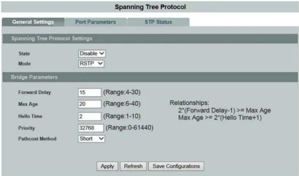
Figure 95: WBM "Spanning Tree Protocol" Page – "General Settings" Tab
Table 97: WBM "Spanning Tree Protocol" Page – "General Settings" Tab
| Spanning Tree Protocol Settings | ||
| Parameter | Default | Description |
| State | Disable | Select “Disable” in the selection box to disable this function. |
| Enable | Select “Enable” in the selection box to use the “Spanning Tree Protocol” (STP) or “Rapid Spanning Tree Protocol” (RSTP). | |
| Mode | RSTP | Select “RSTP” in the selection box if you want to use the faster “Rapid Spanning Tree Protocol.” |
| MSTP | Select “MSTP” in the selection box if you want to use the “Multiple Spanning Tree Protocol.” | |
| STP | Select “STP” in the selection box if you want to use the “Spanning Tree Protocol.” | |
| Bridge Parameters | ||
| Parameter | Default | Description |
| Forward Delay(Range: 4~30) | 15 | Enter the “Forward Delay” time in the input field. Valid range: 4 ... 30 s |
| Max Age(Range: 6~40) | 20 | Enter the “Max Age” time in the input field. Valid range: 6 ... 40 s |
| Hello Time(Range: 1~10) | 2 | Enter the “Hello Time” in the input field. Valid range: 1 ... 10 s |
| Priority(Range: 0~61440) | 32768 | Enter a value for the priority in the input field. The lower the numerical value you assign, the higher the priority of this bridge is. Valid range: 0 ... 61440 |
| Pathcost Method | Short | Select “Short” in the selection box if you want to select a size of 16 bits and a transmission rate of up to 10 GBit.10 MBit = 100100 MBit = 191 GBit = 410 GBit = 2 |
| Long | Select “Long” in the selection box if you want to select a size of 32 bits and a transmission rate of up to 10 TBit.10 MBit = 2000000100 MBit = 2000001 GBit = 2000010 GBit = 2000100 GBit = 2001 TBit = 20 | |
9.3.17.2 Port Parameters
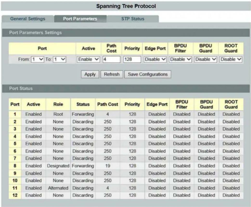
Figure 96: WBM "Spanning Tree Protocol" Page – "Port Parameters" Tab
Table 98: WBM "Spanning Tree Protocol" Page – "Port Parameters" Tab
| Port Parameter Settings | |||
| Parameter | Default | Description | |
| Port | From: | 1 | Select a port or port range in the selection box to configure the “STP Function.” |
| To: | 1 | Select a port or port range in the selection box to configure the “STP Function.” | |
| Active | Enable | Select “Enable” in the selection box if you want to enable the “STP” function for the specific port. | |
| Disable | Select “Disable” in the selection box if you want to disable the STP function for the specific port. | ||
| Path Costs | 250 | Enter the value for the path costs for the specific port in the input field. | |
| Priority | 128 | Enter the value for the priority for the specific port in the input field. | |
| Edge Port | Disable | Select “Disable” in the selection box to disable the “Edge Port” port type for the specific port. | |
| Enable | Select “Enable” in the selection box to enable the “Edge Port” port type for the specific port. | ||
| BPDU Filter | Disable | Select “Disable” in the selection box to disable the BPDU filter function for the specific port. | |
| Enable | Select “Enable” in the selection box to enable the BPDU filter function for the specific port. | ||
| BPDU Guard | Disable | Select “Disable” in the selection box to disable the “BPDU Guard” function for the specific port. | |
| Enable | Select “Enable” in the selection box to enable the “BPDU Guard” function for the specific port. | ||
| ROOT Guard | Disable | Select “Disable” in the selection box to disable the “ROOT Guard” function for the specific port. | |
| Enable | Select “Enable” in the selection box to enable the “ROOT Guard” function for the specific port. | ||
Table 98: WBM "Spanning Tree Protocol" Page – "Port Parameters" Tab
| Port Status | ||
| Parameter | Default | Description |
| Port | 1 ... 10 (12) | This column shows the port numbers. |
| Active | EnableDisable | This column displays the status of the “STP” function. |
| Role | Alternated Designated Root Backup None | This column displays the role of the port. |
| Status | Discarding Blocking Listening Learning Forwarding Disabled | This column displays the port status. |
| Path Costs | 0 ... 65535 | This column displays the path cost of the port. |
| Priority | 0 ... 61440 | This column displays the port priority. |
| Edge Port | Disable Enable | This column displays the status of the “Edge Port” function. |
| BPDU Filter | Disable Enable | This column displays the status of the BPDU filter function. |
| BPDU Guard | Disable Enable | This column displays the status of the “BPDU Guard” function. |
| ROOT Guard | Disable Enable | This column displays the status of the “Root Guard” function. |
9.3.17.3 STP Status

Figure 97: WBM "Spanning Tree Protocol" Page – "STP Status" Tab
Table 99: WBM "STP" Page – "STP Status" Tab
| Current Root Status | ||
| Parameter | Default | Description |
| MAC Address | This field displays the MAC address of the “Root Bridge.” | |
| Priority | This field displays the priority of the “Root Bridge.” This switch can also be the “Root Bridge.” | |
| Max Age | This field displays the “Max Age” of the “Root Bridge.” | |
| Hello Time | This field displays the “Hello Time” of the “Root Bridge.”The “Root Bridge” determines the “Hello Time,” “Max Age and “Forwarding Delay.” | |
| Forward Delay | This field displays the maximum time (in seconds) that the root switch waits before changing states. | |
| Current Bridge Status | ||
| Parameter | Default | Description |
| MAC Address | This field displays the MAC address of the current bridge. | |
| Priority | This field displays the priority. | |
| Max Age | This field displays the “Max Age.” | |
| Hello Time | This field displays the “Hello Time.” | |
| Forward Delay | This field displays the “Forward Time.” | |
| Path Costs | This field displays the path cost. | |
| ROOT Port | This field displays the number of the port on the switch through which the switch has to communicate with the root of the “Spanning Tree.” | |
9.3.18 Xpress Ring

Note
Additional information
Please refer to the section "Function Description" for more information on "Xpress Ring."
Xpress Ring
Xpress Ring Settings
| Global State: Disabled | ||
| Ring1 | Ring2 | |
| State | Disabled | Disabled |
| Destination MAC (Last byte) | f0 | f1 |
| Role | Forwarder | Forwarder |
| Primary Port | None | None |
| Secondary Port | None | None |
Xpress Ring Status
| Ring1 | Ring2 | |
| State | Disabled | Disabled |
| Destination MAC | 01:80:c2:ff.ff:f0 | 01:80:c2:ff.ff.f1 |
| Role | Forwarder | Forwarder |
| Primary Port | N/A (No connection) | N/A (No connection) |
| Secondary Port | N/A (No connection) | N/A (No connection) |
Figure 98: WBM "Xpress Ring" Page
Table 100: WBM "Xpress Ring" Page
| Xpress Ring Settings | ||
| Parameter | Default | Description |
| Global State | Disable | Select "Disable" in the selection box to disable the "Xpress Ring" function. |
| Enable | Select "Enable" in the selection box to enable the "Xpress Ring" function. | |
| Ring 1 | This column can be used to configure ring 1. | |
| Ring 2 | This column can be used to configure ring 2. | |
| State | Disable | Select "Disable" in the selection box to disable the "Xpress Ring" function for the respective ring. |
| Enable | Select "Enable" in the selection box to enable the "Xpress Ring" function for the respective ring. | |
| Destination MAC (last byte) | Enter the MAC address of the respective ring in the input field. | |
| Role | Forwarder | Select the "Forwarder" role for the switch in the selection box. |
| Arbiter | Select the "Arbiter" role for the switch in the selection box. | |
| Primary Port | None | Select "None" in the selection box if you do not want to enable a primary port in the ring. |
| 1 ... 10 (12) | Select the respective primary port in the selection box. | |
| Secondary Port | None | Select "None" in the selection box if you do not want to enable a secondary port in the ring. |
| 1 ... 10 (12) | Select the respective secondary port in the selection box. | |
| Xpress Ring Status | ||
| Parameter | Default | Description |
| State | Disable Enable | This field displays the current status of the Xpress ring. |
| Ring 1 | This column displays the configurations for ring 1. | |
| Ring 2 | This column displays the configurations for ring 2. | |
| Destination MAC | This field displays the last byte of the respective MAC address of the Xpress ring. | |
| Role | Forwarder Arbiter | This field displays the role of switch. |
| Primary Port | N/A (No Connection)0 ... 10 (12)(Forwarding, Blocking) | This field displays the status of the primary port. |
| Secondary Port | N/A (No Connection)0 ... 10 (12)(Forwarding, Blocking) | This field displays the status of the secondary port. |
9.4 Security
9.4.1 IP Source Guard

Note
Additional information
Please refer to the section "Function Description" for more information on "IP Source Guard."
Additional information
Please refer to the section "Function Description" for more information on "DHCP Snooping" (Dynamic Host Configuration Protocol).
Figure 99: WBM "DHCP Snooping" Page – "DHCP Snooping" Tab
Table 101: WBM "DHCP Snooping" Page – "DHCP Snooping" Tab
| DHCP Snooping Settings | |||
| Parameter | Default | Description | |
| State | Disable | Select “Disable” in the selection box if you do not want to use this function. | |
| Enable | Select “Enable” in the selection box to enable the “DHCP Snooping.”You must then enable this function for specific VLANs and configure “Trusted Ports.” | ||
 | NoteConfiguring DHCP requestsThe switch drops all DHCP requests when “DHCP Snooping” is enabled and there are no “Trusted Ports.”Select “Disable” if you do not want to use this function. | ||
| VLAN State | Add | Select “Add” in the selection box and enter the VLANs for which “DHCP Snooping” should be enabled.Valid range of VLAN IDs: 1 ... 4094.Use a comma (,) or hyphen (-) to specify individual VLANs or VLAN ranges. | |
| Delete | Select “Delete” in the selection box and enter the VLANs for which “DHCP Snooping” should be disabled. | ||
| DHCP Snooping Status | |||
| Parameter | Default | Description | |
| DHCP Snooping State | Disable Enable | This field indicates whether “DHCP Snooping” is enabled or disabled. | |
| Enabled for VLAN | None1 ... 4094 | This field displays the VLANs in which the “DHCP Snooping” function is enabled.“None” is displayed if no VLANs have been specified. | |
9.4.1.1.2 Port Settings

Figure 100: WBM "DHCP Snooping" Page – "Port Settings" Tab
Table 102: WBM "DHCP Snooping" Page – "Port Settings" Tab
| Port Settings | |||
| Parameter | Default | Description | |
| Port | from: | 1 | Select a port or port range in the selection box for which you want to specify the maximum number of hosts. |
| to: | 1 | Select a port or port range in the selection box for which you want to specify the maximum number of hosts. | |
| Trust | No | Select “No” in the selection box if the specific port should not be a “Trusted Port.” | |
| Yes | Select “Yes” in the selection box if the specific port should be a “Trusted Port.” | ||
| Maximum Host Count (range: 1~32) | 32 | In the input field, enter the maximum number of hosts that can be connected to a port at the same time. Valid range: 1 ... 32 | |
| Port Status | |||
| Parameter | Default | Description | |
| Port | 1 ... 10 (12) | This column shows the port numbers. | |
| Trust | None Yes | This column displays the status of the “Trusted Ports.” | |
| Maximum Host Count | This column displays the maximum number of hosts that can be connected to a port at the same time. | ||
9.4.1.1.3 Server Screening

Note
Additional information
Please refer to the section "Function Description" for more information on "Server Screening."
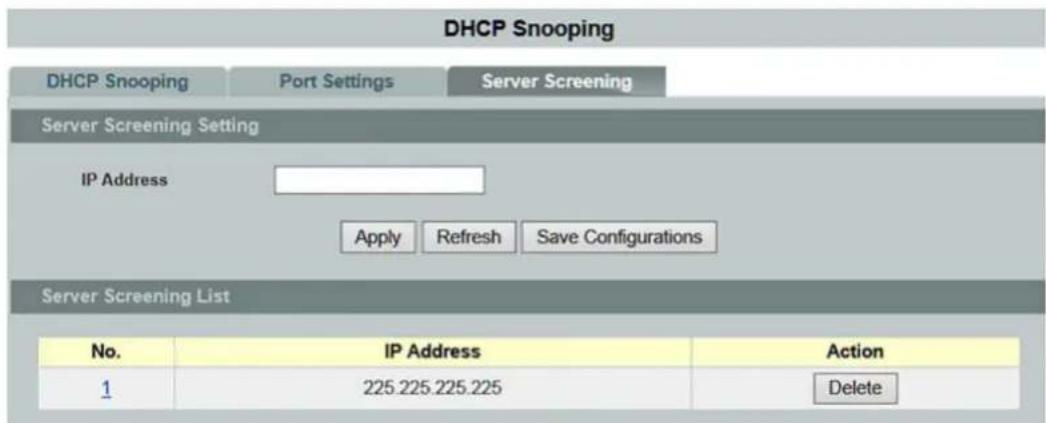
Figure 101: WBM "DHCP Snooping" Page – "Server Screening" Tab
Table 103: WBM "DHCP Snooping" Page – "Server Screening" Tab
| Server Screening Settings | ||
| Parameter | Default | Description |
| IP Address | Enter the IP address of a valid DHCP server in the input field. | |
| Server Screening List | ||
| Parameter | Default | Description |
| No. | This column displays the index number of the DHCP server entry. Click the number to modify the entry. | |
| IP Address | This column displays the IP address of the DHCP server. | |
| Action | Click [Delete] to delete a specific entry. | |
9.4.1.2 DHCP Snooping Binding Table

Note
Additional information
Please refer to the section "Function Description" for more information on "DHCP Snooping Binding Table."
9.4.1.2.1 Static Entry Settings
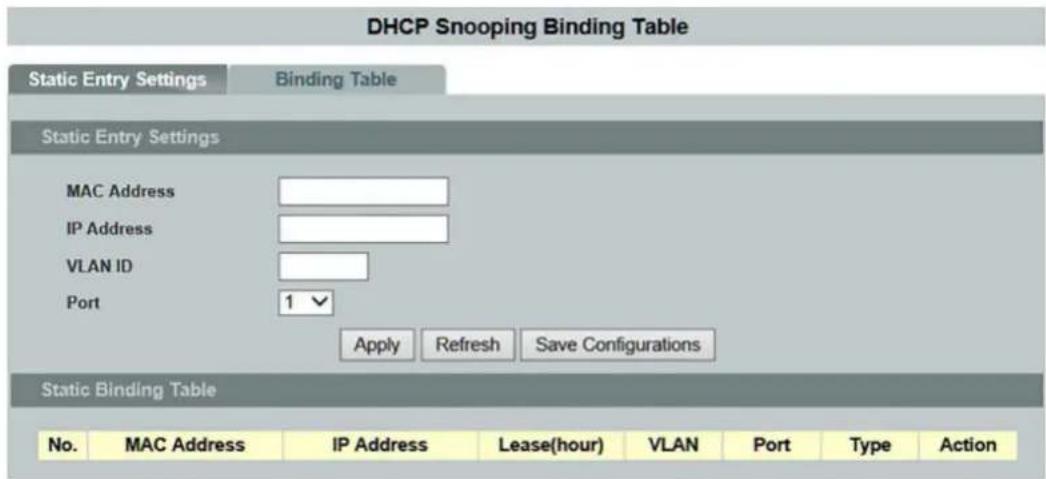
Figure 102: WBM "DHCP Snooping Binding Table" Page – "Static Entry Settings" Tab
Table 104: WBM "DHCP Snooping Binding Table" Page – "Static Entry Settings" Tab
| Static Entry Settings | ||
| Parameter | Default | Description |
| MAC Address | Enter the MAC source address for the binding in the input field. | |
| IP Address | Enter the IP address assigned to the MAC source address for the binding in the input field. | |
| VLAN ID | Enter the source VLAN ID for the binding in the input field. | |
| Port | 1 ... 10 (12) | Select the physical port of the binding in the selection box. |
| Static Binding Table | ||
| Parameter | Default | Description |
| No. | 1 ... 10 (12) | This column displays the sequential numbers for each binding. Click on it to update the existing entries. |
| MAC Address | This column displays the MAC address for the binding. | |
| IP Address | This column displays the IP address assigned to the source MAC address for the binding. | |
| Lease (Hour) | This column indicates how long the binding is valid. | |
| VLAN | This column displays the source VLAN ID for the binding. | |
| Port | 1 ... 10 (12) | This column displays the port number for the binding. |
| Type | Static Dynamic | This column indicates how the binding was communicated to the switch."Static": This binding was manually entered by an administrator."Dynamic": This binding was entered through information from "DHCP Snooping." |
| Action | Click [Delete] to delete a specific entry. | |
9.4.1.2.2 Binding Table
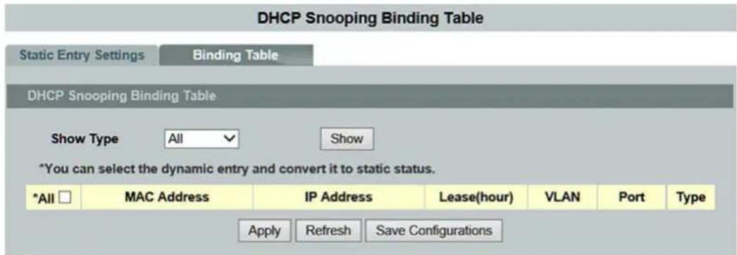
Figure 103: WBM "DHCP Snooping Binding Table" Page – "Binding Table" Tab
Table 105: WBM "DHCP Snooping Binding Table" Page – "Binding Table" Tab
| DHCP Snooping Binding Table | ||
| Parameter | Default | Description |
| Show Type | All | Select “All” in the selection box if you want to display all binding table entries. |
| Dynamic | Select “Dynamic” in the selection box if you want to display the dynamic binding table entries. | |
| Static | Select “Static” in the selection box if you want to display the static binding table entries. | |
| Parameter | Default | Description |
| All | 1 ... 10 (12) | This column displays the sequential numbers for each binding. Click on it to update the existing entries. |
| MAC Address | This column displays the MAC address for the binding. | |
| IP Address | This column displays the IP address assigned to the source MAC address for the binding. | |
| Lease (Hour) | This column indicates how long the binding is valid. | |
| VLAN | This column displays the source VLAN ID for the binding. | |
| Port | This column displays the port number for the binding. If this field is empty, the binding applied to all ports. | |
| Type | Static Dynamic | This column indicates how the binding was communicated to the switch.“Static”: This binding was manually entered by an administrator.“Dynamic”: This binding was entered through information from “DHCP Snooping.” |
Additional information
Please refer to the section "Function Description" for more information on ARP inspection" ("Address Resolution Protocol inspection").
Figure 104: WBM "ARP Inspection" Page – "ARP Inspection" Tab
Table 106: WBM "ARP Inspection" Page – "ARP Inspection" Tab
| ARP Inspection Settings | ||||
| Parameter | Default | Description | ||
| State | Disable | Select "Disable" in the selection box if you want to disable ARP inspection on the switch. | ||
| Enable | Select "Enable" in the selection box if you want to enable ARP inspection on the switch. | |||
| VLAN State | Add | Select "Add" in the selection box and enter the VLANs for which "ARP Inspection" should be enabled on the switch. Valid range of VLAN IDs: 1 ... 4094. Use a comma (,) or hyphen (-) to specify individual VLANs or VLAN ranges. | ||
| Delete | Select "Delete" in the selection box and enter the VLANs on which the switch should not run "ARP Inspection." | |||
| Trusted Ports | Select the ports that you want to select or deselect as "Trusted Ports." The switch does not drop ARP packets from "Trusted Ports" for any reason. The switch discards DHCP packets from "Untrusted Ports" in the following situations: ·The sender information in an ARP packet does not match any current bindings. ·The transmission rate of the DHCP packets received is too high. You can specify the maximum rate for receiving packets on "Untrusted Ports." | |||
| Select All | ○ | ○ | No port is selected as "Trusted." | |
| ◎ | All ports are selected as "Trusted." | |||
| Cancel Selection | ○ | ○ | No port is disabled as "Trusted." | |
| ◎ | All ports are disabled as "Trusted." | |||
| □ 1 ... □ 10 (12) | □ | □ | The port is not enabled. | |
| ☑ | The port is enabled. | |||
| ARP Inspection Status | ||||
| Parameter | Default | Description | ||
| ARP Inspection State | Disable Enable | This field displays the current status of the ARP inspection. | ||
| Enabled on VLAN | None 1 ... 10 (12) | This field displays the VLAN IDs for which ARP inspection is enabled. | ||
| Trusted Ports | None 1 ... 10 (12) | This field displays the ports specified as "Trusted Ports." | ||
Additional information
Please refer to the section "Function Description" for more information on the "Filter Table."

Figure 105: WBM "ARP Inspection" Page – "Filter Table" Tab
Table 107: WBM "ARP Inspection" Page – "Filter Table" Tab
| Filter Age Time Settings | ||
| Parameter | Default | Description |
| Filter Age Time min (Range: 1~10080) | 5 | Enter a time in the input field for how long a MAC address filter entry should remain in the switch after the switch has received an unauthorized ARP packet.Time: 1 ... 10,080 minOnce this time has elapsed; the switch deletes the entry automatically.This setting has no effect on existing MAC address filters. |
| Filter Table | ||
| Parameter | Default | Description |
| No. | This column displays the sequential number of each MAC address filter entry. | |
| MAC Address | This column displays the source MAC addresses in the MAC address filter. | |
| VLAN | This column displays the source VLAN IDs in the MAC address filter. | |
| Port | This field displays the source port of the discarded ARP packets. | |
| Expiry Time (min) | This column indicates how long (in minutes) a MAC address filter entry remains in the switch. | |
| Action | Click [Delete] to delete a specific entry. | |
| Quantity | This field displays the total number of current MAC address filter entries that the switch created due to identified unauthorized ARP packets. | |
9.4.2 Access Control List (ACL)
Note

Additional information
Please refer to the section "Function Description" for more information on the "Access Control List."
Access Control List
Access Control List Settings
Profile Name
Ethernet Type
Source MAC Address
Destination MAC Address
Source IP
Destination IP Address
IP Protocol
Source Application
Destination Application
Source Interface

Any ▼
Any ▼
Any ▼
Any ▼
Any ▼
Any ▼
Any ▼
Any ▼
Apply
Refresh
Action
VLAN
Mask of Source MAC Address
Mask of Destination MAC Address
Mask of Source IP Address
Mask of Destination IP Address
Disable ▼
Any ▼




Access Control List Status
Profile Name 521582
Ethernet Type Any
IP Protocol Any
Source MAC Address Any
Destination MAC Address Any
IP Protocol Any
Source IP Any
Destination IP Address Any
Source Application 10
Source Application Any
Action Disable
VLAN Any
Mask of Source MAC Address None
Mask of Destination MAC Address None
Mask of Source IP Address None
Mask of Destination IP Address None
Destination Application Any
Delete
Figure 106: WBM "Access Control List" Page
Table 108: WBM "Access Control List" Page
| Access Control List Settings | |||
| Parameter | Default | Description | |
| IP Type | IPv4 | Select “IPv4” in the selection field if you want to select this version of the Internet protocol. | |
| IPv6 | Select “IPv6” in the selection box if you want to select this version of the Internet protocol. | ||
| Profile Name | Enter the name of the profile in the input field. | ||
| Action | Disable | Select “Disable” in the selection box to disable access control. | |
| Permission | Select “Permission” in the selection box to forward data packets that match the information. | ||
| Discard | Select “Discard” in the selection box to drop data packets that match the information. | ||
| DSCP | Select “DSCP” in the selection box to give a new priority value to data packets that match the information. (only with IPv4) | ||
| ETHERNET Type(only with IPv4) | Any | Select “Any” in the selection box to make every ETHERNET type valid. | |
| Other | Select “Other” in the selection box to specify an ETHERNET type for which access control is valid. | ||
| VLAN | Any | Select “any” in the selection box to make every VLAN ID valid. | |
| Other | Select “Other” in the selection box to enter a specific VLAN ID in the access control list. | ||
| Source MAC Address(only with IPv4) | Any | Select “Any” in the selection box to make every MAC address valid. | |
| Other | Select “Other” in the selection box to enter the MAC address for the source in the access control list. | ||
| Mask of the Source MAC Address(only with IPv4) | In the input field, enter the source MAC ID of the bitmap mask for source MAC addresses of packets to be filtered.If you selected “Source MAC Address” in the selection box, this field remains empty. The profile then only filters the MAC address entered in the source MAC address field. | ||
| Destination MAC Address(only with IPv4) | Any | Select “Any” in the selection box to make every MAC address valid. | |
| Other | Select “Other” in the selection box to enter the MAC address for the destination in the access control list. | ||
| Mask of the Destination MAC Address(only with IPv4) | In the input field, enter the destination MAC ID of the bitmap mask for destination MAC addresses of packets to be filtered.If you selected “Destination MAC Address” in the selection box, this field remains empty. The profile then only filters the MAC address entered in the destination MAC address field. | ||
| DSCP(only with IPv4) | Any | Select “Any” in the selection box to make every DSCP priority valid for the access control list. | |
| Other | 0 ... 63 | Select the DSCP priority in the selection box. | |
Table 108: WBM "Access Control List" Page
| Source IP | Any | Select “Any” in the selection box to make every IP address valid. | |
| Other | Select “Other” in the selection box to enter the IP address for the source in the access control list. | ||
| Mask of the Source IP Address | In the input field, enter the source IP address ID of the bitmap mask for source IP addresses of packets to be filtered.If you selected “Source IP” in the selection box, this field remains empty. The profile then only filters the IP address entered in the source IP address field. | ||
| Destination IP | Any | Select “Any” in the selection box to make every IP address valid. | |
| Other | Select “Other” in the selection box to enter the IP address for the destination in the access control list. | ||
| Mask of the Destination IP Address(only with IPv4) | In the input field, enter the destination IP address of the bitmap mask for IP destination MAC addresses of packets to be filtered.If you selected “Destination MAC Address” in the selection box, this field remains empty. The profile then only filters the IP address entered in the destination IP address field. | ||
| IP Protocol | Any | Select “Any” in the selection box to make every IP protocol for the access control list valid. | |
| Other | Enter “Other” in the selection box to enter the protocol. | ||
| Source Application | Any | Select “Any” in the selection box to make every application valid. | |
| Other | Select “Other” in the selection box to enter the source port (e.g., 2234). | ||
| Destination Application | Any | Select “Any” in the selection box to make every destination application valid. | |
| Other | Select “Other” in the selection box to enter the port (e.g., 502) for the destination in the access control list. | ||
| Source Interface | Any | Select “Any” in the selection box if every physical port is valid. | |
| Other | 1 ... 10(12) | Enter the physical port in the input field for which this entry is valid in the access control list. | |
Table 108: WBM "Access Control List" Page
| Access Control List Status | ||
| Parameters | Default | Description |
| IP Type | IPv4IPv6 | This field displays the selected IP type. |
| Profile Name | This field displays the selected name of the profile. | |
| Action | DisablePermissionDiscardDSCP | This field displays the status of the access control.(DSCP only with IPv4) |
| ETHERNET Type(only with IPv4) | AnyOther | This field displays the ETHERNET type. |
| VLAN | AnyOther | This field displays the VLAN ID. |
| Source MAC Address(only with IPv4) | AnyOther | This field displays the source MAC address. |
| Mask of the Source MACAddress(only with IPv4) | This field displays the source MAC ID of the bitmap mask. | |
| Destination MAC Address(only with IPv4) | AnyOther | This field displays the destination MAC address. |
| Mask of the DestinationMAC Address(only with IPv4) | This field displays the destination MAC ID of the bitmap mask. | |
| DSCP(only with IPv4) | AnyOther | This field displays the DSCP priority. |
| IP Protocol | AnyOther | This field displays the IP protocol. |
| Source IP | AnyOther | This field displays the source IP. |
| Mask of the Source IPAddress | This field displays the source MAC ID of the bitmap mask. | |
| Destination IP | AnyOther | This field displays the destination IP. |
| Mask of the Destination IPAddress(only with IPv4) | This field displays the destination IP ID of the bitmap mask. | |
| Source Application | AnyOther | This field displays the source application. |
| Destination Application | AnyOther | This field displays the destination application. |
| Source Interface | 1 ... 10 (12) | This field displays the source interface. |
9.4.3 IEEE 802.1X

Note
Additional information
Please refer to the section "Function Description" for more information on the "IEEE 802.1X" standard.
9.4.3.1 Global Settings
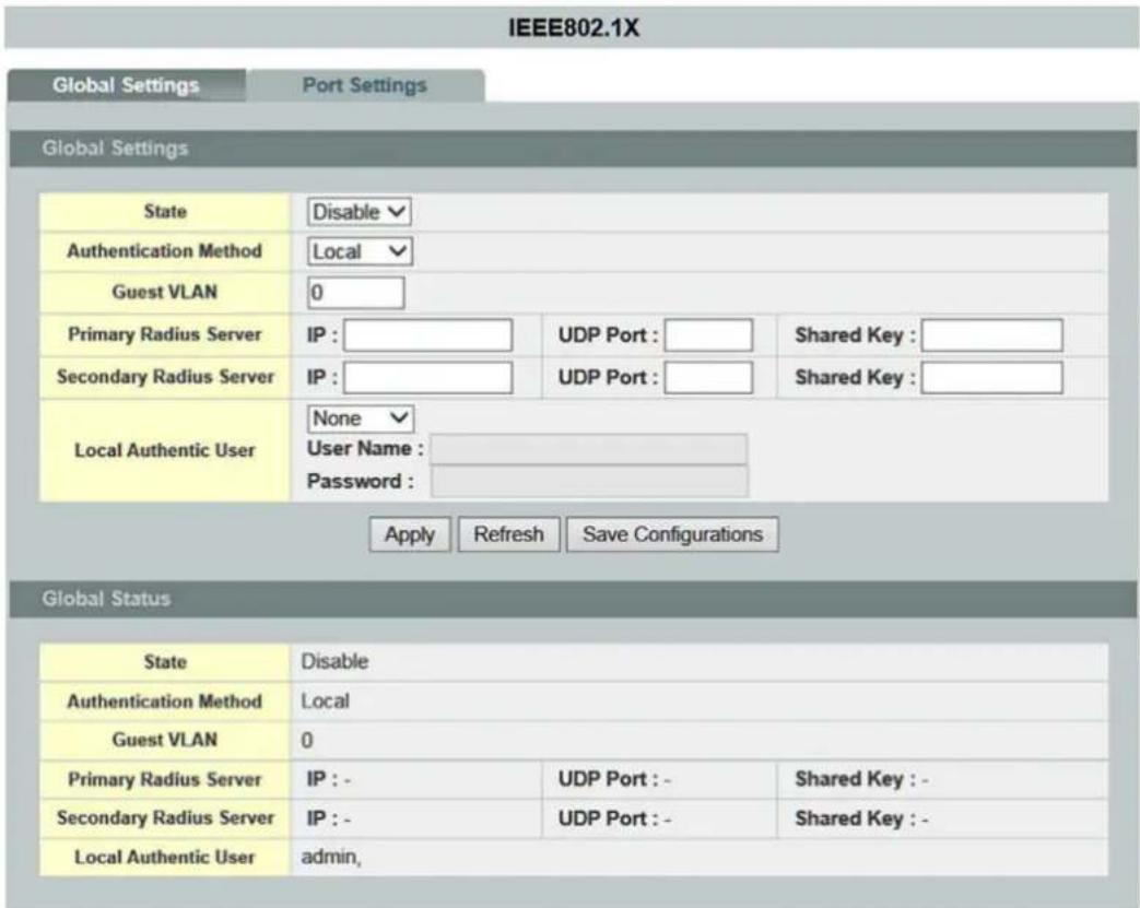
Figure 107: WBM "IEEE 802.1X" Page – "Global Settings" Tab
Table 109: WBM "IEEE 802.1X" Page – "Global Settings" Tab
| Global Settings | |||
| Parameter | Default | Description | |
| State | Disable | Select “Disable” in the selection box to disable IEEE 802.1X authentication on the switch. | |
| Enable | Select “Enable” in the selection box to enable IEEE 802.1X authentication on the switch. | ||
 NoteIEEE802.1X AuthenticationYou must first enable IEEE 802.1X authentication on the switch before you can configure this function for individual ports. NoteIEEE802.1X AuthenticationYou must first enable IEEE 802.1X authentication on the switch before you can configure this function for individual ports. | |||
| Authentication Method | Local | Select “Local” in the selection box to use the “Guest” and “User” user groups from the user account database on the switch for authentication.However, the number of nodes that can exist at the same time is limited. | |
| RADIUS | Select “RADIUS” in the selection box to enable the security protocol that uses an external server for user authentication, in contrast to the internal user database, in devices with limited storage.In general, “RADIUS” allows validation of an unlimited number of users from a central location. | ||
| Guest VLAN | This field is used to configure the VLAN ID. | ||
| Primary RADIUS Server | If you selected “RADIUS” for the authentication method, the primary RADIUS server is used for all authentication requests. | ||
| IP: | In the input field, enter the IP address of the external RADIUS server in decimal-point notation. | ||
| UDP Port: | Enter the UDP port in the input field. | ||
| Shared Key: | Enter a password (up to 32 alphanumeric characters) in the input field to use as the common key for the connection between the external RADIUS server and the switch.This key must not be sent over the network. The key must be identical on the external RADIUS server and the switch. | ||
Table 109: WBM "IEEE 802.1X" Page – "Global Settings" Tab
| Secondary RADIUS Server | This is the back-up server that is only used if the primary RADIUS server fails. | |||
| IP: | In the input field, enter the IP address of the external RADIUS server in decimal-point notation. | |||
| UDP Port: | 0 ... 65535 | Enter the port number of the RADIUS server in the input field. | ||
| Shared Key: | Enter a password (up to 32 alphanumeric characters) in the input field to use as the common key for the connection between the external RADIUS server and the switch.This key must not be sent over the network. The key must be identical on the external RADIUS server and the switch. | |||
| Authentication Method | The user name and password are displayed, added or deleted in these input fields. | |||
| None | If you selected “None” in the selection box, you then cannot change the user name and password. | |||
| Delete | User Name: | If you selected “Delete” in the selection box, you can change the user name. | ||
| Add | Password: | If you selected “Add” in the selection box, you can change the user name and password. | ||
| Global Status | ||||
| Parameter | Default | Description | ||
| Status | Disable Enable | This field indicates whether IEEE 802.1X authentication is enabled or disabled. | ||
| Authentication Method | Local RADIUS | This field displays the authentication method. | ||
| Guest VLAN | This field displays the guest VLAN. | |||
| Primary RADIUS Server | IP: | This field displays the IP address, UDP port and common key for the primary RADIUS server.The fields are empty if no configuration is performed. | ||
| UDP Port: | ||||
| Shared Key: | ||||
| Secondary RADIUS Server | IP: | This field displays the IP address, UDP port and common key for the secondary RADIUS server.The fields are empty if no configuration is performed. | ||
| UDP Port: | ||||
| Shared Key: | ||||
| Local Authenticated User | admin, | This field displays the list of users that are logged in. | ||
9.4.3.2 Port Settings

Figure 108: WBM "IEEE 802.1X" Page – "Port Settings" Tab
Table 110: WBM "IEEE 802.1X" Page – "Port Settings" Tab
| Port Settings | ||||
| Parameter | Default | Description | ||
| Port | From: | 1 | Select a port or port range in the selection box to configure the “Port Settings.” | |
| To: | 1 | Select a port or port range in the selection box to configure the “Port Settings.” | ||
| IEEE 802.1X State | Disable | Select “Disable” in the selection box to disable IEEE 802.1X authentication for the port. | ||
| Enable | Select “Enable” in the selection box to enable IEEE 802.1X authentication for the port. | |||
 | NoteIEEE 802.1X AuthenticationYou must first enable IEEE 802.1X authentication on the switch before you can configure this function for individual ports. | |||
| Admin Control Direction | Both | In the selection box, select “Both” to drop incoming and outgoing packets on the port when a user has not passed IEEE 802.1X port authentication. | ||
| Input | In the selection box, select “Incoming” to drop only incoming packets on the port when a user has not passed IEEE 802.1X port authentication. | |||
| Reauthentication | Disable | Select “Disable” in the selection box if a subscriber does not have to regularly reenter the user name and password to remain connected to the port. | ||
| Enable | Select “Enable” in the selection box if a subscriber has to regularly reenter the user name and password to remain connected to the port. | |||
| Port Control Mode | Auto | Select “Auto” in the selection box to enable authentication for the port. | ||
| Force Authorized | Select “Force Authorized” in the selection box to enable permanent authentication for the port. | |||
| Force Unauthorized | Select “Force Unauthorized” in the selection box to enable permanent denial of authentication for the port. No packets can pass through this port. | |||
| Guest VLAN | Disable | Select “Disable” in the selection box to disable the guest VLAN on the port. | ||
| Enable | Select “Enable” in the selection box to enable the guest VLAN on the port. | |||
| Max Req Times | 2 | Enter a value for the maximum required times in the input field that the switch should attempt to connect to the authentication server before it sees the server as not connected. | ||
| Reauth Period | 3600 | Enter a value in the input field for interval at which a subscriber has to reenter the user name and password to remain connected to the port. | ||
| Quiet Period | 60 | Enter a value for the time in the input field that the client must wait before it can request authentication again.This prevents the switch from becoming overloaded with continuous authentication attempts from the client. | ||
Table 110: WBM "IEEE 802.1X" Page – "Port Settings" Tab
| Supp Timeout | 30 | Enter a value in the input field for the time that the switch must wait before it can communicate with the server. | |
| Server Timeout | 30 | Enter a value for the time in the input field that the switch should wait for a response from the authentication server. | |
| Reset to Default | ☐ | ☐ | No custom settings for IEEE 802.1X port authentication are reset to the default values. |
| ☑ | The custom settings for IEEE 802.1X port authentication are reset to the default values. | ||
| Port Status | |||
| Parameter | Default | Description | |
| Port | 1 ... 10 (12) | This column shows the port numbers. | |
| IEEE 802.1X State | Disable Enable | This column indicates whether IEEE 802.1X authentication for a port is enabled or disabled. | |
| Admin Control Direction | Both Incoming | This column displays the “Control Direction.” | |
| Reauthentication | Disable Enable | This column indicates whether the subscriber has to reenter the user name and password regularly to remain connected to the port. | |
| Port Control Mode | Automatic, Force Authorized, Force Unauthorized | This column displays the port control mode. | |
| Guest VLAN | Disable Enable | This column displays the guest VLAN setting for hosts for which authentication has failed. | |
| Max Req Times | 1 ... 10 | This column indicates how often the switch attempts to connect to the authentication server before it sees the server as not connected. | |
| Reauth Period | 0 ... 65535 | This column displays the interval at which a subscriber must reenter the user name and password to remain connected to the port. | |
| Quiet Period | 0 ... 65535 | This column displays the time that a client must wait before it can request authentication again. | |
| Supp Timeout | 0 ... 65535 | This column indicates how long the switch should wait before communicating with the server. | |
| Server Timeout | 0 ... 65535 | This column indicates how long the switch should wait before communicating with the client. | |
9.4.4 Port Security
9.4.4.1 Port Security

Note
Additional information
Please refer to the section "Function Description" for more information on "Port Security."

Figure 109: WBM "Port Security" Page – "Port Security" Tab
Table 111: WBM "Port Security" Page – "Port Security" Tab
| Port Security Settings | |||
| Parameter | Default | Description | |
| Port Security | Disable | Select “Disable” in the selection box to disable port security on the switch. | |
| Enable | Select “Enable” in the selection box to enable port security on the switch. | ||
| Port | From: | 1 | Select a port or port range in the selection box to configure the port security. |
| To: | 1 | Select a port or port range in the selection box to configure the port security. | |
| State | Disable | Select “Disable” in the selection box to disable port security for a port or port range. | |
| Enable | Select “Enable” in the selection box to enable port security for a port or port range. | ||
| Maximum MAC Address (1–30) | 5 | Enter the maximum number of MAC addresses per interface in the input field. | |
| Port Security Status | |||
| Parameter | Default | Description | |
| Port | 1 ... 10 (12) | This column shows the port numbers. | |
| State | Enable Disable | This field indicates whether port security is enabled or disabled. | |
| Maximum MAC Address | 0 ... 1000 | This column displays the maximum number of MAC addresses. | |
9.4.4.2 Sticky MAC Settings

Note
Additional information
Please refer to the section "Function Description" for more information on "Sticky MAC Settings".
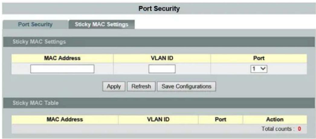
Figure 110: WBM "Port Security" Page – "Sticky MAC Settings" Tab
Table 112: WBM "Port Security" Page – "Sticky MAC Settings" Tab
| Sticky MAC Settings | ||
| Parameter | Default | Description |
| MAC Address | In this input field, enter the MAC address for the connection. | |
| VLAN-ID | In this input field, enter the source VLAN ID for the connection. | |
| Port | 1 ... 10 (12) | Select the physical port of the connection in the selection box. |
| Sticky MAC Table | ||
| Parameter | Default | Description |
| MAC Address | This column displays the MAC address for the connection. | |
| VLAN ID | This column displays the VLAN ID for the connection. | |
| Port | 1 ... 10 (12) | This column shows the port numbers. |
| Action | Click [Delete] to delete a specific entry. | |
9.5 Monitor
9.5.1 Alarm Information

Note
Additional information
Please refer to the section "Function Description" for more information on the "Alarm."
Alarm Information
Alarm Information
| Alarm Status | No Alarm. | ||
| Alarm Reason(s) | |||
| Port | DIP switch settings | Port | DIP switch settings |
| 1 | Disable | 2 | Disable |
| 3 | Disable | 4 | Disable |
| 5 | Disable | 6 | Disable |
| 7 | Disable | 8 | Disable |
| 9 | Disable | 10 | Disable |
| PWR | Disable | RPS | Disable |
Figure 111: WBM "Alarm Information" Page
Table 113: WBM "Alarm Information" Page
| Alarm Information | ||
| Parameter | Default | Description |
| Alarm Status | This display field shows if there are any alarm events. | |
| Alarm Reason | This display field shows details about the alarm events. | |
| Port | 0 ... 10 (12)PWR RPS | This column displays the DIP switch name. |
| DIP Switch Settings | Enable Disable | This column displays the current status of the DIP switch. |
9.5.2 System Information

Note
Additional information
Please refer to the section "Function Description" for more information on "System Information."
Monitor Information
Temperature unit: Celsius(C)
Hardware-Monitor Alarm: Enable ▼
Hardware Information:
| Temperature(C) | Current | MAX | MIN | Threshold | Status |
| BOARD | 52.0 | 52.0 | 49.0 | 80.0 | Normal |
| CPU | 51.8 | 51.8 | 48.8 | 80.0 | Normal |
| PHY | 51.0 | 51.0 | 48.0 | 80.0 | Normal |
| Voltage(V) | Current | MAX | MIN | Threshold | Status |
| 1.0V IN | 0.998 | 0.998 | 0.988 | +/-6% | Normal |
| 1.8V IN | 1.784 | 1.810 | 1.777 | +/-6% | Normal |
| 5.0V IN | 5.002 | 5.048 | 4.970 | +/-6% | Normal |
Apply Refresh Save Configurations
Figure 112: WBM "System Information" Page
Table 114: WBM "System Information" Page
| Hardware Information | ||
| Parameter | Default | Description |
| Temperature Unit | Celsius (C) | Select “Celsius (C)” in the selection box if you want to display the temperature in Celsius. |
| Fahrenheit (F) | Select “Fahrenheit (F)” in the selection box if you want to display the temperature in Fahrenheit. | |
| Hardware Information | ||
| Parameter | Default | Description |
| Temperature (C) | ||
| Current | This column displays the current temperature of the “BOARD,” “CPU” and “PHY” MAC chip. | |
| MAX | This column displays the maximum temperature of the “BOARD,” “CPU” and “PHY” MAC chip. | |
| MIN | This column displays the minimum temperature of the “BOARD,” “CPU” and “PHY” MAC chip. | |
| Threshold | This column displays the threshold setting. | |
| Status | This column displays the status. | |
| Voltage [V] | ||
| Current | This column displays the current voltage for the “1.0 V IN,” “2.5 V IN” and “3.3 V IN” inputs. | |
| MAX | This column displays the maximum voltage for the “1.0 V IN,” “2.5 V IN” and “3.3 V IN” inputs. | |
| MIN | This column displays the minimum voltage for the “1.0 V IN,” “2.5 V IN” and “3.3 V IN” inputs. | |
| Threshold | This column displays the threshold setting. | |
| Status | This column displays the status. | |
9.5.3 Port Statistics

Note
Additional information
Please refer to the section "Function Description" for more information on the "Port Statistics".
Port Statistics
Port Statistics
| Port | Receive Drops | Transmit Drops | Receive Errors | Transmit Errors | Receive Packets | Transmit Packets | Receive Bytes | Transmit Bytes |
| 1 | 0 | 0 | 0 | 0 | 162814 | 219841 | 23349083 | 38610264 |
| 8 | 0 | 0 | 0 | 0 | 821080 | 871944 | 135804810 | 121615480 |
| 11 | 0 | 0 | 0 | 0 | 52356 | 922 | 3870714 | 118703 |
Refresh
Clear
Figure 113: WBM "Port Statistics" Page
Table 115: WBM "Port Statistics" Page
| Port Statistics | ||
| Parameter | Default | Description |
| Port | This column shows the port numbers. | |
| Transmit Drops | This column displays the number of dropped data packets on the transmission line. | |
| Receive Drops | This column displays the number of dropped data packets on the receiving line. | |
| Transmit Errors | This column displays the errors on the transmission line. | |
| Receive Errors | This column displays the errors on the receiving line. | |
| Transmit Packets | This column displays the number of data packets transmitted since power ON. | |
| Receive Packets | This column displays the number of data packets received since power ON. | |
| Transmit Byte | This column displays the number of bytes sent on the port since power ON. | |
| Receive Bytes | This column displays the number of bytes received on the port since power ON. | |
9.5.4 Port Utilization

Note
Additional information
Please refer to the section "Function Description" for more information on the "Port Utilization."
Port Utilization
| Port | Speed | RX Traffic Utilization (%) | RX Traffic Utilization (bps) | TX Traffic Utilization (%) | TX Traffic Utilization (bps) |
| 1 | 1000 | 0.00 | 0 | 0.00 | 341 |
| 8 | 100 | 0.01 | 16725 | 0.01 | 14821 |
| 11 | 1000 | 0.00 | 341 | 0.00 | 0 |
Figure 114: WBM "Port Utilization" Page
Table 116: WBM "Port Utilization" Page
| Port Utilization Status | ||
| Parameter | Default | Description |
| Port | This column shows the port numbers. | |
| Speed | This column displays the transfer rate. | |
| RX Port Utilization (%) | This column displays the RX bandwidth utilization as a percentage. | |
| RX Port Utilization (bps) | This column displays the RX bandwidth utilization in bps. | |
| TX Port Utilization (%) | This column displays the TX bandwidth utilization as a percentage. | |
| RX Port Utilization (bps) | This column displays RX bandwidth utilization in bps. | |
9.5.5 RMON Statistics

Note
Additional information
Please refer to the section "Function Description" for more information on "RMON Statistics".
RMON Statistics
RMON Statistics
Port

Show
Clear
Port 8 (active)
| Inbound | Total Octets | 138137205 | ||
| BroadcastPkts | 358 | UnicastPkts | 834746 | |
| Non-unicastPkts | 934 | MulticastPkts | 576 | |
| FragmentsPkts | 0 | UndersizePkts | 0 | |
| OversizePkts | 0 | DiscardsPkts | 0 | |
| ErrorPkts | 0 | UnknownProtos | 0 | |
| AlignError | 0 | CRCAlignErrors | 0 | |
| Jabbers | 0 | DropEvents | 0 | |
| Outbound | Total Octets | 124304365 | ||
| BroadcastPkts | 0 | UnicastPkts | 834417 | |
| Non-unicastPkts | 52636 | Collisions | 0 | |
| LateCollision | 0 | SingleCollision | 0 | |
| MultipleCollision | 0 | DiscardsPkts | 0 | |
| ErrorPkts | 0 | |||
| #of packets received with a length of | 64 Octets | 1009822 | 65to127 Octets | 356498 |
| 128to255 Octets | 134735 | 256to511 Octets | 144291 | |
| 512to1023 Octets | 37586 | 1024toMax Octets | 39802 | |
Figure 115: WBM "RMON Statistics" Page
Table 117: WBM "RMON Statistics" Page
| RMON Statistics | |||
| Parameter | Default | Description | |
| Port | - | Select “-” in the selection box if you do not want to view any statistics. | |
| 1 ... 10 (12) All | In the selection box, select a port, or all ports, for which you want to display RMON statistics. | ||
| Selected Port x (active) | |||
| Parameter | Default | Description | |
| Incoming | Total Octets | This display field shows the number of data packets received on the port. | |
| Broadcast Packets | This display field shows the number of broadcast packets received on the port. | ||
| Unicast Packets | This display field shows the number of unicast packets received on the port. | ||
| Non Unicast Packets | This display field shows the total number of broadcast and multicast packets received on the port. | ||
| Multicast Packets | This display field shows the number of multicast packets received on the port. | ||
| Fragmented Packets | This display field shows the number of fragmented data packets received on the port. | ||
| Undersized Packets | This display field shows the number of data packets received on the port that are too small. | ||
| Oversized Packets | This display field shows the number of data packets received on the port that are too large. | ||
| Discards Packets | This display field shows the number of data packets received on the port that were dropped. | ||
| Error Packets | This display field shows the number of data packets received on the port that were faulty. | ||
| Unknown Protos | This display field shows the number of packets received by this port that contain an unknown or unsupported protocol as the destination. | ||
| Align Error | This display field shows the number of data packets received where the total number of bits of a received frame is not divisible by eight. | ||
| CRC Align Error | This display field shows the number of data packets received with a checksum error. | ||
| Jabbers | This display field shows the number of jabbers received by this port. | ||
| Drop Events | This display field shows the number of dropped data packets. | ||
Table 117: WBM "RMON Statistics" Page
| Outgoing | Total Octets | This display field shows the number of data packets sent from the port. | |
| Broadcast Packets | This display field shows the number of broadcast packets sent from the port. | ||
| Unicast Packets | This display field shows the number of unicast packets sent from the port. | ||
| Non Unicast Packets | This display field shows the number of unicast packets sent from the port. | ||
| Collisions | This display field shows the number of data packets that were to be sent, have collided and were discarded. | ||
| Late Collision | This display field shows the number of data packets that were to be sent, have collided and were discarded. | ||
| Single Collisions | This display field shows the number of single collisions of the data packets sent. | ||
| Multiple Collisions | This display field shows the number of multiple collisions of the data packets sent. | ||
| Discards Packets | This display field shows the number of data packets sent from the port that were dropped. | ||
| Error Packets | This display field shows the number of data packets sent from the port that were faulty. | ||
| #(number) of packets received with a length of ?. | 64 Octets | This display field shows the number of data packets received that had a length of 64 octets. | |
| 65 to 127 Octets | This display field shows the number of data packets received that had a length of 65 to 127 octets. | ||
| 128 to 255 Octets | This display field shows the number of data packets received that had a length of 128 to 255 octets. | ||
| 256 to 511 Octets | This display field shows the number of data packets received that had a length of 256 to 511 octets. | ||
| 512 to 1023 Octets | This display field shows the number of data packets received that had a length of 512 to 1023 octets. | ||
| 1024 to Max. Octets | This display field shows the number of data packets received that had a length of more than 1024 octets. |
9.5.6 SFP Information

Note
Additional information
Please refer to the section "Function Description" for more information on "SFP Information".
SFP Information
SFP Information
Port


SFP Information
| Fiber Cable | Link Up |
| Connector | LC |
| Wavelength | 850 |
| Transfer Distance | 550m(50um, OM2), Multi mode |
| DDM Supported | YES (Internally Calibrated) |
| Vendor Name | WAGO |
| Vendor PN | 852-1200 |
| Vendor rev | V2.0 |
| Vendor SN | AX15470009620 |
| Date code | 151120 |
DDMI Information
| Current | High-Alarm | Low-Alarm | High-Warn | Low-Warn | |
| Temperature(C) | 50.199 | 90.000 | -45.000 | 85.000 | -40.000 |
| Voltage(V) | 3.264 | 3.600 | 3.000 | 3.500 | 3.100 |
| Tx Bias(mA) | 6.088 | 25.000 | 1.000 | 20.000 | 2.000 |
| Tx Power(mW) | 0.197 | 0.501 | 0.089 | 0.398 | 0.112 |
| Tx Power(dBm) | -7.065 | -3.000 | -10.505 | -4.001 | -9.506 |
| Rx Power(mW) | 0.242 | 0.631 | 0.016 | 0.501 | 0.020 |
| Rx Power(dBm) | -6.160 | -2.004 | -18.016 | -3.000 | -17.012 |
Refresh
Figure 116: WBM "SFP Information" Page
Table 118: WBM "SFP Information" Page
| SFP Information | ||
| Parameter | Default | Description |
| Port | - | Select “-” in the selection box if you have not inserted an SFP module |
| 9, 10, (11, 12) | In the selection box, select the port in which you have inserted an SFP module. | |
| SFP Information | ||
| Parameter | Default | Description |
| Fiber Cable | This display field shows if a fiber optic cable is connected. | |
| Connector | This display field shows the code for the optical connector type. | |
| Wavelength | This display field shows the wavelength. | |
| Transfer Distance | This field displays the transmission distance. | |
| DDM Support | This display field shows if the SFP module supports DDM (“Dynamic Device Mapping”). | |
| Vendor Name | This display field shows the name of the SFP provider. | |
| Vendor Part Number | This display field shows the part number. | |
| Vendor Revision Status | This display shows the revision status of the part number. | |
| Vendor Serial Number | This display field shows the serial number (ASCII). | |
| Date code | This field displays the version date. | |
Table 118: WBM "SFP Information" Page
| DDMI Information (nm) | ||
| Parameter | Default | Description |
| Current | This column displays the following current values:- Temperature (C)- Voltage (V)- Tx bias (mA)- Tx power (mW)- Rx power (dBm)- Rx power (mW)- Rx power (dBm) | |
| High-Alarm | This column displays the “Alarm High” values of the following values:- Temperature (C)- Voltage (V)- Tx bias (mA)- Tx power (mW)- Rx power (dBm)- Rx power (mW)- Rx power (dBm) | |
| Low-Alarm | This column displays the “Alarm Low” values of the following values:- Temperature (C)- Voltage (V)- Tx bias (mA)- Tx power (mW)- Rx power (mW)- Rx power (dBm) | |
| High-Warn | This column displays the “Warning High” values of the following values:- Temperature (C)- Voltage (V)- Tx bias (mA)- Tx power (mW)- Rx power (dBm)- Rx power (mW)- Rx power (dBm) | |
| Low-Warn | This column displays the “Warning Low” values of the following values:- Temperature (C)- Voltage (V)- Tx bias (mA)- Tx power (mW)- Rx power (mW)- Rx power (dBm) | |
9.5.7 Traffic Monitor

Note
Additional information
Please refer to the section "Function Description" for more information on the "Traffic Monitor".
Traffic Monitor
Traffic Monitor Settings
| Port | State | Action | Packet Type | Packet Rate (pps) | Recovery State | Recovery Time | Quarantine times |
| From: 1 To: 1 | Disable | None | Broadcast | 100 | Enable | 1 | 3 |
Traffic Monitor Status
| Port | State | Status | Packet Type | Packet Rate(pps) | Recovery State | Recovery Time | Quarantine times |
| 1 | Disable | Normal | Broadcast | 100 | Enable | 1 | 3 |
| 2 | Disable | Normal | Broadcast | 100 | Enable | 1 | 3 |
| 3 | Disable | Normal | Broadcast | 100 | Enable | 1 | 3 |
| 4 | Disable | Normal | Broadcast | 100 | Enable | 1 | 3 |
| 5 | Disable | Normal | Broadcast | 100 | Enable | 1 | 3 |
| 6 | Disable | Normal | Broadcast | 100 | Enable | 1 | 3 |
| 7 | Disable | Normal | Broadcast | 100 | Enable | 1 | 3 |
| 8 | Disable | Normal | Broadcast | 100 | Enable | 1 | 3 |
| 9 | Disable | Normal | Broadcast | 100 | Enable | 1 | 3 |
| 10 | Disable | Normal | Broadcast | 100 | Enable | 1 | 3 |
| 11 | Disable | Normal | Broadcast | 100 | Enable | 1 | 3 |
| 12 | Disable | Normal | Broadcast | 100 | Enable | 1 | 3 |
Figure 117: WBM "Traffic Monitor" Page
Table 119: WBM "Traffic Monitor" Page
| Traffic Monitor Settings | |||
| Parameter | Default | Description | |
| State | Disable | Select “Disable” in the selection box to disable the “Traffic Monitor” function globally. | |
| Enable | Select “Enable” in the selection box to enable the “Traffic Monitor” function globally. | ||
| Port | From: | 1 | Select a port or port range in the selection box which you want to configure. |
| To: | 1 | Select a port or port range in the selection box which you want to configure. | |
| State | Disable | Select “Disable” in the selection box if you want to disable the “Traffic Monitor” function for the port or port range. | |
| Enable | Select “Enable” in the selection box if you want to enable the “Traffic Monitor” function for the port or port range. | ||
| Action | None | Select “None” in the selection box if you do not want to cancel port blocking. | |
| Unblock | Select “Unblocked” in the selection box if you want to cancel port blocking. | ||
| Packet Type | Broadcast | Select “Broadcast” in the selection box if you want to monitor this as the packet type. | |
| Multicast | Select “Multicast” in the selection box if you want to monitor this as the packet type. | ||
| Bcast+Mcast | Select “Bcast+Mcast” in the selection box if you want to monitor both as the packet types. | ||
| Packet Rate (pps) | In the input field, enter the packet rate that you want to monitor. | ||
| Recovery State | Enable | Select “Enable” in the selection box if you want to enable the recovery function with the “Traffic Monitor” function for the port or port range. | |
| Disable | Select “Disable” in the selection box if you want to disable the recovery function with the “Traffic Monitor” function for the port or port range. | ||
| Recovery Time | 1 | In the input field, enter the recovery time that you want to monitor. | |
| Quarantine Time | 3 | Enter a value in the input field for the “Quarantine Time” for the “Traffic Monitor” function. | |
Table 119: WBM "Traffic Monitor" Page
| Traffic Monitor Status | ||
| Parameter | Default | Description |
| Port | 1 ... 10 (12) | This column shows the port numbers. |
| State | Disable Enable | This column displays the status of the specific port. |
| Status | Normal | This column displays the status of the operational state. |
| Packet Type | Broadcast Multicast Bcast+Mcast | This column displays the type of data packet. |
| Packet Rate (pps) | This column displays the selected packet rate. | |
| Recovery Status | Enable Disable | This column displays the status of the selected recovery function. |
| Recovery Time (min) | 1 ... 60 | This column displays the selected recovery time. |
| Quarantine Time | 3 | This column displays the selected quarantine time. |
9.6 Management
9.6.1 SNMP
9.6.1.1 SNMP

Note
Additional information
Please refer to the section "Function Description" for more information on "SNMP" (Simple Network Management Protocol).
9.6.1.1.1 SNMP Settings
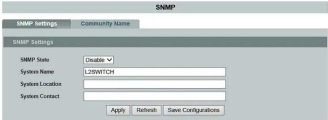
Figure 118: WBM "SNMP" Page – "SNMP Settings" Tab
Table 120: WBM "SNMP" Page – "SNMP Settings" Tab
| SNMP Settings | ||
| Parameter | Default | Description |
| SNMP State | Disable | Select “Disable” in the selection box to disable SNMP on the switch. |
| Enable | Select “Enable” in the selection box to enable SNMP on the switch. | |
| System Name | L2SWITCH | Enter the system name for the switch in the input field.(The system name and host name are identical.) |
| System Location | Enter the IP address (location information) of the switch in decimal-point notation. | |
| System Contact | Enter the IP subnet mask of the switch in decimal-point notation. | |
9.6.1.1.2 Community Name
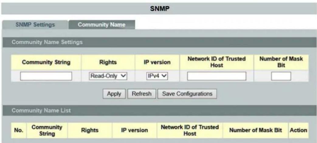
Figure 119: WBM "SNMP" Page – "Community Name" Tab
Table 121: WBM SNMP" Page – "Community Name" Tab
| Community Name Settings | ||
| Parameter | Default | Description |
| Community String | Enter the “Community String” that acts as a password for requests from the management station. | |
| Rights | Read Only | Select ““Read Only” in the selection box so that the SNMP manager can use this string to receive information from the switch. |
| Read/Write | Select “Read/Write” in the selection box so that the SNMP manager can use this string to configure settings on the switch. | |
| IP Version | IPv4 | Select “IPv4” in the selection field if you want to select this version of the Internet protocol. |
| IPv6 | Select “IPv6” in the selection box if you want to select this version of the Internet protocol. | |
| Network ID of the Trusted Host | Enter the IP address of the remote SNMP management station in decimal-point notation (e.g., 192.168.1.0). | |
| Number of Mask Bit | Enter the IP address of the subnet mask for the remote SNMP management station in decimal-point notation (e.g., 255.255.255.0). | |
| Community Name List | ||
| Parameter | Default | Description |
| No. | This column displays the “Community” number. It is used for identification only.Click a number to modify the setting for a specific “Community.” | |
| Community String | This column displays the “SNMP Community String.” This is a text element that acts as a password. | |
| Rights | Read Only, Read/Write | This column displays the rights for the “SNMP Community String.” |
| IP Version | IPv4IPv6 | This field displays the selected IP type. |
| Network ID of the Trusted Host | This column displays the IP address of the remote SNMP management station after it has been modified by the subnet mask. | |
| Number of Mask Bit | This column displays the subnet mask for the IP address of the remote SNMP management station. | |
| Action | Click [Delete] to delete a specific “Community String.” | |
9.6.1.2 SNMP Trap

Note
Additional information
Please refer to the section "Function Description" for more information on "SNMP Trap" (Simple Network Management Protocol Trap).
9.6.1.2.1 Trap Receiver Settings
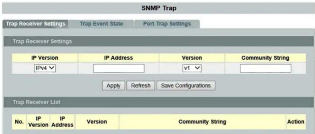
Figure 120: WBM "SNMP Trap" Page – "Trap Receiver Settings" Tab
Table 122: WBM "SNMP Trap" Page – "Trap Receiver Settings" Tab
| Trap Receiver Settings | ||
| Parameter | Default | Description |
| IP Version | IPv4 | Select "IPv4" in the selection field if you want to select this version of the Internet protocol. |
| IPv6 | Select "IPv6" in the selection box if you want to select this version of the Internet protocol. | |
| IP Address | Enter the IP address of the remote trap station in decimal-point notation. | |
| Version | v1 | Select "v1" in the selection box if you want to use SNMP Version v1. |
| v2c | Select "v2c" in the selection box if you want to use SNMP Version v2c. | |
| Community String | Enter the IP address of the remote SNMP management station in decimal-point notation (e.g., 192.168.1.0). | |
| Trap Receiver List | ||
| Parameter | Default | Description |
| No. | This column displays the "Community" number. It is used for identification only.Click a number to modify the setting for a specific "Community." | |
| IP Version | IPv4IPv6 | This column displays the selected IP type. |
| IP Address | This column displays the IP address of the remote trap station. | |
| Version | v1v2c | This column displays the SNMP version in use. |
| Community String | This column displays the "Community String" used by the remote trap station. | |
| Action | Click the [Delete] button to delete a configured trap receiver station. | |
9.6.1.2.2 Trap Event Status
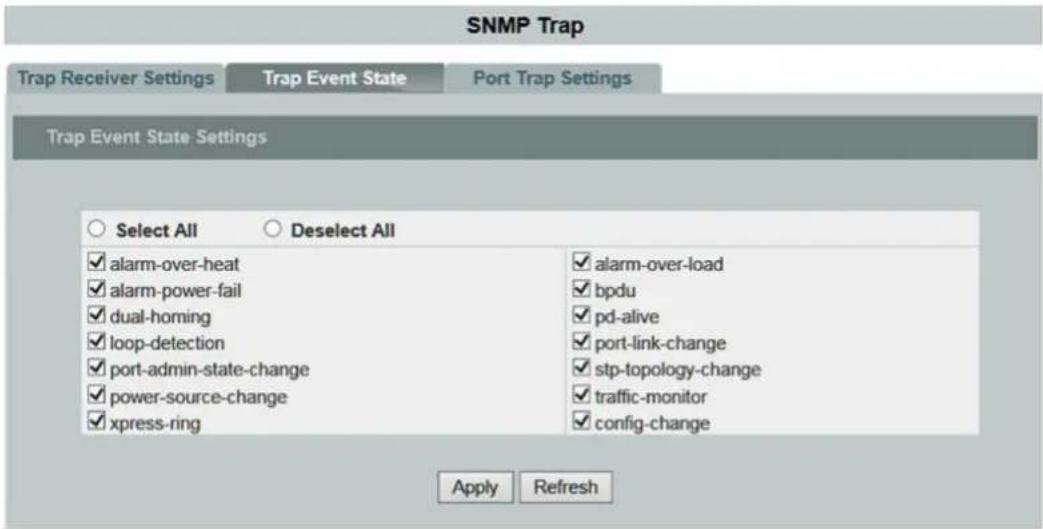
Figure 121: WBM "SNMP Trap" Page – "Trap Event State" Tab
Table 123: WBM "SNMP Trap" Page – "Trap Event State" Tab
| Trap Event State Settings | ||
| Parameter | Default | Description |
| alarm-over-heat | ☑ | Enables/disables the SNMP trap when the system temperature is too high. |
| alarm-power-fail | ☑ | Enables/disables the SNMP trap when system capacity is overvoltage/undervoltage. RPS overvoltage / RPS voltage |
| dual-homing | ☑ | Enables/disables the SNMP trap when the port is blocked by dual homing. |
| loop-detection | ☑ | Enables/disables the SNMP trap when the port is blocked by loop detection. |
| port-admin-state-change | ☑ | Enables/disables the SNMP trap when the port is enabled/disabled by the Administrator. |
| power-source-change | ☑ | Enables/disables the SNMP trap when the power source is changed (AC to DC or DC to AC). |
| xpress-ring | ☑ | Enables/disables the SNMP trap when the port is blocked by Xpress Ring. |
| alarm-over-load | ☑ | Enables/disables the SNMP trap when the system is overloaded. |
| bpdu | ☑ | Enables/disables the SNMP trap when the port is blocked by BPDU Guard/BDPU Root. The Guard/BPDU connection status is changed. |
| pd-alive | ☑ | Enables/disables the SNMP trap when the PD device does not receive any responses. |
| port-link-change | ☑ | Enables/disables the SNMP trap when the port switches between upward and downward. |
| stp-topology-change | ☑ | Enables/disables the SNMP trap when the STP topology changes. |
| traffic-monitor | ☑ | Enables/disables the SNMP trap when the port is blocked by the traffic monitor. |
| config-change | ☑ | Enables/disables the SNMP trap when the configuration is changed. |
9.6.1.2.3 Port Trap Settings
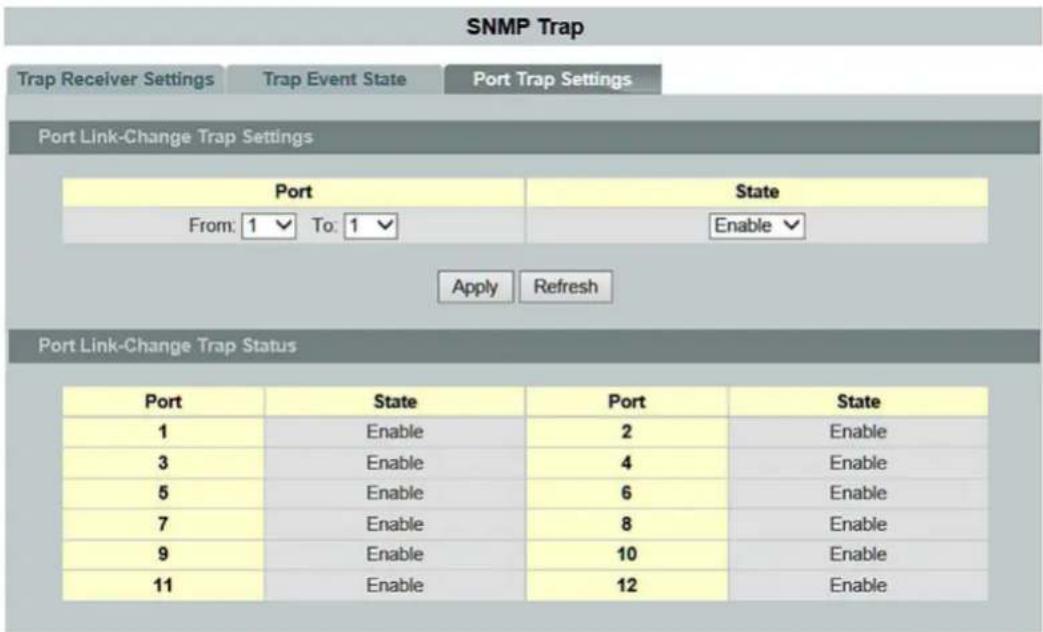
Figure 122: WBM "SNMP Trap" Page – "Port Trap Settings" Tab
Table 124: WBM "SNMP Trap" Page – "Port Trap Settings" Tab
| Port Link Change Trap Settings | |||
| Parameter | Default | Description | |
| Port | von: | 1 | Select a port or port range to configure in the selection box. |
| an: | 1 | Select a port or port range to configure in the selection box. | |
| State | Disable | Select “Enable” in the selection box to enable the port status. | |
| Enable | Select “Disable” in the selection box to disable the port status. | ||
| Port Link Change Trap Status | |||
| Parameter | Default | Description | |
| Port | 1 ... 10 (12) | This column displays the port range. | |
| State | Enable Disable | This field displays the port status. | |
9.6.1.3 SNMPv3 Configuration
9.6.1.3.1 SNMPv3 User

Note
Additional information
Please refer to the section "Function Description" for more information on "SNMPv3."
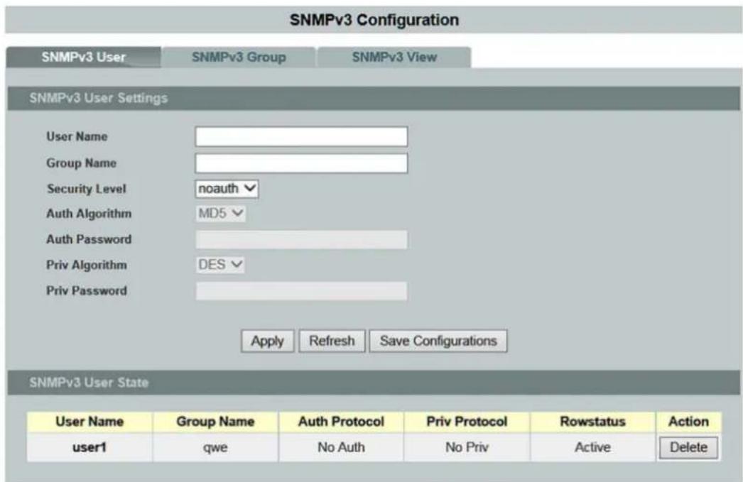
Figure 123: WBM "SNMPv3 Configuration" Page – "SNMPv3 User" Tab
Table 125: WBM "SNMPv3 Configuration" Page – "SNMPv3 User" Tab
| SNMPv3 User Settings | ||
| Parameter | Default | Description |
| User Name | Enter a new user name in the input field, or modify an existing user name. | |
| Group Name | Enter the group name for the SNMPv3 in the input field. | |
| Security Level | This selection box is used to select he security level. | |
| noauth | If you selected “noauth” in the selection box, you then cannot change the “Auth Algorithm” or the “Priv Algorithm.” | |
| auth | If you selected “auth” in the selection box, you then can change the “Auth Algorithm” and the “Auth Password.” | |
| priv | If you selected “priv” in the selection box, you then can change the “Auth Algorithm,” the “Priv Algorithm” and the “Priv Password.” | |
| Auth Algorithm | MD5 | If you selected “auth” or “priv” in the selection box, you then can change the “Auth Algorithm” “MD5.” |
| SHA | If you selected “auth” or “priv” in the selection box, you then can change the “Auth Algorithm” “SHA.” | |
| Auth Password | If you selected “auth” in the selection box, you can enter a password in the input field (consist of at least eight alphanumeric characters). | |
| Priv Algorithm | DES | If you selected “priv” in the selection box, you can then select “DES” in the selection box. |
| AES | If you selected “priv” in the selection box, you can then select “AES” in the selection box. | |
| Priv Password | If you selected “priv” in the selection box, you can enter a password in the input field (consist of at least eight alphanumeric characters). | |
| SNMPv3 User Status | ||
| Parameter | Default | Description |
| User Name | This column displays the user name. | |
| Group Name | This column displays the group name. | |
| Auth Protocol | This column displays the selected “Auth Algorithm.” | |
| Priv Protocol | This column displays the selected “Priv Algorithm.” | |
| Row Status | This column displays the state of the “Row Status”. | |
| Action | Click [Delete] to delete a specific entry. | |
9.6.1.3.2 SNMPv3 Groups

Figure 124: WBM "SNMPv3 Configuration" Page – "SNMPv3 Groups" Tab
Table 126: WBM "SNMPv3 Configuration" Page – "SNMPv3 Groups" Tab
| SNMPv3 Group Settings | ||
| Parameter | Default | Description |
| Group Name | Enter the group name for the SNMPv3 group in the input field. | |
| Security Level | This selection box is used to select he security level. | |
| Noauth auth priv | Select the respective security level in the selection box. | |
| Read View | In the input field, enter the name of the objects that should be available in the Read view. If you do not enter an object, all objects will be readable. | |
| Write View | In the input field, enter the name of the objects to which you want to grant write access. | |
| Notify View | In the input field, enter the name of the object that can receive user notifications. | |
| SNMPv3 Group Status | ||
| Parameter | Default | Description |
| Group Name | This column displays the group name. | |
| Security Model | This column displays the selected security level. | |
| Security Level | This column displays the selected security level. | |
| Read View | This column displays the Read view | |
| Write View | This column displays the Write view | |
| Notify View | This column displays the Notify view | |
| Action | Click [Delete] to delete a specific entry. | |
9.6.1.3.3 SNMPv3 View

Figure 125: WBM "SNMPv3 Configuration" Page – "SNMPv3 View" Tab
Table 127: WBM "SNMPv3 Configuration" Page – "SNMPv3 View" Tab
| SNMPv3 View Settings | ||
| Parameter | Default | Description |
| View Name | Enter the name for the SNMPv3 view in the input field. | |
| View Subtree | Enter the name for the subtree in the input field. | |
| View Type | Inserted | If you selected “Inserted” in the selection box, the subtree is inserted |
| Removed | If you selected “Removed” in the selection box, the subtree is not inserted. | |
| SNMPv3 View Status | ||
| Parameter | Default | Description |
| View Name | This column displays the name of the SNMPv3 view. | |
| View Subtree | This column displays the name of the subtree. | |
| View Type | Inserted Removed | This column displays the selected type. |
| Action | Click [Delete] to delete a specific entry. | |
9.6.2 Auto Provision

Note
Additional information
Please refer to the section "Function Description" for more information on "Auto Provision."
Auto Provision

Figure 126: WBM "Auto Provision" Page
Table 128: WBM "Auto Provision" Page
| Auto Provision Settings | ||
| Parameter | Default | Description |
| State | Disable | Select “Disable” in the selection box to disable the “Auto Provision” function on the switch. |
| Enable | Select “Enable” in the selection box to enable the “Auto Provision” function on the switch. | |
| Status | Disable | This field displays the “Auto Provision” status. |
| Version | 0 | This field displays the version. |
| Protocol | FTP | Select “FTP” (“File Transfer Protocol”) in the selection box if you want to select this type as the Auto Provision server. |
| TFTP | Select “TFTP” (“Trivial File Transfer Protocol”) in the selection box if you want to select this type as the Auto Provision server. | |
| HTTP | Select “HTTP” (“Hypertext Transfer Protocol”) in the selection box if you want to select this type as the Auto Provision server. | |
| Server IP | Enter the ID for the IP subnet mask of the server in decimal-point notation. | |
| User Name | Enter the name for the FTP server in the input field. | |
| Password | Enter the password for the FTP server in the input field. | |
| Folder Path | Select the folder structure of the FTP server in this input field. | |
9.6.3 Mail Alarm

Note
Additional information
Please refer to the section "Function Description" for more information on "Mail Alarm."
Mail Alarm

Figure 127: WBM "Mail Alarm" Page
Table 129: WBM "Mail Alarm" Page
| Mail Alarm Settings | ||||
| Parameter | Default | Description | ||
| State | Disable | Select "Disable" in the selection box to disable the "Mail Alarm" function. | ||
| Enable | Select "Enable" in the selection box to enable the "Mail Alarm" function. | |||
| Server IP | IP | Select "IP" in the selection box if you want to use the server IP of the mail server. | ||
| IPv6 | Select "IPv6" in the selection box if you want to use the server IP of the IPv6 server. | |||
| Domain | Select "Domain" in the selection box if you want to use the domain address of the mail server. | |||
| 0.0.0.0 | Enter the IP address in the input field. | |||
| Server Port (Default:25) | 25 | Enter the TCP port for SMTP in the input field. | ||
| Account Name | Enter the name of the e-mail account in the input field. | |||
| Account Password | Enter the password for the e-mail account in the input field. | |||
| Mail from | Enter the name of the e-mail sender in the input field. | |||
| Mail to | Enter the name of the e-mail recipient in the input field. | |||
| Trap State | Select All | ○ | ○ | No port has been selected for sending event traps. |
| ◎ | All ports are selected for sending event traps. | |||
| Disable All | ○ | ○ | No port has been disabled for sending event traps. | |
| ◎ | All ports are disabled for sending event traps. | |||
| System Restart | □ | □ | The port is not enabled. | |
| ☑ | The port is enabled. | |||
| Port Link Change | □ | □ | The "Port Link Change" state is disabled. | |
| ☑ | The "Port Link Change" state is enabled. | |||
| Configuration Change | □ | □ | The "Configuration Change" state is disabled. | |
| ☑ | The "Configuration Change" state is enabled. | |||
| Firmware Update | □ | □ | The "Firmware Upgrade" state is disabled. | |
| ☑ | The "Firmware Upgrade" state is enabled. | |||
| User Login | □ | □ | The "User Login" state is disabled. | |
| ☑ | The "User Login" state is enabled. | |||
| Port Blocked | □ | □ | The "Port Blocked" state is disabled. | |
| ☑ | The "Port Blocked" state is enabled. | |||
| Alarm | □ | □ | The "Alarm" state is disabled. | |
| ☑ | The "Alarm" state is enabled. | |||
9.6.4 Maintenance
9.6.4.1 Configuration

Figure 128: WBM "Maintenance" Page – "Configuration" Tab
Save Configuration
- Click the [Save Configurations] button to save the current settings in NV-RAM (Flash).
Upload and Download of the Configuration
Execute the following steps to upload the configuration file from your PC to the switch.
- Select "Upload the configuration file to the Switch."
- Click the [Choose file] button. Select the configuration file by specifying the full path.
- Click the [Upload] button to begin uploading the file.
Execute the following steps to save the configuration file to your PC.
- Select "Press Download to save the configuration file to your PC."
- Click the [Download] button to start the download.
Reset Configuration
- Click the [Reset] button to reset the switch configuration to the factory default.
Configuration Status
"The configurations have been changed" indicates that changes have been made to the configurations.
If no changes were made to the configurations, the following message appears: "The user configuration file is the default. The configurations are default values."
9.6.4.2 Firmware
![graph TD A["Maintenance"] --> B["Configuration"] A --> C["Firmware"] A --> D["Reboot"] A --> E["Protocols"] F["Upgrade Firmware"] --> G["File path: Durchsui No file chosen"] F --> H["Upgrade"]](/content/2026/05/1008228/images/171da164faa1d46e1a1044d4bd5f201a4afe822bc35d7ab499ec78ebdbdeb16f.jpg)
Figure 129: WBM "Maintenance" Page – "Firmware" Tab
Firmware Update
Execute the following steps to update the switch's firmware.
- Click the [Choose file] button.
The file selection dialog opens. Select the respective firmware file. - Click the [Upgrade] button to load the new firmware.
9.6.4.3 Reboot

Figure 130: WBM "Maintenance" Page – "Reboot" Tab
Reboot
The "Reboot" function allows you to restart the switch without physically turning the power off.
Follow the steps below to reboot the switch.
- Click the [Reboot] button in the "Reboot" menu. The following windows open:
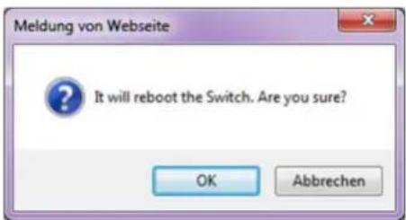
Figure 131: WBM "Maintenance" Page – "Reboot" Tab – Message
- Click [OK] and wait for the switch to restart. The process can take up to two minutes. This process does not change the switch configuration.
9.6.4.4 Protocols

Figure 132: WBM "Maintenance" Page – "Protocols" Tab
Table 130: WBM "Maintenance" Page – "Protocols" Tab
| Server Settings | ||
| Parameter | Default | Description |
| HTTP Server State | Enable | Select “Enable” to enable the HTTP server. |
| Disable | Select “Disable” to disable the HTTP server. | |
| HTTP Server TCP Port (80, 1025–9999) | 801025 ... 9999 | Enter the “HTTP Server TCP Port” in the input field. |
| HTTP Server State | Enable | Select “Enable” to enable the HTTPS server. |
| Disable | Select “Disable” to disable the HTTPS server. | |
| SNMP v1/v2c Server State | Enable | Select “Enable” to enable the SNMP v1/v2c server. |
| Disable | Select “Disable” to disable the SNMP v1/v2c server. | |
| SNMP v3 Server State | Enable | Select “Enable” to enable the SNMP v3 server. |
| Disable | Select “Disable” to disable the SNMP v3 server. | |
| SSH Server State | Enable | Select “Enable” to enable the SSH server. |
| Disable | Select “Disable” to disable the SSH server. | |
| Telnet Server State | Enable | Select “Enable” to enable the Telnet server. |
| Disable | Select “Disable” to disable the Telnet server. | |
| Telnet Server TCP Port (23, 1025~9999) | 231025 ... 9999 | Enter the “Telnet Server TCP Port” in the input field. |
| Server Status | ||
| Parameter | Default | Description |
| HTTP Server State | EnableDisable | This field displays the status of the HTTP server. |
| HTTP Server TCP Port | 801025 ... 9999 | This field displays the status of the HTTP server TCP port. |
| HTTP Server State | EnableDisable | This field displays the status of the HTTPS server. |
| SNMP v1/v2c Server State | EnableDisable | This field displays the status of the SNMP v1/v2c server. |
| SNMP v3 Server State | EnableDisable | This field displays the status of the SNMP v3 server. |
| SSH Server State | EnableDisable | This field displays the status of the SSH server. |
| Telnet Server Status | EnableDisable | This field displays the status of the Telnet server. |
| Telnet Server TCP Port | 231025 ... 9999 | This field displays the status of the Telnet server TCP port. |
9.6.5 System Log
The "syslog" function records various system information for "Debugging."
Each log entry records one of the following levels:
- Alert
- Critical
- Error
- Warning
- Notice
- Information
The Syslog function can be enabled or disabled. The default setting is "disabled."
The log message is recorded in the switch's file system. If the IP address of the syslog server has been configured, the switch sends a copy to it.

Note
Size of the Log Message File
The size of the log message file is limited to 4 KB. If the file is full, the oldest message is replaced.

Figure 133: WBM "System Log" Page
Table 131: WBM "System Log" Page
| Syslog Server Settings | ||
| Parameter | Default | Description |
| Server IP | IPv4 | Select “IPv4” in the selection field if you want to select this version of the Internet protocol. |
| IPv6 | Select “IPv6” in the selection box if you want to select this version of the Internet protocol. | |
| Enter the IP address in decimal-point notation (e.g., 192.168.1.1). | ||
| Disable | Select “Disable” in the selection box to prevent the switch from sending all new log messages to the syslog server. | |
| Enable | Select “Enable” in the selection box to allow the switch to send all new log messages to the syslog server. | |
| Facility | (1) User-level messages | Select “(1) User-level messages” in the selection box if you want to display user-specific messages. |
| (5) Messages generated internally by syslogd | Select “(5) Messages generated internally by syslogd” in the selection box if you want to display messages generated by syslog internally. | |
| (14) Log alert | ||
| (16) Local use 0 | ||
| (17) Local use 1 | ||
| (18) Local use 2 | ||
| (19) Local use 3 | ||
| (20) Local use 4 | ||
| (21) Local use 5 | ||
| (22) Local use 6 | ||
| (23) Local use 7 | ||
| System Log | ||
| Parameter | Default | Description |
| Log Level | All | Select “All” in the selection box if you want to display all log messages. |
| 1:Alarm | Select “Alarm” in the selection box if you want to display the log messages. | |
| 2:Critical | Select “Critical” in the selection box if you want to display critical log messages. | |
| 3:Error | Select “Error” in the selection box if you want to display the errors. | |
| 4:Warning | Select “Warning” in the selection box if you want to display the warnings. | |
| 5:Notice | Select “Notice” in the selection box if you want to display the notices. | |
| 6:Information | Select “Information” in the selection box if you want to display all information. | |
9.6.6 Ping

Note
Additional information
Please refer to the section "Function Description" for more information on "Ping".
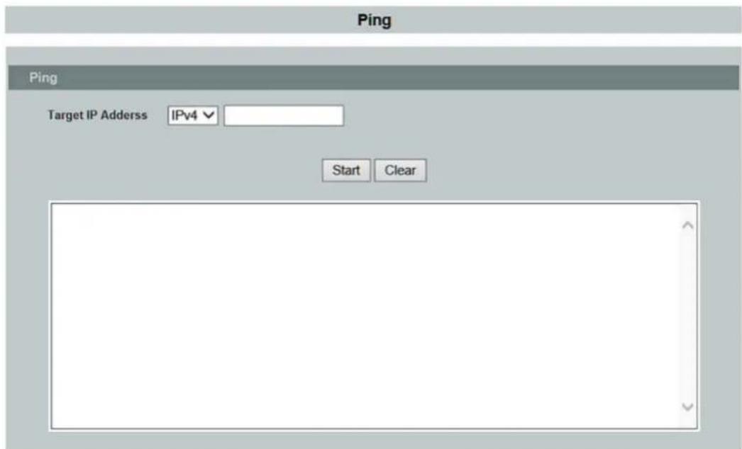
Figure 134: WBM "Ping" Page
Table 132: WBM „Ping“ Page
| Ping | ||
| Parameter | Default | Description |
| Target IP Address | IPv4 | Select “IPv4” in the selection box to enable this Internet protocol version. |
| IPv6 | Select “IPv6” in the selection box to enable this Internet protocol version. | |
9.6.7 USB Functions
The following functions can be performed through the switch's USB interface:
- Uploading the firmware
- Saving the configuration file
- Saving the Syslog file
- Uploading the configuration file
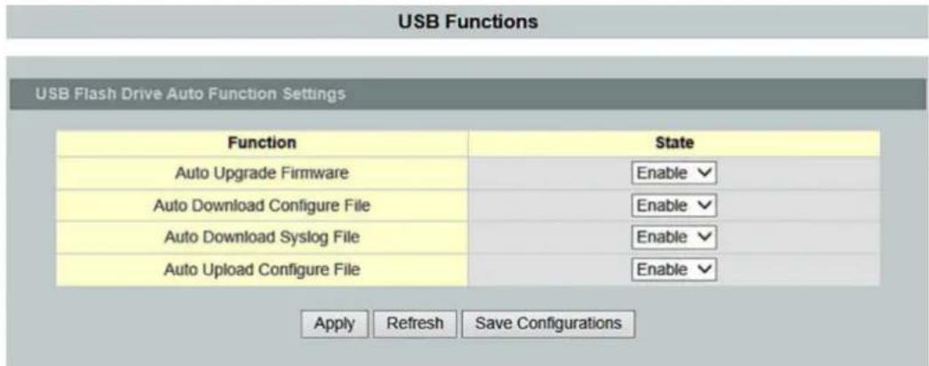
Figure 135: WBM "USB Functions" Page
Table 133: WBM „USB Functions“ Page
| USB Flash Drive Auto Function Settings | ||
| Parameter | Default | Description |
| Function | The USB function can be selected in this column. | |
| Auto Upgrade Firmware | Enable | Select “Enable” in the selection box to enable the function. |
| Auto Download Configure File | ||
| Auto Download Syslog File | ||
| Auto Upload Configure File | Disable | Select “Disable” in the selection box to disable the function. |
9.6.8 User Account
The switch allows users to create up to six user accounts. The user name and password must be a combination of numbers or letters. The last admin account cannot be deleted. To use the CLI or Web-Based Management, a user has to be logged into a valid user account.
User Permissions
The switch supports two types of user accounts:
The default user accounts have the following credentials:
User Name = "admin"
User Password = "wago"
-
Admin account Read/Write permissions
-
Normal user account Read permission only
-
Use of the privileged mode in the CLI is not possible.
- Configurations cannot be changed in the Web-Based Management.
The switch also supports a "backdoor" user account. If a user has forgotten his user name or password, the switch can create a "backdoor" account with the MAC address of the system. A usesr can then log into the switch and create a new account.

Figure 136: WBM "User Account" Page
Table 134: WBM "User Account" Page
| User Account Settings | |||
| Parameter | Default | Description | |
| User Name | Enter a new user name in the input field, or modify an existing user name. | ||
| User Password | Enter a new password in the input field, or modify an existing password.You can enter up to 32 alphanumeric characters or digits. | ||
| User Authority | In this box, select the type of user account. | ||
| Normal | Select “Normal” in the selection box if you need only read permission for this user account. | ||
| Admin | Select “Admin” in the selection box if you need read and write permission for this user account. | ||
| Parameter | Default | Description | |
| No. | This column displays the index number of an entry. | ||
| Name | This column displays the name of the user account. | ||
| Authority | This column displays the type of user account. | ||
| Action | Click the [Delete] button to delete a user account. | ||
 | NoteDeleting an administrator accountThe last admin account cannot be deleted. | ||
10 Appendix
10.1 Console Port (RJ-45 to DB9)
Use the included console cable to connect the console port of the industrial managed switch to the COM port. The connector pin assignment is:

Figure 137: RJ-45 Connector Pin Assignment

Figure 138: Connector Pin Assignment RJ-45 to DB9
10.2 RJ-45 Cable
Always use category 5e cables to connect your network devices. The pin assignment is given below:
Table 135: RJ-45 Cable
| Contact | Description | Pair | Color (acc. EIA/TIA 568B) | |
| 4-wire | 8-wire | |||
| 1 | TD | D1+ | 2 | White/Orange |
| 2 | TD- | D1- | 2 | Orange |
| 3 | RX+ | D2+ | 3 | White/Green |
| 4 | Not assigned | D3+ | 1 | Blue |
| 5 | Not assigned | D3- | 1 | White/Blue |
| 6 | RX- | D2- | 3 | Green |
| 7 | Not assigned | D4+ | 4 | White/Brown |
| 8 | Not assigned | D4- | 4 | Brown |

Note
Functions on the RJ45 connector
The industrial managed switch offers the functions autocrossing und autonegotiation to the RJ-45 connection.
10.3 Configuring in the Command Line Interface (CLI)
10.3.1 System Status
10.3.1.1 System Information
Table 136: CLI "System Information" Configuration
| Node | Command | Description |
| enable | show hostname | This command displays the system's network name. |
| configure | reboot | This command reboots the system. |
| eth0 | ip address A.B.C.D/M | This command configures the static IP and subnet mask for the system. |
| interface | show | This command displays the current port configuration. |
| acl | show | This command displays the current access control list. |
| vlan | show | This command displays the current VLAN configuration. |
| enable | show interface eth0 | This command displays the current Eth0 configurations. |
| enable | show model | This command displays the system information. |
| enable | show running-config | This command displays the current operating configurations. |
| enable | show system-info | This command displays the system's CPU utilization and memory information. |
| enable | show uptime | This command displays the system uptime. |
10.3.2 Basic Settings
10.3.2.1 System
Table 137: CLI "System" Configuration
| Node | Command | Description |
| enable | ping IPADDR [-c COUNT] | This command sends an echo request to the destination host. The -c parameter allow user to specific the packet count.The default count is 4. |
| enable | ping IPADDR s SIZE] | This command sends an echo request to the destination host. The -s parameter allow user to specific the packet size.Valid range: 0 ~ 1047 bytes. |
| enable | ping IPADDR [-c COUNT -s SIZE] | This command sends an echo request to the destination host. The -c parameter allow user to specific the packet count.The default count is 4.The -s parameter allow user to specific the packet size.Valid range: 0 ~ 1047 bytes. |
| enable | ping IPADDR [-s SIZE -c COUNT] | This command sends an echo request to the destination host. The -c parameter allow user to specific the packet count.The default count is 4.The -s parameter allow user to specific the packet size.Valid range: 0 ~ 1047 bytes. |
| configure | reboot | This command reboots the system. |
| configure | hostname STRINGS | This command sets the system's network name. |
| configure | interface eth0 | This command enters the eth0 interface node to configure the system IP. |
| configure | configure terminal | This command changes the mode to config mode. |
| configure | interface eth0 | This command changes the mode to eth0 mode. |
| eth0 | show | This command displays the eth0 configurations. |
| eth0 | ip address A.B.C.D/M | This command configures a static IP and subnet mask for the system. |
| eth0 | ip address default-gateway A.B.C.D | This command configures the system's default gateway. |
| eth0 | ip dhcp client (disable|enable|renew) | This command configures a DHCP client function for the system."Disable": Use a static IP address for the switch."Enable & Renew": Use the DHCP client to get an IP address from the DHCP server. |
| eth0 | management vlan VLAN_ID | This command configures the management VLAN. |
| eth0 | ip ipv6-addressAAAA:BBBB:CCC C:DDDD:EEEE:FFFF:GG GG:HHHH/M | This command configures a global scope of IPv6 address and subnet mask for the system. |
| eth0 | ip ipv6-addressdefault-gatewayAAAA:BBBB:CCC C:DDDD:EEEE:FFFF:GG GG:HHHH | This command configures a default gateway for the system. |
| eth0 | ip ipv6-dhcp client (disable|enable|renew) | This command configures a DHCPv6 client function for the system. |
10.3.2.1.1 Jumbo Frame
Table 138: CLI "Jumbo Frame" Configuration
| Node | Command | Description |
| enable | show jumboframe | This command displays the current jumbo frame settings. |
| configure | jumboframe(10240|1522|1536|1552|9216) | This command configures the maximum number of bytes of frame size for all ports. |
| configure | interface IFNAME | This command enters the interface configure node. |
| interface | jumboframe(10240|1522|1536|1552|9010|9216) | This command configures the maximum number of bytes of frame size. |
| configure | interface range gigabitethernet1/0/PORTLISTS | This command enters the interface configure node. |
| if-range | jumboframe(10240|1522|1536|1552|9010|9216) | This command configures the maximum number of bytes of frame size. |
10.3.2.1.2 SNTP
Table 139: CLI "SNTP" Configuration
| Node | Command | Description |
| enable | show time | This command displays the current time and date configuration. |
| configure | time HOUR:MINUTE:SECOND | This command sets the current time of the switch. hour: 0-23 min: 0-59 sec: 0-59 Note: If you configure daylight saving time after you configure the date and time, the switch uses daylight saving time. |
| configure | time date YEAR/MONTH/DAY | This command sets the current date of the switch. year: 1970–month: 1–12 day: 1–31 |
| configure | time daylight-saving-time | This command enables the daylight saving time. |
| configure | no time daylight-saving-time | This command disables daylight saving time on the switch. |
| configure | time daylight-saving-time start-date (first|second|third|fourth| last) (Sunday|Monday|Tuesday| Wednesday|Thursday| Friday|Saturday) MONTH HOUR | This command sets the start date of daylight saving time. |
| configure | time daylight-saving-time end-date (first|second|third|fourth| last) (Sunday|Monday|Tuesday| Wednesday|Thursday| Friday|Saturday) MONTH HOUR | This command sets the end date of daylight saving time. |
| configure | time ntp-server (disable|enable) | This command disables/enables the NTP server settings. |
| configure | time ntp-server IP_ADDRESS | This command sets the IP address of the time server. |
| configure | time ntp-server domain-name STRING | This command sets the domain names of the time server. |
| configure | time timezone STRING | This command sets the time difference between UTC (formerly GMT) and the time zone. Valid range: -1200 ... +1200 |
Example
L2SWITCH(config)#time ntp-server 192.5.41.41
L2SWITCH(config)#time timezone +0800
L2SWITCH(config)#time ntp-server enable
L2SWITCH(config)#time daylight-saving-time start-date first Monday 6 0
L2SWITCH(config)#time daylight-saving-time end-date last Saturday 10 0
10.3.2.1.3 Management Host
Table 140: CLI "Management Host" Configuration
| Node | Command | Description |
| enable | show interface eth0 | The command displays all eth0 interface configurations. |
| eth0 | show | The command displays all eth0 interface configurations. |
| eth0 | management host A.B.C.D | The command adds a management host address. |
| eth0 | no management host A.B.C.D | The command deletes a management host address. |
Example
L2SWITCH#configure terminal
L2SWITCH(config)#interface eth0
L2SWITCH(config-if)#management host 192.168.200.106
10.3.2.2 MAC Management
Table 141: CLI "MAC Management" Configuration
| Node | Command | Description |
| enable | show mac-address-table aging-time | This command displays the current “Age Time” for the MAC address table. |
| enable | show mac-address-table (static|dynamic) | This command displays the current static/dynamic unicast address entries. |
| enable | show mac-address-table mac MACADDR | This command displays information of a specific MAC address table. |
| enable | show mac-address-table port PORT_ID | This command displays the current unicast address entries recognized by the specific port. |
| configure | mac-address-table static MACADDR vlan VLANID port PORT_ID | This command configures a static unicast entry. |
| configure | no mac-address-table static MACADDR vlan VLANID | This command deletes a static unicast entry from the address table. |
| configure | mac-address-table aging-time VALUE | This command configures the MAC table “Age Time”. |
| configure | clear mac address-table dynamic | This command deletes the dynamic address entries. |
Example
L2SWITCH(config)#mac-address-table static 00:11:22:33:44:55 vlan 1 port 1
10.3.2.2.1 Blackhole MAC
Table 142: CLI "Blackhole MAC" Configuration
| Node | Command | Description |
| enable | show mac-address-table refusal | This command displays the current rejected MAC address only. |
| configure | mac-address-table refusal MACADDR vlan VLANID | This command configures the rejection of a MAC address in a specific VLAN. |
| configure | mac-address-table refusal MACADDR | This command configures the rejection of a MAC address. |
Example
L2SWITCH(config)#mac-address-table refusal 00:11:22:33:44:55
L2SWITCH(config)#mac-address-table refusal 00:11:22:33:44:55 vlan 1
10.3.2.3 Port Mirroring
Table 143: CLI "Port Mirroring" Configuration
| Node | Command | Description |
| enable | show mirror | This command displays the current “Port Mirroring” configurations. |
| configure | mirror (disable|enable) | This command disables/enables “Port Mirroring” on the switch. |
| configure | mirror destination port PORT_ID | This command specifies the monitor port for the port mirroring. |
| configure | mirror source ports PORT_LIST mode (both|ingress|egress) | This command adds a port or a range of ports as the source ports of the port mirroring. |
| configure | no mirror source ports PORT_LIST | This command removes a port or a range of ports from the source ports of the port mirroring. |
Example
L2SWITCH#configure terminal
L2SWITCH(config)#mirror enable
L2SWITCH(config)#mirror destination port 2
L2SWITCH(config)#mirror source ports 3-10 mode both
10.3.2.4 Port Settings:
Table 144: CLI "Port Settings" Configuration
| Node | Command | Description |
| enable | show interface IFNAME | This command displays the current port configurations. |
| configure | interface IFNAME | This command enters the interface configure node. |
| interface | show | This command displays the current port configurations. |
| interface | loopback (none|mac) | This command tests the loopback mode of operation for the specific port. |
| interface | Flow control (off|on) This command disables/enables the flow control for the port. | |
| interface | speed (auto|10-full||10-half|100-full|100-half) | This command configures the speed and duplex mode for a port. |
| interface | Shutdown | This command disables a specific port. |
| interface | no shutdown | This command enables a specific port. |
| interface | description STRINGs | This command configures a description for the specific port. |
| interface | no description | This command configures the default port description. |
| interface | cable test | This command diagnostics the Ethernet cable and shows the broken distance. |
| interface | clean cable-test result | This command cleans the test result of the Ethernet cable test. |
| interface | show cable-test result | This command displays the test result of the Ethernet cable test. |
| configure | interface range gigabitethernet1/0/PORTLI STS | This command enters the interface configure node. |
| if-range | description STRINGs | This command configures a description for the specific ports. |
| if-range | no description | This command configures the default port description for the specific ports. |
| if-range | shutdown | This command disables the specific ports. |
| if-range | no shutdown | This command enables the specific ports. |
| if-range | speed (auto|10-full||10-half|100-full|100-half|1000-full) | This command configures the speed and duplex for the port. |
Example
L2SWITCH#configure terminal
L2SWITCH(config)#interface gil/0/1
L2SWITCH(config-if)#speed auto
10.3.3 Advanced Settings
10.3.3.1 Bandwidth Control
10.3.3.1.1 QoS
Table 145: CLI "QoS" Configuration
| Node | Command | Description |
| enable | show queue cos-map | This command displays the current 802.1p priority mapping to the “Service Queue”. |
| enable | show qos mode | This command displays the current IEEE 802.1p QoS mode. |
| configure | queue cos-map PRIORITY QUEUE_ID | This command configures the 802.1p priority mapping of the “Service Queue”. |
| configure | no queue cos-map | This command configures the default settings for the 802.1p priority mapping of the “Service Queue”. |
| configure | qos mode high-first | This command sets the QoS mode to “high_first” so every “Hardware Queue” transmits all packets in its buffer before permitting the next lower priority queue to transmit its packets. |
| configure | qos mode wrr-queue weights VALUE VALUE VALUE VALUE VALUE VALUE VALUE | This command sets the QoS mode to “Weighted Round Robin”. |
| interface | default-priority | This command allows the user to specify which priority is assigned by default to the untagged packets received by the switch. The priority value entered with this command is used to determine which of the “Hardware Priority Queues” the packet is forwarded to.Default: 0. |
| interface | no default-priority | This command sets the default priority for the specific port to 0. |
| enable | show diffserv | This command displays DiffServ configurations. |
| configure | diffserv (disable|enable) | This command disables/enables the DiffServ function. |
| configure | diffserv dscp VALUE priority VALUE | This command sets the DSCP-to-IEEE 802.1q mappings. |
10.3.3.1.2 Rate Limitation
Table 146: CLI "Rate Limitation" Configuration
| Node | Command | Description |
| enable | show bandwidth-limit | This command displays the current “Rate Limitation” configurations. |
| configure | bandwidth-limit egress RATE_LIMIT ports PORTLISTS | This command enables the rate limitation for outgoing packets and sets the limit. |
| configure | no bandwidth-limit egress ports PORTLISTS | This command disables the rate limitation for outgoing packets. |
| configure | bandwidth-limit ingress RATE_LIMIT ports PORTLISTS | This command enables the rate limitation for incoming packets and sets the limit. |
| configure | no bandwidth-limit ingress ports PORTLISTS | This command disables the rate limitation for incoming packets. |
Example
L2SWITCH#configure terminal
L2SWITCH(config)#bandwidth-limit egress 1 ports 1-8
L2SWITCH(config)#bandwidth-limit ingress 1 ports 1-8
10.3.3.1.2.1 Storm Control
Table 147: CLI "Storm Control" Configuration
| Node | Command | Description |
| enable | show storm-control | This command displays the current “Storm Control” configurations. |
| configure | storm-control rate RATE_LIMIT type (bcast|mcast|DLF|bcast+ mcast|bcast+DLF|mcast+ DLF|bcast+mcast+DLF) ports PORTLISTS | This command enables the rate limitation for broadcast, multicast or DLF packets and sets the rate limitation for a specified type. |
| configure | no storm-control type (bcast|mcast|DLF|bcast+ mcast|bcast+DLF|mcast+ DLF|bcast+mcast+DLF) ports PORTLISTS | This command disables the rate limitation for broadcast, multicast or DLF packets. |
Example
L2SWITCH#configure terminal
L2SWITCH(config)#storm-control rate 1 type broadcast ports 1-6
L2SWITCH(config)#storm-control rate 1 type multicast ports 1-6
L2SWITCH(config)#storm-control rate 1 type DLF ports 1-6
10.3.3.2 IGMP Snooping
Table 148: CLI "IGMP Snooping" Configuration
| Node | Command | Description |
| enable | show igmp-snooping | This command displays the current “IGMP Snooping” configurations. |
| enable | show igmp-snooping counters | This command displays the current IGMP snooping counters. |
| enable | show igmp-snooping querier | This command displays the current IGMP Queriers. |
| enable | show multicast | This command displays the multicast group in IP format. |
| configure | clear igmp-snooping counters | This command clears all of the IGMP snooping counters. |
| configure | igmp-snooping (disable|enable) | This command disables/enables “IGMP Snooping” on the switch. |
| configure | igmp-snooping vlan VLAN_ID | This command enables “IGMP Snooping” on a VLAN or VLAN range. |
| configure | no igmp-snooping vlan VLAN_ID | This command disables “IGMP Snooping” on a VLAN or VLAN range. |
| configure | igmp-snooping unknown-multicast(drop|flooding) | This command configures the process for unknown multicast packets when the IGMP snooping function is enabled. |
| configure | igmp-snooping report-suppression (disable|enable) | This command disables/enables the “IGMP Snooping Report Suppression” function on the switch. |
| configure | clear igmp-counters | This command clears the IGMP snooping counters. |
| interface | igmp-querier-mode (auto|fixed|edge) | This command specifies if and under what conditions the ports are “IGMP Query Ports”.The switch forwards the “IGMP Join/Leave” packets to an “IGMP Query Port,” treating the port as if it were connected to an IGMP multicast router (or server).“IGMP Snooping” must also be enabled (default: “Auto”). |
| interface | igmp-immediate-leave | The command enables the “Immediate Leave” function for “IGMP Snooping” for a specific interface. |
| interface | no igmp-immediate-leave | The command disables the “Immediate Leave” function for “IGMP Snooping” for a specific interface. |
| interface | igmp-snooping group-limit VALUE | This command configures the maximum groups for the specific interface. |
| interface | no igmp-snooping group-limit | This command removes the limitation of the maximum groups for the specific interface. |
| configure | interface range gigabitethernet1/0/PORTLI STS | This command enters the interface configure node. |
| if-range | igmp-immediate-leave | This command enables the IGMP Snooping immediate leave function for the specific ports. |
| if-range | no igmp-immediate-leave | This command disables the IGMP Snooping immediate leave function for the specific ports. |
| if-range | igmp-snooping group-limit VALUE | This command configures the maximum groups for the specific ports. |
| if-range | no igmp-snooping group-limit | This command removes the limitation of the maximum groups for the specific ports. |
| if-range | igmp-querier-mode (auto|fixed|edge) | This command specifies whether or not and under what conditions the ports are (are) IGMP query port(s). The Switch forwards IGMP join or leave packets to an IGMP query port, treating the port as being connected to an IGMP multicast router (or server). You must enable IGMP snooping as well. Default: auto |
Example
L2SWITCH(config)#igmp-snooping enable
L2SWITCH(config)#igmp-snooping vlan 1
L2SWITCH(config)#igmp-snooping querier enable
L2SWITCH(config)#igmp-snooping querier vlan 1
L2SWITCH(config)#interface 1/0/1
L2SWITCH(config-if)#igmp-immediate-leave
L2SWITCH(config-if)# igmp-querier-mode fixed
L2SWITCH(config-if)# igmp-snooping group-limit 20
10.3.3.2.1 IGMP Snooping Querier
Table 149: CLI "IGMP Snooping Querier" Configuration
| Node | Command | Description |
| configure | igmp-snooping querier (disable|enable) | This command disables/enables the IGMP snooping querier on the Switch. |
| configure | igmp-snooping querier vlan VLANIDs | This command enables the IGMP snooping querier function on a VLAN or range of VLANs. |
| configure | no igmp-snooping querier vlan VLANIDs | This command disables the IGMP snooping querier function on a VLAN or range of VLANs. |
10.3.3.2.2 IGMP Snooping Filtering
Table 150: CLI "IGMP Snooping Filtering" Configuration
| Node | Command | Description |
| enable | show igmp-snooping filtering | This command displays the IGMP snooping filtering configurations. |
| configure | igmp-snooping filtering (enable|disable) | This command enables/disables the IGMP snooping filtering profiles on the Switch. |
| configure | igmp-snooping filtering profile | This command enters the IGMP snooping filtering profiles configuration node. |
| configure | no igmp-snooping filtering all | This command removes all of the IGMP snooping filtering profiles from the Switch. |
| configure | no igmp-snooping filtering STRINGS | This command removes the IGMP snooping filtering profiles by name from the Switch. |
| config-igmp | Group GROUP_ID start-address START-ADDR end-address END-ADDR | This command configures the group configurations, including group index and start multicast address and end multicast address. |
| config-igmp | type (deny|permit) | This command configures the type of deny or permit for the group. |
| config-igmp | no group GROUP-ID | This command removes the group configurations. |
| config-igmp | no group all | This command removes all of the group configurations. |
| config-igmp | type (deny|permit) | This command configures the type of deny or permit for the group. |
| interface | igmp-snooping filtering profile STRING | This command enables the IGMP snooping filtering profiles on the specific port. |
| interface | no igmp-snooping filtering profile STRINGS | This command disables the IGMP snooping filtering profiles on the specific port. |
| configure | interface range gigabitethernet1/0/PORTLISTS | This command enters the interface configure node. |
| if-config | igmp-snooping filtering profile STRING | This command enables the IGMP snooping filtering profiles on the range of ports. |
| if-config | no igmp-snooping filtering profile STRINGS | This command disables the IGMP snooping filtering profiles on the range of ports. |
10.3.3.2.3 MVR
Table 151: CLI "MVR" Configuration
| Node | Command | Description |
| enable | show mvr | This command displays the current MVR configurations. |
| enable | show mvr vlan VLANID | This command displays the current MVR configurations of the specific VLAN. |
| enable | show igmp-snooping | This command displays the current “IGMP Snooping” configurations. |
| configure | mvr VLANID | This command creates the MVR configurations for the specific VLAN. |
| configure | no mvr VLANID | This command disables the MVR configurations for the specific VLAN. |
| MVR | group NAME | This command creates a group configuration for the MVR. |
| MVR | no group NAME | This command deletes the group configurations from the MVR. |
| MVR | inactive | This command disables the MVR settings. |
| MVR | no inactive | This command enables the MVR settings. |
| MVR | mode (dynamic|compatible) | This command configures the mode for the MVR.- Dynamic: Sends “IGMP reports” to all MVR source ports in the multicast VLAN.- Compatibility: The switch does not send any “IGMP Reports”. |
| MVR | name STRING | This command configures the name for the MVR. |
| MVR | no name | This command configures the default name for the MVR. |
| MVR | receiver-port PORTLIST | This command sets the receiver port or receiver port range. Normally, the source ports are connected to the streaming client. |
| MVR | no receiver-port PORTLIST | This command removes a port or range of ports from the list of receiver ports. |
| MVR | source-port PORTLIST | This command sets the source port or source port range. Normally, the source ports are connected to the streaming server. |
| MVR | no source-port PORTLIST | This command removes a port or range of ports from the list of source ports. |
| MVR | tagged PORTLIST | This command assigns a tagged port or port range. The same applies to VLAN tagged ports. |
| MVR | no tagged PORTLIST | This command removes a port or range of ports from the tagged port(s). |
| MVR | priority-override (disable|enable) | This command enables/disables the multicast priority override. |
10.3.3.2.4 Multicast Address
Table 152: CLI "Multicast Address" Configuration
| Node | Command | Description |
| enable | show mac-address-table multicast | This command displays the current static/dynamic multicast address entries. |
| enable | show mac-address-table multicast vlan VLANID | This command displays the current static/dynamic multicast address entries with a specific vlan. |
| configure | mac-address-table multicast MACADDR vlan VLAN_ID ports PORTLIST | This command configures a static multicast entry. |
| configure | no mac-address-table multicast MACADDR | This command deletes a static multicast entry from the address table. |
10.3.3.3 VLAN
10.3.3.3.1 Port Isolation
Table 153: CLI "Port Isolation" Configuration
| Node | Command | Description |
| enable | show port-isolation | This command displays the current “Port Isolation” configurations.“V” indicates that the port’s packets can be sent to this port.“-” indicates that the port’s packets cannot be sent to this port. |
| interface | port-isolation ports PORTLISTS | This command configures a port or a range of ports to forward traffic from a specific port. |
| interface | no port-isolation | This command configures all ports to forward data packets from a specific port. |
Example
L2SWITCH(config)#interface 1/0/2
L2SWITCH(config-if)#port-isolation ports 3-10
10.3.3.3.2 VLAN Settings
Table 154: CLI "VLAN Settings" Configuration
| Node | Command | Description |
| enable | show vlan VLANID | This command displays the VLAN configurations. |
| configure | vlan <1-4094> | This command enables a VLAN and enters the VLAN node. |
| configure | no vlan <1-4094> | This command deletes a VLAN. |
| vlan | show | This command displays the current VLAN configurations. |
| vlan | name STRING | This command assigns a name for the specific VLAN. The VLAN name should be a combination of numbers, letters, hyphens (-) and underscores (_). The maximum length of the name is 16 characters. |
| vlan | no name | This command resets the VLAN name to the default setting.Note: The default VLAN name is comprised as follows: “VLAN”+VLAN_ID, VLAN1, VLAN2, ... |
| vlan | add PORTLISTS | This command adds a port or a range of ports to the vlan. |
| vlan | fixed PORT_LIST | This command assigns ports to a VLAN group as fixed subscribers. |
| vlan | no fixed PORTLISTS | This command deletes all fixed ports from a VLAN. |
| vlan | tagged PORT_LIST | This command assigns fixed ports to a VLAN group as tagged subscribers. The port(s) should be a fixed subscriber of the VLAN group. |
| vlan | no tagged PORTLISTS | This command deletes all permanently assigned tagged ports from a VLAN. |
| vlan | untagged PORT_LIST | This command assigns fixed ports to a VLAN group as untagged subscribers. The port(s) should be a fixed subscriber of the VLAN group. |
| vlan | no untagged PORTLISTS | This command deletes all untagged ports from a VLAN. |
| interface | acceptable frame type (all|tagged|untagged) | This command configures the acceptable frame type. All - acceptable all frame types.tagged - acceptable tagged frame only. untagged - acceptable untagged frame only. |
| interface | pvid VLANID | This command configures a VLAN ID for the port default VLAN ID. |
| interface | no pvid | This command configures 1 for the port default VLAN ID. |
| configure | interface range gigabitethernet1/0/PORTLISTS | This command enters the interface configure node. |
| if-range | pvid VLANID | This command configures a VLAN ID for the port default VLAN ID. |
| if-range | no pvid | This command configures 1 for the port default VLAN ID. |
| configure | vlan range STRINGS | This command configures a range of vlans. |
| configure | no vlan range STRINGS | This command removes a range of vlans. |
| vlan-range | add PORTLISTS | This command adds a port or a range of ports to the vlans. |
| vlan-range | fixed PORTLISTS | This command assigns ports for permanent member of the VLAN group. |
| vlan-range | no fixed PORTLISTS | This command removes all fixed member from the vlans. |
Table 154: CLI "VLAN Settings" Configuration
| Node | Command | Description |
| vlan-range | Tagged PORTLISTS | This command assigns ports for tagged member of the VLAN group. The ports should be one/some of the permanent members of the vlans. |
| vlan-range | no tagged PORTLISTS | This command removes all tagged member from the vlans. |
| vlan-range | Untagged PORTLISTS | This command assigns ports for untagged member of the VLAN group. The ports should be one/some of the permanent members of the vlans. |
| vlan-range | no untagged PORTLISTS | This command removes all untagged member from the vlans. |
Example
L2SWITCH#configure terminal
L2SWITCH(config)#vlan 2
L2SWITCH(config-vlan)#fixed 1-6
L2SWITCH(config-vlan)#untagged 1-3
10.3.3.3.3 GARP/GVRP
Table 155: CLI "GARP/GVRP" Configuration
| Node | Command | Description |
| enable | show gvrp configuration | This command displays the GVRP configurations. |
| enable | show gvrp statistics | This command displays the GVRP configurations for one port or all ports. |
| enable | show garp timer | This command displays the timers for GARP. |
| configure | gvrp (disable|enable) | This command disables/enables GVRP on the switch. |
| configure | no gvrp configuration | This command resets the GVRP configuration to the default setting. |
| interface | gvrp (disable|enable) | This command disables/enables GVRP on a specific port. |
| interface | gvrp registration (normal|forbidden) | This command configures the registration mode for GVRP on a specific port. |
| interface | no gvrp configuration | This command resets the GVRP configuration for a specific port to the default setting. |
| interface | garp join-time VALUE leave-time VALUE leaveall-time VALUE | This command configures the “Join Time,” “Leave Time” and “Leaveall Time” for GVRP on a specific port. |
| interface | no garp time | This command resets the Join, Leave and Leave all times for GVRP on a specific port to the default settings. |
10.3.3.3.4 IP Subnet VLAN
Table 156: CLI "IP Subnet VLAN" Configuration
| Node | Command | Description |
| enable | show ip-subnet-vlan | This command displays the all of the IP subnet vlan configurations. |
| configure | ip-subnet-vlan ip IPADDR mask IPADDR vlan <1-4094> priority <0-7> | This command creates an IP subnet vlan entry with the IP address, subnet mask, vlan and priority. |
| configure | no ip-subnet-vlan ip IPADDR | This command deletes an IP subnet vlan entry. |
| configure | no ip-subnet-vlan all | This command deletes all of the IP subnet vlan entries. |
Example
L2SWITCH(config)#ip-subnet-vlan 192.168.203.1 mask 255.255.255.0 vlan2 priority 3l
L2SWITCH#show ip-subnet-vlan
10.3.3.3.5 MAC VLAN
Table 157: CLI "MAC VLAN" Configuration
| Node | Command | Description |
| enable | show mac-vlan | This command displays the all of the mac-vlan configurations. |
| configure | mac-vlan STRINGS vlan VLANID priority <0-7> | This command creates a mac-vlan entry with the leading three or more bytes of mac address and the VLAN and the priority. |
| configure | no mac-vlan entry STRINGS | This command deletes a mac-vlan entry. |
| configure | no mac-vlanall | This command deletes all of the mac-vlan entries. |
Example
L2SWITCH(config)# mac-vlan 00:01:02:03:04vlan 111 priority 1
L2SWITCH(config)# mac-vlan 00:01:02:22:04vlan 121 priority 1
L2SWITCH(config)# mac-vlan 00:01:22:22:04:05 vlan 221 priority 1
10.3.3.3.6 Protocol VLAN
Table 158: CLI "Protocol VLAN" Configuration
| Node | Command | Description |
| enable | show protocol-vlan | This command displays the all of the protocol-vlan configurations. |
| configure | protocol-vlan frame-type ethernetII ether-type STRINGS vlan VLANID ports PORTLISTS | This command creates a protocol-vlan entry with ethernetII frame type. |
| configure | protocol-vlan frame-type nonLLC-SNAP vlan VLANID ports PORTLISTS | This command creates a protocol-vlan entry with nonLLC-SNAP frame type. |
| configure | protocol-vlan frame-type LLC-SNAP vlan VLANID ports PORTLISTS | This command creates a protocol-vlan entry with LLC-SNAP frame type. |
| configure | no protocol-vlan frame-type ethernetII ether-type STRINGS vlan VLANID | This command deletes a protocol-vlan entry with ethernetII frame type. |
| configure | no protocol-vlan frame-type nonLLC-SNAP vlan VLANID | This command deletes a protocol-vlan entry with nonLLC-SNAP frame type and vlan. |
| configure | no protocol-vlan frame-type LLC-SNAP vlan VLANID | This command deletes a protocol-vlan entry with LLC-SNAP frame type and vlan. |
| configure | no protocol-vlan all | This command deletes all of the protocol-vlan entries. |
Example
L2SWITCH(config)# protocol-vlan frame-type LLC-SNAP vlan 12 ports 1-2
L2SWITCH(config)# protocol-vlan frame-type ethernetII ether-type 0800 vlan 14 ports 1-2
10.3.3.3.7 Q-in-Q
10.3.3.3.7.1 VLAN Stacking
Table 159: CLI "VLAN Stacking" Configuration
| Node | Command | Description |
| enable | show vlan-stacking | This command displays the current vlan-stacking type. |
| enable | show vlan-stacking selective-qinq | This command displays the selective Q-in-Q configurations. |
| enable | show vlan-stacking portbased-qinq | This command displays the port-based q-in-Q configurations. |
| enable | show vlan-stacking tpid-inform | This command displays the TPID configurations. |
| configure | vlan-stacking (disable|port-based|selective) | This command disables the vlan stacking or enable the vlan-stacking with port-based or selective on the switch. |
| configure | vlan-stacking selective-qinq STRINGS | This command creates a selective Q-in-Q profile with the name. |
| configure | no vlan-stacking selective-qinq STRINGS | This command removes the selective Q-in-Q profile with the name. |
| configure | vlan-stacking tpid-table index<2-6> value STRINGS | This command configures TPID table. |
| interface | vlan-stacking port-based priority <0~7> | This command sets the priority in port based Q-in-Q. |
| interface | vlan-stacking port-based role (tunnel|access|normal) | This command sets VLAN stacking port role. |
| interface | vlan-stacking port-based spvid <1~4096> | This command sets the service provider's VID of the specified port. |
| interface | vlan-stacking tunnel-tpid index<1-6> | This command sets TPID for a Q-in-Q tunnel port. |
| configure | interface range gigabitethernet1/0/ORTLISTS | This command enters the interface configure node. |
| if-range | vlan-stacking port-based priority <0~7> | This command sets the priority in port based Q-in-Q. |
| if-range | vlan-stacking port-based role (tunnel|access|normal) | This command sets VLAN stacking port role. |
| if-range | vlan-stacking port-based spvid <1~4096> | This command sets the service provider's VID of the specified port. |
| if-range | vlan-stacking tunnel-tpid index<1-6> | This command sets TPID for a Q-in-Q tunnel port. |
| qinq | active | This command enables the selective Q-in-Q profile. |
| qinq | inactive | This command disables the selective Q-in-Q profile. |
| qinq | cvid VLANID | This command specifies the customer's VLAN range on the incoming packets. |
| qinq | spvid VLANID | This command sets the service provider's VLAN ID for outgoing packets in selective Q-in-Q. |
| qinq | priority <0-7> | This command sets priority in selective Q-in-Q. |
| qinq | access-ports PORTLISTS | This command specifies the access ports to apply the rule. |
| qinq | tunnel-ports PORTLISTS | This command specifies the tunnel ports to apply the rule. |
Table 159: CLI "VLAN Stacking" Configuration
| Node | Command | Description |
| qinq | end | The command exits the CLI Q-in-Q node and enters the CLI enable node. |
| qinq | exit | The command exits the CLI Q-in-Q node and enter the CLI configure node. |
| qinq | show | The command shows the current selective Q-in-Q profile configurations. |
| configure | interface range gigabitethernet1/0/PORTLI STS | This command enters the interface configure node. |
| if-range | vlan-stacking port-based priority <0~7> | This command sets the priority in port based Q-in-Q. |
| if-range | vlan-stacking port-based role (tunnel|access|normal) | This command sets VLAN stacking port role. |
| if-range | vlan-stacking port-based spvid <1~4096> | This command sets the service provider's VID of the specified port. |
| if-range | vlan-stacking tunnel-tpid index<1-6> | This command sets TPID for a Q-in-Q tunnel port. |
10.3.3.4 DHCP Relay
Table 160: CLI "DHCP Relay" Configuration
| Node | Command | Description |
| enable | show dhcp relay | This command displays the current configurations for the DHCP relay. |
| configure | dhcp relay (disable|enable) | This command disables/enables the DHCP relay on the switch. |
| configure | dhcp relay vlan VLAN_RANGE | This command enables the DHCP relay function on a VLAN or a range of VLANs. |
| configure | no dhcp relay vlan VLAN_RANGE | This command disables the DHCP relay function on a VLAN or a range of VLANs. |
| configure | dhcp helper-address IP_ADDRESS | This command configures the DHCP server's IP address. |
| configure | no dhcp helper-address | This command removes the DHCP server's IP address. |
Example
L2SWITCH#configure terminal
L2SWITCH(config)# interface eth0
L2SWITCH(config-if)# ip address 172.20.1.101/24
L2SWITCH(config-if)# ip address default-gateway 172.20.1.1
L2SWITCH(config)#dhcp relay enable
L2SWITCH(config)# dhcp relay vlan 1
L2SWITCH(config)# dhcp helper-address 172.20.1.1
10.3.3.5 DHCP Options
Table 161: CLI "DHCP Options" Configuration
| Node | Command | Description |
| enable | show dhcp-options | This command displays the configurations and status for the DHCP option 66 and 67. |
| configure | dhcp-optionsoption_66_67(disable|enable) | This command disables/enables the DHCP option 66 and 67 on the Switch. |
| configure | dhcp-optionsoption_66_67 auto-backup | This command uploads the current configurations to TFTP server. The file name is vcmsh_config_MODEL-NAME_MAC if you didn't specify a filename for it. |
| configure | dhcp-optionsoption_66_67 auto-backupfile FILENAME | This command configures a filename for the auto-backup function. |
10.3.3.6 Dual Homing
Table 162: CLI "Dual Homing" Configuration
| Node | Command | Description |
| enable | show dual-homing | This command displays the “Dual Homing” information. |
| configure | dual-homing (disable|enable) | This command disables/enables the “Dual Homing” function in the system. |
| configure | no dual-homing primary-channel | This command deletes the primary channel for “Dual Homing” from the system. |
| configure | no dual-homing primary-channel | This command deletes the primary channel for “Dual Homing” from the system. |
| configure | dual-homing secondary-channel (port|trunk) VALUE | This command configures the secondary channel for “Dual Homing” in the system. The channel can be a single port or a “Trunk Group”. |
| configure | no dual-homing secondary-channel | This command deletes the secondary channel for “Dual Homing” from the system. |
Example
L2SWITCH(config)# link-aggregation 1 ports 5-6
L2SWITCH(config)# link-aggregation 1 enable
L2SWITCH(config)# dual-homing primary-channel port 2
L2SWITCH(config)# dual-homing secondary -channel trunk 1
L2SWITCH(config)# dual-homing enable
10.3.3.7 ERPS
Table 163: CLI "ERPS" Configuration
| Node | Command | Description |
| enable | show erps | This command displays the ERPS configurations. |
| enable | show erps instance | This command displays the ERPS instance configurations. |
| enable | show erps instanceINSTANCE_ID | This command displays the specific ERPS instance configurations. |
| configure | erps enable | This command enables the global ERPS on the Switch. |
| configure | no erps enable | This command disables the global ERPS on the Switch. |
| configure | erps ring-id VALUE | This command creates an ERPS ring and its ID and enter ERPS node. |
| configure | erps instance | This command enters the instance configure node. |
| configure | no erps ring-id VALUE | This command creates an ERPS ring and enter ERPS node to configure detail ring configurations. |
| erps-ring | show | This command displays the configurations of the ring. |
| erps-ring | control-vlan | This command configures a control-vlan for the ERPS ring. |
| erps-ring | guard-timer | This command configures the Guard Timer for the ERPS ring. (default:500ms) |
| erps-ring | holdoff-timer | This command configures the Hold-off Timer for the ERPS ring. (default:0 ms) |
| erps-ring | left-port PORTID type[owner|neighbor|normal] | This command configures the left port and type for the ERPS ring. |
| erps-ring | mel VALUE | This command configures a Control MEL for the ERPS ring. |
| erps-ring | name STRING | This command configures a name for the ERPS ring. |
| erps-ring | revertive | This command configures the revertive mode for the ERPS ring. |
| erps-ring | no revertive | This command configures then on-revertive mode for the ERPS ring. |
| erps-ring | right-port PORTID type[owner|neighbor|normal] | This command configures the right port and type for the ERPS ring. |
| erps-ring | ring enable | This command enables the ring. |
| erps-ring | no ring enable | This command disables the ring. |
| erps-ring | version | This command configures a version for the ERPS ring. |
| erps-ring | wtr-timer | This command configures the WTR Timer for the ERPS ring. (default: 5 minutes) |
| config-erps-inst | instance INSTANCE_IDcontrol-vlan VLAN_IDdata-vlan VLAN_ID | This command configures a new instance and specifies its control vlan and data vlan. |
| config-erps-inst | no instanceINSTANCE_ID | This command removes an instance. |
| config-erps-inst | show | This command displays all of the instance configurations. |
10.3.3.8 Link Aggregation
Table 164: CLI "Link Aggregation" Configuration
| Node | Command | Description |
| enable | show link-aggregation | The command displays the current configuration for “Trunking.” |
| configure | link-aggregation [GROUP_ID] (disable|enable) | The command disables/enables “Trunking” for the specific “Trunk Group.” |
| configure | link-aggregation [GROUP_ID] interface PORTLISTS | The command adds ports to a specific “Trunk Group.” |
| configure | no link-aggregation [GROUP_ID] interface PORTLISTS | The command deletes ports from a specific “Trunk Group.” |
Example
L2SWITCH(config)# configure terminal
L2SWITCH(config)# link-aggregation 1 enable
L2SWITCH(config)# link-aggregation 1 ports 1-4
10.3.3.8.1 LACP
Table 165: CLI "LACP" Configuration
| Node | Command | Description |
| enable | show lacp counters [GROUP_ID] | This command displays the LACP counters for the specific group or all groups. |
| enable | show lacp internal [GROUP_ID] | This command displays the LACP internal information for the specific group or all groups. |
| enable | show lacp neighbor [GROUP_ID] | This command displays the LACP neighbor's information for the specific group or all groups. |
| enable | show lacp port_priority | This command c displays the port priority for the LACP. |
| enable | show lacp sys_id | This command displays the actor's and partner's system ID. |
| configure | lacp (disable|enable) | This command disables/enables the LACP on the switch. |
| configure | lacp GROUP_ID (disable|enable) | This command disables/enables the LACP on the specific trunk group. |
| configure | clear lacp counters [PORT_ID] | This command clears the LACP statistics for the specific port or all ports. |
| configure | lacp system-priority<1-65535> | This command configures the system priority for the LACP. Note: The default value is 32768. |
| configure | no lacp system-priority | This command configures the default for the system priority for the LACP. |
| interface | lacp port_priority <1-65535> | This command configures the priority for the specific port.Note: The default value is 32768. |
| interface | no lacp port_priority | This command configures the default for the priority for the specific port. |
| configure | interface range gigabitethernet1/0/PORTLISTS | This command enters the interface configure node. |
| if-range | lacp port_priority <1-65535> | This command configures the priority for the specific ports.Note: The default value is 32768. |
| if-range | no lacp port_priority | This command configures the default for the priority for the specific ports. |
10.3.3.9 LLDP
Table 166: CLI "LLDP" Configuration
| Node | Command | Description |
| enable | show lldp | This command displays the LLDP configurations. |
| enable | show lldp neighbor | This command displays all the information of the port neighbors. |
| configure | lldp (disable|enable) | This command globally enables/disables the LLDP function on the switch. |
| configure | lldp tx-interval | This command configures the transmission interval for LLDP packets. |
| configure | lldp tx-hold | This command configures the “tx-Hold Time” that determines the TTL of the switch message.(TTL = tx-hold * tx-interval) |
| interface | lldp-agent(disable|enable|rx-only|tx-only) | This command configures the Agent function for LLDP.“disable”: LLDP is disabled for a specific port.“enable”: The LLDP packet is transmitted on a specific port and received.“tx-only”: The LLDP packet is only transmitted on a specific port.“rx-only”: The LLDP packet is only received on a specific port. |
| configure | interface range gigabitethernet1/0/PORTLISTS | This command enters the interface configure node. |
| if-range | lldp-agent(disable|enable|rx-only|tx-only) | This command configures the LLDP agent function.“disable”: Disable the LLDP on the specific port.“enable” Transmit and Receive the LLDP packet on the specific port.“tx-only” Transmit the LLDP packet on the specific port only.“rx-only” Receive the LLDP packet on the specific port. |
10.3.3.10 Loop Detection
Table 167: CLI "Loop Detection" Configuration
| Node | Command | Description |
| enable | show loop-detection | This command displays the current loop detection configurations. |
| configure | loop-detection (disable|enable) | This command disables/enables the loop detection on the switch. |
| configure | loop-detection address MACADDR | This command configures the destination MAC for the loop detection special packets. |
| configure | no loop-detection address | This command configures the destination MAC to default.(00:0b:04:AA:AA:AB) |
| interface | loop-detection (disable|enable) | This command disables/enables the loop detection on the port. |
| interface | no shutdown | This command enables the port. It can unblock port blocked by loop detection. |
| interface | loop-detection recovery (disable|enable) | This command enables/disables the recovery function on the port. |
| interface | loop-detection recovery time VALUE | This command configures the recovery period time. |
| configure | interface range gigabitethernet1/0/PORTLISTS | This command enters the interface configure node. |
| if-range | loop-detection (disable|enable) | This command disables/enables the loop detection on the ports. |
| if-range | loop-detection recovery (disable enable) | This command enables/disables the recovery function on the port. |
| if-range | loop-detection recovery time VALUE | This command configures the recovery period time. |
Example
L2SWITCH(config)#loop-detection enable
L2SWITCH(config)#interface 1/0/1
L2SWITCH(config-if)#loop-detection enable
10.3.3.11 Modbus
Table 168: CLI "Modbus" Configuration
| Node | Command | Description |
| enable | show modbus | This command displays the current Modbus configurations. |
| configure | modbus(disable|enable) | This command disables/enables the Modbus on the switch. |
10.3.3.12 PoE
Table 169: CLI "PoE" Configuration
| Node | Command | Description |
| enable | show poe | This command displays the PoE configurations and status. |
| enable | show poe schedule port PORT_ID | This command displays the PoE port schedule configurations. |
| configure | poe (disable|enable) | This command disables or enables the global PoE for the Switch. |
| configure | poe total-power | This command configures the total power which the Switch can support. |
| interface | poe (disable|enable) | This command enables or disables the PoE function on the specific port. |
| interface | poe priority(critical|high|low) | This command configures the priority of the PoE function for the specific port.- critical: The highest priority.- high: The middle priority.- low: The lowest priority. |
10.3.3.12.1 PoE Schedule
Table 170: CLI "PoE Schedule" Configuration
| Node | Command | Description |
| enable | show poe schedule port PORT_ID | This command displays the PoE port schedule configurations. |
| interface | poe schedule (disable|enable) | This command disables or enables the PoE schedule on the specific port. |
| interface | poe schedule week (Sun|Mon|Tue|Wed|Thu|Fri|Sat) check (yes|no) | This command enables or disables the PoE schedule on the specific day. |
| interface | poe schedule week (Sun|Mon|Tue|Wed|Thu|Fri|Sat) start-time VALUE end-time VALUE action (enable|disable) | This command configures the PoE schedule start-time and end-time on a specific day on the specific port. Users can enable or disable the PoE on the time period. |
10.3.3.12.2 PD Alive Check
Table 171: CLI "PD Alive Check" Configuration
| Node | Command | Description |
| enable | show pd-alive | This command displays the configuration of the PD Alive Check. |
| configure | pd-alive (disable|enable) | This command disables or enables the global PD Alive Check for the Switch. |
| Interface | pd-alive action (reboot|alarm|all|none) | This command configures the action when the system detects that the host cannot respond the keep-a-live probe packet. |
| Interface | pd-alive interval VALUE | This command configures the interval to send the keep-a-live probe packets to check if the host is still alive for the specific port. |
| Interface | pd-alive ip IP_ADDR | This command configures the Host IP address which connects to the specific port. |
| Interface | pd-alive retry-time VALUE | This command configures the retry times when no response from the host for the keep-a-live probe packet for the specific port. |
| Interface | pd-alive power-off-time VALUE startup-time VALUE | This command configures the power-off time and startup time. |
10.3.3.12.3 Power Delay
Table 172: CLI "Power Delay" Configuration
| Node | Command | Description |
| enable | show poe power-delay | This command displays the PoE power delay configurations. |
| interface | poe power-delay(enable|disable) | This command enables/disables of the Power Delay function for the specific port. |
| interface | poe power-delay time VALUE | This command configures the delay time of the Power Delay for the specific port. |
| configure | interface range gigabitethernet1/0/PORTLISTS | This command enters the interface configure node. |
| if-range | poe power-delay(enable|disable) | This command enables/disables of the Power Delay function for the range of ports. |
| if-range | poe power-delay time VALUE | This command configures the delay time of the Power Delay for the range of ports. |
10.3.3.13 Static Route
Table 173: CLI "Static Route" Configuration
| Node | Command | Description |
| enable | show ip forwarding status | This command displays the current configuration of the ip forwarding status. |
| enable | show ip routes(all|ipv4|ipv6) | This command displays the configurations of IPv4 or IPv6 or both routes from routing table. |
| enable | show ip arp(all|ipv4|ipv6) | This command displays dynamic and static IPv4 orIPv6or both ARP entries in ARP table. |
| enable | show ip hosts(all|ipv4|ipv6) | This command displays assigned IPv4 or IPv6 or both addresses for interfaces in router. |
| configure | ip forwarding enable | This command enables layer 3 IPv4 and IPv6 forwarding/routing globally. |
| configure | no ip forwarding enable | This command disables layer 3 IPv4 and IPv6 forwarding/routing globally.This will delete all assigned IP addresses and static routes from interfaces. |
| configure | ip arp proxy enable | This command enables route to act as an ARP proxy globally; It will be useful in Inter VLAN routing. |
| configure | no ip arp proxy enable | This command disables route to act as an ARP proxy. |
| configure | ipv4 arpMAC_ADDR | This command allows adding static IPv4 ARP entry in ARP table. |
| configure | ipv4 arpMAC_ADDR | This command allows adding static IPv4 ARP entry in ARP table. |
| configure | ip6 arpMAC_ADDR | This command allows adding static IPv6 ARP entry in ARP table. |
| configure | no ipv4 arpMAC_ADDR | This command deletes a static IPv4 ARP entry from ARP table. |
| configure | interface vlan VLAN-ID | This command enters the L3 interface node. |
| L3 interface | ipv4 address A.B.C.D/M | This command assigns a specified IPv4 interface route to the interface.We can assign multiple IPv4 interface route to a single interface with different IP segment.If this configuration is a first IP assigning to the interface then automatically interface is enabled for routing. |
| L3 interface | ipv6 address/M | This command assigns a specified IPv6 interface route to the interface.We can assign only one IPv6 interface route for an interface vlan.If this configuration is a first IP assigning to the interface then it automatically enables the interface with routing. |
| L3 interface | no ipv4 addressA.B.C.D/M | This command deletes a specified IPv4 interface route from the interface vlan.This command deletes all dependent static routes on the specified IPv4 interface route.If there is no assigned IP addresses for the specified interface after deleting then it will automatically disables routing in interface. |
Table 173: CLI "Static Route" Configuration
| Node | Command | Description |
| L3 interface | no ipv4 address/M | This command deletes a specified IPv6 interface route from the interface.This command deletes all dependent static routes on the specified IPv6 interface route.If there is no assigned IP addresses for the specified interface after deleting then it will automatically disables routing in interface vlan. |
| L3 interface | ipv4 route A.B.C.D/MA.B.C.D | This command configures anIPv4 static route onto the specified interface vlan. |
| L3 interface | ipv6 route/M | This command configures anIPv6 static route onto the specified interface vlan. |
| L3 interface | no ipv4 route A.B.C.D/MA.B.C.D | This command deletes a specified IPv4 static route from an interface vlan. |
| L3 interface | no ipv6route/M | This command deletes a specified IPv6 static route from an interface vlan. |
10.3.3.14 STP
Table 174: CLI "STP" Configuration
| Node | Command | Description |
| enable | show spanning-tree active | This command only displays STP information for active ports. |
| enable | show spanning-tree blocked ports | This command only displays STP information for blocked ports. |
| enable | show spanning-tree port detail PORT_ID | This command displays the spanning tree information for the interface port. |
| enable | show spanning-tree statistics PORT_ID | This command displays the spanning tree information for the interface port. |
| enable | show spanning-tree summary | This command displays a summary of the port states and configurations |
| enable | clear spanning-tree counters | This command clears the STP statistics for all ports. |
| enable | clear spanning-tree counters PORT_ID | This command clears the STP statistics for a specific port. |
| configure | spanning-tree (disable|enable) | This command disables/enables the STP function in the system. |
| configure | spanning-tree algorithm-timer forward-time TIME max-age TIME hello-time TIME | This command configures the bridge times ("Forward Delay", "Max Age", "Hello Time"). |
| configure | no spanning-tree algorithm-timer | This command configures the default values for "Forward Delay", "Max Age" and "Hello Time." |
| configure | spanning-tree forward-time <4-30> | This command configures the "Forward Delay" period (in seconds) for the bridge. |
| configure | no spanning-tree forward-time | This command configures the default values for "Forward Delay". |
| configure | spanning-tree hello-time <1-10> | This command configures the "Hello Time" period (in seconds) for the bridge. |
| configure | no spanning-tree hello-time | This command configures the default values for the "Hello Time". |
| configure | spanning-tree max-age <6-40> | This command configures the "Max Age" period (in seconds) for bridge messages. |
| configure | no spanning-tree max-age | This command configures the default values for the "Max Age". |
| configure | spanning-tree mode (rstp|stp) | This command configures the STP mode. |
| configure | spanning-tree pathcost method (short|long) | This command configures the path cost method. |
| configure | spanning-tree priority <0-61440> | This command configures the priority for the system. |
| configure | no spanning-tree priority | This command configures the default values for the system priority. |
| interface | spanning-tree bpdufilter (disable|enable) | This command configures enables/disables the "BPDU Filter" function. |
| interface | spanning-tree bpduguard (disable|enable) | This command configures enables/disables the "BPDU Guard" function. |
| interface | spanning-tree edge-port (disable|enable) | This command enables/disables the "Edge Port" setting. |
| interface | spanning-tree rootguard (disable|enable) | This command enables/disables the BPDU Root guard port setting for the specific port. |
| interface | spanning-tree edge-port(disable|enable) | This command enables/disables the edge port setting for the specific port. |
Table 174: CLI "STP" Configuration
| Node | Command | Description |
| interface | spanning-tree cost VALUE | This command configures the cost for the specific port.Cost range:16-bit based value range 1-65535,32-bit based value range 1-200000000. |
| interface | no spanning-tree cost | This command configures the path cost to default for the specific port. |
| interface | spanning-tree port-priority<0-240> | This command configures the port priority for the specific port.Default: 128. |
| interface | no spanning-tree port-priority | This command configures the port priority to default for the specific port. |
| configure | interface range gigabitethernet1/0/PORTLISTS | This command enters the interface configure node. |
| if-range | spanning-tree(disable|enable) | This command configures enables/disables the STP function for the specific port. |
| if-range | spanning-tree bpdufilter(disable|enable) | This command configures enables/disables the bpdu filter function for the specific port. |
| if-range | spanning-tree bpduguard(disable|enable) | This command configures enables/disables the bpdu guard function for the specific port. |
| if-range | spanning-tree rootguard (disable|enable) | This command enables/disables the BPDU Root guard port setting for the specific port. |
| if-range | spanning-tree edge-port(disable|enable) | This command enables/disables the edge port setting for the specific port. |
| if-range | spanning-tree cost VALUE | This command configures the cost for the specific port.Cost range:16-bit based value range 1-65535,32-bit based value range 1-200000000. |
| if-range | no spanning-tree cost | This command configures the path cost to default for the specific port. |
| if-range | spanning-tree port-priority<0-240> | This command configures the port priority for the specific port.Default: 128. |
| if-range | no spanning-tree port-priority | This command configures the port priority to default for the specific port. |
10.3.3.14.1 MSTP
Table 175: CLI "MSTP" Configuration
| Node | Command | Description |
| enable | show spanning-tree mst configuration | This command displays the MSTP configurations. |
| enable | show spanning-tree mst instance | This command displays all of the instance configurations of the MSTP. |
| enable | show spanning-tree mst instance <0-63> | This command displays specific instance configurations of the MSTP. |
| enable | show spanning-tree mst instance <0-63>interface IFNAME | This command displays specific instance configurations on an interface of the MSTP. |
| enable | show spanning-tree mst interface IFNAME | This command displays the configurations on an interface of the MSTP. |
| enable | show spanning-tree mst root | This command displays the root bridge configurations. |
| configure | spanning-tree(disable|enable) | This command enables / disables the spanning tree. |
| configure | spanning-tree mode mst | This command configures the mode of the spanning tree. (one of the three modes STP/RSTP/MSTP.) |
| configure | spanning-tree mst forward-time | This command configures the forward time for the MSTP. |
| configure | no spanning-tree mst forward-time | This command resets the forward time for the MSTP. The default forward delay time is 15 seconds. |
| configure | spanning-tree mst hello-time | This command configures the hello time for the MSTP. |
| configure | no spanning-tree mst hello-time | This command resets the hello time for the MSTP. The default hello time is 2 seconds. |
| configure | spanning-tree mst max-age | This command configures the maximum age time for the MSTP. |
| configure | no spanning-tree mst max-age | This command resets the maximum age time for the MSTP. The default maximum age time is 20 seconds. |
| configure | spanning-tree mst max-hops | This command configures the maximum hop count. |
| configure | no spanning-tree mst max-hops | This command resets the maximum hop count. The default maximum hop count is 20. |
| configure | spanning-tree mst instance STRING priority <0-61440> | This command resets the maximum hop count. The default maximum hop count is 20. |
| configure | no spanning-tree mst instance STRING priority | This command resets the priority for the specific instance. |
| interface | spanning-tree mst instance STRING cost <1-200000000> | This command configures a cost on the specific port for the MSTP. |
| interface | no spanning-tree mst instance STRING cost | This command resets the cost on the specific port for the MSTP. |
| interface | spanning-tree mst instance STRING port-priority <0-240> | This command configures a priority on the specific port for the MSTP. |
| interface | no spanning-tree mst instance STRING port-priority | This command resets the priority on the specific port for the MSTP. |
| configure | spanning-tree mst configuration | This command enters the MSTP configure node. |
Table 175: CLI "MSTP" Configuration
| Node | Command | Description |
| configure | no spanning-tree mst configuration | This command resets all of configurations for the MSTP. |
| mst | apply | This command applies configurations to current instant. |
| mst | instance | This command configures the instance and vlan map. |
| mst | name | This command configures a region name for the MSTP. |
| mst | no name | This command reset the region name for the MSTP. |
| mst | revision | This command configures the revision for the MSTP. |
| mst | no revision | This command resets the revision for the MSTP. |
| mst | show (current|pending) | This command shows the MSTP configures. Current – the working configurations. Pending – the not applied configurations. |
Example
L2SWITCH(config)# spanning-tree mst configuration
L2SWITCH(config)# name MSTP
L2SWITCH(config)# revision 1
L2SWITCH(config)# instance 1 vlan 1-10
10.3.3.15 Xpress Ring
Table 176: CLI "Xpress Ring" Configuration
| Node | Command | Description |
| enable | show xpress-ring | This command displays the current Xpress-Ring configurations. |
| configure | xpress-ring(disable|enable) | This command enables/disables the Xpress-Ring on the Switch. |
| configure | xpress-ring ring (RING1|RING2) state (disable|enable) | This command enables/disables the ring on the Switch. |
| configure | xpress-ring ring (RING1|RING2) last-byte-destination-mac VALUE | This command configures the last byte of the destination MAC for the ring on the Switch. |
| configure | xpress-ring ring (RING1|RING2) role (forwarder|arbiter) | This command configures the role (forwarder/arbiter) for the ring on the Switch. |
| configure | xpress-ring ring (RING1|RING2) primary-port PORTID | This command configures the primary port for the ring on the Switch.Note: If the global xpress ring is disabled or ring state is disabled, you can input 0 to reset the primary port. |
| configure | xpress-ring ring (RING1|RING2) secondary-port PORTID | This command configures the secondary port for the ring on the Switch.Note: If the global xpress ring is disabled or ring state is disabled, you can input 0 to reset the primary port. |
10.3.4 Security
10.3.4.1 IP Source Guard
Table 177: CLI "DHCP Snooping" Configuration
| Node | Command | Description |
| enable | show dhcp-snooping | This command displays the current “DHCP Snooping” configurations. |
| configure | dhcp-snooping (disable|enable) | This command disables/enables “DHCP Snooping” on the switch. |
| configure | dhcp-snooping vlan VLANID | This command enables the “DHCP Snooping” function on a VLAN or VLAN range. |
| configure | no dhcp-snooping vlan VLANID | This command disables the “DHCP Snooping” function on a VLAN or VLAN range. |
| configure | dhcp-snooping server IPADDR | This command configures a valid DHCP server. |
| interface | dhcp-snooping host | This command configures the maximum host count for the specific port. |
| interface | no dhcp-snooping host | This command configures the maximum host count to default for the specific port. |
| interface | dhcp-snooping trust | This command configures the trust port for the specific port. |
| interface | no dhcp-snooping trust | This command configures the un-trust port for the specific port. |
| configure | interface range gigabitethernet1/0/PORTLI STS | This command enters the interface configure node. |
| if-range | dhcp-snooping host | This command configures the maximum host count for the specific ports. |
| if-range | no dhcp-snooping host | This command configures the maximum host count to default for the specific ports. |
| if-range | dhcp-snooping trust | This command configures the trust port for the specific ports. |
| if-range | no dhcp-snooping trust | This command configures the un-trust port for the specific ports. |
Example
L2SWITCH#configure terminal
L2SWITCH(config)#dhcp-snooping enable
L2SWITCH(config)#dhcp-snooping vlan 1
L2SWITCH(config)#interface 1/0/1
L2SWITCH(config-if)#dhcp-snooping trust
10.3.4.1.1.1 Server Screening
Table 178: CLI "Server Screening" Configuration
| Node | Command | Description |
| enable | show dhcp-snooping server | This command displays the IP address of the valid DHCP server. |
| configure | dhcp-snooping server IPADDR | This command configures the IP address of a valid DHCP server. |
| configure | no dhcp-snooping server IPADDR | This command deletes the IP address of a valid DHCP server. |
10.3.4.1.2 Binding Table
Table 179: CLI "Binding Table" Configuration
| Node | Command | Description |
| enable | show dhcp-snooping binding | This command displays the current “DHCP Snooping” binding table. |
| configure | dhcp-snooping binding mac MAC_ADDR ip IP_ADDR vlan VLANID port PORT_NO | This command configures a static host in the “DHCP Snooping” binding table. |
| configure | no dhcp-snooping binding mac MACADDR | This command deletes a static host from the “DHCP Snooping” binding table. |
Example
L2SWITCH#configure terminal
L2SWITCH(config)#dhcp-snooping binding mac 00:11:22:33:44:55 ip 1.1.1.1 vlan 1 port 2
L2SWITCH(config)#no dhcp-snooping binding mac 00:11:22:33:44:55
L2SWITCH#show dhcp-snooping binding
Table 180: CLI "ARP Inspection" Configuration
| Node | Command | Description |
| enable | show arp-inspection | This command displays the current configurations for the ARP Inspection. |
| configure | arp-inspection (disable|enable) | This command disables/enables the ARP Inspection function on the switch. |
| configure | arp-inspection vlan VLANID | This command enables the ARP Inspection function on a VLAN or VLAN range. |
| configure | no arp-inspection vlan VLANID | This command disables the ARP Inspection function on a VLAN or VLAN range. |
| interface | arp-inspection trust | This command configures the “Trusted Port” for the specific port. |
| interface | no arp-inspection trust | This command configures the “Untrusted Port” for the specific port. |
Example
L2SWITCH#configure terminal
L2SWITCH(config)#arp-inspection enable
L2SWITCH(config)#arp-inspection vlan 1
L2SWITCH(config)#interface 1/0/1
L2SWITCH(config-if)#arp-inspection trust
| Node | Command | Description |
| enable | show arp-inspection mac-filter | This command displays the current MAC address filter for the ARP Inspection. |
| configure | arp-inspection mac-filter age VALUE | This command configures the “Age Time” for the MAP address filter entries of the ARP Inspection. |
| configure | clear arp-inspection mac-filter | This command clears all of entries in the filter table. |
| configure | no arp-inspection mac-filter mac MACADDR vlan VLANID | This command deletes a MAC address filter entry from the MAC filter table of the ARP Inspection. |
10.3.4.2 Access Control List
Table 182: CLI "Access Control List" Configuration
| Node | Command | Description |
| enable | show access-list | This command displays all access control profiles. |
| configure | access-list STRING ip-type (ipv4|ipv6) | This command creates a new access control profile. Where the STRING is the profile name. And you can specify the type, ipv4 or ipv6. |
| configure | no access-list STRING | This command deletes an access control profile. |
| acl | show | This command displays the current access control profile. |
| acl | action (disable|drop|permit) | This command processes this profile. “disable”: The profile is disabled. “drop”: If packets match the profile, they are dropped. “permit”: If packets match the profile, they are forwarded. |
| acl | action dscp remarking <0-63> | This command actives this profile and specify that it is for DSCP remark. And configures the new DSCP value which will be override to all packets matched this profile. |
| acl | action 802.1p remarking <0-7> | This command actives this profile and specify that it is for 802.1p remark. And configures the new 802.1p value which will be override to all packets matched this profile. |
| acl | 802.1p VALUE | This command configures the 802.1p value for the profile. |
| acl | dscp VALUE | This command configures the DSCP value for the profile. |
| acl | destination mac hostMACADDR | This command configures the destination MAC and mask for the profile. |
| acl | destination mac MACADDR MACADDR | This command configures the destination MAC and mask for the profile. |
| acl | destination mac MACADDR MACADDR | This command configures the destination MAC and mask for the profile. The second MACADDR parameter is the mask for the profile. |
| acl | no destination mac | This command removes the destination MAC from the profile. |
| acl | ethertype STRING | This command configures the ether type for the profile. Where the STRING is a hex-decimal value. e.g.: 08AA. |
| acl | no ethertype | This command removes the limitation of the ether type from the profile. |
| acl | source mac host MACADDR | This command configures the source MAC and mask for the profile. |
| acl | source mac MACADDR MACADDR | This command configures the source AMC and mask for the profile. |
| acl | no source mac | This command removes the source MAC and mask from the profile. |
| acl | source ip host IPADDR | This command configures the source IP address for the profile. |
| acl | source ip IPADDR IPMASK | This command configures the source IP address and mask for the profile. |
| acl | no source ip | This command removes the source IP address from the profile. |
| acl | destination ip host IPADDR | This command configures a specific destination IP address for the profile. |
Table 182: CLI "Access Control List" Configuration
| Node | Command | Description |
| acl | destination ip IPADDRIPMASK | This command configures the destination IP address and mask for the profile. |
| acl | no destination ip | This command removes the destination IP address from the profile. |
| acl | l4-source-port IPADDR | This command configures UDP/TCP source port for the profile. |
| acl | no l4-source-port IPADDR | This command removes the UDP/TCP source port from the profile. |
| acl | L4-destination-port PORT | This command configures the UDP/TCP destination port for the profile. |
| acl | no l4-destination-port | This command removes the UDP/TCP destination port from the profile. |
| acl | vlan VLANID | This command configures the VLAN for the profile. |
| acl | no vlan | This command removes the limitation of the VLAN from the profile. |
| acl | source interfacePORT_ID | This command configures the source interface for the profile. |
| acl | no source interfacePORT_ID | This command removes the source interface from the profile. |
Example:
L2SWITCH#configure terminal
L2SWITCH(config)#access-list 111
L2SWITCH(config-acl)#vlan 2
L2SWITCH(config-acl)#source interface 1
L2SWITCH(config-acl)#show
10.3.4.3 802.1X
Table 183: CLI "802.1X" Configuration
| Node | Command | Description |
| enable | show dot1x | This command displays the current 802.1X configurations. |
| enable | show dot1x username | This command displays the current user accounts for local authentication. |
| enable | show dot1x accounting-record | This command displays the local accounting records. |
| configure | dot1x authentication (disable|enable) | This command enables/disables 802.1X authentication on the switch. |
| configure | dot1x authentic-method (local|radius) | This command configures the 802.1X authentication method. |
| configure | no dot1x authentic-method | This command sets the 802.1X authentication method to the default setting. |
| configure | dot1x radius primary-server-ipport PORTID | This command configures the primary RADIUS server. |
| configure | dot1x radius primary-server-ipport PORTID key KEY | This command configures the primary RADIUS server. |
| configure | dot1x radius secondary-server-ipport PORTID | This command configures the secondary RADIUS server. |
| configure | dot1x radius secondary-server-ipport PORTID key KEY | This command configures the secondary RADIUS server. |
| configure | no dot1x radius secondary-server-ip | This command deletes the secondary RADIUS server. |
| configure | dot1x usernamepasswd | This command configures the user account for local authentication. |
| configure | no dot1x username | This command deletes the user account for local authentication. |
| configure | dot1x accounting (disable|enable) | This command enables/disables the local .1x accounting records. |
| configure | dot1x guest-vlan VLANID | This command configures the guest VLAN. |
| configure | no dot1x guest-vlan | This command deletes the guest VLAN. |
| interface | dot1x admin-control-direction (both|in) | This command configures the control direction for blocking packets. |
| interface | dot1x default | This command resets the port configuration to default settings. |
| interface | dot1x max-req <1-10> | This command sets the “Max Req Times” of a port (1 to 10). |
| interface | dot1x port-control (auto|force-authorized|force-unauthorized) | This command configures the port control mode for the port. |
| interface | dot1x authentication (disable|enable) | This command enables/disables 802.1X authentication on the port. |
| interface | dot1x reauthentication (disable|enable) | This command enables/disables the authentication interval on the port. |
| interface | dot1x timeout quiet-period | This command configures the “Quiet Period” value on the port. |
Table 183: CLI "802.1X" Configuration
| Node | Command | Description |
| interface | dot1x timeout server-timeout | This command configures the server timeout value on the port. |
| interface | dot1x timeout reauth-period | This command configures the authentication interval value on the port. |
| interface | dot1x timeout supp-timeout | This command configures the supplicant timeout value on the port. |
| interface | dot1x guest-vlan (disable|enable) | This command configures the 802.1X state on the port. |
10.3.4.4 Port Security
Table 184: CLI "Port Security" Configuration
| Node | Command | Description |
| enable | show port-security | This command displays the current port security configurations. |
| config | port-security (disable|enable) | This command enables/disables the global port security function. |
| interface | port-security (disable|enable) | This command enables/disables the port security function on the specific port. |
| interface | port-security limit VALUE | This command configures the maximum number of MAC address entries for the specific port. |
10.3.5 Monitor
10.3.5.1 Alarm
Table 185: CLI "Alarm" Configuration
| Node | Command | Description |
| enable | show alarm-info | This command displays alarm information. |
10.3.5.2 Monitor Information
Table 186: CLI "Monitor Information" Configuration
| Node | Command | Description |
| enable | show hardware-monitor (C|F) | This command displays hardware operation information. |
10.3.5.3 Port Statistics
Table 187: CLI "Port Statistics" Configuration
| Node | Command | Description |
| enable | show port-statistics | This command displays the link up ports' statistics. |
10.3.5.4 Port Utilization
Table 188: CLI "Port Statistics" Configuration
| Node | Command | Description |
| enable | show port-utilization | This command displays the link up ports' traffic utilization. |
10.3.5.5 RMON Statistics
Table 189: CLI "RMON Statistics" Configuration
| Node | Command | Description |
| enable | show rmon statistics | This command displays the RMON statistics. |
| configure | clear rmon statistics [IFNAME] | This command clears the RMON statistics for one or all ports. |
10.3.5.6 SFP Information
Table 190: CLI "SFP Information" Configuration
| Node | Command | Description |
| enable | show sfp info portPORT_ID | This command displays the SFP information. |
| enable | show sfp ddmi portPORT_ID | This command displays the SFP DDMI status. |
10.3.5.7 Traffic Monitor
Table 191: CLI "Traffic Monitor" Configuration
| Node | Command | Description |
| enable | show traffic-monitor | This command displays the “Traffic Monitor” configurations and current status. |
| configure | traffic-monitor (disable|enable) | This command enables/disables the “Traffic Monitor” on the switch. |
| interface | traffic-monitor (disable|enable) | This command enables/disables the “Traffic Monitor” on a specific port. |
| interface | traffic-monitor rate RATE_LIMIT type (bcast|mcast|bcast+mcast) | This command configures the packet rate and type for the “Traffic Monitor” on a specific port.mcast: broadcast packetmcast: multicast packetThe rate should be greater than 50 pps. |
| interface | traffic-monitor recovery (disable|enable) | This command enables/disables the “Recover” function for the “Traffic Monitor” on a specific port. |
| interface | traffic-monitor recovery time VALUE | This command configures the “Recovery Time” for the “Traffic Monitor” on a specific port. |
| configure | interface range gigabitethernet1/0/PORTLISTS | This command enters the interface configure node. |
| if-range | traffic-monitor (disable|enable) | This command enables/disables the traffic monitor on the port. |
| if-range | traffic-monitor rateRATE_LIMIT type (bcast|mcast|bcast+mcast) | This command configures the packet rate and packet type for the traffic monitor on the port.bcast – Broadcast packet.mcast – Multicast packet. |
| if-range | traffic-monitor recovery (disable|enable) | This command enables/disables the recovery function for the traffic monitor on the port. |
| if-range | traffic-monitor recovery time VALUE | This command configures the recovery time for the traffic monitor on the port. |
10.3.6 Management
10.3.6.1 SNMP
10.3.6.1.1 SNMP
Table 192: CLI "SNMP" Configuration
| Node | Command | Description |
| enable | show snmp | This command displays the SNMP configurations. |
| configure | snmp community STRING (ro|rw) trusted-host IPADDR | This command configures the “SNMP Community” name. |
| configure | snmp (disable|enable) | This command disables/enables SNMP on the switch. |
| configure | snmp system-contact STRING | This command configures contact information for the system. |
| configure | snmp system-location STRING | This command configures the location information for the system. |
| configure | snmp system-name STRING | This command assigns a name to the system. |
| configure | snmp trap-receiver IPADDR VERSION COMMUNITY | This command configures the trap receiver's configurations, including the IP address, version (v1 or v2c) and “Community.” |
Example
L2SWITCH#configure terminal
L2SWITCH(config)#snmp enable
L2SWITCH(config)#snmp community public rw trusted-host 192.168.200.106/24
L2SWITCH(config)#snmp trap-receiver 192.168.200.106 v2c public
L2SWITCH(config)#snmp system-contact IT engineer
L2SWITCH(config)#snmp system-location Wago
10.3.6.1.2 SNMP Trap
Table 193: CLI "SNMP Trap" Configuration
| Node | Command | Description |
| enable | show snmp trap-event | This command displays the SNMP configurations. |
| configure | snmp trap-event alarm-over-heat (disable/enable) | This command enables/disables the alarm-over-heat trap. |
| configure | snmp trap-event alarm-over-load (disable/enable) | This command enables/disables the alarm-over-load trap. |
| configure | snmp trap-event alarm-power-fail (enable/enable) | This command enables/disables the alarm-power-fail trap. |
| configure | snmp trap-event bpdu (disable/enable) | This command enables/disables the BPDU port state change/BPDU Root Guard/BPDU Guard trap. |
| configure | snmp trap-event dual-homing (disable/enable) | This command enables/disables the dual-homing trap. |
| configure | snmp trap-event dying-gasp (disable/enable) | This command enables/disables the dying-gasp trap. |
| configure | snmp trap-event loop-detection (disable/enable) | This command enables/disables the loop-detection trap. |
| configure | snmp trap-event pd-alive (disable/enable) | This command enables/disables the pd-alive trap. |
| configure | snmp trap-event port-admin-state-change (disable/enable) | This command enables/disables the port-admin-state-change trap. |
| configure | snmp trap-event port-link-change (disable/enable) | This command enables/disables the port-link-change trap. |
| configure | snmp trap-event power-source-change (disable/enable) | This command enables/disables the power-source-change trap. |
| configure | snmp trap-event stp-topology-change (disable/enable) | This command enables/disables the stp-topology-change trap. |
| configure | snmp trap-event traffic-monitor (disable/enable) | This command enables/disables thetraffic-monitor trap. |
| configure | snmp trap-event xpress-ring (disable/enable) | This command enables/disables the xpress-ring trap. |
10.3.6.1.2.1 Port Trap Settings
Table 194: CLI "Port Trap Settings" Configuration
| Node | Command | Description |
| enable | show snmp port-link-change-trap | This command displays the SNMP port link-change trap configurations. |
| interface | snmp port-link-change-trap | This command enables the link change trap on the specific port. |
| interface | no snmp port-link-change-trap | This command disables the link change trap on the specific port. |
| configure | interface range gigabitethernet1/0/PORTLISTS | This command enters the interface configure node. |
| if-range | snmp port-link-change-trap | This command enables the link change trap on the specific ports. |
| if-range | no snmp port-link-change-trap | This command disables the link change trap on the specific ports. |
10.3.6.1.3 SNMPv3
Table 195: CLI "SNMPv3" Configuration
| Node | Command | Description |
| enable | show snmp user | This command displays all snmp v3 users. |
| enable | show snmp group | This command displays all snmp v3 groups. |
| enable | show snmp view | This command displays all snmp v3 view. |
| configure | snmp user USERNAME GROUPNAME noauth | Configures v3 user of non- authentication. |
| configure | snmp user USERNAME GROUPNAME auth (MD5|SHA) STRINGS | Configures v3 user of authentication. |
| configure | snmp user USERNAME GROUPNAME priv (MD5|SHA) STRINGS des STRINGS | Configures v3 user osnmf authentication and encryption. |
| configure | snmp group GROUPNAME noauth (read STRINGS write STRINGS notify STRINGS) | Configures v3 group of non- authentication. |
| configure | snmp group GROUPNAME auth (read STRINGS write STRINGS notify STRINGS) | Configures v3 group of authentication. |
| configure | snmp group GROUPNAME priv (read STRINGS write STRINGS notify STRINGS) | Configures v3 group of authentication and encryption. |
| configure | snmp view VIEWNAME STRINGS (included|excluded) | To identify the subtree. |
| configure | no snmp user USERNAME GROUPNAME | This command removes a v3 user from switch. |
| configure | no snmp group GROUPNAME | This command removes a v3 group from switch. |
| configure | no snmp view VIEWNAME STRINGS | This command removes a v3 view from switch. |
10.3.6.2 Auto Provision
Table 196: CLI "Auto Provision" Configuration
| Node | Command | Description |
| enable | show auto-provision | This command displays the current auto provision configurations. |
| configure | auto-provision | This command enters the auto-provision node. |
| auto-provision | show | This command displays the current auto provision configurations. |
| auto-provision | active (enable|disable) | This command enables/disables the auto provision function. |
| auto-provision | server-addressIPADDR | This command configures the auto provision server's IP. |
| auto-provision | protocol (tftp|http|ftp) | The command configurations the upgrade protocol. |
| auto-provision | FTP-user username STRING password STRING | The command configurations the username and password for the FTP server. |
| auto-provision | folder STRING | The command configurations the folder for the auto provision server. |
| auto-provision | no folder | The command configurations the folder to default. |
| auto-provision | no FTP-user | The command configurations the username and password to default. |
10.3.6.3 Mail Alarm
Table 197: CLI "Mail Alarm" Configuration
| Node | Command | Description |
| enable | show mail-alarm | This command displays the Mail Alarm configurations. |
| configure | mail-alarm (disable|enable) | This command disables/enables the Mail Alarm function. |
| configure | mail-alarm auth-account | This command configures the Mail server authentication account. |
| configure | mail-alarm mail-from | This command configures the mail sender. |
| configure | mail-alarm mail-to | This command configures the mail receiver. |
| configure | mail-alarm server-ip IPADDR server-port VALUE | This command configures the mail server IP address and the TCP port. |
| configure | mail-alarm server-ip IPADDR server-port Default | This command configures the mail server IP address and configures 25 as the server's TCP port. |
| configure | mail-alarm trap-event (reboot|link-change|config.|firmware|login|port-blocked|alarm)(disable|enable) | This command disables/enables mail trap events. |
10.3.6.4 Maintenance
Table 198: CLI "Maintenance" Configuration
| Node | Command | Description |
| enable | show config-change-status | This command displays the configurations status if there are default values. |
| configure | reboot | This command reboots the system. |
| configure | reload default-config | This command copies a default-config file to replace the current one.Note: The system will reboot automatically to take effect the configurations. |
| configure | write memory | This command writes current operating configurations to the configuration file. |
| configure | archive download-config | This command downloads a new copy of configuration file from TFTP server.Wherecan be:ftp://user:pass@192.168.1.1/filehttp://192.168.1.1/filetftp://192.168.1.1/file |
| configure | archive upload-config | This command uploads the current configurations file to a TFTP server. |
| configure | archive download-fw | This command downloads a new copy of firmware file from TFTP / FTP / HTTP server.Wherecan be:ftp://user:pass@192.168.1.1/filehttp://192.168.1.1/filetftp://192.168.1.1/file |
Example
L2SWITCH#configure terminal
L2SWITCH(config)#interface eth0
L2SWITCH(config-if)#ip address 172.20.1.101/24
L2SWITCH(config-if)#ip address default-gateway 172.20.1.1
L2SWITCH(config-if)#management vlan 1
10.3.6.4.1 Reboot
Table 199: CLI "Reboot" Configuration
| Node | Command | Description |
| enable | show server status | This command displays the current server status. |
| configure | http server | This command enables the http on the Switch. |
| configure | no http server | This command disables the http on the Switch. |
| configure | http server port VALUE | This command configures the TCP port for the HTTP server. |
| configure | no http server port | This command resets the HTTP TCP port to 80. |
| configure | https server | This command enables the https on the Switch. |
| configure | no https server | This command disables the https on the Switch. |
| configure | ssh server | This command enables the ssh on the Switch. |
| configure | no ssh server | This command disables the ssh on the Switch. |
| configure | telnet server | This command enables the telnet on the Switch. |
| configure | no telnet server | This command disables the telnet on the Switch. |
| configure | telnet server port VALUE | This command configures the TCP port for the TELNET server. |
| configure | no telnet server port | This command resets the TELNET TCP port to 23. |
10.3.6.5 System Log
Table 200: CLI "System Log" Configuration
| Node | Command | Description |
| enable | show syslog | The command displays the entire log message recorded in the Switch. |
| enable | show syslog level LEVEL | The command displays the log message with the LEVEL recorded in the Switch. |
| enable | show syslog server | The command displays the syslog server configurations. |
| configure | clear syslog | The command clears the syslog message. |
| configure | syslog-server (disable|enable) | The command disables/enables the syslog server function. |
| configure | syslog-server ipv4-ip IPADDR | The command configures the syslog server's IP address in IPv4 format. |
| configure | syslog-server ipv6-ip IPADDR | The command configures the syslog server's IP address in IPv6 format. |
| configure | syslog-server facility | The command configures the syslog facility level. |
Example
L2SWITCH#configure terminal
L2SWITCH(config)#syslog-server ipv4-ip 192.168.200.106
L2SWITCH(config)#syslog-server enable
10.3.6.6 USB Flash
Table 201: CLI "USB Flash" Configuration
| Node | Command | Description |
| enable | show usb status | This command displays the current USB function configurations. |
| configure | usb auto-upgrade-fw (disable|enable) | This command disables/enables the USB upgrade firmware automatically. |
| configure | usb auto-download-config (disable|enable) | This command disables/enables the USB download configuration file automatically. |
| configure | usb auto-download-syslog (disable|enable) | This command disables/enables the USB download syslog file automatically. |
Example
L2SWITCH#show usb status
L2SWITCH#configure terminal
L2SWITCH(config)#usb auto-upgrade-fw enable
L2SWITCH(config)#usb auto-download-config enable
L2SWITCH(config)#usb auto-download-syslog enable
10.3.6.7 User Account
Table 202: CLI "System Log" Configuration
| Node | Command | Description |
| enable | show user account | This command displays the current user accounts. |
| configure | add userUSER_ACCOUNTPASSWORD(normal|admin) | This command adds a new user account. |
| configure | delete userUSER_ACCOUNT | The command deletes an existing user account. |
Example
L2SWITCH#configure terminal
L2SWITCH(config)#add user q q admin
L2SWITCH(config)#add user 1 1 normal
10.4 MODBUS/TCP Tables
10.4.1 Data Format and Function Code
MODBUS/TCP supports different types of data formats for reading. The four most important types are:
Table 203: Data Format and Function Code
| Data Access Type | Function Code | Function Name | Note | |
| Bit access | Physical Discrete Inputs | 2 | Read Discrete Inputs | Not supported. |
| Internal Bits or Physical Coils | 1 | Read Coils | Not supported. | |
| Word access (16-bit access) | Physical Input Registers | 4 | Read Input Registers | |
| Physical Output | 3 | Read Holding Registers | Not supported. | |
10.4.2 MODBUS Register
The MODBUS address space of the industrial managed switches starts at 1000 (decimal) for function code 4.
Table 204: MODBUS Registers
| Register Address | DateLength/Word | Format | Description | |
| Dec | Hex | |||
| System Information | ||||
| 1000 | 3E8 | 1 | HEX | Vendor ID = 0x30DE |
| 1001 | 3E9 | 16 | ASCII | Vendor Name = “WAGO”Word 0 Hi byte = ‘W’Word 0 Lo byte = ‘A’Word 1 Hi byte = ‘G’Word 1 Lo byte = ‘O’Word 2 Hi byte = '\0' |
| 1032 | 408 | 16 | ASCII | Product Name = “852-1505/000-001” |
| Word 0 Hi byte = ‘8’Word 0 Lo byte = ‘5’Word 1 Hi byte = ‘2’Word 1 Lo byte = ‘-’Word 2 Hi byte = ‘1’Word 2 Lo byte = ‘5’Word 3 Hi byte = ‘0’Word 3 Lo byte = ‘5’Word 4 Hi byte = ‘/’Word 4 Lo byte = ‘0’Word 5 Hi byte = ‘0’Word 5 Lo byte = ‘0’Word 6 Hi byte = ‘-’Word 6 Lo byte = ‘0’Word 7 Hi byte = ‘0’ | ||||
Table 204: MODBUS Registers
| Register Address | Date Length/Word | Format | Description | |
| Dec | Hex | |||
| System Information | ||||
| Word 7 Lo byte = '1'Word 8 Hi byte = '\0'Word 8 Lo byte = '\0 | ||||
| 1064 | 428 | 7 | ASCII | Product Serial Number |
| Ex: Serial No=A000000000001 | ||||
Table 204: MODBUS Registers
| Register Address | Date Length/Word | Format | Description | |
| Dec | Hex | |||
| System Information | ||||
| 1080 | 438 | 12 | ASCII | Firmware Version="V1.0.2.S0" |
| Word 0 Hi byte = 'V' | ||||
| Word 0 Lo byte = '1' | ||||
| Word 1 Hi byte = '.' | ||||
| Word 1 Lo byte = '0' | ||||
| Word 2 Hi byte = '.' | ||||
| Word 2 Lo byte = '2' | ||||
| Word 3 Hi byte = '.' | ||||
| Word 3 Lo byte = 'S' | ||||
| Word 4 Hi byte = '0' | ||||
| Word 4 Lo byte = '\0' | ||||
| Word 5 Hi byte = '\0' | ||||
| Word 5 Lo byte = '\0' | ||||
| Word 6 Hi byte = '\0' | ||||
| Word 6 Lo byte = '\0' | ||||
| Word 7 Hi byte = '\0' | ||||
| Word 7 Lo byte = '\0' | ||||
| Word 8 Hi byte = '\0' | ||||
| Word 8 Lo byte = '\0' | ||||
| 1096 | 448 | 16 | ASCII | Firmware Release Date="Mon Jun 17 13:36:33 CST 2019" |
| 1112 | 458 | 3 | HEX | ETHERNET MAC Address |
| Ex: MAC = 00 30 DE FF F1 99 | ||||
| Word 0 Hi byte = 0 x 00 | ||||
| Word 0 Lo byte = 0 x 30 | ||||
| Word 1 Hi byte = 0 x DE | ||||
| Word 1 Lo byte = 0 x FF | ||||
| Word 2 Hi byte = 0 x F1 | ||||
| Word 2 Lo byte = 0 x 99 | ||||
| 1128 | 468 | 1 | HEX | Power 1 (PWR) Alarm, DIP switch 1 need ON |
| 0x0000: no alarm | ||||
| 0x0001: input voltage < 11.7V | ||||
| 0x0002: input voltage > 57V | ||||
| 0x0003: No PWR input | ||||
| 1129 | 469 | 1 | HEX | Power 2(RPS) Alarm, DIP switch 1 need ON |
| 0x0000: no alarm | ||||
| 0x0001: input voltage < 11.7V | ||||
| 0x0002: input voltage > 57V | ||||
| 0x0003: No RPS input | ||||
| 1144 | 478 | 1 | HEX | Fault LED Status |
| 0x0000: No | ||||
| 0x0001: Yes | ||||
Table 204: MODBUS Registers
| Register Address | Date Length/Word | Format | Description | |
| Dec | Hex | |||
| System Information | ||||
| Port Information | ||||
| 1 | HEX | 1256 (Port 1) ... 1267 (Port 12)Port 1 to 12 Link Status | ||
| 0x0000: Link down0x0001: 10M-Full-FC_ON (FC: Flow Control)0x0002: 10M-Full-FC_OFF0x0003: 10M-Half-FC_ON0x0004: 10M-Half-FC_OFF0x0005: 100M-Full-FC_ON0x0006: 100M-Full-FC_OFF0x0007: 100M-Half-FC_ON0x0008: 100M-Half-FC_OFF0x0009: 1000M-Full-FC_ON0x000A: 1000M-Full-FC_OFF0x000B: 1000M-Half-FC_ON0x000C: 1000M-Half-FC_OFF0xFFFF: No port | ||||
| 1256 | 4E8 | |||
| 1257 | 4E9 | |||
| 1258 | 4EA | |||
| 1259 | 4EB | |||
| 1260 | 4EC | |||
| 1261 | 4ED | |||
| 1262 | 4EE | |||
| 1263 | 4EF | |||
| 1264 | 4F0 | |||
| 1265 | 4F1 | |||
| 1266 | 4F2 | |||
| 1267 | 4F3 | |||
| 32 | ASCII | Port 1 to 12 Medium | ||
| 1512 | 5E8 | Port Description = "100TX, RJ45." Or "1000TX, SFP."Word 0 Hi byte = '1'Word 0 Lo byte = '0'Word 1 Hi byte = '0'Word 1 Lo byte = 'T'...Word 4 Hi byte = '4'Word 4 Lo byte = '5'Word 5 Hi byte = '.'Word 5 Lo byte = '\0' | ||
| 1544 | 608 | |||
| 1576 | 628 | |||
| 1608 | 648 | |||
| 1640 | 668 | |||
| 1672 | 688 | |||
| 1704 | 6A8 | |||
| 1736 | 6C8 | |||
| 1768 | 6E8 | |||
| 1800 | 708 | |||
| 1832 | 728 | |||
| 1864 | 748 | |||
| 2 | HEX | 2024 (Port 1) ... 2046 (Port 12)Port 1 to 12 Tx Packets | ||
| 2024 | 7E8 | Ex: port 1 Tx Packet Amount = 0x87654321Word 0 = 8765Word 1 = 4321 | ||
| 2026 | 7EA | |||
| 2028 | 7EB | |||
| 2030 | 7EE | |||
| 2032 | 7F0 | |||
| 2034 | 7F2 | |||
| 2036 | 7F4 | |||
| 2038 | 7F6 | |||
| 2040 | 7F8 | |||
| 2042 | 7FA | |||
| 2044 | 7FC | |||
| 2046 | 7FE | |||
Table 204: MODBUS Registers
| Register Address | Date Length/Word | Format | Description | |
| Dec | Hex | |||
| System Information | ||||
| 2 | HEX | 2088 (Port 1) ... 2110 (Port 12)Port 1 to 12 Rx Packets | ||
| 2088 | 828 | Ex: port 1 Rx Packet Amount = 0x123456Word 0 = 0012Word 1 = 3456 | ||
| 2090 | 82A | |||
| 2092 | 82C | |||
| 2094 | 82E | |||
| 2096 | 830 | |||
| 2098 | 832 | |||
| 2100 | 834 | |||
| 2102 | 836 | |||
| 2104 | 838 | |||
| 2106 | 83A | |||
| 2108 | 83C | |||
| 2110 | 83E | |||
| 2 | HEX | 2152 (Port 1) ... 2174 (Port 12)Port 1 to 12 Tx Error Packets | ||
| 2152 | 868 | Ex: port 1 Tx Error Packet Amount = 0x87654321Word 0 =8765Word 1 = 4321 | ||
| 2154 | 86A | |||
| 2156 | 86C | |||
| 2158 | 86E | |||
| 2160 | 870 | |||
| 2162 | 872 | |||
| 2164 | 874 | |||
| 2166 | 876 | |||
| 2168 | 878 | |||
| 2170 | 87A | |||
| 2172 | 87C | |||
| 2174 | 87E | |||
| 2 | HEX | 2216 (Port 1) ... 2238 (Port 12)Port 1 to 12 Rx Error Packets | ||
| 2216 | 8A8 | Ex: port 1 Rx Error Packet Amount = 0x123456Word 0 = 0012Word 1 = 3456 | ||
| 2218 | 8AA | |||
| 2220 | 8AC | |||
| 2222 | 8AE | |||
| 2224 | 8B0 | |||
| 2226 | 8B2 | |||
| 2228 | 8B4 | |||
| 2230 | 8B6 | |||
| 2232 | 8B8 | |||
| 2234 | 8BA | |||
| 2236 | 8BC | |||
| 2238 | 8BE | |||
Table 204: MODBUS Registers
| Register Address | Date Length/ Word | Format | Description | |
| Dec | Hex | |||
| System Information | ||||
| Redundancy & Ring Information | ||||
| 2280 | 8E8 | 1 | HEX | Spanning Tree Status |
| 0x0000 : none0x0001 : STP0x0002 : RSTP0x0003 : MSTP | ||||
| 2281 | 8E9 | 1 | HEX | Xpress-ring Status |
| 0x0000 : Disabled0x0001 : Enabled | ||||
| 2282 | 8EA | 1 | HEX | Jet-ring Status |
| 0x0000 : Disabled0x0001 : Enabled | ||||
| 2283 | 8EB | 1 | HEX | Dual-ring Status |
| 0x0000 : Disabled0x0001 : Enabled | ||||
| 2284 | 8EC | 1 | HEX | ERPS Status |
| 0x0000 : Disabled0x0001 : Enabled | ||||
| 2296 | 8F8 | 1 | HEX | Xpress-ring Status Ring 1 |
| 0x0000 : Disabled0x0001 : Enabled | ||||
| 2297 | 8F9 | 1 | HEX | Xpress-ring Status Ring 2 |
| 0x0000 : Disabled0x0001 : Enabled | ||||
| 2298 | 8FA | 3 | HEX | Xpress-ring MAC Ring 1 |
| Ex:Word 0 Hi byte = 0 x 00Word 0 Lo byte = 0 x 01Word 1 Hi byte = 0 x 02Word 1 Lo byte = 0 x 03Word 2 Hi byte = 0 x 04Word 2 Lo byte = 0 x 05 | ||||
| 2301 | 8FD | 3 | HEX | Xpress-ring MAC Ring 2 |
| Ex:Word 0 Hi byte = 0 x 00Word 0 Lo byte = 0 x 01Word 1 Hi byte = 0 x 02Word 1 Lo byte = 0 x 03Word 2 Hi byte = 0 x 04Word 2 Lo byte = 0 x 05 | ||||
| 2304 | 900 | 1 | HEX | Primary Port of Xpress_Ring 1 |
| Ex:Port 5 = 0x0005 | ||||
| 2305 | 901 | 1 | HEX | Secondary Port of Xpress_Ring 1 |
| Ex:Port 6 = 0x0006 | ||||
Table 204: MODBUS Registers
| Register Address | Date Length/Word | Format | Description | |
| Dec | Hex | |||
| System Information | ||||
| 2306 | 902 | 1 | HEX | Primary Port of Xpress_Ring 2 |
| Ex:Port 5 = 0x0005 | ||||
| 2307 | 903 | 1 | HEX | Secondary Port of Xpress_Ring 2 |
| Ex:Port 6 = 0x0006 | ||||
| 2308 | 904 | 1 | HEX | Xpress-ring Role Ring 1 |
| 0x0000 : Forwarder0x0001 : Arbiter | ||||
| 2309 | 905 | 1 | HEX | Xpress-ring Role Ring 2 |
| 0x0000 : Forwarder0x0001 : Arbiter | ||||
| 2310 | 906 | 1 | HEX | Xpress-ring Current status for Ring 1 |
| Primary Port | ||||
| 0x0000 : No connection0x0001 : Forwarding0x0002 : Blocking | ||||
| 2311 | 907 | 1 | HEX | Xpress-ring Current status for Ring 1 |
| Secondary Port | ||||
| 0x0000 : No connection0x0001 : Forwarding0x0002 : Blocking | ||||
| 2312 | 908 | 1 | HEX | Xpress-ring Current status for Ring 2 |
| Primary Port | ||||
| 0x0000 : No connection0x0001 : Forwarding0x0002 : Blocking | ||||
| 2313 | 909 | 1 | HEX | Xpress-ring Current status for Ring 2 |
| Secondary Port | ||||
| 0x0000 : No connection0x0001 : Forwarding0x0002 : Blocking | ||||
Table 204: MODBUS Registers
| Register Address | Date Length/Word | Format | Description | |
| Dec | Hex | |||
| System Information | ||||
| Jet-Ring Information | ||||
| 2536 | 9E8 | 1 | HEX | Jet Ring State |
| 0x0000: Disabled.0x0001: Enabled. | ||||
| 2537 | 9E9 | 3 | HEX | Master Bridge MAC: |
| Ex: MAC=00:01:02:03:04:05Word 0, high byte=0x00.Word 0, low byte=0x01.Word 1, high byte=0x02.Word 1, low byte=0x03.Word 2, high byte=0x04.Word 2, low byte=0x05. | ||||
| 2540 | 9EC | 1 | HEX | Jet Ring Total Nodes: |
| Ex: When total nodes is 255(0xff).Word 0, high byte=0x00.Word 0, low byte=0xff. | ||||
| 2541 | 9ED | 1 | HEX | Bridge Role: |
| 0x0000: Learning.0x0001: Master.0x0002: Arbiter.0x0003: Forwarder.0x0004: Pre-Forwarder. | ||||
| 1 | HEX | 2552 (Port 1) ... 2563 (Port 12)Port Role (Port 1 to Port 12) | ||
| 2552 | 9F8 | 0x0000: Disabled.0x0001: Listening.0x0002: Learning.0x0003: Forwarding.0x0004: Blocking.0x0005: No connection. | ||
| 2553 | 9F9 | |||
| 2554 | 9FA | |||
| 2555 | 9FB | |||
| 2556 | 9FC | |||
| 2557 | 9FD | |||
| 2558 | 9FE | |||
| 2559 | 9FF | |||
| 2560 | A00 | |||
| 2561 | A01 | |||
| 2562 | A02 | |||
| 2563 | A03 | |||
Table 204: MODBUS Registers
| Register Address | Date Length/Word | Format | Description | |
| Dec | Hex | |||
| System Information | ||||
| 1 | HEX | 2584 (Port 1) ... 2595 (Port 12)Ring Role (Port 1 to Port 12) | ||
| 2584 | A18 | 0x0000: No0x0001: Yes | ||
| 2585 | A19 | |||
| 2586 | A1A | |||
| 2587 | A1B | |||
| 2588 | A1C | |||
| 2589 | A1D | |||
| 2590 | A1E | |||
| 2591 | A1F | |||
| 2592 | A20 | |||
| 2593 | A21 | |||
| 2594 | A22 | |||
| 2595 | A23 | |||
| Dual-Ring Information | ||||
| 2792 | AE8 | 1 | HEX | Dual-Ring State: |
| 0x0000: Disabled.0x0001: Enabled. | ||||
| 2793 | AE9 | 3 | HEX | Xpress-ring MAC for Dual-Ring: |
| Ex: MAC=00:01:02:03:04:05Word 0, high byte=0x00.Word 0, low byte=0x01.Word 1, high byte=0x02.Word 1, low byte=0x03.Word 2, high byte=0x04.Word 2, low byte=0x05. | ||||
| 2796 | AEC | 1 | HEX | Xpress-ring Role for Dual-Ring: |
| 0x0000 : Forwarder0x0001 : Arbiter | ||||
Table 204: MODBUS Registers
| Register Address | Date Length/Word | Format | Description | |
| Dec | Hex | |||
| System Information | ||||
| 2797 | AED | 1 | HEX | Xpress-ring Current status for Dual-Ring |
| Port-1 – (Primary Port) | ||||
| High byte – Port No.0x01~ 0x0a: Port 1~Port 12Low byte – Port Status0x00 : No connection0x01 : Forwarding0x02 : BlockingEx: 0x0501– Port 5 Forwarding0x0b02 – Port 12 Blocking | ||||
| 2798 | AEE | 1 | HEX | Xpress-ring Current status for Dual-Ring |
| Port-2 – (Secondary Port) | ||||
| High byte – Port No.0x01~ 0x0a: Port 1~Port 12Low byte – Port Status0x00 : No connection0x01 : Forwarding0x02 : BlockingEx: 0x0501– Port 5 Forwarding0x0b02 – Port 12 Blocking | ||||
| 2799 | AEF | 3 | HEX | Sub-Ring Master Bridge MAC : |
| Ex: MAC=00:01:02:03:04:05Word 0, high byte=0x00.Word 0, low byte=0x01.Word 1, high byte=0x02.Word 1, low byte=0x03.Word 2, high byte=0x04.Word 2, low byte=0x05. | ||||
| 2802 | AF2 | 1 | HEX | Jet Ring Total Nodes for Sub-Ring. |
| Ex: When total nodes is 255(0xff).Word 0, high byte=0x00.Word 0, low byte=0xff. | ||||
| 2803 | AF3 | 1 | HEX | Bridge Role for Sub-Ring: |
| 0x0000: Learning.0x0001: Master.0x0002: Arbiter.0x0003: Forwarder.0x0004: Pre-Forwarder. | ||||
| 2804 | AF4 | 1 | HEX | Sub-ring Current status for Dual-Ring |
| Subport-1 – (Primary Port) | ||||
| High byte – Port No.0x01~ 0x0a: Port 1~Port 12Low byte – Port Status0x00 : No connection0x01 : Forwarding0x02 : BlockingEx: 0x0501– Port 5 Forwarding0x0b02 – Port 12 Blocking | ||||
Table 204: MODBUS Registers
| Register Address | Date Length/Word | Format | Description | |
| Dec | Hex | |||
| System Information | ||||
| 2805 | AF5 | 1 | HEX | Subport-2 – (Secondary Port) |
| High byte – Port No.0x01~ 0x0a: Port 1~Port 12Low byte – Port Status0x00 : No connection0x01 : Forwarding0x02 : BlockingEx: 0x0501– Port 5 Forwarding0x0b02 – Port 12 Blocking | ||||
| ERPS Information(Active Ring Only) | ||||
| 3048 | BE8 | 1 | HEX | Ring ID for ERPSn (n=1) |
| Ex: 0x001 Ring ID=1 | ||||
| 3049 | BE9 | 1 | HEX | State for ring of ERPS |
| 0x0000: Disabled.0x0001: Enabled. | ||||
| 3050 | BEA | 33 | ASCII | Name of Ring |
| Ring Name = “Ring1”Word 1 Lo byte = ‘R’Word 2 Lo byte = ‘i’Word 3 Lo byte = ‘n’Word 4 Lo byte = ‘g’Word 5 Lo byte = ‘1’Word 6 Lo byte = '\0' | ||||
| 3083 | C0B | 1 | HEX | Version & Ring Type |
| High byte – Version.Low byte – Ring Type.0x01:Major-ring0x02:Sub-ringEx: 0x0201– Version2, Type:Major-ring | ||||
| 3084 | C0C | 1 | HEX | Instance of Ring |
| Ex: 0x0001 Instance ID=1 | ||||
| 3085 | C0D | 1 | HEX | Control VLAN of Ring |
| E:0x000b Control VLAN=11 | ||||
Table 204: MODBUS Registers
| Register Address | Date Length/Word | Format | Description | |
| Dec | Hex | |||
| System Information | ||||
| 3086 | C0E | 1 | HEX | Right Port of Ring |
| High byte -Port No.Low byte - Port Type.0x01:Normal0x02:RPL Owner0x03:RPL NeighbourEx: 0x0502- Port 5, RPL Owner | ||||
| 3087 | C0F | 1 | HEX | Left Port of Ring |
| High byte -Port No.Low byte - Port Type.0x01:Normal0x02:RPL Owner0x03:RPL NeighbourEx: 0x0303- Port 3, RPL Neighbour | ||||
| 3088 | C10 | 1 | HEX | Ring port state |
| High byte -Left port state.Low byte - Right port state.0x00: No connection0x01: Forwarding0x02: BlockingEx: 0x0001- Left Port No connectionRight Port Forwarding | ||||
| 3089 | C11 | 1 | HEX | Ring ID for ERPSn (n=2) |
| 3090 | C12 | 1 | State of ERPS Ring | |
| 3091 | C13 | 33 | ASCII | Name of Ring |
| 3124 | C34 | 1 | HEX | Version & Ring Type |
| 3125 | C35 | 1 | Instance of Ring | |
| 3126 | C36 | 1 | Control VLAN of Ring | |
| 3127 | C37 | 1 | Right Port of Ring | |
| 3128 | C38 | 1 | Left Port of Ring | |
| 3129 | C39 | 1 | Ring port state | |
| 3130 | C3A | 1 | HEX | Ring ID for ERPSn (n=3) |
| 3131 | C3B | 1 | State of ERPS Ring | |
| 3132 | C3C | 33 | ASCII | Name of Ring |
| 3165 | C5D | 1 | HEX | Version & Ring Type |
| 3166 | C5E | 1 | Instance of Ring | |
| 3167 | C5F | 1 | Control VLAN of Ring | |
| 3168 | C60 | 1 | Right Port of Ring | |
| 3169 | C61 | 1 | Left Port of Ring | |
| 3170 | C62 | 1 | Ring port state | |
Table 204: MODBUS Registers
| Register Address | Date Length/Word | Format | Description | |
| Dec | Hex | |||
| System Information | ||||
| 3171 | C63 | 1 | HEX | Ring ID for ERPSn (n=4) |
| 3172 | C64 | 1 | State of ERPS Ring | |
| 3173 | C65 | 33 | ASCII | Name of Ring |
| 3206 | C86 | 1 | HEX | Version & Ring Type |
| 3207 | C87 | 1 | Instance of Ring | |
| 3208 | C88 | 1 | Control VLAN of Ring | |
| 3209 | C89 | 1 | Right Port of Ring | |
| 3210 | C8A | 1 | Left Port of Ring | |
| 3211 | C8B | 1 | Ring port state | |
| 3212 | C8C | 1 | HEX | Ring ID for ERPSn (n=5) |
| 3213 | C8D | 1 | State of ERPS Ring | |
| 3214 | C8E | 33 | Name of Ring | |
| 3247 | CAF | 1 | Version & Ring Type | |
| 3248 | CB0 | 1 | Instance of Ring | |
| 3249 | CB1 | 1 | Control VLAN of Ring | |
| 3250 | CB2 | 1 | Right Port of Ring | |
| 3251 | CB3 | 1 | Left Port of Ring | |
| 3252 | CB4 | 1 | Ring port state | |
| 3253 | CB5 | 1 | HEX | Ring ID for ERPSn (n=6) |
| 3254 | CB6 | 1 | State of ERPS Ring | |
| 3255 | CB7 | 33 | ASCII | Name of Ring |
| 3288 | CD8 | 1 | HEX | Version & Ring Type |
| 3289 | CD9 | 1 | Instance of Ring | |
| 3290 | CDA | 1 | Control VLAN of Ring | |
| 3291 | CDB | 1 | Right Port of Ring | |
| 3292 | CDC | 1 | Left Port of Ring | |
| 3293 | CDD | 1 | Ring port state | |
Table 204: MODBUS Registers
| Register Address | Date Length/Word | Format | Description | |
| Dec | Hex | |||
| System Information | ||||
| MSTP Information | ||||
| 3304 | CE8 | 1 | HEX | Instance ID (Fixed 0x00, 0) |
| High byte –Instance ID.Low byte –Used State.0x01: used0x00: non used | ||||
| 3305 | CE9 | 3 | HEX | Root bridge MAC |
| Ex: MAC=00:01:02:03:04:05Word 0, high byte=0x00.Word 0, low byte=0x01.Word 1, high byte=0x02.Word 1, low byte=0x03.Word 2, high byte=0x04.Word 2, low byte=0x05. | ||||
Table 204: MODBUS Registers
| Register Address | Date Length/Word | Format | Description | |
| Dec | Hex | |||
| System Information | ||||
| 3308 | CEC | 1 | HEX | Port 1 status |
| High byte -Port No.Low byte -Port Status.b'0:1 Type00: Bound(STP)01: Bound(RSTP)10: Bound(MSTP)11: Internal(MSTP)b'2 P2P0: non P2P1: P2Pb'3:4 State00: Blocking01: Learning10: Forwardingb'5:7 Role000: Master001:Alternate010: Root011: Designated100: Backup101: Disabled110: Boundary111: Unknown | ||||
| 3309 | CED | Port 2 statusPort 3 statusPort 4 statusPort 5 statusPort 6 statusPort 7 statusPort 8 statusPort 9 statusPort 10 statusPort 11 statusPort 12 status | ||
| 3310 | CEE | |||
| 3311 | CEF | |||
| 3312 | CF0 | |||
| 3313 | CF1 | |||
| 3314 | CF2 | |||
| 3315 | CF3 | |||
| 3316 | CF4 | |||
| 3317 | CF5 | |||
| 3318 | CF6 | |||
| 3319 | CF7 | |||
Table 204: MODBUS Registers
| Register Address | Date Length/ Word | Format | Description | |
| Dec | Hex | |||
| System Information | ||||
| 3336 | D08 | 1 | HEX | Instance ID (Fixed 0x00, 1) |
| 3337 | D09 | 3 | Root bridge MAC | |
| 3340 | D0C | 1 | Port 1 status | |
| 3341 | D0D | 1 | Port 2 status | |
| 3342 | D0E | 1 | Port 3 status | |
| 3343 | D0F | 1 | Port 4 status | |
| 3344 | D10 | 1 | Port 5 status | |
| 3345 | D11 | 1 | Port 6 status | |
| 3346 | D12 | 1 | Port 7 status | |
| 3347 | D13 | 1 | Port 8 status | |
| 3348 | D14 | 1 | Port 9 status | |
| 3349 | D15 | 1 | Port 10 status | |
| 3350 | D16 | 1 | Port 11 status | |
| 3351 | D17 | 1 | Port 12 status | |
| 3368 | D28 | 1 | HEX | Instance ID (Fixed 0x00, 2) |
| 3369 | D29 | 3 | Root bridge MAC | |
| 3372 | D2C | 1 | Port 1 status | |
| 3373 | D2D | 1 | Port 2 status | |
| 3374 | D2E | 1 | Port 3 status | |
| 3375 | D2F | 1 | Port 4 status | |
| 3376 | D30 | 1 | Port 5 status | |
| 3377 | D31 | 1 | Port 6 status | |
| 3378 | D32 | 1 | Port 7 status | |
| 3379 | D33 | 1 | Port 8 status | |
| 3380 | D34 | 1 | Port 9 status | |
| 3381 | D35 | 1 | Port 10 status | |
| 3382 | D36 | 1 | Port 11 status | |
| 3383 | D37 | 1 | Port 12 status | |
| 3400 | D48 | 1 | HEX | Instance ID (Fixed 0x00, 3) |
| 3401 | D49 | 3 | Root bridge MAC | |
| 3404 | D4C | 1 | Port 1 status | |
| 3405 | D4D | 1 | Port 2 status | |
| 3406 | D4E | 1 | Port 3 status | |
| 3407 | D4F | 1 | Port 4 status | |
| 3408 | D50 | 1 | Port 5 status | |
| 3409 | D51 | 1 | Port 6 status | |
| 3410 | D52 | 1 | Port 7 status | |
| 3411 | D53 | 1 | Port 8 status | |
| 3412 | D54 | 1 | Port 9 status | |
| 3413 | D55 | 1 | Port 10 status | |
| 3414 | D56 | 1 | Port 11 status | |
| 3415 | D57 | 1 | Port 12 status | |
Table 204: MODBUS Registers
| Register Address | Date Length/ Word | Format | Description | |
| Dec | Hex | |||
| System Information | ||||
| 3432 | D68 | 1 | HEX | Instance ID (Fixed 0x00, 4) |
| 3433 | D69 | 3 | Root bridge MAC | |
| 3436 | D6C | 1 | Port 1 status | |
| 3437 | D6D | 1 | Port 2 status | |
| 3438 | D6E | 1 | Port 3 status | |
| 3439 | D6F | 1 | Port 4 status | |
| 3440 | D70 | 1 | Port 5 status | |
| 3441 | D71 | 1 | Port 6 status | |
| 3442 | D72 | 1 | Port 7 status | |
| 3443 | D73 | 1 | Port 8 status | |
| 3444 | D74 | 1 | Port 9 status | |
| 3445 | D75 | 1 | Port 10 status | |
| 3446 | D76 | 1 | Port 11 status | |
| 3447 | D77 | 1 | Port 12 status | |
| 3464 | D88 | 1 | HEX | Instance ID (Fixed 0x00, 5) |
| 3465 | D89 | 3 | Root bridge MAC | |
| 3468 | D8C | 1 | Port 1 status | |
| 3469 | D8D | 1 | Port 2 status | |
| 3470 | D8E | 1 | Port 3 status | |
| 3471 | D8F | 1 | Port 4 status | |
| 3472 | D90 | 1 | Port 5 status | |
| 3473 | D91 | 1 | Port 6 status | |
| 3474 | D92 | 1 | Port 7 status | |
| 3475 | D93 | 1 | Port 8 status | |
| 3476 | D94 | 1 | Port 9 status | |
| 3477 | D95 | 1 | Port 10 status | |
| 3478 | D96 | 1 | Port 11 status | |
| 3479 | D97 | 1 | Port 12 status | |
| 3496 | DA8 | 1 | HEX | Instance ID (Fixed 0x00, 6) |
| 3497 | DA9 | 3 | Root bridge MAC | |
| 3500 | DAC | 1 | Port 1 status | |
| 3501 | DAD | 1 | Port 2 status | |
| 3502 | DAE | 1 | Port 3 status | |
| 3503 | DAF | 1 | Port 4 status | |
| 3504 | DB0 | 1 | Port 5 status | |
| 3505 | DB1 | 1 | Port 6 status | |
| 3506 | DB2 | 1 | Port 7 status | |
| 3507 | DB3 | 1 | Port 8 status | |
| 3508 | DB4 | 1 | Port 9 status | |
| 3509 | DB5 | 1 | Port 10 status | |
| 3510 | DB6 | 1 | Port 11 status | |
| 3511 | DB7 | 1 | Port 12 status | |
Table 204: MODBUS Registers
| Register Address | Date Length/ Word | Format | Description | |
| Dec | Hex | |||
| System Information | ||||
| 3528 | DC8 | 1 | HEX | Instance ID (Fixed 0x00, 7) |
| 3529 | DC9 | 3 | Root bridge MAC | |
| 3532 | DCC | 1 | Port 1 status | |
| 3533 | DCD | 1 | Port 2 status | |
| 3534 | DCE | 1 | Port 3 status | |
| 3535 | DCF | 1 | Port 4 status | |
| 3536 | DD0 | 1 | Port 5 status | |
| 3537 | DD1 | 1 | Port 6 status | |
| 3538 | DD2 | 1 | Port 7 status | |
| 3539 | DD3 | 1 | Port 8 status | |
| 3540 | DD4 | 1 | Port 9 status | |
| 3541 | DD5 | 1 | Port 10 status | |
| 3542 | DD6 | 1 | Port 11 status | |
| 3543 | DD7 | 1 | Port 12 status | |
| 3560 | DE8 | 1 | HEX | Instance ID (Fixed 0x00, 8) |
| 3561 | DE9 | 3 | Root bridge MAC | |
| 3564 | DEC | 1 | Port 1 status | |
| 3565 | DED | 1 | Port 2 status | |
| 3566 | DEE | 1 | Port 3 status | |
| 3567 | DEF | 1 | Port 4 status | |
| 3568 | DF0 | 1 | Port 5 status | |
| 3569 | DF1 | 1 | Port 6 status | |
| 3570 | DF2 | 1 | Port 7 status | |
| 3571 | DF3 | 1 | Port 8 status | |
| 3572 | DF4 | 1 | Port 9 status | |
| 3573 | DF5 | 1 | Port 10 status | |
| 3574 | DF6 | 1 | Port 11 status | |
| 3575 | DF7 | 1 | Port 12 status | |
| 3592 | E08 | 1 | HEX | Instance ID (Fixed 0x00, 9) |
| 3593 | E09 | 3 | Root bridge MAC | |
| 3596 | E0C | 1 | Port 1 status | |
| 3597 | E0D | 1 | Port 2 status | |
| 3598 | E0E | 1 | Port 3 status | |
| 3599 | E0F | 1 | Port 4 status | |
| 3600 | E10 | 1 | Port 5 status | |
| 3601 | E11 | 1 | Port 6 status | |
| 3602 | E12 | 1 | Port 7 status | |
| 3603 | E13 | 1 | Port 8 status | |
| 3604 | E14 | 1 | Port 9 status | |
| 3605 | E15 | 1 | Port 10 status | |
| 3606 | E16 | 1 | Port 11 status | |
| 3607 | E17 | 1 | Port 12 status | |
Table 204: MODBUS Registers
| Register Address | Date Length/ Word | Format | Description | |
| Dec | Hex | |||
| System Information | ||||
| 3624 | E28 | 1 | HEX | Instance ID (Fixed 0x00, 10) |
| 3625 | E29 | 3 | Root bridge MAC | |
| 3628 | E2C | 1 | Port 1 status | |
| 3629 | E2D | 1 | Port 2 status | |
| 3630 | E2E | 1 | Port 3 status | |
| 3631 | E2F | 1 | Port 4 status | |
| 3632 | E30 | 1 | Port 5 status | |
| 3633 | E31 | 1 | Port 6 status | |
| 3634 | E32 | 1 | Port 7 status | |
| 3635 | E33 | 1 | Port 8 status | |
| 3636 | E34 | 1 | Port 9 status | |
| 3637 | E35 | 1 | Port 10 status | |
| 3638 | E36 | 1 | Port 11 status | |
| 3639 | E37 | 1 | Port 12 status | |
| 3656 | E48 | 1 | HEX | Instance ID (Fixed 0x00, 11) |
| 3657 | E49 | 3 | Root bridge MAC | |
| 3660 | E4C | 1 | Port 1 status | |
| 3661 | E4D | 1 | Port 2 status | |
| 3662 | E4E | 1 | Port 3 status | |
| 3663 | E4F | 1 | Port 4 status | |
| 3664 | E50 | 1 | Port 5 status | |
| 3665 | E51 | 1 | Port 6 status | |
| 3666 | E52 | 1 | Port 7 status | |
| 3667 | E53 | 1 | Port 8 status | |
| 3668 | E54 | 1 | Port 9 status | |
| 3669 | E55 | 1 | Port 10 status | |
| 3670 | E56 | 1 | Port 11 status | |
| 3671 | E57 | 1 | Port 12 status | |
| 3688 | E68 | 1 | HEX | Instance ID (Fixed 0x00, 12) |
| 3689 | E69 | 3 | Root bridge MAC | |
| 3692 | E6C | 1 | Port 1 status | |
| 3693 | E6D | 1 | Port 2 status | |
| 3694 | E6E | 1 | Port 3 status | |
| 3695 | E6F | 1 | Port 4 status | |
| 3696 | E70 | 1 | Port 5 status | |
| 3697 | E71 | 1 | Port 6 status | |
| 3698 | E72 | 1 | Port 7 status | |
| 3699 | E73 | 1 | Port 8 status | |
| 3700 | E74 | 1 | Port 9 status | |
| 3701 | E75 | 1 | Port 10 status | |
| 3702 | E76 | 1 | Port 11 status | |
| 3703 | E77 | 1 | Port 12 status | |
Table 204: MODBUS Registers
| Register Address | Date Length/ Word | Format | Description | |
| Dec | Hex | |||
| System Information | ||||
| 3720 | E88 | 1 | HEX | Instance ID (Fixed 0x00, 13) |
| 3721 | E89 | 3 | Root bridge MAC | |
| 3724 | E8C | 1 | Port 1 status | |
| 3725 | E8D | 1 | Port 2 status | |
| 3726 | E8E | 1 | Port 3 status | |
| 3727 | E8F | 1 | Port 4 status | |
| 3728 | E90 | 1 | Port 5 status | |
| 3729 | E91 | 1 | Port 6 status | |
| 3730 | E92 | 1 | Port 7 status | |
| 3731 | E93 | 1 | Port 8 status | |
| 3732 | E94 | 1 | Port 9 status | |
| 3733 | E95 | 1 | Port 10 status | |
| 3734 | E96 | 1 | Port 11 status | |
| 3735 | E97 | 1 | Port 12 status | |
| 3752 | EA8 | 1 | HEX | Instance ID (Fixed 0x00, 14) |
| 3753 | EA9 | 3 | Root bridge MAC | |
| 3756 | EAC | 1 | Port 1 status | |
| 3757 | EAD | 1 | Port 2 status | |
| 3758 | EAE | 1 | Port 3 status | |
| 3759 | EAF | 1 | Port 4 status | |
| 3760 | EB0 | 1 | Port 5 status | |
| 3761 | EB1 | 1 | Port 6 status | |
| 3762 | EB2 | 1 | Port 7 status | |
| 3763 | EB3 | 1 | Port 8 status | |
| 3764 | EB4 | 1 | Port 9 status | |
| 3765 | EB5 | 1 | Port 10 status | |
| 3766 | EB6 | 1 | Port 11 status | |
| 3767 | EB7 | 1 | Port 12 status | |
| 3784 | EC8 | 1 | HEX | Instance ID (Fixed 0x00, 15) |
| 3785 | EC9 | 3 | Root bridge MAC | |
| 3788 | ECC | 1 | Port 1 status | |
| 3789 | ECD | 1 | Port 2 status | |
| 3790 | ECE | 1 | Port 3 status | |
| 3791 | ECF | 1 | Port 4 status | |
| 3792 | ED0 | 1 | Port 5 status | |
| 3793 | ED1 | 1 | Port 6 status | |
| 3794 | ED2 | 1 | Port 7 status | |
| 3795 | ED3 | 1 | Port 8 status | |
| 3796 | ED4 | 1 | Port 9 status | |
| 3797 | ED5 | 1 | Port 10 status | |
| 3798 | ED6 | 1 | Port 11 status | |
| 3799 | ED7 | 1 | Port 12 status | |
Table 204: MODBUS Registers
| Register Address | Date Length/ Word | Format | Description | |
| Dec | Hex | |||
| System Information | ||||
| 3816 | EE8 | 1 | HEX | Instance ID (Fixed 0x00, 16) |
| 3817 | EE9 | 3 | Root bridge MAC | |
| 3820 | EEC | 1 | Port 1 status | |
| 3821 | EED | 1 | Port 2 status | |
| 3822 | EEE | 1 | Port 3 status | |
| 3823 | EEF | 1 | Port 4 status | |
| 3824 | EF0 | 1 | Port 5 status | |
| 3825 | EF1 | 1 | Port 6 status | |
| 3826 | EF2 | 1 | Port 7 status | |
| 3827 | EF3 | 1 | Port 8 status | |
| 3828 | EF4 | 1 | Port 9 status | |
| 3829 | EF5 | 1 | Port 10 status | |
| 3830 | EF6 | 1 | Port 11 status | |
| 3831 | EF7 | 1 | Port 12 status | |
| 3848 | F08 | 1 | HEX | Instance ID (Fixed 0x00, 17) |
| 3849 | F09 | 3 | Root bridge MAC | |
| 3852 | F0C | 1 | Port 1 status | |
| 3853 | F0D | 1 | Port 2 status | |
| 3854 | F0E | 1 | Port 3 status | |
| 3855 | F0F | 1 | Port 4 status | |
| 3856 | F10 | 1 | Port 5 status | |
| 3857 | F11 | 1 | Port 6 status | |
| 3858 | F12 | 1 | Port 7 status | |
| 3859 | F13 | 1 | Port 8 status | |
| 3860 | F14 | 1 | Port 9 status | |
| 3861 | F15 | 1 | Port 10 status | |
| 3862 | F16 | 1 | Port 11 status | |
| 3863 | F17 | 1 | Port 12 status | |
| 3880 | F28 | 1 | HEX | Instance ID (Fixed 0x00, 18) |
| 3881 | F29 | 3 | Root bridge MAC | |
| 3884 | F2C | 1 | Port 1 status | |
| 3885 | F2D | 1 | Port 2 status | |
| 3886 | F2E | 1 | Port 3 status | |
| 3887 | F2F | 1 | Port 4 status | |
| 3888 | F30 | 1 | Port 5 status | |
| 3889 | F31 | 1 | Port 6 status | |
| 3890 | F32 | 1 | Port 7 status | |
| 3891 | F33 | 1 | Port 8 status | |
| 3892 | F34 | 1 | Port 9 status | |
| 3893 | F35 | 1 | Port 10 status | |
| 3894 | F36 | 1 | Port 11 status | |
| 3895 | F37 | 1 | Port 12 status | |
Table 204: MODBUS Registers
| Register Address | Date Length/ Word | Format | Description | |
| Dec | Hex | |||
| System Information | ||||
| 3912 | F48 | 1 | HEX | Instance ID (Fixed 0x00, 19) |
| 3913 | F49 | 3 | Root bridge MAC | |
| 3916 | F4C | 1 | Port 1 status | |
| 3917 | F4D | 1 | Port 2 status | |
| 3918 | F4E | 1 | Port 3 status | |
| 3919 | F4F | 1 | Port 4 status | |
| 3920 | F50 | 1 | Port 5 status | |
| 3921 | F51 | 1 | Port 6 status | |
| 3922 | F52 | 1 | Port 7 status | |
| 3923 | F53 | 1 | Port 8 status | |
| 3924 | F54 | 1 | Port 9 status | |
| 3925 | F55 | 1 | Port 10 status | |
| 3926 | F56 | 1 | Port 11 status | |
| 3927 | F57 | 1 | Port 12 status | |
| 3944 | F68 | 1 | HEX | Instance ID (Fixed 0x00, 20) |
| 3945 | F69 | 3 | Root bridge MAC | |
| 3948 | F6C | 1 | Port 1 status | |
| 3949 | F6D | 1 | Port 2 status | |
| 3950 | F6E | 1 | Port 3 status | |
| 3951 | F6F | 1 | Port 4 status | |
| 3952 | F70 | 1 | Port 5 status | |
| 3953 | F71 | 1 | Port 6 status | |
| 3954 | F72 | 1 | Port 7 status | |
| 3955 | F73 | 1 | Port 8 status | |
| 3956 | F74 | 1 | Port 9 status | |
| 3957 | F75 | 1 | Port 10 status | |
| 3958 | F76 | 1 | Port 11 status | |
| 3959 | F77 | 1 | Port 12 status | |
| 3976 | F88 | 1 | HEX | Instance ID (Fixed 0x00, 21) |
| 3977 | F89 | 3 | Root bridge MAC | |
| 3980 | F8C | 1 | Port 1 status | |
| 3981 | F8D | 1 | Port 2 status | |
| 3982 | F8E | 1 | Port 3 status | |
| 3983 | F8F | 1 | Port 4 status | |
| 3984 | F90 | 1 | Port 5 status | |
| 3985 | F91 | 1 | Port 6 status | |
| 3986 | F92 | 1 | Port 7 status | |
| 3987 | F93 | 1 | Port 8 status | |
| 3988 | F94 | 1 | Port 9 status | |
| 3989 | F95 | 1 | Port 10 status | |
| 3990 | F96 | 1 | Port 11 status | |
| 3991 | F97 | 1 | Port 12 status | |
Table 204: MODBUS Registers
| Register Address | Date Length/ Word | Format | Description | |
| Dec | Hex | |||
| System Information | ||||
| 4008 | FA8 | 1 | HEX | Instance ID (Fixed 0x00, 22) |
| 4009 | FA9 | 3 | Root bridge MAC | |
| 4012 | FAC | 1 | Port 1 status | |
| 4013 | FAD | 1 | Port 2 status | |
| 4014 | FAE | 1 | Port 3 status | |
| 4015 | FAF | 1 | Port 4 status | |
| 4016 | FB0 | 1 | Port 5 status | |
| 4017 | FB1 | 1 | Port 6 status | |
| 4018 | FB2 | 1 | Port 7 status | |
| 4019 | FB3 | 1 | Port 8 status | |
| 4020 | FB4 | 1 | Port 9 status | |
| 4021 | FB5 | 1 | Port 10 status | |
| 4022 | FB6 | 1 | Port 11 status | |
| 4023 | FB7 | 1 | Port 12 status | |
| 4040 | FC8 | 1 | HEX | Instance ID (Fixed 0x00, 23) |
| 4041 | FC9 | 3 | Root bridge MAC | |
| 4044 | FCC | 1 | Port 1 status | |
| 4045 | FCD | 1 | Port 2 status | |
| 4046 | FCE | 1 | Port 3 status | |
| 4047 | FCF | 1 | Port 4 status | |
| 4048 | FD0 | 1 | Port 5 status | |
| 4049 | FD1 | 1 | Port 6 status | |
| 4050 | FD2 | 1 | Port 7 status | |
| 4051 | FD3 | 1 | Port 8 status | |
| 4052 | FD4 | 1 | Port 9 status | |
| 4053 | FD5 | 1 | Port 10 status | |
| 4054 | FD6 | 1 | Port 11 status | |
| 4055 | FD7 | 1 | Port 12 status | |
| 4072 | FE8 | 1 | HEX | Instance ID (Fixed 0x00, 24) |
| 4073 | FE9 | 3 | Root bridge MAC | |
| 4076 | FEC | 1 | Port 1 status | |
| 4077 | FED | 1 | Port 2 status | |
| 4078 | FEE | 1 | Port 3 status | |
| 4079 | FEF | 1 | Port 4 status | |
| 4080 | FF0 | 1 | Port 5 status | |
| 4081 | FF1 | 1 | Port 6 status | |
| 4082 | FF2 | 1 | Port 7 status | |
| 4083 | FF3 | 1 | Port 8 status | |
| 4084 | FF4 | 1 | Port 9 status | |
| 4085 | FF5 | 1 | Port 10 status | |
| 4086 | FF6 | 1 | Port 11 status | |
| 4087 | FF7 | 1 | Port 12 status | |
Table 204: MODBUS Registers
| Register Address | Date Length/ Word | Format | Description | |
| Dec | Hex | |||
| System Information | ||||
| 4104 | 1008 | 1 | HEX | Instance ID (Fixed 0x00, 25) |
| 4105 | 1009 | 3 | Root bridge MAC | |
| 4108 | 100C | 1 | Port 1 status | |
| 4109 | 100D | 1 | Port 2 status | |
| 4110 | 100E | 1 | Port 3 status | |
| 4111 | 100F | 1 | Port 4 status | |
| 4112 | 1010 | 1 | Port 5 status | |
| 4113 | 1011 | 1 | Port 6 status | |
| 4114 | 1012 | 1 | Port 7 status | |
| 4115 | 1013 | 1 | Port 8 status | |
| 4116 | 1014 | 1 | Port 9 status | |
| 4117 | 1015 | 1 | Port 10 status | |
| 4118 | 1016 | 1 | Port 11 status | |
| 4119 | 1017 | 1 | Port 12 status | |
| 4136 | 1028 | 1 | HEX | Instance ID (Fixed 0x00, 26) |
| 4137 | 1029 | 3 | Root bridge MAC | |
| 4140 | 102C | 1 | Port 1 status | |
| 4141 | 102D | 1 | Port 2 status | |
| 4142 | 102E | 1 | Port 3 status | |
| 4143 | 102F | 1 | Port 4 status | |
| 4144 | 1030 | 1 | Port 5 status | |
| 4145 | 1031 | 1 | Port 6 status | |
| 4146 | 1032 | 1 | Port 7 status | |
| 4147 | 1033 | 1 | Port 8 status | |
| 4148 | 1034 | 1 | Port 9 status | |
| 4149 | 1035 | 1 | Port 10 status | |
| 4150 | 1036 | 1 | Port 11 status | |
| 4151 | 1037 | 1 | Port 12 status | |
| 4168 | 1048 | 1 | HEX | Instance ID (Fixed 0x00, 27) |
| 4169 | 1049 | 3 | Root bridge MAC | |
| 4172 | 104C | 1 | Port 1 status | |
| 4173 | 104D | 1 | Port 2 status | |
| 4174 | 104E | 1 | Port 3 status | |
| 4175 | 104F | 1 | Port 4 status | |
| 4176 | 1050 | 1 | Port 5 status | |
| 4177 | 1051 | 1 | Port 6 status | |
| 4178 | 1052 | 1 | Port 7 status | |
| 4179 | 1053 | 1 | Port 8 status | |
| 4180 | 1054 | 1 | Port 9 status | |
| 4181 | 1055 | 1 | Port 10 status | |
| 4182 | 1056 | 1 | Port 11 status | |
| 4183 | 1057 | 1 | Port 12 status | |
Table 204: MODBUS Registers
| Register Address | Date Length/ Word | Format | Description | |
| Dec | Hex | |||
| System Information | ||||
| 4200 | 1068 | 1 | HEX | Instance ID (Fixed 0x00, 28) |
| 4201 | 1069 | 3 | Root bridge MAC | |
| 4204 | 106C | 1 | Port 1 status | |
| 4205 | 106D | 1 | Port 2 status | |
| 4206 | 106E | 1 | Port 3 status | |
| 4207 | 106F | 1 | Port 4 status | |
| 4208 | 1070 | 1 | Port 5 status | |
| 4209 | 1071 | 1 | Port 6 status | |
| 4210 | 1072 | 1 | Port 7 status | |
| 4211 | 1073 | 1 | Port 8 status | |
| 4212 | 1074 | 1 | Port 9 status | |
| 4213 | 1075 | 1 | Port 10 status | |
| 4214 | 1076 | 1 | Port 11 status | |
| 4215 | 1077 | 1 | Port 12 status | |
| 4232 | 1088 | 1 | HEX | Instance ID (Fixed 0x00, 29) |
| 4233 | 1089 | 3 | Root bridge MAC | |
| 4236 | 108C | 1 | Port 1 status | |
| 4237 | 108D | 1 | Port 2 status | |
| 4238 | 108E | 1 | Port 3 status | |
| 4239 | 108F | 1 | Port 4 status | |
| 4240 | 1090 | 1 | Port 5 status | |
| 4241 | 1091 | 1 | Port 6 status | |
| 4242 | 1092 | 1 | Port 7 status | |
| 4243 | 1093 | 1 | Port 8 status | |
| 4244 | 1094 | 1 | Port 9 status | |
| 4245 | 1095 | 1 | Port 10 status | |
| 4246 | 1096 | 1 | Port 11 status | |
| 4247 | 1097 | 1 | Port 12 status | |
| 4264 | 10A8 | 1 | HEX | Instance ID (Fixed 0x00, 30) |
| 4265 | 10A9 | 3 | Root bridge MAC | |
| 4268 | 10AC | 1 | Port 1 status | |
| 4269 | 10AD | 1 | Port 2 status | |
| 4270 | 10AE | 1 | Port 3 status | |
| 4271 | 10AF | 1 | Port 4 status | |
| 4272 | 10B0 | 1 | Port 5 status | |
| 4273 | 10B1 | 1 | Port 6 status | |
| 4274 | 10B2 | 1 | Port 7 status | |
| 4275 | 10B3 | 1 | Port 8 status | |
| 4276 | 10B4 | 1 | Port 9 status | |
| 4277 | 10B5 | 1 | Port 10 status | |
| 4278 | 10B6 | 1 | Port 11 status | |
| 4279 | 10B7 | 1 | Port 12 status | |
Table 204: MODBUS Registers
| Register Address | Date Length/ Word | Format | Description | |
| Dec | Hex | |||
| System Information | ||||
| 4296 | 10C8 | 1 | HEX | Instance ID (Fixed 0x00, 31) |
| 4297 | 10C9 | 3 | Root bridge MAC | |
| 4300 | 10CC | 1 | Port 1 status | |
| 4301 | 10CD | 1 | Port 2 status | |
| 4302 | 10CE | 1 | Port 3 status | |
| 4303 | 10CF | 1 | Port 4 status | |
| 4304 | 10D0 | 1 | Port 5 status | |
| 4305 | 10D1 | 1 | Port 6 status | |
| 4306 | 10D2 | 1 | Port 7 status | |
| 4307 | 10D3 | 1 | Port 8 status | |
| 4308 | 10D4 | 1 | Port 9 status | |
| 4309 | 10D5 | 1 | Port 10 status | |
| 4310 | 10D6 | 1 | Port 11 status | |
| 4311 | 10D7 | 1 | Port 12 status | |
| 4328 | 10E8 | 1 | HEX | Instance ID (Fixed 0x00, 32) |
| 4329 | 10E9 | 3 | Root bridge MAC | |
| 4332 | 10EC | 1 | Port 1 status | |
| 4333 | 10ED | 1 | Port 2 status | |
| 4334 | 10EE | 1 | Port 3 status | |
| 4335 | 10EF | 1 | Port 4 status | |
| 4336 | 10F0 | 1 | Port 5 status | |
| 4337 | 10F1 | 1 | Port 6 status | |
| 4338 | 10F2 | 1 | Port 7 status | |
| 4339 | 10F3 | 1 | Port 8 status | |
| 4340 | 10F4 | 1 | Port 9 status | |
| 4341 | 10F5 | 1 | Port 10 status | |
| 4342 | 10F6 | 1 | Port 11 status | |
| 4343 | 10F7 | 1 | Port 12 status | |
| 4360 | 1108 | 1 | HEX | Instance ID (Fixed 0x00, 33) |
| 4361 | 1109 | 3 | Root bridge MAC | |
| 4364 | 110C | 1 | Port 1 status | |
| 4365 | 110D | 1 | Port 2 status | |
| 4366 | 110E | 1 | Port 3 status | |
| 4367 | 110F | 1 | Port 4 status | |
| 4368 | 1110 | 1 | Port 5 status | |
| 4369 | 1111 | 1 | Port 6 status | |
| 4370 | 1112 | 1 | Port 7 status | |
| 4371 | 1113 | 1 | Port 8 status | |
| 4372 | 1114 | 1 | Port 9 status | |
| 4373 | 1115 | 1 | Port 10 status | |
| 4374 | 1116 | 1 | Port 11 status | |
| 4375 | 1117 | 1 | Port 12 status | |
Table 204: MODBUS Registers
| Register Address | Date Length/ Word | Format | Description | |
| Dec | Hex | |||
| System Information | ||||
| 4392 | 1128 | 1 | HEX | Instance ID (Fixed 0x00, 34) |
| 4393 | 1129 | 3 | Root bridge MAC | |
| 4396 | 112C | 1 | Port 1 status | |
| 4397 | 112D | 1 | Port 2 status | |
| 4398 | 112E | 1 | Port 3 status | |
| 4399 | 112F | 1 | Port 4 status | |
| 4400 | 1130 | 1 | Port 5 status | |
| 4401 | 1131 | 1 | Port 6 status | |
| 4402 | 1132 | 1 | Port 7 status | |
| 4403 | 1133 | 1 | Port 8 status | |
| 4404 | 1134 | 1 | Port 9 status | |
| 4405 | 1135 | 1 | Port 10 status | |
| 4406 | 1136 | 1 | Port 11 status | |
| 4407 | 1137 | 1 | Port 12 status | |
| 4424 | 1148 | 1 | HEX | Instance ID (Fixed 0x00, 35) |
| 4425 | 1149 | 3 | Root bridge MAC | |
| 4428 | 114C | 1 | Port 1 status | |
| 4429 | 114D | 1 | Port 2 status | |
| 4430 | 114E | 1 | Port 3 status | |
| 4431 | 114F | 1 | Port 4 status | |
| 4432 | 1150 | 1 | Port 5 status | |
| 4433 | 1151 | 1 | Port 6 status | |
| 4434 | 1152 | 1 | Port 7 status | |
| 4435 | 1153 | 1 | Port 8 status | |
| 4436 | 1154 | 1 | Port 9 status | |
| 4437 | 1155 | 1 | Port 10 status | |
| 4438 | 1156 | 1 | Port 11 status | |
| 4439 | 1157 | 1 | Port 12 status | |
| 4456 | 1168 | 1 | HEX | Instance ID (Fixed 0x00, 36) |
| 4457 | 1169 | 3 | Root bridge MAC | |
| 4460 | 116C | 1 | Port 1 status | |
| 4461 | 116D | 1 | Port 2 status | |
| 4462 | 116E | 1 | Port 3 status | |
| 4463 | 116F | 1 | Port 4 status | |
| 4464 | 1170 | 1 | Port 5 status | |
| 4465 | 1171 | 1 | Port 6 status | |
| 4466 | 1172 | 1 | Port 7 status | |
| 4467 | 1173 | 1 | Port 8 status | |
| 4468 | 1174 | 1 | Port 9 status | |
| 4469 | 1175 | 1 | Port 10 status | |
| 4470 | 1176 | 1 | Port 11 status | |
| 4471 | 1177 | 1 | Port 12 status | |
Table 204: MODBUS Registers
| Register Address | Date Length/ Word | Format | Description | |
| Dec | Hex | |||
| System Information | ||||
| 4488 | 1188 | 1 | HEX | Instance ID (Fixed 0x00, 37) |
| 4489 | 1189 | 3 | Root bridge MAC | |
| 4492 | 118C | 1 | Port 1 status | |
| 4493 | 118D | 1 | Port 2 status | |
| 4494 | 118E | 1 | Port 3 status | |
| 4495 | 118F | 1 | Port 4 status | |
| 4496 | 1190 | 1 | Port 5 status | |
| 4497 | 1191 | 1 | Port 6 status | |
| 4498 | 1192 | 1 | Port 7 status | |
| 4499 | 1193 | 1 | Port 8 status | |
| 4500 | 1194 | 1 | Port 9 status | |
| 4501 | 1195 | 1 | Port 10 status | |
| 4502 | 1196 | 1 | Port 11 status | |
| 4503 | 1197 | 1 | Port 12 status | |
| 4520 | 11A8 | 1 | HEX | Instance ID (Fixed 0x00, 38) |
| 4521 | 11A9 | 3 | Root bridge MAC | |
| 4524 | 11AC | 1 | Port 1 status | |
| 4525 | 11AD | 1 | Port 2 status | |
| 4526 | 11AE | 1 | Port 3 status | |
| 4527 | 11AF | 1 | Port 4 status | |
| 4528 | 11B0 | 1 | Port 5 status | |
| 4529 | 11B1 | 1 | Port 6 status | |
| 4530 | 11B2 | 1 | Port 7 status | |
| 4531 | 11B3 | 1 | Port 8 status | |
| 4532 | 11B4 | 1 | Port 9 status | |
| 4533 | 11B5 | 1 | Port 10 status | |
| 4534 | 11B6 | 1 | Port 11 status | |
| 4535 | 11B7 | 1 | Port 12 status | |
| 4552 | 11C8 | 1 | HEX | Instance ID (Fixed 0x00, 39) |
| 4553 | 11C9 | 3 | Root bridge MAC | |
| 4556 | 11CC | 1 | Port 1 status | |
| 4557 | 11CD | 1 | Port 2 status | |
| 4558 | 11CE | 1 | Port 3 status | |
| 4559 | 11CF | 1 | Port 4 status | |
| 4560 | 11D0 | 1 | Port 5 status | |
| 4561 | 11D1 | 1 | Port 6 status | |
| 4562 | 11D2 | 1 | Port 7 status | |
| 4563 | 11D3 | 1 | Port 8 status | |
| 4564 | 11D4 | 1 | Port 9 status | |
| 4565 | 11D5 | 1 | Port 10 status | |
| 4566 | 11D6 | 1 | Port 11 status | |
| 4567 | 11D7 | 1 | Port 12 status | |
Table 204: MODBUS Registers
| Register Address | Date Length/ Word | Format | Description | |
| Dec | Hex | |||
| System Information | ||||
| 4584 | 11E8 | 1 | HEX | Instance ID (Fixed 0x00, 40) |
| 4585 | 11E9 | 3 | Root bridge MAC | |
| 4588 | 11EC | 1 | Port 1 status | |
| 4589 | 11ED | 1 | Port 2 status | |
| 4590 | 11EE | 1 | Port 3 status | |
| 4591 | 11EF | 1 | Port 4 status | |
| 4592 | 11F0 | 1 | Port 5 status | |
| 4593 | 11F1 | 1 | Port 6 status | |
| 4594 | 11F2 | 1 | Port 7 status | |
| 4595 | 11F3 | 1 | Port 8 status | |
| 4596 | 11F4 | 1 | Port 9 status | |
| 4597 | 11F5 | 1 | Port 10 status | |
| 4598 | 11F6 | 1 | Port 11 status | |
| 4599 | 11F7 | 1 | Port 12 status | |
| 4616 | 1208 | 1 | HEX | Instance ID (Fixed 0x00, 41) |
| 4617 | 1209 | 3 | Root bridge MAC | |
| 4620 | 120C | 1 | Port 1 status | |
| 4621 | 120D | 1 | Port 2 status | |
| 4622 | 120E | 1 | Port 3 status | |
| 4623 | 120F | 1 | Port 4 status | |
| 4624 | 1210 | 1 | Port 5 status | |
| 4625 | 1211 | 1 | Port 6 status | |
| 4626 | 1212 | 1 | Port 7 status | |
| 4627 | 1213 | 1 | Port 8 status | |
| 4628 | 1214 | 1 | Port 9 status | |
| 4629 | 1215 | 1 | Port 10 status | |
| 4630 | 1216 | 1 | Port 11 status | |
| 4631 | 1217 | 1 | Port 12 status | |
| 4648 | 1228 | 1 | HEX | Instance ID (Fixed 0x00, 42) |
| 4649 | 1229 | 3 | Root bridge MAC | |
| 4652 | 122C | 1 | Port 1 status | |
| 4653 | 122D | 1 | Port 2 status | |
| 4654 | 122E | 1 | Port 3 status | |
| 4655 | 122F | 1 | Port 4 status | |
| 4656 | 1230 | 1 | Port 5 status | |
| 4657 | 1231 | 1 | Port 6 status | |
| 4658 | 1232 | 1 | Port 7 status | |
| 4659 | 1233 | 1 | Port 8 status | |
| 4660 | 1234 | 1 | Port 9 status | |
| 4661 | 1235 | 1 | Port 10 status | |
| 4662 | 1236 | 1 | Port 11 status | |
| 4663 | 1237 | 1 | Port 12 status | |
Table 204: MODBUS Registers
| Register Address | Date Length/ Word | Format | Description | |
| Dec | Hex | |||
| System Information | ||||
| 4680 | 1248 | 1 | HEX | Instance ID (Fixed 0x00, 43) |
| 4681 | 1249 | 3 | Root bridge MAC | |
| 4684 | 124C | 1 | Port 1 status | |
| 4685 | 124D | 1 | Port 2 status | |
| 4686 | 124E | 1 | Port 3 status | |
| 4687 | 124F | 1 | Port 4 status | |
| 4688 | 1250 | 1 | Port 5 status | |
| 4689 | 1251 | 1 | Port 6 status | |
| 4690 | 1252 | 1 | Port 7 status | |
| 4691 | 1253 | 1 | Port 8 status | |
| 4692 | 1254 | 1 | Port 9 status | |
| 4693 | 1255 | 1 | Port 10 status | |
| 4694 | 1256 | 1 | Port 11 status | |
| 4695 | 1257 | 1 | Port 12 status | |
| 4712 | 1268 | 1 | HEX | Instance ID (Fixed 0x00, 44) |
| 4713 | 1269 | 3 | Root bridge MAC | |
| 4716 | 126C | 1 | Port 1 status | |
| 4717 | 126D | 1 | Port 2 status | |
| 4718 | 126E | 1 | Port 3 status | |
| 4719 | 126F | 1 | Port 4 status | |
| 4720 | 1270 | 1 | Port 5 status | |
| 4721 | 1271 | 1 | Port 6 status | |
| 4722 | 1272 | 1 | Port 7 status | |
| 4723 | 1273 | 1 | Port 8 status | |
| 4724 | 1274 | 1 | Port 9 status | |
| 4725 | 1275 | 1 | Port 10 status | |
| 4726 | 1276 | 1 | Port 11 status | |
| 4727 | 1277 | 1 | Port 12 status | |
| 4744 | 1288 | 1 | HEX | Instance ID (Fixed 0x00, 45) |
| 4745 | 1289 | 3 | Root bridge MAC | |
| 4748 | 128C | 1 | Port 1 status | |
| 4749 | 128D | 1 | Port 2 status | |
| 4750 | 128E | 1 | Port 3 status | |
| 4751 | 128F | 1 | Port 4 status | |
| 4752 | 1290 | 1 | Port 5 status | |
| 4753 | 1291 | 1 | Port 6 status | |
| 4754 | 1292 | 1 | Port 7 status | |
| 4755 | 1293 | 1 | Port 8 status | |
| 4756 | 1294 | 1 | Port 9 status | |
| 4757 | 1295 | 1 | Port 10 status | |
| 4758 | 1296 | 1 | Port 11 status | |
| 4759 | 1297 | 1 | Port 12 status | |
Table 204: MODBUS Registers
| Register Address | Date Length/ Word | Format | Description | |
| Dec | Hex | |||
| System Information | ||||
| 4776 | 12A8 | 1 | HEX | Instance ID (Fixed 0x00, 46) |
| 4777 | 12A9 | 3 | Root bridge MAC | |
| 4780 | 12AC | 1 | Port 1 status | |
| 4781 | 12AD | 1 | Port 2 status | |
| 4782 | 12AE | 1 | Port 3 status | |
| 4783 | 12AF | 1 | Port 4 status | |
| 4784 | 12B0 | 1 | Port 5 status | |
| 4785 | 12B1 | 1 | Port 6 status | |
| 4786 | 12B2 | 1 | Port 7 status | |
| 4787 | 12B3 | 1 | Port 8 status | |
| 4788 | 12B4 | 1 | Port 9 status | |
| 4789 | 12B5 | 1 | Port 10 status | |
| 4790 | 12B6 | 1 | Port 11 status | |
| 4791 | 12B7 | 1 | Port 12 status | |
| 4808 | 12C8 | 1 | HEX | Instance ID (Fixed 0x00, 47) |
| 4809 | 12C9 | 3 | Root bridge MAC | |
| 4812 | 12CC | 1 | Port 1 status | |
| 4813 | 12CD | 1 | Port 2 status | |
| 4814 | 12CE | 1 | Port 3 status | |
| 4815 | 12CF | 1 | Port 4 status | |
| 4816 | 12D0 | 1 | Port 5 status | |
| 4817 | 12D1 | 1 | Port 6 status | |
| 4818 | 12D2 | 1 | Port 7 status | |
| 4819 | 12D3 | 1 | Port 8 status | |
| 4820 | 12D4 | 1 | Port 9 status | |
| 4821 | 12D5 | 1 | Port 10 status | |
| 4822 | 12D6 | 1 | Port 11 status | |
| 4823 | 12D7 | 1 | Port 12 status | |
| 4840 | 12E8 | 1 | HEX | Instance ID (Fixed 0x00, 48) |
| 4841 | 12E9 | 3 | Root bridge MAC | |
| 4844 | 12EC | 1 | Port 1 status | |
| 4845 | 12ED | 1 | Port 2 status | |
| 4846 | 12EE | 1 | Port 3 status | |
| 4847 | 12EF | 1 | Port 4 status | |
| 4848 | 12F0 | 1 | Port 5 status | |
| 4849 | 12F1 | 1 | Port 6 status | |
| 4850 | 12F2 | 1 | Port 7 status | |
| 4851 | 12F3 | 1 | Port 8 status | |
| 4852 | 12F4 | 1 | Port 9 status | |
| 4853 | 12F5 | 1 | Port 10 status | |
| 4854 | 12F6 | 1 | Port 11 status | |
| 4855 | 12F7 | 1 | Port 12 status | |
Table 204: MODBUS Registers
| Register Address | Date Length/ Word | Format | Description | |
| Dec | Hex | |||
| System Information | ||||
| 4872 | 1308 | 1 | HEX | Instance ID (Fixed 0x00, 49) |
| 4873 | 1309 | 3 | Root bridge MAC | |
| 4876 | 130C | 1 | Port 1 status | |
| 4877 | 130D | 1 | Port 2 status | |
| 4878 | 130E | 1 | Port 3 status | |
| 4879 | 130F | 1 | Port 4 status | |
| 4880 | 1310 | 1 | Port 5 status | |
| 4881 | 1311 | 1 | Port 6 status | |
| 4882 | 1312 | 1 | Port 7 status | |
| 4883 | 1313 | 1 | Port 8 status | |
| 4884 | 1314 | 1 | Port 9 status | |
| 4885 | 1315 | 1 | Port 10 status | |
| 4886 | 1316 | 1 | Port 11 status | |
| 4887 | 1317 | 1 | Port 12 status | |
| 4904 | 1328 | 1 | HEX | Instance ID (Fixed 0x00, 50) |
| 4905 | 1329 | 3 | Root bridge MAC | |
| 4908 | 132C | 1 | Port 1 status | |
| 4909 | 132D | 1 | Port 2 status | |
| 4910 | 132E | 1 | Port 3 status | |
| 4911 | 132F | 1 | Port 4 status | |
| 4912 | 1330 | 1 | Port 5 status | |
| 4913 | 1331 | 1 | Port 6 status | |
| 4914 | 1332 | 1 | Port 7 status | |
| 4915 | 1333 | 1 | Port 8 status | |
| 4916 | 1334 | 1 | Port 9 status | |
| 4917 | 1335 | 1 | Port 10 status | |
| 4918 | 1336 | 1 | Port 11 status | |
| 4919 | 1337 | 1 | Port 12 status | |
| 4936 | 1348 | 1 | HEX | Instance ID (Fixed 0x00, 51) |
| 4937 | 1349 | 3 | Root bridge MAC | |
| 4940 | 134C | 1 | Port 1 status | |
| 4941 | 134D | 1 | Port 2 status | |
| 4942 | 134E | 1 | Port 3 status | |
| 4943 | 134F | 1 | Port 4 status | |
| 4944 | 1350 | 1 | Port 5 status | |
| 4945 | 1351 | 1 | Port 6 status | |
| 4946 | 1352 | 1 | Port 7 status | |
| 4947 | 1353 | 1 | Port 8 status | |
| 4948 | 1354 | 1 | Port 9 status | |
| 4949 | 1355 | 1 | Port 10 status | |
| 4950 | 1356 | 1 | Port 11 status | |
| 4951 | 1357 | 1 | Port 12 status | |
Table 204: MODBUS Registers
| Register Address | Date Length/ Word | Format | Description | |
| Dec | Hex | |||
| System Information | ||||
| 4970 | 136A | 1 | HEX | Instance ID (Fixed 0x00, 52) |
| 4971 | 136B | 3 | Root bridge MAC | |
| 4972 | 136C | 1 | Port 1 status | |
| 4973 | 136D | 1 | Port 2 status | |
| 4974 | 136E | 1 | Port 3 status | |
| 4975 | 136F | 1 | Port 4 status | |
| 4976 | 1370 | 1 | Port 5 status | |
| 4977 | 1371 | 1 | Port 6 status | |
| 4978 | 1372 | 1 | Port 7 status | |
| 4979 | 1373 | 1 | Port 8 status | |
| 4980 | 1374 | 1 | Port 9 status | |
| 4981 | 1375 | 1 | Port 10 status | |
| 4982 | 1376 | 1 | Port 11 status | |
| 4983 | 1377 | 1 | Port 12 status | |
| 5000 | 1388 | 1 | HEX | Instance ID (Fixed 0x00, 53) |
| 5001 | 1389 | 3 | Root bridge MAC | |
| 5004 | 138C | 1 | Port 1 status | |
| 5005 | 138D | 1 | Port 2 status | |
| 5006 | 138E | 1 | Port 3 status | |
| 5007 | 138F | 1 | Port 4 status | |
| 5008 | 1390 | 1 | Port 5 status | |
| 5009 | 1391 | 1 | Port 6 status | |
| 5010 | 1392 | 1 | Port 7 status | |
| 5011 | 1393 | 1 | Port 8 status | |
| 5012 | 1394 | 1 | Port 9 status | |
| 5013 | 1395 | 1 | Port 10 status | |
| 5014 | 1396 | 1 | Port 11 status | |
| 5015 | 1397 | 1 | Port 12 status | |
| 5032 | 13A8 | 1 | HEX | Instance ID (Fixed 0x00, 54) |
| 5033 | 13A9 | 3 | Root bridge MAC | |
| 5036 | 13AC | 1 | Port 1 status | |
| 5037 | 13AD | 1 | Port 2 status | |
| 5038 | 13AE | 1 | Port 3 status | |
| 5039 | 13AF | 1 | Port 4 status | |
| 5040 | 13B0 | 1 | Port 5 status | |
| 5041 | 13B1 | 1 | Port 6 status | |
| 5042 | 13B2 | 1 | Port 7 status | |
| 5043 | 13B3 | 1 | Port 8 status | |
| 5044 | 13B4 | 1 | Port 9 status | |
| 5045 | 13B5 | 1 | Port 10 status | |
| 5046 | 13B6 | 1 | Port 11 status | |
| 5047 | 13B7 | 1 | Port 12 status | |
Table 204: MODBUS Registers
| Register Address | Date Length/ Word | Format | Description | |
| Dec | Hex | |||
| System Information | ||||
| 5064 | 13C8 | 1 | HEX | Instance ID (Fixed 0x00, 55) |
| 5065 | 13C9 | 3 | Root bridge MAC | |
| 5068 | 13CC | 1 | Port 1 status | |
| 5069 | 13CD | 1 | Port 2 status | |
| 5070 | 13CE | 1 | Port 3 status | |
| 5071 | 13CF | 1 | Port 4 status | |
| 5072 | 13D0 | 1 | Port 5 status | |
| 5073 | 13D1 | 1 | Port 6 status | |
| 5074 | 13D2 | 1 | Port 7 status | |
| 5075 | 13D3 | 1 | Port 8 status | |
| 5076 | 13D4 | 1 | Port 9 status | |
| 5077 | 13D5 | 1 | Port 10 status | |
| 5078 | 13D6 | 1 | Port 11 status | |
| 5079 | 13D7 | 1 | Port 12 status | |
| 5096 | 13E8 | 1 | HEX | Instance ID (Fixed 0x00, 56) |
| 5097 | 13E9 | 3 | Root bridge MAC | |
| 5100 | 13EC | 1 | Port 1 status | |
| 5101 | 13ED | 1 | Port 2 status | |
| 5102 | 13EE | 1 | Port 3 status | |
| 5103 | 13EF | 1 | Port 4 status | |
| 5104 | 13F0 | 1 | Port 5 status | |
| 5105 | 13F1 | 1 | Port 6 status | |
| 5106 | 13F2 | 1 | Port 7 status | |
| 5107 | 13F3 | 1 | Port 8 status | |
| 5108 | 13F4 | 1 | Port 9 status | |
| 5109 | 13F5 | 1 | Port 10 status | |
| 5110 | 13F6 | 1 | Port 11 status | |
| 5111 | 13F7 | 1 | Port 12 status | |
| 5130 | 140A | 1 | HEX | Instance ID (Fixed 0x00, 57) |
| 5131 | 140B | 3 | Root bridge MAC | |
| 5132 | 140C | 1 | Port 1 status | |
| 5133 | 140D | 1 | Port 2 status | |
| 5134 | 140E | 1 | Port 3 status | |
| 5135 | 140F | 1 | Port 4 status | |
| 5136 | 1410 | 1 | Port 5 status | |
| 5137 | 1411 | 1 | Port 6 status | |
| 5138 | 1412 | 1 | Port 7 status | |
| 5139 | 1413 | 1 | Port 8 status | |
| 5140 | 1414 | 1 | Port 9 status | |
| 5141 | 1415 | 1 | Port 10 status | |
| 5142 | 1416 | 1 | Port 11 status | |
| 5143 | 1417 | 1 | Port 12 status | |
Table 204: MODBUS Registers
| Register Address | Date Length/ Word | Format | Description | |
| Dec | Hex | |||
| System Information | ||||
| 5160 | 1428 | 1 | HEX | Instance ID (Fixed 0x00, 58) |
| 5161 | 1429 | 3 | Root bridge MAC | |
| 5164 | 142C | 1 | Port 1 status | |
| 5165 | 142D | 1 | Port 2 status | |
| 5166 | 142E | 1 | Port 3 status | |
| 5167 | 142F | 1 | Port 4 status | |
| 5168 | 1430 | 1 | Port 5 status | |
| 5169 | 1431 | 1 | Port 6 status | |
| 5170 | 1432 | 1 | Port 7 status | |
| 5171 | 1433 | 1 | Port 8 status | |
| 5172 | 1434 | 1 | Port 9 status | |
| 5173 | 1435 | 1 | Port 10 status | |
| 5174 | 1436 | 1 | Port 11 status | |
| 5175 | 1437 | 1 | Port 12 status | |
| 5192 | 1448 | 1 | HEX | Instance ID (Fixed 0x00, 59) |
| 5193 | 1449 | 3 | Root bridge MAC | |
| 5196 | 144C | 1 | Port 1 status | |
| 5197 | 144D | 1 | Port 2 status | |
| 5198 | 144E | 1 | Port 3 status | |
| 5199 | 144F | 1 | Port 4 status | |
| 5200 | 1450 | 1 | Port 5 status | |
| 5201 | 1451 | 1 | Port 6 status | |
| 5202 | 1452 | 1 | Port 7 status | |
| 5203 | 1453 | 1 | Port 8 status | |
| 5204 | 1454 | 1 | Port 9 status | |
| 5205 | 1455 | 1 | Port 10 status | |
| 5206 | 1456 | 1 | Port 11 status | |
| 5207 | 1457 | 1 | Port 12 status | |
| 5224 | 1468 | 1 | HEX | Instance ID (Fixed 0x00, 60) |
| 5225 | 1469 | 3 | Root bridge MAC | |
| 5228 | 146C | 1 | Port 1 status | |
| 5229 | 146D | 1 | Port 2 status | |
| 5230 | 146E | 1 | Port 3 status | |
| 5231 | 146F | 1 | Port 4 status | |
| 5232 | 1470 | 1 | Port 5 status | |
| 5233 | 1471 | 1 | Port 6 status | |
| 5234 | 1472 | 1 | Port 7 status | |
| 5235 | 1473 | 1 | Port 8 status | |
| 5236 | 1474 | 1 | Port 9 status | |
| 5237 | 1475 | 1 | Port 10 status | |
| 5238 | 1476 | 1 | Port 11 status | |
| 5239 | 1477 | 1 | Port 12 status | |
Table 204: MODBUS Registers
| Register Address | Date Length/ Word | Format | Description | |
| Dec | Hex | |||
| System Information | ||||
| 5256 | 1488 | 1 | HEX | Instance ID (Fixed 0x00, 61) |
| 5257 | 1489 | 3 | Root bridge MAC | |
| 5260 | 148C | 1 | Port 1 status | |
| 5261 | 148D | 1 | Port 2 status | |
| 5262 | 148E | 1 | Port 3 status | |
| 5263 | 148F | 1 | Port 4 status | |
| 5264 | 1490 | 1 | Port 5 status | |
| 5265 | 1491 | 1 | Port 6 status | |
| 5266 | 1492 | 1 | Port 7 status | |
| 5267 | 1493 | 1 | Port 8 status | |
| 5268 | 1494 | 1 | Port 9 status | |
| 5269 | 1495 | 1 | Port 10 status | |
| 5270 | 1496 | 1 | Port 11 status | |
| 5271 | 1497 | 1 | Port 12 status | |
| 5288 | 14A8 | 1 | HEX | Instance ID (Fixed 0x00, 62) |
| 5289 | 14A9 | 3 | Root bridge MAC | |
| 5292 | 14AC | 1 | Port 1 status | |
| 5293 | 14AD | 1 | Port 2 status | |
| 5294 | 14AE | 1 | Port 3 status | |
| 5295 | 14AF | 1 | Port 4 status | |
| 5296 | 14B0 | 1 | Port 5 status | |
| 5297 | 14B1 | 1 | Port 6 status | |
| 5298 | 14B2 | 1 | Port 7 status | |
| 5299 | 14B3 | 1 | Port 8 status | |
| 5300 | 14B4 | 1 | Port 9 status | |
| 5301 | 14B5 | 1 | Port 10 status | |
| 5302 | 14B6 | 1 | Port 11 status | |
| 5303 | 14B7 | 1 | Port 12 status | |
| 5320 | 14C8 | 1 | HEX | Instance ID (Fixed 0x00, 63) |
| 5321 | 14C9 | 3 | Root bridge MAC | |
| 5324 | 14CC | 1 | Port 1 status | |
| 5325 | 14CD | 1 | Port 2 status | |
| 5326 | 14CE | 1 | Port 3 status | |
| 5327 | 14CF | 1 | Port 4 status | |
| 5328 | 14D0 | 1 | Port 5 status | |
| 5329 | 14D1 | 1 | Port 6 status | |
| 5330 | 14D2 | 1 | Port 7 status | |
| 5331 | 14D3 | 1 | Port 8 status | |
| 5332 | 14D4 | 1 | Port 9 status | |
| 5333 | 14D5 | 1 | Port 10 status | |
| 5334 | 14D6 | 1 | Port 11 status | |
| 5335 | 14D7 | 1 | Port 12 status | |
List of Figures
Figure 1: Front View of the Industrial Managed Switch....25
Figure 2: Top View of the Industrial Managed Switch....27
Figure 3: Grounding screw....28
Figure 4: Power Supply (PWR/RPS)....29
Figure 5: Network Connections ....30
Figure 6: Device-LEDs ....33
Figure 7: Port-LEDs ....34
Figure 8: DIP Switches....35
Figure 9: Reset Button ......36
Figure 10: Label ......37
Figure 11: MAC Address Table Flowchart....51
Figure 12: Half-Duplex Mode....53
Figure 13: Full-Duplex Mode ....53
Figure 14: MOD without MVR....68
Figure 15: MOD Supports MVR....68
Figure 16: Multicast Address....71
Figure 17: Port-Based Q-in-Q....81
Figure 18: Configuration Example....82
Figure 19: Application 1 (via a Router)....84
Figure 20: Application 2 (Local in Different VLANs)....84
Figure 21: Dual Homing ....88
Figure 22: Dual Ring Switch ABC....89
Figure 23: Dual Ring Switch AB 89
Figure 24: Jet Ring....97
Figure 25: DHCP Snooping....109
Figure 26: IEEE 802.1X....114
Figure 27: RADIUS Server....114
Figure 28: USB Functions, Creating Folder....124
Figure 29: USB Functions, Firmware File in Folder....124
Figure 30: USB Functions, Creating Folder....125
Figure 31: USB Functions, Configuration File in Folder....126
Figure 32: WBM "System Information" Page 134
Figure 33: WBM Page, "General Settings" – "System" Tab ....136
Figure 34: WBM Page, "General" – "Jumbo Frame" Tab 138
Figure 35: WBM Page, "General" – "SNTP" Tab 139
Figure 36: WBM Page, "General" – "Management Host" Tab 142
Figure 37: WBM Page, "MAC Management" – "Static MAC Settings" Tab......143
Figure 38: WBM Page, "MAC Management" – "MAC Table" Tab .....145
Figure 39: WBM Page, "MAC Management" – "Age Time Setting" Tab......146
Figure 40: WBM Page, "MAC Management" – "Refusal MAC Settings" Tab ....147
Figure 41: WBM "Port Mirroring" Page....148
Figure 42: WBM Page, "Port Settings" – "General Settings" Tab....150
Figure 43: WBM Page, "Port Settings" – "Information" Tab ....152
Figure 44: WBM "QoS" Page – "Port Priority" Tab....153
Figure 45: WBM "QoS" Page – "IP DiffServ (DSCP)" Tab .....154
Figure 46: WBM "QoS" Page – "Priority/Queue Mapping" Tab .....155
Figure 47: WBM "QoS" Page – "Schedule Mode" Tab....156
Figure 48: WBM "Rate Limitation" Page – "Storm Control" Tab....158
Figure 49: WBM "Rate Limitation" Page – "Bandwidth Limitation" Tab .....160
Figure 50: WBM "IGMP Snooping" Page – "General Settings" Tab ......162
Figure 51: WBM "IGMP Snooping" Page – "Port Settings" Tab ....164
Figure 52: WBM "IGMP Snooping" Page – "Querier Settings" Tab....166
Figure 53: WBM "IGMP Filtering" Page – "General Settings" Tab....167
Figure 54: WBM "IGMP Filter" Page – "Multicast Groups" Tab....168
Figure 55: WBM "IGMP Filter" Page – "Port Settings" Tab .....169
Figure 56: WBM "Multicast VLAN" Page – "MVR Settings" Tab....170
Figure 57: WBM "Multicast VLAN" Page – "Group Settings" Tab....172
Figure 58: WBM "Static Multicast" Page....173
Figure 59: WBM "Multicast Statistics" Page....174
Figure 60: WBM "Port Isolation" Page 175
Figure 61: WBM "VLAN" Page – "VLAN Settings" Tab .....177
Figure 62: WBM "VLAN" Page – "Tag Settings" Tab ....179
Figure 63: WBM "VLAN" Page – "Port Settings" Tab....180
Figure 64: WBM "GARP VLAN Registration Protocol" Page – "GVRP" Tab .....182
Figure 65: WBM "GARP VLAN Registration Protocol" Page – "GARP Timer" Tab 184
Figure 66: WBM "IP Subnet VLAN" Page....186
Figure 67: WBM "MAC VLAN" Page....187
Figure 68: WBM "Protocol VLAN" Page....188
Figure 69: WBM "Q-in-Q" Page – "VLAN Stacking" Tab....189
Figure 70: WBM "Q-in-Q" Page – "Port-Based Q-in-Q" Tab....191
Figure 71: WBM "Q-in-Q" Page – "Selective Q-in-Q" Tab....192
Figure 72: WBM "DHCP Relay" Page....194
Figure 73: WBM "DHCP Options" Page....195
Figure 74: WBM "DHCP Server" Page – "General Settings" Tab....197
Figure 75: WBM "DHCP Server" Page – "Pool Settings" Tab ....199
Figure 76: WBM "DHCP Server" Page – "Binding Information" Tab....203
Figure 77: WBM "DHCP Server" Page – "Statistics" Tab....204
Figure 78: WBM "Dual Homing" Page 205
Figure 79: WBM "Dual Ring" Page 207
Figure 80: WBM "ERPS" Page – "Ring Settings" Tab....209
Figure 81: WBM "ERPS" Page – "Instance Settings" Tab....213
Figure 82: WBM "Link Aggregation" Page – "Static Trunk" Tab .....214
Figure 83: WBM "Link Aggregation" Page – "LACP" Tab....216
Figure 84: WBM "Link Aggregation" Page – "LACP Info." Tab....218
Figure 85: WBM "LLDP" Page – "LLDP Settings" Tab....220
Figure 86: WBM "LLDP" Page – "Neighboring Detection" Tab....222
Figure 87: WBM "Loop Detection" Page....223
Figure 88: WBM "Jet Ring" Page....225
Figure 89: WBM "Modbus" Page....227
Figure 90: WBM "PoE" Page – "Configuration" Tab....228
Figure 91: WBM "PoE" Page – "Schedule" Tab....230
Figure 92: WBM "PoE" Page – "PD Alive Check" Tab 233
Figure 93: WBM "PoE" Page – "Power Delay" Tab....236
Figure 94: WBM "Static Route" Page ......238
Figure 95: WBM "Spanning Tree Protocol" Page – "General Settings" Tab .....240
Figure 96: WBM "Spanning Tree Protocol" Page – "Port Parameters" Tab......242
Figure 97: WBM "Spanning Tree Protocol" Page – "STP Status" Tab .....245
Figure 98: WBM "Xpress Ring" Page 246
Figure 99: WBM "DHCP Snooping" Page – "DHCP Snooping" Tab....248
Figure 100: WBM "DHCP Snooping" Page – "Port Settings" Tab .....250
Figure 101: WBM "DHCP Snooping" Page – "Server Screening" Tab .....251
Figure 102: WBM "DHCP Snooping Binding Table" Page – "Static Entry Settings" Tab ....252
Figure 103: WBM "DHCP Snooping Binding Table" Page – "Binding Table" Tab 254
Figure 104: WBM "ARP Inspection" Page – "ARP Inspection" Tab....255
Figure 105: WBM "ARP Inspection" Page – "Filter Table" Tab ......257
Figure 106: WBM "Access Control List" Page 258
Figure 107: WBM "IEEE 802.1X" Page – "Global Settings" Tab .....262
Figure 108: WBM "IEEE 802.1X" Page – "Port Settings" Tab....265
Figure 109: WBM "Port Security" Page – "Port Security" Tab....268
Figure 110: WBM "Port Security" Page – "Sticky MAC Settings" Tab ......270
Figure 111: WBM "Alarm Information" Page....271
Figure 112: WBM "System Information" Page 272
Figure 113: WBM "Port Statistics" Page 274
Figure 114: WBM "Port Utilization" Page....275
Figure 115: WBM "RMON Statistics" Page....276
Figure 116: WBM "SFP Information" Page 279
Figure 117: WBM "Traffic Monitor" Page 282
Figure 118: WBM "SNMP" Page – "SNMP Settings" Tab .....285
Figure 119: WBM "SNMP" Page – "Community Name" Tab....286
Figure 120: WBM "SNMP Trap" Page – "Trap Receiver Settings" Tab ......288
Figure 121: WBM "SNMP Trap" Page – "Trap Event State" Tab ......290
Figure 122: WBM "SNMP Trap" Page – "Port Trap Settings" Tab .....291
Figure 123: WBM "SNMPv3 Configuration" Page – "SNMPv3 User" Tab ......292
Figure 124: WBM "SNMPv3 Configuration" Page – "SNMPv3 Groups" Tab .....294
Figure 125: WBM "SNMPv3 Configuration" Page – "SNMPv3 View" Tab......295
Figure 126: WBM "Auto Provision" Page....296
Figure 127: WBM "Mail Alarm" Page 297
Figure 128: WBM "Maintenance" Page – "Configuration" Tab ......299
Figure 129: WBM "Maintenance" Page – "Firmware" Tab ....301
Figure 130: WBM "Maintenance" Page – "Reboot" Tab....302
Figure 131: WBM "Maintenance" Page – "Reboot" Tab – Message....302
Figure 132: WBM "Maintenance" Page – "Protocols" Tab ....303
Figure 133: WBM "System Log" Page 305
Figure 134: WBM "Ping" Page....307
Figure 135: WBM "USB Functions" Page 308
Figure 136: WBM "User Account" Page....309
Figure 137: RJ-45 Connector Pin Assignment....311
Figure 138: Connector Pin Assignment RJ-45 to DB9....311
List of Tables
Table 1: Number Notation ...... 14
Table 2: Font Conventions ...... 14
Table 3: Legend for the Figure "Front View of the Industrial Managed Switch"...25
Table 4: Legend for the Figure "Top View of the Industrial Managed Switch" .....27
Table 5: Legend for Figure "Power Supply (PWR/RPS)" 29
Table 6: Legend for Figure “Network Connections”....30
Table 7: Legend for "Device LEDs" Figure ......33
Table 8: Legend for "Port LEDs" Figure....34
Table 9: Legend for Figure "DIP Switches....35
Table 10: Legend for Figure "Reset Button" 36
Table 11: Legend for Figure "Label"......37
Table 12: Technical Data – Device Data ....38
Table 13: Technical Data – System Data ......38
Table 14: Technical Data – Power Supply....38
Table 15: Technical Data – Power over Ethernet (PoE) ......38
Table 16: Technical Data – Communication ......39
Table 17: Technical Data – Environmental Conditions ....40
Table 18: Priority Levels....59
Table 19: Multicast Classes and Address Ranges....70
Table 20: IP Multicast Addresses ....71
Table 21: Option Frame Format ....86
Table 22: Option Frame Format ....86
Table 23: Frame Format of the "Circuit ID" Sub-Option 86
Table 24: Frame Format of the "Remote ID" Sub-Option....86
Table 25: Format of the "Circuit ID" Sub-Option 86
Table 26: Comparison of PoE and PoE+....98
Table 27: Calculation Example for PoE+....98
Table 28: STP Path Costs....101
Table 29: Default Settings for the Telnet Port....128
Table 30: Default Settings for the Console Port.....129
Table 31: Login Screen....129
Table 32: Overview – Navigation Links and WBM Pages ......131
Table 33: WBM "System Information" Page ......135
Table 34: WBM Page, "General Settings" – "System" Tab .....137
Table 35: WBM Page, "General" – "Jumbo Frame" Tab .....138
Table 36: WBM Page, "General" – "SNTP" Tab....140
Table 37: WBM Page, "General" – "Management Host" Tab ....142
Table 38: WBM Page, "MAC Management" – "Static MAC Settings" Tab......144
Table 39: WBM Page, "MAC Management" – "MAC Table" Tab .....145
Table 40: WBM Page, "MAC Management" – "Age Time Setting" Tab ......146
Table 41: WBM Page, "MAC Management" – "Refusal MAC Settings" Tab.....147
Table 42: WBM "Port Mirroring" Page 149
Table 43: WBM Page, "Port Settings" – "General Settings" Tab ....151
Table 44: WBM Page, "Port Settings" – "Information" Tab....152
Table 45: WBM "QoS" Page – "Port Priority" Tab....153
Table 46: WBM "QoS" Page – "IP DiffServ (DSCP)" Tab .....154
Table 47: WBM "QoS" Page – "Priority/Queue Mapping" Tab .....155
Table 48: Default Settings....155
Table 49: WBM "QoS" Page – "Schedule Mode" Tab....157
Table 50: WBM "Rate Limitation" Page – "Storm Control" Tab .....159
Table 51: WBM "Rate Limitation" Page – "Rate Limitation" Tab ......161
Table 52: WBM "IGMP Snooping" Page – "General Settings" Tab .....163
Table 53: WBM "IGMP Snooping" Page – "Port Settings" Tab .....165
Table 54: WBM "IGMP Snooping" Page – "Querier Settings" Tab .....166
Table 55: WBM "IGMP Filtering" Page – "General Settings" Tab....167
Table 56: WBM "IGMP Filter" Page – "Multicast Groups" Tab .....168
Table 57: WBM "IGMP Filter" Page – "Port Settings" Tab .....169
Table 58: WBM "Multicast VLAN" Page – "MVR Settings" Tab....171
Table 59: WBM "Multicast VLAN" Page – "Group Settings" Tab....172
Table 60: WBM "Static Multicast" Page 173
Table 61: WBM "Multicast Statistics" Page....174
Table 62: WBM "Port Isolation" Page 176
Table 63: WBM "VLAN" Page – "VLAN Settings" Tab .....178
Table 64: WBM "VLAN" Page – "TAG Settings" Tab 179
Table 65: WBM "VLAN" Page – "Port Settings" Tab....181
Table 66: WBM "GARP VLAN Registration Protocol" Page – "GVRP" Tab......183
Table 67: WBM "GARP VLAN Registration Protocol" Page – "GARP Timer" Tab 185
Table 68: WBM "IP Subnet VLAN" Page 186
Table 69: WBM "MAC VLAN" Page....187
Table 70: WBM "Protocol VLAN" Page....188
Table 71: WBM "Q-in-Q" Page – "VLAN Stacking" Tab .....190
Table 72: WBM "Q-in-Q" Page – "Port-Based Q-in-Q" Tab....191
Table 73: WBM "Q-in-Q" Page – "Selective Q-in-Q" Tab....193
Table 74: WBM "DHCP Relay" Page....194
Table 75: WBM "DHCP Options" Page....196
Table 76: WBM "DHCP Server" Page – "General Settings" Tab......198
Table 77: WBM "DHCP Server" Page – "Pool Settings" Tab .....200
Table 78: WBM "DHCP Server" Page – "Binding Information" Tab......203
Table 79: WBM "DHCP Server" Page – "Statistics" Tab....204
Table 80: WBM "Dual Homing" Page 206
Table 81: WBM "Dual Ring" Page 208
Table 82: WBM "ERPS" Page – "Ring Settings" Tab....210
Table 83: WBM "ERPS" Page – "Instance Settings" Tab....213
Table 84: WBM "Link Aggregation" Page – "Static Trunk" Tab .....215
Table 85: WBM "Link Aggregation" Page – "LACP" Tab....217
Table 86: WBM "Link Aggregation" Page – "LACP Info." Tab....219
Table 87: WBM "LLDP" Page – "LLDP Settings" Tab ......221
Table 88: WBM "LLDP" Page – "Neighboring Detection" Tab....222
Table 89: WBM "Loop Detection" Page 224
Table 90: WBM "Jet Ring" Page....226
Table 91: WBM "Modbus" Page 227
Table 92: WBM "PoE" Page – "Configuration" Tab....229
Table 93: WBM "PoE" Page – "Schedule" Tab 231
Table 94: WBM "PoE" Page – "PD Alive Check" Tab ......234
Table 95: WBM "PoE" Page – "Power Delay" Tab....237
Table 96: WBM "Static Route" Page....239
Table 97: WBM "Spanning Tree Protocol" Page – "General Settings" Tab .....241
Table 98: WBM "Spanning Tree Protocol" Page – "Port Parameters" Tab......243
Table 99: WBM "STP" Page – "STP Status" Tab....245
Table 100: WBM "Xpress Ring" Page....247
Table 101: WBM "DHCP Snooping" Page – "DHCP Snooping" Tab....249
Table 102: WBM "DHCP Snooping" Page – "Port Settings" Tab .....250
Table 103: WBM "DHCP Snooping" Page – "Server Screening" Tab .....251
Table 104: WBM "DHCP Snooping Binding Table" Page – "Static Entry Settings" Tab ......253
Table 105: WBM "DHCP Snooping Binding Table" Page – "Binding Table" Tab 254
Table 106: WBM "ARP Inspection" Page – "ARP Inspection" Tab....256
Table 107: WBM "ARP Inspection" Page – "Filter Table" Tab....257
Table 108: WBM "Access Control List" Page....259
Table 109: WBM "IEEE 802.1X" Page – "Global Settings" Tab .....263
Table 110: WBM "IEEE 802.1X" Page – "Port Settings" Tab ......266
Table 111: WBM "Port Security" Page – "Port Security" Tab ......269
Table 112: WBM "Port Security" Page – "Sticky MAC Settings" Tab ......270
Table 113: WBM "Alarm Information" Page....271
Table 114: WBM "System Information" Page ......273
Table 115: WBM "Port Statistics" Page 274
Table 116: WBM "Port Utilization" Page 275
Table 117: WBM "RMON Statistics" Page....277
Table 118: WBM "SFP Information" Page ......280
Table 119: WBM "Traffic Monitor" Page 283
Table 120: WBM "SNMP" Page – "SNMP Settings" Tab .....285
Table 121: WBM SNMP" Page – "Community Name" Tab ....287
Table 122: WBM "SNMP Trap" Page – "Trap Receiver Settings" Tab ......289
Table 123: WBM "SNMP Trap" Page – "Trap Event State" Tab....290
Table 124: WBM "SNMP Trap" Page – "Port Trap Settings" Tab....291
Table 125: WBM "SNMPv3 Configuration" Page – "SNMPv3 User" Tab .....293
Table 126: WBM "SNMPv3 Configuration" Page – "SNMPv3 Groups" Tab .....294
Table 127: WBM "SNMPv3 Configuration" Page – "SNMPv3 View" Tab .....295
Table 128: WBM "Auto Provision" Page....296
Table 129: WBM "Mail Alarm" Page ......298
Table 130: WBM "Maintenance" Page – "Protocols" Tab....304
Table 131: WBM "System Log" Page 306
Table 132: WBM „Ping“ Page....307
Table 133: WBM „USB Functions“ Page ....308
Table 134: WBM "User Account" Page....310
Table 135: RJ-45 Cable ......312
Table 136: CLI "System Information" Configuration....313
Table 137: CLI "System" Configuration ....314
Table 138: CLI "Jumbo Frame" Configuration ....315
Table 139: CLI "SNTP" Configuration....316
Table 140: CLI "Management Host" Configuration ....317
Table 141: CLI "MAC Management" Configuration....318
Table 142: CLI "Blackhole MAC" Configuration ....318
Table 143: CLI "Port Mirroring" Configuration....319
Table 144: CLI "Port Settings" Configuration....320
Table 145: CLI "QoS" Configuration ....321
Table 146: CLI "Rate Limitation" Configuration....322
Table 147: CLI "Storm Control" Configuration ....322
Table 148: CLI "IGMP Snooping" Configuration ....323
Table 149: CLI "IGMP Snooping Querier" Configuration....325
Table 150: CLI "IGMP Snooping Filtering" Configuration....325
Table 151: CLI "MVR" Configuration ....326
Table 152: CLI "Multicast Address" Configuration ....327
Table 153: CLI "Port Isolation" Configuration....327
Table 154: CLI "VLAN Settings" Configuration ....328
Table 155: CLI "GARP/GVRP" Configuration ....329
Table 156: CLI "IP Subnet VLAN" Configuration....330
Table 157: CLI "MAC VLAN" Configuration ....330
Table 158: CLI "Protocol VLAN" Configuration ....331
Table 159: CLI "VLAN Stacking" Configuration....332
Table 160: CLI "DHCP Relay" Configuration ....333
Table 161: CLI "DHCP Options" Configuration....334
Table 162: CLI "Dual Homing" Configuration....334
Table 163: CLI "ERPS" Configuration....335
Table 164: CLI "Link Aggregation" Configuration....336
Table 165: CLI "LACP" Configuration....337
Table 166: CLI "LLDP" Configuration ....338
Table 167: CLI "Loop Detection" Configuration....339
Table 168: CLI "Modbus" Configuration....340
Table 169: CLI "PoE" Configuration....340
Table 170: CLI "PoE Schedule" Configuration....340
Table 171: CLI "PD Alive Check" Configuration....341
Table 172: CLI "Power Delay" Configuration ....341
Table 173: CLI "Static Route" Configuration....342
Table 174: CLI "STP" Configuration ....344
Table 175: CLI "MSTP" Configuration ....346
Table 176: CLI "Xpress Ring" Configuration....347
Table 177: CLI "DHCP Snooping" Configuration ....348
Table 178: CLI "Server Screening" Configuration....349
Table 179: CLI "Binding Table" Configuration....349
Table 180: CLI "ARP Inspection" Configuration....350
Table 181: CLI "Filter Table" Configuration....350
Table 182: CLI "Access Control List" Configuration....351
Table 183: CLI "802.1X" Configuration....353
Table 184: CLI "Port Security" Configuration....354
Table 185: CLI "Alarm" Configuration....355
Table 186: CLI "Monitor Information" Configuration....355
Table 187: CLI "Port Statistics" Configuration....355
Table 188: CLI "Port Statistics" Configuration....355
Table 189: CLI "RMON Statistics" Configuration ....355
Table 190: CLI "SFP Information" Configuration....355
Table 191: CLI "Traffic Monitor" Configuration....356
Table 192: CLI "SNMP" Configuration....357
Table 193: CLI "SNMP Trap" Configuration....358
Table 194: CLI "Port Trap Settings" Configuration....358
Table 195: CLI "SNMPv3" Configuration ....359
Table 196: CLI "Auto Provision" Configuration ....360
Table 197: CLI "Mail Alarm" Configuration....360
Table 198: CLI "Maintenance" Configuration ....361
Table 199: CLI "Reboot" Configuration....362
Table 200: CLI "System Log" Configuration....362
Table 201: CLI "USB Flash" Configuration ....363
Table 202: CLI "System Log" Configuration....364
Table 203: Data Format and Function Code....365
Table 204: MODBUS Registers....365
- WAGO INDUSTRIAL SWITCHES
- 852-1505/000-001
- INDUSTRIAL MANAGED SWITCH
- TABLE OF CONTENTS
- 1 NOTES ABOUT THIS DOCUMENTATION....11
- 2 IMPORTANT NOTES ....15
- 3 GENERAL 21
- 4 DEVICE DESCRIPTION....24
- 1 NOTES ABOUT THIS DOCUMENTATION
- NOTE
- ALWAYS RETAIN THIS DOCUMENTATION
- 1.1 VALIDITY OF THIS DOCUMENTATION
- 1.2 COPYRIGHT
- 1.3 SYMBOLS
- DANGER
- PERSONAL INJURY
- PERSONAL INJURY CAUSED BY ELECTRIC CURRENT
- WARNING
- CAUTION
- NOTICE
- DAMAGE TO PROPERTY
- DAMAGE TO PROPERTY CAUSED BY ELECTROSTATIC DISCHARGE (ESD)
- IMPORTANT NOTE
- INFORMATION
- ADDITIONAL INFORMATION
- 1.4 NUMBER NOTATION
- 1.5 FONT CONVENTIONS
- 2 IMPORTANT NOTES
- 2.1 LEGAL BASES
- 2.1.1 SUBJECT TO CHANGES
- 2.1.2 PERSONNEL QUALIFICATION
- 2.1.3 PROPER USE OF THE INDUSTRIAL SWITCHES
- 2.1.4 TECHNICAL CONDITION OF SPECIFIED DEVICES
- 2.1.5 STANDARDS AND REGULATIONS FOR OPERATING THE INDUSTRIAL SWITCHES
- 2.2 SAFETY ADVICE (PRECAUTIONS)
- DO NOT WORK ON DEVICES WHILE ENERGIZED
- ONLY INSTALL IN APPROPRIATE HOUSINGS, CABINETS OR ELECTRICAL OPERATION ROOMS
- ENSURE A STANDARD CONNECTION
- DO NOT USE IN TELECOMMUNICATION CIRCUITS
- REPLACE DEFECTIVE OR DAMAGED DEVICES
- PROTECT THE COMPONENTS AGAINST MATERIALS HAVING SEEPING AND INSULATING PROPERTIES
- CLEAN ONLY WITH PERMITTED MATERIALS
- DO NOT USE ANY CONTACT SPRAY
- DO NOT REVERSE THE POLARITY OF CONNECTION LINES
- AVOID ELECTROSTATIC DISCHARGE
- LASER RADIATION WARNING
- RADIO INTERFERENCE IN RESIDENTIAL AREAS
- 2.3 SPECIAL USE CONDITIONS FOR ETHERNET DEVICES
- 3 GENERAL
- 3.1 SCOPE OF SUPPLY
- 3.2 INDUSTRIAL ETHERNET-TECHNOLOGY
- 3.3 SWITCHING TECHNOLOGY
- 3.4 POE (POWER OVER ETHERNET)
- 3.5 AUTONEGOTIATION
- 3.6 AUTOCROSSING
- 3.7 STORE-AND-FORWARD SWITCHING MODE
- 3.8 TRANSMISSION METHODS
- 4 DEVICE DESCRIPTION
- 4.1 VIEW
- 4.1.1 FRONT VIEW
- 4.1.2 TOP VIEW
- 4.2 CONNECTORS
- 4.2.1 GROUNDING SCREW
- 4.2.2 POWER SUPPLY (PWR/RPS)
- 4.2.3 NETWORK CONNECTIONS
- 4.2.3.1 RJ45 CONNECTION
- 4.2.3.2 USB CONNECTION
- 4.2.3.3 10/100/1000BASE-T-PORTS
- 4.2.3.4 10/100/1000BASE-T-PORTS WITH POE
- OBSERVE THE POE BUDGET
- 4.2.3.5 1000BASE-SX/-LX-PORTS
- 4.3 DISPLAY ELEMENTS
- 4.3.1 UNIT-LEDS
- 4.3.2 PORT-LEDS
- 4.4 OPERATING ELEMENTS
- 4.4.1 DIP SWITCHES
- 4.4.2 RESET BUTTON
- 4.5 LABEL
- 4.5.1 HARDWARE AND SOFTWARE VERSION
- 4.6 TECHNICAL DATA
- 4.6.1 DEVICE DATA
- 4.6.2 SYSTEM DATA
- 4.6.3 POWER SUPPLY
- 4.6.4 POWER OVER ETHERNET (POE)
- 4.6.5 COMMUNICATION
- 4.6.6 ENVIRONMENTAL CONDITIONS
- 4.7 STANDARDS AND GUIDELINES
- 4.8 APPROVALS
- APPLICABLE FROM HW 02
- 5 MOUNTING
- 5.1 INSTALLATION SITE
- 5.2 INSTALLATION ON A CARRIER RAIL
- 5.3 REMOVAL FROM CARRIER AIL
- 6 CONNECT DEVICES
- 6.1 POWER SUPPLY
- GROUND FOR THE SWITCH
- GROUNDING INSTRUCTION
- 6.2 EXTERNAL ALARM CONTACT PORT
- 1 PWR/RPS
- 2 ERROR IN THE JET-RING OR ERPS-RING
- 6.3 CONSOLE PORT CABLE CONNECTION
- 6.4 1000BASE-SX/LX PORT, FIBER OPTIC
- RUBBER COVERS
- PROPER CONNECTION OF THE FIBER OPTIC CABLE TO THE SFP MODULE
- 6.5 10/100/1000BASE-T PORTS
- 7 FUNCTION DESCRIPTION
- 7.1 BASIC SETTINGS
- 7.1.1 JUMBO FRAME
- 7.1.2 SNTP
- 7.1.3 MANAGEMENT HOST
- 7.1.4 MAC MANAGEMENT
- DYNAMIC ADDRESS
- STATIC ADDRESS
- MAC TABLE
- MAC ADDRESS TABLE
- 7.1.4.1 STATIC MAC
- STATIC MAC ADDRESSES
- 7.1.4.2 MAC BLACKLIST (BLACKLISTING)
- 7.1.5 PORT MIRRORING
- SOURCE MODE
- 7.1.6 PORT SETTINGS
- DUPLEX MODE
- HALF-DUPLEX
- FULL-DUPLEX
- LOOPBACK TEST
- AUTO MDI/MDIX
- AUTO-NEGOTIATION
- FLOW CONTROL
- 7.2 ADVANCED SETTINGS
- 7.2.1 BANDWIDTH CONTROL
- 7.2.1.1 QOS
- QOS ENHANCEMENT
- ADVANCED QOS METHODS
- 802.1P PRIORITY
- ETHERNET PACKET
- PRIORITY LEVELS
- DIFFSERV (DSCP)
- EXAMPLE INTERNET DATA PACKET HEADER
- PRECEDENCE
- EXAMPLE
- QUEUING ALGORITHMS
- SPQ
- WRR
- DIFFSERV FUNCTION
- 7.2.1.2 RATE LIMITATION
- 7.2.1.2.1 STORM CONTROL
- 7.2.1.2.2 RATE LIMITATION
- 7.2.2 IGMP SNOOPING
- IMMEDIATE LEAVE
- FAST LEAVE
- LAST MEMBER QUERY INTERVAL
- IGMP QUERIER
- PORT IGMP QUERIER MODE
- AUTO
- FIXED
- EDGE
- FORWARDING "IGMP JOIN/LEAVE" PACKETS
- IGMP PROXY SNOOPING
- CONFIGURATIONS
- VLAN STATES
- 7.2.3 MVR
- MVR MODE
- DYNAMIC MODE
- COMPATIBILITY MODE
- OPERATING MODE
- LEAVE OPERATION
- IMMEDIATE LEAVE OPERATION
- DEFAULT CONFIGURATION FOR A NEW MVR
- 7.2.3.1 MULTICAST ADDRESS
- 7.2.3.2 VLAN
- FORWARDED TAGGED AND UNTAGGED FRAMES
- 802.1Q PORT-BASED VLAN
- 7.2.3.3 PORT ISOLATION
- 7.2.4 GARP/GVRP
- REGISTRATION MODE
- NORMAL
- FORBIDDEN
- GVRP TIMER
- JOIN TIMER
- LEAVE TIMER
- LEAVEALL TIMER
- 7.2.4.1 Q-IN-Q
- DOUBLE TAGGING FORMAT
- TPID
- PRIORITY
- VID
- VLAN STACKING PORT ROLES
- Q-IN-Q CONFIGURATION
- 7.2.4.2 PORT-BASED Q-IN-Q
- 7.2.4.3 SELECTIVE Q-IN-Q
- 7.2.4.3.1 DHCP RELAY
- APPLICATIONS
- APPLICATION 1 (VIA A ROUTER)
- APPLICATION 2 (LOCAL IN DIFFERENT VLANS)
- DHCP SERVER CONNECTION
- 7.2.4.3.2 DHCP RELAY OPTION 82
- OPTION FRAME FORMAT
- 7.2.5 DHCP SERVER
- THE DHCP CONFIGURATION IS NOT SAVED
- 7.2.6 DUAL HOMING
- 7.2.7 DUAL RING
- 7.2.8 ERPS
- GUARD TIMER
- WTR TIMER
- WTB TIMER
- HOLD-OFF TIMER
- ERPS REVERTIVE AND NON-REVERTIVE SWITCHING
- CONTROL VLAN
- INSTANCE
- CONTROL VLAN AND INSTANCE
- 7.2.9 LINK AGGREGATION
- 7.2.9.1 STATIC TRUNK
- LINK AGGREGATION
- 7.2.9.2 LACP
- SYSTEM PRIORITY
- SYSTEM ID
- ADMINISTRATIVE KEY
- PORT PRIORITY
- 7.2.10 LLDP
- 7.2.11 LOOP DETECTION
- LOOP RECOVERY
- 7.2.12 JET RING
- STEP 1
- STEP 2
- 7.2.13 POE (POWER OVER ETHERNET)
- CALCULATION EXAMPLE FOR POE
- OPERATING MODE A
- 7.2.14 STATIC ROUTE
- IP FORWARDING
- 7.2.15 STP
- STP SWITCH PORT STATES
- RSTP BRIDGE PORT ROLES
- ROOT
- DESIGNATED
- ALTERNATE
- BACKUP
- DISABLED
- STP/RSTP
- STP TERMINOLOGY
- ROOT BRIDGE
- PATH COST
- FORWARD TIME (FORWARD DELAY)
- MAX AGE
- HELLO TIME
- STP
- EDGE PORT
- FORWARD DELAY
- TRANSMISSION LIMIT
- BRIDGE PRIORITY
- BPDU GUARD
- BPDU FILTER
- BPDU FILTER AND BPDU GUARD
- ROOT GUARD
- MSTP
- 7.2.16 XPRESS RING
- 7.3 SECURITY
- 7.3.1 IP SOURCE GUARD
- TRUSTED VS. UNTRUSTED PORTS
- DHCP REQUESTS
- DHCP SNOOPING DATABASE
- CONFIGURING DHCP SNOOPING
- DHCP SNOOPING
- 7.3.1.1.1 SERVER SCREENING
- 7.3.1.2 BINDING TABLE
- TRUSTED PORT AND UNTRUSTED PORT
- GLOBAL STATE/VLAN STATE
- 7.3.2 ACCESS CONTROL LIST (ACL)
- 7.3.3 IEEE 802.1X COMMUNICATION STANDARD
- RADIUS SERVER
- LOCAL USER ACCOUNTS
- GUEST VLAN
- PORT PARAMETERS
- ADMIN CONTROL DIRECTION
- RE-AUTHENTICATION
- REAUTH PERIOD
- PORT CONTROL MODE
- QUIET PERIOD
- SERVER TIMEOUT
- SUPP TIMEOUT
- MAX REQ TIME
- 7.3.4 PORT SECURITY
- STATE CHANGE OF A PORT ON THE SWITCH
- 7.3.4.1 STICKY MAC SETTINGS
- 7.4 MONITOR
- 7.4.1 ALARM
- ALARM DIP SWITCHES
- 7.4.2 MONITOR INFORMATION
- 7.4.3 PORT STATISTICS
- 7.4.4 PORT UTILIZATION
- 7.4.5 RMON STATISTICS
- JABBER
- 7.4.6 SFP
- 7.4.6.1 DDMI
- 7.4.7 TRAFFIC MONITOR
- 7.5 MANAGEMENT
- 7.5.1 SNMP
- SUPPORT FOR MIBS
- COMMUNITY STRING
- 7.5.1.1 SNMP TRAP
- 7.5.1.2 SNMPV3
- 7.5.2 AUTO PROVISION
- 7.5.3 MAIL ALARM
- 7.5.4 PING
- 7.5.5 USB FUNCTIONS
- 7.5.5.1 UPLOADING THE FIRMWARE
- FOLDER NAME
- FOLDER CONTENTS
- 7.5.5.2 SAVING THE CONFIGURATION FILE
- 7.5.5.3 SAVING THE SYSLOG FILE
- 7.5.5.4 UPLOADING THE CONFIGURATION FILE
- 8 CONFIGURATION
- 8.1 OVERVIEW OF CONFIGURATION OPTIONS
- TELNET/SSH PORT
- CONSOLE PORT
- 8.1.1 TELNET PORT
- 8.2 CONSOLE PORT
- REQUIREMENT TO ESTABLISH THE CONNECTION
- 9 CONFIGURATION IN THE WBM
- ALWAYS RESTART AFTER MAKING CHANGES TO THE CONFIGURATION
- [ADVANCED SETTINGS]
- [BANDWIDTH CONTROL]
- [IMGP SNOOPING]
- [VLAN]
- [SECURITY]
- [IP-SOURCE-GUARD]
- [MONITOR]
- [MANAGEMENT]
- [SNMP]
- 9.1 SYSTEM STATUS
- 9.1.1 SYSTEM INFORMATION
- 9.2 BASIC SETTINGS
- 9.2.1 GENERAL SETTINGS
- 9.2.1.1 SYSTEM
- 9.2.1.2 JUMBO FRAME
- 9.2.1.3 SNTP
- 9.2.1.4 MANAGEMENT HOST
- 9.2.2 MAC MANAGEMENT
- 9.2.2.1 STATIC MAC SETTINGS
- 9.2.2.2 MAC TABLE
- 9.2.2.3 AGE TIME SETTING
- 9.2.2.4 BLACKLISTING
- MAXIMUM NUMBER OF MAC BLACKLIST ENTRIES
- 9.2.3 PORT MIRRORING
- MONITOR PORT
- PORT MIRRORING
- 9.2.4 PORT SETTINGS
- 9.2.4.1 GENERAL SETTINGS
- 9.2.4.2 INFORMATION
- 9.3 ADVANCED SETTINGS
- 9.3.1 BANDWIDTH SETTINGS
- 9.3.1.1 QOS
- 9.3.1.1.2 IP DIFFSERV (DSCP)
- 9.3.1.1.3 PRIORITY/QUEUE MAPPING
- 9.3.1.1.4 SCHEDULE MODE
- 9.3.1.2 RATE LIMITATION
- 9.3.1.2.1 STORM CONTROL
- 9.3.1.2.2 BANDWIDTH LIMITATION
- 9.3.2 IGMP SNOOPING
- 9.3.2.1 IGMP SNOOPING
- 9.3.2.1.1 GENERAL SETTINGS
- 9.3.2.1.2 PORT SETTINGS
- 9.3.2.1.3 QUERIER SETTINGS
- 9.3.2.2 IGMP FILTERING
- 9.3.2.2.1 GENERAL SETTINGS
- 9.3.2.2.2 MULTICAST GROUPS
- 9.3.2.2.3 PORT SETTINGS
- 9.3.2.3 MULTICAST VLAN REGISTRATION
- 9.3.2.3.1 MVR SETTINGS
- 9.3.2.3.2 GROUP SETTINGS
- 9.3.2.4 STATIC MULTICAST
- 9.3.2.5 MULTICAST STATISTICS
- 9.3.3 VLAN
- 9.3.3.1 PORT ISOLATION
- PORT ISOLATION
- PORT ISOLATION SETTINGS
- PORT ISOLATION STATUS
- 9.3.3.2 VLAN
- 9.3.3.2.1 VLAN SETTINGS
- 9.3.3.2.2 TAG SETTINGS
- 9.3.3.2.3 PORT SETTINGS
- 9.3.3.3 GARP VLAN REGISTRATION PROTOCOL
- 9.3.3.3.1 GVRP
- 9.3.3.3.2 GARP TIMER
- 9.3.3.4 IP SUBNET VLAN
- 9.3.3.5 MAC VLAN
- 9.3.3.6 PROTOCOL VLAN
- 9.3.3.7 Q-IN-Q
- 9.3.3.7.1 VLAN STACKING
- 9.3.3.7.2 PORT-BASED Q-IN-Q
- 9.3.3.7.3 SELECTIVE Q-IN-Q
- 9.3.4 DHCP RELAY
- 9.3.5 DHCP OPTIONS
- DHCP OPTIONS
- DHCP OPTION 82 SETTINGS
- OPTION 82 COMMAND STATE
- 9.3.6 DHCP SERVER
- 9.3.6.1 GENERAL SETTINGS
- 9.3.6.2 POOL SETTINGS
- 9.3.6.3 BINDING INFORMATION
- 9.3.6.4 STATISTICS
- 9.3.7 DUAL HOMING
- DUAL HOMING
- DUAL HOMING SETTINGS
- DUAL HOMING STATUS
- 9.3.8 DUAL RING
- DUAL RING
- DUAL RING SETTINGS
- DUAL RING STATUS
- 9.3.9 ERPS
- 9.3.9.1 RING SETTINGS
- 9.3.9.2 INSTANCE SETTINGS
- 9.3.10 LINK AGGREGATION
- 9.3.10.1 STATIC TRUNK
- 9.3.10.2 LACP
- 9.3.10.3 LACP INFO
- 9.3.11 LLDP
- 9.3.11.1 SETTINGS
- 9.3.11.2 NEIGHBORING DETECTION
- 9.3.12 LOOP DETECTION
- LOOP DETECTION
- LOOP DETECTION SETTINGS
- LOOP DETECTION STATUS
- 9.3.13 JET RING
- 9.3.14 MODBUS
- MODBUS TABLES
- 9.3.15 POE
- 9.3.15.1 CONFIGURATION
- 9.3.15.2 SCHEDULE
- 9.3.15.3 PD ALIVE CHECK
- 9.3.15.4 POWER DELAY (SWITCH-ON DELAY)
- POWER DELAY VALUE
- 9.3.16 STATIC ROUTE
- STATIC ROUTE
- GLOBAL SETTINGS
- ROUTE SETTINGS
- STATUS
- 9.3.17 SPANNING TREE PROTOCOL
- 9.3.17.1 GENERAL SETTINGS
- 9.3.17.2 PORT PARAMETERS
- 9.3.17.3 STP STATUS
- 9.3.18 XPRESS RING
- XPRESS RING
- 9.4 SECURITY
- 9.4.1 IP SOURCE GUARD
- 9.4.1.1.2 PORT SETTINGS
- 9.4.1.1.3 SERVER SCREENING
- 9.4.1.2 DHCP SNOOPING BINDING TABLE
- 9.4.1.2.1 STATIC ENTRY SETTINGS
- 9.4.1.2.2 BINDING TABLE
- 9.4.2 ACCESS CONTROL LIST (ACL)
- ACCESS CONTROL LIST
- ACCESS CONTROL LIST SETTINGS
- ACCESS CONTROL LIST STATUS
- 9.4.3 IEEE 802.1X
- 9.4.3.1 GLOBAL SETTINGS
- 9.4.3.2 PORT SETTINGS
- 9.4.4 PORT SECURITY
- 9.4.4.1 PORT SECURITY
- 9.4.4.2 STICKY MAC SETTINGS
- 9.5 MONITOR
- 9.5.1 ALARM INFORMATION
- 9.5.2 SYSTEM INFORMATION
- 9.5.3 PORT STATISTICS
- PORT STATISTICS
- 9.5.4 PORT UTILIZATION
- 9.5.5 RMON STATISTICS
- RMON STATISTICS
- 9.5.6 SFP INFORMATION
- SFP INFORMATION
- 9.5.7 TRAFFIC MONITOR
- TRAFFIC MONITOR
- 9.6 MANAGEMENT
- 9.6.1 SNMP
- 9.6.1.1 SNMP
- 9.6.1.1.1 SNMP SETTINGS
- 9.6.1.1.2 COMMUNITY NAME
- 9.6.1.2 SNMP TRAP
- 9.6.1.2.1 TRAP RECEIVER SETTINGS
- 9.6.1.2.2 TRAP EVENT STATUS
- 9.6.1.2.3 PORT TRAP SETTINGS
- 9.6.1.3 SNMPV3 CONFIGURATION
- 9.6.1.3.1 SNMPV3 USER
- 9.6.1.3.2 SNMPV3 GROUPS
- 9.6.1.3.3 SNMPV3 VIEW
- 9.6.2 AUTO PROVISION
- AUTO PROVISION
- 9.6.3 MAIL ALARM
- 9.6.4 MAINTENANCE
- 9.6.4.1 CONFIGURATION
- SAVE CONFIGURATION
- UPLOAD AND DOWNLOAD OF THE CONFIGURATION
- RESET CONFIGURATION
- CONFIGURATION STATUS
- 9.6.4.2 FIRMWARE
- FIRMWARE UPDATE
- 9.6.4.3 REBOOT
- REBOOT
- 9.6.4.4 PROTOCOLS
- 9.6.5 SYSTEM LOG
- SIZE OF THE LOG MESSAGE FILE
- 9.6.6 PING
- 9.6.7 USB FUNCTIONS
- 9.6.8 USER ACCOUNT
- USER PERMISSIONS
- 10 APPENDIX
- 10.1 CONSOLE PORT (RJ-45 TO DB9)
- 10.2 RJ-45 CABLE
- FUNCTIONS ON THE RJ45 CONNECTOR
- 10.3 CONFIGURING IN THE COMMAND LINE INTERFACE (CLI)
- 10.3.1 SYSTEM STATUS
- 10.3.1.1 SYSTEM INFORMATION
- 10.3.2 BASIC SETTINGS
- 10.3.2.1 SYSTEM
- 10.3.2.1.1 JUMBO FRAME
- 10.3.2.1.2 SNTP
- 10.3.2.1.3 MANAGEMENT HOST
- 10.3.2.2 MAC MANAGEMENT
- 10.3.2.2.1 BLACKHOLE MAC
- 10.3.2.3 PORT MIRRORING
- 10.3.2.4 PORT SETTINGS
- 10.3.3 ADVANCED SETTINGS
- 10.3.3.1 BANDWIDTH CONTROL
- 10.3.3.1.1 QOS
- 10.3.3.1.2 RATE LIMITATION
- 10.3.3.1.2.1 STORM CONTROL
- 10.3.3.2 IGMP SNOOPING
- 10.3.3.2.1 IGMP SNOOPING QUERIER
- 10.3.3.2.2 IGMP SNOOPING FILTERING
- 10.3.3.2.3 MVR
- 10.3.3.2.4 MULTICAST ADDRESS
- 10.3.3.3 VLAN
- 10.3.3.3.1 PORT ISOLATION
- 10.3.3.3.2 VLAN SETTINGS
- 10.3.3.3.3 GARP/GVRP
- 10.3.3.3.4 IP SUBNET VLAN
- 10.3.3.3.5 MAC VLAN
- 10.3.3.3.6 PROTOCOL VLAN
- 10.3.3.3.7 Q-IN-Q
- 10.3.3.3.7.1 VLAN STACKING
- 10.3.3.4 DHCP RELAY
- 10.3.3.5 DHCP OPTIONS
- 10.3.3.6 DUAL HOMING
- 10.3.3.7 ERPS
- 10.3.3.8 LINK AGGREGATION
- 10.3.3.8.1 LACP
- 10.3.3.9 LLDP
- 10.3.3.10 LOOP DETECTION
- 10.3.3.11 MODBUS
- 10.3.3.12 POE
- 10.3.3.12.1 POE SCHEDULE
- 10.3.3.12.2 PD ALIVE CHECK
- 10.3.3.12.3 POWER DELAY
- 10.3.3.13 STATIC ROUTE
- 10.3.3.14 STP
- 10.3.3.14.1 MSTP
- 10.3.3.15 XPRESS RING
- 10.3.4 SECURITY
- 10.3.4.1 IP SOURCE GUARD
- 10.3.4.1.1.1 SERVER SCREENING
- 10.3.4.1.2 BINDING TABLE
- 10.3.4.2 ACCESS CONTROL LIST
- 10.3.4.3 802.1X
- 10.3.4.4 PORT SECURITY
- 10.3.5 MONITOR
- 10.3.5.1 ALARM
- 10.3.5.2 MONITOR INFORMATION
- 10.3.5.3 PORT STATISTICS
- 10.3.5.4 PORT UTILIZATION
- 10.3.5.5 RMON STATISTICS
- 10.3.5.6 SFP INFORMATION
- 10.3.5.7 TRAFFIC MONITOR
- 10.3.6 MANAGEMENT
- 10.3.6.1 SNMP
- 10.3.6.1.1 SNMP
- 10.3.6.1.2 SNMP TRAP
- 10.3.6.1.2.1 PORT TRAP SETTINGS
- 10.3.6.1.3 SNMPV3
- 10.3.6.2 AUTO PROVISION
- 10.3.6.3 MAIL ALARM
- 10.3.6.4 MAINTENANCE
- 10.3.6.4.1 REBOOT
- 10.3.6.5 SYSTEM LOG
- 10.3.6.6 USB FLASH
- 10.3.6.7 USER ACCOUNT
- 10.4 MODBUS/TCP TABLES
- 10.4.1 DATA FORMAT AND FUNCTION CODE
- 10.4.2 MODBUS REGISTER
- LIST OF FIGURES
- LIST OF TABLES
Brand : Wago
Model : 852-1505/000-001
Category : Switch